DELTALLOY STUDBOLTS - Konnect Fastening Systems
17
DELTALLOY STUDBOLTS
-
Upload
khangminh22 -
Category
Documents
-
view
1 -
download
0
Transcript of DELTALLOY STUDBOLTS - Konnect Fastening Systems

DELTALLOY STUDBOLTS

CO
NST
RU
CTI
ON
FA
STEN
ERS
DEL
TALL
OY
STU
DB
OLT
S292
We make it easier to buy. www.konnectshop.comAUST: 1300 KONNECT (566632) NZ: 0508 KONNECT (566632)
Some products may not be available in all branches. Contact your local Sales Representative.
Deltalloy Quality, Totally Documented & TraceableKonnect’sstudboltfacilityinWelshpool(WA)operatestoaQualitySystemcertifiedbyDetNorskeVeritasasmeetingtherequirementsofAS/NZSISO9001:2000.Tomaintainproductquality,rawmaterialsintheformofalloybar,nutsandcoatingsarepurchasedfromleadinglocalandoverseassupplierswhohavebeenformallyassessedasmeetingtherelevantqualitystandards.Allshipmentsarereceivedwithheatlotandmechanicaltestingcertification.Duringmanufacture,studsaremarkedtoidentifythemasDeltalloyproductandindicatethegradeofmaterial.TraceabilitytorawmaterialsusedismaintainedthroughoutthemanufacturingprocessandallDeltalloyproductscanbesuppliedwithfullcertificationformaterialcompositionandmechanicalproperties.
High Integrity Fasteners, Complementing the Deltalloy RangeInadditiontothestandardDeltalloyrange,highintegrityfastenersinexoticorsuperalloymaterialsareavailable.Ifrequiredchemicalandmechanicaltestcertificationcanbesupplied,providingcustomerswithhighlyengineered,wellfinishedandfullydocumentedproducts.Konnect’sexperienceinthesupplyofawiderangeofcomponentstoexactingcriteriaisrecognisedthroughouttheindustry.
Connected to our customers like no other fastener companyAt Konnect, our focus is on supplying the right fastener products at the best value, in the shortest possible time. Our far reaching network of branches, specialist knowledge, and huge range of standard and specialised fasteners, means a streamlined service with prompt delivery to any location around Australia.AspartofthepubliclylistedAustraliancompanyCoventryGroupLtd,Konnectisthebiggestnameinfastenerswithaproudhistoryofservicingmining,construction,andmanufacturingindustriesforover50years.TheKonnectbusinesshasbeenbuiltthroughacquisitionofstrategicregionaldistributorsacrossthecountry.Nowwithoneconsolidatedtradingnameand48branchesthroughoutAustraliastockedwiththelargestrangeoffastenersavailable,westandoutasthepremierfastenerspecialistinAustralia.Ourexperienceinmanufacturingacustomisedrangeofstudboltingforthegas,petroleumandchemicalindustriesfurthersupportsourposition.Weremainsingle-mindedinourbusinessapproachbecauseweunderstandcustomerswantqualityindustrialfastenerswithminimumfussandmaximumefficiency.

CO
NSTR
UC
TION
FASTEN
ERS
DELTA
LLOY STU
DB
OLTS
293
We make it easier to buy. www.konnectshop.comAUST: 1300 KONNECT (566632) NZ: 0508 KONNECT (566632)
Some products may not be available in all branches. Contact your local Sales Representative.
The Deltalloy Product RangeThetablebelowsetsoutthematerialgradesanddiameterrangesavailablefromstockforpetrochemicalstudboltsandnutsinbothimperialandmetricdimensions.
4PR
OD
UCT
RA
NG
E
ORDER BY PHONE, FAX, MAIL OR VISIT YOUR LOCAL COVENTRY FASTENERS BRANCHDETAILS ON THE BACK OF THIS DATA BOOK
AUSTRALIA’S FASTENER SPECIALISTS
TECHNICAL DATA
The sketch indicates dimensions for ordering, where d is the diameter and I is the length.
The Deltalloy Product RangeThe table below sets out the material grades and diameter ranges available from stock for petrochemical studbolts and nuts in both imperial and metric dimensions.
Studbolts Compatible Nuts
ASTM Material Diameter Range ASTM Material Diameter Range
A193 Grade B7 ³⁄₈” to 3 ¹⁄₂” A194 Grade 2H ³⁄₈” to 3 ¹⁄₂” M10 to M39 M10 to M39 A193/A320 Grade B8 Class 2 ³⁄₈” to 1 ¹⁄₂” A194 Grade 8 ³⁄₈” to 1 ¹⁄₂” A193/A320 Grade B8M Class 2 ³⁄₈” to 1 ¹⁄₂” A194 Grade 8M ³⁄₈” to 1 ¹⁄₂” A193 Grade B16 ¹⁄₂” to 3 ¹⁄₂” A194 Grade 4 ¹⁄₂” to 3 ¹⁄₂” A320 Grade L7 ¹⁄₂” to 3 ¹⁄₂” A194 Grade 4 or 7 ¹⁄₂” to 3 ¹⁄₂”
Note.1. Studbolt threads up to and including 1” diameter are UNC. Over 1” diameter studbolts are threaded 8UN.2. The pitch for metric threads is ISO Coarse for all diameters.
Dimensions for Ordering
dl, length
4
PRO
DU
CT R
AN
GE
ORDER BY PHONE, FAX, MAIL OR VISIT YOUR LOCAL COVENTRY FASTENERS BRANCHDETAILS ON THE BACK OF THIS DATA BOOK
AUSTRALIA’S FASTENER SPECIALISTS
TECHNICAL DATA
The sketch indicates dimensions for ordering, where d is the diameter and I is the length.
The Deltalloy Product RangeThe table below sets out the material grades and diameter ranges available from stock for petrochemical studbolts and nuts in both imperial and metric dimensions.
Studbolts Compatible Nuts
ASTM Material Diameter Range ASTM Material Diameter Range
A193 Grade B7 ³⁄₈” to 3 ¹⁄₂” A194 Grade 2H ³⁄₈” to 3 ¹⁄₂” M10 to M39 M10 to M39 A193/A320 Grade B8 Class 2 ³⁄₈” to 1 ¹⁄₂” A194 Grade 8 ³⁄₈” to 1 ¹⁄₂” A193/A320 Grade B8M Class 2 ³⁄₈” to 1 ¹⁄₂” A194 Grade 8M ³⁄₈” to 1 ¹⁄₂” A193 Grade B16 ¹⁄₂” to 3 ¹⁄₂” A194 Grade 4 ¹⁄₂” to 3 ¹⁄₂” A320 Grade L7 ¹⁄₂” to 3 ¹⁄₂” A194 Grade 4 or 7 ¹⁄₂” to 3 ¹⁄₂”
Note.1. Studbolt threads up to and including 1” diameter are UNC. Over 1” diameter studbolts are threaded 8UN.2. The pitch for metric threads is ISO Coarse for all diameters.
Dimensions for Ordering
dl, length
Note.1.Studboltthreadsuptoandincluding1”diameterareUNC.Over1”diameterstudboltsarethreaded8UN.2.ThepitchformetricthreadsisISOCoarseforalldiameters.
Dimensions for OrderingThesketchindicatesdimensionsforordering,wheredisthediameterandIisthelength.
Studbolt Material Grades, Composition & Mechanical Properties
5
STUD
BO
LT SPECIFICATION
S
AUSTRALIA’S FASTENER SPECIALISTS
TECHNICAL DATA
ORDER BY PHONE, FAX, MAIL OR VISIT YOUR LOCAL COVENTRY FASTENERS BRANCHDETAILS ON THE BACK OF THIS DATA BOOK
Studbolt Material Grades, Composition & Mechanical Properties ASTM Studbolt Grade A193, B7 A193, B7M A193/A320 B8 Class 2
Service Temperature -30°C to 400°C -30°C to 400°C -150°C to 575°C AISI Material Specification 4140, 4142,4145 4140, 4142, 4145 Type 304 Stainless Strain Hardened
Chemical Composition % Carbon 0.37 to 0.49 0.37 to 0.49 0.08 max Silicon 0.15 to 0.35 0.15 to 0.35 1.00 max Manganese 0.65 to 1.10 0.65 to 1.10 2.00 max Nickel 8.00 to 10.50 Chromium 0.75 to 1.20 0.75 to 1.20 18.00 to 20.00 Molybdenum 0.15 to 0.25 0.15 to 0.25 Sulphur 0.040 max 0.040 max 0.030 max Phosphorus 0.035 max 0.035 max 0.045 max
Mechanical Properties Diameter 2 ¹⁄₂” (65mm) and under 4” (100mm) and under Minimum Tensile Strength 125 ksi min 100 ksi min Yield Strength, 0.2% offset 105 ksi min 80 ksi min Brinell Hardness HB 321 max HB 235 max Diameter Over 2 ¹⁄₂” to 4” (65mm to 100mm) Over 4” to 7” (100mm to 180mm) Refer to Minimum Tensile Strength 115 ksi min 100 ksi min the table Yield Strength, 0.2% offset 95 ksi min 75 ksi min below Brinell Hardness HB 321 max HB 235 max Diameter 4” (100mm) and under 4” (100mm) and under Elongation in 4D 16% min 18% min Reduction of Area 50% min 50% min Brinell Hardness HB 321 max HB 235 max HB 321 max ASTM Compatible Nut A194, Gr 2H A194, Gr 2HM A194, Gr 8
MECHANICAL PROPERTIES FOR ASTM A193/A320 GRADE B8 CLASS 2 STUDBOLTS
Diameter Tensile Yield Strength Elongation A193/A320 Reduction of Areas Strength 0.2% Offset A193 in 4D min % Brinell min % ksi min ksi min A320 in 2” min % Hardness max A193 A320
³⁄₄” (20mm) and under 125 100 12 321 35 35 Over ³⁄₄” to 1” (20mm to 25mm), incl 115 80 15 321 35 30 Over 1” to 1¹⁄₄” (25mm to 32mm), incl 105 65 25 321 35 35 Over 1¹⁄₄” to 1¹⁄₂” (32mm to 40mm), incl 100 50 28 321 45 45
Note.Service temperatures refer to actual metal temperatures.
MECHANICAL PROPERTIES FOR ASTM A193/A320 GRADE B8 CLASS 2 STUDBOLTS
Note.Servicetemperaturesrefertoactualmetaltemperatures.

CO
NST
RU
CTI
ON
FA
STEN
ERS
DEL
TALL
OY
STU
DB
OLT
S294
We make it easier to buy. www.konnectshop.comAUST: 1300 KONNECT (566632) NZ: 0508 KONNECT (566632)
Some products may not be available in all branches. Contact your local Sales Representative.
Studbolt Material Grades, Composition & Mechanical Properties (continued)
6
STU
DB
OLT
SPE
CIFI
CATI
ON
S
AUSTRALIA’S FASTENER SPECIALISTS
TECHNICAL DATA
ORDER BY PHONE, FAX, MAIL OR VISIT YOUR LOCAL COVENTRY FASTENERS BRANCHDETAILS ON THE BACK OF THIS DATA BOOK
Studbolt Material Grades, Composition & Mechanical Properties(continued) ASTM Studbolt Grade A193/A320 A193, B16 A320, L7 B8M Class 2
Service Temperature -150°C to 575°C 0°C to 525°C -100°C to -30°C AISI Material Specification Type 316 Stainless Chromium, Molybdenum, 4140, 4142,4145 Strain Hardened Vanadium
Chemical Composition % Carbon 0.08 max 0.36 to 0.47 0.38 to 0.48 Silicon 1.00 max 0.15 to 0.35 0.15 to 0.35 Manganese 2.00 max 0.45 to 0.70 0.75 to 1.00 Nickel 10.00 to 14.00 Chromium 16.00 to 18.00 0.80 to 1.15 0.80 to 1.10 Molybdenum 2.00 to 3.00 0.50 to 0.65 0.15 to 0.25 Vanadium 0.25 to 0.35 Sulphur 0.030 max 0.040 max 0.040 max Phosphorus 0.045 max 0.035 max 0.035 max
Mechanical Properties Diameter 2 ¹⁄₂” (65mm) and under 2 ¹⁄₂” (65mm) and under Minimum Tensile Strength 125 ksi min 125 ksi min Yield Strength, 0.2% offset 105 ksi min 105 ksi min Elongation Refer to 18% min in 4D 16% min in 2” Reduction of Area the table 50% min 50% min Diameter appearing Over 2 ¹⁄₂” to 4” (65mm to 100mm) Minimum Tensile Strength below 110 ksi min Yield Strength, 0.2% offset 95 ksi min Elongation 17% min in 4D Reduction of Area 45% min Impact value @ -101°C for average of each set of three specimens, 10mm x 10mm. 20 ft.lbf min Impact value @ -101°C permitted for one specimen only of a set, 10mm x 10mm. 15 ft.lbf min ASTM Compatible Nut A194, Gr8M A194, Gr4 A194, Gr4 or 7
MECHANICAL PROPERTIES FOR ASTM A193/A320 GRADE B8M CLASS 2 STUDBOLTS
Diameter Tensile Yield Strength Elongation A193/A320 A193/A320 Strength 0.2% Offset A193 in 4D min % Brinell Reduction of Area ksi min ksi min A320 in 2” min % Hardness max min %
³⁄₄” (20mm) and under 110 95 15 321 45 Over ³⁄₄” to 1” (20mm to 25mm), incl 100 80 20 321 45 Over 1” to 1 ¹⁄₄” (25mm to 32mm), incl 95 65 25 321 45 Over 1 ¹⁄₄” to 1 ¹⁄₂” (32mm to 40mm), incl 90 50 30 321 45
Note.Service temperatures refer to actual metal temperatures.
MECHANICAL PROPERTIES FOR ASTM A193/A320 GRADE B8M CLASS 2 STUDBOLTS
Note.Servicetemperaturesrefertoactualmetaltemperatures.

CO
NSTR
UC
TION
FASTEN
ERS
DELTA
LLOY STU
DB
OLTS
295
We make it easier to buy. www.konnectshop.comAUST: 1300 KONNECT (566632) NZ: 0508 KONNECT (566632)
Some products may not be available in all branches. Contact your local Sales Representative.
Note.Servicetemperaturesrefertoactualmetaltemperatures.
Nut Material Grades, Composition & Mechanical Properties
7N
UT SPECIFICATIO
NS
AUSTRALIA’S FASTENER SPECIALISTS
TECHNICAL DATA
ORDER BY PHONE, FAX, MAIL OR VISIT YOUR LOCAL COVENTRY FASTENERS BRANCHDETAILS ON THE BACK OF THIS DATA BOOK
Nut Material Grades, Composition & Mechanical Properties ASTM Nut Grade A 194, 2H A194, 2HM A194, 8
Service Temperature -30°C to 400°C -30°C to 400°C -150°C to 575°C AISI Material Specification Carbon Steel Carbon Steel Type 304 Stainless
Chemical Composition % Carbon 0.40 min 0.40 min 0.08 max Silicon 0.40 max 0.40 max 1.00 max Manganese 1.00 max 1.00 max 2.00 max Nickel 8.00 to 10.50 Chromium 18.00 to 20.00 Sulphur 0.050 max 0.050 max 0.030 max Phosphorus 0.040 max 0.040 max 0.045 max
Mechanical Properties Brinell Hardness Up to 1 ¹⁄₂” (36mm) diam 248 to 327 HB 159 to 235 HB 126 to 300 HB Over 1 ¹⁄₂” (36mm) diam 212 to 327 HB 159 to 235 HB 126 to 300 HB
ASTM Nut Grade A194, 8M A194, 4 A194, 7
Service Temperature -150°C to 575°C -100°C to 525°C -100°C to 565°C AISI Material Specification Type 316 Stainless Carbon Moly 4140, 4142, 4145
Chemical Composition % Carbon 0.08 max 0.40 to 0.50 0.37 to 0.49 Silicon 1.00 max 0.15 to 0.35 0.15 to 0.35 Manganese 2.00 max 0.70 to 0.90 0.65 to 1.10 Nickel 10.00 to 14.00 Chromium 16.00 to 18.00 0.75 to 1.20 Molybdenum 2.00 to 3.00 0.20 to 0.30 0.15 to 0.25 Sulphur 0.030 max 0.040 max 0.040 max Phosphorus 0.045 max 0.035 max 0.040 max
Mechanical Properties Brinell Hardness 126 to 300 HB 248 to 352 HB 248 to 352 HB Note.Service temperatures refer to actual metal temperatures.

CO
NST
RU
CTI
ON
FA
STEN
ERS
DEL
TALL
OY
STU
DB
OLT
S296
We make it easier to buy. www.konnectshop.comAUST: 1300 KONNECT (566632) NZ: 0508 KONNECT (566632)
Some products may not be available in all branches. Contact your local Sales Representative.
Nut Dimensions
IMPERIAL NUTSNutsforimperialstudboltsareUnifiedHeavyHexagonseriestodimensionsinthefollowingtable.TheseconformtoAS2528andareequivalenttoANSIB18.2.2forHeavyHexagonNuts.
METRIC NUTSMetricnutsin2HmaterialaremanufacturedtoDIN934,H=Ddimensions.Nominaldimensionsaresetoutinthetablebelow
8
NU
T D
IMEN
SIO
NS
AUSTRALIA’S FASTENER SPECIALISTS
TECHNICAL DATA
ORDER BY PHONE, FAX, MAIL OR VISIT YOUR LOCAL COVENTRY FASTENERS BRANCHDETAILS ON THE BACK OF THIS DATA BOOK
Nut DimensionsIMPERIAL NUTS
Nuts for imperial studbolts are Unified Heavy Hexagon series to dimensions in the following table. These conform to AS 2528 and are equivalent to ANSI B18.2.2 for Heavy Hexagon Nuts.
Dia Pitch Across Flats Nut Height inch TPI Max Min Max Min
³⁄₈ 16 0.688 0.669 0.377 0.341 ¹⁄₂ 13 0.875 0.850 0.504 0.464 ⁵⁄₈ 11 1.062 1.031 0.631 0.587 ³⁄₄ 10 1.250 1.212 0.758 0.710 ⁷⁄₈ 9 1.438 1.394 0.885 0.833 1 8 1.625 1.575 1.012 0.956 1 ¹⁄₈ 8 1.812 1.756 1.139 1.079 1 ¹⁄₄ 8 2.000 1.938 1.251 1.187 1 ³⁄₈ 8 2.188 2.119 1.378 1.310 1 ¹⁄₂ 8 2.375 2.300 1.505 1.433 1 ⁵⁄₈ 8 2.562 2.481 1.632 1.556 1 ³⁄₄ 8 2.750 2.662 1.759 1.679 1 ⁷⁄₈ 8 2.938 2.844 1.886 1.802 2 8 3.125 3.025 2.013 1.925 2 ¹⁄₄ 8 3.500 3.388 2.251 2.155 2 ¹⁄₂ 8 3.875 3.750 2.505 2.401 2 ³⁄₄ 8 4.250 4.112 2.759 2.647 3 8 4.625 4.475 3.013 2.893 3 ¹⁄₄ 8 5.000 4.838 3.252 3.124 3 ¹⁄₂ 8 5.375 5.200 3.506 3.370
METRIC NUTS
Metric nuts in 2H material are manufactured to DIN 934, H = D dimensions. Nominal dimensions are set out in the table below.
D Dia Pitch Across Flats H Nut Height mm mm Nominal Nominal
M10 1.50 17.0 10.0 M12 1.75 19.0 12.0 M14 2.00 22.0 14.0 M16 2.00 24.0 16.0 M18 2.50 27.0 18.0 M20 2.50 30.0 20.0 M22 2.50 32.0 22.0 M24 3.00 36.0 24.0 M27 3.00 41.0 27.0 M30 3.50 46.0 30.0 M33 3.50 50.0 33.0 M36 4.00 55.0 36.0 M39 4.00 60.0 39.0
Note.Diameters shown in italics are non preferred.
Note.Diametersshowninitalicsarenonpreferred.
Coloured Mixed Rags 10kgRAG10ProductUse:Paint&Panelusingof
thinners,BoatBuilding,Printers,FrenchPolishing,CabinetMakers,StoneMasons,KitchenManufacturers

CO
NSTR
UC
TION
FASTEN
ERS
DELTA
LLOY STU
DB
OLTS
297
We make it easier to buy. www.konnectshop.comAUST: 1300 KONNECT (566632) NZ: 0508 KONNECT (566632)
Some products may not be available in all branches. Contact your local Sales Representative.
Coatings
Petrochemicalfastenersareusedinvaryingcorrosiveenvironmentsrangingfrommildtohighlycorrosiveconditionswhereproductmaybesubjecttoimmersioninseawaterorexposuretochemicals.Deltalloyproductsareavailableinarangeoffinishesdesignedtomeetcorrosionprotectionneedsacrossthespectrumofenvironments.Thefinishtypesavailableandtheirrelativemeritsaresetoutinthefollowingnotes.
Plain Finish with Light OilNocorrosionprotectionisoffered.Inexternalsituations,corrosionwillcommenceimmediatelyuponinstallation,withevidenceof“redrust”appearinginafewdays.Theremaybedifficultyindisassemblyofboltsandnutsduetoseizureofthreadsduetorustbuildup.Fortighteningpurposesthecoefficientoffrictionforthisfinishisconsideredtobe0.20.
Electro Plated Zinc with Clear or Yellow Chromate ConversionThisfinishwillofferonlyminimalprotectionandtheninverymildenvironments.Platingthicknessisnormally3to5microns.Althoughyellowchromatewillofferbetterprotectionthanclearchromatezincplating,neitherareconsideredtooffermorethanoneyear'sprotectioninheavilypollutedindustrialatmospheres.Thecoefficientoffrictionforthisfinishinlightlyoiledconditionisconsideredtobe0.18.
GalvanisedAprovenfinishwheretheprimaryrequirementistoprotectfastenersfromtheeffectsofweatherandindustrialatmospheres.Coatingthicknessisintheorderof50microns.Thisfinishisnotsuitableforuseinsituationswhereproductsareimmersedinseawaterorcomeintodirectcontactwithcorrosivechemicals.Asanaidtocorrecttightening,galvanisedproductshouldbelightlyoiled.Inthisconditionthecoefficientoffrictionisintheregionof0.22.
Electro Plated Cadmium and Yellow ChromateExceptinhighlycorrosiveenvironments,cadmiumplatingoffersmoderateprotectionduetothefactthatcadmiumislesssacrificialthanzinc.Thisfinishisspecifiedbymajorpetroleumproducersatathicknessof12microns,platedinaccordancewithAS1897,formoderateserviceconditions.Cadmiumhasbeenfoundtobemostsuitableinmarineatmosphereswheretheremaybesaltspray.Theyelloworiridescentchromateconversionfurthercontributestotheperformanceofthisfinish.Thecoefficientoffrictionforthisfinishinalightlyoiledconditionwouldbeexpectedtobe0.14/0.15.
Molybdenum Disulphide Equivalent CoatingsThesecoatingsaregreytoblackincolourandusuallyappliedoveraphosphatebase.Dependingontheactualvarietychosen,corrosionprotectionatcontinuousoperatingtemperaturesfrom-70°to300°C,isachieved.Again,dependingupontheactualfinish,saltsprayresistancetestingendurancefrom100to300hoursisachieved.Goodresistanceisofferedtoacid,alkaliandsolventattack.Anti-seizeprotectionisacharacteristic.Coatingthicknessistypically25to35microns,henceitmaybenecessarytoadjustnuttappingtoachievecorrectthreadfit.Uniformtorquecharacteristicsarealsoafeature.Frictionalcoefficientsrangingfrom0.03to0.18aretypicallyavailable.Duetothevarietyofthesecoatingsitisrecommendedthatassistanceberequestedwhenselectingtheactualcoatingtobesupplied.
Superior Coatings for Product in Harsh Corrosive EnvironmentsSpecialisedcoatingshavebeendevelopedthatprovideforlongtermprotectioninharshcorrosiveenvironments.Suchenvironmentsmightbetotalimmersioninseawater,continualexposuretoseasprayorexposuretocorrosivechemicalsinindustrialsituations.Inadditiontotheneedtoprovidecorrosionprotection,thereistheneedtoavoidthreadseizurewhendisassemblyisrequired.Saltsprayendurancetestingfrequentlyproducesresultsbetween500and1000hours.Typically,standardfastenerfinishesofferlessthan50hoursprotectionundertestconditions.Predominantamongstthesesuperiorfinishesareorganicfluoropolymer(PTFE)coatings.DependinguponspecificationPTFEcoatingsmaybeappliedoveraphosphateorcadmiumplatedbase.Somecoatingsareidentifiabletotheuserbycolour.Ontheotherhand,someuserswillspecifythatacoatingbeaparticularcolourtoindicateuseinaparticularapplication.OneofthemostfrequentlyspecifiedPTFEfinishesisblueincolourandwidelyusedforcorrosionprotectioninthegas,petroleumandchemicalindustries.Corrosionprotectioninexcessof500hourssaltsprayisafeature.Anti-seizepropertiesareverygood.Excellentresistanceisofferedtocorrosionfromacids,alkalisandsolvents.Coatingthicknessistypically25to35microns,henceitisnecessarytoadjustnuttappingtoachievecorrectthreadfit.NotethatthereareotherPTFEfinishesavailableofferingdifferentfeaturesfordifferentapplications.Saltsprayendurancetestinginexcessof1000hourscanbeachieved.Frictionalcoefficientsareintherange0.04to0.10.Whenselectingtheseformsofcoatingsitisrecommendedthatspecialistassistanceissought.

CO
NST
RU
CTI
ON
FA
STEN
ERS
DEL
TALL
OY
STU
DB
OLT
S298
We make it easier to buy. www.konnectshop.comAUST: 1300 KONNECT (566632) NZ: 0508 KONNECT (566632)
Some products may not be available in all branches. Contact your local Sales Representative.
Assembly and TighteningInalmostallcasessomeformofgasketingmaterialwillbeplacedbetweentheflangesbeingbolted.Reliableperformanceofthejointinservicewilllargelybedeterminedbythecaretakeninpreparation,installationandboltingtechnique.
Preparation•Thegasketseatingsurfacesshouldbeinspectedfortoolmarks,pitting,cracksorscratches.Radialscratchesacrossthegasketsealing
surfacearealmostimpossibletosealregardlessofthetypeofgasketbeingused.Itmaybenecessarytoreworktheflange.•Cleanandinspecteachstudboltandnut.Nutsshouldrunfreelyonthestudbolt.•Verifyfrommarkingsthatstudboltandnutmaterialsarecompatibleorcomplywithspecificassemblyinstructions.•Itisgoodpracticetorenewallstudsandnuts.Shouldthisnotbepossible,ensurethatstudsbeingreusedareinaserviceablecondition.
Lookfordamagedthreads,heavycorrosionorsignsthattheproducthasotherwisebeendamagedinuseordisassembly.•Lubricateallstudboltsandnutswithanti-seizecompoundsorpartinglubricants.Somecompaniesspecifytypestouseintheir
installationprocedures.Allthreadcontactareasandnutfacesmustbeincludedinthisprocess.Differinglubricantsproducechangestothecoefficientoffrictionbetweentheboltandnutthreads.Approximatevaluesareshowninthetablebelow.Thesecoefficientvaluesarealsodependantonthesurfacefinishofflanges.Thevaluesshownaretypicalformachinedsurfacesbutcanvary,afurtherreasontoconsiderthevaluesshownasapproximate.
ASS
EMB
LY A
ND
TIG
HTE
NIN
GAUSTRALIA’S FASTENER SPECIALISTS
TECHNICAL DATA10
ORDER BY PHONE, FAX, MAIL OR VISIT YOUR LOCAL COVENTRY FASTENERS BRANCHDETAILS ON THE BACK OF THIS DATA BOOK
Assembly and TighteningIn almost all cases some form of gasketing material will be placed between the flanges being bolted. Reliable performance of the joint in service will largely be determined by the care taken in preparation, installation and bolting technique.
Preparation
• The gasket seating surfaces should be inspected for tool marks, pitting, cracks or scratches. Radial scratches across the gasket sealing surface are almost impossible to seal regardless of the type of gasket being used. It may be necessary to rework the flange.
• Clean and inspect each studbolt and nut. Nuts should run freely on the studbolt.
• Verify from markings that studbolt and nut materials are compatible or comply with specific assembly instructions.
• It is good practice to renew all studs and nuts. Should this not be possible, ensure that studs being reused are in a serviceable condition. Look for damaged threads, heavy corrosion or signs that the product has otherwise been damaged in use or disassembly.
• Lubricate all studbolts and nuts with anti-seize compounds or parting lubricants. Some companies specify types to use in their installation procedures. All thread contact areas and nut faces must be included in this process. Differing lubricants produce changes to the coefficient of friction between the bolt and nut threads. Approximate values are shown in the table below. These coefficient values are also dependant on the surface finish of flanges. The values shown are typical for machined surfaces but can vary, a further reason to consider the values shown as approximate.
• Inspect the gasket for damage and ensure that the gasket is suitable for the flange operating conditions of temperature, pressure and material being sealed.
• Never reuse a gasket. Small cost savings may be quickly consumed by the costs of unplanned down time.
• When using “cut from sheet” gaskets make sure that bolt holes are flat with no burrs or ridges. These imperfections can lead to uneven tightening stresses and premature failure.
• Specify a jointing material manufactured with a suitable release coating or finish if the joint is to be broken regularly. The use of some form of anti-seize is common practice. Gasket manufacturers recommend the use of talcum powder. Industry experience shows this form of release coating is not reliable.
• The use of jointing compounds or grease is not recommended when assembling pipe flange gaskets due to the potential of reduction in friction between gaskets and flanges. This can lead to gasket blow out.
Installation
• Insert two or three bolts at the bottom of the flange. Do not tighten. The purpose of these bolts initially is to support the gasket whilst all bolts are installed in the flange.
• Insert the gasket between the flange faces taking care not to damage the sealing elements.
• Insert one bolt at the top of the flange. Do not tighten. The purpose of this bolt is to roughly align the gasket in the joint.
• Finally align gasket and insert all other bolts. Tighten to a “finger tight” condition.
Lubricant Coefficient of Friction
No lubricant, clean stainless steel studbolts & nuts 0.30 No lubricant, clean steel studbolts & nuts 0.25 Zinc plated, dry 0.29 Machine oil 0.20 Molybdenum disulphide based grease 0.15 Copper based anti-seize 0.15 Solid PTFE film 0.04 to 0.10 In simple terms, for a given torque, clamping load applied by the studbolts and nuts increases as the coefficient of friction decreases. Therefore the lower the coefficient of friction, the better the chance of producing reliable joints.Insimpleterms,foragiventorque,clampingloadappliedbythestudboltsandnutsincreasesasthecoefficientoffrictiondecreases.Thereforethelowerthecoefficientoffriction,thebetterthechanceofproducingreliablejoints.
•Inspectthegasketfordamageandensurethatthegasketissuitablefortheflangeoperatingconditionsoftemperature,pressureandmaterialbeingsealed.
•Neverreuseagasket.Smallcostsavingsmaybequicklyconsumedbythecostsofunplanneddowntime.•Whenusing“cutfromsheet”gasketsmakesurethatboltholesareflatwithnoburrsorridges.Theseimperfectionscanleadtouneven
tighteningstressesandprematurefailure.•Specifyajointingmaterialmanufacturedwithasuitablereleasecoatingorfinishifthejointistobebrokenregularly.Theuseofsome
formofanti-seizeiscommonpractice.Gasketmanufacturersrecommendtheuseoftalcumpowder.Industryexperienceshowsthisformofreleasecoatingisnotreliable.
•Theuseofjointingcompoundsorgreaseisnotrecommendedwhenassemblingpipeflangegasketsduetothepotentialofreductioninfrictionbetweengasketsandflanges.Thiscanleadtogasketblowout.
Installation•Inserttwoorthreeboltsatthebottomoftheflange.Donottighten.Thepurposeoftheseboltsinitiallyistosupportthegasketwhilstall
boltsareinstalledintheflange.•Insertthegasketbetweentheflangefacestakingcarenottodamagethesealingelements.•Insertoneboltatthetopoftheflange.Donottighten.Thepurposeofthisboltistoroughlyalignthegasketinthejoint.•Finallyaligngasketandinsertallotherbolts.Tightentoa“fingertight”condition.

CO
NSTR
UC
TION
FASTEN
ERS
DELTA
LLOY STU
DB
OLTS
299
We make it easier to buy. www.konnectshop.comAUST: 1300 KONNECT (566632) NZ: 0508 KONNECT (566632)
Some products may not be available in all branches. Contact your local Sales Representative.
Assembly and Tightening (continued)
TighteningStudboltsshouldbefinallytightenedtoinducedesiredclampingloads.Tightening torque values necessary to induce these loads should be specified by the authority responsible for safe operation of the connection.Fastenermechanicalpropertiesspecify“yieldloads”forfastenermaterials.Insimpleterms,fastenermaterialhasceasedtobeelasticwhenayieldloadisapplied.Afoursteptighteningprocessshouldbeemployed.•Allstudboltsshouldbelightlytightened.•Furthertightentoapproximately30%offinalconditionortorque.•Furthertightentoapproximately60%offinalconditionortorque.•Tightentofinalconditionor100%oftorque.Dependinguponcircumstancesandtheexperienceofthetradespersoncarryingoutthetighteningprocess,tighteningby“feel”maybeadequate.Iftorquewrenchesareusedensurethattheyareproperlycalibrated.Duringthistighteningprocessthecorrectsequencemustbeused.
11A
SSEMB
LY AN
D TIG
HTEN
ING
AUSTRALIA’S FASTENER SPECIALISTS
TECHNICAL DATA
ORDER BY PHONE, FAX, MAIL OR VISIT YOUR LOCAL COVENTRY FASTENERS BRANCHDETAILS ON THE BACK OF THIS DATA BOOK
Assembly and Tightening (continued)Tightening
Studbolts should be finally tightened to induce desired clamping loads. Tightening torque values necessary to induce these loads should be specified by the authority responsible for safe operation of the connection. Fastener mechanical properties specify “yield loads” for fastener materials. In simple terms, fastener material has ceased to be elastic when a yield load is applied.
A four step tightening process should be employed.
• All studbolts should be lightly tightened.
• Further tighten to approximately 30% of final condition or torque.
• Further tighten to approximately 60% of final condition or torque.
• Tighten to final condition or 100% of torque.
Depending upon circumstances and the experience of the trades person carrying out the tightening process, tightening by “feel” may be adequate. If torque wrenches are used ensure that they are properly calibrated.
During this tightening process the correct sequence must be used.
2416
8
20
12
4
22
14
618
10 2 2315
7
19
11
3
21
13
517
91
11220
8
16
4
10
186
14 2 1119
7
15
3
9
175
13168
12
4
14
610 2 15
7
11
3
13
591
9
51
12
8
4
10
62
11
7
3
6
4
8
2
5
3
7
1
4
2
3
1
The sketch above shows the sequence for 4, 8 and 12 bolt flanges.
Sequences for 16, 20 and 24 bolt flanges are shown below.
2416
8
20
12
4
22
14
618
10 2 2315
7
19
11
3
21
13
517
91
11220
8
16
4
10
186
14 2 1119
7
15
3
9
175
13168
12
4
14
610 2 15
7
11
3
13
591
9
51
12
8
4
10
62
11
7
3
6
4
8
2
5
3
7
1
4
2
3
1
Having reached the final tightened condition it is likely that some further compression of the gasket material may occur. This would cause loss of studbolt clamping load.
Tightening at the final torque figure should be continued in a clockwise manner until no further rotation of the nut is observed.
Note that good bolting practice requires a minimum of two full threads protruding beyond the nut.
Thesketchaboveshowsthesequencefor4,8and12boltflanges.Sequencesfor16,20and24boltflangesareshownbelow.
Havingreachedthefinaltightenedconditionitislikelythatsomefurthercompressionofthegasketmaterialmayoccur.Thiswouldcauselossofstudboltclampingload.Tighteningatthefinaltorquefigureshouldbecontinuedinaclockwisemanneruntilnofurtherrotationofthenutisobserved.Notethatgoodboltingpracticerequiresaminimumoftwofullthreadsprotrudingbeyondthenut.
CO
NST
RU
CTI
ON
FA
STEN
ERS
DEL
TALL
OY
STU
DB
OLT
S300
We make it easier to buy. www.konnectshop.comAUST: 1300 KONNECT (566632) NZ: 0508 KONNECT (566632)
Some products may not be available in all branches. Contact your local Sales Representative.
Tightening TorquesSetoutbelowandonpage299aretighteningtorquefiguresforthestudboltproductrange.Thesearetheoreticalcalculationsassumingacoefficientoffrictionof0.20.Adjustmentsarenecessaryincircumstanceswherethecoefficientisknowntodifferfromthisvalue.Torquefigureshavebeencalculatedtogeneratestudboltclampingloadsof30%and60%ofyieldloads.Notethattorquevaluesindicatedareintendedforinitialguidanceandshouldbeconfirmedasaresultofactualusageandexperience.Commonindustrypracticeforindustrialboltingistospecifytighteningtorquestodevelopclampingloadsof60%to65%ofyieldload.However, for studbolts, there is field experience to suggest that clamping loads of more than 44% of yield load may cause deformation of flanges and difficulty in sealing joints. Thisfactneedstobetakenintoaccountinfinallyarrivingattighteningtorques.Intruth,someauthoritiesadopttheflangedeformationstressasthecontrollingfactor.Thisallowstheselectionofasingleboltstressvalueforarangeofpipeclassesevenifanumberofdifferentbolttypesareinuse.
Note.Torquevaluesarecalculatedontheassumptionthatstudboltshavebeenlubricatedtocreateacoefficientoffrictionof0.20.Refertocommentsaboveandonpage298.
ASTM A193 GRADE B7 STUDBOLTS IMPERIAL DIMENSIONS ASTM A193 GRADE B7 STUDBOLTS METRIC DIMENSIONS
12
TIG
HTE
NIN
G T
ORQ
UES
AUSTRALIA’S FASTENER SPECIALISTS
TECHNICAL DATA
ORDER BY PHONE, FAX, MAIL OR VISIT YOUR LOCAL COVENTRY FASTENERS BRANCHDETAILS ON THE BACK OF THIS DATA BOOK
Tightening TorquesSet out below and on page 13 are tightening torque figures for the studbolt product range. These are theoretical calculations assuming a coefficient of friction of 0.20. Adjustments are necessary in circumstances where the coefficient is known to differ from this value. Torque figures have been calculated to generate studbolt clamping loads of 30% and 60% of yield loads.
Note that torque values indicated are intended for initial guidance and should be confirmed as a result of actual usage and experience.
Common industry practice for industrial bolting is to specify tightening torques to develop clamping loads of 60% to 65% of yield load. However, for studbolts, there is field experience to suggest that clamping loads of more than 44% of yield load may cause deformation of flanges and difficulty in sealing joints. This fact needs to be taken into account in finally arriving at tightening torques. In truth, some authorities adopt the flange deformation stress as the controlling factor. This allows the selection of a single bolt stress value for a range of pipe classes even if a number of different bolt types are in use.
Dia Thread Yield Tightening Torques
Pitch Load For 30% of Yield Load For 60% of Yield Load mm kN ft. lbs Nm ft. lbs Nm
M10 1.50 41.8 18 25 37 50 M12 1.75 60.7 32 44 64 87 M14 2.00 82.8 51 69 103 139 M16 2.00 113.0 80 108 160 217 M18 2.50 138.2 110 149 220 298 M20 2.50 176.4 156 212 312 423 M22 2.50 218.2 212 288 425 576 M24 3.00 254.2 270 366 540 732 M27 3.00 330.5 395 536 790 1071 M30 3.50 403.9 536 727 1072 1454 M33 3.50 499.7 729 989 1460 1979 M36 4.00 588.2 937 1271 1874 2541 M39 4.00 702.7 1213 1644 2425 3288
Note.Torque values are calculated on the assumption that studbolts have been lubricated to create a coefficient of friction of 0.20. Refer to comments above and on page 10.
Dia Thread Yield Tightening Torques
Load For 30% of Yield Load For 60% of Yield Load inch lbf ft. lbs Nm ft. lbs Nm
¹⁄₂ UNC 11360 28 38 57 77 ⁹⁄₁₆ UNC 14560 41 56 82 111 ⁵⁄₈ UNC 18080 57 77 113 153 ³⁄₄ UNC 26720 100 136 200 271 ⁷⁄₈ UNC 36960 162 220 323 438 1 UNC 48480 242 328 485 658 1 ¹⁄₈ UN8 63200 356 483 711 964 1 ¹⁄₄ UN8 80000 500 678 1000 1356
Dia Thread Yield Load Tightening Torques
For 30% of Yield Load For 60% of Yield Load inch lbf ft. lbs Nm ft. lbs Nm
³⁄₈ UNC 8138 15 20 31 42 ⁷⁄₁₆ UNC 11130 24 33 49 66 ¹⁄₂ UNC 14910 37 50 75 102 ⁹⁄₁₆ UNC 19110 54 73 107 145 ⁵⁄₈ UNC 23730 74 100 148 201 ³⁄₄ UNC 35070 132 179 263 357 ⁷⁄₈ UNC 48510 212 287 424 575 1 UNC 63630 318 431 636 862 1 ¹⁄₈ UN8 82950 467 633 933 1265 1 ¹⁄₄ UN8 105000 656 889 1313 1780 1 ³⁄₈ UN8 129465 890 1207 1780 2413 1 ¹⁄₂ UN8 156660 1175 1593 2350 3186 1 ⁵⁄₈ UN8 186900 1519 2059 3037 4118 1 ³⁄₄ UN8 218400 1911 2591 3822 5182 1 ⁷⁄₈ UN8 253050 2372 3216 4745 6433 2 UN8 290850 2909 3944 5817 7887 2 ¹⁄₄ UN8 373800 4205 5701 8411 11404 2 ¹⁄₂ UN8 466200 5828 7902 11655 15802 2 ³⁄₄ UN8 515850 7093 9617 14186 19234 3 UN8 618450 9277 12578 18554 25156 3 ¹⁄₄ UN8 730550 11871 16095 23743 32191 3 ¹⁄₂ UN8 851200 14896 20196 29792 40393
Dia Tensile Strength Yield Strength inch ksi min ksi min
≤ 2 ¹⁄₂ 125 105 > 2 ¹⁄₂ to 4 115 95
ASTM A193 GRADE B7 STUDBOLTS IMPERIAL DIMENSIONS
See Note.
ASTM A193 GRADE B7 STUDBOLTS METRIC DIMENSIONS
ASTM A193 GRADE B7M STUDBOLTS IMPERIAL DIMENSIONS
Dia Tensile Strength Yield Strength mm MPa min MPa min
≤ M64 860 720
Dia Tensile Strength Yield Strength inch ksi min ksi min
≤ 2 ¹⁄₂ 100 80
See Note.
See Note.
SeeNote.
SeeNote.
SeeNote.
ASTM A193 GRADE B7M STUDBOLTS IMPERIAL DIMENSIONS

CO
NSTR
UC
TION
FASTEN
ERS
DELTA
LLOY STU
DB
OLTS
301
We make it easier to buy. www.konnectshop.comAUST: 1300 KONNECT (566632) NZ: 0508 KONNECT (566632)
Some products may not be available in all branches. Contact your local Sales Representative.
Tightening Torques (continued)
13TIG
HTEN
ING
TORQ
UES
AUSTRALIA’S FASTENER SPECIALISTS
TECHNICAL DATA
ORDER BY PHONE, FAX, MAIL OR VISIT YOUR LOCAL COVENTRY FASTENERS BRANCHDETAILS ON THE BACK OF THIS DATA BOOK
Tightening Torques (continued)
Dia Thread Yield Tightening Torques
Load For 30% of Yield Load For 60% of Yield Load inch lbf ft. lbs Nm ft. lbs Nm
³⁄₈ UNC 7750 15 20 29 39 ⁷⁄₁₆ UNC 10600 23 31 46 62 ¹⁄₂ UNC 14200 36 49 71 96 ⁹⁄₁₆ UNC 18200 51 69 102 138 ⁵⁄₈ UNC 22600 71 96 141 191 ³⁄₄ UNC 26720 100 136 200 271 ⁷⁄₈ UNC 36960 162 220 323 438 1 UNC 48480 242 328 485 658 1 ¹⁄₈ UN8 51350 289 392 578 784 1 ¹⁄₄ UN8 65000 406 550 813 1102 1 ³⁄₈ UN8 61650 424 575 848 1150 1 ¹⁄₂ UN8 74600 560 759 1119 1517
Note.Torque values are calculated on the assumption that studbolts have been lubricated to create a coefficient of friction of 0.20. Refer to comments on pages 10 and 12.
ASTM A193/A320 GRADE B8 CLASS 2 STUDBOLTS IMPERIAL DIMENSIONS
Dia Tensile Strength Yield Strength inch ksi min 0.2% Offset ksi min
≤ ³⁄₄ 125 100 > ³⁄₄ to 1 115 80 > 1 to 1 ¹⁄₄ 105 65 > 1 ¹⁄₄ to 1 ¹⁄₂ 100 50
Dia Thread Yield Tightening Torques
Load For 30% of Yield Load For 60% of Yield Load inch lbf ft. lbs Nm ft. lbs Nm
³⁄₈ UNC 7363 14 19 28 38 ⁷⁄₁₆ UNC 10070 22 30 44 60 ¹⁄₂ UNC 13490 34 46 67 91 ⁹⁄₁₆ UNC 17290 49 66 97 132 ⁵⁄₈ UNC 21470 67 91 134 182 ³⁄₄ UNC 26720 100 136 200 271 ⁷⁄₈ UNC 36960 162 220 323 438 1 UNC 48480 242 328 485 658 1 ¹⁄₈ UN8 51350 289 392 578 784 1 ¹⁄₄ UN8 65000 406 550 813 1102 1 ³⁄₈ UN8 61650 424 575 848 1150 1 ¹⁄₂ UN8 74600 560 759 1119 1517
ASTM A193/A320 GRADE B8M CLASS 2 STUDBOLTS IMPERIAL DIMENSIONS
Dia Tensile Strength Yield Strength inch ksi min 0.2% Offset ksi min
≤ ³⁄₄ 110 95 > ³⁄₄ to 1 100 80 > 1 to 1 ¹⁄₄ 95 65 > 1 ¹⁄₄ to 1 ¹⁄₂ 90 50
Dia Thread Yield Tightening Torques
Load For 30% of Yield Load For 60% of Yield Load inch lbf ft. lbs Nm ft. lbs Nm
³⁄₈ UNC 8138 15 20 31 42 ⁷⁄₁₆ UNC 11130 24 33 49 66 ¹⁄₂ UNC 14910 37 50 75 102 ⁹⁄₁₆ UNC 19110 54 73 107 145 ⁵⁄₈ UNC 23730 74 100 148 201 ³⁄₄ UNC 35070 132 179 263 357 ⁷⁄₈ UNC 48510 212 287 424 575 1 UNC 63630 318 431 636 862 1 ¹⁄₈ UN8 82950 467 633 933 1265 1 ¹⁄₄ UN8 105000 656 889 1313 1780 1 ³⁄₈ UN8 129465 890 1207 1780 2413 1 ¹⁄₂ UN8 156660 1175 1593 2350 3186 1 ⁵⁄₈ UN8 186900 1519 2059 3037 4118 1 ³⁄₄ UN8 218400 1911 2591 3822 5182 1 ⁷⁄₈ UN8 253050 2372 3216 4745 6433 2 UN8 290850 2909 3944 5817 7887 2 ¹⁄₄ UN8 373800 4205 5701 8411 11404 2 ¹⁄₂ UN8 466200 5828 7902 11655 15802 2 ³⁄₄ UN8 515850 7093 9617 14186 19234 3 UN8 618450 9277 12578 18554 25156 3 ¹⁄₄ UN8 730550 11871 16095 23743 32191 3 ¹⁄₂ UN8 851200 14896 20196 29792 40393
Dia Thread Yield Tightening Torques
Load For 30% of Yield Load For 60% of Yield Load inch lbf ft. lbs Nm ft. lbs Nm
³⁄₈ UNC 8138 15 20 31 42 ⁷⁄₁₆ UNC 11130 24 33 49 66 ¹⁄₂ UNC 14910 37 50 75 102 ⁹⁄₁₆ UNC 19110 54 73 107 145 ⁵⁄₈ UNC 23730 74 100 148 201 ³⁄₄ UNC 35070 132 179 263 357 ⁷⁄₈ UNC 48510 212 287 424 575 1 UNC 63630 318 431 636 862 1 ¹⁄₈ UN8 82950 467 633 933 1265 1 ¹⁄₄ UN8 105000 656 889 1313 1780 1 ³⁄₈ UN8 129465 890 1207 1780 2413 1 ¹⁄₂ UN8 156660 1175 1593 2350 3186 1 ⁵⁄₈ UN8 186900 1519 2059 3037 4118 1 ³⁄₄ UN8 218400 1911 2591 3822 5182 1 ⁷⁄₈ UN8 253050 2372 3216 4745 6433 2 UN8 290850 2909 3944 5817 7887 2 ¹⁄₄ UN8 373800 4205 5701 8411 11404 2 ¹⁄₂ UN8 466200 5828 7902 11655 15802
See Note.
See Note.
ASTM A193 GRADE B16 STUDBOLTS IMPERIAL DIMENSIONS
Dia Tensile Strength Yield Strength inch ksi min ksi min
≤ 2 ¹⁄₂ 125 105 > 2 ¹⁄₂ to 4 105 95
ASTM A320 GRADE L7 STUDBOLTS IMPERIAL DIMENSIONS
Dia Tensile Strength Yield Strength inch ksi min ksi min
≤ 2 ¹⁄₂ 125 105
See Note.
See Note.
SeeNote.
SeeNote.
SeeNote.
SeeNote.
Note.Torquevaluesarecalculatedontheassumptionthatstudboltshavebeenlubricatedtocreateacoefficientoffrictionof0.20.Refertocommentsonpages298and300.
ASTM A193/A320 GRADE B8 CLASS 2 STUDBOLTS IMPERIALDIMENSIONS
ASTM A193 GRADE B16 STUDBOLTS IMPERIAL DIMENSIONS
ASTM A193/A320 GRADE B8M CLASS 2 STUDBOLTS IMPERIALDIMENSIONS
ASTM A320 GRADE L7 STUDBOLTS IMPERIAL DIMENSIONS

CO
NST
RU
CTI
ON
FA
STEN
ERS
DEL
TALL
OY
STU
DB
OLT
S302
We make it easier to buy. www.konnectshop.comAUST: 1300 KONNECT (566632) NZ: 0508 KONNECT (566632)
Some products may not be available in all branches. Contact your local Sales Representative.
Temperature and Pressure Ratings
14TE
MPE
RATU
RE A
ND
PRE
SSU
RE R
ATIN
GS
AUSTRALIA’S FASTENER SPECIALISTS
TECHNICAL DATA
ORDER BY PHONE, FAX, MAIL OR VISIT YOUR LOCAL COVENTRY FASTENERS BRANCHDETAILS ON THE BACK OF THIS DATA BOOK
Note.
1. Forged flanges to ASTM A 105 are not recommended for prolonged use above 427°C.
2. Forged flanges to ASTM A350-LF2 are not to be used above 343°C.
3. Flanges above DN 600 are not included in ANSI B16.5 and the class designations in these large diameters do not imply specific temperature/pressure ratings.
Temperature and Pressure RatingsCARBON STEEL PIPE FLANGES TO ANSI B16.5 (BS 1560)
Operating Maximum Working Pressure Temperature kPa by PN (Pressure Numbers) (For approximate PSI divide by 7)
oC PN20 PN50 PN100 PN150 PN250 PN420
-29 to 38 1960 5110 10210 15320 25530 42550 50 1920 5010 10020 15020 25040 41730 100 1770 4640 9280 13910 23190 38650 150 1580 4520 9050 13570 22610 37690 200 1400 4380 8760 13150 21910 36520 250 1210 4170 8340 12520 20860 34770 300 1020 3870 7750 11620 19370 32280 350 840 3700 7390 11090 18480 30800 375 740 3650 7290 10940 18230 30390 400 650 3450 6900 10350 17250 28750 425 560 2880 5750 8630 14380 23960 450 470 2000 4010 6010 10020 16690 475 370 1350 2710 4060 6770 11290 500 280 880 1760 2540 4400 7330 525 190 520 1040 1550 2590 4320 540 130 330 650 980 1630 2720
CARBON STEEL FLANGES TO AS 2129
Operating Maximum Allowable Pressure Temperature kPa by Flange Tables (For approximate PSI divide by 7)
oC C D E F H
-18 to 120 1200* -50 to 232 700 1400 2100 3500 250 650 1300 2000 3300 275 600 1200 1800 3100 300 570 1100 1700 2900 325 550 1000 1600 2600 350 500 950 1400 2400 375 450 900 1300 2200 400 400 800 1200 2000 425 350 700 1000 1700 450 1300 475 900 kPA Maximum Hydrostatic 1800* 1050 2100 3150 5250 Test Pressure
* Applicable to O ring groove flanges only, for water service.
Operating Maximum Allowable Pressure Temperature kPa by Flange Tables (For approximate PSI divide by 7)
oC J K R S T
-50 to 232 4800 6200 8300 12400 19300 250 4600 5900 7900 11800 18400 275 4300 5500 7400 11100 17200 300 4000 5100 6800 10300 16000 325 3700 4700 6300 9500 14700 350 3400 4300 5800 8700 13500 375 3100 3900 5200 7900 12200 400 2700 3500 4700 7100 11000 425 2400 3100 4200 6300 9800 450 1900 2400 3200 4800 7500 475 1300 1600 2200 3300 5100 kPA Maximum Hydrostatic 7200 9300 12450 18600 28950 Test Pressure
CARBON STEEL PIPE FLANGES TO ANSI B16.5 (BS 1560) CARBON STEEL FLANGES TO AS 2129
Note.1.ForgedflangestoASTMA105arenotrecommendedforprolonged
useabove427°C.2.ForgedflangestoASTMA350-LF2arenottobeusedabove343°C.3.FlangesaboveDN600arenotincludedinANSIB16.5andthe
classdesignationsintheselargediametersdonotimplyspecifictemperature/pressureratings.
*ApplicabletoOringgrooveflangesonly,forwaterservice.
CO
NSTR
UC
TION
FASTEN
ERS
DELTA
LLOY STU
DB
OLTS
303
We make it easier to buy. www.konnectshop.comAUST: 1300 KONNECT (566632) NZ: 0508 KONNECT (566632)
Some products may not be available in all branches. Contact your local Sales Representative.
Bolting Requirements for Raised Face Flanges
15B
OLTIN
G REQ
UIREM
ENTS
AUSTRALIA’S FASTENER SPECIALISTS
TECHNICAL DATA
ORDER BY PHONE, FAX, MAIL OR VISIT YOUR LOCAL COVENTRY FASTENERS BRANCHDETAILS ON THE BACK OF THIS DATA BOOK
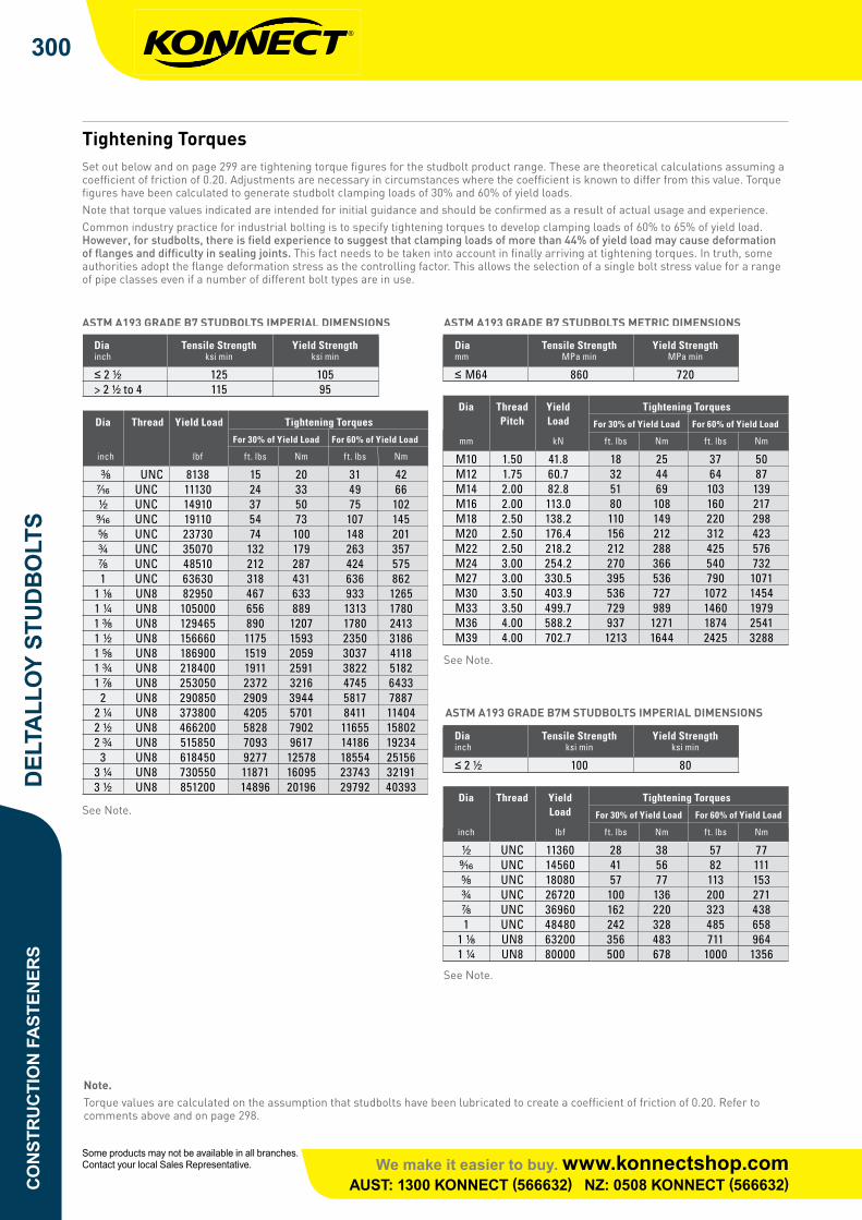
Bolting Requirements for Raised Face FlangesSIZES DN 15 TO 600 CONFORMING TO ANSI B16.5 AND DN 750 & 900 TO BS 3293
Nominal Flange Size PN20 (Class 150) PN50 (Class 300)
Length Length
DN NPS No. of Bolts Bolt Dia Stud Bolt Hex Bolt No. of Bolts Bolt Dia Stud Bolt Hex Bolt inch mm mm inch mm mm
15 ¹⁄₂ 4 ¹⁄₂ 60 45 4 ¹⁄₂ 65 55 20 ³⁄₄ 4 ¹⁄₂ 65 50 4 ⁵⁄₈ 75 60 25 1 4 ¹⁄₂ 65 55 4 ⁵⁄₈ 80 65 32 1 ¹⁄₄ 4 ¹⁄₂ 70 55 4 ⁵⁄₈ 80 65 40 1 ¹⁄₂ 4 ¹⁄₂ 70 60 4 ³⁄₄ 90 75 50 2 4 ⁵⁄₈ 80 65 8 ⁵⁄₈ 90 75 65 2 ¹⁄₂ 4 ⁵⁄₈ 90 75 8 ³⁄₄ 100 85 80 3 4 ⁵⁄₈ 90 75 8 ³⁄₄ 110 90 90 3 ¹⁄₂ 8 ⁵⁄₈ 90 75 8 ³⁄₄ 110 95 100 4 8 ⁵⁄₈ 90 75 8 ³⁄₄ 110 95 125 5 8 ³⁄₄ 90 80 8 ³⁄₄ 120 100 150 6 8 ³⁄₄ 100 85 12 ³⁄₄ 125 105 200 8 8 ³⁄₄ 110 90 12 ⁷⁄₈ 140 110 250 10 12 ⁷⁄₈ 115 95 16 1 155 130 300 12 12 ⁷⁄₈ 120 100 16 1 ¹⁄₈ 170 145 350 14 12 1 130 110 20 1 ¹⁄₈ 175 150 400 16 16 1 135 115 20 1 ¹⁄₄ 190 160 450 18 16 1 ¹⁄₈ 150 125 24 1 ¹⁄₄ 195 170 500 20 20 1 ¹⁄₈ 160 135 24 1 ¹⁄₄ 205 180 600 24 20 1 ¹⁄₄ 175 145 24 1 ¹⁄₂ 230 195 750 30 28 1 ¹⁄₄ 190 160 28 1 ³⁄₄ 290 250 900 36 32 1 ¹⁄₂ 215 180 32 2 325 280
SIZES DN 15 TO 600 CONFORMING TO ANSI B16.5 AND DN 750 & 900 TO BS 3293
Nominal Flange Size PN100 (Class 600) PN150 (Class 900)
Stud Bolt Stud Bolt
DN NPS No. of Bolts Bolt Dia Length No. of Bolts Bolt Dia Length inch mm inch mm
15 ¹⁄₂ 4 ¹⁄₂ 80 4 ³⁄₄ 105 20 ³⁄₄ 4 ⁵⁄₈ 90 4 ³⁄₄ 115 25 1 4 ⁵⁄₈ 90 4 ⁷⁄₈ 125 32 1 ¹⁄₄ 4 ⁵⁄₈ 100 4 ⁷⁄₈ 125 40 1 ¹⁄₂ 4 ³⁄₄ 105 4 1 140 50 2 8 ⁵⁄₈ 105 8 ⁷⁄₈ 145 65 2 ¹⁄₂ 8 ³⁄₄ 120 8 1 160 80 3 8 ³⁄₄ 125 8 ⁷⁄₈ 145 90 3 ¹⁄₂ 8 ⁷⁄₈ 140 100 4 8 ⁷⁄₈ 145 8 1 ¹⁄₈ 170 125 5 8 1 165 8 1 ¹⁄₄ 190 150 6 12 1 170 12 1 ¹⁄₈ 195 200 8 12 1 ¹⁄₈ 195 12 1 ³⁄₈ 220 250 10 16 1 ¹⁄₄ 216 16 1 ³⁄₈ 235 300 12 20 1 ¹⁄₄ 220 20 1 ³⁄₈ 255 350 14 20 1 ³⁄₈ 235 20 1 ¹⁄₂ 275 400 16 20 1 ¹⁄₂ 255 20 1 ⁵⁄₈ 285 450 18 20 1 ⁵⁄₈ 275 20 1 ⁷⁄₈ 325 500 20 24 1 ⁵⁄₈ 290 20 2 345 600 24 24 1 ⁷⁄₈ 330 20 2 ¹⁄₂ 435 750 30 28 2 355 Not listed in BS 3293 900 36 28 2 ¹⁄₂ 400 Not listed in BS 3293
Note.
1. Raised face height of 2mm for PN20 & 50 and 7mm for PN 100 and above is included in bolt length.
2. Studbolt lengths are exclusive of point lengths.
3. Bolt lengths are rounded to the nearest 5mm.
See Note.
See Note.
SIZES DN 15 TO 600 CONFORMING TO ANSI B16.5 AND DN 750 & 900 TO BS 3293
SeeNote.
SeeNote.
SIZES DN 15 TO 600 CONFORMING TO ANSI B16.5 AND DN 750 & 900 TO BS 3293
Note.1.Raisedfaceheightof2mmforPN20&50and7mmforPN100andaboveisincludedinboltlength.2.Studboltlengthsareexclusiveofpointlengths.3.Boltlengthsareroundedtothenearest5mm.

CO
NST
RU
CTI
ON
FA
STEN
ERS
DEL
TALL
OY
STU
DB
OLT
S304
We make it easier to buy. www.konnectshop.comAUST: 1300 KONNECT (566632) NZ: 0508 KONNECT (566632)
Some products may not be available in all branches. Contact your local Sales Representative.
16B
OLT
ING
REQ
UIR
EMEN
TS
AUSTRALIA’S FASTENER SPECIALISTS
TECHNICAL DATA
ORDER BY PHONE, FAX, MAIL OR VISIT YOUR LOCAL COVENTRY FASTENERS BRANCHDETAILS ON THE BACK OF THIS DATA BOOK
Bolting Requirements for Raised Face Flanges (continued)SIZES DN 15 TO 600 CONFORMING TO ANSI B16.5 AND DN 750 & 900 TO BS 3293
Nominal Flange Size PN250 (Class 1500) PN420 (Class 2500)
Stud Bolt Stud Bolt
DN NPS No. of Bolts Bolt Dia Length No. of Bolts Bolt Dia Length inch mm inch mm
15 ¹⁄₂ 4 ³⁄₄ 105 4 ³⁄₄ 125 20 ³⁄₄ 4 ³⁄₄ 115 4 ³⁄₄ 125 25 1 4 ⁷⁄₈ 125 4 ⁷⁄₈ 140 32 1 ¹⁄₄ 4 ⁷⁄₈ 125 4 1 150 40 1 ¹⁄₂ 4 1 140 4 1 ¹⁄₈ 170 50 2 8 ⁷⁄₈ 145 8 1 175 65 2 ¹⁄₂ 8 1 160 8 1 ¹⁄₈ 195 80 3 8 1 ¹⁄₈ 180 8 1 ¹⁄₄ 220 100 4 8 1 ¹⁄₄ 195 8 1 ¹⁄₂ 255 125 5 8 1 ¹⁄₂ 250 8 1 ³⁄₄ 300 150 6 12 1 ³⁄₈ 260 8 2 345 200 8 12 1 ⁵⁄₈ 290 12 2 380 250 10 12 1 ⁷⁄₈ 335 12 2 ¹⁄₂ 485 300 12 16 2 375 12 2 ³⁄₄ 540 350 14 16 2 ¹⁄₄ 405 400 16 16 2 ¹⁄₂ 445 450 18 16 2 ³⁄₄ 495 500 20 16 3 540 600 24 16 3 ¹⁄₂ 615 750 30 Not Listed in BS 3293 900 36 Not Listed in BS 3293
Note.
1. Raised face height of 7mm for PN 100 and above is included in bolt length.
2. Studbolt lengths are exclusive of point lengths.
3. Bolt lengths are rounded to the nearest 5mm.
Bolting Requirements for Raised Face Flanges (continued)
SIZES DN 15 TO 600 CONFORMING TO ANSI B16.5 AND DN 750 & 900 TO BS 3293
Note.1.Raisedfaceheightof7mmforPN100andaboveisincludedinboltlength.2.Studboltlengthsareexclusiveofpointlengths.3.Boltlengthsareroundedtothenearest5mm.
Konnect Jobber Drills - 6mm Metric•135°SplitPointcutsfasterandreduceswandering
•FullygroundM2HSSincreasesdrilllife•Packsof10#K6MJDBUDrillDiam6.0mm,OAlength93mm,FL57mm

CO
NSTR
UC
TION
FASTEN
ERS
DELTA
LLOY STU
DB
OLTS
305
We make it easier to buy. www.konnectshop.comAUST: 1300 KONNECT (566632) NZ: 0508 KONNECT (566632)
Some products may not be available in all branches. Contact your local Sales Representative.
17
BO
LTING
REQU
IREMEN
TS
AUSTRALIA’S FASTENER SPECIALISTS
TECHNICAL DATA
ORDER BY PHONE, FAX, MAIL OR VISIT YOUR LOCAL COVENTRY FASTENERS BRANCHDETAILS ON THE BACK OF THIS DATA BOOK
Bolting For Carbon Steel Flanges to AS 2129 Set out below and on page 18 are details of bolting for carbon steel flanges to AS 2129. The following notes apply.
1. Integral valve flanges may differ in thickness to equivalent loose flanges. When integral flanges are involved, adjustments may be necessary to bolt lengths.
2. Bolt lengths listed apply to flat faced or 1.6mm raised face flanges and provide for 1.6mm gasket thickness.
3. Bolts for flanges in Tables D, E and F should conform to AS 1111, Property Class 4.6. For flanges in Tables H, J and R bolts should conform to AS 1110, Property Class 8.8. The operating temperature range for bolting to these Standards is -50°C to +300°C. Studbolts to AS 2528 should be used in applications outside of this range.
4. The listed diameters of M27, M33 and M39 are non preferred diameters and may be difficult to source. Should this be the case, substitute 1”, 1 ¹⁄₄” and 1 ¹⁄₂” studbolts to AS 2528 as appropriate to the metric diameter. Where bolt diameters are greater than M24 it is recommended that studbolts to AS 2528 are substituted.
Nominal Table D Table E Table F
Flange Size No. of Bolts Size No. of Bolts Size No. of Bolts Size DN
15 4 M12 x 40 4 M12 x 40 4 M12 x 40 20 4 M12 x 40 4 M12 x 40 4 M12 x 40 25 4 M12 x 40 4 M12 x 40 4 M16 x 45 32 4 M12 x 40 4 M12 x 40 4 M16 x 45 40 4 M12 x 40 4 M12 x 40 4 M16 x 45 50 4 M16 x 45 4 M16 x 45 4 M16 x 50 65 4 M16 x 45 4 M16 x 45 8 M16 x 50 80 4 M16 x 45 4 M16 x 45 8 M16 x 50 100 4 M16 x 45 8 M16 x 45 8 M16 x 60 125 8 M16 x 45 8 M16 x 50 8 M20 x 70 150 8 M16 x 45 8 M20 x 60 12 M20 x 70 200 8 M16 x 45 8 M20 x 60 12 M20 x 75 250 8 M20 x 55 12 M20 x 70 12 M24 x 85 300 12 M20 x 60 12 M24 x 80 16 M24 x 100 350 12 M24 x 75 12 M24 x 85 16 M27 x 100 400 12 M24 x 75 12 M24 x 100 20 M27 x 120 450 12 M24 x 80 16 M24 x 100 20 M30 x 130 500 16 M24 x 85 16 M24 x 110 24 M30 x 140 600 16 M27 x 100 16 M30 x 130 24 M33 x 150 700 20 M27 x 100 20 M30 x 140 24 M33 x 160 750 20 M30 x 120 20 M33 x 150 28 M33 x 170 800 20 M33 x 120 20 M33 x 150 28 M33 x 180 900 24 M33 x 140 24 M33 x 170 32 M36 x 200 1000 24 M33 x 140 24 M36 x 180 36 M36 x 220 1200 32 M33 x 160 32 M36 x 200 40 M39 x 240
Bolting For Carbon Steel Flanges to AS 2129
Setoutbelowandonpage306aredetailsofboltingforcarbonsteelflangestoAS2129.Thefollowingnotesapply.1.Integralvalveflangesmaydifferinthicknesstoequivalentlooseflanges.Whenintegralflangesareinvolved,adjustmentsmaybe
necessarytoboltlengths.2.Boltlengthslistedapplytoflatfacedor1.6mmraisedfaceflangesandprovidefor1.6mmgasketthickness.3.BoltsforflangesinTablesD,EandFshouldconformtoAS1111,PropertyClass4.6.ForflangesinTablesH,JandRboltsshould
conformtoAS1110,PropertyClass8.8.TheoperatingtemperaturerangeforboltingtotheseStandardsis-50°Cto+300°C.StudboltstoAS2528shouldbeusedinapplicationsoutsideofthisrange.
4.ThelisteddiametersofM27,M33andM39arenonpreferreddiametersandmaybedifficulttosource.Shouldthisbethecase,substitute1”,1¼”and1½”studboltstoAS2528asappropriatetothemetricdiameter.WhereboltdiametersaregreaterthanM24itisrecommendedthatstudboltstoAS2528aresubstituted.
M18 Brushless Hammer Drill Driver – skin onlyM18CPD-0

CO
NST
RU
CTI
ON
FA
STEN
ERS
DEL
TALL
OY
STU
DB
OLT
S306
We make it easier to buy. www.konnectshop.comAUST: 1300 KONNECT (566632) NZ: 0508 KONNECT (566632)
Some products may not be available in all branches. Contact your local Sales Representative.
18B
OLT
ING
REQ
UIR
EMEN
TSAUSTRALIA’S FASTENER SPECIALISTS
TECHNICAL DATA
ORDER BY PHONE, FAX, MAIL OR VISIT YOUR LOCAL COVENTRY FASTENERS BRANCHDETAILS ON THE BACK OF THIS DATA BOOK
Note.Refer to the notes on page 17.
Converting Bolt Lengths to Studbolt Lengths 1. Round the bolt diameter up to the next 5mm increment.
2. Add this figure to the bolt length to arrive at the total length for the studbolt expressed in millimetres.
Bolt Hole Clearances for Flanges to AS 2129 For bolts up to M24 diameter, flange holes should be 2mm larger than the bolt diameter. Above M24 diameter, holes should be 3mm larger.
Note.M14 and M18 diameters may be difficult to obtain.
Bolt Diameter Interchangeability for Flanges to AS 2129 Metric Imp Metric Imp Metric Imp
M12 ¹⁄₂ M24 ⁷⁄₈ M33 1 ¹⁄₄ M16 ⁵⁄₈ M27 1 M36 1 ³⁄₈ M20 ³⁄₄ M30 1 ¹⁄₈ M39 1 ¹⁄₂
Imperial to Metric Studbolt Interchangeability Diameter Diameter Diameter inch Use inch Use inch Use
¹⁄₂ M14 1 ¹⁄₄ M33 1 ⁷⁄₈ M48 ⁵⁄₈ M18 1 ³⁄₈ M36 2 M52 ³⁄₄ M20 1 ¹⁄₂ M39 2 ¹⁄₄ M56 ⁷⁄₈ M24 1 ⁵⁄₈ M42 2 ¹⁄₂ M64 1 M27 1 ³⁄₄ M45 2 ³⁄₄ M72 1 ¹⁄₈ M30
Bolting For Carbon Steel Flanges to AS 2129 (continued) Nominal Table H Table J Table R
Flange Size No. of Bolts Size No. of Bolts Size No. of Bolts Size DN
15 4 M16 x 45 4 M16 x 50 4 M16 x 50 20 4 M16 x 45 4 M16 x 50 4 M16 x 60 25 4 M16 x 50 4 M16 x 60 4 M16 x 65 32 4 M16 x 55 4 M16 x 60 4 M16 x 65 40 4 M16 x 55 4 M16 x 65 4 M20 x 75 50 4 M16 x 60 4 M20 x 75 8 M16 x 70 65 8 M16 x 60 8 M20 x 75 8 M20 x 80 80 8 M16 x 65 8 M20 x 90 8 M20 x 90 100 8 M16 x 70 8 M20 x 100 8 M24 x 100 125 8 M20 x 80 8 M24 x 110 12 M24 x 110 150 12 M20 x 80 12 M24 x 110 12 M24 x 120 200 12 M20 x 90 12 M24 x 110 12 M27 x 140 250 12 M24 x 100 12 M27 x 130 16 M27 x 150 300 16 M24 x 110 16 M27 x 140 16 M30 x 180 350 16 M27 x 130 16 M30 x 150 16 M33 x 200 400 20 M27 x 140 20 M30 x 170 20 M33 x 220 450 20 M30 x 160 20 M33 x 180 20 M36 x 240 500 24 M30 x 170 24 M33 x 200 20 M39 x 260 600 24 M30 x 190 24 M36 x 240
Bolting For Carbon Steel Flanges to AS 2129 (continued)
Note.Refertothenotesonpage303.
Bolt Hole Clearances for Flanges to AS 2129ForboltsuptoM24diameter,flangeholesshouldbe2mmlargerthantheboltdiameter.AboveM24diameter,holesshouldbe3mmlarger.
Converting Bolt Lengths to Studbolt Lengths1.Roundtheboltdiameteruptothenext5mmincrement.2.Addthisfiguretotheboltlengthtoarriveatthetotallengthforthestudboltexpressedinmillimetres.
Bolt Diameter Interchangeability for Flanges to AS 2129
Imperial to Metric Studbolt Interchangeability
Note.M14andM18diametersmaybedifficulttoobtain.

CO
NSTR
UC
TION
FASTEN
ERS
DELTA
LLOY STU
DB
OLTS
307
We make it easier to buy. www.konnectshop.comAUST: 1300 KONNECT (566632) NZ: 0508 KONNECT (566632)
Some products may not be available in all branches. Contact your local Sales Representative.
19PRO
DU
CT WEIG
HTS
AUSTRALIA’S FASTENER SPECIALISTS
TECHNICAL DATA
ORDER BY PHONE, FAX, MAIL OR VISIT YOUR LOCAL COVENTRY FASTENERS BRANCHDETAILS ON THE BACK OF THIS DATA BOOK
Product Weights PRODUCT WEIGHTS KG PER 100 FOR STUDBOLTS COMPLETE WITH 2 NUTS
Length Diameter, inches
mm inch ³⁄₈ ⁷⁄₁₆ ¹⁄₂ ⁹⁄₁₆ ⁵⁄₈ ³⁄₄ ⁷⁄₈ 1 1 ¹⁄₈ 1 ¹⁄₄
65 2 ¹⁄₂ 5.5 7.6 10.8 13.5 70 2 ³⁄₄ 5.9 8.2 11.6 14.5 19.8 80 3 ¹⁄₄ 6.3 8.8 12.4 15.5 21.0 32.4 90 3 ¹⁄₂ 6.7 9.4 13.2 16.5 22.2 34.3 50.0 100 4 7.1 10.0 14.0 17.5 23.4 36.2 52.6 71.8 110 4 ¹⁄₄ 7.5 10.6 14.8 18.5 24.6 38.1 55.2 75.2 102 120 4 ³⁄₄ 7.9 11.2 15.6 19.5 25.8 40.0 57.8 78.6 106 137 125 5 8.5 11.8 16.4 20.5 27.0 41.9 60.4 82.0 111 142 140 5 ¹⁄₂ 8.9 12.2 17.2 21.5 28.2 43.8 63.0 85.4 115 147 150 6 9.4 12.8 18.0 22.5 29.4 45.7 65.6 88.8 119 153 160 6 ¹⁄₄ 13.4 18.8 23.5 30.6 47.6 68.2 92.2 123 158 170 6 ³⁄₄ 14.0 19.6 24.5 32.3 49.5 70.8 95.6 128 164 180 7 14.7 20.4 25.5 33.5 50.8 73.4 99.0 132 169 190 7 ¹⁄₂ 21.2 26.5 34.8 52.7 75.5 103 136 174 205 8 22.0 27.6 36.1 54.5 78.0 106 141 180 220 8 ³⁄₄ 29.6 38.6 58.1 83.1 112 149 191 240 9 ¹⁄₂ 41.1 61.8 88.2 118 158 201 260 10 ¹⁄₄ 93.3 125 166 212 300 11 ³⁄₄ 138 184 233 Nuts kg/I00 1.3 2.3 3.1 4.9 5.4 8.6 13.2 19.1 26.3 36.7
Length Diameter, inches
mm inch 1 ³⁄₈ 1 ¹⁄₂ 1 ⁵⁄₈ 1 ³⁄₄ 1 ⁷⁄₈ 2 2 ¹⁄₄ 2 ¹⁄₂ 2 ³⁄₄ 3
125 5 179 140 5 ¹⁄₂ 186 234 150 6 193 242 289 160 6 ¹⁄₄ 200 250 298 363 170 6 ³⁄₄ 206 258 308 374 437 180 7 213 266 317 385 449 190 7 ¹⁄₂ 220 275 326 396 462 205 8 226 283 336 407 475 220 8 ³⁄₄ 240 299 354 429 500 593 240 9 ¹⁄₂ 253 316 373 451 526 622 830 260 10 ¹⁄₄ 267 332 391 474 551 651 868 300 11 ³⁄₄ 292 358 429 518 602 710 944 1208 1516 1879 400 15 ³⁄₄ 359 437 524 627 731 856 1126 1440 1798 2214 500 19 ³⁄₄ 517 619 738 858 1000 1313 1672 2080 2552 600 23 ³⁄₄ 986 1146 1500 1904 2362 2890 700 27 ¹⁄₂ 1686 2136 2644 3227 Nuts kg/I00 47.6 62 78 97 116 140 190 256 335 432
Product Weights
PRODUCT WEIGHTSKG PER 100 FOR STUDBOLTS COMPLETE WITH 2 NUTS