DEG-001 Evolution Series E9000 MCC Renewal Parts Bulletin
16
GE Industrial Solutions Evolution * Series E9000 Motor Control Center Renewal Parts Bulletin
-
Upload
khangminh22 -
Category
Documents
-
view
0 -
download
0
Transcript of DEG-001 Evolution Series E9000 MCC Renewal Parts Bulletin
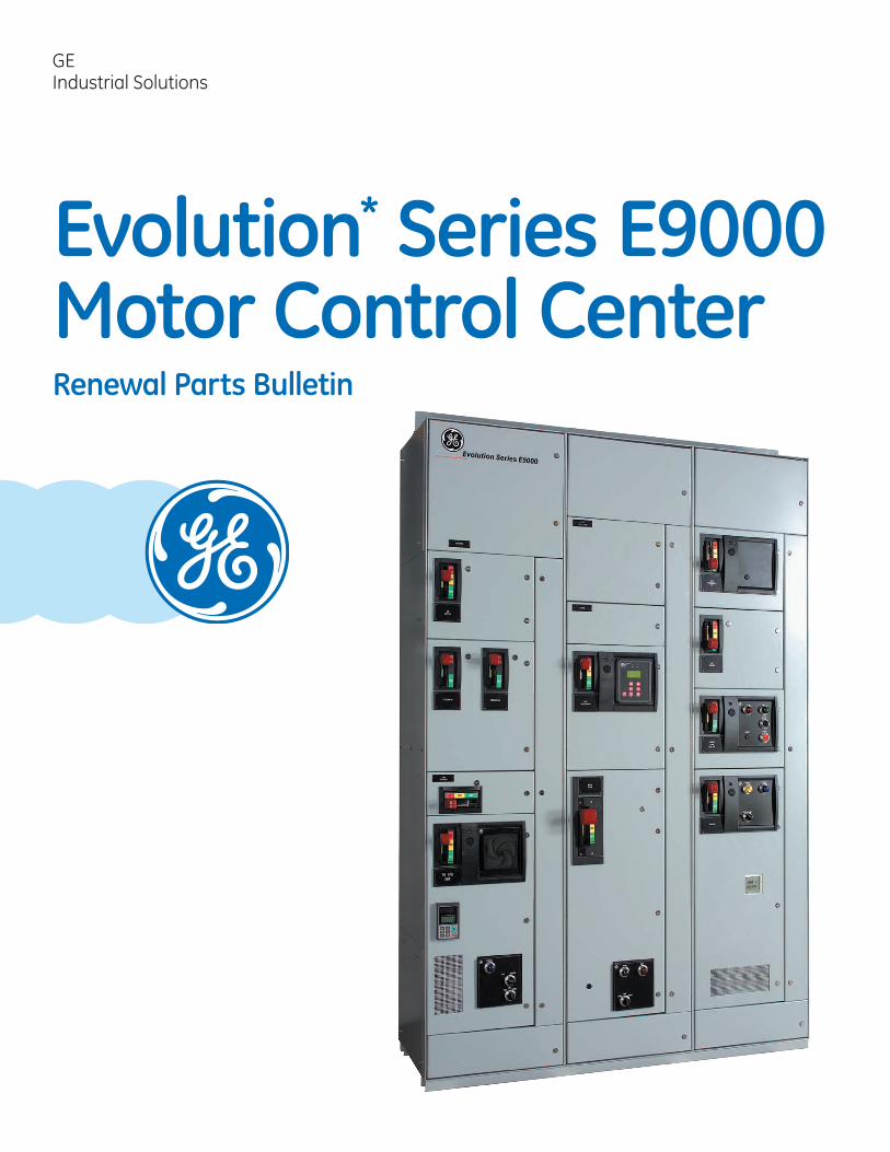
GE Industrial Solutions
Evolution Series E9000 Motor Control Center Renewal Parts Bulletin
2 Evolution Series E9000 Motor Control Center Renewal Parts Bulletin
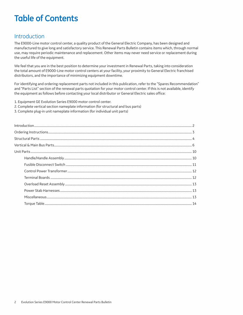
Table of Contents
Introduction The E9000-Line motor control center a quality product of the General Electric Company has been designed and manufactured to give long and satisfactory service This Renewal Parts Bulletin contains items which through normal use may require periodic maintenance and replacement Other items may never need service or replacement during the useful life of the equipment
We feel that you are in the best position to determine your investment in Renewal Parts taking into consideration the total amount of E9000-Line motor control centers at your facility your proximity to General Electric franchised distributors and the importance of minimizing equipment downtime
For identifying and ordering replacement parts not included in this publication refer to the ldquoSpares Recommendationrdquo and ldquoParts Listrdquo section of the renewal parts quotation for your motor control center If this is not available identify the equipment as follows before contacting your local distributor or General Electric sales office
1 Equipment GE Evolution Series E9000 motor control center 2 Complete vertical section nameplate information (for structural and bus parts)
Complete plug-in unit nameplate information (for individual unit parts)
Introduction 2
3
Ordering Instructions 3
Structural Parts 4
Vertical amp Main Bus Parts 6
Unit Parts 10
HandleHandle Assembly 10
Fusible Disconnect Switch 11
Control Power Transformer 12
Terminal Boards 12
Overload Reset Assembly 13
Power Stab Harnesses 13
Miscellaneous 13
Torque Table 14
Evolution Series E9000 Motor Control Center Renewal Parts Bulletin
Ordering Instructions The ordering of renewal parts or complete unit replacements will be simplified by referencing the data provided on the E9000 motor control center section nameplate and if required unit nameplate
Section Nameplate (located on the front of each UL listed section near the upper right-hand corner)
daggerCAT NO The General Electric Mebane NC factory catalog number
daggerDIAGRAM NO The outline summary sheet (often referred to as ldquorecord drawingsrdquo) for this section
AMPS-SUPPLY The main (ie horizontal) bus rating
AMPS-SECTION The vertical bus rating
When ordering replacement parts not identified in this bulletin both the ldquoCAT NOrdquo and ldquoDIAGRAM NOrdquo must be referenced accompanied by a complete description of the replacement part(s) desired
daggerThis information must be included in the order form
Unit Nameplate (plug-in units located on the right-hand vertical side barrier bolt-in units located in close proximity to the branch circuit overcurrent protective device)
MODEL Type of motor control center design
VOLTS TYPE Unit power supply voltage unit function (as listed on outline summary sheet)
daggerCONT VOLTS UNIT NO Unit control voltage The factory catalog number this identifies the section and unit location within that section
DIAGRAM The outline summary sheet and page number which contains the wiring elementary diagram for this unit
SIZE AMPSHP The NEMA size rating of the starter The ampere rating of the circuit breaker or fusible switch (for feeder unit) or horsepower rating (for combination starter units)
When ordering a complete replacement unit or replacement parts not identified in this bulletin the ldquoMODELrdquo ldquoUNIT NOrdquo and ldquoDIAGRAMrdquo must be referenced accompanied by a complete description of the replacement part(s) desired
3
4 Evolution Series E9000 Motor Control Center Renewal Parts Bulletin
13
13
13
13 13
Item 2 - Side Case Assembly Structural Parts
1
19
4
10 5
9
2
6
Item Number Part Description Page Number
1 Rear Cover 4
2 Side Case Assembly 4
3 Case Sill (See Figure 3) 4
4 Rodent Barrier 4
5 Front Top Cover Plate 4
6 Floor Plate 5
7 Mullions Wireway (See Figure 7) 5
8 Full Width Mullions (See Figure 8) 5
9 Side Enclosure Cover 5
10 Lifting Angle 6
Figure 2
Enclosure side With Channel 90 x 20 x 3 201D1001G1
Enclosure side With Channel 90 x 22 x 5 201D1001G4
Enclosure side With Channel 90 x 30 x 5 Rear Aligned 201D1001G10
Enclosure side BTB With Channel 90 x 25 x 3 201D1034G1
Enclosure side BTB With Channel 90 x 25 x 5 201D1034G2
Item 3 - Case Sills
Figure 3
Case Sill 20 IN 190B1009P1
Item 1 - Rear Cover Case Sill 24 IN 190B1009P2
Figure 1
33 x 20 190B1007P1
33 x 24 190B1007P2
33 x 30 190B1007P3
33 x 36 190B1007P4
39 x 20 190B1007P5
39 x 24 190B1007P6
39 x 30 190B1007P7
39 x 36 190B1007P8
45 x 20 190B1007P9
45 x 24 190B1007P10
45 x 30 190B1007P11
45 x 36 190B1007P12
24 x 20 190B1007P13
Item 4 - Rodent Barrier
Figure 4
BARRIER RODENT 13D 3IN 190B2177G1
BARRIER RODENT 20D 3IN 190B2177G2
BARRIER RODENT 22D 5IN 190B2177G3
BARRIER RODENT 30D 3IN 190B2177G4
Screw Steel T-Roll 14-20 X 38 (1)
Screw Steel T-Roll 10-24 X 34 (6)
Evolution Series E9000 Motor Control Center Renewal Parts Bulletin
13
13 13
13
13
Item 8 - Full Width Mullions Item 5 - Front Top Cover Plate
Figure 8
20 x 8
24 x 8
Screw Steel T-Roll 14-20 X 38 (8)
Figure 5
190B1060P1
190B1060P2
Item 6 - Floor Plate Top 20W 190B1238P1
Top 24W 190B1238P2
Top 30W 190B1238P3
Top 36W 190B1238P4
Item 9 - Side Covers
Figure 6A (Front) Figure 6B (Rear)
Figure 9 Front 20 x 2030 110C1030P1
Front 20 x 22 110C1030P2
Front 24 x 2030 110C1030P3
Front 24 x 22 110C1030P4
Front 20 x 25 110C1030P10
Front 24 x 25 110C1030P11
Rear 20 x 20 110C1060P1
Rear 20 x 22 110C1060P2
Rear 24 x 20 110C1060P4
Rear 24 x 22 110C1060P5
Rear 20 x 25 110C1060P1
Rear 24 x 25 110C1060P4
Cover Side Enclosure 2030 IN 3IN Vert 110C1029G1
Cover Side Enclosure 2230 IN 5IN Vert 110C1029G2
Cover Side Enclosure 13 IN 3IN Vert 110C1029G3
Cover Side Enclosure 25IN BTB 110C1029G11
Screw Steel T-Roll 14-20 X 12 (4)
Item 10 - Lifting Angle
Figure 10
Screw Steel T-Roll 14 ndash20 X 58 (4)
Item 7 - Mullions Wireway (See also Page 6) Angle Lifting ASM 20 110C1044G1
Angle Lifting ASM 20 x 20 110C1044G2
Angle Lifting ASM 20 x 20 x 20 110C1044G5
Includes Bolting Hardware
Floor Sill Figure 7
4 IN Case Width 20 IN 190B1255P1
9 IN Case Width 24 IN 190B1255P2
15 IN Case Width 30 IN 190B1255P3
Floor Sill - 20 110C1043G1
Floor Sill - 20 - 20 110C1043G2
Floor Sill - 20 - 20 - 20 110C1043G6
5
6 Evolution Series E9000 Motor Control Center Renewal Parts Bulletin
13
13
13
13
13
13
Item 11 - Top Wireway Door Vertical amp Main Bus Parts
11
13
12
14
Figure 11
DOOR ASSEMBLY TOP WIRE WAY 20 X 12 110C1440G1
DOOR ASSEMBLY TOP WIRE WAY 20 X 18 110C1440G2
DOOR ASSEMBLY TOP WIRE WAY 24 X 12 110C1440G6
DOOR ASSEMBLY TOP WIRE WAY 24 X 18 110C1440G7
DOOR ASSEMBLY TOP WIRE WAY 30 X 12 110C1440G14
DOOR ASSEMBLY TOP WIRE WAY 30 X 18 110C1440G15
Includes Door Hinges Latch Assembly Case Side Hinges Door Pin and Split Pin
Item 12 - Bottom Wireway Door
Figure 12
Item Number Part Description Page Number
11 Top Wireway Door 7
12 Bottom Wireway Door 7
13 Vertical Bus Accessories 7
14 Vertical Wire Way Door Assembly 8
DOOR ASSEMBLY BOTTOM WIREWAY 20 X 12 110C1450G1
DOOR ASSEMBLY BOTTOM WIREWAY 20 X 18 110C1450G2
DOOR ASSEMBLY BOTTOM WIREWAY 24 X 12 110C1450G6
DOOR ASSEMBLY BOTTOM WIREWAY 24 X 18 110C1450G7
DOOR ASSEMBLY BOTTOM WIREWAY 20 X 6 110C1450G11
DOOR ASSEMBLY BOTTOM WIREWAY 24 X 6 110C1450G12
DOOR ASSEMBLY BOTTOM WIREWAY 30 X 12 110C1450G16
DOOR ASSEMBLY BOTTOM WIREWAY 30 X 6 110C1450G54
DOOR ASSEMBLY BOTTOM WIREWAY 30 X 18 110C1450G59
7
15
16
17
Includes Door Hinges Latch Assembly Case Side Hinges Door Pin and Split Pin
Item 13 - Vertical Bus Accessories
Figure 13A
Stab Opening Cover 190B1215P1
Reference
Item Number Part Description Page Number
15 Ladder Assembly 8
16 Ladder Assembly Cut Out 8
17 Shelf Assembly 9
18 Blank Unit Door Assembly (See Figure 18) 9
19 Filler Kits (Not Shown) 10
Figure 13B
Bottom Vertical Bus Barrier 190B1549G1
Evolution Series E9000 Motor Control Center Renewal Parts Bulletin
13
13
13
Item 13 - Vertical Bus Accessories (continued) Item 14 - Vertical Wireway Door Assembly (continued)
24rdquo Wide Section
Figure 13C
Vertical Bus Shutter ASM At Top Most 110C1783G1
Vertical Bus Shutter ASM At Middle 110C1783G2
Vertical Bus Shutter ASM At Bottom Most 110C1783G3
9W 6H 110C1163G13
9W 12H 110C1163G14
9W 18H 110C1163G15
9W 24H 110C1163G16
9W 30H 110C1163G17
9W 36H 110C1163G18
9W 42H 110C1163G19
9W 48H 110C1163G20
9W 54H 110C1163G21
9W 60H 110C1163G22
9W 66H 110C1163G23
9W 72H 110C1163G24
Item 15 - Ladder Assembly Gasket 3245A1888P7
(13rdquo x 12rdquo) 25rsquo Roll Closed Cellular black neoprene UL recognized (JMST2) with pressure sensitive adhesive and removable backing
N3R Door Filter 75C143964P102
Aluminum Framed Uni-Foam Media 475rdquo x 175rdquo (Qty-2 per door)
Item 14 - Vertical Wireway Door Assembly
Figure 15
Figure 14
36 IN 110C1010P1
30 IN 110C1010P2
24 IN 110C1010P3
18 IN 110C1010P4
12 IN 110C1010P5
42 IN 110C1010P6
48 IN 110C1010P7
54 IN 110C1010P8
60 IN 110C1010P9
66 IN 110C1010P10
72 IN 110C1010P11
6 IN 110C1010P12
20rdquo Wide Section
5W 6H 110C1163G1
5W 12H 110C1163G2
5W 18H 110C1163G3
5W 24H 110C1163G4
5W 30H 110C1163G5
5W 36H 110C1163G6
5W 42H 110C1163G7
5W 48H 110C1163G8
5W 54H 110C1163G9
5W 60H 110C1163G10
5W 66H 110C1163G11
5W 72H 110C1163G12
Item 16 - Wireway Knockout Plate
Figure 16
Wireway knockout plate 190B1014P1
1 used every 6rdquo
7
8 Evolution Series E9000 Motor Control Center Renewal Parts Bulletin
13
13
Item 18 - Blank Unit Door Assembly (continued) Item 17 - Shelf Assembly
Figure 17
Shelf and Bracket Assembly 110C1850P1
Item 18 - Blank Unit Door Assembly
30 x 42
30 x 48
30 x 54
30 x 60
30 x 66 FOR 90 CASE HEIGHT
30 x 72
36 x 60
36 x 66 FOR 90 CASE HEIGHT
20 x 90
24 x 90
20 x 24 (PULL BOX)
20 x 30 (PULL BOX)
24 x 24 (PULL BOX)
24 x 30 (PULL BOX)
15 x 54
15 x 60
15 x 66
15 x 72
110C1240KKG39
110C1240KKG40
110C1240KKG41
110C1240KKG42
110C1240KKG43
110C1240KKG44
110C1240KKG45
110C1240KKG46
110C1240KKG47
110C1240KKG48
110C1240KKG49
110C1240KKG50
110C1240KKG51
110C1240KKG52
110C1240KKG53
110C1240KKG54
110C1240KKG55
110C1240KKG56
Includes Door Hinges Latch Assembly Case Side Hinges Door Pins Nameplate and Canoe Clips
Figure 18 Item 19 - Filler Kits
15 x 6 110C1240KKG1
15 x 12 110C1240KKG2
15 x 18 110C1240KKG3
15 x 24 110C1240KKG4
15 x 30 110C1240KKG5
15 x 36 110C1240KKG6
15 x 42 110C1240KKG7
15 x 48 110C1240KKG8
20 x 6 110C1240KKG9
20 x 12 110C1240KKG10
20 x 18 110C1240KKG11
20 x 24 110C1240KKG12
20 x 30 110C1240KKG13
20 x 36 110C1240KKG14
20 x 42 110C1240KKG15
20 x 48 110C1240KKG16
20 x 54 110C1240KKG17
20 x 60 110C1240KKG18
20 x 66 FOR 90 CASE HEIGHT 110C1240KKG19
20 x 72 110C1240KKG20
24 x 6 110C1240KKG21
24 x 12 110C1240KKG22
24 x 18 110C1240KKG23
24 x 24 110C1240KKG24
24 x 30 110C1240KKG25
24 x 36 110C1240KKG26
24 x 42 110C1240KKG27
24 x 48 110C1240KKG28
24 x 54 110C1240KKG29
24 x 60 110C1240KKG30
24 x 66 FOR 90 CASE HEIGHT 110C1240KKG31
24 x 72 110C1240KKG32
30 x 6 110C1240KKG33
30 x 12 110C1240KKG34
30 x 18 110C1240KKG35
30 x 24 110C1240KKG36
30 x 30 110C1240KKG37
30 x 36 110C1240KKG38
Common Doors
6 Feeder Door
12 Feeder Door
Door Hinge
Cabinet Side Hinge
Hinge Pin
Description
6 Filler kit
12 Filler kit
Catalog Number
EK06
EK12
Door - Sz 1 - 6
Door - Sz 1 amp 2 w PB cutout - 12
Door - Sz 3 w PB cutout - 18
Door - Sz 4 w PB cutout - 24
Door - Sz 4 w PB cutout - 30
Door - Sz 4 w PB cutout - 36
Door - Sz 1 amp 2 wo PB cutout - 12
Door - Sz 3 wo PB cutout - 18
Door - Sz 4 wo PB cutout - 24
Door - Sz 4 wo PB cutout - 30
Door - Sz 4 wo PB cutout - 36
110C1540BAG1
110C1540AAG11
110C1540AAG12
110C1540AZG13
110C1540AZG14
110C1540AZG15
110C1540AAG1
110C1540ABG2
110C1540AZG3
110C1540AZG4
110C1540AZG5
110C1540DAG2
110C1540AAG41
190B1013P1
190B1080P1
Evolution Series E9000 Motor Control Center Renewal Parts Bulletin
Main Bus Structural Parts Thermostat Assembly
20
IItetemm 2200 - C- Clleeaar Hr Hoorriizzoonnttaal Bl Buus Bs Baarrrriieerrss
Thermostat Assembly 190B2375G1
Cable Support
Cable Support 204B4135P1
Main Bus Splice Kit Figure 20
2rdquo HORZ MAIN BUS BARRIER ASM 20 110C1147G1
2rdquo HORZ MAIN BUS BARRIER ASM 24 110C1147G2
2rdquo HORZ MAIN BUS BARRIER ASM 30 110C1147G3
2rdquo HORZ MAIN BUS BARRIER ASM 36 110C1147G4
Main Bus Support
Main Bus Support - 2 Bus 190B1059P1
Space Heater Assembly
Space Htr Asm - 12 Bottom - 20 190B2643G1
Space Htr Asm - 12 Bottom - 24 190B2643G2
Space Htr Asm - 12 Bottom - 30 190B2643G3
Space Htr Asm - 6 Bottom - 20 190B2643G9
Space Htr Asm - 6 Bottom - 24 190B2643G10
Space Htr Asm - 6 Bottom - 30 190B2643G11
E9000 to E9000 Splice Kit - 3 phase
600A - 2 - Tin plated 110C1735G1SM
600A - 2 - Silver plated 110C1735G1KT
800A - 2 - Tin plated 110C1735G4SM
800A - 2 - Silver plated 110C1735G4KT
10001200A - 2 - Tin plated 110C1735G7SM
10001200A - 2 - Silver plated 110C1735G7KT
1600A - 4 - Tin plated 110C1735G10SM
1600A - 4 - Silver plated 110C1735G10KT
2500A - 2 - Tin Plated 110C1735G13SM
2500A - 2 - Silver Plated 110C1735G13KT
600A - 2 - Tin plated - for NEMA 3 110C1735G14SM
600A - 2 - Silver plated - for NEMA 3 110C1735G14KT
800A - 2 - Tin plated - for NEMA 3 110C1735G15SM
800A - 2 - Silver plated - for NEMA 3 110C1735G15KT
10001200A - 2 - Tin plated - for NEMA 3 110C1735G16SM
10001200A - 2 - Silver plated - for NEMA 3 110C1735G16KT
9
10 Evolution Series E9000 Motor Control Center Renewal Parts Bulletin
13
13
13 13
13
13 13
13
Unit Parts
8
2
3
1
12
19
18
5
14
6 8
11
13
4
10
Figure 19C G-Frame Assembly
Handle Assemblies Catalog Number
G-Frame Handle Assembly ndash Sz 5 Starter 110C1130G1
QMW 200A Handle Assembly 110C1130G2
Figure 19D 110C1725G1
Figure 19E 110C1734G1
Item 1 - Handles for combination starter units Handle (Only) includes plastic handle with egg shaped knob Handle assembly includes handle egg shaped knob escutcheon and steel linkage to mount on unit
Handle Actuator Assembly Figure 20
190B1704G1 amp G5 Item 2 - Handle Actuator Assembly includes metal actuator top hat and door defeater as shown below
Handle Assemblies Catalog Number
K-Frame Handle Assembly ndash Sz 6 Starter 110C1725G1
K-Frame Handle Assembly ndash Feeder Main 110C1734G1
Figure 19A Figure 19B 190B1704G2
Handle Assemblies Catalog Number
Escutcheon ASM SZ1-4 SE SF 190B1704G1
Escutcheon ASM SZ1-4 frac12 XSE 190B1704G2
Escutcheon ASM 3060100 A QMW 190B1704G5
Handle Actuator Assembly Catalog Number
SE-BREAKER OPERATOR SUB-ASM 110C1032G1
E-BREAKER OPERATOR SUB-ASM 110C1032G2
12X SE-BREAKER STARTERFEEDER SUB-ASM 110C1032G3
12X E-BREAKER STARTERFEEDER SUB-ASM 110C1032G4
DUAL FEEDER SUB-ASM 110C1032G5
DUAL FEEDER SUB-ASM WITH LOCK PROVISION 110C1032G6
F-FRAME ACTUATOR 110C1034G1
Evolution Series E9000 Motor Control Center Renewal Parts Bulletin
13 13
13 13
Item 3 - Branch Over-current Protective Device
Circuit Breaker E9000-Line motor control centers utilize General Electric circuit breakers in combination starters feeder tap units and main disconnect units Replacement circuit breakers may be purchased through General Electric Mebane NC 27302 Order by the catalog number as it appears on the devices itself
Fusible Disconnect Modified versions of QMR and QMW switches are utilized in E9000-Line construction When selecting the proper replacement switch consideration must be given to the following
1 Type of switch (QMR or QMW) 2 Size of starter feeder tap or main 3 Fuse amperage and type of clip 4 Power supply voltage
Complete fusible disconnect switches consists of switch assembly fuse clip base or base (as required) plus other factory modifications Order by complete catalog number as listed in the tables on the following pages
Does Not Include Fuses
Figure 21A 110C1718G9M
Figure 21B 110C1719G5M
Figure 21C 110C1720G9M
Figure 21D 110C1720G10M
Figure 21E 110C1040GVG14
Item 3 - Fusible Disconnect Switches for Starter Units (All functions except part winding)
NEMA Size
Reference Figure
Switch Rating
(Amperes)
Fuse Clips QMW Switch Catalog Number Type
Rating (Amperes)
1 21A
21A 30
R 0-30 110C1718G9M
J 0-30 110C1718G1M
2 21A
21A 60
R 31-60 110C1718G11M
J 31-60 110C1718G4M
3Dagger
21B
21B
21B
21B
100
R 61-100 110C1719G5M R (Bottom
Mount) 61-100 110C1719G13M
J 61-100 110C1719G1M J (Bottom
Mount) 61-100 110C1719G9M
4 21C
21D 200
R 101-200 110C1720G7M
J 101-200 110C1720G2M
Dagger For 24 inch high unit refer to Spare Recommendations before ordering
Item 3 - Fusible Disconnect Switches for for Feeder Units
Switch Size
(Amperes)
Reference Figure
Unit Door Height
(inches)
Fuse Clips QMW Switch Catalog Number Type
Rating (Amperes)
30 21A 21A
12 R 0-30 110C1718G13M J 0-30 110C1718G1M
60 21A
21A 12
R 31-60 110C1718G15M
J 31-60 110C1718G4M
100
21B
21B
21B
21B
12
R 61-100 110C1719G5M R (Bottom
Mount) 61-100 110C1719G13M
J 61-100 110C1719G1M
J (Bottom Mount)
61-100 110C1719G9M
20 21C
21D 24
R 101-200 110C1720G9M
J 101-200 110C1720G10M
Item 3 - Fusible Disconnect Switches for Part Winding Starter Units Only (See Notes below)
NEMA Size
Reference Figure
Switch Rating
(Amperes)
Fuse Clips QMW Switch Catalog Number Type
Rating (Amperes)
1 21A 21A
30 R 0-30 110C1718G9M J 0-30 110C1718G1M
1 or 2 21A 21A
60 R 31-60 110C1718G11M J 31-60 110C1718G4M
3 21B 21B
100 R 61-100 110C1719G5M J 61-100 110C1719G1M
3 or 4 21C 21D
200 R 101-200 110C1720G7M J 101-200 110C1720G2M
Item 3 - Fusible Disconnect Switches for Main Switches (See Notes below)
Switch Reference
Unit Door Fuse Clips QMW Switch Catalog Number
Size (Amperes)
Figure Height
(inches) Type Rating
(Amperes)
200 21C 21D
30 R 101-200 110C1720G9M J 101-200 110C1720G10M
Notes For Item 3 (Fusible Disconnect Switch)
1 All switches listed are rated for 600 volts for 250 volt applications refer to Spare Recommendations
11
12 Evolution Series E9000 Motor Control Center Renewal Parts Bulletin
13 13
13
13
13
Pullapart HD 3PT 190B1692G1
Stationary Single 3 point TB 190B1627P1
Stationary HD 6PT 190B1631G1
Stationary HD 12PT 190B1631G2
Stationary HD 18PT 190B1631G3
Item 4 - StarterContactor - Refer to Spare Recommendations Item 7 - Door Latch Assembly (14 turn) and Parts List for your motor control center If none is available refer to catalog number as it appears on the device itself before ordering replacement parts
Item 5 - Control Power Transformer - (120 Volt Secondary 60 Hz)
Control Power Transformer 480 Volt Primary Catalog Number
600 Volt Primary Catalog Number
Size 1 FVNRFVR (Standard) 60 VA 30213600YDP1 30213600YDP25
Size 2 FVNRFVR (Standard) 150 VA 30213600YDP300 30213600YDP301
Size 3 FVNRFVR (Standard) 300 VA 30213600YDP7 30213600YDP30
Size 4 FVNRFVR (Standard) 300VA 30213600YDP7 30213600YDP30
12X Sz 1 Micron Transformer MICB100-2989-5 -Figure 23
Catalog Number 190B1511P1 Item 6 - Terminal Boards
Figure 22A Figure 22B 190B1692G1 190B1631G1
Control Terminal Boards
Item 8 - Unit Frame Latch Assembly (14 turn)
Figure 24
Catalog Number 110C1572G1
Item 9 - WireTrough Door Latch Assembly (14-turn)
Item 6A - Power Terminal Block
Figure 22C
Figure 25
Catalog Number 190B1512P1
Power Terminal Boards
Catalog Number 190B1691G1
Evolution Series E9000 Motor Control Center Renewal Parts Bulletin
13 13
13 13
13 13
13
Item 10 - Pilot Device Bracket Escutcheon Item 12 - Vertical Ground Bus Stab Finger
Figure 28
Figure 26A Blank Figure 26B 6-Hole Catalog Number 270A1032G1
Pilot Device Catalog Number
Blank (No Holes) 110C1039P100
6 hole 110C1039P1
Plug Button Assembly (Black) 272A5650UWG2 (Not Pictured)
Plug Button Assembly (Gray) 272A5650UWG4 (Not Pictured)
Mounting Bracket 190B1512P1 (Not Pictured)
Item 13 - Pilot Device (Type CR104P)
Refer to Spare Recommendations furnished with your motor control center
Type CR104P Standard
Type C2000 for 12X starters
Item 11 - Overload Reset Assembly Item 14 - Fuse Block
Figure 27A 190B1048G1
1-Pole In Line CSCFEC-11-11
1-Pole Midget CSC30311
1-Pole CC CSC30311R
2-Pole Class CC CSC30312R
3-Pole Class CC CSC30313R
1-Pole CC Pull Out Din Rail Mtg CSC23302-G
2-Pole CC Pull Out Din Rail Mtg CSC23312-G
3-Pole CC Pull Out Din Rail Mtg CSC23314-G
Figure 27B Item 18 - Stab Power Harness (includes harness and stab fingers) 190B1048G2 Combination Starter Units
Function NEMA Size Catalog Number
(For Circuit Breaker)
Tin Silver
FVNR FVR and 2S1W or 2S2W
1 E9000L8G2 E9000L8G4
2 E9000L8G2 E9000L8G4
3 E9000L4G2 E9000L4G8
4 E9000L4G15 E9000L4G16
4 (F-Frame) E9000L4G10 E9000L4G4
Figure 27C Figure 27D 190B1421G1 190B1418G1
Door Mounted Reset
Reset Button Assembly Bimetal Sz 1 3 amp 4 190B1048G1
Reset Button Assembly Bimetal Sz 2 amp 5 190B1048G2
Reset Button Assembly Electronic Sz 1 190B1048G1
Reset Button Assembly Electronic Sz 2 3 4 amp 5 190B1048G2
Function NEMA
Size Amperes
Catalog Number (For Fusible Disconnect)
Tin Silver
FVNR FVR and 2S1W or 2S2W
1 30 E9000L8G7 E9000L8G8
2 60 E9000L8G7 E9000L8G8
3 100 E9000L4G17 E9000L4G18
3 amp 4 200 E9000L4G10 E9000L4G4
OLR Reset Button Adapter Bimetal Sz 1 2 amp 5 190B1421G1
OLR Reset Button Adapter Bimetal Sz 3 amp 4 190B1421G2
OLR Reset Button Adapter Electronic Sz 1 thru 5 190B1418G1
Clear Plastic OL Adapter NOTE Above harnesses utilize standard GE type THW (flamenol) wirecable Do not order above catalog numbers if your motor control center was ordered with special type power wirecable
Common Screws
frac14 - 20 Thread Rolling screws ndash pack of 5 204B4139AAG11
10-32 Thread Rolling screws ndash pack of 5 204B4139AAG15
13
14 Evolution Series E9000 Motor Control Center Renewal Parts Bulletin
Plastic Nameplate rivets ndash pack of 6 204B4139AAG5
Blank Nameplate ndash Small ndash 6 Bucket 1 x 3
Black face 273A7916P3FC
White Face 273A7916P3EC
Blank Nameplate ndash Large ndash 12rdquo Bucket amp Larger 5rdquo x 23rdquo
Black face 273A7916P3F3523
White Face 273A7916P3E3523
Joint Compound
4oz Tube 302A3747P3
Bucket Removal Tool 270A1581G1
Torque Table Values
Bolt Size Copper Joint Aluminum Joint
lb-ft N-m lb-ft N-m
516 - 18 5 - 9 7 - 12 65 - 9 9 - 12
38 - 16 12 - 16 16 - 22 10 - 15 14 - 20
12 - 13 30 - 39 41 - 53 25 - 35 34 - 47
58 - 11 65 - 80 88 - 108 35 - 45 47 - 61
34 - 10 125 - 150 169 - 203 50 - 75 68 - 102
Note When assembling or connecting aluminum bus apply a suitable joint compound between the contacting surfaces
Evolution Series E9000 Motor Control Center Renewal Parts Bulletin 15
GE Industrial Solutions 41 Woodford Avenue Plainville CT 06062 wwwgeindustrialcom
Trademark of the General Electric Company andor its subsidiaries Information provided is subject to change without notice Please verify all details with GE All values are design or typical values when measured under laboratory conditions and GE makes no warranty or guarantee express or implied that such performance will be obtained under end-use conditions
415 DEG-001
2 Evolution Series E9000 Motor Control Center Renewal Parts Bulletin
Table of Contents
Introduction The E9000-Line motor control center a quality product of the General Electric Company has been designed and manufactured to give long and satisfactory service This Renewal Parts Bulletin contains items which through normal use may require periodic maintenance and replacement Other items may never need service or replacement during the useful life of the equipment
We feel that you are in the best position to determine your investment in Renewal Parts taking into consideration the total amount of E9000-Line motor control centers at your facility your proximity to General Electric franchised distributors and the importance of minimizing equipment downtime
For identifying and ordering replacement parts not included in this publication refer to the ldquoSpares Recommendationrdquo and ldquoParts Listrdquo section of the renewal parts quotation for your motor control center If this is not available identify the equipment as follows before contacting your local distributor or General Electric sales office
1 Equipment GE Evolution Series E9000 motor control center 2 Complete vertical section nameplate information (for structural and bus parts)
Complete plug-in unit nameplate information (for individual unit parts)
Introduction 2
3
Ordering Instructions 3
Structural Parts 4
Vertical amp Main Bus Parts 6
Unit Parts 10
HandleHandle Assembly 10
Fusible Disconnect Switch 11
Control Power Transformer 12
Terminal Boards 12
Overload Reset Assembly 13
Power Stab Harnesses 13
Miscellaneous 13
Torque Table 14
Evolution Series E9000 Motor Control Center Renewal Parts Bulletin
Ordering Instructions The ordering of renewal parts or complete unit replacements will be simplified by referencing the data provided on the E9000 motor control center section nameplate and if required unit nameplate
Section Nameplate (located on the front of each UL listed section near the upper right-hand corner)
daggerCAT NO The General Electric Mebane NC factory catalog number
daggerDIAGRAM NO The outline summary sheet (often referred to as ldquorecord drawingsrdquo) for this section
AMPS-SUPPLY The main (ie horizontal) bus rating
AMPS-SECTION The vertical bus rating
When ordering replacement parts not identified in this bulletin both the ldquoCAT NOrdquo and ldquoDIAGRAM NOrdquo must be referenced accompanied by a complete description of the replacement part(s) desired
daggerThis information must be included in the order form
Unit Nameplate (plug-in units located on the right-hand vertical side barrier bolt-in units located in close proximity to the branch circuit overcurrent protective device)
MODEL Type of motor control center design
VOLTS TYPE Unit power supply voltage unit function (as listed on outline summary sheet)
daggerCONT VOLTS UNIT NO Unit control voltage The factory catalog number this identifies the section and unit location within that section
DIAGRAM The outline summary sheet and page number which contains the wiring elementary diagram for this unit
SIZE AMPSHP The NEMA size rating of the starter The ampere rating of the circuit breaker or fusible switch (for feeder unit) or horsepower rating (for combination starter units)
When ordering a complete replacement unit or replacement parts not identified in this bulletin the ldquoMODELrdquo ldquoUNIT NOrdquo and ldquoDIAGRAMrdquo must be referenced accompanied by a complete description of the replacement part(s) desired
3
4 Evolution Series E9000 Motor Control Center Renewal Parts Bulletin
13
13
13
13 13
Item 2 - Side Case Assembly Structural Parts
1
19
4
10 5
9
2
6
Item Number Part Description Page Number
1 Rear Cover 4
2 Side Case Assembly 4
3 Case Sill (See Figure 3) 4
4 Rodent Barrier 4
5 Front Top Cover Plate 4
6 Floor Plate 5
7 Mullions Wireway (See Figure 7) 5
8 Full Width Mullions (See Figure 8) 5
9 Side Enclosure Cover 5
10 Lifting Angle 6
Figure 2
Enclosure side With Channel 90 x 20 x 3 201D1001G1
Enclosure side With Channel 90 x 22 x 5 201D1001G4
Enclosure side With Channel 90 x 30 x 5 Rear Aligned 201D1001G10
Enclosure side BTB With Channel 90 x 25 x 3 201D1034G1
Enclosure side BTB With Channel 90 x 25 x 5 201D1034G2
Item 3 - Case Sills
Figure 3
Case Sill 20 IN 190B1009P1
Item 1 - Rear Cover Case Sill 24 IN 190B1009P2
Figure 1
33 x 20 190B1007P1
33 x 24 190B1007P2
33 x 30 190B1007P3
33 x 36 190B1007P4
39 x 20 190B1007P5
39 x 24 190B1007P6
39 x 30 190B1007P7
39 x 36 190B1007P8
45 x 20 190B1007P9
45 x 24 190B1007P10
45 x 30 190B1007P11
45 x 36 190B1007P12
24 x 20 190B1007P13
Item 4 - Rodent Barrier
Figure 4
BARRIER RODENT 13D 3IN 190B2177G1
BARRIER RODENT 20D 3IN 190B2177G2
BARRIER RODENT 22D 5IN 190B2177G3
BARRIER RODENT 30D 3IN 190B2177G4
Screw Steel T-Roll 14-20 X 38 (1)
Screw Steel T-Roll 10-24 X 34 (6)
Evolution Series E9000 Motor Control Center Renewal Parts Bulletin
13
13 13
13
13
Item 8 - Full Width Mullions Item 5 - Front Top Cover Plate
Figure 8
20 x 8
24 x 8
Screw Steel T-Roll 14-20 X 38 (8)
Figure 5
190B1060P1
190B1060P2
Item 6 - Floor Plate Top 20W 190B1238P1
Top 24W 190B1238P2
Top 30W 190B1238P3
Top 36W 190B1238P4
Item 9 - Side Covers
Figure 6A (Front) Figure 6B (Rear)
Figure 9 Front 20 x 2030 110C1030P1
Front 20 x 22 110C1030P2
Front 24 x 2030 110C1030P3
Front 24 x 22 110C1030P4
Front 20 x 25 110C1030P10
Front 24 x 25 110C1030P11
Rear 20 x 20 110C1060P1
Rear 20 x 22 110C1060P2
Rear 24 x 20 110C1060P4
Rear 24 x 22 110C1060P5
Rear 20 x 25 110C1060P1
Rear 24 x 25 110C1060P4
Cover Side Enclosure 2030 IN 3IN Vert 110C1029G1
Cover Side Enclosure 2230 IN 5IN Vert 110C1029G2
Cover Side Enclosure 13 IN 3IN Vert 110C1029G3
Cover Side Enclosure 25IN BTB 110C1029G11
Screw Steel T-Roll 14-20 X 12 (4)
Item 10 - Lifting Angle
Figure 10
Screw Steel T-Roll 14 ndash20 X 58 (4)
Item 7 - Mullions Wireway (See also Page 6) Angle Lifting ASM 20 110C1044G1
Angle Lifting ASM 20 x 20 110C1044G2
Angle Lifting ASM 20 x 20 x 20 110C1044G5
Includes Bolting Hardware
Floor Sill Figure 7
4 IN Case Width 20 IN 190B1255P1
9 IN Case Width 24 IN 190B1255P2
15 IN Case Width 30 IN 190B1255P3
Floor Sill - 20 110C1043G1
Floor Sill - 20 - 20 110C1043G2
Floor Sill - 20 - 20 - 20 110C1043G6
5
6 Evolution Series E9000 Motor Control Center Renewal Parts Bulletin
13
13
13
13
13
13
Item 11 - Top Wireway Door Vertical amp Main Bus Parts
11
13
12
14
Figure 11
DOOR ASSEMBLY TOP WIRE WAY 20 X 12 110C1440G1
DOOR ASSEMBLY TOP WIRE WAY 20 X 18 110C1440G2
DOOR ASSEMBLY TOP WIRE WAY 24 X 12 110C1440G6
DOOR ASSEMBLY TOP WIRE WAY 24 X 18 110C1440G7
DOOR ASSEMBLY TOP WIRE WAY 30 X 12 110C1440G14
DOOR ASSEMBLY TOP WIRE WAY 30 X 18 110C1440G15
Includes Door Hinges Latch Assembly Case Side Hinges Door Pin and Split Pin
Item 12 - Bottom Wireway Door
Figure 12
Item Number Part Description Page Number
11 Top Wireway Door 7
12 Bottom Wireway Door 7
13 Vertical Bus Accessories 7
14 Vertical Wire Way Door Assembly 8
DOOR ASSEMBLY BOTTOM WIREWAY 20 X 12 110C1450G1
DOOR ASSEMBLY BOTTOM WIREWAY 20 X 18 110C1450G2
DOOR ASSEMBLY BOTTOM WIREWAY 24 X 12 110C1450G6
DOOR ASSEMBLY BOTTOM WIREWAY 24 X 18 110C1450G7
DOOR ASSEMBLY BOTTOM WIREWAY 20 X 6 110C1450G11
DOOR ASSEMBLY BOTTOM WIREWAY 24 X 6 110C1450G12
DOOR ASSEMBLY BOTTOM WIREWAY 30 X 12 110C1450G16
DOOR ASSEMBLY BOTTOM WIREWAY 30 X 6 110C1450G54
DOOR ASSEMBLY BOTTOM WIREWAY 30 X 18 110C1450G59
7
15
16
17
Includes Door Hinges Latch Assembly Case Side Hinges Door Pin and Split Pin
Item 13 - Vertical Bus Accessories
Figure 13A
Stab Opening Cover 190B1215P1
Reference
Item Number Part Description Page Number
15 Ladder Assembly 8
16 Ladder Assembly Cut Out 8
17 Shelf Assembly 9
18 Blank Unit Door Assembly (See Figure 18) 9
19 Filler Kits (Not Shown) 10
Figure 13B
Bottom Vertical Bus Barrier 190B1549G1
Evolution Series E9000 Motor Control Center Renewal Parts Bulletin
13
13
13
Item 13 - Vertical Bus Accessories (continued) Item 14 - Vertical Wireway Door Assembly (continued)
24rdquo Wide Section
Figure 13C
Vertical Bus Shutter ASM At Top Most 110C1783G1
Vertical Bus Shutter ASM At Middle 110C1783G2
Vertical Bus Shutter ASM At Bottom Most 110C1783G3
9W 6H 110C1163G13
9W 12H 110C1163G14
9W 18H 110C1163G15
9W 24H 110C1163G16
9W 30H 110C1163G17
9W 36H 110C1163G18
9W 42H 110C1163G19
9W 48H 110C1163G20
9W 54H 110C1163G21
9W 60H 110C1163G22
9W 66H 110C1163G23
9W 72H 110C1163G24
Item 15 - Ladder Assembly Gasket 3245A1888P7
(13rdquo x 12rdquo) 25rsquo Roll Closed Cellular black neoprene UL recognized (JMST2) with pressure sensitive adhesive and removable backing
N3R Door Filter 75C143964P102
Aluminum Framed Uni-Foam Media 475rdquo x 175rdquo (Qty-2 per door)
Item 14 - Vertical Wireway Door Assembly
Figure 15
Figure 14
36 IN 110C1010P1
30 IN 110C1010P2
24 IN 110C1010P3
18 IN 110C1010P4
12 IN 110C1010P5
42 IN 110C1010P6
48 IN 110C1010P7
54 IN 110C1010P8
60 IN 110C1010P9
66 IN 110C1010P10
72 IN 110C1010P11
6 IN 110C1010P12
20rdquo Wide Section
5W 6H 110C1163G1
5W 12H 110C1163G2
5W 18H 110C1163G3
5W 24H 110C1163G4
5W 30H 110C1163G5
5W 36H 110C1163G6
5W 42H 110C1163G7
5W 48H 110C1163G8
5W 54H 110C1163G9
5W 60H 110C1163G10
5W 66H 110C1163G11
5W 72H 110C1163G12
Item 16 - Wireway Knockout Plate
Figure 16
Wireway knockout plate 190B1014P1
1 used every 6rdquo
7
8 Evolution Series E9000 Motor Control Center Renewal Parts Bulletin
13
13
Item 18 - Blank Unit Door Assembly (continued) Item 17 - Shelf Assembly
Figure 17
Shelf and Bracket Assembly 110C1850P1
Item 18 - Blank Unit Door Assembly
30 x 42
30 x 48
30 x 54
30 x 60
30 x 66 FOR 90 CASE HEIGHT
30 x 72
36 x 60
36 x 66 FOR 90 CASE HEIGHT
20 x 90
24 x 90
20 x 24 (PULL BOX)
20 x 30 (PULL BOX)
24 x 24 (PULL BOX)
24 x 30 (PULL BOX)
15 x 54
15 x 60
15 x 66
15 x 72
110C1240KKG39
110C1240KKG40
110C1240KKG41
110C1240KKG42
110C1240KKG43
110C1240KKG44
110C1240KKG45
110C1240KKG46
110C1240KKG47
110C1240KKG48
110C1240KKG49
110C1240KKG50
110C1240KKG51
110C1240KKG52
110C1240KKG53
110C1240KKG54
110C1240KKG55
110C1240KKG56
Includes Door Hinges Latch Assembly Case Side Hinges Door Pins Nameplate and Canoe Clips
Figure 18 Item 19 - Filler Kits
15 x 6 110C1240KKG1
15 x 12 110C1240KKG2
15 x 18 110C1240KKG3
15 x 24 110C1240KKG4
15 x 30 110C1240KKG5
15 x 36 110C1240KKG6
15 x 42 110C1240KKG7
15 x 48 110C1240KKG8
20 x 6 110C1240KKG9
20 x 12 110C1240KKG10
20 x 18 110C1240KKG11
20 x 24 110C1240KKG12
20 x 30 110C1240KKG13
20 x 36 110C1240KKG14
20 x 42 110C1240KKG15
20 x 48 110C1240KKG16
20 x 54 110C1240KKG17
20 x 60 110C1240KKG18
20 x 66 FOR 90 CASE HEIGHT 110C1240KKG19
20 x 72 110C1240KKG20
24 x 6 110C1240KKG21
24 x 12 110C1240KKG22
24 x 18 110C1240KKG23
24 x 24 110C1240KKG24
24 x 30 110C1240KKG25
24 x 36 110C1240KKG26
24 x 42 110C1240KKG27
24 x 48 110C1240KKG28
24 x 54 110C1240KKG29
24 x 60 110C1240KKG30
24 x 66 FOR 90 CASE HEIGHT 110C1240KKG31
24 x 72 110C1240KKG32
30 x 6 110C1240KKG33
30 x 12 110C1240KKG34
30 x 18 110C1240KKG35
30 x 24 110C1240KKG36
30 x 30 110C1240KKG37
30 x 36 110C1240KKG38
Common Doors
6 Feeder Door
12 Feeder Door
Door Hinge
Cabinet Side Hinge
Hinge Pin
Description
6 Filler kit
12 Filler kit
Catalog Number
EK06
EK12
Door - Sz 1 - 6
Door - Sz 1 amp 2 w PB cutout - 12
Door - Sz 3 w PB cutout - 18
Door - Sz 4 w PB cutout - 24
Door - Sz 4 w PB cutout - 30
Door - Sz 4 w PB cutout - 36
Door - Sz 1 amp 2 wo PB cutout - 12
Door - Sz 3 wo PB cutout - 18
Door - Sz 4 wo PB cutout - 24
Door - Sz 4 wo PB cutout - 30
Door - Sz 4 wo PB cutout - 36
110C1540BAG1
110C1540AAG11
110C1540AAG12
110C1540AZG13
110C1540AZG14
110C1540AZG15
110C1540AAG1
110C1540ABG2
110C1540AZG3
110C1540AZG4
110C1540AZG5
110C1540DAG2
110C1540AAG41
190B1013P1
190B1080P1
Evolution Series E9000 Motor Control Center Renewal Parts Bulletin
Main Bus Structural Parts Thermostat Assembly
20
IItetemm 2200 - C- Clleeaar Hr Hoorriizzoonnttaal Bl Buus Bs Baarrrriieerrss
Thermostat Assembly 190B2375G1
Cable Support
Cable Support 204B4135P1
Main Bus Splice Kit Figure 20
2rdquo HORZ MAIN BUS BARRIER ASM 20 110C1147G1
2rdquo HORZ MAIN BUS BARRIER ASM 24 110C1147G2
2rdquo HORZ MAIN BUS BARRIER ASM 30 110C1147G3
2rdquo HORZ MAIN BUS BARRIER ASM 36 110C1147G4
Main Bus Support
Main Bus Support - 2 Bus 190B1059P1
Space Heater Assembly
Space Htr Asm - 12 Bottom - 20 190B2643G1
Space Htr Asm - 12 Bottom - 24 190B2643G2
Space Htr Asm - 12 Bottom - 30 190B2643G3
Space Htr Asm - 6 Bottom - 20 190B2643G9
Space Htr Asm - 6 Bottom - 24 190B2643G10
Space Htr Asm - 6 Bottom - 30 190B2643G11
E9000 to E9000 Splice Kit - 3 phase
600A - 2 - Tin plated 110C1735G1SM
600A - 2 - Silver plated 110C1735G1KT
800A - 2 - Tin plated 110C1735G4SM
800A - 2 - Silver plated 110C1735G4KT
10001200A - 2 - Tin plated 110C1735G7SM
10001200A - 2 - Silver plated 110C1735G7KT
1600A - 4 - Tin plated 110C1735G10SM
1600A - 4 - Silver plated 110C1735G10KT
2500A - 2 - Tin Plated 110C1735G13SM
2500A - 2 - Silver Plated 110C1735G13KT
600A - 2 - Tin plated - for NEMA 3 110C1735G14SM
600A - 2 - Silver plated - for NEMA 3 110C1735G14KT
800A - 2 - Tin plated - for NEMA 3 110C1735G15SM
800A - 2 - Silver plated - for NEMA 3 110C1735G15KT
10001200A - 2 - Tin plated - for NEMA 3 110C1735G16SM
10001200A - 2 - Silver plated - for NEMA 3 110C1735G16KT
9
10 Evolution Series E9000 Motor Control Center Renewal Parts Bulletin
13
13
13 13
13
13 13
13
Unit Parts
8
2
3
1
12
19
18
5
14
6 8
11
13
4
10
Figure 19C G-Frame Assembly
Handle Assemblies Catalog Number
G-Frame Handle Assembly ndash Sz 5 Starter 110C1130G1
QMW 200A Handle Assembly 110C1130G2
Figure 19D 110C1725G1
Figure 19E 110C1734G1
Item 1 - Handles for combination starter units Handle (Only) includes plastic handle with egg shaped knob Handle assembly includes handle egg shaped knob escutcheon and steel linkage to mount on unit
Handle Actuator Assembly Figure 20
190B1704G1 amp G5 Item 2 - Handle Actuator Assembly includes metal actuator top hat and door defeater as shown below
Handle Assemblies Catalog Number
K-Frame Handle Assembly ndash Sz 6 Starter 110C1725G1
K-Frame Handle Assembly ndash Feeder Main 110C1734G1
Figure 19A Figure 19B 190B1704G2
Handle Assemblies Catalog Number
Escutcheon ASM SZ1-4 SE SF 190B1704G1
Escutcheon ASM SZ1-4 frac12 XSE 190B1704G2
Escutcheon ASM 3060100 A QMW 190B1704G5
Handle Actuator Assembly Catalog Number
SE-BREAKER OPERATOR SUB-ASM 110C1032G1
E-BREAKER OPERATOR SUB-ASM 110C1032G2
12X SE-BREAKER STARTERFEEDER SUB-ASM 110C1032G3
12X E-BREAKER STARTERFEEDER SUB-ASM 110C1032G4
DUAL FEEDER SUB-ASM 110C1032G5
DUAL FEEDER SUB-ASM WITH LOCK PROVISION 110C1032G6
F-FRAME ACTUATOR 110C1034G1
Evolution Series E9000 Motor Control Center Renewal Parts Bulletin
13 13
13 13
Item 3 - Branch Over-current Protective Device
Circuit Breaker E9000-Line motor control centers utilize General Electric circuit breakers in combination starters feeder tap units and main disconnect units Replacement circuit breakers may be purchased through General Electric Mebane NC 27302 Order by the catalog number as it appears on the devices itself
Fusible Disconnect Modified versions of QMR and QMW switches are utilized in E9000-Line construction When selecting the proper replacement switch consideration must be given to the following
1 Type of switch (QMR or QMW) 2 Size of starter feeder tap or main 3 Fuse amperage and type of clip 4 Power supply voltage
Complete fusible disconnect switches consists of switch assembly fuse clip base or base (as required) plus other factory modifications Order by complete catalog number as listed in the tables on the following pages
Does Not Include Fuses
Figure 21A 110C1718G9M
Figure 21B 110C1719G5M
Figure 21C 110C1720G9M
Figure 21D 110C1720G10M
Figure 21E 110C1040GVG14
Item 3 - Fusible Disconnect Switches for Starter Units (All functions except part winding)
NEMA Size
Reference Figure
Switch Rating
(Amperes)
Fuse Clips QMW Switch Catalog Number Type
Rating (Amperes)
1 21A
21A 30
R 0-30 110C1718G9M
J 0-30 110C1718G1M
2 21A
21A 60
R 31-60 110C1718G11M
J 31-60 110C1718G4M
3Dagger
21B
21B
21B
21B
100
R 61-100 110C1719G5M R (Bottom
Mount) 61-100 110C1719G13M
J 61-100 110C1719G1M J (Bottom
Mount) 61-100 110C1719G9M
4 21C
21D 200
R 101-200 110C1720G7M
J 101-200 110C1720G2M
Dagger For 24 inch high unit refer to Spare Recommendations before ordering
Item 3 - Fusible Disconnect Switches for for Feeder Units
Switch Size
(Amperes)
Reference Figure
Unit Door Height
(inches)
Fuse Clips QMW Switch Catalog Number Type
Rating (Amperes)
30 21A 21A
12 R 0-30 110C1718G13M J 0-30 110C1718G1M
60 21A
21A 12
R 31-60 110C1718G15M
J 31-60 110C1718G4M
100
21B
21B
21B
21B
12
R 61-100 110C1719G5M R (Bottom
Mount) 61-100 110C1719G13M
J 61-100 110C1719G1M
J (Bottom Mount)
61-100 110C1719G9M
20 21C
21D 24
R 101-200 110C1720G9M
J 101-200 110C1720G10M
Item 3 - Fusible Disconnect Switches for Part Winding Starter Units Only (See Notes below)
NEMA Size
Reference Figure
Switch Rating
(Amperes)
Fuse Clips QMW Switch Catalog Number Type
Rating (Amperes)
1 21A 21A
30 R 0-30 110C1718G9M J 0-30 110C1718G1M
1 or 2 21A 21A
60 R 31-60 110C1718G11M J 31-60 110C1718G4M
3 21B 21B
100 R 61-100 110C1719G5M J 61-100 110C1719G1M
3 or 4 21C 21D
200 R 101-200 110C1720G7M J 101-200 110C1720G2M
Item 3 - Fusible Disconnect Switches for Main Switches (See Notes below)
Switch Reference
Unit Door Fuse Clips QMW Switch Catalog Number
Size (Amperes)
Figure Height
(inches) Type Rating
(Amperes)
200 21C 21D
30 R 101-200 110C1720G9M J 101-200 110C1720G10M
Notes For Item 3 (Fusible Disconnect Switch)
1 All switches listed are rated for 600 volts for 250 volt applications refer to Spare Recommendations
11
12 Evolution Series E9000 Motor Control Center Renewal Parts Bulletin
13 13
13
13
13
Pullapart HD 3PT 190B1692G1
Stationary Single 3 point TB 190B1627P1
Stationary HD 6PT 190B1631G1
Stationary HD 12PT 190B1631G2
Stationary HD 18PT 190B1631G3
Item 4 - StarterContactor - Refer to Spare Recommendations Item 7 - Door Latch Assembly (14 turn) and Parts List for your motor control center If none is available refer to catalog number as it appears on the device itself before ordering replacement parts
Item 5 - Control Power Transformer - (120 Volt Secondary 60 Hz)
Control Power Transformer 480 Volt Primary Catalog Number
600 Volt Primary Catalog Number
Size 1 FVNRFVR (Standard) 60 VA 30213600YDP1 30213600YDP25
Size 2 FVNRFVR (Standard) 150 VA 30213600YDP300 30213600YDP301
Size 3 FVNRFVR (Standard) 300 VA 30213600YDP7 30213600YDP30
Size 4 FVNRFVR (Standard) 300VA 30213600YDP7 30213600YDP30
12X Sz 1 Micron Transformer MICB100-2989-5 -Figure 23
Catalog Number 190B1511P1 Item 6 - Terminal Boards
Figure 22A Figure 22B 190B1692G1 190B1631G1
Control Terminal Boards
Item 8 - Unit Frame Latch Assembly (14 turn)
Figure 24
Catalog Number 110C1572G1
Item 9 - WireTrough Door Latch Assembly (14-turn)
Item 6A - Power Terminal Block
Figure 22C
Figure 25
Catalog Number 190B1512P1
Power Terminal Boards
Catalog Number 190B1691G1
Evolution Series E9000 Motor Control Center Renewal Parts Bulletin
13 13
13 13
13 13
13
Item 10 - Pilot Device Bracket Escutcheon Item 12 - Vertical Ground Bus Stab Finger
Figure 28
Figure 26A Blank Figure 26B 6-Hole Catalog Number 270A1032G1
Pilot Device Catalog Number
Blank (No Holes) 110C1039P100
6 hole 110C1039P1
Plug Button Assembly (Black) 272A5650UWG2 (Not Pictured)
Plug Button Assembly (Gray) 272A5650UWG4 (Not Pictured)
Mounting Bracket 190B1512P1 (Not Pictured)
Item 13 - Pilot Device (Type CR104P)
Refer to Spare Recommendations furnished with your motor control center
Type CR104P Standard
Type C2000 for 12X starters
Item 11 - Overload Reset Assembly Item 14 - Fuse Block
Figure 27A 190B1048G1
1-Pole In Line CSCFEC-11-11
1-Pole Midget CSC30311
1-Pole CC CSC30311R
2-Pole Class CC CSC30312R
3-Pole Class CC CSC30313R
1-Pole CC Pull Out Din Rail Mtg CSC23302-G
2-Pole CC Pull Out Din Rail Mtg CSC23312-G
3-Pole CC Pull Out Din Rail Mtg CSC23314-G
Figure 27B Item 18 - Stab Power Harness (includes harness and stab fingers) 190B1048G2 Combination Starter Units
Function NEMA Size Catalog Number
(For Circuit Breaker)
Tin Silver
FVNR FVR and 2S1W or 2S2W
1 E9000L8G2 E9000L8G4
2 E9000L8G2 E9000L8G4
3 E9000L4G2 E9000L4G8
4 E9000L4G15 E9000L4G16
4 (F-Frame) E9000L4G10 E9000L4G4
Figure 27C Figure 27D 190B1421G1 190B1418G1
Door Mounted Reset
Reset Button Assembly Bimetal Sz 1 3 amp 4 190B1048G1
Reset Button Assembly Bimetal Sz 2 amp 5 190B1048G2
Reset Button Assembly Electronic Sz 1 190B1048G1
Reset Button Assembly Electronic Sz 2 3 4 amp 5 190B1048G2
Function NEMA
Size Amperes
Catalog Number (For Fusible Disconnect)
Tin Silver
FVNR FVR and 2S1W or 2S2W
1 30 E9000L8G7 E9000L8G8
2 60 E9000L8G7 E9000L8G8
3 100 E9000L4G17 E9000L4G18
3 amp 4 200 E9000L4G10 E9000L4G4
OLR Reset Button Adapter Bimetal Sz 1 2 amp 5 190B1421G1
OLR Reset Button Adapter Bimetal Sz 3 amp 4 190B1421G2
OLR Reset Button Adapter Electronic Sz 1 thru 5 190B1418G1
Clear Plastic OL Adapter NOTE Above harnesses utilize standard GE type THW (flamenol) wirecable Do not order above catalog numbers if your motor control center was ordered with special type power wirecable
Common Screws
frac14 - 20 Thread Rolling screws ndash pack of 5 204B4139AAG11
10-32 Thread Rolling screws ndash pack of 5 204B4139AAG15
13
14 Evolution Series E9000 Motor Control Center Renewal Parts Bulletin
Plastic Nameplate rivets ndash pack of 6 204B4139AAG5
Blank Nameplate ndash Small ndash 6 Bucket 1 x 3
Black face 273A7916P3FC
White Face 273A7916P3EC
Blank Nameplate ndash Large ndash 12rdquo Bucket amp Larger 5rdquo x 23rdquo
Black face 273A7916P3F3523
White Face 273A7916P3E3523
Joint Compound
4oz Tube 302A3747P3
Bucket Removal Tool 270A1581G1
Torque Table Values
Bolt Size Copper Joint Aluminum Joint
lb-ft N-m lb-ft N-m
516 - 18 5 - 9 7 - 12 65 - 9 9 - 12
38 - 16 12 - 16 16 - 22 10 - 15 14 - 20
12 - 13 30 - 39 41 - 53 25 - 35 34 - 47
58 - 11 65 - 80 88 - 108 35 - 45 47 - 61
34 - 10 125 - 150 169 - 203 50 - 75 68 - 102
Note When assembling or connecting aluminum bus apply a suitable joint compound between the contacting surfaces
Evolution Series E9000 Motor Control Center Renewal Parts Bulletin 15
GE Industrial Solutions 41 Woodford Avenue Plainville CT 06062 wwwgeindustrialcom
Trademark of the General Electric Company andor its subsidiaries Information provided is subject to change without notice Please verify all details with GE All values are design or typical values when measured under laboratory conditions and GE makes no warranty or guarantee express or implied that such performance will be obtained under end-use conditions
415 DEG-001

Evolution Series E9000 Motor Control Center Renewal Parts Bulletin
Ordering Instructions The ordering of renewal parts or complete unit replacements will be simplified by referencing the data provided on the E9000 motor control center section nameplate and if required unit nameplate
Section Nameplate (located on the front of each UL listed section near the upper right-hand corner)
daggerCAT NO The General Electric Mebane NC factory catalog number
daggerDIAGRAM NO The outline summary sheet (often referred to as ldquorecord drawingsrdquo) for this section
AMPS-SUPPLY The main (ie horizontal) bus rating
AMPS-SECTION The vertical bus rating
When ordering replacement parts not identified in this bulletin both the ldquoCAT NOrdquo and ldquoDIAGRAM NOrdquo must be referenced accompanied by a complete description of the replacement part(s) desired
daggerThis information must be included in the order form
Unit Nameplate (plug-in units located on the right-hand vertical side barrier bolt-in units located in close proximity to the branch circuit overcurrent protective device)
MODEL Type of motor control center design
VOLTS TYPE Unit power supply voltage unit function (as listed on outline summary sheet)
daggerCONT VOLTS UNIT NO Unit control voltage The factory catalog number this identifies the section and unit location within that section
DIAGRAM The outline summary sheet and page number which contains the wiring elementary diagram for this unit
SIZE AMPSHP The NEMA size rating of the starter The ampere rating of the circuit breaker or fusible switch (for feeder unit) or horsepower rating (for combination starter units)
When ordering a complete replacement unit or replacement parts not identified in this bulletin the ldquoMODELrdquo ldquoUNIT NOrdquo and ldquoDIAGRAMrdquo must be referenced accompanied by a complete description of the replacement part(s) desired
3
4 Evolution Series E9000 Motor Control Center Renewal Parts Bulletin
13
13
13
13 13
Item 2 - Side Case Assembly Structural Parts
1
19
4
10 5
9
2
6
Item Number Part Description Page Number
1 Rear Cover 4
2 Side Case Assembly 4
3 Case Sill (See Figure 3) 4
4 Rodent Barrier 4
5 Front Top Cover Plate 4
6 Floor Plate 5
7 Mullions Wireway (See Figure 7) 5
8 Full Width Mullions (See Figure 8) 5
9 Side Enclosure Cover 5
10 Lifting Angle 6
Figure 2
Enclosure side With Channel 90 x 20 x 3 201D1001G1
Enclosure side With Channel 90 x 22 x 5 201D1001G4
Enclosure side With Channel 90 x 30 x 5 Rear Aligned 201D1001G10
Enclosure side BTB With Channel 90 x 25 x 3 201D1034G1
Enclosure side BTB With Channel 90 x 25 x 5 201D1034G2
Item 3 - Case Sills
Figure 3
Case Sill 20 IN 190B1009P1
Item 1 - Rear Cover Case Sill 24 IN 190B1009P2
Figure 1
33 x 20 190B1007P1
33 x 24 190B1007P2
33 x 30 190B1007P3
33 x 36 190B1007P4
39 x 20 190B1007P5
39 x 24 190B1007P6
39 x 30 190B1007P7
39 x 36 190B1007P8
45 x 20 190B1007P9
45 x 24 190B1007P10
45 x 30 190B1007P11
45 x 36 190B1007P12
24 x 20 190B1007P13
Item 4 - Rodent Barrier
Figure 4
BARRIER RODENT 13D 3IN 190B2177G1
BARRIER RODENT 20D 3IN 190B2177G2
BARRIER RODENT 22D 5IN 190B2177G3
BARRIER RODENT 30D 3IN 190B2177G4
Screw Steel T-Roll 14-20 X 38 (1)
Screw Steel T-Roll 10-24 X 34 (6)
Evolution Series E9000 Motor Control Center Renewal Parts Bulletin
13
13 13
13
13
Item 8 - Full Width Mullions Item 5 - Front Top Cover Plate
Figure 8
20 x 8
24 x 8
Screw Steel T-Roll 14-20 X 38 (8)
Figure 5
190B1060P1
190B1060P2
Item 6 - Floor Plate Top 20W 190B1238P1
Top 24W 190B1238P2
Top 30W 190B1238P3
Top 36W 190B1238P4
Item 9 - Side Covers
Figure 6A (Front) Figure 6B (Rear)
Figure 9 Front 20 x 2030 110C1030P1
Front 20 x 22 110C1030P2
Front 24 x 2030 110C1030P3
Front 24 x 22 110C1030P4
Front 20 x 25 110C1030P10
Front 24 x 25 110C1030P11
Rear 20 x 20 110C1060P1
Rear 20 x 22 110C1060P2
Rear 24 x 20 110C1060P4
Rear 24 x 22 110C1060P5
Rear 20 x 25 110C1060P1
Rear 24 x 25 110C1060P4
Cover Side Enclosure 2030 IN 3IN Vert 110C1029G1
Cover Side Enclosure 2230 IN 5IN Vert 110C1029G2
Cover Side Enclosure 13 IN 3IN Vert 110C1029G3
Cover Side Enclosure 25IN BTB 110C1029G11
Screw Steel T-Roll 14-20 X 12 (4)
Item 10 - Lifting Angle
Figure 10
Screw Steel T-Roll 14 ndash20 X 58 (4)
Item 7 - Mullions Wireway (See also Page 6) Angle Lifting ASM 20 110C1044G1
Angle Lifting ASM 20 x 20 110C1044G2
Angle Lifting ASM 20 x 20 x 20 110C1044G5
Includes Bolting Hardware
Floor Sill Figure 7
4 IN Case Width 20 IN 190B1255P1
9 IN Case Width 24 IN 190B1255P2
15 IN Case Width 30 IN 190B1255P3
Floor Sill - 20 110C1043G1
Floor Sill - 20 - 20 110C1043G2
Floor Sill - 20 - 20 - 20 110C1043G6
5
6 Evolution Series E9000 Motor Control Center Renewal Parts Bulletin
13
13
13
13
13
13
Item 11 - Top Wireway Door Vertical amp Main Bus Parts
11
13
12
14
Figure 11
DOOR ASSEMBLY TOP WIRE WAY 20 X 12 110C1440G1
DOOR ASSEMBLY TOP WIRE WAY 20 X 18 110C1440G2
DOOR ASSEMBLY TOP WIRE WAY 24 X 12 110C1440G6
DOOR ASSEMBLY TOP WIRE WAY 24 X 18 110C1440G7
DOOR ASSEMBLY TOP WIRE WAY 30 X 12 110C1440G14
DOOR ASSEMBLY TOP WIRE WAY 30 X 18 110C1440G15
Includes Door Hinges Latch Assembly Case Side Hinges Door Pin and Split Pin
Item 12 - Bottom Wireway Door
Figure 12
Item Number Part Description Page Number
11 Top Wireway Door 7
12 Bottom Wireway Door 7
13 Vertical Bus Accessories 7
14 Vertical Wire Way Door Assembly 8
DOOR ASSEMBLY BOTTOM WIREWAY 20 X 12 110C1450G1
DOOR ASSEMBLY BOTTOM WIREWAY 20 X 18 110C1450G2
DOOR ASSEMBLY BOTTOM WIREWAY 24 X 12 110C1450G6
DOOR ASSEMBLY BOTTOM WIREWAY 24 X 18 110C1450G7
DOOR ASSEMBLY BOTTOM WIREWAY 20 X 6 110C1450G11
DOOR ASSEMBLY BOTTOM WIREWAY 24 X 6 110C1450G12
DOOR ASSEMBLY BOTTOM WIREWAY 30 X 12 110C1450G16
DOOR ASSEMBLY BOTTOM WIREWAY 30 X 6 110C1450G54
DOOR ASSEMBLY BOTTOM WIREWAY 30 X 18 110C1450G59
7
15
16
17
Includes Door Hinges Latch Assembly Case Side Hinges Door Pin and Split Pin
Item 13 - Vertical Bus Accessories
Figure 13A
Stab Opening Cover 190B1215P1
Reference
Item Number Part Description Page Number
15 Ladder Assembly 8
16 Ladder Assembly Cut Out 8
17 Shelf Assembly 9
18 Blank Unit Door Assembly (See Figure 18) 9
19 Filler Kits (Not Shown) 10
Figure 13B
Bottom Vertical Bus Barrier 190B1549G1
Evolution Series E9000 Motor Control Center Renewal Parts Bulletin
13
13
13
Item 13 - Vertical Bus Accessories (continued) Item 14 - Vertical Wireway Door Assembly (continued)
24rdquo Wide Section
Figure 13C
Vertical Bus Shutter ASM At Top Most 110C1783G1
Vertical Bus Shutter ASM At Middle 110C1783G2
Vertical Bus Shutter ASM At Bottom Most 110C1783G3
9W 6H 110C1163G13
9W 12H 110C1163G14
9W 18H 110C1163G15
9W 24H 110C1163G16
9W 30H 110C1163G17
9W 36H 110C1163G18
9W 42H 110C1163G19
9W 48H 110C1163G20
9W 54H 110C1163G21
9W 60H 110C1163G22
9W 66H 110C1163G23
9W 72H 110C1163G24
Item 15 - Ladder Assembly Gasket 3245A1888P7
(13rdquo x 12rdquo) 25rsquo Roll Closed Cellular black neoprene UL recognized (JMST2) with pressure sensitive adhesive and removable backing
N3R Door Filter 75C143964P102
Aluminum Framed Uni-Foam Media 475rdquo x 175rdquo (Qty-2 per door)
Item 14 - Vertical Wireway Door Assembly
Figure 15
Figure 14
36 IN 110C1010P1
30 IN 110C1010P2
24 IN 110C1010P3
18 IN 110C1010P4
12 IN 110C1010P5
42 IN 110C1010P6
48 IN 110C1010P7
54 IN 110C1010P8
60 IN 110C1010P9
66 IN 110C1010P10
72 IN 110C1010P11
6 IN 110C1010P12
20rdquo Wide Section
5W 6H 110C1163G1
5W 12H 110C1163G2
5W 18H 110C1163G3
5W 24H 110C1163G4
5W 30H 110C1163G5
5W 36H 110C1163G6
5W 42H 110C1163G7
5W 48H 110C1163G8
5W 54H 110C1163G9
5W 60H 110C1163G10
5W 66H 110C1163G11
5W 72H 110C1163G12
Item 16 - Wireway Knockout Plate
Figure 16
Wireway knockout plate 190B1014P1
1 used every 6rdquo
7
8 Evolution Series E9000 Motor Control Center Renewal Parts Bulletin
13
13
Item 18 - Blank Unit Door Assembly (continued) Item 17 - Shelf Assembly
Figure 17
Shelf and Bracket Assembly 110C1850P1
Item 18 - Blank Unit Door Assembly
30 x 42
30 x 48
30 x 54
30 x 60
30 x 66 FOR 90 CASE HEIGHT
30 x 72
36 x 60
36 x 66 FOR 90 CASE HEIGHT
20 x 90
24 x 90
20 x 24 (PULL BOX)
20 x 30 (PULL BOX)
24 x 24 (PULL BOX)
24 x 30 (PULL BOX)
15 x 54
15 x 60
15 x 66
15 x 72
110C1240KKG39
110C1240KKG40
110C1240KKG41
110C1240KKG42
110C1240KKG43
110C1240KKG44
110C1240KKG45
110C1240KKG46
110C1240KKG47
110C1240KKG48
110C1240KKG49
110C1240KKG50
110C1240KKG51
110C1240KKG52
110C1240KKG53
110C1240KKG54
110C1240KKG55
110C1240KKG56
Includes Door Hinges Latch Assembly Case Side Hinges Door Pins Nameplate and Canoe Clips
Figure 18 Item 19 - Filler Kits
15 x 6 110C1240KKG1
15 x 12 110C1240KKG2
15 x 18 110C1240KKG3
15 x 24 110C1240KKG4
15 x 30 110C1240KKG5
15 x 36 110C1240KKG6
15 x 42 110C1240KKG7
15 x 48 110C1240KKG8
20 x 6 110C1240KKG9
20 x 12 110C1240KKG10
20 x 18 110C1240KKG11
20 x 24 110C1240KKG12
20 x 30 110C1240KKG13
20 x 36 110C1240KKG14
20 x 42 110C1240KKG15
20 x 48 110C1240KKG16
20 x 54 110C1240KKG17
20 x 60 110C1240KKG18
20 x 66 FOR 90 CASE HEIGHT 110C1240KKG19
20 x 72 110C1240KKG20
24 x 6 110C1240KKG21
24 x 12 110C1240KKG22
24 x 18 110C1240KKG23
24 x 24 110C1240KKG24
24 x 30 110C1240KKG25
24 x 36 110C1240KKG26
24 x 42 110C1240KKG27
24 x 48 110C1240KKG28
24 x 54 110C1240KKG29
24 x 60 110C1240KKG30
24 x 66 FOR 90 CASE HEIGHT 110C1240KKG31
24 x 72 110C1240KKG32
30 x 6 110C1240KKG33
30 x 12 110C1240KKG34
30 x 18 110C1240KKG35
30 x 24 110C1240KKG36
30 x 30 110C1240KKG37
30 x 36 110C1240KKG38
Common Doors
6 Feeder Door
12 Feeder Door
Door Hinge
Cabinet Side Hinge
Hinge Pin
Description
6 Filler kit
12 Filler kit
Catalog Number
EK06
EK12
Door - Sz 1 - 6
Door - Sz 1 amp 2 w PB cutout - 12
Door - Sz 3 w PB cutout - 18
Door - Sz 4 w PB cutout - 24
Door - Sz 4 w PB cutout - 30
Door - Sz 4 w PB cutout - 36
Door - Sz 1 amp 2 wo PB cutout - 12
Door - Sz 3 wo PB cutout - 18
Door - Sz 4 wo PB cutout - 24
Door - Sz 4 wo PB cutout - 30
Door - Sz 4 wo PB cutout - 36
110C1540BAG1
110C1540AAG11
110C1540AAG12
110C1540AZG13
110C1540AZG14
110C1540AZG15
110C1540AAG1
110C1540ABG2
110C1540AZG3
110C1540AZG4
110C1540AZG5
110C1540DAG2
110C1540AAG41
190B1013P1
190B1080P1
Evolution Series E9000 Motor Control Center Renewal Parts Bulletin
Main Bus Structural Parts Thermostat Assembly
20
IItetemm 2200 - C- Clleeaar Hr Hoorriizzoonnttaal Bl Buus Bs Baarrrriieerrss
Thermostat Assembly 190B2375G1
Cable Support
Cable Support 204B4135P1
Main Bus Splice Kit Figure 20
2rdquo HORZ MAIN BUS BARRIER ASM 20 110C1147G1
2rdquo HORZ MAIN BUS BARRIER ASM 24 110C1147G2
2rdquo HORZ MAIN BUS BARRIER ASM 30 110C1147G3
2rdquo HORZ MAIN BUS BARRIER ASM 36 110C1147G4
Main Bus Support
Main Bus Support - 2 Bus 190B1059P1
Space Heater Assembly
Space Htr Asm - 12 Bottom - 20 190B2643G1
Space Htr Asm - 12 Bottom - 24 190B2643G2
Space Htr Asm - 12 Bottom - 30 190B2643G3
Space Htr Asm - 6 Bottom - 20 190B2643G9
Space Htr Asm - 6 Bottom - 24 190B2643G10
Space Htr Asm - 6 Bottom - 30 190B2643G11
E9000 to E9000 Splice Kit - 3 phase
600A - 2 - Tin plated 110C1735G1SM
600A - 2 - Silver plated 110C1735G1KT
800A - 2 - Tin plated 110C1735G4SM
800A - 2 - Silver plated 110C1735G4KT
10001200A - 2 - Tin plated 110C1735G7SM
10001200A - 2 - Silver plated 110C1735G7KT
1600A - 4 - Tin plated 110C1735G10SM
1600A - 4 - Silver plated 110C1735G10KT
2500A - 2 - Tin Plated 110C1735G13SM
2500A - 2 - Silver Plated 110C1735G13KT
600A - 2 - Tin plated - for NEMA 3 110C1735G14SM
600A - 2 - Silver plated - for NEMA 3 110C1735G14KT
800A - 2 - Tin plated - for NEMA 3 110C1735G15SM
800A - 2 - Silver plated - for NEMA 3 110C1735G15KT
10001200A - 2 - Tin plated - for NEMA 3 110C1735G16SM
10001200A - 2 - Silver plated - for NEMA 3 110C1735G16KT
9
10 Evolution Series E9000 Motor Control Center Renewal Parts Bulletin
13
13
13 13
13
13 13
13
Unit Parts
8
2
3
1
12
19
18
5
14
6 8
11
13
4
10
Figure 19C G-Frame Assembly
Handle Assemblies Catalog Number
G-Frame Handle Assembly ndash Sz 5 Starter 110C1130G1
QMW 200A Handle Assembly 110C1130G2
Figure 19D 110C1725G1
Figure 19E 110C1734G1
Item 1 - Handles for combination starter units Handle (Only) includes plastic handle with egg shaped knob Handle assembly includes handle egg shaped knob escutcheon and steel linkage to mount on unit
Handle Actuator Assembly Figure 20
190B1704G1 amp G5 Item 2 - Handle Actuator Assembly includes metal actuator top hat and door defeater as shown below
Handle Assemblies Catalog Number
K-Frame Handle Assembly ndash Sz 6 Starter 110C1725G1
K-Frame Handle Assembly ndash Feeder Main 110C1734G1
Figure 19A Figure 19B 190B1704G2
Handle Assemblies Catalog Number
Escutcheon ASM SZ1-4 SE SF 190B1704G1
Escutcheon ASM SZ1-4 frac12 XSE 190B1704G2
Escutcheon ASM 3060100 A QMW 190B1704G5
Handle Actuator Assembly Catalog Number
SE-BREAKER OPERATOR SUB-ASM 110C1032G1
E-BREAKER OPERATOR SUB-ASM 110C1032G2
12X SE-BREAKER STARTERFEEDER SUB-ASM 110C1032G3
12X E-BREAKER STARTERFEEDER SUB-ASM 110C1032G4
DUAL FEEDER SUB-ASM 110C1032G5
DUAL FEEDER SUB-ASM WITH LOCK PROVISION 110C1032G6
F-FRAME ACTUATOR 110C1034G1
Evolution Series E9000 Motor Control Center Renewal Parts Bulletin
13 13
13 13
Item 3 - Branch Over-current Protective Device
Circuit Breaker E9000-Line motor control centers utilize General Electric circuit breakers in combination starters feeder tap units and main disconnect units Replacement circuit breakers may be purchased through General Electric Mebane NC 27302 Order by the catalog number as it appears on the devices itself
Fusible Disconnect Modified versions of QMR and QMW switches are utilized in E9000-Line construction When selecting the proper replacement switch consideration must be given to the following
1 Type of switch (QMR or QMW) 2 Size of starter feeder tap or main 3 Fuse amperage and type of clip 4 Power supply voltage
Complete fusible disconnect switches consists of switch assembly fuse clip base or base (as required) plus other factory modifications Order by complete catalog number as listed in the tables on the following pages
Does Not Include Fuses
Figure 21A 110C1718G9M
Figure 21B 110C1719G5M
Figure 21C 110C1720G9M
Figure 21D 110C1720G10M
Figure 21E 110C1040GVG14
Item 3 - Fusible Disconnect Switches for Starter Units (All functions except part winding)
NEMA Size
Reference Figure
Switch Rating
(Amperes)
Fuse Clips QMW Switch Catalog Number Type
Rating (Amperes)
1 21A
21A 30
R 0-30 110C1718G9M
J 0-30 110C1718G1M
2 21A
21A 60
R 31-60 110C1718G11M
J 31-60 110C1718G4M
3Dagger
21B
21B
21B
21B
100
R 61-100 110C1719G5M R (Bottom
Mount) 61-100 110C1719G13M
J 61-100 110C1719G1M J (Bottom
Mount) 61-100 110C1719G9M
4 21C
21D 200
R 101-200 110C1720G7M
J 101-200 110C1720G2M
Dagger For 24 inch high unit refer to Spare Recommendations before ordering
Item 3 - Fusible Disconnect Switches for for Feeder Units
Switch Size
(Amperes)
Reference Figure
Unit Door Height
(inches)
Fuse Clips QMW Switch Catalog Number Type
Rating (Amperes)
30 21A 21A
12 R 0-30 110C1718G13M J 0-30 110C1718G1M
60 21A
21A 12
R 31-60 110C1718G15M
J 31-60 110C1718G4M
100
21B
21B
21B
21B
12
R 61-100 110C1719G5M R (Bottom
Mount) 61-100 110C1719G13M
J 61-100 110C1719G1M
J (Bottom Mount)
61-100 110C1719G9M
20 21C
21D 24
R 101-200 110C1720G9M
J 101-200 110C1720G10M
Item 3 - Fusible Disconnect Switches for Part Winding Starter Units Only (See Notes below)
NEMA Size
Reference Figure
Switch Rating
(Amperes)
Fuse Clips QMW Switch Catalog Number Type
Rating (Amperes)
1 21A 21A
30 R 0-30 110C1718G9M J 0-30 110C1718G1M
1 or 2 21A 21A
60 R 31-60 110C1718G11M J 31-60 110C1718G4M
3 21B 21B
100 R 61-100 110C1719G5M J 61-100 110C1719G1M
3 or 4 21C 21D
200 R 101-200 110C1720G7M J 101-200 110C1720G2M
Item 3 - Fusible Disconnect Switches for Main Switches (See Notes below)
Switch Reference
Unit Door Fuse Clips QMW Switch Catalog Number
Size (Amperes)
Figure Height
(inches) Type Rating
(Amperes)
200 21C 21D
30 R 101-200 110C1720G9M J 101-200 110C1720G10M
Notes For Item 3 (Fusible Disconnect Switch)
1 All switches listed are rated for 600 volts for 250 volt applications refer to Spare Recommendations
11
12 Evolution Series E9000 Motor Control Center Renewal Parts Bulletin
13 13
13
13
13
Pullapart HD 3PT 190B1692G1
Stationary Single 3 point TB 190B1627P1
Stationary HD 6PT 190B1631G1
Stationary HD 12PT 190B1631G2
Stationary HD 18PT 190B1631G3
Item 4 - StarterContactor - Refer to Spare Recommendations Item 7 - Door Latch Assembly (14 turn) and Parts List for your motor control center If none is available refer to catalog number as it appears on the device itself before ordering replacement parts
Item 5 - Control Power Transformer - (120 Volt Secondary 60 Hz)
Control Power Transformer 480 Volt Primary Catalog Number
600 Volt Primary Catalog Number
Size 1 FVNRFVR (Standard) 60 VA 30213600YDP1 30213600YDP25
Size 2 FVNRFVR (Standard) 150 VA 30213600YDP300 30213600YDP301
Size 3 FVNRFVR (Standard) 300 VA 30213600YDP7 30213600YDP30
Size 4 FVNRFVR (Standard) 300VA 30213600YDP7 30213600YDP30
12X Sz 1 Micron Transformer MICB100-2989-5 -Figure 23
Catalog Number 190B1511P1 Item 6 - Terminal Boards
Figure 22A Figure 22B 190B1692G1 190B1631G1
Control Terminal Boards
Item 8 - Unit Frame Latch Assembly (14 turn)
Figure 24
Catalog Number 110C1572G1
Item 9 - WireTrough Door Latch Assembly (14-turn)
Item 6A - Power Terminal Block
Figure 22C
Figure 25
Catalog Number 190B1512P1
Power Terminal Boards
Catalog Number 190B1691G1
Evolution Series E9000 Motor Control Center Renewal Parts Bulletin
13 13
13 13
13 13
13
Item 10 - Pilot Device Bracket Escutcheon Item 12 - Vertical Ground Bus Stab Finger
Figure 28
Figure 26A Blank Figure 26B 6-Hole Catalog Number 270A1032G1
Pilot Device Catalog Number
Blank (No Holes) 110C1039P100
6 hole 110C1039P1
Plug Button Assembly (Black) 272A5650UWG2 (Not Pictured)
Plug Button Assembly (Gray) 272A5650UWG4 (Not Pictured)
Mounting Bracket 190B1512P1 (Not Pictured)
Item 13 - Pilot Device (Type CR104P)
Refer to Spare Recommendations furnished with your motor control center
Type CR104P Standard
Type C2000 for 12X starters
Item 11 - Overload Reset Assembly Item 14 - Fuse Block
Figure 27A 190B1048G1
1-Pole In Line CSCFEC-11-11
1-Pole Midget CSC30311
1-Pole CC CSC30311R
2-Pole Class CC CSC30312R
3-Pole Class CC CSC30313R
1-Pole CC Pull Out Din Rail Mtg CSC23302-G
2-Pole CC Pull Out Din Rail Mtg CSC23312-G
3-Pole CC Pull Out Din Rail Mtg CSC23314-G
Figure 27B Item 18 - Stab Power Harness (includes harness and stab fingers) 190B1048G2 Combination Starter Units
Function NEMA Size Catalog Number
(For Circuit Breaker)
Tin Silver
FVNR FVR and 2S1W or 2S2W
1 E9000L8G2 E9000L8G4
2 E9000L8G2 E9000L8G4
3 E9000L4G2 E9000L4G8
4 E9000L4G15 E9000L4G16
4 (F-Frame) E9000L4G10 E9000L4G4
Figure 27C Figure 27D 190B1421G1 190B1418G1
Door Mounted Reset
Reset Button Assembly Bimetal Sz 1 3 amp 4 190B1048G1
Reset Button Assembly Bimetal Sz 2 amp 5 190B1048G2
Reset Button Assembly Electronic Sz 1 190B1048G1
Reset Button Assembly Electronic Sz 2 3 4 amp 5 190B1048G2
Function NEMA
Size Amperes
Catalog Number (For Fusible Disconnect)
Tin Silver
FVNR FVR and 2S1W or 2S2W
1 30 E9000L8G7 E9000L8G8
2 60 E9000L8G7 E9000L8G8
3 100 E9000L4G17 E9000L4G18
3 amp 4 200 E9000L4G10 E9000L4G4
OLR Reset Button Adapter Bimetal Sz 1 2 amp 5 190B1421G1
OLR Reset Button Adapter Bimetal Sz 3 amp 4 190B1421G2
OLR Reset Button Adapter Electronic Sz 1 thru 5 190B1418G1
Clear Plastic OL Adapter NOTE Above harnesses utilize standard GE type THW (flamenol) wirecable Do not order above catalog numbers if your motor control center was ordered with special type power wirecable
Common Screws
frac14 - 20 Thread Rolling screws ndash pack of 5 204B4139AAG11
10-32 Thread Rolling screws ndash pack of 5 204B4139AAG15
13
14 Evolution Series E9000 Motor Control Center Renewal Parts Bulletin
Plastic Nameplate rivets ndash pack of 6 204B4139AAG5
Blank Nameplate ndash Small ndash 6 Bucket 1 x 3
Black face 273A7916P3FC
White Face 273A7916P3EC
Blank Nameplate ndash Large ndash 12rdquo Bucket amp Larger 5rdquo x 23rdquo
Black face 273A7916P3F3523
White Face 273A7916P3E3523
Joint Compound
4oz Tube 302A3747P3
Bucket Removal Tool 270A1581G1
Torque Table Values
Bolt Size Copper Joint Aluminum Joint
lb-ft N-m lb-ft N-m
516 - 18 5 - 9 7 - 12 65 - 9 9 - 12
38 - 16 12 - 16 16 - 22 10 - 15 14 - 20
12 - 13 30 - 39 41 - 53 25 - 35 34 - 47
58 - 11 65 - 80 88 - 108 35 - 45 47 - 61
34 - 10 125 - 150 169 - 203 50 - 75 68 - 102
Note When assembling or connecting aluminum bus apply a suitable joint compound between the contacting surfaces
Evolution Series E9000 Motor Control Center Renewal Parts Bulletin 15
GE Industrial Solutions 41 Woodford Avenue Plainville CT 06062 wwwgeindustrialcom
Trademark of the General Electric Company andor its subsidiaries Information provided is subject to change without notice Please verify all details with GE All values are design or typical values when measured under laboratory conditions and GE makes no warranty or guarantee express or implied that such performance will be obtained under end-use conditions
415 DEG-001

Evolution Series E9000 Motor Control Center Renewal Parts Bulletin
13
13 13
13
13
Item 8 - Full Width Mullions Item 5 - Front Top Cover Plate
Figure 8
20 x 8
24 x 8
Screw Steel T-Roll 14-20 X 38 (8)
Figure 5
190B1060P1
190B1060P2
Item 6 - Floor Plate Top 20W 190B1238P1
Top 24W 190B1238P2
Top 30W 190B1238P3
Top 36W 190B1238P4
Item 9 - Side Covers
Figure 6A (Front) Figure 6B (Rear)
Figure 9 Front 20 x 2030 110C1030P1
Front 20 x 22 110C1030P2
Front 24 x 2030 110C1030P3
Front 24 x 22 110C1030P4
Front 20 x 25 110C1030P10
Front 24 x 25 110C1030P11
Rear 20 x 20 110C1060P1
Rear 20 x 22 110C1060P2
Rear 24 x 20 110C1060P4
Rear 24 x 22 110C1060P5
Rear 20 x 25 110C1060P1
Rear 24 x 25 110C1060P4
Cover Side Enclosure 2030 IN 3IN Vert 110C1029G1
Cover Side Enclosure 2230 IN 5IN Vert 110C1029G2
Cover Side Enclosure 13 IN 3IN Vert 110C1029G3
Cover Side Enclosure 25IN BTB 110C1029G11
Screw Steel T-Roll 14-20 X 12 (4)
Item 10 - Lifting Angle
Figure 10
Screw Steel T-Roll 14 ndash20 X 58 (4)
Item 7 - Mullions Wireway (See also Page 6) Angle Lifting ASM 20 110C1044G1
Angle Lifting ASM 20 x 20 110C1044G2
Angle Lifting ASM 20 x 20 x 20 110C1044G5
Includes Bolting Hardware
Floor Sill Figure 7
4 IN Case Width 20 IN 190B1255P1
9 IN Case Width 24 IN 190B1255P2
15 IN Case Width 30 IN 190B1255P3
Floor Sill - 20 110C1043G1
Floor Sill - 20 - 20 110C1043G2
Floor Sill - 20 - 20 - 20 110C1043G6
5
6 Evolution Series E9000 Motor Control Center Renewal Parts Bulletin
13
13
13
13
13
13
Item 11 - Top Wireway Door Vertical amp Main Bus Parts
11
13
12
14
Figure 11
DOOR ASSEMBLY TOP WIRE WAY 20 X 12 110C1440G1
DOOR ASSEMBLY TOP WIRE WAY 20 X 18 110C1440G2
DOOR ASSEMBLY TOP WIRE WAY 24 X 12 110C1440G6
DOOR ASSEMBLY TOP WIRE WAY 24 X 18 110C1440G7
DOOR ASSEMBLY TOP WIRE WAY 30 X 12 110C1440G14
DOOR ASSEMBLY TOP WIRE WAY 30 X 18 110C1440G15
Includes Door Hinges Latch Assembly Case Side Hinges Door Pin and Split Pin
Item 12 - Bottom Wireway Door
Figure 12
Item Number Part Description Page Number
11 Top Wireway Door 7
12 Bottom Wireway Door 7
13 Vertical Bus Accessories 7
14 Vertical Wire Way Door Assembly 8
DOOR ASSEMBLY BOTTOM WIREWAY 20 X 12 110C1450G1
DOOR ASSEMBLY BOTTOM WIREWAY 20 X 18 110C1450G2
DOOR ASSEMBLY BOTTOM WIREWAY 24 X 12 110C1450G6
DOOR ASSEMBLY BOTTOM WIREWAY 24 X 18 110C1450G7
DOOR ASSEMBLY BOTTOM WIREWAY 20 X 6 110C1450G11
DOOR ASSEMBLY BOTTOM WIREWAY 24 X 6 110C1450G12
DOOR ASSEMBLY BOTTOM WIREWAY 30 X 12 110C1450G16
DOOR ASSEMBLY BOTTOM WIREWAY 30 X 6 110C1450G54
DOOR ASSEMBLY BOTTOM WIREWAY 30 X 18 110C1450G59
7
15
16
17
Includes Door Hinges Latch Assembly Case Side Hinges Door Pin and Split Pin
Item 13 - Vertical Bus Accessories
Figure 13A
Stab Opening Cover 190B1215P1
Reference
Item Number Part Description Page Number
15 Ladder Assembly 8
16 Ladder Assembly Cut Out 8
17 Shelf Assembly 9
18 Blank Unit Door Assembly (See Figure 18) 9
19 Filler Kits (Not Shown) 10
Figure 13B
Bottom Vertical Bus Barrier 190B1549G1
Evolution Series E9000 Motor Control Center Renewal Parts Bulletin
13
13
13
Item 13 - Vertical Bus Accessories (continued) Item 14 - Vertical Wireway Door Assembly (continued)
24rdquo Wide Section
Figure 13C
Vertical Bus Shutter ASM At Top Most 110C1783G1
Vertical Bus Shutter ASM At Middle 110C1783G2
Vertical Bus Shutter ASM At Bottom Most 110C1783G3
9W 6H 110C1163G13
9W 12H 110C1163G14
9W 18H 110C1163G15
9W 24H 110C1163G16
9W 30H 110C1163G17
9W 36H 110C1163G18
9W 42H 110C1163G19
9W 48H 110C1163G20
9W 54H 110C1163G21
9W 60H 110C1163G22
9W 66H 110C1163G23
9W 72H 110C1163G24
Item 15 - Ladder Assembly Gasket 3245A1888P7
(13rdquo x 12rdquo) 25rsquo Roll Closed Cellular black neoprene UL recognized (JMST2) with pressure sensitive adhesive and removable backing
N3R Door Filter 75C143964P102
Aluminum Framed Uni-Foam Media 475rdquo x 175rdquo (Qty-2 per door)
Item 14 - Vertical Wireway Door Assembly
Figure 15
Figure 14
36 IN 110C1010P1
30 IN 110C1010P2
24 IN 110C1010P3
18 IN 110C1010P4
12 IN 110C1010P5
42 IN 110C1010P6
48 IN 110C1010P7
54 IN 110C1010P8
60 IN 110C1010P9
66 IN 110C1010P10
72 IN 110C1010P11
6 IN 110C1010P12
20rdquo Wide Section
5W 6H 110C1163G1
5W 12H 110C1163G2
5W 18H 110C1163G3
5W 24H 110C1163G4
5W 30H 110C1163G5
5W 36H 110C1163G6
5W 42H 110C1163G7
5W 48H 110C1163G8
5W 54H 110C1163G9
5W 60H 110C1163G10
5W 66H 110C1163G11
5W 72H 110C1163G12
Item 16 - Wireway Knockout Plate
Figure 16
Wireway knockout plate 190B1014P1
1 used every 6rdquo
7
8 Evolution Series E9000 Motor Control Center Renewal Parts Bulletin
13
13
Item 18 - Blank Unit Door Assembly (continued) Item 17 - Shelf Assembly
Figure 17
Shelf and Bracket Assembly 110C1850P1
Item 18 - Blank Unit Door Assembly
30 x 42
30 x 48
30 x 54
30 x 60
30 x 66 FOR 90 CASE HEIGHT
30 x 72
36 x 60
36 x 66 FOR 90 CASE HEIGHT
20 x 90
24 x 90
20 x 24 (PULL BOX)
20 x 30 (PULL BOX)
24 x 24 (PULL BOX)
24 x 30 (PULL BOX)
15 x 54
15 x 60
15 x 66
15 x 72
110C1240KKG39
110C1240KKG40
110C1240KKG41
110C1240KKG42
110C1240KKG43
110C1240KKG44
110C1240KKG45
110C1240KKG46
110C1240KKG47
110C1240KKG48
110C1240KKG49
110C1240KKG50
110C1240KKG51
110C1240KKG52
110C1240KKG53
110C1240KKG54
110C1240KKG55
110C1240KKG56
Includes Door Hinges Latch Assembly Case Side Hinges Door Pins Nameplate and Canoe Clips
Figure 18 Item 19 - Filler Kits
15 x 6 110C1240KKG1
15 x 12 110C1240KKG2
15 x 18 110C1240KKG3
15 x 24 110C1240KKG4
15 x 30 110C1240KKG5
15 x 36 110C1240KKG6
15 x 42 110C1240KKG7
15 x 48 110C1240KKG8
20 x 6 110C1240KKG9
20 x 12 110C1240KKG10
20 x 18 110C1240KKG11
20 x 24 110C1240KKG12
20 x 30 110C1240KKG13
20 x 36 110C1240KKG14
20 x 42 110C1240KKG15
20 x 48 110C1240KKG16
20 x 54 110C1240KKG17
20 x 60 110C1240KKG18
20 x 66 FOR 90 CASE HEIGHT 110C1240KKG19
20 x 72 110C1240KKG20
24 x 6 110C1240KKG21
24 x 12 110C1240KKG22
24 x 18 110C1240KKG23
24 x 24 110C1240KKG24
24 x 30 110C1240KKG25
24 x 36 110C1240KKG26
24 x 42 110C1240KKG27
24 x 48 110C1240KKG28
24 x 54 110C1240KKG29
24 x 60 110C1240KKG30
24 x 66 FOR 90 CASE HEIGHT 110C1240KKG31
24 x 72 110C1240KKG32
30 x 6 110C1240KKG33
30 x 12 110C1240KKG34
30 x 18 110C1240KKG35
30 x 24 110C1240KKG36
30 x 30 110C1240KKG37
30 x 36 110C1240KKG38
Common Doors
6 Feeder Door
12 Feeder Door
Door Hinge
Cabinet Side Hinge
Hinge Pin
Description
6 Filler kit
12 Filler kit
Catalog Number
EK06
EK12
Door - Sz 1 - 6
Door - Sz 1 amp 2 w PB cutout - 12
Door - Sz 3 w PB cutout - 18
Door - Sz 4 w PB cutout - 24
Door - Sz 4 w PB cutout - 30
Door - Sz 4 w PB cutout - 36
Door - Sz 1 amp 2 wo PB cutout - 12
Door - Sz 3 wo PB cutout - 18
Door - Sz 4 wo PB cutout - 24
Door - Sz 4 wo PB cutout - 30
Door - Sz 4 wo PB cutout - 36
110C1540BAG1
110C1540AAG11
110C1540AAG12
110C1540AZG13
110C1540AZG14
110C1540AZG15
110C1540AAG1
110C1540ABG2
110C1540AZG3
110C1540AZG4
110C1540AZG5
110C1540DAG2
110C1540AAG41
190B1013P1
190B1080P1
Evolution Series E9000 Motor Control Center Renewal Parts Bulletin
Main Bus Structural Parts Thermostat Assembly
20
IItetemm 2200 - C- Clleeaar Hr Hoorriizzoonnttaal Bl Buus Bs Baarrrriieerrss
Thermostat Assembly 190B2375G1
Cable Support
Cable Support 204B4135P1
Main Bus Splice Kit Figure 20
2rdquo HORZ MAIN BUS BARRIER ASM 20 110C1147G1
2rdquo HORZ MAIN BUS BARRIER ASM 24 110C1147G2
2rdquo HORZ MAIN BUS BARRIER ASM 30 110C1147G3
2rdquo HORZ MAIN BUS BARRIER ASM 36 110C1147G4
Main Bus Support
Main Bus Support - 2 Bus 190B1059P1
Space Heater Assembly
Space Htr Asm - 12 Bottom - 20 190B2643G1
Space Htr Asm - 12 Bottom - 24 190B2643G2
Space Htr Asm - 12 Bottom - 30 190B2643G3
Space Htr Asm - 6 Bottom - 20 190B2643G9
Space Htr Asm - 6 Bottom - 24 190B2643G10
Space Htr Asm - 6 Bottom - 30 190B2643G11
E9000 to E9000 Splice Kit - 3 phase
600A - 2 - Tin plated 110C1735G1SM
600A - 2 - Silver plated 110C1735G1KT
800A - 2 - Tin plated 110C1735G4SM
800A - 2 - Silver plated 110C1735G4KT
10001200A - 2 - Tin plated 110C1735G7SM
10001200A - 2 - Silver plated 110C1735G7KT
1600A - 4 - Tin plated 110C1735G10SM
1600A - 4 - Silver plated 110C1735G10KT
2500A - 2 - Tin Plated 110C1735G13SM
2500A - 2 - Silver Plated 110C1735G13KT
600A - 2 - Tin plated - for NEMA 3 110C1735G14SM
600A - 2 - Silver plated - for NEMA 3 110C1735G14KT
800A - 2 - Tin plated - for NEMA 3 110C1735G15SM
800A - 2 - Silver plated - for NEMA 3 110C1735G15KT
10001200A - 2 - Tin plated - for NEMA 3 110C1735G16SM
10001200A - 2 - Silver plated - for NEMA 3 110C1735G16KT
9
10 Evolution Series E9000 Motor Control Center Renewal Parts Bulletin
13
13
13 13
13
13 13
13
Unit Parts
8
2
3
1
12
19
18
5
14
6 8
11
13
4
10
Figure 19C G-Frame Assembly
Handle Assemblies Catalog Number
G-Frame Handle Assembly ndash Sz 5 Starter 110C1130G1
QMW 200A Handle Assembly 110C1130G2
Figure 19D 110C1725G1
Figure 19E 110C1734G1
Item 1 - Handles for combination starter units Handle (Only) includes plastic handle with egg shaped knob Handle assembly includes handle egg shaped knob escutcheon and steel linkage to mount on unit
Handle Actuator Assembly Figure 20
190B1704G1 amp G5 Item 2 - Handle Actuator Assembly includes metal actuator top hat and door defeater as shown below
Handle Assemblies Catalog Number
K-Frame Handle Assembly ndash Sz 6 Starter 110C1725G1
K-Frame Handle Assembly ndash Feeder Main 110C1734G1
Figure 19A Figure 19B 190B1704G2
Handle Assemblies Catalog Number
Escutcheon ASM SZ1-4 SE SF 190B1704G1
Escutcheon ASM SZ1-4 frac12 XSE 190B1704G2
Escutcheon ASM 3060100 A QMW 190B1704G5
Handle Actuator Assembly Catalog Number
SE-BREAKER OPERATOR SUB-ASM 110C1032G1
E-BREAKER OPERATOR SUB-ASM 110C1032G2
12X SE-BREAKER STARTERFEEDER SUB-ASM 110C1032G3
12X E-BREAKER STARTERFEEDER SUB-ASM 110C1032G4
DUAL FEEDER SUB-ASM 110C1032G5
DUAL FEEDER SUB-ASM WITH LOCK PROVISION 110C1032G6
F-FRAME ACTUATOR 110C1034G1
Evolution Series E9000 Motor Control Center Renewal Parts Bulletin
13 13
13 13
Item 3 - Branch Over-current Protective Device
Circuit Breaker E9000-Line motor control centers utilize General Electric circuit breakers in combination starters feeder tap units and main disconnect units Replacement circuit breakers may be purchased through General Electric Mebane NC 27302 Order by the catalog number as it appears on the devices itself
Fusible Disconnect Modified versions of QMR and QMW switches are utilized in E9000-Line construction When selecting the proper replacement switch consideration must be given to the following
1 Type of switch (QMR or QMW) 2 Size of starter feeder tap or main 3 Fuse amperage and type of clip 4 Power supply voltage
Complete fusible disconnect switches consists of switch assembly fuse clip base or base (as required) plus other factory modifications Order by complete catalog number as listed in the tables on the following pages
Does Not Include Fuses
Figure 21A 110C1718G9M
Figure 21B 110C1719G5M
Figure 21C 110C1720G9M
Figure 21D 110C1720G10M
Figure 21E 110C1040GVG14
Item 3 - Fusible Disconnect Switches for Starter Units (All functions except part winding)
NEMA Size
Reference Figure
Switch Rating
(Amperes)
Fuse Clips QMW Switch Catalog Number Type
Rating (Amperes)
1 21A
21A 30
R 0-30 110C1718G9M
J 0-30 110C1718G1M
2 21A
21A 60
R 31-60 110C1718G11M
J 31-60 110C1718G4M
3Dagger
21B
21B
21B
21B
100
R 61-100 110C1719G5M R (Bottom
Mount) 61-100 110C1719G13M
J 61-100 110C1719G1M J (Bottom
Mount) 61-100 110C1719G9M
4 21C
21D 200
R 101-200 110C1720G7M
J 101-200 110C1720G2M
Dagger For 24 inch high unit refer to Spare Recommendations before ordering
Item 3 - Fusible Disconnect Switches for for Feeder Units
Switch Size
(Amperes)
Reference Figure
Unit Door Height
(inches)
Fuse Clips QMW Switch Catalog Number Type
Rating (Amperes)
30 21A 21A
12 R 0-30 110C1718G13M J 0-30 110C1718G1M
60 21A
21A 12
R 31-60 110C1718G15M
J 31-60 110C1718G4M
100
21B
21B
21B
21B
12
R 61-100 110C1719G5M R (Bottom
Mount) 61-100 110C1719G13M
J 61-100 110C1719G1M
J (Bottom Mount)
61-100 110C1719G9M
20 21C
21D 24
R 101-200 110C1720G9M
J 101-200 110C1720G10M
Item 3 - Fusible Disconnect Switches for Part Winding Starter Units Only (See Notes below)
NEMA Size
Reference Figure
Switch Rating
(Amperes)
Fuse Clips QMW Switch Catalog Number Type
Rating (Amperes)
1 21A 21A
30 R 0-30 110C1718G9M J 0-30 110C1718G1M
1 or 2 21A 21A
60 R 31-60 110C1718G11M J 31-60 110C1718G4M
3 21B 21B
100 R 61-100 110C1719G5M J 61-100 110C1719G1M
3 or 4 21C 21D
200 R 101-200 110C1720G7M J 101-200 110C1720G2M
Item 3 - Fusible Disconnect Switches for Main Switches (See Notes below)
Switch Reference
Unit Door Fuse Clips QMW Switch Catalog Number
Size (Amperes)
Figure Height
(inches) Type Rating
(Amperes)
200 21C 21D
30 R 101-200 110C1720G9M J 101-200 110C1720G10M
Notes For Item 3 (Fusible Disconnect Switch)
1 All switches listed are rated for 600 volts for 250 volt applications refer to Spare Recommendations
11
12 Evolution Series E9000 Motor Control Center Renewal Parts Bulletin
13 13
13
13
13
Pullapart HD 3PT 190B1692G1
Stationary Single 3 point TB 190B1627P1
Stationary HD 6PT 190B1631G1
Stationary HD 12PT 190B1631G2
Stationary HD 18PT 190B1631G3
Item 4 - StarterContactor - Refer to Spare Recommendations Item 7 - Door Latch Assembly (14 turn) and Parts List for your motor control center If none is available refer to catalog number as it appears on the device itself before ordering replacement parts
Item 5 - Control Power Transformer - (120 Volt Secondary 60 Hz)
Control Power Transformer 480 Volt Primary Catalog Number
600 Volt Primary Catalog Number
Size 1 FVNRFVR (Standard) 60 VA 30213600YDP1 30213600YDP25
Size 2 FVNRFVR (Standard) 150 VA 30213600YDP300 30213600YDP301
Size 3 FVNRFVR (Standard) 300 VA 30213600YDP7 30213600YDP30
Size 4 FVNRFVR (Standard) 300VA 30213600YDP7 30213600YDP30
12X Sz 1 Micron Transformer MICB100-2989-5 -Figure 23
Catalog Number 190B1511P1 Item 6 - Terminal Boards
Figure 22A Figure 22B 190B1692G1 190B1631G1
Control Terminal Boards
Item 8 - Unit Frame Latch Assembly (14 turn)
Figure 24
Catalog Number 110C1572G1
Item 9 - WireTrough Door Latch Assembly (14-turn)
Item 6A - Power Terminal Block
Figure 22C
Figure 25
Catalog Number 190B1512P1
Power Terminal Boards
Catalog Number 190B1691G1
Evolution Series E9000 Motor Control Center Renewal Parts Bulletin
13 13
13 13
13 13
13
Item 10 - Pilot Device Bracket Escutcheon Item 12 - Vertical Ground Bus Stab Finger
Figure 28
Figure 26A Blank Figure 26B 6-Hole Catalog Number 270A1032G1
Pilot Device Catalog Number
Blank (No Holes) 110C1039P100
6 hole 110C1039P1
Plug Button Assembly (Black) 272A5650UWG2 (Not Pictured)
Plug Button Assembly (Gray) 272A5650UWG4 (Not Pictured)
Mounting Bracket 190B1512P1 (Not Pictured)
Item 13 - Pilot Device (Type CR104P)
Refer to Spare Recommendations furnished with your motor control center
Type CR104P Standard
Type C2000 for 12X starters
Item 11 - Overload Reset Assembly Item 14 - Fuse Block
Figure 27A 190B1048G1
1-Pole In Line CSCFEC-11-11
1-Pole Midget CSC30311
1-Pole CC CSC30311R
2-Pole Class CC CSC30312R
3-Pole Class CC CSC30313R
1-Pole CC Pull Out Din Rail Mtg CSC23302-G
2-Pole CC Pull Out Din Rail Mtg CSC23312-G
3-Pole CC Pull Out Din Rail Mtg CSC23314-G
Figure 27B Item 18 - Stab Power Harness (includes harness and stab fingers) 190B1048G2 Combination Starter Units
Function NEMA Size Catalog Number
(For Circuit Breaker)
Tin Silver
FVNR FVR and 2S1W or 2S2W
1 E9000L8G2 E9000L8G4
2 E9000L8G2 E9000L8G4
3 E9000L4G2 E9000L4G8
4 E9000L4G15 E9000L4G16
4 (F-Frame) E9000L4G10 E9000L4G4
Figure 27C Figure 27D 190B1421G1 190B1418G1
Door Mounted Reset
Reset Button Assembly Bimetal Sz 1 3 amp 4 190B1048G1
Reset Button Assembly Bimetal Sz 2 amp 5 190B1048G2
Reset Button Assembly Electronic Sz 1 190B1048G1
Reset Button Assembly Electronic Sz 2 3 4 amp 5 190B1048G2
Function NEMA
Size Amperes
Catalog Number (For Fusible Disconnect)
Tin Silver
FVNR FVR and 2S1W or 2S2W
1 30 E9000L8G7 E9000L8G8
2 60 E9000L8G7 E9000L8G8
3 100 E9000L4G17 E9000L4G18
3 amp 4 200 E9000L4G10 E9000L4G4
OLR Reset Button Adapter Bimetal Sz 1 2 amp 5 190B1421G1
OLR Reset Button Adapter Bimetal Sz 3 amp 4 190B1421G2
OLR Reset Button Adapter Electronic Sz 1 thru 5 190B1418G1
Clear Plastic OL Adapter NOTE Above harnesses utilize standard GE type THW (flamenol) wirecable Do not order above catalog numbers if your motor control center was ordered with special type power wirecable
Common Screws
frac14 - 20 Thread Rolling screws ndash pack of 5 204B4139AAG11
10-32 Thread Rolling screws ndash pack of 5 204B4139AAG15
13
14 Evolution Series E9000 Motor Control Center Renewal Parts Bulletin
Plastic Nameplate rivets ndash pack of 6 204B4139AAG5
Blank Nameplate ndash Small ndash 6 Bucket 1 x 3
Black face 273A7916P3FC
White Face 273A7916P3EC
Blank Nameplate ndash Large ndash 12rdquo Bucket amp Larger 5rdquo x 23rdquo
Black face 273A7916P3F3523
White Face 273A7916P3E3523
Joint Compound
4oz Tube 302A3747P3
Bucket Removal Tool 270A1581G1
Torque Table Values
Bolt Size Copper Joint Aluminum Joint
lb-ft N-m lb-ft N-m
516 - 18 5 - 9 7 - 12 65 - 9 9 - 12
38 - 16 12 - 16 16 - 22 10 - 15 14 - 20
12 - 13 30 - 39 41 - 53 25 - 35 34 - 47
58 - 11 65 - 80 88 - 108 35 - 45 47 - 61
34 - 10 125 - 150 169 - 203 50 - 75 68 - 102
Note When assembling or connecting aluminum bus apply a suitable joint compound between the contacting surfaces
Evolution Series E9000 Motor Control Center Renewal Parts Bulletin 15
GE Industrial Solutions 41 Woodford Avenue Plainville CT 06062 wwwgeindustrialcom
Trademark of the General Electric Company andor its subsidiaries Information provided is subject to change without notice Please verify all details with GE All values are design or typical values when measured under laboratory conditions and GE makes no warranty or guarantee express or implied that such performance will be obtained under end-use conditions
415 DEG-001

Evolution Series E9000 Motor Control Center Renewal Parts Bulletin
13
13
13
Item 13 - Vertical Bus Accessories (continued) Item 14 - Vertical Wireway Door Assembly (continued)
24rdquo Wide Section
Figure 13C
Vertical Bus Shutter ASM At Top Most 110C1783G1
Vertical Bus Shutter ASM At Middle 110C1783G2
Vertical Bus Shutter ASM At Bottom Most 110C1783G3
9W 6H 110C1163G13
9W 12H 110C1163G14
9W 18H 110C1163G15
9W 24H 110C1163G16
9W 30H 110C1163G17
9W 36H 110C1163G18
9W 42H 110C1163G19
9W 48H 110C1163G20
9W 54H 110C1163G21
9W 60H 110C1163G22
9W 66H 110C1163G23
9W 72H 110C1163G24
Item 15 - Ladder Assembly Gasket 3245A1888P7
(13rdquo x 12rdquo) 25rsquo Roll Closed Cellular black neoprene UL recognized (JMST2) with pressure sensitive adhesive and removable backing
N3R Door Filter 75C143964P102
Aluminum Framed Uni-Foam Media 475rdquo x 175rdquo (Qty-2 per door)
Item 14 - Vertical Wireway Door Assembly
Figure 15
Figure 14
36 IN 110C1010P1
30 IN 110C1010P2
24 IN 110C1010P3
18 IN 110C1010P4
12 IN 110C1010P5
42 IN 110C1010P6
48 IN 110C1010P7
54 IN 110C1010P8
60 IN 110C1010P9
66 IN 110C1010P10
72 IN 110C1010P11
6 IN 110C1010P12
20rdquo Wide Section
5W 6H 110C1163G1
5W 12H 110C1163G2
5W 18H 110C1163G3
5W 24H 110C1163G4
5W 30H 110C1163G5
5W 36H 110C1163G6
5W 42H 110C1163G7
5W 48H 110C1163G8
5W 54H 110C1163G9
5W 60H 110C1163G10
5W 66H 110C1163G11
5W 72H 110C1163G12
Item 16 - Wireway Knockout Plate
Figure 16
Wireway knockout plate 190B1014P1
1 used every 6rdquo
7
8 Evolution Series E9000 Motor Control Center Renewal Parts Bulletin
13
13
Item 18 - Blank Unit Door Assembly (continued) Item 17 - Shelf Assembly
Figure 17
Shelf and Bracket Assembly 110C1850P1
Item 18 - Blank Unit Door Assembly
30 x 42
30 x 48
30 x 54
30 x 60
30 x 66 FOR 90 CASE HEIGHT
30 x 72
36 x 60
36 x 66 FOR 90 CASE HEIGHT
20 x 90
24 x 90
20 x 24 (PULL BOX)
20 x 30 (PULL BOX)
24 x 24 (PULL BOX)
24 x 30 (PULL BOX)
15 x 54
15 x 60
15 x 66
15 x 72
110C1240KKG39
110C1240KKG40
110C1240KKG41
110C1240KKG42
110C1240KKG43
110C1240KKG44
110C1240KKG45
110C1240KKG46
110C1240KKG47
110C1240KKG48
110C1240KKG49
110C1240KKG50
110C1240KKG51
110C1240KKG52
110C1240KKG53
110C1240KKG54
110C1240KKG55
110C1240KKG56
Includes Door Hinges Latch Assembly Case Side Hinges Door Pins Nameplate and Canoe Clips
Figure 18 Item 19 - Filler Kits
15 x 6 110C1240KKG1
15 x 12 110C1240KKG2
15 x 18 110C1240KKG3
15 x 24 110C1240KKG4
15 x 30 110C1240KKG5
15 x 36 110C1240KKG6
15 x 42 110C1240KKG7
15 x 48 110C1240KKG8
20 x 6 110C1240KKG9
20 x 12 110C1240KKG10
20 x 18 110C1240KKG11
20 x 24 110C1240KKG12
20 x 30 110C1240KKG13
20 x 36 110C1240KKG14
20 x 42 110C1240KKG15
20 x 48 110C1240KKG16
20 x 54 110C1240KKG17
20 x 60 110C1240KKG18
20 x 66 FOR 90 CASE HEIGHT 110C1240KKG19
20 x 72 110C1240KKG20
24 x 6 110C1240KKG21
24 x 12 110C1240KKG22
24 x 18 110C1240KKG23
24 x 24 110C1240KKG24
24 x 30 110C1240KKG25
24 x 36 110C1240KKG26
24 x 42 110C1240KKG27
24 x 48 110C1240KKG28
24 x 54 110C1240KKG29
24 x 60 110C1240KKG30
24 x 66 FOR 90 CASE HEIGHT 110C1240KKG31
24 x 72 110C1240KKG32
30 x 6 110C1240KKG33
30 x 12 110C1240KKG34
30 x 18 110C1240KKG35
30 x 24 110C1240KKG36
30 x 30 110C1240KKG37
30 x 36 110C1240KKG38
Common Doors
6 Feeder Door
12 Feeder Door
Door Hinge
Cabinet Side Hinge
Hinge Pin
Description
6 Filler kit
12 Filler kit
Catalog Number
EK06
EK12
Door - Sz 1 - 6
Door - Sz 1 amp 2 w PB cutout - 12
Door - Sz 3 w PB cutout - 18
Door - Sz 4 w PB cutout - 24
Door - Sz 4 w PB cutout - 30
Door - Sz 4 w PB cutout - 36
Door - Sz 1 amp 2 wo PB cutout - 12
Door - Sz 3 wo PB cutout - 18
Door - Sz 4 wo PB cutout - 24
Door - Sz 4 wo PB cutout - 30
Door - Sz 4 wo PB cutout - 36
110C1540BAG1
110C1540AAG11
110C1540AAG12
110C1540AZG13
110C1540AZG14
110C1540AZG15
110C1540AAG1
110C1540ABG2
110C1540AZG3
110C1540AZG4
110C1540AZG5
110C1540DAG2
110C1540AAG41
190B1013P1
190B1080P1
Evolution Series E9000 Motor Control Center Renewal Parts Bulletin
Main Bus Structural Parts Thermostat Assembly
20
IItetemm 2200 - C- Clleeaar Hr Hoorriizzoonnttaal Bl Buus Bs Baarrrriieerrss
Thermostat Assembly 190B2375G1
Cable Support
Cable Support 204B4135P1
Main Bus Splice Kit Figure 20
2rdquo HORZ MAIN BUS BARRIER ASM 20 110C1147G1
2rdquo HORZ MAIN BUS BARRIER ASM 24 110C1147G2
2rdquo HORZ MAIN BUS BARRIER ASM 30 110C1147G3
2rdquo HORZ MAIN BUS BARRIER ASM 36 110C1147G4
Main Bus Support
Main Bus Support - 2 Bus 190B1059P1
Space Heater Assembly
Space Htr Asm - 12 Bottom - 20 190B2643G1
Space Htr Asm - 12 Bottom - 24 190B2643G2
Space Htr Asm - 12 Bottom - 30 190B2643G3
Space Htr Asm - 6 Bottom - 20 190B2643G9
Space Htr Asm - 6 Bottom - 24 190B2643G10
Space Htr Asm - 6 Bottom - 30 190B2643G11
E9000 to E9000 Splice Kit - 3 phase
600A - 2 - Tin plated 110C1735G1SM
600A - 2 - Silver plated 110C1735G1KT
800A - 2 - Tin plated 110C1735G4SM
800A - 2 - Silver plated 110C1735G4KT
10001200A - 2 - Tin plated 110C1735G7SM
10001200A - 2 - Silver plated 110C1735G7KT
1600A - 4 - Tin plated 110C1735G10SM
1600A - 4 - Silver plated 110C1735G10KT
2500A - 2 - Tin Plated 110C1735G13SM
2500A - 2 - Silver Plated 110C1735G13KT
600A - 2 - Tin plated - for NEMA 3 110C1735G14SM
600A - 2 - Silver plated - for NEMA 3 110C1735G14KT
800A - 2 - Tin plated - for NEMA 3 110C1735G15SM
800A - 2 - Silver plated - for NEMA 3 110C1735G15KT
10001200A - 2 - Tin plated - for NEMA 3 110C1735G16SM
10001200A - 2 - Silver plated - for NEMA 3 110C1735G16KT
9
10 Evolution Series E9000 Motor Control Center Renewal Parts Bulletin
13
13
13 13
13
13 13
13
Unit Parts
8
2
3
1
12
19
18
5
14
6 8
11
13
4
10
Figure 19C G-Frame Assembly
Handle Assemblies Catalog Number
G-Frame Handle Assembly ndash Sz 5 Starter 110C1130G1
QMW 200A Handle Assembly 110C1130G2
Figure 19D 110C1725G1
Figure 19E 110C1734G1
Item 1 - Handles for combination starter units Handle (Only) includes plastic handle with egg shaped knob Handle assembly includes handle egg shaped knob escutcheon and steel linkage to mount on unit
Handle Actuator Assembly Figure 20
190B1704G1 amp G5 Item 2 - Handle Actuator Assembly includes metal actuator top hat and door defeater as shown below
Handle Assemblies Catalog Number
K-Frame Handle Assembly ndash Sz 6 Starter 110C1725G1
K-Frame Handle Assembly ndash Feeder Main 110C1734G1
Figure 19A Figure 19B 190B1704G2
Handle Assemblies Catalog Number
Escutcheon ASM SZ1-4 SE SF 190B1704G1
Escutcheon ASM SZ1-4 frac12 XSE 190B1704G2
Escutcheon ASM 3060100 A QMW 190B1704G5
Handle Actuator Assembly Catalog Number
SE-BREAKER OPERATOR SUB-ASM 110C1032G1
E-BREAKER OPERATOR SUB-ASM 110C1032G2
12X SE-BREAKER STARTERFEEDER SUB-ASM 110C1032G3
12X E-BREAKER STARTERFEEDER SUB-ASM 110C1032G4
DUAL FEEDER SUB-ASM 110C1032G5
DUAL FEEDER SUB-ASM WITH LOCK PROVISION 110C1032G6
F-FRAME ACTUATOR 110C1034G1
Evolution Series E9000 Motor Control Center Renewal Parts Bulletin
13 13
13 13
Item 3 - Branch Over-current Protective Device
Circuit Breaker E9000-Line motor control centers utilize General Electric circuit breakers in combination starters feeder tap units and main disconnect units Replacement circuit breakers may be purchased through General Electric Mebane NC 27302 Order by the catalog number as it appears on the devices itself
Fusible Disconnect Modified versions of QMR and QMW switches are utilized in E9000-Line construction When selecting the proper replacement switch consideration must be given to the following
1 Type of switch (QMR or QMW) 2 Size of starter feeder tap or main 3 Fuse amperage and type of clip 4 Power supply voltage
Complete fusible disconnect switches consists of switch assembly fuse clip base or base (as required) plus other factory modifications Order by complete catalog number as listed in the tables on the following pages
Does Not Include Fuses
Figure 21A 110C1718G9M
Figure 21B 110C1719G5M
Figure 21C 110C1720G9M
Figure 21D 110C1720G10M
Figure 21E 110C1040GVG14
Item 3 - Fusible Disconnect Switches for Starter Units (All functions except part winding)
NEMA Size
Reference Figure
Switch Rating
(Amperes)
Fuse Clips QMW Switch Catalog Number Type
Rating (Amperes)
1 21A
21A 30
R 0-30 110C1718G9M
J 0-30 110C1718G1M
2 21A
21A 60
R 31-60 110C1718G11M
J 31-60 110C1718G4M
3Dagger
21B
21B
21B
21B
100
R 61-100 110C1719G5M R (Bottom
Mount) 61-100 110C1719G13M
J 61-100 110C1719G1M J (Bottom
Mount) 61-100 110C1719G9M
4 21C
21D 200
R 101-200 110C1720G7M
J 101-200 110C1720G2M
Dagger For 24 inch high unit refer to Spare Recommendations before ordering
Item 3 - Fusible Disconnect Switches for for Feeder Units
Switch Size
(Amperes)
Reference Figure
Unit Door Height
(inches)
Fuse Clips QMW Switch Catalog Number Type
Rating (Amperes)
30 21A 21A
12 R 0-30 110C1718G13M J 0-30 110C1718G1M
60 21A
21A 12
R 31-60 110C1718G15M
J 31-60 110C1718G4M
100
21B
21B
21B
21B
12
R 61-100 110C1719G5M R (Bottom
Mount) 61-100 110C1719G13M
J 61-100 110C1719G1M
J (Bottom Mount)
61-100 110C1719G9M
20 21C
21D 24
R 101-200 110C1720G9M
J 101-200 110C1720G10M
Item 3 - Fusible Disconnect Switches for Part Winding Starter Units Only (See Notes below)
NEMA Size
Reference Figure
Switch Rating
(Amperes)
Fuse Clips QMW Switch Catalog Number Type
Rating (Amperes)
1 21A 21A
30 R 0-30 110C1718G9M J 0-30 110C1718G1M
1 or 2 21A 21A
60 R 31-60 110C1718G11M J 31-60 110C1718G4M
3 21B 21B
100 R 61-100 110C1719G5M J 61-100 110C1719G1M
3 or 4 21C 21D
200 R 101-200 110C1720G7M J 101-200 110C1720G2M
Item 3 - Fusible Disconnect Switches for Main Switches (See Notes below)
Switch Reference
Unit Door Fuse Clips QMW Switch Catalog Number
Size (Amperes)
Figure Height
(inches) Type Rating
(Amperes)
200 21C 21D
30 R 101-200 110C1720G9M J 101-200 110C1720G10M
Notes For Item 3 (Fusible Disconnect Switch)
1 All switches listed are rated for 600 volts for 250 volt applications refer to Spare Recommendations
11
12 Evolution Series E9000 Motor Control Center Renewal Parts Bulletin
13 13
13
13
13
Pullapart HD 3PT 190B1692G1
Stationary Single 3 point TB 190B1627P1
Stationary HD 6PT 190B1631G1
Stationary HD 12PT 190B1631G2
Stationary HD 18PT 190B1631G3
Item 4 - StarterContactor - Refer to Spare Recommendations Item 7 - Door Latch Assembly (14 turn) and Parts List for your motor control center If none is available refer to catalog number as it appears on the device itself before ordering replacement parts
Item 5 - Control Power Transformer - (120 Volt Secondary 60 Hz)
Control Power Transformer 480 Volt Primary Catalog Number
600 Volt Primary Catalog Number
Size 1 FVNRFVR (Standard) 60 VA 30213600YDP1 30213600YDP25
Size 2 FVNRFVR (Standard) 150 VA 30213600YDP300 30213600YDP301
Size 3 FVNRFVR (Standard) 300 VA 30213600YDP7 30213600YDP30
Size 4 FVNRFVR (Standard) 300VA 30213600YDP7 30213600YDP30
12X Sz 1 Micron Transformer MICB100-2989-5 -Figure 23
Catalog Number 190B1511P1 Item 6 - Terminal Boards
Figure 22A Figure 22B 190B1692G1 190B1631G1
Control Terminal Boards
Item 8 - Unit Frame Latch Assembly (14 turn)
Figure 24
Catalog Number 110C1572G1
Item 9 - WireTrough Door Latch Assembly (14-turn)
Item 6A - Power Terminal Block
Figure 22C
Figure 25
Catalog Number 190B1512P1
Power Terminal Boards
Catalog Number 190B1691G1
Evolution Series E9000 Motor Control Center Renewal Parts Bulletin
13 13
13 13
13 13
13
Item 10 - Pilot Device Bracket Escutcheon Item 12 - Vertical Ground Bus Stab Finger
Figure 28
Figure 26A Blank Figure 26B 6-Hole Catalog Number 270A1032G1
Pilot Device Catalog Number
Blank (No Holes) 110C1039P100
6 hole 110C1039P1
Plug Button Assembly (Black) 272A5650UWG2 (Not Pictured)
Plug Button Assembly (Gray) 272A5650UWG4 (Not Pictured)
Mounting Bracket 190B1512P1 (Not Pictured)
Item 13 - Pilot Device (Type CR104P)
Refer to Spare Recommendations furnished with your motor control center
Type CR104P Standard
Type C2000 for 12X starters
Item 11 - Overload Reset Assembly Item 14 - Fuse Block
Figure 27A 190B1048G1
1-Pole In Line CSCFEC-11-11
1-Pole Midget CSC30311
1-Pole CC CSC30311R
2-Pole Class CC CSC30312R
3-Pole Class CC CSC30313R
1-Pole CC Pull Out Din Rail Mtg CSC23302-G
2-Pole CC Pull Out Din Rail Mtg CSC23312-G
3-Pole CC Pull Out Din Rail Mtg CSC23314-G
Figure 27B Item 18 - Stab Power Harness (includes harness and stab fingers) 190B1048G2 Combination Starter Units
Function NEMA Size Catalog Number
(For Circuit Breaker)
Tin Silver
FVNR FVR and 2S1W or 2S2W
1 E9000L8G2 E9000L8G4
2 E9000L8G2 E9000L8G4
3 E9000L4G2 E9000L4G8
4 E9000L4G15 E9000L4G16
4 (F-Frame) E9000L4G10 E9000L4G4
Figure 27C Figure 27D 190B1421G1 190B1418G1
Door Mounted Reset
Reset Button Assembly Bimetal Sz 1 3 amp 4 190B1048G1
Reset Button Assembly Bimetal Sz 2 amp 5 190B1048G2
Reset Button Assembly Electronic Sz 1 190B1048G1
Reset Button Assembly Electronic Sz 2 3 4 amp 5 190B1048G2
Function NEMA
Size Amperes
Catalog Number (For Fusible Disconnect)
Tin Silver
FVNR FVR and 2S1W or 2S2W
1 30 E9000L8G7 E9000L8G8
2 60 E9000L8G7 E9000L8G8
3 100 E9000L4G17 E9000L4G18
3 amp 4 200 E9000L4G10 E9000L4G4
OLR Reset Button Adapter Bimetal Sz 1 2 amp 5 190B1421G1
OLR Reset Button Adapter Bimetal Sz 3 amp 4 190B1421G2
OLR Reset Button Adapter Electronic Sz 1 thru 5 190B1418G1
Clear Plastic OL Adapter NOTE Above harnesses utilize standard GE type THW (flamenol) wirecable Do not order above catalog numbers if your motor control center was ordered with special type power wirecable
Common Screws
frac14 - 20 Thread Rolling screws ndash pack of 5 204B4139AAG11
10-32 Thread Rolling screws ndash pack of 5 204B4139AAG15
13
14 Evolution Series E9000 Motor Control Center Renewal Parts Bulletin
Plastic Nameplate rivets ndash pack of 6 204B4139AAG5
Blank Nameplate ndash Small ndash 6 Bucket 1 x 3
Black face 273A7916P3FC
White Face 273A7916P3EC
Blank Nameplate ndash Large ndash 12rdquo Bucket amp Larger 5rdquo x 23rdquo
Black face 273A7916P3F3523
White Face 273A7916P3E3523
Joint Compound
4oz Tube 302A3747P3
Bucket Removal Tool 270A1581G1
Torque Table Values
Bolt Size Copper Joint Aluminum Joint
lb-ft N-m lb-ft N-m
516 - 18 5 - 9 7 - 12 65 - 9 9 - 12
38 - 16 12 - 16 16 - 22 10 - 15 14 - 20
12 - 13 30 - 39 41 - 53 25 - 35 34 - 47
58 - 11 65 - 80 88 - 108 35 - 45 47 - 61
34 - 10 125 - 150 169 - 203 50 - 75 68 - 102
Note When assembling or connecting aluminum bus apply a suitable joint compound between the contacting surfaces
Evolution Series E9000 Motor Control Center Renewal Parts Bulletin 15
GE Industrial Solutions 41 Woodford Avenue Plainville CT 06062 wwwgeindustrialcom
Trademark of the General Electric Company andor its subsidiaries Information provided is subject to change without notice Please verify all details with GE All values are design or typical values when measured under laboratory conditions and GE makes no warranty or guarantee express or implied that such performance will be obtained under end-use conditions
415 DEG-001

Evolution Series E9000 Motor Control Center Renewal Parts Bulletin
Main Bus Structural Parts Thermostat Assembly
20
IItetemm 2200 - C- Clleeaar Hr Hoorriizzoonnttaal Bl Buus Bs Baarrrriieerrss
Thermostat Assembly 190B2375G1
Cable Support
Cable Support 204B4135P1
Main Bus Splice Kit Figure 20
2rdquo HORZ MAIN BUS BARRIER ASM 20 110C1147G1
2rdquo HORZ MAIN BUS BARRIER ASM 24 110C1147G2
2rdquo HORZ MAIN BUS BARRIER ASM 30 110C1147G3
2rdquo HORZ MAIN BUS BARRIER ASM 36 110C1147G4
Main Bus Support
Main Bus Support - 2 Bus 190B1059P1
Space Heater Assembly
Space Htr Asm - 12 Bottom - 20 190B2643G1
Space Htr Asm - 12 Bottom - 24 190B2643G2
Space Htr Asm - 12 Bottom - 30 190B2643G3
Space Htr Asm - 6 Bottom - 20 190B2643G9
Space Htr Asm - 6 Bottom - 24 190B2643G10
Space Htr Asm - 6 Bottom - 30 190B2643G11
E9000 to E9000 Splice Kit - 3 phase
600A - 2 - Tin plated 110C1735G1SM
600A - 2 - Silver plated 110C1735G1KT
800A - 2 - Tin plated 110C1735G4SM
800A - 2 - Silver plated 110C1735G4KT
10001200A - 2 - Tin plated 110C1735G7SM
10001200A - 2 - Silver plated 110C1735G7KT
1600A - 4 - Tin plated 110C1735G10SM
1600A - 4 - Silver plated 110C1735G10KT
2500A - 2 - Tin Plated 110C1735G13SM
2500A - 2 - Silver Plated 110C1735G13KT
600A - 2 - Tin plated - for NEMA 3 110C1735G14SM
600A - 2 - Silver plated - for NEMA 3 110C1735G14KT
800A - 2 - Tin plated - for NEMA 3 110C1735G15SM
800A - 2 - Silver plated - for NEMA 3 110C1735G15KT
10001200A - 2 - Tin plated - for NEMA 3 110C1735G16SM
10001200A - 2 - Silver plated - for NEMA 3 110C1735G16KT
9
10 Evolution Series E9000 Motor Control Center Renewal Parts Bulletin
13
13
13 13
13
13 13
13
Unit Parts
8
2
3
1
12
19
18
5
14
6 8
11
13
4
10
Figure 19C G-Frame Assembly
Handle Assemblies Catalog Number
G-Frame Handle Assembly ndash Sz 5 Starter 110C1130G1
QMW 200A Handle Assembly 110C1130G2
Figure 19D 110C1725G1
Figure 19E 110C1734G1
Item 1 - Handles for combination starter units Handle (Only) includes plastic handle with egg shaped knob Handle assembly includes handle egg shaped knob escutcheon and steel linkage to mount on unit
Handle Actuator Assembly Figure 20
190B1704G1 amp G5 Item 2 - Handle Actuator Assembly includes metal actuator top hat and door defeater as shown below
Handle Assemblies Catalog Number
K-Frame Handle Assembly ndash Sz 6 Starter 110C1725G1
K-Frame Handle Assembly ndash Feeder Main 110C1734G1
Figure 19A Figure 19B 190B1704G2
Handle Assemblies Catalog Number
Escutcheon ASM SZ1-4 SE SF 190B1704G1
Escutcheon ASM SZ1-4 frac12 XSE 190B1704G2
Escutcheon ASM 3060100 A QMW 190B1704G5
Handle Actuator Assembly Catalog Number
SE-BREAKER OPERATOR SUB-ASM 110C1032G1
E-BREAKER OPERATOR SUB-ASM 110C1032G2
12X SE-BREAKER STARTERFEEDER SUB-ASM 110C1032G3
12X E-BREAKER STARTERFEEDER SUB-ASM 110C1032G4
DUAL FEEDER SUB-ASM 110C1032G5
DUAL FEEDER SUB-ASM WITH LOCK PROVISION 110C1032G6
F-FRAME ACTUATOR 110C1034G1
Evolution Series E9000 Motor Control Center Renewal Parts Bulletin
13 13
13 13
Item 3 - Branch Over-current Protective Device
Circuit Breaker E9000-Line motor control centers utilize General Electric circuit breakers in combination starters feeder tap units and main disconnect units Replacement circuit breakers may be purchased through General Electric Mebane NC 27302 Order by the catalog number as it appears on the devices itself
Fusible Disconnect Modified versions of QMR and QMW switches are utilized in E9000-Line construction When selecting the proper replacement switch consideration must be given to the following
1 Type of switch (QMR or QMW) 2 Size of starter feeder tap or main 3 Fuse amperage and type of clip 4 Power supply voltage
Complete fusible disconnect switches consists of switch assembly fuse clip base or base (as required) plus other factory modifications Order by complete catalog number as listed in the tables on the following pages
Does Not Include Fuses
Figure 21A 110C1718G9M
Figure 21B 110C1719G5M
Figure 21C 110C1720G9M
Figure 21D 110C1720G10M
Figure 21E 110C1040GVG14
Item 3 - Fusible Disconnect Switches for Starter Units (All functions except part winding)
NEMA Size
Reference Figure
Switch Rating
(Amperes)
Fuse Clips QMW Switch Catalog Number Type
Rating (Amperes)
1 21A
21A 30
R 0-30 110C1718G9M
J 0-30 110C1718G1M
2 21A
21A 60
R 31-60 110C1718G11M
J 31-60 110C1718G4M
3Dagger
21B
21B
21B
21B
100
R 61-100 110C1719G5M R (Bottom
Mount) 61-100 110C1719G13M
J 61-100 110C1719G1M J (Bottom
Mount) 61-100 110C1719G9M
4 21C
21D 200
R 101-200 110C1720G7M
J 101-200 110C1720G2M
Dagger For 24 inch high unit refer to Spare Recommendations before ordering
Item 3 - Fusible Disconnect Switches for for Feeder Units
Switch Size
(Amperes)
Reference Figure
Unit Door Height
(inches)
Fuse Clips QMW Switch Catalog Number Type
Rating (Amperes)
30 21A 21A
12 R 0-30 110C1718G13M J 0-30 110C1718G1M
60 21A
21A 12
R 31-60 110C1718G15M
J 31-60 110C1718G4M
100
21B
21B
21B
21B
12
R 61-100 110C1719G5M R (Bottom
Mount) 61-100 110C1719G13M
J 61-100 110C1719G1M
J (Bottom Mount)
61-100 110C1719G9M
20 21C
21D 24
R 101-200 110C1720G9M
J 101-200 110C1720G10M
Item 3 - Fusible Disconnect Switches for Part Winding Starter Units Only (See Notes below)
NEMA Size
Reference Figure
Switch Rating
(Amperes)
Fuse Clips QMW Switch Catalog Number Type
Rating (Amperes)
1 21A 21A
30 R 0-30 110C1718G9M J 0-30 110C1718G1M
1 or 2 21A 21A
60 R 31-60 110C1718G11M J 31-60 110C1718G4M
3 21B 21B
100 R 61-100 110C1719G5M J 61-100 110C1719G1M
3 or 4 21C 21D
200 R 101-200 110C1720G7M J 101-200 110C1720G2M
Item 3 - Fusible Disconnect Switches for Main Switches (See Notes below)
Switch Reference
Unit Door Fuse Clips QMW Switch Catalog Number
Size (Amperes)
Figure Height
(inches) Type Rating
(Amperes)
200 21C 21D
30 R 101-200 110C1720G9M J 101-200 110C1720G10M
Notes For Item 3 (Fusible Disconnect Switch)
1 All switches listed are rated for 600 volts for 250 volt applications refer to Spare Recommendations
11
12 Evolution Series E9000 Motor Control Center Renewal Parts Bulletin
13 13
13
13
13
Pullapart HD 3PT 190B1692G1
Stationary Single 3 point TB 190B1627P1
Stationary HD 6PT 190B1631G1
Stationary HD 12PT 190B1631G2
Stationary HD 18PT 190B1631G3
Item 4 - StarterContactor - Refer to Spare Recommendations Item 7 - Door Latch Assembly (14 turn) and Parts List for your motor control center If none is available refer to catalog number as it appears on the device itself before ordering replacement parts
Item 5 - Control Power Transformer - (120 Volt Secondary 60 Hz)
Control Power Transformer 480 Volt Primary Catalog Number
600 Volt Primary Catalog Number
Size 1 FVNRFVR (Standard) 60 VA 30213600YDP1 30213600YDP25
Size 2 FVNRFVR (Standard) 150 VA 30213600YDP300 30213600YDP301
Size 3 FVNRFVR (Standard) 300 VA 30213600YDP7 30213600YDP30
Size 4 FVNRFVR (Standard) 300VA 30213600YDP7 30213600YDP30
12X Sz 1 Micron Transformer MICB100-2989-5 -Figure 23
Catalog Number 190B1511P1 Item 6 - Terminal Boards
Figure 22A Figure 22B 190B1692G1 190B1631G1
Control Terminal Boards
Item 8 - Unit Frame Latch Assembly (14 turn)
Figure 24
Catalog Number 110C1572G1
Item 9 - WireTrough Door Latch Assembly (14-turn)
Item 6A - Power Terminal Block
Figure 22C
Figure 25
Catalog Number 190B1512P1
Power Terminal Boards
Catalog Number 190B1691G1
Evolution Series E9000 Motor Control Center Renewal Parts Bulletin
13 13
13 13
13 13
13
Item 10 - Pilot Device Bracket Escutcheon Item 12 - Vertical Ground Bus Stab Finger
Figure 28
Figure 26A Blank Figure 26B 6-Hole Catalog Number 270A1032G1
Pilot Device Catalog Number
Blank (No Holes) 110C1039P100
6 hole 110C1039P1
Plug Button Assembly (Black) 272A5650UWG2 (Not Pictured)
Plug Button Assembly (Gray) 272A5650UWG4 (Not Pictured)
Mounting Bracket 190B1512P1 (Not Pictured)
Item 13 - Pilot Device (Type CR104P)
Refer to Spare Recommendations furnished with your motor control center
Type CR104P Standard
Type C2000 for 12X starters
Item 11 - Overload Reset Assembly Item 14 - Fuse Block
Figure 27A 190B1048G1
1-Pole In Line CSCFEC-11-11
1-Pole Midget CSC30311
1-Pole CC CSC30311R
2-Pole Class CC CSC30312R
3-Pole Class CC CSC30313R
1-Pole CC Pull Out Din Rail Mtg CSC23302-G
2-Pole CC Pull Out Din Rail Mtg CSC23312-G
3-Pole CC Pull Out Din Rail Mtg CSC23314-G
Figure 27B Item 18 - Stab Power Harness (includes harness and stab fingers) 190B1048G2 Combination Starter Units
Function NEMA Size Catalog Number
(For Circuit Breaker)
Tin Silver
FVNR FVR and 2S1W or 2S2W
1 E9000L8G2 E9000L8G4
2 E9000L8G2 E9000L8G4
3 E9000L4G2 E9000L4G8
4 E9000L4G15 E9000L4G16
4 (F-Frame) E9000L4G10 E9000L4G4
Figure 27C Figure 27D 190B1421G1 190B1418G1
Door Mounted Reset
Reset Button Assembly Bimetal Sz 1 3 amp 4 190B1048G1
Reset Button Assembly Bimetal Sz 2 amp 5 190B1048G2
Reset Button Assembly Electronic Sz 1 190B1048G1
Reset Button Assembly Electronic Sz 2 3 4 amp 5 190B1048G2
Function NEMA
Size Amperes
Catalog Number (For Fusible Disconnect)
Tin Silver
FVNR FVR and 2S1W or 2S2W
1 30 E9000L8G7 E9000L8G8
2 60 E9000L8G7 E9000L8G8
3 100 E9000L4G17 E9000L4G18
3 amp 4 200 E9000L4G10 E9000L4G4
OLR Reset Button Adapter Bimetal Sz 1 2 amp 5 190B1421G1
OLR Reset Button Adapter Bimetal Sz 3 amp 4 190B1421G2
OLR Reset Button Adapter Electronic Sz 1 thru 5 190B1418G1
Clear Plastic OL Adapter NOTE Above harnesses utilize standard GE type THW (flamenol) wirecable Do not order above catalog numbers if your motor control center was ordered with special type power wirecable
Common Screws
frac14 - 20 Thread Rolling screws ndash pack of 5 204B4139AAG11
10-32 Thread Rolling screws ndash pack of 5 204B4139AAG15
13
14 Evolution Series E9000 Motor Control Center Renewal Parts Bulletin
Plastic Nameplate rivets ndash pack of 6 204B4139AAG5
Blank Nameplate ndash Small ndash 6 Bucket 1 x 3
Black face 273A7916P3FC
White Face 273A7916P3EC
Blank Nameplate ndash Large ndash 12rdquo Bucket amp Larger 5rdquo x 23rdquo
Black face 273A7916P3F3523
White Face 273A7916P3E3523
Joint Compound
4oz Tube 302A3747P3
Bucket Removal Tool 270A1581G1
Torque Table Values
Bolt Size Copper Joint Aluminum Joint
lb-ft N-m lb-ft N-m
516 - 18 5 - 9 7 - 12 65 - 9 9 - 12
38 - 16 12 - 16 16 - 22 10 - 15 14 - 20
12 - 13 30 - 39 41 - 53 25 - 35 34 - 47
58 - 11 65 - 80 88 - 108 35 - 45 47 - 61
34 - 10 125 - 150 169 - 203 50 - 75 68 - 102
Note When assembling or connecting aluminum bus apply a suitable joint compound between the contacting surfaces
Evolution Series E9000 Motor Control Center Renewal Parts Bulletin 15
GE Industrial Solutions 41 Woodford Avenue Plainville CT 06062 wwwgeindustrialcom
Trademark of the General Electric Company andor its subsidiaries Information provided is subject to change without notice Please verify all details with GE All values are design or typical values when measured under laboratory conditions and GE makes no warranty or guarantee express or implied that such performance will be obtained under end-use conditions
415 DEG-001

Evolution Series E9000 Motor Control Center Renewal Parts Bulletin
13 13
13 13
Item 3 - Branch Over-current Protective Device
Circuit Breaker E9000-Line motor control centers utilize General Electric circuit breakers in combination starters feeder tap units and main disconnect units Replacement circuit breakers may be purchased through General Electric Mebane NC 27302 Order by the catalog number as it appears on the devices itself
Fusible Disconnect Modified versions of QMR and QMW switches are utilized in E9000-Line construction When selecting the proper replacement switch consideration must be given to the following
1 Type of switch (QMR or QMW) 2 Size of starter feeder tap or main 3 Fuse amperage and type of clip 4 Power supply voltage
Complete fusible disconnect switches consists of switch assembly fuse clip base or base (as required) plus other factory modifications Order by complete catalog number as listed in the tables on the following pages
Does Not Include Fuses
Figure 21A 110C1718G9M
Figure 21B 110C1719G5M
Figure 21C 110C1720G9M
Figure 21D 110C1720G10M
Figure 21E 110C1040GVG14
Item 3 - Fusible Disconnect Switches for Starter Units (All functions except part winding)
NEMA Size
Reference Figure
Switch Rating
(Amperes)
Fuse Clips QMW Switch Catalog Number Type
Rating (Amperes)
1 21A
21A 30
R 0-30 110C1718G9M
J 0-30 110C1718G1M
2 21A
21A 60
R 31-60 110C1718G11M
J 31-60 110C1718G4M
3Dagger
21B
21B
21B
21B
100
R 61-100 110C1719G5M R (Bottom
Mount) 61-100 110C1719G13M
J 61-100 110C1719G1M J (Bottom
Mount) 61-100 110C1719G9M
4 21C
21D 200
R 101-200 110C1720G7M
J 101-200 110C1720G2M
Dagger For 24 inch high unit refer to Spare Recommendations before ordering
Item 3 - Fusible Disconnect Switches for for Feeder Units
Switch Size
(Amperes)
Reference Figure
Unit Door Height
(inches)
Fuse Clips QMW Switch Catalog Number Type
Rating (Amperes)
30 21A 21A
12 R 0-30 110C1718G13M J 0-30 110C1718G1M
60 21A
21A 12
R 31-60 110C1718G15M
J 31-60 110C1718G4M
100
21B
21B
21B
21B
12
R 61-100 110C1719G5M R (Bottom
Mount) 61-100 110C1719G13M
J 61-100 110C1719G1M
J (Bottom Mount)
61-100 110C1719G9M
20 21C
21D 24
R 101-200 110C1720G9M
J 101-200 110C1720G10M
Item 3 - Fusible Disconnect Switches for Part Winding Starter Units Only (See Notes below)
NEMA Size
Reference Figure
Switch Rating
(Amperes)
Fuse Clips QMW Switch Catalog Number Type
Rating (Amperes)
1 21A 21A
30 R 0-30 110C1718G9M J 0-30 110C1718G1M
1 or 2 21A 21A
60 R 31-60 110C1718G11M J 31-60 110C1718G4M
3 21B 21B
100 R 61-100 110C1719G5M J 61-100 110C1719G1M
3 or 4 21C 21D
200 R 101-200 110C1720G7M J 101-200 110C1720G2M
Item 3 - Fusible Disconnect Switches for Main Switches (See Notes below)
Switch Reference
Unit Door Fuse Clips QMW Switch Catalog Number
Size (Amperes)
Figure Height
(inches) Type Rating
(Amperes)
200 21C 21D
30 R 101-200 110C1720G9M J 101-200 110C1720G10M
Notes For Item 3 (Fusible Disconnect Switch)
1 All switches listed are rated for 600 volts for 250 volt applications refer to Spare Recommendations
11
12 Evolution Series E9000 Motor Control Center Renewal Parts Bulletin
13 13
13
13
13
Pullapart HD 3PT 190B1692G1
Stationary Single 3 point TB 190B1627P1
Stationary HD 6PT 190B1631G1
Stationary HD 12PT 190B1631G2
Stationary HD 18PT 190B1631G3
Item 4 - StarterContactor - Refer to Spare Recommendations Item 7 - Door Latch Assembly (14 turn) and Parts List for your motor control center If none is available refer to catalog number as it appears on the device itself before ordering replacement parts
Item 5 - Control Power Transformer - (120 Volt Secondary 60 Hz)
Control Power Transformer 480 Volt Primary Catalog Number
600 Volt Primary Catalog Number
Size 1 FVNRFVR (Standard) 60 VA 30213600YDP1 30213600YDP25
Size 2 FVNRFVR (Standard) 150 VA 30213600YDP300 30213600YDP301
Size 3 FVNRFVR (Standard) 300 VA 30213600YDP7 30213600YDP30
Size 4 FVNRFVR (Standard) 300VA 30213600YDP7 30213600YDP30
12X Sz 1 Micron Transformer MICB100-2989-5 -Figure 23
Catalog Number 190B1511P1 Item 6 - Terminal Boards
Figure 22A Figure 22B 190B1692G1 190B1631G1
Control Terminal Boards
Item 8 - Unit Frame Latch Assembly (14 turn)
Figure 24
Catalog Number 110C1572G1
Item 9 - WireTrough Door Latch Assembly (14-turn)
Item 6A - Power Terminal Block
Figure 22C
Figure 25
Catalog Number 190B1512P1
Power Terminal Boards
Catalog Number 190B1691G1
Evolution Series E9000 Motor Control Center Renewal Parts Bulletin
13 13
13 13
13 13
13
Item 10 - Pilot Device Bracket Escutcheon Item 12 - Vertical Ground Bus Stab Finger
Figure 28
Figure 26A Blank Figure 26B 6-Hole Catalog Number 270A1032G1
Pilot Device Catalog Number
Blank (No Holes) 110C1039P100
6 hole 110C1039P1
Plug Button Assembly (Black) 272A5650UWG2 (Not Pictured)
Plug Button Assembly (Gray) 272A5650UWG4 (Not Pictured)
Mounting Bracket 190B1512P1 (Not Pictured)
Item 13 - Pilot Device (Type CR104P)
Refer to Spare Recommendations furnished with your motor control center
Type CR104P Standard
Type C2000 for 12X starters
Item 11 - Overload Reset Assembly Item 14 - Fuse Block
Figure 27A 190B1048G1
1-Pole In Line CSCFEC-11-11
1-Pole Midget CSC30311
1-Pole CC CSC30311R
2-Pole Class CC CSC30312R
3-Pole Class CC CSC30313R
1-Pole CC Pull Out Din Rail Mtg CSC23302-G
2-Pole CC Pull Out Din Rail Mtg CSC23312-G
3-Pole CC Pull Out Din Rail Mtg CSC23314-G
Figure 27B Item 18 - Stab Power Harness (includes harness and stab fingers) 190B1048G2 Combination Starter Units
Function NEMA Size Catalog Number
(For Circuit Breaker)
Tin Silver
FVNR FVR and 2S1W or 2S2W
1 E9000L8G2 E9000L8G4
2 E9000L8G2 E9000L8G4
3 E9000L4G2 E9000L4G8
4 E9000L4G15 E9000L4G16
4 (F-Frame) E9000L4G10 E9000L4G4
Figure 27C Figure 27D 190B1421G1 190B1418G1
Door Mounted Reset
Reset Button Assembly Bimetal Sz 1 3 amp 4 190B1048G1
Reset Button Assembly Bimetal Sz 2 amp 5 190B1048G2
Reset Button Assembly Electronic Sz 1 190B1048G1
Reset Button Assembly Electronic Sz 2 3 4 amp 5 190B1048G2
Function NEMA
Size Amperes
Catalog Number (For Fusible Disconnect)
Tin Silver
FVNR FVR and 2S1W or 2S2W
1 30 E9000L8G7 E9000L8G8
2 60 E9000L8G7 E9000L8G8
3 100 E9000L4G17 E9000L4G18
3 amp 4 200 E9000L4G10 E9000L4G4
OLR Reset Button Adapter Bimetal Sz 1 2 amp 5 190B1421G1
OLR Reset Button Adapter Bimetal Sz 3 amp 4 190B1421G2
OLR Reset Button Adapter Electronic Sz 1 thru 5 190B1418G1
Clear Plastic OL Adapter NOTE Above harnesses utilize standard GE type THW (flamenol) wirecable Do not order above catalog numbers if your motor control center was ordered with special type power wirecable
Common Screws
frac14 - 20 Thread Rolling screws ndash pack of 5 204B4139AAG11
10-32 Thread Rolling screws ndash pack of 5 204B4139AAG15
13
14 Evolution Series E9000 Motor Control Center Renewal Parts Bulletin
Plastic Nameplate rivets ndash pack of 6 204B4139AAG5
Blank Nameplate ndash Small ndash 6 Bucket 1 x 3
Black face 273A7916P3FC
White Face 273A7916P3EC
Blank Nameplate ndash Large ndash 12rdquo Bucket amp Larger 5rdquo x 23rdquo
Black face 273A7916P3F3523
White Face 273A7916P3E3523
Joint Compound
4oz Tube 302A3747P3
Bucket Removal Tool 270A1581G1
Torque Table Values
Bolt Size Copper Joint Aluminum Joint
lb-ft N-m lb-ft N-m
516 - 18 5 - 9 7 - 12 65 - 9 9 - 12
38 - 16 12 - 16 16 - 22 10 - 15 14 - 20
12 - 13 30 - 39 41 - 53 25 - 35 34 - 47
58 - 11 65 - 80 88 - 108 35 - 45 47 - 61
34 - 10 125 - 150 169 - 203 50 - 75 68 - 102
Note When assembling or connecting aluminum bus apply a suitable joint compound between the contacting surfaces
Evolution Series E9000 Motor Control Center Renewal Parts Bulletin 15
GE Industrial Solutions 41 Woodford Avenue Plainville CT 06062 wwwgeindustrialcom
Trademark of the General Electric Company andor its subsidiaries Information provided is subject to change without notice Please verify all details with GE All values are design or typical values when measured under laboratory conditions and GE makes no warranty or guarantee express or implied that such performance will be obtained under end-use conditions
415 DEG-001
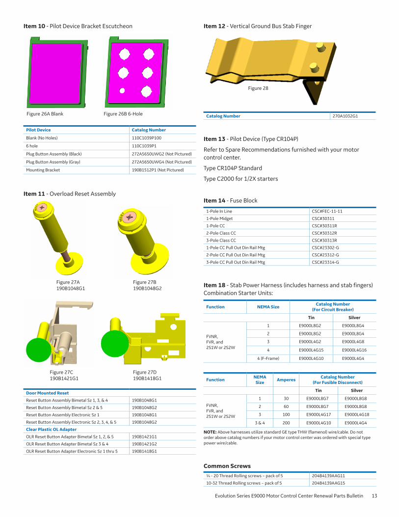
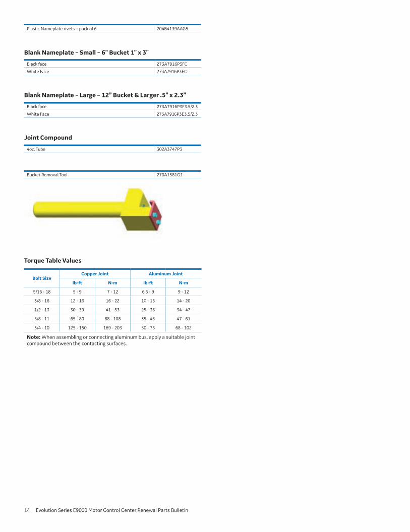