DECwindows Program
99
DECwindows Program Digital Technical Journal X Toolt XUb Digital Equipment Corporation Volume 2 Number 3 Summer 1990 H 10 lJ RNAl .I 1G pplications X I Toolkit lnt1in.d .·. ---A.-- - ---------------- - ---------- ·.· ... .. ' .. • .. I . •••••••111••··············:·· f. I t • ·, l t f I I I t l \ t I t t f I I I t t I > f t I I I J t I t t I I f I I ft f t ft• f I ft I I t t, t I I I t \I• f' I J t It f • i. I I I I• t 1 1 •1 :: : .. : t It ..... t'. '-'• ~\'/ .. I .. t t ... .,_. f ... ti/ .,. \ ... f I S- 1 ... ,.., ) .... t If I., I: t 4 J .. t: r\ t fl: t' /.' li .. ; ........... I .. j~ ... /.' .. 1 I .... .'.': ..... ·: ft,,.\\ t I I i f ' t f t t f ,( f I t I t I J" • I I l f I It I J I J I J, I I I I , t I f I i J I I , • f 1 I • I 6 I t J f t I • I I :i I I I I t I f i • t I j, ' i t I ' t I J. I I t t 11 I t I I I t t , t t \1 I~ I I I JI t ft ~·m I I •tt t I I I I ill I It! t. J t t l, ft ft t t t ,t t I f t ,I.) t I • It 1 t lltllfilft1t•l.tltt14, ,t •, I 1f1 • ... •• , 000 t,ttttltt1i1ltttlft•fttti•ltti\ _ f. f 11 t t H-1 tJ It It f I I ft It, t •, I 1' t I • I I · f I. I I It I It It t t t t t t • t f It*' I ... tt f i fi • f' t • , • t t t J • t t I • t 1 • t t t , f t t t t t t t , I I . . . I I I t ' t I I t t I t t t t I t J t i • f I I I ( C t f; t t t , f t It t t t t t f • t .9 J ft t t f t I l • ff I.ft, t' t • t I t. I ti f ft I t t ' I t f It t • .t t • t t t .t • 11 t I I f I It t ft It I t t f ~ff• t I f I t t f I • ' f I I I t I· I t • I t f t • I I i I I I f. ;t I I I t t I I I t I t I t I I I I ; t f t t • I I f I f t I l I I ) l I f I • I t I I J I l t ) t f. I I I t f I t I t t f t ; I f J J j i t f I ,- t 't j I I ; I I f 1 I I ! I I I I I • I I I I t I t I t t • I I I I I t I I f t. t f t t I ) I f t' I f 1 I I 1 l l. • if•••··············••••ttti .• , ...... • , .... •..• , .• ...... ,,, .•...••••.. , ........... , .•. .. · .. .. .. . ·•·.·•· .. · .. · .. · .. · .. · .. · .. · .. · .. · . .. .. . ·•· .. ·•· .. · .. · .. · ... , .. · .. · .. · .. · .. · .. · ... .. _ .. ,. ·.·.·.·.· .. · .. · .. · .. · .. · ... · .. ·•· .. · .. · .. · .· .. · .. .. .. . ·•·•·•· .. · .. · .. · .. · .. · .. · .. · .. · .. · .. · .. · .. · • · ·•· .. · .·•· .. \:,:·:· X Servt< ,. r .. ...
-
Upload
khangminh22 -
Category
Documents
-
view
2 -
download
0
Transcript of DECwindows Program
DECwindows Program
Digital Technical Journal
X Toolkit
XUb
Digital Equipment Corporation
Volume 2 Number 3 Summer 1990
H
10 lJRNAl .I 1G
pplications
X I Toolkit
lnt1in.d .·. ---A.------------------------------·.· ... .. ' .. • .. I .•••••••111••··············:·· f. I t • ·, l t f I I I t l \ t I t t f I I I t t I > f t I I I J t I t t I I f I I ft f t ft• f I ft I I t t, t I I I t \I• f' I J t It f • i. I I I I• t 11•1
:: : .. : t It ..... t'. '-'• ~\'/ .. I .. t t ... .,_. f ... ti/ ~ .,. ~ \ ... f I S-1
... ,.., ) .... t If I., I: t4 J .. t: r\ t fl: t' /.' li .. ; ........... I .. j~ ... /.' .. 1 I .... .'.': ..... ·: ft,,.\\
t I I i f ' t f ~ t t f ,( f I t I t I J" • I I l f I It I J I J I J, I I I I , t I f I i J I I , • f 1 I • I 6 I t J f t I • I I :i I I I I ~ t I f i • t I j, ' i t I ' t I J. I I t t 11 I t I I I t t , t t \1 I~ I I I JI t ft ~·m I I •tt t I I I I il l I It! t. J t t l, ft ft t t t ,t t I f t ,I.) t I • It 1 t lltllfilft1t•l.tltt14, ,t •, I 1f1 • ... •• , 000 t,ttttltt1i1ltttlft•fttti•ltti\ _f.
f 11 t t ~ H -1 tJ It It f I I ft It, t •, I 1' t I • I I · f I. I I It I It It t t t t t t • t f It*' I ... tt f i fi • f' t • , • t t t J • t t I • t 1 • t t t , f t t t t t t t , I I . . . I I I t ' t I I t t I t t t t I t J t i ~ • f I I I ( C t ~ f; t t
t , f t It t t t t t f • t .9 J ft t t f t I l • ff I.ft, t' t • t I t. I ti f ft I t t ' I t f It t • .t t • t t t .t • 11 t I I f I It t ft It I t t f ~ff• t I f I t t f I • ' f I I I t I · ~ I t • I t f t • I I i I I I f. ;t I I I t t I I I t I t I t I I I I ~ ; t f t t • I I f I f t I l I I ) l I f I • I t I I J I l t ) t
f. I I I t f I t I t t f t ; I f J J j i t f I ,- ~ t 't j I I ; I I f 1 I I ! I I I I I • I I I I t I t I t t • I I I I I t I I f t. t f t t I ) I f t' I f 1 I I 1 l l. • if•••··············••••ttti .• , ......• , ....•..• , .•...... ,,, .•...••••.. , ........... , .•. .. · ........ ·•·.·•· .. · .. · .. · .. · .. · .. · .. · .. · .. · ....... ·•· .. ·•· .. · .. · .. · ... , .. · .. · .. · .. · .. · .. · ..... _ .. ,.·.·.·.·.· .. · .. · .. · .. · .. · ... · .. ·•· .. · .. · .. · .· .. · ........ ·•·•·•· .. · .. · .. · .. · .. · .. · .. · .. · .. · .. · .. · .. · •· ·•· .. ·.·•· .. \:,:·:· X Servt<,.r
.. ...
Cover Design This issue features papers on DECwindows architecture and
applications. Our cover design is a display of several windows called
up on a VAXstation 3500 screen. The DEC windows applications used
to create the display are DEC write, DEC paint, and DEC image.
The cover was designed by David Comberg of the Corporate Design
Group with technical assistance from Victor Bah/ of the Image
Systems Advanced Development Group.
Editorial Jane C. Blake, Editor Barbara Lindmark, Associate Editor Richard W. Beane, Managing Editor
Circulation Catherine M. Phillips, AdministratOr Suzanne ). Babineau, Secretary
Production Helen L. Patterson, Production Editor Gaye Tatro, Typographer Peter Woodbury, IllustratOr and Designer
Advisory Board Samuel H. Fuller, Chairman Robert M. Glorioso John W. McCredie Mahendra R. Patel F. Gram Saviers Robert K. Spitz William D. Strecker VictOr A. Vyssotsky
The Digital Technicaljournal is published quarterly by Digital Equipment Corporation, 146 Main Street MLOI-3/Il68, Maynard, Massachusens 01754-2571 . Subscriptions to the Journal are S40.00 for four issues and must be prepaid in U.S. funds. University and college professors and Ph.D. students in the electrical engineering and computer science fields receive complimentary subscriptions upon request. Orders, inquiries, and address changes should be sent to the Digital Technical journal at the published-by address.
Inquiries can also be sent electronically 10 [email protected]. Single copies and back issues are available for S 16.00 each from Digital Press of Digital Equipment Corporation, 12 Crosby Drive, Bedford, MA 01730-1493.
Digital employees may send subscription orders on the ENET to RDVAX,JOURNALor by interoffice mail tO mailstop MLOI-3/Il68. Orders should include badge number, cost center, site location code and address. u.s. engineers in Engineering and Manufacturing receive complimentary subscriptions; engineers in these organizations in countries outside the u.s. should contact the Journal office to receive their complimentary subscriptions. All employees must advise of changes of address.
Comments on the content of any paper are welcomed and may be sent to the editor at the published-by or network address.
Copyright<tl 1990 Digital Equipment Corporation. Copying without fee is permiued provided that such copies are made for use in educational institutions by faculty members and are not distributed for commercial advantage. Abstracting with credit of Digital Equipment Corporation's authorship is permiued. All rights reserved.
The information in this Journal is subject to change without notice and should not be construed as a commitment by Digital Equipment Corporation. Digital Equipment Corporation assumes no responsibility for any errors that may appear in this Journal.
ISSN 0898-90 I X
Documentation Number EY-E756E-DP
The following are trademarks of Digital Equipment Corporation, ALL-IN- 1, CDA, DEC net, DECstation 3100, DECwindows, DECwrite, Digital, the Digital logo, MicroVAX, ULTRIX, VAX, VAX 8000, VAX 8650, VAXC, VAX SCAN, VAXcluster, VAXset, VAXstation, VAXstation 100, VAXstation 2000, VAXstation 3100, VAXstation 3540/3520, VAXstation IIIGPX, VAXstation 8000, VMS, XU I.
Apple II, HyperCard, and Macintosh are trademarks of Apple Computer, Inc.
MS-DOS is a registered trademark and MS-Windows is a trademark of Microsoft Corporation.
os/2 and Presentation Manager are trademarks of International Business Machines Corporation.
OSF/Motif is a trademark of Open Software Corporation.
PostScript is a registered trademark of Adobe Systems, Inc.
UNIX is a registered trademark of American Telephone & Telegraph Company.
X Window System is a trademark of the Massachuseus Institute of Technology.
Book production was done by Digital's Educational Services Media Communications Group in Bedford, MA.
I Contents
7 Foreword Richard Treadway
9 An Overview of the DECwindows Architecture Scott A. McGregor
16 TbeSampleXll Server Architecture Susan Angebranndt and Todd D. Newman
24 Development of the XVI Toolkit Leo P. Treggiari and Michael D. Collins
34 The DECwindows User Interface Language Stephen R. Greenwood
44 The Evolution of the X User Interface Style Thomas M. Spine and Jacob L. VanNoy
DECwindows Program
52 PEX: A Network-transparent Three-dimensional Graphics System Randi ). Rost, Jeffrey D. Friedberg, and Peter L. Nishimoto
64 XDPS: A Display Postscript System &tension for DECwindows Christopher A. Kent
7 4 The Development of DECwindows VMS Mail Michael R. Ryan and James H. VanGilder
84 Ethernet Performance of Remote DECwindows Applications Dinesh Mirchandani and Prabuddha Biswas
I
I Editor's Introduction
Jane C. Blake Editor
This issue of the Digital Technical Journal focuses on Digital's DECwindows program, its architecture, and applications for the window environment. The DECwindows program begins with the X Window System, which was developed at MIT with the support of Digital and IBM. Papers herein describe how Digital's engineers have built on X as well as contributed to related industry standards that help to ensure compatibility across systems.
Involved early in both the X Window and the DECwindows projects, Scott McGregor describes the DECwindows architecture as an upwardly compatible superset of X. In his overview paper for this issue, Scott reviews aspects of the X design and the significant enhancements made by Digital in the development of its DECwindows program.
The backbone of this program is the Xll protocol for which Digital has developed a sample server implementation. In their paper, Susan Angebranndt and Todd Newman review the development of the Xll server, which is the basis for all Digital product servers. Now publicly available, the Xll server is also a sample for all developers of X server product implementations.
Several layers above the Xll server is the XUI toolkit. Leo Treggiari and Mike Collins discuss this set of run-time routines and application development tools, which is the primary programming interface to DECwindows applications. This toolkit was chosen as the base programming interface for the Open Software Foundation's Motif toolkit.
The XUI toolkit contains hundreds of attributes, actions, and widgets, which can contain thousands of lines of code. Steve Greenwood relates how the user interface language (UIL) was developed to manage the complexity of the toolkit. UIL preserves the conceptual simplicity of the toolkit by allowing application developers to specify interfaces without writing the multitude of code lines normally required.
2
The style of user interaction with computers is then addressed by Tom Spine and Jake VanNoy. As they point out, the XUI style represents a change in approach for Digital to modem, graphic, directmanipulation user interfaces and to consistency across applications. XUI has evolved to provide a consistent means of user interaction for applications across the VMS, ULTRIX, and MS-DOS systems.
Extensions to the X architecture are the topics of two papers. PEX, an extension of X to support the PHIGS standard, is the subject of a paper by Randi Rost, Jeff Friedberg, and Peter Nishimoto. The authors describe some unique features of PEX and present the major design decisions made in its development.
Chris Kent is the author of a paper about XDPS, another extension supported by DECwindows. XDPS was jointly developed by Digital and Adobe Systems Inc. to integrate the X imaging model and Display Postscript. As Chris explains, XDPS was designed to give application programmers the best features of the X and Postscript systems.
Our last two papers address the topics of application development for the DECwindows environment and explain how the performance of such applications can be measured. The implementation of DEC windows VMS mail is an example of an application development effort described here by Mike Ryan and Jim VanGilder. Among the development issues discussed is the coordination needed between the VMS and ULTRIX mail applications developers to design a common interface for both mail applications.
Dinesh Mirchandani and Prabuddha Biswas then present the results of a study made to determine whether distributed DECwindows applications have an impact on the Ethernet network. The authors developed a simulation model running on a local area VAXcluster (LAVc) on the Ethernet to
predict the limiting system configuration in this scenario.
I thank John Hurd of the DECwindows program and Jesse Grodnik of the Western Software Laboratory for their help in preparing this issue.
Biographies
Susan Angebranndt A consulting engineer for the Open Systems Group in Digital's Western Software Laboratory, Susan Angebranndt was the project leader for the sample XU server. Susan also worked on the team that designed and implemented the Display Postscript extension for the DECwindows X servers. She joined Digital in 1986 and is a graduate of Carnegie-Mellon University (1980) with a B.S. in applied mathematics.
Prabuddha Biswas Prabuddha Biswas joined Digital in 1985 after receiving a B. Tech. from IIT, Delhi, India, and an M.S. from the University of Massachusetts. Among the projects with which he has been invoived are the performance analysis and modeling of software systems for the Business and Office Systems Engineering (BOSE) Group and characterization of file system activity from commercial I/0 traces. Prabuddha has applied for a patent and has authored papers for presentation to IEEE, ACM, and CMG conferences. He has received the BOSE Achievement Award for outstanding contribution.
Michael D. Collins A member of the XUI toolkit team, Michael Collins contributed to the design and implementation of the toolkit version 1 and version 3, and served as project leader for version 2. He is a principal software engineer in the Commercial Languages and Tools Group of the Software Development Technology organization. Mike is a member of ACM and AAAS and joined Digital in 1987. He received a Bachelor of Environmental Design (1981) from the University of Minnesota's School of Architecture.
Jeffrey D. Friedberg One of the chief architects of PEX, Jeffrey Friedberg is a principal engineer in the Workstations Advanced Technology Group. Jeff is the principal architect and document editor of the X multibuffering extension and developer of a suite of software tools that allow distributed source control within a networked ULTRIX environment. Currently, he is the project leader of the group implementing PEX on the DECstation 5000 Model 200 workstation. Jeff received a B.S. (1980) in computer science from Cornell University and is a member of ACM and ACM SIGGRAPH.
I
3
Biographies
4
Stephen R. Greenwood Stephen Greenwood is a consulting software engineer in the Commercial Languages and Tools Group. At present, he is a member of the team building a new DECwindows design tool. He was the project leader and chief designer of the DECwindows user interface language {UIL) and VAX SCAN programming language. Prior to joining Digital in 1981, Steve was a principal engineer for Sperry Univac. He received a B.S. (1973) in physics from Bucknell University and an M.S. (1975) in computer science from the University of Wisconsin.
Christopher A. Kent The project leader for the Display Postscript server extension, Christopher Kent is a principal engineer in Digital's Western Software Laboratory. He was also one of the developers of the TCP/IP version of the PrintServer 40 software and was a member of the development team for the MultiTitan processor board. Chris received a B.S. (1979, magna cum laude) in physics from Xavier University, and a Ph.D. (1986) in computer science from Purdue University. He is a member of ACM and Usenix Association.
Scott A. McGregor Scott McGregor manages the Western Software Laboratory in Palo Alto and is responsible for ULTRIX workstation software at Digital. Previously, he was the DECwindows Program Architect and was one of the designers of the X Window System. Before joining Digital in 1985, Scott led the design and implementation of Microsoft's MS-Windows, and spent seven years at the Xerox Palo Alto Research Center working on the Xerox Star and the Cedar programming environment. He has degrees in Psychology and Computer Science from Stanford University.
Dinesh Mirchandani As a senior software engineer in the VMS Engineering Group, Dinesh Mirchandani is now working on the advanced development of VAXcluster systems. Since joining Digital in 1985, he has evaluated the performance of Rdb/VMS and coo Plus and, through modeling, characterized the performance of distributed systems based on DECwindows software. Dinesh received a B.E. (1981, honors) in EEE from Birla Institute of Technology and Science, India, and an M.S. (1985) in computer science from North Carolina University. He is a member of Upsilon Pi Epsilon.
Todd D. Newman A principal engineer in the Workstation Advanced Technology Development Group, Todd Newman has been involved with several projects based on the sample Xll server. He was a member of the design and implementation team of that server, as well as a member of the teams that adapted the server to the DECstation 3100 workstation and extended the server for the PEX graphics application. Todd worked at Microsoft Corporation before joining Digital in 1986. He received an A.B. (1981) from Harvard University.
Peter L. Nishimoto Peter Nishimoto was project leader for the PEX implementations on the DECstation 3100 and VAXstation 3100/SPX workstations. He is also the coarchitect of the PEX protocol and a member of the multivendor PEX architecture team. Peter is a principal software engineer in the Workstations Software Group. Before joining Digital in 1986, he worked for Daisy Systems and Vulcan Software. He holds a B.A. (1976, cum laude) in mathematics from Colgate University and is a member of IEEE, ACM, and ACM SIGGRAPH.
RandiJ. Rost Principal engineer Randi Rost was the project leader for the PEX specification effort, one of PEX's chief architects, and the PEX document editor. Randi currently manages a group within the Workstations Advanced Technology Group that is concentrating on photorealistic rendering. He has published over a dozen technical papers and is the author of the X/Motif Quick Reference Guide. He received a B.S. (1980, summa cum laude) from Mankato State University and an M.S. from the University of California, both in computer science.
Michael R. Ryan Since joining Digital in 1984, Michael Ryan has worked on several software development projects. He is the project leader for the DECwindows VMS mail application and a contributing member of the development team for ALL-IN-I MAIL for DECwindows mail on the VMS system. Prior to his involvement with the mail program, Mike did advanced development for Business Communications Systems Engineering and VMS DIBOL compiler development. Mike holds a B.S. and M.S. in computer science from Rensselaer Polytechnic Institute.
Thomas M. Spine As a principal software engineer in the Software Usability Engineering Group, Thomas Spine is developing software usability engineering methodologies and contributing to the user interface design of several products. Tom has published a number of papers on the usability of speech recognition devices, file management with interactive computers, and usability engineering. He received an A.B. ( 1982) in mathematics and psychology from Washington University and an M.S. ( 1984) in industrial engineering from Virginia Polytechnic Institute and State University.
Leo P. Treggiari Currently responsible for the development of the architecture of the XUI and Motif toolkits, Leo Treggiari is a consulting software engineer with the Commercial Languages and Tools Group. He has acted as project leader for a number of products within the group, including version 1.0 of the XUI toolkit. Leo was a senior software engineer for Wang Laboratories before joining Digital in 1979. He is a member of ACM and holds a B.S. (1975, summa cum laude) in chemistry from Boston College.
I
5
Biographies
6
James H. VanGilder James VanGilder has developed several products for Digital since joining the company in 1979, including the PDP-11 RPG II, VAX DIBOL, BCSE advanced development, and DECwindows VMS mail version 1.0. He is a principal software engineer in the Commercial Languages and Tools Group, where he is at present acting as project leader for the development of the DECwindows implementation of the OSF/Motiftoolkit.Jim worked for Motorola, Inc., and Kollsman, Inc. before coming to Digital. He has a B.S. (1973) from Arizona State University.
Jacob L. VanNoy A consulting software engineer, Jacob VanNoy has been the DECwindows program architect since January 1989. He joined Digital in 1980 in the VMS Development Group and was part of the initial VMS workstation software development team. During the DECwindows project version 1, Jake was responsible for the content of the XUI Style Guide. He was also involved in the design of many aspects of the user interface, including the design of XUI toolkit. Jake received a B.S. and an M.S. in computer science from the University of Pittsburgh.
I Foreword
Richard Treadway Director Open Software Strategy
In 1986 Digital's desktop strategy could only be described as fragmented. On VMS workstations we offered a proprietary windowing system, on ULTRIX workstations we offered an early version of the X Window System, and on PCs we offered MS-Windows. Because of the diversity of systems, it was very difficult to convince an application builder to support our range of desktop systems. Furthermore, this strategy was unsatisfactory to customers. Our customers wanted a consistent user interface that would allow them to access and execute applications on the appropriate processor anywhere in the distributed network.
In January 1987, Digital announced the DECwindows system, which was a major design change intended to solve these problems. The system would provide a single application programming interface for application builders and give users network-wide access to applications through a common graphic user interface. The DECwindows system also would have the extensibility and flexibility to grow into the next decade and provide access to not only Digital systems, but to any system in a multi vendor network. In essence, the DECwindows system would bring the resources of the network to a single point on the desk.
To rally the entire corporation behind such a major change in direction, the DECwindows program put forward a simple vision to Digital's engineers and customers. Unified access to the VMS and ULTRIX operating systems would be provided through a single programming interface for interactive graphic applications and a common user interface for all the desktop devices we support. This simple and concerted focus made it possible
to manage the complexity involved in delivering more than 50 components built by nine separate groups located throughout the world in Nashua, New Hampshire, Reading, England, Littleton, Massachusetts, Palo Alto, California, and Valbonne, France.
Our strategy was to base the DECwindows system on standards and enhance that base. Standards enable application designers to port applications between different hardware and software platforms. In late 1986, no standards existed for networked windowing systems. Therefore, in choosing a basis for the DECwindows program, we had to select a technology that not only met our requirements but could be put forward to the industry as a potential standard. For this reason, we chose to base the DECwindows architecture on MIT's X Window System.
After Digital's endorsement of the X Window System in January 1987, eight other vendors, including Apollo and Hewlett-Packard, announced the X Window System as the basis for their future graphics-based computers.
Because the X Window System is hardware and software platform-independent, we could provide it on the VMS, ULTRIX, and MS-DOS operating systems. The X architecture allows applications to be transparently distributed throughout the network. This capability is critical in fulfilling our goal to be the leader in distributed computing. The X system allows applications executing anywhere in the network to be displayed and controlled from the user's desktop computer. In addition, the windowed computing model offers significant benefits over the time-sharing, character-cell terminal model. For example, sharing data among simultaneously executing character-cell applications is difficult, but in the X system, data-sharing is a fundamental property. Finally, the X system protocol can be extended to include future subsystems. This feature is important in providing a path for the integration of future technologies. As you will read in this issue of the Digital Technical]ournal, we used this capability to develop Display Postscript as an extension to X.
The value the DECwindows system adds to the X system is a consistent user interface, and a highperformance, robust, and flexible toolkit. The XUI toolkit and style guide make possible the implementation of applications that offer good interactive
7
I performance. Because the same XUI toolkit runs on both the VMS and ULTRIX systems, developers can provide their applications on both operating systems with a single implementation.
To test the robustness, performance, and usability of the toolkit and style guide, we committed to develop a highly complex interactive application, the DECwrite editor, on both the VMS and ULTRIX
operating systems. We learned a great deal about DECwindows performance and quality from that project. The ability to test our enabling technology while we were building it was fundamental to our success.
In addition to performance and completeness, the DECwindows toolkit separates the definition of user interfaces from application coding. The user interface can be specified with a nonprocedural language, called the user interface language (UIL).
The resultant definition is accessed at run-time by the application. Separating form and function in the DECwindows system is very imponant for the development of international applications and for the separation of user interface design from application implementation.
For international applications, the user interface can be completely translated without changes to application code. This approach significantly reduces the cost and complexity of translating applications. Since the toolkit supports multiple user interfaces, applications can switch languages dynamically.
For user interface design, UIL 's separation of form and function allows rapid prototyping in the user interface. With UIL the user interface design need no longer be entirely the programmer's responsibility. User interface design specialists can concentrate solely on the interactive aspects of the application without making programming changes. All this can lead to better designed and easier to use applications.
The DECwindows system is very significant to Digital in two imponant ways. First, it is our first open systems product. We initially thought the value added by the DECwindows user interface and toolkit would be our competitive advantage. However, we came to realize that in a fully distributed computing environment the user really
8
needs that same interface for all applications regardless of the vendor's system. Therefore, the DECwindows user interface had to support multivendor systems to encourage application builders to base their designs on it. That conclusion and the opportunity to create a de facto standard led us to create the X user interface (XUI) as a separate component of the DECwindows system that we would license to run on any system. When the Open Software Foundation (OSF) announced a request for technology to specify the user environment component, XUI was submitted and eventually accepted as OSF/Motif. XUI marked the first time Digital released technology that it once considered proprietary to the industry.
Second, the DECwindows system initiated a new design center for applications. The system was a fundamental change from a time-sharing, charactercell model to a graphic, windowed, distributed computing model. In this regard, the DECwindows system presented application designers with a whole set of opportunities for new application capability and an associated set of complex problems to solve.
As with any enabling technology, it takes time and creativity to evolve techniques and methodologies that allow the technology to be used effectively. The series of articles in this journal, which includes papers on the style guide, toolkit, UIL and XUI, will help you better understand how far we have come and where we still have to go.
Scott A. McGregor I
An Overview of the DECwindows Architecture
The DECwindows architecture builds on industry standards and adds enhancements to provide greater perfomumce and reliability in the window environment. The architecture is based on the X Window System developed at MIT, which consists of three main components - the X seroer, Xlib, and the toolkit intrinsics. The DECwindows implementation extends X in several ways. DECwindows uses algorithms that expose additional interfaces, supports a broader choice of prrr gramming languages, provides a complete set of tools for application development, and promotes ease of use and user-interface consistency by means of a style guide. In addition, the DECwindows architecture includes industry-standard interfaces and extends the seroer to take advantage of Postscript, three-dimensional graphics, and imaging.
The DECwindows architecture provides a complete set of mechanisms that control windowing, graphics, the user interface, and data interchange in order to make easy the task of building highquality applications that work well together. In this role, the DECwindows architecture is a key component in Digital's Network Application Support (NAS) in conjunction with other components such as networking and printing.
It can be argued that the move from charactercell-oriented applications to window-based applications is as significant as the move from batch computing to time-sharing. The reasons for choosing to adopt the X Window System are as many as they are varied; some of the most important are as follows:
• Windowing systems provide a richer computing environment that includes detailed graphics artwork and significantly improved ease of use.
• The direct manipulation of objects on the screen is a more intuitive model of computer applications.
• The prevalence of windowing systems has led to increased expectations on the part of our users. For example, users can start any number of applications simultaneously, allow them to remain running all day, and shift between them by using a pointing device.
• Window-based applications allow for a natural separation of form and function.
Digital Tecbnical]ournal Vol. 2 No. 3 Summer 1990
• Just as time-sharing allowed the creation of applications that were inconceivable or impos· sible in batch-oriented systems, windowing systems support problem-solving approaches that cannot be made to fit the time-sharing model. For example, sharing data between applications has often been cumbersome for applications designed to run on character-cell terminals. In contrast, the ability to share data among cooperating applications is a fundamental property of the X window model.
The DECwindows theme is to build on standards and to add incremental value. Standards make sense because application designers want portability between hardware platforms. Users of applications also want standards because it rarely makes sense to learn new interaction techniques that are unique to specific applications. The DECwindows architecture is built on and compatible with industry standards such as the X Window System from MIT, Motif from the Open Software Foundation, and Adobe's Postscript page-description language. The architecture is designed to allow easy integration with various personal computer (PC) systems such as those produced by IBM and Apple. The value of Digital's offerings is in the performance and reliability of the implementation, the set of additional layered libraries and services available, and integration with other services defined by NAS.
Prior to the DECwindows "unification," there were different windowing and applications solutions for each of the operating systems supported
9
DECwind ows Program
by Digital (VMS, ULTRJX, and MS-DOS). A goal of the DECwindows architecture is to provide a common user interface that spans all three operating systems, and a programming interface common across VMS and ULTRIX. Although memory limitations of the MS-DOS environment prevent us from supporting the full DECwindows applications interface for current PCs (that is, until OS/2), the intent is to make it easy to port DECwindows applications between VMS and ULTRJX operating systems, and straightforward to port applications that use MS-Windows, the Presentation Manager, or Apple's Macintosh.
Although the DECwindows architecture is based on the X Window System, DECwindows is an upward-compatible superset of that design. This means that the DECwindows architecture has all the advantages of the X Window System, as well as the advantages of the Digital enhancements. The balance of this paper presents a summary of the X Window System and the additional components and design enhancements that make up the DECwindows products.
The X Window System The history of the X Window System seems surprising, given the role it plays today as a workstation industry standard . X started out at Stanford University as W W became X when it was jointly adopted by MIT 's Laboratory for Computer Science and Project Athena (an educational program jointly funded by Digital and IBM). The first version of X to be widely used and shipped as a product was version 10 (XIO). X had three important features that made it popular: it provided a highperformance network protocol for windowing and graphics, it was independent of workstation hardware, and it was available in source form to anyone for the cost of the media.
Work on X version 11 (XU) began in 1986. This effort was a serious attempt to reconsider some of the original design ideas in order to make X into a more functional system that would meet the needs of a larger class of application developers. Graphics state was added for performance, and precise semantics were defined for the output routines. Input events were generalized, and perhaps most important, work began on a toolkit for applications developers. Digital agreed to implement the sample server, Xlib (the library of X routines), and the toolkit that are available on the MIT Xll tape. MIT has agreed to continue to support X and to control the architecture and evolution of the system design.
10
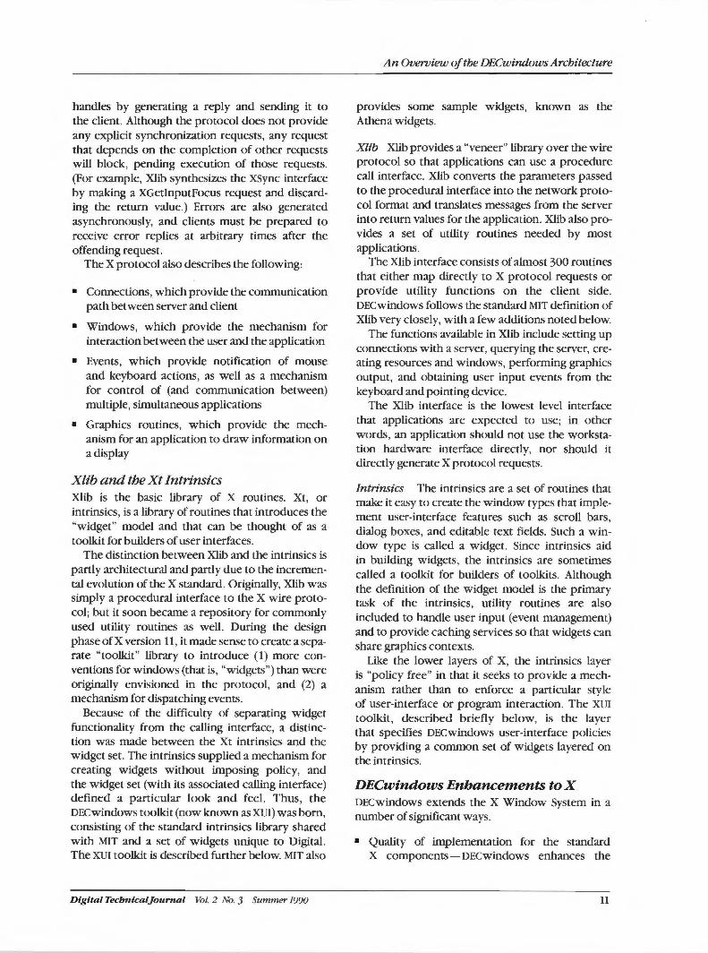
X consists of three main components: the X server, Xlib, and the toolkit intrinsics (also known as Xt). The substructure of each of these components is briefly described in the following sections.1•
2 The overall architecture of the X Window System, showing the relationship of the server, network protocol, Xlib, Xt, and applications is shown in Figure 1.
The X Server and the X Protocol The task of an X server is to implement the requests defined in the protocol and encoding specifications.
The X server runs on the hardware where the display and keyboard are located and provides lowlevel graphics, windowing, and user input functions. It relies on a very low-level interface that is supplied for each type of supported workstation. Clients communicate with an X server by means of the network or "wire" protocol. This protocol, also known as the X protocol, is a very precisely defined interface. By tightly defining the semantics of the wire protocol, it is made independent of the operating system, the network transport technology, and the programming language.
The X protocol defines the data structures used to transmit requests between applications and user-interface stations over the network .1
Applications do not normally generate protocol requests themselves, but instead use Xlib or other layered libraries.
Most X requests are asynchronous, meaning that a client can send requests without waiting for the completion of previous requests. This approach allows for fast request processing through the use of pipelining techniques in the server implementation and in Xlib, and it means that the application usually does not have to wait for the completion of an operation. Some X requests (state queries , for example) have return values, which the server
APPLICATION
::::== =~-x __ T_ (::.IN.:..T __ R:...IN.:..s __ 1c:.:S:.:..) _J EXTENSION CLIENT
XLIB LIBRARIES
X PROTOCOL
X SERVER EXTENSIONS SERVER
Figure 1 X Architecture
Vol. 2 No. 3 Summer 1990 Digital Tecbntcal]ournal
handles by generating a reply and sending it to the client. Although the protocol does not provide any explicit synchronization requests, any request that depends on the completion of other requests will block, pending execution of those requests. (For example, Xlib synthesizes the xsync interface by making a XGetlnputFocus request and discarding the return value.) Errors are also generated asynchronously, and clients must be prepared to receive error replies at arbitrary times after the offending request.
The X protocol also describes the following:
• Connections, which provide the communication path between server and client
• Windows, which provide the mechanism for interaction between the user and the application
• Events, which provide notification of mouse and keyboard actions, as well as a mechanism for control of (and communication between) multiple, simultaneous applications
• Graphics routines, which provide the mechanism for an application to draw information on a display
Xlib and the Xt Intrinsics Xlib is the basic library of X routines. Xt, or intrinsics, is a library of routines that introduces the "widget" model and that can be thought of as a toolkit for builders of user interfaces.
The distinction between Xlib and the intrinsics is partly architectural and partly due to the incremental evolution of the X standard. Originally, Xlib was simply a procedural interface to the X wire protocol; but it soon became a repository for commonly used utility routines as well. During the design phase ofX version 11, it made sense to create a separate "toolkit" library to introduce (1) more conventions for windows (that is, "widgets") than were originally envisioned in the protocol, and (2) a mechanism for dispatching events.
Because of the difficulty of separating widget functionality from the calling interface, a distinction was made between the Xt intrinsics and the widget set. The intrinsics supplied a mechanism for creating widgets without imposing policy, and the widget set (with its associated calling interface) defined a particular look and feel. Thus, the DECwindows toolkit (now known as XVI) was born, consisting of the standard intrinsics library shared with MIT and a set of widgets unique to Digital. The XVI toolkit is described further below. MIT also
Digital Tecbnical]ournal Vol. 2 No. 3 Summer 1990
An Overview of the DECwindows Architecture
provides some sample widgets, known as the Athena widgets.
Xlib Xlib provides a "veneer" library over the wire protocol so that applications can use a procedure call interface. Xlib converts the parameters passed to the procedural interface into the network protocol format and translates messages from the server into return values for the application. Xlib also provides a set of utility routines needed by most applications.
The Xlib interface consists of almost 300 routines that either map directly to X protocol requests or provide utility functions on the client side. DECwindows follows the standard MIT definition of Xlib very closely, with a few additions noted below.
The functions available in Xlib include setting up connections with a server, querying the server, creating resources and windows, performing graphics output, and obtaining user input events from the keyboard and pointing device.
The Xlib interface is the lowest level interface that applications are expected to use; in other words, an application should not use the workstation hardware interface directly, nor should it directly generate X protocol requests.
Intrinsics The intrinsics are a set of routines that make it easy to create the window types that implement user-interface features such as scroll bars, dialog boxes, and editable text fields. Such a window type is called a widget. Since intrinsics aid in building widgets, the intrinsics are sometimes called a toolkit for builders of toolkits. Although the definition of the widget model is the primary task of the intrinsics, utility routines are also included to handle user input (event management) and to provide caching services so that widgets can share graphics contexts.
Like the lower layers of X, the intrinsics layer is "policy free" in that it seeks to provide a mechanism rather than to enforce a particular style of user-interface or program interaction. The XVI toolkit, described briefly below, is the layer that specifies DECwindows user-interface policies by providing a common set of widgets layered on the intrinsics.
DECwindows Enhancements to X DECwindows extends the X Window System in a number of significant ways.
• Quality of implementation for the standard X components - DECwindows enhances the
11
DECwindows Program
sample MIT implementation by using algorithms that expose additional interfaces, or by allowing more flexibility. Examples include faster window repositioning algorithms, international keyboard support, and font caching. Robustness is another important implementation quality; Digital has led the effort in developing an X validation test suite.
• A choice of programming languages - MIT supports only a C and a Common LISP interface for Xlib. DECwindows supports standard UNIX C as well as the complete set of VAX standard language bindings, including FORTRAN, ADA, and PASCAL.
• XUI toolkit- The X Window System components stop short of providing a complete set of tools needed for application development. DECwindows provides libraries for user interface primitives (widgets), resource management, and internationalization. Additional development tools are also included. The XUI toolkit makes it easy to write applications that follow the XUI Style Guide.
• XUI Style Guide - To promote ease of use and user-interface consistency among applications, DECwindows includes a set of guidelines for application developers. All applications developed by Digital conform to these guidelines.
• Industry-standard interfaces - In addition to the X interfaces, DECwindows includes industrystandard libraries such as PHIGS and GKS.
• Extension libraries - X provides a mechanism for extensions to the server's capabilities. The DECwindows architecture takes advantage of this feature to provide Postscript, threedimensional graphics, and imaging capabilities.
• Base applications - DECwindows includes a set of base applications useful to all workstation users, such as window and session managers, terminal emulators, and personal productivity tools.
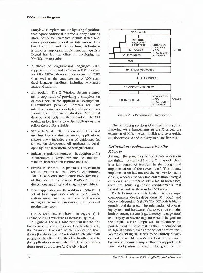
The X architecture (shown in Figure I ) is expanded in DECwindows as shown in Figure 2.
In Figure 2, the Xll wire protocol denotes the line between client and server. On the client side, the "staircase layering" of the application layer shows the ability for applications to intermix calls to any of the client-side libraries. In other words, the application can use whatever level of abstraction is most appropriate for the job at hand.
12
APPLICATION
INDUSTRY STANDARD LIBRARIES EXTENSION -......&.--------! LIBRARIES
XUI TOOLKIT o PEX CLIENT - ......1.- ------......1 • POSTSCRIPT
XT (INTRINSICS) • IMAGING
XLIB
TRANSPORT MECHANISM
X11 PROTOCOL
TRANSPORT MECHANISM
EXTENSIONS
X SERVER KERNEL • PEX SERVER • POSTSCRIPT • IMAGING
Figure 2 DECwindows Architecture
The remaining sections of this paper describe DECwindows enhancements to the X server, the extension of Xlib, the XUI toolkit and style guide, and the extension and industry-standard libraries.
DECwindows Enhancements to the XSeroer Although the semantics of the server operations are tightly constrained by the X protocol, there is a fair degree of freedom in the design and implementation of the server itself. The ULTRIX implementation has tracked the MIT version quite closely, whereas the VMS in1plementation diverged early on in an attempt to add value. In both cases, there are some significant enhancements that Digital has made to the standard MIT server.
The MIT sample server is divided into two major components: device-dependent X (DDX) and device-independent X (DIX). The DIX code is highly portable and designed to be independent of operating system and hardware. The DDX code contains both operating system (e.g. , memory management) and display hardware dependencies. The goal for the original server design was to maximize the portability of the code, making the DIX component as large as possible, even at the cost of performance. Re-implementing the server to be entirely devicedependent would provide the best performance, but would require a major effort to support each new workstation product. The goal for the
Vol. 2 No. 3 Summer 1990 Digital Tecbntcal]ournal
DECwindows server is to seek a compromise that provides higher performance without completely sacrificing portability.
The DECwindows X server implementation differs from the MIT X server implementation in the following ways:
• Font and glyph caching- In the MIT X server, a font is either in memory or it is not. The DECwindows X server provides glyph caching, so that a portion of a font may be stored in memory. Glyph caching is especially important for users of ideographic (e.g., Far Eastern) fonts.
• Run-time loading of DDX, DIX, transport mechanisms, and extensions (on VMS)-The advantage of run-time loading is that an application need not load code until it is actually needed. Thus the apparent performance of an application can improve, because it does not need to initialize all functions before it invokes any function.
• Multiple, simultaneous transport mechanismsThe X server can have an arbitrary number of open connections at a time, and these connections can use the transport mechanism available (e.g., to a given remote node) or most desirable (e.g., shared memory for a local client).
DECwindows Extension to Xlib As noted earlier, the DECwindows Xlib implementation follows the standard MIT definition of Xlib very closely. Some of the few differences from the X implementation are summarized below.
F.xteru:led Keyboard Support The XLookupString routine has been extended to support international character sets. The DECwindows Xlib implementation supports the Alt-Space (Compose-Space) introducer sequence to enter key sequences that generate characters not available on the user's keyboard. The intention is to expand these capabilities further to support Asian languages and "soft" keyboard displays on the user's screen.
Asynchronous Event Notification Events from the X server are synchronous, meaning the events must be read from a queue by the application. A DECwindows specific enhancement allows for an asynchronous notification of the arrival of an event, through an AST on the VMS system, and a signal on the ULTRIX system. In addition, Xlib may be called from this asynchronous event call.
Digital Tecbnical]ournal Vol. 2 No. 3 Summer 1990
An Overview of the DEC windows Architecture
VMS-specific Extensions Under the VMS operating system, Xlib (along with the other layered libraries) is a shareable library. Shareable libraries reduce the size of an application's image.
XUIToolkit The XUI toolkit is layered on top of Xlib and the Xt intrinsics and is the first layer that defines the userinterface policy of the DECwindows architecture: The XUI toolkit consists of three major components:
• The XUI toolkit widgets
• The DECwindows resource management facilities
• The cut-and-paste interfaces
The goal of the XUI toolkit is to make it easy for an application designer to write an application by providing the designer with widgets for almost all the common user-interface components. Applications are expected to write widgets for their own unique function, but functions that are common across applications are supported by the XUI toolkit. For example, a spreadsheet application would likely create its own widget class for the cell array, but it would use XUI toolkit widgets to display error messages and menus. Although the application needs to create its own widgets to differentiate it from other applications, sharing the commonly used widgets has two advantages: the application writer has less code to write and maintain, and consistency between application is increased.
To achieve the goal of interapplication consistency, the XUI toolkit is closely tied to the XUI Style Guide in its selection of widgets to implement, and in the functions and visual appearance of those widgets. In other words, the XUI toolkit is an implementation of the user interface specified by the style guide.
XU! Style Guide The XUI Style Guide is a set of user-interface guidelines that describe preferred screen appearance, types of application/user interactions, proper use of keyboard and mouse functions, and so on. In human terms, it might be described as a guide to effective communication~·5
The XUI Style Guide has three main areas of emphasis:
13
DECwindows Program
• Use of graphics to present information
• Use of direct manipulation, in cases in which users point at and directly interact with objects on the screen
• User-interface consistency
The style guide provides enough detail to let application designers achieve a high level of consistency, but by itself, it cannot guarantee that the designer will do a good job. Guiding the creation of consistent applications might be compared to guiding the creation of musical compositions in a specific style, like jazz or the blues. Although a good guide might provide the fundamentals, the composer still needs to hear examples of the music in order to copy the style. And a composer can still write bad compositions even if the guide is followed to the letter.
Extension Libraries The X architecture supports an extension facility so that functions can be added to the core routines. Extensions allow support for special workstation hardware capabilities as well as for operations that are seldom used.
An extension consists of two components: a hardware-dependent extension to the X server, and a client-side library that sends requests to the server using the extension protocol. Figure 2 illustrates the position of the extensions within the X server. A routine is provided in Xlib to test whether a particular named extension is supported in a server or to query the set of supported extensions.
Extension libraries supported by DECwindows include the following:
• PEX, a high-performance three-dimensional graphics library
• Display Postscript, a graphics output library that uses Adobe's Postscript imaging model
In addition, some anticipated extension libraries include the following:
• Input, extended support for tablets, dial boxes and other user input devices (part of the MIT XllR4 release)
• Nonrectangular windows, which permits windows to be defined as arbitrary shapes rather than limited to rectangles
14
• Imaging, a library of functions that support operations on scanned images
• Multimedia, support for sound and video
/ndustry-standtlrd Libraries Industry-standard libraries are either officially sanctioned or de facto standards that enjoy wide popularity in the industry. Application developers use these interfaces when they want to minimize the cost of supporting multiple graphics and/or windowing environments (including DECwindows) from a single application.
DECwindows implements GKS, PHIGS, and other industry-standard programming interfaces by: (1) providing shells on top of Xlib and other standard X libraries, (2) by extending the Xll wire protocol and using it directly, or (3) by some combination of the two.
Since GKS is a two-dimensional interface, it is strictly layered on top of Xlib and the XUI toolkit .
Since PHIGS seeks to take advantage of threedimensional hardware capabilities not exposed by Xlib, PHIGS uses a combination of the PEX threedimensional extension to Xll and the existing programming libraries.
Summary The DECwindows architecture offers significant new technology for building applications; it is based on the graphical user interface and the use of an operating-system-independent "client-server" model to distinguish between where an application is run versus where it appears to the user. The architecture also provides a high degree of source-level compatibility between ULTRIX and VMS, which permits applications to be easily ported between the two operating systems.
DECwindows is based on the industry-standard X Window System, including the X server, the X wire protocol, Xlib, and the Xt intrinsics. It offers value beyond these standards through improved implementation as well as by incremental functionality. The architecture has proven both robust and extensible, making it the preferred base for new applications created by Digital and by our software partners.
A Postscript Since the original creation of the DECwindows product, a new organization came into being to
drive convergence of open systems standards. The Open Software Foundation (OSF) evaluated tech-
Vol. 2 No. 3 Summer 1990 Dig ita l Tecbnical]o un1a/
nology from a number of companies and created a toolkit called Motif that combines XUI from Digital and the visual appearance from Microsoft and Hewlett-Packard. In 1990, Motif will replace XUI as the toolkit in Digital's DECwindows architecture.
Given the wide acceptance of X and Motif, the DECwindows architecture has truly become an industry standard, much to the credit of the many Digital engineers who put in their imagination and hard work.
References
1. R. Scheifler, J. Gettys, and R. Newman, X Window System C Library and Protocol Reference (Bedford: Digital Press, 1988).
2. ). McCormack, P. Asente, and R. Swick, X Toolkit
Digital Tecbnicaljournal Vol. 2 No. 3 Summer 1990
An Overoiew of the DECwindows Architecture
Library - C Language Interface, X Version 11 Release 3 (Cambridge: Massachusetts Institute of Technology, 1988).
3. L. Treggiari and M. Collins, "Development of the XUI Toolkit," Digital Technical]ournal, vol. 2, no. 3 (Summer 1990, this issue): 24-33.
4. T. Spine and). VanNoy, "The Evolution of the X User Interface Style," Digital Technical journal, vol. 2, no. 3 (Summer 1990, this issue): 44 -51.
5. XU/ Style Guide (Maynard: Digital Equipment Corporation, Order No. AA-MB20A-TE, 1988).
General Reference
R. Scheifler and ). Gettys, "The X Window System," ACM Transactions on Graphics, vol. 5, no. 2 (April 1986).
15
Susan Angebranndt I ToddD. Newman
The Sample Xll Server Architecture
1be XII protocol is the backbone of Digitals DECwindows program. 1be sample seroer is an implementation of the protocol. 1be seroer was developed by Digital and has become the basis for all Digital product seroers. As part of Digitals commitment to support open system standards within the industry, the seroer code was donated to MIT. Because the software is now publicly available, the seroer is the starting point for the X seroer product implementations for all other vendors. This paper describes the architecture of the sample seroer and comments on the implementation.
The Need for a Sample Server The X Window System protocol was developed jointly by MIT and Digital.1 The protocol permits network-transparent access to the input, windowing, and two-dimensional graphics capabilities of workstations and display systems. Further, the protocol presents a high-performance, device independent graphics model. As such, it provides a hierarchy of resizable, overlapping windows, which support the easy building of a wide variety of applications and user interface styles.
The server is an implementation of the X protocol. Its job is to arbitrate access to the display and to the keyboard and pointing device, generally a mouse. Applications that use the X protocol are called clients. Clients communicate with a server through an 8-bit byte stream. A simple packet stream protocol is layered on top of the byte stream. For example, a packet of commands might create a window and draw an arc.
Our goal was to design and implement a sample server based on the X Window System version II (X 11) protocol. By sample we mean an example implementation of the protocol that other developers can use to implement the X protocol on their workstations. When we began, there was a sample implementation of version 10 (XlO) of the X Window System already in use on UNIX systembased products. This XIO sample server had been ported to Digital, Sun, Apollo, and IBM PC/RT workstations, among others. But the XlO protocol was not suited to advanced graphics devices. The XlO implementation was based on the VAXstation 100 graphics primitives and architecture. Therefore, it was difficult to make performance enhancements on hardware other than the VAXstation 100
16
workstation because of assumptions in the XlO protocol and its sample code.
Xll was more advanced that Xl0.2 Xll completely overhauled the XlO protocol. It considered the needs of operating systems other than the UNIX system, as well as graphics devices other than the VAXstation 100. Because of the massive changes from XlO to XII, the sample server had to be reimplemented from scratch. It was important that this implementation not depend on a specific device but apply to a wide range of workstations.
Digital wanted to develop and promote XII as a de facto standard in the workstation market, just as we promote the UNIX system (in the form of Digital's ULTRIX system) as a standard. We felt a common, open windowing environment was as important as a common, open operating system environment. XlO was too limited in scope and capabilities to become popular on workstations with advanced graphics. By making the sample implementation publicly available, other vendors would be more likely to adopt XII as a standard.
Digital receives several direct benefits from making the sample server publicly available. It is the basis for all current Digital server implementations on the VMS, ULTRIX, and PC systems. MIT maintains the bulk of the source code. Therefore, Digital benefits from the changes, enhancements, and bug fixes done not only by MIT but by other companies that use the server. Also, we can easily incorporate server extensions, such as HewlettPackard's input extension. Over 75 percent of the code in the ULTRIX system-based DECstation 3100 color server is from MIT. Therefore, this server can be ported easily to new graphics devices because few lines of code need to be modified.
Vol. 2 No. 3 Summer 1990 Digital Tecbnical]ournal
Design Goals and Constraints Designing and writing software to be used on a wide class of machines is a lesson in compromises. In this section, we list our goals and constraints. In the sections following, we give an overview of the server architecture and some porting concerns. Finally, we evaluate our end result.
Tailorabk The primary technical goal of the project was to provide code that would remain useful on current and future operating systems and graphics devices. Writing portable code is not new. Software is often ported. Just as often, performance is decreased in favor of the increased portability. For example, the UNIX operating system has been ported often, but the system's performance is diminished on all but a few architectures.3 Customization is needed to regain the speed lost in favor of generality. Therefore, our server design had to emphasize portability and customization in equal measure. We term the software design using this approach as tailorable. Almost every other design consideration or constraint grew out of the requirement tailorability.
Standards The sample server is used by a wide audience, on a variety of workstations. Our implementation was constrained by some of the "least common denominator" features found on most workstations. We wanted to be assured that most vendors would be able to use our implementation.
An example of such a constraint was in the choice of language used for the server. We preferred to implement the X protocol in a multithreaded, object-oriented language. However, the implementation is in the C language because most other vendors provide C compilers. Therefore, the C language would provide a more universal· standard. The problems with using the C language are discussed in more detail in the Sample Server in Retrospect section of this paper.
Firewalls and !Ayering Modularity makes software easier to maintain and modify. Whole modules can be reimplemented with different internal data structures and procedures. As long as interfaces and firewalls are maintained, the rest of the system will continue to function.
We also chose to use modularity because we could reuse software by partitioning the software
Digital Tecbntcaljournal Vol. :Z No. 3 Summer 1990
The Sample Xll Server Architecture
into layers. Layers that were machine-independent could be completely portable. Machine-defined layers required modification to port to a new architecture. Therefore, our goal was to provide as much machine-independent code as possible.
Simplicity Because of our time constraints, we opted to keep our approach simple. Simplicity meant adding an extra level of indirection or an extra procedure call in some cases. However, it is easier to optimize the code later by deletion than by addition.
Simplicity was also achieved by setting restrictions and understanding limits. The bitmap graphics workstations that might run the X protocol currently range from the 8-bit Apple II through the 16-bit IBM PC to Digital 's 32-bit VAXstation 3520 workstation. Frame buffers range from the I-bit-deep VAXstation 2000 workstation to the 24-bit-deep frame buffer of the VAXstation 3520 workstation. The X protocol supports frame buffers up to 32 bits deep. As a practical observation, no machines with 8-bit integers would have enough performance to run the X protocol.
Although the X protocol supports many different graphics devices, we had to implement for only one device for practical purposes. We chose the most general device, one with no graphics hardware, which would enable us to write all the drawing algorithms in software. When other developers use the sample code, they can replace our software algorithms with calls to their hardware graphics routines. We selected the monochrome VAXstation 2000, running the ULTRIX operating system. The frame buffer is treated as main memory. However, it is impossible to generalize from one example. Therefore, as we were writing the sample, we had two other development engineers port it to the VAXstation 8000 and VAXstation 11-GPX workstations.
Architecture The server architecture reflects our perception of how the code would be ported to new machines and operating systems. The architecture has three major layers: device-independent X (DIX), operating system (OS), and device-dependent X (DDX).
The DIX layer contains device-independent routines, OS contains operating system-specific routines, and oox contains device-specific routines. The operating system interface insulates DIX from the details of file access, network com-
17
DECwindows Program
munication, and the keyboard and mouse. DDX is the graphics interface, which is a virtual interface to the painting routines.
Procedures in DIX should rarely require changes, OS should be written once per operating system (or version of the UNIX operating system), and DDX
should be modified for each graphics platform. For example, when porting from one ULTRIX
graphics subsystem to another, the only layer to be modified would be DDX. However, some routines in DDX will be shared across different ULTRIX
graphics subsystems.
Shared Data Structure Firewalls are created by strictly defining the exported routines and the data structures that are shared by the layers. Although the C language does not explicitly support objects, we treated the shared data structures as objects, which let us hide information between any two layers. Each structure contains state variables, i.e., attributes, and procedure vectors, i.e., methods. DIX writes the state and calls the methods. DDX and os read the state and set the methods. In addition, each structure has an opaque pointer, which is usually an implementation-specific structure that belongs to either DDX or OS. Screens, drawables, and graphics contexts are the primary data structures shared between the different layers in the server.
The X protocol supports multiple screens that are connected to the same server. In other words, one workstation can have multiple displays connected to the same keyboard and pointer. Therefore, all information about a particular screen is bundled into one data structure of attributes and procedures. Resources that are defined per screen are color maps, cursors, and fonts.
Windows and pixmaps are considered drawables. Windows are rectangular graphic areas on the screen into which graphics routines can be drawn. Pixmaps are graphics drawing areas located off-screen. All graphics operations work on drawables, and operations can copy areas from one drawable to another.
Graphics contexts contain state variables, such as foreground and background pixel value (i.e., color); the current line style and width; the current tile or stipple for pattern generation; and the current font for text generation. Graphics contexts also include functions that support fundamental painting operations, e.g., drawing lines, polygons, arcs, text, and copying areas of drawables.
18
Device-independent X DIX dispatches requests to either DDX or OS, manipulates a tree of windows and their associated properties, maintains the input focus, and sends mouse and keyboard events to the appropriate clients. In addition, DDX checks client requests for the correct length and maps identifiers created by a client to the server's internal data structures.
The core of DIX is a loop, called the dispatch loop. Each time around the loop, DIX sends the accumulated input events and processes requests from the clients to DDX or OS. The loop, shown below, is the most organized way for the server to process the asynchronous client requests.
while (true) { if (inputPending)
Process inputEvents(); nextRequest = WaitForSomething(); if (newConnection)
lnitializeConnection(); if (Connect ionDied)
CleanUpConnection(); DispatchRequest (nextRequest);
Requests fall into three categories:
• Edits to internal data structures, e.g., setting the keyboard click on or off
• Queries on internal resources, e.g., asking the placement of a window on the display
• Drawing requests, which are handled by calls to DDX
Edit requests usually set some state shared by DIX
and either DDX or OS. A side effect of the edit is a bear trap set by DIX. When a painting request occurs, the bear trap is triggered. DDX notices the state change and sets the method associated with the new attribute values.
Keyboard and Mouse Handling Input events from the keyboard and mouse travel in the reverse direction of requests, that is, from the workstation to the client application.
Some examples of synchronous events are grabs and input focus change. Synchronous events are initiated by clients or the window manager and are very similar to requests. These events result in state changes, some of which are visible on the screen. However, whereas requests generate at most one reply or error, events may cause the creation of more events.
Vol. 2 No. 3 Summer 1990 Digital Tecbnlca/Journal
A linked list of clients and the interest the clients have expressed in an event or events is stored in the window. The direct path in the window hierarchy is cached. The path extends from the root window down to the window containing the mouse (i.e., pointer focus) and from the root to the window where the keyboard events are sent (i.e., keyboard focus). This method makes it easier to generate events, such as notification that the pointer has crossed a window boundary, which are then passed to all the windows in the chain.
Asynchronous events occur outside the server's control. The events include button presses, keyboard events, and mouse motion events. Once started, many server operations must be performed to completion. However, the asynchronous events continue to occur while the server is busy processing requests. Even if the server itself is synchronous, it must look to the clients as though events are occurring asynchronously. The C language does not support interrupt handling. Therefore, the server cannot handle the events while performing a client request. The device driver notes new input events. The server then attempts to simulate an asynchronous response by polling for events between each request the server processes.
We learned from the XlO implementation that a rapid response to new input events was required to achieve the responsiveness necessary for good user interaction. Copying data from one layer to another would degrade response time substantially. Because of this need, DIX and DDX had to use the same physical memory location and data structure to represent the event state.
A problem existed in that different devices want to represent their input queue differently. For example, some may want head and tail pointers, a single or double linked list, or a circular buffer. Further, some may want a list and a count, whereas others might use a null-terminated list and not need a second value at all. The server solves the problem by representing the input stream by two 32-bit words. The two words are not required to be adjacent because they are pointed to by a two-entry array. If the values in the words are different, there is keyboard or mouse input. The DDX implementation decides which representation for the input queue is best-suited to its hardware.
The relative sequence between keyboard and mouse events must be maintained to implement the X protocol properly. Clients must be able to determine the order that the user pressed the keys or moved the mouse. All Digital workstations merge
Digital Tecbnicaljournal Vol. 2 No. 3 Summer 1990
The Sample XII Server Architecture
these input streams at the device driver level, which makes event processing easy for the server. If merging were not done at the device driver level, DDX would need to ensure that each event was time-stamped very accurately in order to tell if a mouse event occurred before a keyboard event.
Operating System wyer The X protocol is operating system-independent. A few operating system functions are provided, such as file access. In keeping with the operating system independence, our server implementation design hides the specific details of the operating system from DIX as much as possible. A narrow OS layer ensures that our code is more portable. Below are two examples of operating system independence: the font interface and the scheduler that determines which client request to service next.
Font Interface If the client wishes to open a font by name, the server must find the font. The X protocol does not dictate how or where the font is stored. For example, there might be a file per font, or fonts may be stored in read-only memory (ROM). Our interface provides only one routine to translate from the name the client gives to the operating system-specific name. We allow the developer to provide the most appropriate implementation.
Scheduler Interface The OS interface hides client communication and scheduling from DIX. The specific policy and details for deciding which client should be serviced next is hidden in the OS layer. Again, one basic routine is provided in the interface to the scheduler.
Our implementation of the sample server scheduler was based on the XlO code. The XlO version had performed fairly well. Still, we felt that on different operating systems or after the sample server had been tuned, the XlO scheduler performance might not be sufficient. To allow for tailoring, we put the scheduling decisions in the OS implementation. Thus, tuning the scheduler policy for a specific operating system would not necessitate changes to the DIX layer.
Device-dependent X The DDX interface was the most difficult interface to design because it is the interface to the painting routines. The two goals for the interface were to provide enough flexibility for easy adaptation to different graphics devices and to provide a fast path between DIX and DDX for painting requests.
19
DECwindows Program
The goal of the DDX implementation was to provide enough code to enable developers to quickly port our sample to their hardware. In line with our goal to provide as much device-independent code as possible, we wrote general-purpose routines, called machine-independent (MI) routines, for each routine in DDX. These routines make minimal assumptions about the underlying graphics device. The server is ported to a new device by writing painting methods that take advantage of that device's particular graphics capabilities and by using the general-purpose (i.e., software-only) methods for operations the device does not support.
In what follows, the software graphics algorithms that we provide in the sample server are called device and machine-independent algorithms. When a developer ports our server to a device, the implementation of these algorithms is called devicedependent.
DDX and DIX share two main data structures: windows and graphics state. A window describes a painting surface and the painting that may have already been done on it. A graphics state describes the painting process. In other words, a window is similar to a canvas, and a graphics state is similar to a paintbrush.
The key to our design is to allow each implementation of DDX to select the appropriate painting method based on the graphics attributes at runtime. The DDX implementation updates the generalpurpose methods by marking the graphics state dirty whenever an attribute changes. However, DDX does not change any of the procedures until a graphics request actually occurs. This process is called validation. When DIX receives a painting request, only one comparison is needed to validate that the graphics state is consistent. If it is, the correct method can immediately be used. This process provides a fast path between DIX and DDX. If the methods are not set correctly, DIX first calls the more time-consuming process of updating the methods.
For example, on Digital's VAXstation 11-GPX workstations, lines can be drawn using hardware assist. However, the method used to draw thin solid lines, i.e. , width equals zero, differs from the one used to draw line widths greater than zero. On-off dashed lines are also separate routines, depending on the line width. The developer must write four special-purpose routines for the cases the hardware can handle: GPXZerolineSolid, GPXZerolineDashed, GPXWideLlneSolid, and GPXWidelineDashed. A sample of the code to
20
set the line routine in the graphics state is shown in Figure I.
When DIX receives a line drawing request, part of the code in Figure I would become
if(gc.dirty> C • gc. validate) Cgc) ;
c• gc . line>Cgc , window, data) ;
Each X protocol graphics request encapsulates substantial functionality. Some vendors' devices provide hardware assistance for all functions specified by the X protocol, whereas others provide only a subset or none at all. However, the X protocol states that any server implementation must be able to paint in all possible styles on any drawable. To make compliance easier, we provided machine-independent implementations of the painting code to supplement the hardware.
Because of machine differences, we could not provide a completely generic, machineindependent server. As a result, we designed the MI routines to assume three bootstrapping procedures. Developers must write these routines to port our server to their machines. (Note: A span is a row of pixels and a region is a column of spans.)
• FillSpans fills a region with the texture specified in the current graphics state.
• SetSpans copies the contents of a source region to a destination window using the bitwise composition function from the current graphics state.
• GetSpans reads a region from the current contents of a window.
These bootstrapping procedures must be written for each port and turn the bits in the frame buffer on or off. Our sample server provides an example software implementation of the bootstrap routines for a frame buffer with no hardware-assist.
Fonts Another important function of the X server is the ability to paint text on the display. A font is stored i,n a file and contains the character bitmaps (i.e., the glyphs), information about each character (e.g.', bounding box or kerning data), and information about the overall font (e.g., family or number of characters).
Text must be painted quickly and efficiently. Users also want to share fonts with each other, for example, through electronic mail. Thus, easy exchange requires a portable, ASCII format. How-
Vol. 2 No. 3 Summer 1990 Digital Tecbnkal]ournal
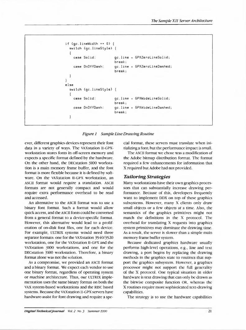
The Sample Xll Server Architecture
if Cgc.lineWidth =z 0) {
switch Cgc . lineStyle> {
case Solid : gc.line GPXZerolineSolid ; break;
case DnOffDash : gc . line GPXZerolineDashed ; break;
else switch Cgc.lineStyle)
case Solid : gc . line = GPXWidelineSolid; break;
case OnDffDash: gc.line = GPXWidelineDashed; break;
Figure 1 Sample Line Drawing Routine
ever, different graphics devices represent their font data in a variety of ways. The VAXstation 11-GPXworkstation stores fonts in off-screen memory and expects a specific format defined by the hardware. On the other hand, the DECstation 3100 workstation is a main memory frame buffer, and the font format is more flexible because it is defined by software. On the VAXstation 11-GPX workstation, an ASCII format would require a translation. ASCII formats are not generally compact and would require extra performance overhead to be read and accessed.
An alternative to the ASCII format was to use a binary font format. Such a format would allow quick access, and the ASCII fonts could be converted from a general format to a device-specific format. However, this alternative would lead to a proliferation of on-disk font files, one for each device. For example, ULTRIX systems would need three separate formats: one for the VAXstation 3540/3520 workstation, one for the VAXstation 11-GPX and the VAXstation 3100 workstations, and one for the DECstation 3100 workstation. Therefore, a binary format alone was not the solution.
As a compromise, we provided an ASCII format and a binary format. We expect each vendor to use one binary format, regardless of operating system or machine architecture. Thus, our ULTRIX implementation uses the same binary format on both the VAX system-based workstations and the RISC based systems. Because the VAXstation 11-GPX servers have hardware-assist for font drawing and require a spe-
Dtgttal Tecbntcal]ournal Vol. 2 No. 3 Summer 1990
cial format, these servers must translate when initializing a font; but the performance impact is small.
The ASCII format we chose was a modification of the Adobe bitmap distribution format. The format required a few enhancements for information that X required but Adobe had not provided.
Tailoring Strategies Many workstations have their own graphics processors that can substantially increase drawing performance. Because of this, developers frequently want to implement DDX on top of these graphics subsystems. However, many X clients only draw small objects or a few objects ar a time. Also, the semantics of the graphics primitives might not match the definitions in the X protocol. The overhead for translating X requests into graphics system primitives may dominate the drawing time. As a result, the server is slower than a simple main memory frame buffer system.
Because dedicated graphics hardware usually performs high-level operations, e.g., line and text drawing, a port begins by replacing the drawing methods in the graphics state to routines that support the graphics subsystem. However, a graphics processor might not support the full generality of the X protocol. One typical situation in older hardware is text drawing that can only be drawn as the bitwise composite function OR, whereas the X routines require more sophisticated text-drawing capabilities.
The strategy is to use the hardware capabilities
21
DECwindows Program
when they match the X protocol specification. If the hardware does not match, then the MI routines are used. The correct drawing methods, based on the current graphics attributes, are selected by the graphics state validate routine.
The following two examples describe what a developer might do when porting the sample server to hardware that does not comply with the Xprotocol.
Hardwired Fonts The X protocol allows the glyph in a single font to vary in width. However, some graphics processors can draw only glyphs with a fixed width. During validation, the text-painting method is changed in the graphics state, depending upon whether the font is fixed or variable width. Fixed-width fonts go directly to the graphics processor. Variable-width fonts are drawn in software, using routines based upon MI routines. Validation works in this example because the font is an attribute of the graphics state.
Hardware Clipping Restrictions The capability to clip graphics requests to an irregular region is a requirement of the X protocol. However, some graphics processors have clipping restrictions. For example, the VAXstation II-GPX workstation cannot paint some text strings that are clipped on the left. Unlike the hardwired font example above, the string is not an attribute of the graphics state. At validation, the DDX layer cannot tell whether a string will be clipped to the left, it only knows the font . Therefore, the actual painting routine must check if the string is clipped to the left. If so, the painting is executed by the graphics processor. If any part is clipped, the entire operation is done by MI code. This restriction cannot be handled in the same manner as font widths because it is impossible to know in advance if the drawing request will be clipped.
Sample Server in Retrospect As noted earlier, designing software to be used on a wide variety of devices requires making many compromises. Some of our decisions were good, and some could have been better.
Problem Areas Some areas of the sample server implementation could have been improved. For example, we learned a valuable lesson from using the ULTRIX system-based VAX.station workstations as our development environment. A machine that tolerates NULL pointer access will not discover when code
22
is written carelessly. Many errors were found only after the system was ported to Sun workstations. Other problems were the result of design constraints over which we had no control. Also, we could have improved the tuning we did for small memory machines. There is little hope of recovering if the server runs out of memory.
The C Ltmguage The C language caused many problems. Although the language is relatively standardized, it has many drawbacks. For our purposes, the major deficiency was a lack of support for information hiding. The language provides no support for hiding data structures defined in DDX or OS
from the DIX layer. Another problem with the C language is the
ambiguous representation of int. The only certain fact about int is that short is no longer than long.• Given our time constraints and the class of machines we planned to support, we had to assume that C type long is at least 32 bits and the C type short is at least 16, which was a bad assumption. Machines with 16-bit words were not addressed adequately because the sample assumes that the C type int is a 32-bit integer. Therefore, our server must be substantially reworked for 16-bit machines.
We also had C compiler problems. We tried not to rely on the implementation of the portable C compiler that comes with the ULTRIX system because not every vendor supports this compiler.
MI Routines The MI painting methods are useful for quick bootstrapping. However, by designing MI routines to support generality, we sacrificed performance. Writing general-purpose code requires care and diligent adherence to the rules for writing portable code. The rules include not relying on machine instructions, compiler idiosyncrasies, or knowledge of the hardware. No assembly language was allowed. The MI wide-line code is an example of a feature in which performance was severely affected by these constraints because we had to use floating point arithmetic rather than write a machine-independent, fixed-point math package.
The Best of the Server The biggest issue raised by our design was the potential performance degradation that could result from the inclusion of so much deviceindependent software. Was the cost of a common code base and device independence too great? We estimated the impact to be 5 percent for the simplest request and even less for more com-
Vol. 2 No. 3 Summer 1990 Digital Tecbntca/Journal
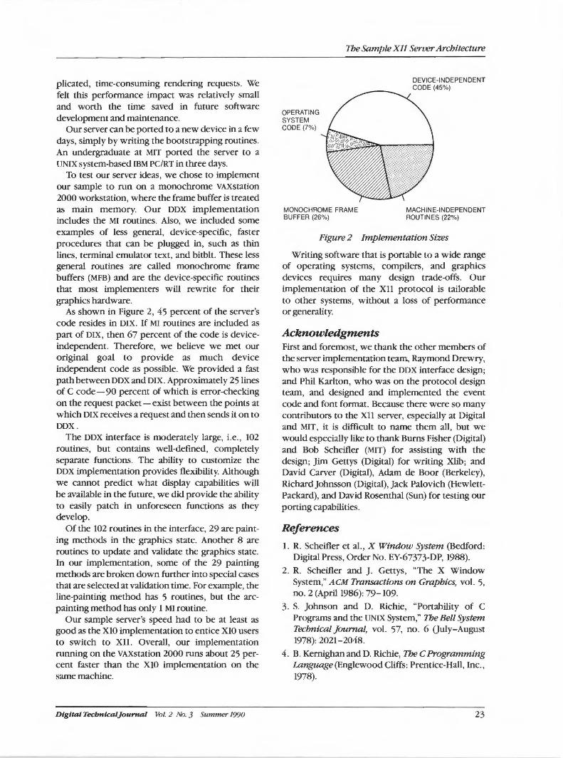
plicated, time-consuming rendering requests. We felt this performance impact was relatively small and worth the time saved in future software development and maintenance.
Our server can be ported to a new device in a few days, simply by writing the bootstrapping routines. An undergraduate at MIT ported the server to a UNIX system-based IBM PC/RT in three days.
To test our server ideas, we chose to implement our sample to run on a monochrome VAXstation 2000 workstation, where the frame buffer is treated as main memory. Our DDX implementation includes the MI routines. Also, we included some examples of less general, device-specific, faster procedures that can be plugged in, such as thin lines, terminal emulator text, and bitblt. These less general routines are called monochrome frame buffers (MFB) and are the device-specific routines that most implementers will rewrite for their graphics hardware.
As shown in Figure 2, 45 percent of the server's code resides in DIX. If MI routines are included as part of DIX, then 67 percent of the code is deviceindependent. Therefore, we believe we met our original goal to provide as much device independent code as possible. We provided a fast path between DDX and DIX. Approximately 25 lines of C code-90 percent of which is error-checking on the request packet-exist between the points at which DIX receives a request and then sends it on to DDX.
The DDX interface is moderately large, i.e., 102 routines, but contains well-defined, completely separate functions. The ability to customize the DDX implementation provides flexibility. Although we cannot predict what display capabilities will be available in the future, we did provide the ability to easily patch in unforeseen functions as they develop.
Of the 102 routines in the interface, 29 are painting methods in the graphics state. Another 8 are routines to update and validate the graphics state. In our implementation, some of the 29 painting methods are broken down further into special cases that are selected at validation time. For example, the line-painting method has 5 routines, but the arcpainting method has only 1 MI routine.
Our sample server's speed had to be at least as good as the XlO implementation to entice XlO users to switch to Xll. Overall, our implementation running on the VAXstation 2000 runs about 25 percent faster than the XlO implementation on the same machine.
Digital Tecbnlcal]ournal Vol. 2 No. 3 Summer 1990
The Sample XJJ Server Architecture
OPERATING SYSTEM CODE (7%)
MONOCHROME FRAME BUFFER (26%)
DEVICE-INDEPENDENT CODE (45%)
MACHINE-INDEPENDENT ROUTINES (22%)
Figure 2 Implementation Sizes
Writing software that is portable to a wide range of operating systems, compilers, and graphics devices requires many design trade-offs. Our implementation of the Xll protocol is tailorable to other systems, without a loss of performance or generality.
Acknowledgments First and foremost, we thank the other members of the server implementation team, Raymond Drewry, who was responsible for the DDX interface design; and Phil Karlton, who was on the protocol design team, and designed and implemented the event code and font format. Because there were so many contributors to the Xll server, especially at Digital and MIT, it is difficult to name them all, but we would especially like to thank Burns Fisher (Digital) and Bob Scheifler (MIT) for assisting with the design; Jim Gettys (Digital) for writing Xlib; and David Carver (Digital), Adam de Boor (Berkeley), RichardJohnsson (Digital), Jack Palovich (HewlettPackard), and David Rosenthal (Sun) for testing our porting capabilities.
References
1. R. Scheifler et al., X Window System (Bedford: Digital Press, Order No. EY-67373-DP, 1988).
2. R. Scheifler and J. Gettys, "The X Window System," ACM Transactions on Graphics, vol. 5, no. 2 (April 1986): 79-109.
3. S. Johnson and D. Richie, "Portability of C Programs and the UNIX System," The Bell System Technical Journal, vol. 57, no. 6 (July-August 1978): 2021-2048.
4. B. Kernighan and D. Richie, The C Programming Language (Englewood Cliffs: Prentice-Hall, Inc., 1978).
23
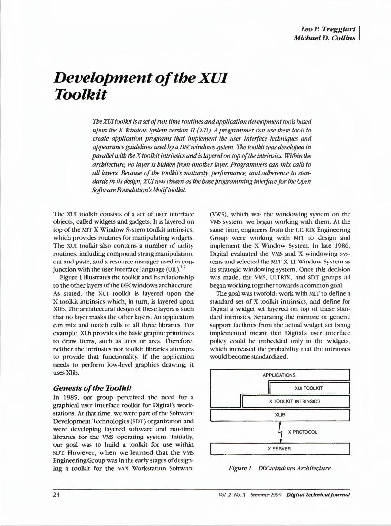
Leo P. Treggiart I Michael D. Collins
Development of the XU/ Toolkit
The XU/ toolkit is a set of run-time routines and application development tools based upon the X Window System version 11 (XJJ). A programmer can use these tools to create application programs that implement the user interface techniques and appearance guidelines used by a DECwindows system. The toolkit was developed in parallel with the X toolkit intrinsics and is layered on top of the intrinsics. Within the architecture, no layer is hidden from another layer. Programmers can mix calls to all layers. BeCtluse of the toolkit's maturity, performance, and adherence to standards in its design, XU/ was chosen as the base programming interface for the Open Software Foundation's Motif toolkit.
The XUI toolkit consists of a set of user interface objects, called widgets and gadgets. It is layered on top of the MIT X Window System toolkit intrinsics, which provides routines for manipulating widgets. The XUI toolkit also contains a number of utility routines, including compound string manipulation, cut and paste, and a resource manager used in conjunction with the user interface language {UIL).1'
2
Figure 1 illustrates the toolkit and its relationship to the other layers of the OECwindows architecture. As stated, the XUI toolkit is layered upon the X toolkit intrinsics which, in tum, is layered upon Xlib. The architectural design of these layers is such that no layer masks the other layers. An application can mix and match calls to all three libraries. For example, Xlib provides the basic graphic primitives to draw items, such as lines or arcs. Therefore, neither the intrinsics nor toolkit libraries attempts to provide that functionality. If the application needs to perform low-level graphics drawing, it uses Xlib.
Genesis of the Toolkit In 1985, our group perceived the need for a graphical user interface toolkit for Digital's workstations. At that time, we were part of the Software Development Technologies (SDT) organization and were developing layered software and run-time libraries for the VMS operating system. Initially, our goal was to build a toolkit for use within SOT. However, when we learned that the VMS Engineering Group was in the early stages of designing a toolkit for the VAX Workstation Software
24
(VWS), which was the windowing system on the VMS system, we began working with them. At the same time, engineers from the ULTRIX Engineering Group were working with MIT to design and implement the X Window System. In late 1986, Digital evaluated the VMS and X windowing systems and selected the MIT X 11 Window System as its strategic windowing system. Once this decision was made, the VMS, ULTRIX, and SOT groups all began working together towards a common goal.
The goal was twofold: work with MIT to define a standard set of X toolkit intrinsics, and define for Digital a widget set layered on top of these standard intrinsics. Separating the intrinsic or generic support facilities from the actual widget set being implemented meant that Digital's user interface policy could be embedded only in the widgets, which increased the probability that the intrinsics would become standardized.
APPLICATIONS
XUI TOOLKIT
X TOOLKIT INTRINSICS
XLIB
X PROTOCOL
X SERVER
Figure 1 DEC windows Architecture
Vol. 2 No. 3 Summer 1990 Digital Tecbnicaljournal
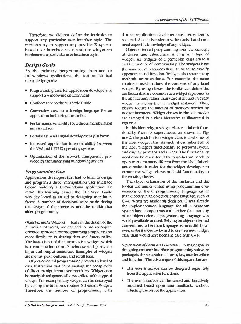
Therefore, we did not define the intrinsics to support any particular user interface style. The intrinsics try to support any possible X systembased user interface style, and the widget set implements a particular user interface style.
Design Goals As the primary programming interface to DECwindows applications, the XUI toolkit had many design goals:
• Programming ease for application developers to support a windowing environment
• Conformance to the XUI Style Guide
• Conversion ease to a foreign language for an application built using the toolkit
• Performance suitability for a direct manipulation user interface
• Portability to all Digital development platforms
• Increased application interoperability between the VMS and ULTRIX operating systems
• Optimization of the network transparency provided by the underlying windowing system
Programming Ease Applications developers first had to learn to design and program a direct manipulation user interface before building a DECwindows application. To make this learning easier, the XUI Style Guide was developed as an aid to designing user interfaces.3 A number of decisions were made during the design of the intrinsics and the toolkit that aided programming.
Object-oriented Method Early in the design of the X toolkit intrinsics, we decided to use an objectoriented approach for programming simplicity and more flexibility in sharing data and functionality. The basic object of the intrinsics is a widget, which is a combination of an X window and particular input and output semantics. Examples of widgets are menus, push-buttons, and scroll bars.
Object-oriented programming provides a level of data abstraction that helps manage the complexity of direct manipulation user interfaces. Widgets can be manipulated generically, regardless of the type of widget. For example, any widget can be destroyed by calling the intrinsics routine XtDestroyWidget. Therefore, the number of programming calls
Dig i tal TecbnicalJounial Vol. 2 No. 3 Summer 1990
Development of the XUI Toolkit
that an application developer must remember is reduced. Also, it is easier to write tools that do not need a specific knowledge of any widget.
Object-oriented programming uses the concept of classes and inheritance. A class is a type of widget. All widgets of a particular class share a certain amount of commonality. The widgets have the same set of resources that can be set to modify appearance and function. Widgets also share many methods or procedures. For example, the same routine is used to draw the contents of any label widget. By using classes, the toolkit can define the attributes that are common to a widget type once in the application, rather than store attributes in every widget in a class (i.e., a widget instance). Thus, classes reduce the amount of memory needed by widget instances. Widget classes in the XUI toolkit are arranged in a class hierarchy as illustrated in Figure 2.
In this hierarchy, a widget class can inherit functionality from its superclasses. As shown in Figure 2, the push-button widget class is a subclass of the label widget class. As such, it can inherit all of the label widget's functionality to perform layout, and display pixmaps and strings. The functionality need only be rewritten if the push-button needs to operate _in a manner different from the label. Inheritance makes it easier for the widget developer to create new widget classes and add functionality to the existing classes.
The object orientation of the intrinsics and the toolkit are implemented using programming conventions of the C programming language rather than directly in an object-oriented language, such as C++. When we made this decision, C was already the implementation language for all X Window System base components and neither C++ nor any other object-oriented programming language was widely available or used. Relying on object-oriented conventions rather than language features did, however, make it more awkward to create a new widget class than would have been the case with C++.
Separation of Form and Function A major goal in designing any user interface programming software package is the separation of form, i.e., user interface and function. The advantages of this separation are
• The user interface can be designed separately from the application functions.
• The user interface can be tested and iteratively modified based upon user feedback, without affecting the rest of the application.
25
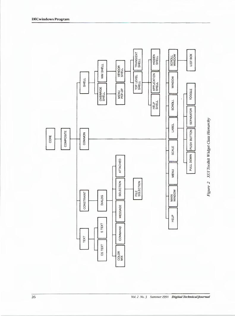
N
0\
CS
TE
XT
CO
LOR
M
IX
S T
EX
T
CO
MM
AN
D
HE
LP
FIL
E
SE
LEC
TIO
N
MA
IN
WIN
DO
W
AT
IAC
HE
D
CO
RE
CO
MM
ON
Fig
ure
2
XU
/ To
olk
it W
idg
et C
lass
Hie
rarc
hy
HE
LP
S
HE
LL
A
PP
LIC
AT
ION
S
HE
LL
WIN
DO
W
TO
GG
LE
TR
AN
SIE
NT
S
HE
LL
HID
DE
N
SH
EL
L
LIS
T B
OX
• An application can support more than one user interface that is using the same application code. This feature is especially useful for changing the language and other aspects of an application for a user in another culture. Multiple interfaces can also be used to tailor a single application to support different classes of users.
The OECwindows user interface language (UIL) and resource manager (ORM) are the tools which allow form and function to be separated. Ull is a specification language that describes the initial state of a user interface, i.e., it describes the objects used in the interface and the application callbacks to be invoked when the interface changes state.4
ORM provides the application with a run-time library for accessing the compiled Ull descriptions. ORM, therefore, builds the run-time structures necessary to actually create the user interface during execution of the application.
Conformance to the XU/ Style The toolkit had to support XUI style at a detail level in both look and feel. Supporting the look primarily meant setting default values for the many graphic aspects of a widget, such as the border width of a push-button. Supporting the feel meant establishing tables that translate user events, such as button press, into a widget action, such as highlight. Defining the widgets that compose the toolkit was based on partitioning the XUI style look and feel demands into logical pieces and on predicting application needs.
Although a widget would have many customizable attributes, all of which could be controlled by the application, we wanted to make it easy for an application developer to design and implement a OECwindows application that conformed to the XUI style. A widget should, by default, select conforming values for any attribute the application could have but did not set. Therefore, we implemented a default look and feel that matched the precise user interactions defined in the style guide and the precise graphic design that was defined for XUI by our graphic artists. However, we also made the widgets as flexible as possible. Although widgets defaulted to the XUI style, the customization methods inherent in the intrinsics, e.g. , resource and translation management, could be used to customize a widget to another style. This design philosophy helped give applications a consistent look and feel but did not constrain user interface innovation.
Digital Tecbnical]ournal Vol. 2 No. 3 Summer 19'.JO
Development of the XU/ Toolkit
Further, we decided to structure the set of widgets based upon the object's function as seen by the application's developer rather than as seen by the application's user. An example is the use of buttons in menus and dialog boxes. Both menus and dialog boxes contain buttons that directly invoke application actions (i.e., pushbuttons). However, the graphical appearance and user invocation syntax of the buttons is different depending upon whether the button is placed within a menu or a dialog box. The toolkit, however, presents only one push-button class to the application programmer. The buttons are dynamically configured based upon the environment in which they are placed. Thus, an application developer can change the environment of a widget without changing any other code.
Conformance to Standards The OECwindows program was intended to be based on MIT's X Window System standard. Therefore, the toolkit had to be based upon the standard X toolkit intrinsics. It was a challenge to do so because the toolkit and the intrinsics were designed, implemented, and standardized in parallel.
The standard language bindings for the intrinsics were designed for the C language. However, we were mindful of the requirements of other languages and attempted not to prohibit other language bindings from being possible. It is a wellknown technology to provide multiple language bindings, in the form of header file definitions and entry point names, for a single set of run-time routines. Digital used this approach in providing VAX procedure calling standard bindings for Xlib, the intrinsics, and the toolkit.
A special problem arose in defining the bindings for the intrinsics because the intrinsics would call back into the application code to provide notification of a user action such as a button press. The intrinsics, however, has no knowledge of the language used in the called procedure. Therefore, we had to restrict the parameter passing mechanism in callbacks to the set that could be understood by most languages. Parameters to callbacks are passed by a reference mechanism as opposed to a value mechanism that is commonly used when calling C procedures.
Performance From the beginning of the OECwindows program development, a team of Digital software usability engineers worked closely with the OECwindows developers to design the XUI style and define user
27
DECwindows Program
interaction performance goals for the DECwindows interface. The DECwindows environment uses a direct manipulation user interface model that requires real-time responses to user actions. The success of direct manipulation is dependent upon creating the illusion that objects are being physically manipulated. For example, if the interface is sufficiently slow, the user fails to perceive a cause-and-effect relationship between a button press and a push-button highlighting. Once such a relationship is lost, much of the interface illusion breaks down.
To test the interface's performance, the software usability engineers defined a number of scenarios that consisted of test scripts and covered six major functional areas:
• Menu manipulation
• Dialog box manipulation
• Window manager operations
• Text operations
• Dragging graphics objects within a window
• Application start-up and shutdown
Each test was described in enough detail to support designing a simple DECwindows application that would measure the system performance. Our goal was to use a small number of tests to cover the most critical areas of user interface performance. For each test, performance numbers were given in terms of worst case, planned level, best case, and competitive level. The worst case defined the worst acceptable level. The planned level represented success. Once the planned level was attained for an attribute, further resources would be focused on those attributes that did not yet meet the planned level. The best case was a state-of-the-art limit for the test. The competitive level was the average performance seen on competitive systems.
Obviously, the design of the intrinsics and the toolkit played a major role in our ability to meet these goals. The problems we encountered are included in the performance discussion in the Initial Implementation section of this paper.
Internationalization UIL and ORM are major components of the internationalization of DECwindows applications. The majority of an application's culture-specific information can be separated from the executable image
28
by putting text strings and other culturally variant data into UIL files rather than the application code. Because an application is bound to a UIL description at run-time as opposed to compilation or link time, an application can be moved from one country to another without a different application executable image.
Compound strings are another major internationalization component. The initial design of the toolkit was based upon ASCII null-terminated strings, which acted as the data representation for text strings passed between the application and the widgets. However, based on input from engineering groups around the world, we decided that ASCII was not sufficient. A simple example demonstrates why this is true. The Digital corporate name in Japan was Nihon Digital in English, in Japanese it is B * Digital. To display this name as the title of a window, the application must pass a widget a single string with characters in Japanese Kanji and Latin fonts.
Compound strings allow a single text object to be composed of multiple segments. Each segment has its own character set and characters. Thus, Nihon Digital is a compound string with two segments. The first segment is in the Japanese Kanji character set, with the characters B *, and the second segment is in a Latin character set, with the characters Digital.
We implemented a compound string library that provided applications with basic string manipulation facilities. The toolkit was revised to enable application-widget interfaces to use compound strings rather than ASCII strings. As the DECwindows program and the Open Software Foundation's (OSF) Motif evolved, the actual data representation also evolved. Currently, both systems use the International Standards Organaation's (ISO) Abstract Syntax Notation (ASN.l) encoding that is compatible with Digital's document interchange syntax, DDIS.5
The toolkit also provides a mechanism that dynamically selects the appropriate UIL description based on a run-time determination of the user's cultural preference. This mechanism further capitalizes on the run-time binding of UIL descriptions and application code. The mechanism was designed as a logical extension to the X/Open portability guide native language switching mechanism (XPG NLS).6 The XPG NLS is a de facto standard supported by OSF that is primarily targeted at character-cell environments. We extended the XPG NLS model to encompass run-time selection of cultural databases
Vol. 2 No. 3 Summer 1990 Dtgttal Tecbntcal]ournal
that affect such things as UIL descriptions and HELP databases.
Resource and schedule pressures precluded changing the text widget from ASCII to compound strings in conjunction with the rest of the toolkit. As a result, we had to build a non-ASCII text widget for the Asian and Hebrew markets. The second major release of the toolkit included a compound string text widget and an ASCII text widget.
Portability and Interoperability A goal of the entire DECwindows program was to define an application programming environment that would be the same for the VMS and ULTRIX operating systems. If the VMS and ULTRIX engineers worked together to design and implement the base software, expenses would be reduced. Therefore, the toolkit and the intrinsics were written simultaneously in the C language for the VMS and ULTRIX systems.
We wanted all DECwindows components to capitalize on the network transparency provided by the underlying windowing system. That is, the DECwindows components should interoperate with other systems that supported the X protocol in a heterogeneous networked environment. Therefore, we were careful not to build specific DECwindows features into the toolkit.
Initial Implementation The initial development of the toolkit presented the software engineers with a number of challenges. The major challenge was to develop several different layers · of the architecture at the same time. Further, none of the layers had proven suitable for their designed task. Therefore, it was difficult to predict the performance characteristics of the layers.
To reduce the inherent risks of this situation, we established a development plan that allowed major functionality to become available for serious application development early in the product development cycle. We then used the applications to determine whether the goals of the DECwindows program, in general, and the toolkit, in particular, were being met.
Intrinsics and Toolkit Codevelopment Our plan to design and implement the toolkit and the intrinsics simultaneously was further complicated by the fact that the layers below the intrinsics, i.e., Xlib and the X protocol, also were being changed. Some of the changes were driven by the
Digital Tecbnlcal]ournal Vol. 2 No. 3 Summer 1990
Development of tbe XU/ Toolkit
needs of the toolkit and intrinsics. Others were due to the lack of maturity of the XU protocol. Because of these changes, we had to respond to a number of releases of the lower layers of the architecture.
The intrinsics design was changed several times during the first year of development as a result of two major factors. First, the problems and deficiencies of the intrinsics and the toolkit became apparent when we began to write serious applications. Second, other companies became more involved in the definition of the intrinsics standard. Therefore, we had to work with a formal process of proposing and reviewing changes to the standard and negotiating the inclusion of those changes with engineers from MIT and other companies. As each of these changes then became standardized, each would, in turn, cause changes in widget code, which caused changes in application code.
Each time a significant change in a layer of the architecture occurred, all of the layers above it had to change in a coordinated manner to provide a consistent development environment. Much time was spent in planning the management of these changes. Also, the changes necessitated rewriting code that had already been completed. We had not accounted for the time taken by these unanticipated changes in our original development plans.
Distributed Engineering/or Multiple Platforms The development of the toolkit involved Digital engineering teams worldwide. The intrinsics were developed in California, primarily on ULTRIX system-based workstations, by a team of engineers familiar with the ULTRIX system. The toolkit was developed in New Hampshire, primarily on VMS system-based workstations, by a team of engineers familiar with the VMS system. As a result, some problems occurred at software integration points. However, the codevelopment effort ensured that the final software provided the same programming interface, with the same quality, on multiple operating system platforms.
Performance Performance was the most serious problem encountered during early implementation. The first internal field test of the DECwindows software provided fairly complete functionality for the toolkit and the layers below it. However, the DECwindows developers, including the toolkit team, had devoted nearly all their efforts toward developing the functionality and postponed measuring, examining, and
29
DECwindows Program
improving performance. Now that we had an existing collection of applications, serious work could begin on performance.
In the initial measurements of the system's performance against the goals described earlier, even the worst-case goal was missed in many areas. Early investigation also indicated that the performance problem did not seem to be localized. That is, the problems could not be isolated to a single component in the architecture. With this information, a task force with members from most DECwindows development groups was convened to determine where the performance problems were and what could be done about them.
We quickly learned that we could not determine where the performance problems were as easily as we could have in the typical engineering environment to which we were accustomed. Our experience was in evaluating isolated layered applications, such as compilers, and individual primitive operations, such as system calls. However, the user interface actions that were being measured involved the issuance of possibly hundreds of X primitives, and the interaction of up to three separate processes (i.e., the application, the X server, and the window manager). Although the usual evaluation tools were of some help, additional tools were needed.
Existing tools, such as the VAX performance and coverage analyzer on the VMS system, were used to locate performance bottlenecks. These tools helped but did not provide the level of improvements that were necessary. A number of internal tools to aid in X performance analysis were used to supplement the traditional tools. These X performance tools included:
• An instrumented X server that counted the resources an application requested, such as graphic contexts, windows, and pixmaps
• A set of tests that measured the performance of Xlib primitive calls
• A protocol monitor that recorded the interactions between an application and the X server
• A tool that recorded the dynamic memory allocation of an application
By using these tools on the applications, a large amount of data was collected and evaluated. Some of the more important observations were:
30
• Applications were using more server resources than anticipated. The most common overuse was windows because each user interface object had its own X window. However, application use of other resources, such as graphic contexts, pixmaps, and fonts was also at a higher level than anticipated.
• Applications were using too much memory. The object-oriented design of the toolkit and the XUI Style Guide encouraged applications to use hundreds or thousands of widgets, and each widget was then using about 600 bytes of memory. A number of X toolkit intrinsics features, such as resource management and translation management, also used a large amount of memory.
• Application start-up was slow. Loading the large programming libraries, connecting to the X server, and creating widgets were some of the principal functions that slowed application start-up.
• The Digital Xll server design was optimized for graphic primitives, e.g., line and text drawing. The performance of these operations was very good. However, in optimizing the graphics aspect, the design had traded performance in windowing operations, for example, window creation and mapping. The analysis showed that windowing operation performance was important throughout much of the direct manipulation style user interface.
• Many context switches existed between the server and the application during time-critical operations. Even simple applications required the coordinated efforts of the application, a window manager, and a server. Careful analysis and planning were needed to minimize the communication traffic and switching among the processes.
• The basic round-trip time between the server and the application using the DECnet transport was higher than anticipated. This factor increased the need to reduce the amount of communication traffic between the application and the server.
Solutions were designed and tasks defined to help fix the problems. Steps were taken in all layers of the architecture to reduce CPU utilization, memory utilization, and communication traffic. The two most radical design changes were the design and
Vol. 2 No. 3 Summer 1990 Digital Tecbnlcaljournal
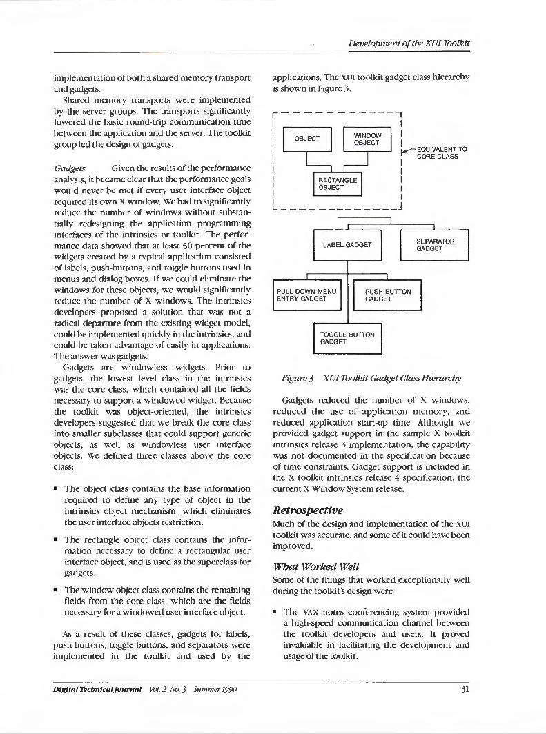
implementation of both a shared memory transport and gadgets.
Shared memory transports were implemented by the server groups. The transports significantly lowered the basic round-trip communication time between the application and the server. The toolkit group led the design of gadgets.
Gadgets Given the results of the performance analysis, it became clear that the performance goals would never be met if every user interface object required its own X window. We had to significantly reduce the number of windows without substantially redesigning the application programming interfaces of the intrinsics or toolkit. The performance data showed that at least 50 percent of the widgets created by a typical application consisted of labels, push-buttons, and toggle buttons used in menus and dialog boxes. If we could eliminate the windows for these objects, we would significantly reduce the number of X windows. The intrinsics developers proposed a solution that was not a radical departure from the existing widget model, could be implemented quickly in the intrinsics, and could be taken advantage of easily in applications. The answer was gadgets.
Gadgets are windowless widgets. Prior to gadgets, the lowest level class in the intrinsics was the core class, which contained all the fields necessary to support a windowed widget. Because the toolkit was object-oriented, the intrinsics developers suggested that we break the core class into smaller subclasses that could support generic objects, as well as windowless user interface objects. We defined three classes above the core class:
• The object class contains the base information required to define any type of object in the intrinsics object mechanism, which eliminates the user interface objects restriction.
• The rectangle object class contains the information necessary to define a rectangular user interface object, and is used as the superclass for gadgets.
• The window object class contains the remaining fields from the core class, which are the fields necessary for a windowed user interface object.
As a result of these classes, gadgets for labels, push buttons, toggle buttons, and separators were implemented in the toolkit and used by the
Digital Tecbnlcal]ournal Vol. 2 No. 3 Summer 1990
Development of the XU/ Toolkit
applications. The XUI toolkit gadget class hierarchy is shown in Figure 3.
LABEL GADGET
PULL DOWN MENU ENTRY GADGET
PUSH BUTTON GADGET
TOGGLE BUTTON GADGET
SEPARATOR GADGET
Figure 3 XU/ Toolkit Gadget Class Hierarchy
Gadgets reduced the number of X windows, reduced the use of application memory, and reduced application start-up time. Although we provided gadget support in the sample X toolkit intrinsics release 3 implementation, the capability was not documented in the specification because of time constraints. Gadget support is included in the X toolkit intrinsics release 4 specification, the current X Window System release.
Retrospective Much of the design and implementation of the XUI
toolkit was accurate, and some of it could have been improved.
What Worked Well Some of the things that worked exceptionally well during the toolkit's design were
• The VAX notes conferencing system provided a high-speed communication channel between the toolkit developers and users. It proved invaluable in facilitating the development and usage of the toolkit.
31
DECwindows Program
• Developing the toolkit simultaneously on the VMS and ULTRIX systems was easier than anticipated. We were able to limit ourselves to the use of standard C language and X Window System features. The amount of operating system dependent code in the toolkit is very small.
• Distributed development worked fairly well. At times there might have been too many developers involved, but published schedules and extensive use of electronic mail allowed us to integrate pieces being simultaneously developed in Israel, France, New Hampshire, California, and Japan. We believe the history of the DECwindows program shows that it is possible to do large-scale distributed software development.
Improvement Areas The text widget was designed with more functionality than was required for most usage. If we had recognized earlier that not as much design intricacy was needed, we could have devoted more time and resources to addressing the issue of a compound string text widget.
The intrinsics were designed around a single thread of execution. There is considerable pressure from applications that are multithreaded to allow use of the toolkit from multiple simultaneous threads of execution. Currently, this is not possible.
Documentation was started early and proved invaluable, but we did not have sufficient resources to produce less formal, "how-to" manuals. The scope and scale of the DECwindows programming environment is quite large. Some basic but comprehensive manuals on how to get started would have complemented the documentation we did produce and made programming much easier for application developers.
Tbe XU/ Toolkit as tbe Basts for OSFIMOTIF Early in the DECwindows program development, Digital and several other companies founded the Open Software Foundation (OSF}. Towards the end of DECwindows version I development, OSF issued a request for technology to become OSF's User Environment Component. In response, Digital submitted the XUI Style Guide, XUI toolkit, and window manager as a package. Altogether, OSF received a total of 38 submissions.
32
OSF chose the XUI toolkit as the base application programming interface and implementation for the Motif toolkit? Because of the OSF's members desire for Presentation Manager compatibility, the XUI toolkit was modified to use Hewlett-Packard's three-dimensional appearance and be compatible with Microsoft's Presentation Manager behavior.
Digital is currently transitioning from the XUI toolkit to the Motif toolkit for the DECwindows program. Although the transition for an application requires some changes, most of the XUI toolkit programming concepts remain. The group that designed and implemented the XUI toolkit is now focused on delivering the Digital implementation of the OSF/Motif toolkit. We are working closely with OSF on the evolution of the toolkit through specification and design reviews. We are also working with other Digital groups to make the transition as smooth as possible.
Tbe Future and Standards In summary, the XUI toolkit provided a successful user interface programming toolkit for the DECwindows program and provided the basis for OSF's graphical user interface toolkit, OSF/Motif. For the future, the definition of the OSF/Motif toolkit belongs to OSF and its member companies, which is a major benefit for application developers. The user interface component of an application can now be ported to many different systems. End users also benefit because a consistent user interface will exist on many different systems.
We will remain heavily involved in the evolution of the Motif toolkit to help ensure that it maintains the quality required of it as the user interface toolkit for the DECwindows programming environment. However, now that the toolkit is an OSF standard rather than a Digital proprietary interface, we are faced with some new challenges.
We can no longer change (or not change) the Motif toolkit to fit our proprietary needs. If we want to make changes, we must propose the changes through the OSF process. Also, we must accept changes made by OSF, even if those changes create rather than solve problems for us.
For example, the XUI toolkit, as with all other VMS run-time libraries, is packaged as a shareable image. One of the goals of VMS shareable images is binary-upward compatibility. This compatibility allows the VMS system to ship new versions of a shareable image, which may fix bugs or improve
Vol. 2 No. 3 Summer 1990 Digital Tecbnica/Journal
performance, without requiring the application to be relinked. However, with OSF-defined changes, we cannot ensure binary-upward compatibility between releases of Motif. At present, we are working on how to solve these problems.
Acknowledgments We would like to thank the many people who contributed to the development of the intrinsics and the XUI toolkit, especially the members of the toolkit and UIL teams who combined exceptional talent and dedication to produce the toolkit programming environment: Vick Bennison, Jeff Orthober, Jay Bolgatz, Steve Greenwood, Scott Smith, Ross Faneuf, Marc Zehngut, Dave Utz, John Ronan, Dan Mullen, Jerry Harrow, Steve Grass, Pat Chandler, Jeff Reyer, Jim VanGilder, Roger Brinkley, and Bob Pellegrino. We would also like to thank the engineering groups who provided essential components to the XUI toolkit: the Western Software Lab in Palo Alto, California; Asian-based Systems in New Hampshire, Japan, and Israel; the Commercial Languages and Tools Group in Valbonne, France; and the Software Usability Group in New Hampshire.
Digita l Tecbntca/Journal Vol. 2 No. 3 Summer 1990
Development of the XU/ Toolkit
References
1. VMS DECwindows Toolkit Routines Reference Manual (Maynard: Digital Equipment Corporation, Order Nos. AA-MG23B-TE, AA-MK88B-TE, October 1989).
2. VMS DECwindows Guide to Application Programming (Maynard: Digital Equipment Corporation, Order No. AA-MG21A-TE, October 1989).
3. T. Spine and). VanNoy, "The Evolution of the X User Interface Style," Digital Technical Journal, vol. 2., no. 3 (Summer 1990, this issue): 44-51.
4. S. Greenwood, "The DECwindows User Interface Language," Digital Technical Journal, vol. 2, no. 3 (Summer 1990, this issue): 34-43.
5. R. Travis, "CDA Overview," Digital Technical Journal, vol. 2, no. 1 (Winter 1990): 8-15.
6. X/Open Portability Guide XS/ Supplementary Definitions (Englewood Cliffs: Prentice-Hall, Inc., U.S.A., December 1988).
7. SF/Motif Programmer's Reference Manual, revision 1.0 (Cambridge: Open Software Foundation, Inc., August 1989).
33
Stephen R. Greenwood I
The DECwindows User Interface Language
A key theme of the DECwindows program is to improve productivity for both the end user and the developer of an application. End user productivity can improve through the use of a windowing environment; the developers' productivity is improved by the the availability of a high-level set of constructs for building a windowing application. The user interface language (UIL) plays an important role in enhancing productivity. UIL significantly reduces the cost to build and maintain DECwindows applications by providing a specification language for describing an application interface. This paper analyzes the motivation for developing UJL, its key features, several interesting implementation issues, and possible future directions for the language and the product.
The DECwindows user interface language (UIL) aids application developers in managing the complexity of DECwindows interfaces. This paper investigates UIL 's relationship to the other DECwindows program components and how UIL deals with managing interface complexity. Specifically, the paper discusses the history ofUIL, its key concepts, major implementation issues, and the future of the language.
History of the User Interface Language January 1988 was the target date for the first internal release of the DECwindows program. To meet that deadline, much of the high-level strategy for the DECwindows program had been set by August 1987. Digital was making a major move into the workstation market with products built around the X windows protocol developed at MIT.1 Both the ULTRIX and VMS system development groups were producing servers and host libraries that conformed to the X standard. The object-oriented XUI toolkit was under development. It would implement the standard set of objects and operations ( often called the "look and feel" or style) of the DECwindows program. The toolkit would layer on top of the X windows platform being developed on both operating systems.
To be viable in the marketplace, the DECwindows program had to be more than a toolkit based on the X Window System. Applications had to illustrate the DECwindows style, capture the growing seg-
34
ment of the market that had no interest in typing a command line, and show Digital's commitment to the workstation market through the DECwindows program.
The XUI toolkit was, and still is, the key to leveraging applications. It presents DECwindows concepts at a high level and still allows substantial flexibility in controlling those concepts. Widgets are the high-level abstractions that map one-to-one with the graphic components of an interface. If a dialog box that contains a set of toggle buttons is needed, a dialog box widget that contains a set of toggle button widgets is created. Widgets provide flexibility through their attributes. Each attribute controls some visual aspect of the widget's appearance on the screen. By giving most attributes a default setting that conforms to the DECwindows style, applications can look similar but have the power to be different.
A DECwindows interface can be created by invoking procedures in the XUI toolkit. These procedures create widgets, specify the widgets' attributes, specify the actions to be invoked when the widgets are manipulated, and control when widgets should be displayed or hidden from view. Attributes and their corresponding values are passed to a creation routine, using a variable length array. If one widget will contain other widgets, as in the case of a dialog box, the container is created first. Each of the widgets contained within the dialog box is then created by designating the dialog box as its parent. Once the entire structure has been
Vol. 2 No. 3 Summer 1990 Digital Tecbnlcal]ournal
constructed, another call is made to an XUI toolkit routine to display the dialog box and its contents on the screen.
Although the toolkit made the process of mapping Widgets to screen artifacts conceptually simple, the coordination and sheer number of artifacts made the process complex. An application's attributes, actions, and contained widgets, which could number in the hundreds, might require several thousand lines of code to construct. To see the structure of the application interface within that code required discipline.
UIL was the tool developed to manage the complexity of the interface. UIL preserves the simple conceptual model established by the toolkit. Through the UIL specification language, an application developer states the widgets that compose the interface, their attributes, and the relationships among them. Missing from a UIL-specified interface are the thousands of lines of code to construct the interface.
Range of Solutions Several approaches to the problem of managing a large number of windows exist in the industry.
One approach is Microsoft's Resource Script File, which contains ASCII descriptions of user interface components.2 The resource script file gives textual descriptions of fonts and windows. For dialog boxes, the attributes of the box and the objects that are within the box are specified. An application uses the information in the script file to create its interface. The application controls the degree to which the application interface is described by a script file versus being described in the code of the application.
Another approach is to build interfaces through direct manipulation.3 With this approach, the interface designer uses a workstation to construct the interface as it will appear to the user of the application. The interface is built by selecting the appropriate components from a palette or list and placing them on the screen. For example, if the designer chooses a dialog box, a default dialog box is displayed on the screen. The designer can then manipulate the borders of the box until it is the correct size. Toggle buttons and list boxes can be selected from a palette and placed wherever desired within the dialog box. Each graphical artifact has a list of attributes that can be displayed and modified by the designer. The effects of the changes to the attributes are displayed immediately. The Macintosh resource editor and SuperCard are examples of this approach~·5
Digital Tecbnical]ournal Vol. 2 No. 3 Summer 1990
The DEC windows User I n terj ace La.nguage
Graphical solutions are the best method for a designer to see how each window will look. The designer receives an immediate picture of the placement, size, and visual characteristics of each graphic component. To build such a system, a working toolkit with dialog boxes, list boxes, labels, and toggles is necessary. In fact, the toolkit had best be quite mature. The XUI toolkit was not ready in August 1987. Therefore, despite the many advantages of graphical solutions, a specification language was the correct solution to support interface building in the DECwindows program at that time. The language could be constructed and ready to leverage building DECwindows interfaces by the target date of}anuary 1988.
UIL Constructs The user interface language (UIL) is a simple, textbased language. Its objective is to specify the
• Graphical objects in a DECwindows interface
• Attributes of each graphical object
• Actions each graphical object can trigger
• Relationships among these graphical objects
The code fragment in Figure 1 illustrates the specification of two widgets using UIL.6 Widgets are the most common graphical objects in the XUI toolkit. (Note: The XUI toolkit supports both widgets and gadgets, the latter being a restrictive form of widget. UIL defines objects that may be either widgets or gadgets. A more detailed explanation is provided in the Support for Defining UIL Objects section of this paper.)
The first declaration in Figure 1 defines a popup dialog box, called OPEN_LIBRARY This declaration contains two subparts that specify the attributes for the dialog box and also the other widgets that the dialog box contains. The attributes listed are specific to the popup_dialog_box widget. Each attribute also has a type, such as integer, string, Boolean, or another object. All of the attributes of a popup_dialog_box widget need not be listed. Each attribute has a default value that is used when a value is not specified for that attribute.
The OPEN_LIBRARY widget contains six other objects listed in its controls clause, which specifies the objects contained within the object being defined. Both the XUI toolkit and the X Window System use a tree to describe the relationships between objects, i.e., widgets in the case of the toolkit, and windows in the case of the X Window
35
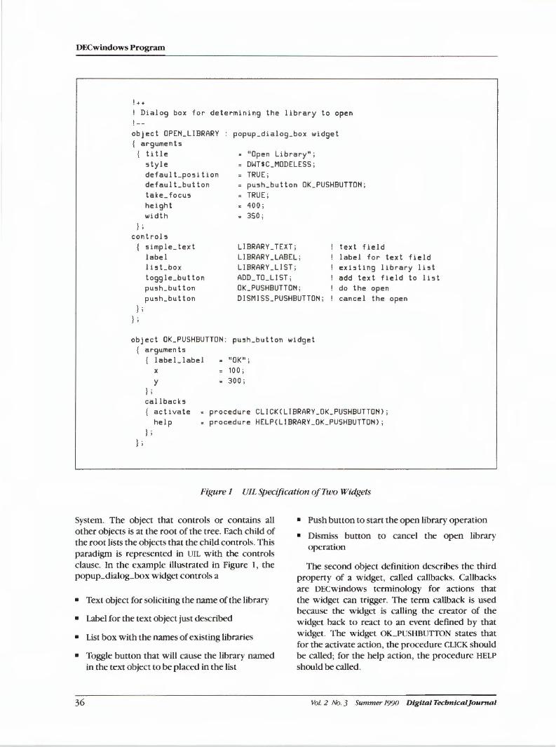
DECwindows Program
! + +
l Dialog box for determining the library to open ! --object OPEN_LIBRARY { arguments
{ title
popup_d i alog_box widget
"Open Library" ; DWHC _MODELESS ; TRUE ;
style default_po5 i tion defaul Lbut ton take_focu5 height
push_button OK _PUSHBUTTON ; TRUE ;
width } ;
control5 5imple_text label li5Lbox toggle_button pu5h_button pu5h_button
} ; } ;
z 400 ; 350 ;
LIBRARY_ TEXT ; LIBRARY _LABEL ; LIBRARY _LI ST ; ADD_TO_LIST ; OK_PUSHBUTTON ; DISMISS_PUSHBUTTON ;
object OK_PUSHBUTTON : pu5h_button widget arguments { label_label "OK" ;
x
y } ;
100 ; s 300 ;
text field label for text field existing library li5t add text field to list do the open can ce 1 the open
cal lback5 { activate
help } ;
s procedure CLICKCLIBRARY_OK_PUSHBUTTON> ; procedure HELPCLIBRARY _OK _PUSHBUTTON) ;
} ;
Figure 1 UIL Specification of Two Widgets
System. The object that controls or contains all other objects is at the root of the tree. Each child of the root lists the objects that the child controls. This paradigm is represented in UIL with the controls clause. In the example illustrated in Figure 1, the popup_dialog_box widget controls a
• Push button to start the open library operation
• Dismiss button to cancel the open library operation
The second object definition describes the third property of a widget, called callbacks. Callbacks are DECwindows terminology for actions that the widget can trigger. The term callback is used because the widget is calling the creator of the widget back to react to an event defined by that widget. The widget OK_PUSHBUTTON states that for the activate action, the procedure CLICK should be called; for the help action, the procedure HELP should be called.
• Text object for soliciting the name of the library
• Label for the text object just described
• List box with the names of existing libraries
• Toggle button that will cause the library named in the text object to be placed in the list
36 Vol. 2 No. 3 Summer 1990 Digital Tecbnicaljournal
Each widget has a specific set of callbacks that it makes. Many of the callbacks, such as help and activate, are common to more than one widget. The sequence of actions performed by the user to trigger the callback can also be programmed by the application through its translation table attribute. Most applications, however, accept the defaults for these sequences since the defaults are programmed to conform to the DECwindows style. For example, activate is a down click on mouse button (MB) 1.
By convention, a procedure invoked as a call back has three arguments. One of these arguments is the widget identifier, a unique value used to distinguish one widget from another. Using this identifier, a callback can inquire about any of the widget's attributes at run-time. The second argument is application-defined information that can be designated in UIL. The value of this second argument is often used to distinguish which widget has initiated the callback. In the example in Figure 1, all help callbacks may invoke the HELP procedure. The HELP procedure determines the information to be displayed based on the value of the application-defined argument. The third argument varies widely from one type of widget to another. It normally contains useful state information about the widget, such as the state of a toggle button.
The concepts covered so far in this section are the core of a UIL specification. UIL is a declarative language. It contains no constructs that specify flow of control, such as the if-then-else or loop constructs found in programming languages like C or FORTRAN. The language simply states the objects in an interface, the attributes of each object, the procedures to invoke when an object is manipulated, which objects are contained within other objects, and what those other objects are.
Creating an Interface with UIL To create an interface for an application, the information in a UIL specification must be transformed into a series of calls that will invoke the necessary XUI toolkit routines to create that interface.
This transformation can be implemented in many ways. The Challenges in Implementing UIL section of this paper discusses a few of those possibilities. Digital's solution consists of compiling the UIL specification into a binary format that resides on disk, called a user interface description (Um) file. The XUI toolkit includes routines that can create all or part of an interface from the description in a um file. The steps to create an interface using UIL are discussed in more detail below.
Digital Tecbntcal]ournal Vol. 1 No. 3 Summer 1990
The DECwindows User Interface Language
Step 1: Creating a UJL Specification File The UIL specifications are ASCII files that contain the definitions of the widgets in the interface, the widgets' attributes, and actions that result in callbacks to the application. The order of the widget definitions in a UIL specification is irrelevant. The controls clause indicates the parent-child relationship between the widgets. The MANAGED attribute controls whether a child is visible when its parent is visible. The MANAGED attribute is also the default attribute in UIL. If a child widget is attributed as being MANAGED, it will be visible when the parent widget is visible.
Step 2: Compiling the UJL Specification Two purposes are served by compiling the specification. First, the compiler checks the specification to ensure that the attributes, callbacks, and children described for a widget are valid for that widget. Furthermore, for attributes, the compiler checks that the type of value for that attribute is correct. Checking is very important and is done before the application is run. The checks need not be performed by the XUI toolkit creation routines and actually are not. Attributes or callbacks not supported by a widget are simply ignored at run-time. Attribute values of the wrong type cause the application to misbehave. The second purpose of «ompilation is to produce the um file.
Step 3: Creating the Callback and Driving Routines An application is a program written in a programming language, such as the C language. The application must call several XUI toolkit routines to create the interface:
• Call A initializes the toolkit
• Call B registers the um files that describe the interface
• Call C designates addresses of callback routines
• Call D builds the interface
• Call E starts delivering events to the application
Calls A and E are standard to all DECwindows applications. Calls B, C, and D are unique to UIL and take the place of the thousands of lines of code described earlier.
The callback routines listed in the UIL specification must also be a part of the application program. um files are not object files. Therefore, the addresses in the application that correspond to the
37
DECwindows Program
callbacks listed in the UID file must be registered with the toolkit. This is call C in the list above.
Call D in the list above is the subject of the next step.
Step 4: Building the Interface To create and display a part of the interface, the application program must fetch that part of the interface using a routine in the toolkit. The fetch operation specifies an object in the interface. The toolkit then creates that object with the specified attributes and callbacks. Furthermore, the fetch call fetches any child of the object and creates the child object as well. In fact, the entire tree of objects contained within the original object is created. In the case shown in Figure 1, if the popup_dialog_box OPEN_LIBRARY were fetched, the widgets for the popup_dialog_box, the six children of the box, and the children's children would be created.
The fetch routine returns the widget identifier of the widget the routine created. The tree of widgets is displayed by calling the toolkit routine to manage that widget. Because the UIL specification listed the containing widgets to be displayed, the single call to manage the fetched widget displays both the widget and the containing widgets.
UID files actually hold a template of each tree of widgets. Consequently, a tree of widgets can be fetched as many times as needed. Each fetch produces a new set of widgets.
UIL Hierarchies Customization is another important facet of an interface. Users of a tool prefer that the tool's interface be tailored for the user's environment. Customi7..ation can involve such things as changing all text to a foreign language, omitting advanced features, or changing the default settings of toggle buttons and text fields. Separating the interface from the functions that implement the interface, as is the case with UIL, inherently provides some degree of customization capability. However, UIL also provides hierarchies of interfaces that simplify customization.
A UIL hierarchy is a list of UID files. The XUI toolkit receives the UID list when a user declares an intent to use UIL (call Bin the last section). When an application directs the XUI toolkit to fetch a widget, the toolkit initially searches for the widget in the first UID file on the list. If the widget is not found, the toolkit continues to search down the list until it finds the widget. In this hierarchy, parts of an interface can be overridden by redefining the interface
38
in another file that is located earlier in the hierarchy list. The balance of the interface is located in another UID file later in the list.
UIL further supports the hierarchy concept by permitting every named resource to have one of three attributes: exported, imported, or private. An exported resource is visible outside the UID file. Thus, an exported resource is a value or widget that can be fetched at run-time. An imported resource is not defined in the UID file. The resource is expected to be supplied by a corresponding exported resource in another UID file in the hierarchy. Private resources are local to a UID file and cannot be overridden by another definition of the same name in the hierarchy list.
With these attributes and the hierarchy, UIL allows a designer considerable control in tailoring an application. Those parts of the application that can be tailored without breaking the application can be exported. The names of buttons, labels, and titles are commonly exported resources where a user can supply alternate definitions. On the other hand, the designer may designate that a button widget, e.g., the buttons used to insert the control rods, may not be altered. In this case, the button widget is designated private, and the button cannot be customized.
Support for Defining UIL Objects UIL is not a large language. However, it extensively supports widget definition.
The values of toolkit attributes include strings, compound strings (e.g., non-Latin text, such as Kanji and Hebrew), icons, integers, widgets, Booleans, and fonts. UIL contains primitives to express these values. Arithmetic operations are provided for integers and concatenation for string,. UIL also provides lists for common sets of attributes, callbacks, and controls. The list can be defined once and subsequently used in multiple places.
Combining the widgets in the toolkit to build more specialized or complex widgets is an important part of the XUI toolkit. UIL supports this concept in two ways. First , UIL contains constructs for defining new attributes and callbacks. These can be used in conjunction with a user-defined widget to specify widgets for which the compiler has no knowledge. The second technique is to reconfigure the compiler to understand the new widget. The Challenges in Implementing UIL section of this paper discusses this technique in more detail.
A UIL specification defines objects. The XUI toolkit creates widgets. We use two different terms
Vol. 2 No. 3 Summer 1990 Digital TecbnlcalJounial
because the toolkit creates two kinds of objects: widgets and gadgets. A gadget is a more efficient and more restricted form of widget. An application that does not need all the capabilities of a label or push-button widget may use a label or push-button gadget. In general, gadgets use less time and memory than the corresponding widget. UIL supports gadgets and widgets, but calls them both objects. Users can change from one to the other in the UIL
specification. Thus, it is simple to develop an application by using widgets and then converting parts to gadgets during the tuning of the application.
The Challenges in Implementing UIL The challenges in implementing UIL are typical of the constraints that most software projects face in the 1990s. Resources are limited, and the product has to have the vision to last a decade.
Time and personnel were at the top of the resources list. In September 1987, UIL was a thought with no concrete language specification. By January 1988, it was in field test. The project started with one engineer; it was staffed with two engineers by the end of September. Engineering resources equivalent to the time of 1.5 engineers were added to perform the run-time fetching of widgets in October. Thus, by the field test date, the equivalent of 3.5 engineers was assigned to the UIL project.
Neither of the starting engineers had any experience in developing an application in the C language. The C language was, however, the logical choice for an implementation language because UIL needed to run on both the VMS and ULTRIX
operating systems, and both systems had reasonably compatible C compilers and run-time libraries.
The principles of the XUI toolkit were in place. However, the list of widgets to be implemented and their attributes and supported callbacks continually changed up until the last field test update.
Thus, in addition to the personnel and time constraints, the team was forced to deal with a new implementation language and a toolkit whose specification was in flux.
Careful planning of the parts and interfaces of the compiler was the key to delivering the product on schedule. To be ready in January, it was essential that communications among the developers be frequent and thorough because there was no time in the schedule to redesign parts. To make the project simpler, the compiler was separated into operating system specific parts (those that needed to be recoded for each operating system) and operating system-independent parts (portable code that
Digital Tecbnical]ournal Vol. 2 No. 3 Summer 1990
The DECwindows User I nter/ace Language
would run on all systems). The operating systemspecific sections were the command line parsing, and within the I/0: reading the source, writing the listing file, issuing diagnostics, and writing the um file. The remaining parts were common code.
Changes in the Widgets The compiler group worked closely with the XUI
toolkit group. Therefore, we knew early that the specification of the widgets would change during the implementation of the compiler. As a result, we developed a small specification language for describing the widgets, their attributes, their callbacks, and the kinds of widgets that could act as children. A program was written in VAX SCAN to read the widget specifications and create tables that the compiler could use to validate widgets.7 Once this mechanism was in place, the XUI toolkit developers could provide the compiler group with a new specification for a widget, and, within a few hours, the compiler could be regenerated to include the new specification.
The specification language aided the development of UIL in several ways. First, the compiler group could concentrate more on the development of the compiler and less on the validation of current widgets in the toolkit. Second, communication between the toolkit and the compiler groups was enhanced. The toolkit group better understood the impact of changes. The group recognized that new widgets with attributes similar to those already developed could be added to the compiler easily. However, new types of arguments and new types of relationships between widgets required more work in the compiler.
The Open Systems Foundation (OSF) recognized the advantage of a configurable compiler. The configurable compiler was one of the reasons OSF chose the XUI toolkit as the basis for its windowing star.dard. OSF envisioned that each of its members might want a different set of widgets in their individual toolkits. The UIL compiler could be altered to support each vendor without each vendor having its own version of the source. Therefore, bugs fixes and enhancements could be made to the base compiler. Each vendor need only regenerate its version of the compiler to incorporate the changes. The vendor need not apply the set of changes to its version of the compiler sources.
OSF was less impressed with the implementation technique for configuring the compiler. VAX SCAN
is a Digital product that runs on VAX computers supporting VMS systems. In accepting UIL, OSF
39
DECwindows Program
stipulated that the table generators be recoded in a portable language. Due to time constraints, the first version of Motif VIL emulated the work of the VAX SCAN program in the C language.
Version 2 provided a better solution. A formal language was devised for specifying widgets, and a compiler was built to produce the tables needed by the VIL compiler to perform its validations. These tables also could be used by other tools, such as the direct manipulation version of VIL or even the toolkit, for a formal definition of a widget.
Determining the Form of a UID File Several requirements were placed on the implementation of VIL interfaces. First, the interface needed to be created efficiently. If VIL-based interfaces made the application run appreciably slower, application developers would not use VIL for performance reasons. Second, an interface that used VIL could not significantly increase the memory requirements of the application. Third, operating system independence was important to minimize the additional work needed to port VIL to another platform. Finally, the technique had to support the hierarchy concept discussed in the last section.
We explored two designs for the form of UID files. The first design was to produce an object file, i.e. , .o files for ULTRIX systems and .obj files for VMS systems. The second design was to encode VIL using the X resource manager (XRM}, a database already used in the XVI toolkit to retrieve user preferences.
Object files were appealing since they already are a standard component of an application and programmers have experience with using them. With object files, the VIL compiler might be able to produce the XVI toolkit's internal structures for widgets. If it could, the creation of interfaces coded using VIL would be even faster than using the creation routines supplied by the toolkit. We opted, however, not to use object files because they made the compiler too dependent on the internal structure of the toolkit. Each time the toolkit's internal structures changed, the compiler would need to be modified. We would also need to establish mechanisms to handle the inevitable changes to the toolkit in subsequent releases. If we did not, applications that used VIL would need to be recompiled for each subsequent release of the toolkit. This violates the VAX and VMS systems convention of upward compatibility, i.e., old programs continue to run with newer versions of the operating system.
The second difficulty with object files was their portability. Object files are different for each operat-
40
ing system, and storage allocation varies with each hardware platform. The logistics of creating a new object file emitter for each operating system and hardware platform involved a considerable amount of work, especially in an environment such as OSF.
XRM, the second potential solution, is an inmemory database that has a rather elegant retrieval mechanism. Arbitrary values can be stored in the database. Each value is associated with a key in the form of:
string1. string2 .... stringM
where stringl through stringN are ASCII strings. To retrieve a value from the database, the user provides the retrieval key for that value, such as
CMS .OPEM_LIBRARY . OK_PUSHBUTTOM . COLOR
XRM then matches the key in the database that most exactly matches the retrieval key. All of the database keys in Figure 2, except the second and sixth keys, match the retrieval key in some form.
XRM returns the fourth key because it most exactly matches the start of the retrieval key and does not contain any string not found in the retrieval key.
The XVI toolkit includes routines to read an ASCII file containing records, such as those shown in Figure 2, and to create an XRM database. Routines also exist to merge XRM databases. Given a retrieval key, routines exist to find the value whose key best matches the retrieval key.
The XRM database was already an integral part of the toolkit. On creation, a widget determines the value of its attributes by first looking at the attributes passed on the creation call. If the attributes are not found in that list, the widget checks the XRM database for a value for the attribute. The key used to retrieve the value consists of the names of the widgets from the root of the widget tree to the widget interested in retrieving the value. Thus,
CMS . OPEM_LJBRARY . OK_PUSHBUTTOM . COLOR
is the retrieval key for the color attribute contained within the OK_PUSHBUTTON widget, within the OPEN_LIBRARY widget, and within the CMS root widget. If XRM does not find a match, the widget uses a default value for the attribute.
To use XRM databases for UID files, the VIL compiler emits an ASCII XRM file containing records that encode the widgets described in a VIL specification. However, the primitive parser for reading key-value pairs into an XRM database could understand only string and integer values. New types of values
Vol. 2 No. 3 Summer 1990 Dtgttal TecbntcalJournal
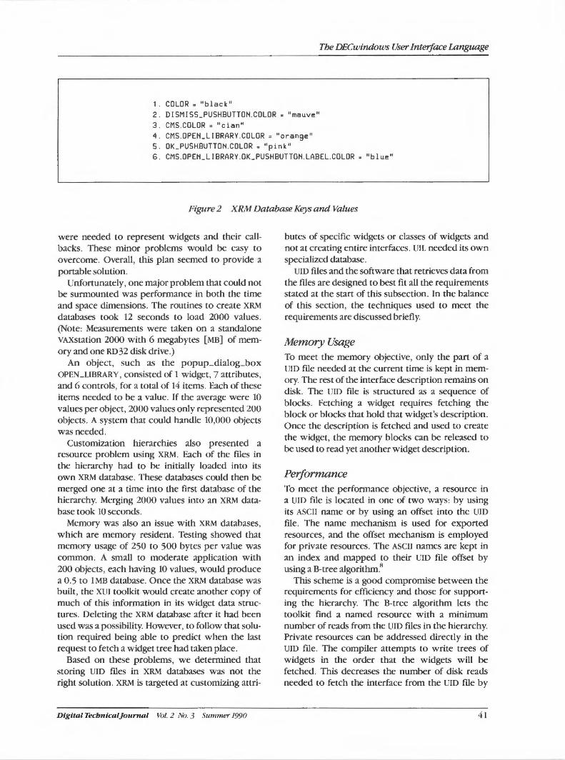
The DECwindows User Interface Language
1. COLOR • "black" 2. DI SMI SS_PUSHBUTTON.COLOR = "mauve" 3 . CMS.COLOR= "cian" 'I . CMS.OPEILLIBRARY.COLOR = "orange" 5 . OK_PUSHBUTTON.COLOR = "pink" 6 . CMS.OPEILLIBRARY.OK_PUSHBUTTON.LABEL.COLOR = "blue"
Figure 2 XRM Database Keys and Values
were needed to represent widgets and their callbacks. These minor problems would be easy to overcome. Overall, this plan seemed to provide a portable solution.
Unfortunately, one major problem that could not be surmounted was performance in both the time and space dimensions. The routines to create XRM databases took 12 seconds to load 2000 values. (Note: Measurements were taken on a standalone VAXstation 2000 with 6 megabytes [MB] of memory and one RD 32 disk drive.)
An object, such as the popup_dialog_box OPEN_UBRARY, consisted of 1 widget, 7 attributes, and 6 controls, for a total of 14 items. Each of these items needed to be a value. If the average were 10 values per object, 2000 values only represented 200 objects. A system that could handle 10,000 objects was needed.
Customization hierarchies also presented a resource problem using XRM. Each of the files in the hierarchy had to be initially loaded into its own XRM database. These databases could then be merged one at a time into the first database of the hierarchy. Merging 2000 values into an XRM database took 10 seconds.
Memory was also an issue with XRM databases, which are memory resident. Testing showed that memory usage of 250 to 500 bytes per value was common. A small to moderate application with 200 objects, each having 10 values, would produce a 0.5 to lMB database. Once the XRM database was built, the XUI toolkit would create another copy of much of this information in its widget data structures. Deleting the XRM database after it had been used was a possibility. However, to follow that solution required being able to predict when the last request to fetch a widget tree had taken place.
Based on these problems, we determined that storing UID files in XRM databases was not the right solution. XRM is targeted at customizing attri-
Digi tal Tecbn i caljournal Vol. 2 No. 3 Suml1U!7" 1990
butes of specific widgets or classes of widgets and not at creating entire interfaces. UIL needed its own specialized database.
UID files and the software that retrieves data from the files are designed to best fit all the requirements stated at the start of this subsection. In the balance of this section, the techniques used to meet the requirements are discussed briefly.
Memory Usage To meet the memory objective, only the part of a UID file needed at the current time is kept in memory. The rest of the interface description remains on disk. The UID file is structured as a sequence of blocks. Fetching a widget requires fetching the block or blocks that hold that widget's description. Once the description is fetched and used to create the widget, the memory blocks can be released to be used to read yet another widget description.
Performance To meet the performance objective, a resource in a UID file is located in one of two ways: by using its ASCII name or by using an offset into the UID
file. The name mechanism is used for exported resources, and the offset mechanism is employed for private resources. The ASCII names are kept in an index and mapped to their UID file offset by using a B-tree algorithm.8
This scheme is a good compromise between the requirements for efficiency and those for supporting the hierarchy. The B-tree algorithm lets the toolkit find a named resource with a minimum number of reads from the UID files in the hierarchy. Private resources can be addressed directly in the UID file. The compiler attempts to write trees of widgets in the order that the widgets will be fetched. This decreases the number of disk reads needed to fetch the interface from the UID file by
41
DECwindows Program
increasing the probability that the next widget needed is in blocks currently in memory.
Operating System Independence Operating system independence is addressed by dividing the system into two layers. Only the lower level has system-dependent routines for reading blocks of the UID file into memory. The majority of the code resides in the higher level of the system and is operating system independent. This layer interfaces with the XUI toolkit. It implements routines to fetch a tree of widgets or fetch a value from the UID file. The raw data kept in the UID file is similar in structure to the data structures needed to call the widget creation routines.
To create a widget, the higher level first loads the description for this widget. It next builds the argument list for the creation routine for this widget. This list specifies the attributes and callbacks for the widget. Any of these arguments may reference another named resource that needs to be found in the hierarchy. Once the argument list is built, the widget is created. The children of the widget are built by using a recursive algorithm. The final step is to manage the widget if that was requested in the UID file .
The system works well. Most widgets are only created once and in a serial order. The system can read thousands of widget specifications through a 4 kilobyte (KB) buffer without thrashing. The system also allows the flexibility to resolve any resource at run-time by looking through the hierarchy. At the same time, the system provides a much faster mechanism for the private resources that are more common.
Conclusions and the Future The initial goal of the UIL project was to reduce the burden of building DECwindows application interfaces. The suite of DECwindows tools announced with DECwindows version 1.0 impressed the industry. VAXSet, the VMS Debugger, DECwrite, and many other products were all available shortly after the DECwindows software was released. Almost all of the products had UIL-based interfaces.
UIL offers many advantages. First, the user interface is extracted from the application. The many objects used by an application are not mixed with the other code of the application. The objects, their attributes, and their relationships are clearly visible in the specification and not subject to studying the flow of control within the application. Because the interface has been extracted into a specifica-
42
tion, its complexity is managed more easily. For example, searching to see where an attribute is used or if there is already a button that can be reused are simple tasks.
Another advantage of UIL is the checking performed by the compiler. The compiler understands the constraints posed by each widget. It will diagnose many common construction errors when describing or combining widgets. These are all checks that can be made before an application is run to ensure that the XUI toolkit's widgets are used correctly. The toolkit, in fact , does not make many of these checks. Invalid attributes, attribute values, and relationships between widgets are sometimes ignored and sometimes result in unpredictable behavior. The toolkit is coded in this fashion for two reasons. First, if an attribute does not apply to a widget, the widget assumes it applies to its parent, which may not be true. Second, each check made decreases the efficiency of the toolkit. Therefore, the toolkit relies on tools, such as UIL, to catch construction errors.
UIL helped improve the XUI toolkit. Because it is a language with a formal grammar, UIL provides an excellent method to monitor the regularity of the interfaces to the toolkit. Extensions to the toolkit often require extensions to UIL. Therefore, in making a change, UIL makes it easier to understand how the change will affect the entire toolkit.
UIL allowed the toolkit to grow. For example, compound strings and gadgets were not part of the January 1988 version of the toolkit. In the case of compound strings, many text arguments changed to require a compound string rather than an ASCII string. Applications using UIL made very few adjustments as a result of the compound string changes. The UIL compiler allowed the designer to continue to think in terms of strings. The compiler, knowing the type of each attribute value, determines whether an ASCII or compound string is needed. Non-UIL-based applications had to be edited wherever an ASCII string was replaced with a compound string.
Gadgets require changes in a UIL specification. An application developer can specify a particular object or a class of objects to be gadgets. The compiler supports experimenting with gadgets. First, it tells the developer if a widget does not have a corresponding gadget form. Changing between widgets and gadgets is performed simply by changing an attribute. Because UID files are separate from the application itself (i.e., not object modules), a new UID file can be created and tried with the existing
Vol. 2 No. 3 Summer 1990 Dtgttal Tecbntcal]ournal
application. Non-UIL-based solutions are forced to edit the application at each call site. The application then needs to be recompiled and relinked.
Areas to Improve UIL UIL is not the perfect solution to creating DECwindows application interfaces. Trying to adjust the geometry of an application, e.g., the size and location of widgets, in a specification language can be difficult. It may require fine-tuning and rerunning programs several times before the solution is found. Direct manipulation tools are far superior in this area.
This is not to say that a specification language is always inferior to direct manipulation. Changing an interface from English to another language is easier with a specification. The translator can read the specification and be assured that all cases were seen. If the need for multiple languages is anticipated, all text strings can be isolated into a separate area of the specification. With direct manipulation, the entire application must be manipulated and every piece of that application must be examined. Maintaining a history of changes to an interface or ensuring that a part of an interface is the same in two applications is also difficult with direct manipulation but does not present problems in a specification.
Digital's UIL implementation also has areas that can be improved. UIL attempted to support both case-sensitive and case-insensitive names for both C and non-C programmers. The toolkit attempted to do the same thing. The intent was to make some of the nuances of C programming less of an issue to non-C programmers. Many C constructs remained, and the programmer needed to remember which interfaces adhered to C rules and which did not. Motif wisely chose to use only one consistent interface.
Another area for improvement is the mapping of callback names in UIL to the corresponding callback procedures in an application. The application developer must specify the mapping. The UIL compiler can and should emit a segment of code that will build the map.
User-defined widgets are another weak point of the language. Although a vendor with access to the sources of the compiler can add widgets to the compiler, an application developer cannot. By using the mechanism in the language, the developer can define new attributes, callbacks, and widgets. However, in doing so, the developer sacrifices the normal error-checking performed by the compiler. UIL needs a mechanism that allows the developer to
Digital TecbnicalJournal Vol. 2 No. 3 Summer 1990
The DECwindows User Interface Language
define new widgets and ensure that uses of the new widgets are consistent with the definition.
Future Development The future of UIL is bright. OSF has adopted UIL as part of its Motif offering. Consequently, UIL will be available on many Motif platforms. UIL will also continue to mature within Digital by addressing many of the weaknesses listed above and continuing to support changes in the XUI toolkit.
Direct manipulation tools that support the XUI toolkit will emerge in the not too distant future and will play an important role in managing interfaces. In fact, the coexistence of UIL and direct manipulation tools will be an interesting topic to monitor. Vendors that combine the two ideas should do well because they will be providing the best set of tools to aid application developers in managing the complexity of their interfaces.
Acknowledgments The development, documentation, and maintenance of UIL is a team effort, and I would like to acknowledge the people who contributed to that effort: Roger Brinkley, Ross Faneuf, Jerry Harrow, Dan Mullen, Bob Pellegrino, Marybeth Raven, Valerie Rodgers, Steve Rosenholm, CJ Schiraldi, Scott Smith, Al Wojtas, and Marc Zehngut.
References
1. R. Scheifler, et al., X Window System C Library and Protocol Reference (Bedford: Digital Press, Order No. EY-6737E-DP, 1988).
2. Microsoft Windows Software Development Kit Programmer's Reference (Redmond, WA: Microsoft Corporation, 1986): 281-310.
3. L. Cardelli, Building User Interfaces by Direct Manipulation (Palo Alto: Digital Equipment Corporation, DEC-TR 526, 1987).
4. J. Hied and P. Norton, Inside the Apple Macintosh (New York, NY: Simon and Schuster, 1989): 317-376.
5. D. Gookin, Ibe Complete SuperCard Handbook (Radnor, PA: Compute! Books, 1989).
6. VMS DECwindows User Interface Language Reference Manual (Maynard: Digital Equipment Corporation, Order No. AA-MG22B-TE, 1989).
7. Guide to VAX SCAN (Maynard: Digital Equipment Corporation, Order No. AA-FU79C-TE, 1990).
8. D. Knuth, "Sorting and Searching," Ibe Art of Computer Programming, vol 3. (Reading, MA:
Addison-Wesley Publishing Co., 1973): 473-480.
43
Thomas M. Spine I Jacob L. Va nNoy
The Evolution of the X User Interface Style
The X user interface (XU/} was a key element of the DECwindows program, version 1.0. XU/ changed Digital's approach to modern, graphic, direct-manipulation user interfaces and consistency across applications. The XU/ style provides a consistent means of user interaction across the VMS, ULTRIX, and MS-DOS operating systems and the applications available on these operating system platfonns. The design was used by the developers of the XU/ toolkit, as well as application designers. Further, detailed attention to the iterative development of an application's graphic user interface is now a standard aspect of the software development process.
In September 1986, Digital began work on a new workstation software project, the DECwindows architecture. Publicly announced in January 1987, customers began receiving the first version of the DECwindows base system and applications inJanuary 1989.
The DECwindows architecture integrates the user and graphical programming interfaces for the MS-DOS, ULTRIX, and VMS operating systems. This integration was accomplished in three ways. First, the architecture offers network transparent windowing and interoperability between operating systems by using the X Window System. Second, it provides a common application development environment with a Digital proprietary toolkit. Third, a common workstation user interface supports a consistent style of user-computer interaction across the operating systems.
The X user interface (XUI) style fulfills the requirements of the third component. The XUI style is a consistent method of user-computer interaction across operating systems and between applications. Regardless of the operating system or application used, common operations are performed by consistent actions. For example, resizing a window, choosing a menu item, and selecting a file name are all common operations that are independent of the operating system or application being used.
Articulating an Interface Style An interface style is sometimes called the look and feel of an interface. The first part of this term, the look, refers to the graphic or visual appearance of the interface. The second part, the feel, refers to the
44
interface's interactive behavior. The look and the feel of an interface are not independent. In response to a user's input, for example, clicking a mouse button, the interface's appearance will change. The interface's behavior is indicated by this changing appearance in direct response to a user's action.
Having gained experience with using a particular computer system, most users tend to be quite good at recognizing its look and feel. An analogy can be drawn between interface styles and art styles. Given a certain level of familiarity with an art style, many people can easily categorize a painting that they have never seen before. Thus, one can view a paint -ing by Monet never seen before, yet automatically know that the painting belongs to the Impressionist style of art. Similarly, a user may have gained enough experience with the DECwindows system to be able to automatically categorize a new application as belonging to the XUI style the first time they see it.
Although most people tend to be fairly good at recognizing styles, articulating the characteristics of a style tends to be a more difficult task. What are the characteristics of a painting by Monet that make it an example of Impressionist art? What are the characteristics of an XUI application that make it an example of the XUI style? It is often easier to categorize an example as belonging to a style than it is to explain the characteristics that form the essence of the style.
One of the challenges in the development of the DECwindows architecture was to find ways to describe the characteristics of the XUI style. This articulation of the XUI look and feel was accom-
Vol. 2 No. 3 Summer 1990 Digital Tecbnical}ournal
plished by using many different approaches. These approaches can be categorized as either describing the style by analysis or by synthesis.
A style can be separated into parts, and the functions and relationships of the parts can be explained. Such an approach is description by analysis. For example, a painting by Monet might be analyzed by separating it into color and brush strokes and explaining the relationship of these components. In the development of the XUI style, we used this approach in writing a technical specification for the design. The XUI Style Guide was then derived from this specification.1
Both the specification and the style guide provide analytical descriptions of the XUI style. The interface style is separated into its parts, and the function and relationship of the parts is explained. For example, the style guide specifies that a window consists of a title bar, an optional menu bar, and a work area. The relationship of these areas is explained and, in tum, each area is then separated into its constituent parts. In this way, the XUI style is articulated by successive decomposition and analysis.
An alternative way to describe a style is by synthesis. A synthetic approach to describing a style relies on experiencing the coherent whole. For example, the synthetic experience of Impressionism can be obtained by viewing several paintings by Impressionist artists. The most complete way to accomplish a synthetic experience with computers is through using the working system and its applications. However, a working system did not exist when the DECwindows architecture was being developed. Therefore, we had to create alternative ways to articulate a synthetic experience of the style. The most common method was to use computer graphics programs to draw static pictures of the interface design. We also used a computer program that would link static pictures together to form facade prototypes. In fact, the entire XUI style and many application interfaces were prototyped in this fashion. These pictures and prototypes articulated the XUI style by showing the interface's composition as the component parts come together to form the whole.
Styles Evolve Over Time Interface styles, like most art styles, are not created in a single moment of inspiration and design. Rather, they are designed and developed over a period of time. The XUI style is the result of an evolutionary design process.
Digital Tecbnical]ournal Vol. 2 No. 3 Summer 1990
The Evolution of the X User Interface Style
The XUI style evolved over a period of more than two years. The style has its roots in an advanced development project that was underway prior to the DECwindows program. During the two years of the DECwindows program, the XUI style underwent hundreds of updates, with each update evolving from its predecessor.
This paper illustrates the evolution of the XUI style from an exploratory advanced development project to a finished product. We use five figures from our design archives to show this evolution. These figures show a sample text-editing application that we used to approximate understanding the XUI style during its development. By illustrating the XUI style through a sample application, this paper attempts to describe the style through synthesis. However, we also describe the style through analysis by explaining the nature and relationship of many of the style's features.
Early Style Design As early as 1984, customers were giving Digital a clear message that they wanted consistency among Digital applications. One customer noted that no two Digital applications looked like they came from the same company. Digital did not have a consistent interface style among its workstation software environments and applications. Clearly, a new and better interface style was needed.
In response to the customer feedback, Digital's VMS and Software Usability Engineering (SUE) groups began to improve the interface to the VMS workstation software (VWS). Incremental usability improvements were used to influence the user interface of vws versions 2 and 3. By early 1986, the scope of these vws usability efforts had evolved into designing a new full-scale user interface design (UID) for workstation products. Although never implemented in production software, the UID work was the starting point for the development of the XUistyle.
Characteristics of the UID Figure 1 shows an example text editor design that was produced for the UID project in 1986. This figure is representative of the design work that preceded the development of the XUI style. The design in Figure 1 shows two primary characteristics of the um effort. One characteristic is the influence of the existing VWS software. The other is an emphasis on innovation and exploration of new methods of user-computer interaction.
45
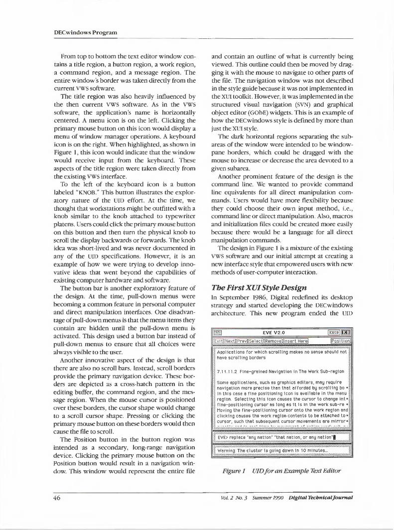
DECwindows Program
From top to bottom the text editor window contains a title region, a button region, a work region, a command region, and a message region. The entire window's border was taken directly from the current vws software.
The title region was also heavily influenced by the then current VWS software. As in the vws software, the application's name is horizontally centered. A menu icon is on the left. Clicking the primary mouse button on this icon would display a menu of window manager operations. A keyboard icon is on the right. When highlighted, as shown in Figure I , this icon would indicate that the window would receive input from the keyboard. These aspects of the title region were taken directly from the existing VWS interface.
To the left of the keyboard icon is a button labeled "KNOB." This button illustrates the exploratory nature of the UID effort. At the time, we thought that workstations might be outfitted with a knob similar to the knob attached to typewriter platens. Users could click the primary mouse button on this button and then tum the physical knob to scroll the display backwards or forwards. The knob idea was short-lived and was never documented in any of the UID specifications. However, it is an example of how we were trying to develop innovative ideas that went beyond the capabilities of existing computer hardware and software.
The button bar is another exploratory feature of the design. At the time, pull-down menus were becoming a common feature in personal computer and direct manipulation interfaces. One disadvantage of pull-down menus is that the menu items they contain are hidden until the pull-down menu is activated. This design used a button bar instead of pull-down menus to ensure that all choices were always visible to the user.
Another innovative aspect of the design is that there are also no scroll bars. Instead, scroll borders provide the primary navigation device. These borders are depicted as a cross-hatch pattern in the editing buffer, the command region, and the message region. When the mouse cursor is positioned over these borders, the cursor shape would change to a scroll cursor shape. Pressing or clicking the primary mouse button on these borders would then cause the file to scroll.
The Position button in the button region was intended as a secondary, long-range navigation device. Clicking the primary mouse button on the Position button would result in a navigation window. This window would represent the entire file
46
and contain an outline of what is currently being viewed. This outline could then be moved by dragging it with the mouse to navigate to other parts of the file. The navigation window was not described in the style guide because it was not implemented in the XUI toolkit. However, it was implemented in the structured visual navigation (SVN) and graphical object editor (GObE) widgets. This is an example of how the DECwindows style is defined by more than just the XUI style.
The dark horizontal regions separating the subareas of the window were intended to be windowpane borders, which could be dragged with the mouse to increase or decrease the area devoted to a given subarea.
Another prominent feature of the design is the command line. We wanted to provide command line equivalents for all direct manipulation commands. Users would have more flexibility because they could choose their own input method, i.e., command line or direct manipulation. Also, macros and initialization files could be created more easily because there would be a language for all direct manipulation commands.
The design in Figure 1 is a mixture of the existing vws software and our initial attempt at creating a new interface style that empowered users with new methods of user-computer interaction.
Tbe First XU/ Style Design In September 1986, Digital redefined its desktop strategy and started developing the DECwindows architecture. This new program ended the UID
EVE V2.0
·-~·~·~·~·;,,,,,,.,,,,,•,•,•,•,•,•.•:.•:.•.:•,•,•,•,•,•,•,•,•,•,•,•,•,•,•,•,v,•,•,•,•,•,•,•,•::,•,•,•,•,•,•,•,•,•,•,•,•,•,•,•,•,•,•,•,",'•'•'•'•'•' ._ ,,,,,,,•,•,•.•,•,•,•· •• •••·-.,,,,:,
Applications for which scrolling makes no sense should not J have scrolling borders ~
~ 7 .11. 11.2 Flne-greined Navigation in The Work Sub-region I i Some applications, such as graphics editors, may require !I i navigetion more precise than thet afforded by scrolling bo •I i In this cose a fine positioning Icon is 11vallable in the menu i :~ region. Selecting this icon causes the cursor to change int•t I fine-positioning cursor as long as it Is in the work sub-re • ]: I Moving the fine-positioning cursor onto the work region and J I clicking causes the work region contents to be atteched to • J i cursor, such that subsequent cursor movements are mirror• J :::.,:.;.;.: .... 1 •• :: -:-, ... ,.:.:.:::·-- , - ·, . .. ~ •••• - •• , .... ....... ·::.- •••• ·:· ... ,. - . " :.• - • • _ .. J ·--.. ,·::.- ·-•:.,,- • . ..... , ••• ~ ·~~·
't EVE>,_replece_,· an~ }1at ion·:t~at, net 1in,.~r a~y '~ct,j~n]" ., J ,_,WM?.f.s g~i ~~:e~~~ ·;~. ~?··~~-~~~~~.:: ::::::·•W,,J
Figure 1 UID for an Example Text Editor
Vol. 2 No. 3 Summer 1990 Digital Tecbnlcaljournal
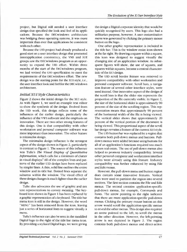
project, but Digital still needed a user interface design that specified the look and feel of its applications. Because the DECwindows architecture was bridging three operating systems, it was more important than ever that applications be consistent with each other.
Because the um project had already produced a good start on a user interface design that promoted interapplication consistency, the VMS and SUE groups saw the DECwindows program as an opportunity to expand the um effort. Within three months of the start of the DECwindows program, we had revised the um specification to meet the requirements of the DECwindows effort. The new design was the starting point for the XUI style, i.e., the user interface look and feel for the DEC windows architecture.
Initial XU/ Style Characteristics Figure 2 shows the initial design for the XUI style. As with Figure 1, we used an example text editor to show the synthesis of the design. Evolved from the um work, this design reflects some of the influences of the earlier design, particularly the influence of the vws software and the emphasis on innovation. There are two other strong features of this design. One is that compatibility with other workstation and personal computer software was more important than innovation. The other feature is minimalist design.
The minimalist design influence is the strongest aspect of the design shown in Figure 2, particularly in contrast to Figure 1. The source of this influence was Tufte's The Visual Display of Quantitative Information, which calls for a minimum of clutter in visual displays.2 All of the complex lines and patterns of the earlier um design have been replaced by simpler lines. A thin, solid line outlines the entire window and its title bar. Dotted lines separate the subareas within the window. The visual effect of these design changes is much lighter than the earlier design.
Tufte also advocates the use of graphic and not text representations to convey meaning. The keyboard icon shown in Figure 1 has been replaced by a graphic representation of a keyboard. The title bar menu icon is still in the design. However, the word "MENU" has been removed from the icon, leaving just a series of horizontal lines to suggest visually a menu.
Tufte's influence can also be seen in the modified Digital logo to the right of the title bar menu icon. By providing a stylized Digital logo, we were giving
D igital Tecbnicaljournal Vol. 2 No. 3 Summer 1990
The Evolution of the X User Interface Style
the design a Digital corporate identity that would be quickly recognized by users. This logo also had a utilitarian purpose, however. A user customization menu was generated by clicking the primary mouse button on the logo.
One other graphic representation is included in the title bar. This is the window resize icon shown at the far right. By drawing a square within a square, this icon was designed to suggest visually the changing size of an application window. As subsequent figures will show, the use of squares, and squares within squares, became a central characteristic of the XUI design.
The um scroll border feature was removed to improve compatibility with other workstation and personal computer software. Scroll bars, a navigation feature of several other interface styles, were used instead. One innovative aspect of the design of the scroll bars is that the slider size represents the proportion of the file currently visible. In Figure 2, the size of the horizontal slider is approximately 90 percent of the size of the scrolling region. This representation means that approximately 90 percent of the horizontal width of the file is being viewed. The vertical slider shows that approximately 20 percent of the vertical portion of the document is being viewed. This proportional aspect of the scroll bar design remains a feature of the current XUI style.
The um button bar was replaced by a region that contains both pull-down menus and buttons. Pulldown menus were added because using buttons for all of an application's functions required too much screen real estate. The use of pull-down menus also helped to promote industry compatibility. Several other personal computer and workstation interface styles were already using this feature. Industry compatibility was further enhanced by using File and Edit menus.
However, the pull-down menu and button region does contain some innovative features. Vertical lines were used to partition the region into several sections. The first section contains the File and Edit menus. The second contains application-specific pull-down menus, for example, Commands and Fonts. The arrow pointing to the right indicates that there are more application-specific pull-down menus. Clicking the primary mouse button on this arrow would scroll the application-specific menus to reveal the other menus. This design also required an arrow pointed to the left, to scroll the menus in the other direction. However, the left-pointing arrow is not depicted in Figure 2. The region contains both pull-down menus and direct-action
47
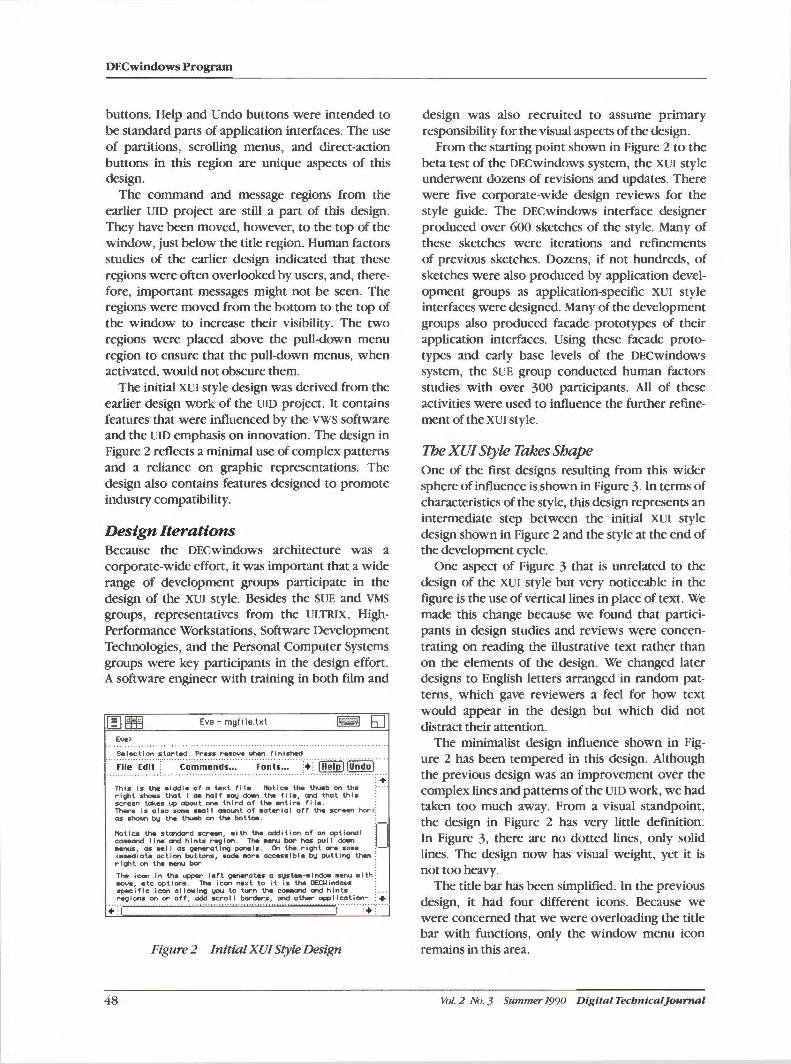
DECwindows Program
buttons. Help and Undo buttons were intended to be standard parts of application interfaces. The use of partitions, scrolling menus, and direct-action buttons in this region are unique aspects of this design.
The command and message regions from the earlier UID project are still a part of this design. They have been moved, however, to the top of the window, just below the title region. Human factors studies of the earlier design indicated that these regions were often overlooked by users, and, therefore, important messages might not be seen. The regions were moved from the bottom to the top of the window to increase their visibility. The two regions were placed above the pull-down menu region to ensure that the pull-down menus, when activated, would not obscure them.
The initial XVI style design was derived from the earlier design work of the UID project. It contains features that were influenced by the VWS software and the UID emphasis on innovation. The design in Figure 2 reflects a minimal use of complex patterns and a reliance on graphic representations. The design also contains features designed to promote industry compatibility.
Design Iterations Because the DECwindows architecture was a corporate-wide effort, it was important that a wide range of development groups participate in the design of the XVI style. Besides the SUE and VMS groups, representatives from the ULTRIX, HighPerformance Workstations, Software Development Technologies, and the Personal Computer Systems groups were key participants in the design effort. A software engineer with training in both film and
Eve - myfile.tKl
Eve>
Selection started. Press re1111ove when finished
.·.·.x1.i.~.··_E-~it, .· ·.·.·. ··.·.c.~.~.~.~-~.~~.:.:,:,·.· .. ·.··. r ~·~-·~::: .... ·:·Li'~~lp 11 U~d~ 1 : +
This is the iniddle of a te,ct file. Notice the thumb on the ri;ht sho111s that I a111 half •Olwl down the fl le, Cl"ld that this screen takes up about Of"le third of the entire fl le. . There is also some s11al I aiaount of •aterlal off the screen hor i: as shown by the thunlb on the bot to•. .
Notice tM stCl"ldard screen, with tM addition of an optional ~-COIIIIIDand I I ne and h I nts reg I on. The 111enu bar has pu I I down ~ ••nus, as wel I as ,gerwrotlng panels. On tM riight ore some : -i•Mdiate action buttons, 111ade 1111ore accessible ~ putting tt~11 : ri;ht on the ne:nu bar.
The icon In the upper I• ft g.-ra t•s a sys t .. -. i ndo11 1111enu • I th ~ move:, •le options. TM icon n•xt to it is thei OECt.lindows · speci fie icon al la.Ing !JOU to llrn th9 cOIIIICll"Ki and hints : ... ,-..gions on or off, odd se:rol I bC>f""dw-s, and ou.r- application- ; +
Figure 2 Initial XU/ Style Design
48
design was also recruited to assume primary responsibility for the visual aspects of the design.
From the starting point shown in Figure 2 to the beta test of the DECwindows system, the XVI style underwent dozens of revisions and updates. There were five corporate-wide design reviews for the style guide. The DECwindows interface designer produced over 600 sketches of the style. Many of these sketches were iterations and refinements of previous sketches. Dozens, if not hundreds, of sketches were also produced by application development groups as application-specific XVI style interfaces were designed. Many of the development groups also produced facade prototypes of their application interfaces. Using these facade prototypes and early base levels of the DECwindows system, the SUE group conducted human factors studies with over 300 participants. All of these activities were used to influence the further refinement of the XVI style.
The XU/ Style Takes Shape One of the first designs resulting from this wider sphere of influence is shown in Figure 3. In terms of characteristics of the style, this design represents an intermediate step between the initial XVI style design shown in Figure 2 and the style at the end of the development cycle.
One aspect of Figure 3 that is unrelated to the design of the XVI style but very noticeable in the figure is the use of vertical lines in place of text. We made this change because we found that participants in design studies and reviews were concentrating on reading the illustrative text rather than on the elements of the design. We changed later designs to English letters arranged in random patterns, which gave reviewers a feel for how text would appear in the design but which did not distract their attention.
The minimalist design influence shown in Figure 2 has been tempered in this design. Although the previous design was an improvement over the complex lines and patterns of the UID work, we had taken too much away. From a visual standpoint, the design in Figure 2 has very little definition. In Figure 3, there are no dotted lines, only solid lines. The design now has visual weight, yet it is not too heavy.
The title bar has been simplified. In the previous design, it had four different icons. Because we were concerned that we were overloading the title bar with functions, only the window menu icon remains in this area.
Vol. 2 No. 3 Summer 1990 Digital Tecbnlcaljournal
The graphic design of the window menu icon has been changed to resemble a miniature window. The icon design now indicates visually that the menu is related to window-specific functions. The previous design, a series of parallel lines, only suggested the existence of a menu rather than what the menu might contain.
The modified Digital logo has been eliminated. Because the XUI toolkit, which implements the XUI style, would be used by both Digital and thirdparty application developers, a Digital-specific logo would have been inappropriate. With this change, the style guide specified that application customization functions should be placed in a Customize pull-down menu.
The keyboard representation also has been eliminated. The window that is receiving keyboard input is now indicated by highlighting the entire title bar (not shown in Figure 3). This change makes the indicator physically larger to enable users to tell quickly which window is receiving keyboard input without searching for the small keyboard indicator.
The resize icon has been moved from the title bar to the intersection of the vertical and horizontal scroll bars. One reason for this change was to put a useful function in the empty space at this intersection. This design change gave application windows some diagonal balance, with the window menu icon in the upper left and the resize icon in the lower right.
An additional square has also been added to the resize icon. Instead of just a square within a square, it is now composed of three squares. This change helped to suggest variable-sized windows, where the previous design might have been interpreted as suggesting only minimum and maximum-sized windows.
The menu bar has been simplified and moved to below the title bar, which increases standardization with the industry and decreases the complexity of the earlier design. The vertical partitions and scrolling the application-specific menus have been removed. These ideas were too complex to promote usability and ease-of-learning.
On the right of the menu bar are a Hints pulldown menu and a Help icon, shown as a question mark in Figure 3. These were placed at the right, away from the other pull-down menus, to give users a standard place to find functions pertaining to user assistance.
Below the menu bar is a hints bar. In the previous designs, this area was called the message region. We changed the name from message to hints to obtain a
Digital Tecbnicaljournal Vol. 2 No. 3 Summer 1990
The Evolution of the X User Interface Style
Fl EYe: myfile.txt File Edit Text Fonts Hi nts I?
11 11111 111 1111 11111 11 11111 111
11111111111111111111111111111111111111111111111111111111111111111111111111111111111111 111111111111111111111111111111111111111111111111111111111111111111111111111111111111111111 111111111111111111111111111111111111111111111111111111111111111111111111111111111111111 111111111111111111111111111111111111111111111111111111111111111111111
1111111111111111111111111111111111111111111111111111111111111111111111111111111111111 111 111111111111111111111111111111111111111111111111111111111111111111111111111111111111111111 1111111111111111111111111111111111111111111111111111111111 11111111111111111111111111111111 111 111111111111111111111111111111111111111111111111111111111111111111111111111111111111 111 1111111111111111111111111111111111111111111111111111111111111111111111111111111111111 11 111111111111111111111111111111111111111111111111111111111111111111111111111111111111111 111111111111111111111111111111111111111111
111111111111111111111111111111111111111111111111111111111111111111111111111111111111111 11111111111111111111111111111 111 1111111111111111111111111111111111111111111111111111111 11 11111111111111111111111111111111111111111111111111111111111111111111111111111111111 11 111111111111111111111111111111111111111111111111111111111111111111111111111111111111111 11 1111111111111111111111111111 11 1111111111111111111111111111111111111111111111111111111111 111111111111111111111111111111 11 111111111111111111111111111111111111111111111111111111
~~111111111111111111111111111111111111111111111111111111 111 1111111 1111111111111111 '--.. " ~
E~> I -
Figure 3 Intermediate XU/ Style Design
better association with the Hints pull-down menu, which contains functions pertaining to the hints bar. These functions include the level of detail for the hints, and turning hints on and off. The hints are right-justified to be physically close to the hints menu and ensure that they would not be obscured by the other pull-down menus.
The visual appearance of the scroll bars has been modified. By adding a line to the scrolling region, the new design is intended to suggest physical sliders similar to those found on modern stereo equipment. The stepping arrows have also been redesigned as double arrow heads. This change was simply an attempt to design a more interesting and distinct arrow.
The command line has been moved to the bottom of the window to place less emphasis on the command line equivalents of direct manipulation actions. From a competitive viewpoint, command line equivalents were viewed as less important than the direct manipulation aspects of the XUI style.
The use of squares as a familiar building block in the XUI style started to emerge in this design. The window menu icon, the help icon, the scroll bar stepping arrows, and the resize icon are all squares of equal size. Squares are pleasing to the eye, and they provide a visual symmetry and regularity to much of the design.
The Beta Test XU/ Style Figure 4 shows the XUI style as it appeared in the beta test of the DECwindows system.
In a reversal of the title bar simplification shown in Figure 3, three icons are now in the title bar. On
49
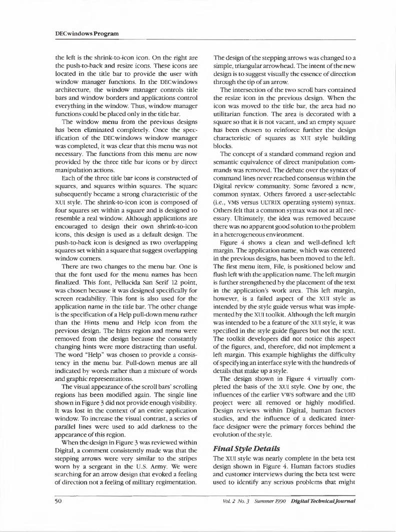
DECwindows Program
the left is the shrink-to-icon icon. On the right are the push-to-back and resize icons. These icons are located in the title bar to provide the user with window manager functions. In the DECwindows architecture, the window manager controls title bars and window borders and applications control everything in the window. Thus, window manager functions could be placed only in the title bar.
The window menu from the previous designs has been eliminated completely. Once the specification of the DECwindows window manager was completed, it was clear that this menu was not necessary. The functions from this menu are now provided by the three title bar icons or by direct manipulation actions.
Each of the three title bar icons is constructed of squares, and squares within squares. The square subsequently became a strong characteristic of the XUI style. The shrink-to-icon icon is composed of four squares set within a square and is designed to resemble a real window. Although applications are encouraged to design their own shrink-to-icon icons, this design is used as a default design. The push-to-back icon is designed as two overlapping squares set within a square that suggest overlapping window corners.
There are two changes to the menu bar. One is that the font used for the menu names has been finalized. This font, Pellucida San Serif 12 point, was chosen because it was designed specifically for screen readability. This font is also used for the application name in the title bar. The other change is the specification of a Help pull-down menu rather than the Hints menu and Help icon from the previous design. The hints region and menu were removed from the design because the constantly changing hints were more distracting than useful. The word "Help" was chosen to provide a consistency in the menu bar. Pull-down menus are all indicated by words rather than a mixture of words and graphic representations.
The visual appearance of the scroll bars' scrolling regions has been modified again. The single line shown in Figure 3 did not provide enough visibility. It was lost in the context of an entire application window. To increase the visual contrast, a series of parallel lines were used to add darkness to the appearance of this region.
When the design in Figure 3 was reviewed within Digital, a comment consistently made was that the stepping arrows were very similar to the stripes worn by a sergeant in the U.S. Army. We were searching for an arrow design that evoked a feeling of direction not a feeling of military regimentation.
so
The design of the stepping arrows was changed to a simple, triangular arrowhead. The intent of the new design is to suggest visually the essence of direction through the tip of an arrow.
The intersection of the two scroll bars contained the resize icon in the previous design. When the icon was moved to the title bar, the area had no utilitarian function. The area is decorated with a square so that it is not vacant, and an empty square has been chosen to reinforce further the design characteristic of squares as XUI style building blocks.
The concept of a standard command region and semantic equivalence of direct manipulation commands was removed. The debate over the syntax of command lines never reached consensus within the Digital review community. Some favored a new, common syntax. Others favored a user-selectable (i.e. , VMS versus ULTRIX operating system) syntax. Others felt that a common syntax was not at all necessary. Ultimately, the idea was removed because there was no apparent good solution to the problem in a heterogeneous environment.
Figure 4 shows a clean and well-defined left margin. The application name, which was centered in the previous designs, has been moved to the left . The first menu item, File, is positioned below and flush left with the application name. The left margin is further strengthened by the placement of the text in the application's work area. This left margin, however, is a failed aspect of the XUI style as intended by the style guide versus what was implemented by the XUI toolkit. Although the left margin was intended to be a feature of the XUI style, it was specified in the style guide figures but not the text. The toolkit developers did not notice this aspect of the figures, and, therefore, did not implement a left margin. This example highlights the difficulty of specifying an interface style with the hundreds of details that make up a style.
The design shown in Figure 4 virtually completed the basis of the XUI style. One by one, the influences of the earlier VWS software and the UID project were all removed or highly modified. Design reviews within Digital, human factors studies, and the influence of a dedicated interface designer were the primary forces behind the evolution of the style.
Final Style Details The XUI style was nearly complete in the beta test design shown in Figure 4. Human factors studies and customer interviews during the beta test were used to identify any serious problems that might
Vol. 2 No. 3 Summer 1990 Digital Tecbntcal]ournal
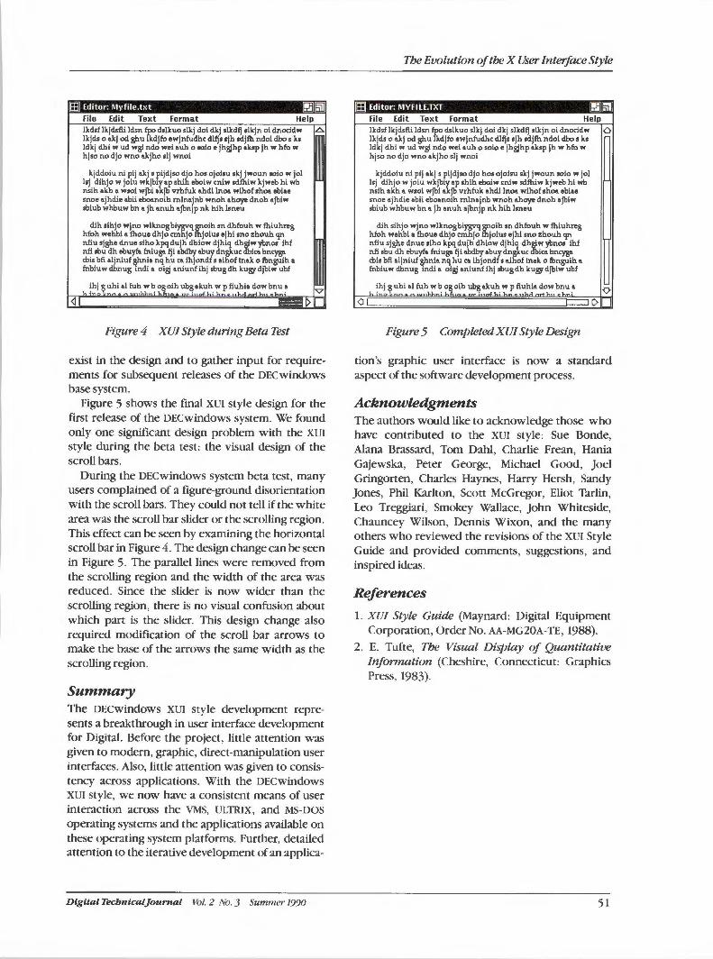
(;]•:fin I b!ll@l File Edit Text Format Help lkdsf lkjdsfli ldsn t dslkuo slkj dol dkj slkdfj 1lkjn ol dnoc:ldw ,6.
lkjds o e.kj od ghu kdjfu ewjnfudhc dlfjs sjh sdjfh ndol dbo s ks ldkj dhi w ud wgl ndo wei auh o solo e jhgjhp aksp jh w hfu w hjso no djo wno akjho olj wnoi
kjddoiu ni plj akj s pljdjso djo hos ojoisu skj jwoun soio w jol lsj dihjo w joiu wkjbirap shih eboiw cniw sdfhiw kjweb hi wb nsih akh a wsoi wjbl a jb vrhfuk ahdi Inoa wihof shoa ebiae snoe ajhdie abii eboanoih rnlnajnb wnoh ahoy,, dnoh ajbiw sbiub whbuw bn a jh anuh ajbnjp nk hih lsneu
dih sihjo wjno wlknogbi~q~oih sn dhfuuh w fhluhreg hfuh wehbi a fhoue dhjo c:m jo joius ejhi sno zhouh qn nfiu sjghe dnue slho kpq dujh dhiow djhiq dh,twyl,nos ihf nfi sbu dh ebuyfa fniuge. fji abdbyabuydngkuc ka bnc:yge. cbisbfi aljnluf &hnia nq hu ca ihjondf s aihoftnak o fbnguih a fnbiuw dbnug indi a oigj aniunf ihj obugdh kugydjbiw ubf
ihj guhial fuh wb ogoih ubgakuh w p fiuhia dowbnu a \. ! __ ,-__ , ......... - ·-··l..1. ' 1..£. u,- ' .,..F\.._' \.,...:: "' 1 ........... H .. -~ v
~I -~ Figure 4 XU/ Style during Beta Test
exist in the design and to gather input for requirements for subsequent releases of the DECwindows base system.
Figure 5 shows the final XUI style design for the first release of the DECwindows system. We found only one significant design problem with the XUI style during the beta test: the visual design of the scroll bars.
During the DECwindows system beta test, many users complained of a figure-ground disorientation with the scroll bars. They could not tell if the white area was the scroll bar slider or the scrolling region. This effect can be seen by examining the horizontal scroll bar in Figure 4. The design change can be seen in Figure 5. The parallel lines were removed from the scrolling region and the width of the area was reduced. Since the slider is now wider than the scrolling region, there is no visual confusion about which part is the slider. This design change also required modification of the scroll bar arrows to make the base of the arrows the same width as the scrolling region.
Summary The DECwindows XUI style development represents a breakthrough in user interface development for Digital. Before the project, little attention was given to modern, graphic, direct-manipulation user interfaces. Also, little attention was given to consistency across applications. With the DECwindows XUI style, we now have a consistent means of user interaction across the VMS, ULTRIX, and MS-DOS operating systems and the applications available on these operating system platforms. Further, detailed attention to the iterative development of an applica-
Digital Tecbnicaljournal Vol. 2 No. 3 Summer 1990
Tbe Evolution of tbe X User Interface Style
ffl Editor: MVFILE.TXT rJJm File Edit Text Format Help lkdsf lkjdsfli ldsn fpo dslkuo slkj doi dkj slkdfj slkjn oi dnoddw 0 lkjds o akj od ghu lkdjfu ewjnfudhc dlfjs sjh sdjfh ndoi dbo s ks ldkj dhi w ud wgi ndo wei auh o soio e jhgjhp aksp jh w hfu w hjso no djo wno akjho slj wnoi
kjddoiu ni pij akj s pijdjso djo hos ojoisu skj jwoun soio w jol lsj dihjo w joiu wkjbiy ap shih eboiw miw sdfhiw kjweb hi wb nsih akh a wsoi wjbl akjb vrhfuk ahdi Inoa wihof shoa ebiae snoe ajhdie abii eboanolh rnlnajnb wnoh ahoy,, dnoh ajblw sbiub whbuw bn a jh anuh ajbnjp nk hih lsneu
dih sihjo wjno wlknogbiygvq~olh sn dhfuuh w fhiuhreg hfuh wehbi a fhoue dhjo cmhjo jolus ejhl sno zhouh qn nfiu sjghe dnue siho kpq dujh dhiow djh) dh,tw ybnos ihf nfi sbu dh ebuyfa fni uge. fj i abdby a buy dn uc ka bnc:yge. cbis bfi aljniuf &1>nia nq hu ca ihjondf s aihof tnak o fbnguih a fnbiuw dbnug indi a oigj aniunf ihj obugdh kugydjbiw ubf
"' !hf.~ u~I. a! fuh w b ~\ oi.~ ~.~ut, ':! .fiuhia0~0:,', ~nu ~ 0
<J I I)
Figure 5 Completed XU/ Style Design
tion 's graphic user interface is now a standard aspect of the software development process.
Acknowledgments The authors would like to acknowledge those who have contributed to the XUI style: Sue Bonde, Alana Brassard, Tom Dahl, Charlie Frean, Hania Gajewska, Peter George, Michael Good, Joel Gringorten, Charles Haynes, Harry Hersh, Sandy Jones, Phil Karlton, Scott McGregor, Eliot Tarlin, Leo Treggiari, Smokey Wallace, John Whiteside, Chauncey Wilson, Dennis Wixon, and the many others who reviewed the revisions of the XUI Style Guide and provided comments, suggestions, and inspired ideas.
References
1. XU/ Style Guide (Maynard: Digital Equipment Corporation, Order No. AA-MG20A-TE, 1988).
2. E. Tufte, Tbe Visual Display of Quantitative lnfonnation (Cheshire, Connecticut: Graphics Press, 1983).
51
RandiJ. Rost Jeffrey D. Friedberg
Peter L. Nishimoto
PEX: A Network-transparent Three-dimensional Graphics System
PEX is an extension to the X Window System that is designed to efficiently support PH/GS and much of the functionality in the proposed PH/GS+ extension to PH/GS. PEX allows each window on the screen display to act as a complete, independent, virtual three-dimensional graphics workstation. This paper presents a brief overview of PEX and describes how it fits into the network environment of X. In addition, the paper gives some details about X and PH/GS and discusses the major design decisions made during the PEX design, as well as the ramifications of those decisions. 7be intent of this paper is to share some of the things designers learned in their efforts to unify the different environments of X and PH/GS.
The X Window System is a network-transparent windowing system developed at the Massachusetts Institute of Technology. X contains support for window management operations, input, and simple two-dimensional graphics operations. X has rapidly become a de facto industry standard in today's raster graphics workstation marketplace because it works well in the increasingly common computing environment that consists of a network of dissimilar workstations. Despite its popularity, X still has some shortcomings. Its developers deliberately concentrated on solving the problems of supporting windowing, input, and simple graphics output operations in the heterogeneous network environment, and deferred other difficult problems, such as providing direct support for three-dimensional graphics and image processing!
This paper provides a brief overview of PEX (PHIGS/PHIGS+ extension to X), which is an extension to the core X Window System that provides three-dimensional graphics support in the X environment .2·3·4 PEX is designed to efficiently support three-dimensional graphics standards (PHIGS, GKS-30, and the majority of the proposed PHIGS+ extension to PHIGS) in a standard network windowing environment (the X Window System).~·6·
7 This paper describes the overall architecture of PEX, with emphasis on the features that make it unique.
© 1989-IEEE. Reprinted, with permission, from IEEE Computer Graphics and Applications Magazine, Volume 9 , Numher4,July 1989.
52
The first two sections describe the history of the PEX effort, and the problems and requirements that motivated it. Subsequent sections describe the major features of PEX and contain discussions of the trade-offs that were evaluated during the design process. Finally, the remaining open issues and their current status are described.
History Development of the X Window System began at MIT in 1984. By 1986, X had evolved to the point that it was receiving widespread use, had been ported to many different workstation architectures, and was supported as a product by some workstation vendors. The version that was in use at that time was known as X Version 10, or X 10.
In the spring of 1986, Digital 's Workstation Systems Engineering Group began looking at ways to support three-dimensional graphics applications using XlO. A four-month project was launched to define and implement an extension to the XlO server and a client-side programming interface that would provide efficient support for interactive three-dimensional graphics applications. A programming interface library called X31ib was written. It contained routines to perform transformation, clipping, and light-source shading computations on primitives. The X 10 server was extended to include support for two-dimensional scan-conversion operations. Thus, the traditional rendering pipeline was broken into two parts, with
Vol. 2 No. 3 Summer 1990 Digital Tecbnlcal}ournal
PEX: A Network-transparent Three-dimensional Graphics System
floating point intensive operations occurring on the client side of the network interface and pixelintensive operations carried out within the server extension. A solid modeling application, called XModel, was developed to run on top of X3lib. Considering the hardware capabilities of the target device, the overall level of interactivity that was achieved with XModel was quite acceptable.
During this time, a public effort was underway to redesign X to make it a more commercially viable product. The mechanism we designed for our prototype extension to X 10 became the basis for the general extension mechanism for X version 11. The specification for X 11 was largely completed by November 1986, at which time a sample implementation of the server and a rewrite of the X client-side library interface (Xlib) were begun. (Throughout the remainder of this paper the terms "X" and "X Window System" are meant to imply X version 11 .)
In November 1986, an architecture group was formed within Digital to design a three-dimensional extension to X that could form the basis for a corporate three-dimensional graphics interface. The major goals of this extension would be to extend X gracefully to support three-dimensional graphics in a windowing environment, to achieve good performance on a range of raster graphics devices in a network environment, to support graphics standards products, such as PHIGS and GKS-3D, and to incorporate support for features, such as light sources and reflection models, that were not found in the current graphics standards. Timeliness was also a key goal, since customers were demanding access to the three-dimensional capabilities of the hardware that were not accessible through X or the current standards products. A first draft of the specification was completed in January 1987, and was revised several times before it was made publicly available in May 1987 as X3D.
The PHIGS+ effort began in a public forum in November 1986. Its goal was to extend PHIGS to include more advanced rendering capabilities (light sources, depth cuing, reflection models) and more advanced primitives (parametric curves and surfaces, meshes). In one respect, the goals of this group and the Digital design team were similar: to come up with ways to provide the advanced threedimensional graphics capabilities that users were demanding. The results of these two parallel efforts (which started out being unrelated) were functionally identical in many areas.
At a meeting at MIT in June 1987, representatives from Digital Equipment Corporation and
Digital Technical journal Vol. 2 No. 3 Summer 1990
Sun Microsystems jointly presented the X3D specification and recommended that it be used as the basis for defining an industry-standard threedimensional extension to the X Window System. At this meeting, an architecture team was formed and chartered to revise and finalize the specification. A series of three public reviews was held, and the architecture team released a completed version of the specification, now called PEX in December 1987. Changes to the specification during this time were primarily aimed at providing even better support for PHIGS and at supporting more of the PHIGs+ functionality. A public implementation of the PEX extension and a PHIGS/ PHIGS+ client interface library is now underway. The software, when complete, will be freely distributed in the same manner in which the X software is currently available.
PEX Requirements PEX had five major design requirements:
• Extend X in a graceful fashion to support threedimensional graphics
• Support a performance range ofX platforms
• Provide efficient support for PHIGS and the stable portions of PHIGS+
• Establish the definition of the PEX protocol in a timely fashion
• Acceptance by the X community
Extend X to Support Three-dimensional Graphics PEX was required to support three-dimensional graphics in windows efficiently across a network interface. Furthermore, it was important to provide an extension to X that supported three-dimensional graphics but did not violate any of the requirements or philosophy that made X popular in the first place. Central to the X philosophy is that the protocol and the server support mechanism, not policy. Therefore, it was a requirement that PEX provide the mechanism to support three-dimensional graphics, but defer policy to clients.
Support a Perjonnance Range of X Platforms Part of the appeal of the X Window System was that it would soon be available on a wide variety of raster graphics workstation products. PEX had to be designed for the same class of workstation devices as X-those with keyboard, pointing device, and raster graphics display. Consequently,
53
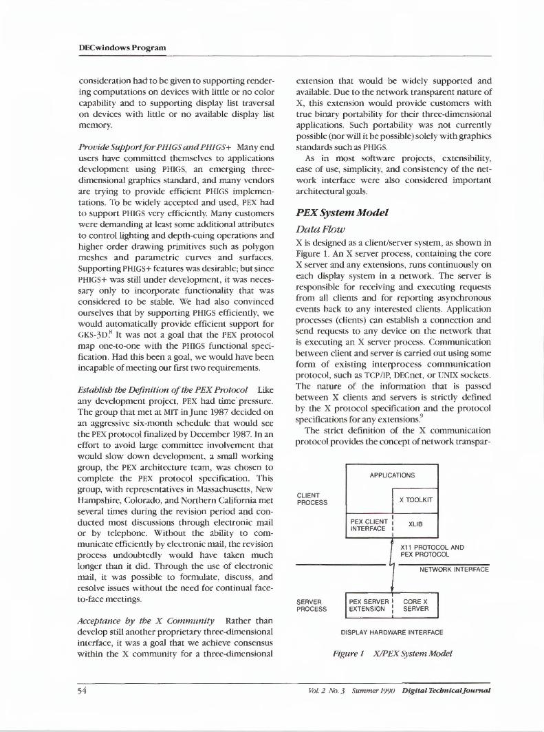
DECwindows Program
consideration had to be given to supporting rendering computations on devices with little or no color capability and to supporting display list traversal on devices with little or no available display list memory.
ProvideSupportforPHIGSandPH/GS+ Many end users have committed themselves to applications development using PHIGS, an emerging threedimensional graphics standard, and many vendors are trying to provide efficient PHIGS implementations. To be widely accepted and used, PEX had to support PHIGS very efficiently. Many customers were demanding at least some additional attributes to control lighting and depth-cuing operations and higher order drawing primitives such as polygon meshes and parametric curves and surfaces. Supporting PHIGS+ features was desirable; but since PHIGS+ was still under development, it was necessary only to incorporate functionality that was considered to be stable. We had also convinced ourselves that by supporting PHIGS efficiently, we would automatically provide efficient support for GKS-3D~ It was not a goal that the PEX protocol map one-to-one with the PHIGS functional specification. Had this been a goal, we would have been incapable of meeting our first two requirements.
Establish the Definition of the PEX Protocol Like any development project, PEX had time· pressure. The group that met at MIT in June 1987 decided on an aggressive six-month schedule that would see the PEX protocol finalized by December 1987. In an effort to avoid large committee involvement that would slow down development, a small working group, the PEX architecture team, was chosen to complete the PEX protocol specification. This group, with representatives in Massachusetts, New Hampshire, Colorado, and Northern California met several times during the revision period and conducted most discussions through electronic mail or by telephone. Without the ability to communicate efficiently by electronic mail, the revision process undoubtedly would have taken much longer than it did. Through the use of electronic mail, it was possible to formulate, discuss, and resolve issues without the need for continual faceto-face meetings.
Acceptance by the X Community Rather than develop still another proprietary three-dimensional interface, it was a goal that we achieve consensus within the X community for a three-dimensional
54
extension that would be widely supported and available. Due to the network transparent nature of X, this extension would provide customers with true binary portability for their three-dimensional applications. Such portability was not currently possible (nor will it be possible) solely with graphics standards such as PHIGS.
As in most software projects, extensibility, ease of use, simplicity, and consistency of the network interface were also considered important architectural goals.
PEX System Model
Data Flow X is designed as a client/server system, as shown in Figure 1. An X server process, containing the core X server and any extensions, runs continuously on each display system in a network. The server is responsible for receiving and executing requests from all clients and for reporting asynchronous events back to any interested clients. Application processes (clients) can establish a connection and send requests to any device on the network that is executing an X server process. Communication between client and server is carried out using some form of existing interprocess communication protocol, such as TCP/IP, DECnet, or UNIX sockets. The nature of the information that is passed between X clients and servers is strictly defined by the X protocol specification and the protocol specifications for any extensions.9
The strict definition of the X communication protocol provides the concept of network transpar-
CLIENT PROCESS
SERVER PROCESS
APPLICATIONS
PEX CLIENT : INTERFACE I
I
X TOOLKIT
XLIB
X11 PROTOCOL AND PEX PROTOCOL
NETWORK INTERFACE
PEX SERVER I CORE X EXTENSION : SERVER
DISPLAY HARDWARE INTERFACE
Figure 1 XIPEX System Model
Vol. 2 No. 3 Summer 1990 Digital Tecbntcaljournal
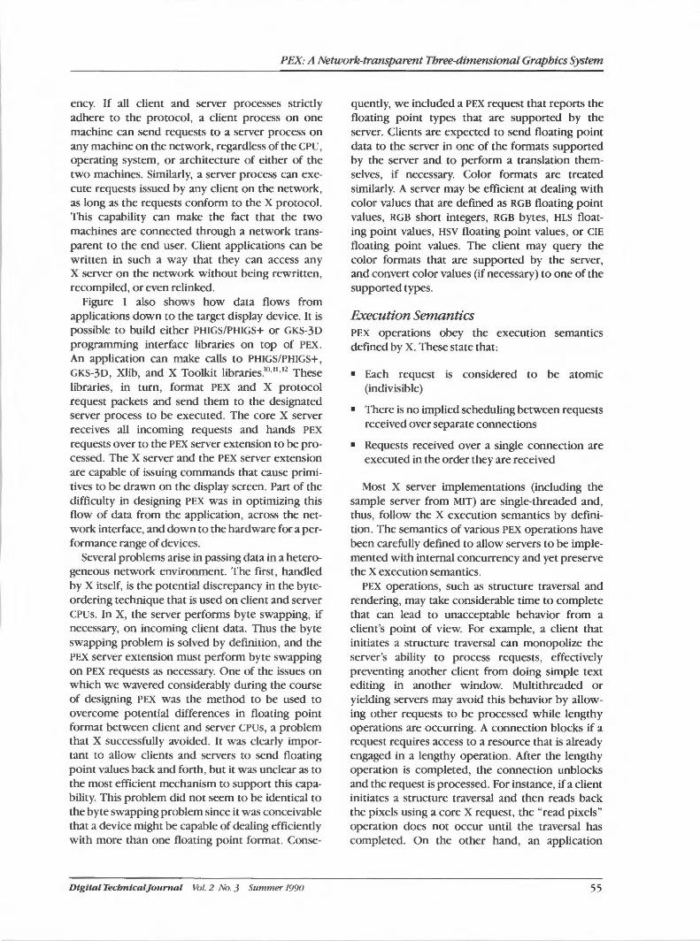
PEX: A Network-transparent Three-dimensional Graphics System
ency. If all client and server processes strictly adhere to the protocol, a client process on one machine can send requests to a server process on any machine on the network, regardless of the CPU, operating system, or architecture of either of the two machines. Similarly, a server process can execute requests issued by any client on the network, as long as the requests conform to the X protocol. This capability can make the fact that the two machines are connected through a network transparent to the end user. Client applications can be written in such a way that they can access any X server on the network without being rewritten, recompiled, or even relinked.
Figure 1 also shows how data flows from applications down to the target display device. It is possible to build either PHIGS/PHIGS+ or GKS-30 programming interface libraries on top of PEX. An application can make calls to PHIGS/PHIGS+, GKS-30, Xlib, and X Toolkit libraries.Kl·11
•12 These
libraries, in turn, format PEX and X protocol request packets and send them to the designated server process to be executed. The core X server receives all incoming requests and hands PEX requests over to the PEX server extension to be processed. The X server and the PEX server extension are capable of issuing commands that cause primitives to be drawn on the display screen. Part of the difficulty in designing PEX was in optimizing this flow of data from the application, across the network interface, and down to the hardware for a performance range of devices.
Several problems arise in passing data in a heterogeneous network environment. The first, handled by X itself, is the potential discrepancy in the byteordering technique that is used on client and server CPUs. In X, the server performs byte swapping, if necessary, on incoming client data. Thus the byte swapping problem is solved by definition, and the PEX server extension must perform byte swapping on PEX requests as necessary. One of the issues on which we wavered considerably during the course of designing PEX was the method to be used to overcome potential differences in floating point format between client and server CPUs, a problem that X successfully avoided. It was clearly important to allow clients and servers to send floating point values back and forth, but it was unclear as to the most efficient mechanism to support this capability. This problem did not seem to be identical to the byte swapping problem since it was conceivable that a device might be capable of dealing efficiently with more than one floating point format. Conse-
Digital Tecbntcal]ournal Vol. 2 No. 3 Summer 1990
quently, we included a PEX request that reports the floating point types that are supported by the server. Clients are expected to send floating point data to the server in one of the formats supported by the server and to perform a translation themselves, if necessary. Color formats are treated similarly. A server may be efficient at dealing with color values that are defined as RGB floating point values, RGB short integers, RGB bytes, HLS floating point values, HSV floating point values, or CIE floating point values. The client may query the color formats that are supported by the server, and convert color values (if necessary) to one of the supported types.
Execution Semantics PEX operations obey the execution semantics defined by X. These state that:
• Each request is considered to be atomic (indivisible)
• There is no implied scheduling between requests received over separate connections
• Requests received over a single connection are executed in the order they are received
Most X server implementations (including the sample server from MIT) are single-threaded and, thus, follow the X execution semantics by definition. The semantics of various PEX operations have been carefully defined to allow servers to be implemented with internal concurrency and yet preserve the X execution semantics.
PEX operations, such as structure traversal and rendering, may take considerable time to complete that can lead to unacceptable behavior from a client's point of view. For example, a client that initiates a structure traversal can monopolize the server's ability to process requests, effectively preventing another client from doing simple text editing in another window. Multithreaded or yielding servers may avoid this behavior by allowing other requests to be processed while lengthy operations are occurring. A connection blocks if a request requires access to a resource that is already engaged in a lengthy operation. After the lengthy operation is completed, the connection unblocks and the request is processed. For instance, if a client initiates a structure traversal and then reads back the pixels using a core X request, the "read pixels" operation does not occur until the traversal has completed. On the other hand, an application
55
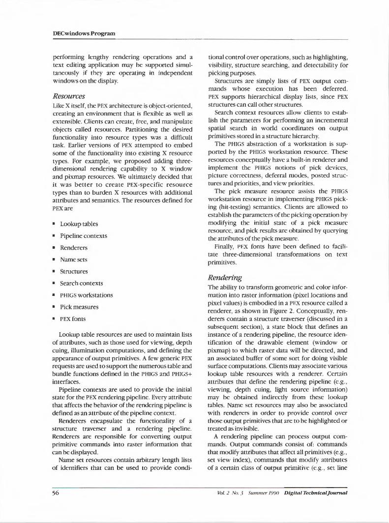
DECwindows Program
performing lengthy rendering operations and a text editing application may be supported simultaneously if they are operating in independent windows on the display.
Resources Like X itself, the PEX architecture is object-oriented, creating an environment that is flexible as well as extensible. Clients can create, free, and manipulate objects called resources. Partitioning the desired functionality into resource types was a difficult task. Earlier versions of PEX attempted to embed some of the functionality into existing X resource types. For example, we proposed adding threedimensional rendering capability to X window and pixmap resources. We ultimately decided that it was better to create PEX-specific resource types than to burden X resources with additional attributes and semantics. The resources defined for PEXare
• Lookup tables
• Pipeline contexts
• Renderers
• Namesets
• Structures
• Search contexts
• PHIGS workstations
• Pick measures
• PEXfonts
Lookup table resources are used to maintain lists of attributes, such as those used for viewing, depth cuing, illumination computations, and defining the appearance of output primitives. A few generic PEX requests are used to support the numerous table and bundle functions defined in the PHIGS and PHIGS+ interfaces.
Pipeline contexts are used to provide the initial state for the PEX rendering pipeline. Every attribute that affects the behavior of the rendering pipeline is defined as an attribute of the pipeline context.
Renderers encapsulate the functionality of a structure traverser and a rendering pipeline. Renderers are responsible for converting output primitive commands into raster information that can be displayed.
Name set resources contain arbitrary length lists of identifiers that can be used to provide condi-
56
tional control over operations, such as highlighting, visibility, structure searching, and detectability for picking purposes.
Structures are simply lists of PEX output commands whose execution has been deferred. PEX supports hierarchical display lists, since PEX structures can call other structures.
Search context resources allow clients to establish the parameters for performing an incremental spatial search in world coordinates on output primitives stored in a structure hierarchy.
The PHIGS abstraction of a workstation is supported by the PHIGS workstation resource. These resources conceptually have a built-in renderer and implement the PHIGS notions of pick devices, picture correctness, deferral modes, posted structures and priorities, and view priorities.
The pick measure resource assists the PHIGS workstation resource in implementing PHIGS picking (hit-testing) semantics. Clients are allowed to establish the parameters of the picking operation by modifying the initial state of a pick measure resource, and pick results are obtained by querying the attributes of the pick measure.
Finally, PEX fonts have been defined to facilitate three-dimensional transformations on text primitives.
Rendering The ability to transform geometric and color information into raster information (pixel locations and pixel values) is embodied in a PEX resource called a renderer, as shown in Figure 2. Conceptually, renderers contain a structure traverser (discussed in a subsequent section), a state block that defines an instance of a rendering pipeline, the resource identification of the drawable element (window or pixmap) to which raster data will be directed, and an associated buffer of some sort for doing visible surface computations. Clients may associate various lookup table resources with a renderer. Certain attributes that define the rendering pipeline (e.g., viewing, depth cuing, light source information) may be obtained indirectly from these lookup tables. Name set resources may also be associated with renderers in order to provide control over those output primitives that are to be highlighted or treated as invisible.
A rendering pipeline can process output commands. Output commands consist of: commands that modify attributes that affect all primitives (e.g. , set view index), commands that modify attributes of a certain class of output primitive (e.g., set line
Vol. 2 No. 3 Summer 1990 Digita l Tecbntcaljournal
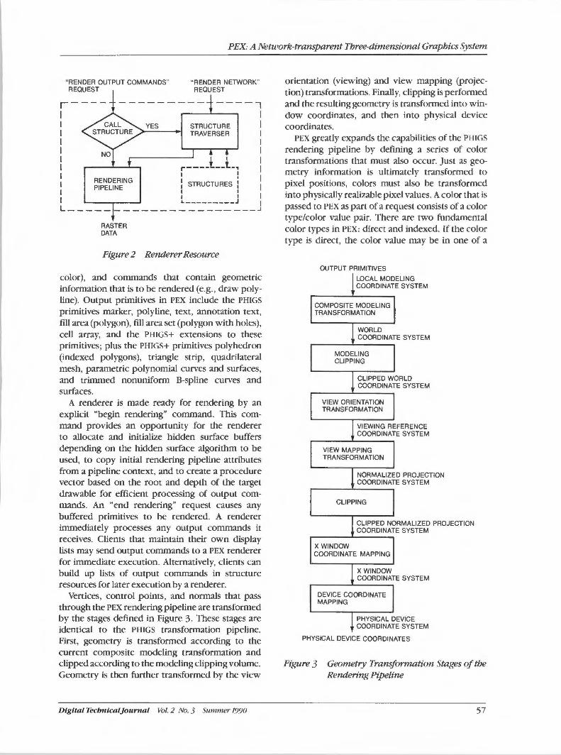
PBX: A Network-transparent Three-dimensional Graphics System
"RENDER OUTPUT COMMANDS" REQUEST
"RENDER NETWORK" REQUEST
r---- ----- ---- ----, I I YES STRUCTURE I TRAVERSER I I l ,_ ___ _l __ L, I I I
I RENDERING 1, STRUCTURES •.' PIPELINE
I I : I L---------J L---------------------
RASTER DATA
Figure 2 Renderer Resource
color), and commands that contain geometric information that is to be rendered (e.g., draw polyline). Output primitives in PEX include the PHIGS
primitives marker, polyline, text, annotation text, fill area (polygon), fill area set (polygon with holes), cell array, and the PHIGS+ extensions to these primitives; plus the PHIGS+ primitives polyhedron (indexed polygons), triangle strip, quadrilateral mesh, parametric polynomial curves and surfaces, and trimmed nonuniform B-spline curves and surfaces.
A renderer is made ready for rendering by an explicit "begin rendering" command. This command provides an opportunity for the renderer to allocate and initialize hidden surface buffers depending on the hidden surface algorithm to be used, to copy initial rendering pipeline attributes from a pipeline context, and to create a procedure vector based on the root and depth of the target drawable for efficient processing of output commands. An "end rendering" request causes any buffered primitives to be rendered. A renderer immediately processes any output commands it receives. Clients that maintain their own display lists may send output commands to a PEX renderer for immediate execution. Alternatively, clients can build up lists of output commands in structure resources for later execution by a renderer.
Vertices, control points, and normals that pass through the PEX rendering pipeline are transformed by the stages defined in Figure 3. These stages are identical to the PHIGS transformation pipeline. First, geometry is transformed according to the current composite modeling transformation and clipped according to the modeling clipping volume. Geometry is then further transformed by the view
Digital Tecbnical]ournal Vol. 2 No. 3 Summer 1990
orientation (viewing) and view mapping (projection) transformations. Finally, clipping is performed and the resulting geometry is transformed into window coordinates, and then into physical device coordinates.
PEX greatly expands the capabilities of the PHIGS
rendering pipeline by defining a series of color transformations that must also occur. Just as geometry information is ultimately transformed to pixel positions, colors must also be transformed into physically realizable pixel values. A color that is passed to PEX as part of a request consists of a color type/color value pair. There are two fundamental color types in PEX: direct and indexed. If the color type is direct, the color value may be in one of a
OUTPUT PRIMITIVES
LOCAL MODELING COORDINATE SYSTEM
COMPOSITE MODELING TRANSFORMATION
WORLD COORDINATE SYSTEM
MODELING CLIPPING
CLIPPED WORLD COORDINATE SYSTEM
VIEW ORIENTATION TRANSFORMATION
VIEWING REFERENCE COORDINATE SYSTEM
VIEW MAPPING TRANSFORMATION
NORMALIZED PROJECTION COORDINATE SYSTEM
CLIPPING
CLIPPED NORMALIZED PROJECTION COORDINATE SYSTEM
X WINDOW COORDINATE MAPPING
X WINDOW COORDINATE SYSTEM
DEVICE COORDINATE MAPPING
PHYSICAL DEVICE COORDINATE SYSTEM
PHYSICAL DEVICE COORDINATES
Figure 3 Geometry Transformation Stages of the Rendering Pipeline
57
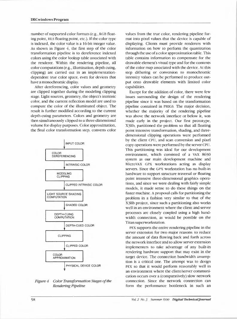
DECwindows Program
number of supported color formats (e.g., RGB floating point, HLS floating point, etc.). If the color type is indexed, the color value is a 16-bit integer value. As shown in Figure 4, the first step of the color transformation pipeline is to dereference indexed colors using the color lookup table associated with the renderer. Within the rendering pipeline, all color computations (e.g., illumination, depth cuing, clipping) are carried out in an implementationdependent true color space, even for devices that have a monochromic display.
After dereferencing, color values and geometry are clipped together during the modeling clipping stage. Light sources, geometry, the object's intrinsic color, and the current reflection model are used to compute the color of the illuminated object. The result is further modified according to the current depth-cuing parameters. Colors and geometry are then simultaneously clipped to a three-dimensional volume for display purposes. Color approximation, the final color transformation step, converts color
INPUT COLOR
COLOR DEREFERENCING
INTRINSIC COLOR
MODELING CLIPPING
CLIPPED INTRINSIC COLOR
LIGHT SOURCE SHADING COMPUTATION
SHADED COLOR
DEPTH-CUING COMPUTATION
DEPTH-CUED COLOR
CLIPPING
CLIPPED COLOR
COLOR APPROXIMATION
PHYSICAL DEVICE COLOR
Figure 4 Color Tra-nsformation Stages of the Rendering Pipeline
58
values from the true color, rendering pipeline format into pixel values that the device is capable of displaying. Clients must provide renderers with information on how to perform the quantization through the use of a color approximation table. This table contains information to compensate for the drawable element's visual type and for the contents of the color map associated with the device. At this step dithering or conversion to monochromic intensity values can be performed to produce output onto drawable elements with limited color capabilities.
Except for the addition of color, there were few issues surrounding the design of the rendering pipeline since it was based on the transformation pipeline contained in PHIGS. The major decision, whether the majority of the rendering pipeline was above the network interface or below it, was made early in the project. Our first prototype, X3lib, partitioned the problem so that all floating point intensive transformation, shading, and threedimensional clipping operations were performed by the client CPU , and scan conversion and pixel copy operations were performed by the server CPU.
This partitioning was ideal for our development environment, which consisted of a VAX 8650 system as our main development machine and MicroVAX GPX workstations acting as display servers. Since the GPX workstation has no built-in hardware to support structure traversal or floating point intensive three-dimensional graphics operations, and since we were dealing with fairly simple models, it made sense to do these things on the faster machine. A proposal calls for partitioning the problem in a fashion very similar to that of the X3lib project, since such a panitioning also works well in an environment where the client and server processes are closely coupled using a high bandwidth connection, as would be possible on the Titan superworkstation.
PEX supports the entire rendering pipeline in the server extension for two major reasons: to reduce the amount of data flowing back and forth across the network interface and to allow server extension implementers to take advantage of any built-in rendering hardware support that may exist in the target device. The connection bandwidth assumption is a critical one. The attempt was to design PEX so that it would perform reasonably well in an environment where the client/server communication occurs over a (comparatively) slow network connection. Since the network connection can form the performance bottleneck in such an
Vol. 2 No. 3 Summer 1990 Digital Tecbnlcal]ournal
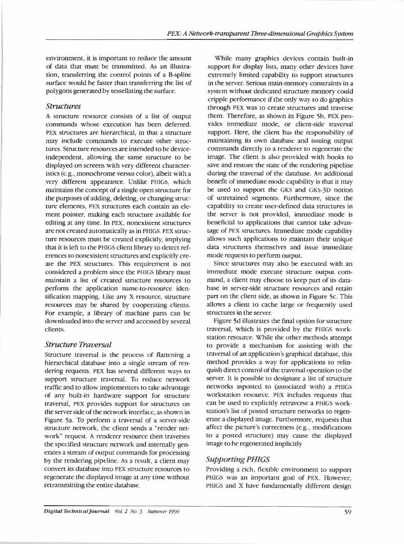
PEX: A Network-transpa,rent Three-dimensional Graphics System
environment, it is important to reduce the amount of data that must be transmitted. As an illustration, transferring the control points of a B-spline surface would be faster than transferring the list of polygons generated by tessellating the surface.
Structures A structure resource consists of a list of output commands whose execution has been deferred. PEX structures are hierarchical, in that a structure may include commands to execute other structures. Structure resources are intended to be deviceindependent, allowing the same structure to be displayed on screens with very different characteristics (e.g., monochrome versus color), albeit with a very different appearance. Unlike PHIGS, which maintains the concept of a single open structure for the purposes of adding, deleting, or changing structure elements, PEX structures each contain an element pointer, making each structure available for editing at any time. In PEX, nonexistent structures are not created automatically as in PHIGS. PEX structure resources must be created explicitly, implying that it is left to the PHIGS client library to detect references to nonexistent structures and explicitly create the PEX structures. This requirement is not considered a problem since the PHIGS library must maintain a list of created structure resources to perform the application name-to-resource identification mapping. like any X resource, structure resources may be shared by cooperating clients. For example, a library of machine parts can be downloaded into the server and accessed by several clients.
Structure Traversal Structure traversal is the process of flattening a hierarchical database into a single stream of rendering requests. PEX has several different ways to support structure traversal. To reduce network traffic and to allow implementers to take advantage of any built-in hardware support for structure traversal, PEX provides support for structures on the server side of the network interface, as shown in Figure 5a. To perform a traversal of a server-side structure network, the client sends a "render network" request. A renderer resource then traverses the specified structure network and internally generates a stream of output commands for processing by the rendering pipeline. As a result, a client may convert its database into PEX structure resources to regenerate the displayed image at any time without retransmitting the entire database.
Digital Tecbnical]ounzal Vol. 2 No. 3 Summer 1990
While many graphics devices contain built-in support for display lists, many other devices have extremely limited capability to support structures in the server. Serious main-memory constraints in a system without dedicated structure memory could cripple performance if the only way to do graphics through PEX was to create structures and traverse them. Therefore, as shown in Figure 5b, PEX provides immediate mode, or client-side traversal support. Here, the client has the responsibility of maintaining its own database and issuing output commands directly to a renderer to regenerate the image. The client is also provided with hooks to save and restore the state of the rendering pipeline during the traversal of the database. An additional benefit of immediate mode capability is that it may be used to support the GKS and GKS-30 notion of unretained segments. Furthermore, since the capability to create user-defined data structures in the server is not provided, immediate mode is beneficial to applications that cannot take advantage of PEX structures. Immediate mode capability allows such applications to maintain their unique data structures themselves and issue immediate mode requests to perform output.
Since structures may also be executed with an immediate mode execute structure output command, a client may choose to keep part of its database in server-side structure resources and retain part on the client side, as shown in Figure 5c. This allows a client to cache large or frequently used structures in the server.
Figure 5d illustrates the final option for structure traversal, which is provided by the PHIGS workstation resource. While the other methods attempt to provide a mechanism for assisting with the traversal of an application's graphical database, this method provides a way for applications to relinquish direct control of the traversal operation to the server. It is possible to designate a list of structure networks asposted to (associated with) a PHIGS
workstation resource. PEX includes requests that can be used to explicitly retraverse a PHIGS workstation's list of posted structure networks to regenerate a displayed image. Furthermore, requests that affect the picture's correctness (e.g., modifications to a posted structure) may cause the displayed image to be regenerated implicitly
Supporting PH/GS Providing a rich, flexible environment to support PHIGS was an important goal of PEX. However, PHIGS and X have fundamentally different design
59
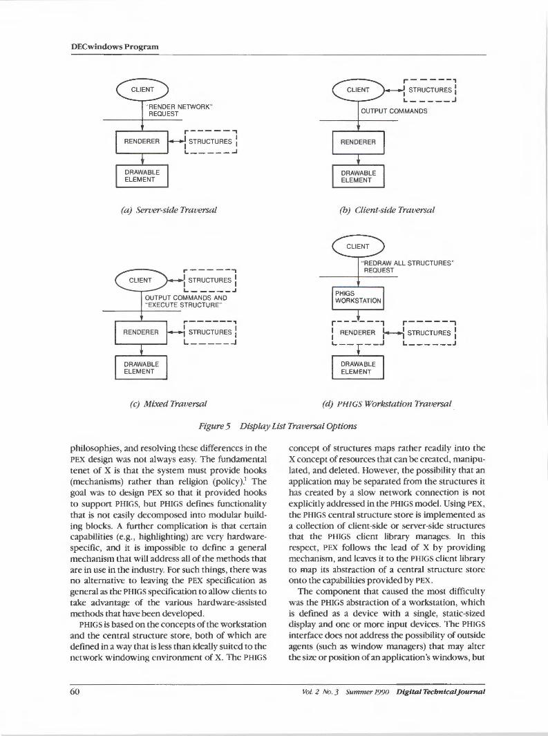
DECwindows Program
CLIENT
"RENDER NETWORK" REQUEST
RENDERER
DRAWABLE ELEMENT
r-----, I STRUCTURES :
L.-----..J
(a) Server-side Traversal
,------, CLIENT I STRUCTURES :
L-----.J OUTPUT COMMANDS AND "EXECUTE STRUCTURE"
RENDERER
DRAWABLE ELEMENT
.-------, I STRUCTURES : L _____ ...J
(c) Mixed Traversal
r------, CLIENT I STRUCTURES I
L-----.J
OUTPUT COMMANDS
RENDERER
DRAWABLE ELEMENT
(b) Client-side Traversal
CLIENT
"REDRAW ALL STRUCTURES" REQUEST
PHIGS WORKSTATION
r------, r-----, : RENDERER t---l STRUCTURES :
L-- __ .J L------J
DRAWABLE ELEMENT
(d) PH/GS Workstation Traversal .
Figure 5 Display List Traversal Options
philosophies, and resolving these differences in the PEX design was not always easy. The fundamental tenet of X is that the system must provide hooks (mechanisms) rather than religion (policy).1 The goal was to design PEX so that it provided hooks to support PHIGS, but PHIGS defines functionality that is not easily decomposed into modular building blocks. A further complication is that certain capabilities (e.g., highlighting) are very hardwarespecific, and it is impossible to define a general mechanism that will address all of the methods that are in use in the industry. For such things, there was no alternative to leaving the PEX specification as general as the PHIGS specification to allow clients to take advantage of the various hardware-assisted methods that have been developed.
PHIGS is based on the concepts of the workstation and the central structure store, both of which are defined in a way that is less than ideally suited to the network windowing environment of X. The PHIGS
60
concept of structures maps rather readily into the X concept of resources that can be created, manipulated, and deleted. However, the possibility that an application may be separated from the structures it has created by a slow network connection is not explicitly addressed in the PHIGS model. Using PEX,
the PHIGS central structure store is implemented as a collection of client-side or server-side structures that the PHIGS client library manages. In this respect, PEX follows the lead of X by providing mechanism, and leaves it to the PHIGS client library to map its abstraction of a central structure store onto the capabilities provided by PEX.
The component that caused the most difficulty was the PHIGS abstraction of a workstation, which is defined as a device with a single, static-sized display and one or more input devices. The PHIGS
interface does not address the possibility of outside agents (such as window managers) that may alter the size or position of an application's windows, but
Vol. 2 No. 3 Summer 1990 Digital Tecbnical]ournal
PEX: A Network-transparent Three-dimensional Graphics System
it is possible for the PHIGS client library to handle the dynamics of windows in X without reporting such occurrences back to PHIGS applications. The PHIGS workstation abstraction also states that the workstation has the ability to control when and how picture changes are visualized. For example, a PHIGS application can suggest that the workstation simulate changes when possible rather than perform another rendering of the entire picture. PHIGS does not specify how these changes should be simulated, only that they can be simulated if and when the workstation finds it convenient to do so. This PHIGS attitude of let the workstation decide is exactly the opposite of the X philosophy of let the client decide.
Rather than completely discard the philosophy ofX in order to support PHIGS, the compromise that was reached was to provide a resource devoted to supporting all of the attributes and state of the PHIGS workstation abstraction. The PHIGS workstation resource has the same functionality as a renderer resource, but also supports the PHIGS workstation abstraction's concepts of posted structures, picture correctness, deferral and modification modes, view priorities, and picking.
This resource requires additional bookkeeping to determine whether or not the displayed image is correct. Because it has a built-in renderer and structure traverser, it can automatically regenerate the image when changes have been made to resources that affect the displayed image. Since the PHIGS workstation resource is capable of regenerating the image implicitly, it must also maintain a list of structures that are to be traversed whenever regeneration occurs.
Supporting PHIGS virtual input devices also involved some trade-offs. In X, all input events are sent up to the clients for processing. In PHIGS, the workstation handles all input. Due to general experience with X and our work with the prototype three-dimensional extension, it was believed that most PHIGS input capabilities could be layered on top of existing X input mechanisms. PHIGS "locator" and "stroke" input may be implemented using the X pointing device, but need to map device coordinates to world coordinates. The PHIGS workstation supports a request to do such a mapping. PEX includes support for picking operations, since preselection and selection highlighting are usually hardware-dependent and must be performed efficiently to be useful. The PEX pick measure resource is used to measure output primitives to determine which ones satisfy a specific set of selec-
Digital Tecbnical]ournal Vol. 2 No. 3 Summer 1990
tion criteria. A device-dependent input record that is passed to a pick measure initiates the picking operation. It is hoped that at least one common input record will be supported by all PEX implementations (implementations are free to support others as well) so that PEX clients may avoid one of the portability problems that plague PHIGS applications.
Open Issues
Lengthy Operations Certain PEX requests, such as a complete structure traversal, initiate operations that can take a long time, particularly on devices with little or no hardware support for three-dimensional graphics operations. However, this problem is not unique to PEX. Certain core X requests (get/put pixmaps, draw many polylines/polygons) and requests from other X extensions can also take considerable time. Although the ability to execute these types of requests is useful, it is also desirable to execute requests on other connections while the lengthy operations are occurring. Furthermore, it is often necessary to terminate (abort) a lengthy operation that has been started.
Whether or not a server supports concurrency is an implementation detail that should not be visible to clients above the network interface. Consequently, the design of the PEX protocol does not prohibit either single threaded or multithreaded server implementations. How well PEX supports multithreaded implementations cannot accurately be gauged until a multithreaded X server proposal (or implementation) is publicly available. The addition of an "abort operation" request that is specific to PEX is currently under consideration. If an abort mechanism is designed that works across X and all extensions, it can be considered in a future revision ofPEX.
Input There is still some question as to whether the use of the X input mechanisms will be sufficient to meet three-dimensional interactivity requirements. Obtaining the mouse position from X and using it as input to a PEX picking request requires a network round trip. The possibility of defining tightly coupled input loops within the server has been briefly explored. Interest has also been expressed in supporting input devices other than the standard X pointing device. It seems likely that these issues will be investigated as part of a general effort to
61
DECwindows Program
extend the input capabilities of X. Until then, because of general experience with X and with the three-dimensional prototype extension, we believe the X input mechanisms will suffice.
Fonts The type of font required for PHIGS text support requires more information than is present in X fonts. PHIGS text fonts must be fully transformable, hence they require a representation in some normalized coordinate space. Although the type of fonts that are required for PHIGS support may be useful to other extensions, such fonts were defined only within the aegis of PEX. This definition made it possible to control the design of the font support for PEX and the schedule for such support independently of other extension efforts. If PEX fonts prove to be generally useful, a separate extension could be defined to support them in the future.
Double Buffering Certain applications find the use of double buffering, or multibuffering, to be necessary to hide the construction of displayed images or to produce flicker-free animation. Neither PHIGS nor PHIGS+ explicitly includes double-buffering capabilities, although some implementations of these standards include double buffering implicitly or as an extension. X itself does not include support for double buffering beyond drawing to an offscreen pix map and copying the pixmap to a visible window. Double buffering in PEX has been deferred as a general X problem. Several proposals for double buffering in X already exist, and work is underway to establish a general solution, which may also include accessing overlay planes and stereoscopic viewing.13
Z-buffers Most (but not all) of today's high-performance rendering systems are based on some form of hardware 2-buffer support. Consequently, there has been a strong temptation to expose 2-buffer capabilities to clients. This temptation has been resisted, mostly on the grounds that exposing such capabilities would lead to a great many device-dependent applications. However, as proposals for including double-buffering support in X are firmed up, it may be advantageous to incorporate additional 2-buffer semantics and capabilities, such as defining initial Z values and reading them back.
62
Conclusion PEX is an extension to the X Window System that has been designed to provide the capabilities of PHIGS and other three-dimensional graphics standards in the X environment. We consider the original design goals of PEX to have been well met. With PEX, it is possible to create windows on the display that function exactly as independent, three-dimensional workstations. A single workstation device supporting PEX can maintain several virtual threedimensional workstations on its screen simultaneously, and resources can be shared among these virtual workstations to reduce overall server load. PEX can be implemented, with varying levels of performance, on a wide range of raster graphics workstations. Client applications communicate with the PEX server extension through a network connection, which makes the fact that a network separates the client and server CPUs transparent to the end user. This network transparency provides the possibility of true applications portability within the X environment. Application code need not be rewritten, recompiled, or even relinked to take advantage of a new workstation that supports X andPEX.
The length of time between initial proposal and public acceptance (six months) is unprecedented in the computer graphics industry. With a public implementation effort in progress, it is anticipated that PEX will become widely available, thus giving users windowing support and three-dimensional graphics capability in a well-integrated, industrystandard environment for the first time.
Acknowledgments The authors gratefully acknowledge the people who have contributed to the design and development of PEX. In addition to the authors, the members of the PEX architecture team who were responsible for revising and finalizing the PEX specification after it was originally submitted to the public forum were Jeffrey S. Saltz and John McConnell (Digital), Marty Hess and Jim Van Loo (Sun Microsystems, Inc.), Dave Gorgen and Tom Gross (Apollo Computer Inc.), and Jeff Stevenson (Hewlett-Packard Company). Bertram Herzog of the University of Michigan is the chairman of the X3D committee and was responsible for seeing that the public process was carried out in a timely fashion. Special thanks go to Robert W. Scheifler, director of the X Consortium, for his invaluable review and suggestions throughout the PEX effort.
Vol. 2 No. 3 Summer 1990 Digital Tecbntcal]ounial
PEX: A Network-transparent Three-dimensional Graphics System
Finally, we acknowledge Jeff Lane, director of graphics software development for workstations at Digital, whose advice, criticism, support, and unbounded enthusiasm always seemed to come at the right time.
References
1. R. Scheifler and ]. Gettys, "The X Window System," A CM Transactions on Graphics, vol. 5, no. 2 (April 1986): 79-109.
2. R. Rost,' PEX Introduction and Overview (Cambridge: MIT X Consonium, May 1, 1988).
3. R. Rost, ed., PEX Protocol Specification (Cambridge: MIT X Consortium, April 2, 1990).
4. S. Barry, ed., PEX Protocol Encoding Document(Cambridge: MIT X Consonium, April 2, 1990).
5. Programmer's Hierarchical Interactive Graphics System (PH/GS) (International Standards Organization, Draft Standard ISO
dp95921: 1987(E), October 1987). 6. Graphical Kernel System for Three Dimen
sions (GKS-3D) (International Standards Organization, ISO/DIS 8805, April 1987).
Digital Tecbnical]ournal Vol. 2 No. 3 Summer 1990
7. "PHIGS+ Functional Description Revision 3.0," Computer Graphics, vol. 22, no. 3 Ouly, 1988): 125- 218.
8. W. Clifford, Jr. et al., "The Development of PEX, a Three-dimensional Graphics Extension to Xll ," Eurographics '88 Proceedings (Nice, France, September 1988).
9. R. Scheifler, X Window System Protocol, Version 11 (Cambridge: MIT Laboratory for Computer Science, February 27, 1988).
10. ]. Gettys et al., Xlib - C Language X Interface, Protocol Version 11 (Cambridge: MIT Project Athena, February 27, 1988).
11. ]. McCormack et al., X Toolkit Intrinsics -C Language X Interface, X version 11, release 2 (Cambridge: MIT Project Athena, February 27, 1988).
12. R. Swick and T. Weissman, X Toolkit Widgets - C Language X Interface, X version 11, release 2 (Cambridge: MIT Project Athena, February 27, 1988).
13. ]. Friedberg et al., Extending X for DoubleBuffering, Multibuffering, and Stereo, version 3.3 (Cambridge: MIT X Consonium, January 11, 1990).
63
Christopher A. Kent I
XDPS: A Display Postscript System Extension for DECwindows
XDPS extends the Display Postscript System into the DECwindows environment. 1be extension integrates the capabilities of both the X imaging model within DECwindows and the Postscript language for screen display-Display Postscript. Designers resolved differences between X and Postscript systems in order to add a complete Postscript interpreter to the DECwindows seroer and a protocol that defines application access. Most significant among the differences encountered was each systems approach to graphical attributes, coordinate systems, color strategies, and communications models. In their implementation of the extension protocol and merger of the two graphics systems, the designers' overall goal was to provide applications programmers the best features of each system without imposing constraints on their use.
The Display Postscript System is Adobe Systems Incorporated's implementation of the Postscript language for workstations. The subject of this paper, XDPS, is an extension to the X protocol that brings the Display Postscript system to the DECwindows program. (The DECwindows program is Digital's implementation of the X Window System.) The extension is the result of a joint effort by Digital and Adobe.
XDPS makes available the full capabilities of the Postscript language and adapts these capabilities for screen display, as opposed to printed pages. Further, XDPS fully integrates the Postscript imaging model with the basic X imaging model. Applications can freely mix standard X graphics requests with XDPS requests. Thus the application programmer can use either X graphics commands or Postscript programs as appropriate.
XDPS is designed to be complementary to X. It provides new capabilities that are missing from the basic X imaging model. With XDPS, applications can show text with arbitrarily rotated and scaled fonts, ignore resolution and color model differences, manipulate the coordinate system to be the most convenient one, and deal more easily with complex curves and shapes. Applications have access to the entire Adobe font library. Application writers can use Postscript for all graphics and be assured that what is seen on the screen is exactly
64
what will be seen when the same graphics are printed on a Postscript printer.
This paper discusses the design decisions made in the development of XDPS and describes the major features of the final extension. An overview of the Display Postscript System's features is presented as a preface to the main discussion. (All instances of the name Postscript in this paper are references to the Postscript language as defined by Adobe Systems Incorporated, unless otherwise stated.)
Features of the Display Postscript System PostScript is the de facto industry standard pagedescription language. Unlike most of its predecessors, a PostScript file does not describe a set of bits on a page. Rather, it is a program that is interpreted in the printer. The effect of this interpretation is that some bits get "painted" on the page. In this manner, the interpreter, rather than the program, can handle details concerning the device, such as output resolution, spot size, and color model. The same program can be used to describe a page on a 300 dpi (dot per inch) bitonal printer and a 1200 dpi full-color film recorder. Each device's interpreter can be tuned to make the output look as good as possible.
The basic concept of the Postscript imaging model is called "stencil and paint." The program-
Vol. 2 No. 3 Summer 1990 Digital Tecbnical]ournal
XDPS: A Display PostScript System Extension for DECwindows
mer constructs an arbitrarily complex stencil (known as a path) and then squeezes paint through it. Paint can be a single color, a pattern, or a scanned image. It is the interpreter's job to decide exactly which bits get painted. The programmer can concentrate on describing the desired image, rather than on the details of the device.
The Display PostScript System (DPS} is an implementation of Postscript for workstation displays. It retains all the features of the PostScript language, but serves an environment quite different from that of printers. Screen displays require interactive manipulation of graphics, frequent redisplays, complicated clipping and repainting to accommodate overlapping, movable and resizable windows, and simultaneous display of complex images in multiple windows.
The Display Postscript System adds a number of features to the Postscript language.1•
2•3 The major
new features are as follows:
• Multiple execution contexts. A context can be thought of as a virtual printer, or a separate process. A context is an instance of the interpreter with its own input stream and output device. Several contexts can share the same output device. In its most simple usage, several applications can simultaneously draw to the workstation display. In a more complicated usage, several contexts can draw to the same window, and each context is responsible for managing a portion of the window's appearance.
• Multiprocessing support. Given multiple contexts, application programmers need mechanisms to control them. DPS provides a range of mechanisms, including fork, join, detach, and monitor.
• Shared program memory (VM}. Shared VM is an implementation of shared memory for the multiple contexts. One context can define a variable, procedure, or resource (such as a font) in shared VM and allow it to be used by other contexts in the system.
• Garbage collection. In the Display Postscript System, programs are long lived in comparison to the duration of Postscript print jobs. Consequently, the system requires more dynamic memory management. DPS provides a garbage collector that runs automatically and can be activated at any time by programs.
• Graphics state objects. The Display Postscript System adds the ability to encapsulate the
D igital Tecbnicaljournal Vol. 2 No. 3 Summer 1990
Postscript graphics state in an object. With this mechanism, application programs can switch between several graphics states with a single command, rather than rebuilding the graphics state every time it is needed or using the standard graphics state stack mechanism.
• Screen fonts. PostScript allows the user to paint text with fonts at any size or orientation. Fonts are described in terms of outlines, and the interpreter scan converts these outlines into rasters of the appropriate size and orientation. At large point sizes and printer resolutions, this technique works very well. At smaller point sizes on low-resolution devices, the output is not as clearly defined as one would like. To enhance the readability of the resulting text in such cases, the Display PostScript System provides a mechanism to use tuned bitmaps for characters at certain sizes and orientations instead of the output of the scan converter.
• Optimized rendering operators. Many of the operations in window system applications involve operations on rectangles. The Display Postscript System provides optimized versions of several operators (such as fill and stroke) that execute more quickly on rectangles than on general paths.
• User paths. DPS provides a mechanism for the user to cache paths that are to be used more than once, and several operators for working with these user paths.
Relationship oftbe Display Postscript System and DECwindows The Display Postscript System, described above, is not a window system. Instead, it is a component that can be integrated into any window system. Vendors that license the Display PostScript System from Adobe Systems must decide how best to integrate it into their window system offerings. Our decision was to use the X protocol extension mechanism to add the Postscript imaging model to the DECwindows served
X applications (also known as clients) communicate with the server by sending a stream of asynchronous requests and receiving back a stream of results and events. The core set of requests covers all facets of window manipulation (geometry, location, visibility) and provides a simple, pixel-based graphical model.5
Extensions add to the requests in the protocol, and therefore add to the functionality available to
65
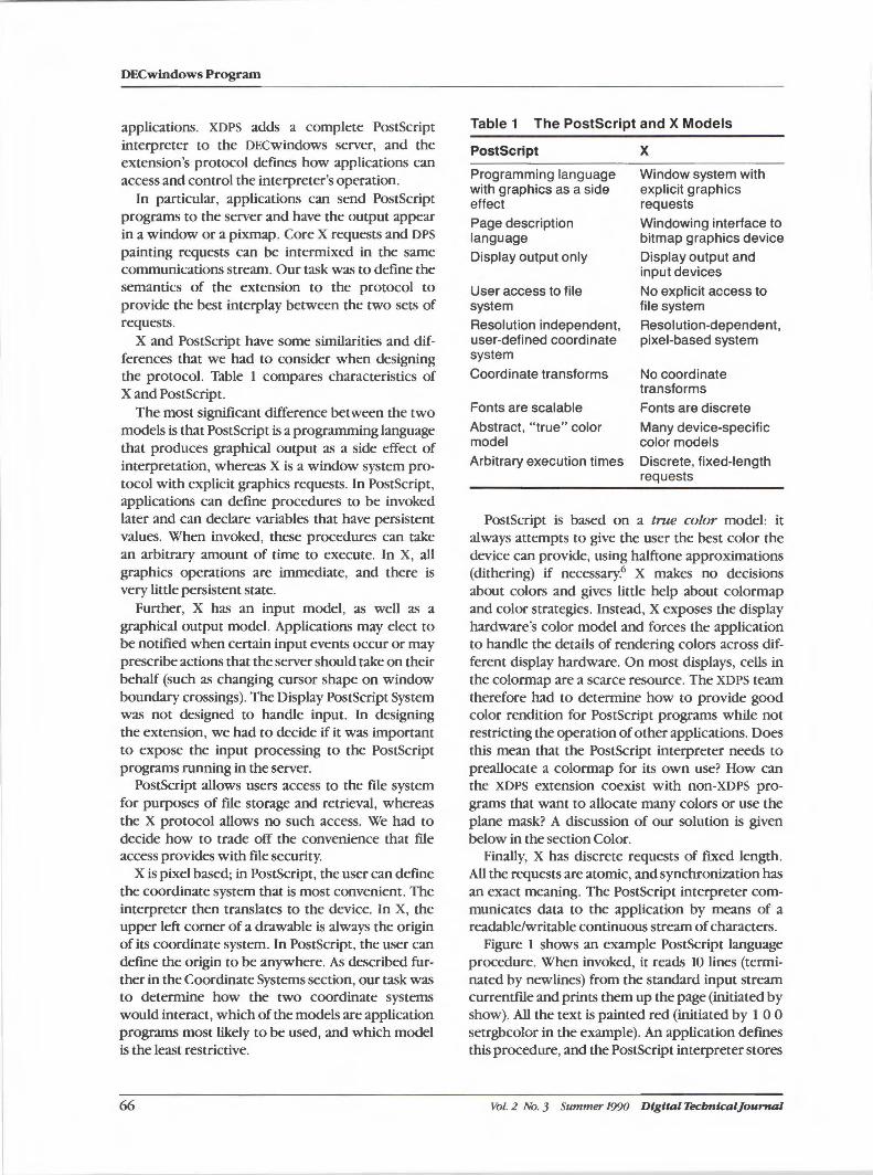
DECwindows Program
applications. XDPS adds a complete Postscript interpreter to the DECwindows server, and the extension's protocol defines how applications can access and control the interpreter's operation.
In particular, applications can send PostScript programs to the server and have the output appear in a window or a pixmap. Core X requests and DPS painting requests can be intermixed in the same communications stream. Our task was to define the semantics of the extension to the protocol to provide the best interplay between the two sets of requests.
X and Postscript have some similarities and differences that we had to consider when designing the protocol. Table 1 compares characteristics of X and Postscript.
The most significant difference between the two models is that Postscript is a programming language that produces graphical output as a side effect of interpretation, whereas X is a window system protocol with explicit graphics requests. In Postscript, applications can define procedures to be invoked later and can declare variables that have persistent values. When invoked, these procedures can take an arbitrary amount of time to execute. In X, all graphics operations are immediate, and there is very little persistent state.
Further, X has an input model, as well as a graphical output model. Applications may elect to be notified when certain input events occur or may prescribe actions that the server should take on their behalf (such as changing cursor shape on window boundary crossings). The Display Postscript System was not designed to handle input. In designing the extension, we had to decide if it was important to expose the input processing to the PostScript programs running in the server.
Postscript allows users access to the file system for purposes of file storage and retrieval, whereas the X protocol allows no such access. We had to decide how to trade off the convenience that file access provides with file security.
X is pixel based; in Postscript, the user can define the coordinate system that is most convenient. The interpreter then translates to the device. In X, the upper left corner of a drawable is always the origin of its coordinate system. In PostScript, the user can define the origin to be anywhere. As described further in the Coordinate Systems section, our task was to determine how the two coordinate systems would interact, which of the models are application programs most likely to be used, and which model is the least restrictive.
66
Table 1 The Postscript and X Models
Postscript
Programming language with graphics as a side effect
Page description language Display output only
User access to file system
Resolution independent, user-defined coordinate system
Coordinate transforms
Fonts are scalable
Abstract, "true" color model
Arbitrary execution times
x Window system with explicit graphics requests
Windowing interface to bitmap graphics device Display output and input devices
No explicit access to file system Resolution-dependent, pixel-based system
No coordinate transforms
Fonts are discrete
Many device-specific color models Discrete, fixed-length requests
Postscript is based on a true color model: it always attempts to give the user the best color the device can provide, using halftone approximations (dithering) if necessary.6 X makes no decisions about colors and gives little help about colormap and color strategies. Instead, X exposes the display hardware's color model and forces the application to handle the details of rendering colors across different display hardware. On most displays, cells in the colormap are a scarce resource. The XDPS team therefore had to determine how to provide good color rendition for Postscript programs while not restricting the operation of other applications. Does this mean that the PostScript interpreter needs to preallocate a colormap for its own use? How can the XDPS extension coexist with non-XDPS programs that want to allocate many colors or use the plane mask? A discussion of our solution is given below in the section Color.
Finally, X has discrete requests of fixed length. All the requests are atomic, and synchronization has an exact meaning. The Postscript interpreter communicates data to the application by means of a readable/writable continuous stream of characters.
Figure 1 shows an example Postscript language procedure. When invoked, it reads 10 lines (terminated by newlines) from the standard input stream currentfile and prints them up the page (initiated by show). All the text is painted red (initiated by 1 O O setrgbcolor in the example). An application defines this procedure, and the Postscript interpreter stores
Vol. 2 No. 3 Summer 1990 Dtgttal Tecbntcaljournal
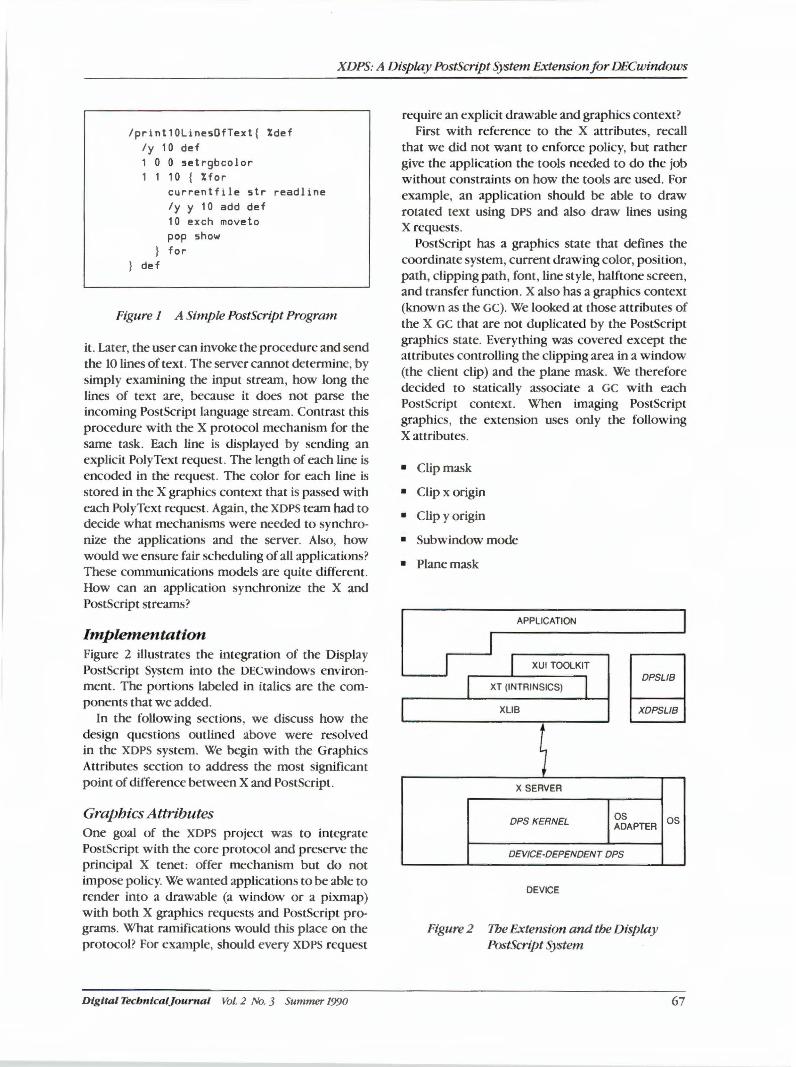
XDPS: A Display Postscript System Extension for DECwindows
/print10Line5QfText{ %def /y 10 def 1 0 0 5etrgbcolor 1 1 10 { %for
def
currentfil e 5tr readline /y y 10 add def 10 exch moveto pop 5how for
Figure I A Simple Postscript Program
it. Later, the user can invoke the procedure and send the 10 lines of text. The server cannot determine, by simply examining the input stream, how long the lines of text are, because it does not parse the incoming Postscript language stream. Contrast this procedure with the X protocol mechanism for the same task. Each line is displayed by sending an explicit PolyText request. The length of each line is encoded in the request. The color for each line is stored in the X graphics context that is passed with each PolyText request . Again, the XDPS team had to decide what mechanisms were needed to synchronize the applications and the server. Also, how would we ensure fair scheduling of all applications? These conununications models are quite different. How can an application synchronize the X and PostScript streams?
Implementation Figure 2 illustrates the integration of the Display Postscript System into the DECwindows environment. The portions labeled in italics are the components that we added.
In the following sections, we discuss how the design questions outlined above were resolved in the XDPS system. We begin with the Graphics Attributes section to address the most significant point of difference between X and Postscript.
Graphics Attributes One goal of the XDPS project was to integrate Postscript with the core protocol and preserve the principal X tenet: offer mechanism but do not impose policy. We wanted applications to be able to render into a drawable (a window or a pixmap) with both X graphics requests and Postscript programs. What ramifications would this place on the protocol? For example, should every XDPS request
Digital Tecbnlcaljounial Vol. 2 No. 3 Summer 1990
require an explicit drawable and graphics context? First with reference to the X attributes, recall
that we did not want to enforce policy, but rather give the application the tools needed to do the job without constraints on how the tools are used. For example, an application should be able to draw rotated text using DPS and also draw lines using X requests.
Postscript has a graphics state that defines the coordinate system, current drawing color, position, path, clipping path, font, line style, halftone screen, and transfer function. X also has a graphics context (known as the Ge). We looked at those attributes of the X GC that are not d uplicated by the PostScript graphics state. Everything was covered except the attributes controlling the clipping area in a window (the client clip) and the plane mask. We therefore decided to statically associate a GC with each Postscript context. When imaging Postscript graphics, the extension uses only the following X attributes.
• Clipmask
• Clip x origin
• Clip y origin
• Subwindow mode
• Planemask
APPLICATION
XUI TOOLKIT I I I
DPSL/B XT (INTRINSICS)
XLIB XDPSL/8
; X SERVER
DPS KERNEL OS ADAPTER
DEV/CE-DEPENDENT DPS
DEVICE
Figure 2 1be Extension and the Display Postscript System
OS
67
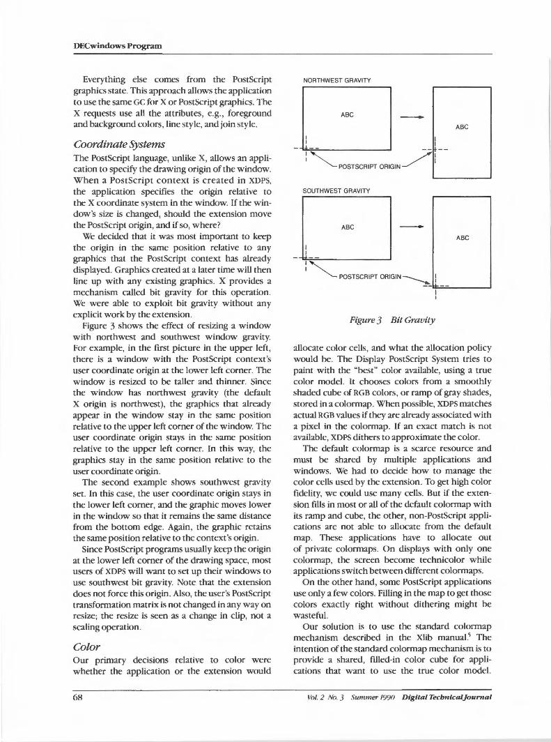
DECwindows Program
Everything else comes from the Postscript graphics state. This approach allows the application to use the same GC for X or Postscript graphics. The X requests use all the attributes, e.g., foreground and background colors, line style, and join style.
Coordinate Systems The PostScript language, unlike X, allows an application to specify the drawing origin of the window. When a Postscript context is created in XDPS,
the application specifies the origin relative to the X coordinate system in the window. If the window's size is changed, should the extension move the Postscript origin, and if so, where?
We decided that it was most important to keep the origin in the same position relative to any graphics that the PostScript context has already displayed. Graphics created at a later time will then line up with any existing graphics. X provides a mechanism called bit gravity for this operation. We were able to exploit bit gravity without any explicit work by the extension.
Figure 3 shows the effect of resizing a window with northwest and southwest window gravity. For example, in the first picture in the upper left, there is a window with the PostScript context's user coordinate origin at the lower left corner. The window is resized to be taller and thinner. Since the window has northwest gravity (the default X origin is northwest), the graphics that already appear in the window stay in the same position relative to the upper left corner of the window. The user coordinate origin stays in the same position relative to the upper left corner. In this way, the graphics stay in the same position relative to the user coordinate origin.
The second example shows southwest gravity set. In this case, the user coordinate origin stays in the lower left corner, and the graphic moves lower in the window so that it remains the same distance from the bottom edge. Again, the graphic retains the same position relative to the context's origin.
Since Postscript programs usually keep the origin at the lower left corner of the drawing space, most users of XDPS will want to set up their windows to use southwest bit gravity. Note that the extension does not force this origin. Also, the user's Postscript transformation matrix is not changed in any way on resize; the resize is seen as a change in clip, not a scaling operation.
Color · Our primary decisions relative to color were whether the application or the extension would
68
NORTHWEST GRAVITY
ABC - ABC
I I 1! I - - --~--: ~POSTSCRIPT ORIGIN/ I
SOUTHWEST GRAVITY
ABC -ABC
: ~ POSTSCRIPT ORIGIN~ !
=-==-----' I I
Figure 3 Bit Gravity
allocate color cells, and what the allocation policy would be. The Display PostScript System tries to paint with the "best" color available, using a true color model. It chooses colors from a smoothly shaded cube of RGB colors, or ramp of gray shades, stored in a colonnap. When possible, XDPS matches actual RGB values if they are already associated with a pixel in the colonnap. If an exact match is not available, XDPS dithers to approximate the color.
The default colonnap is a scarce resource and must be shared by multiple applications and windows. We had to decide how to manage the color cells used by the extension. To get high color fidelity, we could use many cells. But if the extension fills in most or all of the default colonnap with its ramp and cube, the other, non-Postscript applications are not able to allocate from the default map. These applications have to allocate out of private colonnaps. On displays with only one colonnap, the screen become technicolor while applications switch between different colonnaps.
On the other hand, some Postscript applications use only a few colors. Filling in the map to get those colors exactly right without dithering might be wasteful.
Our solution is to use the standard colonnap mechanism described in the Xlib manual.5 The intention of the standard colonnap mechanism is to provide a shared, filled-in color cube for applications that want to use the true color model.
Vol. 2 No. 3 Summer 1990 Digital Tecbnlcaljournal
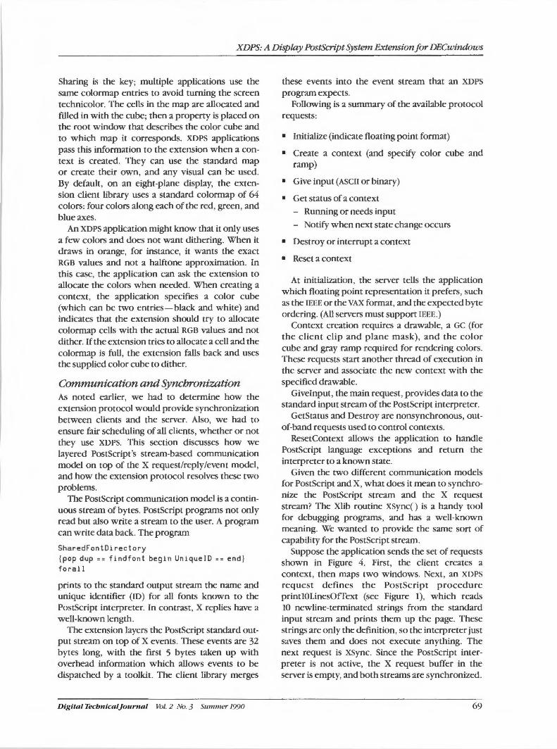
XDPS: A Display PostScript System Extension for DECwindows
Sharing is the key; multiple applications use the same colormap entries to avoid turning the screen technicolor. The cells in the map are allocated and filled in with the cube; then a property is placed on the root window that describes the color cube and to which map it corresponds. XDPS applications pass this information to the extension when a context is created. They can use the standard map or create their own, and any visual can be used. By default, on an eight-plane display, the extension client library uses a standard colormap of 64 colors: four colors along each of the red, green, and blue axes.
An XDPS application might know that it only uses a few colors and does not want dithering. When it draws in orange, for instance, it wants the exact RGB values and not a halftone approximation. In this case, the application can ask the extension to allocate the colors when needed. When creating a context, the application specifies a color cube (which can be two entries-black and white) and indicates that the extension should try to allocate colormap cells with the actual RGB values and not dither. If the extension tries to allocate a cell and the colormap is full, the extension falls back and uses the supplied color cube to dither.
Communication and Synchronization As noted earlier, we had to determine how the extension protocol would provide synchronization between clients and the server. Also, we had to ensure fair scheduling of all clients, whether or not they use XDPS. This section discusses how we layered Postscript's stream-based communication model on top of the X request/reply/event model, and how the extension protocol resolves these two problems.
The Postscript communication model is a continuous stream of bytes. PostScript programs not only read but also write a stream to the user. A program can write data back. The program
SharedFontDirectory {pop dup == findfont begin Unique!D u end} forall
prints to the standard output stream the name and unique identifier (ID) for all fonts known to the PostScript interpreter. In contrast, X replies have a well-known length.
The extension layers the PostScript standard output stream on top of X events. These events are 32 bytes long, with the first 5 bytes taken up with overhead information which allows events to be dispatched by a toolkit. The client library merges
Digital Tecbnical]ounial Vol. 2 No. 3 Summer 1990
these events into the event stream that an XDPS
program expects. Following is a summary of the available protocol
requests:
• Initialize (indicate floating point format)
• Create a context (and specify color cube and ramp)
• Give input (ASCII or binary)
• Get status of a context - Running or needs input
- Notify when next state change occurs
• Destroy or interrupt a context
• Reset a context
At initialization, the server tells the application which floating point representation it prefers, such as the IEEE or the VAX format, and the expected byte ordering. (All servers must support IEEE.)
Context creation requires a drawable, a GC (for the client clip and plane mask), and the color cube and gray ramp required for rendering colors. These requests start another thread of execution in the server and associate the new context with the specified drawable.
Givelnput, the main request, provides data to the standard input stream of the PostScript interpreter.
GetStatus and Destroy are nonsynchronous, outof-band requests used to control contexts.
ResetContext allows the application to handle Postscript language exceptions and return the interpreter to a known state.
Given the two different communication models for PostScript and X, what does it mean to synchronize the PostScript stream and the X request stream? The Xlib routine xsync() is a handy tool for debugging programs, and has a well-known meaning. We wanted to provide the same sort of capability for the Postscript stream.
Suppose the application sends the set of requests shown in Figure 4. First, the client creates a context, then maps two windows. Next, an XDPS
request defines the Postscript procedure printlOLinesOfText (see Figure I), which reads 10 newline-terminated strings from the standard input stream and prints them up the page. These strings are only the definition, so the interpreter just saves them and does not execute anything. The next request is xsync. Since the Postscript interpreter is not active, the X request buffer in the server is empty, and both streams are synchronized.
69
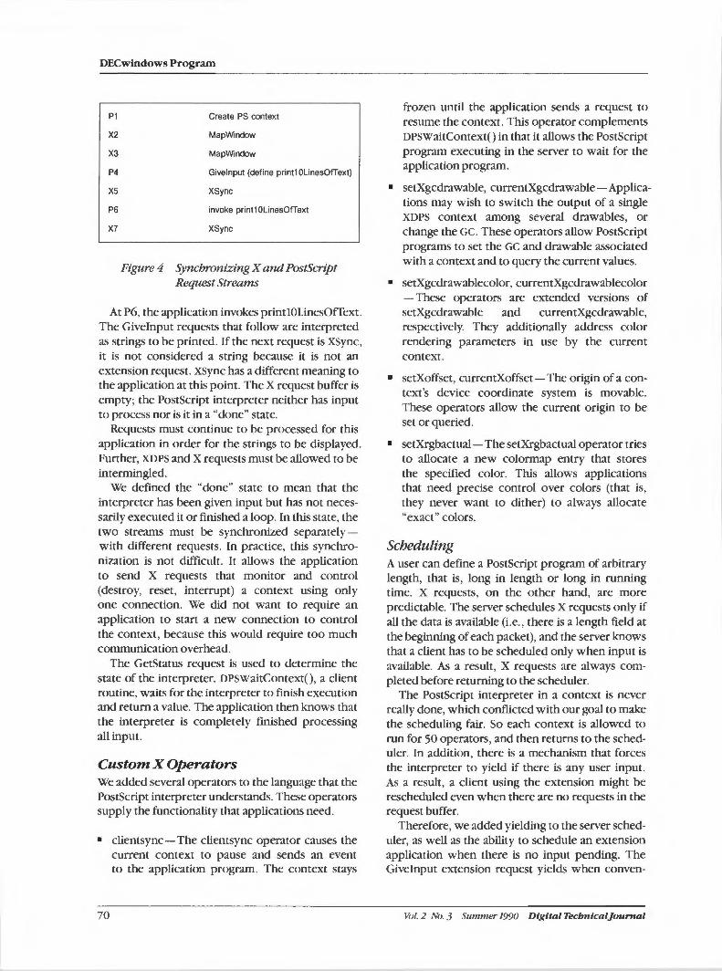
DECwindows Program
P1
X2
X3
P4
XS
P6
X7
Create PS context
MapWindow
MapWindow
Givelnput (define print1 OlinesOfText)
XSync
invoke print1 OLinesOfText
XSync
Figure 4 Synchronizing X and Postscript Request Streams
At P6, the application invokes printlOLinesOfText. The Giveinput requests that follow are interpreted as strings to be printed. If the next request is XSync, it is not considered a string because it is not an extension request. XSync has a different meaning to the application at this point. The X request buffer is empty; the Postscript interpreter neither has input to process nor is it in a "done" state.
Requests must continue to be processed for this application in order for the strings to be displayed. Further, XDPS and X requests must be allowed to be intermingled.
We defined the "done" state to mean that the interpreter has been given input but has not necessarily executed it or finished a loop. In this state, the two streams must be synchronized separatelywith different requests. In practice, this synchronization is not difficult. It allows the application to send X requests that monitor and control (destroy, reset, interrupt) a context using only one connection. We did not want to require an application to start a new connection to control the context, because this would require too much communication overhead.
The GetStatus request is used to determine the state of the interpreter. DPSWaitContext(), a client routine, waits for the interpreter to finish execution and return a value. The application then knows that the interpreter is completely finished processing all input.
Custom X Operators We added several operators to the language that the PostScript interpreter understands. These operators supply the functionality that applications need.
• clientsync - The clientsync operator causes the current context to pause and sends an event to the application program. The context stays
70
frozen until the application sends a request to resume the context. This operator complements DPSWaitContext() in that it allows the Postscript program executing in the server to wait for the application program.
• setXgcdrawable, currentXgcdrawable-Applications may wish to switch the output of a single XDPS context among several drawables, or change the GC. These operators allow Postscript programs to set the GC and drawable associated with a context and to query the current values.
• setXgcdrawablecolor, currentXgcdrawablecolor - These operators are extended versions of setXgcdrawable and currentXgcdrawable, respectively. They additionally address color rendering parameters in use by the current context.
• setXoffset, currentXoffset- The origin of a context's device coordinate system is movable. These operators allow the current origin to be set or queried.
• setXrgbactual - The setXrgbactual operator tries to allocate a new colormap entry that stores the specified color. This allows applications that need precise control over colors (that is, they never want to dither) to always allocate "exact" colors.
Scheduling A user can define a Postscript program of arbitrary length, that is, long in length or long in running time. X requests, on the other hand, are more predictable. The server schedules X requests only if all the data is available (i.e., there is a length field at the beginning of each packet), and the server knows that a client has to be scheduled only when input is available. As a result, X requests are always completed before returning to the scheduler.
The Postscript interpreter in a context is never really done, which conflicted with our goal to make the scheduling fair. So each context is allowed to run for 50 operators, and then returns to the scheduler. In addition, there is a mechanism that forces the interpreter to yield if there is any user input. As a result, a client using the extension might be rescheduled even when there are no requests in the request buffer.
Therefore, we added yielding to the server scheduler, as well as the ability to schedule an extension application when there is no input pending. The Giveinput extension request yields when conven-
Vol. 2 No. 3 Summer 1990 Digital Tecbntcaljournal
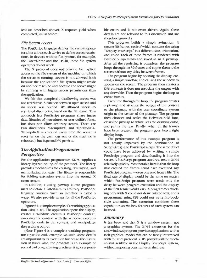
XDPS: A Display PostScript System Extension for DECwindows
ient (as described above); X requests yield when completed, just as before.
File System Access The Postscript language defines file system operators, but allows each device to define access restrictions. In devices without file systems, for example, the LaserWriter and the LPS40, these file system operators do not work.
The X protocol does not provide for explicit access to the file system of the machine on which the server is running. Access is not allowed both because the application's file system might reside on another machine and because the server might be running with higher access permissions than the application.
We felt that completely disallowing access was too restrictive. A balance between open access and no access was needed. We allowed access to restricted directories, based on the file name. This approach lets Postscript programs share image data, libraries of procedures, or user-defined fonts, but does not allow arbitrary access. There are two directories: %tempdir% and %permdir%. %tempdir% is emptied every time the server is reset (when the user logs out or the machine is rebooted), but % permdir% persists.
The Application Programmer Perspective For the application programmer, XDPS supplies a library layered on top of the protocol. The library provides mechanisms for creating, destroying, and manipulating contexts. The library is responsible for folding extension events into the normal X event stream.
In addition, a utility, pswrap, allows programmers to define C interfaces to arbitrary Postscript language routines. Such an interface is called a wrap. We also provide wraps for all the Postscript operators.
Figure 5 is a simple example of a working application using XDPS. The application opens the display, creates a window, creates a Postscript context, associates the context with the window, executes Postscript code in the context, and manipulates the resulting output.
(Note Figure 5 is a complete working program, not a pseudo-code example. As such, some details are important to its execution but not to the discussion at hand. Also, the program is an example of several bad programming practices: it ignores possi-
Digital Tecbntcaljournal Vol. 2 No. 3 Summer 1990
ble errors and is not event driven. Again, these details are not relevant to this discussion and are therefore ignored.)
This program builds a simple animation. It creates 36 frames, each of which contains the string "Display Postscript" in a different size, orientation, and color. Each of these frames is rendered with Postscript operators and saved in an X pixmap. After all the rendering is complete, the program loops through the 36 frames and copies them to the screen without any delay between frames.
The program begins by opening the display, creating a simple window, and causing the window to appear on the screen. The program then creates a DPS context; it does not associate the output with any drawable. Then the program begins the loop to create frames.
Each time through the loop, the program creates a pixmap and attaches the output of the context to the pixmap, with the user coordinate system origin at the center of the pixmap. The program then chooses and scales the Helvetica-bold font, clears the pixmap to white, sets the drawing color, and paints the text. Finally, when all the frames have been created, the program goes into a tight display loop.
The performance of this example program is not greatly improved by the combination of xcopy Area() and Postscript wraps. The same effect could have been achieved by writing a simple Postscript program and downloading it into the server. A Postscript program can draw text in XDPS relatively quickly. Most notable here is that the loop that created the frames could have executed any PostScript program - even one read from a file. The final rate of display would be the same no matter which Postscript program were used; only the delay between program execution and the display of the first frame would vary. A programmer working only with X could not draw rotated text; and a programmer using DPS could not write flip-bookstyle animation. The extension combines these capabilities so the bes, features of each system can be used.
Summary It has been said that X is a window system, not a graphics system. The XDPS extension for the DECwindows program provides applications with a rich graphical model that can be freely intermixed with the core protocol. XDPS provides all the mechanisms available in the Display Postscript System, without imposing constraints on their use.
71
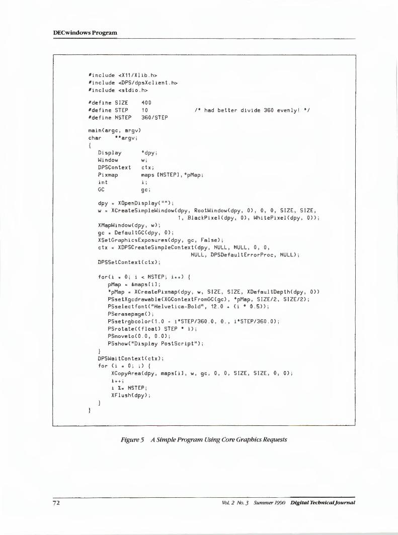
DECwindows Program
72
#include <X11/Xlib . h> 'include <DPS/dpsXclient . h> 'include <stdio . h>
'define SIZE #define STEP #define HSTEP
mainCargc, argv) char ••argv ;
Display Window DPSContext
400 10 360/STEP
*dpy ; lll j
ctx;
I* had better divide 360 evenly! */
Pixmap maps CHSTEPJ, *pMap ; int i j
GC gc ;
dpy XOpenDisplayC"") ; 111 = XCreateSimpleWindo111Cdpy 1 RootWindo111Cdpy, 0), 0, 0, SIZE, SIZE,
1, BlackPixelCdpy, 0), WhitePixelCdpy, 0)) ; XMapWindo111Cdpy, 111) ; gc • DefaultGCCdpy, 0) ; XSetGraphicsExposuresCdpy, gc, False) ; ctx. XDPSCreateSimpleContextCdpy, HULL, HULL, 0, 0,
DPSSetContextCctx);
forCi • O; i < HSTEP; i++> { pMap • &maps[il ;
HULL, DPSDefaultErrorProc, HULL) ;
*pMap = XCreatePixmapCdpy , 111, SIZE, SIZE, XDefaultDepthCdpy, 0)) PSsetXgcdrawableCXGContextFromGCCgc), *pMap, SIZE/2, SIZE/2) ; PSselectfontC"Helvetica-Bold", 12 . 0 + Ci• 0 . 5)) ; PSera!epageC) ; PSsetrgbcolorC1 . 0 - i*STEP/360 . 0 , 0 ., i*STEP/360 . 0) ; PSrotat e C(float) STEP • i); PSmovetoCO . O, 0 . 0) ; PSsho111C"Display Postscript");
DPSWaitContextCctx) ; for Ci s O; ; ) {
XCopyArea Cdpy, mapsCil, 111, gc, 0 , 0 , SIZE, SIZE , 0, 0) ; i ++ j
i X. HSTEP ; XFlush(dpy> ;
Figure 5 A Simple Program Using Core Graphics Requests
Vol. 2 No. 3 Summer 1990 Digital Tecbnlcaljournal
XDPS: A Display Postscript System Extension far DECwindows
Acknowledgments XDPS is the result of work by many people. The original protocol definition is the work of Susan Angebranndt, Phil Karlton, and Terry Weissman of Digital, and Ramin Behtash, Ivor Durham, and Jim Sandman of Adobe. Perry Caro and Joe Pasqua of Adobe have done further work with Bums Fisher, Terry Weissman, and the author to nail down the final protocol. All of us at Digital have had a hand in the implementation. Erik Fortune added the font support we needed to the server.
References
1. Adobe Systems Inc., Postscript Language Reference Manual (Reading: Addison-Wesley Publishing Company, Inc., 1985).
2. PostScript Language Extensions far the Display PostScript System (Mountain View, CA: Adobe Systems, Inc., 1988, 1989).
3. PostScript Language Color Extensions (Mountain View, CA: Adobe Systems, Inc., 1988, 1989).
4. B. Fisher, Xll Seroer Extensions Engineering Specification Xll R3 edition (Cambridge:
Digital Tecbnicaljournal Vol. 2 No. 3 Summer 1990
Massachusetts Institute of Technology, 1987).
5. R. Scheifler, J. Gettys, and R. Newman, X Window System C Library and Protocol Reference (Bedford: Digital Press, 1988).
6. R. Ulichney, Digital Halftoning (Cambridge: The MIT Press, 1987).
General References
The Display PostScript System: Perspective far Software Developers (Mountain View, CA: Adobe Systems, Inc., 1988).
pswrap Reference Manual (Mountain View, CA: Adobe Systems, Inc., 1988).
Client Library Reference Manual (Mountain View, CA: Adobe Systems, Inc., 1988, 1989).
X Window System Programmer's Supplement to the Client Library Reference Manual (Mountain View, CA: Adobe Systems, Inc., 1990).
ULTRIX Wark.rystem Software Guide to Developing Applications far the Display Postscript System, UWS2.2 edition (Maynard: Digital Equipment Corporation, 1989).
73
Micha.el R. Ryan I JamesH. VanGilder
The Development of DECwindows VMS Mail
In the DECwindows program, the windowing interface to the VMS mail utility demonstrates the power of window-based user interfaces. Users can access mail from either character-cell terminals or workstations, exchange mail between all Digital systems, and exchange compound documents. DECwindows VMS mail also supports a common user interface with its counterpart on the ULTRIX system. 1be development of DECwindows VMS mail illustrates many of the issues faced in developing DECwindows applications of moderate size. Further, the development exemplifies the more general problems encountered by developers who must integrate applications with components which are themselves in initial development stages.
Project Start-up When Digital began the DECwindows engineering effort, a number of applications were identified as being critical to its success. One of these applications was electronic mail, which is one of the most widely used system utilities. A windowing interface to an electronic mail application would be very beneficial to the DECwindows program because it would help demonstrate the power of windowbased user interfaces.
The Business and Office Systems Engineering (BOSE) Group, in conjunction with the Telecommunications and Networks (TaN) Group, was responsible for Digital 's corporate mail strategy. Therefore, BOSE was assigned responsibility to deliver the DECwindows mail interface. The engineering team within BOSE that produced the interface is called the Electronic Mail Engineering (EME) Group.
EME began the project by evaluating three existing Digital mail technologies: the ALL-IN-I mail component, the PC ALL-IN- I mail component, and the VMS mail utility. After carefully studying each technology for potential adaptability to the DECwindows system, the group opted to produce an interface that was compatible with the VMS mail utility for several reasons. First, the interface could be developed in a relatively short time frame. Second, VMS mail is the most widely used mail system on VMS systems and the only mail system bundled with the VMS operating system. Therefore, a DECwindows interface to VMS mail would receive the most exposure and would not require addi-
74
tional products to be bundled with the VMS system. Third, the VMS mail callable interface would provide the necessary electronic mail functionality needed and be compatible with the existing character-cell terminal interface. Thus, the developers would have to concentrate only on implementing the DECwindows user interface.
Finally, an interface based on VMS mail would not be an obstruction to Digital's long-term mail strategy. It is the corporate plan to have all of Digital's mail systems conform to the Consultative Committee on International Telephony and Telegraphy ( CCITT) X.400 recommendations for message handling systems.1 Therefore, the code developed for this interface would also serve as the basis for the strategic layered product to be built on top of the Message Router and the X. 400 standards. 2
Design Goals and Trade-offs First and foremost among the design goals was to enable users to access mail either through the DECwindows interface or from a character-cell terminal. Although we wanted DECwindows to
be the interface of choice for the workstation user, we also acknowledged that sometimes users were away from their workstations. The VMS mail callable interface ensured that this goal would be met. A second goal was to enable users to exchange mail between all of Digital's systems, from personal computers to ULTRIX systems to ALL-IN-1 office systems. The third goal was support in the DECwindows VMS mail interface for Digital's emerging CDA architecture by allowing users to
Vol. 2 No. 3 Summer 1990 Digital Tecbnical]ournal
exchange compound documents. Fourth, we had to provide a user interface on VMS systems that was consistent with the user interface on ULTRIX systems.
The major constraint of the DECwindows VMS mail project was the time available for development. DECwindows ULTRIX mail and some-of the other bundled applications started as applications built on X widgets and X Window System version 10 (XIO). However, the DECwindows VMS mail system was developed from scratch. The initial field test of the DECwindows system was scheduled for less than nine months after the start of the mail project. Because of this short time frame, we opted for a compromise implementation approach. We used the standard features and widgets of the XUI toolkit as they became available. We also shared other software to the greatest extent possible rather than develop custom software. This compromise meant that the user interface might not be as ideal as we would have preferred, however, the mail application is consistent with other DECwindows applications and conforms to the XUI Style Guide.3
This paper discusses the development process of the DECwindows VMS mail application, hereafter referred to as DECwindows mail, in its first two functional releases. Version 1 was shipped with version 5.1 of the VMS system, and version 2 was shipped with the VMS system version 5. 3. The first part of the paper focuses on the project definition and development. The second part discusses some of the specific implementation details.
Project Definition and Development Once the project goals were defined, the next step was to assemble a development team. The team consisted of a manager, a supervisor, and engineers who could work well together and who were willing to put in the extra effort and hours that would be required. In addition, the BOSE user interface {UI) group dedicated the services of one of their engineers to help in the design and specification of the user interface.
The next step was to begin training. The DECwindows system is based on MIT's X Window System version 11 (XU) and X toolkit (Xt) intrinsics library, which are written in the C programming language.4
VAX language bindings to these libraries would be provided as part of the DECwindows program. However, the bindings were not available early in our development schedule and were not the most natural interface. As a result, we chose to use
Digital Technical]ournal Vol. 2 No. 3 Summer 1990
1be Development of DEC windows VMS Mail
C as our implementation language, although only a few engineers on the team had experience programming with C. A course on C programming and hands-on experience with initial XU-based prototypes helped us become more familiar with the language.
We also assessed computer-aided software engineering {CASE) tools that we hoped would help speed the development of DECwindows mail. We analyzed the tools commonly used in Digital, including the language sensitive editor {LSE), code management system {CMS), and module management system {MMS), as well as design tools from outside vendors. We chose not to use the external tools for a number of reasons. We were not convinced that they were applicable to the project. The tools were also expensive. Further, we had a short schedule and could not afford the time required to learn to use the tools.
When the project began, the XUI toolkit was still under development and not available for use. Therefore, our early prototypes were based on MIT's widget set. The prototypes primarily gave us a basic understanding of the XII programming interface and Xt intrinsics widget architecture. The early prototypes also allowed us to become more proficient in coding in C. In addition, we studied the user interfaces of mail products on other windowing systems, including Apple Macintosh products, Vsmail (an internal tool layered on VMS mail), as well as xmh, an ULTRIX system-based mail handler that uses the XIO toolkit.
1be Initial Interface The initial design of the DECwindows mail application user interface was based on the ideas we gathered from other applications, our own experience using VMS mail, and suggestions from the BOSE UI group. This interface was repeatedly revised as we learned more about the capabilities of XU and the XUI toolkit. At first, our early screen designs were created using the internal Sight tool under the VAX workstation software {VWS). However, our UI engineer soon took advantage of the tools available on the Apple Macintosh to create screen designs using SuperPaint and HyperCard. These tools allowed us to generate Postscript images of the screens, which could then be transferred to the VMS system for inclusion in specifications and documentation using VAX Document.
The design of the user interface had progressed substantially when management decided that the DECwindows interfaces to ULTRIX mail and VMS
75
DECwindows Program
mail should be identical. We realized immediately that it was impractical to develop both interfaces from common code because of the completely different underlying mail systems. However, the abstract functionality provided by both systems was close, which would make it possible to produce nearly identical interfaces. Developers and managers from both the ULTRIX and VMS development groups met to design a common interface. We all soon learned that the only way that both systems could look and behave as identically as possible would be to compromise some of the functionality in each interface.
The compromise that caused the most trouble for DECwindows VMS mail was delivery of mail. When new mail arrives in VMS mail, it is inserted directly into the NEWMAIL folder of the user's primary mail file, i.e., MAIL. When new mail is read, it is automatically refiled to the MAIL folder. However, when new mail arrives on the ULTRIX system, the mail is held in a system area. To read new mail, users type the "inc" (i.e., incorporate) command, which moves the new mail into the INBOX folder. Mail read from INBOX is not automatically refiled to another folder.
The abstraction for mail delivery chosen for the common user interface specification was the ULTRIX model. New mail for the user would not be visible in the DECwindows user interface until the user delivered it. Delivery could be done explicitly by using the "Deliver Mail" push button, or implicitly by executing "Read New Mail" or at application start-up. Mail would be delivered by default to the INBOX, and read mail would not be automatically refiled.
In VMS mail, new mail is initially delivered to the NEWMAIL folder. To implement the ULTRIX model, we had to move new messages from the NEWMAIL folder to the INBOX folder. At the same time, we had to be careful to preserve the NEWMAIL state of each message and prevent messages from being automatically refiled as they were read.
Moving the messages had a negative impact on performance. How to keep track of the number of remaining new messages was a problem well into development for version 2 of DECwindows mail. However, the greatest resistance to this process came from VMS mail users who did not like having messages delivered to the INBOX. If a user accessed mail using character-cell VMS mail, new messages were not in the expected folders, i.e., NEWMAIL and MAIL. In response to this feedback, we made the name of the folder to which new mail would be
76
delivered and the automatic refiling of a message to the MAIL folder customizable options. In addition, we made the default values for these options dependent on the presence of a MAIL file. Thus, users who already have a MAIL file are presumed to be experienced VMS mail users and are given values consistent with VMS mail behavior. Users who do not have a MAIL file are presumed to be new DECwindows users and are given INBOX as a delivery folder and messages are not refiled, which is consistent with the ULTRIX interface.
While EME was working on the common interface problem, the BOSE UI group was evaluating the use of a hierarchical display as the user interface for structured data, such as mail messages within mail folders within mail drawers. This hierarchical display eventually became known as structured visual navigation (SVN). SVN had the potential to be used in a wide range of applications and could be developed as a general X user interface (XUI) widget that could be incorporated wherever useful. SVN's first test in a real application would be on DECwindows VMS mail. To do the test without jeopardizing the delivery of a mail interface on schedule, one engineer from the BOSE group was assigned to the design and development of SVN. In addition, two engineers were assigned to integrate SVN into the mail interface, in parallel with the already planned interface. Software Design Tools' (SDT) Software Usability Engineering (SUE) Group agreed to evaluate the completed interface.
Once both the SVN interface and the ULTRIX system-compatible interface were completed, the SUE group interviewed and videotaped users for reactions to each. From these videotaped interviews, the group produced a set of recommendations for improving both interfaces and a survey of preferences about the two interfaces. Based on this evaluation and other factors, we decided to integrate the SVN interface into the existing interface. A single version would be produced that could be switched from one interface to the other.
Because this integration had not been designed into the code from the beginning, the integrating process was more difficult than we had first thought. As a result, we chose not to incorporate the ability to switch interfaces at run-time but to start-up one interface or the other through a customization option. The decision to produce a single executable image that supported both interfaces became significant when the DECwindows VMS group later decided that the SVN interface should be the default interface on the VMS system.
Vol. 2 No. 3 Summer 1990 Digital Tecbnical]ournal
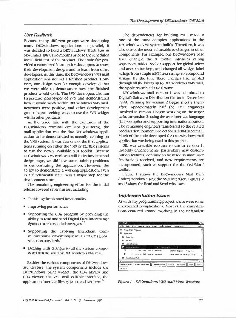
User Feedback Because many different groups were developing many DECwindows applications in parallel, it was decided to hold a DECwindows Trade Fair in November 1987, two months prior to the scheduled initial field test of the product. The trade fair provided a centralized location for developers to show their development designs and to learn from other developers. At this time, the DECwindows VMS mail application was not yet a finished product. However, our design was far enough developed that we were able to demonstrate how the finished product would work. The SYN developers also ran HyperCard prototypes of SYN and demonstrated how it would work within DECwindows VMS mail. Reactions were positive, and other development groups began seeking ways to use the SYN widget within other products.
At the trade fair, with the exclusion of the DECwindows terminal emulator (DECterm), the mail application was the first DECwindows application to be demonstrated as actually running on the VMS system. It was also one of the first applications running on either the VMS or ULTRIX systems to use the newly available XUI toolkit. Because DECwindows VMS mail was still in its fundamental design stage, we did have some stability problems in demonstrating the application. However, the ability to demonstrate a working application, even in a fundamental state, was a major step for the development team.
The remaining engineering effort for the initial release covered several areas, including
• Finishing the planned functionality
• Improving performance
• Supporting the CDA program by providing the ability to read and send Digital Data Interchange Syntax (ODIS) encoded messages 5·
6
• Supporting the evolving Interclient Communications Conventions Manual (ICCCM) global selection standards 7
• Dealing with changes to all the system components that are used by DECwindows VMS mail
Besides the various components of DECwindows architecture, the system components include the DECwindows print widget, the CDA library and CDA viewer, the VMS mail callable interface, the application interface library (AIL), and DECterm.8
Digital Tecbnicaljournal Vol. 2 No. 3 Summer 1990
The Development of DECwindows VMS Mail
The dependencies for building mail made it one of the most complex applications in the DECwindows VMS system builds. Therefore, it was also one of the most vulnerable to changes in other components. For example, one DECwindows base level changed the X toolkit intrinsics calling sequences, added toolkit support for global select and accelerator keys, and changed all widget label strings from simple ASCII text strings to compound strings. By the time these changes had rippled through all the layers up to DECwindows VMS mail, the ripple resembled a tidal wave.
DECwindows mail version 1 was submitted to Digital's Software Distribution Center in December 1988. Planning for version 2 began shortly thereafter. Approximately half the EME engineers involved in version 1 began working on the major tasks for version 2: using the user interface language (UIL) compiler and supporting internationalization. The remaining engineers transferred to the related product development project for X.400-based mail. Much of the code developed for DECwindows mail application was being used in this project.
UIL was available too late to use in version 1. Usability enhancements, particularly new customization features, continue to be made as more user feedback is received, and new requirements are incorporated, such as support for the OSF/Motif toolkit.
Figure 1 shows the DECwindows Mail Main (index) window using the SYN interface. Figures 2 and 3 show the Read and Send windows.
Implementation Issues As with any programming project, there were some unexpected complications. Most of the complications centered around working in the unfamiliar
Pl !\lcul -~:I
Fil e Edit Pick Create-Send Read Maintenance Customize Help
El Non-Mail Projects 4
~ Personal 6
e, Computers
~ e, Fitness
e, Miscellaneous
le,
18 1 6-APR-1990 KOALA: : JAC~ON Statu., Report - 6 April
18 2 6-APR-1990 J::.OALA: JACllON Teu Beeting Nonday, 9 April
Ill WASTEBASKET ':2.
<i (>
j Deliver Mail 11 Read New Mail 11 Create-Send . I~ j Forwant I~ j Mnve I I n,~h~te I
Figure 1 DECwindows VMS Mail Main Window
77
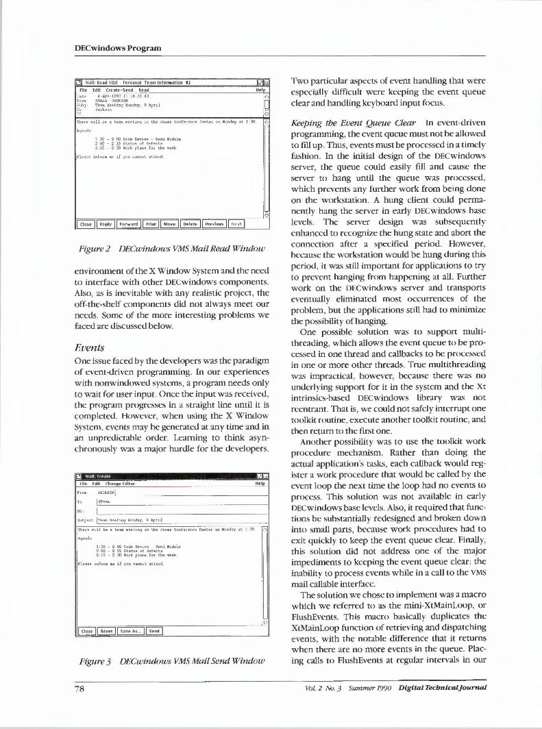
DECwindows Program
;iJI Mail: Read l[D] rersonal Team Information 12
File Edit Create- Send Read Help
Date 6- APR-1990 11 14 -22 43 6 Fro• KOALA: · Ji'r.CKSOH Sub] · Teea Meeting Nonday, 9 April To Jackson cc 0
There 11111 be a teaa 11.eet1ng 1n the Jones Confe r ence Center on Monday at 1 JO O
Agenda
1: 30 - 2: 00 Code Reviev - Send Nodule 2: 00 - 2: 15 Statu:, of defect:, 2:15 - 2:30 Vork plans for the veek
_Plea,e infora 11e if you cannot attend.
0
Figure 2 DECwindows VMS Mail Read Window
environment of the X Window System and the need to interface with other DECwindows components. Also, as is inevitable with any realistic project, the off-the-shelf components did not always meet our needs. Some of the more interesting problems we faced are discussed below.
Events One issue faced by the developers was the paradigm of event-driven programming. In our experiences with nonwindowed systems, a program needs only to wait for user input. Once the input was received, the program progresses in a straight line until it is completed. However, when using the X Window System, events may be generated at any time and in an unpredictable order. Learning to think asynchronously was a major hurdle for the developers.
File Edit Change Editor Help
, CC:
Subject: ITeaa Meeting Monday, 9 Aprq
: There v1ll be a teaa 11.eet1ng m the Jones Conf e rence Center on Monday- at 1 30 O
: Agenda
1 : 30 - 2: 00 Code Reviev - Send Nodule 2: 00 - 2: 15 Status of defects 2: 15 - 2: 30 lork plans for the veek
· Plea~e infora 111.e if you cMnot attend
0
Figure 3 DECwindows VMS Mail Send Window
78
Two particular aspects of event handling that were especially difficult were keeping the event queue clear and handling keyboard input focus.
Keeping the Event Queue Clear In event-driven programming, the event queue must not be allowed to fill up. Thus, events must be processed in a timely fashion. In the initial design of the DECwindows server, the queue could easily fill and cause the server to hang until the queue was processed, which prevents any further work from being done on the workstation. A hung client could permanently hang the server in early DECwindows base levels. The server design was subsequently enhanced to recognize the hung state and abort the connection after a specified period. However, because the workstation would be hung during this period, it was still important for applications to try to prevent hanging from happening at all. Further work on the DECwindows server and transports eventually eliminated most occurrences of the problem, but the applications still had to minimize the possibility of hanging.
One possible solution was to support multithreading, which allows the event queue to be processed in one thread and callbacks to be processed in one or more other threads. True multithreading was impractical, however, because there was no underlying support for it in the system and the Xt intrinsics-based DECwindows library was not reentrant. That is, we could not safely interrupt one toolkit routine, execute another toolkit routine, and then return to the first one.
Another possibility was to use the toolkit work procedure mechanism. Rather than doing the actual application's tasks, each callback would register a work procedure that would be called by the event loop the next time the loop had no events to process. This solution was not available in early DECwindows base levels. Also, it required that functions be substantially redesigned and broken down into small parts, because work procedures had to exit quickly to keep the event queue clear. Finally, this solution did not address one of the major impediments to keeping the event queue clear: the inability to process events while in a call to the VMS mail callable interface.
The solution we chose to implement was a macro which we referred to as the mini-XtMainLoop, or FlushEvents. This macro basically duplicates the XtMainLoop function of retrieving and dispatching events, with the notable difference that it returns when there are no more events in the queue. Placing calls to FlushEvents at regular intervals in our
Vol. 2 No. 3 Summer 1990 Digital Tecbnical]ournal
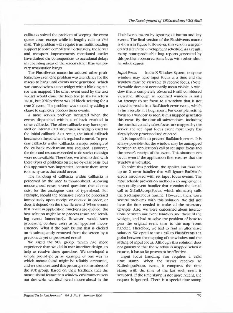
callbacks solved the problem of keeping the event queue clear, except while in lengthy calls to VMS mail. This problem will require true multithreading support to solve completely. Fortunately, the s~rver and transport improvements mentioned earlier have limited the consequences to occasional delays in repainting areas of the screen rather than temporary workstation hangs.
The FlushEvents macro introduced other problems, however. One problem was a tendency for the macro to hang until events were generated, which was caused when a text widget with a blinking cursor was mapped. The timer event used by the text widget would cause the loop test to always return TRUE, but XtNextEvent would block waiting for a true X event. The problem was solved by adding a clause to explicitly process timer events.
A more serious problem occurred when the events dispatched within a callback resulted in other callbacks. The other callbacks may have operated on internal data structures or widgets used by the initial callback. As a result, the initial callback became confused when it regained control. To process callbacks within callbacks, a major redesign of the callback mechanism was required. However, the time and resources needed to do such a redesign were not available. Therefore, we tried to deal with these types of problems on a case-by-case basis, but this approach was impractical because there were too many cases that could occur.
The handling of callbacks within callbacks is perceived by the user as mouse-ahead. Allowing mouse-ahead raises several questions that do not exist for the analogous case of type-ahead. For example, should the recursive events be processed immediately upon receipt or queued in order; or does it depend on the specific event? When events that result in application functions are queued, the best solution might be to process resize and scrolling events immediately. However, would such processing confuse users as an apparent inconsistency? What if the push button that is clicked on is subsequently removed from the screen by a previous as-yet-unprocessed event?
We asked the SUE group, which had more experience than we did in user interface design, to help us resolve these questions. We developed a simple prototype as an example of one way in which mouse-ahead might be reliably supported, and we demonstrated this prototype to members of the SUE group. Based on their feedback that the mouse-ahead feature in a window environment was not desirable, we disallowed mouse-ahead in the
Digital Tecbnicaljournal Vol. 2 No. 3 Summer 1990
1be Development of DECwindows VMS Mail
FlushEvents macro by ignoring all button and key events. The final version of the FlushEvents macro is shown in Figure 4. However, this version was generated late in the development schedule. As a result, many nonreproducible bug reports generated by this problem obscured some bugs with other, similar subtle causes.
Input Focus In the X Window System, only one window may have input focus at a time and the window must be viewable to receive focus. (Note: Viewable does not necessarily mean visible. A window that is completely obscured is still considered viewable, although an iconified window is not.) An attempt to set focus to a window that is not viewable results in a BadMatch error event, which in turn results in a bug report. For example, setting focus to a window as soon as it is mapped generates this error. By the time all subwindows, including the one that actually takes focus, are mapped by the server, the set input focus event most likely has already been processed and rejected.
It is impossible to prevent BadMatch errors. It is always possible that the window may be unmapped between an application's call to set input focus and the server's receipt of the event. This situation can occur even if the application first ensures that the window is viewable.
To solve this problem, the application must set up an X error handler that will ignore BadMatch errors associated with set input focus events. The most reliable prevention method is to implement a map notify event handler that contains the actual call to XtCallAcceptFocus, which ultimately calls the XSetlnputFocus routine. However, there were several problems with this solution. We did not have the time needed to make all the necessary changes. Also, we were concerned about interactions between our event handlers and those of the widgets, and had to solve the problem of how to pass the original event time to the map event handler. Therefore, we had to find an alternative solution. We opted to use a call to FlushEvents at a point between the mapping of the window and the setting of input focus. Although this solution does not guarantee that the window is mapped when it returns, it has so far proven to be effective.
Input focus handling also requires a valid time stamp. When the server receives an X_SetlnputFocus event, it compares the time stamp with the time of the last such event it accepted. If the time stamp is not more recent, the request is ignored. There is a special time stamp
79
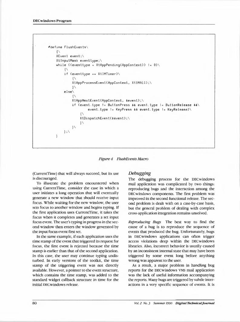
DECwindows Program
#define Flu5hEvent5 \ {\ XEvent event ;\ XtlnputMask eventtype; \ while ((eventtype = XtAppPendingCAppContext)) != 0) \
{\ if Ceventtype == XtIMTimer) \
{\ XtAppProce5sEventCAppContext, XtlMAll); \ }\
else\ {\ XtAppHextEventCAppContext, &event) ;\ if (event . type != ButtonPress && even t.type != ButtonRelea5e &&\
event . type != KeyPress && event.type != KeyRelease) \ {\ XtDis pa tchEven tC&event);\ }\
}\ } ; \
Figure 4 FlusbEvents Macro
(CurrentTime) that will always succeed, but its use is discouraged.
To illustrate the problem encountered when using CurrentTime, consider the case in which a user initiates a long operation that will eventually generate a new window that should receive input focus. While waiting for the new window, the user sets focus to another window and begins typing. If the first application uses CurrentTime, it takes the focus when it completes and generates a set input focus event. The user's typing in progress in the second window then enters the window generated by the input focus event first set.
In the same example, if each application uses the time stamp of the event that triggered its request for focus, the first event is rejected because the time stamp is earlier than that of the second application. In this case, the user may continue typing undisturbed. In early versions of the toolkit, the time stamp of the triggering event was not directly available. However, a pointer to the event structure, which contains the time stamp, was added to the standard widget callback structure in time for the initial DECwindows release.
80
Debugging The debugging process for the DECwindows mail application was complicated by two things: reproducing bugs and the interaction among the DECwindows components. The first problem was improved in the second functional release. The second problem is dealt with on a case-by-case basis, but the general problem of dealing with complex cross-application integration remains unsolved.
Reproducing Bugs The best way to find the cause of a bug is to reproduce the sequence of events that produced the bug. Unfortunately, bugs in DECwindows applications can often trigger access violations deep within the DECwindows libraries. Also, incorrect behavior is usually caused by an inconsistent internal state that may have been triggered by some event long before anything wrong was apparent to the user.
As a result, a major problem in handling bug reports for the DECwindows VMS mail application was the lack of useful information accompanying the reports. Many bugs are triggered by subtle interactions in a very specific sequence of events. It is
Vol. 2 No. 3 Summer 1990 Digital TecbntcalJournal

unrealistic to expect users to recall every detail of the sequence leading to the appearance of the bug, particularly after a few days have passed. Furthermore, when trying to recount actions, users often skip those that appear to be too trivial to have affected the application. For example, resizing windows might appear to the user to only affect the appearance of the display and not any internal state. However, we did find one bug in which resizing under particular circumstances caused the wrong messages to be associated with the visible index lines, resulting in access violations at a later time.
To aid in tracing a bug-generation sequence, macros were defined in version 2 to log all DECwindows callbacks, user customizations, and certain other information to a special file. This method was helpful in tracking down bugs because it is quicker to follow a step-by-step log to reproduce the problem. Some bugs that were fixed would otherwise have been closed as not reproducible without this process. When trace support is disabled at compilation time, the macros do not generate any code. This disabling feature was included in the external field test update and final releases to maximize performance.
The trace log was also used by the SUE group to help improve usability. By examining the log, SUE engineers determined which features were used frequently, which features were seldom used, and which actions were used in combinations.
Interaction among Components The effects that DECwindows applications can have on each other also make it difficult to find and resolve bugs. For example, when spawning several DECwindows applications from the same parent, job-wide quotas may quickly run out. Component interaction through the global selection mechanism causes more subtle problems. A bug in one application may crash another application. A specific example that occurred was a user report of a crash in the FileView application caused by a memory allocation failure in the XUI toolkit.
The true source of the problem was only discovered when the user noted that the crash happened following the deselection of a folder in DECwindows VMS mail. When the global selection was requested, DECwindows VMS mail would accept the request rather than reject it and return a length of- I. The toolkit routine would receive the length and attempt to allocate 4,294,967,295 (i.e., the unsigned value of -1) bytes to hold the selection value and fail. As cross-application
Digital Technical journal Vol. 2 No. 3 Summer 1990
1be Development of DECwindows Vi11S Mail
integration increases using X global selections, client messages, and other means, for example, LiveLink connections, these problems can be expected to become more and more frequent. Testing and debugging tools suitable for these multiple application interactions are needed.
CDASupport In order to support the interchange of compound documents across the network, DECwindows VMS mail incorporates a number of compound document functions. Messages received in compound document format are stored as files with a special tag indicating the format . The compound document viewer widget replaces the text widget to display these messages when read. By using the compound document converters, DECwindows VMS mail can convert these messages to other formats such as plain text or Postscript.
To deal with documents that contain references to other documents, the Digital Object Transport Syntax (oars) was developed in conjunction with the CDA group. The oars syntax allows us to incorporate the primary document and all of its references into a single file that can then be mailed. When a oars message is received and read, the message is split back into its multiple components for use by the viewer. Testing the exchange of messages in various formats between the VMS and ULTRIX systems involved the use of several different mail applications, and required cooperation among mail groups from Palo Alto, California, Nashua, New Hampshire, and Reading, England, as well as the CDA architecture and ULTRIX DECnet developers.
Context-sensitive Help One aspect of the DECwindows style is contextsensitive help. By clicking mouse button 1 while holding the Help key, a user should be able to point at any screen artifact and view a help frame on that object. The implication is that each object must have a help topic associated with it. Therefore, a certain amount of coordination between the developers and the help library writer is essential.
To be able to change the help frames associated with each widget, the writer must be kept informed of changes in the widget hierarchy and any changes in functionality or the user interface. Therefore, the method of associating widgets with help topics must be reasonably straightforward.
Our initial approach to this problem was to document the widget hierarchy in a text file and organize
81
DECwindows Program
the hierarchy of the help library to match. The writer periodically would fetch the hierarchy file, check for any changes, and alter the help library hierarchy to match the changes. The help callback would proceed up the widget hierarchy, using the widget names to build the topic string.
This approach introduced significant problems. The method of forcing the help library structure to reflect the widget structure seemed intuitive to the developers. However, a task-oriented structure is better suited to end users, who rely most heavily on the online help utility. Another problem was the need to specify a help frame for each and every widget, when, in many cases, one help frame could serve the purpose for several widgets. To address these problems, we borrowed a design from the developers of the DEC windows calendar. We added a help frame resource to each widget. Each widget was assigned a full help topic name by a resource line, which eliminated the dependence on the widget hierarchy.
Through the use of resource wildcards, one resource line could assign the same topic string to several widgets at once. The developers added a line to the resource table whenever the hierarchy was changed. Initially, the resources were specified in the system resource file. Later, resources were hardcoded in an internal table to improve performance.
Dununy topic strings were inserted, which the writer would later edit to the correct topic strings. The help callback would then find the help frame resource associated with the widget. This process was an improvement, but it still required that the developers add a line to the table for new widgets, and required the writer to edit C code.
An easier method was implemented as part of the DECwindows VMS mail conversion to UIL. The help topic string is now passed as an argument to the help callback when the widget is defined. The help topic strings are kept in a separate file where they are defined by the developers and later edited by the writer.
Toolkit Restrictions At times, the default behavior of toolkit widgets was not the best user interface behavior in the specific context of our application. Sometimes no existing widgets provided the functionality we needed. Thus, in certain cases, we had to write our own widgets or borrow widgets from other development groups. In other cases, we had to find ways to override the toolkit widgets' default behavior. Two particular cases of this were in the text widget's
82
handling of word wrapping, and the dialog box widget's handling of navigation with the Tab key.
Line Wrapping The DEC windows text widget supports automatic wrapping of lines when the cursor reaches the right edge if the word wrap resource is set. Because this setting eliminates the need for the user to hit a return at the end of each line, it was enabled as a default for the Create-Send window in DECwindows mail. However, the wrapping was done on the screen only. The text sent by the mail application only contained the hard returns entered by the user. In general, there was no problem as long as the mail message was read with DECwindows VMS mail. The word wrap is set in the Read window as well, and the lines are wrapped to fit the reader's window width. However, if the reader were using VMS mail, the paragraph would be displayed as a single line with only the first 80 characters visible. Also, if the paragraph was very long, the VMS mail protocol record length restrictions would prevent transmission of the message.
We considered two options to solve the word wrapping problem because we did not have a direct way to obtain the wrapped text from the text widget. First, we could eliminate the default word wrap and require users to enter a return at the end of each line. The other possibility was to insert returns at an arbitrary point near the end of each line, e.g. , the last white space previous to the 80th character of each line. However, in reading the sources for the text widget, we found that it might be possible to query the text widget indirectly to find where it had wrapped the text on the screen. Word wrapping was achieved by using undocumented text widget calls and data structures and forcing the text widget to move through the entire message text one screen at a time.
Tab Navigation According to the XUI Style Guide, the Tab key navigates from one text field to the next one within the same window and selects the field's entire contents for pending delete. In other words, the next keystroke automatically inserts itself after deleting the selected text. This feature was designed for dialog boxes containing several short text fields, but was less appropriate for DECwindows VMS mail Create-Send window's message area. In fact, it created problems. For example, if a user pressed the Tab key while in the message area, the cursor would move to the personal name field, which is the first text field in the window. A tab character could not
Vol. 2 No. 3 Summer 1990 Digital Tecbnlcal]ournal
be inserted into a text widget, even a widget being used more as a text editor than a text field.
A more serious problem was that of selection for pending delete. When users would tab to the message area and begin typing, the first keystroke would wipe out the previous contents. Since the text widget provides no practical way to undo such changes, the user could not recover from a simple and common error. We had to override the dialog box's translation for tab and reimplement the normal processing to fix the problem. In this case, normal processing means process as normal for envelope text widgets and insert the tab for the message area.
Summary DECwindows VMS mail was one component in the integrated development effort of the DECwindows system. The problems we faced and solved and those which still need to be addressed, reflect many of the problems of developing integrated systems in an environment in which some components are constrained by external standards, the components interact in potentially complex ways, and many components are under active development. Our experiences in developing DECwindows VMS mail have left us better prepared to deal with the continuing trends toward software integration.
Acknowledgments We would like to thank everyone who has worked on and helped with DECwindows VMS mail during its development. This includes the members of the XUI toolkit team, the VMS DECwindows team, as well as the many people throughout Digital who used and helped test mail. In particular we would like to thank Terry Weissman, the ULTRIX systembased DECwindows mail developer, for his help and cooperation throughout the project, and the engineers, writers, and managers who were directly involved in the development of DECwindows VMS mail: Pam Bantis, Roger Brinkley, Mike Daugherty, Elaine Egolf, Eric Hansen, Gerry Hornik, Debbie Huffman, Craig Jackson, Lorri Menard, Cheryl Mrozienski, Linda Nallett, Kelly Solinas, and Duane Smith.
References
1. CC/TT Data Communication Networks Message Handling Systems Recommendations x. 400-X. 430, Volume VIII - Fascicle VIII.7, CCITT, ISBN 92-61-02361-4.
D igital Tecbntcaljournal Vol. 2 No. 3 Summer 1990
The Development of DECwindows VMS Mail
2. P. Mierswa, "The Evolution of the MAILbus," Digital Technical Journal, vol. 1, no. 9 Oune 1989): 37-43.
3. XUI Style Guide (Maynard: Digital Equipment Corporation, Order No. AA-MG20A-TE, 1988).
4. R. Scheifler et al., "Introduction" and "Introduction to Xlib," X Window System, C Library and Protocol Reference (Bedford: Digital Press, Order No. EY-6737E-DP, 1988).
5. R. Travis, "CDA Overview," Digital Technical Journal, vol. 2, no. 1 (Winter 1990): 8-15.
6. W. Laurune and R. Travis, "The Digital Document Interchange Format," Digital Technical Journal, vol. 2, no. 1 (Winter 1990): 16-27.
7. D. Rosenthal, X Window System, Version 11-lnterclient Communication Conventions Manual Version 1.0.
8. B. Cheung and N. Jacobson, "Interapplication Access and Integration," Digital Technical Journal, vol. 2, no. 1 (Winter 1990): 49-59.
83
Dinesb Mirchandani I Prabuddba Biswas
Ethernet Performance of Remote DECwindows Applications
In Digitals windowed computing system, the Ethernet is the communication medium for both DECwindows traffic and remote disk I/0 traffic. Ibis level of traffic prompted a study to investigate whether or not the Ethernet would be a system-level bottleneck for DECwindows applications. lbe methodology developed characterizes the Ethernet traffic generated by a DECwindows application executing remotely on the workstations in a local area VAXcluster. A simulation model was used to predict the Ethernet perfonnance of a large cluster running this application and a range of other hypothetical remote DECwindows applications. 1be results of this study can be extended in many ways and should be of interest to those involved in sizing local area clusters running remote DECwindows applications.
In the past few years, we have seen a proliferation in the number of local area networks (LANs) installed worldwide. This development largely results from advances in workstation technology and innovations in the design and performance of various communication protocols. These protocols are now the building blocks of distributed computing environments.
These advances also have affected the ways in which LANs are used. Initial applications of LANs were for remote terminal access and file transfer. Diskless workstations and distributed processing came next. Today's environment is a networkoriented, windowed user interface standard: the X Window System! DECwindows is Digital's implementation of the X Window System. As each of these networking environments was developed, researchers reviewed the performance implications of the new environment on the network.2•3•
4
Following in that tradition, the study presented in this paper investigates the impact of the distributed DECwindows computing environment on the performance of the Ethernet.
The study was based on a distributed computing model using Digital's local area VAXcluster (LAVc)systems in which a few large systems are connected to several workstations over an Ethernet segment.5 These larger systems provide distributed file services and the resources to run many
84
DECwindows clients (or applications) that present their user interfaces remotely on the workstations.
This paper is organized into four sections. The first section describes the methodology and tools used in the characterization of Ethernet traffic generated by a DECwindows workload. The next section analyzes the traffic both at the application level and at the Ethernet level. The third section presents the results of a modeling study that extended the measurement data to predict Ethernet performance in large configurations. The paper concludes with a brief discussion of areas to which this study may be extended in the future.
Methodology Our preliminary monitoring of network traffic indicated that the network would not be a performance bottleneck for small LAN configurations. Therefore, our goal was to investigate what would happen when hundreds of workstations simultaneously ran DECwindows applications remotely over the network. To set up and execute a workload on a large network of workstations is a difficult task. We had to carefully characterize the network traffic generated by one workstation and, through modeling, extend this characterization to a large network of workstations. This approach is similar to a study that was successfully done for terminal environments.2
Vol. 2 No. 3 Summer 1990 Digital Tecbnical]ournal
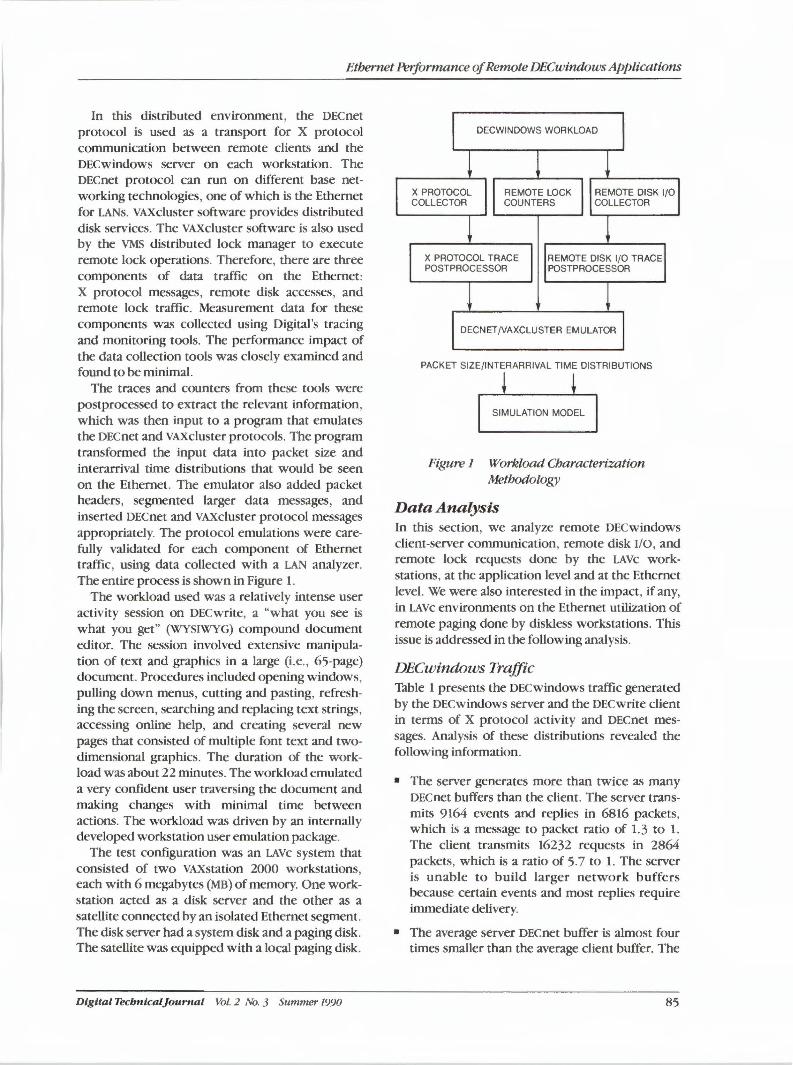
Ethernet Performance of Remote DECwindows Applications
In this distributed environment, the DECnet protocol is used as a transport for X protocol communication between remote clients and the DECwindows server on each workstation. The DECnet protocol can run on different base networking technologies, one of which is the Ethernet for LANs. VAXcluster software provides distributed disk services. The VAXcluster software is also used by the VMS distributed lock manager to execute remote lock operations. Therefore, there are three components of data traffic on the Ethernet: X protocol messages, remote disk accesses, and remote lock traffic. Measurement data for these components was collected using Digital's tracing and monitoring tools. The performance impact of the data collection tools was closely examined and found to be minimal.
The traces and counters from these tools were postprocessed to extract the relevant information, which was then input to a program that emulates the DECnet and VAXcluster protocols. The program transformed the input data into packet size and interarrival time distributions that would be seen on the Ethernet. The emulator also added packet headers, segmented larger data messages, and inserted DECnet and VAXcluster protocol messages appropriately. The protocol emulations were carefully validated for each component of Ethernet traffic , using data collected with a LAN analyzer. The entire process is shown in Figure 1.
The workload used was a relatively intense user activity session on DECwrite, a "what you see is what you get" (WYSIWYG) compound document editor. The session involved extensive manipulation of text and graphics in a large (i.e., 65-page) document. Procedures included opening windows, pulling down menus, cutting and pasting, refreshing the screen, searching and replacing text strings, accessing online help, and creating several new pages that consisted of multiple font text and twodimensional graphics. The duration of the workload was about 22 minutes. The workload emulated a very confident user traversing the document and making changes with minimal time between actions. The workload was driven by an internally developed workstation user emulation package.
The test configuration was an LAVc system that consisted of two VAXstation 2000 workstations each with 6 megabytes (MB) of memory. One work: station acted as a disk server and the other as a satellite connected by an isolated Ethernet segment. The disk server had a system disk and a paging disk. The satellite was equipped with a local paging disk.
Digital Tecbnlcal}ournal Vol. 2 No. 3 Summer 1990
DECWINDOWS WORKLOAD
X PROTOCOL COLLECTOR
REMOTE LOCK COUNTERS
REMOTE DISK 1/0 COLLECTOR
X PROTOCOL TRACE POSTPROCESSOR
REMOTE DISK 1/0 TRACE POSTPROCESSOR
DECNET/VAXCLUSTER EMULATOR
PACKET SIZE/INTERARRIVAL TIME DISTRIBUTIONS
SIMULATION MODEL
Figure 1 Workload Characterization Methodology
Data Analysis In this section, we analyze remote DECwindows client-server communication, remote disk I/0, and remote lock requests done by the LAVc workstations, at the application level and at the Ethernet level. We were also interested in the impact, if any, in LAVc environments on the Ethernet utilization of remote paging done by diskless workstations. This issue is addressed in the following analysis.
DECwindows Traffic Table 1 presents the DECwindows traffic generated by the DECwindows server and the DECwrite client in terms of X protocol activity and DECnet messages. Analysis of these distributions revealed the following information.
• The server generates more than twice as many DECnet buffers than the client. The server transmits 9164 events and replies in 6816 packets, which is a message to packet ratio of 1.3 to I. The client transmits 16232 requests in 2864 packets, which is a ratio of 5.7 to I. The server is unable to build larger network buffers because certain events and most replies require immediate delivery.
• The average server DECnet buffer is almost four times smaller than the average client buffer. The
85
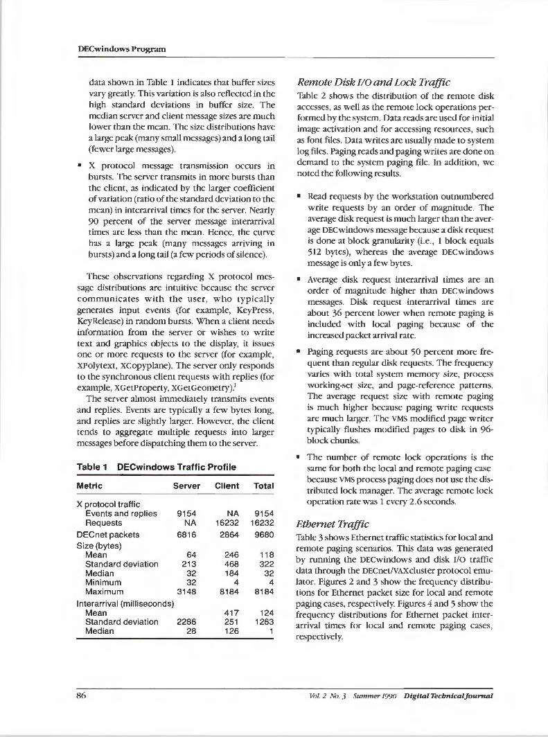
DECwindows Program
data shown in Table 1 indicates that buffer sizes vary greatly. This variation is also reflected in the high standard deviations in buffer size. The median server and client message sizes are much lower than the mean. The size distributions have a large peak (many small messages) and a long tail (fewer large messages).
• X protocol message transmission occurs in bursts. The server transmits in more bursts than the client, as indicated by the larger coefficient of variation (ratio of the standard deviation to the mean) in interarrival times for the server. Nearly 90 percent of the server message interarrival times are less than the mean. Hence, the curve has a large peak (many messages arriving in bursts) and a long tail (a few periods of silence).
These observations regarding X protocol message distributions are intuitive because the server communicates with the user, who typically generates input events (for example, KeyPress, KeyRelease) in random bursts. When a client needs information from the server or wishes to write text and graphics objects to the display, it issues one or more requests to the server (for example, XPolytext, xcopyplane). The server only responds to the synchronous client requests with replies (for example, XGetProperty, XGetGeometry).1
The server almost immediately transmits events and replies. Events are typically a few bytes long, and replies are slightly larger. However, the client tends to aggregate multiple requests into larger messages before dispatching them to the server.
Table 1 DECwindows Traffic Profile
Metric Server Client Total
X protocol traffic Events and replies 9154 NA 9154 Requests NA 16232 16232
DECnet packets 6816 2864 9680 Size (bytes)
Mean 64 246 118 Standard deviation 213 468 322 Median 32 184 32 Minimum 32 4 4 Maximum 3148 8184 8184
lnterarrival (milliseconds) Mean 417 124 Standard deviation 2286 251 1263 Median 28 126 1
86
Remote Disk I/0 and Lock Traffic Table 2 shows the distribution of the remote disk accesses, as well as the remote lock operations performed by the system. Data reads are used for initial image activation and for accessing resources, such as font files. Data writes are usually made to system log files. Paging reads and paging writes are done on demand to the system paging file. In addition, we noted the following results.
• Read requests by the workstation outnumbered write requests by an order of magnitude. The average disk request is much larger than the average DECwindows message because a disk request is done at block granularity (i.e., 1 block equals 512 bytes), whereas the average DECwindows message is only a few bytes.
• Average disk request interarrival times are an order of magnitude higher than DECwindows messages. Disk request interarrival times are about 36 percent lower when remote paging is included with local paging because of the increased packet arrival rate.
• Paging requests are about 50 percent more frequent than regular disk requests. The frequency varies with total system memory size, process working-set size, and page-reference patterns. The average request size with remote paging is much higher because paging write requests are much larger. The VMS modified page writer typically flushes modified pages to disk in 96-block chunks.
• The number of remote lock operations is the same for both the local and remote paging case because VMS process paging does not use the distributed lock manager. The average remote lock operation rate was 1 every 2 .6 seconds.
Ethernet Traffic Table 3 shows Ethernet traffic statistics for local and remote paging scenarios. This data was generated by running the DECwindows and disk I/0 traffic data through the DECnet/VAXcluster protocol emulator. Figures 2 and 3 show the frequency distributions for Ethernet packet size for local and remote paging cases, respectively. Figures 4 and 5 show the frequency distributions for Ethernet packet interarrival times for local and remote paging cases, respectively.
Vol. 2 No. 3 Summer 1990 Digital Tecbnlcaljournal
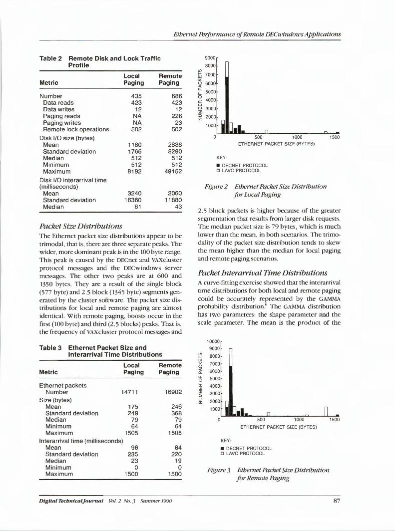
Ethernet Performance of Remote DECwindows Applications
Table 2 Remote Disk and Lock Traffic Profile
Local Remote Metric Paging Paging
Number 435 686 Data reads 423 423 Data writes 12 12 Paging reads NA 226 Paging writes NA 23 Remote lock operations 502 502
Disk 1/0 size (bytes) Mean 1180 2838 Standard deviation 1766 8290 Median 512 512 Minimum 512 512 Maximum 8192 49152
Disk 1/0 interarrival time (milliseconds)
Mean 3240 2060 Standard deviation 16360 11880 Median 61 43
Packet Size Distributions The Ethernet packet size distributions appear to be trimodal, that is, there are three separate peaks. The wider, more dominant peak is in the 100 byte range. This peak is caused by the DECnet and VAXcluster protocol messages and the DECwindows server messages. The other two peaks are at 600 and 1350 bytes. They are a result of the single block (577 byte) and 2.5 block (1345 byte) segments generated by the cluster software. The packet size distributions for local and remote paging are almost identical. With remote paging, boosts occur in the first (100 byte) and third (2.5 blocks) peaks. That is, the frequency of VAXcluster protocol messages and
Table 3 Ethernet Packet Size and lnterarrival Time Distributions
Local Remote Metric Paging Paging
Ethernet packets Number 14711 16902
Size (bytes) Mean 175 246 Standard deviation 249 368 Median 79 79 Minimum 64 64 Maximum 1505 1505
lnterarrival time (milliseconds) Mean 96 84 Standard deviation 235 220 Median 23 19 Minimum 0 0 Maximum 1500 1500
Dtgttal Tecbntcal}ournal Vol. 2 No. 3 Summer 1990
Cl) t-w ~ (.) <( Cl. u.. 0 a: w CD ::::; ::> z
9000
8000
7000
6000
5000
4000
3000
2000
1000 ETHERNET PACKET SIZE (BYTES)
KEY:
• DECNET PROTOCOL D LAVC PROTOCOL
Figure 2 Ethernet Packet Size Distribution for Local Paging
1500
2.5 block packets is higher because of the greater segmentation that results from larger disk requests. The median packet size is 79 bytes, which is much lower than the mean, in both scenarios. The trimodality of the packet size distribution tends to skew the mean higher than the median for local paging and remote paging scenarios.
Packet Interarrival Time Distributions A curve-fitting exercise showed that the interarrival time distributions for both local and remote paging could be accurately represented by the GAMMA probability distribution.6 The GAMMA distribution has two parameters: the shape parameter and the scale parameter. The mean is the product of the
Cl) t-w ~ (.) <( Cl. u.. 0 a: w CD ::::; ::> z
10000 9000
8000
7000
6000 5000 4000
3000
2000
1000
0 500 1000
ETHERNET PACKET SIZE (BYTES)
KEY:
• DECNET PROTOCOL D LAVC PROTOCOL
Figure 3 Ethernet Packet Size Distribution for Remote Paging
1500
87
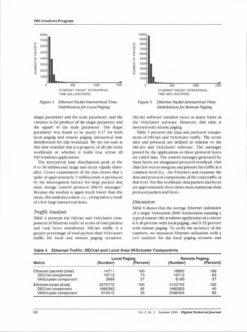
DECwindows Program
en I-w :.:: (.J < !l. u. 0 a: w CD ~ ::i z
8000
7000
6000
5000
4000
3000
2000
1000
0 500 1000
ETHERNET PACKET INTERARRIVAL TIME (MILLISECONDS)
1500
Figure 4 Ethernet Packet Interarrival Time Distribution for Local Paging
shape parameter and the scale parameter, and the variance is the product of the shape parameter and the square of the scale parameter. The shape parameter was found to be nearly 0.17 for both local paging and remote paging interarrival time distributions for this workload. We are not sure at this time whether this is a property of all DECwrite workloads or whether it holds true across all DECwindows applications.
The interarrival time distributions peak in the O to 50 millisecond range and decay rapidly thereafter. Closer examination of the data shows that a spike of approximately 2 milliseconds is produced by the intersegment latency for large packets and mass storage control protocol (MSCP) messages.5
Because the median is again much lower than the mean, this indicates a skew, i.e. , a long tail as a result of a few large interarrival times.
Traffic Analysis Table 4 presents the DECnet and VA.Xcluster components of Ethernet traffic in tenns of total packets and total bytes transferred. DECnet traffic is a greater percentage of total packets than VAX cluster traffic for local and remote paging scenarios.
en I-w :.:: (.J < !l. u. 0 a: w CD ~ ::i z
10000
9000 8000
7000
6000
5000
4000
3000
2000
0 500 1000
ETHERNET PACKET INTERARRIVAL TIME (MILLISECONDS)
1500
Figure 5 Ethernet Packet Interarrival Time Distribution for Remote Paging
DECnet software transfers twice as many bytes as the VA.Xcluster software. However, this ratio is inverted with remote paging.
Table 5 presents the data and protocol components of DECnet and VA.Xcluster traffic. The terms data and protocol are defined in relation to the DECnet and VA.Xcluster software. The messages passed by the applications to these protocol layers are called data. The control messages generated by these layers are designated protocol overhead. Our objective was to integrate and present the traffic at a common level (i.e., the Ethernet) and examine the data and protocol components of the total traffic at that level. For this workload, data packets and bytes are approximately three times more numerous than protocol packets and bytes.
Discussion Table 6 shows that the average Ethernet utilization of a single VA.Xstation 2000 workstation running a typical remote DECwindows application in a cluster is 0.16 percent with local paging, and 0.25 percent with remote paging. To verify the accuracy of the numbers, we measured Ethernet utilization with a LAN analyzer for the local paging scenario and
Table 4 Ethernet Traffic: DECnet and Local Area VAXcluster Components
Local Paging Remote Paging Metric (Number) (Percent) (Number) (Percent)
Ethernet packets (total) 14711 100 16902 100 DECnet component 10712 73 10712 63 VAXcluster component 3999 27 6190 37
Ethernet bytes (total) 2570772 100 4152742 100 DECnet component 1660353 65 1660353 40 VAXcluster component 910412 35 2492404 60
88 Vol. 2 No. 3 Summer 1990 Digital Tecbntcal]ournal
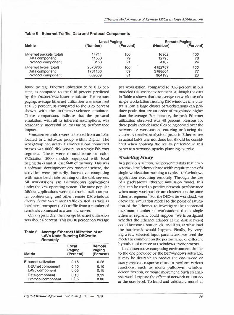
Ethernet Performance of Remote DECwindows Applications
Table 5 Ethernet Traffic: Data and Protocol Components
Local Paging Remote Paging Metric (Number) (Percent) (Number) (Percent)
Ethernet packets (total) Data component Protocol component
Ethernet bytes (total) Data component Protocol component
14711 11558 3153
2570765 1761156 809609
found average Ethernet utilization to be 0.13 percent, as compared to the 0.16 percent predicted by the DECnet/VAXcluster emulator. For remote paging, average Ethernet utilization was measured at 0.23 percent, as compared to the 0.25 percent shown with the DECnet/VAXcluster emulator. These comparisons indicate that the protocol emulation, with all its inherent assumptions, was reasonably successful in measuring performance impact.
Measurements also were collected from an LAVc located in a software group within Digital. The workgroup had nearly 40 workstations connected to two VAX 8000 disk servers on a single Ethernet segment. These were monochrome or color VAXstation 2000 models, equipped with local paging disks and at least 6MB of memory. This was a software development environment where, the activities were primarily interactive computing with some batch jobs running on the disk servers. All workstations ran DECwindows applications under the VMS operating system. The most popular DECnet applications were electronic mail, computer conferencing, and other remote DECwindows clients. Some VAXcluster traffic existed, as well as local area transport (LAT) traffic from a number of terminals connected to a terminal server.
On a typical day, the average Ethernet utilization was about 4 percent. This is 0.10 percent on average
Table 6 Average Ethernet Utilization of an LAVc Node Running DECwrite Remotely
Local Remote Paging Paging
Metric (Percent) (Percent)
Ethernet utilization 0.15 0.25 DECnet component 0.10 0.10 LAVc component 0.05 0.15 Data component 0.10 0.19 Protocol component o:os 0.06
Digital Tecbntcal}ournal Vol. 2 No. 3 Summer 1990
100 79 21
100 69 31
16902 12795 4107
4152757 3188564 964193
100 76 24
100 77 23
per workstation, compared to 0.16 percent in our modeled DECwrite environment. Although the data in Table 6 shows that the average network use of a single workstation running DECwindows in a cluster is low, a large cluster of workstations can produce peaks that are an order of magnitude higher than the average. For instance, the peak Ethernet utilization observed was 38 percent. Reasons for these peaks include large files being copied over the network or workstations entering or leaving the cluster. A detailed analysis of peaks in Ethernet use in actual LANs was not done but should be considered when applying the results presented in this paper to a network capacity planning exercise.
Modeling Study In a previous section, we presented data that characterized the Ethernet bandwidth requirements of a single workstation running a typical DECwindows application executing remotely. Through the use of a packet-level Ethernet simulation model, this data can be used to predict network performance when many workstations are clustered on the same Ethernet segment.7 For the DECwrite workload, we drove the simulation model to the point of saturation of the Ethernet to investigate the theoretical maximum number of workstations that a single Ethernet segment could support. We investigated whether the Ethernet adapter at the disk server(s) could become a bottleneck, and if so, at what load the bottleneck would happen. Finally, by varying a few selected input parameters, we used the model to comment on the performance of different hypothetical remote DECwindows environments.
In an interactive computing environment similar to the one provided by the DECwindows software, it may be desirable to predict the end-to-end or user-perceived response times to perform various functions, such as menu pulldown, window deiconification, or mouse movement. Such an analysis would capture the effect of network utilization at the user level. To build and validate a model at
89
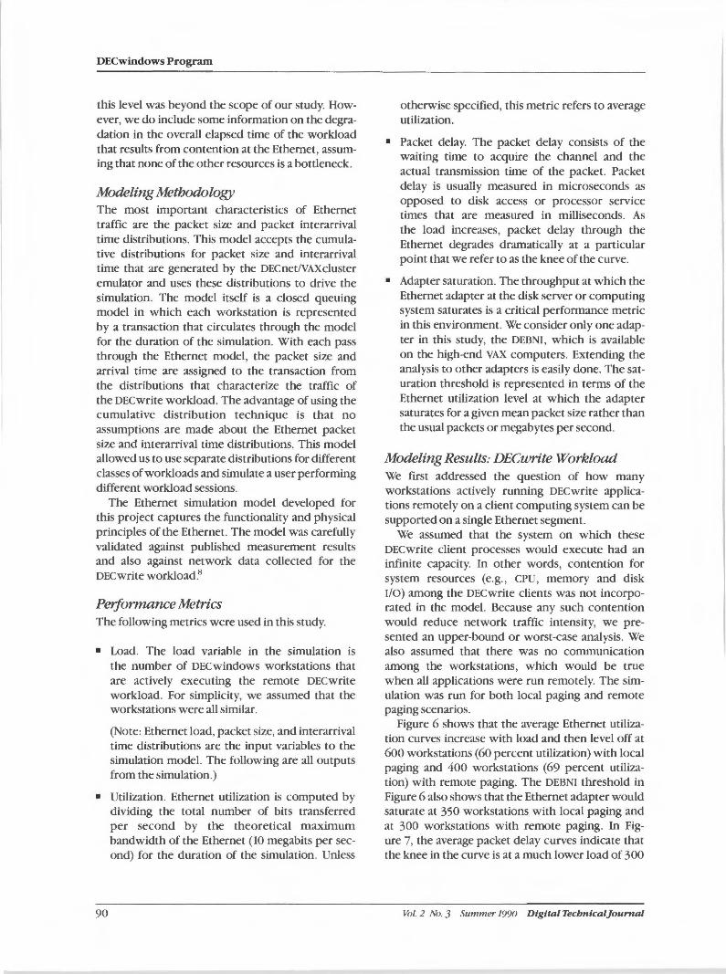
DECwindows Program
this level was beyond the scope of our study. However, we do include some information on the degradation in the overall elapsed time of the workload that results from contention at the Ethernet, assuming that none of the other resources is a bottleneck.
Modeling Methodology The most important characteristics of Ethernet traffic are the packet size and packet interarrival time distributions. This model accepts the cumulative distributions for packet size and interarrival time that are generated by the DECnet/VAXcluster emulator and uses these distributions to drive the simulation. The model itself is a closed queuing model in which each workstation is represented by a transaction that circulates through the model for the duration of the simulation. With each pass through the Ethernet model, the packet size and arrival time are assigned to the transaction from the distributions that characterize the traffic of the DEC write workload. The advantage of using the cumulative distribution technique is that no assumptions are made about the Ethernet packet size and interarrival time distributions. This model allowed us to use separate distributions for different classes of workloads and simulate a user performing different workload sessions.
The Ethernet simulation model developed for this project captures the functionality and physical principles of the Ethernet. The model was carefully validated against published measurement results and also against network data collected for the DECwrite workload.11
Performance Metrics The following metrics were used in this study.
• Load. The load variable in the simulation is the number of DECwindows workstations that are actively executing the remote DECwrite workload. For simplicity, we assumed that the workstations were all similar.
(Note: Ethernet load, packet size, and interarrival time distributions are the input variables to the simulation model. The following are all outputs from the simulation.)
• Utilization. Ethernet utilization is computed by dividing the total number of bits transferred per second by the theoretical maximum bandwidth of the Ethernet (10 megabits per second) for the duration of the simulation. Unless
90
otherwise specified, this metric refers to average utilization.
• Packet delay. The packet delay consists of the waiting time to acquire the channel and the actual transmission time of the packet. Packet delay is usually measured in microseconds as opposed to disk access or processor service times that are measured in milliseconds. As the load increases, packet delay through the Ethernet degrades dramatically at a particular point that we refer to as the knee of the curve.
• Adapter saturation. The throughput at which the Ethernet adapter at the disk server or computing system saturates is a critical performance metric in this environment. We consider only one adapter in this study, the DEBNI, which is available on the high-end VAX computers. Extending the analysis to other adapters is easily done. The saturation threshold is represented in terms of the Ethernet utilization level at which the adapter saturates for a given mean packet size rather than the usual packets or megabytes per second.
Modeling Results: DECwrite Workload We first addressed the question of how many workstations actively running DECwrite applications remotely on a client computing system can be supported on a single Ethernet segment.
We assumed that the system on which these DECwrite client processes would execute had an infinite capacity. In other words, contention for system resources (e.g., CPU, memory and disk I/0) among the DECwrite clients was not incorporated in the model. Because any such contention would reduce network traffic intensity, we presented an upper-bound or worst-case analysis. We also assumed that there was no communication among the workstations, which would be true when all applications were run remotely. The simulation was run for both local paging and remote paging scenarios.
Figure 6 shows that the average Ethernet utilization curves increase with load and then level off at 600 workstations (60 percent utilization) with local paging and 400 workstations (69 percent utilization) with remote paging. The DEBNI threshold in Figure 6 also shows that the Ethernet adapter would saturate at 350 workstations with local paging and at 300 workstations with remote paging. In Figure 7, the average packet delay curves indicate that the knee in the curve is at a much lower load of 300
Vol . 2 No. 3 Summer 1990 Digital Technical Journal
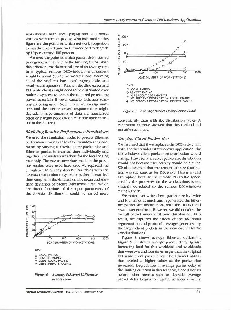
Ethernet Performance of Remote DECwindows Applications
workstations with local paging and 200 workstations with remote paging. Also indicated in this figure are the points at which network congestion causes the elapsed time for the workload to degrade by 10 percent and 100 percent.
We used the point at which packet delay started to degrade, in Figure 7, as the limiting factor. With this criterion, the theoretical size of an LAVc system in a typical remote DECwindows environment would be about 300 active workstations, assuming all of the satellites have local paging disks and steady-state operation. Further, the disk server and DECwrite clients might need to be distributed over multiple systems to obtain the required processing power especially if lower capacity Ethernet adapters are being used. (Note: These are average numbers and the user-perceived response time might degrade if large amounts of data are transferred often or if many nodes frequently transition in and out of the cluster.)
Modeling Results: Performance Predictions We used the simulation model to predict Ethernet performance over a range of DECwindows environments by varying DECwrite client packet size and Ethernet packet interarrival time individually and together. The analysis was done for the local paging case only. The two assumptions made in the previous section were used here also. We replaced the cumulative frequency distribution tables with the GAMMA distribution to generate packet interarrival time samples in the simulation. The mean and standard deviation of packet interarrival time, which are direct functions of the input parameters of the GAMMA distribution, could be varied more
KEY:
200 400 600 800
LOAD (NUMBER OF WORKSTATIONS)
1000
O LOCAL PAGING O REMOTE PAGING 6 DEBNI: LOCAL PAGING 'il DEBNI: REMOTE PAGING
Figure 6 Average Ethernet Utiliza.tion versus Load
Dig ital Tecbnlcaljo u rnal Vol. 2 No. 3 Summer 199()
LOAD (NUMBER OF WORKSTATIONS)
KEY:
D LOCAL PAGING O REMOTE PAGING 6 10 PERCENT DEGRADATION 'il 100 PERCENT DEGRADATION, LOCAL PAGING e 100 PERCENT DEGRADATION, REMOTE PAGING
1000
Figure 7 Average Packet Delay versus Load
conveniently than with the distribution tables. A calibration exercise showed that this method did not affect accuracy.
Varying Client Packet Size We assumed that if we replaced the DEC write client with another similar DECwindows application, the DECwindows client packet size distribution would change. However, the server packet size distribution would not because user activity would be similar. We also assumed that the remote I/0 size distribution was the same as for DECwrite. This is a valid assumption because the remote I/0 traffic generated by the processes on the workstations is not strongly correlated to the remote DECwindows client activity.
We varied DECwrite client packet size by twice and four times as much and regenerated the Ethernet packet size distributions with the DECnet and VAXcluster emulator. However, we did not alter the overall packet interarrival time distribution. As a result, we captured the effects of the additional segmentation and protocol messages generated by the larger client packets in the new overall traffic size distributions.
Figure 8 shows average Ethernet utilization. Figure 9 illustrates average packet delay against increasing load for this workload and workloads that were two and four times larger than the original DECwrite client packet sizes. The Ethernet utilization leveled at higher values as the packet size increased. Degradation in average packet delay is the limiting criterion in this scenario, since it occurs before other metrics start to degrade. Average packet delay begins to degrade at approximately
91
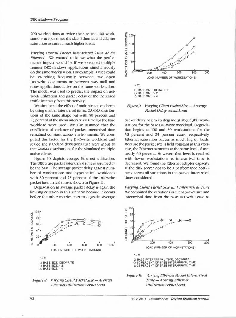
DECwindows Program
200 workstations at twice the size and 160 workstations at four times the size. Ethernet and adapter saturation occurs at much higher loads.
Varying Overall Packet lnterarrival Time at the Ethernet We wanted to know what the performance impact would be if we executed multiple remote DECwindows applications simultaneously on the same workstation. For example, a user could be switching frequently between two open DECwrite documents or between VMS mail and notes applications active on the same workstation. The model was used to predict the impact on network utilization and packet delay of the increased traffic intensity from this activity.
We simulated the effect of multiple active clients by using smaller interarrival times. GAMMA distributions of the same shape but with 50 percent and 25 percent of the mean interarrival time for the base workload were used. We also assumed that the coefficient of variance of packet interarrival time remained constant across environments. We computed this factor for the DECwrite workload and scaled the standard deviations that were input to the GAMMA distributions for the simulated multiple active clients.
Figure 10 depicts average Ethernet utilization. The DECwrite packet interarrival time is assumed to be the base. The average packet delay against number of workstations and hypothetical workloads with 50 percent and 25 percent of the DECwrite packet interarrival time is shown in Figure 11.
Degradation in average packet delay is again the limiting criterion in this scenario because it occurs before the other metrics start to degrade. Average
z 100 0 ~ 80 N ::J 60 ~ :)
1jj 40 z ffi 20 :i: ljj
0
LOAD (NUMBER OF WORKSTATIONS)
KEY:
O BASE SIZE, DECWRITE O BASE SIZE x 2 6 BASE SIZE x 4
1000
Figure 8 Varying Client Packet Size -Average Ethernet Utilization versus Load
92
gf 200 z 0 u w 150 en ::J ...J
~ 100
; w 50 0 f-w :.:
~ 0 200
LOAD (NUMBER OF WORKSTATIONS)
KEY:
O BASE SIZE, DECWRITE O BASE SIZE x 2 6 BASE SIZE x 4
1000
Figure 9 Varying Client Packet Size-Average Packet Delay versus Load
packet delay begins to degrade at about 300 workstations for the base DECwrite workload. Degradation begins at 100 and 50 workstations for the 50 percent and 25 percent cases, respectively. Ethernet saturation occurs at much higher loads. Because the packet size is held constant in this exercise, the Ethernet saturates at the same level of use, nearly 60 percent. However, that level is reached with fewer workstations as interarrival time is decreased. We found the Ethernet adapter capacity at the disk server not to be a performance bottleneck across all variations in the packet interarrival times considered.
Varying Client Packet Size and Interarrival Time We combined the variations in client packet size and interarrival time from the base DECwrite case to
z 100 0 ~ 80 N
::J 60 ~ :)
1jj 40 z ffi 20 :i: ljj
0 200 400 600
LOAD (NUMBER OF WORKSTATIONS)
KEY:
O BASE INTERARRIVAL TIME, DECWRITE 0 50 PERCENT OF BASE INTERARRIVAL TIME 6 25 PERCENT OF BASE INTERARRIVAL TIME
800
Figure 10 Varying Ethernet Packet Interarrival Time -Average Ethernet Utilization versus Load
Vol. 2 No. 3 Summer 1990 Digital Tecbntcaljournal
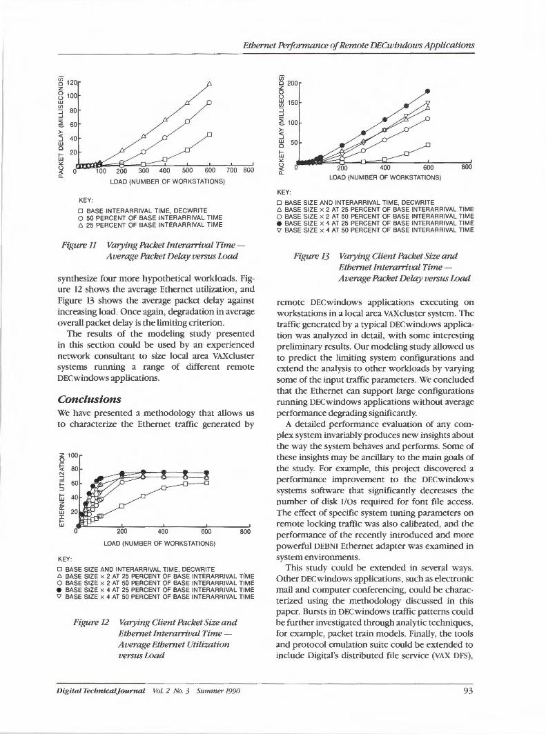
Ethernet Performance of Remote DECwindows Applications
~ 120 z 8 100 w
~ 80 ...J
~ 60
~ ...J 40 w c 20 f-w :.:: (.)
it O LOAD (NUMBER OF WORKSTATIONS)
KEY:
D BASE INTERARRIVAL TIME, DECWRITE O 50 PERCENT OF BASE INTERARRIVAL TIME t:,, 25 PERCENT OF BASE INTERARRIVAL TIME
700 800
Figure 11 Varying Packet Interarrival Time -Average Packet Delay versus Load
synthesize four more hypothetical workloads. Figure 12 shows the average Ethernet utilization, and Figure 13 shows the average packet delay against increasing load. Once again, degradation in average overall packet delay is the limiting criterion.
The results of the modeling study presented in this section could be used by an experienced network consultant to size local area VAXcluster systems running a range of different remote DECwindows applications.
Conclusions We have presented a methodology that allows us to characterize the Ethernet traffic generated by
~ 100
~ 80 N :J i= 60 ::> f-w z rr
20 w J: f-w
0
KEY:
200 400 600 800
LOAD (NUMBER OF WORKSTATIONS)
D BASE SIZE AND INTERARRIVAL TIME, DECWRITE t:,, BASE SIZE x 2 AT 25 PERCENT OF BASE INTERARRIVAL TfME O BASE SIZE x 2 AT 50 PERCENT OF BASE INTERARRIVAL TIME e BASE SIZE x 4 AT 25 PERCENT OF BASE INTERARRIVAL TIME 'v BASE SIZE x 4 AT 50 PERCENT OF BASE INTERARRIVAL TIME
Figure 12 Varying Client Packet Size and Ethernet Interarrival Time -Average Ethernet Utilimtion versus Load
D igital Tecbntcaljournal Vol. 2 No. 3 Summer 1990
cii c 200
~ (.)
~ 150 :J ...J
~ 100
~ ...J
~ 50
Iii :.::
~
KEY:
600
LOAD (NUMBER OF WORKSTATIONS)
D BASE SIZE AND INTERARRIVAL TIME, DECWRITE
800
t:,, BASE SIZE x 2 AT 25 PERCENT OF BASE INTERARRIVAL TIME O BASE SIZE x 2 AT 50 PERCENT OF BASE INTERARRIVAL TIME e BASE SIZE x 4 AT 25 PERCENT OF BASE INTERARRIVAL TIME 'v BASE SIZE x 4 AT 50 PERCENT OF BASE INTERARRIVAL TIME
Figure 13 Varying Client Packet Size and Ethernet Interarrival Time -Average Packet Delay versus Load
remote DECwindows applications executing on workstations in a local area VAXcluster system. The traffic generated by a typical DECwindows application was analyzed in detail, with some interesting preliminary results. Our modeling study allowed us to predict the limiting system configurations and extend the analysis to other workloads by varying some of the input traffic parameters. We concluded that the Ethernet can support large configurations running DECwindows applications without average performance degrading significantly.
A detailed performance evaluation of any complex system invariably produces new insights about the way the system behaves and performs. Some of these insights may be ancillary to the main goals of the study. For example, this project discovered a performance improvement to the DECwindows systems software that significantly decreases the number of disk I/Os required for font file access. The effect of specific system tuning parameters on remote locking traffic was also calibrated, and the performance of the recently introduced and more powerful DEBNI Ethernet adapter was examined in system environments.
This study could be extended in several ways. Other DECwindows applications, such as electronic mail and computer conferencing, could be characterized using the methodology discussed in this paper. Bursts in DECwindows traffic patterns could be further investigated through analytic techniques, for example, packet train models. Finally, the tools and protocol emulation suite could be extended to include Digital's distributed file service (VAX DFS),
93
DECwindows Program
and local area transport (LAT), as well as other network protocols.
This paper presents a checkpointing study of a new technology. By extending this work in some of the directions proposed, we would increase our understanding of the network performance issues associated with the X Window System computing paradigm.
Acknowledgments We wish to thank all those who made valuable contributions to this project. We would particularly like to acknowledge Mike Fox, VMS VAXcluster Systems Engineering Manager, for sponsoring this study; Ken Miller, formerly of BOSE Performance Engineering, for developing the DECwrite workload used in this project; K. K. Ramakrishnan, Distributed Systems Architecture and Performance, for providing information regarding Ethernet performance; and our colleagues in the VMS Systems Analysis and Availability Engineering and BOSE Functional Analysis Groups for providing useful suggestions at different stages of the project.
References 1. R. Scheifler et al., X Window System C Library
and Protocol Reference (Bedford: Digital Press, 1988).
94
2. M. Marathe and W. Hawe, "Predicting Ethernet Capacity-A Case Study," Proceedings of the Computer Perfomiance Evaluation User's Group (1982): 375-387.
3. W. Adams, "LAN Performance for Distributed Manufacturing Applications," ISA '89 Trade Conference Paper (October 22-27, 1989): 693-702.
4. R. Gussella, "The Analysis of Disk.less Workstation Traffic on an Ethernet," Report No. UCB/ CSD 87/379 Computer Sciences Division (EECS) (Berkeley: University of California, November 1987).
5. M. Fox and). Ywoskus, "Local Area VAXcluster Systems," Digital Technical]oumal, vol. 1, no. 5 (September 1987): 56-68.
6. A. Law and D. Kelton, Simulation Modeling and Analysis (New York: McGraw-Hill Book Company, 1982).
7. V. Fernandes et al. , "Some Performance Models of Distributed Systems," Proceedings of the CMG xv International Conference (December, 1984): 30-37.
8. D. Boggs et al. , "Measured Capacity of an Ethernet: Myths and Reality," Proceedings of SIGCOMM'BB(ACMSIGCOMM, 1988): 222-234.
Vol. 2 No. 3 Summer 1990 Dtgttal Tecbntcaljournal
I Further Readings
The Digital Technical Journal publishes papers that explore the technological foundations of Digitals major products. Each Journal focuses on at least one product area and presents a compilation of papers written by the engineers who developed the product. The content for the Journal is selected by the Journal Advisory Board.
Topics covered in previous issues of the Digital Technical Journal are as follows:
VAX 8600 Processor Vol. 1, No. 1, August 1985
MicroVAX II System Vol. 1, No. 2, March 1986
Networking Products Vol. 1, No. 3, September 1986
VAX 8800 Family Vol. 1, No. 4, February 198'7
VAXcluster Systems Vol. 1, No. 5, September 1987
Software Productivity Tools Vol. 1, No. 6, February 1988
CVAX-based Systems Vol. 1, No. 7, August 1988
Storage Technology Vol. 1, No. 8, February 1989
Distributed Systems Vol. 1, No. 9, June 1989
Compound Document Architecture Vol. 2, No. 1, Winter 1990
VAX 6000 Model 400 System Vol. 2, No. 2, spring 1990
Digital Tecbnical]ournal Vol. 2 No. 3 Summer 1990
Subscriptions to the Digital Technical Journal are available on a yearly, prepaid basis. The subscription rate is $40.00 per year (four issues). Requests should be sent to Cathy Phillips, Digital Equipment Corporation, MLOl-3/868, 146 Main Street, Maynard, MA 01754, U.S.A. Subscriptions must be paid in U.S.
dollars, and checks should be made payable to Digital Equipment Corporation.
Single copies and past issues of the Digital Technical Journal can be ordered from Digital Press at a cost of $16.00 per copy.
Readings Related to lbis Issue Listed below are articles and books that provide further reading on some of the topics covered in this issue. In addition, three books on related topics will be available from Digital Press in the near future. (See Digital Press section.)
"Adding a Dimension to X" Randi). Rost, UNIX Review, vol. 6, no. IO (October 1988): 50-59
"PEX Brings Networking to 3-D Graphics" Randi ). Rost and Jeffrey D. Friedberg, Computer Graphics Review, vol. 3, no. 5 (September/October 1988): 13-16
"The Development of PEX, a 3D Graphics Extension to Xll " William H. Clifford, Jr., John I. McConnell, and Jeffrey S. Saltz, Proceedings of EUROGRAPHICS '88, Elseviers Science Publishing Co. (New York: September 1988): 21-29
"User Interface Consistency in the DECwindows Program" Michael Good, Proceedings of the Human Factors Society, 32nd Annual Meeting, Vol. 1 (Santa Monica: 1988): 259-263
"Developing the XUI Style" Michael Good, Coordinating User Interfaces for Consistency(Academic Press, 1989): 75-78
"User-derived Impact Analysis as a Tool for Useability Engineering" Michael Good et al. , Proceedings CHI '86 Human Factors in Computing Systems (New York: 1986): 241- 246
95
Further Readings
OSF/Motif Style Guide Open Software Foundation (Prentice Hall, ISBN 0-13-640491-X)
OSF/Motif User's Guide Open Software Foundation (Prentice Hall, ISBN 0-13-640509-6)
OSF/Motif Programmer's Reference Open Software Foundation (Prentice Hall, ISBN 0-13-640517-7)
OSF!Motif Programmer's Guide Open Software Foundation (Prentice Hall, ISBN 0-13-640525-8)
OSF/Motif Application Environment Specifications (AES) Open Software Foundation (Prentice Hall, ISBN 0-13-640483-9)
The X Window System, Programming with Xt Douglas A. Young, OSF/Motif edition (Prentice Hall, ISBN 0-13-497074-8)
Digital Press Digital Press is the book publishing group of Digital Equipment Corporation. Digital Press publishes books internationally for computer professionals who specialize in the areas of networking and data communication, artificial intelligence, computerintegrated manufacturing, windowing systems, and the VMS operating system. Copies of the new titles now available from Digital Press that are listed below can be ordered by writing to Digital Press, Department DTJ, 12 Crosby Drive, Bedford, MA 01730, U.S.A.
UNIX for VMS Users Philip E. Bourne, 1990 ($28. 95)
The VMS User's Guide James F. Peters III and Patrick J. Holmay, 1990 ($28.95)
A Beginner's Guide to VAX/VMS Utilities and Applications Ronald M. Sawey and Troy T. Stokes, 1989 ($26.95)
\lorking with WPS-PLUS Charlotte Temple and Dolores Cordeiro, 1990 ($24 .95)
Information Technology Standardization: Theory, Practice, and Organizations Carl F. Cargill, 1989 ($24.95)
The Digital Guide to Software Development Corporate User Publication Group of Digital Equipment Corporation, 1990 ($27.95)
VMS Internals and Data Structures: Version 5 Update Xpress Ruth E. Goldenberg and Lawrence J. Kenah, Volumes 1, 2, 3, 4, 5, 1989, 1990, 1991 ($35.00 each)
VAX/VMS Internals and Data Structures: Version4.4 Lawrence J. Kenah, Ruth E. Goldenberg, and Simon
· F. Bate, 1988 ($75.00)
Computer Programming and Architecture: The VAX, Second Edition Henry M. Levy and Richard H. Eckhouse, Jr., 1989 ($38.00)
Using MS-DOS Kermit: Connecting Your PC to the Electronic World Christine M. Gianone, 1990 ($29.95 with Kermit diskette)
Technical Aspects of Data Communication, lbird Edition John E. McNamara, 1988 ($42.00)
The Matrix: Computer Networks and Conferencing Systems Worldwide John S. Quarterman, 1990 ($49.95)
The User's Directory of Computer Networks Tracy L. LaQuey, February 1990($34.95)
Fifth Generation Management: Integrating Enterprises Through Human Networking Charles M. Savage, 1990 ($28.95)
Common LISP: The Language, Second Edition Guy L. Steele Jr., 1990 ($38.95 in soft cover, $46.95 in cloth cover)
LISP Style and Design Molly M. Miller and Eric Benson, 1990 ($26.95)
ABCs of MUMPS: An Introduction for Novice and Intermediate Programmers Richard F. Walters, 1989 ($25.95)
Forthcoming from Digital Press in the near future are
X Window System, Second Edition Robert Scheller and James Gettys (due July 1990, $49.95)
X Window System Toolkit: The Complete Programmer's Guide and Specification Paul Asente and Ralph Swick (due August 1990, $44 .95)
X/MOTIF Quick Reference Guide Randi Rost (due October 1990, $24 .95)
Software Design Techniques for Large Ada Systems William Byrne (due September 1990, $44.95 hardcover)
Vol. 2 No. 3 Summer 1990 Digital TecbnicalJournal
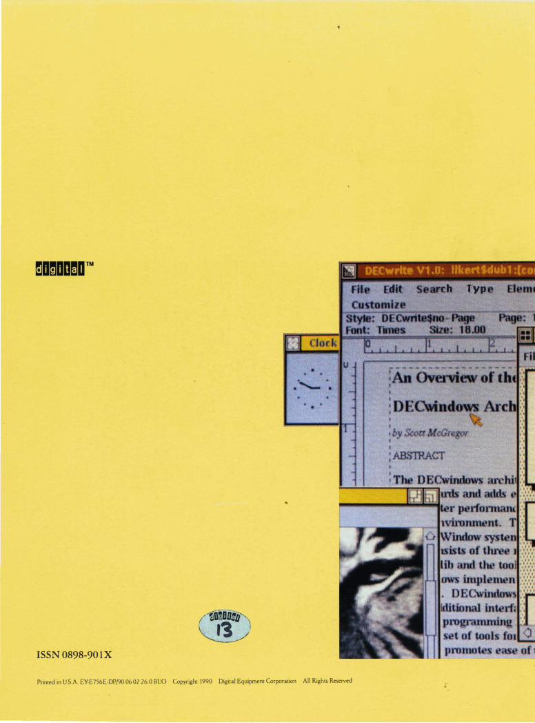
DECWrlttt V1 .0: likertSdub1
Fit dit rth Typ
. ·-........... · .
ISSN 0898-90 1 X
Printed in U.S.A. EY-E756E-DP/90 06 02 26.0 BUO Copyright 1990 Digital Equipment Corporation All Rights Reserved
•
•
..
;