Data Protection in the Cloud
123
Data Protection in the Cloud Jan de Muijnck-Hughes BSc (Hons) March, 2011 s0819824 Student No 640 Thesis No prof. Bart Jacobs and dr. Erik Poll Supervisor(s)
Transcript of Data Protection in the Cloud
Data Protection in the Cloud
Jan de Muijnck-Hughes BSc (Hons)March, 2011
s0819824 Student No640 Thesis No
prof. Bart Jacobs and dr. Erik Poll Supervisor(s)


Data Protection in the Cloud
THESIS
submitted in partial fulfillment of therequirements for the degree of
Master of Science
in
Computer Science
specialising in
Computer Security Research
byJan de Muijnck-Hughes BSc (Hons)
Digital Security Group,Institute for Computing and Information Sciences,
Faculty of Science,Radboud University Nijmegen,
Nijmegen, Gelderland,The Netherlands
http://www.ru.nl/ds


Abstract
Cloud Computing sees a technical and cultural shift of computing service provision frombeing provided locally to being provided remotely, and en masse, by third-party serviceproviders. Data that was once housed under the security domain of the service user hasnow been placed under the protection of the service provider. Users have lost control overthe protection of their data: No longer is our data kept under our own watchful eyes.
This thesis investigates how Predicate Based Encryption (PBE) could be leveraged withinthe Cloud to protect data. PBE is a novel family of asymmetric encryption schemes inwhich decryption of a cipher-text is dependent upon a set of attributes satisfying a certainpredicate, allowing for selective fine-grained access control to be specified over cipher-texts.
It is argued that obfuscation of one’s data is not enough when seeking to protect data.The control of how one’s data is used and the trust afforded to service providers is equallyas important. To this end, three archetypal scenarios are described that illustrate waysin which service users could specify precisely with whom they wish to share their data,for what purpose, and for how long. Furthermore, two additional scenarios are presentedthat would allow a service provider to facilitate keyword search over encrypted data usingexpressive queries supporting conjunction and disjunction of terms.


Declaration
I declare that the material submitted for assessment is my own work, except wherecredit is explicitly given to others by citation or acknowledgement.
In submitting this project to the Radboud Universiteit Nijmegen, I give permissionfor it to be made available for use in accordance with the regulations of the RadboudUniversiteit Nijmegen. I also give permission for the title and abstract to be publishedand for copies of the report to be made and supplied to any bona fide library orresearch worker, and to be made available on the World Wide Web.
Jan de Muijnck-Hughes BSc (Hons)March, 2011
iii


To-morrow, and to-morrow, andto-morrow. [. . . ] It is a tale, toldby an idiot, full of sound and fury,signifying nothing.
Macbeth (Act V, Sc. 5)
xYGUSPUVh4QeMU8


Contents
Declaration iii
Contents vii
Mathematical Notation xi
1 Introduction 11.1 Motivation: Alice and her Suitors . . . . . . . . . . . . . . . . . . . . . . . . . . . 11.2 Cloud Computing . . . . . . . . . . . . . . . . . . . . . . . . . . . . . . . . . . . . 11.3 Research Project and Objectives . . . . . . . . . . . . . . . . . . . . . . . . . . . 21.4 Research Outcomes . . . . . . . . . . . . . . . . . . . . . . . . . . . . . . . . . . . 21.5 Organisation . . . . . . . . . . . . . . . . . . . . . . . . . . . . . . . . . . . . . . 3
I Data Security within the Cloud 5
2 Defining Cloud Computing 72.1 Overview . . . . . . . . . . . . . . . . . . . . . . . . . . . . . . . . . . . . . . . . 72.2 Computing as a Service . . . . . . . . . . . . . . . . . . . . . . . . . . . . . . . . 72.3 Defining the Cloud . . . . . . . . . . . . . . . . . . . . . . . . . . . . . . . . . . . 92.4 Benefits of Cloud Computing . . . . . . . . . . . . . . . . . . . . . . . . . . . . . 10
3 Cloud Security Issues 113.1 Overview . . . . . . . . . . . . . . . . . . . . . . . . . . . . . . . . . . . . . . . . 113.2 Abuse and Nefarious Use of Cloud Computing . . . . . . . . . . . . . . . . . . . 113.3 Insecure Interfaces and APIs . . . . . . . . . . . . . . . . . . . . . . . . . . . . . 123.4 Malicious Insiders . . . . . . . . . . . . . . . . . . . . . . . . . . . . . . . . . . . . 123.5 Shared Technology Issues . . . . . . . . . . . . . . . . . . . . . . . . . . . . . . . 123.6 Data Loss or Leakage . . . . . . . . . . . . . . . . . . . . . . . . . . . . . . . . . 133.7 Account or Service Hijacking . . . . . . . . . . . . . . . . . . . . . . . . . . . . . 143.8 Unknown Risk Profile . . . . . . . . . . . . . . . . . . . . . . . . . . . . . . . . . 143.9 Jurisprudence Oriented Issues . . . . . . . . . . . . . . . . . . . . . . . . . . . . . 153.10 Summary . . . . . . . . . . . . . . . . . . . . . . . . . . . . . . . . . . . . . . . . 16
4 Cloud Threat Models 174.1 Overview . . . . . . . . . . . . . . . . . . . . . . . . . . . . . . . . . . . . . . . . 174.2 Threat Overview . . . . . . . . . . . . . . . . . . . . . . . . . . . . . . . . . . . . 174.3 The Lifecycle of Data . . . . . . . . . . . . . . . . . . . . . . . . . . . . . . . . . 184.4 Data Lifecycle Threat Models . . . . . . . . . . . . . . . . . . . . . . . . . . . . . 19
5 Data Security Requirements 215.1 Overview . . . . . . . . . . . . . . . . . . . . . . . . . . . . . . . . . . . . . . . . 215.2 Confidentiality . . . . . . . . . . . . . . . . . . . . . . . . . . . . . . . . . . . . . 215.3 Remote Access . . . . . . . . . . . . . . . . . . . . . . . . . . . . . . . . . . . . . 22
vii

Contents
5.4 Non-Repudiation . . . . . . . . . . . . . . . . . . . . . . . . . . . . . . . . . . . . 225.5 Integrity and Consistency . . . . . . . . . . . . . . . . . . . . . . . . . . . . . . . 225.6 Availability and Fault Tolerance . . . . . . . . . . . . . . . . . . . . . . . . . . . 235.7 Summary . . . . . . . . . . . . . . . . . . . . . . . . . . . . . . . . . . . . . . . . 23
6 The Trappings of a Solution 256.1 Overview . . . . . . . . . . . . . . . . . . . . . . . . . . . . . . . . . . . . . . . . 256.2 Defining Empowerment . . . . . . . . . . . . . . . . . . . . . . . . . . . . . . . . 256.3 In CSP, we Trust? . . . . . . . . . . . . . . . . . . . . . . . . . . . . . . . . . . . 276.4 Security Responsibilities . . . . . . . . . . . . . . . . . . . . . . . . . . . . . . . . 286.5 Towards a Solution . . . . . . . . . . . . . . . . . . . . . . . . . . . . . . . . . . . 29
II Predicate Based Encryption 31
7 Introduction to PBE 337.1 Overview . . . . . . . . . . . . . . . . . . . . . . . . . . . . . . . . . . . . . . . . 337.2 Definition . . . . . . . . . . . . . . . . . . . . . . . . . . . . . . . . . . . . . . . . 337.3 Characteristics . . . . . . . . . . . . . . . . . . . . . . . . . . . . . . . . . . . . . 347.4 Access Control . . . . . . . . . . . . . . . . . . . . . . . . . . . . . . . . . . . . . 367.5 Attributes . . . . . . . . . . . . . . . . . . . . . . . . . . . . . . . . . . . . . . . . 367.6 Access Policies . . . . . . . . . . . . . . . . . . . . . . . . . . . . . . . . . . . . . 377.7 Note on Existing Schemes . . . . . . . . . . . . . . . . . . . . . . . . . . . . . . . 39
8 Constructing PBE Schemes 418.1 Overview . . . . . . . . . . . . . . . . . . . . . . . . . . . . . . . . . . . . . . . . 418.2 Pairing Based Cryptography . . . . . . . . . . . . . . . . . . . . . . . . . . . . . . 418.3 General Predicates and LSSS . . . . . . . . . . . . . . . . . . . . . . . . . . . . . 428.4 Transforming an Access Policy into a LSSS . . . . . . . . . . . . . . . . . . . . . 448.5 Waters Construction . . . . . . . . . . . . . . . . . . . . . . . . . . . . . . . . . . 468.6 Security Discussion . . . . . . . . . . . . . . . . . . . . . . . . . . . . . . . . . . . 48
9 Using PBE in Crypto-Systems 539.1 Introduction . . . . . . . . . . . . . . . . . . . . . . . . . . . . . . . . . . . . . . . 539.2 General Model . . . . . . . . . . . . . . . . . . . . . . . . . . . . . . . . . . . . . 539.3 The Key Authority . . . . . . . . . . . . . . . . . . . . . . . . . . . . . . . . . . . 549.4 Issuing Keys . . . . . . . . . . . . . . . . . . . . . . . . . . . . . . . . . . . . . . . 569.5 Constructing Keys . . . . . . . . . . . . . . . . . . . . . . . . . . . . . . . . . . . 579.6 Key Revocation . . . . . . . . . . . . . . . . . . . . . . . . . . . . . . . . . . . . . 599.7 Types of Crypto-System . . . . . . . . . . . . . . . . . . . . . . . . . . . . . . . . 609.8 Using Predicate Based Encryption . . . . . . . . . . . . . . . . . . . . . . . . . . 64
10 Evaluating PBE 6710.1 Novelty of PBE . . . . . . . . . . . . . . . . . . . . . . . . . . . . . . . . . . . . . 6710.2 Comparison with Existing Systems . . . . . . . . . . . . . . . . . . . . . . . . . . 6710.3 Mode of Operations . . . . . . . . . . . . . . . . . . . . . . . . . . . . . . . . . . 6910.4 Security Issues . . . . . . . . . . . . . . . . . . . . . . . . . . . . . . . . . . . . . 6910.5 Deployment Issues . . . . . . . . . . . . . . . . . . . . . . . . . . . . . . . . . . . 71
III Leveraging PBE in the Cloud 75
11 Scenarios for using PBE in the Cloud 7711.1 Overview . . . . . . . . . . . . . . . . . . . . . . . . . . . . . . . . . . . . . . . . 7711.2 Leveraging PKI Mode . . . . . . . . . . . . . . . . . . . . . . . . . . . . . . . . . 7711.3 Leveraging DDI Mode . . . . . . . . . . . . . . . . . . . . . . . . . . . . . . . . . 7911.4 Leveraging MCP Mode . . . . . . . . . . . . . . . . . . . . . . . . . . . . . . . . . 8011.5 Summary . . . . . . . . . . . . . . . . . . . . . . . . . . . . . . . . . . . . . . . . 82
viii

Contents
12 Discussing PBE in the Cloud 8312.1 Overview . . . . . . . . . . . . . . . . . . . . . . . . . . . . . . . . . . . . . . . . 8312.2 What can PBE be used to Protect? . . . . . . . . . . . . . . . . . . . . . . . . . . 8312.3 Effect of Cryptographic Operation Placement . . . . . . . . . . . . . . . . . . . . 8412.4 Fulfilling the remit of the Key Authority . . . . . . . . . . . . . . . . . . . . . . . 8512.5 Comparing Scenarios . . . . . . . . . . . . . . . . . . . . . . . . . . . . . . . . . . 85
IV Conclusion and Further Research 87
13 Conclusion 89
14 Further Research 9114.1 Attribute Based Signing . . . . . . . . . . . . . . . . . . . . . . . . . . . . . . . . 9114.2 Decentralising the Key Authority . . . . . . . . . . . . . . . . . . . . . . . . . . . 9114.3 Cryptographic Keys . . . . . . . . . . . . . . . . . . . . . . . . . . . . . . . . . . 9214.4 Use Case Development . . . . . . . . . . . . . . . . . . . . . . . . . . . . . . . . . 9214.5 Practical Considerations . . . . . . . . . . . . . . . . . . . . . . . . . . . . . . . . 92
Bibliography 93
Content Listings and Glossary 103
List of Acronyms 105
List of Figures 106
List of Definitions 107
ix


Mathematical Notation
Symbol Term Description
A Access Structure A data structure that describes sets ofauthorised items.
{|M |}K Asymmetric Cryptography Represents asymmetric cryptographicoperations.
S Attribute Set Represents a set of attributes from U
U Attribute Universe Represents the universe of all attrib-utes used.
CT Cipher-text Information that has been encryptedinto a ‘meaningless’ form.
Dec(Entity) Decryption Key Decryption (private) key of an Entity
Enc(Entity) Encryption Key Encryption (public) key of an Entity
H Hash Well defined procedure to convertarbitrary data into a fixed-size bitstring.
IDentity Identity Represents the identity of an entity.
MPK Master Public Key Public parameters of a crypto-system.
MSK Master Secret Key Private global parameters of a crypto-system.
M Message Unencrypted information that is read-able to all.
(M, ρ) Monotone Span Program A data structure used to describe anyaccess structure.
A→ B : M Send Message Send a message m from Entity A toEntity B.
{M}K Symmetric Cryptography Represents symmetric cryptographicoperations.
xi


Chapter 1
Introduction
Perfer et obdura; dolor hic tibiproderit olim.
Ovid
1.1 Motivation: Alice and her Suitors
The use of encryption schemes is often described through an analogy depicting the transmissionon a plain-text message M from one entity, Alice to another entity, Bob. Here Alice wishes toensure that only Bob will be able to read M . This analogy has persisted due to its ability todescribe a prevalent communication style, that of unicast communication. However, this simpleanalogy does not necessarily represent the entirety of communication styles that are activelyused, it does not take into account multicast communication: What if Alice’s wish were to sendher message not to Bob but to Bobs plural?
Traditional symmetric and asymmetric encryption schemes can be leveraged to provide Alicewith a secure means through which she can send her message. However, with symmetric schemeseach recipient will be in a position to decrypt all cipher-texts that have been encrypted with thesame key: Access is too coarse-grained. With asymmetric schemes the encrypting entity needs toexplicitly state for whom decryption is permissible: Access is too fine-grained. To reference thedifferent styles of communication, symmetric schemes represent broadcast communication andasymmetric schemes unicast communication. A multicast encryption scheme is required thatallows for a more expressive fine-grained means through which Alice can specify access over herdata.
A promising solution to ‘multicast’ encryption is that of Predicate Based Encryption (PBE).PBE is a novel family of asymmetric encryption schemes in which decryption of a cipher-textis dependent upon a set of attributes satisfying a predicate. A generalisation of both AttributeBased Encryption (ABE) [SW05] and Identity Based Encryption (IBE) [Sha85], PBE allows forselective fine-grained access control to be specified over encrypted data. Generally speaking,attributes are used to construct users’ decryption keys and to encrypt plain-text messages.Decryption occurs when a match occurs between the attributes held by the entity (in theirdecryption key) and the attributes used to construct a cipher-text. This matching occurs throughthe use of predicates, that describe: a) the required attributes needed to decrypt; and b) therelationship between the attributes.
1.2 Cloud Computing
Cloud Computing is the name given to the recent trend in computing service provision. Thistrend has seen the technological and cultural shift of computing service provision from beingprovided locally to being provided remotely and en masse, by third-party service providers[Hay08]. Functionality such as storage, processing and other functionality is now offered ondemand, as a service and both freely and at cost [AF+09]. Data, that was once housed under aconsumers own administrative and security domain, has now been extracted and placed underthe domain of the Cloud Service Provider (CSP) [Pea09]. The consumer has effectively lostcontrol over how their data is being stored, shared and used, and also over the security used
1

1. Introduction
to protect their data. Moreover, it can be the case that a surreptitious employee of the serviceprovider will have access to your data for legitimate purposes but will abuse this power for theirown means [Won10]. Users are no longer in full control over the security of their data and theprotection offered by the service provider is not absolute. There is a need for users to have morecontrol over the protection of their data within the cloud: Users need to become empowered.
1.3 Research Project and Objectives
Given service users’ need to regain control over their data together with PBE’s ability to offerselective fine-grained access control over encrypted data. This thesis seeks to investigate:
How Predicate Based Encryption schemes can be lever-aged within the Cloud to protect data.
The investigation was divided broadly into three stages.
• Data Security and the Cloud. The initial stage sought to provide a clear definition forCloud Computing and the security issues therein, looking to identify precisely where andwhen threats can occur to data and how these threats ought to be mitigated.
• Predicate Based Encryption. The next stage focused solely upon PBE schemes discussinghow they work and what they allow for. This provided a foundation upon which theirdeployment as part of a crypto-system could be explored and to define the types of problemthat PBE schemes can be used to solve.
• Leveraging PBE. The final stage of the investigation built upon, and combined the results,of the previous stages. Here the investigation looked to determine the problems that PBEschemes can be used to solve within the Cloud, and the quality of solution provided.
1.4 Research Outcomes
From the investigation, it was determined that PBE can be used to protect data within thecloud. The main results for each stage of the investigation are outlined below.
• Data Security and the Cloud. From the initial stage two threat-models were produced:one user, and the other CSP orientated. These models described the threats upon data interms of the data lifecycle. Furthermore, it was determined that a privacy model centredaround Kafka’s The Trial together with the idea that the CSP provider could be trustedfacilitates a better understanding of the problems present within the Cloud and how suchproblems can be solved.
• Predicate Based Encryption. Characteristics that can be used to categorise PBE schemeswere identified. Of which predicate placement had the greatest affect upon the accesscontrol afforded by the scheme. A generic model for deploying PBE schemes as part of acrypto-system was developed. From this model three modes of operation that characterisesthe deployment of a PBE scheme were identified.
• Leveraging Predicate Based Encryption. Three scenarios are described that illustrate waysin which service users could specify precisely with whom they wish to share their data,for what purpose, and for how long. Furthermore, two additional scenarios are presentedthat would allow a service provider to facilitate keyword search over encrypted data usingexpressive queries supporting conjunction and disjunction of terms.
2

1.5. Organisation
1.5 Organisation
Part I: Data Security and the Cloud Within the first part of the thesis a definition towardsCloud Computing is given (Chapter 2) together with an overview of the technical andlegal security issues found therein—Chapter 3. Chapter 4 introduces two threat modelsthat establish what threats can occur to data in the Cloud and where. Several securityrequirements that govern data in the Cloud are discussed in Chapter 5. Finally this partconcludes with Chapter 6 that provides a discussion over the trappings of what makes agood solution.
Part II: Predicate Based Encryption The second part of this thesis introduces PBE, theconstruction of PBE schemes, and PBE schemes use as part of a cryptographic system.As with any modern encryption scheme the mathematics involved can be complex andintimidating for those not already versed in the field. Chapter 7 provides a high-leveloverview towards PBE schemes and their operation. For those more versed in mathemat-ics, Chapter 8 looks at the underlying mathematics surrounding the construction of PBEschemes that use general predicates. Chapter 9 discusses the use of PBE as a part of acryptographic system. Finally, Chapter 10 provides an evaluation over PBE.
Part III: Leveraging PBE in the Cloud The third part of this thesis discusses how PBEcould be leveraged within the Cloud. Chapter 11 introduces five scenarios and Chapter 12evaluates them.
Part IV: Conclusion, Reflection, and Further Work Chapter 13, provides a summary overthe research findings and Chapter 14 provides information pertaining to future directionsthat this topic could be taken in and over related areas of interest.
3


Part I
Data Security within the Cloud
5


Chapter 2
Defining Cloud Computing
A definition for Cloud Computing is given together with an overview concerningcomputing as a service and the benefits from using the Cloud.
2.1 Overview
Cloud Computing is the name given to a recent trend in computing service provision. This trendhas seen the technological and cultural shift of computing service provision from being providedlocally to being provided remotely and en masse, by third-party service providers [Hay08]. Thesethird-parties offer consumers an affordable and flexible computing service that consumers wouldotherwise not have been accessible, let alone afford [MKL09, Chapter 1]. This new means ofservice provision has evolved from and is the culmination of research stemming from (amongothers) distributed and networked systems, utility computing, the web and software servicesresearch [Vou08; AF+09]. This paradigm shift has led to computing being seen as anotherhousehold utility, aka “fifth utility”, and has prompted many a business and individual to migrateparts of their IT infrastructure to the cloud and for this data to become managed and hostedby Cloud Service Providers (CSPs). However, Cloud Computing is the cause celebre amongtech pundits and has led to the term ‘Cloud Computing’ as an umbrella term being applied todiffering situations and their solutions. As such a broad range of definitions for Cloud Computingexists, each of which differ depending on the originating authors’ leaning. This chapter seeks toprovide a coherent and general introduction to Cloud Computing.
2.2 Computing as a Service
One of the main tenets of Cloud Computing is the ‘as-a-Service’ paradigm in which ‘some’ serviceis offered by a Service Provider (also known as a Cloud Service Provider) to a User (consumer) foruse. This service can also be categorised according to the application domain of its deployment.Examples of application domains that offer services are: Financial e.g. Mint.com, Manageriale.g. EverNote and Analytical e.g. Google Analytics. The agreed terms of use, indicating theactions that must be taken by both the provider and consumer, are described in a contract thatis agreed upon before service provision. Failure to honour this agreement can lead to denialof service for the consumer or legal liability for the service provider. This contract is oftendescribed as a Terms of Service or Service Level Agreement. Moreover, as part of this agreementthe service provider will provide a Privacy Policy which outlines how the users data will bestored, managed, used and protected.
2.2.1 Service Levels
The services offered are often categorised using the SPI Service Model. This model representsthe different layers/levels of service that can be offered to users by service providers over thedifferent application domains and types of cloud available [MKL09, Chapter 2]. Clouds can beused to provided as-a-Service: software to use, a platform to develop on, or an infrastructure toutilise. Figure 2.1 summarises the SPI Service Model.
Software as a Service The first and highest layer is known as: Software as a Service (SaaS). Itrepresents the applications that are deployed/enabled over a cloud by CSPs. These are mature
7

2. Defining Cloud Computing
SoftwarePlatform
Infrastructure
Pub
lic Hyb
rid
Private
Financ
e
Managem
ent
Securi
ty
Analy
tics
Other
ServiceLayers
Deplo
yment
Models
Application Domains
Figure 2.1: Summary of the SPI Service Model
applications that often offer an API to allow for greater application extensibility. For instance,Google Docs can be seen as the archetypal SaaS application, it has been deployed solely withinthe Cloud and offers several APIs to promote use of the application.
Platform as a Service The next layer is known as: Platform as a Service (PaaS). This representsa development platform that developers can utilise to write, deploy and manage applications thatrun on the cloud. This can include aspects such as development, administration and managementtools, run-time and data management engines, and security and user management services. Forinstance, Force.com and Amazon Web Services [AWS] offers a suite of services that allowsdevelopers to construct an application that is deployed using web-based tooling.
Infrastructure as a Service The final and lowest layer is known as: Infrastructure as a Ser-vice (IaaS). CSP offer developers, a highly scaled and elastic computing infrastructure that areused to run applications. This infrastructure can be comprised of virtualised servers, storage,databases and other items. Two well known examples are the Amazon Elastic Compute Cloud,a commercial platform offered as part of Amazon.com’s Web Service platform and Eucalyptus,an open source platform that offers the same functionality [AWS; NW+09].
2.2.2 Entities Involved
Cloud actors/entities can be divided into two main categories: A) CSP or Service Providerthose who provide a service; and B) Cloud Service User (Users) those who use a service. WithinCloud Computing the differences between the role played by a service provider and a user can beblurred. The service provider could also be the user of another service e.g. when infrastructureis the service. The exact definition whether an entity is a provider or user is dependent on thecontext of the interaction and the service being offered. Some service providers will offer servicesat all three service levels, or offer just one particular level of service and have their own internalIaaS infrastructure.
A possible refinement could be that CSP providers are either: a) Infrastructure ServiceProviders—those that offer IaaS and own and run the data centers that physically house theservers and software; or b) Service Providers—those that offer PaaS or SaaS services. AndthatCloud Service Users are either: A) Platform Users— are users who buy into a serviceproviders platform e.g. Facebook; and B) Consumers—are service users who use either SaaS orIaaS services.
8

2.3. Defining the Cloud
2.3 Defining the Cloud
The term ‘cloud’ has been used traditionally as a metaphor for networks and helps abstractover their inherent complexity. This term, however, has evolved to encompass the transparencybetween the technological infrastructure of the CSP and the consumers point of view. A cloudcan be one of the following types:
Public Constituting publicly accessible services that are accessed over the Internet and areoften described using the term “The Cloud”.
Private These are private services deployed on private networks. Such clouds may also bemanaged by third parties.
Hybrid A combination of services offered both privately and publicly. For example core-servicesmay be offered on a private cloud; other services originate from public clouds.
Vaquero, Rodero-Merino et al. provides a definition for Clouds based upon the commonalitiesfound among existing definitions [VRM+09]. They define Clouds to be:
“. . . a large pool of easily usable and accessible virtualized resources (such as hard-ware, development platforms and/or services). These resources can be dynamicallyreconfigured to adjust to a variable load (scale), allowing also for an optimum re-source utilization. This pool of resources is typically exploited by a pay-per-use modelin which guarantees are offered by the Infrastructure Provider by means of customizedSLAs.”
The provision of virtualised resources, as a service, allows for an elastic and on demand com-puting environment that can be expanded and shrunk as needed, depending on the needs of theconsumer. Mather, Kumaraswamy and Latif [MKL09, Chapter 2] provides a slightly alternatedefinition. This definition is based on five attributes that can be used to describe a cloud-basedsystem. They are:
Multi-tenancy The sharing of resources being offered by the service providers to the consumersat the network, host and application level.
Massive Scalability The ability to scale the storage, bandwidth and systems available to pro-portions unattainable if performed by the organisation itself.
Elasticity Consumers can rapidly and dynamically increase and decrease the resources requiredas needed.
Pay-as-you-go Consumers only pay for the resources they consume such as processing cyclesand disk space.
Self-Provisioning of Resources Consumers have the ability for the self-provisioning of re-sources.
This is a better definition, it does not pertain to a particular technology. However, one attributePay-as-you-go is in itself too constrictive as it pertains to a particular style of payment andprohibits subscription based models. A better attribute should be:
Flexible Payment Payment for resource usage is flexible and consumers can be offered differ-ent payment models dependent on their intended use of the resources.
For instance in Amazon EC2 pricing for image use is dependent on three factors: 1. Image Type—On Demand, Reserved, Spot 2. OS Used—UNIX/LINUX or Windows; and 3. Data Center Loca-tion—West Coast America, East Coast America or Ireland. Consumers are billed differently perhour based upon these factors and other services used [AWS-Pricing]. On the other-hand GoogleApps Premium Edition will cost companies $50 per user per year for their IT infrastructuresolution [GooApps] and users will have a fixed set of resources. The use of such models oftenensures for a lower operational cost than when compared with an in-house solution.
9

2. Defining Cloud Computing
CloudController
Physical Machine Physical Machine
. . .
Service
Virtualised Resource
Consumer
Figure 2.2: The Data Center Model for Cloud Computing.
When discussing the physical constructions of Clouds the Data Center Model is a popularchoice. This model stipulates clusters of machines running specialist, dedicated hardware andsoftware to provide the infrastructure for the large scale provision of virtualised resources [AWS;NW+09]. Though a consumer can access the virtualised resources directly, when managing theirresources, consumers interact with a Cloud Controller that mediates the interaction betweenthe consumer, and: a) the physical machines; and b) the virtualised resources owned by theconsumer. Figure 2.2 illustrates a rather simplified view of this data center model. A moreinteresting realisation of clouds is the Adhoc model in which the existing (idle) computing powerwithin an enterprise is tapped to provide the required infrastructure. The more interested readeris asked to read Kirby, Dearle et al. [KD+09] for more information concerning the adhoc cloudmodel.
2.4 Benefits of Cloud Computing
Many of the benefits to be had when using Cloud Computing are the lower costs associated. Atthe infrastructure level, virtual images can be scaled and contracted with complete disregard forany associated hardware costs such as equipment procurement, storage, maintenance and use.This is all taken care of by the service provider and will be factored into the payment for theservice: capital expenditure has been converted into operational expenditure. Resources withinthe cloud can be treated as a commodity, an ‘unlimited’ medium. At both the platform andsoftware level similar benefits are seen. Aspects such as software installation, deployment andmaintenance is virtually non-existent. This is taken care of by the provider within their owninfrastructure. The service user only pays technical support.
Service providers at the SaaS level, often tout features that allow users to collaborate andinteract with each other, in real-time, within the scope of the service being offered. For example,Google Docs allows users to edit documents simultaneously and for users to see each others editsin real time. Moreover, the provision of platform and software ‘as a service’ allows cloud serviceusers the ability to aggregate services together either for their own use or to promote as anotherservice i.e. Mashups. The aggregation could imply the combination of functionality from severalservices, or the change/combination of output from the services involved.
Remark. Service aggregation is a good example outlining how a service user can become aservice provider.
10

Chapter 3
Cloud Security Issues
Security issues to be found within the cloud from both a technical and socio-technicalperspective are discussed.
3.1 Overview
Security issues come under many guises both technical and socio-technical in origin. To coverall the security issues possible within the cloud, and in-depth, would be herculean—a task notsuited even for Heracles himself. Existing efforts look to provide a taxonomy over the issuesseen. The Cloud Security Alliance1 is a non-profit organisation that seeks to promote the bestpractises for providing security assurance within the cloud computing landscape. In Hubbard,Sutton et al. [HS+10] the Cloud Security Alliance identify seven threats to cloud computingthat can be interpreted as a classification of security issues found within the cloud. They are:
1. Abuse and Nefarious Use of Cloud Computing
2. Insecure Application Programming Interfaces
3. Malicious Insiders
4. Shared Technology Vulnerabilities
5. Data Loss/Leakage
6. Account, Service and Traffic Hijacking
7. Unknown Risk Profile
For an alternate classification of threats to Cloud Computing, one can consult [ENISA-CC-RA09]. This chapter provides a general view of the security issues within the scope of thethreats presented by the Cloud Security Alliance. This chapter concludes with an overview ofthe legislative aspects governing security within the cloud.
3.2 Abuse and Nefarious Use of Cloud Computing
Legitimate CSPs can be abused for nefarious purposes, supporting criminal or other untowardactivities towards consumers. For instance, services can be used to host malicious code or used tofacilitate communication between remote entities i.e. botnets. The emphasis is that legitimateservices are used with malicious intent in mind. Other issues seen include the provision ofpurposefully insecure services used for data capture.
Service providers may entice potential users with offers too good to be true. For examplethe promise of unlimited resources or a ‘30-day Free Trial’. During the registration processthe consumer will be asked to provide more information than what would normally be requiredunder the pretence of providing service personalisation e.g. location or age based advertisement.Commonly asked information includes the consumers name, email/postal address, D.O.B oreven credit card details. Users are essentially being goaded to part with more informationthan required as a prerequisite for service use. Malicious entities can then use this information
1http://www.cloudsecurityalliance.org/
11

3. Cloud Security Issues
for nefarious purposes, most notably identity theft. Even if the entities are not malicious thedisclosure of information to the CSP can also be said to be an abuse of service by the CSPthemselves. CSPs may collect this information, or any other information provided at laterstages, and market this information to third parties for data mining purposes. This is akin tostore cards such as Tesco Clubcard in which the perceived benefits i.e. monetary savings, comeat the cost of handing over personal information such as shopping habits.
Another security issue found is the provision of legitimate maliciously-oriented services. Thisservice provision. also known as (In)Security-as-a-Service, offers users the same security guaran-tees as existing services yet their use is malicious. For example http://www.wpacracker.com/
is a cloud-based cracking service that can be used to ‘check’ the security of WPA-PSK protectedwireless networks. By using a cloud based service it is claimed that a process that would takearound five plus days now takes on average twenty minutes.
3.3 Insecure Interfaces and Application Programming Interfaces
Data placed in the Cloud will be accessed through Application Programming Interfaces (APIs)and other interfaces. Malfunctions and errors in the interface software, and also the softwareused to run the Cloud, can lead to the unwanted exposure of users data and impugn uponthe data’s integrity. For example a (fixed) flaw in Apache, a popular HTTP server, allowed anattacker to gain complete control over the web server [Ho10]. Data exposure can also occur whena software malfunction affects the access policies governing users data. This has been seen inseveral Cloud based services in which a software malfunction resulted in which a users privacysettings were overwritten and the user data exposed to non-authorised entities [For10; Vas09].Threats can also exist as a result of poorly designed or implemented security measures. If thesemeasures can be bypassed, or are non-existent, the software can be easily abused by maliciousentities. Regardless of the threat origin, APIs and other interfaces need to be made secureagainst accidental and malicious attempts to circumvent the APIs and their security measures.
3.4 Malicious Insiders
Although a CSP can be seen as being honest their employees may not be. A malicious insideris an employee of the CSP who abuses their position for information gain or for other nefariouspurposes e.g. disgruntled employee. Regardless, of the employees motivation the worrying aspectis that a surreptitious employee will have access to consumers data for legitimate purposes butwill abuse this power for their own means [Won10].
Another more subtle form of the malicious insider problem is through PaaS based services.If the service provider offers a platform that allows developers the ability to interact with usersdata i.e. Facebook Applications, users may unknowingly allow these developers access to all theirdata. Use of this platform may be unchecked. For example, it is well known on the FacebookPlatform that once a user adds an application the application will have the ability to accessall the users information, if allowed to do so, regardless of the applications function. With thepopularity of these applications it raises the question of: How safe are Cloud based applications?Even if the application developers are not malicious this does not mean that the applicationcannot be hacked [Tho09; ACLU-fb-app; Per09].
3.5 Shared Technology Issues
A more interesting form of confidentiality issue relates to the construction of a cloud and theservices themselves.
3.5.1 Virtualisation Issues
The underlying virtualisation architecture allows IaaS service providers the ability to host severalmachine images on a single server. Ristenpart, Tromer et al. [RT+09] discuss practical attackson such services, concentrating on Amazon EC2. First, the authors showed that they couldmap the internal structure of the cloud, allowing them to determine if two virtual machineswere co-resident with each other i.e. were running on the same physical machine. Secondly, they
12

3.6. Data Loss or Leakage
demonstrated that they were able to, purposefully, add a virtual machine to the cloud so thatit was co-resident with another machine. Finally, the authors were able to show that once amachine was co-resident, they would be able to launch several attacks that would allow them tolearn information regarding CPU cache use, network traffic rates and keystroke timings.
3.5.2 Service Aggregation
Aggregated services offer services based upon the functionality offered by existing services. Oftenaggregated services offer the combined functionality of existing services allowing for rapid serviceconstruction. However, service aggregation presents consumers with several interesting problems[Pea09]. Data is now being shared across multiple service providers whose privacy policies willalso subject to change. Under whose privacy policy is the data governed by, how to combinethe two policies? Furthermore, service aggregation can occur in an ad-hoc and rapid mannerimplying that less stringent controls could have been applied to the protection of data, increasingthe likelihood of a problem.
3.6 Data Loss or Leakage
Although insecure APIs can lead to data loss or the unwanted exposure of information, consumerscan also loose their information through other means.
3.6.1 Availability Issues
Availability issues are when users data is made inaccessible to the consumer. The data has beenmade unavailable. Such a lack of availability can be a result of access privilege revocation, datadeletion or restricting physical access to the data itself. Availability issues can be attributedto an attacker using flooding based attacks [JGL08]. For example, Denial of Services attacks,attempt to flood the service with requests in an attempt to overwhelm the service and cease allof the services intended operations.
A monetary effect can also be seen with availability issues. Monetary issues affect not only theconsumer but also the CSP. Recall from Section 2.3, that one of the benefits of Cloud Computingis that of Flexible Payment, consumers can be charged on a pay-as-you-go tariff. Flooding attackswill have an effect upon resource utilisation and will result in increases to power consumption,network usage and hardware maintenance. Ultimately this will also increase the amount ofmoney the consumer will be charged for resource usage. Moreover, these monetary increases willalso increase the operational expenditure of the service provider [JS09].
Fault tolerance protocols are used to combat the issue of node failure within the Cloud [Cri91].Fault tolerance protocols replicate data across machines, and data centers, ensuring that if partof the cloud does fail a version of the data will still be available to the user. Part of the cloudwill be redundant though for good measure. Data replication also requires that the data stateof the data be synchronised across multiple nodes. However, poorly designed protocols can alsolead to availability issues. Birman, Chockler and Renesse [BCR09] discuss that synchronisationprotocols with tightly coupled nodes have more adverse affects such as higher network usage anddeadlock when compared to loosely coupled asynchronous nodes. Furthermore, the existence ofmultiple copies of data can also introduce confidentiality problems. The increased number ofdata instances also increases the likelihood that an attacker will be able to access the data.
3.6.2 Data Leakage
Another form of data leakage stems from the disclosure of information that, though hidden, isdeduced from freely available information. For example: say that Bob is a member of a rathermasculine society i.e. rugby club. Say that Bob is also homosexual and is actively involved withan LGBT society. Bob may wish to keep his sexuality a secret from his friends in the rugby clubdue to fears of being emasculated. In this situation Bob will wish to keep his on-line activitiesinvolving these two facets of his private life separate. However, this does not mean that neverthe twain shall never meet. In Chew, Balfanz and Laurie [CBL08] the authors discuss waysin which the privacy of social networking sites can be undermined. The authors describe how
13

3. Cloud Security Issues
such personal information e.g. Bob’s sexuality, can be disclosed from unwelcome linkage and alsothrough social graph merger.
When users interact with a service they can leave a public trail, be it from status/updatemessages or through new postings. Unwelcome linkage occurs when new information is discernedabout an individual through analysis of the individuals public trail i.e. links. This unwelcomelinkage could be accidental or the result of the individual not covering their tracks. That isBob may keep a private, anonymous blog detailing his frustration with being homosexual in therugby club and use a photo from an online photo account that is linked to his real identity. Thisis accidental linkage. Similarly, a friend of Bob’s from the LGBT society could place a link toBob’s blog within their own blog and refer to Bob’s real identity. This is defined as trackbacklinkage from Chew, Balfanz and Laurie [CBL08].
Social graph merging is similar to unwelcome linkage however the links formed occur throughthe aggregation of social graphs. A social graph is a graph describing a person’s social informationsuch as friends, groups and interests.
Through combination of a persons social graphs from separate social networking sites, orthe social graphs of people from the same social network site, new information can be deduced.Continuing with the example of Bob used earlier, it is feasible that through the analysis ofBob’s social graph, and the social graphs of his friends, Bob’s sexual orientation can be deduced.This attack to determine the sexual orientation of a person and the ability to ‘out’ them wasshown to be feasible in Jernigan and Mistree [JM09]. The authors determined that the morehomosexual friends that an individual has the higher the probability that the person was alsohomosexual. Furthermore, both Narayanan and Shmatikov [NS09] and Wondracek, Holz et al.[WH+10] demonstrated practical attacks that analyse a persons social graph and allow thepersons identity to be revealed i.e. de-anonymised.
3.7 Account or Service Hijacking
When communicating with the CSP malicious entities may seek to affect the integrity andauthenticity of the user’s communication with the CSP and vice versa. There are several waysin which the integrity and authenticity of a users session can be impugned [JS+09, Section 3.1–2]. The rise of ‘Web 2.0’, has seen the web browser becoming increasingly used as a means toaccess remote services. Browser-based interfaces and authentication are used by consumers toestablish a session with their service provider. A malicious entity can attempt to capture orhijack this session or steal the users credentials to access or influence the users data, from withinthe browser. Most browsers operate on a Same Origin Policy where client scripts are allowedto access resources if they share the same origin. However, attacks such as Cross Site Scripting[XSS02] and Cross Site Request Forgery [XSRF10], as well as DNS Poisoning [Lem08] can beused to undermine this security feature. Other issues found include the manipulation of thedata being sent within the sessions. For example the XML Signature Element Wrapping attack[MA05] targets protocols that make use of WS-Security. The attacker will capture an XML-Signed SOAP message and modify it such that the original body is placed within the SOAPheader and in its place is the malicious payload. When checked by the recipient the originalsignature will still hold.
The effects of breaking session integrity are two-fold, for one the attacker will be able to stealthe identity of their victim, and secondly impugn the reputation of the victim through falsifieddata. Such man-in-the-middle attacks will have lasting repercussions such as violation of theservices terms of use, or criminal. For instance, the hacking of many a celebrities twitter account[Arr09].
Remark. The man-in-the-middle attack is also an affront to the confidentiality of data if theattacker is able to read the data as well as modify it.
3.8 Unknown Risk Profile
Risk Management is a business process that users can use to identify and mitigate threats.It allows users to determine their current stance towards the security of their data. Auditinginformation such as software version, code updates, current security practises, intrusion attemptset cetera, are used as a basis for determining this stance. CSPs may not be so forthcoming
14

3.9. Jurisprudence Oriented Issues
with this information. Consumers, when adopting a service, must also accept the Terms andConditions (including privacy policy) of the service, together with any Service Level Agreementsmade. Consumers and providers need to comply with existing laws and regulations. Howeverthe degree to which service providers adhere to current security practises and legislation, orimplement them may not be clear. This leaves the consumers with an unknown risk profile.Users are unable to determine the risk to their data as they do not have sufficient informationto do so.
3.9 Jurisprudence Oriented Issues
Jaeger, Lin and Grimes [JLG08] discusses the widening gap between technology and local, na-tional and international legislation. Technological innovation occurs at a much more rapid pacethan the pace at which legislation can change. This rapid pace has left a cloud of ambiguityconcerning how users’ data can be treated legally within the cloud. Given the nature for ‘ever-changing’ service level agreements, the terms and conditions that one originally agreed to maynot be the current versions. Furthermore, the laws and regulations themselves may not be suit-able, are open for interpretation and also bounded by jurisdiction. These issues are discussedbelow.
3.9.1 Service Level Agreements
Users implicitly trust the service provider not to violate terms and conditions, and be in a positionto securely store their information. The terms and conditions set by the service provider may notactual conform with the established policies set by the consumers organisation. Non-compliancewith such policies could lead to a loss of reputation and credibility.
Service providers will also adapt their terms and conditions over time and often not informusers of these changes in an explicit manner. This presents the user with a dilemma: Eitherthey accept terms that are not absolute or a privacy policy that they disagree with, or they donot use the service. Users may be unaware that the terms and conditions have changed andwill use a service governed by policies and agreements which were not the ones originally agreedupon. Even more so, the user may be subject to peer pressure in which the service is also usedby the users’ peer group and used actively for collaboration. Leaving the service may have anadverse affect upon the users interaction with their peers. Further problems arise when the usersthemselves fail to adhere to the conditions set out in the agreement e.g. failure to pay or theuploading of inappropriate material. What happens to the users data when this occurs? Willthe data be retained and can it be extracted from the service provider? Furthermore a CSP willalso change, over time, the terms and conditions attached to the service to further the CSPsown business interests [Bar10]. Users are not in full control over the security of their data andthat the protection offered by the service provider is not absolute.
3.9.2 Expectations of Privacy
The Fourth Amendment of the United States Constitution states:
“The right of the people to be secure in their persons, houses, papers, and effects,against unreasonable searches and seizures, shall not be violated. . . ”
Similarly, Article 8 of the European Convention of Human Rights states:
“Everyone has the right to respect for his private and family life, his home and hiscorrespondence”
This has resulted in a ‘reasonable expectation of privacy’ existing, and being guaranteed, overones home and its contents. Couillard [Cou09] discusses this problem under the auspices ofUnited States Common Law. In the United States the contents of ones briefcase and alsoschool satchel is governed under this expectation of privacy. With Cloud Computing societyhas naturally extended this reasonable expectation of privacy to cloud services that offer similarfunctionality e.g. Dropbox. Such services are often described using the terminology VirtualContainers. This raises the legal problem of can data stored in the cloud afford the same
15

3. Cloud Security Issues
level of protection as data stored within ones home. The Katz Test, used to determine onesreasonable expectation of privacy requires that: a) there was a subjective expectation of privacyover the object; and b) the expectation was reasonable. Implying that there is some form ofconcealment i.e. opacity, to the object in question. Within the Cloud this would imply thatsimple password protection or data encryption would be sufficient. Couillard comments thatthese measures have only been upheld within case law and not in written law. Furthermore,under US Law this expectation of privacy is diminished if the data is handed over to a third-party.The third-party doctrine is that transactional data, data that contains information regardingthe transaction itself, can no longer be afforded the same expectation of privacy as the contentsof the transaction. The third-party needs transactional data to operate. Couillard contendsthat a URL can be seen as transactional data and that unlisted links i.e. dynamic ones, do notfall under the fourth amendment. This implies that the contents of a URL that may includeauthentication tokens and other identifying information will also not be protected by the fourthamendment.
3.9.3 National Legislation
Though there is some debate concerning expectations of privacy, existing legislation exists thatCSPs should comply with. Such legislation governs the country that the CSP is operatingwithin. Failure to comply with local legislation, or if the information of service users were tobe lost, stolen or exposed then such acts could lead have potential legal ramifications for theservice provider. Which in turn could result in loss of credibility, loss of reputation and possiblereduction in user base [Pea09].
3.9.4 Supra-National Legislation
Service provision is not in principle bound at a national level. Users from one country commonlyaccess services located in another. This presents service providers and consumers with problemsof under whose laws must the service abide by, and to what degree. Are the consumers allowed toexport their data to a foreign country? And what provisions are there for the safety of the data?Amazon.com, for example, offer their Simple Storage Service from US (Northern California),European (Ireland) and Asian (Singapore) based data centers to be able to offer services withinthe different regulatory frameworks of those regions. Furthermore the European Commission’sDirective on Data Protection prohibits the transfer of personal data to non-EU nations.
The Safe Harbour Framework is a supra-national framework for US based companies tocomply with the data protection laws of Switzerland and the European Union [SafeHarbour].Thus providing a ‘safe harbour’ for Swiss and EU citizens data residing within the United States.For a US company to comply it must adhere to seven principles, derived from the Directive onData Protection, of: Notice, Choice, Onward Transfer, Access, Security, Data Integrity andEnforcement. However, there has been significant criticism of this framework concerning thecompliance and its enforcement. It was noted in an external study [Con08] that false claimswere made by US companies concerning membership and certification. For more informationconcerning the criticisms made towards the Safe Harbour Framework see Connolly [Con08];[SEC-2002-196]; [SEC-2004-1323].
3.10 Summary
While there are many security issues to be found within the Cloud, one of the common, andunderlying, issues is related to the privacy of data stored by the consumer. Such data is sus-ceptible to unwanted exposure, the manner and means of which are dependent upon level ofservice offered and the protection given. Data stored within the Cloud is more vulnerable andopen to attacks than before; its protection is paramount and users need to regain control overthe protection of their data from Cloud Service Provider.
16

Chapter 4
Cloud Threat Models
The origin of threats towards data within the cloud are described together with twothreat models based upon said lifecycle. The first model represents a user-centricview, the other a Cloud Service Provider point of view.
4.1 Overview
By considering the Cloud as a remote storage system i.e. NAS, one can take existing threatmodels (c.f Hasan, Myagmar et al. [HM+05]) that look towards the area of remote storage andadapt them, as necessary, for the Cloud. Hasan, Myagmar et al. [HM+05] provides a discussionof two threat models for remote storage systems. The first, classifies threats based upon theireffect upon the four ‘classical’ security requirements of confidentiality, integrity, authorisationand availability. The second classifies threats according to how the threats affect data during itslifecycle.
The CIAA Threat Model is based upon the four classical security requirements of: Confiden-tiality, Integrity, Availability and Authentication—cf. Chapter 5. Proposed threats are classifiedaccording to their relation to each requirement. This model is rather coarse-grained with re-spect to the classification of threats. Threats are categorised upon the effect they have on eachrequirement and not towards the context of their implementation. A more granular model isrequired that considers where the threats originate and when the threat is likely to occur duringservice operation. A threat model based upon the data lifecycle allows for such a model to beconstructed.
Remote storage systems can be viewed as a single system by consumers. The presentation ofa unified interface through which the consumers interact can also be used to hide the complexityof the underlying infrastructure. This is an important concept and is also shared by CloudComputing. Cloud Users can also view the Cloud as a ‘single’ system, however, this viewpointprohibits for a complete threat model to be established for data in the Cloud. It only providesthe users with a view of the flow of their data: into the cloud and back from the cloud.
Using these concepts two different yet related threat models for the cloud can be constructed.Section 4.2 provides an overview of the threats in terms of origin, goal, and means. The datalife-cycle is enumerated in Section 4.3. Finally, Section 4.4 presents two threat models derivedfrom an overall perspective and from a service user perspective.
Note. The purpose of a threat model is to classify the different threats and vulnerabilities intogroups so that they can be resolved accordingly. As Chapter 3 has already discussed possibleattacks to data within the cloud, if one were to reiterate these attacks there there will be aduplication of attack descriptions. For brevity the possible threats are not described in detail,furthermore, the attacks listed are not exhaustive.
4.2 Threat Overview
Before the data life cycle threat models are introduced, some time will be spent detailing theorigin and nature of the threats.
4.2.1 Origin
The origin of threats to data can be divided into the following categories:
17

4. Cloud Threat Models
Outsiders Outsiders are entities that exist outside of the system and attempt to subvert/cir-cumvent the security infrastructure of the service or masquerade as a legitimate service toensnare users. Their motivation will stem from simple curiosity or from malice.
Insiders More serious threats originate from current or past employees of the CSP. Employeeswill have intricate knowledge of the actual infrastructure including that of security and aspart of their remit may have had direct access to the data itself or through other means.Similar to insiders their motive may be out of curiosity or of malice.
Natural Although both insiders and outsiders can induce ‘errors’ within the infrastructure,other errors can occur naturally from the software itself or from hardware failure. Forexample, when Google pushed a software update to Google Docs [Vas09]. The softwaremalfunction changed the sharing settings of several users documents to include those withwhom the affected users had share documents with before.
4.2.2 Goals
Attackers will also have a goal that drives them. This normally implies targeting a particularasset. These are resources that are either tangible or abstract respectively data and data consist-ency. Hasan, Myagmar et al. [HM+05] provides an incomplete list of what these assets maybe.One can add to this list more cloud specific assets. An incomplete list of possibly targeted assetsincludes:
• Communication channel• Storage media• Data management software• Data availability• Data secrecy• Data integrity
• Data consistency• Virtual image availability• Virtual image secrecy• Virtual image integrity• Virtual Image consistency• Service availability
4.2.3 Means
Attackers will usually accomplish their goals by exploiting some technical exploit to gain accessto the assets. This can include service hijacking, service impersonation or through poorly securedAPIs. If the attacker is a malicious insider they may not need to exploit technical insecuritiesand will have direct access to the data or will gain access through privilege escalation.
4.3 The Lifecycle of Data
The typical lifecycle of data can be describe as the following stages:
Stage 1: Data Creation/Transmission—this is the initial stage, data is created by the user andthen pushed to the Cloud for consumption.
Stage 2: Data Reception—data is received in the Cloud before being written to storage and logstaken of activity.
Stage 3: Output Preparation—data is prepared to be returned to the consumer, this involvesany transformations that needs to be performed on the data prior to its return i.e.serialisation.
Stage 4: Data Retrieval—data is received by the consumer from the cloud and has now withinthe domain of the user.
Stage 5: Data Backup—the CSP will replicate data for archival purposes. This may involve thetransferral of a copy of the data to an external store.
Stage 6: Data Deletion—data is permanently deleted from the cloud.
18

4.4. Data Lifecycle Threat Models
4.4 Data Lifecycle Threat Models
While the CIAA Model can be used to model threats to data, it lacks context. The Data LifecycleThreat Model seeks to classify the threats, first by their placement within the data lifecycle andthen using the CIAA model. It is through this classification that one is able to provide somecontext to the threats and able to produce a more fine grained classification. Hasan, Myagmaret al. [HM+05] introduced a data lifecycle model to describe the threats associated with remotestorage. This threat model can be used as a basis upon which a model for cloud resident datacan be introduced.
4.4.1 Overall Model
CloudController
Consumer Consumer
Data Reception
Output Preparation
Data Creation
Data Retrieval
Data Retrieval
Data Creation
Data Backup
Data Deletion
Figure 4.1: The Data Lifecycle Threat Model for the Cloud.
Recall from earlier that in the remote storage context one can assume that the data will becentrally stored within a single store. Within the cloud this cannot be guaranteed. Consumersinteracting with both the Cloud Controller and also with the virtualised resources will also bepresented with the appearance of a single entity. The data (including the virtual machine) mayalso be replicated on various virtualised resources and also among different physical machines.By combining this data center model with that of the data lifecycle model for remote storagesystems a threat model for the cloud can be produced. Figure 4.1 summarises this new model.The difference between this model and the existing one is that the single data store has beenreplace by virtual resources. This increases the number of places within the model where thesestages can exist. The data creation and retrieval will always occur with the consumer. However,the data reception and output preparation stages can now occur either in the Cloud Controller,if interacting with the controller, or with one of the many virtual resources that will exist.Moreover, as a result one must add an additional stage, representing the internal migration ofdata within the cloud, to the data lifecycle:
Stage 7: Data Migration—data is migrated from a resource inside the cloud to another foravailability or scalability purposes.
The threats occurring at this new stage can be viewed as an amalgamation of the first and fourthstages of the data lifecycle. That is the sending agent will transmit data and the receiving agentwill receive the data. Furthermore, data migration can also be seen as a type of data backupand the threats to those stages can be included as well.
4.4.2 User Centric Model
The overall threat model represents an omniscient narrator’s view of the cloud; they see and areprivy to all aspects. However, one must also consider the user’s point of view. In Chapter 3 itwas established that the cloud, to a user, represents an unknown risk profile. They are not awareof all aspects of the internal workings of the cloud. Thus, one can also present a user centric
19

4. Cloud Threat Models
I/O Server Data Store
Consumer
Data Creation
Data Retrieval
Data Reception
Output Preparation
Data Backup
Data Deletion
Figure 4.2: The Data Lifecycle Threat Model for Service Users.
threat model that uses as a basis the clients viewpoint. In this model the client views the cloudas a single entity. The more astute reader will notice that this is reminiscent of the original datalifecycle model. Data goes in the cloud, data comes out the cloud, data gets archived, data isdeleted. The user is not aware per se that the data could migrate between nodes within thecloud. Figure 4.2 illustrates this user centric model.
20

Chapter 5
Data Security Requirements
Grid Computing is used as a basis for defining a set of security requirements for datain the cloud. The responsibility over providing assurances towards these requirementsis also discussed.
5.1 Overview
Chapter 4 provided two threat models that one can use to look at the security of data in theCloud. The threat models presented classified threats according to their relevance within thedata lifecycle. This chapter looks to establish a set of security requirements for data held withinthe Cloud.
Grid Computing is a related paradigm to cloud computing, both seek to make available largequantities of computing resources and use them for the processing of large amounts of data[Fos01]. The security issues discussed in Chapter 3 can be used together with cloud computing’ssimilarity with grid computing to enumerate a list of data security requirements based uponexisting grid computing requirements [BM03; NR05]. Specifically, Broadfoot and Martin [BM03]provides a detailed set of security requirements for the grid. These are used as the basis for apossible set of, though not exhaustive, security requirements that a solution for securing data inthe cloud must look towards. These security requirements will aide when developing or analysingany solution, and also when describing the security offered.
Moreover, it was highlighted that when describing the possible threats to data in the cloudtwo viewpoints must be taken into account: a) the users; and b) the CSP. This arose as data iseither in the cloud or not in the cloud. Thus the security requirements will be the responsibilityof: a) the user; b) the CSP; or c) of both the user and the CSP. This shall be addressed for eachsecurity requirement presented.
5.2 Confidentiality
The data that is to be entrusted to the cloud may be of a sensitive nature and will thus besubject to several confidentiality measures. Although confidentiality of data is primarily seen asbeing solved via encryption, as discussed in Broadfoot and Martin [BM03], other aspects needto be considered.
User and Resource Privacy Within the Cloud, confidentiality of data also extends to howthe data is being processed/used and also the users actions. The means by which CSP canstore or process the data is bound by law and these laws must be adhered to. Such dataincludes and is not limited to: auditing records indicating access attempts and changes(and their results) to the data; properties of the data including size, access policies andorigin; and even the existence of the data itself.
Deducible Data Recall from the previous Chapter in Section 3.6.2 that hidden informationpertaining to an individual can be deduced from existing information i.e. Bob’s sexuality.An attacker should not be able to use existing information or information relating to theconfidential data i.e. meta-data to deduce any other information. Such attacks should bemade as difficult as possible. For those who have multiple personae on the web relating tothe different facets of their private life. The ability of an attacker to link the two shouldbe hard.
21

5. Data Security Requirements
The requirement of confidentiality is an aspect that both the user and CSP need to be made awareof. Specifically, the confidentiality of the plain-text data itself should be the responsibility of theuser before it goes into the cloud. Guarantees towards user and resource privacy, and deducibledata is best made by the CSP. They are in a better position to provide such guarantees.
5.3 Remote Access
The Cloud, by nature, is inherently a ‘public place’. Services are exposed over HTTP, a publicmedium. Access to these services need to be controlled and access kept to authorised personnel.Moreover as the data is held remotely, trust needs to be established with the service and with thesecurity provided by the service over the data itself. Access to the data needs to be regulated.CSPs must ensure that entities trying to access the data are not only who they say they are(authentication) but also that they have the right to do so (authorisation) This is made moredifficult as CSP will be interacting with multiple users from multiple companies (domains) eachof whom will require different management and access policies; and all done remotely.
Authentication CSPs must ensure that those trying to access the service are who they saythey are. Unauthenticated users and impostors should not be able to access the data. Theidentity of the entities must be assured. This will imply some form of identity management.
Authorisation Once the identity of an entity has been established access to the data held bythe CSP needs to be regulated and controlled. Authenticated entities should not be able toaccess data that they are not authorised to access. For example, two users from differentcompanies should not be able to access each others remote data held by the CSP unlessthe access has been explicitly allowed.
Location Users may be accessing the service/resource from different locations. Authenticationof the user should always be performed and should not be linked to the device from whichthe entity accesses the service.
Revocation An important requirement is that of revocation. The revocation of access toindividual data and to the service itself must be permissible.
With remote access, guarantees towards location privacy, authentication of identity and author-isation to the data that is resident within the cloud should be made by the CSP. Revocation,and thus assignation, of access to the data should be made by the user themselves.
5.4 Non-Repudiation
Both the CSP and user should not be able to deny the origin or refute the integrity of data.Moreover, a verifiable record of the data’s lifecycle should exist. The lifecycle of the data andthe operations performed on the data should be attestable if a CSP attempts to defraud a userand vice versa. This is especially important if flexible payment models are used. A dishonestCSP could claim that more resources were used by the user and thus be in a position to billthe consumer more than what was actually the case. This implies that records need to bekept concerning usage that can be verified by both users and consumers. Guarantees towardsnon-repudiation should be made by both the user and the CSP.
5.5 Integrity and Consistency
The mobility of data within the cloud only increases the threats that can affect the integrity ofdata. Data is being transported to-and-from the user and service providers, and also internallywithin the cloud. The integrity of the data must be guaranteed when it has been placed withinthe Cloud. Consistency problems can arise from omission and commission failures. Omissionfailures occur when an entity fails to act upon input. Commission failures are those that occurwhen an entity though responds to input the output is not what was expected. It is possible forhardware to fail or connections to be lost at which time the data may be in an inconsistent stateor unrecoverable. If data is replicated for some reason e.g. to combat availability, scalability orarchival purposes, the consistency of the replicated data must be ensured. The consistency of
22

5.6. Availability and Fault Tolerance
replicated data can be affected by omission and commission failures. Also, consistency problemscan arise during multi-author collaboration when access to the data is performed concurrently.
With regards to integrity and consistency this is a joint responsibility, though it can bedivided cleanly between the two entities. The user can make guarantees towards the integrityof the data before it goes into the cloud i.e. pre-cloud insertion integrity, and the CSP needs toensure the integrity and consistency of the data once it is in the cloud i.e. post-insertion.
5.6 Availability and Fault Tolerance
Another problem with entrusting data to a service provider is ensuring the availability of the dataonce it has been placed within the cloud i.e. resource availability. This is essentially a guaranteethat can only be made by the CSP themselves. Users only have the assurances made by theirservice provider that data will be made available. If the data were to be made unavailablefor some reason, users will not be able to access their data and become inconvenienced. Theinconvenience caused could also lead to profit loss for both the user and the CSP. Moreover,internally the nodes within the Cloud must also be resilient to node failure and the data heldon the nodes must still be available. Internally the Cloud must be fault tolerant.
Note. Availability also overlaps with remote access requirements. Access rights to the data canalso be seen as a form of availability, however this was already discussed in terms of authorisationin Section 5.3.
5.7 Summary
Below a summation of the requirements according to their division is given.
User Joint CSP
Data Confidentiality;Access Right Revocation;Access Right Assignment;Pre-Cloud Insertion Integ-rity
Non-repudiation User and Resource Privacy;Deducible Data;User Authentication;Location Privacy;Post-Cloud Insertion Integ-rity and Consistency;Resource Availability;Fault Tolerance
23


Chapter 6
The Trappings of a Solution
A discussion towards the security of, and how best to protect data in the Cloud isprovided. The notion of data privacy is addressed. The degree of trust afforded to aCloud Service Provider is analysed. Finally, responsibilities over guarantees towardssecurity requirements are discussed.
6.1 Overview
Over the preceding chapters the notion of data security within the cloud was discussed. Oneof the prevailing factors has been the unwanted exposure of data be it a result of a softwaremalfunction or malicious CSP. When entrusting data to the cloud the data creators i.e. serviceusers and CSPs, need assurances over access to their data. In essence data creators need to regaincontrol over this access, data creators need to become empowered. This chapter discusses whatpotential solutions should aim towards when looking to empower those whom create data. Moreprecisely, the discussion begins with a look at what this empowerment should entail (Section 6.2)before discussing the trust that can be afforded towards a CSP—Section 6.3. The responsibilitiesconcerning the protection of data is discussed within Section 6.4. Concluding this chapter isSection 6.5 in which the salient points over what makes a solution are presented.
6.2 Defining Empowerment
Within computer security the protection of one’s data can be seen as being synonymous withthe protection of one’s privacy. The ‘right to privacy’ is a fundamental right and is enshrinedin many a countries constitution. A user empowered over the privacy of their data can be seenas being empowered over the protection of their data. A thorough grasp of this notion of dataprivacy is fundamental when building a solution to empower users. As such a better solutioncan thus be designed and what it means for a user to become empowered can be determined.
However one of the major problems with this interpretation of data privacy, is its definition.Data Privacy is a rather vague and often misunderstood term. For example, take three existingsolutions: None of Your Business (NOYB) [GTF08]; Privacy Manager [MP09]; and ContentCloaking (CoClo) [DVZ10]. Each of these three solutions each have a different take on how toprotect the privacy of data.
• Encryption. The CoClo solution dictated the encryption of data prior to its insertion intothe cloud. Data was hidden completely from unauthorised users and the CSP.
• Obfuscation. With Privacy Manager data was obfuscated. While ‘obfuscation’ does notnecessarily imply the encryption of data, obfuscated data can still nonetheless be operatedupon by a CSP with the CSP not learning anything about the underlying data. Examplesof obfuscation techniques can be found in Kantarcioglu [Kan08].
• Contextual Integrity. The NOYB solution sought to destroy the link between the data andits creator, as well as hide the data itself.
The remainder of this section will discuss each of these takes on data privacy and will discusshow a model based upon Kafka’s The Trial best describes how users can become empoweredwithin the Cloud.
25

6. The Trappings of a Solution
6.2.1 Obfuscating Data: 1984 was not a good year
The encryption and obfuscation of data to protect privacy is by far the most common responsewhen seeking to protect the privacy of data. All the aforementioned solutions use this techniqueto some degree. Obfuscation techniques are a dogmatic response to the fears envisaged by thepopulistic metaphor of the Orwellian ‘nightmare’. Originating from George Orwell’s famousnovel 1984, this metaphor’s core theme is the harm that arises from the constant surveillance ofindividuals. Through the constant surveillance of an individual ‘Big Brother’ i.e. the government,is able to use this information for both useful and nefarious purposes. In the novel the harmdepicted relates to how the information was used to curb and control social activities. Naturally,this Orwellian ‘nightmare’ has led to the view that the data collector, in this setting the CSP,is inherently malicious, seeks to cause harm and should not at all be trusted. As mentionedpreviously the initial response to alley these fears is to prevent the collection of data throughobfuscation techniques including that of data encryption: The CSP is not trusted at all. This wasnoted in Chapter 3 with the unknown risk profile presented by the CSP which in turn resultedin the user-centric threat model presented in Chapter 4. In this threat model consumers cannotmake any guarantees, themselves, towards the data once it is in the cloud.
However, when using obfuscation based techniques if the CSP is not aware of the obfuscationit will not necessarily be able to correctly process the information: some functionality of theservice will be lost [MP09]. This loss of functionality may also have a detrimental effect uponthe service’s user experience. In D’Angelo, Vitali and Zacchirolo [DVZ10] the authors note thatby using client side encryption all server side functionality such as document search will belost. This ‘loss of functionality’ represents a lack of trust between the service user and CSP. Adifferent approach to defining privacy and what the protection of data entails is required. Such asolution needs to bridge the gap over the control of the privacy of the data and the functionalityoffered by the CSP.
6.2.2 Contextual Privacy
The NOYB solution uses a privacy model based upon the contextual integrity of data: ContextualPrivacy. Originating from Nissenbaum [Nis04], the privacy of data is based upon its context.Data Privacy holds if the data cannot be linked back to the originator of the data: the data willbe viewed out of context. ‘Big Brother’ will be able to collect data and use the data but will notbe able to link the data back to the data originator. Ostensibly, this appears to be madness, one’sdata will still be public. However, the success of the contextual privacy is dependent on whatthe ‘context’ of the data is and also what the data itself is. With NOYB the original contextof the users data is their Facebook profile [GTF08]. This information is then broken down intoatoms representing data items that are common to all i.e. christian name, age and gender, beforebeing randomly distributed among other profiles. While, the person’s information will still resideon Facebook it will be viewed out of context of the persons own profile. Facebook, will thusbe able to use the information but will no longer be able to link the data back to the originalusers. Furthermore, the non-common data items such as email addresses, telephone numbersand addresses are first broken down into atoms representing individual characters. While this isan interesting privacy model, users’ data is nonetheless publicly available.
6.2.3 A Kafkaesque Approach
Solove [Sol07] argues that a better understanding of privacy can come from not seeing privacyas a single concept but rather as a pluralistic one. The privacy of data will take on variousforms depending upon the context under which the data is being examined. This resemblesthe views expressed in the previous section in which the privacy of data holds if the data stays‘out-of-context’ i.e. cannot be linked back to the data originator. The underlying metaphor usedby Solove [Sol07] stems from Franz Kafka’s The Trial ; the approach is Kafkaesque. The Trialdepicts a bureaucracy that uses people’s information to make decisions about them yet preventsthe peoples ability to participate in how their information is used. Much like the problemsassociated with users placing their data within the cloud. Here the collection of data is not themain issue, rather it is the unauthorised and unchecked processing i.e. storage, use and analysis,of the collected data.
26

6.3. In CSP, we Trust?
Taxonomy of Privacy
By conceptualising privacy as what happens to data once it has been collected Solove [Sol07]demonstrates that a taxonomy of privacy violations can be constructed. The taxonomy presen-ted by Solove presents four general categories of privacy problems. The four general categoriesare: a) Information Collection—representing the collection of information itself; b) InformationProcessing—representing the use of information by the data collector; c) Information Dissemin-ation—representing the unauthorised release of information; and d) Invasion—representing theuse of information to intrude upon an individuals life.
Under the Orwellian model there is only ‘one’ category of privacy violation, that of informa-tion collection. One can also view the taxonomy by Solove as relating to the potential lifecycleof data in terms of privacy violations. First information is collected, it is then processed, dissem-inated and then used purposefully to violate ones privacy. With the typical response to privacywoes being preventing the collection of data i.e. response to the Orwellian model, this responseeffectively curtails all privacy violations. However, the prevention of the collection of data is agreedy solution, it seeks to solve all problems in one fell swoop. This is not the most effectivesolution, it implies loss of service functionality when using obfuscated data—cf. Section 6.2.1.With this taxonomy a new and more informed response can be constructed.
The Kafkaesque Response
The use of this taxonomy allows for the shift of the discussion concerning privacy woes away fromviewing the CSP as inherently malicious i.e. it wants to collect ones data for nefarious purposes.The focus is now on the data collector as an entity that (mis)uses one’s data regardless of theuser’s own wish. This is the comment made in The Trial. The collector need not be an overtlymalevolent or benevolent entity, their character is not the main issue. The issue is the loss ofcontrol that the user has over the use of their data; they have been left powerless.
The objective is to now empower the users over the use of their data. This is a better fitto the privacy woes presented by the Cloud than that of the default anti-collection response.The emphasis is letting the users take control over how their data can be used by the CSP.The empowerment stems from giving the users the choice of what happens to their data andpreventing the CSP from making such choices on their behalf. However, this new approachimplies that some trust needs to be placed with the CSP, to respect the users choice. In thenext section this trust, between users and Cloud Service Providers, is discussed.
Remark. The important notion here is that of choice, the user should be able to choose what,if any, information should be collected and then used.
6.3 In CSP, we Trust?
Trust is an important notion. To trust an entity implies that one has confidence or faith inthat entity. In the previous section the trust imparted to the data collector/CSP by the uservaried and was dependent upon the view the user had of the CSP. For instance, the Orwellianapproach stipulated no trust in the data collector, while the Kafkaesque approach stipulatedthat one could trust the CSP somewhat. From these differences a ‘taxonomy of trust’ can beconstructed that describes how a user views and comprehends the actions of the CSP. They are:
• No Trust—the Orwellian approach, one does not trust the CSP at all. Used by the CoClosolution [DVZ10].
• Some Trust—the users trust the CSP to some degree. Used by the NOYB and PrivacyManager solutions [GTF08; MP09].
• Complete Trust—the user completely trusts the CSP.
The remainder of this section will discuss each of these modes.
27

6. The Trappings of a Solution
6.3.1 No Trust
With the Orwellian approach, one thought of the CSP as being inherently malicious: In CSPthey did not trust. The typical response was to interact with the CSP using obfuscated data. Aswas discussed previously, this approach has one major drawback. When one starts to not trustthe CSP with data and thus send obfuscated data, some functionality of the service will be lostif the CSP is unprepared, or such measures cannot fit into operation of the service [MP09]. Thisis especially pertinent if one sends encrypted data. Having no trust in the CSP appears to leadto more problems than it does solutions. Moreover, from a legal point of view the transmissionof obfuscated data may result in a breach of any service level agreement that the data creatorhas signed, or agreed upon, with their CSP.
6.3.2 Complete Trust
At the other end of the spectrum from having no trust in the CSP is to have complete trust.While this was not specified by any of the solutions mentioned thus far, its use has been seen.Grendel is a complete service-side solution touted by Hedlund [Hed10]. Grendel stores usersdata in an encrypted format and only decrypts the data when it is being used by an authorisedentity. This approach implies that the user has complete faith in the CSP to provide securityover their data. The user has effectively acquiesced to the CSP providing all guarantees overthe protection of their data. This acquiescence also extends to how the data is used. Users areleft with no real empowerment over the control over the protection of their data. Therein liesa problem, all the security is now service-side. Any consumer must have complete trust in theCSP to keep their data secure. Though the cryptographic operations maybe secure the CSP stillis responsible entirely for the security of the data. Moreover, key management and storage isalso completely service-side, the client must have faith in the CSP concerning key managementand storage. This leads one to acknowledge that there is a trade-off between trusting, and thusletting, the CSP protect and use data, and its security.
Note. Grendel’s operation for securing and sharing data is the same as that of CoClo. UnlikeCoClo, however, all the operations are performed service-side, thus relieving the client of theburden concerning the security of their data.
6.3.3 Some Trust
The third and final mode of trust implies that the user has some trust in the operation of theCSP but is allowed to have reservations about said operation. Such trust can originate from theservice level agreements provided by the CSP (see Section 3.9.1) in which a certain standard ofprotection has been promised. The reservations, will originate from the unknown risk profile ofthe service—see Section 3.8. With this mode of trust, one needs techniques that allow for theuser to trust the CSP to some degree over the protection of their data and remain empowered.Two such examples that have already been mentioned in this chapter were NOYB and PrivacyManager. They allowed the user to use the service and more importantly not lose functionalityprovided by said service. However, with these examples, particularly that of Privacy Manager,it was noted that for the solution to work the CSP needs to have sufficient knowledge of thetechniques used by the user to protect their data so that the CSP can work with the data andrespect the users choice.
6.4 Security Responsibilities
When protecting data that is to be placed in the Cloud, one also has to think about who isresponsible for the protection of data. That is for which security requirements are users andthe CSP liable. Throughout the discussion presented in this chapter a recurrent theme is thatof both the user and the CSP playing a role. For instance, Section 6.2 mentioned that theKafkaesque approach implied both the user and the CSP needing to work together for privacyto hold. This was reiterated within Section 6.3 with the some trust view. From this, it canbe argued that both the CSP and user need to take active responsibility over this protection.Such as view was stated within Chapter 5 and a division of responsibility was summarised inSection 5.7. The service user is responsible for the confidentiality and integrity of data prior
28

6.5. Towards a Solution
to its insertion into the cloud, and for specifying access to the data post insertion. The CSPis responsible for the security guarantees that the users themselves cannot make such as: dataavailability, accessibility (as specified by the user), and the consistency and confidentiality of thedata once it has been placed within the cloud.
6.5 Towards a Solution
When designing a solution that allows those that place their data in the cloud, one needs to takeinto account the following salient points.
• User empowerment does not alone equal Data Obfuscation.
When ensuring the confidentiality over one’s data the aim should be for the data creator to gaincontrol over how the data is being used rather than solely preventing its initial collection. Thiswill include the data creator being in a position to dictate to whom access to their data shouldbe granted.
• The user need not be responsible for ensuring all security guarantees.
By design the service user has entrusted their data to some service. It is obvious that some formof co-operation must occur between the service user and the CSP over the protection of thisdata. A service user cannot be responsible for all aspects governing the confidentiality of theirdata. A good solution must recognise this and allow the service user to have trust in the CSP’sability to offer data protection.
• Some CSPs may be evil but some are more evil than others.
The maliciousness of a CSP will differ from CSP to CSP. The degree of trust afforded to eachindividual CSP will as a result also differ. Service users who can recognise this difference shouldhave the option of allowing trusted CSPs access to their data, and also be able to revoke suchaccess.
29


Part II
Predicate Based Encryption
31


Chapter 7
Introduction to Predicate Based Encryption
A high-level overview of Predicate Based Encryption schemes is given looking at their:definition, characteristics, access control, and cryptographic key composition.
7.1 Overview
Predicate Based Encryption (PBE), represents a family of asymmetric encryption schemes thatallows for selective fine-grained access control as part of the underlying cryptographic operation[KSW08]. The origins of PBE are in Identity Based Encryption (IBE) [Sha85]. In IBE schemesan entity’s encryption key is derived from a simple string that represents the entity’s own publicidentity e.g. an email address. For example, given an entity Albert his corresponding encryptionkey will be Enc(Albert) == [email protected]. During encryption, the resulting cipher-textwill effectively be labelled with the string representing the encryption key, the entity’s publicidentity. An entity’s decryption key will be derived from the same string used for the encryptionkey e.g. Albert’s decryption key will be derived from his e-mail address. On recipt of a cipher-text message the recipient will be able to decrypt the cipher-text if and only if the two identities,contained within the decryption key and cipher-text, are ‘equal’. PBE schemes offer a richerscheme in which an entity’s ‘identity’ can be constructed from a set of attributes and decryptionis associated with access policies that offers a more expressive means with which to describe therelation between the attributes.
Generally speaking, within PBE schemes entities and cipher-texts are each associated with aset of attributes. These attributes are used to describe some aspect of the entity, the data thatis being encrypted, and the environment. An entity will be able to decrypt a cipher-text only ifthere is a match between the attributes of the cipher-text and the decrypting entity. Matching isachieved through predicates (access policies) that denote: a) the set(s) of authorised attributesthat an entity must possess in order to decrypt and access the plain-text; and b) the relationshipbetween the attributes. Taking a dating website as an example. To indicate that only femalesover 5′9′′ with an ability to speak Dutch or British English will be able to access encrypted dataa user can use the following policy:
gender:female ∧ (speaks:dutch ∨ speaks:british-english) ∧ height >= 5′9′′
Various constructions of PBE schemes have been proposed that use general predicates (repres-ented as boolean formula) or specific predicates such as equality, hidden vector or inner product.The choice of predicate will have a direct affect upon the scheme, its characteristics and thecomposition of the access policies. Moreover, the placement of the predicate (either with thecipher-text or the decryption key) has a great affect upon the workings of a PBE scheme. Theaffect of predicate placement and other characteristics are discussed in Section 7.3. This chapterprovides a high-level overview of PBE schemes. Details concerning the construction of PBEschemes are to be found in Chapter 8. Their use as part of a cryptographic system is discussedwithin in Chapter 9.
7.2 Definition
Common to all PBE schemes are four operations allowing for encryption, decryption and keygeneration. The precise value for encryption and decryption keys is dependent upon both the
33

7. Introduction to PBE
construction of the scheme and placement of predicates. This is defined later in Section 7.3.2.A general PBE scheme is defined as follows:
Definition 1 (General Predicate Based Encryption (PBE) scheme). A general PBE schemeconsists of the four operations:
• Setup: initialises the crypto-scheme and generates a master secret key MSK, used togenerate decryption keys, and a set of public parameters MPK.
(MSK,MPK) := Setup() (7.1)
• KeyGen: generates a decryption key Dec(entity) based upon the master secret key andsome entity supplied input.
Dec(entity) := KeyGen(MSK, input) (7.2)
• Encrypt: encrypts a plain-text message M using the public parameters and supplied en-cryption key for an entity.
CT := Encrypt(M,MPK,Enc(entity)) (7.3)
• Decrypt: decrypts a cipher-text if and only if the attributes held by the entity can satisfythe access policy.
M := Decrypt(CT,MPK,Dec(entity)) (7.4)
Note. Several constructions also provide a fifth operation: Delegate in which an entity willdelegate decryption to a secondary entity. This operation is not common to many a PBE con-struction and for brevity it shall be omitted. The more interested reader should consult Bethen-court, Sahai and Waters [BSW07] for an example of a scheme that supports delegation.
7.3 Characteristics
PBE schemes will each possess different characteristics. Theses characteristics are based upon:a) the type of predicates used—Section 7.3.1; b) the placement of the predicate—Section 7.3.2;and c) visibility of attributes and predicates—Section 7.3.3. These characteristics have beenderived and collated from several existing sources governing PBE schemes. Primarily Katz,Sahai and Waters [KSW08], Goyal, Sahai et al. [GS+06], Waters [Wat10] and Bethencourt, Sahaiand Waters [BSW07] were consulted. PBE schemes can also be categorised further according todifferences in how the scheme was constructed. The different ways in which PBE schemes canbe realised is discussed in Chapter 8.
7.3.1 Types of Predicates
When looking at the different PBE schemes, three groupings (or family) of schemes emerge basedupon the predicates being used, the scheme’s aim and the schemes construction.
Identity Based Identity Based Encryption (IBE) schemes are used to encrypt messages usinga single attribute that refers to the users identity i.e. email address or passport numberShamir [Sha85]; Boneh and Franklin [BF01]. In these schemes the access policy is alsocomprised of a single attribute. To add extensibility to IBE schemes these ‘single’ attributeswere extended using string concatenation to encode more information.
Attribute Based Attribute Based Encryption (ABE) schemes [GS+06] further generalisesupon IBE schemes and uses general predicates styled as boolean formula covering opera-tions such as conjunction, disjunction and thresholds. The attributes themselves need notnecessarily refer to an entity’s identity, or even to an entity, and can refer to non-identityrelated aspects such as TCP/IP port numbers and addresses.
Specific Predicate Based The final family of schemes are those that use specific predicatesduring their construction. Although these schemes can be referred to by the predicate beingused, the general term Predicate Based Encryption can also be used. Specific predicatesthat have been used include that of inner product [KSW08] and hidden vector [BW07]predicates.
34

7.3. Characteristics
7.3.2 Predicate Placement
The placement of the predicate will have an affect upon the values that the cryptographic keyscan take and ultimately the parameters used by the operations described at the beginning ofthis section. Ciphertext-Policy schemes are schemes in which the access policy is associated withthe cipher-text. Key-Policy schemes are those in which the access policy is associated with thedecryption key. The difference between these two types of scheme, when used as part of a PBEcrypto-system, is discussed further in Chapter 9.
Key-Policy In Key-Policy (KP) schemes an entity’s decryption key is derived from an accesspolicy A, and encryption keys are sets of attributes S. During encryption a set of attributes Sis used to encrypt a message, and S is also encoded alongside the resulting cipher-text for useduring decryption. A decryption key will be able to decrypt a cipher-text if the access policyused to generate the decryption key can be satisfied by the attributes encoded alongside thecipher-text. Figure 7.1a illustrates the overall operation of a Key-Policy scheme.
Remark. An alternate way to think of KP schemes is that the decryption key tells the de-crypting entity what ‘types’ of cipher-text they can decrypt. The encryption key, or encryptionprocess, will assign ‘types’ to the cipher-text.
BS Encrypt B
S
Decrypt BA KeyGen A
(a) Key-Policy Scheme
BA Encrypt B
A
Decrypt BS KeyGen S
(b) Ciphertext-Policy Scheme
Figure 7.1: Outline of Ciphertext-Policy and Key-Policy Schemes’ Operation.
Ciphertext-Policy In Ciphertext-Policy (CP) schemes encryption keys are access policies andan entity’s decryption key is derived from a set of attributes S. During encryption an accesspolicy A is used to encrypt messages, and A is also encoded alongside the resulting cipher-textfor use during decryption. Decryption of a cipher-text will occur only if the values containedwithin the decryption key i.e. within S, can satisfy the access policy embedded alongside thecipher-text. Figure 7.1b illustrates the overall operation of a Ciphertext-Policy scheme.
Remark. An alternate way to think of CP schemes is that the encryption key explicitly statesthe conditions under which decryption can be performed. While the decryption key is the condi-tion itself.
7.3.3 Privacy
The visibility of the access policies and attributes will differ between schemes. By design all PBEschemes are Payload Hiding (PH). This ensures that the payload cannot be accessed by a mali-cious entity. A PBE scheme is Attribute Hiding (AH) if the scheme also hides knowledge of theencryption key i.e. attributes/access policies, used to encrypt the cipher-text. During decryptionwhen an entity attempts to access the plain-text they will only learn if the decryption procedureis successful or not and will not learn anything else concerning the cipher-text and its attrib-utes/access policy. While all schemes by default are payload hiding, attribute hiding schemesare dependent upon the underlying predicates used to realise the scheme. Such functionality isachieved when using inner product [KSW08] and hidden vector [BW07] predicates.
35

7. Introduction to PBE
7.4 Access Control
Through the use of attributes and predicates, a more richer form of access control has been builtinto the cryptography when compared to more traditional asymmetric encryption schemes suchas RSA and El Gamal [RSA78; ElG85]. In traditional asymmetric schemes cipher-texts can onlybe decrypted using a single key that is paired with a single encryption key. One can summarisethe relationship between decryption keys and cipher-texts as being one-to-one: one cipher-textcan be decrypted only by one decryption key. However, with PBE schemes this relationship ismore flexible. Decryption in a PBE scheme will occur if the predicate can be satisfied by a givenset of attributes. This relationship can be described as being one-to-many: one cipher-text canbe decrypted by many decryption keys.
By specifying access control in terms of attributes and predicates, the access control offeredby PBE is analogous to Attribute Based Access Control (ABAC) and involves the assignmentof descriptive attributes to entities, resources and the environment [YT05]. Access to a resourceis decided upon by access policies that described the sets of attributes required, often as aboolean formula, for access to occur. ABAC is considered to be more flexible and scalable whencompared to other existing access control techniques such as Role Based Access Control (RBAC)[SC+96] and Lattice Based Access Control (LBAC) [SS94]. Moreover, ABAC is able to combinethe functionality of both RBAC and LBAC into a single access control model. The authorisationarchitecture for ABAC consists of the following four actors:
• An Attribute Authority (AA) is responsible for the creation and management surroundingattributes used to describe the resources, entities and the environment respectively.
• The Policy Authority (PA) is responsible for the creation and management of the accesspolicies that govern access to resources.
• The Policy Decision Point (PDP), is where the access policies governing access to a resourceare evaluated against the attributes attributed to the requesting entity, resource and theenvironment.
• A Policy Enforcement Point (PEP) is a fixed point where the right of the entity requestingaccess to a resource is challenged. This differs from the PDP in that here the challenge isissued, and at the PDP the challenge is performed.
PBE does not replicate the functionality seen in ABAC completely. Unlike ABAC the environ-ment, entities and resources are not assigned to attributes directly, they are attached to crypto-graphic keys. The use of which, will have an affect upon the access control. Furthermore, thedistribution of these four actors to entities will differ based upon the placement of access policiesi.e. the type of PBE scheme. Moreover, there is no central point at which policy enforcementand decision will occur. The remainder of this discussion is deferred until Chapter 9.
7.5 Attributes
The set(s) of attributes used to label both entities and cipher-texts, and construct access policies,originates from a universe of attributes U . The size of the attribute universe is dependent uponthe construction of PBE being used. The universe of attributes is either: a) Small—if thenumber of attributes is fixed and the attribute values specified as part of the system instantiation;or b) Large—if the number of attributes is unlimited in size and values can be specified later.
While the precise semantics governing these attributes are dependent upon the setting of usemuch can nonetheless be discerned. Attributes are either textual or numerical in value, and canalso be represented as key-value pairs in which the key can possess multiple different values.Within PBE attributes are used either as an identifier or as a descriptor of some (in)tangibleaspect of either the entity or data that is to be encrypted. Attributes can be divided roughlyinto three categories corresponding to whom and what they reference:
• Entity Attributes Attributes that define the identity and other related characteristics as-sociated with an entity. Such attributes may include an entity’s name, pay grade, securityclearance level and organisation affiliation.
36

7.6. Access Policies
• Resource Attributes Attributes that describe characteristics associated with the resourcethat is to be encrypted. Taking TCP/IP connections as an example; the source and destin-ation IP address and port numbers could be used as attributes within the cryptographicsystem.
• Environment Attributes There will often be attributes that relate neither to a resource noran entity e.g. the current date and current locale. Such attributes refer to the environmentin which both entities and resources reside.
Remark. It will be the case that entities or cipher-texts will have several attributes in common,for example: office number, address, IP-address et cetera. It is this commonality that allows forthe selective fine-grained access control to exist.
7.5.1 Attribute Uniqueness
Attributes must be uniquely named and their meaning clearly distinguishable from other at-tributes. Moreover, related types of attributes such as dates should be presented in a commonformat to ensure their canonicity. This could otherwise give rise to the malicious use of attrib-utes. For example, take the use of attributes to capture the source and destination IP addresseswithin a TCP connection. Naively, one would be tempted to simply allow for IP addresses to becaptured and used in their standard form i.e. 127.0.0.1. However, this form conveys no inform-ation concerning whether or not this is the source or destination address within the TCP header.A more suitable and canonical form would be DEST.ADDRESS=127.0.0.1. This conveys moreinformation concerning the meaning of the attribute and leaves rise to less confusion concerningas to if this were the destination or source address.
7.5.2 Compound Attributes
Attributes with PBE schemes are represented within a single set. When attempting to satisfyan access policy, all possible combinations of the attributes issued can be used. While this isuseful for natural singleton attributes, compound attributes representing natural combinationsof single attributes are more difficult to specify and use. Such attributes arise when re-enforcingthe notion of attribute uniqueness. A typical example of where compound attributes comeinto existence are when attributes are used to refer to entities. Within an organisational settingindividuals are often given some short term responsibility. For example, within a university PhDstudents are often tasked with teaching assistant duties. These duties will change yearly, if noteach semester. This would result in attributes of the form: TA:<course code>:<year> beingused to identify a teaching assistant for a course, for a particular year. This causes problemsas this precludes the use of the attribute in an access policy that grants access to all teachingassistants i.e. TA. PBE schemes are not designed to decompose compound attributes.
Naively, one may be tempted to solve the problem of compound attributes by stating thatwhen using only singleton attributes the ‘construction’ of compound attributes can be achievedwithin access policies using conjunctions. For example, TA:<course code>:<year> would be-come: TA ∧ <course code> ∧ <year>. However, this can give rise to the malicious use ofattributes to satisfy poorly designed access policies if the attributes were not uniquely named.
Although there have been attempts at the creation of PBE schemes that alleviate the prob-lems associated with compound attributes (see Bobba, Khurana and Prabhakaran [BKP10]) theproblem of compound attributes still remain an important issue when using PBE schemes.
7.6 Access Policies
Predicates are used to define the required sets of attributes needed, often in terms of boolean for-mula, by the decrypting entity for decryption to occur. Within PBE the term Access Policy canbe used interchangeably with the term predicate, and within Key-Policy schemes with decryptionkey. This section presents an overview of access policies, their definition and limitations.
37

7. Introduction to PBE
7.6.1 Expressiveness of Access Policies
The expressiveness of an access policy is dependent upon both: a) the predicates used by thescheme; and b) other mathematical constructs used within the scheme’s construction. That is,the permissible operations available when constructing an access policy are not universal and willdiffer. The reasons for this difference, aside from differences in underlying predicates, is discussedfurther within Section 8.3. This difference, in expressiveness, can be summarised in terms of theoperations available and the number of arguments that these operations allow. The most commonform of predicate seen supported, is that of a two-argument operator supporting conjunction anddisjunction operations. Other forms seen include the use of multi-argument boolean operationssupporting threshold, numerical comparisons and attribute negation. Section 7.7 presents severalPBE schemes and notes the expressiveness of their access policies.
Though there are constraints over the exact operations permissible, these constraints reflectthe internal use and representation of the predicates within the crypto-scheme itself. The in-ternal representation represents a normalised form that the predicates must take. Implying thatmore complex policies can be constructed as long as they can be transformed into the requirednormalised form.
7.6.2 Definition
The disparity between the expressiveness of access policies in PBE schemes increases the scopeof the discussion greatly. For simplicity the scope of the discussion concerning access policieswill be restricted to the use of general predicates. General predicates can be represented as aboolean function F . The definition for an access policy is as follows:
Definition 2 (Access Policy). Adapted from [BL88, Section 2]: Given a universe of attributesU , an access policy A is a boolean function F , indexed by a set of attributes P = {P1, . . . , Pn}, Pi ∈U . The function F supports the following boolean operations:• Disjunction: ∨—1 out of n attributes.• Conjunction: ∧—n out of n attributes.• Threshold: Tn(a1, . . . , am)—n out of the following m attributes must be present.
The operations define the set A of a ⊆ P for which F is true whenever the variables indexed bya set in A are also set to true. That is, the function F returns true if and only if an entity isable to satisfy at least one a ∈ A.
Remark. Conjunction and disjunction operations represent specific instances of a thresholdfunction when n = m and n = 1 respectively.
Note. With respect to multi-valued attributes standard set notation can be introduced as a shorthand in certain cases. When the same attribute is referred to in a series of disjunction operationsthe following can be specified att ∈ {a1, . . . , am}. Where ‘att’ refers to the key and each ai is thedifferent values. Similarly when assigning an attribute set that allows for multiple values to beassigned the following can be specified: att = {a1, . . . , am}.
7.6.3 Additional Operations
Although Definition 2 provides a healthy set of operations that can be performed upon attributesusing general predicates, other operations can also be used.
Numerical Comparison
Numerical operations allow for the existence of key value pairs to be specified, and used withinaccess policies to construct range queries. In supporting PBE schemes the standard set ofnumerical comparison operations i.e. <, >, ≤, ≥, =, can be represented.
Unfortunately numerical comparisons are more troublesome to implement than regular at-tributes. Conceptually it seems trivial to use numerical comparisons in access policies. Theirresult is boolean; the number either satisfies the comparison or it does not. Numerical attributescan be assigned to individual entities however in these access policies one needs to explicitly stateranges of numerical attributes i.e. all the attributes that are required. For example: an entitycan be assigned a pay grade of four in a system with twelve levels, yet an access policy can state
38

7.7. Note on Existing Schemes
Paygrade < 4 which, when using the previously mentioned access policy definition, would implythat the policy would be expanded as follows:
Paygrade = 3 ∨ Paygrade = 2 ∨ Paygrade = 1
In Bethencourt, Sahai and Waters [BSW07] the authors present a PBE scheme construction thatsupports numerical comparisons and provides a novel means by which to implement them. Forall numerical attributes the authors re-represent them in base-2 form rather than in base-10. Inthis form bit-masking can be used to indicate preferred values, and positions of each individualbinary digit within a binary string. Thus, an n-bit integer would be represented as n attributes.For example using 4-bit binary strings, the attribute a = 5 would instead be represented as:a:1***, a:*0**, a:**0*, and a:***1.
When used in conjunction with disjunction and conjunction operations, the numerical com-parison operation can be represented as an access policy in its own right. That is the operationcan be represented as an access policy comprised of various bit masking values that when com-bined produce a value that satisfies the comparison. For example, the comparison a < 11 using4-bit integers can be represented as follows:
a:0*** ∨ (a:*0** ∧ (a:**0* ∨ a:***0))
The solution presented in Bethencourt, Sahai and Waters [BSW07] is a natural extension to theuse of general predicates and fits in naturally with the existing definition. Numerical comparisonswill be included when using general predicates within this thesis as a result.
Attribute Negation
Attribute negation can be seen as an important operation to perform upon an attribute. It isparticularly useful when trying to exclude a certain member of a group where their presence mayresult in a conflict of interest. For example organising a surprise party for Bob who is leavingthe Digital-Security research group. In this situation an ideal access policy for organisationalmessages would be:
Digital-Security ∧ ¬IDbob
Where ¬ indicates attribute negation. Here Bob would not be able to access these secret messagesand spoil the surprise. However, the addition of a negation operation is not trivial. Ostrovsky,Sahai and Waters [OSW07] looked towards, among other aspects, at implementing attributenegation. As such attribute negation will not be a supported operation within this thesis. Moredetails concerning how attribute negation can be achieved can be found in Ostrovsky, Sahai andWaters [OSW07].
7.6.4 Examples
This section ends with an example to illustrate further the use and declaration of an accesspolicy. The example is as follows:
(Role:ceo ∨ (T2(Paygrade = 3,Group:audit,Role:secretary) ∧OfficeNumber = 1234))
With reference to Definition 2: The policy itself is the function F acting upon the set of attributesP = {ceo,Paygrade = 3, audit, secretary,OfficeNo = 1234}. For the access policy to be satisfiedthe entity must either be a ceo, or work in Office 1234 and is either: a) a secretary or part ofthe audit team with a Paygrade equal to three; or b) a member of both the audit team and is asecretary.
7.7 Note on Existing Schemes
Numerous constructions of PBE are known to exist. Table 7.1 presents a categorisation of aselect number of these constructions according to the characteristics as discussed in Section 7.1and the expressiveness of their access policies. This is to give the reader some indication ofthe different constructions available and their differences at a high-level. Although the schemepresented in Bethencourt, Sahai and Waters [BSW07] is the only one that appears to support
39

7. Introduction to PBE
numerical operations, the use of numerical attributes and comparisons on said attributes caneasily be extended to the other schemes during their implementation.
The papers listed also contain several variants of the main construction, found within eachpaper, that differ in relation to their implementation and assumptions made. The more math-ematical oriented reader is asked to consult Chapter 8 for more information regarding the im-plementation of PBE schemes.
Construction Family PrivacyAccess Policy Expressiveness
Placement Operators Multi-Arg.
[GS+06] ABE PH KP ∨,∧, Tn(),= yes[PT+06] ABE PH KP ∨,∧, Tn(),= yes[BSW07] ABE PH CP ∨,∧, Tn(), <
,>,≤,≥,=yes
[Wat10, Appendix C] ABE PH CP ∨,∧,= no[KSW08, Appendix C] PBE PH, AH KP ∨,∧, Tn(),= yes
Table 7.1: Categorisation of several known PBE constructions
Other existing constructions not included in the categorisation include: Sahai and Waters[SW05]; Cocks [Coc01]; Yao, Fazio et al. [YF+04]; Gentry [Gen06]; Liang, Cao et al. [LC+09];Ibraimi, Petkovic et al. [IP+09]; Shen, Shi and Waters [SSW09]; Lewko, Okamoto et al. [LO+10]and Bobba, Khurana and Prabhakaran [BKP10]. From which, the following presents some in-teresting findings:
Shen, Shi and Waters [SSW09] Introduces a symmetric variant of PBE that would allowfor predicate privacy in a remote setting. For example, a user can upload their files toa remote server and query the server for files that satisfy a certain access policy using aspecially constructed token. The server performing the query would not learn anythingregarding the construction of the access policy.
Bobba, Khurana and Prabhakaran [BKP10] Extends upon the construction found in Beth-encourt, Sahai and Waters [BSW07] by increasing the flexibility of representing user at-tributes in the keys.
40

Chapter 8
Constructing PBE Schemes
The construction of Predicate Based Encryption schemes using general predicates isdiscussed. A CP-ABE from Waters [Wat10] is used to illustrate a working PBEscheme. A discussion over the security of PBE schemes is also provided.
8.1 Overview
Chapter 7 provided a high-level overview over how PBE schemes work. Several existing schemeswere discussed in Section 7.7. The aim of this chapter is to discuss how these PBE schemes canbe realised.
As with many a encryption scheme, PBE schemes encrypt messages using some secret value.PBE schemes differ in their operation by using Linear Secret Sharing Scheme (LSSS) to distributethis secret value among a set of attributes according to some access policy. Only those authorisedto decrypt the cipher-text will be able to reconstruct the secret value. While it is typical tosee PBE schemes being implemented using pairing based cryptography, the techniques usedto transform the predicate/access policy into a LSSS will vary. Moreover where this policytransformation occurs is dependent upon whether the scheme is a Key-Policy or Ciphertext-Policy scheme. To illustrate and discuss all the differences between the various methods ofconstruction for different predicates only increases the scope and complexity of this discussion.As such the discussion within this chapter will only focus on general predicate PBE schemes.It is hoped by focusing on these schemes that the reader can gain a ‘feel’ for how other PBEschemes operate.
Constructions of PBE schemes can be characterised in terms of: a) how predicates are trans-formed into LSSSs; b) how the resulting LSSS integrates with the pairing based cryptography.c) the underlying pairing based cryptography. Section 8.2 offers a short introduction to pair-ing based cryptography and how the encryption and decryption operations can be realised.Section 8.3 provides an alternate and more formal definition for access policies, and how theyrelate to LSSS and cryptographic operations of PBE schemes. For many general predicate PBEschemes the means by which the LSSS and pairing based cryptography are integrated will differsubstantially. Section 8.5 details how this can be achieved using the large universe CP-ABEscheme from Waters [Wat10]. Finally, Section 8.6 discusses several security aspects related tothe construction of PBE schemes.
8.2 Pairing Based Cryptography
The construction given in Section 7.7 use pairing-based cryptography, specifically bilinear pair-ings, as a means to realise the encryption and decryption operations.
Definition 3 (Bilinear Pairings). From Bethencourt, Sahai and Waters [BSW07]: Let G1 andG2 be two multiplicative cyclic groups of prime order p. Let g be a generator of G0 and e be abilinear map, e : G0 ×G0 → G1. The bilinear map e has the following properties:
1. Bilinearity: for all u, v ∈ G0 and a, b ∈ Zp, we have e(ua, vb) = e(u, v)ab.
2. Non-degeneracy: e(g, g) 6= 1.
41

8. Constructing PBE Schemes
We say that G0 is a bilinear group if the group operation in G0 and the bilinear map e : G0 ×G0 → G1 are both efficiently computable. Notice that the map e is symmetric since e(ga, gb) =e(u, v)ab = e(gb, ga).
Bilinear pairings are used to perform the ‘cryptographic step’ used to encrypt a message [BF01].The encryption and decryption operations can be defined, generally, as follows: When encryptinga message M the encrypting entity will perform some ‘encrypting’ operation, say ×, on m usinga well known value v, i.e.
CT = M × v.This well known value is part of the recipients public key. During the ‘decrypting’ step therecipient will apply their ‘decrypting’ value, say v−1, that reverses the original operation. Thedecrypting value is essentially the inverse of the encrypting value i.e.
M = CT × v−1 = M × v × v−1.
For example, take the well known RSA and El Gamal encryption schemes [RSA78; ElG85]. ForEl Gamal the transformation of a message m to a cipher-text and back is:
CT = M · s. M = CT · s−1 = M · s · s−1.
where s is the shared secret shared between sender and recipient. For RSA the transformationis as follows:
CT = Me (mod n). M = CT d ≡ (Me)d (mod n).
where e is the encryption exponent and d is the decryption exponent that ‘cancel’ each other outbecause of the modulus operation. Within pairing-based cryptography the operation performedupon a plain-text message M , represented as a group element, is:
CT = Me(g, g)s. M =CT
e(g, g)s=Me(g, g)s
e(g, g)s.
where e(g, g) is a bilinear mapping and s is the secret exponent. More interested readers areasked to consult Dutta, Barua and Sarkar [DBS04]; Menezes [Men09] and Boneh [Bon07] formore information on pairing-based cryptography. The fine-grained access control associatedwith PBE comes from the use of LSSS schemes to distribute the secret exponent s among groupelements representing attributes. The security of pairing based cryptography is discussed inSection 8.6.4.
8.3 General Predicates and LSSS
As it was established within Section 7.1, predicates are used to specify for which sets of attributesdecryption is permissible. This use of a general predicate is analogous to that of an AccessStructure, a known mathematical construct. Formally, access structures are defined as follows:
Definition 4 (Access Structure). Adapted from Beimel [Bei96, Section 3.2 Definition 3.5]: LetP = {P1, P2, P3, . . . , Pn} be a set of parties, an access structure A is the set of all authorisedsubsets of P. Access structures are often monotone, that is given sets Y and Z, if Y ∈ A andY ⊆ Z then Z ∈ A for all Y,Z ⊆ POn their own access structures cannot be used directly within the cryptographic operations.Access structures must first be transformed into a Secret Sharing Scheme (SSS) scheme.
Definition 5 (Secret Sharing Scheme (SSS)). A SSS Π is a scheme used to distribute a secretvalue s ⊆ K, where K is a finite field, among a predefined set of participants P according to someaccess structure A. The result of this distribution is that given an set of participants B ⊆ P, if:• B ∈ A then s can be computed.
42

8.3. General Predicates and LSSS
• B /∈ A then s cannot be computed.
For each scheme Π there will exists a share (piece) generation and secret reconstruction function.
While, SSSs can be used to distribute the secret, they imply that a fixed number of participantsare required before the secret can be reconstructed. Threshold secret sharing differs from generalsecret sharing in that a minimum number of participants i.e. a quorum, is required before thesecret can be reconstructed.
Definition 6 (Threshold Secret Sharing). Given a set S of possible secret values, a (k, n)-threshold scheme on S is a (randomised) method of dividing each s ∈ S into an array of sharessi ⊂ s such that:
1. Given any set of k or more of the si, the secret value s can be reconstructed easily.
2. Given any set of fewer than k of the si, the secret value s is completely undetermined inan information theoretic sense.
Furthermore, a Threshold-SSS can also be linear, resulting in a LSSS.
Definition 7 (Linear Secret Sharing Scheme (LSSS)). Adapted from Beimel [Bei96]: A secretsharing scheme Π is linear (a linear generation of pieces) if:
1. The piece of each party is a vector over K.
2. During generation of the pieces, the dealer chooses independent random variables, denotedr1, . . . , rl each one distributed uniformly over K. Each co-ordinate of the piece of everyparty is a linear combination of r1, . . . , rl and the secret s.
Generally speaking: With pairing based cryptography each attribute is represented as a groupelement. By virtue of the bilinearity property it allows for two independent sets of operationsto be performed upon a set of group elements representing each Pi ∈ P. These operations hidethe secret exponent among the group elements such that when the result of these operations arecombined if the conditions are right the secret exponent to be recovered. These conditions aredictated by the LSSS.
The precise use of LSSSs to hide and recover the secret exponent is dependent not only uponthe placement of the predicates within the PBE scheme but also upon the exact predicate used.For the remainder of this section, a general overview of how LSSSs are used as part of both CPand KP schemes. Section 8.5 provides a concrete example of how one can use LSSS precisely aspart of a CP-ABE construction.
Note. Several techniques that allow access structures to be turned directly into LSSSs are de-tailed within Section 8.4.
8.3.1 Ciphertext-Policy
Recall from Section 7.3.2 that with CP schemes a message will be encrypted under an accesspolicy A and can be decrypted from a key that is derived from a set of attributes S. The use ofLSSS within CP schemes can be seen as LSSS in its standard form.
Encrypt The LSSS is used to generate piece vectors, from the secret exponent, for each groupelement that represents an attribute Pi ∈ P as defined in A. These vectors along with adescription of the LSSS are stored along side the encrypted message.
Key Generation With the generation of decryption keys each user is assigned a set of attrib-utes represented as a set of group elements modified by some random secret value.
Decrypt During decryption the LSSS, described in the cipher-text, will only reconstruct thesecret exponent if an authorised set of attributes can be found within the elements of thedecryption key.
43

8. Constructing PBE Schemes
8.3.2 Key-Policy
With Key-Policy schemes, a message will be encrypted under a set of attributes S and can bedecrypted using a key that is derived from an access policy A. The use of LSSS differs from itsstandard use.
Encrypt After the message has been encrypted the secret exponent is hidden among a setof group elements that have been derived from each Si ∈ S, the encryption key. Theseelements along with a description of S are stored along side the encrypted message.
Key Generation When generating the decryption key, the LSSS is used to distribute a sec-ondary secret value among each attribute Pi ∈ P from A. The resulting piece vectors anddescription of A are returned as the decryption key.
Decrypt With decryption the LSSS, taken from the decryption key, will only reconstruct thesecret exponent if an authorised set of elements exists within the elements stored alongsidethe cipher-text.
8.4 Transforming an Access Policy into a LSSS
There are two families of technique that can be used to transform general predicates into a LSSS.
• Access Tree: Constructs a LSSS, based upon Shamir’s construction [Sha79], directly froma tree representation of the access structure.
• Monotone Span Program (MSP): Constructs a LSSS derived from a MSP, often referredto as the LSSS-Matrix technique.
The choice of technique when constructing a PBE scheme is important and will affect not onlythe supported operations that can be used when defining access policies (cf. Section 7.7) butalso the efficiency of the implementation. It is known that implementations of LSSSs basedupon Shamir’s construction [Sha79], are not the most elegant way in which such schemes canbe built. Beimel [Bei96] demonstrated the equivalence between a LSSS and a MSP. The LSSS-Matrix family of techniques presents a more efficient, and also interesting, construct. However,a downside with this technique is that the number of permissible arguments that each operatorcan have is dependent upon the precise algorithm used.
This section discusses three algorithms that can be used to transform an access structureinto a LSSS by way of a MSP. These three algorithms are: a) Lewko-Waters; b) Beimel ; andc) Liu-Cao. Before these algorithms are discussed some background information on MSPs isgiven, before the definition for a LSSS-matrix.
8.4.1 Preliminaries
Span Programs were first introduced in Karchmer and Widgerson [KW93], the following descrip-tion of a span program is taken directly from Karchmer and Widgerson [KW93]:
A Span Program is a linear algebraic model that computes a function f on n variable,over any field K. Given a fixed vector space W over K, a non-zero vector w ∈ Wand let Xε
i (with 1 ≤ n, ε ∈ {0, 1}) be 2n subspaces of W that correspond to the 2nliterals of f . Any truth assignment σ to the variables makes exactly n literals ‘true’.We demand that the n associated subspaces span the fixed vector w iff f(σ) = 1.
More formally the definition for a Span Program is:
Definition 8 (Span Program). From Karchmer and Widgerson [KW93, Definition 2]: Fix afield K. A span program over K is a labelled matrix M(M, ρ) where M is a matrix over K andρ : rows(M)→ {xεi | i ∈ [n], ε = 0, 1}. The size of M is the number of rows in M.
When using span programs, for every input sequence σ ∈ {0, 1}n, the sub-matrix Mσ of M isdefined by keeping the rows r that are ρ(r) = xεi and σi = ε. The span of M is defined by thesubspace generated by the rows of M. It is denoted using span(M). Given the all one vector~1 in W , M accepts σ iff ~1 ∈ span(Mσ). Span programs can compute a boolean function F , if
44

8.4. Transforming an Access Policy into a LSSS
the program accepts exactly the inputs σ where F (σ) = 1. Now the definition for a MSP can begiven:
Definition 9 (Monotone Span Program). Adapted from Karchmer and Widgerson [KW93,Section 3]: A span program M(M, ρ) is called monotone, if the image of ρ is only the positiveliterals {x1, . . . , xn}. Such span programs can also compute monotone functions.
By adapting the definitions for both LSSSs and MSPs a definition for an LSSS-Matrix can beconstructed:
Definition 10 (Linear Secret Sharing Scheme (LSSS)-Matrix). Adapted from Waters [Wat10]A secret-sharing scheme Π over a set of parties P is called linear (over Zp) if:
1. The shares for each party form a vector over Zp.
2. There exists a matrix M called the share-generating matrix for Π. The matrix M has lrows and n columns. For all i = 1, . . . , l, the ith row of M we let the function ρ definethe party labelling row i as ρ(i). We consider the column vector v = (s, r2, . . . , rn), wheres ∈ Zp is the secret to be shared, and r2, . . . , rn ∈ Zp are randomly chosen, then Mv is thevector of l shares of the secret s according to Π. The share (Mv)i belongs to party ρ(i).
Remark. This is the definition for an LSSS-Matrix that has been used in several PBE construc-tions [GS+06; BSW07; Wat10]. When using such access structures, it is essential to rememberthat it is a MSP.
Note. For notation purposes the following shall be used to represent a LSSS access structurewhen describing PBE constructions: (M, ρ).
8.4.2 Lewko-Waters Algorithm
First hinted in Beimel [Bei96, Chapter 4 Section 4.2 Example 4.5] and ultimately describedin Lewko and Waters [LW10, Appendix G] this algorithm, based upon symmetric branchingprograms, requires that the access policy consists of two-argument conjunction and disjunctionnodes and that leaf nodes represent the attributes of the policy. General threshold gates andmulti-argument operators are not supported. An example of a supported formula is: A ∧ (D ∨B ∧ C)).
Remark. Although, the algorithm was first hinted at in Beimel [Bei96] for the purposes of thisdocument it shall be called the Lewko-Waters Algorithm.
The Lewko-Waters Algorithm directly constructs the LSSS-Matrix from the access policy. Thisalgorithm iterates over the nodes within the tree and labels each node with a vector whoseconstruction is dependent on the type of node and its parent vector. Once each node has beenlabelled the vectors of the leaf node are used to construct the LSSS-Matrix.
Note. In Liu and Cao [LC10, Section 1 Related Work] it is hinted that threshold gates con-tained within the access structure are first expanded to DNF form before use within the algorithm.Threshold gates are not supported directly. However, this has not been made explicit in the papersconcerning this construction.
8.4.3 Beimel Algorithm
This method as hinted in Beimel [Bei96, Chapter 4 Section 4.4] requires that the monotoneboolean formula is first transformed into a LSSS and then into a monotone span program. To doso one can use the Benaloh-Leichter technique [BL88] to transform the boolean formula into aLSSS and then use the transformation method described in Beimel [Bei96, Chapter 4 Section 4.4Claim 4.9] to transform the LSSS piece vectors into an MSP. Like the Lewko-Waters constructionthe boolean formula, taken as input, are represented as an access tree (or boolean circuit),however, unlike the previous technique, the interior nodes can be multi-input AND, OR andTHRESHOLD gates. An example of a supported formula is: (A∧C ∧D)∨ (B∧C)∨T2(D,E, F ).
Using this algorithm the size of the LSSS-Matrix is not optimal, the number of rows inthe matrix is equal to the number of leaf nodes. Also Liu and Cao [LC10] mention that withthreshold operators the number of rows within the LSSS-Matrix will be unnecessarily large. Itis clear that LSSS-Matrices constructed using this technique are not optimal.
45

8. Constructing PBE Schemes
8.4.4 Liu-Cao Algorithm
In Liu and Cao [LC10], a recently released ePrint, the authors discuss and present an algorithmto construct optimal nay efficient LSSS-Matrices for use in CP-ABE, using an MSP based con-struction. They claim to be able to convert access trees in the same form as used with theaforementioned Lewko-Waters algorithm. For example given the following access structure:
Γ = (A ∧B) ∨ (B ∧ C) ∨ (A ∧ C)
= (B ∧ (A ∨ C)) ∨ (A ∧ C)
= T2(A,B,C)
And using the middle transformation as input, the Lewko-Waters algorithm generates the fol-lowing LSSS-Matrix:
matrix :=
1 1 00 −1 00 −1 01 0 10 0 −1
ρ :=
BACAC
Using the algorithm from Liu and Cao [LC10] they generate the following:
matrix :=
1 11 21 3
ρ :=
ABC
It is clear that this matrix is smaller in size: Liu and Cao contend that when the boolean formuladoes not contain threshold gates, its size will be the same as that produced using the Lewko-Waters algorithm. If threshold gates are used then the Liu-Cao algorithm produces a smallermatrix. Given the recent publication status of the paper and that it was published as an ePrintleaves one with reservations concerning the papers claims i.e. it has yet to be peer-reviewed.However, once the authors claims have been substantiated then the Liu-Cao algorithm certainlydoes look promising.
8.5 Waters Construction
Section 8.2 detailed how pairing based cryptography performs the cryptographic step. Section 8.3discussed how pairing based cryptography can be combined with a LSSS to ensure that onlyentities in possession of an authorised set of attributes can recover the secret exponent used toencrypt the message. Converting a predicate into a LSSS was discussed in Section 8.4. Thissection illustrates how all this can be combined to provide a coherent PBE scheme.
The “large-universe” construction (see Waters [Wat10, Appendix C]) has been chosen, itdoes not require any restriction on the size of U due to the use of a random oracle. Thisconstruction uses the Decisional Parallel Bilinear Diffie-Hellman Exponent (d-Parallel BDHE)as the main security assumption with respect to the pairing-based cryptography. The authorsprovide a Game based security proof for their construction, for brevity this scheme is given sanssecurity proof. The full proof can be found in Waters [Wat10, Section 2.4.1, Section 3.1 andAppendix C.1]. The security of this scheme and other PBE is discussed more in Section 8.6.5.
8.5.1 Definition
Definition 11 (Waters Ciphertext-Policy (CP) Attribute Based Encryption (ABE) Scheme).Adapted from Katz, Sahai and Waters [KSW08, Section 3.1]: The Waters CP ABE schemeconsists of four fundamental algorithms:
• Setup: takes as input a security parameter and outputs a master public key MPK (publicparameters) and a master secret key MSK:
(MSK,MPK) := Setup(1n) (8.1)
46

8.5. Waters Construction
• Encrypt: takes as input a master public key, an access structure A and a message M insome associated message space. It returns a cipher-text CT :
CT := Encrypt(MPK,A,M) (8.2)
• KeyGen: takes as input the master secret key and a set of attributes S that describe thekey. It returns the decryption key Dec(S):
Dec(S) := KeyGen(MSK, S) (8.3)
• Decrypt: takes as input the public parameters MPK, a decryption key Dec(S) and a cipher-text C. It outputs either a message M or the distinguished symbol ⊥ if the set of attributesS do not satisfy the access structure A.
Decrypt(MPK,Dec(S), C) =
{M If correct private key
⊥ If incorrect private key(8.4)
Remark. The decrypt operation can also be defined without the public parameters and thattheir existence for decryption is implicit. In Bethencourt, Sahai and Waters [BSW07] the de-scribe their system with the public parameters and when describing the implementation the publicparameters are absent from the functions parameters.
The remainder of this section will detail the implementations for each of the four algorithmsspecified in the definition.
8.5.2 Setup
The Setup algorithm (listed in Algorithm 1) takes as input a security parameter and outputs amaster public key MPK (public parameters) and a master secret key MSK.
Algorithm 1 Waters Setup Algorithm
Input: 1n : Implicit Security ParameterOutput: MSK : Master Secret KeyOutput: MPK : Master Public Key
1. Generate a prime p2. Select G of prime order p with generator g3. Define a Hash function H : {0, 1}∗ → G4. Choose random α, a ∈ Zp5. let MPK := (g, e(g, g)α, ga,H)6. let MSK := gα
7. return (MPK,MSK)
8.5.3 KeyGen
The KeyGen (listed in Algorithm 2) takes as input the master secret key and a set of attributesS that describe the key. It returns the decryption key Dec(S).
Algorithm 2 Waters Key Generation Algorithm
Input: MSK : Master Secret KeyInput: S : Set of attributesOutput: Dec(S) : Decryption Key associated with S
1. Choose random t ∈ Zp2. let K := gαgat
3. let L := gt
4. let K := (∀x ∈ S let Kx := H(x)t)5. return (K,L,K)
47

8. Constructing PBE Schemes
8.5.4 Encrypt
The encryption algorithm works by first using the access structure to distributed the secret samong the attributes and constructs a series of randomised variables to hold the result of thisdistribution. It then constructs the cipher-text and publishes that along with a description ofthe access structure. The algorithm is listed in Algorithm 3.
Algorithm 3 Waters Encryption Algorithm
Input: MPK : Master Public KeyInput: (M, ρ) : An LSSS Access StructureInput: M : PlaintextOutput: CT : Ciphertext
1. Choose random s ∈ Zp2. // Distribute the secret exponent3. let M be a l × n matrix4. Construct random vector ~v = (s, y2, . . . , yn) ∈ Znp5. for i := 1 to l // For each row in matrix do6. let λi := ~v · Mi
7. Choose random r1, . . . , rl ∈ Zp8. end for9. // Construct the Cipher-text
10. let C := Me(g, g)αs
11. let C ′ = gs
12. for i := 1 to n do13. let Ci := gλiH(ρ(i))−ri
14. let Di := gri
15. end for16. return (C,C ′, (Ci, Di)) where 1 ≤ i ≤ n and a description of (M, ρ)
Remark. Recall: The function ρ associates a row in M to an attribute. In this constructionρ is an injective function and attributes are associated with at most one row in M.
8.5.5 Decrypt
Decryption of a cipher-text is relatively straight forward. First the algorithm checks to ascertainif the private key satisfies the access structure. If satisfaction does not occur then the algorithmreturns the distinguished symbol ⊥. Otherwise, the algorithm will identify the attributes thatsatisfied the access structure as: I ⊂ {1, 2, . . . , l} where I = {i : ρ(i) ∈ S}. The existence of Iimplies that there exists constants {ω ∈ Zp}i∈I such that if {λi} are valid shares of the secretexponent s then
∑i∈I ωiλi = s. These constants can be obtained using the LSSS associated
with the access structure. The algorithm then uses these constants to reconstruct the secretexponent s and will then perform a calculation using the value C from the cipher-text that whendivided out will return M . The algorithm can be found in Algorithm 4.
8.6 Security Discussion
This section discuss several security issues relating to the construction of PBE schemes in gen-eral and also relating to the Waters scheme illustrated in Section 8.5. For readers who areunfamiliar with formal cryptographic security the literature can be quite daunting, confusingand downright incomprehensible at times. This is due to a plethora of differing concepts anddefinitions arising from the various literature. Interested readers should consult Stinson [Sti04]for an interesting polemic on cryptographic security. As such this section of the thesis whendealing with more advanced concepts such as provable security and computational security will,at times, be sparse and shall include general descriptions only and where appropriate links torelevant further material.
48

8.6. Security Discussion
Algorithm 4 Waters Decryption Algorithm
Input: Dec(S) : Decryption KeyInput: CT : Cipher-textInput: (M, ρ) : Access structure associated with the Cipher-text, inclusion is implied.Output: M : Plain-text
1. // Check for satisfaction2. if Dec(S) does not satisfy (M, ρ) then3. return ⊥4. else5. let I = {i : ρ(i) ∈ S} where I ⊂ {1, 2, . . . , l}6. let {ω ∈ Zp}i∈I be a set of constants obtained from CT .7. // Perform Decryption8. let
γ :=e(C ′,K)∏
i∈I(e(Ci, L)e(Di,Kρ(i)))
ωi=e(g, g)αse(g, g)ast∏i∈I
e(g, g)taλiωi= e(g, g)αs
9. return Cγ = Me(g,g)αs
e(g,g)αs = M
10. end if
8.6.1 Policy Expressiveness
The expressiveness allowed by an access policy is dependent on the transformation technique usedto convert the predicate into a LSSS. The permissible node types and number of node inputs havebeen summarised within Table 8.1. From Table 8.1 it is clear that the Lewko-Waters techniquediffers in that it only permits operators with two arguments and does not support thresholdoperations natively. The remaining techniques do not possess such limitations.
TechniqueInterior Node Type
Multi-input GatesOR AND THRESHOLD
Access Tree yes yes yes yesLewkoWaters yes yes not directly no
Beimal yes yes yes yesLiu-Cao yes yes yes yes
Table 8.1: Summary of Access Policies Realisation and Permissible Boolean Formula Composi-tion.
8.6.2 Entity Collusion
As the relationship between cipher-texts and entities, when decrypting, is one-to-many, one ofthe problems encountered when designing an PBE scheme is that of entity collusion. Entitycollusion is an attack performed by two or more entities who individually do not have enoughattributes to satisfy an access policy. The entities will then combine their attributes in anattempt to satisfy the policy. This is an important attack that constructions of PBE must beresistant to and many schemes have been designed to counter such an attack.
PBE schemes can be resistant to such attacks through the use of blinding. With blinding thesecret exponent is blinding using a random value, say α—the blinding value When decryptinga cipher-text the algorithm must recover the secret exponent as well as this blinding value i.e.e(g, g)sα. This value can be removed (blinded out) if the decryption key can satisfy the accesspolicy. This random value and its distribution among the attributes is performed on a per entitybasis. Malicious entities cannot combine their attributes and reconstruct the blinding value.
49

8. Constructing PBE Schemes
8.6.3 Complexity
The computational complexity of PBE schemes is dependent upon the exact construction of thescheme. Regardless, of exact construction some general observations over the complexity canbe discerned. Below the complexity in terms of decryption key and cipher-text, and encryptionand decryption times are discussed. For a more in-depth look at the complexity of severalconstructions of PBE the reader is asked to consult Emura, Miyaji et al. [EM+09].
Size of Key(s) and Cipher-text The size of the cryptographic keys and cipher-text withinPBE schemes is inherently dependent on the number of attributes used during key construction.The size of the decryption keys and cipher-text will be based upon the bit-length of the groupelements involved, if the construction is based upon pairings. The size of both MPK and MSKwill remain constant during operation. For Ciphertext-Policy schemes the size of the cipher-textwill be O(n+ 1), where n is the size of (number of group elements used in) the access policy i.e.number of leaf nodes, and the one represents the element representing the encrypted message.Decryption keys will be O(| S |). For Key-Policy schemes the size of the cipher-text will beO(| S | +1) where the one represents the encrypted message. For both types of schemes theencryption keys can be represented a plain-old-strings.
Computational Complexity Related to the size of the cipher-text and is the computationalcomplexity associated with the encryption and decryption steps. The following discussions applyto both Ciphertext-Policy and Key-Policy schemes.
Encryption The time required to perform encryption is dependent upon the number ofexponentiations performed. For the Waters construction (see Section 8.5) the number of ex-ponentiations required is O(n), where n is the size of (number of group elements used in) theaccess policy i.e. its leaf nodes.
Decryption The time required is dependent upon: a) the number of pairing operationsperformed; and b) the minimum number of nodes required for the access policy to be satisfied.For the Waters construction the number of pairing operations required is O(P ), where P is theminimum number of nodes needed to satisfy the access policy.
8.6.4 Computational Security
The security of pairing-based cryptographic schemes relies upon the assumption made concerningthe difficulty of computing some problem within some group model—see Dutta, Barua and Sarkar[DBS04, Section 2] for a partial list of these problems. For the Waters construction discussed,the authors specifically mention that they use a more formal assumption than the constructiongiven in Bethencourt, Sahai and Waters [BSW07].
Within the construction given in Bethencourt, Sahai and Waters [BSW07] the authors relyupon the security of the generic bilinear group model (cf. Boneh, Boyrn and Goh [BBG05])and also upon the use of random oracles. Bethencourt, Sahai and Waters argue that theirconstruction itself is secure and that if a vulnerability were to be found then it must exploitspecific mathematical properties of the generating elliptic curve or cryptographic hash functionused. The assumption made in Waters [Wat10] is the authors own. The authors define andmake use of the Decisional Parallel Bilinear Diffie-Hellman Exponent (d-Parallel BDHE) inconjunction with a random oracle to support a large universe.
When comparing both constructions the Bethencourt Sahai Waters (BSW) construction hasbeen based upon the generic group model, though this assumption aides in an easier and moreexpressive construction it is nonetheless not ‘ideal’. A more formal model should be given. TheWaters construction provides an almost identical scheme concerning functionality and perform-ance yet under a more stronger and formal proof model.
8.6.5 Provable Security
Aside from the computational security (see Section 8.6.4), proof of security for PBE schemescan be given. These proofs seek to define what it means for a cryptographic scheme to be
50

8.6. Security Discussion
secure, and the actions that a malicious entity (or entities) must take in order to compromisethe scheme. The exact model used to define the security of the scheme is dependent upon thetype of predicates used, access policy placement, if the scheme is attribute as well as payloadhiding, and the security aims of the authors. Moreover, the proofs themselves are also dependanton the construction of the scheme itself. Two common approaches to constructing these modelsand proofs are that of Game and Simulation based approaches. However, these two approachesdo have their differences [Den06, Section 2 c]. Below an overview of the game and simulationapproaches are given together with their differences.
Game-Based Approach Game-based approaches looks at the interaction between an attackerand an instance of the cryptographic scheme, this interaction is the ‘game’ itself. This interactionis used to determine if the attacker is able to break the security of scheme. If it can be shownthat the probability that the attacker is successful is small then security has been achieved. Moreinterested readers are asked to consult individual constructions for differences in security modelsand Bellare and Rogaway [BR08, Introduction] for more information on Game based approaches.However, as noted in [Den06], a game based approach only looks at a single instance of the gameand does not look at the security of the scheme in a larger context. Simulation is used to addressthis issue.
Simulation-Based Approach With simulation based approaches the goal is to look at the out-put from the crypto-scheme and compare it to the output from an idealised instance [GMW86].Both an adversary and a representation of the environment in which the crypto-scheme is placed.The idealised version is used under the proviso that the idealised version of the crypto-schemeis unconditionally secure. If the output from the idealised version is indistinguishable fromthat of the non-idealised version, the non-idealised crypto-scheme is said to be secure. Hence,if the probability that a difference can be established between the outputs is small then thecrypto-scheme is also secure. Although simulation based approaches presents a stronger securitymodel the proofs are, inherently, more complex. For more information surrounding a simulationbased security model, and example proofs, readers are asked to consult Katz, Sahai and Waters[KSW08] and Shen, Shi and Waters [SSW09].
51


Chapter 9
Using PBE in Cryptographic Systems
The use of Predicate Based Encryption as part of a cryptographic system is addressed.Issues arising from key management are treated. The deployment of both Key-Policyand Ciphertext-Policy schemes are illustrated. Finally, three modes of operation forPredicate Based Encryption schemes are introduced.
9.1 Introduction
Cryptographic schemes document a set of related algorithms that when used facilitate some cryp-tographic primitive such as encryption or signing. On the other hand, cryptographic systems(crypto-systems) describe the deployment and subsequent use of various cryptographic primit-ives within some setting. When used as part of a crypto-system, public key encryption schemesprovide guarantees towards message confidentiality only and allow for end-to-end security. Se-curity requirements such as integrity, authenticity and non-repudiation require the additionaluse of digital signatures and other security mechanisms before any guarantees can be made.
On their own, traditional asymmetric crypto-scheme, such as El Gamal and RSA [RSA78;ElG85], cannot be used within a crypto-system. Their keys are simply numbers and as suchwithout the use of a Public Key Infrastructure (PKI), the authenticity of encryption keys can-not be guaranteed. PKIs are the technical and organisational means required to generate andmaintain asymmetric key pairs as used in a crypto-system Adams and Lloyd [AL02]. NormallyPKIs are considered separately to encryption schemes and can be viewed as an add-on. How-ever, decryption keys in PBE schemes can be derived either from: a) attributes that describereal-life characteristics; or b) access policies. The right of the decrypting entity to possess thesekeys needs to be proven. PBE schemes represent a mongrelised form of encryption scheme thatrequires elements from a traditional PKI such as key and certificate management before it canbe successfully used at all, let alone as part of a crypto-system.
Unfortunately, current research towards PBE appears to have been focused on the construc-tion of PBE schemes rather than the use of PBE as a part of a crypto-system. While this focusis not necessarily detrimental it has led to aspects such as key management and deployment tobe assumed, weakly defined or not even addressed at all. This chapter aims to explore how PBEcan be used as part of a crypto-system.
Section 9.2 provides a general overview over how PBE schemes can be deployed regardlessof predicate placement. Management of a deployed PBE scheme is discussed in Section 9.3,before key management topics discussing key assignment (Section 9.4), key creation (Section 9.5and key revocation (Section 9.6) are introduced. The effect predicate placement can have on theoperation, and also deployment, of PBE schemes in Section 9.7. This chapter ends in Section 9.8by introducing three modes of operation that can be applied to any PBE schemes.
9.2 General Model
Generally speaking, PBE is an asymmetric scheme and as such there are the traditional encrypt-ing and decrypting entities that make use of the encryption and decryption algorithms from theunderlying PBE scheme. However, PBE schemes require the use of a set of master keys to useand generate encryption and decryption keys, respectively. The creation and management ofthese master keys should be performed by an entity that can be considered, but not necessarily
53

9. Using PBE in Crypto-Systems
is, distinct from the encrypting and decrypting entities. Moreover, this entity will also be re-sponsible for the creation of the master secret key. This additional entity will be referred to inthis thesis as the Key Authority (KA).
Given the responsibility of decryption key generation it naturally follows that the KA is alsoresponsible for the management of attribute universe U . Encrypting entities will interact with theKA to acquire the necessary information to construct encryption keys and perform encryption.Decrypting entities, on the other hand, interact with the KA to acquire their decryption key. Therole of the KA is discussed further in Section 9.3. Figure 9.1 provides a graphical representationof this general description, illustrating the distribution of the various algorithms from a PBEscheme among the different entities.
Setup
Keygen
Key Authority
Encrypt
Encryptor
Decrypt
Decryptor
Figure 9.1: Distribution of cryptographic operations among entities.
From Section 7.2 it is known that PBE schemes have various characteristics that will affect howthe scheme can be utilised. The expressiveness of the access policies will be determined by theunderlying predicates used as part of the underlying PBE scheme. The characteristic of attributehiding will affect the visibility of the attributes/predicates when they are embedded within thecipher-text. This will in turn affect the privacy and suitability of the PBE scheme used. Theeffect of predicate expressiveness and attribute hiding is nominal when discussing the overalloperation of PBE within a crypto-system. Within this discussion no assumptions shall be madewith respect to the expressiveness of access policies; all operations as described in Section 7.6aside from attribute negation are assumed to be permissible. Similarly, whether the underlyingscheme is attribute hiding or not will not be considered with regards to a systems operation.
The characteristic that has the greatest affect is that concerning predicate placement. Pre-dicate placement gave rise to the Ciphertext-Policy and Key-Policy PBE scheme variants. Thesevariants differ in relation to the access control afforded and will affect the semantics governing theattributes used to construct cryptographic keys. It follows that from these two distinct variantstwo distinct types of crypto-system can be constructed, one derived from a Ciphertext-Policyscheme and the other from a Key-Policy scheme. Although the effect of predicate placementis great there is nonetheless a fair degree of commonality between the different types of PBEscheme and their use as part of a crypto-system. In an effort to reduce the amount of needlessrepetition within this discussion the general model of PBE, as illustrated in Figure 9.1, will bereferred to unless otherwise stated.
9.3 The Key Authority
The KA plays a central role within the operation of PBE. They are responsible for key manage-ment, that is the generation, issuing, and revocation of the cryptographic keys used by entities.Within PBE this will imply establishing the authenticity of the link between the semantics be-hind encryption and decryption keys, and their owners. This section explores the role that theKA has within PBE schemes.
9.3.1 Functions
The main functions of the KA are similar to those seen within a standard PKI. The mainfunctions are listed below.
• Master Key Set Generation: The generation of both the master secret (MSK) andpublic (MPK) keys.
54

9.3. The Key Authority
• Cryptographic Key Issuance: Decryption keys need to be generated and assigned toentities, with the entity’s right to possess decryption key being verified. With encryptionkeys this entails controlling the ability of encrypting entities to both construct and useencryption keys.
• Attribute Universe Management: The attribute universe U needs to be defined, main-tained and published.
• Key Revocation: When necessary attributes or access policies will need to be revoked.The act of revocation is based upon a decision to remove the item from circulation i.e.a decision has been made to purposefully curtail the lifetime of the item. The reasoningbehind this revocation can be the result of either: a) an artificially induced lifetime e.g.weekly key cycle; b) the result of a managerial decision e.g. retirement; or c) a naturallifetime based upon an items semantic meaning.
• Key Escrow and Recovery: Key escrow, though, controversial, involve the KA main-taining a copy of an entity’s decryption key that is made accessible to a higher authority.This may be as a result of organisational or legal practices. One of the benefits of keyescrow is that it gives the KA a copy of an entity’s decryption key in case the decryptionkey has been accidentally destroyed or its owner is no longer around. The downside is thata third-party is now in possession of an entity’s decryption key, which can then be abused.
Note. Although, key escrow can be classed as a main function, it can also be considered op-tional. Sending decryption keys upon creation to law enforcement agencies is not an explicitrequirement in many a countries legal system.
9.3.2 Components
Although, the KA can be depicted as a single entity, it is actual composed of specialist compon-ents that aide in achieving the functionality depicted in Section 9.3.1. These components canbe considered as independent agents working together or as a single entity, and are describedbelow and illustrated in Figure 9.2.
Owner
MasterKeyGen DecKeyGen EscrowAuth
Crypto Unit
RevocAuth AttrAuth EncAuth DecAuth
Registration Authority
Figure 9.2: Components within a Key Authority
Owner The first component is that of the scheme owner and they are responsible for its oper-ation.
Cryptographic Unit The next set of components are each involved with several cryptographicoperations of the KA. These components may also each require that their hardware is physicallysecure, tamper proof and offers secure storage of data.
55

9. Using PBE in Crypto-Systems
• Master Key Generator (MKG): The MKG is the centralised system responsible for gener-ating and storing MPK and MSK. This component will use the setup algorithm from thePBE scheme.
• Decryption Key Generator (DKG): The DKG is used to generate decryption keys usingthe keygen algorithm.
• Escrow Authority (EA): The final component is that of the EA. This system is responsiblefor keeping copies of generated decryption keys for retrieval at a later date. Naturally,access to the decryption keys should be strictly controlled and logged.
Registration Authority The final set of components are responsible for managing the operationof the KA. These components can be seen as the main interface to the KA through which entitiesinteract.
• Attribute Authority (AA): The AA is the component responsible for the management of theattribute universe U . Management of U includes, per attribute its: definition, propagation,assignment, revocation, and canonicalisation.
• Encryption Authority (EncAuth): The EncAuth is responsible for issuing the master publickey to authorised entities and information relevant to the construction of encryption keys.This is an encrypting entity’s main point of contact with the KA.
• Decryption Authority (DecAuth): The DecAuth is responsible for the generation of de-cryption keys and their correct assignment to entities. This is a decrypting entity’s mainpoint of contact with the KA.
• Revocation Authority (RA): The RA is responsible for specifying and enforcing the re-vocation of attributes and access policies. This component may also require the use of asecure means of generating time-stamps.
9.4 Issuing Cryptographic Keys
9.4.1 Decryption Keys
Decryption keys are generated by the KA for use by the decrypting entity. This leaves thesource of key composition open. The input for decryption key generation can either stem fromthe KA themselves, or from the decrypting entity. This would be an implementation choice,either decryption keys are assigned or they are requested. However, this would imply thatthe decrypting entities have a say in their access control which unless vetted is not preferable.Regardless, the link between decryption key semantics and the decrypting entity must first beverified. The means by which verification is performed is context dependent and will vary. Thesteps involved are outlined below.
Step 1: Key Request : First the decrypting entity sends a decryption key generation request tothe DecAuth along with information concerning their identity.
Step 2: Identity Verification: The DecAuth will then verify the identity of the entity.
Step 3: Information Collection: The DecAuth then collects the information required to generatethe key from the AA. It is assumed that based upon the verified identity that the AAwill collect the correct information. This includes key revocation information.
Step 4: Key Generation: With the validated information, the DecAuth will send this informa-tion to the DKG. After generating the decryption key, the DKG returns the key to theDecAuth.
Step 5: Key Escrow : Depending on the operation policies of the PA, the decryption key maybe stored with the EA after it is generated.
Step 6: Key Issuance: This final step concerns the DecAuth sending the decryption key togetherwith MPK securely to the requesting entity.
56

9.5. Constructing Keys
9.4.2 Encryption Keys
The generation of encryption keys is more interesting when compared to the generation of de-cryption keys. While, the generation of decryption keys was performed mainly by the KA,encrypting entities should have a say in the composition of the encryption keys—it is only nat-ural. The composition of the encryption key is technically arbitrary and the attributes chosenby the encrypting entity may not exist within the attribute universe as defined by the KA. Thispresents the issue of who constructs encryption keys. There are several solutions to consider,they are:
Solution I: The KA may produce authorised encryption keys that are requested by encrypt-ing entities. This is similar to how the decryption keys are generated but isrestrictive and does not allow the encrypting entity to have an encryption keythat is precisely what they want.
Solution II: The KA may actively restrict the set of recognised attributes used to generateencryption keys. The KA publishes the information required to construct keysallowing the encrypting entities some freedom in constructing their keys.
Solution III: The KA will publish the information required to construct encryption keys, andalso allow the encrypting entities to submit new attributes for inclusion in Ualongside information on any restrictions associated with them.
With encrypting key generation the overriding theme is that of control, with Solution I, the KAis in complete control over the specification of the encryption key. With Solution II, the KA isin less control and the encrypting entity has some control. With Solution III, the encryptingentity has complete control. While the first two solutions look appealing there is still the chancethat encryption keys will be used that use attributes not in U , moreover, with Solution I, theexact composition of the encryption key is known by the KA, this raise issues concerning themaliciousness of the KA—discussed further within Section 10.4. This leaves Solution I, as themore viable one.
The information required to construct encryption keys is subject to the underlying PBEscheme type. Key-Policy requires knowledge of U and MPK and Ciphertext-Policy requires thesame as well as knowledge of the predicate type—this allows for syntactically correct predicatesto be constructed. Moreover, the KA can restrict the ability of an encrypting entity to useencryption keys by restricting access to MPK. Furthermore, the onus is on the encrypting entitywith regards to checking the encryption key for any defects and ensuring that any newly definedattributes, together with information concerning their revocation and who they can be issued.The steps for ‘issuing’ encryption keys are:
Step 1: Key Request : First the encrypting entity sends a request to the EncAuth along withinformation concerning their identity.
Step 2: Identity Verification: The EncAuth will then verify the identity of the entity.
Step 3: Information Collection: The DecAuth then collects the information required to generateencryption keys from the AA, MKG i.e. the MPK, and the RA.
Step 4: Key Issuance: This final step concerns the DecAuth sending the information securelyto the requesting entity.
9.5 Constructing Keys
Within PBE, cryptographic keys are either a set of attributes, or an access policy. Whenconstruction keys comprised of a set of attributes their construction can be seen as trivial, itis the selection of the attributes that is of more concern. Recall from Section 9.4 that it wasdiscussed that this process is verified by the user of the attributes. However, with cryptographickeys made from access policies, the definitions given in Section 7.6 do not account for theirmanagement and use. So far in this thesis no formal model has been described that can be useto aid in the creation and definition of access policies. A formal model provides for a more esotericunderstanding towards the operation of PBE out with the confines of predicate placement and
57

9. Using PBE in Crypto-Systems
attribute placement. Furthermore, a formal model allows for the semantic use of access policiesto reasoned upon and also defined. This also has a bearing when discussion the constructionand definition of the attribute universe, and to some degree the selection and definition of theset of attributes used as cryptographic keys
From Section 7.4 it is known that PBE facilitates ABAC. As such existing policy models forABAC systems can be used as a guide (and base) when defining a formal access policy model forPBE schemes. Specifically, the model expressed in Yuan and Tong [YT05, Section 3.2] can beused directly , albeit with a few modifications, as a policy model for PBE schemes. This modelis presented in the next section.
9.5.1 Formal Model
Attribute Universe From Section 7.5, a grouping of attributes were given in terms of their useto describe, entities, resources and environments. Formally these groupings are represented asfollows:
S =S1 × · · · × SIR =R1 × · · · ×RJE =E1 × · · · × EK
Where, Si, Rj , Ek represent an attribute that is used to describe an entity, resource and envir-onment, respectively. Following this the attribute universe is defined as U := S ×R× E .
Attribute Relations Given an entity s, resource r and an environment e, ATTR(s) ⊆ S,ATTR(r) ⊆ R, ATTR(e) ⊆ E represent the attribute assignments for s, r and e respectively.For attributes that can possess different values, such as Role, function notation is used for valueassignment. For example: Role(s) = Manager.
Policy Rule A policy rule is a function that when given an entity s wishing to decrypt acipher-text r in an environment e determines if the entity is allowed to decrypt or note. A ruleis described as a boolean function F operating on the attributes associated with s, r and e:
Policy(s, r, e)← F(ATTR(s),ATTR(r),ATTR(e))
If the boolean function F evaluates to true then decryption will be permitted, otherwise it isnot. It is from these rules that access policies used as cryptographic keys can be constructed.
Note. Policy rules can, though defined separately, can also be merged together to form newpolicy rules.
Policy Store A Policy Store, represents a collection of policy rules that are used to mitigateaccess to resources by entities within a particular environment. It is from this store that theaccess policies, as generated from, policy rules are to be found.
9.5.2 Using
Some examples are given to illustrate the composition of policy rules and the extraction ofaccess policies from them. Policy rules can come in various guises, dependent upon the contextof their use. One common form seen is that of name, value pairs in which attributes assignedto resources, entities and the environment are not related. The example access policy given inSection 7.6.4 can be derived from one such policy rule. This rule is as follows:
Policy(s, r, e)←(Role(s) = ceo) ∨ ((OfficeNumber(s) = 1234)
∧ T2(Paygrade(s) = 3,Group(s) = audit,Role(s) = secretary))(9.1)
The description of the access control afforded by this rule is found within Section 7.6.4. Entitiesare assigned attributes that describe their Role(s), Paygrade, Groupings and Office Number.Implying that the set of attributes used as a key would be comprised of the aforementioneddescriptive attributes.
58

9.6. Key Revocation
Remark. With respect to attribute canonicity (see Section 7.5), the functional notation thatindicates value assignment can be used as a guide when declaring the value of the attributes asused by the underlying cryptography.
The model presented in Yuan and Tong [YT05], facilitates much more richer access control se-mantics than simple name value pairs. The attributes of resources and entities, and environmentcan be used together to specify interesting access control rules. For example:
Policy(s, r, e)←(Group(s) = Group(r))
∧(HireDate(s) ≤ CreationDate(r))
∧(CurrentDate(e) ≤ 20121212)
(9.2)
This policy states that access is granted if a) the entity and resource have the same groupattribute; b) the entity was hired before the creation of the resource; and c) the current date isbefore December, 12th 2012. Recall that policy rules are used directly as access policies. Specificinstances of this policy rule are used as access policies. For example:
Group:it-team ∧ (HireDate ≤ 20101212) ∧ (CurrentDate ≤ 201212)
Here the ‘Group’ attribute has been specified as that of the it-team and that the creation dateof the resource is December, 12th, 2010.
When placed within the context of a crypto-system, authority over the policy store andthe creation of policy rules lie the KA (within Key-Policy schemes) and the encrypting entitiesthemselves—within Key-Policy schemes. This will have a bearing on the access control offered.This is discussed further, and per scheme type, in Section 9.7.
9.6 Key Revocation
Within the context of PBE key revocation is applicable to both access policies and attributes,the two types of cryptographic key found. The reasoning behind revocation can be the resultof either: a) an artificially induced lifetime e.g. weekly key cycle; b) the result of a managerialdecision e.g. retirement; or c) a natural lifetime based upon an items semantic meaning. Eitherway, cryptographic keys will possess some form of lifetime and the problem in relation to PBEis: How can a lifetime be enforced upon attributes and access policies? Unfortunately, revocationmechanisms for PBE schemes have not been studied in too great a depth. Fortunately, the revoc-ation of attributes is a known problem within IBE systems [Sha85; BF01], and these techniquescan be carried over into PBE schemes—Bethencourt, Sahai and Waters [BSW07, Section 4.3].Although it must be stated that these techniques by no means represent an absolute solution.
9.6.1 Some Solutions
The solutions seen within IBE schemes stipulate that an expiration date be appended to each at-tribute. When applying this solution to PBE there are two ways in which it can be implemented,either as: a) a textual attribute; or as b) a numerical attribute. With the latter imploring theuse of numerical comparisons. Through use of an expiration dates attributes now possess a fixedlife time and are usable until their date of expiration. However, these same attributes cannotbe pulled from circulation and are still usable after they have been expired. Proper attributerevocation i.e. removing an attribute from circulation, is not permissible.
Textual Solution With the textual solution, attributes that possess a limited lifetime will takethe form: <attribute>:<date>, where : denotes concatenation and date is the expiration dateto be used. When the expiration date passes a new attribute will be issued as a replacement.When constructing access policies, a date attribute can be used as a clause surrounding the accesspolicy e.g. date ∧ (. . .). The conjunction stipulates that an entity needs to be in possession ofthe date attribute as well as satisfy the internal access policy. However this is itself not a perfectsolution, dates are treated as textual attributes and specify the date that the attributes arevalid until. If an access policy is to be created whose use spans multiple lifetimes of an attribute,clauses need to be added to support each lifetime. A range of dates can not be specified.Furthermore, the format of the date itself would need to be finalised and propagated by the KA.
59

9. Using PBE in Crypto-Systems
With respect to the validity period of an attribute, the more fine-grained the validity period,the higher the frequency of attribute renewal. This will: a) increase the interactions betweenthe KA and entities; and b) increase the number of attributes that need to be managed, andsupported for both decrypting and encrypting entities.
Numerical Solution An alternative solution is to treat the date attribute as a number in bigendian form, that is the date: February, 29th, 2009, would be represented as 20090229. It is clearthat with this solution the granularity of the date would need to be established in accordance withthe renewal period i.e. daily, monthly, annually et cetera. Attributes, when assigned an expirationdate, will thus take the form of key-value pairs i.e. <attribute>=<date>. Unfortunately withattributes that are already in a key-value form, the use of a date in this fashion cannot be so, theattribute already has a ‘value’. In such circumstances appending the date to the attribute nameitself would be a one solution. With a key-value form for attributes, it allows these date valuesto be queried and also for ranges to be specified. For instance, given an attribute representing astudent within the academic year starting 2010 their student attribute would be: Student = 2010.To specify that access is for all students enrolled between the years 2000 and 2010, the followingpolicy can be created: Student >= 2000 ∧ Student <= 2010. Similarly, one can specify thataccess is for all current students enrolled since 2000 the policy is: Student >= 2000. Treating thedate as a number allows for: a) periods to be specified in a compact manner; and b) decreasesthe complexity when managing access policies. However, entities whose keys are comprised ofattributes still bare the burden of managing specific instances of these attributes.
9.7 Types of Crypto-System
The discussion within this chapter has been concentrated on looking at PBE schemes in generalwhen used within a crypto-system. This was due to the large degree of commonality betweenCiphertext-Policy and Key-Policy oriented PBE schemes. This section looks at these two typesof schemes individually in terms of their operation, access control and example usage.
Remark. Section 9.2 already provided an outline of the interaction between entities and theKA. This was further refined in Section 9.4 detailing the steps taken by entities to obtain cryp-tographic keys. Here the operational outline will tie together the information from the previoussections together with explicit details over the information being passed around.
9.7.1 Ciphertext-Policy Crypto-Systems
Within Ciphertext-Policy PBE schemes access policies are used to encrypt data and sets ofattributes are used to derive decryption keys. Figure 9.4a outlines the interactions between thedecrypting and encrypting entities, with the KA. The steps for encryption and decryption areas follows:
Encrypting Data The steps to encrypt a message M , are:
Step 1: The encrypting entity identifies and authenticates itself with the KA.
Step 2: In return, the KA sends a) MPK; and b) U together with the operations permiss-ible. MPK indicates that the encrypting entity has the right to encrypt data. Theremaining information allows the encrypting entity to construct policy rules fromwhich access policies can be generated.
Step 3: With the required information, the encrypting entity can then construct a policyrule and derive the necessary access policy A.
Step 4: The final step is the use of MPK and A to generate a cipher-text CT .
Decrypting Data The steps to decrypt a cipher-text CT are:
Step 1: The decrypting entity identifies and authenticates itself with the KA.
Step 2: The KA constructs a set of attributes Sentity, derived from the decrypting entity’sidentity IDentity.
Step 3: Sentity is then used to generate a decryption key Dec(Sentity).
60

9.7. Types of Crypto-System
Step 4: Dec(Sentity) and MPK are then sent to the decrypting entity.
Step 5: Using Dec(Sentity) and MPK the decrypting entity can then decrypt CT .
Access Control
Ciphertext-Policy schemes provide a tight fit with the ABAC model as described within Sec-tion 7.4. The decrypting entity i.e. the subject, is assigned attributes that are used to satisfyan access policy, that is attached to the cipher-text i.e. the resource. This mimics closely theoperation of ABAC in that the entity comes to the cipher-text with a set of attributes that willdecided if access is granted. With access policies being attached during encryption, the accesspolicy governing a cipher-text cannot be modified at a later date without re-encrypting the data.The decision to decrypt lies with the cipher-text rather than the decrypting entity. As such theaccess policy, used for encryption, is essentially tied to the cipher-text, and all decrypting entit-ies are subject to this access policy. For decrypting entities, this is a permissive environment,and their decryption keys place no restrictions per se on what they can and cannot decrypt. Itis the cipher-text, through the access policy used for encryption, that places the restrictions.Again this mimics the access control afforded by ABAC, moreover it is reminiscent of the accesscontrol as seen in RBAC models [SC+96]. Within this setting the emphasis, for access, lies withwhom the decrypting entity is and what they are, rather than with the resource itself: access isuser-centric.
With respect to the authorisation architecture, the AA resides with the Key Authority. TheKA is responsible for the assignment, and specification, of attributes to entities. Thus the KA isalso partly responsible for the actions associated with a PDP. The actions of the PDP and thePA lie with the encrypting entity. The encrypting entity both specifies, constructs and uses theaccess policy. That is the encrypting entity has their own policy store populated with variouspolicy rules. Alternatively, the operations associated with the PA and PDP may not lie withthe encrypting entity and instead lie with the KA. The encrypting entity would only indicatethe intended recipients. Finally, the PEP is associated with the decrypting entity, the act ofdecryption is in itself a fixed point where the right of the decrypting entity is challenged and theresult will determine is decryption occurs or not.
Remark. The user-centric nature of the access control implies that the attributes describedin the attribute universe U will be used primarily to describe the decrypting entities i.e. theiridentity, rather than the data itself.
Example
With the user-centric nature of Ciphertext-Policy schemes, an example setting for its use wouldbe that of a University. Here the university would play the role of the KA, and students (anduniversity staff) would be the encrypting and decrypting entities. Upon matriculation, studentsare assigned attributes that represent their matriculation number, status as a student, and degreeprogramme into which they have enrolled. During the course of their studies, students will beassigned attributes representing the courses that they have enrolled in to, and also any officialaffiliation within the university itself.
786b63642e636f6d2f3335332f
Cipher-text
(Student >= 2000) ∧(DigitalSec = 201009)
Access Policy
Jelle
s0312345,Student=2010,CompSci=2010,IntelliSys=201009,ISOFSE=201009. . .
Attributes
Ruben
s0354321,Student=2010,CompSci=2010,DigtalSec=201009,ISOFSE=201009. . .
Attributes
Figure 9.3: Example of cryptographic keys for Ciphertext-Policy systems.
With respect to key revocation, recall from Section 9.6.1 the representation of dates as numer-ical attributes. In this example, the attributes representing status and degree programme wouldbe renewed each year at matriculation, indicating the attributes are to be renewed annually andtheir value is the current year in which the academic year began. For attributes representingofficial affiliations and course enrolment the granularity of renewal is per semester. While it istempting to treat the semester values as ‘1’ and ‘2’, the year must also be taken into account.
61

9. Using PBE in Crypto-Systems
Encryptor KeyAuth Decryptor
MPK,MSK := Setup(K)
send IDencryptor
U ,MPK
Construct A
CT := Encrypt(MPK,A,M)
send IDdecryptor
Get S for IDdecryptor
Dec(S) := KeyGen(MSK,S)
send Dec(S),MPK
send CT
M ==Decrypt(MPK,Dec(S), CT )
(a) Ciphertext-Policy
Encryptor KeyAuth Decryptor
(MPK, MSK) := Setup()
send IDencrypto
U ,MPK
Construct S
CT := Encrypt(MPK, S,M)
send IDdecryptor
Get A for IDdecryptor
Dec(A) := KeyGen(MSK,A)
send Dec(A)
send CT
M ==Decrypt(MPK,Dec(A), CT )
(b) Key-Policy
Figure 9.4: Operational Outline for PBE Systems
Affiliations, and course taken, change from year to year. Here the value of the attribute wouldbe comprised of the year and the numerical value of the month in which the semester began.The attribute used to represent matriculation number needs no revocation value as matricula-tion numbers are unique per student. An example set of these attributes can be found withinFigure 9.3. An example policy rule from which access policies can be constructed is:
Policy(s, r, e)←(Student(s) = CurrentYear(e))
∧ (Group(s) = CurrentSemester(e))(9.3)
This policy rule states that only students within the current year, and who are also affiliatedwith a group within the current semester. Figure 9.3, provides an example of an access policyderived from this policy rule. The access policy states that only students from the last ten yearsand who are affiliated with the Digital Security group within the first semester of the academicyear 2010 are permitted access—Ruben within the example.
9.7.2 Key-Policy Crypto-Systems
In Key-Policy PBE schemes access policies are used to construct decryption keys and sets ofattributes are used as encryption keys. Figure 9.4b outlines the interactions between the de-crypting and encrypting entities with the KA. The steps for encryption and decryption are:
Encryption The steps required to encrypt a message M are:
Step 1: The encrypting entity identifies and authenticates itself with the KA.
Step 2: In return, the KA sends: a) MPK; and b) U . As before, MPK indicates that theencrypting entity can encrypt data, and U allows the entity to construct sets ofattributes.
Step 3: Using U , the encrypting entity can then construct a set SM of attributes to encryptM under.
Step 4: Finally M is encrypted using MPK and SM .
Decryption The steps required to decrypt a cipher-text CT are:
Step 1: The decrypting entity identifies and authenticates itself with the KA.
62

9.7. Types of Crypto-System
Step 2: The KA can then construct an appropriate access policy Aentity, for the decrypt-ing entity.
Step 3: Aentity, is then used to generate a corresponding decryption key Dec(Aentity).
Step 4: Dec(Aentity) and MPK are then sent securely to the decrypting entity.
Step 5: Dec(Aentity) and MPK, the decrypting entity can then decrypt CT .
Access Control
With Key-Policy schemes, the mimicry of ABAC is not as tight when compared to Ciphertext-Policy schemes. The decrypting entity i.e. the subject, is assigned an access policy that is satisfiedby the attributes attributed to the cipher-text i.e. the resource. It is not the decrypting entitythat provides the attributes but the resource. Access policies are constructed per decryptingentity and explicitly states the cipher-texts the decrypting entity can and cannot decrypt. Itis the decryption key that places restrictions on what is required for decryption to occur. Thisis a permissive environment for decrypting entities and somewhat restricts what they can doi.e. decrypt, by default. Such functionality is more akin to Mandatory Access Control models[SS94] than with ABAC. Implying that the access control afforded by Key-Policy schemes arepreferable in proscriptive environments. Moreover, as the attributes are attributed to the cipher-text rather than the decrypting entity, it also gives the impression that Key-Policy schemes aremore suitable in data-centric environments in which the data itself is more important than theidentity of the decrypting entity.
Concerning the authorisation architecture, as per usual, the AA resides with the Key Author-ity. As with CP schemes the PEP is associated with the decrypting entity. The responsibility foractions associated with the PA and PDP also lies with the KA. The KA will have its own policystore containing various policy rules from which to construct access policies used to constructdecryption keys. Although the encrypting entity can specify the attributes used to construct theencryption key, ultimately it is the KA with whom access is decided. This is exacerbated furtherwith the alternative idea of the KA constructing S using input from the encrypting entity: theKA is in control.
Remark. As access policies are not constructed by the encrypting entity it presents an inter-esting dilemma, the encrypting entity is reliant upon the KeyServer to adhere dutifully to itsremit. Moreover, the data-centric nature of the access control implies that the attribute universeU will be used primarily to describe resources.
Example
The setting of mitigating access to a set of TCP/IP connections provides a setting that Key-Policyschemes would excel in. An Internet Service Provider, acting as the KA would mitigate accessto traffic logs to authorised third-parties such as law enforcement agencies. When a connectionis logged PBE is used to encrypt the payload. The set of attributes used for encryption canbe derived from the TCP and IP headers. One possible set of attributes includes: a) the sourceand destination, port numbers and IP addresses; and b) timestamps corresponding to connectionestablishment and termination. Concerning key revocation, both the connection and terminationtimes associated with the connection will be represented as numerical attributes i.e. key-valuepairs. This representation shall also be used for the IP addresses, each resolved to single number,and port numbers. Figure 9.5 contains an example of a set of attributes associated with severalconnections. With this example, the policy rules can be used to specify the subset of the logsthat the decrypting entity will be able to decrypt. An example of one such policy rule is:
Policy(s, r, e)←(DestinationAddress(r)=722620399)
∧ ((DestinationPort(r) <= 8080))
∧ (DestinationPort(r) >= 8000))
(9.4)
This policy rule states that access is granted if the destination IP address is 72.26.203.99 andthe destination port should be between 8000 and 8080. Figure 9.5 contains the access policyderived from this rule.
63

9. Using PBE in Crypto-Systems
(D.IP = 72, 26, 203, 99)
∧((D.PORT <= 8080)
∧(D.PORT >= 8000))
Access Policy
Allan
786b6364. . .
Ciphertext S.IP=195,169,212,170;S.PORT=80;D.IP=72,26,203,99;D.PORT=8080;EST=201002291212;TERM=201002291230;
Attributes
2e636f6d2. . .
Ciphertext S.IP=195,169,212,170;S.PORT=80;D.IP=64,131,83,210;D.PORT=8080;EST=201002291415;TERM=201002291630;
Attributes
f3335332f. . .
Ciphertext S.IP=195,169,212,170;S.PORT=80;D.IP=69,17,116,124;D.PORT=8080;EST=201002290900;TERM=201002291000;
Attributes
Figure 9.5: Example of cryptographic keys for Key-Policy systems.
9.8 Using Predicate Based Encryption
Section 9.7 introduced and discussed the two fundamental types of PBE crypto-system andprovided an outline of the fundamental steps governing their usage. It was shown that theplacement of the access policy will have an affect over how such crypto-systems can be used:it determines access control type. However, policy placement is not the only factor affectingusage. The ownership of the crypto-system, and the number of encrypting and decryptingentities interacting with the crypto-system will also have an effect. From these factors severalinteresting modes of operation/use can be constructed for PBE crypto-systems. These modesare:
• Public Key Infrastructure (PKI)—where a third-party controls over the Key Authority;• Multicast Content Provision (MCP)—where an encrypting entity controls the Key Au-
thority; and• Duty Delegation Infrastructure (DDI)—where a decrypting entity control the Key Author-
ity.
These three modes of operation describe the different ways in which PBE crypto-systems can beused. In this final section of the chapter, these modes of operation are introduced and elaboratedupon. First the factors affecting use are introduced:
Ownership The first factor discussed is that of crypto-system ownership. Recall from Sec-tion 9.2 that ownership of a PBE crypto-system is determined by the owner of the KA.This owner can be one of three types of entities: encrypting; decrypting; or neither, aka athird party. The different owners can be said to have different priorities based upon theirrole within PBEs’ ecosystem i.e. encryption. It is this role that will affect the purpose ofthe crypto-system. Boneh and Franklin [BF01, Section 2] also discusses the affect thatownership had when using IBE.
Number of Users With any crypto-system there will either be one or many, encrypting or de-crypting entities, which when permuted offer the following possible combinations: 1) Oneencrypting, One decrypting; 2) Many encrypting, Many decrypting; 3) Many encrypt-ing, One decrypting; and 4) One encrypting, Many decrypting. The one encrypting, onedecrypting relation is not in itself useful and does not leverage the inherent functionalityoffered by PBE crypto-systems. The remaining scenarios present some interesting scenariosthat allude to the ways in which PBE crypto-systems can be used.
Predicate Placement The effect that predicate placement has on PBE crypto-systems wasdescribed in Section 9.7. Ciphertext-Policy provides a permissive user-centric ABAC modelin which access is determined by the attributes the decrypting entity possesses. Ciphertext-Policy provides a proscriptive data-centric ABAC model in which access is determinedfor the decrypting entity by the KA. Although the use of either type of scheme can bepermitted, a schemes suitability per mode of operation will nonetheless be affected by theaccess control provided.
64

9.8. Using Predicate Based Encryption
9.8.1 Third-Party Owner: Public Key Infrastructure Mode
Domain of Ownership
Encryptor Key Authority Decryptor
Figure 9.6: Third Party Owner
Throughout this chapter the KA has been pre-sumed to be an independent third-party, thatis the interest of the KA is solely that of keyprovision and management. This set-up rep-resents the ‘standard use case’ for PBE. TheKA facilitates the cryptography as used by theencrypting and decrypting entities: the crypto-graphy is offered as a service. In essence, thethird-party owner is providing a PKI in the tra-ditional sense. Other entities use the crypto-system to encrypt data under the proviso that entitlement to decryption keys has been validatedby the third-party. This ‘generic’ mode of operation can thus be referred to, simply, as the Pub-lic Key Infrastructure mode of operation. Taking into account the number of encrypting anddecrypting entities it is clear that combination of many decrypting and many encrypting entitiesprovides the only mode of operation. The other combinations are just specific instances thatcan easily be represented within the context of many encrypting and many decrypting entities.
With a third-party being the KA it implies that the third-party will not have a vested interestin the data that is to be encrypted. Rather, the ‘vested interest’ is in the entity’s themselves.Given Ciphertext-Policy scheme’s disposition towards the provision of user-centric access control,Ciphertext-Policy schemes are more preferable to use as the underlying PBE scheme. Moreover,if a Key-Policy scheme were to be used then this would imply that not only would the third-party owner have some say in access policy creation but also that access control is defined perdecrypting entity.
9.8.2 Encrypting Entity as Owner: Multicast Content Provision Mode
Domain of Ownership
Encryptor Key Authority Decryptor
Figure 9.7: Encryptor as Owner
With an encrypting entity in control over theKA, the owner is encrypting their own dataand is assigning the ability to decrypt the datato other entities. Here, the encrypting entityshould be viewed as the distributor of their owncontent. PBE is used to mitigate access to thecontent to select entities i.e. multicast access,through the assignment of decryption keys—cf.Targeted Broadcast Goyal, Sahai et al. [GS+06].This mode of operation can be referred to as:MCP. This mode of operation encompasses several different ways in which ones content can beprovided: the content stream and the content pool. The stream prescribes the active distribu-tion of content. The pool is when the content has been collected together i.e. a database, andstored together. With these viewpoints, and mode of operation, to only have a single decryptingentity leaves no obvious benefits or usefulness. This leaves only situations in which the numberof encrypting and decrypting entities involved is: one, many, and many, many, respectively. Theonly difference being is that with the latter, the owner has given the ability to encrypt, and thusadd content for distribution, to other entities as well as itself.
With the provision of a stream/pool of content this mode of operation is inherently data-oriented. Ciphertext-Policy schemes are suited in this situation if the access afforded to adecrypting entity is to be permissive, or based upon who the entity is. However, the use ofKey-Policy schemes is more suitable, not only do they provided proscriptive access control butthat the decryption key assigned to a decrypting entity imitates, albeit crudely, a search query.Here the use of KP-PBE is analogous to key word based encrypted search [BDC+04]. Regardlessof the underlying scheme this mode of operation affords the owner complete control over keymanagement and to whom decryption of their content is permissible.
9.8.3 Decrypting Entity as Owner: Duty Delegation Infrastructure Mode
65

9. Using PBE in Crypto-Systems
Domain of Ownership
Encryptor Key Authority Decryptor
Figure 9.8: Decryptor as Owner
A decrypting entity in control over the KA im-plies that PBE will be used to mitigate accessto data that has been encrypted for the ownerby other entities. PBE allows for the owner todelegate access the cipher-text to other, select,entities. The raison d’etre for this mode of op-eration is to facilitate the delegation of decryp-tion duties to other entities. As such this modeof operation can be referred to as a DDI. This
mode of operation is similar to the MCP mode in that the aim is to restrict access to contentto other entities, however, the flow of information is inward rather than outward. Within thissetting a single encrypting entity or a single decrypting entity provides no obvious benefits, onlymany encrypting and many decrypting entities.
As with the MCP mode of operation, a more proscriptive form of access control is prefer-able i.e. Key-Policy schemes. The emphasis is on restricting explicitly the cipher-texts that adecrypting entity (aside from the owner) can decrypt. The owner already allows the decryptingentity the ability to read the owners’ messages but the trick is to limit which messages theentity can read. A permissive form of access control i.e. Ciphertext-Policy, does not allow forthis. Moreover, with Ciphertext-Policy schemes the access policy is decided, ultimately, by theencrypting entity rather than the Key Authority.
66

Chapter 10
Evaluating Predicate Based Encryption
Predicate Based Encryption schemes are evaluated discussing their novelty, benefitsover existing schemes, security issues and deployment worries.
10.1 Novelty of Predicate Based Encryption
The novelty of PBE schemes is derived from: a) the use of attributes to define cryptographic keys;b) the loose link between encryption and decryption keys; and c) the novelty of the constructionof PBE schemes. Unlike existing asymmetric cryptographic schemes where the encrypting anddecrypting keys can, on their own, be seen as ‘numbers’. The set of attributes assigned toan entity are not just ‘numbers’. They represent attributes that are intrinsically linked to theentity, data or environment in which the scheme is being used. This link stems from the attributesthemselves being mapped to the group elements used in the underlying cryptography. One ofthe more interesting aspects of PBE schemes relates to the creation of the cryptographic keys. Intraditional asymmetric schemes the encryption key is generated, and is linked to, the decryptionkey. Within PBE the cryptographic keys are not paired and are created independently fromeach other. Decryption keys are generated by the Key Authority and encryption keys by theencrypting entity. This gives rise to an temporal aspect to the relationship between entities andkeys. Data can be encrypted for an entity before their decryption key has been created. The finalnovel aspect of PBE schemes stems from their construction. Recall from Section 8.3 that SSSsare used to control access over the secret exponent used during encryption. It is through theuse of SSSs that the loose link between cipher-texts and decryption keys can be achieved. Theapplication of a secret sharing scheme to ‘distribute’ the secret value used to encrypt the plain-text data, and then specify this distribution according to some predicates is a rather insightfulcombination.
10.2 Comparison with Existing Systems
Section 7.1 introduced the idea that with the use of PBE schemes comes selective fine-grainedaccess control over access to encrypted data. If this functionality was to be compared to existingasymmetric and symmetric crypto-systems in terms of communication styles then: symmetricsystems can be seen as providing broadcast access control, access is targeted for everyone; tradi-tional asymmetric systems can be viewed as providing unicast access control, access is targetedfor a particular entity; and PBE systems provide multicast access control, access is targetedfor a particular set of entities. This ‘multicast’ communication style exhibited by PBE systemscan also be achieved using existing techniques by using: a) only Asymmetric cryptography; orb) a Combined Scheme that uses a combination of both asymmetric and symmetric schemes foroperation. This section illustrates, and discusses the differences between, how existing systemscan be used to replicate the functionality seen when using PBE scheme (Section 10.2.1) and alsocompare to PBE schemes in terms of: a) Number of Cryptographic Operations—Section 10.2.2;b) Key Management Overhead—Section 10.2.3; and c) Cipher-text Management—Section 10.2.4.
67
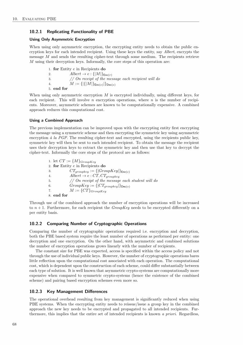
10. Evaluating PBE
10.2.1 Replicating Functionality of PBE
Using Only Asymmetric Encryption
When using only asymmetric encryption, the encrypting entity needs to obtain the public en-cryption keys for each intended recipient. Using these keys the entity, say Albert, encrypts themessage M and sends the resulting cipher-text through some medium. The recipients retrieveM using their decryption keys. Informally, the core steps of this operation are:
1. for Entity e in Recipients do2. Albert→ e : {|M |}Enc(r)3. // On receipt of the message each recipient will do4. M := {|{|M |}Enc(e)|}Dec(e)
5. end for
When using only asymmetric encryption M is encrypted individually, using different keys, foreach recipient. This will involve n encryption operations, where n is the number of recipi-ents. Moreover, asymmetric schemes are known to be computationally expensive. A combinedapproach reduces this computational cost.
Using a Combined Approach
The previous implementation can be improved upon with the encrypting entity first encryptingthe message using a symmetric scheme and then encrypting the symmetric key using asymmetricencryption a la PGP. The resulting cipher-text and encrypted, using the recipients public key,symmetric key will then be sent to each intended recipient. To obtain the message the recipientuses their decryption keys to extract the symmetric key and then use that key to decrypt thecipher-text. Informally the core steps of the protocol are as follows:
1. let CT := {M}GroupKey2. for Entity e in Recipients do3. CTgroupkey := {|GroupKey|}Enc(e)4. Albert→ e : CT,CTgroupkey5. // On receipt of the message each student will do6. GroupKey := {|CTgroupkey|}Dec(e)
7. M := {CT}GroupKey8. end for
Through use of the combined approach the number of encryption operations will be increasedto n + 1. Furthermore, for each recipient the GroupKey needs to be encrypted differently on aper entity basis.
10.2.2 Comparing Number of Cryptographic Operations
Comparing the number of cryptographic operations required i.e. encryption and decryption,both the PBE based system require the least number of operations as performed per entity: onedecryption and one encryption. On the other hand, with asymmetric and combined solutionsthe number of encryption operations grows linearly with the number of recipients.
The constant size for PBE was expected, access is specified within the access policy and notthrough the use of individual public keys. However, the number of cryptographic operations bareslittle reflection upon the computational cost associated with each operation. The computationalcost, which is dependent upon the construction of each scheme, could differ substantially betweeneach type of solution. It is well known that asymmetric crypto-systems are computationally moreexpensive when compared to symmetric crypto-systems (hence the existence of the combinedscheme) and pairing based encryption schemes even more so.
10.2.3 Key Management Differences
The operational overhead resulting from key management is significantly reduced when usingPBE systems. When the encrypting entity needs to reissue/issue a group key in the combinedapproach the new key needs to be encrypted and propagated to all intended recipients. Fur-thermore, this implies that the entire set of intended recipients is known a priori. Regardless,
68

10.3. Mode of Operations
when using the traditional schemes it implies that the encrypting entity needs to actively main-tain a list of intended recipients. When using PBE not only does the number of encryptionoperations remain constant, at one but the encrypting entity does not need to maintain a listof intended recipients. This is done implicitly due to the novelty of PBE schemes. However,with PBE schemes other additional key management issues can arise. This is discussed furtherin Section 10.5.5. Furthermore, as it stands there are no means through which key revocationcan be performed explicitly; attributes have validity periods, while with traditional asymmetricschemes the keys are revocable directly.
10.2.4 Cipher-text Management Differences
With the asymmetric schemes multiple copies of the plain-text, encrypted with different encryp-tion keys, exist: one copy per receiving entity. This increases the number of cipher-texts thatcontain the same message that can then be used in known-plaintext attacks by a recipient againstother recipients, or in a cipher-text-only attack by others. Similarly with the combined approachalthough there was a single copy of the encrypted data, multiple copies of the group key didexist. Thus, allowing attackers the ability to conduct ciphertext-only attacks on the group key.With PBE crypto-systems only one cipher-text is created and reduces the risk of such attacks.
10.3 Mode of Operations
The three mode of operations introduced in Section 9.8 each present a specific way in which aPBE scheme can be used. MCP presents a situation in which a single, or multiple authors, canrestrict access to the content they produce. The DDI mode of operation allows for submittedcontent to be searched by the receiving entity but also by other authorised entities. The finalmode, PKI mode, represents a more generic and traditional mode of operation, allowing entitiesto communicate securely with each other. With the generality seen with the PKI mode similarfunctionality as seen with the DDI and MCP modes of operation can be achieved. However, thiswould require that the data sender (for MCP) and data receiver (DDI) would have to involveand thus trust a third party in relation to any form of key management. This could lead tothe encrypting/decrypting entity unknowingly allowing unauthorised parties (to them) access totheir data. When compared to the other modes of operation the data sender and receiver havecomplete control over key management and the assurances therein, a third party need not beused.
10.4 Security Issues
This section presents several security issues that arise from the use of PBE schemes as part ofa crypto-system. For a discussion towards the mathematical, and construction related, securityissues of PBE schemes readers are asked to consult Section 8.6.
10.4.1 Attribute Revocation
An interesting dilemma with PBE schemes is the issue of key revocation. Section 9.6 alreadydiscussed a popular means through which a form of key revocation can be achieved. However,with these schemes the instant revocation of cryptographic keys is difficult. As keys will be issuedusing attributes that have an expiration date, there is a window between when the KA decidesto revoke an decryption key (or encryption key) and when the attributes naturally expires. Asa result, newly unauthorised entities can still decrypt messages. There is a trade-off betweenhow long the KA wishes to allow an attribute to be active i.e. its validity period, and the riskinvolved of use by an unauthorised entity.
10.4.2 System Integrity
The use of PBE within a crypto-system relies upon several components to work together. Com-promising any one of this components can affect the operational integrity of the PBE scheme.Moreover, multiple decrypting entities may collude in an attempt to decrypt messages that owntheir cannot do so. In this section these issues are discussed further.
69

10. Evaluating PBE
Key Authority Integrity The KA itself is comprised of several different components that neednot reside or operate under the same administrative domain. These components may well beadministered and operated independently of each other. If one of these components were to becompromised the integrity of the Key Authority will no longer be intact.
• Decryption Authority and Encryption Authority The effects of compromising the DecAuthand EncAuth are similar. A malicious entity will be able to circumvent, or unduly in-fluence, any identification and assignment checks performed when issuing keys. As suchcryptographic keys can be constructed and issued, incorrectly and moreover falsely. Fur-thermore, the key requests of legitimate entities may also be ignored.
• Decryption Key Generator. If a malicious entity were to compromise the DKG then theentity will be in a position to construct any decryption key they so wish. This has theuntoward affect of allowing malicious entities to then infringe upon the confidentiality ofencrypted data that can be decrypted using the keys.
• Attribute Authority Compromising the AA allows a malicious entity to influence the com-position of the attribute universe U . Allowing for U , and thus the system, to be populatedwith falsely defined attributes.
• Revocation Authority By compromising the RA, a malicious entity can affect the revocationdetails of attributes and as a result access policies. Allowing for attributes to be revokedprematurely or not at all.
• Escrow Authority Compromising the EA gives the malicious entity access to all the de-cryption keys stored. These keys can then be used to impugn upon the confidentiality ofencrypted data.
Single Point of Failure PBE schemes are susceptible to Denial of Service attacks, if the KeyAuthority were to be made unavailable then entities would not be in a position to acquire/updatetheir cryptographic keys. Furthermore, the operational integrity of any crypto-system that usesPBE is at risk if any of the internal components of the Key Authority were also to be madeunavailable.
User Collusion With PBE schemes there is a risk of user collusion, multiple decrypting entitiescan attempt to combine their decryption keys in order to decrypt some cipher-text. As discussedSection 8.6.2, PBE schemes are collusion resistant. Decryption keys contain a random value thataffects the use of the key during decryption. It is this random value that prevents two or morekeys from being combined.
10.4.3 A Reputable Key Authority?
So far the maliciousness of the KA has been assumed to be false, the KA partakes not in anyfraudulent nor malicious activity. With the different modes of operation discussed in Section 9.8the problem of a malicious KA is only prevalent when a third-party is owner: the PKI mode ofoperation. The remaining two modes alleviate the problem of a malicious KA to a fair extent.The owner/operator of the KA has s vested interest in its correct operation. For example withthe MCP mode of operation the aim is for the crypto-system owner to restrict access to thecontent that it encrypts itself. To be fraudulent with respect to this access seems to be anunfounded position for the owner to take.
With a third-party owner, entities are reliant on this owner to perform their duties dutifullyand more importantly correctly. Suppose that the owner is malicious. The owner will be ableto purposefully assign fraudulent decryption keys to other entities or themselves. When usingnon-attribute hiding schemes (see Section 7.3.3) a malicious KA owner can assign themselves adecryption key that will be able to decrypt a cipher-text upon inspection of the cipher-text andits meta-data. With non-attribute hiding schemes extra guarantees/measures are needed fromthe crypto-system owner to not commit fraud. These guarantees/measures may be technical orlegal based and are outwith the scope of this discussion.
70

10.5. Deployment Issues
10.4.4 Privacy
Unless the crypto-system has been constructed using an Attribute Hiding scheme, by defaultthe access policy/attributes associated with the cipher-text will be publicly available. Theyare embedded along side the actual encrypted value of the plain-text data and ass such areaccessible—see Algorithm 3. This functionality, in some cases, could be detrimental to securityafforded by the use of PBE. The attributes and access policies represent a hidden informationchannel that can be abused—see Section 3.6.2.
The need for Attribute Hiding schemes is also dependent upon the setting in which the systemis to be used used. For instance, consider the setting of a company that uses a Ciphertext-Policyscheme. It is quite plausible for the attributes assigned to entities to consist of well knownattributes e.g. department and office number. It can be argued that the access policies, as wellas the attributes involved, need not be private; well known information has been used. Securingthe payload provides good enough security when compared to hiding the value of the accesspolicy. Moreover correct operation of the PBE scheme ensures end-to-end confidentiality of themessage contents.
On the other hand within a military setting the value of the attributes themselves and theaccess policy would require Attribute Hiding. The attributes themselves can allude to sensitivemeta-data such as clearance level i.e. top secret. Disclosure of these values as well as the accesspolicy itself unintentionally leaks information about the encrypted data. Allowing attackers ameans to determine the worth of the cipher-text, that is attackers will be able to distinguishbetween cipher-texts accessible to those with low-level clearance and those that require a higherclearance level. Moreover, attackers will be able to use this information to obtain decryptionkeys fraudulently or even encrypt information.
10.5 Deployment Issues
This evaluation concerning PBE ends with a discussion concerning several deployment issuesthat can arise when deploying PBE schemes. These issues relate not to the security issues (seeSection 10.4) but to those concerned with management and usability of PBE schemes.
10.5.1 User Interaction
While the KA is responsible for the construction of decryption keys, the responsibility for theconstruction of encryption keys lies with the encrypting entity. However, this implies that the enduser will have to be able to construct suitable canonical attributes for use within an encryptionkey. For Ciphertext-Policy schemes this problem is exacerbated further with the additionalrequirement that encrypting entities are also responsible for the construction of correct policyrules and their conversion into access policies. There is a need when deploying and using PBEschemes that a suitable interface can be constructed that abstracts over the complexities arisingfrom specifying attributes or access policies.
10.5.2 Computational Cost
Pairing-based cryptography is known to be computationally expensive. The greater the num-ber of pairing operations within a PBE scheme will increase the time required to perform theencryption and decryption step, similar cost is seen when using large plain-text data. The costassociated through large plain-text data can be abated through the use of a combined schemein which the message is encrypted using symmetric cryptography and the symmetric key is en-crypted using PBE. Taking the example setting used in Section 10.2, the steps associated withthis combined approach would be as follows:
1. let CT := {M}GroupKey2. let CTgroupkey := Encrypt(MPK, GroupKey,Enc(Some PBE Key))3. for Entity e in Recipients do4. Albert→ e : CT,CTgroupkey5. // On receipt of the message each student will do6. GroupKey := Decrypt(MPK,Dec(e), CTgroupkey)7. M := {CT}GroupKey8. end for
71

10. Evaluating PBE
10.5.3 Cost of Numerical Attributes
Numerical attributes can be implemented on top of PBE. Section 7.6.3 already described howthey can be implemented as ‘miniature access-policies’. However, the addition of numericalattributes and the operations performed on them increases the complexity of the access policiesand set of attributes used as decryption keys. For each n− bit numerical attribute n attributesare required for representation. Using 64−bit integers, each decryption key in Figure 9.3 will use64× 6 = 384 attributes rather than the six actually depicted. Similarly, for access policies, eachcomparison operation will require O(n) gates. Again using 64− bit integers, each decryption inFigure 9.5 will require the use of 64× 3 = 192 additional gates, one per comparison. Again thiscontrasts to the simplistic view of only seeing five operations within the access policy.
10.5.4 Sourcing Attributes
It is without question that attributes are an integral component of PBE. When discussing thedeployment of PBE schemes, there are several issues that need to be addressed: a) the origin ofthe attribute universe; b) assignment of cryptographic keys; and c) how attributes can be used.From Chapter 9 several points concerned with the attribute universe and key management wereestablished. Firstly, the choice of attributes and their semantic meaning is at the discretionof both the Key Authority and encrypting entities, with the Key Authority being primarilyresponsible for the attribute universe U . Secondly, the Key Authority is also responsible forverifying an entity’s right to be assigned cryptographic keys and also the selection of the usedattributes. Thirdly, the attribute semantics is not only influenced by the setting in which schemewill be used but also by the underlying type of PBE system. It is the latter two points that areof interest and can be addressed using existing technologies.
Identity-Based Attributes With Ciphertext-Policy schemes the access control implies the useof attributes to describe an entity’s identity prescribing the need for some form of identity man-agement to define the attributes and an entity’s right to them. While, the KA can themselves beresponsible for identity management it can also be performed by other parties by identity pro-viders. Examples of existing identity providers that could be used include: OpenID [OpenID],Windows CardSpace [CardSpace] or Higgins Project [HigginsProject]. However, identity man-agement, and the security and usability issues therein, is a contentious issue [AHS11] that liesoutwith the scope of this thesis. Moreover, it can be the case that the provided attributes onlyprovide attributes covering a subset of an entity’s identity, more attributes may be needed thatcan be sourced manually. Within the confines of an organisational setting, for example, theaddition of attributes, and ownership verification, can be performed through official medium-s/occasions. For example within a University, extra information such as matriculation number,enrolled courses and degree program can be discerned during yearly matriculation and program-me/course induction/enrolment.
Environment and Resource-Based Attributes Sourcing and verifying ownership/right to pos-sess for attributes used to describe an environment and resource is more troublesome than anentity’s identity. The problem relates to the provenance of the attributes and the veracity ofclaims unto the attributes. For time related attributes this will imply the use of a trusted timestamp authority. For attributes that refer to the encrypted data or some other (in)tangibleaspect of the data, sourcing the attributes and to whom they can be assigned is not trivial.Fortunately, some attributes are more predictable that others and as such can be known a priorito their initial use.
10.5.5 Policy Administration
The policy model described in Section 9.5.1 allows those working with access policies to reasonover the construction of access policies, in an abstract manner. However, this adds additionaloverhead to those entities responsible for the construction of access policies.
Key-Policy Schemes For Key-Policy schemes the burden of responsibilities lies with the KAand as such the decrypting entity need not be aware of the complexities surrounding the con-
72

10.5. Deployment Issues
struction of their decryption key. They need only to request a decryption key and they get onein return.
Ciphertext-Policy Schemes Within Ciphertext-Policy schemes the burden of responsibility lieswith the encrypting entity, unlike Key-Policy schemes this burden is greater. Encrypting entitieshave to manage access policies, the complexity of which is determined by whom the encryptingentities wishes to encrypt their data for. However, as mentioned in Section 10.5.1, a goodinterface will aide in reducing the complexity of constructing policy rules and access policies.
10.5.6 Key Storage
Although, the issue of key management was discussed in Chapter 9 a concern when deployingPBE schemes is that of key storage. Both encryption and decryption keys will need to be storedby an end user. This will include expired decryption keys used to decrypt messages accessibleonly by those keys. When storing decryption keys this will imply storing a decryption pervalidity period of the attribute. In resource constrained environments the issue of decryptionkey storage might pose a problem.
Key-Policy Schemes For Key-Policy schemes, encryption keys are comprised from a set ofattributes. Managing these attributes and their storage is negligible, individual attributes canbe stored efficiently as plain strings. However for decryption keys, comprised from access policiesthe, size of a single key will be n× bit-length of a group element, where n is the number of leafnodes in the access policy—see Section 8.6.3. As the complexity of the access policy grows,so will its size. This is especially pertinent for the use of numerical attributes and numericalcomparisons that have a hidden underlying cost—see Section 10.5.3.
Ciphertext-Policy Schemes As with encryption keys for Key-Policy schemes, the storage re-quirements for policy rules and any generated access policies can be abated through their stor-age as plain strings. As with decryption keys for a set S the key generated will be | S |×bit-length of a group element in size. As the number of attributes in S grows so to will itssize. As with KP schemes this is especially pertinent for the use of numerical attributes andnumerical comparisons that have a hidden underlying cost.
73


Part III
Leveraging Predicate Based Encryption in the Cloud
75


Chapter 11
Scenarios for using PBE in the Cloud
Five scenarios for using Predicate Based Encryption within the Cloud are presented.These scenarios differ in terms of: mode of operation, predicate placement, andownership over the Key Authority.
11.1 Overview
The focus of this thesis now turns towards how Predicate Based Encryption (PBE) can be usedwithin the cloud. Part II introduced PBE and discussed how it provides for an efficient andsecure single-encryptor/multi-decryptor environment. Section 9.8 introduced three modes ofoperation that characterises how a PBE scheme can be used within a crypto-system. The PublicKey Infrastructure (PKI) mode allows a third-party to offer other entities a means throughwhich they (the other entities) can share their data. The Multicast Content Provision (MCP)mode allows an entity the means through which they can selectively share their data withothers without having to rely upon a third-party. The final mode, that of Duty DelegationInfrastructure (DDI), allows an entity to restrict access to data that has been sent to them.However, the application of these three modes of operation to a Cloud setting will be affectedby: a) whether the Key Authority (KA)—the owner of the PBE scheme—is a service user or aservice provider—Cloud Service Provider (CSP); and b) the style of access control required i.e.Ciphertext-Policy (CP) or Key-Policy (KP). From these factors, five viable scenarios emerged:
Scenario I: Embedded within a Service. A CSP incorporates a CP-PBE scheme in PKI modewithin an existing service. Providing service users the means with which theycan share data amongst each other within the domain of a particular service.
Scenario II: PBE-as-a-Service. Similar to Scenario I with the exception that PBE is usedoutwith the confines of a particular service domain.
Scenario III: ‘Database’ Submission. A CSP offers a service in which service users can submitdata to a database. A KP-PBE scheme in DDI mode is used to restrict access overthe submitted content to authorised employees of the CSP and other affiliatedparties.
Scenario IV: ‘Database’ Access. The antithesis of Scenario III. A CSP offers content that canonly be accessed by subscribed users. A KP-PBE scheme is used in MCP modeto restrict subscribed users’ access to the CSP’s content.
Scenario V: ‘Distributed Security’. The service user deploys their own CP-PBE scheme inMCP mode. PBE is used to mitigate access over data the user pushes to theCloud.
This chapter introduces these different scenarios and what they pertain to. Within Chapter 12further discussion over these scenarios and other issues can be found.
11.2 Leveraging PKI Mode
The PKI mode of operation leans naturally towards the as-a-Service paradigm, and consequentlyits use by a CSP. The CSP is the third-party offering the use of PBE to its service users. With
77

11. Scenarios for using PBE in the Cloud
this in mind, PBE can be offered by the CSP in two distinct ways, either: a) embedded withina service; or b) provided as a service. In both cases, the CSP is promoting the sharing of dataamongst other users of the services; sharing is a dominate feature exhibited by many Software asa Service (SaaS) services. Leading to the implication that these two scenarios, at least, appearto be best suited for SaaS services. Moreover, an access control style is required that allows theencrypting entity to state explicitly for whom access will be granted on a per message basis. Aswas discussed in Section 9.8.1, Ciphertext-Policy schemes provide such access control. Indicatingthat the attribute universe is used to, at least, describe users of the service.
11.2.1 Scenario I: Embedded within a Service
CSP
Enc. User
Key Authority
Service(s)Dec. User
Decryption Keys
Data Retrieval
Encryption Keys
Data Submission
Figure 11.1: Outline of Scenario I
Embedding a CP-PBE scheme within an existing service allows for the complete integration ofPBE within the service itself. Figure 11.1 outlines the core interactions within this scenario.Upon registering with the service, new users are provided with a decryption key derived from aset of attributes that describe the user. When pushing data to the service, service users encrypttheir data under access policies of their choosing. Moreover, as the KA is embedded within theservice, the CSP can also aid in policy administration. In other words, the CSP can offer serviceusers a means through which to specify policy rules and thus construct access policies.
Due to embedding PBE within the service itself, the attribute universe can be extendedto refer to service specific functionality such as the CSP’s ability to read the users data fortargeted ads. For example, take an Online Social Network (OSN). The attribute universe canidentify service users through attributes such as: identification number, gender, school networks,interests, location, D.O.B. et cetera. Functionality such as, the visibility of users’ messages canalso be included within the same attribute universe. Following on from indicating the visibilityof a user’s message is the notion that the CSP can also be referenced within the policy rules andtreated as a user in their own right. Though this does not adhere strictly to the PKI’s modusoperandi (see Section 9.8.1) it nonetheless allows the encrypting user to explicitly opt-in theCSP when the user constructs policy rules. Moreover, such an attribute can be combined witha date attribute to provide the CSP with a limited window of opportunity to access encrypteddata. This is a powerful construct, the user has explicitly stated within an access policy thatthe CSP can access the encrypted data, and more importantly for how long.
A problem for this scenario is that service users need to trust the CSP. As the CSP is theKA, the CSP could easily construct their own arbitrary decryption keys, and use these keys todecrypt service users’ messages. Service users still need to trust the CSP to not be malicious inthis respect. As discussed in Section 3.9.1, this trust can be enforced through legal means i.e.privacy policies and service level agreements. Furthermore, using PBE as described requires thateach CSP provide their own scheme. With each service that the user interacts with a differentPBE scheme needs to be taken into account. That is, separate key management facilities andalgorithms need to be managed by the user; one per service. Given what is known over keystorage issues (see Section 10.5.6) this could be a problem. Although, how the PBE is actuallydeployed will affect this somewhat, see Section 12.3 for more information.
11.2.2 Scenario II: PBE-as-a-Service
Providing a CP-PBE scheme as a service in itself allows service users to interact with multipleservices, offered by different CSPs, and use a common solution. This reduces the overheadconcerning key management, and also the different encryption and decryption algorithms that aservice user must be aware of. Providing ‘PBE-as-a-Service’ makes this scenario an example of
78

11.3. Leveraging DDI Mode
Enc. User
Service(s)
CSP
Dec. User
Key Authority
PBE Service
Decryption Keys
Data Retrieval
Encryption Keys
Data Submission
Figure 11.2: Outline of Scenario II
Security-as-a-Service—more specifically it can be tied directly into Identity-as-a-Service services.This implies that not only can this scenario be used to protect SaaS level services but also atthe Platform as a Service (PaaS) level as a service. Figure 11.2 outlines the core interactionswithin this scenario.
Like Scenario I, users possess decryption keys comprised of a set of attributes used to describethe user themselves. When interacting with different services the user can push encrypted dataknowing that only others who can satisfy the access policy can access the underlying plain-textdata. Policy administration service can also be offerd by the PBE service. As with Scenario ICSPs should be treated as users in their own right. Hence, when constructing policy rules theencrypting user can explicitly opt-in the CSPs as someone with whom they wish to share theirdata with. Moreover, CSPs ‘service users’ can themselves integrate this pre-existing PBE serviceinto their own service offerings. Unlike Scenario I, however, service users can treat the CSP likeany other user and not have to worry about the CSP’s maliciousness. A CSP in this setting isunable to construct arbitrary decryption keys. Users can use a service even though they mayhave no trust in the CSP offering that service. When the user does have trust in the CSP toaccess the user’s data, then the CSP can be opted in.
However, the service agnosticism does present several interesting issues. For one, the at-tribute universe is defined by a third-party who may not possess knowledge of service specificinformation, offering users attributes that describe information outwith the context of a service.This may affect the expressiveness of policy rules as defined by encrypting users. Offering a PBEservice does reduce the overhead in terms of key management and knowledge of algorithms, how-ever, this reduction in overhead comes at some cost. Scenario I is highly compartmentalised,CSPs are only able to access the data that has been pushed to their service. With the solutiondescribed in this section the PBE service provider, if malicious, has the ability to constructdecryption keys to access data that a user has pushed to multiple services.
Remark. A recurring element with Scenarios I and II is that the KA is a third-party distinctfrom the service user. While this does simplify the involvement of the service user it requiresthe service user to be reliant upon the KA to adhere dutiful to its remit—see Section 10.4.3.Such misgivings can be addressed with the MCP mode of operation that removes the need for athird-party KA.
11.3 Leveraging DDI Mode—Scenario III: ‘Database Submission’
The rationale behind the DDI mode is controlling access over submitted data. When a serviceuser uses this mode of operation it implies that the service user themselves will be controllingaccess to data that has been submitted to them: This has no obvious benefits or uses. It isbetter for the user to utilise the MCP mode of operation—see Section 11.4. On the other handwith a CSP as the KA, an interesting use case does emerge.
With DDI mode the CSP is using PBE to facilitate selective access over data, submittedexpressly for use by the CSP, under the proviso that said data will only be accessible by theCSP’s own employees and affiliates. That is data is submitted by service users and the CSPallows authorised entities access to select subsets of all data that has been submitted. Thisessentially describes the operation of a database. Databases can be thought of in terms of:a) who is submitting the data; b) who is accessing the data; and c) the data itself. With DDImode, the database is stored with the CSP. Data is submitted for the CSP by service users,
79

11. Scenarios for using PBE in the Cloud
and is being accessed by the CSP’s employees and other affiliates. Figure IV outlines the coreinteractions for this scenario.
CSP
Enc. User
Key Authority
Data Store Dec. User
Decryption Keys
Data Retrieval
Encryption Keys
Data Submission
Figure 11.3: Outline of Scenario III
Within databases one needs to control access not only to the database itself but also tothe data stored within. Obviously, users’ access over the data within the database needs to beproscriptive and users ability to access individual records needs to be curtailed. As discussed inSection 9.7 Key-Policy schemes provide such access control. As such data is encrypted undera set of attributes, and decryption keys from a predicate. Another and more intuitive reasonfor using Key-Policy schemes stems from the decryption keys. Decryption keys in this settingrepresent simple search queries. As mentioned in Section 9.8.2 such use of a KP scheme isanalogous to keyword based search albeit with a more expressive query mechanism. Whensubmitting data, service users encrypt their data under a set of attributes. The CSP can theninternally determine on a per employee basis what the employee can access from this database.Moreover, with numerical attributes it is feasible to limit the period during which the employeecan use their query.
The analogy of a ‘database’ implies the deployment of PBE as part of either a SaaS, or PaaSservice. For example, a course submission service could use DDI mode to control submissionof students submission. During submission, students could encrypt their course under a set ofattributes that describe1: a) the student’s matriculation number; b) the course code; c) theassignment number; and d) submission time. Lecturers and teaching assistants can then beassigned decryption keys pertaining to the course(s) they are associated with.
Remark. This use of PBE could also be extended to situations in which users of Infrastructureas a Service (IaaS) services require their configuration files to be stored within the cloud.
11.4 Leveraging MCP Mode
Recall from Section 9.8.2 that with the MCP mode of operation an encrypting entity is the KA.Within a cloud setting two scenarios emerge when: a) a service user is the encrypting entity;and when b) a CSP is the encrypting entity. The first scenario provides an alternate solutionto those presented in Section 11.2. The second scenario, on the other hand provides a settingin which a CSP can control access to their own content in a manner similar to that seen withthe DDI scenario. Although both scenarios require a proscriptive form of access control, thechoice of underlying PBE scheme will differ. With a service user Ciphertext-Policy schemes arebetter suited, access needs to be decided per message. With the CSP as the encrypting entitythe setting is more data centric and as such a Key-Policy scheme will suffice.
11.4.1 Scenario IV: ‘Database Access’
CSPs can utilise MCP mode to restrict access to the content that they produce in much the samemanner as was seen with Scenario III—Section 11.3. The difference lies in the involved actorsand origin of the data. Figure 11.4 outlines the actors involved and core interactions betweenthem. Employees of the CSP together with authorised affiliates are those permitted to encryptdata. Decryption of data is performed by service users. When signing up to a service, usersare assigned a decryption key derived from some policy rule that describes the data they areallowed to access. Such policy rules can be used to indicate service related information such as
1Student names have been omitted due to the need for anonymous marking in tertiary level education.
80

11.4. Leveraging MCP Mode
CSP
Dec. User
Key Authority
Data Store Enc. User
Encryption Keys
Data Submission
Decryption Keys
Data Retrieval
Figure 11.4: Outline of Scenario IV
subscription level and periods of time. This provides the CSP with a means to enforce differentsubscription models i.e. freemium. With MCP mode the act of restricting access can also extendto any content streams that the CSP produces and broadcasts. This implies that this scenariocan be used at both the PaaS and SaaS service levels. Take a media streaming service such asNetflicks, streamed content can be encrypted under a set of attributes that describe, for example:a) the content’s rating i.e. U, PG, 12, 16, 18; b) the subscription level e.g. free, gold member,silver memeber; and c) the content’s details such as title, season and episode.
11.4.2 Scenario V: ‘Distributed Security’
Service User/Key Authority
Enc. User
Key Authority
Service(s)
CSP(s)Data Submission Data Retrieval
Dec. UserSend Decryption Key
Figure 11.5: Outline of Scenario V
Scenarios I and II present solutions to protecting data they wish to share via the cloud. Theunderlying problem with these solutions is the reliance upon a third-party to act as the KA.When deployed by a service user the MCP mode presents an improvement with respect totrusting a third-party. With the MCP mode there is no need for a trusted third-party over keymanagement, users provide their own PBE scheme.
When signing up to a service or when starting to interact with a new ‘friend’, the encryptinguser i.e. the Key Authority, will create and assign to the entity a decryption key. This decryptionkey will be derived from a set of attributes that describes how the decrypting user relates to theencrypting user. Through use of a Ciphertext-Policy scheme, the encrypting user can encrypttheir data locally under a policy rule, and then push the cipher-text into the cloud. Attributescan be used to indicate, for example: a) type of relationship with another entity i.e. an associate,a friend, a close friend, a really close friend, family, or CSP; b) visibility of message i.e. is themessage to be private or public; and c) an identifier for each domain that the user has interactedwith i.e. on a OSN.
This use of the MCP mode of operation presents a decentralised solution to the problemsassociated with Scenarios I and II. Implying this scenarios use at the PaaS and SaaS servicelevels, with each ‘user’ providing their own encryption scheme. From this two interesting ob-servations can be made that can affect the management and deployment of this mode. First,the encrypting user is responsible for the remit of the Key Authority. The user is responsiblefor policy rule administration, responsible for the the correct assignment of decryption keys,responsible for key management et cetera. Secondly, the security guarantees provided cover uni-directional communication. Each user utilises PBE to protect their own data only. For n userscommunicating it requires each user to take into account the decryption keys, and associateddecryption algorithms for n− 1 other PBE schemes.
81

11. Scenarios for using PBE in the Cloud
11.5 Summary
Table 11.1 provides a summary of the scenarios presented in this chapter according to: a) modeof operation; b) type of scheme; and c) the entity acting as the KA.
Scenario PBE Mode CP/KP Identity of ‘KA’ Service Level
Scenario I PKI CP CSP SaaS, PaaSScenario II PKI CP CSP SaaS, PaaS
Scenario III DDI KP CSP SaaS, PaaS, IaaSScenario IV MCP KP CSP SaaS, PaaSScenario V MCP CP Service User SaaS, PaaS
Table 11.1: Summary of the five different scenarios that PBE can be used in the Cloud.
82

Chapter 12
Discussing PBE in the Cloud
The use of Predicate Based Encryption within the cloud is discussed. Data that canbe protected is identified. End-to-End security is addressed. Fulfilling the remit ofthe Key Authority is touched upon, and finally, the five scenarios are compared.
12.1 Overview
Chapter 11 presented five different scenarios that describe how PBE could be leveraged withinthe cloud. As a denouement to this part, and to this thesis, this chapter evaluates the use ofPBE in the cloud. For a discussion over PBE in general and within a crypto-system can befound within Chapter 10. Section 12.2 discusses the data that PBE can be used to protect ateach of the three service layers. The effect that placement of the cryptographic operations hasover security is discussed in Section 12.3. Section 12.4 discusses how the role of the KA can befulfilled by both CSPs and service users. Finally, the five different scenarios are compared interms of the protection offered within Section 12.5.
12.2 What can PBE be used to Protect?
Chapter 4 presented two threat models for data in terms of its life cycle, from which data is beingdescribed as either being: a) in the cloud; or b) outwith the cloud. When pushing and retrievingdata from the cloud existing mechanisms (e.g. HTTPS and SSH) can be used to protect the datain flight. However, the problems associated with data in the cloud stem not from when it is inflight but rather from once it has become resident within the cloud—see Chapter 6. With PBE,assurances over the confidentiality and accessibility can be made. PBE can aide in preventingthe unwanted exposure, unwanted leakage and other unwanted breaches of confidentiality ofcloud resident data. Other guarantees such as integrity, non-repudiation and authenticity needadditional security mechanisms.
Recall from Section 2.2 that there are three different service levels. The nature of the datathat needs to be protected will differ depending upon the exact service layer being addressed:
Infrastructure as a Service (IaaS) The IaaS service level is concerned with the deploymentof virtual machines. With this service level the data that is of concern are the settings andcommands used when configuring, deploying, and managing the virtual machine instances.This is data that will be submitted to the CSP. While commands are to be invoked, settingsare to be stored for use.
Platform as a Service (PaaS) Services at the PaaS service level are characterised throughthe APIs exposed by the CSP through some platform tooling. Although, the range of thistooling is vast it can nonetheless be seen as just an exposed Application ProgrammingInterface (API) promoting some functionality. The APIs themselves can be characterisedas performing some data processing or providing access to some data store.
Software as a Service (SaaS) The highest service level, SaaS, deals with services that offermore complex interactions and functionality. The range, shape and form of the data beingpushed into the cloud will vary greatly from service to service. For example, the datapushed by the user can include but is not necessarily limited to: messages posted on asocial networking site, documents in an online office suite, or photographs posted to an
83

12. Discussing PBE in the Cloud
photo sharing site. A dominant feature of many SaaS services is the collaboration, orsharing of this information with other users.
A related discussion to what needs to be protected is when (and where) the protect be applied.That is where should encryption and decryption of data occur. Such a decision will affect theuse of PBE and is discussed within Section 12.3.
12.3 Effect of Cryptographic Operation Placement
Chapter 4 presented threat models that describe when data will be vulnerable during its lifecycle.When deploying PBE in the cloud an important question to ask concerns where in the datalifecycle should the encryption and decryption operations be deployed. Such a decision will affectthe end-to-end security of encrypting entities’ data. At what point during the data lifecycle canthe confidentiality of data be assured and when can it be questioned? Moreover, this issue raisesconcerns over the trusted computing base established by the CSP.
12.3.1 Key Authority and Service are not linked
With Scenarios II and V the KA is not tied to any particular service. The deployment ofencryption and decryption operations is trivial. Data will be encrypted by the service user priorto its insertion into the cloud—Stage 1. When the decrypting entity is a CSP the data can bedecrypted once it has entered the cloud—Stage 2. Finally, service users can decrypt data once ithas been received locally—Stage 4. End-to-end confidentiality of the message has been assured.
12.3.2 Key Authority and Service are linked
Wwith Scenarios I, III and IV the deployment is not as straightforward. With these scenariosthe CSP is the KA and is the provider of the service that service users are interacting with.Generally, speaking two options exist over the placement of the operations:
Option 1: Cryptographic operations are performed by service users themselves. Data is en-crypted and decrypted at Stages 1 and 4 of the data life-cycle.
Option 2: Cryptographic operations are performed by the ‘CSP’ on behalf of the users. Datais encrypted and decrypted at Stages 2 and 3 of the data life-cycle.
Option 1 places the encrypting user in control of the encryption process. Their data has beenencrypted at the first stage within its life-cycle prior to its push to the cloud. This affordsthe user knowledge of the precise composition of the encryption key used to encrypt the data,and also of the encryption process. Similarly, the decrypting user only accesses the cipher-textand decrypts the cipher-text once it has been received locally i.e. it is outside the domain ofthe service. By performing the cryptographic operations locally, in the domain of the user, thescope at which threats attacking the confidentiality can occur has been reduced. End-to-endconfidentiality has been assured: The data goes into the cloud encrypted, it leaves the cloudencrypted.
Option 2 on the other hand, cannot offer the same guarantees. Data pushed into the cloudby the service user has now been encrypted within the domain of the CSP. The entity needsextra assurances as to the key used to encrypt their data. With decryption, the service user’sdecryption key must now also reside in the service for it to be used. Unauthorised use of this keyneeds to be assured as well, especially from malicious insiders. Steadfast guarantees over end-to-end confidentiality cannot be assured: The data sent by the user enters the cloud unencryptedand will leave the cloud unencrypted.
With Option 2 threats to data, and also to the decryption key can now also occur withinthe domain of the CSP. Although this option may appear to be a forlorn one it does has itsadvantages. Section 6.3 made reference to the Grendel solution. This solution also placed thecryptographic operations on the service side of the interaction allowing the user to be ‘unaware’of the protection given to their data. This not only reduces the perceived complexity but alsorelieves the service user over the responsibility for maintaining and storing cryptographic keys.This may be of advantage within resource constrained environments, and mobile environmentsin which the service user does not have continuous access to their decryption keys.
84

12.4. Fulfilling the remit of the Key Authority
12.4 Fulfilling the remit of the Key Authority
Central to the use of PBE as part of a crypto-system is the KA. Chapter 9 introduced the KAtogether with a discussion over the remit that the KA must adhere to and how parts of thisremit could be achieved. This includes responsibility for managing the attribute universe, as-signing/issuing cryptographic keys, and for KP schemes policy rule administration. Section 10.5also discussed how attributes can be sourced, among other deployment issues. However, how aCSP or a service user can fulfil this remit will differ.
Cloud Service Provider Naturally, CSPs have access to a comprehensive existing infrastructure.This infrastructure can be leveraged by the CSP when perform their duty as a KA. Whenincluding/using PBE as part of a service, the CSP can use existing information from the serviceto determine the attributes used within U . An existing identity management infrastructurecan also be used to verify any claims a user has over attributes. Furthermore, existing policyrule specifications can be used as a base when constructing decryption policies i.e. Key-Policyschemes, or as a guide when users need to construct encryption policies i.e. Ciphertext-Policyschemes. Finally, with Ciphertext-Policy schemes the CSP can also offer an interface, andservice, through which users can abstract over the complexities of policy rule specification andmanagement.
Service User When a service user is the Key Authority, they will not have the same level ofresources and existing infrastructure when compared to a CSP. However, the scale of operationsfor a service user is vastly different when compared to that of a CSP. Here the service useroperates in a smaller more personalised environment. They deal with entities directly i.e. one-on-one, the service user can perform the remit ‘manually’. That is, the service user can verifyclaims over attributes when constructing decryption keys themselves. Unlike a CSP who willhave a fixed address, however, the service user is inherently mobile. The service user will beaccess services from different locations from different machines. How exactly is the service usergoing to fulfil this remit, if they are continuously on the move?
12.5 Comparing Scenarios
The five different scenarios presented in Chapter 11 can be divided into two distinct groupingsconcerning the style of interaction (between the service user and CSP) that the scenarios areused to protect: bidirectional and unidirectional. This grouping can be used to compare relatedscenarios. Moreover, Chapter 6 argued that a good solution for protecting the confidentiality ofdata pushed to the cloud should take into account the following three points:
• User empowerment does not alone equal Data Obfuscation.
• The user need not be responsible for ensuring all security guarantees.
• Some CSPs may be evil but some are more evil than others.
12.5.1 Comparing Scenarios I, II and V
Scenarios I, II and V describe a means to protect the results of a bidirectional communicationstyle. With this style of communication a service user expects to push their, and pull otherservice users’ data from the cloud. PBE is used to ensure confidentiality of this data.
User Empowerment In each of the three scenarios, service users have control over whomprecisly can decrypt their data, and by extension how it can be used. They have becomeempowered. However, the degree of empowerment depends upon the KA. The KA is responsiblefor defining the attribute universe, and assignment of decryption keys. This in turn affects theexpressivness of access policies in terms of what attributes the user can specify, and the effect ofapplication e.g. attributes that identify if the CSP can decrypt encrypted data. Scenario I offerstight integration with a single service. The CSP can design an attribute universe that caters tothe needs of the service. On the other hand, Scenario II does not offer as tight an integration.The definition of the attribute universe is dependent upon a third-party who is not necessarily
85

12. Discussing PBE in the Cloud
aware of a particular services needs. Finally, Scenario V offers the service user complete freedomover the composition of the attribute universe, and moreover, the service user is also in controlof who is able to obtain decryption keys.
User Responsiblities With these scenarios, the CSP is not afforded complete trust in theirabilities to secure user’s data. In Scenario V the service user has no trust in the abilities ofthe CSP to offer data confidentialy. The service user is responsible for all matters, excludingdecryption, arising from the use of the PBE scheme. Scenario I offers a solution that allows theservice user to have some trust in the CSP. The CSP is responsible for all matters excluding thespecification of encryption keys, this is left for the service user. Finally, Scenario II implies thatthe service use has no trust in the CSP to protect the confidentiality of users’ data. However,with Scenario II this service user must now have some trust in the ability of the ‘PBE Service’to fulfill its remit.
Trust in the CSP Each of the three scenarios offers differing levels of trust over the CSP. Thepreceding paragraph explained this in relation to who provides assurances over data confidenti-ality. Section 11.2 established that a malicious CSP acting as the KA will be able to constructarbitrary decryption keys. This is not a problem for Scenario V. For all three scenarios, however,service users can explicitly stipulate on a per message basis if the CSP can access the serviceusers data.
12.5.2 Comparing Scenarios III and IV
Scenarios III and IV, describe a means to protect a distinctly unidirectional style of interac-tion. With Scenario III, the service user is pushing data to the cloud. With, Scenario IV theservice user is pulling CSP’s data from the cloud. These scenarios do not necessarily seek toempower service users over the confidentiality of their data: They seek to empower the CSPinstead. Moreover, both of these scenarios allow the CSP to provide a form keyword searchusing expressive queries over an ‘encrypted database’.
Scenario III Scenario III presents a scenario in which the user is afforded some control overaccess to their data through specification of the encryption key. Ultimatly, however, it is theCSP that has been empowered. This solution presents users with a solution that they must havecomplete trust in the CSP to control access to the submitted data.
Scenario IV With Scenario IV, the three guidelines iterated at the start of this section cannot beapplied. This scenario seeks to empower the CSP over access to their data, and not service users.In this scenario the CSP is in control over the attribute universe and over issuing decryptionkeys. The CSP has guarantees over the confidentiality of their content, and allows them toenforce not only fine grained access control but also support for tiered content provision.
86

Part IV
Conclusion and Further Research
87


Chapter 13
Conclusion
Quem deus vult perdere, de-mentat prius.
Euripides
Cloud Computing embodies the as-a-Service paradigm and allows for services to be provided enmasse to consumers. The problems associated with the use of cloud based services can be sum-marised by the unknown risk profile (see Section 3.8) and unknown expectation of privacy—seeSection 3.9.2. When service users push data to the cloud they need to rely upon Cloud ServiceProviders (CSPs) adhering to their remit, and doing so dutifully. However, when looking tobuild solutions to protect data in the cloud it is important to remember that for the service userthe CSP can be trusted, albeit at arms length—see Section 6.3. The threat models presentedin Chapter 4 illustrate that threats to data occur both in the domain of the service user andthe domain of the CSP. Traditional privacy models are too user-centric and CSP-fearing whentrying to address the problem of protecting data—see Section 6.2. A privacy model centredaround Kafka’s The Trial helps to address this problem, this privacy model indicates that whenprotecting one’s data one should also have control over its use rather than solely preventing itscollection: CSPs and service users need to work together.
Predicate Based Encryption (PBE) presents an interesting and also novel family of asymmetricencryption schemes. PBE combines Attribute Based Access Control (ABAC) with asymmetricencryption, allowing for a single-encryptor/multi-decryptor environment to be realised using asingle scheme. Replicating such functionality using more traditional techniques requires a morecomplex approach—see Section 10.2. Even so, PBE is inherently more flexible, data can beencrypted for a decrypting entity prior to the creation of the decrypting entity’s decryption key:The precise list of decrypting entities need not be known a priori. Such novelty lies with thecryptographic keys—see Section 10.1. Cryptographic keys are not just numbers, there is noone-to-one pairing of encryption and decryption keys, and encryption and decryption keys arecreated separately from each other.
Though understanding the operation and potential use of PBE schemes was not inherentlydifficult it was not trivial either. Understanding the means through which PBE schemes canbe constructed also proved to be a somewhat tedious affair. Unfortunately with PBE, a dis-proportionate amount of time was spent searching for, and collating, information from differentsources; different papers begat different schemes which in turn begat different terminology. How-ever, these efforts were not without dividends, by learning more about PBE scheme construction,various issues surrounding cryptographic keys were identified and addressed. For instance, blind-ing values prevent decrypting entities from combining their decryption keys—see Section 8.6.2.The inclusion of numerical attributes also presents an underlying hidden cost (see Section 10.5.3),which together with key revocation techniques will increase the space needed to store decryptionkeys—see Section 10.5.6. Furthermore, by looking at different schemes a means to categorisethe different PBE schemes emerged from such schemes’ emergent properties.
89

13. Conclusion
Similarly, describing PBE’s use as part of a crypto-system was also a necessary evil, it establishednot only how PBE schemes could be deployed (see Section 9.8) but also points of contentionwithin such deployment. Of which the most notable issues were those surrounding key manage-ment such as constructing, issuing and revocation. Furthermore, the use of PBE identified threedifferent modes of operation that describe the three different ways in which PBE schemes canbe leveraged within an crpyto-system—see Section 9.8. When combined with the cloud setting,two different sets of scenarios emerged based upon whether the service user’s or CSP’s data wasto be protected.
PBE schemes can be used to protect service user’s data in three different scenarios: Scenario Isaw the inclusion of PBE within a service; Scenario II saw the provision of PBE as-a-Service; andScenario V saw PBE being deployed by the user themselves. In each of these three scenarios PBEcan be used by service users to specify precisely with whom they wish to share their data, forwhat purpose, and for how long. Although Scenario V may be a privacy zealot’s ideal choice—they are in full control—its practical feasibility has yet to be determined; the ability for serviceusers’ to act competently as a Key Authority is still unclear. The remaining two scenarios, on theother hand, do appear to be more promising. However, these scenarios in themselves do presenta dilemma between usability and the guarantees made over end-to-end security—see Section 12.3.
When looking to protect CSP’s data, PBE can facilitate keyword search with complex queriesover encrypted data: Scenario III by the CSP; and in Scenario IV by a service user. This useof PBE is rather interesting in that the focus of these scenarios is on the CSP and not serviceuser, and is most certainly worthy of further investigation.
The use of PBE within the cloud appears to be concentrated at both the PaaS and SaaS servicelayers. Though some may be surprised at PBE’s lack of use at the IaaS layer, this was nottotally unexpected. The primary interaction between a service user and CSP at this level is overmanaging virtual machines: Not much else happens.
As previously mentioned, comprehending the field of PBE was made more difficult due to the in-herently heterogeneous nature of the schemes studied. As such this thesis also sought to providereaders with a decent starting point over PBE schemes and also their use within crypto-systems.However, towards the end of this investigation a plethora of papers have been released address-ing PBE in terms of its description and use within a cryptographic system. From Boneh, Sahaiand Waters [BSW10], PBE can now be seen under the guise of Functional Based Encryption(FBE), here Boneh, Sahai and Waters provides a coherent, and authoritative, definition towardsPBE together with a categorisation of the different FBE schemes. Interestingly the categor-isation presented is similar to that presented within this thesis—see Section 7.3. Furthermore,Akinyele, Lehmann et al. [AL+10] utilises PBE to secure medical records, and Bobba, Fatemiehet al. [BF+10] utilises PBE to for secure messaging. Both these solutions show real-life uses ofPBE schemes and as part of a cryptographic system. In fact the solutions presented in Bobba,Fatemieh et al. [BF+10] and Akinyele, Lehmann et al. [AL+10] would both correspond to Scen-ario I.
In summation, the scenarios presented in this thesis do show that the use of PBE in the Cloud isadvantageous, moreover recent papers supports these claims. However, this investigation is farfrom being over. The results here are just the tip of the iceberg, and there are several directionsin which this investigation can go in. These new directions are discussed in Chapter 14.
90

Chapter 14
Further Research
Several avenues for further research are discussed. Addressing Predicate Based Sign-ing, Distributed Attribute Based Encryption, Use Case development and practicalfeasibility.
Omnium rerum principia parvasunt
Marcus Tullius Cicero
14.1 Attribute Based Signing
PBE schemes provide assurances towards the confidentiality of data. They do not provide as-surances towards the authenticity of the data. To provide such assurances digital signatureschemes are required. Attribute Based Signing (ABS) is an adaptation of Attribute Based En-cryption (ABE) for the purposes of providing guarantees towards the provenance of the signeddata, and moreover towards the anonymity of the signer [MPR10]. Within ABS schemes thedigital signature indicates that the signer can satisfy the given predicate and hence has attestedto the message—provenance. Furthermore, the precise set of attributes used by the signer isnot revealed—signer anonymity. Such a signature scheme has several practical uses. Maji,Prabhakaran and Rsulek [MPR10] discusses the use of ABS schemes for attribute-based authen-tication, trust negotiation, and the leaking of secrets. Future research would seek to investigate:
• The feasibility of such schemes.• How such schemes can be leveraged in general: What do they allow for? and What do
they bring? and finally• How these schemes can be used within the Cloud.
14.2 Decentralising the Key Authority
The Key Authority is responsible for the management of attributes, attribute definition, andalso over attribute assignment to entities. However, these attributes naturally originate fromdifferent sources and as such they will also be managed by different authorities. For example,within a university setting students, and information concerning students, are handled by variousadministrative departments1. Matriculation is typically performed by a central administrativebody, while more degree programme specific aspects (e.g. advising) are handled at a facultylevel, and also further on a per school/department basis. There may not be one central bodythat collates and is able to verify the attributes/access policies that are to be assigned to thestudent. The ability for a single Attribute Authority and Decryption Authority to administerover a ‘global’ attribute universe is made more difficult.
Distributed Attribute Based Encryption (DABE), also known as Multi-Authority ABE, isan adaptation of Ciphertext-Policy-ABE that delegates the management of attributes and thecreation of decryption keys to other individual attribute authorities [LC+10; MKE09; Cha07].Future work will be to investigate:
• The feasibility of such schemes.
1This will no doubt differ from University to University.
91

14. Further Research
• How these schemes can be incorporated within the existing description for the use of PBEwithin a crypto-system—see Chapter 9.
• Following from the previous point, how this new description of the crypto-system affectsthe scenarios governing its use within the Cloud.
14.3 Cryptographic Keys
Chapter 8 discussed the different techniques that can be used to construct a Linear SecretSharing Scheme (LSSS) from boolean formula. These techniques fell into two categories: accesstree oriented, or based upon MSPs. It is also known that these different techniques will havesome affect upon the composition, namely that of efficiency, of the constructed LSSS. Futureinvestigations should include the comparison of these different techniques looking at how theconstructed LSSSs affect: storage requirements, encryption and decryption efficiency.
A similar avenue for further investigation is concerned with key revocation. With Key-Policyschemes it is the Key Authority (KA) that is responsible for the specification and construction ofpolicy rules. These policies can be combined to construct other policy rules, creating a hierarchyof policy rules. Can this be used to facilitate key revocation within Key-Policy schemes?
14.4 Use Case Development
The description of how PBE can be used within a crypto-system (given in Chapter 9) does notaddress fully how other security issues/guarantees such as authenticity and non-repudiation canbe assured. This is necessary when discussing the distribution of cryptographic keys and thesending of messages. Area of future work can be the provision of a ‘complete description’ ofa crypto-system that makes used of PBE. Following on from this, another area of investiga-tion will be to look at how such a complete description affects the different scenarios given inChapter 11. Moreover, these scenarios have been described rather generically and have used‘guiding examples’ to aid in their description. An area of future work would be to develop thesescenarios further providing more concrete examples of their use.
14.5 Practical Considerations
This thesis has primarily been concerned with the theoretical considerations and implicationsover PBE and the Cloud. Following on from the future work suggested Section 14.5, an obviousnext step is to investigate various practical aspects of the use of PBE such as its implementation,deployment and Quality of Service (QoS). Areas of interest that should be addressed include:• The effect that access policy composition, especially concerning numerical comparisons,
has upon the performance of the encryption, decryption and key generation functions.• The QoS measurements and guarantees that can be made, aside from function efficiency,
over PBE.• The effect that access policy composition has upon, if any, the size of cipher-text produced.• The representation (encoding) of access policies/rules and list of attributes.• Existing standards and technologies that should be leveraged or adhered to.• The construction of a means through which policy rule administration, for both users and
CSPs, can be achieved.
92

Bibliography
93


Bibliography
Access Control
[SC+96] Ravi S. Sandhu, Edward J. Coyne et al. ‘Role-Based Access Control Mod-els’. In: Computer 29.2 (1996), pp. 38–47. issn: 0018-9162. doi: http:
//doi.ieeecomputersociety.org/10.1109/2.485845.
[SS94] R S Sandhu and P Samarati. ‘Access Control: Principle and Practice’. In:IEEE COmmunications Magazine 32.9 (Sept. 1994), pp. 40–48.
[YT05] Eric Yuan and Jin Tong. ‘Attributed Based Access Control (ABAC) forWeb Services’. In: Proceedings of the IEEE International Conference onWeb Services. ICWS ’05. Washington, DC, USA: IEEE Computer Society,2005, pp. 561–569. isbn: 0-7695-2409-5. doi: http://dx.doi.org/10.
1109/ICWS.2005.25. url: http://dx.doi.org/10.1109/ICWS.2005.25.
Cloud Computing
[AF+09] Michael Armbrust, Armando Fox et al. Above the Clouds: A Berkeley Viewof Cloud Computing. Tech. rep. UCB/EECS-2009-28. Electrical Engineer-ing and Computer Sciences, University of California at Berkeley, Feb. 2009.url: http://www.eecs.berkeley.edu/Pubs/TechRpts/2009/EECS-
2009-28.html.
[AHS11] G. Alpar, J.-H. Hoepman and J. Siljee. ‘The Identity Crisis. Security, Pri-vacy and Usability Issues in Identity Management’. In: ArXiv e-prints (Jan.2011). arXiv:1101.0427 [cs.CR].
[BCR09] Ken Birman, Gregory Chockler and Robbert van Renesse. ‘Toward a cloudcomputing research agenda’. In: SIGACT News 40.2 (2009), pp. 68–80.issn: 0163-5700. doi: http://doi.acm.org/10.1145/1556154.1556172.
[BM03] Philippa J. Broadfoot and Andrew P. Martin. A Critical Survey of GridSecurity Requirements and Technologies. Tech. rep. PRG-RR-03-15. Wolf-son Building Oarks Road Oxford OX1 3QD: Oxford University ComputingLaboratory, 2003. url: http://www.comlab.ox.ac.uk/files/930/RR-03-15.ps.gz.
[CBL08] Monica Chew, Dirk Balfanz and Ben Laurie. ‘(Under)mining Privacy in So-cial Networks’. In: Proceedings of the 2008 IEEE Symposium on Securityand Privacy Workshop: Web 2.0 Security and Privacy - W2SP 2008. Pub-lish Online. 2008. url: http://w2spconf.com/2008/papers/s3p2.pdf.
[Cri91] Flavin Cristian. ‘Understanding fault-tolerant distributed systems’. In:Commun. ACM 34.2 (1991), pp. 56–78. issn: 0001-0782. doi: http://
doi.acm.org/10.1145/102792.102801.
[DVZ10] Gabriele D’Angelo, Fabio Vitali and Stefano Zacchirolo. ‘Content Cloack-ing: Preserving Privacy with Google Docs and other Web Applications’. Toappear in the 25th Symposium On Applied Computing (SAC’10), March22-26, 2010, Sierre Switzerland. Mar. 2010.
[ENISA-CC-RA09] Cloud Computing: Benefits, risks and recommendations for informationsecurity. Tech. rep. European Network and Information Security Agency(ENISA), 2009. url: http://www.enisa.europa.eu/act/rm/files/
deliverables/cloud-computing-risk-assessment.
[Fos01] Ian Foster. ‘The Anatomy of the Grid: Enabling Scalable Virtual Organiz-ations’. In: Euro-Par 2001 Parallel Processing (2001), pp. 1–4. url: http://dx.doi.org/10.1007/3-540-44681-8_1.
[GTF08] Saikat Guha, Kevin Tang and Paul Francis. ‘NOYB: privacy in online socialnetworks’. In: WOSP ’08: Proceedings of the first workshop on Online socialnetworks. Seattle, WA, USA: ACM, 2008, pp. 49–54. isbn: 978-1-60558-182-8. doi: http://doi.acm.org/10.1145/1397735.1397747.
95

Cloud Computing
[Hay08] Brian Hayes. ‘Cloud computing’. In: Commun. ACM 51.7 (2008), pp. 9–11.issn: 0001-0782. doi: http://doi.acm.org/10.1145/1364782.1364786.url: http://portal.acm.org/citation.cfm?doid=1364782.1364786.
[HM+05] Ragib Hasan, Suvda Myagmar et al. ‘Toward a threat model for storagesystems’. In: StorageSS ’05: Proceedings of the 2005 ACM workshop onStorage security and survivability. Fairfax, VA, USA: ACM, 2005, pp. 94–102. isbn: 1-59593-233-X. doi: http://doi.acm.org/10.1145/1103780.1103795.
[HS+10] Dan Hubbard, Michael Sutton et al. Top Threats to Cloud Computing v1.0.Tech. rep. v1.0. Cloud Security Alliance, Mar. 2010. url: http://www.cloudsecurityalliance.org/topthreats/csathreats.v1.0.pdf.
[JGL08] Meiko Jensen, Nils Gruschka and Norbert Luttenberger. ‘The Impact ofFlooding Attacks on Network-based Services’. In: ARES ’08: Proceedingsof the 2008 Third International Conference on Availability, Reliability andSecurity. Washington, DC, USA: IEEE Computer Society, 2008, pp. 509–513. isbn: 978-0-7695-3102-1. doi: http://dx.doi.org/10.1109/ARES.2008.16.
[JM09] Carter Jernigan and Behram F.T. Mistree. ‘Gaydar: Facebook friendshipsexpose sexual orientation’. In: First Monday 14.10 (Oct. 2009). [Online].url: http://firstmonday.org/htbin/cgiwrap/bin/ojs/index.php/fm/article/view/2611/2302.
[JS09] Meiko Jensen and Jorg Schwenk. ‘The Accountability Problem of FloodingAttacks in Service-Oriented Architectures’. In: Availability, Reliability andSecurity, International Conference on 0 (2009), pp. 25–32. doi: http://doi.ieeecomputersociety.org/10.1109/ARES.2009.11.
[JS+09] Meiko Jensen, Jorg Schwenk et al. ‘On Technical Security Issues in CloudComputing’. In: Cloud Computing, IEEE International Conference on 0(2009), pp. 109–116. doi: http://doi.ieeecomputersociety.org/10.1109/CLOUD.2009.60.
[KD+09] Graham Kirby, Alan Dearle et al. An Approach to Ad hoc Cloud Computing.Tech. rep. St Andrews Cloud Computing Initiative, School of ComputerScience, University of St Andrews, Feb. 2009. url: http://arxiv.org/abs/1002.4738.
[MA05] Michael McIntosh and Paula Austel. ‘XML signature element wrapping at-tacks and countermeasures’. In: SWS ’05: Proceedings of the 2005 workshopon Secure web services. Fairfax, VA, USA: ACM, 2005, pp. 20–27. isbn: 1-59593-234-8. doi: http://doi.acm.org/10.1145/1103022.1103026.
[MKL09] Tim Mather, Subra Kumaraswamy and Shahed Latif. Cloud Security andPrivacy: An Enterprise Perspective on Risk and Compliance. Editor MikeLoukides. O’Reilly, 2009.
[MP09] Miranda Mowbray and Siani Pearson. ‘A client-based privacy manager forcloud computing’. In: COMSWARE ’09: Proceedings of the Fourth Inter-national ICST Conference on COMmunication System softWAre and mid-dlewaRE. Dublin, Ireland: ACM, 2009, pp. 1–8. isbn: 978-1-60558-353-2.doi: http://doi.acm.org/10.1145/1621890.1621897.
[NR05] Syed Naqvi and Michel Riguidel. ‘Threat Model for Grid Security Services’.In: Advances in Grid Computing - EGC 2005. Ed. by Peter M. A. Sloot,Alfons G. Hoekstra et al. Vol. 3470. Lecture Notes in Computer Science.Springer Berlin / Heidelberg, 2005, pp. 1048–1055. doi: 10.1007/11508380_107. url: http://dx.doi.org/10.1007/11508380_107.
[NS09] Arvind Narayanan and Vitaly Shmatikov. ‘De-anonymizing Social Net-works’. In: Security and Privacy, IEEE Symposium on 0 (2009), pp. 173–187. issn: 1081-6011. doi: http://doi.ieeecomputersociety.org/10.1109/SP.2009.22.
96

Legal Perspectives
[NW+09] Daniel Nurmi, Rich Wolski et al. ‘The Eucalyptus Open-Source Cloud-Computing System’. In: CCGRID ’09: Proceedings of the 2009 9thIEEE/ACM International Symposium on Cluster Computing and the Grid.Washington, DC, USA: IEEE Computer Society, 2009, pp. 124–131. isbn:978-0-7695-3622-4. doi: http://dx.doi.org/10.1109/CCGRID.2009.93.
[Pea09] Siani Pearson. ‘Taking account of privacy when designing cloud comput-ing services’. In: CLOUD ’09: Proceedings of the 2009 ICSE Workshop onSoftware Engineering Challenges of Cloud Computing. Washington, DC,USA: IEEE Computer Society, 2009, pp. 44–52. isbn: 978-1-4244-3713-9.doi: http://dx.doi.org/10.1109/CLOUD.2009.5071532.
[RT+09] Thomas Ristenpart, Eran Tromer et al. ‘Hey, You, Get Off of My Cloud:Exploring Information Leakage in Third-Party Compute Clouds’. In: 16thACM Conference on Computer and Communications Security CCS’09.Nov. 2009.
[Vou08] Mladen A. Vouk. ‘Cloud Computing — Issues, Research and Implement-ations’. In: Journal of Computing and Information Technology 16 (2008),pp. 235–246. doi: 10.2498/cit.1001391. url: http://cit.srce.unizg.hr/index.php/CIT/article/view/1674/1378.
[VRM+09] Luis M. Vaquero, Luis Rodero-Merino et al. ‘A break in the clouds: towardsa cloud definition’. In: SIGCOMM Comput. Commun. Rev. 39.1 (2009),pp. 50–55. issn: 0146-4833. doi: http://doi.acm.org/10.1145/1496091.1496100.
[WH+10] Gilbert Wondracek, Thorsten Holz et al. ‘A Practical Attack to De-anonymize Social Network Users’. In: Security and Privacy, IEEE Sym-posium on 0 (2010), pp. 223–238. issn: 1081-6011. doi: http://doi.
ieeecomputersociety.org/10.1109/SP.2010.21.
Legal Perspectives
[Con08] Chris Connolly. ‘The US Safe Harbor - Fact or Fiction?’ In: PrivacyLaws&Business International 96 (Dec. 2008). url: http://www.galexia.com/public/research/articles/research_articles-pa07.html.
[Cou09] David A. Couillard. ‘Defogging the Cloud: Applying Fourth AmendmentPrinciples to Evolving Privacy Expectations in Cloud Computing’. In: Min-nesota Law Review 93 (June 2009), pp. 2205–2238.
[JLG08] Paul T. Jaeger, Jimmy Lin and Justin M. Grimes. ‘Cloud Computing andInformation Policy: Computing in a Policy Cloud?’ In: Journal of Inform-ation Technology & Politics 5.3 (2008), pp. 269–283. url: http://www.informaworld.com/10.1080/19331680802425479.
[Nis04] Helen Nissenbaum. ‘Privacy as Contextual Integrity’. In: Washington LawReview 79.1 (2004). url: http://ssrn.com/abstract=534622.
[SEC-2002-196] The application of Commission Decision 520/2000/EC of 26 July 2000pursuant to Directive 95/46 of the European Parliament and of the Councilon the adequate protection of personal data provided by the Safe HarbourPrivacy Principles and related Frequently Asked Questions issued by the USDepartment of Commerce. English. Commission Staff Working DocumentSEC (2002) 196. Commission of the European Communities. url: http://ec.europa.eu/justice_home/fsj/privacy/docs/adequacy/sec-
2002-196/sec-2002-196_en.pdf.
97
Misc Topics on Cryptography
[SEC-2004-1323] The implementation of Commission Decision 520/2000/EC on the ad-equate protection of personal data provided by the Safe Harbour privacyPrinciples and related Frequently Asked Questions issued by the US Depart-ment of Commerce. English. Commission Staff Working Document SEC(2004) 1323. Commission of the European Communities. url: http://
ec.europa.eu/justice_home/fsj/privacy/docs/adequacy/sec-2004-
1323_en.pdf.
[Sol07] Daniel J. Solove. ‘’I’ve got nothing to hide’ and Other Misunderstandingsof Privacy’. In: San Diego Law Review 44 (2007). GWU Law School Pub-lic Law Research Paper No. 289, pp. 745–772. url: http://ssrn.com/abstract=998565.
Misc Topics on Cryptography
[AL02] Carlisle Adams and Steve Lloyd. Understanding PKI: Concepts, Standards,and Deployment Considerations. 2nd. Boston, MA, USA: Addison-WesleyLongman Publishing Co., Inc., 2002. isbn: 0672323915.
[Bei96] Amos Beimel. ‘Secure Schemes for Secret Sharing and Key Distribution’.PhD thesis. Israel Institute of Technology, 1996.
[BL88] Josh Benaloh and Jerry Leichter. ‘Generalized Secret Sharing and Mono-tone Functions’. In: Advances in Cryptology —CRYPTO’88 (1988), pp. 27–35. url: http://dx.doi.org/10.1007/0-387-34799-2_3.
[BR08] Mihir Bellare and Phillip Rogaway. ‘Code-Based Game-Playing Proofs andthe Security of Triple Encryption’. Cryptology ePrint Archive, Report2004/331. Version: 20081129:034148. 2008. url: http://eprint.iacr.
org/2004/331.
[BW07] Dan Boneh and Brent Waters. ‘Conjunctive, Subset, and Range Querieson Encrypted Data’. In: Theory of Cryptography. Ed. by Salil Vadhan.Vol. 4392. Lecture Notes in Computer Science. Springer Berlin / Heidel-berg, 2007, pp. 535–554. doi: 10.1007/978-3-540-70936-7_29. url:http://dx.doi.org/10.1007/978-3-540-70936-7_29.
[Den06] Alexander W Dent. ‘Fundamental problems in provable security and cryp-tography’. In: Philosophical Transactions of the Royal Society A: Math-ematical, Physical and Engineering Sciences 364.1849 (2006), pp. 3215–3230. doi: 10 . 1098 / rsta . 2006 . 1895. eprint: http : / / rsta .
royalsocietypublishing.org/content/364/1849/3215.full.pdf+
html. url: http://rsta.royalsocietypublishing.org/content/364/1849/3215.abstract.
[ElG85] T. ElGamal. ‘A public key cryptosystem and a signature scheme basedon discrete logarithms’. In: IEEE Transactions on Information Theory. 31(1985). Could not find PDF, pp. 469–472.
[GMW86] Oded Goldreich, Silvio Micali and Avi Wigderson. ‘Proofs that yieldnothing but their validity and a methodology of cryptographic pro-tocol design’. In: Foundations of Computer Science, Annual IEEE Sym-posium on 0 (1986), pp. 174–187. issn: 0272-5428. doi: http://doi.
ieeecomputersociety.org/10.1109/SFCS.1986.47.
[Kan08] Murat Kantarcioglu. ‘A Survey of Privacy-Preserving Methods Across Ho-rizontally Partitioned Data’. In: Privacy-Preserving Data Mining. Ed. byAhmed K. Elmagarmid, Amit P. Sheth et al. Vol. 34. Advances in Data-base Systems. Springer US, 2008, pp. 313–335. isbn: 978-0-387-70992-5.url: http://dx.doi.org/10.1007/978-0-387-70992-5_13.
[KW93] M Karchmer and A Widgerson. ‘On Span Programs’. In: Proceedings ofthe Eighth Annual Structure in Complexity Theory Conference, 1993. IEEEComputer Society, June 1993, pp. 102–111. doi: 10.1109/SCT.1993.336536.
98

Guides to Pairing Based Cryptography
[LC10] Zhen Liu and Zhenfu Cao. ‘On Efficiently Transferring the Linear Secret-Sharing Scheme Matrix in Ciphertext-Policy Attribute-Based Encryption’.Cryptology ePrint Archive, Report 2010/374. 2010. url: http://eprint.iacr.org/2010/374.
[RSA78] R. L. Rivest, A. Shamir and L. Adleman. ‘A method for obtaining digitalsignatures and public-key cryptosystems’. In: Commun. ACM 21.2 (1978),pp. 120–126. issn: 0001-0782. doi: http://doi.acm.org/10.1145/359340.359342.
[Sha79] Adi Shamir. ‘How to share a secret’. In: Commun. ACM 22.11 (1979),pp. 612–613. issn: 0001-0782. doi: http://doi.acm.org/10.1145/359168.359176.
[Sti04] Douglas Stinson. ‘A Polemic on Notions of Cryptographic Security’. July2004. url: http://www.cacr.math.uwaterloo.ca/~dstinson/papers/polemic.pdf.
Guides to Pairing Based Cryptography
[Bon07] Dan Boneh. ‘A Brief Look at Pairings Based Cryptography’. In: Founda-tions of Computer Science, Annual IEEE Symposium on 0 (2007), pp. 19–26. issn: 0272-5428. doi: http://doi.ieeecomputersociety.org/10.
1109/FOCS.2007.51.
[DBS04] Ratna Dutta, Rana Barua and Palash Sarkar. ‘Pairing-Based Cryp-tographic Protocols : A Survey’. Cryptology ePrint Archive. Version20040624:121914. 2004. url: http://eprint.iacr.org/2004/064.
[Men09] Alfred Menezes. ‘Recent Trends in Cryptography’. In: ed. by IgnacioLuengo. Vol. 477. American Mathematical Society and Real SociedadMatematica Espanola, 2009. Chap. An Introduction to Pairing-Based Cryp-tography, pp. 47–65.
Predicate Based Cryptography
[AL+10] Joseph A. Akinyele, Christoph U. Lehmann et al. ‘Self-Protecting Elec-tronic Medical Records Using Attribute-Based Encryption’. CryptologyePrint Archive, Report 2010/565. Version 20101118:220821. 2010. url:http://eprint.iacr.org/2010/565.
[BBG05] Dan Boneh, Xavier Boyrn and Eu-Jin Goh. ‘Hierarchical identity basedencryption with constant size ciphertext’. In: Lecture Notes in ComputerScience 3494 (2005). Anglais, p. 17.
[BDC+04] Dan Boneh, Giovanni Di Crescenzo et al. ‘Public Key Encryption withKeyword Search’. In: Advances in Cryptology - EUROCRYPT 20043027/2004 (2004), pp. 506–522. url: http://www.springerlink.com/
content/0hafhrbbvt2l7vn3.
[BF01] Dan Boneh and Matt Franklin. ‘Identity-Based Encryption from the WeilPairing’. In: Advances in Cryptology — CRYPTO 2001 2139/2001 (2001),pp. 213–229. doi: 10.1007/3-540-44647-8_13.
[BF+10] Rakesh Bobba, Omid Fatemieh et al. ‘Attribute-Based Messaging: AccessControl and Confidentiality’. In: ACM Trans. Inf. Syst. Secur. 13 (4 Dec.2010), 31:1–31:35. issn: 1094-9224. doi: http://doi.acm.org/10.1145/1880022.1880025. url: http://doi.acm.org/10.1145/1880022.1880025.
[BKP10] Rakesh Bobba, Himanshu Khurana and Manoj Prabhakaran. ‘Attribute-Sets: A Practically Motivated Enhancement to Attribute-Based Encryp-tion’. In: Computer Security — ESORICS 2009 (2010), pp. 587–604. url:http://dx.doi.org/10.1007/978-3-642-04444-1_36.
99

Predicate Based Cryptography
[BSW07] John Bethencourt, Amit Sahai and Brent Waters. ‘Ciphertext-PolicyAttribute-Based Encryption’. In: SP ’07: Proceedings of the 2007 IEEESymposium on Security and Privacy. Washington, DC, USA: IEEE Com-puter Society, 2007, pp. 321–334. isbn: 0-7695-2848-1. doi: http://dx.doi.org/10.1109/SP.2007.11.
[BSW10] Dan Boneh, Amit Sahai and Brent Waters. ‘Functional Encryption: Defin-itions and Challenges’. Cryptology ePrint Archive, Report 2010/543. Ver-sion 20101025:151309. 2010. url: http://eprint.iacr.org/2010/543.
[Cha07] Melissa Chase. ‘Multi-authority Attribute Based Encryption’. In: Theoryof Cryptography (2007), pp. 515–534. url: http://dx.doi.org/10.1007/978-3-540-70936-7_28.
[Coc01] Clifford Cocks. ‘An Identity Based Encryption Scheme Based on QuadraticResidues’. In: Cryptography and Coding (2001), pp. 360–363. doi: 10.1007/3-540-45325-3_32.
[EM+09] Keita Emura, Atsuko Miyaji et al. ‘A Ciphertext-Policy Attribute-BasedEncryption Scheme with Constant Ciphertext Length’. In: Information Se-curity Practice and Experience (2009), pp. 13–23. url: http://dx.doi.org/10.1007/978-3-642-00843-6_2.
[Gen06] Craig Gentry. ‘Practical Identity-Based Encryption Without Random Or-acles’. In: Advances in Cryptology - EUROCRYPT 2006 (2006), pp. 445–464. url: http://dx.doi.org/10.1007/11761679_27.
[GS+06] Vipul Goyal, Amit Sahai et al. ‘Attribute-Based Encryption for Fine-Grained Access Control of Encrypted Data’. In: Conference on Computerand Communications Security: Proceedings of the 13th ACM conference onComputer and communications security. Oct. 2006.
[IP+09] Luan Ibraimi, Milan Petkovic et al. Ciphertext-Policy Attribute-BasedThreshold Decryption with Flexible Delegation and Revocation of User At-tributes (extended version). Tech. rep. TR-CTIT-09-12. Enschede: Centrefor Telematics and Information Technology, University of Twente, Apr.2009. url: http://doc.utwente.nl/65471/.
[KSW08] Jonathan Katz, Amit Sahai and Brent Waters. ‘Predicate Encryption Sup-porting Disjunctions, Polynomial Equations, and Inner Products’. In: Ad-vances in Cryptology – EUROCRYPT 2008 (2008), pp. 146–162. url:http://dx.doi.org/10.1007/978-3-540-78967-3_9.
[LC+09] Xiaohui Liang, Zhenfu Cao et al. ‘Attribute based proxy re-encryption withdelegating capabilities’. In: ASIACCS ’09: Proceedings of the 4th Interna-tional Symposium on Information, Computer, and Communications Secur-ity. Sydney, Australia: ACM, 2009, pp. 276–286. isbn: 978-1-60558-394-5.doi: http://doi.acm.org/10.1145/1533057.1533094.
[LC+10] Huang Lin, Zhenfu Cao et al. ‘Secure threshold multi authority attributebased encryption without a central authority’. In: Information Sciences180.13 (2010), pp. 2618–2632. issn: 0020-0255. doi: DOI:10.1016/j.ins.2010.03.004. url: http://www.sciencedirect.com/science/article/B6V0C-4YK7J6G-4/2/67406d4044d9006f6c0f2c6520e3cda9.
[LO+10] Allison Lewko, Tatsuaki Okamoto et al. ‘Fully Secure Functional Encryp-tion: Attribute-Based Encryption and (Hierarchical) Inner Product En-cryption’. Cryptology ePrint Archive, Report 2010/110. http://eprint.iacr.org/. 2010.
[LW10] Allison Lewko and Brent Waters. ‘Decentralizing Attribute-Based Encryp-tion’. Cryptology ePrint Archive, Report 2010/351. 2010. url: http://eprint.iacr.org/2010/351.
[MKE09] Sascha Muller, Stefan Katzenbeisser and Claudia Eckert. ‘On multi-authority ciphertext-policy attribute-based encryption’. In: Bulletin of theKorean Mathematical Society 46.4 (2009), pp. 803–819.
100

Online
[MPR10] Hementa K. Maji, Manoj Prabhakaran and Mike Rsulek. ‘Attribute-Based Signatures’. Cryptology ePrint Archive, Report 2010/595. Version20101124:045114. Nov. 2010. url: http://eprint.iacr.org/2010/595.
[OSW07] Rafail Ostrovsky, Amit Sahai and Brent Waters. ‘Attribute-based encryp-tion with non-monotonic access structures’. In: CCS ’07: Proceedings of the14th ACM conference on Computer and communications security. Alexan-dria, Virginia, USA: ACM, 2007, pp. 195–203. isbn: 978-1-59593-703-2.doi: http://doi.acm.org/10.1145/1315245.1315270.
[PT+06] Matthew Pirretti, Patrick Traynor et al. ‘Secure attribute-based systems’.In: Conference on Computer and Communications Security: Proceedings ofthe 13th ACM conference on Computer and communications security. 2006.
[Sha85] Adi Shamir. ‘Identity-Based Cryptosystems and Signature Schemes’. In:Advances in Cryptology (1985), pp. 47–53. doi: 10.1007/3-540-39568-7_5.
[SSW09] Emily Shen, Elaine Shi and Brent Waters. ‘Predicate Privacy in EncryptionSystems’. In: TCC ’09: Proceedings of the 6th Theory of Cryptography Con-ference on Theory of Cryptography. San Francisco, CA: Springer-Verlag,2009, pp. 457–473. isbn: 978-3-642-00456-8. doi: http://dx.doi.org/10.1007/978-3-642-00457-5_27.
[SW05] Amit Sahai and Brent Waters. ‘Fuzzy Identity-Based Encryption’. In: Ad-vances in Cryptology – EUROCRYPT 2005 (2005), pp. 457–473. url:http://dx.doi.org/10.1007/11426639_27.
[Wat10] Brent Waters. ‘Ciphertext-Policy Attribute-Based Encryption: An Express-ive, Efficient, and Provably Secure Realization’. Cryptology ePrint Archive,Report 2008/290. Version 20101220:203013. 2010. url: http://eprint.iacr.org/2008/290.
[YF+04] Danfeng Yao, Nelly Fazio et al. ‘ID-based encryption for complex hierarch-ies with applications to forward security and broadcast encryption’. In: CCS’04: Proceedings of the 11th ACM conference on Computer and commu-nications security. Washington DC, USA: ACM, 2004, pp. 354–363. isbn:1-58113-961-6. doi: http://doi.acm.org/10.1145/1030083.1030130.
Online
[ACLU-fb-app] What Do Quizzes Really Know About You? English. Facebook ApplicationPage. Northern California Chapter of the American Civil Liberties Union.url: http://www.facebook.com/apps/application.php?id=114232425072.
[Arr09] Michael Arrington. Celebrity Twitter Accounts Hacked (Bill O’Reilly, Brit-ney Spears, Obama, More). English. TechCrunch. Jan. 2009. url: http://techcrunch.com/2009/01/05/either-fox-news-had-their-twitter-
account-hacked-or-bill-oreilly-is-gay-or-both/.
[AWS] English. Amazon Web Services LLC. url: http://aws.amazon.com/.
[AWS-Pricing] English. Amazon Web Services LLC. url: http://aws.amazon.com/ec2/pricing/.
[Bar10] Emma Barnett. Facebook’s Mark Zuckerberg says privacy is no longera ’social norm’. English. Telegraph Media Group Limited. Jan. 2010.url: http://www.telegraph.co.uk/technology/facebook/6966628/Facebooks - Mark - Zuckerberg - says - privacy - is - no - longer - a -
social-norm.html.
[CardSpace] English. Microsoft Inc. url: http://www.microsoft.com/windows/
products/winfamily/cardspace/.
101

Online
[For10] Chris Foresman. Brief Facebook glitch sent private messages to wrongusers. English. Ars Technica. Feb. 2010. url: http://arstechnica.com/tech-policy/news/2010/02/brief-facebook-glitch-sent-private-
messages-to-wrong-users.ars.
[GooApps] English. Google Inc. url: http://www.google.com/apps/intl/en/
business/index.html.
[Hed10] Marc Hedlund. Protecting “Cloud” Secrets with Grendel. English. Wesabe,Inc. Jan. 2010. url: http://blog.wesabe.com/2010/01/04/protecting-cloud-secrets-with-grendel/.
[HigginsProject] English. The Eclipse Foundation. url: http : / / www . eclipse . org /
higgins/.
[Ho10] Colin Ho. Apache flaw opens systems up to attack. English. ZDNet UK.Mar. 2010. url: http://www.zdnet.co.uk/news/security-threats/2010/03/08/apache-flaw-opens-systems-up-to-attack-40077943/.
[Lem08] Robert Lemos. Alliance forms to fix DNS poisoning flaw. English. SecurityFocus. July 2008. url: http://www.securityfocus.com/news/11526.
[OpenID] English. OpenID Foundation. url: http://openid.net/.
[Per09] Sarah Perez. How Safe are Facebook Applications? English. Read WriteWeb. Oct. 2009. url: http://www.readwriteweb.com/archives/how_safe_are_facebook_applications.php.
[SafeHarbour] English. U.S. Department Of Commerce. url: http://www.export.gov/safeharbor/.
[Tho09] Roger Thompson. Hacked Facebook Applications reach out to Exploit Sitesin Russia. English. AVG. Oct. 2009. url: http : / / thompson . blog .
avg.com/2009/10/hacked-facebook-applications-reach-out-to-
exploit-sites-in-russia.html.
[Vas09] Jessica E. Vascellaro. Google Discloses Privacy Glitch. English. Wall StreetJournal. Mar. 2009. url: http://blogs.wsj.com/digits/2009/03/08/1214/.
[Won10] Phil Wong. Conversations About the Internet #5: Anonymous FacebookEmployee. English. The Rumpus. Jan. 2010. url: http://therumpus.
net/2010/01/conversations- about- the- internet- 5- anonymous-
facebook-employee.
[XSRF10] The Cross-Site Request Forgery (CSRF/XSRF) FAQ. English. CGI Secur-ity. Apr. 2010. url: http://www.cgisecurity.com/csrf-faq.html.
[XSS02] The Cross-Site Scripting (XSS) FAQ. English. CGI Security. May 2002.url: http://www.cgisecurity.com/xss-faq.html.
102

Content Listings and Glossary
103


List of Acronyms
AA Attribute Authority.
ABAC Attribute Based Access Control.
ABE Attribute Based Encryption.
ABS Attribute Based Signing.
AH Attribute Hiding.
API Application Programming Interface.
BSW Bethencourt Sahai Waters.
CoClo Content Cloaking.
CP Ciphertext-Policy.
CSP Cloud Service Provider.
DABE Distributed Attribute Based Encryp-tion.
DDI Duty Delegation Infrastructure.
DecAuth Decryption Authority.
DKG Decryption Key Generator.
EA Escrow Authority.
EncAuth Encryption Authority.
FBE Functional Based Encryption.
IaaS Infrastructure as a Service.
IBE Identity Based Encryption.
KA Key Authority.
KP Key-Policy.
LBAC Lattice Based Access Control.
LSSS Linear Secret Sharing Scheme.
MCP Multicast Content Provision.
MKG Master Key Generator.
MSP Monotone Span Program.
NOYB None of Your Business.
OSN Online Social Network.
PA Policy Authority.
PaaS Platform as a Service.
PBE Predicate Based Encryption.
PDP Policy Decision Point.
PEP Policy Enforcement Point.
PH Payload Hiding.
PKI Public Key Infrastructure.
QoS Quality of Service.
RA Revocation Authority.
RBAC Role Based Access Control.
SaaS Software as a Service.
SSS Secret Sharing Scheme.
105

List of Figures
2.1 Summary of the SPI Service Model . . . . . . . . . . . . . . . . . . . . . . . . . . . 82.2 The Data Center Model for Cloud Computing. . . . . . . . . . . . . . . . . . . . . . 10
4.1 The Data Lifecycle Threat Model for the Cloud. . . . . . . . . . . . . . . . . . . . . 194.2 The Data Lifecycle Threat Model for Service Users. . . . . . . . . . . . . . . . . . . 20
7.1 Outline of Ciphertext-Policy and Key-Policy Schemes’ Operation. . . . . . . . . . . . 35
9.1 Distribution of cryptographic operations among entities. . . . . . . . . . . . . . . . . 549.2 Components within a Key Authority . . . . . . . . . . . . . . . . . . . . . . . . . . . 559.3 Example of cryptographic keys for Ciphertext-Policy systems. . . . . . . . . . . . . . 619.4 Operational Outline for PBE Systems . . . . . . . . . . . . . . . . . . . . . . . . . . 629.5 Example of cryptographic keys for Key-Policy systems. . . . . . . . . . . . . . . . . . 649.6 Third Party Owner . . . . . . . . . . . . . . . . . . . . . . . . . . . . . . . . . . . . . 659.7 Encryptor as Owner . . . . . . . . . . . . . . . . . . . . . . . . . . . . . . . . . . . . 659.8 Decryptor as Owner . . . . . . . . . . . . . . . . . . . . . . . . . . . . . . . . . . . . 66
11.1 Outline of Scenario I . . . . . . . . . . . . . . . . . . . . . . . . . . . . . . . . . . . . 7811.2 Outline of Scenario II . . . . . . . . . . . . . . . . . . . . . . . . . . . . . . . . . . . 7911.3 Outline of Scenario III . . . . . . . . . . . . . . . . . . . . . . . . . . . . . . . . . . . 8011.4 Outline of Scenario IV . . . . . . . . . . . . . . . . . . . . . . . . . . . . . . . . . . . 8111.5 Outline of Scenario V . . . . . . . . . . . . . . . . . . . . . . . . . . . . . . . . . . . 81
106

List of Definitions
1 Definition (General Predicate Based Encryption (PBE) scheme) . . . . . . . . . . 342 Definition (Access Policy) . . . . . . . . . . . . . . . . . . . . . . . . . . . . . . . 38
3 Definition (Bilinear Pairings) . . . . . . . . . . . . . . . . . . . . . . . . . . . . . 414 Definition (Access Structure) . . . . . . . . . . . . . . . . . . . . . . . . . . . . . 425 Definition (Secret Sharing Scheme (SSS)) . . . . . . . . . . . . . . . . . . . . . . 426 Definition (Threshold Secret Sharing) . . . . . . . . . . . . . . . . . . . . . . . . 437 Definition (Linear Secret Sharing Scheme (LSSS)) . . . . . . . . . . . . . . . . . 438 Definition (Span Program) . . . . . . . . . . . . . . . . . . . . . . . . . . . . . . . 449 Definition (Monotone Span Program) . . . . . . . . . . . . . . . . . . . . . . . . 4510 Definition (Linear Secret Sharing Scheme (LSSS)-Matrix) . . . . . . . . . . . . . 4511 Definition (Waters Ciphertext-Policy (CP) Attribute Based Encryption (ABE)
Scheme) . . . . . . . . . . . . . . . . . . . . . . . . . . . . . . . . . . . . . . . . . 46
107