Data collection and processing from distributed system of ...
71
Data collection and processing from distributed system of wireless sensors MASTER THESIS Kawa Haji Mahmoud Brno, 2013 MASARYK UNVIVERSITY FACULTY OF INFORMATICS
-
Upload
khangminh22 -
Category
Documents
-
view
1 -
download
0
Transcript of Data collection and processing from distributed system of ...

Data collection and processing from
distributed system of wireless sensors
MASTER THESIS
Kawa Haji Mahmoud
Brno, 2013
MASARYK UNVIVERSITY
FACULTY OF INFORMATICS

i
Declaration
Hereby I declare that this paper is my original authorial work, which I have
worked out by my own. All sources, references and literature used or excerpted
during elaboration of this work are properly cited and listed in complete reference
to the due source.
Advisor:RNDr. ZdeněkMatěj
ii
Acknowledgments
I would like to thank my supervisor prof. Ing. VáclavPřenosil, CSc. and the adviser of my
master thesis RNDr. ZdeněkMatěj, for their valuable comments, suggestions and time
they spent on helping me with this work.

iii
Abstract
ZigBee protocol is one of the most common protocols in wireless sensor networks
(WSNs) oflow bandwidth, low cost, high level of security, and low power consumption.
This protocol supports mesh, tree, cluster tree and peer-to-peer topologies. In multi-hop
mesh topology, ZigBee defines three type of devices; coordinator, router and end devices.
Routers consume much more power than end device nodes.
In this work, we perform some measurements to estimate the power consumption of
the XBee-Pro S2B module which supports ZigBee protocol. We measure the power
consumption in different operational modes for coordinator, router and end device.
XBee-Pro S2B supports five transmit power levels. We measure the power consumption
at every transmit power level. Additionally, we measure the coverage range of XBee-Pro
S2B in indoor and outdoor scenarios in real life conditions. This measurement is also
carried out at different transmit powers.
In our experiments, we use some development kits such as XBIB-R-DEVfor range
test and some supported tools for XBee modules such as X-CTU. In order to design our
network and carry out the measurements, we implement an embedded temperature
wireless sensor node using a PIC microcontroller utilizing XBee-Pro S2B module.
We intensively study the architecture of WSN and its requirements. We analyze some
of the available technologies including ZigBee technology. We intensively study the
analysis of ZigBee and XBee power consumption in related works. Later in this thesis we
analyze our measurement results and we discuss the tradeoff between power
consumption, and at different transmit power levels and device types with signal outage
in real life conditions.
iv
Keywords
ZigBee, XBee, XBee modules, XBee-Pro S2B, wireless sensor network, WSN,
measurements, power consumption, transmit power levels, topology, coverage range,
RSSI, indoor, outdoor.
v
Contents 1 Introduction ....................................................................................................................... 1
2 Wireless Sensor Network Architecture and requirements ................................................ 3
2.1 Types of applications ................................................................................................. 3
2.1.1 Event detection applications .............................................................................. 3
2.1.2 Periodic Applications ......................................................................................... 3
2.2 Requirements for wireless sensor networks ............................................................... 4
2.3 Power Consumption in WSNs ................................................................................... 5
2.4 Power management and energy efficiency ................................................................ 6
2.5 WSN Architectural issues .......................................................................................... 7
2.5.1 Frequency of Radio ............................................................................................ 8
2.5.2 Network Topology ........................................................................................... 12
2.5.3 Routing Protocols ............................................................................................ 13
2.5.4 MAC Protocols ................................................................................................ 15
2.6 Operating Systems ................................................................................................... 16
2.6.1 TinyOS ............................................................................................................. 16
2.6.2 Contiki ............................................................................................................. 17
3 Technology...................................................................................................................... 18
3.1 IEEE 802.15.4 Protocol ........................................................................................... 18
3.2 ZigBee Protocol ....................................................................................................... 21
3.3 DigiMesh Protocol ................................................................................................... 22
3.4 XBee ........................................................................................................................ 24
3.4.1 XBee and ZigBee importance and power consumption ................................... 24
3.4.2 XBee S2B vs. XBee-PRO S2B ........................................................................ 27
3.4.3 XBee addresses and channels .......................................................................... 27
3.4.4 XBee Operation Modes ................................................................................... 29
3.4.5 AT communication mode ................................................................................ 32

vi
3.4.6 API communication mode ............................................................................... 33
4 Methodology ................................................................................................................... 35
4.1 X-CTU Software ...................................................................................................... 35
4.2 XBee Setup .............................................................................................................. 37
4.3 Implementing an Embedded Wireless Sensor Node ................................................ 38
4.3.1 DS18B20 Temperature Sensor ........................................................................ 38
4.3.2 Microcontroller ................................................................................................ 39
4.3.3 Voltage regulator ............................................................................................. 40
4.3.4 XBee ................................................................................................................ 41
4.3.5 Software description ........................................................................................ 41
4.4 XBee ZigBee network setup .................................................................................... 42
4.5 Power measuring circuit .......................................................................................... 43
4.6 Coverage Range ....................................................................................................... 43
4.6.1 Indoor ............................................................................................................... 44
4.6.2 Outdoor ............................................................................................................ 44
5 Measurements Results ..................................................................................................... 45
5.1 XBee power consumption ........................................................................................ 45
5.1.1 XBee coordinator ............................................................................................. 45
5.1.2 XBee Router .................................................................................................... 46
5.1.3 XBee end device .............................................................................................. 47
5.2 Coverage Range Test ............................................................................................... 50
5.2.1 Indoor ............................................................................................................... 51
5.2.2 Outdoor ............................................................................................................ 52
6 Discussion ....................................................................................................................... 54
6.1 XBee-Pro S2B ZigBee coverage range and power consumption ............................ 54
6.2 Choosing network topology ..................................................................................... 54
6.3 Further work ............................................................................................................ 55
vii
7 Conclusion ...................................................................................................................... 56
References ........................................................................................................................... 58
List of Figures
Figure 2-1 Architecture of a sensor node [3]. ............................................................................ 8
Figure 2-2 The power distribution in a commercial WSN chip [12]. ....................................... 9
Figure 2-3 the main specifications of several commercial RF chips common used in WSN
[12]. ............................................................................................................................................ 9
Figure 2-4 Some of ISM bands [7]. ........................................................................................ 10
Figure 2-5 illustration of wave propagation phenomena [7]................................................... 11
Figure 2-6 Network topologies [13]. ...................................................................................... 12
Figure 2-7 Routing Protocols for WSN [17]............................................................................ 14
Figure 3-1 ZigBee Protocol Stack [3]. .................................................................................... 18
Figure 3-2 The two IEEE 802.15.4 compliant topologies: star and peer-to-peer topology [3].
................................................................................................................................................. 19
Figure 3-3 A detailed overview of ZigBee stack Architecture [3]. ........................................ 21
Figure 3-4 Comparison between wireless devices [33] ........................................................... 25
Figure 3-5 XBee modules power consumption vs. verious operation modes [5]. .................. 26
Figure 3-6 Venn diagram showing channel, PAN and addressing [27]. ................................. 29
Figure 3-7 Syntax of Sending AT Command [35]. ................................................................. 33
Figure 4-1 Configuration Screen with fully commented setup commands. ........................... 36
Figure 4-2 Range Test Screen. ................................................................................................ 37
Figure 4-3 Wireless Temperature Sensor Node ...................................................................... 38
Figure 4-4 Flow Chart of the system. ..................................................................................... 41
Figure 4-5 Node position for coverage range test inside the building. ................................... 44
Figure 5-1 Coordinator at transmitting and idle mode. ........................................................... 46
Figure 5-2 Router in transmitting and idle mode. ................................................................... 47
Figure 5-3 End Device in sleeping, idle and transmitting mode. ............................................ 48
Figure 5-4 Time at which end device changes operation mode from idle to active ............... 49

viii
Figure 5-5 Indoor measurement of RSSI value vs. distance at transmit power level P0 and P4
................................................................................................................................................. 50
Figure 5-6 Outdoor measurement of RSSI value vs. distance at transmit power level P0 and
P4 ............................................................................................................................................. 50
Figure 5-7 X-CTU screen for indoor Measurement of RSSI value at transmit power level P4
................................................................................................................................................. 51
Figure 5-8 X-CTU screen for indoor Measurement of RSSI value at transmit power level P0
................................................................................................................................................. 51
Figure 5-9 X-CTU screen for outdoor Measurement of RSSI value at transmit power level
P4. ............................................................................................................................................ 52
Figure 5-10 X-CTU screen for outdoor Measurement of RSSI value at transmit power level
P0. ............................................................................................................................................ 53
List of Tables
Table 3-1 Comparison of the specification of XBee-Pro S2B and XBee S2B ....................... 27
Table 5-1 the current drawn by the XBee-Pro S2B coordinator in different operational modes
and at each transmit power level. ............................................................................................. 46
Table 5-2 the current drawn by the XBee-Pro S2B end device in different operational modes
and at each transmit power level. ............................................................................................. 49
Table 7-1 Power consumption of XBee-Pro S2B in different operational modes at different
transmit power levels ............................................................................................................... 56
Table 7-2 Measured coverage range of XBee-Pro S2B .......................................................... 57

1
1 Introduction
A wireless sensor network (WSN) is a special ad-hoc, multi-hop and self-organizing
network that consists of a huge number of nodes deployed in a wide area in order to
monitor the phenomena of interest. They can be useful for medical, environmental,
scientific and military applications. WSNs mainly consist of sensor nodes or motes
responsible for sensing a phenomenon and base nodes which are responsible for
managing the network and collecting data from remote nodes. However, the design of the
sensor network is influenced by many factors including scalability, operation system,
fault tolerance, sensor network topology, hardware constraints, transmission media and
power consumption [1].
ZigBee protocol is a communication technology which represents a key feature of
designing low-rate, low power consumption, self-organizing and self-healing large-scale
networks. ZigBee supports a variety of network topologies, such as peer-to-peer, star,
cluster tree and mesh topology. A challenging issue in designing WSNs is that the motes
have limited power supply and in some applications it is not possible to change the
battery or recharge it. A failure of a mote may cause the failure of the whole network. In
WSN design, choosing a topology such as a minimum number of routers is used with a
large number of end devices can play a significant role in reducing the power
consumption. In [5] an example shows that with a network of 5000 nodes, the annual cost
of electricity for powering the network is approximately €1000 (if all nodes are routers).
If the same network is replaced with a combined network (90% End node, 10% routers)
the annual cost for electricity is reduced to €130 [2].
XBee is a device that supports full functionality of ZigBee protocol with many
features such as different transmit power levels and encryption capability. Generally, the
transceiver in sensor nodes drains much more current from the battery than the
microprocessor in active mode, where the ratio between the energy needed for
transmitting and for processing a bit of information is usually assumed to be much larger
than one (more than one hundred or one thousand in most commercial platforms) [3].
Thus for a successful deployment of wireless sensor networks, basic parameters such as
radio performance (received signal strength, coverage range and link failure probability),
packet delay and throughput should be evaluated [4]. In addition to that, the authors in [5]

2
measure the power consumption of XBee ZigBee modules in different operational modes
and at different transmit power levels. Moreover, they study the signal propagation in real
life conditions at different transmit power level. Their aim of this study is to prove the
reduction of the consumed power by Adaptive Transmission Power control (ADTP)
method [47].
In accordance to the above mentioned factors, the type of devices in the chosen
topology play a significant role, and the trade-off between the power consumption at
different transmit power levels and the signal outage should be analyzed when WSNs are
designed. To this aim, we measure the power consumption in XBee-Pro S2B in different
types of ZigBee devices (coordinator, router and end device) in different operational
modes (transmitting, idle and sleeping). We also measure the power consumed in
different transmit power levels of this module. Additionally, we analyze the actual
coverage range of this module in real life conditions including indoor and outdoor cases,
at different transmit power levels. To study these parameters for designing a self-
organized WSNs, we implement an embedded wireless sensor node with a PIC
microcontroller utilizing the XBee-Pro S2B module.
The thesis is organized as follow. Chapter 2 presents an intensive study ofmany
aspects in designing WSNs such as architectural issues, requirements, types of
application and power management. In chapter 3, we discuss different technologies and
protocol implemented in WSN including an intensive study of XBee ZigBee modules
capability and operational aspects in order to choose a suitable technology for our design
and analysis. In chapter 4, we discuss the proposed methodology in our thesis. We also
explain the steps toward our measurements including the tools used and a precise
description of the testing scenarios. Aspects and steps related to implementing our
embedded wireless sensor node are discussed in chapter 4 as well. In chapter 5, we
provide the results of our measurements on energy consumption in XBee-Pro S2B
module along with the RSSI (Received Signal Strength Indicator)measurements of this
module in real life conditions. Chapter 6 includes the discussion of our results and their
effect on choosing a topology for WSNs design, and suggestions for further work.
Finally, chapter 7 presents the conclusion.
3
2 Wireless Sensor Network Architecture and
requirements
2.1 Types of applications
Inmany applications there are some basic shared characteristics. Sensor nodes collect
data and sinks where the data should be delivered. The type of data gathered in the
network defines allow to classify the sort of applications in WSN. Based on this
definition two types of application can be derived: event detection and periodic
applications
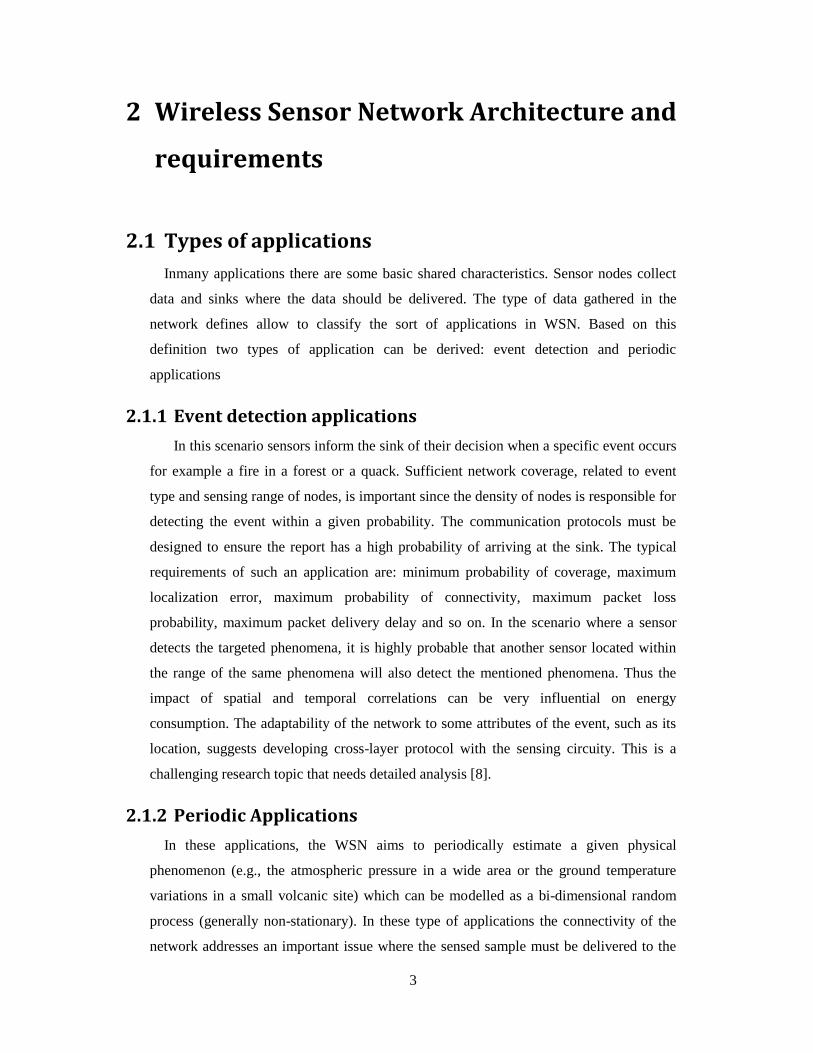
2.1.1 Event detection applications
In this scenario sensors inform the sink of their decision when a specific event occurs
for example a fire in a forest or a quack. Sufficient network coverage, related to event
type and sensing range of nodes, is important since the density of nodes is responsible for
detecting the event within a given probability. The communication protocols must be
designed to ensure the report has a high probability of arriving at the sink. The typical
requirements of such an application are: minimum probability of coverage, maximum
localization error, maximum probability of connectivity, maximum packet loss
probability, maximum packet delivery delay and so on. In the scenario where a sensor
detects the targeted phenomena, it is highly probable that another sensor located within
the range of the same phenomena will also detect the mentioned phenomena. Thus the
impact of spatial and temporal correlations can be very influential on energy
consumption. The adaptability of the network to some attributes of the event, such as its
location, suggests developing cross-layer protocol with the sensing circuity. This is a
challenging research topic that needs detailed analysis [8].
2.1.2 Periodic Applications
In these applications, the WSN aims to periodically estimate a given physical
phenomenon (e.g., the atmospheric pressure in a wide area or the ground temperature
variations in a small volcanic site) which can be modelled as a bi-dimensional random
process (generally non-stationary). In these type of applications the connectivity of the
network addresses an important issue where the sensed sample must be delivered to the

4
sink within a given probability. In addition, the communication protocols must ensure the
process of estimation error is maintained under a given threshold considering the low
power consumption. Typical requirements for such applications are maximum estimation
error, maximum localization error, minimum probability of connectivity, maximum
packet loss and so on [3]. Since the network has to collect the information periodically, a
proper scheduling operation can utilize the sleeping cycle of nodes. Hence, it reduces
power consumption.
In [8] a wake-up receiver technique is introduced to compensate duty scheduling,
thus minimizing power consumption. A single sensor can manage the timing, and when
the data is to be collected, it initiates communication by waking up its neighbors. The
node may reject the waking up signal based on the level of the residual energy.
Therefore, a handshaking protocol should be utilized in this strategy where a sensor can
dynamically decide an alternative route based on the neighbor’s decision.
2.2 Requirements for wireless sensor networks
By considering the aforementioned categories of WSN applications, the wide range of
applications used by WSN led to the definition of these networks as a large-scale,
wireless, ad-hoc, multi hop, mostly immobile, tiny, randomly deployed and remotely
deployed (need for long life). Handling such a wide range of application types will hardly
be possible with any single realization of a WSN. Realizing the characteristics of WSNs
with new mechanisms is the major challenge of the vision of wireless sensor networks
[7].
The basic constraints for wireless sensor networks can be summarized as follows:
• Low power consumption
• Maintainability: The System has to monitor its health and situation against some
failures in the network. The system has to adapt to the network, for example the
system could change some parameters to provide lower quality due to lack of
energy resources.
• Fault tolerance
• Lifetime: failure of a node in the network due to limited supply of energy could
lead to the failure of the whole network.

5
• Scalability:Employed architectures and Protocols must be able to scale a huge
number of nodes in the network
• Programmability: Nodes must exhibits a flexibility toward changes in the
operation tasks, so they should be programmable
• Small physical size
• Low cost nodes
• Single design for international market
• Functioning in a wide range of temperature changes
2.3 Power Consumption in WSNs
Energy is the most challenging issue in WSN. The energy supply is batteries, which
have a small capacity and limited lifetime. The main consumers of energy in sensor node
in [7] are categorized as follow: The controller, the radio front ends and to some degree
the memory depending on the type of application.
Chip-level and lower technique issues present one of the important contributions in the
process of preserving power in WSN. Indeed, the improvement on the chip-level is not
the perfect image of energy efficient scheme in WSNs, due to the fact that any advantage
gained by such design can be wasted when the components are improperly operated.
Since the sensor node cannot do anything most of the time, turning off the node can
significantly reduce the amount of energy but it has to wake up again based on external
stimuli or a scheduling scheme. Therefore, levels of operational can be introduced in the
context of reducing the functionality of the node and as a result preserve energy. Energy
can be improved using several methods relevant to the most energy consumption
elements:
Microcontroller: efficient programming of the microcontroller can reduce the energy
consumption by taking into consideration that some components can be turned off when
they are not in use, such as the transceiver or external sensors. Additionally, the concept
of multiple operational states is commonly implemented by embedded controllers such as
the Atmel ATmega [9], which provides six modes of power consumption which

6
varybetween 6 mW and 15 mW in idle and active modes and is about 75 µW in power-
down modes.
Radio Transceiver: thisis considered to be the biggest energy consumer in the node. It
mainly has four operation modes; transmitting, receiving, idle and sleeping. Transmitting
is considered to be the highest energy consumer because the process of transmitting a
packet contains two main operations: RF signal generation, which is the power radiated
by the antenna, and energy used by the electronic components. In order to achieve
efficient power consumption by the radio, duty cycling is introduced as key for that. By
definition, duty cycle is the ratio between the total time of sending and receiving data to
the total time of 1 cycle. As a result, the radio must sleep most of time and wake up
quickly to send data then sleep again.
2.4 Power management and energy efficiency
In the previous section the most crucial issues have been discussed and the main
consumer elements in WSN have been briefly mentioned. As the batteries are considered
to be the energy source of WSN, many energy harvesting techniques have been studied in
[10].
The technical report in [11] discusses a number of techniques for power management
solutions according to the OSI protocol stack. OSI is a network stack containing
interactive layers where each layer is supported with protocols in order to serve the next
layer. The techniques discussed are summarized with regard to every OSI layer as
follows:
Application layer: Load partition technique allows an application to have power
intensive computations performed at central node rather than remote nodes. The remote
node avoids data processing and the load of computation; instead it just transmits the
sensed data to the central node where it can be processed.
Transport layer: Techniques are used to reduce retransmission of packet losses due to a
faulty wireless link.
Network layer: Techniques in this layer are more concerned with designing intelligent
routing algorithms. For example, the most common technique is multi-hop routing where

7
every node is assumed to be a router when data is sent to the destination and hence the
shortest way will represent less energy consumption in the network.
Data link layer: Automatic Repeat Request (ARQ) and Forward Error Correction (FEC)
are known to be the most common techniques for reducing retransmission overhead. In
ARQ, the routing node automatically requests the retransmission of a packet from the
source node without first requiring the receiver node to detect that a packet error has
occurred
MAC Layer: The main technique is sleep scheduling in order to optimize the duty
cycling of a radio when it has to go on and off. Sleep scheduling has two categories:
Synchronous sleep scheduling, which depends on clock synchronization between all
nodes, and asynchronous scheduling which uses continues transmission to wake up the
receiver node when needed.
Physical layer: The techniques in this layer are more concerned with the hardware
components, for instance the current leakage effects on the long lifetime of the node, thus
a proper hardware design by which this leakage of current is decreased can represent a
good solution for a longer node life.
2.5 WSN Architectural issues
Generally the wireless sensor network consists of nodes and sinks /gateways. The
sensor node is considered the simplest component in the network. Sinks or gateways are
considered to be more complex than sensor nodes due to their complex functionality. In
many applications the number of nodes is much higher than the number of sinks or
gateways, thus their cost and size must be kept low. The traditional architecture of a
sensor network consists of Microcontroller, sensor, memory, radio transceiver and power
resource (battery).

8
Figure 2-1Architecture of a sensor node [3].
As shown in the figure 2-1the Microcontroller forms the core part of the sensor node
to tackle many aspects including the operating system, networking and power
management. The transceiver is considered the most power consuming part; it works on
different frequencies such as ISM band 900MHz and 2.4 GHz. The type of sensor is
specified according to the desired application. The battery is the energy storage unit of
this embedded system.
In this section we will study and summarize the different approaches that have been
adopted by many organizations and scholars in order to solve the different issues with
regard to better design of WSNs and their architecture.
2.5.1 Frequency of Radio
The core part of a WSN is the RF transceiver, which is responsible for the
modulation and demodulation of digital data; hence it represents the physical layer in
WSN. In [12] the authors summarize the distribution of power consumption in the WSN
for a commercial chip. Figure 2-2 shows the RF part is in charge of the most consumed
power in the node where TX (transmitting) and RX (Receiving).

9
Figure 2-2The power distribution in a commercial WSN chip [12].
The commonly demanded characteristics for RF transceivers for WSNs which are
considered by many companies to develop highly-integrated chips for RF transceiver can
be summarized as follows:
• Low data rate.
• Low power consumption.
• High sensitivity.
• Relatively low output power.
• Simple modulation scheme.
The table in figure 2-3 presents the main specifications of several commercial chips
which are described by authors in [12].
Figure 2-3the main specifications of several commercial RF chips common used in WSN
[12].

10
Frequency allocation
In designing a practical RF based system wireless network, the carrier frequency has
to be chosen carefully. The most important consideration in choosing the carrier
frequency is the propagation characteristics, such as walls penetration in indoor
applications. In communication a finite portion of the electromagnetic spectrum is called
Frequency band.
Most of today’s RF-based systems work at frequencies below 6 GHz. In order to
avoid interference between different systems, the range of radio frequency is subject to
regulation. For example, in Europe the GSM system uses 900 (880-915 MHz) and 1800
(1710-1785 MHz). Moreover, ITU (International Communication Union-Radio) grants a
licensefree bands, based on the standards published by IEEE, for the Industrial, Scientific
and Medical bands (ISM). The recommended standard of this institute is IEEE 802.15.4
which uses the band 2.4 GHz ISM, this band is also used for Bluetooth, IEEE 802.11b/g
and IEEE 802.11. The table in figure 2-4 Lists some of the ISM frequency bands [7].
Figure 2-4Some of ISM bands [7].
Free-license is considered to be the main advantage of ISM bands since it reduces the
cost of implementation of such systems. In other words, working in unlicensed bands
means that one can just go to a shop, buy equipment and start to transmit data without
requiring any permission from the government/frequency allocation body. On the other
hand, all systems in the same band must be robust against interference from other
systems. Coexistence needs to be approached both on the physical and MAC layer [7].

11
Moreover, security is mandatory with devices working in freelicense bands to avoid
unwanted interference and intrusion.
Another consideration in the choice of frequency is antenna efficiency. This
parameter is the ratio of the radiated power to the total input power to the antenna; the
remaining power is dissipated as heat. For example, radio waves at 2.4 GHz have a wave
length of 12.5 cm, much longer than the intended dimensions of many sensor nodes. In
general, as the ratio of the antenna decreases the efficiency decreases and therefore more
energy must be spent to achieve a fixed radiated power [7].
Electromagnetic propagation effects and noise
Unlike the wire medium, the waveforms transmitted over the wireless
communication are affected by several physical phenomena which distort the transmitted
waveform causing a bit error and dependence of power loss on direction of transmission.
According to [7] figure 2-5 illustrates the basic wave propagation phenomena which are
defined as follows:
Figure 2-5illustration of wave propagation phenomena [7].
Reflection: When a waveform propagating in medium A hits the boundary to another
medium B and the boundary layer between them is smooth, one part of the waveform is
reflected back into medium A, another one is transmitted into medium B, and the rest is
absorbed (Figure 2-5(a)). The amount of reflected/transmitted/absorbed energy depends
on the materials and frequencies involved.
Diffraction: By Huygen’s principle, all points on a wavefront can be considered as
sources of a new wavefront. If a waveform hits a sharp edge, it can by this token be
propagated into a shadowed region (figure 2-5(b))

12
Scattering: When a waveform hits a rough surface, it can be reflected multiple times and
diffused into many directions (Figure 2-5(c)).
Doppler fading: When a transmitter and receiver move relative to each other, the
waveforms experience a shift in frequency, according to the Doppler effect. Too much of
a shift can cause the receiver to sample signals at wrong frequencies.
2.5.2 Network Topology
A group of nodes constructs a communication network. Those nodes can receive and
transmit messages in the network over communication links. The communication
between nodes can be wireless or cable, and the single node consumes a certain amount
of energy in order to deliver or receive a message. Thus, one important issue in WSN is
how to distribute the nodes physically and by that to improve the connectivity of the
network. The basic network topologies are shown in figure 2-6. Choosing a topology
depends on many factors including quality of service (QoS), environmental restrictions
and the application necessities [13].
Figure 2-6Network topologies [13].
In some cases the network requires several topologies, for example the internet topology
which consists of star and tree topology called hybrid topology.
Fully connected topology exhibits a complex problem for large or dynamic
networks. In large networks the number of links increases among the nodes, while in

13
dynamic networks the addition of one node causes an exponential increase in the number
of links. This increase in the number of links leads to routing computational overhead
thus consuming power.
In star topology, the nodes are connected to a single hub/center. This center is
responsible for decision making, routing and controlling the topology. The Failure of one
communication link does not affect the whole system but if the center fails then the
system fails, which is at a disadvantage of this topology. The ring topology functions in
the same way as star topology without a center, but the message should travel around the
ring in a single direction.
The distribution of nodes in Mesh topology is close to being peer-to-peer topology
since the nodes are generally identical. In mesh topology the network only allows
transmission between neighboring nodes, hence a failure of one node does not cause the
failure of the system. In addition, one node can have many nodes as neighbors where
different routing paths exist and the failure of a link can be substituted by other paths.
Therefore mesh topology is robust against system failure, and it is considered a good
model for large wireless sensor networks. In mesh networks certain nodes can be leaders
and perform additional functions. The advantage of this feature is presented by the fact
that any node can be a leader if the existence leader fails since all nodes are identical in
this network.
In bus topology, nodes are always listeners since the message is broadcasted to all
nodes. Every node checks the destination address of the message, thus the bus topology is
considered to be passive.
2.5.3 Routing Protocols
Many applications of WSN require an ad hoc method of nodes deployment, which
leads to the network being able to autonomously organize itself. The density of the sensor
nodes along with the management and control of the network present severe power,
computation and memory constraints. The conventional routing protocols have several
shortcomings when applied to WSNs, which are mainly due to the energy-constrained
nature of the networks [14]. For example, some protocol and techniques in the traditional
networks broadcast data to all the members of network until the data is delivered to the
destination, which may lead to duplication of received packets by intermediate nodes. As
a result this can lead to significant power consumption. In [15] gossiping is a technique

14
for WSN where a node sends the packet just to its neighbors then the procedure will be
repeated until the packet arrives at its destination. This method can overcome the problem
of unnecessary processing of duplicated packets, but in high density networks it causes a
significant delay.
Various routing protocols have been tested to tackle the WSN constraints and the
particular requirements in WSN designs. In WSN there is no infrastructure, wireless links
are unreliable, sensor nodes may fail and routing protocols have to meet strict energy
saving requirements [16]. In figure 2-7, the various types of WSN routing protocols are
divided into seven categories [17].
In location-based protocol, sensor nodes are addressed by means of their locations.
Routing protocols in this category use this information to calculate the distance between
two particular nodes so that energy consumption can be estimated. Other factors can be
considered, such as the residual energy of every node.
Figure 2-7Routing Protocols for WSN [17].
In data-centric protocols, when the source sensors send their data to the sink,
intermediate sensors can perform some form of aggregation on the data originating from
multiple source sensors and send the aggregated data towards the sink. This process can
result in energy savings because less transmission is required to send the data from the
sources to the sink.

15
In the hierarchical approach, the network isdivided into cluster layers. Each cluster
has a head, the data is collected by nodes and routed by cluster heads until it reaches the
destination. In this approach, data travels a huge distance with each hop between clusters.
This moves data to the destinationfaster. Thus, clustering is considered to be an energy
efficient protocol.
In mobile networks, the sink changes its place and acquires data from nodes. Thus,
energy-efficient protocols are required to guarantee data delivery originated from source
sensors toward mobile sinks.
The main idea in Multipath-based protocols is that every sensor calculates K shortest
paths to the destination then it divides its load evenly between the possible shortest paths.
In Heterogeneity-based Protocols, the architecture of the network consists of two
main categories of nodes, line-powered sensors which have no power constraints and
battery-powered sensors with limited lifetime. The protocol should use the available
nodes with high energy to minimize the data communication and computation in limited
energy nodes.
The last category of routing protocols is designed to find the trade-off between
minimizing energy consumption and meeting the Quality of Service (QoS) requirements
in terms of delay, reliability, and fault tolerance in routing in WSN.
2.5.4 MAC Protocols
In the previous section the importance of special routing protocol has been discussed
in order to meet the requirements of WSN design, first and foremost the need to conserve
energy. Additional important requirements are scalability and robustness; these
requirements are mainly needed due to topology changes during the network lifetime.
These changes can be caused by the death of some nodes, deployments of new nodes and
mobility.
The transceiver of a sensor node can be in one of four states: transmitting, sleeping,
idling and receiving. The energy cost in each state can differ; transmitting and receiving
can consume more energy while sleeping costs almost nothing but in this case the node
needs additional techniques for waking up. Hence the following energy problems and
design goals are discussed in [18]:

16
Collisions: collisions mainly happen in dense networks where the number of packets in
the process of transmitting and receiving is huge. Thus, losing a packet costs the
transmitter additional power for retransmitting, while a receiver prolongs the listening
time. Collisions can be avoided in the case of low data rate networks
Overhearing: This problem can wake up additional nodes in the case where two nodes
are communication since the wireless medium is a broadcast medium. The reference
shows that for higher node densities overhearing avoidance can save a significant amount
of energy.
Protocol overhead: The MAC protocol itself causes additional overheads by its related
frames like RTS and CTS packets or by per-packet overhead like packet header and
trailer.
Idle listening: Most radio modems consume a huge amount of energy in the idle mode
since the radio is in the readiness state waiting to receive the packet. Some protocols offer
a solution to this problem by dividing the overall time into time slots. The process of
transmitting/receiving packets can be assigned to a time slot thus the node can stay idle at
other times.
2.6 Operating Systems
The operating systems for WSN should require certain needs such as energy efficient
execution for energy management. Moreover, the different components such as sensors
and the radio modem should be handled easily and efficiently. Therefore, a light and
efficient programming model is required to support the above mentioned requirements
[7].
In the next two sections we chose TinyOS and Contiki which address the challenges in
designing and implementing an efficient operating system for WSN.
2.6.1 TinyOS
Tiny-OS is a free and open source component-based operating system and platform
targeting wireless sensor networks (WSNs). Tiny-OS is an embedded operating system
written in the NesC programming language as a set of cooperating tasks and processes. It
is intended to be incorporated into smartdust(a hypothetical wireless network of tiny
micro electromechanically sensors, robots, or devices, that can detect for example light,

17
temperature or vibration). Tiny-OS started as a collaboration between the University of
California, Berkeley in co-operation with Intel Research, and has since grown to a be an
international consortium, the Tiny-OS Alliance [19].
Tiny-OS applications are written in NesC [20], a dialect of the C programming
language optimized for the memory limitations of sensor networks. Its supplementary
tools come mainly in the form of Java and shell script front-ends. Associated libraries and
tools, such as the NesC compiler and AVR binutils tool-chains, are mostly written in C.
Authors in [21] present three important goals by TinyOS regarding wireless sensor
architecture. First, allow varying implementations of operating system services in
different software and hardware platform such as different node generations. Secondly,
consider the specific challenges for WSN such as concurrency interface intensive
operation, a need for robustness, limited resources and application-specific requirements.
Finally, consider the current and probable future designs for WSN.
2.6.2 Contiki
Contiki is an open source, highly portable, multi-tasking operating system for
memory-constrained networked embedded systems [22]. Contiki is designed for
embedded systems with small amounts of memory. A typical Contiki configuration is 2
kilobytes of RAM and 40 kilobytes of ROM. Contiki consists of an event-driven kernel
on top of which application programs are dynamically loaded and unloaded at runtime.
Contiki processes use light-weight protothreads that provide a linear, thread-like
programming style on top of the event-driven kernel.
Contiki also supports per-process optional preemptive multi-threading, interprocess
communication using message passing through events, as well as an optional GUI
subsystem with either direct graphic support for locally connected terminals or networked
virtual display with VNC or over Telnet.
Contiki contains two communication stacks: uIP and Rime. uIP is a small RFC-
compliant TCP/IP stack that makes it possible for Contiki to communicate over the
Internet. Rime is a lightweight communication stack designed for low-power radios.
Rime provides a wide range of communication primitives, from best-effort local area
broadcast to reliable multi-hop bulk data flooding.

18
3 Technology
In this chapter, we discuss technologies and protocols implemented in WSNs including
an intensive study of XBee ZigBee modules capabilities and operational aspects. Later in
section 3.4.1, we study a comparison of ZigBee and XBee with different wireless
devices. Additionally, this section presents a comparison ofpower consumption of
different XBee ZigBee modules at different transmit power levels and in different
operational mode.
3.1 IEEE 802.15.4 Protocol
IEEE 802.15.4 is standardization by IEEE 802.15.4 Working group [23] focused on the
bottom two layers of ISO/OSI protocol stack, namely physical layer and Data Link layer,
also called the Medium Access Control (MAC) layer. The other layers are normally
specified by industrial consortia such as ZigBee Alliance [24]. See figure 3-1:
Figure 3-1 ZigBee Protocol Stack [3].
IEEE 802.15.4 wireless technology is a short-range communication system for
applications with relaxed throughput and latency requirements in wireless personal area
networks (WPANs). The key features of IEEE 802.15.4 wireless technology are low
complexity, low cost, low power consumption, and low data rate transmissions,
supported by cheap fixed or moving devices. The main field of application of this
technology is the implementation of WSNs [3].
19
The service which is provided by PHY physical layer [25] is the interface with
Wireless medium. Features of PHY include: radio transceiver activation and deactivation,
energy detection, link quality, clear channel, assessment, channel selection and
transmission and reception of the message packet. The IEEE 802.15.4 working group
specifies a total of 27 half-duplex channels across the three frequency license-free bands
as follows [3]:
• In the range 868-868.6 MHz; the 868 MHZ band mode is used in Europe: One
channel is available with data rate 20 Kbps, RF sensitivity is -92 dBm and the ideal
transmission rate is approximately 1 km.
• In the range 902-928 MHz; the 915 MHz band mode is used in North America and
the Pacific area: Ten channels are available with data rate 40 kbps, RF sensitivity is
minimum -92 dBm and the ideal transmission is approximately 1 km.
• In the range 2400-2483.5 MHz; the 2.4 GHz Industrial Specific Medical ISM band
mode is used worldwide: sixteen channels are available with data rate 250 kbps, RF
sensitivity is minimum -85 dBm and the ideal transmission rate is approximately
220m
Two types of devices which are used in LR-WPAN are defined as follows: Full
function device (FFD) and Reduced Function Device (RFD). FFD is supported with a
complete set of MAC services, thus it can operate in different modes as a PAN
coordinator, a coordinator, or simple network device. FFD can just serve as a simple
network device since it contains a reduced set of MAC services.
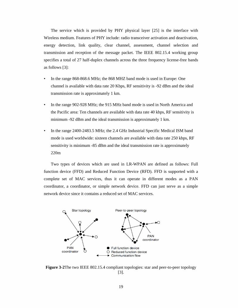
Figure 3-2The two IEEE 802.15.4 compliant topologies: star and peer-to-peer topology
[3].

20
To overcome the limited transmission range, multi-hop self-organizing network
topologies are required. The two possible network topologies are shown in figure 3-2.
In star topology, the network consists of an FFD as PAN coordinator connected to the
network devices. The PAN coordinator is considered master of the network; it is
responsible for managing device association. The procedure of managing the network can
be summarized as follow: any node which wishes to join the network listens for a beacon
message, and after receiving it sends an association request back to the PAN coordinator.
Any FFD can establish its own network by becoming PAN coordinator based on
predefined policies. Star topology is preferable in case the coverage area is small and low
latency is required by the application. In peer-to-peer topology each device can
communicate with any other device within the range of radio. In addition, this topology
has the feature of allowing one FFD to communicate with another FFD locating out of
the first one radio range via multiple-hop. Peer-to-peer topology is preferable in case a
large area needs to be covered and latency is not a critical issue.
MAC layer provides reliable data delivery and access control to a shared channel.
The IEEE 802.15.4 uses a fully acknowledged protocol based on the CSMA/CA
algorithm, which requires listening to the channel before transmitting to reduce the
probability of collision with other ongoing transmissions.
The main functions performed by MAC :
• Generation of acknowledgment frames
• Support of PAN association and disassociation
• Security control
Optional star topology functions (Generating network beacons for the coordinator )
• Handling and maintaining the guaranteed time slot mechanism (GTS)
• Provision of application support for the two possible network topologies
21
3.2 ZigBee Protocol
ZigBee is an industrial standard to cope with the restrictions of WSN. ZigBee Alliance
offers a standard based on very low-cost, low power consumption and two-way wireless
communications. The name of ZigBee comes from the domestic honeybee which uses a
zig-zag type of dance to communicate with other hive members [26].
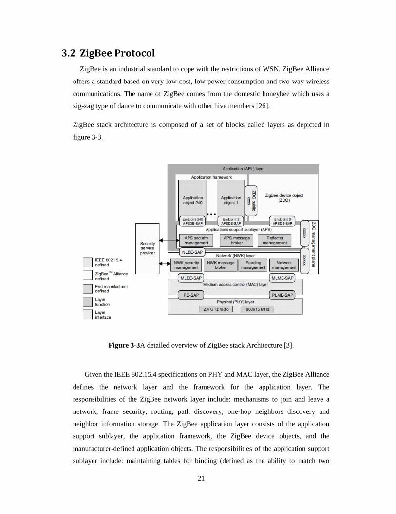
ZigBee stack architecture is composed of a set of blocks called layers as depicted in
figure 3-3.
Figure 3-3A detailed overview of ZigBee stack Architecture [3].
Given the IEEE 802.15.4 specifications on PHY and MAC layer, the ZigBee Alliance
defines the network layer and the framework for the application layer. The
responsibilities of the ZigBee network layer include: mechanisms to join and leave a
network, frame security, routing, path discovery, one-hop neighbors discovery and
neighbor information storage. The ZigBee application layer consists of the application
support sublayer, the application framework, the ZigBee device objects, and the
manufacturer-defined application objects. The responsibilities of the application support
sublayer include: maintaining tables for binding (defined as the ability to match two

22
devices together based on their services and their needs) and forwarding messages
between bound devices. The responsibilities of the ZigBee device objects include:
defining the role of the device within the network (e.g., PAN coordinator or end device),
initiating and/or responding to binding requests, establishing secure relationships between
network devices, discovering devices in the network, and determining which application
services they provide [3].
ZigBee specifications define a beacon-enabled tree-based topology, as a particular
case of the IEEE 802.15.4 peer-to-peer network. This topology consists of one root
device which is PAN coordinator (generally the sink of the scenario) and the nodes of the
tree. The nodes of the tree are divided into two categories: routers and leaves. Routers
must be FFDs; they receive data from children, aggregate them, and transmit the packet
obtained to their parents. Leaves can be FFDs or RFDs, they only have to transmit
packets to their parent.
The application of ZigBee protocol is mesh topology/networking. In mesh topology,
ZigBee network will have a single coordinator device and at least one other device, either
router or end device [27]:
Coordinator: ZigBee networks always have a single coordinator device for forming the
network, handing out the address, securing the network and keeping it healthy
Router: A router is a full-featured ZigBee node. It can join existing networks, send
information, receive information and route information. Routers are typically plugged
into an electrical outlet because they must be turned on all the time.
End Device:An end device always need a router or coordinator to be their parent device.
The parent helps end devices join the network, and stores messages for them when they
sleep.
3.3 DigiMesh Protocol
DigiMesh is a proprietary protocol developed by Digi international to offer an alternate
mesh protocol. DigiMesh is similar to ZigBee in that both of them support mesh
networking, nevertheless DigiMesh has its specific characteristics and advantages which
are important to support different applications.

23
In [28] a white paper by DigiInc states the characteristics and differences between
DigiMesh and ZigBee. DigiMesh has only one node type. As a homogenous network, all
nodes can route data and are interchangeable. There are no parent-child relationships. All
can be configured as low power / battery powered devices. Hence, DigiMesh is able to
provide a better sleeping scheme by allowing all nodes to sleep in the network, while
ZigBee just allows end device to sleep. In DigiMesh, time synchronizing is established
through a nomination or election process, enabling the network to operate autonomously.
Moreover, DigiMesh eliminate the single point of failure which affects the
Coordinator/Gateway in ZigBee, this can be considered as a significant advantage of
DigiMesh.
Additional features offered by DigiMesh include [29]:
• Self-healing: A node may associate or leave the network at any time without
causing a failure of the network.
• Peer-To-Peer architecture: Unlike ZigBee, there is no hierarchy architecture
where all the nodes are one type, and thus no parent-child relationship constraint.
• Sleep mode and synchronization: Synchronized wake up is supported by this
protocol to allow of all nodes in the network to sleep.
• Reliable Delivery of Data: Reliable delivery of data exists by means of
acknowledgments.
• Quite Routing: Routing overhead will be reduced by using a reactive protocol
similar to AODV
• Route Discovery: This technique is used to create the route on demand. More
precisely, when a node transmits data to the destination then the route will be
determined. This therefore avoids the requirement to have a route map in the
network.
The main difference between DigiMesh and ZigBee can be:
ZigBee is an open standard. Therefore it is capable of interoperating with devices
made by different vendors, and has the ability to have over-the-air firmware updates.
Additionally, ZigBee has good tools for network diagnostic, low-rate, low power

24
consumption and light controlling. Despite all the features supported in DigiMesh,
especially sleeping scheme and robustness against failure of the network, it is a
proprietary protocol.
3.4 XBee
XBee is a brand of radio that supports a variety of communication protocols. XBee is a
feature-rich RF module which makes it a very good solution for WSN designers; the
implemented protocols on the modules like IEEE 802.15.4 and ZigBee can significantly
reduce the work by the programmer for ensuring data communication. Besides the
capability of these modules to communicate with Microcontroller through UART serial
communication, it also has additional pins which can serve for XBee standalone
applications. For example, a router node can be built without the need for a
microcontroller. XBee has digital input/output pins that can be used to read a digital
value by a sensor or to control a motor. XBee also has PMW/analog pins; a 10-bit PWM
pulse width modulated output may be sent to another XBee. One important feature is line
passing where a digital input on one XBee can be reflected on the digital output of
another, thus controlling the output of the second XBee.
In this thesis we use XBee-Pro S2B [30]. This module offers the capability for long
distance communication. In addition to that, it supports ZigBee protocol in order to test
the mesh topology reliability.
3.4.1 XBee and ZigBee importance and power consumption
In section in 3.2 we have introduced ZigBee protocol. In this thesis the experiments
will be done based on the ZigBee protocol which is considered one of the most common
protocols in personal WSN of low bandwidth, low cost, high level of security and low
power consumption.
An example of a module which includes ZigBee protocol is CrossBowMicaZ. The
inability to customize proprietary communication protocols or develop custom software
makes the area of research for additional power consumption reduction narrowed [31].
CrossBowMicaZ provides the ability to customize the communication protocol, but it has
some disadvantages relating to the size, range and different hardware for different
network functions [32]. In this thesis, we use Digi’s Xbee modules with ZigBee protocols

25
for our experiments. Those modules are small in size, have variant coverage range up to
80 km and the ability to use the same hardware for all node types (Coordinator, Router,
End node).
In [33] the author aims to develop a Centralized Home Control System using wireless
transceivers. The author draws a comparison of the available wireless technologies,
mainly in terms of less frequent battery replacement, and then concludes that XBee
(ZigBee) modules are the most efficient solution. The table in figure 3-4 shows the
comparison between different technologies.
Figure 3-4Comparison between wireless devices [33]
In order to study the power consumption of different XBee modules, in [5] an
analysis of the power consumption for various XBee ZigBee modules is carried out by
using National Instruments NI DAQ system to acquire the current and voltage. The

26
author analyzes the power consumption of two different firmwares (Router and End
Node) against three different hardware modules (XBee PRO 60mW, XBee PRO S2B and
XBee Series 2) in two modes (Transmitting and Idle). Figure 3-5 shows the results of this
measurement.
Figure 3-5XBee modules power consumption vs. verious operation modes [5].
According to this measurement, the XBee PRO 60mW among the other modules
exhibits the highest power consumption in different modes of operation. In XBee PRO
60mW, the router consumesjust 8.5% less power in idle mode than in transmitting mode.
With XBee PRO S2B, the router reduces the power consumption in idle mode to 6%
while the ratio between the idle and transmitting mode is constant in the case of XBee
Series 2. The power consumed by the end device in the idle mode is considered to be a
very important parameter in WSN node. The measurement shows that the XBee S2 uses
less than 500uA reducing the consumption in transmitting mode by 95%, while XBee
PRO S2B needs 1.1mA in idle mode. XBee PRO 60mW presents the best ratio between
transmitting and idle mode since their difference is large.

27
3.4.2 XBee S2B vs. XBee-PRO S2B
As in the previous section, the difference between both versions is coverage distance
and power consumption. In order to extend the range of the network through routing,
these modules are supplied with ZigBee protocol. As mentioned in section 3.2 ZigBee
protocol is placed on top of IEEE 802.15.4 protocol; it supports mesh topology. These
modules are desired for establishing self-healing, self-establishing networks. These
devices can be programmed with either AT or API, mode as it will be discussed later.
According to the functionality of mesh network, there will be three different devices
Coordinator, Router and End device.
The suitable firmware for the specific type of node can be loaded onto these modules
using X-CTU software offered by Digi. This tool will be discussed in detail later in this
thesis.
The next table 3-1 summarizes the specification of both modules and their comparison
[35]:
Table 3-1Comparison of the specification of XBee-Pro S2B and XBee S2B
3.4.3 XBee addresses and channels
Each RF data packet sent over-the-air contains a source address and destination
address field in its header [9]. XBee modules have a unique and permanent address on
earth, this address is a 64-bit serial number assigned by the manufacturer. XBee

28
modules also have a 16-bit short address assigned within the network. Finally, Node
Identifier can be assigned to each module as a string of text. Table 3-2 shows the type of
addresses:
Table 3-2 Type of address in ZigBee Network.
XBee ZigBee: The 16-bit short address of a node is assigned by a coordinator or router at
the time of joining the network. For this reason, it is also called “network address” the
16-bit address of 0x0000 is therefore reserved for coordinator. This way of
resolving the identity of a node in a network can be unreliable since the 16-bit address is
not static. To solve this problem, the 64-bit destination address is often included in data
transmissions to guarantee data is delivered to the correct destination [35].
Although both modules support the same type of addresses, the configuration of
addresses of nodes within the network is different. XBee ZigBee supports mesh topology;
in this case the addresses of nodes which wish to join or leave the network are assigned
by the coordinator, thus they are dynamically assigned. Meanwhile XBee IEEE 802.15.4
basically supports peer-to-peer network in which the address is configured manually.
PAN Address: This is another 16-bit address relevant to the Personal Area Network. The
16-bit PAN address gives the possibility of 65,536 different PAN addresses along with
65,536 16-bit module address for each PAN. This addressing scheme gives the capability
for more than 4 billion total radios[27].
Channels: Assuming that all the addressing is correct in the network, the communication
still may not be established unless the modules work on the same frequency. Thus, all
modules in the network must use the same channel. Generally 12 channels, or more based
on the type of radio, are available, but the programmer doesn't have to worry about
selecting a specific channel since the XBee modules select it automatically.

29
Figure 3-6shows a demonstration example of how a message is being delivered
within a network or between two XBee modules that belong to different networks. In
both scenarios, the XBee modules have to communicate on the same channel [27].
Figure 3-6Venn diagram showing channel, PAN and addressing [27].
In peer-to-peer network, if any pair of XBee modules wish to communicate in the
same area where a network already exists, they have to choose either a different address,
PAN ID or frequency channels [36].
For troubleshooting, it is important to know that all modules within a PAN should
operate using the same firmware version.
3.4.4 XBee Operation Modes
XBee has five modes of operation; the basic one is idle mode. This is the mode when
the module is not receiving, transmitting, commanding or sleeping [34] [35]. This mode
can consume a significant amount of energy compared to active mode where data is being
sent or received. One solution is to put the XBee in sleep mode. However, sleep mode
depends on the type of application; whether it is event-driven or periodic application.
Moreover, sleeping requires a light scheduling algorithm in order to wake up the nodes in
the network in harmony.
Idle mode
In Idle Mode, the mode shifts into other modes of operation when serial data is
received in the ID buffer then changes to transmit mode. When valid RF data is received
through the antenna, it switches to receive mode. It changes to sleep mode based on sleep
register conditions. When a command mode sequence is issued, then it changes to
command mode.
30
Transmit and receive modes
In Transmit Mode, the module packetizesthe data and ensures the 16-bit address is n
in order to establish a route to the destination. When the module cannot find the
destination address, it runs the network address discovery. If the module with the
destination address is not known, then the packet will be discarded. Route discovery will
take place in order to establish a route to the destination and retransmit the packet. If
route discovery fails to establish a route, then the packet will be discarded.
In Receive Mode, If a valid RF packet is received, the data is transferred to the serial
transmit buffer.
Command Mode
Commands are used to modify or read the module parameters. The key point is how
to let the module understand that the incoming serial character is a command and not data
to transmit. In order for the module to understand the command mode, an enter mode
code “+++” must be sent to the module with respect to the guard time before and after the
code. In details:
• No character is sent for one second
• Three Characters “+++” are input to the module within one second
• No character is sent for one second
If the procedure is issued correctly, then the module responds with OK out on DOUT pin.
Sleep Mode
XBee modules, like many other communication or microcontroller devices can put
themselves into sleep mode to save the power which is mainly consumed in sensor node
by the transceiver. But the most important trade-off is that during sleep no activities can
be handled and the device is nearly turned off until it wakes up. ZigBee mesh networking
is specifically designed to handle communication in the network where many nodes
might be in such a type of very low-power state [27].When an end device is asleep, one
of the parents stores the data and forwards it when the end device wakes up. ZigBee
network gets this feature without any additional components or code required to manage
the process.

31
XBee end devices support two different sleep modes:
• Pin Sleep
• Cyclic Sleep
Pin sleep allows an external microcontroller to determine when the XBee should sleep
and when it should wake by controlling the Sleep_RQ pin. In contrast, cyclic sleep allows
the sleep period and wake times to be configured through the use of AT commands. The
sleep mode is configurable with the SM command.
ATSM command for configuring sleep mode is as follows:
XBee ZigBee:
ATSM 0: this is for disabling sleep mode, this value is set by default for No Sleep and
XBee is always awake
ATSM 1: In this mode, the function of Sleep_RQ pin will be activated and entering or
ending sleep mode will be upon the external device which is most commonly
Microcontroller.
ATSM 2,3: These modes are currently not defined.
ATSM 4: This value allows the Cyclic Sleep Mode. This mode allows the module to
sleep and wake on a predefined schedule. This mode gives the capability for the module
to control its sleeping mode if it is not controlled by any external devices.
ATSM 5: Cyclic Sleep with pin wake. This value gives the same functionality of the
Cyclic mode but with the capability for the module to be woken up using the physical pin
9.
Beside the basic configuration command SM, there are five advance commands described
as follows:
SN: Number of Sleep Periods. This command allows the module to extend the sleeping
periods if no RF data is waiting for the end device. The parameter range is 1-0xFFFF.
SP: Sleep Period. This command determines how long a time the node can sleep at a
time. This value isalso used for the parents to determine for how long they will buffer the
message. For the range of this value is 0x20 to 0xAF0 in mS

32
ST: Time before Sleep. This command sets the time-before-sleep timer on an end device.
The timer is reset each time serial or RF data is received. Once the timer expires, the end
device may enter low-power operation. Range 1-0xFFFF 1mS
SO: Sleep Options, range between 0-0xFF. Sleep options include: 0x02 always wake for
ST time. 0x04 Sleep entire SN*SP time.
WH: Wake Host. This command sets or reads the wake host timer value.
Some constraints during powersavingwhen the designer uses sleep mode present
important trade-off in designing power efficient wireless sensor networks. Storage
devices in routers must be carefully considered in designing WSNs, since the longer
nodes sleep the longer messages must be stored. Anotherfactor,is that network chatters
must be kept at a minimum to avoid overwhelming the parent device’s storage resources
and discarding important information [27].
3.4.5 AT communicationmode
The AT-configured radio can be used in two modes:
Transparent mode: This mode allows simple serial transmission and reception of one
XBee with remote node. This mode is called transparent because of the transparent
protocol link between two nodes to the user.
Command mode: In this mode, the user talks to the radio rather than passing the data
through it. AT commands are used by the user in order to configure XBee radio such as
destination address, PAN (Personal Area Network) ID, Sleep mode and sleep period .AT
commands are a descendant of the Hayes command set that was originally developed for
configuring telephone modems [27].
The user can enter dedicated commands for his/her configuration of the module via
terminal software or X-CTU software offered by Digi’s. Regardless of the software used,
the communication with XBee will be through at the serial port. These possibilities will
be discussed in further details in this thesis.
To enter into Command mode the following steps must be taken in order to inform the
module that the received characters are commands and data to be sent:
• No character is sent for one second

33
• Three Characters “+++” are input to the module within one second
• No character is sent for one second
Every command is followed by AT. For example, the command CH for choosing a
channel frequency is written ATCH. Figure 3-7 shows the Syntax of sending AT
command.
Figure 3-7Syntax of Sending AT Command [35].
3.4.6 API communication mode
An Application Programming Interface (API) is simply a set of standard interfaces
created to allow one software program to interact with another. They are generally not
designed for direct human interaction. In API Mode, the programmer packages the data
with necessary information, such as destination address, type of packet, and checksum
value. Also, the receiving node accepts the data with information such as source address,
type of packet, signal strength, and checksum value. The advantages are the user can
build a packet that includes important data, such as destination address, and that the
receiving node can pull from the packet information such as source address of the data.
While more programming intensive, API Mode allows the user greater flexibility and
increased reliability in some cases [36].
In [37] the authors develop a mesh networking system for autonomous acoustic buoy.
They use API mode to implement their operations such as:
• Addressing different nodes without entering the command mode.
• Automatic retries and acknowledgements of transmissions.
• Collision avoidance.
• Identification of the source address of each received packed.
• A checksum.

34
API was adopted in their design mesh networking, since in AT mode they will
develop these operations by themselves. Hence, this will take them a considerable
amount of extra development time.
It is important to note that during the communication between two XBee module’s both
sides do not need to be in the same mode. Data may be sent in API Mode and received in
AT Mode or vice-versa. The mode defines the communications link between the PC or
controller and the XBee module, and not between XBee modules.

35
4 Methodology
In this chapter, we present the proposed methodology. We present the tools which we
used such as X-CTU, XBIB-R-DEV development kit. We also discuss the aspects related
to implementing our embedded wireless sensor node. Measurement setup is also
presented in this chapter.
4.1 X-CTU Software
The X-CTU software is the official configuration program for XBee modules provided
by digiinc [38]. X-CTU is available only for Windows operating system; if the user has
Linux then X-CTU should be running under WINE windows emulator. X-CTU is used
mainly for setting the firmware to XBee module. Figure 4-1 shows the main
configuration screen. The tab modem includes the list of available firmware for various
types of XBee module. “Function set” determine the function in which the XBee module
will work. For example, when we select the firmware XBP24BZ7 which supports the full
ZigBee functionality, then the function can be to set up the module as coordinator, router
or end device. Moreover, each function is supported with the ability to work in AT or
API mode. In figure 4-1 we can see that X-CTU provides fully commented setup
commands with the ability to change the values of these commands then to write them to
the module by pressing on the write button. X-CTU has a terminal window which can be
used to read the data being received by the connected module to X-CTU. Additionally,
this terminal can be used to enter AT command mode and write the setting to the module.
Range test is another feature by X-CTU which we use in this thesis. Figure 4-2 shows
the screen of range test. It provides the Received Signal Strength Indication (RSSI) in
dBm where -40 dBm represents the strongest signal received by the module. Range test
procedure is done as follows:
• Local XBee module connected to PC sends a packet of data to a remote XBee
module
• The remote XBee module sends the packet back to the local module
• X-CTU reads the value of the received signal strength by the received packet by local
module and shows it in dBm
“Data Received Timeout”, “Packet Delay” and “Data Packet Size” are parameters by
which the user is able to simulate a wide range of scenarios.

36
Although the X-CTU is required software for updating/uploading firmware on XBee
modules, there is the possibility to use terminal programs to communicate with XBee
such as “CoolTerm” or “ZTerm” for Macintosh. Using such programs we can configure
the XBee settings using AT commands.
Figure 4-1Configuration Screen with fully commented setup commands.

37
Figure 4-2Range Test Screen.
4.2 XBee Setup
In order to update the firmware using X-CTU software, thus we need to connect the
XBee to the computer before attaching it to the sensor node. This is done by placing the
XBee into a USB explorer unit. The USB explorer is used to connect the XBee to a
computer with a USB port. In this project we use SparFun XBee Explorer [6]. In addition
to upgrading the firmware, we use the explorer to set the needed registers value of XBee.
Firmware XBP24BZ7 is used in XBee-Pro S2B which supports the full functionality of
ZigBee protocol. The function of this firmware supports coordinator, router and end
device

38
4.3 Implementing an Embedded Wireless Sensor Node
The wireless temperature sensor node wasimplemented in this thesis based on a PIC
microcontroller that Utilizes XBee-Pro S2B to create sensing phenomena. Thus
implementing a WSN model in which we study some factors which affect the design of
such networks.
Although the design of sensor nodes is different for different applications, but the basic
structure is similar. The architecture of sensor nodes consists of a processing unit which
is responsible for collecting and processing the data sensed by a sensor. A radio
transceiver works as the communication unit among sensors and a battery is the power
supply unit in this system.
In this section, we will study the capabilities of each chosen item in implementing the
sensor node. Moreover the constraints and designing issues along with troubleshooting
will be discussed as well. Figure 4-3 shows our embedded wireless sensor node.
Figure 4-3Wireless Temperature Sensor Node
4.3.1 DS18B20 Temperature Sensor
After investigating the available temperature sensors, we found the DS18B20 digital
thermometer to be an adequate element in our design. In [39], DS18B20 digital
thermometer has an operating temperature range of -55°C to +125°C and resolution from
9 to 12 bits, and the accuracy is ±0.5°C over the range of -10°C to +85°C. DS18B20
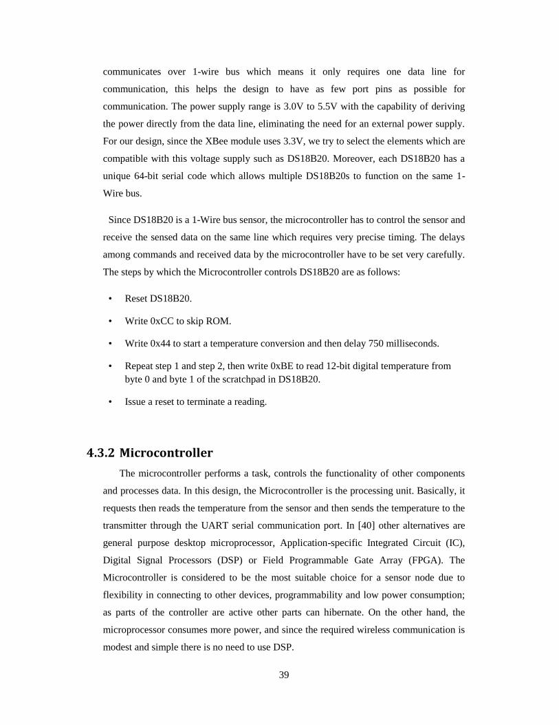
39
communicates over 1-wire bus which means it only requires one data line for
communication, this helps the design to have as few port pins as possible for
communication. The power supply range is 3.0V to 5.5V with the capability of deriving
the power directly from the data line, eliminating the need for an external power supply.
For our design, since the XBee module uses 3.3V, we try to select the elements which are
compatible with this voltage supply such as DS18B20. Moreover, each DS18B20 has a
unique 64-bit serial code which allows multiple DS18B20s to function on the same 1-
Wire bus.
Since DS18B20 is a 1-Wire bus sensor, the microcontroller has to control the sensor and
receive the sensed data on the same line which requires very precise timing. The delays
among commands and received data by the microcontroller have to be set very carefully.
The steps by which the Microcontroller controls DS18B20 are as follows:
• Reset DS18B20.
• Write 0xCC to skip ROM.
• Write 0x44 to start a temperature conversion and then delay 750 milliseconds.
• Repeat step 1 and step 2, then write 0xBE to read 12-bit digital temperature from
byte 0 and byte 1 of the scratchpad in DS18B20.
• Issue a reset to terminate a reading.
4.3.2 Microcontroller
The microcontroller performs a task, controls the functionality of other components
and processes data. In this design, the Microcontroller is the processing unit. Basically, it
requests then reads the temperature from the sensor and then sends the temperature to the
transmitter through the UART serial communication port. In [40] other alternatives are
general purpose desktop microprocessor, Application-specific Integrated Circuit (IC),
Digital Signal Processors (DSP) or Field Programmable Gate Array (FPGA). The
Microcontroller is considered to be the most suitable choice for a sensor node due to
flexibility in connecting to other devices, programmability and low power consumption;
as parts of the controller are active other parts can hibernate. On the other hand, the
microprocessor consumes more power, and since the required wireless communication is
modest and simple there is no need to use DSP.

40
In this thesis we use a Microcontroller of the PIC18 family due to its popularity,
availability and available development tools. The requirements for the microcontroller in
this design are:
• The Xbee module works with a supply voltage of 3.3V, so it is more flexible for the
design to have the process unit using the same voltage. Hence, a second regulation
circuit is not needed.
• Power usage should be as low as possible.
• Two UART interfaces are needed. UART1 to send data to XBee module. UART2 for
further development such as serial interface with computer.
• The software programmed on the microchip is about 5 KB of program memory.
After investigating microchip comparison utility [41] we found that PIC18F46K22 has
the capabilities to meet all our requirements.
In order to achieve the lowest possible power consumption, we choose the frequency
of the oscillator to be 1 MHz. Since the default baud rate of XBee module is 9600, we
have to configure the setting of the Microcontroller to function on baud rate 9600 with
the frequency 1 MHz. Thus we follow the following setting [42]:
Set the value of register BRGH to 1, Set value of register SPBRGH to 0 and SPBRG to
25.
The Microcontroller is connected to DS18B20 via pin RA0, UART interface is connected
to XBee. The Microcontroller sends data through UART to XBee.
The PIC is programmed using MPLABX software which utilizes C language using
C18 compiler. The program is developed to receive the reading temperature from
DS18B20 and send this data through UART to XBee which is configured as an end
device to the coordinator.
4.3.3 Voltage regulator
There are varieties of voltage regulators that can be selected to build a 3.3V power
supply circuit such as linear voltage regulators and switching voltage regulators. To
design a circuit which needs a stable 3.3V power supply using a Low-Dropout fixed
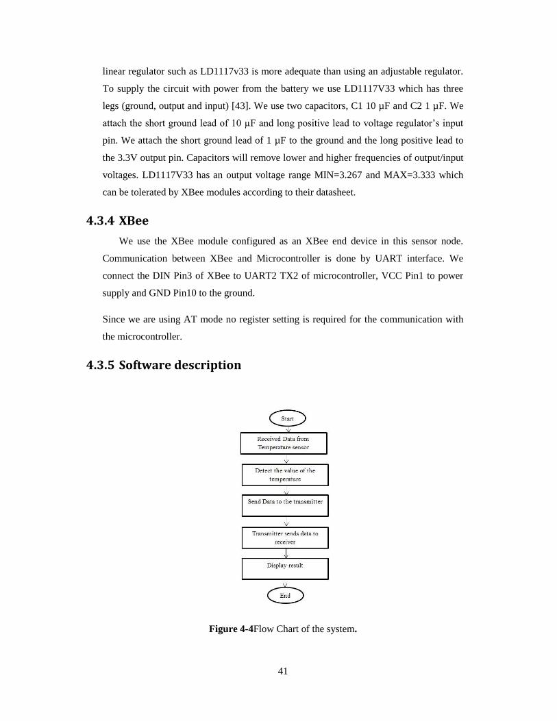
41
linear regulator such as LD1117v33 is more adequate than using an adjustable regulator.
To supply the circuit with power from the battery we use LD1117V33 which has three
legs (ground, output and input) [43]. We use two capacitors, C1 10 µF and C2 1 µF. We
attach the short ground lead of 10 µF and long positive lead to voltage regulator’s input
pin. We attach the short ground lead of 1 µF to the ground and the long positive lead to
the 3.3V output pin. Capacitors will remove lower and higher frequencies of output/input
voltages. LD1117V33 has an output voltage range MIN=3.267 and MAX=3.333 which
can be tolerated by XBee modules according to their datasheet.
4.3.4 XBee
We use the XBee module configured as an XBee end device in this sensor node.
Communication between XBee and Microcontroller is done by UART interface. We
connect the DIN Pin3 of XBee to UART2 TX2 of microcontroller, VCC Pin1 to power
supply and GND Pin10 to the ground.
Since we are using AT mode no register setting is required for the communication with
the microcontroller.
4.3.5 Software description
Figure 4-4Flow Chart of the system.

42
Figure 4-4describes the flowchart of the working procedure of the sensor node. The
microcontroller reads the data from the sensor node, and then sends the temperature via
XBee end device to XBee coordinator which presents the reading temperature on X-CTU
terminal screen.
4.4 XBee ZigBee network setup
For our experiments we use mesh topology which is implemented by ZigBee protocol.
Building a network using ZigBee protocol is done automatically, since ZigBee is
self-healing and self-organizing protocol. The coordinator is responsible for establishing
the ZigBee network by scanning for existing PANs and available channels. As a result, it
will select an unused channel and PAN ID. For routers and end devices, they scan for a
coordinator or router working with a valid PAN and then they join the network. They
send an association request frame to an associate device and receive an association
response to verify allowance into the network. Finally, they send a broadcast discovery
frame to discover the 64bit address of the coordinator.
In order for the router/end device to join the specific network, we choose a PAN ID
for the network. Hence, the router/end device will join the intended network with the
same PAN ID.
The setting of each XBee-Pro S2B device in the network is as follows:
Coordinator: connected to X-CTU software via USB explorer. Register settings are:
NI: COORD (Human Readable Name)
DH: 0 , DL: FFFF (Broadcasting) . ID:2001 .
SP: C8 , ST 3E8 (to buffer the data until end device wake up)
Router: in installed on XBIB-R-DEV development kit.
Register settings are: DH:0, DL:0. ID:2001. JV: enabled (To allow joining the
coordinator)
SP: C8 , ST 3E8 (to buffer the data until end device wake up)
NI: REMOTE1 (Human Readable Name)

43
End Device: this is our sensor node as mentioned in the previous chapter. Register
settings are: DH:0, DL:0. ID:2001. NJ: FF (the end device assumes permit-joining is
always enabled on the network and joins through association)
SP: C8 , ST 3E8 (Sleep cyclic for 2 seconds)
NI: ENDNODE (Human Readable Name)
4.5 Power measuring circuit
We measure the amount of the running current in sensor node and XBee modules by
using 1.8 Ohm resistor and Oscilloscope. We use oscilloscope TekTDS2012B [44] for
our measurements with the highest possible resolution. This model of oscilloscope has a
USB port in order to record data digitally.The resistor is connected in series to the circuit.
The voltage drop over the resistor is proportional to the current running through it.
Therefore, we can measure the voltage by connecting Oscilloscope to the resistor and
calculate the amount of current using Ohm’s law. For example, the current of 95mA
through a 1.8 Ohm resistor drops 172 mV. On the other hand, when we measure the
voltage 172mV by the oscilloscope with the known value of the resistor, then we can
calculate the current as I = V/R = 0.172/1.8 = 0.0955 A.
This method of measuring the current is not very accurate, but it shows how power is
being consumed in every operation mode and power level of XBee.
4.6 Coverage Range
In this measurement we aim to study the actual coverage range of the XBee-Pro S2B in
real life conditions. For our measurement we use a loop back test which is performed by
X-CTU in order to measure the relationship between Received Signal Strength RSSI and
the distance for a point to point link.
XBIB-R-DEV development kit [46] is used in this measurement;this kit has a feature
to perform a loop back test. The coordinator sends a packet of data using X-CTU
software to the remote XBee which is installed on this kit, and then the kit sends back the
packet via the installed XBee.
Indoor and outdoor range tests were done representing, respectively, the LOS (Line of
Sight) and NLOS (Non-line of Sight). This measurement is also implemented on different
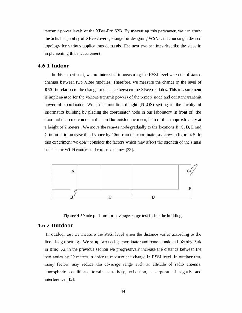
44
transmit power levels of the XBee-Pro S2B. By measuring this parameter, we can study
the actual capability of XBee coverage range for designing WSNs and choosing a desired
topology for various applications demands. The next two sections describe the steps in
implementing this measurement.
4.6.1 Indoor
In this experiment, we are interested in measuring the RSSI level when the distance
changes between two XBee modules. Therefore, we measure the change in the level of
RSSI in relation to the change in distance between the XBee modules. This measurement
is implemented for the various transmit powers of the remote node and constant transmit
power of coordinator. We use a non-line-of-sight (NLOS) setting in the faculty of
informatics building by placing the coordinator node in our laboratory in front of the
door and the remote node in the corridor outside the room, both of them approximately at
a height of 2 meters . We move the remote node gradually to the locations B, C, D, E and
G in order to increase the distance by 10m from the coordinator as show in figure 4-5. In
this experiment we don’t consider the factors which may affect the strength of the signal
such as the Wi-Fi routers and cordless phones [33].
Figure 4-5Node position for coverage range test inside the building.
4.6.2 Outdoor
In outdoor test we measure the RSSI level when the distance varies according to the
line-of-sight settings. We setup two nodes; coordinator and remote node in Lužánky Park
in Brno. As in the previous section we progressively increase the distance between the
two nodes by 20 meters in order to measure the change in RSSI level. In outdoor test,
many factors may reduce the coverage range such as altitude of radio antenna,
atmospheric conditions, terrain sensitivity, reflection, absorption of signals and
interference [45].

45
5 Measurements Results
In this chapter, we provide the results of our measurements on energy consumption in
XBee-Pro S2B module along with the measurements on Received Signal Strength
Indicator (RSSI) in both outdoor and indoor scenarios at transmit power level P0 and P4.
5.1 XBee power consumption
There aremany parameters affectingthe power consumed by the XBee modules.
Operation modes (transmitting, receiving, idle, and sleeping) draw different amount of
currents, hence their power consumption is different. On the other hand, there are
different power levels at which the RF transmits conducted power. The power level is set
by the register PL using AT commands or through the configuration panel of X-CTU.
There are five power levels- the setting parameter and value of each power level are as
follow:
XBee-Pro S2B: PL=4: 10dBm, PL=3: 8dBm, PL=2: 6dBm, PL=1: 4dBm and PL=0:
2dBm.
In the following sections, we measure the actual power consumption by coordinators,
routers and end devices considering the effect of different transmit power levels on power
consumption by XBee-Pro S2B module.
5.1.1 XBee coordinator
Our measurement shows the XBee coordinator at the transmit power level P4 draws a
constant current approximately 95 mA. We also measure a draw of a constant current 51
mA which is close to the specification when the device turns the radio on and listens to
the channel and is operating in full functionality mode to ensure minimal retransmission
and delay. However, the specification of the ZigBee device states that the current at
transmitting mode should be higher than the current which we measured. This can be
avoided by improving the measurement circuit. Figure 5-1 shows the results from
oscilloscope at the power level P4. Table 5-1 describes current drawn by different
transmit power levels. We can see that PL3 and PL2 consume approximately the same
amount of power, which is the same case for PL1 and PL0, while a difference can be
noticed between P4 and P0.

46
Table 5-1the currentdrawn by the XBee-Pro S2B coordinator in different operational
modes and at each transmit power level.
Figure 5-1Coordinator at transmitting and idle mode.
5.1.2 XBee Router
Our measurements show that the router has the same power consumption as the
coordinator. When we measure the constant current by router at the default power level
P4 we find it to be 51 mA, then we measure a change in the current to be 95 mA when

47
router sends data. This similarity explains that router operate in the same way as
coordinator which means it has to listen to the channel for a request from any device
within its range. For the power consumption in different transmit power levels versus
operational modes, the table 5-1 in the previous section presents the same values for the
router. Figure 5-2 shows the reading value from the oscilloscope at the power level P4.
Figure 5-2Router in transmitting and idle mode.
5.1.3 XBee end device
In this measurement we study the power profile usage of the end device in our
embedded wireless sensor node. This end device works in cyclical sleeping mode for 2
seconds. In other words, it sleeps for 2 seconds and wakes up for another 2 seconds.
During the waking up time the Microcontroller sends the data through UART serial
communication to the XBee end device which transmits this data to the coordinator.
Figure 5-3 demonstrates the results of our measurements when the end device works
in sleeping mode. When the end device is sleeping the measured voltage is almost 0mv

48
which means the power drawn is below the threshold of our measurement tool since the
specification says that the power down current is 3.3µA. When the end device wakes up,
it draws a constant current of 12 mA which is close to the specification in idle mode. The
peaks in figure 5-3 are up to 160 mVosc; that presents a current of 88 mA which occurs
when the device turns on the radio to transmit the data.
Figure 5-4demonstrates how the end device changes from idle mode to
transmitting/receiving mode and then returns to idle mode. We notice that this transition
takes just under 10 milliseconds where the peak is 160mVosc (88 mA). By comparing the
drawn current of the end device in the idle mode which is 12 mA with the drawn current
of router in idle which is 51 mA, we can see the significant difference in power saving
between end devices.
Figure 5-3End Device in sleeping, idle and transmitting mode.
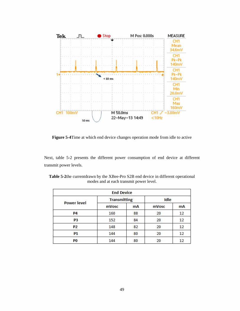
49
Figure 5-4Time at which end device changes operation mode from idle to active
Next, table 5-2 presents the different power consumption of end device at different
transmit power levels.
Table 5-2the currentdrawn by the XBee-Pro S2B end device in different operational
modes and at each transmit power level.

50
5.2 Coverage Range Test
The results of this measurement are shown in figure 5-5 and figure 5-6. The x-axis
represents the distance between the two nodes and the y-axis represents the RSSI value in
-dBm.
Figure 5-5Indoor measurement of RSSI value vs. distance at transmit power level P0 and
P4
Figure 5-6Outdoor measurement of RSSI value vs. distance at transmit power level P0
and P4
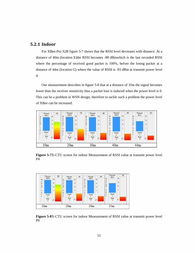
51
5.2.1 Indoor
For XBee-Pro S2B figure 5-7 shows that the RSSI level decreases with distance. At a
distance of 40m (location E)the RSSI becomes -88 dBmwhich is the last recorded RSSI
where the percentage of received good packet is 100%, before the losing packet at a
distance of 44m (location G) where the value of RSSI is -93 dBm at transmit power level
4.
Our measurement describes in figure 5-8 that at a distance of 35m the signal becomes
lower than the receiver sensitivity thus a packet lose is induced when the power level is 0.
This can be a problem in WSN design; therefore to tackle such a problem the power level
of XBee can be increased.
Figure 5-7X-CTU screen for indoor Measurement of RSSI value at transmit power level
P4
Figure 5-8X-CTU screen for indoor Measurement of RSSI value at transmit power level
P0

52
5.2.2 Outdoor
In figure 5-9 our measurement shows the actual coverage range of XBee-Pro S2B in
outdoor conditions. The result of our measurement is achieved with respect to the LOS
(Line-of-Sight) setting. At a distance of 220m, the RSSI was -94 dBm and the percentage
of good packets 6.3%.As we can see in figure 5-9the loss of data packet is limited below
200m. At transmit power level P0 the maximum covered distance between the two
modules is 160m at which RSSI becomes -93 and the percentage of good packets is
14.3%. Figure 5-10shows the actual data on X-CTU screen. We can therefore see that the
percentage of good packets is not good enough, in the contrast with the measurement at
transmit power level 4.
Figure 5-9X-CTU screen for outdoor Measurement of RSSI value at transmit power
level P4.

53
Figure 5-10X-CTU screen for outdoor Measurement of RSSI value at transmit power
level P0.

54
6 Discussion
6.1 XBee-Pro S2B ZigBee coverage range and power
consumption
The results of our measurements show that ZigBee and XBee modules are reliable in
the presence of various obstacles in both indoor and outdoor scenarios. In outdoor
measurement the maximum, line of sight, range of XBee-Pro S2B at power level 0 is
160m. This can be due to many factors which cause signal outage propagation, such as
trees and the presence of people. This can be a problem for designing a WSN which can
be avoided by rising the transmit power of module to P4 then the distance will become
220m as is shown in our measurements. On the other hand, applications such as those for
monitoring agriculture fields may use XBee modules at power level P0 in case the
modules are placed on a level higher than the plants and hence facesless obstacles. For
indoor environments, the discussion follows the same track as the outdoor case where the
maximum, non-line of sight, range at transmit power level 0 is 35m and at level 4 is
44m.On the other hand, we can see that the difference in power consumption between
every two consecutive levels is not large, through it can have an influence on the network
life time in the case of P0 and P4. Thus we can conclude that the transmit power of
XBee-Pro S2B can be reduced in an environment with less obstacles, then the power
consumption of the node can be reduces.
6.2 Choosing network topology
Our measurements on ZigBee devices show that the XBee end device consumes less
power than the router as is expected. The significant difference in power consumption
between router and end device is present in the idle mode of operation since the router
has to listen to the channel all the time. According to this, we can conclude that the type
of node is a very important factor in designing the WSN with ZigBee protocol.
In accordance with the above results, the choice of topology plays an important role in
defining the operating nodes in the network. In other words, reducing power consumption
in the network can be achieved by replacing as many routers as possible with an end
device. But still, the tradeoff between power consumption and reliability must be taken
into consideration since using end devices will reduce the number of links, hence a drop

55
of one link can present a significant problem in some applications. This requires an
intelligent network design.
ZigBee protocol supports networks with star topology and mesh topology with the
ability to extend the network by using cluster tree topology. An overview of our
measurements; star topology can present the best designing choice when the application
demand is within the capability of the XBee ZigBee coverage range. In star topology all
devices can be configured as end devices and they can only communicate with the
coordinator. To extend the range of the network, the designer can use cluster tree
topology. In cluster trees only the PAN coordinators can communicate with each other.
Routers can connect each cluster head and end devices are considered as leaves which are
communicating with the coordinator either directly or via routers. Mesh topology can be
another choice for large networks. Since mesh topology is a self-healing, reliable and
self-organizing network, it can be the choice for some applications such as industrial
monitoring applications which demand a high level of reliability. Therefore by using
mesh topology the designer increases the number of links but consequently a high
number of routers will be existed in the network.Consequently, this lasts with significant
costof power consumption in comparison to a topology with more end devices.
Hence, the choice of topology depends on the application and the availability of energy
for powering nodes and the required level of reliability.
6.3 Further work
Future work includes implementing several nodes in order to extend the measurements in
larger network. Future measurements include the effect of other parameters on designing
WSNs such as packet delay. To this aim, a software tool should be designed to study the
packet delay in multi-hop networking since we find the X-CTU tool is not flexible
enough for this experiment.We also intend to investigate in the possible measurement
tools in order to measure the power consumption more precisely.
Future work can also include the effect of encryption on network life time, packet delay
and power consumption. An automatic measurement tool of RSSI in real life conditions
and large network is another future aim.

56
7 Conclusion
In this work, we intensively studied different architectural aspects and requirements for
designing WSNs. Later we investigated different technologies and protocols of WSNs
Including a comprehensive study of XBee ZigBee modules capabilities, an analysis of the
power consumption of XBee ZigBee modules as well as a comparison with other wireless
devices. We studied the structure of ZigBee protocol in order to design a multi-hop
wireless sensor network including addressing, ZigBee devices operational modes and
communication modes. Then, we implemented our embedded temperature wireless
sensor node using a PIC microcontroller utilizing an XBee-Pro S2B module to create a
sensing phenomenon in the network. Using our sensor node along with other
development kits and software tools we were able to design a self-organizing WSN.
We went through a series of experiments to measure different parameters in our
WSN. We measured the power consumption in ZigBee protocol devices; coordinator,
router and end device during their different operational modes. We also estimated the
power consumption of these devices at different transmit power levels (P4, P3, P2, P1,
P0) which are supported by XBee-Pro S2B. We noticed that the difference in the power
consumption of end devices and router/coordinator is large. The summary of our
measurements is shown in table 7-1.
Table 7-1Power consumption of XBee-Pro S2B in different operational modes at
different transmit power levels
To evaluate the capability of XBee-Pro S2B transceiver coverage range in real life
conditions, we measured the XBee coverage range in outdoor and indoor scenarios at
transmitpower level P0 and P4. Table 7-2 summarizes the maximum distance in every
scenario with the power consumption at every level.

57
Table 7-2Measured coverage range of XBee-Pro S2B
We discussed the trade-off between the coverage range of XBee-Pro S2B in real life
conditions at different transmit power levels and its power consumption. We also
discussed the effect of the topology used in designing WSN on the power consumption.
Finally we discussed further developments in order to study the effect of more parameters
such as multi-hop delay on WSN design.

58
References
[1] W. S. LanF.Akyildiz, yogeshSankarasubramaniam, ErdalCayirci, “A Survey on
Sensor Network,” IEEE Communication Magazine, pp. 102, August 2002, 2002.
[2] Jahn, M.; Jentsch, M.; Prause, C.R.; Pramudianto, F.; Al-Akkad, A.; Reiners, R.; ,
"The Energy Aware Smart Home," Future Information Technology (FutureTech), 2010
5th International Conference on , vol., no., pp.1-8, 21-23 May 2010.
[3]Verdone, R.; Dardari, D.; Mazzini, G.; Conti, A. Wireless Sensors and Actuator
Networks. Elsevier: London, UK, 2008.
[4] V.Mayalarp, N.Limpaswadpaisarn, T.Poombansao, S.Kittipiyakul, “Wireless Mesh
Networking with XBee”
[5] Goran HORVAT, Damir Sostaric, Drago Zagar.” Power Consumption and RF
Propagation analysis on ZigBee XBee Modules for ATPC”. 35th International
Conference on Telecommunications and Signal Processing (TSP), IEEE , July 2012.
[6] Sparkfun Electronics, https://www.sparkfun.com/products/8687
[7]Holger Karl and Andreas Willing. “Protocol and Architectures for Wireless Sensor
Networks”, ISBN 0-470-09510-5, UK, 2005
[8]I.Demirkol, C.Ersoy, “Wake-Up Receiver for Wireless Sensor Networks: Benefits and
Challanges”, IEEE Wireless Communication, August 2009.
[9]ATmega 128(L) Preliminary Complete.ATmel product documentation, 2004.
[10]Stojcev, M.K, Kosanovic, M.R,Golubovic, L.R.” Power management and energy
harvesting techniques for wireless sensor nodes” E-ISBN :978-1-4244-4383-3 IEEE,
October 2009.
[11]C. Kompis and P.Sureka, “Power Management Technologies to Enable Remote and
Wireless Sensing”, ESP central Ltd, may 2010.
[12] Bo Zhao and Huazhong Yang (2010). Design of Radio-Frequency Transceivers for
Wireless Sensor Networks, Wireless Sensor Networks: Application-Centric Design, Yen
Kheng Tan (Ed.), ISBN: 978-953-307-321-7, InTech,
59
[13]F.L.Lewis (2004). Wireless Sensor Networks. Smart Environments: Protocols and
Applications ed. D.J.Cook and S.K.Das, John Willey, New York. 1-18.
[14] Jun Zheng and Abbas Jamalipour, “Wireless Sensor Networks: A Networking
Perspective”, a book published by A John & Sons, Inc, and IEEEE, 2009.
[15] E. Zanaj, M. Baldi, and F. Chiaraluce, “Efficiency of the Gossip Algorithm for
Wireless Sensor Networks”, In Proceedings of the 15th International Conference on
Software, Telecommunications and Computer Networks (SoftCOM), Split–Dubrovnik,
Croatia, September, 2007.
[16] S. Misra et al. (eds.), “Guide to Wireless Sensor Networks, Computer
Communications and Networks”, DOI: 10.1007/978-1-84882-218-4 4, Springer-Verlag
London Limited 2009.
[17] S.K.Singh, M.P.Singh, D.K.Singh, “Routing Protocols in Wireless Sensor Networks
A Survey”, International Journal of Computer Science & Engineering Survey (IJCSES)
Vol.1, No.2, November 2010.
[18] W. Ye, J. Heidemann, and D. Estrin. Medium Access Control with Coordinated,
Adaptive Sleeping for Wireless Sensor Networks.IEEE/ACM Transactions on
Networking, 2004.
[19] J. Hill, R. Szewczyk, A. Woo, S. Hollar, D. E. Culler, and K. S. J. Pister. System
Architecture Directions for Networked Sensors. In Proceedings of the 9th International
Conference on Architectural Support for Programming Languages and Operating
Systems, pages 93–104, Cambridge, MA, 2000.
[20] D. Gay, P. Levis, R. von Behren, M. Welsh, E. Brewer, and D. Culler. The nesC
Language: A Holistic Approach to Networked Embedded Systems. Proceedings of ACM
SIGPLAN Conference on Programming Language Design and Implementation, pages 1–
11.ACM Press, 2003.
[21] ]Ph.Levis, S.Madden, D.Gay, J.Polastre, R.Szewczyk, A.Woo, E.Brewer and
D.Culler "The Emergence of Networking Abstractions and Techniques in TinyOS." In
Proceedings of the First USENIX/ACM Symposium on Networked Systems Design and
Implementation (NSDI 2004).

60
[22] A.Dunkels, B. Gronvall and T. Voigt, „ Contiki – a lightwight and flexible operating
system for tiny networked sensors“. ISBN: 0-7695-2260-2, 29’th annual IEEE
International Conference on Local Computer Networks, 2004.
[23] IEEE 802.15 WPAN™ Task Group 4 (TG4),
http://www.ieee802.org/15/pub/TG4.html
[24] ZigBee Alliance, http://www.zigbee.org/en/index.asp
[25] IEEE Computer Science: Part 15.4: Wireless Medium Access Control (MAC) and
Physical Layer (PHY) specification for low-rate Wireless Personal Area Networks
(WPANs), 2007.
[26] ZigBee Specification. ZigBee Document 053474r05, Version 1.0. Sponsored by:
ZigBee Alliance. June 20, 2005. http://www.zigbee.org/en/.
[27] Robert Faludi. “Building Wireless Sensors Networks”.ISBN 978-0-596-80773-
3.USA, 2011.
[28] 2008 Digi International Inc, “Wireless Mesh Networking ZigBee Vs. DigiMesh”
http://www.digi.com/pdf/wp_zigbeevsdigimesh.pdf
[29] 2013 Digi International Inc, “XBee DigiMesh product manual”
http://ftp1.digi.com/support/documentation/90000991_F.pdf
[30]Xbee Wireless RF modules,Digiinc.www.digi.com/xbee
[31] Goran HORVAT, Damir Sostaric, Drago Zagar.” Power Consumption and RF
Propagation analysis on ZigBee XBee Modules for ATPC”. ISBN: 978-1-4673-1118-2
IEEE, 2012.
[32] Crossbow MICAz datasheet, www.xbow.com
[33] SeongPeng Lim and Gik Hong Yeap, “Centralised Smart Home Control System via
XBee Transceivers”, ISBN: 978-1-4673-0020-9, IEEE 2011.
[34] XBee IEEE 802.15.4 product manual, DigiInc,
http://ftp1.digi.com/support/documentation/90000982_L.pdf

61
[35] XBee ZigBee product manual,
Digiinc.http://ftp1.digi.com/support/documentation/90000976_P.pdf
[36] M.Hebel, G.Bricker, D.Harris, “A tutorial, Getting Start with Xbee RF Modules ”,
ISBN 9781928982562, Parallax Inc 2010.
http://www.parallax.com/portals/0/downloads/docs/prod/book/122-32450-xbeetutorial-
v1.0.pdf
[37]H.Boreck, J.Balaguer, M.Andre, M.Schaar, M.Goossens, “Development of a Mesh
Networking System for the Autonomous Acoustic Buoy”, Artesis University College
Antwerp - dept. of Applied Engineering, 2012.
[38] X-CTU configuration and test utility software,
http://ftp1.digi.com/support/documentation/90001003_A.pdf
[39] DS18B20 datasheet, http://datasheets.maximintegrated.com/en/ds/DS18B20.pdf
[40] YmYussoff, H.Z Abidin, R Ab.Rhman, .H Yahaya. “Development of a PIC-Based
Wireless Sensor Node Utilizing XBee Technology”, E-ISBN: 978-1-4244-5265-1, The
2nd IEEE International Conference onInformation Management and Engineering
(ICIME). April 2010.
[41] Microchip .http://www.microchip.com/pagehandler/en-
us/products/picmicrocontrollers
[42] PIC18F46K22 datasheet. Microchip,
http://ww1.microchip.com/downloads/en/DeviceDoc/41412F.pdf
[43] LD33V datasheet,
https://www.sparkfun.com/datasheets/Components/LD1117V33.pdf
[44] Tektronix TDS2012B Oscilloscope: http://www.tek.com/
[45] K. Benki., M. Malajner, P. Planinši., Ž.u.ej, “Using RSSI value for distance
estimation in wireless sensor networks based on ZigBee,” 15th IEEE International
Conference on Systems, Signals and Image Processing, Bratislava, Slovakia 25-28 June,
2008.

62
[46]Digi International Inc, 2010,
ftp://ftp1.digi.com/support/documentation/90001109_B.pdf
[47] S. Lin, J. Zhang, G. Zhou, L. Gu, T. He and J. A. Stankovic, “ATPC: Adaptive
Transmission Power Control for Wireless Sensor Networks” Proc. of the 4th ACM
Conference on Embedded Networked Sensor Systems (SenSys'06), Nov., 2006