CURRICULUM - 2005
71
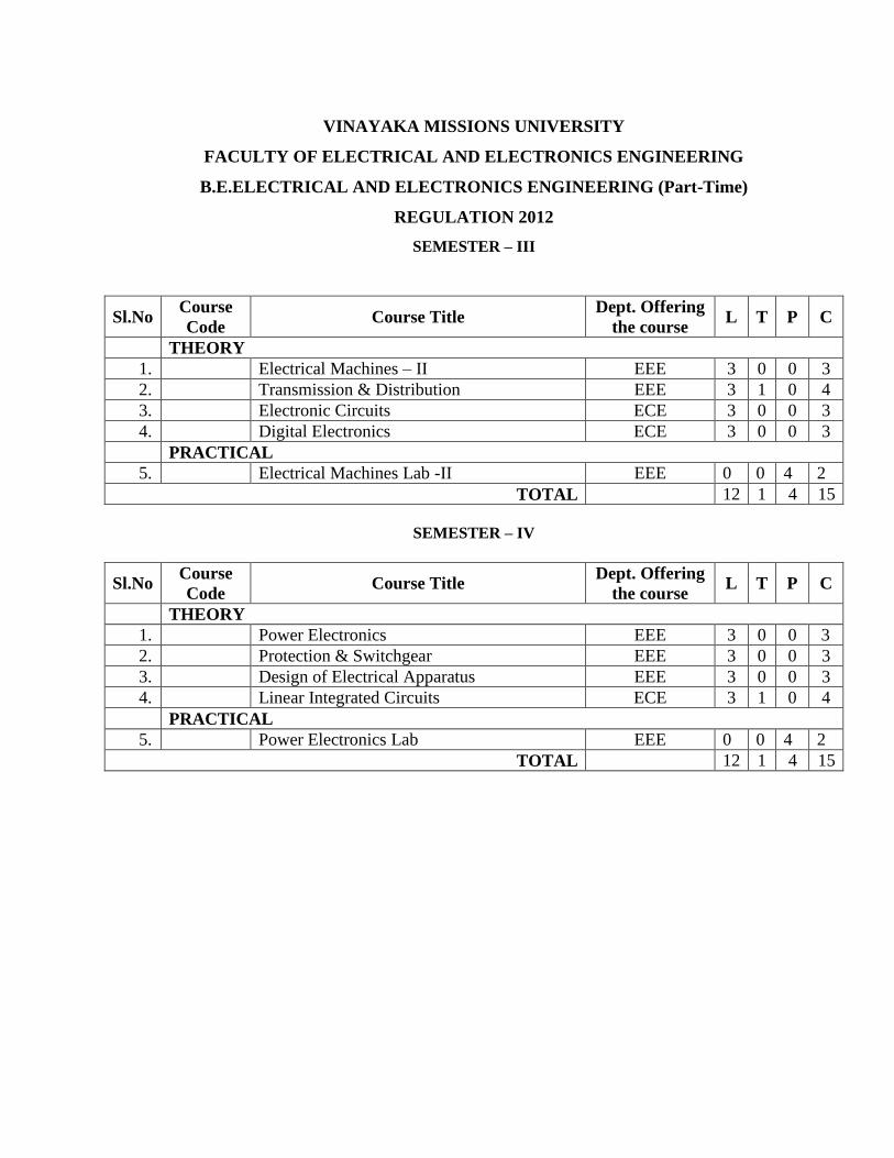
VINAYAKA MISSIONS UNIVERSITY FACULTY OF ELECTRICAL AND ELECTRONICS ENGINEERING B.E.ELECTRICAL AND ELECTRONICS ENGINEERING (Part-Time) REGULATION 2012 SEMESTER – III Sl.No Course Code Course Title Dept. Offering the course L T P C THEORY 1. Electrical Machines – II EEE 3 0 0 3 2. Transmission & Distribution EEE 3 1 0 4 3. Electronic Circuits ECE 3 0 0 3 4. Digital Electronics ECE 3 0 0 3 PRACTICAL 5. Electrical Machines Lab -II EEE 0 0 4 2 TOTAL 12 1 4 15 SEMESTER – IV Sl.No Course Code Course Title Dept. Offering the course L T P C THEORY 1. Power Electronics EEE 3 0 0 3 2. Protection & Switchgear EEE 3 0 0 3 3. Design of Electrical Apparatus EEE 3 0 0 3 4. Linear Integrated Circuits ECE 3 1 0 4 PRACTICAL 5. Power Electronics Lab EEE 0 0 4 2 TOTAL 12 1 4 15
-
Upload
independent -
Category
Documents
-
view
0 -
download
0
Transcript of CURRICULUM - 2005
VINAYAKA MISSIONS UNIVERSITY
FACULTY OF ELECTRICAL AND ELECTRONICS ENGINEERING
B.E.ELECTRICAL AND ELECTRONICS ENGINEERING (Part-Time)
REGULATION 2012
SEMESTER – III
Sl.No Course
Code Course Title
Dept. Offering
the course L T P C
THEORY
1. Electrical Machines – II EEE 3 0 0 3
2. Transmission & Distribution EEE 3 1 0 4
3. Electronic Circuits ECE 3 0 0 3
4. Digital Electronics ECE 3 0 0 3
PRACTICAL
5. Electrical Machines Lab -II EEE 0 0 4 2
TOTAL 12 1 4 15
SEMESTER – IV
Sl.No Course
Code Course Title
Dept. Offering
the course L T P C
THEORY
1. Power Electronics EEE 3 0 0 3
2. Protection & Switchgear EEE 3 0 0 3
3. Design of Electrical Apparatus EEE 3 0 0 3
4. Linear Integrated Circuits ECE 3 1 0 4
PRACTICAL
5. Power Electronics Lab EEE 0 0 4 2
TOTAL 12 1 4 15
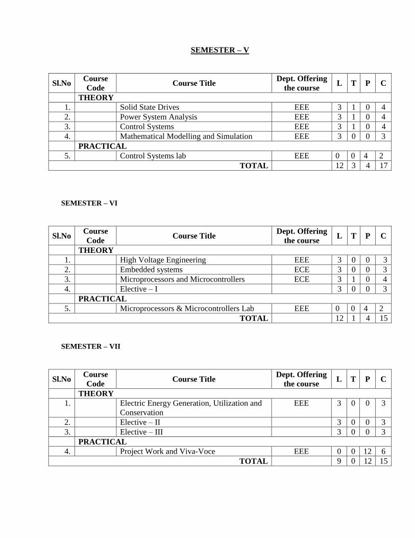
SEMESTER – V
Sl.No Course
Code Course Title
Dept. Offering
the course L T P C
THEORY
1. Solid State Drives EEE 3 1 0 4
2. Power System Analysis EEE 3 1 0 4
3. Control Systems EEE 3 1 0 4
4. Mathematical Modelling and Simulation EEE 3 0 0 3
PRACTICAL
5. Control Systems lab EEE 0 0 4 2
TOTAL 12 3 4 17
SEMESTER – VI
Sl.No Course
Code Course Title
Dept. Offering
the course L T P C
THEORY
1. High Voltage Engineering EEE 3 0 0 3
2. Embedded systems ECE 3 0 0 3
3. Microprocessors and Microcontrollers ECE 3 1 0 4
4. Elective – I 3 0 0 3
PRACTICAL
5. Microprocessors & Microcontrollers Lab EEE 0 0 4 2
TOTAL 12 1 4 15
SEMESTER – VII
Sl.No Course
Code Course Title
Dept. Offering
the course L T P C
THEORY
1. Electric Energy Generation, Utilization and
Conservation
EEE 3 0 0 3
2. Elective – II 3 0 0 3
3. Elective – III 3 0 0 3
PRACTICAL
4. Project Work and Viva-Voce EEE 0 0 12 6
TOTAL 9 0 12 15
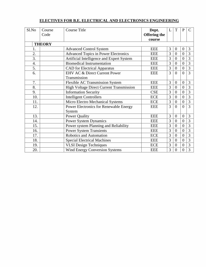
ELECTIVES FOR B.E. ELECTRICAL AND ELECTRONICS ENGINEERING
Sl.No Course
Code
Course Title Dept.
Offering the
course
L T P C
THEORY
1. Advanced Control System EEE 3 0 0 3
2. Advanced Topics in Power Electronics EEE 3 0 0 3
3. Artificial Intelligence and Expert System EEE 3 0 0 3
4. Biomedical Instrumentation EEE 3 0 0 3
5. CAD for Electrical Apparatus EEE 3 0 0 3
6. EHV AC & Direct Current Power
Transmission
EEE 3 0 0 3
7. Flexible AC Transmission System EEE 3 0 0 3
8. High Voltage Direct Current Transmission EEE 3 0 0 3
9. Information Security CSE 3 0 0 3
10. Intelligent Controllers ECE 3 0 0 3
11. Micro Electro Mechanical Systems ECE 3 0 0 3
12. Power Electronics for Renewable Energy
System
EEE 3 0 0 3
13. Power Quality EEE 3 0 0 3
14. Power System Dynamics EEE 3 0 0 3
15. Power system Planning and Reliability EEE 3 0 0 3
16. Power System Transients EEE 3 0 0 3
17. Robotics and Automation ECE 3 0 0 3
18. Special Electrical Machines EEE 3 0 0 3
19. VLSI Design Techniques ECE 3 0 0 3
20. Wind Energy Conversion Systems EEE 3 0 0 3
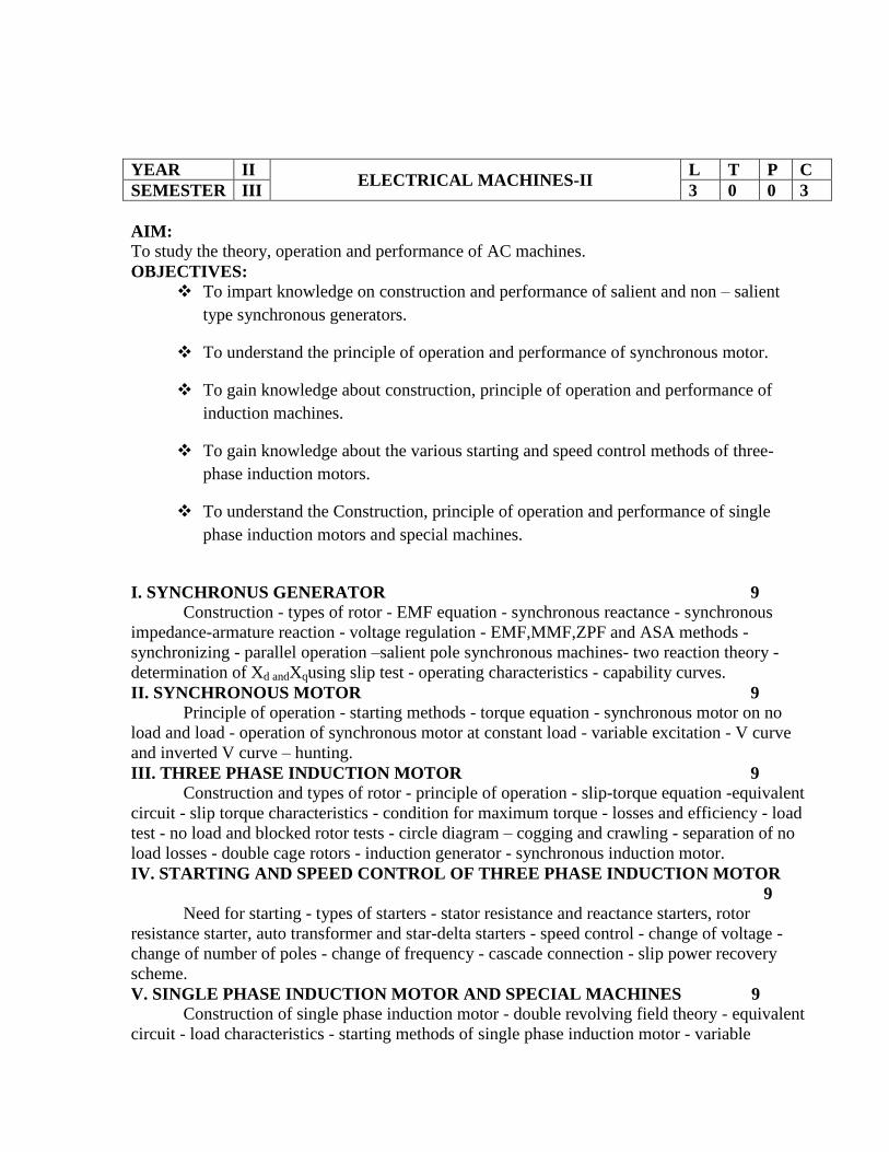
YEAR II ELECTRICAL MACHINES-II
L T P C
SEMESTER III 3 0 0 3
AIM:
To study the theory, operation and performance of AC machines.
OBJECTIVES:
To impart knowledge on construction and performance of salient and non – salient
type synchronous generators.
To understand the principle of operation and performance of synchronous motor.
To gain knowledge about construction, principle of operation and performance of
induction machines.
To gain knowledge about the various starting and speed control methods of three-
phase induction motors.
To understand the Construction, principle of operation and performance of single
phase induction motors and special machines.
I. SYNCHRONUS GENERATOR 9
Construction - types of rotor - EMF equation - synchronous reactance - synchronous
impedance-armature reaction - voltage regulation - EMF,MMF,ZPF and ASA methods -
synchronizing - parallel operation –salient pole synchronous machines- two reaction theory -
determination of Xd andXqusing slip test - operating characteristics - capability curves.
II. SYNCHRONOUS MOTOR 9
Principle of operation - starting methods - torque equation - synchronous motor on no
load and load - operation of synchronous motor at constant load - variable excitation - V curve
and inverted V curve – hunting.
III. THREE PHASE INDUCTION MOTOR 9
Construction and types of rotor - principle of operation - slip-torque equation -equivalent
circuit - slip torque characteristics - condition for maximum torque - losses and efficiency - load
test - no load and blocked rotor tests - circle diagram – cogging and crawling - separation of no
load losses - double cage rotors - induction generator - synchronous induction motor.
IV. STARTING AND SPEED CONTROL OF THREE PHASE INDUCTION MOTOR
9
Need for starting - types of starters - stator resistance and reactance starters, rotor
resistance starter, auto transformer and star-delta starters - speed control - change of voltage -
change of number of poles - change of frequency - cascade connection - slip power recovery
scheme.
V. SINGLE PHASE INDUCTION MOTOR AND SPECIAL MACHINES 9
Construction of single phase induction motor - double revolving field theory - equivalent
circuit - load characteristics - starting methods of single phase induction motor - variable
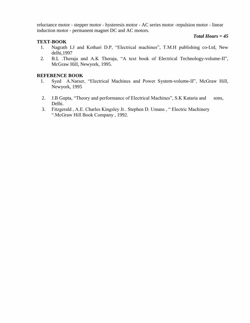
reluctance motor - stepper motor - hysteresis motor - AC series motor -repulsion motor - linear
induction motor - permanent magnet DC and AC motors.
Total Hours = 45
TEXT-BOOK
1. Nagrath I.J and Kothari D.P, “Electrical machines”, T.M.H publishing co-Ltd, New
delhi,1997
2. B.L .Theraja and A.K Theraja, “A text book of Electrical Technology-volume-II”,
McGraw Hill, Newyork, 1995.
REFERENCE BOOK
1. Syed A.Narser, “Electrical Machines and Power System-volume-II”, McGraw Hill,
Newyork, 1995
2. J.B Gupta, “Theory and performance of Electrical Machines”, S.K Kataria and sons,
Delhi.
3. Fitzgerald , A.E. Charles Kingsley Jr.. Stephen D. Umans , “ Electric Machinery
“.McGraw Hill Book Company , 1992.
YEAR II TRANSMISSION AND DISTRIBUTION
L T P C
SEMESTER III 3 0 0 3
AIM:
To become familiar with the function of different components used in Transmission and
Distribution levels of power systems and modeling of these components.
OBJECTIVES:
1. To understand structure of electric power systems, its various operating voltages.
2. To study transmission line parameters for different systems and corona effect.
3. To understand modeling and performance of different transmission lines.
4. To study different types of insulators and constructional features of HT & LT
cables.
5. To understand classification and functions of major components of substations.
UNIT I: INTRODUCTION 9
Structure of electric power system – different operating voltages of generation,
transmission and distribution –advantage of higher operating voltage for AC transmission. An
introduction to HVDC and EHV AC transmission. FACTS Devices Mechanical design of
transmission line between towers – sag and tension calculations using approximate equations
taking into account the effect of ice and wind.
UNIT II: TRANSMISSION LINE PARAMETERS 9
Parameters resistance, inductance and capacitance calculations – single and three phase
transmission lines – single and double circuits - solid, stranded and bundled conductors -
symmetrical and unsymmetrical spacing - transposition of lines – concepts of GMR and GMD -
Skin and Proximity effects - interference with neighbouring communication circuits – Corona
discharge - characteristics – critical voltage and loss. (Simple diagrams of typical towers and
conductors for 400, 220 ,110,66 and 33 kV operations)
UNIT III: MODELLING AND PERFORMANCE OF TRANSMISSION LINES 9
Transmission line classification – short line, medium line and long line – equivalent circuits –
Ferranti effect – surge impedance, attenuation constant and phase constant – voltage regulation
and transmission efficiency – real and reactive power flow in lines – power circle diagrams –
shunt and series compensation. An introduction to power angle diagram – surge – impedance
loading, loadability limits based on thermal loading; angle and voltage stability considerations.
UNIT IV: INSULATORS AND CABLES 9
Classification of insulators for transmission and distribution purpose – voltage distribution in
insulator string and grading – improvement of string efficiency. Underground cables –
constructional features of LT and HT cables – insulation resistance, capacitance, dielectric stress
and grading – tan δ and power loss – thermal characteristics.
UNIT V: SUBSTATION , GROUNDING SYSTEM AND DISTRIBUTION SYSTEM 9
Classification functions and major components of substations. Bus-bar arrangements – substation
bus schemes – single bus, double bus with double breaker, double bus with single breaker, main
and transfer bus, ring bus, breaker- and - a half with two main buses, double bus-bar bypass
isolators. Importance of earthing in a substation. Qualitative treatment to neutral grounding and
earthing practises in substations. Feeders, distributors and service mains. DC distributor – 2 -
wire and 3 - wire, radial and ring main distribution. AC distribution - single phase and three
phase 4 -wire distribution.
L=45 T = 15 Total =60
TEXT BOOKS
1. B.R.Gupta, ‘Power System Analysis and Design’, S.Chand, New Delhi, 2003.
2. S.N. Singh, ‘Electric Power Generation, Transmission and Distribution’, Prentice Hall of
India Pvt. Ltd, New Delhi, 2002.
REFERENCE BOOKS
1. Luces M.Fualkenberry ,Walter Coffer, ‘Electrical Power Distribution and Transmission’,
Pearson Education, 1996.
2. Hadi Saadat, ‘Power System Analysis,’ Tata McGraw Hill Publishing Company’, 2003.
3. Central Electricity Authority (CEA), ‘Guidelines for Transmission System Planning’,
New Delhi.
4. ‘Tamil Nadu Electricity Board Handbook’, 2003.
YEAR II ELECTRONIC CIRCUITS
L T P C
SEMESTER III 3 0 0 3
AIM:
The aim of this course is to introduce to the students the rectifiers, power supplies, basics of
biasing transistor circuits, low frequency amplifiers, multi stage amplifiers, power amplifiers,
tuned amplifiers, feedback amplifiers and oscillators.
OBJECTIVES:
To understand the basic operation of rectifiers, filters and power Supplies
To study the biasing circuits and analyze the small signal BJT amplifiers
To understand the working and to find the efficiency of different types of large signal
amplifiers
To understand the basic concept and working of various types of feedback amplifiers and
oscillators.
To understand the working of different types of tuned amplifiers and multivibrators and their
analysis.
UNIT I RECTIFIERS AND POWER SUPPLIES 9
Half Wave and Full Wave Rectifier-Bridge rectifier-performance measures of rectifiers-
filters-Full Wave rectifier with inductive filter, capacitive filter, LC filter, π
multiple LC Filter- Regulators-Shunt and series voltage regulators-Performance measures of
regulators.
UNIT II BIASING CIRCUITS AND ANALYSIS OF SMALL SIGNAL BJT
AMPLIFIERS 9
Biasing circuit of BJT, DC equivalent circuit of BJT, DC and AC Load Lines, Stability factor
analysis, Types of amplifiers-Small Signal Equivalent circuit-Calculation of gain, Input and
Output Impedance of various amplifiers using h-Parameters.
UNIT III MULTISTAGE AMPLIFIERS AND POWER AMPLIFIERS 9
Introduction-Two stage RC Coupled amplifier-Cascade amplifier-Darlington emitter
follower amplifier-Bootstrap amplifier Introduction-Class A Power Amplifier-Push Pull
Principle-Class B push pull amplifier and complementary symmetry amplifier-Class C
amplifier-Distortion in amplifiers-Collector power dissipation-efficiency and figure of merit
calculation-Maximum power dissipation hyperbola.
UNIT IV FEEDBACK AMPLIFIERS AND OSCILLATORS 9
Introduction-Performance analysis of feedback amplifiers-Voltage and current feedback
amplifiers-Barkhausen Criterion for Oscillation-RC and Wein bridge oscillator, Hartley
Oscillator, Colpitts Oscillator-Crystal Oscillator-Stabilization in Oscillator.
UNIT V TUNED AMPLIFIERS AND MULTIVIBRATORS 9
Single tuned amplifier-Stagger tuned amplifier-Tuned amplifier instability-Neutralization
and Unilateralization.

TOTAL HOURS: 45
TEXT BOOKS:
1. Robert L. Boystead and Louis Nashelky, "Electronic Devices and Circuits", 8th Edition,
PHI, 2005.
REFERNCE BOOKS
1. Theodore F. Bogart Jr., Jeffrey S. Beasley, Guillermo Rico, "Electronic devices and
circuits", PPH, 2004.
2. Millman & Halkias, "Integrated Electronics", McGraw Hill International Edition. 1991
3. David A. Bell, "Electronic Devices and Circuits", PHI, 2004
YEAR II DIGITAL ELECTRONICS
L T P C
SEMESTER III 3 0 0 3
AIM
The Aim of this course is to develop a strong foundation in analysis and design of digital
electronics.
OBJECTIVES:
1. Understand the basic concepts.
2. Understand concepts of logic gates constructional features.
3. To understand the concepts of gate-level minimization & combinational logic.
4. To analyze synchronous sequential logic.
5. To realize the hazard free circuits and pulse mode sequential Circuits.
Unit – I: BASIC CONCEPTS AND BOOLEAN ALGEBRA 9
Number systems - Binary, Octal, Decimal, Hexadecimal, conversion from one to another,
complement arithmetic, Boolean theorems of Boolean algebra, Sum of products and product of
sums, Minterms and Maxterms, Karnaugh map, M-C Tabulation methods and computer aided
minimization procedures.
Unit – II: LOGIC GATES 9
RTL, DTL, TTL, ECL, ICL, HTL, NMOS & CMOS logic gates, Circuit diagram and analysis
characteristics and specifications, tri-state gates.
Unit – III: COMBINATIONAL CIRCUITS 9
Problem formulation and design of combinational circuits, Adder / Subtractor, Encoder /
decoder, Mux / Demux, Code-converters, Comparators, Implementation of combinational logic
using standard ICs, ROM, EPROM, EEPROM, Basics of PLD, PAL, PLA and their use in
combinational circuit design.
Unit – IV: SEQUENTIAL CIRCUITS 9
Flip flops - SR, JK, T, D, Master/Slave FF, Triggering of FF, Analysis of clocked sequential
circuits - their design, State minimization, state assignment, Circuit implementation, Registers-
Shift registers, Ripple counters, Synchronous counters, Timing signal, RAM, Memory decoding,
Semiconductor memories.
Unit – V: FUNDAMENTAL MODE SEQUENTIAL CIRCUITS 9
Stable, Unstable states, Output specifications, Cycles and Races, Race free Assignments,
Hazards, Essential hazards, Pulse mode sequential circuits.
TOTAL HOURS: 45

TEXT BOOKS:
1. Morris Mano, “Digital logic and Computer Design ", Prentice-Hall of India, 1998.
2. New text book
REFERENCE BOOKS:
1. William I. Fletcher, “An Engineering Approach to Digital Design ", Prentice-Hall of
India, 1980
2. Floyd T.L., “Digital Fundamentals ", Charles E. Merrill publishing Company, 1982.
3. Tokheim R.L., “Digital Electronics - Principles and Applications ", Tata McGraw Hill,
1999.
4. Jain R.P., “Modern Digital Electronics ", Tata McGraw Hill, 1999.

YEAR II ELECTRICAL MACHINES LAB– II
L T P C
SEMESTER III 0 0 3 2
1. Regulation of 3-phase alternator by EMF and MMF methods.
Aim: To predetermine the regulation of 3-phase alternator by EMF and MMF
methods.
3. Regulation of 3-phase alternator by ZPF and ASA method.
Aim: To predetermine the regulation of 3-phase alternator by ZPF and ASA
methods.
4. Slip test on 3-phase alternator.
Aim: To predetermine the regulation of 3-phase alternator by conducing slip test.
5. Load characteristics of 3-phase alternator by bus bar loading
Aim: To synchronize 3-phase alternator with bus bar and determine its load
characteristics.
6. V and inverted V curve of synchronous motors.
Aim: To draw the V and inverted V curves of synchronous motor.
7. Load test on 3-phase induction motor (s).
Aim: To conduct load test on 3-phase squirrel cage induction motor and determine its
performance characteristics.
Aim: To conduct load test on 3-phase slip ring induction motor and determine its
performance characteristics.
8. No load and blocked rotor test on 3-phase induction motor.
Aim: To conduct no load and blocked rotor tests on 3 phase squirrel cage induction
motor and obtain the parameters of the equivalent circuit.
9. Study of Synchronous induction motor.
Aim: To study the operation of Synchronous induction motor.
10. Study of induction motor starters.
Aim: To study the various induction motor starters
11. Separation of losses in three-phase induction motor.
Aim: To determine the no load losses in three-phase induction motor.
12. Load test on 1-phase induction motor.
Aim: To conduct load test on single phase induction motor and determine its
performance characteristics.
13. Equivalent circuit and pre – determination of performance characteristics of single-
phase induction motor.
Aim: To conduct no load and blocked rotor tests on single phase induction motor and
determine the parameters of equivalent circuit.
Total Hours: 45

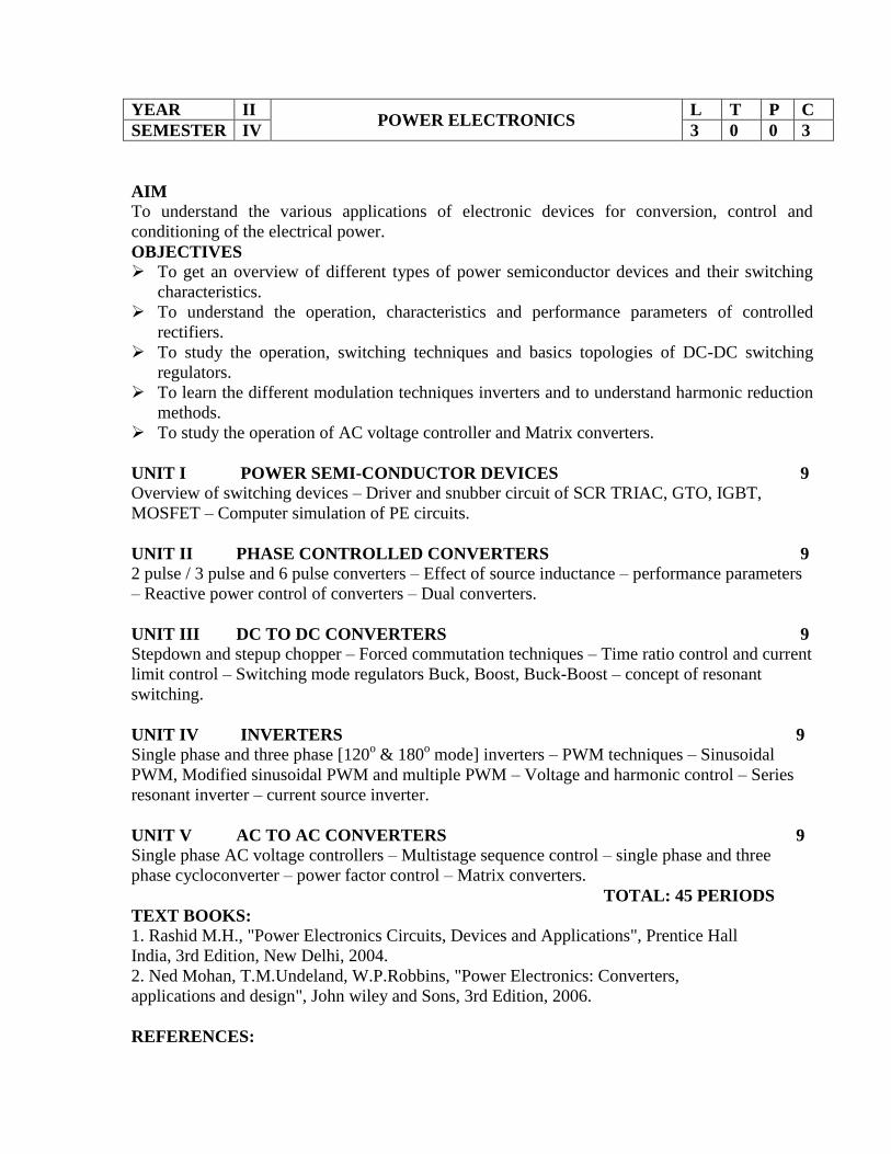
YEAR II POWER ELECTRONICS
L T P C
SEMESTER IV 3 0 0 3
AIM
To understand the various applications of electronic devices for conversion, control and
conditioning of the electrical power.
OBJECTIVES
To get an overview of different types of power semiconductor devices and their switching
characteristics.
To understand the operation, characteristics and performance parameters of controlled
rectifiers.
To study the operation, switching techniques and basics topologies of DC-DC switching
regulators.
To learn the different modulation techniques inverters and to understand harmonic reduction
methods.
To study the operation of AC voltage controller and Matrix converters.
UNIT I POWER SEMI-CONDUCTOR DEVICES 9
Overview of switching devices – Driver and snubber circuit of SCR TRIAC, GTO, IGBT,
MOSFET – Computer simulation of PE circuits.
UNIT II PHASE CONTROLLED CONVERTERS 9
2 pulse / 3 pulse and 6 pulse converters – Effect of source inductance – performance parameters
– Reactive power control of converters – Dual converters.
UNIT III DC TO DC CONVERTERS 9
Stepdown and stepup chopper – Forced commutation techniques – Time ratio control and current
limit control – Switching mode regulators Buck, Boost, Buck-Boost – concept of resonant
switching.
UNIT IV INVERTERS 9
Single phase and three phase [120o & 180
o mode] inverters – PWM techniques – Sinusoidal
PWM, Modified sinusoidal PWM and multiple PWM – Voltage and harmonic control – Series
resonant inverter – current source inverter.
UNIT V AC TO AC CONVERTERS 9
Single phase AC voltage controllers – Multistage sequence control – single phase and three
phase cycloconverter – power factor control – Matrix converters.
TOTAL: 45 PERIODS
TEXT BOOKS:
1. Rashid M.H., "Power Electronics Circuits, Devices and Applications", Prentice Hall
India, 3rd Edition, New Delhi, 2004.
2. Ned Mohan, T.M.Undeland, W.P.Robbins, "Power Electronics: Converters,
applications and design", John wiley and Sons, 3rd Edition, 2006.
REFERENCES:

1. Cyril.W.Lander, "Power Electronics", McGraw Hill International, Third Edition, 1993.
2. P.S.Bimbra "Power Electronics", Khanna Publishers, third Edition 2003.
3. Philip T.Krein, "Elements of Power Electronics" Oxford University Press, 2004 Edition.

YEAR II PROTECTION AND SWITCHGEAR
L T P C
SEMESTER IV 3 1 0 4
AIM:
To understand the various protection schemes in electrical system, theory of arc
interruption and operation of various circuit breakers.
OBJECTIVE:
1. To study the basic principles, construction and operation of various protection relays.
2. To understand the protection schemes of various electrical equipments and application of
CTS and PTS.
3. To study the theory of arc phenomena and arc interruption.
4. To understand construction, operation and capacitive merits of various types of circuit
breakers.
5. To study protection schemes against over voltages.
1 RELAYS -PRINCIPLES &OPERATION 9
Need for protection – relay terminology – definitions – zones of protection - essential
qualities of protective relays. Over current relays directional, distance and differential, under
frequency, negative sequence relays - static relays – microprocessor-based relays.
2 APPARATUS PROTECTION 9
Apparatus Protection - generator and Transformer Protection, Protection of bus bars,
transmission lines, CT’s & PT’s and their application in protective schemes.
3 THEORY ARC QUENCHING 9
Theory of arcing and arc quenching – RRRV – Current Chopping and Capacitive Current
breaking – D.C. circuit breaking.
4 CIRCUIT BREAKERS 9
Switchgear – fault clearing and interruption of current - various types of circuit breakers
- selection of circuit breakers - testing of circuit breakers- intelligent circuit breakers
5 PROTECTION AGAINST OVERVOLTAGES 9
Protection against over voltages due to lightning and switching - arcing grounds -
Peterson coil - ground wires - surge absorber and diverters Power system earthing –
neutral earthing - basic ideas of insulation coordination
Total Hours: 45 PERIODS
TEXT BOOKS
1. Veerappan.N and Krishnamurthi .S.R,’ Power Systems Switch Gear and Protection’ ,
S.Chand Edition 2009.
2. Ravindranath, B and Chander, N, ‘Power System Protection and Switchgear’, Wiley
Eastern Ltd., 1977.
3. Chakrabarti .A, Soni .M.L, Gupta .P.V, ’A text book on power system Engineering’,
Dhanpat rai & Co. pvt. Ltd., 1998.
REFERENCE BOOKS
1. Wadhwa, C.L., ‘Electrical Power Systems’, New Age International (P) Ltd., Publishers,
1995.

2. Patra, S.P., Basu , S.K. and Chowduri, S., ‘Power systems Protection’, Oxford and IBH
Publishing Co, 1983.
3. Sunil.S.Rao, ‘Switchgear and Protection’, Khanna Publishers, New Delhi, 1986

YEAR II DESIGN OF ELECTRICAL APPARATUS
L T P C
SEMESTER IV 3 0 0 3
1 INTRODUCTION 9 Major considerations – Limitations – Electrical Engineering Materials – Space factor – temperature
gradient – Heat flow in two dimensions – thermal resistivity of winding – Temperature gradient in
conductors placed in slots – Rating of machines – Eddy current losses in conductors – Standard
specifications
2 DC MACHINES 9 Magnetic circuit calculations – Net length of Iron –Real & Apparent flux densities – Design of
rotating machines – D.C machines output equations – Selection of number of poles – Armature
design – Design of commutator and brushes.
3 TRANSFORMERS 9 KVA output for single and three phase transformers – Window space factor – Overall dimensions –
Operating characteristics – Regulation – No load current – Temperature rise of Transformers –
Design of Tank with & without cooling tubes – Thermal rating – Methods of cooling of
Transformers – Design of chokes – Design of welding Transformers – Design of CTs & PTs.
4 INDUCTION MOTORS 9 Magnetic leakage calculations – Leakage reactance of polyphase machines- Magnetizing current –
Output equation of Induction motor – Main dimensions –Length of air gap- Rules for selecting rotor
slots of squirrel cage machines – Design of rotor bars & slots – Design of end rings – Design of
wound rotor-Operating characteristics –Short circuit current – circle diagram – Dispersion co-
efficient – relation between D & L for best power factor.
5 SYNCHRONOUS MACHINES 9 Runaway speed – construction – output equations – choice of loadings – Design of salient pole
machines – Short circuit ratio – shape of pole face – Armature design – Armature parameters –
Estimation of air gap length – Design of rotor –Design of damper winding – Determination of full
load field MMF – Design of field winding – Design of turbo alternators – Rotor design -
Introduction to computer aided design – Program to design main dimensions of Alternators.
Total Hours : 45
TEXT BOOKS
1. Sawhney, A.K., 'A Course in Electrical Machine Design', Dhanpat Rai & Sons, New
Delhi, 1984.
2. Sen, S.K., 'Principles of Electrical Machine Designs with Computer Programmes', Oxford
and IBH Publishing Co. Pvt. Ltd., New Delhi, 1987.
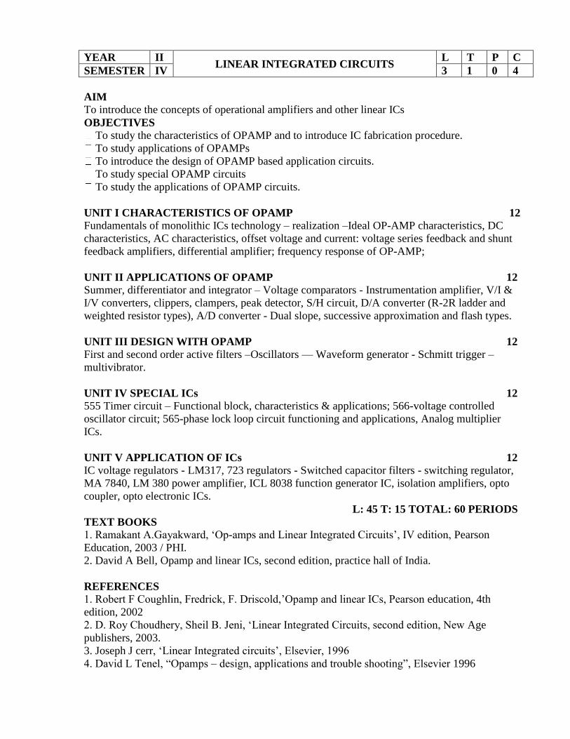
YEAR II LINEAR INTEGRATED CIRCUITS
L T P C
SEMESTER IV 3 1 0 4
AIM
To introduce the concepts of operational amplifiers and other linear ICs
OBJECTIVES
To study the characteristics of OPAMP and to introduce IC fabrication procedure.
To study applications of OPAMPs
To introduce the design of OPAMP based application circuits.
To study special OPAMP circuits
To study the applications of OPAMP circuits.
UNIT I CHARACTERISTICS OF OPAMP 12
Fundamentals of monolithic ICs technology – realization –Ideal OP-AMP characteristics, DC
characteristics, AC characteristics, offset voltage and current: voltage series feedback and shunt
feedback amplifiers, differential amplifier; frequency response of OP-AMP;
UNIT II APPLICATIONS OF OPAMP 12
Summer, differentiator and integrator – Voltage comparators - Instrumentation amplifier, V/I &
I/V converters, clippers, clampers, peak detector, S/H circuit, D/A converter (R-2R ladder and
weighted resistor types), A/D converter - Dual slope, successive approximation and flash types.
UNIT III DESIGN WITH OPAMP 12
First and second order active filters –Oscillators –– Waveform generator - Schmitt trigger –
multivibrator.
UNIT IV SPECIAL ICs 12
555 Timer circuit – Functional block, characteristics & applications; 566-voltage controlled
oscillator circuit; 565-phase lock loop circuit functioning and applications, Analog multiplier
ICs.
UNIT V APPLICATION OF ICs 12
IC voltage regulators - LM317, 723 regulators - Switched capacitor filters - switching regulator,
MA 7840, LM 380 power amplifier, ICL 8038 function generator IC, isolation amplifiers, opto
coupler, opto electronic ICs.
L: 45 T: 15 TOTAL: 60 PERIODS
TEXT BOOKS
1. Ramakant A.Gayakward, ‘Op-amps and Linear Integrated Circuits’, IV edition, Pearson
Education, 2003 / PHI.
2. David A Bell, Opamp and linear ICs, second edition, practice hall of India.
REFERENCES
1. Robert F Coughlin, Fredrick, F. Driscold,’Opamp and linear ICs, Pearson education, 4th
edition, 2002
2. D. Roy Choudhery, Sheil B. Jeni, ‘Linear Integrated Circuits, second edition, New Age
publishers, 2003.
3. Joseph J cerr, ‘Linear Integrated circuits’, Elsevier, 1996
4. David L Tenel, “Opamps – design, applications and trouble shooting”, Elsevier 1996
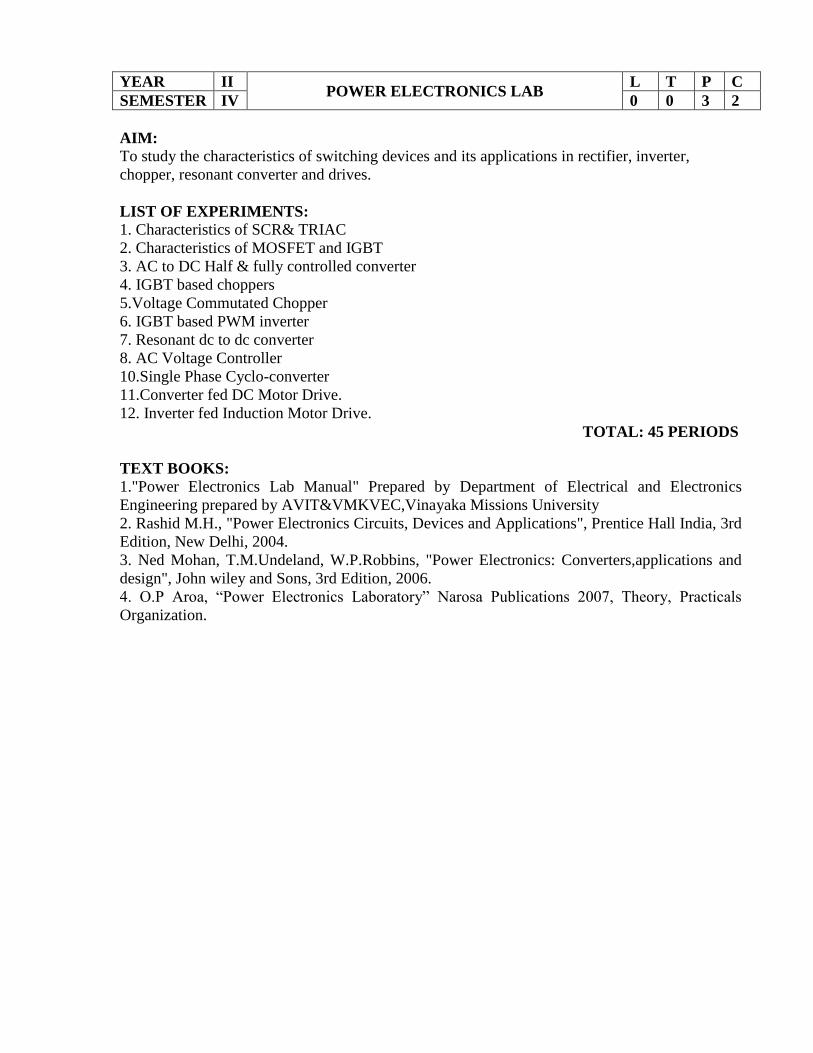
YEAR II POWER ELECTRONICS LAB
L T P C
SEMESTER IV 0 0 3 2
AIM:
To study the characteristics of switching devices and its applications in rectifier, inverter,
chopper, resonant converter and drives.
LIST OF EXPERIMENTS:
1. Characteristics of SCR& TRIAC
2. Characteristics of MOSFET and IGBT
3. AC to DC Half & fully controlled converter
4. IGBT based choppers
5.Voltage Commutated Chopper
6. IGBT based PWM inverter
7. Resonant dc to dc converter
8. AC Voltage Controller
10.Single Phase Cyclo-converter
11.Converter fed DC Motor Drive.
12. Inverter fed Induction Motor Drive.
TOTAL: 45 PERIODS
TEXT BOOKS:
1."Power Electronics Lab Manual" Prepared by Department of Electrical and Electronics
Engineering prepared by AVIT&VMKVEC,Vinayaka Missions University
2. Rashid M.H., "Power Electronics Circuits, Devices and Applications", Prentice Hall India, 3rd
Edition, New Delhi, 2004.
3. Ned Mohan, T.M.Undeland, W.P.Robbins, "Power Electronics: Converters,applications and
design", John wiley and Sons, 3rd Edition, 2006.
4. O.P Aroa, “Power Electronics Laboratory” Narosa Publications 2007, Theory, Practicals
Organization.

YEAR III SOLID STATE DRIVES
L T P C
SEMESTER V 3 1 0 4
AIM
To study and understand the operation of electrical machines controlled by a power electronic
converter and to introduce the controller design concepts.
OBJECTIVES
To understand steady state operation and transient dynamics of a motor load system.
To study and analyze the operation of the converter / chopper fed dc drive, both
qualitatively and quantitatively.
To analyze and design the current and speed controllers for a closed loop solid state DC
motor drive.
To study and understand the operation and performance of AC Induction motor drives.
To study and understand the operation and performance of AC Synchronous motor
drives.
UNIT I DRIVE CHARACTERISTICS 12
Equations governing motor load dynamics - steady state stability - Multi quadrant dynamics -
Acceleration, deceleration, starting and stopping - load torque characteristics of various
drives.
UNIT II CONVERTER / CHOPPER FED DC MOTOR DRIVE 12
Steady state analysis of the single and three phase fully controlled converter fed separately
excited D.C motor drive - Continuous and discontinuous conduction Time ratio and current
limit control - 4 quadrant operation of converter.
UNIT III DESIGN OF CONTROLLERS FOR DRIVES 12
Transfer function for DC motor, load and converter – Closed loop control with current and
speed feedback - Armature voltage control and field weakening mode control, Design of
controllers: Current controller and speed controller - Converter selection and characteristics -
Use of simulation software package.
UNIT IV INDUCTION MOTOR DRIVES 12
Stator voltage control – energy efficient drive - v/f control, constant air-gap flux – field
weakening mode - voltage/current fed inverters - Block diagram of vector control - closed
loop control.
UNIT V SYNCHRONOUS MOTOR DRIVES 12
V/f control and self-control of synchronous motor – Marginal angle control and power factor
control - Permanent magnet synchronous motor Black diagram of closed loop control.
L: 45 T: 15 TOTAL: 60 PERIODS
TEXT BOOKS:
1. Gopal K.Dubey, "Fundamentals of Electrical Drives", Narosa Publishing House, 1992.
2. Bimal K.Bose. "Modern Power Electronics and AC Drives", Pearson Education, 2002.
REFERENCES:
1. S.K.Pillai, "A First course on Electrical Drives", Wiley Eastern Limited, 1993.
2. Murphy J.M.D and Turnbull, "Thyristor Control of AC Motor", Pergamon Press, Oxford
1988.
3. Gopal K.Dubey, "Power semiconductor controlled Drives:, Prentice Hall Inc., New Jersey,
1989.
4. R.Krishnan, "Electric Motor & Drives: Modeling, Analysis and Control", Prentice hall of
India, 2001.

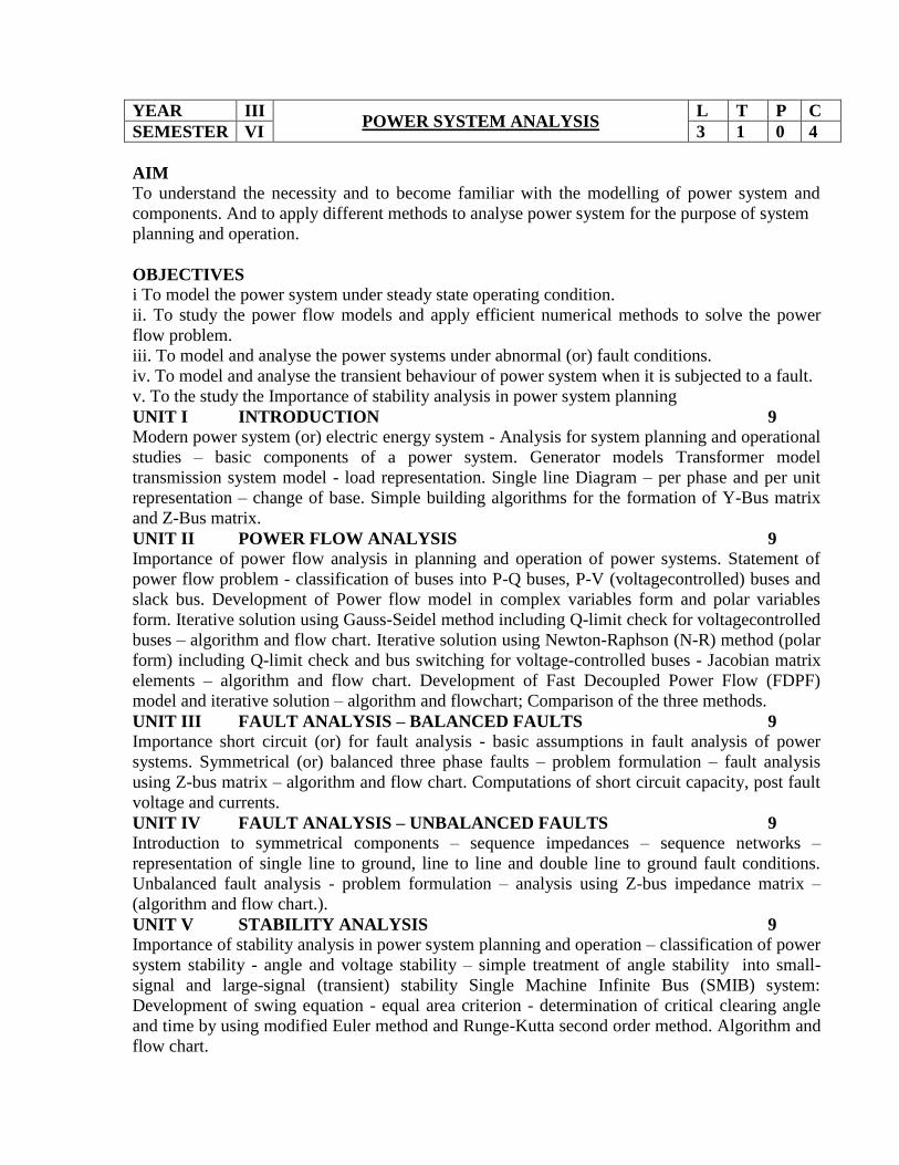
YEAR III POWER SYSTEM ANALYSIS
L T P C
SEMESTER VI 3 1 0 4
AIM
To understand the necessity and to become familiar with the modelling of power system and
components. And to apply different methods to analyse power system for the purpose of system
planning and operation.
OBJECTIVES
i To model the power system under steady state operating condition.
ii. To study the power flow models and apply efficient numerical methods to solve the power
flow problem.
iii. To model and analyse the power systems under abnormal (or) fault conditions.
iv. To model and analyse the transient behaviour of power system when it is subjected to a fault.
v. To the study the Importance of stability analysis in power system planning
UNIT I INTRODUCTION 9
Modern power system (or) electric energy system - Analysis for system planning and operational
studies – basic components of a power system. Generator models Transformer model
transmission system model - load representation. Single line Diagram – per phase and per unit
representation – change of base. Simple building algorithms for the formation of Y-Bus matrix
and Z-Bus matrix.
UNIT II POWER FLOW ANALYSIS 9
Importance of power flow analysis in planning and operation of power systems. Statement of
power flow problem - classification of buses into P-Q buses, P-V (voltagecontrolled) buses and
slack bus. Development of Power flow model in complex variables form and polar variables
form. Iterative solution using Gauss-Seidel method including Q-limit check for voltagecontrolled
buses – algorithm and flow chart. Iterative solution using Newton-Raphson (N-R) method (polar
form) including Q-limit check and bus switching for voltage-controlled buses - Jacobian matrix
elements – algorithm and flow chart. Development of Fast Decoupled Power Flow (FDPF)
model and iterative solution – algorithm and flowchart; Comparison of the three methods.
UNIT III FAULT ANALYSIS – BALANCED FAULTS 9
Importance short circuit (or) for fault analysis - basic assumptions in fault analysis of power
systems. Symmetrical (or) balanced three phase faults – problem formulation – fault analysis
using Z-bus matrix – algorithm and flow chart. Computations of short circuit capacity, post fault
voltage and currents.
UNIT IV FAULT ANALYSIS – UNBALANCED FAULTS 9
Introduction to symmetrical components – sequence impedances – sequence networks –
representation of single line to ground, line to line and double line to ground fault conditions.
Unbalanced fault analysis - problem formulation – analysis using Z-bus impedance matrix –
(algorithm and flow chart.).
UNIT V STABILITY ANALYSIS 9
Importance of stability analysis in power system planning and operation – classification of power
system stability - angle and voltage stability – simple treatment of angle stability into small-
signal and large-signal (transient) stability Single Machine Infinite Bus (SMIB) system:
Development of swing equation - equal area criterion - determination of critical clearing angle
and time by using modified Euler method and Runge-Kutta second order method. Algorithm and
flow chart.

TEXT BOOKS
1. Hadi Saadat, ‘Power System Analysis’, Tata McGraw Hill Publishing Company, New
Delhi, 2002.
2. Olle. I. Elgerd, ‘Electric Energy Systems Theory – An Introduction’, Tata McGraw Hill
Publishing Company Limited, New Delhi, Second Edition, 2003.
REFERENCES
1. P. Kundur, ‘Power System Stability and Control, Tata McGraw Hill, Publications,1994.
2. John J. Grainger and W.D. Stevenson Jr., ‘Power System Analysis’, McGraw Hill
International Book Company, 1994.
3. I.J. Nagrath and D.P. Kothari, ‘Modern Power System Analysis’, Tata McGraw-Hill
Publishing Company, New Delhi, 1990.
4. .K.Nagasarkar and M.S. Sukhija Oxford University Press, 2007

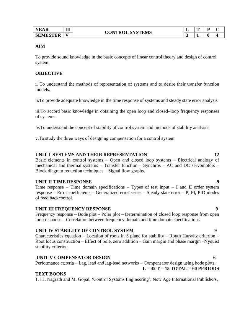
YEAR III CONTROL SYSTEMS
L T P C
SEMESTER V 3 1 0 4
AIM
To provide sound knowledge in the basic concepts of linear control theory and design of control
system.
OBJECTIVE
i. To understand the methods of representation of systems and to desire their transfer function
models.
ii.To provide adequate knowledge in the time response of systems and steady state error analysis
iii.To accord basic knowledge in obtaining the open loop and closed–loop frequency responses
of systems.
iv.To understand the concept of stability of control system and methods of stability analysis.
v.To study the three ways of designing compensation for a control system
UNIT I SYSTEMS AND THEIR REPRESENTATION 12
Basic elements in control systems – Open and closed loop systems – Electrical analogy of
mechanical and thermal systems – Transfer function – Synchros – AC and DC servomotors –
Block diagram reduction techniques – Signal flow graphs.
UNIT II TIME RESPONSE 9
Time response – Time domain specifications – Types of test input – I and II order system
response – Error coefficients – Generalized error series – Steady state error – P, PI, PID modes
of feed backcontrol.
UNIT III FREQUENCY RESPONSE 9
Frequency response – Bode plot – Polar plot – Determination of closed loop response from open
loop response – Correlation between frequency domain and time domain specifications.
UNIT IV STABILITY OF CONTROL SYSTEM 9
Characteristics equation – Location of roots in S plane for stability – Routh Hurwitz criterion –
Root locus construction – Effect of pole, zero addition – Gain margin and phase margin –Nyquist
stability criterion.
.UNIT V COMPENSATOR DESIGN 6
Performance criteria – Lag, lead and lag-lead networks – Compensator design using bode plots.
L = 45 T = 15 TOTAL = 60 PERIODS
TEXT BOOKS
1. I.J. Nagrath and M. Gopal, ‘Control Systems Engineering’, New Age International Publishers,

2003.
2. Benjamin C. Kuo, Automatic Control systems, Pearson Education, New Delhi, 2003.
REFERENCES
1. K. Ogata, ‘Modern Control Engineering’, 4th edition, PHI, New Delhi, 2002.
2. Norman S. Nise, Control Systems Engineering, 4th Edition, John Wiley, New Delhi, 2007.
3. Samarajit Ghosh, Control systems, Pearson Education, New Delhi, 2004
4. M. Gopal, ‘Control Systems, Principles and Design’, Tata McGraw Hill, New Delhi, 2002.

YEAR III MATHEMATICAL MODELLING AND
SIMULTION
L T P C
SEMESTER V 3 0 0 3
UNIT I MATLAB ENVIRONMENT 9
Defining Variables – functions – Matrices and Vectors –Strings – Input and Output statements -
Script files – Arrays in Mat lab – Addressing Arrays – Dynamic Array – Cell Array – Structure
Array – File input and output – Opening & Closing – Writing & Reading data from files.
UNIT II PROGRAMMING IN MATLAB 9
Relational and logical operators – Control statements IF-END, IF-ELSE – END, ELSEIF,
SWITCH CASE – FOR loop – While loop – Debugging – Applications to Simulation
miscellaneous MAT lab functions & Variables.
UNIT III PLOTTING IN MATLAB 9
Basic 2D plots – modifying line styles – markers and colors – grids – placing text on a plot –
Various / Special Mat Lab 2D plot types – SEMILOGX – SEMILOGY – LOG- LOG – POLAR
– COMET – Example frequency response of filter circuits.
UNIT IV APPLICATION OF MATLAB 9
Linear algebric equations – elementary solution method – matrix method for linear equation –
Cramer’s method – Statistics, Histogram and probability – normal distribution – random number
generation – Interpolation – Analytical solution to differential equations – Numerical methods
for differential equations.
UNIT V TOOL BOXES 9
Simulink – Simulink model for a dead zone system, nonlinear system – Applications in DSP –
Computation of DFT & FFT – Filter structure –IIR & FIR filter design – Applications in
Communication PCM, DPCM, DM, DTMFInterfacing of Matlab with event driven simulators.
TEXT BOOKS:
1. Rudra Pratap,Getting Started with MATLAB6.0, 1st Edition, Oxford University Press, 2004.
REFERENCE BOOKS:
1. William J.Palm,Introduction to MATLAB 6.0 for Engineers, Mc Graw Hill & Co
2. M.Herniter, Programming in MATLAB, Thomson Learning.
3. John G.Proakis, Digital Signal Processing using MATLAB, Thomson Learning.

YEAR III CONTROL SYSTEMS LAB
L T P C
SEMESTER V 0 0 3 2
1. Transfer function of self and separately excited DC Generator.
Aim
To determine the transfer function of self and separately excited DC generator.
2. Transfer function of Armature and Field controlled DC Motor.
Aim
To determine the transfer function of armature and field controlled DC motor.
3. Transfer function of AC Servomotor.
Aim
To derive the transfer function of the given A.C Servomotor and experimentally determine
the transfer function parameters.
4. Frequency response of Lag, Lead & Lag – Lead networks.
Aim
To obtain the Frequency response of Lag, Lead & Lag – Lead networks.
5. Study of Synchros and DC Stepper Motor
Aim
To study the working of Synchros & stepper motor
6. Transfer function of Ward – Leonard method of speed control of DC motor.
Aim
To determine the transfer function parameters of Ward – Leonard method of speed control of
DC motor.
7. Study of DC Position Control system and study of various transducers
Aim
To study the DC position control system and draw the error characteristics between
setpoint and error and to study the various Transducers.
8. Study of P, PI and PID Controllers (First Order).
Aim
To determine the Time Response characteristics of the controllers.
9. Analog and simulation of type – o and type – 1 systems
Aim
To simulate the time response characteristics of I order and II order, type 0 and type-1
systems.
10.Stability analysis of Linear Systems
Aim
To analyse the stability of linear systems using Bode / Root locus / Nyquist plot.
11.Digital simulation of first order systems
Aim
To digitally simulate the time response characteristics of first -order system
12.Digital simulation of second order systems
Aim
To digitally simulate the time response characteristics of second -order system
Total Hours : 45
YEAR III HIGH VOLTAGE ENGINEERING
L T P C
SEMESTER VI 3 1 0 4
AIM
(i) To expose the students to causes and various types of over voltage Transients in Power
system and its effects on power system.
(ii) To understand the Generation of over voltages in Laboratory.
(iii) To know about the Testing of power apparatus and system.
OBJECTIVES
(i) To understand the various types of over voltages in power system and protection.
(ii) Generation of over voltages in laboratories.
(iii) Measurement of overvoltage.
(iv) Nature of Breakdown mechanism in Solids.
(v) Testing of Power apparatus and insulation coordination.
Unit I OVER VOLTAGES AND INSULATION COORDINATION 6
Natural causes of over voltages-Lightning phenomena-Over voltages due to switching surges -
System faults and other abnormal conditions-Principles of insulation co-ordination.
Unit II ELECTRICAL BREAKDOWN IN SOLIDS 12
Classical gas laws- Ionization and decay process- Secondary effects- Paschen’s law-Streamer
theory- Breakdown in non-uniform fields and corona discharges- Electromechanical breakdown-
Thermal breakdown- Breakdown in composite dielectrics.
Unit III GENERATION OF HIGH VOLTAGE AND HIGH CURRENT 9
Generation of high DC voltage, alternating voltage , impulse voltage and impulse currents.
Unit IV MEASUREMENT OF HIGH VOLTAGE AND HIGH CURRENT 9
Measurement of high voltages and high currents - Digital techniques in high voltage
measurement.
Unit V HIGH VOLTAGE TESTING 9
High voltage testing of electrical power apparatus - Power frequency, Impulse voltage and DC,
International and Indian Standards.
L: 45 T: 15 TOTAL: 60 PERIODS
TEXT BOOKS
1. M. S. Naidu and V. Kamaraju, ‘High Voltage Engineering’, Tata McGraw Hill,1995.
2. Kuffel,E and Zaengl, W.S, ‘High Voltage Engineering Fundamentals’, Pergamon Press,
Oxford , Londan,1986
REFERENCE BOOKS
1. Kuffel, E and Abdullah..M, ‘High Voltage Engineering Fundamentals’, Pergamon Press,
Oxford ,Londan,1970.
2. Gallghar, P.J and Pearmain,A.J., ‘High Voltage Measurement’,Testing and Design,John Wiley
and Sons, Newyork,1982
YEAR III EMBEDDED SYSTEMS
L T P C
SEMESTER VI 3 0 0 3
AIM
To learn the basic concepts of embedded systems and its applications.
OBJECTIVES
To introduce students to the embedded systems, its hardware and software.
To introduce devices and buses used for embedded networking.
To explain programming concepts and embedded programming in C and C++
To introduce the software development tools in embedded systems.
To introduce the concepts of Real Time Operating System.
UNIT I INTRODUCTION TO EMBEDDED SYSTEMS 9
Definition –Processor Embedded into a System – Embedded Hardware Units and Devices in
system –Embedded Software in a System – Examples of Embedded system –System on Chip
(Soc) and Use of VLSI Design Technology – Complex Design and Processors – Design Process
– Formalizations of System Design – Design Process and Design Examples – Classifications of
Embedded Systems.
UNIT II DEVICES AND BUSES FOR DEVICES NETWORK 9
Device I/O Types and Examples – Serial Communication Devices – Parallel Devices Ports –
Sophisticated Interfacing Features in Devices Ports – Wireless Devices – Timer and Counting
Devices – Watchdog Timer – Real Time Clock – Networked Embedded Systems – Serial Bus
Communication Protocols – Parallel Bus Device Protocol – Parallel Communication Network
Using ISA, PCI, PCI-X, cPCI and advanced buses.
UNIT III PROGRAMMING CONCEPTS AND EMBEDDED PROGRAMMING IN C,
C++ 9
Programming in assembly language (ALP) vs. High Level Language - C Program
Elements,Macros and functions -Use of Pointers - NULL Pointers - Use of Function Calls –
Multiple functioncalls in a Cyclic Order in the Main Function Pointers – Function Queues and
Interrupt ServiceRoutines Queues Pointers – Concepts of EMBEDDED PROGRAMMING in
C++ - ObjectedOriented Programming – Embedded Programming in C++, ‘C’ Program
compilers – Cross compiler– Optimization of memory codes.
UNIT IV SOFTWARE DEVELOPMENT AND TOOLS 9
Embedded system evolution trends. Round - Robin, robin with Interrupts, function-One-
Scheduling Architecture, Algorithms. Introduction to-assembler-compiler-cross compilers and
Integrated Development Environment (IDE). Object Oriented Interfacing, Recursion, Debugging
strategies, Simulators.
UNIT V REAL TIME OPERATING SYSTEMS 9

Task and Task States, tasks and data, semaphores and shared Data Operating system Services-
Message queues-Timer Function-Events-Memory Management, Interrupt Routines in an RTOS
environment, basic design Using RTOS.
TOTAL HOURS: 45 PERIODS
TEXT BOOKS:
1. Rajkamal, Embedded Systems Architecture, Programming and Design, TATA McGraw-
Hill,Second Edition,Sixth reprint Oct. 2010
2. David E Simon, “An Embedded Software Primer ", Pearson education Asia, 2001.
REFERENCE BOOKS:
1. Steve Heath, Embedded Systems Design, Second Edition-2003, Newnes,
2. Wayne Wolf, Computers as Components; Principles of Embedded Computing System
Design – Harcourt India, Morgan Kaufman Publishers, First Indian Reprint 2001
3. Frank Vahid and Tony Givargis, Embedded Systems Design – A unified Hardware
/Software Introduction, John Wiley, 2002.

YEAR III MICROPROCESSORS AND MICRO
CONTROLLERS
L T P C
SEMESTER VI 3 1 0 4
AIM
To introduce Microprocessor Intel 8085, 8086 and the Micro Controller 8051
OBJECTIVES
To study the Architecture of 8085, 8086 & 8051.
To study the addressing modes & instruction set of 8085, 8086 & 8051.
To introduce the need & use of Interrupt structure.
To develop skill in simple program writing.
To introduce commonly used peripheral/ interfacing ICs
UNIT I 8085 PROCESSOR 9
8085:Functional block diagram - Signals– Memory interfacing – I/O ports and data transfer
concepts – Timing Diagram – Interrupt structure, 8086 Architecture.
UNIT II PROGRAMMING OF 8085 PROCESSOR 9
Instruction format and addressing modes – Assembly language format – Data transfer, data
manipulation & control instructions – Programming: Loop structure with counting & Indexing -
Look up table - Subroutine instructions stack.
UNIT III PERIPHERAL INTERFACING 9
Study of Architecture and programming of ICs: 8255 PPI, 8259 PIC, 8251 USART, 8279 Key
board display controller and 8253 Timer/ Counter – Interfacing with 8085 - A/D and D/A
converter interfacing.
UNIT IV MICRO CONTROLLER 8051 9
Functional block diagram - Instruction format and addressing modes – Interrupt structure –
Timer –I/O ports – Serial communication, Simple programming.
UNIT V MICRO CONTROLLER PROGRAMMING & APPLICATIONS 9
Data Transfer, Manipulation, Control & I/O instructions – Simple programming exercises key
board and display interface – Closed loop control of DC shunt motor- stepper motor control.
L=45 T=15 TOTAL: 60 PERIODS
TEXT BOOKS:
1. R.S. Gaonkar, ‘Microprocessor Architecture Programming and Application’, Wiley Eastern
Ltd., New Delhi,
2. Muhammad Ali Mazidi & Janice Gilli Mazidi, ‘The 8051 Micro Controller and Embedded
Systems’, Pearson Education, 2007.
REFERENCES:
1. Antonakos, ‘The Pentium microprocessor’, Pearson Education, 2007
2. Kenneth Ayala, ‘The 8051Microcontroller’, Thomson, 2005
3. N.K De and P.K Sen, ‘Electric Drives’, Prentice Hall of India, 2005

YEAR III MICROPROCESSOR AND
MICROCONTROLLER LAB
L T P C
SEMESTER VI 0 0 3 2
List of experiments
1. Familiarization of 8085 trainer kit, 8086 trainer kit,8051 trainer kit & 89C51 mC.
2. Addition & subtraction of 8 and 16 bits using 8085.
3. Multiplication & division 8 and 16 bits using 8085
4. Interfacing of stepper motor using 8085.
5. Interfacing of traffic light using 8085.
6. Addition and subtraction of two 16 bit numbers using 8086.
7. Code converters using 8086.
8. Sorting of N numbers using 8086.
9. Arithmetic operation programs using 8051.
10. Interfacing of ADC using 8051.
11 Interfacing of DAC using 8051.
12 Addition and subtraction using 89C51.
13 Filling of internal memory using 89C51.
YEAR IV ELECTRIC ENERGY GENERATION,
UTILIZATION AND CONSERVATION
L T P C
SEMESTER VII 3 0 0 3
AIM
To expose students to the main aspects of generation, utilization and conservation.
OBJECTIVES
(i)To impart knowledge on Generation of electrical power by conventional and
non–conventional methods.
(ii) To understand the importance of Electrical energy conservation, energy auditing and power
quality.
(iii)To learn the Principle and design of illumination systems and methods of heating and
welding.
(iv)To understand the laws of illumination and the basic design of illumination schemes.
(v) Industrial applications of electric heating and welding.
UNIT I POWER GENERATION 9
Review of conventional methods – thermal, hydro and nuclear based power generation. Non-
conventional methods of power generation – fuel cells - tidal waves – wind – geothermal – solar
- bio-mass - municipal waste. Cogeneration. Effect of distributed generation on power system
operation.
UNIT II ECONOMIC ASPECTS OF GENERATION 9
Economic aspects of power generation – load and load duration curves – number and size of
units – cost of electrical energy – tariff. Economics of power factor improvement power
capacitors – power quality.Importance of electrical energy conservation – methods – energy
efficient equipments. Introduction to energy auditing.
UNIT III ILLUMINATION 9
Importance of lighting – properties of good lighting scheme – laws of illumination – photometry
- types of lamps – lighting calculations – basic design of illumination schemes for residential,
commercial, street lighting, and sports ground – energy efficiency lamps.
UNIT IV INDUSTRIAL HEATING AND WELDING 9
Role electric heating for industrial applications – resistance heating – induction heating –
dielectric heating - electric arc furnaces. Brief introduction to electric welding – welding
generator, welding transformer and the characteristics.
UNIT V ELECTRIC TRACTION 9
Merits of electric traction – requirements of electric traction system – supply systems –
mechanics of train movement – traction motors and control – braking – recent trends in
electric traction.
TOTAL HOURS : 45
TEXT BOOKS
1. C.L. Wadhwa, ‘Generation, Distribution and Utilization of Electrical Energy’, New Age
International Pvt. Ltd, 2003.
2. B.R. Gupta, ‘Generation of Electrical Energy’, Eurasia Publishing House (P) Ltd, New
Delhi, 2003.
REFERENCE BOOKS
1. H. Partab, ‘Art and Science of Utilisation of Electrical Energy’, Dhanpat Rai and
Co, New Delhi, 2004.
2. E. Openshaw Taylor, ‘Utilization of Electrical Energy in SI Units’, Orient Longman
Pvt. Ltd, 2003.
3. J.B. Gupta, ‘Utilization of Electric Power and Electric Traction’, S.K.Kataria and
Sons, 2002.

YEAR IV PROJECT WORK & VIVA VOCE
L T P C
SEMESTER VII 0 0 12 6
OBJECTIVE
The objective of the project work is to enable the students to form the groups of not more
than 3 members on a project involving theoretical and experimental studies related to the
branch of study.
Formation of Group as follows
Group A : 8.5CGPA and above
Group B : 7 to 8.49 CGPA
Group C : 5 to 6.9 CGPA
Group A Student will have a choice to take 2 students from Group B&C
Every project work shall have a guide who is the member of the faculty of the institution.
Six periods per week shall be allotted in the time table and this time shall be utilized by
the students to receive the directions from the guide, on library reading, laboratory work,
computer analysis or field work as assigned by the guide and also to present in periodical
seminars on the progress made in the project.
The aim of the project work is to deepen comprehension of principles by applying them
to a new problem which may be the design and manufacture of a device, a research
investigation, a computer or management project or a design problem.
The progress of the project is evaluated based on a minimum of three reviews. The
review committee may be constituted by the Head of the Department.
Each student shall finally produce a comprehensive report covering background
information, literature survey, problem statement, project work details and conclusion.
This final report shall be typewritten form as specified in the guidelines.
The continuous assessment shall be made as prescribed in the regulations

ELECTIVES
ELECTIVE ADVANCED CONTROL SYSTEM L T P C
3 0 0 3
UNIT I STATE VARIABLE ANALYSIS 9
Concept of state – State Variable and State Model – State models for linear and continuous time
systems – Solution of state and output equation – controllability and\ observability - Pole
Placement – State observer Design of Control Systems with observers.
UNIT II PHASE PLANE ANALYSIS 9
Features of linear and non-linear systems - Common physical non-linearities – Methods of
linearising non-linear systems - Concept of phase portraits – Singular points – Limit cycles –
Construction of phase portraits – Phase plane analysis of linear and non-linear systems – Isocline
method.
UNIT III DESCRIBING FUNCTION ANALYSIS 9
Basic concepts, derivation of describing functions for common non-linearities – Describing
function analysis of non-linear systems – Conditions for stability – Stability of oscillations.
UNIT IV STABILITY ANALYSIS 9
Introduction – Liapunov’s stability concept – Liapunov’s direct method – Lure’s transformation
– Aizerman’s and Kalman’s conjecture – Popov’s criterion – Circle criterion.
UNIT V OPTIMAL CONTROL 9
Introduction -Decoupling - Time varying optimal control – LQR steady state optimal control –
Optimal estimation – Multivariable control design.
Total Hours: 45
TEXT BOOKS
1. I.J. Nagrath and M. Gopal, ‘Control Systems Engineering’, New Age International Publishers,
2003.
2. Ashish Tewari, ‘Modern control Design with Matlab and Simulink’, John Wiley, New Delhi,
2002.
REFERENCE BOOKS
1. George J. Thaler, ‘Automatic Control Systems’, Jaico Publishers, 1993.
2. M.Gopal, Modern control system theory, New Age International Publishers, 2002.
3. Gene F. Franklin, J. David Powell and Abbasemami-Naeini, “ Feedback Control of Dynamic
Systems”, Fourth edition, Pearson Education, Low price edition. 2002.

ELECTIVE ADVANCED TOPICS IN POWER ELECTRONICS L T P C
3 0 0 3
AIM
To study modern power electronic converters and its applications in electric power utility like
low power SMPS and UPS technologies
OBJECTIVE
To study the operation, switching techniques and basics topologies of DC-DC switching
regulators
To understand the operation, characteristics and performance parameters of switching mode
power converters.
To study the operation of resonant converters and concept of Zero voltage Switching.
To learn the concept and operation of Inverters and different modulation techniques of pulse
width modulated inverters and to understand harmonic reduction methods.
To study the operation of various power electronics applications like UPS and filters.
UNIT I DC-DC CONVERTERS 9
Principles of stepdown and stepup converters – Analysis and state space modeling of Buck,
Boost, Buck- Boost and Cuk converters.
UNIT II SWITCHING MODE POWER CONVERTERS 9
Analysis and state space modeling of flyback, Forward, Luo, Half bridge and full bridge
converters- control circuits and PWM techniques.
UNIT III RESONANT CONVERTERS 9
Introduction- classification- basic concepts- Resonant switch- Load Resonant converters- ZVS ,
Clamped voltage topologies- DC link inverters with Zero Voltage Switching- Series and parallel
Resonant inverters- Voltage control .
UNIT IV DC-AC CONVERTERS 9
Single phase and three phase inverters, control using various (sine PWM, SVPWM and advanced
modulation) techniques, various harmonic elimination techniques- Multilevel inverters-Concepts
- Types: Diode clamped- Flying capacitor- Cascaded types- Applications.
UNIT V POWER CONDITIONERS, UPS & FILTERS 9
Introduction- Power line disturbances- Power conditioners –UPS: offline UPS, Online UPS,
Applications – Filters: Voltage filters, Series-parallel resonant filters, filter without series
capacitors, filter for PWM VSI, current filter, DC filters – Design of inductor and transformer for
PE applications – Selection of capacitors.
TOTAL: 45 PERIODS
TEXT BOOKS:
1. Ned Mohan, Tore.M.Undeland, William.P.Robbins, Power Electronics converters,
Applications and design- Third Edition- John Wiley and Sons- 2006
2. M.H. Rashid – Power Electronics circuits, devices and applications- third edition Prentice Hall
of India New Delhi, 2007.
REFERENCES:
1. M.H. Rashid – Power Electronics handbook, Elsevier Publication, 2001.
2. Kjeld Thorborg, “Power Electronics – In theory and Practice”, Overseas Press, First Indian
Edition 2005.
3. Philip T Krein, “ Elements of Power Electronics”, Oxford University Press
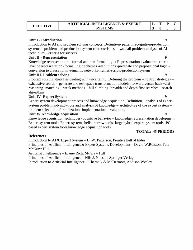
ELECTIVE ARTIFICIAL INTELLIGENCE & EXPERT
SYSTEMS
L T P C
3 0 0 3
Unit I - Introduction 9 Introduction to AI and problem solving concepts: Definition- pattern recognition-production
systems – problem and production system characteristics – two-pail problem-analysis of AI
techniques – criteria for success
Unit II - Representation 9 Knowledge representation – formal and non-formal logic: Representation evaluation criteria -
level of representation -formal logic schemes -resolutions -predicate and prepositional logic -
conversion to clause form -semantic networks-frames-scripts-production system
Unit III- Problem solving 9 Problem solving strategies dealing with uncertainty: Defining the problem – control strategies –
exhaustive search – generate and test-space transformation models- forward versus backward
reasoning -matching – weak methods – hill climbing -breadth and depth first searches – search
algorithms.
Unit IV- Expert System 9 Expert system development process and knowledge acquisition: Definition – analysis of expert
system problem solving – role and analysis of knowledge – architecture of the expert system –
problem selection – formalization -implementation –evaluation.
Unit V- Knowledge acquisition 9
Knowledge acquisition techniques- cognitive behavior – knowledge representation development.
Expert system tools: Expert system shells -narrow tools -large hybrid expert system tools -PC
based expert system tools knowledge acquisition tools.
TOTAL: 45 PERIODS
References
Introduction to AI & Expert System – D. W. Patterson, Prentice hall of India
Principles of Artificial Intelligence& Expert Systems Development – David W.Rolston, Tata
McGraw Hill
Artificial Intelligence – Elaine Rich, McGraw Hill
Principles of Artificial Intelligence – Nils J. Nilsson, Springer Verlag
Introduction to Artificial Intelligence – Charnaik & McDermott, Addison Wesley

ELECTIVE BIOMEDICAL INSTRUMENTATION L T P C
3 0 0 3
AIM
The course is designed to make the student acquire an adequate knowledge of the
physiological systems of the human body and relate them to the parameters that have
clinical importance. The fundamental principles of equipment that are actually in use at
the present day are introduced.
OBJECTIVE:
To provide an acquaintance of the physiology of the heart, lung, blood circulation
and circulation respiration , Methods of different transducers used.
To introduce the student to the various sensing and measurement devices of
electrical origin.
To provide the latest ideas on devices of non-electrical devices.
To bring out the important and modern methods of imaging techniques.
To provide latest knowledge of medical assistance / techniques and therapeutic
equipments.
UNIT I PHYSIOLOGY AND TRANSDUCERS 9
Cell and its structure – Resting and Action Potential – Nervous system: Functionalorganisation
of the nervous system – Structure of nervous system, neurons - synapse –transmitters and neural
communication – Cardiovascular system – respiratory system –Basic components of a
biomedical system - Transducers – selection criteria – Piezoelectric, ultrasonic transducers -
Temperature measurements - Fibre optic temperaturesensors.
UNIT II ELECTRO – PHYSIOLOGICAL MEASUREMENTS 9
Electrodes –Limb electrodes –floating electrodes – pregelled disposable electrodes -Micro,
needle and surface electrodes – Amplifiers: Preamplifiers, differential amplifiers,chopper
amplifiers – Isolation amplifier.ECG – EEG – EMG – ERG – Lead systems and recording
methods – Typicalwaveforms.Electrical safety in medical environment: shock hazards – leakage
current-Instrumentsfor checking safety parameters of biomedical equipments
UNIT III NON-ELECTRICAL PARAMETER MEASUREMENTS 9
Measurement of blood pressure – Cardiac output – Heart rate – Heart sound – Pulmonary
function measurements – spirometer – Photo Plethysmography, BodyPlethysmography – Blood
Gas analysers : pH of blood –measurement of blood pCO2,pO2, finger-tip oxymeter - ESR, GSR
measurements .
UNIT IV MEDICAL IMAGING 9
Radio graphic and fluoroscopic techniques – Computer tomography – MRI –Ultrasonography –
Endoscopy – Thermography – Different types of biotelemetrysystems and patient monitoring –
Introduction to Biometric systems
UNIT V ASSISTING AND THERAPEUTIC EQUIPMENTS 9
Pacemakers – Defibrillators – Ventilators – Nerve and muscle stimulators – Diathermy –
Heart – Lung machine – Audio meters – Dialysers – Lithotripsy
TOTALHOURS : 45
TEXT BOOKS
1. R.S.Khandpur, ‘Hand Book of Bio-Medical instrumentation’, Tata McGraw Hill Publishing
Co Ltd., 2003.
2. Leslie Cromwell, Fred J.Weibell, Erich A.Pfeiffer, ‘Bio-Medical Instrumentation and
Measurements’, II edition, Pearson Education, 2002 / PHI.
REFERENCE BOOKS
1. M.Arumugam, ‘Bio-Medical Instrumentation’, Anuradha Agencies, 2003.
2. L.A. Geddes and L.E.Baker, ‘Principles of Applied Bio-Medical Instrumentation’, John Wiley
& Sons, 1975.
3. J.Webster, ‘Medical Instrumentation’, John Wiley & Sons, 1995.
4. C.Rajarao and S.K. Guha, ‘Principles of Medical Electronics and Bio-medical
Instrumentation’, Universities press (India) Ltd, Orient Longman ltd, 2000.

ELECTIVE CAD FOR ELECTRICAL APPARATUS L T P C
3 0 0 3
AIM To introduce the basics of Computer Aided Design technology for the design of Electrical
Machines.
OBJECTIVE At the end of this course the student will be able to
1. Learn the importance of computer aided design method.
2. Understand the basic electromagnetic field equations and the problem formulation for
CAD applications.
3. Become familiar with Finite Element Method as applicable for Electrical Engineering.
4. Know the organization of a typical CAD package.
5. Apply Finite Element Method for the design of different Electrical apparatus.
UNIT I INTRODUCTION Conventional design procedures – Limitations – Need for field analysis based design – Review
of Basic principles of energy conversion – Development of Torque/Force.
UNIT II MATHEMATICAL FORMULATION OF FIELD PROBLEMS Electromagnetic Field Equations – Magnetic Vector/Scalar potential – Electrical vector Scalar
potential – Stored energy in Electric and Magnetic fields – Capacitance - Inductance- Laplace
and Poisson’s Equations – Energy functional.
UNIT III PHILOSOPHY OF FEM Mathematical models – Differential/Integral equations – Finite Difference method – Finite
element method – Energy minimization – Variational method- 2D field problems –Discretisation
– Shape functions – Stiffness matrix – Solution techniques.
UNIT IV CAD PACKAGES Elements of a CAD System –Pre-processing – Modelling – Meshing – Material properties-
Boundary Conditions – Setting up solution – Post processing.
UNIT V DESIGN APPLICATIONS Voltage Stress in Insulators – Capacitance calculation - Design of Solenoid Actuator –
Inductance and force calculation – Torque calculation in Switched Reluctance Motor.
TEXT BOOKS 1. S.J Salon, ‘Finite Element Analysis of Electrical Machines’, Kluwer Academic
Publishers, London, 1995.
2. Nicola Bianchi, ‘Electrical Machine Analysis using Finite Elements’, CRC Taylor&
Francis, 2005.
REFERENCES 1. Joao Pedro, A. Bastos and Nelson Sadowski, ‘Electromagnetic Modeling by Finite
Element Methods’, Marcell Dekker Inc., 2003.
2. P.P.Silvester and Ferrari, ‘Finite Elements for Electrical Engineers’, Cambridge
University Press, 1983.
3. D.A.Lowther and P.P Silvester, ‘Computer Aided Design in Magnetics’, Springer
Verlag, New York, 1986.
4. S.R.H.Hoole, ‘Computer Aided Analysis and Design of Electromagnetic Devices’,
Elsevier, New York, 1989.
5. User Manuals of MAGNET, MAXWELL & ANSYS Software
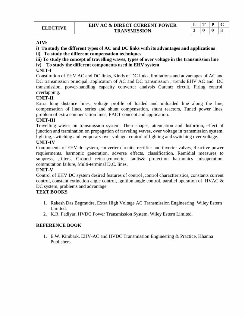
ELECTIVE EHV AC & DIRECT CURRENT POWER
TRANSMISSION
L T P C
3 0 0 3
AIM:
i) To study the different types of AC and DC links with its advantages and applications
ii) To study the different compensation techniques
iii) To study the concept of travelling waves, types of over voltage in the transmission line
iv) To study the different components used in EHV system
UNIT-I
Constitution of EHV AC and DC links, Kinds of DC links, limitations and advantages of AC and
DC transmission principal, application of AC and DC transmission , trends EHV AC and DC
transmission, power-handling capacity converter analysis Garentz circuit, Firing control,
overlapping.
UNIT-II
Extra long distance lines, voltage profile of loaded and unloaded line along the line,
compensation of lines, series and shunt compensation, shunt reactors, Tuned power lines,
problem of extra compensation lines, FACT concept and application.
UNIT-III
Travelling waves on transmission system, Their shapes, attenuation and distortion, effect of
junction and termination on propagation of traveling waves, over voltage in transmission system,
lighting, switching and temporary over voltage: control of lighting and switching over voltage.
UNIT-IV
Components of EHV dc system, converter circuits, rectifier and inverter valves, Reactive power
requierments, harmonic generation, adverse effects, classification, Remidial measures to
suppress, ,filters, Ground return,converter faults& protection harmonics misoperation,
commutation failure, Multi-terminal D,C. lines.
UNIT-V
Control of EHV DC system desired features of control ,control charactteristics, constants current
control, constant extinction angle control, lgnition angle control, parallel operation of HVAC &
DC system, problems and advantage
TEXT BOOKS
1. Rakesh Das Begmudre, Extra High Voltage AC Transmission Engineering, Wiley Estern
Limited.
2. K.R. Padiyar, HVDC Power Transmission System, Wiley Estern Limited.
REFERENCE BOOK
1. E.W. Kimbark. EHV-AC and HVDC Transmission Engineering & Practice, Khanna
Publishers.
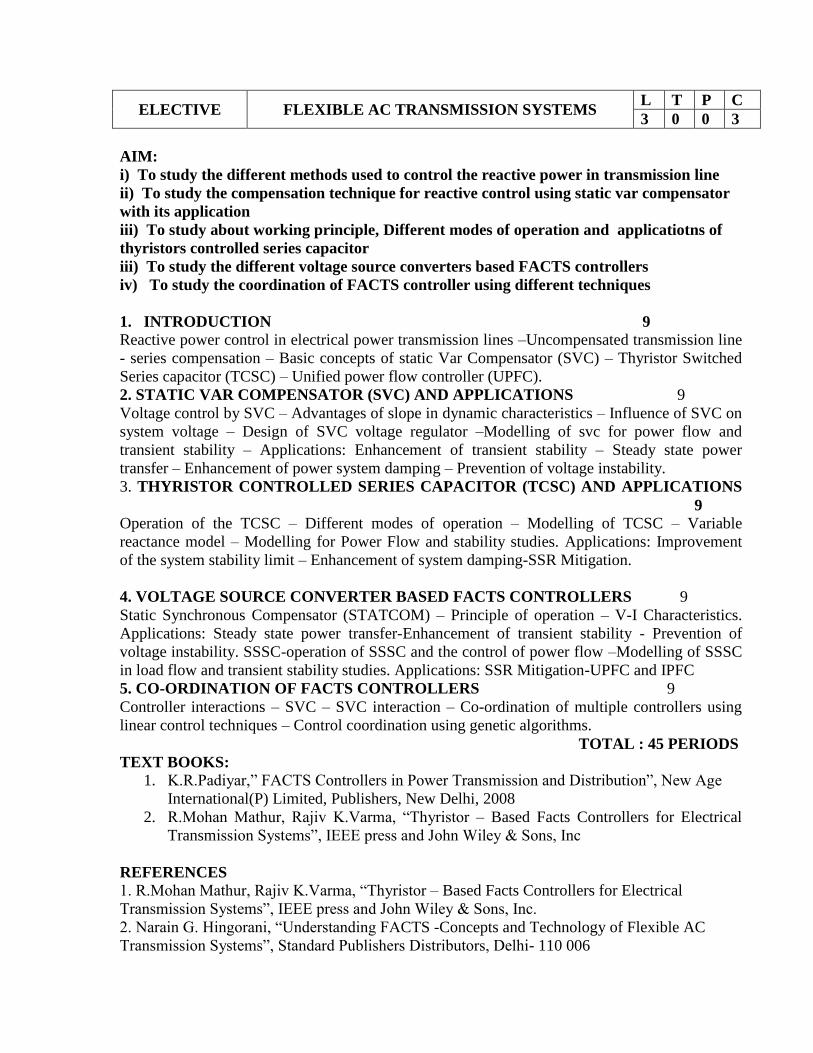
ELECTIVE FLEXIBLE AC TRANSMISSION SYSTEMS L T P C
3 0 0 3
AIM:
i) To study the different methods used to control the reactive power in transmission line
ii) To study the compensation technique for reactive control using static var compensator
with its application
iii) To study about working principle, Different modes of operation and applicatiotns of
thyristors controlled series capacitor
iii) To study the different voltage source converters based FACTS controllers
iv) To study the coordination of FACTS controller using different techniques
1. INTRODUCTION 9
Reactive power control in electrical power transmission lines –Uncompensated transmission line
- series compensation – Basic concepts of static Var Compensator (SVC) – Thyristor Switched
Series capacitor (TCSC) – Unified power flow controller (UPFC).
2. STATIC VAR COMPENSATOR (SVC) AND APPLICATIONS 9
Voltage control by SVC – Advantages of slope in dynamic characteristics – Influence of SVC on
system voltage – Design of SVC voltage regulator –Modelling of svc for power flow and
transient stability – Applications: Enhancement of transient stability – Steady state power
transfer – Enhancement of power system damping – Prevention of voltage instability.
3. THYRISTOR CONTROLLED SERIES CAPACITOR (TCSC) AND APPLICATIONS
9
Operation of the TCSC – Different modes of operation – Modelling of TCSC – Variable
reactance model – Modelling for Power Flow and stability studies. Applications: Improvement
of the system stability limit – Enhancement of system damping-SSR Mitigation.
4. VOLTAGE SOURCE CONVERTER BASED FACTS CONTROLLERS 9
Static Synchronous Compensator (STATCOM) – Principle of operation – V-I Characteristics.
Applications: Steady state power transfer-Enhancement of transient stability - Prevention of
voltage instability. SSSC-operation of SSSC and the control of power flow –Modelling of SSSC
in load flow and transient stability studies. Applications: SSR Mitigation-UPFC and IPFC
5. CO-ORDINATION OF FACTS CONTROLLERS 9
Controller interactions – SVC – SVC interaction – Co-ordination of multiple controllers using
linear control techniques – Control coordination using genetic algorithms.
TOTAL : 45 PERIODS
TEXT BOOKS:
1. K.R.Padiyar,” FACTS Controllers in Power Transmission and Distribution”, New Age
International(P) Limited, Publishers, New Delhi, 2008
2. R.Mohan Mathur, Rajiv K.Varma, “Thyristor – Based Facts Controllers for Electrical
Transmission Systems”, IEEE press and John Wiley & Sons, Inc
REFERENCES
1. R.Mohan Mathur, Rajiv K.Varma, “Thyristor – Based Facts Controllers for Electrical
Transmission Systems”, IEEE press and John Wiley & Sons, Inc.
2. Narain G. Hingorani, “Understanding FACTS -Concepts and Technology of Flexible AC
Transmission Systems”, Standard Publishers Distributors, Delhi- 110 006

3. K.R.Padiyar,” FACTS Controllers in Power Transmission and Distribution”, New Age
International(P) Limited, Publishers, New Delhi, 2008
4. A.T.John, “Flexible A.C. Transmission Systems”, Institution of Electrical and Electronic
Engineers (IEEE), 1999.
5. V.K.Sood,HVDC and FACTS controllers – Applications of Static Converters in Power
System, APRIL 2004 , Kluwer Academic Publishers.
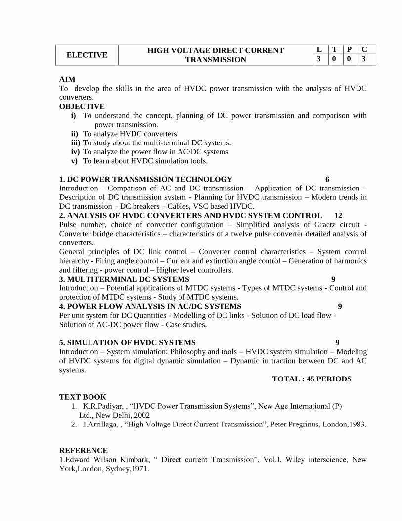
ELECTIVE HIGH VOLTAGE DIRECT CURRENT
TRANSMISSION
L T P C
3 0 0 3
AIM
To develop the skills in the area of HVDC power transmission with the analysis of HVDC
converters.
OBJECTIVE
i) To understand the concept, planning of DC power transmission and comparison with
power transmission.
ii) To analyze HVDC converters
iii) To study about the multi-terminal DC systems.
iv) To analyze the power flow in AC/DC systems
v) To learn about HVDC simulation tools.
1. DC POWER TRANSMISSION TECHNOLOGY 6
Introduction - Comparison of AC and DC transmission – Application of DC transmission –
Description of DC transmission system - Planning for HVDC transmission – Modern trends in
DC transmission – DC breakers – Cables, VSC based HVDC.
2. ANALYSIS OF HVDC CONVERTERS AND HVDC SYSTEM CONTROL 12
Pulse number, choice of converter configuration – Simplified analysis of Graetz circuit -
Converter bridge characteristics – characteristics of a twelve pulse converter detailed analysis of
converters.
General principles of DC link control – Converter control characteristics – System control
hierarchy - Firing angle control – Current and extinction angle control – Generation of harmonics
and filtering - power control – Higher level controllers.
3. MULTITERMINAL DC SYSTEMS 9
Introduction – Potential applications of MTDC systems - Types of MTDC systems - Control and
protection of MTDC systems - Study of MTDC systems.
4. POWER FLOW ANALYSIS IN AC/DC SYSTEMS 9
Per unit system for DC Quantities - Modelling of DC links - Solution of DC load flow -
Solution of AC-DC power flow - Case studies.
5. SIMULATION OF HVDC SYSTEMS 9
Introduction – System simulation: Philosophy and tools – HVDC system simulation – Modeling
of HVDC systems for digital dynamic simulation – Dynamic in traction between DC and AC
systems.
TOTAL : 45 PERIODS
TEXT BOOK
1. K.R.Padiyar, , “HVDC Power Transmission Systems”, New Age International (P)
Ltd., New Delhi, 2002
2. J.Arrillaga, , “High Voltage Direct Current Transmission”, Peter Pregrinus, London,1983.
REFERENCE
1.Edward Wilson Kimbark, “ Direct current Transmission”, Vol.I, Wiley interscience, New
York,London, Sydney,1971.
2. P. Kundur, “Power System Stability and Control”, McGraw-Hill, 1993.
3. Erich Uhlmann, “ Power Transmission by Direct Current”, BS Publications, 2004.
4. V.K.Sood,HVDC and FACTS controllers – Applications of Static Converters in

ELECTIVE INFORMATION SECURITY L T P C
3 0 0 3
AIM
To study the critical need for ensuring Information Security in Organizations
OBJECTIVES
1. To understand the basics of Information Security
2. To know the legal, ethical and professional issues in Information Security
3. To know the aspects of risk management
4. To become aware of various standards in this area
5. To know the technological aspects of Information Security
UNIT 1 INTRODUCTION 9
History, What is Information Security?, Critical Characteristics of Information, NSTISSC Security
Model, Components of an Information System, Securing the Components, Balancing Security and
Access, The SDLC, The Security SDLC
UNIT II SECURITY INVESTIGATION 9
Need for Security, Business Needs, Threats, Attacks, Legal, Ethical and Professional Issues
UNIT III SECURITY ANALYSIS 9
Risk Management: Identifying and Assessing Risk, Assessing and Controlling Risk
UNIT IV LOGICAL DESIGN 9
Blueprint for Security, Information Security Poicy, Standards and Practices, ISO 17799/BS
7799, NIST Models, VISA International Security Model, Design of Security Architecture,
Planning for Continuity
UNIT V PHYSICAL DESIGN 9
Security Technology, IDS, Scanning and Analysis Tools, Cryptography, Access Control
Devices, Physical Security, Security and Personnel
TOTAL : 45
TEXT BOOK
1. Michael E Whitman and Herbert J Mattord, “Principles of Information Security”, Vikas
Publishing House, New Delhi, 2003
REFERENCES
1. Micki Krause, Harold F. Tipton, “ Handbook of Information Security Management”, Vol
1-3 CRC Press LLC, 2004.
2. Stuart Mc Clure, Joel Scrambray, George Kurtz, “Hacking Exposed”, Tata McGraw-Hill,
2003
3. Matt Bishop, “ Computer Security Art and Science”, Pearson/PHI, 2002.
ELECTIVE INTELLIGENT CONTROLLERS L T P C
3 0 0 3
UNIT I INTRODUCTION 9
Approaches to intelligent control. Architecture for intelligent control. Symbolic reasoning
system, rule-based systems, the AI approach. Knowledge representation. Expert systems.
UNIT II ARTIFICIAL NEURAL NETWORKS 9
Concept of Artificial Neural Networks and its basic mathematical model, McCulloch Pitts
neuron model, simple perceptron, Adaline and Madaline, Feed-forward Multilayer Perceptron.
Learning and Training the neural network. Data Processing: Scaling, Fourier transformation,
principal-component analysis and wavelet transformations. Hopfield network, Self-organizing
network and Recurrent network. Neural Network based controller
UNIT III GENETIC ALGORITHM 9
Basic concept of Genetic algorithm and detail algorithmic steps, adjustment of free parameters.
Solution of typical control problems using genetic algorithm. Concept on some other search
techniques like tabu search and ant-colony search techniques for solving optimization problems.
UNIT IV FUZZY LOGIC SYSTEM 9
Introduction to crisp sets and fuzzy sets, basic fuzzy set operation and approximate reasoning.
Introduction to fuzzy logic modeling and control. Fuzzification, inferencing and defuzzification.
Fuzzy knowledge and rule bases. Fuzzy modeling and control schemes for nonlinear systems.
Self-organizing fuzzy logic control. Fuzzy logic control for nonlinear time-delay system.
UNIT V APPLICATIONS 9
GA application to power system optimisation problem, Case studies: Identification and control
of linear and nonlinear dynamic systems using Matlab-Neural Network toolbox. Stability
analysis of Neural-Network interconnection systems. Implementation of fuzzy logic controller
using Matlab fuzzy-logic toolbox. Stability analysis of fuzzy control systems.
TOTAL HOURS: 45
TEXT BOOKS
1. Padhy.N.P.(2005), Artificial Intelligence and Intelligent System, Oxford University Press.
2. KOSKO,B. "Neural Networks And Fuzzy Systems", Prentice-Hall of India Pvt. Ltd., 1994.

ELECTIVE MICRO ELECTRO MECHANICAL SYSTEMS L T P C
3 0 0 3
AIM
The aim of this course is to educate the student to understand the fundamentals of Micro
Electro Mechanical Systems (MEMS)
OBJECTIVES
To integrate the knowledge of semiconductors and solid mechanics to fabricate
MEMS devices.
To understand the rudiments of Micro fabrication techniques.
To identify and understand the various sensors and actuators
To study the different materials used for MEMS
To Study the applications of MEMS to disciplines beyond Electrical and
Mechanical engineering.
UNIT I INTRODUCTION 9
Intrinsic Characteristics of MEMS – Energy Domains and Transducers- Sensors and Actuators –
Introduction to Microfabrication - Silicon based MEMS processes – New Materials – Review of
Electrical and Mechanical concepts in MEMS – Semiconductor devices – Stress and strain
analysis – Flexural beam bending- Torsional deflection.
UNIT II SENSORS AND ACTUATORS-I 9
Electrostatic sensors – Parallel plate capacitors – Applications – Interdigitated Finger capacitor –
Comb drive devices – Thermal Sensing and Actuation – Thermal expansion – Thermal couples –
Thermal resistors – Applications – Magnetic Actuators – Micromagnetic components – Case
studies of MEMS in magnetic actuators.
UNIT III SENSORS AND ACTUATORS-II 9
Piezoresistive sensors – Piezoresistive sensor materials - Stress analysis of mechanical elements
–Applications to Inertia, Pressure, Tactile and Flow sensors – Piezoelectric sensors and actuators
–piezoelectric effects – piezoelectric materials – Applications to Inertia , Acoustic, Tactile and
Flow sensors.
UNIT IV MICROMACHINING 9
Silicon Anisotropic Etching – Anisotrophic Wet Etching – Dry Etching of Silicon – Plasma
Etching –Deep Reaction Ion Etching (DRIE) – Isotropic Wet Etching – Gas Phase Etchants –
Case studies -Basic surface micromachining processes – Structural and Sacrificial Materials –
Acceleration of sacrificial Etch – Striction and Antistriction methods – Assembly of 3D MEMS
– Foundry process
UNIT V POLYMER AND OPTICAL MEMS 9
Polymers in MEMS– Polimide - SU-8 - Liquid Crystal Polymer (LCP) – PDMS – PMMA –
Parylene –Fluorocarbon - Application to Acceleration, Pressure, Flow and Tactile sensors-
Optical MEMS –Lenses and Mirrors – Actuators for Active Optical MEMS.
TOTAL : 45 PERIODS
TEXT BOOK:
1. Chang Liu, ‘Foundations of MEMS’, Pearson Education Inc., 2006.

REFERENCES:
1. Nadim Maluf, “ An introduction to Micro electro mechanical system design”, Artech
House, 2000.
2. Mohamed Gad-el-Hak, editor, “ The MEMS Handbook”, CRC press Baco Raton, 2000
3. Tai Ran Hsu, “MEMS & Micro systems Design and Manufacture” Tata McGraw Hill,
New Delhi, 2002.
4. Julian w. Gardner, Vijay k. varadan, Osama O.Awadelkarim,micro sensors mems and
smart devices, John Wiley & son LTD,2002
5. James J.Allen, micro electro mechanical system design, CRC Press published in 2005
ELECTIVE POWER ELECTRONICS FOR RENEWABLE
ENERGY SYSTEM
L T P C
3 0 0 3
1. INTRODUCTION 9 Environmental aspects of electric energy conversion: impacts of renewable energy generation on
environment (cost-GHG Emission) - Qualitative study of different renewable energy resources:
Solar, wind, ocean, Biomass, Fuel cell, Hydrogen energy systems and hybrid renewable energy
systems.
2. ELECTRICAL MACHINES FOR RENEWABLE ENERGY CONVERSION 9
Review of reference theory fundamentals-principle of operation and analysis: IG, PMSG, SCIG
and DFIG.
3. POWER CONVERTERS 9 Solar: Block diagram of solar photo voltaic system -Principle of operation: line commutated
converters (inversion-mode) - Boost and buck-boost converters- selection Of inverter, battery
sizing, array sizing Wind: three phase AC voltage controllers- AC-DC-AC converters:
uncontrolled rectifiers, PWM Inverters, Grid Interactive Inverters-matrix converters.
4. ANALYSIS OF WIND AND PV SYSTEMS 9 Stand alone operation of fixed and variable speed wind energy conversion systems and solar
system-Grid connection Issues -Grid integrated PMSG and SCIG Based WECSGrid Integrated
solar system
5. HYBRID RENEWABLE ENERGY SYSTEMS 9
Need for Hybrid Systems- Range and type of Hybrid systems- Case studies of Wind PV
Maximum Power Point Tracking (MPPT).
TOTAL : 45 PERIODS
REFERENCES:
1. Rashid .M. H “power electronics Hand book”, Academic press, 2001.
2. Rai. G.D, “Non conventional energy sources”, Khanna publishes, 1993.
3. Rai. G.D,” Solar energy utilization”, Khanna publishes, 1993.
4. Gray, L. Johnson, “Wind energy system”, prentice hall linc, 1995.
5. Non-conventional Energy sources B.H.Khan Tata McGraw-hill Publishing Company, New
Delhi

ELECTIVE POWER QUALITY L T P C
3 0 0 3
AIM: To study the various issues affecting power quality, their production, monitoring and
suppression.
OBJECTIVES: i. To study the production of voltages sags, overvoltage's and harmonics and methods of control.
ii. To study various methods of power quality monitoring.
UNIT I INTRODUCTION TO POWER QUALITY 9
Terms and definitions: Overloading - under voltage - over voltage. Concepts of transients - short
duration variations such as interruption - long duration variation such as sustained interruption.
Sags and swells - voltage sag - voltage swell - voltage imbalance - voltage fluctuation - power
frequency variations. International standards of power quality. Computer Business Equipment
Manufacturers Associations (CBEMA) curve.
UNIT II VOLTAGE SAGS AND INTERRUPTIONS 9 Sources of sags and interruptions - estimating voltage sag performance. Thevenin’s equivalent
source - analysis and calculation of various faulted condition. Voltage sag due to induction motor
starting. Estimation of the sag severity - mitigation of voltage sags, active series compensators.
Static transfer switches and fast transfer switches.
UNIT III OVERVOLTAGES 9
Sources of over voltages - Capacitor switching – lightning - ferro resonance. Mitigation of
voltage swells - surge arresters - low pass filters - power conditioners. Lightning protection –
shielding - line arresters - protection of transformers and cables. An introduction to computer
analysis tools for transients, PSCAD and EMTP.
UNIT IV HARMONICS 9
Harmonic sources from commercial and industrial loads, locating harmonic sources. Power
system response characteristics - Harmonics Vs transients. Effect of harmonics - harmonic
distortion -voltage and current distortion - harmonic indices - inter harmonics – resonance.
Harmonic distortion evaluation - devices for controlling harmonic distortion - passive and active
filters. IEEE and IEC standards.
UNIT V POWER QUALITY MONITORING 9
Monitoring considerations - monitoring and diagnostic techniques for various power quality
problems - modeling of power quality (harmonics and voltage sag) problems by mathematical
simulation tools - power line disturbance analyzer – quality measurement equipment - harmonic /
spectrum analyzer - flicker meters - disturbance analyzer. Applications of expert systems for
power quality monitoring.
TOTAL : 45 PERIODS
TEXT BOOK: 1. Roger. C. Dugan, Mark. F. McGranagham, Surya Santoso, H.Wayne Beaty, ‘Electrical Power
Systems Quality’ McGraw Hill,2003.(For Chapters1,2,3, 4 and 5)
REFERENCES:
1. G.T. Heydt, 'Electric Power Quality', 2nd Edition. (West Lafayette, IN, Stars in a Circle
Publications, 1994). (For Chapter 1, 2, 3 and 5)
2. M.H.J Bollen, ‘Understanding Power Quality Problems: Voltage Sags and Interruptions’,
(New York: IEEE Press, 1999). (For Chapters 1, 2, 3 and 5)
3. J. Arrillaga, N.R. Watson, S. Chen, 'Power System Quality Assessment', (New York: Wiley,
1999). (For Chapters 1, 2, 3, 4 and 5)
4. PSCAD User Manual
ELECTIVE POWER SYSTEM DYNAMICS L T P C
3 0 0 3
AIM
To become familiar with the modelling of components and system for carrying out transient and
dynamic stability analysis of large scale power system.
OBJECTIVES 1. To study detailed modeling of synchronous machine and its excitation and speed-governing
controllers.
2. To study transient stability simulation of multi machine power system.
3. To study small signal stability analysis of a single-machine infinite bus system with excitation
system and power system stabilizer.
INTRODUCTION 9
Concept and importance of stability in power system operation and design; distinction between
transient and dynamic stability; complexity of stability problem in large system: Need for
reduced models; stability of interconnected systems.
MACHINE MODELLING 9
Park’s transformation; flux linkage equations, current space model, per unit conversion,
normalizing the equations, equivalent circuit, flux linkage state space model, sub transient and
transient inductances and time constants. Simplified models (one axis and constant flux linkage),
steady state equations and phasor diagrams.
MACHINE CONTROLLERS 9
Exciter and voltage regulators, function of excitation systems, types of excitation systems,
typical excitation system configuration, block diagram and state space representation of IEEE
type 1 excitation system, saturation function, stabilizing circuit. Function of speed governing
systems, block diagram and state space representation of IEEE mechanical hydraulic governor
and electrical hydraulic governors for hydro turbines and steam turbines.
TRANSIENT STABILITY 9
State equation for multimachine simulation with one axis model, transient stability simulation of
multimachine power system with one axis machine model including excitation system and speed
governing system using R-K method of fourth order (Gill’s technique), power system stabilizer.
DYNAMIC STABILITY 9
System response to small disturbances: Linear model of the unregulated synchronous machine
and its modes of oscillation, regulated synchronous machine, distribution of power impact,
linearization of the load equation for the one machine problem – Simplified linear model, effect
of excitation on dynamic stability, approximate system representation; supplementary stabilizing
signals, dynamic performance measure, small signal performance measures.
TOTAL HOURS: 45
TEXT BOOKS
1. P.M. Anderson and A.A.Fouad, Power System Control and Stability Galgotia Publications,
New Delhi, 2003.
2. P.Kundur, Power System Stability and Control, McGraw Hill Inc., USA, 1994.
REFERENCE BOOK
1. M.A.Pai and W.Sauer, Power System Dynamics and Stability, Pearson Education Asia, India,
2002.

ELECTIVE POWER SYSTEM PLANNING AND RELIABILITY L T P C
3 0 0 3
AIM:
To make students become familiar with power system operation and the various control
actions to be implemented on the power system for reliability
OBJECTIVES:
i) To introduce the students ves of power system
ii) To make the students learn the reliability stability analysis of generation in power system
iii) To make the students learn the reliability stability analysis of transmission in power
system
iv) To familiarize the students with the planning of expansion of power system
v) To introduce the students with the overview of planning of distribution system
UNIT I LOAD FORECASTING 9
Objectives of forecasting - Load growth patterns and their importance in planning - Load
forecasting Based on discounted multiple regression technique-Weather sensitive load
forecasting-Determination of annual forecasting-Use of AI in load forecasting.
UNIT II GENERATION SYSTEM RELIABILITY ANALYSIS 9
Probabilistic generation and load models- Determination of LOLP and expected value of demand
not served –Determination of reliability of iso and interconnected generation systems.
UNIT III TRANSMISSION SYSTEM RELIABILITY ANALYSIS 9
Deterministic contingency analysis-probabilistic load flow-Fuzzy load flow probabilistic
transmission system reliability analysis-Determination of reliability indices like LOLP and
expected value of demand not served.
UNIT IV EXPANSION PLANNING 9
Basic concepts on expansion planning-procedure followed for integrate transmission system
planning, current practice in India-Capacitor placer problem in transmission system and radial
distributions system.
UNIT V DISTRIBUTION SYSTEM PLANNING OVERVIEW 9
Introduction, sub transmission lines and distribution substations-Design primary and secondary
systems-distribution system protection and coordination of protective devices.
TOTAL : 45 PERIODS
TEXT BOOKS
1.Roy Billinton and Allan Ronald, “Power System Reliability.”
2.J.Endreny,”Reliability modeling in electric power systems”John Wiley & sons
REFERENCES
1. Proceeding of work shop on energy systems planning & manufacturing CI.
2. R.L .Sullivan, “ Power System Planning”,.
3. 4. Turan Gonen, Electric power distribution system Engineering ‘McGraw Hill,1986
ELECTIVE POWER SYSTEM TRANSIENTS L T P C
3 0 0 3
AIM
To review the over voltages (or) surges due to the phenomena of switching operations and
lighting discharge. Also to study propagation, reflection and refraction of these surges on the
equipments their impact on the power system grid.
OBJECTIVES
(i)To study the generation of switching transients and their control using circuit – theoretical
concept.
(ii)To study the mechanism of lighting strokes and the production of lighting surges.
(iii)To study the propagation, reflection and refraction of travelling waves.
(iv)To study the impact of voltage transients caused by faults, circuit breaker action, load
rejection on integrated power system.
(v)To study the over voltages faults and switching surges on integrated system.
UNIT I INTRODUCTION AND SURVEY 9
Review and importance of the study of transients - causes for transients. RL circuit transient with
sine wave excitation - double frequency transients – basic transforms of the RLC circuit
transients. Different types of power system transients - effect of transients on power systems –
role of the study of transients in system planning.
UNIT II SWITCHING TRANSIENTS 9
Over voltages due to switching transients - resistance switching and the equivalent circuit for
interrupting the resistor current - load switching and equivalent circuit - waveforms for transient
voltage across the load and the switch - normal and abnormal switching transients. Current
suppression - current chopping - effective equivalent circuit. Capacitance switching - effect of
source regulation - capacitance switching with a restrike, with multiple restrikes. Illustration for
multiple restriking transients – ferro resonance.
UNIT III LIGHTNING TRANSIENTS 9
Review of the theories in the formation of clouds and charge formation - rate of charging of
thunder clouds – mechanism of lightning discharges and characteristics of lightning strokes –
model for lightning stroke - factors contributing to good line design – protection using ground
wires - tower footing resistance - Interaction between lightning and power system.
UNIT IV TRAVELING WAVES ON TRANSMISSION LINE COMPUTATION OF
TRANSIENTS 9
Computation of transients - transient response of systems with series and shunt lumped
parameters and distributed lines. Traveling wave concept - step response - Bewely’s lattice
diagram - standing waves and natural frequencies - reflection and refraction of travelling waves.
UNIT V TRANSIENTS IN INTEGRATED POWER SYSTEM 9
The short line and kilometric fault - distribution of voltages in a power system – Line dropping
and load rejection - voltage transients on closing and reclosing lines – over voltage induced by
faults - switching surges on integrated system. Qualitative application of EMTP for transient
computation.
TOTAL HOURS : 45
TEXT BOOKS
1. Allan Greenwood, ‘Electrical Transients in Power Systems’, Wiley Interscience, New York,
2nd edition 1991.

2. R.D.Begamudre, ‘Extra High Voltage AC Transmission Engineering’, Wiley Eastern Limited,
1986.
REFERENCE BOOKS
1. M.S.Naidu and V.Kamaraju, ‘High Voltage Engineering’, Tata McGraw Hill, 2nd edition,
2000.

ELECTIVE ROBOTICS AND AUTOMATION L T P C
3 0 0 3
AIM
To provide comprehensive knowledge of robotics in the design, analysis and control point of
view.
OBJECTIVES
To study the various parts of robots and fields of robotics.
To study the various kinematics and inverse kinematics of robots.
To study the Euler, Lagrangian formulation of Robot dynamics.
To study the trajectory planning for robot.
To study the control of robots for some specific applications.
UNIT I BASIC CONCEPTS 9
Definition and origin of robotics – different types of robotics – various generations of robots –
degrees of freedom – Asimov’s laws of robotics – dynamic stabilization of robots.
UNIT II POWER SOURCES AND SENSORS 9
Hydraulic, pneumatic and electric drives – determination of HP of motor and gearing ratio –
variable speed arrangements – path determination – micro machines in robotics – machine vision
– ranging – laser – acoustic – magnetic, fiber optic and tactile sensors.
UNIT III MANIPULATORS, ACTUATORS AND GRIPPERS 9
Construction of manipulators – manipulator dynamics and force control – electronic and
pneumatic manipulator control circuits – end effectors – U various types of grippers – design
considerations.
UNIT IV KINEMATICS AND PATH PLANNING 9
Solution of inverse kinematics problem – multiple solution jacobian work envelop – hill
climbing techniques – robot programming languages
UNIT V CASE STUDIES 9
Mutiple robots – machine interface – robots in manufacturing and non- manufacturing
applications – robot cell design – selection of robot.
TOTAL : 45 PERIODS
TEXT BOOKS
1. Mikell P. Weiss G.M., Nagel R.N., Odraj N.G., Industrial Robotics, McGraw-Hill Singapore,
1996.
2. Ghosh, Control in Robotics and Automation: Sensor Based Integration, Allied Publishers,
Chennai, 1998.
REFERENCES
1. Deb.S.R., Robotics technology and flexible Automation, John Wiley, USA 1992.
2. Asfahl C.R., Robots and manufacturing Automation, John Wiley, USA 1992.
3. Klafter R.D., Chimielewski T.A., Negin M., Robotic Engineering – An integrated approach,
Prentice Hall of India, New Delhi, 1994.
4. Mc Kerrow P.J. Introduction to Robotics, Addison Wesley, USA, 1991.
5. Issac Asimov I Robot, Ballantine Books, New York, 1986.
ELECTIVE SPECIAL ELECTRICAL MACHINES L T P C
3 0 0 3
OBJECTIVES:
(i) Provide the concept of construction, operating principle and characteristics of
synchronous reluctance motor, stepper motor and switched reluctance motor..
(ii) Give basic knowledge about the principle of operation, analysis, emf and torque
equation, and control of permanent magnet synchronous motors and brushless DC
motors
UNIT I SYNCHRONOUS RELUCTANCE MOTORS 9
Constructional features – Types – Axial and Radial flux motors – Operating principles –
Variable Reluctance and Hybrid Motors – SYNREL Motors – Voltage and Torque Equations -
Phasor diagram - Characteristics.
UNIT II STEPPING MOTORS 9
Constructional features – Principle of operation – Variable reluctance motor – Hybrid motor –
Single and multi stack configurations – Torque equations – Modes of excitations –
Characteristics – Drive circuits – Microprocessor control of stepping motors – Closed loop
control.
UNIT III SWITCHED RELUCTANCE MOTORS 9
Constructional features – Rotary and Linear SRMs - Principle of operation – Torque production
– Steady state performance prediction- Analytical method -Power Converters and their
controllers – Methods of Rotor position sensing – Sensorless operation – Closed loop control of
SRM - Characteristics.
UNIT IV PERMANENT MAGNET BRUSHLESS D.C. MOTORS 9
Permanent Magnet materials – Magnetic Characteristics – Permeance coefficient - Principle of
operation – Types – Magnetic circuit analysis – EMF and torque equations – Commutation -
Power controllers – Motor characteristics and control.
UNIT V PERMANENT MAGNET SYNCHRONOUS MOTORS 9
Principle of operation – Ideal PMSM – EMF and Torque equations – Armature reaction MMF –
Synchronous Reactance – Sinewave motor with practical windings - Phasor diagram
Torque/speed characteristics - Power controllers - Converter Volt-ampere requirements.
TOTAL HOURS: 45
TEXT BOOKS
1. T.J.E. Miller, ‘Brushless Permanent Magnet and Reluctance Motor Drives’, Clarendon Press,
Oxford, 1989.
2. T. Kenjo, ‘Stepping Motors and Their Microprocessor Controls’, Clarendon Press London,
1984.
REFERENCE BOOKS
1. R.Krishnan, ‘Switched Reluctance Motor Drives – Modeling, Simulation, Analysis, Design
and Application’, CRC Press, New York, 2001.
2. P.P. Aearnley, ‘Stepping Motors – A Guide to Motor Theory and Practice’, Peter Perengrinus,
London, 1982.
3. T. Kenjo and S. Nagamori, ‘Permanent Magnet and Brushless DC Motors’, Clarendon Press,
London, 1988.
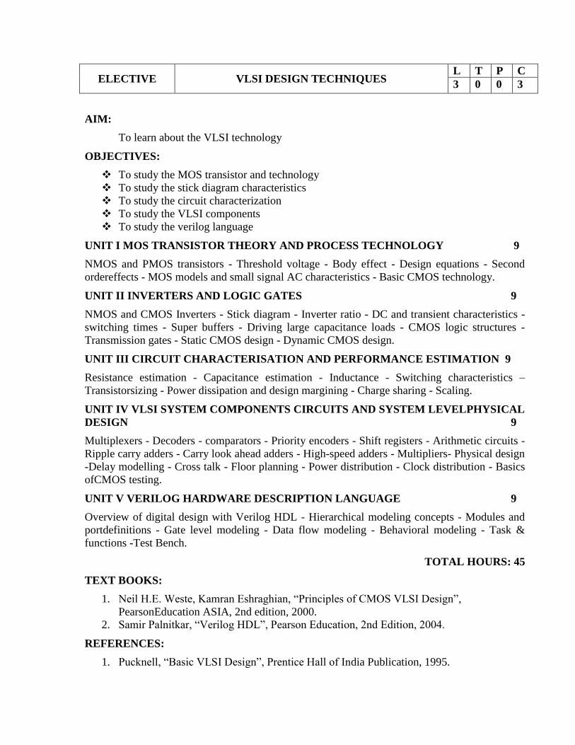
ELECTIVE VLSI DESIGN TECHNIQUES L T P C
3 0 0 3
AIM:
To learn about the VLSI technology
OBJECTIVES:
To study the MOS transistor and technology
To study the stick diagram characteristics
To study the circuit characterization
To study the VLSI components
To study the verilog language
UNIT I MOS TRANSISTOR THEORY AND PROCESS TECHNOLOGY 9
NMOS and PMOS transistors - Threshold voltage - Body effect - Design equations - Second
ordereffects - MOS models and small signal AC characteristics - Basic CMOS technology.
UNIT II INVERTERS AND LOGIC GATES 9
NMOS and CMOS Inverters - Stick diagram - Inverter ratio - DC and transient characteristics -
switching times - Super buffers - Driving large capacitance loads - CMOS logic structures -
Transmission gates - Static CMOS design - Dynamic CMOS design.
UNIT III CIRCUIT CHARACTERISATION AND PERFORMANCE ESTIMATION 9
Resistance estimation - Capacitance estimation - Inductance - Switching characteristics –
Transistorsizing - Power dissipation and design margining - Charge sharing - Scaling.
UNIT IV VLSI SYSTEM COMPONENTS CIRCUITS AND SYSTEM LEVELPHYSICAL
DESIGN 9
Multiplexers - Decoders - comparators - Priority encoders - Shift registers - Arithmetic circuits -
Ripple carry adders - Carry look ahead adders - High-speed adders - Multipliers- Physical design
-Delay modelling - Cross talk - Floor planning - Power distribution - Clock distribution - Basics
ofCMOS testing.
UNIT V VERILOG HARDWARE DESCRIPTION LANGUAGE 9
Overview of digital design with Verilog HDL - Hierarchical modeling concepts - Modules and
portdefinitions - Gate level modeling - Data flow modeling - Behavioral modeling - Task &
functions -Test Bench.
TOTAL HOURS: 45
TEXT BOOKS:
1. Neil H.E. Weste, Kamran Eshraghian, “Principles of CMOS VLSI Design”,
PearsonEducation ASIA, 2nd edition, 2000.
2. Samir Palnitkar, “Verilog HDL”, Pearson Education, 2nd Edition, 2004.
REFERENCES:
1. Pucknell, “Basic VLSI Design”, Prentice Hall of India Publication, 1995.

2. Eugene D. Fabricius, “Introduction to VLSI Design”, McGraw Hill International
Editions,1990.
3. Bhasker J., “A Verilog HDL Primer”, 2nd Edition, B.S. Publications, 2001.
4. John P. Uyemura, “Introduction to VLSI Circuits and Systems”, John Wiley & Sons,
Inc.,2002.

ELECTIVE WIND ENERGY CONVERSION SYSTEMS L T P C
3 0 0 3
OBJECTIVE:
(i)To learn the types of renewable energy sources
(ii)To study the application of electrical machines in renewable energy conversion
(iii)To study the application of semi conductor devices in renewable energy conversion
(iv)To analyze the grid integrated renewable energy.
(v)To introduce the hybrid renewable energy systems
UNIT I INTRODUCTION 9
Components of WECS-WECS schemes-Power obtained from wind-simple momentum theory-
Power coefficient-Sabinin’s theory-Aerodynamics of Wind turbine
UNIT II WIND TURBINES 9
HAWT-VAWT-Power developed-Thrust-Efficiency-Rotor selection-Rotor design
considerations-Tip speed ratio-No. of Blades-Blade profile-Power Regulation-yaw control-Pitch
angle control-stall control-Schemes for maximum power extraction.
UNIT III FIXED SPEED SYSTEMS 9
Generating Systems- Constant speed constant frequency systems -Choice of Generators-
Deciding factors-Synchronous Generator-Squirrel Cage Induction Generator- Model of Wind
Speed- Model wind turbine rotor - Drive Train model-Generator model for Steady state and
Transient stability analysis.
UNIT IV VARIABLE SPEED SYSTEMS 9
Need of variable speed systems-Power-wind speed characteristics-Variable speed constant
frequency systems synchronous generator- DFIG- PMSG -Variable speed generators modeling -
Variable speed variable frequency schemes.
UNIT V GRID CONNECTED SYSTEMS 9
Stand alone and Grid Connected WECS system-Grid connection Issues-Machine side & Grid
side controllers-WECS in various countries
TOTAL HOURS : 45
REFERENCE BOOKS
1. L.L.Freris “Wind Energy conversion Systems”, Prentice Hall, 1990
2. Ion Boldea, “Variable speed generators”, Taylor & Francis group, 2006.
3. E.W.Golding “The generation of Electricity by wind power”, Redwood burn Ltd.,
Trowbridge,1976.
4. S.Heir “Grid Integration of WECS”, Wiley 1998.