

Current Harmonics Testing - In Compliance Magazine
60
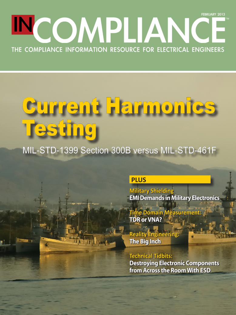
TM FEBRUARY 2013 THE COMPLIANCE INFORMATION RESOURCE FOR ELECTRICAL ENGINEERS Military Shielding EMI Demands in Military Electronics Time Domain Measurement: TDR or VNA? Reality Engineering: The Big Inch Technical Tidbits: Destroying Electronic Components from Across the Room With ESD PLUS Current Harmonics Testing MIL-STD-1399 Section 300B versus MIL-STD-461F
-
Upload
khangminh22 -
Category
Documents
-
view
2 -
download
0
Transcript of Current Harmonics Testing - In Compliance Magazine
TMFEBRUARY 2013
THE COMPLIANCE INFORMATION RESOURCE FOR ELECTRICAL ENGINEERS
Military ShieldingEMI Demands in Military Electronics
Time Domain Measurement: TDR or VNA?
Reality Engineering:The Big Inch
Technical Tidbits:Destroying Electronic Components from Across the Room With ESD
PLUS
Current Harmonics TestingMIL-STD-1399 Section 300B versus MIL-STD-461F
• Signal Integrity • EMC Management • Nanotechnology • Spectrum Management • EM Product Safety
• EM Interference and Environments • Shielding, Grounding, Bonding • EMP, Lightning, ESD • Transient Suppression • EMC Measurement
Learn the Leading Edge Info on:
For Event Details Visit: www.emc2013.org
Technology is advancing at a MILE HIGH pace and EMC testing is necessary to the success of this progress. No longer are the boundaries of EMC testing relegated to open area test sites, laboratories and text books; they are becoming part of our daily lives. The electric and hybrid
vehicles and the Smart Grid, are two big arenas where EMC plays a major role.
The EMC 2013 Symposium will include many topics to enhance your understanding of EMC, sharpen your design skills, and perfect your skills in dealing with EM phenomena. Join us in the Mile High City for a week of learning, collaboration and connecting
with industry peers and start your path into the world of EMC green.
emc_savethedate_ad2013_8.375x10.875.indd 1 8/17/12 1:02 PM

4 In Compliance February 2013 www.incompliancemag.com
In Compliance MagazineISSN 1948-8254 (print)ISSN 1948-8262 (online) is published by
Same Page Publishing Inc.531 King Street, Suite 5Littleton, MA 01460-1279tel: (978) 486-4684fax: (978) 486-4691
editorial staffeditor/publisher Lorie [email protected](978) 873-7777
production director Erin [email protected](978) 873-7756
contributing editor Mary Ann [email protected]
publishing staffdirector of sales Sharon [email protected](978) 873-7722
national sales manager Shellie [email protected](404) 991-8695
marketing communications specialist Heather [email protected](978) 873-7710
circulation manager Alexis [email protected](978) 873-7745
subscriptionsIn Compliance Magazine subscriptions are free to qualified subscribers in North America.
Subscriptions outside North America are $129 for 12 issues. The digital edition is free.
Please contact our circulation department at [email protected]
advertisingFor information about advertising contact:Sharon Smith at 978-873-7722 [email protected]
© Copyright 2013 Same Page Publishing, Inc. all rights reserved.
Contents may not be reproduced in any form without the prior consent of the publisher. While every attempt is made to provide accurate information, neither the publisher nor the authors accept any liability for errors or omissions.

www.incompliancemag.com February 2013 In Compliance 5
Volume 4 l Number 2
CONTENTS February 2013
DEPARTMENTS
8 News in Compliance
14 The iNARTE Informer
18 Mr. StaticAcupuncture and Atmospheric Ions
22 Reality EngineeringThe Big Inch
44 Technical TidbitsDestroying Electronic Components from Across the Room With ESD
48 EMC EducationThe View from the Chalkboard
5 1 Events
54 Business News
57 Authors
58 Product Showcase
FEATURES
32 Military ShieldingShielding to control EMI is a staple in modern electronics, playing a major role in military applications. Internal design practices can do much to control EMI in commercial and industrial electronics, but there is a limit to how much you can do. The EMI demands in military electronics are such that good internal design practices are inadequate - shielding is usually needed.
William D. Kimmel, PE and Daryl D. Gerke, PE
38 Time Domain Measurement: TDR or VNA?Nowadays, semiconductor technology requires that integrated circuits be interconnected at very high-speed data rates. Taking time domain measurements on the digital links can offer challenges for electronic engineers. The time domain reflectometer (TDR) and vector network analyzer (VNA) are the staple instruments to consider, each one having its pros and cons. Here we compare the responses of the two instruments when used for taking time domain measurements of typical signal integrity devices under test (DUTs): a stripline and a through hole on a FR-4 board.
by Vittorio Ricchiuti
Current Harmonics TestingMIL-STD-1399 Section 300B versus MIL-STD-461F
The extensive use of power electronics on vessels and offshore installations, especially on electric propulsion ships, has had a substantial impact on the power quality of the power distribution system. This article discusses the effects of current harmonic distortion created by commercial uninterruptible power supplies (UPS) being deployed in Naval shipboard applications.
Jeffrey Viel
26
April 9 - 11, 2013Westford Regency Inn & Conference Center
Westford, MA
REGISTRATION FORMELECTROMAGNETIC COMPATIBILITY ENGINEERING
April 9 - 11, 2013, Westford Regency Inn & Conference Center, Westford, MAFee: ___ $1,495 ___ $1,295 until 2/22/13Payment required prior to start of course.
Name: _________________________________________ PAYMENT METHOD
Title: __________________________________________ g Check g P.O. g AMEX
Company: ______________________________________ g Discover g Visa g MC
Address: ________________________________________ Card # __________________________________________________
City: _______________ State: ______ Zip: __________ Exp date: ____________ Security Code: ____________
Signature: _______________________________________________
Office Phone: _______________________ Fax: ______________________ E-Mail: ____________________________________
Call 973-992-1793, fax to 973-533-1442 or mail registration form to: Henry Ott Consultants, 48 Baker Road, Livingston, NJ 07039-2502. Make checks payable to Henry Ott Consultants.
EMC EXHIBITS AND EVENING RECEPTION: WEDNESDAY, APRIL 10, 2013Exhibitors:for information contact Sharon Smith - e-mail: [email protected] or call (978) 873-7722
HEN
RY O
TT
Henry W. Ott is President and Principal Consultant of Henry Ott Consultants (www.hottconsultants.com), an EMC training and consulting organization. He has literally “written the book” on the subject of EMC and is considered by many to be the nation’s leading EMC educator. He is the author of the popular EMC book Noise Reduction Techniques in Electronic Systems (1976, 1988). The book has sold over 65,000 copies and has been translated into six other languages. In addition to knowing his subject, Mr. Ott has the rare ability to communicate that knowledge to others.
Mr. Ott’s newly published (Aug. 2009) 872-page book, Electromagnetic Compatibility Engineering, is the most comprehensive book available on EMC. While still retaining the core information that made Noise Reduction Techniques an international success, this new book contains over 600 pages of new and revised material.
Prior to starting his own consulting company, Mr. Ott was with AT&T Bell Laboratories, Whippany, NJ for 30 years, where he was a Distinguished Member of the Technical Staff and a consultant on EMC.
Mr. Ott is a Life Fellow of the IEEE and has served the EMC Society in various capacities including: membership on the Board of Directors, Education Committee Chairman, Symposium Committee Chairman and Vice President of Conferences. He is also a member of the ESD Association and a NARTE certified ESD engineer. He is a past Distinguished Lecturer of the EMC Society, and lectures extensively on the subject of EMC.
CABLINGElectric and magnetic field coupling, crosstalk. Cable types: coax, twisted pair and ribbon cables. Cable shielding and terminations.
GROUNDING PRINCIPLESWhy do we ground? Ground systems: single point, multipoint, hybrid. Ground loops. Return current paths, split reference planes. EMC grounding philosophy. AC power grounds.
DIGITAL LAYOUT & GROUNDINGNoise sources, PCB layout, power distribution, ground grids, characteristics of ground planes. Decoupling capacitors: value, placement, resonance and limitations.
HIGH SPEED DIGITAL DECOUPLINGAlternative decoupling methods, use of distributed decoupling capacitance, power supply isolation, effect of paralleling capacitors. Embedded PCB capacitance.
DIFFERENTIAL-MODE EMISSIONRadiated emission mechanisms. Fourier spectrum. Methods of controlling differential-mode emission. Clock dithering. Cancellation techniques.
COMMON-MODE FILTERINGBasic C-M filter theory. Filter source and load impedances. Single and multi-stage filters. Ferrite chokes versus shunt capacitors. Effectiveness of various filter configurations. Filter mounting and layout.
TRANSMISSION LINESWhat is a transmission line? Transmission-line effects, transmission-line radiation, and matching. How currents flow on transmission lines. Series, shunt and AC terminations. Simulation.
MIXED SIGNAL PCBsDefining the problem, A/D converter requirements, return current paths, split ground planes, PCB partitioning, bridges & moats, routing discipline.
RF & TRANSIENT IMMUNITYRF immunity: circuits affected, PCB layout, audio rectification, RFI filters. Transient immunity: circuits affected, the three-prong approach, keeping transient energy out, protecting the sensitive devices, designing software/firmware for transient immunity.
CONDUCTED EMISSIONAC power line conducted emission models, switching power supplies, parasitic capacitance, layout. Common-mode and differential-mode conducted emission, common-mode chokes, saturation. Power line filters.
SHIELDINGAbsorption and reflection loss. Seams, joints, gaskets, slot antennas, and multiple apertures. Waveguides below cutoff, conductive coatings. Cabinet and enclosure design.
COURSE DATES/TIME: April 9 - 11, 2013Tuesday and Thursday 8:30 a.m. to 4:30 p.m.Wednesday 8:30 a.m. to 5:00 p.m.
COURSE LOCATION: Westford Regency Inn & Conference Center 219 Littleton Road, Westford, MA 01886
COURSE FEE: $1,495 ($1,295 until 2/22/13). Fee includes notes, textbook*, breakfast, luncheon and beverage breaks. Payment required prior to course. Hotel accommodations are NOT included.
CANCELLATION POLICY: You may cancel your registration up to two weeks prior to the course and receive a full refund. For cancellations received after this time there will be a $100 cancellation fee, or you can send a substitute, or use the registration for a future
course. No-shows will not receive a refund; however the seminar fee may be applied to a future course.
TO REGISTER: Call 973-992-1793, fax 973-533-1442 or mail the registration form.
HOTEL RESERVATIONS: Call the Westford Regency Inn at 978-692-8200. Room rates start at $115 per night (tax not included). Book by April 1 to receive this rate. Rate is based on availability. You must mention In Compliance Magazine when making reservations to get this special rate. The hotel is holding a limited block of rooms.
*Electromagnetic Compatibility Engineering, by Henry W. Ott
In this 3-day intensive course we’ll cover practical aspects of noise and interference control in electronic systems and provide a working knowledge of EMC principles. Ideas are illustrated with examples of actual case histories and mathematic complexity is kept to a minimum. Participants will gain knowledge needed to design electronic equipment compatible with the electromagnetic environment and in compliance with national and international EMC regulations.
CO
UR
SE C
ON
TEN
TR
EGIS
TRAT
ION
Feedback from recent participants“This is really a fantastic course. Everything is very practical, and I have a much more intuitive feel for what is important in EMC and why.”
“Very enjoyable presentation; passionate about subject, used good practical examples.”
“Henry is the best in EMC.”
“Probably the most useful technical seminar I have ever attended. Should have learned this 20 years ago.”
“Thank You. Your work is very valuable and your presentation style is refreshing!!”
“Really happy I flew all the way here.”
“Excellent course! Presented in a very understandable way, even for a mechanical engineer.”
“Should be required training for all engineers.”
“This is the best practical course available.”
“An excellent seminar presented by a pragmatic, knowledgeable and entertaining teacher.”
“This seminar exceeded by far my expectations, and my expectations were high already.”
Who Should AttendThis course is directed toward electrical engineers. However, mechanical engineers, reliability and standards engineers, technical managers, systems engineers, regulatory compliance engineers, technicians and others who need a working knowledge of electromagnetic compatibility engineering principles will also benefit from the course.
Presented by Henry Ott Consultantsin partnership with
Includes Henry Ott’s latest book!
Register by 2/22/13
and save $200!
Electromagnetic Compatibility Engineering
Join us for this 3-Day Intensive Course
presented by renowned EMC expert Henry Ott
a course in noise and interference control in electronic systems

8 In Compliance February 2013 www.incompliancemag.com
News in Compliance
New
s in
Com
plia
nce FCC News
online application that creates a 10-step plan designed to increase smartphone security. Security plans are customizable to meet the unique requirements of phones based on the currently most popular smartphone platforms. The Smartphone Security Checker also includes links to online tutorials to help consumers take the steps necessary to increase the security of their smartphones.
According to the Commission, there are 120 million Americans who own a
FCC Contemplates Rules for Text-to-911 Service
Acknowledging the widespread use of texting as a primary communications medium, the U.S. Federal Communications Commission (FCC) has proposed rules that would make it easier for citizens to send text messages to 911 emergency services.
In a Further Notice of Proposed Rulemaking issued in December 2012, the Commission would require all
The Commission’s action follows a voluntary pledge by Sprint Nextel, AT&T, T-Mobile and Verizon to provide text-to-911 service by not later than May 15, 2014, and is intended to solicit comment on whether all carriers and third-party message providers can offer comparable service within this time frame.
The Commission’s Further Notice of Proposed Rulemaking on Text-to-911 services is available at incompliancemag.com/news/1302_01.
Acknowledging the widespread use of texting as a primary communications medium, the FCC has
proposed rules that would make it easier for citizens to send text messages to 911 emergency services.
smartphone. However, less than 5% of smartphones in use have third-party security software installed, and fewer than 50% are password protected. With mobile security threats having increased more than 350% since 2010, the likelihood of being victim of a smartphone cyber crime is high.
The FCC’s Smartphone Security Checker is available at incompliancemag.com/news/1302_02.
wireless phone service carriers and certain providers of text messaging applications to enable customers to send 911 messages to those public safety answering points (PSAPs) that are equipped to receive them. The Commission notes that text-to-911 capabilities could provide an important alternative means of communication with emergency service personnel for those with hearing or speech disabilities, or in cases where a 911 voice call might endanger the caller.
FCC Releases “Smartphone Security Checker” to Protect Mobile Devices
The U.S. Federal Communications Commission (FCC) has implemented an online tool to help consumers protect their smartphones from mobile security threats.
The FCC’s new Smartphone Security Checker is a free and easy-to-use
DILBERT © 2009 Scott Adams. Used By permission of UNIVERSAL UCLICK. All rights reserved.

New
s in Compliance
FCC News
Commission’s forfeiture guidelines have established a base forfeiture amount of $40,000 for each instance of slamming. However, because of the egregious behavior by Preferred telemarketers in misrepresenting themselves to consumers, the Commission proposed tripling the base forfeiture amount in each instance of deception, resulting is a total proposed forfeiture of $1,440,000.
The complete text of the Commission’s Notice of Apparent Liability for Forfeiture against Preferred Long Distance is available at incompliancemag.com/news/1302_03.
FCC Proposes $1.4 Million Fine for Slamming
The U.S. Federal Communications Commission (FCC) has proposed a fine of more than a $1.4 million against a California-based telecommunications firm that allegedly changed the preferred long-distance telecommunications service of a group of consumers without authorization, a practice known as “slamming.”
In a Notice of Apparent Liability for Forfeiture issued in December 2012, the Commission proposed a fine of
$1,440,000 for Preferred Long Distance, Inc. of Encino, CA for switching telephone service of 14 consumers without authorization. In this particular instance, Preferred telemarketers allegedly represented themselves to 11 of those consumers as employees of their incumbent long-distance carrier, which the Commission found “deceptive” and “fraudulent.”
Section 258 of the Federal Communications Act prohibits carriers from changing a subscriber’s selection of telephone service providers without their explicit permission. The
TEST TOMORROW.TEST TOMORROW.TEST TOMORROW.
Amplifiers · Antennas · Audio Analyzers · CDNs
Current Probes · Complete Immunity Test Systems
EMI Receivers · Field Probes · ESD Guns · LISNs
Lightning Simulators · Preamplifiers · Spectrum Analyzers
Signal Generators · Transient Generators
SHIP TODAY.IEC61000 w MIL-STD-461 w DO160 w ISO7637 w Automotive w EFT/Surge w Ringwave w Emissions & Immunity
RENT EMC TEST SYSTEMS
Teseq · Haefely · Keytek · Narda
Solar · IFI · Amplifier Research
HV Technologies · FCC · NoiseKen
ETS-Lindgren · Rohde & Schwarz
Com-Power · Agilent · and more
Follow Us!
Call us today 888-544-ATEC (2832) Visit us on the web www.atecorp.com
The Knowledge. The Equipment. The Solution.
Advanced Test Equipment Rentals

10 In Compliance February 2013 www.incompliancemag.com
News in Compliance
New
s in
Com
plia
nce European Union News
The standard list for compliance with the eco-design requirements of standby and off-mode electric power consumption is available at incompliancemag.com/news/1302_06. The standards list for compliance with the eco-design requirements of electric motors is available at incompliancemag.com/news/1302_07.
EU Commission Updates Standards List for PPE Directive
The Commission of the European Union (EU) has an updated list of standards that can be used to demonstrate conformity with the essential requirements of its Directive 89/686/EEC concerning personal protective equipment.
For the purposes of the Directive, personal protective equipment (PPE) is defined as “any device or appliance designed to be worn or held by an individual for protection against one or more health and safety hazards.” Specifically excluded from the scope of the Directive is equipment designed specifically for private use (such as seasonal outdoor clothing), equipment for use by armed forces or law enforcement personnel, and equipment intended for the protection or rescue of individuals on vessels or aircraft.
The extensive list of CEN and Cenelec standards was published in December 2012 in the Official Journal of the European Union, and replaces all previously published standards lists for the Directive.
The complete updated standards list for the EU’s PPE Directive is available at incompliancemag.com/news/1302_08.
Updated Standards List Published for EU’s ATEX Directive
The Commission of the European Union (EU) has published an updated list of standards that can be used to demonstrate conformity with the essential requirements of its directive concerning equipment and protective systems intended for use in potentially explosive atmospheres.
The directive, 94/9/EC, which is also known as the ATEX Directive, applies to “machines, apparatus, fixed or mobile devices, control components and instrumentation…and detection or prevention systems which…are intended for the generation, transfer, storage, measurement, control and conversion of energy and/or the processing of material,” and “which are capable of causing an explosion through their own potential sources of ignition.”
The updated list of standards was published in November 2012 in the Official Journal of the European Union, and replaces all previously published standards lists for the ATEX Directive.
The complete list of standards can be viewed at incompliancemag.com/news/1302_04.
EU Sets Eco-Design Requirements for Directional Lamps, LEDs
The Commission of the European Union (EU) has issued a regulation implementing new energy efficiency requirements for directional lamps, light emitting diodes (LEDs) and related equipment.
The regulation, which was published in December 2012 in the Official Journal of the European Union, is considered
an implementation measure under the EU’s Eco-Design Directive, 2009/125/EC. That directive gives the Commission the authority to establish minimum efficiency standards for those “energy-related products representing significant volume of sales and trade, having significant environmental impact and presenting significant potential for improvement in terms of their environmental impact without entailing excessive costs.”
The new energy efficiency requirements for directional lamps and LEDs, which come into effect beginning in September 2013, are extensively detailed in Section 1 of Annex III of the regulation. Annex III also includes functionality requirements for various light categories as well as applicable product information requirements. Annex IV of the regulation details the procedure to be used by authorities in EU member states for verifying compliance with the regulation’s requirements.
The complete text of the Commission’s regulation regarding the eco-design of directional lamps and LEDs is available at incompliancemag.com/news/1302_05.
EU Commission Publishes Additional Eco-Design Related Standards Lists
The Commission of the European Union (EU) has published updated lists of standards that can be used to demonstrate conformity with its eco-design requirements for electric motors and the eco-design requirements applicable to electronic household and office equipment incorporating standby and off-mode electric power consumption features.
The standards lists were published in December 2012 in the Official Journal of the European Union.

rf/microwave instrumentation Other ar divisions: modular rf • receiver systems • ar europeUSA 215-723-8181. For an applications engineer, call 800-933-8181. In Europe, call ar United Kingdom 441-908-282766 • ar France 33-1-47-91-75-30 • ar Benelux 31-172-423-000
Copyright © 2013 AR. The orange stripe on AR products is Reg. U.S. Pat. & TM. Off.
www.arworld.us
ISO 9001:2008Certified
When it comes to the largest selection of Traveling Wave Tube (TWT) Amplifiers, AR has no equal. We cover a wider range of high-power, broadband amplifiers for your specific test application than any other brand.
CW models also have the capability to faithfully reproduce AM, FM, and pulse modulation input signals. Features that are included at no extra cost are our “Sleep mode” which prolongs the tube life, rugged construction for the rigorous treatment in test labs, modular supplies to reduce repair turn-around, and well thought out digital displays to help you monitor essential amplifier conditions.
So before you choose a look-alike traveling wave tube amplifier, examine all the features and benefits that come along at no extra charge with an AR amplifier. If you want a TWTA that will take you farther, you’ll choose the one with the AR logo on it … the company that stands behind our products with the global service and support that you demand.
To learn more, visit www.arworld.us or call us at 215-723-8181.
If You Can’t Find The Power You Need Here,
It Doesn’t Exist.
Traveling Wave Tube Amplifiers“T” Series–CW TWTA’s from 1 to 45 GHz. 15 to 2000 watts.
“TP” Series–Pulsed TWTA’s from 1 to 18 GHz. 1000 to 10,000 watts.
www.arworld.us/twta
InCompliance_Doesn'tExist.indd 1 12/19/12 9:52 PM

12 In Compliance February 2013 www.incompliancemag.com
News in Compliance
New
s in
Com
plia
nce UL Standards Update
UL 797: Electrical Metallic Tubing - SteelRevision dated December 21, 2012
UL 817: Standard for Cord Sets and Power-Supply CordsRevision dated December 20, 2012
UL 1004-3: Standard for Thermally Protected MotorsRevision dated December 18, 2012
UL 1417: Standard for Special Fuses for Radio- and Television- Type AppliancesRevision dated December 20, 2012
UL 4248-4: Fuseholders - Part 4: Class CCRevision dated December 21, 2012
UL 4248-5: Fuseholders - Part 5: Class GRevision dated December 21, 2012
UL 4248-6: Fuseholders - Part 6: Class HRevision dated December 21, 2012
UL 4248-9: Fuseholders - Part 9: Class KRevision dated December 21, 2012
UL 4248-11: Fuseholders - Part 11: Type C (Edison Base) and Type S Plug FuseRevision dated December 21, 2012
UL 4248-12: Fuseholders - Part 12: Class RRevision dated December 21, 2012
UL 4248-15: Fuseholders - Part 15: Class TRevision dated December 21, 2012
STANDARDSUL 879A: Standard for LED Sign and Sign Retrofit KitsNew Edition dated December 12, 2012
UL 1993: Self-Ballasted Lamps and Lamp AdaptersNew Edition dated December 4, 2012
UL 60335-2-40: Safety of Household and Similar Electrical Appliances, Part 2-40: Particular Requirements for Electrical Heat Pumps, Air-Conditioners and DehumidifiersNew Edition dated November 30, 2012
UL 746D: Standard for Polymeric Materials - Fabricated PartsNew Edition dated December 20, 2012
REVISIONSUL 250: Household Refrigerators and FreezersRevision dated December 7, 2012
UL 305: Standard for Panic HardwareRevision dated December 14, 2012
UL 471: Standard for Commercial Refrigerators and FreezersRevision dated December 3, 2012
UL 497A: Standard for Secondary Protectors for Communications CircuitsRevision dated December 13, 2012
UL 1559: Standard for Insect-Control Equipment - Electrocution TypeRevision dated December 14, 2012
UL 2079: Standard for Tests for Fire Resistance of Building Joint SystemsRevision dated December 12, 2012
UL 2202: Standard for Electric Vehicle (EV) Charging System EquipmentRevision dated December 14, 2012
UL 5085-1: Low Voltage Transformers - Part 1: General RequirementsRevision dated November 30, 2012
UL 5085-2: Low Voltage Transformers - Part 2: General Purpose TransformersRevision dated November 30, 2012
UL 5085-3: Low Voltage Transformers - Part 3: Class 2 and Class 3 TransformersRevision dated November 30, 2012
UL 47: Standard for Semiautomatic Fire Hose Storage DevicesRevision dated December 18, 2012
UL 401: Standard for Portable Spray Hose Nozzles for Fire-Protection Service
Revision dated December 18, 2012
UL 497B: Standard for Protectors for Data Communications and Fire-Alarm CircuitsRevision dated December 17, 2012
UL 497C: Standard for Protectors for Coaxial Communications CircuitsRevision dated December 21, 2012
UL 668: Standard for Hose Valves for Fire-Protection ServiceRevision dated December 18, 2012
Underwriters Laboratories has announced the availability of these standards and revisions. For additional information, please visit their website at www.ul.com.

www.incompliancemag.com February 2013 In Compliance 13
New
s in Compliance
CPSC News
photos of Khamenei, along with the text of his speeches and pronouncements. Khamenei’s Facebook page appears to be an officially authorized presentation, according to Reuters, and already has several thousand “likes.”
Publicity for Khamenei’s Facebook page is reportedly spread with a complemen-tary Twitter account, with tweets appar-ently coming from Twitter-savvy assis-tants in the Supreme Leader’s office.
Although blocked in Iran, social media sites are used by millions of Iranians who have found ways around government censorship mechanisms to access their favorite sites.
Company Recalls Christmas Trees for Fire Hazard
CKI Bethlehem Lights of Taunton, MA has voluntarily recalled about 15,500 of its artificially lit Christmas trees manufactured in China and sold through television retailer QVC.
According to information released by the U.S. Consumer Product Safety Commission (CPSC), the Christmas tree base can overheat, posing a fire hazard. QVC has reportedly received 30 reports of the tree base overheating, melting or smoking, but has not received any reports of injuries.
The recalled Christmas trees were sold through QVC from July through November 2011 for between $320 and $398, depending on the tree size.
Additional details about this recall are available at incompliancemag.com/news/1302_09.
Fire and Burn Hazard Lead to Cordless Drill Recall
Harbor Freight Tools of Camarillo, CA is recalling about 108,000 of its cordless drills manufactured in China.
The U.S. Consumer Product Safety Commission (CPSC) reports that the black trigger switch on the 19.2v cordless drill model can overheat, posing a fire and burn hazard to consumers. Harbor Freight says that it has received one report of a drill overheating and burning through the handle of the unit, which resulted in minor burn to a consumer.
The recalled drills were sold at Harbor Freight Tools stores nationwide, and through the company’s website, from April 2008 through May 2012 for between $27 and $30.
More information about this recall is available at incompliancemag.com/news/1302_10.
Iranian Cleric on Facebook (from our “You Can’t Make This Stuff Up” File)
Although access to Facebook and Twitter are officially blocked in Iran, it seems that the country’s top leaders still think it’s important to have a social media presence.
Reuters reports that Iranian Supreme Leader Ayatollah Ali Khamenei now has an official Facebook page, which displays
14 In Compliance February 2013 www.incompliancemag.com
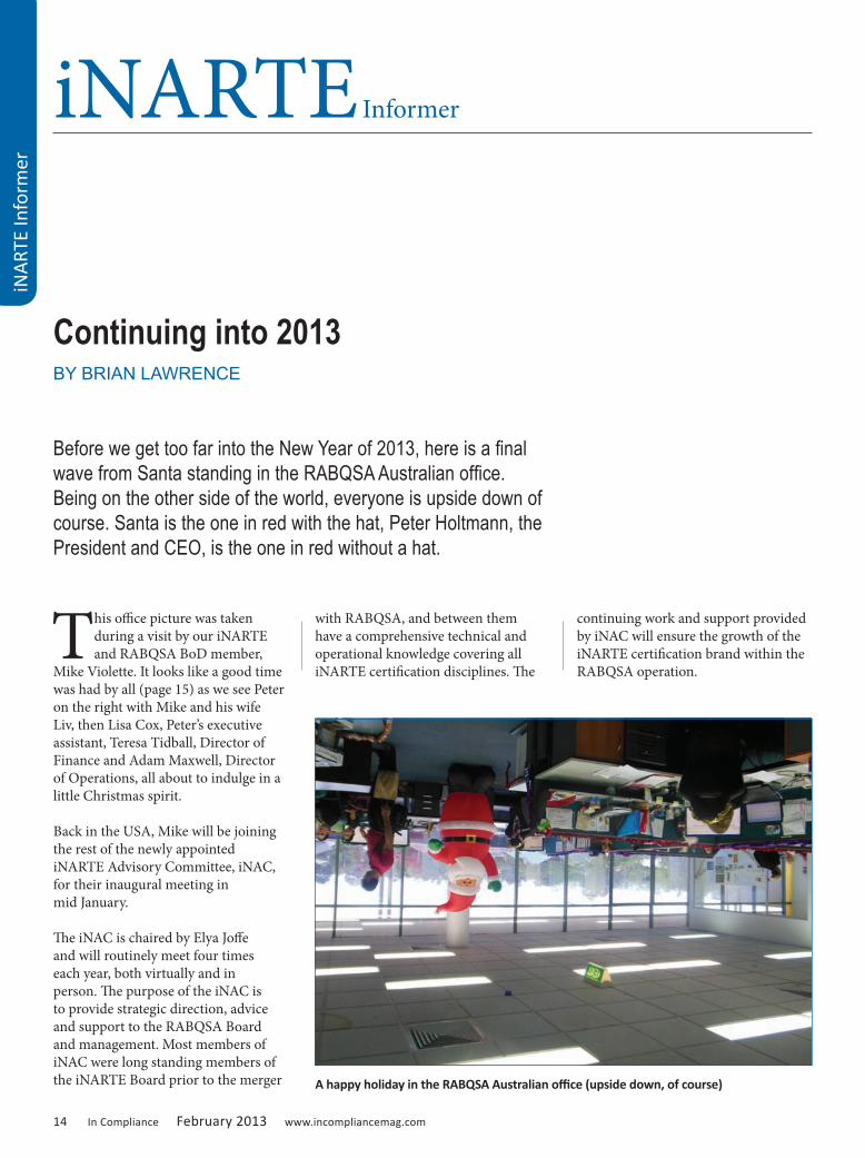
This office picture was taken during a visit by our iNARTE and RABQSA BoD member,
Mike Violette. It looks like a good time was had by all (page 15) as we see Peter on the right with Mike and his wife Liv, then Lisa Cox, Peter’s executive assistant, Teresa Tidball, Director of Finance and Adam Maxwell, Director of Operations, all about to indulge in a little Christmas spirit.
Back in the USA, Mike will be joining the rest of the newly appointed iNARTE Advisory Committee, iNAC, for their inaugural meeting in mid January.
The iNAC is chaired by Elya Joffe and will routinely meet four times each year, both virtually and in person. The purpose of the iNAC is to provide strategic direction, advice and support to the RABQSA Board and management. Most members of iNAC were long standing members of the iNARTE Board prior to the merger
with RABQSA, and between them have a comprehensive technical and operational knowledge covering all iNARTE certification disciplines. The
continuing work and support provided by iNAC will ensure the growth of the iNARTE certification brand within the RABQSA operation.
iNARTE Informer
iNA
RTE
Info
rmer
Continuing into 2013BY BRIAN LAWRENCE
Before we get too far into the New Year of 2013, here is a final wave from Santa standing in the RABQSA Australian office. Being on the other side of the world, everyone is upside down of course. Santa is the one in red with the hat, Peter Holtmann, the President and CEO, is the one in red without a hat.
A happy holiday in the RABQSA Australian office (upside down, of course)

www.incompliancemag.com February 2013 In Compliance 15
PRODUCT SAFETY CERTIFICATION
Last November, as we prepared to attend the IEEE PSES symposium in Portland, we reported that a revamping of the Product Safety Engineering Certification program would seem to be necessary in order for it to have a wider appeal and represent greater value to the community. To set the stage for this effort, we have been conducting both an on line and hard copy job analysis survey of Product Safety practitioners. The survey has been focused in the two main regions from where we see most PS certification activity, the USA and Japan. Our thanks to all who took time to respond to our survey request.
iNA
RTE Informer
Let Panashield help you with your EMC facility project.
Our experienced personnel will provide technical support
to guide you through design, supply and certification.
P3 RF Sliding Doors
Turnkey Services
Facility
Relocations/Upgrades
Antenna Measurement Systems
Tel: 203.866.5888 Fax: 203.866.6162 [email protected]
www.panashield.comwww.panashield.co.uk
Let Panashield help you with your
Our experienced personnel will provide technical support
design, supply and certification.
Facility SolutionsFor Global EMC
EMC Chambers
RF Shielded Enclosures
Military Test Chambers
Avionics Test Chambers
Free Space Chambers
Reverberation Chambers
Adam Maxwell, Teresa Tidball, Lisa Cox, Liv Violette, Mike Violette and Peter Holtman
16 In Compliance February 2013 www.incompliancemag.com
A preliminary analysis showed the following:
• Two thirds of all the responses were received from Japan.
• Almost 90% were from Engineers.
• About 80% were involved with some other aspect of product compliance.
• However, about two thirds were involved in duties other than Product Safety.
• About half spend more than 50% of their time on Product Safety issues.
• Almost two thirds were from organizations having more than 500 employees.
• About 80% had more than 10 years experience in Product Safety.
• And, almost 80% hold degrees and advanced degrees.
• 95% were iNARTE PS certificate holders, (thanks for your support).
We would have wished for a much larger representation from the USA, but hopefully a more detailed analysis of the responses will help us add an improved universal appeal to this credential for the future.
THE NEW QUESTION REQUIREMENT
Maintaining the standard of examination question pools and maintaining currency and credibility of questions is critically important to maintaining certification value. All iNARTE certification applicants are asked to write new questions as part of the credentialing process. We ask that these questions be in the candidate’s own words, that they are original questions, and if possible the questions should reflect real life problems and experiences. We also expect that candidates will write questions
iNARTE Informer
iNA
RTE
Info
rmer that are appropriately challenging
for future applicants at the writer’s certification level. In other words, we do not expect Engineers to send us too many questions copied straight from regulatory standards, which would normally be a Technician’s field of expertise.
Our most popular certifications have traditionally required candidates to send us ten (10) new questions. However, a detailed analysis of these past questions reveals much duplication, many too simplistic to be useful, many copied straight from popular text books and standards, and many that do not have a sufficient range of answer choices. From the first day of February, we will be limiting the number of candidate questions from new applicants to no more than three (3). However, the three questions will be carefully scrutinized by our
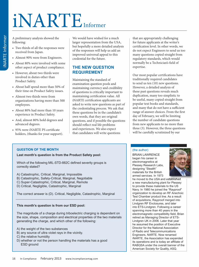
QUESTION OF THE MONTHLast month’s question is from the Product Safety pool:
Which of the following MIL-STD-882C defined severity groups is correctly stated?
A) Catastrophic, Critical, Marginal, ImpossibleB) Catastrophic, Safety-Critical, Marginal, NegotiableC) Super-Catastrophic, Critical, Marginal, RemoteD) Critical, Negligible, Catastrophic, Marginal
The correct answer is (D). Critical, Negligible, Catastrophic, Marginal
This month’s question is from our ESD pool:
The magnitude of a charge during triboelectric charging is dependent on the size, shape, composition and electrical properties of the two materials generating the charge, and which other of the following:
A) the weight of the two substancesB) any source of ultra violet rays in the vicinity.C) the relative humidityD) whether or not the person handling the materials has a good ESD ground
(the author)BRIAN LAWRENCE began his career in electromagnetics at Plessey Research Labs, designing “Stealth” materials for the British armed services. In 1973 he moved to the USA and established a new manufacturing plant for Plessey to provide these materials to the US Navy. In 1980 he joined the “Rayproof” organization to develop an RF Anechoic Test Chamber product line. As a result of acquisitions, Rayproof merged into Lindgren RF Enclosures, and later into ETS-Lindgren. Following a career spanning more than 40 years in the electromagnetic compatibility field, Brian retired as Managing Director of ETS-Lindgren UK in 2006. Later that year he assumed the position of Executive Director for the National Association of Radio and Telecommunications Engineers, NARTE. Now renamed iNARTE, the Association has expanded its operations and is today an affiliate of RABQSA under the overall banner of the American Society for Quality, ASQ.
he moved to the USA and established

committee of technical experts and psychometricians. The smaller number of questions will allow this review to be conducted promptly. Any question that fails to meet appropriate technical standards or suitable formats with all information clearly presented will be returned for replacement.
All new certification applicants, all iNARTE support committee members, certification review committees, and anyone interested in the science of good question writing must watch the two part presentations that RABQSA has now uploaded to YouTube:
Part 1 (required for all question writers): https://asq.webex.com/asq/k2/e.php?AT=RINF&recordingID=6221112
Part 2 (optional but helpful for question writers): https://asq.webex.com/asq/k2/e.php? AT=RINF&recordingID=6221212
Before visiting these URLs, it will be valuable to understand the following terminology being used, which is taken from ISO 17024:
• Item: A “question” that appears in a test
• Stem: The opening question or statement in an item
• Option(s): The possible responses to the stem
• Key: The correct response (option) to the stem
• Distractors: The incorrect responses (options) to the stem
In future iNARTE will require all new items to have no less than four (4) options and no more than five (5) options. One option must be the key and the other options must be plausible but clearly incorrect distracters. No longer with we accept items with options such as simply, “Yes” or “No”, and, “True” or “False”. Nor will we accept options such as, “All of the above”, and, “None of the above”. Such options indicate a lack of imagination. We also encourage item writers to avoid the use of negative stems, such as, “Which is NOT the correct definition of the Human Body Model?” Almost all negative stems can be turned into positive stems with appropriate choice of options, and in so doing will avoid confusing the examinee with double negatives.
iNA
RTE Informer
18 In Compliance February 2013 www.incompliancemag.com
MR. Static
MR.
Sta
tic
Acupuncture and Atmospheric Ions BY NIELS JONASSEN, sponsored by the ESD Association
New experiments look at the effect of acupuncture needles on the number of ions arriving to a body in an electric field
INTRODUCTION
Associate Professor Neils Jonassen authored a bi-monthly static column that appeared in Compliance Engineering Magazine. The series explored charging, ionization, explosions, and other ESD related topics. The ESD Association, working with In Compliance Magazine is re-publishing this series as the articles offer timeless insight into the field of electrostatics.
Professor Jonassen was a member of the ESD Association from 1983-2006. He received the ESD Association Outstanding Contribution Award in 1989 and authored technical papers, books and technical reports. He is remembered for his contributions to the understanding of Electrostatic control, and in his memory we reprise “Mr. Static”.
~ The ESD Association
Reprinted with permission from: Compliance Engineering Magazine, Mr. Static Column Copyright © UBM Cannon
points are scientific facts and that they represent especially sensitive zones of the body. Is there then a way that a needle in such a point might interact physically with the environment?
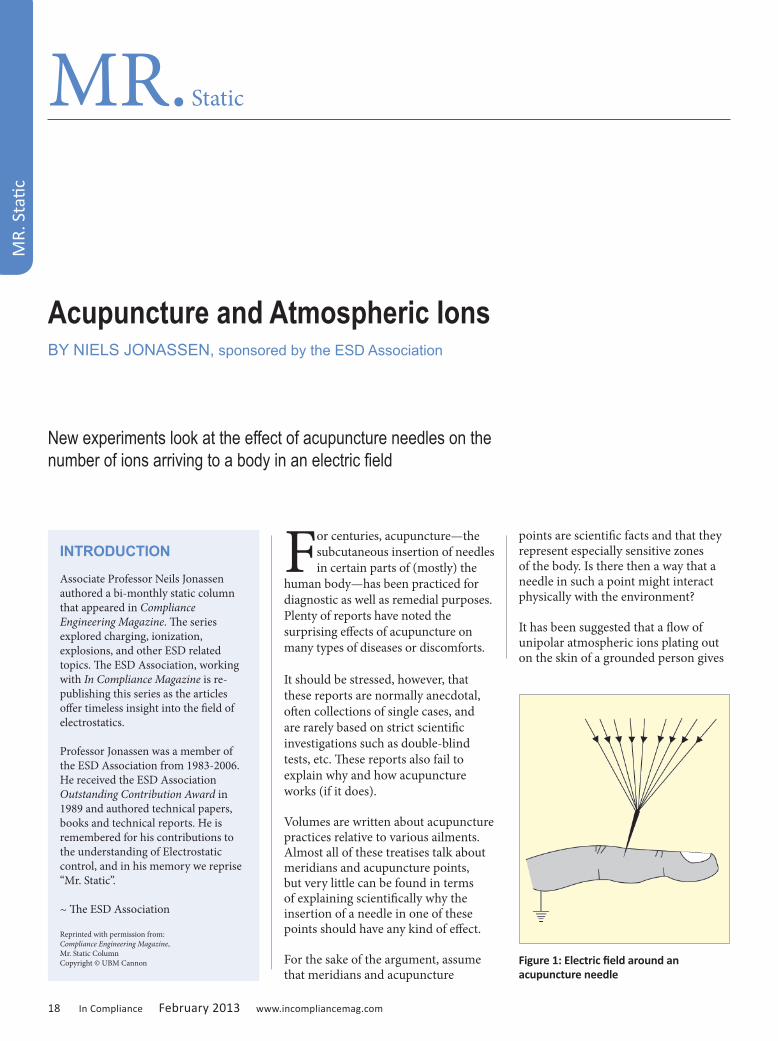
It has been suggested that a flow of unipolar atmospheric ions plating out on the skin of a grounded person gives
For centuries, acupuncture—the subcutaneous insertion of needles in certain parts of (mostly) the
human body—has been practiced for diagnostic as well as remedial purposes. Plenty of reports have noted the surprising effects of acupuncture on many types of diseases or discomforts.
It should be stressed, however, that these reports are normally anecdotal, often collections of single cases, and are rarely based on strict scientific investigations such as double-blind tests, etc. These reports also fail to explain why and how acupuncture works (if it does).
Volumes are written about acupuncture practices relative to various ailments. Almost all of these treatises talk about meridians and acupuncture points, but very little can be found in terms of explaining scientifically why the insertion of a needle in one of these points should have any kind of effect.
For the sake of the argument, assume that meridians and acupuncture
Figure 1: Electric field around an acupuncture needle

www.incompliancemag.com February 2013 In Compliance 19
rise to effects similar to those claimed to be associated with acupuncture.1 If it is assumed that a static electric field exists around the person, the needle will distort the field (see Figure 1) and attract (more) atmospheric ions to the person. The ions will be neutralized
when arriving at the needle, resulting in a current through the body, possibly along meridians or other paths of low resistance.
I decided to demonstrate this effect. However, the currents involved in these
processes are very low (on the order of 10–14 A, or even lower). Therefore, it would have been extremely difficult to measure directly the current flowing to a person caused by an acupuncture needle. Even a person’s unavoidable movements (e.g., breathing) would interfere negatively with the measurements.
EXPERIMENT It was decided to try to simulate the situation shown in Figure 1. The setup used for the simulation is shown in Figure 2. Between two metallic field plates (0.35 x 0.35 m2) at a distance d, an electric field is established. One plate was connected to a high-voltage supply; the other plate was virtually grounded through an electrometer. The field plates were placed about
MR. Static
Figure 2: Experimental setup without acupuncture needle
It's time to rethink EMC pre-compliance testing!
$1,295Starting at
• Make limit lines for the EMI tests you need• Load correction tables for your antenna and connection• Set scans as quickly as 10 ms for a first look• Use RBWs down to 100 Hz to find error sources• Special EMI option & tracking generator for even
more accurate readings
Get our New EMC App Note @ RigolEMC.com
Save one trip to the compliance lab and the DSA815 pays for itself!
DSA815 Ad-InComp_Layout 1 9/6/12 2:22 PM Page 1

20 In Compliance February 2013 www.incompliancemag.com
0.5 m above the floor in an approximately 70-m3 room. The electrometer was connected to a recorder because the presence of persons in the room during measurements would interfere with the results.
If the voltage difference between the field plates is V, an electric field exists between the plates with the mean value of
(1)
With the experiments performed in this investigation, the voltage V was negative; i.e., negative ions were driven toward the plate connected to the electrometer (and positive ions in the opposite direction).
A series of measurements were performed where the voltage V and the distance d were varied. For each value of V and d (i.e., for a given field strength E, Equation 1), the mean value of the current I to the electrometer was calculated from the charge q integrated over the measuring time t by
(2)
In the first series of measurements, both field plates were planar and even. To simulate the effect of an acupuncture needle, a sewing needle was mounted in a hole in the field plate connected to the electrometer. Figure 3 illustrates the difference between the two situations. Figure 3a shows the homogeneous field with no needle, and Figure 3b shows the distorted field around the needle.
(3)
Figure 4 shows an example of the relationship between the current I and the mean field strength E with
and without a needle. It appears that the relationship is linear with the inclinations.
(4)
Equations 3 and 4 indicate that the presence of the needle causes 25% more ions to collect on the metal plate. The results shown in Figure 4 are typical of the relationship of the values with and without a needle. A series of 25 sets of measurements were performed. The actual currents varied considerably from day to day, and even within the same day. These fluctuations are due to variations in the natural ion concentrations caused primarily
by changes in the aerosol density. To a lesser degree, variations in the ion production rate also cause fluctuations. However, when the measurements were performed in a stable period (at least 5–6 hours), the results were consistent with the needle giving rise to an increase in the current of 15–25%.
(5)
The relationship expressed in Equation 3 obviously reflects the concentration and mobility of the negative ions in the room. If the area of the collecting plate is S, the relationship can be expressed as
(6)
where i is the current density, i.e., current per unit area (A x m–2). As the area S is 0.35 x 0.35 m2, Equations 3 and 5 lead to
(7)
The relationship between field strength and resulting current density is Ohm’s law (in differential form)
(8)
where x is the (polar) conductivity. Equation 7 can also be written as
(9)
From Equations 6 and 8, Equation 9 can be derived as The conductivity x can be written as
(10)
where e is the electronic charge, and n and k are the concentration and mobility, respectively (in this case, the
MR. Static
MR.
Sta
tic
Figure 3: Electric field without and with needle.
Figure 4: Current I as a function of the mean field strength E.
www.incompliancemag.com February 2013 In Compliance 21
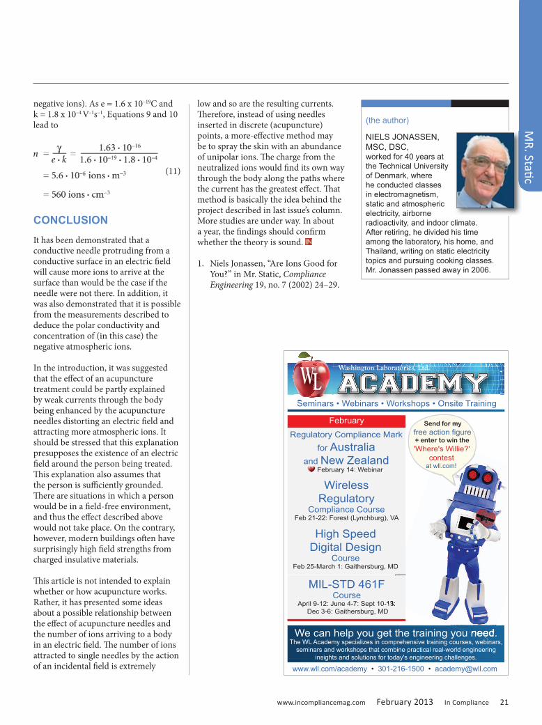
negative ions). As e = 1.6 x 10⁻¹⁹C and k = 1.8 x 10⁻⁴ V–1s–1, Equations 9 and 10 lead to
(11)
CONCLUSION It has been demonstrated that a conductive needle protruding from a conductive surface in an electric field will cause more ions to arrive at the surface than would be the case if the needle were not there. In addition, it was also demonstrated that it is possible from the measurements described to deduce the polar conductivity and concentration of (in this case) the negative atmospheric ions.
In the introduction, it was suggested that the effect of an acupuncture treatment could be partly explained by weak currents through the body being enhanced by the acupuncture needles distorting an electric field and attracting more atmospheric ions. It should be stressed that this explanation presupposes the existence of an electric field around the person being treated. This explanation also assumes that the person is sufficiently grounded. There are situations in which a person would be in a field-free environment, and thus the effect described above would not take place. On the contrary, however, modern buildings often have surprisingly high field strengths from charged insulative materials.
This article is not intended to explain whether or how acupuncture works. Rather, it has presented some ideas about a possible relationship between the effect of acupuncture needles and the number of ions arriving to a body in an electric field. The number of ions attracted to single needles by the action of an incidental field is extremely
low and so are the resulting currents. Therefore, instead of using needles inserted in discrete (acupuncture) points, a more-effective method may be to spray the skin with an abundance of unipolar ions. The charge from the neutralized ions would find its own way through the body along the paths where the current has the greatest effect. That method is basically the idea behind the project described in last issue’s column. More studies are under way. In about a year, the findings should confirm whether the theory is sound.
1. Niels Jonassen, “Are Ions Good for You?” in Mr. Static, Compliance Engineering 19, no. 7 (2002) 24–29.
MR. Static
(the author)
NIELS JONASSEN, MSC, DSC, worked for 40 years at the Technical University of Denmark, where he conducted classes in electromagnetism, static and atmospheric electricity, airborne radioactivity, and indoor climate. After retiring, he divided his time among the laboratory, his home, and Thailand, writing on static electricity topics and pursuing cooking classes. Mr. Jonassen passed away in 2006.
Regulatory Compliance Mark for Australia
and New Zealand February 14: Webinar
www.wll.com/academy • 301-216-1500 • [email protected]
Washington Laboratories, Ltd.
We can help you get the training you need. The WL Academy specializes in comprehensive training courses, webinars,
seminars and workshops that combine practical real-world engineering insights and solutions for today's engineering challenges.
Seminars • Webinars • Workshops • Onsite Training
February
Seminars • Webinars • Workshops • Onsite TrainingSeminars • Webinars • Workshops • Onsite Training
High SpeedDigital Design
CourseFeb 25-March 1: Gaithersburg, MD
February 14: Webinar
WirelessRegulatory
Compliance CourseFeb 21-22: Forest (Lynchburg), VA
MIL-STD 461F Course
April 9-12: June 4-7: Sept 10-13: Dec 3-6: Gaithersburg, MD
We can help you get the training you need.The WL Academy specializes in comprehensive training courses, webinars,
Feb 25-March 1: Gaithersburg, MD
April 9-12: June 4-7: Sept 10-13:
Send for myfree action figure + enter to win the 'Where's Willie?'
contestat wll.com!

22 In Compliance February 2013 www.incompliancemag.com
Even when the snow stopped falling there was no relief. A cold wind continued to bend
the maples and oaks, rattling their branches, and, unable to knock the white stuff from those branches, moaned to us through leaky windows. The dog couldn’t stand outside long
(then again she was a city creature with a physique fit for a couch, not a snow bank).
During the dead of that winter, we traveled to the Northern Territories in western Canada, chasing the late afternoon sun as we flew from DC to
REALITY Engineering
REA
LITY
Eng
inee
ring
The Big InchBY MIKE VIOLETTE
The days are lengthening and daffodils are only a month away, but this challenge remembers another winter when thick sheets of sleet enveloped the ground and wipers froze to windows. It was a brutal winter offering only an occasional glimpse of the sun. It was the Yukon.
Seattle and then hopped the border northward to Vancouver. In Vancouver we met our hosts, three local engineers — Tyler, Terry and Bill — who would accompany us north. After perfunctory introductions (one doesn’t dawdle on a Canadian tarmac in January), we bundled bags and bodies into an eight-seat puddle jumper. After one more short flight, we set down in a stiff crosswind onto the single runway at Prince George, an outpost town on the Trans-Canada/Yellowhead Highway.
“The rental car will be parked at the terminal,” the agent on the phone told me a few days before. “The keys are on the visor and the contract on the dash. Just fill it with gas when you’re done and I’ll send you a bill.” Those were, indeed, different days, and it was a different place.
We exited the double-wide trailer-sized terminal, tended by a bored gate agent turning the pages of the local paper for the fourth time that day. In the lot, the cars all had electric cords lolling out the front of their grills because, if you didn’t plug in the crankcase heaters overnight when the mercury retreats to minus 30o, the oil around the crankshaft turned to honey-thick sludge that no starter could turn.
Tyler unplugged the sedan as we piled in. The hesitant V8 groaned, then sputtered to life, and we headed to the only hotel in town. Along the way, one of the veterans directed us to a quick pit stop; the local ABC retailer, where we loaded up on our own individual form of anti-freeze.
“The winter nights are kinda long out here,” Terry laughed, “and cold.”
“Ya, ya. And za men come out of woods in Spring to shower,” Bill replied in a mock-Russian accent. Picking up his brown bag with a liter of Stoli from the counter, he added, “Let’s go.”

www.incompliancemag.com February 2013 In Compliance 23
Our companions worked with the field engineering group at Westcoast Transmission, based out of Vancouver. Founded in 1949 by the late Frank McMahon, Westcoast provided a few billion cubic feet of natural gas per day to the United States and the eastern cities of Canada. The pipeline, called the Big Inch1, pushed the gaseous gold between remote pumping stations throughout the territory to energy-hungry consumers. The stations were spaced at intervals of a few hours drive along the pipeline. Our task was to take some measurements and look at a noise problem at one of the stations.
1 The “big inch” referred to pipes that were 20 to 48 inches in diameter. In the larger branches, a man could crouch and walk through the line.
REALITY Engineering
Count on LCR to meet all your filter needs, including: COTS and Custom Military: MIL-STD-461,
MIL-STD-220A; full custom available.
Commercial Off-the-Shelf: power line and power entry filters, industrial and medical; UL, CSA and VDE; RoHS compliant.
EMC Test and Design: total in-house capability for appliances, EN55014-1.
For details on these and a full range of other filter solutions, call or visit our website.
9 South Forest Avenue Norristown, PA 19401 (800) 527-4362 sales email: [email protected]
www.lcr-inc.com
LCR-F-11189 CommFilters Half_LCR-F-11189 CommFilters Half pg 6/8/12 2:58 PM Page 1
24 In Compliance February 2013 www.incompliancemag.com
Two kinds of pumping stations were operated along the Big Inch: the first type were installed in the late 60s and the others came on line during the 80s.
Our first stop, the lower quad station, was of the older variety. The pumps were powered by four-stroke V-12 engines, not your Jaguar sports-car variety — but freighter-sized boat motors adapted for the job. These machines were as large as a two-bedroom home, with cylinders large enough for a man to squeeze into. The beasts ate the same stuff they were pumping, with one-inch copper tubing feeding the natural gas to injectors at the piston heads. To reach the spark plugs (two serving each piston) a technician needed to climb a 20-foot ladder.
The pump house contained ten of these behemoths lined up in a row on a concrete deck. The room shook as the monster machines rumbled and grumbled, and the deck vibrated enough to induce minor vertigo. We made some measurements and shrugged our shoulders. Everything here was working fine.
The next pump station, four hours away, was one of the newer ones served by jet turbines instead of the mammoth V-12s. (If memory serves, the boat engines cranked out about 10,000 horsepower, and the jet turbines roared with 100,000 HP). But the afternoon sun, which had risen only a few degrees above the horizon, was retreating quickly, so we beat feet back to the hotel as the sun dove into the snowy
plain. With not much else to do, we shot pool and watched championship curling on the tube in the bar.
The following morning we set out north, driving over the flat lands and into near-virgin forest. We were the only car on the road in either direction as we headed to this second pumping station.
Arriving at the earth-bound jet with an uber-sonic scream that pierced ear plugs and ear muffs, we set up our antennas and spectrum analyzer to map the space, collect some data and perform quick checks of the control instrumentation. After a cross-continental trip and two days buzzing around the Yukon in dire winter, we were beginning to wonder what the heck we were doing here.
REALITY Engineering
REA
LITY
Eng
inee
ring
COMMITMENT. COMMUNITY. COMPLIANCE.
EMC / EMI • PRODUCT SAFETY • ESD • ENVIRONMENTALMonthly Print & Digital Editions
incompliancemag.comOnline Product & Vendor Directory
Annual Reference Guidee-Newsletters
Tradeshows and SeminarsSocial Media
EMC / EMI • PRODUCT SAFETY • ESD • ENVIRONMENTALEMC / EMI • PRODUCT SAFETY • ESD • ENVIRONMENTALEMC / EMI • PRODUCT SAFETY • ESD • ENVIRONMENTALEMC / EMI • PRODUCT SAFETY • ESD • ENVIRONMENTALEMC / EMI • PRODUCT SAFETY • ESD • ENVIRONMENTALEMC / EMI • PRODUCT SAFETY • ESD • ENVIRONMENTALEMC / EMI • PRODUCT SAFETY • ESD • ENVIRONMENTAL
Sign up for FREE subscriptions at www.incompliancemag.com/subscribe
In Compliance is committed to the community of compliance engineering professionals who make up our readership.
You can turn to us as your #1 source for all your compliance news - in our magazine, at events andonline.
www.incompliancemag.com February 2013 In Compliance 25
Outside, we packed up our gear and asked, “Where’s the problem?”
Tyler shouted back over the whine of the machine, which was still cutting through at 90 dB although we were sitting in the car parked outside the building. “No problems here! This is just to have a look. But we’ve got some kind of noise at the next pumping station. We’ve got the big V-12s there.”
He turned the car around in the parking lot and we headed away from the scream. “You’ll see. The control feedback loop signals are bouncing all over the place. We just installed the same new systems in two places. One works great, but the other has lots of noise and jitter.”
“Remember the lower station?” Bill asked. “You know, the first place…yesterday afternoon?”
“Yup.”
“Well, this next station is exactly the same as that one: same layout, same engines, same control, same everything — or it’s supposed to be.”
We drove while Bill and Terry traded jibes over last night’s curling match. “You owe me five loonies, Bill. Saskatoon’s number one. Again.”
“I’ll pay ya in beer when we get back,” Terry laughed.
By mid-afternoon we arrived at the third location. Indeed, it was the same building; a large weather-beaten steel-paneled building, loudly thrumming. “Let’s go inside.”
Engine 3 was down and a mechanic was crouching inside the crankcase. We looked over and his head popped up from the cylinder casing. Wrenches, two feet long, were laid out on the ground. I kicked one. It didn’t move.
Terry waved at the mechanic, who was wrestling with an enormous thrust-rod nut.
“Take a look over here,” Terry motioned us to the wiring that fired the dual spark plugs sprouting from the enormous heads. Not much different from a ginormous lawn mower engine. The wiring was tied to the natural gas supply lines that fed injectors on the heads. Then all were tied neatly back to an enormous distributor. Gray sensor cables were wrapped on the same array.
We asked to see the sensor collection point. The shielded twisted pairs that carried sensor data were pulled neatly into the breakout box, the same as at the first station.
“But look at the shields,” Norm said. We all looked down. There was the problem. “Two different guys wired these systems.”
What did Norm see?
Excerpted and adapted from the IEEE EMC Society Newsletter, Winter 2011. Used by permission.
REALITY Engineering
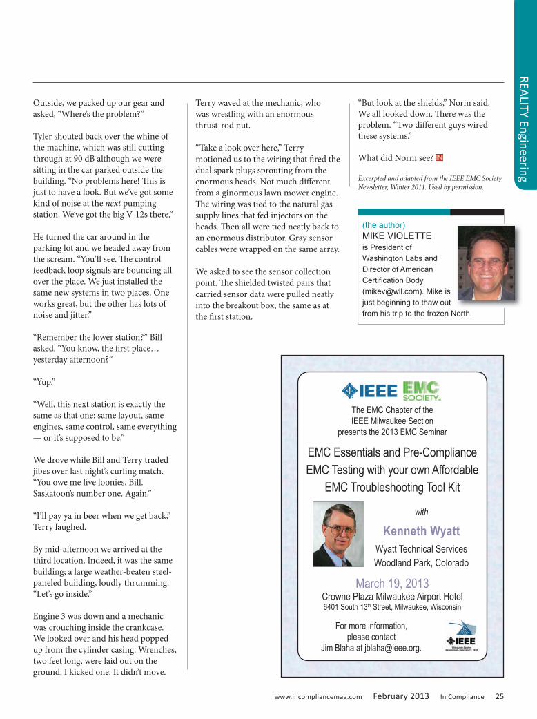
(the author)MIKE VIOLETTEis President of Washington Labs and Director of American Certification Body ([email protected]). Mike is just beginning to thaw out from his trip to the frozen North.
The EMC Chapter of the IEEE Milwaukee Section
presents the 2013 EMC Seminar
EMC Essentials and Pre-Compliance EMC Testing with your own Affordable
EMC Troubleshooting Tool Kit
For more information, please contact
Jim Blaha at [email protected].
with
Kenneth WyattWyatt Technical ServicesWoodland Park, Colorado
March 19, 2013Crowne Plaza Milwaukee Airport Hotel6401 South 13th Street, Milwaukee, Wisconsin

www.incompliancemag.com February 2013 In Compliance 27
The extensive use of power electronics on vessels and offshore installations, especially
on electric propulsion ships, has had a substantial impact on the power quality of the power distribution system. This article discusses the effects of current harmonic distortion created by commercial uninterruptible power supplies (UPS) being deployed in Naval shipboard applications.
MIL‑STD‑1399 300 Revision B defines the electrical interface power requirements for shipboard and submarine equipment. The current waveform test dictated by this standard provides current harmonic control limits for single phase and three phase equipment operating at 60 Hz and 400 Hz services. The measurement and control of current harmonics, especially for power electronics equipment, is essential for both on and off shore
defense platforms and is also covered under the electromagnetic interference control for subsystems and equipment requirements provided by MIL‑STD‑461F test method CE101. In many instances, the measurement techniques and limits are leveraged and shared between the two standards. However, differences do exist which can lead to errors in compliance reporting if one method is used versus the other. Our purpose here is to compare the requirements of the current waveform test in accordance with MIL‑STD‑1399 Section 300B to those of the CE101 test specified in MIL‑STD‑461F.
Harmonics are simply integer multiples of the fundamental power system
Current Harmonics Testing
MIL-STD-1399 Section 300B versus MIL-STD-461F
BY JEFFREY VIEL
Figure 1: Example of non linear current waveform
Figure 2: Example of harmonic frequency distribution
28 In Compliance February 2013 www.incompliancemag.com
frequency which are caused by the interaction of non-linear loads with the impedance of the supply network. Harmonic distortion can lead to heating effects on induction motors, transformers and capacitors, and in severe cases will cause operational interference or equipment damage. In theory, a generator built with perfectly distributed stator and field windings operating in a completely uniform magnetic field, connected to linear load, will produce perfectly sinusoidal current waveform free of harmonic distortion. When sinusoidal voltage is applied to a linear load (i.e., resistive or reactive), the current drawn is determined by load impedance using Ohms Law (E/R=I). In resistive loads, voltage and current will be in phase or synchronized with each other, meaning that the amount of actual power consumed by the load (true power) equals the amount of power absorbed by the circuit (apparent power). When sinusoidal voltage is applied to reactive loads, the phase relationship between the voltage and current waveforms will shift (current will “lag” voltage in inductive circuits, and “lead” in capacitive circuits). This shift in phase will negatively affect the circuit’s apparent power, requiring more current to fulfill the loads true power requirement. The ratio between true power and apparent power, or the “power factor”, is determined by the cosine of the phase angle difference between voltage and current. Reactive loads are different as they draw current disproportionately to the sinusoidal voltage. In power conversion circuits, such as a bridge rectifier in a battery charging circuit, current flows when the rectified instantaneous voltage exceeds the battery voltage, causing distortions
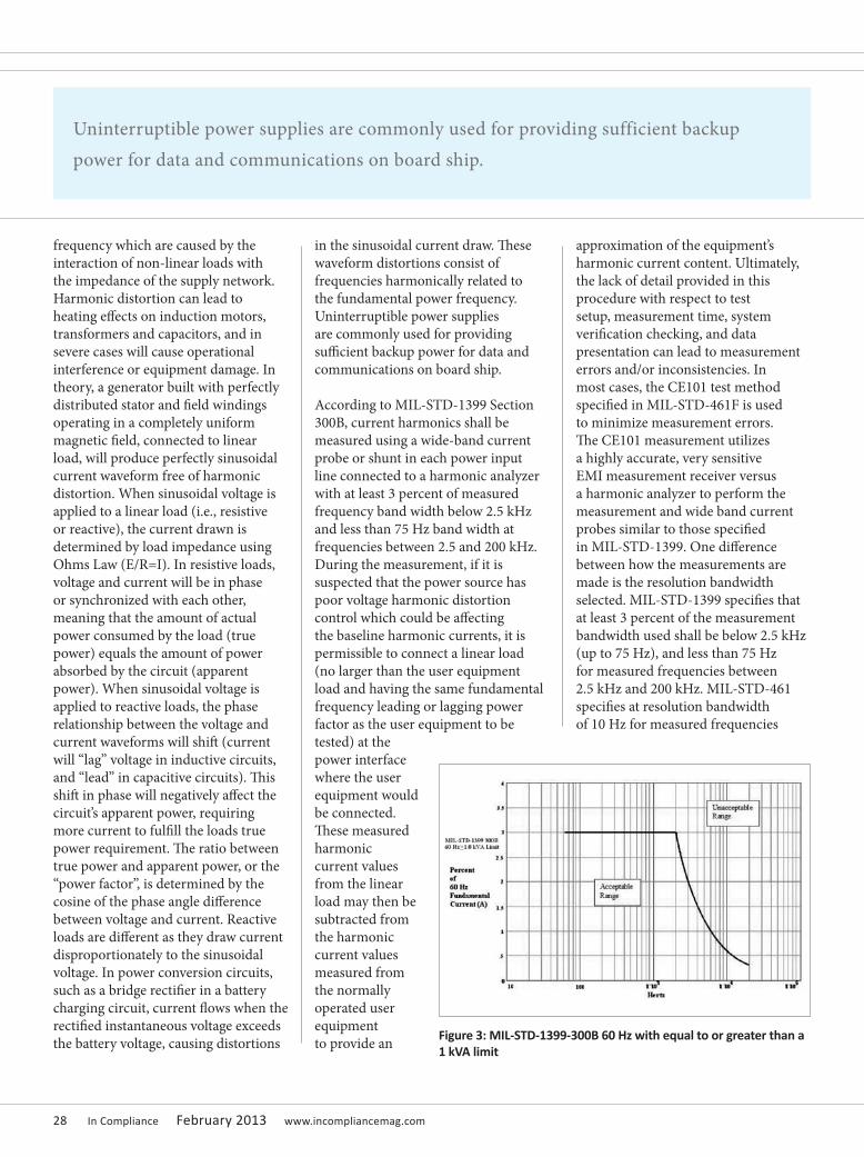
in the sinusoidal current draw. These waveform distortions consist of frequencies harmonically related to the fundamental power frequency. Uninterruptible power supplies are commonly used for providing sufficient backup power for data and communications on board ship.
According to MIL-STD-1399 Section 300B, current harmonics shall be measured using a wide-band current probe or shunt in each power input line connected to a harmonic analyzer with at least 3 percent of measured frequency band width below 2.5 kHz and less than 75 Hz band width at frequencies between 2.5 and 200 kHz. During the measurement, if it is suspected that the power source has poor voltage harmonic distortion control which could be affecting the baseline harmonic currents, it is permissible to connect a linear load (no larger than the user equipment load and having the same fundamental frequency leading or lagging power factor as the user equipment to be tested) at the power interface where the user equipment would be connected. These measured harmonic current values from the linear load may then be subtracted from the harmonic current values measured from the normally operated user equipment to provide an
approximation of the equipment’s harmonic current content. Ultimately, the lack of detail provided in this procedure with respect to test setup, measurement time, system verification checking, and data presentation can lead to measurement errors and/or inconsistencies. In most cases, the CE101 test method specified in MIL-STD-461F is used to minimize measurement errors. The CE101 measurement utilizes a highly accurate, very sensitive EMI measurement receiver versus a harmonic analyzer to perform the measurement and wide band current probes similar to those specified in MIL-STD-1399. One difference between how the measurements are made is the resolution bandwidth selected. MIL-STD-1399 specifies that at least 3 percent of the measurement bandwidth used shall be below 2.5 kHz (up to 75 Hz), and less than 75 Hz for measured frequencies between 2.5 kHz and 200 kHz. MIL-STD-461 specifies at resolution bandwidth of 10 Hz for measured frequencies
Figure 3: MIL‑STD‑1399‑300B 60 Hz with equal to or greater than a 1 kVA limit
Uninterruptible power supplies are commonly used for providing sufficient backup power for data and communications on board ship.
www.incompliancemag.com February 2013 In Compliance 29
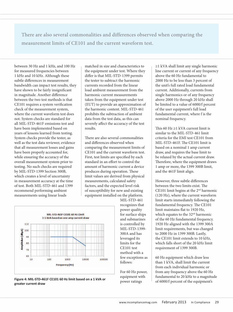
between 30 Hz and 1 kHz, and 100 Hz for measured frequencies between 1 kHz and 10 kHz. Although these subtle differences in measurement bandwidth can impact test results, they have shown to be fairly insignificant in magnitude. Another difference between the two test methods is that CE101 requires a system verification check of the measurement system, where the current waveform test does not. System checks are standard for all MIL-STD-461F emissions test and have been implemented based on years of lessons learned from testing. System checks provide the tester, as well as the test data reviewer, evidence that all measurement losses and gains have been properly accounted for, while ensuring the accuracy of the overall measurement system prior to testing. No such checks are required by MIL-STD-1399 Section 300B, which creates a level of uncertainty in measurement accuracy at the time of test. Both MIL-STD-461 and 1399 recommend performing ambient measurements using linear loads
matched in size and characteristics to the equipment under test. Where they differ is that MIL-STD-1399 permits the tester to subtract the harmonic currents recorded from the linear load ambient measurement from the harmonic current measurements taken from the equipment under test (EUT) to provide an approximation of the harmonic content. MIL-STD-461 prohibits the subtraction of ambient data from the test data, as this can severely affect the accuracy of the test results.
There are also several commonalities and differences observed when comparing the measurement limits of CE101 and the current waveform test. First, test limits are specified by each standard in an effort to control the amount of harmonic current a device produces during operation. These limit values are derived from physical measurements, calculated safety factors, and the expected level risk of susceptibility for new and existing equipment installed on the platform.
MIL-STD-461 recognizes that power quality for surface ships and submarines is controlled by MIL-STD-1399-300A and has leveraged its limits for the CE101 test method with a few exceptions as follows:
For 60 Hz power, equipment with power ratings
≥1 kVA shall limit any single harmonic line current or current of any frequency above the 60 Hz fundamental to 2000 Hz to be less than 3 percent of the unit’s full rated load fundamental current. Additionally, currents from single harmonics or of any frequency above 2000 Hz through 20 kHz shall be limited to a value of 6000/f percent of the user equipment’s full load fundamental current, where f is the nominal frequency.
This 60 Hz ≥1 kVA current limit is similar to the MIL-STD-461 limit criteria for the EMI test CE101 from MIL-STD-461F. The CE101 limit is based on a nominal 1 amp current draw, and requires the base limit to be relaxed by the actual current draw. Therefore, where the equipment draws 1 amp or more, the 1399 300B limit, and the 461F limit align.
However, three subtle differences between the two limits exist. The CE101 limit begins at the 2nd harmonic (120 Hz), where the current waveform limit starts immediately following the fundamental frequency. The CE101 limit maintains flat to 1920 Hz, which equates to the 32nd harmonic of the 60 Hz fundamental frequency. 1920 Hz aligned with the 1399 300A limit requirements, but was changed to 2000 Hz in 1399 300B. Lastly, the CE101 limit extends to 10 kHz, which falls short of the 20 kHz limit requirement of 1399 300B.
60 Hz equipment which draw less than 1 kVA, shall limit the current from each individual harmonic or from any frequency above the 60 Hz fundamental to 20 kHz to a magnitude of 6000/f percent of the equipment’s Figure 4: MIL‑STD‑461F CE101 60 Hz limit based on a 1 kVA or
greater current draw
There are also several commonalities and differences observed when comparing the measurement limits of CE101 and the current waveform test.
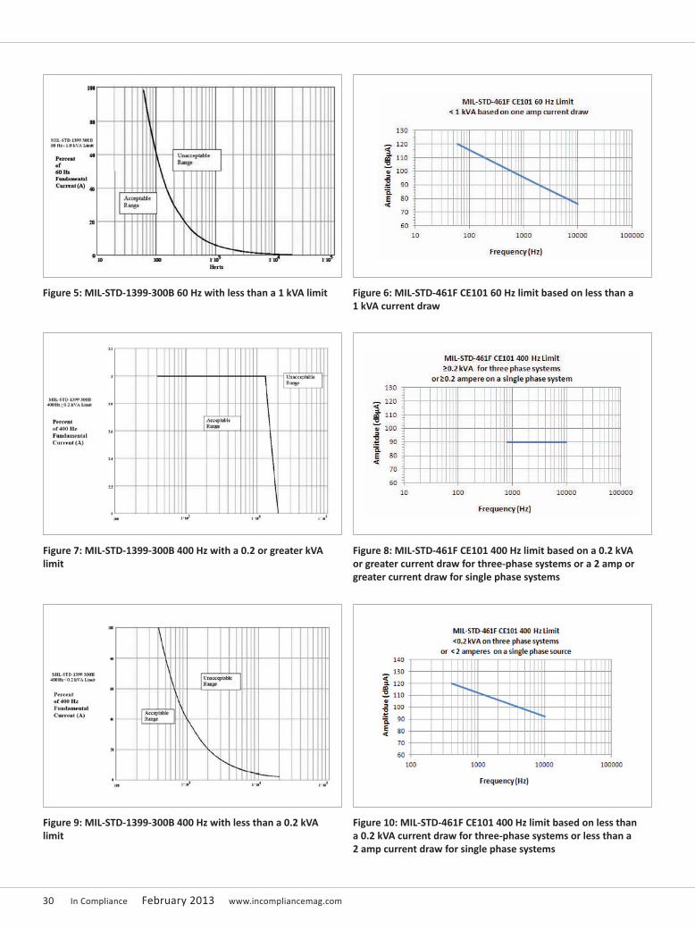
30 In Compliance February 2013 www.incompliancemag.com
Figure 7: MIL‑STD‑1399‑300B 400 Hz with a 0.2 or greater kVA limit
Figure 8: MIL‑STD‑461F CE101 400 Hz limit based on a 0.2 kVA or greater current draw for three-phase systems or a 2 amp or greater current draw for single phase systems
Figure 9: MIL‑STD‑1399‑300B 400 Hz with less than a 0.2 kVA limit
Figure 10: MIL‑STD‑461F CE101 400 Hz limit based on less than a 0.2 kVA current draw for three-phase systems or less than a 2 amp current draw for single phase systems
Figure 5: MIL‑STD‑1399‑300B 60 Hz with less than a 1 kVA limit Figure 6: MIL‑STD‑461F CE101 60 Hz limit based on less than a 1 kVA current draw

www.incompliancemag.com February 2013 In Compliance 31
full load fundamental current, where f is the frequency. This 60 Hz <1 kVA current limit is similar to the MIL-STD-461 limit criteria for the EMI test CE101 from MIL-STD-461F. The CE101 limit is based on a nominal 1 amp current draw, and requires that the base limit be relaxed by the actual current draw. Therefore, where the equipment draws 1 amp or more, the 1399 300B limit and the 461F limit align up to 10 kHz.
However, one major difference between the 1399 300B and MIL-STD-461 60 Hz <1 kVA limits exists when the equipment draw falls below 1 ampere. As shown, the CE101 limit is based on a nominal current draw of one amp. This limit remains unchanged regardless of the equipment current draw below 1 amp. The current waveform limit again is based upon a percentage of the fundamental current draw and not based on a nominal 1 amp. Therefore the limit scales with the measured/actual current level below 1 amp.
For 400 Hz equipment with a power demand of 0.2 kVA or more, the current from each individual harmonic or from any frequency above the 400 Hz fundamental to 13.33 kHz (roughly the 33rd harmonic) shall be limited to 3 percent of the equipment full load current. From 13.334 kHz through 20 kHz, the limit decays at a calculated rate of 40,000/f percent of the user equipment’s full load fundamental current, where f is the frequency. There is a similar overlapping region between this limit and the CE101 limit from MIL-STD-461F. However, the CE101 limit is based on 3 percent of a nominal 1 amp current draw, shown as 90 dBµA.
This base limit is also relaxed by the actual current draw over 1 ampere for three phase systems, and 2 amperes for single phase systems. According to MIL-STD-461F, the rms current level measured at the fundamental frequency is converted to dBµA by multiplying this value by 20Log, then adding it to the limit normalized to 1 amp.
For example, a 4.0 amp current draw at 400 Hz would require a 12 dB increase of the base limit (3 percent of 1 ampere = 90 dBµA), 12 dB to 102 dBµA, to maintain the 3 percent limitation.
The MIL-STD-1399 300B does not make this distinction. The 461F CE101 limit begins at the 2nd harmonic (800 Hz), where the current waveform limit starts immediately following the fundamental frequency. Also, the CE101 limit ends abruptly at 10 kHz, whereas the current waveform limit extends to the 33rd harmonic then decays to 20 kHz as described above.
For 400 Hz equipment drawing less than 0.2 kVA, currents of any frequency above the 400 Hz fundamental to 20 kHz above the fundamental shall be limited to 40,000/f percent of the user equipment’s full load fundamental current, where f is the frequency.
As discussed previously, the MIL-STD-461F limits are all based on a nominal current draw of 1 amp, displayed in current, whereas MIL-STD-1399 300B limits are based on and displayed as a percentage of the fundamental current draw exclusively.
For current draws equal to or greater than 1 amp for three phase systems and 2 amps for single phase systems, the limits are similar except that the CE101 limit ends at 10 kHz. The difference is where the current draw drops below 1 amp. As previously pointed out in the 60 Hz < 1 kVA limit comparison, the MIL-STD-461F limits remain unchanged regardless of the equipment current draw below 1 amp, but the MIL-STD-1399 300B limits scale with the measured/actual current level below 1 amp. This can cause non-compliance issues with low-powered electronic equipment. NAVSEA has recognized that current waveform failures observed on equipment lines drawing less than 1 amp will pose an insignificant impact on the shipboard power distribution system and will review the data to determine if further control efforts are required. There are discussions to better align the current waveform limits with the CE101 limits in the next revision of 1399 300.
(the author)
JEFFREY VIELis the EMI/EMC engineering manager for National Technical Systems Boxborough, Massachusetts operations. He is an electrical engineer with over 15 years experience working in the EMI engineering industry. Jeffrey is considered a subject matter expert in multiple fields relating to electromagnetic interference design, and compatibility including lightning/power cross, shielding, bonding and grounding, and power quality filtering. He is also former sergeant in the U.S. Marine Corps, and long term member of IEEE, and SAE International, and an active member on several NTS/EMC related technical boards. Jeffrey currently provides technical training, product design consultation, EMI mitigation, test procedure development, and test/engineering staffing services to NTS clientele.
There are discussions to better align the current waveform limits with the CE101 limits in the next revision of 1399 300.
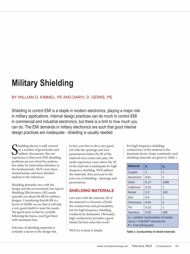
www.incompliancemag.com February 2013 In Compliance 33
Shielding theory is well covered in a number of good books and military documents. But our
experience is that most EMI shielding problems are not solved by analysis, but rather by meticulous attention to the fundamentals. We’ll cover these fundamentals, and leave detailed analysis to the references.
Shielding demands vary with the design and the environment, but typical Shielding Effectiveness (SE) needs typically run about 80 dB for military designs. Considering that 80 dB is a factor of 10,000, we see that it will take a very good shield to meet the needs. The good news is that by carefully following the basics, you’ll get there with minimum fuss.
Selection of shielding materials is certainly a factor in the design but,
in fact, you have to do a very good job with the openings and wire penetrations before the SE of the material even comes into play. We rarely experience cases where the SE of the material is inadequate for high frequency shielding. We’ll address the materials, then proceed to the real crux of shielding - openings and penetrations.
SHIELDING MATERIALS
Let’s start with the material. SE of the material is a function of both the conductivity and permeability, but for high frequency shielding, conductivity dominates. Obviously, high conductivity provides a good shield, but how does this work?
We’ll try to keep it simple.
For high frequency shielding, conductivity of the material is the dominant factor. Some commonly used shielding materials are given in Table 1.
Military Shielding
Shielding to control EMI is a staple in modern electronics, playing a major role in military applications. Internal design practices can do much to control EMI in commercial and industrial electronics, but there is a limit to how much you can do. The EMI demands in military electronics are such that good internal design practices are inadequate - shielding is usually needed.
BY WILLIAM D. KIMMEL, PE AND DARYL D. GERKE, PE
Material σr μr
Copper 1 1
Aluminum 0.61 1
Steel 0.17 1000
Cadmium 0.25 1
Nickel 0.2 100
Zinc 0.3 1
Chromium 0.65 1
Tin 0.15 1
Stainless 0.02 500
σr = relative conductivity of medias(cu) = 5.8x10E7 siemens/mR = 1/σt (Ω/square)
Table 1: Conductivity of shield materials
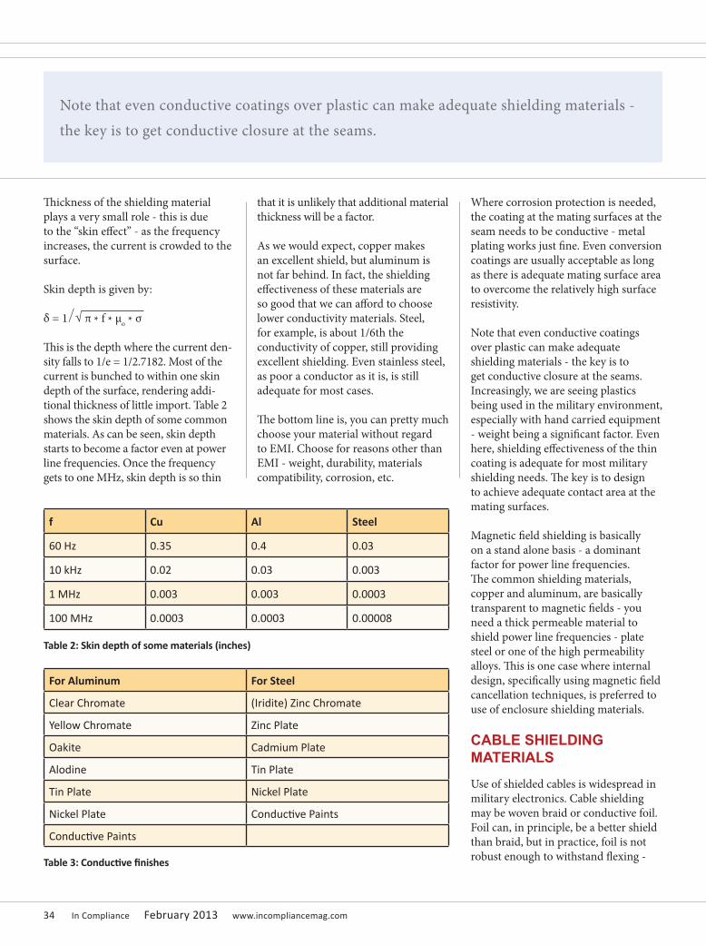
34 In Compliance February 2013 www.incompliancemag.com
Thickness of the shielding material plays a very small role - this is due to the “skin effect” - as the frequency increases, the current is crowded to the surface.
Skin depth is given by:
δ = 1 ∕ √ π * f * μo * σ
This is the depth where the current den-sity falls to 1/e = 1/2.7182. Most of the current is bunched to within one skin depth of the surface, rendering addi-tional thickness of little import. Table 2 shows the skin depth of some common materials. As can be seen, skin depth starts to become a factor even at power line frequencies. Once the frequency gets to one MHz, skin depth is so thin
that it is unlikely that additional material thickness will be a factor.
As we would expect, copper makes an excellent shield, but aluminum is not far behind. In fact, the shielding effectiveness of these materials are so good that we can afford to choose lower conductivity materials. Steel, for example, is about 1/6th the conductivity of copper, still providing excellent shielding. Even stainless steel, as poor a conductor as it is, is still adequate for most cases.
The bottom line is, you can pretty much choose your material without regard to EMI. Choose for reasons other than EMI - weight, durability, materials compatibility, corrosion, etc.
Where corrosion protection is needed, the coating at the mating surfaces at the seam needs to be conductive - metal plating works just fine. Even conversion coatings are usually acceptable as long as there is adequate mating surface area to overcome the relatively high surface resistivity.
Note that even conductive coatings over plastic can make adequate shielding materials - the key is to get conductive closure at the seams. Increasingly, we are seeing plastics being used in the military environment, especially with hand carried equipment - weight being a significant factor. Even here, shielding effectiveness of the thin coating is adequate for most military shielding needs. The key is to design to achieve adequate contact area at the mating surfaces.
Magnetic field shielding is basically on a stand alone basis - a dominant factor for power line frequencies. The common shielding materials, copper and aluminum, are basically transparent to magnetic fields - you need a thick permeable material to shield power line frequencies - plate steel or one of the high permeability alloys. This is one case where internal design, specifically using magnetic field cancellation techniques, is preferred to use of enclosure shielding materials.
CABLE SHIELDING MATERIALS
Use of shielded cables is widespread in military electronics. Cable shielding may be woven braid or conductive foil. Foil can, in principle, be a better shield than braid, but in practice, foil is not robust enough to withstand flexing -
f Cu Al Steel
60 Hz 0.35 0.4 0.03
10 kHz 0.02 0.03 0.003
1 MHz 0.003 0.003 0.0003
100 MHz 0.0003 0.0003 0.00008
Table 2: Skin depth of some materials (inches)
For Aluminum For Steel
Clear Chromate (Iridite) Zinc Chromate
Yellow Chromate Zinc Plate
Oakite Cadmium Plate
Alodine Tin Plate
Tin Plate Nickel Plate
Nickel Plate Conductive Paints
Conductive Paints
Table 3: Conductive finishes
Note that even conductive coatings over plastic can make adequate shielding materials - the key is to get conductive closure at the seams.
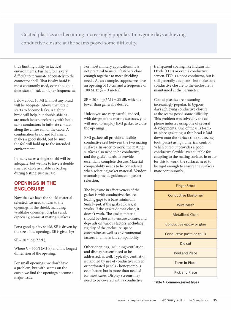
www.incompliancemag.com February 2013 In Compliance 35
thus limiting utility in tactical environments. Further, foil is very difficult to terminate adequately to the connector shell. That is why braid is most commonly used, even though it does start to leak at higher frequencies.
Below about 10 MHz, most any braid will be adequate. Above that, braid starts to become leaky. A tighter braid will help, but double shields are much better, preferably with both cable conductors in intimate contact along the entire run of the cable. A combination braid and foil shield makes a good shield, but be sure the foil will hold up to the intended environment.
In many cases a single shield will be adequate, but we like to have a double shielded cable available as backup during testing, just in case.
OPENINGS IN THE ENCLOSURE
Now that we have the shield material selected, we need to turn to the openings in the shield, including ventilator openings, displays and, especially, seams at mating surfaces.
For a good quality shield, SE is driven by the size of the openings. SE is given by:
SE = 20 * log (λ/2L),
Where λ = 300/f (MHz) and L is longest dimension of the opening.
For small openings, we don’t have a problem, but with seams on the cover, we find the openings become a major issue.
For most military applications, it is not practical to install fasteners close enough together to meet shielding needs. As an example, suppose we have an opening of 10 cm and a frequency of 100 MHz (λ = 3 meter).
SE = 20 * log(3/.1) = 23 dB, which is lower than generally desired.
Unless you are very careful, indeed, with design of the mating surfaces, you will need to employ EMI gasket to close the openings.
EMI gaskets all provide a flexible conductive seal between the two mating surfaces. In order to work, the mating surfaces also need to be conductive, and the gasket needs to provide essentially complete closure. Material compatibility needs to be considered when selecting gasket material. Vendor manuals provide guidance on gasket selection.
The key issue in effectiveness of the gasket is with conductive closure, leaving gaps to a bare minimum. Simply put, if the gasket closes, it works. If the gasket doesn’t close, it doesn’t work. The gasket material should be chosen to ensure closure, and depends on various factors, including rigidity of the enclosure, space constraints as well as environmental factors and materials compatibility.
Other openings, including ventilation and display screens need to be addressed, as well. Typically, ventilation is handled by use of conductive screen or perforated panels - honeycomb is even better, but is more than needed for most cases. Display screens may need to be covered with a conductive
transparent coating like Indium Tin Oxide (ITO) or even a conductive screen. ITO is a poor conductor, but is still generally adequate - but make sure conductive closure to the enclosure is maintained at the perimeter.
Coated plastics are becoming increasingly popular. In bygone days achieving conductive closure at the seams posed some difficulty. This problem was solved by the cell phone industry using one of several developments. One of these is form-in-place gasketing: a thin bead is laid down onto the surface (like squeezing toothpaste) using numerical control. When cured, it provides a good conductive flexible layer suitable for coupling to the mating surface. In order for this to work, the surfaces need to be rigid enough to ensure the surfaces mate continuously.
Finger Stock
Conductive Elastomer
Wire Mesh
Metallized Cloth
Conductive epoxy or glue
Conductive paste or caulk
Die cut
Peel and Place
Form in Place
Pick and Place
Table 4: Common gasket types
Coated plastics are becoming increasingly popular. In bygone days achieving conductive closure at the seams posed some difficulty.

36 In Compliance February 2013 www.incompliancemag.com
SHIELD PENETRATIONS
The last factor to consider is the penetrations to the shield - this includes data and power cables. Simply put, any currents on the wire will pass through the shield no matter how good the shield. There are only two ways this condition can be prevented - cable shielding or filtering (Figure 1). Cable shielding prevents currents from penetrating the shield, filtering allows the currents onto the wire, but filters them off to the enclosure boundary. Generally, high speed data cables will need to be shielded. Power lines and low frequency data cables can be filtered.
The principle is simple, this is the most common reason for shielding failure, so is a topic worth investigating in some depth.
The key to filtering is careful termination of the filter capacitors. To be effective, the filter must be mounted immediately at the enclosure boundary with the filter capacitors having a low impedance connection to enclosure ground. The filter may be in the bulkhead or the cable connector, but must have low impedance connection to the enclosure - noting that there may be several metallic connections between the capacitor and the enclosure. In particular, lead inductance in the shunt path must be absolutely eliminated.
For most applications, you will need a low pass filter, whether a simple C or L or a Pi filter depends on the attenuation needed. T filters are also good, but they are not widely available in filter arrays.
For shielded cables, the cable shield needs to be well terminated to the enclosure. Again, this requires a number of metallic connections, including cable shield to backshell, backshell to connector, connector to mating connector, mating connector to bulkhead. If any of these connections Figure 2: Cable shield termination
Figure 1: Shield penetrations

www.incompliancemag.com February 2013 In Compliance 37
are not low resistance and around the entire perimeter, the shield will fail. To be specific, the cable shield needs to be circumferentially terminated to the perimeter of the connector, typically at the compression ring for military style connectors. Pigtail connections are unacceptable. Full circumferential conductivity needs to be maintained through to the bulkhead. The connectors are designed to mate to each other. The connector to bulkhead connection must be complete, as well - specifically, watch for conductivity at the mating surfaces. Paints, rubber gaskets, and nonconductive coatings are of concern.
Military cables are often complex, consisting of a combination of individually shielded lines (e.g. shielded twisted pair), voltage supply with filters, and shielded high speed data lines. There may be a shielded overbraid. Each of these must be individually terminated correctly. Let’s take a closer look at this.
First, the outer shield of the cable must be circumferentially fastened to the compression ring - pigtail grounding is unacceptable. Shield must be grounded at both ends - single point grounding is inappropriate for high frequency shielding.
Second, where multiple shields are involved, it is not possible to circumferentially terminate each shield. In that case, each shield should be grounded to the compression ring with as short a path as possible. In the extreme case, where there are many inner shields, the shields may need to be conductively mated to adjacent cable shields in order to make conductive contact.
Third, low frequency inner shielded wires may need to be single point grounded. Thus, the outer shield (sometimes called an over-braid) provides the high frequency shield, the inner shield breaks the signal ground loop.
Fourth, there may need to be a mix of shield terminations and filters. Military style connectors will accommodate such a mix.
A final note: In troubleshooting EMI problems, we find cable terminations are most often at the root. Sadly, even professionally assembled cables from reputable companies are often incorrectly assembled - open the shell, see if there are any internal pigtails and remove them.
SUMMARY
Shielding for military projects requires considerable care - the good news is that the book has been written, and if you follow the rules, you will have a good shield. Shielding material selection is not critical - most shielding material is adequate for the job. Even conductive coatings often provide
adequate shielding. Here is a step-by-step approach to good shielding:
1. Moderate conductors are adequate for good high frequency effectiveness.
2. Cable shields begin to leak above about 10 MHz - may need double shield.
3. Use gaskets for seams - the selection is made for mechanical reasons, as all gaskets will work well if properly installed.
4. Ensure conductive contact for all mating surfaces.
5. Large openings need perforated panels, conductive screens or honeycomb.
6. Filter or shield all wire penetrations - shielding for high frequency data, filters for power line frequencies or audio frequency signals.
7. Ensure cable shield is circumferentially mated to connector shell.
Follow these basic rules, and you will have a good shield, even without complex analysis.
(the authors)
DARYL GERKE, PE AND BILL KIMMEL, PE are the founding partners of Kimmel Gerke Associates, Ltd. The firm specializes in EMC consulting and training, and has offices in Minnesota and Arizona. The firm was founded in 1978 and has been in full time EMC practice since 1987.
Daryl and Bill have solved or prevented hundreds of EMC problems in a wide range of industries - computers, medical, military, avionics, industrial controls, vehicular electronics and more. They have also trained over 10,000 designers through their public and in-house EMC seminars.
Daryl and Bill are both degreed Electrical Engineers, registered Professional Engineers, and NARTE Certified EMC Engineers. Between them, they share over 80 years of industry experience. For more information and resources, visit their web site at www.emiguru.com.
In troubleshooting EMI problems, we find cable terminations are most often at the root. Sadly,
even professionally assembled cables from reputable companies are often incorrectly assembled.

www.incompliancemag.com February 2013 In Compliance 39
Most electrical engineers agree that the TDR and VNA are the two different instruments
in the labs which can be used for taking time domain measurements [1]. It appears that these two tools are not indiscriminately interchangeable due to the fact that TDR works in the time domain while the VNA functions in the frequency domain. However, the use of a fast Fourier transform (FFT) allows us to use either the two instruments for time and frequency domain measurements. Typically a digital or signal integrity (SI) engineer
uses a TDR for taking time domain measurements due to its quick setup and easy to use. The microwave or radio frequency (RF) engineer instead prefers to use VNA for tacking measurements up to very high frequencies with good accuracy. It is of paramount importance to note that the current semiconductor technology develops digital chips interconnected at always increasing data rates in the gigahertz range, which means digital signals with very deep edges and very high content of frequencies. Consequently the job of a digital engineer gets closer
and closer to that of a microwave engineer, and requires taking useful design information from both the time and frequency domain measurements. Considering that both the TDR and VNA are expensive instruments and sometimes a same lab cannot afford to buy both, the question is: “What is the better instrument for the needed time domain measurement?” In other words, say for a connector manufacturer using VNA: ‘”re the time domain measurements taken with a VNA comparable with the same measurements taken with a TDR?”.
Time Domain Measurement: TDR or VNA?
Nowadays, semiconductor technology requires that integrated circuits be interconnected at very high-speed data rates. Taking time domain measurements on the digital links can offer challenges for electronic engineers, one of which is to decide which is the better measurement instrument to use in the given signal integrity environment. The time domain reflectometer (TDR) and vector network analyzer (VNA) are the staple instruments to consider, each one having its pros and cons. Here we compare the responses of the two instruments when used for taking time domain measurements of typical signal integrity devices under test (DUTs): a stripline and a through hole on a FR-4 board.
BY VITTORIO RICCHIUTI
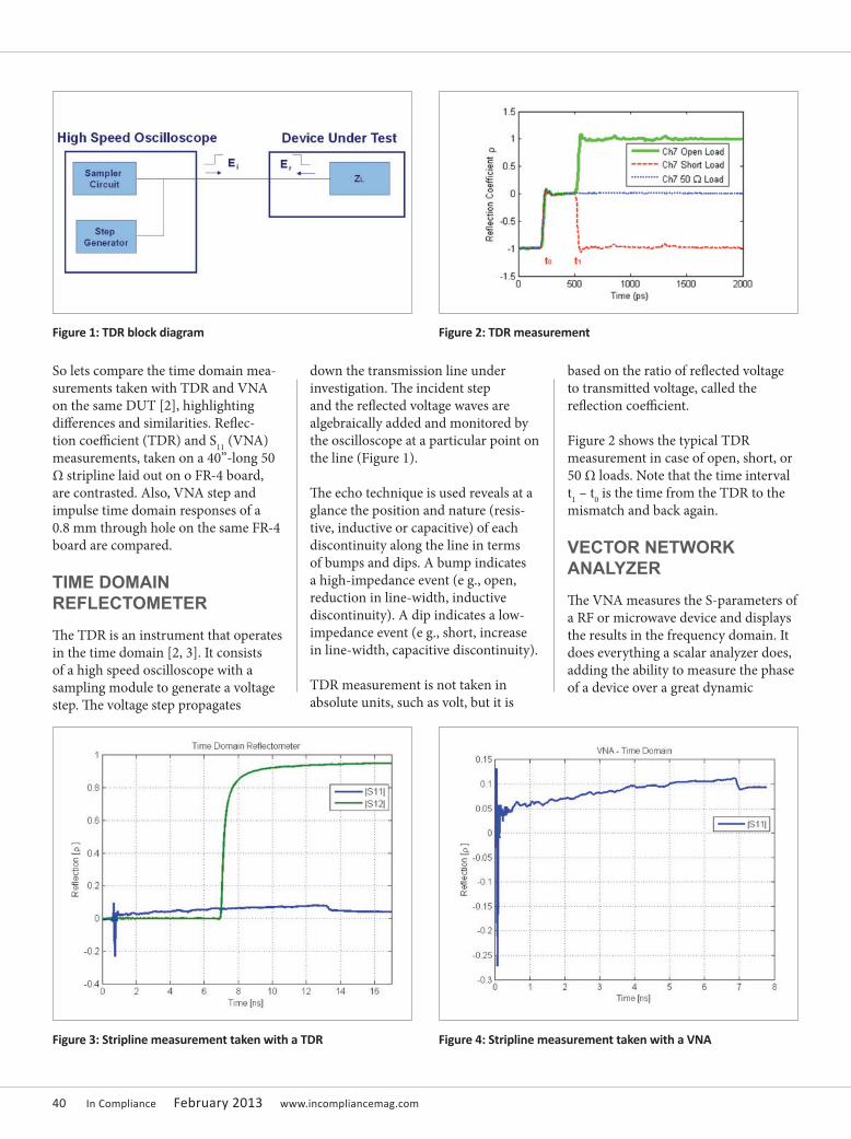
40 In Compliance February 2013 www.incompliancemag.com
So lets compare the time domain mea-surements taken with TDR and VNA on the same DUT [2], highlighting differences and similarities. Reflec-tion coefficient (TDR) and S11 (VNA) measurements, taken on a 40”-long 50 Ω stripline laid out on o FR-4 board, are contrasted. Also, VNA step and impulse time domain responses of a 0.8 mm through hole on the same FR-4 board are compared.
TIME DOMAIN REFLECTOMETER
The TDR is an instrument that operates in the time domain [2, 3]. It consists of a high speed oscilloscope with a sampling module to generate a voltage step. The voltage step propagates
down the transmission line under investigation. The incident step and the reflected voltage waves are algebraically added and monitored by the oscilloscope at a particular point on the line (Figure 1).
The echo technique is used reveals at a glance the position and nature (resis-tive, inductive or capacitive) of each discontinuity along the line in terms of bumps and dips. A bump indicates a high-impedance event (e g., open, reduction in line-width, inductive discontinuity). A dip indicates a low-impedance event (e g., short, increase in line-width, capacitive discontinuity).
TDR measurement is not taken in absolute units, such as volt, but it is
based on the ratio of reflected voltage to transmitted voltage, called the reflection coefficient.
Figure 2 shows the typical TDR measurement in case of open, short, or 50 Ω loads. Note that the time interval t1 – t0 is the time from the TDR to the mismatch and back again.
VECTOR NETWORK ANALYZER
The VNA measures the S-parameters of a RF or microwave device and displays the results in the frequency domain. It does everything a scalar analyzer does, adding the ability to measure the phase of a device over a great dynamic
Figure 1: TDR block diagram Figure 2: TDR measurement
Figure 3: Stripline measurement taken with a TDR Figure 4: Stripline measurement taken with a VNA

www.incompliancemag.com February 2013 In Compliance 41
range and with more accuracy. The availability of the phase information allows the time domain feature.
An inverse FFT is used to convert the frequency domain to time domain. Note that the digital signal processing (DSP) technology, fundamental by computing error correction terms, permits implementation of a type of FFT known as a chirp Z transform.
The VNA uses two different time domain processing techniques: low pass and band pass.
The low pass technique requires a harmonically related set of frequencies that start at the lowest frequency possible and extrapolate a DC term that provides a phase reference so that the true nature of a discontinuity can be seen. It allows two presentations: step response or impulse response. A step response is the integral of the impulse response and displays the discontinuities as would a TDR.The band pass technique does not use
phase reference, so vector information is lost; only magnitude information is available. This type of processing is common in fault location for testing transmission lines
It is important to consider that the VNA uses windowing to condition data prior to time domain transformation. The window is a curve derived from a mathematical function used to mitigate edge effects associated with a finite data set in the FFT.
MEASUREMENT EXAMPLES
Figures 3 and 4 compare the measurements taken with a TDR and a VNA on a matched 4” long 50 Ω stripline laid out on a FR-4 board.
The incident step of the TDR being used has a rise time equal to 20 ps.
The VNA being used has a frequency span from 0.04 GHz to 40 GHz. It considers a low pass technique with
step response and a nominal window.
As is shown, the two measurements are quite similar. Note that the length in nanaseconds for the stripline in Figure 3 is double with respect to the same length in Figure 4. This is due to the fact that the TDR (Figure 3) measures the round trip delay of the step propagating along the stripline, which is the time from the TDR to the mismatch (the end of the line) and back again.
Both the measurements show an upward trend of the measured reflection coefficient due to the frequency dependence of the characteristic impedance of the line [4].
To confirm the equivalence of the two instruments in the time domain, the discontinuity due to the input SMA connector of the stripline has been displayed on the TDR and VNA (Figures 5 and 6). Note the capacitive behavior of the connector.
Figure 5: Input SMA of the stripline displayed on the TDR Figure 6: Input SMA of the stripline displayed on the VNA
The low pass technique requires a harmonically related set of frequencies that start at the lowest frequency possible and extrapolate a DC term that provides a phase reference so that the true nature of a discontinuity can be seen.
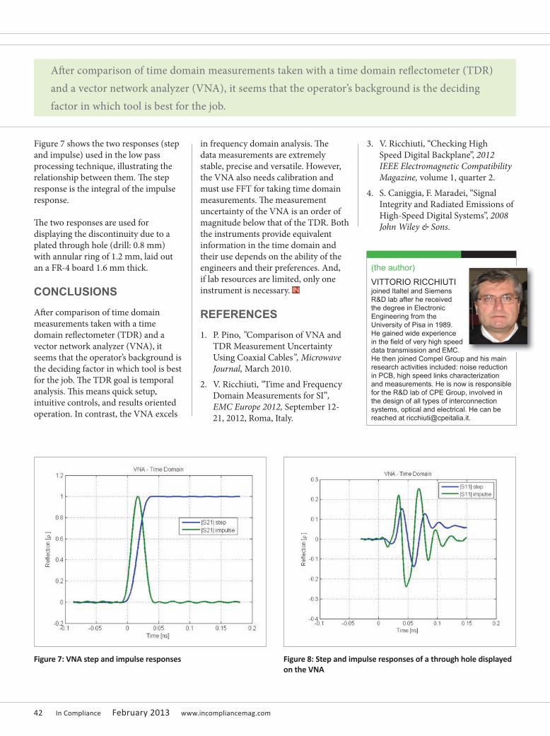
42 In Compliance February 2013 www.incompliancemag.com
Figure 7 shows the two responses (step and impulse) used in the low pass processing technique, illustrating the relationship between them. The step response is the integral of the impulse response.
The two responses are used for displaying the discontinuity due to a plated through hole (drill: 0.8 mm) with annular ring of 1.2 mm, laid out an a FR-4 board 1.6 mm thick.
CONCLUSIONS
After comparison of time domain measurements taken with a time domain reflectometer (TDR) and a vector network analyzer (VNA), it seems that the operator’s background is the deciding factor in which tool is best for the job. The TDR goal is temporal analysis. This means quick setup, intuitive controls, and results oriented operation. In contrast, the VNA excels
in frequency domain analysis. The data measurements are extremely stable, precise and versatile. However, the VNA also needs calibration and must use FFT for taking time domain measurements. The measurement uncertainty of the VNA is an order of magnitude below that of the TDR. Both the instruments provide equivalent information in the time domain and their use depends on the ability of the engineers and their preferences. And, if lab resources are limited, only one instrument is necessary.
REFERENCES
1. P. Pino, ”Comparison of VNA and TDR Measurement Uncertainty Using Coaxial Cables”, Microwave Journal, March 2010.
2. V. Ricchiuti, “Time and Frequency Domain Measurements for SI”, EMC Europe 2012, September 12-21, 2012, Roma, Italy.
3. V. Ricchiuti, “Checking High Speed Digital Backplane”, 2012 IEEE Electromagnetic Compatibility Magazine, volume 1, quarter 2.
4. S. Caniggia, F. Maradei, “Signal Integrity and Radiated Emissions of High-Speed Digital Systems”, 2008 John Wiley & Sons.
Figure 7: VNA step and impulse responses Figure 8: Step and impulse responses of a through hole displayed on the VNA
After comparison of time domain measurements taken with a time domain reflectometer (TDR) and a vector network analyzer (VNA), it seems that the operator’s background is the deciding factor in which tool is best for the job.
(the author)
VITTORIO RICCHIUTI joined Italtel and Siemens R&D lab after he received the degree in Electronic Engineering from the University of Pisa in 1989. He gained wide experience in the field of very high speed data transmission and EMC. He then joined Compel Group and his main research activities included: noise reduction in PCB, high speed links characterization and measurements. He is now is responsible for the R&D lab of CPE Group, involved in the design of all types of interconnection systems, optical and electrical. He can be reached at [email protected].
www.incompliancemag.com February 2013 In Compliance 43
THE ANNUALREFERENCE GUIDE
The #1 Reference Guide for the EMC, ESD and Product Safety industries
An essential collection of technical articles to keep today’s compliance engineer up-to-date on the ever changing industry.
Comprehensive product and service directory.
Contact vendors directly through their company profiles.
Read, share and save your favorite articles.
Available in print and online.
CONFIRM YOUR SUBSCRIPTION TODAY!incompliancemag.com
MARCH2013
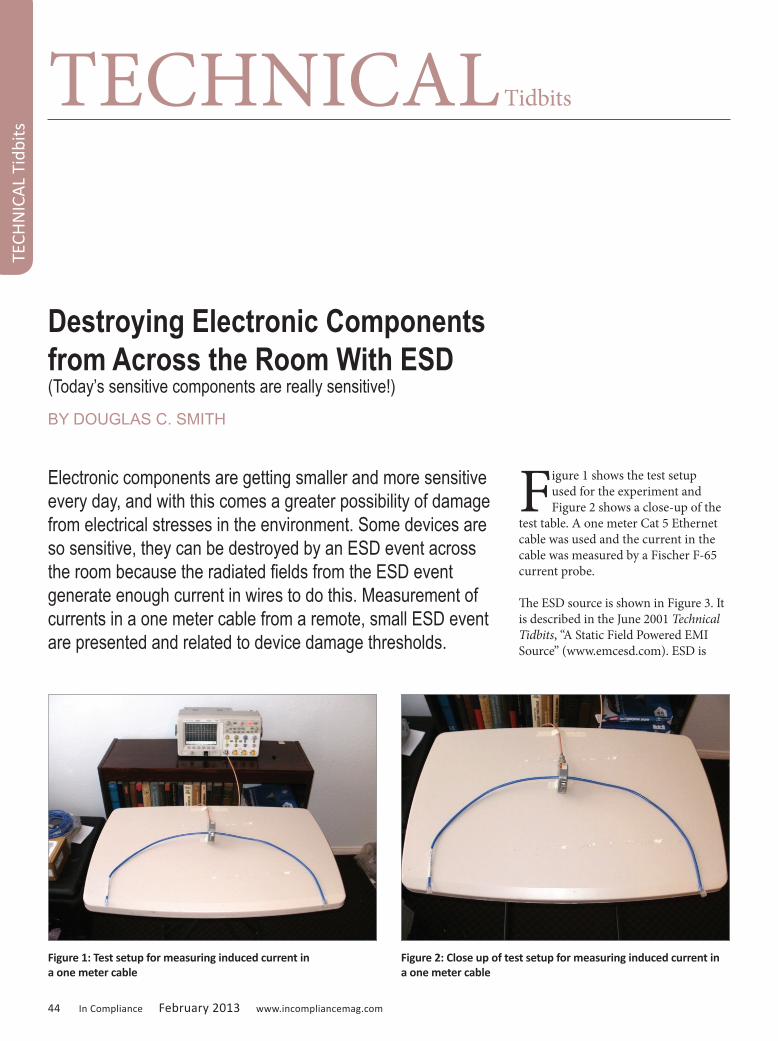
44 In Compliance February 2013 www.incompliancemag.com
Destroying Electronic Components from Across the Room With ESD(Today’s sensitive components are really sensitive!)
BY DOUGLAS C. SMITH
Electronic components are getting smaller and more sensitive every day, and with this comes a greater possibility of damage from electrical stresses in the environment. Some devices are so sensitive, they can be destroyed by an ESD event across the room because the radiated fields from the ESD event generate enough current in wires to do this. Measurement of currents in a one meter cable from a remote, small ESD event are presented and related to device damage thresholds.
Figure 1 shows the test setup used for the experiment and Figure 2 shows a close-up of the
test table. A one meter Cat 5 Ethernet cable was used and the current in the cable was measured by a Fischer F-65 current probe.
The ESD source is shown in Figure 3. It is described in the June 2001 Technical Tidbits, “A Static Field Powered EMI Source” (www.emcesd.com). ESD is
TECHNICAL Tidbits
TECH
NIC
AL
Tidb
its
Figure 1: Test setup for measuring induced current in a one meter cable
Figure 2: Close up of test setup for measuring induced current in a one meter cable

www.incompliancemag.com February 2013 In Compliance 45
generated in the very small gap between the points of the strips of copper foil tape when a charged object is brought close to one of the copper foil strips. This is caused by electrons jumping across the gap due attraction or repul-sion by the applied electric field. Figure 4 shows a charged strip of Teflon™being passed back and forth along the plastic backing of the copper foil strips. This generates hundreds of ESD events be-tween the copper foil strips as electrons are chased back and forth across the gap. I estimate the breakdown voltage of the gap to be several hundred volts. The rising edge of the radiated field is on the order of 200 to 300 ps.
Three distances were used between the ESD events and the one meter cable/current probe: 3 m, 1 m, and 30 cm. Figure 5 shows the induced current at 3 m. The ringing in the waveform is due to the resonant frequency of the copper foil strips (~500 MHz) and to some extent the lower resonant frequency of the 1 m cable. Note the peak current of about 17 mA. One of the most sensitive devices in use today are the read heads in disk drives. They have an ESD Human Body damage threshold of just a Volt or two (not thousands or even hundreds of volts, a few volts)! [2]
It takes just a milliamp or two for a nanosecond to destroy the head. [2] Clearly, if such a head was not in a shielded enclosure and connected to wires (for testing possibly), it could easily be damaged from across the room. If one were to split the 1 m cable in the middle to form a dipole, the two terminals at the middle of the dipole would have enough voltage between them at a 70 Ohm source impedance to damage a disk drive head from a voltage point of view as well.
Figure 6 shows another typical current waveform generated showing greater than 20 mA flowing in the 1m cable, an even worse case. This is enough to damage even the older GMR heads of 15 years ago. Those heads were damaged by 20 mA flowing for a nanosecond.
Figures 7 and 8 (page 46) show the measured currents at a distance of one meter from the ESD events. The peak current for this distance was over 40 mA!
Figures 9 and 10 (page 46) show the measured currents at 30 cm. The peak current is greater than 80 mA in Figure 10.
TECHN
ICAL Tidbits
Figure 3: Spark gap EMI source for experiment
Figure 4: Test setup for measuring induced current in one meter cable with ESD source shown [1]
Figure 5: Discharge at 3 m From Cable and Current Probe - #1(Vertical scale ~ 5 mA/div, Horizontal scale = 2 ns/div)
Figure 6: Discharge at 3 m From Cable and Current Probe - #2(Vertical scale ~ 5 mA/div, Horizontal scale = 2 ns/div)

46 In Compliance February 2013 www.incompliancemag.com
The induced current from a remote discharge having more energy could be much larger than this.
In order to check for EMI from the ESD directly into the measurement, a null experiment, the 1 m cable was removed from the current probe, leaving the probe alone on the table as shown in Figure 11. ESD was generated as before at about 30 cm and the results are shown in Figure 12 and 13. The peak reading recorded was about 4 mA. This represents less than 5% error compared to the greater than 80 mA displayed in Figure 10, an acceptable amount of error.
There are many devices very sensitive to ESD in use today. They carry an ESD damage threshold rating of Class 0, less than 50 volts Human Body Model. For such devices,
TECHNICAL Tidbits
TECH
NIC
AL
Tidb
its
Figure 7: Discharge at 1 m from cable and current probe - #1(Vertical scale ~ 10 mA/div, Horizontal scale = 2 ns/div)
Figure 8: Discharge at 1 m from cable and current probe - #2(Vertical scale ~ 10 mA/div, Horizontal scale = 2 ns/div)
Figure 9: Discharge at 30 cm from cable and current probe - #1(Vertical scale ~ 20 mA/div, Horizontal scale = 2 ns/div)
Figure 10: Discharge at 30 cm from cable and current probe - #2(Vertical scale ~ 20 mA/div, Horizontal scale = 2 ns/div)
Figure 11: Null experiment discharge at 30 cm from current probe
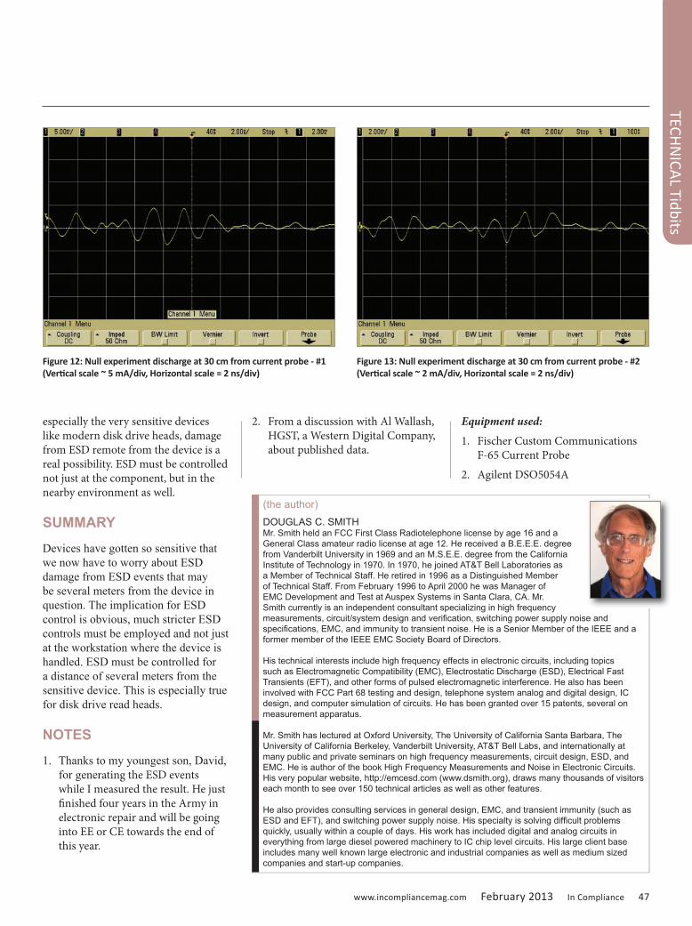
www.incompliancemag.com February 2013 In Compliance 47
especially the very sensitive devices like modern disk drive heads, damage from ESD remote from the device is a real possibility. ESD must be controlled not just at the component, but in the nearby environment as well.
SUMMARY
Devices have gotten so sensitive that we now have to worry about ESD damage from ESD events that may be several meters from the device in question. The implication for ESD control is obvious, much stricter ESD controls must be employed and not just at the workstation where the device is handled. ESD must be controlled for a distance of several meters from the sensitive device. This is especially true for disk drive read heads.
NOTES
1. Thanks to my youngest son, David, for generating the ESD events while I measured the result. He just finished four years in the Army in electronic repair and will be going into EE or CE towards the end of this year.
2. From a discussion with Al Wallash, HGST, a Western Digital Company, about published data.
Equipment used:
1. Fischer Custom Communications F-65 Current Probe
2. Agilent DSO5054A
TECHN
ICAL Tidbits
(the author)DOUGLAS C. SMITHMr. Smith held an FCC First Class Radiotelephone license by age 16 and a General Class amateur radio license at age 12. He received a B.E.E.E. degree from Vanderbilt University in 1969 and an M.S.E.E. degree from the California Institute of Technology in 1970. In 1970, he joined AT&T Bell Laboratories as a Member of Technical Staff. He retired in 1996 as a Distinguished Member of Technical Staff. From February 1996 to April 2000 he was Manager of EMC Development and Test at Auspex Systems in Santa Clara, CA. Mr. Smith currently is an independent consultant specializing in high frequency measurements, circuit/system design and verification, switching power supply noise and specifications, EMC, and immunity to transient noise. He is a Senior Member of the IEEE and a former member of the IEEE EMC Society Board of Directors.
His technical interests include high frequency effects in electronic circuits, including topics such as Electromagnetic Compatibility (EMC), Electrostatic Discharge (ESD), Electrical Fast Transients (EFT), and other forms of pulsed electromagnetic interference. He also has been involved with FCC Part 68 testing and design, telephone system analog and digital design, IC design, and computer simulation of circuits. He has been granted over 15 patents, several on measurement apparatus.
Mr. Smith has lectured at Oxford University, The University of California Santa Barbara, The University of California Berkeley, Vanderbilt University, AT&T Bell Labs, and internationally at many public and private seminars on high frequency measurements, circuit design, ESD, and EMC. He is author of the book High Frequency Measurements and Noise in Electronic Circuits. His very popular website, http://emcesd.com (www.dsmith.org), draws many thousands of visitors each month to see over 150 technical articles as well as other features.
He also provides consulting services in general design, EMC, and transient immunity (such as ESD and EFT), and switching power supply noise. His specialty is solving difficult problems quickly, usually within a couple of days. His work has included digital and analog circuits in everything from large diesel powered machinery to IC chip level circuits. His large client base includes many well known large electronic and industrial companies as well as medium sized companies and start-up companies.
Figure 12: Null experiment discharge at 30 cm from current probe - #1(Vertical scale ~ 5 mA/div, Horizontal scale = 2 ns/div)
Figure 13: Null experiment discharge at 30 cm from current probe - #2(Vertical scale ~ 2 mA/div, Horizontal scale = 2 ns/div)

48 In Compliance February 2013 www.incompliancemag.com
One of the most interesting comments I received emphasizes the sometimes
unknown future benefits of a
background in EMC studies. The comments were from Mr. Dieter Paasche of Kitchener, Ontario, Canada. I found Mr. Paasche’s insight very
The View from the ChalkboardBY MARK STEFFKA
Welcome to the second installment of my column on who’s doing what in university-based EMC education. I received a number of comments and course information after the first column was published in the November edition of In Compliance. Thank you to all who took the time to contact me. As you can see, I’ve made some additions to the table that was first published in 2012. Please continue to let me know of your courses so that this table will grow.
EMC Education
EMC Ed
ucati
on
Course Title Location When Delivery Method Contact
Introduction to EMC (Undergraduate course)
University of Michigan - Dearborn
Fall semester (typically) On campus class with lab Mark Steffka
Advanced Topics in EMC (Graduate course)
University of Michigan - Dearborn
Winter semester (typically)
On campus with distance learning available
Mark Steffka [email protected]
Electromagnetic Compatibility (Undergraduate/graduate class) University of Detroit - Mercy Once every 2 to 3
years On campus Mark Steffka [email protected]
Interference Control in Electronic System Design (Undergraduate/graduate course)
Missouri University of Science and Technology, Rolla, MO
Fall semester (typically)
On campus and distance learning available
Dr. Daryl Beetner http://dce.mst.edu/emc/
Signal Integrity (Undergraduate/graduate course)
Missouri University of Science and Technology, Rolla, MO
Spring semester (typically) On campus Dr. Jun Fan
http://dce.mst.edu/emc/
Microwave Principles for Mixed-signal Design (Undergraduate/graduate course)
Missouri University of Science and Technology, Rolla, MO
Fall semester of odd years (typically)
On campus Dr. Jim Drewniak http://dce.mst.edu/emc/
Advanced RF & Time Domain Measurement (Graduate course)
Missouri University of Science and Technology, Rolla, MO Check catalog On campus Dr. David Pommerenke
http://dce.mst.edu/emc/
Signal Integrity, High Speed Digital & RF Design Laboratory (Graduate course)
Missouri University of Science and Technology, Rolla, MO Check catalog On campus Dr. David Pommerenke
http://dce.mst.edu/emc/
Advanced Electromagnetics I (Graduate course)
Missouri University of Science and Technology, Rolla, MO
Spring semester (typically) On campus Dr. Richard DuBroff
http://dce.mst.edu/emc/
Computational Electromagnetics (Graduate course)
Missouri University of Science and Technology, Rolla, MO
Fall semester of even years (typically)
On campus and distance learning available
Dr. Jun Fan http://dce.mst.edu/emc/
EMC Principles (Certification)
Missouri University of Science and Technology, Rolla, MO
40 hours of class lectures available on video
Non-credit video course with test for certification
Dr. Daryl Beetner http://dce.mst.edu/emc/
Grounding and Shielding Plus Circuit Board Layout (Certification)
Missouri University of Science and Technology, Rolla, MO
20 hours of class lectures available on video
Non-credit video course with test for certification
Dr. Tom Van Doren http://dce.mst.edu/emc/
Signal Integrity for High-speed Digital Design (Certification)
Missouri University of Science and Technology, Rolla, MO
40 hours of class lectures available on video
Non-credit video course with test for certification
Dr. Jun Fan http://dce.mst.edu/emc/
Grounding and Shielding for Electronic Systems (Certification)
Missouri University of Science and Technology, Rolla, MO
2-day, on-site presentation
Non-credit live course with test for certification
Dr. Tom Van Doren http://dce.mst.edu/emc/
Circuit Board Layout to Reduce Noise Emission & Susceptibility (Certification)
Missouri University of Science and Technology, Rolla, MO
1-day, on-site presentation
Non-credit live course with test for certification
Dr. Tom Van Doren http://dce.mst.edu/emc/
EMC Protection of Communication Systems University of Zagreb, Croatia Fall semester On campus Krešimir Malarić
[email protected] EMC Course University name When it’s taught Method Contact information

www.incompliancemag.com February 2013 In Compliance 49
EMC Education
Course Title Location When Delivery Method Contact
Introduction to EMC (Undergraduate course)
University of Michigan - Dearborn
Fall semester (typically) On campus class with lab Mark Steffka
Advanced Topics in EMC (Graduate course)
University of Michigan - Dearborn
Winter semester (typically)
On campus with distance learning available
Mark Steffka [email protected]
Electromagnetic Compatibility (Undergraduate/graduate class) University of Detroit - Mercy Once every 2 to 3
years On campus Mark Steffka [email protected]
Interference Control in Electronic System Design (Undergraduate/graduate course)
Missouri University of Science and Technology, Rolla, MO
Fall semester (typically)
On campus and distance learning available
Dr. Daryl Beetner http://dce.mst.edu/emc/
Signal Integrity (Undergraduate/graduate course)
Missouri University of Science and Technology, Rolla, MO
Spring semester (typically) On campus Dr. Jun Fan
http://dce.mst.edu/emc/
Microwave Principles for Mixed-signal Design (Undergraduate/graduate course)
Missouri University of Science and Technology, Rolla, MO
Fall semester of odd years (typically)
On campus Dr. Jim Drewniak http://dce.mst.edu/emc/
Advanced RF & Time Domain Measurement (Graduate course)
Missouri University of Science and Technology, Rolla, MO Check catalog On campus Dr. David Pommerenke
http://dce.mst.edu/emc/
Signal Integrity, High Speed Digital & RF Design Laboratory (Graduate course)
Missouri University of Science and Technology, Rolla, MO Check catalog On campus Dr. David Pommerenke
http://dce.mst.edu/emc/
Advanced Electromagnetics I (Graduate course)
Missouri University of Science and Technology, Rolla, MO
Spring semester (typically) On campus Dr. Richard DuBroff
http://dce.mst.edu/emc/
Computational Electromagnetics (Graduate course)
Missouri University of Science and Technology, Rolla, MO
Fall semester of even years (typically)
On campus and distance learning available
Dr. Jun Fan http://dce.mst.edu/emc/
EMC Principles (Certification)
Missouri University of Science and Technology, Rolla, MO
40 hours of class lectures available on video
Non-credit video course with test for certification
Dr. Daryl Beetner http://dce.mst.edu/emc/
Grounding and Shielding Plus Circuit Board Layout (Certification)
Missouri University of Science and Technology, Rolla, MO
20 hours of class lectures available on video
Non-credit video course with test for certification
Dr. Tom Van Doren http://dce.mst.edu/emc/
Signal Integrity for High-speed Digital Design (Certification)
Missouri University of Science and Technology, Rolla, MO
40 hours of class lectures available on video
Non-credit video course with test for certification
Dr. Jun Fan http://dce.mst.edu/emc/
Grounding and Shielding for Electronic Systems (Certification)
Missouri University of Science and Technology, Rolla, MO
2-day, on-site presentation
Non-credit live course with test for certification
Dr. Tom Van Doren http://dce.mst.edu/emc/
Circuit Board Layout to Reduce Noise Emission & Susceptibility (Certification)
Missouri University of Science and Technology, Rolla, MO
1-day, on-site presentation
Non-credit live course with test for certification
Dr. Tom Van Doren http://dce.mst.edu/emc/
EMC Protection of Communication Systems University of Zagreb, Croatia Fall semester On campus Krešimir Malarić
[email protected] EMC Course University name When it’s taught Method Contact information

50 In Compliance February 2013 www.incompliancemag.com
much on target with how I feel about EMC education. With Mr. Paasche’s permission, I’d like to share his comments with you.
I would like to share with you my personal experience with EMC education. I was born and grew up in Mexico City , where I went to the National University of Mexico (UJAM) to get my electrical engineering bachelors degree. I had a class called Electromagnetic Theory and, funny but true, that subject is what got me into EMC years later. ( By the way, my teacher was Dr Prof Rodolfo Nervi Vela, the first Mexican Astronaut.) After graduating, I went to Germany. A recently build EMC lab was looking for people to test their products, young people fresh out of school with years of experience in EMC. Kind of a contradiction, right? Well, I was the only person that had “Electromagnetic” as a university subject and got the job. Twenty years later, here I am still working in EMC.
Personally, I think that EMC should be part of the regular engineering education. Products are getting smaller, more powerful, more wireless, and also more sensitive. Some day I would also like to see safety included as well, so we can avoid telling all smart design engineer, “Sorry, but you cannot do that. It will fail EMC.” From personal experience. 50% of new designs fail the EMC test. After the engineers come two or three times, the failing rate drops to about 20%. If EMC design is taken into account from the beginning, chances are a product will pass the first time.
Mr. Dieter Paasche Kitchener, Ontario, Canada
While I’m sure Mr. Paasche’s experience might not be unique to many of us (except for the chance to receive an education from an astronaut), his insight on the chances of a product successfully passing EMC testing the first time demonstrates that EMC design is extremely valuable. In today’s competitive environment, meeting program requirements and getting a product to market quickly is crucial to a company’s success. One way that Mr. Paasche suggests that this be accomplished is by the incorporation of EMC as a regular part of engineering education. Of course, many of us could not agree more!
So in follow up to that point, I’d like to ask you the following questions:
• If you have a formal university course on EMC, how is it perceived by the instructors of the “regular curriculum”? Do they support it? Do they mention it to their students?
• What do you think of having EMC be a required course? Are there other required courses that should be changed to an elective to make room for EMC?
Again, thank you for all your input and comments. I look forward to hearing from more of you as time goes by.
EMC Education
EMC Ed
ucati
on
(the author)
MARK STEFFKA, B.S.E., M.S.is a Lecturer (at the University of Michigan - Dearborn), an Adjunct Professor (at the University of Detroit – Mercy) and an automotive company Electromagnetic Compatibility (EMC) Technical Specialist. His university experience includes teaching undergraduate, graduate, and professional development courses on EMC, antennas, and electronic communications. His extensive industry background consists of over 30 years’ experience with military and aerospace communications, industrial electronics, and automotive systems.
Mr. Steffka is the author and/or co-author of numerous technical papers and publications on EMC presented at various Institute of Electrical and Electronics Engineers (IEEE) and Society of Automotive Engineers (SAE) conferences. He has also written about and has been an invited conference speaker on topics related to effective methods in university engineering education. He is an IEEE member, has served as a technical session chair for SAE and IEEE conferences and has served as an IEEE EMC Society Distinguished Lecturer. He holds a radio communications license issued by the United States’ Federal Communication Commission (FCC) and holds the call sign WW8MS.
Send your university EMC courses to be included in the matrix to Mark Steffka at [email protected]
What do you think of having EMC be a required course? Are there other required
courses that should be changed to an elective to make room for EMC?
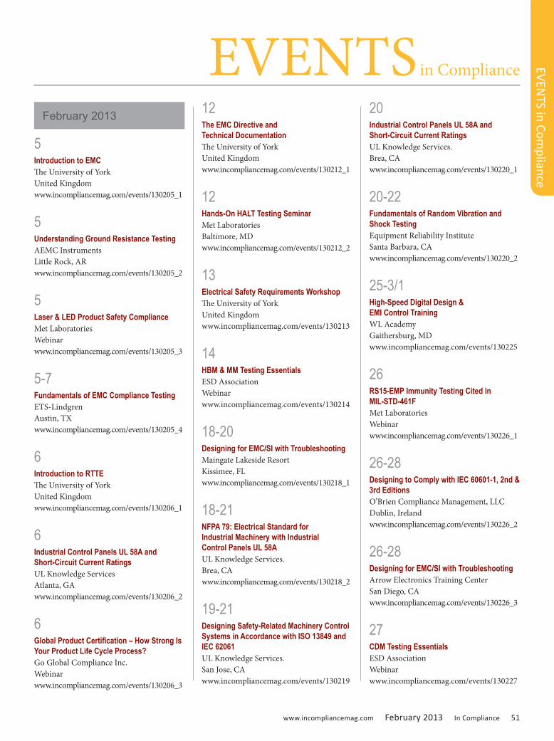
www.incompliancemag.com February 2013 In Compliance 51
5 Introduction to EMCThe University of York United Kingdomwww.incompliancemag.com/events/130205_1
5 Understanding Ground Resistance TestingAEMC InstrumentsLittle Rock, ARwww.incompliancemag.com/events/130205_2
5 Laser & LED Product Safety ComplianceMet LaboratoriesWebinarwww.incompliancemag.com/events/130205_3
5-7 Fundamentals of EMC Compliance TestingETS-Lindgren Austin, TXwww.incompliancemag.com/events/130205_4
6 Introduction to RTTEThe University of York United Kingdomwww.incompliancemag.com/events/130206_1
6 Industrial Control Panels UL 58A and Short-Circuit Current RatingsUL Knowledge ServicesAtlanta, GAwww.incompliancemag.com/events/130206_2
6 Global Product Certification – How Strong Is Your Product Life Cycle Process?Go Global Compliance Inc.Webinarwww.incompliancemag.com/events/130206_3
12 The EMC Directive and Technical DocumentationThe University of York United Kingdomwww.incompliancemag.com/events/130212_1
12 Hands-On HALT Testing SeminarMet LaboratoriesBaltimore, MDwww.incompliancemag.com/events/130212_2
13 Electrical Safety Requirements WorkshopThe University of York United Kingdomwww.incompliancemag.com/events/130213
14 HBM & MM Testing EssentialsESD AssociationWebinarwww.incompliancemag.com/events/130214
18-20 Designing for EMC/SI with TroubleshootingMaingate Lakeside Resort Kissimee, FLwww.incompliancemag.com/events/130218_1
18-21 NFPA 79: Electrical Standard for Industrial Machinery with Industrial Control Panels UL 58AUL Knowledge Services.Brea, CAwww.incompliancemag.com/events/130218_2
19-21 Designing Safety-Related Machinery Control Systems in Accordance with ISO 13849 and IEC 62061UL Knowledge Services.San Jose, CAwww.incompliancemag.com/events/130219
20 Industrial Control Panels UL 58A and Short-Circuit Current RatingsUL Knowledge Services.Brea, CAwww.incompliancemag.com/events/130220_1
20-22 Fundamentals of Random Vibration and Shock TestingEquipment Reliability InstituteSanta Barbara, CAwww.incompliancemag.com/events/130220_2
25-3/1 High-Speed Digital Design & EMI Control TrainingWL Academy Gaithersburg, MDwww.incompliancemag.com/events/130225
26 RS15-EMP Immunity Testing Cited in MIL-STD-461FMet LaboratoriesWebinarwww.incompliancemag.com/events/130226_1
26-28 Designing to Comply with IEC 60601-1, 2nd & 3rd EditionsO’Brien Compliance Management, LLCDublin, Irelandwww.incompliancemag.com/events/130226_2
26-28 Designing for EMC/SI with TroubleshootingArrow Electronics Training Center San Diego, CAwww.incompliancemag.com/events/130226_3
27 CDM Testing EssentialsESD AssociationWebinarwww.incompliancemag.com/events/130227
EVENTS in Com
pliance
February 2013
EVENTS in Compliance

52 In Compliance February 2013 www.incompliancemag.com
4-5 Principles of AntennasThe University of York United Kingdomwww.incompliancemag.com/events/130304_1
4-8 Reverberation Chamber Theory/Experiment Short CourseOklahoma State University Stillwater, OKwww.incompliancemag.com/events/130304_2
5 Understanding Ground Resistance TestingAEMC InstrumentsSan Franciso/Oakland, CAwww.incompliancemag.com/events/130305_1
5-7 Fundamentals of Random Vibration and Shock TestingDynaQual Test Labs Houston, TXwww.incompliancemag.com/events/130305_2
5-7 ESD Association Texas Local Chapter Regional Tutorial Program3M Innovation Center Austin, TXwww.incompliancemag.com/events/130305_3
5-7 EMV 2013International Congress Center Stuttgart Stuttgart, Germanywww.incompliancemag.com/events/130305_4
6 Industrial Control Panels UL 58A and Short-Circuit Current RatingsUL Knowledge Services.Phoenix, AZwww.incompliancemag.com/events/130306
12 Essentials for Controlling the ESD Work AreaESD AssociationWebinarwww.incompliancemag.com/events/130312_1
12-14 MIL-STD 461FETS-Lindgren Austin, TXwww.incompliancemag.com/events/130312_2
12-14 Measurement, Control and Laboratory Use Equipment: Designing for Compliance to IEC 61010-1 3rd Ed.UL Knowledge ServicesResearch Triangle Park, NCwww.incompliancemag.com/events/130312_3
13 Industrial Control Panels UL 58A and Short-Circuit Current RatingsUL Knowledge ServicesDallas, TXwww.incompliancemag.com/events/130313
19 Electrical Safety Requirements WorkshopThe University of York United Kingdomwww.incompliancemag.com/events/130319_1
19 IEEE Milwaukee Section 2013 EMC SeminarCrowne Plaza Milwaukee Airport Hotel Milwaukee, WIwww.incompliancemag.com/events/130319_2
20 The EMC Directive and Technical DocumentationThe University of York United Kingdomwww.incompliancemag.com/events/130320_1
20-21 Fundamentals of Applied EMC EngineeringUL Knowledge ServicesSan Jose, CAwww.incompliancemag.com/events/130320_2
20-22 MIL-STD-461F Training CourseMET LaboratoriesBaltimore, MDwww.incompliancemag.com/events/130320_3
21 EMF AwarenessThe University of York United Kingdomwww.incompliancemag.com/events/130321_1
21 Fundamentals of Failure AnalysisESD AssociationWebinarwww.incompliancemag.com/events/130321_2
24-28 The 29th International Review of Progress in Applied Computational ElectromagneticsEmbassy Suites Monterey BaySeaside, CAwww.incompliancemag.com/events/130324
25-26 EMC for Working EngineersOklahoma State University Stillwater, OKwww.incompliancemag.com/events/130325
EVENTS in Compliance
EVEN
TS in
Com
plia
nce
March 2013
www.incompliancemag.com February 2013 In Compliance 53
26-28 Designing to Comply with IEC 60601-1, 2nd & 3rd EditionsO’Brien Compliance Management, LLCSan Jose, CAwww.incompliancemag.com/events/130326
27-28 Advanced EMC Design Using Simulation ToolsOklahoma State University Stillwater, OKwww.incompliancemag.com/events/130327_1
27-28 Grounding and Shielding of Electronic SystemsUniversity of Missouri-St. Louis St. Louis, MOwww.incompliancemag.com/events/130327_2
2 Understanding Ground Resistance TestingAEMC InstrumentsTampa, FLwww.incompliancemag.com/events/130402
4 Advanced HBM – Dealing with Tester Parasitics, High Pin Count and Two Pin TestingESD AssociationWebinarwww.incompliancemag.com/events/130404
8-12 EuCAP 2013: the 7th European Conference on Antennas and PropagationSwedish Exhibition & Congress Center Gothenburg, Swedenwww.incompliancemag.com/events/130408
9 Industrial Control Panels UL 58A and Short-Circuit Current RatingsUL Knowledge ServicesNatick, MAwww.incompliancemag.com/events/130409_1
9-10 EMI/EMC in Military SystemsKimmel Gerke AssociatesColumbia, MDwww.incompliancemag.com/events/130409_2
9-11 Electromagnetic Compatibility EngineeringHenry Ott ConsultantsWestford, MAwww.incompliancemag.com/events/130409_3
9-11 Fundamentals of Random Vibration and Shock TestingDFR Solutions Beltsville, MDwww.incompliancemag.com/events/130409_4
9-12 MIL-STD-461FWL Academy Gaithersburg, MDwww.incompliancemag.com/events/130409_5
15-19 Fundamentals of Design and TestingThe University of York United Kingdomwww.incompliancemag.com/events/130415
16 TLP Fundamentals – Understanding the Equipment Options and IV Data ESD AssociationWebinarwww.incompliancemag.com/events/130416_1
16-18 Designing to Comply with IEC 60601-1, 2nd & 3rd Editions O’Brien Compliance Management, LLC North Chelmsford, MAwww.incompliancemag.com/events/130416_2
17 Electrical Safety Requirements Workshop The University of YorkUnited Kingdomwww.incompliancemag.com/events/130417_1
17 Northeast Product Safety Society, Inc. 17th Annual Vendors’ Night Holiday InnBoxborough, MAwww.incompliancemag.com/events/130417_2
18-19 EMC Testing The University of YorkUnited Kingdomwww.incompliancemag.com/events/130418
23-25 EMC By Your Design: A Practical Applications Seminar & Workshop D.L.S. Electronic Systems, Inc.Northbrook, IL www.incompliancemag.com/events/130423
25 Fundamentals of System Level Testing ESD AssociationWebinarwww.incompliancemag.com/events/130425_1
17-18 DATE CHANGE ESD Association North Central Local Chapter Regional Tutorial Program Crowne Plaza Hotel and Suites-Bloomington, MNwww.incompliancemag.com/events/130425_2
EVENTS in Com
pliance
April 2013
EVENTS in Compliance

54 In Compliance February 2013 www.incompliancemag.com
BUSINESS News
BUSI
NES
S N
ews
Aeroflex Introduces a Multi-Strategy Test System for Analog In-Circuits and Functions Test for Electronic AssembliesAeroflex has announced its new 5860 multi-strategy test system that combines analog in-circuit test and functional test capabilities in a compact, floor-standing system. This system is the first Aeroflex ATE (Automated Test Equipment) product incorporating a Virginia Panel – the industry-standard mass interconnect interface suitable for all production test requirements.
The 5860 allows seamless integration of third party PXI instruments in a single test system for fast and configurable in-circuit test, functional test and device programming.
For more information, contact your local Aeroflex sales office in the US at 800-835-2352, in the UK at +44 (0) 1438 742200 or email [email protected].
New Amphenol Canada Filter CatalogAmphenol Canada has released their new 2013 filter connector catalog. Amphenol Canada specializes in designing and supply filter connectors to meeting customer
requirements with aggressive lead times and extensive capabilities. View the new catalog online at www.amphenolcanada.com
Com-Power Microwave Biconical Antenna for CISPR 16 Site Calibration above 1 GHzCom-Power Microwave has announced the introduction of a new biconcial antenna that is ideal for CISPR-16-1-4 Site Voltage Standing Wave Ratio testing. Model ABM-6000 operates in the 1 to 6 GHz frequency range and features a dipole-like radiation pattern. It can be used as a transmitting or receive antenna and is covered by a three year warranty.
For more information, visit Com-Power Microwave online at www.com-power.com.
D.L.S. Electronic Systems Now Offers Wireless Qi CertificationD.L.S. Electronic Systems has announced they are offering Qi pre-compliance and formal certification as of December 15, 2012. They are one of only two North American laboratories participating in the Qi Compliance Program.
For more information on their capabilities, contact D.L.S. Electronic Systems at 847-537-6400 or online at www.dlsemc.com.
Fair-Rite Products Corporation Expands Power Inductive SelectionFair-Rite Products Corp. has announced the expansion of its line of power inductive materials to include a full offering of standard components as well as custom shapes and sizes. These materials are highlighted in a new catalog and are designed to optimize performance across operating frequency and temperature to produce efficient energy conversation products.
There are 5 new materials for transformers and power supplies operating in the 20 to 750 kHz frequency range. Above 200 MHz, Fair-Rite has 4 additional materials available. These materials will provide the same quality and performance synonymous with the Fair-Rite family of EMC products.
In addition to these materials, Fair-Rite has also broadened its offerings for power applications including complex geometrics of pot cores, RM cores and much more.
For more information on these new lines of materials, visit Fair-Rite online at www.fair-rite.com.
Global Test Solutions Introduce New DL Series Electronic DC LoadsGlobal Test Solutions announced the launch of the DL Series electronic direct current (DC) loads from NF Corporation with high speed feedback control. Four mod-els are available, each with six modes combining
www.incompliancemag.com February 2013 In Compliance 55
BUSIN
ESS New
s
constant voltage, current and resis-tance from 300 to 1000 watts.
These DL series loads can be ganged together to configured up to a 10,000 watt system. Input voltage is variable – options available up to 120V at 180A or 500V at 36A for the 1000 watt models.
For more information, call Global Test Solutions at 760-751-2049 or online at www.globaltestsolutions.com.
Hipotronics Launches New Training ProgramHipotronics has announced the launch of their new training program, HIPO University. Through the courses offered, students will gain familiarity with a wide range of test sets and applications. These courses are ideal for individuals working in the high voltage industry. For more information on HIPO University, visit www.hipotronics.com/training.htm
IQD Announces New Low Phase Noise and Low Power Clock OscillatorIQD Frequency Products has intro-duced a new crystal clock oscillator offering two key features – low phase noise and low cur-rent con-sumption. The CFPS-115 is available at any frequency between 26 to 44 MHz and offers a standard 45/55% duty cycle HCMOS output.
The CFPS-115 is versatile oscillator designed for computing, aviation, data logging and monitoring equipment applications or where low phase and low power are critical to the end product performance.
For more information about the CFPS-115 oscillator, visit www.iqdfrequencyproducts.com.
Leader Tech Now Offers CFS Conductive Foam for Die-Cut EMI GasketsLeader Tech announced their CFS conductive form shielding material that consists of resilient Nickel-Copper polyurethane foam which is layered between two pieces of conductive fabric. The CFS conductive foam is ideal for applications that require low compression forces but excellent shielding effectiveness. For more information on the CFS conductive form, visit www.leadertechinc.com.
MI Technologies Celebrates 15th AnniversaryMI Technologies announced their 15th anniversary as an independent entity. In 1997, MI Technologies was formed through the purchase of several operating divisions of Scientific-Atlantic, Inc. MI Technologies is the leading supplier of precision microwave test, measurement and motion control products and solutions.
For more information on MI Technologies and their products, visit www.mitechnologies.com.
Rohde & Schwarz RTO Oscilloscopes Verify USB Interface Compliance Rohde & Schwarz has announced new software for their high-performance oscilloscopes that is ideal for automated USB 2.0
compliance tests. The software offers scenarios for testing USB 2.0 devices (DUT) when functioning as a device, host or hub. The different tests verify the signal quality, exchange of data packets, timing between transmitter and receiver, receiver sensitivity and much more. The R&S RTO-K21 USB 2.0 compliance software and R&S RT-ZF1 test fixture set are now available.
For more information, contact Rohde & Schwarz in North America at 888-837-8772 or [email protected].
RTP Company’s Multi-Property Compound Solves Impact Challenge When the makers of a power system for the marine industry wanted to include a 50 amp version of their popular 30 am SmartPlug system, they needed to find a new thermoplastic material solution that would provide the necessary flame retardancy and impact resistance required for this new design. Working together with RTP company, a custom compounder, they were able to engineer a material solution that met the electrical connector requirements and regulatory approvals.
For more information on RTP Company’s flame retardant or custom engineered thermoplastics compounds, call (507) 454-6900, or visit their website at www.rtpcompany.com.

56 In Compliance February 2013 www.incompliancemag.com
BUSINESS News
BUSI
NES
S N
ews
TDK Extends Voltage Range of EPCOS AL EL Capacitors TDK Corporation has announced the extended the range of EPCOS aluminum electrolytic capacitors by adding types with higher rated voltages. For the screw terminal types in the new B43700* and B43720* series, the previous rated voltage of 550 V DC has been raised to 600 V DC. These capacitors cover a capacitance range from 1200 µF to 6800 µF and are designed for temperatures up to 85° C.
With these significant voltage increases, developers of industrial power supplies and frequency converters for drives, inverters for photovoltaic systems, and converters for wind power plants now need fewer capacitors in series in the DC link, thus reducing costs.
For additional information on these capacitors, call 1-800-888-7726 or go to www.epcos.com/inquiry.
New Development Kit from Teseq Helps Build Personalized Pulse NetworksTeseq has introduced a new development kit that allows automotive technicians and engineers the ability to design their own pulse networks. In conjunction with the NSG5500, automotive EMC test labs can use the FLX5510 to easily design their own pulses as well as meet unique and custom specifi-cations includ-
ing pulse impedance, peak voltage, pulse width and pulse width under load.
For more information, contact MaryJane Salvador at [email protected].
TUV SUD is one of the “Brands of the Century”TUV SUD announced they are among the winners of the “Brand of the Century” award for the second, consecutive year. Receiving this award, makes TUV SUD a member of an exclusive circle of approximately 250 German brands offering a unique selling proposition which distinguishes them as representative of their product sector.
As the high-profile jury agreed, the name of TUV SUD is virtually synonymous with testing and inspection organizations in Germany. As a “Brand of the Century,” TUV SUD is in the best company. Other German companies awarded the prize include Haribo, Tempo, Persil, and wall-plug manufacturer Fischer. Part of the prize for TUV SUD is the company’s inclusion in the book “Beacons in a Sea of Brands,” which is available from bookshops in three languages - German, English, and Mandarin Chinese.
For more information about TUV SUD, visit www.tuv-sud.de.
New Protective Vent Improves Reliability of Small Electronic DevicesW. L. Gore & Associates has announced an expanded line of adhesive vents with a new product specifically engineered for small enclosures, such as displays for electric bikes, mobility aids, and heavy duty equipment. The VE80205 vent has the smallest footprint in the
family and improves the integrity, reliability and safety of electronic components in harsh weather by equalizing pressure and reducing condensation.
Available in standard packaging of five parts across a 41-millimeter wide carrier, the two-by-five millimeter (2.0 x 5.0 mm) VE80205 vent has a typical airflow of 103.62 ml/min/cm2 and is constructed with a robust adhesive that withstands challenging environments and adheres to different product surfaces. This durable construction enables the vent to be installed manually or with an automated process on either the internal or external wall of the enclosure without compromising its performance.
For more information about Gore’s full line of venting products, visit www.gore.com/protectivevents.
Wurth Electronics Midcom Inc. Releases LTspice Transformer Library Wurth Electronics Midcom Inc. has announced the release of the LTspice Transfomer Library. The library provides LTspice models for products including the flyback transformer product group, PoE and PoE+ products, offline power solutions, isolated DC-DC converters, and power supply solutions for lighting and metering applications. Two libraries are available, Standard and Basic. Customers can access the LTspice Library online at www.we-online.com/toolbox. For information on custom models, or for any questions, contact Wurth Electronics Midcom Inc. at [email protected].
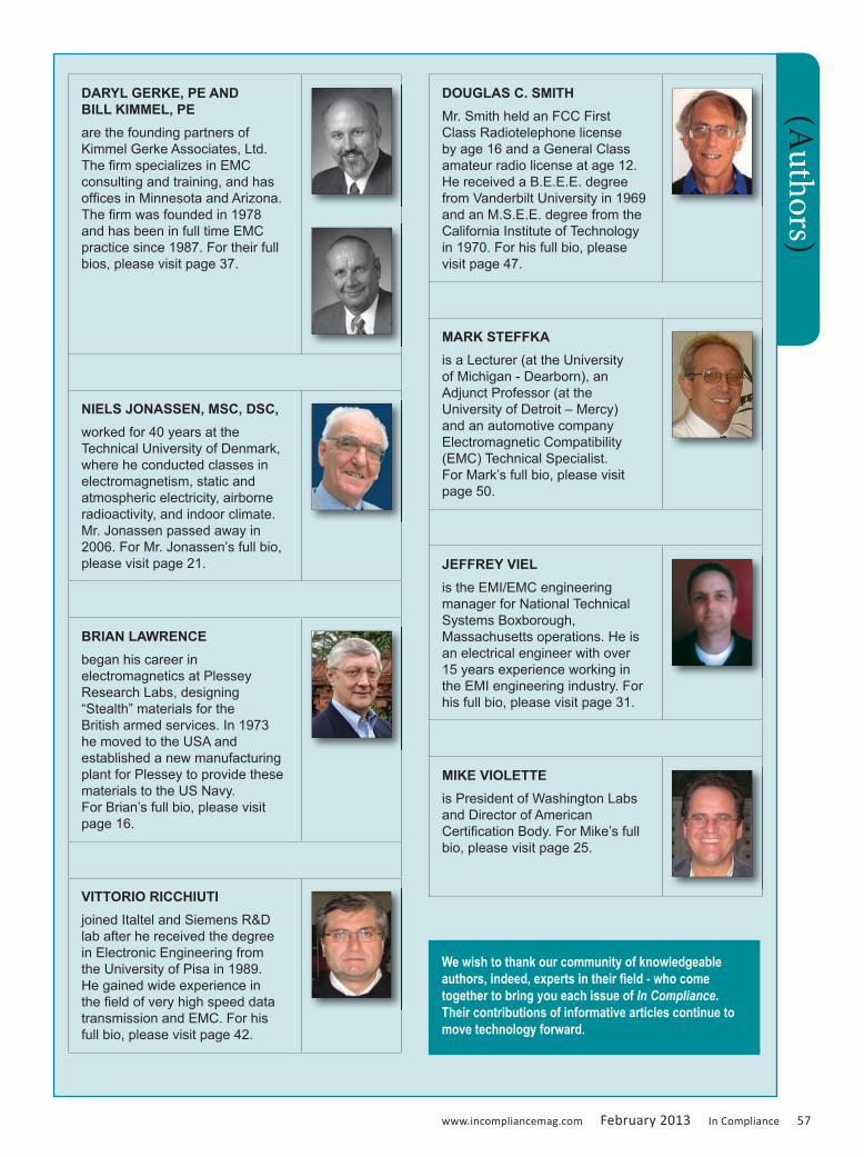
www.incompliancemag.com February 2013 In Compliance 57
DARYL GERKE, PE AND BILL KIMMEL, PE are the founding partners of Kimmel Gerke Associates, Ltd. The firm specializes in EMC consulting and training, and has offices in Minnesota and Arizona. The firm was founded in 1978 and has been in full time EMC practice since 1987. For their full bios, please visit page 37.
NIELS JONASSEN, MSC, DSC, worked for 40 years at the Technical University of Denmark, where he conducted classes in electromagnetism, static and atmospheric electricity, airborne radioactivity, and indoor climate. Mr. Jonassen passed away in 2006. For Mr. Jonassen’s full bio, please visit page 21.
BRIAN LAWRENCE began his career in electromagnetics at Plessey Research Labs, designing “Stealth” materials for the British armed services. In 1973 he moved to the USA and established a new manufacturing plant for Plessey to provide these materials to the US Navy. For Brian’s full bio, please visit page 16.
VITTORIO RICCHIUTI joined Italtel and Siemens R&D lab after he received the degree in Electronic Engineering from the University of Pisa in 1989. He gained wide experience in the field of very high speed data transmission and EMC. For his full bio, please visit page 42.
DOUGLAS C. SMITHMr. Smith held an FCC First Class Radiotelephone license by age 16 and a General Class amateur radio license at age 12. He received a B.E.E.E. degree from Vanderbilt University in 1969 and an M.S.E.E. degree from the California Institute of Technology in 1970. For his full bio, please visit page 47.
MARK STEFFKAis a Lecturer (at the University of Michigan - Dearborn), an Adjunct Professor (at the University of Detroit – Mercy) and an automotive company Electromagnetic Compatibility (EMC) Technical Specialist. For Mark’s full bio, please visit page 50.
JEFFREY VIELis the EMI/EMC engineering manager for National Technical Systems Boxborough, Massachusetts operations. He is an electrical engineer with over 15 years experience working in the EMI engineering industry. For his full bio, please visit page 31.
MIKE VIOLETTEis President of Washington Labs and Director of American Certification Body. For Mike’s full bio, please visit page 25.
(Authors)
We wish to thank our community of knowledgeable authors, indeed, experts in their field - who come together to bring you each issue of In Compliance. Their contributions of informative articles continue to move technology forward.
58 In Compliance February 2013 www.incompliancemag.com
Advertiser Name Page Advertiser Name Page
A.H. Systems C2 IEEE EMC Milwaukee 2013 Seminar 25, 58
AR 11 LCR Electronics, Inc. 23
Advanced Test Equipment Rentals 9 Monroe Electronics 58
Dexmet Corporation 13 Panashield Inc. 15
E. D. & D., Inc. 17 Rigol Technologies 19
ETS-Lindgren C3 Teseq C4
Henry Ott Consultants 6/7, 58 Washington Laboratories Academy 21
IEEE EMC 2013 Symposium 3(Adv
ertis
ers)
April 9-11, 2013Westford Regency Inn & Conference Center
Westford, MassachusettsIn this 3-day intensive course we’ll cover practical aspects of noise and interference control in electronic systems and provide a working knowledge of EMC principles. Ideas are illustrated with examples of actual case histories and mathematic complexity is kept to a minimum. Participants will gain knowledge needed to design electronic equipment compatible with the electromagnetic environment and in compliance with national and international EMC regulations.
For more information please visit www.hottconsultants.com
or call 973-992-1793
Electromagnetic Compatibility Engineering
a course in noise and interference control in electronic systems
presented by renowned EMC expert Henry Ott
PRO
DU
CT S
how
case
PRODUCT ShowcaseYour Source for Product and Service Solutions
IEEE Milwaukee Section presents the
2013 EMC Seminar with Kenneth Wyatt
This year’s program is focused on Developing a Personal EMC Trouble Shooting Kit that will meet today’s challenges of tight engineering budgets. The assembly of your own EMC Troubleshooting Kit will keep the “Focus of EMC” at the forefront of your designs. Mr. Kenneth Wyatt has developed an outstanding approach that can be implemented for less than $5,000.00 (including spectrum analyzer)! Those attending will greatly benefit from Ken’s tutorials and classroom experimentation of these recommended tools.
For more information contact Jim Blaha at
Tuesday, March 19, 2013Crowne Plaza Milwaukee Airport Hotel
Milwaukee, Wisconsin
www.ets-lindgren.com
Offices in the US, Brazil, Finland, Germany, France, UK, India, Japan, Singapore, China, TaiwanEMCenter and TILE! are trademarks of ETS-Lindgren ©2013 ETS-Lindgren
Solutions for Aerospace and Defense Testing
• AnechoicAbsorber• AnechoicChambers• Antennas• E-FieldProbes• EMCenter™• Filters• GTEM&TEMCells
• IntegratedSystems• ReverbChambers• Shielding• ShieldedDoors• ShieldedRooms• TestCells• TILE!™Software
Solutions for MIL-STD & DO-160 Testing:
Whole Aircraft Test Chambers
Whole Vehicle Test Chambers
courtesy of Otokar
Component Test Chambers
How-To, Hands-On Classes
Aero-Defense_ad2.indd 1 1/9/13 4:25 PM

a TESEQ Company a TESEQ Company
Teseq, IFI & mIlmega –The New BraNd To rememBer!
Three strong brands joined forces in 2012 under the Teseq umbrella
to offer the industry’s widest product range: Teseq, IFI and Milmega!
Our product portfolio includes Milmega’s famous solid state micro-
wave amplifiers, Teseq’s rugged Class A power amplifiers and IFI’s
high power RF solid state and Tetrode tube amplifiers, as well as
their well-known TWT amplifiers up to 40 GHz. Teseq now covers any
application in the EMC, telecommunications and defense industries.
Our strong global service network with local accredited calibration
labs ensures fast turn-around for calibration and repair. We back our
commitment to quality and reliability with a warranty up to 5 years.
Teseq – IFI – Milmega, the new power amplifier team to remember!
What we offer:
AmplifiersforEMC,ISM,telecomanddefense
Solid-stateclassAandclassABmodels
CW,pulsedandcombinedTWTamplifiers
Tetrodetubeamplifiers
Whatmakesusunique:
Rugged,reliabledesignforEMCtestingwithanyload
Higherpoweratlowerfrequencytocompensatefor
antennagain
Compactdesignwithmodulararchitecture
Upto5yearswarranty
LocalservicethroughTeseq’sownserviceorganizations
TeseqInc. Edison, NJ USA T + 1 732 417 0501 F + 1 732 417 0511 [email protected] www.tesequsa.com