Table of Compliance
47
1 Scope The detailed design submissions include: 1) Schematic or Circuit Drawings (Station & Bay Level) – AC and DC distribution, instrument transformer & power circuit, measuring & instrumentation circuit, communication network, switching device tripping & closing circuits, protection circuits, manual synchronizing, alarm monitoring, system drawing, terminal function diagram, etc. The Integrated SCPS shall be designed: 1) To accommodate future substation upgrades, modifications, extension and expansion 2) To achieve the objectives of IEC 61850 standard, i.e. interoperability, simple configuration & allocation of functions, and be future proof 3) To ensure high reliability, performance and availability to minimize the interruption of service and functions 4) To ensure that single failure at station level or one bay will not affect the operation and functions of other bays 5) To maximize the utilization of substation information for supporting decision processes, engineering, operation & maintenance, fault investigation & diagnostics, and asset management 6) To optimize the application of devices, panels, cabling and substation space 7) To provide safe, secure and reliable operation of the substation throughout its total life cycle 8) To withstand harsh operational substation environment such as the impact of electromagnetic interference and adverse environmental conditions. Table of Compliance Standard Equipment Status (S or M) Bid No. : PAT-SCS-SCPS01/2018 Specification No : RSUB–010/2560 (Rev.1.0) Substation control and protection system (SCPS) Clause No. Clause Name Conformance Status (C,A or N) Proposed Data Referred to Page Remark C:Conform N: Non-Conform A:Alternative S:Standard Equipment M:Modify Page 1 of 47
-
Upload
khangminh22 -
Category
Documents
-
view
1 -
download
0
Transcript of Table of Compliance

1 Scope
The detailed design submissions include: 1) Schematic or Circuit Drawings (Station & Bay Level) – AC and DC distribution, instrument transformer & power circuit, measuring & instrumentation circuit, communication network, switching device tripping & closing circuits, protection circuits, manual synchronizing, alarm monitoring, system drawing, terminal function diagram, etc.
The Integrated SCPS shall be designed: 1) To accommodate future substation upgrades, modifications, extension and expansion 2) To achieve the objectives of IEC 61850 standard, i.e. interoperability, simple configuration & allocation of functions, and be future proof 3) To ensure high reliability, performance and availability to minimize the interruption of service and functions 4) To ensure that single failure at station level or one bay will not affect the operation and functions of other bays 5) To maximize the utilization of substation information for supporting decision processes, engineering, operation & maintenance, fault investigation & diagnostics, and asset management 6) To optimize the application of devices, panels, cabling and substation space 7) To provide safe, secure and reliable operation of the substation throughout its total life cycle 8) To withstand harsh operational substation environment such as the impact of electromagnetic interference and adverse environmental conditions.
Table of Compliance
Standard Equipment
Status(S or M)
Bid No. : PAT-SCS-SCPS01/2018
Specification No : RSUB–010/2560 (Rev.1.0) Substation control and protection system (SCPS)Clause
No.Clause Name Conformance
Status(C,A or N)
Proposed Data
Referred to Page
Remark C:Conform N: Non-Conform A:Alternative S:Standard Equipment M:Modify Page 1 of 47

Table of Compliance
Standard Equipment
Status(S or M)
Bid No. : PAT-SCS-SCPS01/2018
Specification No : RSUB–010/2560 (Rev.1.0) Substation control and protection system (SCPS)Clause
No.Clause Name Conformance
Status(C,A or N)
Proposed Data
Referred to Page
The Contractor shall design and implement the Integrated SCPS to facilitate:1) A distributed architecture using distributed station and bay intelligent devices, functions and applications 2) full system integration via substation communication network 3) fully automated functions 4) the separation of substation operator interface and engineering interface 5) the station level operator interface and SCADA gateway to perform station/supervisory monitoring and control operation of the substation 6) to support engineering workstations to manage the SCPS, communication network and substation information, and to provide applications utilizing the substation information 7) to support the application of Ethernet Technology and Information Communication Technology (ICT) such as Client-Server communication, Peer-to-Peer communication, web-based application, SCL, MMS (Manufacturer Message Specification), TCP/IP and Ethernet 8) IEC 61850 enabled technology including IEC 61850 conformant multifunction intelligent devices
9) self-monitoring, condition-based monitoring (optional) and management of intelligent devices, communication network and substation equipment. The Contractor shall propose condition-based monitoring as an option, together with a separate quotation, for PEA approval. 10) the integration of intelligent devices in single panel 11) the interoperability of IEDs from several different manufacturers to exchange information and use the information for their own functions. 12) the maximum utilization of information from IEDs.
Remark C:Conform N: Non-Conform A:Alternative S:Standard Equipment M:Modify Page 2 of 47
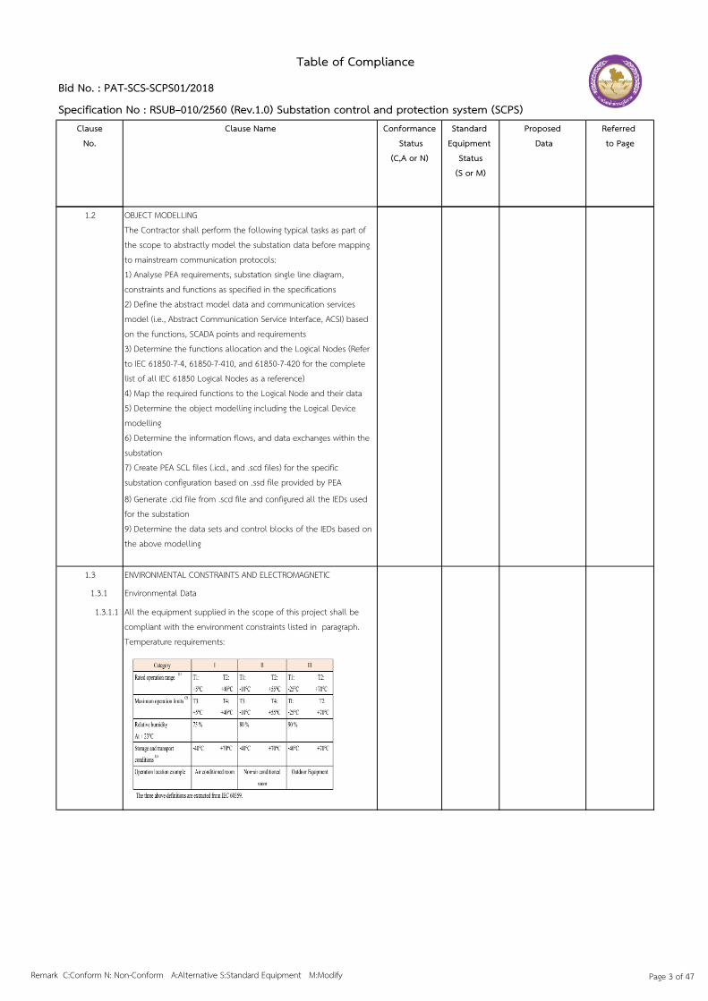
Table of Compliance
Standard Equipment
Status(S or M)
Bid No. : PAT-SCS-SCPS01/2018
Specification No : RSUB–010/2560 (Rev.1.0) Substation control and protection system (SCPS)Clause
No.Clause Name Conformance
Status(C,A or N)
Proposed Data
Referred to Page
1.2 OBJECT MODELLINGThe Contractor shall perform the following typical tasks as part of the scope to abstractly model the substation data before mapping to mainstream communication protocols: 1) Analyse PEA requirements, substation single line diagram, constraints and functions as specified in the specifications 2) Define the abstract model data and communication services model (i.e., Abstract Communication Service Interface, ACSI) based on the functions, SCADA points and requirements 3) Determine the functions allocation and the Logical Nodes (Refer to IEC 61850-7-4, 61850-7-410, and 61850-7-420 for the complete list of all IEC 61850 Logical Nodes as a reference)4) Map the required functions to the Logical Node and their data 5) Determine the object modelling including the Logical Device modelling 6) Determine the information flows, and data exchanges within the substation 7) Create PEA SCL files (.icd., and .scd files) for the specific substation configuration based on .ssd file provided by PEA
8) Generate .cid file from .scd file and configured all the IEDs used for the substation 9) Determine the data sets and control blocks of the IEDs based on the above modelling
1.3 ENVIRONMENTAL CONSTRAINTS AND ELECTROMAGNETIC COMPATIBILITY 1.3.1 Environmental Data
1.3.1.1 All the equipment supplied in the scope of this project shall be compliant with the environment constraints listed in paragraph. Temperature requirements:
Remark C:Conform N: Non-Conform A:Alternative S:Standard Equipment M:Modify Page 3 of 47

Table of Compliance
Standard Equipment
Status(S or M)
Bid No. : PAT-SCS-SCPS01/2018
Specification No : RSUB–010/2560 (Rev.1.0) Substation control and protection system (SCPS)Clause
No.Clause Name Conformance
Status(C,A or N)
Proposed Data
Referred to Page
1.3.1.2 Class of Equipment
According to these figures, the equipment to be supplied shall be compliant with tropical constraints.
ELECTROMAGNETIC ENVIRONMENTAL STANDARDSIsolation tests: voltage withstand
ISOLATION TESTS: DIELECTRIC WITHSTAND
Isolation tests: impulse voltage withstand
Immunity tests against radiated electromagnetic field disturbances
Immunity tests against recurrent fast transient
Remark C:Conform N: Non-Conform A:Alternative S:Standard Equipment M:Modify Page 4 of 47
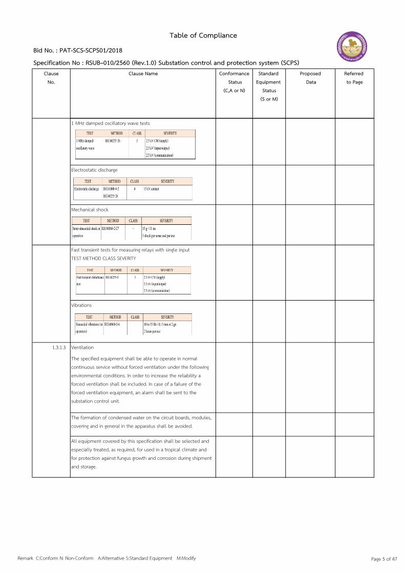
Table of Compliance
Standard Equipment
Status(S or M)
Bid No. : PAT-SCS-SCPS01/2018
Specification No : RSUB–010/2560 (Rev.1.0) Substation control and protection system (SCPS)Clause
No.Clause Name Conformance
Status(C,A or N)
Proposed Data
Referred to Page
1 MHz damped oscillatory wave tests
Electrostatic discharge
Mechanical shock
Fast transient tests for measuring relays with single inputTEST METHOD CLASS SEVERITY
Vibrations
1.3.1.3 Ventilation
The specified equipment shall be able to operate in normal continuous service without forced ventilation under the following environmental conditions. In order to increase the reliability a forced ventilation shall be included. In case of a failure of the forced ventilation equipment, an alarm shall be sent to the substation control unit.
The formation of condensed water on the circuit boards, modules, covering and in general in the apparatus shall be avoided.
All equipment covered by this specification shall be selected and especially treated, as required, for used in a tropical climate and for protection against fungus growth and corrosion during shipment and storage.
Remark C:Conform N: Non-Conform A:Alternative S:Standard Equipment M:Modify Page 5 of 47

Table of Compliance
Standard Equipment
Status(S or M)
Bid No. : PAT-SCS-SCPS01/2018
Specification No : RSUB–010/2560 (Rev.1.0) Substation control and protection system (SCPS)Clause
No.Clause Name Conformance
Status(C,A or N)
Proposed Data
Referred to Page
1.3.2 Physical Environment and Service Conditions
All SCPS equipment shall be housed in dust proof and water proof housing cabinet to IEC 60529, protection class IP50 or better for indoor, and protection class IP65 for outdoor, but shall be adequately ventilated to prevent damage to any component when exposed to high ambient temperatures.
1.3.2.1 Outdoor Devices
supporting LAN plus all necessary connectors, extenders, terminators and LAN assembly devices shall be classed as SCPS outdoor devices.The proposed SCPS outdoor devices shall be suitable for continuous operation in Thailand’s tropical monsoon climate and shall also be subject to severe thunderstorms, heavy industrial pollution and high levels of airborne dust.The proposed SCPS outdoor devices shall be conformally coated to meet the specified climatic conditions (Class C2 in accordance with IEC 60870-2-2 and class 3K7 in accordance with IEC 60721), and shall have been type tested for continuous operation over the following environmental conditions:
• Temperature : -10°C to +70°C (test with IEC 60068-2-1, 60068-2-2, 60068-2-3 and 60068-2-14)• Temperature Gradient : Up to 30°C (test with IEC 60068-2-1, 60068-2-2, 60068-2-3 and 60068-2-14)• Relative Humidity : Up to 95% at 40°C (test with IEC 60068-2-30 and 60068-2-38)• Cyclic Damp Heat : +40°C to +25°C at 95% Relative Humidity (test with IEC 60068-2-30 and 60068-2-38)• Absolute Humidity : Up to 29 g/m3 (test with IEC 60068-2-30 and 60068-2-38)• Vibration (sinusoidal) : 2 g acceleration 9 to 350 Hz (test with IEC 60068-2-6)• Shock : 15 g 11 ms (test with IEC 60068-2-27)The above referenced type tests shall be carried out by suitably accredited test laboratories, which are independent of the bidder and SCPS manufacturer. The certified copies of test certificates and test results shall be included as part of the bidder’s proposal. Failure to conform to this requirement shall be constitute for rejection of the bidder’s proposal
Remark C:Conform N: Non-Conform A:Alternative S:Standard Equipment M:Modify Page 6 of 47

Table of Compliance
Standard Equipment
Status(S or M)
Bid No. : PAT-SCS-SCPS01/2018
Specification No : RSUB–010/2560 (Rev.1.0) Substation control and protection system (SCPS)Clause
No.Clause Name Conformance
Status(C,A or N)
Proposed Data
Referred to Page
1.3.2.2 Indoor Devices
The SCPS Systems, IED relay, BCU, IED device and Local User Interface (HMI) plus their power supplies and all supporting equipment shall be classed as SCPS indoor devices.Indoor devices, in air-conditioned rooms, shall be suitable for continuous operation over the following environmental conditions:• Operating Temperature : between 20 °C and 27 °C.• Relative humidity : between 40% and 60%.Malfunctioning of air conditioning equipment may cause the temperature to increase to 40 °C with humidity up to 95%. Therefore, indoor devices shall be suitable for operation under these conditions for a continuous period of up to 24 hours. So, the same IEC standards as mentioned in the previous chapter (outdoor devices), shall be also the standards for indoor devices.
1.3.3 Electromagnetic Environmental Precautions
The correct operation of the substation control system and protection equipment shall not be limited or restricted by environmental influences. Therefore the substation control system and protection equipment shall be designed to withstand the influence of:1) Switching operations in primary circuits2) Lightning stroke in HV line3) Lightning stroke in grounded component4) Switching operations in secondary circuits5) Faults occurring within or near the substation producing ground currents and ground potential rise6) Radio interferences produced by hand-held walkie-talkie type radio communication equipment (P = 2 Watt) in the frequency range 80/160/460 MHz at 30 cm distanceThe measures to be taken to reduce EMI (electromagnetic interferences) are listed below:
Remark C:Conform N: Non-Conform A:Alternative S:Standard Equipment M:Modify Page 7 of 47

Table of Compliance
Standard Equipment
Status(S or M)
Bid No. : PAT-SCS-SCPS01/2018
Specification No : RSUB–010/2560 (Rev.1.0) Substation control and protection system (SCPS)Clause
No.Clause Name Conformance
Status(C,A or N)
Proposed Data
Referred to Page
1.3.3.1 Primary circuits
Most of the measures listed below are necessary to protect HV equipment but they have also a beneficial effect on interference to secondary circuits.1) Protection against lightning strokes2) Protection by lightning arrests3) Configuration of earthing systems4) Use of VT and CT with acceptable transient response
1.3.3.2 Secondary circuits
In secondary circuits the following measures shall be at least adopted to reduce EMI.1) Separation of the various circuits connected with devices having different degrees of interference level (power supplies, input and output network circuits, earth connections).2) Galvanic separation of the I/O signal circuits and of the auxiliary supply circuit lines with isolating relays, optodiodes, transformers, coupling condensers.3) Screens of the cables from switch bays shall not be laid to adjacent unshielded circuits.
Further following measures are to be taken in the installation:1) Separation (spacing out or different routes) of power circuits (e.g. AC power supply cables) from control cables.2) Separate cabling of the low frequency and high frequency circuits3) Earthing connection of equipment shall be kept as short as possible and generally separated from the cables. For HV equipment at least two connections are necessary.4) Increasing density of the earthing mat meshes where the occurrence of high transient current is more likely (lightning arresters, spark gaps, VT and CT).5) Impedance between equipment (VT and CT etc.) and the earth network shall be as low as possible.6) Cable route shall run as far as possible from and not parallel to busbars or power cables.7) The forward and return conductor of the same circuit shall run in the same cable.8) Twisted pairs or quad cables shall be adopted whenever possible (i.e. low current circuits and data lines).
Remark C:Conform N: Non-Conform A:Alternative S:Standard Equipment M:Modify Page 8 of 47

Table of Compliance
Standard Equipment
Status(S or M)
Bid No. : PAT-SCS-SCPS01/2018
Specification No : RSUB–010/2560 (Rev.1.0) Substation control and protection system (SCPS)Clause
No.Clause Name Conformance
Status(C,A or N)
Proposed Data
Referred to Page
9) Screened cables shall run as close together as possible.10) DC auxiliary supply cables shall be laid in a radial configuration better than a ring.11) Screen of perfectly homogeneous with low resistance, protected of the external high frequency electric and magnetic field for the cables shall be provided.12) Screen of the cables shall have low coupling impedance within the interference frequency range.13) Earthing of the screen shall have very low impedance with adequate section minimum length and optimum contact arrangements.
1.3.4 Immunity to Electrical Stress and Disturbance
The electrical and electronic components of the proposed SCPS shall satisfy the requirements for insulation, isolation, and immunity from electromagnetic interference, radiated disturbance and electrostatic discharge stated in the following sub-clauses 1.3.4.1 and 1.3.4.2. The ability to meet these requirements shall be verified by type tests.
1.3.4.1 Minimum Insulation of Equipment
Exposed Equipment: “Exposed” equipment terminals may be interconnected without special protection of the insulation. Equipment terminals shall be considered “Exposed” when they directly connected to:1) Current or voltage transformer secondary circuits.2) Substation 125 V DC battery supplies.3) Conductor longer than 100 meters within the substation.4) Substation 125 V DC supplies.
Controlled Exposure Equipment: “Controlled Exposure” equipment terminals may be interconnected when special conditions are met. Equipment terminals shall be considered “Controlled Exposure” terminals when all of the following criteria are met:1) The rated voltage of the associated circuit does not exceed 32 V AC or 48 V DC. 2) Direct galvanic connections to exposed equipment terminals are made using a suitable barrier device which has the isolation ratings required for exposed equipment.3) Terminals are galvanically connected to circuits which less than 100 meters in length and are themselves isolated from other components in a way that meets the requirements of exposed equipment.
Remark C:Conform N: Non-Conform A:Alternative S:Standard Equipment M:Modify Page 9 of 47
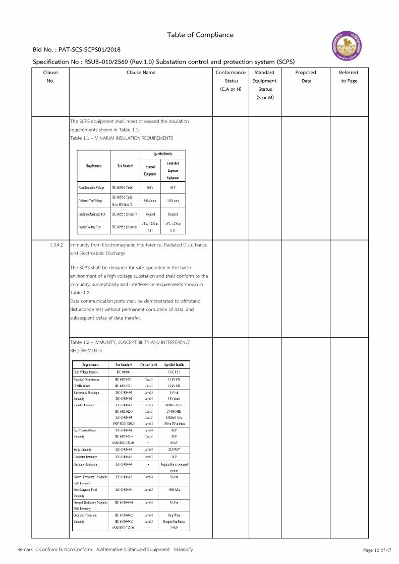
Table of Compliance
Standard Equipment
Status(S or M)
Bid No. : PAT-SCS-SCPS01/2018
Specification No : RSUB–010/2560 (Rev.1.0) Substation control and protection system (SCPS)Clause
No.Clause Name Conformance
Status(C,A or N)
Proposed Data
Referred to Page
The SCPS equipment shall meet or exceed the insulation requirements shown in Table 1.1:Table 1.1 – MINIMUM INSULATION REQUIREMENTS
1.3.4.2 Immunity from Electromagnetic Interference, Radiated Disturbance and Electrostatic Discharge
The SCPS shall be designed for safe operation in the harsh environment of a high voltage substation and shall conform to the immunity, susceptibility and interference requirements shown in Table 1.2:Data communication ports shall be demonstrated to withstand disturbance test without permanent corruption of data, and subsequent delay of data transfer.
Table 1.2 – IMMUNITY, SUSCEPTIBILITY AND INTERFERENCE REQUIREMENTS
Remark C:Conform N: Non-Conform A:Alternative S:Standard Equipment M:Modify Page 10 of 47

ClauseNo.
Clause Name Conformance Status
(C,A or N)
Standard Equipment
Status(S or M)
Proposed Data
Referred to Page
4 CONTROL AND PROTECTION SYSTEM FUNCTIONAL REQUIREMENTS4.1 GENERAL REQUIREMENTS
4.1.1 System Average Life Time and Life Cycle3) The Contractor shall state the expectancy support for spare parts. Availability of these parts shall be guaranteed for a period of no less than ten (10) years from the date of the latest delivery of equipment containing these parts or assemblies. The Contractor shall commit to notifying PEA at least six (6) months in advance of any part or assembly becoming unavailable for purchase, in order to enable PEA to stock up on that item.
4.1.2 Substation Environment
The SCPS shall be designed to withstand harsh operational HV substation environment. All IEDs shall be certified by an independent competent entity and type tested as protection grade devices. Unless specified otherwise, all station clients shall be certified and type tested as industrial grade equipment.
The following is the summary of the required electrical technological conformance and mechanical requirements for substation environment considerations:
4.1.3 System PerformanceThe SCPS shall be designed such that system performance, including system availability and system reliability set forth in Clause 4.3 is satisfied.
4.1.4 Operation and Maintenance (Maintainability)The SCPS shall be designed such that system maintainability, including future extension and upgrade, system flexibility, system scalability, and substation access control and cyber security measure, which are described further in Chapter 11, is satisfied.
4.1.5 Operational and System SafetyThe SCPS shall be designed so that it is compliant with PEA safety rules and other safety standards, such as IEC 61010-1. Hence, safety of personnel, plants and equipment is fully and highly aware of
4.1.6 System ConfigurationsThe SCPS shall be designed by taking into account the following important implementation issues which are described further in details in Annex 1 Control and Protection System Configurations.
Table of Compliance
Bid No. : PAT-SCS-SCPS01/2018
Specification No : RSUB–010/2560 (Rev.1.0) Substation control and protection system (SCPS)
Remark C:Conform N: Non-Conform A:Alternative S:Standard Equipment M:Modify Page 11 of 47
ClauseNo.
Clause Name Conformance Status
(C,A or N)
Standard Equipment
Status(S or M)
Proposed Data
Referred to Page
Table of Compliance
Bid No. : PAT-SCS-SCPS01/2018
Specification No : RSUB–010/2560 (Rev.1.0) Substation control and protection system (SCPS)
4.2 SYSTEM HIERARCHICAL STRUCTURE
The system architecture shall be configured based on multi-tier hierarchical structure. The multi-tier hierarchical structure levels as a minimum for the SCPS are: 1) Level 1 – Station Level 2) Level 2 – Bay Level 3) Level 3 – Process Level or Physical Device Level
Bidders shall be able to propose a solution, e.g., using a redundant box (Redbox), so that the systems are connected and functioning as required. When a Redbox is used with a relay, due to hardware or speed issues with massive SV traffic, a relay shall be connected to a station-level side, not to a process-level side
Redundant equipment should be on different source of power supply from main equipment.
Relay of 115 kV systems will be separated into Main 1 and Main 2 Relays. The mechanism control and protection of selecting either Main 1/BCU and or Main 2/BCU to perform the functions of control and protection, in case of commanding/controlling from SCADA center, shall be configured within the IEDs.
Smart I/O and MU can be separated, or be in the same unit.
An Engineering Workstation might have 1 connection port, but can interchangeably connect to main or redundant connection.
The Contractor shall provide IED servers, i.e. Bay Controller, at bay level to perform all allocated distributed functions of bay level functionality. A relay should support Process Bus; in case of a small relay, e.g., the one operating with 22 or 33 kV, that might not support Process Bus, the contractor should provide a plan and method on how to integrate this relay so that all the SCPS requirements are still satisfied.
Engineering workstation shall be provided to ensure secure information flow with the SCADA/DMS located at ADDC engineering offices. The station bus shall provide the communication network (IEC 61850), integration, data exchange and data flow between station-to-bay level and bay-to-bay level.
Remark C:Conform N: Non-Conform A:Alternative S:Standard Equipment M:Modify Page 12 of 47

ClauseNo.
Clause Name Conformance Status
(C,A or N)
Standard Equipment
Status(S or M)
Proposed Data
Referred to Page
Table of Compliance
Bid No. : PAT-SCS-SCPS01/2018
Specification No : RSUB–010/2560 (Rev.1.0) Substation control and protection system (SCPS)
4.2.1 Station Level The main characteristics of the station devices shall be;1) multifunction IED2) use of IED technology3) IEDs conform with IEC 61850 standard4) interface to user through device HMI and remote client such as Engineering Workstation integrated as part of SCPS through networked communication.5) flexible applications and functions6) capability to interoperate with other IEDs from several different manufacturers to exchange information and use the information for own functions7) IEC 61850 server which provide rich source of IED information such as settings, configuration information, events, alarms, power system information, fault records, COMTRADE fault waveform files, etc.a. Station-level data management, data storage, and data retrieval mechanisms: include support for IEC 61850 information models, historical data, configuration data, diagnostic and maintenance data, and files (e.g. non-operational, configuration, application programs, software updates).b. Station-wide collection of maintenance data, diagnostic data, and statistical data for (1) primary system components, (2) secondary system components, and (3) application functions
8) self-monitoring and supervision9) certified and type tested as protection grade device10) enact programmable logic: any IED or other devices which can act as a programmable logical controller should be able to be programmed using methods stipulated in IEC 6113111) powered from substation auxiliary DC system12) interfaced to the station bus via hardened managed Ethernet Switch13) failure not affecting other functions or bay level14) Hardwired parallel connections to the primary equipment or apparatus (switchgears and instrument transformers). (“This part belongs to the Bay Level”).
Local Repository and System Logs: The following data structures form the core of the SCPS system. They include six system logs that chronologically capture the stations operational history.
1) Local Repository The Repository represents the present state of the station. It shall hold the IEC 61850-based information models for the primary system and secondary system components, including off-the-shelf and programmable logic applications.
IEC 61850 provides information models for most of the available system data, and those models can be extended to include new components. Although it is not desirable for the Repository to store all data available in the station, it must at least include all data subscribed by station or enterprise clients.
The SCPS Systems shall implement all of IEC 61850’s ASCI service models, with the following exceptions: GSSE Control Block and the Sampled Value Class Model. Clients and servers using the Repository shall find all of the other services available. The Repository must be maintained in a replaceable flash memory module. Battery power is an unacceptable approach to maintaining non-volatile data memory.
Remark C:Conform N: Non-Conform A:Alternative S:Standard Equipment M:Modify Page 13 of 47

ClauseNo.
Clause Name Conformance Status
(C,A or N)
Standard Equipment
Status(S or M)
Proposed Data
Referred to Page
Table of Compliance
Bid No. : PAT-SCS-SCPS01/2018
Specification No : RSUB–010/2560 (Rev.1.0) Substation control and protection system (SCPS)
2) StatusLog The StatusLog is a chronological record of recent changes in either primary or secondary system status, either commanded or uncommanded.- The StatusLog shall hold events for the most recent 100 records. It shall be backed up in archives, each archive containing events for a particular month.- All StatusLog entries shall include a time-stamp, identify the system item that changed, identify the new status, and identify the cause (or agent) of the change.
3) CommandLog - The CommandLog is a chronological record of recent control commands to station equipment (e.g. Trip, Close, Open, Close, Raise, Lower, Enable, Disable, and set-points) issued by System Clients.-The CommandLog shall hold commands issued during the most recent 100 days. It shall be backed up in archives, each archive containing control commands for a particular month.- All CommandLog entries shall include a time-stamp, identify the system item being controlled, identify the state being commanded, and identify the source of the control command.
4) ChangeLog - The ChangeLog is a chronological record of recent changes made by an HMI unit to system and device configuration parameters. The ChangeLog shall hold changes issued during the most recent 100 days. It is backed up in archives, each archive containing changes for a particular month. All ChangeLog entries shall include a time-stamp, identify the system or IED parameter being changed, identify the new state, and identify the source (i.e. agent) of the change.
5) SubLog The SubLog is a chronological record of changes made by clients using the IEC 61850 substitution services. The SubLog shall include all substitution events, including a return to process values, that have occured during the most recent 100 days.
6) FileLog The FileLog is a chronological record of recent file transfers and file deletions involving any intelligent station device (e.g. BCU, SCPS Systems, HMI). The FileLog shall include all such file events that have occured during the most recent 100 days. It shall be backed up in archives, each archive containing file events for a particular month. All FileLog entries shall include a time-stamp, identify the file reference, identify the action taken, and identify the source (i.e. agent) of the action.
The station functions and the Logical Nodes (LN) shall be distributed and allocated to station level devices.1) Engineering Workstation (EWS) with HMI2) SCADA gateway to PEA SCADA/DMS: Protocol for communications between the SCADA/DMS and substations is DNP3.0 over IP. Communications between the SCADA gateway and IED servers are via SCPS Systems3) SCPS Systems4) Station optical fibre ring bus, providing the means by which devices and applications exchange data within the station5) Station-operator HMI or station level operator interface (SLOI)6) Time synchronization server with GPS receiver
Remark C:Conform N: Non-Conform A:Alternative S:Standard Equipment M:Modify Page 14 of 47

ClauseNo.
Clause Name Conformance Status
(C,A or N)
Standard Equipment
Status(S or M)
Proposed Data
Referred to Page
Table of Compliance
Bid No. : PAT-SCS-SCPS01/2018
Specification No : RSUB–010/2560 (Rev.1.0) Substation control and protection system (SCPS)
Operating Systems (OS) of HMI and Engineering Workstation shall be Windows. OS of Gateway and SCPS Systems shall be a stable one, such as Linux.
4.2.2 Bay Level The main characteristics of the bay devices shall be;1) multifunction IED2) use of IED technology3) IED conform with IEC 61850 standard4) performing distributed bay level functionalities5) interface to user through device HMI and remote client such as Engineering Workstation6) compact with integrated functionalities in one device. Integrated as part of SCPS through networked communication.7) flexible applications and functions8) duplicated Protection Devices with similar functions but from different manufacturers9) ability to activate or deactivate the main functions10) capability to interoperate with other IEDs from several different manufacturers to exchange information and use the information for own functions
11) IEDs which provide rich source of IED information such as settings, configuration information, events, alarms, power system information, fault records, COMTRADE fault waveform files, etc.12) self-monitoring and supervision13) certified and type tested as protection grade device
14) enact programmable logic.interfaced to the station bus via hardened managed Ethernet Switch15) possibility to minimise the use of external electromechanical auxiliary relays and lockout relay. powered from substation 125V auxiliary DC system interfaced to the station bus via hardened managed Ethernet Switch16) proxy to legacy devices or non-IEDs (as an alternative, a dedicated protocol converter with generic logical nodes shall be provided)17) failure not affecting other functions within or external to the particular bay or level18) hardwired parallel connections to the primary equipment or apparatus (switchgears and instrument transformers). The IEC 61850 process bus shall also be implemented.
The bay functions and the Logical Nodes shall be distributed and allocated to bay level devices, i.e. protection devices and single control device.
Data flow of operational real time data and control, through client-servers communication, shall be ensured between IEDs and station level clients. Each IED shall be able to support multiple clients (at least 5 clients). The IEDs shall be able to provide configuration information and IED specific information including COMTRADE files, IED native individual parameters, etc. to the Engineering Workstation at station level.
Remark C:Conform N: Non-Conform A:Alternative S:Standard Equipment M:Modify Page 15 of 47

ClauseNo.
Clause Name Conformance Status
(C,A or N)
Standard Equipment
Status(S or M)
Proposed Data
Referred to Page
Table of Compliance
Bid No. : PAT-SCS-SCPS01/2018
Specification No : RSUB–010/2560 (Rev.1.0) Substation control and protection system (SCPS)
4.2.3 System Logical Architecture The main features of the SCPS architecture are:
1) distributed architecture using Ethernet Local Area Network (LAN) station bus with 1 Gbits/s optical fibre ring topology
2) All IEDs and clients are connected to the station bus via hardened managed Ethernet Switch certified to IEC 61850-3 and IEEE 1613
3) Distributed multifunction bay IEDs or relays integrated in single panel per bay
4) Transformer Automatic Voltage Control/Regulator device shall be located in a separate panel
5) For AIS (Air Insulated Switchgear?) substations, the bay panels may be located in Prefabricated relay house(s) at the substation switchyard
6) Local displays (mimic screen) in independent panel at each Prefabricated relay house to provide safe operational awareness for operation and maintenance purposes, unless PEA states otherwise
7) SCPS Systems to perform station level functions including control and automation functions
8) Station Level Operator Interface (SLOI) to perform Station-operator HMI
9) Gateway for communication interface with PEA SCADA/DMS. The gateway shall be supplied by the Contractor
10) Engineering Workstation to manage the SCPS, communication network and substation information, and to provide applications utilizing the substation information
11) Time synchronization server (NTP, and IEEE 1588 or IRIG-B, with the latest version, if IEEE 1588 is not available, Server) synchronizing with GPS master clock receiver to provide time source for time synchronization of all SCPS components. Depending on synchronization standard used, a dedicated communication interface and network might be provided for time synchronization, such as for IRIG-B.
4.2.4 Supporting SCADA/DMS Operations
The Dispatchers shall be able to control station equipment and gather system data via DNP3.0 over IP command and polling messages transmitted from the SCADA/DMS control centre. Implementation of DNP 3.0 over IP protocol shall meet at least ALL DNP 3.0 over IP standard requirements.
Remark C:Conform N: Non-Conform A:Alternative S:Standard Equipment M:Modify Page 16 of 47
ClauseNo.
Clause Name Conformance Status
(C,A or N)
Standard Equipment
Status(S or M)
Proposed Data
Referred to Page
Table of Compliance
Bid No. : PAT-SCS-SCPS01/2018
Specification No : RSUB–010/2560 (Rev.1.0) Substation control and protection system (SCPS)
The DNP communications shall be supported by the Gateway via a process that links and converts IEC 61850 data from the Local Repository to the desired DNP values and formats. These resulting DNP data shall be stored and maintained in a separate DNP database that can be accessed by DNP data communication services. This approach provides two significant advantages: (1) the continual DNP data conversion process is independent of (i.e. not interrupted by) DNP message processing, and (2) the DNP database allows the HMI to quickly respond to message requests. DNP commands shall likewise be translated to use IEC 61850 control blocks and procedures for controlling system equipment.
4.6 SYSTEM SECURITY
The software system shall be the latest version, and free of viruses when the Contractor delivers. During the guarantee period, the Contractor shall keep the software up-to-date. After the guarantee period, the Contractor shall propose an option to update the software to PEA; the update shall not be via the internet.
The Contractor shall recommend security capabilities that conform with standard IEC 62351 for SCPS security, and IEC 27032 for other relevant Information Technology (IT) operations. The recommendations shall provide reasonable protection for a reasonable cost, so as to significantly reduce the risk of damage, loss of information, unauthorized use, or impairment of use or control of the station facility.
4.9 AUTOMATIC CONTROL FUNCTIONS
Automatic function is like programmable inside the memory of Relay or BCU, and shall be included in Relay or BCU, for example, Sequential Switching, Load Shedding, Automatic Transfer Switch etc.
The automation function shall be programmed and performed at station level in the station intelligent electronic device IED. However, the automated sequence may be initiated by operator at the Station-operator HMI or Station Level Operator Interface (SLOI).
4.10 MEASUREMENT FUNCTIONS
Measurement of electrical quantities such as voltage, current, active power, reactive power, etc. shall be taken directly, without separate interposing or transducers, by the IED from substation current and/or voltage transformer(s). Measurement from DC and 400V AC voltages may be derived from substation auxiliary AC and DC systems.
The measurement functions are modelled and grouped according to the IEC 61850 Logical Node Group which begins with the character M.
Remark C:Conform N: Non-Conform A:Alternative S:Standard Equipment M:Modify Page 17 of 47

ClauseNo.
Clause Name Conformance Status
(C,A or N)
Standard Equipment
Status(S or M)
Proposed Data
Referred to Page
Table of Compliance
Bid No. : PAT-SCS-SCPS01/2018
Specification No : RSUB–010/2560 (Rev.1.0) Substation control and protection system (SCPS)
4.11 MONITORING FUNCTIONS The monitoring function provides substation device or equipment indications and information
4.12 CONTROL INTERLOCKING FUNCTIONSAll station and bay interlocking schemes shall be provided and controlled by intelligent electronic control devices using GOOSE messages.
4.14.4 Technical IEC 61850 Functions1) All devices shall conform with IEC 61850 standard and the following requirements:a. Interoperability, i.e. ability to communicate and to exchange information with other IEDs from several different manufacturers and use the information for own functionsb. Free configuration and allocation of functions Future proof, independent of communication technology and evolving system requirementsc. Successfully pass IED conformance test based on IEC 61850 part10 as necessaryd. Information management by standardizing the Data Models and Abstract Communication Servicese. Engineering and configuration management using XML based Substation Configuration Language (SCL) and IEC 61850 conformant Engineering Tools.f. Client-Server communication including relevant services such as reporting, data sets, control blocks and self-description via MMS protocolg. Peer-to-peer communication using IEC61850-9-2 SV and IEC61850 GOOSE tripping channels.h. IED native Ethernet port that support all relevant IEC 61850 protocolsi. Engineering access, event report collection, and non-IEC 61850 setting transfer via TCP/IP mechanisms2) The following device information shall be provided:a. IED Capability Description (ICD)b. Configured IED capability Description (CID)c. Model Implementation Conformance Statement (MICS)d. Protocol Implementation Conformance Statement (PICS)e. Protocol Implementation Extra Information for Testing (PIXIT)
4) The IED shall support IEC 61850 standard in terms of the following:a. Buffered reports supportedb. Unbuffered reports supportedc. Customization of the reports and data setsd. Ability to freely rename data sets, and logical devicese. Ability to add prefix and suffix to logical nodesf. Use specific logical node name for commonly used information rather than generic data references (such as GGIO)g. Ability to change data sets and reporting configuration via Configuration Toolh. Ability to download CID file directly into IED via Configuration Tooli. Ability to download CID file directly into IED via Ethernet using standard TCP/IP mechanism from remote such as from HMI.j. Flexible configuration of data setsk. Ability to setting logical devices, logical nodes, and their contentsl. Ability for user to query IED directly and to verify which IEC 61850 configuration file (.CID file) is active within the IED
Remark C:Conform N: Non-Conform A:Alternative S:Standard Equipment M:Modify Page 18 of 47

ClauseNo.
Clause Name Conformance Status
(C,A or N)
Standard Equipment
Status(S or M)
Proposed Data
Referred to Page
Table of Compliance
Bid No. : PAT-SCS-SCPS01/2018
Specification No : RSUB–010/2560 (Rev.1.0) Substation control and protection system (SCPS)
5) The IED shall also support the IEC 61850 GOOSE implementation in terms of the followings:a. At least 8 of unique GOOSE messages capable to be publishedb. At least 24 GOOSE messages to be subscribedc. Capability of monitoring GOOSE message qualityd. Capability of processing incoming data elements and their associated qualitye. Capability of monitoring message and data quality as permissive prior to use of the incoming data. At the time of configuration, the end user can choose to ignore the possibly corrupted data if the data or message quality fails to prevent an unwanted operation.f. Capability of creating GOOSE data set that include Boolean values and non-Boolean data type, such as Analog valuesg. Capability of accepting and processing data sets from other IEDs that contain Boolean and non-Boolean data typesh. Ability to support priority tagging of GOOSE messages for optimizing latency through Ethernet Switch.
i. Ability to support VLAN identifiers to facilitate segregation of GOOSE traffic on Ethernet network.j. Ability to support custom editing of data sets published in the GOOSE messages.k. Ability to change data sets, GOOSE parameters, GOOSE publication, and GOOSE subscription via Configuration Tool.l. Ability to support Recovery delay demands acc. to IEC 61850-5 Ed. 2 on Ethernet network.6) The Network shall also support the Recovery Time implementation in terms of the followings:a. IEC 61850-8-1 Station Bus.• GOOSE traffic not delayed beyond a critical threshold due to failover.• Unless stated otherwise, PRP and/or HSR provide seamless recovery, i.e. zero recovery time, on Station Bus for demanding applications. If a RedBox (Redundant Box) is needed in the proposed topology, the Bidder shall provide specification and quotation of the RedBox for PEA approval.b. IEC 61850-9-2 Process Bus.• SV traffic not to be affected during disruption.• No failover time.• Seamless redundancy• PRP and/or HSR fulfil these requirements with zero recovery time.
Remark C:Conform N: Non-Conform A:Alternative S:Standard Equipment M:Modify Page 19 of 47

ClauseNo.
Clause Name Conformance Status
(C,A or N)
Standard Equipment
Status(S or M)
Proposed Data
Referred to Page
Table of Compliance
Bid No. : PAT-SCS-SCPS01/2018
Specification No : RSUB–010/2560 (Rev.1.0) Substation control and protection system (SCPS)
7) The IEDs specified in the specifications are for the followings:a. Control devices, i.e. station and bay control devicesb. IED Protective relay or devicesc. IED for Protection (main & backup) for each bay level shall be physically independent.d. The IEDs are devices incorporating one or more processors with the capability to receive or send data/control from or to an external source. The IEDs shall also be capable for peer-to-peer communication (IEC61850 GOOSE) and Client/Server communication. (Such as Reporting by Exception)e. All IEDs supplied shall pass the IEC 61850 Conformance Test based on IEC61850-10. The IEC 61850 Conformance Test Certificate from an independent laboratory shall be provided as evidence and part of the tender submission. The laboratory shall be accredited by UCA International Users Group with ISO/IEC17025 certification with certification.f. The IEDs shall not show any non-conformance to IEC 61850-3, 6, 7-1, 7-2, 7-3, 7-4&8-1, and 9-2 (2011).g. Markings and Labelling Data. Clearly inscribed labels or markings shall be provided on the devices to describe the manufacturer name, model number, application and ratings.
8) Device Electrical Parameter Values.The standard device electrical parameter values are:a. The device shall be suitable for operation using substation auxiliary DC system.b. The device shall not mal-operate on DC auxiliary supply interruption or application/restoration or when energized from inverted polarities.c. The device shall also be stable and not affected by slow decay, surges, dips, ripples, spikes, capacitive coupling, DC earth fault, transient and switching disturbances. Indication shall be made available in the event of DC failure.
4.14.5 Station Level Devices FunctionsThe main characteristics of the station devices shall be:1) Multifunction IED2) Use of IED technology.3) IED conform with IEC 61850 standard4) Interface to user through device HMI and remote client such as Engineering Workstation5) Integrated as part of SCPS through networked communication flexible applications and functions.6) Capability to interoperate with other IEDs from several different manufacturers to exchange information and use the information for own functions.7) IEC 61850 server which provide rich source of IED information such as settings, configuration information, events, alarms, power system information, fault records, COMTRADE fault waveform files and can be send COMTRADE files to HMI by automatically, etc.8) Self-monitoring and supervision.9) Certified and type tested as protection grade device.10) Interfaced to the station bus via hardened managed Ethernet Switch.11) Failure not affecting other functions or bay level.12) The station functions and the Logical Nodes shall be distributed and allocated to station level devices.
Remark C:Conform N: Non-Conform A:Alternative S:Standard Equipment M:Modify Page 20 of 47

ClauseNo.
Clause Name Conformance Status
(C,A or N)
Standard Equipment
Status(S or M)
Proposed Data
Referred to Page
Table of Compliance
Bid No. : PAT-SCS-SCPS01/2018
Specification No : RSUB–010/2560 (Rev.1.0) Substation control and protection system (SCPS)
4.14.6 Bay Level Devices Functions
Generally, Bay Control Device functions and specifications are:1) Switchgear Manual Close and Open Control Operation 2) Dead line-live bus (DLLB), Live line-dead bus (LLDB), Dead line-dead bus (DLDB) 3) Interlocking (Command Supervision) 27UV 4) Event and Alarm Handling 5) Monitoring 6) Bay IED Operations and Status, CB Alarm 7) User Interface 8) Measurements
4.14.6.1 IED Bay Control Unit (BCU) without Protective RelayThis specification refers to smart bay implementations as BCU. As such, they are assumed to have sufficient local processing, memory, programmable logic, and communication resources to support expanded responsibilities and capabilities. In case of an IED BCU (without Protective Relay), the programmable logic should be included in the IED. When these resources are combined with support for the IEC 61850 communications standard, BCU gain flexibility and power that can significantly elevate their system roles and provide enormous flexibility.
4.14.7 Process Level Devices Functions
This specification refers to smart bay implementations as MU: 1) MUThe MU work as a bridge between primary equipment (such as electronic CT/VT or traditional electro-magnetic CT/VT) and bay level IEDs for signal capturing and transmission based on IEC 61850-9-2 or IEC 60044-8. MU can be used to convert Analog signals to digital signals for electro-magnetic CTs/VTs and dispatch them to different relays and controllers after data synchronization. Signal type accessed through merging unit can be:a. Digital sampling data outputs from electronic CT/VT or simulator (Now digital sampling output module is available in relay testing equipment such as Omicron).b. Analog signals from electro-magnetic CT/VT or simulator.c. Switching signals from intelligent primary equipment.
Remark C:Conform N: Non-Conform A:Alternative S:Standard Equipment M:Modify Page 21 of 47

ClauseNo.
Clause Name Conformance Status
(C,A or N)
Standard Equipment
Status(S or M)
Proposed Data
Referred to Page
Table of Compliance
Bid No. : PAT-SCS-SCPS01/2018
Specification No : RSUB–010/2560 (Rev.1.0) Substation control and protection system (SCPS)
2) Smart I/O (Input/Output Units)The intelligent control units connect circuit breakers and bay level IEDs for capturing the circuit breaker status information to protection & control devices via GOOSE network. In the other direction, the I/O Units deliver GOOSE commands from the protection & control devices to circuit breakers. The I/O Units can be installed outdoor nearby the primary equipment and connected to the protection & control devices in the control room via optic GOOSE network.
4.14.8 Enhanced Automation FunctionsThe SCPS systems shall perform enhanced automation functions, including the following:1) Heartbeat function for IED health and on-line status monitoring2) Maintenance of TRIP Counters for breakers3) Rate of Change (ROC) Limit Checking4) Breaker operating time checks (should perform at HMI)5) Substation-wide, automated control sequences: Automatic Transfer Switch(ATS), Bus Coupler Throw-over Scheme (CTO), Line Throw-over (LTO) & Bus Throw-over (BTO), Load Shedding / Load Restoration, and Voltage Selection (VT connection is Hardwire, Logic at Software at Bay Level).6) Station-wide interlocking (GOOSE interlocking at Bay level)7) Protection applications (Breaker Failure Protection) (at Bay level, both Main & Back up protection)
Remark C:Conform N: Non-Conform A:Alternative S:Standard Equipment M:Modify Page 22 of 47

ClauseNo. Clause Name
Conformance Status
(C,A or N)
Standard Equipment
Status(S or M)
Proposed Data
Referred to Page
5 SCPS: CONTROL REQUIREMENTS
5.1 5.1 SCOPE OF WORK
The scope of work shall include1) the preparation of a SCPS Detailed Design Documents for approval by PEA prior to commencement of system production. The initial list of required data points and typical screen displays are provided in Annexes 4 and 5, respectively. A printout report shall be kept electronically as a raw log file, and can be printed out according to the format guideline given in Annex 5.
2) the development of the control software to perform all substation manual and automatic functions.
3) all necessary hardware/software required for integrating the SCPS to the Distribution Management System (DMS) Mater Station located at each Area Distribution Dispatching Center (ADDC).
4) the preparation and maintenance to as built stage of a database, which documents all data points within the substation.
The Contractor shall submit performance test report and interoperability test report from independent testing laboratories for PEA approval.
5.2 SOFTWARE/FIRMWARE
The major system functions to be implemented in the SCPS software area shall be as follows:1) Substation equipment control2) Substation equipment indications3) Substation equipment alarm and event handling facilities4) Graphical information display5) System configuration and database maintenance6) Manual and automatic control function maintenance7) Interlocking maintenance8) Serial ports protocol assignment9) DMS Interface software maintenance10) IED devices management11) System Disturbance Analysis12) Measurement values including Load reports and Load curves creation and display13) Printing14) Automatic self-diagnostic15) Help information16) Archiving
Table of Compliance
Specification No : RSUB–010/2560 (Rev.1.0) Substation control and protection system (SCPS)Bid No. : PAT-SCS-SCPS01/2018
Remark C:Conform N: Non-Conform A:Alternative S:Standard Equipment M:Modify Page 23 of 47

ClauseNo. Clause Name
Conformance Status
(C,A or N)
Standard Equipment
Status(S or M)
Proposed Data
Referred to Page
Table of Compliance
Specification No : RSUB–010/2560 (Rev.1.0) Substation control and protection system (SCPS)Bid No. : PAT-SCS-SCPS01/2018
5.3 FUNCTIONAL REQUIREMENTS
5.3.1 GeneralThe SCPS shall perform the following functions:1) Control electric power substation equipment 2) Monitor the status of electric power substation equipment3) Acquire operating data from electric power substations4) Operate autonomously and on command from the DMS and a local user interface (HMI).
5.3.2 Input/Output Point Types
The SCPS shall include facilities for handling all analog input, status input, and control output points. Requirements for each type of I/O point are described in the following sub-clauses.
Where the SCPS is used to acquire any of the specified data I/O via an interface to the IED devices such as substation Protective relays or power meters, the overall system performance and responses as called for in theses specifications shall not be compromised.
5.3.2.1 Analog Input
Analog measurement from CT/VT shall be processed in IED relay and/or BCU and input through MU&Smart I/O (Merging Unit and Smart I/O) equipment.
5.3.2.2 Status Input
Status Inputs shall be processed in IED relay and/or BCU and input through Smart I/O equipment.
5.3.2.3 Control Output
The SCPS shall include the following types of control points to support control actions initiated by the DMS master stations or, where applicable, the integral programmable logic facilities of the SCPS:1) On/Off Device Control2) Raise/Lower Control3) Setpoint Control
Remark C:Conform N: Non-Conform A:Alternative S:Standard Equipment M:Modify Page 24 of 47

6
6.1
6.1.2
6.1.3.2
6.2
6.2.2.2
6.2.2.3
6.2.2.4
6.2.2.7
Access to relay display and setting parameters will be keyed by different authorization levels (password).
GENERAL REQUIREMENTS
Reference Standards All equipment, materials, fabrication and testing under this Specification shall conform to the latest applicable standard specifications and codes contained in the following list, or to equivalent applicable standard specifications and codes established and approved in the country of manufacturer of the equipment. Where standards are mentioned by name, equivalent applicable standards may be used. IEC 60068-2-1, IEC 60068-2-2, IEC 60068-2-6, IEC 60068-2-27, IEC 60068-2-78, IEC 60255-3, IEC 60255-27, IEC 60255-26, IEC 60870-5-1012, IEC 60947-1, IEC 60947-7-1, IEC 61000-4-2, IEC 61000-4-3, IEC 61000-4-4, IEC 61000-4-5; see more details in Clause 2.2 Specific Relevant Standards. Any details not specifically covered by these standards shall be subject to the approval of PEA. In the event of contradictory requirements between such standards and this Specification, the terms of the Specification shall govern.
Equipment shall be protected against electrical and electro-magnetic disturbance and shall particularly comply with IEC 60255-27 and IEC 60255-26 standards.
DETAILED REQUIREMENTS
Bay Control Unit (BCU)Refer to Sub-Clause Bay Control Unit 8.3.8 for Hardware Requirement.
I/O Interface All signals shall be processed by the SCPS from the SCPS Systems.
Trip circuit All the relays used for tripping shall still operate if the DC supply voltage is equal to 80% of the rated voltage. All tripping control circuits for the CB shall be interrupted for the qualitative and quantitative tests. These circuits shall be located at the same test block provided to test the relay with currents and/or voltages.
DC-SupplyThe power supply shall be based on 125 V lead-acid station battery.
SCPS: Protection requirements
Table of Compliance
ClauseNo.
Clause Name
Conformance Status
(C,A or N)
Standard Equipment
Status(S or M)
Proposed Data
Referred to Page or
Clarification Letters
Bid No. : PAT-SCS-SCPS01/2018Specification No : RSUB–010/2560 (Rev.1.0) Substation control and protection system (SCPS)
Remark C:Conform N: Non-Conform A:Alternative S:Standard Equipment M:Modify Page 25 of 47
Table of Compliance
ClauseNo.
Clause Name
Conformance Status
(C,A or N)
Standard Equipment
Status(S or M)
Proposed Data
Referred to Page or
Clarification Letters
Bid No. : PAT-SCS-SCPS01/2018Specification No : RSUB–010/2560 (Rev.1.0) Substation control and protection system (SCPS)
6.2.2.8
6.2.2.8.1
6.2.2.8.2
6.2.2.8.3
6.3.1
6.3.1.1
6.3.1.2
Line protection
Requirement for IED Protective Relay
Hardware and Software Requirement The features of the IED relays to be supplied shall include: • Programmable scheme logic • Remote setting/interrogation • Serial communication interface • Time-tagged event/disturbance record • Measured quantities displayed • Self-monitoring (Hardware/Software)
Interface RequirementsThe main requirements applicable to communication with the relay shall be the following: • On and Off line communication• Relay Settings • Relay configuration (I/O’s, programmable scheme logic, fault recording programming …)• Switching of setting group• Extract disturbance records• Access to relay monitored parameters
Disturbance records requirementsThe relay shall include an internal disturbance recorder, with sufficient analog channels to record three-phase currents and/or three-phase voltages, residual current and/or residual voltage depending on the relay model. Main protective relays shall have capacity to record at least 16 logic channels and backup protective relays shall have capacity to record at least 8 logic channels. The internal disturbance recorder shall have the capability to store at least the last 5 disturbance records with a minimum total storage capacity of 3 seconds (typical).
Each reclosing relay may be combined with synchro-check relay.
Line differential protection (87 L) The required current differential protective relay shall be fully IED and suitable for 2 terminals lines and/or line-cable.
The backup protection of the line shall be protected by a directional phase and ground overcurrent relays with at least four (4) inverse time curves and one (1) definite time characteristics.
Distance Protection (21/21 N) and Direction Overcurrent Protection (67/67N) Each distance relay shall be of the full scheme and IED type.
Each relay system shall be provided with at least four (4) Inverse Time Curves and one definite time characteristic.
Remark C:Conform N: Non-Conform A:Alternative S:Standard Equipment M:Modify Page 26 of 47

Table of Compliance
ClauseNo.
Clause Name
Conformance Status
(C,A or N)
Standard Equipment
Status(S or M)
Proposed Data
Referred to Page or
Clarification Letters
Bid No. : PAT-SCS-SCPS01/2018Specification No : RSUB–010/2560 (Rev.1.0) Substation control and protection system (SCPS)
6.3.1.3
6.3.1.4
6.3.1.5
6.3.1.6
At least 4 Inverse Time curves (IEC 60255) and 1 definite time shall be provided. Each relay shall have a current setting range of 0.1-2.5In and shall be used with 1A rated secondary current CT.
Transformer Protection 115 kV/MV• Internal faults, such as Short-circuit between windings, short-circuit between turns, Ground faults, Tap changer failure and transformer tank oil leaks.• External faults, such as Power system phase faults, Power system ground faults, Over-load and Over-excitation.
Tripping and interposing supervision relay (95)Supervision relay shall be used for monitoring important control and signalling circuit such as circuit breaker or disconnector circuits. The supervision relay shall be able to detect interruptions, too high resistances cause by galvanically bad connections, increased transfer resistance in the contacts, welding of the control contact, loss of control voltage and failure of the relay itself.
Voltage circuits failure (27)The fuse failure relay shall monitor the output of voltage transformer and will block the trip of distance protection and give an alarm in case of VT fuse failure. The 3-phase voltage shall be monitored.
Backup protection (67-67N)
The measuring element shall be adjustable between 0.25 to 150 ohm per phase with 1A current rating and 115 V secondary voltage rating.
The time delay for each zone shall be independent, and the operating time of the relay shall be less than 25 ms.
At least four (4) distance stages with impedance set polygon characteristics for forward and reverse measurement shall be implemented.
Remark C:Conform N: Non-Conform A:Alternative S:Standard Equipment M:Modify Page 27 of 47

Table of Compliance
ClauseNo.
Clause Name
Conformance Status
(C,A or N)
Standard Equipment
Status(S or M)
Proposed Data
Referred to Page or
Clarification Letters
Bid No. : PAT-SCS-SCPS01/2018Specification No : RSUB–010/2560 (Rev.1.0) Substation control and protection system (SCPS)
6.3.1.6.1
6.3.1.6.2
6.3.1.6.3
6.3.1.6.4
Back-up Protection (50/51, 50G/51G)
At least one Definite Time and four selectable Inverse Time curves for the phase and ground elements shall be provided according to IEC 60255-151.• Standard inverse curve, • Very inverse curve, • Extremely inverse curve, • Long time inverse curve • Definite time
Transformer Differential Protection (87 T – 64 REF) The transformer differential Protective relay required shall be of IED type design with all main functions individually configurable by the user.
The transformer differential Protective relay required shall be of IED type design with all main functions individually configurable by the user.
Static voltage regulator control relay (90)
The relay shall have the following facilities:• Integral line drops compensation.• Inverse or definitive time characteristics.• In case of several transformers in parallel, reverse reactance or circulating current compensation shall be taken in consideration. • Under voltage, over voltage and over current supervision.• Alarms.
Mechanical Functions
All necessary tripping relays associated with the transformer, should be provided e.g: • Buchholz protection, • Transformer pressure relief device • Transformer sudden pressure relay • LTC diverted switch pressure relief device • LTC diverted switch sudden oil flow • Winding temperature sensors. Operating signal of these different sensors and protections shall be routed to the binary inputs of the main integrated Differential protection.
Remark C:Conform N: Non-Conform A:Alternative S:Standard Equipment M:Modify Page 28 of 47

Table of Compliance
ClauseNo.
Clause Name
Conformance Status
(C,A or N)
Standard Equipment
Status(S or M)
Proposed Data
Referred to Page or
Clarification Letters
Bid No. : PAT-SCS-SCPS01/2018Specification No : RSUB–010/2560 (Rev.1.0) Substation control and protection system (SCPS)
6.3.1.7
6.3.1.7.1
6.3.1.7.2
6.3.1.8
Bus AC wiring supervision relay (95B) Providing continuous supervision of the bus wires in high impedance type busbar protection scheme, detecting open circuited bus wires as well as open circuited main current transformer.
The relay shall be sensitive to detect fault 0.2 to 2 times of the rated current, adjustable in steps of less than to 01 times of this currents.
Busbar Protection (87B) (for Double Bus – Single Breaker)
Busbar Protection (87B) (for Every Bus Scheme except Double Bus – Single Breaker)The protection shall be suitable for use on a bus with up to all connected feeders and shall have the following properties: - The protection shall be able to operate on CT’s having a wide range of different ratio - Tripping time less than 20 ms - Event recorder with resolution of not more than 1 ms shall be provided - Self-checking and supervision shall be continuously monitored
Breaker failure protection (50BF)
Busbar Protection (87B) (for Every Bus Scheme except Double Bus – Single Breaker) Each busbar shall be protected by a high impedance differential relay with shunt resistor or a low impedance IED busbar protection. The busbar differential relay required shall be of microprocessor-based /digital type and electronic solid-state plug-in type shall be accepted
Remark C:Conform N: Non-Conform A:Alternative S:Standard Equipment M:Modify Page 29 of 47

Table of Compliance
ClauseNo.
Clause Name
Conformance Status
(C,A or N)
Standard Equipment
Status(S or M)
Proposed Data
Referred to Page or
Clarification Letters
Bid No. : PAT-SCS-SCPS01/2018Specification No : RSUB–010/2560 (Rev.1.0) Substation control and protection system (SCPS)
6.3.1.8.1
6.3.1.8.2
6.4.1
6.4.2
6.4.3
Breaker failure timers shall be adjustable for use with current detector relay above. The setting range shall be from 0.05 to 1.0 seconds in step of not more than 10 ms.
At least one Definite Time and four selectable Inverse Time curves for phase and ground elements shall be provided according to IEC 60255-151.• Normally inverse curve,• Very inverse curve,• Extremely inverse curve,• Long time inverse curve• Definite time
• 1 Ground Fault overcurrent protection [50G/51G] and/or 67N, using 3 independent stages
• Reclosing Relay having a minimum of 4 shots (79),
• Breaker Failure Relaying System,
• Event and Disturbance Recorder,
• Metering System
Incoming feeders Each incoming feeder and bus-section shall be protected by a three-phase with instantaneous and time-delayed overcurrent and a ground fault protection [50/51, 50G/51G].
Capacitor Bank feeder Capacitor Bank feeder shall be protected by: • 3 Phases overcurrent protection, • 1 Earth Fault Overcurrent protection, • Under and Overvoltage relay
Outgoing feeder Each outgoing feeder shall contain the following metering and relaying systems: • 3 phasesovercurrent protection [50/51] and/or 67, using 3 independent stages
Current Detector Relays (50BF).
Current detector relays shall be of IED type, non-directional instantaneous overcurrent relays with fast-resetting time of less than 12.5 milliseconds when the current drops to 90 per cent of the pickup. Each shall contain either two-phase units with 0.2-1.6 A pickup range and one ground unit with 0.05-0.4 A pickup range or three-phase units with 0.2-1.6 A pickup ranges.
Breaker Failure Timers (62BF).
Remark C:Conform N: Non-Conform A:Alternative S:Standard Equipment M:Modify Page 30 of 47

7
7.1
7.2
7.3
COMMUNICATION SYSTEM REQUIREMENTS
FUNCTION HIERARCHY, INTERFACE, AND TOPOLOGY
Bid No. : PAT-SCS-SCPS01/2018
Specification No : RSUB–010/2560 (Rev.1.0) Substation control and protection system (SCPS)
Table of Compliance
ClauseNo.
Clause Name
Conformance Status
(C,A or N)
Standard Equipment
Status(S or M)
Proposed Data
Referred to Page
GENERAL REQUIREMENTS
The communication requirements shall be based on IEC 61850 standards, in particular IEC 61850-3: General Requirements, 61850-5: Communication Requirements For Functions and Device Models, IEEE 1615: Recommended Practice for Network Communication in Electric Power Substations and IEEE 1613: Standard Environmental and Testing Requirements for Communications Networking Devices in Electric Power Substations.
the optical SCPS or CGW ports shall meet the following requirements: 1) 2.5 kV optical isolation 2) Electrical EIA RS-232 DB-25 or DB-9 male connector (DTE-DCE selectable) 3) Optical connector supporting ST or LC multimode 4) Power budget of 12 db (optical fibre cable 62.5/125 micron) 5) Data rate from 300 to 19,200 bps6) Auto-powered from RS-232 interface 7) Environmental capability of 0 to 50 °C, 5 to 95% relative humidity
COMMUNICATION NETWORK The communication network infrastructure shall satisfy the following requirements:1) Access control and cyber security especially for remote access 2) Configuration, system and network management 3) Deterministic predictable network (collision-free environment) with the utilization of a dedicated managed Ethernet Switch 4) Deterministic real time network capability
5) Environmentally hardened network devices and components, rated for operation in HV substation environment 6) Flexibility and scalability for system change or expansion 7) Fully duplex communication backbone using high speed 1Gbit/s optical fibre ring Ethernet local area network (LAN) topology 8) Fully duplex Ethernet communication connection to IEDs using either 100Base Fx (Preferred) or 100BaseT9) Integration of intelligent devices 10) Priority queuing support 11) Simultaneously support multiple applications including virtual LAN (VLAN) support 12) Time synchronization over Ethernet.
Remark C:Conform N: Non-Conform A:Alternative S:Standard Equipment M:Modify Page 31 of 47

Bid No. : PAT-SCS-SCPS01/2018
Specification No : RSUB–010/2560 (Rev.1.0) Substation control and protection system (SCPS)
Table of Compliance
ClauseNo.
Clause Name
Conformance Status
(C,A or N)
Standard Equipment
Status(S or M)
Proposed Data
Referred to Page
7.3.1
Network Redundancy using IEC 62439 1) IEC SC65C WG15 published IEC 62439 “Highly Available Automation Networks” 2) IEC 62439-3 Clause 4 Parallel Redundancy Protocol PRP 3) IEC 62439-3 Clause 5 High Availability Seamless Ring HSR
Internet protocol suite (IPS) shall be used for the transfer of operational and non-operational data as well as configuration management. The followings shall be considered: 1) Development plan for IP address allocations. PEA will manage the IP addressing. Details on PEA IP addressing management is in Annex 6. 2) Private and fixed IP addressing shall be employed on the substation network. 3) SCPS connected to an enterprise or WAN must pass through a properly configured router with firewall and cyber security measures as described in Clauses 8.4.3 System Access Control and Cyber Security Management and 11.5 Substation Access Control and Cyber Security measures. However, the provision of the router with firewall is not under the scope of this specification, and shall be supplied by PEA ICT Division.
Communication Network Device – Ethernet Switch All Ethernet switches shall be certified and type tested as protection grade devices.
The main characteristics of the Ethernet Switch shall be designed for continuous operation in a high voltage substation shall conform to the industrial environment: IEEE1613 - class 2 “error free” performance for real-time control and EMI immunity and IEC61850-3 Type test. And the equirements stated in Clause 4.6 System Security. Ethernet Switch at a station bus level shall be L3 type, and those at a process bus level shall be L2 type.
Remark C:Conform N: Non-Conform A:Alternative S:Standard Equipment M:Modify Page 32 of 47

Bid No. : PAT-SCS-SCPS01/2018
Specification No : RSUB–010/2560 (Rev.1.0) Substation control and protection system (SCPS)
Table of Compliance
ClauseNo.
Clause Name
Conformance Status
(C,A or N)
Standard Equipment
Status(S or M)
Proposed Data
Referred to Page
The basic requirements of the managed Ethernet switch are:
Remark C:Conform N: Non-Conform A:Alternative S:Standard Equipment M:Modify Page 33 of 47

Bid No. : PAT-SCS-SCPS01/2018
Specification No : RSUB–010/2560 (Rev.1.0) Substation control and protection system (SCPS)
Table of Compliance
ClauseNo.
Clause Name
Conformance Status
(C,A or N)
Standard Equipment
Status(S or M)
Proposed Data
Referred to Page
7.3.2
7.5 COMMUNICATION PROFILECommunication profiles the Contractor must comply with are Application (A) Profile, and Transport (T) Profile, which can be found in the following services: 1) Client/Server services (Core ACSI Services) 2) GOOSE/GSE Management Services 3) Time Synchronization
The type of the optical fibre to be used in the substation as the network backbone interface (station bus communication) shall be as the following:
Other requirements of the optical fibre cabling are:1) Vermin proof with mechanical protection 2) Redundant spare optical fibre cable shall be provided as per project specific requirements 3) 100% spare optical fibre cores in each cable shall be provided, i.e., full redundant fibre cores should be provided in each cable 4) Optical fibre cables lay in PVC conduit if mechanical protection is not provided. 5) Power budget calculation shall be approved by PEA
The copper cable used in the network segment inside a panel shall be UTP or STP Ethernet cable (depend on the induced and radiated noise within the panel) as the following:
Alternatively, multi-mode optical fibre may be used in the network X, subject to Ethernet switch port availability and PEA approval, as the following:
Communication Network Device – Media
Remark C:Conform N: Non-Conform A:Alternative S:Standard Equipment M:Modify Page 34 of 47

Bid No. : PAT-SCS-SCPS01/2018
Specification No : RSUB–010/2560 (Rev.1.0) Substation control and protection system (SCPS)
Table of Compliance
ClauseNo.
Clause Name
Conformance Status
(C,A or N)
Standard Equipment
Status(S or M)
Proposed Data
Referred to Page
7.5.1
7.5.2
7.5.3
7.6
7.7 STATION TIME SYNCHRONIZATION Time synchronisation of all IEDs and IEC 61850 based SCPS components in the substation shall be accomplished via NTP Server and modulated IEEE 1588 or IRIG-B with GPS master clock receiver(s).
The expected time stamp resolution of devices shall be 1ms (IEC 61850 Time Performance Class T1) and the expected accuracy (±) between network devices shall be 0.1ms.
INTRA-SUBSTATION AND REMOTE CONTROL CENTER COMMUNICATIONSThe communications should comply with IEC 61850, Part 90-1 for communications between substations, and Part 90-2 for communications between substation and a control center.
Communication Profile – Client/Server Services The client/server communication profile shall be used when declaring support for the services shown in the following tables of IEC 61850-8-11) Table 2 Service Requiring Client/Server Communication Profile 2) Table 3 Service and Protocols for Client/Server Communication A-Profile 3) Table 4 Service and Protocols for Client/Server Communication T-Profile
Communication Profile – GOOSE/GSE Management Services For the GSE Management and GOOSE communication profile when declaring support for the services, refer to Table 6 Service Requiring GSE Management and GOOSE Communication Profile of IEC 61850-8-1.
Communication Profile – Time Synchronization Time synchronisation for the SCPS shall be accomplished using NTP protocol with direct interface to the Ethernet network through connectionless user datagram protocol (UDP) at transport layer.
Remark C:Conform N: Non-Conform A:Alternative S:Standard Equipment M:Modify Page 35 of 47

Bid No. : PAT-SCS-SCPS01/2018
Specification No : RSUB–010/2560 (Rev.1.0) Substation control and protection system (SCPS)
Table of Compliance
ClauseNo.
Clause Name
Conformance Status
(C,A or N)
Standard Equipment
Status(S or M)
Proposed Data
Referred to Page
7.8
7.8.1
7.8.2
The basic requirements of the Time Server are:
BCU, MU, Smart I/O and TRU units must support both NTP, and IEEE1588 (PTP) or IRIG-B protocols.
SUBSTATION CONFIGURATION LANGUAGE (SCL)
A standard configuration language SCL, (Substation Configuration Language), based on the XML (Extensible Markup Language) shall be used to define the characteristics of each IED with regards to communication configuration, data model and parameters.
IED Configuration
Any IED supporting the IEC 61850 standard will be accompanied by a configuration file with ICD (IED Capability Description) which defines capacities of the IED.
System Configuration and Specification
The Contractor shall provide all relevant SCL files including System Specification Description (SSD), Substation Configuration Description (SCD), and make sure for IED can be automatically configured from the power system design.
Remark C:Conform N: Non-Conform A:Alternative S:Standard Equipment M:Modify Page 36 of 47

Bid No. : PAT-SCS-SCPS01/2018
Specification No : RSUB–010/2560 (Rev.1.0) Substation control and protection system (SCPS)
Table of Compliance
ClauseNo.
Clause Name
Conformance Status
(C,A or N)
Standard Equipment
Status(S or M)
Proposed Data
Referred to Page
7.9
7.9.1
7.14 REDUNDANCY The Contractor shall comply with IEC 61850-3 Reliability Requirement.Full power redundancy with support for two power supplies shall also be provided. These power supplies can be of the same type, or of mixed voltage type to ensure reliability through diverse power sources.
Communication Message PerformanceThe seven message types specified must meet the following performance requirements:
COMMUNICATION PERFORMANCE
Remark C:Conform N: Non-Conform A:Alternative S:Standard Equipment M:Modify Page 37 of 47

8 SYSTEM COMPONENT REQUIREMENTS
8.2 INTELLIGENT ELECTRONIC DEVICE (IED) 8.2.3 Device Electrical Parameter Values
The standard device electrical parameter values are:
The standard nominal range of ambient temperature is -10°C to 55°C.
8.2.5 Technological Conformance and Mechanical Requirements The electrical technological and mechanical hardware tests and standards for the devices are:
8.2.6 Operating and Reset Time The required operating and reset time of the protection device are:
8.2.7 User Interface for Protection DeviceThe HMI provides device parameter display, device operational record/status display and device interrogation facility.
8.2.8 User Interface for Control Device The HMI provides bay single line diagram mimic, device parameter display, device operational record/status display and device interrogation facility.
Table of ComplianceBid No. : PAT-SCS-SCPS01/2018Specification No : RSUB–010/2560 (Rev.1.0) Substation control and protection system (SCPS)
Referredto Page
ClauseNo.
Clause NameConformance
Status(C,A or N)
Standard Equipment
Status(S or M)
Proposed of Data
Remark C:Conform N: Non-Conform A:Alternative S:Standard Equipment M:Modify Page 38 of 47

Table of ComplianceBid No. : PAT-SCS-SCPS01/2018Specification No : RSUB–010/2560 (Rev.1.0) Substation control and protection system (SCPS)
Referredto Page
ClauseNo.
Clause NameConformance
Status(C,A or N)
Standard Equipment
Status(S or M)
Proposed of Data
8.2.9 Relay Indicator The indications shall be visible with or without front cover mounted. The indication shall be stored and will not be lost in the event of DC supply failure.
8.2.10 Event Recording
8.2.11 Fault Recording The basic requirements of the relay fault recording are
8.2.12 Fault Locator (For Line Protection) The basic requirements of the relay fault location are:
8.2.13 Measurement/ Metering Function The basic requirements of the relay measurement/metering function are:
Remark C:Conform N: Non-Conform A:Alternative S:Standard Equipment M:Modify Page 39 of 47

Table of ComplianceBid No. : PAT-SCS-SCPS01/2018Specification No : RSUB–010/2560 (Rev.1.0) Substation control and protection system (SCPS)
Referredto Page
ClauseNo.
Clause NameConformance
Status(C,A or N)
Standard Equipment
Status(S or M)
Proposed of Data
8.2.15 IED Clock Circuit and Time-Stamping CapabilityIEDs shall be equipped with a real-time clock, with full calendar support (including leap year). Clock resolution shall be governed by IEC 60870-4, Table 7 Class TR4. Clocks shall have an accuracy of ±2ppm and shall not drift more than twenty (20) ms per hour. All IEDs that need to maintain precise time for time-stamping shall be capable of supporting IEEE 1588 time-synchronization by the Time Data Server, maintaining acceptably low drift in time between synchronizations, and time-stamping events with a precision of +/-0.5ms relative to the GPS source.
8.2.16 Performance
The IEC 61850 Conformance Test Certificate from an independent laboratory shall be provided as evidence and part of the tender submission. The laboratory shall be accredited by UCA International Users Group with ISO/IEC17025 certification with certification. The IEDs shall not show any non-conformance to IEC 61850 Parts 3, 6, 7-1, 7-2, 7-3, 7-4 & 8-1, and 9-2 (2011).
8.3.1 Substation LAN Operation of the Substation LAN shall comply with the IEC 61850 Ethernet profile using TCP/IP. Substation LAN shall support 10/100 Mbps for bay level and 1/10/100 Mbps for process level, with consideration of whether 1Gbps is technically and economically appropriate.
8.3.2 Communication network Cable
Construction of Optical Fibre cable (OFC)Characteristics of the OFC shall be the graded index multimode optical fibre conforming to the requirement of IEC Publication No.60793-2-10, 60794-1 and DIN VDE 0888-3. The fibres shall be high grade pure or doped silica. The OFC shall withstand at least 150 kg force without breaking or damaging the fibres in the cable. The permissible bending radius shall be no greater than 20 times the outside diameter of the cable.
8.3.4 Ethernet SwitchPlease refer to Clause 7.3.1 Communication Network Devices- Ethernet Switch.
8.3.5 HMI Units based on Industrial ComputerThe HMI unit shall conform to UL approved safety standards and be certified to FCC Class B. The statistical MTBF for the HMI unit shall be not less than 50,000 hours, when analyzed at 75% loading and 25°C. The equipment shall be capable of operating under the specified ambient conditions for indoor equipment.
The equipment shall be warranted to work in PEA electrical substation environments. Full repair services shall be available in THAILAND for the selected equipment.
All HMI hardware shall be latest available technology and shall have prior approval from the PEA before making orders by the Contractor.
One Personal Computer (PC), which is a 19-inch rack mounted industrial type, shall comply with the minimum requirements stated in Annex 3.
Remark C:Conform N: Non-Conform A:Alternative S:Standard Equipment M:Modify Page 40 of 47

Table of ComplianceBid No. : PAT-SCS-SCPS01/2018Specification No : RSUB–010/2560 (Rev.1.0) Substation control and protection system (SCPS)
Referredto Page
ClauseNo.
Clause NameConformance
Status(C,A or N)
Standard Equipment
Status(S or M)
Proposed of Data
8.3.6 Communications Gateway (CGW)The CGW shall support a data rate of 10/100/1000 Mbps Ethernet port. The CGW interfaces with the SDH WAN through a fibre optic Ethernet port, or can interface with PEA backbone network.
The CGW hardware shall be latest available technology and shall have prior approval from PEA before making orders by the Contractor. The CGW shall either be a PC or a Microprocessor Controller. The CGW shall be delivered at least as follows,1) 1 GHz Intel Processor (or equivalent )2) 1 GB SDRAM of main memory (or better)3) 250 GB 24/7 server-type hard disk4) Real-time clock, calendar with battery backup, and support for time-synchronization.5) Auto-restart capability.6) Diagnostics, on-site installation, and validation.7) Protocol configuration8) Security Service
In case that the Contractor proposes a microprocessor-based IED to work as the CGW, the proposed IED shall at least have performance equivalent to the CGW function specified above.
8.3.7 Communication InterfaceWhere data communication interfaces using DNP 3.0 protocol are necessary, DNP3.0 over IP shall be used over the Substation LAN.
A communication port between PEA SCADA control centre and fibre optic cable at the SCPS or multiplexer is RS-232, as specified in 7.2.
8.3.8 IED Bay Control Unit (BCU)BCU servers have data acquisition and control responsibilities within the SCPS system. In the systems to be delivered under this technical specification, they connect to traditional I/O points on the back end (e.g. status contacts, counter contacts, analog inputs, and control outputs). On the front end they are presented as IEC 61850 data models, just as though they originated from true IEC 61850-compatible sources. The data from these models shall be selectively delivered to the HMI’s Local Repository according to station needs.
The BCU servers shall be capable of storing and executing programmable logic applications. In support of a distributed processing environment, they shall be capable of interconnecting with other BCU servers via IEC 61850 GOOSE messaging to acquire status and commands and to provide the same in return. In this way, multiple units can cooperate perform bay interlocking and automation applications. All parameters, configurations, programs, software, and process data shall be stored in non-volatile memory, along with revision control information.
Remark C:Conform N: Non-Conform A:Alternative S:Standard Equipment M:Modify Page 41 of 47

Table of ComplianceBid No. : PAT-SCS-SCPS01/2018Specification No : RSUB–010/2560 (Rev.1.0) Substation control and protection system (SCPS)
Referredto Page
ClauseNo.
Clause NameConformance
Status(C,A or N)
Standard Equipment
Status(S or M)
Proposed of Data
8.3.9 Merging Units (MU’s)
The MU shall, at least, comply with the following requirements:1) The nominal frequency range must be wide enough to allow for the analysis of all expected transients.2) Sampling Rate: 4000 samples/sec at 50Hz3) The maximum Number of Event Recorded shall be at least 8,000 time tagged event records4) Operating Temperature Rangea. -25 °C to +55 °C (continuous)b. -40 °C to +70 °C (96 hours)5) Voltage Measurements Composite Error: the composite error is the sum of the errors between the input and output of the device. It includes both the ratio and phase errora. Typical measurement application range: < 0.25% for 0.8 Vn to 1.2 Vnb. Typical protection application range: < 1.5 % for 0.1 Vn to 1.2 Vn6) Current Measurements Composite Errora. Typical measurement application range: < 0.25% for 0.6 In to 1.2 Inb. Typical protection application range: < 2.5% up to 40 x In
7) Ambient Humidity Range: shall comply with IEC 60068-2-78: 2001, and IEC 60068-2-30: 20058) Corrosive Environments: shall comply with IEC 60068-2-42: 2003, IEC 60068-2-43: 20039) High Voltage (Dielectric) Withstand & Impulse Voltage Withstand Test: shall comply with IEC 60255-27: 201310) Surge Withstand Capability: shall comply with IEEE/ANSI C37.90.1: 2002
11) Vibration Test: shall comply with EN 60255-21-1:1996a. Response: class 2b. Endurance: class 2
8.3.10 Smart I/OThe Contractor shall refer to Clause 5.3.2 I/O Point Types, Clause 5.3.3 I/O Point Counts and ANNEX 4 for details of Smart I/O.
8.3.12 Printing Facility The printers shall be an A4 color laser printer.
8.3.13 Control Circuit Requirements and Internal Wiring Conductor All BCUs or MUs and Protective relays shall be house in a dust proof cover, class IP51.
8.3.14 Communication Port Ethernet: 1) For optic for 10/100 Mbps shall be provided at station level devices and bay level devices. 2) For optic for 1/10/100 Mbps shall be provided at process level devices.
Remark C:Conform N: Non-Conform A:Alternative S:Standard Equipment M:Modify Page 42 of 47

Table of ComplianceBid No. : PAT-SCS-SCPS01/2018Specification No : RSUB–010/2560 (Rev.1.0) Substation control and protection system (SCPS)
Referredto Page
ClauseNo.
Clause NameConformance
Status(C,A or N)
Standard Equipment
Status(S or M)
Proposed of Data
8.3.16 KVM Switch The Contractor shall provide communication between a monitor, keyboard, mouse connecting to The HMI-server cabinets in a communication room, by using a KVM Switch.
8.4 ENGINEERING WORKSTATION AND HMI/SCPS-Server8.4.1 Engineering Workstation Functions
The main features of the Engineering Workstation shall be:1) Analysis of alarm, events and historical trending2) Data Historian (Real Time Database) to gather, validate, organize & archive substation data and information from multiple distributed IEDs3) Dedicated Engineering Interface separate from Station-operator HMI/SCPS-Server / Station Level Operator Interface (SLOI)4) Local single central point of access of the SCPS and all IEDs within the substation5) Management of substation configurations, settings and IEC 61850 communication services6) Monitoring and management of communication network, primary and secondary equipment7) Panel mounted with all components powered from substation auxiliary DC system without a DC/AC inverter8) Power system fault information handling, analysis, evaluation & diagnostics9) Provision of accurate, timely and trusted substation information for supporting effective decision making, engineering, operation & maintenance, fault investigation & diagnostics, and asset management, and planning processes10) Seamless communication and interrogation with substation IEDs11) Substation documentation management12) Value added user specific applications developed utilising the substation information13) Web-based remote access and applications with system access control and cyber security measures
8.4.2 Communication Network ManagementThe Communication Network Management application shall be provided as a management tool to commission, monitor, maintain, troubleshoot, and reconfigure the communication channels and end devices.
The Communication Network Management function shall manage and monitor the status information of the substation communication network, SCPS components together with IED communication interface and communication network devices. The operation and failure of the function shall not affect the substation communication network.
Remark C:Conform N: Non-Conform A:Alternative S:Standard Equipment M:Modify Page 43 of 47
Table of ComplianceBid No. : PAT-SCS-SCPS01/2018Specification No : RSUB–010/2560 (Rev.1.0) Substation control and protection system (SCPS)
Referredto Page
ClauseNo.
Clause NameConformance
Status(C,A or N)
Standard Equipment
Status(S or M)
Proposed of Data
8.4.3 System Access Control and Cyber Security Management
The major features of the System Access Control and Cyber Security Management function are as follows:Table 8.1 – Security Management
The system will allow access to, and/or manipulation of the following:Table 8.2 – User Access Functions
Please refer to Annex 7 for details of cyber security requirements.
Remark C:Conform N: Non-Conform A:Alternative S:Standard Equipment M:Modify Page 44 of 47

Table of ComplianceBid No. : PAT-SCS-SCPS01/2018Specification No : RSUB–010/2560 (Rev.1.0) Substation control and protection system (SCPS)
Referredto Page
ClauseNo.
Clause NameConformance
Status(C,A or N)
Standard Equipment
Status(S or M)
Proposed of Data
8.4.6 SCPS System and IED Configuration Management The SCPS Systems and IED Configuration Management application shall be provided;
1) to manage, maintain and archive all the Substation Configuration Language (SCL) files using System and IED Configuration engineering tools as follows: a. Library of approved IED Capability Description (ICD) files b. System Specification Description (SSD) files (if available) c. Substation Configuration Description (SCD) file d. Configured IED Description (CID) files (if available) 2) to provide capability to automatically update the SCL files during installation and commissioning 3) to manage and control the revision or version of the SCL files including and comparing different versions of the configuration file databases 4) to configure the substation IEDs based on generated System Configuration Description (.SCD) file specific for the substation 5) to provide capability of distributing configuration files from single point of access to various substation IEDs and ensuring version consistency among them 6) to provide automated information log and audit trail of the configuration change or revision
8.4.7 GOOSE Messaging Management Generic Object Oriented Substation Event (GOOSE), supports the exchange of a wide range of possible common data organized by a DATA-SET and is used to very rapidly exchange input and output data mainly of relays of trip, CB position and block, etc. The data exchange is based on publish/subscription. The IED in the same GOOSE can receive data from subscription, and also send data from publish
8.4.8 Disturbance and Fault Information Handling The Disturbance and Fault Information Handling, application shall be provided; 1) to provide IEC 61850 disturbance recorder handling function Logical Node RDRE 2) to automatically retrieve, transfer (through IEC61850 file transfer services) or upload fault or disturbance oscillography waveform in COMTRADE file format (IEC 60255-24) from all substation IEDs. The followings are the information to be handled from the files; a. Voltage waveform b. Current waveform c. Zero sequence voltage & current d. Activated element e. Binary Input and Output Status f. CB status 3) to collect and archive the fault or disturbance COMTRADE files in Data Historian for further analysis and evaluation 4) to provide application software to perform fault or disturbance analysis and evaluation using the retrieved COMTRADE files
8.4.9 Engineering HMI/SCPS-Server The Engineering HMI/SCPS-Server shall be provided as a graphical user interface for engineers; 1) to access the Engineering Workstation 2) to utilise all the Engineering Workstation functions and applications, and 3) to perform the engineering-related works
Remark C:Conform N: Non-Conform A:Alternative S:Standard Equipment M:Modify Page 45 of 47

Table of ComplianceBid No. : PAT-SCS-SCPS01/2018Specification No : RSUB–010/2560 (Rev.1.0) Substation control and protection system (SCPS)
Referredto Page
ClauseNo.
Clause NameConformance
Status(C,A or N)
Standard Equipment
Status(S or M)
Proposed of Data
8.4.10 Web Server and Interface The Web Server shall provide user-friendly web-based graphical user interface, accessed via Internet browser; 1) to deliver secure, accurate & timely SCPS information to multiple users 2) to incorporate interactive web-based applications to the user interface 3) to allow remote access from multiple users with different authorization level
8.4.13 Trending and Historical Analysis The Trending and Historical Analysis application shall be provided to view, trend & analyze accurate operational (real time or historical) process data with high accuracy (actual time stamp) & dependability.
8.4.14 Automatic Fault Report Generation and Notification The Automatic Fault Report Generation and Notification application shall be provided to automatically deliver accurate, timely and trusted fault & disturbance information to the appropriate personnel.
8.5 Power Supplypower supply voltage variations within the following ranges in accordance with IEC 60870-2-1 Ed. 2. DC-Power supply: 125 V + 20% together with a transformer that will reduce the voltage to 48 V + 20% for communications equipment and PCs. HMI/SCPS-Server will be powered by an AC power supply.
8.6 POWER DISTRIBUTION SYSTEM The Contractor shall supply power distribution cabinets, power cables, circuit protection, and other accessories needed to supply DC power to the SCPS components.
Remark C:Conform N: Non-Conform A:Alternative S:Standard Equipment M:Modify Page 46 of 47
Table of ComplianceBid No. : PAT-SCS-SCPS01/2018Specification No : RSUB–010/2560 (Rev.1.0) Substation control and protection system (SCPS)
Referredto Page
ClauseNo.
Clause NameConformance
Status(C,A or N)
Standard Equipment
Status(S or M)
Proposed of Data
8.8 INTEROPERABILITY AMONG DEVICES FROM DIFFERENT MANUFACTURERS, AND WITH LEGACY DEVICES/SYSTEMSUsing this specification, in combination with IEC 61850-7 and IEC 61850-6, the Contractor shall make sure that interoperability between devices from different manufacturers is achievable.
8.8.1 Interoperability among Clients and ServersThe Contractor shall develop the necessary IEC 61850-IED interface from detailed IEC 61850 communications requirements provided by PEA so that interoperability at a Bay level is achievable.
8.8.2 Interoperability between Control Systems and Bay LANEach BCU shall communicate with the BCUs of different manufacturers, protective relays, and other IEDs instead of, or in addition to, the IEDs communicating directly through the bay and station Ethernet Switch, to the SCPS Systems.
10 ENGINEERING AND CONFIGURATION TOOLS
10.1 PROTOCOL ANALYSER SOFTWAREThe Contractor shall provide test set software for DNP 3.0 protocol and the IEC 61850 communications architecture.
10.6 ENGINEERING TOOLSThe Contractor shall be provided the engineering tools for In IEC 61850-6 part of the standard two different tools are identified in the IEC 61850 engineering process.
The following Engineering Tools shall be supplied for substation:1) IED configuration tools2) System (Substation) configuration tools3) IED interrogation, monitoring and analysis software tools4) Diagnostics and maintenance tools
Remark C:Conform N: Non-Conform A:Alternative S:Standard Equipment M:Modify Page 47 of 47