Table of Contents
162
4/2005 PAGE 1 www.delevan.com E-mail: [email protected] 270 Quaker Rd., East Aurora NY 14052 • Phone 716-652-3600 • Fax 716-652-4814 RF INDUCTORS POWER INDUCTORS SUPPRESSORS TRANSFORMERS TECHNICAL Table of Contents Surface Mount Series 100 2 Series 103 3 Series 105 4 Series 106 5 Series 108 4 Series 160 6 Series 0402 10 Series 0603 11 Series 0805 12 Series 1008 13 Series HF1008 14 Series WW1008 15 Series S1008 16 Series 1210 18 -19 Series S1210 17 Series 1330 27 Series MIL1330 28 Series 1331 29 Series MIL1331 30 Series C1608 39 Series 1812 22-23 Series MIL1812 24 Series S1812 25 Series MILS1812 26 Series C2012 39 Series 2510 31 Series MIL2510 32 Series 3090 7 Series 3094 8 Series 3223 33 Series 4232 21 Series 4302 20 Series 4379 9 Series 4426 37 Series 4494 40 Series S4924 34 Series 5022 35-36 Series 5526 38 Thru-hole Series 511 46 Series 0819 40 Series 0925 53 Series 1025 42 Series 1026 42 Series 1537 44 Series 1638 45 Series 1641 54 Series 1782 43 Series 1840 47 Series 1944 48 Series 1945 48 Series 2150 49 Series 2500 50 Series 2890 51 Series 4307 55 Series 4470 52 Series ER 56-59 Radial Leaded Series 2020 60 Series 2534 63 Series 2727 61 Series 4445 62 Series 4554 64 Series 4564 64 Series 4669 65 Series 9405 66 Series 9406 66 Surface Mount Series P1330 68 Series P1812 67 Series 2512 69 Series 3483 70 Series S3483 70 Series SDS130 71 Series SDS680 72 Series SDS850 73 Series 4501 74 Series 4448 75 Series CMT4545 76 Series 4922 77 Series 5142 78 Series 8532 79 Series HCT 80-81 Series FW1405 82 Series LLST 88 Series PD 83-84 Series PTHF-SM & Series PTKM-SM 89-90 Series SPD62 85 Series SPD73 & Series SPD74 86 Series SPD125 & Series SPD127 87 Thru-hole Series 2256 91 Series 2474 92 Series 4590 93 Series SPST 94 Radial Leaded Series 3443 95 Series DC630 97 Series DC780 98 Series HC 96 Series PT 99-102 Series PTHF & Series PTKM 103-104 Series PTHF-VM & Series PTKM-VM 105-106 Common Mode Surface Mount Series CM6296 127 Series CM6149 128 Series CM6350 129 Series CM6460 130 Series CM6560 131 Series CM6594 132 Thru-hole Series CM1011 133 Series CM7560 134 Series CM9900 135 Switch Mode - EE Core Series 6655-6658 136 Switch Mode - ETD Core Series 6665-6668 137 Laminated - PC Mount Series 6012 - 6027 138 Series 6051 - 6055 139 Series 6443 - 6448 140 Laminated - Quick-Connect Series 6494 - 6498 141 Specialty Products Custom Air Cores 142 Custom Ferrite Cores 143 Other Custom Products Technical & Appendix Glossary 144-145 SMT Technical Notes 146-147 Thru-Hole Technical Notes 148-150 Mil Standard to Delevan Conversion Chart 151-156 SMT Suggested Land Patterns 157 Component Surface Finish 158-160 Prototyping Kits 161 RF Inductors Power Inductors Transformers EMI/RFI Suppressors Surface Mount Series EMI 107 Series 4221 108 Series 4222 109 Series 8454 110 Series SMB 2.5 111 Thru-hole Series 4211 112 Series 4212 113 Series 4214 114 Series 9565 115 Cable Series BF 116-118 Series CF 119-120 Series CSP 121 Series RPC/RPU 122 API Materials 123 Absorbers Series FFAM 125-126 Series FFAT 124 CONTACT API DELEVAN FOR THE FOLLOWING: Inductors – Series 0920 Series 1027 Series 1325 Series 1537-7XX Series 1539 Series 1842 Series 2502 Series 2892 Series 3500 Series M0820 Series M1330 Series M1331 Suppressors – Series 7085/7273 Series FTA Series PA
-
Upload
khangminh22 -
Category
Documents
-
view
0 -
download
0
Transcript of Table of Contents
4/2005
PAGE1
www.delevan .com E-mail: apisales@delevan .com270 Quaker Rd., East Aurora NY 14052 • Phone 716-652-3600 • Fax 716-652-4814
RF
IND
UC
TO
RS
PO
WE
R IN
DU
CT
OR
SS
UP
PR
ES
SO
RS
TR
AN
SF
OR
ME
RS
TE
CH
NIC
AL
Table of ContentsSurface MountSeries 100 2Series 103 3Series 105 4Series 106 5Series 108 4Series 160 6Series 0402 10Series 0603 11Series 0805 12Series 1008 13Series HF1008 14Series WW1008 15Series S1008 16Series 1210 18 -19Series S1210 17Series 1330 27Series MIL1330 28Series 1331 29Series MIL1331 30Series C1608 39Series 1812 22-23Series MIL1812 24Series S1812 25Series MILS1812 26Series C2012 39Series 2510 31Series MIL2510 32Series 3090 7Series 3094 8Series 3223 33Series 4232 21Series 4302 20Series 4379 9Series 4426 37Series 4494 40Series S4924 34Series 5022 35-36Series 5526 38
Thru-holeSeries 511 46Series 0819 40Series 0925 53Series 1025 42Series 1026 42Series 1537 44Series 1638 45Series 1641 54Series 1782 43Series 1840 47Series 1944 48Series 1945 48Series 2150 49Series 2500 50Series 2890 51Series 4307 55Series 4470 52Series ER 56-59
Radial LeadedSeries 2020 60Series 2534 63Series 2727 61Series 4445 62Series 4554 64Series 4564 64Series 4669 65Series 9405 66Series 9406 66
Surface MountSeries P1330 68Series P1812 67Series 2512 69Series 3483 70Series S3483 70Series SDS130 71Series SDS680 72Series SDS850 73Series 4501 74Series 4448 75Series CMT4545 76Series 4922 77Series 5142 78Series 8532 79Series HCT 80-81Series FW1405 82Series LLST 88Series PD 83-84Series PTHF-SM &
Series PTKM-SM 89-90Series SPD62 85Series SPD73 &
Series SPD74 86Series SPD125 &
Series SPD127 87
Thru-holeSeries 2256 91Series 2474 92Series 4590 93Series SPST 94
Radial LeadedSeries 3443 95Series DC630 97Series DC780 98Series HC 96Series PT 99-102Series PTHF &
Series PTKM 103-104Series PTHF-VM &
Series PTKM-VM 105-106
Common Mode Surface MountSeries CM6296 127Series CM6149 128Series CM6350 129Series CM6460 130Series CM6560 131Series CM6594 132
Thru-holeSeries CM1011 133Series CM7560 134Series CM9900 135
Switch Mode - EE CoreSeries 6655-6658 136
Switch Mode - ETD CoreSeries 6665-6668 137
Laminated - PC MountSeries 6012 - 6027 138Series 6051 - 6055 139Series 6443 - 6448 140
Laminated - Quick-ConnectSeries 6494 - 6498 141
Specialty Products
Custom Air Cores 142Custom Ferrite Cores 143Other Custom Products
Technical & Appendix
Glossary 144-145SMT Technical Notes 146-147Thru-Hole Technical Notes 148-150Mil Standard to Delevan
Conversion Chart 151-156SMT Suggested
Land Patterns 157Component Surface Finish 158-160Prototyping Kits 161
RF Inductors
Power Inductors
TransformersEMI/RFISuppressors
Surface MountSeries EMI 107Series 4221 108Series 4222 109Series 8454 110Series SMB 2.5 111
Thru-holeSeries 4211 112Series 4212 113Series 4214 114Series 9565 115
CableSeries BF 116-118Series CF 119-120Series CSP 121Series RPC/RPU 122
API Materials 123
AbsorbersSeries FFAM 125-126Series FFAT 124
CONTACT API DELEVANFOR THE FOLLOWING:Inductors –Series 0920Series 1027Series 1325Series 1537-7XXSeries 1539Series 1842Series 2502Series 2892Series 3500Series M0820Series M1330Series M1331Suppressors –Series 7085/7273Series FTASeries PA
PAGE2
www.delevan .com E-mail: apisales@delevan .com270 Quaker Rd., East Aurora NY 14052 • Phone 716-652-3600 • Fax 716-652-4814 4/2005
RF
IN
DU
CT
OR
S
SRF MINIM
UM (MHz)
DASH NUMBER*
MIL DASH #
INDUCTANCE (µ
H)
TOLE
RANCE
Q MINIM
UM
TEST FREQUENCY (MHz)
DC RESISTANCE
MAXIMUM (O
HMS)
CURRENT RATING
MAX. (mA)
0.0650.0900.1150.1200.1500.1700.1400.1600.1900.210.240.250.280.310.450.620.650.731.001.201.501.702.002.202.803.103.303.805.005.60
492418370360324304335313287274256251237225185159155145125114102
968984757169645653
250250250250250250250250250250250250200175170165160135120110
95807065605550454340
50.050.050.050.050.050.025.025.025.025.025.025.025.025.025.025.025.025.0
7.97.97.97.97.97.97.97.97.97.97.97.9
404040404040354040404040404040403535353232353537374040404040
±30%±30%±30%±30%±30%±30%±20%±20%±20%±20%±20%±20%±20%±20%±20%±20%±20%±20%±10%±10%±10%±10%±10%±10%±10%±10%±10%±10%±10%±10%
0.0150.0220.0330.0470.0680.1000.120.150.180.220.270.330.390.470.560.680.821.001.201.501.802.202.703.303.904.705.606.808.20
10.0
010203040506070809101112131415161718192021222324252627282930
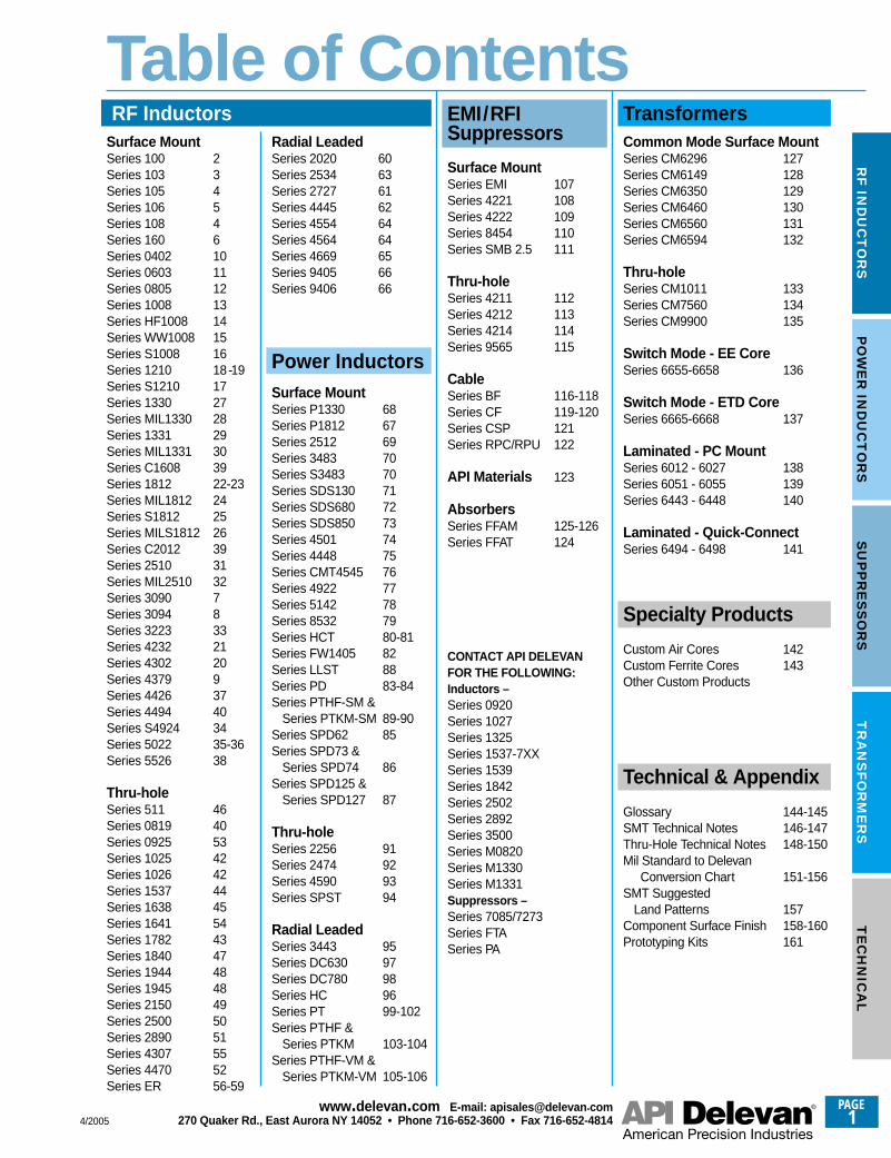
Military Specifications MS21367 (LT10K)
Physical ParametersInches Millimeters
A 0.065 Max. 1.65 Max.B 0.100 ± 0.010 2.54 ± 0.254C 0.100 ± 0.010 2.54 ±0 .254D 0.210 Min. 5.33 Min.E 0.012 ± 0.002 (Typ.) 0.30 ± 0.05F 0.095 ± 0.015 2.41 ± 0.381G 0.002 +0.001-0.000 0.05 +0.025-0.000
Weight Max. (Grams) 0.03
Current Rating at 90°C Ambient 15°C Rise
Operating Temperature Range –55°C to +105°C
Maximum Power Dissipation at 90°C 0.0205 Watts
Notes 1) L, Q and SRF measured on Boonton Qand RX meters using special test fixtures. Details forfixtures available. 2) Part number and quantity willappear on package as units are too small for legiblemarking.
Core Material Iron (LT10K)
Mechanical Configuration 1) Units are epoxyencapsulated. 2) Leads are tin/lead plated BerylliumCopper 3) Gold Plated leads available on specialorder. 4) RoHS compliant part available by ordering100R Series.
Packaging Bulk only
Made In the U.S.A. Patent Protected
M21367– SERIES 100 IRON CORE (LT10K)-150N-220N-330N-470N-680N-101N-121M-151M-181M-221M-271M-331M-391M-471M-561M-681M-821M-102M-122K-152K-182K-222K-272K-332K-392K-472K-562K-682K-822K-103K
Parts listed above are QPL/MIL qualified
Optional Tolerances: J = 5% H = 3% G = 2% F = 1%
*Complete part # must include series # PLUS the dash #
For further surface finish information, refer to TECHNICAL section of this catalog.
100R 100
Micro i ® Ribbon-Lead Inductors
MIL I TA RY
AP P R O V E D
Series
4/2005
PAGE3
www.delevan .com E-mail: apisales@delevan .com270 Quaker Rd., East Aurora NY 14052 • Phone 716-652-3600 • Fax 716-652-4814
RF
IND
UC
TO
RS
CURRENT RATING
MAX. (mA)
DASH NUMBER*
MIL DASH #
INDUCTANCE
(µH) s
ee Note
3
TOLE
RANCE
Q MINIM
UM
TEST FREQUENCY (MHz)
SRF MINIM
UM (MHz)
DC RESISTANCE
MAXIMUM (O
HMS)
0.0600.0690.0780.0930.1080.1140.1200.1330.1450.1700.1950.2120.230
0.1250.1750.2000.2200.2300.2350.2400.2600.2780.5200.5300.5400.7400.8400.9201.001.151.401.551.802.002.202.503.453.805.605.806.406.90
1270119011101030
950925900860820760705675650
880745695665650645635610590435430425360340325310290260250230220210195165160135130125120
27002450220020001800162514501335122011101000
915830
750650550450375300235215195175160145130115105
8577706860555048403530282522
50.050.050.050.050.050.050.050.050.050.050.050.050.0
25.025.025.025.025.025.025.025.025.025.025.025.0
7.97.97.97.97.97.97.97.97.97.97.97.92.52.52.52.52.5
60575552504948454239363432
3025252525252222222222222222222224242424222222242525252525
± (**)± 10%
± (**)± 10%
± (**)± 10%
± (**)± 10%
± (**)± 10%
± (**)± 10%
± (**)
± 10%± 10%± 10%± 10%± 10%± 10%± 10%± 10%± 10%± 10%± 10%± 10%± 10%± 10%± 10%± 10%± 10%± 10%± 10%± 10%± 10%± 10%± 10%± 10%± 10%± 10%± 10%± 10%± 10%
0.0100.0120.0150.0180.0220.0270.0330.0390.0470.0560.0680.0820.100
0.120.150.180.220.270.330.390.470.560.680.821.01.21.51.82.22.73.33.94.75.66.88.2
10.012.015.018.022.027.0
30/3738
31/3940
32/4142
33/4344
34/4546
35/4748
36/49
0102030405060708091011121314151617181920212223242526272829
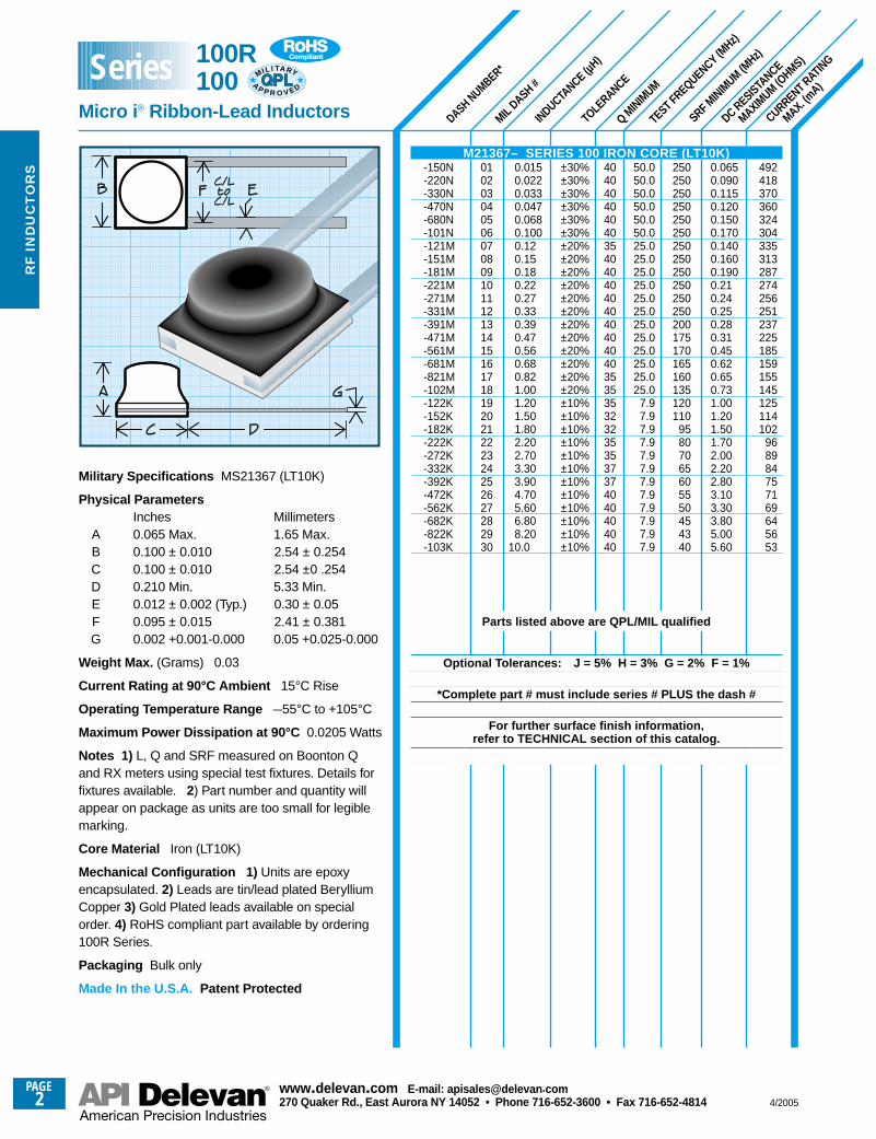
Military Specifications MIL-PRF-83446/04
Physical ParametersInches Millimeters
A 0.075 Max. 1.91 Max.B 0.100 ± 0.010 2.54 ± 0.25C 0.100 ± 0.010 2.54 ± 0.25D 0.050 Min. 1.27 Min.E 0.015 Min. (Typ.) 0.38 Min. (Typ.)F 0.020 Max. (Typ.) 0.51 Max. (Typ.)
Weight Max. (Grams) 0.03
Current Rating at 90°C Ambient 35°C Rise
Operating Temperature Range –55°C to +125°C
Maximum Power Dissipation at 90°C 0.135 Watts
Termination Finish Options (Part # Code)Gold over Nickel (Standard): As shown.Tin/Lead over Nickel: Add suffix “S” to part # (e.g.,103-102KS).Mil type “A:” Gold over Nickel (Standard)Mil type “B” or “F:” Tin/Lead (solder) over Nickel.RoHS type: Order 103R - XXXKS
Mechanical Configuration Units are epoxy encapsulated. Contact areas for reflow soldering are gold plated perMIL-G-45204 Type 1-Grade A. Internal connectionsare thermal compression bonded.
Packaging Tape & reel (8mm): 7" reel, 2000 piecesmax.; 13" reel, 8000 pieces max.
Made In the U.S.A.
M83446/04– SERIES 103 PHENOLIC CORE-100(*)-120K-150(*)-180K-220(*)-270K-330(*)-390K-470(*)-560K-680(*)-820K-101(*)
M83446/04– SERIES 103 FERRITE CORE-121K-151K-181K-221K-271K-331K-391K-471K-561K-681K-821K-102K-122K-152K-182K-222K-272K-332K-392K-472K-562K-682K-822K-103K-123K-153K-183K-223K-273K
Parts listed above are QPL/MIL qualified
Optional Tolerances: J = 5% H = 3% G = 2% F = 1%
*Complete part # must include series # PLUS the dash #
For further surface finish information, refer to TECHNICAL section of this catalog.
Notes 1) Designed specifically for reflow soldering and other hightemperature processes with metalized edges to exhibit solder
fillet. 2) Self Resonant Frequency (SRF) Values above 250 MHzare calculated and for reference only. 3) (**) - MS slash numbers
available in 20% (Suffix “M”) and 10% (Suffix “K”) tolerances.
103R 103
Micro i ® Chip Inductors
MIL I TA RY
AP P R O V E D
Series
PAGE4
www.delevan .com E-mail: apisales@delevan .com270 Quaker Rd., East Aurora NY 14052 • Phone 716-652-3600 • Fax 716-652-4814 4/2005
RF
IN
DU
CT
OR
S
SRF MINIM
UM (MHz)
TOLE
RANCE
DASH NUMBER*
MIL DASH #
(Refe
rence
)
INDUCTANCE (µ
H)
Q MINIM
UM
TEST FREQUENCY (MHz)
DC RESISTANCE
MAXIMUM (O
HMS)
CURRENT RATING
MAX. (mA)
0.140.160.190.210.230.250.280.310.450.620.650.731.01.21.51.72.02.22.83.13.33.85.05.6
4.04.24.47.58.0
13.017.019.023.025.028.031.0
830775710675650620585555460395385360310280250235220210185175170160135130
797975575545383633323028
500440405360330280185178163160155130115100
90756862575247424038
26.024.021.019.014.012.010.0
9.08.58.28.07.0
25.025.025.025.025.025.025.025.025.025.025.025.0
7.97.97.97.97.97.97.97.97.97.97.97.9
2.52.52.52.52.52.52.52.52.52.52.52.5
404040404035353535353030252525252525253030303030
363232323230303030303030
± 20%± 20%± 20%± 10%± 10%± 10%± 10%± 10%± 10%± 10%± 10%± 10%± 10%± 10%± 10%± 10%± 10%± 10%± 10%± 10%± 10%± 10%± 10%± 10%
± 10%± 10%± 10%± 10%± 10%± 10%± 10%± 10%± 10%± 10%± 10%± 10%
0.120.150.180.220.270.330.390.470.560.680.821.01.21.51.82.22.73.33.94.75.66.88.2
10.0
12.015.018.022.027.033.039.047.056.068.082.0
100.0
878889909192939495969798
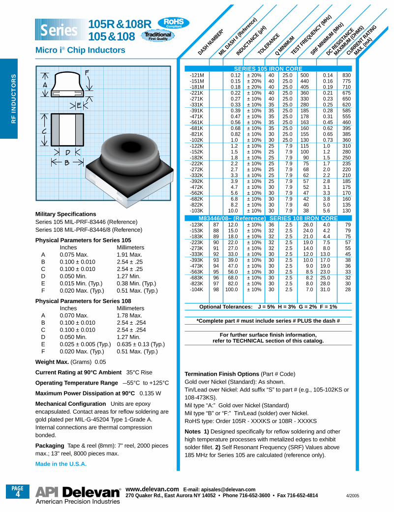
Military SpecificationsSeries 105 MIL-PRF-83446 (Reference)Series 108 MIL-PRF-83446/8 (Reference)
Physical Parameters for Series 105Inches Millimeters
A 0.075 Max. 1.91 Max.B 0.100 ± 0.010 2.54 ± .25C 0.100 ± 0.010 2.54 ± .25D 0.050 Min. 1.27 Min.E 0.015 Min. (Typ.) 0.38 Min. (Typ.)F 0.020 Max. (Typ.) 0.51 Max. (Typ.)
Physical Parameters for Series 108Inches Millimeters
A 0.070 Max. 1.78 Max.B 0.100 ± 0.010 2.54 ± .254C 0.100 ± 0.010 2.54 ± .254D 0.050 Min. 1.27 Min.E 0.025 ± 0.005 (Typ.) 0.635 ± 0.13 (Typ.)F 0.020 Max. (Typ.) 0.51 Max. (Typ.)
Weight Max. (Grams) 0.05
Current Rating at 90°C Ambient 35°C Rise
Operating Temperature Range –55°C to +125°C
Maximum Power Dissipation at 90°C 0.135 W
Mechanical Configuration Units are epoxyencapsulated. Contact areas for reflow soldering aregold plated per MIL-G-45204 Type 1-Grade A.Internal connections are thermal compressionbonded.
Packaging Tape & reel (8mm): 7" reel, 2000 piecesmax.; 13" reel, 8000 pieces max.
Made in the U.S.A.
SERIES 105 IRON CORE-121M-151M-181M-221K-271K-331K-391K-471K-561K-681K-821K-102K-122K-152K-182K-222K-272K-332K-392K-472K-562K-682K-822K-103K
M83446/08– (Reference) SERIES 108 IRON CORE-123K-153K-183K-223K-273K-333K-393K-473K-563K-683K-823K-104K
Optional Tolerances: J = 5% H = 3% G = 2% F = 1%
*Complete part # must include series # PLUS the dash #
For further surface finish information, refer to TECHNICAL section of this catalog.
Termination Finish Options (Part # Code)Gold over Nickel (Standard): As shown.Tin/Lead over Nickel: Add suffix “S” to part # (e.g., 105-102KS or108-473KS).Mil type “A:” Gold over Nickel (Standard)Mil type “B” or “F:” Tin/Lead (solder) over Nickel.RoHS type: Order 105R - XXXKS or 108R - XXXKS
Notes 1) Designed specifically for reflow soldering and otherhigh temperature processes with metalized edges to exhibitsolder fillet. 2) Self Resonant Frequency (SRF) Values above185 MHz for Series 105 are calculated (reference only).
105R&108R105&108
Micro i ® Chip Inductors
Series
4/2005
PAGE5
www.delevan .com E-mail: apisales@delevan .com270 Quaker Rd., East Aurora NY 14052 • Phone 716-652-3600 • Fax 716-652-4814
RF
IND
UC
TO
RS
SRF MINIM
UM (MHz)*
*
DASH NUMBER*
INDUCTANCE
(µH) ±
10%
Q MINIM
UM
TEST FREQUENCY (MHz)
DC RESISTANCE
MAXIMUM (O
HMS)
CURRENT RATING
MAX. (mA)
12001200120012001200120012001200110010501000
960
820710635580550520500475450425410380355335300265250230225215200185180175165150135130110105
857570
0.0700.0700.0700.0700.0700.0700.0700.0700.0800.0900.1000.110
0.150.200.250.300.330.370.400.450.500.550.600.700.800.901.101.301.501.701.802.002.302.602.803.003.304.005.204.507.508.00
13.017.019.0
17001600150014001300120011001000
900850840750
550400350300260230200190180170160150130120100
9085827565554540353326242119141210
9.0
150150150150100100100100100100100100
25.025.025.025.025.025.025.025.025.025.025.025.025.0
7.97.97.97.97.97.97.97.97.97.97.97.92.52.52.52.52.52.52.52.5
454545454545474747474747
404242454545454545424242423636383841424241413636363232323232303030
0.0100.0120.0150.0180.0220.0270.0330.0390.0470.0560.0680.082
0.100.120.150.180.220.270.330.390.470.560.680.82
1.01.21.51.82.22.73.33.94.75.66.88.2
10.012.015.018.022.027.033.039.047.0
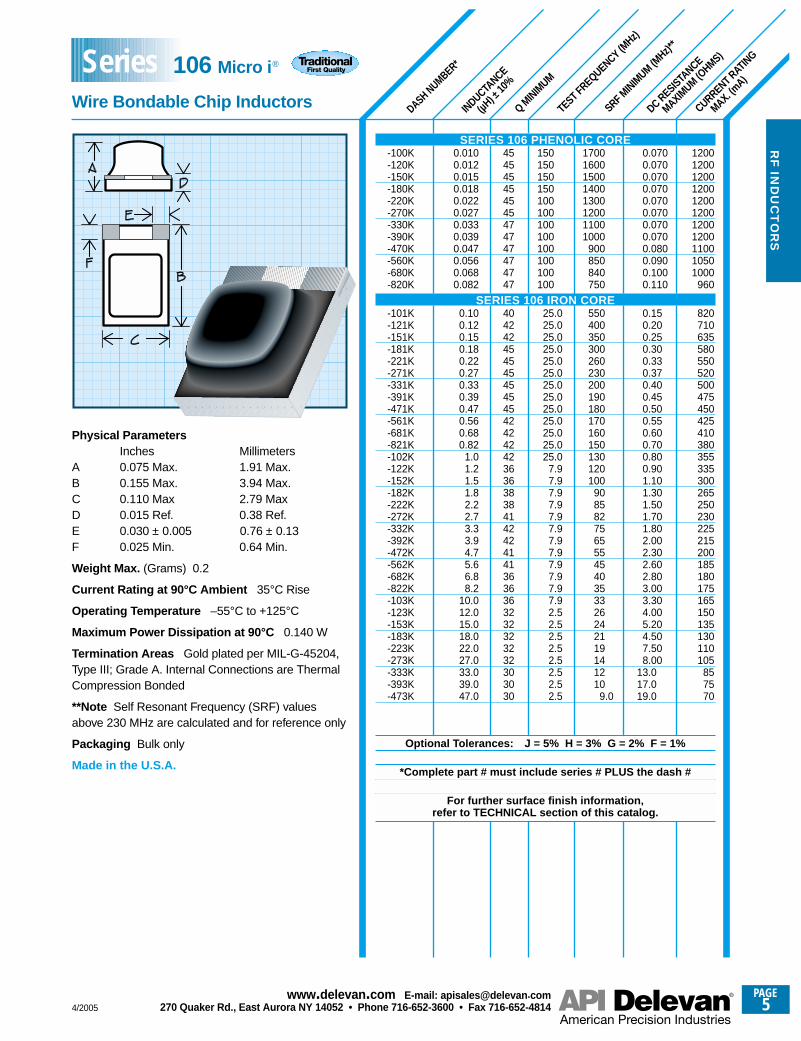
Physical ParametersInches Millimeters
A 0.075 Max. 1.91 Max.B 0.155 Max. 3.94 Max.C 0.110 Max 2.79 MaxD 0.015 Ref. 0.38 Ref.E 0.030 ± 0.005 0.76 ± 0.13F 0.025 Min. 0.64 Min.
Weight Max. (Grams) 0.2
Current Rating at 90°C Ambient 35°C Rise
Operating Temperature –55°C to +125°C
Maximum Power Dissipation at 90°C 0.140 W
Termination Areas Gold plated per MIL-G-45204,Type III; Grade A. Internal Connections are ThermalCompression Bonded
**Note Self Resonant Frequency (SRF) valuesabove 230 MHz are calculated and for reference only
Packaging Bulk only
Made in the U.S.A.
SERIES 106 PHENOLIC CORE-100K-120K-150K-180K-220K-270K-330K-390K-470K-560K-680K-820K
SERIES 106 IRON CORE-101K-121K-151K-181K-221K-271K-331K-391K-471K-561K-681K-821K-102K-122K-152K-182K-222K-272K-332K-392K-472K-562K-682K-822K-103K-123K-153K-183K-223K-273K-333K-393K-473K
Optional Tolerances: J = 5% H = 3% G = 2% F = 1%
*Complete part # must include series # PLUS the dash #
For further surface finish information, refer to TECHNICAL section of this catalog.
106 Micro i ®
Wire Bondable Chip Inductors
Series
PAGE6 4/2005
RF
IN
DU
CT
OR
S
SRF MINIM
UM (MHz)
TEST FREQUENCY (MHz)
DASH NUMBER*
MIL DASH #
INDUCTANCE (µ
H)
Q MINIM
UM
TOLE
RANCE
DC RESISTANCE
MAXIMUM (O
HMS)
CURRENT RATING
MAX. (mA)
159015151450139513451295129512551220119511651150
129512951220112510701025
985950915890860835795740695610545475410370325310290275270255230200185180175150145140135
125120100
9590858075706555504240
0.0500.0550.0600.0650.0700.0750.0750.0800.0850.0880.0930.095
0.0750.0750.0850.100.110.120.130.140.150.160.170.180.200.230.260.340.420.560.760.931.21.31.51.71.81.92.43.23.73.84.25.56.16.67.0
8.38.9
13.014.016.017.018.022.028.032.044.048.075.081.0
900900900900900900900900850800750700
600550420390340290250230220210200190180170150140130120100
98917648464239302624232218171312
11.010.0
9.18.67.66.85.64.54.03.83.53.43.22.8
150150150150100100100100100100100100
25.025.025.025.025.025.025.025.025.025.025.025.025.025.025.025.0
7.97.97.97.97.97.97.97.97.97.97.97.92.52.52.52.52.52.52.5
2.52.52.52.52.50.790.790.790.790.790.790.790.790.79
484848484848484848484848
5050505050505050505050505050505036363636404047474440404641464647474750
5050505047303232323232322828
± 20%± 20%± 20%± 20%± 20%± 20%± 20%± 20%± 20%± 20%± 20%± 20%
± 10%± 10%± 10%± 10%± 10%± 10%± 10%± 10%± 10%± 10%± 10%± 10%± 10%± 10%± 10%± 5%± 5%± 5%± 5%± 5%± 5%± 5%± 5%± 5%± 5%± 5%± 5%± 5%± 5%± 5%± 5%± 5%± 5%± 5%± 5%
± 5%± 5%± 5%± 5%± 5%± 5%± 5%± 5%± 5%± 5%± 5%± 5%± 5%± 5%
0.0100.0120.0150.0180.0220.0270.0330.0390.0470.0560.0680.082
0.1000.1200.1500.1800.2200.2700.3000.3300.3600.3900.4300.4700.5600.6800.8201.001.201.501.802.202.703.303.904.705.606.808.20
10.012.015.018.022.027.033.039.0
47.056.068.082.0
100.0120.0150.0180.0220.0270.0330.0390.0470.0560.0
010203040506070809101112
1314151617181920212223242526272829303132333435363738394041424344454647
4849505152535455565758596061
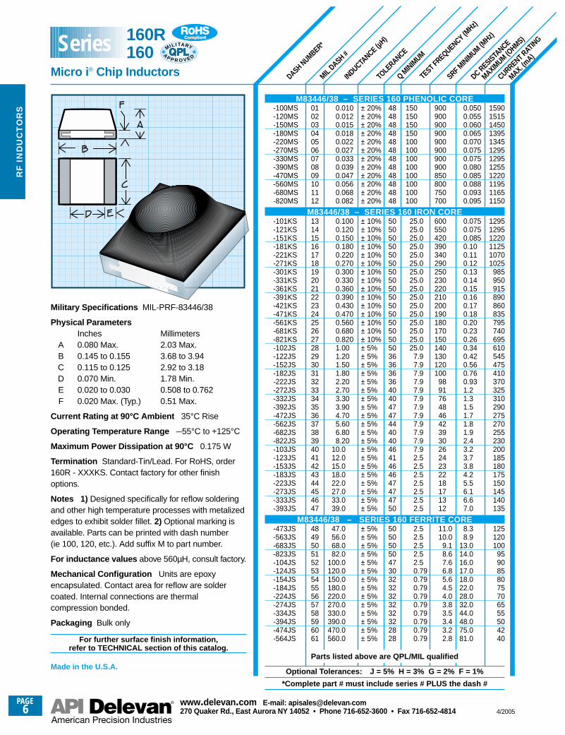
Military Specifications MIL-PRF-83446/38
Physical ParametersInches Millimeters
A 0.080 Max. 2.03 Max.B 0.145 to 0.155 3.68 to 3.94C 0.115 to 0.125 2.92 to 3.18D 0.070 Min. 1.78 Min.E 0.020 to 0.030 0.508 to 0.762F 0.020 Max. (Typ.) 0.51 Max.
Current Rating at 90°C Ambient 35°C Rise
Operating Temperature Range –55°C to +125°C
Maximum Power Dissipation at 90°C 0.175 W
Termination Standard-Tin/Lead. For RoHS, order160R - XXXKS. Contact factory for other finishoptions.
Notes 1) Designed specifically for reflow solderingand other high temperature processes with metalizededges to exhibit solder fillet. 2) Optional marking isavailable. Parts can be printed with dash number (ie 100, 120, etc.). Add suffix M to part number.
For inductance values above 560µH, consult factory.
Mechanical Configuration Units are epoxyencapsulated. Contact area for reflow are soldercoated. Internal connections are thermalcompression bonded.
Packaging Bulk only
For further surface finish information, refer to TECHNICAL section of this catalog.
Made in the U.S.A.
M83446/38 – SERIES 160 PHENOLIC CORE-100MS-120MS-150MS-180MS-220MS-270MS-330MS-390MS-470MS-560MS-680MS-820MS
M83446/38 – SERIES 160 IRON CORE-101KS-121KS-151KS-181KS-221KS-271KS-301KS-331KS-361KS-391KS-421KS-471KS-561KS-681KS-821KS-102JS-122JS-152JS-182JS-222JS-272JS-332JS-392JS-472JS-562JS-682JS-822JS-103JS-123JS-153JS-183JS-223JS-273JS-333JS-393JS
M83446/38 – SERIES 160 FERRITE CORE-473JS-563JS-683JS-823JS-104JS-124JS-154JS-184JS-224JS-274JS-334JS-394JS-474JS-564JS
Parts listed above are QPL/MIL qualified
Optional Tolerances: J = 5% H = 3% G = 2% F = 1%
*Complete part # must include series # PLUS the dash #
160R 160
Micro i ® Chip Inductors
Series
www.delevan .com E-mail: apisales@delevan .com270 Quaker Rd., East Aurora NY 14052 • Phone 716-652-3600 • Fax 716-652-4814
MIL I TA RY
AP P R O V E D
4/2005
PAGE7
www.delevan .com E-mail: apisales@delevan .com270 Quaker Rd., East Aurora NY 14052 • Phone 716-652-3600 • Fax 716-652-4814
RF
IND
UC
TO
RS
SRF MINIM
UM (MHz)
DASH NUMBER*
INDUCTANCE (µ
H)
TOLE
RANCE
Q MINIM
UM
TEST FREQUENCY (MHz)
DC RESISTANCE
MAXIMUM (O
HMS)
CURRENT RATING
MAX. (mA)
890810765640870830750690630970870795765690615550500460410390355330265250245240225200180160145135130120
0.0950.1150.1400.1850.1000.1100.1350.160.190.080.100.120.140.160.200.250.300.360.450.500.600.701.101.201.251.301.501.902.303.003.504.004.505.00
100010001000
900900900800700650510410370330300250220200180160140120100
959085807065605553504540
50.050.050.050.050.050.050.050.050.025.025.025.025.025.025.025.025.025.025.025.025.025.0
7.97.97.97.97.97.97.97.97.97.97.97.9
42424040403835302532323232343434343434302824242424252525252422222220
± 20%± 20%± 20%± 10%± 10%± 10%± 10%± 10%± 10%± 10%± 10%± 10%± 10%± 10%± 10%± 10%± 10%± 10%± 10%± 10%± 10%± 10%± 10%± 10%± 10%± 10%± 10%± 10%± 10%± 10%± 10%± 10%± 10%± 10%
0.0100.0150.0220.0330.0390.0470.0560.0680.0820.100.120.150.180.220.270.330.390.470.560.680.821.001.201.501.802.202.703.303.904.705.606.808.20
10.0
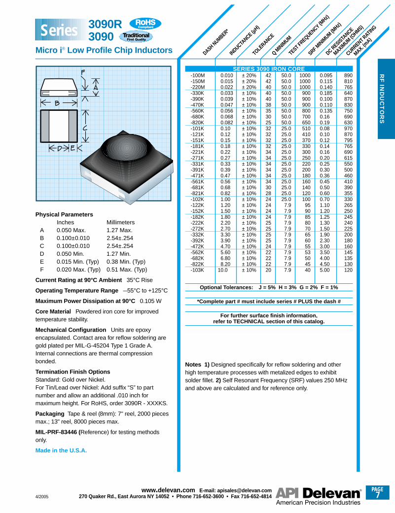
Physical ParametersInches Millimeters
A 0.050 Max. 1.27 Max.B 0.100±0.010 2.54±.254C 0.100±0.010 2.54±.254D 0.050 Min. 1.27 Min.E 0.015 Min. (Typ) 0.38 Min. (Typ)F 0.020 Max. (Typ) 0.51 Max. (Typ)
Current Rating at 90°C Ambient 35°C Rise
Operating Temperature Range –55°C to +125°C
Maximum Power Dissipation at 90°C 0.105 W
Core Material Powdered iron core for improvedtemperature stability.
Mechanical Configuration Units are epoxyencapsulated. Contact area for reflow soldering aregold plated per MIL-G-45204 Type 1 Grade A.Internal connections are thermal compressionbonded.
Termination Finish OptionsStandard: Gold over Nickel.For Tin/Lead over Nickel: Add suffix “S” to partnumber and allow an additional .010 inch formaximum height. For RoHS, order 3090R - XXXKS.
Packaging Tape & reel (8mm): 7" reel, 2000 piecesmax.; 13" reel, 8000 pieces max.
MIL-PRF-83446 (Reference) for testing methodsonly.
Made in the U.S.A.
SERIES 3090 IRON CORE-100M-150M-220M-330K-390K-470K-560K-680K-820K-101K-121K-151K-181K-221K-271K-331K-391K-471K-561K-681K-821K-102K-122K-152K-182K-222K-272K-332K-392K-472K-562K-682K-822K-103K
Optional Tolerances: J = 5% H = 3% G = 2% F = 1%
*Complete part # must include series # PLUS the dash #
For further surface finish information, refer to TECHNICAL section of this catalog.
Notes 1) Designed specifically for reflow soldering and otherhigh temperature processes with metalized edges to exhibitsolder fillet. 2) Self Resonant Frequency (SRF) values 250 MHzand above are calculated and for reference only.
3090R3090
Micro i ® Low Profile Chip Inductors
Series
PAGE8
www.delevan .com E-mail: apisales@delevan .com270 Quaker Rd., East Aurora NY 14052 • Phone 716-652-3600 • Fax 716-652-4814 4/2005
RF
IN
DU
CT
OR
S
SRF MINIM
UM (MHz)
DASH NUMBER*
MIL DASH #
(Refe
rence
)
INDUCTANCE
(µH) ±
10%
Q MINIM
UM
TEST FREQUENCY (MHz)
DC RESISTANCE
MAXIMUM (O
HMS)
CURRENT RATING
MAX. (mA)
1000100010001000100010001000
900900900840840840840790790790700700700590510430400380330290260230210200180170160140130120118115114113110100
847970676462595652454441393733302625
0.0400.0400.0400.0400.0500.0500.0500.0600.0600.0600.0700.0700.0700.0700.0800.0800.0800.100.100.100.140.190.260.300.340.450.570.720.901.101.201.401.601.802.403.003.503.603.703.803.904.005.007.008.00
10.011.012.013.014.016.018.024.025.029.032.035.045.055.070.080.0
2000.01800.01500.01500.01300.01300.01000.01000.0
800.0760.0700.0650.0570.0520.0400.0360.0320.0270.0240.0220.0190.0170.0160.0150.0130.0120.0110.0100.0
80.060.050.045.042.040.037.034.029.027.022.017.016.015.014.013.012.011.010.0
9.08.07.06.05.04.03.33.12.92.42.11.91.81.7
150150150150100100100100100100100100
50505050505050502525252525
7.97.97.97.97.97.97.97.97.97.97.97.92.52.52.52.52.52.52.52.52.52.52.52.50.790.790.790.790.790.790.790.790.790.790.790.79
60606060606060606565656565657575707070707070707575656565656560606065656565606060606565657070656060404040404040403535353030
0.0100.0120.0150.0180.0220.0270.0330.0390.0470.0560.0680.0820.1000.1200.1500.1800.2200.2700.3300.3900.4700.5600.6800.8201.001.201.501.802.202.703.303.904.705.606.808.20
10.012.015.018.022.027.033.039.047.056.068.082.0
100.0120.0150.0180.0220.0270.0330.0390.0470.0560.0680.0820.0
1000.0
6263646566676869707172737475767778798081828384858687888990919293949596979899
100101102103104105106107108109110111112113114115116117118119120121122
Physical ParametersInches Millimeters
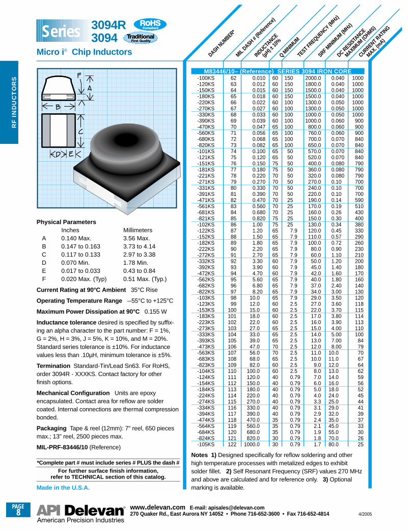
A 0.140 Max. 3.56 Max.B 0.147 to 0.163 3.73 to 4.14C 0.117 to 0.133 2.97 to 3.38D 0.070 Min. 1.78 Min.E 0.017 to 0.033 0.43 to 0.84F 0.020 Max. (Typ) 0.51 Max. (Typ.)
Current Rating at 90°C Ambient 35°C Rise
Operating Temperature Range –55°C to +125°C
Maximum Power Dissipation at 90°C 0.155 W
Inductance tolerance desired is specified by suffix-ing an alpha character to the part number: F = 1%,G = 2%, H = 3%, J = 5%, K = 10%, and M = 20%.Standard series tolerance is ±10%. For inductancevalues less than .10µH, minimum tolerance is ±5%.
Termination Standard-Tin/Lead Sn63. For RoHS,order 3094R - XXXKS. Contact factory for other finish options.
Mechanical Configuration Units are epoxyencapsulated. Contact area for reflow are soldercoated. Internal connections are thermal compressionbonded.
Packaging Tape & reel (12mm): 7" reel, 650 piecesmax.; 13" reel, 2500 pieces max.
MIL-PRF-83446/10 (Reference)
*Complete part # must include series # PLUS the dash #For further surface finish information,
refer to TECHNICAL section of this catalog.
Made in the U.S.A.
M83446/10– (Reference) SERIES 3094 IRON CORE-100KS-120KS-150KS-180KS-220KS-270KS-330KS-390KS-470KS-560KS-680KS-820KS-101KS-121KS-151KS-181KS-221KS-271KS-331KS-391KS-471KS-561KS-681KS-821KS-102KS-122KS-152KS-182KS-222KS-272KS-332KS-392KS-472KS-562KS-682KS-822KS-103KS-123KS-153KS-183KS-223KS-273KS-333KS-393KS-473KS-563KS-683KS-823KS-104KS-124KS-154KS-184KS-224KS-274KS-334KS-394KS-474KS-564KS-684KS-824KS-105KS
Notes 1) Designed specifically for reflow soldering and otherhigh temperature processes with metalized edges to exhibitsolder fillet. 2) Self Resonant Frequency (SRF) values 270 MHzand above are calculated and for reference only. 3) Optionalmarking is available.
3094R3094
Micro i ® Chip Inductors
Series
RF
IND
UC
TO
RS
SRF MINIM
UM (MHz)
CURRENT RATING
MAX. (mA)
DC RESISTANCE
MAXIMUM (O
HMS)
TEST FREQUENCY (MHz)
Q MINIM
UM
INDUCTANCE
(µH) ±
10%
MIL DASH #
(Refe
rence
)
DASH NUMBER*4379R Micro i ®
4379 Micro i ®
Shielded Surface Mount Inductors
100010001000100010001000
750750750700700700650650600500400350330310300285270225200180170160150140130125125120111102
93898988827875726966645347454443403835292625232221
0.030.030.030.040.040.040.050.050.050.060.060.060.090.090.140.200.300.400.460.520.540.600.661.001.201.51.81.92.12.42.73.13.23.54.04.85.76.26.36.47.48.18.89.7
10.011.012.017.022.024.025.027.030.034.039.056.070.080.090.0
100.0110.0
600520490460430370310280260240200185175150135120105
85806456494541393430262320181716141210
9.48.08.06.96.15.24.64.03.62.82.32.12.01.71.61.51.41.31.21.11.00.90.80.70.7
25.025.025.025.025.025.025.025.025.025.025.025.025.0
7.97.97.97.97.97.97.97.97.97.97.97.92.52.52.52.52.52.52.52.52.52.52.52.50.790.790.790.790.790.790.790.790.790.790.790.790.250.250.250.250.250.250.250.250.250.250.250.25
79797979798893
102106106106106106
90100100100100100105115115115115100100100100105110120120120110110110110
8585858585
100100100100100
9595757575757575757575757575
0.100.120.150.180.220.270.330.390.470.560.680.821.01.21.51.82.22.73.33.94.75.66.88.2
101215182227333947566882
100120150180220270330390470560680820
100012001500180022002700330039004700560068008200
10000
6263646566676869707172737475767778798081828384858687888990919293949596979899
100101102103104105106107108109110111112113114115116117118119120121122
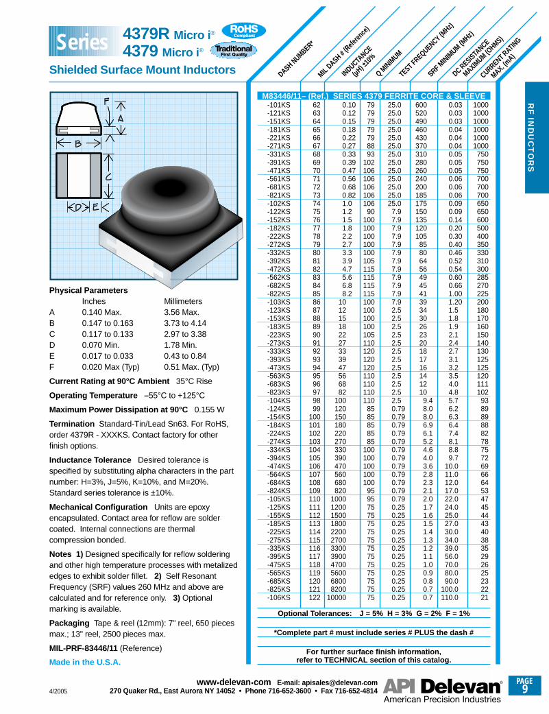
Physical ParametersInches Millimeters
A 0.140 Max. 3.56 Max.B 0.147 to 0.163 3.73 to 4.14C 0.117 to 0.133 2.97 to 3.38D 0.070 Min. 1.78 Min.E 0.017 to 0.033 0.43 to 0.84F 0.020 Max (Typ) 0.51 Max. (Typ)
Current Rating at 90°C Ambient 35°C Rise
Operating Temperature – 55°C to +125°C
Maximum Power Dissipation at 90°C 0.155 W
Termination Standard-Tin/Lead Sn63. For RoHS,order 4379R - XXXKS. Contact factory for other finish options.
Inductance Tolerance Desired tolerance isspecified by substituting alpha characters in the partnumber: H=3%, J=5%, K=10%, and M=20%.Standard series tolerance is ±10%.
Mechanical Configuration Units are epoxyencapsulated. Contact area for reflow are soldercoated. Internal connections are thermalcompression bonded.
Notes 1) Designed specifically for reflow solderingand other high temperature processes with metalizededges to exhibit solder fillet. 2) Self ResonantFrequency (SRF) values 260 MHz and above arecalculated and for reference only. 3) Optionalmarking is available.
Packaging Tape & reel (12mm): 7" reel, 650 piecesmax.; 13" reel, 2500 pieces max.
MIL-PRF-83446/11 (Reference)
Made in the U.S.A.
M83446/11– (Ref.) SERIES 4379 FERRITE CORE & SLEEVE-101KS-121KS-151KS-181KS-221KS-271KS-331KS-391KS-471KS-561KS-681KS-821KS-102KS-122KS-152KS-182KS-222KS-272KS-332KS-392KS-472KS-562KS-682KS-822KS-103KS-123KS-153KS-183KS-223KS-273KS-333KS-393KS-473KS-563KS-683KS-823KS-104KS-124KS-154KS-184KS-224KS-274KS-334KS-394KS-474KS-564KS-684KS-824KS-105KS-125KS-155KS-185KS-225KS-275KS-335KS-395KS-475KS-565KS-685KS-825KS-106KS
Optional Tolerances: J = 5% H = 3% G = 2% F = 1%
*Complete part # must include series # PLUS the dash #
For further surface finish information, refer to TECHNICAL section of this catalog.
Series
4/2005
PAGE9
www.delevan .com E-mail: apisales@delevan .com270 Quaker Rd., East Aurora NY 14052 • Phone 716-652-3600 • Fax 716-652-4814
4/2005
PAGE10
www.delevan .com E-mail: apisales@delevan .com270 Quaker Rd., East Aurora NY 14052 • Phone 716-652-3600 • Fax 716-652-4814
RF
IN
DU
CT
OR
S
SRF MINIM
UM (MHz)
CURRENT RATING
MAXIMUM (m
A)
DC RESISTANCE
MAXIMUM (O
HMS)
DASH NUMBER*
INDUCTANCE
(nH) ±
10%
INDUCTANCE & Q
TEST
FREQUENCY (MHz)
Q MINIM
UM
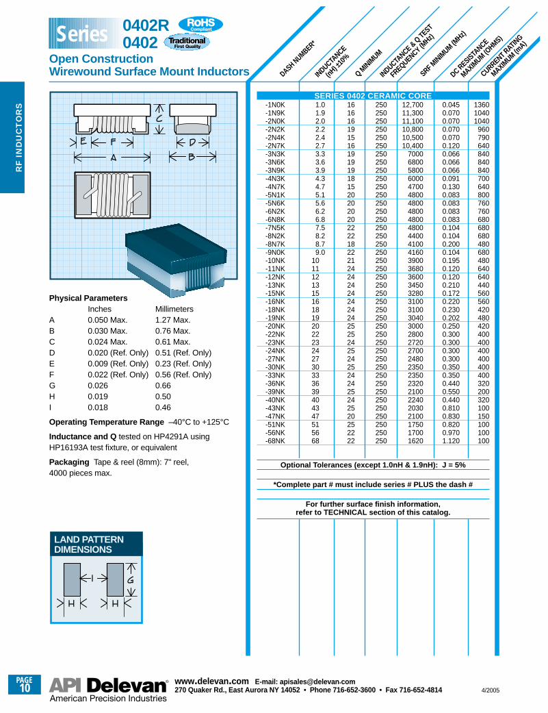
Physical ParametersInches Millimeters
A 0.050 Max. 1.27 Max.B 0.030 Max. 0.76 Max. C 0.024 Max. 0.61 Max.D 0.020 (Ref. Only) 0.51 (Ref. Only)E 0.009 (Ref. Only) 0.23 (Ref. Only)F 0.022 (Ref. Only) 0.56 (Ref. Only)G 0.026 0.66H 0.019 0.50I 0.018 0.46
Operating Temperature Range –40°C to +125°C
Inductance and Q tested on HP4291A usingHP16193A test fixture, or equivalent
Packaging Tape & reel (8mm): 7" reel,4000 pieces max.
136010401040
960790640840840840700640800760760680680680480680480640640440560560420480420400400400400400400320200320100150100100100
0.0450.0700.0700.0700.0700.1200.0660.0660.0660.0910.1300.0830.0830.0830.0830.1040.1040.2000.1040.1950.1200.1200.2100.1720.2200.2300.2020.2500.3000.3000.3000.3000.3500.3500.4400.5500.4400.8100.8300.8200.9701.120
12,70011,30011,10010,80010,50010,400
700068005800600047004800480048004800480044004100416039003680360034503280310031003040300028002720270024802350235023202100224020302100175017001620
250250250250250250250250250250250250250250250250250250250250250250250250250250250250250250250250250250250250250250250250250250
161616191516191919181520202020222218222124242424242424252524252425242425242520252222
1.01.92.02.22.42.73.33.63.94.34.75.15.66.26.87.58.28.79.0
1011121315161819202223242730333639404347515668
SERIES 0402 CERAMIC CORE-1N0K-1N9K-2N0K-2N2K-2N4K-2N7K -3N3K-3N6K-3N9K-4N3K -4N7K-5N1K-5N6K-6N2K-6N8K -7N5K-8N2K-8N7K-9N0K-10NK-11NK-12NK-13NK -15NK-16NK -18NK -19NK-20NK -22NK -23NK-24NK -27NK-30NK -33NK -36NK-39NK -40NK-43NK-47NK-51NK-56NK -68NK
Optional Tolerances (except 1.0nH & 1.9nH): J = 5%
*Complete part # must include series # PLUS the dash #
For further surface finish information, refer to TECHNICAL section of this catalog.
LAND PATTERNDIMENSIONS
0402R0402
Open Construction Wirewound Surface Mount Inductors
Series
4/2005
PAGE11
www.delevan .com E-mail: apisales@delevan .com270 Quaker Rd., East Aurora NY 14052 • Phone 716-652-3600 • Fax 716-652-4814
RF
IND
UC
TO
RS
SRF MINIM
UM (MHz)
CURRENT RATING
MAXIMUM (m
A)
DC RESISTANCE
MAXIMUM (O
HMS)
DASH NUMBER*
INDUCTANCE
(nH) ±
10%
INDUCTANCE & Q
TEST
FREQUENCY (MHz)
Q MINIM
UM
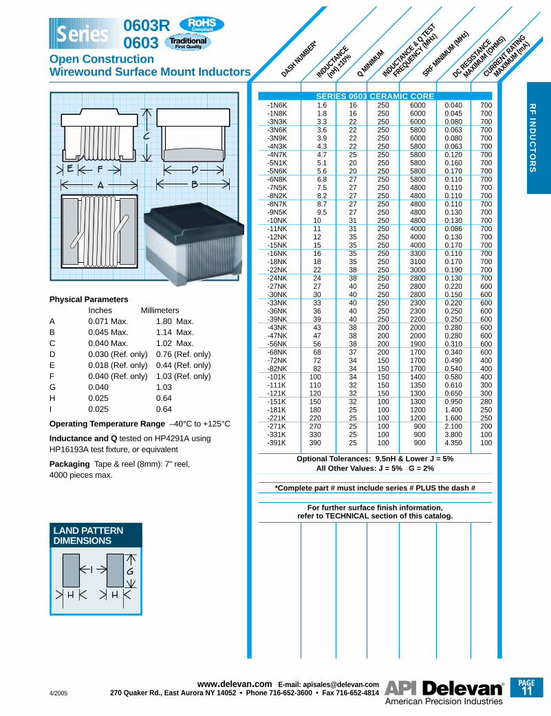
Physical ParametersInches Millimeters
A 0.071 Max. 1.80 Max.B 0.045 Max. 1.14 Max.C 0.040 Max. 1.02 Max.D 0.030 (Ref. only) 0.76 (Ref. only)E 0.018 (Ref. only) 0.44 (Ref. only)F 0.040 (Ref. only) 1.03 (Ref. only)G 0.040 1.03H 0.025 0.64I 0.025 0.64
Operating Temperature Range –40°C to +125°C
Inductance and Q tested on HP4291A usingHP16193A test fixture, or equivalent
Packaging Tape & reel (8mm): 7" reel,4000 pieces max.
700700700700700700700700700700700700700700700700700700700700700700600600600600600600600600600400400400300300280250250200100100
0.0400.0450.0800.0630.0800.0630.1200.1600.1700.1100.1100.1100.1100.1300.1300.0860.1300.1700.1100.1700.1900.1300.2200.1500.2200.2500.2500.2800.2800.3100.3400.4900.5400.5800.6100.6500.9501.4001.6002.1003.8004.350
600060006000580060005800580058005800580048004800480048004800400040004000330031003000280028002800230023002200200020001900170017001700140013501300130012001200
900900900
250250250250250250250250250250250250250250250250250250250250250250250250250250250200200200200150150150150150100100100100100100
161622222222252020272727272731313535353538384040404040383838373434343232322525252525
1.61.83.33.63.94.34.75.15.66.87.58.28.79.5
10111215161822242730333639434756687282
100110120150180220270330390
LAND PATTERNDIMENSIONS
SERIES 0603 CERAMIC CORE-1N6K-1N8K-3N3K-3N6K-3N9K-4N3K-4N7K-5N1K-5N6K-6N8K-7N5K-8N2K-8N7K-9N5K-10NK-11NK-12NK-15NK-16NK-18NK-22NK-24NK-27NK-30NK-33NK-36NK-39NK-43NK-47NK-56NK-68NK-72NK-82NK-101K-111K-121K-151K-181K-221K-271K-331K -391K
Optional Tolerances: 9.5nH & Lower J = 5%All Other Values: J = 5% G = 2%
*Complete part # must include series # PLUS the dash #
For further surface finish information, refer to TECHNICAL section of this catalog.
0603R0603
Open Construction Wirewound Surface Mount Inductors
Series
PAGE12
www.delevan .com E-mail: apisales@delevan .com270 Quaker Rd., East Aurora NY 14052 • Phone 716-652-3600 • Fax 716-652-4814 4/2005
RF
IN
DU
CT
OR
S
SRF MINIM
UM (MHz)
CURRENT RATING
MAXIMUM (m
A)
DC RESISTANCE
MAXIMUM (O
HMS)
DASH NUMBER*
INDUCTANCE
(nH) ±
10%
Q TEST
FREQUENCY (MHz)
INDUCTANCE TEST
FREQUENCY (MHz)
Q MINIM
UM
800800600600600600600600600600600500500500500500500500500500500400400400400400400400400350350310290220210210190180180170170170170160150
0.060.060.080.080.110.140.120.100.150.170.200.220.220.250.270.270.290.340.310.340.380.420.480.460.480.510.560.640.701.01.01.41.51.71.92.22.22.32.352.502.502.50 2.502.70 2.95
79007900600055005500450047004200400034003300260020002500205017002000165016501550145013001200120010001100
920870850690650600560375340220200200200100100100
806050
1500150015001000100010001000
500500500500500500500500500500500500500500500500500250250250250250250250250250100
5050505050502525
7.97.97.9
806550655050506050505055505560556060606060656565505050505044484848332323232323201816161616
250250250250250250250250250250250250250250250250250200200200200150150150150150100100100100100100100
50252525252525
7.97.97.97.97.9
2.83.03.35.66.87.58.2
10121518222427333639434756688291
100110120150180220240270330390470560620680750820
100012001500180022002700
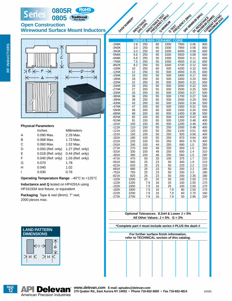
Physical ParametersInches Millimeters
A 0.090 Max. 2.29 Max.B 0.068 Max. 1.73 Max.C 0.060 Max. 1.52 Max.D 0.050 (Ref. only) 1.27 (Ref. only)E 0.018 (Ref. only) 0.44 (Ref. only)F 0.040 (Ref. only) 1.03 (Ref. only)G 0.070 1.78H 0.040 1.02I 0.030 0.76
Operating Temperature Range –40°C to +125°C
Inductance and Q tested on HP4291A usingHP16193A test fixture, or equivalent
Packaging Tape & reel (8mm): 7" reel,2000 pieces max.
LAND PATTERNDIMENSIONS
SERIES 0805 CERAMIC CORE-2N8K-3N0K-3N3K-5N6K-6N8K-7N5K-8N2K-10NK-12NK-15NK-18NK-22NK-24NK-27NK-33NK-36NK-39NK-43NK-47NK-56NK-68NK-82NK-91NK-101K-111K-121K-151K-181K-221K-241K-271K-331K-391K-471K-561K-621K-681K-751K-821K-102K-122K -152K -182K-222K-272K
Optional Tolerances: 8.2nH & Lower J = 5%All Other Values: J = 5% G = 2%
*Complete part # must include series # PLUS the dash #
For further surface finish information, refer to TECHNICAL section of this catalog.
0805R0805
Open Construction Wirewound Surface Mount Inductors
Series
4/2005
PAGE13
www.delevan .com E-mail: apisales@delevan .com270 Quaker Rd., East Aurora NY 14052 • Phone 716-652-3600 • Fax 716-652-4814
RF
IND
UC
TO
RS
SRF MINIM
UM (MHz)
CURRENT RATING
MAX. (mA)
DC RESISTANCE
MAXIMUM (O
HMS)
DASH NUMBER*
INDUCTANCE (µ
H)
TOLE
RANCE
TEST FREQUENCY (MHz)
Q MINIM
UM
156215621562156215621562156215621562156214501381132012351164110510531008
847823801728
12251168111910551000
954913846808760708685591548457433413398354334312274264245207194173158146135125120
0.0500.0500.0500.0500.0500.0500.0500.0500.0500.0500.0580.0640.0700.0800.0900.1000.1100.1200.1700.1800.1900.230
0.1000.1100.1200.1350.1500.1650.1800.2100.2300.2600.3000.3200.4300.5000.7200.8000.8800.9501.201.351.542.002.162.503.504.005.006.007.008.009.00
10.00
27002700270027002700270027002700270027002450220020001800162514501335122011101000
915550
750650550450375300250215195175140125100
92767062605747443533282421191715131211
50505050505050505050505050505050505050505025
2525252525252525252525
7.97.97.97.97.97.97.97.97.97.97.97.97.92.52.52.52.52.52.52.52.5
40404040404040404040404040353530303025252515
4040404040404040404040303030303030303030303030303030303030303030
±20%±20%±20%±20%±20%±20%±20%±20%±20%±10%±10%±10%±10%±10%±10%±10%±10%±10%±10%±10%±10%±10%
±10%±10%±10%±10%±10%±10%±10%±10%±10%±10%±10%±5%±5%±5%±5%±5%±5%±5%±5%±5%±5%±5%±5%±5%±5%±5%±5%±5%±5%±5%±5%±5%
0.00180.00220.00270.00330.00390.00470.00560.00680.00820.0100.0120.0150.0180.0220.0270.0330.0390.0470.0560.0680.0820.100
0.120.150.180.220.270.330.390.470.560.680.821.01.21.51.82.22.73.33.94.75.66.88.2
101215182227333947
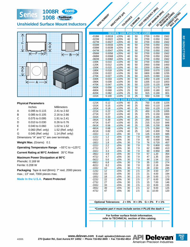
Physical ParametersInches Millimeters
A 0.095 to 0.115 2.41 to 2.92B 0.085 to 0.105 2.16 to 2.66C 0.075 to 0.095 1.91 to 2.41D 0.010 to 0.030 0.26 to 0.76E 0.040 to 0.060 1.02 to 1.52F 0.060 (Ref. only) 1.52 (Ref. only)G 0.045 (Ref. only) 1.14 (Ref. only)Dimensions “A” and “C” are over terminals.
Weight Max. (Grams) 0.1
Operating Temperature Range –55°C to +125°C
Current Rating at 90°C Ambient 35°C Rise
Maximum Power Dissipation at 90°CPhenolic: 0.169 WFerrite: 0.208 W
Packaging Tape & reel (8mm): 7" reel, 2000 piecesmax.; 13" reel, 7000 pieces max.
Made In the U.S.A. Patent Protected
SERIES 1008 PHENOLIC CORE-018M-022M-027M-033M-039M-047M-056M-068M-082M-100K-120K-150K-180K-220K-270K-330K-390K-470K-560K-680K-820K-101K
SERIES 1008 FERRITE CORE-121K-151K-181K-221K-271K-331K-391K-471K-561K-681K-821K-102J-122J-152J-182J-222J-272J-332J-392J-472J-562J-682J-822J-103J-123J-153J-183J-223J-273J-333J-393J-473J
Optional Tolerances: J = 5% H = 3% G = 2% F = 1%
*Complete part # must include series # PLUS the dash #
For further surface finish information, refer to TECHNICAL section of this catalog.
1008R1008
Unshielded Surface Mount Inductors
Series
PAGE14
www.delevan .com E-mail: apisales@delevan .com270 Quaker Rd., East Aurora NY 14052 • Phone 716-652-3600 • Fax 716-652-4814 4/2005
RF
IN
DU
CT
OR
S
SRF MINIM
UM (MHz)
CURRENT RATING
MAX. (mA)
DC RESISTANCE
MAXIMUM (O
HMS)
DASH NUMBER*
INDUCTANCE (n
H)
TOLE
RANCE
TEST FREQUENCY (MHz)
Q MINIM
UM
13201275123510751053
965950930900870847570550390375
405395375360345330320310300290280275273270325320315305300285280275273
0.0700.0750.0800.1050.1100.1300.1350.1400.1500.1600.1700.3700.4000.8000.850
0.9100.9501.051.151.251.351.451.551.651.751.851.952.002.051.401.451.501.601.651.801.901.952.00
>3000>3000>3000
27002400225020001800160015001350120010501000
900
850800700600550500465425415375340330325305290200165150120110
605040
505050505050505050505050505025
252525252525252525252525252525
7.97.97.97.97.97.97.97.9
404030303030303030303020201515
3030303030303030303030303030303030303030303030
±20%±20%±20%±20%±20%±20%±20%±20%±20%±20%±20%±10%±10%±10%±10%
±10%±10%±10%±10%±10%±10%±10%±10%±10%±10%±10%±10%±10%±10%±10%±10%±10%±10%±10%±10%±10%±10%±10%
4.78.2
10.012.015.018.022.027.033.039.047.056.068.082.0
100
120150180220270330390470560620680750820910
100012001500180022002700330039004700
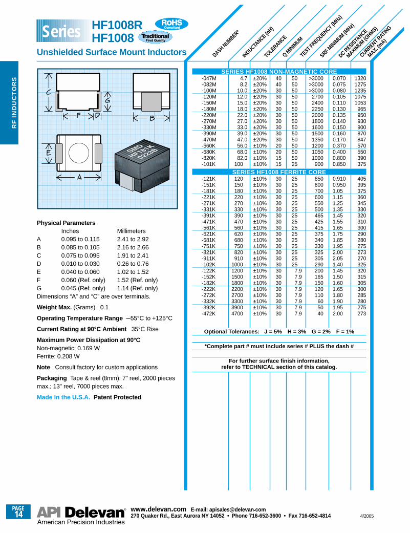
Physical ParametersInches Millimeters
A 0.095 to 0.115 2.41 to 2.92B 0.085 to 0.105 2.16 to 2.66C 0.075 to 0.095 1.91 to 2.41D 0.010 to 0.030 0.26 to 0.76E 0.040 to 0.060 1.02 to 1.52F 0.060 (Ref. only) 1.52 (Ref. only)G 0.045 (Ref. only) 1.14 (Ref. only)Dimensions “A” and “C” are over terminals.
Weight Max. (Grams) 0.1
Operating Temperature Range –55°C to +125°C
Current Rating at 90°C Ambient 35°C Rise
Maximum Power Dissipation at 90°CNon-magnetic: 0.169 WFerrite: 0.208 W
Note Consult factory for custom applications
Packaging Tape & reel (8mm): 7" reel, 2000 piecesmax.; 13" reel, 7000 pieces max.
Made In the U.S.A. Patent Protected
SERIES HF1008 NON-MAGNETIC CORE-047M-082M-100M-120M-150M-180M-220M-270M-330M-390M-470M-560K-680K-820K-101K
SERIES HF1008 FERRITE CORE-121K-151K-181K-221K-271K-331K-391K-471K-561K-621K-681K-751K-821K-911K-102K-122K-152K-182K-222K-272K-332K-392K-472K
Optional Tolerances: J = 5% H = 3% G = 2% F = 1%
*Complete part # must include series # PLUS the dash #
For further surface finish information, refer to TECHNICAL section of this catalog.
HF1008RHF1008
Unshielded Surface Mount Inductors
Series
4/2005
PAGE15
www.delevan .com E-mail: apisales@delevan .com270 Quaker Rd., East Aurora NY 14052 • Phone 716-652-3600 • Fax 716-652-4814
SRF MINIM
UM (MHz)
CURRENT RATING
MAXIMUM (m
A)
DC RESISTANCE
MAXIMUM (O
HMS)
DASH NUMBER*
INDUCTANCE
(nH) ±
10%
Q TEST
FREQUENCY (MHz)
INDUCTANCE TEST
FREQUENCY (MHz)
Q MINIM
UM
1000100010001000100010001000100010001000100010001000100010001000
650650580520500500500450450470470470470400300400360400380370310330300280290290260260240200170150130120
0.150.080.090.110.120.120.120.130.140.150.160.180.200.200.210.220.560.630.700.770.840.880.911.001.051.101.121.151.191.331.401.471.541.611.681.752.002.302.602.803.203.403.604.004.004.906.009.00
10.5011.50
40004100330025002400240019001600160015001500130012501300110010001000
950850750700650600585570530500480450415375375360350320290250200160160140110100
90404025201815
1500500500500350350350350350350350350350350350350350350100100100100100100100100100100100100100100100100
50505050505025252525
7.97.97.97.97.97.9
5050505050555555606065656565606060604545454545454545454545454545453535353528282822222020161818181818
505050505050505050505050505050502525252525252525252525252525252525252525
7.97.97.97.97.97.97.97.97.97.97.92.52.52.5
5.6101215182224273339475659687582
100120150180220240270300330360390430470560620680750820910
100012001500180022002700330039004700560068008200
100001200015000
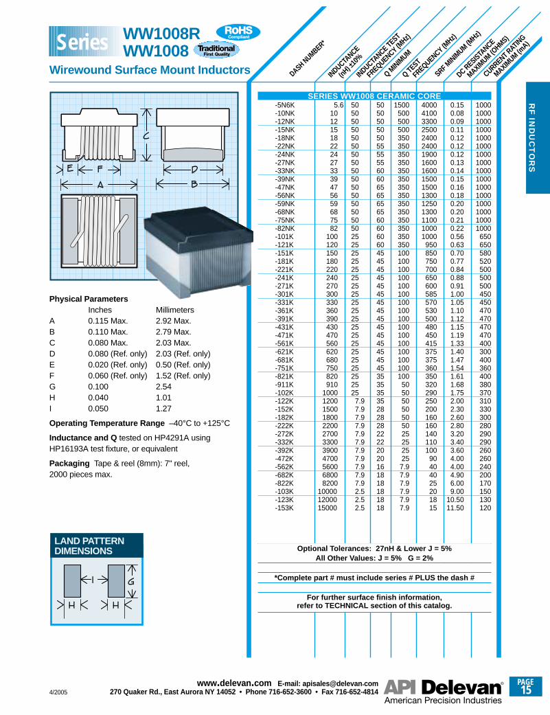
Physical ParametersInches Millimeters
A 0.115 Max. 2.92 Max.B 0.110 Max. 2.79 Max.C 0.080 Max. 2.03 Max.D 0.080 (Ref. only) 2.03 (Ref. only)E 0.020 (Ref. only) 0.50 (Ref. only)F 0.060 (Ref. only) 1.52 (Ref. only)G 0.100 2.54H 0.040 1.01I 0.050 1.27
Operating Temperature Range –40°C to +125°C
Inductance and Q tested on HP4291A usingHP16193A test fixture, or equivalent
Packaging Tape & reel (8mm): 7" reel,2000 pieces max.
SERIES WW1008 CERAMIC CORE-5N6K-10NK-12NK-15NK-18NK-22NK-24NK-27NK-33NK-39NK-47NK-56NK-59NK-68NK-75NK-82NK-101K-121K-151K-181K-221K-241K-271K-301K-331K-361K-391K-431K-471K-561K-621K-681K-751K-821K-911K-102K-122K-152K-182K-222K-272K-332K-392K-472K-562K-682K-822K-103K-123K-153K
Optional Tolerances: 27nH & Lower J = 5%All Other Values: J = 5% G = 2%
*Complete part # must include series # PLUS the dash #
For further surface finish information, refer to TECHNICAL section of this catalog.
RF
IND
UC
TO
RS
LAND PATTERNDIMENSIONS
WW1008RWW1008
Wirewound Surface Mount Inductors
Series
PAGE16
www.delevan .com E-mail: apisales@delevan .com270 Quaker Rd., East Aurora NY 14052 • Phone 716-652-3600 • Fax 716-652-4814 4/2005
RF
IN
DU
CT
OR
S
SRF MINIM
UM (MHz)
CURRENT RATING
MAX. (mA)
DC RESISTANCE
MAXIMUM (O
HMS)
DASH NUMBER*
INDUCTANCE
(µH) ±
10%
TEST FREQUENCY (MHz)
Q MINIM
UM
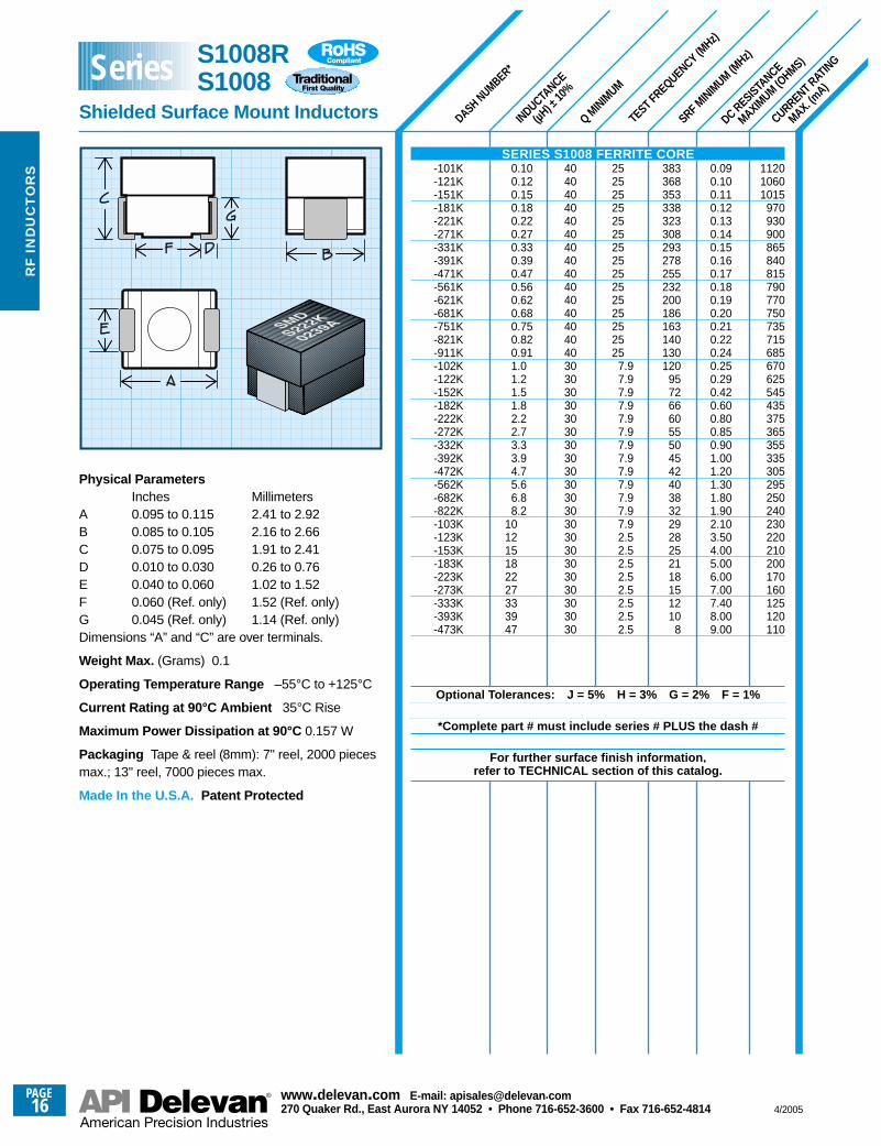
Physical ParametersInches Millimeters
A 0.095 to 0.115 2.41 to 2.92B 0.085 to 0.105 2.16 to 2.66C 0.075 to 0.095 1.91 to 2.41D 0.010 to 0.030 0.26 to 0.76E 0.040 to 0.060 1.02 to 1.52F 0.060 (Ref. only) 1.52 (Ref. only)G 0.045 (Ref. only) 1.14 (Ref. only)Dimensions “A” and “C” are over terminals.
Weight Max. (Grams) 0.1
Operating Temperature Range –55°C to +125°C
Current Rating at 90°C Ambient 35°C Rise
Maximum Power Dissipation at 90°C 0.157 W
Packaging Tape & reel (8mm): 7" reel, 2000 piecesmax.; 13" reel, 7000 pieces max.
Made In the U.S.A. Patent Protected
112010601015
970 930900865840815790770750735715685670625545435375365355335305295 250240230220210200170160125120110
0.090.100.110.120.130.140.150.160.170.180.190.200.210.220.240.250.290.420.600.800.850.901.001.201.301.801.902.103.504.005.006.007.007.408.009.00
383368353338323308293278255232200186163140130120
95726660555045424038322928252118151210
8
252525252525252525252525252525
7.97.97.97.97.97.97.97.97.97.97.9 7.97.92.52.52.52.52.52.52.52.5
404040404040404040404040404040303030303030303030303030303030303030303030
0.100.120.150.180.220.270.330.390.470.560.620.680.750.820.911.01.21.51.82.22.73.33.94.75.66.88.2
101215182227333947
SERIES S1008 FERRITE CORE-101K-121K-151K-181K-221K-271K-331K-391K-471K-561K-621K-681K-751K-821K-911K-102K-122K-152K-182K-222K-272K-332K-392K-472K-562K-682K-822K-103K-123K-153K-183K -223K-273K-333K-393K-473K
Optional Tolerances: J = 5% H = 3% G = 2% F = 1%
*Complete part # must include series # PLUS the dash #
For further surface finish information, refer to TECHNICAL section of this catalog.
S1008RS1008
Shielded Surface Mount Inductors
Series
4/2005
PAGE17
www.delevan .com E-mail: apisales@delevan .com270 Quaker Rd., East Aurora NY 14052 • Phone 716-652-3600 • Fax 716-652-4814
RF
IND
UC
TO
RS
SRF MINIM
UM (MHz)
CURRENT RATING
MAX. (mA)
DC RESISTANCE
MAXIMUM (O
HMS)
TEST FREQUENCY (MHz)
Q MINIM
UM
INDUCTANCE
(µH) ±
10%
DASH NUMBER*
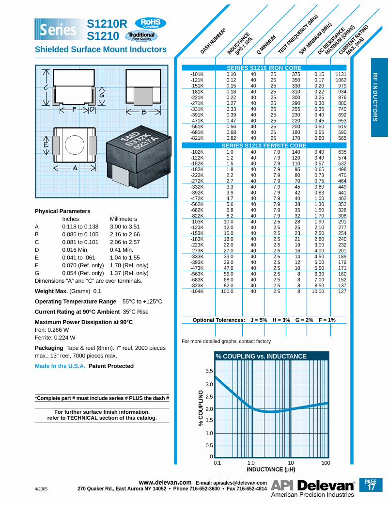
11311062
979934876800740692653619590565
635574532498470464449441402352328308291277254240232201189179171160152137127
0.150.170.200.220.250.300.350.400.450.500.550.60
0.400.490.570.650.730.750.800.831.001.301.501.701.902.102.502.803.004.004.505.005.506.307.008.50
10.00
375350330310300290255230220200180170
140120110
958070454240383532282523211916141210
8888
252525252525252525252525
7.97.97.97.97.97.97.97.97.97.97.97.92.52.52.52.52.52.52.52.52.52.52.52.52.5
404040404040404040404040
40404040404040404040404040404040404040404040404040
Physical ParametersInches Millimeters
A 0.118 to 0.138 3.00 to 3.51B 0.085 to 0.105 2.16 to 2.66C 0.081 to 0.101 2.06 to 2.57D 0.016 Min. 0.41 Min.E 0.041 to .061 1.04 to 1.55F 0.070 (Ref. only) 1.78 (Ref. only)G 0.054 (Ref. only) 1.37 (Ref. only)Dimensions “A” and “C” are over terminals.
Weight Max. (Grams) 0.1
Operating Temperature Range –55°C to +125°C
Current Rating at 90°C Ambient 35°C Rise
Maximum Power Dissipation at 90°CIron: 0.266 WFerrite: 0.224 W
Packaging Tape & reel (8mm): 7" reel, 2000 piecesmax.; 13" reel, 7000 pieces max.
Made In the U.S.A. Patent Protected
*Complete part # must include series # PLUS the dash #
For further surface finish information, refer to TECHNICAL section of this catalog.
0.100.120.150.180.220.270.330.390.470.560.680.82
1.01.21.51.82.22.73.33.94.75.66.88.2
10.012.015.018.022.027.033.039.047.056.068.082.0
100.0
SERIES S1210 IRON CORE-101K-121K-151K-181K-221K-271K-331K-391K-471K-561K-681K-821K
SERIES S1210 FERRITE CORE-102K-122K-152K-182K-222K-272K-332K-392K-472K-562K-682K-822K-103K-123K-153K-183K-223K-273K-333K-393K-473K-563K-683K-823K-104K
Optional Tolerances: J = 5% H = 3% G = 2% F = 1%
For more detailed graphs, contact factory
S1210RS1210
Shielded Surface Mount Inductors
Series
0.1
0.5
INDUCTANCE (µH)
% C
OU
PLI
NG
1.0
1.5
2.0
2.5
3.0
3.5
1.0 10 1000
% COUPLING vs. INDUCTANCE
PAGE18
www.delevan .com E-mail: apisales@delevan .com270 Quaker Rd., East Aurora NY 14052 • Phone 716-652-3600 • Fax 716-652-4814 4/2005
RF
IN
DU
CT
OR
S
SRF MINIM
UM (MHz) **
DASH NUMBER*
INDUCTANCE (µ
H)
TOLE
RANCE
Q MINIM
UM
TEST FREQUENCY (MHz)
DC RESISTANCE
MAXIMUM (O
HMS)
CURRENT RATING
MAX. (mA)
156215621562156215621562156215621562
966931871821779743711670636606580551
1018971910860805759720679644614588556
515497467454431411393378352341321305297272257237224193182170163152144136120
0.0500.0500.0500.0500.0500.0500.0500.0500.0500.130.140.160.180.200.220.240.270.300.330.360.40
0.200.220.250.280.320.360.400.450.500.550.600.67
0.700.750.850.901.01.11.21.31.51.61.82.02.12.52.83.33.75.05.66.47.08.09.0
10.013.0
2700**2700**2700**2700**2700**2700**2700**2700**2700**2000**1850**1700**1550**1300**1150**1000**
900**800**750**700**625**
550500450400350320300250220180160140
120100
857570655850454240353028252320181514131110
98
50.050.050.050.050.050.050.050.050.050.050.050.050.050.050.050.050.050.050.050.050.0
25.025.025.025.025.025.025.025.025.025.025.025.0
7.97.97.97.97.97.97.97.97.97.97.97.97.92.52.52.52.52.52.52.52.52.52.52.52.5
404040404040404040303030303030303030303030
303030303030303030303030
30303030303030303030303030303030303030303030303030
± 20%± 20%± 20%± 20%± 20%± 20%± 20%± 20%± 20%± 10%± 10%± 10%± 10%± 10%± 10%± 10%± 10%± 10%± 10%± 10%± 10%
± 10%± 10%± 10%± 10%± 10%± 10%± 10%± 10%± 10%± 10%± 10%± 10%
± 5%± 5%± 5%± 5%± 5%± 5%± 5%± 5%± 5%± 5%± 5%± 5%± 5%± 5%± 5%± 5%± 5%± 5%± 5%± 5%± 5%± 5%± 5%± 5%± 5%
0.00180.00220.00270.00330.00390.00470.00560.00680.00820.0100.0120.0150.0180.0220.0270.0330.0390.0470.0560.0680.082
0.100.120.150.180.220.270.330.390.470.560.680.82
1.01.21.51.82.22.73.33.94.75.66.88.2
101215182227333947566882
100
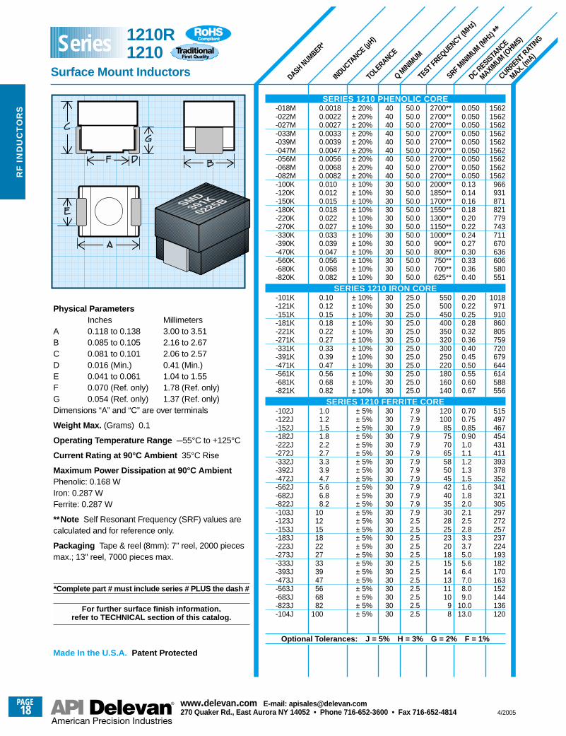
Physical ParametersInches Millimeters
A 0.118 to 0.138 3.00 to 3.51B 0.085 to 0.105 2.16 to 2.67C 0.081 to 0.101 2.06 to 2.57D 0.016 (Min.) 0.41 (Min.)E 0.041 to 0.061 1.04 to 1.55F 0.070 (Ref. only) 1.78 (Ref. only)G 0.054 (Ref. only) 1.37 (Ref. only)Dimensions “A” and “C” are over terminals
Weight Max. (Grams) 0.1
Operating Temperature Range –55°C to +125°C
Current Rating at 90°C Ambient 35°C Rise
Maximum Power Dissipation at 90°C AmbientPhenolic: 0.168 WIron: 0.287 WFerrite: 0.287 W
**Note Self Resonant Frequency (SRF) values arecalculated and for reference only.
Packaging Tape & reel (8mm): 7" reel, 2000 piecesmax.; 13" reel, 7000 pieces max.
*Complete part # must include series # PLUS the dash #
For further surface finish information, refer to TECHNICAL section of this catalog.
Made In the U.S.A. Patent Protected
SERIES 1210 PHENOLIC CORE-018M-022M-027M-033M-039M-047M-056M-068M-082M-100K-120K-150K-180K-220K-270K-330K-390K-470K-560K-680K-820K
SERIES 1210 IRON CORE-101K-121K-151K-181K-221K-271K-331K-391K-471K-561K-681K-821K
SERIES 1210 FERRITE CORE-102J-122J-152J-182J-222J-272J-332J-392J-472J-562J-682J-822J-103J-123J-153J-183J-223J-273J-333J-393J-473J-563J-683J-823J-104J
Optional Tolerances: J = 5% H = 3% G = 2% F = 1%
1210R1210
Surface Mount Inductors
Series
4/2005
PAGE19
www.delevan .com E-mail: apisales@delevan .com270 Quaker Rd., East Aurora NY 14052 • Phone 716-652-3600 • Fax 716-652-4814
RF
IND
UC
TO
RS
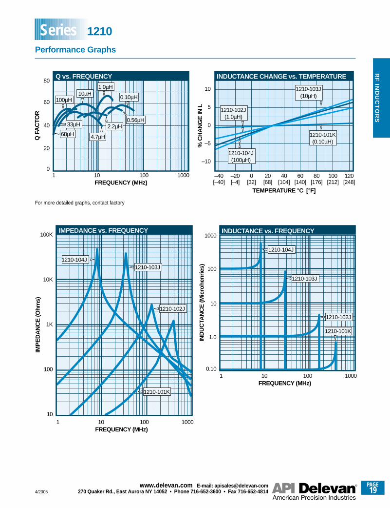
1
20
FREQUENCY (MHz)
Q F
AC
TOR
40
60
80
010 100 1000
0.56µH
4.7µH
1.0µH
0.10µH10µH
100µH
68µH
33µH 2.2µH
Q vs. FREQUENCY
110
FREQUENCY (MHz)
IMP
ED
AN
CE
(Ohm
s)
100
1K
10K
100K
10 100 1000
1210-103J
1210-102J
1210-104J
1210-101K
IMPEDANCE vs. FREQUENCY
–40 –20 0 20 40 60 80 100 120
–10
–5
0
5
10
TEMPERATURE °C [°F][–40] [–4] [32] [68] [104] [140] [176] [212] [248]
% C
HA
NG
E IN
L
INDUCTANCE CHANGE vs. TEMPERATURE
1210-101K(0.10µH)
1210-103J(10µH)
1210-104J(100µH)
1210-102J(1.0µH)
10.10
FREQUENCY (MHz)
IND
UC
TAN
CE
(Mic
rohe
nrie
s)
1.0
10
100
1000
10 100 1000
INDUCTANCE vs. FREQUENCY
1210-104J
1210-103J
1210-102J
1210-101K
For more detailed graphs, contact factory
Performance Graphs
Series 1210
PAGE20
www.delevan .com E-mail: apisales@delevan .com270 Quaker Rd., East Aurora NY 14052 • Phone 716-652-3600 • Fax 716-652-4814 4/2005
RF
IN
DU
CT
OR
S
SRF MINIM
UM (MHz)
CURRENT RATING
MAX. (mA)
DC RESISTANCE
MAXIMUM (O
HMS)
DASH NUMBER*
INDUCTANCE
(µH) ±
10%
TEST FREQUENCY (MHz)
Q MINIM
UM
10751000
955925890865825790710685540520500455430345305285265255225205195180140125115110105
0.1300.1500.1650.1750.1900.2000.2200.2400.2950.3200.5100.5500.6000.7300.8001.251.601.852.102.303.003.504.004.507.509.00
11.0012.0013.00
400375325270240180160130115105
95807570605045403530262220181614121110
25.025.025.025.025.025.025.025.025.025.025.0
7.97.97.97.97.97.97.97.97.97.97.97.97.92.52.52.52.52.5
4040404040404040404040303030303030303030303030302020202020
0.120.150.180.220.270.330.390.470.560.680.821.01.21.51.82.22.73.33.94.75.66.88.2
10.012.015.018.022.027.0
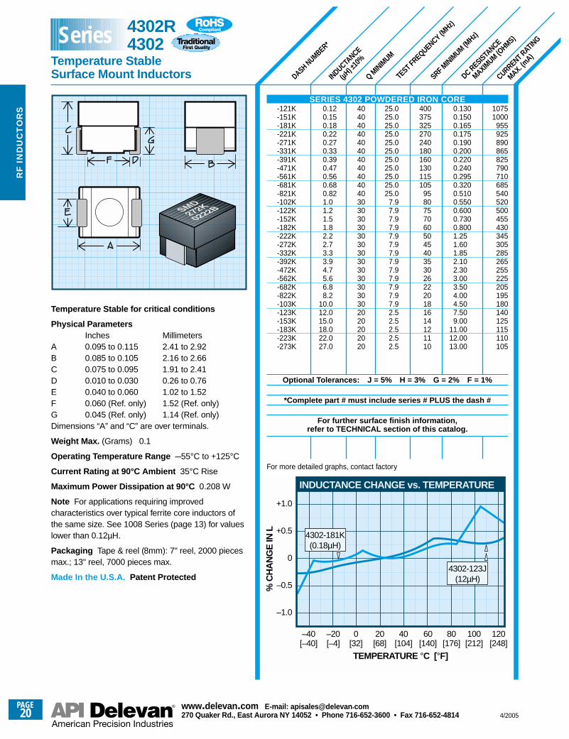
Temperature Stable for critical conditions
Physical ParametersInches Millimeters
A 0.095 to 0.115 2.41 to 2.92B 0.085 to 0.105 2.16 to 2.66C 0.075 to 0.095 1.91 to 2.41D 0.010 to 0.030 0.26 to 0.76E 0.040 to 0.060 1.02 to 1.52F 0.060 (Ref. only) 1.52 (Ref. only)G 0.045 (Ref. only) 1.14 (Ref. only)Dimensions “A” and “C” are over terminals.
Weight Max. (Grams) 0.1
Operating Temperature Range –55°C to +125°C
Current Rating at 90°C Ambient 35°C Rise
Maximum Power Dissipation at 90°C 0.208 W
Note For applications requiring improvedcharacteristics over typical ferrite core inductors ofthe same size. See 1008 Series (page 13) for valueslower than 0.12µH.
Packaging Tape & reel (8mm): 7" reel, 2000 piecesmax.; 13" reel, 7000 pieces max.
Made In the U.S.A. Patent Protected
SERIES 4302 POWDERED IRON CORE-121K-151K-181K-221K-271K-331K-391K-471K-561K-681K-821K-102K-122K-152K-182K-222K-272K-332K-392K-472K-562K-682K-822K-103K-123K-153K-183K-223K-273K
Optional Tolerances: J = 5% H = 3% G = 2% F = 1%
*Complete part # must include series # PLUS the dash #
For further surface finish information, refer to TECHNICAL section of this catalog.
4302-123J(12µH)
–40 –20 0 20 40 60 80 100 120
–1.0
–0.5
0
+0.5
+1.0
TEMPERATURE °C [°F][–40] [–4] [32] [68] [104] [140] [176] [212] [248]
% C
HA
NG
E IN
L
INDUCTANCE CHANGE vs. TEMPERATURE
4302-181K(0.18µH)
For more detailed graphs, contact factory
4302R4302
Temperature Stable Surface Mount Inductors
Series
RF
IND
UC
TO
RS
SRF MINIM
UM (MHz)
CURRENT RATING
MAX. (mA)
DC RESISTANCE
MAXIMUM (O
HMS)
DASH NUMBER*
INDUCTANCE
(µH) ±
10%
TEST FREQUENCY (MHz)
Q MINIM
UM
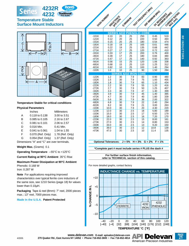
Temperature Stable for critical conditions
Physical ParametersInches Millimeters
A 0.118 to 0.138 3.00 to 3.51B 0.085 to 0.105 2.16 to 2.67C 0.081 to 0.101 2.06 to 2.57D 0.016 Min. 0.41 Min.E 0.041 to 0.061 1.04 to 1.55F 0.070 (Ref. Only) 1.78 (Ref. Only)G 0.054 (Ref. Only) 1.37 (Ref. Only)
Dimensions “A” and “C” are over terminals.
Weight Max. (Grams) 0.1
Operating Temperature –55°C to +125°C
Current Rating at 90°C Ambient 35°C Rise
Maximum Power Dissipation at 90°C AmbientPhenolic: 0.168 WIron: 0.287 W
Note For applications requiring improvedcharacteristics over typical ferrite core inductors ofthe same size, see 1210 Series (page 18) for valueslower than 0.10µH.
Packaging Tape & reel (8mm): 7" reel, 2000 piecesmax.; 13" reel, 7000 pieces max.
Made In the U.S.A. Patent Protected
519493474446442410400380363338312294284
480455434416407399385339322294263220189179170161153150139135
0.450.500.540.610.680.720.760.840.921.061.251.401.50
0.901.001.101.201.251.301.401.802.002.403.004.305.806.507.208.008.809.20
10.811.4
250220180165135120200180140120110100
90
8375655550474540362221201817161514131210
25252525252525252525252525
7.97.97.97.97.97.97.97.97.97.97.97.92.52.52.52.52.52.52.52.5
20202019191717171715151010
3030303030303030303030303030303030303030
0.100.120.150.180.220.270.330.390.470.560.680.821.0
1.21.51.82.22.73.33.94.75.66.88.2
10.012.015.018.022.027.033.039.047.0
SERIES 4232 PHENOLIC CORE-101K-121K-151K-181K-221K-271K-331K-391K-471K-561K-681K-821K-102K
SERIES 4232 IRON CORE-122K-152K-182K-222K-272K-332K-392K-472K-562K-682K-822K-103K-123K-153K-183K-223K-273K-333K-393K-473K
Optional Tolerances: J = 5% H = 3% G = 2% F = 1%
*Complete part # must include series # PLUS the dash #
For further surface finish information, refer to TECHNICAL section of this catalog.
–40 –20 0 20 40 60 80 100 120
–10
–5
0
+5
+10
TEMPERATURE °C [°F][–40] [–4] [32] [68] [104] [140] [176] [212] [248]
% C
HA
NG
E IN
L
INDUCTANCE CHANGE vs. TEMPERATURE
FERRITE4232
PHENOLIC4232IRON
For more detailed graphs, contact factory
4232R4232
Temperature Stable Surface Mount Inductors
Series
4/2005
PAGE21
www.delevan .com E-mail: apisales@delevan .com270 Quaker Rd., East Aurora NY 14052 • Phone 716-652-3600 • Fax 716-652-4814
PAGE22
www.delevan .com E-mail: apisales@delevan .com270 Quaker Rd., East Aurora NY 14052 • Phone 716-652-3600 • Fax 716-652-4814 4/2005
RF
IN
DU
CT
OR
S
SRF MINIM
UM (MHz) *
CURRENT RATING
MAX. (mA)
DC RESISTANCE
MAXIMUM (O
HMS)
TEST FREQUENCY (MHz)
Q MINIM
UM
INDUCTANCE (µ
H)
TOLE
RANCE
DASH NUMBER*
1230123012301230123010001000
870870770770700
818818818757708668604535501409379354
634604578556535517501472448427409375354317283268250236224211200191183169158158149145142129120100
8882826755
0.100.100.100.100.100.150.150.200.200.250.250.25
0.300.300.300.350.400.450.550.700.801.201.401.60
0.500.550.600.650.700.750.800.901.001.101.201.401.602.002.502.803.203.604.004.505.005.506.007.008.008.09.09.5
10.012.014.020.026.030.030.045.060.0
1000*1000*1000*1000*1000*1000*1000*1000*1000*
850*750*750*
650600500400350300250220190170150140
1008070605550454035332725201817151312111010
9988665443.53.03.03.03.02.52.5
505050505050505050505050
252525252525252525252525
7.97.97.97.97.97.97.97.97.97.97.97.97.92.52.52.52.52.52.52.52.52.52.52.52.50.790.790.790.790.790.790.790.790.790.790.790.79
404040404040403030302525
303030303030303030303030
50505050505050505050505050505050505050505050505050404040404040404030303030
±20%±20%±20%±20%±20%±20%±20%±20%±20%±20%±20%±20%
±10%±10%±10%±10%±10%±10%±10%±10%±10%±10%±10%±10%
±5%±5%±5%±5%±5%±5%±5%±5%±5%±5%±5%±5%±5%±5%±5%±5%±5%±5%±5%±5%±5%±5%±5%±5%±5%±5%±5%±5%±5%±5%±5%±5%±5%±5%±5%±5%±5%
0.0100.0120.0150.0180.0220.0270.0330.0390.0470.0560.0680.082
0.100.120.150.180.220.270.330.390.470.560.680.82
1.01.21.51.82.22.73.33.94.75.66.88.2
101215182227333947566882
100120150180220270330390470560680820
1000
Physical ParametersInches Millimeters
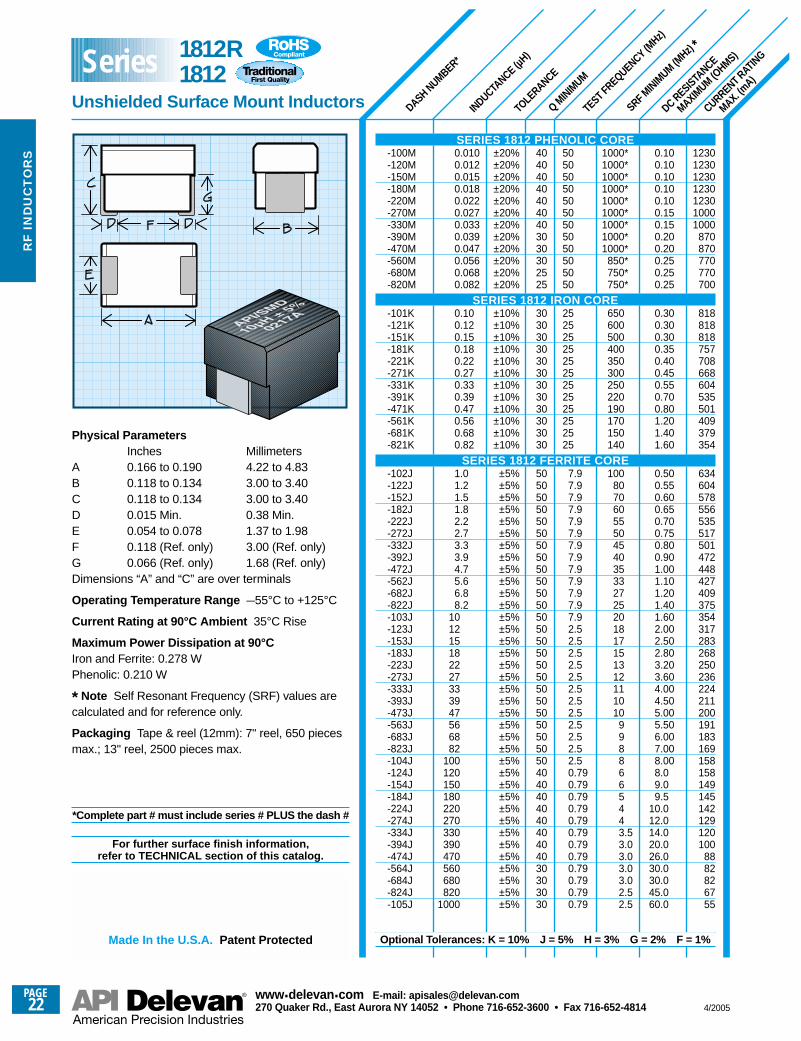
A 0.166 to 0.190 4.22 to 4.83B 0.118 to 0.134 3.00 to 3.40C 0.118 to 0.134 3.00 to 3.40D 0.015 Min. 0.38 Min.E 0.054 to 0.078 1.37 to 1.98F 0.118 (Ref. only) 3.00 (Ref. only)G 0.066 (Ref. only) 1.68 (Ref. only)Dimensions “A” and “C” are over terminals
Operating Temperature Range –55°C to +125°C
Current Rating at 90°C Ambient 35°C Rise
Maximum Power Dissipation at 90°CIron and Ferrite: 0.278 WPhenolic: 0.210 W
* Note Self Resonant Frequency (SRF) values arecalculated and for reference only.
Packaging Tape & reel (12mm): 7" reel, 650 piecesmax.; 13" reel, 2500 pieces max.
*Complete part # must include series # PLUS the dash #
For further surface finish information, refer to TECHNICAL section of this catalog.
Made In the U.S.A. Patent Protected
SERIES 1812 PHENOLIC CORE-100M-120M-150M-180M-220M-270M-330M-390M-470M-560M-680M-820M
SERIES 1812 IRON CORE-101K-121K-151K-181K-221K-271K-331K-391K-471K-561K-681K-821K
SERIES 1812 FERRITE CORE-102J-122J-152J-182J-222J-272J-332J-392J-472J-562J-682J-822J-103J-123J-153J-183J-223J-273J-333J-393J-473J-563J-683J-823J-104J-124J-154J-184J-224J-274J-334J-394J-474J-564J-684J-824J-105J
Optional Tolerances: K = 10% J = 5% H = 3% G = 2% F = 1%
1812R1812
Unshielded Surface Mount Inductors
Series
4/2005
PAGE23
www.delevan .com E-mail: apisales@delevan .com270 Quaker Rd., East Aurora NY 14052 • Phone 716-652-3600 • Fax 716-652-4814
1100
FREQUENCY (MHz)
IMP
ED
AN
CE
(Ohm
s)
1K
10K
100K
10 100 1000
1812-564J
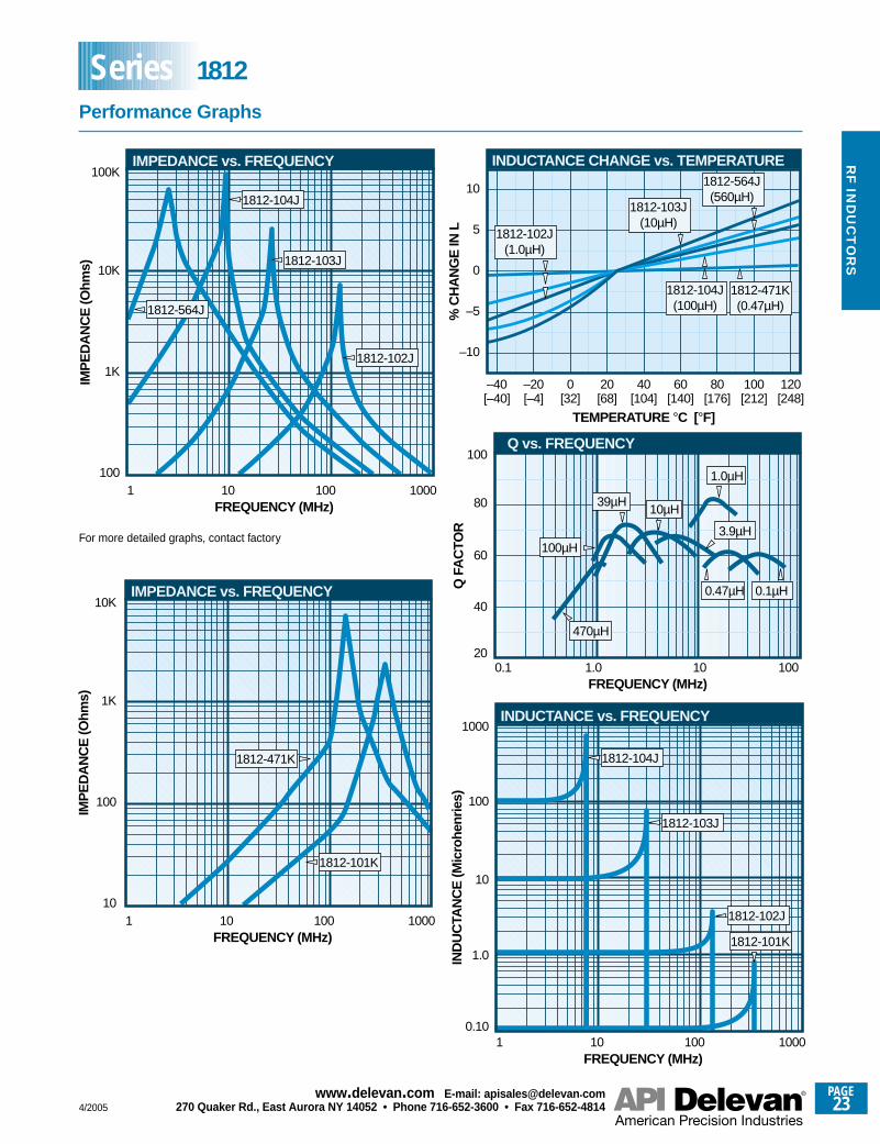
IMPEDANCE vs. FREQUENCY
1812-104J
1812-103J
1812-102J
–40 –20 0 20 40 60 80 100 120
–10
–5
0
5
10
TEMPERATURE °C [°F][–40] [–4] [32] [68] [104] [140] [176] [212] [248]
% C
HA
NG
E IN
L
INDUCTANCE CHANGE vs. TEMPERATURE
1812-471K(0.47µH)
1812-564J(560µH)
1812-102J(1.0µH)
1812-104J(100µH)
1812-103J(10µH)
1.0µH
0.47µH
100µH
39µH
3.9µH
0.1µH
10µH
0.1
40
FREQUENCY (MHz)
Q F
AC
TOR
60
80
100
201.0 10 100
Q vs. FREQUENCY
470µH
10.10
FREQUENCY (MHz)
IND
UC
TAN
CE
(Mic
rohe
nrie
s)
1.0
10
100
1000
10 100 1000
INDUCTANCE vs. FREQUENCY
1812-104J
1812-103J
1812-102J
1812-101K
110
FREQUENCY (MHz)
IMP
ED
AN
CE
(Ohm
s)
100
1K
10K
10 100 1000
IMPEDANCE vs. FREQUENCY
1812-101K
1812-471K
For more detailed graphs, contact factory
RF
IND
UC
TO
RS
Performance Graphs
Series 1812
PAGE24
www.delevan .com E-mail: apisales@delevan .com270 Quaker Rd., East Aurora NY 14052 • Phone 716-652-3600 • Fax 716-652-4814 4/2005
RF
IN
DU
CT
OR
S
SRF MINIM
UM (MHz)*
*†
CURRENT RATING
MAX. (mA)
DC RESISTANCE
MAXIMUM (O
HMS)
TEST FREQUENCY (MHz)
Q MINIM
UM
INDUCTANCE (µ
H)
MIL DASH*
TOLE
RANCE
DASH NUMBER**
1230123012301230123010001000
870870770770700
818818818757708668604535501409379354
634604578556535517501472448427409375354317283268250236224211200191183169158158149145142129120100
8882826755
0.100.100.100.100.100.150.150.200.200.250.250.25
0.300.300.300.350.400.450.550.700.801.201.401.60
0.500.550.600.650.700.750.800.901.001.101.201.401.602.002.502.803.203.604.004.505.005.506.007.008.008.09.09.5
10.012.014.020.026.030.030.045.060.0
1000**†1000**†1000**†1000**†1000**†1000**†1000**†1000**†1000**†
850**†750**†750**†
650**†600**†500**†400**†350**†300**†250220190170150140
1008070605550454035332725201817151312111010
9988665443.53.03.03.03.02.52.5
505050505050505050505050
252525252525252525252525
7.97.97.97.97.97.97.97.97.97.97.97.97.92.52.52.52.52.52.52.52.52.52.52.52.50.790.790.790.790.790.790.790.790.790.790.790.79
404040404040403030302525
303030303030303030303030
50505050505050505050505050505050505050505050505050404040404040404030303030
-01*-02*-03*-04*-05*-06*-07*-08*-09*-10*-11*-12*
-13*-14*-15*-16*-17*-18*-19*-20*-21*-22*-23*-24*
-25*-26*-27*-28*-29*-30*-31*-32*-33*-34*-35*-36*-37*-38*-39*-40*-41*-42*-43*-44*-45*-46*-47*-48*-49*-50*-51*-52*-53*-54*-55*-56*-57*-58*-59*-60*-61*
±20%±20%±20%±20%±20%±20%±20%±20%±20%±20%±20%±20%
±10%±10%±10%±10%±10%±10%±10%±10%±10%±10%±10%±10%
±5%±5%±5%±5%±5%±5%±5%±5%±5%±5%±5%±5%±5%±5%±5%±5%±5%±5%±5%±5%±5%±5%±5%±5%±5%±5%±5%±5%±5%±5%±5%±5%±5%±5%±5%±5%±5%
0.0100.0120.0150.0180.0220.0270.0330.0390.0470.0560.0680.082
0.100.120.150.180.220.270.330.390.470.560.680.82
1.01.21.51.82.22.73.33.94.75.66.88.2
101215182227333947566882
100120150180220270330390470560680820
1000
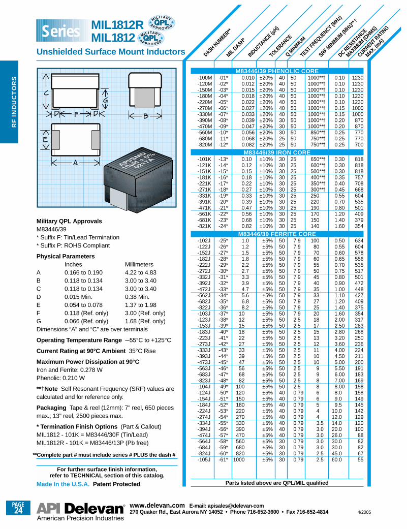
Military QPL ApprovalsM83446/39 * Suffix F: Tin/Lead Termination* Suffix P: ROHS Compliant
Physical ParametersInches Millimeters
A 0.166 to 0.190 4.22 to 4.83B 0.118 to 0.134 3.00 to 3.40C 0.118 to 0.134 3.00 to 3.40D 0.015 Min. 0.38 Min.E 0.054 to 0.078 1.37 to 1.98F 0.118 (Ref. only) 3.00 (Ref. only)G 0.066 (Ref. only) 1.68 (Ref. only)Dimensions “A” and “C” are over terminals
Operating Temperature Range –55°C to +125°C
Current Rating at 90°C Ambient 35°C Rise
Maximum Power Dissipation at 90°CIron and Ferrite: 0.278 WPhenolic: 0.210 W
**†Note Self Resonant Frequency (SRF) values arecalculated and for reference only.
Packaging Tape & reel (12mm): 7" reel, 650 piecesmax.; 13" reel, 2500 pieces max.
* Termination Finish Options (Part & Callout)MIL1812 - 101K = M83446/30F (Tin/Lead)MIL1812R - 101K = M83446/13P (Pb free)
**Complete part # must include series # PLUS the dash #
For further surface finish information, refer to TECHNICAL section of this catalog.
Made In the U.S.A. Patent Protected
M83446/39 PHENOLIC CORE-100M-120M-150M-180M-220M-270M-330M-390M-470M-560M-680M-820M
M83446/39 IRON CORE-101K-121K-151K-181K-221K-271K-331K-391K-471K-561K-681K-821K
M83446/39 FERRITE CORE-102J-122J-152J-182J-222J-272J-332J-392J-472J-562J-682J-822J-103J-123J-153J-183J-223J-273J-333J-393J-473J-563J-683J-823J-104J-124J-154J-184J-224J-274J-334J-394J-474J-564J-684J-824J-105J
Parts listed above are QPL/MIL qualified
MIL1812RMIL1812
Unshielded Surface Mount Inductors
SeriesMIL I TA RY
AP P R O V E D
MIL I TA RY
AP P R O V E D
SRF MINIM
UM (MHz)
0.1
0.5
INDUCTANCE (µH)
% C
OUP
LING
1.0
1.5
2.0
2.5
3.0
3.5
1.0 10 1000
% COUPLING vs. INDUCTANCE
@ .060”
@ .040”
1000
DCR RESISTANCE
MAXIMUM (O
HMS)
TEST FREQUENCY (MHz)
Q MINIM
UM
INDUCTANCE
(µH) ±
10%
DASH NUMBER*
CURRENT RATING
MAX. (mA)
149014121347129011541053
952876802735675614
755725706681658638534487471447408372333315301288277267258250242235215196169163158153149135129105
9184797160
0.090.100.110.120.150.180.220.260.310.370.440.53
0.350.380.400.430.460.490.700.840.901.001.201.441.802.002.202.402.602.803.003.203.403.604.305.207.007.508.008.509.00
11.012.018.024.028.032.040.055.0
460400390350310280240215205185166155
160140110100
90676156504032302522181514131211
9.08.07.67.27.06.05.04.54.24.03.73.53.32.82.62.22.0
252525252525252525252525
7.97.97.97.97.97.97.97.97.97.97.97.92.52.52.52.52.52.52.52.52.52.52.52.50.790.790.790.790.790.790.790.790.790.790.790.790.79
505050505050404040404040
40404040404040404040404050505050505050505050505040404040404040404040404040
0.100.120.150.180.220.270.330.390.470.560.680.82
1.01.21.51.82.22.73.33.94.75.66.88.2
101215182227333947566882
100120150180220270330390470560680820
1000
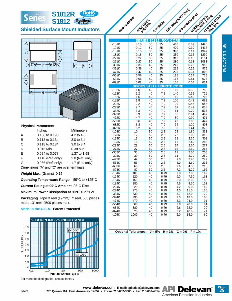
Physical ParametersInches Millimeters
A 0.166 to 0.190 4.2 to 4.8B 0.118 to 0.134 3.0 to 3.4C 0.118 to 0.134 3.0 to 3.4D 0.015 Min. 0.38 Min.E 0.054 to 0.078 1.37 to 1.98F 0.118 (Ref. only) 3.0 (Ref. only)G 0.066 (Ref. only) 1.7 (Ref. only)Dimensions “A” and “C” are over terminals
Weight Max. (Grams) 0.15
Operating Temperature Range –55°C to +125°C
Current Rating at 90°C Ambient 35°C Rise
Maximum Power Dissipation at 90°C 0.278 W
Packaging Tape & reel (12mm): 7" reel, 650 piecesmax.; 13" reel, 2500 pieces max.
Made In the U.S.A. Patent Protected
For more detailed graphs, contact factory
4/2005
PAGE25
www.delevan .com E-mail: apisales@delevan .com270 Quaker Rd., East Aurora NY 14052 • Phone 716-652-3600 • Fax 716-652-4814
RF
IND
UC
TO
RS
S1812RS1812
Shielded Surface Mount Inductors
Series
SERIES S1812 IRON CORE-101K-121K-151K-181K-221K-271K-331K-391K-471K-561K-681K-821K
SERIES S1812 FERRITE CORE-102K-122K-152K-182K-222K-272K-332K-392K-472K-562K-682K-822K-103K-123K-153K-183K-223K-273K-333K-393K-473K-563K-683K-823K-104K-124K-154K-184K-224K-274K-334K-394K-474K-564K-684K-824K-105K
Optional Tolerances: J = 5% H = 3% G = 2% F = 1%
TEST FREQUENCY (MHz)
-01*-02*-03*-04*-05*-06*-07*-08*-09*-10*-11*-12*
-13*-14*-15*-16*-17*-18*-19*-20*-21*-22*-23*-24*-25*-26*-27*-28*-29*-30*-31*-32*-33*-34*-35*-36*-37*-38*-39*-40*-41*-42*-43*-44*-45*-46*-47*-48*-49*
RF
IN
DU
CT
OR
S
SRF MINIM
UM (MHz)
DCR RESISTANCE
MAXIMUM (O
HMS)
Q MINIM
UM
INDUCTANCE
(µH) ±
10%
MIL DASH*
DASH NUMBER**
CURRENT RATING
MAX. (mA)
149014121347129011541053
952876802735675614
755725706681658638534487471447408372333315301288277267258250242235215196169163158153149135129105
9184797160
0.090.100.110.120.150.180.220.260.310.370.440.53
0.350.380.400.430.460.490.700.840.901.001.201.441.802.002.202.402.602.803.003.203.403.604.305.207.007.508.008.509.00
11.012.018.024.028.032.040.055.0
460**†400**†390**†350**†310**†280**†240215205185166155
160140110100
90676156504032302522181514131211
9.08.07.67.27.06.05.04.54.24.03.73.53.32.82.62.22.0
252525252525252525252525
7.97.97.97.97.97.97.97.97.97.97.97.92.52.52.52.52.52.52.52.52.52.52.52.50.790.790.790.790.790.790.790.790.790.790.790.790.79
505050505050404040404040
40404040404040404040404050505050505050505050505040404040404040404040404040
0.100.120.150.180.220.270.330.390.470.560.680.82
1.01.21.51.82.22.73.33.94.75.66.88.2
101215182227333947566882
100120150180220270330390470560680820
1000
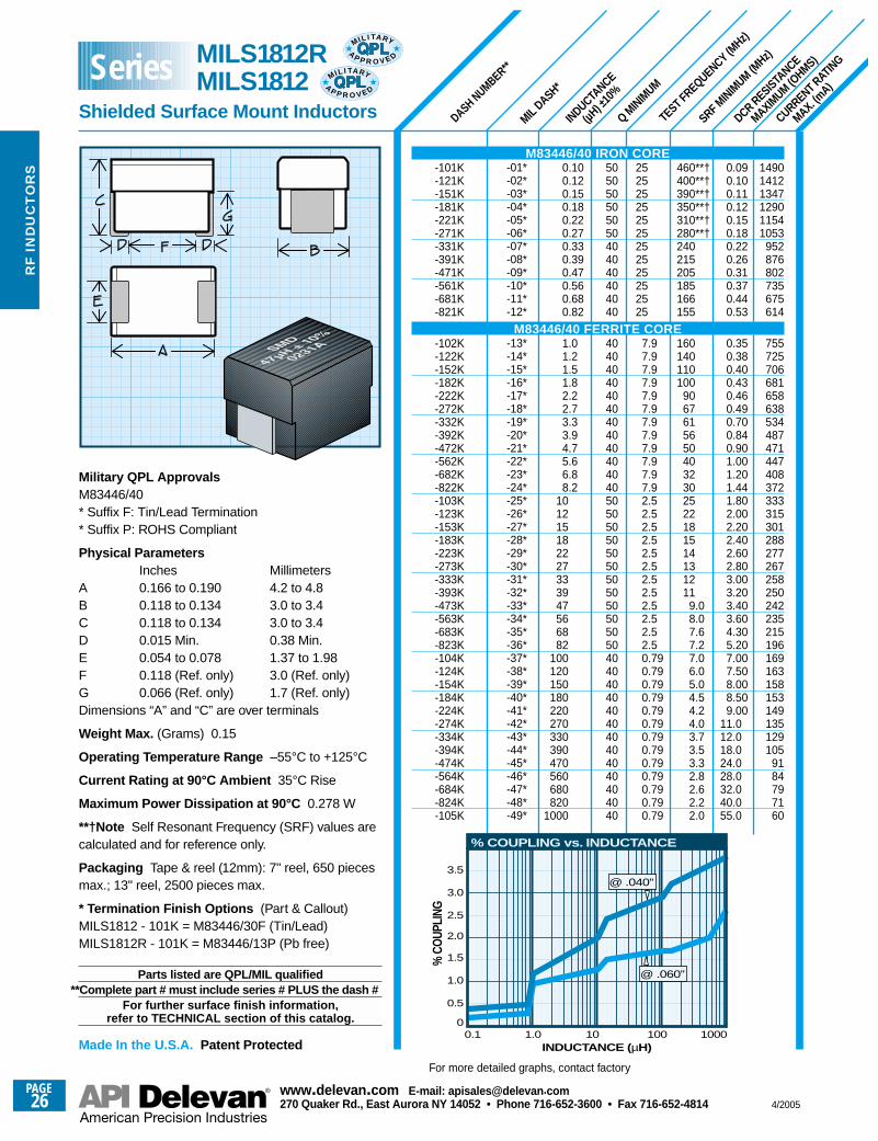
Military QPL ApprovalsM83446/40 * Suffix F: Tin/Lead Termination* Suffix P: ROHS Compliant
Physical ParametersInches Millimeters
A 0.166 to 0.190 4.2 to 4.8B 0.118 to 0.134 3.0 to 3.4C 0.118 to 0.134 3.0 to 3.4D 0.015 Min. 0.38 Min.E 0.054 to 0.078 1.37 to 1.98F 0.118 (Ref. only) 3.0 (Ref. only)G 0.066 (Ref. only) 1.7 (Ref. only)Dimensions “A” and “C” are over terminals
Weight Max. (Grams) 0.15
Operating Temperature Range –55°C to +125°C
Current Rating at 90°C Ambient 35°C Rise
Maximum Power Dissipation at 90°C 0.278 W
**†Note Self Resonant Frequency (SRF) values arecalculated and for reference only.
Packaging Tape & reel (12mm): 7" reel, 650 piecesmax.; 13" reel, 2500 pieces max.
* Termination Finish Options (Part & Callout)MILS1812 - 101K = M83446/30F (Tin/Lead)MILS1812R - 101K = M83446/13P (Pb free)
Parts listed are QPL/MIL qualified**Complete part # must include series # PLUS the dash #
For further surface finish information, refer to TECHNICAL section of this catalog.
Made In the U.S.A. Patent Protected
For more detailed graphs, contact factory
MILS1812RMILS1812
Shielded Surface Mount Inductors
SeriesMIL I TA RY
AP P R O V E D
MIL I TA RY
AP P R O V E D
M83446/40 IRON CORE-101K-121K-151K-181K-221K-271K-331K-391K-471K-561K-681K-821K
M83446/40 FERRITE CORE-102K-122K-152K-182K-222K-272K-332K-392K-472K-562K-682K-822K-103K-123K-153K-183K-223K-273K-333K-393K-473K-563K-683K-823K-104K-124K-154K-184K-224K-274K-334K-394K-474K-564K-684K-824K-105K
0.1
0.5
INDUCTANCE (µH)
% C
OUP
LING
1.0
1.5
2.0
2.5
3.0
3.5
1.0 10 1000
% COUPLING vs. INDUCTANCE
@ .060”
@ .040”
1000
PAGE26
www.delevan .com E-mail: apisales@delevan .com270 Quaker Rd., East Aurora NY 14052 • Phone 716-652-3600 • Fax 716-652-4814 4/2005
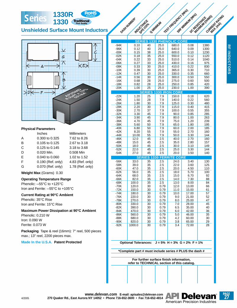
SRF MINIM
UM (MHz)
CURRENT RATING
MAX. (mA)
DC RESISTANCE
MAXIMUM (O
HMS)
DASH NUMBER*
INDUCTANCE
(µH) ±
10%
TEST FREQUENCY (MHz)
Q MINIM
UM
13801300123011201040
975830710660550500420390
620560480415355285263239195185160144160157149144140
130125110100
928884666157524745403635302928
0.080.090.100.120.140.160.220.300.350.500.600.851.00
0.180.220.300.400.550.851.001.201.802.002.703.302.702.803.103.303.50
3.403.604.505.706.707.308.00
13.0015.0017.0021.0025.0028.0035.0042.0046.0060.0065.0072.00
680.0640.0600.0550.0510.0430.0410.0365.0330.0300.0275.0250.0230.0
150.0140.0125.0115.0100.0
90.080.075.065.060.055.050.040.035.030.025.020.0
24.022.020.018.015.014.013.012.011.010.0
9.08.07.06.56.05.04.23.83.4
25.025.025.025.025.025.025.025.025.025.025.025.025.0
7.97.97.97.97.97.97.97.97.97.97.97.92.52.52.52.52.5
2.52.52.52.52.52.52.50.790.790.790.790.790.790.790.790.790.790.790.79
40403835333330303030282825
2528303037454545505055554545454545
35353535353535303030303030303030303030
0.100.120.150.180.220.270.330.390.470.560.680.821.00
1.201.501.802.202.703.303.904.705.606.808.20
10.0012.015.018.022.027.0
33.039.047.056.068.082.0
100.0120.0150.0180.0220.0270.0330.0390.0470.0560.0680.0820.0
1000.0
Physical ParametersInches Millimeters
A 0.300 to 0.325 7.62 to 8.26B 0.105 to 0.125 2.67 to 3.18C 0.125 to 0.145 3.18 to 3.68D 0.020 Min. 0.508 MinE 0.040 to 0.060 1.02 to 1.52F 0.190 (Ref. only) 4.83 (Ref. only)G 0.070 (Ref. only) 1.78 (Ref. only)
Weight Max (Grams) 0.30
Operating Temperature RangePhenolic: –55°C to +125°CIron and Ferrite: –55°C to +105°C
Current Rating at 90°C AmbientPhenolic: 35°C Rise Iron and Ferrite: 15°C Rise
Maximum Power Dissipation at 90°C AmbientPhenolic: 0.210 W Iron: 0.090 WFerrite: 0.073 W
Packaging Tape & reel (16mm): 7" reel, 500 piecesmax.; 13" reel, 2200 pieces max.
Made In the U.S.A. Patent Protected
SERIES 1330 PHENOLIC CORE-94K-96K-00K-02K-04K-06K-08K-10K-12K-14K-16K-18K-20K
SERIES 1330 IRON CORE-22K-24K-26K-28K-30K-32K-34K-36K-38K-40K-42K-44K-46K-48K-50K-52K-54K
SERIES 1330 FERRITE CORE-56K-58K-60K-62K-64K-66K-68K-70K-72K-74K-76K-78K-80K-82K-84K-86K-88K-90K-92K
Optional Tolerances: J = 5% H = 3% G = 2% F = 1%
*Complete part # must include series # PLUS the dash #
For further surface finish information, refer to TECHNICAL section of this catalog.
1330R1330
Unshielded Surface Mount Inductors
Series
4/2005
PAGE27
www.delevan .com E-mail: apisales@delevan .com270 Quaker Rd., East Aurora NY 14052 • Phone 716-652-3600 • Fax 716-652-4814
RF
IND
UC
TO
RS
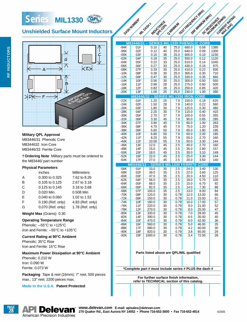
01F02F03F04F05F06F07F08F09F10F11F12F13F
01F02F03F04F05F06F07F08F09F10F11F12F13F14F15F16F17F
01F02F03F04F05F06F07F08F09F10F11F12F13F14F15F16F17F18F19F
SRF MINIM
UM (MHz)
CURRENT RATING
MAX. (mA)
DC RESISTANCE
MAXIMUM (O
HMS)
DASH NUMBER*
MIL DASH #
INDUCTANCE
(µH) ±
10%
TEST FREQUENCY (MHz)
Q MINIM
UM
13801300123011201040
975830710660550500420390
620560480415355285263239195185160144160157149144140
130125110100
928884666157524745403635302928
0.080.090.100.120.140.160.220.300.350.500.600.851.00
0.180.220.300.400.550.851.001.201.802.002.703.302.702.803.103.303.50
3.403.604.505.706.707.308.00
13.0015.0017.0021.0025.0028.0035.0042.0046.0060.0065.0072.00
680.0640.0600.0550.0510.0430.0410.0365.0330.0300.0275.0250.0230.0
150.0140.0125.0115.0100.0
90.080.075.065.060.055.050.040.035.030.025.020.0
24.022.020.018.015.014.013.012.011.010.0
9.08.07.06.56.05.04.23.83.4
25.025.025.025.025.025.025.025.025.025.025.025.025.0
7.97.97.97.97.97.97.97.97.97.97.97.92.52.52.52.52.5
2.52.52.52.52.52.52.50.790.790.790.790.790.790.790.790.790.790.790.79
40403835333330303030282825
2528303037454545505055554545454545
35353535353535303030303030303030303030
0.100.120.150.180.220.270.330.390.470.560.680.821.00
1.201.501.802.202.703.303.904.705.606.808.20
10.0012.015.018.022.027.0
33.039.047.056.068.082.0
100.0120.0150.0180.0220.0270.0330.0390.0470.0560.0680.0820.0
1000.0
Military QPL ApprovalM83446/31 Phenolic CoreM8344632 Iron CoreM83446/33 Ferrite Core
† Ordering Note Military parts must be ordered tothe M83446/ part number
Physical ParametersInches Millimeters
A 0.300 to 0.325 7.62 to 8.26B 0.105 to 0.125 2.67 to 3.18C 0.125 to 0.145 3.18 to 3.68D 0.020 Min. 0.508 MinE 0.040 to 0.060 1.02 to 1.52F 0.190 (Ref. only) 4.83 (Ref. only)G 0.070 (Ref. only) 1.78 (Ref. only)
Weight Max (Grams) 0.30
Operating Temperature RangePhenolic: –55°C to +125°CIron and Ferrite: –55°C to +105°C
Current Rating at 90°C AmbientPhenolic: 35°C Rise Iron and Ferrite: 15°C Rise
Maximum Power Dissipation at 90°C AmbientPhenolic: 0.210 W Iron: 0.090 WFerrite: 0.073 W
Packaging Tape & reel (16mm): 7" reel, 500 piecesmax.; 13" reel, 2200 pieces max.
Made In the U.S.A. Patent Protected
M83446/31 – SERIES MIL1330 PHENOLIC CORE-94K-96K-00K-02K-04K-06K-08K-10K-12K-14K-16K-18K-20K
M83446/32 – SERIES MIL1330 IRON CORE-22K-24K-26K-28K-30K-32K-34K-36K-38K-40K-42K-44K-46K-48K-50K-52K-54K
M83446/33 – SERIES MIL1330 FERRITE CORE-56K-58K-60K-62K-64K-66K-68K-70K-72K-74K-76K-78K-80K-82K-84K-86K-88K-90K-92K
Parts listed above are QPL/MIL qualified
*Complete part # must include series # PLUS the dash #
For further surface finish information, refer to TECHNICAL section of this catalog.
MIL1330Unshielded Surface Mount Inductors
Series MIL I TA RY
AP P R O V E D
PAGE28
www.delevan .com E-mail: apisales@delevan .com270 Quaker Rd., East Aurora NY 14052 • Phone 716-652-3600 • Fax 716-652-4814 4/2005
RF
IN
DU
CT
OR
S
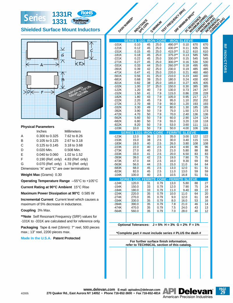
SRF MINIM
UM (MHz)*
*
CURRENT RATING
MAXIMUM (m
A)
DC RESISTANCE
MAXIMUM (O
HMS)
DASH NUMBER*
INDUCTANCE
(µH) ±
10%
TEST FREQUENCY (MHz)
Q MINIM
UM
INCREMENTAL
CURRENT (mA)
670635610585545530495485460440430405385247228217202193185173136124118111106
122115108
968883756964615951
272422201816141312
670635610585545530495485460440430405385247228217202193185173136124118111106
122115108
968883756964615951
887569646153464340
0.100.110.120.130.150.160.180.190.210.230.240.270.300.730.860.951.101.201.301.502.402.903.203.604.00
3.003.403.804.905.806.507.909.30
11.012.013.016.8
5.807.909.40
11.012.016.021.024.028.0
490.0**430.0**415.0**375.0**330.0**300.0**260.0**230.0220.0210.0180.0165.0150.0130.0115.0105.0
95.090.080.075.070.060.055.053.050.0
35.030.026.024.021.020.019.016.015.013.011.010.5
13.012.011.010.0
9.08.07.87.57.0
25.025.025.025.025.025.025.025.025.025.025.025.025.0
7.97.97.97.97.97.97.97.97.97.97.97.9
2.52.52.52.52.52.52.52.52.52.52.52.5
0.790.790.790.790.790.790.790.790.79
45454545454544424141393837404143454849505050505050
363840404041424444454540
313333353535353535
0.100.120.150.180.220.270.330.390.470.560.680.821.001.201.501.802.202.703.303.904.705.606.808.20
10.0
12.015.018.022.027.033.039.047.056.068.082.0
100.0
120.0150.0180.0220.0270.0330.0390.0470.0560.0
Physical ParametersInches Millimeters
A 0.300 to 0.325 7.62 to 8.26B 0.105 to 0.125 2.67 to 3.18C 0.125 to 0.145 3.18 to 3.68D 0.020 Min. 0.508 Min.E 0.040 to 0.060 1.02 to 1.52F 0.190 (Ref. only) 4.83 (Ref. only)G 0.070 (Ref. only) 1.78 (Ref. only)Dimensions “A” and “C” are over terminations
Weight Max (Grams) 0.30
Operating Temperature Range –55°C to +105°C
Current Rating at 90°C Ambient 15°C Rise
Maximum Power Dissipation at 90°C 0.585 W
Incremental Current Current level which causes amaximum of 5% decrease in inductance.
Coupling 3% Max.
**Note Self Resonant Frequency (SRF) values for-101K to -331K are calculated and for reference only.
Packaging Tape & reel (16mm): 7" reel, 500 piecesmax.; 13" reel, 2200 pieces max.
Made In the U.S.A. Patent Protected
SERIES 1331 IRON CORE - IRON SLEEVE-101K-121K-151K-181K-221K-271K-331K-391K-471K-561K-681K-821K-102K-122K-152K-182K-222K-272K-332K-392K-472K-562K-682K-822K-103K
SERIES 1331 IRON CORE - FERRITE SLEEVE-123K-153K-183K-223K-273K-333K-393K-473K-563K-683K-823K-104K
SERIES 1331 FERRITE CORE - FERRITE SLEEVE-124K-154K-184K-224K-274K-334K-394K-474K-564K
Optional Tolerances: J = 5% H = 3% G = 2% F = 1%
*Complete part # must include series # PLUS the dash #
For further surface finish information, refer to TECHNICAL section of this catalog.
1331R 1331
Shielded Surface Mount Inductors
Series
4/2005
PAGE29
www.delevan .com E-mail: apisales@delevan .com270 Quaker Rd., East Aurora NY 14052 • Phone 716-652-3600 • Fax 716-652-4814
RF
IND
UC
TO
RS
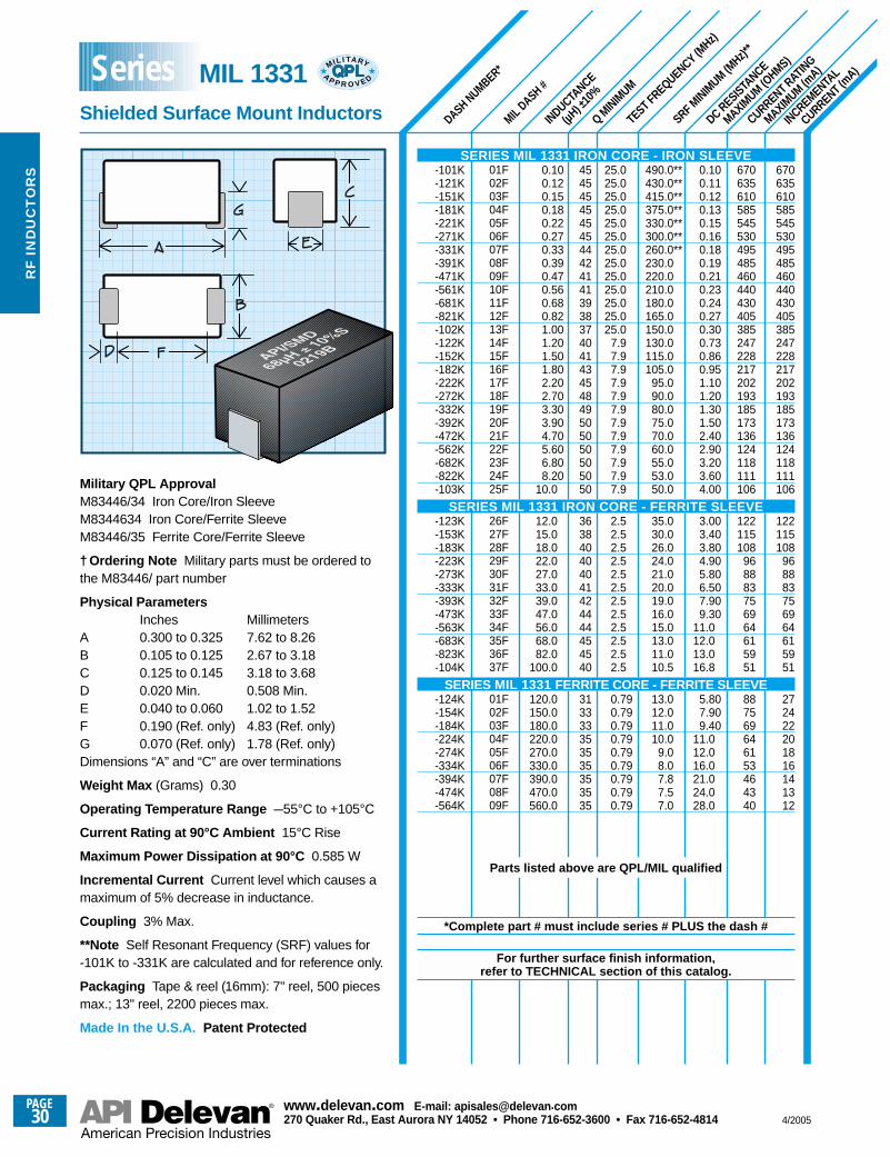
01F02F03F04F05F06F07F08F09F10F11F12F13F14F15F16F17F18F19F20F21F22F23F24F25F
26F27F28F29F30F31F32F33F34F35F36F37F
01F02F03F04F05F06F07F08F09F
SRF MINIM
UM (MHz)*
*
CURRENT RATING
MAXIMUM (m
A)
DC RESISTANCE
MAXIMUM (O
HMS)
DASH NUMBER*
INDUCTANCE
(µH) ±
10%
TEST FREQUENCY (MHz)
Q MINIM
UM
INCREMENTAL
CURRENT (mA)
670635610585545530495485460440430405385247228217202193185173136124118111106
122115108
968883756964615951
272422201816141312
670635610585545530495485460440430405385247228217202193185173136124118111106
122115108
968883756964615951
887569646153464340
0.100.110.120.130.150.160.180.190.210.230.240.270.300.730.860.951.101.201.301.502.402.903.203.604.00
3.003.403.804.905.806.507.909.30
11.012.013.016.8
5.807.909.40
11.012.016.021.024.028.0
490.0**430.0**415.0**375.0**330.0**300.0**260.0**230.0220.0210.0180.0165.0150.0130.0115.0105.0
95.090.080.075.070.060.055.053.050.0
35.030.026.024.021.020.019.016.015.013.011.010.5
13.012.011.010.0
9.08.07.87.57.0
25.025.025.025.025.025.025.025.025.025.025.025.025.0
7.97.97.97.97.97.97.97.97.97.97.97.9
2.52.52.52.52.52.52.52.52.52.52.52.5
0.790.790.790.790.790.790.790.790.79
45454545454544424141393837404143454849505050505050
363840404041424444454540
313333353535353535
0.100.120.150.180.220.270.330.390.470.560.680.821.001.201.501.802.202.703.303.904.705.606.808.20
10.0
12.015.018.022.027.033.039.047.056.068.082.0
100.0
120.0150.0180.0220.0270.0330.0390.0470.0560.0
Military QPL ApprovalM83446/34 Iron Core/Iron SleeveM8344634 Iron Core/Ferrite SleeveM83446/35 Ferrite Core/Ferrite Sleeve
† Ordering Note Military parts must be ordered tothe M83446/ part number
Physical ParametersInches Millimeters
A 0.300 to 0.325 7.62 to 8.26B 0.105 to 0.125 2.67 to 3.18C 0.125 to 0.145 3.18 to 3.68D 0.020 Min. 0.508 Min.E 0.040 to 0.060 1.02 to 1.52F 0.190 (Ref. only) 4.83 (Ref. only)G 0.070 (Ref. only) 1.78 (Ref. only)Dimensions “A” and “C” are over terminations
Weight Max (Grams) 0.30
Operating Temperature Range –55°C to +105°C
Current Rating at 90°C Ambient 15°C Rise
Maximum Power Dissipation at 90°C 0.585 W
Incremental Current Current level which causes amaximum of 5% decrease in inductance.
Coupling 3% Max.
**Note Self Resonant Frequency (SRF) values for-101K to -331K are calculated and for reference only.
Packaging Tape & reel (16mm): 7" reel, 500 piecesmax.; 13" reel, 2200 pieces max.
Made In the U.S.A. Patent Protected
SERIES MIL 1331 IRON CORE - IRON SLEEVE-101K-121K-151K-181K-221K-271K-331K-391K-471K-561K-681K-821K-102K-122K-152K-182K-222K-272K-332K-392K-472K-562K-682K-822K-103K
SERIES MIL 1331 IRON CORE - FERRITE SLEEVE-123K-153K-183K-223K-273K-333K-393K-473K-563K-683K-823K-104K
SERIES MIL 1331 FERRITE CORE - FERRITE SLEEVE-124K-154K-184K-224K-274K-334K-394K-474K-564K
Parts listed above are QPL/MIL qualified
*Complete part # must include series # PLUS the dash #
For further surface finish information, refer to TECHNICAL section of this catalog.
MIL 1331Shielded Surface Mount Inductors
Series MIL I TA RY
AP P R O V E D
MIL DASH #
PAGE30
www.delevan .com E-mail: apisales@delevan .com270 Quaker Rd., East Aurora NY 14052 • Phone 716-652-3600 • Fax 716-652-4814 4/2005
RF
IN
DU
CT
OR
S
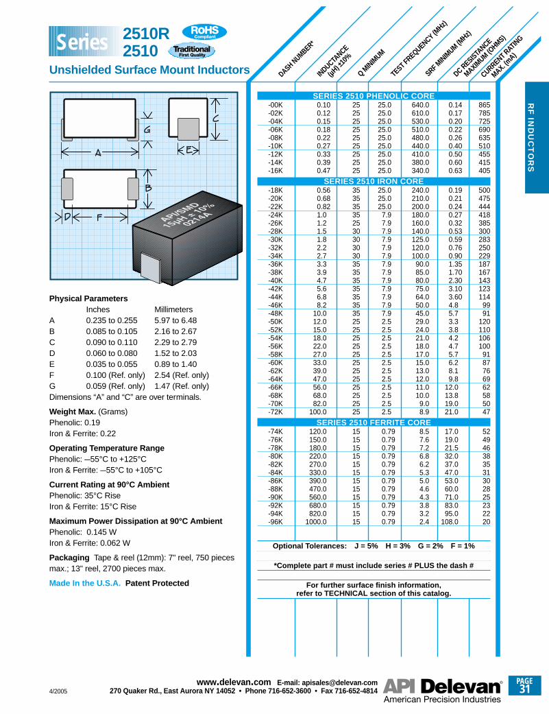
SRF MINIM
UM (MHz)
CURRENT RATING
MAX. (mA)
DC RESISTANCE
MAXIMUM (O
HMS)
TEST FREQUENCY (MHz)
Q MINIM
UM
INDUCTANCE
(µH) ±
10%
DASH NUMBER*
865785725690635510455415405
500475444418385300283250229187167143123114
9991
120110106100
9187766962585047
524946383531302825232220
0.140.170.200.220.260.400.500.600.63
0.190.210.240.270.320.530.590.760.901.351.702.303.103.604.85.73.33.84.24.75.76.28.19.8
12.013.819.021.0
17.019.021.532.037.047.053.060.071.083.095.0
108.0
640.0610.0530.0510.0480.0440.0410.0380.0340.0
240.0210.0200.0180.0160.0140.0125.0120.0100.0
90.085.080.075.064.050.045.029.024.021.018.017.015.013.012.011.010.0
9.08.9
8.57.67.26.86.25.35.04.64.33.83.22.4
25.025.025.025.025.025.025.025.025.0
25.025.025.0
7.97.97.97.97.97.97.97.97.97.97.97.97.92.52.52.52.52.52.52.52.52.52.52.52.5
0.790.790.790.790.790.790.790.790.790.790.790.79
252525252525252525
35353535253030303035353535353535252525252525252525252525
151515151515151515151515
0.100.120.150.180.220.270.330.390.47
0.560.680.821.01.21.51.82.22.73.33.94.75.66.88.2
10.012.015.018.022.027.033.039.047.056.068.082.0
100.0
120.0150.0180.0220.0270.0330.0390.0470.0560.0680.0820.0
1000.0
Physical ParametersInches Millimeters
A 0.235 to 0.255 5.97 to 6.48B 0.085 to 0.105 2.16 to 2.67C 0.090 to 0.110 2.29 to 2.79D 0.060 to 0.080 1.52 to 2.03E 0.035 to 0.055 0.89 to 1.40F 0.100 (Ref. only) 2.54 (Ref. only)G 0.059 (Ref. only) 1.47 (Ref. only)Dimensions “A” and “C” are over terminals.
Weight Max. (Grams)Phenolic: 0.19 Iron & Ferrite: 0.22
Operating Temperature RangePhenolic: –55°C to +125°C Iron & Ferrite: –55°C to +105°C
Current Rating at 90°C AmbientPhenolic: 35°C Rise Iron & Ferrite: 15°C Rise
Maximum Power Dissipation at 90°C AmbientPhenolic: 0.145 WIron & Ferrite: 0.062 W
Packaging Tape & reel (12mm): 7" reel, 750 piecesmax.; 13" reel, 2700 pieces max.
Made In the U.S.A. Patent Protected
SERIES 2510 PHENOLIC CORE-00K-02K-04K-06K-08K-10K-12K-14K-16K
SERIES 2510 IRON CORE-18K-20K-22K-24K-26K-28K-30K-32K-34K-36K-38K-40K-42K-44K-46K-48K-50K-52K-54K-56K-58K-60K-62K-64K-66K-68K-70K-72K
SERIES 2510 FERRITE CORE-74K-76K-78K-80K-82K-84K-86K-88K-90K-92K-94K-96K
Optional Tolerances: J = 5% H = 3% G = 2% F = 1%
*Complete part # must include series # PLUS the dash #
For further surface finish information, refer to TECHNICAL section of this catalog.
2510R 2510
Unshielded Surface Mount Inductors
Series
4/2005
PAGE31
www.delevan .com E-mail: apisales@delevan .com270 Quaker Rd., East Aurora NY 14052 • Phone 716-652-3600 • Fax 716-652-4814
RF
IND
UC
TO
RS
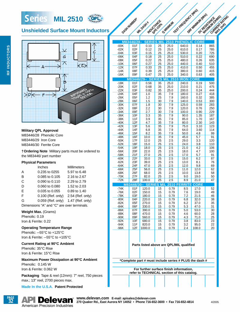
SRF MINIM
UM (MHz)
CURRENT RATING
MAX. (mA)
DC RESISTANCE
MAXIMUM (O
HMS)
TEST FREQUENCY (MHz)
Q MINIM
UM
MIL DASH #
INDUCTANCE
(µH) ±
10%
DASH NUMBER*
865785725690635510455415405
500475444418385300283250229187167143123114
9991
120110106100
9187766962585047
524946383531302825232220
0.140.170.200.220.260.400.500.600.63
0.190.210.240.270.320.530.590.760.901.351.702.303.103.604.85.73.33.84.24.75.76.28.19.8
12.013.819.021.0
17.019.021.532.037.047.053.060.071.083.095.0
108.0
640.0610.0530.0510.0480.0440.0410.0380.0340.0
240.0210.0200.0180.0160.0140.0125.0120.0100.0
90.085.080.075.064.050.045.029.024.021.018.017.015.013.012.011.010.0
9.08.9
8.57.67.26.86.25.35.04.64.33.83.22.4
25.025.025.025.025.025.025.025.025.0
25.025.025.0
7.97.97.97.97.97.97.97.97.97.97.97.97.92.52.52.52.52.52.52.52.52.52.52.52.5
0.790.790.790.790.790.790.790.790.790.790.790.79
252525252525252525
35353535253030303035353535353535252525252525252525252525
151515151515151515151515
0.100.120.150.180.220.270.330.390.47
0.560.680.821.01.21.51.82.22.73.33.94.75.66.88.2
10.012.015.018.022.027.033.039.047.056.068.082.0
100.0
120.0150.0180.0220.0270.0330.0390.0470.0560.0680.0820.0
1000.0
01F02F03F04F05F06F07F08F09F
01F02F03F04F05F06F07F08F09F10F11F12F13F14F15F16F17F18F19F20F21F22F23F24F25F26F27F28F
01F02F03F04F05F06F07F08F09F10F11F12F
Military QPL ApprovalM83446/28 Phenolic CoreM83446/29 Iron CoreM83446/30 Ferrite Core
†Ordering Note Military parts must be ordered tothe M83446/ part number
Physical ParametersInches Millimeters
A 0.235 to 0255 5.97 to 6.48B 0.085 to 0.105 2.16 to 2.67C 0.090 to 0.110 2.29 to 2.79D 0.060 to 0.080 1.52 to 2.03E 0.035 to 0.055 0.89 to 1.40F 0.100 (Ref. only) 2.54 (Ref. only)G 0.059 (Ref. only) 1.47 (Ref. only)Dimensions “A” and “C” are over terminals.
Weight Max. (Grams)Phenolic: 0.19 Iron & Ferrite: 0.22
Operating Temperature RangePhenolic: –55°C to +125°C Iron & Ferrite: –55°C to +105°C
Current Rating at 90°C AmbientPhenolic: 35°C Rise Iron & Ferrite: 15°C Rise
Maximum Power Dissipation at 90°C AmbientPhenolic: 0.145 WIron & Ferrite: 0.062 W
Packaging Tape & reel (12mm): 7" reel, 750 piecesmax.; 13" reel, 2700 pieces max.
Made In the U.S.A. Patent Protected
M83446/28– SERIES MIL 2510 PHENOLIC CORE-00K-02K-04K-06K-08K-10K-12K-14K-16K
M83446/29– SERIES MIL 2510 IRON CORE-18K-20K-22K-24K-26K-28K-30K-32K-34K-36K-38K-40K-42K-44K-46K-48K-50K-52K-54K-56K-58K-60K-62K-64K-66K-68K-70K-72K
M83446/30– SERIES MIL 2510 FERRITE CORE-74K-76K-78K-80K-82K-84K-86K-88K-90K-92K-94K-96K
Parts listed above are QPL/MIL qualified
*Complete part # must include series # PLUS the dash #
For further surface finish information, refer to TECHNICAL section of this catalog.
MIL 2510
Unshielded Surface Mount Inductors
MIL I TA RY
AP P R O V E DSeries
PAGE32
www.delevan .com E-mail: apisales@delevan .com270 Quaker Rd., East Aurora NY 14052 • Phone 716-652-3600 • Fax 716-652-4814 4/2005
RF
IN
DU
CT
OR
S
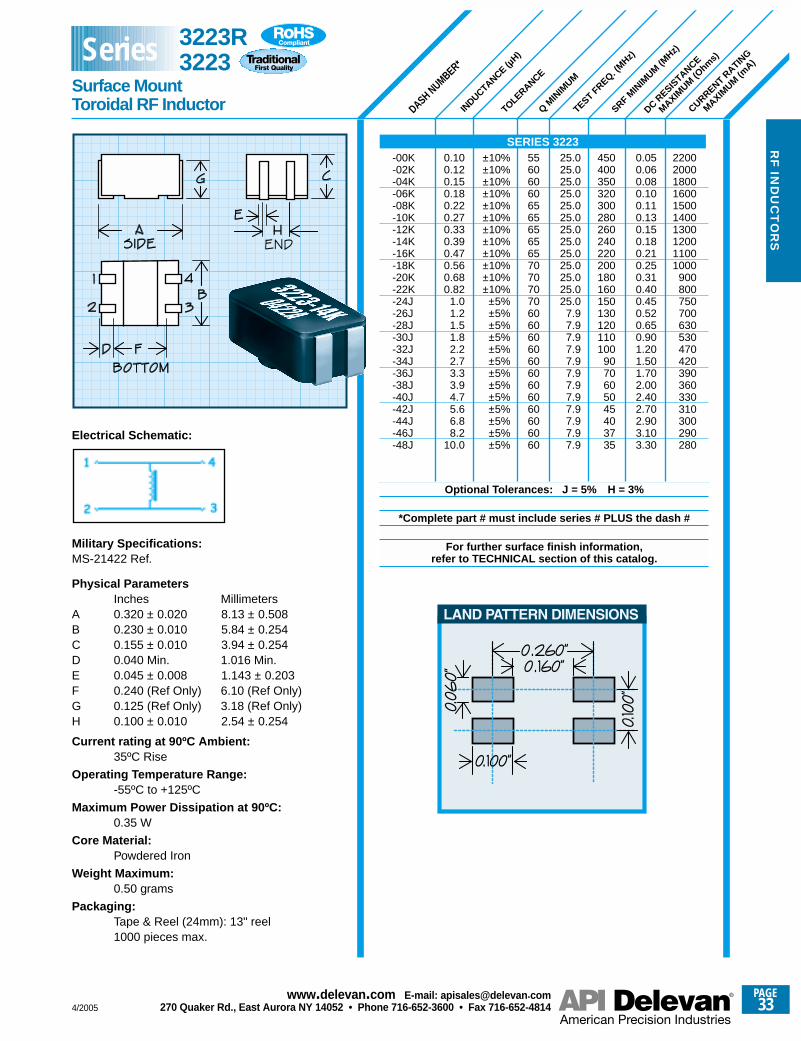
DASH NUMBER*
INDUCTANCE (µ
H)
TOLERANCE
Q MIN
IMUM
TEST FREQ. (
MHz)
SRF MIN
IMUM (M
Hz)
DC RESIS
TANCE
MAXIMUM (O
hms)
-00K 0.10 ±10% 55 25.0 450 0.05 2200-02K 0.12 ±10% 60 25.0 400 0.06 2000-04K 0.15 ±10% 60 25.0 350 0.08 1800-06K 0.18 ±10% 60 25.0 320 0.10 1600-08K 0.22 ±10% 65 25.0 300 0.11 1500-10K 0.27 ±10% 65 25.0 280 0.13 1400-12K 0.33 ±10% 65 25.0 260 0.15 1300-14K 0.39 ±10% 65 25.0 240 0.18 1200-16K 0.47 ±10% 65 25.0 220 0.21 1100-18K 0.56 ±10% 70 25.0 200 0.25 1000-20K 0.68 ±10% 70 25.0 180 0.31 900-22K 0.82 ±10% 70 25.0 160 0.40 800-24J 1.0 ±5% 70 25.0 150 0.45 750-26J 1.2 ±5% 60 7.9 130 0.52 700-28J 1.5 ±5% 60 7.9 120 0.65 630-30J 1.8 ±5% 60 7.9 110 0.90 530-32J 2.2 ±5% 60 7.9 100 1.20 470-34J 2.7 ±5% 60 7.9 90 1.50 420-36J 3.3 ±5% 60 7.9 70 1.70 390-38J 3.9 ±5% 60 7.9 60 2.00 360-40J 4.7 ±5% 60 7.9 50 2.40 330-42J 5.6 ±5% 60 7.9 45 2.70 310-44J 6.8 ±5% 60 7.9 40 2.90 300-46J 8.2 ±5% 60 7.9 37 3.10 290-48J 10.0 ±5% 60 7.9 35 3.30 280
Optional Tolerances: J = 5% H = 3%
*Complete part # must include series # PLUS the dash #
For further surface finish information, refer to TECHNICAL section of this catalog.
CURRENT RATIN
G
MAXIMUM (m
A)
SERIES 3223
3223R3223
Surface MountToroidal RF Inductor
Series
Electrical Schematic:
Military Specifications: MS-21422 Ref.
Physical ParametersInches Millimeters
A 0.320 ± 0.020 8.13 ± 0.508B 0.230 ± 0.010 5.84 ± 0.254C 0.155 ± 0.010 3.94 ± 0.254D 0.040 Min. 1.016 Min. E 0.045 ± 0.008 1.143 ± 0.203F 0.240 (Ref Only) 6.10 (Ref Only)G 0.125 (Ref Only) 3.18 (Ref Only)H 0.100 ± 0.010 2.54 ± 0.254
Current rating at 90ºC Ambient:35ºC Rise
Operating Temperature Range:-55ºC to +125ºC
Maximum Power Dissipation at 90ºC:0.35 W
Core Material:Powdered Iron
Weight Maximum:0.50 grams
Packaging:Tape & Reel (24mm): 13" reel 1000 pieces max.
END
4/2005
PAGE33
www.delevan .com E-mail: apisales@delevan .com270 Quaker Rd., East Aurora NY 14052 • Phone 716-652-3600 • Fax 716-652-4814
RF
IND
UC
TO
RS
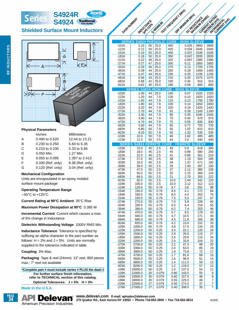
SRF MINIM
UM (MHz)
DASH NUMBER*
INDUCTANCE
(µH) ±
10%
Q MINIM
UM
TEST FREQUENCY (MHz)
DC RESISTANCE
MAXIMUM (O
HMS)
CURRENT RATING
MAXIMUM (m
A)
INCREMENTAL
CURRENT (mA)
3900334531952835238518551705145012351075
915800
2320192017801650142011601045
970830725610535485440
300250210195160150135124122120113
988476676055464340383329282724222019171514131211
98777
3900334531952835238518551705145012351075
915800
2320192017801650142011601045
970830725610535485440
618580561504471397380369355342312291272263247228218203178171160152134120115110104
88857268615957545048463735
0.0250.0340.0370.0470.0670.110.130.180.250.330.450.59
0.070.100.120.140.190.280.350.400.550.721.021.321.622.0
0.80.890.961.191.371.932.112.232.702.443.123.64.14.45.05.86.47.49.5
10.511.813.017.522.126.529.933.847.353.073.881.698.9
111.0119.0137.0143.0157.0225.0274.0308.0
450425400350325300275250235210190180
140130115105100
928575706555504644
49454138342927252110.510.0
9.78.58.07.57.06.56.25.74.74.54.23.83.02.82.62.42.22.01.91.71.61.41.21.00.800.600.550.500.40
25.025.025.025.025.025.025.025.025.025.025.025.0
25.07.97.97.97.97.97.97.97.97.97.97.97.92.5
2.52.52.52.52.52.52.52.52.52.52.50.790.790.790.790.790.790.790.790.790.790.790.790.250.250.250.250.250.250.250.250.250.250.250.250.0790.0790.0790.0790.079
505050504947464444434240
4444444444444444444450505055
45454545455050505050505555555555556060606060605050505050505050505050503030302727
0.100.120.150.180.220.270.330.390.470.560.680.82
1.001.201.501.802.202.703.303.904.705.606.808.20
10.012.0
15.018.022.027.033.039.047.056.068.082.0
100.0120.0150.0180.0220.0270.0330.0390.0470.0560.0680.0820.0
1000.01200.01500.01800.02200.02700.03300.03900.04700.05600.06800.08200.0
10000.012000.015000.018000.022000.027000.0
Physical ParametersInches Millimeters
A 0.490 to 0.520 12.44 to 13.21B 0.230 to 0.250 5.84 to 6.35C 0.210 to 0.230 5.33 to 5.84D 0.050 Min. 1.27 Min.E 0.055 to 0.095 1.397 to 2.413F 0.330 (Ref. only) 8.38 (Ref. only)G 0.120 (Ref. only) 3.04 (Ref. only)
Mechanical ConfigurationUnits are encapsulated in an epoxy moldedsurface mount package
Operating Temperature Range–55°C to +125°C
Current Rating at 90°C Ambient 35°C Rise
Maximum Power Dissipation at 90°C 0.385 W
Incremental Current Current which causes a max.of 5% change in Inductance
Dielectric Withstanding Voltage 1000V RMS Min.
Inductance Tolerance Tolerance is specified bysuffixing an alpha character to the part number asfollows: H = 3% and J = 5%. Units are normallysupplied to the tolerance indicated in table.
Coupling 3% Max.
Packaging Tape & reel (24mm): 13" reel, 800 piecesmax.; 7" reel not available
*Complete part # must include series # PLUS the dash #For further surface finish information,
refer to TECHNICAL section of this catalog.Optional Tolerances: J = 5% H = 3%
Made In the U.S.A.
SERIES S4924 PHENOLIC CORE - IRON SLEEVE-101K-121K-151K-181K-221K-271K-331K-391K-471K-561K-681K-821K
SERIES S4924 IRON CORE - IRON SLEEVE-102K-122K-152K-182K-222K-272K-332K-392K-472K-562K-682K-822K-103K-123K
SERIES S4924 FERRITE CORE - FERRITE SLEEVE-153K-183K-223K-273K-333K-393K-473K-563K-683K-823K-104K-124K-154K-184K-224K-274K-334K-394K-474K-564K-684K-824K-105K-125K-155K-185K-225K-275K-335K-395K-475K-565K-685K-825K-106K-126K-156K-186K-226K-276K
S4924RS4924
Shielded Surface Mount Inductors
Series
PAGE34
www.delevan .com E-mail: apisales@delevan .com270 Quaker Rd., East Aurora NY 14052 • Phone 716-652-3600 • Fax 716-652-4814 4/2005
RF
IN
DU
CT
OR
S
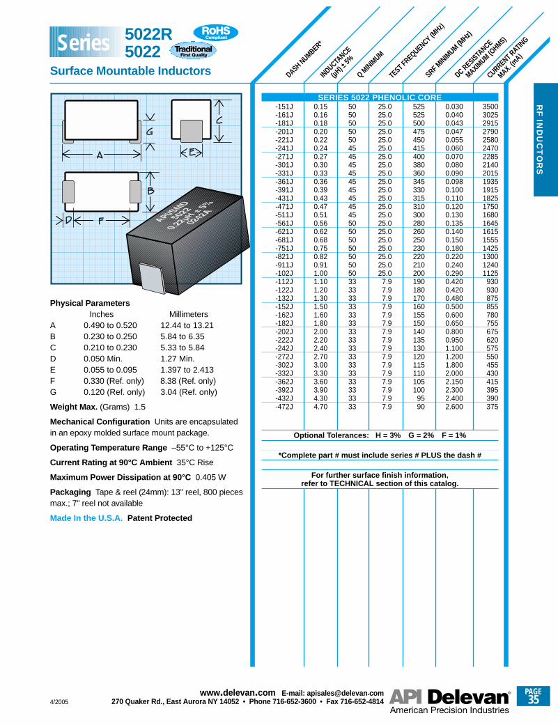
SRF MINIM
UM (MHz)
CURRENT RATING
MAX. (mA)
DC RESISTANCE
MAXIMUM (O
HMS)
TEST FREQUENCY (MHz)
Q MINIM
UM
INDUCTANCE
(µH) ±
5%
DASH NUMBER*
350030252915279025802470228521402015193519151825175016801645161515551425130012401125
930930875855780755675620575550455430415395390375
0.0300.0400.0430.0470.0550.0600.0700.0800.0900.0980.1000.1100.1200.1300.1350.1400.1500.1800.2200.2400.2900.4200.4200.4800.5000.6000.6500.8000.9501.1001.2001.8002.0002.1502.3002.4002.600
525525500475450415400380360345330315310300280260250230220210200190180170160155150140135130120115110105100
9590
25.025.025.025.025.025.025.025.025.025.025.025.025.025.025.025.025.025.025.025.025.0
7.97.97.97.97.97.97.97.97.97.97.97.97.97.97.97.9
50505050504545454545454545455050505050505033333333333333333333333333333333
0.150.160.180.200.220.240.270.300.330.360.390.430.470.510.560.620.680.750.820.911.001.101.201.301.501.601.802.002.202.402.703.003.303.603.904.304.70
Physical Parameters Inches Millimeters
A 0.490 to 0.520 12.44 to 13.21B 0.230 to 0.250 5.84 to 6.35C 0.210 to 0.230 5.33 to 5.84D 0.050 Min. 1.27 Min.E 0.055 to 0.095 1.397 to 2.413F 0.330 (Ref. only) 8.38 (Ref. only)G 0.120 (Ref. only) 3.04 (Ref. only)
Weight Max. (Grams) 1.5
Mechanical Configuration Units are encapsulatedin an epoxy molded surface mount package.
Operating Temperature Range –55°C to +125°C
Current Rating at 90°C Ambient 35°C Rise
Maximum Power Dissipation at 90°C 0.405 W
Packaging Tape & reel (24mm): 13" reel, 800 piecesmax.; 7" reel not available
Made In the U.S.A. Patent Protected
SERIES 5022 PHENOLIC CORE-151J-161J-181J-201J-221J-241J-271J-301J-331J-361J-391J-431J-471J-511J-561J-621J-681J-751J-821J-911J-102J-112J-122J-132J-152J-162J-182J-202J-222J-242J-272J-302J-332J-362J-392J-432J-472J
Optional Tolerances: H = 3% G = 2% F = 1%
*Complete part # must include series # PLUS the dash #
For further surface finish information, refer to TECHNICAL section of this catalog.
5022R5022
Surface Mountable Inductors
Series
4/2005
PAGE35
www.delevan .com E-mail: apisales@delevan .com270 Quaker Rd., East Aurora NY 14052 • Phone 716-652-3600 • Fax 716-652-4814
RF
IND
UC
TO
RS
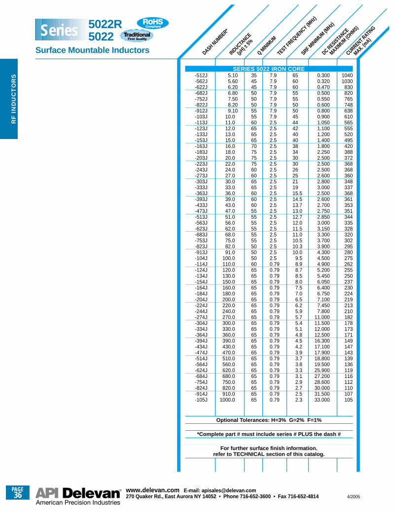
SRF MINIM
UM (MHz)
CURRENT RATING
MAX. (mA)
DC RESISTANCE
MAXIMUM (O
HMS)
TEST FREQUENCY (MHz)
Q MINIM
UM
INDUCTANCE
(µH) ±
5%
DASH NUMBER*
10401030
830820765748638610565555520495420388372368368360348337368361353351344335328320302295280275262255250237230224219213210182178173171149147143139136119116112110107105
0.3000.3200.4700.5000.5500.6000.8000.9001.0501.1001.2001.4001.8002.2502.5002.5002.5002.6002.8003.0002.5002.6002.7002.7502.8503.0003.1503.3003.7003.9004.3004.5004.9005.2005.4506.0506.4006.7507.1007.4507.800
11.00011.50012.00012.50016.30017.10017.90018.80019.50025.90027.20028.60030.00031.50033.000
656060555550504544424040383430302625211915.514.513.713.012.712.011.511.010.510.310.0
9.58.98.78.58.07.57.06.56.25.95.75.45.14.84.54.23.93.73.83.33.12.92.72.52.3
7.97.97.97.97.97.97.97.92.52.52.52.52.52.52.52.52.52.52.52.52.52.52.52.52.52.52.52.52.52.52.52.50.790.790.790.790.790.790.790.790.790.790.790.790.790.790.790.790.790.790.790.790.790.790.790.79
3545455050505555606565657075757560606565606060555555555555505050606565656565656565656565656565656565656565656565
5.105.606.206.807.508.209.10
10.011.012.013.015.016.018.020.022.024.027.030.033.036.039.043.047.051.056.062.068.075.082.091.0
100.0110.0120.0130.0150.0160.0180.0200.0220.0240.0270.0300.0330.0360.0390.0430.0470.0510.0560.0620.0680.0750.0820.0910.0
1000.0
SERIES 5022 IRON CORE-512J-562J-622J-682J-752J-822J-912J-103J-113J-123J-133J-153J-163J-183J-203J-223J-243J-273J-303J-333J-363J-393J-433J-473J-513J-563J-623J-683J-753J-823J-913J-104J-114J-124J-134J-154J-164J-184J-204J-224J-244J-274J-304J-334J-364J-394J-434J-474J-514J-564J-624J-684J-754J-824J-914J-105J
Optional Tolerances: H=3% G=2% F=1%
*Complete part # must include series # PLUS the dash #
For further surface finish information, refer to TECHNICAL section of this catalog.
5022R5022
Surface Mountable Inductors
Series
PAGE36
www.delevan .com E-mail: apisales@delevan .com270 Quaker Rd., East Aurora NY 14052 • Phone 716-652-3600 • Fax 716-652-4814 4/2005
RF
IN
DU
CT
OR
S
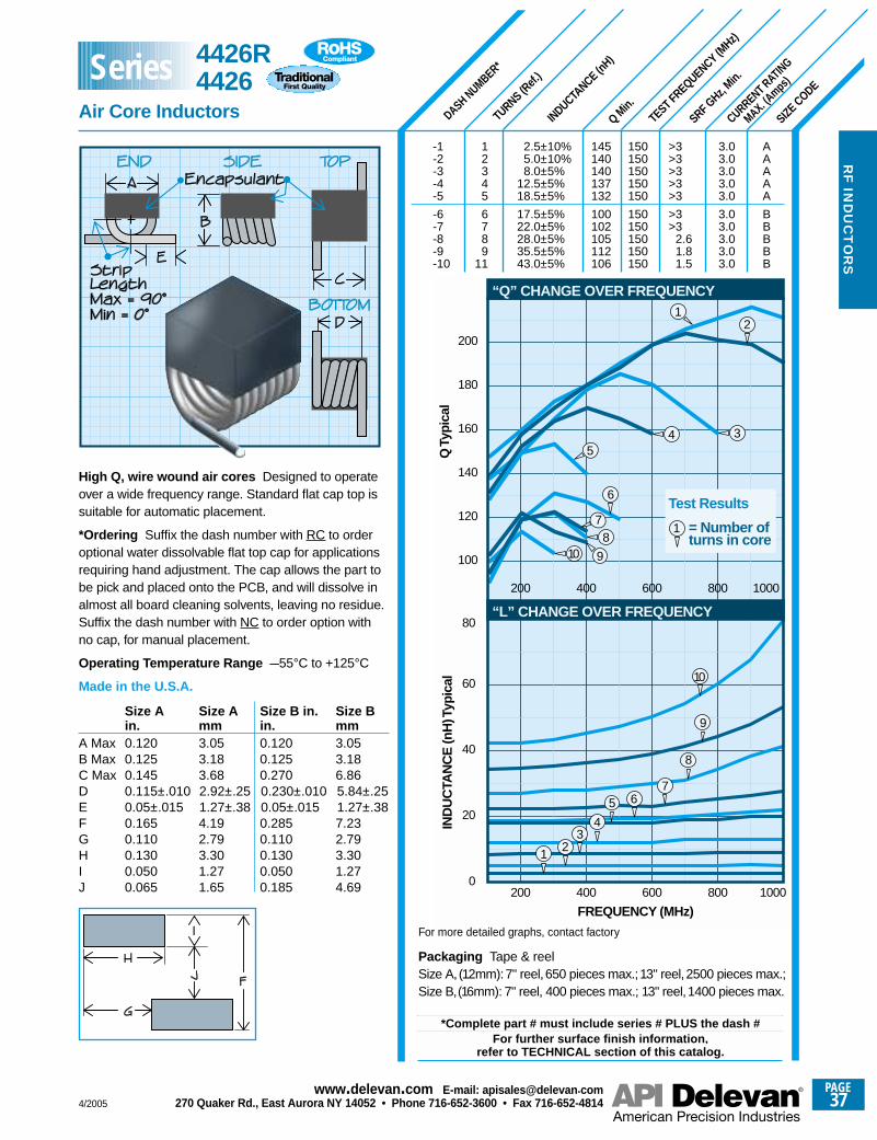
DASH NUMBER*
TURNS (Ref.
)
INDUCTANCE (n
H)
Q Min.
TEST FREQUENCY (MHz)
SRF GHz,
Min.
CURRENT RATING
MAX. (Amps
)
SIZE CODE
High Q, wire wound air cores Designed to operateover a wide frequency range. Standard flat cap top issuitable for automatic placement.
*Ordering Suffix the dash number with RC to orderoptional water dissolvable flat top cap for applicationsrequiring hand adjustment. The cap allows the part tobe pick and placed onto the PCB, and will dissolve inalmost all board cleaning solvents, leaving no residue.Suffix the dash number with NC to order option with no cap, for manual placement.
Operating Temperature Range –55°C to +125°C
Made in the U.S.A.
Size A Size A Size B in. Size Bin. mm in. mm
A Max 0.120 3.05 0.120 3.05B Max 0.125 3.18 0.125 3.18C Max 0.145 3.68 0.270 6.86D 0.115±.010 2.92±.25 0.230±.010 5.84±.25E 0.05±.015 1.27±.38 0.05±.015 1.27±.38F 0.165 4.19 0.285 7.23G 0.110 2.79 0.110 2.79H 0.130 3.30 0.130 3.30I 0.050 1.27 0.050 1.27J 0.065 1.65 0.185 4.69
-1 1 2.5±10% 145 150 >3 3.0 A-2 2 5.0±10% 140 150 >3 3.0 A-3 3 8.0±5% 140 150 >3 3.0 A-4 4 12.5±5% 137 150 >3 3.0 A-5 5 18.5±5% 132 150 >3 3.0 A
-6 6 17.5±5% 100 150 >3 3.0 B-7 7 22.0±5% 102 150 >3 3.0 B-8 8 28.0±5% 105 150 2.6 3.0 B-9 9 35.5±5% 112 150 1.8 3.0 B-10 11 43.0±5% 106 150 1.5 3.0 B
200 400 600 800 1000
100
120
140
160
180
Q T
ypic
al
“Q” CHANGE OVER FREQUENCY
200
1
3
2
45
6
78
10 9
200 400 600 800 10000
20
40
60
80
FREQUENCY (MHz)
IND
UC
TAN
CE
(nH
) Typ
ical
“L” CHANGE OVER FREQUENCY
12
6
Test Results
= Number ofturns in core
1
34
57
8
9
10
*Complete part # must include series # PLUS the dash #For further surface finish information,
refer to TECHNICAL section of this catalog.
For more detailed graphs, contact factory
4426R4426
Air Core Inductors
Series
Packaging Tape & reelSize A, (12mm):7" reel,650 pieces max.;13" reel,2500 pieces max.;Size B,(16mm): 7" reel, 400 pieces max.; 13" reel,1400 pieces max.
4/2005
PAGE37
www.delevan .com E-mail: apisales@delevan .com270 Quaker Rd., East Aurora NY 14052 • Phone 716-652-3600 • Fax 716-652-4814
RF
IND
UC
TO
RS
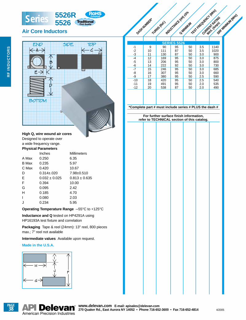
CURRENT RATING
MAX. (Amps
)
DASH NUMBER*
TURNS (Ref.
)
INDUCTANCE (n
H) ±5%
Q MINIM
UM
TEST FREQUENCY (MHz)
SRF MINIM
UM (MHz)
11401020
900875800730685660590540535490
505050505050505050505050
3.53.53.03.03.03.03.03.02.52.52.02.0
958787959592959595959587
90111130169206222246307380420491538
91011121314151617181920
High Q, wire wound air cores Designed to operate overa wide frequency range.Physical Parameters
Inches MillimetersA Max 0.250 6.35B Max 0.235 5.97C Max 0.420 10.67D 0.314±.020 7.98±0.510E 0.032 ± 0.025 0.813 ± 0.635F 0.394 10.00G 0.095 2.42H 0.185 4.70I 0.080 2.03J 0.234 5.95
Operating Temperature Range –55°C to +125°C
Inductance and Q tested on HP4291A usingHP16193A test fixture and correlation
Packaging Tape & reel (24mm): 13" reel, 800 piecesmax.; 7" reel not available
Intermediate values Available upon request.
Made in the U.S.A.
SERIES 5526-1-2-3-4-5-6-7-8-9-10-11-12
*Complete part # must include series # PLUS the dash #
For further surface finish information, refer to TECHNICAL section of this catalog.
5526R5526
Air Core Inductors
Series
PAGE38
www.delevan .com E-mail: apisales@delevan .com270 Quaker Rd., East Aurora NY 14052 • Phone 716-652-3600 • Fax 716-652-4814 4/2005
RF
IN
DU
CT
OR
S
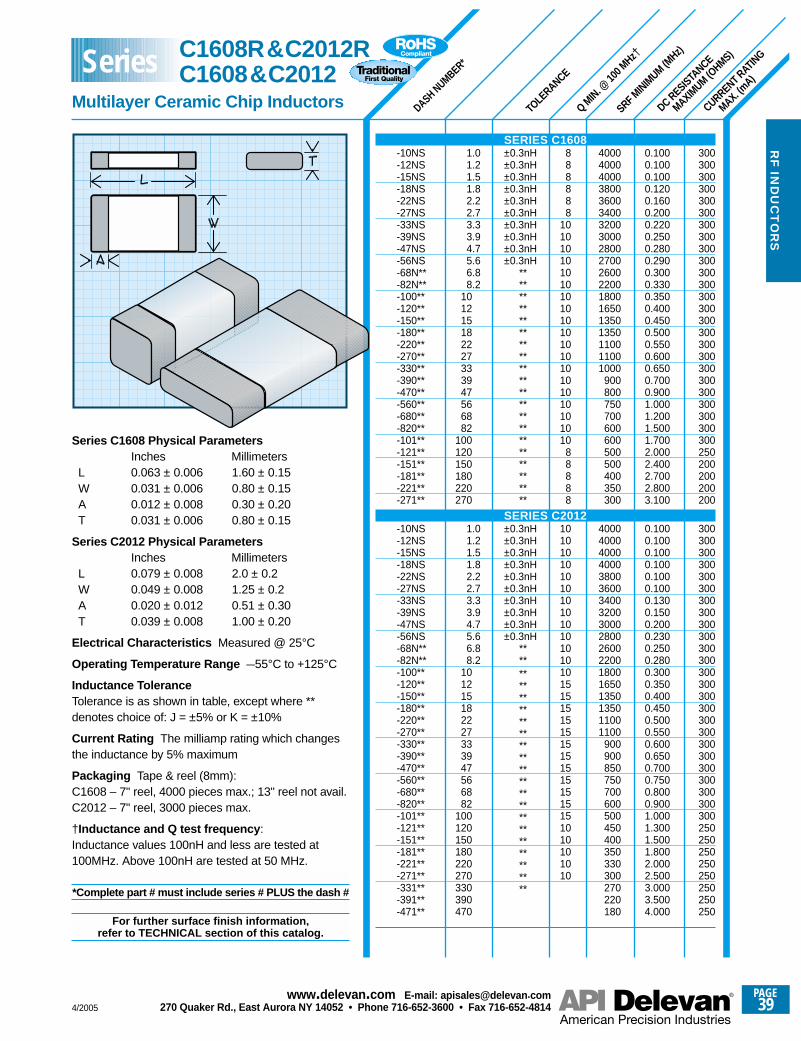
SRF MINIM
UM (MHz)
DASH NUMBER*
Q MIN. @
100 M
Hz†
TOLE
RANCE
DC RESISTANCE
MAXIMUM (O
HMS)
CURRENT RATING
MAX. (mA)
300300300300300300300300300300300300300300300300300300300300300300300300300250200200200200
300300300300300300300300300300300300300300300300300300300300300300300300300250250250250250250250250
0.1000.1000.1000.1200.1600.2000.2200.2500.2800.2900.3000.3300.3500.4000.4500.5000.5500.6000.6500.7000.9001.0001.2001.5001.7002.0002.4002.7002.8003.100
0.1000.1000.1000.1000.1000.1000.1300.1500.2000.2300.2500.2800.3000.3500.4000.4500.5000.5500.6000.6500.7000.7500.8000.9001.0001.3001.5001.8002.0002.5003.0003.5004.000
400040004000380036003400320030002800270026002200180016501350135011001100 1000
900800750700600600500500400350300
400040004000400038003600340032003000280026002200180016501350135011001100
900900850750700600500450400350330300270220180
888888
1010 10 10 10 10 10 10 10 10 10 10 10 10 10 10 10 10 10
88888
101010101010101010101010101515151515151515151515151010101010
±0.3nH±0.3nH±0.3nH±0.3nH±0.3nH±0.3nH±0.3nH±0.3nH±0.3nH±0.3nH
****************************************
±0.3nH±0.3nH±0.3nH±0.3nH±0.3nH±0.3nH±0.3nH±0.3nH±0.3nH±0.3nH
******************************************
1.01.21.51.82.22.73.33.94.75.66.88.2
101215182227333947566882
100120150180220270
1.01.21.51.82.22.73.33.94.75.66.88.2
101215182227333947566882
100120150180220270330390470
Series C1608 Physical ParametersInches Millimeters
L 0.063 ± 0.006 1.60 ± 0.15W 0.031 ± 0.006 0.80 ± 0.15A 0.012 ± 0.008 0.30 ± 0.20T 0.031 ± 0.006 0.80 ± 0.15
Series C2012 Physical ParametersInches Millimeters
L 0.079 ± 0.008 2.0 ± 0.2W 0.049 ± 0.008 1.25 ± 0.2A 0.020 ± 0.012 0.51 ± 0.30T 0.039 ± 0.008 1.00 ± 0.20
Electrical Characteristics Measured @ 25°C
Operating Temperature Range –55°C to +125°C
Inductance ToleranceTolerance is as shown in table, except where **denotes choice of: J = ±5% or K = ±10%
Current Rating The milliamp rating which changesthe inductance by 5% maximum
Packaging Tape & reel (8mm):C1608 – 7" reel, 4000 pieces max.; 13" reel not avail.C2012 – 7" reel, 3000 pieces max.
†Inductance and Q test frequency :Inductance values 100nH and less are tested at100MHz. Above 100nH are tested at 50 MHz.
*Complete part # must include series # PLUS the dash #
For further surface finish information, refer to TECHNICAL section of this catalog.
C1608R&C2012RC1608&C2012
Multilayer Ceramic Chip Inductors
Series
SERIES C1608-10NS-12NS-15NS-18NS-22NS-27NS-33NS-39NS-47NS-56NS-68N**-82N**-100**-120**-150**-180**-220**-270**-330**-390**-470**-560**-680**-820**-101**-121**-151**-181**-221**-271**
SERIES C2012-10NS-12NS-15NS-18NS-22NS-27NS-33NS-39NS-47NS-56NS-68N**-82N**-100**-120**-150**-180**-220**-270**-330**-390**-470**-560**-680**-820**-101**-121**-151**-181**-221**-271**-331**-391**-471**
4/2005
PAGE39
www.delevan .com E-mail: apisales@delevan .com270 Quaker Rd., East Aurora NY 14052 • Phone 716-652-3600 • Fax 716-652-4814
RF
IND
UC
TO
RS
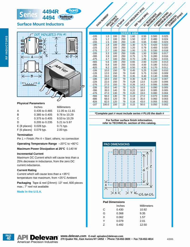
250250250250250250250250250250250250
79797979797979797979797925
SRF Typic
al (M
Hz)
CURRENT RATING
MAXIMUM (A
mps)
DC RESISTANCE
MAXIMUM (O
HMS)
DASH NUMBER*
INDUCTANCE
(mH) ±
25%
TEST FREQUENCY (KHz)
Q Typic
al
INCREMENTAL
CURRENT (Amps
)
0.0250.0240.0230.0220.0200.0180.0170.0160.0150.0130.0120.0110.0100.0090.0080.0070.0060.0060.0050.0050.0040.0030.0030.0020.002
0.5000.4800.4600.4200.4000.3300.3000.2800.2600.2200.1800.1700.1600.1500.1400.1200.1000.0950.0900.0850.0800.0700.0600.0550.050
0.500.570.650.700.791.251.501.701.852.604.004.505.255.756.409.25
13.014.516.018.019.027.035.043.050.0
1.601.501.401.301.201.000.850.750.700.650.550.500.450.400.350.300.280.260.250.220.200.190.180.160.15
100100100100100100100100100100100100150150150150150150140140130130120120150
1.01.21.51.82.22.73.33.94.75.66.88.2
10.012.015.018.022.027.033.039.047.056.068.082.0
100.0Physical ParametersInches Millimeters
A 0.435 to 0.465 11.05 to 11.81B 0.385 to 0.405 9.78 to 10.29C 0.375 to 0.405 9.53 to 10.29D 0.205 to 0.235 5.21 to 5.97E (8 places) 0.028 typ. 0.71 typ.F (6 places) 0.079 typ. 2.00 typ.
TerminationPin 1 = Finish; Pin 4 = Start; others, no connection
Operating Temperature Range –20°C to +80°C
Maximum Power Dissipation at 25°C 0.140 W
Incremental CurrentMaximum DC Current which will cause less than a25% decrease in inductance, from the zero DCcurrent inductance.
Current Rating Current which will cause less than a +35°Ctemperature rise maximum, from +25°C Ambient
Packaging Tape & reel (24mm): 13" reel, 600 piecesmax.; 7" reel not available
Made In the U.S.A.
Pad DimensionsInches Millimeters
C 0.430 10.92G 0.368 9.35X 0.062 1.57Y 0.079 2.01Z 0.492 12.50
PAD DIMENSIONS
SERIES 4494-105-125-155-185-225-275-335-395-475-565-685-825-106-126-156-186-226-276-336-396-476-566-686-826-107
*Complete part # must include series # PLUS the dash #
For further surface finish information, refer to TECHNICAL section of this catalog.
4494R4494
Surface Mount Inductors
Series
PAGE40
www.delevan .com E-mail: apisales@delevan .com270 Quaker Rd., East Aurora NY 14052 • Phone 716-652-3600 • Fax 716-652-4814 4/2005
RF
IN
DU
CT
OR
S
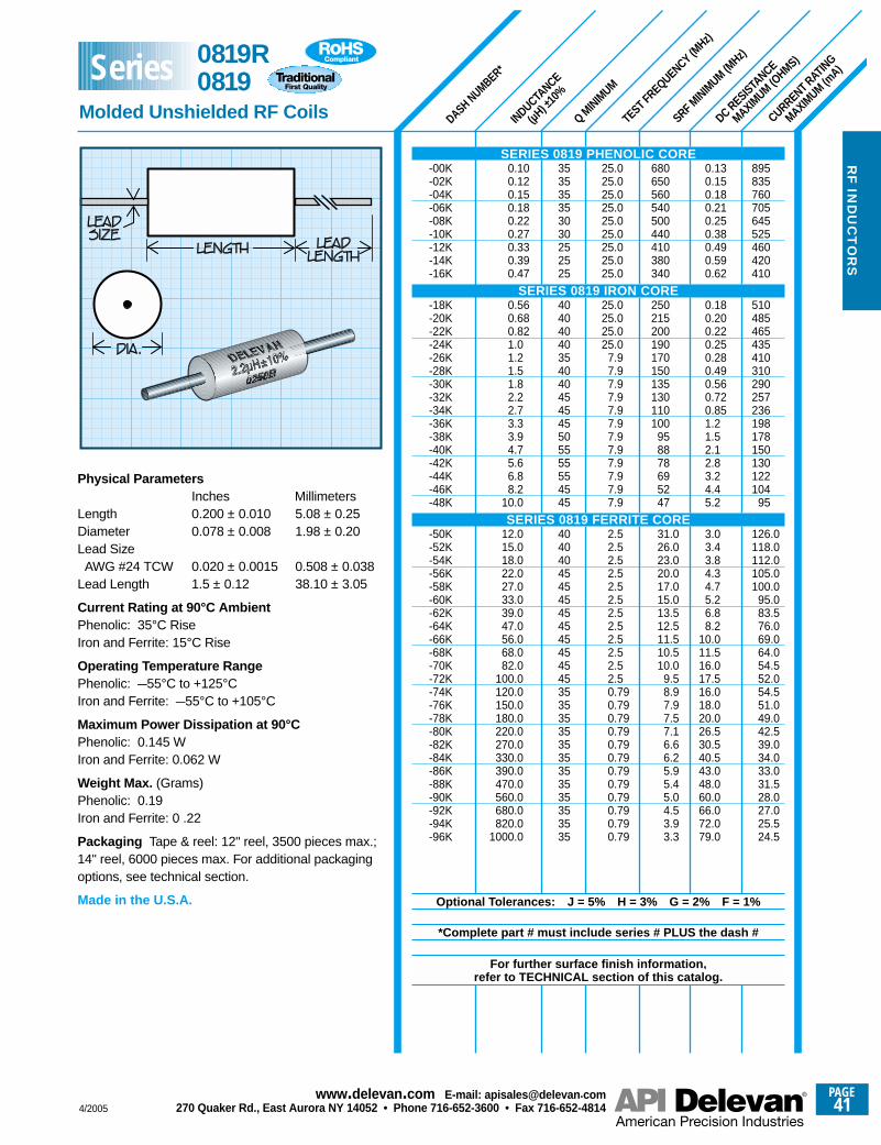
SRF MINIM
UM (MHz)
DASH NUMBER*
INDUCTANCE
(µH) ±
10%
Q MINIM
UM
TEST FREQUENCY (MHz)
DC RESISTANCE
MAXIMUM (O
HMS)
CURRENT RATING
MAXIMUM (m
A)
895835760705645525460420410
510485465435410310290257236198178150130122104
95
126.0118.0112.0105.0100.0
95.083.576.069.064.054.552.054.551.049.042.539.034.033.031.528.027.025.524.5
0.130.150.180.210.250.380.490.590.62
0.180.200.220.250.280.490.560.720.851.21.52.12.83.24.45.2
3.03.43.84.34.75.26.88.2
10.011.516.017.516.018.020.026.530.540.543.048.060.066.072.079.0
680650560540500440410380340
250215200190170150135130110100
958878695247
31.026.023.020.017.015.013.512.511.510.510.0
9.58.97.97.57.16.66.25.95.45.04.53.93.3
25.025.025.025.025.025.025.025.025.0
25.025.025.025.0
7.97.97.97.97.97.97.97.97.97.97.97.9
2.52.52.52.52.52.52.52.52.52.52.52.50.790.790.790.790.790.790.790.790.790.790.790.79
353535353030252525
40404040354040454545505555554545
404040454545454545454545353535353535353535353535
0.100.120.150.180.220.270.330.390.47
0.560.680.821.01.21.51.82.22.73.33.94.75.66.88.2
10.0
12.015.018.022.027.033.039.047.056.068.082.0
100.0120.0150.0180.0220.0270.0330.0390.0470.0560.0680.0820.0
1000.0
Physical ParametersInches Millimeters
Length 0.200 ± 0.010 5.08 ± 0.25Diameter 0.078 ± 0.008 1.98 ± 0.20Lead SizeAWG #24 TCW 0.020 ± 0.0015 0.508 ± 0.038
Lead Length 1.5 ± 0.12 38.10 ± 3.05
Current Rating at 90°C AmbientPhenolic: 35°C RiseIron and Ferrite: 15°C Rise
Operating Temperature RangePhenolic: –55°C to +125°CIron and Ferrite: –55°C to +105°C
Maximum Power Dissipation at 90°CPhenolic: 0.145 WIron and Ferrite: 0.062 W
Weight Max. (Grams)Phenolic: 0.19Iron and Ferrite: 0 .22
Packaging Tape & reel: 12" reel, 3500 pieces max.;14" reel, 6000 pieces max. For additional packagingoptions, see technical section.
Made in the U.S.A.
SERIES 0819 PHENOLIC CORE-00K-02K-04K-06K-08K-10K-12K-14K-16K
SERIES 0819 IRON CORE-18K-20K-22K-24K-26K-28K-30K-32K-34K-36K-38K-40K-42K-44K-46K-48K
SERIES 0819 FERRITE CORE-50K-52K-54K-56K-58K-60K-62K-64K-66K-68K-70K-72K-74K-76K-78K-80K-82K-84K-86K-88K-90K-92K-94K-96K
Optional Tolerances: J = 5% H = 3% G = 2% F = 1%
*Complete part # must include series # PLUS the dash #
For further surface finish information, refer to TECHNICAL section of this catalog.
0819R0819
Molded Unshielded RF Coils
Series
4/2005
PAGE41
www.delevan .com E-mail: apisales@delevan .com270 Quaker Rd., East Aurora NY 14052 • Phone 716-652-3600 • Fax 716-652-4814
RF
IND
UC
TO
RS
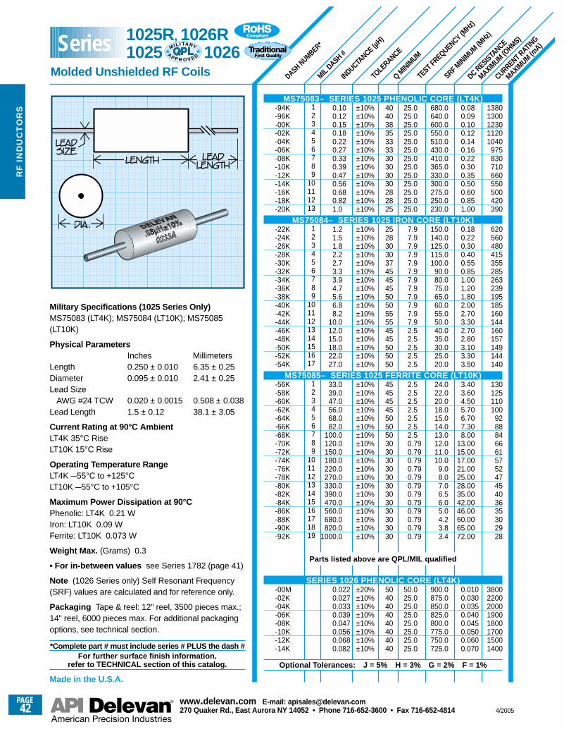
SRF MINIM
UM (MHz)
CURRENT RATING
MAXIMUM (m
A)
DC RESISTANCE
MAXIMUM (O
HMS)
TEST FREQUENCY (MHz)
Q MINIM
UM
INDUCTANCE (µ
H)
TOLE
RANCE
MIL DASH #
DASH NUMBER*
13801300123011201040
975830710660550500420390
620560480415355285263239195185160144160157149144140
130125110100
928884666157524745403635302928
38002200200019001800170015001400
0.080.090.100.120.140.160.220.300.350.500.600.851.00
0.180.220.300.400.550.851.001.201.802.002.703.302.702.803.103.303.50
3.403.604.505.706.707.308.00
13.0015.0017.0021.0025.0028.0035.0042.0046.0060.0065.0072.00
0.0100.0300.0350.0400.0450.0500.0600.070
680.0640.0600.0550.0510.0430.0410.0365.0330.0300.0275.0250.0230.0
150.0140.0125.0115.0100.0
90.080.075.065.060.055.050.040.035.030.025.020.0
24.022.020.018.015.014.013.012.011.010.0
9.08.07.06.56.05.04.23.83.4
900.0875.0850.0825.0800.0775.0750.0725.0
25.025.025.025.025.025.025.025.025.025.025.025.025.0
7.97.97.97.97.97.97.97.97.97.97.97.92.52.52.52.52.5
2.52.52.52.52.52.52.50.790.790.790.790.790.790.790.790.790.790.790.79
50.025.025.025.025.025.025.025.0
40403835333330303030282825
2528303037454545505055554545505050
45454545505050303030303030303030303030
5040404040404040
123456789
10111213
123456789
1011121314151617
123456789
10111213141516171819
±10%±10%±10%±10%±10%±10%±10%±10%±10%±10%±10%±10%±10%
±10%±10%±10%±10%±10%±10%±10%±10%±10%±10%±10%±10%±10%±10%±10%±10%±10%
±10%±10%±10%±10%±10%±10%±10%±10%±10%±10%±10%±10%±10%±10%±10%±10%±10%±10%±10%
±20%±10%±10%±10%±10%±10%±10%±10%
0.100.120.150.180.220.270.330.390.470.560.680.821.0
1.21.51.82.22.73.33.94.75.66.88.2
10.012.015.018.022.027.0
33.039.047.056.068.082.0
100.0120.0150.0180.0220.0270.0330.0390.0470.0560.0680.0820.0
1000.0
0.0220.0270.0330.0390.0470.0560.0680.082
Military Specifications (1025 Series Only)MS75083 (LT4K); MS75084 (LT10K); MS75085(LT10K)
Physical ParametersInches Millimeters
Length 0.250 ± 0.010 6.35 ± 0.25Diameter 0.095 ± 0.010 2.41 ± 0.25Lead Size
AWG #24 TCW 0.020 ± 0.0015 0.508 ± 0.038Lead Length 1.5 ± 0.12 38.1 ± 3.05
Current Rating at 90°C AmbientLT4K 35°C RiseLT10K 15°C Rise
Operating Temperature RangeLT4K –55°C to +125°CLT10K –55°C to +105°C
Maximum Power Dissipation at 90°CPhenolic: LT4K 0.21 W Iron: LT10K 0.09 W Ferrite: LT10K 0.073 W
Weight Max. (Grams) 0.3
• For in-between values see Series 1782 (page 41)
Note (1026 Series only) Self Resonant Frequency(SRF) values are calculated and for reference only.
Packaging Tape & reel: 12" reel, 3500 pieces max.;14" reel, 6000 pieces max. For additional packagingoptions, see technical section.
*Complete part # must include series # PLUS the dash #For further surface finish information,
refer to TECHNICAL section of this catalog.
Made in the U.S.A.
MS75083– SERIES 1025 PHENOLIC CORE (LT4K)-94K-96K-00K-02K-04K-06K-08K-10K-12K-14K-16K-18K-20K
MS75084– SERIES 1025 IRON CORE (LT10K)-22K-24K-26K-28K-30K-32K-34K-36K-38K-40K-42K-44K-46K-48K-50K-52K-54K
MS75085– SERIES 1025 FERRITE CORE (LT10K)-56K-58K-60K-62K-64K-66K-68K-70K-72K-74K-76K-78K-80K-82K-84K-86K-88K-90K-92K
Parts listed above are QPL/MIL qualified
SERIES 1026 PHENOLIC CORE (LT4K)-00M-02K-04K-06K-08K-10K-12K-14K
Optional Tolerances: J = 5% H = 3% G = 2% F = 1%
1025R, 1026R1025 1026
Molded Unshielded RF Coils
Series MIL I TA RY
AP P R O V E D
PAGE42
www.delevan .com E-mail: apisales@delevan .com270 Quaker Rd., East Aurora NY 14052 • Phone 716-652-3600 • Fax 716-652-4814 4/2005
RF
IN
DU
CT
OR
S
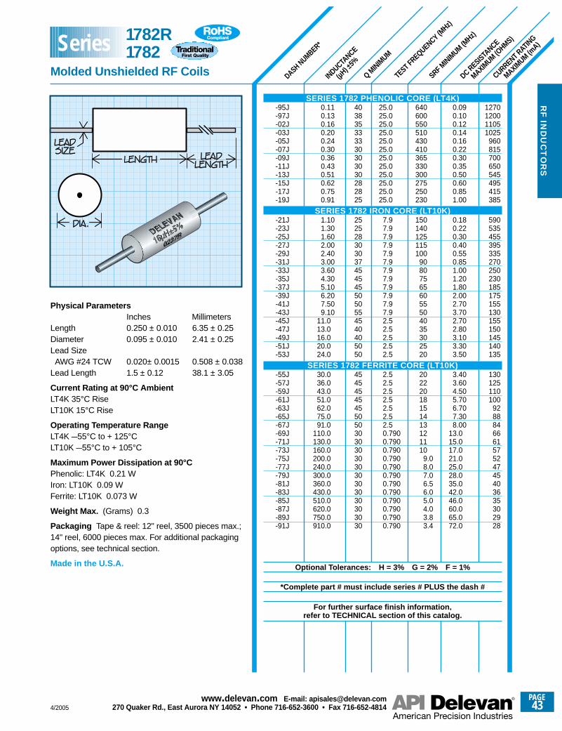
SRF MINIM
UM (MHz)
DASH NUMBER*
INDUCTANCE
(µH) ±
5%
Q MINIM
UM
TEST FREQUENCY (MHz)
DC RESISTANCE
MAXIMUM (O
HMS)
CURRENT RATING
MAXIMUM (m
A)
1270120011051025
960815700650545495415385
590535455395335270250230185175155130155150145140135
130125110100
928884666157524745403635302928
0.090.100.120.140.160.220.300.350.500.600.851.00
0.180.220.300.400.550.851.001.201.802.002.703.702.702.803.103.303.50
3.403.604.505.706.707.308.00
13.015.017.021.025.028.035.042.046.060.065.072.0
640600550510430410365330300275250230
150140125115100
908075656055504035302520
20222018151413121110
9.08.07.06.56.05.04.03.83.4
25.025.025.025.025.025.025.025.025.025.025.025.0
7.97.97.97.97.97.97.97.97.97.97.97.92.52.52.52.52.5
2.52.52.52.52.52.52.50.7900.7900.7900.7900.7900.7900.7900.7900.7900.7900.7900.790
403835333330303030282825
2525283030374545455050554540405050
45454545455050303030303030303030303030
0.110.130.160.200.240.300.360.430.510.620.750.91
1.101.301.602.002.403.003.604.305.106.207.509.10
11.013.016.020.024.0
30.036.043.051.062.075.091.0
110.0130.0160.0200.0240.0300.0360.0430.0510.0620.0750.0910.0
Physical ParametersInches Millimeters
Length 0.250 ± 0.010 6.35 ± 0.25Diameter 0.095 ± 0.010 2.41 ± 0.25Lead SizeAWG #24 TCW 0.020± 0.0015 0.508 ± 0.038
Lead Length 1.5 ± 0.12 38.1 ± 3.05
Current Rating at 90°C AmbientLT4K 35°C RiseLT10K 15°C Rise
Operating Temperature RangeLT4K –55°C to + 125°CLT10K –55°C to + 105°C
Maximum Power Dissipation at 90°CPhenolic: LT4K 0.21 WIron: LT10K 0.09 WFerrite: LT10K 0.073 W
Weight Max. (Grams) 0.3
Packaging Tape & reel: 12" reel, 3500 pieces max.;14" reel, 6000 pieces max. For additional packagingoptions, see technical section.
Made in the U.S.A.
SERIES 1782 PHENOLIC CORE (LT4K)-95J-97J-02J-03J-05J-07J-09J-11J-13J-15J-17J-19J
SERIES 1782 IRON CORE (LT10K)-21J-23J-25J-27J-29J-31J-33J-35J-37J-39J-41J-43J-45J-47J-49J-51J-53J
SERIES 1782 FERRITE CORE (LT10K)-55J-57J-59J-61J-63J-65J-67J-69J-71J-73J-75J-77J-79J-81J-83J-85J-87J-89J-91J
Optional Tolerances: H = 3% G = 2% F = 1%
*Complete part # must include series # PLUS the dash #
For further surface finish information, refer to TECHNICAL section of this catalog.
1782R1782
Molded Unshielded RF Coils
Series
4/2005
PAGE43
www.delevan .com E-mail: apisales@delevan .com270 Quaker Rd., East Aurora NY 14052 • Phone 716-652-3600 • Fax 716-652-4814
RF
IND
UC
TO
RS
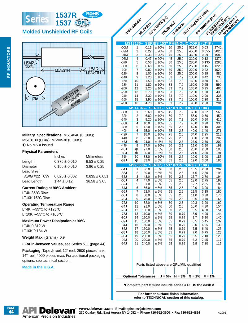
SRF MINIM
UM (MHz)
DASH NUMBER*
MIL DASH #
INDUCTANCE (µ
H)
TOLE
RANCE
Q MINIM
UM
TEST FREQUENCY (MHz)
DC RESISTANCE
MAXIMUM (O
HMS)
CURRENT RATING
MAXIMUM (m
A)
2740202015801370129012201020
880730670590485430335310294
565450410335305271213202202198198191185185
202198194193189184180176166162154151144140137130126123120117115
0.030.0550.090.120.1350.150.220.290.420.500.650.951.202.002.302.60
0.320.500.600.901.101.402.252.502.502.602.602.803.003.00
2.502.602.702.752.853.003.153.303.703.904.304.504.905.205.456.056.406.757.107.457.80
525.0450.0360.0310.0280.0250.0220.0200.0180.0160.0150.0135.0120.0110.0100.0
90.0
60.055.050.045.042.040.034.030.026.025.025.021.019.019.0
15.514.513.713.012.712.011.511.010.510.310.0
9.58.98.78.58.07.57.06.56.25.9
± 20%± 20%± 20%± 20%± 10%± 10%± 10%± 10%± 10%± 10%± 10%± 10%± 10%± 10%± 10%± 10%
± 10%± 10%± 10%± 10%± 10%± 10%± 10%± 10%± 5%± 10%± 5%± 5%± 10%± 5%
± 5%± 5%± 5%± 5%± 5%± 5%± 5%± 5%± 5%± 5%± 5%± 5%± 5%± 5%± 5%± 5%± 5%± 5%± 5%± 5%± 5%
50504545505050503333333333333333
4550505565657575606060656565
606060555555555555505050606565656565656565
25.025.025.025.025.025.025.025.0
7.97.97.97.97.97.97.97.9
7.97.97.97.92.52.52.52.52.52.52.52.52.52.5
2.52.52.52.52.52.52.52.52.52.52.52.50.790.790.790.790.790.790.790.790.79
0.150.220.330.470.560.680.821.001.201.501.802.202.703.303.904.70
5.606.808.20
10.012.015.018.022.024.027.027.030.033.033.0
36.039.043.047.051.056.062.068.075.082.091.0
100.0110.0120.0130.0150.0160.0180.0200.0220.0240.0
123456789
10111213141516
12345678g9gg10g
123456789
101112131415161718192021
Military Specifications MS14046 (LT10K);MS18130 (LT4K); MS90538 (LT10K);g No MS # Issued
Physical ParametersInches Millimeters
Length 0.375 ± 0.010 9.53 ± 0.25Diameter 0.156 ± 0.010 3.96 ± 0.25Lead SizeAWG #22 TCW 0.025 ± 0.002 0.635 ± 0.051
Lead Length 1.44 ± 0.12 36.58 ± 3.05
Current Rating at 90°C Ambient LT4K 35°C RiseLT10K 15°C Rise
Operating Temperature RangeLT4K –55°C to +125°C;LT10K –55°C to +105°C
Maximum Power Dissipation at 90°C LT4K 0.312 WLT10K 0.134 W
Weight Max. (Grams) 0.9
• For in-between values, see Series 511 (page 44)
Packaging Tape & reel: 12" reel, 2500 pieces max.;14" reel, 4000 pieces max. For additional packagingoptions, see technical section.
Made in the U.S.A.
MS18130– SERIES 1537 PHENOLIC CORE (LT4K)-00M-02M-04M-06M-07K-08K-10K-12K-14K-16K-18K-20K-22K-24K-26K-28K
MS14046– SERIES 1537 IRON CORE (LT10K)-30K-32K-34K-36K-38K-40K-42K-44K-46J-47K-48J-50J-51K-52J
MS90538– SERIES 1537 IRON CORE (LT10K)-54J-56J-58J-60J-62J-64J-66J-68J-70J-72J-74J-76J-78J-80J-82J-84J-86J-88J-90J-92J-94J
Parts listed above are QPL/MIL qualified
Optional Tolerances: J = 5% H = 3% G = 2% F = 1%
*Complete part # must include series # PLUS the dash #
For further surface finish information, refer to TECHNICAL section of this catalog.
1537R 1537
Molded Unshielded RF Coils
MIL I TA RY
AP P R O V E D
Series
PAGE44
www.delevan .com E-mail: apisales@delevan .com270 Quaker Rd., East Aurora NY 14052 • Phone 716-652-3600 • Fax 716-652-4814 4/2005
RF
IN
DU
CT
OR
S
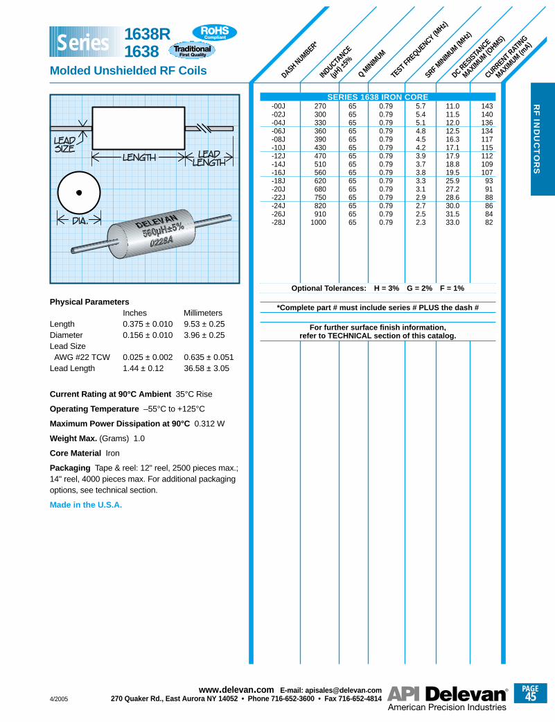
SRF MINIM
UM (MHz)
DASH NUMBER*
INDUCTANCE
(µH) ±
5%
Q MINIM
UM
TEST FREQUENCY (MHz)
DC RESISTANCE
MAXIMUM (O
HMS)
CURRENT RATING
MAXIMUM (m
A)
143140136134117115112109107
939188868482
11.011.512.012.516.317.117.918.819.525.927.228.630.031.533.0
5.75.45.14.84.54.23.93.73.83.33.12.92.72.52.3
0.790.790.790.790.790.790.790.790.790.790.790.790.790.790.79
656565656565656565656565656565
270300330360390430470510560620680750820910
1000
Physical ParametersInches Millimeters
Length 0.375 ± 0.010 9.53 ± 0.25Diameter 0.156 ± 0.010 3.96 ± 0.25Lead SizeAWG #22 TCW 0.025 ± 0.002 0.635 ± 0.051
Lead Length 1.44 ± 0.12 36.58 ± 3.05
Current Rating at 90°C Ambient 35°C Rise
Operating Temperature –55°C to +125°C
Maximum Power Dissipation at 90°C 0.312 W
Weight Max. (Grams) 1.0
Core Material Iron
Packaging Tape & reel: 12" reel, 2500 pieces max.;14" reel, 4000 pieces max. For additional packagingoptions, see technical section.
Made in the U.S.A.
SERIES 1638 IRON CORE-00J-02J-04J-06J-08J-10J-12J-14J-16J-18J-20J-22J-24J-26J-28J
Optional Tolerances: H = 3% G = 2% F = 1%
*Complete part # must include series # PLUS the dash #
For further surface finish information, refer to TECHNICAL section of this catalog.
1638R1638
Molded Unshielded RF Coils
Series
4/2005
PAGE45
www.delevan .com E-mail: apisales@delevan .com270 Quaker Rd., East Aurora NY 14052 • Phone 716-652-3600 • Fax 716-652-4814
RF
IND
UC
TO
RS
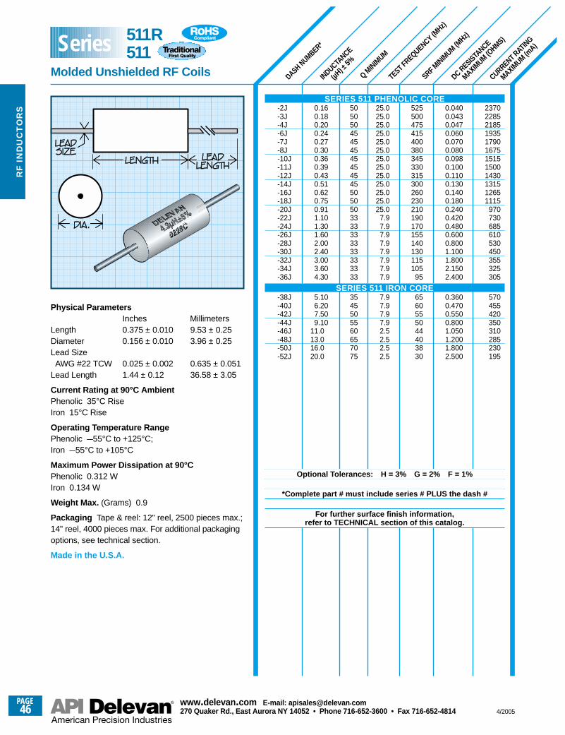
SRF MINIM
UM (MHz)
DASH NUMBER*
INDUCTANCE
(µH) ±
5%
Q MINIM
UM
TEST FREQUENCY (MHz)
DC RESISTANCE
MAXIMUM (O
HMS)
CURRENT RATING
MAXIMUM (m
A)
237022852185193517901675151515001430131512651115
970730685610530450355325305
570455420350310285230195
0.0400.0430.0470.0600.0700.0800.0980.1000.1100.1300.1400.1800.2400.4200.4800.6000.8001.1001.8002.1502.400
0.3600.4700.5500.8001.0501.2001.8002.500
525500475415400380345330315300260230210190170155140130115105
95
6560555044403830
25.025.025.025.025.025.025.025.025.025.025.025.025.0
7.97.97.97.97.97.97.97.9
7.97.97.97.92.52.52.52.5
505050454545454545455050503333333333333333
3545505560657075
0.160.180.200.240.270.300.360.390.430.510.620.750.911.101.301.602.002.403.003.604.30
5.106.207.509.10
11.013.016.020.0
Physical ParametersInches Millimeters
Length 0.375 ± 0.010 9.53 ± 0.25Diameter 0.156 ± 0.010 3.96 ± 0.25Lead SizeAWG #22 TCW 0.025 ± 0.002 0.635 ± 0.051
Lead Length 1.44 ± 0.12 36.58 ± 3.05
Current Rating at 90°C AmbientPhenolic 35°C RiseIron 15°C Rise
Operating Temperature RangePhenolic –55°C to +125°C;Iron –55°C to +105°C
Maximum Power Dissipation at 90°CPhenolic 0.312 WIron 0.134 W
Weight Max. (Grams) 0.9
Packaging Tape & reel: 12" reel, 2500 pieces max.;14" reel, 4000 pieces max. For additional packagingoptions, see technical section.
Made in the U.S.A.
SERIES 511 PHENOLIC CORE-2J-3J-4J-6J-7J-8J-10J-11J-12J-14J-16J-18J-20J-22J-24J-26J-28J-30J-32J-34J-36J
SERIES 511 IRON CORE-38J-40J-42J-44J-46J-48J-50J-52J
Optional Tolerances: H = 3% G = 2% F = 1%
*Complete part # must include series # PLUS the dash #
For further surface finish information, refer to TECHNICAL section of this catalog.
511R511
Molded Unshielded RF Coils
Series
PAGE46
www.delevan .com E-mail: apisales@delevan .com270 Quaker Rd., East Aurora NY 14052 • Phone 716-652-3600 • Fax 716-652-4814 4/2005
RF
IN
DU
CT
OR
S
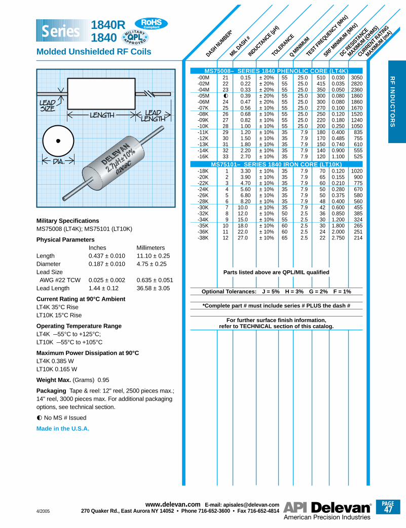
SRF MINIM
UM (MHz)
DASH NUMBER*
MIL DASH #
INDUCTANCE (µ
H)
TOLE
RANCE
Q MINIM
UM
TEST FREQUENCY (MHz)
DC RESISTANCE
MAXIMUM (O
HMS)
CURRENT RATING
MAXIMUM (m
A)
305028202360186018601670152012401050
835755610555525
1020900775670580560455385324265251214
0.0300.0350.0500.0800.0800.1000.1200.1800.2500.4000.4850.7400.9001.100
0.1200.1550.2100.2800.3750.4000.6000.8501.2001.8002.0002.750
510415350300300270250220200180170150140120
706560505048423630302422
25.025.025.025.025.025.025.025.025.0
7.97.97.97.97.9
7.97.97.97.97.97.97.92.52.52.52.52.5
5555555555555555553535353535
353535353535355055606065
± 20%± 20%± 20%± 20%± 20%± 10%± 10%± 10%± 10%± 10%± 10%± 10%± 10%± 10%
± 10%± 10%± 10%± 10%± 10%± 10%± 10%± 10%± 10%± 10%± 10%± 10%
0.150.220.330.390.470.560.680.821.001.201.501.802.202.70
3.303.904.705.606.808.20
10.012.015.018.022.027.0
212223g24252627282930313233
123456789
101112
Military SpecificationsMS75008 (LT4K); MS75101 (LT10K)
Physical ParametersInches Millimeters
Length 0.437 ± 0.010 11.10 ± 0.25Diameter 0.187 ± 0.010 4.75 ± 0.25Lead Size AWG #22 TCW 0.025 ± 0.002 0.635 ± 0.051
Lead Length 1.44 ± 0.12 36.58 ± 3.05
Current Rating at 90°C AmbientLT4K 35°C RiseLT10K 15°C Rise
Operating Temperature RangeLT4K –55°C to +125°C;LT10K –55°C to +105°C
Maximum Power Dissipation at 90°CLT4K 0.385 WLT10K 0.165 W
Weight Max. (Grams) 0.95
Packaging Tape & reel: 12" reel, 2500 pieces max.;14" reel, 3000 pieces max. For additional packagingoptions, see technical section.
g No MS # Issued
Made in the U.S.A.
MS75008– SERIES 1840 PHENOLIC CORE (LT4K)-00M-02M-04M-05M-06M-07K-08K-09K-10K-11K-12K-13K-14K-16K
MS75101– SERIES 1840 IRON CORE (LT10K)-18K-20K-22K-24K-26K-28K-30K-32K-34K-35K-36K-38K
Parts listed above are QPL/MIL qualified
Optional Tolerances: J = 5% H = 3% G = 2% F = 1%
*Complete part # must include series # PLUS the dash #
For further surface finish information, refer to TECHNICAL section of this catalog.
1840R 1840
Molded Unshielded RF Coils
MIL I TA RY
AP P R O V E D
Series
4/2005
PAGE47
www.delevan .com E-mail: apisales@delevan .com270 Quaker Rd., East Aurora NY 14052 • Phone 716-652-3600 • Fax 716-652-4814
RF
IND
UC
TO
RS
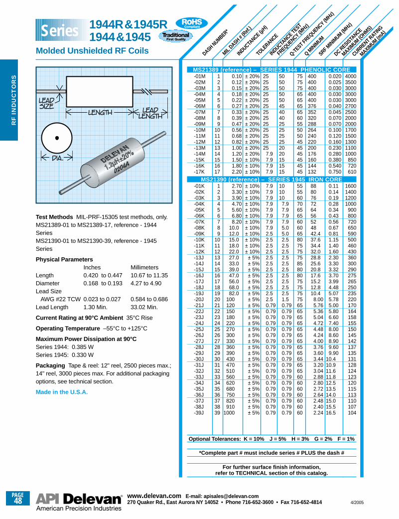
SRF MINIM
UM (MHz)
MIL DASH #
(Ref.
)
DASH NUMBER*
INDUCTANCE (µ
H)
TOLE
RANCE
INDUCTANCE TEST
FREQUENCY (MHz)
Q-TEST FREQUENCY (MHz)
Q MINIM
UM
DC RESISTANCE
MAXIMUM (O
HMS)
CURRENT RATING
MAXIMUM (m
A)
40003500300030003000270025002000200017001500130011001000
850720610
1600140012001000
900800720650590500460430360300290275265250235220170164158155150145142137135131128124123120115113110107104
0.0200.0250.0300.0300.0300.0400.0450.0700.0700.1000.1200.1600.2300.2800.3800.5400.750
0.110.140.190.280.340.430.560.670.811.151.401.602.303.303.323.703.994.485.075.785.005.806.607.408.008.608.909.609.90
10.410.911.611.812.513.514.015.015.516.5
400400400400400376352320288264240220200176160144132
888076726456524842.437.634.432.028.825.620.817.615.212.810.4
8.005.765.365.044.724.484.244.003.763.603.443.203.042.882.802.722.642.482.402.24
7575756565656560555050454545454545
555560706565606065807575758580807575757565656565656565656565656560606060606060
5050505050454040252525252020151515
101010
7.97.97.97.95.05.02.52.52.52.52.52.52.52.52.52.51.50.790.790.790.790.790.790.790.790.790.790.790.790.790.790.790.790.790.790.79
25252525252525252525252525
7.97.97.97.9
7.97.97.97.97.97.97.97.92.52.52.52.52.52.52.52.52.52.52.52.50.790.790.790.790.790.790.790.790.790.790.790.790.790.790.790.790.790.790.79
123456789
1011121314151617
123456789
101112131415161718192021222324252627282930313233343536373839
0.100.120.150.180.220.270.330.390.470.560.680.821.001.201.501.802.20
2.703.303.904.705.606.808.20
10.012.015.018.022.027.033.039.047.056.068.082.0
100120150180220270300330360390430470510560620680750820910
1000
± 20%± 20%± 20%± 20%± 20%± 20%± 20%± 20%± 20%± 20%± 20%± 20%± 20%± 20%± 10%± 10%± 10%
± 10%± 10%± 10%± 10%± 10%± 10%± 10%± 10%± 10%± 10%± 10%± 10%
± 5%± 5%± 5%± 5%± 5%± 5%± 5%± 5%± 5%± 5%± 5%± 5%± 5%± 5%± 5%± 5%± 5%± 5%± 5%± 5%± 5%± 5%± 5%± 5%± 5%± 5%± 5%
Test Methods MIL-PRF-15305 test methods, only.MS21389-01 to MS21389-17, reference - 1944SeriesMS21390-01 to MS21390-39, reference - 1945Series
Physical ParametersInches Millimeters
Length 0.420 to 0.447 10.67 to 11.35Diameter 0.168 to 0.193 4.27 to 4.90Lead Size
AWG #22 TCW 0.023 to 0.027 0.584 to 0.686Lead Length 1.30 Min. 33.02 Min.
Current Rating at 90°C Ambient 35°C Rise
Operating Temperature –55°C to +125°C
Maximum Power Dissipation at 90°C Series 1944: 0.385 WSeries 1945: 0.330 W
Packaging Tape & reel: 12" reel, 2500 pieces max.;14" reel, 3000 pieces max. For additional packagingoptions, see technical section.
Made in the U.S.A.
MS21389 (reference) – SERIES 1944 PHENOLIC CORE-01M-02M-03M-04M-05M-06M-07M-08M-09M-10M-11M-12M-13M-14M-15K-16K-17K
MS21390 (reference) – SERIES 1945 IRON CORE-01K-02K-03K-04K-05K-06K-07K-08K-09K-10K-11K-12K-13J-14J-15J-16J-17J-18J-19J-20J-21J-22J-23J-24J-25J-26J-27J-28J-29J-30J-31J-32J-33J-34J-35J-36J-37J-38J-39J
Optional Tolerances: K = 10% J = 5% H = 3% G = 2% F = 1%
*Complete part # must include series # PLUS the dash #
For further surface finish information, refer to TECHNICAL section of this catalog.
1944R&1945R1944&1945
Molded Unshielded RF Coils
Series
PAGE48
www.delevan .com E-mail: apisales@delevan .com270 Quaker Rd., East Aurora NY 14052 • Phone 716-652-3600 • Fax 716-652-4814 4/2005
RF
IN
DU
CT
OR
S
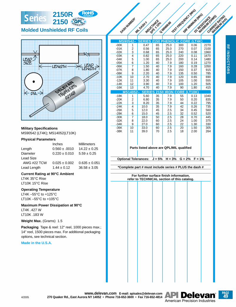
SRF MINIM
UM (MHz)
DASH NUMBER*
MIL DASH #
INDUCTANCE
(µH) ±
10%
Q MINIM
UM
TEST FREQUENCY (MHz)
DC RESISTANCE
MAXIMUM (O
HMS)
CURRENT RATING
MAXIMUM (m
A)
2270210019601670148012701050
915785690555505415
1040835795735560520445375330305264
0.060.070.080.110.140.190.280.370.500.651.001.201.80
0.130.200.220.260.450.520.701.001.301.502.00
300270240220200180160150135120105100
90
5550444234322824222018
25.025.025.025.025.0
7.97.97.97.97.97.97.97.9
7.97.97.97.92.52.52.52.52.52.52.5
65656565654040404040404040
3535353545455060606070
0.470.560.680.821.001.201.501.802.202.703.303.904.70
5.606.808.20
10.012.015.018.022.027.033.039.0
123456789
10111213
123456789
1011
Military SpecificationsMS90542 (LT4K); MS14052(LT10K)
Physical ParametersInches Millimeters
Length 0.560 ± .0010 14.22 ± 0.25Diameter 0.220 ± 0.010 5.59 ± 0.25Lead SizeAWG #22 TCW 0.025 ± 0.002 0.635 ± 0.051
Lead Length 1.44 ± 0.12 36.58 ± 3.05
Current Rating at 90°C Ambient LT4K 35°C RiseLT10K 15°C Rise
Operating Temperature LT4K –55°C to +125°CLT10K –55°C to +105°C
Maximum Power Dissipation at 90°CLT4K .427 WLT10K .183 W
Weight Max. (Grams) 1.5
Packaging Tape & reel: 12" reel, 1000 pieces max.;14" reel, 1500 pieces max. For additional packagingoptions, see technical section.
Made in the U.S.A.
MS90542– SERIES 2150 PHENOLIC CORE (LT4K)-00K-01K-02K-03K-04K-05K-06K-07K-08K-10K-12K-14K-16K
MS14052– SERIES 2150 IRON CORE (LT10K)-18K-20K-22K-24K-26K-28K-30K-32K-34K-36K-38K
Parts listed above are QPL/MIL qualified
Optional Tolerances: J = 5% H = 3% G = 2% F = 1%
*Complete part # must include series # PLUS the dash #
For further surface finish information, refer to TECHNICAL section of this catalog.
2150R 2150
Molded Unshielded RF Coils
MIL I TA RY
AP P R O V E D
Series
4/2005
PAGE49
www.delevan .com E-mail: apisales@delevan .com270 Quaker Rd., East Aurora NY 14052 • Phone 716-652-3600 • Fax 716-652-4814
RF
IND
UC
TO
RS
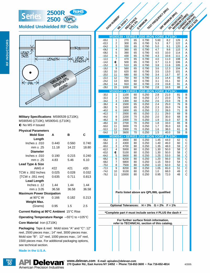
SRF MINIM
UM (MHz)
DASH NUMBER*
MIL DASH #
INDUCTANCE
(µH) ±
5%
Q MINIM
UM
TEST FREQUENCY (MHz)
DC RESISTANCE
MAXIMUM (O
HMS)
CURRENT RATING
MAXIMUM (m
A)
MOLDSIZE
126122120115114111108106105104101
9795929188
81797876747169686765636159
626059585856555452514948
AAAAAAAAAAAAAAAA
BBBBBBBBBBBBB
CCCCCCCCCCCC
8.28.79.19.6
10.010.611.011.311.612.313.013.714.415.115.816.5
21.022.023.025.026.028.029.030.031.033.035.038.040.0
44.046.048.050.050.053.056.059.062.065.068.072.0
5.605.35.04.74.54.34.03.73.83.63.53.43.33.12.92.8
2.82.72.62.42.32.22.12.01.91.81.71.61.5
1.451.401.351.301.301.251.201.151.101.051.00.95
0.7900.7900.7900.7900.7900.7900.7900.7900.7900.7900.7900.7900.7900.7900.7900.790
0.2500.2500.2500.2500.2500.2500.2500.2500.2500.2500.2500.2500.250
0.2500.2500.2500.2500.2500.2500.2500.2500.2500.2500.2500.250
65656565656565656565606060606060
60606065656565707070707070
808080808080808080808080
270300330360390430470500510560620680750820910
1000
1100120013001500160018002000220024002700300033003600
39004300470050005100560062006800750082009100
10000
1234567g89
101112131415
123456789
10111213
1234g56789
1011
Military Specifications MS90539 (LT10K);MS90540 (LT10K); MS90541 (LT10K);g No MS # Issued
Physical ParametersMold Size A B C
LengthInches ± .010 0.440 0.560 0.740
mm ± .25 11.18 14.22 18.80Diameter
Inches ± .010 0.190 0.215 0.240mm ± .25 4.83 5.46 6.10
Lead Type & SizeAWG # #22 #21 #20
TCW ± .002 Inches 0.025 0.028 0.032[TCW ± .051 mm] 0.635 0.711 0.813
Lead LengthInches ± .12 1.44 1.44 1.44
mm ± 3.05 36.58 36.58 36.58Maximum Power Dissipation
at 90°C W 0.166 0.182 0.213Weight Max.
(Grams) 0.95 1.5 2.5
Current Rating at 90°C Ambient 15°C Rise
Operating Temperature Range –55°C to +105°C
Core Material Iron (LT10K)
Packaging Tape & reel: Mold sizes "A" and "C": 12"reel, 2500 pieces max.; 14" reel, 3000 pieces max.Mold size "B": 12" reel, 1000 pieces max.; 14" reel,1500 pieces max. For additional packaging options, see technical section.
Made in the U.S.A.
MS90539 • SERIES 2500 IRON CORE (LT10K)-00J-02J-04J-06J-08J-10J-12J-14J-15J-16J-18J-20J-22J-24J-26J-28J
MS90540 • SERIES 2500 IRON CORE (LT10K)-30J-32J-34J-36J-38J-40J-42J-44J-46J-48J-50J-52J-54J
MS90541 • SERIES 2500 IRON CORE (LT10K)-56J-58J-60J-62J-63J-64J-66J-68J-70J-72J-74J-76J
Parts listed above are QPL/MIL qualified
Optional Tolerances: H = 3% G = 2% F = 1%
*Complete part # must include series # PLUS the dash #
For further surface finish information, refer to TECHNICAL section of this catalog.
2500R 2500
Molded Unshielded RF Coils
MIL I TA RY
AP P R O V E D
Series
PAGE50
www.delevan .com E-mail: apisales@delevan .com270 Quaker Rd., East Aurora NY 14052 • Phone 716-652-3600 • Fax 716-652-4814 4/2005
RF
IN
DU
CT
OR
S
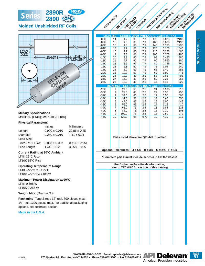
SRF MINIM
UM (MHz)
DASH NUMBER*
MIL DASH #
INDUCTANCE
(µH) ±
10%
Q MINIM
UM
TEST FREQUENCY (MHz)
DC RESISTANCE
MAXIMUM (O
HMS)
CURRENT RATING
MAXIMUM (m
A)
240021901790164014001190
980880760640555475405365320
815750595550445410325305279219
0.0750.0900.1350.1600.2200.3050.4500.5600.7451.051.401.902.653.254.15
0.2950.350.550.651.001.151.852.102.504.10
170160140125115100
959080756860535045
24221918161413121210
7.97.97.97.97.97.97.97.97.97.97.97.92.52.52.5
2.52.52.52.52.52.52.52.52.50.79
606060606060606060606060404040
50456055656575757595
1.21.51.82.22.73.33.94.75.66.88.2
10.012.015.018.0
22.027.033.039.047.056.068.082.0
100.0120.0
141516171819202122232425262728
123456789
10Military Specifications MS91189 (LT4K); MS75103(LT10K)
Physical ParametersInches Millimeters
Length 0.900 ± 0.010 22.86 ± 0.25Diameter 0.280 ± 0.010 7.11 ± 0.25Lead SizeAWG #21 TCW 0.028 ± 0.002 0.711 ± 0.051
Lead Length 1.44 ± 0.12 36.58 ± 3.05
Current Rating at 90°C AmbientLT4K 35°C RiseLT10K 15°C Rise
Operating Temperature RangeLT4K –55°C to +125°CLT10K –55°C to +105°C
Maximum Power Dissipation at 90°CLT4K 0.598 WLT10K 0.256 W
Weight Max. (Grams) 3.9
Packaging Tape & reel: 12" reel, 800 pieces max.;14" reel, 1300 pieces max. For additional packagingoptions, see technical section.
Made in the U.S.A.
MS91189– SERIES 2890 PHENOLIC CORE (LT4K)-00K-02K-03K-04K-06K-08K-10K-12K-14K-16K-18K-20K-22K-24K-26K
MS75103– SERIES 2890 IRON CORE (LT10K)-28K-30K-32K-34K-36K-38K-39K-40K-42K-44K
Parts listed above are QPL/MIL qualified
Optional Tolerances: J = 5% H = 3% G = 2% F = 1%
*Complete part # must include series # PLUS the dash #
For further surface finish information, refer to TECHNICAL section of this catalog.
2890R 2890
Molded Unshielded RF Coils
MIL I TA RY
AP P R O V E D
Series
4/2005
PAGE51
www.delevan .com E-mail: apisales@delevan .com270 Quaker Rd., East Aurora NY 14052 • Phone 716-652-3600 • Fax 716-652-4814
RF
IND
UC
TO
RS
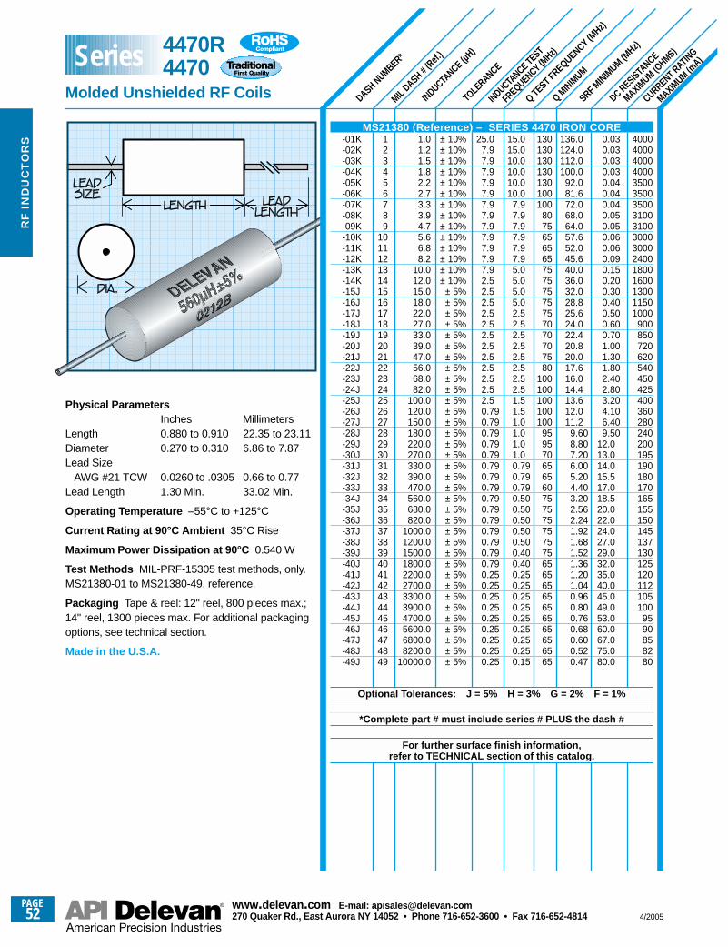
SRF MINIM
UM (MHz)
DASH NUMBER*
MILDASH #
(Ref.
)
INDUCTANCE (µ
H)
TOLERANCE
INDUCTANCE TEST
FREQUENCY (MHz)
Q TEST FREQUENCY (MHz)
Q MINIM
UM
DC RESISTANCE
MAXIMUM (O
HMS)
CURRENT RATING
MAXIMUM (m
A)
136.0124.0112.0100.0
92.081.672.068.064.057.652.045.640.036.032.028.825.624.022.420.820.017.616.014.413.612.011.2
9.608.807.206.005.204.403.202.562.241.921.681.521.361.201.040.960.800.760.680.600.520.47
0.030.030.030.030.040.040.040.050.050.060.060.090.150.200.300.400.500.600.701.001.301.802.402.803.204.106.409.50
12.013.014.015.517.018.520.022.024.027.029.032.035.040.045.049.053.060.067.075.080.0
40004000400040003500350035003100310030003000240018001600130011501000
900850720620540450425400360280240200195190180170165155150145137130125120112105100
9590858280
130130130130130100100
807565656575757575757070707580
100100100100100
95957065656075757575757565656565656565656565
15.015.010.010.010.010.0
7.97.97.97.97.97.95.05.05.05.02.52.52.52.52.52.52.52.51.51.51.01.01.01.00.790.790.790.500.500.500.500.500.400.400.250.250.250.250.250.250.250.250.15
25.07.97.97.97.97.97.97.97.97.97.97.97.92.52.52.52.52.52.52.52.52.52.52.52.50.790.790.790.790.790.790.790.790.790.790.790.790.790.790.790.250.250.250.250.250.250.250.250.25
± 10%± 10%± 10%± 10%± 10%± 10%± 10%± 10%± 10%± 10%± 10%± 10%± 10%± 10%
± 5%± 5%± 5%± 5%± 5%± 5%± 5%± 5%± 5%± 5%± 5%± 5%± 5%± 5%± 5%± 5%± 5%± 5%± 5%± 5%± 5%± 5%± 5%± 5%± 5%± 5%± 5%± 5%± 5%± 5%± 5%± 5%± 5%± 5%± 5%
1.01.21.51.82.22.73.33.94.75.66.88.2
10.012.015.018.022.027.033.039.047.056.068.082.0
100.0120.0150.0180.0220.0270.0330.0390.0470.0560.0680.0820.0
1000.01200.01500.01800.02200.02700.03300.03900.04700.05600.06800.08200.0
10000.0
123456789
10111213141516171819202122232425262728293031323334353637383940414243444546474849
Physical ParametersInches Millimeters
Length 0.880 to 0.910 22.35 to 23.11Diameter 0.270 to 0.310 6.86 to 7.87Lead Size
AWG #21 TCW 0.0260 to .0305 0.66 to 0.77Lead Length 1.30 Min. 33.02 Min.
Operating Temperature –55°C to +125°C
Current Rating at 90°C Ambient 35°C Rise
Maximum Power Dissipation at 90°C 0.540 W
Test Methods MIL-PRF-15305 test methods, only.MS21380-01 to MS21380-49, reference.
Packaging Tape & reel: 12" reel, 800 pieces max.;14" reel, 1300 pieces max. For additional packagingoptions, see technical section.
Made in the U.S.A.
MS21380 (Reference) – SERIES 4470 IRON CORE-01K-02K-03K-04K-05K-06K-07K-08K-09K-10K-11K-12K-13K-14K-15J-16J-17J-18J-19J-20J-21J-22J-23J-24J-25J-26J-27J-28J-29J-30J-31J-32J-33J-34J-35J-36J-37J-38J-39J-40J-41J-42J-43J-44J-45J-46J-47J-48J-49J
Optional Tolerances: J = 5% H = 3% G = 2% F = 1%
*Complete part # must include series # PLUS the dash #
For further surface finish information, refer to TECHNICAL section of this catalog.
4470R4470
Molded Unshielded RF Coils
Series
PAGE52
www.delevan .com E-mail: apisales@delevan .com270 Quaker Rd., East Aurora NY 14052 • Phone 716-652-3600 • Fax 716-652-4814 4/2005
RF
IN
DU
CT
OR
S
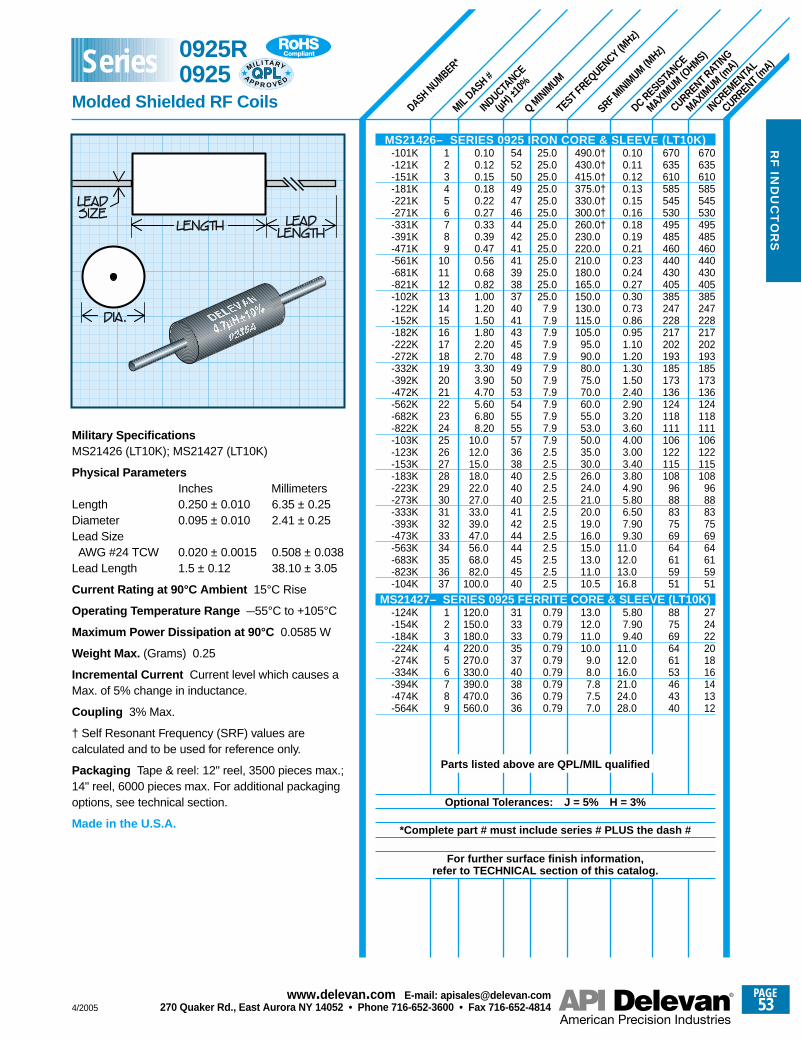
SRF MINIM
UM (MHz)
DASH NUMBER*
MIL DASH #
INDUCTANCE
(µH) ±
10%
Q MINIM
UM
TEST FREQUENCY (MHz)
DC RESISTANCE
MAXIMUM (O
HMS)
CURRENT RATING
MAXIMUM (m
A)
INCREMENTAL
CURRENT (mA)
670635610585545530495485460440430405385247228217202193185173136124118111106122115108
968883756964615951
887569646153464340
670635610585545530495485460440430405385247228217202193185173136124118111106122115108
968883756964615951
272422201816141312
0.100.110.120.130.150.160.180.190.210.230.240.270.300.730.860.951.101.201.301.502.402.903.203.604.003.003.403.804.905.806.507.909.30
11.012.013.016.8
5.807.909.40
11.012.016.021.024.028.0
490.0†430.0†415.0†375.0†330.0†300.0†260.0†230.0220.0210.0180.0165.0150.0130.0115.0105.0
95.090.080.075.070.060.055.053.050.035.030.026.024.021.020.019.016.015.013.011.010.5
13.012.011.010.0
9.08.07.87.57.0
25.025.025.025.025.025.025.025.025.025.025.025.025.0
7.97.97.97.97.97.97.97.97.97.97.97.92.52.52.52.52.52.52.52.52.52.52.52.5
0.790.790.790.790.790.790.790.790.79
54525049474644424141393837404143454849505354555557363840404041424444454540
313333353740383636
0.100.120.150.180.220.270.330.390.470.560.680.821.001.201.501.802.202.703.303.904.705.606.808.20
10.012.015.018.022.027.033.039.047.056.068.082.0
100.0
120.0150.0180.0220.0270.0330.0390.0470.0560.0
123456789
10111213141516171819202122232425262728293031323334353637
123456789
Military SpecificationsMS21426 (LT10K); MS21427 (LT10K)
Physical ParametersInches Millimeters
Length 0.250 ± 0.010 6.35 ± 0.25Diameter 0.095 ± 0.010 2.41 ± 0.25Lead SizeAWG #24 TCW 0.020 ± 0.0015 0.508 ± 0.038
Lead Length 1.5 ± 0.12 38.10 ± 3.05
Current Rating at 90°C Ambient 15°C Rise
Operating Temperature Range –55°C to +105°C
Maximum Power Dissipation at 90°C 0.0585 W
Weight Max. (Grams) 0.25
Incremental Current Current level which causes aMax. of 5% change in inductance.
Coupling 3% Max.
† Self Resonant Frequency (SRF) values arecalculated and to be used for reference only.
Packaging Tape & reel: 12" reel, 3500 pieces max.;14" reel, 6000 pieces max. For additional packagingoptions, see technical section.
Made in the U.S.A.
MS21426– SERIES 0925 IRON CORE & SLEEVE (LT10K)-101K-121K-151K-181K-221K-271K-331K-391K-471K-561K-681K-821K-102K-122K-152K-182K-222K-272K-332K-392K-472K-562K-682K-822K-103K-123K-153K-183K-223K-273K-333K-393K-473K-563K-683K-823K-104K
MS21427– SERIES 0925 FERRITE CORE & SLEEVE (LT10K)-124K-154K-184K-224K-274K-334K-394K-474K-564K
Parts listed above are QPL/MIL qualified
Optional Tolerances: J = 5% H = 3%
*Complete part # must include series # PLUS the dash #
For further surface finish information, refer to TECHNICAL section of this catalog.
0925R 0925
Molded Shielded RF Coils
MIL I TA RY
AP P R O V E D
Series
4/2005
PAGE53
www.delevan .com E-mail: apisales@delevan .com270 Quaker Rd., East Aurora NY 14052 • Phone 716-652-3600 • Fax 716-652-4814
RF
IND
UC
TO
RS
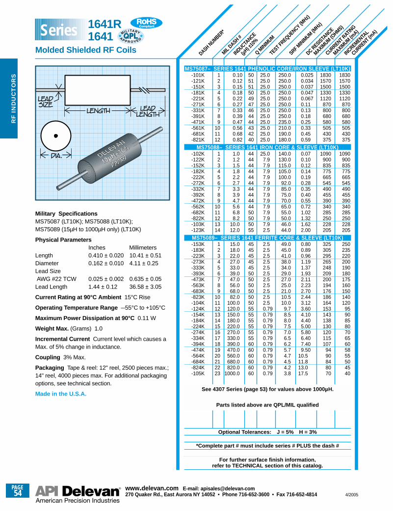
SRF MINIM
UM (MHz)
INCREMENTAL
CURRENT (mA)
CURRENT RATING
MAXIMUM (m
A)
DC RESISTANCE
MAXIMUM (O
HMS)
TEST FREQUENCY (MHz)
Q MINIM
UM
INDUCTANCE
(µH) ±
10%
MILDASH #
DASH NUMBER*
18301570150013301120
870800680580505430375
1090900835775665545490455390340285250228205
250235220200190180175160150140120
959085807065605855504540
18301570150013301120
870800680580505430375
1090900835775665545490455390340285250228205
325305295265248209200194176186164153143138130120115107
9490848070
0.0250.0340.0370.0470.0670.110.130.180.250.330.450.59
0.070.100.120.140.190.280.350.400.550.721.021.321.622.00
0.800.890.961.191.371.932.112.232.702.443.123.604.104.405.005.806.407.409.50
10.511.813.017.5
250.0250.0250.0250.0250.0250.0250.0250.0235.0210.0190.0180.0
140.0130.0115.0105.0100.0
92.085.075.070.065.055.050.046.044.0
49.045.041.038.034.029.027.025.021.010.510.0
9.78.58.07.57.06.56.25.74.74.54.23.8
25.025.025.025.025.025.025.025.025.025.025.025.0
25.07.97.97.97.97.97.97.97.97.97.97.97.92.5
2.52.52.52.52.52.52.52.52.52.52.50.790.790.790.790.790.790.790.790.790.790.790.79
505151504947464444434240
4444444444444444444450505055
4545454545505050505050555555555555606060606060
123456789
101112
123456789
1011121314
123456789
1011121314151617181920212223
0.100.120.150.180.220.270.330.390.470.560.680.82
1.01.21.51.82.22.73.33.94.75.66.88.2
10.012.0
15.018.022.027.033.039.047.056.068.082.0
100.0120.0150.0180.0220.0270.0330.0390.0470.0560.0680.0820.0
1000.0
Military SpecificationsMS75087 (LT10K); MS75088 (LT10K);MS75089 (15µH to 1000µH only) (LT10K)
Physical ParametersInches Millimeters
Length 0.410 ± 0.020 10.41 ± 0.51Diameter 0.162 ± 0.010 4.11 ± 0.25Lead Size AWG #22 TCW 0.025 ± 0.002 0.635 ± 0.05Lead Length 1.44 ± 0.12 36.58 ± 3.05
Current Rating at 90°C Ambient 15°C Rise
Operating Temperature Range –55°C to +105°C
Maximum Power Dissipation at 90°C 0.11 W
Weight Max. (Grams) 1.0
Incremental Current Current level which causes aMax. of 5% change in inductance.
Coupling 3% Max.
Packaging Tape & reel: 12" reel, 2500 pieces max.;14" reel, 4000 pieces max. For additional packagingoptions, see technical section.
Made in the U.S.A.
MS75087– SERIES 1641 PHENOLIC CORE/IRON SLEEVE (LT10K)-101K-121K-151K-181K-221K-271K-331K-391K-471K-561K-681K-821K
MS75088– SERIES 1641 IRON CORE & SLEEVE (LT10K)-102K-122K-152K-182K-222K-272K-332K-392K-472K-562K-682K-822K-103K-123K
MS75089– SERIES 1641 FERRITE CORE & SLEEVE (LT10K)-153K-183K-223K-273K-333K-393K-473K-563K-683K-823K-104K-124K-154K-184K-224K-274K-334K-394K-474K-564K-684K-824K-105K
See 4307 Series (page 53) for values above 1000µH.
Parts listed above are QPL/MIL qualified
Optional Tolerances: J = 5% H = 3%
*Complete part # must include series # PLUS the dash #
For further surface finish information, refer to TECHNICAL section of this catalog.
1641R 1641
Molded Shielded RF Coils
MIL I TA RY
AP P R O V E D
SeriesR
F I
ND
UC
TO
RS
PAGE54
www.delevan .com E-mail: apisales@delevan .com270 Quaker Rd., East Aurora NY 14052 • Phone 716-652-3600 • Fax 716-652-4814 4/2005
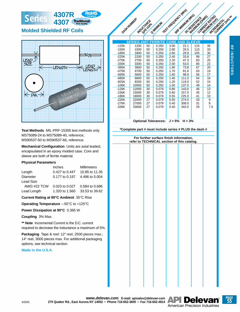
SRF MINIM
UM (MHz)
DASH NUMBER*
INDUCTANCE
(µH) ±
10%
Q MINIM
UM
TEST FREQUENCY (MHz)
DC RESISTANCE
MAXIMUM (O
HMS)
CURRENT RATING
MAXIMUM (m
A)
INCREMENTAL
CURRENT (mA) **
353330272522201917161514131210
987.5
115110105
998380676356545249464541333129
22.126.529.933.847.353.073.881.698.9
111.0119.0137.0143.0157.0225.0274.0308.0343.0
3.002.802.602.402.202.001.901.701.601.401.201.000.800.600.550.500.400.40
0.2500.2500.2500.2500.2500.2500.2500.2500.2500.2500.2500.2500.0790.0790.0790.0790.0790.079
505050505050505050505050303030272727
12001500180022002700330039004700560068008200
10000120001500018000220002700033000
Test Methods MIL-PRF-15305 test methods only.MS75089-24 to MS75089-40, reference;MS90537-50 to MS90537-66, reference.
Mechanical Configuration Units are axial leaded,encapsulated in an epoxy molded case. Core andsleeve are both of ferrite material.
Physical ParametersInches Millimeters
Length 0.427 to 0.447 10.85 to 11.35Diameter 0.177 to 0.197 4.496 to 5.004Lead Size
AWG #22 TCW 0.023 to 0.027 0.584 to 0.686Lead Length 1.320 to 1.560 33.53 to 39.62
Current Rating at 90°C Ambient 35°C Rise
Operating Temperature –-55°C to +125°C
Power Dissipation at 90°C 0.385 W
Coupling 3% Max.
** Note Incremental Current is the D.C. currentrequired to decrease the inductance a maximum of 5%.
Packaging Tape & reel: 12" reel, 2500 pieces max.;14" reel, 3000 pieces max. For additional packagingoptions, see technical section.
Made in the U.S.A.
SERIES 4307 FERRITE CORE AND SLEEVE-125K-155K-185K-225K-275K-335K-395K-475K-565K-685K-825K-106K-126K-156K-186K-226K-276K-336K
Optional Tolerances: J = 5% H = 3%
*Complete part # must include series # PLUS the dash #
For further surface finish information, refer to TECHNICAL section of this catalog.
4307R4307
Molded Shielded RF Coils
Series
4/2005
PAGE55
www.delevan .com E-mail: apisales@delevan .com270 Quaker Rd., East Aurora NY 14052 • Phone 716-652-3600 • Fax 716-652-4814
RF
IND
UC
TO
RS
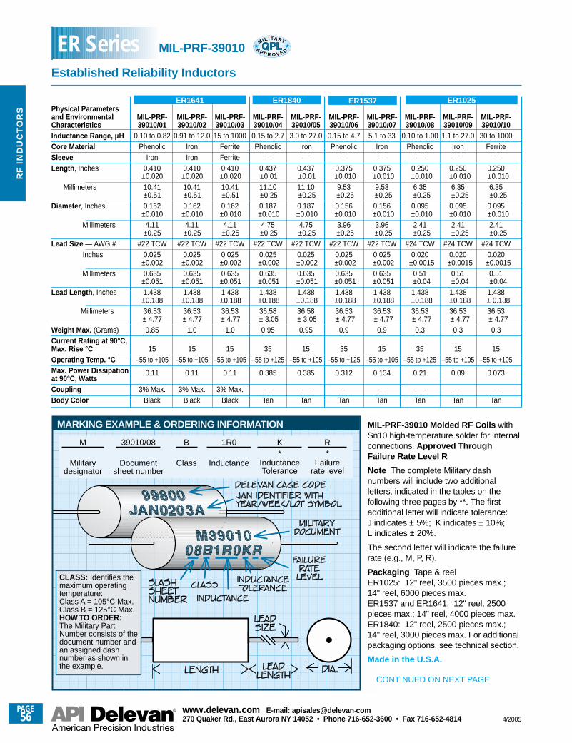
ER1641 ER1840 ER1537 ER1025
MARKING EXAMPLE & ORDERING INFORMATION
M
Militarydesignator
39010/08
Documentsheet number
B
Class
1R0
Inductance
K*
InductanceTolerance
R*
Failurerate level
CLASS: Identifies themaximum operatingtemperature:Class A = 105°C Max.Class B = 125°C Max.HOW TO ORDER:The Military PartNumber consists of thedocument number andan assigned dashnumber as shown inthe example.
Physical Parametersand Environmental MIL-PRF- MIL-PRF- MIL-PRF- MIL-PRF- MIL-PRF- MIL-PRF- MIL-PRF- MIL-PRF- MIL-PRF- MIL-PRF-Characteristics 39010/01 39010/02 39010/03 39010/04 39010/05 39010/06 39010/07 39010/08 39010/09 39010/10Inductance Range, µH 0.10 to 0.82 0.91 to 12.0 15 to 1000 0.15 to 2.7 3.0 to 27.0 0.15 to 4.7 5.1 to 33 0.10 to 1.00 1.1 to 27.0 30 to 1000Core Material Phenolic Iron Ferrite Phenolic Iron Phenolic Iron Phenolic Iron FerriteSleeve Iron Iron Ferrite — — — — — — —Length , Inches 0.410 0.410 0.410 0.437 0.437 0.375 0.375 0.250 0.250 0.250
±0.020 ±0.020 ±0.020 ±0.01 ±0.01 ±0.010 ±0.010 ±0.010 ±0.010 ±0.010Millimeters 10.41 10.41 10.41 11.10 11.10 9.53 9.53 6.35 6.35 6.35
±0.51 ±0.51 ±0.51 ±0.25 ±0.25 ±0.25 ±0.25 ±0.25 ±0.25 ±0.25Diameter , Inches 0.162 0.162 0.162 0.187 0.187 0.156 0.156 0.095 0.095 0.095
±0.010 ±0.010 ±0.010 ±0.010 ±0.010 ±0.010 ±0.010 ±0.010 ±0.010 ±0.010Millimeters 4.11 4.11 4.11 4.75 4.75 3.96 3.96 2.41 2.41 2.41
±0.25 ±0.25 ±0.25 ±0.25 ±0.25 ±0.25 ±0.25 ±0.25 ±0.25 ±0.25Lead Size — AWG # #22 TCW #22 TCW #22 TCW #22 TCW #22 TCW #22 TCW #22 TCW #24 TCW #24 TCW #24 TCW
Inches 0.025 0.025 0.025 0.025 0.025 0.025 0.025 0.020 0.020 0.020±0.002 ±0.002 ±0.002 ±0.002 ±0.002 ±0.002 ±0.002 ±0.0015 ±0.0015 ±0.0015
Millimeters 0.635 0.635 0.635 0.635 0.635 0.635 0.635 0.51 0.51 0.51±0.051 ±0.051 ±0.051 ±0.051 ±0.051 ±0.051 ±0.051 ±0.04 ±0.04 ±0.04
Lead Length , Inches 1.438 1.438 1.438 1.438 1.438 1.438 1.438 1.438 1.438 1.438±0.188 ±0.188 ±0.188 ±0.188 ±0.188 ±0.188 ±0.188 ±0.188 ±0.188 ± 0.188
Millimeters 36.53 36.53 36.53 36.58 36.58 36.53 36.53 36.53 36.53 36.53± 4.77 ± 4.77 ± 4.77 ± 3.05 ± 3.05 ± 4.77 ± 4.77 ± 4.77 ± 4.77 ± 4.77
Weight Max. (Grams) 0.85 1.0 1.0 0.95 0.95 0.9 0.9 0.3 0.3 0.3 Current Rating at 90°C,Max. Rise °C 15 15 15 35 15 35 15 35 15 15Operating Temp. °C –55 to +105 –55 to +105 –55 to +105 –55 to +125 –55 to +105 –55 to +125 –55 to +105 –55 to +125 –55 to +105 –55 to +105Max. Power Dissipationat 90°C, Watts
0.11 0.11 0.11 0.385 0.385 0.312 0.134 0.21 0.09 0.073
Coupling 3% Max. 3% Max. 3% Max. — — — — — — —Body Color Black Black Black Tan Tan Tan Tan Tan Tan Tan
MIL-PRF-39010 Molded RF Coils withSn10 high-temperature solder for internalconnections. Approved ThroughFailure Rate Level R
Note The complete Military dashnumbers will include two additionalletters, indicated in the tables on thefollowing three pages by **. The firstadditional letter will indicate tolerance:J indicates ± 5%; K indicates ± 10%;L indicates ± 20%.
The second letter will indicate the failurerate (e.g., M, P, R).
Packaging Tape & reelER1025: 12" reel, 3500 pieces max.;14" reel, 6000 pieces max.ER1537 and ER1641: 12" reel, 2500pieces max.; 14" reel, 4000 pieces max.ER1840: 12" reel, 2500 pieces max.;14" reel, 3000 pieces max. For additionalpackaging options, see technical section.
Made in the U.S.A.
CONTINUED ON NEXT PAGE
MIL-PRF-39010
Established Reliability Inductors
ER Series MIL I TA RY
AP P R O V E D
PAGE56
www.delevan .com E-mail: apisales@delevan .com270 Quaker Rd., East Aurora NY 14052 • Phone 716-652-3600 • Fax 716-652-4814 4/2005
RF
IN
DU
CT
OR
S
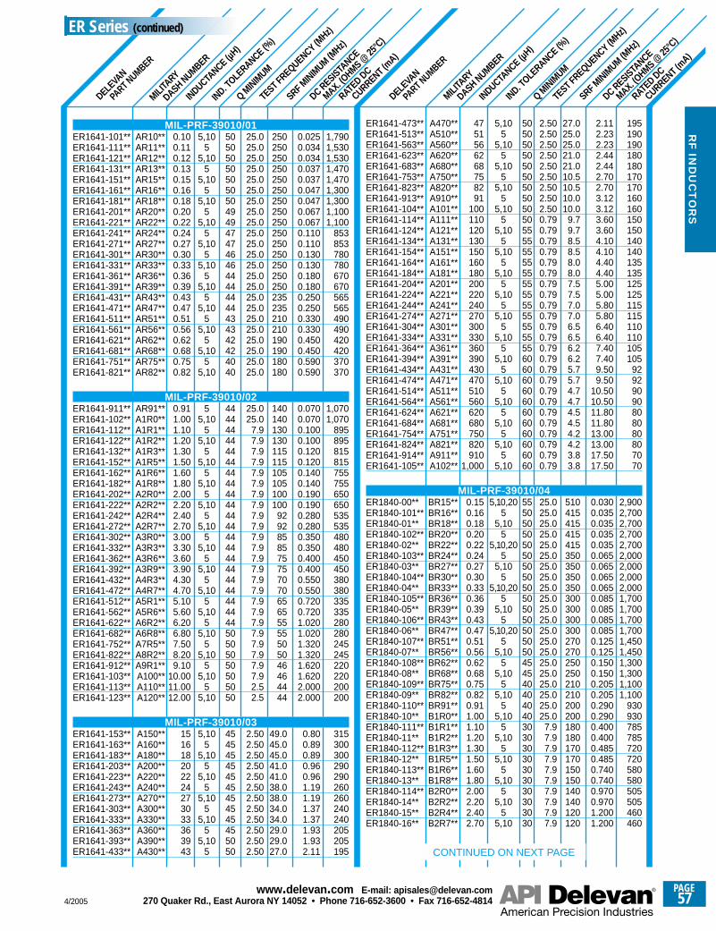
SRF MINIM
UM (MHz)
SRF MINIM
UM (MHz)
A470**A510**A560**A620**A680**A750**A820**A910**A101**A111**A121**A131**A151**A161**A181**A201**A221**A241**A271**A301**A331**A361**A391**A431**A471**A511**A561**A621**A681**A751**A821**A911**A102**
BR15**BR16**BR18**BR20**BR22**BR24**BR27**BR30**BR33**BR36**BR39**BR43**BR47**BR51**BR56**BR62**BR68**BR75**BR82**BR91**B1R0**B1R1**B1R2**B1R3**B1R5**B1R6**B1R8**B2R0**B2R2**B2R4**B2R7**
AR10**AR11**AR12**AR13**AR15**AR16**AR18**AR20**AR22**AR24**AR27**AR30**AR33**AR36**AR39**AR43**AR47**AR51**AR56**AR62**AR68**AR75**AR82**
AR91**A1R0**A1R1**A1R2**A1R3**A1R5**A1R6**A1R8**A2R0**A2R2**A2R4**A2R7**A3R0**A3R3**A3R6**A3R9**A4R3**A4R7**A5R1**A5R6**A6R2**A6R8**A7R5**A8R2**A9R1**A100**A110**A120**
A150**A160**A180**A200**A220**A240**A270**A300**A330**A360**A390**A430**
RATED DC
CURRENT (mA)
DC RESISTANCE
MAX. (OHMS @
25°C
)
TEST FREQUENCY (MHz)
Q MINIM
UM
IND. TOLE
RANCE (%)
MILITA
RY
DASH NUMBER
DELEVA
N
PART NUMBER
INDUCTANCE (µ
H)
RATED DC
CURRENT (mA)
DC RESISTANCE
MAX. (OHMS @
25°C
)
TEST FREQUENCY (MHz)
Q MINIM
UM
IND. TOLE
RANCE (%)
MILITA
RY
DASH NUMBER
DELEVA
N
PART NUMBER
INDUCTANCE (µ
H)
1,7901,5301,5301,4701,4701,3001,3001,1001,100
853853780780670670565565490490420420370370
1,0701,070
895895815815755755650650535535480480450450380380335335280280245245220220200200
315300300290290260260240240205205195
0.0250.0340.0340.0370.0370.0470.0470.0670.0670.1100.1100.1300.1300.1800.1800.2500.2500.3300.3300.4500.4500.5900.590
0.0700.0700.1000.1000.1200.1200.1400.1400.1900.1900.2800.2800.3500.3500.4000.4000.5500.5500.7200.7201.0201.0201.3201.3201.6201.6202.0002.000
0.800.890.890.960.961.191.191.371.371.931.932.11
250250250250250250250250250250250250250250250235235210210190190180180
140140130130115115105105100100
929285857575707065655555505046464444
49.045.045.041.041.038.038.034.034.029.029.027.0
25.025.025.025.025.025.025.025.025.025.025.025.025.025.025.025.025.025.025.025.025.025.025.0
25.025.0
7.97.97.97.97.97.97.97.97.97.97.97.97.97.97.97.97.97.97.97.97.97.97.97.92.52.5
2.502.502.502.502.502.502.502.502.502.502.502.50
5,105
5,105
5,105
5,105
5,105
5,105
5,105
5,105
5,105
5,105
5,105
5,10
55,10
55,10
55,10
55,10
55,10
55,10
55,10
55,10
55,10
55,10
55,10
55,10
55,10
55,10
5,105
5,105
5,105
5,105
5,105
5,105
5050505050505049494747464644444444434342424040
44444444444444444444444444444444444444444450505050505050
454545454545454545455050
0.100.110.120.130.150.160.180.200.220.240.270.300.330.360.390.430.470.510.560.620.680.750.82
0.911.001.101.201.301.501.601.802.002.202.402.703.003.303.603.904.304.705.105.606.206.807.508.209.10
10.0011.0012.00
151618202224273033363943
195190190180180170170160160150150140140135135125125115115110110105105
92929090808080807070
2,9002,7002,7002,7002,7002,0002,0002,0002,0001,7001,7001,7001,7001,4501,4501,3001,3001,1001,100
930930785785720720580580505505460460
2.112.232.232.442.442.702.703.123.123.603.604.104.104.404.405.005.005.805.806.406.407.407.409.509.50
10.5010.5011.8011.8013.0013.0017.5017.50
0.0300.0350.0350.0350.0350.0650.0650.0650.0650.0850.0850.0850.0850.1250.1250.1500.1500.2050.2050.2900.2900.4000.4000.4850.4850.7400.7400.9700.9701.2001.200
27.025.025.021.021.010.510.510.010.0
9.79.78.58.58.08.07.57.57.07.06.56.56.26.25.75.74.74.74.54.54.24.23.83.8
510415415415415350350350350300300300300270270250250210210200200180180170170150150140140120120
2.502.502.502.502.502.502.502.502.500.790.790.790.790.790.790.790.790.790.790.790.790.790.790.790.790.790.790.790.790.790.790.790.79
25.025.025.025.025.025.025.025.025.025.025.025.025.025.025.025.025.025.025.025.025.0
7.97.97.97.97.97.97.97.97.97.9
5,105
5,105
5,105
5,105
5,105
5,105
5,105
5,105
5,105
5,105
5,105
5,105
5,105
5,105
5,105
5,105
5,10
5,10,205
5,105
5,10,205
5,105
5,10,205
5,105
5,10,205
5,105
5,105
5,105
5,105
5,105
5,105
5,105
5,105
5,10
505050505050505050505555555555555555555555556060606060606060606060
55505050505050505050505050505045454040404030303030303030303030
4751566268758291
100110120130150160180200220240270300330360390430470510560620680750820910
1,000
0.150.160.180.200.220.240.270.300.330.360.390.430.470.510.560.620.680.750.820.911.001.101.201.301.501.601.802.002.202.402.70
ER1641-473**ER1641-513**ER1641-563**ER1641-623**ER1641-683**ER1641-753**ER1641-823**ER1641-913**ER1641-104**ER1641-114**ER1641-124**ER1641-134**ER1641-154**ER1641-164**ER1641-184**ER1641-204**ER1641-224**ER1641-244**ER1641-274**ER1641-304**ER1641-334**ER1641-364**ER1641-394**ER1641-434**ER1641-474**ER1641-514**ER1641-564**ER1641-624**ER1641-684**ER1641-754**ER1641-824**ER1641-914**ER1641-105**
MIL-PRF-39010/04ER1840-00**ER1840-101**ER1840-01**ER1840-102**ER1840-02**ER1840-103**ER1840-03**ER1840-104**ER1840-04**ER1840-105**ER1840-05**ER1840-106**ER1840-06**ER1840-107**ER1840-07**ER1840-108**ER1840-08**ER1840-109**ER1840-09**ER1840-110**ER1840-10**ER1840-111**ER1840-11**ER1840-112**ER1840-12**ER1840-113**ER1840-13**ER1840-114**ER1840-14**ER1840-15**ER1840-16**
CONTINUED ON NEXT PAGE
MIL-PRF-39010/01ER1641-101**ER1641-111**ER1641-121**ER1641-131**ER1641-151**ER1641-161**ER1641-181**ER1641-201**ER1641-221**ER1641-241**ER1641-271**ER1641-301**ER1641-331**ER1641-361**ER1641-391**ER1641-431**ER1641-471**ER1641-511**ER1641-561**ER1641-621**ER1641-681**ER1641-751**ER1641-821**
MIL-PRF-39010/02ER1641-911**ER1641-102**ER1641-112**ER1641-122**ER1641-132**ER1641-152**ER1641-162**ER1641-182**ER1641-202**ER1641-222**ER1641-242**ER1641-272**ER1641-302**ER1641-332**ER1641-362**ER1641-392**ER1641-432**ER1641-472**ER1641-512**ER1641-562**ER1641-622**ER1641-682**ER1641-752**ER1641-822**ER1641-912**ER1641-103**ER1641-113**ER1641-123**
MIL-PRF-39010/03ER1641-153**ER1641-163**ER1641-183**ER1641-203**ER1641-223**ER1641-243**ER1641-273**ER1641-303**ER1641-333**ER1641-363**ER1641-393**ER1641-433**
ER Series (continued)
4/2005
PAGE57
www.delevan .com E-mail: apisales@delevan .com270 Quaker Rd., East Aurora NY 14052 • Phone 716-652-3600 • Fax 716-652-4814
RF
IND
UC
TO
RS
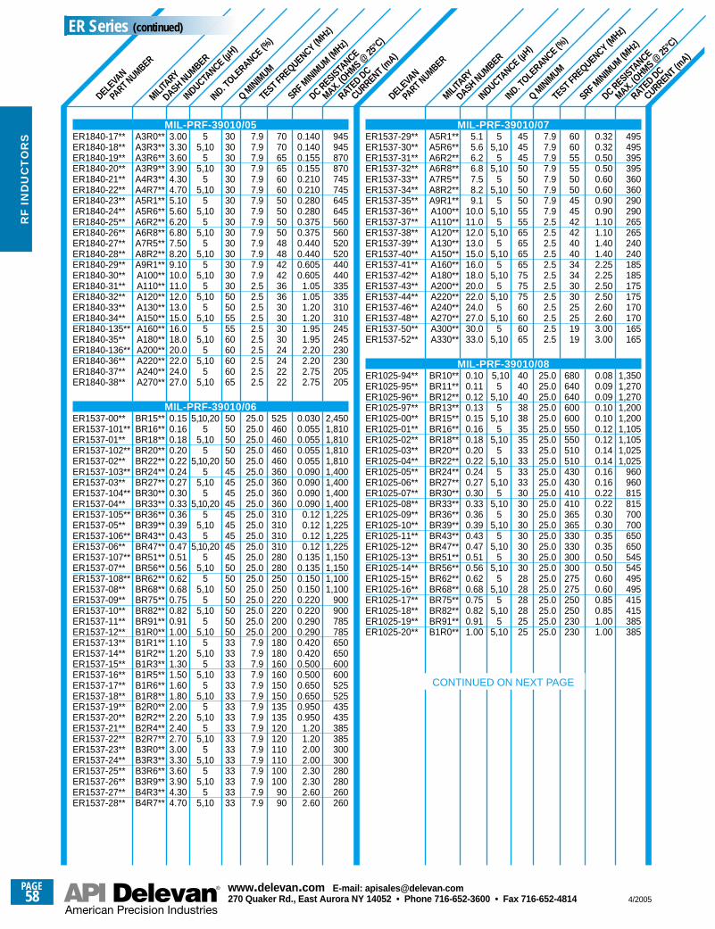
SRF MINIM
UM (MHz)
SRF MINIM
UM (MHz)
RATED DC
CURRENT (mA)
DC RESISTANCE
MAX. (OHMS @
25°C
)
TEST FREQUENCY (MHz)
Q MINIM
UM
IND. TOLE
RANCE (%)
MILITA
RY
DASH NUMBER
DELEVA
N
PART NUMBER
INDUCTANCE (µ
H)
RATED DC
CURRENT (mA)
DC RESISTANCE
MAX. (OHMS @
25°C
)
TEST FREQUENCY (MHz)
Q MINIM
UM
IND. TOLE
RANCE (%)
MILITA
RY
DASH NUMBER
DELEVA
N
PART NUMBER
INDUCTANCE (µ
H)
945945870870745745645645560560520520440440335335310310245245230230205205
2,4501,8101,8101,8101,8101,4001,4001,4001,4001,2251,2251,2251,2251,1501,1501,1001,100
900900785785650650600600525525435435385385300300280280260260
0.1400.1400.1550.1550.2100.2100.2800.2800.3750.3750.4400.4400.6050.605
1.051.051.201.201.951.952.202.202.752.75
0.0300.0550.0550.0550.0550.0900.0900.0900.090
0.120.120.120.12
0.1350.1350.1500.1500.2200.2200.2900.2900.4200.4200.5000.5000.6500.6500.9500.950
1.201.202.002.002.302.302.602.60
707065656060505050504848424236363030303024242222
525460460460460360360360360310310310310280280250250220220200200180180160160150150135135120120110110100100
9090
7.97.97.97.97.97.97.97.97.97.97.97.97.97.92.52.52.52.52.52.52.52.52.52.5
25.025.025.025.025.025.025.025.025.025.025.025.025.025.025.025.025.025.025.025.025.0
7.97.97.97.97.97.97.97.97.97.97.97.97.97.97.97.9
55,10
55,10
55,10
55,10
55,10
55,10
55,10
55,10
55,10
55,10
55,10
55,10
5,10,205
5,105
5,10,205
5,105
5,10,205
5,105
5,10,205
5,105
5,105
5,105
5,105
5,105
5,105
5,105
5,105
5,105
5,105
5,105
5,10
303030303030303030303030303030505055556060606065
50505050504545454545454545455050505050505033333333333333333333333333333333
3.003.303.603.904.304.705.105.606.206.807.508.209.1010.011.012.013.015.016.018.020.022.024.027.0
0.150.160.180.200.220.240.270.300.330.360.390.430.470.510.560.620.680.750.820.911.001.101.201.301.501.601.802.002.202.402.703.003.303.603.904.304.70
A3R0**A3R3**A3R6**A3R9**A4R3**A4R7**A5R1**A5R6**A6R2**A6R8**A7R5**A8R2**A9R1**A100**A110**A120**A130**A150**A160**A180**A200**A220**A240**A270**
BR15**BR16**BR18**BR20**BR22**BR24**BR27**BR30**BR33**BR36**BR39**BR43**BR47**BR51**BR56**BR62**BR68**BR75**BR82**BR91**B1R0**B1R1**B1R2**B1R3**B1R5**B1R6**B1R8**B2R0**B2R2**B2R4**B2R7**B3R0**B3R3**B3R6**B3R9**B4R3**B4R7**
495495395395360360290290265265240240185185175175170170165165
1,3501,2701,2701,2001,2001,1051,1051,0251,025
960960815815700700650650545545495495415415385385
0.320.320.500.500.600.600.900.901.101.101.401.402.252.252.502.502.602.603.003.00
0.080.090.090.100.100.120.120.140.140.160.160.220.220.300.300.350.350.500.500.600.600.850.851.001.00
6060555550504545424240403434303025251919
680640640600600550550510510430430410410365365330330300300275275250250230230
7.97.97.97.97.97.97.97.92.52.52.52.52.52.52.52.52.52.52.52.5
25.025.025.025.025.025.025.025.025.025.025.025.025.025.025.025.025.025.025.025.025.025.025.025.025.0
55,10
55,10
55,10
55,10
55,10
55,10
55,10
55,10
55,10
55,10
5,105
5,105
5,105
5,105
5,105
5,105
5,105
5,105
5,105
5,105
5,105
5,105
5,10
4545455050505055556565656575757560606065
40404038383535333333333030303030303030282828282525
5.15.66.26.87.58.29.1
10.011.012.013.015.016.018.020.022.024.027.030.033.0
0.100.110.120.130.150.160.180.200.220.240.270.300.330.360.390.430.470.510.560.620.680.750.820.911.00
A5R1**A5R6**A6R2**A6R8**A7R5**A8R2**A9R1**A100**A110**A120**A130**A150**A160**A180**A200**A220**A240**A270**A300**A330**
BR10**BR11**BR12**BR13**BR15**BR16**BR18**BR20**BR22**BR24**BR27**BR30**BR33**BR36**BR39**BR43**BR47**BR51**BR56**BR62**BR68**BR75**BR82**BR91**B1R0**
MIL-PRF-39010/05ER1840-17**ER1840-18**ER1840-19**ER1840-20**ER1840-21**ER1840-22**ER1840-23**ER1840-24**ER1840-25**ER1840-26**ER1840-27**ER1840-28**ER1840-29**ER1840-30**ER1840-31**ER1840-32**ER1840-33**ER1840-34**ER1840-135**ER1840-35**ER1840-136**ER1840-36**ER1840-37**ER1840-38**
MIL-PRF-39010/06ER1537-00**ER1537-101**ER1537-01**ER1537-102**ER1537-02**ER1537-103**ER1537-03**ER1537-104**ER1537-04**ER1537-105**ER1537-05**ER1537-106**ER1537-06**ER1537-107**ER1537-07**ER1537-108**ER1537-08**ER1537-09**ER1537-10**ER1537-11**ER1537-12**ER1537-13**ER1537-14**ER1537-15**ER1537-16**ER1537-17**ER1537-18**ER1537-19**ER1537-20**ER1537-21**ER1537-22**ER1537-23**ER1537-24**ER1537-25**ER1537-26**ER1537-27**ER1537-28**
MIL-PRF-39010/07ER1537-29**ER1537-30**ER1537-31**ER1537-32**ER1537-33**ER1537-34**ER1537-35**ER1537-36**ER1537-37**ER1537-38**ER1537-39**ER1537-40**ER1537-41**ER1537-42**ER1537-43**ER1537-44**ER1537-46**ER1537-48**ER1537-50**ER1537-52**
MIL-PRF-39010/08ER1025-94**ER1025-95**ER1025-96**ER1025-97**ER1025-00**ER1025-01**ER1025-02**ER1025-03**ER1025-04**ER1025-05**ER1025-06**ER1025-07**ER1025-08**ER1025-09**ER1025-10**ER1025-11**ER1025-12**ER1025-13**ER1025-14**ER1025-15**ER1025-16**ER1025-17**ER1025-18**ER1025-19**ER1025-20**
CONTINUED ON NEXT PAGE
ER Series (continued)
PAGE58
www.delevan .com E-mail: apisales@delevan .com270 Quaker Rd., East Aurora NY 14052 • Phone 716-652-3600 • Fax 716-652-4814 4/2005
RF
IN
DU
CT
OR
S
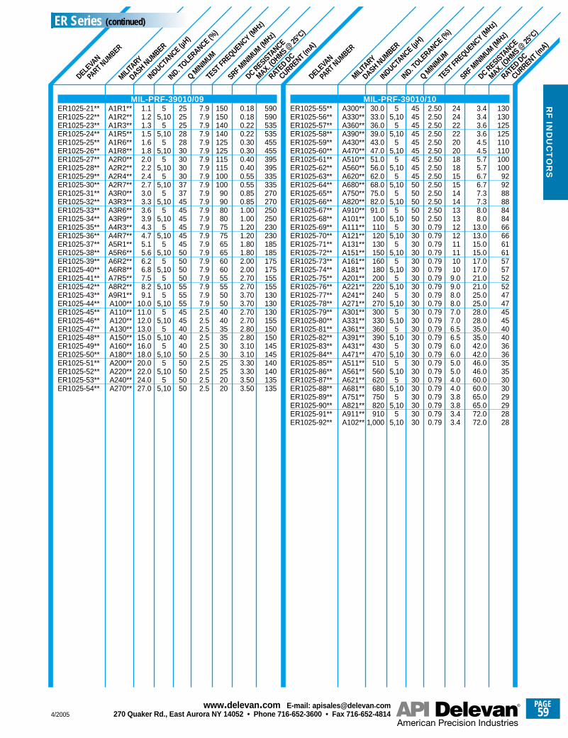
SRF MINIM
UM (MHz)
SRF MINIM
UM (MHz)
RATED DC
CURRENT (mA)
DC RESISTANCE
MAX. (OHMS @
25°C
)
TEST FREQUENCY (MHz)
Q MINIM
UM
IND. TOLE
RANCE (%)
MILITA
RY
DASH NUMBER
DELEVA
N
PART NUMBER
INDUCTANCE (µ
H)
RATED DC
CURRENT (mA)
DC RESISTANCE
MAX. (OHMS @
25°C
)
TEST FREQUENCY (MHz)
Q MINIM
UM
IND. TOLE
RANCE (%)
MILITA
RY
DASH NUMBER
DELEVA
N
PART NUMBER
INDUCTANCE (µ
H)
590590535535455455395395335335270270250250230230185185175175155155130130130155150150145145140140135135
0.180.180.220.220.300.300.400.400.550.550.850.851.001.001.201.201.801.802.002.002.702.703.703.702.702.702.802.803.103.103.303.303.503.50
150150140140125125115115100100
909080807575656560605555505040403535303025252020
7.97.97.97.97.97.97.97.97.97.97.97.97.97.97.97.97.97.97.97.97.97.97.97.92.52.52.52.52.52.52.52.52.52.5
55,10
55,10
55,10
55,10
55,10
55,10
55,10
55,10
55,10
55,10
55,10
55,10
55,10
55,10
55,10
55,10
55,10
25252528283030303037374545454545455050505055555545454040405050505050
1.11.21.31.51.61.82.02.22.42.73.03.33.63.94.34.75.15.66.26.87.58.29.1
10.011.012.013.015.016.018.020.022.024.027.0
A1R1**A1R2**A1R3**A1R5**A1R6**A1R8**A2R0**A2R2**A2R4**A2R7**A3R0**A3R3**A3R6**A3R9**A4R3**A4R7**A5R1**A5R6**A6R2**A6R8**A7R5**A8R2**A9R1**A100**A110**A120**A130**A150**A160**A180**A200**A220**A240**A270**
130130125125110110100100
929288888484666661615757525247474545404036363535303029292828
3.43.43.63.64.54.55.75.76.76.77.37.38.08.0
13.013.015.015.017.017.021.021.025.025.028.028.035.035.042.042.046.046.060.060.065.065.072.072.0
2424222220201818151514141313121211111010
9.09.08.08.07.07.06.56.56.06.05.05.04.04.03.83.83.43.4
2.502.502.502.502.502.502.502.502.502.502.502.502.502.500.790.790.790.790.790.790.790.790.790.790.790.790.790.790.790.790.790.790.790.790.790.790.790.79
55,10
55,10
55,10
55,10
55,10
55,10
55,10
55,10
55,10
55,10
55,10
55,10
55,10
55,10
55,10
55,10
55,10
55,10
55,10
4545454545454545455050505050303030303030303030303030303030303030303030303030
30.033.036.039.043.047.051.056.062.068.075.082.091.0100110120130150160180200220240270300330360390430470510560620680750820910
1,000
A300**A330**A360**A390**A430**A470**A510**A560**A620**A680**A750**A820**A910**A101**A111**A121**A131**A151**A161**A181**A201**A221**A241**A271**A301**A331**A361**A391**A431**A471**A511**A561**A621**A681**A751**A821**A911**A102**
MIL-PRF-39010/09ER1025-21**ER1025-22**ER1025-23**ER1025-24**ER1025-25**ER1025-26**ER1025-27**ER1025-28**ER1025-29**ER1025-30**ER1025-31**ER1025-32**ER1025-33**ER1025-34**ER1025-35**ER1025-36**ER1025-37**ER1025-38**ER1025-39**ER1025-40**ER1025-41**ER1025-42**ER1025-43**ER1025-44**ER1025-45**ER1025-46**ER1025-47**ER1025-48**ER1025-49**ER1025-50**ER1025-51**ER1025-52**ER1025-53**ER1025-54**
MIL-PRF-39010/10ER1025-55**ER1025-56**ER1025-57**ER1025-58**ER1025-59**ER1025-60**ER1025-61**ER1025-62**ER1025-63**ER1025-64**ER1025-65**ER1025-66**ER1025-67**ER1025-68**ER1025-69**ER1025-70**ER1025-71**ER1025-72**ER1025-73**ER1025-74**ER1025-75**ER1025-76**ER1025-77**ER1025-78**ER1025-79**ER1025-80**ER1025-81**ER1025-82**ER1025-83**ER1025-84**ER1025-85**ER1025-86**ER1025-87**ER1025-88**ER1025-89**ER1025-90**ER1025-91**ER1025-92**
ER Series (continued)
4/2005
PAGE59
www.delevan .com E-mail: apisales@delevan .com270 Quaker Rd., East Aurora NY 14052 • Phone 716-652-3600 • Fax 716-652-4814
RF
IND
UC
TO
RS
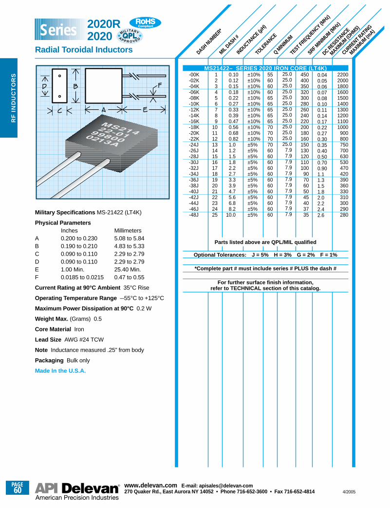
SRF MINIM
UM (MHz)
DASH NUMBER*
MILDASH #
INDUCTANCE (µ
H)
TOLE
RANCE
Q MINIM
UM
TEST FREQUENCY (MHz)
DC RESISTANCE
MAXIMUM (O
HMS)
CURRENT RATING
MAXIMUM (m
A)
2200200018001600150014001300120011001000
900800750700630530470420390360330310300290280
0.040.050.060.070.080.100.110.140.170.220.270.300.350.400.500.700.901.11.31.51.82.02.22.42.6
25.025.025.025.025.025.025.025.025.025.025.025.025.0
7.97.97.97.97.97.97.97.97.97.97.97.9
450400350320300280260240220200180160150130120110100
9070605045403735
55606060656565656570707070606060606060606060606060
±10%±10%±10%±10%±10%±10%±10%±10%±10%±10%±10%±10%±5%±5%±5%±5%±5%±5%±5%±5%±5%±5%±5%±5%±5%
123456789
10111213141516171819202122232425
0.100.120.150.180.220.270.330.390.470.560.680.821.01.21.51.82.22.73.33.94.75.66.88.2
10.0Military Specifications MS-21422 (LT4K)
Physical ParametersInches Millimeters
A 0.200 to 0.230 5.08 to 5.84B 0.190 to 0.210 4.83 to 5.33C 0.090 to 0.110 2.29 to 2.79D 0.090 to 0.110 2.29 to 2.79E 1.00 Min. 25.40 Min.F 0.0185 to 0.0215 0.47 to 0.55
Current Rating at 90°C Ambient 35°C Rise
Operating Temperature Range –55°C to +125°C
Maximum Power Dissipation at 90°C 0.2 W
Weight Max. (Grams) 0.5
Core Material Iron
Lead Size AWG #24 TCW
Note Inductance measured .25” from body
Packaging Bulk only
Made In the U.S.A.
MS21422– SERIES 2020 IRON CORE (LT4K)-00K-02K-04K-06K-08K-10K-12K-14K-16K-18K-20K-22K-24J-26J-28J-30J-32J-34J-36J-38J-40J-42J-44J-46J-48J
Parts listed above are QPL/MIL qualified
Optional Tolerances: J = 5% H = 3% G = 2% F = 1%
*Complete part # must include series # PLUS the dash #
For further surface finish information, refer to TECHNICAL section of this catalog.
2020R 2020
Radial Toroidal Inductors
MIL I TA RY
AP P R O V E D
Series
PAGE60
www.delevan .com E-mail: apisales@delevan .com270 Quaker Rd., East Aurora NY 14052 • Phone 716-652-3600 • Fax 716-652-4814 4/2005
RF
IN
DU
CT
OR
S
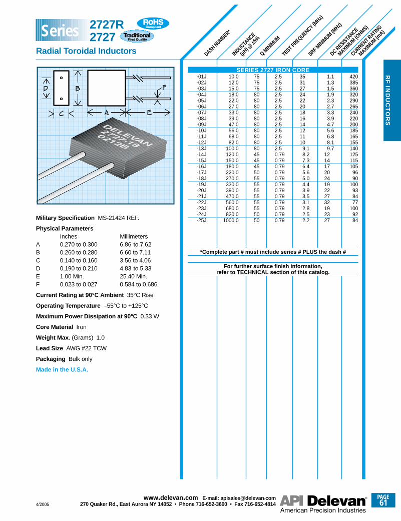
SRF MINIM
UM (MHz)
DASH NUMBER*
INDUCTANCE
(µH) @
±5%
Q MINIM
UM
TEST FREQUENCY (MHz)
DC RESISTANCE
MAXIMUM (O
HMS)
CURRENT RATING
MAXIMUM (m
A)
420385360320290265240220200185165155140125115105
9690
100938477
1009284
1.11.31.51.92.32.73.33.94.75.66.88.19.7
121417202419222732192327
353127242220181614121110
9.18.27.36.45.65.04.43.93.53.12.82.52.2
2.52.52.52.52.52.52.52.52.52.52.52.52.50.790.790.790.790.790.790.790.790.790.790.790.79
75757580808080808080808080454545505555555555555050
10.012.015.018.022.027.033.039.047.056.068.082.0
100.0120.0150.0180.0220.0270.0330.0390.0470.0560.0680.0820.0
1000.0Military Specification MS-21424 REF.
Physical ParametersInches Millimeters
A 0.270 to 0.300 6.86 to 7.62B 0.260 to 0.280 6.60 to 7.11C 0.140 to 0.160 3.56 to 4.06D 0.190 to 0.210 4.83 to 5.33E 1.00 Min. 25.40 Min.F 0.023 to 0.027 0.584 to 0.686
Current Rating at 90°C Ambient 35°C Rise
Operating Temperature –55°C to +125°C
Maximum Power Dissipation at 90°C 0.33 W
Core Material Iron
Weight Max. (Grams) 1.0
Lead Size AWG #22 TCW
Packaging Bulk only
Made in the U.S.A.
SERIES 2727 IRON CORE-01J-02J-03J-04J-05J-06J-07J-08J-09J-10J-11J-12J-13J-14J-15J-16J-17J-18J-19J-20J-21J-22J-23J-24J-25J
*Complete part # must include series # PLUS the dash #
For further surface finish information, refer to TECHNICAL section of this catalog.
2727R2727
Radial Toroidal Inductors
Series
4/2005
PAGE61
www.delevan .com E-mail: apisales@delevan .com270 Quaker Rd., East Aurora NY 14052 • Phone 716-652-3600 • Fax 716-652-4814
RF
IND
UC
TO
RS
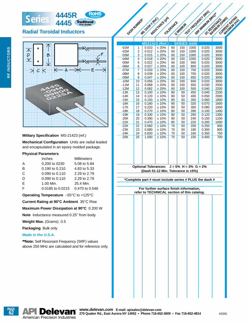
SRF MINIM
UM (MHz)*
*
DASH NUMBER*
MIL DASH #
(Ref.
)
INDUCTANCE (µ
H)
TOLE
RANCE
Q MINIM
UM
TEST FREQUENCY (MHz)
DC RESISTANCE
MAXIMUM (O
HMS)
CURRENT RATING
MAXIMUM (m
A)
300030003000300030003000300030003000300025002200220020001800160015001400130011501000
900800750700
0.0200.0200.0200.0200.0200.0200.0200.0200.0200.0200.0300.0400.0400.0500.0600.0700.0800.1000.1200.1500.2000.2500.3000.3500.400
1000100010001000
900800750700650600550500450400350320300280260240220200180160150
150150150150100100100100100100100100
50505050505050505050505050
60606060606060606060606080808080808080808070707070
± 20%± 20%± 20%± 20%± 20%± 20%± 20%± 20%± 20%± 20%± 20%± 20%± 10%± 10%± 10%± 10%± 10%± 10%± 10%± 10%± 10%± 10%± 10%± 10%± 10%
123456789
10111213141516171819202122232425
0.0100.0120.0150.0180.0220.0270.0330.0390.0470.0560.0680.0820.1000.1200.1500.1800.2200.2700.3300.3900.4700.5600.6800.8201.000Military Specification MS-21423 (ref.)
Mechanical Configuration Units are radial leadedand encapsulated in an epoxy molded package.
Physical ParametersInches Millimeters
A 0.200 to 0230 5.08 to 5.84B 0.190 to 0.210 4.83 to 5.33C 0.090 to 0.110 2.29 to 2.79D 0.090 to 0.110 2.29 to 2.79E 1.00 Min. 25.4 Min.F 0.0185 to 0.0215 0.470 to 0.546
Operating Temperature –55°C to +125°C
Current Rating at 90°C Ambient 35°C Rise
Maximum Power Dissipation at 90°C 0.200 W
Note Inductance measured 0.25" from body.
Weight Max. (Grams) 0.5
Packaging Bulk only
Made in the U.S.A.
*** Note: Self Resonant Frequency (SRF) valuesabove 250 MHz are calculated and for reference only.
MS21423 (Ref.) – SERIES 4445-01M-02M-03M-04M-05M-06M-07M-08M-09M-10M-11M-12M-13K-14K-15K-16K-17K-18K-19K-20K-21K-22K-23K-24K-25K
Optional Tolerances: J = 5% H = 3% G = 2%(Dash 01-12 Min. Tolerance is ±5%)
*Complete part # must include series # PLUS the dash #
For further surface finish information, refer to TECHNICAL section of this catalog.
4445R4445
Radial Toroidal Inductors
Series
PAGE62
www.delevan .com E-mail: apisales@delevan .com270 Quaker Rd., East Aurora NY 14052 • Phone 716-652-3600 • Fax 716-652-4814 4/2005
RF
IN
DU
CT
OR
S
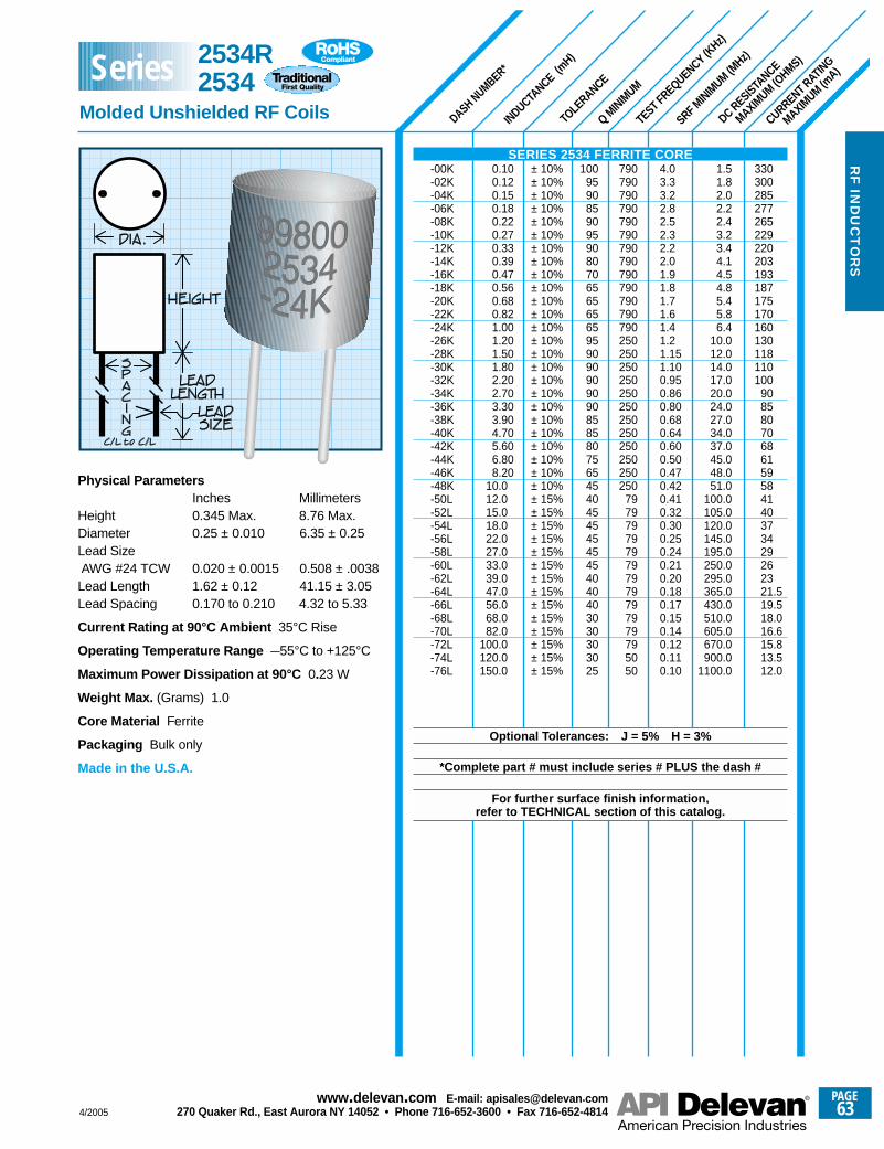
SRF MINIM
UM (MHz)
DASH NUMBER*
INDUCTANCE (m
H)
TOLE
RANCE
Q MINIM
UM
TEST FREQUENCY (KHz)
DC RESISTANCE
MAXIMUM (O
HMS)
CURRENT RATING
MAXIMUM (m
A)
330300285277265229220203193187175170160130118110100
90858070686159584140373429262321.519.518.016.615.813.512.0
1.51.82.02.22.43.23.44.14.54.85.45.86.4
10.012.014.017.020.024.027.034.037.045.048.051.0
100.0105.0120.0145.0195.0250.0295.0365.0430.0510.0605.0670.0900.0
1100.0
4.03.33.22.82.52.32.22.01.91.81.71.61.41.21.151.100.950.860.800.680.640.600.500.470.420.410.320.300.250.240.210.200.180.170.150.140.120.110.10
790790790790790790790790790790790790790250250250250250250250250250250250250
7979797979797979797979795050
1009590859095908070656565659590909090908585807565454045454545454040403030303025
± 10%± 10%± 10%± 10%± 10%± 10%± 10%± 10%± 10%± 10%± 10%± 10%± 10%± 10%± 10%± 10%± 10%± 10%± 10%± 10%± 10%± 10%± 10%± 10%± 10%± 15%± 15%± 15%± 15%± 15%± 15%± 15%± 15%± 15%± 15%± 15%± 15%± 15%± 15%
0.100.120.150.180.220.270.330.390.470.560.680.821.001.201.501.802.202.703.303.904.705.606.808.20
10.012.015.018.022.027.033.039.047.056.068.082.0
100.0120.0150.0
Physical ParametersInches Millimeters
Height 0.345 Max. 8.76 Max.Diameter 0.25 ± 0.010 6.35 ± 0.25Lead SizeAWG #24 TCW 0.020 ± 0.0015 0.508 ± .0038Lead Length 1.62 ± 0.12 41.15 ± 3.05Lead Spacing 0.170 to 0.210 4.32 to 5.33
Current Rating at 90°C Ambient 35°C Rise
Operating Temperature Range –55°C to +125°C
Maximum Power Dissipation at 90°C 0.23 W
Weight Max. (Grams) 1.0
Core Material Ferrite
Packaging Bulk only
Made in the U.S.A.
SERIES 2534 FERRITE CORE-00K-02K-04K-06K-08K-10K-12K-14K-16K-18K-20K-22K-24K-26K-28K-30K-32K-34K-36K-38K-40K-42K-44K-46K-48K-50L-52L-54L-56L-58L-60L-62L-64L-66L-68L-70L-72L-74L-76L
Optional Tolerances: J = 5% H = 3%
*Complete part # must include series # PLUS the dash #
For further surface finish information, refer to TECHNICAL section of this catalog.
2534R2534
Molded Unshielded RF Coils
Series
4/2005
PAGE63
www.delevan .com E-mail: apisales@delevan .com270 Quaker Rd., East Aurora NY 14052 • Phone 716-652-3600 • Fax 716-652-4814
RF
IND
UC
TO
RS
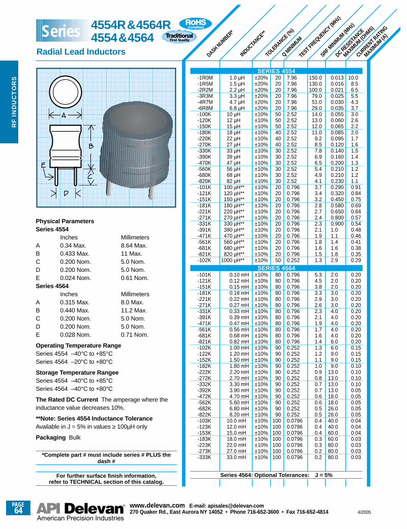
SRF MINIM
UM (MHz)
DASH NUMBER*
INDUCTANCE**
TOLE
RANCE (%)
Q MINIM
UM
TEST FREQUENCY (MHz)
DC RESISTANCE
MAXIMUM (O
HMS)
CURRENT RATING
MAXIMUM (A
)
10.08.56.55.54.33.73.02.62.22.01.71.61.51.41.31.21.21.10.910.840.750.690.640.570.540.480.460.410.380.350.29
0.200.200.200.200.200.200.200.200.200.200.200.200.150.150.150.100.100.100.100.050.050.050.050.050.040.040.040.030.030.030.03
0.0130.0160.0210.0250.0300.0350.0550.0600.0650.0850.0950.1200.1400.1600.2000.2100.2100.2300.2900.3200.4500.5800.6500.8000.9001.01.11.41.61.82.9
2.02.02.03.03.03.04.04.04.04.04.06.06.09.09.09.0
13.013.013.013.018.018.026.026.040.040.060.060.080.080.080.0
150.0130.0100.0
79.051.029.014.013.012.011.0
9.28.57.86.96.55.44.94.13.73.43.22.82.72.42.32.11.91.81.61.51.3
5.34.53.83.32.92.62.32.11.91.71.61.41.31.21.11.00.90.80.70.70.60.60.50.50.40.40.40.30.30.20.2
7.967.967.967.967.967.962.522.522.522.522.522.522.522.522.522.522.522.520.7960.7960.7960.7960.7960.7960.7960.7960.7960.7960.7960.7960.252
0.7960.7960.7960.7960.7960.7960.7960.7960.7960.7960.7960.7960.2520.2520.2520.2520.2520.2520.2520.2520.2520.2520.2520.2520.07960.07960.07960.07960.07960.07960.0796
20202020202050505040404030303030303020202020202020202020202050
808080808080808080808080909090909090909090909090
100100100100100100100
±20%±20%±20%±20%±20%±20%±10%±10%±10%±10%±10%±10%±10%±10%±10%±10%±10%±10%±10%±10%±10%±10%±10%±10%±10%±10%±10%±10%±10%±10%±10%
±10%±10%±10%±10%±10%±10%±10%±10%±10%±10%±10%±10%±10%±10%±10%±10%±10%±10%±10%±10%±10%±10%±10%±10%±10%±10%±10%±10%±10%±10%±10%
1.0 µH1.5 µH2.2 µH3.3 µH4.7 µH6.8 µH
10 µH12 µH15 µH18 µH22 µH27 µH33 µH39 µH47 µH56 µH68 µH82 µH
100 µH**120 µH**150 µH**180 µH**220 µH**270 µH**330 µH**390 µH**470 µH**560 µH**680 µH**820 µH**
1000 µH**
0.10 mH0.12 mH0.15 mH0.18 mH0.22 mH0.27 mH0.33 mH0.39 mH0.47 mH0.56 mH0.68 mH0.82 mH1.00 mH1.20 mH1.50 mH1.80 mH2.20 mH2.70 mH3.30 mH3.90 mH4.70 mH5.60 mH6.80 mH8.20 mH
10.0 mH12.0 mH15.0 mH18.0 mH22.0 mH27.0 mH33.0 mH
Physical ParametersSeries 4554
Inches MillimetersA 0.34 Max. 8.64 Max.B 0.433 Max. 11 Max.C 0.200 Nom. 5.0 Nom.D 0.200 Nom. 5.0 Nom.E 0.024 Nom. 0.61 Nom.Series 4564
Inches MillimetersA 0.315 Max. 8.0 Max.B 0.440 Max. 11.2 Max.C 0.200 Nom. 5.0 Nom.D 0.200 Nom. 5.0 Nom.E 0.028 Nom. 0.71 Nom.
Operating Temperature RangeSeries 4554 –40°C to +85°CSeries 4564 –20°C to +80°C
Storage Temperature RangeeSeries 4554 –40°C to +85°CSeries 4564 –40°C to +80°C
The Rated DC Current The amperage where theinductance value decreases 10%.
**Note: Series 4554 Inductance ToleranceAvailable in J = 5% in values ≥ 100µH only
Packaging Bulk
*Complete part # must include series # PLUS thedash #
For further surface finish information, refer to TECHNICAL section of this catalog.
SERIES 4554-1R0M-1R5M-2R2M-3R3M-4R7M-6R8M-100K-120K-150K-180K-220K-270K-330K-390K-470K-560K-680K-820K-101K-121K-151K-181K-221K-271K-331K-391K-471K-561K-681K-821K-102K
SERIES 4564-101K-121K-151K-181K-221K-271K-331K-391K-471K-561K-681K-821K-102K-122K-152K-182K-222K-272K-332K-392K-472K-562K-682K-822K-103K-123K-153K-183K-223K-273K-333K
Series 4564: Optional Tolerances: J = 5%
4554R&4564R4554&4564
Radial Lead Inductors
Series
PAGE64
www.delevan .com E-mail: apisales@delevan .com270 Quaker Rd., East Aurora NY 14052 • Phone 716-652-3600 • Fax 716-652-4814 4/2005
RF
IN
DU
CT
OR
S
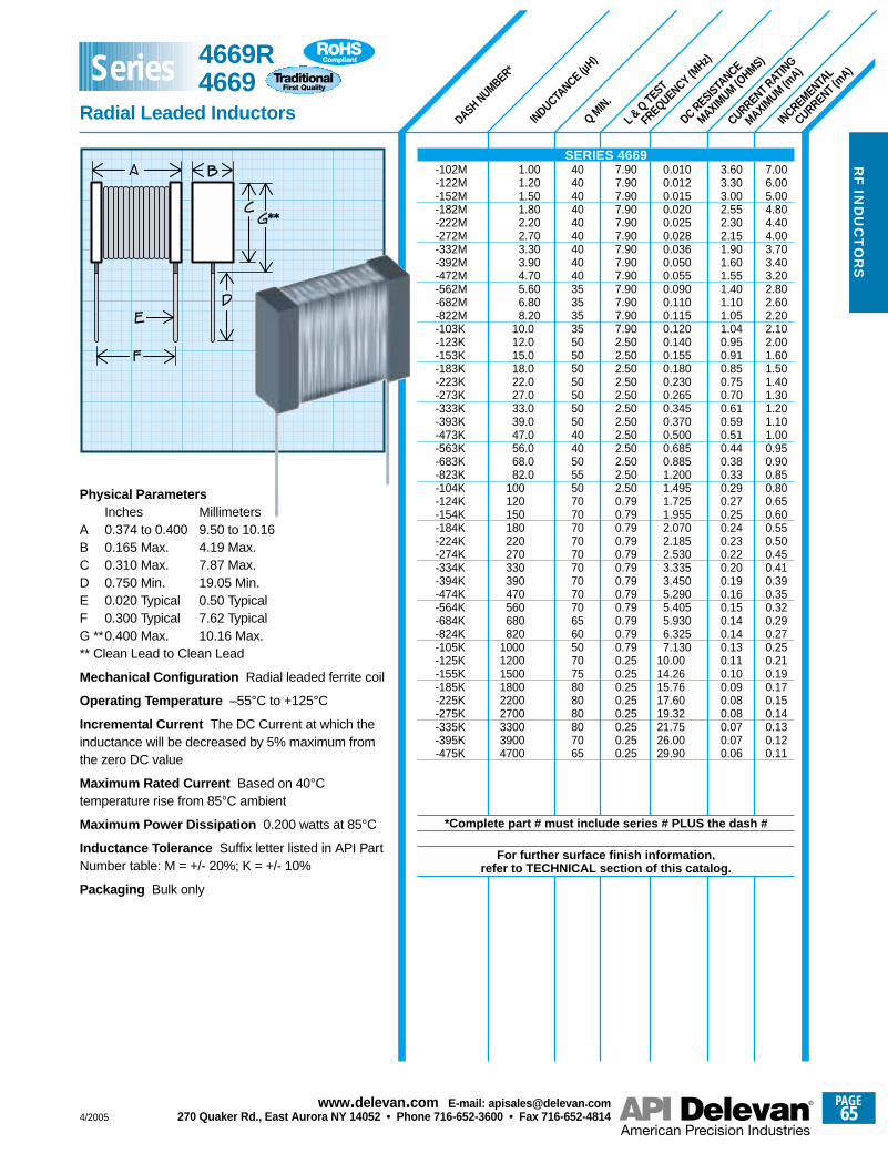
DASH NUMBER*
INCREMENTAL
CURRENT (mA)
CURRENT RATING
MAXIMUM (m
A)
INDUCTANCE (µ
H)
Q MIN.
L & Q TEST
FREQUENCY (MHz)
DC RESISTANCE
MAXIMUM (O
HMS)
7.006.005.004.804.404.003.703.403.202.802.602.202.102.001.601.501.401.301.201.101.000.950.900.850.800.650.600.550.500.450.410.390.350.320.290.270.250.210.190.170.150.140.130.120.11
3.603.303.002.552.302.151.901.601.551.401.101.051.040.950.910.850.750.700.610.590.510.440.380.330.290.270.250.240.230.220.200.190.160.150.140.140.130.110.100.090.080.080.070.070.06
0.0100.0120.0150.0200.0250.0280.0360.0500.0550.0900.1100.1150.1200.1400.1550.1800.2300.2650.3450.3700.5000.6850.8851.2001.4951.7251.9552.0702.1852.5303.3353.4505.2905.4055.9306.3257.130
10.0014.2615.7617.6019.3221.7526.0029.90
7.907.907.907.907.907.907.907.907.907.907.907.907.902.502.502.502.502.502.502.502.502.502.502.502.500.790.790.790.790.790.790.790.790.790.790.790.790.250.250.250.250.250.250.250.25
404040404040404040353535355050505050505040405055507070707070707070706560507075808080807065
1.001.201.501.802.202.703.303.904.705.606.808.20
10.012.015.018.022.027.033.039.047.056.068.082.0
100120150180220270330390470560680820
100012001500180022002700330039004700
Physical ParametersInches Millimeters
A 0.374 to 0.400 9.50 to 10.16B 0.165 Max. 4.19 Max.C 0.310 Max. 7.87 Max.D 0.750 Min. 19.05 Min.E 0.020 Typical 0.50 TypicalF 0.300 Typical 7.62 TypicalG **0.400 Max. 10.16 Max.** Clean Lead to Clean Lead
Mechanical Configuration Radial leaded ferrite coil
Operating Temperature –55°C to +125°C
Incremental Current The DC Current at which theinductance will be decreased by 5% maximum fromthe zero DC value
Maximum Rated Current Based on 40°Ctemperature rise from 85°C ambient
Maximum Power Dissipation 0.200 watts at 85°C
Inductance Tolerance Suffix letter listed in API PartNumber table: M = +/- 20%; K = +/- 10%
Packaging Bulk only
SERIES 4669-102M-122M-152M-182M-222M-272M-332M-392M-472M-562M-682M-822M-103K-123K-153K-183K-223K-273K-333K-393K-473K-563K-683K-823K-104K-124K-154K-184K-224K-274K-334K-394K-474K-564K-684K-824K-105K-125K-155K-185K-225K-275K-335K-395K-475K
*Complete part # must include series # PLUS the dash #
For further surface finish information, refer to TECHNICAL section of this catalog.
4669R4669
Radial Leaded Inductors
Series
4/2005
PAGE65
www.delevan .com E-mail: apisales@delevan .com270 Quaker Rd., East Aurora NY 14052 • Phone 716-652-3600 • Fax 716-652-4814
RF
IND
UC
TO
RS
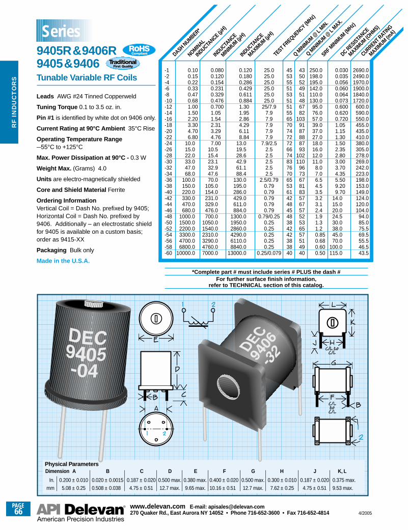
SRF MINIM
UM (MHz)
CURRENT RATING
MAXIMUM (m
A)
DC RESISTANCE
MAXIMUM (O
HMS)
Q MINIM
UM @ L
MAX.
Q MINIM
UM @ L
MIN.
TEST FREQUENCY (MHz)
INDUCTANCE
MAXIMUM (µ
H)
INDUCTANCE
MINIMUM (µ
H)
NOMINAL
INDUCTANCE (µ
H)
DASH NUMBER*
-1-2-4-6-8-10-12-14-16-18-20-22-24-26-28-30-32-34-36-38-40-42-44-46-48-50-52-54-56-58-60
*Complete part # must include series # PLUS the dash #For further surface finish information,
refer to TECHNICAL section of this catalog.
250.0198.0195.0142.0110.0130.0
95.076.057.039.037.027.018.016.012.011.0
8.07.06.54.53.53.23.12.41.91.31.20.850.680.600.50
0.0300.0350.0560.0600.0640.0730.6000.6200.7201.051.151.301.502.352.803.003.704.355.509.209.70
14.015.020.024.530.038.045.070.0
100.0115.0
2690.02490.01970.01900.01840.01720.0
600.0590.0550.0455.0435.0410.0380.0305.0278.0269.0242.0223.0198.0153.0149.0124.0120.0104.0
94.085.075.569.555.546.543.5
4350524951486782
1039187888793
102110
967367818357675752536557514940
45535551535151556570747272667483767065536142484548384242383840
25.025.025.025.025.025.0
25/7.97.97.97.97.97.9
7.9/2.52.52.52.52.52.5
2.5/0.790.790.790.790.790.79
0.79/0.250.250.250.250.250.25
0.25/0.079
0.1200.1800.2860.4290.6110.8841.301.952.864.296.118.84
13.019.528.642.961.188.4
130.0195.0286.0429.0611.0884.0
1300.01950.02860.04290.06110.08840.0
13000.0
0.0800.1200.1540.2310.3290.4760.7001.051.542.313.294.767.00
10.515.423.132.947.670.0
105.0154.0231.0329.0476.0700.0
1050.01540.02310.03290.04760.07000.0
0.100.150.220.330.470.681.001.502.203.304.706.80
10.015.022.033.047.068.0
100.0150.0220.0330.0470.0680.0
1000.01500.02200.03300.04700.06800.0
10000.0
Leads AWG #24 Tinned Copperweld
Tuning Torque 0.1 to 3.5 oz. in.
Pin #1 is identified by white dot on 9406 only.
Current Rating at 90°C Ambient 35°C Rise
Operating Temperature Range –55°C to +125°C
Max. Power Dissipation at 90°C - 0.3 W
Weight Max. (Grams) 4.0
Units are electro-magnetically shielded
Core and Shield Material Ferrite
Ordering InformationVertical Coil = Dash No. prefixed by 9405;Horizontal Coil = Dash No. prefixed by9406. Additionally – an electrostatic shieldfor 9405 is available on a custom basis;order as 9415-XX
Packaging Bulk only
Made in the U.S.A.
A
0.200 ± 0.010
5.08 ± 0.25
Physical ParametersDimension
In.
mm
A B C D
0.500 max.
12.7 max.
E
0.380 max.
9.65 max.
F G H J K, L
0.375 max.
9.53 max.
0.020 ± 0.0015
0.508 ± 0.038
0.187 ± 0.020
4.75 ± 0.51
0.400 ± 0.020
10.16 ± 0.51
0.500 max.
12.7 max.
0.300 ± 0.010
7.62 ± 0.25
0.187 ± 0.020
4.75 ± 0.51
9405R&9406R9405&9406Tunable Variable RF Coils
Series
PAGE66
www.delevan .com E-mail: apisales@delevan .com270 Quaker Rd., East Aurora NY 14052 • Phone 716-652-3600 • Fax 716-652-4814 4/2005
RF
IN
DU
CT
OR
S
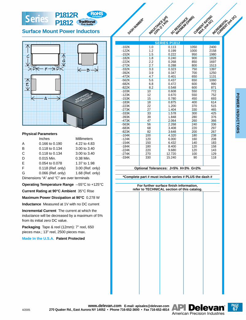
CURRENT RATING
MAX. (mA DC)
INCREMENTAL
CURRENT (mA DC)
DC RESISTANCE
MAXIMUM (O
HMS)
DASH NUMBER*
INDUCTANCE (µ
H)
±10%
@ 1
KHz
Physical ParametersInches Millimeters
A 0.166 to 0.190 4.22 to 4.83B 0.118 to 0.134 3.00 to 3.40C 0.118 to 0.134 3.00 to 3.40D 0.015 Min. 0.38 Min.E 0.054 to 0.078 1.37 to 1.98F 0.118 (Ref. only) 3.00 (Ref. only)G 0.066 (Ref. only) 1.68 (Ref. only)Dimensions “A” and “C” are over terminals
Operating Temperature Range –55°C to +125°C
Current Rating at 90°C Ambient 35°C Rise
Maximum Power Dissipation at 90°C 0.278 W
Inductance Measured at 1V with no DC current
Incremental Current The current at which theinductance will be decreased by a maximum of 5%from its initial zero DC value.
Packaging Tape & reel (12mm): 7" reel, 650pieces max.; 13" reel, 2500 pieces max.
Made In the U.S.A. Patent Protected
2400215819801828169715131397125011311060
990871772752693614515465425376366336297267238208183158143129118
10501000
950900850800750700650650600600550550450400370330300280260240220200180160140120120100
90
0.1130.1990.2220.2400.2680.2880.3230.3470.4010.4370.4720.5480.6080.6700.7800.8751.2001.4041.5781.8482.0642.2683.4083.6484.3206.0006.4328.4009.680
12.72015.240
1.01.21.51.82.22.73.33.94.75.66.88.2
101215182227333947566882
100120150180220270330
SERIES P1812-102K-122K-152K-182K-222K-272K-332K-392K-472K-562K-682K-822K-103K-123K-153K-183K-223K-273K-333K-393K-473K-563K-683K-823K-104K-124K-154K-184K-224K-274K-334K
Optional Tolerances: J=5% H=3% G=2%
*Complete part # must include series # PLUS the dash #
For further surface finish information, refer to TECHNICAL section of this catalog.
P1812RP1812
Surface Mount Power Inductors
Series
4/2005
PAGE67
www.delevan .com E-mail: apisales@delevan .com270 Quaker Rd., East Aurora NY 14052 • Phone 716-652-3600 • Fax 716-652-4814
PO
WE
R IN
DU
CT
OR
S
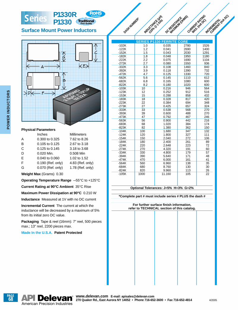
CURRENT RATING
MAX. (mA DC)
INCREMENTAL
CURRENT (mA DC)
DC RESISTANCE
MAXIMUM (O
HMS)
DASH NUMBER*
INDUCTANCE (µ
H)
±10%
@ 1
KHz
15261400129111801104
936840732720612600600564516432420348324270270246216174150132111106
89726057484135302622
278026902030195016901550146013901330111010801020
946912858817694657568488467442384362347327272261223191179171161138130113105
0.0350.0410.0430.0480.0750.0800.1080.1180.1250.1450.1650.1800.2160.2520.2880.3280.3840.4250.5380.6000.7920.9001.0201.3801.6801.8002.0402.4002.6484.3204.8005.6406.0006.9608.7609.960
11.160
1.01.21.51.82.22.73.33.94.75.66.88.2
101215182227333947566882
100120150180220270330390470560680820
1000
Physical ParametersInches Millimeters
A 0.300 to 0.325 7.62 to 8.26B 0.105 to 0.125 2.67 to 3.18C 0.125 to 0.145 3.18 to 3.68D 0.020 Min. 0.508 MinE 0.040 to 0.060 1.02 to 1.52F 0.190 (Ref. only) 4.83 (Ref. only)G 0.070 (Ref. only) 1.78 (Ref. only)
Weight Max (Grams) 0.30
Operating Temperature Range –55°C to +125°C
Current Rating at 90°C Ambient 35°C Rise
Maximum Power Dissipation at 90°C 0.210 W
Inductance Measured at 1V with no DC current
Incremental Current The current at which theinductance will be decreased by a maximum of 5%from its initial zero DC value.
Packaging Tape & reel (16mm): 7" reel, 500 piecesmax.; 13" reel, 2200 pieces max.
Made In the U.S.A. Patent Protected
SERIES P1330 FERRITE CORE-102K-122K-152K-182K-222K-272K-332K-392K-472K-562K-682K-822K-103K-123K-153K-183K-223K-273K-333K-393K-473K-563K-683K-823K-104K-124K-154K-184K-224K-274K-334K-394K-474K-564K-684K-824K-105K
Optional Tolerances: J=5% H=3% G=2%
*Complete part # must include series # PLUS the dash #
For further surface finish information, refer to TECHNICAL section of this catalog.
P1330RP1330
Surface Mount Power Inductors
Series
PAGE68
www.delevan .com E-mail: apisales@delevan .com270 Quaker Rd., East Aurora NY 14052 • Phone 716-652-3600 • Fax 716-652-4814 4/2005
PO
WE
R I
ND
UC
TO
RS
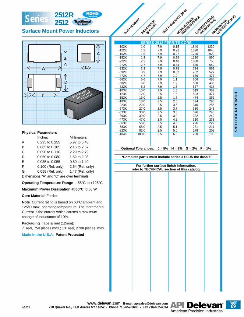
DASH NUMBER*
INDUCTANCE
(µH) ±
10%
TEST FREQUENCY (MHz)
DC RESISTANCE
MAXIMUM (O
HMS)
CURRENT RATING
MAXIMUM (m
A)
INCREMENTAL
CURRENT DC (mA)
12301040
920890750649551527477455435418389377355296255248245242233222211209195
16401390122011801000
865734702636606580557519503474394340330326322310296281278260
0.150.210.270.290.400.540.750.821.01.11.21.31.51.61.82.63.53.73.83.94.24.65.15.66.0
7.97.97.97.97.97.97.97.97.97.97.97.97.92.52.52.52.52.52.52.52.52.52.52.52.5
1.01.21.51.82.22.73.33.94.75.66.88.2
10.012.015.018.022.027.033.039.047.056.068.082.0
100.0Physical ParametersInches Millimeters
A 0.235 to 0.255 5.97 to 6.48B 0.085 to 0.105 2.16 to 2.67C 0.090 to 0.110 2.29 to 2.79D 0.060 to 0.080 1.52 to 2.03E 0.035 to 0.055 0.89 to 1.40F 0.100 (Ref. only) 2.54 (Ref. only)G 0.058 (Ref. only) 1.47 (Ref. only)Dimensions “A” and “C” are over terminals
Operating Temperature Range –55°C to +125°C
Maximum Power Dissipation at 60°C 0 .56 W
Core Material Ferrite
Note Current rating is based on 60°C ambient and125°C max. operating temperature. The IncrementalCurrent is the current which causes a maximumchange of inductance of 10%.
Packaging Tape & reel (12mm):7" reel, 750 pieces max.; 13" reel, 2700 pieces max.
Made In the U.S.A. Patent Protected
SERIES 2512 FERRITE CORE-102K-122K-152K-182K-222K-272K-332K-392K-472K-562K-682K-822K-103K-123K-153K-183K-223K-273K-333K-393K-473K-563K-683K-823K-104K
Optional Tolerances: J = 5% H = 3% G = 2% F = 1%
*Complete part # must include series # PLUS the dash #
For further surface finish information, refer to TECHNICAL section of this catalog.
2512R2512
Surface Mount Power Inductors
Series
4/2005
PAGE69
www.delevan .com E-mail: apisales@delevan .com270 Quaker Rd., East Aurora NY 14052 • Phone 716-652-3600 • Fax 716-652-4814
PO
WE
R IN
DU
CT
OR
S
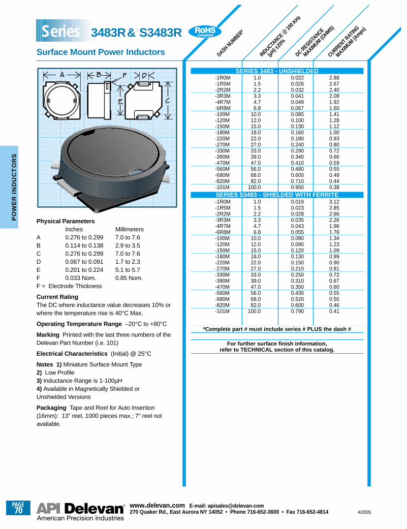
CURRENT RATING
MAXIMUM (A
mps)
DC RESISTANCE
MAXIMUM (O
HMS)
INDUCTANCE @
100 K
Hz
(µH) ±
20%
Physical ParametersInches Millimeters
A 0.276 to 0.299 7.0 to 7.6B 0.114 to 0.138 2.9 to 3.5C 0.276 to 0.299 7.0 to 7.6D 0.067 to 0.091 1.7 to 2.3E 0.201 to 0.224 5.1 to 5.7F 0.033 Nom. 0.85 Nom.F = Electrode Thickness
Current RatingThe DC where inductance value decreases 10% orwhere the temperature rise is 40°C Max.
Operating Temperature Range –20°C to +80°C
Marking Printed with the last three numbers of theDelevan Part Number (i.e. 101)
Electrical Characteristics (Initial) @ 25°C
Notes 1) Miniature Surface Mount Type2) Low Profile3) Inductance Range is 1-100µH4) Available in Magnetically Shielded orUnshielded Versions
Packaging Tape and Reel for Auto Insertion(16mm): 13" reel, 1000 pieces max.; 7" reel notavailable.
DASH NUMBER*
2.882.672.402.081.921.601.411.281.121.000.930.800.720.660.590.550.490.440.38
3.122.852.662.261.961.761.341.231.090.990.900.810.720.670.600.550.500.460.41
0.0220.0260.0320.0410.0490.0670.0850.1000.1300.1600.1800.2400.2900.3400.4100.4800.6000.7100.950
0.0190.0230.0280.0350.0430.0550.0800.0900.1200.1300.1500.2100.2500.3100.3500.4300.5200.6000.790
1.01.52.23.34.76.8
10.012.015.018.022.027.033.039.047.056.068.082.0
100.0
1.01.52.23.34.76.8
10.012.015.018.022.027.033.039.047.056.068.082.0
100.0
SERIES 3483 - UNSHIELDED-1R0M-1R5M-2R2M-3R3M-4R7M-6R8M-100M-120M-150M-180M-220M-270M-330M-390M-470M-560M-680M-820M-101MSERIES S3483 - SHIELDED WITH FERRITE-1R0M-1R5M-2R2M-3R3M-4R7M-6R8M-100M-120M-150M-180M-220M-270M-330M-390M-470M-560M-680M-820M-101M
*Complete part # must include series # PLUS the dash #
For further surface finish information, refer to TECHNICAL section of this catalog.
3483R& S3483R
Surface Mount Power Inductors
Series
PAGE70
www.delevan .com E-mail: apisales@delevan .com270 Quaker Rd., East Aurora NY 14052 • Phone 716-652-3600 • Fax 716-652-4814 4/2005
PO
WE
R I
ND
UC
TO
RS
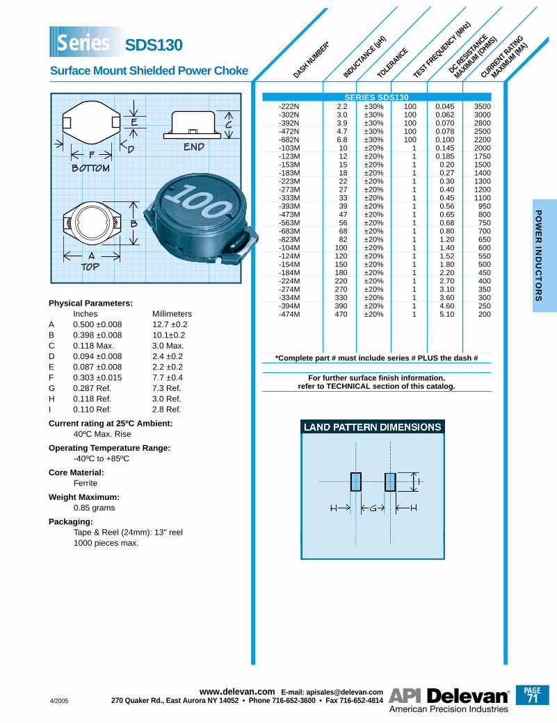
Physical Parameters:Inches Millimeters
A 0.500 ±0.008 12.7 ±0.2 B 0.398 ±0.008 10.1±0.2C 0.118 Max. 3.0 Max.D 0.094 ±0.008 2.4 ±0.2 E 0.087 ±0.008 2.2 ±0.2F 0.303 ±0.015 7.7 ±0.4G 0.287 Ref. 7.3 Ref.H 0.118 Ref. 3.0 Ref.I 0.110 Ref. 2.8 Ref.
Current rating at 25ºC Ambient:40ºC Max. Rise
Operating Temperature Range:-40ºC to +85ºC
Core Material:Ferrite
Weight Maximum:0.85 grams
Packaging:Tape & Reel (24mm): 13" reel 1000 pieces max.
DASH NUMBER*
INDUCTANCE (µ
H)
TOLE
RANCE
TEST FREQUENCY (MHz)
DC RESISTANCE
MAXIMUM (O
HMS)
CURRENT RATING
MAXIMUM (M
A)
Surface Mount Shielded Power Choke
Series SDS130
SERIES SDS130-222N 2.2 ±30% 100 0.045 3500-302N 3.0 ±30% 100 0.062 3000-392N 3.9 ±30% 100 0.070 2800-472N 4.7 ±30% 100 0.078 2500-682N 6.8 ±30% 100 0.100 2200-103M 10 ±20% 1 0.145 2000-123M 12 ±20% 1 0.185 1750-153M 15 ±20% 1 0.20 1500-183M 18 ±20% 1 0.27 1400-223M 22 ±20% 1 0.30 1300-273M 27 ±20% 1 0.40 1200-333M 33 ±20% 1 0.45 1100-393M 39 ±20% 1 0.56 950-473M 47 ±20% 1 0.65 800-563M 56 ±20% 1 0.68 750-683M 68 ±20% 1 0.80 700-823M 82 ±20% 1 1.20 650-104M 100 ±20% 1 1.40 600-124M 120 ±20% 1 1.52 550-154M 150 ±20% 1 1.80 500-184M 180 ±20% 1 2.20 450-224M 220 ±20% 1 2.70 400-274M 270 ±20% 1 3.10 350-334M 330 ±20% 1 3.60 300-394M 390 ±20% 1 4.60 250-474M 470 ±20% 1 5.10 200
*Complete part # must include series # PLUS the dash #
For further surface finish information, refer to TECHNICAL section of this catalog.
4/2005
PAGE71
www.delevan .com E-mail: apisales@delevan .com270 Quaker Rd., East Aurora NY 14052 • Phone 716-652-3600 • Fax 716-652-4814
PO
WE
R IN
DU
CT
OR
S
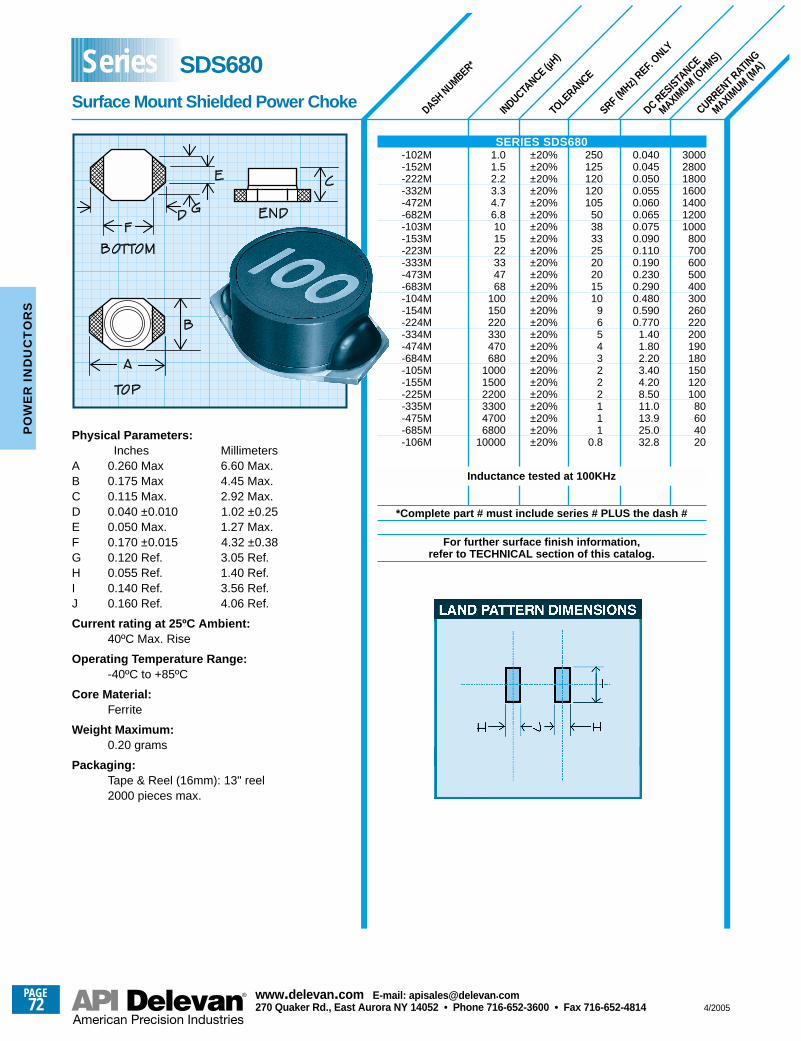
Physical Parameters:Inches Millimeters
A 0.260 Max 6.60 Max.B 0.175 Max 4.45 Max.C 0.115 Max. 2.92 Max.D 0.040 ±0.010 1.02 ±0.25 E 0.050 Max. 1.27 Max.F 0.170 ±0.015 4.32 ±0.38G 0.120 Ref. 3.05 Ref.H 0.055 Ref. 1.40 Ref.I 0.140 Ref. 3.56 Ref.J 0.160 Ref. 4.06 Ref.
Current rating at 25ºC Ambient:40ºC Max. Rise
Operating Temperature Range:-40ºC to +85ºC
Core Material:Ferrite
Weight Maximum:0.20 grams
Packaging:Tape & Reel (16mm): 13" reel 2000 pieces max.
DASH NUMBER*
INDUCTANCE (µ
H)
TOLE
RANCE
SRF (MHz)
REF. ONLY
DC RESISTA
NCE
MAXIMUM (O
HMS)
CURRENT RATIN
G
MAXIMUM (M
A)
SERIES SDS680-102M 1.0 ±20% 250 0.040 3000-152M 1.5 ±20% 125 0.045 2800-222M 2.2 ±20% 120 0.050 1800-332M 3.3 ±20% 120 0.055 1600-472M 4.7 ±20% 105 0.060 1400-682M 6.8 ±20% 50 0.065 1200-103M 10 ±20% 38 0.075 1000-153M 15 ±20% 33 0.090 800-223M 22 ±20% 25 0.110 700-333M 33 ±20% 20 0.190 600-473M 47 ±20% 20 0.230 500-683M 68 ±20% 15 0.290 400-104M 100 ±20% 10 0.480 300-154M 150 ±20% 9 0.590 260-224M 220 ±20% 6 0.770 220-334M 330 ±20% 5 1.40 200-474M 470 ±20% 4 1.80 190-684M 680 ±20% 3 2.20 180-105M 1000 ±20% 2 3.40 150-155M 1500 ±20% 2 4.20 120-225M 2200 ±20% 2 8.50 100-335M 3300 ±20% 1 11.0 80-475M 4700 ±20% 1 13.9 60-685M 6800 ±20% 1 25.0 40-106M 10000 ±20% 0.8 32.8 20
Inductance tested at 100KHz
*Complete part # must include series # PLUS the dash #
For further surface finish information, refer to TECHNICAL section of this catalog.
Surface Mount Shielded Power Choke
Series SDS680
PAGE72
www.delevan .com E-mail: apisales@delevan .com270 Quaker Rd., East Aurora NY 14052 • Phone 716-652-3600 • Fax 716-652-4814 4/2005
PO
WE
R I
ND
UC
TO
RS
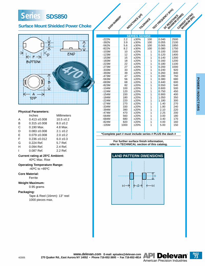
Physical Parameters:Inches Millimeters
A 0.413 ±0.008 10.5 ±0.2 B 0.315 ±0.008 8.0 ±0.2C 0.190 Max. 4.8 Max.D 0.083 ±0.008 2.1 ±0.2 E 0.079 ±0.008 2.0 ±0.2F 0.236 ±0.012 6.0 ±0.3G 0.224 Ref. 5.7 Ref.H 0.094 Ref. 2.4 Ref.I 0.087 Ref. 2.2 Ref.
Current rating at 25ºC Ambient:40ºC Max. Rise
Operating Temperature Range:-40ºC to +85ºC
Core Material:Ferrite
Weight Maximum:0.95 grams
Packaging:Tape & Reel (16mm): 13" reel 1000 pieces max.
DASH NUMBER*
INDUCTANCE (µ
H)
TOLE
RANCE
TEST FREQUENCY (KHz)
DC RESISTA
NCE
MAXIMUM (O
HMS)
CURRENT RATIN
G
MAXIMUM (M
A)
Surface Mount Shielded Power Choke
Series SDS850
SERIES SDS850-222N 2.2 ±30% 100 0.040 2500-392N 3.9 ±30% 100 0.055 2100-562N 5.6 ±30% 100 0.065 1950-822N 8.2 ±30% 100 0.080 1750-103M 10 ±20% 1 0.100 1500-123M 12 ±20% 1 0.120 1400-153M 15 ±20% 1 0.140 1300-183M 18 ±20% 1 0.160 1200-223M 22 ±20% 1 0.180 1100-273M 27 ±20% 1 0.200 1000-333M 33 ±20% 1 0.240 920-393M 39 ±20% 1 0.260 840-473M 47 ±20% 1 0.280 750-563M 56 ±20% 1 0.380 680-683M 68 ±20% 1 0.440 600-823M 82 ±20% 1 0.550 540-104M 100 ±20% 1 0.600 500-124M 120 ±20% 1 0.750 450-154M 150 ±20% 1 0.900 400-184M 180 ±20% 1 1.050 350-224M 220 ±20% 1 1.180 300-274M 270 ±20% 1 1.40 270-334M 330 ±20% 1 1.80 240-394M 390 ±20% 1 2.10 220-474M 470 ±20% 1 2.25 200-564M 560 ±20% 1 3.00 180-684M 680 ±20% 1 3.40 170-824M 820 ±20% 1 4.00 160-105M 1000 ±20% 1 5.00 150
*Complete part # must include series # PLUS the dash #
For further surface finish information, refer to TECHNICAL section of this catalog.
4/2005
PAGE73
www.delevan .com E-mail: apisales@delevan .com270 Quaker Rd., East Aurora NY 14052 • Phone 716-652-3600 • Fax 716-652-4814
PO
WE
R IN
DU
CT
OR
S
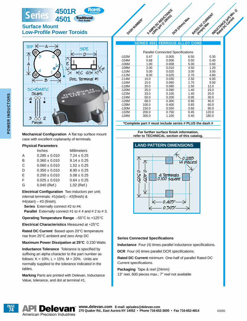
DASH NUMBER*
0 AMPS DC IN
DUCTANCE
±20%
(µH @
10KHz)
DCR (Ohm
s) Max
.
RATED DC CURRENT
(Amps) M
ax
INDUCTANCE (µ
H) Min.
@
Rated D
C Curren
t
0.300.400.601.203.004.806.009.50
12.015.020.030.040.060.090.0
120.0180.0
0.470.681.002.005.008.00
10.015.020.025.033.050.068.0
100.0150.0200.0300.0
6.505.505.004.503.002.702.501.701.501.401.400.950.800.650.600.450.40
0.0050.0060.0080.0100.0200.0250.0300.0600.0800.0900.1050.2000.3000.4000.5500.7501.100
Mechanical Configuration A flat top surface mountcase with excellent coplanarity of terminals.
Physical ParametersInches Millimeters
A 0.285 ± 0.010 7.24 ± 0.25B 0.360 ± 0.010 9.14 ± 0.25C 0.060 ± 0.010 1.52 ± 0.25D 0.350 ± 0.010 8.90 ± 0.25 E 0.200 ± 0.010 5.08 ± 0.25F 0.025 ± 0.010 0.64 ± 0.25G 0.040 (Ref.) 1.02 (Ref.)
Electrical Configuration Two inductors per unit;internal terminals: #1(start) – #2(finish) (start) – #3 (finish).Series Externally connect #2 to #4.Parallel Externally connect #1 to # 4 and # 2 to # 3.
Operating Temperature Range –55°C to +125°C
Electrical Characteristics Measured at +25°C
Rated DC Current Based upon 20°C temperaturerise from 25°C ambient and zero Amp DC
Maximum Power Dissipation at 25°C 0.230 Watts
Inductance Tolerance Tolerance is specified bysuffixing an alpha character to the part number asfollows: K = 10%, L = 15%. M = 20%. Units arenormally supplied to the tolerance indicated in thetables.
Marking Parts are printed with Delevan, InductanceValue, tolerance, and dot at terminal #1.
SERIES 4501 FERROUS ALLOY CORE
Parallel Connected Specifications-102M-104M-106M-108M-110M-112M-114M-116M-118M-120M-122M-124M-126M-128M-130M-132M-134M
*Complete part # must include series # PLUS the dash #
For further surface finish information, refer to TECHNICAL section of this catalog.
Series Connected Specifications
Inductance Four (4) times parallel inductance specifications.
DCR Four (4) times parallel DCR specifications.
Rated DC Current minimum One-half of parallel Rated DCCurrent specifications.
Packaging Tape & reel (24mm):13" reel, 600 pieces max.; 7" reel not available
LAND PATTERN DIMENSIONS
4501R4501
Surface Mount Low-Profile Power Toroids
Series
PAGE74
www.delevan .com E-mail: apisales@delevan .com270 Quaker Rd., East Aurora NY 14052 • Phone 716-652-3600 • Fax 716-652-4814 4/2005
PO
WE
R I
ND
UC
TO
RS
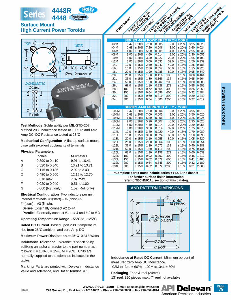
TOLE
RANCE
TOLE
RANCE
SERIES DC RESISTANCE
MAX. (OHMS)
RATED SERIES
DC CURRENT MAX. (A
MPS)
0 AMPS DC SERIES
INDUCTANCE (µ
H)
PARALL
EL DC
RESIST. MAX. (O
HMS)
RATED PA
RALLEL
DC CURRENT. MAX. (A
MPS)
0 AMPS DC PA
RALLEL
INDUCTANCE (µ
H)
DASH NUMBER*
3.953.602.952.301.651.501.251.150.950.800.650.600.550.360.320.300.27
3.953.503.252.952.201.751.701.501.051.000.900.750.600.460.410.320.31
0.0200.0240.0360.0560.1080.1320.1880.2280.3400.4640.6640.8080.9522.2602.7843.2404.012
0.0160.0200.0240.0280.0560.0760.0800.0960.2200.2540.2880.4440.6321.2121.4882.1802.688
± 20%± 20%± 20%± 20%± 20%± 20%± 15%± 15%± 15%± 15%± 15%± 15%± 15%± 15%± 15%± 15%± 15%
± 20%± 20%± 20%± 20%± 20%± 20%± 15%± 15%± 15%± 15%± 15%± 15%± 15%± 15%± 15%± 15%± 15%
2.003.004.008.00
20.032.040.060.080.0
100132200272400600800
1200
2.003.004.008.00
20.032.040.060.080.0
100132200272400600800
1200
0.0050.0060.0090.0140.0270.0330.0470.0570.0850.1160.1660.2020.2380.5650.6960.8101.003
0.0040.0050.0060.0070.0140.0190.0200.0240.0550.0640.0720.1110.1580.3030.3720.5450.672
7.907.205.904.603.303.002.502.301.901.601.301.201.100.720.640.600.54
7.907.006.505.904.403.503.403.002.102.001.801.501.200.920.820.640.62
± 20%± 20%± 20%± 20%± 20%± 20%± 15%± 15%± 15%± 15%± 15%± 15%± 15%± 15%± 15%± 15%± 15%
± 20%± 20%± 20%± 20%± 20%± 20%± 15%± 15%± 15%± 15%± 15%± 15%± 15%± 15%± 15%± 15%± 15%
0.470.681.002.005.008.00
10.015.020.025.033.050.068.0
100150200300
0.470.681.002.005.008.00
10.015.020.025.033.050.068.0
100150200300
Test Methods Solderability per MIL-STD-202,Method 208. Inductance tested at 10 KHZ and zeroAmp DC. DC Resistance tested at 25°C
Mechanical Configuration A flat top surface mountcase with excellent coplanarity of terminals.
Physical ParametersInches Millimeters
A 0.390 to 0.410 9.91 to 10.41B 0.520 to 0.540 13.21 to 13.71C 0.115 to 0.135 2.92 to 3.43D 0.480 to 0.500 12.19 to 12.70E 0.310 max. 7.87 max.F 0.020 to 0.040 0.51 to 1.02G 0.060 (Ref. only) 1.52 (Ref. only)
Electrical Configuration Two inductors per unit;internal terminals: #1(start) – #2(finish) (start) – #3 (finish).Series Externally connect #2 to #4.Parallel Externally connect #1 to # 4 and # 2 to # 3.
Operating Temperature Range –55°C to +125°C
Rated DC Current Based upon 20°C temperaturerise from 25°C ambient and zero Amp DC
Maximum Power Dissipation at 25°C 0.313 Watts
Inductance Tolerance Tolerance is specified bysuffixing an alpha character to the part number asfollows: K = 10%, L = 15%. M = 20%. Units arenormally supplied to the tolerance indicated in thetables.
Marking Parts are printed with Delevan, InductanceValue and Tolerance, and Dot at Terminal # 1.
LAND PATTERN DIMENSIONS
Inductance at Rated DC Current Minimum percent ofmeasured zero Amp DC Inductance.-02M to -34L = 60%; -102M to134L = 50%
Packaging Tape & reel (24mm):13" reel, 350 pieces max.; 7" reel not available
SERIES 4448 POWDERED IRON CORE-02M-04M-06M-08M-10M-12M-14L-16L-18L-20L-22L-24L-26L-28L-30L-32L-34L
SERIES 4448 FERROUS ALLOY CORE-102M-104M-106M-108M-110M-112M-114L-116L-118L-120L-122L-124L-126L-128L-130L-132L-134L
*Complete part # must include series # PLUS the dash #For further surface finish information,
refer to TECHNICAL section of this catalog.
4448R4448
Surface Mount High Current Power Toroids
Series
4/2005
PAGE75
www.delevan .com E-mail: apisales@delevan .com270 Quaker Rd., East Aurora NY 14052 • Phone 716-652-3600 • Fax 716-652-4814
PO
WE
R IN
DU
CT
OR
S
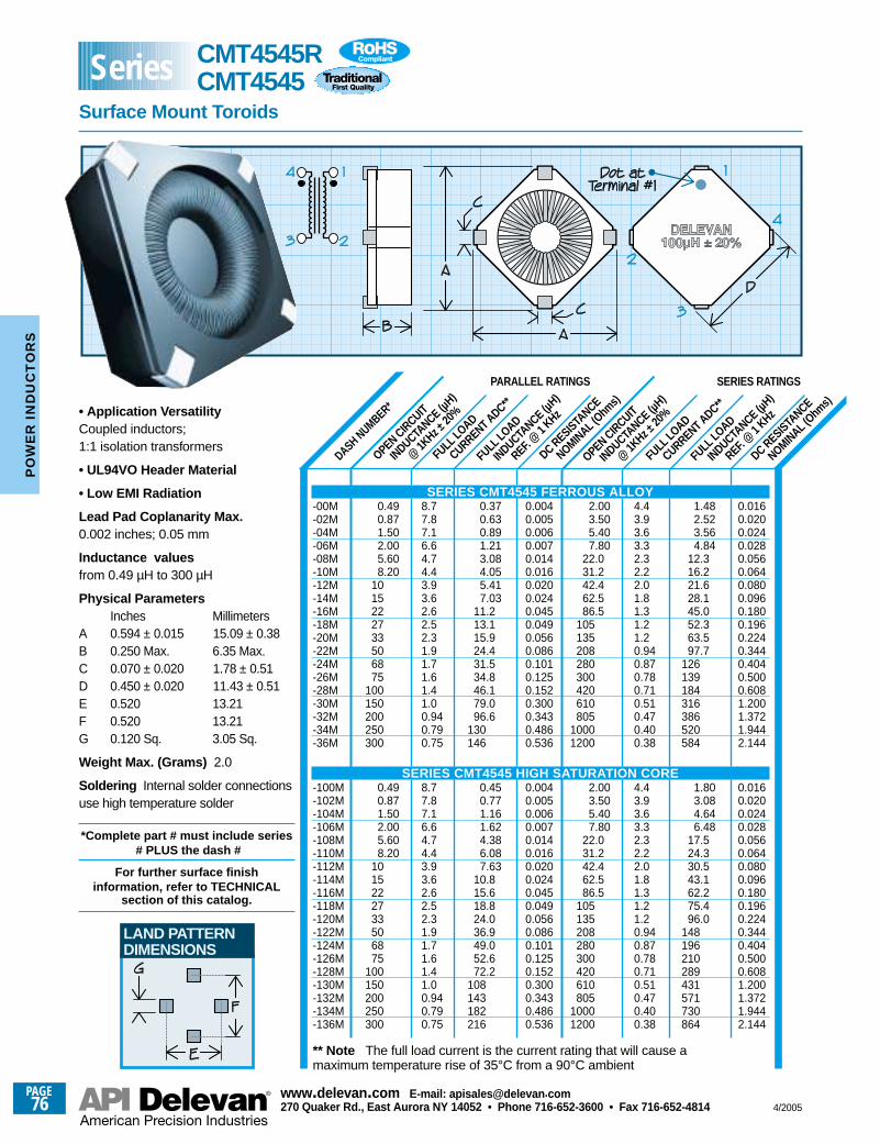
DASH NUMBER*
FULL LO
AD
INDUCTANCE (µ
H)
REF. @
1 KHz
FULL LO
AD
CURRENT ADC**
OPEN CIRCUIT
INDUCTANCE (µ
H)
@ 1K
Hz ±20
%
DC RESISTANCE
NOMINAL (Ohm
s)
DC RESISTANCE
NOMINAL (Ohm
s)
FULL LO
AD
INDUCTANCE (µ
H)
REF. @
1 KHz
FULL LO
AD
CURRENT ADC**
OPEN CIRCUIT
INDUCTANCE (µ
H)
@ 1K
Hz ±20
%
0.490.871.502.005.608.20
1015222733506875
100150200250300
0.490.871.502.005.608.20
1015222733506875
100150200250300
8.77.87.16.64.74.43.93.62.62.52.31.91.71.61.41.00.940.790.75
8.77.87.16.64.74.43.93.62.62.52.31.91.71.61.41.00.940.790.75
0.370.630.891.213.084.055.417.03
11.213.115.924.431.534.846.179.096.6
130146
0.450.771.161.624.386.087.63
10.815.618.824.036.949.052.672.2
108143182216
0.0040.0050.0060.0070.0140.0160.0200.0240.0450.0490.0560.0860.1010.1250.1520.3000.3430.4860.536
0.0040.0050.0060.0070.0140.0160.0200.0240.0450.0490.0560.0860.1010.1250.1520.3000.3430.4860.536
• Application VersatilityCoupled inductors; 1:1 isolation transformers
• UL94VO Header Material
• Low EMI Radiation
Lead Pad Coplanarity Max.0.002 inches; 0.05 mm
Inductance valuesfrom 0.49 µH to 300 µH
Physical ParametersInches Millimeters
A 0.594 ± 0.015 15.09 ± 0.38B 0.250 Max. 6.35 Max.C 0.070 ± 0.020 1.78 ± 0.51D 0.450 ± 0.020 11.43 ± 0.51E 0.520 13.21F 0.520 13.21G 0.120 Sq. 3.05 Sq.
Weight Max. (Grams) 2.0
Soldering Internal solder connectionsuse high temperature solder
*Complete part # must include series# PLUS the dash #
For further surface finish information, refer to TECHNICAL
section of this catalog.
PARALLEL RATINGS
2.003.505.407.80
22.031.242.462.586.5
105135208280300420610805
10001200
2.003.505.407.80
22.031.242.462.586.5
105135208280300420610805
10001200
4.43.93.63.32.32.22.01.81.31.21.20.940.870.780.710.510.470.400.38
4.43.93.63.32.32.22.01.81.31.21.20.940.870.780.710.510.470.400.38
1.482.523.564.84
12.316.221.628.145.052.363.597.7
126139184316386520584
1.803.084.646.48
17.524.330.543.162.275.496.0
148196210289431571730864
0.0160.0200.0240.0280.0560.0640.0800.0960.1800.1960.2240.3440.4040.5000.6081.2001.3721.9442.144
0.0160.0200.0240.0280.0560.0640.0800.0960.1800.1960.2240.3440.4040.5000.6081.2001.3721.9442.144
SERIES RATINGS
** Note The full load current is the current rating that will cause amaximum temperature rise of 35°C from a 90°C ambient
LAND PATTERNDIMENSIONS
SERIES CMT4545 FERROUS ALLOY-00M-02M-04M-06M-08M-10M-12M-14M-16M-18M-20M-22M-24M-26M-28M-30M-32M-34M-36M
SERIES CMT4545 HIGH SATURATION CORE-100M-102M-104M-106M-108M-110M-112M-114M-116M-118M-120M-122M-124M-126M-128M-130M-132M-134M-136M
CMT4545RCMT4545
Surface Mount Toroids
Series
PAGE76
www.delevan .com E-mail: apisales@delevan .com270 Quaker Rd., East Aurora NY 14052 • Phone 716-652-3600 • Fax 716-652-4814 4/2005
PO
WE
R I
ND
UC
TO
RS
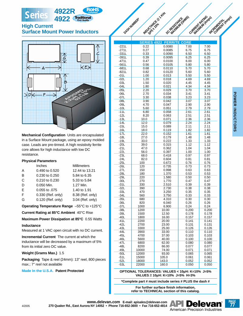
DASH NUMBER*
INDUCTANCE @
1 KHz
(µH) ±
15%
DC RESISTANCE
MAXIMUM (O
HMS)
CURRENT RATING
MAXIMUM (A
mps)
INCREMENTAL
CURRENT (Amps
)
7.006.756.506.256.005.805.705.605.504.694.454.343.703.413.233.072.902.792.612.512.362.242.111.821.611.481.331.121.041.000.970.810.760.730.630.530.500.470.390.380.350.330.300.260.240.2000.1780.1570.1410.1310.1260.1100.1030.1000.0800.0770.0710.0650.0610.0520.050
7.006.756.506.256.005.805.705.605.504.694.454.343.703.413.233.072.902.792.612.512.362.242.111.821.611.481.331.121.041.000.970.810.760.730.630.530.500.470.390.380.350.330.300.260.240.2000.1780.1570.1410.1310.1260.1100.1030.1000.0800.0770.0710.0650.0610.0520.050
0.00800.00850.00900.00950.01000.01050.01100.01200.0130.0180.0200.0210.0290.0340.0380.0420.0470.0510.0580.0630.0710.0790.0890.1190.1520.1790.2220.3150.3620.3970.4180.6040.6720.7350.9981.3701.5801.7702.5102.7303.2503.7504.3106.0406.900
10.0012.5016.0020.0023.0025.0033.0037.0040.0062.0066.0074.0093.00
105.0143.0160.0
0.220.270.330.390.470.560.680.821.001.201.501.802.202.703.303.904.705.606.808.20
10.012.015.018.022.027.033.039.047.056.068.082.0
100120150180220270330390470560680820
100012001500180022002700330039004700560068008200
1000012000150001800022000
Mechanical Configuration Units are encapsulatedin a Surface Mount package, using an epoxy moldedcase. Leads are pre-tinned. A high resistivity ferritecore allows for high inductance with low DCresistance.
Physical ParametersInches Millimeters
A 0.490 to 0.520 12.44 to 13.21B 0.230 to 0.250 5.84 to 6.35C 0.210 to 0.230 5.33 to 5.84D 0.050 Min. 1.27 Min.E 0.055 to .075 1.40 to 1.91F 0.330 (Ref. only) 8.38 (Ref. only)G 0.120 (Ref. only) 3.04 (Ref. only)
Operating Temperature Range –55°C to +125°C
Current Rating at 85°C Ambient 40°C Rise
Maximum Power Dissipation at 85°C 0.55 Watts
InductanceMeasured at 1 VAC open circuit with no DC current.
Incremental Current The current at which theinductance will be decreased by a maximum of 5%from its initial zero DC value.
Weight (Grams Max.) 1.5
Packaging Tape & reel (24mm): 13" reel, 800 piecesmax.; 7" reel not available
Made In the U.S.A. Patent Protected
SERIES 4922 FERRITE CORE-221L-271L-331L-391L-471L-561L-681L-821L-01L-02L-03L-04L-05L-06L-07L-08L-09L-10L-11L-12L-13L-14L-15L-16L-17L-18L-19L-20L-21L-22L-23L-24L-25L-26L-27L-28L-29L-30L-31L-32L-33L-34L-35L-36L-37L-38L-39L-40L-41L-42L-43L-44L-45L-46L-47L-48L-49L-50L-51L-52L-53L
OPTIONAL TOLERANCES: VALUES < 10µH: K=10% J=5%VALUES > 10µH: K=10% J=5% H=3%
*Complete part # must include series # PLUS the dash #
For further surface finish information, refer to TECHNICAL section of this catalog.
4922R4922
High Current Surface Mount Power Inductors
Series
4/2005
PAGE77
www.delevan .com E-mail: apisales@delevan .com270 Quaker Rd., East Aurora NY 14052 • Phone 716-652-3600 • Fax 716-652-4814
PO
WE
R IN
DU
CT
OR
S
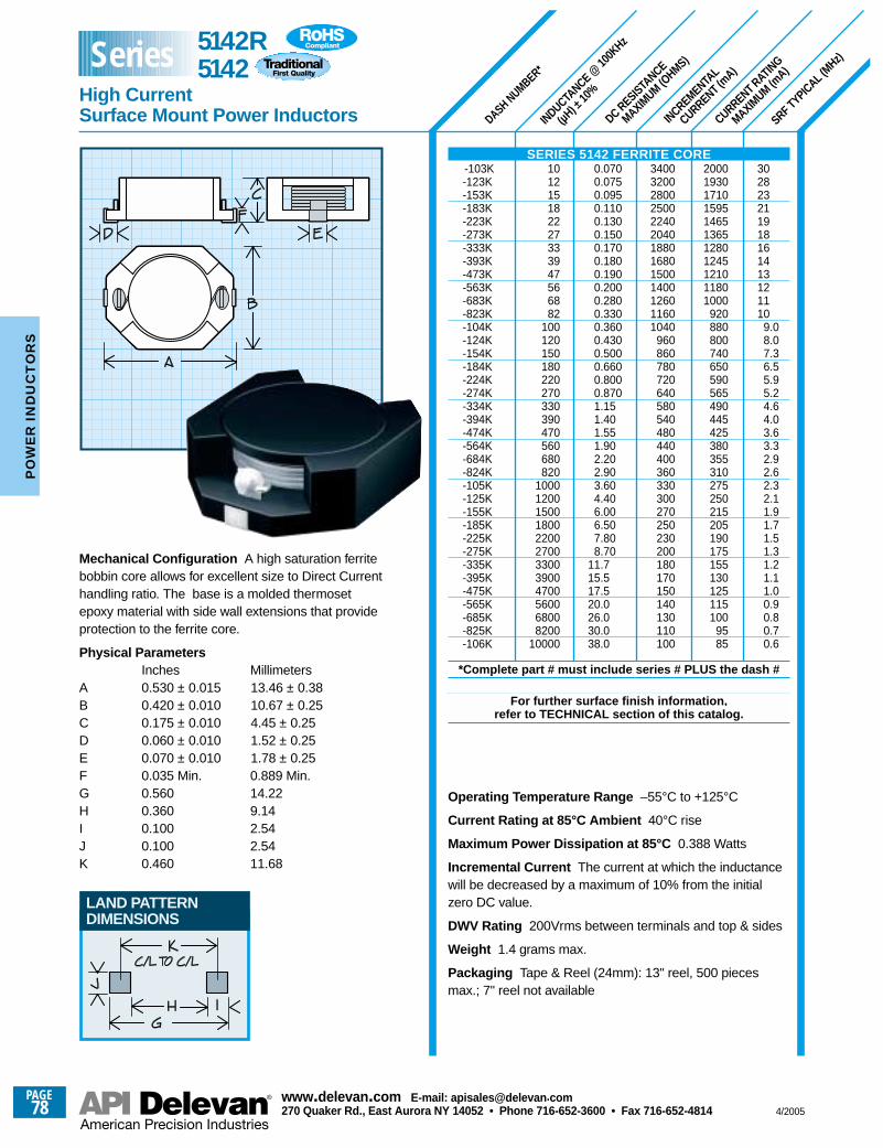
INCREMENTAL
CURRENT (mA)
SRF TYPICAL (MHz)
DC RESISTANCE
MAXIMUM (O
HMS)
CURRENT RATING
MAXIMUM (m
A)
INDUCTANCE @
100K
Hz
(µH) ±
10%
DASH NUMBER*
LAND PATTERNDIMENSIONS
302823211918161413121110
9.08.07.36.55.95.24.64.03.63.32.92.62.32.11.91.71.51.31.21.11.00.90.80.70.6
20001930171015951465136512801245121011801000
920880800740650590565490445425380355310275250215205190175155130125115100
9585
3400320028002500224020401880168015001400126011601040
960860780720640580540480440400360330300270250230200180170150140130110100
0.0700.0750.0950.1100.1300.1500.1700.1800.1900.2000.2800.3300.3600.4300.5000.6600.8000.8701.151.401.551.902.202.903.604.406.006.507.808.70
11.715.517.520.026.030.038.0
101215182227333947566882
100120150180220270330390470560680820
100012001500180022002700330039004700560068008200
10000
Mechanical Configuration A high saturation ferritebobbin core allows for excellent size to Direct Currenthandling ratio. The base is a molded thermosetepoxy material with side wall extensions that provideprotection to the ferrite core.
Physical ParametersInches Millimeters
A 0.530 ± 0.015 13.46 ± 0.38 B 0.420 ± 0.010 10.67 ± 0.25C 0.175 ± 0.010 4.45 ± 0.25D 0.060 ± 0.010 1.52 ± 0.25E 0.070 ± 0.010 1.78 ± 0.25F 0.035 Min. 0.889 Min.G 0.560 14.22H 0.360 9.14I 0.100 2.54J 0.100 2.54K 0.460 11.68
Operating Temperature Range –55°C to +125°C
Current Rating at 85°C Ambient 40°C rise
Maximum Power Dissipation at 85°C 0.388 Watts
Incremental Current The current at which the inductancewill be decreased by a maximum of 10% from the initialzero DC value.
DWV Rating 200Vrms between terminals and top & sides
Weight 1.4 grams max.
Packaging Tape & Reel (24mm): 13" reel, 500 piecesmax.; 7" reel not available
5142R 5142
High CurrentSurface Mount Power Inductors
Series
SERIES 5142 FERRITE CORE-103K-123K-153K-183K-223K-273K-333K-393K-473K-563K-683K-823K-104K-124K-154K-184K-224K-274K-334K-394K-474K-564K-684K-824K-105K-125K-155K-185K-225K-275K-335K-395K-475K-565K-685K-825K-106K
*Complete part # must include series # PLUS the dash #
For further surface finish information, refer to TECHNICAL section of this catalog.
PAGE78
www.delevan .com E-mail: apisales@delevan .com270 Quaker Rd., East Aurora NY 14052 • Phone 716-652-3600 • Fax 716-652-4814 4/2005
PO
WE
R I
ND
UC
TO
RS
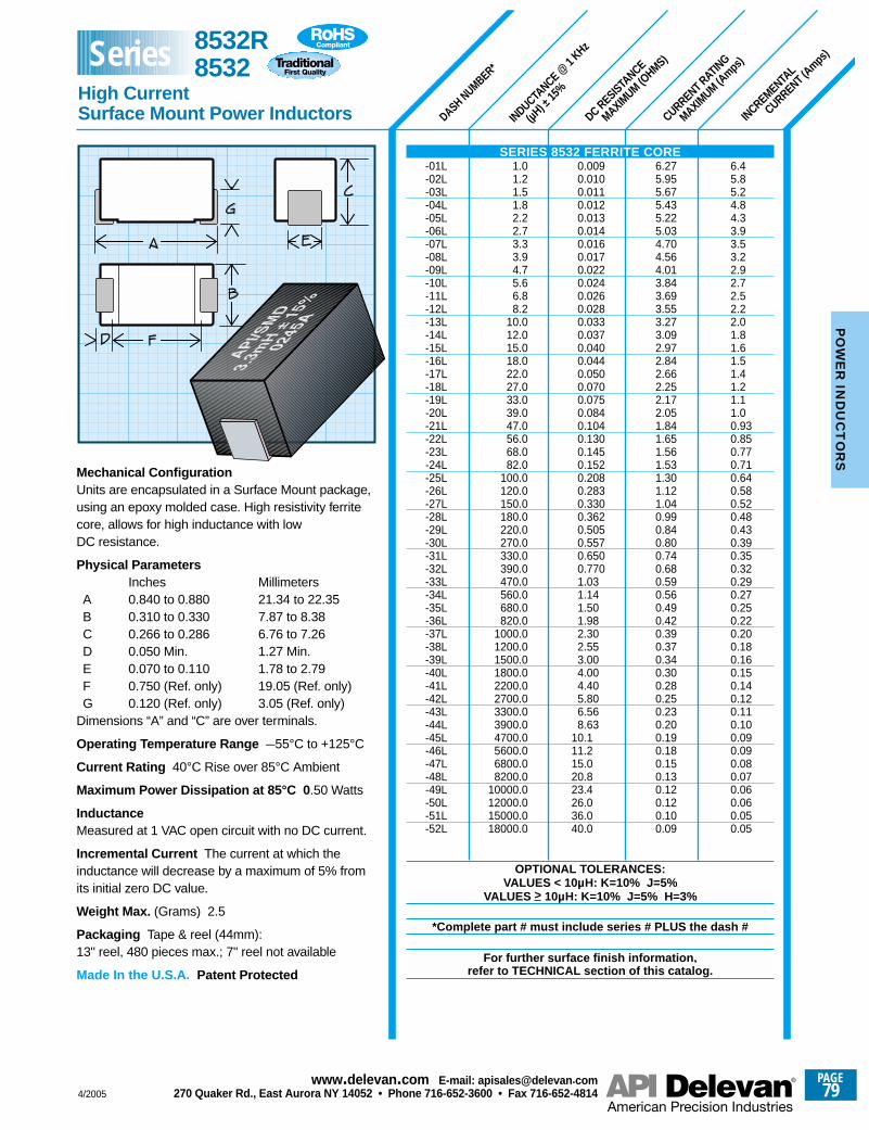
DASH NUMBER*
INDUCTANCE @
1 KHz
(µH) ±
15%
DC RESISTANCE
MAXIMUM (O
HMS)
CURRENT RATING
MAXIMUM (A
mps)
INCREMENTAL
CURRENT (Amps
)
6.45.85.24.84.33.93.53.22.92.72.52.22.01.81.61.51.41.21.11.00.930.850.770.710.640.580.520.480.430.390.350.320.290.270.250.220.200.180.160.150.140.120.110.100.090.090.080.070.060.060.050.05
6.275.955.675.435.225.034.704.564.013.843.693.553.273.092.972.842.662.252.172.051.841.651.561.531.301.121.040.990.840.800.740.680.590.560.490.420.390.370.340.300.280.250.230.200.190.180.150.130.120.120.100.09
0.0090.0100.0110.0120.0130.0140.0160.0170.0220.0240.0260.0280.0330.0370.0400.0440.0500.0700.0750.0840.1040.1300.1450.1520.2080.2830.3300.3620.5050.5570.6500.7701.031.141.501.982.302.553.004.004.405.806.568.63
10.111.215.020.823.426.036.040.0
1.01.21.51.82.22.73.33.94.75.66.88.2
10.012.015.018.022.027.033.039.047.056.068.082.0
100.0120.0150.0180.0220.0270.0330.0390.0470.0560.0680.0820.0
1000.01200.01500.01800.02200.02700.03300.03900.04700.05600.06800.08200.0
10000.012000.015000.018000.0
Mechanical ConfigurationUnits are encapsulated in a Surface Mount package,using an epoxy molded case. High resistivity ferritecore, allows for high inductance with lowDC resistance.
Physical ParametersInches Millimeters
A 0.840 to 0.880 21.34 to 22.35B 0.310 to 0.330 7.87 to 8.38C 0.266 to 0.286 6.76 to 7.26D 0.050 Min. 1.27 Min.E 0.070 to 0.110 1.78 to 2.79F 0.750 (Ref. only) 19.05 (Ref. only)G 0.120 (Ref. only) 3.05 (Ref. only)
Dimensions “A” and “C” are over terminals.
Operating Temperature Range –55°C to +125°C
Current Rating 40°C Rise over 85°C Ambient
Maximum Power Dissipation at 85°C 0 .50 Watts
InductanceMeasured at 1 VAC open circuit with no DC current.
Incremental Current The current at which theinductance will decrease by a maximum of 5% fromits initial zero DC value.
Weight Max. (Grams) 2.5
Packaging Tape & reel (44mm):13" reel, 480 pieces max.; 7" reel not available
Made In the U.S.A. Patent Protected
SERIES 8532 FERRITE CORE-01L-02L-03L-04L-05L-06L-07L-08L-09L-10L-11L-12L-13L-14L-15L-16L-17L-18L-19L-20L-21L-22L-23L-24L-25L-26L-27L-28L-29L-30L-31L-32L-33L-34L-35L-36L-37L-38L-39L-40L-41L-42L-43L-44L-45L-46L-47L-48L-49L-50L-51L-52L
OPTIONAL TOLERANCES:VALUES < 10µH: K=10% J=5%
VALUES > 10µH: K=10% J=5% H=3%
*Complete part # must include series # PLUS the dash #
For further surface finish information, refer to TECHNICAL section of this catalog.
8532R 8532
High CurrentSurface Mount Power Inductors
Series
4/2005
PAGE79
www.delevan .com E-mail: apisales@delevan .com270 Quaker Rd., East Aurora NY 14052 • Phone 716-652-3600 • Fax 716-652-4814
PO
WE
R IN
DU
CT
OR
S
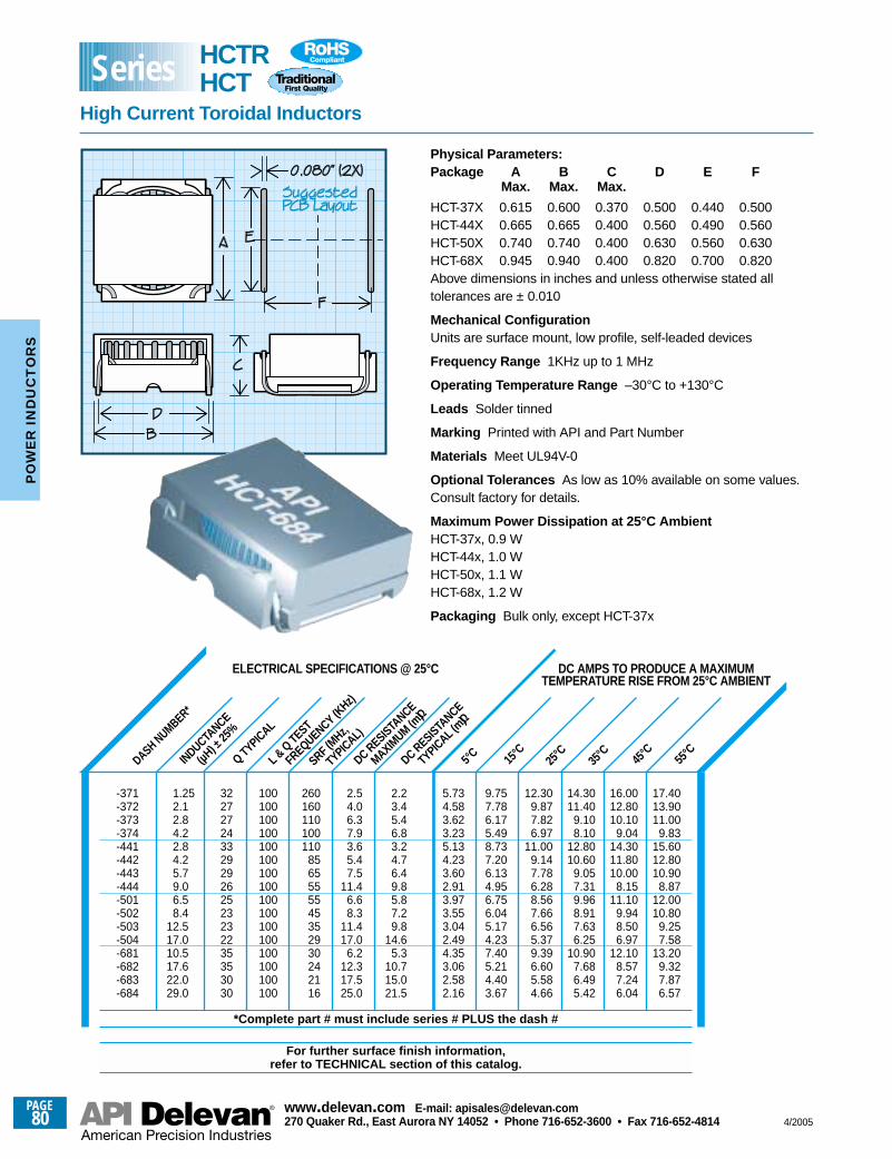
SRF (MHz,
TYPICAL)
L & Q TEST
FREQUENCY (KHz)
ELECTRICAL SPECIFICATIONS @ 25°C DC AMPS TO PRODUCE A MAXIMUMTEMPERATURE RISE FROM 25°C AMBIENT
INDUCTANCE
(µH) ±
25%
Q TYPICAL
DC RESISTANCE
MAXIMUM (m
Ω)
DC RESISTANCE
TYPICAL (mΩ)
5°C 15°C
25°C
35°C 45
°C55
°CDASH NUMBER*
Physical Parameters:Package A B C D E F
Max. Max. Max.
HCT-37X 0.615 0.600 0.370 0.500 0.440 0.500HCT-44X 0.665 0.665 0.400 0.560 0.490 0.560HCT-50X 0.740 0.740 0.400 0.630 0.560 0.630HCT-68X 0.945 0.940 0.400 0.820 0.700 0.820Above dimensions in inches and unless otherwise stated alltolerances are ± 0.010
Mechanical ConfigurationUnits are surface mount, low profile, self-leaded devices
Frequency Range 1KHz up to 1 MHz
Operating Temperature Range –30°C to +130°C
Leads Solder tinned
Marking Printed with API and Part Number
Materials Meet UL94V-0
Optional Tolerances As low as 10% available on some values.Consult factory for details.
Maximum Power Dissipation at 25°C AmbientHCT-37x, 0.9 WHCT-44x, 1.0 WHCT-50x, 1.1 WHCT-68x, 1.2 W
Packaging Bulk only, except HCT-37x
2.23.45.46.83.24.76.49.85.87.29.8
14.65.3
10.715.021.5
5.734.583.623.235.134.233.602.913.973.553.042.494.353.062.582.16
9.757.786.175.498.737.206.134.956.756.045.174.237.405.214.403.67
12.309.877.826.97
11.009.147.786.288.567.666.565.379.396.605.584.66
14.3011.40
9.108.10
12.8010.60
9.057.319.968.917.636.25
10.907.686.495.42
16.0012.8010.10
9.0414.3011.8010.00
8.1511.10
9.948.506.97
12.108.577.246.04
17.4013.9011.00
9.8315.6012.8010.90
8.8712.0010.80
9.257.58
13.209.327.876.57
2.54.06.37.93.65.47.5
11.46.68.3
11.417.0
6.212.317.525.0
260160110100110
8565555545352930242116
100100100100100100100100100100100100100100100100
32272724332929262523232235353030
1.252.12.84.22.84.25.79.06.58.4
12.517.010.517.622.029.0
-371-372-373-374-441-442-443-444-501-502-503-504-681-682-683-684
*Complete part # must include series # PLUS the dash #
For further surface finish information, refer to TECHNICAL section of this catalog.
HCTRHCT
High Current Toroidal Inductors
Series
PAGE80
www.delevan .com E-mail: apisales@delevan .com270 Quaker Rd., East Aurora NY 14052 • Phone 716-652-3600 • Fax 716-652-4814 4/2005
PO
WE
R I
ND
UC
TO
RS
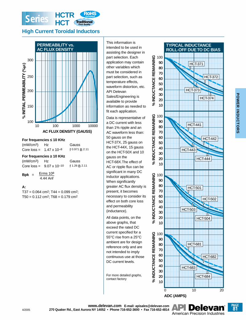
This information isintended to be used inassisting the designer inpart selection. Eachapplication may containother variables whichmust be considered inpart selection, such astemperature effects,waveform distortion, etc.API DelevanSales/Engineering isavailable to provideinformation as needed tofit each application.
Data is representative ofa DC current with lessthan 1% ripple and anAC waveform less than:50 gauss on theHCT-37X, 25 gauss onthe HCT-44X, 15 gausson the HCT-50X and 10gauss on theHCT-68X.The effect ofAC or ripple flux can besignificant in many DCinductor applications.When significantlygreater AC flux density ispresent, it becomesnecessary to consider itseffect on both core lossand permeability(inductance).
All data points, on theabove graphs, thatexceed the rated DCcurrent specified for a55°C rise from a 25°Cambient are for designreference only and arenot intended to implycontinuous use at thoseDC current levels.
For frequencies ≤ 10 KHz(mW/cm3) Hz GaussCore loss = 1.47 x 10⁻⁸ f 0.971 B 2.11
For frequencies ≥ 10 KHz(mW/cm3) Hz GaussCore loss = 9.07 x 10⁻¹⁰ f 1.26 B 2.11
Bpk =
A:T37 = 0.064 cm2; T44 = 0.099 cm2;T50 = 0.112 cm2; T68 = 0.179 cm2
Erms 108
4.44 Anf
0
10
ADC (AMPS)
% IN
DU
CTA
NC
E R
EM
AIN
ING
20
30
40
50
60
70
80
90
100
10 20
TYPICAL INDUCTANCEROLL-OFF DUE TO DC BIAS
HCT-682
HCT-683
HCT-684
HCT-681
10
20
30
40
50
60
70
80
90
10% IN
DU
CTA
NC
E R
EM
AIN
ING
20
30
40
50
60
70
80
90
100
10
20
30
40
50
60
70
80
90
10% IN
DU
CTA
NC
E R
EM
AIN
ING
20
30
40
50
60
70
80
90
100
10
20
30
40
50
60
70
80
90
10% IN
DU
CTA
NC
E R
EM
AIN
ING
20
30
40
50
60
70
80
90
100
10
20
30
40
50
60
70
80
90
HCT-502
HCT-503
HCT-504
HCT-501
HCT-442
HCT-443
HCT-444
HCT-441
HCT-372
HCT-373
HCT-374
HCT-371
10
AC FLUX DENSITY (GAUSS)
100100 1000 10000
PERMEABILITY vs.AC FLUX DENSITY
150
200
250
300
For more detailed graphs,contact factory
HCTRHCT
High Current Toroidal Inductors
Series
4/2005
PAGE81
www.delevan .com E-mail: apisales@delevan .com270 Quaker Rd., East Aurora NY 14052 • Phone 716-652-3600 • Fax 716-652-4814
PO
WE
R IN
DU
CT
OR
S
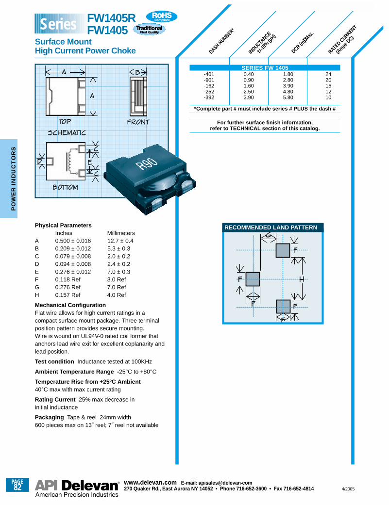
DASH NUMBER*
INDUCTANCE
±/-15
% (µH)
DCR (mΩ) M
ax.
RATED CURRENT
(AmpsDC)
Physical ParametersInches Millimeters
A 0.500 ± 0.016 12.7 ± 0.4B 0.209 ± 0.012 5.3 ± 0.3C 0.079 ± 0.008 2.0 ± 0.2D 0.094 ± 0.008 2.4 ± 0.2E 0.276 ± 0.012 7.0 ± 0.3F 0.118 Ref 3.0 Ref G 0.276 Ref 7.0 RefH 0.157 Ref 4.0 Ref
Mechanical Configuration Flat wire allows for high current ratings in a compact surface mount package. Three terminalposition pattern provides secure mounting. Wire is wound on UL94V-0 rated coil former thatanchors lead wire exit for excellent coplanarity andlead position.
Test condition Inductance tested at 100KHz
Ambient Temperature Range - 25°C to +80°C
Temperature Rise from +25ºC Ambient40°C max with max current rating
Rating Current 25% max decrease in initial inductance
Packaging Tape & reel 24mm width600 pieces max on 13˝ reel; 7˝ reel not available
SERIES FW 1405-401 0.40 1.80 24-901 0.90 2.80 20-162 1.60 3.90 15-252 2.50 4.80 12-392 3.90 5.80 10
*Complete part # must include series # PLUS the dash #
For further surface finish information, refer to TECHNICAL section of this catalog.
FW1405R FW1405
Surface MountHigh Current Power Choke
Series
PAGE82
www.delevan .com E-mail: apisales@delevan .com270 Quaker Rd., East Aurora NY 14052 • Phone 716-652-3600 • Fax 716-652-4814 4/2005
PO
WE
R I
ND
UC
TO
RS
RECOMMENDED LAND PATTERN
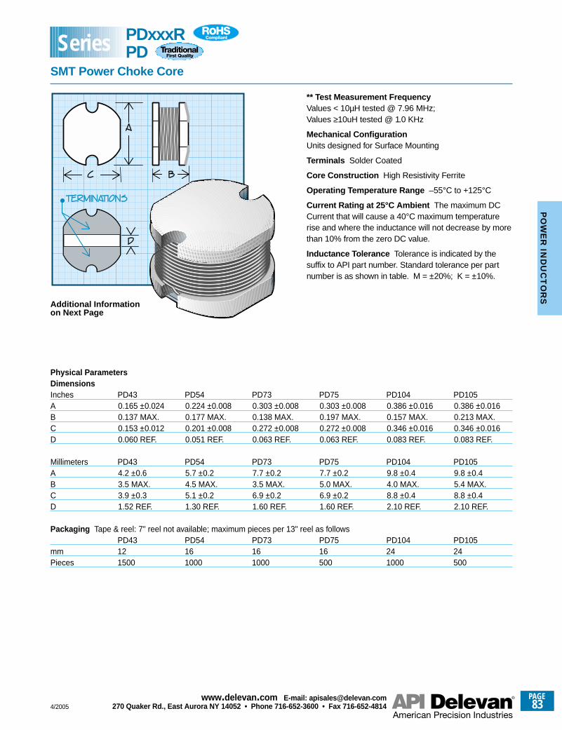
0.165 ±0.0240.137 MAX.0.153 ±0.0120.060 REF.
4.2 ±0.63.5 MAX.3.9 ±0.31.52 REF.
0.224 ±0.0080.177 MAX.0.201 ±0.0080.051 REF.
5.7 ±0.24.5 MAX.5.1 ±0.21.30 REF.
0.303 ±0.0080.138 MAX.0.272 ±0.0080.063 REF.
7.7 ±0.23.5 MAX.6.9 ±0.21.60 REF.
0.303 ±0.0080.197 MAX.0.272 ±0.0080.063 REF.
7.7 ±0.25.0 MAX.6.9 ±0.21.60 REF.
0.386 ±0.0160.157 MAX.0.346 ±0.0160.083 REF.
9.8 ±0.44.0 MAX.8.8 ±0.42.10 REF.
0.386 ±0.0160.213 MAX.0.346 ±0.0160.083 REF.
9.8 ±0.45.4 MAX.8.8 ±0.42.10 REF.
** Test Measurement FrequencyValues < 10µH tested @ 7.96 MHz;Values ≥10uH tested @ 1.0 KHz
Mechanical ConfigurationUnits designed for Surface Mounting
Terminals Solder Coated
Core Construction High Resistivity Ferrite
Operating Temperature Range –55°C to +125°C
Current Rating at 25°C Ambient The maximum DCCurrent that will cause a 40°C maximum temperaturerise and where the inductance will not decrease by morethan 10% from the zero DC value.
Inductance Tolerance Tolerance is indicated by thesuffix to API part number. Standard tolerance per partnumber is as shown in table. M = ±20%; K = ±10%.
Additional Informationon Next Page
Physical ParametersDimensionsInches PD43 PD54 PD73 PD75 PD104 PD105ABCD
Millimeters PD43 PD54 PD73 PD75 PD104 PD105ABCD
Packaging Tape & reel: 7" reel not available; maximum pieces per 13" reel as followsPD43 PD54 PD73 PD75 PD104 PD105
mm 12 16 16 16 24 24Pieces 1500 1000 1000 500 1000 500
PDxxxRPD
SMT Power Choke Core
Series
4/2005
PAGE83
www.delevan .com E-mail: apisales@delevan .com270 Quaker Rd., East Aurora NY 14052 • Phone 716-652-3600 • Fax 716-652-4814
PO
WE
R IN
DU
CT
OR
S
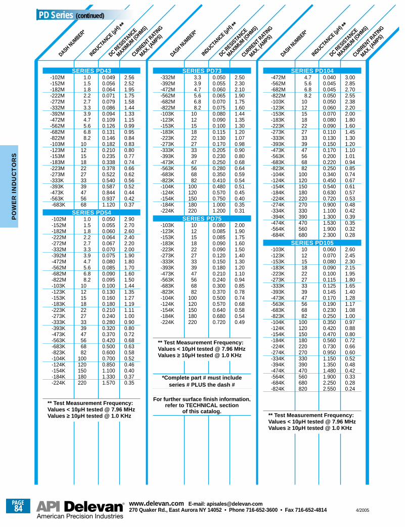
DASH NUMBER*
INDUCTANCE (µ
H) **
DC RESISTANCE
MAXIMUM (O
HMS)
CURRENT RATING
MAX. (AMPS)
DASH NUMBER*
INDUCTANCE (µ
H) **
DC RESISTANCE
MAXIMUM (O
HMS)
CURRENT RATING
MAX. (AMPS)
DASH NUMBER*
INDUCTANCE (µ
H) **
DC RESISTANCE
MAXIMUM (O
HMS)
CURRENT RATING
MAX. (AMPS)
1.01.51.82.22.73.33.94.75.66.88.2
1012151822273339475668
1.01.51.82.22.73.33.94.75.66.88.2
101215182227333947566882
100120150180220
0.0490.0560.0640.0710.0790.0860.0940.1090.1260.1310.1460.1820.2100.2350.3380.3780.5220.5400.5870.8440.9371.120
0.0500.0550.0600.0640.0670.0700.0750.0800.0850.0900.0950.1000.1300.1600.1800.2100.2400.2800.3200.3700.4200.5000.6000.7000.8501.1001.3301.570
2.562.521.951.751.581.441.331.150.990.950.840.830.800.770.740.660.620.560.520.440.420.37
2.902.702.602.402.202.001.901.801.701.601.501.441.351.271.191.111.000.900.800.720.680.630.580.520.460.400.370.35
3.33.94.75.66.88.2
101215182227333947566882
100120150180220
101215182227333947566882
100120150180220
0.0500.0550.0600.0650.0700.0750.0800.0900.1000.1150.1300.1700.2050.2300.2500.2800.3500.4100.4800.5700.7501.0001.200
0.0800.0850.0850.0900.0900.1200.1500.1800.2100.2400.3000.3700.5000.5700.6400.6800.720
2.502.302.101.901.751.601.441.351.301.201.070.980.900.800.680.640.590.540.510.450.400.350.31
2.001.901.751.601.501.401.301.201.100.940.850.780.740.680.580.540.49
4.75.66.88.2
101215182227333947566882
100120150180220270330390470560680
101215182227333947566882
100120150180220270330390470560680820
0.0400.0450.0450.0500.0500.0600.0700.0800.0900.1100.1300.1500.1700.2000.2200.2500.3400.4500.5400.6300.7200.9001.1001.3001.5301.9002.300
0.0600.0700.0800.0900.1000.1150.1250.1450.1700.1900.2300.2500.3500.4200.4700.5600.7300.9501.1501.3501.4801.9002.2502.550
3.002.852.702.552.382.202.001.801.601.451.301.201.101.010.940.850.740.670.610.570.530.480.420.390.350.320.28
2.602.452.302.151.951.801.651.401.281.171.081.000.970.880.800.720.660.600.520.480.420.330.280.24
SERIES PD104-472M-562M-682M-822M-103K-123K-153K-183K-223K-273K-333K-393K-473K-563K-683K-823K-104K-124K-154K-184K-224K-274K-334K-394K-474K-564K-684K
SERIES PD105-103K-123K-153K-183K-223K-273K-333K-393K-473K-563K-683K-823K-104K-124K-154K-184K-224K-274K-334K-394K-474K-564K-684K-824K
** Test Measurement Frequency:Values < 10µH tested @ 7.96 MHzValues ≥ 10µH tested @ 1.0 KHz
SERIES PD73-332M-392M-472M-562M-682M-822M-103K-123K-153K-183K-223K-273K-333K-393K-473K-563K-683K-823K-104K-124K-154K-184K-224K
SERIES PD75-103K-123K-153K-183K-223K-273K-333K-393K-473K-563K-683K-823K-104K-124K-154K-184K-224K
*Complete part # must include series # PLUS the dash #
For further surface finish information,refer to TECHNICAL section
of this catalog.
** Test Measurement Frequency:Values < 10µH tested @ 7.96 MHzValues ≥ 10µH tested @ 1.0 KHz
SERIES PD43-102M-152M-182M-222M-272M-332M-392M-472M-562M-682M-822M-103M-123M-153M-183M-223M-273M-333K-393K-473K-563K-683K
SERIES PD54-102M-152M-182M-222M-272M-332M-392M-472M-562M-682M-822M-103K-123K-153K-183K-223K-273K-333K-393K-473K-563K-683K-823K-104K-124K-154K-184K-224K
** Test Measurement Frequency:Values < 10µH tested @ 7.96 MHzValues ≥ 10µH tested @ 1.0 KHz
PD Series (continued)
PAGE84
www.delevan .com E-mail: apisales@delevan .com270 Quaker Rd., East Aurora NY 14052 • Phone 716-652-3600 • Fax 716-652-4814 4/2005
PO
WE
R I
ND
UC
TO
RS
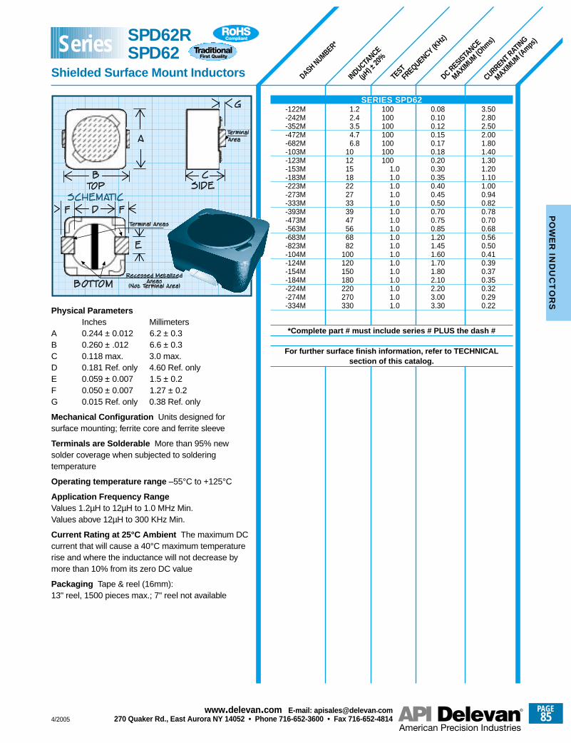
INDUCTANCE
(µH) ±
20%
TESTFREQUENCY (K
Hz)
DC RESISTANCE
MAXIMUM (O
hms)
CURRENT RATING
MAXIMUM (A
mps)
DASH NUMBER*
3.502.802.502.001.801.401.301.201.101.000.940.820.780.700.680.560.500.410.390.370.350.320.290.22
0.080.100.120.150.170.180.200.300.350.400.450.500.700.750.851.201.451.601.701.802.102.203.003.30
100100100100100100100
1.01.01.01.01.01.01.01.01.01.01.01.01.01.01.01.01.0
1.22.43.54.76.8
101215182227333947566882
100120150180220270330
Physical ParametersInches Millimeters
A 0.244 ± 0.012 6.2 ± 0.3B 0.260 ± .012 6.6 ± 0.3C 0.118 max. 3.0 max.D 0.181 Ref. only 4.60 Ref. onlyE 0.059 ± 0.007 1.5 ± 0.2F 0.050 ± 0.007 1.27 ± 0.2G 0.015 Ref. only 0.38 Ref. only
Mechanical Configuration Units designed forsurface mounting; ferrite core and ferrite sleeve
Terminals are Solderable More than 95% newsolder coverage when subjected to solderingtemperature
Operating temperature range –55°C to +125°C
Application Frequency RangeValues 1.2µH to 12µH to 1.0 MHz Min.Values above 12µH to 300 KHz Min.
Current Rating at 25°C Ambient The maximum DCcurrent that will cause a 40°C maximum temperaturerise and where the inductance will not decrease bymore than 10% from its zero DC value
Packaging Tape & reel (16mm):13" reel, 1500 pieces max.; 7" reel not available
SERIES SPD62-122M-242M-352M-472M-682M-103M-123M-153M-183M-223M-273M-333M-393M-473M-563M-683M-823M-104M-124M-154M-184M-224M-274M-334M
*Complete part # must include series # PLUS the dash #
For further surface finish information, refer to TECHNICAL section of this catalog.
SPD62RSPD62
Shielded Surface Mount Inductors
Series
4/2005
PAGE85
www.delevan .com E-mail: apisales@delevan .com270 Quaker Rd., East Aurora NY 14052 • Phone 716-652-3600 • Fax 716-652-4814
PO
WE
R IN
DU
CT
OR
S
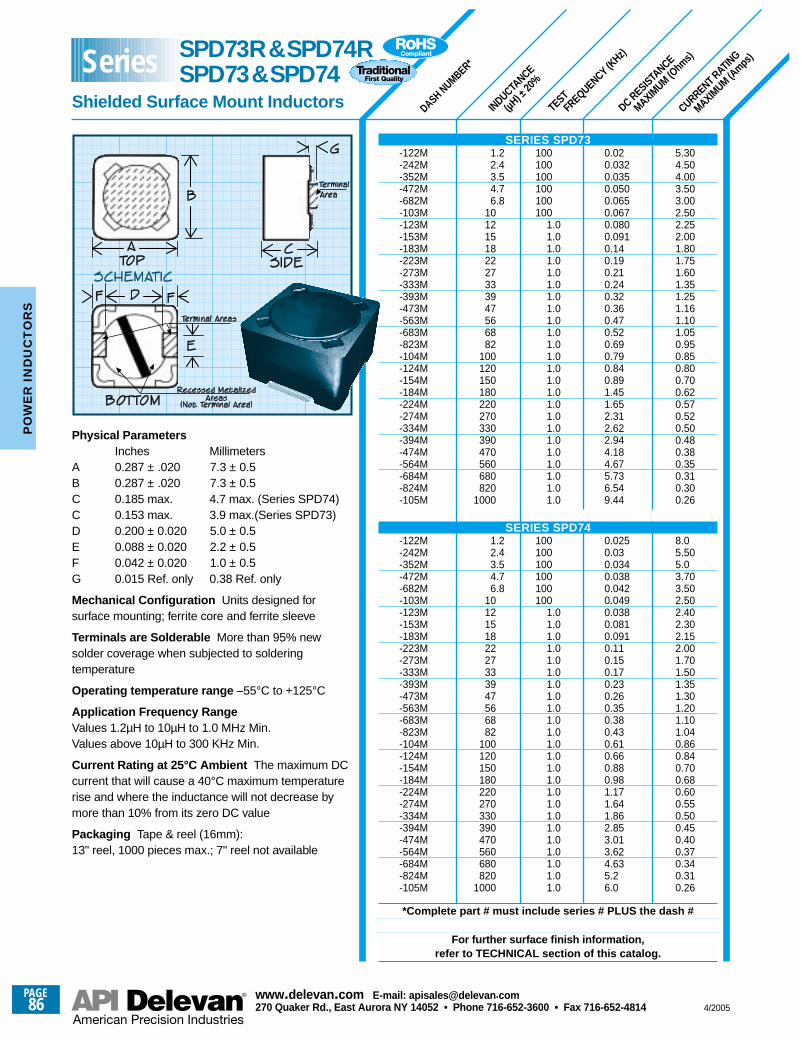
INDUCTANCE
(µH) ±
20%
TESTFREQUENCY (K
Hz)
DC RESISTANCE
MAXIMUM (O
hms)
CURRENT RATING
MAXIMUM (A
mps)
DASH NUMBER*
5.304.504.003.503.002.502.252.001.801.751.601.351.251.161.101.050.950.850.800.700.620.570.520.500.480.380.350.310.300.26
8.05.505.03.703.502.502.402.302.152.001.701.501.351.301.201.101.040.860.840.700.680.600.550.500.450.400.370.340.310.26
0.020.0320.0350.0500.0650.0670.0800.0910.140.190.210.240.320.360.470.520.690.790.840.891.451.652.312.622.944.184.675.736.549.44
0.0250.030.0340.0380.0420.0490.0380.0810.0910.110.150.170.230.260.350.380.430.610.660.880.981.171.641.862.853.013.624.635.26.0
100100100100100100
1.01.01.01.01.01.01.01.01.01.01.01.01.01.01.01.01.01.01.01.01.01.01.01.0
100100100100100100
1.01.01.01.01.01.01.01.01.01.01.01.01.01.01.01.01.01.01.01.01.01.01.01.0
1.22.43.54.76.8
101215182227333947566882
100120150180220270330390470560680820
1000
1.22.43.54.76.8
101215182227333947566882
100120150180220270330390470560680820
1000
Physical ParametersInches Millimeters
A 0.287 ± .020 7.3 ± 0.5B 0.287 ± .020 7.3 ± 0.5C 0.185 max. 4.7 max. (Series SPD74)C 0.153 max. 3.9 max.(Series SPD73)D 0.200 ± 0.020 5.0 ± 0.5E 0.088 ± 0.020 2.2 ± 0.5F 0.042 ± 0.020 1.0 ± 0.5G 0.015 Ref. only 0.38 Ref. only
Mechanical Configuration Units designed forsurface mounting; ferrite core and ferrite sleeve
Terminals are Solderable More than 95% newsolder coverage when subjected to solderingtemperature
Operating temperature range –55°C to +125°C
Application Frequency RangeValues 1.2µH to 10µH to 1.0 MHz Min.Values above 10µH to 300 KHz Min.
Current Rating at 25°C Ambient The maximum DCcurrent that will cause a 40°C maximum temperaturerise and where the inductance will not decrease bymore than 10% from its zero DC value
Packaging Tape & reel (16mm):13" reel, 1000 pieces max.; 7" reel not available
SERIES SPD73-122M-242M-352M-472M-682M-103M-123M-153M-183M-223M-273M-333M-393M-473M-563M-683M-823M-104M-124M-154M-184M-224M-274M-334M-394M-474M-564M-684M-824M-105M
SERIES SPD74-122M-242M-352M-472M-682M-103M-123M-153M-183M-223M-273M-333M-393M-473M-563M-683M-823M-104M-124M-154M-184M-224M-274M-334M-394M-474M-564M-684M-824M-105M
*Complete part # must include series # PLUS the dash #
For further surface finish information,refer to TECHNICAL section of this catalog.
SPD73R&SPD74RSPD73&SPD74
Shielded Surface Mount Inductors
SeriesP
OW
ER
IN
DU
CT
OR
S
PAGE86
www.delevan .com E-mail: apisales@delevan .com270 Quaker Rd., East Aurora NY 14052 • Phone 716-652-3600 • Fax 716-652-4814 4/2005
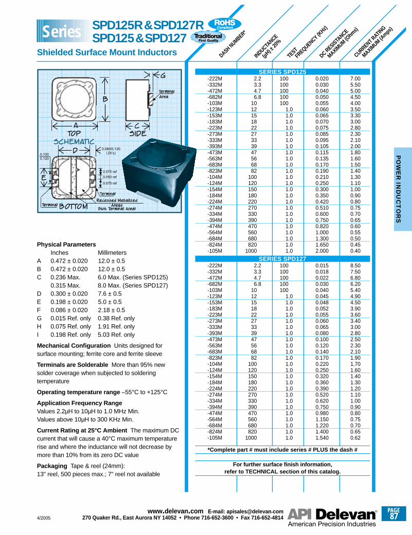
TESTFREQUENCY (KHz)
DASH NUMBER*
INDUCTANCE
(µH) ±
20%
CURRENT RATING
MAXIMUM (A
mps)
DC RESISTANCE
MAXIMUM (O
hms)
7.005.505.004.504.003.503.303.002.802.302.102.001.801.601.501.401.301.101.000.900.800.750.700.650.600.550.500.450.40
8.507.506.806.205.404.904.503.903.603.403.002.802.502.302.101.901.701.601.401.301.201.101.000.900.800.750.700.650.62
0.0200.0300.0400.0500.0550.0600.0650.0700.0750.0850.0950.1050.1150.1350.1700.1900.2100.2500.3000.3500.4200.5100.6000.7500.8201.0001.3001.6502.000
0.0150.0180.0220.0300.0400.0450.0480.0520.0550.0600.0650.0800.1000.1200.1400.1700.2200.2500.3200.3600.3900.5200.6200.7500.9801.1501.2201.4001.540
2.23.34.76.8
101215182227333947566882
100120150180220270330390470560680820
1000
2.23.34.76.8
101215182227333947566882
100120150180220270330390470560680820
1000
100100100100100
1.01.01.01.01.01.01.01.01.01.01.01.01.01.01.01.01.01.01.01.01.01.01.01.0
100100100100100
1.01.01.01.01.01.01.01.01.01.01.01.01.01.01.01.01.01.01.01.01.01.01.01.0
Physical ParametersInches Millimeters
A 0.472 ± 0.020 12.0 ± 0.5B 0.472 ± 0.020 12.0 ± 0.5C 0.236 Max. 6.0 Max. (Series SPD125)
0.315 Max. 8.0 Max. (Series SPD127)D 0.300 ± 0.020 7.6 ± 0.5E 0.198 ± 0.020 5.0 ± 0.5F 0.086 ± 0.020 2.18 ± 0.5G 0.015 Ref. only 0.38 Ref. onlyH 0.075 Ref. only 1.91 Ref. onlyI 0.198 Ref. only 5.03 Ref. only
Mechanical Configuration Units designed forsurface mounting; ferrite core and ferrite sleeve
Terminals are Solderable More than 95% newsolder coverage when subjected to solderingtemperature
Operating temperature range –55°C to +125°C
Application Frequency RangeValues 2.2µH to 10µH to 1.0 MHz Min.Values above 10µH to 300 KHz Min.
Current Rating at 25°C Ambient The maximum DCcurrent that will cause a 40°C maximum temperaturerise and where the inductance will not decrease bymore than 10% from its zero DC value
Packaging Tape & reel (24mm):13" reel, 500 pieces max.; 7" reel not available
SERIES SPD125-222M-332M-472M-682M-103M-123M-153M-183M-223M-273M-333M-393M-473M-563M-683M-823M-104M-124M-154M-184M-224M-274M-334M-394M-474M-564M-684M-824M-105M
SERIES SPD127-222M-332M-472M-682M-103M-123M-153M-183M-223M-273M-333M-393M-473M-563M-683M-823M-104M-124M-154M-184M-224M-274M-334M-394M-474M-564M-684M-824M-105M
*Complete part # must include series # PLUS the dash #
For further surface finish information,refer to TECHNICAL section of this catalog.
SPD125R&SPD127RSPD125&SPD127
Shielded Surface Mount Inductors
Series
4/2005
PAGE87
www.delevan .com E-mail: apisales@delevan .com270 Quaker Rd., East Aurora NY 14052 • Phone 716-652-3600 • Fax 716-652-4814
PO
WE
R IN
DU
CT
OR
S
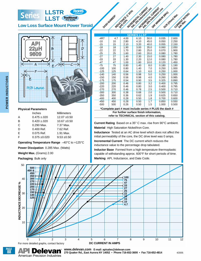
SRF MINIM
UM (MHz)
DASH NUMBER*
INDUCTANCE @
1KHz
(µH) ±
15%
INCREMENTAL C
URRENT
Adc, 1
0% In
ducta
nce L
oss
INCREMENTAL C
URRENT
Adc, 2
0% In
ducta
nce L
oss
CURRENT RATING
Adc M
ax.
DCR (Ohm
s) Max
.
2.6002.2502.1502.0501.9001.7801.7801.7801.4501.1901.0001.0001.0000.9850.8900.7950.7950.7100.7100.6500.6000.5500.500
0.0350.0500.0550.0600.0700.0800.0800.0800.1200.1800.2500.2500.2500.2600.3250.4000.4000.5000.5000.6250.7000.8501.000
50.045.040.035.025.020.015.012.010.0
8.07.06.05.04.03.53.23.02.52.01.91.81.71.5
6.104.103.203.002.802.602.302.201.801.401.401.100.980.980.900.800.800.780.680.620.500.500.50
4.002.802.101.901.701.601.401.301.000.800.800.640.560.560.540.460.460.460.380.360.280.280.26
4.7101518222527334775
100125140150175200220270300350400450500
Physical ParametersInches Millimeters
A 0.475 ±.020 12.07 ±0.50B 0.420 ±.020 10.67 ±0.50C 0.290 Max. 7.37 Max.D 0.400 Ref. 7.62 Ref.E 0.075 Ref. 1.91 Max.F 0.375 ±0.020 9.53 ±0.50
Operating Temperature Range –40°C to +125°C
Power Dissipation 0.285 Max. (Watts)
Weight Max. (Grams) 2.00
Packaging Bulk only
1DC CURRENT IN AMPS
IND
UC
TAN
CE
DE
CR
EA
SE
%
10
20
30
40
50
0 2 3 4 5 6 7 8 9 10 11 12
500400 & 450
350300270220200175150140125
1007547332725221815104.7
SERIES LLST-4R7-10-15-18-22-25-27-33-47-75-100-125-140-150-175-200-220-270-300-350-400-450-500
*Complete part # must include series # PLUS the dash #For further surface finish information,
refer to TECHNICAL section of this catalog.
Current Rating Based on a 35° C max. rise from 90°C ambient.
Material High Saturation Nickel/Iron Core.
Inductance Tested at an AC drive level which does not affect theinitial permeability of the core, the DC drive level was 0 amps.
Incremental Current The DC current which reduces theinductance value to the percentage drop tabulated.
Inductor Base Formed from a high temperature thermoplasticcapable of withstanding approx. 600°F for short periods of time.
Marking API, Inductance, and Date Code.
For more detailed graphs, contact factory
LLSTRLLST
Low Loss Surface Mount Power Toroid
Series
PAGE88
www.delevan .com E-mail: apisales@delevan .com270 Quaker Rd., East Aurora NY 14052 • Phone 716-652-3600 • Fax 716-652-4814 4/2005
PO
WE
R I
ND
UC
TO
RS
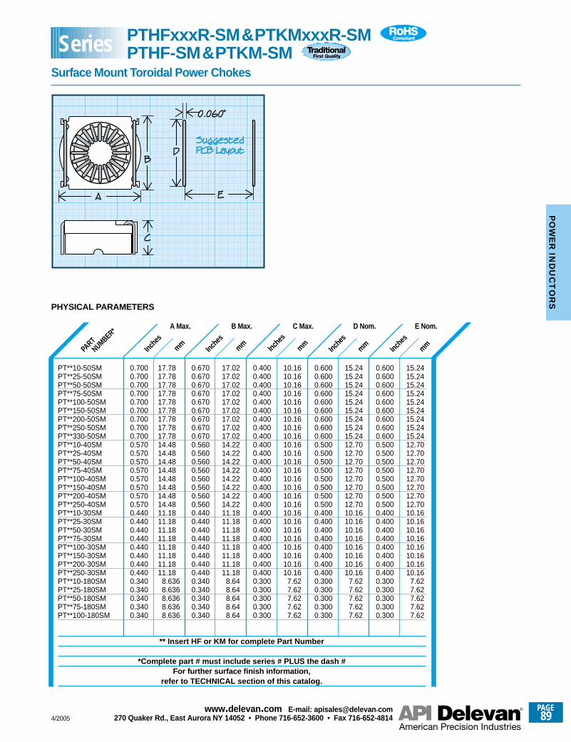
Inche
smm
Inche
smm Inc
hes
mmInc
hes
mm Inche
smm
PHYSICAL PARAMETERS
PART
NUMBER* A Max.
17.7817.7817.7817.7817.7817.7817.7817.7817.7814.4814.4814.4814.4814.4814.4814.4814.4811.1811.1811.1811.1811.1811.1811.1811.18
8.6368.6368.6368.6368.636
0.7000.7000.7000.7000.7000.7000.7000.7000.7000.5700.5700.5700.5700.5700.5700.5700.5700.4400.4400.4400.4400.4400.4400.4400.4400.3400.3400.3400.3400.340
B Max.
17.0217.0217.0217.0217.0217.0217.0217.0217.0214.2214.2214.2214.2214.2214.2214.2214.2211.1811.1811.1811.1811.1811.1811.1811.18
8.648.648.648.648.64
0.6700.6700.6700.6700.6700.6700.6700.6700.6700.5600.5600.5600.5600.5600.5600.5600.5600.4400.4400.4400.4400.4400.4400.4400.4400.3400.3400.3400.3400.340
C Max.
10.1610.1610.1610.1610.1610.1610.1610.1610.1610.1610.1610.1610.1610.1610.1610.1610.1610.1610.1610.1610.1610.1610.1610.1610.16
7.627.627.627.627.62
0.4000.4000.4000.4000.4000.4000.4000.4000.4000.4000.4000.4000.4000.4000.4000.4000.4000.4000.4000.4000.4000.4000.4000.4000.4000.3000.3000.3000.3000.300
D Nom.
15.2415.2415.2415.2415.2415.2415.2415.2415.2412.7012.7012.7012.7012.7012.7012.7012.7010.1610.1610.1610.1610.1610.1610.1610.16
7.627.627.627.627.62
0.6000.6000.6000.6000.6000.6000.6000.6000.6000.5000.5000.5000.5000.5000.5000.5000.5000.4000.4000.4000.4000.4000.4000.4000.4000.3000.3000.3000.3000.300
E Nom.
15.2415.2415.2415.2415.2415.2415.2415.2415.2412.7012.7012.7012.7012.7012.7012.7012.7010.1610.1610.1610.1610.1610.1610.1610.16
7.627.627.627.627.62
0.6000.6000.6000.6000.6000.6000.6000.6000.6000.5000.5000.5000.5000.5000.5000.5000.5000.4000.4000.4000.4000.4000.4000.4000.4000.3000.3000.3000.3000.300
PT**10-50SMPT**25-50SMPT**50-50SMPT**75-50SMPT**100-50SMPT**150-50SMPT**200-50SMPT**250-50SMPT**330-50SMPT**10-40SMPT**25-40SMPT**50-40SMPT**75-40SMPT**100-40SMPT**150-40SMPT**200-40SMPT**250-40SMPT**10-30SMPT**25-30SMPT**50-30SMPT**75-30SMPT**100-30SMPT**150-30SMPT**200-30SMPT**250-30SMPT**10-180SMPT**25-180SMPT**50-180SMPT**75-180SMPT**100-180SM
** Insert HF or KM for complete Part Number
*Complete part # must include series # PLUS the dash #For further surface finish information,
refer to TECHNICAL section of this catalog.
PTHFxxxR-SM&PTKMxxxR-SMPTHF-SM&PTKM-SM
Surface Mount Toroidal Power Chokes
Series
4/2005
PAGE89
www.delevan .com E-mail: apisales@delevan .com270 Quaker Rd., East Aurora NY 14052 • Phone 716-652-3600 • Fax 716-652-4814
PO
WE
R IN
DU
CT
OR
S
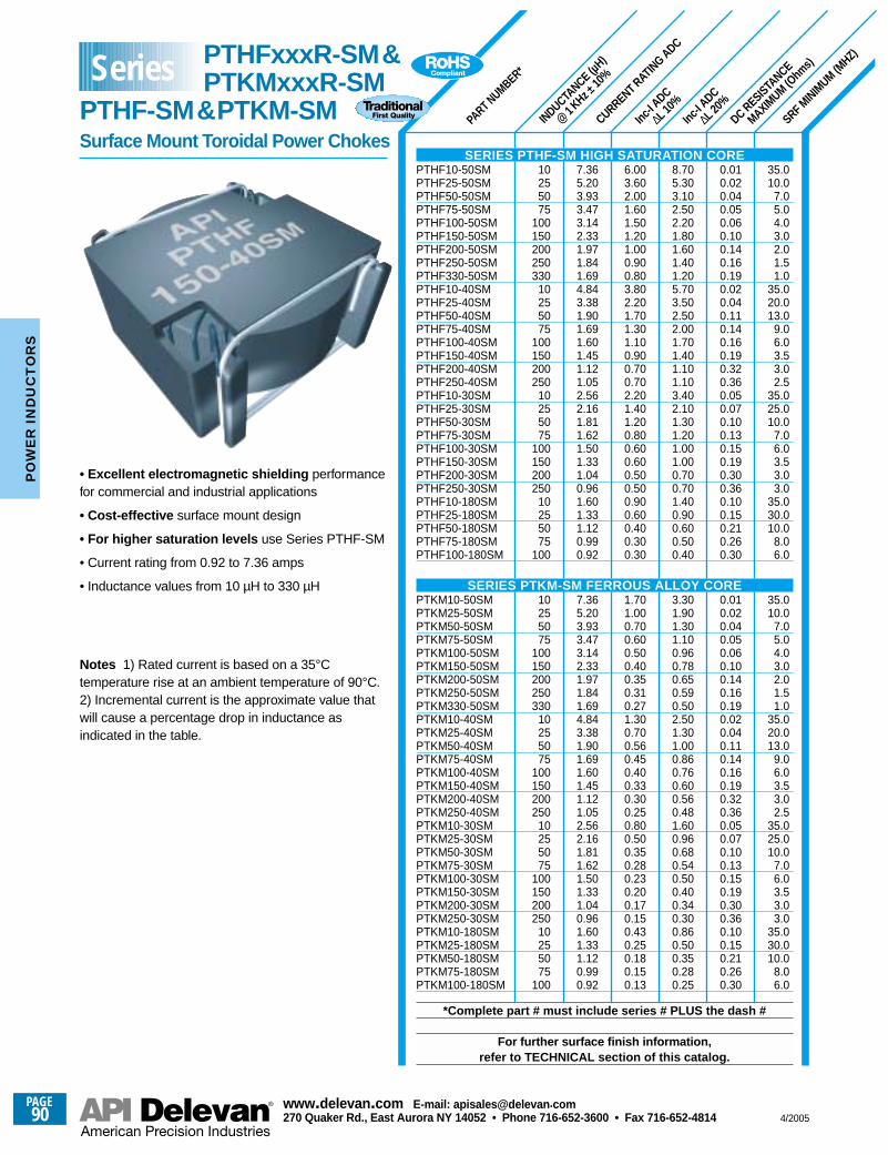
INDUCTANCE (µ
H)
@1 KHz ±
10%
PART NUMBER*
CURRENT RATING ADC
DC RESISTANCE
MAXIMUM (O
hms)
Inc-I A
DC
∆L 20%
Inc-I A
DC
∆L 10%
SRF MINIMUM
(MHZ)
10255075
100150200250330
10255075
100150200250
10255075
100150200250
10255075
100
10255075
100150200250330
10255075
100150200250
10255075
100150200250
10255075
100
7.365.203.933.473.142.331.971.841.694.843.381.901.691.601.451.121.052.562.161.811.621.501.331.040.961.601.331.120.990.92
7.365.203.933.473.142.331.971.841.694.843.381.901.691.601.451.121.052.562.161.811.621.501.331.040.961.601.331.120.990.92
6.003.602.001.601.501.201.000.900.803.802.201.701.301.100.900.700.702.201.401.200.800.600.600.500.500.900.600.400.300.30
1.701.000.700.600.500.400.350.310.271.300.700.560.450.400.330.300.250.800.500.350.280.230.200.170.150.430.250.180.150.13
8.705.303.102.502.201.801.601.401.205.703.502.502.001.701.401.101.103.402.101.301.201.001.000.700.701.400.900.600.500.40
3.301.901.301.100.960.780.650.590.502.501.301.000.860.760.600.560.481.600.960.680.540.500.400.340.300.860.500.350.280.25
0.010.020.040.050.060.100.140.160.190.020.040.110.140.160.190.320.360.050.070.100.130.150.190.300.360.100.150.210.260.30
0.010.020.040.050.060.100.140.160.190.020.040.110.140.160.190.320.360.050.070.100.130.150.190.300.360.100.150.210.260.30
35.010.0
7.05.04.03.02.01.51.0
35.020.013.0
9.06.03.53.02.5
35.025.010.0
7.06.03.53.03.0
35.030.010.0
8.06.0
35.010.0
7.05.04.03.02.01.51.0
35.020.013.0
9.06.03.53.02.5
35.025.010.0
7.06.03.53.03.0
35.030.010.0
8.06.0
• Excellent electromagnetic shielding performancefor commercial and industrial applications
• Cost-effective surface mount design
• For higher saturation levels use Series PTHF-SM
• Current rating from 0.92 to 7.36 amps
• Inductance values from 10 µH to 330 µH
Notes 1) Rated current is based on a 35°Ctemperature rise at an ambient temperature of 90°C.2) Incremental current is the approximate value thatwill cause a percentage drop in inductance asindicated in the table.
SERIES PTHF-SM HIGH SATURATION COREPTHF10-50SMPTHF25-50SMPTHF50-50SMPTHF75-50SMPTHF100-50SMPTHF150-50SMPTHF200-50SMPTHF250-50SMPTHF330-50SMPTHF10-40SMPTHF25-40SMPTHF50-40SMPTHF75-40SMPTHF100-40SMPTHF150-40SMPTHF200-40SMPTHF250-40SMPTHF10-30SMPTHF25-30SMPTHF50-30SMPTHF75-30SMPTHF100-30SMPTHF150-30SMPTHF200-30SMPTHF250-30SMPTHF10-180SMPTHF25-180SMPTHF50-180SMPTHF75-180SMPTHF100-180SM
SERIES PTKM-SM FERROUS ALLOY COREPTKM10-50SMPTKM25-50SMPTKM50-50SMPTKM75-50SMPTKM100-50SMPTKM150-50SMPTKM200-50SMPTKM250-50SMPTKM330-50SMPTKM10-40SMPTKM25-40SMPTKM50-40SMPTKM75-40SMPTKM100-40SMPTKM150-40SMPTKM200-40SMPTKM250-40SMPTKM10-30SMPTKM25-30SMPTKM50-30SMPTKM75-30SMPTKM100-30SMPTKM150-30SMPTKM200-30SMPTKM250-30SMPTKM10-180SMPTKM25-180SMPTKM50-180SMPTKM75-180SMPTKM100-180SM
*Complete part # must include series # PLUS the dash #
For further surface finish information,refer to TECHNICAL section of this catalog.
Series PTHFxxxR-SM&PTKMxxxR-SM
PTHF-SM&PTKM-SMSurface Mount Toroidal Power Chokes
PAGE90
www.delevan .com E-mail: apisales@delevan .com270 Quaker Rd., East Aurora NY 14052 • Phone 716-652-3600 • Fax 716-652-4814 4/2005
PO
WE
R I
ND
UC
TO
RS
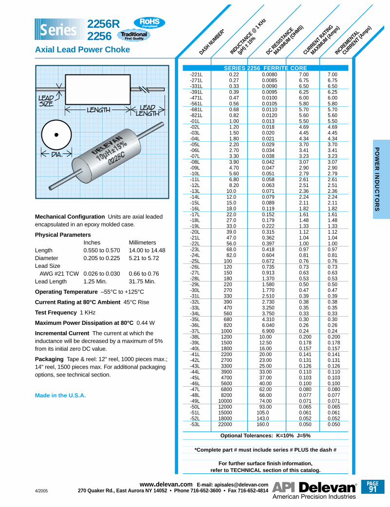
7.006.756.506.256.005.805.705.605.504.694.454.343.703.413.233.072.902.792.612.512.362.242.111.821.611.481.331.121.041.000.970.810.760.730.630.530.500.470.390.380.350.330.300.260.240.2000.1780.1570.1410.1310.1260.1100.1030.1000.0800.0770.0710.0650.0610.0520.050
7.006.756.506.256.005.805.705.605.504.694.454.343.703.413.233.072.902.792.612.512.362.242.111.821.611.481.331.121.041.000.970.810.760.730.630.530.500.470.390.380.350.330.300.260.240.2000.1780.1570.1410.1310.1260.1100.1030.1000.0800.0770.0710.0650.0610.0520.050
0.00800.00850.00900.00950.01000.01050.01100.01200.0130.0180.0200.0210.0290.0340.0380.0420.0470.0510.0580.0630.0710.0790.0890.1190.1520.1790.2220.3150.3620.3970.4180.6040.6720.7350.9131.3701.5801.7702.5102.7303.2503.7504.3106.0406.900
10.0012.5016.0020.0023.0025.0033.0037.0040.0062.0066.0074.0093.00
105.0143.0160.0
0.220.270.330.390.470.560.680.821.001.201.501.802.202.703.303.904.705.606.808.20
10.012.015.018.022.027.033.039.047.056.068.082.0
100120150180220270330390470560680820
100012001500180022002700330039004700560068008200
1000012000150001800022000
INDUCTANCE @
1 KHz
(µH) ±
15%
DC RESISTANCE
MAXIMUM (O
HMS)
CURRENT RATING
MAXIMUM (A
mps)
INCREMENTAL
CURRENT (Amps
)
DASH NUMBER*
Mechanical Configuration Units are axial leadedencapsulated in an epoxy molded case.
Physical ParametersInches Millimeters
Length 0.550 to 0.570 14.00 to 14.48Diameter 0.205 to 0.225 5.21 to 5.72Lead Size
AWG #21 TCW 0.026 to 0.030 0.66 to 0.76Lead Length 1.25 Min. 31.75 Min.
Operating Temperature –55°C to +125°C
Current Rating at 80°C Ambient 45°C Rise
Test Frequency 1 KHz
Maximum Power Dissipation at 80°C 0.44 W
Incremental Current The current at which theinductance will be decreased by a maximum of 5%from its initial zero DC value.
Packaging Tape & reel: 12" reel, 1000 pieces max.;14" reel, 1500 pieces max. For additional packagingoptions, see technical section.
Made in the U.S.A.
SERIES 2256 FERRITE CORE-221L-271L-331L-391L-471L-561L-681L-821L-01L-02L-03L-04L-05L-06L-07L-08L-09L-10L-11L-12L-13L-14L-15L-16L-17L-18L-19L-20L-21L-22L-23L-24L-25L-26L-27L-28L-29L-30L-31L-32L-33L-34L-35L-36L-37L-38L-39L-40L-41L-42L-43L-44L-45L-46L-47L-48L-49L-50L-51L-52L-53L
Optional Tolerances: K=10% J=5%
*Complete part # must include series # PLUS the dash #
For further surface finish information,refer to TECHNICAL section of this catalog.
2256R2256
Axial Lead Power Choke
Series
4/2005
PAGE91
www.delevan .com E-mail: apisales@delevan .com270 Quaker Rd., East Aurora NY 14052 • Phone 716-652-3600 • Fax 716-652-4814
PO
WE
R IN
DU
CT
OR
S
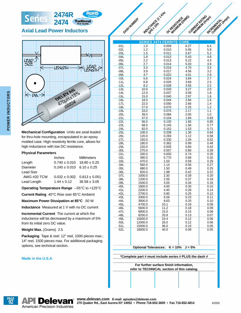
DASH NUMBER*
INDUCTANCE @
1 KHz
(µH) ±
15%
DC RESISTANCE
MAXIMUM (O
HMS)
CURRENT RATING
MAXIMUM (A
mps)
INCREMENTAL
CURRENT (Amps
)
6.45.85.24.84.33.93.53.22.92.72.52.22.01.81.61.51.41.21.11.00.930.850.770.710.640.580.520.480.430.390.350.320.290.270.250.220.200.180.160.150.140.120.110.100.090.090.080.070.060.060.050.05
6.275.955.675.435.225.034.704.564.013.843.693.553.273.092.972.842.662.252.172.051.841.651.561.531.301.121.040.990.840.800.740.680.590.560.490.420.390.370.340.300.280.250.230.200.190.180.150.130.120.120.100.09
1.01.21.51.82.22.73.33.94.75.66.88.2
10.012.015.018.022.027.033.039.047.056.068.082.0
100.0120.0150.0180.0220.0270.0330.0390.0470.0560.0680.0820.0
1000.01200.01500.01800.02200.02700.03300.03900.04700.05600.06800.08200.0
10000.012000.015000.018000.0
0.0090.0100.0110.0120.0130.0140.0160.0170.0220.0240.0260.0280.0330.0370.0400.0440.0500.0700.0750.0840.1040.1300.1450.1520.2080.2830.3300.3620.5050.5570.6500.7701.031.141.501.982.302.553.004.004.405.806.568.63
10.111.215.020.823.426.036.040.0
Mechanical Configuration Units are axial leadedfor thru-hole mounting, encapsulated in an epoxymolded case. High resistivity ferrite core, allows forhigh inductance with low DC resistance.
Physical ParametersInches Millimeters
Length 0.740 ± 0.010 18.80 ± 0.25Diameter 0.240 ± 0.010 6.10 ± 0.25Lead SizeAWG #20 TCW 0.032 ± 0.002 0.813 ± 0.051
Lead Length 1.44 ± 0.12 36.58 ± 3.05
Operating Temperature Range –55°C to +125°C
Current Rating 40°C Rise over 85°C Ambient
Maximum Power Dissipation at 85°C .50 W
Inductance Measured at 1 V with no DC current
Incremental Current The current at which theinductance will be decreased by a maximum of 5%from its initial zero DC value.
Weight Max. (Grams) 2.5
Packaging Tape & reel: 12" reel, 1000 pieces max.;14" reel, 1500 pieces max. For additional packagingoptions, see technical section.
Made in the U.S.A.
SERIES 2474 FERRITE CORE-01L-02L-03L-04L-05L-06L-07L-08L-09L-10L-11L-12L-13L-14L-15L-16L-17L-18L-19L-20L-21L-22L-23L-24L-25L-26L-27L-28L-29L-30L-31L-32L-33L-34L-35L-36L-37L-38L-39L-40L-41L-42L-43L-44L-45L-46L-47L-48L-49L-50L-51L-52L
Optional Tolerances: K = 10% J = 5%
*Complete part # must include series # PLUS the dash #
For further surface finish information,refer to TECHNICAL section of this catalog.
2474R2474
Axial Lead Power Inductors
Series
PAGE92
www.delevan .com E-mail: apisales@delevan .com270 Quaker Rd., East Aurora NY 14052 • Phone 716-652-3600 • Fax 716-652-4814 4/2005
PO
WE
R I
ND
UC
TO
RS
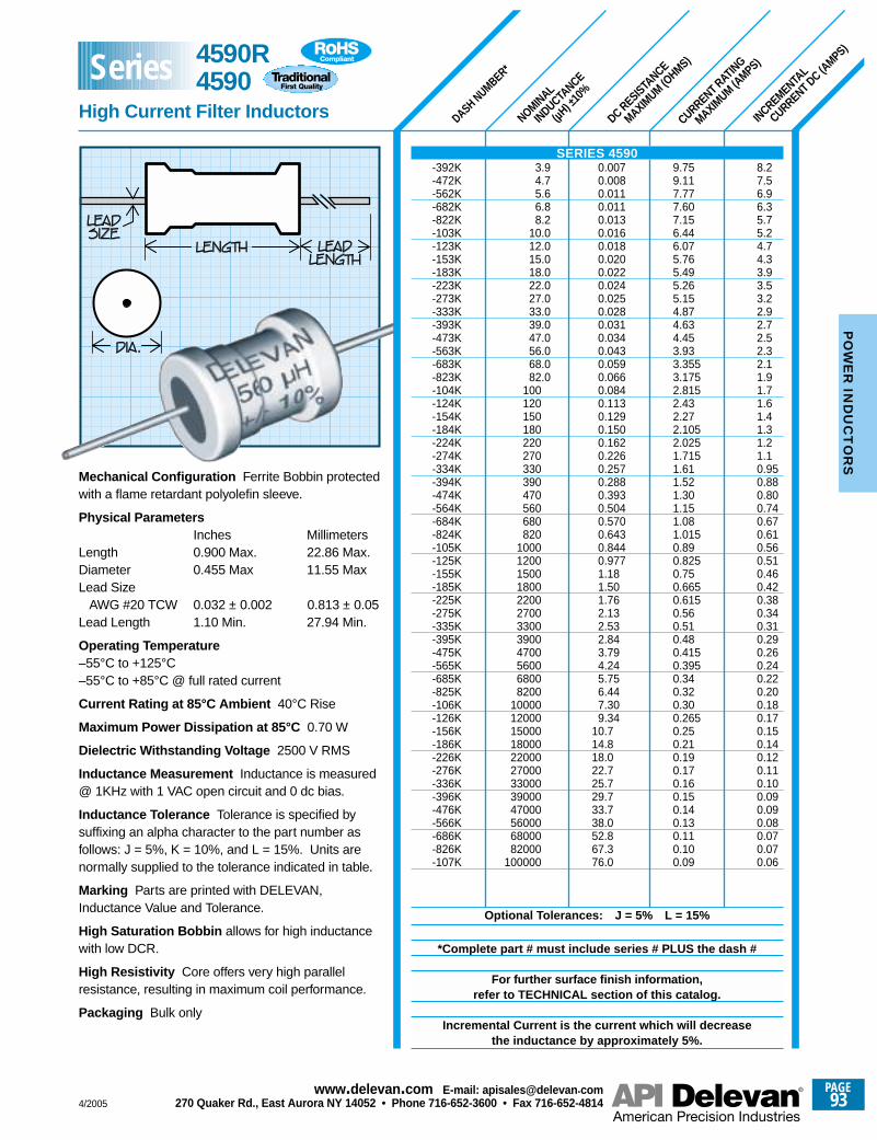
CURRENT RATING
MAXIMUM (A
MPS)
DC RESISTANCE
MAXIMUM (O
HMS)
INCREMENTAL
CURRENT DC (AMPS)
NOMINAL
INDUCTANCE
(µH) ±
10%
DASH NUMBER*
8.27.56.96.35.75.24.74.33.93.53.22.92.72.52.32.11.91.71.61.41.31.21.10.950.880.800.740.670.610.560.510.460.420.380.340.310.290.260.240.220.200.180.170.150.140.120.110.100.090.090.080.070.070.06
9.759.117.777.607.156.446.075.765.495.265.154.874.634.453.933.3553.1752.8152.432.272.1052.0251.7151.611.521.301.151.081.0150.890.8250.750.6650.6150.560.510.480.4150.3950.340.320.300.2650.250.210.190.170.160.150.140.130.110.100.09
3.94.75.66.88.2
10.012.015.018.022.027.033.039.047.056.068.082.0
100120150180220270330390470560680820
100012001500180022002700330039004700560068008200
100001200015000180002200027000330003900047000560006800082000
100000
0.0070.0080.0110.0110.0130.0160.0180.0200.0220.0240.0250.0280.0310.0340.0430.0590.0660.0840.1130.1290.1500.1620.2260.2570.2880.3930.5040.5700.6430.8440.9771.181.501.762.132.532.843.794.245.756.447.309.34
10.714.818.022.725.729.733.738.052.867.376.0
Mechanical Configuration Ferrite Bobbin protectedwith a flame retardant polyolefin sleeve.
Physical ParametersInches Millimeters
Length 0.900 Max. 22.86 Max.Diameter 0.455 Max 11.55 MaxLead Size
AWG #20 TCW 0.032 ± 0.002 0.813 ± 0.05Lead Length 1.10 Min. 27.94 Min.
Operating Temperature –55°C to +125°C–55°C to +85°C @ full rated current
Current Rating at 85°C Ambient 40°C Rise
Maximum Power Dissipation at 85°C 0.70 W
Dielectric Withstanding Voltage 2500 V RMS
Inductance Measurement Inductance is measured@ 1KHz with 1 VAC open circuit and 0 dc bias.
Inductance Tolerance Tolerance is specified bysuffixing an alpha character to the part number asfollows: J = 5%, K = 10%, and L = 15%. Units arenormally supplied to the tolerance indicated in table.
Marking Parts are printed with DELEVAN,Inductance Value and Tolerance.
High Saturation Bobbin allows for high inductancewith low DCR.
High Resistivity Core offers very high parallelresistance, resulting in maximum coil performance.
Packaging Bulk only
SERIES 4590-392K-472K-562K-682K-822K-103K-123K-153K-183K-223K-273K-333K-393K-473K-563K-683K-823K-104K-124K-154K-184K-224K-274K-334K-394K-474K-564K-684K-824K-105K-125K-155K-185K-225K-275K-335K-395K-475K-565K-685K-825K-106K-126K-156K-186K-226K-276K-336K-396K-476K-566K-686K-826K-107K
Optional Tolerances: J = 5% L = 15%
*Complete part # must include series # PLUS the dash #
For further surface finish information,refer to TECHNICAL section of this catalog.
Incremental Current is the current which will decreasethe inductance by approximately 5%.
4590R4590
High Current Filter Inductors
Series
4/2005
PAGE93
www.delevan .com E-mail: apisales@delevan .com270 Quaker Rd., East Aurora NY 14052 • Phone 716-652-3600 • Fax 716-652-4814
PO
WE
R IN
DU
CT
OR
S
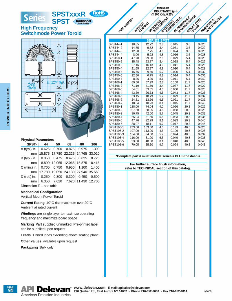
WITHOUT
CURRENT
MINIMUMINDUCTANCE (µH)
@ 100 KHz, 0.25V
WITH RATED
BIAS CURRENT
PART NUMBER*
DIMENSIO
N E -
LEAD DIAMETER
WEIGHT (T
YP.)
GRAMS
RATED BIAS
CURRENT (ADC)
DC RESISTANCE
MAXIMUM (O
HMS)
0.0200.0220.0250.0280.0200.0220.0250.0280.0320.0360.0400.0200.0220.0250.0280.0320.0360.0400.0260.0280.0320.0360.0400.0450.0260.0280.0320.0360.0400.045
3.63.63.63.65.45.45.45.45.45.45.4
11.711.711.711.711.711.711.720.320.320.320.320.320.340.540.540.540.540.540.5
0.0450.0310.0240.0160.0790.0580.0410.0300.0200.0140.0110.1080.0870.0600.0430.0290.0210.0150.0960.0680.0450.0330.0230.0170.1390.1060.0740.0490.0400.024
2.83.44.04.82.83.44.04.85.76.88.12.83.44.04.85.76.88.14.04.85.76.88.19.74.04.85.76.88.19.7
12.729.827.755.22
29.0023.7716.1312.27
9.506.754.80
57.9941.5933.0526.6318.7913.5610.2374.0458.0542.0031.6022.7918.11
153.00113.00
84.0061.9048.0035.30
18.8514.7512.30
8.0647.7035.4827.1621.6516.7612.50
8.8689.5071.1054.8143.3033.1524.3118.64
128.00107.50
80.7565.0447.7038.07
253.00197.00154.00116.00
93.0070.05
Physical ParametersSPST- 44 50 68 80 106
A (typ.) in. 0.625 0.700 0.875 0.975 1.300mm 15.875 17.780 22.225 24.765 33.020
B (typ.) in. 0.350 0.475 0.475 0.625 0.725mm 8.890 12.065 12.065 15.875 18.415
C (min.) in. 0.700 0.750 0.950 1.100 1.400mm 17.780 19.050 24.130 27.940 35.560
D (ref.) in. 0.250 0.300 0.300 0.450 0.500mm 6.350 7.620 7.620 11.430 12.700
Dimension E – see table
Mechanical ConfigurationVertical Mount Power Toroid
Current Rating 40°C rise maximum over 20°CAmbient at rated current
Windings are single layer to maximize operatingfrequency and maximize board space
Marking Part supplied unmarked; Pre-printed labelcan be supplied upon request
Leads Tinned leads extending above seating plane
Other values available upon request
Packaging Bulk only
SERIES SPSTSPST44-1SPST44-2SPST44-3SPST44-4SPST50-1SPST50-2SPST50-3SPST50-4SPST50-5SPST50-6SPST50-7SPST68-1SPST68-2SPST68-3SPST68-4SPST68-5SPST68-6SPST68-7SPST80-1SPST80-2SPST80-3SPST80-4SPST80-5SPST80-6SPST106-1SPST106-2SPST106-3SPST106-4SPST106-5SPST106-6
*Complete part # must include series # PLUS the dash #
For further surface finish information,refer to TECHNICAL section of this catalog.
SPSTxxxR SPST
High FrequencySwitchmode Power Toroid
Series
PAGE94
www.delevan .com E-mail: apisales@delevan .com270 Quaker Rd., East Aurora NY 14052 • Phone 716-652-3600 • Fax 716-652-4814 4/2005
PO
WE
R I
ND
UC
TO
RS
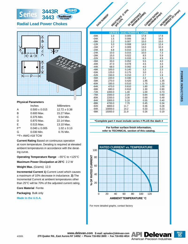
DASH NUMBER*
INDUCTANCE @
1KHz
(µH) ±
10%
DC RESISTANCE
MAXIMUM (O
HMS)
CURRENT RATING
MAXIMUM (A
mps)
INCREMENTAL
CURRENT DC (Amps
)
17.816.215.012.410.3
8.97.35.94.94.03.32.82.32.11.91.51.351.201.000.900.730.600.490.400.340.280.230.19
17.816.215.014.013.012.510.0
8.56.55.54.54.03.33.02.72.21.951.701.601.301.000.840.690.550.450.360.330.26
0.0050.0060.0070.0080.0090.0100.0150.0220.0330.0520.0780.0920.1400.1750.2100.3300.4200.5100.6100.9101.402.203.305.107.70
11.714.221.9
1.01.52.23.34.76.8
10.015.022.033.047.068.0
100.0120.0150.0220.0270.0330.0470.0680.0
1000.01500.02200.03300.04700.06800.0
10000.015000.0
Physical ParametersInches Millimeters
A 0.500 ± 0.015 12.72 ± 0.38B 0.600 Max. 15.27 Max.C 0.375 Min. 9.54 Min.D 0.870 Max. 22.14 Max.E 0.515 Max. 13.10 Max.F** 0.040 ± 0.005 1.02 ± 0.13G 0.030 Min. 0.76 Min.**F= AWG #18 TCW
Current Rating Based on continuous operationat room temperature. Derating is required at elevatedambient temperatures in accordance with the derat-ing curve.
Operating Temperature Range –55°C to +125°C
Maximum Power Dissipation at 25°C 2.2 W
Weight Max. (Grams) 12.0
Incremental Current 1) Current Level which causesa maximum of 10% decrease in inductance. 2) TheIncremental Current at ambient temperatures otherthan 25°C will be 70% of the adjusted current rating.
Core Material Ferrite
Packaging Bulk only
Made In the U.S.A.
SERIES 3443 FERRITE CORE-00K-04K-08K-12K-16K-20K-24K-28K-32K-36K-40K-44K-48K-50K-52K-56K-58K-60K-64K-68K-72K-76K-80K-84K-88K-92K-94K-98K
*Complete part # must include series # PLUS the dash #
For further surface finish information,refer to TECHNICAL section of this catalog.
RATED CURRENT vs. TEMPERATURE
0 20 40 60 80 100 120
20
AMBIENT TEMPERATURE °C
% O
F R
ATE
D C
UR
RE
NT
40
60
80
100
For more detailed graphs, contact factory
3443R3443
Radial Lead Power Chokes
Series
4/2005
PAGE95
www.delevan .com E-mail: apisales@delevan .com270 Quaker Rd., East Aurora NY 14052 • Phone 716-652-3600 • Fax 716-652-4814
PO
WE
R IN
DU
CT
OR
S
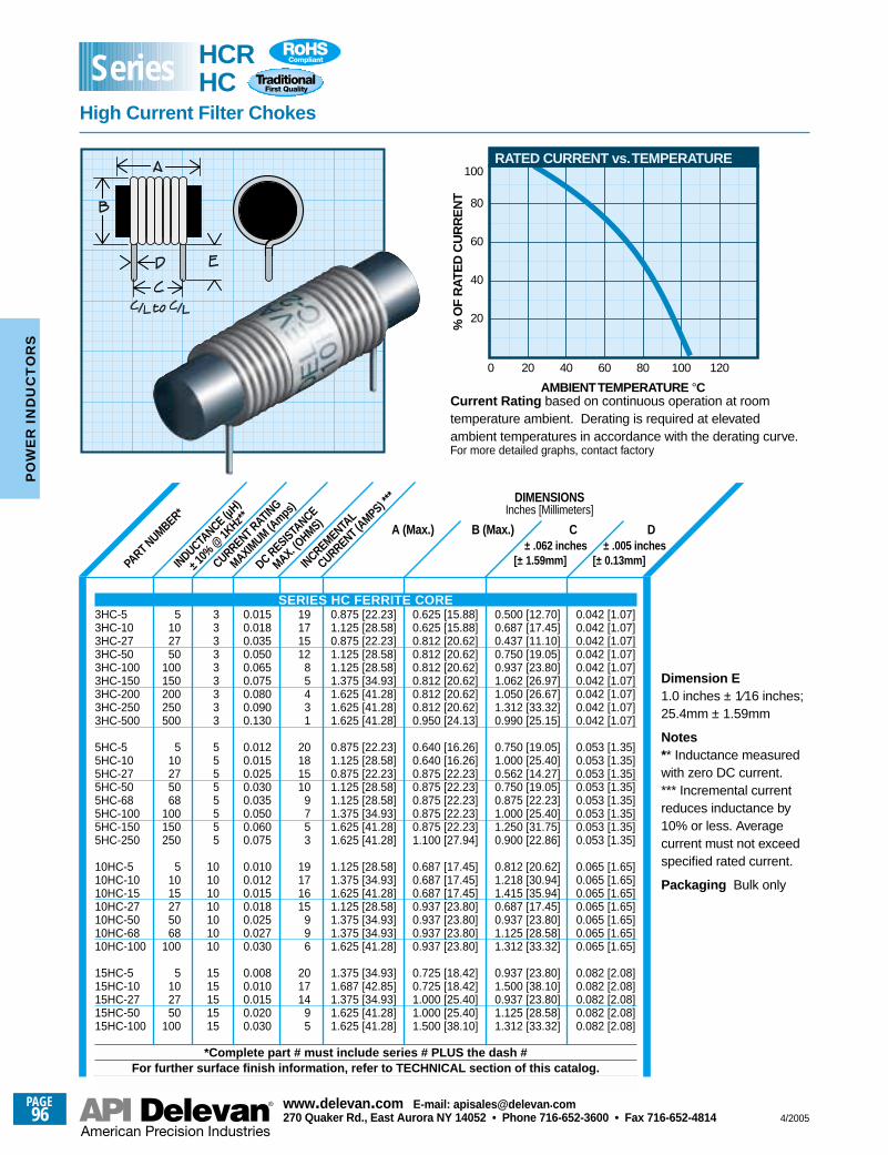
± .005 inches[± 0.13mm]PA
RT NUMBER*
INDUCTANCE (µ
H)
± 10% @
1KHz**
INCREMENTAL
CURRENT (AMPS) **
*
DC RESISTANCE
MAX. (OHMS)
CURRENT RATING
MAXIMUM (A
mps)
± .062 inches[± 1.59mm]
DIMENSIONSInches [Millimeters]
A (Max.) B (Max.) C D
0.042 [1.07]0.042 [1.07]0.042 [1.07]0.042 [1.07]0.042 [1.07]0.042 [1.07]0.042 [1.07]0.042 [1.07]0.042 [1.07]
0.053 [1.35]0.053 [1.35]0.053 [1.35]0.053 [1.35]0.053 [1.35]0.053 [1.35]0.053 [1.35]0.053 [1.35]
0.065 [1.65]0.065 [1.65]0.065 [1.65]0.065 [1.65]0.065 [1.65]0.065 [1.65]0.065 [1.65]
0.082 [2.08]0.082 [2.08]0.082 [2.08]0.082 [2.08]0.082 [2.08]
0.500 [12.70]0.687 [17.45]0.437 [11.10]0.750 [19.05]0.937 [23.80]1.062 [26.97]1.050 [26.67]1.312 [33.32]0.990 [25.15]
0.750 [19.05]1.000 [25.40]0.562 [14.27]0.750 [19.05]0.875 [22.23]1.000 [25.40]1.250 [31.75]0.900 [22.86]
0.812 [20.62]1.218 [30.94]1.415 [35.94]0.687 [17.45]0.937 [23.80]1.125 [28.58]1.312 [33.32]
0.937 [23.80]1.500 [38.10]0.937 [23.80]1.125 [28.58]1.312 [33.32]
0.625 [15.88]0.625 [15.88]0.812 [20.62]0.812 [20.62]0.812 [20.62]0.812 [20.62]0.812 [20.62]0.812 [20.62]0.950 [24.13]
0.640 [16.26]0.640 [16.26]0.875 [22.23]0.875 [22.23]0.875 [22.23]0.875 [22.23]0.875 [22.23]1.100 [27.94]
0.687 [17.45]0.687 [17.45]0.687 [17.45]0.937 [23.80]0.937 [23.80]0.937 [23.80]0.937 [23.80]
0.725 [18.42]0.725 [18.42]1.000 [25.40]1.000 [25.40]1.500 [38.10]
0.875 [22.23]1.125 [28.58]0.875 [22.23]1.125 [28.58]1.125 [28.58]1.375 [34.93]1.625 [41.28]1.625 [41.28]1.625 [41.28]
0.875 [22.23]1.125 [28.58]0.875 [22.23]1.125 [28.58]1.125 [28.58]1.375 [34.93]1.625 [41.28]1.625 [41.28]
1.125 [28.58]1.375 [34.93]1.625 [41.28]1.125 [28.58]1.375 [34.93]1.375 [34.93]1.625 [41.28]
1.375 [34.93]1.687 [42.85]1.375 [34.93]1.625 [41.28]1.625 [41.28]
0.0150.0180.0350.0500.0650.0750.0800.0900.130
0.0120.0150.0250.0300.0350.0500.0600.075
0.0100.0120.0150.0180.0250.0270.030
0.0080.0100.0150.0200.030
19171512
85431
20181510
9753
19171615
996
201714
95
333333333
55555555
10101010101010
1515151515
5102750
100150200250500
510275068
100150250
51015275068
100
5102750
100
Current Rating based on continuous operation at roomtemperature ambient. Derating is required at elevatedambient temperatures in accordance with the derating curve.For more detailed graphs, contact factory
RATED CURRENT vs. TEMPERATURE
0 20 40 60 80 100 120
20
AMBIENT TEMPERATURE °C
% O
F R
ATE
D C
UR
RE
NT
40
60
80
100
Dimension E1.0 inches ± 1⁄16 inches;25.4mm ± 1.59mm
Notes** Inductance measuredwith zero DC current.*** Incremental currentreduces inductance by10% or less. Averagecurrent must not exceedspecified rated current.
Packaging Bulk only
SERIES HC FERRITE CORE3HC-53HC-103HC-273HC-503HC-1003HC-1503HC-2003HC-2503HC-500
5HC-55HC-105HC-275HC-505HC-685HC-1005HC-1505HC-250
10HC-510HC-1010HC-1510HC-2710HC-5010HC-6810HC-100
15HC-515HC-1015HC-2715HC-5015HC-100
*Complete part # must include series # PLUS the dash #For further surface finish information, refer to TECHNICAL section of this catalog.
HCRHC
High Current Filter Chokes
Series
PAGE96
www.delevan .com E-mail: apisales@delevan .com270 Quaker Rd., East Aurora NY 14052 • Phone 716-652-3600 • Fax 716-652-4814 4/2005
PO
WE
R I
ND
UC
TO
RS
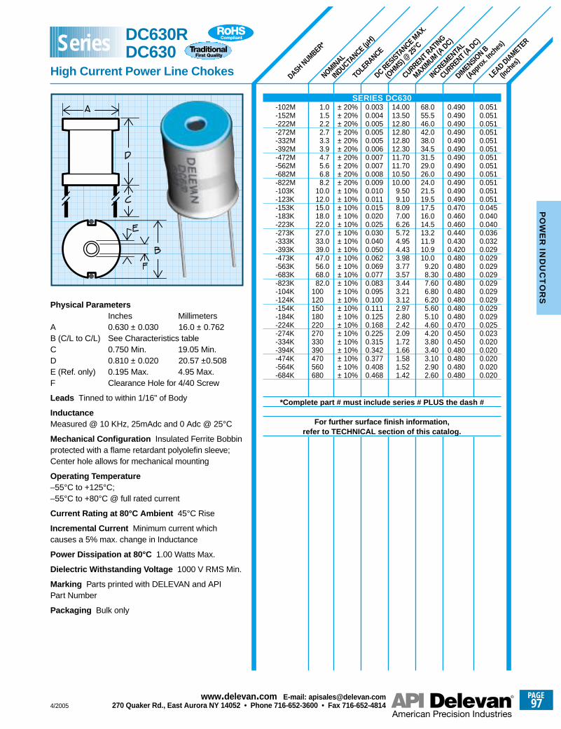
LEAD DIAMETER
(Inch
es)
TOLE
RANCE
DASH NUMBER*
INCREMENTAL
CURRENT (A DC)
NOMINAL
INDUCTANCE (µ
H)
DC RESISTANCE M
AX.
(OHMS) @
25°C
CURRENT RATING
MAXIMUM (A
DC)
DIMENSIO
N B
(Approx
. Inch
es)
Physical ParametersInches Millimeters
A 0.630 ± 0.030 16.0 ± 0.762B (C/L to C/L) See Characteristics tableC 0.750 Min. 19.05 Min.D 0.810 ± 0.020 20.57 ±0.508E (Ref. only) 0.195 Max. 4.95 Max.F Clearance Hole for 4/40 Screw
Leads Tinned to within 1/16" of Body
InductanceMeasured @ 10 KHz, 25mAdc and 0 Adc @ 25°C
Mechanical Configuration Insulated Ferrite Bobbinprotected with a flame retardant polyolefin sleeve;Center hole allows for mechanical mounting
Operating Temperature–55°C to +125°C;–55°C to +80°C @ full rated current
Current Rating at 80°C Ambient 45°C Rise
Incremental Current Minimum current whichcauses a 5% max. change in Inductance
Power Dissipation at 80°C 1.00 Watts Max.
Dielectric Withstanding Voltage 1000 V RMS Min.
Marking Parts printed with DELEVAN and APIPart Number
Packaging Bulk only
0.4900.4900.4900.4900.4900.4900.4900.4900.4900.4900.4900.4900.4700.4600.4600.4400.4300.4200.4800.4800.4800.4800.4800.4800.4800.4800.4700.4500.4500.4800.4800.4800.480
0.0510.0510.0510.0510.0510.0510.0510.0510.0510.0510.0510.0510.0450.0400.0400.0360.0320.0290.0290.0290.0290.0290.0290.0290.0290.0290.0250.0230.0200.0200.0200.0200.020
14.0013.5012.8012.8012.8012.3011.7011.7010.5010.00
9.509.108.097.006.265.724.954.433.983.773.573.443.213.122.972.802.422.091.721.661.581.521.42
68.055.546.042.038.034.531.529.026.024.021.519.517.516.014.513.211.910.910.0
9.208.307.606.806.205.605.104.604.203.803.403.102.902.60
0.0030.0040.0050.0050.0050.0060.0070.0070.0080.0090.0100.0110.0150.0200.0250.0300.0400.0500.0620.0690.0770.0830.0950.1000.1110.1250.1680.2250.3150.3420.3770.4080.468
± 20%± 20%± 20%± 20%± 20%± 20%± 20%± 20%± 20%± 20%± 10%± 10%± 10%± 10%± 10%± 10%± 10%± 10%± 10%± 10%± 10%± 10%± 10%± 10%± 10%± 10%± 10%± 10%± 10%± 10%± 10%± 10%± 10%
1.01.52.22.73.33.94.75.66.88.2
10.012.015.018.022.027.033.039.047.056.068.082.0
100120150180220270330390470560680
SERIES DC630-102M-152M-222M-272M-332M-392M-472M-562M-682M-822M-103K-123K-153K-183K-223K-273K-333K-393K-473K-563K-683K-823K-104K-124K-154K-184K-224K-274K-334K-394K-474K-564K-684K
*Complete part # must include series # PLUS the dash #
For further surface finish information,refer to TECHNICAL section of this catalog.
DC630RDC630
High Current Power Line Chokes
Series
4/2005
PAGE97
www.delevan .com E-mail: apisales@delevan .com270 Quaker Rd., East Aurora NY 14052 • Phone 716-652-3600 • Fax 716-652-4814
PO
WE
R IN
DU
CT
OR
S
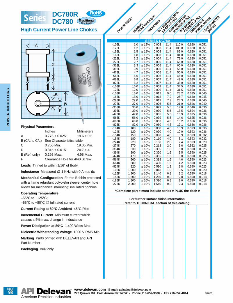
LEAD DIAMETER
(Inch
es)
TOLE
RANCE
DASH NUMBER*
INCREMENTAL
CURRENT (A DC)
NOMINAL
INDUCTANCE (µ
H)
DC RESISTANCE M
AX.
(OHMS) @
25°C
CURRENT RATING
MAXIMUM (A
DC)
DIMENSIO
N B
(Approx
. Inch
es)
0.6200.6200.6200.6200.6200.6200.6200.6200.6200.6200.6200.6200.6200.6200.6250.6300.6300.5460.5460.5940.6250.6250.6560.6560.5930.5930.5930.5930.5930.5620.5900.5900.5900.5900.5900.5900.5900.5900.5900.5900.590
0.0510.0510.0510.0510.0510.0510.0510.0510.0510.0510.0510.0510.0510.0510.0450.0450.0450.0400.0360.0360.0360.0360.0360.0360.0360.0360.0320.0320.0290.0250.0250.0250.0250.0230.0230.0230.0200.0180.0180.0180.018
11.411.411.411.411.411.411.411.411.411.411.411.411.411.4
9.07.27.25.55.55.55.55.54.84.84.04.04.04.02.82.01.61.61.61.61.61.31.00.80.80.80.8
110.0108.0
89.081.073.066.060.055.050.046.042.038.034.531.528.225.723.321.019.017.515.914.613.212.110.910.0
8.98.17.46.66.05.55.04.64.23.83.53.22.82.62.3
0.0030.0030.0030.0030.0040.0050.0050.0050.0050.0060.0070.0070.0090.0090.0130.0180.0190.0260.0290.0300.0350.0390.0530.0600.0800.0900.0980.1100.1500.2130.3050.3200.3550.3880.4300.5900.8181.1401.2601.3901.540
± 15%± 15%± 15%± 15%± 15%± 15%± 15%± 15%± 15%± 15%± 15%± 15%± 10%± 10%± 10%± 10%± 10%± 10%± 10%± 10%± 10%± 10%± 10%± 10%± 10%± 10%± 10%± 10%± 10%± 10%± 10%± 10%± 10%± 10%± 10%± 10%± 10%± 10%± 10%± 10%± 10%
1.01.21.51.82.22.73.33.94.75.66.88.2
10.012.015.018.022.027.033.039.047.056.068.082.0
100120150180220270330390470560680820
1,0001,2001,5001,8002,200
Physical ParametersInches Millimeters
A 0.775 ± 0.025 19.6 ± 0.6B (C/L to C/L) See Characteristics tableC 0.750 Min. 19.05 Min.D 0.815 ± 0.015 20.7 ±.4E (Ref. only) 0.195 Max. 4.95 Max.F Clearance Hole for 4/40 Screw
Leads Tinned to within 1/16" of Body
Inductance Measured @ 1 KHz with 0 Amps dc
Mechanical Configuration Ferrite Bobbin protectedwith a flame retardant polyolefin sleeve; center holeallows for mechanical mounting; insulated bobbins.
Operating Temperature–55°C to +125°C;–55°C to +80°C @ full rated current
Current Rating at 80°C Ambient 45°C Rise
Incremental Current Minimum current whichcauses a 5% max. change in Inductance
Power Dissipation at 80°C 1.400 Watts Max.
Dielectric Withstanding Voltage 1000 V RMS Min.
Marking Parts printed with DELEVAN and APIPart Number
Packaging Bulk only
SERIES DC780-102L-122L-152L-182L-222L-272L-332L-392L-472L-562L-682L-822L-103K-123K-153K-183K-223K-273K-333K-393K-473K-563K-683K-823K-104K-124K-154K-184K-224K-274K-334K-394K-474K-564K-684K-824K-105K-125K-155K-185K-225K
*Complete part # must include series # PLUS the dash #
For further surface finish information,refer to TECHNICAL section of this catalog.
DC780RDC780
High Current Power Line Chokes
Series
PAGE98
www.delevan .com E-mail: apisales@delevan .com270 Quaker Rd., East Aurora NY 14052 • Phone 716-652-3600 • Fax 716-652-4814 4/2005
PO
WE
R I
ND
UC
TO
RS
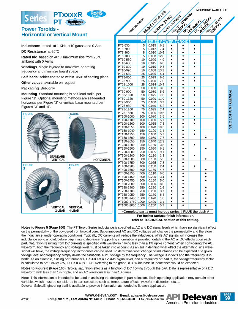
FIG. “1
” STA
NDARD
VERTICAL
FIG. “2
”
HORIZONTAL
FIG. “3
” 2-L
EAD
VERTICAL
FIG. “4
” 4-L
EAD
VERTICAL
PART NUMBER*
IND.(µH) ±
15%
@1 KHz
DCR MAX. (O
HMS)
RATED Id
c (Amps
)
5555
10101010252525255050505075757575
100100100100150150150150250250250300300300400400400500500500750750750
100010001000
0.0150.0120.0100.0080.0200.0150.0100.0080.0350.0250.0200.0140.0500.0300.0250.0200.0600.0400.0350.0250.0800.0500.0350.0280.1000.0600.0500.0400.1300.0800.0550.1500.1000.0750.2500.1800.1100.2200.1600.0900.3500.2800.1500.6200.4200.200
6.17.4
10.612.8
4.96.89.3
13.24.46.67.0
10.43.85.67.0
11.03.95.27.4
10.63.55.17.8
10.33.45.77.7
12.33.86.19.13.35.57.32.44.76.03.45.08.02.63.76.41.83.15.9
••••••••••••••••••••••••••••••••••••••••••••••
••••••••••••••••••••••••••••••••••••••••••••••
•••
•••
•••
•••
•••
•••
••
•
•
•
•
•
•
••••
••••••
MOUNTING AVAILABLE
Inductance tested at 1 KHz, <10 gauss and 0 Adc
DC Resistance at 25°C
Rated Idc based on 40°C maximum rise from 25°Cambient with 0 Arms
Windings single layered to maximize operatingfrequency and minimize board space
Self leads solder coated to within .050" of seating plane
Other values available on request
Packaging Bulk only
Mounting Standard mounting is self-lead radial perFigure “1”. Optional mounting methods are self-leadedhorizontal per Figure “2” or vertical base mounted perFigures “3” and “4”.
PT SERIES POWER TOROIDSPT5-530PT5-700PT5-800PT5-1000PT10-530PT10-680PT10-820PT10-990PT25-680PT25-800PT25-900PT25-1000PT50-780PT50-900PT50-1020PT50-1320PT75-900PT75-980PT75-1260PT75-1550PT100-1000PT100-1100PT100-1260PT100-1550PT150-1040PT150-1250PT150-1500PT150-2050PT250-1200PT250-1500PT250-1800PT300-1200PT300-1500PT300-1750PT400-1200PT400-1500PT400-1750PT500-1450PT500-1750PT500-2000PT750-1400PT750-1700PT750-2050PT1000-1400PT1000-1750PT1000-2050
*Complete part # must include series # PLUS the dash #For further surface finish information,
refer to TECHNICAL section of this catalog.
Notes to Figure 5 (Page 100) The PT Toroid Series inductance is specified at AC and DC signal levels which have no significant effecton the permeability of the powdered iron toroidal core. Superimposed AC and DC voltages will change the permeability and thereforethe inductance, under operating conditions. Typically, DC currents will reduce the inductance, while AC signals will increase theinductance up to a point, before beginning to decrease. Supporting information is provided, detailing the AC or DC effects upon eachpart. Saturation resulting from DC currents is specified with waveform having less than a 1% ripple content. When considering the ACwaveform, both the frequency and voltage level must be taken into account. As an aid in defining what effect the alternating sine wavesignal will have, the voltage/frequency factor curve can be used. To determine what change of inductance can be expected at a givenvoltage level and frequency, simply divide the sinusoidal RMS voltage by the frequency. The voltage is in volts and the frequency is inhertz. As an example, if using part number PT25-680 at a 1VRMS signal level, and a frequency of 25KHz, the voltage/frequency factoris calculated to be: 1VRMS/25,000Hz = 40 x 10–6. Referring to the graph, a 39% increase in inductance would be expected.
Notes to Figure 6 (Page 100) Typical saturation effects as a function of DC flowing through the part. Data is representative of a DCwaveform with less than 1% ripple, and an AC waveform less than 10 gauss.
Note This information is intended to be used in assisting the designer in part selection. Each operating application may contain othervariables which must be considered in part selection; such as temperature effects, waveform distortion, etc.…Delevan Sales/Engineering staff is available to provide information as needed to fit each application.
STANDARDVERTICAL HORIZONTAL
VERTICAL2-LEAD
VERTICAL4-LEAD
FIGURE1
FIGURE2
FIGURE3
FIGURE4
PTxxxxRPT
Power Toroids - Horizontal or Vertical Mount
Series
4/2005
PAGE99
www.delevan .com E-mail: apisales@delevan .com270 Quaker Rd., East Aurora NY 14052 • Phone 716-652-3600 • Fax 716-652-4814
PO
WE
R IN
DU
CT
OR
S
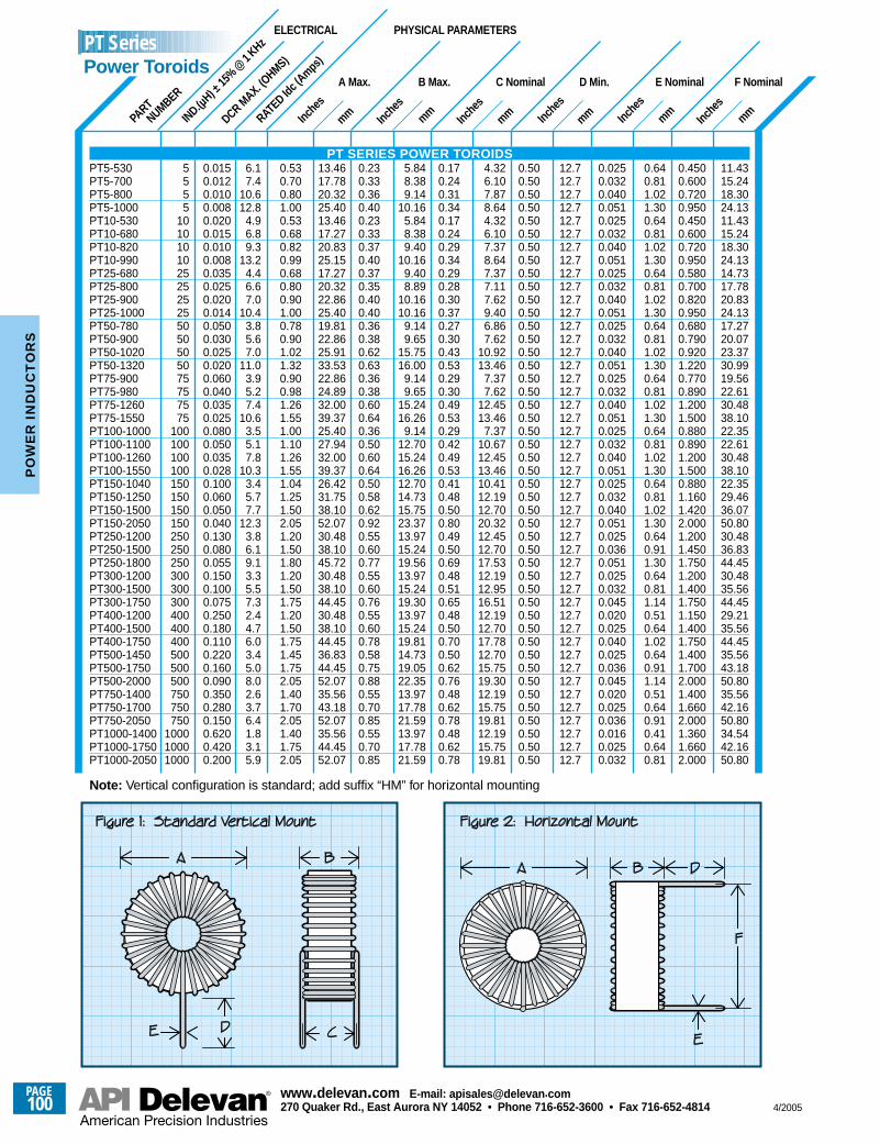
mmInche
smmInc
hes
mmInche
smmInc
hes
mmInche
smmInc
hes
IND.(µH) ±
15%
@1 KHz
DCR MAX. (O
HMS)
PART
NUMBER
RATED Id
c (Amps
)
A Max.
5555
10101010252525255050505075757575
100100100100150150150150250250250300300300400400400500500500750750750
100010001000
0.0150.0120.0100.0080.0200.0150.0100.0080.0350.0250.0200.0140.0500.0300.0250.0200.0600.0400.0350.0250.0800.0500.0350.0280.1000.0600.0500.0400.1300.0800.0550.1500.1000.0750.2500.1800.1100.2200.1600.0900.3500.2800.1500.6200.4200.200
6.17.4
10.612.8
4.96.89.3
13.24.46.67.0
10.43.85.67.0
11.03.95.27.4
10.63.55.17.8
10.33.45.77.7
12.33.86.19.13.35.57.32.44.76.03.45.08.02.63.76.41.83.15.9
0.530.700.801.000.530.680.820.990.680.800.901.000.780.901.021.320.900.981.261.551.001.101.261.551.041.251.502.051.201.501.801.201.501.751.201.501.751.451.752.051.401.702.051.401.752.05
13.4617.7820.3225.4013.4617.2720.8325.1517.2720.3222.8625.4019.8122.8625.9133.5322.8624.8932.0039.3725.4027.9432.0039.3726.4231.7538.1052.0730.4838.1045.7230.4838.1044.4530.4838.1044.4536.8344.4552.0735.5643.1852.0735.5644.4552.07
B Max.
0.230.330.360.400.230.330.370.400.370.350.400.400.360.380.620.630.360.380.600.640.360.500.600.640.500.580.620.920.550.600.770.550.600.760.550.600.780.580.750.880.550.700.850.550.700.85
5.848.389.14
10.165.848.389.40
10.169.408.89
10.1610.16
9.149.65
15.7516.00
9.149.65
15.2416.26
9.1412.7015.2416.2612.7014.7315.7523.3713.9715.2419.5613.9715.2419.3013.9715.2419.8114.7319.0522.3513.9717.7821.5913.9717.7821.59
C Nominal
0.170.240.310.340.170.240.290.340.290.280.300.370.270.300.430.530.290.300.490.530.290.420.490.530.410.480.500.800.490.500.690.480.510.650.480.500.700.500.620.760.480.620.780.480.620.78
4.326.107.878.644.326.107.378.647.377.117.629.406.867.62
10.9213.46
7.377.62
12.4513.46
7.3710.6712.4513.4610.4112.1912.7020.3212.4512.7017.5312.1912.9516.5112.1912.7017.7812.7015.7519.3012.1915.7519.8112.1915.7519.81
D Min.
0.500.500.500.500.500.500.500.500.500.500.500.500.500.500.500.500.500.500.500.500.500.500.500.500.500.500.500.500.500.500.500.500.500.500.500.500.500.500.500.500.500.500.500.500.500.50
12.712.712.712.712.712.712.712.712.712.712.712.712.712.712.712.712.712.712.712.712.712.712.712.712.712.712.712.712.712.712.712.712.712.712.712.712.712.712.712.712.712.712.712.712.712.7
E Nominal
0.0250.0320.0400.0510.0250.0320.0400.0510.0250.0320.0400.0510.0250.0320.0400.0510.0250.0320.0400.0510.0250.0320.0400.0510.0250.0320.0400.0510.0250.0360.0510.0250.0320.0450.0200.0250.0400.0250.0360.0450.0200.0250.0360.0160.0250.032
0.640.811.021.300.640.811.021.300.640.811.021.300.640.811.021.300.640.811.021.300.640.811.021.300.640.811.021.300.640.911.300.640.811.140.510.641.020.640.911.140.510.640.910.410.640.81
F Nominal
0.4500.6000.7200.9500.4500.6000.7200.9500.5800.7000.8200.9500.6800.7900.9201.2200.7700.8901.2001.5000.8800.8901.2001.5000.8801.1601.4202.0001.2001.4501.7501.2001.4001.7501.1501.4001.7501.4001.7002.0001.4001.6602.0001.3601.6602.000
11.4315.2418.3024.1311.4315.2418.3024.1314.7317.7820.8324.1317.2720.0723.3730.9919.5622.6130.4838.1022.3522.6130.4838.1022.3529.4636.0750.8030.4836.8344.4530.4835.5644.4529.2135.5644.4535.5643.1850.8035.5642.1650.8034.5442.1650.80
ELECTRICAL PHYSICAL PARAMETERS
Note: Vertical configuration is standard; add suffix “HM” for horizontal mounting
PT SERIES POWER TOROIDSPT5-530PT5-700PT5-800PT5-1000PT10-530PT10-680PT10-820PT10-990PT25-680PT25-800PT25-900PT25-1000PT50-780PT50-900PT50-1020PT50-1320PT75-900PT75-980PT75-1260PT75-1550PT100-1000PT100-1100PT100-1260PT100-1550PT150-1040PT150-1250PT150-1500PT150-2050PT250-1200PT250-1500PT250-1800PT300-1200PT300-1500PT300-1750PT400-1200PT400-1500PT400-1750PT500-1450PT500-1750PT500-2000PT750-1400PT750-1700PT750-2050PT1000-1400PT1000-1750PT1000-2050
PT SeriesPower Toroids
PAGE100
www.delevan .com E-mail: apisales@delevan .com270 Quaker Rd., East Aurora NY 14052 • Phone 716-652-3600 • Fax 716-652-4814 4/2005
PO
WE
R I
ND
UC
TO
RS
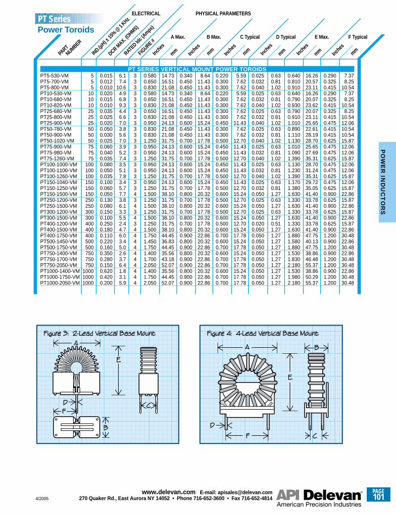
mmInche
smmInc
hes
mmInche
s
mmInche
smmInc
hes
mmInche
sIND.(µ
H) ±15
%@
1 KHz
DCR MAX. (O
HMS)
PART
NUMBER
RATED Id
c (Amps
)
FIGURE #
A Max.
555
101010252525505050757575
100100100150150150250250300300400400400500500750750750
100010001000
0.0150.0120.0100.0200.0150.0100.0350.0250.0200.0500.0300.0250.0600.0400.0350.0800.0500.0350.1000.0600.0500.1300.0800.1500.1000.2500.1800.1100.2200.1600.3500.2800.1500.6200.4200.200
6.17.4
10.64.96.89.34.46.67.03.85.67.03.95.27.43.55.17.83.45.77.73.86.13.35.52.44.76.03.45.02.63.76.41.83.15.9
333333333333333333334343434444444444
0.5800.6500.8300.5800.6500.8300.6500.8300.9500.8300.8301.2500.9500.9501.2500.9500.9501.2500.9501.2501.5001.2501.5001.2501.5001.2501.5001.7501.4501.7501.4001.7002.0501.4001.7502.050
14.7316.5121.0814.7316.5121.0816.5121.0824.1321.0821.0831.7524.1324.1331.7524.1324.1331.7524.1331.7538.1031.7538.1031.7538.1031.7538.1044.4536.8344.4535.5643.1852.0735.5644.4552.07
B Max.
0.3400.4500.4500.3400.4500.4500.4500.4500.6000.4500.4500.7000.6000.6000.7000.6000.6000.7000.6000.7000.8000.7000.8000.7000.8000.7000.8000.9000.8000.9000.8000.9000.9000.8000.9000.900
8.6411.4311.43
8.6411.4311.4311.4311.4315.2411.4311.4317.7815.2415.2417.7815.2415.2417.7815.2417.7820.3217.7820.3217.7820.3217.7820.3222.8620.3222.8620.3222.8622.8620.3222.8622.86
C Typical
0.2200.3000.3000.2200.3000.3000.3000.3000.4500.3000.3000.5000.4500.4500.5000.4500.4500.5000.4500.5000.6000.5000.6000.5000.6000.5000.6000.7000.6000.7000.6000.7000.7000.6000.7000.700
5.597.627.625.597.627.627.627.62
11.437.627.62
12.7011.4311.4312.7011.4311.4312.7011.4312.7015.2412.7015.2412.7015.2412.7015.2417.7815.2417.7815.2417.7817.7815.2417.7817.78
D Typical
0.0250.0320.0400.0250.0320.0400.0250.0320.0400.0250.0320.0400.0250.0320.0400.0250.0320.0400.0250.0320.0500.0250.0500.0250.0500.0200.0500.0500.0500.0500.0500.0500.0500.0500.0500.050
0.630.811.020.630.811.020.630.811.020.630.811.020.630.811.020.630.811.020.630.811.270.631.270.631.270.511.271.271.271.271.271.271.271.271.271.27
E Max.
0.6400.8100.9100.6400.7900.9300.7900.9101.0100.8901.1101.1301.0101.0901.3901.1301.2301.3901.1701.3801.6301.3301.6301.3301.6301.3301.6301.8801.5801.8801.5301.8302.1801.5301.9802.180
16.2620.5723.1116.2620.0723.6220.0723.1125.6522.6128.1928.7025.6527.6935.3128.7031.2435.3129.7235.0541.4033.7841.4033.7841.4033.7841.4047.7540.1347.7538.8646.4855.3738.8650.2955.37
F Typical
0.2900.3250.4150.2900.3250.4150.3250.4150.4750.4150.4150.6250.4750.4750.6250.4750.4750.6250.4750.6250.9000.6250.9000.6250.9000.6250.9001.2000.9001.2000.9001.2001.2000.9001.2001.200
7.378.25
10.547.378.25
10.548.25
10.5412.0610.5410.5415.8712.0612.0615.8712.0612.0615.8712.0615.8722.8615.8722.8615.8722.8615.8722.8630.4822.8630.4822.8630.4830.4822.8630.4830.48
ELECTRICAL PHYSICAL PARAMETERS
PT SERIES VERTICAL MOUNT POWER TOROIDSPT5-530-VMPT5-700-VMPT5-800-VMPT10-530-VMPT10-680-VMPT10-820-VMPT25-680-VMPT25-800-VMPT25-900-VMPT50-780-VMPT50-900-VMPT50-1020-VMPT75-900-VMPT75-980-VMPT75-1260-VMPT100-1000-VMPT100-1100-VMPT100-1260-VMPT150-1040-VMPT150-1250-VMPT150-1500-VMPT250-1200-VMPT250-1500-VMPT300-1200-VMPT300-1500-VMPT400-1200-VMPT400-1500-VMPT400-1750-VMPT500-1450-VMPT500-1750-VMPT750-1400-VMPT750-1700-VMPT750-2050-VMPT1000-1400-VMPT1000-1750-VMPT1000-2050-VM
PT SeriesPower Toroids
4/2005
PAGE101
www.delevan .com E-mail: apisales@delevan .com270 Quaker Rd., East Aurora NY 14052 • Phone 716-652-3600 • Fax 716-652-4814
PO
WE
R IN
DU
CT
OR
S

PT SERIES, FIGURE 6 See Notes, Page 92
0
0
DC CURRENT IN AMPS
20
40
2
10
30
50
4 6 8 10 120
IND
UC
TAN
CE
DE
CR
EA
SE
%
20
40
10
30
0 2 4 6 8 10 12 0 2 4 6 8 10 12 0 2 4 6 8 10 12
PT300-1200PT100-1000PT1000-1750PT750-1400PT400-1200PT1000-1400
PT50-780PT500-1450PT150-1040PT75-900PT10-530PT750-1750
PT50-1020PT300-1750PT10-680PT25-800PT5-530PT750-2050
PT50-900PT100-1100 PT400-1500PT25-680PT250-1200PT75-980
PT50-1320PT10-820PT100-1550PT5-700PT75-1260
PT250-1500PT150-1250PT400-1750PT300-1500PT1000-2050PT500-1750
PT5-1000PT5-800PT150-2050PT10-990PT75-1550
PT500-2000PT250-1800PT25-900PT100-1260
PT25-1000PT150-1500
1
10
VOLTAGE/FREQUENCY FACTOR (X 10–6)
IND
UC
TAN
CE
INC
RE
AS
E %
20
30
40
50
60
70
80
90100
10 100 1000 100000.1
PT SERIES, FIGURE 5 See Notes, Page 84 1 10 20 30 40 4525155
1) PT5-5302) PT10-5303) PT5-7004) PT5-8005) PT10-6806) PT5-1000
7) PT10-8208) PT10-9909) PT25-68010) PT25-80011) PT25-90012) PT25-1000
13) PT50-78014) PT50-90015) PT75-90016) PT75-98017) PT50-102018) PT100-1000
19) PT100-110020) PT50-132021) PT150-104022) PT75-126023) PT100-126024) PT75-1550
25) PT100-155026) PT150-125027) PT150-150028) PT250-120029) PT300-120030) PT250-1500
31) PT400-120032) PT300-150033) PT400-150034) PT250-180035) PT150-205036) PT300-1750
37) PT500-145038) PT400-175039) PT750-140040) PT500-175041) PT1000-140042) PT750-1750
43) PT500-200044) PT1000-175045) PT750-205046) PT1000-2050
KEY TO FIGURE 5 CURVE NUMBERS Graphs apply to all mounting styles. For more detailed graphs, contact factory.
For more detailed graphs, contact factory
PT SERIES, FIGURE 5 See Notes, Page 97
PT SERIES, FIGURE 6 See Notes, Page 97
PTxxxxRPT
Power Toroids - Horizontal or Vertical Mount
Series
PAGE102
www.delevan .com E-mail: apisales@delevan .com270 Quaker Rd., East Aurora NY 14052 • Phone 716-652-3600 • Fax 716-652-4814 4/2005
PO
WE
R I
ND
UC
TO
RS
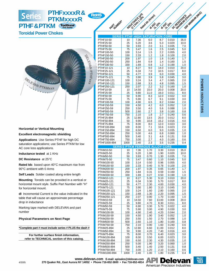
INDUCTANCE (µ
H)
@1 KHz ±
10%
PART
NUMBER*
Rated I
dc (A
mps)
DC RESISTANCE
MAXIMUM (O
hms)
dI ADC
∆L 20%
dI ADC
∆L 10%
SRF MINIMUM
(MHZ)
10255075
100150200250330
10255075
100150250
10255075
100150250500750
255075
100150250500750
1000
10255075
100150200250330
10255075
100150250
10255075
100150250500750
255075
100150250500750
1000
7.365.203.933.473.142.331.971.841.698.276.344.773.903.242.682.07
14.509.806.905.904.904.503.502.602.10
12.809.908.008.006.505.003.403.002.40
7.365.203.933.473.142.331.971.841.698.276.344.773.903.242.682.07
14.509.806.905.904.904.503.502.602.10
12.809.908.008.006.505.003.403.002.40
6.03.62.01.61.51.21.00.90.89.07.03.93.93.43.32.2
15.011.0
8.36.76.54.24.02.71.8
13.510.8
8.07.16.04.63.12.72.3
1.701.000.700.600.500.400.350.310.275.303.302.301.801.601.300.907.604.703.303.002.401.901.501.100.906.604.203.703.502.301.901.401.201.00
8.75.33.12.52.21.81.61.41.2
14.010.5
6.05.84.74.83.2
20.016.012.0
9.18.26.05.63.82.7
20.015.212.010.6
9.06.84.64.03.5
3.301.901.301.100.960.780.650.590.509.105.704.003.102.802.201.70
13.008.305.704.904.203.402.701.801.60
11.007.406.406.004.303.202.502.101.80
0.0100.0200.0350.0450.0550.1000.1400.1600.1900.0100.0170.0300.0450.0650.0950.1600.0080.0110.0220.0300.0440.0520.0880.1600.2400.0120.0160.0230.0230.0350.0600.1310.1600.235
0.0100.0200.0350.0450.0550.1000.1400.1600.1900.0100.0170.0300.0450.0650.0950.1600.0080.0110.0220.0300.0440.0520.0880.1600.2400.0120.0160.0230.0230.0350.0600.1310.1600.235
35.010.0
7.05.04.02.01.71.51.0
20.08.04.03.02.01.51.0
20.08.04.03.02.01.01.00.80.68.04.03.02.01.01.00.80.60.4
35.010.0
7.05.04.02.01.71.51.0
20.08.04.03.02.01.51.0
20.08.04.03.02.01.01.00.80.68.04.03.02.01.01.00.80.60.4
Horizontal or Vertical Mounting
Excellent electromagnetic shielding
Applications Use Series PTHF for high DCsaturation applications; use Series PTKM for lowAC core loss applications.
Inductance tested at 1 KHz
DC Resistance at 25°C
Rated Idc based upon 40°C maximum rise from90°C ambient with 0 Arms
Self Leads Solder coated along entire length
Mounting Toroids can be provided in a vertical orhorizontal mount style. Suffix Part Number with “H”for horizontal mount.
dI Incremental Current is the value indicated in thetable that will cause an approximate percentagedrop in inductance
Marking tape marked with DELEVAN and partnumber
Physical Parameters on Next Page
*Complete part # must include series # PLUS the dash #
For further surface finish information,refer to TECHNICAL section of this catalog.
SERIES PTHF HIGH SATURATION COREPTHF10-50PTHF25-50PTHF50-50PTHF75-50PTHF100-50PTHF150-50PTHF200-50PTHF250-50PTHF330-50PTHF10-121PTHF25-121PTHF50-121PTHF75-121PTHF100-121PTHF150-121PTHF250-121PTHF10-59PTHF25-59PTHF50-59PTHF75-59PTHF100-59PTHF150-59PTHF250-59PTHF500-59PTHF750-59PTHF25-894PTHF50-894PTHF75-894PTHF100-894PTHF150-894PTHF250-894PTHF500-894PTHF750-894PTHF1000-894
SERIES PTKM FERROUS ALLOY COREPTKM10-50PTKM25-50PTKM50-50PTKM75-50PTKM100-50PTKM150-50PTKM200-50PTKM250-50PTKM330-50PTKM10-121PTKM25-121PTKM50-121PTKM75-121PTKM100-121PTKM150-121PTKM250-121PTKM10-59PTKM25-59PTKM50-59PTKM75-59PTKM100-59PTKM150-59PTKM250-59PTKM500-59PTKM750-59PTKM25-894PTKM50-894PTKM75-894PTKM100-894PTKM150-894PTKM250-894PTKM500-894PTKM750-894PTKM1000-894
Series PTHFxxxxR&PTKMxxxxR
PTHF&PTKMToroidal Power Chokes
4/2005
PAGE103
www.delevan .com E-mail: apisales@delevan .com270 Quaker Rd., East Aurora NY 14052 • Phone 716-652-3600 • Fax 716-652-4814
PO
WE
R IN
DU
CT
OR
S
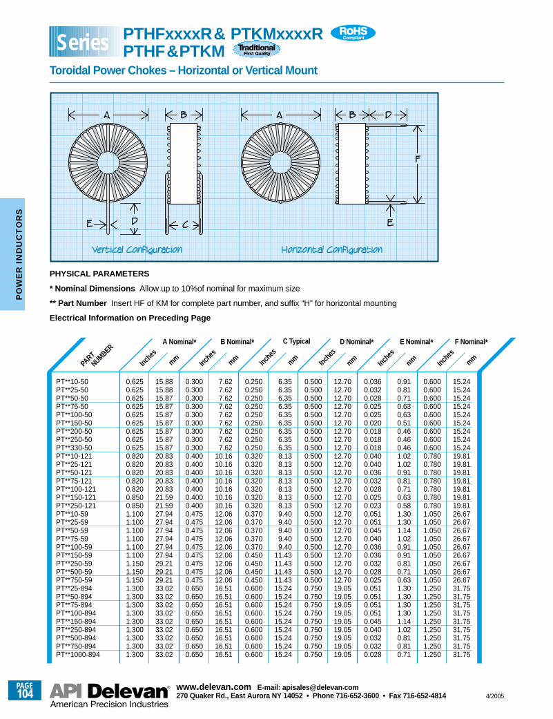
mmInc
hes
Inche
smm
Inche
smm Inc
hes
mm Inche
smm Inc
hes
mm
PHYSICAL PARAMETERS
* Nominal Dimensions Allow up to 10%of nominal for maximum size
** Part Number Insert HF of KM for complete part number, and suffix “H” for horizontal mounting
Electrical Information on Preceding Page
PART
NUMBERA Nominal *
15.8815.8815.8715.8715.8715.8715.8715.8715.8720.8320.8320.8320.8320.8321.5921.5927.9427.9427.9427.9427.9427.9429.2129.2129.2133.0233.0233.0233.0233.0233.0233.0233.0233.02
0.6250.6250.6250.6250.6250.6250.6250.6250.6250.8200.8200.8200.8200.8200.8500.8501.1001.1001.1001.1001.1001.1001.1501.1501.1501.3001.3001.3001.3001.3001.3001.3001.3001.300
B Nominal *
7.627.627.627.627.627.627.627.627.62
10.1610.1610.1610.1610.1610.1610.1612.0612.0612.0612.0612.0612.0612.0612.0612.0616.5116.5116.5116.5116.5116.5116.5116.5116.51
0.3000.3000.3000.3000.3000.3000.3000.3000.3000.4000.4000.4000.4000.4000.4000.4000.4750.4750.4750.4750.4750.4750.4750.4750.4750.6500.6500.6500.6500.6500.6500.6500.6500.650
C Typical
6.356.356.356.356.356.356.356.356.358.138.138.138.138.138.138.139.409.409.409.409.40
11.4311.4311.4311.4315.2415.2415.2415.2415.2415.2415.2415.2415.24
0.2500.2500.2500.2500.2500.2500.2500.2500.2500.3200.3200.3200.3200.3200.3200.3200.3700.3700.3700.3700.3700.4500.4500.4500.4500.6000.6000.6000.6000.6000.6000.6000.6000.600
D Nominal *
12.7012.7012.7012.7012.7012.7012.7012.7012.7012.7012.7012.7012.7012.7012.7012.7012.7012.7012.7012.7012.7012.7012.7012.7012.7019.0519.0519.0519.0519.0519.0519.0519.0519.05
0.5000.5000.5000.5000.5000.5000.5000.5000.5000.5000.5000.5000.5000.5000.5000.5000.5000.5000.5000.5000.5000.5000.5000.5000.5000.7500.7500.7500.7500.7500.7500.7500.7500.750
E Nominal *
0.910.810.710.630.630.510.460.460.461.021.020.910.810.710.630.581.301.301.141.020.910.910.810.710.631.301.301.301.301.141.020.810.810.71
0.0360.0320.0280.0250.0250.0200.0180.0180.0180.0400.0400.0360.0320.0280.0250.0230.0510.0510.0450.0400.0360.0360.0320.0280.0250.0510.0510.0510.0510.0450.0400.0320.0320.028
F Nominal *
15.2415.2415.2415.2415.2415.2415.2415.2415.2419.8119.8119.8119.8119.8119.8119.8126.6726.6726.6726.6726.6726.6726.6726.6726.6731.7531.7531.7531.7531.7531.7531.7531.7531.75
0.6000.6000.6000.6000.6000.6000.6000.6000.6000.7800.7800.7800.7800.7800.7800.7801.0501.0501.0501.0501.0501.0501.0501.0501.0501.2501.2501.2501.2501.2501.2501.2501.2501.250
PT**10-50PT**25-50PT**50-50PT**75-50PT**100-50PT**150-50PT**200-50PT**250-50PT**330-50PT**10-121PT**25-121PT**50-121PT**75-121PT**100-121PT**150-121PT**250-121PT**10-59PT**25-59PT**50-59PT**75-59PT**100-59PT**150-59PT**250-59PT**500-59PT**750-59PT**25-894PT**50-894PT**75-894PT**100-894PT**150-894PT**250-894PT**500-894PT**750-894PT**1000-894
Series PTHFxxxxR& PTKMxxxxRPTHF&PTKM
Toroidal Power Chokes – Horizontal or Vertical Mount
PAGE104
www.delevan .com E-mail: apisales@delevan .com270 Quaker Rd., East Aurora NY 14052 • Phone 716-652-3600 • Fax 716-652-4814 4/2005
PO
WE
R I
ND
UC
TO
RS
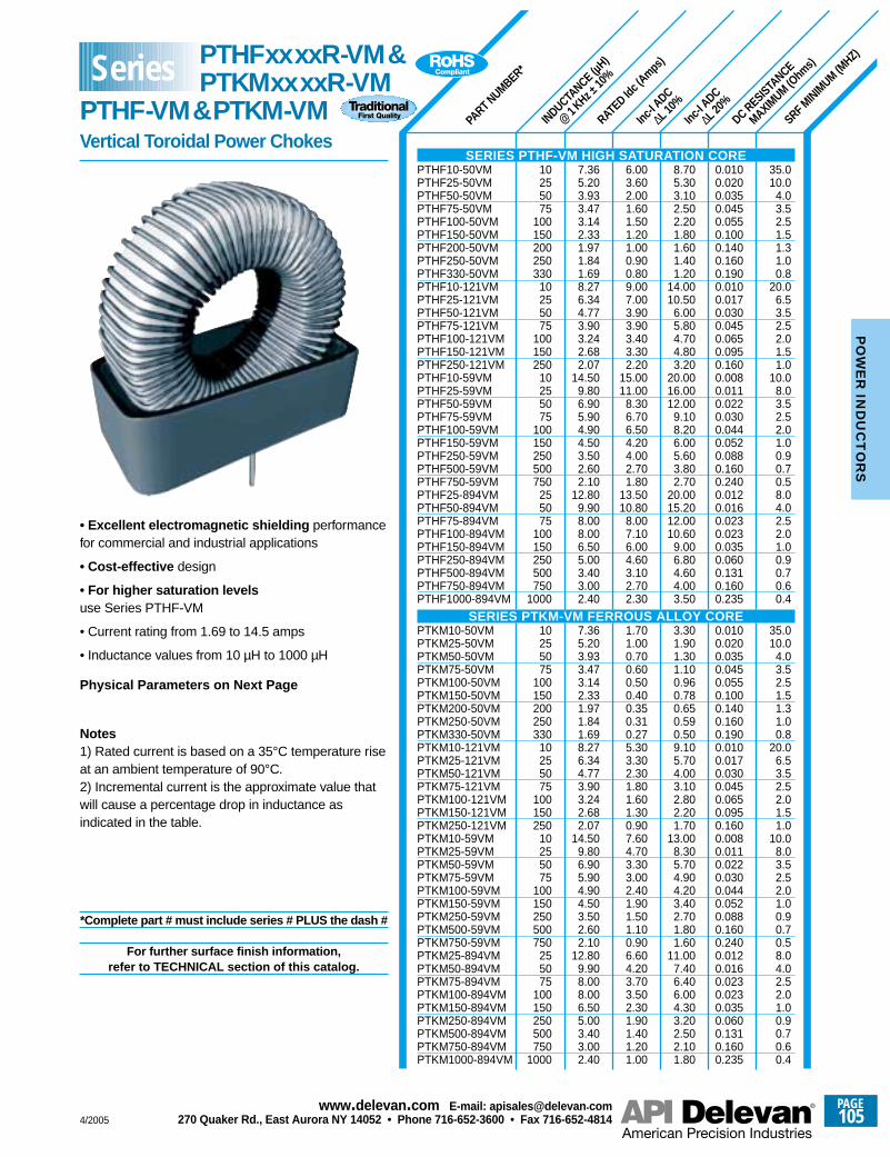
INDUCTANCE (µ
H)
@1 KHz ±
10%
PART NUMBER*
RATED Id
c (Amps
)
DC RESISTANCE
MAXIMUM (O
hms)
Inc-I A
DC
∆L 20%
Inc-I A
DC
∆L 10%
SRF MINIMUM
(MHZ)
10255075
100150200250330
10255075
100150250
10255075
100150250500750
255075
100150250500750
1000
10255075
100150200250330
10255075
100150250
10255075
100150250500750
255075
100150250500750
1000
7.365.203.933.473.142.331.971.841.698.276.344.773.903.242.682.07
14.509.806.905.904.904.503.502.602.10
12.809.908.008.006.505.003.403.002.40
7.365.203.933.473.142.331.971.841.698.276.344.773.903.242.682.07
14.509.806.905.904.904.503.502.602.10
12.809.908.008.006.505.003.403.002.40
6.003.602.001.601.501.201.000.900.809.007.003.903.903.403.302.20
15.0011.00
8.306.706.504.204.002.701.80
13.5010.80
8.007.106.004.603.102.702.30
1.701.000.700.600.500.400.350.310.275.303.302.301.801.601.300.907.604.703.303.002.401.901.501.100.906.604.203.703.502.301.901.401.201.00
8.705.303.102.502.201.801.601.401.20
14.0010.50
6.005.804.704.803.20
20.0016.0012.00
9.108.206.005.603.802.70
20.0015.2012.0010.60
9.006.804.604.003.50
3.301.901.301.100.960.780.650.590.509.105.704.003.102.802.201.70
13.008.305.704.904.203.402.701.801.60
11.007.406.406.004.303.202.502.101.80
0.0100.0200.0350.0450.0550.1000.1400.1600.1900.0100.0170.0300.0450.0650.0950.1600.0080.0110.0220.0300.0440.0520.0880.1600.2400.0120.0160.0230.0230.0350.0600.1310.1600.235
0.0100.0200.0350.0450.0550.1000.1400.1600.1900.0100.0170.0300.0450.0650.0950.1600.0080.0110.0220.0300.0440.0520.0880.1600.2400.0120.0160.0230.0230.0350.0600.1310.1600.235
35.010.0
4.03.52.51.51.31.00.8
20.06.53.52.52.01.51.0
10.08.03.52.52.01.00.90.70.58.04.02.52.01.00.90.70.60.4
35.010.0
4.03.52.51.51.31.00.8
20.06.53.52.52.01.51.0
10.08.03.52.52.01.00.90.70.58.04.02.52.01.00.90.70.60.4
• Excellent electromagnetic shielding performancefor commercial and industrial applications
• Cost-effective design
• For higher saturation levelsuse Series PTHF-VM
• Current rating from 1.69 to 14.5 amps
• Inductance values from 10 µH to 1000 µH
Physical Parameters on Next Page
Notes1) Rated current is based on a 35°C temperature riseat an ambient temperature of 90°C.2) Incremental current is the approximate value thatwill cause a percentage drop in inductance asindicated in the table.
*Complete part # must include series # PLUS the dash #
For further surface finish information,refer to TECHNICAL section of this catalog.
SERIES PTHF-VM HIGH SATURATION COREPTHF10-50VMPTHF25-50VMPTHF50-50VMPTHF75-50VMPTHF100-50VMPTHF150-50VMPTHF200-50VMPTHF250-50VMPTHF330-50VMPTHF10-121VMPTHF25-121VMPTHF50-121VMPTHF75-121VMPTHF100-121VMPTHF150-121VMPTHF250-121VMPTHF10-59VMPTHF25-59VMPTHF50-59VMPTHF75-59VMPTHF100-59VMPTHF150-59VMPTHF250-59VMPTHF500-59VMPTHF750-59VMPTHF25-894VMPTHF50-894VMPTHF75-894VMPTHF100-894VMPTHF150-894VMPTHF250-894VMPTHF500-894VMPTHF750-894VMPTHF1000-894VM
SERIES PTKM-VM FERROUS ALLOY COREPTKM10-50VMPTKM25-50VMPTKM50-50VMPTKM75-50VMPTKM100-50VMPTKM150-50VMPTKM200-50VMPTKM250-50VMPTKM330-50VMPTKM10-121VMPTKM25-121VMPTKM50-121VMPTKM75-121VMPTKM100-121VMPTKM150-121VMPTKM250-121VMPTKM10-59VMPTKM25-59VMPTKM50-59VMPTKM75-59VMPTKM100-59VMPTKM150-59VMPTKM250-59VMPTKM500-59VMPTKM750-59VMPTKM25-894VMPTKM50-894VMPTKM75-894VMPTKM100-894VMPTKM150-894VMPTKM250-894VMPTKM500-894VMPTKM750-894VMPTKM1000-894VM
Series PTHFxxxxR-VM&PTKMxxxxR-VM
PTHF-VM&PTKM-VMVertical Toroidal Power Chokes
4/2005
PAGE105
www.delevan .com E-mail: apisales@delevan .com270 Quaker Rd., East Aurora NY 14052 • Phone 716-652-3600 • Fax 716-652-4814
PO
WE
R IN
DU
CT
OR
S
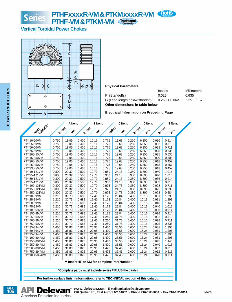
mmInche
smmInc
hes
mmInche
smm
Inche
smm
Inche
s
Physical ParametersInches Millimeters
F (Standoffs) 0.025 0.635G (Lead length below standoff) 0.250 ± 0.062 6.35 ± 1.57Other dimensions in table below
Electrical Information on Preceding Page
PART
NUMBER* A Nom.
19.0519.0519.0519.0519.0519.0519.0519.0519.0520.3220.3220.3220.3220.3220.3220.3230.7330.7330.7330.7330.7330.7330.7330.7330.7336.8336.8336.8336.8336.8336.8336.8336.8336.83
0.7500.7500.7500.7500.7500.7500.7500.7500.7500.8000.8000.8000.8000.8000.8000.8001.2101.2101.2101.2101.2101.2101.2101.2101.2101.4501.4501.4501.4501.4501.4501.4501.4501.450
B Nom.
10.1610.1610.1610.1610.1610.1610.1610.1610.1612.7012.7012.7012.7012.7012.7012.7017.4017.4017.4017.4017.4017.4017.4017.4017.4020.9520.9520.9520.9520.9520.9520.9520.9520.95
0.4000.4000.4000.4000.4000.4000.4000.4000.4000.5000.5000.5000.5000.5000.5000.5000.6850.6850.6850.6850.6850.6850.6850.6850.6850.8250.8250.8250.8250.8250.8250.8250.8250.825
C Nom.
19.6819.6819.6819.6819.6819.6819.6819.6819.6824.1324.1324.1324.1324.7624.7624.7629.8429.8429.8429.8429.8429.8431.7531.7531.7535.5635.5635.5635.5635.5635.5637.4637.4637.46
0.7750.7750.7750.7750.7750.7750.7750.7750.7750.9500.9500.9500.9500.9750.9750.9751.1751.1751.1751.1751.1751.1751.2501.2501.2501.4001.4001.4001.4001.4001.4001.4751.4751.475
D Nom.
6.3506.3506.3506.3506.3506.3506.3506.3506.3508.8908.8908.8908.8908.8908.8908.89010.1610.1610.1610.1610.1610.1610.1610.1610.1615.2415.2415.2415.2415.2415.2415.2415.2415.24
0.2500.2500.2500.2500.2500.2500.2500.2500.2500.3500.3500.3500.3500.3500.3500.3500.4000.4000.4000.4000.4000.4000.4000.4000.4000.6000.6000.6000.6000.6000.6000.6000.6000.600
E Nom.
0.9140.8130.7110.6350.6350.5080.4570.4570.4571.0161.0160.9140.8130.7110.6350.5841.2951.2951.1431.0160.9140.9140.8130.7110.6351.2951.2951.2951.2951.1431.0160.8130.8130.711
0.0360.0320.0280.0250.0250.0200.0180.0180.0180.0400.0400.0360.0320.0280.0250.0230.0510.0510.0450.0400.0360.0360.0320.0280.0250.0510.0510.0510.0510.0450.0400.0320.0320.028
PT**10-50VMPT**25-50VMPT**50-50VMPT**75-50VMPT**100-50VMPT**150-50VMPT**200-50VMPT**250-50VMPT**330-50VMPT**10-121VMPT**25-121VMPT**50-121VMPT**75-121VMPT**100-121VMPT**150-121VMPT**250-121VMPT**10-59VMPT**25-59VMPT**50-59VMPT**75-59VMPT**100-59VMPT**150-59VMPT**250-59VMPT**500-59VMPT**750-59VMPT**25-894VMPT**50-894VMPT**75-894VMPT**100-894VMPT**150-894VMPT**250-894VMPT**500-894VMPT**750-894VMPT**1000-894VM
** Insert HF or KM for complete Part Number
*Complete part # must include series # PLUS the dash #
For further surface finish information, refer to TECHNICAL section of this catalog.
Series PTHFxxxxR-VM&PTKMxxxxR-VMPTHF-VM&PTKM-VM
Vertical Toroidal Power Chokes
PAGE106
www.delevan .com E-mail: apisales@delevan .com270 Quaker Rd., East Aurora NY 14052 • Phone 716-652-3600 • Fax 716-652-4814 4/2005
PO
WE
R I
ND
UC
TO
RS
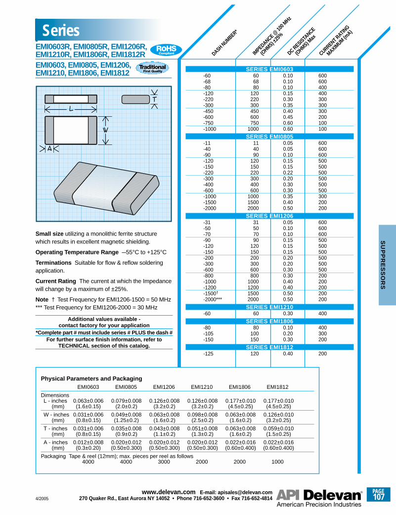
DASH NUMBER*
IMPEDANCE @
100 M
Hz
(OHMS) ±
25%
DC RESISTANCE
(OHMS) M
ax
CURRENT RATING
MAXIMUM (m
A)
Small size utilizing a monolithic ferrite structurewhich results in excellent magnetic shielding.
Operating Temperature Range –55°C to +125°C
Terminations Suitable for flow & reflow solderingapplication.
Current Rating The current at which the Impedancewill change by a maximum of ±25%.
Note † Test Frequency for EMI1206-1500 = 50 MHz*** Test Frequency for EMI1206-2000 = 30 MHz
Additional values available - contact factory for your application
*Complete part # must include series # PLUS the dash #For further surface finish information, refer to
TECHNICAL section of this catalog.
SERIES EMI0603-60-68-80-120-220-300-450-600-750-1000
SERIES EMI0805-11-40-90-120-150-220-300-400-600-1000-1500-2000
SERIES EMI1206-31-50-70-90-120-150-200-300-600-800-1000-1200-1500†
-2000***
SERIES EMI1210-60
SERIES EMI1806-80-105-150
SERIES EMI1812-125
Physical Parameters and PackagingEMI0603 EMI0805 EMI1206 EMI1210 EMI1806 EMI1812
DimensionsL - inches 0.063±0.006 0.079±0.008 0.126±0.008 0.126±0.008 0.177±0.010 0.177±0.010
(mm) (1.6±0.15) (2.0±0.2) (3.2±0.2) (3.2±0.2) (4.5±0.25) (4.5±0.25)
W - inches 0.031±0.006 0.049±0.008 0.063±0.008 0.098±0.008 0.063±0.008 0.126±0.010(mm) (0.8±0.15) (1.25±0.2) (1.6±0.2) (2.5±0.2) (1.6±0.2) (3.2±0.25)
T - inches 0.031±0.006 0.035±0.008 0.043±0.008 0.051±0.008 0.063±0.008 0.059±0.010(mm) (0.8±0.15) (0.9±0.2) (1.1±0.2) (1.3±0.2) (1.6±0.2) (1.5±0.25)
A - inches 0.012±0.008 0.020±0.012 0.020±0.012 0.020±0.012 0.022±0.016 0.022±0.016(mm) (0.3±0.20) (0.50±0.300) (0.50±0.300) (0.50±0.300) (0.60±0.400) (0.60±0.400)
Packaging Tape & reel (12mm); max. pieces per reel as follows4000 4000 3000 2000 2000 1000
606880
120220300450600750
1000
114090
120150220300400600
100015002000
31507090
120150200300600800
1000120015002000
60
80100150
120
0.100.100.100.150.300.350.400.450.600.60
0.050.050.100.150.150.220.200.300.300.350.400.50
0.050.100.100.150.150.150.200.200.300.300.400.400.500.50
0.30
0.100.200.30
0.40
600600400400300300300200100100
600600600500500500500500500300200200
600600600500500500500500500200200200200200
400
400300200
200
SeriesEMI0603R, EMI0805R, EMI1206R, EMI1210R, EMI1806R, EMI1812REMI0603, EMI0805, EMI1206, EMI1210, EMI1806, EMI1812
4/2005
PAGE107
www.delevan .com E-mail: apisales@delevan .com270 Quaker Rd., East Aurora NY 14052 • Phone 716-652-3600 • Fax 716-652-4814
SU
PP
RE
SS
OR
S
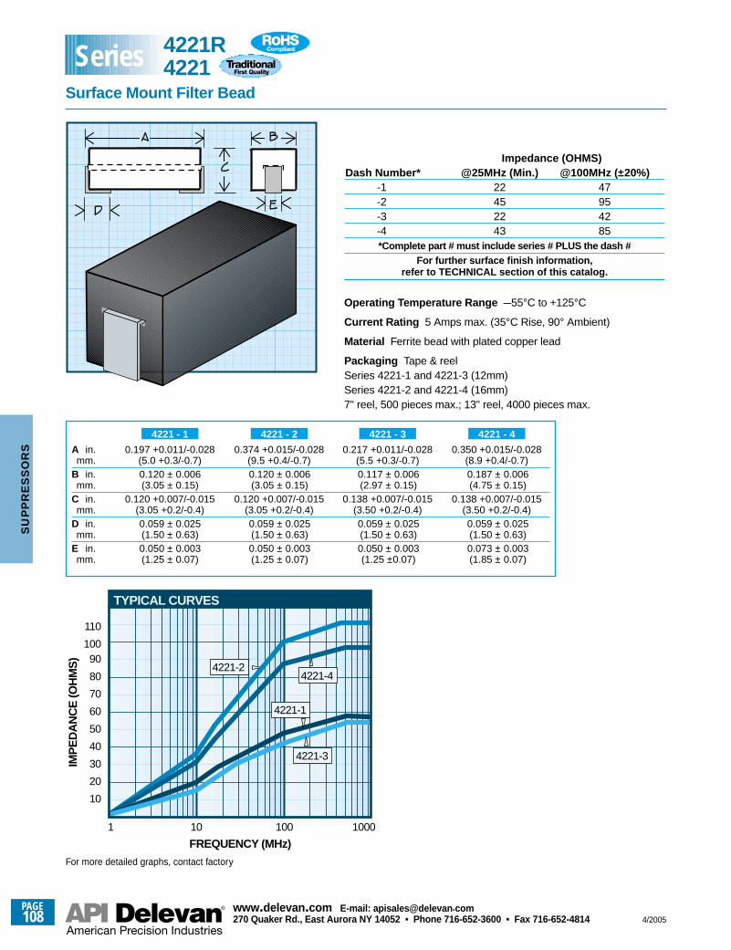
4221-2
1
10
FREQUENCY (MHz)
IMP
ED
AN
CE
(OH
MS
)
4221-4
4221-1
20
30
40
50
60
70
80
90100
10 100 1000
TYPICAL CURVES
110
4221-3
Impedance (OHMS)Dash Number* @25MHz (Min.) @100MHz (±20%)
-1 22 47-2 45 95-3 22 42-4 43 85*Complete part # must include series # PLUS the dash #
For further surface finish information,refer to TECHNICAL section of this catalog.
A in. 0.197 +0.011/-0.028 0.374 +0.015/-0.028 0.217 +0.011/-0.028 0.350 +0.015/-0.028mm. (5.0 +0.3/-0.7) (9.5 +0.4/-0.7) (5.5 +0.3/-0.7) (8.9 +0.4/-0.7)
B in. 0.120 ± 0.006 0.120 ± 0.006 0.117 ± 0.006 0.187 ± 0.006mm. (3.05 ± 0.15) (3.05 ± 0.15) (2.97 ± 0.15) (4.75 ± 0.15)
C in. 0.120 +0.007/-0.015 0.120 +0.007/-0.015 0.138 +0.007/-0.015 0.138 +0.007/-0.015mm. (3.05 +0.2/-0.4) (3.05 +0.2/-0.4) (3.50 +0.2/-0.4) (3.50 +0.2/-0.4)
D in. 0.059 ± 0.025 0.059 ± 0.025 0.059 ± 0.025 0.059 ± 0.025mm. (1.50 ± 0.63) (1.50 ± 0.63) (1.50 ± 0.63) (1.50 ± 0.63)
E in. 0.050 ± 0.003 0.050 ± 0.003 0.050 ± 0.003 0.073 ± 0.003mm. (1.25 ± 0.07) (1.25 ± 0.07) (1.25 ±0.07) (1.85 ± 0.07)
4221 - 44221 - 34221 - 24221 - 1
For more detailed graphs, contact factory
4221R4221
Surface Mount Filter Bead
Series
Operating Temperature Range –55°C to +125°C
Current Rating 5 Amps max. (35°C Rise, 90° Ambient)
Material Ferrite bead with plated copper lead
Packaging Tape & reelSeries 4221-1 and 4221-3 (12mm)Series 4221-2 and 4221-4 (16mm)7" reel, 500 pieces max.; 13" reel, 4000 pieces max.
PAGE108
www.delevan .com E-mail: apisales@delevan .com270 Quaker Rd., East Aurora NY 14052 • Phone 716-652-3600 • Fax 716-652-4814 4/2005
SU
PP
RE
SS
OR
S
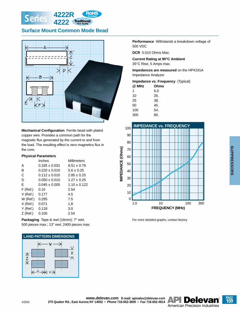
LAND PATTERN DIMENSIONS
1.00
FREQUENCY (MHz)
IMP
ED
AN
CE
(Ohm
s)
10
100
10 100 300
IMPEDANCE vs. FREQUENCY
20
30
40
50
60
70
80
90Mechanical Configuration Ferrite bead with platedcopper wire. Provides a common path for themagnetic flux generated by the current to and fromthe load. The resulting effect is zero magnetics flux inthe core.
Physical ParametersInches Millimeters
A 0.335 ± 0.031 8.51 ± 0.79B 0.220 ± 0.010 5.6 ± 0.25C 0.112 ± 0.010 2.85 ± 0.25D 0.050 ± 0.010 1.27 ± 0.25E 0.045 ± 0.005 1.10 ± 0.122F (Ref.) 0.10 2.54V (Ref.) 0.177 4.5W (Ref.) 0.295 7.5X (Ref.) 0.071 1.8Y (Ref.) 0.118 3.0Z (Ref.) 0.100 2.54
Packaging Tape & reel (16mm): 7" reel,500 pieces max.; 13" reel, 2400 pieces max.
Performance Withstands a breakdown voltage of500 VDC
DCR 0.010 Ohms Max.
Current Rating at 90°C Ambient35°C Rise, 5 Amps max.
Impedances are measured on the HP4191AImpedance Analyzer
Impedance vs. Frequency (Typical)@ MHz Ohms1 6.010 26.25 38.50 45.100 54.300 80.
For more detailed graphs, contact factory
4222R4222
Surface Mount Common Mode Bead
Series
4/2005
PAGE109
www.delevan .com E-mail: apisales@delevan .com270 Quaker Rd., East Aurora NY 14052 • Phone 716-652-3600 • Fax 716-652-4814
SU
PP
RE
SS
OR
S
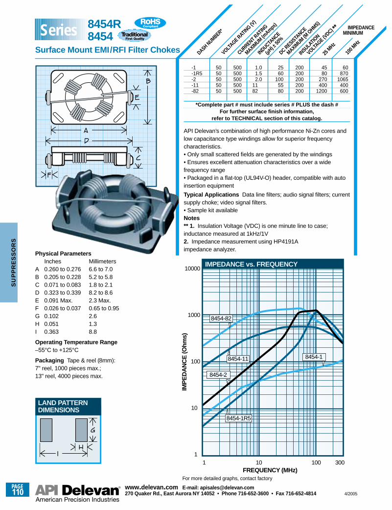
INSULATIO
N
VOLTAGE (V
DC) **
DC RESISTANCE
MAXIMUM (M
OHMS)
INDUCTANCE
(µH) ±
50%
VOLTAGE RAT
ING (V)
CURRENT RATING
MAXIMUM (m
Amps)
100 M
Hz
25 M
Hz
DASH NUMBER*
Physical ParametersInches Millimeters
A 0.260 to 0.276 6.6 to 7.0B 0.205 to 0.228 5.2 to 5.8C 0.071 to 0.083 1.8 to 2.1D 0.323 to 0.339 8.2 to 8.6E 0.091 Max. 2.3 Max.F 0.026 to 0.037 0.65 to 0.95G 0.102 2.6H 0.051 1.3I 0.363 8.8
Operating Temperature Range–55°C to +125°C
Packaging Tape & reel (8mm):7" reel, 1000 pieces max.;13" reel, 4000 pieces max.
11
FREQUENCY (MHz)
IMP
ED
AN
CE
(Ohm
s)
10
100
1000
10000
10 100 300
IMPEDANCE vs. FREQUENCY
8454-82
8454-2
8454-1R5
8454-18454-11
IMPEDANCEMINIMUM
5050505050
500500500500500
1.01.52.0
1182
2560
1005580
200200200200200
60870
1065400600
4580
270400
1200
LAND PATTERNDIMENSIONS
-1-1R5-2-11-82
*Complete part # must include series # PLUS the dash #For further surface finish information,
refer to TECHNICAL section of this catalog.
API Delevan’s combination of high performance Ni-Zn cores andlow capacitance type windings allow for superior frequencycharacteristics.• Only small scattered fields are generated by the windings• Ensures excellent attenuation characteristics over a widefrequency range• Packaged in a flat-top (UL94V-O) header, compatible with autoinsertion equipment
Typical Applications Data line filters; audio signal filters; currentsupply choke; video signal filters.• Sample kit availableNotes** 1. Insulation Voltage (VDC) is one minute line to case;inductance measured at 1kHz/1V2. Impedance measurement using HP4191Aimpedance analyzer.
For more detailed graphs, contact factory
8454R8454
Surface Mount EMI/RFI Filter Chokes
Series
PAGE110
www.delevan .com E-mail: apisales@delevan .com270 Quaker Rd., East Aurora NY 14052 • Phone 716-652-3600 • Fax 716-652-4814 4/2005
SU
PP
RE
SS
OR
S
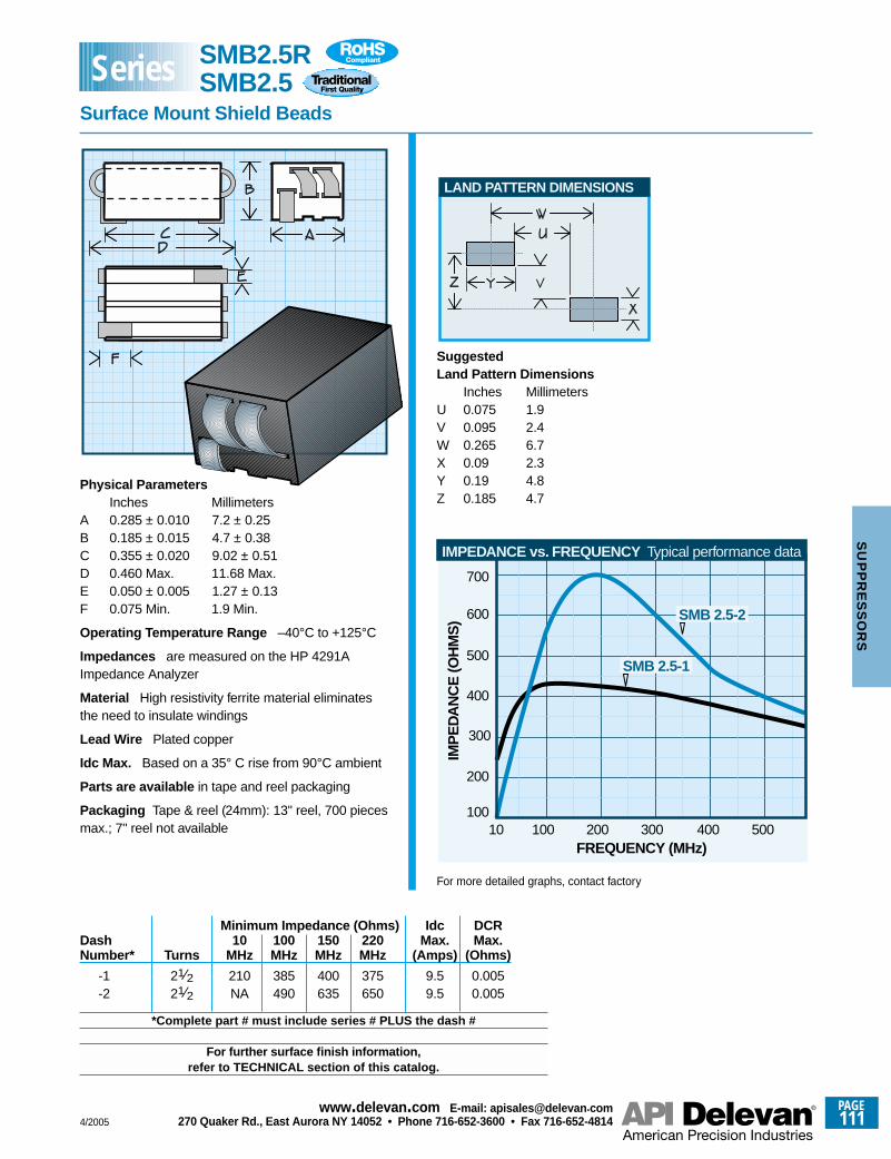
Physical ParametersInches Millimeters
A 0.285 ± 0.010 7.2 ± 0.25B 0.185 ± 0.015 4.7 ± 0.38C 0.355 ± 0.020 9.02 ± 0.51D 0.460 Max. 11.68 Max.E 0.050 ± 0.005 1.27 ± 0.13F 0.075 Min. 1.9 Min.
Operating Temperature Range –40°C to +125°C
Impedances are measured on the HP 4291AImpedance Analyzer
Material High resistivity ferrite material eliminatesthe need to insulate windings
Lead Wire Plated copper
Idc Max. Based on a 35° C rise from 90°C ambient
Parts are available in tape and reel packaging
Packaging Tape & reel (24mm): 13" reel, 700 piecesmax.; 7" reel not available
Minimum Impedance (Ohms) Idc DCRDash 10 100 150 220 Max. Max.Number* Turns MHz MHz MHz MHz (Amps) (Ohms)
-1 21⁄2 210 385 400 375 9.5 0.005-2 21⁄2 NA 490 635 650 9.5 0.005
*Complete part # must include series # PLUS the dash #
For further surface finish information,refer to TECHNICAL section of this catalog.
FREQUENCY (MHz)
IMP
ED
AN
CE
(OH
MS
)
200
300
400
500
600
10
700
SMB 2.5-2
SMB 2.5-1
IMPEDANCE vs. FREQUENCY Typical performance data
100 200 300 400 500100
LAND PATTERN DIMENSIONS
SuggestedLand Pattern Dimensions
Inches MillimetersU 0.075 1.9V 0.095 2.4W 0.265 6.7X 0.09 2.3Y 0.19 4.8Z 0.185 4.7
For more detailed graphs, contact factory
SMB2.5RSMB2.5
Surface Mount Shield Beads
Series
4/2005
PAGE111
www.delevan .com E-mail: apisales@delevan .com270 Quaker Rd., East Aurora NY 14052 • Phone 716-652-3600 • Fax 716-652-4814
SU
PP
RE
SS
OR
S
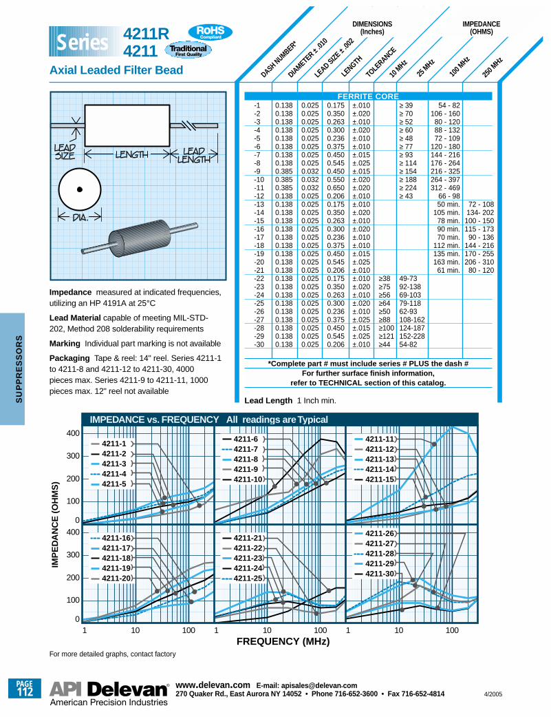
DASH NUMBER*
DIAMETER ±.01
0
LEAD SIZE ±
.002
LENGTH
TOLE
RANCE
10 M
Hz
25 M
Hz
100 M
Hz
250 M
Hz
0.1380.1380.1380.1380.1380.1380.1380.1380.3850.3850.3850.1380.1380.1380.1380.1380.1380.1380.1380.1380.1380.1380.1380.1380.1380.1380.1380.1380.1380.138
72 - 108134- 202
100 - 150115 - 173
90 - 136144 - 216170 - 255206 - 310
80 - 120
54 - 82106 - 160
80 - 12088 - 13272 - 109
120 - 180144 - 216176 - 264216 - 325264 - 397312 - 469
66 - 9850 min.
105 min.78 min.90 min.70 min.
112 min.135 min.163 min.
61 min.
≥ 39≥ 70≥ 52≥ 60≥ 48≥ 77≥ 93≥ 114≥ 154≥ 188≥ 224≥ 43
49-7392-13869-10379-11862-93108-162124-187152-22854-82
≥38≥75≥56≥64≥50≥88≥100≥121≥44
±.010±.020±.010±.020±.010±.010±.015±.025±.015±.020±.020±.010±.010±.020±.010±.020±.010±.010±.015±.025±.010±.010±.020±.010±.020±.010±.025±.015±.025±.010
0.1750.3500.2630.3000.2360.3750.4500.5450.4500.5500.6500.2060.1750.3500.2630.3000.2360.3750.4500.5450.2060.1750.3500.2630.3000.2360.3750.4500.5450.206
0.0250.0250.0250.0250.0250.0250.0250.0250.0320.0320.0320.0250.0250.0250.0250.0250.0250.0250.0250.0250.0250.0250.0250.0250.0250.0250.0250.0250.0250.025
Impedance measured at indicated frequencies,utilizing an HP 4191A at 25°C
Lead Material capable of meeting MIL-STD-202, Method 208 solderability requirements
Marking Individual part marking is not available
Packaging Tape & reel: 14" reel. Series 4211-1to 4211-8 and 4211-12 to 4211-30, 4000pieces max. Series 4211-9 to 4211-11, 1000pieces max. 12" reel not available
FERRITE CORE-1-2-3-4-5-6-7-8-9-10-11-12-13-14-15-16-17-18-19-20-21-22-23-24-25-26-27-28-29-30
*Complete part # must include series # PLUS the dash #For further surface finish information,
refer to TECHNICAL section of this catalog.
DIMENSIONS(Inches)
IMPEDANCE(OHMS)
1 10 100 1 10 100 1 10 1000
100
200
300
400
0
100
200
300
400
FREQUENCY (MHz)
IMP
ED
AN
CE
(O
HM
S)
IMPEDANCE vs. FREQUENCY All readings are Typical
4211-14211-24211-34211-44211-5
4211-64211-74211-84211-94211-10
4211-114211-124211-134211-144211-15
4211-264211-274211-284211-294211-30
4211-214211-224211-234211-244211-25
4211-164211-174211-184211-194211-20
For more detailed graphs, contact factory
4211R4211
Axial Leaded Filter Bead
Series
Lead Length 1 Inch min.
PAGE112
www.delevan .com E-mail: apisales@delevan .com270 Quaker Rd., East Aurora NY 14052 • Phone 716-652-3600 • Fax 716-652-4814 4/2005
SU
PP
RE
SS
OR
S
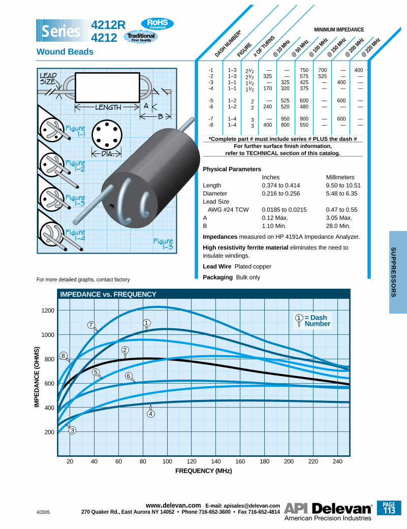
# OF TURNS
@ 10
MHz
@ 50
MHz
@ 10
0 MHz
@ 15
0 MHz
@ 20
0 MHz
@ 22
0 MHz
FIGURE
DASH NUMBER*
-1-2-3-4
-5-6
-7-8
*Complete part # must include series # PLUS the dash #For further surface finish information,
refer to TECHNICAL section of this catalog.
Physical ParametersInches Millimeters
Length 0.374 to 0.414 9.50 to 10.51Diameter 0.216 to 0.256 5.48 to 6.35Lead Size
AWG #24 TCW 0.0185 to 0.0215 0.47 to 0.55A 0.12 Max. 3.05 Max.B 1.10 Min. 28.0 Min.
Impedances measured on HP 4191A Impedance Analyzer.
High resistivity ferrite material eliminates the need toinsulate windings.
Lead Wire Plated copper
Packaging Bulk only
——
400—
600—
600—
400———
——
——
700525
——
——
——
750575425375
600480
900550
——
325320
525520
950800
—325
—170
—240
—400
21⁄221⁄211⁄211⁄2
22
33
1–31–31–11–1
1–21–2
1–41–4
MINIMUM IMPEDANCE
IMPEDANCE vs. FREQUENCY
20
200
FREQUENCY (MHz)
IMP
ED
AN
CE
(OH
MS
)
40 60 80 100 120 140 160 180 200 220 240
400
600
800
1000
1200
3
= DashNumber
1
4
56
17
28
For more detailed graphs, contact factory
4212R4212
Wound Beads
Series
4/2005
PAGE113
www.delevan .com E-mail: apisales@delevan .com270 Quaker Rd., East Aurora NY 14052 • Phone 716-652-3600 • Fax 716-652-4814
SU
PP
RE
SS
OR
S
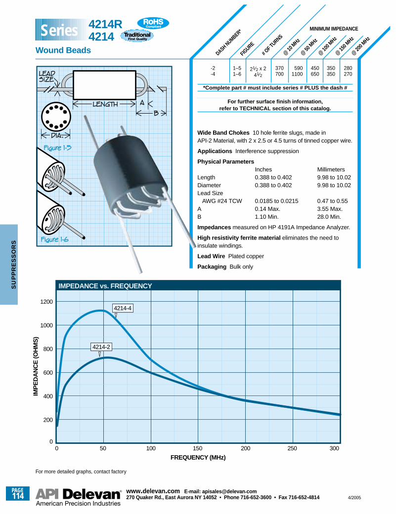
# OF TURNS
@ 10
MHz
@ 50
MHz
@ 10
0 MHz
@ 15
0 MHz
@ 20
0 MHz
FIGURE
DASH NUMBER*
-2-4
*Complete part # must include series # PLUS the dash #
For further surface finish information,refer to TECHNICAL section of this catalog.
Wide Band Chokes 10 hole ferrite slugs, made inAPI-2 Material, with 2 x 2.5 or 4.5 turns of tinned copper wire.
Applications Interference suppression
Physical ParametersInches Millimeters
Length 0.388 to 0.402 9.98 to 10.02Diameter 0.388 to 0.402 9.98 to 10.02Lead Size
AWG #24 TCW 0.0185 to 0.0215 0.47 to 0.55A 0.14 Max. 3.55 Max.B 1.10 Min. 28.0 Min.
Impedances measured on HP 4191A Impedance Analyzer.
High resistivity ferrite material eliminates the need toinsulate windings.
Lead Wire Plated copper
Packaging Bulk only
280270
350350
450650
5901100
370700
21⁄2 x 241⁄2
1–51–6
MINIMUM IMPEDANCE
IMPEDANCE vs. FREQUENCY
200
FREQUENCY (MHz)
IMP
ED
AN
CE
(OH
MS
)
100 200 300
400
600
800
1000
1200
150 2505000
4214-2
4214-4
For more detailed graphs, contact factory
4214R4214
Wound Beads
Series
PAGE114
www.delevan .com E-mail: apisales@delevan .com270 Quaker Rd., East Aurora NY 14052 • Phone 716-652-3600 • Fax 716-652-4814 4/2005
SU
PP
RE
SS
OR
S
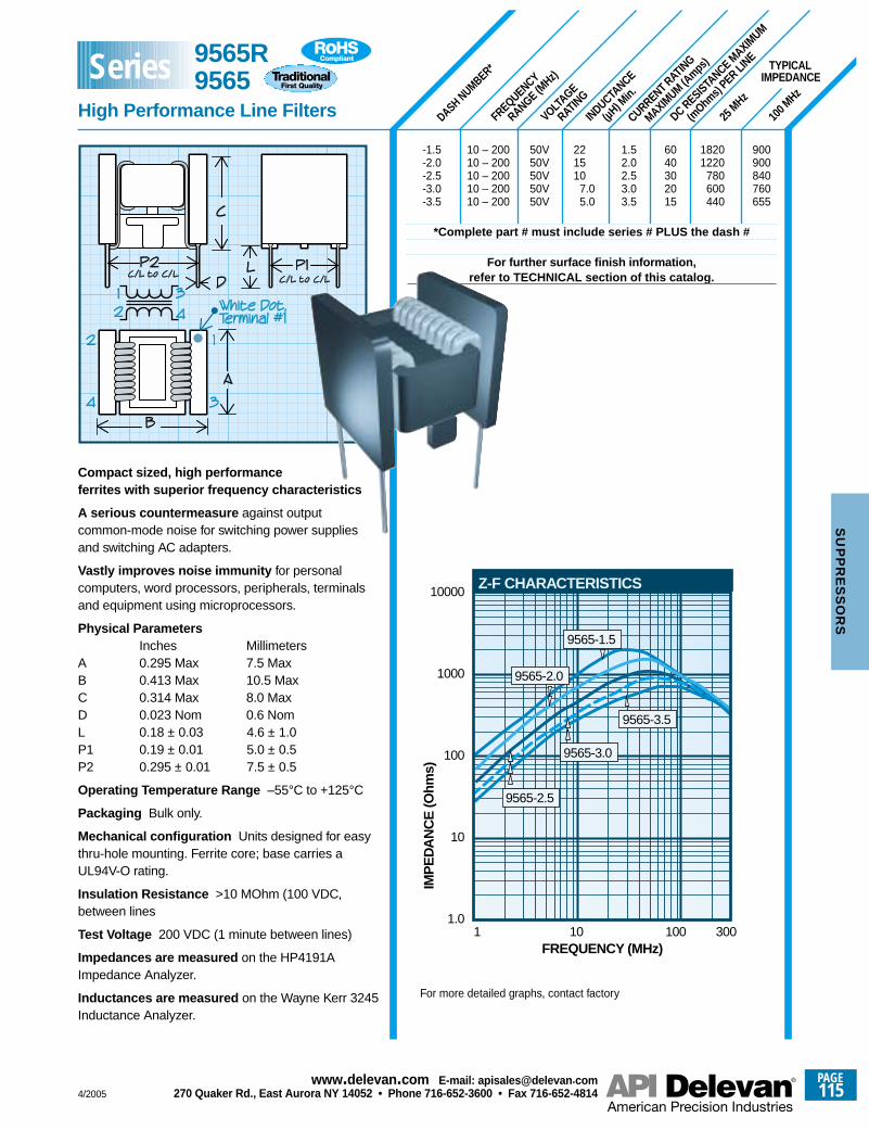
FREQUENCY
RANGE (MHz)
VOLTAGE
RATING
CURRENT RATING
MAXIMUM (A
mps)
INDUCTANCE
(µH) M
in.
25 M
Hz
100 M
Hz
DC RESISTANCE M
AXIMUM
(mOhm
s) PER LI
NE TYPICALIMPEDANCE
DASH NUMBER*
Compact sized, high performanceferrites with superior frequency characteristics
A serious countermeasure against outputcommon-mode noise for switching power suppliesand switching AC adapters.
Vastly improves noise immunity for personalcomputers, word processors, peripherals, terminalsand equipment using microprocessors.
Physical ParametersInches Millimeters
A 0.295 Max 7.5 MaxB 0.413 Max 10.5 MaxC 0.314 Max 8.0 MaxD 0.023 Nom 0.6 NomL 0.18 ± 0.03 4.6 ± 1.0P1 0.19 ± 0.01 5.0 ± 0.5P2 0.295 ± 0.01 7.5 ± 0.5
Operating Temperature Range –55°C to +125°C
Packaging Bulk only.
Mechanical configuration Units designed for easythru-hole mounting. Ferrite core; base carries aUL94V-O rating.
Insulation Resistance >10 MOhm (100 VDC,between lines
Test Voltage 200 VDC (1 minute between lines)
Impedances are measured on the HP4191AImpedance Analyzer.
Inductances are measured on the Wayne Kerr 3245Inductance Analyzer.
1FREQUENCY (MHz)
10 100 300
Z-F CHARACTERISTICS
9565-1.5
1.0
10
100
1000
10000
IMP
ED
AN
CE
(Ohm
s)
9565-2.0
9565-2.5
9565-3.0
9565-3.5
For more detailed graphs, contact factory
9565R9565
High Performance Line Filters
Series
-1.5 10 – 200 50V 22 1.5 60 1820 900-2.0 10 – 200 50V 15 2.0 40 1220 900-2.5 10 – 200 50V 10 2.5 30 780 840-3.0 10 – 200 50V 7.0 3.0 20 600 760-3.5 10 – 200 50V 5.0 3.5 15 440 655
*Complete part # must include series # PLUS the dash #
For further surface finish information,refer to TECHNICAL section of this catalog.
4/2005
PAGE115
www.delevan .com E-mail: apisales@delevan .com270 Quaker Rd., East Aurora NY 14052 • Phone 716-652-3600 • Fax 716-652-4814
SU
PP
RE
SS
OR
S
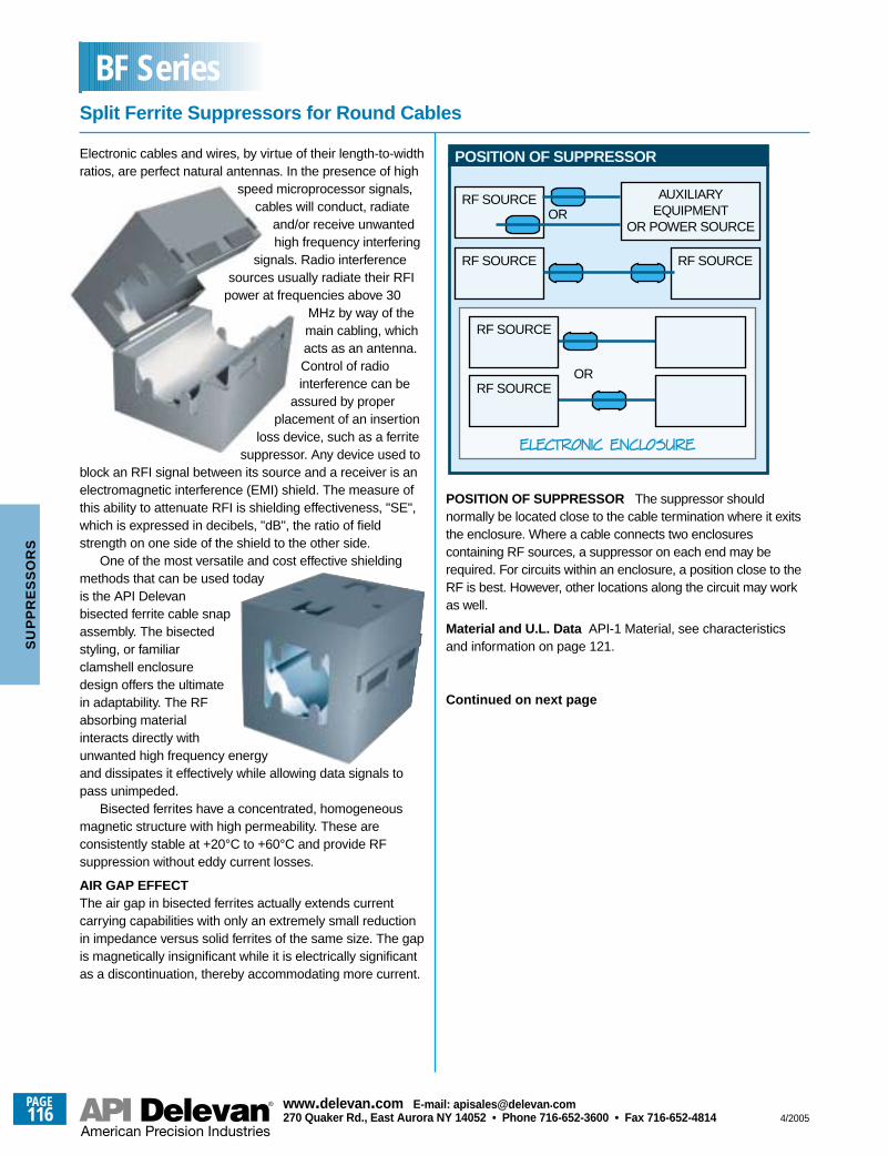
Electronic cables and wires, by virtue of their length-to-widthratios, are perfect natural antennas. In the presence of high
speed microprocessor signals,cables will conduct, radiate
and/or receive unwantedhigh frequency interfering
signals. Radio interferencesources usually radiate their RFI
power at frequencies above 30MHz by way of themain cabling, whichacts as an antenna.Control of radiointerference can be
assured by properplacement of an insertion
loss device, such as a ferritesuppressor. Any device used to
block an RFI signal between its source and a receiver is anelectromagnetic interference (EMI) shield. The measure ofthis ability to attenuate RFI is shielding effectiveness, "SE",which is expressed in decibels, "dB", the ratio of fieldstrength on one side of the shield to the other side.
One of the most versatile and cost effective shieldingmethods that can be used todayis the API Delevanbisected ferrite cable snapassembly. The bisectedstyling, or familiarclamshell enclosuredesign offers the ultimatein adaptability. The RFabsorbing materialinteracts directly withunwanted high frequency energyand dissipates it effectively while allowing data signals topass unimpeded.
Bisected ferrites have a concentrated, homogeneousmagnetic structure with high permeability. These areconsistently stable at +20°C to +60°C and provide RFsuppression without eddy current losses.
AIR GAP EFFECTThe air gap in bisected ferrites actually extends currentcarrying capabilities with only an extremely small reductionin impedance versus solid ferrites of the same size. The gapis magnetically insignificant while it is electrically significantas a discontinuation, thereby accommodating more current.
RF SOURCE AUXILIARYEQUIPMENT
OR POWER SOURCEOR
RF SOURCE RF SOURCE
RF SOURCE
RF SOURCEOR
POSITION OF SUPPRESSOR
POSITION OF SUPPRESSOR The suppressor shouldnormally be located close to the cable termination where it exitsthe enclosure. Where a cable connects two enclosurescontaining RF sources, a suppressor on each end may berequired. For circuits within an enclosure, a position close to theRF is best. However, other locations along the circuit may workas well.
Material and U.L. Data API-1 Material, see characteristicsand information on page 121.
Continued on next page
Split Ferrite Suppressors for Round Cables
BF Series
PAGE116
www.delevan .com E-mail: apisales@delevan .com270 Quaker Rd., East Aurora NY 14052 • Phone 716-652-3600 • Fax 716-652-4814 4/2005
SU
PP
RE
SS
OR
S
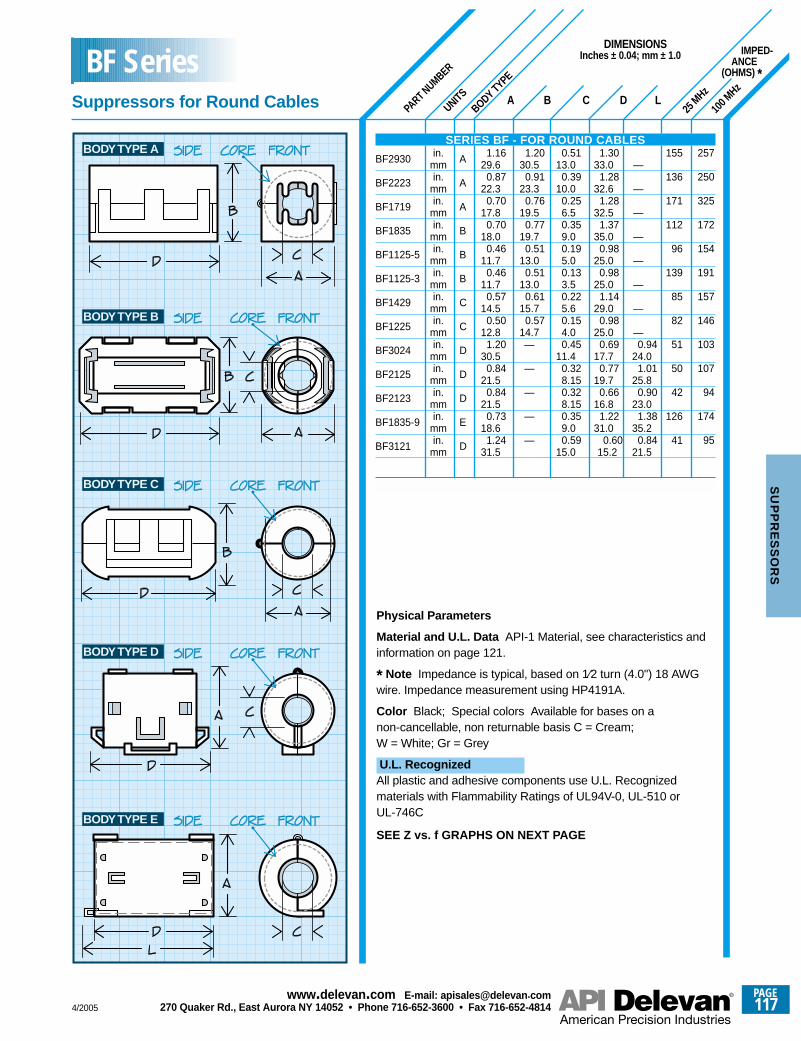
PART NUMBER
IMPED-ANCE
(OHMS) *
UNITS A B
DIMENSIONSInches ± 0.04; mm ± 1.0
C D LBODY TYPE
25 M
Hz
100 M
Hz
BODY TYPE E
BODY TYPE D
BODY TYPE C
BODY TYPE B
BODY TYPE A 155
136
171
112
96
139
85
82
51
50
42
126
41
257
250
325
172
154
191
157
146
103
107
94
174
95
1.3033.0
1.2832.6
1.2832.5
1.3735.0
0.9825.0
0.9825.0
1.1429.0
0.9825.0
0.6917.7
0.7719.7
0.6616.8
1.2231.0
0.6015.2
—
—
—
—
—
—
—
—0.94
24.01.01
25.80.90
23.01.38
35.20.84
21.5
0.5113.0
0.3910.0
0.256.50.359.00.195.00.133.50.225.60.154.00.45
11.40.328.150.328.150.359.00.59
15.0
1.2030.5
0.9123.3
0.7619.5
0.7719.7
0.5113.0
0.5113.0
0.6115.7
0.5714.7—
—
—
—
—
1.1629.6
0.8722.3
0.7017.8
0.7018.0
0.4611.7
0.4611.7
0.5714.5
0.5012.8
1.2030.5
0.8421.5
0.8421.5
0.7318.6
1.2431.5
A
A
A
B
B
B
C
C
D
D
D
E
D
in.mmin.
mmin.
mmin.
mmin.
mmin.
mmin.
mmin.
mmin.
mmin.
mmin.
mmin.
mmin.
mm
Physical Parameters
Material and U.L. Data API-1 Material, see characteristics andinformation on page 121.
* Note Impedance is typical, based on 1⁄2 turn (4.0") 18 AWGwire. Impedance measurement using HP4191A.
Color Black; Special colors Available for bases on anon-cancellable, non returnable basis C = Cream;W = White; Gr = Grey
U.L. RecognizedAll plastic and adhesive components use U.L. Recognizedmaterials with Flammability Ratings of UL94V-0, UL-510 orUL-746C
SEE Z vs. f GRAPHS ON NEXT PAGE
SERIES BF - FOR ROUND CABLES
BF2930
BF2223
BF1719
BF1835
BF1125-5
BF1125-3
BF1429
BF1225
BF3024
BF2125
BF2123
BF1835-9
BF3121
Suppressors for Round Cables
BF Series
4/2005
PAGE117
www.delevan .com E-mail: apisales@delevan .com270 Quaker Rd., East Aurora NY 14052 • Phone 716-652-3600 • Fax 716-652-4814
SU
PP
RE
SS
OR
S
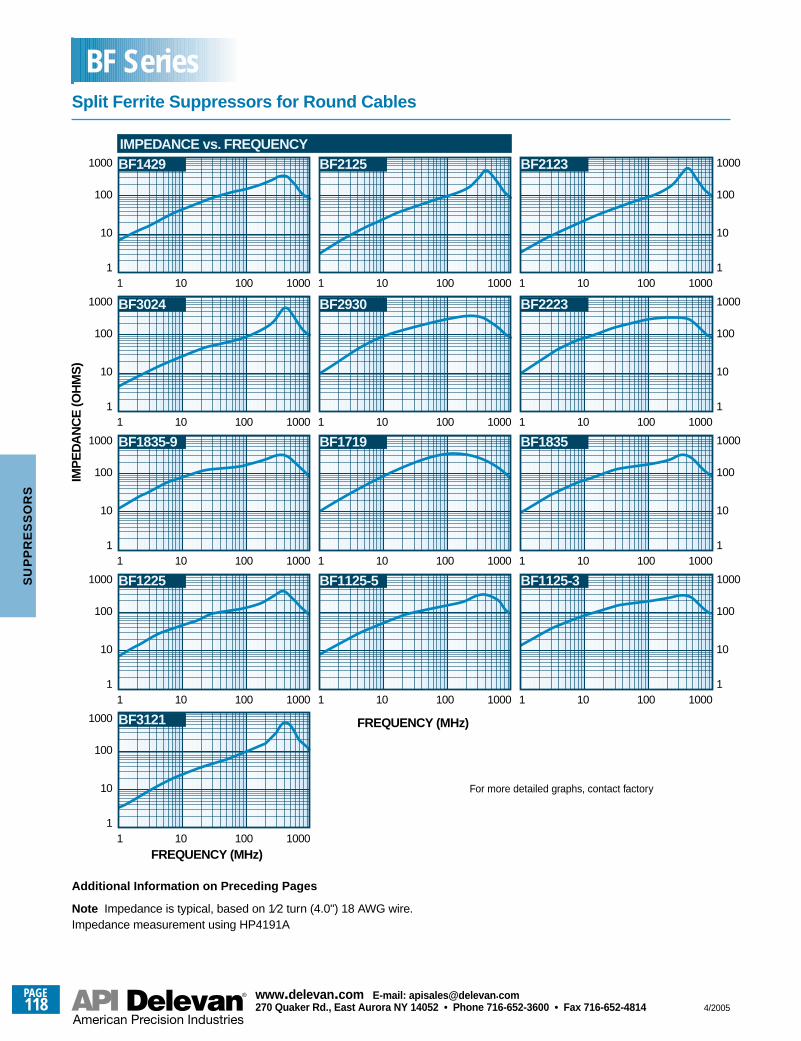
1
FREQUENCY (MHz)
IMP
ED
AN
CE
(OH
MS
)
10
10 100 1000
100
1000
11 10 100 10001 10 100 1000
10
100
1000
1
BF2125 BF2123
BF2930 BF2223
BF1719 BF1835BF1835-9
BF1429
BF3024
1
10
10 100 1000
100
1000
11 10 100 10001 10 100 1000
10
100
1000
1
1
10
10 100 1000
100
1000
11 10 100 10001 10 100 1000
10
100
1000
1
1
10
10 100 1000
100
1000
11 10 100 10001 10 100 1000
10
100
1000
1
IMPEDANCE vs. FREQUENCY
10
100
1000
11 10 100 1000
FREQUENCY (MHz)
BF1125-5 BF1125-3BF1225
BF3121
Additional Information on Preceding Pages
Note Impedance is typical, based on 1⁄2 turn (4.0") 18 AWG wire.Impedance measurement using HP4191A
For more detailed graphs, contact factory
Split Ferrite Suppressors for Round Cables
BF Series
PAGE118
www.delevan .com E-mail: apisales@delevan .com270 Quaker Rd., East Aurora NY 14052 • Phone 716-652-3600 • Fax 716-652-4814 4/2005
SU
PP
RE
SS
OR
S
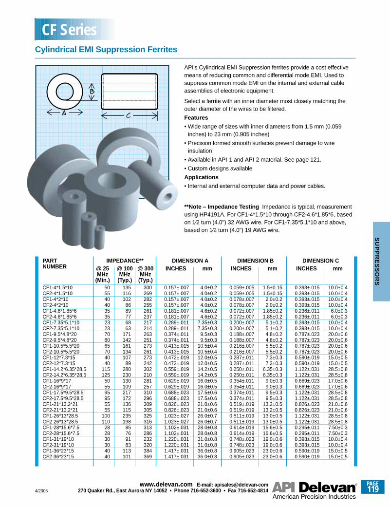
CF1-4*1.5*10CF2-4*1.5*10CF1-4*2*10CF2-4*2*10CF1-4.6*1.85*6CF2-4.6*1.85*6CF1-7.35*5.1*10CF2-7.35*5.1*10CF1-9.5*4.8*20CF2-9.5*4.8*20CF1-10.5*5.5*20CF2-10.5*5.5*20CF1-12*7.3*15CF2-12*7.3*15CF1-14.2*6.35*28.5CF2-14.2*6.35*28.5CF1-16*9*17CF2-16*9*17CF1-17.5*9.5*28.5CF2-17.5*9.5*28.5CF1-21*13.2*21CF2-21*13.2*21CF1-26*13*28.5CF2-26*13*28.5CF1-28*15.6*7.5CF2-28*15.6*7.5CF1-31*19*10CF2-31*19*10CF1-36*23*15CF2-36*23*15
5055404035352323708065704040
115125
505595955555
100110
282830304040
135116102
8689776863
171142161134107
89280230130109217172136115235198
85769183
113101
300269282255261237217214263251273261273242302210281257310296309305325316313286232320384369
0.157±.0070.157±.0070.157±.0070.157±.0070.181±.0070.181±.0070.289±.0110.289±.0110.374±.0110.374±.0110.413±.0150.413±.0150.472±.0190.472±.0190.559±.0190.559±.0190.629±.0190.629±.0190.688±.0230.688±.0230.826±.0230.826±.0231.023±.0271.023±.0271.102±.0311.102±.0311.220±.0311.220±.0311.417±.0311.417±.031
4.0±0.24.0±0.24.0±0.24.0±0.24.6±0.24.6±0.2
7.35±0.37.35±0.3
9.5±0.39.5±0.3
10.5±0.410.5±0.412.0±0.512.0±0.514.2±0.514.2±0.516.0±0.516.0±0.517.5±0.617.5±0.621.0±0.621.0±0.626.0±0.726.0±0.728.0±0.828.0±0.831.0±0.831.0±0.836.0±0.836.0±0.8
0.059±.0050.059±.0050.078±.0070.078±.0070.072±.0070.072±.0070.200±.0070.200±.0070.188±.0070.188±.0070.216±.0070.216±.0070.287±.0110.287±.0110.250±.0110.250±.0110.354±.0110.354±.0110.374±.0110.374±.0110.519±.0190.519±.0190.511±.0190.511±.0190.614±.0190.614±.0190.748±.0230.748±.0230.905±.0230.905±.023
1.5±0.151.5±0.15
2.0±0.22.0±0.2
1.85±0.21.85±0.2
5.1±0.25.1±0.24.8±0.24.8±0.25.5±0.25.5±0.27.3±0.37.3±0.3
6.35±0.36.35±0.3
9.0±0.39.0±0.39.5±0.39.5±0.3
13.2±0.513.2±0.513.0±0.513.0±0.515.6±0.515.6±0.519.0±0.619.0±0.623.0±0.623.0±0.6
0.393±.0150.393±.0150.393±.0150.393±.0150.236±.0110.236±.0110.393±.0150.393±.0150.787±.0230.787±.0230.787±.0230.787±.0230.590±.0190.590±.0191.122±.0311.122±.0310.669±.0230.669±.0231.122±.0311.122±.0310.826±.0230.826±.0231.122±.0311.122±.0310.295±.0110.295±.0110.393±.0150.393±.0150.590±.0190.590±.019
10.0±0.410.0±0.410.0±0.410.0±0.4
6.0±0.36.0±0.3
10.0±0.410.0±0.420.0±0.620.0±0.620.0±0.620.0±0.615.0±0.515.0±0.528.5±0.828.5±0.817.0±0.617.0±0.628.5±0.828.5±0.821.0±0.621.0±0.628.5±0.828.5±0.87.50±0.37.50±0.310.0±0.410.0±0.415.0±0.515.0±0.5
PARTNUMBER
IMPEDANCE**@ 25MHz
(Min.)
@ 100MHz
(Typ.)
DIMENSION AINCHES mm
DIMENSION BINCHES mm
DIMENSION CINCHES mm@ 300
MHz(Typ.)
API's Cylindrical EMI Suppression ferrites provide a cost effectivemeans of reducing common and differential mode EMI. Used tosuppress common mode EMI on the internal and external cableassemblies of electronic equipment.
Select a ferrite with an inner diameter most closely matching theouter diameter of the wires to be filtered.
Features
• Wide range of sizes with inner diameters from 1.5 mm (0.059inches) to 23 mm (0.905 inches)
• Precision formed smooth surfaces prevent damage to wireinsulation
• Available in API-1 and API-2 material. See page 121.
• Custom designs available
Applications
• Internal and external computer data and power cables.
**Note – Impedance Testing Impedance is typical, measurementusing HP4191A. For CF1-4*1.5*10 through CF2-4.6*1.85*6, basedon 1⁄2 turn (4.0") 32 AWG wire. For CF1-7.35*5.1*10 and above,based on 1⁄2 turn (4.0") 19 AWG wire.
Cylindrical EMI Suppression Ferrites
CF Series
4/2005
PAGE119
www.delevan .com E-mail: apisales@delevan .com270 Quaker Rd., East Aurora NY 14052 • Phone 716-652-3600 • Fax 716-652-4814
SU
PP
RE
SS
OR
S
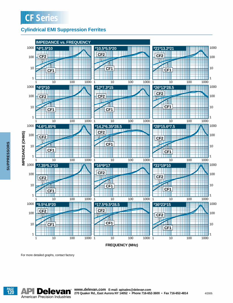
IMP
ED
AN
CE
(OH
MS
)
1
10
10 100 1000
100
1000
11 10 100 10001 10 100 1000
10
100
1000
1
IMPEDANCE vs. FREQUENCY
*4*1.5*10
*12*7.3*15
1
10
10 100 1000
100
1000
11 10 100 10001 10 100 1000
10
100
1000
1
*4*2*10
1
10
10 100 1000
100
1000
11 10 100 10001 10 100 1000
10
100
1000
1
*9.5*4.8*20
*14.2*6.35*28.5
1
10
10 100 1000
100
1000
11 10 100 10001 10 100 1000
10
100
1000
1
1
10
10 100 1000
100
1000
11 10 100 10001 10 100 1000
10
100
1000
1
*4.6*1.85*6
*10.5*5.5*20
*16*9*17*7.35*5.1*10
FREQUENCY (MHz)
CF2
CF1
CF2
CF1
*17.5*9.5*28.5 *36*23*15
*31*19*10
*28*15.6*7.5
*26*13*28.5
*21*13.2*21
CF2
CF1
CF2
CF1
CF2
CF1
CF2
CF1
CF2
CF1
CF2
CF1
CF2
CF1
CF2
CF1
CF2
CF1
CF2
CF1
CF2
CF1
CF2
CF1
CF2
CF1
For more detailed graphs, contact factory
Cylindrical EMI Suppression Ferrites
CF Series
PAGE120
www.delevan .com E-mail: apisales@delevan .com270 Quaker Rd., East Aurora NY 14052 • Phone 716-652-3600 • Fax 716-652-4814 4/2005
SU
PP
RE
SS
OR
S
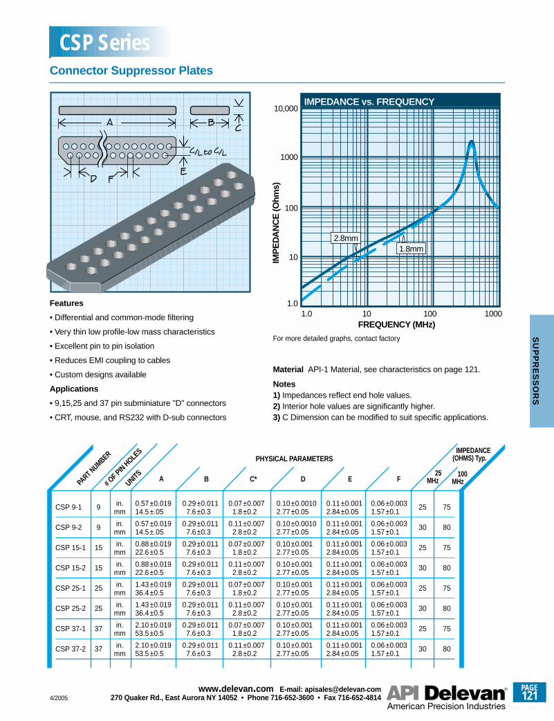
PART NUMBER
A B C*
PHYSICAL PARAMETERS
D E F25
MHz
IMPEDANCE(OHMS) Typ.
100MHz# O
F PIN HOLES
UNITS
0.57±0.01914.5±.05
0.57±0.01914.5±.05
0.88±0.01922.6±0.5
0.88±0.01922.6±0.5
1.43±0.01936.4±0.5
1.43±0.01936.4±0.5
2.10±0.01953.5±0.5
2.10±0.01953.5±0.5
0.29±0.0117.6±0.3
0.29±0.0117.6±0.3
0.29±0.0117.6±0.3
0.29±0.0117.6±0.3
0.29±0.0117.6±0.3
0.29±0.0117.6±0.3
0.29±0.0117.6±0.3
0.29±0.0117.6±0.3
0.07±0.0071.8±0.2
0.11±0.0072.8±0.2
0.07±0.0071.8±0.2
0.11±0.0072.8±0.2
0.07±0.0071.8±0.2
0.11±0.0072.8±0.2
0.07±0.0071.8±0.2
0.11±0.0072.8±0.2
0.10±0.00102.77±0.05
0.10±0.00102.77±0.05
0.10±0.0012.77±0.05
0.10±0.0012.77±0.05
0.10±0.0012.77±0.05
0.10±0.0012.77±0.05
0.10±0.0012.77±0.05
0.10±0.0012.77±0.05
0.11±0.0012.84±0.05
0.11±0.0012.84±0.05
0.11±0.0012.84±0.05
0.11±0.0012.84±0.05
0.11±0.0012.84±0.05
0.11±0.0012.84±0.05
0.11±0.0012.84±0.05
0.11±0.0012.84±0.05
0.06±0.0031.57±0.1
0.06±0.0031.57±0.1
0.06±0.0031.57±0.1
0.06±0.0031.57±0.1
0.06±0.0031.57±0.1
0.06±0.0031.57±0.1
0.06±0.0031.57±0.1
0.06±0.0031.57±0.1
in.mm
in.mm
in.mm
in.mm
in.mm
in.mm
in.mm
in.mm
25
30
25
30
25
30
25
30
75
80
75
80
75
80
75
80
9
9
15
15
25
25
37
37
Features
• Differential and common-mode filtering
• Very thin low profile-low mass characteristics
• Excellent pin to pin isolation
• Reduces EMI coupling to cables
• Custom designs available
Applications
• 9,15,25 and 37 pin subminiature "D" connectors
• CRT, mouse, and RS232 with D-sub connectors
1.01.0
FREQUENCY (MHz)
IMP
ED
AN
CE
(Ohm
s)
10
100
1000
10,000
10 100 1000
IMPEDANCE vs. FREQUENCY
2.8mm1.8mm
Material API-1 Material, see characteristics on page 121.
Notes 1) Impedances reflect end hole values.2) Interior hole values are significantly higher.3) C Dimension can be modified to suit specific applications.
CSP 9-1
CSP 9-2
CSP 15-1
CSP 15-2
CSP 25-1
CSP 25-2
CSP 37-1
CSP 37-2
For more detailed graphs, contact factory
Connector Suppressor Plates
CSP Series
4/2005
PAGE121
www.delevan .com E-mail: apisales@delevan .com270 Quaker Rd., East Aurora NY 14052 • Phone 716-652-3600 • Fax 716-652-4814
SU
PP
RE
SS
OR
S
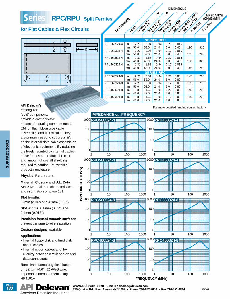
Inche
s ±0.0
4
mm ±1.0
Inche
s ±0.0
3
mm ±0.8
Inche
s ±0.0
2
mm ±0.5
Inche
s +0.0
1 –0.0
06
mm +0.25
–0.15
PART NUMBER
Inche
s ±0.0
4
mm ±1.0
UNITS@
100M
Hz
@ 20
0 MHz
in.mmin.
mmin.
mmin.
mm
in.mmin.
mmin.
mmin.
mm
2.2056.0
2.2056.0
1.8146.0
1.8146.0
2.2056.0
2.2056.0
1.8146.0
1.8146.0
2.0452.0
2.0452.0
1.6542.0
1.6542.0
2.0452.0
2.0452.0
1.6542.0
1.6542.0
0.9424.0
0.9424.0
0.9424.0
0.9424.0
0.9424.0
0.9424.0
0.9424.0
0.9424.0
0.205.00.123.00.205.00.123.0
0.205.00.123.00.205.00.123.0
0.0150.400.0150.400.0150.400.0150.40
0.030.800.030.800.030.800.030.80
190
145
190
145
145
105
145
110
315
280
320
280
280
215
290
220
A C D E GDIMENSIONS
IMPEDANCE(OHMS) MIN.
API Delevan'srectangular"split" componentsprovide a cost-effectivemeans of reducing common modeEMI on flat, ribbon type cableassemblies and flex circuits. Theyare primarily used to suppress EMIon the internal data cable assembliesof electronic equipment. By reducingthe levels radiated by internal cables,these ferrites can reduce the costand amount of overall shieldingrequired to confine EMI within aproduct's enclosure.
Physical Parameters
Material, Closure and U.L. DataAPI-2 Material, see characteristicsand information on page 121.
Slot lengths52mm (2.04") and 42mm (1.65")
Slot widths 0.8mm (0.03") and0.4mm (0.015")
Precision formed smooth surfacesprevent damage to wire insulation
Custom designs available
Applications• Internal floppy disk and hard disk
ribbon cables• Internal ribbon cables and flex
circuitry between circuit boards anddata connectors.
Note Impedance is typical, basedon 1⁄2 turn (4.0") 32 AWG wire.Impedance measurement usingHP4191A
IMP
ED
AN
CE
(OH
MS
)
10
100
1000
11 10 100 1000
RPU560524-4 RPU460524-4
RPC560524-8
RPU560324-4 RPU460324-4
RPC460524-8
RPC560324-8
RPC460324-8
10
100
1000
11 10 100 1000
10
100
1000
11 10 100 1000
10
100
1000
11 10 100 1000
10
100
1000
11 10 100 1000
10
100
1000
11 10 100 1000
10
100
1000
11 10 100 1000
10
100
1000
11 10 100 1000
IMPEDANCE vs. FREQUENCY
FREQUENCY (MHz)
SERIES RPURPU560524-4
RPU560324-4
RPU460524-4
RPU460324-4
SERIES RPCRPC560524-8
RPC560324-8
RPC460524-8
RPC460324-8
For more detailed graphs, contact factory
RPC/RPU Split Ferrites
for Flat Cables & Flex Circuits
Series
PAGE122
www.delevan .com E-mail: apisales@delevan .com270 Quaker Rd., East Aurora NY 14052 • Phone 716-652-3600 • Fax 716-652-4814 4/2005
SU
PP
RE
SS
OR
S
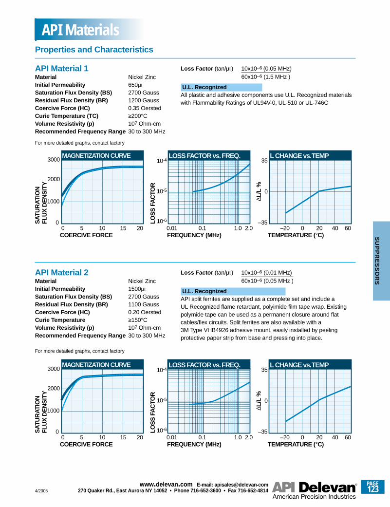
10-5
LOSS FACTOR vs. FREQ.
10-6
10-4
0.01FREQUENCY (MHz)
0.1 1.0
0
L CHANGE vs. TEMP
–35
35
TEMPERATURE (°C)–20 0 604020
LOS
S F
AC
TOR
∆L/L
%
MAGNETIZATION CURVE
0
2000
0COERCIVE FORCE
5 10 2015
SAT
UR
ATIO
NFL
UX
DE
NS
ITY
1000
3000
2.0
Loss Factor (tan/µι ) 10x10–6 (0.05 MHz)60x10–6 (1.5 MHz )
U.L. RecognizedAll plastic and adhesive components use U.L. Recognized materialswith Flammability Ratings of UL94V-0, UL-510 or UL-746C
10-5
LOSS FACTOR vs. FREQ.
10-6
10-4
0.01FREQUENCY (MHz)
0.1 1.0
0
L CHANGE vs. TEMP
–35
35
TEMPERATURE (°C)–20 0 604020
LOS
S F
AC
TOR
∆L/L
%
MAGNETIZATION CURVE
0
2000
0COERCIVE FORCE
5 10 2015
SAT
UR
ATIO
NFL
UX
DE
NS
ITY
1000
3000
2.0
API Material 1Material Nickel ZincInitial Permeability 650µιSaturation Flux Density (BS) 2700 GaussResidual Flux Density (BR) 1200 GaussCoercive Force (HC) 0.35 OerstedCurie Temperature (TC) ≥200°CVolume Resistivity (p) 107 Ohm-cmRecommended Frequency Range 30 to 300 MHz
Loss Factor (tan/µι ) 10x10–6 (0.01 MHz)60x10–6 (0.05 MHz )
U.L. RecognizedAPI split ferrites are supplied as a complete set and include aUL Recognized flame retardant, polyimide film tape wrap. Existingpolymide tape can be used as a permanent closure around flatcables/flex circuits. Split ferrites are also available with a3M Type VHB4926 adhesive mount, easily installed by peelingprotective paper strip from base and pressing into place.
API Material 2Material Nickel ZincInitial Permeability 1500µιSaturation Flux Density (BS) 2700 GaussResidual Flux Density (BR) 1100 GaussCoercive Force (HC) 0.20 OerstedCurie Temperature ≥150°CVolume Resistivity (p) 107 Ohm-cmRecommended Frequency Range 30 to 300 MHz
For more detailed graphs, contact factory
For more detailed graphs, contact factory
Properties and Characteristics
API Materials
4/2005
PAGE123
www.delevan .com E-mail: apisales@delevan .com270 Quaker Rd., East Aurora NY 14052 • Phone 716-652-3600 • Fax 716-652-4814
SU
PP
RE
SS
OR
S
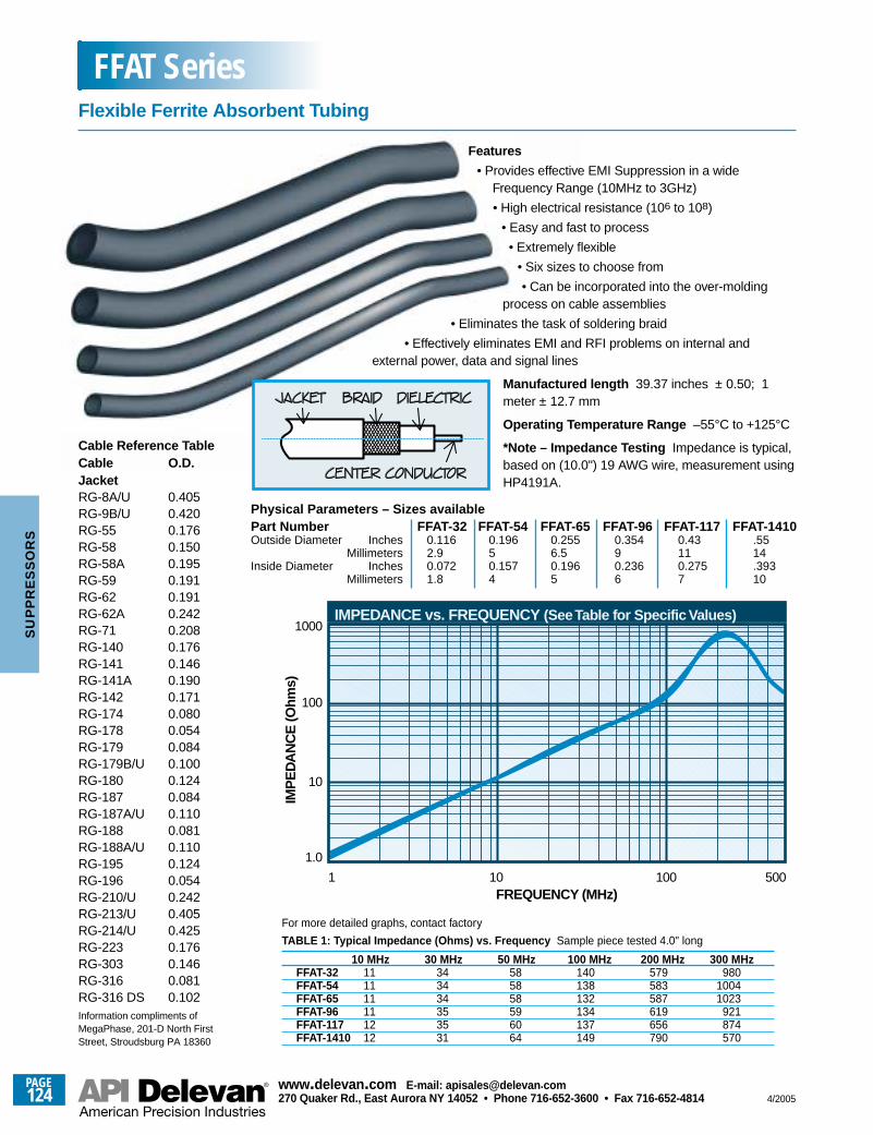
Physical Parameters – Sizes availablePart Number FFAT-32 FFAT-54 FFAT-65 FFAT-96 FFAT-117 FFAT-1410Outside Diameter Inches 0.116 0.196 0.255 0.354 0.43 .55
Millimeters 2.9 5 6.5 9 11 14Inside Diameter Inches 0.072 0.157 0.196 0.236 0.275 .393
Millimeters 1.8 4 5 6 7 10
1FREQUENCY (MHz)
IMP
ED
AN
CE
(Ohm
s)
1.0
10
100
1000
10 100 500
IMPEDANCE vs. FREQUENCY (See Table for Specific Values)
Cable Reference TableCable O.D.JacketRG-8A/U 0.405RG-9B/U 0.420RG-55 0.176RG-58 0.150RG-58A 0.195RG-59 0.191RG-62 0.191RG-62A 0.242RG-71 0.208RG-140 0.176RG-141 0.146RG-141A 0.190RG-142 0.171RG-174 0.080RG-178 0.054RG-179 0.084RG-179B/U 0.100RG-180 0.124RG-187 0.084RG-187A/U 0.110RG-188 0.081RG-188A/U 0.110RG-195 0.124RG-196 0.054RG-210/U 0.242RG-213/U 0.405RG-214/U 0.425RG-223 0.176RG-303 0.146RG-316 0.081RG-316 DS 0.102Information compliments ofMegaPhase, 201-D North FirstStreet, Stroudsburg PA 18360
Features
• Provides effective EMI Suppression in a wideFrequency Range (10MHz to 3GHz)
• High electrical resistance (106 to 108)
• Easy and fast to process
• Extremely flexible
• Six sizes to choose from
• Can be incorporated into the over-moldingprocess on cable assemblies
• Eliminates the task of soldering braid
• Effectively eliminates EMI and RFI problems on internal andexternal power, data and signal lines
Manufactured length 39.37 inches ± 0.50; 1meter ± 12.7 mm
Operating Temperature Range –55°C to +125°C
*Note – Impedance Testing Impedance is typical,based on (10.0") 19 AWG wire, measurement usingHP4191A.
TABLE 1: Typical Impedance (Ohms) vs. Frequency Sample piece tested 4.0" long
10 MHz 30 MHz 50 MHz 100 MHz 200 MHz 300 MHzFFAT-32 11 34 58 140 579 980FFAT-54 11 34 58 138 583 1004FFAT-65 11 34 58 132 587 1023FFAT-96 11 35 59 134 619 921FFAT-117 12 35 60 137 656 874FFAT-1410 12 31 64 149 790 570
For more detailed graphs, contact factory
Flexible Ferrite Absorbent Tubing
FFAT Series
PAGE124
www.delevan .com E-mail: apisales@delevan .com270 Quaker Rd., East Aurora NY 14052 • Phone 716-652-3600 • Fax 716-652-4814 4/2005
SU
PP
RE
SS
OR
S
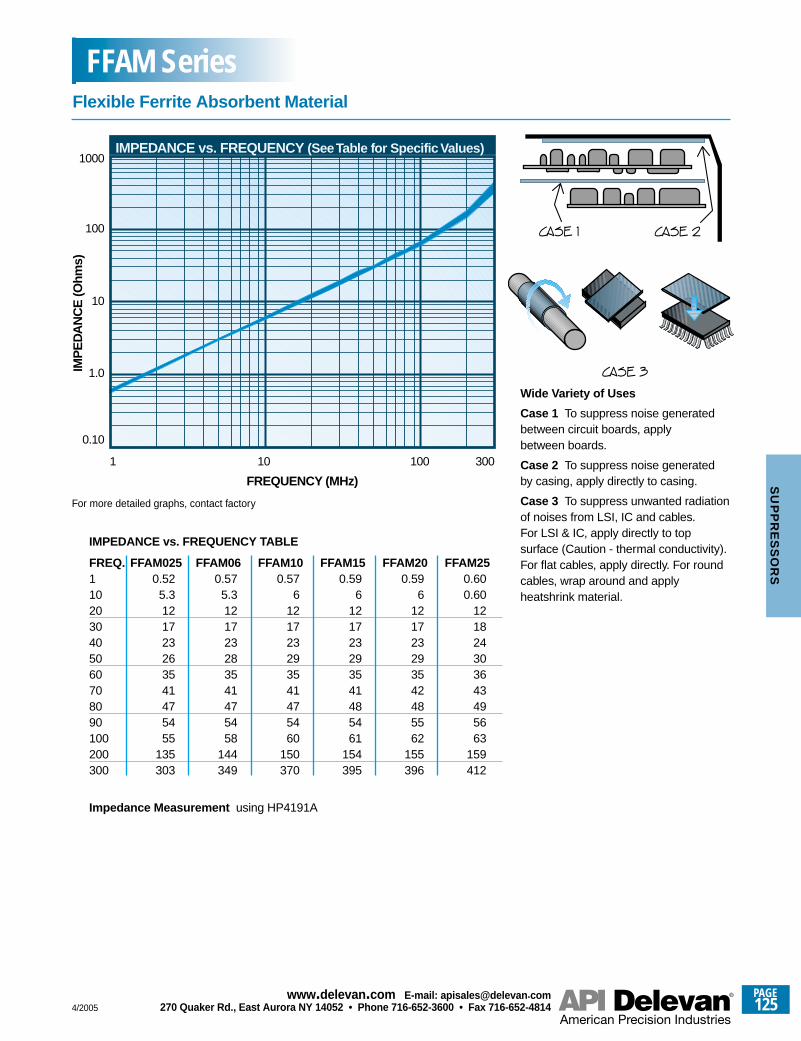
CASE 1 CASE 2
CASE 3
1
0.10
FREQUENCY (MHz)
IMP
ED
AN
CE
(Ohm
s)
1.0
10
100
1000
10 100 300
IMPEDANCE vs. FREQUENCY (See Table for Specific Values)
IMPEDANCE vs. FREQUENCY TABLE
FREQ. FFAM025 FFAM06 FFAM10 FFAM15 FFAM20 FFAM251 0.52 0.57 0.57 0.59 0.59 0.6010 5.3 5.3 6 6 6 0.6020 12 12 12 12 12 1230 17 17 17 17 17 1840 23 23 23 23 23 2450 26 28 29 29 29 3060 35 35 35 35 35 3670 41 41 41 41 42 4380 47 47 47 48 48 4990 54 54 54 54 55 56100 55 58 60 61 62 63200 135 144 150 154 155 159300 303 349 370 395 396 412
Impedance Measurement using HP4191A
Wide Variety of Uses
Case 1 To suppress noise generatedbetween circuit boards, applybetween boards.
Case 2 To suppress noise generatedby casing, apply directly to casing.
Case 3 To suppress unwanted radiationof noises from LSI, IC and cables.For LSI & IC, apply directly to topsurface (Caution - thermal conductivity).For flat cables, apply directly. For roundcables, wrap around and applyheatshrink material.
For more detailed graphs, contact factory
Flexible Ferrite Absorbent Material
FFAM Series
4/2005
PAGE125
www.delevan .com E-mail: apisales@delevan .com270 Quaker Rd., East Aurora NY 14052 • Phone 716-652-3600 • Fax 716-652-4814
SU
PP
RE
SS
OR
S
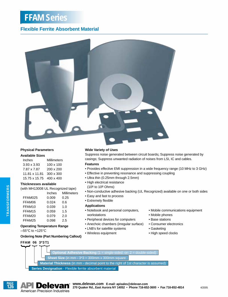
Physical Parameters
Available SizesInches Millimeters3.93 x 3.93 100 x 1007.87 x 7.87 200 x 20011.81 x 11.81 300 x 30015.75 x 15.75 400 x 400
Thicknesses available(with MH13008 UL Recognized tape)
Inches MillimetersFFAM025 0.009 0.25FFAM06 0.024 0.6FFAM10 0.039 1.0FFAM15 0.059 1.5FFAM20 0.079 2.0FFAM25 0.098 2.5
Operating Temperature Range–55°C to +125°C
Ordering Note (Part Numbering Callout)
FFAM 06 3*3 T1
Wide Variety of UsesSuppress noise generated between circuit boards; Suppress noise generated bycasings; Suppress unwanted radiation of noises from LSI, IC and cables.
Features• Provides effective EMI suppression in a wide frequency range (10 MHz to 3 GHz)• Effective in preventing resonance and suppressing coupling• Ultra thin (0.25mm through 2.5mm)• High electrical resistance
(106 to 108 Ohms)• Non-conductive adhesive backing (UL Recognized) available on one or both sides• Easy and fast to process• Extremely flexible
Applications
Flexible Ferrite Absorbent Material
FFAM Series
• Notebook and personal computers,workstations
• Peripheral devices for computers• Anechoic chambers (irregular surface)• LNB's for satellite systems• Wireless equipment
• Mobile communications equipment• Mobile phones• Base stations• Consumer electronics• Gasketing• High speed clocks
Series Designation - Flexible ferrite absorbent material
Material Thickness (in mm - decimal point to the right of 1st character is assumed)
Sheet Size (in mm - 3*3 = 300mm x 300mm square
Optional Adhesive Backing (1 = single-sided -or- 2 = double-sided)
PAGE126
www.delevan .com E-mail: apisales@delevan .com270 Quaker Rd., East Aurora NY 14052 • Phone 716-652-3600 • Fax 716-652-4814 4/2005
TR
AN
SF
OR
ME
RS
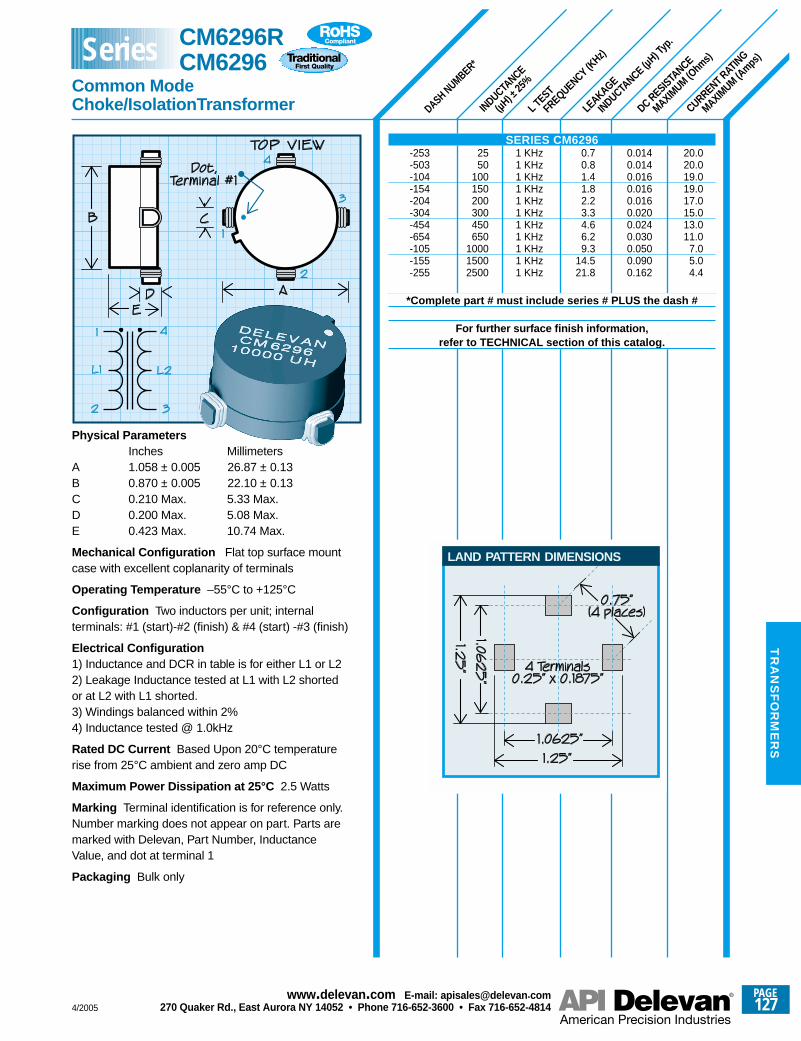
LEAKAGE
INDUCTANCE (µ
H) Typ
.
L TEST
FREQUENCY (KHz)
INDUCTANCE
(µH) ±
25%
CURRENT RATING
MAXIMUM (A
mps)
DC RESISTANCE
MAXIMUM (O
hms)
DASH NUMBER*
20.020.019.019.017.015.013.011.0
7.05.04.4
0.0140.0140.0160.0160.0160.0200.0240.0300.0500.0900.162
0.70.81.41.82.23.34.66.29.3
14.521.8
1 KHz1 KHz1 KHz1 KHz1 KHz1 KHz1 KHz1 KHz1 KHz1 KHz1 KHz
2550
100150200300450650
100015002500
Physical ParametersInches Millimeters
A 1.058 ± 0.005 26.87 ± 0.13B 0.870 ± 0.005 22.10 ± 0.13C 0.210 Max. 5.33 Max.D 0.200 Max. 5.08 Max.E 0.423 Max. 10.74 Max.
Mechanical Configuration Flat top surface mountcase with excellent coplanarity of terminals
Operating Temperature –55°C to +125°C
Configuration Two inductors per unit; internalterminals: #1 (start)-#2 (finish) & #4 (start) -#3 (finish)
Electrical Configuration 1) Inductance and DCR in table is for either L1 or L22) Leakage Inductance tested at L1 with L2 shortedor at L2 with L1 shorted.3) Windings balanced within 2%4) Inductance tested @ 1.0kHz
Rated DC Current Based Upon 20°C temperaturerise from 25°C ambient and zero amp DC
Maximum Power Dissipation at 25°C 2.5 Watts
Marking Terminal identification is for reference only.Number marking does not appear on part. Parts aremarked with Delevan, Part Number, InductanceValue, and dot at terminal 1
Packaging Bulk only
SERIES CM6296-253-503-104-154-204-304-454-654-105-155-255
*Complete part # must include series # PLUS the dash #
For further surface finish information,refer to TECHNICAL section of this catalog.
LAND PATTERN DIMENSIONS
CM6296R CM6296
Common ModeChoke/IsolationTransformer
Series
4/2005
PAGE127
www.delevan .com E-mail: apisales@delevan .com270 Quaker Rd., East Aurora NY 14052 • Phone 716-652-3600 • Fax 716-652-4814
TR
AN
SF
OR
ME
RS
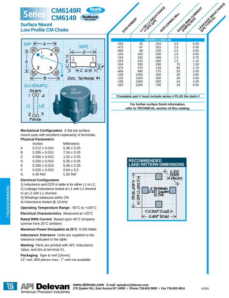
RATED R
MS CURRENT
(AMPS) M
AX
DCR (OHMS) M
ax.
L1 O
R L2 IN
DUCTANCE
+/-25
% (µ
H)
LEAKAGE IN
DUCTANCE
(µH) TYPIC
AL
DASH NUMBER*
Mechanical Configuration A flat top surfacemount case with excellent coplanarity of terminals.Physical Parameters
Inches MillimetersA 0.212 ± 0.010 5.38 ± 0.25B 0.285 ± 0.010 7.24 ± 0.25C 0.060 ± 0.010 1.52 ± 0.25D 0.250 ± 0.010 6.35 ± 0.25E 0.200 ± 0.010 5.08 ± 0.25F 0.025 ± 0.010 0.64 ± 0.2G 0.40 Ref 1.02 Ref
Electrical Configuration1) Inductance and DCR in table is for either L1 or L2.2) Leakage Inductance tested at L1 with L2 shortedor at L2 with L1 shorted.3) Windings balanced within 2%4) Inductance tested @ 10 kHz
Operating Temperature Range -55°C to +105°C
Electrical Characteristics Measured at +25°C
Rated RMS Current Based upon 40°C tempera-turerise from 25°C ambient.
Maximum Power Dissipation at 25 °C 0.200 Watts
Inductance Tolerance Units are supplied to thetolerance indicated in the table.
Marking Parts are printed with API, InductanceValue, and dot at terminal #1.
Packaging Tape & reel (16mm):13˝ reel, 800 pieces max.; 7˝ reel not available
SERIES CM6149-253 25 .010 3.0 0.20-473 47 .015 2.5 0.30-683 68 .020 2.0 0.40-104 100 .030 1.6 0.50-154 150 .040 1.3 0.70-224 220 .060 1.0 1.10-334 330 .090 .75 1.50-474 470 .125 .60 1.70-684 680 .170 .50 2.00-105 1000 .250 .40 2.80 -125 1200 .350 .30 3.50-155 1500 .500 .24 4.30 -225 2200 .750 .18 6.00
*Complete part # must include series # PLUS the dash #
For further surface finish information,refer to TECHNICAL section of this catalog.
CM6149RCM6149
Surface MountLow Profile CM Choke
Series
PAGE128
www.delevan .com E-mail: apisales@delevan .com270 Quaker Rd., East Aurora NY 14052 • Phone 716-652-3600 • Fax 716-652-4814 4/2005
TR
AN
SF
OR
ME
RS
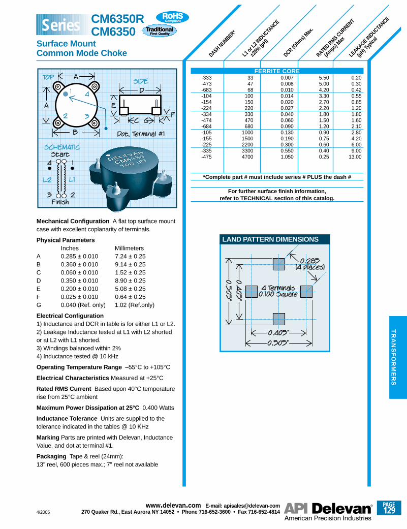
DASH NUMBER*
L1 or
L2 IN
DUCTANCE
±25%
(µH)
DCR (Ohm
s) Max
.
RATED RMS CURRENT
(Amps) M
ax
LEAKAGE IN
DUCTANCE
(µH) T
ypica
l
0.200.300.420.550.851.201.801.602.102.80 4.206.00 9.00
13.00
334768
100150220330470680
10001500220033004700
5.505.004.203.302.702.201.801.501.200.900.750.600.400.25
0.0070.0080.0100.0140.0200.0270.0400.0600.0900.1300.1900.3000.5501.050
Mechanical Configuration A flat top surface mountcase with excellent coplanarity of terminals.
Physical ParametersInches Millimeters
A 0.285 ± 0.010 7.24 ± 0.25B 0.360 ± 0.010 9.14 ± 0.25C 0.060 ± 0.010 1.52 ± 0.25D 0.350 ± 0.010 8.90 ± 0.25 E 0.200 ± 0.010 5.08 ± 0.25F 0.025 ± 0.010 0.64 ± 0.25G 0.040 (Ref. only) 1.02 (Ref.only)
Electrical Configuration 1) Inductance and DCR in table is for either L1 or L2.2) Leakage Inductance tested at L1 with L2 shortedor at L2 with L1 shorted.3) Windings balanced within 2%4) Inductance tested @ 10 kHz
Operating Temperature Range –55°C to +105°C
Electrical Characteristics Measured at +25°C
Rated RMS Current Based upon 40°C temperaturerise from 25°C ambient
Maximum Power Dissipation at 25°C 0.400 Watts
Inductance Tolerance Units are supplied to thetolerance indicated in the tables @ 10 KHz
Marking Parts are printed with Delevan, InductanceValue, and dot at terminal #1.
Packaging Tape & reel (24mm):13" reel, 600 pieces max.; 7" reel not available
FERRITE CORE-333-473-683-104-154-224-334-474-684-105-155-225-335-475
*Complete part # must include series # PLUS the dash #
For further surface finish information,refer to TECHNICAL section of this catalog.
LAND PATTERN DIMENSIONS
CM6350R CM6350
Surface MountCommon Mode Choke
Series
4/2005
PAGE129
www.delevan .com E-mail: apisales@delevan .com270 Quaker Rd., East Aurora NY 14052 • Phone 716-652-3600 • Fax 716-652-4814
TR
AN
SF
OR
ME
RS
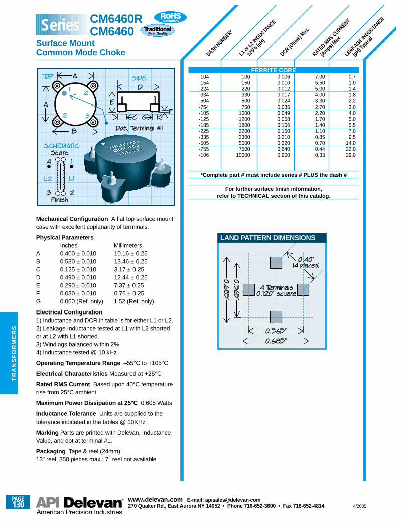
DASH NUMBER*
L1 or
L2 IN
DUCTANCE
±25%
(µH)
DCR (Ohm
s) Max
.
RATED RMS CURRENT
(Amps) M
ax
LEAKAGE IN
DUCTANCE
(µH) T
ypica
l
0.71.01.41.82.23.04.05.05.57.09.5
14.022.029.0
100150220330500750
1000120018002200330050007500
10000
7.005.505.004.003.302.702.201.701.401.100.850.700.440.33
0.0060.0100.0120.0170.0240.0350.0490.0680.1060.1500.2100.3200.6400.900
Mechanical Configuration A flat top surface mountcase with excellent coplanarity of terminals.
Physical ParametersInches Millimeters
A 0.400 ± 0.010 10.16 ± 0.25B 0.530 ± 0.010 13.46 ± 0.25C 0.125 ± 0.010 3.17 ± 0.25D 0.490 ± 0.010 12.44 ± 0.25E 0.290 ± 0.010 7.37 ± 0.25F 0.030 ± 0.010 0.76 ± 0.25G 0.060 (Ref. only) 1.52 (Ref. only)
Electrical Configuration 1) Inductance and DCR in table is for either L1 or L2.2) Leakage Inductance tested at L1 with L2 shortedor at L2 with L1 shorted.3) Windings balanced within 2%4) Inductance tested @ 10 kHz
Operating Temperature Range –55°C to +105°C
Electrical Characteristics Measured at +25°C
Rated RMS Current Based upon 40°C temperaturerise from 25°C ambient
Maximum Power Dissipation at 25°C 0.605 Watts
Inductance Tolerance Units are supplied to thetolerance indicated in the tables @ 10KHz
Marking Parts are printed with Delevan, InductanceValue, and dot at terminal #1.
Packaging Tape & reel (24mm):13" reel, 350 pieces max.; 7" reel not available
FERRITE CORE-104-154-224-334-504-754-105-125-185-225-335-505-755-106
*Complete part # must include series # PLUS the dash #
For further surface finish information,refer to TECHNICAL section of this catalog.
LAND PATTERN DIMENSIONS
CM6460R CM6460
Surface MountCommon Mode Choke
Series
PAGE130
www.delevan .com E-mail: apisales@delevan .com270 Quaker Rd., East Aurora NY 14052 • Phone 716-652-3600 • Fax 716-652-4814 4/2005
TR
AN
SF
OR
ME
RS
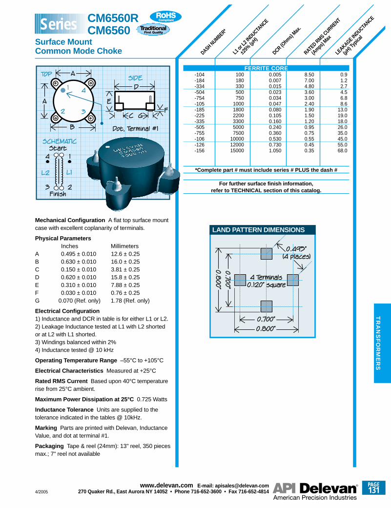
DASH NUMBER*
L1 or
L2 IN
DUCTANCE
±25%
(µH)
DCR (Ohm
s) Max
.
RATED RMS CURRENT
(Amps) M
ax
LEAKAGE IN
DUCTANCE
(µH) T
ypica
l
0.91.22.74.56.88.6
13.019.018.026.035.045.055.068.0
100180330500750
100018002200330050007500
100001200015000
8.507.004.803.603.002.401.901.501.200.950.750.550.450.35
0.0050.0070.0150.0230.0340.0470.0800.1050.1600.2400.3600.5300.7301.050
Mechanical Configuration A flat top surface mountcase with excellent coplanarity of terminals.
Physical ParametersInches Millimeters
A 0.495 ± 0.010 12.6 ± 0.25B 0.630 ± 0.010 16.0 ± 0.25C 0.150 ± 0.010 3.81 ± 0.25D 0.620 ± 0.010 15.8 ± 0.25E 0.310 ± 0.010 7.88 ± 0.25F 0.030 ± 0.010 0.76 ± 0.25G 0.070 (Ref. only) 1.78 (Ref. only)
Electrical Configuration1) Inductance and DCR in table is for either L1 or L2.2) Leakage Inductance tested at L1 with L2 shortedor at L2 with L1 shorted.3) Windings balanced within 2%4) Inductance tested @ 10 kHz
Operating Temperature Range –55°C to +105°C
Electrical Characteristics Measured at +25°C
Rated RMS Current Based upon 40°C temperaturerise from 25°C ambient.
Maximum Power Dissipation at 25°C 0.725 Watts
Inductance Tolerance Units are supplied to thetolerance indicated in the tables @ 10kHz.
Marking Parts are printed with Delevan, InductanceValue, and dot at terminal #1.
Packaging Tape & reel (24mm): 13" reel, 350 piecesmax.; 7" reel not available
FERRITE CORE-104-184-334-504-754-105-185-225-335-505-755-106-126-156
*Complete part # must include series # PLUS the dash #
For further surface finish information,refer to TECHNICAL section of this catalog.
LAND PATTERN DIMENSIONS
CM6560R CM6560
Surface MountCommon Mode Choke
Series
4/2005
PAGE131
www.delevan .com E-mail: apisales@delevan .com270 Quaker Rd., East Aurora NY 14052 • Phone 716-652-3600 • Fax 716-652-4814
TR
AN
SF
OR
ME
RS

DC RESISTANCE
MAXIMUM (O
HMS)
Each W
INDING
INDUCTANCE
Each W
INDING
(µH) ±
25%
MAXIMUM
LEAKAGE
INDUCTANCE (µ
H)**
CURRENT RATING
MAXIMUM (A
mps)
Each W
INDING
DASH NUMBER*
TEST FREQUENCY (KHz)
Physical ParametersInches Millimeters
A 0.435 to 0.465 11.05 to 11.81B 0.385 to 0.405 9.78 to 10.29C 0.375 to 0.405 9.53 to 10.29D 0.205 to 0.235 5.21 to 5.97E (8 places) 0.028 typ. 0.71 typ.F (6 places) 0.079 typ. 2.00 typ.
Mechanical ConfigurationER Core on an 8 Pin Surface Mount Base
Operating Temperature Range –20°C to +80°C
Maximum Power Dissipation at 25°C 0.140 W
Dielectric Withstanding Voltage500V RMS, 60Hz, 5 sec.
Current Rating Current which will cause less than a +35°C temperature rise maximum, from +25°CAmbient, with all windings connected in series
Notes ** 1) Max. leakage inductance measured @ 1 KHz on Pin 1-8 with all other pins shorted.2) Board connections may be altered to createdifferent transformer/inductor configurations.
Custom Applications Consult factory
Packaging Tape & reel (24mm): 13" reel, 600 piecesmax.; 7" reel not available
Made In the U.S.A.
1 KHz1 KHz1 KHz1 KHz1 KHz1 KHz1 KHz1 KHz1 KHz
1.000.900.750.600.500.450.380.300.25
0.040.070.130.190.320.560.901.191.90
0.901.101.301.501.704.306.806.957.00
2550
100150250500750
10001500
Pad DimensionsInches Millimeters
C 0.425 10.80G 0.368 9.35X 0.063 1.60Y 0.079 2.00Z 0.492 12.50
PAD DIMENSIONS
CM6594 SERIES-253-503-104-154-254-504-754-105-155
*Complete part # must include series # PLUS the dash #
For further surface finish information,refer to TECHNICAL section of this catalog.
CM6594R CM6594
4-WindingSurface Mount Transformers
Series
PAGE132
www.delevan .com E-mail: apisales@delevan .com270 Quaker Rd., East Aurora NY 14052 • Phone 716-652-3600 • Fax 716-652-4814 4/2005
TR
AN
SF
OR
ME
RS
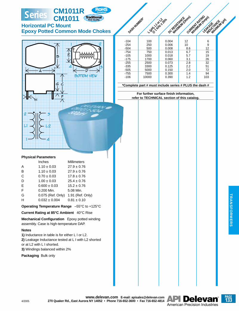
DASH NUMBER*
L (µH
), L1 o
r L2
@ 1
KHz ±25
%
CURRENT RATING
MAXIMUM (A
mps)
LEAKAGE
INDUCTANCE
MAXIMUM (µ
H)
DC RESISTANCE
MAXIMUM (O
hms)
69
1215192632517294
103
1210
8.66.75.73.12.82.22.01.41.2
0.0040.0060.0080.0130.0180.0600.0730.1250.1500.3000.390
100250500750
100017002500330050007500
10000
Physical ParametersInches Millimeters
A 1.10 ± 0.03 27.9 ± 0.76B 1.10 ± 0.03 27.9 ± 0.76C 0.70 ± 0.03 17.8 ± 0.76D 1.00 ± 0.03 25.4 ± 0.76E 0.600 ± 0.03 15.2 ± 0.76F 0.200 Min. 5.08 Min.G 0.075 (Ref. Only) 1.91 (Ref. Only)H 0.032 ± 0.004 0.81 ± 0.10
Operating Temperature Range –55°C to +125°C
Current Rating at 85°C Ambient 40°C Rise
Mechanical Configuration Epoxy potted windingassembly. Case is high-temperature DAP.
Notes1) Inductance in table is for either L I or L2.2) Leakage Inductance tested at L I with L2 shortedor at L2 with L I shorted.3) Windings balanced within 2%
Packaging Bulk only
CM1011R CM1011
Horizontal PC MountEpoxy Potted Common Mode Chokes
Series
-104-254-504-754-105-175-255-335-505-755-106
*Complete part # must include series # PLUS the dash #
For further surface finish information,refer to TECHNICAL section of this catalog.
4/2005
PAGE133
www.delevan .com E-mail: apisales@delevan .com270 Quaker Rd., East Aurora NY 14052 • Phone 716-652-3600 • Fax 716-652-4814
TR
AN
SF
OR
ME
RS
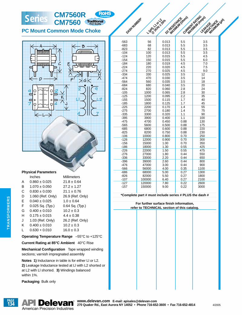
DASH NUMBER*
L (µH
), L1 o
r L2
@ 1K
Hz ±25
%
CURRENT RATING
MAXIMUM (A
mps)
LEAKAGE
INDUCTANCE
MAXIMUM (µ
H)
DC RESISTANCE
MAXIMUM (O
hms)
0.0130.0130.0130.0130.0150.0150.0190.0200.0250.0250.0300.0350.0400.0600.0650.0950.1150.1250.1700.1800.3200.4000.4500.5000.6000.7500.8000.9001.001.301.501.802.202.603.004.005.005.506.407.809.00
566882
100120150180220270330470560680820
100012001500180022002700330039004700560068008200
100001200015000180002200027000330003900047000560006800082000
100000120000150000
5.55.55.55.55.55.54.54.54.53.53.53.53.52.82.82.21.71.71.41.41.11.10.880.880.880.880.700.700.700.550.550.440.440.440.440.350.270.270.270.220.22
3.53.53.53.54.56.07.07.59.0
121418202430354045557590
100130175220230250300350425475550650800900
110013001800210026003000
Physical ParametersInches Millimeters
A 0.860 ± 0.025 21.8 ± 0.64B 1.070 ± 0.050 27.2 ± 1.27C 0.830 ± 0.030 21.1 ± 0.76D 1.060 (Ref. Only) 26.9 (Ref. Only)E 0.040 ± 0.025 1.0 ± 0.64F 0.025 Sq. (Typ.) 0.64 Sq. (Typ.)G 0.400 ± 0.010 10.2 ± 0.3H 0.175 ± 0.015 4.4 ± 0.38J 1.03 (Ref. Only) 26.2 (Ref. Only)K 0.400 ± 0.010 10.2 ± 0.3L 0.630 + 0.010 16.0 ± 0.3
Operating Temperature Range –55°C to +125°C
Current Rating at 85°C Ambient 40°C Rise
Mechanical Configuration Tape wrapped windingsections; varnish impregnated assembly
Notes 1) Inductance in table is for either Ll or L2.2) Leakage Inductance tested at Ll with L2 shorted orat L2 with Ll shorted. 3) Windings balancedwithin 1%.
Packaging Bulk only
CM7560RCM7560
PC Mount Common Mode Choke
Series
-563-683-823-104-124-154-184-224-274-334-474-564-684-824-105-125-155-185-225-275-335-395-475-565-685-825-106-126-156-186-226-276-336-396-476-566-686-826-107-127-157
*Complete part # must include series # PLUS the dash #
For further surface finish information,refer to TECHNICAL section of this catalog.
PAGE134
www.delevan .com E-mail: apisales@delevan .com270 Quaker Rd., East Aurora NY 14052 • Phone 716-652-3600 • Fax 716-652-4814 4/2005
TR
AN
SF
OR
ME
RS
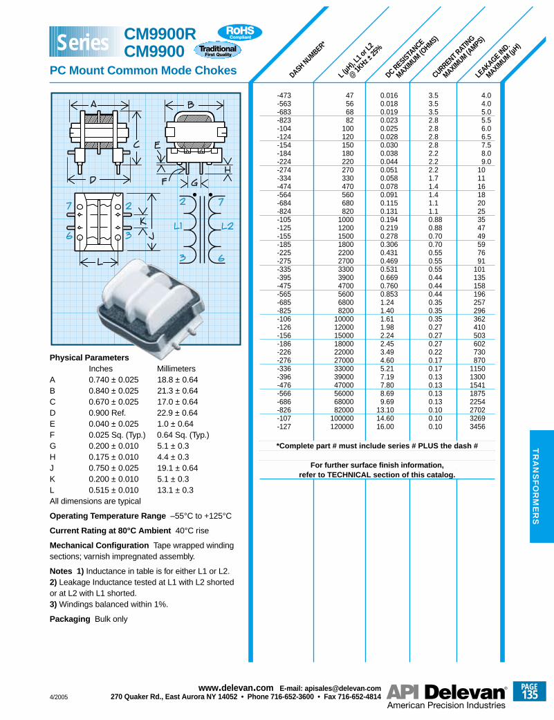
DASH NUMBER*
L (µH
), L1 o
r L2
@ 1K
Hz ±25
%
LEAKAGE IN
D.
MAXIMUM (µ
H)
DC RESISTANCE
MAXIMUM (O
HMS)
CURRENT RATING
MAXIMUM (A
MPS)
4.04.05.05.56.06.57.58.09.0
101116182025354749597691
101135158196257296362410503602730870
11501300154118752254270232693456
3.53.53.52.82.82.82.82.22.22.21.71.41.41.11.10.880.880.700.700.550.550.550.440.440.440.350.350.350.270.270.270.220.170.170.130.130.130.130.100.100.10
0.0160.0180.0190.0230.0250.0280.0300.0380.0440.0510.0580.0780.0910.1150.1310.1940.2190.2780.3060.4310.4690.5310.6690.7600.8531.241.401.611.982.242.453.494.605.217.197.808.699.69
13.1014.6016.00
47566882
100120150180220270330470560680820
100012001500180022002700330039004700560068008200
100001200015000180002200027000330003900047000560006800082000
100000120000
Physical ParametersInches Millimeters
A 0.740 ± 0.025 18.8 ± 0.64B 0.840 ± 0.025 21.3 ± 0.64C 0.670 ± 0.025 17.0 ± 0.64D 0.900 Ref. 22.9 ± 0.64E 0.040 ± 0.025 1.0 ± 0.64F 0.025 Sq. (Typ.) 0.64 Sq. (Typ.)G 0.200 ± 0.010 5.1 ± 0.3H 0.175 ± 0.010 4.4 ± 0.3J 0.750 ± 0.025 19.1 ± 0.64K 0.200 ± 0.010 5.1 ± 0.3L 0.515 ± 0.010 13.1 ± 0.3All dimensions are typical
Operating Temperature Range –55°C to +125°C
Current Rating at 80°C Ambient 40°C rise
Mechanical Configuration Tape wrapped windingsections; varnish impregnated assembly.
Notes 1) Inductance in table is for either L1 or L2.2) Leakage Inductance tested at L1 with L2 shortedor at L2 with L1 shorted.3) Windings balanced within 1%.
Packaging Bulk only
-473-563-683-823-104-124-154-184-224-274-334-474-564-684-824-105-125-155-185-225-275-335-395-475-565-685-825-106-126-156-186-226-276-336-396-476-566-686-826-107-127
*Complete part # must include series # PLUS the dash #
For further surface finish information,refer to TECHNICAL section of this catalog.
CM9900RCM9900
PC Mount Common Mode Chokes
Series
4/2005
PAGE135
www.delevan .com E-mail: apisales@delevan .com270 Quaker Rd., East Aurora NY 14052 • Phone 716-652-3600 • Fax 716-652-4814
TR
AN
SF
OR
ME
RS
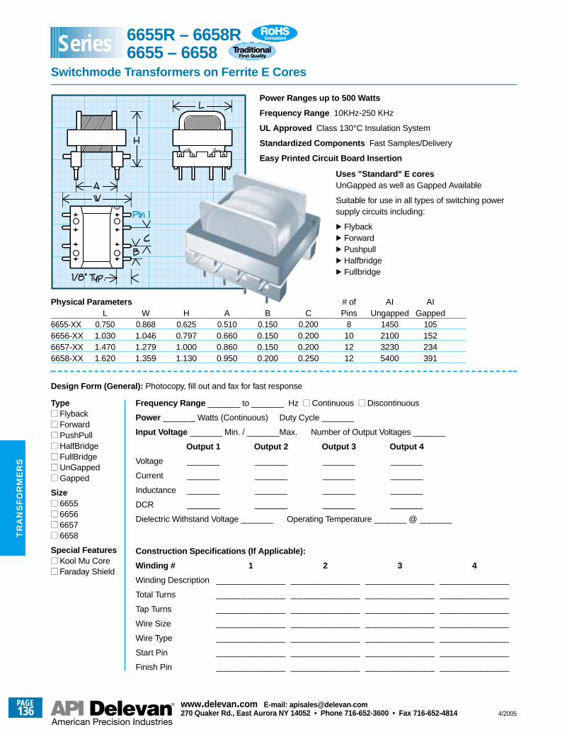
Power Ranges up to 500 Watts
Frequency Range 10KHz-250 KHz
UL Approved Class 130°C Insulation System
Standardized Components Fast Samples/Delivery
Easy Printed Circuit Board Insertion
Uses "Standard" E coresUnGapped as well as Gapped Available
Suitable for use in all types of switching powersupply circuits including:
. Flyback
. Forward
. Pushpull
. Halfbridge
. Fullbridge
Physical Parameters # of AI AIL W H A B C Pins Ungapped Gapped
6655-XX 0.750 0.868 0.625 0.510 0.150 0.200 8 1450 1056656-XX 1.030 1.046 0.797 0.660 0.150 0.200 10 2100 1526657-XX 1.470 1.279 1.000 0.860 0.150 0.200 12 3230 2346658-XX 1.620 1.359 1.130 0.950 0.200 0.250 12 5400 391
Design Form (General): Photocopy, fill out and fax for fast response
Type Flyback Forward PushPull HalfBridge FullBridge UnGapped Gapped
Size 6655 6656 6657 6658
Special Features Kool Mu Core Faraday Shield
Frequency Range _______ to _______ Hz Continuous Discontinuous
Power _______ Watts (Continuous) Duty Cycle _______
Input Voltage _______ Min. / _______Max. Number of Output Voltages _______
Output 1 Output 2 Output 3 Output 4
Voltage _______ _______ _______ _______
Current _______ _______ _______ _______
Inductance _______ _______ _______ _______
DCR _______ _______ _______ _______
Dielectric Withstand Voltage _______ Operating Temperature _______ @ _______
Construction Specifications (If Applicable):
Winding # 1 2 3 4
Winding Description _______________ _______________ _______________ _______________
Total Turns _______________ _______________ _______________ _______________
Tap Turns _______________ _______________ _______________ _______________
Wire Size _______________ _______________ _______________ _______________
Wire Type _______________ _______________ _______________ _______________
Start Pin _______________ _______________ _______________ _______________
Finish Pin _______________ _______________ _______________ _______________
6655R – 6658R6655 – 6658
Switchmode Transformers on Ferrite E Cores
Series
PAGE136
www.delevan .com E-mail: apisales@delevan .com270 Quaker Rd., East Aurora NY 14052 • Phone 716-652-3600 • Fax 716-652-4814 4/2005
TR
AN
SF
OR
ME
RS
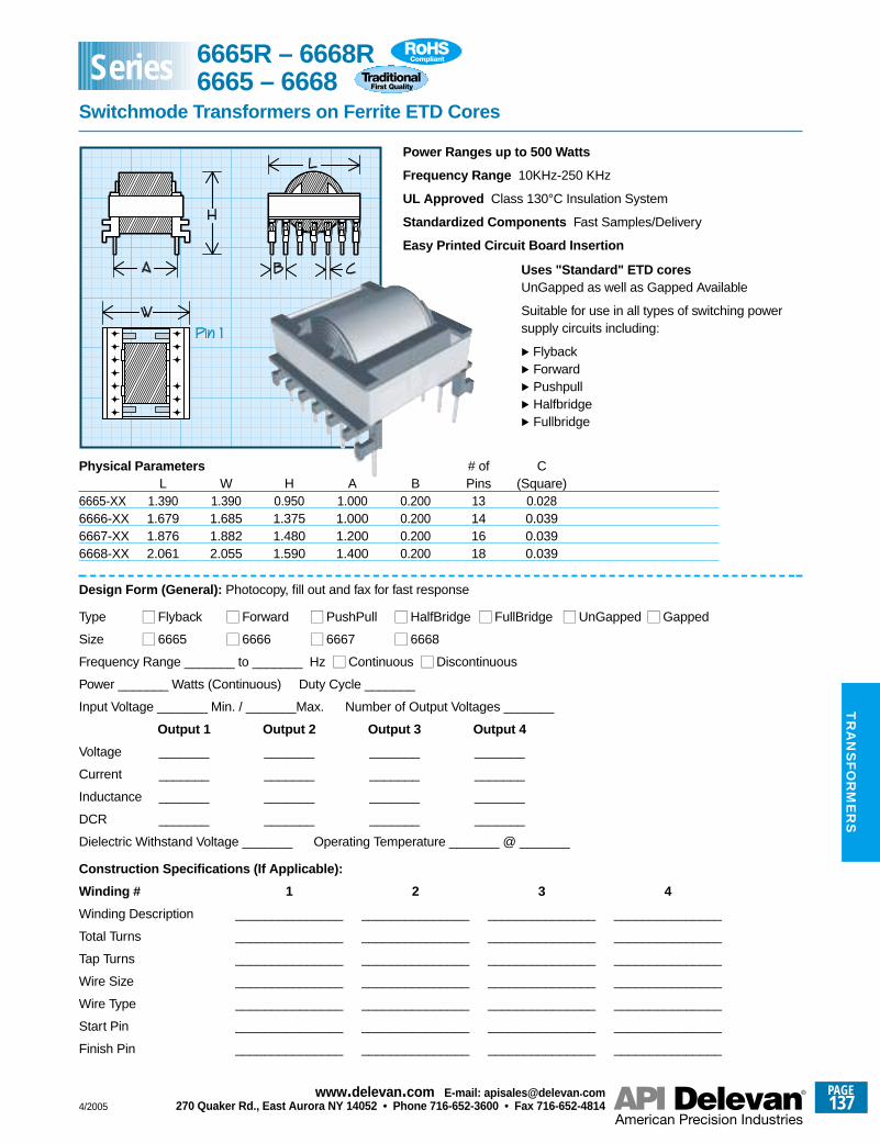
Power Ranges up to 500 Watts
Frequency Range 10KHz-250 KHz
UL Approved Class 130°C Insulation System
Standardized Components Fast Samples/Delivery
Easy Printed Circuit Board Insertion
Uses "Standard" ETD coresUnGapped as well as Gapped Available
Suitable for use in all types of switching powersupply circuits including:
. Flyback
. Forward
. Pushpull
. Halfbridge
. Fullbridge
Physical Parameters # of CL W H A B Pins (Square)
6665-XX 1.390 1.390 0.950 1.000 0.200 13 0.0286666-XX 1.679 1.685 1.375 1.000 0.200 14 0.0396667-XX 1.876 1.882 1.480 1.200 0.200 16 0.0396668-XX 2.061 2.055 1.590 1.400 0.200 18 0.039
Design Form (General): Photocopy, fill out and fax for fast response
Type Flyback Forward PushPull HalfBridge FullBridge UnGapped Gapped
Size 6665 6666 6667 6668
Frequency Range _______ to _______ Hz Continuous Discontinuous
Power _______ Watts (Continuous) Duty Cycle _______
Input Voltage _______ Min. / _______Max. Number of Output Voltages _______
Output 1 Output 2 Output 3 Output 4
Voltage _______ _______ _______ _______
Current _______ _______ _______ _______
Inductance _______ _______ _______ _______
DCR _______ _______ _______ _______
Dielectric Withstand Voltage _______ Operating Temperature _______ @ _______
Construction Specifications (If Applicable):
Winding # 1 2 3 4
Winding Description _______________ _______________ _______________ _______________
Total Turns _______________ _______________ _______________ _______________
Tap Turns _______________ _______________ _______________ _______________
Wire Size _______________ _______________ _______________ _______________
Wire Type _______________ _______________ _______________ _______________
Start Pin _______________ _______________ _______________ _______________
Finish Pin _______________ _______________ _______________ _______________
6665R – 6668R6665 – 6668
Switchmode Transformers on Ferrite ETD Cores
Series
4/2005
PAGE137
www.delevan .com E-mail: apisales@delevan .com270 Quaker Rd., East Aurora NY 14052 • Phone 716-652-3600 • Fax 716-652-4814
TR
AN
SF
OR
ME
RS
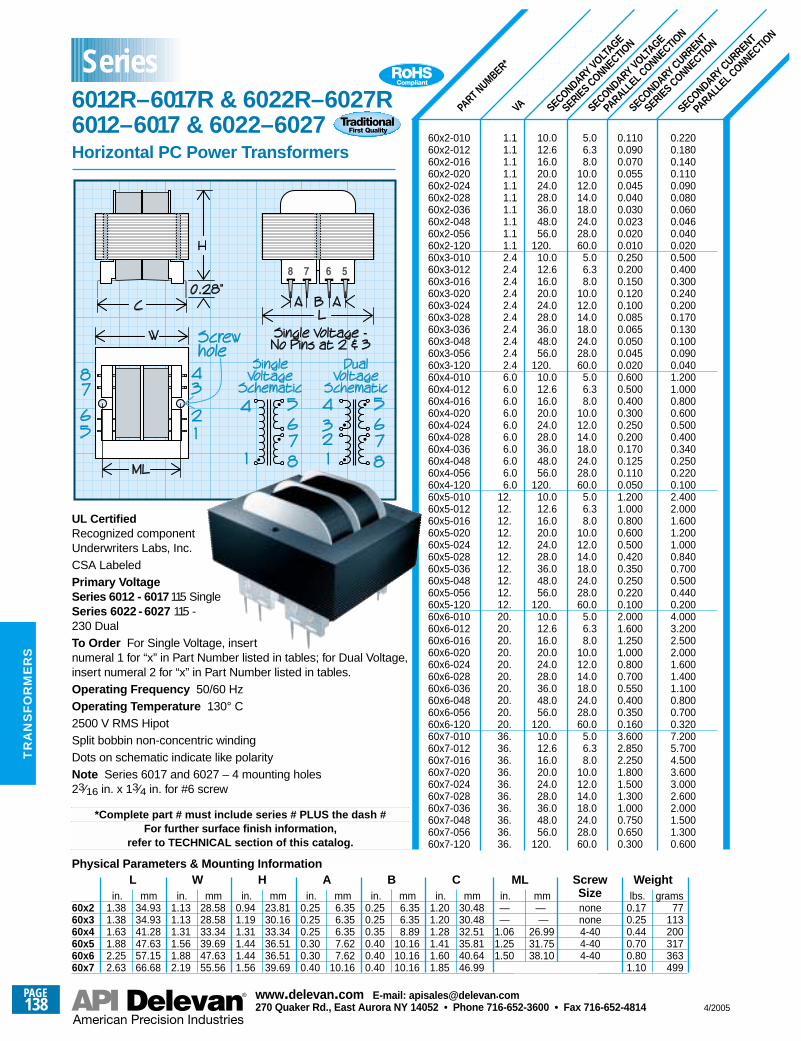
60x260x360x460x560x660x7
VA SECONDARY VOLTAGE
SERIES CONNECTION
SECONDARY VOLTAGE
PARALL
EL CONNECTIO
N
SECONDARY CURRENT
SERIES CONNECTION
SECONDARY CURRENT
PARALL
EL CONNECTIO
N
PART NUMBER*
60x2-01060x2-01260x2-01660x2-02060x2-02460x2-02860x2-03660x2-04860x2-05660x2-12060x3-01060x3-01260x3-01660x3-02060x3-02460x3-02860x3-03660x3-04860x3-05660x3-12060x4-01060x4-01260x4-01660x4-02060x4-02460x4-02860x4-03660x4-04860x4-05660x4-12060x5-01060x5-01260x5-01660x5-02060x5-02460x5-02860x5-03660x5-04860x5-05660x5-12060x6-01060x6-01260x6-01660x6-02060x6-02460x6-02860x6-03660x6-04860x6-05660x6-12060x7-01060x7-01260x7-01660x7-02060x7-02460x7-02860x7-03660x7-04860x7-05660x7-120
0.2200.1800.1400.1100.0900.0800.0600.0460.0400.0200.5000.4000.3000.2400.2000.1700.1300.1000.0900.0401.2001.0000.8000.6000.5000.4000.3400.2500.2200.1002.4002.0001.6001.2001.0000.8400.7000.5000.4400.2004.0003.2002.5002.0001.6001.4001.1000.8000.7000.3207.2005.7004.5003.6003.0002.6002.0001.5001.3000.600
0.1100.0900.0700.0550.0450.0400.0300.0230.0200.0100.2500.2000.1500.1200.1000.0850.0650.0500.0450.0200.6000.5000.4000.3000.2500.2000.1700.1250.1100.0501.2001.0000.8000.6000.5000.4200.3500.2500.2200.1002.0001.6001.2501.0000.8000.7000.5500.4000.3500.1603.6002.8502.2501.8001.5001.3001.0000.7500.6500.300
5.06.38.0
10.012.014.018.024.028.060.0
5.06.38.0
10.012.014.018.024.028.060.0
5.06.38.0
10.012.014.018.024.028.060.0
5.06.38.0
10.012.014.018.024.028.060.0
5.06.38.0
10.012.014.018.024.028.060.0
5.06.38.0
10.012.014.018.024.028.060.0
10.012.616.020.024.028.036.048.056.0
120.10.012.616.020.024.028.036.048.056.0
120.10.012.616.020.024.028.036.048.056.0
120.10.012.616.020.024.028.036.048.056.0
120.10.012.616.020.024.028.036.048.056.0
120.10.012.616.020.024.028.036.048.056.0
120.
1.11.11.11.11.11.11.11.11.11.12.42.42.42.42.42.42.42.42.42.46.06.06.06.06.06.06.06.06.06.0
12.12.12.12.12.12.12.12.12.12.20.20.20.20.20.20.20.20.20.20.36.36.36.36.36.36.36.36.36.36.
UL CertifiedRecognized componentUnderwriters Labs, Inc.CSA LabeledPrimary VoltageSeries 6012 - 6017 115 SingleSeries 6022 - 6027 115 -230 DualTo Order For Single Voltage, insert numeral 1 for “x” in Part Number listed in tables; for Dual Voltage, insert numeral 2 for “x” in Part Number listed in tables.Operating Frequency 50/60 HzOperating Temperature 130° C2500 V RMS HipotSplit bobbin non-concentric windingDots on schematic indicate like polarityNote Series 6017 and 6027 – 4 mounting holes23⁄16 in. x 13⁄4 in. for #6 screw
*Complete part # must include series # PLUS the dash #For further surface finish information,
refer to TECHNICAL section of this catalog.
in.1.381.381.631.882.252.63
mm34.9334.9341.2847.6357.1566.68
in.1.131.131.311.561.882.19
mm28.5828.5833.3439.6947.6355.56
in.0.941.191.311.441.441.56
mm23.8130.1633.3436.5136.5139.69
in.0.250.250.250.300.300.40
mm6.356.356.357.627.62
10.16
in.0.250.250.350.400.400.40
mm6.356.358.89
10.1610.1610.16
in.1.201.201.281.411.601.85
mm30.4830.4832.5135.8140.6446.99
in.——
1.061.251.50
mm——
26.9931.7538.10
nonenone4-404-404-40
lbs.0.170.250.440.700.801.10
grams77
113200317363499
LPhysical Parameters & Mounting Information
W H A B C ML ScrewSize
Weight
Series6012R–6017R & 6022R–6027R6012–6017 & 6022–6027Horizontal PC Power Transformers
PAGE138
www.delevan .com E-mail: apisales@delevan .com270 Quaker Rd., East Aurora NY 14052 • Phone 716-652-3600 • Fax 716-652-4814 4/2005
TR
AN
SF
OR
ME
RS
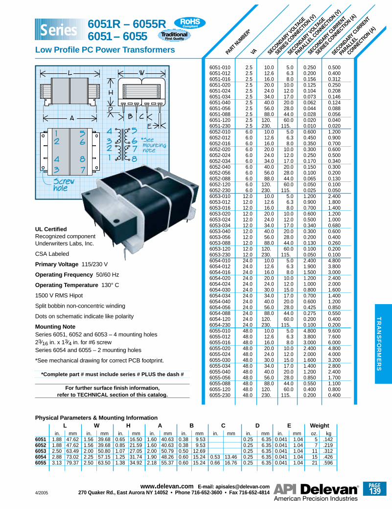
60516052605360546055
VA SECONDARY VOLTAGE
SERIES CONNECTION (V
)
SECONDARY VOLTAGE
PARALL
EL CONNECTIO
N (V)
SECONDARY CURRENT
SERIES CONNECTION (A
)
SECONDARY CURRENT
PARALL
EL
CONNECTION (A
)
PART NUMBER*
*See mounting note
6051-0106051-0126051-0166051-0206051-0246051-0346051-0406051-0566051-0886051-1206051-2306052-0106052-0126052-0166052-0206052-0246052-0346052-0406052-0566052-0886052-1206052-2306053-0106053-0126053-0166053-0206053-0246053-0346053-0406053-0566053-0886053-1206053-2306054-0106054-0126054-0166054-0206054-0246054-0306054-0346054-0406054-0566054-0886054-1206054-2306055-0106055-0126055-0166055-0206055-0246055-0306055-0346055-0406055-0566055-0886055-1206055-230
0.5000.4000.3120.2500.2080.1460.1240.0880.0560.0400.0201.2000.9000.7000.6000.5000.3400.3000.2000.1300.1000.0502.4001.8001.4001.2001.0000.6800.6000.4000.2600.2000.1004.8003.8003.0002.4002.0001.6001.4001.2000.8500.5500.4000.2009.6007.6006.0004.8004.0003.2002.8002.4001.7001.1000.8000.400
0.2500.2000.1560.1250.1040.0730.0620.0440.0280.0200.0100.6000.4500.3500.3000.2500.1700.1500.1000.0650.0500.0251.2000.9000.7000.6000.5000.3400.3000.2000.1300.1000.0502.4001.9001.5001.2001.0000.8000.7000.6000.4250.2750.2000.1004.8003.8003.0002.4002.0001.6001.4001.2000.8500.5500.4000.200
5.06.38.0
10.012.017.020.028.044.060.0
115.5.06.38.0
10.012.017.020.028.044.060.0
115.5.06.38.0
10.012.017.020.028.044.060.0
115.5.06.38.0
10.012.015.017.020.028.044.060.0
115.5.06.38.0
10.012.015.017.020.028.044.060.0
115.
10.012.616.020.024.034.040.056.088.0
120.230.
10.012.616.020.024.034.040.056.088.0
120.230.
10.012.616.020.024.034.040.056.088.0
120.230.
10.012.616.020.024.030.034.040.056.088.0
120.230.
10.012.616.020.024.030.034.040.056.088.0
120.230.
2.52.52.52.52.52.52.52.52.52.52.56.06.06.06.06.06.06.06.06.06.06.0
12.012.012.012.012.012.012.012.012.012.012.024.024.024.024.024.024.024.024.024.024.024.024.048.048.048.048.048.048.048.048.048.048.048.048.0
UL CertifiedRecognized componentUnderwriters Labs, Inc.
CSA Labeled
Primary Voltage 115/230 V
Operating Frequency 50/60 Hz
Operating Temperature 130° C
1500 V RMS Hipot
Split bobbin non-concentric winding
Dots on schematic indicate like polarity
Mounting NoteSeries 6051, 6052 and 6053 – 4 mounting holes23⁄16 in. x 13⁄4 in. for #6 screwSeries 6054 and 6055 – 2 mounting holes
*See mechanical drawing for correct PCB footprint.
*Complete part # must include series # PLUS the dash #
For further surface finish information,refer to TECHNICAL section of this catalog.
in.1.881.882.502.883.13
mm47.6247.6263.4973.0279.37
in.1.561.562.002.252.50
mm39.6839.6850.8057.1563.50
in.0.650.851.071.251.38
mm16.5021.5927.0531.7434.92
in.1.601.602.001.902.18
mm40.6340.6350.7948.2655.37
in.0.380.380.500.600.60
mm9.539.53
12.6915.2415.24
in.
0.530.66
mm
13.4616.76
in.0.250.250.250.250.25
mm6.356.356.356.356.35
oz.57
111521
kg.142.219.312.426.596
LPhysical Parameters & Mounting Information
W H A B C Din.
0.0410.0410.0410.0410.041
mm1.041.041.041.041.04
E Weight
6051R – 6055R6051– 6055
Low Profile PC Power Transformers
Series
4/2005
PAGE139
www.delevan .com E-mail: apisales@delevan .com270 Quaker Rd., East Aurora NY 14052 • Phone 716-652-3600 • Fax 716-652-4814
TR
AN
SF
OR
ME
RS
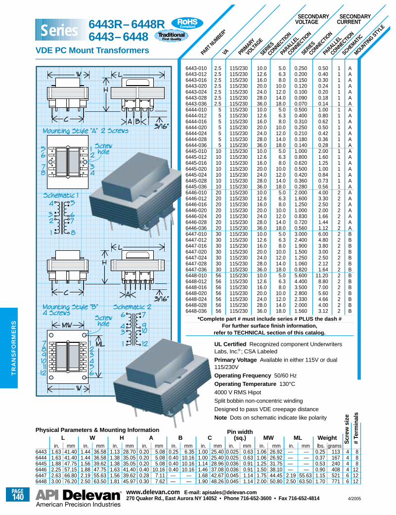
PRIMARY
VOLTAGE
PARALL
EL
CONNECTION
SERIES
CONNECTION
PARALL
EL
CONNECTION
SERIES
CONNECTION
MOUNTING STYLE
SCHEMATIC
VAPART NUMBER*
AAAAAAAAAAAAAAAAAAAAAAAAAAAABBBBBBBBBBBBBB
111111111111111111111222222222222222222222
0.500.400.300.240.200.180.141.000.800.620.500.420.360.282.001.601.251.000.840.730.564.003.302.502.001.661.441.126.004.803.803.002.502.121.64
11.208.807.005.604.664.003.12
0.2500.2000.1500.1200.1000.0900.0700.5000.4000.3100.2500.2100.1800.1401.0000.8000.6200.5000.4200.3600.2802.0001.6001.2501.0000.8300.7200.5603.0002.4001.9001.5001.2501.0600.8205.6004.4003.5002.8002.3302.0001.560
5.06.38.0
10.012.014.018.0
5.06.38.0
10.012.014.018.0
5.06.38.0
10.012.014.018.0
5.06.38.0
10.012.014.018.0
5.06.38.0
10.012.014.018.0
5.06.38.0
10.012.014.018.0
10.012.616.020.024.028.036.010.012.616.020.024.028.036.010.012.616.020.024.028.036.010.012.616.020.024.028.036.010.012.616.020.024.028.036.010.012.616.020.024.028.036.0
115/230115/230115/230115/230115/230115/230115/230115/230115/230115/230115/230115/230115/230115/230115/230115/230115/230115/230115/230115/230115/230115/230115/230115/230115/230115/230115/230115/230115/230115/230115/230115/230115/230115/230115/230115/230115/230115/230115/230115/230115/230115/230
2.52.52.52.52.52.52.5
5555555
10101010101010202020202020203030303030303056565656565656
SECONDARYVOLTAGE
SECONDARYCURRENT
in.1.631.631.882.252.633.00
mm41.4041.4047.7557.1566.8076.20
in.1.441.441.561.882.192.50
mm36.5836.5839.6247.7555.6363.50
in.1.131.381.381.631.561.81
mm28.7035.0535.0541.4039.6245.97
in.0.200.200.200.400.280.30
mm5.085.085.08
10.167.117.62
in.0.250.400.400.40——
mm6.35
10.1610.1610.16
——
in.1.001.001.141.461.681.90
mm25.4025.4028.9637.0842.6748.26
in.0.0250.0250.0360.0360.0450.045
mm0.630.630.910.911.141.14
in.1.061.061.251.501.752.00
mm26.9226.9231.7538.1044.4550.80
in.————
2.192.50
mm————
55.6363.50
lbs.0.250.370.530.901.151.70
grams113167240408521771
444466
888
121212
LPhysical Parameters & Mounting Information
W H A B CPin width
(sq.) MW ML Weight
Scr
ew s
ize
# Te
rmin
als
644364446445644664476448
6443-0106443-0126443-0166443-0206443-0246443-0286443-0366444-0106444-0126444-0166444-0206444-0246444-0286444-0366445-0106445-0126445-0166445-0206445-0246445-0286445-0366446-0106446-0126446-0166446-0206446-0246446-0286446-0366447-0106447-0126447-0166447-0206447-0246447-0286447-0366448-0106448-0126448-0166448-0206448-0246448-0286448-036
*Complete part # must include series # PLUS the dash #For further surface finish information,
refer to TECHNICAL section of this catalog.
UL Certified Recognized component UnderwritersLabs, Inc.®; CSA Labeled
Primary Voltage Available in either 115V or dual115/230V
Operating Frequency 50/60 Hz
Operating Temperature 130°C
4000 V RMS Hipot
Split bobbin non-concentric winding
Designed to pass VDE creepage distance
Note Dots on schematic indicate like polarity
6443R–6448R6443–6448
VDE PC Mount Transformers
Series
PAGE140
www.delevan .com E-mail: apisales@delevan .com270 Quaker Rd., East Aurora NY 14052 • Phone 716-652-3600 • Fax 716-652-4814 4/2005
TR
AN
SF
OR
ME
RS
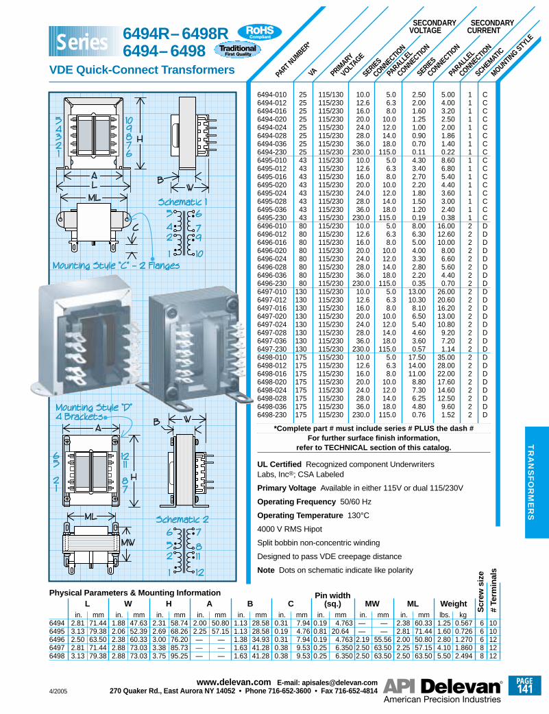
PRIMARY
VOLTAGE
PARALL
EL
CONNECTION
SERIES
CONNECTION
PARALL
EL
CONNECTION
SERIES
CONNECTION
MOUNTING STYLE
SCHEMATIC
VAPART NUMBER*
CCCCCCCCCCCCCCCCDDDDDDDDDDDDDDDDDDDDDDDD
1111111111111111222222222222222222222222
5.004.003.202.502.001.861.400.228.606.805.404.403.603.002.400.38
16.0012.6010.00
8.006.605.604.400.70
26.0020.6016.2013.0010.80
9.207.201.14
35.0028.0022.0017.6014.6012.50
9.601.52
2.502.001.601.251.000.900.700.114.303.402.702.201.801.501.200.198.006.305.004.003.302.802.200.35
13.0010.30
8.106.505.404.603.600.57
17.5014.0011.00
8.807.306.254.800.76
5.06.38.0
10.012.014.018.0
115.05.06.38.0
10.012.014.018.0
115.05.06.38.0
10.012.014.018.0
115.05.06.38.0
10.012.014.018.0
115.05.06.38.0
10.012.014.018.0
115.0
10.012.616.020.024.028.036.0
230.010.012.616.020.024.028.036.0
230.010.012.616.020.024.028.036.0
230.010.012.616.020.024.028.036.0
230.010.012.616.020.024.028.036.0
230.0
115/130115/230115/230115/230115/230115/230115/230115/230115/230115/230115/230115/230115/230115/230115/230115/230115/230115/230115/230115/230115/230115/230115/230115/230115/230115/230115/230115/230115/230115/230115/230115/230115/230115/230115/230115/230115/230115/230115/230115/230
252525252525252543434343434343438080808080808080
130130130130130130130130175175175175175175175175
SECONDARYVOLTAGE
SECONDARYCURRENT
in.2.813.132.502.813.13
mm71.4479.3863.5071.4479.38
in.1.882.062.382.882.88
mm47.6352.3960.3373.0373.03
in.2.312.693.003.383.75
mm58.7468.2676.2085.7395.25
in.2.002.25———
mm50.8057.15
———
in.1.131.131.381.631.63
mm28.5828.5834.9341.2841.28
in.0.310.190.310.380.38
mm7.944.767.949.539.53
in.0.190.810.190.250.25
mm4.763
20.644.7636.3506.350
in.——
2.192.502.50
mm——
55.5663.5063.50
in.2.382.812.002.252.50
mm60.3371.4450.8057.1563.50
lbs.1.251.602.804.105.50
kg0.5670.7261.2701.8602.494
66688
1010121212
LPhysical Parameters & Mounting Information
W H A B CPin width
(sq.) MW ML Weight
Scr
ew s
ize
# Te
rmin
als
6494-0106494-0126494-0166494-0206494-0246494-0286494-0366494-2306495-0106495-0126495-0166495-0206495-0246495-0286495-0366495-2306496-0106496-0126496-0166496-0206496-0246496-0286496-0366496-2306497-0106497-0126497-0166497-0206497-0246497-0286497-0366497-2306498-0106498-0126498-0166498-0206498-0246498-0286498-0366498-230
*Complete part # must include series # PLUS the dash #For further surface finish information,
refer to TECHNICAL section of this catalog.
UL Certified Recognized component UnderwritersLabs, Inc®; CSA Labeled
Primary Voltage Available in either 115V or dual 115/230V
Operating Frequency 50/60 Hz
Operating Temperature 130°C
4000 V RMS Hipot
Split bobbin non-concentric winding
Designed to pass VDE creepage distance
Note Dots on schematic indicate like polarity
64946495649664976498
6494R–6498R6494–6498
VDE Quick-Connect Transformers
Series
4/2005
PAGE141
www.delevan .com E-mail: apisales@delevan .com270 Quaker Rd., East Aurora NY 14052 • Phone 716-652-3600 • Fax 716-652-4814
TR
AN
SF
OR
ME
RS
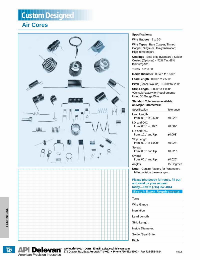
Specifications:
Wire Gauges 8 to 30*
Wire Types Bare Copper; TinnedCopper; Single or Heavy Insulation;High Temperature
Coatings Seal-brite (Standard); SolderCoated (Optional) - (42% Tin, 48%Bismuth)-Std.
Turns 1/2 to 50
Inside Diameter 0.040" to 1.500"
Lead Length 0.000" to 2.500"
Pitch (Space-Wound) 0.000" to .250"
Strip Length 0.020" to 1.000"*Consult Factory for RequirementsUsing 30 Gauge Wire
Standard Tolerances availableon Major Parameters:
Specification Tolerance
Lead Lengthfrom .001" to 2.500" ±0.025"
I.D. and O.D.from .001" to .100" ±0.002"
I.D. and O.D.from .101" and Up ±0.003"
Strip Lengthfrom .001" to 1.000" ±0.025"
Spreadfrom .001" and Up ±0.025"
Overallfrom .001" and Up ±0.025"
Angles: ±5 Degrees
Note: Consult Factory for Parametersfalling outside these ranges.
Please photocopy for reuse, fill outand send us your requesttoday…Fax to (716) 652-4814
Sketch Exact Requirements
Turns
Wire Gauge
Insulation
Lead Length
Strip Length:
Inside Diameter:
Solder/Seal-Brite:
Pitch:
Air CoresCustom Designed
PAGE142
www.delevan .com E-mail: apisales@delevan .com270 Quaker Rd., East Aurora NY 14052 • Phone 716-652-3600 • Fax 716-652-4814 4/2005
TE
CH
NIC
AL
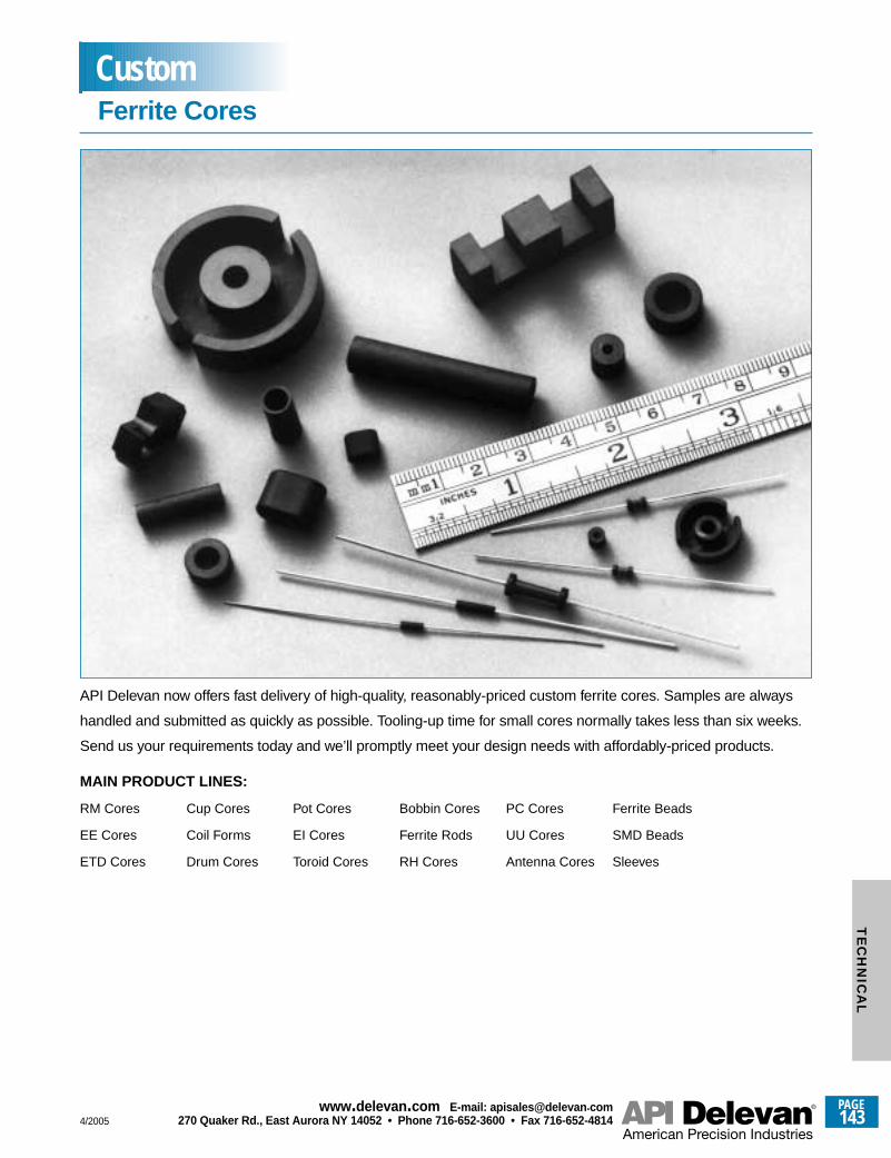
API Delevan now offers fast delivery of high-quality, reasonably-priced custom ferrite cores. Samples are always
handled and submitted as quickly as possible. Tooling-up time for small cores normally takes less than six weeks.
Send us your requirements today and we’ll promptly meet your design needs with affordably-priced products.
MAIN PRODUCT LINES:
RM Cores Cup Cores Pot Cores Bobbin Cores PC Cores Ferrite Beads
EE Cores Coil Forms EI Cores Ferrite Rods UU Cores SMD Beads
ETD Cores Drum Cores Toroid Cores RH Cores Antenna Cores Sleeves
Ferrite CoresCustom
4/2005
PAGE143
www.delevan .com E-mail: apisales@delevan .com270 Quaker Rd., East Aurora NY 14052 • Phone 716-652-3600 • Fax 716-652-4814
TE
CH
NIC
AL
AC FLUX DENSITY (GAUSS) Number of flux lines perunit of cross-sectional area generated by an alternatingmagnetic field.
AMPERE TURNS (NI) the product of current ( I ) flowingin the winding times the number of turns (N).
B-H CURVE Curve to show characteristics of amagnetic material, in terms of magnetizing force (H) andresulting flux density.
COPPER LOSS ( WATTS ) The power absorbed by acoil subjected to an alternating current.
CORE Magnetic material placed within and around acoil to provide a path of lower reluctance for magneticflux.
CORE LOSS Sum of hysteresis and eddy-current lossin a magnetic core.
CURRENT RATING (Idc) is the maximumrecommended DC current for the inductor. Expressed inmilliamps (mA) or amps (A) maximum. This is limited bythe allowable temperature rise.
DCR is the direct current (DC) resistance offered by aninductor due to the resistance of the magnet wire used towind. Expressed in ohms or milliohms maximum. This isan undesirable characteristic, which is a byproduct of thewire or conductive material used. The lower the DCR,the more current an inductor will handle.
FLUX Product of the average component of magneticinduction perpendicular to any given surface in amagnetic field by the area of that surface, expressed inwebers.
FLYBACK TRANSFORMER Transformer used in aflyback power supply. Also called horizontal outputtransformer.
INCREMENTAL CURRENT (dI) is the amount of DCcurrent which causes the inductor to lose a smallpercentage of its inductance (starting to saturate); only ofconcern on Shielded or High Current Inductors.Expressed in milliamps (mA) or amps (A). It is specifiedonly when its value is less than the rated current.
INDUCTANCE The property of a circuit element thatopposes changes in Alternating Current (AC). Expressedin millihenries (mH), microhenries (uH), or nanohenries(nH) and should carry a tolerance (i.e.±5% or ±10%).Inductance does vary as a function of frequency; thehigher the frequency, the higher the inductance of agiven device up to its SRF (self resonant frequency). Asa rule, the inductance remains relatively constant past itsTest Frequency.
INDUCTORS are electrical components that oppose anychange of AC current by means of storing energy in amagnetic field.
INITIAL PERMEABILITY (NO) Permeability = µ = B/HInitial permeability is that value of permeability whenBac = 10gs.
IRON-CORE COIL/ TRANSFORMER Coil/transformerwound around an iron core to increase its inductance. Ataudio frequencies the iron core consists of laminations ofsilicon steel insulated from each other by varnish orshellac. At radio frequencies the core consists ofpowdered iron mixed in a binder which insulates theparticles from each other.
ISOLATION TRANSFORMER Transformer with aone-to-one turns ratio, connected between the a.c.power input to a piece of equipment and the a.c. line, tominimize shock hazard.
LOAD LOSS These losses are caused by theresistance of the windings under loaded conditions.
MAXIMUM POWER DISSIPATION An inductor’s abilityto handle the heat generated by operating at maximumcurrent at an ambient temperature, expressed in Watts(W) or milliwatts (mW). This is a function of the bodyarea of the inductor, core material used, and varies forshielded vs. unshielded.
NO LOAD LOSS (CORE LOSSES) These losses arecaused by the magnetizing of the core and are alwayspresent. The way they are measured is by running fullvoltage with no load on the transformer.
Glossary
PAGE144
www.delevan .com E-mail: apisales@delevan .com270 Quaker Rd., East Aurora NY 14052 • Phone 716-652-3600 • Fax 716-652-4814 4/2005
TE
CH
NIC
AL
OPERATING TEMPERATURE RANGE specifies thetemperature extremes at which the inductor will operatesafely. At the maximum temperature specified, allowancemust be made for the “Temperature Rise” created byheating effects of using the inductor at its maximumcurrent rating. Normally, API uses 90 degrees Celsius asambient temperature for rating current; thus 125 degreesoperating minus 90 degrees ambient, allows 35 degreesfor temperature rise.
PERMEABILITY (u) By definition u = B/H, where B isthe flux density in gauss and H is the magnetizing forcein oersteds.
POWER TRANSFORMER Magnetic-core transformerfor operation at 60 hertz, with nearly zero sourceimpedance, to transfer power from line voltage to somerequired voltage.
PRIMARY WINDING The winding connected to thesource of energy.
Q is Quality Factor of an Inductor relating to the amountof energy lost while an AC current is passing through it. Itis expressed as a minimum value (i.e. 50 minimum). Inmost applications the higher the value of Q, the betterthe inductor will perform.
SRF is the inductor's self resonant frequency; thefrequency at which the inductor looks electricallycapacitive, rather than inductive. Expressed inmegahertz (MHz) minimum. The higher the value, thegreater the range of frequency use. An inductor shouldnever be used at or beyond its SRF (Self ResonantFrequency).
SECONDARY WINDING The winding is the coil whereenergy is induced from the primary.
SHIELDED inductors have internal iron or ferrite aroundthe entire winding to prevent unwanted signals fromescaping and interfering with the other components inthe immediate area.
STEP UP TRANSFORMER When the secondary is at ahigher voltage than the primary.
STEP DOWN TRANSFORMER When the secondaryhas a lower voltage than the primary.
SATURATION Maximum density of magnetic flux thatcan be present in a magnetic material.
TEMPERATURE COEFFICIENT OF INDUCTANCE(Tc of L) is the value of inductance change as a functionof temperature exposure, normally expressed in partsper million per degrees Celsius. This is a calculationcomparing inductance at a reference temperature (25°C,room ambient) to the extremes and other temperatureswithin operating range. Can be called Percent Delta L orTemperature Stability; the lower the change the better formost applications.
TEST FREQUENCY is the industry/military standard fortesting a range of inductances. It is not intended as theapplication frequency. Expressed in megahertz (MHz) orkilohertz (KHz).
TURN RATIO The ratio of the primary voltage (or turns)to the secondary voltage (or turns).
VOLT-AMPERE (VA) In an a.c. circuit, a measure ofapparent power, given by: VA =El, where E is thepotential in volts; I is the current in amperes; and VA isapparent power in volt-amperes
Glossary
4/2005
PAGE145
www.delevan .com E-mail: apisales@delevan .com270 Quaker Rd., East Aurora NY 14052 • Phone 716-652-3600 • Fax 716-652-4814
TE
CH
NIC
AL
PERFORMANCE TESTING
Test Ref. Method Requirement
Thermal Shock MIL-STD-202, Method 107, Parts will be able to withstand 50 cycles of thermalCondition A2 shock with no evidence of failure.
Dielectric Withstanding Voltage MIL-STD-202, Method 301 500 Vrms for 40 seconds. No evidence of breakdown
Barometric Pressure MIL-STD-202, Method 105, No evidence of breakdown. Test voltage: 200 Vrms.Condition C
Insulation Resistance MIL-STD-202, Method 302, 1000 megohms minimum when tested fromCondition A terminations to the component body.
Life Test MIL-STD-202, Method 108 Test condition F
Solderability MIL-STD-202, Method 208 95% coverage after immersing in type RMA flux,solder dip for five seconds @ 245°C ±5°C.
Temperature Rise Characteristics MIL-PRF-83446 para. 3.15 No degradation to series electrical parameters
Overload MIL-PRF-83446 para. 3.16 One and one-half times rated current for 5 minutes
Resistance to Solder Heat MIL-STD-202, Method 210 Test condition B
Moisture Resistance MIL-STD-202, Method 106 No load applied during test
Terminal Strength MIL-STD-883, Method 2011 One kilogram force
Solvent Resistance MIL-STD-202, Method 215 No damage after exposure to processing chemicals.
TESTING: MIL-PRF-83446, MIL-PRF-15305, andMIL-STD-202 are used as guidelines for type oftest, method, and requirement. Thesespecifications are employed as referenceguidelines and may be adjusted, based ondesign, application, or market need. Consult theSales Department for assistance concerning thisimportant issue. All testing and methods forcharacterizing the inductive components are asperformed by API Delevan. Further information isavailable for the details of specific tests. Copiesof Government specifications are not availablefrom API Delevan. For additional informationcontact your local Representative, or the APIDelevan Sales Department.
TEST FIXTURES: Available through special order.The factory recommends test equipmentcorrelation sampling when low inductance(≤0.10µH) and tight tolerance (≤2%) values arerequired.
Surface Mount InductorsTechnical Notes
PAGE146
www.delevan .com E-mail: apisales@delevan .com270 Quaker Rd., East Aurora NY 14052 • Phone 716-652-3600 • Fax 716-652-4814 4/2005
TE
CH
NIC
AL
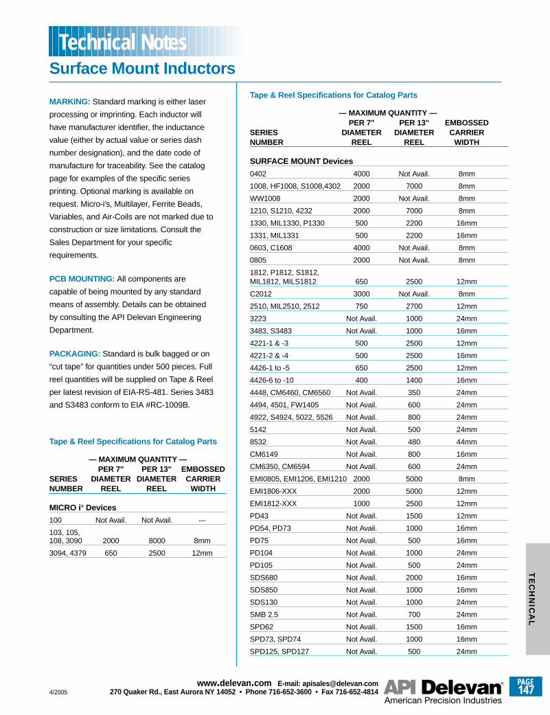
MARKING: Standard marking is either laser
processing or imprinting. Each inductor will
have manufacturer identifier, the inductance
value (either by actual value or series dash
number designation), and the date code of
manufacture for traceability. See the catalog
page for examples of the specific series
printing. Optional marking is available on
request. Micro-i’s, Multilayer, Ferrite Beads,
Variables, and Air-Coils are not marked due to
construction or size limitations. Consult the
Sales Department for your specific
requirements.
PCB MOUNTING: All components are
capable of being mounted by any standard
means of assembly. Details can be obtained
by consulting the API Delevan Engineering
Department.
PACKAGING: Standard is bulk bagged or on
“cut tape” for quantities under 500 pieces. Full
reel quantities will be supplied on Tape & Reel
per latest revision of EIA-RS-481. Series 3483
and S3483 conform to EIA #RC-1009B.
Tape & Reel Specifications for Catalog Parts
— MAXIMUM QUANTITY —PER 7" PER 13" EMBOSSED
SERIES DIAMETER DIAMETER CARRIERNUMBER REEL REEL WIDTH
SURFACE MOUNT Devices
0402 4000 Not Avail. 8mm
1008, HF1008, S1008,4302 2000 7000 8mm
WW1008 2000 Not Avail. 8mm
1210, S1210, 4232 2000 7000 8mm
1330, MIL1330, P1330 500 2200 16mm
1331, MIL1331 500 2200 16mm
0603, C1608 4000 Not Avail. 8mm
0805 2000 Not Avail. 8mm
1812, P1812, S1812, MIL1812, MILS1812 650 2500 12mm
C2012 3000 Not Avail. 8mm
2510, MIL2510, 2512 750 2700 12mm
3223 Not Avail. 1000 24mm
3483, S3483 Not Avail. 1000 16mm
4221-1 & -3 500 2500 12mm
4221-2 & -4 500 2500 16mm
4426-1 to -5 650 2500 12mm
4426-6 to -10 400 1400 16mm
4448, CM6460, CM6560 Not Avail. 350 24mm
4494, 4501, FW1405 Not Avail. 600 24mm
4922, S4924, 5022, 5526 Not Avail. 800 24mm
5142 Not Avail. 500 24mm
8532 Not Avail. 480 44mm
CM6149 Not Avail. 800 16mm
CM6350, CM6594 Not Avail. 600 24mm
EMI0805, EMI1206, EMI1210 2000 5000 8mm
EMI1806-XXX 2000 5000 12mm
EMI1812-XXX 1000 2500 12mm
PD43 Not Avail. 1500 12mm
PD54, PD73 Not Avail. 1000 16mm
PD75 Not Avail. 500 16mm
PD104 Not Avail. 1000 24mm
PD105 Not Avail. 500 24mm
SDS680 Not Avail. 2000 16mm
SDS850 Not Avail. 1000 16mm
SDS130 Not Avail. 1000 24mm
SMB 2.5 Not Avail. 700 24mm
SPD62 Not Avail. 1500 16mm
SPD73, SPD74 Not Avail. 1000 16mm
SPD125, SPD127 Not Avail. 500 24mm
Surface Mount InductorsTechnical Notes
Tape & Reel Specifications for Catalog Parts
— MAXIMUM QUANTITY —PER 7" PER 13" EMBOSSED
SERIES DIAMETER DIAMETER CARRIERNUMBER REEL REEL WIDTH
MICRO i® Devices
100 Not Avail. Not Avail. ---
103, 105, 108, 3090 2000 8000 8mm
3094, 4379 650 2500 12mm
4/2005
PAGE147
www.delevan .com E-mail: apisales@delevan .com270 Quaker Rd., East Aurora NY 14052 • Phone 716-652-3600 • Fax 716-652-4814
TE
CH
NIC
AL
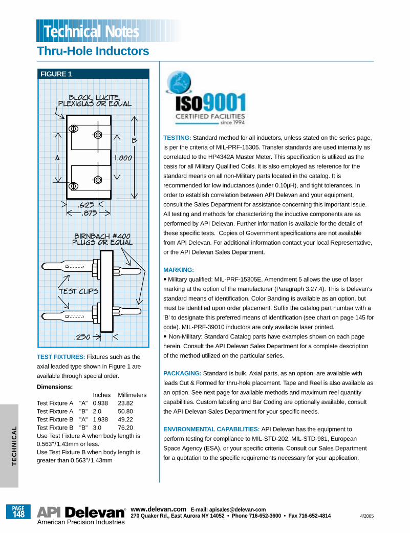
TF-A
OR
B
FIGURE 1
TEST FIXTURES: Fixtures such as the
axial leaded type shown in Figure 1 are
available through special order.
Dimensions:Inches Millimeters
Test Fixture A "A" 0.938 23.82Test Fixture A "B" 2.0 50.80Test Fixture B "A" 1.938 49.22Test Fixture B "B" 3.0 76.20Use Test Fixture A when body length is0.563"/1.43mm or less.Use Test Fixture B when body length isgreater than 0.563"/1.43mm
TESTING: Standard method for all inductors, unless stated on the series page,
is per the criteria of MIL-PRF-15305. Transfer standards are used internally as
correlated to the HP4342A Master Meter. This specification is utilized as the
basis for all Military Qualified Coils. It is also employed as reference for the
standard means on all non-Military parts located in the catalog. It is
recommended for low inductances (under 0.10µH), and tight tolerances. In
order to establish correlation between API Delevan and your equipment,
consult the Sales Department for assistance concerning this important issue.
All testing and methods for characterizing the inductive components are as
performed by API Delevan. Further information is available for the details of
these specific tests. Copies of Government specifications are not available
from API Delevan. For additional information contact your local Representative,
or the API Delevan Sales Department.
MARKING:
• Military qualified: MIL-PRF-15305E, Amendment 5 allows the use of laser
marking at the option of the manufacturer (Paragraph 3.27.4). This is Delevan's
standard means of identification. Color Banding is available as an option, but
must be identified upon order placement. Suffix the catalog part number with a
'B' to designate this preferred means of identification (see chart on page 145 for
code). MIL-PRF-39010 inductors are only available laser printed.
• Non-Military: Standard Catalog parts have examples shown on each page
herein. Consult the API Delevan Sales Department for a complete description
of the method utilized on the particular series.
PACKAGING: Standard is bulk. Axial parts, as an option, are available with
leads Cut & Formed for thru-hole placement. Tape and Reel is also available as
an option. See next page for available methods and maximum reel quantity
capabilities. Custom labeling and Bar Coding are optionally available, consult
the API Delevan Sales Department for your specific needs.
ENVIRONMENTAL CAPABILITIES: API Delevan has the equipment to
perform testing for compliance to MIL-STD-202, MIL-STD-981, European
Space Agency (ESA), or your specific criteria. Consult our Sales Department
for a quotation to the specific requirements necessary for your application.
Thru-Hole InductorsTechnical Notes
PAGE148
www.delevan .com E-mail: apisales@delevan .com270 Quaker Rd., East Aurora NY 14052 • Phone 716-652-3600 • Fax 716-652-4814 4/2005
TE
CH
NIC
AL
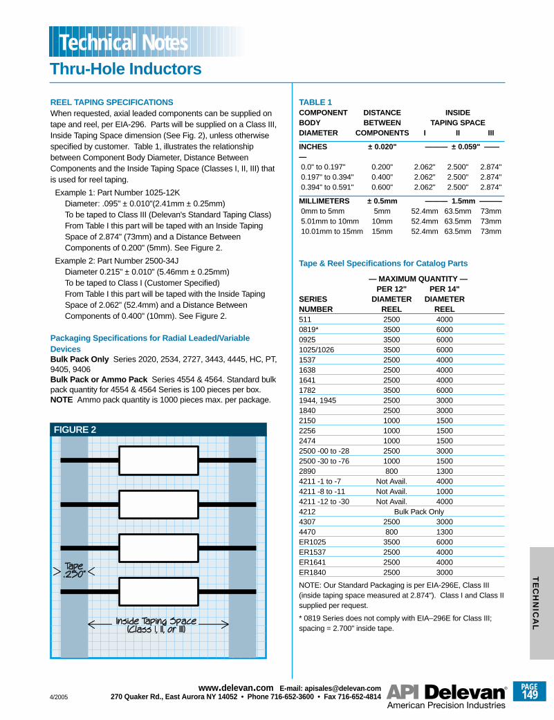
REEL TAPING SPECIFICATIONSWhen requested, axial leaded components can be supplied ontape and reel, per EIA-296. Parts will be supplied on a Class III,Inside Taping Space dimension (See Fig. 2), unless otherwisespecified by customer. Table 1, illustrates the relationshipbetween Component Body Diameter, Distance BetweenComponents and the Inside Taping Space (Classes I, II, III) thatis used for reel taping.
Example 1: Part Number 1025-12KDiameter: .095" ± 0.010"(2.41mm ± 0.25mm)To be taped to Class III (Delevan's Standard Taping Class)From Table I this part will be taped with an Inside TapingSpace of 2.874" (73mm) and a Distance BetweenComponents of 0.200" (5mm). See Figure 2.
Example 2: Part Number 2500-34JDiameter 0.215" ± 0.010" (5.46mm ± 0.25mm)To be taped to Class I (Customer Specified)From Table I this part will be taped with the Inside TapingSpace of 2.062" (52.4mm) and a Distance BetweenComponents of 0.400" (10mm). See Figure 2.
Packaging Specifications for Radial Leaded/VariableDevicesBulk Pack Only Series 2020, 2534, 2727, 3443, 4445, HC, PT,9405, 9406Bulk Pack or Ammo Pack Series 4554 & 4564. Standard bulkpack quantity for 4554 & 4564 Series is 100 pieces per box.NOTE Ammo pack quantity is 1000 pieces max. per package.
TABLE 1COMPONENT DISTANCE INSIDEBODY BETWEEN TAPING SPACEDIAMETER COMPONENTS I II III
INCHES ± 0.020" ——— ± 0.059" ———0.0" to 0.197" 0.200" 2.062" 2.500" 2.874"0.197" to 0.394" 0.400" 2.062" 2.500" 2.874"0.394" to 0.591" 0.600" 2.062" 2.500" 2.874"
MILLIMETERS ± 0.5mm ——— 1.5mm ———0mm to 5mm 5mm 52.4mm 63.5mm 73mm5.01mm to 10mm 10mm 52.4mm 63.5mm 73mm10.01mm to 15mm 15mm 52.4mm 63.5mm 73mm
Tape & Reel Specifications for Catalog Parts
— MAXIMUM QUANTITY —PER 12" PER 14"
SERIES DIAMETER DIAMETERNUMBER REEL REEL511 2500 40000819* 3500 60000925 3500 60001025/1026 3500 60001537 2500 40001638 2500 40001641 2500 40001782 3500 60001944, 1945 2500 30001840 2500 30002150 1000 15002256 1000 15002474 1000 15002500 -00 to -28 2500 30002500 -30 to -76 1000 15002890 800 13004211 -1 to -7 Not Avail. 40004211 -8 to -11 Not Avail. 10004211 -12 to -30 Not Avail. 40004212 Bulk Pack Only4307 2500 30004470 800 1300ER1025 3500 6000ER1537 2500 4000ER1641 2500 4000ER1840 2500 3000
NOTE: Our Standard Packaging is per EIA-296E, Class III(inside taping space measured at 2.874"). Class I and Class IIsupplied per request.
* 0819 Series does not comply with EIA–296E for Class III;spacing = 2.700" inside tape.
FIGURE 2
Thru-Hole InductorsTechnical Notes
4/2005
PAGE149
www.delevan .com E-mail: apisales@delevan .com270 Quaker Rd., East Aurora NY 14052 • Phone 716-652-3600 • Fax 716-652-4814
TE
CH
NIC
AL
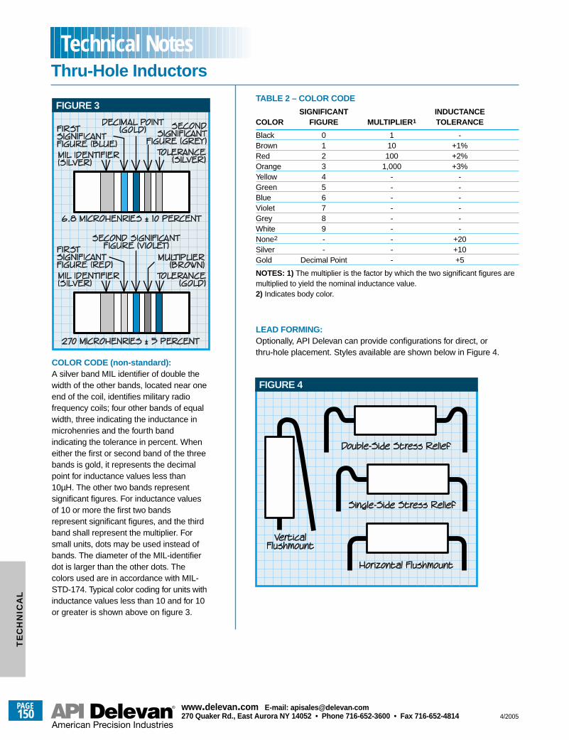
COLOR CODE (non-standard):A silver band MIL identifier of double thewidth of the other bands, located near oneend of the coil, identifies military radiofrequency coils; four other bands of equalwidth, three indicating the inductance inmicrohenries and the fourth bandindicating the tolerance in percent. Wheneither the first or second band of the threebands is gold, it represents the decimalpoint for inductance values less than10µH. The other two bands representsignificant figures. For inductance valuesof 10 or more the first two bandsrepresent significant figures, and the thirdband shall represent the multiplier. Forsmall units, dots may be used instead ofbands. The diameter of the MIL-identifierdot is larger than the other dots. Thecolors used are in accordance with MIL-STD-174. Typical color coding for units withinductance values less than 10 and for 10or greater is shown above on figure 3.
TABLE 2 – COLOR CODE
SIGNIFICANT INDUCTANCECOLOR FIGURE MULTIPLIER 1 TOLERANCE
Black 0 1 -Brown 1 10 +1%Red 2 100 +2%Orange 3 1,000 +3%Yellow 4 - -Green 5 - -Blue 6 - -Violet 7 - -Grey 8 - -White 9 - -None2 - - +20Silver - - +10Gold Decimal Point - +5
NOTES: 1) The multiplier is the factor by which the two significant figures aremultiplied to yield the nominal inductance value.2) Indicates body color.
LEAD FORMING:Optionally, API Delevan can provide configurations for direct, orthru-hole placement. Styles available are shown below in Figure 4.
FIGURE 3
FIGURE 4
Thru-Hole InductorsTechnical Notes
PAGE150
www.delevan .com E-mail: apisales@delevan .com270 Quaker Rd., East Aurora NY 14052 • Phone 716-652-3600 • Fax 716-652-4814 4/2005
TE
CH
NIC
AL
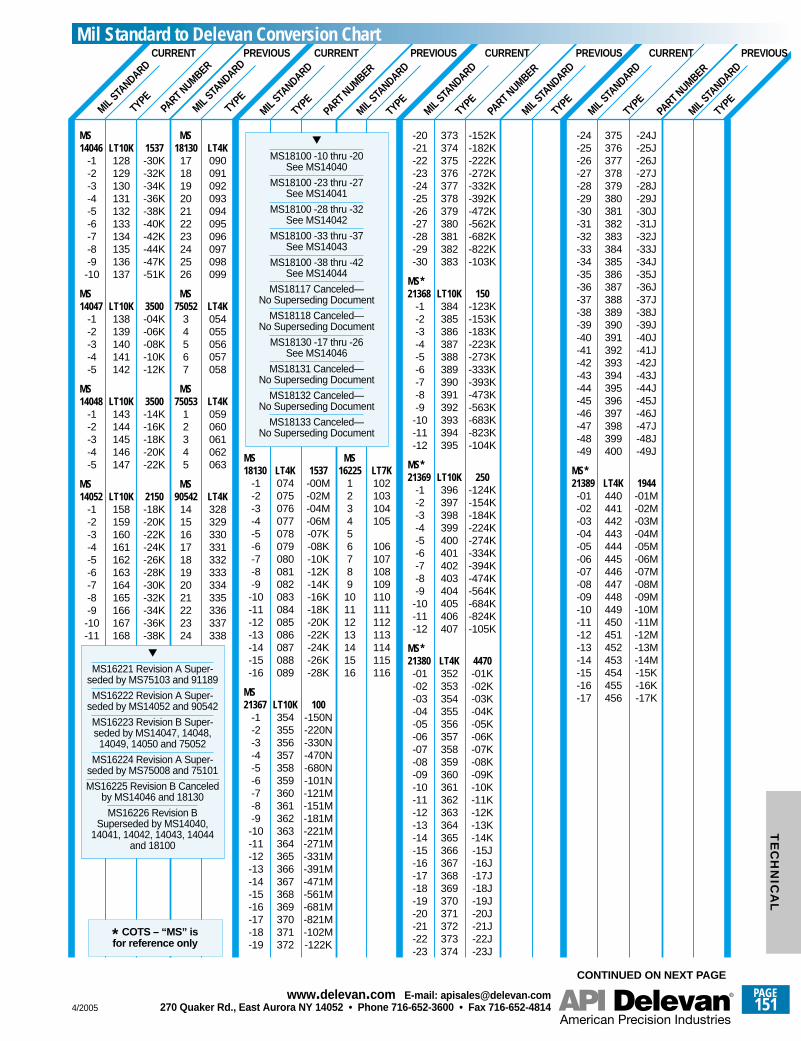
MIL STA
NDARD
TYPEPA
RT NUMBER
TYPEMIL
STANDARD
CURRENT PREVIOUS
MIL STA
NDARD
TYPEPA
RT NUMBER
TYPEMIL
STANDARD
CURRENT
MIL STA
NDARD
TYPEPA
RT NUMBER
TYPEMIL
STANDARD
CURRENT
MIL STA
NDARD
TYPEPA
RT NUMBER
TYPEMIL
STANDARD
CURRENT
MS MS14046 LT10K 1537 18130 LT4K
-1 128 -30K 17 090-2 129 -32K 18 091-3 130 -34K 19 092-4 131 -36K 20 093-5 132 -38K 21 094-6 133 -40K 22 095-7 134 -42K 23 096-8 135 -44K 24 097-9 136 -47K 25 098-10 137 -51K 26 099
MS MS14047 LT10K 3500 75052 LT4K
-1 138 -04K 3 054-2 139 -06K 4 055-3 140 -08K 5 056-4 141 -10K 6 057-5 142 -12K 7 058
MS MS14048 LT10K 3500 75053 LT4K
-1 143 -14K 1 059-2 144 -16K 2 060-3 145 -18K 3 061-4 146 -20K 4 062-5 147 -22K 5 063
MS MS14052 LT10K 2150 90542 LT4K
-1 158 -18K 14 328-2 159 -20K 15 329-3 160 -22K 16 330-4 161 -24K 17 331-5 162 -26K 18 332-6 163 -28K 19 333-7 164 -30K 20 334-8 165 -32K 21 335-9 166 -34K 22 336-10 167 -36K 23 337-11 168 -38K 24 338
MS16221 Revision A Super-seded by MS75103 and 91189
MS16222 Revision A Super-seded by MS14052 and 90542
MS16223 Revision B Super-seded by MS14047, 14048,14049, 14050 and 75052
MS16224 Revision A Super-seded by MS75008 and 75101
MS16225 Revision B Canceledby MS14046 and 18130
MS16226 Revision BSuperseded by MS14040,
14041, 14042, 14043, 14044and 18100
MS MS18130 LT4K 1537 16225 LT7K
-1 074 -00M 1 102-2 075 -02M 2 103-3 076 -04M 3 104-4 077 -06M 4 105-5 078 -07K 5-6 079 -08K 6 106-7 080 -10K 7 107-8 081 -12K 8 108-9 082 -14K 9 109-10 083 -16K 10 110-11 084 -18K 11 111-12 085 -20K 12 112-13 086 -22K 13 113-14 087 -24K 14 114-15 088 -26K 15 115-16 089 -28K 16 116
MS21367 LT10K 100
-1 354 -150N-2 355 -220N-3 356 -330N-4 357 -470N-5 358 -680N-6 359 -101N-7 360 -121M-8 361 -151M-9 362 -181M-10 363 -221M-11 364 -271M-12 365 -331M-13 366 -391M-14 367 -471M-15 368 -561M-16 369 -681M-17 370 -821M-18 371 -102M-19 372 -122K
MS18100 -10 thru -20See MS14040
MS18100 -23 thru -27See MS14041
MS18100 -28 thru -32See MS14042
MS18100 -33 thru -37See MS14043
MS18100 -38 thru -42See MS14044
MS18117 Canceled—No Superseding Document
MS18118 Canceled—No Superseding Document
MS18130 -17 thru -26See MS14046
MS18131 Canceled—No Superseding Document
MS18132 Canceled—No Superseding Document
MS18133 Canceled—No Superseding Document
-20 373 -152K-21 374 -182K-22 375 -222K-23 376 -272K-24 377 -332K-25 378 -392K-26 379 -472K-27 380 -562K-28 381 -682K-29 382 -822K-30 383 -103K
MS*21368 LT10K 150
-1 384 -123K-2 385 -153K-3 386 -183K-4 387 -223K-5 388 -273K-6 389 -333K-7 390 -393K-8 391 -473K-9 392 -563K-10 393 -683K-11 394 -823K-12 395 -104K
MS*21369 LT10K 250
-1 396 -124K-2 397 -154K-3 398 -184K-4 399 -224K-5 400 -274K-6 401 -334K-7 402 -394K-8 403 -474K-9 404 -564K-10 405 -684K-11 406 -824K-12 407 -105K
MS*21380 LT4K 4470-01 352 -01K-02 353 -02K-03 354 -03K-04 355 -04K-05 356 -05K-06 357 -06K-07 358 -07K-08 359 -08K-09 360 -09K-10 361 -10K-11 362 -11K-12 363 -12K-13 364 -13K-14 365 -14K-15 366 -15J-16 367 -16J-17 368 -17J-18 369 -18J-19 370 -19J-20 371 -20J-21 372 -21J-22 373 -22J-23 374 -23J
-24 375 -24J-25 376 -25J-26 377 -26J-27 378 -27J-28 379 -28J-29 380 -29J-30 381 -30J-31 382 -31J-32 383 -32J-33 384 -33J-34 385 -34J-35 386 -35J-36 387 -36J-37 388 -37J-38 389 -38J-39 390 -39J-40 391 -40J-41 392 -41J-42 393 -42J-43 394 -43J-44 395 -44J-45 396 -45J-46 397 -46J-47 398 -47J-48 399 -48J-49 400 -49J
MS*21389 LT4K 1944-01 440 -01M-02 441 -02M-03 442 -03M-04 443 -04M-05 444 -05M-06 445 -06M-07 446 -07M-08 447 -08M-09 448 -09M-10 449 -10M-11 450 -11M-12 451 -12M-13 452 -13M-14 453 -14M-15 454 -15K-16 455 -16K-17 456 -17K
* COTS – “MS” isfor reference only
CONTINUED ON NEXT PAGE
PREVIOUSPREVIOUS PREVIOUSMil Standard to Delevan Conversion Chart
4/2005
PAGE151
www.delevan .com E-mail: apisales@delevan .com270 Quaker Rd., East Aurora NY 14052 • Phone 716-652-3600 • Fax 716-652-4814
TE
CH
NIC
AL
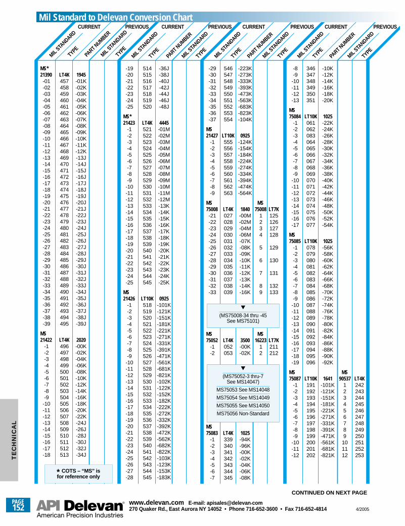
MIL STA
NDARD
TYPEPA
RT NUMBER
TYPEMIL
STANDARD
CURRENT
MIL STA
NDARD
TYPEPA
RT NUMBER
TYPEMIL
STANDARD
MIL STA
NDARD
TYPEPA
RT NUMBER
TYPEMIL
STANDARD
MIL STA
NDARD
TYPEPA
RT NUMBER
TYPEMIL
STANDARD
MS*21390 LT4K 1945-01 457 -01K-02 458 -02K-03 459 -03K-04 460 -04K-05 461 -05K-06 462 -06K-07 463 -07K-08 464 -08K-09 465 -09K-10 466 -10K-11 467 -11K-12 468 -12K-13 469 -13J-14 470 -14J-15 471 -15J-16 472 -16J-17 473 -17J-18 474 -18J-19 475 -19J-20 476 -20J-21 477 -21J-22 478 -22J-23 479 -23J-24 480 -24J-25 481 -25J-26 482 -26J-27 483 -27J-28 484 -28J-29 485 -29J-30 486 -30J-31 487 -31J-32 488 -32J-33 489 -33J-34 490 -34J-35 491 -35J-36 492 -36J-37 493 -37J-38 494 -38J-39 495 -39J
MS21422 LT4K 2020
-1 496 -00K-2 497 -02K-3 498 -04K-4 499 -06K-5 500 -08K-6 501 -10K-7 502 -12K-8 503 -14K-9 504 -16K-10 505 -18K-11 506 -20K-12 507 -22K-13 508 -24J-14 509 -26J-15 510 -28J-16 511 -30J-17 512 -32J-18 513 -34J
-19 514 -36J-20 515 -38J-21 516 -40J-22 517 -42J-23 518 -44J-24 519 -46J-25 520 -48J
MS*21423 LT4K 4445
-1 521 -01M-2 522 -02M-3 523 -03M-4 524 -04M-5 525 -05M-6 526 -06M-7 527 -07M-8 528 -08M-9 529 -09M-10 530 -10M-11 531 -11M-12 532 -12M-13 533 -13K-14 534 -14K-15 535 -15K-16 536 -16K-17 537 -17K-18 538 -18K-19 539 -19K-20 540 -20K-21 541 -21K-22 542 -22K-23 543 -23K-24 544 -24K-25 545 -25K
MS21426 LT10K 0925
-1 518 -101K-2 519 -121K-3 520 -151K-4 521 -181K-5 522 -221K-6 523 -271K-7 524 -331K-8 525 -391K-9 526 -471K-10 527 -561K-11 528 -681K-12 529 -821K-13 530 -102K-14 531 -122K-15 532 -152K-16 533 -182K-17 534 -222K-18 535 -272K-19 536 -332K-20 537 -392K-21 538 -472K-22 539 -562K-23 540 -682K-24 541 -822K-25 542 -103K-26 543 -123K-27 544 -153K-28 545 -183K
-29 546 -223K-30 547 -273K-31 548 -333K-32 549 -393K-33 550 -473K-34 551 -563K-35 552 -683K-36 553 -823K-37 554 -104K
MS21427 LT10K 0925
-1 555 -124K-2 556 -154K-3 557 -184K-4 558 -224K-5 559 -274K-6 560 -334K-7 561 -394K-8 562 -474K-9 563 -564K
MS MS75008 LT4K 1840 75008 LT7K-21 027 -00M 1 125-22 028 -02M 2 126-23 029 -04M 3 127-24 030 -06M 4 128-25 031 -07K-26 032 -08K 5 129-27 033 -09K-28 034 -10K 6 130-29 035 -11K-30 036 -12K 7 131-31 037 -13K-32 038 -14K 8 132-33 039 -16K 9 133
MS MS75052 LT4K 3500 16223 LT7K
-1 052 -00K 1 211-2 053 -02K 2 212
MS75083 LT4K 1025
-1 339 -94K-2 340 -96K-3 341 -00K-4 342 -02K-5 343 -04K-6 344 -06K-7 345 -08K
(MS75052-3 thru-7See MS14047)
MS75053 See MS14048
MS75054 See MS14049
MS75055 See MS14050
MS75056 Non-Standard
(MS75008-34 thru -45See MS75101)
-8 346 -10K-9 347 -12K-10 348 -14K-11 349 -16K-12 350 -18K-13 351 -20K
MS75084 LT10K 1025
-1 061 -22K-2 062 -24K-3 083 -26K-4 064 -28K-5 065 -30K-6 066 -32K-7 067 -34K-8 068 -36K-9 069 -38K-10 070 -40K-11 071 -42K-12 072 -44K-13 073 -46K-14 074 -48K-15 075 -50K-16 076 -52K-17 077 -54K
MS75085 LT10K 1025
-1 078 -56K-2 079 -58K-3 080 -60K-4 081 -62K-5 082 -64K-6 083 -66K-7 084 -68K-8 085 -70K-9 086 -72K-10 087 -74K-11 088 -76K-12 089 -78K-13 090 -80K-14 091 -82K-15 092 -84K-16 093 -86K-17 094 -88K-18 095 -90K-19 096 -92K
MS MS75087 LT10K 1641 90537 LT4K
-1 191 -101K 1 242-2 192 -121K 2 243-3 193 -151K 3 244-4 194 -181K 4 245-5 195 -221K 5 246-6 196 -271K 6 247-7 197 -331K 7 248-8 198 -391K 8 249-9 199 -471K 9 250-10 200 -561K 10 251-11 201 -681K 11 252-12 202 -821K 12 253
* COTS – “MS” isfor reference only
CONTINUED ON NEXT PAGE
PREVIOUS PREVIOUSCURRENTPREVIOUSCURRENTPREVIOUSCURRENTMil Standard to Delevan Conversion Chart
PAGE152
www.delevan .com E-mail: apisales@delevan .com270 Quaker Rd., East Aurora NY 14052 • Phone 716-652-3600 • Fax 716-652-4814 4/2005
TE
CH
NIC
AL
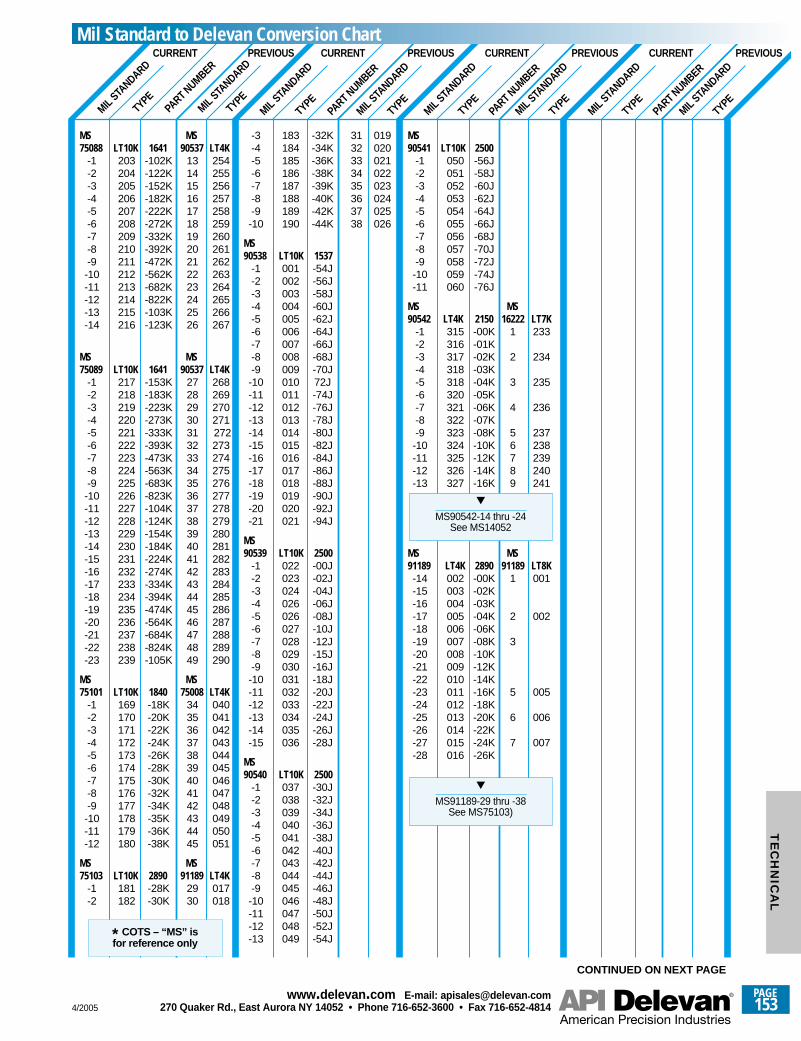
MIL STA
NDARD
TYPEPA
RT NUMBER
TYPEMIL
STANDARD
CURRENT
MIL STA
NDARD
TYPEPA
RT NUMBER
TYPEMIL
STANDARD
CURRENT PREVIOUS
MIL STA
NDARD
TYPEPA
RT NUMBER
TYPEMIL
STANDARD
CURRENT PREVIOUS
MIL STA
NDARD
TYPEPA
RT NUMBER
TYPEMIL
STANDARD
CURRENT PREVIOUS
MS MS75088 LT10K 1641 90537 LT4K
-1 203 -102K 13 254-2 204 -122K 14 255-3 205 -152K 15 256-4 206 -182K 16 257-5 207 -222K 17 258-6 208 -272K 18 259 -7 209 -332K 19 260-8 210 -392K 20 261-9 211 -472K 21 262 -10 212 -562K 22 263-11 213 -682K 23 264-12 214 -822K 24 265-13 215 -103K 25 266-14 216 -123K 26 267
MS MS75089 LT10K 1641 90537 LT4K
-1 217 -153K 27 268-2 218 -183K 28 269 -3 219 -223K 29 270-4 220 -273K 30 271 -5 221 -333K 31 272-6 222 -393K 32 273-7 223 -473K 33 274-8 224 -563K 34 275-9 225 -683K 35 276-10 226 -823K 36 277-11 227 -104K 37 278 -12 228 -124K 38 279-13 229 -154K 39 280-14 230 -184K 40 281-15 231 -224K 41 282-16 232 -274K 42 283-17 233 -334K 43 284-18 234 -394K 44 285-19 235 -474K 45 286-20 236 -564K 46 287-21 237 -684K 47 288-22 238 -824K 48 289-23 239 -105K 49 290
MS MS75101 LT10K 1840 75008 LT4K
-1 169 -18K 34 040-2 170 -20K 35 041-3 171 -22K 36 042-4 172 -24K 37 043-5 173 -26K 38 044-6 174 -28K 39 045-7 175 -30K 40 046-8 176 -32K 41 047-9 177 -34K 42 048-10 178 -35K 43 049-11 179 -36K 44 050-12 180 -38K 45 051
MS MS75103 LT10K 2890 91189 LT4K
-1 181 -28K 29 017-2 182 -30K 30 018
-3 183 -32K 31 019-4 184 -34K 32 020-5 185 -36K 33 021-6 186 -38K 34 022-7 187 -39K 35 023-8 188 -40K 36 024-9 189 -42K 37 025-10 190 -44K 38 026
MS90538 LT10K 1537
-1 001 -54J-2 002 -56J-3 003 -58J-4 004 -60J-5 005 -62J-6 006 -64J-7 007 -66J-8 008 -68J-9 009 -70J-10 010 72J-11 011 -74J-12 012 -76J-13 013 -78J-14 014 -80J-15 015 -82J-16 016 -84J-17 017 -86J-18 018 -88J-19 019 -90J-20 020 -92J-21 021 -94J
MS90539 LT10K 2500
-1 022 -00J-2 023 -02J-3 024 -04J-4 026 -06J-5 026 -08J-6 027 -10J-7 028 -12J-8 029 -15J-9 030 -16J-10 031 -18J-11 032 -20J-12 033 -22J-13 034 -24J-14 035 -26J-15 036 -28J
MS90540 LT10K 2500
-1 037 -30J-2 038 -32J-3 039 -34J-4 040 -36J-5 041 -38J-6 042 -40J-7 043 -42J-8 044 -44J-9 045 -46J-10 046 -48J-11 047 -50J-12 048 -52J-13 049 -54J
MS90541 LT10K 2500
-1 050 -56J-2 051 -58J-3 052 -60J-4 053 -62J-5 054 -64J-6 055 -66J-7 056 -68J-8 057 -70J-9 058 -72J-10 059 -74J-11 060 -76J
MS MS90542 LT4K 2150 16222 LT7K
-1 315 -00K 1 233-2 316 -01K-3 317 -02K 2 234-4 318 -03K-5 318 -04K 3 235-6 320 -05K-7 321 -06K 4 236-8 322 -07K-9 323 -08K 5 237-10 324 -10K 6 238-11 325 -12K 7 239-12 326 -14K 8 240-13 327 -16K 9 241
MS MS91189 LT4K 2890 91189 LT8K-14 002 -00K 1 001-15 003 -02K-16 004 -03K-17 005 -04K 2 002-18 006 -06K-19 007 -08K 3-20 008 -10K-21 009 -12K-22 010 -14K-23 011 -16K 5 005-24 012 -18K-25 013 -20K 6 006-26 014 -22K-27 015 -24K 7 007-28 016 -26K
MS91189-29 thru -38See MS75103)
MS90542-14 thru -24See MS14052
* COTS – “MS” isfor reference only
CONTINUED ON NEXT PAGE
PREVIOUSMil Standard to Delevan Conversion Chart
4/2005
PAGE153
www.delevan .com E-mail: apisales@delevan .com270 Quaker Rd., East Aurora NY 14052 • Phone 716-652-3600 • Fax 716-652-4814
TE
CH
NIC
AL
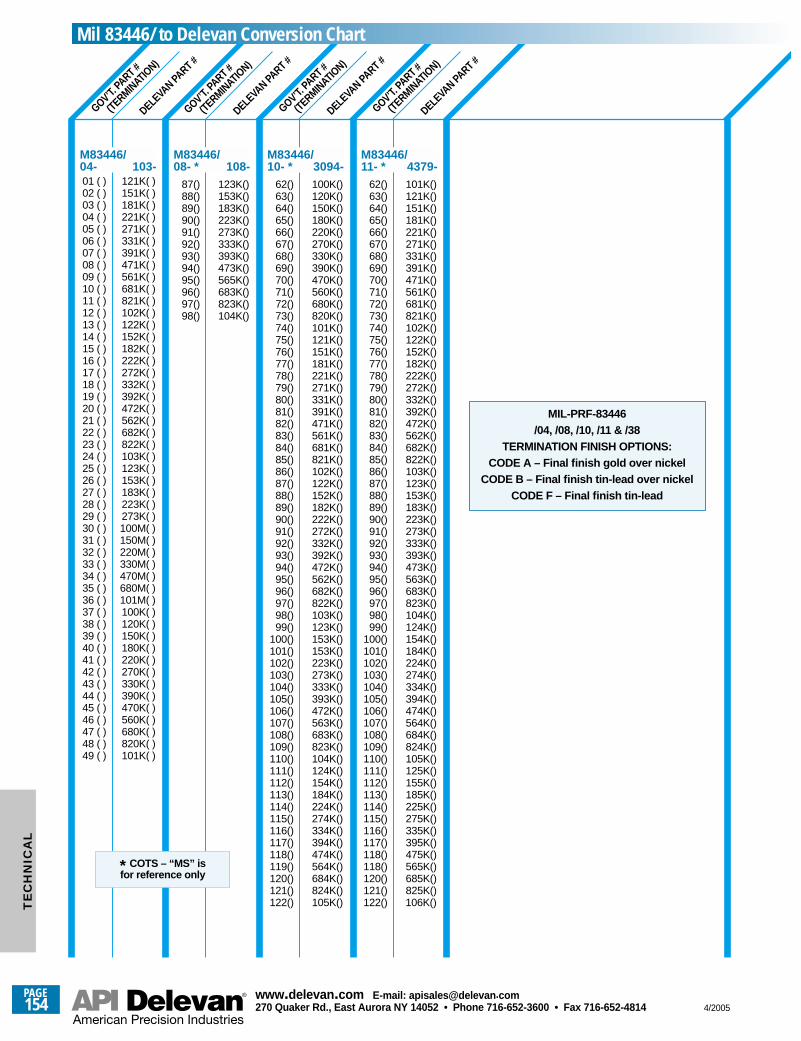
GOV’T. PA
RT #
(TERMINATIO
N)
GOV’T. PA
RT #
(TERMINATIO
N)
GOV’T. PA
RT #
(TERMINATIO
N)
GOV’T. PA
RT #
(TERMINATIO
N)
DELEVA
N PART #
DELEVA
N PART #
DELEVA
N PART #
DELEVA
N PART #
01 ( ) 121K( )02 ( ) 151K( )03 ( ) 181K( )04 ( ) 221K( )05 ( ) 271K( )06 ( ) 331K( )07 ( ) 391K( )08 ( ) 471K( )09 ( ) 561K( )10 ( ) 681K( )11 ( ) 821K( )12 ( ) 102K( )13 ( ) 122K( )14 ( ) 152K( )15 ( ) 182K( )16 ( ) 222K( )17 ( ) 272K( )18 ( ) 332K( )19 ( ) 392K( )20 ( ) 472K( )21 ( ) 562K( )22 ( ) 682K( )23 ( ) 822K( )24 ( ) 103K( )25 ( ) 123K( )26 ( ) 153K( )27 ( ) 183K( )28 ( ) 223K( )29 ( ) 273K( )30 ( ) 100M( )31 ( ) 150M( )32 ( ) 220M( )33 ( ) 330M( )34 ( ) 470M( )35 ( ) 680M( )36 ( ) 101M( )37 ( ) 100K( )38 ( ) 120K( )39 ( ) 150K( )40 ( ) 180K( )41 ( ) 220K( )42 ( ) 270K( )43 ( ) 330K( )44 ( ) 390K( )45 ( ) 470K( )46 ( ) 560K( )47 ( ) 680K( )48 ( ) 820K( )49 ( ) 101K( )
M83446/04- 103-
87() 123K()88() 153K()89() 183K()90() 223K()91() 273K()92() 333K()93() 393K()94() 473K()95() 565K()96() 683K()97() 823K()98() 104K()
M83446/08- * 108-
62() 100K()63() 120K()64() 150K()65() 180K()66() 220K()67() 270K()68() 330K()69() 390K()70() 470K()71() 560K()72() 680K()73() 820K()74() 101K()75() 121K()76() 151K()77() 181K()78() 221K()79() 271K()80() 331K()81() 391K()82() 471K()83() 561K()84() 681K()85() 821K()86() 102K()87() 122K()88() 152K()89() 182K()90() 222K()91() 272K()92() 332K()93() 392K()94() 472K()95() 562K()96() 682K()97() 822K()98() 103K()99() 123K()
100() 153K()101() 153K()102() 223K()103() 273K()104() 333K()105() 393K()106() 472K()107() 563K()108() 683K()109() 823K()110() 104K()111() 124K()112() 154K()113() 184K()114() 224K()115() 274K()116() 334K()117() 394K()118() 474K()119() 564K()120() 684K()121() 824K()122() 105K()
M83446/10- * 3094-
62() 101K()63() 121K()64() 151K()65() 181K()66() 221K()67() 271K()68() 331K()69() 391K()70() 471K()71() 561K()72() 681K()73() 821K()74() 102K()75() 122K()76() 152K()77() 182K()78() 222K()79() 272K()80() 332K()81() 392K()82() 472K()83() 562K()84() 682K()85() 822K()86() 103K()87() 123K()88() 153K()89() 183K()90() 223K()91() 273K()92() 333K()93() 393K()94() 473K()95() 563K()96() 683K()97() 823K()98() 104K()99() 124K()
100() 154K()101() 184K()102() 224K()103() 274K()104() 334K()105() 394K()106() 474K()107() 564K()108() 684K()109() 824K()110() 105K()111() 125K()112() 155K()113() 185K()114() 225K()115() 275K()116() 335K()117() 395K()118() 475K()118() 565K()120() 685K()121() 825K()122() 106K()
M83446/11- * 4379-
MIL-PRF-83446 /04, /08, /10, /11 & /38
TERMINATION FINISH OPTIONS:CODE A – Final finish gold over nickel
CODE B – Final finish tin-lead over nickelCODE F – Final finish tin-lead
* COTS – “MS” isfor reference only
Mil 83446/ to Delevan Conversion Chart
PAGE154
www.delevan .com E-mail: apisales@delevan .com270 Quaker Rd., East Aurora NY 14052 • Phone 716-652-3600 • Fax 716-652-4814 4/2005
TE
CH
NIC
AL
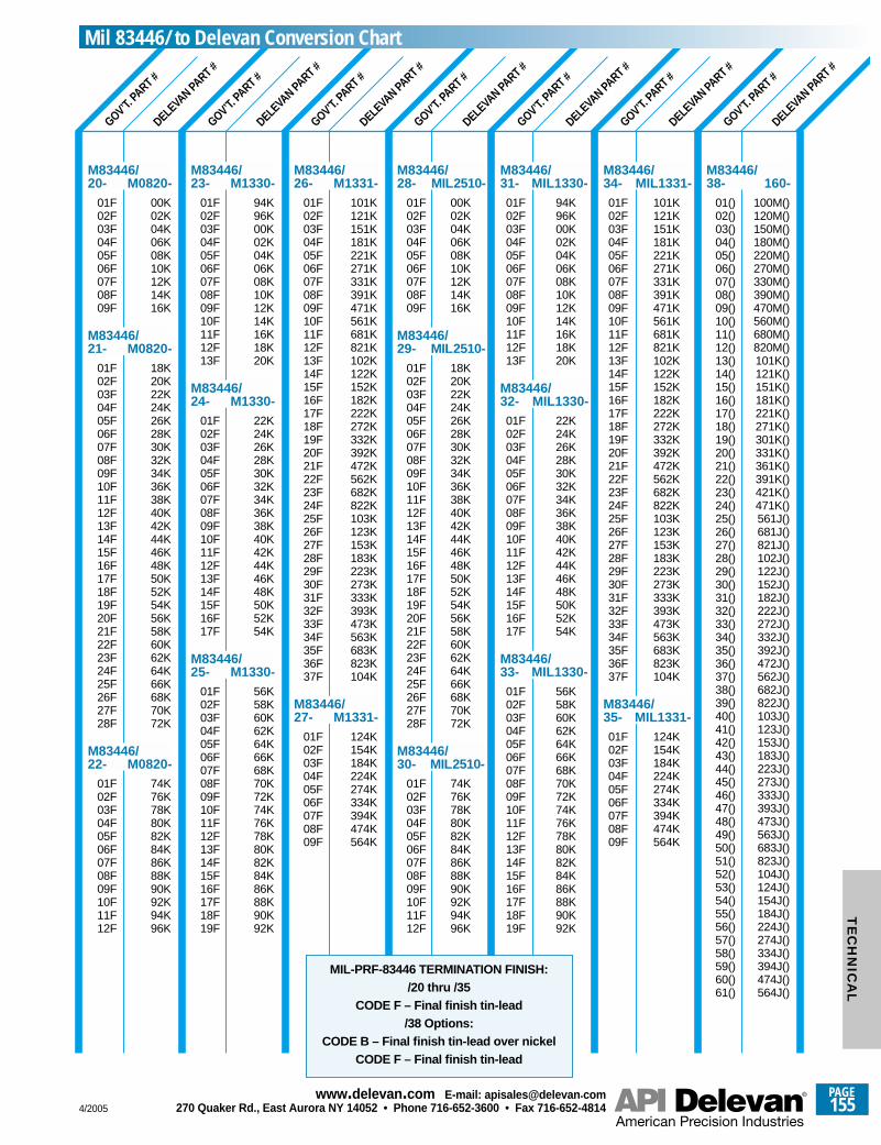
GOV’T. PA
RT #
DELEVA
N PART #
GOV’T. PA
RT #
DELEVA
N PART #
GOV’T. PA
RT #
DELEVA
N PART #
GOV’T. PA
RT #
DELEVA
N PART #
GOV’T. PA
RT #
DELEVA
N PART #
GOV’T. PA
RT #
DELEVA
N PART #
GOV’T. PA
RT #
DELEVA
N PART #
01F 00K02F 02K03F 04K04F 06K05F 08K06F 10K07F 12K08F 14K09F 16K
01F 18K02F 20K03F 22K04F 24K05F 26K06F 28K07F 30K08F 32K09F 34K10F 36K11F 38K12F 40K13F 42K14F 44K15F 46K16F 48K17F 50K18F 52K19F 54K20F 56K21F 58K22F 60K23F 62K24F 64K25F 66K26F 68K27F 70K28F 72K
01F 74K02F 76K03F 78K04F 80K05F 82K06F 84K07F 86K08F 88K09F 90K10F 92K11F 94K12F 96K
M83446/22- M0820-
M83446/21- M0820-
M83446/20- M0820-
01F 94K02F 96K03F 00K04F 02K05F 04K06F 06K07F 08K08F 10K09F 12K10F 14K11F 16K12F 18K13F 20K
01F 22K02F 24K03F 26K04F 28K05F 30K06F 32K07F 34K08F 36K09F 38K10F 40K11F 42K12F 44K13F 46K14F 48K15F 50K16F 52K17F 54K
01F 56K02F 58K03F 60K04F 62K05F 64K06F 66K07F 68K08F 70K09F 72K10F 74K11F 76K12F 78K13F 80K14F 82K15F 84K16F 86K17F 88K18F 90K19F 92K
M83446/25- M1330-
M83446/24- M1330-
M83446/23- M1330-
01F 101K02F 121K03F 151K04F 181K05F 221K06F 271K07F 331K08F 391K09F 471K10F 561K11F 681K12F 821K13F 102K14F 122K15F 152K16F 182K17F 222K18F 272K19F 332K20F 392K21F 472K22F 562K23F 682K24F 822K25F 103K26F 123K27F 153K28F 183K29F 223K30F 273K31F 333K32F 393K33F 473K34F 563K35F 683K36F 823K37F 104K
01F 124K02F 154K03F 184K04F 224K05F 274K06F 334K07F 394K08F 474K09F 564K
M83446/27- M1331-
M83446/26- M1331-
01F 00K02F 02K03F 04K04F 06K05F 08K06F 10K07F 12K08F 14K09F 16K
01F 18K02F 20K03F 22K04F 24K05F 26K06F 28K07F 30K08F 32K09F 34K10F 36K11F 38K12F 40K13F 42K14F 44K15F 46K16F 48K17F 50K18F 52K19F 54K20F 56K21F 58K22F 60K23F 62K24F 64K25F 66K26F 68K27F 70K28F 72K
01F 74K02F 76K03F 78K04F 80K05F 82K06F 84K07F 86K08F 88K09F 90K10F 92K11F 94K12F 96K
M83446/30- MIL2510-
M83446/29- MIL2510-
M83446/28- MIL2510-
01F 94K02F 96K03F 00K04F 02K05F 04K06F 06K07F 08K08F 10K09F 12K10F 14K11F 16K12F 18K13F 20K
01F 22K02F 24K03F 26K04F 28K05F 30K06F 32K07F 34K08F 36K09F 38K10F 40K11F 42K12F 44K13F 46K14F 48K15F 50K16F 52K17F 54K
01F 56K02F 58K03F 60K04F 62K05F 64K06F 66K07F 68K08F 70K09F 72K10F 74K11F 76K12F 78K13F 80K14F 82K15F 84K16F 86K17F 88K18F 90K19F 92K
M83446/33- MIL1330-
M83446/32- MIL1330-
M83446/31- MIL1330-
01F 101K02F 121K03F 151K04F 181K05F 221K06F 271K07F 331K08F 391K09F 471K10F 561K11F 681K12F 821K13F 102K14F 122K15F 152K16F 182K17F 222K18F 272K19F 332K20F 392K21F 472K22F 562K23F 682K24F 822K25F 103K26F 123K27F 153K28F 183K29F 223K30F 273K31F 333K32F 393K33F 473K34F 563K35F 683K36F 823K37F 104K
01F 124K02F 154K03F 184K04F 224K05F 274K06F 334K07F 394K08F 474K09F 564K
M83446/35- MIL1331-
M83446/34- MIL1331-
01() 100M()02() 120M()03() 150M()04() 180M()05() 220M()06() 270M()07() 330M()08() 390M()09() 470M()10() 560M()11() 680M()12() 820M()13() 101K()14() 121K()15() 151K()16() 181K()17() 221K()18() 271K()19() 301K()20() 331K()21() 361K()22() 391K()23() 421K()24() 471K()25() 561J()26() 681J()27() 821J()28() 102J()29() 122J()30() 152J()31() 182J()32() 222J()33() 272J()34() 332J()35() 392J()36() 472J()37() 562J()38() 682J()39() 822J()40() 103J()41() 123J()42() 153J()43() 183J()44() 223J()45() 273J()46() 333J()47() 393J()48() 473J()49() 563J()50() 683J()51() 823J()52() 104J()53() 124J()54() 154J()55() 184J()56() 224J()57() 274J()58() 334J()59() 394J()60() 474J()61() 564J()
M83446/38- 160-
MIL-PRF-83446 TERMINATION FINISH:/20 thru /35
CODE F – Final finish tin-lead/38 Options:
CODE B – Final finish tin-lead over nickel CODE F – Final finish tin-lead
Mil 83446/ to Delevan Conversion Chart
4/2005
PAGE155
www.delevan .com E-mail: apisales@delevan .com270 Quaker Rd., East Aurora NY 14052 • Phone 716-652-3600 • Fax 716-652-4814
TE
CH
NIC
AL
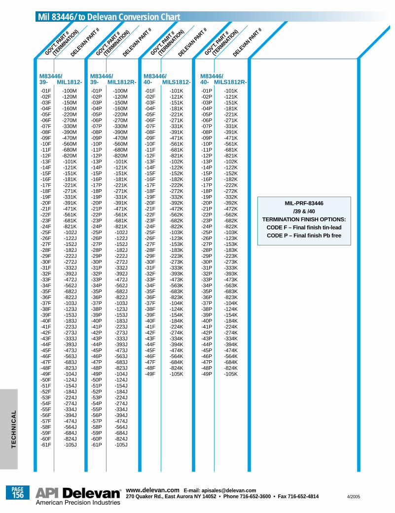
GOV’T. PA
RT #
(TERMINATIO
N)
GOV’T. PA
RT #
(TERMINATIO
N)
GOV’T. PA
RT #
(TERMINATIO
N)
GOV’T. PA
RT #
(TERMINATIO
N)
DELEVA
N PART #
DELEVA
N PART #
DELEVA
N PART #
DELEVA
N PART #
-01F -100M-02F -120M-03F -150M-04F -160M-05F -220M-06F -270M-07F -330M-08F -390M-09F -470M-10F -560M-11F -680M-12F -820M-13F -101K-14F -121K-15F -151K-16F -181K-17F -221K-18F -271K-19F -331K-20F -391K-21F -471K-22F -561K-23F -681K-24F -821K-25F -102J-26F -122J-27F -152J-28F -182J-29F -222J-30F -272J-31F -332J-32F -392J-33F -472J-34F -562J-35F -682J-36F -822J-37F -103J-38F -123J-39F -153J-40F -183J-41F -223J-42F -273J-43F -333J-44F -393J-45F -473J-46F -563J-47F -683J-48F -823J-49F -104J-50F -124J-51F -154J-52F -184J-53F -224J-54F -274J-55F -334J-56F -394J-57F -474J-58F -564J-59F -684J-60F -824J-61F -105J
M83446/39- MIL1812-
-01P -100M-02P -120M-03P -150M-04P -160M-05P -220M-06P -270M-07P -330M-08P -390M-09P -470M-10P -560M-11P -680M-12P -820M-13P -101K-14P -121K-15P -151K-16P -181K-17P -221K-18P -271K-19P -331K-20P -391K-21P -471K-22P -561K-23P -681K-24P -821K-25P -102J-26P -122J-27P -152J-28P -182J-29P -222J-30P -272J-31P -332J-32P -392J-33P -472J-34P -562J-35P -682J-36P -822J-37P -103J-38P -123J-39P -153J-40P -183J-41P -223J-42P -273J-43P -333J-44P -393J-45P -473J-46P -563J-47P -683J-48P -823J-49P -104J-50P -124J-51P -154J-52P -184J-53P -224J-54P -274J-55P -334J-56P -394J-57P -474J-58P -564J-59P -684J-60P -824J-61P -105J
M83446/39- MIL1812R-
-01F -101K-02F -121K-03F -151K-04F -181K-05F -221K-06F -271K-07F -331K-08F -391K-09F -471K-10F -561K-11F -681K-12F -821K-13F -102K-14F -122K-15F -152K-16F -182K-17F -222K-18F -272K-19F -332K-20F -392K-21F -472K-22F -562K-23F -682K-24F -822K-25F -103K-26F -123K-27F -153K-28F -183K-29F -223K-30F -273K-31F -333K-32F -393K-33F -473K-34F -563K-35F -683K-36F -823K-37F -104K-38F -124K-39F -154K-40F -184K-41F -224K-42F -274K-43F -334K-44F -394K-45F -474K-46F -564K-47F -684K-48F -824K-49F -105K
M83446/40- MILS1812-
-01P -101K-02P -121K-03P -151K-04P -181K-05P -221K-06P -271K-07P -331K-08P -391K-09P -471K-10P -561K-11P -681K-12P -821K-13P -102K-14P -122K-15P -152K-16P -182K-17P -222K-18P -272K-19P -332K-20P -392K-21P -472K-22P -562K-23P -682K-24P -822K-25P -103K-26P -123K-27P -153K-28P -183K-29P -223K-30P -273K-31P -333K-32P -393K-33P -473K-34P -563K-35P -683K-36P -823K-37P -104K-38P -124K-39P -154K-40P -184K-41P -224K-42P -274K-43P -334K-44P -394K-45P -474K-46P -564K-47P -684K-48P -824K-49P -105K
M83446/40- MILS1812R-
MIL-PRF-83446 /39 & /40
TERMINATION FINISH OPTIONS:CODE F – Final finish tin-leadCODE P – Final finish Pb free
Mil 83446/ to Delevan Conversion Chart
PAGE156
www.delevan .com E-mail: apisales@delevan .com270 Quaker Rd., East Aurora NY 14052 • Phone 716-652-3600 • Fax 716-652-4814 4/2005
TE
CH
NIC
AL
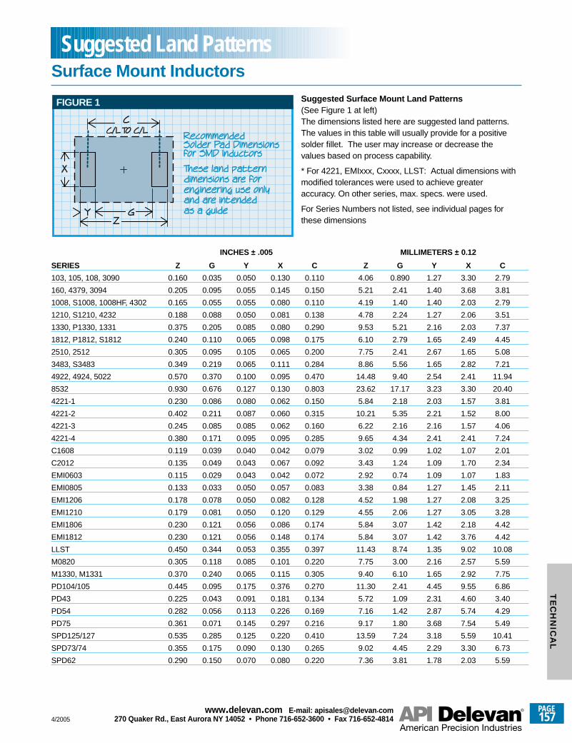
INCHES ± .005 MILLIMETERS ± 0.12
SERIES Z G Y X C Z G Y X C
103, 105, 108, 3090 0.160 0.035 0.050 0.130 0.110 4.06 0.890 1.27 3.30 2.79
160, 4379, 3094 0.205 0.095 0.055 0.145 0.150 5.21 2.41 1.40 3.68 3.81
1008, S1008, 1008HF, 4302 0.165 0.055 0.055 0.080 0.110 4.19 1.40 1.40 2.03 2.79
1210, S1210, 4232 0.188 0.088 0.050 0.081 0.138 4.78 2.24 1.27 2.06 3.51
1330, P1330, 1331 0.375 0.205 0.085 0.080 0.290 9.53 5.21 2.16 2.03 7.37
1812, P1812, S1812 0.240 0.110 0.065 0.098 0.175 6.10 2.79 1.65 2.49 4.45
2510, 2512 0.305 0.095 0.105 0.065 0.200 7.75 2.41 2.67 1.65 5.08
3483, S3483 0.349 0.219 0.065 0.111 0.284 8.86 5.56 1.65 2.82 7.21
4922, 4924, 5022 0.570 0.370 0.100 0.095 0.470 14.48 9.40 2.54 2.41 11.94
8532 0.930 0.676 0.127 0.130 0.803 23.62 17.17 3.23 3.30 20.40
4221-1 0.230 0.086 0.080 0.062 0.150 5.84 2.18 2.03 1.57 3.81
4221-2 0.402 0.211 0.087 0.060 0.315 10.21 5.35 2.21 1.52 8.00
4221-3 0.245 0.085 0.085 0.062 0.160 6.22 2.16 2.16 1.57 4.06
4221-4 0.380 0.171 0.095 0.095 0.285 9.65 4.34 2.41 2.41 7.24
C1608 0.119 0.039 0.040 0.042 0.079 3.02 0.99 1.02 1.07 2.01
C2012 0.135 0.049 0.043 0.067 0.092 3.43 1.24 1.09 1.70 2.34
EMI0603 0.115 0.029 0.043 0.042 0.072 2.92 0.74 1.09 1.07 1.83
EMI0805 0.133 0.033 0.050 0.057 0.083 3.38 0.84 1.27 1.45 2.11
EMI1206 0.178 0.078 0.050 0.082 0.128 4.52 1.98 1.27 2.08 3.25
EMI1210 0.179 0.081 0.050 0.120 0.129 4.55 2.06 1.27 3.05 3.28
EMI1806 0.230 0.121 0.056 0.086 0.174 5.84 3.07 1.42 2.18 4.42
EMI1812 0.230 0.121 0.056 0.148 0.174 5.84 3.07 1.42 3.76 4.42
LLST 0.450 0.344 0.053 0.355 0.397 11.43 8.74 1.35 9.02 10.08
M0820 0.305 0.118 0.085 0.101 0.220 7.75 3.00 2.16 2.57 5.59
M1330, M1331 0.370 0.240 0.065 0.115 0.305 9.40 6.10 1.65 2.92 7.75
PD104/105 0.445 0.095 0.175 0.376 0.270 11.30 2.41 4.45 9.55 6.86
PD43 0.225 0.043 0.091 0.181 0.134 5.72 1.09 2.31 4.60 3.40
PD54 0.282 0.056 0.113 0.226 0.169 7.16 1.42 2.87 5.74 4.29
PD75 0.361 0.071 0.145 0.297 0.216 9.17 1.80 3.68 7.54 5.49
SPD125/127 0.535 0.285 0.125 0.220 0.410 13.59 7.24 3.18 5.59 10.41
SPD73/74 0.355 0.175 0.090 0.130 0.265 9.02 4.45 2.29 3.30 6.73
SPD62 0.290 0.150 0.070 0.080 0.220 7.36 3.81 1.78 2.03 5.59
FIGURE 1 Suggested Surface Mount Land Patterns(See Figure 1 at left)The dimensions listed here are suggested land patterns.The values in this table will usually provide for a positivesolder fillet. The user may increase or decrease thevalues based on process capability.
* For 4221, EMIxxx, Cxxxx, LLST: Actual dimensions withmodified tolerances were used to achieve greateraccuracy. On other series, max. specs. were used.
For Series Numbers not listed, see individual pages forthese dimensions
Surface Mount InductorsSuggested Land Patterns
4/2005
PAGE157
www.delevan .com E-mail: apisales@delevan .com270 Quaker Rd., East Aurora NY 14052 • Phone 716-652-3600 • Fax 716-652-4814
TE
CH
NIC
AL
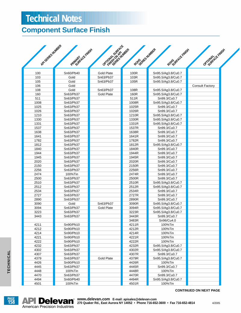
OPTIONAL
SURFACE FINISH
ROHS
SURFACE FINISH
ROHS
SERIES NUMBER
OPTIONAL S
URFACE
FINISH ON API
SERIES NUMBER
PAGE158
www.delevan .com E-mail: apisales@delevan .com270 Quaker Rd., East Aurora NY 14052 • Phone 716-652-3600 • Fax 716-652-4814 4/2005
TE
CH
NIC
AL
Component Surface FinishTechnical Notes
API SERIES NUMBER
PRIMARY
SURFACE FINISH
100 Sn60/Pb40 Gold Plate 100R Sn95.5/Ag3.8/Cu0.7103 Gold Sn63/Pb37 103R Sn95.5/Ag3.8/Cu0.7105 Gold Sn63/Pb37 105R Sn95.5/Ag3.8/Cu0.7106 Gold Consult Factory108 Gold Sn63/Pb37 108R Sn95.5/Ag3.8/Cu0.7160 Sn63/Pb37 Gold Plate 160R Sn95.5/Ag3.8/Cu0.7511 Sn63/Pb37 511R Sn99.3/Cu0.7
1008 Sn63/Pb37 1008R Sn95.5/Ag3.8/Cu0.71025 Sn63/Pb37 1025R Sn99.3/Cu0.71026 Sn63/Pb37 1026R Sn99.3/Cu0.71210 Sn63/Pb37 1210R Sn95.5/Ag3.8/Cu0.71330 Sn63/Pb37 1330R Sn95.5/Ag3.8/Cu0.71331 Sn63/Pb37 1331R Sn95.5/Ag3.8/Cu0.71537 Sn63/Pb37 1537R Sn99.3/Cu0.71638 Sn63/Pb37 1638R Sn99.3/Cu0.71641 Sn63/Pb37 1641R Sn99.3/Cu0.71782 Sn63/Pb37 1782R Sn99.3/Cu0.71812 Sn63/Pb37 1812R Sn95.5/Ag3.8/Cu0.71840 Sn63/Pb37 1840R Sn99.3/Cu0.71944 Sn63/Pb37 1944R Sn99.3/Cu0.71945 Sn63/Pb37 1945R Sn99.3/Cu0.72020 Sn63/Pb37 2020R Sn99.3/Cu0.72150 Sn63/Pb37 2150R Sn99.3/Cu0.72256 Sn63/Pb37 2256R Sn99.3/Cu0.72474 100%Tin 2474R Sn99.3/Cu0.72500 Sn63/Pb37 2500R Sn99.3/Cu0.72510 Sn63/Pb37 2510R Sn95.5/Ag3.8/Cu0.72512 Sn63/Pb37 2512R Sn95.5/Ag3.8/Cu0.72534 Sn63/Pb37 2534R Sn99.3/Cu0.72727 Sn63/Pb37 2727R Sn99.3/Cu0.72890 Sn63/Pb37 2890R Sn99.3/Cu0.73090 Gold Sn63/Pb37 3090R Sn95.5/Ag3.8/Cu0.73094 Sn63/Pb37 Gold Plate 3094R Sn95.5/Ag3.8/Cu0.73223 Sn63/Pb37 3223R Sn95.5/Ag3.8/Cu0.73443 Sn63/Pb37 3443R Sn99.3/Cu0.7
3483R Sn96/Cu4.04211 Sn90/Pb10 4211R 100%Tin4212 Sn90/Pb10 4212R 100%Tin4214 Sn90/Pb10 4214R 100%Tin4221 Sn90/Pb10 4221R 100%Tin4222 Sn90/Pb10 4222R 100%Tin4232 Sn63/Pb37 4232R Sn95.5/Ag3.8/Cu0.74302 Sn63/Pb37 4302R Sn95.5/Ag3.8/Cu0.74307 Sn63/Pb37 4307R Sn99.3/Cu0.74379 Sn63/Pb37 Gold Plate 4379R Sn95.5/Ag3.8/Cu0.74426 Sn90/Pb10 4426R 100%Tin4445 Sn63/Pb37 4445R Sn99.3/Cu0.74448 100%Tin 4448R 100%Tin4470 Sn63/Pb37 4470R Sn99.3/Cu0.74494 Sn60/Pb40 4494R Sn95.5/Ag3.8/Cu0.74501 100%Tin 4501R 100%Tin
CONTINUED ON NEXT PAGE
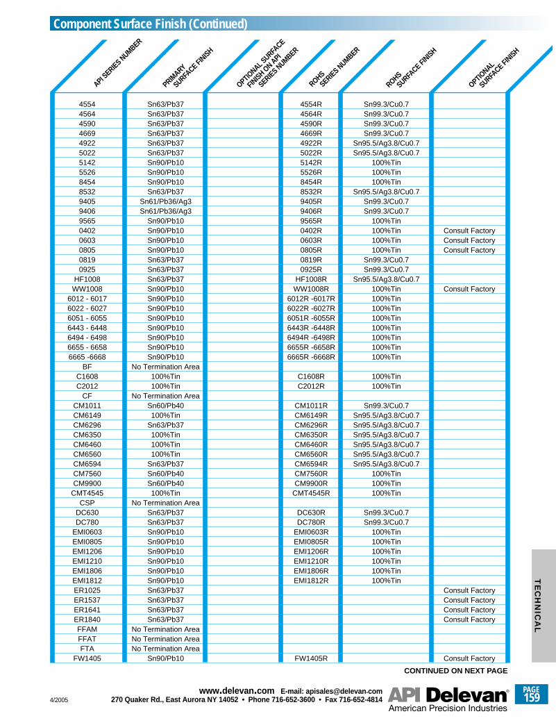
4/2005
PAGE159
www.delevan .com E-mail: apisales@delevan .com270 Quaker Rd., East Aurora NY 14052 • Phone 716-652-3600 • Fax 716-652-4814
TE
CH
NIC
AL
OPTIONAL
SURFACE FINISH
ROHS
SURFACE FINISH
ROHS
SERIES NUMBER
OPTIONAL S
URFACE
FINISH ON API
SERIES NUMBER
API SERIES NUMBER
PRIMARY
SURFACE FINISH
4554 Sn63/Pb37 4554R Sn99.3/Cu0.74564 Sn63/Pb37 4564R Sn99.3/Cu0.74590 Sn63/Pb37 4590R Sn99.3/Cu0.74669 Sn63/Pb37 4669R Sn99.3/Cu0.74922 Sn63/Pb37 4922R Sn95.5/Ag3.8/Cu0.75022 Sn63/Pb37 5022R Sn95.5/Ag3.8/Cu0.75142 Sn90/Pb10 5142R 100%Tin5526 Sn90/Pb10 5526R 100%Tin8454 Sn90/Pb10 8454R 100%Tin8532 Sn63/Pb37 8532R Sn95.5/Ag3.8/Cu0.79405 Sn61/Pb36/Ag3 9405R Sn99.3/Cu0.79406 Sn61/Pb36/Ag3 9406R Sn99.3/Cu0.79565 Sn90/Pb10 9565R 100%Tin0402 Sn90/Pb10 0402R 100%Tin Consult Factory0603 Sn90/Pb10 0603R 100%Tin Consult Factory0805 Sn90/Pb10 0805R 100%Tin Consult Factory0819 Sn63/Pb37 0819R Sn99.3/Cu0.70925 Sn63/Pb37 0925R Sn99.3/Cu0.7
HF1008 Sn63/Pb37 HF1008R Sn95.5/Ag3.8/Cu0.7WW1008 Sn90/Pb10 WW1008R 100%Tin Consult Factory
6012 - 6017 Sn90/Pb10 6012R -6017R 100%Tin6022 - 6027 Sn90/Pb10 6022R -6027R 100%Tin6051 - 6055 Sn90/Pb10 6051R -6055R 100%Tin6443 - 6448 Sn90/Pb10 6443R -6448R 100%Tin6494 - 6498 Sn90/Pb10 6494R -6498R 100%Tin6655 - 6658 Sn90/Pb10 6655R -6658R 100%Tin6665 -6668 Sn90/Pb10 6665R -6668R 100%Tin
BF No Termination AreaC1608 100%Tin C1608R 100%TinC2012 100%Tin C2012R 100%Tin
CF No Termination AreaCM1011 Sn60/Pb40 CM1011R Sn99.3/Cu0.7CM6149 100%Tin CM6149R Sn95.5/Ag3.8/Cu0.7CM6296 Sn63/Pb37 CM6296R Sn95.5/Ag3.8/Cu0.7CM6350 100%Tin CM6350R Sn95.5/Ag3.8/Cu0.7CM6460 100%Tin CM6460R Sn95.5/Ag3.8/Cu0.7CM6560 100%Tin CM6560R Sn95.5/Ag3.8/Cu0.7CM6594 Sn63/Pb37 CM6594R Sn95.5/Ag3.8/Cu0.7CM7560 Sn60/Pb40 CM7560R 100%TinCM9900 Sn60/Pb40 CM9900R 100%Tin
CMT4545 100%Tin CMT4545R 100%TinCSP No Termination Area
DC630 Sn63/Pb37 DC630R Sn99.3/Cu0.7DC780 Sn63/Pb37 DC780R Sn99.3/Cu0.7
EMI0603 Sn90/Pb10 EMI0603R 100%TinEMI0805 Sn90/Pb10 EMI0805R 100%TinEMI1206 Sn90/Pb10 EMI1206R 100%TinEMI1210 Sn90/Pb10 EMI1210R 100%TinEMI1806 Sn90/Pb10 EMI1806R 100%TinEMI1812 Sn90/Pb10 EMI1812R 100%TinER1025 Sn63/Pb37 Consult FactoryER1537 Sn63/Pb37 Consult FactoryER1641 Sn63/Pb37 Consult FactoryER1840 Sn63/Pb37 Consult FactoryFFAM No Termination AreaFFAT No Termination AreaFTA No Termination Area
FW1405 Sn90/Pb10 FW1405R Consult Factory
CONTINUED ON NEXT PAGE
Component Surface Finish (Continued)
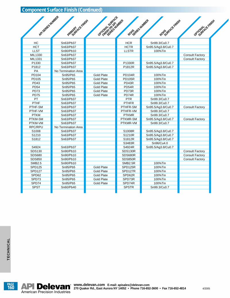
PAGE160
www.delevan .com E-mail: apisales@delevan .com270 Quaker Rd., East Aurora NY 14052 • Phone 716-652-3600 • Fax 716-652-4814 4/2005
OPTIONAL
SURFACE FINISH
ROHS
SURFACE FINISH
ROHS
SERIES NUMBER
OPTIONAL S
URFACE
FINISH ON API
SERIES NUMBER
API SERIES NUMBER
PRIMARY
SURFACE FINISH
HC Sn63/Pb37 HCR Sn99.3/Cu0.7HCT Sn63/Pb37 HCTR Sn95.5/Ag3.8/Cu0.7LLST Sn90/Pb10 LLSTR 100%Tin
MIL1330 Sn63/Pb37 Consult FactoryMIL1331 Sn63/Pb37 Consult FactoryP1330 Sn63/Pb37 P1330R Sn95.5/Ag3.8/Cu0.7P1812 Sn63/Pb37 P1812R Sn95.5/Ag3.8/Cu0.7
PA No Termination AreaPD104 Sn95/Pb5 Gold Plate PD104R 100%TinPD105 Sn95/Pb5 Gold Plate PD105R 100%TinPD43 Sn95/Pb5 Gold Plate PD43R 100%TinPD54 Sn95/Pb5 Gold Plate PD54R 100%TinPD73 Sn95/Pb5 Gold Plate PD73R 100%TinPD75 Sn95/Pb5 Gold Plate PD74R 100%Tin
PT Sn63/Pb37 PTR Sn99.3/Cu0.7PTHF Sn63/Pb37 PTHFR Sn99.3/Cu0.7
PTHF-SM Sn63/Pb37 PTHFR-SM Sn95.5/Ag3.8/Cu0.7 Consult FactoryPTHF-VM Sn63/Pb37 PTHFR-VM Sn99.3/Cu0.7
PTKM Sn63/Pb37 PTKMR Sn99.3/Cu0.7PTKM-SM Sn63/Pb37 PTKMR-SM Sn95.5/Ag3.8/Cu0.7 Consult FactoryPTKM-VM Sn63/Pb37 PTKMR-VM Sn99.3/Cu0.7RPC/RPU No Termination Area
S1008 Sn63/Pb37 S1008R Sn95.5/Ag3.8/Cu0.7S1210 Sn63/Pb37 S1210R Sn95.5/Ag3.8/Cu0.7S1812 Sn63/Pb37 S1812R Sn95.5/Ag3.8/Cu0.7
S3483R Sn96/Cu4.0S4924 Sn63/Pb37 S4924R Sn95.5/Ag3.8/Cu0.7
SDS130 Sn90/Pb10 SDS130R Consult FactorySDS680 Sn90/Pb10 SDS680R Consult FactorySDS850 Sn90/Pb10 SDS850R Consult FactorySMB2.5 Sn90/Pb10 SMB2.5R 100%TinSPD125 Sn95/Pb5 Gold Plate SPD125R 100%TinSPD127 Sn95/Pb5 Gold Plate SPD127R 100%TinSPD62 Sn95/Pb5 Gold Plate SPD62R 100%TinSPD73 Sn95/Pb5 Gold Plate SPD73R 100%TinSPD74 Sn95/Pb5 Gold Plate SPD74R 100%TinSPST Sn60/Pb40 SPSTR Sn99.3/Cu0.7
Component Surface Finish (Continued)T
EC
HN
ICA
L
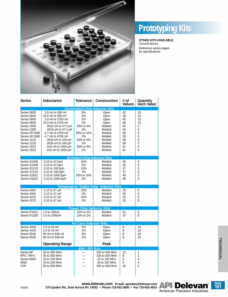
OTHER KITS AVAILABLEConsult factory
Reference series pagesfor specifications
Inductance
1.6 nH to 390 nH 10.0 nH to 390 nH
2.8 nH to 2700 nH10.0 nH to 2700 nH
.0018 uH to 47.0 µH
.0018 uH to 47.0 µH4.7 nH to 4700 nH4.7 nH to 4700 nH
.0018 uH to 100 µH
.0018 uH to 100 µH
.010 uH to 1000 µH
.010 uH to 1000 µH
0.10 to 47.0µH0.10 to 47.0µH0.10 to 100.0µH0.10 to 100.0µH0.10 to 1000.0µH0.10 to 1000.0µH
0.12 to 27 µH0.12 to 27 µH0.10 to 47 µH0.10 to 47 µH
1.0 to 330uH1.0 to 1000uH
2.5 to 43 nH2.5 to 43 nH90 nH to 538 nH90 nH to 538 nH
Operating Range
30 to 300 MHz30 to 300 MHz10 to 100 MHz10 to 200 MHz50 to 500 MHz
Tolerance
5%2%5%2%
20% to 5%2%
20% to 10% 2%
20% to 5%2%
20% to 5%2%
10%2%
10%2%
20% to 10% 2%
10%2%
10%2%
10% to 2%10% to 2%
5%2%5%2%
—————
Construction
OpenOpenOpenOpen
MoldedMoldedMoldedMoldedMoldedMoldedMoldedMolded
MoldedMoldedMoldedMoldedMoldedMolded
MoldedMoldedMoldedMolded
MoldedMolded
OpenOpenOpenOpen
Peak
100 to 400 MHz100 to 500 MHz15 to 100 MHz30 to 100 MHz
300 to 400 MHz
# ofValues
422845385454383858586161
363637374949
29293333
3137
8888
1285516
Quantityeach Value
1010101055555555
555555
5555
55
10101010
11442
Series
Unshielded Chip Inductor KitsSeries 0603Series 0603Series 0805Series 0805Series 1008Series 1008Series HF1008Series HF1008Series 1210Series 1210Series 1812Series 1812
Shielded Chip Inductor KitsSeries S1008Series S1008Series S1210Series S1210Series S1812Series S1812
Temperature Stable Chip Inductor KitsSeries 4302Series 4302Series 4232Series 4232
Power Chip Inductor KitsSeries P1812Series P1330
Air Core Inductor KitsSeries 4426Series 4426Sreies 5526Series 5526
EMI / RFI KitsSeries BFRPC / RPUSeries 84549565CSP
Prototyping Kits
4/2005
PAGE161
www.delevan .com E-mail: apisales@delevan .com270 Quaker Rd., East Aurora NY 14052 • Phone 716-652-3600 • Fax 716-652-4814
TE
CH
NIC
AL
PAGE162
www.delevan .com E-mail: apisales@delevan .com270 Quaker Rd., East Aurora NY 14052 • Phone 716-652-3600 • Fax 716-652-4814 4/2005
Customer Notes