CTU-Code/2021/second-informal-meeting/8 - UNECE
30
CTU-Code/2021/second-informal-meeting/8 1 Informal meeting on Code of Practice for Packing of Cargo Transport Units at the request of the United Nations Economic Commission for Europe Working Party on Intermodal Transport and Logistics Geneva and virtual, 29-30 September 2021 (second meeting) Item 4 of the provisional agenda Updates to the CTU Code Package stability Submitted by ETS Consulting Guidance on package stability may be considered as a new section (3.2) of Annex 7 of the CTU Code Introduction The term “package” is used in this document to refer to any goods that are enclosed within one or more layers of packaging or secured on, or to, a packaging accessory. Consignors should ensure that formed packages are capable of withstanding the hazards of environmental exposure, storage, handling and transport. Packages in the form of overpacks should retain their integrity during transport, failure to do so increases the risk of the cargo being damaged or the CTU stability being adversely affected. To assist Packers in their role, transport stability of the packages is divided to different levels to reflect their capability to withstand the forces during the transport. The transport stability level (TSL) when associated with the CTUs boundary strength can indicate the need for additional securing of the cargo and will be determined in each specific case. General requirements When considering the transport stability of packages in CTUs, a high degree of stability is required to meet roadside inspection requirements for cargo securing. At such an inspection a CTU may be subject to an inspection of its cargo securing in order to ensure that the cargo is secured in such a way that it does not interfere with safe driving, or pose a threat to life, health, property or the environment: • packages can only minimally change their position relative to each other, against walls or surfaces of the CTU, and • packages cannot leave the cargo space or protrude outside the cargo deck. During transport the package will be subjected to transport forces that are describe in Chapter 5 of the CTU Code. These forces can have two similar but different effects on the package. A. The package, when subject to transport acceleration may be deformed, or the packaging failing resulting in the packaged goods moving from their original packed position, or B. The package, when subjected to transport acceleration may tip over or topple. The ability to withstand both these two effects is referred to as stability, and, as such, causes confusion. Stability is defined as: Stability the quality, state or degree of being stable: such as 1. the strength to stand or endure - firmness
-
Upload
khangminh22 -
Category
Documents
-
view
0 -
download
0
Transcript of CTU-Code/2021/second-informal-meeting/8 - UNECE
CTU-Code/2021/second-informal-meeting/8
1
Informal meeting on Code of Practice for Packing of Cargo Transport Units
at the request of the United Nations Economic Commission for Europe Working Party on
Intermodal Transport and Logistics
Geneva and virtual, 29-30 September 2021 (second meeting)
Item 4 of the provisional agenda
Updates to the CTU Code
Package stability
Submitted by ETS Consulting
Guidance on package stability may be considered as a new section (3.2) of Annex 7 of the CTU Code
Introduction
The term “package” is used in this document to refer to any goods that are enclosed within one or more layers of packaging or secured on, or to, a packaging accessory.
Consignors should ensure that formed packages are capable of withstanding the hazards of environmental exposure, storage, handling and transport. Packages in the form of overpacks should retain their integrity during transport, failure to do so increases the risk of the cargo being damaged or the CTU stability being adversely affected.
To assist Packers in their role, transport stability of the packages is divided to different levels to reflect their capability to withstand the forces during the transport. The transport stability level (TSL) when associated with the CTUs boundary strength can indicate the need for additional securing of the cargo and will be determined in each specific case.
General requirements
When considering the transport stability of packages in CTUs, a high degree of stability is required to meet roadside inspection requirements for cargo securing. At such an inspection a CTU may be subject to an inspection of its cargo securing in order to ensure that the cargo is secured in such a way that it does not interfere with safe driving, or pose a threat to life, health, property or the environment:
• packages can only minimally change their position relative to each other, against walls or surfaces of the CTU, and
• packages cannot leave the cargo space or protrude outside the cargo deck.
During transport the package will be subjected to transport forces that are describe in Chapter 5 of
the CTU Code. These forces can have two similar but different effects on the package.
A. The package, when subject to transport acceleration may be deformed, or the packaging failing resulting in the packaged goods moving from their original packed position, or
B. The package, when subjected to transport acceleration may tip over or topple.
The ability to withstand both these two effects is referred to as stability, and, as such, causes confusion. Stability is defined as:
Stability the quality, state or degree of being stable: such as
1. the strength to stand or endure - firmness
CTU-Code/2021/second-informal-meeting/8
2
2. the property of a body that causes it when disturbed from a condition of equilibrium or steady motion to develop forces or moments that restore the original condition
3. resistance to chemical change or to physical disintegration
Therefore, for the purposes of this document, the former (A) is described as Integrity (SI) and the latter (B) as Firmness (SF).
A package with a high degree of SI can still change their position either by sliding or tipping (toppling).
A package with a high degree of SF can leave the cargo space or protrude outside the cargo deck because of deformation, creep, collapse, material fatigue or shifting of secondary packaging forming the transport package.
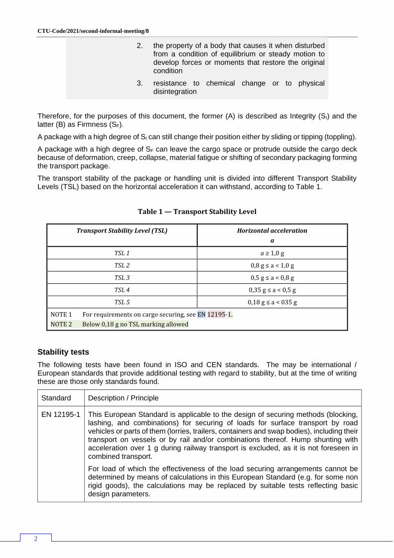
The transport stability of the package or handling unit is divided into different Transport Stability Levels (TSL) based on the horizontal acceleration it can withstand, according to Table 1.
Table 1 — Transport Stability Level
Transport Stability Level (TSL) Horizontal acceleration
a
TSL 1 a ≥ 1,0 g
TSL 2 0,8 g ≤ a < 1,0 g
TSL 3 0,5 g ≤ a < 0,8 g
TSL 4 0,35 g ≤ a < 0,5 g
TSL 5 0,18 g ≤ a < 035 g
NOTE 1 For requirements on cargo securing, see EN 12195-1.
NOTE 2 Below 0,18 g no TSL marking allowed
Stability tests
The following tests have been found in ISO and CEN standards. The may be international / European standards that provide additional testing with regard to stability, but at the time of writing these are those only standards found.
Standard Description / Principle
EN 12195-1 This European Standard is applicable to the design of securing methods (blocking, lashing, and combinations) for securing of loads for surface transport by road vehicles or parts of them (lorries, trailers, containers and swap bodies), including their transport on vessels or by rail and/or combinations thereof. Hump shunting with acceleration over 1 g during railway transport is excluded, as it is not foreseen in combined transport.
For load of which the effectiveness of the load securing arrangements cannot be determined by means of calculations in this European Standard (e.g. for some non rigid goods), the calculations may be replaced by suitable tests reflecting basic design parameters.
CTU-Code/2021/second-informal-meeting/8
3
The effectiveness of the cargo securing arrangements may be verified by suitable tests reflecting basic design parameters like:
• dynamic driving tests; or
• static inclination tests
It has to be ensured that the used test method is applicable to the tested goods and transport.
The dynamic tests are those that are covered in EN 12642.
The static inclination tests require a tilting test bed which can simulate various acceleration forces. The testing text only appear to refer to sliding and not to tilting.
There appears to be no pass / fail criteria.
EN 12642 This standard sets out basic minimum requirements for standard vehicle bodies (side walls, front and rear walls) and for reinforced vehicle bodies and specifies appropriate tests. Forces applied according to the test requirements can be invoked for load securing purposes.
Verification of conformity to the requirements of this standard shall be provided either by:
• dynamic driving tests
• static inclination test according to EN 12195-1:2010
• other methods
• calculation
After finishing the tests, the body structure shall show neither permanent deformation nor other changes which would impair its intended use; and the following criteria shall be satisfied:
• Maximum deflection of the test structure during the tests shall not exceed 300 mm
• At a test force of 100% of the test value a permanent deformation of 20 mm may occur, but only if the intended use is not impaired.
Test carried out are:
▪ Airbag tests,
▪ Dynamic tests
▪ Brake deceleration (0.8g) in driving direction
▪ U turn test (0.5g)
▪ Change of lane test (0.5g) – S-Test
▪ Brake deceleration (0.5g) opposite to driving direction.
For driving tests, the vehicle to be tested should be packed with cargo units on pallets, which lose their stability under the effect of a transverse acceleration of ≤2.25g. For specific purposes, tests with different cargo types of increased stability are allowed.
EN 28768 In simple testing, placing of the test package on a flat, horizontal surface and subjection of the package to an increasing horizontal force applied at a position above its centre of gravity until it topples freely about a lower edge. The test is recommended for packages where the ratio of the longest to the shortest sides is of the order of 3:1 or greater.
CTU-Code/2021/second-informal-meeting/8
4
The test may be used to investigate the performance of packages which are tall in relation to their base dimensions. On completion of the test sequence, the test package and contents shall be examined for damage.
ISO 10531 This International Standard specifies methods of testing for the stability of unit loads. These tests are intended to assess the performance of completely formed unit loads as they are subjected to the hazards of environmental exposure, storage, handling and transportation.
Observations of failure during testing, indicating load instability, may include deformation, creep, collapse, material fatigue or shifting of packages comprising the load.
Failure is defined as any of the following.
a) Package damage resulting in the inability of the product to sustain further distribution, storage or handling.
b) Integrity of the unit load has been degraded to such an extent as to risk instability on further handling.
Tests carried out:
• Drop test,
• Horizontal impact test,
• Clamp handling test,
• Push / Pull handling test,
Considering each of these standards with regard to package stability:
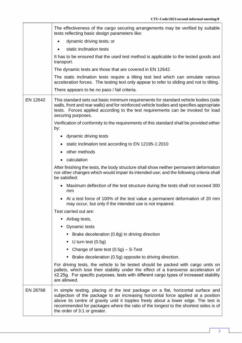
EN 12195-1 is primarily a standard to identify the lashing required to secure a package. The static inclination tests appear to validate the lashing of a package, primarily with regard to sliding, but could also relate to tipping.
As such this standard could be used to identify the SF of the package – an inclined platform test to test the resistance to sliding (see Figure 1) and a tipping test (Figure 2 as described in Annex 7 of the CTU Code.
Figure 1 - Sliding test
Figure 2 - Tipping test
Any deformation of the package which would indicate a potential failure of SI should be noted.
CTU-Code/2021/second-informal-meeting/8
5
EN 12642 is a standard that proves the strength of vehicle bodies and the tests would be normally using airbags, however the procedure for the dynamic tests, particularly the U turn and S turn tests may provide standard forces that could produce both data on SF and SI
..
EN 28768 is a standard that proves the effectiveness of the packaging and as such cannot improve knowledge of the stability (either SF or SI) of the package but does provide information about the formation of the transport package.
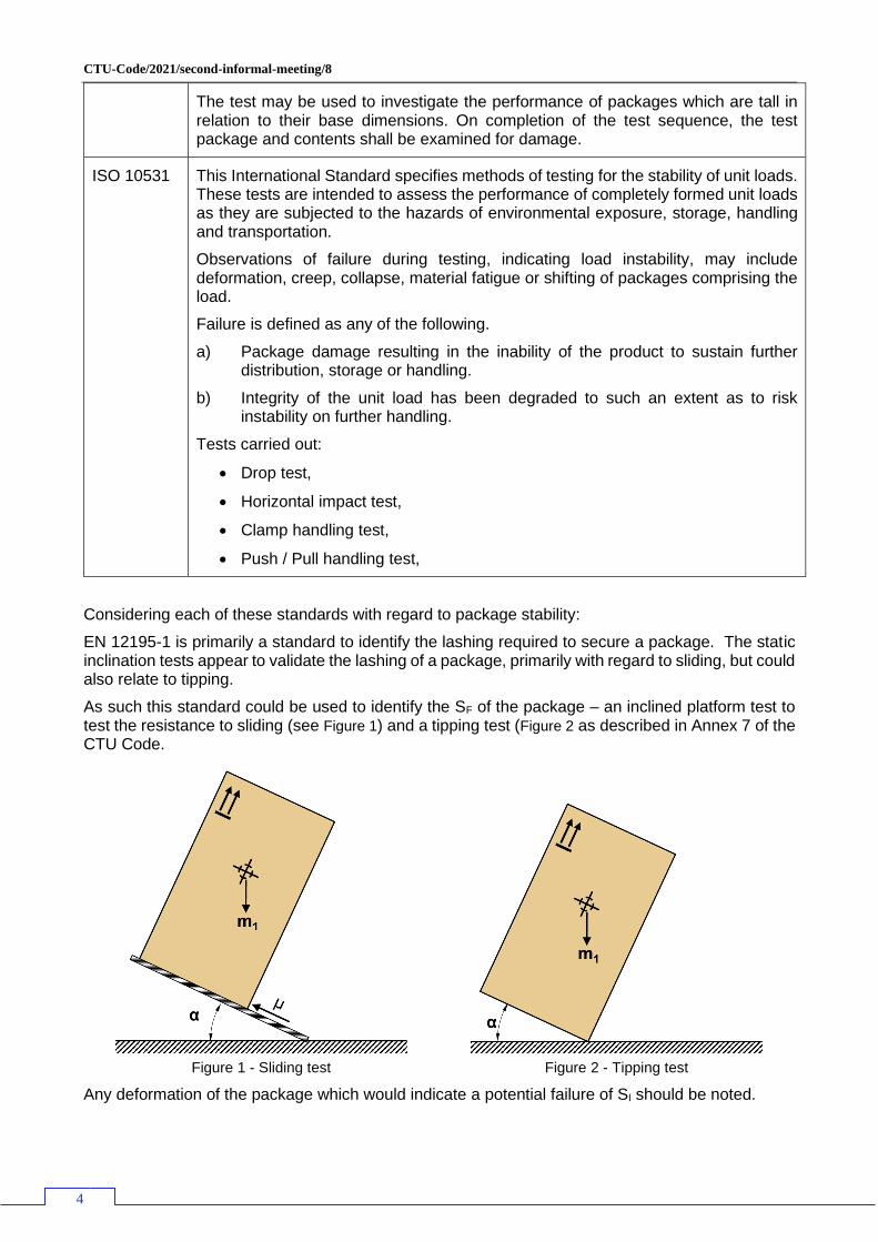
ISO 10531 is a standard that has been written to prove the SI of transport packages, specifically Unit Loads however, the tests described can be applied to all types of package.
Within the prescribed tests is:
• Drop test,
• Horizontal impact test,
• Clamp handling test,
• Push / Pull handling test,
Figure 3 - Drop flat test
Figure 4 - Bottom edge impact test
These two tests can be used to prove the SI of the package. If the package does not show any signs of degradation to the integrity of the package, then the SF value can be used.
The bottom edge impact test proves both the SI and the effectiveness of the packaging along the standing face.
If there are signs of degradation of the integrity of the package following this test, then further tests may be required.
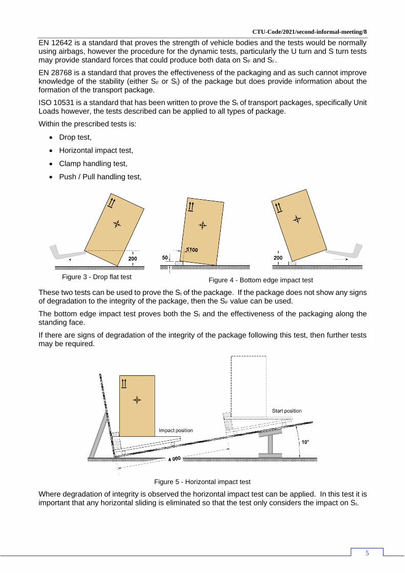
Figure 5 - Horizontal impact test
Where degradation of integrity is observed the horizontal impact test can be applied. In this test it is important that any horizontal sliding is eliminated so that the test only considers the impact on SI.
CTU-Code/2021/second-informal-meeting/8
6
The travel distance would need to be adjusted to produce differing negative acceleration at impact, typically 0.3g, 0.4g, 0.6g and 0.8g. These being the horizontal forces expected in the transport chain and included in the CTU Code.
An alternative to this design is a horizontal track with the test carriage accelerated to a predetermined speed to achieve the required impact force.
Where such test equipment is not available the Lift Truck handling tests detailed in Annex A of the standard can provide.
This test would provide the degree of SI for the package.
Testing
Testing of packages can be divided into two distinct types:
1. Testing of the integrity of the package during handling, storage and transport (SI), and
2. Testing of the stability of the package during transport (SF).
It is the responsibility of the consignor to ensure that completed filled transport packages are formed correctly and perform to the testing requirements specified normative references and others. Under this standard overpacks and formed packages for packing in a CTU they should be subjected to the following tests:
a) Drop tests according to ISO 10531
b) Horizontal impact test according to ISO 10531
c) Toppling test according to EN 28768
Failure is defined as any of the following.
i. Goods are damaged,
ii. Package damage resulting in the inability to sustain further distribution, storage or handling.
iii. Integrity of the package has been degraded to such an extent as to risk instability on further handling.
A package that passes the above tests but where the permanent deformation or displacement in a horizontal direction:
• is greater than 40mm in the bottom 200 mm of the package,
• is greater than 60 mm for packages less than 1200 mm, or
• is greater than 5% of the height of the package
will be classified as having poor package integrity (SI) and shall be marked accordingly (See Annex B).
To test for stability of the package (SF) all packages shall be subject to a static test according to EN 12195-1. and detailed below:
The static tests examines the transport stability of a package or handling unit to identify the forces required to topple over or to slide. The principle of a static test is to tilt up a package or a handling unit on basis of annex D.2 of standard EN 12195-1:2010 or Annex 7, appendix 5 of the CTU Code. Horizontal acceleration for transport stability level is calculated according to D.2.3.3 (Formula D.5) of standard EN 12195-1:2010.
Informative sketch for static test are described in Annex A.
The maximum achieved angle before tilting is considered as value for TSL. The tilting stability of an unsecured package or handling unit in different directions can be determined according to 5.2 of EN 12195-1:2010 or by the test methods described above.
CTU-Code/2021/second-informal-meeting/8
7
Evaluation
The permanent deformation or displacement of the test specimen from the original position after the test shall be according to the selected test methods if not stated it shall be less than 40 mm in any horizontal direction.
There shall be no visible leakage of the product after the test.
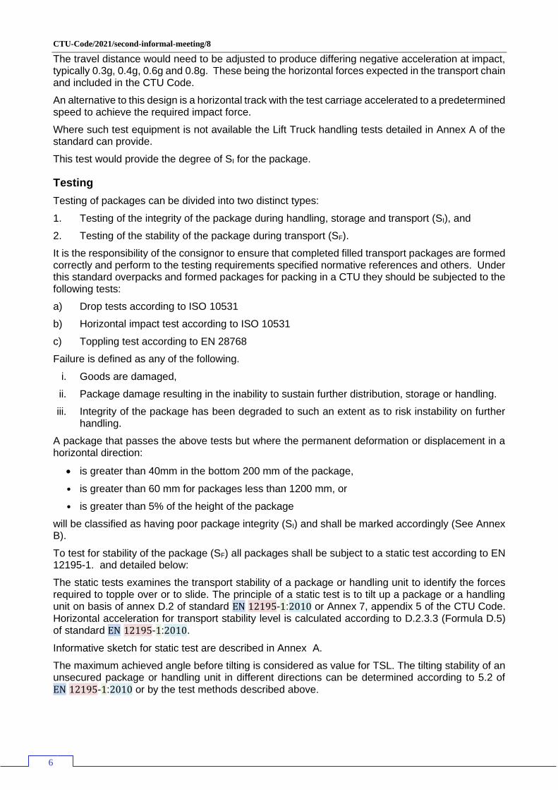
Therefore, to produce a stability factor for a package, the following process chart should be followed:
Figure 6 - Producing a Stability value
By testing the package in transverse and longitudinal directions the transport stability value (TSV) can be calculated.
Marking
All packages tested according to this standard shall be marked with the Transport Stability Level, TSL for packages, separately or incorporated with other markings.
The TSL marking:
a) shall be displayed on at least one side of each package; b) shall be marked with letters at least 12 mm high; c) shall be visible and readable; d) shall be displayed on a background of contrasting colour on the external surface of the package; e) reference to this standard (EN 17321) is optional and may be marked with smaller letters; f) the marking of test values is optional. NOTE Different TSL are possible in different directions on the same specimen.
Examples for marking of TSL:
— EXAMPLE 1: Transport Stability Level 4 in both length (L) and width (W) directions: L/W: TSL4 alternatively L/W: TSL4 (EN 17321) or L/W: TSL4 (0,45g)
— EXAMPLE 2: Transport Stability Level 2 in length (L) and 1 in width (W) direction: L: TSL2, W:TSL1
CTU-Code/2021/second-informal-meeting/8
8
Increasing package integrity stability (SI)
Packages with strong packaging, such as crates and single piece transport packaging are likely to have high stability (SI). This is because the packaging is constraining the primary / secondary packaging or the Goods. However, SI is reduced when there is a break between the packages and / or the packaging accessories, for example between a box and a pallet or between one box stacked on another.
A package comprising a single box when packed in a CTU requires the constraints of the side and end walls to maintain their stability. Gaps greater than 150 mm should be packed with dunnage to prevent excessive sliding. However, if the packages are stacked one above another, there is a risk of a failure of integrity due to the superimposed mass on the bottom packages. The Box Compression Strength (BCT) must be sufficient to withstand the forces likely to be experienced in the transport chain. Increasing BCT will increase SI.
Many packages now are formed into Unit Loads1, either on a pallet or for use with a slip sheet. They can come in three basic forms:
1. Single layer packages not extending to the edges of the pallet, such as drums and steel coils,
2. Multi-layers of packages not extending to the edges of the pallet, or
3. Single or multi-layer packages extending to the edges of the pallet.
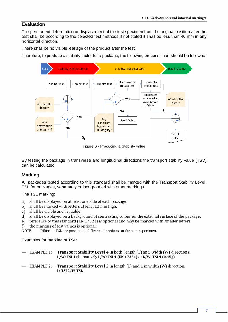
Single layer packages not extending to the edges of the pallet Consider a 900 mm x 800 mm x 900 mm high package comprising a telescope-type box made from C flute corrugated cardboard (Figure 7). The goods are securely packed inside using appropriate interior fitments. The package has a high SI and because of the BCT can be over stowed. Packing a number of these in a CTU with a strong boundary and dunnage to keep the overall gap less than 150 mm will produce a stable load. Any slip agent applied to the cardboard facing to ease handling will reduce the coefficient of friction but a tight stow will negate its effect.
Figure 7 - Box with lid
Figure 8 - Box with lid on pallet
Figure 9 - Box with lid secured to pallet
However, place the same box onto a 1200 mm x 800 mm pallet and both the SF and SI values drop. Subject the package shown in Figure 8 to the sliding or tipping tests and the box with lid is likely to move before the pallet, especially if slip agent has been applied to the cardboard surface. Subject it also to the horizontal impact test and the box with lid will slide to the edge and beyond. While this may appear to be a reduction in SF it is, in fact a reduction of Si since the two parts of the package (box with lid and pallet) have been displaced relative to each other.
To improve the integrity of the package, the box with lid must be secured to the pallet. This can be achieved by the application of strapping as shown in Figure 9. Ensure that the strapping does not pass over the transverse stringer boards as handling with fork tines may damage the strapping or loosen it. In this case the strength of the box with lid must be capable of withstanding the point forces under the strapping and edge protection may be required.
1 Goods, either packaged or not, that are packed onto a pallet, or that are formed using transport packaging with a
footprint equal to that of a pallet are described as a Unit Load. See Table 1
CTU-Code/2021/second-informal-meeting/8
9
The use of stretch wrapping to secure the box with lid to the pallet is not recommended as the gaps between the sides of the box with lid and those of the pallet are excessive.
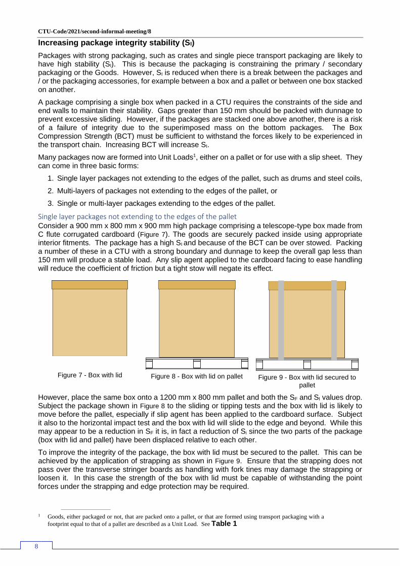
When multiple packages are to be transported on a pallet, but still do not fully cover the pallet, such as drums, this same approach should be followed.
Figure 10 - 200l drums on a 1200
x 800 pallet
Figure 11 - 200l drums of a 1220
x 1220 mm pallet
Figure 12 - 200l drums of a 1200
mm wide pallet with additional strapping
As the mass of the package increases so to does the need to properly secure the primary packaging (drums). As can be seen in Figure 10 there is considerable open area which makes the use of stretch wrap to secure the drums ineffective. Figure 11 shows four drums on a 1220 mm x 1220 mm pallet with perimeter lashing and a single top over lashing to each pair of drums and the strapping under the top slats only. As the mass of the packaged goods increases so too should the lashing. Figure
12 shows the side elevation of drums on a 1200 mm wide pallet with perimeter lashings and transverse and longitudinal top over lashing. The lashing coloured brown passes under the stringer boards and therefore is susceptible to damage from the fork tines. Where such lashing is applied the lashing must be supported with doubler plates.
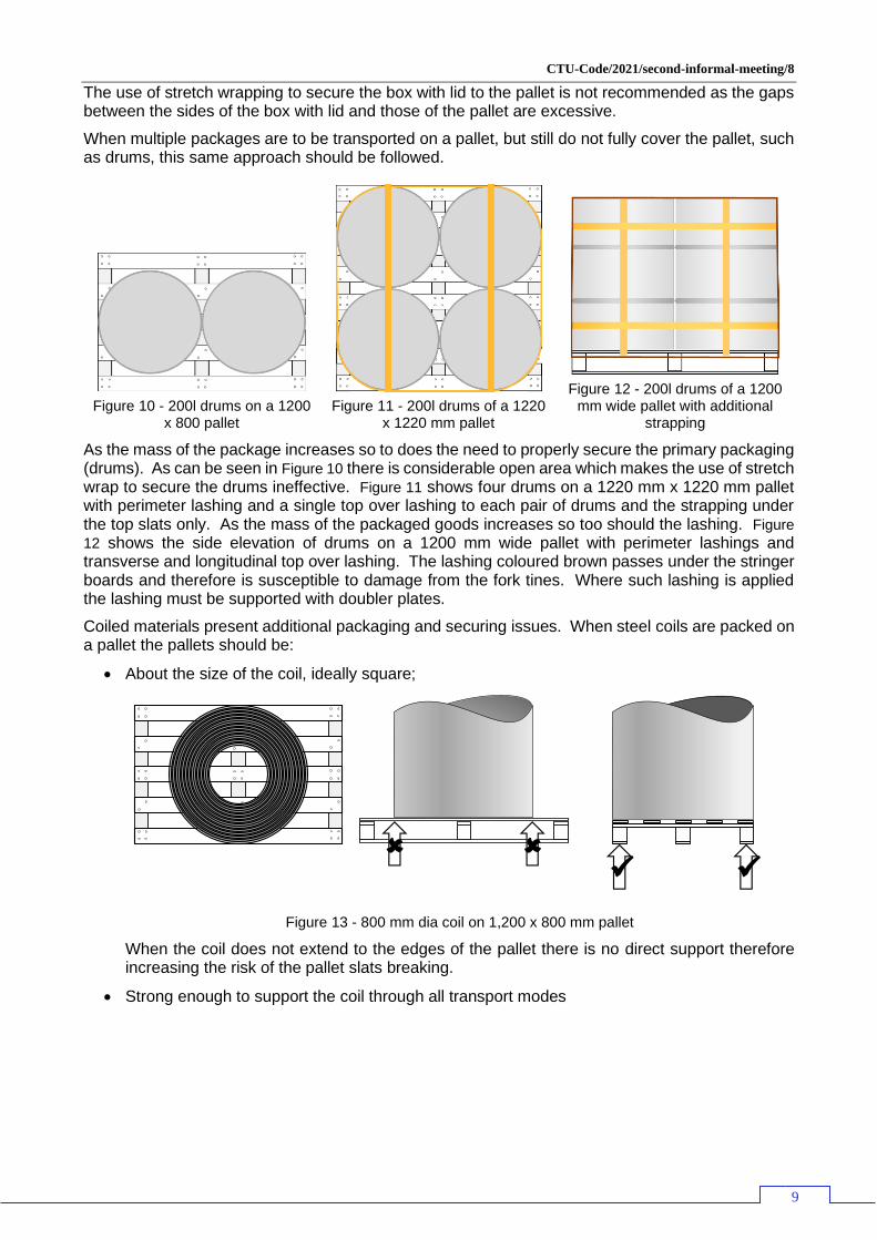
Coiled materials present additional packaging and securing issues. When steel coils are packed on a pallet the pallets should be:
• About the size of the coil, ideally square;
Figure 13 - 800 mm dia coil on 1,200 x 800 mm pallet
When the coil does not extend to the edges of the pallet there is no direct support therefore increasing the risk of the pallet slats breaking.
• Strong enough to support the coil through all transport modes
✓ ✓

CTU-Code/2021/second-informal-meeting/8
10
Figure 14 - Pallet types
Pallet design A is not strong enough,
Pallet design B would be suitable for less dense materials,
Pallet design C is suitable
Pallet design D suitable for the most dense materials
Pallet design E is suitable for coils where the edge can be damaged surface irregularities.
• Have strong anchoring points for lashing the coil to the pallet.
Figure 15 - Strapping only under top slats
Figure 16 - Strapping under top slats and stringer
board
Lashing the coil to the pallet should form a solid package, where the coil cannot move relative to the pallet. This can be achieved by banding the coil to the pallet and, if required adding blocking battens.
✓
A B C
E D
CTU-Code/2021/second-informal-meeting/8
11
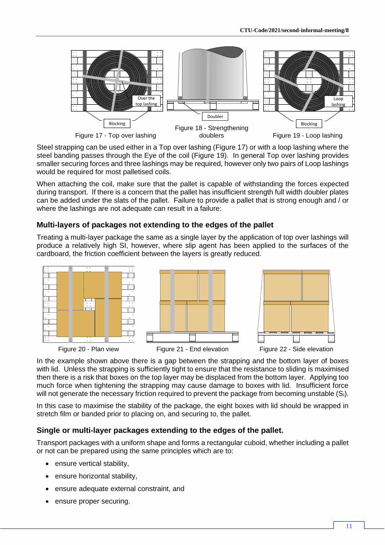
Figure 17 - Top over lashing
Figure 18 - Strengthening
doublers
Figure 19 - Loop lashing
Steel strapping can be used either in a Top over lashing (Figure 17) or with a loop lashing where the steel banding passes through the Eye of the coil (Figure 19). In general Top over lashing provides smaller securing forces and three lashings may be required, however only two pairs of Loop lashings would be required for most palletised coils.
When attaching the coil, make sure that the pallet is capable of withstanding the forces expected during transport. If there is a concern that the pallet has insufficient strength full width doubler plates can be added under the slats of the pallet. Failure to provide a pallet that is strong enough and / or where the lashings are not adequate can result in a failure:
Multi-layers of packages not extending to the edges of the pallet
Treating a multi-layer package the same as a single layer by the application of top over lashings will produce a relatively high SI, however, where slip agent has been applied to the surfaces of the cardboard, the friction coefficient between the layers is greatly reduced.
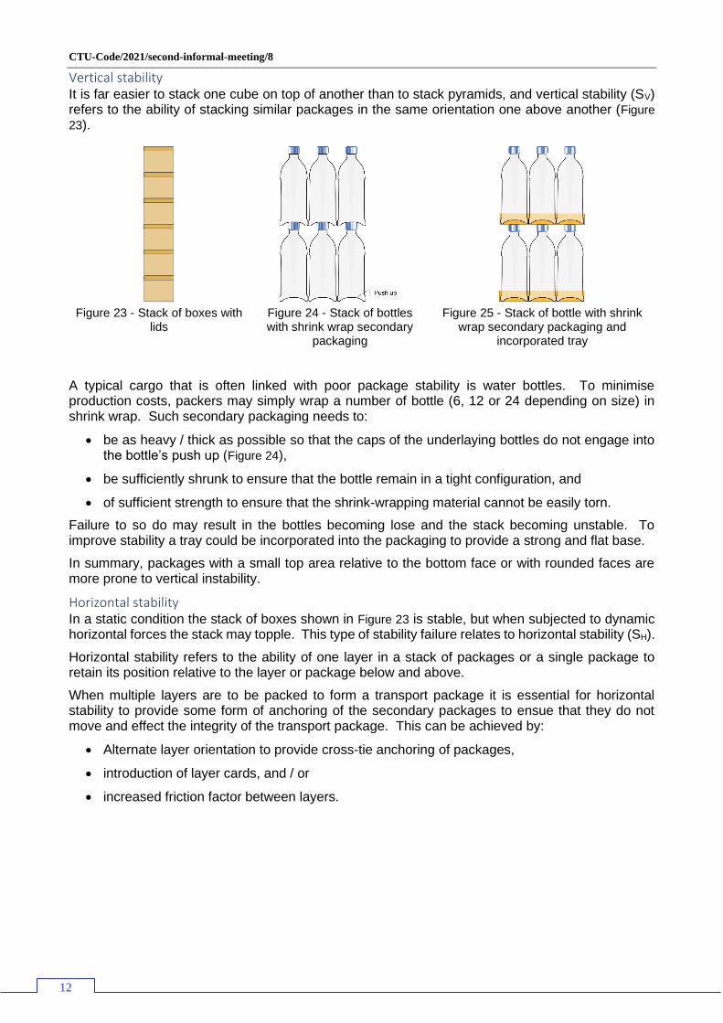
Figure 20 - Plan view
Figure 21 - End elevation
Figure 22 - Side elevation
In the example shown above there is a gap between the strapping and the bottom layer of boxes with lid. Unless the strapping is sufficiently tight to ensure that the resistance to sliding is maximised then there is a risk that boxes on the top layer may be displaced from the bottom layer. Applying too much force when tightening the strapping may cause damage to boxes with lid. Insufficient force will not generate the necessary friction required to prevent the package from becoming unstable (SI).
In this case to maximise the stability of the package, the eight boxes with lid should be wrapped in stretch film or banded prior to placing on, and securing to, the pallet.
Single or multi-layer packages extending to the edges of the pallet.
Transport packages with a uniform shape and forms a rectangular cuboid, whether including a pallet or not can be prepared using the same principles which are to:
• ensure vertical stability,
• ensure horizontal stability,
• ensure adequate external constraint, and
• ensure proper securing.
BlockingBlocking
Over the top lashing
Doubler
BlockingBlocking
Loop lashing
CTU-Code/2021/second-informal-meeting/8
12
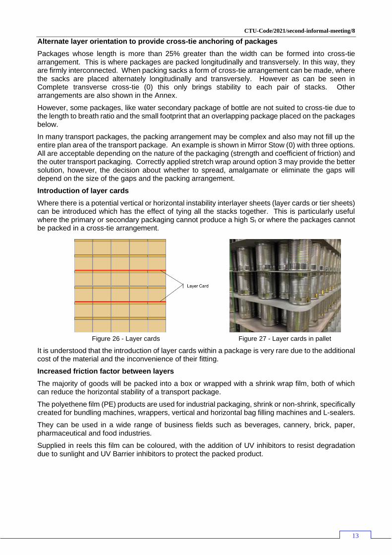
Vertical stability It is far easier to stack one cube on top of another than to stack pyramids, and vertical stability (SV) refers to the ability of stacking similar packages in the same orientation one above another (Figure
23).
Figure 23 - Stack of boxes with
lids
Figure 24 - Stack of bottles with shrink wrap secondary
packaging
Figure 25 - Stack of bottle with shrink
wrap secondary packaging and incorporated tray
A typical cargo that is often linked with poor package stability is water bottles. To minimise production costs, packers may simply wrap a number of bottle (6, 12 or 24 depending on size) in shrink wrap. Such secondary packaging needs to:
• be as heavy / thick as possible so that the caps of the underlaying bottles do not engage into the bottle’s push up (Figure 24),
• be sufficiently shrunk to ensure that the bottle remain in a tight configuration, and
• of sufficient strength to ensure that the shrink-wrapping material cannot be easily torn.
Failure to so do may result in the bottles becoming lose and the stack becoming unstable. To improve stability a tray could be incorporated into the packaging to provide a strong and flat base.
In summary, packages with a small top area relative to the bottom face or with rounded faces are more prone to vertical instability.
Horizontal stability In a static condition the stack of boxes shown in Figure 23 is stable, but when subjected to dynamic horizontal forces the stack may topple. This type of stability failure relates to horizontal stability (SH).
Horizontal stability refers to the ability of one layer in a stack of packages or a single package to retain its position relative to the layer or package below and above.
When multiple layers are to be packed to form a transport package it is essential for horizontal stability to provide some form of anchoring of the secondary packages to ensue that they do not move and effect the integrity of the transport package. This can be achieved by:
• Alternate layer orientation to provide cross-tie anchoring of packages,
• introduction of layer cards, and / or
• increased friction factor between layers.
CTU-Code/2021/second-informal-meeting/8
13
Alternate layer orientation to provide cross-tie anchoring of packages
Packages whose length is more than 25% greater than the width can be formed into cross-tie arrangement. This is where packages are packed longitudinally and transversely. In this way, they are firmly interconnected. When packing sacks a form of cross-tie arrangement can be made, where the sacks are placed alternately longitudinally and transversely. However as can be seen in Complete transverse cross-tie (0) this only brings stability to each pair of stacks. Other arrangements are also shown in the Annex.
However, some packages, like water secondary package of bottle are not suited to cross-tie due to the length to breath ratio and the small footprint that an overlapping package placed on the packages below.
In many transport packages, the packing arrangement may be complex and also may not fill up the entire plan area of the transport package. An example is shown in Mirror Stow (0) with three options. All are acceptable depending on the nature of the packaging (strength and coefficient of friction) and the outer transport packaging. Correctly applied stretch wrap around option 3 may provide the better solution, however, the decision about whether to spread, amalgamate or eliminate the gaps will depend on the size of the gaps and the packing arrangement.
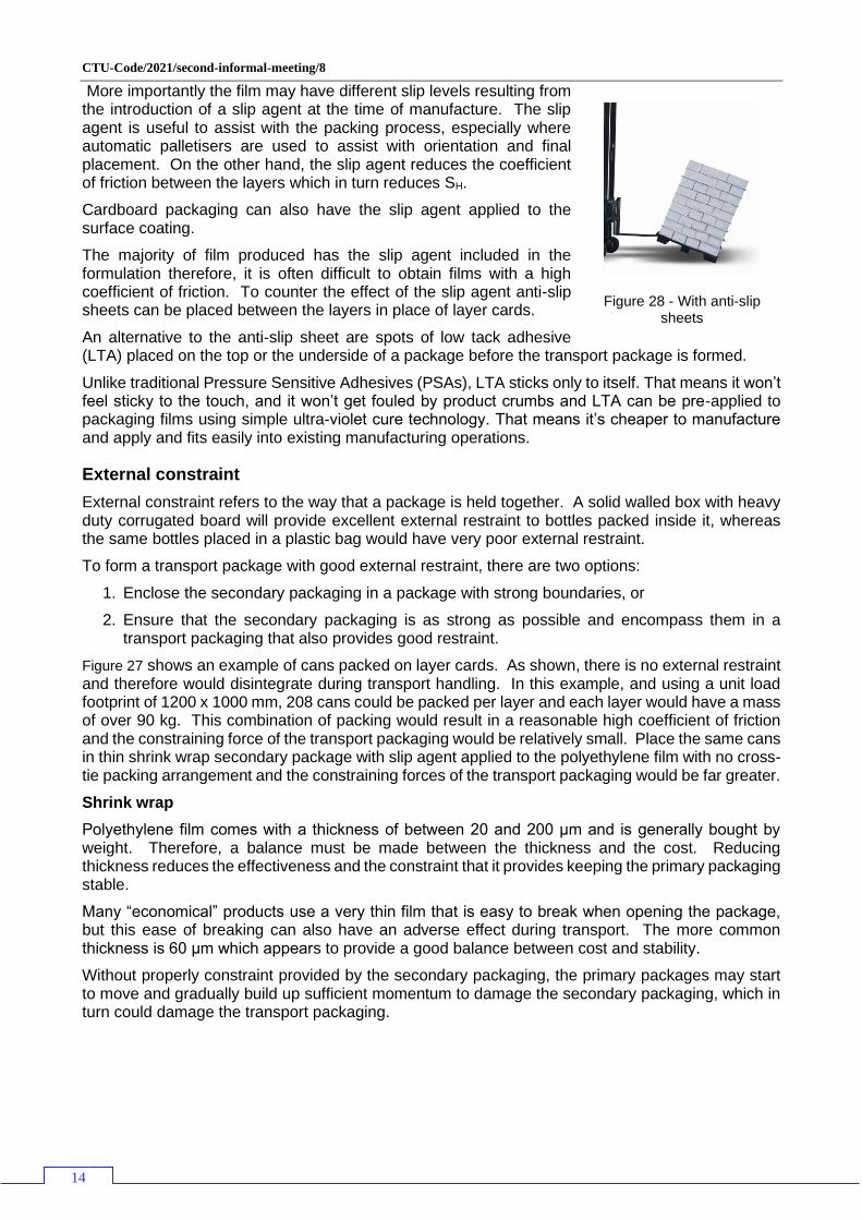
Introduction of layer cards
Where there is a potential vertical or horizontal instability interlayer sheets (layer cards or tier sheets) can be introduced which has the effect of tying all the stacks together. This is particularly useful where the primary or secondary packaging cannot produce a high SI or where the packages cannot be packed in a cross-tie arrangement.
It is understood that the introduction of layer cards within a package is very rare due to the additional cost of the material and the inconvenience of their fitting.
Increased friction factor between layers
The majority of goods will be packed into a box or wrapped with a shrink wrap film, both of which can reduce the horizontal stability of a transport package.
The polyethene film (PE) products are used for industrial packaging, shrink or non-shrink, specifically created for bundling machines, wrappers, vertical and horizontal bag filling machines and L-sealers.
They can be used in a wide range of business fields such as beverages, cannery, brick, paper, pharmaceutical and food industries.
Supplied in reels this film can be coloured, with the addition of UV inhibitors to resist degradation due to sunlight and UV Barrier inhibitors to protect the packed product.
Figure 26 - Layer cards
Figure 27 - Layer cards in pallet
CTU-Code/2021/second-informal-meeting/8
14
More importantly the film may have different slip levels resulting from the introduction of a slip agent at the time of manufacture. The slip agent is useful to assist with the packing process, especially where automatic palletisers are used to assist with orientation and final placement. On the other hand, the slip agent reduces the coefficient of friction between the layers which in turn reduces SH.
Cardboard packaging can also have the slip agent applied to the surface coating.
The majority of film produced has the slip agent included in the formulation therefore, it is often difficult to obtain films with a high coefficient of friction. To counter the effect of the slip agent anti-slip sheets can be placed between the layers in place of layer cards.
An alternative to the anti-slip sheet are spots of low tack adhesive (LTA) placed on the top or the underside of a package before the transport package is formed.
Unlike traditional Pressure Sensitive Adhesives (PSAs), LTA sticks only to itself. That means it won’t feel sticky to the touch, and it won’t get fouled by product crumbs and LTA can be pre-applied to packaging films using simple ultra-violet cure technology. That means it’s cheaper to manufacture and apply and fits easily into existing manufacturing operations.
External constraint
External constraint refers to the way that a package is held together. A solid walled box with heavy duty corrugated board will provide excellent external restraint to bottles packed inside it, whereas the same bottles placed in a plastic bag would have very poor external restraint.
To form a transport package with good external restraint, there are two options:
1. Enclose the secondary packaging in a package with strong boundaries, or
2. Ensure that the secondary packaging is as strong as possible and encompass them in a transport packaging that also provides good restraint.
Figure 27 shows an example of cans packed on layer cards. As shown, there is no external restraint and therefore would disintegrate during transport handling. In this example, and using a unit load footprint of 1200 x 1000 mm, 208 cans could be packed per layer and each layer would have a mass of over 90 kg. This combination of packing would result in a reasonable high coefficient of friction and the constraining force of the transport packaging would be relatively small. Place the same cans in thin shrink wrap secondary package with slip agent applied to the polyethylene film with no cross-tie packing arrangement and the constraining forces of the transport packaging would be far greater.
Shrink wrap
Polyethylene film comes with a thickness of between 20 and 200 μm and is generally bought by weight. Therefore, a balance must be made between the thickness and the cost. Reducing thickness reduces the effectiveness and the constraint that it provides keeping the primary packaging stable.
Many “economical” products use a very thin film that is easy to break when opening the package, but this ease of breaking can also have an adverse effect during transport. The more common thickness is 60 μm which appears to provide a good balance between cost and stability.
Without properly constraint provided by the secondary packaging, the primary packages may start to move and gradually build up sufficient momentum to damage the secondary packaging, which in turn could damage the transport packaging.
Figure 28 - With anti-slip
sheets

CTU-Code/2021/second-informal-meeting/8
15
Stretch wrap
The most common stretch wrap material linear low-density polyethylene or LLDPE, which is produced by copolymerization of ethylene with alpha-olefins, the most common of which are butene, hexene and octene. The use of higher alpha-olefins (hexene or octene) gives rise to enhanced stretch film characteristics, particularly in respect of elongation at break and puncture resistance. Although films can be produced with about 500% stretch at break they are only stretched to about 100 – 300% in use.
It is the elastic recovery that keeps the secondary packages tightly bound.
When applying stretch wrap it is therefore essential that the film is properly stretched during application. Manually winding the film around a package will not generate a necessary elastic recovery and therefore the constraining forces will be low.
As the films provided are prepared with various levels of pre-stretch under or over stretching can result in a poor wrap.
Shrink and stretch hoods
Hoods are preformed transport packaging for unit loads, and generally perform similar to the film versions. Shrink hoods are suitable for applications in glass, brick, paper, ceramics, cement and adhesives industries.
Stretch hoods are similar to the shrink hoods except that they do not require heating instead relying on the pre-stretch qualities of the hood. It is useful for high speed packing, and suitable for any kind of products including heat sensitive materials. However, unlike the stretch film provides only 120% stretchability.
Edge protectors
Where the primary or secondary packaging may damage the transport packaging, such as secondary packaging with a low SI, or primary packaging with edges that may cut through films, it is worth considering placing edge protectors to the top edges or angle boards on the vertical corners of the package.
Angle boards are thick moulded cardboard strips that create Protective Corners that can be used with stretch wrap or strapping to protect the edges of a package from being damage, preventing the tight strap digging into secondary packaging and as well as securing and help stabilise the package during transport. Angle boards are the perfect packaging solution for when you have small light boxes stacked on a pallet, as they can help to hold the cartons together securely in the package before it is strapped and or wrapped ready to be transport.
Proper securing
Typically, any damage incurred in the transport chain occurs because the shipment was improperly packed, wrapped or secured for transport.
This is a particular issue with retail goods such as TVs and DVD players where there is no protection to the primary packaging. If there is cosmetic box damage, the consumer is likely to assume the contents are also damaged. As discussed earlier, package strength and stacking play an important role in freight shipment integrity. So do load protection, stretch wrapping and banding.
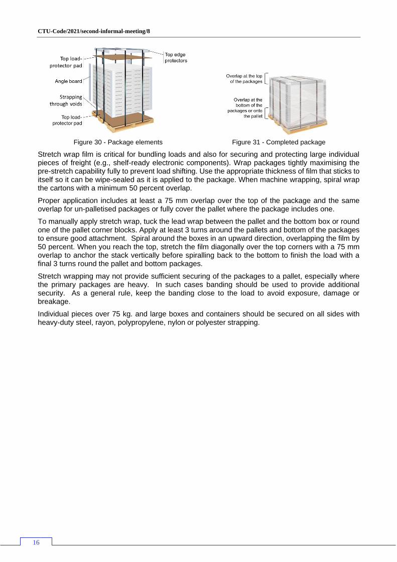
Top and bottom load-protector pads (corrugated pad/tray) help reduce damage to top and bottom layers of your shipment and the top pad provide additional containment from packages ‘popping’ out due to vertical acceleration. They also help distribute the superimposed mass or packages stacked on top. Bottom load protectors provide a level surface and help keep boxes from slipping into the gap between the boards on the pallet. Corner or edge boards should run the full length of the stack to help stabilize the load, increase vertical stacking strength and reduce damage to box edges that make up the load corners.
Figure 29 - Angle boards
CTU-Code/2021/second-informal-meeting/8
16
Figure 30 - Package elements
Figure 31 - Completed package
Stretch wrap film is critical for bundling loads and also for securing and protecting large individual pieces of freight (e.g., shelf-ready electronic components). Wrap packages tightly maximising the pre-stretch capability fully to prevent load shifting. Use the appropriate thickness of film that sticks to itself so it can be wipe-sealed as it is applied to the package. When machine wrapping, spiral wrap the cartons with a minimum 50 percent overlap.
Proper application includes at least a 75 mm overlap over the top of the package and the same overlap for un-palletised packages or fully cover the pallet where the package includes one.
To manually apply stretch wrap, tuck the lead wrap between the pallet and the bottom box or round one of the pallet corner blocks. Apply at least 3 turns around the pallets and bottom of the packages to ensure good attachment. Spiral around the boxes in an upward direction, overlapping the film by 50 percent. When you reach the top, stretch the film diagonally over the top corners with a 75 mm overlap to anchor the stack vertically before spiralling back to the bottom to finish the load with a final 3 turns round the pallet and bottom packages.
Stretch wrapping may not provide sufficient securing of the packages to a pallet, especially where the primary packages are heavy. In such cases banding should be used to provide additional security. As a general rule, keep the banding close to the load to avoid exposure, damage or breakage.
Individual pieces over 75 kg. and large boxes and containers should be secured on all sides with heavy-duty steel, rayon, polypropylene, nylon or polyester strapping.
CTU-Code/2021/second-informal-meeting/8
17
Consequential changes
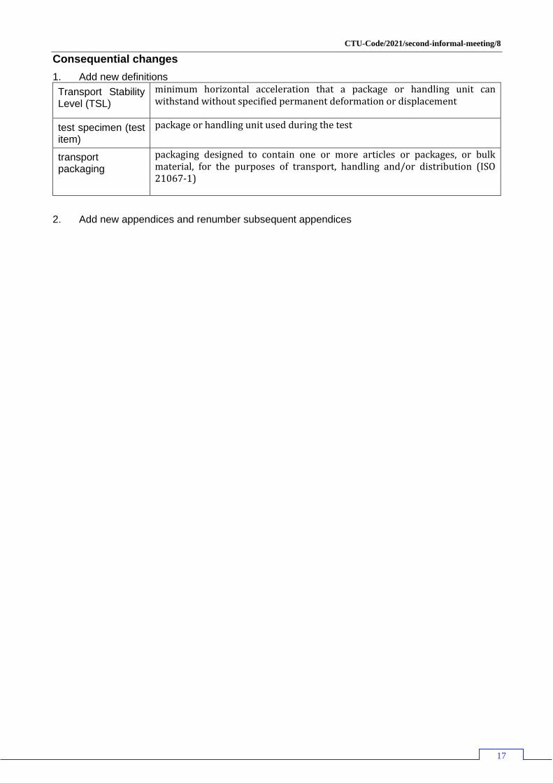
1. Add new definitions
Transport Stability Level (TSL)
minimum horizontal acceleration that a package or handling unit can withstand without specified permanent deformation or displacement
test specimen (test item)
package or handling unit used during the test
transport packaging
packaging designed to contain one or more articles or packages, or bulk material, for the purposes of transport, handling and/or distribution (ISO 21067-1)
2. Add new appendices and renumber subsequent appendices
CTU-Code/2021/second-informal-meeting/8
18
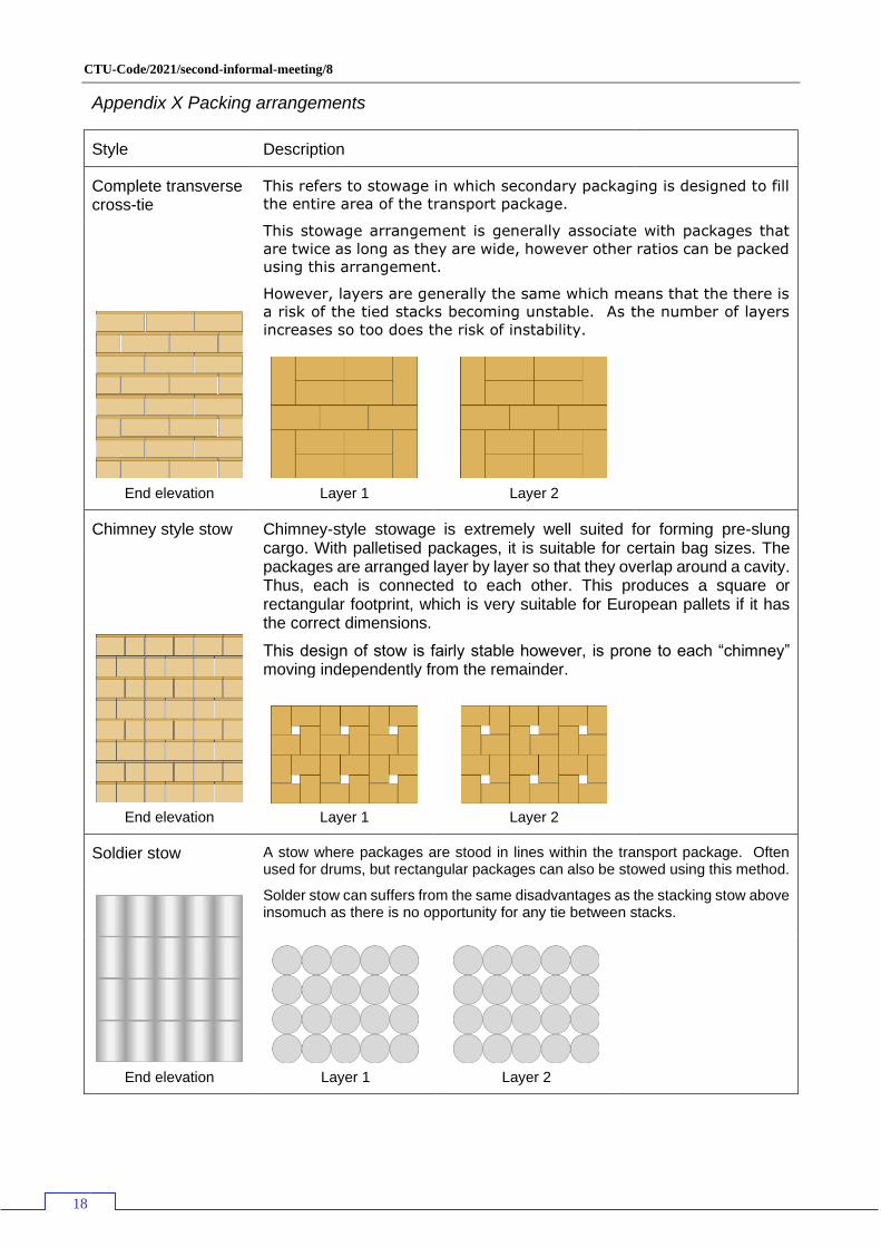
Appendix X Packing arrangements
Style Description
Complete transverse cross-tie
This refers to stowage in which secondary packaging is designed to fill
the entire area of the transport package.
This stowage arrangement is generally associate with packages that
are twice as long as they are wide, however other ratios can be packed
using this arrangement.
However, layers are generally the same which means that the there is
a risk of the tied stacks becoming unstable. As the number of layers
increases so too does the risk of instability.
End elevation
Layer 1
Layer 2
Chimney style stow Chimney-style stowage is extremely well suited for forming pre-slung cargo. With palletised packages, it is suitable for certain bag sizes. The packages are arranged layer by layer so that they overlap around a cavity. Thus, each is connected to each other. This produces a square or rectangular footprint, which is very suitable for European pallets if it has the correct dimensions.
This design of stow is fairly stable however, is prone to each “chimney” moving independently from the remainder.
End elevation
Layer 1
Layer 2
Soldier stow A stow where packages are stood in lines within the transport package. Often used for drums, but rectangular packages can also be stowed using this method.
Solder stow can suffers from the same disadvantages as the stacking stow above insomuch as there is no opportunity for any tie between stacks.
End elevation
Layer 1
Layer 2

CTU-Code/2021/second-informal-meeting/8
19
Off-set soldier stow Sometimes referred to at the vertical bilge and cantline stow. Normally used when it is impossible to complete a proper soldier stow due to width restrictions, however when forming a package and packed on a pallet, this stow arrangement provides an element of cross-tie between stacks.
However, it is only suitable where the dimensions permit layer 2 packages to properly overlap with those in layer 1.
End elevation
Layer 1
Layer 2
Mirror stow When the size of the secondary packages are such that they cannot be formed into a regular arrangement, then a more complex design needs to be adopted.
Below are three possible stow arranged ment options for the same number of packages. The gaps can be equal (option 1), amalgamated (option 2) or with no gaps (option 3). The choice will depend on the specification of the secondary and transport packaging.
The arangements shown below are examples of the many that can be formed.
Option 1
Option 2
Front elevation
layer 1
Layer 2
Option 3
CTU-Code/2021/second-informal-meeting/8
20
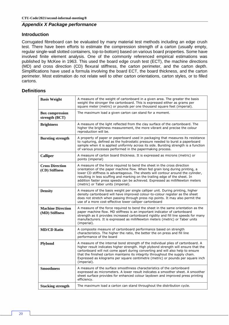
Appendix X Package performance
Introduction
Corrugated fibreboard can be evaluated by many material test methods including an edge crush test. There have been efforts to estimate the compression strength of a carton (usually empty, regular single-wall slotted containers, top-to-bottom) based on various board properties. Some have involved finite element analysis. One of the commonly referenced empirical estimations was published by McKee in 1963. This used the board edge crush test (ECT), the machine directions (MD) and cross direction (CD) flexural stiffness, the carton perimeter, and the carton depth. Simplifications have used a formula involving the board ECT, the board thickness, and the carton perimeter. Most estimation do not relate well to other carton orientations, carton styles, or to filled cartons.
Definitions
Basis Weight A measure of the weight of cartonboard in a given area. The greater the basis weight the stronger the cartonboard. This is expressed either as grams per square meter (metric) or pounds per one thousand square feet (imperial).
Box compression
strength (BCT)
The maximum load a given carton can stand for a moment.
Brightness A measure of the light reflected from the clay surface of the cartonboard. The higher the brightness measurement, the more vibrant and precise the colour reproduction will be.
Bursting strength A property of paper or paperboard used in packaging that measures its resistance to rupturing, defined as the hydrostatic pressure needed to burst a paperboard sample when it is applied uniformly across its side. Bursting strength is a function of various processes performed in the papermaking process.
Calliper A measure of carton board thickness. It is expressed as microns (metric) or points (imperial)
Cross Direction
(CD) Stiffness
A measure of the force required to bend the sheet in the cross direction orientation of the paper machine flow. When fed grain long during printing, a
lower CD stiffness is advantageous. The sheets will contour around the cylinder, resulting in less scuffing and marking on the trailing edge of the sheet. In addition faster press speeds can be achieved. Expressed as milliNewton meters (metric) or Taber units (imperial).
Density A measure of the basis weight per single calliper unit. During printing, higher density cartonboard will have improved colour-to-colour register as the sheet does not stretch when passing through press nip points. It may also permit the use of a more cost-effective lower calliper cartonboard
Machine Direction
(MD) Stiffness
A measure of the force required to bend the sheet in the same orientation as the paper machine flow. MD stiffness is an important indicator of cartonboard strength as it provides increased cartonboard rigidity and fill line speeds for many manufacturers. It is expressed as milliNewton meters (metric) or Taber units (imperial).
MD/CD Ratio A composite measure of cartonboard performance based on strength characteristics. The higher the ratio, the better the on press and fill line performance of the board
Plybond A measure of the internal bond strength of the individual plies of cartonboard. A higher result indicates higher strength. High plybond strength will ensure that the cartonboard will not come apart during converting and will also help to ensure that the finished carton maintains its integrity throughout the supply chain. Expressed as kilograms per square centimetre (metric) or pounds per square inch (imperial).
Smoothness A measure of the surface smoothness characteristics of the cartonboard expressed as micrometers. A lower result indicates a smoother sheet. A smoother sheet surface provides for enhanced colour laydown and improved press printing efficiency.
Stacking strength The maximum load a carton can stand throughout the distribution cycle.
CTU-Code/2021/second-informal-meeting/8
21
Manufacture of corrugated board
In the classical corrugator, the paper is softened with high-pressure steam. After the board is formed it is dried in the so-called dry-end. Here the newly formed corrugated board is heated from the bottom by hot plates. On the top, various pressures are applied by a load system on the belt.
The corrugated medium (middle) is often 0.026 pounds per square foot (0.13 kg/m²) basis weight in the U.S.; in the UK, a 90 grams per square metre (0.018 lbs/ft²) fluting paper is common. At the single-facer, it is heated, moistened, and formed into a fluted pattern on geared wheels. This is joined to a flat linerboard with a starch based adhesive to form single face board. At the double-backer, a second flat linerboard is adhered to the other side of the fluted medium to form single wall corrugated board. Linerboards are test liners (recycled paper) or kraft paperboard (of various grades). The liner may be bleached white, mottled white, coloured, or pre-printed.
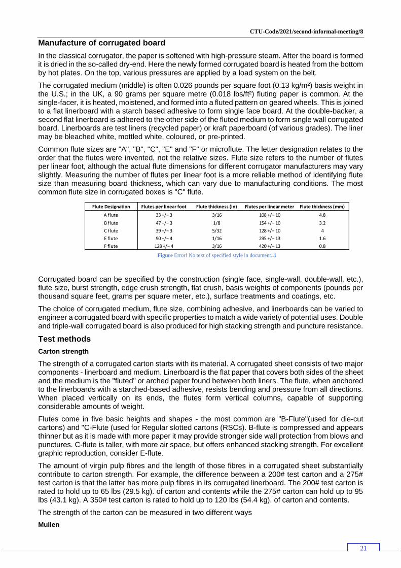
Common flute sizes are "A", "B", "C", "E" and "F" or microflute. The letter designation relates to the order that the flutes were invented, not the relative sizes. Flute size refers to the number of flutes per linear foot, although the actual flute dimensions for different corrugator manufacturers may vary slightly. Measuring the number of flutes per linear foot is a more reliable method of identifying flute size than measuring board thickness, which can vary due to manufacturing conditions. The most common flute size in corrugated boxes is "C" flute.
Figure Error! No text of specified style in document..1
Corrugated board can be specified by the construction (single face, single-wall, double-wall, etc.), flute size, burst strength, edge crush strength, flat crush, basis weights of components (pounds per thousand square feet, grams per square meter, etc.), surface treatments and coatings, etc.
The choice of corrugated medium, flute size, combining adhesive, and linerboards can be varied to engineer a corrugated board with specific properties to match a wide variety of potential uses. Double and triple-wall corrugated board is also produced for high stacking strength and puncture resistance.
Test methods
Carton strength
The strength of a corrugated carton starts with its material. A corrugated sheet consists of two major components - linerboard and medium. Linerboard is the flat paper that covers both sides of the sheet and the medium is the "fluted" or arched paper found between both liners. The flute, when anchored to the linerboards with a starched-based adhesive, resists bending and pressure from all directions. When placed vertically on its ends, the flutes form vertical columns, capable of supporting considerable amounts of weight.
Flutes come in five basic heights and shapes - the most common are "B-Flute"(used for die-cut cartons) and "C-Flute (used for Regular slotted cartons (RSCs). B-flute is compressed and appears thinner but as it is made with more paper it may provide stronger side wall protection from blows and punctures. C-flute is taller, with more air space, but offers enhanced stacking strength. For excellent graphic reproduction, consider E-flute.
The amount of virgin pulp fibres and the length of those fibres in a corrugated sheet substantially contribute to carton strength. For example, the difference between a 200# test carton and a 275# test carton is that the latter has more pulp fibres in its corrugated linerboard. The 200# test carton is rated to hold up to 65 lbs (29.5 kg). of carton and contents while the 275# carton can hold up to 95 lbs (43.1 kg). A 350# test carton is rated to hold up to 120 lbs (54.4 kg). of carton and contents.
The strength of the carton can be measured in two different ways
Mullen
Flute Designation Flutes per linear foot Flute thickness (in) Flutes per linear meter Flute thickness (mm)
A flute 33 +/− 3 3/16 108 +/− 10 4.8
B flute 47 +/− 3 1/8 154 +/− 10 3.2
C flute 39 +/− 3 5/32 128 +/− 10 4
E flute 90 +/− 4 1/16 295 +/− 13 1.6
F flute 128 +/− 4 3/16 420 +/− 13 0.8
CTU-Code/2021/second-informal-meeting/8
22
A test performed to measure the bursting strength of paper or paperboard. In a Mullen test (also called a pop test), the paper sample is placed between two ring-like clamps in a device called a Mullen tester, and hydraulic pressure is used to inflate a rubber diaphragm, which expands against the sample stretching it. The measure of the total hydraulic pressure expanding the diaphragm at the time the sample ruptures (usually expressed in either pounds per square inch or kilopascals) is its bursting strength. Mullen tests are performed for each side of a paper or paperboard, and the bursting strength can be expressed as the average of both sides. Bursting strength expressed as a percentage is called the percent Mullen.
As far as Classification rules go, the mullen test is fairly easy to understand and easy to administer. However it is thought to correlate poorly with another important carton characteristic, stacking strength. In 1990 the trade associations for the corrugated industry sponsored proposals to revise their rules thus paving the way for an alternative rule for measuring carton strength, ECT.
Edge crust test (ECT)
The Edge Crush Test (ECT) measures the ability of combined board to sustain a top-to-bottom load. The strength is directly related to the compression strength of both the liners and medium. There are two gauges of strength. Box compression strength (BCT) is the maximum load a given carton can stand for a moment. Stacking strength is the maximum load a carton can stand throughout the distribution cycle. This means that the bottom carton must support the top load over a period of time in which it may be exposed to fluctuations in temperature and humidity as well as other factors that impact performance such as handling, pallet patterns, pallet deck board spacing, and overhang. All these factors weaken the stacking strength of the carton. Therefore the stacking strength of a carton is almost always much lower than its compression strength. The most commonly used carton style is the Regular Slotted Container (RSC). The McKee formula is a formula that can estimate the compression strength of a given carton. This is useful information when designing a package. By knowing the compression strength and carefully considering all the potential detractors encountered throughout the distribution cycle the designer may better determine the ECT test required to achieve the desired stacking strength.
McKee also created a simpler formula based on calliper of the combined board instead of bending stiffness
It provides accuracy close to the original equation and is easier to use, both in testing and mathematically. McKee's work was based on averages. Individual cartones will vary above and below the predicted value. The ability to predict the compression strength of a container is a considerable tool, but it is even more powerful to take a compression requirement, back out an ECT requirement and use it to determine appropriate board combinations. Solving for Ea, the simplified McKee formula is:
Distribution environment and carton performance
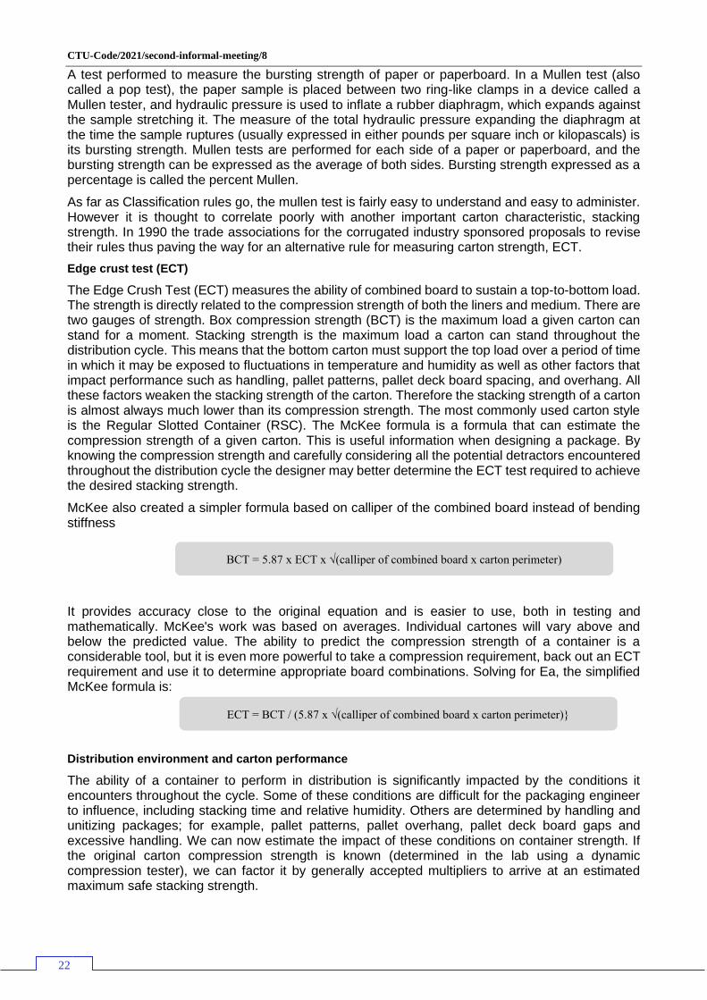
The ability of a container to perform in distribution is significantly impacted by the conditions it encounters throughout the cycle. Some of these conditions are difficult for the packaging engineer to influence, including stacking time and relative humidity. Others are determined by handling and unitizing packages; for example, pallet patterns, pallet overhang, pallet deck board gaps and excessive handling. We can now estimate the impact of these conditions on container strength. If the original carton compression strength is known (determined in the lab using a dynamic compression tester), we can factor it by generally accepted multipliers to arrive at an estimated maximum safe stacking strength.
BCT = 5.87 x ECT x √(calliper of combined board x carton perimeter)
ECT = BCT / (5.87 x √(calliper of combined board x carton perimeter)}
CTU-Code/2021/second-informal-meeting/8
23
Compression Loss Multipliers
Storage time under load
10 days-37 percent loss .63
30 days-40 percent loss .6
90 days-45 percent loss .55
180 days-50 percent loss .5
Relative humidity, under load (cyclical RH variation further increases compressive loss)
50 percent-"--0 percent loss 1
60 percent-10 percent loss .9
70 percent-20 percent loss .8
80 percent-32 percent loss .68
90 percent-52 percent loss .48
100 percent-85 percent loss .15
Pallet Patterns
Best Case Worst case
Columnar, aligned Negligible loss .9 .85
Columnar, misaligned
10-15 percentloss .6 .4
Interlocked 40-60 percent loss .8 .6
Pallet deckboard gap
10-25 percent loss .9 .75
Excessive handling 10-40 percent loss .9 .6
CTU-Code/2021/second-informal-meeting/8
24
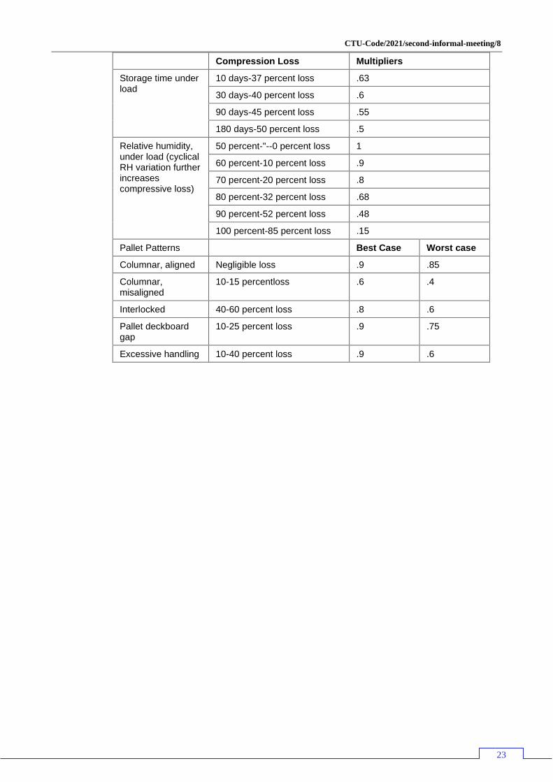
Style Description Diagram
Stacking Stacking means loading, packing or stowing packages in layers so that the edges of the packages lie flush above each other.
High load levels are produced when stowing cargoes in layers with intermediate layers made of squared lumber or wooden dunnage, since only linear bearing surfaces are produced in the area of the bottom and intermediate layers. Only cargoes insensitive to load forces may be stowed in this way. Harmful pressure can be reduced to an acceptable level by using relatively soft wood or by using intermediate layers made of rubber.
Cross-tie stow
In principle, this involves the cargo items interlocking with
each other. It can generally be used to minimize the effort
required for securing cargo. Methods like this improve the
stability of the cargo. This method may only be used with
resilient goods. Remaining gaps must be filled. Wooden
dunnage and similar intermediate layers should also be
used as anchors. The need to bridge or pad out stowage
gaps can result from a difference in the dimensions of
cargo items.
Complete transverse cross-tie
This refers to stowage in which goods fill the stowage
space in the package plan. Anchors do not need to be
inserted if equivalent measures are taken. If the transport
packaging is not sufficiently strong, the cargo items must
be stowed as a cross-tie, interconnected with anchors or
secured using other special measures. It should always be
considered that the speed of unloading can be increased
by selecting the right anchor materials. The use of
mechanical aids should be encouraged and not hindered
in any way. Some examples of a complete transverse
cross-tie have already been provided under the other
stowage methods.
Chimney style stow
Chimney-style stowage is extremely well suited for forming pre-slung cargo. With palletised packages, it is suitable for certain bag sizes. The packages are arranged layer by layer so that they overlap around a cavity. Thus, each is connected to each other. This produces a square or rectangular footprint, which is very suitable for packing containers if it has the correct dimensions.
Soldier stow
A stow where packages are stood in lines within the CTU on in the package. Often used for drums, but rectangular packages can also be stowed using this method
CTU-Code/2021/second-informal-meeting/8
25
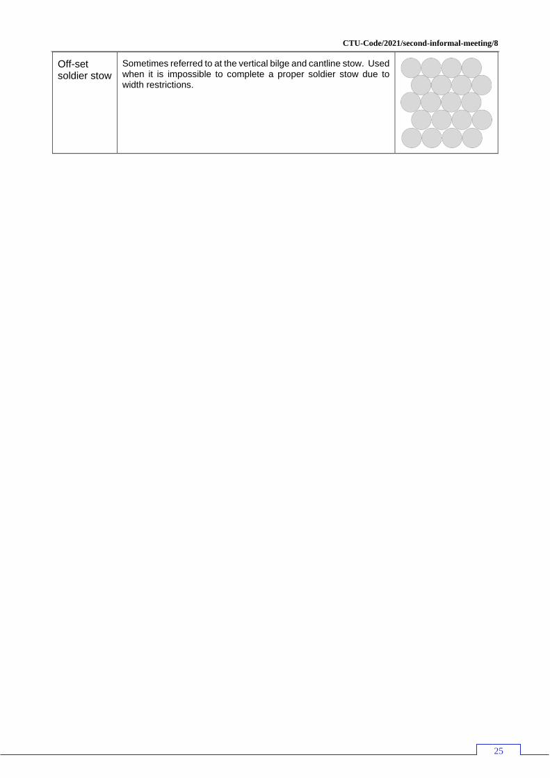
Off-set soldier stow
Sometimes referred to at the vertical bilge and cantline stow. Used when it is impossible to complete a proper soldier stow due to width restrictions.
CTU-Code/2021/second-informal-meeting/8
26
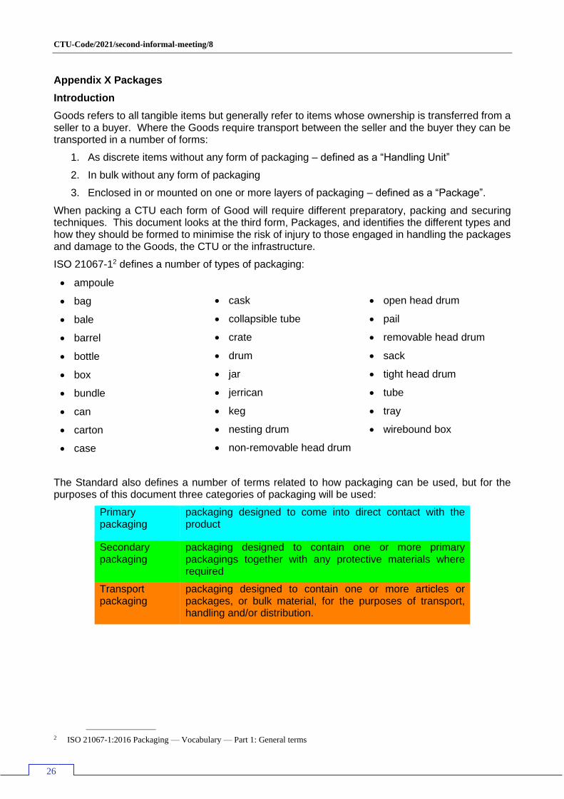
Appendix X Packages
Introduction
Goods refers to all tangible items but generally refer to items whose ownership is transferred from a seller to a buyer. Where the Goods require transport between the seller and the buyer they can be transported in a number of forms:
1. As discrete items without any form of packaging – defined as a “Handling Unit”
2. In bulk without any form of packaging
3. Enclosed in or mounted on one or more layers of packaging – defined as a “Package”.
When packing a CTU each form of Good will require different preparatory, packing and securing techniques. This document looks at the third form, Packages, and identifies the different types and how they should be formed to minimise the risk of injury to those engaged in handling the packages and damage to the Goods, the CTU or the infrastructure.
ISO 21067-12 defines a number of types of packaging:
• ampoule
• bag
• bale
• barrel
• bottle
• box
• bundle
• can
• carton
• case
• cask
• collapsible tube
• crate
• drum
• jar
• jerrican
• keg
• nesting drum
• non-removable head drum
• open head drum
• pail
• removable head drum
• sack
• tight head drum
• tube
• tray
• wirebound box
The Standard also defines a number of terms related to how packaging can be used, but for the purposes of this document three categories of packaging will be used:
Primary packaging
packaging designed to come into direct contact with the product
Secondary packaging
packaging designed to contain one or more primary packagings together with any protective materials where required
Transport packaging
packaging designed to contain one or more articles or packages, or bulk material, for the purposes of transport, handling and/or distribution.
2 ISO 21067-1:2016 Packaging — Vocabulary — Part 1: General terms
CTU-Code/2021/second-informal-meeting/8
27
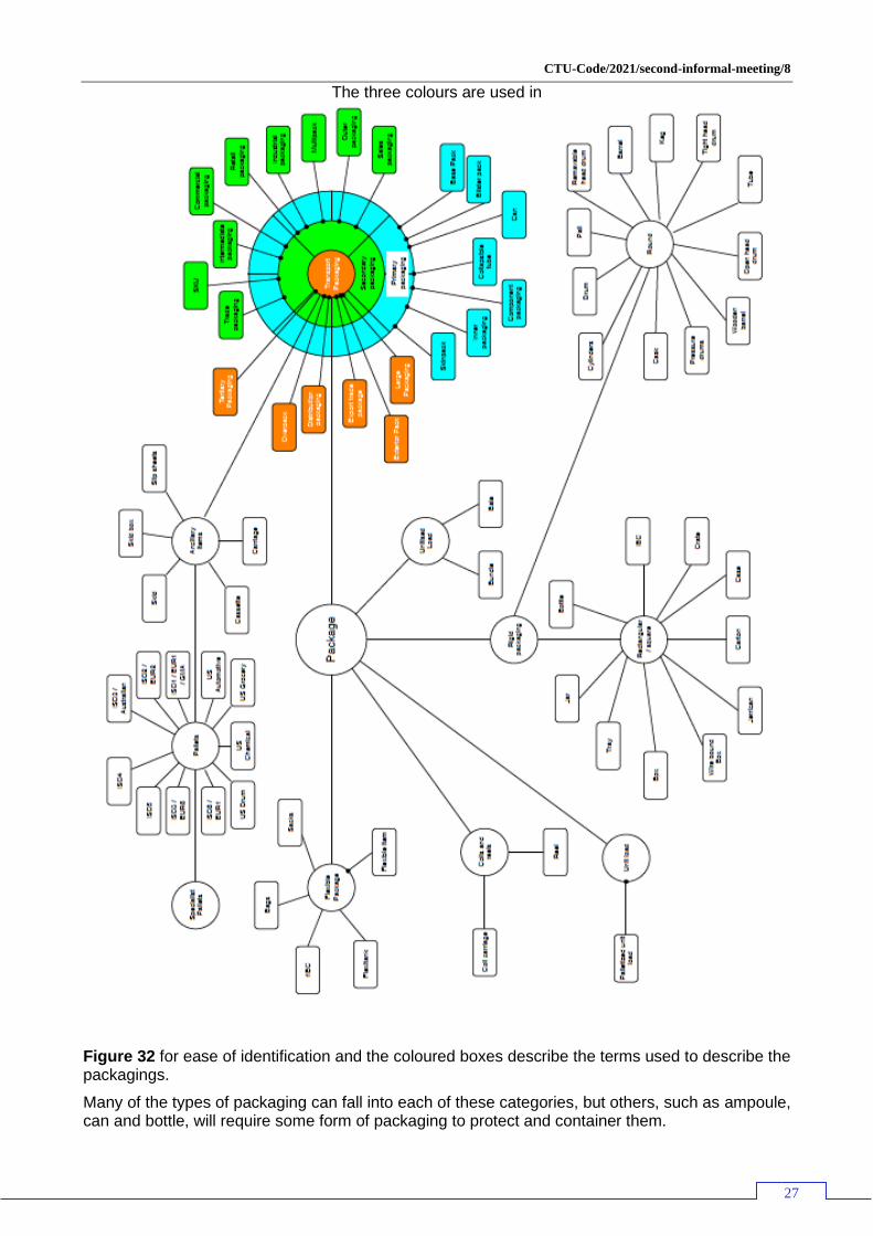
The three colours are used in
Figure 32 for ease of identification and the coloured boxes describe the terms used to describe the packagings.
Many of the types of packaging can fall into each of these categories, but others, such as ampoule, can and bottle, will require some form of packaging to protect and container them.
CTU-Code/2021/second-informal-meeting/8
28
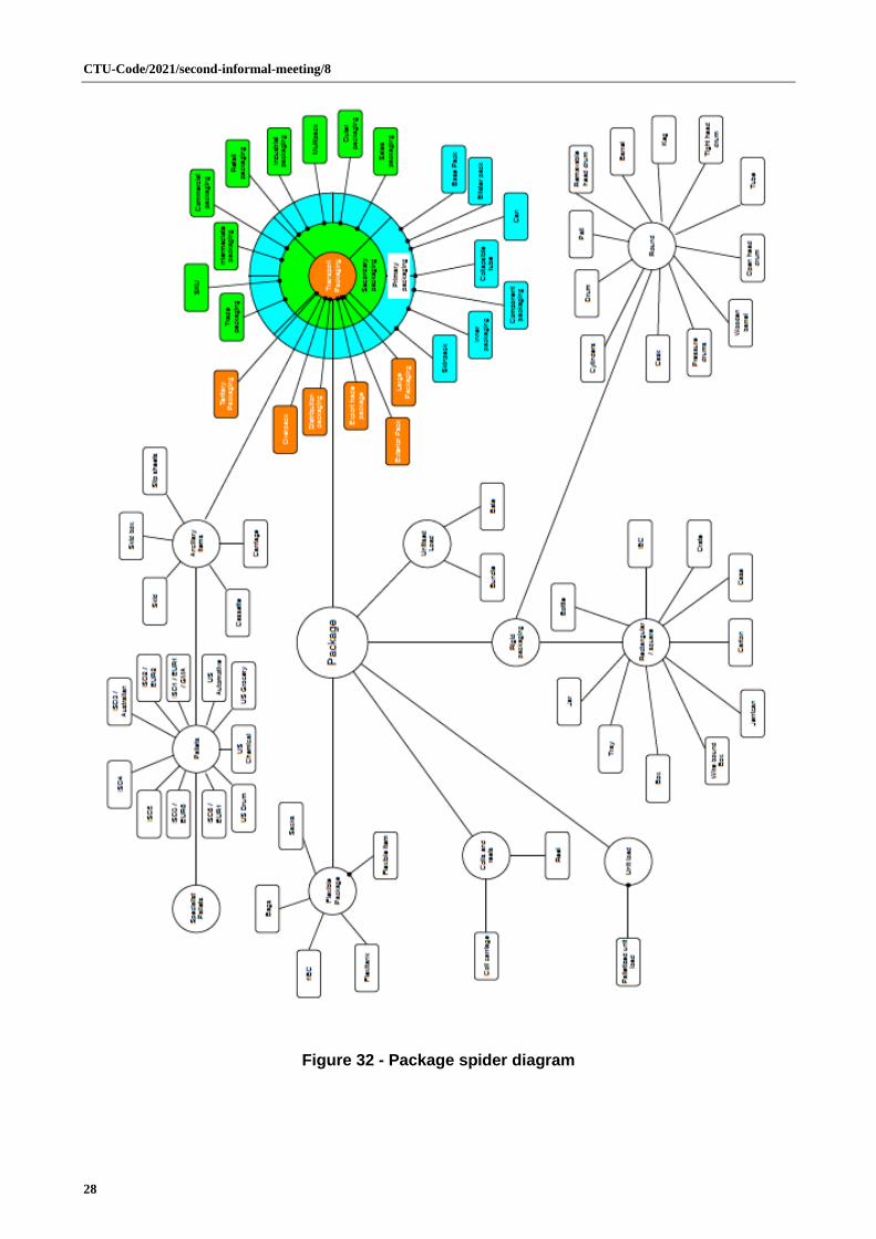
Figure 32 - Package spider diagram
CTU-Code/2021/second-informal-meeting/8
29
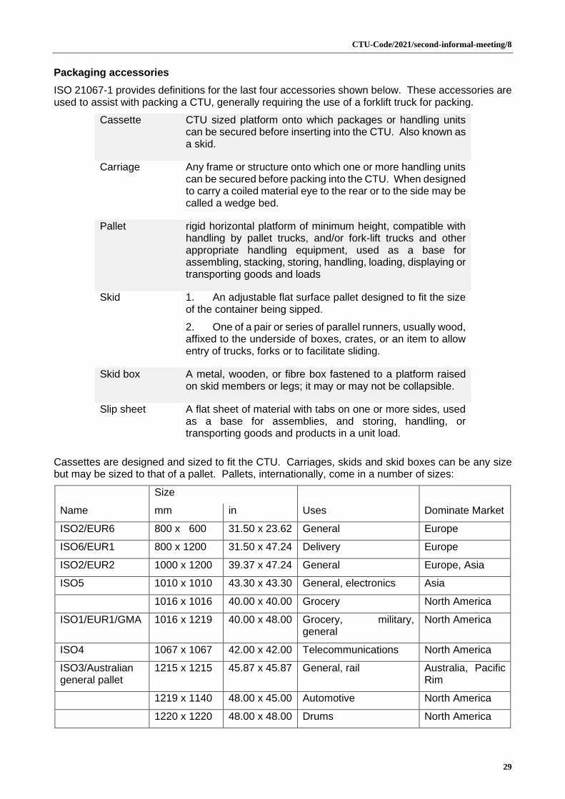
Packaging accessories
ISO 21067-1 provides definitions for the last four accessories shown below. These accessories are used to assist with packing a CTU, generally requiring the use of a forklift truck for packing.
Cassette CTU sized platform onto which packages or handling units can be secured before inserting into the CTU. Also known as a skid.
Carriage Any frame or structure onto which one or more handling units can be secured before packing into the CTU. When designed to carry a coiled material eye to the rear or to the side may be called a wedge bed.
Pallet rigid horizontal platform of minimum height, compatible with handling by pallet trucks, and/or fork-lift trucks and other appropriate handling equipment, used as a base for assembling, stacking, storing, handling, loading, displaying or transporting goods and loads
Skid 1. An adjustable flat surface pallet designed to fit the size of the container being sipped.
2. One of a pair or series of parallel runners, usually wood, affixed to the underside of boxes, crates, or an item to allow entry of trucks, forks or to facilitate sliding.
Skid box A metal, wooden, or fibre box fastened to a platform raised on skid members or legs; it may or may not be collapsible.
Slip sheet A flat sheet of material with tabs on one or more sides, used as a base for assemblies, and storing, handling, or transporting goods and products in a unit load.
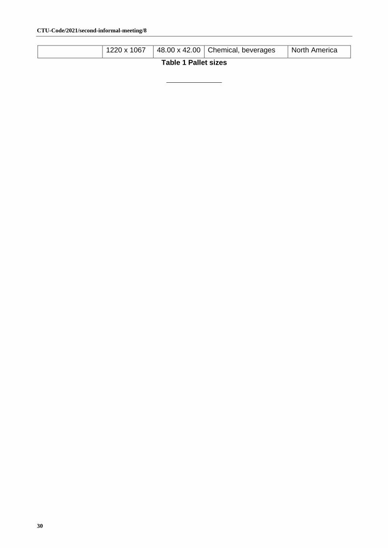
Cassettes are designed and sized to fit the CTU. Carriages, skids and skid boxes can be any size but may be sized to that of a pallet. Pallets, internationally, come in a number of sizes:
Size
Dominate Market Name mm in Uses
ISO2/EUR6 800 x 600 31.50 x 23.62 General Europe
ISO6/EUR1 800 x 1200 31.50 x 47.24 Delivery Europe
ISO2/EUR2 1000 x 1200 39.37 x 47.24 General Europe, Asia
ISO5 1010 x 1010 43.30 x 43.30 General, electronics Asia
1016 x 1016 40.00 x 40.00 Grocery North America
ISO1/EUR1/GMA 1016 x 1219 40.00 x 48.00 Grocery, military, general
North America
ISO4 1067 x 1067 42.00 x 42.00 Telecommunications North America
ISO3/Australian general pallet
1215 x 1215 45.87 x 45.87 General, rail Australia, Pacific Rim
1219 x 1140 48.00 x 45.00 Automotive North America
1220 x 1220 48.00 x 48.00 Drums North America
CTU-Code/2021/second-informal-meeting/8
30
1220 x 1067 48.00 x 42.00 Chemical, beverages North America
Table 1 Pallet sizes