Cross-Reference Tool WORKOVER and INTERVENTION ...
57
© IADC 2017 COPYRIGHT PROTECTED DOCUMENT All rights reserved. No part of this document may be distributed outside of the recipient’s organization unless authorized by the International Association of Drilling Contractors. Cross-Reference Tool WORKOVER and INTERVENTION WELL CONTROL Course for Oil and Gas Operator Representative INSTRUCTIONS: This Cross-Reference Tool is to be used to describe in detail the course for which IADC WellSharp® accreditation is requested. To expedite course review during the application review process, each applicant should provide as much detail as feasible when completing the Cross-Reference Tool for each course for which accreditation is requested. Use the following guidance for the information required. • Manual – In this column, report the page number(s) of the course manual that includes text pertaining to the Learning Topic. Include as many citations as needed to show all content pertaining to this topic. • Delivery Method – Record all delivery methods to be used to deliver content for this Learning Objective. List all that apply. Use the following abbreviations to document the most common options a training provider might utilize: D – Demonstration (Teaching through the use of a simulator, virtual simulation, or visual demonstration through video animation. Can also be a hands-on demonstration with equipment.) E – Any of the eLearning (electronic) methods of delivery H – Homework L – Lecture O – Other methods (for example, video) PE – Practical Exercise(s) S – Simulator • Instructor Resources – Record the name(s) of any video, eLearning or Self-Study product, or other resources available to the Instructor that will be used for delivering content for this Training Module. • Materials available to Trainees – List handouts, reference books, and other materials that will be given to trainees during delivery of this Training Module. • Total Time Range of Training – After entering information on all the required Training Modules, scroll to the bottom of the last page to enter the total time range (in hours and minutes) for delivery of all Training Modules. Include a minimum and maximum amount of time anticipated. *Note: When using the time ranges provided, be aware that your actual course length shall not fall below the minimum time requirement for the course (as stated in accreditation requirements). • Course Outline – Attach course outline that gives time allocations for each Learning Topic. (Record where and how each Learning Topic is to be addressed, i.e., classroom, simulator, live well.)
-
Upload
khangminh22 -
Category
Documents
-
view
6 -
download
0
Transcript of Cross-Reference Tool WORKOVER and INTERVENTION ...

© IADC 2017 COPYRIGHT PROTECTED DOCUMENT
All rights reserved. No part of this document may be distributed outside of the recipient’s organization unless authorized by the International Association of Drilling Contractors.
Cross-Reference Tool WORKOVER and INTERVENTION WELL CONTROL Course for Oil and Gas Operator Representative
INSTRUCTIONS: This Cross-Reference Tool is to be used to describe in detail the course for which IADC WellSharp® accreditation is requested. To expedite course review during the application review process, each applicant should provide as much detail as feasible when completing the Cross-Reference Tool for each course for which accreditation is requested. Use the following guidance for the information required.
• Manual – In this column, report the page number(s) of the course manual that includes text pertaining to the Learning Topic. Include as many citations as needed to show all content pertaining to this topic.
• Delivery Method – Record all delivery methods to be used to deliver content for this Learning Objective. List all that apply. Use the following abbreviations to document the most common options a training provider might utilize: D – Demonstration (Teaching through the use of a simulator, virtual simulation, or visual demonstration through video animation. Can also be a hands-on demonstration with equipment.) E – Any of the eLearning (electronic) methods of delivery H – Homework L – Lecture O – Other methods (for example, video) PE – Practical Exercise(s) S – Simulator
• Instructor Resources – Record the name(s) of any video, eLearning or Self-Study product, or other resources available to the Instructor that will be used for delivering content for this Training Module.
• Materials available to Trainees – List handouts, reference books, and other materials that will be given to trainees during delivery of this Training Module.
• Total Time Range of Training – After entering information on all the required Training Modules, scroll to the bottom of the last page to enter the total time range (in hours and minutes) for delivery of all Training Modules. Include a minimum and maximum amount of time anticipated. *Note: When using the time ranges provided, be aware that your actual course length shall not fall below the minimum time requirement for the course (as stated in accreditation requirements).
• Course Outline – Attach course outline that gives time allocations for each Learning Topic. (Record where and how each Learning Topic is to be addressed, i.e., classroom, simulator, live well.)

WSP-02-WS-OGO-X Page 2 of 57 Revision 0 Created: 27 September 2017
Proprietary / Confidential
© Copyright IADC 2017
Company Name: Accreditation #:
Course Name: Date Submitted:
2.1 Risk Awareness and Management
SUB-MODULES LEARNING TOPICS LEARNING OBJECTIVE AND ASSESSMENT GUIDELINES
MANUAL CHAPTER & PAGE # (Multi-line text field)
DELIVERY METHODS Options: D, E, H, L, O, PE, S (See instructions above; select all that
apply.)
Potential Impacts of a Well Control Event
Risks associated with completion and well intervention operations
Identify potential well control problems that could occur during completion and well intervention operations (e.g., stimulating a completion in a producing reservoir; reworking a producing reservoir to control water and/or gas production; rework to reduce or eliminate water coning; repair mechanical failure; cement repair).
D E H L O PE S
Well Integrity Well integrity management program
Define well integrity (using definition in ISO 16530-1) and explain the importance of maintaining well integrity to prevent well control incidents through the use of well barriers.
D E H L O PE S
Assess current status of the well (e.g., review well records and diagnostic tests to evaluate: well construction, gauge failure, surface failures, hydrate formation, bottomhole pressure, blockage in the well, nearby fracturing operations, perforation depth, type of production).
D E H L O PE S

WSP-02-WS-OGO-X Page 3 of 57 Revision 0 Created: 27 September 2017
Proprietary / Confidential
© Copyright IADC 2017
Explain the importance of assessing and recognizing communication between casing annuli.
D E H L O PE S
Pre-job Communication
Pre-job communications
Explain the importance of communicating operational plan details, risks, and responsibilities.
D E H L O PE S
Safety Margin Selection
Safety Margin Risks a. Safety margins
in Well Kill Operations
b. Dangers of using excess safety margins
c. Acceptable safety margins
d. Dangers of using minimal safety margins
Describe the criteria used to develop a safety margin.
D E H L O PE S
Explain the dangers of using excess safety margins during a well kill (e.g., if the margin is too high that may cause losses; adding a choke safety margin and a fluid weight safety margin adds extra pressure).
D E H L O PE S
Identify an acceptable safety margin from a set of given well and kill data.
D E H L O PE S
Explain the dangers of using minimal safety margins during a well kill (i.e., safety margins applied to tubular integrity, casing integrity, wellhead rating).
D E H L O PE S
Bridging Documents Purpose and Importance of Bridging Documents
Explain the purpose and importance of a well control bridging document (i.e., to assure all parties have the same information; to resolve well control issues between different parties; to handle specific issues in relation to a particular well/environment or legislative regime, how equipment and personnel would be organized, post shut-in, to recover or restart operations).
D E H L O PE S

WSP-02-WS-OGO-X Page 4 of 57 Revision 0 Created: 27 September 2017
Proprietary / Confidential
© Copyright IADC 2017
Pressure Control Equipment/Barrier Envelope Considerations
Equipment Requirements
Define Maximum Allowable Working Pressure (MAWP).
D E H L O PE S
Identify the working pressure of a system based on lowest working pressure component Rated Working Pressure, and Maximum Allowable Working Pressure (e.g., schematic or description).
D E H L O PE S
Discuss difference between Rated Working Pressure and Maximum Allowable Working Pressure and any surface pressure limitations for kill operations.
D E H L O PE S
Load Bearing Considerations
Identify wireline equipment that requires anchoring to withstand maximum expected forces during operations (e.g., wireline units, sheaves).
D E H L O PE S
Identify considerations when determining if a wellhead or tree bending stress analysis is required. (e.g., weight of stack, length of PCE rig-up, center of gravity of the stack and lubricator, age of well, and condition of well).
D E H L O PE S
Identify the size, type, and condition of the wellhead, tree, and connectors, such as studs, and nuts.
D E H L O PE S
Identify considerations when running unsupported length and size of lubricator or riser, and position of wireline valves in the PCE rig up.
D E H L O PE S

WSP-02-WS-OGO-X Page 5 of 57 Revision 0 Created: 27 September 2017
Proprietary / Confidential
© Copyright IADC 2017
Identify environmental factors that can influence well control operations/rig-up (e.g., sea state, wind speed, air temperature).
D E H L O PE S
Instructor Resources: (Types and titles of material used for teaching)
Materials available to Trainees: (Types and titles of materials provided to trainees)
2.2 Organizing a Well Control Operation
SUB-MODULES LEARNING TOPICS LEARNING OBJECTIVE AND ASSESSMENT GUIDELINES
MANUAL CHAPTER & PAGE # (Multi-line text field)
DELIVERY METHODS Options: D, E, H, L, O, PE, S (See instructions above; select all that
apply.)
Personnel Assignments
Roles and Responsibilities
Describe required personnel assignments during a well control operation (i.e., crew knowing their specific well control responsibilities related to detection, well shut-in, and control).
D E H L O PE S
Pre-Recorded Information
Pre-recorded information
Describe what type of pre-recorded information is required to allow planning for a well control event and where the supervisor should post and keep the information.
D E H L O PE S
Plan Responses to Anticipated Well Control Scenarios
Emergency Response Plan
Explain the importance of the emergency response plan for all well operations.
D E H L O PE S

WSP-02-WS-OGO-X Page 6 of 57 Revision 0 Created: 27 September 2017
Proprietary / Confidential
© Copyright IADC 2017
Instructor Resources: (Types and titles of material used for teaching)
Materials available to Trainees: (Types and titles of materials provided to trainees)
2.3 Well Control Principles & Calculations
SUB-MODULES LEARNING TOPICS LEARNING OBJECTIVE AND ASSESSMENT GUIDELINES
MANUAL CHAPTER & PAGE # (Multi-line text field)
DELIVERY METHODS Options: D, E, H, L, O, PE, S (See instructions above; select all that
apply.)
Pressure Fundamentals
Types of pressure a. Hydrostatic
pressure b. Applied Pressures
1. Surface pressure 2. Pump Pressure 3. ECDs (Equivalent Circulating Densities)
4. Trapped Pressure
5. Swab/surge c. Formation
pressure d. Differential
pressure e. Fracture pressure f. Bottomhole
pressure 1. Balanced 2. Underbalanced 3. Overbalanced
Define and calculate hydrostatic pressure.
D E H L O PE S
Explain and calculate the effects of fluid level change on hydrostatic pressure.
D E H L O PE S
Identify the different types of applied pressures.
D E H L O PE S
Explain shut-in pressures. D E H L O PE S
Explain equivalent circulating densities (ECD).
D E H L O PE S
Explain the effects of trapped pressure (e.g., above and below the packer or plug).
D E H L O PE S
Explain the differences between swab and surge.
D E H L O PE S
Calculate formation pressure (i.e., shut-in tubing pressure and fluid density in well).
D E H L O PE S

WSP-02-WS-OGO-X Page 7 of 57 Revision 0 Created: 27 September 2017
Proprietary / Confidential
© Copyright IADC 2017
Explain areas of differential pressure in the wellbore.
D E H L O PE S
Explain fracture pressure (for both the casing shoe and the reservoir in completed interval).
D E H L O PE S
Explain Bottomhole pressure (to include applied pressure).
D E H L O PE S
Explain the difference between overbalanced and underbalanced pressure.
D E H L O PE S
Explain and calculate equivalent fluid weight equal to formation pressure.
D E H L O PE S
Calculate gradient for different density of liquid and gases.
D E H L O PE S
Calculate well gradient from formation pressure and surface pressure.
D E H L O PE S
Calculate bottomhole pressure with at least one well bore with two different densities and surface pressure (e.g. different brine weights in the wellbore, fluid of a different density or gas allowed to flow into the wellbore from underbalanced perforating of after pulling barrier plug).
D E H L O PE S
Maximum Anticipated Surface Pressure (MASP)
Define and calculate MASP. D E H L O PE S
Forces from Applied Pressure
Calculate the effective force with a given pressure over a certain area.
D E H L O PE S
Calculate net force effects due to trapped pressure.
D E H L O PE S

WSP-02-WS-OGO-X Page 8 of 57 Revision 0 Created: 27 September 2017
Proprietary / Confidential
© Copyright IADC 2017
Equivalent circulating density a. Frictional pressure
loss effects on downhole pressure
b. Surface pressure effects
Explain circulating frictional pressure losses and effects on pressure and equivalent circulating density for forward and reverse circulation.
D E H L O PE S
Kill Mud Weight (Equivalent static fluid density) a. Pressures
expressed as an equivalent fluid weight
Explain kill mud weight (equivalent static fluid density).
D E H L O PE S
Calculate kill mud weight (equivalent static fluid density) with temperature effects.
D E H L O PE S
U-tube principles Explain the U-tube concept with examples.
D
(Must be taught through Demonstration)
Buoyancy a. Pipe light b. Pipe heavy c. Balance Point
Explain and calculate buoyancy effects to string weight.
D E H L O PE S
Calculate the balance point to transition from snubbing to stripping operations while going in hole.
D E H L O PE S
Describe forces that must be overcome to push/pull workstring into/out of a pressured well.
D E H L O PE S
Calculate strokes using given data. D E H L O PE S
Calculate displacement volumes using given data for both open-ended and close-ended pipe.
D E H L O PE S
Calculate annular volumes using given data.
D E H L O PE S

WSP-02-WS-OGO-X Page 9 of 57 Revision 0 Created: 27 September 2017
Proprietary / Confidential
© Copyright IADC 2017
Calculate usable volume of fluid in a pit/tank.
D E H L O PE S
Calculate the compressibility and flow-back volume. [Compressibility factor (psi-1) x Volume x Pressure (psi)]
D E H L O PE S
Pre-job calculations Calculate the snub force (tubing body and tubing collar/pipe upset).
D E H L O PE S
Pressure Calculation Exceeding MASP
Describe and discuss conditions where pressure calculations exceed MASP (e.g., perforating, fracturing, energized fluids).
D E H L O PE S
Principles Tubing Collapse and Casing Burst
Explain why applied casing pressure is needed (e.g., prevent packers from unseating, seal units from being pumped out of Polished Bore Receptacle (PBRs), basis point for monitoring, limit differential pressure, prevent failures).
D E H L O PE S
Explain why applied casing pressure can lead to tubing collapse or casing burst.
D E H L O PE S
Snubbing/Buckling Overcoming frictional forces
Explain the consequences of exceeding the tubing integrity due to frictional forces (i.e., buckling pipe, parting pipe, necking/ballooning).
D E H L O PE S
Identify factors that contribute to upward and downward forces (e.g., pumping into a closed system, pumping down a workstring).
D E H L O PE S
WSP-02-WS-OGO-X Page 10 of 57 Revision 0 Created: 27 September 2017
Proprietary / Confidential
© Copyright IADC 2017
Reduction of Tensile under Collapse Loading
Conditions causing collapse or parting of pipe
Recognize how tensile strength of the tubular is reduced when subjected to differential pressure (greater pressure outside the tubing than inside).
D E H L O PE S
Identify how to mitigate reduction in max pull due to collapse loading
D E H L O PE S
Given various pressure conditions and pipe dimensions, identify which could lead to parting.
D E H L O PE S
Describe how well pressure affects the pulling limit on the pipe.
D E H L O PE S
Reduction of Pipe Strength
Conditions causing twist-off of pipe
Describe how well pressure and string weight affects the torque limit on the pipe.
D E H L O PE S
Pre-recorded Well Information
Well configuration a. Top and bottom of
perforations b. Packer/Tool
locations c. Tubing
dimensions, lengths and strengths
Demonstrate how to document pre-recorded data significant to well control situations (e.g., perforation interval, packer locations, tubing strengths, safe working pressures, number of Electrical Submersible Pump (ESP), downhole pressure gauge cables, control lines, integrity issues with wellbore or tree).
D E H L O PE S
Given a well and equipment scenario, determine pump rates to circulate or kill the well.
D E H L O PE S
Demonstrate how to document the wellbore profile including depths, lengths, strengths, capacities, displacements, and safe working pressures.
D E H L O PE S
Maximum safe pressures Identify wellhead pressure rating. D E H L O
PE S

WSP-02-WS-OGO-X Page 11 of 57 Revision 0 Created: 27 September 2017
Proprietary / Confidential
© Copyright IADC 2017
a. Wellhead rating b. Coiled Tubing
String Properties c. Pumping system
Describe safe working pressures and pressure-fatigue cycles (e.g., tubing grade, external damage, internal pressure; provide data in a case study to determine if string is acceptable for use).
D E H L O PE S
Describe safe working pressure of the pumping system (i.e. pumps, lines, valves, hoses).
D E H L O PE S
Instructor Resources: (Types and titles of material used for teaching)
Materials available to Trainees: (Types and titles of materials provided to trainees)
2.4 Barriers
SUB-MODULES LEARNING TOPICS LEARNING OBJECTIVE AND ASSESSMENT GUIDELINES
MANUAL CHAPTER & PAGE # (Multi-line text field)
DELIVERY METHODS Options: D, E, H, L, O, PE, S (See
instructions above; select all that apply.)
Philosophy and Operation of Barrier Systems
Barriers and barrier envelope
Define the term “barrier” and “barrier envelope” (reference WellSharp Definitions document).
D E H L O PE S
List the requirements for a component to be considered a barrier (e.g., designed to withstand the maximum potential differential pressure, it is tested, verified, and maintained to prevent uncontrolled flow from the well).
D E H L O PE S
Describe how the pressure control equipment is part of the primary well barrier envelope (e.g., stuffing box, lubricator, wireline valve, pump-in sub).
D E H L O PE S

WSP-02-WS-OGO-X Page 12 of 57 Revision 0 Created: 27 September 2017
Proprietary / Confidential
© Copyright IADC 2017
Purpose of barriers during completions and well interventions
Explain how barriers are used to maintain well integrity for completions and well interventions.
D E H L O PE S
Barrier Hierarchy
Explain action to take upon detection of a failed primary barrier element(s) and how it affects the failure of the primary envelope.
D E H L O PE S
Explain action to take upon detection of a failed secondary barrier element(s) (i.e., reference Emergency Response Plan).
D E H L O PE S
Levels of Barriers
Primary and Secondary Barriers a. Completions /
Workover b. Well Servicing
Explain what primary and secondary barriers are:
a. For completion / workovers, the fluid is the “Primary well control barrier” and the BOP is the “secondary well control barrier”.
b. For well servicing the primary well barrier envelope consists of the pressure control equipment (PCE) such as the wireline valve, lubricator, stuffing box. The secondary “well control barrier” consist of the Well Control Stack or wireline valve closure.
D E H L O PE S

WSP-02-WS-OGO-X Page 13 of 57 Revision 0 Created: 27 September 2017
Proprietary / Confidential
© Copyright IADC 2017
Minimum number of barriers required for safe operations
Explain why a minimum number of barriers are required for safe operations. (Refer to industry recommendations for minimum number of barriers to be in place for specific operations) (e.g., reference ISO 16530-1).
D E H L O PE S
Types of Barriers
Mechanical barriers
Define and provide examples of mechanical barrier.
D E H L O PE S
Explain the validation needed to be a mechanical barrier.
D E H L O PE S
Fluid barriers
Explain what is required for a fluid to be considered a barrier (i.e., continuously observe the height and the ability to add fluid).
D E H L O PE S
Explain the limitations of fluid barriers (e.g., it is only a barrier for a certain period of time after circulation stops).
D E H L O PE S
Barrier Management Testing mechanical barriers
Explain positive pressure and negative/inflow pressure barrier tests (e.g., increase differential pressure across a barrier in either direction).
D E H L O PE S
Explain the risks associated with negative pressure tests and trapped pressures when testing small volumes (e.g., wellhead voids, lockdown screws, potential for ejection).
D E H L O PE S

WSP-02-WS-OGO-X Page 14 of 57 Revision 0 Created: 27 September 2017
Proprietary / Confidential
© Copyright IADC 2017
Identify the reference sources for mechanical barrier test criteria (e.g., the well program, operations manuals, industry standards, technical specifications from equipment manufacturers, integrity testing, and regulatory agency).
D E H L O PE S
Explain the importance of documenting mechanical barrier testing.
D E H L O PE S
Explain the importance of the test pressure and time period to validate mechanical barrier (e.g., to ensure compressibility and temperature effects are taken into account).
D E H L O PE S
Explain the action to take if there is a test failure of a mechanical well barrier/element (i.e., retest, reinstall, or install additional barrier).
D E H L O PE S
Validating fluid barriers
Explain the importance of monitoring the fluid volume at surface (e.g., open top tanks).
D E H L O PE S
Identify the reference sources for fluid barrier test criteria (e.g., the well program, industry standards, and technical specifications from company manufacturers).
D E H L O PE S
Explain the importance of fluid density measurements as it applies to well control.
D E H L O PE S
Identify conditions that would lead to settling of solids in the fluid.
D E H L O PE S

WSP-02-WS-OGO-X Page 15 of 57 Revision 0 Created: 27 September 2017
Proprietary / Confidential
© Copyright IADC 2017
Explain the action to take if there is a failure of a fluid barrier or a failure of the fluid meeting the acceptance criteria to be considered a barrier. (e.g., shut-in well, change out fluid, install mechanical barrier).
D E H L O PE S
Detecting a failed barrier
Explain how a failed barrier can be detected (e.g., from the flow from the well; through losses to the well; an increase in surface pressure when shut in).
D E H L O PE S
Instructor Resources: (Types and titles of material used for teaching)
Materials available to Trainees: (Types and titles of materials provided to trainees)
2.5 Coiled Tubing Pressure Control Equipment
SUB-MODULES LEARNING TOPICS LEARNING OBJECTIVE AND ASSESSMENT GUIDELINES
MANUAL CHAPTER & PAGE # (Multi-line text field)
DELIVERY METHODS Options: D, E, H, L, O, PE, S (See instructions above; select all that
apply.)
Primary PCE Stripper
Explain the purpose of the stripper as an external primary PCE.
D E H L O PE S
Describe the advantage and use of rigging-up two strippers.
D E H L O PE S
Describe the factors that impact wear rate of the stripper element and how to shut-in the well when it fails.
D E H L O PE S

WSP-02-WS-OGO-X Page 16 of 57 Revision 0 Created: 27 September 2017
Proprietary / Confidential
© Copyright IADC 2017
Identify and describe fluid compatibility and temperature limitations with the common elastomer used in strippers.
D E H L O PE S
Flow Check Assembly in Bottom Hole Assembly (BHA)
Explain the purpose of the flow check assembly in BHA as an internal primary PCE.
D E H L O PE S
Explain when a flow check assembly may not be used (e.g., during reverse circulating or concentric coiled tubing).
D E H L O PE S
Identify and describe the function of different types of flow check assemblies in the BHA (e.g., flapper valve, dart valve).
D E H L O PE S
Explain the limitations of testing the flow check assembly in the BHA (e.g., only test one flapper).
D E H L O PE S
Lubricator/Spool (between the Well Control Stack and Stripper)
Describe the function and potential risks of lubricator/spool in the barrier envelope (e.g. use of quick unions instead of flanged connection; damage to quick union seals and potential to loosen during movement).
D E H L O PE S
Explain the need for sufficient length between stripper and the lower most barrier(s) to accommodate the maximum length of BHA.
D E H L O PE S
Secondary PCE Quad Well Control Stack
Explain how the Quad Well Control Stack acts as a secondary PCE.
D E H L O PE S

WSP-02-WS-OGO-X Page 17 of 57 Revision 0 Created: 27 September 2017
Proprietary / Confidential
© Copyright IADC 2017
Explain the use and limitations of coiled tubing Well Control Stack when used as a PCE. (i.e., quad type; dual combi-type, shear/seal, triple combi rams).
D E H L O PE S
Fluid inlet/outlet a. Flow tee with
isolation valves b. Flow cross with
isolation valves c. Kill line with
isolation and check valves
Identify and describe the function and location of the flow tee/flow cross in a typical Well Control Stack.
D E H L O PE S
Describe valve configuration on flow tee or flow cross needed to meet API standards (i.e., RP16ST; API 53ST 6.2).
D E H L O PE S
Identify the location of kill line inlet and valve configuration on a Coiled Tubing Well Control Stack as recommended in API standards (i.e., RP16ST; API 53ST 6.2).
D E H L O PE S
Additional Blind Shear Ram
Explain when to use the additional blind shear ram.
D E H L O PE S
Explain the implication of using an additional blind shear ram (e.g., additional closing volume, additional pressure remaining to shear, proof testing of shear ram, test frequency).
D E H L O PE S
Christmas tree
Explain the use and limitations of the tree when coiled tubing is not in the well and a release occurs (i.e. personnel approaching gas cloud is not recommended).
D E H L O PE S
Instructor Resources: (Types and titles of material used for teaching)
Materials available to Trainees: (Types and titles of materials provided to trainees)

WSP-02-WS-OGO-X Page 18 of 57 Revision 0 Created: 27 September 2017
Proprietary / Confidential
© Copyright IADC 2017
2.6 Wireline Pressure Control Equipment
SUB-MODULES LEARNING TOPICS LEARNING OBJECTIVE AND ASSESSMENT GUIDELINES
MANUAL CHAPTER & PAGE # (Multi-line text field)
DELIVERY METHODS Options: D, E, H, L, O, PE, S (See instructions above; select all that
apply.)
Control Heads (Primary PCE)
Line Wiper Identify and describe general functions of line wiper and its use.
D E H L O PE S
Stuffing Box/Pack off a. Manual b. Hydraulic
Identify and describe general functions of stuffing boxes and their use.
D E H L O PE S
Determine if a stuffing box would seal if the wire were not present (ball check present, yes/no).
D E H L O PE S
Describe how to regain a seal on the wire following a leak.
D E H L O PE S
Discuss applied forces associated with the use of stuffing boxes.
D E H L O PE S
Describe operational limits of stuffing box/pack-off (i.e., line speed, cable size, and pressure rating).
D E H L O PE S
Identify potential well control risks when using stuffing boxes.
D E H L O PE S
Grease Injection
Identify and describe general functions of grease injection and its use.
D E H L O PE S
Describe how to regain the seal on the wire once the seal has been lost.
D E H L O PE S
Describe operational limits of grease injection in relation to the assembly.
D E H L O PE S
WSP-02-WS-OGO-X Page 19 of 57 Revision 0 Created: 27 September 2017
Proprietary / Confidential
© Copyright IADC 2017
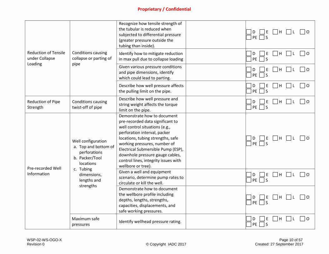
Identify potential well control risks when using grease injection.
D E H L O PE S
Discuss the relationship of flow tubes as it relates to fluid and pressure requirements (e.g., need to season braided line).
D E H L O PE S
Describe the effects of hose length, grease viscosity, hose ID and ambient temperature.
D E H L O PE S
Lubricator (Primary PCE)
Lubricator
Identify potential well control risks when using lubricator (e.g., use of quick unions, seal damage, and potential to back-off during operations).
D E H L O PE S
Quick test sub
Identify and describe general functions of quick test sub and its use.
D E H L O PE S
Identify potential well control risks when using quick test sub.
D E H L O PE S
Wireline Valves (Secondary PCE)
Wireline Valves (Conductor/Braided line rams) a. Line rams b. Shear seal rams
Identify and describe the function of conductor/braided line rams in wireline valves.
D E H L O PE S
Identify and describe the function of shear seal rams in wireline valves when using conductor/braided line rams.
D E H L O PE S
Describe the configuration of the wireline valves when using conductor/braided line rams, including inverted rams.
D E H L O PE S
Describe operational limits such as maximum shear capacity and ability to seal the wellbore.
D E H L O PE S
Identify potential well control risks when using conductor/braided line rams in wireline valves.
D E H L O PE S

WSP-02-WS-OGO-X Page 20 of 57 Revision 0 Created: 27 September 2017
Proprietary / Confidential
© Copyright IADC 2017
Wireline Valves (Slick line) a. Line rams b. Shear seal rams
Identify and describe the function of slick line rams in wireline valves.
D E H L O PE S
Identify and describe the function of shear seal rams in wireline valves when using slick line.
D E H L O PE S
Describe the configuration of the wireline valves when using slick line (e.g., stripping wire through wireline valves).
D E H L O PE S
Describe operational limits such as maximum shear capacity.
D E H L O PE S
Identify potential well control risks when using slick line in wireline valves.
D E H L O PE S
Additional PCE
Pump-in Sub
Describe the configuration of the wireline valves when using pump-in sub and when it can be eliminated from the rig up.
D E H L O PE S
Lubricator Extension (Riser)
Identify potential well control risks when using lubricator extension (riser).
D E H L O PE S
Wireline Shear Seal
Describe the purpose and placement of a wireline shear seal.
D E H L O PE S
Discuss using a tree valve to cut wireline and the qualifications required to maintain valve as barrier.
D E H L O PE S
Identify potential well control risks when using a wireline shear seal.
D E H L O PE S
Instructor Resources: (Types and titles of material used for teaching)
Materials available to Trainees: (Types and titles of materials provided to trainees)

WSP-02-WS-OGO-X Page 21 of 57 Revision 0 Created: 27 September 2017
Proprietary / Confidential
© Copyright IADC 2017
2.7 Snubbing Pressure Control Equipment
SUB-MODULES LEARNING TOPICS LEARNING OBJECTIVE AND ASSESSMENT GUIDELINES
MANUAL CHAPTER & PAGE # (Multi-line text field)
DELIVERY METHODS Options: D, E, H, L, O, PE, S (See instructions above; select all that
apply.)
Snubbing Barriers Barriers
Identify internal (inside the tubulars) barriers (i.e., back pressure valve).
D E H L O PE S
Identify external (annulus) barriers (i.e., stripping rams, annular).
D E H L O PE S
Explain how to maintain barrier(s) when changing a sealing element during intervention and give examples of barriers used.
D E H L O PE S
Stripper Assemblies Sealing elements
Identify different types of sealing elements (e.g., stripping annular, ram type).
D E H L O PE S
Identify critical seals that have the potential to fail through wear and explain why they need to be replaced.
D E H L O PE S
Snubbing Pressure Control Equipment
Additional Rams
Describe major components and operating principles of PCE closing and locking mechanisms.
D E H L O PE S
Describe equipment limitations. D E H L O PE S
Identify flow path(s) used in well control operations.
D E H L O PE S
Identify locations for choke and kill line valves.
D E H L O PE S
Stripping rams Describe operating principles and limitations of stripping rams.
D E H L O PE S

WSP-02-WS-OGO-X Page 22 of 57 Revision 0 Created: 27 September 2017
Proprietary / Confidential
© Copyright IADC 2017
Describe closing and operating sequences to strip and/or snub pipe into the well.
D
(Must be taught through Demonstration)
Describe components that may be well pressure assisted to affect a seal on closure.
D E H L O PE S
Equalizing Loop and Bleed-off Line
Explain what equalizing loops and bleed-off lines are.
D E H L O PE S
Explain the purpose of using the equalizing loop and bleed-off line.
D E H L O PE S
Explain the flow path for bleeding off well fluids and gasses, considering area classifications.
D E H L O PE S
Instructor Resources: (Types and titles of material used for teaching)
Materials available to Trainees: (Types and titles of materials provided to trainees)
WSP-02-WS-OGO-X Page 23 of 57 Revision 0 Created: 27 September 2017
Proprietary / Confidential
© Copyright IADC 2017
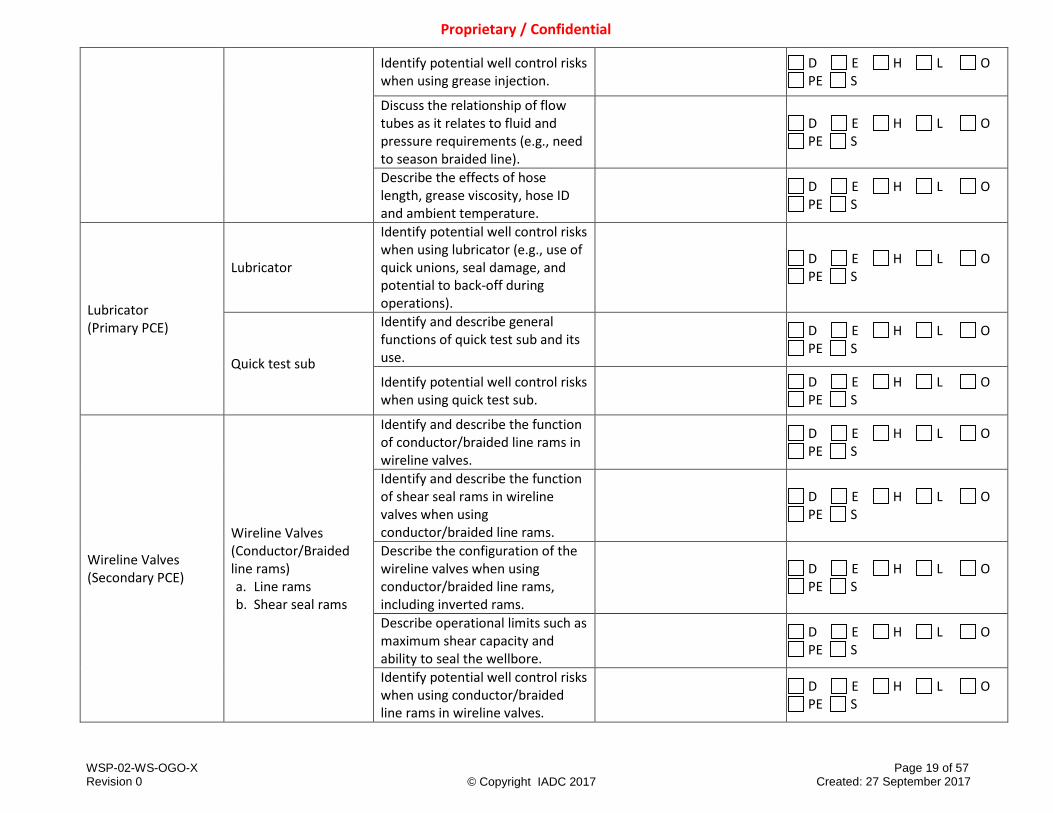
2.8 Influx Fundamentals
SUB-MODULES LEARNING TOPICS LEARNING OBJECTIVE AND ASSESSMENT GUIDELINES
MANUAL CHAPTER & PAGE # (Multi-line text field)
DELIVERY METHODS Options: D, E, H, L, O, PE, S (See instructions above; select all that
apply.)
Influx Detection Possible/Positive Indicators of an Unplanned Influx
Identify possible indicators of an influx
• Decrease in pump pressure/increase in pump rate
• Volume displacement changes during pipe movement
• Change in surface pressures
• Changes in string weight • Oil or gas shows during
circulation • Changes in fluid density
D E H L O PE S
Identify positive indicators of an influx (e.g. pit gain, increase return flow, flow with pumps off).
D E H L O PE S
Identify how to respond to a possible/positive influx indicator (e.g., flow check/shut-in procedure).
D E H L O PE S
Identify or describe potential consequences of improper or untimely response to influx indicators (e.g., extreme changes in operating pressures, possible release of gas, pollution, potential for fire, loss of life, equipment resources).
D E H L O PE S

WSP-02-WS-OGO-X Page 24 of 57 Revision 0 Created: 27 September 2017
Proprietary / Confidential
© Copyright IADC 2017
Instructor Resources: (Types and titles of material used for teaching)
Materials available to Trainees: (Types and titles of materials provided to trainees)
2.9 Gas Characteristics and Behavior
SUB-MODULES LEARNING TOPICS LEARNING OBJECTIVE AND ASSESSMENT GUIDELINES
MANUAL CHAPTER & PAGE # (Multi-line text field)
DELIVERY METHODS Options: D, E, H, L, O, PE, S (See instructions above; select all that
apply.)
Pressure and Volume Relationship (Boyles Law)
Relationship between pressure and volume of a gas in the wellbore
Explain the relationship between gas pressure and gas volume (e.g., the Boyle’s Law concept to explain the pressure/volume relationship with most expansion close to surface).
D E H L O PE S
Calculate new volume or pressure from original volume or pressure change using Boyle’s Law.
D E H L O PE S
Instructor Resources: (Types and titles of material used for teaching)
Materials available to Trainees: (Types and titles of materials provided to trainees)

WSP-02-WS-OGO-X Page 25 of 57 Revision 0 Created: 27 September 2017
Proprietary / Confidential
© Copyright IADC 2017
2.10 Completion and Workover Fluids
SUB-MODULES LEARNING TOPICS LEARNING OBJECTIVE AND ASSESSMENT GUIDELINES
MANUAL CHAPTER & PAGE # (Multi-line text field)
DELIVERY METHODS Options: D, E, H, L, O, PE, S (See instructions above; select all that
apply.)
Workover / Completion Fluid Functions
Fluid loss
Explain why fluid loss control is difficult to achieve when using workover/completion fluids.
D E H L O PE S
Explain the types and methods used in fluid loss control (e.g., pills, multiple fluids, plugs).
D E H L O PE S
Liquids
Brine requirements Explain why a different brine combination may be needed based on density requirements.
D E H L O PE S
Applied stimulation and treatment fluids
Describe how stimulation and treatment fluids affect the dynamics of the well operations (e.g., acids, gel pills, CO2, Steam, and Nitrogen).
D E H L O PE S
Fluid Properties Fluid Properties
Explain compressibility of various fluids (e.g., water based, non-aqueous based).
D E H L O PE S
Explain the importance of compressibility and the effects on pressure and volume calculations.
D E H L O PE S
Define the freezing point of brine and describe how it is related to crystallization.
D E H L O PE S
Describe brine saturation and how it relates to crystallization, maximum fluid weight, and the freezing point.
D E H L O PE S
Explain the temperature effect on the density of the brine.
D E H L O PE S

WSP-02-WS-OGO-X Page 26 of 57 Revision 0 Created: 27 September 2017
Proprietary / Confidential
© Copyright IADC 2017
Explain the importance of fluid density measurements as it applies to well design.
D E H L O PE S
Identify conditions that would lead to settling of solids in the fluid.
D E H L O PE S
Frictional pressure losses
Describe frictional pressure loss changes due to downhole restrictions and other fluid properties, fluid type, flow rate, downhole tools, and viscosity (e.g., crude oil, base oil, diesel, water, brine, gelled fluids).
D E H L O PE S
Fluid Flow Behavior
Fluid flowpath geometry (wellbore/coiled tubing or workstring)
Describe frictional pressure loss changes due to well geometry and restrictions.
D E H L O PE S
Instructor Resources: (Types and titles of material used for teaching)
Materials available to Trainees: (Types and titles of materials provided to trainees)
2.11 General Overview of Surface and Subsurface Wellbore Equipment
SUB-MODULES LEARNING TOPICS LEARNING OBJECTIVE AND ASSESSMENT GUIDELINES
MANUAL CHAPTER & PAGE # (Multi-line text field)
DELIVERY METHODS Options: D, E, H, L, O, PE, S (See instructions above; select all that
apply.)
Blowout Preventer Stacks and Components
Preventer Equipment Explain the importance of recording closing time test for rams and annular.
D E H L O PE S
OEM Replacement Parts
Explain the importance of using originally manufactured components.
D E H L O PE S

WSP-02-WS-OGO-X Page 27 of 57 Revision 0 Created: 27 September 2017
Proprietary / Confidential
© Copyright IADC 2017
Shear or Cutter rams
Explain the functionality and limitations of shear rams.
D E H L O PE S
Identify non-shearables and non-sealables (e.g., production packer, gravel pack screen-in liners, cast iron retainers, bridge plugs, control lines, cables).
D E H L O PE S
Blind/Shear rams
Explain the functionality and limitations of blind rams.
D E H L O PE S
Identify non-shearables and non-sealables (e.g., production packer, gravel pack screen-in liners, cast iron retainers, bridge plugs).
D E H L O PE S
Barrier Elements a. Annular Type
Blowout Preventer (BOP)
b. Ram Type BOP 1) Strippers (see
sub-module lubricator / stripper assemblies for more learning objectives)
2) Pipe/Multiple string
3) Blind 4) Blind/Shear 5) Shear 6) Slip 7) Variable bore
c. Valves
List barrier elements of the Well Control Stack used in snubbing operations.
D E H L O PE S
Explain advantages and disadvantages of each type of equipment used in snubbing operations as a barrier element.
D E H L O PE S
Identify criteria used in the selection of the barrier element for different operating environments (e.g., pressure, safety margins, operational objectives of the job, operating limits of the elements).
D E H L O PE S
Explain what must be done in order for a barrier element to become part of the barrier envelope (e.g., tested, configured, and applied as designed).
D E H L O PE S
Operating Environment
Describe the major components and operating principles of BOP closing and locking mechanisms
D E H L O PE S

WSP-02-WS-OGO-X Page 28 of 57 Revision 0 Created: 27 September 2017
Proprietary / Confidential
© Copyright IADC 2017
Verify operating limits of BOP equipment (e.g., pressure and space out limits).
D E H L O PE S
Accumulators Usable fluid volume/Drawdown test
Identify reasons and procedures for a drawdown test.
D E H L O PE S
Identify drawdown test frequency as per API standards (i.e., API 53 and 16ST (Coiled Tubing)).
D E H L O PE S
Calculate the usable fluid volume for a given BOP stack.
D E H L O PE S
Describe the accumulator system functions.
D E H L O PE S
Explain pre-charge pressure relative to usable fluid volume.
D E H L O PE S
Explain minimum system pressure relative to usable fluid volume.
D E H L O PE S
Explain normal regulated operating pressure relative to usable fluid volume.
D E H L O PE S
Explain maximum system pressure relative to usable fluid volume/drawdown test.
D E H L O PE S
Explain closing time requirements for various Well Control equipment (e.g., surface workover stack rams, coiled tubing stack rams, wireline valves, subbing stripping rams, choke and kill line valves, hose length, hose ID, control fluid viscosity, and ambient temperature).
D E H L O PE S
WSP-02-WS-OGO-X Page 29 of 57 Revision 0 Created: 27 September 2017
Proprietary / Confidential
© Copyright IADC 2017
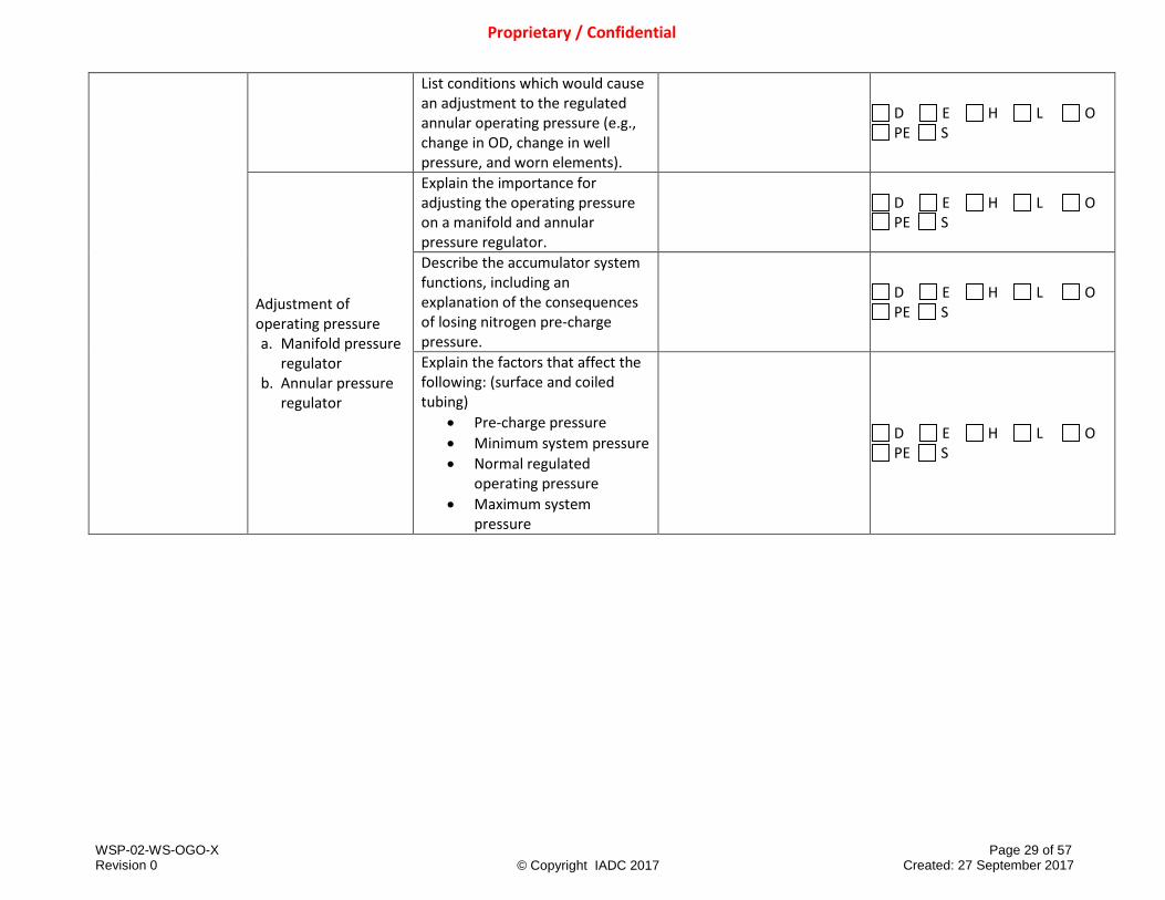
List conditions which would cause an adjustment to the regulated annular operating pressure (e.g., change in OD, change in well pressure, and worn elements).
D E H L O PE S
Adjustment of operating pressure a. Manifold pressure
regulator b. Annular pressure
regulator
Explain the importance for adjusting the operating pressure on a manifold and annular pressure regulator.
D E H L O PE S
Describe the accumulator system functions, including an explanation of the consequences of losing nitrogen pre-charge pressure.
D E H L O PE S
Explain the factors that affect the following: (surface and coiled tubing)
• Pre-charge pressure • Minimum system pressure • Normal regulated
operating pressure • Maximum system
pressure
D E H L O PE S

WSP-02-WS-OGO-X Page 30 of 57 Revision 0 Created: 27 September 2017
Proprietary / Confidential
© Copyright IADC 2017
Operating functions of main and remote well control panels
Explain the functions of main and remote well control panels and the consequences of losing air or power to the remote BOP control panel (e.g., well control panels used to hold open tree actuated valves and subsurface safety valves; Alternatives to Well Control panel – a) Fusible caps for tree actuated valve, b) trapping pressure on the downhole safety valve hydraulic control line to hold open; when to consider using one method over the other; design considerations including hose size, accumulator size, power fluid viscosity for cold environments).
D E H L O PE S
Power packs a. Pressure control
unit
Identify and describe pressure control unit power pack functions and configuration.
D E H L O PE S
Workstring and Production Tubing
Tubing Failures
List three causes that can effect tubing ratings and result in failures (e.g., erosion, corrosion, thread galling).
D E H L O PE S
Explain how tubing movement during testing and stimulation could result in tubing failures.
D E H L O PE S
Identify ways to reduce tubing movement during testing and stimulation.
D E H L O PE S
Polished Bore Receptacle (PBR)
Explain the function of the PBR and seal unit.
D E H L O PE S
Surface Controlled Sub-Surface Safety Valve (SCSSV)
Explain how a failure of a Surface controlled sub-surface safety valve (SCSSV) can result in a well control incident.
D E H L O PE S

WSP-02-WS-OGO-X Page 31 of 57 Revision 0 Created: 27 September 2017
Proprietary / Confidential
© Copyright IADC 2017
Explain how a failure of the lock-out device in a surface controlled Sub-Surface Safety Valve (SCSSV) can result in a well control incident. (i.e., address open flow path through the control line)
D E H L O PE S
Sliding Sleeve Explain the use of sliding sleeves during well control or circulation operations.
D E H L O PE S
Gas lift mandrels and valves
Describe the primary function of side pocket mandrels, either with a working valve (e.g., gas lift, circulation, and chemical injection) or with a dummy valve installed, as it relates to well control.
D E H L O PE S
Auxiliary Well Control Equipment
Floats/downhole check valves
Explain the necessity of redundancy regarding internal application of floats/downhole check valves to prevent flow up the string (i.e., when or why redundant valves are necessary in coiled tubing and snubbing).
D E H L O PE S
Plugs
Type of Plug
Explain the importance of different types of plugs and the direction they hold pressure (reference API Spec 11D1 and API Spec 14L).
D E H L O PE S
Service Ratings
Explain the effect of sweet or sour wellbore conditions on performance of plug and elastomers.
D E H L O PE S
Explain where to locate the pressure differential rating of the plug to ensure proper plug selection (e.g., manufactures specifications, well program).
D E H L O PE S
WSP-02-WS-OGO-X Page 32 of 57 Revision 0 Created: 27 September 2017
Proprietary / Confidential
© Copyright IADC 2017
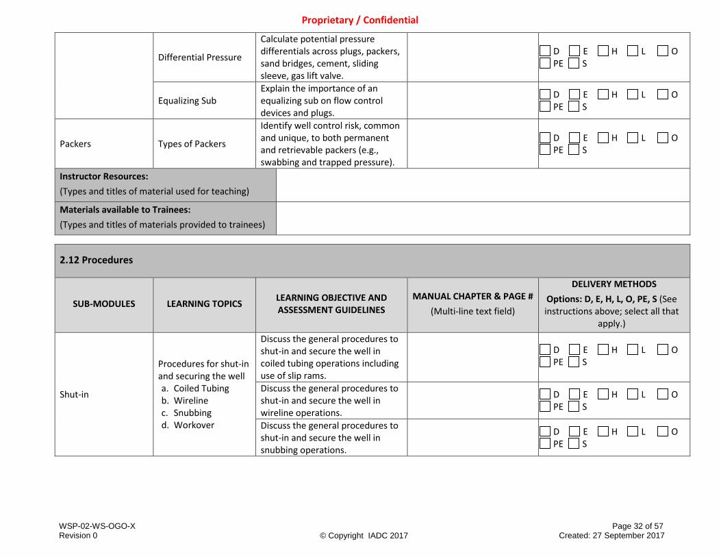
Differential Pressure
Calculate potential pressure differentials across plugs, packers, sand bridges, cement, sliding sleeve, gas lift valve.
D E H L O PE S
Equalizing Sub Explain the importance of an equalizing sub on flow control devices and plugs.
D E H L O PE S
Packers Types of Packers
Identify well control risk, common and unique, to both permanent and retrievable packers (e.g., swabbing and trapped pressure).
D E H L O PE S
Instructor Resources: (Types and titles of material used for teaching)
Materials available to Trainees: (Types and titles of materials provided to trainees)
2.12 Procedures
SUB-MODULES LEARNING TOPICS LEARNING OBJECTIVE AND ASSESSMENT GUIDELINES
MANUAL CHAPTER & PAGE # (Multi-line text field)
DELIVERY METHODS Options: D, E, H, L, O, PE, S (See instructions above; select all that
apply.)
Shut-in
Procedures for shut-in and securing the well a. Coiled Tubing b. Wireline c. Snubbing d. Workover
Discuss the general procedures to shut-in and secure the well in coiled tubing operations including use of slip rams.
D E H L O PE S
Discuss the general procedures to shut-in and secure the well in wireline operations.
D E H L O PE S
Discuss the general procedures to shut-in and secure the well in snubbing operations.
D E H L O PE S

WSP-02-WS-OGO-X Page 33 of 57 Revision 0 Created: 27 September 2017
Proprietary / Confidential
© Copyright IADC 2017
Discuss the general procedures to shut-in and secure the well in workover operations (i.e., while tripping pipe).
D E H L O PE S
Non-shearable or Non-sealable equipment across the BOP
Explain the well shut-in complications and importance of emergency procedures when non-shearable or non-sealable equipment is across the BOP (e.g., sand screens, cables, control lines, Bottom Hole Assembly (BHA), packers, gas lift mandrels, and tubing hangers).
D E H L O PE S
Verification of Shut-in
Verification of Shut-in a. Coiled Tubing b. Snubbing c. Wireline d. Workover
Explain how to verify that the well is shut-in (i.e., check for leaks and pressure, check annulus and tubing, BOP equipment, Christmas tree, and manifold line-up).
D E H L O PE S
Monitoring and Recording During Shut-in
Recordkeeping a. Time of shut-in b. All tubing and
casing pressures 1. At initial shut-in 2. At regular
intervals c. Pit gain
Explain procedures to use for well monitoring during well shut-in.
D E H L O PE S
Describe the purpose of reading, recording, and reporting well shut-in information, including pit gain.
D E H L O PE S
BOP Stack/Wellhead Choke and Kill Lines, Manifolds, Riser Spool, Accumulator Hoses and Connections
Explain the importance of regular intervals of visual checks for leaks.
D E H L O PE S
Accumulator
Identify what needs to be monitored for integrity (e.g., check accumulator and manifold pressure, valve line up, and check status of power sources).
D E H L O PE S

WSP-02-WS-OGO-X Page 34 of 57 Revision 0 Created: 27 September 2017
Proprietary / Confidential
© Copyright IADC 2017
Stripping operations
Importance of trip/stripping tank
Explain the importance of a trip/stripping tank.
D E H L O PE S
Stripping procedure for BOP
Describe purpose and procedure for stripping operations (with and without volumetric control including a bleed chart).
D E H L O PE S
Calculations relating volumes and pressure to be bled for a given number of tubing or workstring stands run in the hole
Perform calculations for bleed volumes or pressures as method requires.
D E H L O PE S
Preparing for Well Entry
Verification prior to well entry
Identify well conditions and equipment that need to be verified prior to well entry (e.g., equipment in the well, equipment ratings, type of fluid and fluid level, restrictions, and maximum anticipated well head pressure).
D E H L O PE S
Use of valve removal plug (VR plug)
List three well control considerations when removing a VR plug (i.e., excess of back pressure behind plug, assure any valve downstream of VR plug has been tested, use of lubricator, include potential risks of the Valve Removal Lubricator, and using dry rods).
D E H L O PE S
Removal of tree
Describe reasons for and use of back pressure valves.
D E H L O PE S
Describe the potential risks from trapped pressure when using a solid rod to recover a plug and the risks of getting a plug stick across the Xmas tree valves.
D E H L O PE S

WSP-02-WS-OGO-X Page 35 of 57 Revision 0 Created: 27 September 2017
Proprietary / Confidential
© Copyright IADC 2017
Describe procedures for installing and testing of BOP and wellhead prior to barrier removal.
D E H L O PE S
Discuss maximum potential force below back pressure valves.
D E H L O PE S
Explain the purpose for using a two-way check valve.
D E H L O PE S
Wireline Open Hole Operations
Conditioning the Wellbore
Describe the importance of bottom-up circulation prior to conducting open-hole operations (e.g., primary logging run, subsequent operations, dipmeter, formation sampling tool (FST), and sidewall coring).
D E H L O PE S
Pre-operating Procedures Drift/Gauge Runs
Describe the importance of drift/gauge runs before other cased hole/completion operations.
D E H L O PE S
Rigging Up and Deployment Into Well
Pressure Control Equipment
Identify potential problems with space-out and configuration when positioning wireline valves (e.g., slick line set on onshore jobs, back pressure valve, tool string across tree).
D E H L O PE S
Contingency Procedure for Wireline
Procedure for Well Control Drills
Describe the procedure for securing the well after shearing wireline with and without the tree installed.
D E H L O PE S
Describe scenarios where wireline valves vs. shear rams would be used.
D E H L O PE S
Open hole logging List potential well control problems that could occur during open hole operations.
D E H L O PE S
WSP-02-WS-OGO-X Page 36 of 57 Revision 0 Created: 27 September 2017
Proprietary / Confidential
© Copyright IADC 2017
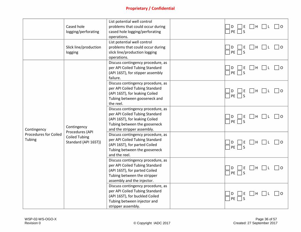
Cased hole logging/perforating
List potential well control problems that could occur during cased hole logging/perforating operations.
D E H L O PE S
Slick line/production logging
List potential well control problems that could occur during slick line/production logging operations.
D E H L O PE S
Contingency Procedures for Coiled Tubing
Contingency Procedures (API Coiled Tubing Standard (API 16ST))
Discuss contingency procedure, as per API Coiled Tubing Standard (API 16ST), for stipper assembly failure.
D E H L O PE S
Discuss contingency procedure, as per API Coiled Tubing Standard (API 16ST), for leaking Coiled Tubing between gooseneck and the reel.
D E H L O PE S
Discuss contingency procedure, as per API Coiled Tubing Standard (API 16ST), for leaking Coiled Tubing between the gooseneck and the stripper assembly.
D E H L O PE S
Discuss contingency procedure, as per API Coiled Tubing Standard (API 16ST), for parted Coiled Tubing between the gooseneck and the reel.
D E H L O PE S
Discuss contingency procedure, as per API Coiled Tubing Standard (API 16ST), for parted Coiled Tubing between the stripper assembly and the injector.
D E H L O PE S
Discuss contingency procedure, as per API Coiled Tubing Standard (API 16ST), for buckled Coiled Tubing between injector and stripper assembly.
D E H L O PE S

WSP-02-WS-OGO-X Page 37 of 57 Revision 0 Created: 27 September 2017
Proprietary / Confidential
© Copyright IADC 2017
Discuss contingency procedure, as per API Coiled Tubing Standard (API 16ST), for leak between tree and Well Control Stack pressure-sealing rams.
D E H L O PE S
Discuss contingency procedure, as per API Coiled Tubing Standard (API 16ST), for leak between the stripper and Well Control Stack rams.
D E H L O PE S
Additional Contingency Procedures
Discuss additional contingency procedures and verification of securing the well (e.g., coiled tubing surface equipment failure, circulation equipment failure, external leak in the riser or Well Control Stack, general muster alarm while coiled tubing in the well, leak at the swivel joint (rotating), simultaneous power pack and coiled tubing failure, and power pack failure).
D E H L O PE S
Handling Kill Problems
Common well kill problems
Identify problems that can happen during a well control operation (i.e., plugging; washouts; losses; equipment failure, surface leak).
D E H L O PE S
Action(s) to take if casing pressure exceeds MAASP
Assess the options available if surface casing pressure is likely to exceed MAASP and decide on the action to take (i.e., continue and accept losses; reduce the circulating friction in the annulus and choke lines yet maintain BHP, use the Volumetric method to manage the pressure).
D E H L O PE S

WSP-02-WS-OGO-X Page 38 of 57 Revision 0 Created: 27 September 2017
Proprietary / Confidential
© Copyright IADC 2017
Communication between casing strings
Identify the well control problems associated when communication exists between casing strings (e.g., leaks, different fluid densities, burst/collapse outer strings, casing annulus gauges, consider using case history for wireline, snubbing, and workover/completions).
D E H L O PE S
Instructor Resources: (Types and titles of material used for teaching)
Materials available to Trainees: (Types and titles of materials provided to trainees)
2.13 Coiled Tubing Operational Considerations
SUB-MODULES LEARNING TOPICS LEARNING OBJECTIVE AND ASSESSMENT GUIDELINES
MANUAL CHAPTER & PAGE # (Multi-line text field)
DELIVERY METHODS Options: D, E, H, L, O, PE, S (See instructions above; select all that
apply.)
Coiled Tubing Operational Limitations
Pressures
Identify the maximum allowable burst and collapse pressures.
D E H L O PE S
Identify conditions that can cause burst and collapse of the coiled tubing string (i.e., mechanical damage to coiled tubing).
D E H L O PE S
Forces
Identify maximum and minimum run-in hole and pull-out hole forces to prevent pipe buckling or parting the pipe.
D E H L O PE S
Surface Force Identify surface force on the Gooseneck and injector forces above the stripper.
D E H L O PE S

WSP-02-WS-OGO-X Page 39 of 57 Revision 0 Created: 27 September 2017
Proprietary / Confidential
© Copyright IADC 2017
Coiled Tubing Limitations
Coiled tubing material strengths
Discuss limitations of material strength selection when working in sour and/or corrosive environments (NACE MR0175/ISO 15156).
D E H L O PE S
Coiled tubing pressure bend-cycle fatigue a. Pressure b. Surface damage c. Corrosion d. Mechanical
defects and ovality e. Erosion
Identify and describe physical conditions leading to pressure bend cycle fatigue damage and subsequent failure of coiled tubing (bending radii over tubing guide arch and reel, coupled with internal pressure).
D E H L O PE S
Explain the importance of avoiding excessive cycling on the coiled tubing string (e.g., trip and cut coiled tubing rather than retire string for fatigue limit).
D E H L O PE S
Collapsed Coiled Tubing
Explain the need to fill coiled tubing with kill fluid prior to conducting simultaneous bullheading pumping operations (through coiled tubing and annular space).
D E H L O PE S
Identify conditions under which mechanically collapse may exist (e.g., ovality; obstructions).
D E H L O PE S
Instructor Resources: (Types and titles of material used for teaching)
Materials available to Trainees: (Types and titles of materials provided to trainees)

WSP-02-WS-OGO-X Page 40 of 57 Revision 0 Created: 27 September 2017
Proprietary / Confidential
© Copyright IADC 2017
2.14 Well Kill in Preparation of Well Intervention
SUB-MODULES LEARNING TOPICS LEARNING OBJECTIVE AND ASSESSMENT GUIDELINES
MANUAL CHAPTER & PAGE # (Multi-line text field)
DELIVERY METHODS Options: D, E, H, L, O, PE, S (See instructions above; select all that
apply.)
Objective of Well Control Techniques
Live Well intervention (without killing the well): a. Relies on pressure
containment through surface well control equipment
Identify the objectives of well intervention well control techniques in a live well.
D E H L O PE S
Dead Well intervention (killing the well): a. Circulate
formation fluid out of wellbore or bullhead fluid back into formation
b. Establish hydrostatic well control
c. Avoid excessive surface and downhole pressures so as not to induce an underground blowout or lose kill fluids to formation
Identify the objectives of circulating formation fluid out of the well as a well control/well intervention technique.
D E H L O PE S
Identify the objectives of displacing formation fluid back into formation as a well control/well intervention technique.
D E H L O PE S
Identify the objectives of reestablishing hydrostatic control.
D E H L O PE S
Identify well intervention techniques which may induce downhole fracturing and fluid loss.
D E H L O PE S

WSP-02-WS-OGO-X Page 41 of 57 Revision 0 Created: 27 September 2017
Proprietary / Confidential
© Copyright IADC 2017
Bullheading Definition, Application, and Calculation
Describe the basic principles of Bullheading (i.e., push the formation fluid back into the formation, possible flow paths).
D E H L O PE S
Discuss when Bullheading is used in preparation for remedial operations.
D E H L O PE S
Describe the advantages and disadvantages of bullheading.
D E H L O PE S
Discuss the well types and identify conditions when bullheading may be preferred to circulation (i.e., toxic gas present; unable to handle influx at surface; potential to exceed equipment limitations if circulated to surface or if debris exists).
D E H L O PE S
Identify the importance of porosity and permeability on formation injectivity.
D E H L O PE S
Identify the importance of a pumping schedule for bullheading a given well scenario.
D E H L O PE S
Prepare a kill sheet for a Bullheading operation.
D E H L O PE S
Calculate minimum pump rate to overcome gas migration.
D E H L O PE S
Calculate kill weight fluid. D E H L O PE S
Describe frictional losses in different well sections (slimhole, tight tubing/casing clearances, small id tubing, restrictions, pump rates, fluid types).
D E H L O PE S

WSP-02-WS-OGO-X Page 42 of 57 Revision 0 Created: 27 September 2017
Proprietary / Confidential
© Copyright IADC 2017
Determine the effect on BHP when bullheading (i.e. fracturing formation).
D E H L O PE S
Calculate minimal theoretical volume to be pumped to reach kill point (without over-displacement for horizontal well or deviated wells with long intervals).
D E H L O PE S
Identify maximum surface pressure vs. volume pumped.
D E H L O PE S
Identify the risks associated with over-displacement.
D E H L O PE S
Explain the difference between rising surface pressure and injection.
D E H L O PE S
Explain pressure, post-Bullhead in a well in which hydrostatic was not sufficient to kill the well.
D E H L O PE S
Summarize how to mitigate a mechanical issue (i.e., place pressure on the annulus to mitigate burst, placing pressure on the coil to mitigate collapse).
D E H L O PE S
Discuss the weakest mechanical link in a bullheading operation.
D E H L O PE S
Identify whether it is mechanical or formation limitations that determine the maximum surface pressure that can be applied.
D E H L O PE S
Interpret data on a kill log and select possible kill problems (e.g., not maintaining pressure; abnormal changes to casing annulus pressure; SPM variations).
D E H L O PE S

WSP-02-WS-OGO-X Page 43 of 57 Revision 0 Created: 27 September 2017
Proprietary / Confidential
© Copyright IADC 2017
Explain how to verify if well has been successfully killed.
D E H L O PE S
List reasons why record keeping during a Bullhead operation is important.
D E H L O PE S
Volumetric Method
When to use the Volumetric Method
Explain when to use the Volumetric Method (e.g., when you are unable to circulate; when there is no SITP to monitor; when you are off-bottom; when you are out of the hole).
D E H L O PE S
Basic principles
Explain the basic principles of the Volumetric Method (e.g., pressure increase and controlled bleed off cycles).
D E H L O PE S
Action(s) to take once an influx reaches the BOP
Summarize actions to take once the influx reaches the surface (e.g., wait for equipment; snubbing options; lube and bleed).
D E H L O PE S
Lube and Bleed Definition, Application, and Calculation
Explain the lube and bleed method.
D E H L O PE S
Describe the advantages and disadvantages of lube and bleed.
D E H L O PE S
Describe the well types where lube and bleed would be applied as opposed to other intervention methods or wellbore conditions (i.e., snubbing, coiled tubing, wireline, annulus kill).
D E H L O PE S
Calculate pressure per unit of volume in lube and bleed operations.
D E H L O PE S
Explain the importance of a pumping schedule for lube and bleed operations.
D E H L O PE S

WSP-02-WS-OGO-X Page 44 of 57 Revision 0 Created: 27 September 2017
Proprietary / Confidential
© Copyright IADC 2017
Develop a pump schedule for lube and bleed operations.
D E H L O PE S
Describe the difference between safety and working margins.
D E H L O PE S
Forward Circulation (Driller’s) Method
Definition, Application, and Calculation
Explain forward circulation (driller’s) method.
D E H L O PE S
Describe the well types and conditions where forward circulation (driller’s) method would be applied.
D E H L O PE S
Describe the advantages and disadvantages of forward circulation (driller’s) method.
D E H L O PE S
Calculate maximum pump pressure.
D E H L O PE S
Determine the effect on BHP when circulating with tools and equipment.
D E H L O PE S
Explain frictional pressure loss of pumped fluids vs. rate.
D E H L O PE S
Demonstrate a detailed forward circulating (driller’s) method example on a simulator.
S
(Must be taught through Simulation)
Interpret data on a kill log and select possible kill problems (e.g., not maintaining pressure; abnormal changes to casing pressure; choke opening size; pit levels; SPM variations).
D E H L O PE S
Explain how kill procedures can impact BHP (i.e., changing SPM; changing fluid weight; not following pressure chart; incorrect startup or shutdown procedure).
D E H L O PE S

WSP-02-WS-OGO-X Page 45 of 57 Revision 0 Created: 27 September 2017
Proprietary / Confidential
© Copyright IADC 2017
Reverse Circulation Applying Reverse Circulation method
Explain reverse circulation. D E H L O PE S
Describe frictional losses in different well sections (slimhole, tight tubing/casing clearances).
D E H L O PE S
Determine the effect on BHP when circulating with tools and equipment.
D E H L O PE S
Explain the main differences between a normal forward circulation kill technique and a reverse circulating technique (i.e., position of choke in the circulating path, start-up procedure, tubing string friction, different fluids in the well, integrity of circulating path, high frictional pressures).
D E H L O PE S
Pump Startup and Shutdown Procedure
Startup/Shutdown procedures
Explain the importance of using startup and shutdown procedure in a well kill (e.g., to maintain BHP).
D E H L O PE S
Demonstrate a startup and shutdown procedure including communication with pump operator on a simulator.
S
(Must be taught through Simulation)
Action(s) to take if a Slow Circulating Rate (SCR) has not been recorded
Explain the action to take to determine the Initial Circulating Pressure (ICP) if a Slow Circulating Rate (SCR) has not been recorded.
D E H L O PE S
Determine the action to take if the shut-in pressures are not the same following the first circulation.
D E H L O PE S
Demonstrate how to maintain constant BHP when an influx is being circulated through the choke lines and choke on a simulator.
S
(Must be taught through Simulation)

WSP-02-WS-OGO-X Page 46 of 57 Revision 0 Created: 27 September 2017
Proprietary / Confidential
© Copyright IADC 2017
Why startup pump pressure may not equal Initial Circulating Pressure (ICP)
Explain why pump startup pressure may differ from pre-calculated ICP and what action(s) to take after establishing a circulation rate (i.e., discuss the situation; monitor pressures as gels are broken down).
D E H L O PE S
Why pump pressure at shutdown may not equal expected pressure
Explain why a shutdown may not return shut-in pressure to the expected value (e.g., safety factors; trapped pressure).
D E H L O PE S
Lag time
Explain or demonstrate how to compensate for lag time between a choke adjustment and pump pressure change.
D E H L O PE S
Verifying the well is dead following kill procedure
Determine the action(s) required to verify a well is dead before opening up the BOP (e.g., use the shutdown procedure; check for trapped pressure; monitor through choke; and use circulating practice once the well is open).
D E H L O PE S
Instructor Resources: (Types and titles of material used for teaching)
Materials available to Trainees: (Types and titles of materials provided to trainees)
2.15 Special Situations
SUB-MODULES LEARNING TOPICS LEARNING OBJECTIVE AND ASSESSMENT GUIDELINES
MANUAL CHAPTER & PAGE # (Multi-line text field)
DELIVERY METHODS Options: D, E, H, L, O, PE, S (See instructions above; select all that
apply.) Blockages & Trapped Pressure in Tubing/Wellbore
Effect of blockages in retaining trapped pressure
Identify types of blockages (i.e., sand bridges, paraffin, tubing plugs, tools across Xmas tree).
D E H L O PE S

WSP-02-WS-OGO-X Page 47 of 57 Revision 0 Created: 27 September 2017
Proprietary / Confidential
© Copyright IADC 2017
Identify potential well control complications with trapping pressure below blockages.
D E H L O PE S
Blockages & Restricted Access in Tubing/Wellbore
Effect of blockages in impeding the ability to run tool string in or out of the wellbore
Describe where paraffin / asphaltenes / scaling is encountered and problems caused (i.e., commonly found in older oil producing wells; prevent tools from being run in to and out of the hole; plug up valves and surface equipment).
D E H L O PE S
Hydrates Effect of Hydrates while Circulating
Define hydrates. D E H L O PE S
Explain how hydrates can complicate well control.
D E H L O PE S
Describe typical hydrate removal techniques.
D E H L O PE S
Identify preventive measures to inhibit hydrate formation.
D E H L O PE S
H2S considerations Effect of H2S on Well Control Methodology
Explain H2S and equipment limitations based on H2S concentration.
D E H L O PE S
Describe additional procedures, precaution and supplemental safety equipment necessary, fluid scavengers, inhibitors while operating in an H2S environment.
D E H L O PE S
Describe equipment addition, limitations, modification or replacement necessary to work in an H2S environment (i.e., tubular or wireline embrittlement and seals).
D E H L O PE S

WSP-02-WS-OGO-X Page 48 of 57 Revision 0 Created: 27 September 2017
Proprietary / Confidential
© Copyright IADC 2017
Explain safety considerations on safely bringing H2S to the surface.
D E H L O PE S
Managing Change During a Well Kill
How to respond to problems that can happen during the well kill
Explain how to react to problems and, if necessary, mobilize the crew (i.e., shut down, realign the manifold line-up, change the choke, change the pump, and correct any mud pit/weight management issues).
D E H L O PE S
Organizing abnormal operations during well control events
Analyze the communication modifications that may be necessary because of an abnormal operation and describe how communications could be handled if differing from standard personnel assignments.
D E H L O PE S
Handover/ changes to personnel during a well kill operation
Explain importance of key components of handover procedures during a well kill operation and the complications created with poor handover (i.e., there must be clear communications between Supervisors and other crew members to ascertain the good and the bad; how handovers between crewmembers must be managed during meal breaks and shift changes; written instructions, and questions).
D E H L O PE S
Kill log as a tool for troubleshooting unplanned events
Identify and communicate trends on a kill log (e.g., pressures; volumes; fluid weights; the choke position; shutdowns/startups).
D E H L O PE S
WSP-02-WS-OGO-X Page 49 of 57 Revision 0 Created: 27 September 2017
Proprietary / Confidential
© Copyright IADC 2017
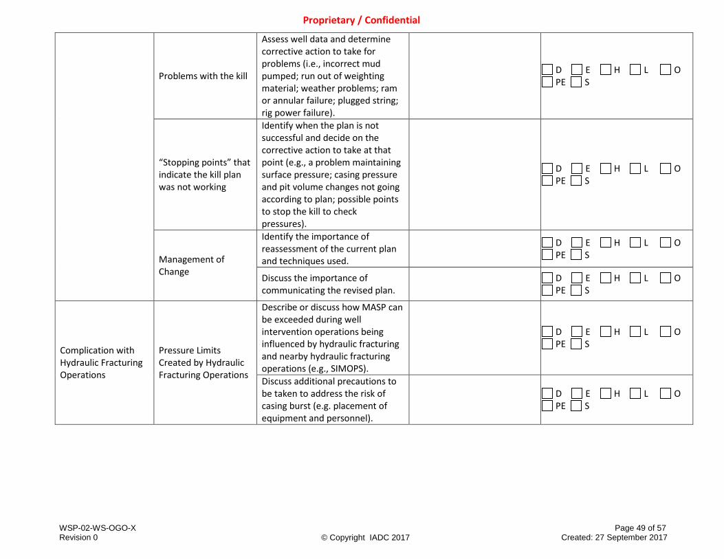
Problems with the kill
Assess well data and determine corrective action to take for problems (i.e., incorrect mud pumped; run out of weighting material; weather problems; ram or annular failure; plugged string; rig power failure).
D E H L O PE S
“Stopping points” that indicate the kill plan was not working
Identify when the plan is not successful and decide on the corrective action to take at that point (e.g., a problem maintaining surface pressure; casing pressure and pit volume changes not going according to plan; possible points to stop the kill to check pressures).
D E H L O PE S
Management of Change
Identify the importance of reassessment of the current plan and techniques used.
D E H L O PE S
Discuss the importance of communicating the revised plan.
D E H L O PE S
Complication with Hydraulic Fracturing Operations
Pressure Limits Created by Hydraulic Fracturing Operations
Describe or discuss how MASP can be exceeded during well intervention operations being influenced by hydraulic fracturing and nearby hydraulic fracturing operations (e.g., SIMOPS).
D E H L O PE S
Discuss additional precautions to be taken to address the risk of casing burst (e.g. placement of equipment and personnel).
D E H L O PE S

WSP-02-WS-OGO-X Page 50 of 57 Revision 0 Created: 27 September 2017
Proprietary / Confidential
© Copyright IADC 2017
Drilling Operations Rig-up Complications
Describe and discuss the potential complications of wireline, coiled tubing, and snubbing operations rigged up on a drilling rig’s well control system (e.g., Use of a shooting nipple, connection from PCE to rig BOP stack, free standing tubular, PCE requirements, securing riser in BOP pipe rams, and testing connections).
D E H L O PE S
Wireline Shear Seals Cutting Wireline with Shear Seal
Identify circumstances where shearing/cutting the wireline may be required (e.g., leak at connection between production tree and wireline valves).
D E H L O PE S
Discuss why using shear seal ram is a method of last resort and the consequences of using shear seal ram.
D E H L O PE S
Fishing Wireline Retrieving Wireline
Identify tools and pressure control considerations necessary for successful fishing operations (e.g., size of fish, size of lubricator, length of lubricator, redundant wireline valves, proper rams for fishing wire and wire size being fished).
D E H L O PE S
Describe the differences between fishing with wireline in pressured and non-pressured environment.
D E H L O PE S
Rig-Up Special BOP Equipment
Describe when a guide ram is used.
D E H L O PE S
Identify special situations that would use guide tubes in a BOP stack to prevent pipe buckling.
D E H L O PE S

WSP-02-WS-OGO-X Page 51 of 57 Revision 0 Created: 27 September 2017
Proprietary / Confidential
© Copyright IADC 2017
Identify special situations when a telescoping tubing guide would be used in the jack.
D E H L O PE S
Identify special situations when an IBOP or downhole check valves are run in the string.
D E H L O PE S
Planned Responses to Anticipated Well Control Scenarios
Encountering Unexpected Pressure
Explain or demonstrate actions to take when encountering unexpected pressure and what are the causes.
D E H L O PE S
Slip bowl failure
Explain preventative measures to take to prevent slip bowl failures.
D E H L O PE S
Given a scenario, explain the potential impact and the action to be taken in the event of slip bowl failure on the immediate operation.
D E H L O PE S
Power unit or hydraulic circuit failure while in the hole
Explain preventative measures to take in relation to power unit or hydraulic circuit failure.
D E H L O PE S
Given a scenario, explain the potential impact and the action to be taken in the event of power unit or hydraulic circuit failure on the immediate operation.
D E H L O PE S
Stripping annular element failure
Explain preventative measures to take in relation to stripping annular element failures.
D E H L O PE S
Given a scenario, explain the potential impact and the action to be taken in the event of stripping annular element failure on the immediate operation.
D E H L O PE S

WSP-02-WS-OGO-X Page 52 of 57 Revision 0 Created: 27 September 2017
Proprietary / Confidential
© Copyright IADC 2017
Leak below BOP stack and/or PCE
Explain preventative measures to take in relation to a leak below BOP stack and/or PCE (e.g., flange connections torqued properly, stack is secured from movement).
D E H L O PE S
Given a scenario, explain the potential impact and the action to be taken in the event of a leak below BOP stack and/or PCE on the immediate operation.
D E H L O PE S
Pressure at surface inside the work string
Explain preventative measures to take in relation to pressure at surface inside the work string.
D E H L O PE S
Given a scenario, explain the potential impact and the action to be taken in the event of pressure at surface inside the work string on the immediate operation.
D E H L O PE S
Leak in the stripper PCE ram
Explain preventative measures to take in relation to a leak in the stripper PCE ram.
D E H L O PE S
Given a scenario, explain the potential impact and the action to be taken in the event of a leak in the stripper PCE ram on the immediate operation.
D E H L O PE S
Buckling of tubulars
Explain tubular buckling. D E H L O PE S
Describe where tubular buckling may occur (e.g., supported and unsupported).
D E H L O PE S
Identify factors that may impact tubular buckling.
D E H L O PE S

WSP-02-WS-OGO-X Page 53 of 57 Revision 0 Created: 27 September 2017
Proprietary / Confidential
© Copyright IADC 2017
Explain the action to take to make the operation safe while maintaining control of the well during buckling of string.
D E H L O PE S
Explain preventative measures to take in relation to buckling of string in BOP stack.
D E H L O PE S
Explain the impact of buckling of string in BOP stack on the immediate operation.
D E H L O PE S
Parting of string
Explain the action to take to make the operation safe while maintaining control of the well during parting of string.
D E H L O PE S
Explain preventative measures to take in relation to parting of string.
D E H L O PE S
Explain the impact of parting of string on the immediate operation.
D E H L O PE S
Instructor Resources: (Types and titles of material used for teaching)
Materials available to Trainees: (Types and titles of materials provided to trainees)

WSP-02-WS-OGO-X Page 54 of 57 Revision 0 Created: 27 September 2017
Proprietary / Confidential
© Copyright IADC 2017
2.16 Testing
SUB-MODULES LEARNING TOPICS LEARNING OBJECTIVE AND ASSESSMENT GUIDELINES
MANUAL CHAPTER & PAGE # (Multi-line text field)
DELIVERY METHODS Options: D, E, H, L, O, PE, S (See instructions above; select all that
apply.)
Testing of Downhole Completion Equipment
Packers and Plugs
Discuss the consequences of ignoring/miscalculating flow-back volume (i.e., compressibility) when testing downhole equipment for integrity.
D E H L O PE S
Monitor flow back for proper flow back volume due to compressibility fluids, volumes greater than expected could indicate a failed test.
D E H L O PE S
Testing of Well Control Equipment Connections
Testing of Connections a. Rig BOP b. Wireline Valve c. Well Control Stack
Explain that the qualification of well control equipment as a barrier requires testing the connection below the lowest closing ram (e.g., rig BOP, wireline valve, Well Control Stack, wellhead).
D E H L O PE S
Instructor Resources: (Types and titles of material used for teaching)
Materials available to Trainees: (Types and titles of materials provided to trainees)

WSP-02-WS-OGO-X Page 55 of 57 Revision 0 Created: 27 September 2017
Proprietary / Confidential
© Copyright IADC 2017
2.17 Well Control Drills
SUB-MODULES LEARNING TOPICS LEARNING OBJECTIVE AND ASSESSMENT GUIDELINES
MANUAL CHAPTER & PAGE # (Multi-line text field)
DELIVERY METHODS Options: D, E, H, L, O, PE, S (See instructions above; select all that
apply.)
Well Control Drills
Pit Drills Explain the importance of and procedure for pit drills.
D E H L O PE S
Trip Drills Explain the importance of and procedure for trip drills.
D E H L O PE S
Choke Drills Explain the importance of and procedure for choke drills.
D E H L O PE S
Various Action Drills
List the various action drills applicable to wireline, coiled tubing, and snubbing operations (e.g., loss of primary well barrier for braided or conductor line, loss of primary well barrier for slick line, loss of power to unit, leak above secondary barrier, leak below secondary barrier).
D E H L O PE S
Instructor Resources: (Types and titles of material used for teaching)
Materials available to Trainees: (Types and titles of materials provided to trainees)
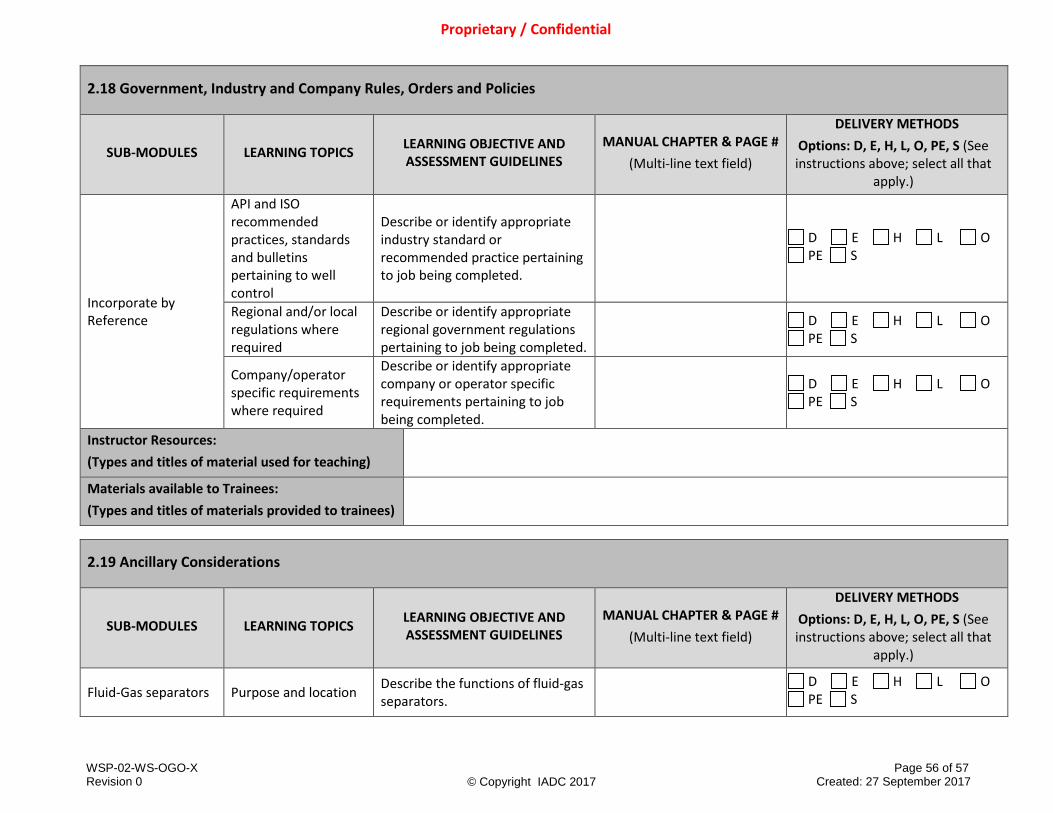
WSP-02-WS-OGO-X Page 56 of 57 Revision 0 Created: 27 September 2017
Proprietary / Confidential
© Copyright IADC 2017
2.18 Government, Industry and Company Rules, Orders and Policies
SUB-MODULES LEARNING TOPICS LEARNING OBJECTIVE AND ASSESSMENT GUIDELINES
MANUAL CHAPTER & PAGE # (Multi-line text field)
DELIVERY METHODS Options: D, E, H, L, O, PE, S (See instructions above; select all that
apply.)
Incorporate by Reference
API and ISO recommended practices, standards and bulletins pertaining to well control
Describe or identify appropriate industry standard or recommended practice pertaining to job being completed.
D E H L O PE S
Regional and/or local regulations where required
Describe or identify appropriate regional government regulations pertaining to job being completed.
D E H L O PE S
Company/operator specific requirements where required
Describe or identify appropriate company or operator specific requirements pertaining to job being completed.
D E H L O PE S
Instructor Resources: (Types and titles of material used for teaching)
Materials available to Trainees: (Types and titles of materials provided to trainees)
2.19 Ancillary Considerations
SUB-MODULES LEARNING TOPICS LEARNING OBJECTIVE AND ASSESSMENT GUIDELINES
MANUAL CHAPTER & PAGE # (Multi-line text field)
DELIVERY METHODS Options: D, E, H, L, O, PE, S (See instructions above; select all that
apply.)
Fluid-Gas separators Purpose and location Describe the functions of fluid-gas separators.
D E H L O PE S

WSP-02-WS-OGO-X Page 57 of 57 Revision 0 Created: 27 September 2017
Proprietary / Confidential
© Copyright IADC 2017
Operating parameters
Explain the operating parameters (e.g., maximum operating pressure, vent line diameter, u-tube height; and potential dangers and action to take if overloaded).
D E H L O PE S
Calculate the water leg for determining the effective operating pressure.
D E H L O PE S
Electrical Classification
Hazardous Area Zone Classification
Describe the various requirements for zone classification.
D E H L O PE S
Explain the importance of equipment classifications for designated zones (e.g., hydrocarbon handling when bleeding off lubricators and risers, proximity to ignition sources, routed away from work area).
D E H L O PE S
Instructor Resources: (Types and titles of material used for teaching)
Materials available to Trainees: (Types and titles of materials provided to trainees)
Required:
Total Time Range for Course:* hours minutes to hours minutes
*The minimum delivery time shall not fall below the minimum time requirement for the course, as stated in accreditation requirements.