WELL DRILLING, WORKOVER AND COMPLETION FLUIDS
11
J ) Europaisches Patentamt European Patent Office Office europeen des brevets 0159 313 B1 Publication number: EUROPEAN PATENT SPECIFICATION mtci.4: E 21 B 33/138, E 21 B 43/00 (§) Date of publication of patent specification: 07.12.88 (Jj) Application number: 83903246.3 (2) Date of filing: 15.09.83 ® International application number: PCT/US83/01408 (g) International publication number: WO 85/01309 28.03.85 Gazette 85/08 WELL DRILLING, WORKOVER AND COMPLETION FLUIDS. Proprietor: TEXAS UNITED CHEMICAL CORPORATION 2000 West Loop South Suite 990 Houston, TX 77027 (US) Date of publication of application: 30.10.85 Bulletin 85/44 Publication of the grant of the patent: 07.12.88 Bulletin 88/49 Inventor: MONDSHINE, Thomas, Charles 6619 Burning Tree Street Houston, TX 77036 (US) 'Designated Contracting States: DEFRGBNLSE Representative: Fisher, Adrian John et al CARPMAELS & RANSFORD 43 Bloomsbury Square London WC1 A 2RA(GB) References cited: GB-A-1 337 651 US-A-3675 717 US-A-3974077 US-A-4046197 US-A-4175 042 US-A-4369 843 CD CO CO O) 1A Note: Within nine months from the publication of the mention of the grant of the European patent, any person may give notice to the European Patent Office of opposition to the European patent granted. Notice of opposition shall be filed in a written reasoned statement. It shall not be deemed to have been filed until the opposition fee has been paid. (Art. 99( 1) European patent convention). Courier Press, Leamington Spa, England. UJ
-
Upload
khangminh22 -
Category
Documents
-
view
0 -
download
0
Transcript of WELL DRILLING, WORKOVER AND COMPLETION FLUIDS

J )
Europaisches Patentamt
European Patent Office
Office europeen des brevets
0 1 5 9 3 1 3
B 1 Publication number:
EUROPEAN PATENT SPECIFICATION
mtci.4: E 21 B 33/138, E 21 B 4 3 / 0 0 (§) Date of publication of patent specification: 07.12.88
(Jj) Application number: 83903246.3
(2) Date of filing: 15.09.83
® International application number: PCT/US83/01408
(g) International publication number: WO 85/01309 28.03.85 Gazette 85/08
WELL DRILLING, WORKOVER AND COMPLETION FLUIDS.
Proprietor: TEXAS UNITED CHEMICAL CORPORATION 2000 West Loop South Suite 990 Houston, TX 77027 (US)
Date of publication of application: 30.10.85 Bulletin 85/44
Publication of the grant of the patent: 07.12.88 Bulletin 88/49
Inventor: MONDSHINE, Thomas, Charles 6619 Burning Tree Street Houston, TX 77036 (US) 'Designated Contracting States:
DEFRGBNLSE
Representative: Fisher, Adrian John et al CARPMAELS & RANSFORD 43 Bloomsbury Square London WC1 A 2RA(GB)
References cited: GB-A-1 337 651 US-A-3675 717 US-A-3974077 US-A-4046197 US-A-4175 042 US-A-4369 843
CD
CO
CO O ) 1A
Note: Within nine months from the publication of the mention of the grant of the European patent, any person may give notice to the European Patent Office of opposition to the European patent granted. Notice of opposition shall be filed in a written reasoned statement. It shall not be deemed to have been filed until the opposition fee has been paid. (Art. 99( 1 ) European patent convention).
Courier Press, Leamington Spa, England. UJ

EP 0 1 5 9 313 B1
Description
Field of the invention The invention relates to a method of completing a well after it has been drilled, or of servicing a well by
5 workover operations. More particularly, it relates to a method of completing and workover of a well by contacting a subterranean formation which produces hydrocarbons with aqueous well completion and workover fluids to maintain the hydrocarbons in the producing well formation or formations under control while at the same time inhibiting or preventing damage to the producing formation or formations during the completion or workover operations.
10 Background of the invention
After a well has been drilled into the earth's surface, one or more subterranean producing formations may be encountered. It is then desirable to complete the well so as to obtain the maximum hydrocarbon production from such subterranean producing formations, and to complete such well in a manner so that
is the pressure in the subterranean producing formations is controlled during completion operations, while bridging or sealing off the producing formation to inhibit damage thereto and to minimize fluid loss into the formation which might inhibit or in some cases substantially reduce the production of hydrocarbons from the subterranean producing formation.
Also, it is desirable or necessary after a period of time to perform workover or other service operations 20 on a previously drilled well, and during such workover or service operations, it is desirable to control the
pressure in the subterranean producing formation or formations while at the same time bridging or sealing off the formations in a manner so as to minimize particle invasion and fluid loss into the producing formation or formations and thereby reduce if not substantially eliminate damage to the formations.
In addition to the necessary required density characteristics of a workover and completion fluid, it is 25 desirable to seal off or temperarily plug the face of the subterranean producing formations or formations in
the well bore so that during the completion and workover operation fluid and solids in the fluid are not lost to the producing formation which might cause damage thereto.
Heretofore various types of workover and completion fluids with components therein of a particle size to bridge and seal off the producing formations have been employed. Workover and completion fluids
30 should have fluid loss (filter loss) control to prevent substantial fluid invasion of the formation. This is achieved by a combination of a fluid loss control agent and a bridging agent.
Various types of soluble or degradable bridging materials are available commercially, and the choice between them depends on reservoir conditions and type of operation. Sized particles of oil-soluble resins or waxes have been used as bridging agents for oil reservoirs. Such particles must be removed by
35 dissolving them in oil when used in dry gas reservoirs or water injection wells. Calcium carbonates were the first degradable bridging particles to be used in workover and completion fluids. On completion of the job, they are removed with acid if necessary. Acidization is an extra operation and additional expense, except in carbonate reservoirs that must be acidized. Furthermore, the acid may dissolve iron on the way down to the acidizing zone and introduce iron compounds into the formation. Then, when the acid is spent,
40 the pH rises, iron hydroxide is precipitated, and formation damage results. All of the carbonate particles may not be contacted by the acid. To avoid this problem, alternate slugs of acid and diverting agent are necessary.
I have found that workover and completion fluids can be formulated utilizing sized particles of a water soluble salt as a bridging agent suspended in a saturated brine solution in which the salt is substantially
45 insoluble. See U.S. Patents No. 4,175,042; 4,186,803; and 4,369,843. The treating fluid comprises a saturated aqueous saline solution with at least one water soluble salt
which is substantially insoluble in the saturated saline solution, the water soluble salt having a particle size range of about 5 micrometer to about 800 micrometer with greater than 5 percent of the particles being coarser than 44 micrometer to control the pressure in the formation while bridging and sealing it, and also
so minimizing particle invasion to the formation. A minor amount of fluid loss additive to inhibit loss of fluid into the subterranean producing formation, and a suspension additive to prevent settling of the water soluble salt particles is included in the treating fluid. The water soluble salt which is substantially insoluble in the saline solution is added in sufficient quantity to control the pressure in the producing formation by increasing the density of the treating fluid.
5S The bridging and sealing salt particles used in the well completion and workover method can be dissolved by the flow of produced field brine or by the injection of water or an unsaturated saline solution. This eliminates the undesirable use of oil or acid solutions to remove the bridge from the subterranean hydrocarbon producing formation. The saturated saline solution is formed by dissolving a salt or mixture of salts in water and normally the minimum density of the saturated saline solution is approximately at
60 least 1.20 grams per cubic centimeter.
Summary of the invention The present invention broadly comprises an improved well completion and workover fluid and method
wherein a subterranean formation or formations is contacted with a fluid having a density less than about 65 1-26 g/cm3 for controlling formation pressure and also for temporarily bridging and sealing off the

EP 0 1 5 9 313 B1
formation or formations in the well bore to minimize fluid loss or damage to the formations. The treating fluid comprises an aqueous liquid having a density in the range from about 1.0 to about 1.20 g/cm3 (8.33—10.0 ppg) in which there is suspended a bridging agent comprising a hydrated borate of sodium and/or calcium to control the pressure in the formation while bridging and sealing it, thus minimizing
5 particle invasion to the formation. A minor amount of fluid loss additive to inhibit loss of fluid into the formation, and a suspension additive to prevent settling of the borate particles is included in the treating fluid. The hydrated borate is added in sufficient quantity to control the pressure in the formation, in the density range from about 1.007 to about 1.26 g/cm3, by increasing the density of the treating fluid, and in sufficient quantity to effectively seal the formation.
10 The hydrated borate particles used in these novel well completing and workover fluids and methods have a limited solubility in water which is insufficient to appreciably dissolve the particles in the aqueous liquid but which is sufficient, however, to allow the particles to be dissolved by the flow of produced field brine or by the injection of water or other unsaturated aqueous solution. This eliminates the undesirable use of oil or acid solutions to remove the bridge from the formation. However, aqueous acid can be used if
'5 desired. Thus the invention provides for the temporary control of fluid loss to productive formations during
completion or workover operations where densities ranging from about 1.007 to about 1.26 g/cm3 are needed to control the formation pressure. The invention further provides for a readily removable bridging or filter cake, i.e., one that is solubilized by contacting with an aqueous liquid, during workover or
20 completion operations. Formation damage caused by excessive fluid invasion of the formation is minimized utilizing the present invention.
While the invention is susceptible of various modifications and alternative forms, specific embodiments thereof will hereinafter be described in detail and shown by way of example. It should be understood, however, that it is not intended to limit the invention to the particular forms disclosed.
25 The compositions can comprise, consist essentially of, or consist of the stated materials. The method can comprise, consist essentially of, or consist of the stated steps with the stated materials.
Description of the preferred embodiment The present invention is based on my discovery that certain naturally occurring hydrated borates of
30 sodium and/or calcium are uniquely applicable for providing water-soluble or acid soluble completion and workover fluids in the density range from about 1.007 to about 1.26 g/cm3. Ulexite and Probertite are naturally occurring hydrated borates of sodium and calcium. Ulexite is principally described by the molecular formula NaCaB5O9 • 8H2O. Probertite is principally described by the molecular formula NaCaB5O9 • 5H2O. Colemanite is a calcium borate principally described by the molecular formula
35 Ca2B6On • 5H2O. These materials have the solubility characteristics indicated in Table A and Table B. The Ulexite, having
a somewhat higher solubility than Colemanite or Probertite, is the preferred hydrated borate bridging and weighting agent. The hydrated borates, when properly sized and graded, can be suspended in an aquoues liquid such as fresh water, KCI or other salt solutions or brines of various densities up to about 1 .20 g/cm3 to
40 provide water-soluble completion and workover fluids in the density range from about 1 .007 to about 1 .26 g/cm3.
The hydrated borate preferably should have a particle size distribution ranging from about 1 micrometer to about 800 micrometer with at least 1 % of the particles being greater than 44 micrometer to adequately bridge and seal typical formations during workover and completion operations. Preferably for
45 most workover and completion operations, the particle size distribution will be such that: at least 5% of the particles will be greater than 44 micrometer; at least 50% of the particles will be greater than 20 micrometer; and less than 10% of the particles will have a particle size less than 10 micrometer.
In gravel pack operations, such as described in U.S. Patent No. 3,675,717, less than about 5% by weight of the particles can be greater than about 44 micrometer for a successful gravel pack. That is, at least 95%
so by weight of the particles must not exceed about 44 micrometer in size. It is essential in gravel packing operations that the concentration and particle size of the carrier fluid not have any effect on the spacing of the gravel particles and be such that it will flow through the voids between the gravel to enable the gravel to be properly placed. If more than about 5% by weight of the hydrated borate particles in the gravel packing carrier liquid exceeds about 44 micrometer in size, the gravel bed will become plugged which
55 renders proper placement of the gravel difficult, if not impossible. A coarser particle size hydrated borate can be used both as a weighting material and as a bridging
agent for controlling lost circulation in higher permeability type formations. In extremely high permeability formations, fractured formations, or vugular type formations, the particle size should be expanded to include particles as high as 2000 micrometer for effective bridging.
60 The amount of hydrated borate added to the aqueous suspension medium, which may contain dissolved inorganic salts, having a density in the range from about 1.0 to about 1.20 g/cm3, need only be sufficient to effectively bridge and seal off the desired formations. Generally, the amount will vary from about 14 kg/m3 to about 570 kg/m3 of the aqueous suspension medium depending on the density desired in the treating fluid and the density of the aqueous suspension medium, preferably from about 20 kg/m3 to
65 about 385 kg/m3. Thus the treating fluid resulting from the combination of the aqueous suspension
EP 0 1 5 9 313 B1
medium and the hydrated borate must have a density sufficient to balance or exceed the formation pressure in the well bore, and it is well known to those skilled in the art how to calculate the amount of hydrated borate and aqueous suspension medium required to obtain such density, and must contain hydrated borate particles to effectively bridge and seal the desired subterranean formations.
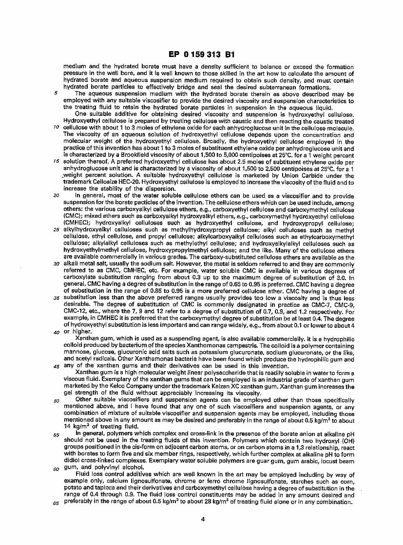
s The aqueous suspension medium with the hydrated borate therein as above described may be employed with any suitable viscosifier to provide the desired viscosity and suspension characteristics to the treating fluid to retain the hydrated borate particles in suspension in the aqueous liquid.
One suitable additive for obtaining desired viscosity and suspension is hydroxyethyl cellulose. Hydroxyethyl cellulose is prepared by treating cellulose with caustic and then reacting the caustic treated
to cellulose with about 1 to 3 moles of ethylene oxide for each anhydroglucose unit in the cellulose molecule. The viscosity of an aqueous solution of hydroxyethyl cellulose depends upon the concentration and molecular weight of the hydroxyethyl cellulose. Broadly, the hydroxyethyl cellulose employed in the practice of this invention has about 1 to 3 moles of substituent ethylene oxide per anhydroglucose unit and is characterized by a Brookfield viscosity of about 1,500 to 5,000 centipoises at 25°C. for a 1 weight percent
15 solution thereof. A preferred hydroxyethyl cellulose has about 2.5 moles of subtituent ethylene oxide per anhydroglucose unit and is characterized by a viscosity of about 1,500 to 2,500 centipoises at 25CC. for a 1 .weight percent solution. A suitable hydroxyethyl cellulose is marketed by Union Carbide under the trademark Cellosize HEC-20. Hydroxyethyl cellulose is employed to increase the viscosity of the fluid and to increase the stability of the dispersion.
20 In general, most of the water soluble cellulose ethers can be used as a viscosifier and to provide suspension for the borate pacticles of the invention. The cellulose ethers which can be used include, among others: the various carboxyalkyl cellulose ethers, e.g., carboxyethyl cellulose and carboxymethyl cellulose (CMC); mixed ethers such as carboxyalkyl hydroxyalkyl ethers, e.g., carboxymethyl hydroxyethyl cellulose (CMHEC); hydroxyalkyl celluloses such as hydroxyethyl cellulose, and hydroxypropyl cellulose;
25 alkylhydroxyalkyl celluloses such as methylhydroxypropyl cellulose; alkyl celluloses such as methyl cellulose, ethyl cellulose, and propyl cellulose; alkylcarboxyalkyl celluloses such as ethylcarboxymethyl cellulose; alkylalkyl celluloses such as methylethyl cellulose; and hydroxyalkylalkyl celluloses such as hydroxyethylmethyl cellulose, hydroxypropylmethyl cellulose; and the like. Many of the cellulose ethers are available commercially in various grades. The carboxy-substituted cellulose ethers are available as the
30 alkali metal salt, usually the sodium salt. However, the metal is seldom referred to and they are commonly referred to as CMC, CMHEC, etc. For example, water soluble CMC is available in various degrees of carboxylate substitution ranging from about 0.3 up to the maximum degree of substitution of 3.0. In general, CMC having a degree of substitution in the range of 0.65 to 0.95 is preferred. CMC having a degree of substitution in the range of 0.85 to 0.95 is a more preferred cellulose ether. CMC having a degree of
35 substitution less than the above preferred ranges usually provides too low a viscosity and is thus less desirable. The degree of substitution of CMC is commonly designated in practice as CMC-7, CMC-9, CMC-12, etc., where the 7, 9 and 12 refer to a degree of substitution of 0.7, 0.9, and 1.2 respectively. For example, in CMHEC it is preferred that the carboxymethyl degree of substitution be at least 0.4. The degree of hydroxyethyl substitution is less important and can range widely, e.g., from about 0.1 or lower to about 4
40 or higher. Xanthan gum, which is used as a suspending agent, is also available commercially. It is a hydrophilic
colloid produced by bacterium of the species Xanthomonas campestris. The colloid is a polymer containing mannose, glucose, glucuronic acid salts such as potassium glucuronate, sodium glucuronate, or the like, and acetyl radicals. Other Xanthamonas bacteria have been found which produce the hydrophilic gum and
45 any of the xanthan gums and their derivatives can be used in this invention. Xanthan gum is a high molecular weight linear polysaccharide that is readily soluble in water to form a
viscous fluid. Exemplary of the xanthan gums that can be employed is an industrial grade of xanthan gum marketed by the Kelco Company under the trademark Kelzan XC xanthan gum. Xanthan gum increases the gel strength of the fluid without appreciably increasing its viscosity.
50 Other suitable viscosifiers and suspension agents can be employed other than those specifically mentioned above, and I have found that any one of such viscosifiers and suspension agents, or any combination of mixture of suitable viscosifier and suspension agents may be employed, including those mentioned above in any amount as may be desired and preferably in the range of about 0.5 kg/m3 to about 14 kg/m3 of treating fluid.
55 In general, polymers which complex and cross-link in the presence of the borate anion at alkaline pH should not be used in the treating fluids of this invention. Polymers which contain two hydroxyl (OH) groups positioned in the cis-form on adjacent carbon atoms, or on carbon atoms in a 1,3 relationship, react with borates to form five and six member rings, respectively, which further complex at alkaline pH to form didiol cross-linked complexes. Exemplary water soluble polymers are guar gum, gum arabic, locust beam
60 gum, and polyvinyl alcohol. Fluid loss control additives which are well known in the art may be employed including by way of
example only, calcium lignosulfonate, chrome or ferro chrome lignosulfonate, starches such as corn, potato and tapioca and their derivatives and carboxymethyl cellulose having a degree of substitution in the range of 0.4 through 0.9. The fluid loss control constituents may be added in any amount desired and
65 preferably in the range of about 0.5 kg/m3 to about 28 kg/m3 of treating fluid alone or in any combination.
EP 0 1 5 9 313 B1
Where any of the lignosulfonates are used either alone or with any of the other fluid loss control agents the amount may be in the range of about 0.5 kg/m3 to about 55 kg/m3 of treating fluid. Also, it is well known in the art that when any of the lignosulfonates are employed it is desirable to neutralize the acidic nature of the lignosulfonates. This may be done by adding a material to raise the pH of the completion fluid to at least
5 7. Any one or more of the alkaline earths, such as magnesium oxide or calcium oxide may be employed. Sodium hydroxide may also be used. The amount of material used to adjust the pH of the completion fluid is in the range of about 0.4 to about 14 kg/m3 of treating fluid.
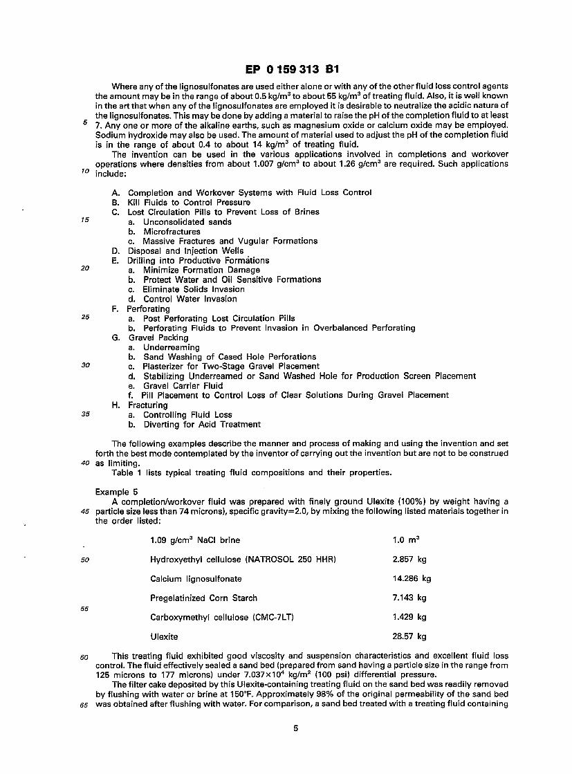
The invention can be used in the various applications involved in completions and workover operations where densities from about 1.007 g/cm3 to about 1.26 g/cm3 are required. Such applications
10 include:
A. Completion and Workover Systems with Fluid Loss Control B. Kill Fluids to Control Pressure C. Lost Circulation Pills to Prevent Loss of Brines
15 a. Unconsolidated sands b. Microfractures c. Massive Fractures and Vugular Formations
D. Disposal and Injection Wells E. Drilling into Productive Formations
20 a. Minimize Formation Damage b. Protect Water and Oil Sensitive Formations c. Eliminate Solids Invasion d. Control Water Invasion
F. Perforating 25 a. Post Perforating Lost Circulation Pills
b. Perforating Fluids to Prevent Invasion in Overbalanced Perforating G. Gravel Packing
a. Underreaming b. Sand Washing of Cased Hole Perforations
30 c. Plasterizer for Two-Stage Gravel Placement d. Stabilizing Underreamed or Sand Washed Hole for Production Screen Placement e. Gravel Carrier Fluid f. Pill Placement to Control Loss of Clear Solutions During Gravel Placement
H. Fracturing 35 a. Controlling Fluid Loss
b. Diverting for Acid Treatment
The following examples describe the manner and process of making and using the invention and set forth the best mode contemplated by the inventor of carrying out the invention but are not to be construed
40 as limiting. Table 1 lists typical treating fluid compositions and their properties.
Example 5 A completion/workover fluid was prepared with finely ground Ulexite (100%) by weight having a
45 particle size less than 74 microns), specific gravity=2.0, by mixing the following listed materials together in the order listed:
1.09 g/cm3 NaCI brine 1.0 m3
so Hydroxyethyl cellulose (NATROSOL 250 HHR) 2.857 kg
Calcium lignosulfonate 14.286 kg
Pregelatinized Corn Starch 7.143 kg 55
Carboxymethyl cellulose (CMC-7LT) 1.429 kg
Ulexite 28.57 kg
60 This treating fluid exhibited good viscosity and suspension characteristics and excellent fluid loss control. The fluid effectively sealed a sand bed (prepared from sand having a particle size in the range from 125 microns to 177 microns) under 7.037X10⁴ kg/m2 (100 psi) differential pressure.
The filter cake deposited by this Ulexite-containing treating fluid on the sand bed was readily removed by flushing with water or brine at 150°F. Approximately 98% of the original permeability of the sand bed
65 was obtained after flushing with water. For comparison, a sand bed treated with a treating fluid containing
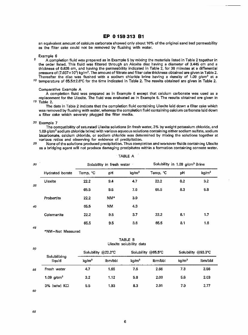
EP 0 1 5 9 313 B1
an equivalent amount of calcium carbonate showed only about 10% of the original sand bed permeability as the filter cake could not be removed by flushing with water.
Example 6 5 A completion fluid was prepared as in Example 5 by mixing the materials listed in Table 2 together in
the order listed. This fluid was filtered through an Aloxite disc having a diameter of 3.445 cm and a thickness of 0.635 cm, and having the permeability indicated in Table 2, for 30 minutes at a differential pressure of (7.037x1 04) kg/m2. The amount of filtrate and filter cake thickness obtained are given in Table 2. Thereafter the disc was flushed with a sodium chloride brine having a density of 1.09 g/cm3 at a
10 temperature of 65.5±2.8°C for the time indicated in Table 2. The results obtained are given in Table 2.
Comparative Example A A completion fluid was prepared as in Example 6 except that calcium carbonate was used as a
replacement for the Ulexite. The fluid was evaluated as in Example 6. The results obtained are given in 15 Table 2.
The data in Table 2 indicate that the completion fluid containing Ulexite laid down a filter cake which was removed by flushing with water, whereas the completion fluid containing calcium carbonate laid down a filter cake which severely plugged the filter media.
20 Example 7 The compatibility of saturated Ulexite solutions (in fresh water, 3% by weight potassium chloride, and
1 .09 g/cm3 sodium chloride brine) with various aqueous solutions containing either sodium sulfate, sodium bicarbonate, calcium chloride, or sodium chloride was determined by mixing the solutions together at various ratios and observing for evidence of precipitation.
25 None of the solutions produced precipitation. Thus completion and workover fluids containing Ulexite as a bridging agent will not produce damaging precipitates within a formation containing connate water.
TABLE A
Solubility in 1.09 g/cm3 Brine Solubility in fresh water 30
Hydrated borate Temp, °C pH kg/m3 Temp, °C pH kg/m3
Ulexite 22.2 9.4 4.7 22.2 8.2 3.2
65.5 9.5 7.6 65.5 8.3 5.8
Probertite 22.2 NM* 3.9
65.5 NM 4.3
Colemanite 22.2 9.5 3.7 22.2 8.1 1.7
65.5 9.5 3.6 65.5 8.1 1.6
*NM=Not Measured
TABLE B Ulexite solubility data
Solubility @22.2°C Solubility @65.5°C Solubility @93.3°C Solubilizing
liquid kg/m3 Ibm/bbl kg/m3 Ibm/bbl kg/m3 Ibm/bbl
35
40
45
50
Fresh water
1.09 g/cm3
3% (w/w) KCI
2.66
2.03
2.91
7.3
5.8
7.9
2.56
2.03
2.77
4.7
3.2
5.5
1.65
1.12
1.93
7.6
5.8
8.3
55
60
65

EP 0 1 5 9 313 B1
TABLE 1
Example
5 Composition Base Brine Density, g/cm3
Volume Base Brine, m3
10 Potassium Chloride, kg
Hydroxyethylcellulose, kg
Xanthan Gum, kg 15
Carboxymethylcellulose, kg
Calcium Lignosulfonate, kg
20 Pregelatinized Corn Starch, kg
Ulexite, kg
Properties 25 Treating Fluid Weight, g/cm3
Plastic Viscosity, g/cm-sec
Yield Point, kg/m2 30
10 sec. gel strength, kg/m2
10 min. gel strength, kg/m2
35 API Filtrate, cm3
Sand Bed (80 — 120 mesh)
PH 40-
1.00 1.08 1.14 1.20
1.0 1.0 1.0 1.0
30 0 0 0
2.857 2.857 2.857 2.857
1.143 1.143 1.143 1.143
1.0 1.0 1.0 1.0
5.714 5.714 5.714 5.714
11.428 11.428 11.428 11.428
20.71 20.71 20.71 20.71
1.036 1.10 1.158 1.217
0.18 0.19 0.23 0.25
1.464 1.464 1.659 1.562
0.244 0.195 0.244 0.244
0.244 0.244 0.244 0.293
6.7 6.0 5.6 3.2
Seal Seal Seal Seal
8.95 8.33 8.10 7.91
10
15
20
25
30
35
45
50
55
60
65

EP 0 1 5 9 313 B1
TABLE 2 Cake solubility from completion fluids prepared with Ulexite or calcium carbonate
Comparative Example 6 Example A
Fluid composition 1.09 g/cm3 NaCI Brine, m3 1.0 1.0
Hydroxyethyl Cellulose, kg 2.857 2.857
XC Polymer, kg 1.0 1.0
Carboxymethyl Cellulose, kg 1.0 1.0
Pregelatinized Starch, kg 11.43 11.43
Lime, kg 0 1.429
Ulexite (<74 microns), kg 28.57 0
Calcium Carbonate (<74 microns), kg 0 28.57
Test conditions Filter Media Aloxite Aloxite
10
15
20
25 Filter Media Aloxite Aloxite
Initial Permeability, md 1000 769.5
Filtrate Volume, cm3 18 23 30
Cake Thickness, cm 0.08 0.12
Wash Time, minutes 60 120
35 Test results Surface Cake Removal, % 100 75
Internal Cake Removal, %* 100 5.5
40 *(lnitial Permeability Final Permeability) x 100
Claims 1. A well treating fluid comprising: (a) an aqueous suspension medium comprising an electrolyte solution,
45 (b) a bridging agent having a particle size in the range from 1 to 2000 micrometers, and (c) a viscosifier and suspension additive in the amount of 0.5 kg/m3 to 14 kg/m3, characterised in that the suspension medium has a density in the range from 1 .0 g/cm3 to 1 .2 g/cm3, the
well treating fluid has an overall density of from 1.007 g/cm3 to 1.26 g/cm3 and the bridging agent comprises at least one hydrated borate selected from calcium borates, sodium calcium borates, and
so mixtures thereof. 2. The fluid of claim 1 wherein the bridging agent has a particle size distribution within the range from 1
micrometer to 800 micrometers with at least 1% of the particles being greater than 44 micrometers. 3. The fluid of claim 2 wherein at least 5% of the particles are greater than 44 micrometers, at least 50%
of the particles are greater than 20 micrometers, and wherein less than 10% of the particles are less than 10 55 micrometers.
4. The fluid of claim 1 including a fluid loss additive. 5. The fluid of claim 1 wherein the viscosifier and suspension additive is selected from water soluble
cellulose ethers, xanthan gum, and mixtures thereof. 6. The fluid of claim 5 including a fluid loss additive.
60 7. The fluid of claim 6 wherein said fluid loss additive comprises calcium lignosulfonate in amount of from 0.5 kg/m3 to 28 kg/m3.
8. The fluid of claim 6 wherein said fluid loss control additive is selected from calcium lignosulfonate, chrome lignosulfonate, ferro chrome lignosulfonate, starch, starch derivatives, carboxymethyl cellulose having a degree of substitution in the range of 0.4 to 0.9, and mixtures thereof, wherein the amount of said
65 fluid loss additive is from 0.5 kg/m3 to 28 kg/m3 of said fluid.
1000 769.5
18 23
0.08 0.12
60 120
30
35 100 75
100 5.5
45
50
55
60
8

EP 0 1 5 9 313 B1
9. A well completion and workover method wherein a subterranean formation in a well is contacted with a well treating fluid according to any preceding claim, to form a bridge and seal on said formation.
10. The method of claim 9 which additionally comprises dissolving said bridge and seal off said formation with an aqueous liquid.
5 11. The method of claim 9 or claim 10 wherein the concentration of said viscosifier and suspension additive is from 0.5 kg/m3 to 14 kg/m3, and wherein said treating fluid also contains a fluid loss additive.
12. A well treating method wherein a subterranean formation in a well is contacted with a treating fluid comprising:
(a) pumping said treating fluid in the well and contacting the formation with said treating fluid to form a 10 bridge and seal thereon, wherein the treating fluid comprises:
(1) an aqueous suspension medium having one or more soluble salts therein; (2) a bridging agent having a particle size distribution within the range from 1 micrometer to 2000
micrometers; and (3) a minor amount of fluid loss additive to inhibit the loss of fluid into the formation and a suspension
15 additive to prevent settling of the particles of bridging agent; and (b) dissolving said bridge and seal from the formation for flow of hydrocarbons therefrom into the well, characterised in that the suspension medium has a density in the range from 1 .0 g/cm3 to 1 .2 g/cm3, the
pressure in the well is controlled by maintaining the density of said treating fluid in the range from 1.007 g/cm3 to 1.26 g/cm3, and the bridging agent comprises at least one hydrated borate selected from calcium
20 borates, sodium calcium borates and mixtures thereof. 13. The well treating method of claim 12 wherein the fluid loss additive is in the amount from 0.5 kg/m3
to 28 kg/m3 of said treating fluid, and wherein said suspension additive is in the amount of from 0.5 kg/m3 to 14 kg/m3 of said treating fluid.
14. The well treating method of claim 13 wherein said fluid loss additive is selected from calcium 25 lignosulfonate, chrome lignosulfonate, ferro chrome lignosulfonate, starch, starch derivatives,
carboxymethyl cellulose having a degree of substitution in the range of from 0.4 to 0.9, and mixtures thereof.
Patentanspruche
1. Bohrlochbehandlungsfliissigkeit, umfassend (a) ein wa'Briges Suspensionsmedium, umfassend eine Elektrolytenlosung, (b) ein Verbruckungsmittel mit einer TeilchengroGe im Bereich von 1 bis 2000 um, und (c) ein Viskosifizier- und Suspensions-Additiv in einer Menge von 0,5 kg/m3 bis 14 kg/m3,
35 dadurch gekennzeichnet, daB das Suspensionsmedium eine Dichte im Bereich von 1,0 g/cm3 bis 1,2 g/cm3 hat, die Bohrlochbehandlungsfliissigkeit eine Gesamtdichte von 1,007 g/cm3 bis 1,26 g/cm3 hat und das Verbruckungsmittel mindestens ein hydratisiertes Borat, ausgewahlt aus Calciumboraten, Natriumcalciumboraten und Mischungen davon, umfalSt.
2. Flussigkeit nach Anspruch 1, worin das Verbruckungsmittel eine TeilchengroSenverteilung 40 innerhalb des Bereichs von 1 um bis 800 jam aufweist, wobei mindestens 1% derTeilchen groBer als 44 |im
ist. 3. Flussigkeit nach Anspruch 2, worin mindestens 5% derTeilchen grolSer als 44 um sind, mindestens
50% der Teilchen groSer als 20 um sind und worin weniger als 10% der Teilchen kleiner als 10 urn sind. 4. Flussigkeit nach Anspruch 1, einschliefclich eines Fliissigkeitsverlust-Additivs.
45 5. Flussigkeit nach Anspruch 1, worin das Viskosifizier- und Suspensions-Additiv ausgewahlt sind aus wasserloslichen Celluloseethern, Xanthangummi und Mischungen davon.
6. Flussigkeit nach Anspruch 5, einschlieBlich eines Flussigkeitsverlust-Additivs. 7. Flussigkeit nach Anspruch 6, worin das Flussigkeitsverlust-Additiv ein Calciumlignosulfonat in einer
5Q Menge von 0,5 kg/m3 bis 28 kg/m3 umfalSt. 8. Flussigkeit nach Anspruch 6, worin das Fliissigkeitsverlust-Kontrolladditiv ausgewahlt ist aus
Calciumlignosulfonat, Chromlignosulfonat, Eisenchromlignosulfonat, Starke, Starkederivaten, Carboxymethylcellulose mit einem Substitutionsgrad im Bereich von 0,4 bis 0,9, und Mischungen davon, wobei die Menge des Flussigkeitsverlust-Additivs zwischen 0,5 kg/m3 und 28 kg/m3 der Flussigkeit liegt.
55 9. Verfahren zur Erweiterung und Oberholung eines Bohrlochs, worin eine subterrane Formation in einem Bohrloch mit einer Bohrlochbehandlungsflussigkeit nach einem der vorhergehenden Anspruche in Kontakt gebracht wird, um eine Brucke zu bilden und die Formation zu versiegeln.
10. Verfahren nach Anspruch 9, zusatzlich umfassend Losen der Brucke und Entsiegeln der Formation mit einer wafcrigen Flussigkeit.
60 11. Verfahren nach Anspruch 9 oder 10, worin die Konzentration des Viskosifizier- und Suspensions- Additivs zwischen 0,5 kg/m3 und 14 kg/m3 liegt, und worin die Behandlungsfliissigkeit zusatlich ein Flussigkeitsverlust-Additiv enthalt.
12. Bohrlochbehandlungsmethode, worin eine subterrane Formation in einem Bohrloch mit einer Behandlungsfliissigkeit in Kontakt gebracht wird, umfassend
65 (a) Pumpen der Behandlungsfliissigkeit in das Bohrloch und Kontaktieren der Formation mit der

EP 0 1 5 9 313 B1
Behandlungsfliissigkeit um eine Brucke und eine Versiegelung darauf zu bilden, worin die Behandlungsfliissigkeit umfalSt:
(1) ein waBriges Suspensionsmedium mit einem oder mehreren loslichen Salzen darin; (2) ein Verbruckungsmittel mit einer TeilchengroBenverteilung innerhalb des Bereichs von 1 bis 2000 5 um; und (3) eine geringere Menge eines Fliissigkeitsverlust-Additivs, um Verlust von Fliissigkeit in die
Formation zu verhindern und ein Suspensionsadditiv um das Absetzen der Teilchen des Verbruckungsmittels zu verhindern; und
(b) Ablosen der Brucke und der Versiegelung von der Formation fur den FlulS von Kohlenwasserstoffen 70 daraus in das Bohrloch, dadurch gekennzeichnet, daS das Suspensionsmedium eine Dichte im Bereich von 1,0 g/cm3 bis 1,2
g/cm3 hat, der Druck in dem Bohrioch durch Aufrechterhalten der Dichte der Behandlungsflussigkeit im Bereich von 1,007 g/cm3 bis 1,26 g/cm3 kontrolliert wird, und das Verbruckungsmittel mindestens ein hydratisiertes Borat, ausgewahlt aus Calciumboraten, Natriumcalciumboraten und Mischungen davon 15 umfalSt.
13. Bohrlochbehandlungsmethode nach Anspruch 12, worin das Flussigkeitsverlust-Additiv in einer Menge von 0,5 kg/m3 bis 28 kg/m3 der Behandlungsflussigkeit vorhanden ist und worin das Suspensionsadditiv in einer Menge von 0,5 kg/m3 bis 14 kg/m3 der Behandlungsflussigkeit vorhanden ist.
14. Bohrlochbehandlungsmethode nach Anspruch 13, worin das Flussigkeitsverlust-Additiv 20 ausgewahlt ist aus Calciumlignosulfonat, Chromlignosulfonat, Eisenchromlignosulfonat, Starke, Starkederivaten, Carboxymethylcellulose mit einem Substitutionsgrad im Bereich von 0,4 bis 0,9 und Mischungen davon.
Revendications 25
1. Fluide pour traitement de puits, ce fluide comprenant: (a) un milieu aqueux de suspension, comprenant une solution d'electrolyte, (b) un agent de pontage, ayant une dimension particulaire dans I'intervalle de 1 a 2000 micrometres, et (c) un additif d'augmentation de viscosite et de maintien en suspension, present en une quantite de 0 5
30 kg/m3 a 14 kg/m3, fluide caracterise en ce que le milieu de suspension a une masse volumique dans I'intervalle de 1,0
g/cm3 a 1,2 g/cm3, le fluide pour traitement de puits presente une masse volumique globale de 1,007 g/cm3 a 1,26 g/cm3, et I'agent de pontage comprend au moins un borate hydrate, choisi parmi les borates de calcium, les borates de sodium et de calcium, et leurs melanges.
2. Fluide selon la revendication 1, dans lequel I'agent de pontage a une distribution granulometrique se situant dans I'intervalle allant de 1 micrometre a 800 micrometres, 1% au moins des particules etant superieures a 44 micrometres.
3. Fluide selon la revendication 2, dans lequel au moins 5% des particules sont superieures a 44 micrometres, au moins 50% des particules sont superieures a 20 micrometres et moins de 10% des particules sont inferieures a 10 micrometres.
4. Fluide selon la revendication 1, caracterise en ce qu'il comprend un additif pour combattre la perte de fluide. 5. Fluide selon la revendication 1, dans lequel I'additif destine a augmenter la viscosite et a maintenir
en suspension est choisi parmi des ethers de cellulose hydrosolubles, de la gomme de xanthane, et leurs melanges.
6. Fluide selon la revendication 5, comprenant un additif pour combattre la perte de fluide. 7. Fluide selon la revendication 6, dans lequel I'additif pour combattre la perte de fluide comprend du
lignosulfonate de calcium, present en une quantite de 0,5 kg/m3 a 28 kg/m3. so 8. Fluide selon la revendication 6, dans lequel I'additif pour combattre la perte de fluide est choisi parmi du lignosulfonate de calcium, du lignosulfonate de chorme, du lignosulfonate de ferrochrome, de I'amidon,
des derives d'admidon, de la carboxymethyl cellulose ayant un degre de substitution dans I'intervalle de 0,4 a 0,9, et leurs melanges, la quantite de cet additif pour combatre la perte de fluide etant de 0,5 kq/m3 a 28 kg/m3 dudit fluide.
55 9- Procede de completion et de reconditionnement de puits, dans lequel on met une formation souterraine, dans un puits, en contact avec un fluide pour traitement de puits, selon I'une quelconque des revendications precedentes, afin de former un pont et une obturation sur cette formation.
10. Procede selon la revendication 9, qui comprend en outre la dissolution dudit pont et de ladite obturation pour les enlever de ladite formation a I'aide d'un liquide aqueux.
60 11. Procede selon la revendication 9 ou la revendication 10, dans lequel la concentration dudit additif pour augmentation de viscosite et maintien en suspension est de 0,5 kg/m3 a 14 kg/m3, et dans lequel ledit fluide pour traitement contient egalement un additif pour combatre la perte de fluide.
12. Procede de traitement d'un puits, dans lequel on met une formation souterraine, dans un puits, en contact avec un fluide pour traitement, ce procede comprenant: 65 (a) le pompage dudit fluide pour traitement dans le puits et la mise en contact de la formation avec ledit
10

EP 0 1 5 9 313 B1
fluide pour traitement, pour former un pont et une obturation sur cette formation, le fluide pour traitement comprenant:
(1) un milieu aqueux de suspension, contenant un ou plusieurs sels solubles; (2) un agent de pontage, ayant une distribution granulometrique se situant dans I'intervalle de 1
5 micrometre a 2000 micrometres, et (3) une quantite mineure d'un additif pour combattre la perte de fluide, afin d'inhiber la perte de fluide
par passage de ce fluide dans la formation, et un additif de suspension pour eviter un depot des particules de I'agent de pontage; et
(b) la dissolution dudit pont et de ladite obturation pour les enlever de la formation et permettre un 10 ecoulement d'hydrocarbures de cette formation dans le puits, procede caracterise en ce que le milieu de
suspension presente une masse volumique de 1,0 g/cm3 a 1,2 g/cm3, on regie la pression regnant dans le puits ne maintenant la masse volumique dudit fluide pour traitement dans I'intervalle de 1,007 g/cm3 a 1,26 g/cm3, et I'agent de pontage comprend au moins un borate hydrate choisi parmi les borates de calcium, les borates de sodium et de calcium, et leurs melanges.
15 13. Procede de traitement d'un puits, selon la revendication 12, dans lequel I'additif pour combattre la perte de fluide est present en une quantite de 0,5 kg/m3 a 28 kg/m3 dudit fluide pour traitement, et dans lequel ledit additif de maintien en suspension est present en une quantite de 0,5 kg/m3 a 14 kg/m3 dudit fluide pour traitement.
14. Procede de traitement d'un puits selon la revendication 13, dans lequel ledit additif pour combattre 20 la perte de fluide est choisi parmi du lignosulfonate de calcium, du lignosulfonate de chrome, du
lignosulfonate de ferrochrome, de I'amidon, des derives de I'amidon, de la carboxymethyl cellulose ayant un degre de substitution dans I'intervalle de 0,4 a 0,9, et leurs melanges.
25
30
35
40
45
50
55
60
65
11