CRITICAL REVIEWS Progress in Flow Battery Research and ...
25
C RITICAL R EVIEWS in Electrochemical and Solid-State Science and Technology Progress in Flow Battery Research and Development M. Skyllas-Kazacos, a, * ,z M. H. Chakrabarti, b S. A. Hajimolana, b F. S. Mjalli, c and M. Saleem d a School of Chemical Engineering, University of New South Wales, Sydney, NSW, Australia, 2052 b Department of Chemical Engineering, Faculty of Engineering, University of Malaya, Kuala Lumpur 50603, Malaysia c Petroleum and Chemical Engineering Department, Sultan Qaboos University, Muscat 123, Oman d Principal Engineer, Karachi Institute of Power Engineering, Karachi 75400, Pakistan The past few decades have shown a rapid and continuous exhaustion of the available energy resources which may lead to serious energy global crises. Researchers have been focusing on developing new and renewable energy resources to meet the increasing fuel demand and reduce greenhouse gas emissions. A surge of research effort is also being directed towards replacing fossil fuel based vehicles with hybrid and electric alternatives. Energy storage is now seen as a critical element in future “smart grid and elec- tric vehicle” applications. Electrochemical energy storage systems offer the best combination of efficiency, cost and flexibility, with redox flow battery systems currently leading the way in this aspect. In this work, a panoramic overview is presented for the various redox flow battery systems and their hybrid alternatives. Relevant published work is reported and critically discussed. A comprehensive study of the available technologies is conducted in terms of technical aspects as well as economic and environmen- tal consequences. Some of the flow battery limitations and technical challenges are also discussed and a range of further research opportunities are presented. Of the flow battery technologies that have been investigated, the all-vanadium redox flow battery has received the most attention and has shown most promise in various pre-commercial to commercial stationary applications to date, while new developments in hybrid redox fuel cells are promising to lead the way for future applications in mechanically and elec- trically “refuelable” electric vehicles. V C 2011 The Electrochemical Society. [DOI: 10.1149/1.3599565] All rights reserved. Manuscript submitted February 4, 2011; revised manuscript received April 18, 2011. Published June 27, 2011. This article was reviewed by Larry Thaller ([email protected]), David Hodgson [email protected]) and Trung Van Nguyen ([email protected]). While the need for batteries in RAPS (Remote Area Power Sys- tems) and renewable energy storage applications has been under- stood for several decades, energy storage in general was largely ignored until recently due to the additional cost that would be intro- duced into any power generation system. With rapidly expanding implementation of wind energy generation in many countries around the world however, utilities are now looking for solutions to increas- ing problems of grid instability and poor reliability introduced by the renewable power sources on the grid. Governments around the world are now stressing the need for integrating storage into the so- called “Smart Grids” of the future. Similarly, the rapid exhaustion of world oil reserves for global transportation needs is focussing world attention on the development of power sources for electric vehicles with lithium ion batteries receiving most of the international government and industry funding and attention. Lithium batteries offer very high energy densities needed for electric vehicle applications, but still suffer from high costs and safety concerns. Furthermore, long recharge times create inconvenience for users while fast charging options are likely to cre- ate enormous electricity demands that will put pressure on existing grid infrastructure. The same consideration will apply to all electri- cally rechargeable battery technologies that might be used in future electric vehicles, so electric power generation technologies that can be mechanically recharged would seem to be a desirable option. A number of different energy storage technologies has been devel- oped and a comparison of these technologies for different applications is presented in Table I. Each technology has some inherent limitations or disadvantages that make it practical or economical for only a lim- ited range of applications. When combining performance require- ments with cost, electrochemical systems are seen to be superior to the other forms of energy storage which are mainly mechanical in na- ture and therefore have relatively long response times compared to batteries and electrochemical capacitors. Electrochemical energy storage systems provide direct conversion between chemical energy and electrical energy and are therefore par- ticularly suited to the storage of electrical energy from all sources. Electrochemical storage technologies, also offer additional advantages compared with other types of energy storage systems, including: Can be sited anywhere, unlike pumped hydro or compressed air systems that have specific geographical or geological requirements. Are modular, so can be used in applications ranging from a few kWh to several MWh. Have millisecond response times so can be used simultaneously for both power quality and energy management applications. Have low environmental footprints so can be sited near resi- dential areas. For electric vehicles, only lithium ion technologies are currently regarded as being viable in terms of energy density and ease of oper- ation, while the main battery technologies that are attracting the most attention for medium to large-scale grid connected energy stor- age applications are the sodium-sulfur, lithium ion and vanadium re- dox flow batteries. 1,7–10 The redox flow battery (RFB) is a highly efficient energy storage technology that uses the redox states of various soluble species for charge/discharge purposes. 11 Putting it simply, the redox flow bat- tery consists of two reservoirs for storing discharged/charged elec- trolytes, an energy converting system (a cell stack) comprising a * Electrochemical Society Active Member. z E-mail: [email protected] Journal of The Electrochemical Society, 158 (8) R55-R79 (2011) 0013-4651/2011/158(8)/R55/25/$28.00 V C The Electrochemical Society R55 ) unless CC License in place (see abstract). ecsdl.org/site/terms_use address. Redistribution subject to ECS terms of use (see 130.203.136.75 Downloaded on 2016-03-05 to IP
-
Upload
khangminh22 -
Category
Documents
-
view
1 -
download
0
Transcript of CRITICAL REVIEWS Progress in Flow Battery Research and ...

CRITICAL REVIEWS
in Electrochemical and Solid-State Science and Technology
Progress in Flow Battery Research and Development
M. Skyllas-Kazacos,a,*,z
M. H. Chakrabarti,b
S. A. Hajimolana,b
F. S. Mjalli,c
and M. Saleemd
aSchool of Chemical Engineering, University of New South Wales, Sydney, NSW, Australia, 2052bDepartment of Chemical Engineering, Faculty of Engineering, University of Malaya, Kuala Lumpur 50603, MalaysiacPetroleum and Chemical Engineering Department, Sultan Qaboos University, Muscat 123, OmandPrincipal Engineer, Karachi Institute of Power Engineering, Karachi 75400, Pakistan
The past few decades have shown a rapid and continuous exhaustion of the available energy resources which may lead to seriousenergy global crises. Researchers have been focusing on developing new and renewable energy resources to meet the increasingfuel demand and reduce greenhouse gas emissions. A surge of research effort is also being directed towards replacing fossil fuelbased vehicles with hybrid and electric alternatives. Energy storage is now seen as a critical element in future “smart grid and elec-tric vehicle” applications. Electrochemical energy storage systems offer the best combination of efficiency, cost and flexibility,with redox flow battery systems currently leading the way in this aspect. In this work, a panoramic overview is presented for thevarious redox flow battery systems and their hybrid alternatives. Relevant published work is reported and critically discussed. Acomprehensive study of the available technologies is conducted in terms of technical aspects as well as economic and environmen-tal consequences. Some of the flow battery limitations and technical challenges are also discussed and a range of further researchopportunities are presented. Of the flow battery technologies that have been investigated, the all-vanadium redox flow battery hasreceived the most attention and has shown most promise in various pre-commercial to commercial stationary applications to date,while new developments in hybrid redox fuel cells are promising to lead the way for future applications in mechanically and elec-trically “refuelable” electric vehicles.VC 2011 The Electrochemical Society. [DOI: 10.1149/1.3599565] All rights reserved.
Manuscript submitted February 4, 2011; revised manuscript received April 18, 2011. Published June 27, 2011. This article wasreviewed by Larry Thaller ([email protected]), David Hodgson [email protected]) and Trung Van Nguyen([email protected]).
While the need for batteries in RAPS (Remote Area Power Sys-tems) and renewable energy storage applications has been under-stood for several decades, energy storage in general was largelyignored until recently due to the additional cost that would be intro-duced into any power generation system. With rapidly expandingimplementation of wind energy generation in many countries aroundthe world however, utilities are now looking for solutions to increas-ing problems of grid instability and poor reliability introduced bythe renewable power sources on the grid. Governments around theworld are now stressing the need for integrating storage into the so-called “Smart Grids” of the future.
Similarly, the rapid exhaustion of world oil reserves for globaltransportation needs is focussing world attention on the developmentof power sources for electric vehicles with lithium ion batteriesreceiving most of the international government and industry fundingand attention. Lithium batteries offer very high energy densitiesneeded for electric vehicle applications, but still suffer from highcosts and safety concerns. Furthermore, long recharge times createinconvenience for users while fast charging options are likely to cre-ate enormous electricity demands that will put pressure on existinggrid infrastructure. The same consideration will apply to all electri-cally rechargeable battery technologies that might be used in futureelectric vehicles, so electric power generation technologies that canbe mechanically recharged would seem to be a desirable option.
A number of different energy storage technologies has been devel-oped and a comparison of these technologies for different applicationsis presented in Table I. Each technology has some inherent limitationsor disadvantages that make it practical or economical for only a lim-
ited range of applications. When combining performance require-ments with cost, electrochemical systems are seen to be superior tothe other forms of energy storage which are mainly mechanical in na-ture and therefore have relatively long response times compared tobatteries and electrochemical capacitors.
Electrochemical energy storage systems provide direct conversionbetween chemical energy and electrical energy and are therefore par-ticularly suited to the storage of electrical energy from all sources.Electrochemical storage technologies, also offer additional advantagescompared with other types of energy storage systems, including:
� Can be sited anywhere, unlike pumped hydro or compressedair systems that have specific geographical or geologicalrequirements.� Are modular, so can be used in applications ranging from a
few kWh to several MWh.� Have millisecond response times so can be used simultaneously
for both power quality and energy management applications.� Have low environmental footprints so can be sited near resi-
dential areas.
For electric vehicles, only lithium ion technologies are currentlyregarded as being viable in terms of energy density and ease of oper-ation, while the main battery technologies that are attracting themost attention for medium to large-scale grid connected energy stor-age applications are the sodium-sulfur, lithium ion and vanadium re-dox flow batteries.1,7–10
The redox flow battery (RFB) is a highly efficient energy storagetechnology that uses the redox states of various soluble species forcharge/discharge purposes.11 Putting it simply, the redox flow bat-tery consists of two reservoirs for storing discharged/charged elec-trolytes, an energy converting system (a cell stack) comprising a
* Electrochemical Society Active Member.z E-mail: [email protected]
Journal of The Electrochemical Society, 158 (8) R55-R79 (2011)0013-4651/2011/158(8)/R55/25/$28.00 VC The Electrochemical Society
R55
) unless CC License in place (see abstract). ecsdl.org/site/terms_use address. Redistribution subject to ECS terms of use (see 130.203.136.75Downloaded on 2016-03-05 to IP

Table I. Comparison of technicalities of different energy storage devices as against the redox flow battery (Refs. 1–6).
Energystoragetechnology
Powerrating(MW)
Dischargeduration
(h)Response
time
Efficiency(w/o powerelectronics)
CapitalCost
($/kWh)
CycleCost ($/kWh)
outputLife(y)
Cycle lifeat 80%
depth ofdischarge Maturity Safety issues Limitations
Pumped hydro 10’s MWs
to GWs
> 8 Very good 70–85% 80–200 0.001–0.02 30 20,000–
50,000
Commercial Exclusion area Special geological
and geographic
requirements
Superconduct-
ing magnet
energy storage
10’s MWs 0.25 Good 90–95% 10,000 0.4–1.70 30 1000–
10,000
Commercial Magnetic field Needs a long loop to
achieve commercially
useful levels of
storage
Compressed
air energy
storage
10’s MWs
to GW
0.1–15 Very good 60–79 50–110 0.03–0.06
(with gas)
30 9,000–
30,000
Demonstration stage
with limited
commercial
Pressure vessels Special geological
and geographic
requirements
Flywheel
energy storage
1–100
kWs
0.1–1 Slow > 90% 300–5,000 0.05–0.4 20 > 20,000 Commercial Containment Low energy density
and efficiency
Super-
capacitors
5–100
kWs
0.02–1 Good > 95% 82,000 0.03–0.4 low 10,000–
100,000
Almost commercial — Low energy density,
Unable to use the full
energy spectrum and
high self-discharge
Thermal
energy storage
MW’s to
100’s
MWs
1–45 Slow 60% $500/kW 0.035–0.16 20 4000–
10,000
Commercial High temperature large investments
required to build the
initial infrastructure
Lead-acid
batteries
kW to 10’s
MWs
0.1–4 Fast 70–76% 350–1500 0.40–1 5–10 200–1500 Commercial in
smaller systems.
Several MW scale
demonstrations
Potential for hydrogen
explosions
Low to medium
energy density. Poor
deep discharge
performance
Sodium sul-
phur batteries
0.1–100’s
MWs
1–10 Fast 85–90% 300–950 0.09–0.5 5–10 210–4500 Commercial More
than 50 multi-kW to
MW scale
demonstrations
High temperature
operation. Potential
fires
Poor thermal cycling
Lithium ion
batteries
KWs to
100’s
MWs
0.1–1 Fast > 90% 850–5,000 0.3–1 5–10 5,000–
7,000
Commercial in small
scale appliances.
Several MW-scale
demonstrations
Potential fires and
explosions (require
advanced monitoring
and control)
High cost
Flow batteries kW–100’s
MW
1–20 High 75–85% 180–250 0.06–0.2a > 10 5,000–
14,000bAlmost commercial.
More than 20
multi-kW to MW
scale demonstrations.
Several companies
setting up commercial
manufacture
Chemical handling
and leakage
Low to medium
energy density.
Require more parts
(such as pumps) com-
pared with other types
of batteries
aDecreases with increasing energy to power ratio. Possible reduction by partial refurbishment.bUp to 270,000 cycles reported for All- Vanadium Redox Battery by Sumitomo Electric Industries, Japan.
Journalof
The
Electrochem
icalSociety,
158
(8)
R55-R
79
(2011)
R56
) unless CC
License in place (see abstract). ecsd
l.org
/site/terms_u
se address. R
edistribution subject to EC
S term
s of use (see 130.203.136.75
Dow
nloaded on 2016-03-05 to IP

number of cells connected in series or parallel, pumps for pumpingthe electrolytes through the power converting system and connec-tion to the energy generating/consuming device.11,12 A simple sche-matic of an RFB is shown in Fig. 1.10,13,14
The electrolytes in each half-cell store the energy chemically assolutions and are pumped around the cell stack where electron trans-fer reactions take place at inert electrodes. Typically each redox cellemploys ion exchange membranes to separate the two half-cell elec-trolytes and flow-through/flow-by electrodes. The electrolyte solu-tions contain electro-active species and a high concentration of a sup-porting electrolyte to minimize the solution resistance.11 Each half-cell electrolyte is stored in a separate storage tank. There are two re-dox species with different electrochemical potentials involved. Anexternal source of power is applied at the terminals and as the twohalf-cell solutions are pumped through the cell stack, the dischargedform of each redox couple is converted into the correspondingcharged form. When a load is connected across the terminals of thecharged or partially charged cell or battery, electrons flow betweenthe redox species and chemical energy is converted to electricalenergy.10 Energy is therefore stored in the solutions and the capacityof the system is determined by the concentration of the active redoxcouple species and the solution volume. On the other hand, the powerrating of the system is determined by the number of cells in the cellstack and the electrode area.
While the redox flow cell concept has been around for close to 40years with several systems evaluated by various groups around theworld, only the vanadium redox flow battery invented by Skyllas-Kazacos and co-workers at the University of New South Wales, Aus-tralia10,14–63 has to date, reached commercial fruition.64–67 Earlierreviews of redox flow batteries have described a range of chemistriesand cell technologies that have been researched and developed11,68
and these are also reviewed in this paper. Since these reviews werepublished, however, a number of new developments have taken placeand these warrant further assessment. Furthermore, certain redox flowbatteries and redox couple systems were omitted from earlier reviews(including the all-chromium redox species and the iron/titanium sys-tem). The focus of the review by Ponce de Leon and co-workers68
was towards system operating conditions and charge/discharge char-acteristics of selected systems instead of an overall comparison of var-ious technologies and their commercial potential. The present paperattempts to discuss the technology in general and can be considered tobe an extension to the original historical review of Bartolozzi,11 whilealso providing a status report on commercial development and large-scale field testing, in addition to a detailed assessment of the technicalchallenges and future research opportunities in the field.
Some of the systems that have been considered here are notstrictly redox flow batteries because their half-cell reactions involvethe deposition of solid species.69 These systems are also known as“hybrid” redox flow batteries. They are included here because oftheir similar design and operation to the redox flow battery andcome under the general heading of “flow batteries”. Such hybridsystems include those that involve the deposition of a metal at thenegative electrode during charging (e.g. the zinc-bromine (Zn/Br)and zinc-chlorine (Zn/Cl) batteries) and the hybrid redox fuel cells,the first of which utilises a fuel and oxidant to chemically regeneratethe two redox couple solutions in-situ.
The chemically regenerative redox fuel cell incorporates a redoxcouple electrolyte as the mediator in the charge-discharge reactionsof a hydrogen-oxygen fuel cell as a means of eliminating the needfor expensive noble metal catalysts for hydrogen oxidation and oxy-gen reduction. Chemically regenerative fuel cells were originallyinvestigated for electric vehicle applications, but low power den-sities and slow reaction kinetics restricted their application. A fur-ther extension of this concept is the hybrid redox fuel cell conceptthat eliminates the positive half-cell electrolyte and replaces it witha gas diffusion air or oxygen electrode, effectively doubling theenergy density compared with the conventional redox flow cell.These variations to the flow cell concept have not been discussed inprevious reviews and are included here for completeness.
Redox Flow Battery Technology
Redox flow batteries are sometimes referred to as electrochemi-cally regenerative fuel cells since they involve the supply of an exter-nally stored fuel and oxidant in the form of two soluble redox couplesthat produce electrical energy when they undergo oxidation andreduction reactions at inert electrodes that are separated by an ionexchange membrane in an electrochemical cell. Redox flow batteriesare distinguished from fuel cells however, by the fact that the electro-chemical reactions involved are reversible, i.e. they are generally ofthe secondary battery type and so they can be recharged withoutreplacing the electroactive material.10 Although fuel cells have previ-ously been considered as possible electrochemical storage devices,their very low round trip efficiencies (less that 40% compared with70–85% for redox flow batteries), has ruled them out as near termcontenders for large-scale energy storage applications. Although stillunder consideration for electric vehicle applications in the longerterm, technical solutions to the generation, storage and transportationof hydrogen are still needed for their practical implementation.
The redox flow cell concept was investigated in Japan as farback as 1971.70 Since then, the redox flow battery has seen signifi-cant developments leading to many small to medium-scale field testsand demonstrations in the 1980s and 90s, mainly in Japan under var-ious NEDO projects.11,68,71–73 As fully soluble redox couples andinert electrodes are used, undesirable electrode processes are elimi-nated (especially structural changes of the electrode) in comparisonto secondary battery systems.74 The system energy storage capacityis determined by the concentrations of the reactants and the size ofthe storage tanks, while the system power is determined by the num-ber of individual cells within a battery stack and their electrodearea.22,75 As a result it is possible to independently optimize theflow cell’s storage capacity and the power output.10 This featuremakes redox flow batteries unique in their ability to provide the spe-cific power and energy requirement for each application. Storagecapacity can be increased by simply adding more electrolytes, so theincremental cost of each additional energy storage capacity unit islower than other types of battery technologies. The cost per kWh ofthe system therefore decreases substantially with increasing storagecapacity, making the flow battery particularly attractive for applica-tions requiring storage times in excess of 4–6 h.10
Other attractive features of redox flow batteries (as opposed toother electrochemical energy storage systems) are (Refs. 76 and 77):
• Simple electrode reactions;• Favourable exchange currents (for some redox couples);
Figure 1. (Color online) Redox Flow Battery Schematic.
Journal of The Electrochemical Society, 158 (8) R55-R79 (2011) R57
) unless CC License in place (see abstract). ecsdl.org/site/terms_use address. Redistribution subject to ECS terms of use (see 130.203.136.75Downloaded on 2016-03-05 to IP

• Compared with sodium sulphur batteries, no high temperaturesare required;
• No morphological changes that limit cycle life and depth ofdischarge.
The only moving parts are the pumps, which need replacement ev-ery 5–7 years. One drawback of flow batteries, at least compared toother batteries, is their size. While the power cells or stacks are notextremely large, the electrolyte storage tanks can be quite bulky78,79
and this could be a disadvantage where space is limited as in commer-cial buildings and in cars. Another concern is due to the toxicity ofsome of the electrolytes employed. For these reasons, the technologyis more attractive as a stationary storage device for load-levelling andstand-alone applications,80–82 although further progress with thehybrid redox fuel cells is expected to lead to significant improvementsin energy density that will open up applications in electric vehicles.Such systems would be of particular interest in electric cars sincethey would allow rapid refuelling by solution exchange at specialrefuelling stations, eliminating the slow charging times associatedwith conventional battery technologies while also allowing recharg-ing of the spent solutions during periods of low demand.22 Recentwork in this area will be reviewed and discussed later.
Early technology and the iron-chromium redox flowbattery.— Many potential redox couples were screened by NASA(Refs. 22 and 83) since the first proposal of the redox flow cell con-cept by Thaller.77 Out of several candidates for application as redoxcouples in the electrochemical energy storage system, the iron/chro-mium couple was selected and developed.84 The main criteria usedby NASA in the selection of iron and chromium were cost and avail-ability. In general, the system consisted of acidified solutions of chro-mium [Cr(III)/Cr(II)] and iron [Fe(III)/Fe(II)], initially as unmixedreactants22,83 and later as premixed solutions in order to address theissue of cross mixing of the electrolytes across the membrane.85
In premixed solutions both the positive and negative electrolytescontained iron and chromium species as soluble salts in aqueous sol-utions of hydrochloric acid. The cell reactions as well as the maintechnical features of the iron/chromium system are summarized inTable II, while an historical overview of its development is given inTable III.
Scale-up studies of the iron/chromium RFB were conducted by anumber of workers81,94–97 but the system was not commerciallydeveloped at the time due to problems of low energy density for themixed electrolyte cell, membrane fouling and the slow reaction ofchromium redox species on most electrode surfaces that required ex-pensive noble metal catalysts.93
Thaller77 discussed the possibility of employing a soluble Fe(III)/Fe(II) – Ti(IV)/Ti(III) redox system in aqueous hydrochloric acid solu-tion for use in a redox flow battery. Preliminary size and cost estimatesfor bulk energy storage using such redox couples were also eval-uated.82 The overall cost of constructing such a system compared wellwith that of competing energy storage systems and savings in trans-mission costs were also achievable. However, the system was nevercommercialized due to the slow kinetics of the negative electrode reac-tion. The technical features of the iron-titanium system are summar-ized in Table II.98 The charge-discharge reactions are as follows86,87
Positive electrode: FeðIIÞ $ FeðIIIÞ þ e�
Negative electrode: TiðIVÞ þ e� $ TiðIIIÞ
[1]
The open-circuit potential (OCP) of this system was 1.19 V whilstoperating at room temperature, with an energy efficiency varyingbetween 44 and 50%.88,89 The energy density of the system wasreported to be 13.25 Wh/kg. These values were obtained for cellsusing lead as an electro-catalyst to enhance the kinetics of the tita-nium redox couple [Ti(IV)/Ti(III)] at a graphite negative electrode.The slow kinetics of this couple was also confirmed independently
Table II. Early Redox Flow Battery Technology developed by NASA and Japanese researchers.
No.Redoxsystem
Electrolytecondition
Charge/dischargereaction at electrodes OCP (V)
Charge/dischargecurrent density
(mA/cm2) Cell type
Electrode andmembrane
materials usedCharge/discharge
Efficiency(%) References
1 Iron-
chromium
1 M CrCl3 and
FeCl2 in 2 M HCl
in the negative
and positive sides
of the cell,
respectively
Positive electrode:
Fe2þ ! Fe3þþ e�
Negative electrode:
Cr3þþe� ! Cr2þ
1.18 21.5 Flow-cell 1/8 in. carbon felt
electrodes with
traces of lead
(100–200 mg cm�2)
and gold (12.5 mg
cm�2) deposited on
the electrode used
for chromium along
with ion exchange
membrane (Ionics
Inc. series CD1L)
95 (coulombic) 68
2 Iron-titanium Positive half-cell:
1 M FeCl3þ 3 M
HC1 and Negative
half-cell: 1M
TiC13þ 3.5 M
HC1
Positive electrode:
Fe2þ ! Fe3þþ e�
Negative electrode:
Ti4þþ e� ! Ti3þ
1.19 14 Flow cell Graphite foil elec-
trodes compared
with platinized
platinum foil and
a titanium-base
chlorine anode.
Anion-permeable
membrane Ionac
MA-3745.
44–50 (overall) 86–89
3 [Ru(bpy)3]
(BF4)2
0.02 M
[Ru(bpy)3](BF4)2
as the active
species and
0.1 M TEABF4
as the background
electrolyte in
acetonitrile
Positive electrode:
[Ru(bpy)3]2þ $[Ru(bpy)3]3þþ e�
Negative electrode:
[Ru(bpy)3]2þþ e�$[Ru(bpy)3]þ
2.6 3 V–50% SOC
(charge)
5 (discharge)
Flow cell Anion exchange
membrane
(Neocepta ACH-
45T, Tokuyama
Soda) Carbon
fibre cloth
electrodes
18 (overall) 90
Journal of The Electrochemical Society, 158 (8) R55-R79 (2011)R58
) unless CC License in place (see abstract). ecsdl.org/site/terms_use address. Redistribution subject to ECS terms of use (see 130.203.136.75Downloaded on 2016-03-05 to IP

by other researchers.99 Other workers87 found that the kinetics ofthe titanium couple could be enhanced by impregnating the graphitenegative electrode of their cell with palladium, but the cost of thiswould be prohibitive. Further investigations using flow cells haveyet to be carried out to compare their performance with the originalprototype system developed by NASA.86 As with the Fe-Cr system,the low energy density and expensive electrode catalysts needed forthe Fe-Ti cell make this system less attractive that other prospectiveredox couple combinations.
Organometallic redox species in acetonitrile solvent were pro-posed for redox flow batteries by Japanese researchers in the late-1980s.90,100 These species included tris(2,2’-bipyridine) ruthenium(II)tetrafluoroborate and ruthenium(III) acetylacetonate. The former spe-cies was investigated in a redox flow cell, yielding an overall energyefficiency of 18% as shown in Table II.90 The cell charge-dischargereactions are also given in Table II. Given the high cost of ruthenium,such a system is unlikely to become practical however and there is lit-tle justification for further research.
The iron-chlorine and tin-chlorine batteries were patented in1985.101 These cells employed the Cl�/Cl2 couple in the positivehalf-cell and the Fe(II)/Fe(III) and Sn(II)/Sn(IV) couples in thenegative half-cells respectively. Nozaki also reported studies of asecondary redox-flow battery (hybrid) with chromium and halogencouples giving a voltage of 1.2 V.102 In addition, an iron-chlorineredox system with graphite cloth gas electrodes was studied byKondo (National Chemical Laboratory, Tsukuba, Japan) (Ref. 103)while electrolytes for redox-flow batteries, prepared from ferrochro-mium ores, were patented by Wakabayashi (Chiyoda Chemical En-gineering Co. Ltd., Japan) (Ref. 104). However, none of these redoxsystems were considered for scale-up due to the poor electrochemi-cal reversibility of the respective redox couples in solution.
All-vanadium redox flow battery.— Research on the all-vanadiumredox flow battery (VRB) first began in 1984 at the University ofNew South Wales (UNSW), Australia under funding from theNational Energy Development and Demonstration Council.14,15 TheVRB was first proposed by Skylllas-Kazacos and co-workers to over-come the inherent problem of cross contamination by diffusion of dif-ferent redox ions across the membrane. By employing the same ele-ment in both half-cells, any cross contamination would be avoided,allowing the electrolyte life to be extended indefinitely.10,14
The VRB employs the V(II)/V(III) and V(IV)/V(V) couples inthe negative and positive half-cells respectively with the followingcharge-discharge reactions:
Positive electrode reaction —
VO2þþH2O !charge
discharge
VOþ2 þ2Hþþe [2]
Negative electrode reaction —
V3þþe� charge
!discharge
V2þ [3]
The open circuit potential (OCP) of the fully charged cell is about 1.6V when the negative and positive half-cell electrolytes comprise 2 MV(II) and 2 M V(V) respectively. The energy density for 2 M vana-dium electrolytes is approximately 25 Wh/g.50 The system has beensuccessfully operated over a temperature range of 10–40�C.27,44,49
Development of the vanadium redox flow battery began at theUniversity of New South Wales in Australia where it was taken
Table III. Historical evolution of the iron/chromium redox flow cell.
Redox system Year Electrode materials Electrolyte Membrane Battery type Comment References
Iron-chromium 1985 Carbon felt with
traces of gold and
lead for chromium
half reaction and
carbon felt for iron
half reaction. Area
of electrode 14.5
cm2
1 M CrCl3 and FeCl2in 2 M HCl in the
negative and positive
sides of the cell,
respectively
Ion exchange mem-
brane (Ionics Inc.
series CD1L)
1 kW prototype
flow battery system
demonstrated in
1980
A higher polariza-
tion during the
charging cycle was
observed in compar-
ison to the discharge
cycle that resulted
in lower energy
storage efficiency
91
1988 2 carbon fiber elec-
trodes of 10 cm2
geometrical area
1 M chromic chlo-
ride in the negative
half-cell and 1 M of
both ferric and fer-
rous chloride, both in
4N hydrochloric acid
in the positive side
Cation Exchange
Membrane
Flow cell The addition of bo-
ron into the carbon
fibers help to
achieve high energy
efficiency. Energy
density of 15 Wh/kg
obtained
92
1992 Pre-treated RVC-
4000 (Le Carbonne
Lorraine) carbon
felt. Electrodes
were treated by: (i)
immersing in meth-
anol for 5 min;(ii)
immersing in H2O2
for 48 h and wash-
ing with water until
pH¼ 7
2.3 M HClþ 1.25 M
FeCl2þ 1.25 M
CrCl3 in both half-
cells
Nafion 117 Flow type operating
in bipolar mode
Optimization stud-
ies on electrolyte
composition, tem-
perature and mem-
brane type only.
Battery operated at
44�C and 40 mA/
cm2 current density
80
2002 Thermally treated
graphite felt
Negative half-cell:
0.1 M FeCl2þ 1 M
HCl
Positive half-cell: 0.1
M CrCl3þ 1 M HCl
Cation exchange
membrane (Nafion
450, Du Pont)
H-type glass cell
with no flow
Low open circuit
potential of 1.84 in
comparison to
EDTA complex and
energy output of
1.7� 10�2 Wh
93
Journal of The Electrochemical Society, 158 (8) R55-R79 (2011) R59
) unless CC License in place (see abstract). ecsdl.org/site/terms_use address. Redistribution subject to ECS terms of use (see 130.203.136.75Downloaded on 2016-03-05 to IP

Table IV. General properties and features of the all-vanadium and other vanadium based redox flow battery technologies.
No. Redox system Electrolyte compositionCharge/discharge
reaction at electrodes
OCP (V)at 100%
SOC
Charge/dischargecurrentdensity
(mA/cm2) Cell typeElectrode and membrane
materials usedCharge/discharge
Efficiency (%) References
1 All-vanadium 1.6–2 M vanadium sul-
phate in sulphuric acid in
both half-cells
Negative electrode:
V3þ þe� ! V2þPositive electrode:
VO2þ þH2O� e� !VO2þ þ2Hþ
1.6 10–130 1–5 kW bi-
polar stacks
Graphite felt electrodes heat
bonded on carbon-filled poly-
ethylene conducting plastic
bipolar substrates. Modified
low-cost perfluorinated cation
exchange membrane.
80% at 40 mA/
cm2 (overall)
10, 16, 79
All-vanadium 1.5 M vanadium
sulphateþ 2 M sulphuric
acid at 22�C in both half-
cells
As above 1.6 40 Flow cell Sandwich-type sulfonated pol-
y(ether ether ketone) (SPEEK)/
tungstophosphoric acid (TPA)/
polypropylene (PP) composite.
83% overall 105, 106
2 Vanadium-
bromine
1–3 M vanadium bromide
in 7–9 M HBr plus 1.5–2
M HCl in both half-cells
Positive electrode:
2VBr3þ 2e � !2VBr2þ 2Br�
Negative electrode:
2Br�þCl� !ClBr2
�þ 2e–
1.4 20 Flow cell Nafion 112 membrane. Electro-
des: carbon or graphite felt
bonded onto conductive plastic
sheets
74 (overall) 79, 107
3 Magnesium-
vanadium
Positive half-cell: 0.3M
Mn(II)/Mn(III) in sulfuric
acid). Negative half-cell:
V(III)/V(II) in 5 M sul-
phuric acid
Positive electrode:
Mn(II)!Mn(III)þ e�
Negative electrode:
V(III)þ e� ! V(II)
1.66 20 Flow cell Polyacrylonitrile (PAN) based
carbon felt or spectral pure
graphite electrodes with Nafion
117 (DuPont, USA) membrane
63 (overall) 108
4 Vanadium-
cerium
Positive half-cell: 600 ml
of 0.5 M Ce(III) in 1 M
H2SO4. Negative half-
cell: 600 ml of 0.5 M
V(III) in 1 M H2SO4
Positive electrode:
Ce3þ ! Ce4þþ e�.
Negative electrode:
V3þþ e� ! V2þ
1.5 22 Cylindrical
flow cell
Porous Vycor glass with pore
size of around 45 A as mem-
brane. Carbon fibers of 10 lm
diameter as negative electrode
filled inside cylindrical mem-
brane. Four bundles of the car-
bon fibers arranged evenly
around the outside of the mem-
brane as positive electrode.
90 (coulombic) 109–111
5 Vanadium-
glyoxal(O2)
Positive half-cell: 50 ml
glyoxal–HCl solution of
different concentration.
Negative half-cell: 1–2 M
V(III)þ 3 M H2SO4
solution
Positive electrode:
[OC]REþH2O![OC]OXþ 2Hþþ 2e�
(where [OC]RE represents
the organic reductive raw
materials and [OC]OX rep-
resents the electro-oxi-
dized organic products).
Negative Electrode:
V3þþ e! V2þ
1.2 20 Flow cell The gas diffusion layer and a
PTFE sheet (Nitto Denko, 50
mm thick) were placed on each
side of a Nafion115 cation
exchange membrane and then
hot-pressed at 150�C to form a
gas diffusion layer hot-pressed
separator for the BRFB. Graph-
ite plates and porous graphite
felts served as current collec-
tors and electrodes,
respectively.
66 (coulombic) 112
Journalof
The
Electrochem
icalSociety,
158
(8)
R55-R
79
(2011)
R60
) unless CC
License in place (see abstract). ecsd
l.org
/site/terms_u
se address. R
edistribution subject to EC
S term
s of use (see 130.203.136.75
Dow
nloaded on 2016-03-05 to IP

Table IV. (Continued)
No. Redox system Electrolyte compositionCharge/discharge
reaction at electrodes
OCP (V)at 100%
SOC
Charge/dischargecurrentdensity
(mA/cm2) Cell typeElectrode and membrane
materials usedCharge/discharge
Efficiency (%) References
6 Vanadium-
cystine (O2)
Positive half-cell: 0.1 M
cystine dissolved in HBr
aqueous solution of dif-
ferent concentrations.
Negative half-cell: 50 ml
of 1 M V(III)þ 3M
H2SO4
Positive electrode:
RSSRþBr2þ 6H2O!2RSO3Hþ 10HBr (where
RSSR¼L-cystine and
RSO3H¼L-cysteic acid)
Negative electrode:
V3þþ e� ! V2þ
1.315 20 Flow cell GDL hot pressed separator as
membrane. It employed 2.5
mm thick graphite felts (dimen-
sion: 25� 20 mm) contacted
against graphite plates that
served as current collectors.
58 (overall) 113
7 Vanadium-
polyhalide
Positive half-cell: 1M
NaBr in 1.5M HCl.
Negative half-cell: 1M
VCl3 in 1.5M HCl
Positive electrode:
Br�þ 2Cl� !BrCl2
�þ 2e�
Negative electrode:
VCl3þ e� !VCl2þCl
1.3 20 Flow cell Glassy carbon sheets as the cur-
rent-collectors and graphite felt
as the electrode material in
both the half-cells. Nafion 112
membrane.
83 (coulombic)
80 (voltaic)
107
8 Vanadium
acetylacetonate
0.01 M V(acac)3/0.5 M
TEABF4/CH3CNin both
half-cells
Positive electrode:-
V(III)(acac)3![V(IV)(acac)3]þþ e�.
Negative electrode:
V(III)(acac)3þ e� ![V(II)(acac)3]�
2.2 2.2 (charge)
0.2 (discharge)
Stationary
H-type cell
Graphite electrodes and
AMI-7001 anion-exchange
membrane.
47 (coulombic) 114
9 Vanadium/air
system
Positive half-cell: H2O/
O2. Negative half-cell:
2M V2þ/V3þ solution in
3M H2SO4
Positive electrode: 2H2O
! 4HþþO2þ 4e�.
Negative Electrode:
V3þþ e! V2þ
� 1 V for
8 h
24 A/m2 flow cell with
oxygen gas
diffusion
electrode
For charging, the air side of the
cell contained a membrane-
electrode-assembly (MEA) that
was made from a catalyst
coated Ti-mesh electrode of
100 mm thickness. For dis-
charging, the air side of the cell
contained a MEA of a catalyst
coated sintered porous Ti-elec-
trode of 1.2 mm thickness.
Membrane was Nafion 117.
45.7 (overall) 115, 116
Journalof
The
Electrochem
icalSociety,
158
(8)
R55-R
79
(2011)
R61
) unless CC
License in place (see abstract). ecsd
l.org
/site/terms_u
se address. R
edistribution subject to EC
S term
s of use (see 130.203.136.75
Dow
nloaded on 2016-03-05 to IP

Table V. Historical Overview of the All-Vanadium Redox Flow Battery.
Year Electrode materials Electrolyte Membrane Battery type Comment References
1986 Graphite plates The negative and positive half-
cell electrolytes consisted of 0.1
M V (III) and 0.1 M V(IV) in
2 M H2SO4 respectively
Sulphonated polyethylene anion
selective material.
Stationary H-type cell and
laboratory-scale flow cell
Charged and discharged at 3 mA/cm2 and
gave good performance. Graphite plates not
suitable under high oxidizing conditions
19
1987 Graphite negative and iridium
oxide coated titanium dimension-
ally stable anodes as positive
electrodes
0.5–2 M vanadium solution Sulfonated polyethylene cation
selective and polystyrene sul-
phonic acid cation selective
membranes evaluated
Single redox flow cell Dimensionally stable anode material showed
best stability during short term cycling com-
pared with graphite plates and other types of
electrodes
20
Graphite felt negative electrodes 1.5 M vanadium solution pre-
pared from 0.1 to 2M vanadyl
sulfate (VOSO4) in 2M H2SO4
Polystyrene sulfonic acid cation
selective membrane
Single redox flow cell Coulombic and voltage efficiency of 90 and
81%, respectively, over 10–90% state of
charge
16
1989 6 mm thick felt electrodes of 132
cm2 surface area bonded to a
graphite impregnated polyethyl-
ene plate
2 M vanadium sulphate in 2 M
H2SO4
Polystyrene sulfonic acid
membrane
Single redox flow cell 87% overall energy efficiency obtained
using these electrodes
44
1991 Graphite felt heat bonded onto
conducting plastic bipolar
electrodes
1.5–2 M Vanadium sulphate in
H2SO4
Selemion CMV 1 kW stack incorporating 10
cells with 1500 cm2 electrode
area
90% overall energy efficiency at 30 Amp
charge-discharge currents. Maximum con-
tinuous power of 1.58 kW at 120 A
57
1991 Modified graphite fibre electro-
des by surface ion exchange of
Pt4þ, Pd2þ, Au4þ, Mn2þ,
Te4þ,In3þ and Ir3þ ions
Cyclic voltametric studies
in 1–2 M VOSO4 in H2SO4
N/A Small electrochemical cell Electrode modified by Ir3þ exhibited the
best electrochemical behaviour for the vari-
ous vanadium redox species.
24
1992 Thermally treated graphite felt
electrodes in air atmosphere at
400�C for 30 h
2 M V(III)/2 M H2SO4 solution
as the negative electrolyte, and
2 M V(IV)/3 M H2SO4 solution
as the positive electrolyte
Not specified Single redox flow cell Over 88% energy efficiency. Studied active
surface functional groups on carbon and pro-
posed methods to increase active sites for
improved electrochemical activity
25
Chemically modified graphite
felt electrodes by boiling in con-
centrated sulphuric acid for 5 h
2 M V(III)/2 M H2SO4 solution
as the negative electrolyte, and
2 M V(IV)/3 M H2SO4 solution
as the positive electrolyte
Not specified Single redox flow cell Surface modification of graphite felt was
done with concentrated sulphuric acid to
increase concentration of active sites for
electron transfer reactions. 91% efficiency
reported
26
1992 Graphite felt on graphite plate
current collectors
2 M vanadium sulphate in 3 M
H2SO4
Daramic based composite ion
exchange membranes
Single redox flow cell Preparation of composite membrane using
low cost microporous separator. Coulombic,
voltage and energy efficiencies of 95, 85 and
83%, respectively. More than 700 cycles
(4000 h), without any appreciable drop in
performance
33, 34
1997 Two layer, porous electrodes
comprising high surface area po-
rous carbon fibre electrode layer
at the septum side and a porous
low surface carbon fiber at the
bipolar plate side
Vanadium in sulphuric acid Not specified Flow cell with electrode
dimensions 45 cm x 80 cm
used in 40–50 kW stacks
Grooves in porous graphite used to reduce
pressure drop. 94.1% current efficiency,
82.5% overall efficiency, 87.6% voltage effi-
ciency, 1.07 X.cm2 cell resistance and 0.51
kg/cm2 pressure loss when the electrolytic
solution passed through the multilayer po-
rous electrode. Electrode design used in 40–
50 kW modules for 200 kW/800 kWh VRB
load-levelling system at Kashima-Kita Elec-
tric Power Station
78, 117
Journalof
The
Electrochem
icalSociety,
158
(8)
R55-R
79
(2011)
R62
) unless CC
License in place (see abstract). ecsd
l.org
/site/terms_u
se address. R
edistribution subject to EC
S term
s of use (see 130.203.136.75
Dow
nloaded on 2016-03-05 to IP

Table V. (Continued)
Year Electrode materials Electrolyte Membrane Battery type Comment References
1997 Carbon fibre felt electrodes 2 M VOSO4 in 4 M H2SO4
solution
Cross linked anion exchange
membrane by accelerated elec-
tron radiation
Single redox flow cell Overall energy efficiency of 80% reported 118
2002 Carbon-on-gold Electrolysis of a 1 M solution of
VOSO4 in 25% H2SO4
No membrane Membrane-less vanadium re-
dox fuel cell
A maximum of 10% cell efficiency was
achieved
119
2006 Chemically treated carbon felt 1.5M VOSO4þ 3M H2SO4 Nafion (Du Pont) 14-cell 1 kW class VRB cell 10 x 1 kW stacks integrated into 10 kW bat-
tery. Energy efficiency of more than 80%, at
an average output power of 10.05 kW
120
2007 Carbon felt 2 M V(IV) in 2.5 M H2SO4 cath-
olyte and 2 M V(III) in 2.5 M
H2SO4 anolyte
Nafion/SiO2 hybrid membrane
was prepared via in situ sol–gel
method
Single redox flow cell 1 M active species concentration, 20 mA
cm�2 current density gave an energy effi-
ciency of nearly 80%
121
2008 Graphite felt 2 M V(IV) in 2.5 M H2SO4 cath-
olyte and 2 M V(III) in 2.5 M
H2SO4 anolyte
Nafion–[PDDA-PSS]n membrane
(n¼ the number of multilayers)
Single redox flow cell Maximum CE of 97.6% and EE of 83.9%
achieved at charge–discharge current den-
sities of 80 mA cm�2 and 20 mA cm�2,
respectively
122
Graphite felt (electrode), an ad-
hesive conducting layer (ACL)
and a flexible graphite plate
(bipolar plate)
1.5M VOSO4þ 3M H2SO4 Nafion 117 membrane VRB Single flow cell Energy efficiency of 81% at a charge/dis-
charge current density of 40 mA cm�2123
2009 Graphite felt. 1.5M VOSO4þ 3M H2SO4 Nafion 115 membrane VRB Single flow cell A simple mathematical model approximates
reaction conditions very well. At current
density of 40 mA cm�2 a cell potential of
1.65 V is achieved at 90% state of charge
105
Two pieces of carbon felt were
used as electrodes, serpentine
flow fields graphite as polar
plates
2.0 M V3þ/V4þþ 2.5 M H2SO4
solutions
Nafion/ORMOSIL (novel
Nafion/organically modified sili-
cate) hybrid membrane
VRB Single flow cell Energy efficiency is 87.5% with novel mem-
brane in comparison to traditional Nafion
(74%) and Nafion/SiO2 hybrid membrane
(80%)
124
Two pieces of carbon felt used as
electrodes, serpentine flow fields
graphite as polar plates
1 M vanadium solution in 2.5 M
sulphuric acid
Nafion/organic silica modified
TiO2 composite membrane pre-
pared by in situ sol–gel method
VRB Single flow cell Novel membrane resulted in energy effi-
ciency of 78% in comparison to 77% for
normal Nafion membrane in the all-vana-
dium RFB (SOC of 75%). This was constant
over a cycle life nearing 100.
125
2010 Carbon felt served as electrodes,
and conductive plastic plates
served as current collectors
1.5 M VOSO4 in 2.0 M H2SO4 Sandwich-type sulfonated poly(-
ether ether ketone) (SPEEK)/
tungstophosphoric acid (TPA)/
polypropylene (PP) composite
membrane
VRB Single flow cell 82.6% energy efficiency in comparison to
the employment of a Nafion 212 membrane
for more than 80 charge/discharge cycles at
35.7 mA cm�2
106
Nitrogen-doped mesoporous
carbon
3.0 M H2SO4þ 1.0 M VOSO4
solution
No membrane for CV Cyclic voltammetry and im-
pedance tests only
The reversibility of the redox couple is
greatly improved on N-MPC (0.61 V for
N-MPC vs. 0.34 V for graphite), which is
expected to increase the energy storage
efficiency of redox flow batteries
125
Thermally treated graphite felt
electrodes
0.02 M VOSO4 in 1 M H2SO4
solution
Undivided reactor/membrane
less
Single pass flow cell 13.4% energy efficiency, which is higher
than membrane less vanadium redox fuel
cell (Ref. 119)
13
Journalof
The
Electrochem
icalSociety,
158
(8)
R55-R
79
(2011)
R63
) unless CC
License in place (see abstract). ecsd
l.org
/site/terms_u
se address. R
edistribution subject to EC
S term
s of use (see 130.203.136.75
Dow
nloaded on 2016-03-05 to IP

from the initial concept stage in 1984 through the development anddemonstration of several 1–4 kW prototypes in stationary and elec-tric vehicle applications during the late 1980s and 1990s.14–63 Aspart of the 25 year vanadium flow battery research and developmentprogram, a wide range of research projects were undertaken, thesespanning the areas of electrode screening and characterization,15–23
electrocatalysis and carbon electrode modification and characteriza-tion,24–26 electrolyte optimization and characterization27–31 mem-brane screening, characterization and modification,32–43 conductingplastic electrode formulation and evaluation,44–48 additives for stabi-lisation of supersaturated vanadium solutions,49,50 chemical regener-ation,51 state-of-charge monitoring,52,53 vanadium salt dissolutionand electrolyte production,54,55 control system development,52,56
stack design and optimization57–61 gelled electrolytes62 and vana-dium/oxygen redox fuel cells,63
A brief description of the all-vanadium redox battery’s generalproperties and features is presented in Table IV, while its historicaldevelopment is given in Table V.
Although vanadium redox couples had been previously consid-ered for redox cell applications, they were believed to be impracticaldue to the very low solubility of V(V) compounds which wouldhave restricted the concentration of the vanadium electrolyte to lessthan 0.5 moles/l, this being much too low for practical use. TheUNSW breakthrough came when it was discovered that highly con-centrated V(V) solutions could be prepared in sulphuric acid by theelectrochemical oxidation of V(IV). By oxidising a 2 M vanadyl sul-phate solution, it was possible to prepare a highly concentrated 2 MV(V) solution which did not precipitate over a reasonable tempera-ture range.14 This meant that reasonable vanadium solution concen-trations could be achieved for a practical flow battery system.
A second major challenge that had to be addressed during theearly development was the high cost of vanadyl suphate originallyused in the electrolyte production. Lower cost vanadium oxidematerials could not be used due to their very low solubilities. A fur-ther milestone in the early UNSW research program therefore, wasthe development of a low cost process for producing vanadium elec-trolyte from the vanadium oxide raw material. The low solubility ofthe oxides meant that simple dissolution could not be used in elec-trolyte production, so electrolytic and chemical reductive dissolu-tion processes were developed,54 allowing lower cost raw materialsto be employed and thereby making the VRB economically viable.
The initial system developed at UNSW had an overall energy effi-ciency of 71% but with further enhancements in materials and celldesign, an overall energy efficiency of up to 90% was achieved with a1 kW VRB stack in 1991.57 These enhancements included the identi-fication of high performance membranes with low electrical resistanceto reduce ohmic losses and low vanadium permeability to maximizecoulombic efficiency. In the area of electrode materials, considerablescreening of electrode materials was undertaken and the kinetics ofthe vanadium redox couples were evaluated at different electrodesurfaces. Both redox couple reactions were found to be quasi-reversi-ble,18,19 however, the use of high surface area carbon and graphitefelts allowed very low current density operation, with a dramaticreduction in activation overvoltage and increased voltage efficiency.
Due to the highly oxidizing nature of V(V) ions in the fullycharged positive electrolyte, there are very few materials that can beemployed as positive electrodes.15,20 Carbon and graphite are there-fore used as both positive and negative half-cell electrode materials,but early studies showed that the electrochemical activity of carbonand graphite materials is dependent on the oxide functional groupspresent on the surface.23–26 Sun and Skyllas-Kazacos proposed amechanism for electron mediation via the surface C-O-H bonds forthe vanadium oxidation and reduction reactions and identified anumber of chemical and electrochemical treatment methods thatcould be used to increase the surface concentration of these activesites.24–26 Later studies confirmed this and also showed that electro-oxidation of graphite felt using 3 M H2SO4, 0.0087 M V(IV) and0.0087 M V(V) resulted in high voltage efficiencies of 85% at 50mA cm�2 current density.126 The improvement of the electrochemi-
cal activity was also ascribed to the increase in the COOH func-tional group on the felt surface.
Another critical area for the development of the VRB has beenin the identification, characterization and fabrication of suitable ionexchange membranes with good stability, low resistivity and lowpermeability to vanadium ions. During the early development of theVRB at UNSW, very few commercial membranes could satisfy allof these requirements and only the New Selemion anion exchangemembrane (Asahi Glass Japan) and the Nafion cation exchangemembranes were found to provide the required chemical stability inthe highly oxidising V(V) solution of the charged positive half-cellelectrolyte.32,37 Because of the high cost of these membranes how-ever, the UNSW group investigated the preparation of low costcomposite membranes based on Daramic separator material33–37
and also evaluated a range of membrane pre-treatment methods toimprove the performance of other lower cost membrane types.38–43
The mechanism of water transfer across ion exchange membranes inthe VRB was also investigated along with methods to reduce this bymembrane modification.39,42,43
In addition to the basic research projects in the areas of electro-des, electrolytes and membranes, during the 1990s, of the UNSWteam was also involved in the design and installation a 5 kW/15kWh VRB in a demonstration Solar House in Thailand60 and a VRBpowered electric golf cart field trial.61 Further technical develop-ment of the VRB system was undertaken by Mitsubishi Chemicals,Kashima-Kita Electric Power Corporation and Sumitomo ElectricIndustries in the mid to late 1990s, leading to considerable field test-ing and demonstrations in Japan in a range of applications (to bedescribed in more detail later).
Since 2002, several research groups have begun significantresearch and development activities on the VRB in China and else-where.127 These activities have expanded on the original work ofSkyllas-Kazacos and co-workers and have covered the developmentof novel membranes,41,43,106,121–125,128–137 electrocataly-sis,27,126,138–140 mechanistic studies of vanadium redox cou-ples,31,140–144 cell modelling and simulation studies105,145–149 andstack development and demonstrations.10,38,120,127,150,151 Most ofthe recent research activities have focussed on the development ofnew low cost membranes.
Jia et al.106 synthesized a novel sandwich-type composite mem-brane based on sulfonated poly (fluorenyl ether ketone) (SPEEK).The SPEEK/tungstophosphoric acid/polypropylene (SPEEK/TPA/PP) composite membrane consisted of a film of polypropylene (PP)between two layers of SPEEK/TPA composite membranes. Theycompared its properties and performance against Nafion 212 andfound that the SPEEK/TPA/PP composite membrane exhibits thelowest diffusion coefficient for V(IV) ions under the reported testconditions, while a VRB single cell using the SPEEK/TPA/PP com-posite membrane gave a higher energy efficiency compared withNafion 212. The long-term stability of this membrane was not how-ever, reported.
New membrane materials based on SPEEK- SiO2 compositeshave also been evaluated and proton conduction comparable to thatof Nafion N117 and significantly lower V(IV) ion permeation werereported.133 Again the long-term stability of this material has yet tobe verified. Many of the more recently synthesized hydrocarbon orcomposite membranes designed for VRB applications have not beenextensively studied with regard to their long-term chemical stabilityand in most studies, battery cycling performance is only reported fora short number of cycles122 making it difficult to assess their truepotential for commercial application. In the interim therefore, NewSelemion and Nafion continue to be used in early production sys-tems. In the case of New Selemion, are excellent long-term perform-ance has been demonstrated and the costs are reasonable. On theother hand, Nafion membranes are still very expensive, but offervery high chemical stability in the highly oxidising V(V) electrolyte.
Despite the significant progress in the development of the VRBfor commercial application therefore, a number of challenges stillremain and these will be discussed further in later sections.
Journal of The Electrochemical Society, 158 (8) R55-R79 (2011)R64
) unless CC License in place (see abstract). ecsdl.org/site/terms_use address. Redistribution subject to ECS terms of use (see 130.203.136.75Downloaded on 2016-03-05 to IP
Other vanadium based redox flow cell systems.— Several sys-tems have been developed over the years based upon the use of onehalf of the all-vanadium redox flow battery. These systems havebeen summarized briefly in Table IV. The previous review paper68
discussed the vanadium-bromine system and the vanadium-polyha-lide systems. Other systems have been reported since 2006 and theseare covered in the present review.
Vanadium-polyhalide.— The vanadium-polyhalide and vana-dium bromide batteries were also invented at UNSW by Skyllas-Kazacos and coworkers.10,127 The cells employ the V(II)/V(III) cou-ple and the Br�/Br3
� couple in the negative and positive half-cellsrespectively with the following cell reactions
Positive Half-Cell Reactions
3Br� !charge
discharge
Br�3 ðcomplexedÞ þ 2e [4]
Negative Half-Cell Reactions
VBr3þ e !charge
discharge
VBr2þBr� [5]
Preliminary studies were carried out with a 3–4 M vanadium-bro-mide solution in the negative half-cell and a 8–10 M HBr solution inthe positive half-cell by Skyllas-Kazacos107 followed by evaluationof membrane materials.152 For this concentration of active ions, itwas possible to reach energy densities up to 50 Wh kg�1.10,127,152
This cell showed rapid loss of capacity however due to the transferof vanadium ions across the membrane into the positive half-cell so-lution because of the large difference in ionic strength between thetwo half-cell solutions. To overcome this osmotic pressure effect,vanadium bromide was added to both half-cells, giving rise to thecurrent G2 (second generation) V-Br cell technology that employsthe same electrolyte in both half-cells. As with the all-vanadium bat-tery, the G2 V-Br also overcomes the problem of cross contamina-tion, but the higher solubility of vanadium halides compared withvanadium sulphate salts, allows much higher energy densities to beachieved. This technology was also patented in 2008.153
Further development of the V-Br technology was carried out byUNSW and V-Fuel Pty Ltd between 2005 and 2010 leading to theidentification of highly stable, low cost membranes and electrodematerials for the cell, in addition to the evaluation of bromine com-plexing agents such as tetrabutylammonium bromide, N-ethyl-N-methylpyrrolidiniumbromide (MEP), and N-ethyl-N-methylmor-pholiniumbromide (MEM) to prevent the formation of brominevapor during charge.126 A feature of the G2 V-Br is the formation ofa two-phase electrolyte system in which the bromine complexes sep-arate out into an organic phase during charging, the stability ofwhich is a function of temperature and state-of-charge. Unfortu-nately the current complexing agents are too expensive for commer-cial application, so commercialisation of the G2 V-Br will be de-pendent upon the successful development of improved, low costcomplexing agents that produce stable bromine complexes over awide temperature (0–50�C) and SOC ranges.
Vanadium-cerium.— The best temperature–concentration condi-tions for the vanadium-cerium RFB electrolytes appear to be 40�Cand 1 M sulphuric acid, where the relatively good solubility of bothcerium species, the maximum values of redox potentials, and themore or less satisfactory stability of glassy carbon electrodes werefound.109 Even so, the relatively low solubility of cerium salts insulphuric acid media and slow redox kinetics of the Ce3þ/Ce4þ re-dox reaction at carbon indicate that the Ce3þ/Ce4þ may not be wellsuited for use in RFB technology.109 Table IV gives more informa-tion on this system. As with all RFB that use different elements ineach half-cell, however, problems of cross contamination would beexpected in the V-Ce cell, requiring the use of mixed electrolytes.
The use of mixed electrolytes would further reduce the solubility ofeach of the active materials in solution, and add to the cost of thesystem since twice the amount of active material is required, withhalf remaining un-reacted in each half-cell. Hence, further develop-ments in this system have not been reported and given the inherentlimitations, are difficult to justify.
Vanadium-cystine.— It is shown for the vanadium-cystine systemthat during charge, water transfer is significantly restricted withincreasing concentration of HBr when the Nafion 115 cation exchangemembrane is employed.113 The same result can be obtained whenNafion 115 is replaced with gas diffusion layer (GDL) hot-pressedseparator. However, the GDL separator has been shown to improvethe performance efficiency of the vanadium-cystine system in com-parison to the ion exchange membrane. More details on the RFB oper-ation are given in Table IV. Given the low concentration of the activespecies however, very low energy densities would be expected, mak-ing this system impractical for commercial applications.
Other vanadium based redox flow systems.— Other systems suchas manganese-vanadium, vanadium-glyoxal(O2), vanadium acetyla-cetonate, vanadium polyhalide and vanadium-air were also investi-gated as highlighted in Table IV. To date, the highest energy effi-ciency has been obtained with the all-vanadium redox flow batteryfollowed by the vanadium-bromine cell. With further research and de-velopment of suitable electrodes, membranes and electrolyte addi-tives however, it might be possible to improve the performance of theother vanadium based redox flow cells, allowing them to be consid-ered for different energy storage applications in the future. Importantconsiderations for further development however, will be the need todemonstrate either a lower cost, higher energy efficiency, higherenergy density or greater operating temperature range than the currentVRB. This will require the stabilisation of active material concentra-tions greater than 2 M over a temperature range from 0�C to above40�C, or the use of cheaper and more stable membranes and electrodematerials than are currently used in the VRB.
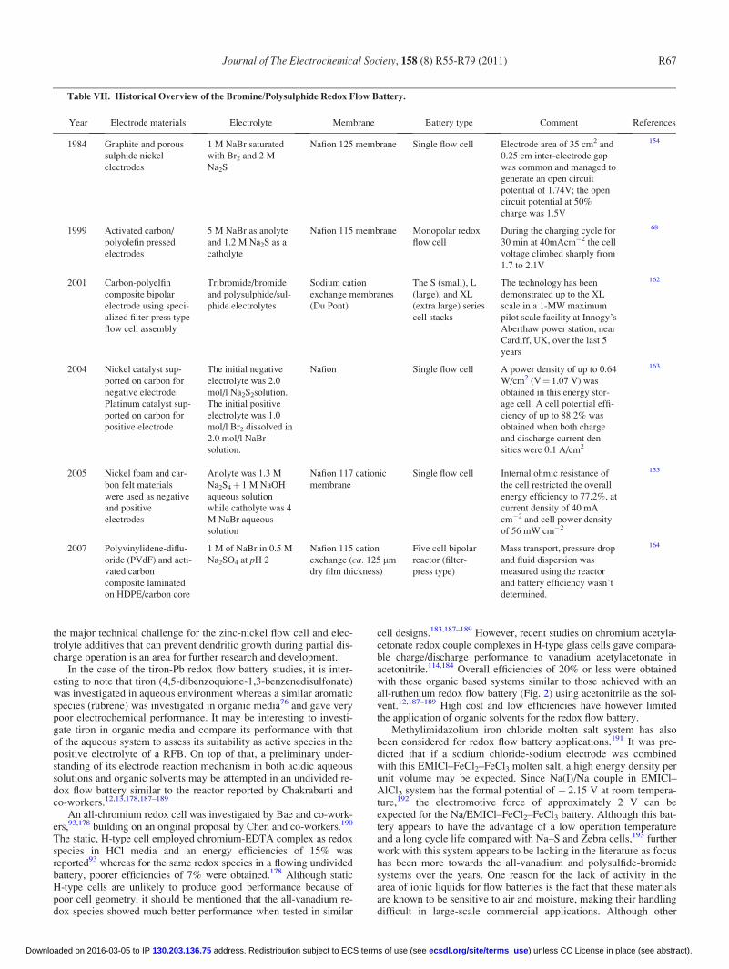
Polysulphide-bromine.— The sulphide-polysulphide system wasfirst patented in 1983, opening up the future for research in the poly-sulphide-bromine redox flow battery.154 This system was found tobe attractive for RFB applications due to abundance of the electro-lyte, reasonable cost of chemicals and high solubility in aqueousmedia.68 The polysulphide-bromine redox flow battery, oftenreferred to as the Regenesys cell, has a nominal open-circuit cellpotential of 1.5 V and cell energy efficiencies of 60–65% dependingon operating conditions. The cell operating temperature is typicallybetween 20 and 40�C.68 Table VI summarizes the battery operatingconditions briefly, while Table VII briefly describes the historicalevolution of the technology.
Technical challenges with this system have included:68,165
(a) cross-contamination problems of both electrolyte solutionsover a period of time;
(b) The difficulty in maintaining electrolyte balance;(c) The possibility of deposition of sulphur species on the mem-
brane; and(d) The need to prevent H2S(g) and Br2(g) formation.
Most of the development of the polysulphide-bromine systemwas carried out by Innogy in the 1990s and considerable advanceswere made with stack design and fabrication. Numerical modellingof the polysulfide-bromide (PSB) system revealed that mass trans-port overpotentials at the bromide electrode limit the performanceduring discharge.166 The model showed that significant drift in con-ditions could occur due to self-discharge and electro-osmoticeffects. Careful electrolyte management was suggested to ensurereliable operation of the polysulphide-bromine RFB system.Because of the complexity of the electrolyte management system,however, it was decided to restrict the application of the polysul-fide-bromide RFB to MW-scale installations where the electrolyte
Journal of The Electrochemical Society, 158 (8) R55-R79 (2011) R65
) unless CC License in place (see abstract). ecsdl.org/site/terms_use address. Redistribution subject to ECS terms of use (see 130.203.136.75Downloaded on 2016-03-05 to IP

maintenance costs would not be prohibitive. A separate mathemati-cal model incorporating capital and operating costs to predict thetechnical and commercial performance of the polysulphide-bromineRFB at a 120MWh/15MW utility-scale storage plant for arbitrageapplications revealed a net loss of US$0.0073/kWh at an optimumcurrent density of 500 Am�2 and an energy efficiency of 64%,167
indicating the need for further cost reduction. Furthermore, unlikethe V-Br cell, the polysulphide-bromine cell has not utilised com-plexing agents to bind any bromine produced at the positive elec-trode during charging, and this has often been seen as a considerablesafety risk with this technology. Hence, considerable research is stillrequired to ensure that this system overcomes current techno-eco-nomic constraints and safety concerns in order to become a wide-spread commercialized technology.
Actinide based redox flow battery.— These systems were verybriefly mentioned in the previous review paper.68 Two systems havebeen proposed as a means of utilizing excess depleted actinides forenergy storage purposes. One involved the neptunium couplesNp3þ/Np4þ and NpO2
þ/NpO22þ in aqueous solution168 while the
other considered the use of uranium {U(IV)/U(III) and U(VI)/U(V)}couples in organic solvents.169–173 An open circuit potential ofaround 1 V was estimated for the all-uranium couples complexed bya range of b-diketone ligands.174 Besides this, charge/discharge testdata of the all-uranium redox flow battery have not been provided asyet. The same is the case for the all-neptunium redox couple system,although theoretical calculations have revealed that an all-neptu-nium battery can produce energy efficiencies ranging from 40 to99.1%,175,176 with 99.1% efficiency obtainable at 70 mA/cm2. Somemore details on the system are given in Table VIII.
A major obstacle in the development of actinide-based RFB, isthe use of radioactive redox species that is likely to encounter signif-icant consumer resistance. Special precautionary measures and a
thorough investigation will therefore need to be conducted to evalu-ate their safety and environmental implications before commerciali-zation. For example, the high radioactivity of neptunium has limitedthe practical evaluation of the all-neptunium redox flow battery sothat only theoretical estimations of energy efficiencies are availableby means of mathematical modeling.176
Other flow cell developments.— The latest redox flow batterychemistries that are currently being developed are summarized inTable VIII. The zinc-nickel hybrid system appears to give an energyefficiency of 86% (Ref. 181) comparable to the all-vanadium RFB,followed by the tiron/Pb redox flow battery.180 The zinc-nickelhybrid system utilises the Zn(II)/Zn and Ni(III)/Ni(II) redox cou-ples. Since this system uses a single electrolyte and produces solidproducts at the electrodes during charging, it does not require amembrane, so its cost is likely to be less than most conventional re-dox flow battery systems.182 Theoretically, the deposition/dissolu-tion of zinc on inert metal current collectors can be cycled end-lessly.185 However, that is not possible practically due to formationof zinc dendrites during charging. Researchers have studied themorphology of zinc dendrites and found that at higher electrolyteflow rates (> 15 cm s�1) good cycle life for the battery can beobtained at 100% depth of discharge.186 Complete discharge is how-ever a critical requirement for the long-term prevention of dendrites,and this produces an operational restriction on any cell employingthe Zn2þ/Zn couple. In addition, the cycle life of the zinc-nickelsingle flow battery is dependent on the stability of nickel oxide elec-trodes in the presence of zinc ions in the electrolyte that lowers thedischarging capacity of the nickel oxide electrode. Cheng et alfound however, that in concentrated KOH electrolytes containing 20g l�1 LiOH, addition of 0.4 M ZnO to the electrolyte actuallyenhanced the stability of the nickel oxide electrodes during a cellcycling.185 The potential for Zn dendrite formation will however be
Table VI. Operating conditions and technicalities of some possible commercial flow batteries excluding the all vanadium system.
No. Redox systemElectrolyte
composition
Charge/DischargeReaction atElectrodes OCP (V)
Charge/Discharge
current density(mA/cm2)
Electrode andmembrane
materials used
Charge/Discharge
Efficiency (%) References
1 Bromine-
polysulfide
5 M NaBr satu-
rated with Br2
and 1.2 M Na2S
Positive electrode:
3Br� ! Br3� þ2e�
Negative electrode:
S42� þ2e� ! 2S2
2�
1.7–2.1 40 Activated carbon/polyo-
lefin pressed electrodes
or nickel foam/carbon
felt materials divided
by a Nafion 115 or 117
membranes
77.2 (overall) 68, 154, 155
2 Zinc-bromine 1–7.7 mol dm�3
ZnBr2 with an
excess of Br2 with
additives such as
KCl or NaCl
Positive electrode:
2Br� ! Br2þ 2e�
Negative electrode:
Zn2þþ 2e� !Zn0(s)
1.6 15 Two carbon electrodes
of 60 cm2 and 5 mm
interelectrode gap sepa-
rated by a Nafion 125 or
polypropylene micropo-
rous membranes
80 (overall) 68; 156–158
3 Zinc-cerium Anolyte: 0.3 M
Ce2(CO3)3 and
1.3 M ZnO in 70
wt.% methane
sulfonic acid
catholyte: 0.36 M
Ce2(CO3)3 and 0.9
M ZnO in 995 g
methane sulfonic
acid
Positive electrode:
2Ce 3þ !2Ce4þþ 2e –
Negative electrode:
Zn 2þþ 2e �
! Zn0 (s)
2.45 50 Carbon plastic anodes
and platinised titanium
mesh cathodes of 100
cm2 geometrical area
separated by a (non-
specified type of)
Nafion membrane
98 (coulombic) 68, 110, 158,
159
4 Soluble lead-acid Soluble lead (II)
species in metha-
nesulfonic acid
Positive electrode:
Pb2þþ 2H2O!PbO2þ 2Hþþ 2e–-
Negative electrode:
Pb 2þþ 2e � ! Pb
(s)
1.62 20 Cathode and anode
made of 70 ppi reticu-
lated vitreous carbon
and 40 ppi reticulated
nickel, respectively
60–66 (overall) 68, 160, 161
Journal of The Electrochemical Society, 158 (8) R55-R79 (2011)R66
) unless CC License in place (see abstract). ecsdl.org/site/terms_use address. Redistribution subject to ECS terms of use (see 130.203.136.75Downloaded on 2016-03-05 to IP
the major technical challenge for the zinc-nickel flow cell and elec-trolyte additives that can prevent dendritic growth during partial dis-charge operation is an area for further research and development.
In the case of the tiron-Pb redox flow battery studies, it is inter-esting to note that tiron (4,5-dibenzoquione-1,3-benzenedisulfonate)was investigated in aqueous environment whereas a similar aromaticspecies (rubrene) was investigated in organic media76 and gave verypoor electrochemical performance. It may be interesting to investi-gate tiron in organic media and compare its performance with thatof the aqueous system to assess its suitability as active species in thepositive electrolyte of a RFB. On top of that, a preliminary under-standing of its electrode reaction mechanism in both acidic aqueoussolutions and organic solvents may be attempted in an undivided re-dox flow battery similar to the reactor reported by Chakrabarti andco-workers.12,13,178,187–189
An all-chromium redox cell was investigated by Bae and co-work-ers,93,178 building on an original proposal by Chen and co-workers.190
The static, H-type cell employed chromium-EDTA complex as redoxspecies in HCl media and an energy efficiencies of 15% wasreported93 whereas for the same redox species in a flowing undividedbattery, poorer efficiencies of 7% were obtained.178 Although staticH-type cells are unlikely to produce good performance because ofpoor cell geometry, it should be mentioned that the all-vanadium re-dox species showed much better performance when tested in similar
cell designs.183,187–189 However, recent studies on chromium acetyla-cetonate redox couple complexes in H-type glass cells gave compara-ble charge/discharge performance to vanadium acetylacetonate inacetonitrile.114,184 Overall efficiencies of 20% or less were obtainedwith these organic based systems similar to those achieved with anall-ruthenium redox flow battery (Fig. 2) using acetonitrile as the sol-vent.12,187–189 High cost and low efficiencies have however limitedthe application of organic solvents for the redox flow battery.
Methylimidazolium iron chloride molten salt system has alsobeen considered for redox flow battery applications.191 It was pre-dicted that if a sodium chloride-sodium electrode was combinedwith this EMICl–FeCl2–FeCl3 molten salt, a high energy density perunit volume may be expected. Since Na(I)/Na couple in EMICl–AlCl3 system has the formal potential of � 2.15 V at room tempera-ture,192 the electromotive force of approximately 2 V can beexpected for the Na/EMICl–FeCl2–FeCl3 battery. Although this bat-tery appears to have the advantage of a low operation temperatureand a long cycle life compared with Na–S and Zebra cells,193 furtherwork with this system appears to be lacking in the literature as focushas been more towards the all-vanadium and polysulfide-bromidesystems over the years. One reason for the lack of activity in thearea of ionic liquids for flow batteries is the fact that these materialsare known to be sensitive to air and moisture, making their handlingdifficult in large-scale commercial applications. Although other
Table VII. Historical Overview of the Bromine/Polysulphide Redox Flow Battery.
Year Electrode materials Electrolyte Membrane Battery type Comment References
1984 Graphite and porous
sulphide nickel
electrodes
1 M NaBr saturated
with Br2 and 2 M
Na2S
Nafion 125 membrane Single flow cell Electrode area of 35 cm2 and
0.25 cm inter-electrode gap
was common and managed to
generate an open circuit
potential of 1.74V; the open
circuit potential at 50%
charge was 1.5V
154
1999 Activated carbon/
polyolefin pressed
electrodes
5 M NaBr as anolyte
and 1.2 M Na2S as a
catholyte
Nafion 115 membrane Monopolar redox
flow cell
During the charging cycle for
30 min at 40mAcm�2 the cell
voltage climbed sharply from
1.7 to 2.1V
68
2001 Carbon-polyelfin
composite bipolar
electrode using speci-
alized filter press type
flow cell assembly
Tribromide/bromide
and polysulphide/sul-
phide electrolytes
Sodium cation
exchange membranes
(Du Pont)
The S (small), L
(large), and XL
(extra large) series
cell stacks
The technology has been
demonstrated up to the XL
scale in a 1-MW maximum
pilot scale facility at Innogy’s
Aberthaw power station, near
Cardiff, UK, over the last 5
years
162
2004 Nickel catalyst sup-
ported on carbon for
negative electrode.
Platinum catalyst sup-
ported on carbon for
positive electrode
The initial negative
electrolyte was 2.0
mol/l Na2S2solution.
The initial positive
electrolyte was 1.0
mol/l Br2 dissolved in
2.0 mol/l NaBr
solution.
Nafion Single flow cell A power density of up to 0.64
W/cm2 (V¼ 1.07 V) was
obtained in this energy stor-
age cell. A cell potential effi-
ciency of up to 88.2% was
obtained when both charge
and discharge current den-
sities were 0.1 A/cm2
163
2005 Nickel foam and car-
bon felt materials
were used as negative
and positive
electrodes
Anolyte was 1.3 M
Na2S4þ 1 M NaOH
aqueous solution
while catholyte was 4
M NaBr aqueous
solution
Nafion 117 cationic
membrane
Single flow cell Internal ohmic resistance of
the cell restricted the overall
energy efficiency to 77.2%, at
current density of 40 mA
cm�2 and cell power density
of 56 mW cm�2
155
2007 Polyvinylidene-diflu-
oride (PVdF) and acti-
vated carbon
composite laminated
on HDPE/carbon core
1 M of NaBr in 0.5 M
Na2SO4 at pH 2
Nafion 115 cation
exchange (ca. 125 mm
dry film thickness)
Five cell bipolar
reactor (filter-
press type)
Mass transport, pressure drop
and fluid dispersion was
measured using the reactor
and battery efficiency wasn’t
determined.
164
Journal of The Electrochemical Society, 158 (8) R55-R79 (2011) R67
) unless CC License in place (see abstract). ecsdl.org/site/terms_use address. Redistribution subject to ECS terms of use (see 130.203.136.75Downloaded on 2016-03-05 to IP

Table VIII. Properties of actinide based redox flow batteries and other novel systems developed after publication of previous review paper (Ref. 68).
No. Redox system Electrolyte compositionCharge/discharge
Reaction at ElectrodesOCP(V)
Charge/dis-charge cur-rent density(mA/cm2) Cell type
Electrode and membranematerials used
Charge/dischargeEfficiency (%) References
1 All-neptunium 1 M nitric acidic solutionof 0.05 M neptunium
Positive electrode:Np3þ ! Np4þþ e�
Negative electrode:NpO2
2þþ e � ! NpO2þ
1.3 70 StationaryH-type cell
c-Plane carbon of pyrolyticgraphite and plastic formed car-bon. A-511 anion exchangemembrane used.
99.1 (predicted via mathe-matical modelling)
175,176
2 All-uranium U(VI)/U(V) b-diketonatesolution as the catholyteand U(IV)/U(III) b-diketo-nate solution as the anolyte
Positive electrode:U(IV)! U(V)þ e�Negativeelectrode:U(IV)þ e � ! U(III)
1.1 75 StationaryH-type cell
A platinum working electrode(1.6/), a Ag/AgNO3 referenceelectrode prepared with a corre-sponding solvent and a 10� 10mm platinum plate counterelectrode were used.
Not measured nor predicted 169–173
3 All-chromium 0.2 M chromium EDTAcomplex in HCl
Positive electrode:[Cr(III)EDTA(H2O)]� ![Cr(V)EDTA(H2O)]þþ 2e�
Negative electrode:2[Cr(III)EDTA(H2O)]�þ 2e� !2[Cr(II)EDTA(H2O)]2�
2.11 30 (duringcharge) 2.5
(duringdischarge)
Flow cell Graphite felt electrodes ther-mally pre-treated at 500�C inmuffle furnace to reduce itshydrophobic nature
15% with stationary H-typecell and 7% with undividedredox flow battery
34,177,178
4 Zinc-air 0.4 M ZnO in 6 M KOH so-lution was employed as thecatholyte and propanol ofdifferent concentrations in6 M KOH solution wasemployed as the anolyte.
Positive electrode: Propanol oxi-dation during charging; oxygenreduction during discharge.Negative electrode:Zn(OH)4
2�þ 2e� ! Znþ 4OH�
1.705 20 Not given Sintered nickel electrodes areemployed as positive electro-des, and inert metal current col-lectors are employed asnegative substrate electrodes.
59.2 (overall) 179
5 Tiron 0.25 M tiron in 3 M H2SO4
as cathodic active speciesand the lead electrode asanodic active species
Positive electrode:[Tiron]þ 2Hþþ 2e� ! [Tiron]�
Negative electrode:Pbþ SO4
2� ! PbSO4þ 2e�
1.10 10 Not given Cation-exchange membrane(Nafion 115, Du Pont) wasused as a separator. A graphitefelt electrode (10 mm in thick-ness) contacted against onegraphite plate was used as theworking electrode. A lead neg-ative electrode with an area ofaround 20 cm2 and a SCE elec-trode were used as the counterelectrode and reference elec-trode, respectively.
82 (overall) 180
6 Zinc-nickel Highly concentrated solu-tions of ZnO in aqueousKOH
Positive electrode:2NiOOHþ 2H2Oþ 2e� !2Ni(OH)2þ 2OH�
Negative electrode: Znþ 4OH�
! Zn(OH)42�þ 2e�
1.705 10 Flow cell The negative electrode is inertmetal such as nickel foil, andthe positive electrode is nickeloxide. No membranerequirement.
88 (overall) 181,182
7 [Ru(acac)3] 0.02 M ruthenium acetyla-cetonate with 0.1 M tetra-ethylammonium tetrafluor-oborate dissolved inacetonitrile
Positive electrode: Ru(acac)3]![Ru(acac)3]þþ e�
Negative electrode:[Ru(acac)3]þ e� ! [Ru(acac)3]�
1.76 0.28(charge)
0.056(discharge)
Flow cell Graphite felt electrodes in undi-vided flow-through electro-chemical reactor
5 (overall) 17,183
8 Cr(acac)3 0.05 M Cr(acac)3 and 0.5M TEABF4 dissolved inacetonitrile
Positive electrode: Cr(acac)3]![Cr(acac)3]þþ e�
Negative electrode:[Cr(acac)3]þ e� ! [Cr(acac)3]�
3.4 0.14(charge)
0.014(discharge)
StationaryH-type cell
Graphite electrodes 55 (coulombic)20 (overall)
184
Journalof
The
Electrochem
icalSociety,
158
(8)
R55-R
79
(2011)
R68
) unless CC
License in place (see abstract). ecsd
l.org
/site/terms_u
se address. R
edistribution subject to EC
S term
s of use (see 130.203.136.75
Dow
nloaded on 2016-03-05 to IP

ionic liquids that are not as sensitive to air and moisture may befound, these materials also tend to be quite expensive and areunlikely to be economically viable for these types of applicationscompared to the lower cost aqueous systems. Given the large elec-trochemical window of many ionic liquids however, the possibilityof using redox couples that fall outside the decomposition potentialof water, may open the way to the development of high voltage flowcells that offer much higher power and energy densities than currentaqueous systems. Further investigation of such couples could there-fore prove fruitful as long as practical systems can be shown to offerbetter performance, cell voltage and cycle life than the VRB andPSB systems to offset the high costs of these electrolytes.
The electrochemical behavior of the Fe(III)/Fe(II)–triethanola-mine(TEA) complex redox couple in alkaline medium and the influ-ence of the concentration of TEA were investigated recently.192 Achange of the concentration of TEA mainly produces the followingtwo results:
1. With an increase of the concentration of TEA, the solubilityof the Fe(III)–TEA can be increased to 0.6 M, and the solubility ofthe Fe(II)–TEA is up to 0.4 M.
2. In high concentration of TEA with the ratio of TEA to NaOHranging from 1 to 6, side reaction peaks on the cathodic main reactionof the Fe(III)–TEA complex at low scan rate can be minimized.192
The electrode process of Fe(III)–TEA/Fe(II)–TEA was shownto be electrochemically reversible with higher reaction rate con-stant than the non-complexed species.93 Constant current charge–discharge showed that applying anodic active materials of rela-tively high concentrations facilitates the improvement of cell per-formance. The open-circuit potential of the Fe–TEA/Br2 cell withthe Fe(III)–TEA of 0.4 M concentration, after full charging, isnearly 2 V and is about 32% higher than that of the all-vanadiumbatteries, while the energy efficiency is comparable at approxi-mately 70%.93 Although the active material concentrations used todate have been too low for practical application, further optimiza-tion of the electrolyte composition may establish its potential forfuture commercialization.
Chemically regenerative redox fuel cells.— The chemically re-generative redox fuel cell is a type of fuel cell that employs redoxcouple solutions as electron mediators for the fuel and oxidant reac-tions. A chemically regenerative redox fuel cell is thus a type offlow cell since it contains two redox couples which are circulatedpast the electrodes, and after electrochemical reaction at the electro-des, the solutions are passed into regeneration reactors where theyare re-reduced or re-oxidized by the reductant and oxidant respec-tively. After the regeneration step the solutions are once more circu-lated past the electrodes, and the process proceeds. Most of the earlywork on redox fuel cells was reported by Kummer and Oei194–196
whose work has shown the advantages and the limitations of theredox fuel cell. These workers investigated a wide range or redoxcouples, the main criterion for selection being the feasibility toregenerate the charged species using hydrogen and/or oxygen forthe negative and positive half-cell reactants respectively, while alsoattaining the required power density for electric vehicle applica-tions.195,197 Other workers evaluated different membranes for redoxfuel cells119,198 and regeneration reactants.199,200 The main attrac-tion of this concept is the possibility of avoiding catalysts at theelectrode surface and of using simple (inexpensive) electrode mate-rials. Although hydrogen was the original fuel of choice, the conceptoffers a freedom of choice of fuels. The main disadvantage of usinghydrogen for the regeneration of the negative half-cell active speciesis the relatively high reversible potential for the hydrogen couplethat limits the range of redox couples that can be used in the nega-tive half-cell. On the other hand, early studies194–196 also showedthat the oxidative regeneration of the positive half-cell couple usingair or oxygen, is also kinetically slow, requiring relatively expensivecatalysts that negate the main purpose of this approach.
More recently, a group of researchers from the University of Brit-ish Columbia and the National Research Council of Canada has beenworking on two new approaches for a direct liquid redox fuel cell(DLRFC) in which the air cathode of a regular direct methanol liquidfuel cell is replaced with a metal-ion redox couple over a carbon cath-ode. For example, in a Fe-methanol fuel cell, methanol is used as thefuel and Fe3þ is used as oxidant. When the Fe3þ is depleted, the Fe2þ
is passed through a separate regeneration cell where it is reacted withoxygen gas at the anode to reform the Fe3þ reactant for the fuel cell.In the DLRFC described by Ilicic et al.201 however, spontaneous re-dox couple regeneration is achieved by simply substituting the metha-nol anolyte with an air stream on the anode side. The methanol anodethen becomes an air cathode, which reverses the direction of electronflow and regenerates the Fe3þ oxidant in the DLRFC.
The first approach uses mixed-reactant operation that involvessupplying a mixed methanol Fe2þ/Fe3þ redox electrolyte only to thecarbon cathode. Spontaneous methanol crossover supplies the fuel tothe anode. This approach eliminates problems associated with the ox-ygen diffusion electrode and has the potential to significantly improvethe cost, compactness, and volumetric and gravimetric power den-sities of the cell. The second approach is the in situ regeneration ofthe redox couple by supplying air to the methanol anode that thenbecomes an air cathode, which reverses the direction of electron flowand regenerates the redox couple on the other electrode.201,202
Hybrid Flow Battery Technologies
Zinc-hybrid technology.— Hybrid flow batteries are distin-guished from conventional redox flow batteries by the feature that atleast one redox couple species is not fully soluble and may be eithera metal or a gas. A number of hybrid flow cells were listed in TablesVI and VIII, but the most widely known of these is the zinc-brominebattery. The underlying concept of the zinc-bromine battery wasfirst proposed more than 100 years ago, but in the mid 1970s andearly 1980s, Exxon and Gould pioneered the initial designs for prac-tical application. The zinc-bromine hybrid system, ranging in sizefrom 50 to 400 kWh, is capable of storing energy for 2–10 h at effi-ciencies of 70% or higher158 Coulombic and voltage efficiencieswere reported to be around 90 and 85% respectively, whereas the
Figure 2. Undivided redox flow battery employing chromium, vanadium or ru-thenium species for charge/discharge applications (Refs. 12, 178, 188, and 189).Figure reproduced with kind permission from Springer Science+Business MediaB.V.
Journal of The Electrochemical Society, 158 (8) R55-R79 (2011) R69
) unless CC License in place (see abstract). ecsdl.org/site/terms_use address. Redistribution subject to ECS terms of use (see 130.203.136.75Downloaded on 2016-03-05 to IP

energy density is around 65–75 Wh kg�1 (Ref. 159) The system isbriefly summarized in Table VI and a schematic of the zinc-brominehybrid system is given in Fig. 3.127
In order to optimise the zinc-bromine battery, various mathemat-ical models have been used to describe the system.203–206 The prob-lems with the zinc-bromine battery include high cost electrodes, ma-terial corrosion, dendrite formation during zinc deposition oncharge, high self-discharge rates, unsatisfactory energy efficiencyand relatively low cycle life68 Another disadvantage of this systemis slow kinetics of the bromine/bromide couple that causes polariza-tion and loss in voltage efficiency. To overcome this, high surfacearea carbon electrode on the cathode side is normally used to reducethe effective current density, however, the active surface area of thecarbon eventually decreases and oxidation of the carbon coatingoccurs.68
In zinc-bromine hybrid systems, the energy storage and powerof the battery are not fully decoupled as the energy storage capacitywill depend on the thickness and morphology of the metallic layerformed. A porous separator is often used between the positive andnegative electrodes to avoid the reduction of dissolved bromineduring charge68 however bromine cross-over is still an importantissue, as is the problem of dendritic growth and shorting. Electro-lyte additives (e.g., quaternary ammonium salts) can be used tocomplex any dissolved bromine that has been inadvertently trans-ported through the membrane to the zinc half-cell.207 However, itsperformance does not match that of the all-vanadium RFB as yetand is mainly being developed for smaller applications up to 500kWh. The main reason for the limited attention has been the opera-tional limitations associated with the need to prevent zinc den-drites. Despite extensive work to optimise the design of electrolytechannels and manifolds to minimise shunt currents, zinc dendritescan still form after extended cycling, causing channel blockage andshorting through the separator. This is typically overcome by regu-lar full discharge to completely strip all of the zinc from the nega-tive plates to eliminate sites where dendrites can grow. Thisrequirement creates undesirable operational restrictions, so furtherwork on electrolyte additives to inhibit dendritic growth is an areathat could yield considerable benefits for the future implementationof this technology.
Despite these problems with zinc plating, however, the very neg-ative potential of the Zn2þ/Zn couple continues to make this half-cell attractive for flow cell applications. The zinc-cerium hybrid re-dox flow battery is one such system that combines the very negativezinc couple with a very positive cerium couple to yield a cell volt-age of more than 2 V and an OCP that is higher than any of its com-mercial competitors.163 The zinc-cerium has been under develop-ment since the early 1990s by Electrochemical Design AssociatesInc.159 and some of its properties are given in Table VII. The testingand development of this system has been undertaken by Plurion Sys-
tems Limited. This hybrid flow cell involves the use of salts of zincand cerium in an organic solvent.68,208 It has some similarity to thezinc-bromine system in that the negative half-cell redox coupleinvolves a solid zinc phase. It also uses an environmentally benignorganic acid as the solvent (not degraded by cross-membrane migra-tion) and a common electrolyte system in both half-cells.
Mathematical modelling to understand the redox nature of theCe(IV)/Ce(III) redox couple has also been conducted for a batch sys-tem comprising an electrochemical reactor and an electrolyte cir-cuit.209 The batch recycle system consisted of a pumped flowthrough divided FM01-LC parallel-plate electrochemical reactor (64cm2 projected electrode area) and a well mixed tank (3600 cm3).Unfortunately, significant differences between experimental and pre-dicted values were found at long electrolysis times. This was partlyattributable to the presence of solvated species and complex forma-tion involving Ce(III) and Ce(IV) species, which modified the actualconcentration of Ce(III) and Ce(IV) from the predicted values.209
This has limited the energy density of the zinc-cerium system todate, however, further research may help to address this limitation,allowing it to compete commercially with the all-vanadium RFB.
Other zinc hybrid systems (such as zinc-nickel) have been devel-oped recently and will be discussed in later sub-sections of thispaper.
Flowing undivided lead acid battery technology.— The systemdiffers from the traditional lead-acid battery since it uses a highlysoluble form of the Pb(II) species that is supplied as a aqueous acidelectrolyte for both the negative and positive half-cells reactions.68
It also differs from conventional redox flow batteries since it uses asingle electrolyte and involves the formation of solid products at thetwo electrodes during charging, so that no separator or membrane isnecessary. This reduces the cost and design complexity of the bat-teries significantly68 Some properties of the system are described inbrief in Table VI, while a schematic representation of the system isgiven in Fig. 4.
The electrode reactions involve the conversion of the solublespecies into solid Pb and PbO2 phases at the negative and positiveelectrodes respectively during charging and re-dissolution duringthe discharging cycles. The deposition of solid phases on the elec-trodes during charging introduces complexities to the electrode reac-tions that may reduce the performance of the battery if the metalgrows across the inter-electrode gap and short circuits the battery.68
Dissolution and deposition of lead is fast and no overpotentials areusually required, however as with conventional lead-acid batteries,hydrogen evolution is observed during the charge cycle at highstate-of-charge, thus reducing storage capacity.210 These cells havebeen studied in several electrolytes; percholoric acid, hydrochloricacid, hexafluorosilicic acid, tetrafluoroboric acid and most recentlyin methanesulphonic acid.68,161,210–212
The structure of lead deposits (approximately 1 mm thick)formed in conditions that are met at the negative electrode duringthe charge/discharge cycling of a soluble lead-acid flow battery was
Figure 3. (Color online) Schematic of Zinc-Bromine Flow Battery(Ref. 127). Figure reproduced with kind permission from Woodhead Publish-ing Limited, Cambridge, UK.
Figure 4. (Color online) Undivided Lead Flow Cell.
Journal of The Electrochemical Society, 158 (8) R55-R79 (2011)R70
) unless CC License in place (see abstract). ecsdl.org/site/terms_use address. Redistribution subject to ECS terms of use (see 130.203.136.75Downloaded on 2016-03-05 to IP

examined in some detail by Pletcher et al.213 The quality of the leaddeposit could be improved by appropriate additives and the pre-ferred additive was shown to be the hexadecyltrimethylammoniumcation, C16H33(CH3)3Nþ, at a concentration of 5 mM. In the pres-ence of this additive, thick layers with acceptable uniformity couldbe formed over a range of current densities (20–80 mA cm�2) andsolution compositions.213 While electrolyte compositions with lea-d(II) concentrations in the range 0.1–1.5 M and methanesulfonicacid concentrations in the range 0–2.4 M have been investigated,the best quality deposits are formed at lower concentrations of bothspecies. Surprisingly, the acid concentration was more importantthan the lead(II) concentration; hence a possible initial electrolytecomposition for an efficient system was postulated to be 1.2 MPb(II)þ 5 mM C16H33(CH3)3Nþ without added acid.212 The systemwas predicted to be cycled between 0.2 M Pb(II)þ 2 M CH3SO3Hat top of charge to 1.15 M Pb(II)þ 0.1 M CH3SO3H at bottom ofcharge. Also the current density was expected to be up in the rangeof 20–80 mAcm�2 for suitable operation of the system.214
Extensive cycling of the soluble lead flow battery has revealedunexpected problems with the reduction of lead dioxide at the posi-tive electrode during discharge.214 This has led to a more detailedstudy of the PbO2/Pb2þ couple in methanesulphonic acid. The varia-tion of the phase composition measured by XRD and deposit struc-ture measured using SEM have been defined as a function of currentdensity, Pb2þ and Hþ concentrations, deposition charge and temper-ature as well as the consequences of charge cycling.214 Purea-PbO2, pure b-PbO2 and their mixtures can be deposited frommethanesulphonic acid media successfully. The a-phase deposits asa more compact, smoother layer, which is well suited to charge cy-cling. While the anodic deposition of thick layers of PbO2 isstraightforward, their reduction is not; the complexities areexplained by an increase in pH within the pores of the deposit. Theresults suggest that operating the battery at lead(II) concentrations< 0.3M and elevated temperatures should be avoided.214
It has been demonstrated that extended cycling of the solublelead acid battery in a 10� 10 cm parallel plate cell is possible, withgreater than 100 cycles achievable under some conditions.215 Even-tual failure is, however, inevitable if the battery is operated underconditions where solids are allowed to accumulate continuously onthe two electrodes. Failure usually results from: (a) shorting of theelectrodes owing to lead dendrites formation largely around theedges of the negative electrode plate and (b) poor adhesion of PbO2
to the positive electrode surface leading to particles in the electro-lyte and loss of active material.215
Extended cycling of the battery can lead to problems due to animbalance in the coulombic efficiency of the negative and positivecharging reactions that produce deposits of Pb and PbO2 on the elec-trodes.160 Periodic addition of hydrogen peroxide to the electrolytelargely overcomes several operational problems seen duringextended cycling. It is shown that this treatment greatly extends thenumber of cycles that can be achieved with a reasonable energy-,voltage-, and charge efficiency of 54–66, 71, and 77–91%, respec-tively.160 Further research and development is necessary before thesoluble lead acid battery can be considered for commercial scaleprojects.
The hybrid oxygen redox fuel cell.— A further extension of thechemically regenerative redox fuel cell is the hybrid redox fuel cellconcept that employs a redox couple electrolyte for the negativehalf-cell, but the positive half-cell electrolyte is replaced by air oroxygen. Like a conventional fuel cell, air or oxygen is fed through agas diffusion electrode in the positive half-cell, but in contrast to thefuel cell, the negative half-cell reactant comprises a soluble redoxcouple electrolyte, as illustrated in Fig. 5. By replacing the positivehalf-cell electrolyte reaction with an air or oxygen gas diffusionelectrode, the total electrolyte volume is reduced by half, effectivelydoubling the energy density of the system.
The vanadium-oxygen redox fuel cell (VOFC) concept was ini-tially proposed by Kaneko and co-workers in 1992 (Refs. 115 and
116) and first evaluated at UNSW by Menictas and Skyllas-Kazacosin 1997.63,216 In this project the performance of the VOFC over arange of temperatures and using different types of membranes andair electrode assemblies was evaluated. Despite early problems withthe membrane electrode assemblies that saw separation of the mem-brane due to swelling and expansion during hydration, withimproved fabrication techniques, this problem was minimized and itwas possible to operate a 5-cell VOFC system for a total of over 100h without any deterioration in its performance.63
With renewed interest in electric vehicles, the VOFC concepthas recently received further attention with a range of reportsemerging from the Fraunhofer Institute217 and Twente University inthe Netherlands218 Hosseiny et al.218 reported the effective quadru-pling of the energy density of the VCFC relative to the conventionalall-vanadium redox battery by the use of 4 M vanadium solutions inthe negative half-cell. The elimination of the positive half-cell reac-tant also eliminates the problem of thermal precipitation of V(V)species at high temperatures that currently restricts the upper tem-perature range of the VRB to 40�C. Without a threat of thermal pre-cipitation, the researchers were able to operate the cell at 80�C,thereby achieving 4 M solubilities for the V(II) and V(III) species inthe sulphuric acid negative electrolyte. This is a major advance inthe development of a high energy density VOFC that could findapplication in electric vehicles, however, an issue that would needto be addresses is the requirement to maintain high temperatures inthe negative electrolyte tanks and half-cells to prevent precipitationof the vanadium ions on cooling to room temperature. The evalua-tion of alternative supporting electrolytes that can give high solubi-lites for V(II) and V(III) ions at room temperature is therefore anarea that requires further attention.
Application and Commercial Status of Flow Batteries
Of all of the flow battery systems that have been researched anddeveloped in the last 30 or so years, the only technologies that havecome close to full-scale commercialisation are the iron-chromium,all-vanadium, zinc-bromine and sodium-polysulphide systems.Their applications and current status is evaluated in brief in thissection.
Figure 5. (Color online) Schematic of V-O2 Redox Fuel Cell.
Journal of The Electrochemical Society, 158 (8) R55-R79 (2011) R71
) unless CC License in place (see abstract). ecsdl.org/site/terms_use address. Redistribution subject to ECS terms of use (see 130.203.136.75Downloaded on 2016-03-05 to IP

Early iron-chromium battery demonstrations and recentcommercialisation.— The first 1 kW prototype Fe-Cr systems wasdeveloped in 1980 by NASA.91 The Fe-Cr redox flow battery wasinstalled and tested in a photovoltaic system but results were notsufficiently satisfactory for consideration of a full-scale prototype.Further work in Japan in the 1980s did however lead to the develop-ment of a 10 kW Fe-Cr redox battery prototype with an 80% energyefficiency and 300 life cycles, as demonstrated by Shimizu and co-workers (Kansai Electrical Power Co., Amagasaki, Japan).219 Oper-ations involving the catholyte and anolyte circulation rates (in a 10kW Fe-Cr redox-flow battery) to save energy, and a method of reba-lancing were described by Nakamura (Mitsui Ltd., Japan).220 Othersimilar prototype systems were developed and tested by NASA(Ref. 85) as well as in Japan95 for different applications while a 0.1MW pilot scale unit was evaluated in the mid 1990s in Spain.81
Commercial development of the Fe-Cr battery was however aban-doned because of problems of cross-contamination between anolyteand catholyte, poor energy efficiencies due to hydrogen evolution atthe negative electrode and fouling of the ion-exchange mem-branes.68 Hence, this system was largely ignored during the late-1990s and early 2000s. In the late 2000s however, the Fe-Cr batterywas revisited by a US-based technology company, Deeya Energy,221
when the world prices for vanadium briefly peaked at close to 4times historical average prices and the company saw the Fe-Cr sys-tem as a potentially lower priced product than the VRB.
All-vanadium redox flow battery.— The all-vanadium redox flowbattery has to date shown the greatest potential for large-scaleenergy storage applications with long cycle life and high energyefficiencies of over 80% in large installations.15–20 This technologyhas already been applied in a MW- scale and several kW scale proj-ects,222–231 with many practical demonstrations covering a range ofstationary and mobile applications in countries such as Japan,Europe, Australia and the USA.79,222–225 One of the main advan-tages of the vanadium redox flow battery that distinguishes it frommost other flow battery systems is the use of the same element inboth half-cells that prevents cross contamination and a theoreticallyindefinite electrolyte life. It also exhibits a low cost for large storagecapacities; cost per kWh decreases as energy storage capacityincreases and typical projected battery costs for eight or more hoursof storage are as low as US$150/kWh.127
Since 1993 a number of field trials of the vanadium battery werebeen undertaken both by UNSW as well as in Thailand and Japan.In collaboration with UNSW Centre for Photovoltaic Devices andSystems and licensee Thai Gypsum Products Ltd., a vanadium bat-tery storage system was installed in a demonstration Solar House inThailand.10,60,61
The solar energy system included 2.2 kW of installed solar cellsand a 12 kWh vanadium battery. The original battery had 12 cellsgiving a system voltage of 16.8 V and used 200 l of each half-cellelectrolyte in the two reservoirs.60 A 48 V, 36 cell stack was laterconstructed in the laboratory and tested with a 4 kW inverter andspecially designed battery controller, prior to installation in the dem-onstration Solar House in Thailand. The 48 V batteries replaced theoriginal 12-cell stack for long-term field trials. The microprocessorcontroller built by the UNSW Centre for Photovoltaic Systems andDevices, was designed to optimise the efficiency of the battery forthis application.60,127 This included the use of a pump control sys-tem that only switched on the pumps if the current exceeded a pre-set value. At lower loads, the pumps would only turn on for a fewminutes at a time when the stack voltage dropped below 1 V,thereby allowing the electrolyte within the cell stack to be replen-ished. This simple on-off pump controller significantly reduced thepumping energy losses so as to maximise the overall energy effi-ciency of the system.
In 1993, a consortium comprising Mitsubishi Chemicals andKashima-Kita Power Corporation of Japan licensed the UNSW va-nadium battery technology for stationary uses and for the next 5–6years spent several million US dollars per annum to scale up the
technology for large-scale load-levelling and solar energy storageapplications.10,127 Kashima-Kita Electric Power Corporationemploys vanadium rich Venezuelan pitch as the fuel for electricitygeneration, thus producing a high vanadium content fly-ash as awaste product. An efficient chemical process was developed toextract the vanadium from the fly-ash which is then used to producea low-cost vanadium electrolyte for the vanadium redox flow bat-tery. A 3 m3 d�1 electrolyte production plant was commissioned inearly 1996.10,127
In 1997, a 200 kW/800 kWh grid-connected vanadium batterywas commissioned at the Kashima-Kita Electric Power station inJapan where it underwent long-term testing as a load-levelling sys-tem. By the beginning of 1998, it had already undergone 150charge-discharge cycles and was continuing to show high energyefficiencies of close to 80% at current densities of 80–100 mAcm�2.10,127
Since 1999, Sumitomo Electric Industries (SEI) in Japan hascompleted more than 20 medium to large VRB demonstration sys-tems in a wide range of applications including wind energy storage,emergency back-up power and load leveling, demonstrating overallenergy efficiencies as high as 80% and up to 270,000 charge-dis-charge cycles.64–66,223
In 2001, a vanadium energy storage system (VESS) incorporat-ing a 250 kW/520 kWh VRB was established in South Africa225
using six 40 kW stacks produced by Sumitomo Electric Industries.Pinnacle VRB also installed a 250 kW/1 MWh system for HydroTasmania in Australia for wind energy storage and the replacementof diesel fuel in 2003 (Refs. 10, 127 and 225) while a 250 kW/2MWh was installed in the USA in 2004 by VRB Power for voltagesupport and rural feeder augmentation.10,225 In 2005, SumitomoElectric Industries installed a 4 MW/6MWh system at Subaru WindFarm in Japan for wind energy storage and wind turbine outputpower stabilization. The latter system was reported to give overallround trip energy efficiency of 80% with cycle life of over 270,000cycles over 3 years of testing.223 In addition a vanadium batterypowered electric golf cart was field tested at UNSW, using 40 l of1.85 M all-vanadium RFB; a driving range of 17 km off-road wasobtained,232 which suggests that the energy density of an optimisedall-vanadium RFB could approach that of lead-acid, with the addedadvantage of rapid recharging by electrolyte replacement.22 Subse-quent studies with a 3 M stabilised vanadium electrolyte gave adriving range of 31.5 km with partly filled electrolyte tanks andshowed that up to 54 km could be achieved if the tanks were filledto their maximum capacity.232 Careful temperature control washowever required to avoid vanadium precipitation at temperaturesabove 35 or below 15�C.
Early VRB stack development in China was initiated by Zhangand co-workers at the Dalian Institute of Chemical Sciences where aone kW vanadium battery stack was designed and tested in 2006.Coulombic, voltage and energy efficiencies of 85.9, 91.1 and78.3%, respectively, were obtained at a current density of 60mAcm�2, with a maximum average output power of 1.35 kW at adischarge current density of 85 mAcm�2.229 The 1 kW moduleswere subsequently integrated into a 10 kW battery with a configura-tion of 4� 2 (serial� parallel) and an overall energy efficiency ofmore than 80%, at an average output power of 10.05 kW (currentdensity 85 mA cm�2) was achieved.
In July 2009, Chinese National Grid announced the launch of theZhangbei storage building, China’s first comprehensive demonstra-tion project, which includes 75 MW of projects in energy storage.Technologies such as all-vanadium, lithium and the Japanese so-dium- sulphur batteries have been included in several demonstrationprojects for energy storage. However, for wind energy storage, theall-vanadium redox battery was found desirable.225–227
A significant number of commercial VRB systems are now beingdelivered to customers for a wide range of applications by PrudentEnergy in China64 and Cellstrom GmbH in Austria.67 In both com-panies, the focus to date has been on the manufacture of 2–5 kWpower rating and these are being integrated into a range of products
Journal of The Electrochemical Society, 158 (8) R55-R79 (2011)R72
) unless CC License in place (see abstract). ecsdl.org/site/terms_use address. Redistribution subject to ECS terms of use (see 130.203.136.75Downloaded on 2016-03-05 to IP
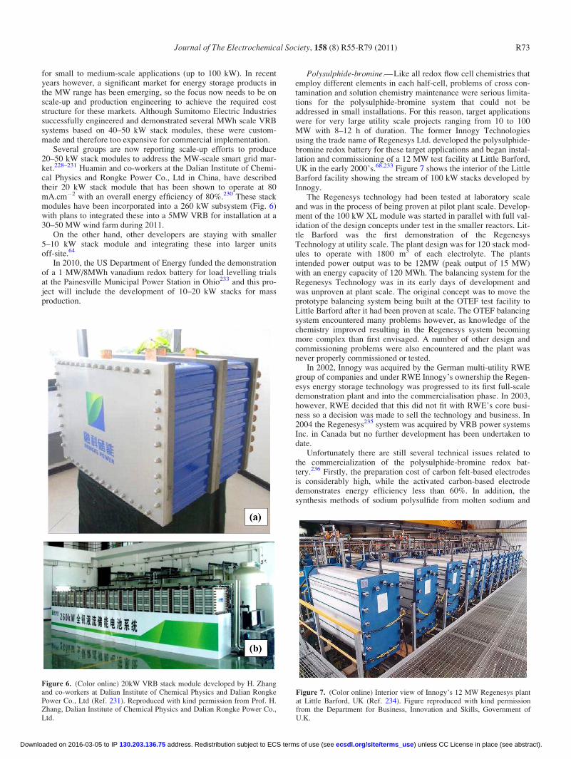
for small to medium-scale applications (up to 100 kW). In recentyears however, a significant market for energy storage products inthe MW range has been emerging, so the focus now needs to be onscale-up and production engineering to achieve the required coststructure for these markets. Although Sumitomo Electric Industriessuccessfully engineered and demonstrated several MWh scale VRBsystems based on 40–50 kW stack modules, these were custom-made and therefore too expensive for commercial implementation.
Several groups are now reporting scale-up efforts to produce20–50 kW stack modules to address the MW-scale smart grid mar-ket.228–231 Huamin and co-workers at the Dalian Institute of Chemi-cal Physics and Rongke Power Co., Ltd in China, have describedtheir 20 kW stack module that has been shown to operate at 80mA.cm�2 with an overall energy efficiency of 80%.230 These stackmodules have been incorporated into a 260 kW subsystem (Fig. 6)with plans to integrated these into a 5MW VRB for installation at a30–50 MW wind farm during 2011.
On the other hand, other developers are staying with smaller5–10 kW stack module and integrating these into larger unitsoff-site.64
In 2010, the US Department of Energy funded the demonstrationof a 1 MW/8MWh vanadium redox battery for load levelling trialsat the Painesville Municipal Power Station in Ohio233 and this pro-ject will include the development of 10–20 kW stacks for massproduction.
Polysulphide-bromine.— Like all redox flow cell chemistries thatemploy different elements in each half-cell, problems of cross con-tamination and solution chemistry maintenance were serious limita-tions for the polysulphide-bromine system that could not beaddressed in small installations. For this reason, target applicationswere for very large utility scale projects ranging from 10 to 100MW with 8–12 h of duration. The former Innogy Technologiesusing the trade name of Regenesys Ltd. developed the polysulphide-bromine redox battery for these target applications and began instal-lation and commissioning of a 12 MW test facility at Little Barford,UK in the early 2000’s.68,233 Figure 7 shows the interior of the LittleBarford facility showing the stream of 100 kW stacks developed byInnogy.
The Regenesys technology had been tested at laboratory scaleand was in the process of being proven at pilot plant scale. Develop-ment of the 100 kW XL module was started in parallel with full val-idation of the design concepts under test in the smaller reactors. Lit-tle Barford was the first demonstration of the RegenesysTechnology at utility scale. The plant design was for 120 stack mod-ules to operate with 1800 m3 of each electrolyte. The plantsintended power output was to be 12MW (peak output of 15 MW)with an energy capacity of 120 MWh. The balancing system for theRegenesys Technology was in its early days of development andwas unproven at plant scale. The original concept was to move theprototype balancing system being built at the OTEF test facility toLittle Barford after it had been proven at scale. The OTEF balancingsystem encountered many problems however, as knowledge of thechemistry improved resulting in the Regenesys system becomingmore complex than first envisaged. A number of other design andcommissioning problems were also encountered and the plant wasnever properly commissioned or tested.
In 2002, Innogy was acquired by the German multi-utility RWEgroup of companies and under RWE Innogy’s ownership the Regen-esys energy storage technology was progressed to its first full-scaledemonstration plant and into the commercialisation phase. In 2003,however, RWE decided that this did not fit with RWE’s core busi-ness so a decision was made to sell the technology and business. In2004 the Regenesys235 system was acquired by VRB power systemsInc. in Canada but no further development has been undertaken todate.
Unfortunately there are still several technical issues related tothe commercialization of the polysulphide-bromine redox bat-tery.236 Firstly, the preparation cost of carbon felt-based electrodesis considerably high, while the activated carbon-based electrodedemonstrates energy efficiency less than 60%. In addition, thesynthesis methods of sodium polysulfide from molten sodium and
Figure 6. (Color online) 20kW VRB stack module developed by H. Zhangand co-workers at Dalian Institute of Chemical Physics and Dalian RongkePower Co., Ltd (Ref. 231). Reproduced with kind permission from Prof. H.Zhang, Dalian Institute of Chemical Physics and Dalian Rongke Power Co.,Ltd.
Figure 7. (Color online) Interior view of Innogy’s 12 MW Regenesys plantat Little Barford, UK (Ref. 234). Figure reproduced with kind permissionfrom the Department for Business, Innovation and Skills, Government ofU.K.
Journal of The Electrochemical Society, 158 (8) R55-R79 (2011) R73
) unless CC License in place (see abstract). ecsdl.org/site/terms_use address. Redistribution subject to ECS terms of use (see 130.203.136.75Downloaded on 2016-03-05 to IP

sulphur or H2S are very complex and expensive, so they are not suit-able for large-scale production. Furthermore, the present commer-cialized cation exchange membrane does not show 100% cationselectivity, so anions can permeate through and cause crossovercontamination during long term operation with the need for regularremoval of sulphate from the positive half-cell solution and replen-ishment of sodium sulphide in the negative electrolyte.235
Zinc-bromine hybrid flow battery.— Several projects were under-taken by ZBB Energy Corporation to evaluate the ability of thezinc-bromine system for solar energy storage.237 In the first project,a 50 kW rooftop PV system was installed in parallel with a 50 kW/100 kWh battery system at a commercial facility in New York. Thesecond project was a 250 kW/500 kWh utility system that was in-stalled on a remote utility circuit in New South Wales, Australia.This system was meant to complement an existing 20 kW PV con-centrator system, support the remote line, and offer enhanced reli-ability. The battery was charged by the solar array during the day inorder to provide reliable night time power to remote area propertyowners.237
Two other companies that are currently commercialising thezinc-bromine battery are Premium Power based in Massachusetts238
and Redflow based in Queensland Australia.239 Each have modularunits that deliver up to 500 and 30 kWh of electricity storage respec-tively, and are designed as integrated power generation units com-plete with inverters and power conditioning equipment within atransportable trailer for easy installation. However, further scale upand full commercialization of the technology is yet to become areality possibly due to the high cost of the bromine complexingagents and problems related to zinc deposition at the cathode duringcharge that can lead to dendrites and short-circuiting across theseparator.
Flow Battery Limitations, Challenges and Future ResearchOpportunities
Despite major technological advances made in the field, the fullcommercial potential of flow battery technologies in both grid-scalestationary systems and in mobile applications will only be realisedwhen a number of challenges are overcome, notably scale-up andoptimization (with respect to flow geometries, state-of-charge sen-sors and automated control systems), improvement in electrolytestability for a wider operating temperature range, development ofelectrode materials resistant to overcharge and mitigation of mem-brane degradation for low cost materials.147 To assist with thisopimisation, a number of mathematical models have been developedto simulate the effect of cell geometry on cell performance and onoxygen and hydrogen evolution during the operation of the all-vana-dium redox flow battery and measures to prevent gas productionhave also been suggested146–149 Further advanced modelling andsimulation will assist in the development of advanced control sys-tems that will allow remote operation of large VRB systems withautomatic electrolyte rebalancing and capacity correction, whileoptimising electrolyte flow-rate to reduce pumping energy require-ments and maximise overall energy efficiency.
Capital and cycle life costs reduction is also essential for wide-spread commercial uptake of all energy storage systems. The mostexpensive component of the all-vanadium redox battery has beenreported to be the ionic exchange membrane and for this reason con-siderable research is being undertaken to develop low-cost alterna-tives. A modified perfluorinated membrane substrate material with acost of less than one-third of the cost of Nafion was reported bySkyllas-Kazacos et al.79 and this material offers a suitable pricestructure for most applications. This new membrane was tested in5–10 kW battery stacks and gave energy efficiency of 80%. Severalresearch groups in China and the USA are currently developingnovel low cost ion exchange membrane materials that promise toprovide further cost reduction that will meet the cost structurerequirements of a wider range of grid-scale applications.240–243 Any
new membrane material will need to satisfy a number of require-ments other than cost however, so the challenge is to develop novelmembranes with high conductivity, low vanadium ion permeability,good chemical stability over a wide temperature range, oxidation re-sistance and resistance to fouling. Another critical property formembranes is their water transfer behaviour since this can lead tooperational problems that require electrolyte level control and man-agement. This is especially problematic when Nafion ion exchangemembranes are employed in the VRB. Nafion exhibits high levels ofswelling when immersed in aqueous electrolytes such as that of theVRB, causing an opening of the pores and excessive water transferfrom one half-cell to the other during charge-discharge cycling.42
On the other hand, Nafion membranes are extremely stable in thehighly oxidising V(V) electrolyte. Because of their high cost, how-ever, Nafion membranes have not been employed in any of the VRBdemonstration systems installed by Sumitomo and Kashima-KitaPower Corporation and alternative high performance anionexchange membranes have instead been used. Although not as ex-pensive as Nafion, these anion exchange membranes are sensitive toelectrolyte impurities, requiring the use of high purity vanadiumelectrolytes that add to the cost of the VRB. Further development ofinexpensive, chemically stable membranes that are not subject tofouling by electrolyte impurities will therefore not only lower thecost of the stack, but will also allow lower purity vanadium oxideraw materials to be used in electrolyte productions, thereby enablingsignificant cost reduction of the entire system to be achieved.
Another critical component of the VRB is the electrode materialthat is traditionally carbon-based. Although a range of carbon andgraphite felt materials is currently available for use in redox flowbatteries with good energy efficiencies at current density ranges upto 100 mA/cm2, further improvements in electrode activity willallow operation at even higher current densities. The resultantincreases in stack power density will mean that electrode areas andstack sizes can be reduced, allowing significant reductions in stackcosts per kW power output. Early work by Skyllas-Kazacos and co-workers identified the important carbon surface functional groupsthat provide active sites for the vanadium reactions as well as treat-ment processes to enhance the surface concentration of thesegroups.24–26 Further work to increase effective surface area andelectroactivity is currently underway in China and elsewhere244–246
and novel composite electrode materials are also expected to emergein the future.
With regard to the bipolar electrode substrate, several groupshave been developing carbon-filled polyolefin composite materials(“conducting plastics”) that offer low cost, light weight, flexibilityand ease of handling.46–48 For these materials to provide good con-ductivity for high current operation, however, the carbon felt needsto be heat bonded to the “conducting plastic” substrate to allow pen-etration of the carbon fibres through the surface to make contactwith the carbon filler within the substrate. Although these heatbonded bipolar electrodes function well under normal operatingconditions, long-term overcharge can cause delamination andincreased electrode resistance. Good cell voltage control is thereforeessential to avoid damage of the bipolar electrodes.
Some manufacturers are currently using polymer-filled expandedgraphite board products,247 however, these materials tend to be veryfragile and more expensive than the “conducting plastic” compo-sites. As they tend to be very difficult to handle in large sizes, somestack developers have preferred to design and manufacture smallerstacks with electrode areas less than 1000 cm2 and output powerless than 7 kW.248 Each scalable system integrates energy storageand power management in 175-kW modules up to 10 MW ofcapacity and 60 MWh of storage.248 With a focus on MW-scale gridstorage applications, however, scale-up to 50 kW stack sizes will beimportant for ease of system assembly and integration. BothKashima-Kita Electric Power Corporation and Sumitomo ElectricIndustries have successfully built and tested 40–50 kW stacks withdemonstrated overall energy efficiencies of 80% and cycle life ashigh as 270,000 in large-scale all-vanadium battery field trials in
Journal of The Electrochemical Society, 158 (8) R55-R79 (2011)R74
) unless CC License in place (see abstract). ecsdl.org/site/terms_use address. Redistribution subject to ECS terms of use (see 130.203.136.75Downloaded on 2016-03-05 to IP

Japan and elsewhere,78,223 while Innogy successfully designed a100 kW stack for the bromine-polysuphide Regenesys battery (seeFig. 7).249 In each case, however, conducting plastic compositeswere used as the bipolar electrode substrate material, allowing largeelectrode areas to be employed. The development of novel flexible,oxidation resistant bipolar electrode substrate materials will there-fore allow the manufacture of large stacks that are resistant to over-charge with greater ease of operation.
Zhang recently describes the development of a conducting plas-tic bipolar electrode substrate with bulk resistance < 0.17 X cm,bending strength > 28 MPa, and corrosion resistance < 0.7mA.cm�2 that is being used in the fabrication of 20 kW stacks.23
Dalian Rongke Power expect to manufacture these at a cost<US$15/m2 for a 10,000 m2/year production volume, however,long-term cycle performance and overcharge resistance has notbeen reported.231
Larger stack sizes require larger electrode areas as well asincreased numbers of cells connected in series and parallel to pro-duce the require kW power output. Flow batteries suffer from para-sitic energy losses associated with the energy needed to power thepumps and the electrical leakage currents (shunt currents) that flowthrough the common electrolyte channels and manifolds.126 Theseparasitic losses typically consume 3–5% of the total energy stored,but can be minimized with optimal stack design. Increasing thecross-sectional area of the electrolyte channels and manifolds willreduce pumping energy losses; however, this will lead to increasedleakage currents through the bipolar stack. As leakage currentsincrease with increasing number of cells in a stack, the practicallimit for a bipolar stack is typically 20–30 cells, although up to 100cell stacks have been achieved in certain flow cells with the use ofshunt current interruption devices.126
Scale-up and shunt currents are a more difficult issue for zinc-bromine battery stack development however because of the potentialfor zinc dendrite formation and shorting.127 Uniform electrolyte andcurrent distribution within each cell is critical for the prevention ofdendrites and avoidance of hydrogen evolution during charging.This is much more difficult to achieve with higher electrode areas,so the tendency is to use smaller electrodes and complicated electro-lyte flow distribution channel designs, but this cannot totally preventzinc dendrites from forming at the negative electrode. To reduce therisk of shorting and possible fires therefore, it is essential to com-pletely strip all of the plated zinc from the negative electrodes everyfew cycles, creating considerable operational problems.
Further stack modelling and simulation will assist in the optimaldesign of larger redox flow battery stacks for MW-scale applica-tions, but a further issue that will need to be addressed is the poten-tial problem of electrolyte leakage. Most early redox flow batterystack developers have used gaskets and O-rings to seal stack compo-nents, but this makes stack assembly cumbersome and labour inten-sive, while also yielding stacks that are prone to electrolyte leakage(both internal and external). This can be minimised by using thickand robust steel end-plates, but this adds considerable cost andmakes the stacks extremely heavy and difficult to handle duringinstallation.
The preferred solution to electrolyte leakage is the design andfabrication of welded stacks using vibration, infra-red and laserwelding techniques as has already been applied to the manufactureof zinc-bromine flow batteries. Cellstrom has successfully produceda welded 2 kW stack module that is being integrated into their all-vanadium redox battery systems in Austria, but further work in scal-ing these processes for larger stack modules will be needed, alongwith automated stack assembly and welding equipment that willreduce labour costs and allow production in high labour costcountries.
Electrolyte maintenance is another important issue that willrequire further research and development in order to provide auto-mated rebalancing and capacity restoration for extended cycle life.As with all aqueous systems, gassing side reactions in all flow bat-teries can occur during charging at high states-of-charge and this is
mainly associated with hydrogen evolution at the negative electrode.Hydrogen evolution will cause a gradual drop in the V(II)/V(III) ra-tio in the negative half-cell electrolyte with each cycle, giving riseto an imbalance between the positive and negative half-cell electro-lytes and a loss of capacity. While hydrogen evolution consumes avery small fraction of the total charging current in the vanadium re-dox battery, even a 1% current consumption can lead to 1% capacityloss per cycle. Similarly, air oxidation of V(II) in the negative half-cell solution will also reduce the V(II)/V(III) ratio relative to theV(V) to V(IV) ratio in the positive half-cell electrolyte, with a fur-ther loss of capacity that cannot be restored by simple electrolyteremixing. While this can be minimised by sealing the negative elec-trolyte reservoirs, capacity loss from gassing side reactions can onlybe restored by chemical or electrochemical rebalancing methods.Further research into state-of-charge monitoring methods for indi-vidual half-cell electrolytes will assist in the development of accu-rate state-of-charge sensors and rebalancing methods for automatedelectrolyte control systems. State-of-charge monitors based on elec-trolyte conductivity and UV-visible light absorbance have beendescribed by Skyllas-Kazacos et al.52 and these can be further devel-oped for specific flow cell electrolyte compositions.
RFBs offer a large number of advantages compared with fuelcells and other types of secondary batteries. They allow a degree ofseparation between power and energy components11 that providesgreat flexibility in designing a system to meet specific power andenergy storage capacity requirements for each type of applica-tion.197 Compared to hydrogen fuel cells, RFBs have several advan-tages including low material cost, easier handling and storage of theliquid reactants compared to hydrogen and higher power density.But the energy density of current RFBs is significantly lower thanthat of fuel cells.74,250,251
Although the VRB has shown excellent cycle life and perform-ance for most large-scale energy storage applications, the low solu-bility of the active vanadium species in the electrolyte of the all-va-nadium redox battery limits its use to stationary systems mainlybecause of low energy density of the vanadium sulphate electrolyte(20–35 Wh/kg).79 As a consequence the vanadium- bromine system(with energy densities reaching 50 Wh/kg) was proposed and isbeing evaluated for possible applications in mobile systems such aselectric buses and vans.107 Other redox couple combinations withhigher energy density may be investigated, however, unless thesecan operate with a common element in both half-cells, diffusion ofthe active ions across the membrane will eventually lead to fullymixed solutions and a halving of the active ion concentration ineach half-cell. A very encouraging recent report by researchers atPacific Northwest National Laboratories in the USA may howeverhold the key to a high energy density all-vanadium battery that usesa 2.7 M vanadium electrolyte in a mixture of sulphuric acid and hy-drochloric acid.252 This mixed acid electrolyte increases the solubil-ity of each of the vanadium ions, allowing an almost 70% increasein energy density compared with the 1.6 M vanadium electrolyescurrently used in commercial systems. This high energy density va-nadium electrolyte has already been tested in small laboratory scalecells and has not only shown energy efficiencies as high as 87%, butimportantly, no precipitation was observed at 0 and 50�C over 20days, indicating a much higher temperature range than the originalVRB using sulphuric acid alone. Further research and developmentof this mixed acid electrolyte system is expected to yield significantimprovements in both energy density and temperature range of theVRB, expanding its practical applications beyond current stationarysystems.
Another promising approach to increasing the energy density isthe V-O2 hybrid redox fuel cell that totally eliminates the positivehalf-cell electrolyte by replacing it with a porous oxygen gas diffu-sion electrode. Such a system can potentially provide energy den-sities of 80–100 Wh/kg and will allow entry into the electric vehiclemarket and the possibility of mechanically refuelling by exchangingthe spent negative half-cell electrolyte with freshly charged solutionat special refuelling stations.22 The main challenge that will need to
Journal of The Electrochemical Society, 158 (8) R55-R79 (2011) R75
) unless CC License in place (see abstract). ecsdl.org/site/terms_use address. Redistribution subject to ECS terms of use (see 130.203.136.75Downloaded on 2016-03-05 to IP
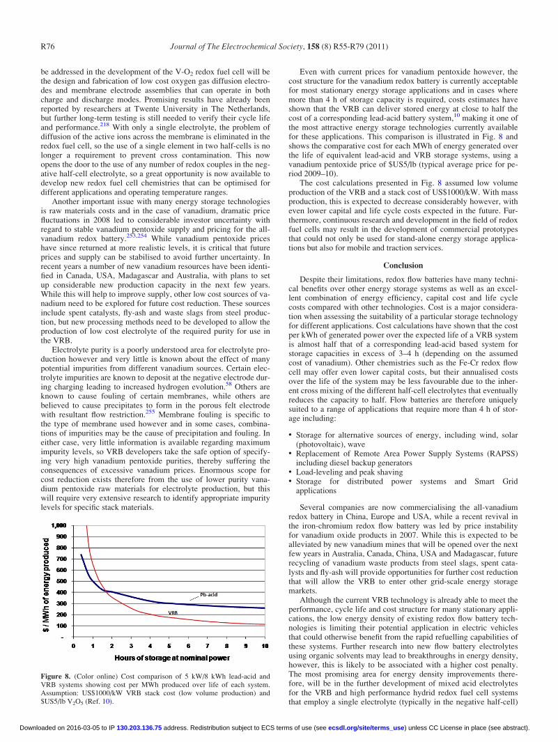
be addressed in the development of the V-O2 redox fuel cell will bethe design and fabrication of low cost oxygen gas diffusion electro-des and membrane electrode assemblies that can operate in bothcharge and discharge modes. Promising results have already beenreported by researchers at Twente University in The Netherlands,but further long-term testing is still needed to verify their cycle lifeand performance.218 With only a single electrolyte, the problem ofdiffusion of the active ions across the membrane is eliminated in theredox fuel cell, so the use of a single element in two half-cells is nolonger a requirement to prevent cross contamination. This nowopens the door to the use of any number of redox couples in the neg-ative half-cell electrolyte, so a great opportunity is now available todevelop new redox fuel cell chemistries that can be optimised fordifferent applications and operating temperature ranges.
Another important issue with many energy storage technologiesis raw materials costs and in the case of vanadium, dramatic pricefluctuations in 2008 led to considerable investor uncertainty withregard to stable vanadium pentoxide supply and pricing for the all-vanadium redox battery.253,254 While vanadium pentoxide priceshave since returned at more realistic levels, it is critical that futureprices and supply can be stabilised to avoid further uncertainty. Inrecent years a number of new vanadium resources have been identi-fied in Canada, USA, Madagascar and Australia, with plans to setup considerable new production capacity in the next few years.While this will help to improve supply, other low cost sources of va-nadium need to be explored for future cost reduction. These sourcesinclude spent catalysts, fly-ash and waste slags from steel produc-tion, but new processing methods need to be developed to allow theproduction of low cost electrolyte of the required purity for use inthe VRB.
Electrolyte purity is a poorly understood area for electrolyte pro-duction however and very little is known about the effect of manypotential impurities from different vanadium sources. Certain elec-trolyte impurities are known to deposit at the negative electrode dur-ing charging leading to increased hydrogen evolution.58 Others areknown to cause fouling of certain membranes, while others arebelieved to cause precipitates to form in the porous felt electrodewith resultant flow restriction.255 Membrane fouling is specific tothe type of membrane used however and in some cases, combina-tions of impurities may be the cause of precipitation and fouling. Ineither case, very little information is available regarding maximumimpurity levels, so VRB developers take the safe option of specify-ing very high vanadium pentoxide purities, thereby suffering theconsequences of excessive vanadium prices. Enormous scope forcost reduction exists therefore from the use of lower purity vana-dium pentoxide raw materials for electrolyte production, but thiswill require very extensive research to identify appropriate impuritylevels for specific stack materials.
Even with current prices for vanadium pentoxide however, thecost structure for the vanadium redox battery is currently acceptablefor most stationary energy storage applications and in cases wheremore than 4 h of storage capacity is required, costs estimates haveshown that the VRB can deliver stored energy at close to half thecost of a corresponding lead-acid battery system,10 making it one ofthe most attractive energy storage technologies currently availablefor these applications. This comparison is illustrated in Fig. 8 andshows the comparative cost for each MWh of energy generated overthe life of equivalent lead-acid and VRB storage systems, using avanadium pentoxide price of $US5/lb (typical average price for pe-riod 2009–10).
The cost calculations presented in Fig. 8 assumed low volumeproduction of the VRB and a stack cost of US$1000/kW. With massproduction, this is expected to decrease considerably however, witheven lower capital and life cycle costs expected in the future. Fur-thermore, continuous research and development in the field of redoxfuel cells may result in the development of commercial prototypesthat could not only be used for stand-alone energy storage applica-tions but also for mobile and traction services.
Conclusion
Despite their limitations, redox flow batteries have many techni-cal benefits over other energy storage systems as well as an excel-lent combination of energy efficiency, capital cost and life cyclecosts compared with other technologies. Cost is a major considera-tion when assessing the suitability of a particular storage technologyfor different applications. Cost calculations have shown that the costper kWh of generated power over the expected life of a VRB systemis almost half that of a corresponding lead-acid based system forstorage capacities in excess of 3–4 h (depending on the assumedcost of vanadium). Other chemistries such as the Fe-Cr redox flowcell may offer even lower capital costs, but their annualised costsover the life of the system may be less favourable due to the inher-ent cross mixing of the different half-cell electrolytes that eventuallyreduces the capacity to half. Flow batteries are therefore uniquelysuited to a range of applications that require more than 4 h of stor-age including:
• Storage for alternative sources of energy, including wind, solar(photovoltaic), wave
• Replacement of Remote Area Power Supply Systems (RAPSS)including diesel backup generators
• Load-leveling and peak shaving• Storage for distributed power systems and Smart Grid
applications
Several companies are now commercialising the all-vanadiumredox battery in China, Europe and USA, while a recent revival inthe iron-chromium redox flow battery was led by price instabilityfor vanadium oxide products in 2007. While this is expected to bealleviated by new vanadium mines that will be opened over the nextfew years in Australia, Canada, China, USA and Madagascar, futurerecycling of vanadium waste products from steel slags, spent cata-lysts and fly-ash will provide opportunities for further cost reductionthat will allow the VRB to enter other grid-scale energy storagemarkets.
Although the current VRB technology is already able to meet theperformance, cycle life and cost structure for many stationary appli-cations, the low energy density of existing redox flow battery tech-nologies is limiting their potential application in electric vehiclesthat could otherwise benefit from the rapid refuelling capabilities ofthese systems. Further research into new flow battery electrolytesusing organic solvents may lead to breakthroughs in energy density,however, this is likely to be associated with a higher cost penalty.The most promising area for energy density improvements there-fore, will be in the further development of mixed acid electrolytesfor the VRB and high performance hydrid redox fuel cell systemsthat employ a single electrolyte (typically in the negative half-cell)
Figure 8. (Color online) Cost comparison of 5 kW/8 kWh lead-acid andVRB systems showing cost per MWh produced over life of each system.Assumption: US$1000/kW VRB stack cost (low volume production) and$US5/lb V2O5 (Ref. 10).
Journal of The Electrochemical Society, 158 (8) R55-R79 (2011)R76
) unless CC License in place (see abstract). ecsdl.org/site/terms_use address. Redistribution subject to ECS terms of use (see 130.203.136.75Downloaded on 2016-03-05 to IP

in combination with an oxygen gas diffusion electrode. The use of asingle electrolyte eliminates the problem of cross contamination,allowing a wider range of redox couple chemistries with a wideroperating temperature range to be employed. Advances in non-noblemetal catalysts for the oxygen electrode and novel processes forleak-proof membrane electrode assemblies are urgently needed forthe commercial implementation of such systems however, so vastopportunities are now available for new breakthroughs in this areathat will lead to “refuelable” power systems for electric vehicles ofthe future.
Acknowledgments
The authors acknowledge the support of Dr. E. P. L. Roberts, Dr.R. A. W. Dryfe, Dr. C. H. Bae, Dr. N. Stevens, Dr. I. M. AlNashef,Prof. M. Azlan Hussain, and Dr. K. C. Namkung in the preparationof this document. The University of Malaya is gratefully acknowl-edged for providing full technical support.
List of Abbreviations
DLRFC Direct Liquid Redox Fuel Cell
EDTA Ethylenediamine-tetraacetic acid
EMICl Methylimidazolium
GDL Gas Diffusion Layer
N-MPC Nitrogen doped mesoporous carbon
[OC]OX Electro-oxidized organic products (vanadium glyoxal RFB)
[OC]RE Organic reductive raw material (vanadium glyoxal RFB)
OCP Open Circuit Potential
OCV Open-Circuit Voltage
PSB Polysulphide-bromine
RFB Redox Flow Battery
[Ru(bpy)3](BF4)2 Tris(2,2’-bipyridine) ruthenium(II) tetrafluoroborate
SEM Scanning Electron Microscope
SOC State of Charge
TEA triethanolamine
TEABF4 Tetraethylammonium tetrafluoroborate
VOFC Vanadium-Oxygen Redox Fuel Cell
VESS Vanadium Energy Storage System
XRD X-ray diffraction
y year
References
1. http://www.electricitystorage.org, last accessed: Jan. 2011.2. W. V. Hassenzahl, IEEE Trans. Magn., 11, 1447 (2001).3. L. G. Stuntz, Electr. J., 31, 476 (1990).4. H. Lund and B. V. Mathiesen, Energy, 34, 524 (2009).5. H. Chen, Y. Cong, W. Yang, C. Tan, Y. Li, and Y. Ding, Prog. Nat. Sci., 19, 291
(2009).6. C. Abbey, W. Li, and G. Joos, “Power electronic converter control technique for
improved low voltage ride through performance in wind turbine generators,” inProc. 37th IEEE Power Electronics Specialists Conference, Jeju, South Korea,June 18–22, 2006, p. 216.
7. EPRI-DOE, EPRI, DOE Technical Update 1008703, Palo Alto, CA, WashingtonDC (Dec. 2004).
8. J. Eyer and G. Corey, Energy Storage for the Electricity Grid: Benefits and Mar-ket Potential Assessment Guide, Sandia Report SAND2010-0815 (Feb. 2010).
9. EPRI-DOE, Handbook of Energy Storage for Transmission and DistributionApplications, EPRI, DOE, Palo Alto, CA, Washington DC (2003).
10. Chapter on “Secondary Batteries: Redox Flow Battery—Vanadium Redox” byMaria Skyllas-Kazacos Encyclopedia of Electrochemical Power Sources, J.Garche, P. Moseley, Z. Ogumi, D. Rand, and B. Scrosati, Editors, Elsevier, NewYork, USA, pp. 444–453, 2009.
11. M. Bartolozzi, J. Power Sources, 27, 219 (1989).12. M. Chakrabarti and E. Roberts, NED Uni. J. Res., 5, 43 (2008).13. M. Chakrabarti, E. Roberts, and M. Saleem, Int. J. Green Energy, 7, 445 (2010).14. M. Skyllas-Kazacos and R. Robins, U.S. Pat. 4,786,567 (1986).15. M. Skyllas-Kazacos, R. Robins, M. A. Green, and A. J. Fane, Final Report for
NERDDC Grant No. 788 (Dec. 1986).16. M. Skyllas-Kazacos and F. Grossmith, J. Electrochem. Soc., 134, 2950 (1987).17. E. Sum and M. Skyllas-Kazacos, J. Power Sources, 15, 179 (1985).18. E. Sum, M. Rychcik, and M. Skyllas-Kazacos, J. Power Sources, 16, 85 (1985).19. M. Skyllas-Kazacos, M. Rychcik, R. Robins, A. Fane, and M. Green, J. Electro-
chem. Soc., 133, 1057 (1986).20. M. Skyllas-Kazacos and M. Rychcik. J. Power Sources, 19, 45 (1987).21. S. Zhong and M. Skyllas-Kazacos, J. Power Sources, 39, 1 (1992).22. M. Rychcik and M. Skyllas-Kazacos, J. Power Sources, 22, 59 (1988).
23. S. Zhong, C. Padeste, M. Kazacos, and M. Skyllas-Kazacos, J. Power Sources,45, 29 (1993).
24. B. T. Sun and M. Skyllas-Kazacos, Electrochem. Acta, 36, 513 (1991).25. B. T. Sun and M. Skyllas-Kazacos, Electrochim. Acta, 37, 1253 (1992).26. B. T. Sun and M. Skyllas-Kazacos, Electrochim. Acta, 37, 2459 (1992).27. M. Kazacos and M. Cheng, J. Appl. Electrochem., 20, 463 (1990).28. M. S. kyllas-Kazacos and C. Menictas, J. Electrochem. Soc, 143, 86 (1996).29. F. Rahman and M. Skyllas-Kazacos, J. Power Sources, 72, 105 (1998).30. N. Kausar, R. Howe, and M. Skyllas-Kazacos, J. Appl. Electrochem., 31, 1327
(2001).31. F. Rahman and M.Skyllas-Kazacos, J. Power Sources, 189, 1212 (2009).32. P. Llewellyn, F. Grossmith, A. Fane, and M. Skyllas-Kazacos, in Proceedings of
Symposium on Energy Storage: Load Levelling and Remote Applications, p. 88,The Electrochemical Society Proceedings Series, Pennington, NJ (1988).
33. S. C. Chieng, M. Kazacos, and M. Skyllas-Kazacos, J. Power Sources, 39, 11(1992).
34. S. C. Chieng and M. Skyllas-Kazacos, J. Membr. Sci., 75, 81 (1992).35. M. Kazacos, M. Skyllas-Kazacos, and J. Chieng, PCT Patent AU9200491 (1992).36. T. Mohammadi and M. Skyllas-Kazacos, J. Membr. Sci., 98, 77 (1995).37. T. Mohammadi and M. Skyllas-Kazacos, J. Membr. Sci., 107, 35 (1995).38. T. Mohammadi and M.Skyllas-Kazacos, J. Power Sources, 56, 91 (1995).39. T. Mohammadi and M. Skyllas-Kazacos, J. Power Sources, 63, 179 (1996).40. T. Mohammadi and M. Skyllas-Kazacos, J. Appl. Electrochem, 27, 153 (1996).41. T. Sukkar and M. Skyllas-Kazacos, J. Appl. Electrochem, 34, 137 (2004).42. T. Sukkar and M. Skyllas-Kazacos, J. Membr. Sci., 222, 235 (2003).43. T. Sukkar and M. Skyllas-Kazacos, J. Membr. Sci., 222, 249 (2003).44. M. Kazacos and M. Skyllas-Kazacos, J. Electrochem. Soc., 136, 2759 (1989).45. S. Zhong, M. Kazacos, R. P. Burford, and M. Skyllas-Kazacos, J. Power Sources,
36, 29 (1991).46. V. Haddadi-Asl, M. Kazacos, and M. Skyllas-Kazacos, J. Appl. Electrochem, 25,
29 (1995).47. V. Haddadi-Asl, M. Kazacos, and M. Skyllas-Kazacos, J. Appl. Polym. Sci., 57,
1455 (1995).48. V. Haddadi-Asl, M. Kazacos, and M. Skyllas-Kazacos, U.S. Pat. 5,665,212
(1997).49. M. Skyllas-Kazacos, Australian Patent 696452 (1998). U.S. Pat. 6,143,443
(2000).50. M. Skyllas-Kazacos, C. Peng, and M. Cheng, Electrochem. Solid State Lett, 2,
121 (1999).51. M. A. Samad and M. Skyllas-Kazacos, in Proceedings of the 9th Australasian
Electrochemical Conference, Wollongong, pp. 65-1–65-4 (1994).52. M. Skyllas-Kazacos, M. Kazacos, J. Joy, and B. G. Madden, Patent PCT/AU89/
00252 (1989).53. M. Kazacos, M.Sc. Thesis, University of New South Wales, Sydney, Australia
(1989).54. M. Skyllas-Kazacos, M. Kazacos, and R. McDermott, South African Patent 88/
9244. (1989).55. C. Menictas, M. Chen, and M. Skyllas-Kazacos, J. Power Sources, 45, 43 (1993).56. M. Kazacos and M. Skyllas-Kazacos, South African Pat. 94/9140 (1995).57. M. Skyllas-Kazacos, D. Kasherman, R. Hong, and M. Kazacos, J. Power Sources,
35, 399 (1991).58. M. Skyllas-Kazacos, Pat. Appl., PCT/AU88/00472 (1988).59. M. Skyllas-Kazacos, M. Kazacos, and R. McDermott Patent Appl., PCT/AU88/
00473 (1988).60. R. L. Largent, M. Skyllas-Kazacos, and J. Chieng, “Improved Photovoltaic Sys-
tem Performance Using Vanadium Batteries,” Conference Record, 23rd IEEE PVSpecialists Conference, Louisville, May, 1993, pp. 1119–1124.
61. C. Menictas, D. R. Hong, Z. H. Yan, J. Wilson, M. Kazacos and M. Skyllas-Kazacos, “Status of the Vanadium Redox Battery Development Program,” Pro-ceedings of the Electrical Engineering Congress, Sydney, Australia, Vol. 1(1994) p. 299.
62. M. Skyllas-Kazacos, Provisional Pat. Appl., PCT/AU01/00923 (2001).63. C. Menictas and M. Skyllas-Kazacos, Final Report, SERDF grant, New South
Wales Office of Energy, Australia (1997).64. http://www.pdenergy.com/en/applications-solutions/projects_installations/by_sei/
by_sei.html, last accessed: Jul. 2010.65. N. Tokuda, T. Kumamoto, T. Shigematsu, H. Deguchi, T. Ito, N. Yoshikawa, and
T. Hara, SEl Tech. Rev., 45, 88 (1998).66. N. Tokudu, T. Kanno, T. Hara, T. Shigematsu, Y. Tsutsui, A. Ikeuchi, T. Itou,
and T. Kumamoto, Sumitomo Electr. Tech. Rev., 50, 88 (2000).67. http://www.cellstrom.com, last accessed: Dec. 2010.68. C. Ponce de Leon, A. Frias-Ferrer, J. Gonzalez-Garcia, D. Szanto, and F. Walsh,
J. Power Sources, 160, 716 (2006).69. H. Wu, R. Selman, and R. Hollandsworth, Indian J. Technol., 24, 372 (1986).70. S. Ashimura, Y. Miyake, and Denki Kagaku, J. Power Sources, 39, 977 (1971).71. http://www.nedo.go.jp/english/index.html, last accessed: Dec. 2010.72. http://energy.electrochem.jp/NEDO_WS100702.pdf, last accessed: Dec. 2010.73. Energy Focus, Magazine of the NSW Department of Energy, St. Leonards, NSW,
Australia, August (1995).74. M. Palacin, Chem. Soc. Rev., 38, 2565 (2009).75. L. H. Thaller, NASA TM-79143, DOE/NASA/1002-79/3 (1979).76. M. Chakrabarti, R. Dryfe and E. Roberts, J. Chem. Soc. Pak., 29, 294 (2007).77. L. H. Thaller, U.S. Pat. 3,996 (1976).78. A. Shibata and K. Sato, Power Eng. J., 13, 130 (1999).79. M. Skyllas-Kazacos, G. Kazacos, G. Poon, and H. Verseema, Int. J. Energy Res.,
34, 182 (2010).
Journal of The Electrochemical Society, 158 (8) R55-R79 (2011) R77
) unless CC License in place (see abstract). ecsdl.org/site/terms_use address. Redistribution subject to ECS terms of use (see 130.203.136.75Downloaded on 2016-03-05 to IP
80. M. Lopez-Atalaya, G. Codina, J. Perez, J. Vazquez, and A. Aldaz, J. PowerSources, 39, 147 (1992).
81. G. Codina, J. Perez, M. Lopez-Atalaya, J. Vasquez, and A. Aldaz, J. PowerSources, 48, 293 (1994).
82. M. Warshay and L. Wright, J. Electrochem. Soc, 124, 173 (1977).83. L. H. Thaller, NASA TM-79186, DOE/NASA/1002-79/4, (1979).84. L. Swette and V. Jalan, NASA CR-174724, DOE/NASA/0262-1, (1984).85. R. F. Gahn, N. H. Hagedorn, and J. A. Johnson, NASA TM-87034, NASA,
Department of Energy, US (1985).86. R. Savinell, C. Liu, R. Galasco, S. Chiang, and J. Coetzee, J. Electrochem. Soc.,
126, 357 (1979).87. Y. Wang, Y. Lin, and C. Wan, J. Power Sources, 13, 65 (1984).88. C. Liu, R. Galasco, and R. Savinell, J. Electrochem. Soc., 128, 1755 (1981).89. C. Liu, R. Galasco, and R. Savinell, J. Electrochem. Soc., 129, 2502 (1982).90. Y. Matsuda, K. Tanaka, M. Okada, Y. Takasu, M. Morita, and M. Matsumura-
Inoue, J. Appl. Electrochem., 18, 909 (1988).91. D. Johnson and M. Reid, J. Electrochem. Soc., 132, 1058 (1985).92. M. Shimada, Y. Tsuzuki, Y. Iizuka, and M. Inoue, Chem. Ind., 3, 80 (1988).93. C. Bae, E. Roberts, and R. Dryfe, Electrochim. Acta, 48, 279 (2002).94. P. Fedkiw and R. Watts, J. Electrochem. Soc., 131, 701 (1984).95. S. Takahashi and T. Hiramatsu, J. Power Sources, 17, 55 (1986).96. M. Futamata, S. Higuchi, O. Nakamura, I. Ogino, Y. Takada, and S. Okazaki,
J. Power Sources, 24, 137 (1988).97. G. Codina and A. Aldaz, J. Appl. Electrochem., 22, 668 (1992).98. L. Hruska and R. Savinell, J. Electrochem. Soc., 128, 18 (1981).99. M. P. Mariani, M. Bartolozzi, and M. R. Moncelli, J. Electroanal. Chem., 209,
275 (1986).100. M. Morita, Y. Tanaka, K. Tanaka, Y. Matsuda, and M. Matsumura-Inoue, Bull.
Chem. Soc. Jpn., 61, 2711 (1988).101. M. Yoshitake, A. Kidoguchi, and Z. Kamio, Japanese Pat. 60227364 (1985).102. T. Nozaki, T. Ozawa, H. Kaneko, and A. Kidoguchi, Japanese Pat. 6124172.
(1986).103. W. Kondo, T. Kumagai, and S. Mizuta, Nippon Kagaku Kaishi, 6, 864 (1988).104. A. Wakabayashi, Y. Sunaga, S. Morie, and K. Yokota, Japanese Pat. 6376268
(1988).105. D. You, H. Zhang, and J. Chen, Electrochim. Acta, 54, 6827 (2009).106. C. Jia, J. Liu, and C. Yan, J. Power Sources, 195, 4380 (2010).107. M. Skyllas-Kazacos, J. Power Sources, 124, 299 (2003).108. F. Xue, Y. Wang, W. Wang, and X. Wang, Electrochim. Acta, 53, 6636 (2008).109. A. Paulenova, S. Creager, J. Navratil, and Y. Wei, J. Power Sources, 109, 431
(2002).110. B. Fang, S. Iwasa, Y. Wei, T. Arai, and M. Kumagai, Electrochim. Acta, 47, 3971
(2002).111. X. Xia, L. Tao, and Y. Liu, J. Electrochem. Soc., 149, 426 (2002).112. Y. Wen, J. Cheng, P. Ma, and Y. Yang, Electrochim. Acta, 53, 3514 (2008).113. Y. Wen, J. Cheng, Y. Xun, P. Ma, and Y. S. Yang, Electrochim. Acta, 53, 6018
(2008).114. Q. Liu, A. Sleightholme, A. Shinkle, Y. Li, and L. Thompson, Electrochem. Com-
mun., 11, 2312 (2009).115. H. Kaneko, N. Akira, N. Ken, S. Kanji, and N. Masato, European Pat. EP0517217
(1997).116. H. Kaneko, N. Akira, N. Ken, S. Kanji, and N. Masato, U.S. Pat. US5318865
(1994).117. Y. Kageyama, T. Tayam, and K. Sato, U.S. Pat. 5,656 (1997).118. G. Hwang and H. Ohya, J. Membr. Sci., 132, 55 (1997).119. R. Ferrigno, A. Stroock, T. Clark, M. Mayer, and G. Whitesides, J. Am. Chem.
Soc., 124, 12930 (2002).120. P. Zhao, H. Zhang, H. Zhou, J. Chen, S. Gao, and B. Yi, J. Power Sources, 162,
1416 (2006).121. J. Xi, Z. Wu, X. Qiu, and L. Chen, J. Power Sources, 166, 531 (2007).122. J. Xi, Z. Wu, X. Teng, Y. Zhao, L. Chen, and X. Qiu, J. Mater. Chem., 18, 1232
(2008).123. P. Qian, H. Zhang, J. Chen, Y. Wen, Q. Luo, Z. Liu, D. You, and B. Yi, J. Power
Sources, 175, 613 (2008).124. X. Teng, Y. Zhao, J. Xi, Z. Wu, X. Qiu, and L. Chen, J. Power Sources, 189,
1240 (2009).125. X. Teng, Y. Zhao, J. Xi, Z. Wu, X. Qiu, and L. Chen, J. Membr. Sci., 341, 149
(2009).126. K. Huang, X. Li, S. Liu, N. Tan, and L. Chen, Renewable Energy, 33, 186 (2008).127. Chapter on “Energy storage for stand-alone/hybrid systems: Electro-chemical
Energy Storage Technologies” by M.Skyllas-Kazacos published in Stand-aloneand Hybrid Wind Systems: Technology, Energy Storage and Applications, J. K.Kaldellis, Editor, Woodhead Publishing, Cambridge, UK (2010).
128. Q. Luo, H. Zhang, J. Chen, D. You, C. Sun, and Y. Zhang, J. Membr. Sci., 325,553 (2008).
129. B. Tian, C. Yan, and F. Wang, J. Appl. Electrochem., 34, 1205 (2004).130. Q. Luo, H. Zhang, J. Chen, P. Qian, and Y. Zhai, J. Membr. Sci., 311, 98 (2008).131. J. Qiu, M. Zhai, J. Chen, Y. Wang, J. Peng, L. Xu, J. Li, and G. Wei, J. Membr.
Sci., 342, 215 (2009).132. B. Tian, C. Yan, and F. Wang, J. Membr. Sci., 234, 51 (2004).133. D. Chen, S. Wang, M. Xiao, and Y. Meng, J. Power Sources, 195, 7701 (2010).134. S. Kim, J. Yan, B. Schwenzer, J. Zhang, L. Li, J. Liu, Z. Yang, and M. Hickner,
Electrochem. Commun., 12, 1650 (2010).135. J. Zeng, C. Jiang, Y. Wang, J. Chen, S. Zhu, B. Zhao, and R. Wang, Electrochem.
Commun., 10, 372 (2008).136. Z. Mai, H. Zhang, X. Li, C. Bi, and H. Dai, J. Power Sources, 196, 482 (2011).
137. M. Vijayakumar, M. Bhuvaneswari, P. Nachimuthu, B. Schwenzer, S. Kim, Z.Yang, J. Liu, G. Graff, S. Thevuthasan, and J. Hu, J. Membr. Sci., 366, 325(2011).
138. H. Li, C. Yan, and B. Tian, Chin. J. Power Sources, 28, 167 (2004).139. K. Salloum and J. Posner, J. Power Sources, 196, 1229 (2011).140. F. Xue, H. Zhang, C. Wu, T. Ning, and X. Xu, Trans. Nonferrous Met. Soc.
China, 19, 594 (2009).141. W. Wang and X. Wang, Electrochim. Acta, 52, 6755 (2007).142. X. Li, K. Huang, S. Liu, and L. Chen, J. Cent. South Univ. Technol., 14, 51
(2007).143. D. Luo, Q. Xu, and Z. Sui, Chin. J. Power Sources, 2, 94 (2004).144. T. Hirao, J. Inorg. Biochem., 80, 27 (2000).145. M. Vynnycky, Energy, In press. [DOI: 10.1016/j.energy]146. H. Al-Fetlawi, A. Shah, and F. Walsh, Electrochim. Acta, 55, 3192 (2009).147. H. Al-Fetlawi, A. Shah, and F. Walsh, Electrochim. Acta, 55, 78 (2009).148. A. Shah, M. Watt-Smith, and F. Walsh, Electrochim Acta, 53, 8087 (2008).149. A. Shah, H. Al-Fetlawi, and F. Walsh, Electrochim. Acta, 55, 1125 (2010).150. C. Rydh, J. Power Sources, 80, 21 (1999).151. Ch. Fabjan, J. Garche, B. Harrer, L. Jorissen, C. Kolbeck, F. Philippi, G. Tom-
azic, and F. Wagner, Electrochim. Acta, 47, 825 (2001).152. H. Vafiadis and M. Skyllas-Kazacos, J. Membr. Sci., 279, 394 (2006).153. M. Skyllas-Kazacos, Australian Pat. 2002328660 (2008). U.S. Pat. 7320844
(2008).154. R. Remick and P. Ang, U.S. Pat. 4,485,154. (1984)155. P. Zhao, H. Zhang, H. Zhou, and B. Yi, Electrochim. Acta, 51, 1091 (2005).156. H. Lim, A. Lackner, and J. Knechtli, J. Electrochem. Soc. 124, 1154 (1977).157. P. Lex and B. Jonshagen, Power Eng. J, 13, 142 (1999).158. D. Linden, Handbook of Batteries and Fuel Cells, 2nd ed., Chap. 29, p. 37,
McGraw-Hill, New York (1995).159. R. Clarke, B. Dougherty, S. Mohanta, and S. Harrison, Abstract 520, Joint Inter-
national Meeting: 206th Meeting of the Electrochemical Society/2004 Fall Meet-ing of the Electrochemical Society of Japan, Honolulu, Hawaii, October3–8, 2004.
160. J. Collins, X. Li, D. Pletcher, R. Tangirala, D. Stratton-Campbell, F. Walsh, andC. Zhang, J. Power Sources, 195, 2975 (2010).
161. A. Hazza, D. Pletcher, and R. Wills, J. Power Sources, 149, 103 (2005).162. F. Walsh, Pure Appl. Chem, 73, 1819 (2001).163. S. Ge, B. Yi, and H. Zhang, J. Appl. Electrochem, 34, 181 (2004).164. C. Ponce-de-Leon, G. Reade, I. Whyte, S. Male, and F. Walsh, Electrochim.
Acta, 52, 5815 (2007).165. S. Licht and J. Davis, J. Phys. Chem, 101, 2540 (1997).166. D. Scamman, G. Reade, and E. Roberts, J. Power Sources, 189, 1220 (2009).167. D. Scamman, G. Reade, and E. Roberts, J. Power Sources, 189, 1231 (2009).168. Y. Shiokawa, H. Yamana, and H. Moriyama, J. Nuclear Sci. Technol, 37, 253
(2000).169. T. Yamamura, Y. Shiokawa, Y. Ikeda, and H. Tomiyasu, J. Nuclear Sci. Technol.
Suppl, 3, 445 (2002).170. T. Yamamura, K. Shirasaki, Y. Shiokawa., Y. Nakamura, and Y. Kim, J. Alloys
Compd., 374, 349 (2004).171. T. Yamamura, K. Shirasaki, D. Li, and Y. Shiokawa, J. Alloys Compd., 418, 139
(2006).172. K. Shirasaki, T. Yamamura, and Y. Shiokawa, J. Alloys Compd., 408, 1296
(2006).173. K. Shirasaki, T. Yamamura, T. Herai, and Y. Shiokawa, J. Alloys Compd., 418,
217 (2006).174. T. Yamamura, Y. Shiokawa, H. Yamana, and H. Moriyama, Electrochim. Acta,
48, 43 (2002).175. K. Hasegawa, A. Kimura, T. Yamamura, and Y. Shiokawa, J. Phys. Chem. Solids,
66, 593 (2005).176. T. Yamamura, N. Watanabe, and Y. Shiokawa, J. Alloys Compd., 408, 1260
(2006).177. C. H. Bae, Ph.D. Thesis, University of Manchester (UMIST), Manchester (2001).178. C. H. Bae, E. P. L. Roberts, M. H. Chakrabarti, and M. Saleem, Int. J. Green
Energy, 8, 248 (2011).179. Y. Wen, J. Cheng, S. Ning, and Y. Yang, J. Power Sources, 188, 301 (2009).180. Y. Xu, Y. Wen, J. Cheng, G. Cao, and Y. Yang, Electrochim. Acta, 55, 715
(2010).181. J. Cheng, L. Zhang, Y. Yang, Y. Wen, G. Cao, and X. Wang, Electrochem.
Commun., 9, 2639 (2007).182. L. Zhang, J. Cheng, Y. Yang, Y. Wen, X. Wang, and G. Cao, J. Power Sources,
179, 381 (2008).183. M. Chakrabarti, R. Dryfe, and E. Roberts, Electrochim. Acta, 52, 2189 (2007).184. Q. Liu, A. Shinkle, Y. Li, C. Monroe, L. Thompson, and A. Sleightholme, Elec-
trochem. Commun, 12, 1634 (2010).185. J. Cheng, Y. Wen, G. Cao, and Y. Yang, J. Power Sources, 196, 1589 (2011).186. Y. Ito, M. Nyce, R. Plivelich, M. Klein, D. Steingart, and S. Banerjee, J. Power
Sources, 196, 2340 (2011).187. M. H. Chakrabarti and E. P. L. Roberts, J. Chem. Soc. Pak, 30, 817 (2008).188. C. Bae, H. Chakrabarti, and E. Roberts, J. Appl. Electrochem., 38, 637 (2008).189. M. H. Chakrabarti, E. P. L. Roberts, C. H. Bae, and M. Saleem, Energy Convers.
Manage., 52(7), 2501 (2011).190. Y. Chen, K. Santhanam, and A. Bard, J. Electrochem. Soc., 128, 1460 (1981).191. Y. Katayama, I. Konishiike, T. Miura, and T. Kishi, J. Power Sources, 109, 327
(2002).192. C. Scordilis-Kelley, J. Fuller, R. Carlin, and J. Wilkes, J. Electrochem. Soc., 139,
694 (1992).
Journal of The Electrochemical Society, 158 (8) R55-R79 (2011)R78
) unless CC License in place (see abstract). ecsdl.org/site/terms_use address. Redistribution subject to ECS terms of use (see 130.203.136.75Downloaded on 2016-03-05 to IP

193. Y. Wen, H. Zhang, P. Qian, H. Zhou, P. Zhao, B. Yi, and Y. Yang, Electrochim.Acta, 51, 3769 (2006).
194. J. Kummer and D. Oei, J. Appl. Electrochem., 15, 619 (1985).195. J. Kummer and D. Oei, J. Appl. Electrochem., 15, 231 (1985).196. J. Kummer and D. Oei, J. Appl. Electrochem., 12, 87 (1982).197. D. Rand, R. Woods, and R. Dell, Batteries for electric vehicles, p. 577, John
Wiley & Sons, New York (1998).198. R. Larsson and B. Folkesson, J. Appl. Electrochem., 20, 737 (1990).199. B. Folkesson, J. Appl. Electrochem., 20, 907 (1990).200. D. Oei, J. Appl. Electrochem., 12, 41 (1982).201. A. Ilicic, D. Wilkinson, and K. Fatih, J. Electrochem. Soc., 157, 529 (2010).202. F. Moraw, K. Fatih, D.P. Wilkinson, F. Girard, Adv. Mater. Res., 15, 315 (2007).203. T. Evans and R. White, J. Electrochem. Soc., 134, 866 (1987).204. G. Simpson and R. White, J. Electrochem. Soc., 136, 2137 (1989).205. G. Simpson and R. White, J. Electrochem. Soc., 137, 1843 (1990).206. T. Evans and R. White, J. Electrochem. Soc., 134, 2725 (1987).207. M. J. Watt-Smith, R. G. A. Wills, F. C. Walsh, Secondary Batteries - Flow Sys-
tems Overview. Encyclopedia of Electrochemical Power Sources, 2009, pp. 438–443, Elsevier B.V., Amsterdam.
208. P. Leung, C. Ponce-de-Leon, C. Low, A. Shah, and F. Walsh, J. Power Sources,196(11), 5174 (2011).
209. P. Trinidad, C. Ponce-de-Leon, and F. Walsh, J. Environ. Manage., 88, 1417(2008).
210. D. Pletcher and R. Wills, Phys. Chem. Chem. Phys, 6, 1779 (2004).211. D. Pletcher and R. Wills, J. Power Sources, 149, 96 (2005).212. A. Hazza and D. Pletcher, Phys. Chem. Chem. Phys, 6, 1773 (2004).213. D. Pletcher, H. Zhou, G. Kear, C. Low, F. Walsh, and R. Wills, J. Power Sources,
180, 630 (2008).214. X. Li, D. Pletcher, and F. Walsh, Electrochim. Acta, 54, 4688 (2009).215. J. Collins, G. Kear, X. Li, C. Low, D. Pletcher, R. Tangirala, D. Stratton-Camp-
bell, F. Walsh, and C. Zhang, J. Power Sources, 195, 1731 (2010).216. M. Skyllas-Kazacos and C. Menictas, J. Appl. Electrochem. Submitted.217. J. Noack, C. Cremers, K. Pinkwart, and J. Tuebke, 218th The Electrochemical So-
ciety Meeting, Las Vegas, NV, Oct 10–15, 2010.218. S. S. Hosseiny, M. Saakes, and M. Wessling, Electrochem. Commun., In press.
[DOI: 10.1016/j.elecom.(2010).11.025]219. M. Shimizu, N. Mori, M. Kuno, K. Mizunami, and T. Shigematsu, Proc. Electro-
chem. Soc., 88, 249 (1988).220. Y. Nakamura, Japanese Pat. 63150863 (1988).221. http://www.deeyaenergy.com/product, last accessed: Jan. 2011.222. A. Gonzalez, B. Gallachoir, E. McKeogh, K. Lynch, Study of electricity storage tech-
nologies and their potential to address wind energy intermittency in Ireland, May 2004,http://www.seai.ie/uploadedfiles/FundedProgrammes/REHC03001FinalReport.pdf, lastaccessed: Dec. 2010.
223. Prudent Energy - case study: VRB Technology in Japan, http://www.pdenergy.com/pdfs/casestudy_japan.pdf, last accessed: Jan. 2011.
224. G. Tsekouras, C. Anastasopoulos, V. Kontargyri, F. Kanellos, I. Karanasiou, A.Salis, and N. Mastorakis, in Proceedings of the 2nd WSEAS/IASME InternationalConference on Energy Planning, Energy Saving, Environmental Education(EPESE’08), p. 94–100 (2008). http://users.ntua.gr/vkont/EPESE_2008.pdf, lastaccessed: Jan. 2011.
225. W. Steeley, EPRI Report 1008434, Technical Update, Utah (Mar. 2005).226. J. Hawkins and T. Robbins, in Proceedings of the 23rd International Telecommu-
nications Energy Conference, INTELEC 01, IEEE, p. 652–656, 2001.227. T. Hennessy and M. Kuntz, “The multiple benefits of integrating electricity
storage with wind energy,” in Proc. IEEE Power Eng. Soc. Gen. Meeting, Jun.12–16, 2005, pp. 1952–1954.
228. http://www.digital-batteries.org/2010/03/17/vanadium-redox-battery-to-solve-the-energy-storage-problem, last accessed: Dec. 2010.
229. P. Zhao, H. Zhang, H. Zhou, J. Chen, S. Gao, and B. Yi, J. Power Sources, 162,1416 (2006).
230. The China Greentech Initiative Report, http://www.china-greentech.com, lastaccessed: Dec. 2010.
231. H. Zhang, Proceedings of 5th International Renewable Energy Storage Confer-ence, Berlin, November, (2010).
232. C. Menictas and M.Skyllas-Kazacos, Internal Unisearch Report (Feb. 1998).233. News Release: US Department of Energy Smart Grid Program Award for Demon-
stration of V-Fuel Vanadium Battery Technology in the USA, 8th July 2010,http://www.energy.gov/news2009/8305.htm, last accessed: Dec. 2010).
234. Regenesys Utility Scale Energy Storage Module Test Programme DTi Report2004. Contract Number: K/El/Oo246/00/00 URN Number: 04/1049, http://webarchive.nationalarchives.gov.uk/tna/þ/http://www.dti.gov.uk/renewables/publications/pdfs/kel00246moduletestprogramme.pdf, last accessed: Jan. 2011.
235. VRB Power Acquires Regenesys Electricity Storage Technology, 5th October2004, http://powerelectronics.com/news/vrb-power-regenesys, last accessed: Dec.2010.
236. Studies on the Sodium Polysulfide/Bromine Redox Flow Battery for Energy Stor-age, http://www.latest-science-articles.com/Technology_Science/Studies-on-the-Sodium-Polysulfide-Bromine-Redox-Flow-Battery-for-Energy-Storage-9491.html,last accessed: Nov. 2010.
237. B. L. Norris, P. Lex, G. Ball, V. Scaini, Grid-Connected Solar Energy Storageusing the Zinc-Bromine Flow Battery. Solar 2002, http://www.zbbenergy.com/pdf/technicalpaper_grid.pdf, last accessed: Dec. 2010.
238. http://www.premiumpower.com, last accessed: Jan. 2011.239. http://www.redflow.com.au/Files/PowerBOSZB600%20-Limited Warranty.pdf,
last accessed: Jan. 2011.240. http://newscenter.lbl.gov/feature-stories/2010/07/29/battery-team-looks-beyond-
vehicles-to-the-electric-grid, last accessed: Jan. 2011.241. U.S. Department of Energy, “Electricity End Use,” http://www.eia.gov/emeu/aer/
pdf/pages/sec8_37.pdf (2010), last accessed: Jan. 2011.242. U.S. Department of Energy, Annual Energy (2010), http://www.eia.doe.gov/oiaf/
aeo/electricity.html, last accessed: Jan. 2011.243. http://arpa-e.energy.gov/portals/0/Documents/ConferencesandEvents/Pastworkshops/
Grid Scale Energy Storage/GS-Sum.pdf, last accessed: Jan. 2011.244. L. Xiao-Gang, H. Ke-Long, L. Su-Qin, T. Ning, and C. Li-Quan, Trans. Nonfer-
rous Met. Soc. China, 17, 195 (2007).245. L. Xiao-Gang, H. Ke-Long, L. Su-Qin, T. Ning, and C. Li-Quan, J. Cent. South
Univ. Technol, 1, 51 (2007).246. X. Tang, J. Li, and J. Hao, Catal. Commun., 11, 871 (2010).247. R. Schmitt and A. Hirschvogel, First International Flow Battery Forum, Vienna, June
12–13 (2010).248. http://www.pdenergy.com/products_systemcomponents.html, last accessed: Jan.
2011.249. T. Hennessy, VRB Power advances storage system production, April 2005, http://
www.powergenworldwide.com/index/display/articledisplay/225911/articles/power-engineering/industry-news-2/2005/04/vrb-power-advances-storage-sys-tem-production.html, last accessed: Jan. 2011.
250. S. Hajimolana and M. Soroush, Ind. Eng. Chem., 48, 6112 (2009).251. D. Ilic, K. Holl, P. Birke, T. Wohrle, F. Birke-Salam, A. Perner, and P. Haug,
J. Power Sources, 155, 72 (2006).252. L. Li, S. Kim, W. Wang, M. Vijaayakumar, Z. Nie, B. Chen, J. Zhang, G. Xia,
J. Hu, G. Graff, et al., Adv. Energy Mater., Published online March 11, 2011.http://onlinelibrary.wiley.com/doi/10.1002/aenm.201100008/abstract;jsessionid¼1A732376F09811F2200A9CB8D1AE5891.d03t04.
253. http://www.energizerresources.com, last accessed: Jan. 2011.254. L. Xiao-Gang, H. Ke-Long, L. Su-Qin, T. Ning, and C. Li-Quan, Renewable
Energy, 33, 186 (2008).255. M. Kubata, H. Nakaishi, N. Tokuda, U.S. Pat. 7258947 (2002).
Journal of The Electrochemical Society, 158 (8) R55-R79 (2011) R79
) unless CC License in place (see abstract). ecsdl.org/site/terms_use address. Redistribution subject to ECS terms of use (see 130.203.136.75Downloaded on 2016-03-05 to IP