Critical assessment of finite element analysis applied to metal–oxide interface roughness in...
7
Critical assessment of finite element analysis applied to metal–oxide interface roughness in oxidising zirconium alloys P. Platt a,⇑ , P. Frankel a , M. Gass b , M. Preuss a a University of Manchester, School of Materials, Materials Performance Centre, Manchester M13 9PL, UK b AMEC, Walton House, Faraday Street, Birchwood Park, Risley, Warrington WA3 6GA, UK article info Article history: Received 21 October 2014 Accepted 3 May 2015 Available online 9 May 2015 abstract As a nuclear fuel cladding material, zirconium alloys act as a barrier between the fuel and pressurised steam or lithiated water environment. Controlling degradation mechanisms such as oxidation is essential to extending the in-service lifetime of the fuel. At temperatures of 360 °C zirconium alloys are known to exhibit cyclical, approximately cubic corrosion kinetics. With acceleration in the oxidation kinetics occur- ring every 2 lm of oxide growth, and being associated with the formation of a network of lateral cracks. Finite element analysis has been used previously to explain the lateral crack formation by the develop- ment of localised out-of-plane tensile stresses at the metal–oxide interface. This work uses the Abaqus finite element code to assess critically current approaches to representing the oxidation of zirconium alloys, with relation to undulations at the metal–oxide interface and localised stress generation. This includes comparison of axisymmetric and 3D quartered modelling approaches, and investigates the effect of interface geometry and plasticity in the metal substrate. Particular focus is placed on the application of the anisotropic strain tensor used to represent the oxidation mechanism, which is typically applied with a fixed coordinate system. Assessment of the impact of the tensor showed that 99% of the localised tensile stresses originated from the out-of-plane component of the strain tensor, rather than the in-plane expan- sion as was previously thought. Discussion is given to the difficulties associated with this modelling approach and the requirements for future simulations of the oxidation of zirconium alloys. Ó 2015 Published by Elsevier B.V. 1. Introduction Zirconium alloys are used as cladding to encapsulate nuclear fuel pellets in pressurised and boiling water reactors. Fundamental to extending the lifetime of the fuel is limiting degra- dation mechanisms in the cladding such as oxidation. For both in and out of reactor, oxides have been seen to form lateral cracks. In autoclave tests these primarily form above undulation peaks at the metal–oxide interface. Small isolated cracks appear fre- quently, however, after 2 lm oxide growth cracking is more extensive leading to the formation of a layer of lateral cracks. This layer of lateral cracks has been linked to transition and accel- eration in the corrosion kinetics [1–8]. Fig. 1 shows an SEM image of the metal–oxide interface roughness and lateral cracking pre- sent in the oxide [9]. Bossis et al. defined the interface undulations as having an amplitude which increases up to 0.2 lm at transi- tion, and an approximately constant wavelength of 1 lm [2]. Ly et al. could not identify any consistent wavelength, or any distinct connection between the amplitude and transition point, but did indicate that undulation amplitudes are in the 0.1–0.2 lm range [6]. Tejland et al. used TEM to demonstrate the presence of disloca- tion loops in the near surface substrate indicating that some level of interface roughness develops as a result of plastic deformation in the substrate [10]. The oxide layer that forms has been shown to be composed of monoclinic and meta-stable tetragonal phases. With in-plane com- pressive stresses ranging from 1 to 2 GPa in the monoclinic phase and 2–3 GPa in the tetragonal phase [3,5,11]. Given that the oxide forms almost entirely due to the inward migration of oxygen [12], this stress is said to be linked to the Pilling–Bedworth ratio [13]. For the Zr/ZrO 2 system the Pilling–Bedworth ratio is 1.56, under isotropic expansion conditions this would mean an expansion strain of 0.16 in each direction. However Parise et al. carried out finite element analysis which showed that this would produce excessively high compressive stresses parallel to the metal–oxide interface [14]. Refinement of the finite element analysis indicated that an in-plane expansion of only 0.005 is required to generate compressive stresses of 2 GPa in the oxide layer. In line with http://dx.doi.org/10.1016/j.jnucmat.2015.05.002 0022-3115/Ó 2015 Published by Elsevier B.V. ⇑ Corresponding author at: Jackson’s Mill, Room D26, Sackville Street, Manch- ester, M13 9PL, UK. Tel.: +44 07753431684. E-mail address: [email protected] (P. Platt). Journal of Nuclear Materials 464 (2015) 313–319 Contents lists available at ScienceDirect Journal of Nuclear Materials journal homepage: www.elsevier.com/locate/jnucmat
-
Upload
manchester -
Category
Documents
-
view
7 -
download
0
Transcript of Critical assessment of finite element analysis applied to metal–oxide interface roughness in...
Journal of Nuclear Materials 464 (2015) 313–319
Contents lists available at ScienceDirect
Journal of Nuclear Materials
journal homepage: www.elsevier .com/ locate / jnucmat
Critical assessment of finite element analysis applied to metal–oxideinterface roughness in oxidising zirconium alloys
http://dx.doi.org/10.1016/j.jnucmat.2015.05.0020022-3115/� 2015 Published by Elsevier B.V.
⇑ Corresponding author at: Jackson’s Mill, Room D26, Sackville Street, Manch-ester, M13 9PL, UK. Tel.: +44 07753431684.
E-mail address: [email protected] (P. Platt).
P. Platt a,⇑, P. Frankel a, M. Gass b, M. Preuss a
a University of Manchester, School of Materials, Materials Performance Centre, Manchester M13 9PL, UKb AMEC, Walton House, Faraday Street, Birchwood Park, Risley, Warrington WA3 6GA, UK
a r t i c l e i n f o
Article history:Received 21 October 2014Accepted 3 May 2015Available online 9 May 2015
a b s t r a c t
As a nuclear fuel cladding material, zirconium alloys act as a barrier between the fuel and pressurisedsteam or lithiated water environment. Controlling degradation mechanisms such as oxidation is essentialto extending the in-service lifetime of the fuel. At temperatures of �360 �C zirconium alloys are known toexhibit cyclical, approximately cubic corrosion kinetics. With acceleration in the oxidation kinetics occur-ring every �2 lm of oxide growth, and being associated with the formation of a network of lateral cracks.Finite element analysis has been used previously to explain the lateral crack formation by the develop-ment of localised out-of-plane tensile stresses at the metal–oxide interface. This work uses the Abaqusfinite element code to assess critically current approaches to representing the oxidation of zirconiumalloys, with relation to undulations at the metal–oxide interface and localised stress generation. Thisincludes comparison of axisymmetric and 3D quartered modelling approaches, and investigates the effectof interface geometry and plasticity in the metal substrate. Particular focus is placed on the application ofthe anisotropic strain tensor used to represent the oxidation mechanism, which is typically applied with afixed coordinate system. Assessment of the impact of the tensor showed that 99% of the localised tensilestresses originated from the out-of-plane component of the strain tensor, rather than the in-plane expan-sion as was previously thought. Discussion is given to the difficulties associated with this modellingapproach and the requirements for future simulations of the oxidation of zirconium alloys.
� 2015 Published by Elsevier B.V.
1. Introduction
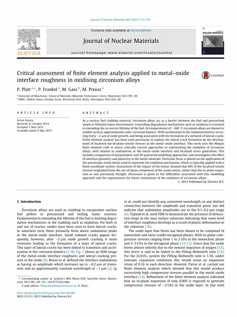
Zirconium alloys are used as cladding to encapsulate nuclearfuel pellets in pressurised and boiling water reactors.Fundamental to extending the lifetime of the fuel is limiting degra-dation mechanisms in the cladding such as oxidation. For both inand out of reactor, oxides have been seen to form lateral cracks.In autoclave tests these primarily form above undulation peaksat the metal–oxide interface. Small isolated cracks appear fre-quently, however, after �2 lm oxide growth cracking is moreextensive leading to the formation of a layer of lateral cracks.This layer of lateral cracks has been linked to transition and accel-eration in the corrosion kinetics [1–8]. Fig. 1 shows an SEM imageof the metal–oxide interface roughness and lateral cracking pre-sent in the oxide [9]. Bossis et al. defined the interface undulationsas having an amplitude which increases up to �0.2 lm at transi-tion, and an approximately constant wavelength of �1 lm [2]. Ly
et al. could not identify any consistent wavelength, or any distinctconnection between the amplitude and transition point, but didindicate that undulation amplitudes are in the 0.1–0.2 lm range[6]. Tejland et al. used TEM to demonstrate the presence of disloca-tion loops in the near surface substrate indicating that some levelof interface roughness develops as a result of plastic deformation inthe substrate [10].
The oxide layer that forms has been shown to be composed ofmonoclinic and meta-stable tetragonal phases. With in-plane com-pressive stresses ranging from 1 to 2 GPa in the monoclinic phaseand 2–3 GPa in the tetragonal phase [3,5,11]. Given that the oxideforms almost entirely due to the inward migration of oxygen [12],this stress is said to be linked to the Pilling–Bedworth ratio [13].For the Zr/ZrO2 system the Pilling–Bedworth ratio is 1.56, underisotropic expansion conditions this would mean an expansionstrain of 0.16 in each direction. However Parise et al. carried outfinite element analysis which showed that this would produceexcessively high compressive stresses parallel to the metal–oxideinterface [14]. Refinement of the finite element analysis indicatedthat an in-plane expansion of only 0.005 is required to generatecompressive stresses of �2 GPa in the oxide layer. In line with
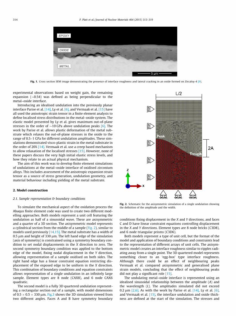
Fig. 1. Cross section SEM image demonstrating the presence of interface roughness and lateral cracking in an oxide formed on Zircaloy-4 [9].
314 P. Platt et al. / Journal of Nuclear Materials 464 (2015) 313–319
experimental observations based on weight gain, the remainingexpansion (�0.54) was defined as being perpendicular to themetal–oxide interface.
Introducing an idealised undulation into the previously planarinterface Parise et al. [14], Ly et al. [6], and Vermaak et al. [15] haveall used the anisotropic strain tensor in a finite element analysis todefine localised stress distributions in the metal–oxide system. Theelastic model presented by Ly et al. gives maximum out-of-planestresses in the order of �10 GPa above undulation peaks [6]. Thework by Parise et al. allows plastic deformation of the metal sub-strate which relaxes the out-of-plane stresses in the oxide to therange of 0.5–1 GPa for different undulation amplitudes. These sim-ulations demonstrated visco-plastic strain in the metal substrate inthe order of 20% [14]. Vermaak et al. use a creep based mechanismto allow relaxation of the localised stresses [15]. However, none ofthese papers discuss the very high initial elastic stress levels, andhow they relate to an actual physical mechanism.
The aim of this work was to develop finite element simulationsof undulations at the metal–oxide interface of oxidised zirconiumalloys. This includes assessment of the anisotropic expansion straintensor as a source of stress generation, undulation geometry, andmaterial behaviour including yielding of the metal substrate.
Fig. 2. Schematic for the axisymmetric simulation of a single undulation showingthe definition of the amplitude and the width.
2. Model construction
2.1. Sample representation & boundary conditions
To simulate the mechanical aspect of the oxidation process theAbaqus finite element code was used to create two different mod-elling approaches. Both models represent a unit cell featuring theundulation as half of a sinusoidal wave. These are axisymmetricand a quarter of a 3D section. The axisymmetric model representsa cylindrical section from the middle of a sample (Fig. 2), similar tomodels used previously [14,15]. The metal substrate has a width of0.5 lm and height of 330 lm. The left hand edge of the simulation(axis of symmetry) is constrained using a symmetry boundary con-dition to set nodal displacements in the X direction to zero. Thesecond symmetry boundary condition was applied to the bottomedge of the model, fixing nodal displacement in the Y direction,allowing representation of a sample oxidised on both sides. Theright hand edge has a linear constraint equation restricting dis-placement of the exposed edge to be uniform in the X direction.This combination of boundary conditions and equation constraintsallows representation of a single undulation in an infinitely largesample. Element types are 8 node (CAX8), and 6 node CAX6quadratic.
The second model is a fully 3D quartered undulation represent-ing a rectangular section out of a sample, with model dimensionsof 0.5 � 0.5 � 330 lm. Fig.3 shows the 3D simulation viewed fromtwo different angles. Faces A and B have symmetry boundary
conditions fixing displacement in the X and Y directions, and facesC and D have linear constraint equations controlling displacementin the X and Y directions. Element types are 8 node bricks (C3D8),and 6 node triangular prisms (C3D6).
Both models represent a type of unit cell, but the format of themodel and application of boundary conditions and constraints leadto the representation of different arrays of unit cells. The axisym-metric model creates an interface roughness similar to ripples radi-ating away from a single point. The 3D quartered model representssomething closer to an ‘egg-box’ type interface roughness.Although there could be an effect of neighbouring peaksVermaak et al. compared axisymmetric and generalised planestrain models, concluding that the effect of neighbouring peaksdid not play a significant role [15].
The undulating metal–oxide interface is represented using anidealised sinusoidal relationship between the amplitude (A) andthe wavelength (L). The amplitudes simulated did not exceed0.2 lm [2,6]. As with the work by Parise et al. [14], Ly et al. [6],and Vermaak et al. [15], the interface undulation and oxide thick-ness are defined at the start of the simulation. The stresses and
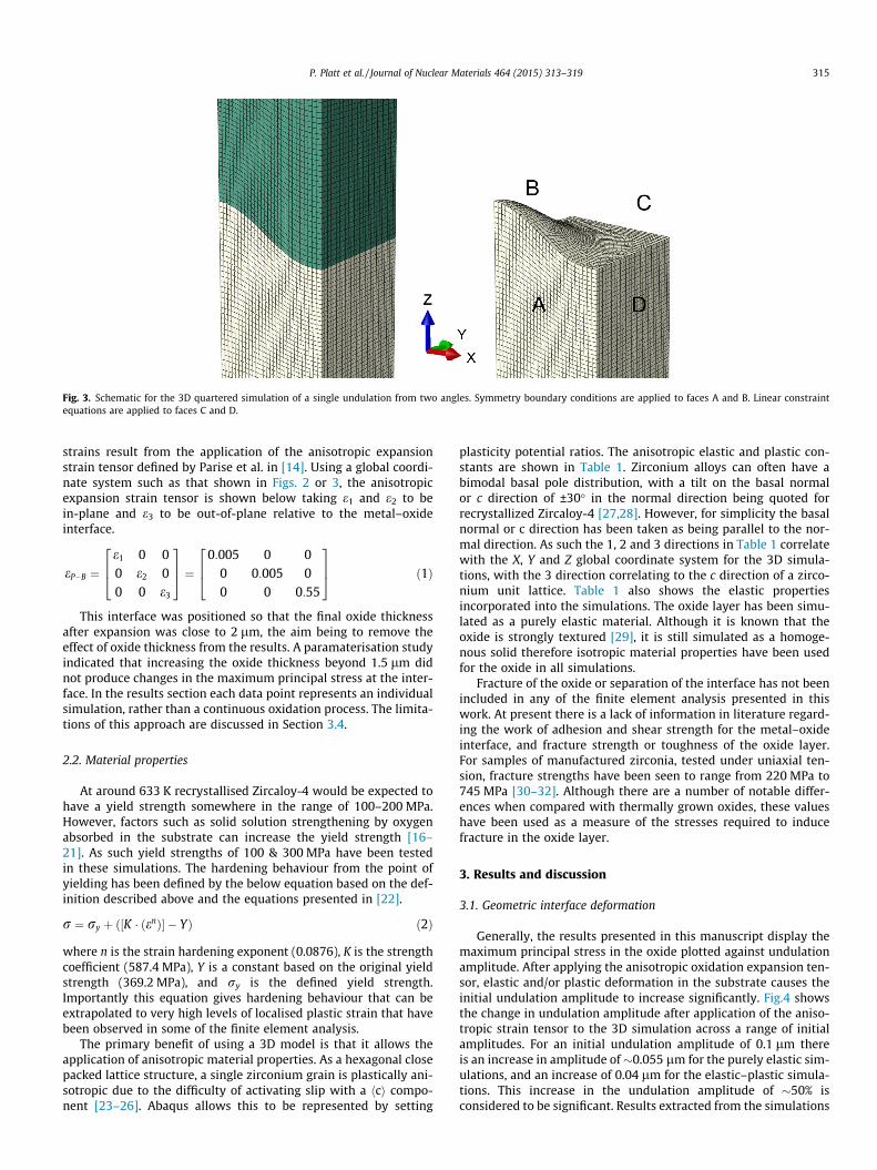
Fig. 3. Schematic for the 3D quartered simulation of a single undulation from two angles. Symmetry boundary conditions are applied to faces A and B. Linear constraintequations are applied to faces C and D.
P. Platt et al. / Journal of Nuclear Materials 464 (2015) 313–319 315
strains result from the application of the anisotropic expansionstrain tensor defined by Parise et al. in [14]. Using a global coordi-nate system such as that shown in Figs. 2 or 3, the anisotropicexpansion strain tensor is shown below taking e1 and e2 to bein-plane and e3 to be out-of-plane relative to the metal–oxideinterface.
eP�B ¼e1 0 00 e2 00 0 e3
264
375 ¼
0:005 0 00 0:005 00 0 0:55
264
375 ð1Þ
This interface was positioned so that the final oxide thicknessafter expansion was close to 2 lm, the aim being to remove theeffect of oxide thickness from the results. A paramaterisation studyindicated that increasing the oxide thickness beyond 1.5 lm didnot produce changes in the maximum principal stress at the inter-face. In the results section each data point represents an individualsimulation, rather than a continuous oxidation process. The limita-tions of this approach are discussed in Section 3.4.
2.2. Material properties
At around 633 K recrystallised Zircaloy-4 would be expected tohave a yield strength somewhere in the range of 100–200 MPa.However, factors such as solid solution strengthening by oxygenabsorbed in the substrate can increase the yield strength [16–21]. As such yield strengths of 100 & 300 MPa have been testedin these simulations. The hardening behaviour from the point ofyielding has been defined by the below equation based on the def-inition described above and the equations presented in [22].
r ¼ ry þ K � enð Þ½ � � Yð Þ ð2Þ
where n is the strain hardening exponent (0.0876), K is the strengthcoefficient (587.4 MPa), Y is a constant based on the original yieldstrength (369.2 MPa), and ry is the defined yield strength.Importantly this equation gives hardening behaviour that can beextrapolated to very high levels of localised plastic strain that havebeen observed in some of the finite element analysis.
The primary benefit of using a 3D model is that it allows theapplication of anisotropic material properties. As a hexagonal closepacked lattice structure, a single zirconium grain is plastically ani-sotropic due to the difficulty of activating slip with a hci compo-nent [23–26]. Abaqus allows this to be represented by setting
plasticity potential ratios. The anisotropic elastic and plastic con-stants are shown in Table 1. Zirconium alloys can often have abimodal basal pole distribution, with a tilt on the basal normalor c direction of ±30� in the normal direction being quoted forrecrystallized Zircaloy-4 [27,28]. However, for simplicity the basalnormal or c direction has been taken as being parallel to the nor-mal direction. As such the 1, 2 and 3 directions in Table 1 correlatewith the X, Y and Z global coordinate system for the 3D simula-tions, with the 3 direction correlating to the c direction of a zirco-nium unit lattice. Table 1 also shows the elastic propertiesincorporated into the simulations. The oxide layer has been simu-lated as a purely elastic material. Although it is known that theoxide is strongly textured [29], it is still simulated as a homoge-nous solid therefore isotropic material properties have been usedfor the oxide in all simulations.
Fracture of the oxide or separation of the interface has not beenincluded in any of the finite element analysis presented in thiswork. At present there is a lack of information in literature regard-ing the work of adhesion and shear strength for the metal–oxideinterface, and fracture strength or toughness of the oxide layer.For samples of manufactured zirconia, tested under uniaxial ten-sion, fracture strengths have been seen to range from 220 MPa to745 MPa [30–32]. Although there are a number of notable differ-ences when compared with thermally grown oxides, these valueshave been used as a measure of the stresses required to inducefracture in the oxide layer.
3. Results and discussion
3.1. Geometric interface deformation
Generally, the results presented in this manuscript display themaximum principal stress in the oxide plotted against undulationamplitude. After applying the anisotropic oxidation expansion ten-sor, elastic and/or plastic deformation in the substrate causes theinitial undulation amplitude to increase significantly. Fig.4 showsthe change in undulation amplitude after application of the aniso-tropic strain tensor to the 3D simulation across a range of initialamplitudes. For an initial undulation amplitude of 0.1 lm thereis an increase in amplitude of �0.055 lm for the purely elastic sim-ulations, and an increase of 0.04 lm for the elastic–plastic simula-tions. This increase in the undulation amplitude of �50% isconsidered to be significant. Results extracted from the simulations
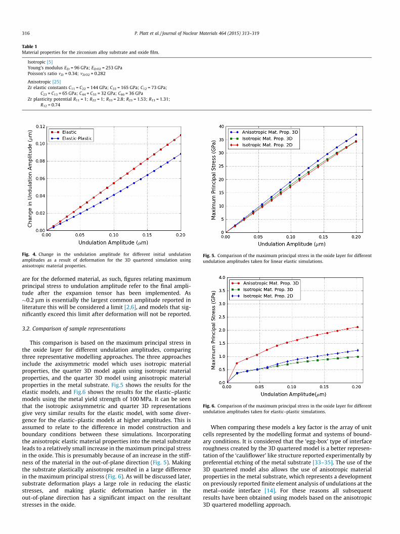
Table 1Material properties for the zirconium alloy substrate and oxide film.
Isotropic [5]Young’s modulus EZr = 96 GPa; EZrO2 = 253 GPaPoisson’s ratio mZr = 0.34; mZrO2 = 0.282
Anisotropic [25]Zr elastic constants C11 = C22 = 144 GPa; C33 = 165 GPa; C12 = 73 GPa;
C23 = C13 = 65 GPa; C44 = C55 = 32 GPa; C66 = 36 GPaZr plasticity potential R11 = 1; R22 = 1; R33 = 2.8; R23 = 1.53; R13 = 1.31;
R12 = 0.74
Fig. 4. Change in the undulation amplitude for different initial undulationamplitudes as a result of deformation for the 3D quartered simulation usinganisotropic material properties.
Fig. 5. Comparison of the maximum principal stress in the oxide layer for differentundulation amplitudes taken for linear elastic simulations.
Fig. 6. Comparison of the maximum principal stress in the oxide layer for differentundulation amplitudes taken for elastic–plastic simulations.
316 P. Platt et al. / Journal of Nuclear Materials 464 (2015) 313–319
are for the deformed material, as such, figures relating maximumprincipal stress to undulation amplitude refer to the final ampli-tude after the expansion tensor has been implemented. As�0.2 lm is essentially the largest common amplitude reported inliterature this will be considered a limit [2,6], and models that sig-nificantly exceed this limit after deformation will not be reported.
3.2. Comparison of sample representations
This comparison is based on the maximum principal stress inthe oxide layer for different undulation amplitudes, comparingthree representative modelling approaches. The three approachesinclude the axisymmetric model which uses isotropic materialproperties, the quarter 3D model again using isotropic materialproperties, and the quarter 3D model using anisotropic materialproperties in the metal substrate. Fig.5 shows the results for theelastic models, and Fig.6 shows the results for the elastic–plasticmodels using the metal yield strength of 100 MPa. It can be seenthat the isotropic axisymmetric and quarter 3D representationsgive very similar results for the elastic model, with some diver-gence for the elastic–plastic models at higher amplitudes. This isassumed to relate to the difference in model construction andboundary conditions between these simulations. Incorporatingthe anisotropic elastic material properties into the metal substrateleads to a relatively small increase in the maximum principal stressin the oxide. This is presumably because of an increase in the stiff-ness of the material in the out-of-plane direction (Fig. 5). Makingthe substrate plastically anisotropic resulted in a large differencein the maximum principal stress (Fig. 6). As will be discussed later,substrate deformation plays a large role in reducing the elasticstresses, and making plastic deformation harder in theout-of-plane direction has a significant impact on the resultantstresses in the oxide.
When comparing these models a key factor is the array of unitcells represented by the modelling format and systems of bound-ary conditions. It is considered that the ‘egg-box’ type of interfaceroughness created by the 3D quartered model is a better represen-tation of the ‘cauliflower’ like structure reported experimentally bypreferential etching of the metal substrate [33–35]. The use of the3D quartered model also allows the use of anisotropic materialproperties in the metal substrate, which represents a developmenton previously reported finite element analysis of undulations at themetal–oxide interface [14]. For these reasons all subsequentresults have been obtained using models based on the anisotropic3D quartered modelling approach.
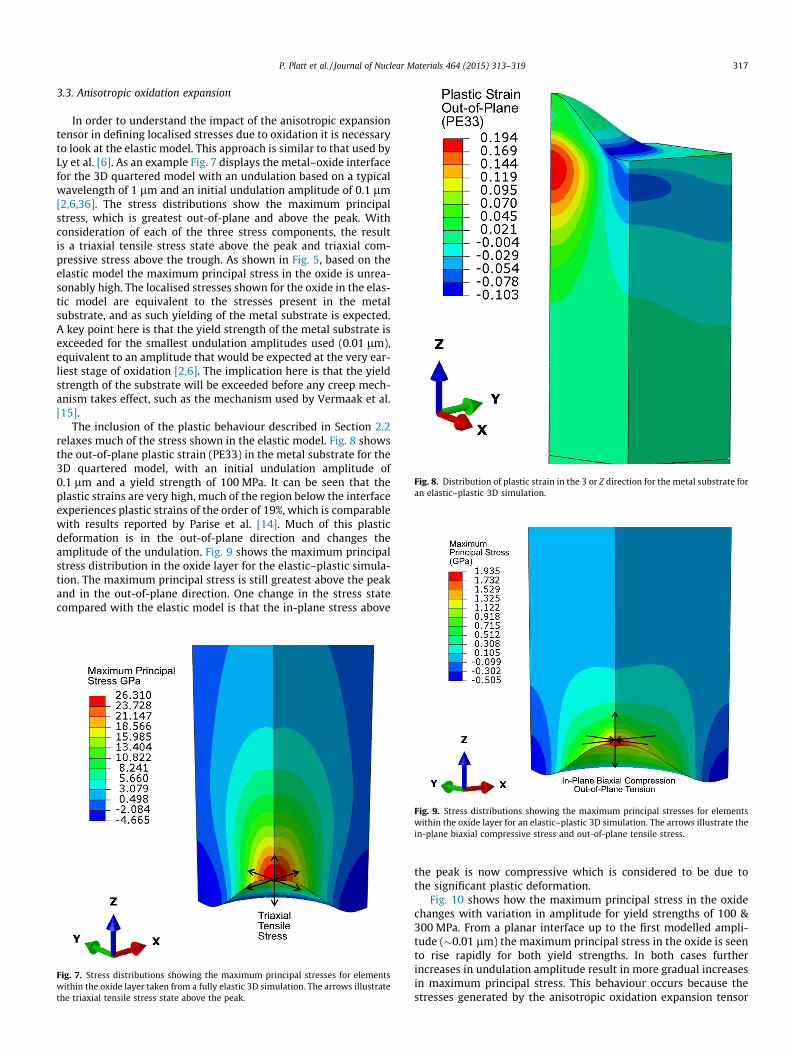
Fig. 8. Distribution of plastic strain in the 3 or Z direction for the metal substrate foran elastic–plastic 3D simulation.
P. Platt et al. / Journal of Nuclear Materials 464 (2015) 313–319 317
3.3. Anisotropic oxidation expansion
In order to understand the impact of the anisotropic expansiontensor in defining localised stresses due to oxidation it is necessaryto look at the elastic model. This approach is similar to that used byLy et al. [6]. As an example Fig. 7 displays the metal–oxide interfacefor the 3D quartered model with an undulation based on a typicalwavelength of 1 lm and an initial undulation amplitude of 0.1 lm[2,6,36]. The stress distributions show the maximum principalstress, which is greatest out-of-plane and above the peak. Withconsideration of each of the three stress components, the resultis a triaxial tensile stress state above the peak and triaxial com-pressive stress above the trough. As shown in Fig. 5, based on theelastic model the maximum principal stress in the oxide is unrea-sonably high. The localised stresses shown for the oxide in the elas-tic model are equivalent to the stresses present in the metalsubstrate, and as such yielding of the metal substrate is expected.A key point here is that the yield strength of the metal substrate isexceeded for the smallest undulation amplitudes used (0.01 lm),equivalent to an amplitude that would be expected at the very ear-liest stage of oxidation [2,6]. The implication here is that the yieldstrength of the substrate will be exceeded before any creep mech-anism takes effect, such as the mechanism used by Vermaak et al.[15].
The inclusion of the plastic behaviour described in Section 2.2relaxes much of the stress shown in the elastic model. Fig. 8 showsthe out-of-plane plastic strain (PE33) in the metal substrate for the3D quartered model, with an initial undulation amplitude of0.1 lm and a yield strength of 100 MPa. It can be seen that theplastic strains are very high, much of the region below the interfaceexperiences plastic strains of the order of 19%, which is comparablewith results reported by Parise et al. [14]. Much of this plasticdeformation is in the out-of-plane direction and changes theamplitude of the undulation. Fig. 9 shows the maximum principalstress distribution in the oxide layer for the elastic–plastic simula-tion. The maximum principal stress is still greatest above the peakand in the out-of-plane direction. One change in the stress statecompared with the elastic model is that the in-plane stress above
Fig. 7. Stress distributions showing the maximum principal stresses for elementswithin the oxide layer taken from a fully elastic 3D simulation. The arrows illustratethe triaxial tensile stress state above the peak.
Fig. 9. Stress distributions showing the maximum principal stresses for elementswithin the oxide layer for an elastic–plastic 3D simulation. The arrows illustrate thein-plane biaxial compressive stress and out-of-plane tensile stress.
the peak is now compressive which is considered to be due tothe significant plastic deformation.
Fig. 10 shows how the maximum principal stress in the oxidechanges with variation in amplitude for yield strengths of 100 &300 MPa. From a planar interface up to the first modelled ampli-tude (�0.01 lm) the maximum principal stress in the oxide is seento rise rapidly for both yield strengths. In both cases furtherincreases in undulation amplitude result in more gradual increasesin maximum principal stress. This behaviour occurs because thestresses generated by the anisotropic oxidation expansion tensor
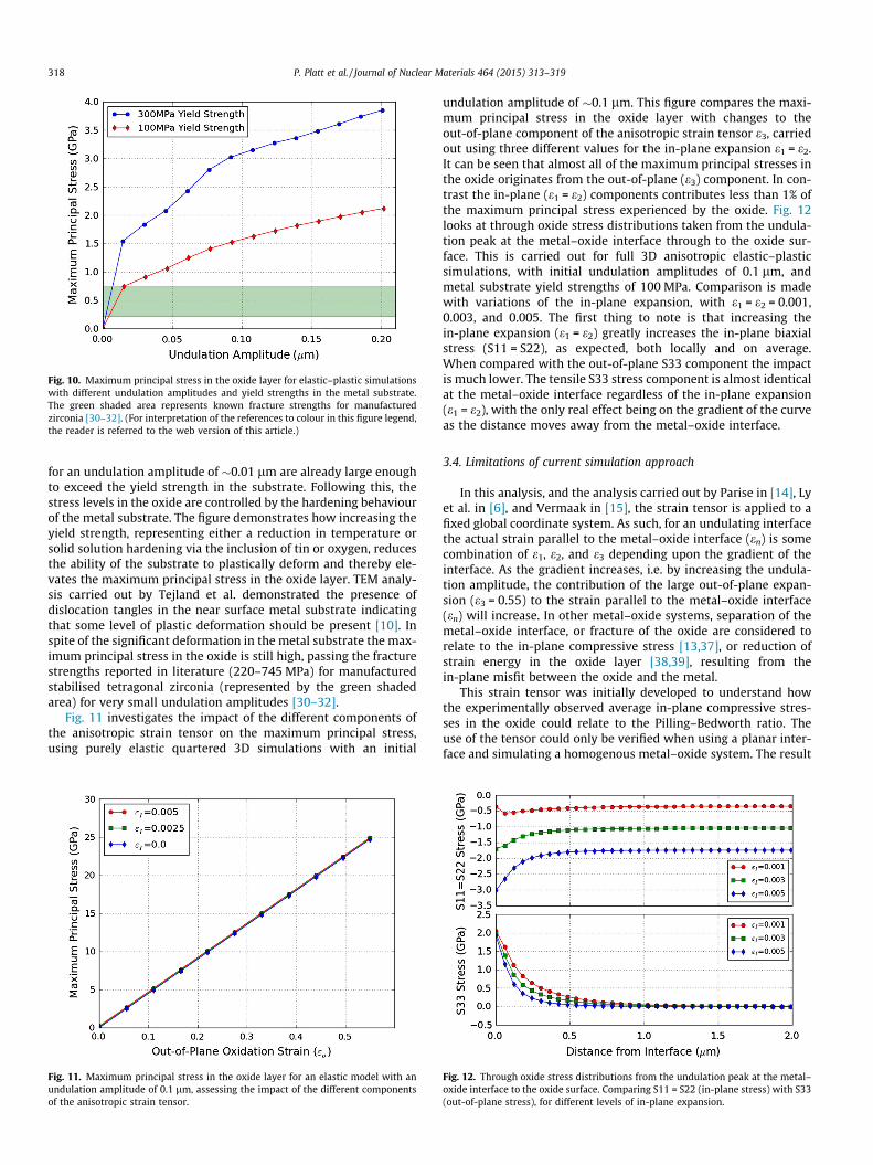
Fig. 10. Maximum principal stress in the oxide layer for elastic–plastic simulationswith different undulation amplitudes and yield strengths in the metal substrate.The green shaded area represents known fracture strengths for manufacturedzirconia [30–32]. (For interpretation of the references to colour in this figure legend,the reader is referred to the web version of this article.)
318 P. Platt et al. / Journal of Nuclear Materials 464 (2015) 313–319
for an undulation amplitude of �0.01 lm are already large enoughto exceed the yield strength in the substrate. Following this, thestress levels in the oxide are controlled by the hardening behaviourof the metal substrate. The figure demonstrates how increasing theyield strength, representing either a reduction in temperature orsolid solution hardening via the inclusion of tin or oxygen, reducesthe ability of the substrate to plastically deform and thereby ele-vates the maximum principal stress in the oxide layer. TEM analy-sis carried out by Tejland et al. demonstrated the presence ofdislocation tangles in the near surface metal substrate indicatingthat some level of plastic deformation should be present [10]. Inspite of the significant deformation in the metal substrate the max-imum principal stress in the oxide is still high, passing the fracturestrengths reported in literature (220–745 MPa) for manufacturedstabilised tetragonal zirconia (represented by the green shadedarea) for very small undulation amplitudes [30–32].
Fig. 11 investigates the impact of the different components ofthe anisotropic strain tensor on the maximum principal stress,using purely elastic quartered 3D simulations with an initial
Fig. 11. Maximum principal stress in the oxide layer for an elastic model with anundulation amplitude of 0.1 lm, assessing the impact of the different componentsof the anisotropic strain tensor.
undulation amplitude of �0.1 lm. This figure compares the maxi-mum principal stress in the oxide layer with changes to theout-of-plane component of the anisotropic strain tensor e3, carriedout using three different values for the in-plane expansion e1 = e2.It can be seen that almost all of the maximum principal stresses inthe oxide originates from the out-of-plane (e3) component. In con-trast the in-plane (e1 = e2) components contributes less than 1% ofthe maximum principal stress experienced by the oxide. Fig. 12looks at through oxide stress distributions taken from the undula-tion peak at the metal–oxide interface through to the oxide sur-face. This is carried out for full 3D anisotropic elastic–plasticsimulations, with initial undulation amplitudes of 0.1 lm, andmetal substrate yield strengths of 100 MPa. Comparison is madewith variations of the in-plane expansion, with e1 = e2 = 0.001,0.003, and 0.005. The first thing to note is that increasing thein-plane expansion (e1 = e2) greatly increases the in-plane biaxialstress (S11 = S22), as expected, both locally and on average.When compared with the out-of-plane S33 component the impactis much lower. The tensile S33 stress component is almost identicalat the metal–oxide interface regardless of the in-plane expansion(e1 = e2), with the only real effect being on the gradient of the curveas the distance moves away from the metal–oxide interface.
3.4. Limitations of current simulation approach
In this analysis, and the analysis carried out by Parise in [14], Lyet al. in [6], and Vermaak in [15], the strain tensor is applied to afixed global coordinate system. As such, for an undulating interfacethe actual strain parallel to the metal–oxide interface (en) is somecombination of e1, e2, and e3 depending upon the gradient of theinterface. As the gradient increases, i.e. by increasing the undula-tion amplitude, the contribution of the large out-of-plane expan-sion (e3 = 0.55) to the strain parallel to the metal–oxide interface(en) will increase. In other metal–oxide systems, separation of themetal–oxide interface, or fracture of the oxide are considered torelate to the in-plane compressive stress [13,37], or reduction ofstrain energy in the oxide layer [38,39], resulting from thein-plane misfit between the oxide and the metal.
This strain tensor was initially developed to understand howthe experimentally observed average in-plane compressive stres-ses in the oxide could relate to the Pilling–Bedworth ratio. Theuse of the tensor could only be verified when using a planar inter-face and simulating a homogenous metal–oxide system. The result
Fig. 12. Through oxide stress distributions from the undulation peak at the metal–oxide interface to the oxide surface. Comparing S11 = S22 (in-plane stress) with S33(out-of-plane stress), for different levels of in-plane expansion.
P. Platt et al. / Journal of Nuclear Materials 464 (2015) 313–319 319
that 99% of the local maximum principal stress above an undula-tion results from the out-of-plane component of the anisotropicstrain tensor cannot be verified experimentally.
The fundamental problem is that oxidation is being simulatedusing a displacive approach similar to a thermal expansion typeproblem using a predefined interface roughness, and applying astrain tensor within a fixed global coordinate system. In reality oxi-dation is a continuous diffusion based process. Anisotropic expan-sion of the oxide, and increasing interface roughness, shoulddevelop as outputs or results of the simulation, rather than inputsas is currently the case. As with the research published by Pariseet al. [14], Ly et al. [6], and Vermaak et al. [15], this modellingapproach leads to excessively high localised stresses and strains.
4. Conclusions
This work presents a critical assessment of the finite elementanalysis approach currently applied to undulations at the metal–oxide interface of zirconium alloys. Comparison of modellingapproaches indicated that the 3D quartered finite element simula-tion was the most appropriate as it allows for the use of anisotropicelastic and plastic material properties in metal substrate. Using theanisotropic oxidation expansion tensor in a fixed global coordinatesystem, as presented previously in literature, led to the develop-ment of high levels of stress and strain. This was found to bealmost entirely due to the significant out-of-plane component ofthe anisotropic oxidation expansion strain tensor. These resultsindicate significant limitations in the current approach to mechan-ical simulation of interface roughness in the Zr–ZrO2 system.
Acknowledgments
The authors would like to thank the EPSRC for funding of theNuclear EngD studentship (Platt) and an EPSRC LeadershipFellowship (Preuss). In addition, top up funding from AMEC isgreatly appreciated. Thanks also go to Ian Symmington formerlyof AMEC for training and support with Abaqus finite elementanalysis.
References
[1] B. Cox, V. Kritsky, C. Lemaignan, V. Polley, I. Richtie, H. Ruhmann, V. Sishov,IAEA TECDOC 996 (1998).
[2] P. Bossis, F. Lefebvre, P. Barbéris, A. Galerie, Mater. Sci. Forum 369–372 (2001)255.
[3] A. Yilmazbayhan, A. Motta, R.J. Comstock, G.P. Sabol, B. Lai, Z. Cai, J. Nucl.Mater. 324 (2004) 6.
[4] M. Preuss, P. Frankel, S. Lozano-Perez, D. Hudson, E. Polatidis, N. Ni, J. Wei, C.English, S. Storer, K.B. Chong, M. Fitzpatrick, F. Wang, J. Smith, C. Grosvenor, J.Sykes, A. Cerezo, B. Cottis, S. Lyon, L. Hallstadius, B. Comstock, in: 16th Int.Symp. Zircon. Nucl. Ind., 2010.
[5] E. Polatidis, P. Frankel, J. Wei, M. Klaus, R.J. Comstock, A. Ambard, S. Lyon, R.A.Cottis, M. Preuss, J. Nucl. Mater. 432 (2013) 102.
[6] A. Ly, A. Ambard, M. Blat-Yrieix, L. Legras, P. Frankel, M. Preuss, C. Curfs, G.Parry, Y. Brechet, in: Zircon. Nucl. Ind. 16th Int. Symp. ASTM STP 1529, 2011,pp. 682–707.
[7] N. Ni, Study of Oxidation Mechanisms of Zirconium Alloys by ElectronMicroscopy, University of Oxford, 2011.
[8] P. Platt, S. Wedge, P. Frankel, M. Gass, R. Howells, M. Preuss, J. Nucl. Mater. 459(2015) 166.
[9] P. Platt, P. Frankel, M. Gass, R. Howells, M. Preuss, J. Nucl. Mater. 454 (2014)290.
[10] P. Tejland, H.-O. Andrén, J. Nucl. Mater. 444 (2014) 30.[11] N. Petigny, J. Nucl. Mater. 280 (2000) 318.[12] B. Cox, J. Nucl. Mater. 336 (2005) 331.[13] H. Evans, Int. Mater. Rev. 40 (1995).[14] M. Parise, O. Sicardy, G. Cailletaud, J. Nucl. Mater. 256 (1998) 35.[15] N. Vermaak, G. Parry, R. Estevez, Y. Bréchet, Acta Mater. 61 (2013) 4374.[16] D. Westlake, Acta Metall. (1964).[17] J.W. Dunlop, Y.J.M. Bréchet, L. Legras, Y. Estrin, Mater. Sci. Eng. A 443 (2007)
77.[18] O. Ruano, G. Elssner, J. Less Common Met. 40 (1975) 121.[19] P. Das Gupta, V. Arunachalam, J. Mater. Sci. 3 (1968) 271.[20] D. Hudson, A. Cerezo, G.D.W. Smith, Ultramicroscopy 109 (2009) 667.[21] A. Yilmazbayhan, E. Breval, A. Motta, R. Comstock, J. Nucl. Mater. 349 (2006)
265.[22] K. Geelhood, W. Luscher, C. Beyer, PNNL Stress/Strain Correlation for Zircaloy,
2008.[23] H. Abdolvand, M.R. Daymond, C. Mareau, Int. J. Plast. 27 (2011) 1721.[24] R. Ballinger, R. Pelloux, J. Nucl. Mater. 97 (1981) 231.[25] R.Y. Zhang, M.R. Daymond, R.A. Holt, Mater. Sci. Eng. A 473 (2008) 139.[26] F. Xu, R.A. Holt, M.R. Daymond, Acta Mater. 56 (2008) 3672.[27] K.L. Murty, J. Ravi, Nucl. Eng. Des. 156 (1995) 359.[28] K. Lingamurty, I. Charit, Prog. Nucl. Energy 48 (2006) 325.[29] M. Parise, I. Touet, O. Sicardy, Textures Microstruct. 30 (1998) 247.[30] J. Eichler, J. Rödel, U. Eisele, M. Hoffman, J. Am. Ceram. Soc. 90 (2007) 2830.[31] K. Noguchi, M. Fujita, J. Am. Ceram. Soc. (1989) 1305.[32] J. Eichler, U. Eisele, J. Rödel, J. Am. Ceram. Soc. 87 (2004) 1401.[33] H. Blank, G. Bart, H. Thiele, J. Nucl. Mater. 188 (1992) 273.[34] Y. Ding, D.O. Northwood, Corros. Sci. 36 (1994) 259.[35] B. Hutchinson, B. Lehtinen, J. Nucl. Mater. 217 (1994) 243.[36] P. Bossis, G. Lelievre, in: Zircon. Nucl. Ind. 12th Int. Symp. ASTM STP 1354,
Astm Intl, 2000, pp. 918–945.[37] J. Stringer, Corros. Sci. I (1970).[38] A. Saillard, M. Cherkaoui, H. El Kadiri, Model. Simul. Mater. Sci. Eng. 19 (2011)
015009.[39] A. Danescu, Int. J. Solids Struct. 38 (2001) 4671.