criteria for water and sanitary sewerage systems within ...
319
CRITERIA FOR WATER AND SANITARY SEWERAGE SYSTEMS WITHIN BREVARD COUNTY AMENDED APRIL 2021 Utility Services Department Brevard County Board of County Commissioners
-
Upload
khangminh22 -
Category
Documents
-
view
2 -
download
0
Transcript of criteria for water and sanitary sewerage systems within ...

CRITERIA FOR
WATER AND SANITARY SEWERAGE
SYSTEMS WITHIN BREVARD COUNTY
AMENDED APRIL 2021
Utility Services Department
Brevard County Board of County Commissioners

Introduction to the Eighth Amendment to the Criteria for Water and Sanitary Sewerage Within Brevard County, Florida
Since 1979, construction standards for Brevard County Utility Services have been set forth in a document titled the Criteria for Water and Sewerage Within Brevard County. It is authorized by Section 110-184 of the Brevard County Code. There have been seven amendments to the Criteria since the original was authorized. The last amendment was done in January 2018.
Originally, the Criteria was intended as a guidebook for the Utility’s field inspectors. Over the years, it has become a comprehensive set of design and construction standards. As with any engineering project, each amendment built upon the work of the prior amendment. After 36 years (11 years since the last amendment) the Utility recognized the need to eliminate redundant sections, consolidate similar standards, consider the use of modern materials, and provide drawings and technical specifications that could be incorporated directly into projects to streamline the review and approval process. Consequently, the re-formatted Criteria now provides standard drawings and technical specifications approved by the Utility. Additionally, administrative matters are consolidated into a single section at the beginning of the document for ease of use.

i
Table of Contents
DEFINITIONS AND ABBREVIATIONS ...................................................................................................... 1
1 POLICY AND ADMINISTRATION ..................................................................................................... 2
1.1 GENERAL ................................................................................................................................. 2
1.1.1 PURPOSE ......................................................................................................................... 2
1.1.2 MINIMUM STANDARDS .................................................................................................. 2
1.1.3 DEVIATIONS .................................................................................................................... 2
1.1.4 PRIVATELY OWNED SYSTEMS ......................................................................................... 2
1.1.5 CONFORMANCE TO MASTER PLAN ................................................................................ 3
1.1.6 SURVEY ............................................................................................................................ 3
1.1.7 DRAWING SIZE ................................................................................................................ 3
1.1.8 PLAN AND PROFILE ......................................................................................................... 3
1.1.9 SIGNATURES .................................................................................................................... 3
1.1.10 MASTER UTILITY PLAN ....................................................................................................... 3
1.1.11 CALCULATIONS ................................................................................................................... 3
1.1.12 CONSTRUCTION PLAN APPROVAL ..................................................................................... 4
1.1.13 PHASED DEVELOPMENTS ................................................................................................... 4
1.1.14 UPGRADES TO EXISTING SYSTEMS ..................................................................................... 4
1.1.15 PIPE SEPARATION ............................................................................................................... 4
1.1.16 LANDSCAPING ................................................................................................................... 4
1.2 EASEMENTS, RIGHTS OF WAY AND PERMITS ........................................................................ 4
1.2.1 GENERAL ......................................................................................................................... 4
1.2.2 EASEMENT WIDTH .......................................................................................................... 4
1.2.3 COUNTY RIGHT-OF-WAY PERMITS .................................................................................. 5
1.2.4 FLORIDA DEPARTMENT OF TRANSPORTATION (FDOT) RIGHT-OF-WAY PERMITS ......... 5
1.2.5 FLORIDA DEPARTMENT OF ENVIRONMENTAL PROTECTION (FDEP) PERMITS .............. 5
1.3 CONSTRUCTION DOCUMENTS ............................................................................................... 5
1.3.1 SPECIFICATIONS AND DRAWINGS ................................................................................... 5
1.3.2 DIMENSIONS .................................................................................................................. 5
1.3.3 EXISTING UTILITIES .......................................................................................................... 5
1.3.4 SHOP DRAWINGS ............................................................................................................ 5
1.4 METHODS AND MATERIALS ................................................................................................... 6
1.4.1 PROOF OF CONFORMANCE AND ALTERNATIVE ITEMS .................................................. 6

ii
1.4.2 MEANS AND METHODS .................................................................................................. 6
1.4.3 DEFECTIVE MATERIALS AND WORKMANSHIP ................................................................ 6
1.4.4 SPECIAL MATERIALS ........................................................................................................ 6
1.4.5 CASTINGS ........................................................................................................................ 6
1.4.6 PRE-CONSTRUCTION MEETING ....................................................................................... 6
1.4.7 OMISSIONS ...................................................................................................................... 7
1.4.8 CHANGES ......................................................................................................................... 7
1.4.9 MONUMENT PRESERVATION .......................................................................................... 7
1.5 PROTECTION OF THE PUBLIC.................................................................................................. 7
1.5.1 BARRICADES, GUARDS, AND SAFETY PROVISIONS ......................................................... 7
1.6 PROTECTION OF EXISTING UTILITIES ...................................................................................... 7
1.6.1 GENERALLY ...................................................................................................................... 7
1.6.2 EXISTING UTILITIES .......................................................................................................... 7
1.6.3 LOCATION OF EXISTING UTILITIES .................................................................................. 8
1.6.4 PROTECTION OF TREES, SHRUBS AND SODDED AREAS .................................................. 8
1.6.5 RESTORATION OF FENCES ............................................................................................... 8
1.6.6 NUISANCE ........................................................................................................................ 8
1.6.7 ISOLATION OF SYSTEM .................................................................................................... 9
1.6.8 OPERATION OF EXISTING VALVES AND CONTROLS ........................................................ 9
1.6.9 UNAUTHORIZED CONNECTIONS ..................................................................................... 9
1.7 INSPECTION ............................................................................................................................ 9
1.7.1 ASSIGNMENT OF INSPECTOR .......................................................................................... 9
1.7.2 AUTHORITY ..................................................................................................................... 9
1.7.3 RIGHT TO REJECT............................................................................................................. 9
1.7.4 SCHEDULED INSPECTIONS .............................................................................................. 9
1.7.5 INSPECTION PROCESS .................................................................................................... 9
1.7.6 COMMENCEMENT OF WORK ........................................................................................ 10
1.7.7 INSPECTOR WORK HOURS ............................................................................................ 10
1.7.8 CONSTRUCTION HOURS ................................................................................................ 10
1.7.9 COUNTY HOLIDAYS ....................................................................................................... 10
1.8 PRIVATELY OWNED UTILITY SYSTEMS .................................................................................. 10
1.8.1 WRITTEN REQUEST ....................................................................................................... 11
1.8.2 REQUIRED DOCUMENTATION ...................................................................................... 11

iii
1.8.3 DIRECT CONNECTION .................................................................................................... 11
1.8.4 CONNECTION TO A PRIVATELY-OWNED UTILITY .......................................................... 11
1.8.5 ACCEPTANCE OF PRIVATE SYSTEMS FOR PUBLIC MAINTENANCE ............................... 12
1.8.6 PRIVATE LIFT STATION CONTACT INFORMATION......................................................... 12
1.8.7 PRIVATE LIFT STATION DESIGN ..................................................................................... 12
1.9 CONSTRUCTION .................................................................................................................... 12
1.9.1 APPROVED CONSTRUCTION DRAWINGS AND SPECIFICATIONS ................................... 12
1.9.2 APPROVED MANUFACTURES AND PRODUCTS ............................................................. 12
1.9.3 GRADES ......................................................................................................................... 12
1.9.4 BENCH MARKS .............................................................................................................. 12
1.9.5 SURVEYS ........................................................................................................................ 12
1.9.6 FACILITY MARKINGS ...................................................................................................... 13
1.9.7 STREET RESTORATION ................................................................................................... 13
1.9.8 DEWATERING EQUIPMENT ........................................................................................... 13
1.9.9 MATERIAL HANDLING ................................................................................................... 13
1.10 SPECIAL CONSTRUCTION .................................................................................................. 14
1.10.1 DIRECTIONAL BORE .......................................................................................................... 14
1.10.2 JACK AND BORE ................................................................................................................ 14
1.11 MAINTENANCE OF TRAFFIC AND CLOSING OF STREETS .................................................. 14
1.12 RECORD DRAWINGS ......................................................................................................... 14
1.12.1 GENERAL .......................................................................................................................... 14
1.12.2 VALVES, FITTINGS AND BENDS ........................................................................................ 15
1.12.3 DEVELOPER'S RESPONSIBILITY ......................................................................................... 15
1.12.4 STATE PLANE COORDINATES ........................................................................................... 15
1.12.5 DISTANCES ....................................................................................................................... 15
1.12.6 ELEVATIONS ..................................................................................................................... 15
1.12.7 SCALE FACTOR .................................................................................................................. 15
1.12.8 ELECTRONIC DATA FILE .................................................................................................... 15
1.12.9 SANITARY SEWER RECORD DRAWINGS ........................................................................... 15
1.12.10 RECORD DRAWING CERTIFICATE ................................................................................... 16
1.13 ACCEPTANCE OF NEW SYSTEMS ....................................................................................... 16
1.13.1 DEDICATION TO COUNTY ................................................................................................. 16
1.13.2 CONFORMANCE TO COUNTY STANDARDS ...................................................................... 16

iv
1.13.3 REQUIRED DOCUMENTATION ......................................................................................... 16
2 SANITARY SEWER SYSTEM .......................................................................................................... 18
2.1 DESIGN ................................................................................................................................. 18
2.1.1 FLORIDA ADMINISTRATIVE CODE ................................................................................. 18
2.1.2 SEWER AVAILABILITY .................................................................................................... 18
2.1.3 “TEN STATE STANDARDS” ............................................................................................ 18
2.1.4 CAPACITY CALCULATIONS ............................................................................................. 18
2.1.5 FDEP PERMIT ................................................................................................................. 18
2.1.6 CALCULATIONS .............................................................................................................. 18
2.1.7 RIM ELEVATION ............................................................................................................. 18
2.2 PRE-TREATMENT .................................................................................................................. 19
2.2.1 GREASE INTERCEPTORS FOR KITCHEN WASTE ............................................................. 19
2.2.2 PEAKING FACTOR .......................................................................................................... 19
2.2.3 SIZING EQUATION ......................................................................................................... 19
2.2.4 DESIGN CALCULATIONS ................................................................................................ 20
2.2.5 RESPONSIBILITY ............................................................................................................. 20
2.2.6 OPERATION AND MAINTENANCE ................................................................................. 20
2.3 GRAVITY SANITARY SEWER SYSTEMS ................................................................................... 21
2.3.1 MINIMUM PIPE DIAMETER ........................................................................................... 21
2.3.2 MINIMUM PIPE SLOPE .................................................................................................. 21
2.3.3 SEWER STUBS FOR FUTURE EXTENSION ....................................................................... 21
2.3.4 INCREASE IN PIPE DIAMETER ........................................................................................ 21
2.3.5 BUILDING SERVICE MANIFOLDS .................................................................................... 21
2.4 MANHOLES ........................................................................................................................... 22
2.4.1 GENERAL ....................................................................................................................... 22
2.4.2 TERMINAL MANHOLE ................................................................................................... 22
2.4.3 EXTERIOR DROP MAN HOLES ........................................................................................ 22
2.4.4 INTERIOR DROP MAN HOLES ........................................................................................ 22
2.4.5 CONFLICT MAN HOLES .................................................................................................. 22
2.5 FORCE MAIN SEWER SYSTEMS ............................................................................................. 22
2.5.1 DESIGN PRESSURE ......................................................................................................... 22
2.5.2 DESIGN FRICTION LOSSES ............................................................................................. 23
2.5.3 DESIGN VELOCITY .......................................................................................................... 23

v
2.5.4 MINIMUM PIPE DIAMETER ........................................................................................... 23
2.5.5 VALVES .......................................................................................................................... 23
2.5.6 AIR RELEASE VALVES ..................................................................................................... 23
2.5.7 FORCE MAIN TERMINATION ......................................................................................... 23
2.5.8 LOW PRESSURE SEWER SYSTEMS ................................................................................. 24
2.6 LIFT STATIONS ...................................................................................................................... 24
2.6.1 TYPE ............................................................................................................................... 24
2.6.2 PUMPS ........................................................................................................................... 24
2.6.3 PEAK PUMP DESIGN ...................................................................................................... 24
2.6.4 LIFT STATION SITE ......................................................................................................... 25
2.6.5 WARRANTY DEED .......................................................................................................... 25
2.6.6 EMERGENCY GENERATOR ............................................................................................. 25
2.6.7 ABOVE GROUND FUEL STORAGE TANK REGISTRATION ............................................... 25
2.6.8 UNDER GROUND FUEL STORAGE TANK ........................................................................ 25
2.6.9 WET WELLS ................................................................................................................... 26
2.6.10 VALVE VAULT ................................................................................................................... 26
2.7 SYSTEM ACCEPTANCE .......................................................................................................... 27
2.7.1 FIELD TESTING ............................................................................................................... 27
2.7.2 ACCEPTABLE LEAKAGE .................................................................................................. 27
2.7.3 VIDEO RECORDING ........................................................................................................ 27
2.7.4 REQUIRED LIFT STATION DOCUMENTS......................................................................... 27
2.8 ABANDONMENT OF ON-SITE TREATMENT .......................................................................... 27
3 POTABLE WATER ......................................................................................................................... 28
3.1 DESIGN ................................................................................................................................. 28
3.1.1 FLORIDA ADMINISTRATIVE CODE ................................................................................. 28
3.1.2 “TEN STATE STANDARDS” ............................................................................................. 28
3.1.3 FDEP PERMIT ................................................................................................................. 28
3.1.4 CROSS CONNECTION CONTROL .................................................................................... 28
3.1.5 CALCULATIONS .............................................................................................................. 28
3.1.6 DESIGN VELOCITY .......................................................................................................... 28
3.1.7 FRICTION LOSS .............................................................................................................. 29
3.1.8 MINIMUM PIPE DIAMETER ........................................................................................... 29
3.1.9 WATER MAIN VALVES ................................................................................................... 29

vi
3.1.10 DEAD END WATER MAINS ............................................................................................... 29
3.2 MATERIALS ........................................................................................................................... 29
3.2.1 BACKFLOW PREVENTION DEVICES ............................................................................... 29
3.2.2 METERS ......................................................................................................................... 29
3.2.3 FIRE HYDRANTS AND FIRE SPRINKLER SYSTEMS ........................................................... 30
3.3 DISINFECTION AND BACTERIOLOGICAL TESTING ................................................................. 32
3.3.1 DISINFECTION................................................................................................................ 32
3.3.2 SAMPLING ..................................................................................................................... 32
3.3.3 TESTING ......................................................................................................................... 32
3.4 CONNECTIONS TO EXISTING COUNTY WATER SYSTEM ....................................................... 32
3.4.1 OPERATION OF VALVES ................................................................................................. 32
3.4.2 JUMPERS ....................................................................................................................... 32
3.4.3 FDEP CLEARANCE .......................................................................................................... 33
3.4.4 FDEP CERTIFICATE OF COMPLETION ............................................................................ 33
3.5 SYSTEM ACCEPTANCE BY BREVARD COUNTY UTILITY SERVICES ......................................... 33
4 RECLAIMED WATER ..................................................................................................................... 34
4.1 DESIGN ................................................................................................................................. 34
4.1.1 FLORIDA ADMINISTRATIVE CODE ................................................................................. 34
4.1.2 CROSS CONNECTION CONTROL .................................................................................... 34
4.1.3 CALCULATIONS .............................................................................................................. 34
4.1.4 MINIMUM PIPE DIAMETER ........................................................................................... 34
4.1.5 RECLAIMED WATER SERVICES....................................................................................... 34
4.1.6 RECLAIMED WATER MAIN VALVES ............................................................................... 34
4.1.7 DESIGN PRESSURE ......................................................................................................... 35
4.1.8 DESIGN VELOCITY .......................................................................................................... 35
4.1.9 FRICTION LOSS .............................................................................................................. 35
4.1.10 SEWER PLAN REQUIREMENT ........................................................................................... 35
4.1.11 APPLICATION FOR USE ..................................................................................................... 35
4.1.12 POTABLE WATER SUPPLY WELLS ..................................................................................... 35
4.1.13 FUTURE POTABLE WATER SUPPLY WELLS ....................................................................... 35
4.1.14 LOCATION OF RECLAIMED WATER TRANSMISSION FACILITIES....................................... 35
4.1.15 HOLD HARMLESS AGREEMENT ........................................................................................ 35
4.1.16 SIGNS ................................................................................................................................ 36

vii
4.1.17 FIRE PROTECTION ............................................................................................................ 36
4.1.18 TANK TRUCKS ................................................................................................................... 36
4.1.19 DWELLINGS ...................................................................................................................... 36
4.1.20 ABOVE GROUND CONNECTIONS ..................................................................................... 36
4.1.21 OTHER USES ..................................................................................................................... 36
4.2 MATERIALS ........................................................................................................................... 36
4.2.1 BACKFLOW PREVENTION DEVICES ............................................................................... 36
4.3 TESTING ................................................................................................................................ 37
4.3.1 CROSS CONNECTION TESTING ...................................................................................... 37
SECTION 02080 UTILITY MATERIALS ..................................................................................................... 1
PART 1 – GENERAL ............................................................................................................................ 1
1.01 DESCRIPTION ................................................................................................................... 1
1.02 CONSTRUCTION REQUIREMENTS ................................................................................... 1
1.03 HANDLING AND INSPECTION .......................................................................................... 2
1.03 SUBMITTALS .................................................................................................................... 2
PART 2 - PRODUCTS .......................................................................................................................... 3
2.01 GENERALLY ...................................................................................................................... 3
2.02 DUCTILE IRON PIPE AND FITTINGS .................................................................................. 3
2.03 POLYVINYL CHLORIDE PIPE AND FITTINGS (PVC) ............................................................ 6
2.04 HIGH DENSITY POLYETHYLENE PIPE AND FITTINGS (HDPE) ........................................... 7
2.05 PIPE COUPLINGS ............................................................................................................. 8
2.06 FLANGED COUPLING ADAPTERS ..................................................................................... 8
2.07 GATE VALVES ................................................................................................................... 9
2.08 PLUG VALVES ................................................................................................................ 10
2.09 WET TAPPING SLEVES AND VALVES .............................................................................. 10
2.10 SWING CHECK VALVES .................................................................................................. 10
2.11 SEWAGE AIR RELEASE VALVES ...................................................................................... 11
2.12 PRESSURE GAUGE ASSEMBLIES .................................................................................... 11
2.13 SERVICE SADDLES, CORPORATION STOPS AND SAMPLING STATIONS ......................... 12
2.14 VALVE BOXES AND EXTENSIONS ................................................................................... 12
2.15 ELECTRONIC MARKERS AND LOCATORS ....................................................................... 13
2.16 LOCATION MARKING ..................................................................................................... 13
2.17 MANHOLE GRADE RINGS .............................................................................................. 13

viii
2.18 MISCELLANEOUS ITEMS ................................................................................................ 14
PART 3 - EXECUTION ....................................................................................................................... 14
3.01 INSPECTION ................................................................................................................... 14
3.02 GENERAL INSTALLATION REQUIREMENTS .................................................................... 14
3.03 TRACING WIRE .............................................................................................................. 15
3.04 INSTALLATION OF DUCTILE IRON PIPE .......................................................................... 15
3.05 INSTALLATION OF PVC PIPE .......................................................................................... 17
3.06 INSTALLATION OF HDPE PIPE ........................................................................................ 20
3.07 FITTINGS ON UNDERGROUND PIPING .......................................................................... 22
3.08 THRUST BLOCKS ............................................................................................................ 22
3.09 INSTALLATION OF VALVES ............................................................................................ 23
3.10 INSTALLATION OF VALVE AND METER VAULTS ............................................................ 24
3.11 MANHOLE RING ADJUSTMENT ..................................................................................... 24
3.12 CLEANING AND FLUSHING ............................................................................................ 25
3.13 TESTING ......................................................................................................................... 25
SECTION 02200 SITE PREPARATION ...................................................................................................... 1
PART 1 – GENERAL ............................................................................................................................ 1
1.01 DESCRIPTION ................................................................................................................... 1
PART 2 - PRODUCTS .......................................................................................................................... 1
PART 3 - EXECUTION ......................................................................................................................... 1
3.01 DEMOLITION ................................................................................................................... 1
3.02 ASBESTOS CONTAINING MATERIAL ................................................................................ 2
3.03 CLEARING AND GRUBBING ............................................................................................. 2
3.04 PRESERVATION OR REMOVAL OF TREES ........................................................................ 3
SECTION 02240 DEWATERING .............................................................................................................. 1
PART 1 – GENERAL ............................................................................................................................ 1
1.01 DESCRIPTION ................................................................................................................... 1
1.02 SUBMITTALS. ................................................................................................................... 2
1.03 PUMPING AND DRAINAGE .............................................................................................. 2
PART 2 – PRODUCTS ......................................................................................................................... 3
2.01 GENERAL ......................................................................................................................... 3
PART 3 - EXECUTION ......................................................................................................................... 3
SECTION 02300 EARTHWORK ............................................................................................................... 1
ix
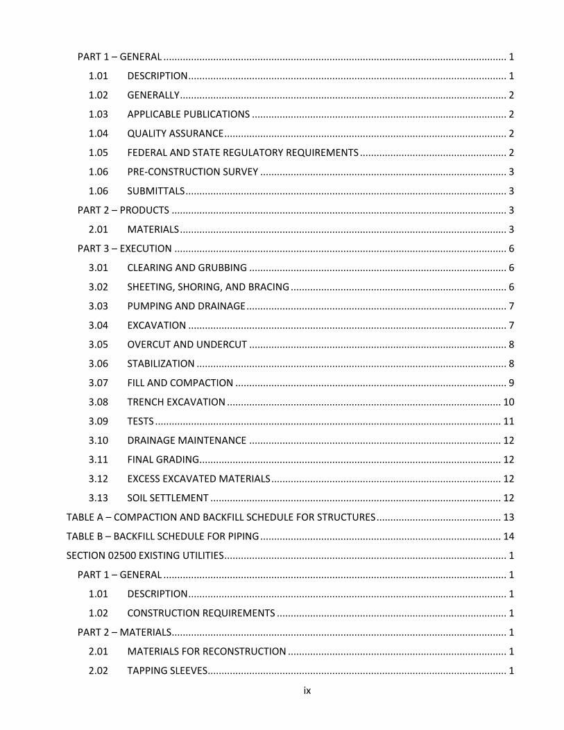
PART 1 – GENERAL ............................................................................................................................ 1
1.01 DESCRIPTION ................................................................................................................... 1
1.02 GENERALLY ...................................................................................................................... 2
1.03 APPLICABLE PUBLICATIONS ............................................................................................ 2
1.04 QUALITY ASSURANCE ...................................................................................................... 2
1.05 FEDERAL AND STATE REGULATORY REQUIREMENTS ..................................................... 2
1.06 PRE-CONSTRUCTION SURVEY ......................................................................................... 3
1.06 SUBMITTALS .................................................................................................................... 3
PART 2 – PRODUCTS ......................................................................................................................... 3
2.01 MATERIALS ...................................................................................................................... 3
PART 3 – EXECUTION ........................................................................................................................ 6
3.01 CLEARING AND GRUBBING ............................................................................................. 6
3.02 SHEETING, SHORING, AND BRACING .............................................................................. 6
3.03 PUMPING AND DRAINAGE .............................................................................................. 7
3.04 EXCAVATION ................................................................................................................... 7
3.05 OVERCUT AND UNDERCUT ............................................................................................. 8
3.06 STABILIZATION ................................................................................................................ 8
3.07 FILL AND COMPACTION .................................................................................................. 9
3.08 TRENCH EXCAVATION ................................................................................................... 10
3.09 TESTS ............................................................................................................................. 11
3.10 DRAINAGE MAINTENANCE ........................................................................................... 12
3.11 FINAL GRADING ............................................................................................................. 12
3.12 EXCESS EXCAVATED MATERIALS ................................................................................... 12
3.13 SOIL SETTLEMENT ......................................................................................................... 12
TABLE A – COMPACTION AND BACKFILL SCHEDULE FOR STRUCTURES ............................................. 13
TABLE B – BACKFILL SCHEDULE FOR PIPING ....................................................................................... 14
SECTION 02500 EXISTING UTILITIES ...................................................................................................... 1
PART 1 – GENERAL ............................................................................................................................ 1
1.01 DESCRIPTION ................................................................................................................... 1
1.02 CONSTRUCTION REQUIREMENTS ................................................................................... 1
PART 2 – MATERIALS ......................................................................................................................... 1
2.01 MATERIALS FOR RECONSTRUCTION ............................................................................... 1
2.02 TAPPING SLEEVES ............................................................................................................ 1
x
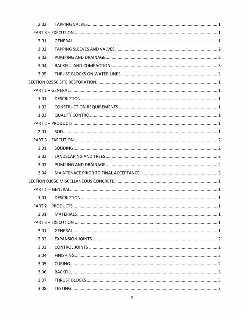
2.03 TAPPING VALVES ............................................................................................................. 1
PART 3 – EXECUTION ........................................................................................................................ 1
3.01 GENERAL ......................................................................................................................... 1
3.02 TAPPING SLEEVES AND VALVES ...................................................................................... 2
3.03 PUMPING AND DRAINAGE .............................................................................................. 2
3.04 BACKFILL AND COMPACTION.......................................................................................... 3
3.05 THRUST BLOCKS ON WATER LINES ................................................................................. 3
SECTION 02950 SITE RESTORATION ...................................................................................................... 1
PART 1 – GENERAL ............................................................................................................................ 1
1.01 DESCRIPTION ................................................................................................................... 1
1.02 CONSTRUCTION REQUIREMENTS ................................................................................... 1
1.03 QUALITY CONTROL .......................................................................................................... 1
PART 2 – PRODUCTS ......................................................................................................................... 1
2.01 SOD .................................................................................................................................. 1
PART 3 – EXECUTION ........................................................................................................................ 2
3.01 SODDING ......................................................................................................................... 2
3.02 LANDSCAPING AND TREES .............................................................................................. 2
3.03 PUMPING AND DRAINAGE .............................................................................................. 2
3.04 MAINTENACE PRIOR TO FINAL ACCEPTANCE ................................................................. 3
SECTION 03050 MISCELLANEOUS CONCRETE ...................................................................................... 1
PART 1 -- GENERAL ............................................................................................................................ 1
1.01 DESCRIPTION ................................................................................................................... 1
PART 2 – PRODUCTS ......................................................................................................................... 1
2.01 MATERIALS ...................................................................................................................... 1
PART 3 – EXECUTION ........................................................................................................................ 1
3.01 GENERAL ......................................................................................................................... 1
3.02 EXPANSION JOINTS ......................................................................................................... 2
3.03 CONTROL JOINTS ............................................................................................................ 2
3.04 FINISHING ........................................................................................................................ 2
3.05 CURING............................................................................................................................ 2
3.06 BACKFILL .......................................................................................................................... 3
3.07 THRUST BLOCKS .............................................................................................................. 3
3.08 TESTING ........................................................................................................................... 3

xi
SECTION 03410 PRECAST CONCRETE .................................................................................................... 1
PART 1 – GENERAL ............................................................................................................................ 1
1.01 DESCRIPTION ................................................................................................................... 1
1.02 QUALITY ASSURANCE ...................................................................................................... 1
1.03 SUBMITTALS .................................................................................................................... 1
1.04 DELIVERY, STORAGE AND HANDLING ............................................................................. 1
PART 2 – PRODUCTS ......................................................................................................................... 2
2.01 MATERIALS AND FABRICATION....................................................................................... 2
PART 3 - EXECUTION ......................................................................................................................... 3
3.01 CONTROL JOINTS ............................................................................................................ 3
SECTION 03600 GROUT ......................................................................................................................... 1
PART 1 – GENERAL ............................................................................................................................ 1
1.01 DESCRIPTION ................................................................................................................... 1
1.02 SUBMITTALS .................................................................................................................... 1
PART 2 - PRODUCTS .......................................................................................................................... 2
2.01 APPLICATION ................................................................................................................... 2
2.02 EPOXY ANCHOR GROUT .................................................................................................. 2
2.03 CEMENT-BASED GROUTS ................................................................................................ 2
2.04 PRESSURE GROUT ........................................................................................................... 3
2.05 CURING MATERIALS ........................................................................................................ 4
PART 3 – EXECUTION ........................................................................................................................ 4
3.01 GENERALLY ...................................................................................................................... 4
3.02 GROUTING PROCEDURES ................................................................................................ 4
SECTION 06820 FIBERGLASS LINERS {PRIVATE} .................................................................................... 1
PART 1 – GENERAL ............................................................................................................................ 1
1.01 DESCRIPTION ................................................................................................................... 1
1.02 SUBMITTALS .................................................................................................................... 1
1.03 CERTIFICATION ................................................................................................................ 1
PART 2 - PRODUCTS .......................................................................................................................... 1
2.01 MATERIALS ...................................................................................................................... 1
PART 3 – EXECUTION ........................................................................................................................ 1
3.01 PREPARATION ................................................................................................................. 1
3.02 INSTALLATION ................................................................................................................. 2

xii
SECTION 09900 PAINTING .................................................................................................................... 1
PART 1 – GENERAL ............................................................................................................................ 1
1.01 WORK INCLUDED ............................................................................................................ 1
PART 2 - PRODUCTS .......................................................................................................................... 1
2.01 MATERIALS ...................................................................................................................... 1
PART 3 – EXECUTION ........................................................................................................................ 2
3.01 MATERIAL PREPARATION................................................................................................ 2
3.02 APPLICATION ................................................................................................................... 2
3.03 FIELD QUALITY CONTROL ................................................................................................ 2
SECTION 09980 CONCRETE COATINGS ................................................................................................. 1
PART 1 – GENERAL ............................................................................................................................ 1
1.01 DESCRIPTION ................................................................................................................... 1
1.02 SUBMITTALS .................................................................................................................... 1
1.03 QUALITY ASSURANCE ...................................................................................................... 1
1.04 SITE CONDITIONS ............................................................................................................ 1
1.05 WARRANTY...................................................................................................................... 2
PART 2 - PRODUCTS .......................................................................................................................... 2
2.01 COATING PRODUCTS ....................................................................................................... 2
2.02 REPAIR AND RESURFACING PRODUCTS .......................................................................... 2
PART 3 – EXECUTION ........................................................................................................................ 2
3.01 INITIAL EXAMINATION .................................................................................................... 2
3.02 SURFACE PREPARATION .................................................................................................. 2
3.03 APPLICATION OF COATING PRODUCTS........................................................................... 3
3.04 TESTING AND INSPECTION .............................................................................................. 3
SECTION 11300 SUBMERSIBLE PUMPS ................................................................................................. 1
PART 1 – GENERAL ............................................................................................................................ 1
1.01 DESCRIPTION ................................................................................................................... 1
1.02 SUBMITTALS .................................................................................................................... 1
1.03 DELIVERY, STORAGE AND HANDLING ............................................................................. 2
1.04 WARRANTY...................................................................................................................... 2
PART 2 - PRODUCTS .......................................................................................................................... 2
2.01 EQUIPMENT .................................................................................................................... 2
2.02 MATERIALS ...................................................................................................................... 2

xiii
PART 3 – EXECUTION ........................................................................................................................ 3
3.01 INSPECTION AND TESTING .............................................................................................. 3
SECTION 11320 DIESEL PUMPS ............................................................................................................. 1
PART 1 – GENERAL ............................................................................................................................ 1
1.01 DESCRIPTION ................................................................................................................... 1
1.02 SUBMITTALS .................................................................................................................... 1
1.03 DELIVERY, STORAGE AND HANDLING ............................................................................. 2
1.04 WARRANTY...................................................................................................................... 2
PART 2 - PRODUCTS .......................................................................................................................... 2
2.01 EQUIPMENT .................................................................................................................... 2
2.02 AUTOMATIC STARTING CONTROL SYSTEM .................................................................... 6
2.03 OPTIONS .......................................................................................................................... 7
PART 3 – EXECUTION ........................................................................................................................ 8
3.01 MANUFACTURERS SERVICE ............................................................................................ 8
3.02 TOOLS AND SPARE PARTS ............................................................................................... 8
Figure 1 – Sewer Service Connection Notes (US-10) ........................................................................ 1
Figure 2 - Sewer Service Connection Details (US-11) ....................................................................... 2
Figure 3 -Sewer Cleanout Detail (US-12) .......................................................................................... 3
Figure 4 - Traffic Bearing Sewer Clean-out (US-13) .......................................................................... 4
Figure 5 -Private/Public Force main Transition (US-14) ................................................................... 5
Figure 6 - In Ground Air Release Valve Vault Detail (US-15) ............................................................ 6
Figure 7 -Above Ground Air Release Valve Detail (US-16) ................................................................ 7
Figure 8 - Grease Interceptor Detail (US-17) .................................................................................... 8
Figure 9 - General Manhole Notes (US-20 Page 1 of 2) .................................................................... 9
Figure 10 - General Manhole Notes (US-20 Page 2 of 2) ................................................................ 10
Figure 11 - Concentric Manhole Detail (US-21) .............................................................................. 11
Figure 12 - Eccentric Manhole Detail (US-22) ................................................................................. 12
Figure 13 - Single Interior Drop Manhole Detail (US-23) ................................................................ 13
Figure 14 - Double Interior Drop Manhole Detail (US-24) .............................................................. 14
Figure 15 - Conflict Manhole Detail (US-25) ................................................................................... 15
Figure 16 - Dog House Manhole Detail (US-26) .............................................................................. 16
Figure 17 - AS Legacy Manhole Cover Detail (US-27) ..................................................................... 17
Figure 18 - Manhole Inverts Detail (US-28) .................................................................................... 18

xiv
Figure 19 - Lift Station Notes (US-30) ............................................................................................. 19
Figure 20 - Lift Station Profile View Detail (US-31 Page 1 of 3) ...................................................... 20
Figure 21 - Tremie Wet Well Installation Detail (US-31 Page 2 of 3).............................................. 21
Figure 22 - Tremie & Wet Well Causes for Rejection Notes (US-31 Page 3 of 3) ........................... 22
Figure 23 - Lift Station Plan View Detail (US-32-ALL Page 1 of 3) ................................................... 23
Figure 24 - Lift Station Plan View Detail (US-32-ALL Page 2 of 3) ................................................... 24
Figure 25 - Lift Station Section View Detail (US-32-ALL Page 3 of 3) .............................................. 25
Figure 26 - Lift Station Above Ground Valving Detail (US-33) ........................................................ 26
Figure 27 - Lift Station Valve Vault Detail (US-34) .......................................................................... 27
Figure 28 - Lift Station Control Panel Detail (US-35 Page 1 of 2 / Elec-10-ALL) ............................. 28
Figure 29 - Lift Station Control Panel Detail (US-35 Page 2 of 2 / Elec-11-ALL) ............................. 29
Figure 30 - 30' Maximum Height Telemetry Mast Detail (US-36) .................................................. 30
Figure 31 - Telemetry RTU Detail (US-37) ....................................................................................... 31
Figure 32 - 45' Maximum Height Telemetry Mast Detail (US-38) .................................................. 32
Figure 33 - Wet Well Pipe Bracing Detail (US-39) ........................................................................... 33
Figure 34 - Water Service General Notes (US-40) .......................................................................... 34
Figure 35 - Water Service Section View Detail (US-41) .................................................................. 35
Figure 36 - Water Service Plan View Detail (US-42) ....................................................................... 36
Figure 37 - Fire Hydrant Assembly Detail (US-43) .......................................................................... 37
Figure 38 - Blow Off Detail (US-44) ................................................................................................. 38
Figure 39 - Temporary Jumper Connection Detail (US-45) ............................................................. 39
Figure 40 - 3/4" to 2" Backflow Preventer Detail (US-46) .............................................................. 40
Figure 41 - Backflow Preventer with Meter for Fire Services 3" to 8" Detail (US-47) .................... 41
Figure 42 - Reclaimed Water Service General Notes (US-50) ......................................................... 42
Figure 43 - Reclaimed Water Service Section View Detail (US-51) ................................................. 43
Figure 44 - Reclaimed Water Service Plan View Detail (US-52) ...................................................... 44
Figure 45 - Reclaimed Water Sign Detail (US-53) ........................................................................... 45
Figure 46 - Reclaimed Water Service Connection Detail (US-54) ................................................... 46
Figure 47 - Pipe Separation Detail (US-60) ..................................................................................... 47
Figure 48 - PVC Pipe Restraint Table Detail (US-61) ....................................................................... 48
Figure 49 - Ductile Iron Pipe Restraint Table Detail (US-62) ........................................................... 49
Figure 50 - Roadway Open Cut Detail (US-63) ................................................................................ 50
Figure 51 - Utility Crossing Detail (US-64)....................................................................................... 51

xv
Figure 52 - Vertical Pipe Deflection Detail (US-65) ......................................................................... 52
Figure 53 - Concrete Support Cradle Detail (US-66) ....................................................................... 53
Figure 54 - Valve Box Detail (US-67) ............................................................................................... 54
Figure 55 - Subaqueous / Ditch Crossing Detail (US-68) ................................................................. 55
Figure 56 - Utility Main Crossing Sign Detail (US-69) ...................................................................... 56
Figure 57 - Casing Installation Detail (US-70) ................................................................................. 57
Figure 58 - Aerial Crossing Fan Guard Detail (US-71) ..................................................................... 58
Figure 59 - Aerial Canal Crossing Detail (US-72) ............................................................................. 59
Figure 60 - Bollard Detail (US-73) ................................................................................................... 60
Figure 61 - Utility Marker Detail (US-74) ........................................................................................ 61
Appendix A – BCUSD Details .................................................................................................................. i
US-10 Sewer Service Connection Notes ............................................................................................ i
US-11 Sewer Service Connection .......................................................................................................ii
US-12 Sewer Cleanout ...................................................................................................................... iii
US-13 Traffic Bearing Sewer Clean-out ............................................................................................. iv
US-14 Private/Public Forcemain Transition ....................................................................................... v
US-15 In-Ground Air Release Valve Vault ......................................................................................... vi
US-16 Above Ground Air Release Valve ........................................................................................... vii
US-17 Grease Interceptor ............................................................................................................... viii
US-20 Page 1 of 2 - General Manhole Notes ..................................................................................... x
US-20 Page 2 of 2 - General Manhole Notes ................................................................................... xii
US-21 - Concentric Manhole ........................................................................................................... xiii
US-22 – Eccentric Manhole ............................................................................................................. xiv
US-23 – Single Interior Drop Manhole ............................................................................................. xv
US-24 - Double Interior Drop Manhole........................................................................................... xvi
US-25 – Conflict Manhole .............................................................................................................. xvii
US-26 – Dog House Manhole ........................................................................................................ xviii
US-27 - AS Legacy Manhole Cover .................................................................................................. xix
US-28 - Manhole Inverts .................................................................................................................. xx
US-30 - Lift Station Notes ................................................................................................................ xxi
US-31 Page 1 of 3 - Lift Station Profile View ................................................................................. xxiii
US-31 Page 2 of 3 - Tremie Wet Well Installation Detail .............................................................. xxiv
US-31 Page 3 of 3 - Tremie & Wet Well Causes for Rejection Notes ............................................ xxv

xvi
US-32-ALL Page 1 of 3 - Lift Station Plan View .............................................................................. xxvi
US-32-ALL Page 2 of 3 Lift Station Plan View ............................................................................... xxvii
US-32-ALL Page 3 of 3 Lift Station Section View ......................................................................... xxviii
US-33 Lift Station Above Ground Valving ..................................................................................... xxix
US-34 Lift Station Valve Vault ........................................................................................................ xxx
US-35 Page 1 of 2 (Elec-10-ALL) Lift Station Control Panel .......................................................... xxxi
US-35 Page 2 of 2 (Elec-11-ALL) Lift Station Control Panel ......................................................... xxxii
US-36 Telemetry Mast 30’ Maximum Height ............................................................................. xxxiii
US-37 Telemetry RTU .................................................................................................................. xxxiv
US-38 Telemetry Mast 45’ Maximum Height .............................................................................. xxxv
US-39 Wet Well Pipe Bracing Detail ........................................................................................... xxxvi
US-40 Water Service General Notes ...........................................................................................xxxvii
US-41 Water Service Section View ............................................................................................ xxxviii
US-42 Water Service Plan View ...................................................................................................xxxix
US-43 Fire Hydrant Assembly ........................................................................................................... xl
US-44 Blow Off Detail ...................................................................................................................... xli
US-45 Temporary Jumper Connection ............................................................................................ xlii
US-46 Backflow Preventer 3/4" – 2” .............................................................................................. xliii
US-47 Backflow Preventer with Meter for Fire Services 3”-8” ...................................................... xliv
US-50 Reclaimed Water Service General Notes ............................................................................. xlv
US-51 Reclaimed Water Service Section View ............................................................................... xlvi
US-52 Reclaimed Water Service Plan View ................................................................................... xlvii
US-53 Reclaimed Water Sign ....................................................................................................... xlviii
US-54 Reclaimed Water Service Connection ..................................................................................... l
US-60 Pipe Separation .......................................................................................................................li
US-61 Restraint Table PVC Pipe ....................................................................................................... liv
US-62 Restraint Table Ductile Iron Pipe ............................................................................................ lv
US-63 Open Cut – Roadway ............................................................................................................ lvii
US-64 Utility Crossing ..................................................................................................................... lviii
US-65 Vertical Pipe Deflection ......................................................................................................... lix
US-66 Concrete Support Cradle ........................................................................................................ lx
US-67 Valve Box ............................................................................................................................... lxi
US-68 Subaqueous / Ditch Crossing ................................................................................................ lxii

xvii
US-69 Utility Main Crossing Sign .................................................................................................... lxiii
US-70 Casing Installation ............................................................................................................... lxiv
US-71 Aerial Crossing Fan Guard .................................................................................................... lxv
US-72 Aerial Canal Crossing ........................................................................................................... lxvi
US-73 Bollard Detail ...................................................................................................................... lxvii
US-74 Utility Markers ................................................................................................................... lxviii
APPROVED MANUFACTURERS AND PRODUCTS ................................................................................... 1
WASTEWATER SERVICE MATERIALS ................................................................................................. 1
Adhesive Marking Tape................................................................................................................. 1
Air Release and Vacuum Valves .................................................................................................... 1
Casing Spacers ............................................................................................................................... 1
Check Valves ................................................................................................................................. 1
Concrete coatings (Spray On Liners) ............................................................................................. 2
Drop Bowls .................................................................................................................................... 2
Ductile Iron Fittings ....................................................................................................................... 2
Ductile Iron Pipe ............................................................................................................................ 2
Ductile Iron Pipe Lining ................................................................................................................. 3
Electronic Markers ........................................................................................................................ 3
Fiberglass Liners ............................................................................................................................ 3
Gate Valves- Resilient Wedge ....................................................................................................... 3
HDPE Liners for Wet Wells ............................................................................................................ 3
HDPE Pipe ...................................................................................................................................... 4
Joint Sealing Compound ............................................................................................................... 4
Joint Restraints .............................................................................................................................. 4
Manhole Coatings ......................................................................................................................... 4
Manhole Exterior Shrink ............................................................................................................... 5
Manhole Adjustment Rings - Concrete ......................................................................................... 5
Manhole Adjustmnent Rings - HDPE ............................................................................................ 5
Non-Shrink Grout .......................................................................................................................... 5
Pipe Couplings ............................................................................................................................... 5
Plug Valves .................................................................................................................................... 6
PVC Fittings ................................................................................................................................... 6
PVC Pipe - Force Main Integral Bell .............................................................................................. 6

xviii
PVC Pipe - Gravity Main Integral Bell ............................................................................................ 6
Resilient Connectors ..................................................................................................................... 6
Substrate Patching Material ......................................................................................................... 6
Stainless Ball Valve ........................................................................................................................ 7
Tapping Saddle .............................................................................................................................. 7
Tapping Sleeves ............................................................................................................................. 7
Tracer Wire ................................................................................................................................... 7
Traffic Bearing Clean Out .............................................................................................................. 7
Valve Boxes ................................................................................................................................... 8
Valve Extensions ........................................................................................................................... 8
LIFT STATION MATERIALS ................................................................................................................. 9
Access Frames and Covers ............................................................................................................ 9
Drop Bowls .................................................................................................................................... 9
Fall Protection ............................................................................................................................... 9
Float Regulators ............................................................................................................................ 9
Pressure Gauges ............................................................................................................................ 9
Pressure Transducers .................................................................................................................... 9
Pressure Transducer Hanger ....................................................................................................... 10
Submersible Pumps .................................................................................................................... 10
WATER SERVICE MATERIALS ........................................................................................................... 11
Adhesive Marking Tape............................................................................................................... 11
Backflow Prevention ................................................................................................................... 11
Ball Valves ................................................................................................................................... 11
Casing Spacers ............................................................................................................................. 11
Corporation Stops ....................................................................................................................... 11
Curb Stops ................................................................................................................................... 12
Ductile Iron Fittings ..................................................................................................................... 12
Ductile Iron Pipe (cement lined) ................................................................................................. 12
Electronic Markers ...................................................................................................................... 12
Fire Hydrants ............................................................................................................................... 12
Gate Valves (Resilient Wedge) .................................................................................................... 13
HDPE Pipe .................................................................................................................................... 13
Joint Restraints ............................................................................................................................ 13

xix
Meter Boxes ................................................................................................................................ 13
Meter, Fire Services .................................................................................................................... 14
Polyethylene Tubing ................................................................................................................... 14
Pipe Couplings ............................................................................................................................. 14
PVC Pipe, Integral Bell ................................................................................................................. 14
Service Saddles ............................................................................................................................ 15
Tapping Sleeves ........................................................................................................................... 15
RECLAIMED WATER SERVICE MATERIALS ....................................................................................... 16
Adhesive Marking Tape............................................................................................................... 16
Casing Spacers ............................................................................................................................. 16
Corporation Stops ....................................................................................................................... 16
Curb Stops ................................................................................................................................... 16
Ductile Iron Fittings ..................................................................................................................... 17
Ductile Iron Pipe .......................................................................................................................... 17
Electronic Markers ...................................................................................................................... 17
Gate Valves- Resilient Wedge ..................................................................................................... 17
Hose Bibb Lockable Box .............................................................................................................. 17
HDPE Pipe .................................................................................................................................... 18
Joint Restraints ............................................................................................................................ 18
Meter Box ................................................................................................................................... 18
Polyethylene Tubing ................................................................................................................... 18
Pipe Couplings ............................................................................................................................. 19
PVC Pipe - Integral Bell ................................................................................................................ 19
Service Saddles ............................................................................................................................ 19
Tapping Sleeves ........................................................................................................................... 19
Tracer Wire ................................................................................................................................. 20
Valve Boxes ................................................................................................................................. 20
Valve Extensions ......................................................................................................................... 20
Cross Reference .................................................................................................................................... 1
GENERAL INFORMATION .................................................................................................................. 1
SANITARY SEWERAGE SYSTEM ......................................................................................................... 5
WATER SYSTEM ............................................................................................................................... 15
RECLAIMED WATER SYSTEM ........................................................................................................... 21

xx
Cross Reference .................................................................................................................................... 1
GENERAL INFORMATION .................................................................................................................. 1
SANITARY SEWERAGE SYSTEM ......................................................................................................... 5
WATER SYSTEM ............................................................................................................................... 15
RECLAIMED WATER SYSTEM ........................................................................................................... 21

DEFINITIONS AND ABBREVIATIONS
Within the context of this document, the terms and abbreviations below have the following meanings:
Contractor - A constructor of water, wastewater, and reclaimed water utilities. County - The Brevard County Government Criteria - (see STANDARDS) Engineer (or Design Engineer) - A developer's engineer or the Utility's design engineering
consultant, as the case may be, who is the engineer of record for the utility design or construction project.
Developer - An owner or developer of real estate proposing water or wastewater utility construction.
Facility - Water, wastewater, or reclaimed water pipeline, structure, or appurtenance. Inspector - The Brevard County Utility Services utility construction inspector. Proponent - A person or entity advancing or advocating the proposal or project. Standards - The engineering and construction standards that comprise the Criteria for Water
and Sanitary Sewerage Systems Within Brevard County, most recent edition. Utility (the Utility or Utility Services) - Brevard County Utility Services Work (the Work) - Any of the items that comprise the construction of a water, wastewater, or
reclaimed water utility project. AASHTO - American Association of State Highway and Transportation Officials ANSI - American National Standards Institute ASTM - American Society for Testing and Materials AWWA - American Water Works Association C-Factor - Hazen-Williams equation pipe friction factor DIP - Ductile Iron Pipe DR - Dimension Ratio EPA - United States Environmental Protection Agency FAC - Florida Administrative Code FDEP - Florida Department of Environmental Protection FDOT - Florida Department of Transportation HDPE - High Density Polyethylene NAVD88 - North American Vertical Datum of 1988 OSHA - United States Occupational Safety and Health Administration PSI - Pounds per Square Inch PVC - Polyvinyl Chloride SRF - State Revolving Funds

2
1 POLICY AND ADMINISTRATION
1.1 GENERAL
1.1.1 PURPOSE
Section 110-180 of the Brevard County Code states, “It is hereby declared that public ownership of all water and sewerage systems in the County is in the public interest and that the furnishing of water and sewerage service by publicly owned utilities is in the public interest.”
The authority for these standards is provided for in Section 110-184 of the Brevard County Code. Applicable State and federal laws and regulations shall be adhered to concurrently with these standards. When laws or regulations are conflicting, the most restrictive requirement shall be followed.
The objective of these standards is to create durable and economically maintainable public utility systems.
The information in this document is available on-line at the following website: www.brevardcounty.us/utilityservices.
1.1.2 MINIMUM STANDARDS
This document sets forth the minimum standards applicable to utility construction projects and is intended to provide a basis for the design and construction of water and wastewater facilities within Brevard County as follows:
1. Facilities owned and operated by Brevard County, or
2. Facilities connecting to Brevard County utility systems.
1.1.3 DEVIATIONS
Any deviation from these standards must be approved in writing by the Utility Services Department Director before construction plans can be approved.
1.1.4 PRIVATELY OWNED SYSTEMS
A privately-owned utility system connecting to a County maintained system shall conform to these standards. Privately owned systems are not permitted for residential subdivisions or properties that have the potential to be subdivided in the future. Proposals for privately owned systems must be approved by the Utility Services Department Director prior to construction plan review.

3
1.1.5 CONFORMANCE TO MASTER PLAN
Developer constructed wastewater collection and transmission systems, water distribution systems, and reclaimed water distribution systems shall conform to master plans for system extensions proposed by Brevard County Utility Services.
1.1.6 SURVEY
The Design Engineer should strive to design utility systems to avoid occupying points that are important for surveying, such as points of intersection, curvature, or tangency.
1.1.7 DRAWING SIZE
All drawings shall be submitted on 24” x 36” sheets of paper, or if delivered electronically, formatted to be viewed in scale on 24" x 36" format. Electronic format (pdf) submittal is encouraged in lieu of paper format for review purposes. Drawings shall be of true scale when submitted for review. Reduced drawings are not acceptable for review.
1.1.8 PLAN AND PROFILE
Construction drawings for site plans and subdivisions shall include plan and profile of the proposed utilities, including gravity sewer, force mains, reclaimed water lines, and potable water lines. Plan and profile shall be on the same sheet, show all other utilities that may conflict with the proposed construction, and shall be formatted so the plan is aligned with the profile. The plan and profile sheets shall have a horizontal scale no smaller than 1” =60’ and have a horizontal to vertical scale ratio of 10:1.
1.1.9 SIGNATURES
All drawings, excluding record drawings, and calculations submitted for review and approval shall be signed, sealed and dated by an engineer registered in the State of Florida. Record drawings shall be certified by an engineer registered in the State of Florida.
1.1.10 MASTER UTILITY PLAN
A master utility plan shall be included in the construction drawings for all projects. The master utilities plan shall be on one sheet, shall show existing and proposed water, sewer, reclaimed water, and storm sewer; and shall clearly show connections to existing systems. All phases of a phased development shall be shown.
1.1.11 CALCULATIONS
The Design Engineer shall provide calculations demonstrating the adequacy of the existing and proposed utility systems in a manner that is clear and convincing.

4
1.1.12 CONSTRUCTION PLAN APPROVAL
Approval of construction plans by Utility Services is valid for a period of one year, beginning when permit applications and drawings are forwarded to the Florida Department of Environmental Protection for approval. If construction is not started within one year, Utility Services retains the right to require compliance with the version of these standards in effect at the time an extension of the approval is requested. This requirement shall apply to currently approved projects.
1.1.13 PHASED DEVELOPMENTS
When a development is to be constructed in phases, each phase must be applied for, permitted, and cleared separately by the Florida Department of Environmental Protection.
1.1.14 UPGRADES TO EXISTING SYSTEMS
If the Utility has determined that a proposed development will overload existing systems, or is inconsistent with established master plans, the Developer shall pay for improvements to the existing systems to assure adequate additional capacity for the proposed development and compliance with established master plans.
1.1.15 PIPE SEPARATION
Minimum pipe separations are set forth in US-60
1.1.16 LANDSCAPING
Trees must be planted a minimum 10-foot offset from all utility mains
1.2 EASEMENTS, RIGHTS OF WAY AND PERMITS
1.2.1 GENERAL
Whenever possible, utility lines shall be located within road rights-of-way or utility easements immediately adjacent to road rights-of-way.
1.2.2 EASEMENT WIDTH
Easements of sufficient width are required to guarantee that permanent or semi-permanent non-utility structures are not placed close to a facility or main. The easement shall allow unhindered access to all such facilities and mains. Easements adjacent to and parallel with rights-of-ways shall have a minimum width of 10-feet. For single lines in open areas and for lines running on side property lines of subdivisions, the minimum width shall be 15 feet for lines up to 7 feet deep measured from the finished grade to the bottom of the pipe or two times the excavated depth rounded up to the next five-foot interval, whichever is greater. The width is based on the utility being located in the center of the easement. A wider easement may be required when utilities are not centered within the

5
easement or when more than one line is in the same easement. Utility Services reserves the right to require wider easements for access where it deems necessary.
1.2.3 COUNTY RIGHT-OF-WAY PERMITS
Right-of-way permits are required for work within public rights-of-way. The Contractor is responsible for obtaining these permits from Brevard County Public Works Department. Copies of permits must be submitted to Utility Services prior to the start of construction.
1.2.4 FLORIDA DEPARTMENT OF TRANSPORTATION (FDOT) RIGHT-OF-WAY PERMITS
Right-of-way permits are required for work within Florida Department of Transportation (FDOT) rights-of-way. In addition to an FDOT permit, a performance bond is required by Utility Services, prior to the preconstruction conference, in the amount of 125% of the value of the work to be performed within the FDOT right-of-way.
1.2.5 FLORIDA DEPARTMENT OF ENVIRONMENTAL PROTECTION (FDEP) PERMITS
Copies of Florida Department of Environmental Protection (FDEP) permits shall be submitted to Utility Services prior to construction.
1.3 CONSTRUCTION DOCUMENTS
1.3.1 SPECIFICATIONS AND DRAWINGS
The Work shall be completed according to the intention of the design engineer as reflected in the drawings and specifications. The Work exhibited in one but not the other shall be executed as if it had been set forth in both.
1.3.2 DIMENSIONS
Drawings are not intended to be scaled for dimensions. If dimensions are not shown, the Contractor shall request them from the Design Engineer.
1.3.3 EXISTING UTILITIES
Existing utility lines shall have been located from available information furnished by the Utility and from additional site investigation. Such obstructions are to be shown for the purpose of advising the Contractor that they may interfere with the work to be done, but not for the purpose of indicating that the work can be performed without such interference. It shall be the responsibility of the Design Engineer to secure proper existing utility information, and prepare drawings in accordance with these standards.
1.3.4 SHOP DRAWINGS
Details and shop drawings for products and materials to be used in the utility construction shall be first submitted to the Design Engineer and then to the Utility for review prior to construction. The Utility will accept shop drawings only after they are stamped approved by

6
both the Contractor and the Design Engineer. Electronic submittals in pdf format are acceptable. Two stamped copies shall be sent to Utility Services. Products that are not manufactured and installed in strict compliance with approved shop drawings and specifications will be rejected.
1.4 METHODS AND MATERIALS
1.4.1 PROOF OF CONFORMANCE AND ALTERNATIVE ITEMS
When a material is specified by brand or “approved equal”, an alternate material may be submitted for consideration by Utility Services. Proof of conformity is the Proponent’s responsibility. “Equal” items may be used only if approved by the Proponent’s Engineer and Utility Services.
1.4.2 MEANS AND METHODS
The means and methods used by a Contractor shall conform to generally accepted standards for underground utility construction.
1.4.3 DEFECTIVE MATERIALS AND WORKMANSHIP
The Contractor shall repair any damage or leaks caused by defective materials or workmanship during the period of the maintenance bond.
1.4.4 SPECIAL MATERIALS
Utility Services reserves the right to mandate certain materials to be used where deemed necessary. Special materials will be specified during the review process when possible. The Utility intends to allow PVC, HDPE, or ductile iron pipe for construction of potable water, reclaimed water, and force mains 4 inches in diameter to 12 inches in diameter. Potable water, Reclaimed water and Sanitary Sewer Force Mains larger than 12 inches in diameter shall be ductile iron.
1.4.5 CASTINGS
Castings for valves, vaults, manholes and other appurtenances shall conform to, and shall be tested in accordance with the specifications for Gray Cast Iron, ANSI/ASTM A48, Class 30 and meet FDOT specifications where applicable. Castings that are to be located within a dedicated public right-of-way, or any other location subject to vehicular traffic, shall have all bearing surfaces machined so that the fitting parts will not rattle or rock under traffic. All castings shall be subject to a hammer test before installation.
1.4.6 PRE-CONSTRUCTION MEETING
Construction shall not start until a pre-construction meeting has been conducted with Utility Services’ staff.

7
1.4.7 OMISSIONS
Should anything be omitted from the specifications and drawings that is necessary for a clear understanding of the work, or should it appear that instructions are in conflict, the Contractor shall request written instructions from the Design Engineer before proceeding with the construction affected by such omissions or discrepancies.
1.4.8 CHANGES
Changes shall not be made to finally-approved drawings without the approval of Utility Services.
1.4.9 MONUMENT PRESERVATION
Property corners and survey monuments shall be preserved using care not to disturb or destroy them. If a property corner or survey monument is disturbed or destroyed during construction, whether intentionally or unintentionally, or is required to be disturbed or destroyed by the construction work, said property corner or survey monument shall be restored by a land surveyor registered in the State of Florida. All costs for this work shall be paid for by the Contractor.
1.5 PROTECTION OF THE PUBLIC
1.5.1 BARRICADES, GUARDS, AND SAFETY PROVISIONS
The Contractor shall be solely responsible for adhering to the rules and regulations of the Occupational Safety and Health Administration (OSHA), the Trench Safety Act, and appropriate authorities regarding safety provisions. Adequate barricades, construction signs, lights, and guards as required shall be placed and maintained by the Contractor at his expense during the progress of the Work until it is safe. All material piles, equipment, and pipe that may obstruct traffic shall be enclosed by fences or barricades and shall be protected by proper lights when the visibility is poor. All signage and barricades shall be in accordance with the Manual on Uniform Traffic Control Devices and Florida Department of Transportation standards.
1.6 PROTECTION OF EXISTING UTILITIES
1.6.1 GENERALLY
If public property is damaged, destroyed, or removed, it shall be repaired, replaced, or paid for by the Contractor. Intentional disturbance to public property must first be approved by the agency that manages it.
1.6.2 EXISTING UTILITIES
Existing utilities shall be protected in accordance with the direction of the utility company owning the conduits or mains. The Contractor shall notify the companies and obtain their permission before making any crossing or revision. The Contractor shall furnish at his own

8
expense temporary support, adequate protection, and maintenance of all underground and surface utility structures, including drains, sewers, manholes, hydrants, valves, valve boxes, utility poles and miscellaneous utility structures encountered in the progress of the Work. Structures that may have been disturbed shall be restored upon completion of the Work.
1.6.3 LOCATION OF EXISTING UTILITIES
It is the Contractor’s responsibility to coordinate the Work with all utility companies for location and maintenance of existing utilities. Forty-eight hours prior to proceeding with excavation, the Contractor shall contact Sunshine State One Call of Florida, Inc. to aid in locating underground utilities. It shall be the Contractor’s responsibility to contact utility companies at least two working days prior to starting construction, or as required by law. The Contractor shall proceed with caution in the excavation and preparation of a trench so that the exact location of underground utilities may be determined. The Contractor shall take all reasonable precautions against damage to existing utilities. In the event of a break in an existing water main, reclaimed water main, gas main, sewer or underground cable, the Contractor shall immediately notify the responsible official of the organization operating the interrupted utility. The Contractor shall lend assistance in restoring services and shall assume all cost, charges, or claims connected with the interruption and repair of such service.
1.6.4 PROTECTION OF TREES, SHRUBS AND SODDED AREAS
All trees and shrubs not shown to be removed on the plans shall be protected by the Contractor at the Contractor’s expense. No excavated materials shall be placed so as to injure such trees and shrubs. Trees and shrubs destroyed by the Contractor shall be replaced with new stock of similar size and age at the sole expense of the Contractor. Sodded areas shall be left in as good or better condition than before starting of the work. Where sod is damaged or removed, it shall be carefully restored with new sod of the same type.
1.6.5 RESTORATION OF FENCES
Any fence, or part thereof, that is damaged or removed during the course of the work shall be repaired or replaced by the Contractor and shall be left in as good or better condition than before the starting of the work. The manner in which the fence is repaired or replaced and the materials used shall be subject to the approval of the Utility.
1.6.6 NUISANCE
The contractor shall not create a nuisance including but not limited to encroachment on adjacent lands or excessive noise or dust. The Contractor shall eliminate noise to as great an extent as practicable at all times.

9
1.6.7 ISOLATION OF SYSTEM
New construction shall remain isolated from County systems until it is approved for service by the Utility.
1.6.8 OPERATION OF EXISTING VALVES AND CONTROLS
No valve or other control on any existing utility main or building service line shall be operated for any purpose by the Contractor.
1.6.9 UNAUTHORIZED CONNECTIONS
Contractor shall not make any unauthorized connections to a utility system nor shall the Contractor permit any such connections to be made.
1.7 INSPECTION
1.7.1 ASSIGNMENT OF INSPECTOR
An Inspector will be assigned by Utility Services to all utility projects (public and private) to inspect preparation, fabrication, and manufacture of components, and construction.
1.7.2 AUTHORITY
The Inspector is not authorized to revoke, alter, or waive any requirements of these Standards. He or she is expected and authorized to call to the attention of the Contractor any failure to conform to these Standards. The Inspector shall not act as a foreman, give advice, or perform other duties of the Design Engineer or Contractor.
1.7.3 RIGHT TO REJECT
The Inspector shall have the authority to reject materials or issue deficient work notices until questions of conformity can be resolved to the Utility’s satisfaction.
1.7.4 SCHEDULED INSPECTIONS
Inspectors will make ongoing routine inspections. Scheduled inspections are required for jacking and boring operations, setting of wet wells, lift station start-ups, any time a connection is to be made to a County system, delivery of pre-cast structures (including grease interceptors) and other times when deemed necessary by Utility Services.
1.7.5 INSPECTION PROCESS
It shall be the Contractor’s responsibility to notify Utility Services when he or she is ready for inspection. The Contractor’s qualified representative shall be present at all scheduled tests and inspections. Prior to final Inspection, all concerned parties shall inspect the project or facility to ensure quality workmanship and compliance with these Standards. Utility Services will notify the Design Engineer, the Developer, and the Contractor of any problems or outstanding items required for final acceptance of the project (punch list).

10
After all punch list items are completed, the Contractor shall notify Utility Services and another inspection will be scheduled. The inspection party shall include at a minimum, the Contractor and a Utility Services representative.
1.7.6 COMMENCEMENT OF WORK
The Contractor shall give 48 hours’ notice to Utility Services before beginning construction in the field.
1.7.7 INSPECTOR WORK HOURS
The normal work shift for Inspectors is 7:00 am to 3:30 pm. Any work done on other than the normal work shift, Saturday, Sunday, or County holiday for which an Inspector is required shall be considered overtime and shall be paid for by the Contractor. The necessity for the presence of an Inspector will be determined by the Utility Services Department Director or his or her designated representative. Inspector overtime rates are available from Utility Services upon written request.
1.7.8 CONSTRUCTION HOURS
No work shall be done between the hours of 6:00 p.m. and 6:00 a.m., or on Saturdays or Sundays or County holidays unless the proper and efficient prosecution of the work requires operations during those times. Written request for doing the after-hours work shall be submitted to Utility Services a minimum 48 hours before starting the work.
1.7.9 COUNTY HOLIDAYS
The following are County Holidays:
a. New Year’s Day b. Martin Luther King Jr’s Birthday c. Memorial Day d. Independence Day e. Labor Day f. Veteran’s Day g. Thanksgiving Day h. The Friday following Thanksgiving Day i. Christmas Eve j. Christmas Day k. Others as adopted by the Board of County Commissioners
1.8 PRIVATELY OWNED UTILITY SYSTEMS
Privately owned utility systems that connect to County systems shall meet these standards.

11
1.8.1 WRITTEN REQUEST
A written request to construct a privately-owned utility system must be approved by the Utility Services Director before it will be reviewed by Utility Services staff. The request must include a sketch showing the layout of the property and the proposed utilities. The Proponent will be advised in writing of the Director’s decision. If approved, an irrevocable license agreement for inspection will be required. Only systems on single parcels perpetually under single ownership may be maintained as private systems. Properties that can be subdivided in the future do not qualify for private system. Regardless, each sewer customer must have individual and direct legal access to the public sewer.
1.8.2 REQUIRED DOCUMENTATION
The following items must be submitted to Brevard County Utility Services prior to allowing connection of a private utility system to a County system.
1.8.2.1 RESPONSIBILITY FOR OPERATION
A letter from the owner of the private system stating that he or she accepts full responsibility for the operation and maintenance of the system along with two 24-hour local emergency contact names and phone numbers,
1.8.2.2 RECORD DRAWINGS
Record drawings, prepared in accordance with these Standards.
1.8.2.3 FDEP CERTIFICATE OF COMPLETION
An FDEP Certificate of Completion signed and sealed by a professional engineer registered in the State of Florida. Evidence of passing bacteriological clearances must also be submitted where required.
1.8.3 DIRECT CONNECTION
All individual customers must have a direct individual connection to the utility system. Any system proposing the connection of multiple customers or units to a single service connection must receive approval from the Director of Utility Services. If approved, the limits of Utility Services' maintenance will be identified. Sufficient easements for maintenance and operation of the public portions must be provided.
1.8.4 CONNECTION TO A PRIVATELY-OWNED UTILITY
If a proposed utility system will connect to a privately-owned utility system for service, the Proponent shall obtain a contractual agreement from the owner of the existing private system to provide a perpetual right of service through the owner's property. Proof of this executed agreement shall be submitted to Utility Services prior to review of the construction plans.

12
1.8.5 ACCEPTANCE OF PRIVATE SYSTEMS FOR PUBLIC MAINTENANCE
Brevard County Utility Services may accept private systems for operation and maintenance only if they conform to the utility standards in effect at the time of the request for acceptance after all maintenance items have been corrected.
1.8.6 PRIVATE LIFT STATION CONTACT INFORMATION
Emergency contact information is to be clearly posted on the exterior of the control panel of a private lift station.
1.8.7 PRIVATE LIFT STATION DESIGN
Private lift stations installed at close proximity of vehicle use area shall be designed to meet H20 load rating.
1.9 CONSTRUCTION
1.9.1 APPROVED CONSTRUCTION DRAWINGS AND SPECIFICATIONS
The Contractor must have a set of drawings and specifications approved by Utility Services on the project site at all times.
1.9.2 APPROVED MANUFACTURES AND PRODUCTS
A list of approved manufacturers and products is located in Appendix A of these Standards.
1.9.3 GRADES
All work shall be constructed in accordance with the lines and grades shown on the plans.
1.9.4 BENCH MARKS
Benchmarks and base line controlling points shall be established prior to beginning the work. Benchmarks shall be established on the project site by a land surveyor registered in the State of Florida. The level loop establishing the bench marks shall meet the requirements of Chapter 61G17-6 Florida Administrative Code, “Minimum Technical Standards”. Field notes and closure calculations identifying the datum shall be provided to the Utility Services Inspector.
1.9.5 SURVEYS
The Contractor is responsible for the surveying required to conduct the work and to provide record drawings. The Contractor shall, at his own expense, establish all working or construction lines and grades as required from the reference marks and shall be solely responsible for the accuracy thereof. The Contractor's surveys shall be subject to checking and reviewing by the County.

13
1.9.6 FACILITY MARKINGS
Markings on manhole covers, valve box covers, and piping shall accurately describe the type and use of the facility.
1.9.7 STREET RESTORATION
All features within the road right-of-way (backfill, base, pavement, driveways, shoulders, curb, landscaping, etc.) shall be restored to conform to the latest requirements of the agency that maintains the road, or pre-construction conditions, as applicable.
1.9.8 DEWATERING EQUIPMENT
The Contractor shall furnish, install, and operate all machinery, appliances, and equipment necessary to keep excavations reasonably free from water during construction, and shall dewater and dispose of the water so as not to cause injury to public or private property or to cause a nuisance or a menace to the public. The Contractor shall at all times have on hand sufficient pumping equipment and machinery in good working condition for ordinary emergencies, and shall have available at all times competent workers for the operation of the pumping equipment.
1.9.8.1 CONTROL OF GROUND WATER
The control of ground water shall be such that softening of the bottom of excavations, or formation of “quick” conditions or “boils” shall be prevented. Dewatering systems shall be designed and operated so as to prevent the removal of the natural soils. Well point holes shall be backfilled and compacted to grade with sand. Sand shall be graded from fine to coarse, free from objectionable material.
1.9.8.2 STATIC WATER LEVEL
The static water level shall be drawn down to six (6) inches below the bottom of the excavation so as to maintain the undisturbed state of the natural soils and allow for the placement of backfill to the required density. The dewatering system shall be installed and operated so that the ground water level outside the excavation is not reduced to the extent that would damage or endanger adjacent structures or property.
1.9.9 MATERIAL HANDLING
Every precaution shall be taken to prevent injury to materials during transportation and delivery to the work site. Under no condition shall materials be dropped, bumped, or dragged. If in the process of transportation, unloading, or handling any item is damaged, it shall be rejected by the Utility Services Inspector and immediately removed from the site. All materials shall be stored such that material quality is not degraded.

14
1.10 SPECIAL CONSTRUCTION
1.10.1 DIRECTIONAL BORE
Directional boring for water, reclaimed water, and force main installations under roadways shall conform to the Florida Department of Transportation Standard Specifications for Road and Bridge Construction, Section 555 (latest edition) and shall utilize high density polyethylene (HDPE, DR 11), Certa-Lock PVC pipe (C-900, DR 18) or TR Flex ductile iron (C-151, pressure class 350). Boring logs shall reference station and offset.
1.10.2 JACK AND BORE
The Jack and Bore method for utility main installations under roadways will conform to the Florida Department of Transportation Standard Specifications for Road and Bridge Construction, Section 556 (latest edition). Boring logs shall reference station and offset.
1.11 MAINTENANCE OF TRAFFIC AND CLOSING OF STREETS
The Contractor shall carry out the work in a manner which causes a minimum of interruption to traffic. Where traffic must cross open trenches, the Contractor shall provide suitable bridges at street intersections and driveways. The Contactor shall post suitable signs indicating that a street is closed and necessary detour signs for the proper maintenance of traffic. Prior to closing any streets, the Contractor shall notify and obtain the approval of responsible authorities and the County. Unless permission to close a street is received in writing from the proper authority (County, City, FDOT, etc.) all excavated material shall be placed so that vehicular and pedestrian traffic can be maintained at all times. If the Contractor’s operations cause traffic hazards, he shall repair the road surface, provide temporary ways, erect wheel guards or fences, or take other measures satisfactory to the County. It shall be the sole responsibility of the Contractor to take precautions to prevent injury to the public from open trenches.
1.12 RECORD DRAWINGS
1.12.1 GENERAL
One copy of the final record drawings may be submitted on 24” x 36” sheets of paper (with an electronic copy in pdf format) certified by a professional engineer, and labeled "Record Drawing". Drawings shall be of true scale when submitted for review, have a minimum scale of 1” =60’, and display a north arrow, legend, and graphic scale. Property lines and utility easements shall be shown and noted with references to public records. Drawings shall show the constructed locations and elevations of manholes, lift stations, gravity sewers, force mains, water mains, reclaimed mains, fittings, valves, and service laterals with conflict details as appropriate. Special care shall be taken to accurately map the location of underground electrical services from the transformer to the control panel. Drilling logs shall be included for directionally bored pipes. Systems taken out of service but left in place shall be noted. Valve types, pipe materials, and pipe diameters shall also be noted. The record

15
drawings shall include a location map and an overall plan view of the construction showing street and utility layout. Electronic format (pdf) submittal is encouraged in lieu of paper format for review purposes. If submitted electronically for review, drawings shall be prepared for plotting in the intended scale on 24” x 36” format. Reduced size drawings are not acceptable for review.
1.12.2 VALVES, FITTINGS AND BENDS
Record drawings shall have locations of valves, fittings, and bends tied to permanent, readily visible structures such as curbs, buildings, manholes, etc. with a minimum of two measurements per location.
1.12.3 DEVELOPER'S RESPONSIBILITY
The Developer is responsible to provide the Utility with documentation from the Design Engineer that the facilities were constructed at the locations depicted on the approved plans or at the locations indicated on the record drawings. Record drawings shall be signed and sealed by an Engineer registered in the State of Florida.
1.12.4 STATE PLANE COORDINATES
State Plane Coordinates shall be shown on a minimum of three permanent reference monuments and any section corners in accordance with the requirements for State Plane Coordinates as defined by Chapter 177.151, Florida Statutes.
1.12.5 DISTANCES
Distances shall be shown and noted as being horizontal distances.
1.12.6 ELEVATIONS
All elevations are to be based upon the North Atlantic Vertical Datum of 1988 (NAVD 88).
1.12.7 SCALE FACTOR
The appropriate scale factor used shall be clearly shown on each sheet of the record drawings.
1.12.8 ELECTRONIC DATA FILE
An electronic data file, including all plot files and externally referenced drawings for the record drawings, shall be provided to the Utility Services Department in AutoCAD 2013 and pdf format with the final submittal of record drawings. The coordinates in this file are to be rotated and translated into State Plane coordinates in the currently approved datum.
1.12.9 SANITARY SEWER RECORD DRAWINGS
Sanitary sewer record drawings shall include constructed lengths and slopes of sewer mains. Locations of sanitary sewer service laterals shall be referenced by station and offset
16
from the sewer main referenced from each downstream manhole as station 0+00 and offset left or right from the main. Sewer service laterals must show top of pipe elevation at the wye and the finish grade at the same location. Sanitary sewer record drawings must show the vertical separation from all other utilities crossed. Manholes not within paved areas shall be located from readily visible structures such as curbs, buildings, manholes, etc. with a minimum of two measurements per location. If the construction includes lift stations, provide separate detail sheets for each lift station, including layout details, elevations, and pump performance curves.
1.12.10 RECORD DRAWING CERTIFICATE
The Engineer's certificate on record drawings shall be substantially as follows:
RECORD DRAWING
This drawing was compiled from information provided by the Contractor and reflects the finished condition of the work completed under the Contract. ______________________________________ Engineer's Signature Date ____________
1.13 ACCEPTANCE OF NEW SYSTEMS
1.13.1 DEDICATION TO COUNTY
New systems that will connect to a Utility Services facility shall be dedicated to the County and shall fully adhere to these Standards, unless written approval to maintain a private system is obtained from the Utility Services Department Director.
1.13.2 CONFORMANCE TO COUNTY STANDARDS
Utility Services may accept for maintenance facilities that lie within dedicated rights-of-way, easements, and property owned by the Board of County Commissioners that connect to a Utility Services facility and conform to these Standards. The County will not operate, maintain, or accept ownership of any facilities that do not meet these Standards.
1.13.3 REQUIRED DOCUMENTATION
The following documentation is required for a project to be accepted by Brevard County Utility Services:
1.13.3.1 MAINTENANCE BOND
A two-year maintenance bond in the amount of twenty-five percent of the construction cost of the utility system. This bond shall benefit the County and shall be from a surety with an “A” or better rating in the A.M. Best Insurance Rating Service and in a form acceptable to the County. An irrevocable letter of credit, certificate of deposit, or cash is also acceptable.

17
1.13.3.2 FDEP CERTIFICATE OF COMPLETION
An engineer registered in the State of Florida must submit an FDEP Certificate of Completion prior to activation of a utility system. Evidence of passing bacteriological clearances must also be submitted when required.
1.13.3.3 KEYS AND GATE CODES
Keys and gate codes to gated communities must be provided to the Utility and routinely updated for operation and maintenance access.
1.13.3.4 MISCELLANEOUS DOCUMENTS
Any other items identified at the time the application was made that Utility Services requires for acceptance including recorded deeds, easements, rights of way for ingress and egress, and itemized statement of net value. Dedication of easements and warranty deeds must follow Brevard County Land Acquisition policy and procedure.

18
2 SANITARY SEWER SYSTEM
2.1 DESIGN
2.1.1 FLORIDA ADMINISTRATIVE CODE
Sanitary sewer systems shall be designed and constructed in accordance with these Standards and Chapter 62-604 of the Florida Administrative Code. Where these standards and Chapter 62-604 are in conflict, the more restrictive requirements shall apply.
2.1.2 SEWER AVAILABILITY
There is an obligation to connect to the public sewer utility where public sewer is available. Availability of public sewer is defined in Chapter 381.0065 of the Florida Statutes.
2.1.3 “TEN STATE STANDARDS”
Recommended Standards for Sewage Works (Ten States Standards) is a guide for design and construction and has been used in the development of these Standards.
2.1.4 CAPACITY CALCULATIONS
Pumping station, force main, and gravity sewer transmission capacities shall be sized in accordance with good engineering practice as addressed in Wastewater Engineering by Metcalf and Eddy.
2.1.5 FDEP PERMIT
Application for a General or Individual FDEP sewer permit shall be made on FDEP form 62-604.300(8)(a) and submitted to Utility Services.
2.1.6 CALCULATIONS
Calculations verifying the adequacy of the existing and proposed sanitary sewer systems shall be provided by the Design Engineer. The calculations shall be clear, logical, and understandable. Sewer flows shall be calculated using 350 gallons per unit per day for residential developments. For condominiums and townhomes, sewer flows shall be calculated using 300 gallons per unit per day. Commercial sewer flows shall be obtained from Florida Administrative Code Chapter 64E-6.008 Table 1. The peaking factor to be used in all cases shall be 3.
2.1.7 RIM ELEVATION
The top or rim elevation of all lift stations, valve vaults, gravity sewer manholes, and air release valve structures that are constructed within rear or side lot easements shall be at least equal to the centerline elevation of the nearest roadway or otherwise designed so storm water runoff will be directed away from the structures. A detailed storm water

19
management plan will be required for review by Utility Services if the above-mentioned structures are not at the minimum elevation specified above.
2.2 PRE-TREATMENT
2.2.1 GREASE INTERCEPTORS FOR KITCHEN WASTE
The standard grease interceptor for use within Brevard County for protection of the utility system is a 750-gallon effective capacity water-tight in-ground tank with non-removable baffles, located outside the building in a location accessible for cleaning, inspection, and maintenance, It shall be designed consistent with Chapter 64E-6.013, Florida Administrative Code, and made of concrete, fiberglass, HDPE, or other durable material suitable for the purpose of removing of fat, oil, and grease from wastewater through cooling, settling, and skimming.
Interceptors shall be required for food service establishments such as restaurants, hotel kitchens, cafeterias and any other establishment where grease can be introduced into the sewer system. Grease interceptors are not required for single-family residential service connections.
Interceptors shall be installed on private property, on the building sewer line between the source of the kitchen wastewater and the county-maintained wastewater collection system. Interceptors located in areas subject to vehicle traffic shall be certified as being able to withstand the AASHTO H-20 traffic loading.
Under-counter grease traps do not satisfy the Utility's requirement for grease interceptors.
2.2.2 PEAKING FACTOR
A peaking factor of 8 will be applied to the average daily flow estimates for interceptors to determine the peak hourly flow rate.
2.2.3 SIZING EQUATION
2.2.3.1 Grease Interceptor Sizing
Sizing of grease interceptors shall be based on the equations below:
Restaurants: (S) x (GS) x (HR/12) x (LF) = effective capacity of interceptor in gallons
S = number of seats in dining area. GS = gallons of wastewater per seat: Use 25 gallons for standard restaurant; use 10 gallons for
single service article restaurants. HR = hours of operation LF = loading factor (2.0 interstate highways, 1.5 other freeways, 1.25 recreational areas, 1.0 main
highways and 0.75 other roads) All other commercial kitchens: (M) x (GM) x (LF) = effective capacity of interceptor in gallons

20
M = meals prepared per day GM = gallons of wastewater per meal: Use 5 gallons LF = loading factor (1.0 with dishwashing and 0.75 without dishwashing)
2.2.3.2 Lint Interceptor Sizing
Sizing shall be in accordance with the following formula:
(TGC) x (CPH) x (RT) x (ST) = Size of lint interceptor (gallons) Where: TGC = Total Gallons per Cycle RT = Retention Time 2.5 for institutional laundry 2.0 for standard commercial laundry 1.5 for light commercial laundry (single load, similar to residential washer) ST = Storage Factor, based on hours of operation; 1.0 for 8 hours of operation 1.5 for 12 hours of operation
2.2.3.3 Oil/Water Separator Sizing
Self-service car wash separators shall have the minimum capacity of 1000 gallons for the first bay, with an additional 500 gallons of capacity for every other bay.
Full service car wash separators shall be rated to the design flow of the wash with a 10-minute retention time at peak flow. Example: 150 gpm x 10-minute retention time = 1500-gallon tank size.
2.2.4 DESIGN CALCULATIONS
The Design Engineer shall submit calculations and shop drawings for approval by Utilities Services as part of the building permit application process.
2.2.5 RESPONSIBILITY
The design of an acceptable interceptor is the responsibility of the Proponent and the Proponent's Engineer. The County reserves the right to require modifications to the interceptor design if in the opinion of Utility Services, it does not or will not perform satisfactorily.
2.2.6 OPERATION AND MAINTENANCE
Operation and maintenance of interceptors shall be the responsibility of the Property Owner. The Property Owner shall remain accountable for the discharge of contaminants into the County wastewater system as per County Code Section 110-69 & 110-70.

21
2.3 GRAVITY SANITARY SEWER SYSTEMS
2.3.1 MINIMUM PIPE DIAMETER
The minimum allowable diameter for any gravity sewer main shall be eight inches. Minimum diameter for service laterals shall be six inches. Pipe diameter shall be defined as the nominal interior diameter of the pipe.
2.3.2 MINIMUM PIPE SLOPE
Gravity sewers shall be designed and constructed with the following minimum slopes:
Size Design Constructed
6” (service) 1.00% 1.00% *
8” 0.36% 0.33%
10” 0.28% 0.25%
12” 0.22% 0.20%
15” 0.17% 0.15%
*Per the Florida Plumbing Code Section 704.1
The minimum design slope for an 8-inch sewer main at the upper run of a system is 0.44%. The minimum acceptable constructed slope at the upper run is 0.40%. There is no maximum slope limitation. Manholes shall be designed with a minimum difference of 0.1 feet between the invert elevations of the incoming and outgoing sewer mains.
2.3.3 SEWER STUBS FOR FUTURE EXTENSION
Sewers that are stubbed for future extension shall be designed and constructed to the required grade and anticipated alignment. They shall extend at least ten feet beyond the edge of pavement where appropriate. Stubs shall be plugged water tight and supported to prevent them from sliding into the manhole. The minimum length of a stub shall be appropriate for its intended purpose and shall be approved by Utility Services.
2.3.4 INCREASE IN PIPE DIAMETER
When sewers are increased in size, or when a smaller sewer joins a larger one, the crown of the smaller sewer shall match the crown of the larger sewer to maintain the energy gradient.
2.3.5 BUILDING SERVICE MANIFOLDS
Building service manifolds will be reviewed and approved on a case by case basis. Building service manifolds, where used for multi-family dwelling units, shall be constructed on private property and shall be the maintenance responsibility of the Property Owner.

22
2.4 MANHOLES
2.4.1 GENERAL
Manholes shall be installed at the end of each gravity sewer line, at all changes in grade, size, or alignment, at all sewer intersections, and at distances not greater that 400 linear feet for sewers 15-inches and smaller and 500 linear feet for sewers 18-inches and larger. Private gravity sewer systems must be separated from the County sewer system by a manhole located at the right-of-way line.
Excavation for manholes shall be made with vertical sides and minimum dimensions permitting construction of the manhole. Manholes that are constructed within rear or side lot easements shall have top elevation equal to or above the centerline elevation of the nearest roadway or otherwise designed so that stormwater runoff will be directed away from the structures. Manholes shall be built within paved streets, grassed rights-of way, or driveways accessible by Utility maintenance personnel and equipment. Manholes are not permitted in sidewalks.
Manholes shall have an inside diameter of 4 feet or greater. Manholes with depths greater than 12 foot shall have an inside diameter of 5 feet or greater.
2.4.2 TERMINAL MANHOLE
All terminal manholes shall be lined. A lined terminal manhole shall be accessible to lift station without crossing vehicular travel lane or sidewalk.
2.4.3 EXTERIOR DROP MAN HOLES
Exterior drop manholes are not permitted.
2.4.4 INTERIOR DROP MAN HOLES
Interior drop manhole shall be required for a sewer main entering a manhole where its invert is 24 inches or greater above the lowest manhole invert. Interior drop manholes with depths greater than 12 feet shall have an minimum interiro diameter of 6 feet.
2.4.5 CONFLICT MAN HOLES
Conflict manholes for existing utilities will be approved on a case by case basis.
2.5 FORCE MAIN SEWER SYSTEMS
2.5.1 DESIGN PRESSURE
Exact pressure is not available at all points of potential connection. The Engineer of Record shall meet with Utility Services personnel to discuss force main pressures on a case-by-case basis. Force main fittings shall be designed to withstand pressure surges.

23
2.5.2 DESIGN FRICTION LOSSES
Friction losses through force mains shall be based on the Hazen-Williams equation or other acceptable methods. A “C” factor of 120 shall be used to calculate friction losses.
2.5.3 DESIGN VELOCITY
At design pumping rates, a minimum cleansing velocity of two feet per second must be obtained. Lower velocities may be permitted on a case by case basis. The maximum velocity shall be approximately five feet per second.
2.5.4 MINIMUM PIPE DIAMETER
The minimum pipe diameter for force mains operated and maintained by Brevard County Utility Services shall be four inches. Pipe diameter shall be defined as the nominal interior diameter of the pipe.
2.5.5 VALVES
Isolation valves shall be designed to facilitate isolation of the pipeline. Isolation valves shall be installed at intervals not greater than 1000 linear feet.
Air Release Valves shall be installed at all high points and intervals not greater than 1700 linear feet. The use of above-ground air release valves is encouraged. In-ground air release valves will be reviewed and accepted on a case by case basis by Utility Services.
2.5.6 AIR RELEASE VALVES
Air Release Valves shall be installed at all high points and intervals not greater than 1700 linear feet. The use of above-ground valves are encouraged. In-ground air release valves will be reviewed and accepted on a case by case basis by Utility Services.
2.5.7 FORCE MAIN TERMINATION
2.5.7.1 TERMINATION AT MANHOLES
Gravity sewer systems that accept force main discharges shall be designed to accommodate the maximum lift station flow with both lift station pumps operating. Force mains shall enter manholes at a point less than two (2) feet above the flow line and be directed toward the downstream opening of the receiving manhole. The receiving manhole must be lined.
2.5.7.2 CONNECTION TO EXISTING FORCE MAINS
Connections to existing force mains shall be made with a tapping sleeve and saddle unless a previously installed tee and gate valve is available for connection. The option to install a tee and valve is available if Utility Services can reasonably isolate the force main long enough for installation by the Proponent.

24
2.5.8 LOW PRESSURE SEWER SYSTEMS
2.5.7.1 GENERAL
Low pressure systems are not authorized for new developments and will not be accepted as a substitute for conventional gravity sewer systems. They are to be considered a system of last resort and are to be used only in cases of extreme technical hardship where significant portions of the natural features of a property can be preserved. They may be authorized in areas where significant numbers of septic systems have failed. Authorization to construct a low-pressure sewer system must come from the Director of Utility Services upon a written request from the Proponent.
Approved low pressure sewer systems must connect to the nearest gravity sewer manhole. Connection to a force main may be authorized if it can be shown by the Proponent’s engineer that there will be no negative consequences to the operation and maintenance of the existing force main or the area served by the low-pressure sewer system.
A separate pump and connection to the low-pressure sewer system shall be provided for each individual service location. The connection at the service location shall be consistent with the detail titled “Private-Public Force Main Transition” found elsewhere in these Standards. Duplex pumps are required for commercial connections, in situations where there may be multiple individual connections, and where otherwise specified by the Utility.
The proponent shall provide to the Utility documentation acknowledging the extent to which the Homeowner’s Association and the individual lot owners are responsible for the installation, operation, and maintenance of the low-pressure sewer system and its components, in addition to any documentation required by the Florida Department of Environmental Protection.
2.6 LIFT STATIONS
2.6.1 TYPE
The standard sewage lift station shall be below ground submersible pump type. All stations shall be designed for not less than 240 volt, 3-phase, 60-hertz electrical service. Phase converters are not acceptable.
2.6.2 PUMPS
Two or more pumps are required. Each pump shall be capable of handling the anticipated maximum peak design flow and each pump shall be of equal capacity.
2.6.3 PEAK PUMP DESIGN
Pumps shall be designed to operate with high efficiencies for the service intended. The pumps shall be installed to operate under positive suction head and shall operate in the mid-range of the published pump curve. Each pump shall have an individual intake and the

25
wet well shall be designed to minimize turbulence at the pump intake. Pump suction and discharge openings shall be a minimum of four-inch diameter and the pumps shall be designed to pass solids of a diameter specified by FDEP. Pump motors shall be non-overloading throughout the entire range of the pump curve.
2.6.4 LIFT STATION SITE
Lift stations shall be located adjacent to road rights-of way and within sites dedicated to Brevard County with a warranty deed. The minimum size for a lift station site shall be 30’ x 30’. If an emergency generator or emergency pump is required, minimum size will be 40’ x 40’. A lift station with an emergency generator or emergency pump may be 30’ x 40’ if the 30’ side of the lot is abutting the right of way. Special provisions shall be made to locate all utilities and pedestrian walkways around these lift stations. Width and length of the access road shall be sufficient to provide a Jet-Vac vehicle access to the lift station site without blocking vehicular traffic on the adjoining roadway. Water service is required for the lift station site. Reclaimed water service shall be utilized, if available, per Detail US-32-ALL 1 and 2 of 3.
2.6.5 WARRANTY DEED
A warranty deed to “Brevard County Board of County Commissioners” and a certified survey of the lift station site are required to be submitted to Utility Services prior to acceptance of the lift station.
2.6.6 EMERGENCY GENERATOR
All lift stations receiving flows from one or more upstream lift stations by a force main, or pump stations discharging through pipes 12 inches or larger require a self-contained emergency generator or emergency pump capable of continuous operation of the lift station, at full capacity, for a period of three days. All access panels, venting and openings shall be secured to prevent unauthorized access. The determination of the use of emergency generators or pumps shall be made by Utility Services staff.
2.6.7 ABOVE GROUND FUEL STORAGE TANK REGISTRATION
Emergency generator above ground fuel storage tanks in excess of 550-gallon capacity must meet the requirements of Chapter 62-762 of the Florida Administrative Code. Permitting for the fuel storage will be the responsibility of the Developer. Permits must be issued prior to Utility Services' acceptance of the lift station.
2.6.8 UNDER GROUND FUEL STORAGE TANK
Underground fuel storage tanks are not permitted.

26
2.6.9 WET WELLS
2.6.9.1 LIFTING LOOPS
Each wet well section shall have a minimum of three lifting loops (not rebar). Loops shall be cut off and grouted over prior to completion of the installation of the structure. Lifting holes through the structure are not permitted. Partially penetrating lift holes are permitted in the riser sections if the following conditions are met:
1. The hole shall not penetrate the wall deeper than would allow a minimum of 2-1/2 inches of cover over the hole from the other side of the wall.
2. The Contractor shall only use lifting pins furnished and approved by the pre-caster. 3. The hole shall be acid washed if oil is present and sealed with non-shrink grout.
Structures dropped, chipped, or cracked during handling will be rejected and shall be immediately removed from the construction site.
2.6.9.2 LINER
A corrosion resistant liner shall be installed in all lift station wet wells. The minimum thickness for manufactured HDPE or PP-R liners shall be three millimeters. Fiberglass liners shall be a minimum of 3/4-inch thick and meet H-20 load ratings. Spray on liners shall be applied at the minimum thickness recommended by the manufacturer. Installers of fiberglass liners and spray on coatings shall be certified by the manufacturer for application or installation of the product.
2.6.9.3 WET WELL EQUIPMENT
No valves or electrical junction boxes shall be installed within the wet well.
2.6.9.4 NEW OPENINGS IN EXISTING WET WELLS
New openings in existing wet wells shall be constructed by core drilling. Methods other than core drilling are not permitted. Exposed concrete penetrations to be lined or coated with materials approved by the Utility.
2.6.9.5 DUCTILE IRON FITTINGS
All ductile iron items located within the wet well and valve vaults shall receive an appropriate coating 40-mils dry film thickness on the exterior. Interior of fittings shall be coated with an approved epoxy polymeric lining.
2.6.10 VALVE VAULT
2.6.10.1 GENERAL
The use of above ground valves and piping is encouraged. In-ground valve vaults will be reviewed and accepted on a case by case basis by Utility Services staff.

27
2.7 SYSTEM ACCEPTANCE
2.7.1 FIELD TESTING
Gravity sewer lines shall be flushed and subject to an infiltration leakage test and may be subject to deflection tests, air tests, vacuum tests, or exfiltration tests. All tests shall be conducted by the Developer’s representative, at the expense of the Developer, and all tests shall be conducted in the presence of the Utility Services Department representative.
The Contractor shall not dispose of flushing water into the County sewer system.
2.7.2 ACCEPTABLE LEAKAGE
Leakage through gravity pipeline and structures shall not be greater than 0.04 gallons/hour/inch-diameter/100’ of pipe. All visible leakage must be repaired.
2.7.3 VIDEO RECORDING
Video recording of gravity sanitary sewer mains may be required at the discretion of the Utility Services inspector to evaluate a suspected deficiency in the line. One copy of the recording, along with supporting documentation, shall be provided to the Utility Services Department on DVD.
2.7.4 REQUIRED LIFT STATION DOCUMENTS
When a project contains a lift station, a warranty deed, title insurance, and certified survey of the property (including property line ties to all above ground improvements) on which the lift station is located must be provided to Utility Services along with two hard copies and one electronic (pdf) copy of the operation and maintenance manuals and manufacturer’s warranties and start-up report. Start-up documents are to be submitted to the Utility Services Department Administrative Office and are not to be delivered to field staff during the start-up.
2.8 ABANDONMENT OF ON-SITE TREATMENT
When a property served by a septic system or other on-site wastewater treatment system is connected to the sewer system, the sewer connection shall be made upstream of the on-site treatment system. Wastes shall be pumped out of the abandoned septic tank, the bottom of the tank shall be broken up, and the structure filled with sand. Abandonment of an on-site sewerage system requires a permit from the Environmental Health Department in accordance with Chapter 64E-6 of the Florida Administrative Code.

28
3 POTABLE WATER
3.1 DESIGN
3.1.1 FLORIDA ADMINISTRATIVE CODE
Potable water systems shall be designed and constructed in accordance with these standards and Chapter 62-555 Florida Administrative Code Where these standards and Chapter 62-555 conflict, the more restrictive requirements shall apply.
3.1.2 “TEN STATE STANDARDS”
Recommended Standards for Water Works (Ten States Standards) is a guide for design and construction and has been used in the development of these standards.
3.1.3 FDEP PERMIT
Application for a General or Specific FDEP potable water permit shall be made on FDEP form 62-555-900 and submitted to Utility Services together with the application fee. Utility Services will forward the application to FDEP.
3.1.4 CROSS CONNECTION CONTROL
There shall be no physical connection between a potable water supply and any other system which would allow non-potable water to enter the water system by pressure, vacuum, gravity, or any other means. Utility Services approved backflow prevention devices shall be installed by the Contractor on potable water services serving any property using or installing reclaimed water.
3.1.5 CALCULATIONS
Calculations verifying the adequacy of the existing and proposed systems shall be provided by the Design Engineer. The system shall be designed using peak domestic flow plus fire flow and shall meet the design flows with a minimum residual pressure of 20 psi. Minimum peak domestic flow shall be calculated using 3.5 persons per dwelling, 100 gallons per capita per day and a peak factor of four. Fire flow shall meet the requirements of the Fire Department. Water mains and fittings shall be designed to withstand pressure surges. The calculations shall be clear, logical, and understandable and shall be made using Hardy-Cross or other acceptable method.
3.1.6 DESIGN VELOCITY
Design velocity shall not exceed five feet per second (fps) for peak domestic flow and shall not exceed ten fps for fire flow.

29
3.1.7 FRICTION LOSS
Friction losses through mains shall be based on the Hazen-Williams equation or other acceptable method. A “C” factor of 140 shall be used to calculate friction losses.
3.1.8 MINIMUM PIPE DIAMETER
The minimum pipe diameter for water mains operated and maintained by Brevard County Utility Services shall be six inches. Pipe diameter shall be defined as the nominal interior diameter of the pipe.
3.1.9 WATER MAIN VALVES
Valves shall be designed to facilitate the isolation of each section of the pipeline between intersections of the grid. The minimum number of valves at an intersection shall be one less than the number of pipes forming the intersection. No more than four valves should need to be operated to isolate any pipe segment. Valves shall be installed at the following intervals: Distribution main – 700 linear feet
Transmission main – 800 linear feet
3.1.10 DEAD END WATER MAINS
Permanent dead-end mains will not be approved unless they are reasonably unavoidable. Dead end water mains shall be equipped with a blow off for flushing purposes
3.2 MATERIALS
3.2.1 BACKFLOW PREVENTION DEVICES
Backflow prevention devices shall conform to AWWA C-506 (latest revision) Reduced Pressure Principle Backflow Prevention Device.
3.2.2 METERS
3.2.2.1 TEMPORARY METERS
Water used for construction shall be metered and paid for by the Contractor.
3.2.2.2 METER INSTALLATION DETAIL
Construction drawings shall include a typical meter installation detail for each size meter to be installed.
3.2.2.3 METER INSTALLATION
Meters shall be installed by the Utility. Meter boxes shall be provided by the Contractor who constructs the water main and shall be installed by the County. The meter boxes shall

30
be delivered to the Brevard County Water Treatment Plant responsible for the service area prior to acceptance of the water main by the County.
3.2.2.4 METER LOCATION
Water meters shall be placed at the property line. In developments where the property line is not clearly defined (i.e. condominiums) the meter shall be placed for ready access by the Utility. Services crossing under parking tracts shall have their meters placed at the main prior to the crossing so that the County is not responsible for the maintenance of service lines under parking tracts.
3.2.2.5 MASTER METER
Master metering systems will not be approved for single family, multi family, condominiums, apartment complexes or commercial projects per Chapter 46, Article 7, Section 46-329, (c), (5) of the Brevard County Code of Ordinances.
3.2.2.6 NEW CONSTRUCTION AND RENOVATION
All new commercial developments and all commercial building renovation projects are required to purchase, install, and maintain an above ground double check backflow preventer at the property line upstream of the water meter.
3.2.3 FIRE HYDRANTS AND FIRE SPRINKLER SYSTEMS
3.2.3.1 FLOW METER FOR FIRE SERVICES
Flow meter for fire service lines shall be provided and installed by the contractor. Meter shall be capable of registering flows during high flow and low flow situations with precision.
3.2.3.2 FIRE HYDRANT DATE OF MANUFACTURE
New hydrants must be delivered to the project site within one year of the date of manufacture cast into the body of the hydrant.
3.2.3.3 FIRE HYDRANT SPECIFICATIONS
Fire hydrants and hydrant connections shall conform to, and be tested in accordance with, AWWA Standard for Dry-Barrel Fire Hydrants, ANSI/AWWA C-502 (latest revision). Hydrants shall have the following characteristics:
1. Breakable connection features and a breakable coupling on the stem 2. immediately above the buried line that has a lower breaking point than the rest of the
unit 3. 5-1/4-inch compression valve 4. 6-inch inlet connection – less accessories 5. Standard bell of mechanical joint hub 6. 36-inch minimum buried length

31
7. One 4-1/2 inch and two 2-1/2-inch hose nozzles with National Standard threads 8. “O” ring seals 9. Left (counter clockwise) opening 10. Replaceable nozzle threads 11. Closed drains
All working parts shall be of cast iron, ductile iron and high-grade bronze. All hose threads shall be ANSI Standard threads. The 2-1/2-inch nozzles shall have 60-degree V-threads 7-1/2 threads per inch, and a 3-1/16 inch outside diameter male thread. The 4-1/2-inch nozzle shall have 4 threads per inch and a 5 -3/4 inch outside diameter male thread. Nozzles shall be easily replaceable.
3.2.3.4 PAINTING
Fire hydrants shall have a primer coat of 5-8 mil minimum thickness and be compatible with finish coat. The finish coat shall be Rust-O-Thane 9400 as manufactured by Rust-Oleum Corporation. The finish coat color shall be 9406-659 yellow and shall have a minimum dry film thickness of 3.0 mils. Paint is to be applied in accordance with manufacturer’s recommendations.
3.2.3.5 HYDRANT ASSEMBLY
Hydrant shoes shall be provided with lugs for strapping and hydrants shall be held in place with bolted rods designed to absorb all thrust. As an alternate, hydrants, valves, fittings, and hydrant lead pipe may be fitted with lock-type joints approved by the Design Engineer and Utility Services.
3.2.3.6 NOZZLE CAPS
Nozzle caps with gaskets shall be provided for all outlets to provide a tight closure for the nozzles. Caps shall be securely chained to the barrel of the hydrant. Cap nuts shall have the same dimensions as the operating nut of the hydrant.
3.2.3.7 EXTENSIONS
Fire hydrant extensions shall not be installed by the contractor.
3.2.3.8 BRANCHES
Fire hydrant branches (from main to hydrant) shall not be less than six (6) inches in diameter. Each branch shall be provided with a gate valve located as close as possible to the main.

32
3.3 DISINFECTION AND BACTERIOLOGICAL TESTING
3.3.1 DISINFECTION
Before a water system is put into operation, all water mains and appurtenances and any item of new construction with which water comes into contact shall be thoroughly disinfected and flushed. Valves in the lines being disinfected shall be opened and closed several times during the sterilization period.
Disinfecting and flushing shall be in accordance with AWWA C-651 (latest revision). Chlorine shall be flushed from the new main until measurements show that the chlorine residual in the water leaving the main is not higher than that generally prevailing in the system supplying water to the new main. An alternative method of flushing may be required on large or excessively long lines. A procedure for flushing shall be submitted to Utility Services for review.
3.3.2 SAMPLING
After the water system has been disinfected and thoroughly flushed as specified herein, samples shall be taken at the locations indicated on the project’s FDEP permit by a private sampling company hired by the Contractor.
3.3.3 TESTING
Water samples shall be submitted to a certified testing laboratory for bacteriological testing. If tests of such samples indicate the presence of coliform organisms, the disinfection as outlined in AWWA C-651 shall be repeated until such tests indicate the absence of coliform organisms. The bacteriological tests shall be satisfactorily completed in accordance with FDEP requirements before the system is placed into operation. Testing and retesting shall be performed at the Contractor’s expense. The results of the tests shall be forwarded to Utility Services along with the FDEP Certification of Completion. Utility Services will forward the Certificate of Completion, the record drawings, and the test results to FDEP.
3.4 CONNECTIONS TO EXISTING COUNTY WATER SYSTEM
3.4.1 OPERATION OF VALVES
The Contractor will not operate any valve on the County owned system except under the direct supervision of a representative from Utility Services.
3.4.2 JUMPERS
Jumpers are required on connections of new water mains to existing County-owned water systems. The Contractor will provide a two-inch tap on the new water main at the valve connection of the new water main to the existing water system. A two-inch jumper consisting of a meter, double check backflow preventer, and two gate valves will be

33
installed at this location. The jumper will be utilized for filling and flushing the main, providing water for bacteriological sampling, and to maintain pressure in the line until completion of the FDEP clearance process. Jumpers must remain in place until their removal is authorized by Utility Services.
3.4.3 FDEP CLEARANCE
Jumpers may be removed and the valves between the two systems opened under the supervision of a representative of Utility after FDEP clearance has been obtained.
3.4.4 FDEP CERTIFICATE OF COMPLETION
An engineer registered in the State of Florida must submit an FDEP Certificate of Completion and evidence of bacteriological clearance prior to activation of the system.
3.5 SYSTEM ACCEPTANCE BY BREVARD COUNTY UTILITY SERVICES
All new systems that will connect to a Utility Services facility and are intended to be maintained by the public will be dedicated to the County and shall fully conform to these Standards, unless written approval for a deviation is obtained from the Utility Services Department Director.

34
4 RECLAIMED WATER
4.1 DESIGN
4.1.1 FLORIDA ADMINISTRATIVE CODE
Reclaimed water systems shall be designed and constructed in accordance with these standards and Chapter 62-610, Florida Administrative Code. Where these standards and Chapter 62-610 are in conflict, the more restrictive requirements shall apply.
4.1.2 CROSS CONNECTION CONTROL
There shall be no physical connection between a potable water supply and a reclaimed water supply or any other system which would allow reclaimed water to enter any non-reclaimed system by pressure, vacuum, gravity or any other means. Backflow prevention devices approved by the potable water provider shall be installed on potable water services serving any property using or installing reclaimed water.
4.1.3 CALCULATIONS
Calculations verifying the adequacy of the existing and proposed systems shall be provided by the Design Engineer. The calculations shall be clear, logical and understandable. Calculations shall assume a minimum application rate of 1.5 inches per week over the irrigated area.
4.1.4 MINIMUM PIPE DIAMETER
The minimum pipe diameter for reclaimed water mains operated and maintained by Utility Services shall be four inches. Pipe diameter shall be defined as the nominal interior diameter of the pipe.
4.1.5 RECLAIMED WATER SERVICES
When practical, Reclaimed Water Services shall be located on the same lot corner as Sanitary Sewer Services.
4.1.6 RECLAIMED WATER MAIN VALVES
Valves shall be designed to facilitate the isolation of each section of the pipeline between intersections of the grid. The minimum number of valves at an intersection shall be one less than the number of pipes forming the intersection. No more than four valves should need to be operated to isolate any pipe segment. Valves shall be installed at the following intervals:
Distribution main – 700 linear feet Transmission main – 800 linear feet

35
4.1.7 DESIGN PRESSURE
Reclaimed water mains and fittings shall be designed to withstand the required pressure and pressure surges.
4.1.8 DESIGN VELOCITY
Design velocity for peak domestic flow shall not exceed five feet per second.
4.1.9 FRICTION LOSS
Friction losses through mains shall be based on the Hazen-Williams equation or other acceptable method. A “C” factor of 140 shall be used to calculate friction losses.
4.1.10 SEWER PLAN REQUIREMENT
Projects for which reclaimed water systems are required or requested shall submit plans for both the reclaimed water system and the sanitary sewer system simultaneously.
4.1.11 APPLICATION FOR USE
All users of reclaimed water must be granted specific authorization for said use by Utility Services. Application for reclaimed water service must be made on the approved application form. An approved application for reclaimed water service or a binding contract shall constitute a reclaimed water permit.
4.1.12 POTABLE WATER SUPPLY WELLS
Plans for subdivisions and commercial sites that include provisions for reclaimed water services shall include a survey of all surrounding property for the purpose of identifying the existence of potable water wells within 200 feet of potential reclaimed water wetted surfaces.
4.1.13 FUTURE POTABLE WATER SUPPLY WELLS
Reclaimed water will not be permitted within 75 feet of an existing Florida Department of Environmental Protection or Florida Department of Health permitted future potable water supply well.
4.1.14 LOCATION OF RECLAIMED WATER TRANSMISSION FACILITIES
Reclaimed water transmission facilities shall be set back 75 feet from any public water supply well.
4.1.15 HOLD HARMLESS AGREEMENT
Applications for reclaimed water service must include the standard Utility Services' hold harmless agreement for reclaimed water service.

36
4.1.16 SIGNS
Public notice signage identifying the site as using reclaimed, non-drinking water for irrigation shall be installed by the Contractor. Subdivisions using Reclaimed Water shall provide signs at all entrances and at a minimum of 200 feet intervals around bodies of water where reclaimed water is used for augmentation.
4.1.17 FIRE PROTECTION
Reclaimed water shall not be designated as a source for fire protection.
4.1.18 TANK TRUCKS
Requests to fill tank trucks with reclaimed water must be accompanied by a written verification from the vehicle owner that the truck will not be used for the transport of potable water or any other product intended for human consumption.
4.1.19 DWELLINGS
Reclaimed water shall not be plumbed to enter any residential building. Reclaimed water shall not be used to fill swimming pools, hot tubs, or wading pools.
4.1.20 ABOVE GROUND CONNECTIONS
Hose bibs, spigots, or other hand operated connections shall not be present except under the following conditions:
1. Hose bibs shall be located in locked vaults above or below grade and shall be clearly labeled as being non-potable water.
2. Hose bibs that can only be operated by a special tool may be placed in non-lockable service boxes clearly labeled as non-potable water bearing the words in English and Spanish “Do not drink” together with the equivalent standard international symbol.
4.1.21 OTHER USES
Reclaimed water to be used for purposes other than urban landscape irrigation requires specific written authorization from the Utility Services Department Director.
4.2 MATERIALS
4.2.1 BACKFLOW PREVENTION DEVICES
All potable water service connections to a property served by a reclaimed water service line shall have a backflow prevention device approved by the potable water provider to prevent the flow of reclaimed water into the potable water distribution system.

37
4.3 TESTING
4.3.1 CROSS CONNECTION TESTING
All reclaimed water connections will be tested to check for the presence of a cross connection. Upon activation of the reclaimed water system, the Utility Services Department Inspector shall observe a test of the separation of the potable and reclaimed water systems. The valves to the potable water supply shall be closed and hose bibs or faucets shall be opened. If there is any resultant flow of water, the reclaimed water system shall be immediately disconnected or isolated. The reclaimed water system shall not be reactivated without a demonstration that the suspected cross contamination has been eliminated.

02080-1 Rev. 01/2019 UTILITY MATERIALS Pub. 04/2021
SECTION 02080 UTILITY MATERIALS
PART 1 – GENERAL
1.01 DESCRIPTION
A. The Work included in this section consists of furnishing all labor, equipment and materials for the construction and installation of all utility piping, valves, and appurtenances within the limits of the Work shown, complete and ready for operation as shown on the drawings.
B. The Contractor shall coordinate making connection of the new mains to mains which are in service at the time of construction with the Utility. The Contractor shall not connect to existing facilities unless the Engineer and a representative of the Utility are present. The Engineer and the Utility shall be notified at least 48 hours prior to the time connection is desired.
C. Operation of all system valves shall be done by the Utility's personnel only. At no time shall the Contractor operate any system valves. System valves shall be defined as any valve which has main pressure against either side of the valve. The Contractor shall notify the Utility to request that a valve be operated, at least 48 hours prior to the time operation is required.
1.02 CONSTRUCTION REQUIREMENTS
A. All underground pipes shall be installed with at least 36 inches of cover, unless otherwise shown or indicated on the Drawings.
B. For underground water and force main, changes in horizontal alignment of less than 11 1/4 degrees may be achieved through the use of allowable pipe deflection subject to approval of the Engineer. Said deflection shall not exceed 80 percent of the maximum allowable deflection as stated in the pipe manufacturer's installation instructions. Deflection shall not occur in fittings.
C. The minimum diameter for pressurized utility mains is 4-inch diameter. D. Valves shall be designed to facilitate the isolation of each section of the pipeline
between intersections of the grid. The minimum number of valves at an intersection shall be one less than the number of pipes forming the intersection. No more than four valves should need to be operated to isolate any pipe segment.
E. Valves shall be installed at intervals not greater than those listed below: 1. Force main – 1000 linear feet 2. Potable Water Main
i. Distribution main – 700 linear feet ii. Transmission main – 800 linear feet
3. Reclaimed Water Main i. Distribution main – 700 linear feet

02080-2 Rev. 01/2019 UTILITY MATERIALS Pub. 04/2021
ii. Transmission main – 800 linear feet F. Water shall not be allowed in trenches while underground pipes or structures are
being laid or tested. The Contractor shall not open more trench than the available pumping facilities are able to dewater to the satisfaction of the Engineer. The Contractor shall assume responsibility for disposing of all water so as not to injure or interfere with the normal drainage of the area in which he is working. In no case shall pipelines being installed be used as drains. Pipe ends shall be kept properly and adequately plugged during construction by the use of stoppers approved by the Utility and not by improvised equipment. All necessary precautions shall be taken to prevent the entrance of mud, sand, or other obstructing matter into pipelines. If upon completion of the work any such materials have entered the pipelines, they must be cleaned as directed by the Engineer so that the entire system will be left clean and unobstructed.
1.03 HANDLING AND INSPECTION
A. Materials shall be handled and stored in a manner to prevent them from damage. Particular care shall be taken not to damage pipe coatings. Insides of pipes, valves, and backflow preventers shall be kept free of dirt and debris.
B. The Contractor shall obtain from pipe manufacturers a certificate of inspection that the pipe and fittings supplied for this Contract have been inspected at the plant and that they meet the requirements of these specifications.
C. All materials shall be subject to visual inspection at time of delivery and also just before they are incorporated into the work. Items that do not conform to specifications will be rejected and must be removed immediately by the Contractor.
D. All materials shall be clearly marked or otherwise identified with the date of manufacture. Materials greater than the age listed below will not be accepted: 1. Valves and fittings: 2 years 2. PVC Pipe: 4 years 3. Fire Hydrants: 1 year
E. The entire product of any plant may be rejected when, in the opinion of the Utility, the methods of manufacture fail to secure uniform results, or where the materials used are such as to produce inferior pipe or fittings.
1.03 SUBMITTALS
A. Shop Drawings: 1. Shop drawings for all components of the project shall be submitted to the
Engineer for approval prior to construction. 2. A separate shop drawing submittal will be required for each major item and
for each different type of an item within a major item. For example, with regard to valves, separate submittals will be required for gate, plug, butterfly, ball, check, and automatic air release valves.
B. Material Affidavits:

02080-3 Rev. 01/2019 UTILITY MATERIALS Pub. 04/2021
1. The Contractor shall furnish an Affidavit of Compliance certified by the pipe manufacturer that the pipe, fittings and specials furnished under this Contract comply with all applicable provisions of current AWWA and ASTM Standards and these Specifications. No pipe or fittings will be accepted for use in the work on this project until the Affidavit has been submitted and approved by the Engineer.
2. The Utility reserves the right to sample and test any pipe or fitting after delivery and to reject all pipe and fittings represented by any sample which fails to comply with the specified requirements.
3. Fire hydrants shall be clearly marked with a year of manufacture cast onto the barrel of the hydrant. Fire hydrants greater than one year old will not be accepted.
PART 2 - PRODUCTS
2.01 GENERALLY
A. The intent of the Utility is to allow either PVC or HDPE pipe for potable water, reclaimed water and sewer lines 4 inches in diameter to 12 inches in diameter unless a particular pipe material is expressly called for on the Drawings. Pipes larger than 12-inch diameter shall be ductile iron pipe.
2.02 DUCTILE IRON PIPE AND FITTINGS
A. Ductile iron pipe shall conform to the requirements of ANSI, A 21.51 and AWWA C 151, latest revision. The pipe shall have a minimum pressure class of Class 350 for diameters 4 to 12 inches in size and a minimum pressure class of Class 250 for diameters larger than 12 inches in size. Flanged pipe shall have a minimum thickness class of Class 53.
B. Pipe shall be furnished in nominal laying lengths of 20 feet or less, unless specifically shown otherwise on the Drawings.
C. The applicator firm and personnel shall be certified, experienced, and qualified to perform the application of the lining and coating materials specified herein. All ductile iron pipe and ductile iron fittings shall have the linings and coatings applied and warranted by the same applicator firm. The applicator firm shall submit certification attesting that it met the requirements of this specification and the requirements of the lining and/or coating materials manufacturer's application specifications. The pipe lining material shall be applied to new, unused, never lined ductile iron pipe and fittings. The pipe and fitting linings and coatings shall be tested for freedom from holidays and pinholes. The pipe shall be lined and coated as specified below: 1. Ductile iron pipe and fittings used for potable water shall be cement lined in
accordance with ANSI/AWWA C 104, current revision, "Cement-Mortar Lining for Ductile Iron and Gray Iron Pipe and Fittings for Water". The cement lining shall have standard thickness and, after curing, the lining shall have a seal coat

02080-4 Rev. 01/2019 UTILITY MATERIALS Pub. 04/2021
of bituminous material in accordance with AWWA C 104, current revision and shall be listed by ANSI/NSF Standard 61 for potable water contact.
2. Ductile iron pipe and fittings used for force main shall be coated with a ceramic epoxy lining and reclaimed water shall be coated with a fusion bonded epoxy lining or a cement lining. The interiors of the ductile iron pipe and fittings shall receive 40 mils dry film thickness of the protective lining. Storage, surface preparation, application and safety precautions shall strictly follow manufacturers’ instructions. The applicator of the interior lining shall be approved by the lining manufacturer and written certification of such approval shall be submitted to the Engineer before any lining work is initiated. Applicator firms not having lining manufacturer’s written approval will not be considered.
3. Ductile iron pipe, fittings and specials to be installed underground shall be coated on exterior at the factory with an asphaltic coating as specified in AWWA C 151 (latest revision). All clamps, bolts, nuts, studs and other uncoated parts of joints for underground installation shall be coated with epoxy prior to backfilling. Epoxy shall be equal to Carboline Bitumastic No. 300-M.
4. Ductile iron pipe and fittings to be installed aboveground shall be furnished with a shop applied primer on the exterior.
5. Polyethylene Pipe Encasement for Buried Pipe: i. Polyethylene tube encasement shall be provided and installed for all
buried ductile iron pipe. Both material and installation procedures shall be in accordance with AWWA C 105 (latest revision).
ii. The polyethylene encasement shall be a minimum of 8 mil thick and shall be certified by the manufacturer to provide suitable protection of pipe installation in corrosive soil.
iii. All pipe joints shall consist of a minimum of one foot of polyethylene overlap onto the adjacent pipe at both ends. All overlap material shall be secured in place with at least two wraps of ½-inch x 8 mils polyethylene adhesive tape. Any slack liner material along the pipe barrel shall be taken up by folds secured in-place with adhesive tape. Repair any rips, punctures or other damage to polyethylene with tape or by patching.
iv. All valves, fittings and specialty items shall be jointed with proper overlaps and fastening as described above. Prepare openings for service taps, air-reliefs, etc., by making a cut in the polyethylene and temporarily folding back the edges. After installation is completed, replace the polyethylene and repair the cut with polyethylene adhesive tape.
v. Care shall be taken during backfilling so that no damage will occur to the polyethylene liner. In general, backfilling shall be done in accordance with AWWA Standard C 600 (latest revision).

02080-5 Rev. 01/2019 UTILITY MATERIALS Pub. 04/2021
vi. The Contractor shall install polyethylene encasement in accordance with all liner and pipe manufacturer recommendations.
D. Fittings for ductile iron pipe shall be either mechanical joint, restrained joint or flanged joint as indicated on the Drawings and shall have a minimum working pressure of 250 psi. Fittings shall be ductile iron and shall conform to ANSI/AWWA C 110, ANSI/AWWA C 111 and ANSI/AWWA C 153, latest revisions for flanged and mechanical joint pipe. Fittings shall be coated and lined as specified above for ductile iron pipe. The rubber gaskets for flanged, mechanical, and push-on joints shall be as described below.
E. Pipe using push-on joints shall be in strict accordance with AWWA C 111 and ANSI A 21.11, latest revision. Jointing materials shall be provided by the pipe manufacturer and installation shall be in strict accordance with the manufacturer's recommended practice.
F. Jointing materials for mechanical joints shall be provided by the pipe and fitting manufacturer. Materials assembly and bolting shall be in strict accordance with ANSI/AWWA C 111 and ANSI/AWWA C 153, latest revisions. Tee head bolts and nuts for mechanical joints shall be manufactured of CORTEN, high strength, low alloy, corrosion resistant steel.
G. Flange joints shall be Class 125 per ANSI B 16.1 with any special drilling and tapping as required to ensure correct alignment and bolting. 1. Gaskets shall be full-face, 1/8-inch thick, cloth-inserted rubber and shall be
suitable for a water pressure of 350 psi at a temperature of 180°F. 2. Bolts and Nuts for Flanges:
i. Bolts and nuts for flange located outside above ground or indoors and in enclosed vaults and structures shall be carbon steel, ASTM A 307, Grade B.
ii. Bolts and nuts for buried and submerged flanges and flanges located in wet wells, and manholes shall be Type 316 stainless steel conforming to ASTM A 193, Grade B8M for bolts, and ASTM A 194, Grade 8M for nuts.
iii. Flanges shall be long-hub type screwed tightly on pipe by machine at the foundry prior to facing and drilling. Flange machine surfaces shall be coated with rust inhibitor immediately after facing and drilling. Field assembled screwed on flanges are prohibited.
H. Restrained joints shall be provided for all piping systems in accordance with the restraint tables contained elsewhere within these criteria. 1. Joints shall be manufacturer's standard specifically modified push-on type
joints with joint restraint provided by ductile iron retainer rings joined together by corrosion resistant, high strength steel tee head bolts and nuts or with joint restraint provided by a welded-on retainer ring and a split flexible ring assembled behind the retainer ring.
2. Restrained joint pipe and fittings shall be ductile iron and shall comply with applicable portions of this specification. Manufactured restrained joints shall

02080-6 Rev. 01/2019 UTILITY MATERIALS Pub. 04/2021
be capable of deflection during assembly. Deflection shall not exceed 80 percent of the manufacturer's recommendations. Deflection at fittings is not permitted.
3. Tee head bolts and nuts for restrained joints shall be manufactured of CORTEN, high strength, low alloy, corrosion resistant steel.
4. Surcharged gravity pipes shall be restrained as pressure pipes. I. Ductile iron pipe fittings with mechanical joints may also be restrained, at the
Contractor's option, using a follower gland which includes a restraining mechanism. When actuated during installation, the restraining device shall impart multiple wedging actions against the pipe wall which increases resistance as internal pressure in the pipeline increases. 1. The joint shall maintain flexibility after installation. Glands shall be
manufactured of ductile iron conforming to ASTM A 536 and restraining devices shall be of heat-treated ductile iron with a minimum hardness of 370 Brinell Hardness Number. The gland shall have standard dimension and bolting patterns for mechanical joints conforming to ANSI/AWWA C 111 and C 153, latest revisions.
2. Tee head bolts and nuts shall be manufactured of corrosion resistant, high strength, low alloy CORTEN steel in accordance with ASTM A 242.
3. The restraining wedges shall have twist-off nuts to insure proper torqueing. The mechanical joint restraint device shall have a minimum working pressure rating of 250 psi with a minimum safety factor of 2 to 1. After installation prior to backfilling, all parts of the joint restraint system shall be coated with coal tar epoxy equal to Carboline Bitumastic No. 300-M.
J. All buried piping shall receive a color-coded adhesive tape or other identification tape as specified elsewhere in these Criteria.
2.03 POLYVINYL CHLORIDE PIPE AND FITTINGS (PVC)
A. PVC Gravity Sewer: PVC pipe and fittings 4 inches nominal diameter and larger for wastewater gravity sewer lines and services shall conform to the requirements of ASTM D 3034, latest revision, with a standard dimension ratio (SDR) 26 or 35. Pipe shall be furnished in standard laying lengths of 14 ft. 1. Pipe joints shall be an integral wall bell and spigot with a solid cross section,
elastomeric ring gasket which shall conform to the manufacturer's standard dimensions and tolerances and meet the requirements of ASTM D 3212, latest revision. The elastomeric ring gasket shall be factory assembled in the pipe bell and securely locked in place to prevent displacement during jointing in the field.
2. All fittings and accessories shall be manufactured of PVC in accordance with the same specifications as PVC pipe of the same size. Fittings shall have bell ends with elastomeric gaskets which conform to the same dimensions, tolerances and specifications as the PVC pipe. PVC fittings shall be molded where available.

02080-7 Rev. 01/2019 UTILITY MATERIALS Pub. 04/2021
B. Unless otherwise noted, PVC pressure pipe for nominal diameters 4 to 12 inches in size shall conform to the requirements of AWWA C 900 (latest revision), pressure class 150, dimension ratio of DR18, and gasketed integral bell ends. Fittings shall be ductile iron with restrained mechanical joint ends. Pipe shall be made to ductile iron pipe outer diameters. 1. Pipe joints shall be made with integral bell and spigot pipe ends. The bell shall
consist of an integral thickened wall section designed to be at least as strong as the pipe wall. The bell shall be supplied with factory glued rubber ring gasket which conforms to the manufacturer's standard dimensions and tolerances. The gasket shall meet the requirements of ASTM F 477 "Elastomeric Seals (Gaskets) for Joining Plastic Pipe".
2. Restrained joints shall be provided for all piping systems in accordance with DIPRA Standards, to restrain system thrust. Restraint calculations shall be based on pipe laying condition type 4 and soil type SM. Pipe joints and fittings shall be restrained in accordance with the restraint tables contained elsewhere within these criteria.
3. Surcharged gravity lines shall be restrained as pressure lines. C. All buried piping shall receive a color-coded adhesive tape or other identification tape
as specified elsewhere in these Criteria.
2.04 HIGH DENSITY POLYETHYLENE PIPE AND FITTINGS (HDPE)
A. Polyethylene pipe shall be manufactured in accordance with and conforming with AWWA C 906 latest edition and ASTM F714. Pipe diameters are as shown on the drawings.
B. Polyethylene pipe shall be rated for use with water at 73.4 degrees F at a hydrostatic design basis of 1,600 psi.
C. Dimension Ratio (DR) of DR 9 shall be the minimum allowed for HDPE less than four inches in diameter
D. Dimension Ratio (DR) of DR 11 shall be the minimum allowed for HDPE four inches and greater in diameter
E. Polyethylene extrusion compound from which the polyethylene pipe is extruded must comply with application requirements for PE-4710 high molecular weight polyethylene plastic material, as described in ASTM D 3350.
F. The pipe color shall be solid color or co-extruded with color strips for wastewater, potable water or reclaimed water and marked to include nominal pipe or tubing size; type of plastic material, i.e., PE-4710; standard thermoplastic pipe dimension ratio or pressure rating in psi for water at 73.4oF @100 psi; ASTM designation with which pipe complies; and manufacturer’s name or trademark and code.
G. All molded fittings and fabricated fittings shall be fully pressure rated to match the pipe STANDARD DIMENSION RATIO pressure rating to which they are made. All fittings shall be molded or fabricated by the manufacturer. No Contractor fabricated fittings shall be used unless approved by the Utility.

02080-8 Rev. 01/2019 UTILITY MATERIALS Pub. 04/2021
H. The manufacturer of the HDPE pipe shall supply all HDPE fittings and accessories as well as any adapters and/or specials required to perform the work as shown on the Drawings and specified herein.
I. All fittings shall be installed using butt-fused fittings, thermo-fused fittings/couplings, or flanged adapters and must be approved by the Utility. Size on size wet taps are prohibited for HDPE pipe
J. All transition from HDPE pipe to ductile iron or PVC shall be made per the approval of Engineer and per the HDPE pipe manufacturer’s recommendations and specifications. A molded flange connector adapter within a carbon steel back-up ring assembly shall be used for pipe type transitions. Ductile iron back-up rings shall mate with cast iron flanges per ANSI B16.1. A 316 stainless steel back-up ring shall mate with a 316 stainless steel flange per ANSI B16.1.
K. Stainless steel stiffener inserts shall be installed in the bore of HDPE pipe when connection plain end HDPE pipe with mechanical fittings of valves. Stiffeners may be one or two pieces and shall be constructed of 316 stainless steel.
2.05 PIPE COUPLINGS
A. Pipe couplings used to join two pieces of plain end pipe shall be sized to suit the outside diameter of the pipe ends to be jointed. Transition couplings shall be used to join pipes of different outside diameters. Pipe couplings shall be bolted-type with steel middle ring and end followers.
B. All carbon steel parts of the coupling shall be coated on the interior and exterior with a fusion bonded or thermosetting epoxy coating with a 12-mil nominal coating thickness.
C. Gaskets for the coupling shall be wedge -type of Buna-N resilient rubber. D. Bolts shall be manufactured of high strength Type 304 stainless steel with Type 316
stainless steel hexagonal nuts. Bolts and nuts shall conform dimensionally to ANSI/AWWA C 111, latest revision.
2.06 FLANGED COUPLING ADAPTERS
A. Adapters shall be suitable for joining plain end pipe to flanged pipes and fittings. Adapters shall conform in size and bolt hole placement to ANSI standards for steel and/or cast-iron flanges 125- or 150-pound standard unless otherwise required for connections.
B. Adapters shall be constructed of steel or cast iron, coated in accordance with Section 09900. Bolts and nuts shall be Type 304 stainless steel conforming to ASTM A 193, Grade B8 for bolts, and ASTM A 194, Grade 8 for nuts and washers. Bolts and nuts greater than 1 1/8-inches shall be carbon steel, ASTM A 307, Grade B, with cadmium plating, ASTM A 165, Type NS.
C. Adapters shall be equipped with tie rods and all required accessories needed to restrain plain end pipe joint against piping system thrust.

02080-9 Rev. 01/2019 UTILITY MATERIALS Pub. 04/2021
2.07 GATE VALVES
A. Gate valves shall have a cast or ductile iron body with the manufacturer's distinctive marking, pressure rating and year of manufacture cast on the body. Gate valves shall open by turning to the left (counter-clock-wise), when viewed from the stem. When fully open, gate valves shall have a clear waterway equal to the nominal diameter of the pipe. Operating nut or hand wheel shall have an arrow cast in the metal indicating the direction of opening. Prior to shipment from the factory, each valve shall be tested by applying to it a hydrostatic pressure equal to twice the specified working pressure. Hydrostatic and leakage tests shall be conducted in accordance with ANSI/AWWA C 509 or ANSI/AWWA C 515, latest revisions, whichever is applicable.
B. Gate valves with nominal sizes from 3 to 36 inches shall conform to ANSI/AWWA C 515, latest revision, and shall be designed for a minimum working pressure of 250 psi. Valves shall be iron body resilient seat type with O-ring stem seals. The valve stem, stem nut, glands and bushings shall be bronze. Valve disc shall be constructed to assure uniform seating pressure between disc seat ring and body seating surface. Resilient seat of valve shall be formed by EPDM rubber which is permanently bonded to and completely encapsulates a cast or ductile iron valve disc. Valve ends for underground installation shall be mechanical joint as specified for ductile iron pipe and flanged for above ground valves. Interior of valve body shall be coated with a fusion bonded or thermosetting epoxy coating in accordance with AWWA C 550, latest revision. Coating shall be holiday-free, NSF approved, with a minimum thickness of 12 mils. Surfaces shall be clean, dry and free from rust and grease before coating. Exterior surfaces shall be coated as specified hereinafter.
C. All gate valves shall have either mechanical joint, restrained joint or flanged ends to fit the pipe run in which they are to be used. Gate valves installed on push-on joint pipe shall have mechanical joint ends unless otherwise specified.
D. Unless otherwise shown on the Drawings or specified herein, gate valves shall have non-rising stems. Buried gate valves shall be furnished with a 2-inch square AWWA standard nut operator with a valve box and cover. Gate valves located aboveground or inside structures shall be furnished with a handwheel operator which shall have an arrow cast in the metal indicating the direction of opening.
E. All exterior surfaces of iron body gate valves shall be clean, dry and free from rust and grease before coating. For buried service, the exterior ferrous parts of all valves shall be coated at the factory with epoxy with a minimum total finish dry film thickness of 20 mils. Prior to back filling, all uncoated nuts, bolts, glands, rods and other parts of joints shall be coated in the field with Carboline Bitumastic No. 300- M or approved equal. For valves installed aboveground, the exterior ferrous parts of all valves shall be shop primed at the factory with one coat, minimum dry film thickness 2 - 3.5 mils, of a lead and chromate- free primer with rust-inhibitive pigments and synthetic resins. Primer shall be suitable for finish paint specified.

02080-10 Rev. 01/2019 UTILITY MATERIALS Pub. 04/2021
2.08 PLUG VALVES
A. Plug valves shall be non-lubricated eccentric plug type with semi-steel bodies, resilient faced plugs and welded nickel port areas shall be one hundred percent (100%) of full pipe area. Valves shall be capable of drip-tight shutoff at pressure in either direction. All exposed nuts, bolts, springs and washers shall be zinc plated, except exposed hardware for submerged valves which shall be 304 stainless steel. Valve bodies shall be furnished with 125-pound ANSI Standard flanged ends, or mechanical joints, as shown on the drawings.
2.09 WET TAPPING SLEVES AND VALVES
A. Wet tapping sleeves shall be stainless steel, mechanical joint type, with working pressure rating of 200 psi for sizes 4 through 12 inches and 150 psi for sizes 14 inches and larger, and shall conform to the applicable Sections of AWWA Standard C 110 of current revision. Tapping sleeve shall have a full-face rubber gasket or O- ring and shall be tested in accordance with ASTM A-285. Sleeve and glands shall be split type for assembly on pipe, and sleeve and mechanical joint glands and gaskets shall be sized for use with the class and type of pipe being tapped. A pressure testing port shall be provided. Sleeve and glands shall be factory coated on interior and exterior with a fusion bonded, thermosetting epoxy coating in accordance with AWWA C 550, current revision. Coating shall be holiday free with a minimum thickness of 12 mils dry film thickness, and shall be furnished complete with all accessories. Outlet flange shall be Class 125 Standard. Contractor shall obtain approval from the Engineer for the drilling machine prior to tapping operations. Prior to backfilling, all uncoated exterior nuts, bolts, glands, rods and other parts of sleeve shall be coated in the field with coal tar epoxy to Carboline Bitumastic No. 300-M.
B. Wet tapping valves shall conform to ANSI/AWWA C 509 or ANSI/AWWA C 515, current revision, and shall be designed for a minimum working pressure of 250 psi. Tapping valves 3 to 16 inches in size shall be resilient seat type gate valves as specified for gate valves 3 to 16 inches in size. Resilient seat type tapping valves shall be furnished with a raised guide ring cast integrally on the flanged end which is designed to match the groove in the tapping sleeve in accordance with MSS-SP60. The purpose of this guide ring shall be to ensure true alignment of the valve with the tapping sleeve. The interior of the waterway in the valve body shall be a full opening and capable of passing a full-sized shell cutter equal to the nominal diameter of the valve.
2.10 SWING CHECK VALVES
A. Swing check valves 4 inch through 12 inch in size shall conform to AWWA C 508, latest revision, and shall be designed for a minimum water working pressure of 150 psi. Check valves shall have cast iron body with flanged ends and Class 125 drilling pattern in accordance with ANSI B 16.1. When open, the valve shall have a straight way passage with a minimum flow area equal to the full pipe area. Swing check valves shall be completely bronze fitted with renewable bronze seat ring and a rubber faced disc; valve hinge pin shall be stainless steel. Check valves shall be supplied with an outside

02080-11 Rev. 01/2019 UTILITY MATERIALS Pub. 04/2021
lever and weight. The check valve bonnet shall be provided with a tapped boss with plug for installation of the pressure gauges.
B. Swing check valves shall absolutely prevent the return of water back through the valve when the inlet pressure decreases below the downstream pressure. The check valve shall be constructed such that the disc and body seat ring may be easily removed and replaced without removing the valve from the line. Each valve shall be hydrostatically tested at the factory, at a test pressure of 300 psi.
C. Prior to shipment from the factory, the interior ferrous surfaces of the valve, except for finished, non-ferrous or bearing surfaces, shall be coated with a fusion bonded or thermosetting epoxy coating in accordance with AWWA C 550, latest revision. Coating shall be holiday-free, NSF approved, with a minimum thickness of 12 mils. Surfaces shall be clean, dry and free from rust and grease before coating.
D. All exterior surface of swing check valves shall be clean, dry and free from rust and grease before coating. For valves installed in below ground valve vaults, the exterior ferrous parts of all valves shall be coated at the factory with epoxy with a minimum total finish dry film thickness of 20 mils. Following installation, all uncoated nuts, bolts, glands, rods and other parts of joints shall be coated in the field with coal tar epoxy equal to Carboline Bitumastic No. 300-M. For valves installed aboveground, the exterior ferrous parts of all valves shall be shop primed at the factory with one coat, minimum dry film thickness 2 - 3.5 mils, of a lead and chromate-free primer with rust-inhibitive pigments and synthetic resins. Primer shall be suitable for finish paint specified.
2.11 SEWAGE AIR RELEASE VALVES
A. Air release valves shall be a heavy-duty combination air release and air vacuum type for 150 psi working pressure, tested to 300 psi. The body of these valves shall be conical shaped to maintain maximum air gap with the spring-loaded float and seal plug connection combining to ensure no contact between the sewage and the seal. The valve shall have a double float design with the upper float being enclosed in the upper section of the valve and shall be made of polypropylene. The lower float shall be in the main body of the valve and shall be foam filled polypropylene. The body shall be constructed of reinforced nylon, and shall have a funnel shaped lower body to automatically drain sewage back in to the system. All internal metal parts are to be made from corrosion resistant stainless steel, with all operating parts in the upper section to be non-metallic reinforced nylon materials. The rolling resilient seal shall provide smooth positive opening, closing, and leak free sealing over the fluctuation of pressure differentials.
2.12 PRESSURE GAUGE ASSEMBLIES
A. Pressure gauges shall have the following design features: glycerin filled, 4 ½-inch dial, Type 316 stainless steel bourdon tube and movement, stainless steel case and ring, safety glass lens, and threaded lens retaining ring. Gauge shall be dual range (psi and ft. of water) and will be selected such that the normal operating pressure is indicated
02080-12 Rev. 01/2019 UTILITY MATERIALS Pub. 04/2021
approximately at mid span. Diaphragm seals shall be furnished for gauges used for wastewater service. Connections for both the gauge and the bottom connection shall be ½-inch female National Pipe Thread Taper threaded connections. The bottom member shall have a 1/2-inch plugged flushing connection with a Type 316 stainless steel plug. Liquid filling for the diaphragm seals shall be silicone. Diaphragm protection seals shall be supplied by the manufacturer of the gauge.
B. Each pressure gauge assembly shall be furnished with an isolation ball valve. Body, stem and all other parts of valves shall be manufactured of Type 316 stainless steel. Valve packing shall be high-density TFE. Valve connections shall be ½-inch female National Pipe Thread Taper threaded connections.
2.13 SERVICE SADDLES, CORPORATION STOPS AND SAMPLING STATIONS
A. Service saddles shall have 85-5-5- brass alloy bodies in accordance with ASTM B62, ASTM B584 and AWWA C800, latest revisions, with double stainless-steel straps. Straps shall be Type 304 stainless steel with premium grade Type 304 L stainless steel bolts and Type 304 stainless steel washers and nuts. The nuts shall be Teflon coated. The gasket material shall be an elastomeric compound resistant to degradation by oil, natural gas, acids, alkalis, most aliphatic fluids and chloramines. The outlet of the saddle shall have National Pipe Thread Taper threads.
B. Corporation stops shall be all bronze construction in accordance with AWWA C 800, latest revision. Inlet threads shall be National Pipe Thread Taper iron pipe threads and the outlet connection shall be of the packed joint type suitable for use with CTS Poly Pipe. 1. Temporary sampling stations shall be a combination of corporation stops,
service saddles, polyethylene tubing, and curb stops. Temporary sampling stations shall be properly abandoned after successful testing.
2.14 VALVE BOXES AND EXTENSIONS
A. A valve box shall be placed over the operating nut for each buried valve. The valve box shall be designed so as to prevent the transmission of surface loads directly to the valve or piping
B. Valve boxes shall be of the adjustable slide-type of suitable length with an interior diameter of not less than 5 inches. The valve boxes shall be manufactured of cast iron and shall be of the two-piece heavy-duty design including a bottom section and top section with cover. The cast iron cover shall be cast with the applicable service markings --"WATER", "SEWER", etc. The top section shall be adjustable for elevation and shall be set to allow equal movement above and below finished grade.
C. The castings shall be manufactured of clean, even grain, gray cast iron conforming to ASTM A48, Class 30B for Gray Iron Castings; and shall be smooth, true to pattern, free from blow holes, sand holes, projections and other harmful defects. The seating surfaces of both the cover and the top section shall be machined so that the cover will not rock after it has been seated.

02080-13 Rev. 01/2019 UTILITY MATERIALS Pub. 04/2021
D. The valve boxes shall be coated inside and outside with an asphaltic coating prior to machining, so that the machined seating surfaces will be free of any coating.
E. If the depth of the valve nut is greater than 36" below grade, or 30" below grade and under the water table, a valve extension stem will be required. The extension stem shall be a continuous length of solid stainless steel 1-1/4-inch diameter round bar fitted with a 2-inch square operating nut on the top, have a centering collar, and will be mechanically attached to the valve operating nut.
2.15 ELECTRONIC MARKERS AND LOCATORS
A. Marker disks shall consist of a passive device capable of reflecting a specifically designated repulse frequency tuned to the utility being installed.
B. Marker disks shall be fifteen inches (15”) in diameter and one inch (1”) thick with a solid polyethylene shell.
C. Marker balls shall be 4” in diameter with a solid polyethylene shell. D. Marker balls and disks shall be coded in accordance with the American Public Works
Association’s Utility Location and Coordinating Council Standards.
2.16 LOCATION MARKING
A. A suitable number of electronic markers shall be furnished so that a marker can be installed at one hundred-foot (100') intervals along the pipeline length.
B. Markers shall be placed at tees, valves or other points of connection and as directed by the Utility.
C. Markers shall be placed at points of horizontal pipe deflection so as to provide accurate indication of pipeline location and as directed by the Utility.
D. Marker disks shall be laid in a flat, horizontal position directly above the gravity sewer service and hand backfilled one-foot (1') above the disk to prevent damage or movement during subsequent backfilling. Depth of burial shall not be less than two feet (2') nor more than four feet (4').
2.17 MANHOLE GRADE RINGS
A. Precast concrete or HDPE rings shall be used to adjust frames to finished grade. Concrete grade rings shall conform to ASTM Standard C-478 and shall be free from cracks, voids, and other defects. HDPE rings should conform to ASTM D-4976 and have an H-20 load rating. Bricks shall not be used to adjust the frame to finished grade, unless previously approved by BCUSD.
B. Interfaces between and among the manhole, manhole ring and grade rings shall be pre-formed plastic or butyl rubber gaskets meeting the requirements of federal specification SS-S-00210, Type 1, rope form. Minimum dimension of preformed material shall be one-half inch square.

02080-14 Rev. 01/2019 UTILITY MATERIALS Pub. 04/2021
2.18 MISCELLANEOUS ITEMS
A. Other items necessary for the complete installation not specified herein shall conform to the details and notes shown on the Construction Drawings. All minor items implied, usually included, or required for the construction of a complete operating system shall be installed whether shown on the Construction Drawings or not.
PART 3 - EXECUTION
3.01 INSPECTION
A. All pipe shall be inspected and tested at the foundry. B. All pipe, fittings, valves, and other material shall be subject to inspection and approval
by the Engineer after delivery, and no broken, cracked, imperfectly coated, or otherwise damaged or unsatisfactory material shall be used. When a defect or crack is discovered, the damaged portion shall not be installed. Cracked pipe shall have the defect cut off at least 12 inches from the break into the sound section of the barrel.
C. The Utility shall have the right to have any or all piping, fittings or special castings inspected and tested by an independent testing agency at the foundry or elsewhere.
D. Such inspection and testing will be at the Utility’s expense. E. All pipe lengths showing a crack, damaged lining, or receiving a severe blow that may
cause an incipient fracture, even though no such fracture can be seen shall be mark as rejected and immediately remove from the job site.
3.02 GENERAL INSTALLATION REQUIREMENTS
A. Excavation, backfill, and compaction shall conform to specifications given elsewhere in these criteria. Upon satisfactory installation of the pipe bedding material, a continuous trough for the pipe barrel and recesses for the pipe bells or couplings shall be excavated by hand digging. When the pipe is laid in the prepared trench, true to line and grade, the pipe barrel shall receive continuous, uniform support and no pressure shall be exerted on the pipe joints from the trench bottom.
B. Cover for underground piping shall not be less than that indicated on the Drawings. The minimum cover for pipe shall be 36 inches. In areas where piping conflicts preclude the minimum cover desired, the piping shall be laid to provide the maximum cover obtainable as directed by Utility Service’s staff.
C. Pipe, fittings, valves, and accessories shall be installed as shown or indicated on the Drawings.
D. All connections to existing piping systems shall be made as shown or indicated on the Drawings after consultation and cooperation with representatives of the Utility. Some such connections may have to be made during off-peak hours (late night or early morning).
E. Pipe and fittings shall be laid accurately to the lines and grades indicated on Drawings. Where grades for the pipeline are not indicated on the Drawings, maintain a uniform depth of cover with respect to finish grade. Care shall be taken to ensure a good

02080-15 Rev. 01/2019 UTILITY MATERIALS Pub. 04/2021
alignment both horizontally and vertically and to give the pipe a firm bearing along its entire length. Any pipe which has its grade or joint disturbed after laying shall be taken up and re-laid.
F. All pipe and fittings shall be cleared of sand, dirt, and debris before laying. All precautions shall be taken to prevent sand, dirt or other foreign material from entering the pipe during installation. If necessary, a heavy, tightly woven canvas bag of suitable size shall be placed over each end of the pipe before lowering into the trench and left there until the connection is made to the adjacent pipe. Any sand, dirt, or other foreign material that enters the pipe shall be removed from the pipe immediately. Interior of all pipe and fittings shall be kept clean after installation until accepted in the complete work.
G. Any time that pipe installation is not in progress, the open ends of pipe shall be closed by a watertight plug or other method approved by the Utility. Plugs shall remain in pipe ends until all water is removed from the trench. No pipe shall be installed when trench conditions are unsuitable for such work, including standing water, excess mud, or rain.
H. After pipe has been laid, inspected, and found satisfactory, sufficient backfill shall be placed along the pipe barrel to hold the pipe securely in place while conducting the preliminary hydrostatic test. Leave joints exposed to view for the detection of visible leaks until the preliminary test is satisfactorily completed,
I. Piping shall be cut accurately to measurements established at the job site and shall be worked into place without springing or forcing. Changes in sizes shall be made with appropriate reducing fittings. Pipe connections shall be made in accordance with the details shown and manufacturer's recommendations. Open ends of pipe lines shall be properly capped or plugged during installation to keep dirt and other foreign material out of the system. Pipe supports and hangers shall be provided where indicated or as required to insure adequate support of the piping.
3.03 TRACING WIRE
A. Lay the tracing wire continuously on the top of the pipe. Splices shall be with a wire nut.
B. Wire shall be brought up in each valve box that is over 48 inches in length. C. Tracing wire shall be #14 UF insulated solid copper wire. D. For pipe installed by horizontal directional drill, a minimum of 2 tracer wires shall be
used.
3.04 INSTALLATION OF DUCTILE IRON PIPE
A. Handling and Cutting Pipe: 1. Care shall be taken in handling, cutting, and laying ductile iron pipe and fittings
to avoid damaging the pipe and interior coal tar epoxy or cement mortar lining, scratching or marring machined surfaces, and abrasion of the pipe coating. All cracked pipe and fittings shall be removed at once from the work at no additional cost to the Utility.

02080-16 Rev. 01/2019 UTILITY MATERIALS Pub. 04/2021
2. Pipe cutting shall be done in a neat workmanlike manner without creating damage to the pipe and interior epoxy or cement mortar lining. Ductile iron pipe may be cut using an abrasive pipe saw, rotary wheel cutter, guillotine pipe saw, milling wheel saw or oxyacetylene torch. Cut ends and rough edges of ductile iron pipe shall be ground smooth. For push-on joint connections, the cut end shall be beveled to prevent gasket damage during joint assembly. Interior lining shall be repaired at cut ends per the manufacturer's instructions prior to joint assembly.
B. Laying Pipe and Fittings: 1. Bedding for Ductile Iron Pipe: Minimum bedding requirements shall be Type 2
as defined in ANSI/AWWA C 600, latest revision. Provide proper bedding required, in accordance with thickness class of pipe being laid and depth of cover. Proper pipe laying conditions shall be in accordance with ANSI/AWWA C 150, C 151, latest revisions, and ANSI/AWWA C 600, latest revision.
C. Ductile Iron Pipe Joints: 1. The joints of all pipelines shall be made absolutely tight. The particular joint
used shall be approved by the Utility prior to installation. Where shown on the Drawings or where, in the opinion of the Engineer, settlement or vibration is likely to occur, all pipe joints shall be bolted mechanical type or restrained type as specified above, or as indicated on the Drawings.
2. Push-on joints shall be made in strict accordance with the manufacturer's recommendations. Lubricant, if required, shall be an NSF approved, inert, non- toxic, water soluble compound incapable of harboring, supporting, or culturing bacterial life. Manufacturer's installation recommendations shall be submitted to the Engineer for review and approval before commencing work. The bell of the pipe shall be cleaned of excess tar or other obstructions and wiped out before the cleaned and prepared spigot of the next pipe is inserted. The new pipe shall be shoved firmly into place until properly seated and held securely until the joint has been completed.
3. All types of mechanical joint pipes shall be laid and jointed in full conformance with manufacturer's recommendations, which shall be submitted to the Engineer for review and approval before work is begun. Only specially skilled workmen shall be permitted to makeup mechanical joints. Torque wrenches, set as specified in AWWA Standard C 111, shall be used; or spanner type wrenches not longer than specified therein may be used without the permission of the Engineer.
4. Restrained joints shall be provided where indicated on the Drawings. Joint assembly shall be made in strict accordance with the manufacturer's instructions, which shall be submitted to the Engineer for review and approval before commencing work.
5. Flanged joints shall be made up by inserting the gasket between the flanges. The threads of the bolts and the faces of the gaskets shall be coated with suitable lubricant immediately before installation.

02080-17 Rev. 01/2019 UTILITY MATERIALS Pub. 04/2021
i. Bolt holes of flanges shall straddle the horizontal and vertical centerlines of the pipe. Clean flanges by wire brushing before installing flanged fittings. Clean flange bolts and nuts by wire brushing lubricate bolts with oil and graphite.
ii. Insert the nuts and bolts (or studs) finger tighten, and progressively tighten diametrically opposite bolts uniformly around the flange to the proper tension.
iii. Execute care when tightening joints to prevent undue strain upon valves, pumps and other equipment.
iv. If flanges leak under pressure testing, loosen or remove the nuts and bolts, reset or replace the gasket, reinstall or retighten the bolts and nuts, and retest the joints. Joints shall be watertight.
3.05 INSTALLATION OF PVC PIPE
A. Storage and Handling: 1. PVC pipe shall be delivered to the site in unbroken bundles packaged in such
manner as to provide protection against damage. When possible, pipe should be stored at the job site in the unit packages until ready for use. Packaged units shall be handled using a forklift or a spreader bar with fabric straps. Packaged units shall not be stacked at the job site higher than two units high.
2. When it is necessary to store PVC pipe for periods greater than six months, exposure to direct sunlight shall be prevented by covering the pipe with an opaque material. Adequate air circulation above and around the pipe shall be provided as required to prevent excessive heat accumulation. PVC pipe shall not be stored close to heat sources of hot objects such as heaters, fires, boilers or engine exhaust. Pipe gaskets shall be protected from excessive exposure to heat, direct sunlight, ozone, oil and grease. The interior and all sealing surfaces of pipe, fittings, and other appurtenances shall be kept clean and free of dirt and foreign matter.
3. Care shall be taken in handling and laying pipe and fittings to avoid severe impact blows, crushing, abrasion damage, gouging or cutting. Pipe shall be lowered, not dropped, from trucks or into trenches. All cracked, damaged, or defective pipe and fittings, or any length of PVC pipe having a gouge, scratch or other permanent indentation of more than 10 percent of the wall thickness in depth, shall be rejected and removed at once from the work and replaced with new acceptable pipe at no additional cost to the Utility.
4. Pipe exceeding manufacturer tolerance for “roundness” will not be accepted. B. Field cutting of pipe shall be done in a neat workmanlike manner without creating
damage to the pipe. 1. The pipe shall be cut square with a fine- toothed hand or power saw or other
cutter or knife designed for use with plastic pipe. Prior to cutting, the pipe shall be marked around its entire circumference or a square-in vise shall be

02080-18 Rev. 01/2019 UTILITY MATERIALS Pub. 04/2021
used to ensure the pipe end is cut square. Remove burrs by smoothing edges with a knife, file, or sandpaper.
2. Bevel the cut end of the pipe using a pipe beveling tool, wood rasp or portable sander to prevent damage to the gasket during joint assembly. A factory-finished beveled end should be used as a guide to ensure proper beveling angle and correct depth of bevel. Round off any sharp edges on the leading edge of the bevel with a knife or file.
C. Laying PVC Pipe: 1. All PVC pipe shall be laid in accordance with the pipe manufacturer's published
installation guide, the AWWA Manual of Practice No. M-23 "PVC Pipe - Design and Installation”, and the Uni-Bell Plastic Pipe Association installation recommendations.
2. Pipe laying shall commence at the lowest end of the system and proceed upgrade with the spigot ends of bell and spigot pipe pointing in the direction of the flow. Each pipe shall be laid true to line and grade and in such manner as to form a close concentric joint with the adjoining pipe and to prevent sudden offsets of the flow lines. As the work progresses, the interior of the pipe shall be cleared of dirt and superfluous materials. Except where authorized, trenches shall be kept completely free from water until the pipe jointing and jointing inspection are completed. At all times when work is not in progress, open ends of pipe and fittings shall be securely plugged so that water, earth or other substances will not enter pipe or fittings.
3. PVC Pipe for gravity sewers shall be installed in accordance with requirements of ASTM D 2321, latest revision, "Underground Installation of Flexible Thermoplastic Sewer Pipe", and the recommendations of the pipe manufacturer. PVC gravity sewer shall not be installed with cover depths in excess of 25 feet without prior approval from the Engineer.
4. Pipe and fittings shall be laid accurately to the lines and grades indicated on Drawings and as specified herein. Care shall be taken to ensure a good alignment both horizontally and vertically and to give the pipe a firm bearing along its entire length. Any pipe which has its grade or joint disturbed after laying shall be taken up and re-laid at no additional expense to the Utility.
5. All pipe and fittings shall be cleared of sand, dirt and debris before laying. All precautions shall be taken to prevent sand, dirt or other foreign material from entering the pipe during installation. If necessary, a heavy, tightly woven canvas bag of suitable size shall be placed over each end of the pipe before lowering into the trench and left there until the connection is made to the adjacent pipe. Any sand, dirt or other foreign material that enters the pipe shall be removed from the pipe immediately. Interior of all pipe and fittings shall be kept clean after installation until accepted in the complete work.
6. Any time that pipe installation is not in progress, the open ends of pipe shall be closed by a watertight plug or other method approved by the Utility. Plugs shall remain in pipe ends until all water is removed from the trench. No pipe

02080-19 Rev. 01/2019 UTILITY MATERIALS Pub. 04/2021
shall be installed when trench conditions are unsuitable for such work including standing water, excess mud, or rain.
D. PVC Pipe Joint Assembly for Rubber Gasketed Bell and Spigot Pipe: 1. The PVC bell and spigot joint shall be assembled in accordance with the pipe
manufacturer's installation instructions, ASTM D 2774, and AWWA Manual M23. Clean the interior of the bell, the gasket, and the spigot of the pipe to be jointed with a rag to remove any dirt or foreign material before assembling. Inspect the gasket, pipe spigot bevel, gasket groove and sealing surfaces for damage or deformation.
2. Lubricate the spigot end of the pipe with a lubricant supplied or specified by the pipe manufacturer for use with gasketed PVC pipe in potable water systems. The lubricant should be supplied as specified by the pipe manufacturer. After the spigot end is lubricated, it must be kept clean and free of dirt and sand. If dirt and sand adhere to the lubricated end, the spigot must be wiped clean and re-lubricated.
3. Insert the spigot into the bell so that it contacts the gasket uniformly. Align the pipe sections and push the spigot end into the bell until the manufacturer's reference mark on the spigot is flush with the end of the bell. The pipe should be pushed into the bell using a bar and wood block. The joint shall not be assembled by "stabbing" or swinging the pipe into the bell, nor shall construction machinery be used to push the pipe into the bell.
4. If undue resistance to insertion of the spigot end is encountered or if the reference mark does not reach the flush position, disassemble the joint and check the position of the gasket. If the gasket is twisted or pushed out of its seat, inspect the components, repair or replace damaged items, clean the components and repeat the assembly steps. Be sure the pipe is in proper alignment during assembly. If the gasket was not out of position, check the distance between the spigot end and the reference mark and relocate the mark if it is out of position.
E. PVC Pipe Joint Assembly for Threaded and Solvent Welded Pipe: 1. All threaded and solvent welded joints shall be made watertight in accordance
with ASTM D 2855, ASTM D 2564, and AWWA Manual M23. All pipe cutting, threading and jointing procedures for threaded and solvent welded PVC pipe joints shall be in strict accordance with the pipe and fitting manufacturer's printed installation instructions. Thread lubricant for threaded joints shall be Teflon tape only.
2. At threaded joints between PVC and metal pipes, the metal side shall contain the socket end and the PVC side the spigot. A metal spigot shall not, under any circumstances, be screwed into a PVC socket.
F. Field Testing: 1. The pipe shall be tested to demonstrate that maximum long-term deflection of
the pipe does not exceed 5 percent of the inside diameter of the pipe. The test method for deflection shall be by using an electronic deflectometer or a rigid

02080-20 Rev. 01/2019 UTILITY MATERIALS Pub. 04/2021
"Go-No Go" device. The test for long term deflection shall be done after the trench has been backfilled a minimum of 72 hours.
2. Joints shall be left exposed following makeup for visual inspection to show that the pipe is fully seated and the bell is not cracked.
3. Following placement of one foot of tamped backfill cover, the pipe shall be sighted between successive manholes to ensure proper grade and alignment. This work shall be performed in the presence of the Utility's Inspector. Upon examination from either end of the sewer line section, a full circle of light shall be visible from the viewed end. Any section which does not pass the alignment test shall be repaired, or removed and re-laid at no additional cost to the Utility, until the section passes the test.
3.06 INSTALLATION OF HDPE PIPE
A. The pipe shall be joined with butt, heat fusion joints as outlined in ASTM D2657 and conform to the Generic Butt Fusion Joining Procedure for Field Joining of Polyethylene Pipe, Technical Report TR-33/2005, published by the Plastic Pipe Institute (PPI). All joints shall be made in strict compliance with the manufacturer’s recommendations. A factory qualified joining technician as designated by pipe manufacturer or experienced, trained technician shall perform all heat fusion joints.
B. Lengths of pipe shall be assembled into suitable installation lengths by the butt- fusion process. All pipes so joined shall be made from the same class and type of raw material made by the same raw material supplier. Pipe shall be furnished in standard laying lengths not to exceed 50 feet and no shorter than 20 feet.
C. On days butt fusions are to be made, the first fusion shall be a trial fusion in the presence of an inspector. The following shall apply: 1. Heating plate surfaces shall be inspected for cuts and scrapes and shall be free
of dirt and residue. Heater surfaces should be between 400° F (minimum) to 450° F (maximum). Measure the temperature @ 12:00, 3:00, 6:00 and 9:00 o’clock positions using a pyrometer or infrared thermometer at locations where the heating plate will contact the pipe/fitting ends. The maximum temperature difference between any two points on a single heating surface must not exceed 24° F. If this temperature is exceeded, the heating plate shall be cleaned per the manufacturer’s recommendations.
2. The fusion or test section shall be cut out after cooling completely for inspection.
3. The test section shall be 12” or 30 times (minimum) the wall thickness in length and 1” or 1.5 times the wall thickness in width (minimum).
4. The joint shall be visually inspected as to continuity of “beads” from the melted material, and for assurance of “cold joint” prevention (i.e. – joint shall have visible molded material between walls of pipe). Joint spacing between the walls of the two ends shall be a minimum of 1/16” to a maximum 3/16”.
D. The polyethylene flange adapters at pipe material transitions shall be backed up by stainless steel flanges conforming to ANSI B16.1 and shaped as necessary to suit the

02080-21 Rev. 01/2019 UTILITY MATERIALS Pub. 04/2021
outside dimensions of the pipe. The flange adapter assemblies shall be connected with corrosion resisting bolts and nuts of Type 316 Stainless Steel as specified in ASTM A726 and ASTM A307. All bolts shall be tightened to the manufacturer’s specified torques. Bolts shall be tightened alternatively and evenly. After installation, apply a bitumastic coating to bolts and nuts.
E. High Density Polyethylene (HDPE) Pipe shall be installed in accordance with the instruction of the manufacturer, as shown on the Drawings and as specified herein. A factory qualified joining technician as designated by the pipe manufacturer shall perform all heat fusion joints.
F. HDPE shall be installed either by Open Trench Construction or Directional Bore Method.
G. Care shall be taken in loading, transporting and unloading to prevent damage to the pipe. Pipe or fittings shall not be dropped. All pipe or fittings shall be examined before installation, and no piece shall be installed which is found to be defective. Any damage to the pipe shall be repaired as directed by the Engineer. If any defective pipe is discovered after it has been installed, it shall be removed and replaced with a sound pipe in a satisfactory manner by the contractor, at his own expense.
H. Under no circumstances shall the pipe or accessories be dropped into the trench or forced through a directional bore upon “pull-back”.
I. Care shall be taken during transportation of the pipe such that it will not be cut, kinked or otherwise damaged.
J. Ropes, fabric or rubber protected slings and straps shall be used when handling pipes. Chains, cables or hooks inserted into the pipe ends shall not be used. Two slings spread apart shall be used for lifting each length of pipe.
K. Pipes shall be stored on level ground, preferably turf or sand, free of sharp objects, which could damage the pipe. Stacking of the polyethylene pipe shall be limited to a height that will not cause excessive deformation of the bottom layers of pipes under anticipated temperature conditions. Where necessary due to ground conditions, the pipe shall be stored on wooden sleepers, spaced suitably and of such width as not to allow deformation of the pipe at the point of contact with the sleeper or between supports.
L. Pipe shall be stored on clean level ground to prevent undue scratching or gouging. The handling of the pipe shall be in such a manner that the pipe is not damaged by dragging it over sharp and cutting objects. The maximum allowable depth of cuts, scratches or gouges on the exterior of the pipe is 5 percent of wall thickness. The interior pipe surface shall be free of cuts, gouges or scratches.
M. Pipe shall be laid to lines and grade shown on the Drawings with bedding and backfill as shown on the Drawings.
N. When laying is not in progress, including lunchtime, the open ends of the pipe shall be closed by fabricated plugs, or by other approved means.
O. Sections of pipe with cuts, scratches or gouges exceeding 5 percent of the pipe wall thickness shall be removed completely and the ends of the pipeline rejoined.

02080-22 Rev. 01/2019 UTILITY MATERIALS Pub. 04/2021
P. The pipe shall be joined by the method of thermal butt fusion. All joints shall be made in strict compliance with the manufacturer’s recommendations.
Q. Mechanical connections of the polyethylene pipe to auxiliary equipment such as valves, pumps and tanks shall be through flanged connections which shall consists of the following: 1. A polyethylene flange shall be thermally butt-fused to the stub end of the
pipe. 2. A 316 stainless steel back up ring shall mate with a 316 stainless steel flange. 3. A 316 stainless steel bolts and nuts shall be used.
R. Flange connections shall be provided with a full-face neoprene gasket. S. All HDPE pipe must be at the temperature of the surrounding soil at the time of
backfilling and compaction. T. If a defective pipe is discovered after it has been installed, it shall be removed and
replaced with a sound pipe in a satisfactory manner at no additional cost to the Utility. All pipe and fittings shall be thoroughly cleaned before installation, shall be kept clean until they are used in the work and when laid, shall conform to the lines and grades required.
U. Restrained joints shall be installed where shown on the Drawings or as directed by the Engineer.
3.07 FITTINGS ON UNDERGROUND PIPING
A. The weight of ductile iron fittings shall not be carried by the pipe on which they are installed. The fitting shall be supported by a concrete cradle. Concrete used for supports shall have a minimum compressive strength of 3,000 psi at 28 days. Concrete for the support cradle shall be poured against undisturbed soil.
B. All glands, clamps, bolts, nuts, studs and other uncoated parts of fitting joints for underground installation shall be coated with two coats, 10 mils dry film thickness per coat, of coal tar epoxy equal to Carboline Bitumastic No. 300-M.
3.08 THRUST BLOCKS
A. Thrust blocks are not favored and shall be avoided. Thrusts blocks may be used for additional support the Contractor may deem desirable, or at certain locations not applicable to restrained joints, and shall be per the Contractor's design, with approval from the Engineer.
B. Suitable concrete reaction or thrust blocking shall be applied on all pressure pipe lines, except for those having flanged or restrained joints, at all tees, plugs, caps and at bends deflecting 11 1/4-degrees or more. Concrete used for thrust blocking shall have a minimum compressive strength of 3,000 psi at 28 days.
C. Areas where thrust blocks are to be placed shall be hand excavated. Excavation for thrust blocks shall be completed following installation of the pipe and fitting to be restrained. For thrust blocks, hand excavate to undisturbed soil and to the sizes and

02080-23 Rev. 01/2019 UTILITY MATERIALS Pub. 04/2021
configurations shown on Drawings. Use extreme care following excavation not to disturb soil in the thrust block area, prior to pouring concrete.
D. Each fitting and pipe shall be wrapped with 8-mil thick polyethylene prior to pouring concrete, so that no concrete comes in direct contact with the surface of the fitting or pipe. Concrete shall cure a minimum of 7 days prior to putting the line under pressure. The Contractor shall not backfill around thrust blocks until approval is obtained from the Engineer.
3.09 INSTALLATION OF VALVES
A. Valves of the size and type shown on the Drawings shall be set plumb and installed at the locations indicated on the Drawings. Valves shall be installed in accordance with manufacturer's installation instructions and with the Details shown on the Drawings.
B. Valves shall be installed such that they are supported properly in their respective positions, free from distortion and strain. Valves shall be installed such that their weight is not borne by pumps, pipes, and equipment that is not designed to support the weight of the valve.
C. Valves shall be carefully inspected during installation; they shall be opened wide and then tightly closed and the various nuts and bolts shall be tested for tightness. Special care shall be taken to prevent any foreign matter from becoming lodged in the valve seat. Check and adjust all valves for smooth operation.
D. Install valves with the operating stem in the vertical or horizontal position. E. Allow sufficient clearance around the valve operator for proper operation. F. Clean iron flanges by wire brushing before installing flanged valves. Clean carbon steel
flange bolts and nuts by wire brushing, lubricate threads with oil or graphite, and tighten nuts uniformly and progressively. Joints shall be watertight.
G. For buried valves, a valve box shall be centered accurately over the operating nut and the entire assembly shall be plumb. The tops of valve boxes shall be adjusted to the proper elevation as specified below and as shown on the Drawings. 1. In paved areas, tops of valve box covers shall be set flush with pavement.
Following paving operations, a 24-inch square shall be neatly cut in the pavement around the box and the paving removed. The top of the box shall then be adjusted to the proper elevation and a 24-inch square by 6-inch-thick concrete pad poured around the box cover. Concrete for the pad shall be 3,000 psi compressive strength.
2. In unpaved areas, tops of valve box cover shall be set 2 inches above finished grade. After the top of the box is set to the proper elevation, a 24-inch square by 6-inch-thick concrete pad shall be poured around the box cover flush to the top of the box. Concrete for the pad shall be 3,000 psi compressive strength.
3. The concrete pad for the valve box cover shall have a 3-inch diameter, bronze identification disc embedded in the concrete surface as shown on the Drawings.
H. Valves shall be tested hydrostatically, concurrently with the pipeline in which they are installed. Protect or isolate any parts of valves, operators, or control and

02080-24 Rev. 01/2019 UTILITY MATERIALS Pub. 04/2021
instrumentation systems whose pressure rating is less than the pressure test(s). If valve joints leak during pressure testing, loosen or remove the nuts and bolts, reseat or replace the gasket, reinstall or retighten the bolts and nuts and hydrostatically retest the joints.
I. Following installation, all above ground valves shall be painted in accordance with the painting system specified shown on the drawing or specified elsewhere in these criteria. Following installation of buried valves or valves installed in valve vaults, repair any scratches, marks and other types of surface damage, etc., with a coating equal to the original coating supplied by the manufacturer. Prior to backfilling, all
nuts, bolts and other parts of the valve joints shall be coated with two coats, 10 mils dry film thickness per coat, of coal tar epoxy equal to Carboline Bitumastic No. 300-M.
3.10 INSTALLATION OF VALVE AND METER VAULTS
A. Precast concrete valve and meter vaults shall be installed in a workmanlike manner at locations and dimensions indicated on the Drawings. Precast concrete vaults shall be set on a foundation of crushed stone, 12 inches thick. The vaults shall be constructed such that the structure will not transmit dead or live loads to the piping. Care shall be taken to prevent earth and other material from entering vault structures.
B. Door frames and covers for meter or vault shall be cast into the top as indicated on the Drawings. In non-paved areas, the top of the vaults shall be set a minimum of 2 inches above finished grade.
3.11 MANHOLE RING ADJUSTMENT
A. Manhole Preparation: 1. All work shall be performed in accordance with manufacturer’s recommended
procedures for the approved products. 2. Excavation depth will depend upon whether the cone section is scheduled for
an external seal repair. Excavate as necessary to at least six-inches below the bottom of the frame adjustment or cone.
3. Prepare surfaces in accordance with manufacturer’s recommendations. Remove any existing brick adjustment, stone, or mortar grade adjustment, and dispose of removed material.
B. Ring Adjustment: 1. Inspect precast concrete sections, cracked or otherwise visibly defective units
will be rejected. 2. Form two concentric rings with the gasket material between all grade
adjustment rings. 3. Space gasket rings approximately one inch inside the inner and outer
diameters of the grade ring with end joints on diametrically opposite sides of the corbel.
4. Set the grade ring.

02080-25 Rev. 01/2019 UTILITY MATERIALS Pub. 04/2021
5. Final adjustment of cover frame may be made by setting the frame on the top riser ring in a full bed of mortar to match the frame and cover to the existing grade.
6. Remove any debris accumulated during the installation process. 7. Apply external waterproofing heat-shrink encapsulation to entire system.
3.12 CLEANING AND FLUSHING
A. Pressure mains shall be cleaned and flushed to remove sand, loose dirt and other debris after testing. Flushing velocity shall be a minimum of 2.5 feet per second. Flushing shall continue until clean water flows from the main. To increase the efficiency of the cleaning and flushing operation, the Contractor shall use a pipeline pigging device of the proper size and designed to clean the intended pipeline. The pigging device shall be capable of turning through a standard 90-degree MJ bend. The type of pipeline pigging device and the method of operation shall be approved by the Utility.
B. Gravity mains shall be flushed to remove dirt, sand, stones and other debris which may have entered the lines during construction and settled out in the lines and manholes. Materials and debris flushed from the drain lines shall be removed from a downstream manhole or basin and disposed of at an approved disposal area. Video recording of gravity sewer mains may be required at the discretion of the Utility Services Inspector to evaluate a suspected deficiency in the line.
C. Temporary blow-offs may be required for the purpose of flushing mains. Temporary blow-offs shall be installed as close as possible to the ends of the main being flushed. Blow-offs installed on mains 12-inch diameter and smaller shall be 2-inch. Blow-offs installed on mains greater than 12 inches in diameter shall be 4 inches. Temporary blow-offs shall be removed and plugged after the main is flushed. All costs for installing and removing temporary blow-offs shall be at no additional cost to the Utility.
D. The Utility shall be notified at least 72 hours prior to flushing mains. E. Blow-offs and temporary drainage piping used for flushing shall not be discharged into
any gravity sewer or pumping station wet well. The Contractor shall obtain prior approvals from the Engineer and the Utility as to the methods and locations of flushing water discharge.
3.13 TESTING
A. Pressure testing shall be conducted per Manufacturer’s recommendations and as approved by the Engineer.
B. All water mains shall be disinfected prior to pressure testing. C. All mains shall be field-tested. Contractor shall supply all labor, equipment, material,
gages, pumps, meters and incidentals required for testing. Each main shall be pressure tested upon completion of the pipe laying and backfilling operations, including placement of any required temporary roadway surfacing.

02080-26 Rev. 01/2019 UTILITY MATERIALS Pub. 04/2021
D. All mains shall be tested at 150 percent of the operating design pressure of the pipe unless otherwise approved by the Engineer.
E. Pressure testing procedure shall be per Manufacturer’s recommendations or as follows: 1. Fill line slowly with water. Maintain flow velocity less than 2 feet per second. 2. Expel air completely from the line during filling and again before applying test
pressure. Air shall be expelled by means of taps at points of highest elevation. 3. Apply initial test pressure and allow to stand without makeup pressure for two
to three hours, to allow for diametric expansion or pipe stretching to stabilize. 4. After this equilibrium period, apply the specified test pressure and turn the
pump off. The final test pressure shall be held for one to three hours. 5. Upon completion of the test, the pressure shall be bled off from a location
other than the point where the pressure is monitored. The pressure drop shall be witnessed by the resident project representative and County representative at the point where the pressure is being monitored and shall show on the recorded pressure read-out submitted to the Engineer of Record.
F. If any test of pipe laid disclosed leakage significant pressure drop greater than the manufacturer’s recommended loss, the Contractor shall, at his/her own expense, locate and repair the cause of leakage and retest the line. The amount of leakage, which will be permitted, shall be in accordance with AWWA C600 Standards (latest revision).
G. All visible leaks are to be repaired regardless of the amount of leakage. H. The Contractor must submit his plan for testing to the Engineer for review at least 10
days before starting the test and shall notify the County a minimum of 48 hours prior to test.
END OF SECTION

02200-1 Rev. 01/2019 SITE PREPARATION Pub. 04/2021
SECTION 02200 SITE PREPARATION
PART 1 – GENERAL
1.01 DESCRIPTION
A. This Section covers demolition, clearing, grubbing, and stripping of construction sites and disposal of the material. The Contractor is expected to visit the sites of the work and determine the extent of the clearing, grubbing, and demolition necessary for the construction operations.
B. The Contractor shall clear and grub all of the area within the limits of actual construction as required, which includes, but is not limited to, roadways, trench work, structures, and open areas. The area to be cleared shall be approved by the Engineer prior to the beginning of any clearing.
C. The Contractor's attention is directed to any Soil Erosion and Sediment Control Ordinances in force. The Contractor shall comply with all applicable sections of these ordinances.
D. All utilities are to be located prior to clearing and grubbing operations. If utilities are not located properly before work begins and the Contractor damages the line in any way, the Contractor shall pay for repair and/or replacement of the utility. Once lines are located, the Contractor is to take care not to damage the existing utilities. Again, if the Contractor damages the line in any way, the Contractor shall pay for repair and/or replacement of the utility.
PART 2 - PRODUCTS
Not applicable.
PART 3 - EXECUTION
3.01 DEMOLITION
A. Notify the Utility three days in advance of demolition to identify items that are to be salvaged and to coordinate shutdowns that may be required. Items salvaged from the premises are the property of the Utility and shall be delivered by the Contractor to a location identified by the Utility. The Utility will open or close valves and electrical disconnects required for shutdowns.
B. Remove existing structures, boxes, pipes, pavements, curbs, and other items as specified herein or as indicated in the drawings. Remove and dispose of all portions of those items that interfere with project construction.
C. Remove and properly dispose of the demolished facilities in their entirety including below-ground footings, foundations, and other associated appurtenances, as shown in the drawings or as specified herein. Backfill and compact all site areas disturbed by

02200-2 Rev. 01/2019 SITE PREPARATION Pub. 04/2021
demolition work with suitable backfill material. Perform the work in a manner that will not damage parts of the structure not intended to be removed or salvaged for the Utility. If in the opinion of the Utility’s inspector, the method of demolition used may cause damage other than intended, the Contractor shall change the method of demolition. Blasting is not permitted.
D. All demolished items and materials, except those specified to be salvaged for the Utility, are the property of the Contractor and shall be removed from the project site. The salvage value of the demolished items and materials shall be reflected in the contract price of the demolition work.
E. Do not reuse material salvaged from demolition work on this project, except as specifically shown.
3.02 ASBESTOS CONTAINING MATERIAL
A. The Contractor shall be responsible for obtaining and paying for the services of an asbestos abatement consultant and contractor licensed in the State of Florida for removal and disposal of asbestos containing materials encountered in the project.
B. Asbestos containing pipe material removed or placed out of service shall be performed by a licensed asbestos abatement contractor registered in the State of Florida.
3.03 CLEARING AND GRUBBING
A. The surface of the ground, for the area to be cleared and grubbed shall be completely cleared of all timber, brush, stumps, roots, grass, weeds, rubbish, and all other objectionable obstructions resting on or protruding from the surface of the ground. Trees designated by the Engineer shall be preserved as hereinafter specified. Clearing operations shall be conducted to prevent damage to existing structures and installations, those under construction, and to provide for the safety of employees and others.
B. Grubbing shall consist of the complete removal of all stumps, roots larger than 1 inch in diameter, matted roots, brush, timber, logs, and any other organic or metallic debris not suitable for foundation purposes, resting on, under, or protruding through the surface of the ground to a depth of 2 feet below the excavated surface under roadways and structures, and 1 foot below all other areas requiring clearing and grubbing. All depressions excavated below the original ground surface for or by the removal of such objects, shall be refilled with suitable materials and compacted to a density conforming to the surrounding ground surface.
C. The Contractor shall dispose of all material and debris from the clearing and grubbing operation by hauling such material and debris away to an approved landfill. No burning shall be allowed on-site. The cost of disposal (including hauling and obtaining the necessary permits) of cleared and grubbed material and debris shall be considered an obligation of the Contractor; the cost of which shall be included in the contract sum. The Contractor shall not allow any debris to accumulate on-site for more than 48 hours and shall remove such debris when requested by the Utility’s inspector.

02200-3 Rev. 01/2019 SITE PREPARATION Pub. 04/2021
3.04 PRESERVATION OR REMOVAL OF TREES
A. Trees outside the limits of construction shall be carefully protected from damage. The Contractor shall erect barricades, guards, and enclosures as necessary for the protection of the trees during construction operations. Care shall be taken to prevent damage not only to the tree trunk, but also the root system and overhanging branches and limbs.
B. Cutting of branches, limbs, and roots shall be subject to the approval of the Engineer. All cutting shall be smoothly and neatly done without splitting or crushing. Cut or injured portions shall be neatly trimmed and covered with an application of grafting wax or tree healing paint. Such cutting or repairing shall be performed by a qualified arborist.
C. Prior to commencing construction, the Contractor shall inform the private owners of shrubs, plants, and trees within the project area so that the owners of the affected vegetation may remove them if they desire; otherwise, removal and replacement shall be done by the Contractor, included as part of the Work.
END OF SECTION

02240-1 Rev. 01/2019 DEWATERING Pub. 04/2021
SECTION 02240 DEWATERING
PART 1 – GENERAL
1.01 DESCRIPTION
A. The Work to be performed under this section shall include the design and installation of a temporary dewatering system for removal of storm and subsurface waters from structure or utility trench excavations as required during construction.
B. The temporary dewatering system shall be designed by a firm who regularly engages in the design of dewatering systems and who is fully experienced, reputable and qualified in the design of such dewatering systems.
C. In lieu of experience, the Contractor shall provide a performance and warranty bond for 1.0 times the total installed cost of the temporary dewatering system. This bond shall be executed prior to award and/or contract execution.
D. The dewatering of any excavation areas and the disposal of water during construction shall be in strict accordance with all local and state government rules and regulations. If a consumptive use permit is required by SJRWMD, the Contractor shall be responsible for obtaining said permit.
E. Dewatering systems, earthwork, machinery, and material staging and stockpiling shall not block the sidewalk or access to residences.
F. The Contractor shall engage a Geotechnical Engineer registered in the State of Florida, to design the temporary dewatering system for all structures. The Contractor shall submit a conceptual plan for the dewatering system prior to commencing work. The dewatering system installed shall be in conformity with the overall construction plan, and certification of this shall be provided by the Geotechnical Engineer. The Geotechnical Engineer shall be required to monitor the performance of the dewatering system at the Contractor's expense during the progress of the work and require such modifications as may be required to assure that the systems will perform satisfactorily. Dewatering system shall be designed in such a manner as to preserve the undisturbed bearing capacity of the subgrade soils at the proposed structures or utilities and to preserve the integrity of any adjacent structures.
G. At all times during the progress of the work the Contractor shall use all reasonable precautions to prevent the entrance of foreign material into storm drain system.
H. Immediately upon completion of the dewatering operations, the Contractor shall remove all of his equipment, materials, and supplies from the site of the Work, remove all surplus materials and debris, fill in all holes or excavations, and grade the site to elevations of the surface levels which existed before the work started. The site shall be thoroughly cleaned and graded as directed by the Engineer.

02240-2 Rev. 01/2019 DEWATERING Pub. 04/2021
1.02 SUBMITTALS.
A. Submit to the Engineer for review, the proposed methods of construction including dewatering, excavation, bedding, filling, compaction and backfilling for the various portions of the Work. Review shall be for method only. The Contractor shall remain responsible to the adequacy and safety of the methods.
B. Submittals shall include the following: 1. Design Notes and Drawings. 2. Descriptive literature of the temporary dewatering system. 3. Layout of all piping involved.
1.03 PUMPING AND DRAINAGE
A. The Contractor shall at all times during construction provide and maintain proper equipment and facilities to remove all water entering excavations. The Contractor shall maintain a satisfactory undisturbed subgrade foundation condition until the fills, structures or pipe installation have been completed to such extent that they will not be floated or otherwise damaged by allowing water levels to return to natural levels.
B. Dewatering shall at all times be conducted in such a manner as to preserve the undisturbed bearing capacity of the subgrade soils at the bottom of excavation and to preserve the integrity of adjacent structures. As a minimum, the water level shall be drawn down to two feet below the trench bottom or excavation. Well or sump installations shall be constructed with proper sand filters to prevent drawing of finer grained soil from the surrounding ground.
C. Water entering the excavation from surface runoff shall be collected in shallow ditches around the perimeter of the excavation, drained to sumps, and pumped from the excavation to maintain a bottom free from standing water.
D. The Contractor shall take all additional precautions or prevent uplift of any structure during construction.
E. The conveying of water in open ditches or trenches will not be allowed. Permission to use any storm sewers or drains that have adequate capacity for water disposal purposes shall be obtained from the Owner of said utility. No flooding of streets, driveways, or private property will be permitted. Any requirements and costs for such use shall be the responsibility of the Contractor. However, the Contractor shall not cause flooding by overloading or blocking up the flow in the drainage facilities, and the Contractor shall leave the facilities unrestricted and as clean as originally found. Any damage to facilities shall be repaired or restored as directed by the Engineer or the Owner of the utility at no additional cost to the Utility.
F. Flotation shall be prevented by the Contractor by maintaining a positive and continuous operation of the dewatering system. The Contractor shall be fully responsible and liable for all damages which may result from failure of this system.
G. Removal of dewatering equipment shall be accomplished after the Contractor and the Engineer agree that the system is no longer required. The material and equipment constituting the system shall be removed by the Contractor.

02240-3 Rev. 01/2019 DEWATERING Pub. 04/2021
H. The Contractor shall take all necessary precautions to preclude the accidental discharge of fuel, oil, etc. in order to prevent adverse effects on groundwater or receiving water quality.
PART 2 – PRODUCTS
2.01 GENERAL
A. The equipment specified herein shall be standard dewatering equipment of proven ability as designed, manufactured, and installed by firms having experience in the design and production of such equipment. The equipment furnished shall be designed, constructed and installed in accordance with the best practices and methods.
B. Equipment shall not exceed noise limits as identified in the Brevard County Code of Ordinances Sec. 62-2271 and shall be located as far as possible away from a residential unit.
PART 3 - EXECUTION
Not applicable.
END OF SECTION

02300-1 Rev. 01/2019 EARTHWORK Pub. 04/2021
SECTION 02300 EARTHWORK
PART 1 – GENERAL
1.01 DESCRIPTION
A. The work included under this Section consists of excavating, trenching, sheeting, shoring, grading, backfilling, and compacting those soil materials required under, adjacent, and for the construction of buildings, structures, piping, ditches, utilities, roads, and appurtenances as shown on the Drawings and specified herein.
B. Definitions: 1. Maximum Density: Maximum weight in pounds per cubic foot of a specific
material. 2. Optimum Moisture Content: The optimum moisture content shall be
determined by ASTM D 1557 specified to determine the maximum dry density for relative compaction. Field moisture content shall be determined on the basis of the fraction passing the 3/4-inch sieve.
3. Rock Excavation: Excavation of any hard-natural substance which requires the use of special impact tools such as jack hammers, sledges, chisels or similar devices specifically designed for use in cutting or breaking rock, but exclusive of trench excavating machinery.
4. Suitable: Suitable materials for fills shall be a non-cohesive, non-plastic granular local sand which shall be free from vegetation, organic material, marl, silt or muck. The Contractor shall furnish all additional fill material required.
5. Unsuitable: Unsuitable materials are highly organic soil (peat or muck) classified as A-8 in accordance with AASHTO Designation M l45.
C. Plan for Earthwork: 1. The Contractor shall be responsible for having determined to his satisfaction,
prior to the submission of his bid, the conformation of the ground, the character and quality of the substrata, the types and quantities of materials to be encountered, the nature of the groundwater conditions, the prosecution of the work, the general and local conditions and all other matters which can in any way affect the Work under this Contract according to the General Conditions.
2. Prior to commencing the excavation, the Contractor shall submit a plan of his proposed operations to the Engineer for review. The Contractor shall reflect the equipment and methods to be employed in the excavation. Prices established in the Proposal for the Work to be done will reflect all costs pertaining to the Work. No claims for extras based on substrata or groundwater table conditions will be allowed.

02300-2 Rev. 01/2019 EARTHWORK Pub. 04/2021
D. Trench Safety Act: The Contractor shall comply with all of the requirements of the Florida Trench Safety Act. The Contractor shall acknowledge that included in various items of his bid proposal and in the total bid price are costs for complying with the provisions of the Act. Additionally, the Contractor is required to break out the costs for complying with the Florida Trench Safety Act.
1.02 GENERALLY
A. Locate existing underground utilities in areas of Work. Provide adequate means of support and protection during earthwork operations.
B. Should uncharted or incorrectly charted piping or other utilities be encountered during excavation, consult utility owner immediately for directions. Cooperate with the utility companies in keeping services and facilities in operation. Repair damaged utilities to the satisfaction of utility owner.
C. Do not interrupt existing utilities serving occupied facilities. D. The use of explosives is not permitted. E. Protect structures, utilities, sidewalks, pavements, and other facilities from damage
caused by vibration, settlement, lateral movement, undermining, washout, equipment tracks, and other damage caused by earthwork operations.
1.03 APPLICABLE PUBLICATIONS
All publications and standard specifications referred to herein are the latest or current issue of that publication or specification as of the specification date.
1.04 QUALITY ASSURANCE
A. A Testing Laboratory employed by the Contractor will make soil tests as required or as necessary for control of the Work. The Contractor shall schedule his Work to permit reasonable time for testing before placing succeeding lifts and shall keep the laboratory informed of his progress. Tests which have to be repeated because of the failure of the tested material to meet specification shall be paid for by the Contractor.
B. Provide the services of a Professional Land Surveyor registered in the State of Florida to establish all vertical and horizontal controls required for layout of the Work and for preparation of a certified survey showing finished elevations and dimensions upon completion of site preparation and earthwork.
1.05 FEDERAL AND STATE REGULATORY REQUIREMENTS
All trench excavations which exceed 5 feet in depth shall comply with the applicable trench safety standards as stated in the OSHA excavation safety standards 29 CFR Sec. 1926.650, Subpart P, as regulated and administered by the Florida Department of Labor and Employment Security as the "Florida Trench Safety Act."

02300-3 Rev. 01/2019 EARTHWORK Pub. 04/2021
1.06 PRE-CONSTRUCTION SURVEY
A. Prior to commencing excavation, backfill or dewatering, the Utility and Contractor shall jointly conduct a survey of those existing structures which, in the opinion of the Engineer, may be subject to settlement or distress resulting from excavation or dewatering operations. This shall include both private and public property, both on the project sites and in and adjacent to the project site.
B. The Contractor shall monitor the structures surveyed to ascertain evidence of settlement or distress. If settlement or distress becomes evident the Contractor shall be required to repair the structures to the previous condition to the satisfaction of the Engineer. Costs shall be paid by the Contractor.
1.06 SUBMITTALS
A. Submit to the Engineer for review the proposed methods of construction, including excavation, bedding, filling, compaction and backfilling for the various portions of the work. Review shall be for information only. The Contractor shall remain responsible for the adequacy and safety of the methods and materials.
B. Submit copies of certifications from independent testing laboratories that the materials to be used for fills, backfills, and structural backfills meet the specified criteria.
PART 2 – PRODUCTS
2.01 MATERIALS
A. Satisfactory soil materials are ASTM D2487 soil classification groups GW, GP, SW and SP. Unsatisfactory soil materials are ASTM D2487 soil classification groups GC, SC, ML, MH, CL, CH, OL, OH and PT.
B. All fill material from on and off-site sources shall be subject to the approval of the Engineer. All fill material shall be free of organic material, trash, or other objectionable material. Excess or unsuitable material designated by the Engineer shall be removed from the job site by the Contractor.
C. Subbase fill material shall be naturally or artificially graded mixture of natural or crushed gravel, crushed stone, crushed slag, natural or crushed sand.
D. Drainage fill material shall be washed, evenly graded mixture of crushed stone, or crushed or uncrushed gravel, with 100 percent passing a 1-1/2 in. sieve and not more than 5 percent passing a No. 4 sieve.
E. Common Fill Material: 1. Common fill shall be sand not containing stones, rock, concrete or other
rubble larger than 2 inches in diameter. It shall have physical properties which allow it to be easily spread and compacted.
2. The Contractor shall utilize as much excavated material as possible for reuse in accordance with the contract drawings and specifications or as directed by the Engineer.

02300-4 Rev. 01/2019 EARTHWORK Pub. 04/2021
3. The Engineer shall direct the Contractor on the type of material allowed in certain sections of the earthwork operations.

02300-5 Rev. 01/2019 EARTHWORK Pub. 04/2021
F. Structural fill shall be well graded sand to gravelly sand having the following gradation:
U.S. Sieve Size Percent Passing By Weight 1-inch 100 No. 4 75-100
No. 40 15-80 No. 100 0-30 No. 200 0-10
G. Class I Soils shall be manufactured angular, granular material, 1/4 to 1/2 inches (6 to 12 mm) in size, including materials having significance such as crushed stone or rock, broken coral, crushed slag, cinders, or crushed shells. Crushed stone shall consist of clean mineral aggregate free from clay, loam or organic matter, conforming to ASTM C33 stone size No. 8 and with particle size limits as follows:
U.S. Sieve Size Percent Passing By Weight 1/2 100 3/8 85-100
No. 4 10-30 No. 8 0-10
No. 16 0-5 H. Class II soils shall be in accordance with ASTM D2487, having stones less than 2”
diameter, organic content less than 1% by weight, and having less than 5 percent passing a No. 200 sieve as follows: 1. GW: Well-graded gravels and gravel-sand mixtures, little or no fines, fifty
percent or more retained on No. 4 sieve. 2. GP: Poorly graded gravels and gravel-sand mixtures, little or no fines, fifty
percent or more retained on No. 4 sieve. 3. SW: Clean, well-graded sands, gravelly sands, little or no fines, more than fifty
percent passing No. 4 sieve. 4. SP: Clean, poorly graded sands, gravelly sands, little or no fines, more than fifty
percent passing No. 4 sieve I. Coarse Sand: Sand shall consist of clean mineral aggregate with particle size limits as
follows: U.S. Sieve Size Percent Passing By Weight
No. 4 95-100 No. 8 85-100
No. 16 65-97 No. 30 25-60 No. 50 5-35
No. 100 0-7

02300-6 Rev. 01/2019 EARTHWORK Pub. 04/2021
J. All other material, not specifically described, but required for proper completion of the work shall be selected by the Contractor and approved by the Engineer.
PART 3 – EXECUTION
3.01 CLEARING AND GRUBBING
Clearing and grubbing shall be performed in accordance with standards found elsewhere in these criteria.
3.02 SHEETING, SHORING, AND BRACING
A. Furnish, put in place, and maintain sheeting, shoring, and bracing as required to support the sides of excavations, to prevent movement which could diminish the width of the excavation, to protect adjacent structures, and to protect workers from hazardous conditions. Such support shall consist of braced steel sheet piling, braced wood lagging and soldier beams or other approved methods. If the Utility is of the opinion that the supports are insufficient, he may order additional supports to be installed at the expense of the Contractor. Compliance with such order shall not relieve or release the Contractor from his responsibility for the sufficiency of supports. Care shall be taken to prevent voids adjacent to the sheeting, but if voids are formed, they shall be immediately filled and compacted. Where soil cannot be properly compacted to fill a void, lean concrete shall be used as backfill at no additional expense to the Utility.
B. The Contractor shall construct sheeting outside the lines of the foundation unless otherwise required for his method of operation. Sheeting shall be plumb and securely braced and tied in position. Sheeting and bracing shall withstand all pressure to which the structure or trench will be subjected. Any deformation shall be corrected by the Contractor at his own expense so as to provide the necessary clearances and dimensions.
C. Where sheeting and bracing is required to support the sides of excavations for structures, the Contractor shall engage a Professional Geotechnical Engineer, registered in the State of Florida, to design the sheeting and bracing. The sheeting and bracing installed shall conform to the design provided by the Professional Geotechnical Engineer.
D. The installation of sheeting, particularly by driving or vibrating, may cause distress to existing structures and will require the prior written approval of the Engineer of Record. The Contractor shall evaluate the potential for such distress and take precautions to prevent distress of existing structures.
E. The Contractor shall leave in place, embedded in the backfill, all sheeting and bracing the Utility directs him to leave in place for the purpose of preventing injury to structures, utilities, or other property, whether public or private.
F. Steel or wood sheeting may be used at the Contractor's option. Sheeting shall be of adequate strength for the purpose intended. Where conditions permit, steel drag shields or trench boxes may be used. Voids left by the advancement of the shield shall

02300-7 Rev. 01/2019 EARTHWORK Pub. 04/2021
be carefully backfilled and compacted in accordance with trench backfill requirements.
G. Steel sheeting above the crown elevation of pipe may be completely removed when sufficient backfill has been placed to prevent damage to the work and/or existing structures. Care shall be exercised to prevent the opening of voids during the extraction process. All sheeting placed below the crown elevation of pipe shall be cut off above the pipe crown elevations and left in place.
H. All sheeting and bracing not left in place shall be carefully removed in such manner as not to endanger the construction, or other structures, utilities, or property. All voids left or caused by withdrawal of sheeting shall be immediately refilled with sand by ramming with tools especially adapted for that purpose, or as otherwise directed by the Utility.
I. The right of the Utility to order sheeting and bracing left in place shall not be construed as creating any obligation on his part to issue such orders, and his failure to exercise his right to do so shall not relieve the Contractor from liability for damages to persons or property growing out of a failure on the part of the Contractor to leave in place sufficient sheeting and bracing to prevent any caving or moving of the ground.
3.03 PUMPING AND DRAINAGE
A. All water pumped or drained from the excavated area shall be disposed of in a suitable manner without undue interference with other Work, without damage to surrounding property, and in accordance with pertinent rules and regulations.
B. No construction, including pipe laying, shall be allowed in water. Groundwater shall be maintained at least two feet below the excavation. No water shall be allowed to come into contact with masonry or concrete within 24 hours after being placed. The Contractor shall constantly guard against damage due to water and take full responsibility for all damage resulting from his failure to do so.
C. The Contractor will be required at his expense to excavate below grade and refill with approved fill material if the Owner determines that adequate drainage has not been provided.
3.04 EXCAVATION
A. Excavating for Structures and Utilities: 1. Excavation work shall be performed in a safe and proper manner with
appropriate precautions being taken against all hazards. Excavations shall provide adequate working space and clearances for the Work to be performed therein and for installation and removal of concrete forms. In no case shall excavation faces be undercut for extended footings.
2. Excavation shall be made to such dimensions as will give suitable room for bracing and supporting, for pumping and draining, for installing the pipelines, and for all other Work required. Conform to elevations and dimensions shown within a tolerance of plus or minus 0.10 ft.

02300-8 Rev. 01/2019 EARTHWORK Pub. 04/2021
i. Pre-Cast Structures: Excavation for precast or prefabricated structures in sub-standard soils shall be carried to an elevation six inches lower than the proposed outside bottom of the structure to provide space for the structural backfill material.
ii. Cast in Place Structures: Excavation for structures constructed or cast- in-place in dewatered excavations such that a dry excavation bottom is exposed and the naturally occurring material can be leveled and made ready to receive construction shall be the elevation of the bottom of the structure. Material disturbed below that elevation in dewatered excavations shall be replaced with structural backfill.
3. Immediately document the location, elevation, size, material type and function of new subsurface installations, including underground utilities encountered during the course of construction.
4. Excavation equipment operators shall be familiar with subsurface obstructions as shown on the Drawings and should anticipate encountering them and other unknown obstructions and utilities during the course of the Work.
5. Encounters with subsurface obstructions shall be hand excavated. 6. Excavation and dewatering shall be accomplished by methods which preserve
the undisturbed state of subgrade soils. Subgrade soils which become soft, loose, "quick" or otherwise unsatisfactory for support of structures as a result of inadequate dewatering or other construction methods shall be removed and replaced by crushed stone as required by the Engineer at the Contractor's expense.
7. The bottom of excavations shall be rendered firm and dry before placing any structure or pipe. Excavated material not suitable for backfill shall be removed from the site and disposed of by the Contractor.
8. Excavated material shall be stockpiled in such a manner as to prevent nuisance conditions. Surface drainage shall not be hindered.
9. Except where trees are indicated to be removed, trees shall be protected from injury during construction operations. No tree roots greater than 2 inches in diameter shall be cut without the permission of the owner. Trees shall be supported during excavation by means approved by the Utility.
3.05 OVERCUT AND UNDERCUT
If any excavation is in excess of that indicated in the Drawings, the Contractor shall refill to proper grade with fill at his own cost. Fill material and compaction method shall be as directed by the Engineer.
3.06 STABILIZATION
A. Subgrades for concrete structures and trench bottoms shall be firm, dense, and thoroughly compacted and consolidated They shall be free from mud and muck and shall be sufficiently stable to remain firm and intact.

02300-9 Rev. 01/2019 EARTHWORK Pub. 04/2021
B. Subgrades for concrete structures or trench bottoms which are otherwise solid, but become mucky on top due to construction operations shall be reinforced with one or more layers of crushed rock or gravel. Not more than 1/2-inch depth of mud or muck shall be allowed to remain on stabilized trench bottoms when the pipe bedding material is placed thereon. The finished elevation of stabilized subgrades for concrete structures shall not be above subgrade elevations shown on the Drawings.
C. All stabilization work shall be performed by and at the expense of the Contractor.
3.07 FILL AND COMPACTION
A. Materials: 1. To the maximum extent available, excess earth obtained from structure and
trench excavation shall be used for the construction of fills and embankments. 2. Materials used as backfill must be acceptable to the Engineer and shall be free
from rocks or stones larger than 2 inches in their greatest dimension, brush, stumps, logs, roots, debris, and organic or other deleterious materials.
B. Placement and Compaction: 1. Backfill materials shall be placed in approximately horizontal layers not to
exceed 8 inches in uncompacted thickness. Material deposited in piles or windrows by excavating and hauling equipment shall be spread and leveled before compaction.
2. Each layer of material being compacted shall have the best practicable uniform moisture content to ensure satisfactory compaction. The Contractor will be required to add water and harrow, disc, blade, or otherwise work the material in each layer to ensure uniform moisture content and adequate compaction. Each layer shall be thoroughly compacted by rolling or other method acceptable to the Engineer to 98 percent of maximum density at optimum moisture content as determined by Modified Proctor Method, ASTM D1557, latest (AASHTO T180).
C. Backfill excavations and construct embankments for structures according to the schedule listed in Table A. Backfill pipes according to the schedule listed in Table B.
D. Pipe shall be laid in open trenches unless otherwise indicated on the Drawings or elsewhere in the Contract Documents.
E. Excavations shall be backfilled to the original grade or as indicated on the Drawings. Deviation from settling shall be corrected.
F. Embankments shall be constructed true to lines, grades and cross sections shown on the plans or ordered by the Utility. Embankments shall be placed in successive layers of not more than 8 inches in thickness, loose measure, for the full width of the embankment. As far as practicable, traffic over the Work during the construction phase shall be distributed so as to cover the maximum surface area of each layer.
G. If the Contractor requests approval to backfill material utilizing lifts and/or methods other than those specified herein, such request shall be in writing to the Engineer. Approval will be considered only after the Contractor has performed tests, at the

02300-10 Rev. 01/2019 EARTHWORK Pub. 04/2021
Contractor's expense, to identify the material used and density achieved throughout the backfill area utilizing the method of backfill requested.
H. Foundation Preparation: Backfilled areas shall be compacted in 8-inch layers to a density of not less than 98 percent of Modified Proctor Dry Density as determined by ASTM D1557 latest (AASHTO T108) for a depth of not less than 2-feet below the bottom of the foundation or concrete slab. Any unsuitable foundation material shall be removed and replaced with suitable material. The ground beneath building foundations, equipment base slabs, and slabs on grade shall be removed and the area proof-rolled. Proof-rolling for building and containment areas should consist of at least 10 passes of a self- propelled vibrator compactor capable of delivering a minimum impact force of 30,000 to 35,000 pounds per drum to the soils. Each pass should overlap the preceding pass by 30 percent to ensure complete coverage.
3.08 TRENCH EXCAVATION
A. The Contractor shall not open more trench in advance of pipe laying than is necessary to expedite the work. Four hundred (400) feet shall be the maximum length of open trench on any line under construction. All trench excavation shall be open cut from the surface. Where pipe grades or elevations are not definitely fixed by the contract drawings, trenches shall be excavated to a depth sufficient to provide a minimum depth of backfill cover over the top of the pipe of 36 inches. Greater pipe cover depths may be necessary to provide clearance beneath existing pipes conduits, drains, drainage structures, or other obstructions encountered at normal pipe grades. Measurement of pipe cover depth shall be made vertically from the outside top of pipe to finished ground or pavement surface elevation.
B. Trench Widths: 1. Cutting trench banks on slopes to prevent sliding and caving will be permitted
only in areas where the increased trench width will not interfere with surface features or encroach upon rights-of-way limits. Slopes shall not extend lower than one foot above the top of the pipe.
2. Trenches shall be excavated to a width that will provide adequate working space and sidewall clearances for proper pipe installation, jointing, and embedment. Minimum permissible sidewall clearances between the installed pipe and the trench wall shall be 12 inches.
C. Mechanical Excavation: 1. The use of mechanical equipment will not be permitted in locations where its
operation would cause damage to trees, buildings, culverts, and other existing property, utilities, or structures above or below ground. In all such locations, hand excavating methods shall be used.
2. Mechanical equipment used for trench excavation shall be of the type, design, and construction that the bottom elevation of the rough trench excavation can be controlled, that uniform trench widths and vertical sidewalls are obtained, and that trench alignment is such that a pipe when accurately laid will be centered in the trench with adequate clearance between the pipe and the

02300-11 Rev. 01/2019 EARTHWORK Pub. 04/2021
sidewalls of the trench. Undercutting a trench sidewall to obtain sidewall clearance will not be permitted.
D. Pavement Cutting: 1. Cuts in concrete pavement, asphalt pavement, and asphalt base pavements
shall be no larger than necessary to provide adequate working space for proper installation of pipe and appurtenances. Cutting shall be done with an asphalt or concrete saw in a manner that will provide a clean groove for the full depth of pavement along each side of the trench and along the perimeter of cuts for structures.
2. Asphalt pavement and pavement base over trenches excavated for pipelines shall be removed so that a shoulder not less than 12 inches in width at any point is left between the cut edge of the pavement and the top edge of the trench. Trench width at the bottom shall not be greater than at the top and no undercutting will be permitted. Pavement cuts shall be made parallel with the centerline of the trench.
3.09 TESTS
A. All tests required for preliminary review of materials shall be made by an independent testing laboratory supplied by the Utility. Two initial gradation tests shall be made for each type of backfill material and one additional gradation test shall be made for each additional 500 tons of each material by the independent testing laboratory. Moisture-density (Proctor) tests and relative in place density tests on the materials, and all in-place field density tests, shall be made at the expense of the Utility.
B. Field Testing 1. All field soil testing will be done by a qualified geotechnical engineering
company licensed in the State of Florida to perform such work as indicated below.
2. Where soil material is required to be compacted to a percentage of maximum density, the maximum density at optimum moisture content will be determined in accordance with the appropriate ASTM standard.
3. Each set of density tests above the gravity sewer pipe, force main, potable water main and reclaimed water main shall consist of one test 2 feet above the top of the pipe and one test for each foot interval up to the bottom of the subgrade or to the ground surface if not under a road.
4. One set of density tests shall be performed at each of the following locations: a. At 200-foot intervals along gravity mains, force mains, potable water
mains and reclaimed water mains. b. Adjacent to manholes or other underground structures. c. Between manholes along segments of gravity sewer 200 feet or longer. d. Brevard County Utility Services reserves the right to require density
tests at other locations, as the inspector may deem necessary. C. If a test shows non-compliance with the required density, the Contractor shall
accomplish such remedy as may be required to insure compliance. Subsequent testing

02300-12 Rev. 01/2019 EARTHWORK Pub. 04/2021
to show compliance shall be done by a testing laboratory selected by the Utility and paid for by the Contractor.
D. The Contractor shall provide test trenches for the Utility’s field soil testing operations. The trenches and excavations shall be provided at the locations to the depths required by the Utility. Lawns destroyed by test trenching and excavation shall be regraded and restored.
3.10 DRAINAGE MAINTENANCE
A. Bridges and other temporary structures required to maintain traffic across unfilled trenches shall be constructed and maintained by the Contractor. Backfilling shall be done so that water will not accumulate in unfilled or partially filled trenches. Material deposited in roadway ditches or other water courses crossed by the trench shall be removed immediately after backfilling and the original sections, grades, and contours of ditches or water courses shall be restored. Surface drainage shall not be obstructed longer than necessary.
3.11 FINAL GRADING
A. All areas on the site of the Work which are to be graded shall be brought to grade within a tolerance of ± 0.1 feet of the indicated elevations.
B. Use of graders or other power equipment will be permitted for final grading and dressing of slopes, provided the result is uniform and equivalent to hand work. All surfaces shall be graded to secure effective drainage. Unless otherwise shown, a slope of at least one percent shall be provided.
C. Where sodding is required, soil grades shall be three inches below finished grade. D. Where seeding is required, soil grades shall be six inches below finished grade. Six
inches of topsoil shall be evenly spread to finished grade. Topsoil shall be from an Engineer approved source and shall be clear of trash and debris.
E. Final grading shall be completed to the satisfaction of the Engineer.
3.12 EXCESS EXCAVATED MATERIALS
Excess excavated materials are property of the Contractor and shall be removed from the work site upon completion of the project.
3.13 SOIL SETTLEMENT
The Contractor shall be responsible for all settlement of fills, backfill, and embankments which may occur within the correction period stipulated in the General Conditions.
END OF SECTION

02300-13 Rev. 01/2019 EARTHWORK Pub. 04/2021
TABLE A – COMPACTION AND BACKFILL SCHEDULE FOR STRUCTURES
LOCATION MATERIAL COMPACTION
Beneath structures, foundations, slabs, and pavements. (minimum 2-foot depth)
Structural Fill 8-inch lifts, compacted to 98% of the soil’s Modified Proctor maximum dry density. Fill should not be placed over any in- place soils until those layers have been compacted to 95% of the soil’s Modified Proctor maximum dry density.
Around structures, foundations, and slabs (minimum 2-foot spacing)
Structural Fill 8-inch lifts, compacted to 98% of the soil’s Modified Proctor maximum dry density. Use lift rubber-tired or vibratory plate compactors.
Subgrade for paved and gravel roadway surfaces
Common Fill 12-inch lifts, compacted to 98% of the soil’s Modified Proctor maximum dry density.
Disturbed area requiring seeding and mulching
Topsoil None

02300-14 Rev. 01/2019 EARTHWORK Pub. 04/2021
TABLE B – BACKFILL SCHEDULE FOR PIPING
Pipe Material Pipe Size Trench Condition (Pipe Bedding)
Material (Pipe Bedding)
Material (Pipe Envelope – Primary Zone)
Depth (Pipe Envelope – Primary Zone)
Material (Pipe Envelope – Secondary Zone)
Depth (Pipe Envelope – Secondary Zone)
Ductile Iron Up to 16” Dry Common Fill
Coarse Sand
1/2 Pipe Dia.
Coarse Sand 1/2 Pipe Dia. + 12”
Ductile Iron Up to 16” Saturated Class I Coarse Sand
1/2 Pipe Dia.
Coarse Sand 1/2 Pipe Dia. +12”
Ductile Iron Greater than 16”
Dry Class II Common Fill
1/4 Pipe Dia.
Common Fill 3/4 Pipe Dia. +12”
Ductile Iron Greater than 16”
Saturated Class I Common Fill
1/4 Pipe Dia.
Common Fill 3/4 Pipe Dia. +12”
PVC and HDPE Up to 6” Dry Coarse Sand
Coarse Sand
3/4 Pipe Dia.
Coarse Sand 1/4 Pipe Dia. + 12”
PVC and HDPE Up to 6” Saturated Class I Coarse Sand
3/4 Pipe Dia.
Coarse Sand 1/4 Pipe Dia. + 12”
PVC and HDPE Greater than 6”
Dry Class II Class II 3/4 Pipe Dia.
Class II 1/4 Pipe Dia. + 12”
PVC and HDPE Greater than 6”
Saturated Class I Class II 3/4 Pipe Dia.
Class II 1/4 Pipe Dia. + 12”
Notes: 1. No special bedding shall be required in the case of a suitable undisturbed earth trench
bottom. 2. Bedding thickness shall be at least 12 inches unless specified otherwise. 3. Backfill shall be compacted to 98% Modified Proctor maximum dry density and shall
be placed in 6-inch lifts for the pipe envelope and 12-inch lifts in the secondary zone. 4. It is intended that additional excavation shall be conducted to remove unsuitable
material below the pipe bedding that would prevent compaction of the bedding and to replace such materials with suitable compacted material. Where indicated on the Drawings, the Contractor shall remove unsuitable material below the bedding to the limits indicated and replace with coarse sand or other suitable stabilization up to the bedding level without any additional cost to the Owner.

02500-1 Rev. 01/2019 EXISTING UTILITIES Pub. 04/2021
SECTION 02500 EXISTING UTILITIES
PART 1 – GENERAL
1.01 DESCRIPTION
This section includes procedures for protecting existing underground utilities, temporary bypassing of utilities, and making connections to existing utilities.
1.02 CONSTRUCTION REQUIREMENTS
A. Contractor shall provide the means and methods to keep existing utilities in uninterrupted service during the entirety of the project except as approved by the Owner of the utility.
PART 2 – MATERIALS
2.01 MATERIALS FOR RECONSTRUCTION
Except as indicated elsewhere or as specifically authorized by the Utility’s inspector, reconstruct utilities with new material of the same size, type, and quality as that removed.
2.02 TAPPING SLEEVES
A. Tapping sleeves shall comply with ASTM A 285. B. Pressure rating shall be at least 200 psi for piping 12 inches and smaller and at least
150 psi for piping 14 through 24 inches. C. Tapping sleeves shall be approved by the Utility.
2.03 TAPPING VALVES
Tapping valves shall be approved by the Utility.
PART 3 – EXECUTION
3.01 GENERAL
A. The Contractor's attention is called to the utilities as shown on the drawings. Protect these utilities from any disturbances and repair the lines and associated vaults and appurtenances if they are damaged in any way. All costs incurred for protection of these lines or any costs incurred due to the presence of the lines, whether or not they lie within the construction limits, shall be borne in full by the Contractor.
B. Where utilities are parallel with or cross the construction but do not conflict with the permanent work to be constructed, protect the utility as required. Notify the utility owner 48 hours in advance of the crossing construction and coordinate the construction schedule with the utility owner's requirements. For utility crossings not

02500-2 Rev. 01/2019 EXISTING UTILITIES Pub. 04/2021
shown in the drawings, refer to the General Conditions and the instructions of the Utility’s inspector for guidance.
C. Determine the true location and depth of utilities and service connections which may be affected by or which may affect the work. Determine the type, material, and condition of these utilities. In order to provide sufficient lead time to resolve unforeseen conflicts, order materials and take appropriate measures to ensure that there is no delay in the work.
D. Protect utilities in place and maintain the utility in service, unless otherwise specified in the drawings or in the specifications.
E. Remove or grout-fill out-of-service utility lines as indicted in the drawings. Where utilities are to be taken out of service but left in place (“abandoned”), electronic markers are to be installed at no more than 100’ spacing and at all changes in horizontal direction.
F. Where conditions require temporary removal of an existing utility, reconstruct it in kind with new materials. Provide temporary service for the disconnected utility.
3.02 TAPPING SLEEVES AND VALVES
A. Excavate the points of connection and verify pipe outer diameters of connecting pipes prior to ordering materials.
B. After installation, wrap the entire tapping sleeve and valve with two layers of polyethylene sheeting conforming to AWWA C105, 8 mils in thickness each. Backfill around the valve with care to avoid damaging the polyethylene.
3.03 PUMPING AND DRAINAGE
A. The Contractor shall supply the pumps, conduits, and other equipment, including stand-by equipment, to divert the flow of sewage around the pump station in which work is to be performed. The by-pass system shall be of sufficient capacity to handle existing flows plus additional flow that may occur during a rain storm. The temporary by-pass system shall be capable of maintaining normal sewer operational levels at all times, without sewer overflows. The Contractor shall be responsible for furnishing the necessary labor and supervision to set up and operate the by-pass pumping system. Connections to the existing force main system shall be through the use of temporary connections to the force main (which are to be removed upon completion of the by-pass requirements) or through the proposed or existing by-pass connection.
B. The design of the temporary by-pass systems shall be the responsibility of the Contractor; however, such systems shall be subject to approval by the Utility. The Contractor shall submit detailed drawings and descriptions of the temporary facilities to the Engineer for approval at least thirty days prior to the installation of any temporary facilities. The temporary by-pass system shall consist of a primary electric by-pass pump, a diesel back up pump, and an auto dialer notification system.
C. The Contractor will be responsible for conforming to the Brevard County Code of Ordinances, Land Development Regulations, Section 62-2271, titled Noise. At no time during the by-pass pumping operation will the noise level of the by-pass pumping

02500-3 Rev. 01/2019 EXISTING UTILITIES Pub. 04/2021
operation exceed 60 db maximum (7a.m. to 10 p.m.) and 55 db (10p.m. to 7 a.m.). The sound level shall be measured at the property line of the parcel or lot from which the sound is emanating. The Contractor will use all acceptable construction industry methods for sound attenuation, such as Quiet Zone type pumps, hay bales, and plywood enclosures to ensure that the by-pass operation does not exceed the maximum limit described above.
D. If the Contractor's operations disrupt sewer service, except for brief periods as expressly permitted and required, the Contractor shall immediately make repairs, and do the work necessary to restore service at no additional cost to the Utility. The Contractor shall provide the services of emergency repair crews on call 24 hours per day.
E. The Contactor shall assign reliable individuals to monitor and maintain the bypass pumps on a continuous basis and to maintain the proper pressure on inflatable plugs to assure that leakage or failure does not occur.
F. Any fines or damage caused by not maintaining sewer service as specified above shall be the responsibility of the Contractor.
3.04 BACKFILL AND COMPACTION
A. Backfill and compact under and around utilities so that no voids are left. B. Sand-cement slurry (flowable fill) consisting of one sack (94 pounds) of Portland
cement per cubic yard of sand and sufficient moisture for workability may be substituted for other backfill materials to aid in reducing compaction difficulties. Submit specific methods and procedures for the review of the Utility’s inspector prior to construction.
3.05 THRUST BLOCKS ON WATER LINES
A. The Contractor's attention is called to thrust blocks for pressure pipes throughout the project whose thrust is in the direction of the new excavation and, therefore, may be affected by the construction. Protect thrust blocks in place or shore to resist the thrust by a means approved by the affected agency. If the thrust blocks are exposed or rendered to be ineffective in the opinion of the Utility’s inspector, reconstruct them to bear against firm unexcavated or backfill material.
B. Provide firm support by backfilling that portion of the trench for a distance of 2 feet on each side of the thrust block to be reconstructed from the pipe bedding to the pavement subgrade, with either: 1. Sand-cement slurry (94 pounds of cement per cubic yard). 2. The native material compacted to a relative compaction of 95%.
C. Excavate the backfill material for construction of the thrust block. D. Test compaction of the backfill material before pouring any concrete thrust block.
END OF SECTION

02950-1 Rev. 01/2019 SITE RESTORATION Pub. 04/2021
SECTION 02950 SITE RESTORATION
PART 1 – GENERAL
1.01 DESCRIPTION
A. The Contractor shall perform the restoration work indicated on the drawings in accordance with the Contract Documents. The Contractor shall furnish all labor, materials, equipment and incidentals necessary to perform the Work.
B. Restoration work shall be performed as indicated in this Section. Restoration shall begin as soon as practical after the utility has been installed. All practical efforts shall be made to complete restoration within 30 days of substantial completion.
1.02 CONSTRUCTION REQUIREMENTS
A. The Contractor shall completely restore any areas disturbed during construction activities with the same type and quality or better of materials and workmanship than previously existed. In grassed areas, restoration shall be replaced with seeding or sod to match existing species as directed by the Engineer.
B. The Contractor shall examine the site and identify items that require restoration prior to completion, and shall coordinate the restoration of such items with the Utility and the Landowner as needed.
1.03 QUALITY CONTROL
The Engineer shall perform quality control to confirm and document that all restoration work performed by the Contractor has been completed to the satisfaction of the Utility and Landowners.
PART 2 – PRODUCTS
2.01 SOD
A. Sod to match existing with well matted roots. The sod shall be taken up in commercial-size rectangles, preferably 12-inch by 24-inch or larger, except where 6- inch strip sodding is called for.
B. The sod shall have no visible broadleaf weeds when viewed from a standing position and the turf shall be visibly consistent with no obvious patches of foreign grasses. In no case may the total amount of foreign grasses or weeds exceed 2% of the total canopy. Florida Standard Grade sod shall be neatly mowed and mature enough that when grasped at one end it can be picked up and handled without damage. The sod shall be sufficiently thick to secure a dense stand of live grass. The sod shall be live, fresh and uninjured, at the time of planting. It shall have a soil mat of sufficient thickness adhering firmly to the roots to withstand all necessary handling.

02950-2 Rev. 01/2019 SITE RESTORATION Pub. 04/2021
PART 3 – EXECUTION
3.01 SODDING
A. Incorporate sodding into the project at the earliest practical time in the life of the contract. Do not use sod which has been cut for more than 3 days. Stack any sod which is not planted within 24 hours after cutting and maintain properly moistened.
B. Prepare the areas to be grassed by disc-harrowing and thoroughly pulverizing to a depth of at least 6 inches.
C. Bring all areas to be grassed to finished grades, remove weeds, surplus dirt and rock debris over 1 inch in diameter, and rough grade the area.
D. Test the soil for pH. If the soil is below a pH level of 5.5, spread lime to raise the pH level to at least 5.5.
E. Uniformly apply fertilizer at the rate of 400 to 500 pounds per acre. Immediately after the fertilizer and/or lime is spread over the area, mix them into the soil to a depth of approximately 4 inches.
F. Grade the area to a smooth uniform grade. Slope all areas to drain. Establish flow lines as shown on the drawings. Grade areas to be grassed approximately 3 inches below top of adjoining curb or pathway.
G. Place the sod on a prepared surface, with abutting joints. Fill any gaps or cracks between sod blocks with sod. Roll with a minimum one-ton roller to obtain an even surface. Bring the sod edge in a neat, clean manner to the edge of all paving and shrub areas and project limits.
H. Where sodding is used in drainage ditches, stagger the setting of the pieces to avoid a continuous seam along the line of flow.
I. On areas where the sod may slide due to height and slope, peg the sod with pegs driven through the sod blocks into firm earth at suitable intervals. Replace any pieces of sod which, after placing, show an appearance of extreme dryness.
3.02 LANDSCAPING AND TREES
Existing trees and shrubs that are damaged during construction shall be trimmed by the Contractor or a certified tree company under permit from the jurisdictional agency and approved by the Utility. If in the opinion of the Utility the damage is such that replacement is necessary, the Contractor shall replace the tree at his own expense. The tree shall be of a like size and variety as the damaged tree, or the Contractor shall pay the Utility a compensatory payment. Planting of replacement trees and shrubs shall be in accordance with the recommendations of the nursery furnishing the plants. The Contractor shall water and maintain replacement trees and shrubs until acceptance by the Utility.
3.03 PUMPING AND DRAINAGE
Wherever fences are removed or damage for purposes of construction, the Contractor shall replace the fence to preexisting conditions or better.

02950-3 Rev. 01/2019 SITE RESTORATION Pub. 04/2021
3.04 MAINTENACE PRIOR TO FINAL ACCEPTANCE
The Contractor shall maintain the planted areas in a satisfactory condition until final acceptance of the project. Such maintenance shall include the filling, leveling, and repairing of any washed or eroded areas and sufficient watering to maintain the plant materials in a healthy condition. The Engineer may require replanting of any areas in which the establishment of the vegetative ground cover does not appear to be developing satisfactorily.
END OF SECTION

03050-1 Rev. 01/2019 MISCELLANEOUS CONCRETE Pub. 04/2021
SECTION 03050 MISCELLANEOUS CONCRETE
PART 1 -- GENERAL
1.01 DESCRIPTION
The work specified in this Section includes the construction of fibrous reinforced concrete for driveways, sidewalks, and other reinforced concrete items in conformity with the lines, grades, dimensions, and notes shown on the Plans.
PART 2 – PRODUCTS
2.01 MATERIALS
A. All materials provided under this Work shall conform to Section 522-2 of the Florida Department of Transportation Specifications (latest ed.), Standard Specification for Fiber Reinforced Concrete (ASTM C-116) and Standard Practice for the Construction and Inspection of Composite Slabs (ASCE 9).
B. All concrete under this Section shall be FDOT approved mix designs mixed in transit mix trucks in proportions to develop a compressive strength of not less than 3000 PSI at 28 days, as indicated by cylinder test.
C. Fibrous Concrete Reinforcement shall be 100 percent virgin polypropylene fibers containing no reprocessed olefin materials. Minimum application rate shall equal 0.1% by volume, 1.5 lb/cy. The use of reinforcing steel is not allowed, unless previously approved by BCUSD.
D. Pre-formed joint filler shall meet the requirements of AASHTO M153 Types I, II or III. Pre-formed joint filler shall have the thickness and width as shown in the Plans.
E. Curing material shall meet the requirements of AASHTO M148.
PART 3 – EXECUTION
3.01 GENERAL
A. Construction shall conform to Section 522 of the Florida Department of Transportation Standard Specifications for Road and Bridge Construction (latest edition) and as supplemented below.
B. Excavate or backfill the foundation to the required depth. Compact the foundation material upon which the concrete is to be placed to at least 98 percent relative density to a depth of 12 inches, with an even surface, true to line, grade and cross section, and soaking wet at the time the concrete is placed.
C. Forms shall be straight, free from warp or bends, and true to line and grade. Set forms at an l/8-inch-per-foot cross slope or as shown on plans. Construct all sidewalks and driveways a minimum of 6 inches thick, unless otherwise shown on the plans.

03050-2 Rev. 01/2019 MISCELLANEOUS CONCRETE Pub. 04/2021
D. Place concrete in forms to the required depth. Tamp and spade until mortar entirely covers its surface.
3.02 EXPANSION JOINTS
A. Provide 1/2-inch thick preformed joint filler for expansion joints. B. Place expansion joints where sidewalks or driveways abut structures, walls, curbs,
other fixed objects or one another. C. Locate expansion joints at maximum 50' on center. D. Place expansion joints where sidewalks or driveways intersect. E. Extend expansion joint the full width and depth of the joint, protecting top edge
which shall not be more than 1/8 inch below the finished surface.
3.03 CONTROL JOINTS
A. Provide control joints at right angles to the run of the sidewalk or driveway and at spacing equal to the width, unless otherwise noted on the drawings.
B. Use open type or saw cut control joints. C. Form open-type control joints by staking a metal bulkhead in place and depositing the
concrete on both sides. After the concrete has set sufficiently to preserve the width and shape of the joint, remove the bulkhead. After the sidewalk has been finished over the joint, edge the slot with a tool having a 1/2 - inch radius.
D. If the Contractor elects to saw the contraction joints, cut a slot approximately 3/16- inch wide and not less than 1-1/2 inches deep with a concrete saw. Saw joints before the formation of uncontrolled cracking and as soon as the concrete has hardened sufficiently to permit cutting without chipping, spalling, or tearing.
3.04 FINISHING
A. Strike off the concrete by means of a wood or metal screed used perpendicular to the forms in order to obtain the required grade, and remove surplus water and laitance.
B. Broom-finish the concrete surface. The surface variations shall not be more than 1/4-inch under a 10-foot straight edge, or more than 1/8-inch on a 5-foot transverse section. Carefully finish the edge of a sidewalk with an edging tool having a radius of 1/2 inch.
3.05 CURING
A. Continuously cure the concrete for a period of at least 72 hours. Commence curing after finishing has been completed and as soon as the concrete has hardened sufficiently to permit application of the curing material without marring the surface. Replace immediately any curing material removed or damaged during the 72-hour period. Curing will be done by the membrane curing compound method.
B. Apply clear membrane curing compound or white pigmented curing compound by a hand sprayer in a single coat continuous film at a uniform coverage of at least one gallon to each 200 square feet. Thoroughly agitate the curing compound prior to

03050-3 Rev. 01/2019 MISCELLANEOUS CONCRETE Pub. 04/2021
application and during applications necessary to prevent settlement of pigment. Re- coat immediately any cracks, checks or other defects appearing in the coating.
3.06 BACKFILL
After the concrete has set sufficiently, backfill the areas adjacent to the concrete to the required elevations with suitable material. Compact the backfill to 98 percent of relative density.
3.07 THRUST BLOCKS
A. Thrust blocks are not favored and shall be avoided. Thrusts blocks may be used for additional support the Contractor may deem desirable, or at certain locations not applicable to restrained joints, and shall be per the Contractor's design, with approval from the Engineer.
B. Suitable concrete reaction or thrust blocking shall be applied on all pressure pipe lines, except for those having flanged or restrained joints, at all tees, plugs, caps and at bends deflecting 11 1/4-degrees or more. Concrete used for thrust blocking shall have a minimum compressive strength of 3,000 psi at 28 days.
C. Areas where thrust blocks are to be placed shall be hand excavated. Excavation for thrust blocks shall be completed following installation of the pipe and fitting to be restrained. For thrust blocks, hand excavate to undisturbed soil and to the sizes and configurations shown on Drawings. Use extreme care following excavation not to disturb soil in the thrust block area, prior to pouring concrete.
D. Each fitting and pipe shall be wrapped with 8-mil thick polyethylene prior to pouring concrete, so that no concrete comes in direct contact with the surface of the fitting or pipe. Concrete shall cure a minimum of 7 days prior to putting the line under pressure. The Contractor shall not backfill around thrust blocks until approval is obtained from the Engineer.
3.08 TESTING
A. Sample and cure the concrete in accordance with ASTM C31. Take at least three 6- inch by 12 -inch cylinders for each day's pour. Take no fewer than three cylinders for each 75 cubic yards of concrete poured in a day. Test the cylinders in accordance with ASTM C39.
B. Finished sidewalk shall be within 0.02 feet of the elevations shown on plans and shall have no cracks other than at control joints.
END OF SECTION

03410-1 Rev. 01/2019 PRECAST CONCRETE Pub. 04/2021
SECTION 03410 PRECAST CONCRETE
PART 1 – GENERAL
1.01 DESCRIPTION
The work under this Section includes the design, casting, delivery, and erection of precast concrete structures as indicated on the Drawings.
1.02 QUALITY ASSURANCE
Unless otherwise indicated, all materials, workmanship, and practices shall be in accordance with the current editions of the following standards: A. ACI 318, Building Code Requirements for Reinforced Concrete. B. PCI MNL 116, Manual for Quality Control for Plants and Production of Precast
Concrete Products.
1.03 SUBMITTALS
A. The following information shall be submitted to the Engineer for approval. Fabrication shall not begin until the submittal has been approved. 1. Satisfactory evidence shall be submitted that plant and production methods
meet the requirements of PCI MNL 116. 2. Complete details including buoyancy calculations shall be submitted. All
computation sheets shall bear the seal of a Professional Engineer registered in the State of Florida. Design water table shall be assumed to be at finished grade.
3. Complete fabrication and erection drawings shall be submitted. All drawings shall bear the seal of a Professional Engineer registered in the State of Florida.
B. Manufacturer's data sheets shall be submitted for the following: 1. Joint mastic and gaskets 2. Pipe connection products 3. Grout material 4. Hatches and manhole covers
1.04 DELIVERY, STORAGE AND HANDLING
A. Transportation, delivery and handling shall be done by qualified personnel using proper equipment.
B. Lifting and supporting shall be done only at points indicated on the shop drawings. Products damaged or dropped during delivery will be rejected.

03410-2 Rev. 01/2019 PRECAST CONCRETE Pub. 04/2021
PART 2 – PRODUCTS
2.01 MATERIALS AND FABRICATION
A. Precast Concrete Items: 1. Design loads shall consist of dead load, live load, impact, soil loads, and loads
due to water table, as well as other loads which may be imposed upon the structure. Wet wells and manholes shall be designed in accordance with ASTM C-478.
2. Forms used for precast concrete shall be of metal and sufficiently designed and braced to maintain their alignment under pressures of the concrete during placement into the form. Base and first sections of precast structures shall be an integral cast.
3. All aggregates other than lightweight aggregate shall conform to ASTM C 33. Lightweight aggregates shall conform to ASTM C 330. Aggregates shall be free of deleterious substances. Aggregate shall be graded in a manner so as to produce a homogenous concrete mix. All materials are to be accurately weighed at a central batching facility for mixing.
4. Cement shall be Portland cement Type II. 5. Minimum compressive strength of concrete used for precast concrete
structures shall be 4,000 psi at 28 days. 6. Concrete shall be handled from the mixer or transport vehicle to the place of
final deposit in a continuous manner, as rapidly as practicable, without segregation or loss of ingredients, until the approved unit is completed. Maximum elapsed time from batching to placement shall be 2 hours. Concrete shall be placed in layers not over 2 feet deep. Each layer shall be compacted by mechanical internal or external vibrating equipment. Duration of the vibration cycle shall be limited to the time necessary to produce satisfactory consolidation without causing objectionable segregation.
7. Curing: i. For purposes of early reuse of forms, precast concrete may be steam
cured after an initial set has taken place. The steam temperature shall not exceed 160°F and the temperature shall be raised from normal ambient temperatures at a rate not to exceed 40°F per hour.
ii. A steam-cured unit shall not be removed from the forms until sufficient strength is obtained for the unit to withstand structural strain to which it may be subjected during the form stripping operation. After the stripping of forms, further curing by means of water spraying or a membrane curing compound may be used, and shall be of a clear or white type, conforming to ASTM C 309.
8. Reinforcing steel shall be sufficiently tied to withstand any displacement during the pouring operation. All bars shall be Grade 60.
9. Joints shall be tongue and groove pipe ends sealed with round or other flexible type natural rubber joint ring gaskets in conformance with ASTM C 433 or by a
03410-3 Rev. 01/2019 PRECAST CONCRETE Pub. 04/2021
flexible preformed bitumastic sealing material equal to Ram-Nek as manufactured by R.K. Snyder and Co., Houston, Texas. If rubber joint ring gaskets are used, interior and exterior voids in joints shall be sealed with flexible sealing material specified above and installed in strict accordance with the manufacturer's printed instructions. If manhole sections are sealed with a flexible preformed bitumastic sealing material, adequate material shall be applied so that "squeeze out" occurs at the interior and exterior of the joint. Rubber joint ring gaskets and flexible preformed bitumastic sealing material shall be provided by the manhole manufacturer.
10. Three equally spaced lifting lugs, rings, or non-penetrating lift inserts shall be provided. Lifting holes through the structures are not permitted.
11. Top slabs for manholes, wet wells, and valve and meter vaults shall be precast. 12. Concrete for top slabs shall have a compressive strength of 4,000 psi at 28
days. Thickness of concrete for top slabs shall be in accordance with the plans. B. Pipe Connections:
1. Pipe connections for wet wells, valve vaults, and manholes shall be resilient, waterproof connections designed in accordance with ASTM C 923 "Resilient Connectors Between Reinforced Concrete Manhole Structures and Pipes". Resilient pipe connectors shall either be cast into the wall or installed following casting in a cored section of the wall. Resilient connectors shall be a flexible neoprene boot with stainless steel clamps. When the pipe is installed in the resilient manhole connector, the pipe shall be capable of 10° deflection in any direction.
C. Frames and Covers 1. Aluminum hatches shall be provided for wet wells and valve and meter vaults
as indicated on the Drawings. Access hatches shall be as specified elsewhere in these criteria.
2. Locking mechanisms shall be a locking bar type to accommodate a padlock supplied by the Utility.
D. Coatings: 1. Interior and exterior surfaces of precast structures shall be coated with a
primer coat and three finish coats of CS-55 or EW-1 solids epoxy. 2. The interior surfaces of certain precast structures shall be cast with liners as
specified on the drawings.
PART 3 - EXECUTION
3.01 CONTROL JOINTS
A. Precast concrete structures shall be installed in a workmanlike manner at the locations and dimensions indicated on the Drawings. Precast structures shall be set on a foundation of crushed stone, 6 inches thick. Crushed stone material shall be a well-graded crushed stone or crushed gravel meeting the requirements of ASTM C 33, Gradation No. 67. The precast structures shall be constructed such that the structure
03410-4 Rev. 01/2019 PRECAST CONCRETE Pub. 04/2021
will not transmit dead or live loads to piping. Care shall be taken to prevent earth and other material from entering precast structures.
B. Installing Precast Sections: 1. Set each precast concrete unit plumb on a bed of sealant to make a watertight
joint at least l/2-inch thick with the concrete base or with the preceding unit. Point the inside of the joint and wipe off the excess sealant.
2. Assemble the units so that the cover conforms to the elevations shown on the Drawings.
3. Pipe connectors shall be provided in precast structures at the locations shown on the Drawings. Connections shall be resilient and waterproof.
4. Voids in interior and exterior section joints and lift holes shall be filled with a non-shrinking, non-metallic grout. Grout shall be applied and cured in accordance with the manufacturer’s recommendations. The grout shall be finished smooth and flush with the wall surface.
C. Backfill 1. After the structure and appurtenances are in place and approved by the
Utility, backfill shall be placed to the grades designated on the Drawings. Backfill material shall consist of sand or loose earth, free from stones or other deleterious material. It shall be placed in horizontal layers not exceeding 12 inches in depth, and shall be moistened and thoroughly compacted to a minimum relative density of 98 percent.
END OF SECTION

03600-1 Rev. 01/2019 GROUT Pub. 04/2021
SECTION 03600 GROUT
PART 1 – GENERAL
1.01 DESCRIPTION
A. The Contractor shall provide grout, complete and in place, in accordance with the Contract Documents.
B. The following types of grout are covered in this Section: 1. Epoxy Anchor Grout for Adhesive Anchors 2. Non-Shrink Grout - Class I (cement based) 3. Topping Grout and Concrete Grout Fill 4. Cement Grout 5. Flowable Fill 6. Pressure Grout
1.02 SUBMITTALS
A. Manufacturer's literature containing instructions and recommendations on the mixing, handling, placement, curing, and appropriate uses for each type of grout used in the work.
B. Certifications that grouts used on the project contain no chlorides or other chemicals that cause corrosion.
C. Manufacturer's written warranty. D. Name and telephone number of grout manufacturer's representative, who will give
on-site service. The representative shall have at least one year of experience with the selected grouts.

03600-2 Rev. 01/2019 GROUT Pub. 04/2021
PART 2 - PRODUCTS
2.01 APPLICATION
Grouts shall be provided as listed below unless otherwise indicated on the Drawings.
APPLICATION TYPE OF GROUT Set drilled anchor bolts or rebar embedment
Epoxy Anchor Grout
Fill blocked-out spaces in pre-cast items Class I Non-Shrink Repair holes and defects in concrete Class I Non-Shrink Fill annular space behind rigid liner Topping Grout Construct manhole inverts and benches Topping Grout Install toppings less than 3-inches thick Topping Grout Install toppings 3-inches thick or greater Structural Concrete Make surface repairs to concrete Cement Grout Fill out-of-service pipe Flowable Fill Repair leaks in manholes and wet wells Pressure Grout Any application not listed above As Specified By Engineer
2.02 EPOXY ANCHOR GROUT
A. Epoxy anchor grout shall conform to ASTM C 881 - Epoxy-Resin Based Bonding Systems for Concrete, Type IV, Grade 3, Class C.
B. Grout shall come in a 2 chambered cartridge with a metering system that provides the proper ratio of hardener and resin. The grout shall also come with a static mixer nozzle to thoroughly mix the hardener and resin together.
C. Epoxy anchor grout shall be capable of being used in submerged applications once cured.
D. Embedment of adhesive anchors or rebar shall be deep enough to develop the strength of the anchor or rebar but shall not exceed 67 percent of the depth of the member.
2.03 CEMENT-BASED GROUTS
A. Generally 1. Cement-based non-shrink grout shall be a prepackaged, inorganic, fluid, non-
gas-liberating, non-metallic, cement-type grout requiring only the addition of water.
2. Manufacturer's instructions shall be printed on each bag or other container in which the materials are packaged.
3. Grout shall not contain chlorides or additives that may contribute to corrosion. 4. Grout shall be formulated to be used at any consistency from fluid to plastic.

03600-3 Rev. 01/2019 GROUT Pub. 04/2021
B. Class I Non-Shrink Grout 1. Class I non-shrink grout shall have a minimum 28 Day compressive strength of
5000 psi when mixed at a fluid consistency. 2. Class I non-shrink grout shall meet the requirements of ASTM C 1107, Grade B
or C, when mixed to fluid, flowable and plastic consistencies. 3. Grout shall have no shrinkage and a maximum of 0.3 percent expansion in the
hardened state when tested in accordance with ASTM C 1090 - Test Method for Measuring Changes in Height of Cylindrical Specimens from Hydraulic-Cement Grout.
C. Topping Grout 1. Grout for topping slabs and basin bottoms shall be composed of cement, fine
aggregate, coarse aggregate, water, and admixtures. Materials and procedures indicated for normal cast in place concrete shall apply unless indicated otherwise.
2. Topping grout fill shall contain a minimum of 450 pounds of cement per cubic yard with a maximum water cement ratio of 0.45.
3. Minimum compressive strength of topping grout shall be 3000 psi at 28 days. 4. Aggregate shall be graded as follows:
U.S. STANDARD SIEVE SIZE PERCENT BY WEIGHT PASSING 1/2 in 100 3/8 in 90-100 No. 4 20-55 No. 8 5-30
No. 16 0-10 No. 30 0
D. Cement Grout 1. Cement grout shall be composed of one-part cement, 3 parts sand, and the
minimum amount of water necessary to obtain the desired consistency. Where needed to match the color of adjacent concrete, white Portland cement shall be blended with regular cement as needed. The minimum compressive strength at 28 Days shall be 4000 psi.
E. Flowable Fill 1. Flowable fill is a mixture of Portland cement, fly ash, fine aggregate,
admixture, and water containing 75-100 pounds of Portland cement per cubic yard and 5% - 35% entrained air with a 28-day compressive strength of 100 psi, and a unit weight of 90 – 100 pounds per cubic feet. Flowable fill shall be per an approved FDOT mix design.
2.04 PRESSURE GROUT
A. Pressure grout shall consist of an acrylic resin chemical grout that forms a cohesive gel in the presence of water with the following characteristics:

03600-4 Rev. 01/2019 GROUT Pub. 04/2021
1. Minimum ratio of acrylic resin base material to water is 3:1 by volume 2. Higher concentration of acrylic resin base material may be used to increase
strength or offset dilution during injection. 3. Must tolerate slight dilution and react in moving water. 4. Cured product is homogeneous, firm, flexible gel, resistant to dehydration,
chemically stable, and non-biodegradable. B. The product shall be designed to rapidly stop flowing leaks in vertical and horizontal
concrete and masonry structures. Product shall develop high early compressive and tensile strength.
2.05 CURING MATERIALS
Curing materials shall be in accordance with the drawings and as recommended by the manufacturer of the grouts.
PART 3 – EXECUTION
3.01 GENERALLY
A. Grout shall be stored in accordance with manufacturer's recommendations. B. Grout shall not be placed until base concrete or masonry has attained its design
strength, unless otherwise authorized by the ENGINEER. C. When cementitious grouts are used on concrete surfaces, the concrete surface shall
be saturated with water for 24 hours prior to placement. Upon completion of the saturation period, excess water shall be removed prior to grouting.
D. Concrete substrate shall be dry prior to placement of epoxy grouts. E. Surfaces that will be in contact with grout shall be free of dirt, loose rust, oil, wax,
grease, curing compounds, laitance, loose concrete, and other deleterious materials. F. Shade the work from sunlight for at least 24 hours before and 48 hours after grouting. G. Mixing, surface preparation, handling, placing, consolidation, curing, and other means
of execution for grouts shall be done according to the instructions and recommendations of the manufacturer.
3.02 GROUTING PROCEDURES
A. Epoxy Adhesive Anchors 1. Unless otherwise indicated, embedment shall be sufficient to develop the
ultimate tensile strength of the anchor or reinforcing bar, but shall not be less than 8 diameters for threaded rod, or 12 diameters for reinforcing or smooth bars.
B. Cement-Based Non-Shrink Grout 1. Grout shall be proportioned and mixed with automatic equipment. 2. Unless otherwise indicated, embedment shall be sufficient to develop the
ultimate tensile strength of the anchor or reinforcing bar, but shall not be less

03600-5 Rev. 01/2019 GROUT Pub. 04/2021
than 16 diameters for threaded rod or 24 diameters for reinforcing or smooth bars.
3. When a bolt diameter is one-inch or less, the hole diameter shall be a minimum of two inches. When the bolt diameter is greater than one-inch, the hole diameter shall be at least twice the bolt diameter.
4. Drilled holes shall be saturated with water and the excess water removed before installation of an anchor.
5. The non-shrink grout shall be placed in the holes in a non-sag consistency. The grout shall be placed in the holes before the anchor and then the anchor inserted and vibrated to ensure proper coverage.
C. Topping Grout 1. To ensure bonding to the base slab, the base slab shall be given an exposed
aggregate finish. 2. The minimum thickness of grout topping and concrete/grout fill shall be one-
inch. 3. The base slab shall be thoroughly cleaned and wetted to saturated surface dry
condition prior to placing topping. No topping grout shall be placed until the slab is completely free from standing pools or ponds of water. A thin coat of neat cement grout shall be broomed into the surface of the slab just before topping or fill placement.
4. Topping grout placed on sloping slabs shall proceed uniformly from the bottom of the slab to the top, for the full width of the placement.
5. The surface shall be tested with a straight edge to detect high and low spots which shall be immediately eliminated. When the topping has hardened sufficiently, it shall be steel troweled to a smooth surface free from pinholes and other imperfections. An approved type of mechanical trowel may be used as an assist in this operation, but the last pass over the surface shall be by hand- troweling. During finishing, no water, dry cement, or mixture of dry cement and sand shall be applied to the surface.
6. As soon as the topping is completed, coat surface with a curing compound. D. Pressure Grout
1. Walls: i. Drill injection holes in the structure wall in a staggered manner to
protect the structural integrity of the structure and to provide adequate distribution of grout to soil. Holes shall be spaced with vertical intervals of 2 feet near the joints and with up to four holes per joint as directed by the Engineer. Care shall be taken not to cause damage to the existing joint gasket.
ii. Grout shall be injected through the holes under pressure with a suitable probe. Inject grout into lowest holes first. Grout travel shall be verified by observation of grout to adjacent injection holes and defects. Engineer will witness the injection to document that grout flows from injection holes.

03600-6 Rev. 01/2019 GROUT Pub. 04/2021
iii. Maximum injection pressure shall be 60 psi at the inlet. Pressure to be adjusted to suit ambient groundwater pressure. Contractor shall repair all manhole damage caused by pressure injection at no extra cost.
iv. Injection holes shall be patched with substrate material and troweled flush with surface of manhole wall.
v. Clean up all debris caused by sealing paying particular attention to pipes and troughs.
2. Seals: i. Two injection holes shall be located at the pipe seal. Additional holes
may necessary for large diameter pipes. Contractor is responsible for damage to existing pipe as a result of the application pressure, drilling operations, or any other activities. Grout travel shall be verified by observation of grout to defects or adjacent injection holes. Provide additional injection holes if necessary to ensure grout travel.
ii. Injection holes shall be patched with substrate material and troweled flush with surface of wall.
iii. Clean up all debris caused by sealing paying particular attention to pipes and troughs.
END OF SECTION

06820-1 Rev. 01/2019 FIBERGLASS LINERS (PRIVATE) Pub. 04/2021
SECTION 06820 FIBERGLASS LINERS {PRIVATE}
PART 1 – GENERAL
1.01 DESCRIPTION
The work of this section is to supply and insert fiberglass liners in manholes and wet wells identified in the plans. The work includes excavation, surface preparation, liner installation, coating of penetrations, replacement of the ring and cover, sealing, testing, and restoration.
1.02 SUBMITTALS
Contractor shall submit shop drawings and samples in accordance with the General Requirements. For any material proposed as an equivalent, the Contractor shall submit sufficient information from the manufacturer to support equivalency to the satisfaction of the Utility.
1.03 CERTIFICATION
Fiberglass liner installers must be certified in installation of the liner by the manufacturer of the liner. Current certification documentation shall be included in the submittal package.
PART 2 - PRODUCTS
2.01 MATERIALS
Fiberglass reinforced polyester liners shall be manufactured from commercial grade polyester resin or other suitable polyester or vinyl ester resins, with fiberglass reinforcements, and have a minimum thickness of 0.75 inches. Liners shall be manufactured to meet or exceed all specifications of ASTM D-3753 latest addition. Liners shall be approximately six inches smaller than the inside diameter of the barrel section of the manhole or wet well. Manhole liners shall be a one-piece unit consisting of a barrel section and a corbel or reducer section with a fiberglass neck that extends to the frame and cover, and shall be H-20 rated.
PART 3 – EXECUTION
3.01 PREPARATION
A. Prepare surfaces in accordance with manufacturer’s recommendations. B. Pressure wash surfaces as required by manufacturer’s procedures to obtain a clean
working surface. C. Remove any root penetrations, mineral deposits, or other materials protruding
through the wall or pipe seal. D. Use substrate patching material product to plug active leaks.

06820-2 Rev. 01/2019 FIBERGLASS LINERS (PRIVATE) Pub. 04/2021
E. Complete repair of active leaking pipe seals before installing liner. No pressure grouting of pipe seals are to be completed without permission of the Engineer or the Utility.
F. Notify Engineer or the Utility when preparation is complete.
3.02 INSTALLATION
A. Tie-in and seal bottom of liner with quick-setting non-shrink hydraulic cement. B. Extend incoming and outgoing lines inside the liner with PVC or another approved
pipe. C. Place grout into the annular space between the liner and existing structure. D. Tie-in and seal all lines extending into the manhole liner with hydraulic cement. Any
exposed cement shall be coated with an approved manhole lining material. E. Use concrete or HDPE grade rings on top of the liner cone section to bring frame and
cover to finish grade. F. Externally seal exposed frame adjustments from liner to frame.
END OF SECTION

09900-1 Rev. 01/2019 PAINTING Pub. 04/2021
SECTION 09900 PAINTING
PART 1 – GENERAL
1.01 WORK INCLUDED
A. The Contractor shall furnish all materials, labor, equipment, and incidentals required to provide protective coating systems for the surfaces listed herein and not otherwise excluded. All surfaces described, whether new or existing, shall be included within the scope of this section.
B. The work includes painting and finishing of interior and exterior exposed items and surfaces. The following major items of the Project shall be painted: 1. Interior and exterior surfaces of pre-cast concrete. 2. Exposed surfaces of any ferrous metal or galvanized components of
equipment (except stainless steel and aluminum). 3. Exposed surfaces of components including pipe, fittings, valves, electrical
conduits, and equipment. 4. Exposed surfaces of equipment, valves, pumps, motors, ferrous metal or
galvanized fittings, and accessories (except stainless steel and aluminum). C. "Paint" as used herein means all coating systems, materials, including primers,
emulsions, enamels, sealers and fillers, and other applied materials whether used as prime, intermediate, or finish coat.
D. The following items shall not be painted: 1. Any code-required labels or any identification, performance rating, name, or
nomenclature plates. 2. Any moving parts of operating units such as valve and damper operators,
linkages, sensing devices, and motor and fan shafts, unless otherwise indicated.
3. Flexible couplings, lubricated bearing surfaces, insulation, and pipe interiors. 4. Aluminum doors, windows, louvers, and other exposed members. 5. Stainless steel angles, tube, pipe, or other components. 6. Products with polished chrome or nickel finish. 7. Signs and nameplates. 8. Finish hardware.
PART 2 - PRODUCTS
2.01 MATERIALS
A. Provide the best quality grade of coatings as regularly manufactured by established paint manufacturers.

09900-2 Rev. 01/2019 PAINTING Pub. 04/2021
B. Use undercoat paint produced by the same manufacturer as the finish coats. Use only thinners approved by the paint manufacturer.
C. Painting shall be accomplished by experienced painters familiar with all aspects of surface preparation and applications required for this project.
D. Paint used in successive field coats shall be produced by the same manufacturer. Paint used in the first field coat over shop painted or previously painted surfaces shall cause no wrinkling other damage to underlying paint.
E. Coatings containing lead shall not be allowed. F. Coating color shall match the following Pantone Color Codes:
1. Potable Water – Pantone 2175C 2. Reclaimed Water – Pantone 522C 3. Sanitary Sewer (inc. force main) – Pantone 3415C
PART 3 – EXECUTION
3.01 MATERIAL PREPARATION
A. After installation, items shall be thoroughly cleaned of grease, dirt, rust, and foreign matter and repainted or touched-up as required with the same color paint applied at the factory. Unless otherwise specified by the Engineer, all items fabricated of carbon steel installed outdoors, in corrosive areas, or in wet or damp areas shall be thoroughly cleaned of surface films and given one coat of epoxy primer and two final coats of two-part epoxy paint.
B. Mix and prepare painting materials in strict accordance with manufacturer's recommendations, stirring materials before and during application to maintain a mixture of uniform density, free of dirt and other foreign materials.
C. Use the manufacturer's recommended thinner or solvent for clean-up.
3.02 APPLICATION
A. Apply paint in accordance with the manufacturer's directions. Use applicators and techniques best suited for the type of material being applied.
B. Paint shall be at room temperature and the surface to be painted shall be dry and clean.
C. Apply additional coats when undercoats, stains, or other conditions show through the final coat of paint until the paint film is of uniform finish, color, and appearance.
D. Paint shall be applied in a neat manner with finished surfaces free of runs, sags, ridges, laps and brush marks. Each coat shall be applied in a manner that will produce an even film of uniform and proper thickness.
3.03 FIELD QUALITY CONTROL
A. Visual and Electrical Inspection for Holidays in Epoxy Corrosion Barrier Coating for ferrous materials:

09900-3 Rev. 01/2019 PAINTING Pub. 04/2021
1. Visual Inspection: Perform visual inspection for holidays in the epoxy corrosion barrier. Mark areas identified for repair and reapplication of epoxy corrosion barrier, per the manufacturer's recommendation.
2. Electrical Inspection: Low voltage holiday detection may be performed in accordance with NACE SP 0188 or as recommended by the manufacturer. Note: Extreme caution should be used when performing high voltage holiday detection in damp and/or potentially explosive environments. Testing shall be performed in the presence of the Inspector and any repairs that need to be made shall be per the manufacturer's recommendations.
END OF SECTION

09980-1 Rev. 01/2019 CONCRETE COATINGS Pub. 04/2021
SECTION 09980 CONCRETE COATINGS
PART 1 – GENERAL
1.01 DESCRIPTION
This specification covers all materials, equipment, and services necessary to complete the installation of spray-on liners for concrete structures as shown in the Drawings.
1.02 SUBMITTALS
A. Product Data: 1. Material Safety Data Sheet (MSDS) for each product used. 2. Project specific data sheets for the materials to be used including application
cure times and surface preparation procedures. B. Contract Data:
1. Current documentation from the coating product manufacturer certifying that the Contractor’s training and equipment complies with the manufacturer’s standards.
2. Evidence of completion of five recent successful applications of the coating products of the type proposed.
C. Measurements of application thicknesses made in the field at the time of application.
1.03 QUALITY ASSURANCE
A. Coating products shall be capable of being installed and properly cured within a manhole or wet well.
B. Coating products shall be resistant to chemical or bacteriological activity found in municipal sanitary sewer systems and shall adhere to structural substrates.
C. Repair products shall be compatible with existing coatings including the ability to bond effectively to form a composite system.
D. The Contractor shall use spray application equipment that has been approved by the coating product manufacturer and the Contractor shall have received training on the operation and maintenance of the equipment from the manufacturer.
1.04 SITE CONDITIONS
A. The Contractor shall conform with local, state, and federal regulations including those set forth by OSHA, FDEP, EPA, and any other applicable authority.
B. Confined space entry, flow diversion, and bypass plans shall be prepared by the Contractor as necessary to perform the specified work.

09980-2 Rev. 01/2019 CONCRETE COATINGS Pub. 04/2021
1.05 WARRANTY
The Contractor shall warrant all work against defects in materials and workmanship for a period of ten years from the date of final acceptance of the project. The Contractor shall repair defects in materials or workmanship that may develop during the ten-year period, and damage to any other work caused by those defects at his own expense and without cost to the Utility.
PART 2 - PRODUCTS
2.01 COATING PRODUCTS
Coating products shall be approved by the Utility.
2.02 REPAIR AND RESURFACING PRODUCTS
A. Repair products shall be used to fill voids and provide smooth transitions between components prior to the installation of the coating products. Repair materials must be compatible with and manufactured by the same manufacturer of the specified coating and shall be used and applied in accordance with the manufacturer’s recommendations.
B. Resurfacing products shall be used to fill large voids, replace lost mortar in masonry structures, smooth deteriorated surfaces, and rebuild severely deteriorated structures. Repair materials must be compatible with and manufactured by the same manufacturer of the specified coating and shall be used and applied in accordance with the manufacturer’s recommendations.
PART 3 – EXECUTION
3.01 INITIAL EXAMINATION
A. Appropriate actions shall be taken by the Contractor to comply with local, state and federal agencies with regard to environment, health, and safety during work.
B. Prior to commencing surface preparation, the Contractor shall inspect all surfaces specified to receive the coating and notify the Utility of any noticeable disparity in the site, structure, or surfaces which may interfere with the work, the use of materials, or the procedures as specified herein.
3.02 SURFACE PREPARATION
A. Remove existing coatings that may affect the performance and adhesion of the new coating prior to application.
B. Prepare surfaces in accordance with manufacturer’s instructions. C. Concrete and mortar damaged by corrosion, chemical reaction, or other means of
degradation shall be removed so that only sound substrate remains. D. Infiltration shall be stopped by using a material which is compatible with the repair
products and is suitable for top-coating with the coating products.
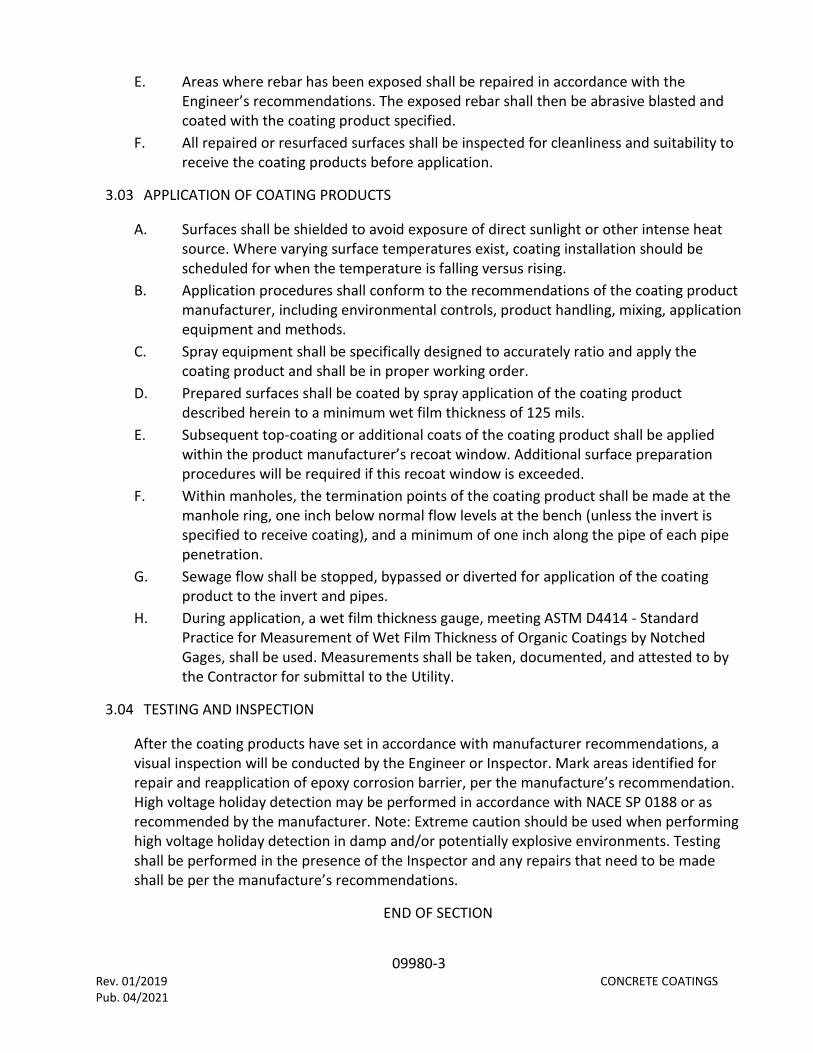
09980-3 Rev. 01/2019 CONCRETE COATINGS Pub. 04/2021
E. Areas where rebar has been exposed shall be repaired in accordance with the Engineer’s recommendations. The exposed rebar shall then be abrasive blasted and coated with the coating product specified.
F. All repaired or resurfaced surfaces shall be inspected for cleanliness and suitability to receive the coating products before application.
3.03 APPLICATION OF COATING PRODUCTS
A. Surfaces shall be shielded to avoid exposure of direct sunlight or other intense heat source. Where varying surface temperatures exist, coating installation should be scheduled for when the temperature is falling versus rising.
B. Application procedures shall conform to the recommendations of the coating product manufacturer, including environmental controls, product handling, mixing, application equipment and methods.
C. Spray equipment shall be specifically designed to accurately ratio and apply the coating product and shall be in proper working order.
D. Prepared surfaces shall be coated by spray application of the coating product described herein to a minimum wet film thickness of 125 mils.
E. Subsequent top-coating or additional coats of the coating product shall be applied within the product manufacturer’s recoat window. Additional surface preparation procedures will be required if this recoat window is exceeded.
F. Within manholes, the termination points of the coating product shall be made at the manhole ring, one inch below normal flow levels at the bench (unless the invert is specified to receive coating), and a minimum of one inch along the pipe of each pipe penetration.
G. Sewage flow shall be stopped, bypassed or diverted for application of the coating product to the invert and pipes.
H. During application, a wet film thickness gauge, meeting ASTM D4414 - Standard Practice for Measurement of Wet Film Thickness of Organic Coatings by Notched Gages, shall be used. Measurements shall be taken, documented, and attested to by the Contractor for submittal to the Utility.
3.04 TESTING AND INSPECTION
After the coating products have set in accordance with manufacturer recommendations, a visual inspection will be conducted by the Engineer or Inspector. Mark areas identified for repair and reapplication of epoxy corrosion barrier, per the manufacture’s recommendation. High voltage holiday detection may be performed in accordance with NACE SP 0188 or as recommended by the manufacturer. Note: Extreme caution should be used when performing high voltage holiday detection in damp and/or potentially explosive environments. Testing shall be performed in the presence of the Inspector and any repairs that need to be made shall be per the manufacture’s recommendations.
END OF SECTION

11300-1 Rev. 01/2019 SUBMERSIBLE PUMPS Pub. 04/2021
SECTION 11300 SUBMERSIBLE PUMPS
PART 1 – GENERAL
1.01 DESCRIPTION
A. The work included under this Section consists of furnishing and installing submersible pumps, motors, and related equipment for the wastewater collection system shown on the drawings, fully tested, complete and in operating condition.
B. Equipment furnished and installed under this Section shall be fabricated, assembled, erected, and placed in proper operating condition in full conformity with the drawings, specifications, engineering data, instructions, and recommendations of the equipment manufacturer as approved by the Utility.
C. A factory representative of all major component manufacturers, who has complete knowledge of proper operation and maintenance, shall be provided for one day to instruct representatives of the Utility on proper operation and maintenance.
1.02 SUBMITTALS
A. For all pumps to be furnished under this Section, the Contractor shall submit shop drawings to the Engineer for approval including: 1. Manufacturer's literature and illustrations. 2. Manufacturer's certified curves showing pump characteristics of head,
discharge, brake horsepower and efficiency. 3. Details of pump assembly and installation, layouts and procedures, types of
materials used in pump construction, details of all pump accessories, and dimensions of major components. Layout drawings shall show exact installation, piping and foundation details for the pumping units being submitted.
4. Complete wiring diagram, panel elevations, and catalog cut sheet information on all components of the electrical control panel.
B. The Contractor shall submit operation and maintenance manuals. The operation and maintenance manuals shall have been prepared specifically for the model and type of pump furnished and shall not refer to other models or types of similar equipment. The operation and maintenance manuals shall include the following: 1. Performance curves. 2. Installation instructions (assembly, alignment, and adjustment procedures). 3. Operation instructions (normal startup and shutdown procedures, normal
operating conditions and emergency situations). 4. Lubrication and maintenance instructions, including a list of at least three
acceptable lubricants in each case. 5. Troubleshooting guide.

11300-2 Rev. 01/2019 SUBMERSIBLE PUMPS Pub. 04/2021
6. Parts lists with catalog numbers and predicted life of parts subject to wear, and normal delivery times of such parts.
7. Drawings - cross sectional view, assembly and wiring diagrams. C. Manufacturer’s service representative report of inspection, start-up, performance
demonstration, and pump test report at completion of construction prior to acceptance.
1.03 DELIVERY, STORAGE AND HANDLING
A. Deliver a complete system ready to install as job progress requires. B. Store in weathertight building or suitable covering to protect against damage. C. Handle in a manner to prevent damage during delivery, storage, and installation.
1.04 WARRANTY
A. The pump manufacturer shall warrant the pumps being supplied to the Utility against defects in workmanship and materials for a period of five years under normal use, operation and service. In addition, the manufacturer shall replace certain parts which shall become defective through normal use and wear on a progressive schedule of cost for a period of five years. Those parts include the mechanical seal, impeller, pump housing, wear rings and ball bearings.
B. The pump manufacturer shall also provide factory-authorized service and parts stock within the State of Florida. The factory-authorized service center's location and the telephone number shall be indicated in the shop drawing submittal and the operation and maintenance manuals.
PART 2 - PRODUCTS
2.01 EQUIPMENT
A. Pumps shall be selected from the pump manufacturers approved by the Utility. B. The pumps, motors, frames and covers, base elbows, guide rail systems, control
panel, and variable frequency drives (if applicable) shall be supplied by the pump supplier to ensure unit integrity.
2.02 MATERIALS
A. All metal components in the wet well, with the exception of the pumps, motors and station piping, shall be Type 316 stainless steel.
B. Pump Accessories: 1. Guide Rails: Guide rail system shall be Schedule 40, Type 316 stainless steel
suitably sized for pumps furnished. Minimum rail size shall be 2 inches in diameter. All nuts required to be double or Nylock nuts.
2. Lifting Device: A grip ring-type pump lifting system shall be provided for each pump furnished.

11300-3 Rev. 01/2019 SUBMERSIBLE PUMPS Pub. 04/2021
3. Cable Holder: A cable holder shall be provided with an adequate number of hooks to secure float control cables and pump lifting system tethers/ chains. The cable holder shall be suitable for wall or access door frame mounting. The cable holder shall be Type 316 stainless steel mounted with Type 316 stainless steel anchor bolts.
4. Base Elbow: The pump discharge fitting shall be a quick disconnect type compatible with the guide rail system and allowing the pump to be lifted from the wet well for service and lowered in place for pumping without unbolting any flange, lowering the liquid level, or requiring personnel to enter the wet well. The entire weight of the pump shall rest on the discharge elbow; no part of the pump shall bear directly on the floor of the wet well sump. The pump discharge shall seal to the discharge elbow with a water tight connection. Sealing by means of a rubber diaphragm or O-ring, not specifically provided by the pump manufacturer, will not be acceptable.
5. The type, length and diameter of anchor bolts shall be as shown on the Drawings and as required by the pump manufacturer. Each anchor bolt shall be furnished with a flat washer, lock washer and double or Nylock nuts. All materials for anchor bolts, washers and nuts shall be Type 316 stainless steel.
6. Base Plate: A 316 Stainless Steel x ½” thick(minimum) base plate must be installed under each base elbow. Sizing of base plate to be per pump manufacturer’s specifications. All base plates and base elbows are required to use double or Nylock nuts.
C. Control Panel and Telemetry (RTU) 1. The pump manufacturer shall supply the pump control panel consistent with
Brevard County Utility Services Electrical Standards. 2. The Contractor can purchase the telemetry unit directly from the Utility, or
alternatively, the Contractor can purchase a Utility approved remote terminal unit system that meets all the requirements of the Utility from another source.
3. The County will determine the height required for the telemetry tower after field testing on site. The Contractor shall coordinate with the Utility for that field testing.
PART 3 – EXECUTION
3.01 INSPECTION AND TESTING
A. Inspection 1. The Contractor shall notify the Utility, the Engineer, and the pump
manufacturer's representative 48 hours prior to start-up. The Contractor shall furnish all labor, piping, equipment, oil, grease, power, water and materials required to perform the acceptance testing. Field tests shall be performed for all pumps furnished under this Section.
2. The duties of the factory service representative shall be as follows:

11300-4 Rev. 01/2019 SUBMERSIBLE PUMPS Pub. 04/2021
i. After the equipment has been installed but before it is offered to the Utility for acceptance, the representative shall inspect the completed installation for soundness (no damaged or cracked components), completeness, correctness of setting and alignment, verify that the pumps are free from stresses imposed by attached piping.
ii. The service representative shall operate the equipment and instruct the Utility personnel in proper operation and maintenance procedures.
3. The Contractor shall submit to the Engineer a report from the factory service representative of the results of the representative's inspections, adjustments, testing and start-up. The report shall include descriptions of the inspection, adjustments made, and a statement that the equipment is ready for permanent operation and that the warranty is in effect.
B. Pump Performance Demonstration: 1. Prior to acceptance, as part of the final inspection, the Contractor shall
conduct a field pump performance test. Pumps shall operate according to the operating conditions specified without excessive vibration or overheating. Testing shall be performed using clean water. Pumping rates shall be determined by pumping a calculated volume of water in a specified time interval. Discharge pressure and flow conditions shall be measured and recorded. Water levels during testing shall fall within the pump control levels shown on the Drawings. The test shall be repeated until satisfactory results are obtained. The test results shall be recorded on a Pump Test Report prepared by the manufacturer’s representative.
2. Two copies of the Operation and Maintenance manual shall be provided to the Utility upon successful completion of the start-up including pump performance curves indicating the model numbers, serial numbers, and other data specific to the pumps.
END OF SECTION

11320-1 Pub. 04/2021 DISEL PUMPS
SECTION 11320 DIESEL PUMPS
PART 1 – GENERAL
1.01 DESCRIPTION
A. The work included under this Section consists of furnishing and installing diesel pumps and related equipment for the wastewater collection system shown on the drawings, fully tested, complete and in operating condition.
B. Equipment furnished and installed under this Section shall be fabricated, assembled, erected, and placed in proper operating condition in full conformity with the drawings, specifications, engineering data, instructions, and recommendations of the equipment manufacturer as approved by the Utility.
C. A factory representative of all major component manufacturers, who has complete knowledge of proper operation and maintenance, shall be provided for one day to instruct representatives of the Utility on proper operation and maintenance.
1.02 SUBMITTALS
A. For all pumps to be furnished under this Section, the Contractor shall submit shop drawings to the Engineer for approval including: 1. Manufacturer's literature and illustrations. 2. Manufacturer's certified curves showing pump characteristics of head,
discharge, brake horsepower and efficiency. 3. Details of pump assembly and installation, layouts and procedures, types of
materials used in pump construction, details of all pump accessories, and dimensions of major components. Layout drawings shall show exact installation, piping and foundation details for the pumping units being submitted.
4. Complete wiring diagram, panel elevations, and catalog cut sheet information on all components of the pump control panel.
B. The Contractor shall submit operation and maintenance manuals. The operation and maintenance manuals shall have been prepared specifically for the model and type of pump furnished and shall not refer to other models or types of similar equipment. The operation and maintenance manuals shall include the following: 1. Performance curves. 2. Installation instructions (assembly, alignment, and adjustment procedures). 3. Operation instructions (normal startup and shutdown procedures, normal
operating conditions and emergency situations). 4. Lubrication and maintenance instructions, including a list of at least three
acceptable lubricants in each case. 5. Troubleshooting guide.

11320-2 Pub. 04/2021 DISEL PUMPS
6. Parts lists with catalog numbers and predicted life of parts subject to wear, and normal delivery times of such parts.
7. Drawings - cross sectional view, assembly and wiring diagrams. C. Manufacturer’s service representative report of inspection, start-up, performance
demonstration, and pump test report at completion of construction prior to acceptance.
1.03 DELIVERY, STORAGE AND HANDLING
A. Deliver a complete system ready to install as job progress requires. B. Store in weathertight building or suitable covering to protect against damage. C. Handle in a manner to prevent damage during delivery, storage, and installation.
1.04 WARRANTY
A. The manufacturer shall furnish the following to the owner: 1. A copy of the engine manufacturer’s party and labor warranty. 2. A 3-yeart Parts and Labor Warranty issued by the manufacturer on the Diesel
Pump System. This warranty must cover all pump parts. 3. The venturi shall have a minimum five (5) year warranty to include parts and
labor.
PART 2 - PRODUCTS
2.01 EQUIPMENT
A. PUMPS: The pumps used in the diesel backup pump system shall be supplied directly by the manufacturer, not by a distributor. The pump itself and the diesel backup pump system as a whole shall come from a single manufacturer. “Packagers” of systems which incorporate pumps from a separate manufacturer to fabricate diesel backup pump systems shall not be allowed.
B. CASING, SUCTION COVER, SEPARATION TANK: Pump casings shall be cast iron or ductile iron with a minimum pressure rating of 100 psi. The pump casing shall be constructed so that the suction flow path is in axial alignment with the impeller eye. There shall be no turns, chambers, obstruction or straightening vanes between the suction line and the impeller. The pump casing shall be complete with a removable port for inspecting impeller / cut water area.
C. IMPELLERS: The pump impeller shall meet the criteria of one of the following: 1. An open, three-bladed, (or 2-bladed) non-clog type with pump-out vanes on
the back shroud and fabricated from hardened cast- chromium steel construction (or other material to meet minimum Brinell Hardness 340 HB).
2. A high efficiency non-clog type, 2-vane, enclosed design with full front and rear shrouds, containing back pump out vanes, constructed of high grade 65-45-12 ductile iron and capable of passing a 3” spherical solid.

11320-3 Pub. 04/2021 DISEL PUMPS
D. WEARPLATES/WEAR RINGS: Shall be fully replaceable, fabricated of cast iron. Wear plat / wear ring clearances shall have no relationship to the ability of the pump to achieve a prime.
E. BEARINGS AND SHAFTS: Pump shall be fitted with a bearing bracket to contain the shaft and bearings. Bearings shall be tapered roller bearings of adequate size to withstand imposed loads for sustained pumping at maximum duty points. Minimum ISO L10 bearing life to be 100,000 hours. Impeller shafts shall be fabricated of high strength alloy steel, accurately machined, polished, and of sufficient size to transmit full driver output without excessive flexing or stress.
F. SEALS: Pump shall be capable of running dry, with no damage, for periods up to twenty-four hours. The pump seals shall be the requirements of one of the following:
G. PUMP SUCTION AND DISCHARGE FLANGES: Shall be cast iron ANSI (B16.1) Class 150, raised face.
H. PUMP GASKETS: Shall be compressed fiber and/or Teflon. I. PUMP O RINGS: Shall be Buna-N. J. PRIMING SYSTEM: Pump shall be fitted with a fully automatic priming system
incorporating an air compressor, venturi (with lifetime warranty), priming chamber, and discharge check valve assembly. The compressor shall be installed on the engine auxiliary drive and shall be gear driven, lubricated and cooled from the engine. Installed system design shall prevent any carryover of the pumping fluid onto the ground. Priming system may require additional drainage pipelines to be constructed to re-circulate pumping fluid back to sump area. The pump must be capable of running totally dry for periods up to 24 hours, then re-priming and returning to normal pumping volumes. Pump and priming system is capable of priming the pump from a completely dry pump casing. The pump shall be capable of static suction lifts to 28 vertical feet, at sea level. It shall also be capable of operation using extended suction lines, and pump shall be capable of priming and re-priming without any user intervention. Equipment acceptance shall be contingent upon the pump’s ability to run continuously at full speed in a completely dry condition. The engineer may require a demonstration. Priming systems that incorporate the use of a positive displacement diaphragms OR oil-coded vacuum pumps will not be accepted.
K. CHECK VALVE: The priming system shall include a discharge check valve to prevent pulling air through the discharge line during priming and prevent in-line return of flow when the pump is shut off. Non-return check valve shall be constructed of cast iron with Nitrile rubber and shall be field replaceable. Check valve shall be vacuum- tested by the factory, and test results shall be provided.
L. DRIVE UNIT: The drive unit shall be a diesel water-cooled engine. The engine shall drive the pump by use of direct-connected intermediate drive plate. Starter shall be twelve-volt electric. Low oil pressure safety shutdown, high temperature shutdown, tachometer, and hour-meter shall be integrated into engine control panel. Batter shall have 180-amp hour rating. A certified continuous-duty engine curve shall be supplied to the owner/engineer.

11320-4 Pub. 04/2021 DISEL PUMPS
M. GOVERNOR: Governor shall be an electronic or mechanical type. Engine speed shall be adjustable to operate the pump between maximum and minimum design operation speeds in manual mode. See section 2.3 for Automatic mode.
N. FUEL SOURCE: Integral skid fuel tank capacity shall be sufficient to provide at least seventy-two (72) hours of continuous operation at full load. The minimum tank size shall be 150 gallons and the maximum tank size shall be 550 gallons. The engine shall be capable of operating satisfactorily on a commercial grade of distilled No. 2 fuel oil.
O. EXHAUST: Exhaust system shall include a hospital grade muffler housed in a separate chamber within the enclosure. All exhaust piping and manifolds shall be encased in fitted acoustic blankets. They shall be constructed of high-density fiberglass material with waterproof jacketing.
P. SOUND ATTENUATED ENCLOSURE: the entire unit including the pump and engine shall be completely enclosed in a lockable enclosure. The enclosure shall be constructed with a modular galvanized steel frame and galvaneel panels. Acoustical material shall be installed as required to reduce pump and engine noise. Maximum sound ratings for specific pump sizes are shown in the table below. These sound ratings shall be the maximum dBA rating measured at 7 meters @ both duty points specified.
Pump Outlet Size Maximum Sound Rating Allowed 4” 68 dBA 6” 70 dBA 8” 72 dBA
10” 72 dBA 12” 72 dBA
Q. Units not meeting this requirement shall not be considered. The enclosure shall be removable for easy access to the engine / pump for maintenance and repair. The enclosure doors shall all be equipped with latches that are keyed alike. For maintenance and service needs, the enclosure sides shall have hinged doors for quick access to the engine oil fill, fuel fill port, oil dipstick, and filters. The enclosure shall be coated in epoxy-based primer and paint to a total dry film thickness of 5 mils.
R. UL LISTED SKID BASE 1. The pump base tank shall be a UL-142 approved double wall design
constructed in accordance with Flammable and Combustible Engine and Gas Turbines, NFPA 37; and the Standard for Emergency and Standby Power Systems, NFPA 110. Pumps installed within 25 feet of a building shall be equipped with UL-2085 fire resistant fuel tanks. All fuel tanks shall comply with the requirements set forth by the Florida Department of Environmental Protection.
2. The tank design shall be a Closed Top Dike Pump Base Tank. It shall be of double wall construction having a primary tank to contain the diesel fuel, held within another tank or dike, which is intended to collect and contain any accidental leakage from the primary fuel tank. The completed base tank

11320-5 Pub. 04/2021 DISEL PUMPS
assembly is to incorporate pump mounting locations and must be able to support four times the rated load.
3. The primary tank shall be designed to withstand normal and emergency internal pressures and external loads. It shall be capable of withstanding internal air pressures of 3 to 5 psig without showing signs of excessive or permanent distortion and 25 psig hydrostatic pressures without evidence of rupture or leakage.
4. The primary and secondary tanks or dike shall have venting provisions to prevent the development of vacuum or pressure capable of distorting them as a result of the atmospheric temperature changes or while emptying or filling. The vent shall also permit the relief of internal pressures caused by exposure to fires. The vent size shall be determined by using the calculated wetted surface area in square feet (the top is excluded) in conjunction with venting capacity table 10.1 of UL-142. The tank’s vent shall also be equipped with a coupling device and shall be located to facilitate connection to a vent piping system. The dike’s vent may be an opening for venting directly to the atmosphere and protection from the entrance of natural elements or debris shall be provided.
5. The primary and outer tanks are to be constructed of 304 stainless steel, 7 gauge minimum. Internal baffles or reinforcement plates shall be located on a maximum of 24-inch centers in tanks up to 60-inch width and on a maximum of 19.5-inch centers in tanks over 60-inch width. At least one baffle shall separate the fuel suction pipe from the fuel return line.
6. The outer tank is to be constructed in a manner to be able to support four times the wet load of the pump and housing. The entire load is to be carried by the outer tank so no load or vibration stress is placed on the primary tank. If the pump base tank is wider than the pump set to be supported, structural rails are to be incorporated to span the width of the base tank so that the load is transferred to the side rails of the tank. Vertical reinforcements shall be welded to the outer sides of the secondary tank or dike at a maximum of 45-inch centers on tanks up to 30 inches high and on 24-inch centers on tanks greater than 30 inches high. At least one vertical reinforcement shall be positioned adjacent to each mounting hole location. Provide level monitoring and interstitial space leak monitoring.
7. Both primary and secondary tanks shall be fitted with the proper welded pipe fittings to accommodate the requirements for the fill port and normal and emergency venting.
8. The completed assembly is to be cleaned with a heated pressure wash followed by a chromium free post treatment to ensure proper paint adhesion. The tank assembly is to be painted with an epoxy ester primer and high-quality polyurethane enamel with a minimum dry film thickness of 3.5 mils.
9. All tanks shall be tested in accordance with NFPA 30 TO INCLUDE ON SITE TIGHTNESS TESTING in accordance with NFPA 30 Section 21.5. This requirement shall not apply to portable trailer mounted diesel pumps.

11320-6 Pub. 04/2021 DISEL PUMPS
10. Manufacturing and testing of this system shall be performed within the scope of Underwriters Laboratories, Inc. “Standard for Safety UL 142.”, or UL 2085, as applicable. A UL label shall be permanently attached to the tank system showing the following information: i. The registered UL mark and the name: Underwriters Laboratories, Inc. ii. A control number and the word “listed” iii. The product’s name as identified by Underwriters Laboratories Inc. iv. The serial number assigned by Underwriters Laboratories, Inc. v. Other manufacturer’s information may also be included.
S. PORTABLE TRAILER (FOR TRAILER MOUNTED UNITS ONLY): 1. The complete pump set shall be factory mounted on a highway trailer meeting
NHTSA, DOT Part 571 standards 108, 119 and 120. 2. Trailers with loads of 5,000 pounds or less with fuel tank filled, shall have a flat
bed, single axle, two 15-inch wheels with 6-ply tires. Axle ratings shall be a minimum of 5,000 pounds. i. Trailers with loads from 5,000 to 10,000 pounds with fuel tank filled,
shall have a flat bed, 2-axle, four 15-inch or 16-inch wheels with 10-ply tires. Axle rating shall be a minimum of 10,000 pounds.
ii. Trailers above shall have following accessories. Ring and pintal hitch including safety chain and fasteners, electric brakes shall be provided on all wheels, and all required ICC lights such as tail, brake, direction signals, license holder and light, etc., shall be provided; jacks and sand shoes for front and rear corners shall be provided so that unit can be completely supported.
iii. The diesel backup pump engine shall be balanced mounted on trailer. All necessary service and checkout of diesel backup pump set shall be performed prior to delivery.
T. FACTORY PAINTING: Pump, engine, and base shall be shop primed and finish painted at the place of manufacturer.
2.02 AUTOMATIC STARTING CONTROL SYSTEM
A. The engine control panel shall be provided in a NEMA 3R enclosure mounted on rubber isolators to reduce vibration, equipped with a factory installed microprocessor-based controller designed to start/stop the engine at a signal supplied by high- and low-level floats or a 4-20 mA transducer.
B. The control system shall be able to start/stop the engine via a signal supplied by a primary level transducer and back-up high- and low-level floats for redundant automatic operation.
C. ENGINE / PUMP CONTROL SPECIFICATIONS 1. The engine shall be started, stopped, and controlled by a digital controller. The
controller shall be weather proof enclosed, and contain an external weatherproof 12-position keypad accessible without the need to remove or open any protective cover or enclosure. It shall be designed to start/stop the

11320-7 Pub. 04/2021 DISEL PUMPS
engine based on relay contact closure provided by others. The controller shall provide the following functions without modification, factory recalibration, or change of chips or boards, by simply accessing the keypad:
D. The keypad shall be a capacitive touch sensing system. No mechanical switches will be acceptable. The keypad shall operate in extreme temperatures, and maintain complete weather-tight sealing of the controller.
E. In automatic mode, the unit shall conserve energy and go to “sleep”. F. The controller shall function interchangeably from remote contact closure, as well as
manual start/stop by selection at the keypad. No other equipment or hardware changes are required.
G. The start function can be programmed to provide two separate functions each day for seven days (i.e. a start, exercise cycle on two separate days at different times and for a varying length of time all via the keypad).
H. Manual – Automatic Button: 1. In Manual Mode, manual “Start” button starts engine and runs until “Stop” or
“Off” button is depressed or an emergency shutdown occurs. 2. In Automatic Mode, start/stop sequencing is initiated by a signal from a digital
input. I. The controller shall integrate the engine safety shut-off for low and high oil
temperature, and provide over-speed protection. J. The controller shall include standard, field-adjustable parameters for engine cycle
crank timer, and shutdown time delay. K. The controller shall have only one circuit board with eight built-in relays. Three (3) of
the relays shall be programmable to output desired parameter on display and to be used as dry-contacts for communication with Collier County’s SCADA system, all via the keypad without changing relays, chips, printed circuits, or any hardware or software. Relays will monitor the following: 1. Low Battery Charge 2. Low Fuel Level (Less than 25 gallons) 3. Diesel Pump Engine Start
L. Standard components shall consist of one of the following set ups: 1. (24) Digital inputs, (7) analog inputs, (1) magnetic pick-up input, (8) 20-amp
form “C” relays, (1) RS232 port, (1) RS485 port, (1) RS232/RS485 port, (1) J1939 port, and (1) 64X128 pixel full graphic LCD display with backlight.
2. (8) Digital inputs, (5) analog inputs, (8) digital outputs, (1) RS232 port, (1) RS485 port, (1) J1939 port, (76) selectable features, (32) alarm event history.
M. The industrially-hardened Controller shall withstand vibration of 3 g, 3 axes, frequency swept in an operating temperature range of 4° to 176°F (-20° to 80°C) and an operating humidity range of 0-95% non-condensing.
2.03 OPTIONS
A. FULLY AUTOMATIC TRICKLE CHARGER: The unit shall include a fully automatic trickle charger powered by 6-amps, 115 VAC.

11320-8 Pub. 04/2021 DISEL PUMPS
B. LIGHT: The unit shall include a single switch operated 12VDC light within the enclosure.
C. FLOATS: The unit shall be supplied with one (1) float assembly including two (2) N/O floats which shall integrate with the engine control panel via a single multi-pin plug.
D. LEVEL TRANSDUCER: The unit shall be supplied with (1) one Teflon diaphragm sewage compatible level transducer assembly including a single 4-20 mA level transducer with leveling guard (0-15 psig), which shall integrate with the engine control panel via a single multi-pin plug.
E. AUTO THROTTLE: The unit/s shall include one (1) automatic throttle controller integrated into (2) relays in the electronic engine control panel. The auto-throttle control panel combination shall allow the pump to ramp up to the target RPM given a start command and ramp down to idle given a stop command via the 4-20 mA level transducer.
F. DC / AC INVERTOR: The unit/s shall include one (1) 12VDC to 110VAC volt single- phase inverter, 1750 watts, mounted inside enclosure, single 15-amp GFI outlet, and one (1) fusible link.
PART 3 – EXECUTION
3.01 MANUFACTURERS SERVICE
A. The manufacturer shall furnish the services of a competent factory representative to do the following: 1. The complete pump set shall be factory tested according to ANSI/HI 1.6¬1994
by a certified quality technician. The pump shall be sound tested according to ISO 3744, ANSI/HI9.4 and CPB Sound Level Measurement Standard.
2. Instruct the Owner’s operating personnel in the proper operation and maintenance of the system for a period of not less than one-half day.
3.02 TOOLS AND SPARE PARTS
A. The manufacturer shall furnish the following on delivery of the pumping system; 1. A recommended list of spare parts. 2. Two (2) replacement mechanical seals. 3. An Operations and Maintenance manual for the pump and engine. 4. A fuel polishing system capable of below 1-micron filtration equipped with a
fuel- water separator and 12V DC fuel pump rated at 40GPH minimum. The system shall be a standard commercial or industrial off the shelf unit intended for portable use of diesel fuel polishing. The fuel polishing system shall include 6 spare filters and an operations and maintenance manuals.
END OF SECTION

Figure 1 – Sewer Service Connection Notes (US-10)
Image Description US-10 Sewer Service Connection Notes

Figure 2 - Sewer Service Connection Details (US-11)
Image Description US-11 Sewer Service Connection

Figure 3 -Sewer Cleanout Detail (US-12)
Image Description US-12 Sewer Cleanout

Figure 4 - Traffic Bearing Sewer Clean-out (US-13)
Image Description US-13 Traffic Bearing Sewer Clean-out

Figure 5 -Private/Public Force main Transition (US-14)
Image Description US-14 Private/Public Force main Transition

Figure 6 - In Ground Air Release Valve Vault Detail (US-15)
Image Description US-15 In-Ground Air Release Valve Vault

Figure 7 -Above Ground Air Release Valve Detail (US-16)
Image Description US-16 Above Ground Air Release Valve

Figure 8 - Grease Interceptor Detail (US-17)
Image Description US-17 Grease Interceptor

Figure 9 - General Manhole Notes (US-20 Page 1 of 2)
Image Description US-20 Page 1 of 2 -General Manhole Notes

Figure 10 - General Manhole Notes (US-20 Page 2 of 2)
Image Description US-20 Page 2 of 2 -General Manhole Notes

Figure 11 - Concentric Manhole Detail (US-21)
Image Description US-21 -Concentric Manhole

Figure 12 - Eccentric Manhole Detail (US-22)
Image Description US-22 – Eccentric Manhole

Figure 13 - Single Interior Drop Manhole Detail (US-23)
Image Description US-23 – Single Interior Drop Manhole

Figure 14 - Double Interior Drop Manhole Detail (US-24)
Image Description US-24 -Double Interior Drop Manhole

Figure 15 - Conflict Manhole Detail (US-25)
Image Description US-25 – Conflict Manhole
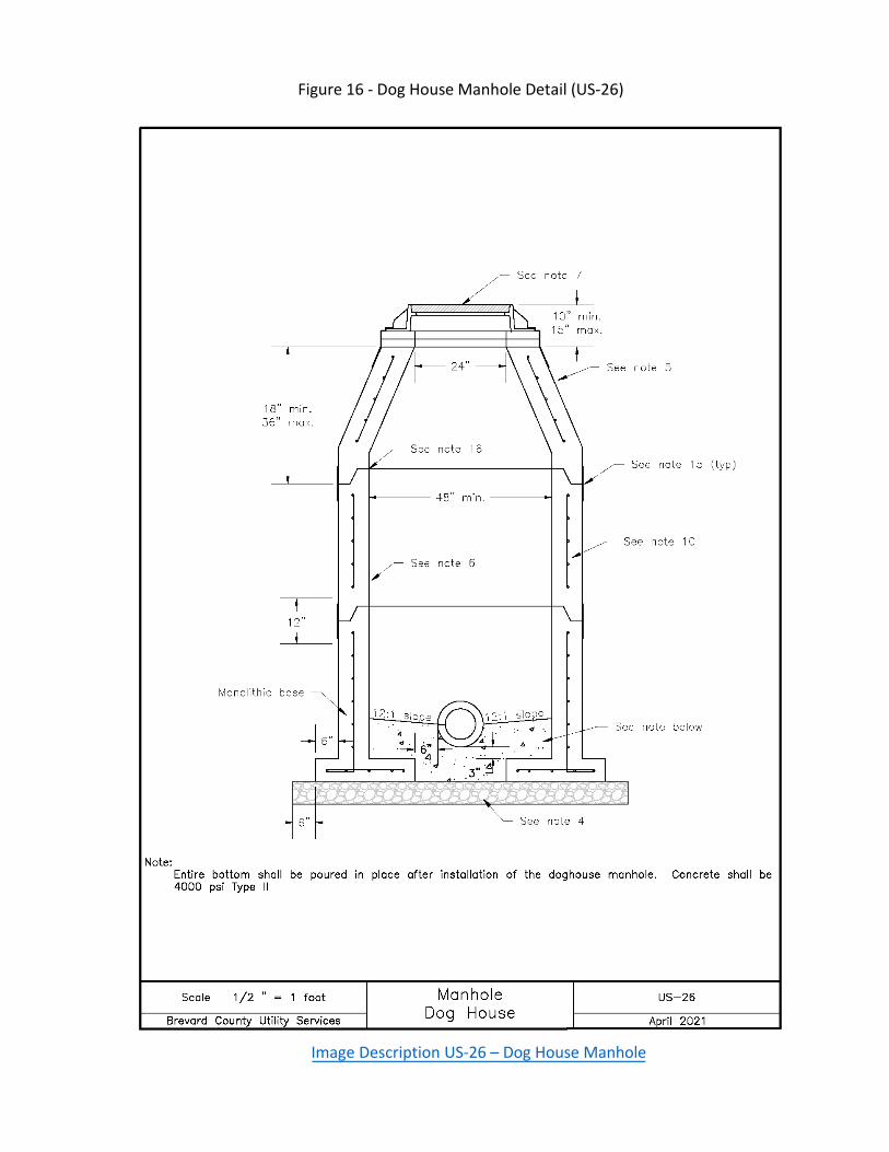
Figure 16 - Dog House Manhole Detail (US-26)
Image Description US-26 – Dog House Manhole

Figure 17 - AS Legacy Manhole Cover Detail (US-27)
Image Description US-27 -AS Legacy Manhole Cover

Figure 18 - Manhole Inverts Detail (US-28)
Image Description US-28 -Manhole Inverts

Figure 19 - Lift Station Notes (US-30)
Image Description US-30 -Lift Station Notes

Figure 20 - Lift Station Profile View Detail (US-31 Page 1 of 3)
Image Description US-31 Page 1 of 3 -Lift Station Profile View

Figure 21 - Tremie Wet Well Installation Detail (US-31 Page 2 of 3)
Image Description US-31 Page 2 of 3 -Tremie Wet Well Installation Detail

Figure 22 - Tremie & Wet Well Causes for Rejection Notes (US-31 Page 3 of 3)
Image Description US-31 Page 3 of 3 -Tremie & Wet Well Causes for Rejection Notes

Figure 23 - Lift Station Plan View Detail (US-32-ALL Page 1 of 3)
Image Description US-32-ALL Page 1 of 3 -Lift Station Plan View

Figure 24 - Lift Station Plan View Detail (US-32-ALL Page 2 of 3)
Image Description US-32-ALL Page 2 of 3 Lift Station Plan View

Figure 25 - Lift Station Section View Detail (US-32-ALL Page 3 of 3)
Image Description US-32-ALL Page 3 of 3 Lift Station Section View

Figure 26 - Lift Station Above Ground Valving Detail (US-33)
Image Description US-33 Lift Station Above Ground Valving

Figure 27 - Lift Station Valve Vault Detail (US-34)
Image Description US-34 Lift Station Valve Vault

Figure 28 - Lift Station Control Panel Detail (US-35 Page 1 of 2 / Elec-10-ALL)
Image Description US-35 Page 1 of 2 (Elec-10-ALL) Lift Station Control Panel

Figure 29 - Lift Station Control Panel Detail (US-35 Page 2 of 2 / Elec-11-ALL)
Image Description US-35 Page 2 of 2 (Elec-11-ALL) Lift Station Control Panel

Figure 30 - 30' Maximum Height Telemetry Mast Detail (US-36)
Image Description US-36 Telemetry Mast 30’ Maximum Height

Figure 31 - Telemetry RTU Detail (US-37)
Image Description US-37 Telemetry RTU

Figure 32 - 45' Maximum Height Telemetry Mast Detail (US-38)
Image Description US-38 Telemetry Mast 45’ Maximum Height

Figure 33 - Wet Well Pipe Bracing Detail (US-39)
Image Description US-39 Wet Well Pipe Bracing Detail

Figure 34 - Water Service General Notes (US-40)
Image Description US-40 Water Service General Notes

Figure 35 - Water Service Section View Detail (US-41)
Image Description US-41 Water Service Section View

Figure 36 - Water Service Plan View Detail (US-42)
Image Description US-42 Water Service Plan View

Figure 37 - Fire Hydrant Assembly Detail (US-43)
Image Description US-43 Fire Hydrant Assembly

Figure 38 - Blow Off Detail (US-44)
Image Description US-44 Blow Off Detail

Figure 39 - Temporary Jumper Connection Detail (US-45)
Image Description US-45 Temporary Jumper Connection

Figure 40 - 3/4" to 2" Backflow Preventer Detail (US-46)
Image Description US-46 Backflow Preventer 3/4" – 2”

Figure 41 - Backflow Preventer with Meter for Fire Services 3" to 8" Detail (US-47)
Image Description US-47 Backflow Preventer with Meter for Fire Services 3”-8”

Figure 42 - Reclaimed Water Service General Notes (US-50)
Image Description US-50 Reclaimed Water Service General Notes

Figure 43 - Reclaimed Water Service Section View Detail (US-51)
Image Description US-51 Reclaimed Water Service Section View

Figure 44 - Reclaimed Water Service Plan View Detail (US-52)
Image Description US-52 Reclaimed Water Service Plan View

Figure 45 - Reclaimed Water Sign Detail (US-53)
Image Description US-53 Reclaimed Water Sign

Figure 46 - Reclaimed Water Service Connection Detail (US-54)
Image Description US-54 Reclaimed Water Service Connection

Figure 47 - Pipe Separation Detail (US-60)
Image Description US-60 Pipe Separation

Figure 48 - PVC Pipe Restraint Table Detail (US-61)
Image Description US-61 Restraint Table PVC Pipe

Figure 49 - Ductile Iron Pipe Restraint Table Detail (US-62)
Image Description US-62 Restraint Table Ductile Iron Pipe

Figure 50 - Roadway Open Cut Detail (US-63)
Image Description US-63 Open Cut – Roadway

Figure 51 - Utility Crossing Detail (US-64)
Image Description US-64 Utility Crossing

Figure 52 - Vertical Pipe Deflection Detail (US-65)
Image Description US-65 Vertical Pipe Deflection

Figure 53 - Concrete Support Cradle Detail (US-66)
Image Description US-66 Concrete Support Cradle

Figure 54 - Valve Box Detail (US-67)
Image Description US-67 Valve Box

Figure 55 - Subaqueous / Ditch Crossing Detail (US-68)
Image Description US-68 Subaqueous / Ditch Crossing

Figure 56 - Utility Main Crossing Sign Detail (US-69)
Image Description US-69 Utility Main Crossing Sign

Figure 57 - Casing Installation Detail (US-70)
Image Description US-70 Casing Installation

Figure 58 - Aerial Crossing Fan Guard Detail (US-71)
Image Description US-71 Aerial Crossing Fan Guard

Figure 59 - Aerial Canal Crossing Detail (US-72)
Image Description US-72 Aerial Canal Crossing

Figure 60 - Bollard Detail (US-73)
Image Description US-73 Bollard Detail

Figure 61 - Utility Marker Detail (US-74)
Image Description US-74 Utility Markers

i
Appendix A – BCUSD Details
US-10 Sewer Service Connection Notes
Notes: 1. Sewer laterals must be located in front of the property to be served.2. Service laterals shall extend two feet inside the property and shall be constructed
regardless of benefit to or ownership of adjacent lots or parcels.3. Service laterals are to be located in side property easements.4. Service laterals shall be located to avoid conflict with other utilities.5. Number and location of service laterals for large parcels shall be determined on a
case- by-case basis.6. Service laterals shall be located at the opposite property line when in conflict with
storm drainage systems.7. Service lateral locations shall be marked along the outside edge of curb with a sawcut
“S” or by a metal tab set into the pavement for roadways without curb.8. Electronic marker discs are required.9. Pipe and fittings for service laterals shall be of the same material as the main and shall
meet the requirements of ASTM D1784.10. Each service shall be staked prior to installation by an engineer or surveyor registered
in the State of Florida or an employee under his direct supervision.11. Location and finished grade of ground shall be staked where the lateral crosses the
right of way line prior to installation.12. Service laterals shall be provided for sewer service to adjacent lots and parcels when a
gravity sewer main is constructed.13. Concrete encasement required for all piping except PVC. PVC connections will be
made with a standard PVC sewer wye and a gasketed slip-on fitting.14. All services shall be six inches in diameter.15. Service laterals shall not be connected to sewer main “future stubs”.16. Service connections shall not terminate into a manhole.
Figure 1 – Sewer Service Connection Notes (US-10)

ii
US-11 Sewer Service Connection
The drawing is scaled 1/2" = 1 foot. The detail is numbered US-11 and named Sewer Service Connection. The detail has been revised as of November 2020 and belongs to Brevard County Utility Services.
Diagram 1: Plan view of a single lot sewer service connection from the sewer main to the sewer service connection point past the property line. Diagram is in accordance with BCUSD US-10 Notes.
Diagram 2: Plan view of a double lot sewer service connection from the sewer main to the sewer service connection past the property line. Diagram is in accordance with BCUSD US-10 Notes.
Diagram 3: Profile view of a standard sewer service connection. Diagram is in accordance with BCUSD US-10 Notes.
Figure 2 - Sewer Service Connection Details (US-11)

iii
US-12 Sewer Cleanout
The drawing is scaled 1" = 1 foot. The detail is numbered US-12 and named Sewer Cleanout. The detail has been revised as of November 2020 and pertains to Brevard County Utility Services.
Diagram: Profile view of a sanitary sewer cleanout consisting of a PVC plug set flush with the finished grade. The diagram also depicts the sanitary service lateral that the sewer cleanout extends from via sanitary wye fitting.
Notes: 1. Cleanout diameter to match service lateral diameter.2. Maximum spacing distance between cleanouts is 100 feet.3. All cleanouts within vehicular traffic areas to have traffic bearing covers.4. Cleanouts shall not be located in sidewalks or driveways.5. Cleanouts shall not be substituted for manholes or installed at the end of mains.6. Cleanouts shall be installed within 2’ of the property or easement line.7. Cleanouts are not permitted in stormwater treatment or conveyance systems.
Figure 3 -Sewer Cleanout Detail (US-12)

iv
US-13 Traffic Bearing Sewer Clean-out
The drawing is scaled 1" = 1 foot. The detail is numbered US-13 and named Sewer Cleanout Traffic bearing. The detail has been revised as of November 2020 and belongs to Brevard County Utility Services.
Diagram: Profile view of a sanitary sewer cleanout consisting of a valve cover (US Foundry 7610) marked “S”, within a 24” x 24” square concrete base in a roadway. The cleanout below the valve cover shall have a threaded cover with a square nut. The diagram also depicts the sanitary service lateral that the sewer cleanout extends from via sanitary wye fitting.
Notes: 1. Cleanout diameter to match service lateral diameter.2. Maximum spacing between cleanouts is 100 feet.3. Cleanouts located in vehicular traffic areas to have traffic bearing covers.4. Cleanouts shall not be located in sidewalks or driveways.5. Cleanouts shall not be substituted for manholes or installed at the end of mains.6. Cleanouts shall be installed within 2’ of the property or easement line.7. Cleanouts are not permitted in stormwater treatment or conveyance systems.
Figure 4 - Traffic Bearing Sewer Clean-out (US-13)

v
US-14 Private/Public Forcemain Transition
The drawing has no scale. The detail is numbered US-14 and named Private/Public Forcemain Transition. The detail has been revised as of November 2020 and belongs to Brevard County Utility Services.
Diagram: Profile view of the Private/Public Forcemain Transition. The diagram depicts a force main from a private lift station connected to a valve box assembly. These elements shall be located within the private maintenance area, outside of county right of way. The public utility structures to be connected to the valve box assembly, located in public right of way, shall be; two gate valves (to correspond with force main size) with an adjustable valve box (with an 18”x18”x4” concrete pad at grade) and a proposed minimum 2” county force main, connected to the existing county sewer main.
Notes: 1. Valve box assembly shall be located at the R/W line (±1’) and shall be the point of
separation between the County maintained force main and the privately maintainedfacilities. Valve boxes shall be installed as part of the lateral assembly by the sitecontractor.
Figure 5 -Private/Public Force main Transition (US-14)

vi
US-15 In-Ground Air Release Valve Vault
The drawing is scaled 3/8" = 1 foot. The detail is numbered US-15 and named Air Release Valve in Ground Valve. The detail has been revised as of November 2020 and belongs to Brevard County Utility Services.
Diagram 1: Plan View of an in-ground air release valve. Diagram depicts the valve box of 60” x 60” with a US Foundry 690 AG/M ring and cover. Existing force main is shown 9” off the edge of the valve box. Air Release Valve is shown on top of force main, 10” north and 15” west of the center of the valve box.
Diagram 2: Profile view of an in-ground air release valve. The diagram indicates there is a 5” brick adjustment below the valve box cover, followed by an 8” thick wall. The valve box has a 36” minimum depth and an 8” thick bottom. The bedding below the existing force main that the air release valve is set upon is coarse sand, below it is 6” compacted FDOT #57 stone. Diagram is in accordance with the notes below.
Notes: 1. US foundry 690 AG/M ring and cover with vents2. H-20 load rating required3. Air release valve size determined by engineer4. brass corporation stop.5. Branch of tee to be ½ diameter of pipe6. Sch 40 PVC pipe and fittings7. Cover shall be marked “SEWER”8. MJ Tee with tapped blind flange
Figure 6 - In Ground Air Release Valve Vault Detail (US-15)

vii
US-16 Above Ground Air Release Valve
The drawing is scaled 1/2" = 1 foot. The detail is numbered US-16 and named Air Release Valve Above Ground. The detail has been revised as of November 2020 and belongs to Brevard County Utility Services.
Diagram: Profile view of above ground air release valve. The diagram depicts the materials
indicated in the Table below. The Above Ground Air Release Valve will be in a 32” tall enclosure. Within the enclosure, An Air Release Valve, coupling, nipple, pipe and ball valve will be located. #57 stone shall be used as the bedding. There shall also be a 9” wide concrete collar outside of the Air Release Valve enclosure.
Table: Materials Item Quantity Description 1 1 Enclosure, Water Plus Corporation model #131632 –
green 2 1 Air release valve size determined by engineer 3 1 coupling, stainless steel 4 1 nipple, stainless steel, sch 80 5 1 ball valve, brass 6 1 sch 80 pipe, stainless steel, length as required 7 3 90° elbow, stainless steel 8 1 HDPE SDR-9 pipe (green) length as required 9 2 HDPE pipe x threaded adapter 10 1 corporation stop, brass 11 1 Branch of tee to be ½ diameter of pipe 12 1 PVC pipe, length as required 13 1 90° elbow, PVC 14 1 MJ Tee with tapped plug
Figure 7 -Above Ground Air Release Valve Detail (US-16)
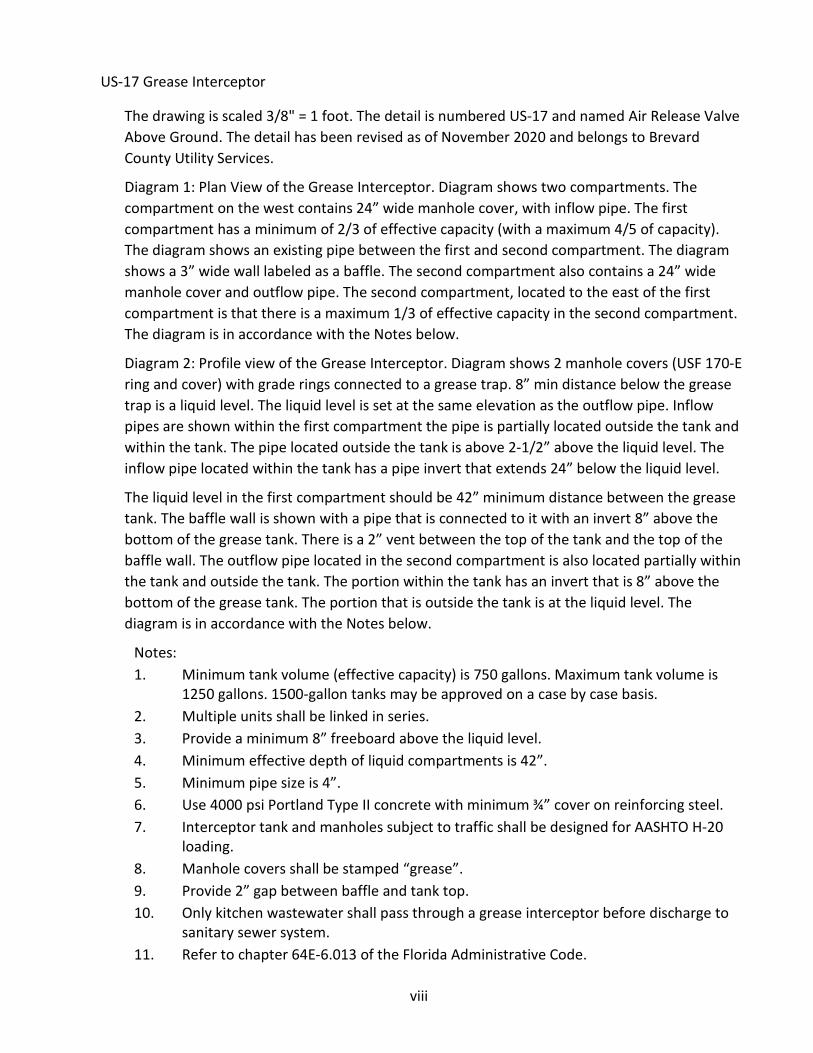
viii
US-17 Grease Interceptor
The drawing is scaled 3/8" = 1 foot. The detail is numbered US-17 and named Air Release Valve Above Ground. The detail has been revised as of November 2020 and belongs to Brevard County Utility Services.
Diagram 1: Plan View of the Grease Interceptor. Diagram shows two compartments. The compartment on the west contains 24” wide manhole cover, with inflow pipe. The first compartment has a minimum of 2/3 of effective capacity (with a maximum 4/5 of capacity). The diagram shows an existing pipe between the first and second compartment. The diagram shows a 3” wide wall labeled as a baffle. The second compartment also contains a 24” wide manhole cover and outflow pipe. The second compartment, located to the east of the first compartment is that there is a maximum 1/3 of effective capacity in the second compartment. The diagram is in accordance with the Notes below.
Diagram 2: Profile view of the Grease Interceptor. Diagram shows 2 manhole covers (USF 170-E ring and cover) with grade rings connected to a grease trap. 8” min distance below the grease trap is a liquid level. The liquid level is set at the same elevation as the outflow pipe. Inflow pipes are shown within the first compartment the pipe is partially located outside the tank and within the tank. The pipe located outside the tank is above 2-1/2” above the liquid level. The inflow pipe located within the tank has a pipe invert that extends 24” below the liquid level.
The liquid level in the first compartment should be 42” minimum distance between the grease tank. The baffle wall is shown with a pipe that is connected to it with an invert 8” above the bottom of the grease tank. There is a 2” vent between the top of the tank and the top of the baffle wall. The outflow pipe located in the second compartment is also located partially within the tank and outside the tank. The portion within the tank has an invert that is 8” above the bottom of the grease tank. The portion that is outside the tank is at the liquid level. The diagram is in accordance with the Notes below.
Notes: 1. Minimum tank volume (effective capacity) is 750 gallons. Maximum tank volume is
1250 gallons. 1500-gallon tanks may be approved on a case by case basis.2. Multiple units shall be linked in series.3. Provide a minimum 8” freeboard above the liquid level.4. Minimum effective depth of liquid compartments is 42”.5. Minimum pipe size is 4”.6. Use 4000 psi Portland Type II concrete with minimum ¾” cover on reinforcing steel.7. Interceptor tank and manholes subject to traffic shall be designed for AASHTO H-20
loading.8. Manhole covers shall be stamped “grease”.9. Provide 2” gap between baffle and tank top.10. Only kitchen wastewater shall pass through a grease interceptor before discharge to
sanitary sewer system.11. Refer to chapter 64E-6.013 of the Florida Administrative Code.

ix
12. Interceptor shall be coated with 100% solid epoxy coating or HDPE liner (minimum of3 mm thickness).
13. A sanitary cleanout is required upstream and downstream of the grease interceptortank.
Figure 8 - Grease Interceptor Detail (US-17)
x
US-20 Page 1 of 2 - General Manhole Notes
The drawing is not scaled. The detail is numbered US-20 page 1 of 2 and named Manholes- General Notes. The detail has been revised as of November 2020 and belongs to Brevard County Utility Services.
Notes: 1. Precast concrete- Type II cement per ASTM C-1502. 4000 psi minimum concrete compressive strength at 28-day cure time.3. Ring and cover to be set flush with finished pavement.4. Six-inch compacted FDOT #57 stone shall extend six inches beyond edge of monolithic
base.5. Exterior coating: Three coats (red, grey, then black) of factory applied CS-55 water
based acrylic coating (12 mils total thickness) or EW-1 water-based epoxy coating (12mils total thickness). Field touch up required after installation of structure.
6. Interior coating: Three coats (red, black, then grey) of factory applied CS-55 waterbased acrylic coating (12 mils total thickness) or EW-1 water-based epoxy coating (12mils total thickness). One coat of grey will be applied to the complete interior of thestructure prior to final acceptance.
7. US Foundry 225 Type “AS Legacy”. See Manhole Cover detail for letteringrequirements.
8. Resilient boot connectors shall be sued where PVC pipe penetrates manhole walls.Boots shall be cemented inside with waterproof non-shrinking grout. Boots shall bewatertight and manufactured of materials resistant to decay caused by the sanitarysewer environment or ambient soil conditions. All hardware inside manhole to be 316stainless steel.
9. All openings shall be sealed with non-shrinking grout.10. Reinforcement shall meet ASTM C-478 with 2” minimum cover for reinforcement.11. Manhole steps are not permitted.12. Minimum pipe penetration hole diameter equals pipe O.D. plus four inches.13. Manholes deeper than twelve feet from finished grade shall have a minimum inside
diameter of five feet.14. Tongue and groove joint may be oriented up or down.15. The cone, riser, iron frame shall be encapsulated with an exterior heat shrink wrap
with a minimum thickness of 100 mils and minimum width of 12 inches regardless oflocation above or below the water table. Joints shall require a minimum wrap widthof 9 inches. Exterior heat shrink wrap must be centered on the joint. Adhesive wrapsare not permitted. Applicators must be factory trained in the application of the wrap.
16. Joints shall be assembled using non-sag grade of polysulfide rubber filler meetingFederal Specification SSS-210A Type 1 and AASHTO Specification M198 Type B. Eachjoint shall be trimmed after assembly.
17. Each section shall have a minimum of three lifting loops (not rebar). Loops shall be cutoff and grouted over prior to completion of the structure installation. Lifting holes

xi
must have a minimum of 2-1/2 inches of cover on the interior wall. Lifting holes must be acid washed and sealed with non-shrink grout.
18. Precast structures off-loaded by the use of pallet forks will be rejected.19. Structures dropped during handling will be rejected.
Table: Largest pipe in structure
Minimum I.D. of structure
Min. wall thickness of structure
Min. Base thickness
Up to 15” 4’-0” 8” 6” 18” and larger Outside pipe
diameter + 3’-0” Per ASTM C-478 (8” minimum)
Per ASTM C-478 (8” minimum)
Figure 9 - General Manhole Notes (US-20 Page 1 of 2)

xii
US-20 Page 2 of 2 - General Manhole Notes
The drawing is not scaled. The detail is numbered US-20 page 2 of 2 and named Manholes- General Notes. The detail has been revised as of November 2020 and belongs to Brevard County Utility Services.
Notes: 20. Pipes protruding into the manhole shall extend approximately ½ inch inside the inner
wall measured at the horizontal midsection points of the pipe. Pipe thirty inches andlarger inside diameter shall be contoured such that the maximum protrusion into themanhole at any point around the pipe shall not exceed five inches.
21. Use of HDPE adjustment rings with butyl rubber sealant and precast concreteadjustment rings that meet H-20 loading requirements are approved. Brick andmortar for grade will require pre-approval from BCUSD.
22. Service connections shall not terminate directly into a manhole.23. Manhole construction shall meet FDOT Design Specifications.24. Base and first riser unit shall be cast monolithically.25. Precast invert channels are not permitted.
Table: Largest pipe in structure
Minimum I.D. of structure
Min. wall thickness of structure
Min. Base thickness
Up to 15” 4’-0” 8” 6” 18” and larger Outside pipe
diameter +3’-0” Per ASTM C-478 (8” minimum)
Per ASTM C-478 (8” minimum)
Figure 10 - General Manhole Notes (US-20 Page 2 of 2)

xiii
US-21 - Concentric Manhole
The drawing is scaled 1/2" = 1 foot. The detail is numbered US-21 and named Manhole Concentric. The detail has been revised as of November 2020 and belongs to Brevard County Utility Services.
Diagram: Profile view of a minimum 48” wide Concentric Manhole. Diagram is in accordance with BCUSD US-20 Notes.
Figure 11 - Concentric Manhole Detail (US-21)

xiv
US-22 – Eccentric Manhole
The drawing is scaled 1/2" = 1 foot. The detail is numbered US-22 and named Manhole Eccentric. The detail has been revised as of November 2020 and belongs to Brevard County Utility Services.
Diagram: Profile view of the Eccentric Manhole with variable width. Diagram is in accordance with BCUSD US-20 Notes.
Figure 12 - Eccentric Manhole Detail (US-22)

xv
US-23 – Single Interior Drop Manhole
The drawing is scaled 1/2" = 1 foot. The detail is numbered US-23 and named Manhole Single Interior Drop. The detail has been revised as of November 2020 and belongs to Brevard County Utility Services.
Diagram: Profile view of a minimum 60” wide Concentric Manhole with a single interior drop. Diagram depicts an SDR 35 PVC inflow pipe outside the manhole. A drop bowl with a minimum 6” diameter drop pipe outfitted with a FERNCO coupling and stainless-steel strap restraint are within the manhole. Diagram is in accordance with BCUSD US-20 Notes.
Figure 13 - Single Interior Drop Manhole Detail (US-23)

xvi
US-24 - Double Interior Drop Manhole
The drawing is scaled 1/2" = 1 foot. The detail is numbered US-24 and named Manhole Double Interior Drop. The detail has been revised as of November 2020 and belongs to Brevard County Utility Services.
Diagram: Profile view of a minimum 72” wide Concentric Manhole with a double interior drop. Diagram depicts an SDR 35 PVC inflow pipe outside the manhole. A drop bowl with a minimum 6” diameter drop pipe outfitted with a FERNCO coupling and stainless-steel strap restraint are within the manhole. Diagram is in accordance with BCUSD US-20 Notes.
Figure 14 - Double Interior Drop Manhole Detail (US-24)

xvii
US-25 – Conflict Manhole
The drawing is scaled 3/4" = 1 foot. The detail is numbered US-25 and named Manhole Conflict. The detail has been revised as of November 2020 and belongs to Brevard County Utility Services.
Diagram 1: Plan view of a conflict manhole. Diagram depicts gravity sewer pipe, with a casing per Note 1 below, through a manhole of another utility or storm system. Non-shrink grout shall be used where the carrier pipe enters the manhole. Diagram is in accordance with Notes.
Diagram 2: Profile view of a conflict manhole. Diagram depicts gravity sewer pipe, with a casing per Note 1, through a manhole of another utility or storm system. Non-shrink grout shall be used where the carrier pipe enters the manhole. Diagram is in accordance with Notes below.
Notes: 1. Casing shall be steel, ductile iron or C-900 PVC. Casing shall be seamless or sealed
half- sleeves.2. Annular space shall be filled with flowable fill or sealed with Link Seals.3. Pipe joints within the casing are to be restrained.4. Carrier pipe shall be C-900 PVC.5. Carrier pipe minimum slope to be maintained using casing.6. Casing insulators may be utilized in lieu of skids. Casing insulators shall be fastened
with stainless steel hardware.7. Conflict manholes prohibited in new construction.
Figure 15 - Conflict Manhole Detail (US-25)

xviii
US-26 – Dog House Manhole
The drawing is scaled 1/2" = 1 foot. The detail is numbered US-25 and named Manhole Conflict. The detail has been revised as of November 2020 and belongs to Brevard County Utility Services.
Diagram: Profile view of a Dog House Manhole. The diagram depicts that the manhole interior diameter shall be at minimum 48 inches. Diagram is in accordance with BCUSD US-20 Notes.
Note: Entire bottom shall be poured in place after installation of the doghouse manhole. Concrete shall be 4000 psi Type II.
Figure 16 - Dog House Manhole Detail (US-26)

xix
US-27 - AS Legacy Manhole Cover
The drawing is not scaled. The detail is numbered US-27 and named Manhole Cover AS Legacy. The detail has been revised as of November 2020 and belongs to Brevard County Utility Services.
Diagram 1: Plan view of the Manhole Cover detail. The diagram depicts the text “Brevard County” “Sanitary Sewer” and “Florida”. The diagram also depicts (2) non-penetrating pick holes.
Diagram 2: Profile view of the Manhole cover. The manhole cover is 25 3/4” wide, 3 11/16” height at the midpoint and 2” tall at the edge.
Notes: 1. Manhole cover manufactured by US Foundry2. “AS 225 Legacy” model manhole covers to be used on all publicly owned sanitary
sewer manholes located within the Brevard County Utility Service area.3. Privately owned and maintained sanitary sewer systems shall use US Foundry AS 225
cover.
Figure 17 - AS Legacy Manhole Cover Detail (US-27)

xx
US-28 - Manhole Inverts
The drawing is scaled 3/8" = 1 foot. The detail is numbered US-28 and named Manhole Inverts. The detail has been revised as of November 2020 and belongs to Brevard County Utility Services.
Diagram 1: Plan view of the manhole inverts located on the floor of the manhole. This diagram depicts two incoming pipe channels from the east and west connecting to an outgoing pipe channel to the north.
Diagram 2: Plan view of the manhole inverts located on the floor of the manhole. This diagram depicts one incoming pipe channel from the east and connects to an outgoing pipe channel located to the north.
Diagram 3: Plan view of the manhole inverts located on the floor of the manhole. This diagram shows two incoming pipes from the east and south connecting to an outgoing pipe located to the north.
Diagram 4: Plan view of the manhole inverts located on the floor of the manhole. This diagram depicts three incoming pipe channels from the east, south and west connecting to an outgoing pipe channel located to the north.
Notes: 1. Invert channels shall be smooth and accurately shaped to a semi-circular bottom
conforming to the inside diameter of the adjacent sewer pipe section.2. Channel shall be constructed between pipes with different elevations providing for
smooth flows.3. Channels for future connections shall be constructed, filled with sand and covered
with mortar.4. Slopes outside the invert channels greater than 12:1 are not permitted.5. Seal all openings with non-shrink grout.6. Common red brick and Type II cement shall be used for invert construction.7. Top of bench shall be equal to the spring line of the largest pipe.8. Precast invert channels are not permitted.9. For sewer lines smaller than 12-inch diameter, provide a minimum radius of the
centerline of the channel 1/2 the inside diameter of the manhole.10. For sewer lines greater than 12-inch diameter, provide a minimum radius of the outer
channel wall 1/2 the inside diameter of the manhole.11. Design the top of bench with an 8% slope from the wall to the channels edge.
Figure 18 - Manhole Inverts Detail (US-28)

xxi
US-30 - Lift Station Notes
The drawing is not scaled. The detail is numbered US-30 and named Lift Station Notes. The detail has been revised as of November 2020 and belongs to Brevard County Utility Services.
Notes: 1. Access cover to be cast in top slab, shall be minimum 30” x 48” aluminum cover with
provisions for external locking with a padlock and shall include an integral two leaf fallthrough protection system.
2. Vent pipe shall be 4” diameter sch 40 PVC with stainless steel screen. Vent shall have8” clearance from top of the lift station slab.
3. Base and first riser unit shall be cast monolithically.4. Stainless steel upper guide bracket shall be attached to access cover cast into the slab.5. Stainless steel guide rails shall be of one-piece construction, regardless of wet well
depth.6. All penetrations through wet well walls shall be sealed with a non-shrinking grout
except where flexible manhole connectors are used. No penetrations are permittedfor lifting purposes.
7. Anchor bolts shall be stainless steel. Anchor type and method of installation shall beas recommended by the pump manufacturer.
8. Liner shall be installed for interior walls, underside of the top slab and any exposedconcrete surfaces within the wet well.
9. A submersible pressure transducer shall be installed per the manufacturer’s cablemounting installation instructions. A single stainless-steel hook shall be provided fortransducer installation.
10. An eight-inch minimum layer of 4,000 psi Type II concrete shall be installed aftercenter line of access is determined. Contractors shall set anchor bolt locations asrequired by the pump manufacturer off center line of access cover. Floor shall beshaped per pump manufacturer’s requirements.
11. Minimum inside diameter of wet well shall be six feet.12. Storage volume between "lead pump on" and "pumps off" elevation shall equal or
exceed the volume one pump can discharge in three minutes with no flow enteringthe wet well. Low water level shall be set as recommended by the pumpmanufacturer to provide adequate cooling of the motor and to prevent vertexing andcavitation from occurring.
13. C-900 pipe shall be installed form the wet well to the first upstream manhole.14. Three coats (black over grey over red) of factory applied CS-55 water based acrylic
coating or EW-1 water-based epoxy coating (12 mil total thickness) shall be applied tothe exterior only. Field touch up will be required after installation.
15. Joint seal shall be applied.16. Wrapid Seal shall be applied to exterior joints. Minimum of 12" wide wrap required
for all lift station joints. Applicators must be factory trained in application of the wrap.17. Floats and transducer shall be installed in an area where flow turbulence is minimal.18. All discharge piping in the wet well shall be HDPE DR 11.

xxii
19. All exposed concrete penetrations to be lined or coated with approved materials.20. Pumps to be installed with base plate provided by the pump manufacturer.21. Vertical plumb shall be considered out of tolerance if greater than 1" horizontal for
each 5' vertical height of precast or caisson wet well structure.22. A minimum 2" reinforcement cover shall be used.
Figure 19 - Lift Station Notes (US-30)

xxiii
US-31 Page 1 of 3 - Lift Station Profile View
The drawing is not scaled. The detail is numbered US-31 and named Lift Station Profile View. The detail has been revised as of November 2020 and belongs to Brevard County Utility Services.
Diagram: Profile view of a County standard wet well & lift station. Diagram depicts the influent pipe entering the wet well (along with a drop bowl, FERNCO coupling and 316 stainless steel strap). The influent pipe invert is set at the pump off elevation of the wet well. Diagram also depicts the floats, the pumps set at the bottom of the well, and the HDPE outflow pipe. On top of the wet well, the diagram depicts the access cover of the wet well adjacent to the vent pipe.
The above ground valving pad is also shown in close proximity to the wet well. The diagram depicts an Air Release valve with a 2” PVC return pipe below ground piped to the wet well.
Note: Refer to US-30 for Lift Station Notes. Refer to US-31 Page 2 of 3 & US-31 Page 3 of 3 for Tremie Wet Well Installation Details and Notes.
Table: Station Diameter Minimum Wall
Concrete Thickness Minimum Base Concrete Thickness
Minimum Top Slab Concrete Thickness
6’ 8” 12” 10” 8’ 9” 12” 10” 10’ 11” 15” 12” 12’ 12” 15” 12”
Figure 20 - Lift Station Profile View Detail (US-31 Page 1 of 3)

xxiv
US-31 Page 2 of 3 - Tremie Wet Well Installation Detail
The drawing is not scaled. The detail is numbered US-74 1 of 2 and named Tremie Wet Well Installation Detail. The detail has been revised as of November 2020 and belongs to Brevard County Utility Services.
Diagram: Profile view of a County standard Tremie Wet Well Installation. The diagram indicates are in accordance with the US-31 2 of 3 Notes.
Notes: 1. Structures and sections shall be inspected by Owner prior to installation.2. Structures shall be designed to minimize the numbers of sections within the structure;
i.e.: 6- or 8-foot sections where possible.3. No section joints permitted within limits of secondary concrete.4. No more than one layer of joint seal permitted on each joint.5. The seal between joints shall be fully compressed prior to retainer straps being
installed.6. Top of tremie seal must be clean, dry and inspected by Owner prior to placement of
secondary concrete. No joints allowed within 2' of the wet well floor elevation.7. All section joints shall be leak free prior to placement of secondary concrete.8. If approved by Owner, leak repair of tremie seal will be by pressure injected epoxy
only. Lead wool, water plug, acrylamide grout, etc. are not permitted. Secondaryconcrete is to be finished as per Note 10, US-30.
9. Tremie seal concrete shall have a minimum compressive strength of 4,000 psi atseven (7) days and testing laboratory results shall be submitted to Authority forapproval prior to placement of the secondary pour.
10. Secondary concrete shall have a minimum compressive strength of 4,000 psi attwenty- eight (28) days and testing laboratory results shall be submitted to Authorityfor approval before completion of lift station.
11. Refer to US-30 and US-31 1 of 3 for additional information on Lift StationConstruction.
Figure 21 - Tremie Wet Well Installation Detail (US-31 Page 2 of 3)

xxv
US-31 Page 3 of 3 - Tremie & Wet Well Causes for Rejection Notes
The drawing is not scaled. The detail is numbered US-74 2 of 2 and named Tremie Wet Well Installation Detail. The detail has been revised as of November 2020 and belongs to Brevard County Utility Services.
Causes for Rejection during or after installation: 1. Well sections installed in improper sequence (keyways not in correct position).2. Leaks (including continually damp areas) which cannot be stopped in wall sections,
tremie seal or in joints of precast sections.3. Wet well installed out of plumb, maximum deviation shall be 1/8" per foot for each
precast section with the completed cylindrical structure no more than two inches outof level prior to setting the top slab. The bottom (first) and section of the structureshall be set level and plumb prior to the beginning the clamming operation and shallbe so maintained until the addition of the third section.
4. Structural damage, gauges, cracks, etc. in wet well sections caused by damage duringconstruction (hit by clam bucket, crane boom, settling, etc.).
5. Settlement of structure after completion of tremie seal and or secondary pour/topslab installation.
Figure 22 - Tremie & Wet Well Causes for Rejection Notes (US-31 Page 3 of 3)

xxvi
US-32-ALL Page 1 of 3 - Lift Station Plan View
The drawing is scaled 3/8" = 1 foot. The detail is numbered US-32-ALL 1 of 3 and named Lift Station Plan View. The detail has been revised as of November 2020 and belongs to Brevard County Utility Services.
Diagram: The Diagram shown is of the plan view of proposed lift stations not including generators. The full lift station area is 30’ by 30’. The detail depicts a 12’ minimum wide driveway with 6” minimum thickness and 3,000 psi fiber reinforced concrete adjacent to the right of way. The driveway has a length of 12.5 ft. The diagram depicts a wet well 6” from the edge of the driveway. The wet well diameter ranges per design characteristics; the minimum wet well diameter is between 6’ and 12’. There is a wet well hatch shown within the wet well area. The wet well is at minimum 60” away from the opposite edge of the lift station site. The valve vault or above ground valve location is located to the south of the wet well. There is a 3’ separation required off the wet well only if the valve vault is used at the station. To the north of the wet well is a concrete pad containing a control panel. To the east of the control panel is a concrete pad containing the Remote Telemetry Unit. The concrete pad is 64” x 64” and is at least 12” off the lift station property line.
Notes: 1. This drawing shown for dimensional tolerances only.2. Engineer shall submit a scaled drawing at a scale no smaller than 1” = 10’ showing
locations of all appurtenances specific to the lift station site. Orientation of accessdrive and appurtenances may vary from that show on this drawing.
3. All lift station equipment must be constructed within the boundaries of the lift stationsite. Installation of apparatus within an easement adjacent to or adjoining the liftstation site is not acceptable.
4. Lift station site shall be graded to direct stormwater runoff away from the structuresand electrical equipment.
5. The lift station site shall contain a three-inch layer of FDOT #57 stone and weedbarrier. Seed and Mulch is not acceptable. Use of sod will require pre-approval fromBCUSD.
6. Limits shown for Rohn tower style foundation. If standard telemetry pole andfoundation is used, locate foundation within the limits shown for the Rohn towerfoundation.
7. Change in location or orientation of control panel must be approved by BCUSD staffprior to panel installation.
8. Reclaimed water service required via hose bib if reclaimed water is available to site.See detail US-53 for Reclaimed Water Signage.
9. A lined terminal manhole shall be accessible without crossing vehicular travel lane orsidewalk.
10. 4” x 4” Concrete Survey monument shall be installed within the lift station site.
Figure 23 - Lift Station Plan View Detail (US-32-ALL Page 1 of 3)

xxvii
US-32-ALL Page 2 of 3 Lift Station Plan View
The drawing is scaled 1/8" = 1 foot. The detail is numbered US-32-ALL 2 of 3 and named Lift Station Plan View. The detail has been revised as of November 2020 and belongs to Brevard County Utility Services.
Diagram: The Diagram shown is of the plan view of proposed lift stations including generators. The full lift station area is 40’ by 40’. The detail depicts a 12’ minimum wide driveway with 6” minimum thickness and 3,000 psi fiber reinforced concrete adjacent to the right of way. The driveway has a length of 22.5 ft. The diagram depicts a wet well 6” from the edge of the driveway. The wet well diameter ranges per design characteristics; the minimum wet well diameter is between 6’ and 12’. There is a wet well hatch shown within the wet well area. The wet well is at minimum 60” away from the opposite edge of the lift station site. The valve vault or above ground valve location is located to the south of the wet well. There is a 3’ separation required off the wet well only if the valve vault is used at the station. To the north of the wet well is a concrete pad containing a control panel. To the east of the control panel is a concrete pad containing the Remote Telemetry Unit. The concrete pad is 64” x 64” and is at least 12” off the lift station property line. To the north of the driveway area is a generator pad typically 48” off the lift station property line to the north and east.
Notes: 1. This drawing shown for dimensional tolerances only.2. Engineer shall submit a scaled drawing at a scale no smaller than 1"=10' showing
locations of all appurtenances specific to the lift station site. Orientation of accessdrive and appurtenances may vary from that shown on this drawing.
3. All lift station equipment must be constructed within the boundaries of the lift stationsite. Installation of apparatus within an easement adjacent to or adjoining the liftstation site is not acceptable.
4. Lift station site shall be graded to direct stormwater runoff away from the structuresand electrical equipment.
5. The lift station site shall contain a three-inch layer of FDOT #57 stone and weedbarrier. Seed and Mulch is not acceptable. Use of sod will require pre-approval fromBCUSD.
6. Limits shown for Rohn tower style foundation. If standard telemetry pole andfoundation is used, locate foundation within the limits shown for the Rohn towerfoundation.
7. Change in location or orientation of control panel must be approved by BCUSD staffprior to panel installation.
8. Reclaimed water service required via hose bib if reclaimed water is available to site.See detail US-53 for Reclaimed Water Signage.
9. A lined terminal manhole shall be accessible without crossing vehicular travel lane orsidewalk.
10. 4” x 4” Concrete Survey monument shall be installed within the lift station site.
Figure 24 - Lift Station Plan View Detail (US-32-ALL Page 2 of 3)

xxviii
US-32-ALL Page 3 of 3 Lift Station Section View
The drawing is not scaled. The detail is numbered US-32-ALL 3 of 3 and named Lift Station Section View. The detail has been revised as of November 2020 and belongs to Brevard County Utility Services.
Diagram: Profile view of the edge of proposed Lift Station sites. The diagram depicts 3” of #57 stone overlaid with a weed barrier on smooth graded, compacted ground. The edge of the site to contain a 6” high aluminum.
Notes: 1. Site shall be graded to drain away from the wet well and electrical equipment.
Maximum cross section slope shall be 10%.2. Provide perimeter protection along lift station boundary line with gate, if specified by
BCUSD.3. Installation of woven weed barrier shall be in accordance with manufacturer's
recommendations. Place weed barrier on graded smoothly compacted ground, incontact with ground free from wrinkles. provide minimum 1' overlap at joints.
4. Installation of edging shall be according to manufacturer's recommendations.5. A retaining wall or concrete curb around the perimeter can be substituted for the
aluminum edging per pre-approval by BCUSD.6. #57 stone shall be placed over the weed barrier at a minimum consolidated thickness
of 3" to cover all unimproved areas within the lift station site.7. Perimeter protection (Fence, Gates, Locks, etc.) shall meet applicable sections of
FDOT specifications or Brevard County Building Code requirements.8. 4” x 4” Concrete Survey Monument depicting the location and elevation shall be
installed within the lift station site.
Figure 25 - Lift Station Section View Detail (US-32-ALL Page 3 of 3)

xxix
US-33 Lift Station Above Ground Valving
The drawing is scaled 1/4" = 1 foot. The detail is numbered US-33 and named Lift Station Above Ground Valving. The detail has been revised as of November 2020 and belongs to Brevard County Utility Services.
Diagram 1: Plan view of the above ground valving, concrete pad and the connection to the wet well. The diagram shows the plan view of the pumps and piping from wet well and leads up to above ground piping set upon a concrete pad. The above ground valving includes check valves, pressure gauges, and a cross with air release valves on top plumbed back to the wet well.
Diagram 2: Cross Section view of the above ground valving and concrete pad. Diagram shows the 6’ fiber reinforced concrete pad. Piping above the concrete pad includes a piece of Ductile Iron piping, a 12” spool piece, a weighted level check valve, a resilient wedge gate valve, a valve support stand, an emergency bypass connection, an air release valve and associated Ductile Iron piping going under the concrete pad. Piping below the concrete pad includes the associated Ductile Iron Piping from the concrete pad, as well as the 2” air release return pipe that is plumbed back to the wet well.
Notes: 1. Emergency by-pass connection. Male Camlock with cap for 4" connection; male Bauer
with cap for 6" and 8" connection.2. A 4 1/2" pressure gauge shall be installed on the top of each check valve. The gauges
shall be mounted on a 1/2" NPT brass nipple with petcock. Gauges shall be calibratedin psi and feet of head increments. Stainless steel diaphragm protectors shall beprovided.
3. Range of pressure gauge shall be approved by Brevard County Utilities staff.4. Above ground valve hand wheels to be secured with 3/8" diameter, epoxy coated,
stainless steel cable and padlock to prevent unauthorized operation of the valves.
Figure 26 - Lift Station Above Ground Valving Detail (US-33)

xxx
US-34 Lift Station Valve Vault
The drawing is scaled 3/8" = 1 foot. The detail is numbered US-34 and named Lift Station Valve Vault. The detail has been revised as of November 2020 and belongs to Brevard County Utility Services.
Diagram 1: Diagram is a plan view. Diagram depicts two separate pipes form the wet well set at a distance per the manufacturer’s recommendation. The valves within the vault include; MJ sleeve, check valve, and pressure gauges. A plug valve and an emergency connection are located on one pipe. The piping has a 12” minimum distance between the valve vault walls.
Diagram 2: Diagram is a profile view of the Valve Vault. The diagram depicts the piping entering the vault. Valves along the pipe include; MJ sleeve (a minimum of 12 inches from the edge of the vault), a weighted lever check valve, plug valve and an emergency connection. The bottom of the vault is sloped at a 2% grade and a 2” drain to well is located at the downstream end of the vault.
Notes: 1. Emergency connection: 4", 6" or 8" plug valve, nipple and quick disconnect fitting.
Male Cam-lock with cap for 4" connection. Male Bauer with cap for 6" or 8"connection.
2. All piping within the valve vault shall be PVC C900 DR 18 or HDPE DR 11, utilizingstainless steel hardware.
3. A 4-1/2" pressure gauge shall be installed on each check valve. The gauges shall bemounted on 1/4" NPT brass nipple with petcock. Gauges shall be calibrated in psi andfeet of head increments. Range of gauge shall be approved by the Utility. Stainlesssteel diaphragm protectors shall be provided.
4. Access cover to be cast in top slab, shall be large enough to permit unobstructedconnection to the emergency by-pass connection, shall be aluminum and shall belocked in the closed position with a padlock.
5. This drawing shown for dimensional tolerances only.6. Valve Vault shall be H-20 rated.7. Reinforcement shall have a minimum cover of 2".
Figure 27 - Lift Station Valve Vault Detail (US-34)

xxxi
US-35 Page 1 of 2 (Elec-10-ALL) Lift Station Control Panel
The drawing is scaled 1/2" = 1 foot. The detail is numbered US-35 1 of 2 (Elec-10-ALL) and named Lift Station Control Panel. The detail has been revised as of November 2020 and belongs to Brevard County Utility Services.
Diagram: This diagram shows a profile view of a County Standard Lift Station Control Panel. Specific Electrical Details can be found in the Brevard County Electrical Criteria.
Notes: 1. See Brevard County Utility Service's Electrical Standards for details related to
equipment mounting2. All cut ends of channel must be filed free of burrs and sharp edges.3. Concrete pad to be sloped on all sides for positive drainage.4. Conduit diameter per Brevard County Electrical Standards.5. Concrete pad (not drawn to scale) extends a minimum of 36" in front of control panel.
Figure 28 - Lift Station Control Panel Detail (US-35 Page 1 of 2 / Elec-10-ALL)

xxxii
US-35 Page 2 of 2 (Elec-11-ALL) Lift Station Control Panel
The drawing is scaled 1/2" = 1 foot. The detail is numbered US-35 2 of 2 (Elec-11-ALL) and named Lift Station Control Panel. The detail has been revised as of November 2020 and belongs to Brevard County Utility Services.
Diagram: This diagram shows a profile view of a County Standard Lift Station Control Panel. Specific Electrical Details can be found in the Brevard County Electrical Criteria.
Notes: 1. See Brevard County Utility Service's Electrical Standards for details related to
equipment mounting.2. All cut ends of channel must be filed free of burrs and sharp edges.3. Concrete pad to be sloped on all sides for positive drainage.4. Conduit diameter per Brevard County Electrical Standards.5. Concrete pad (not drawn to scale) extends a minimum of 36" in front of control panel.
Figure 29 - Lift Station Control Panel Detail (US-35 Page 2 of 2 / Elec-11-ALL)

xxxiii
US-36 Telemetry Mast 30’ Maximum Height
The drawing is not scaled. The detail is numbered US-36 and named Telemetry Mast 30’ Maximum Height. The detail has been revised as of November 2020 and belongs to Brevard County Utility Services.
Diagram 1: Front View of the Telemetry Mast with a 30’ Maximum height. Diagram is in accordance with BCUSD US-36 Notes.
Diagram 2: Side View of the Telemetry Mast with a 30’ Maximum height. Diagram is in accordance with BCUSD US-36 Notes.
Mast installation notes: A. Proposed mast height will be determined by Brevard county utilities prior to
construction.B. Conform to the latest building and zoning codes for new installations.C. Do not construct mast within 3 feet of an electrical service drop (480V or less), within
10' of overhead power line up to 32kV, within 15' of an overhead power line up to115kV, or within 20' of an overhead power line exceeding 115kV.
D. Ground the mast at the base by providing 1/2-inch ground strap. connect to groundrod with #4 AWG bare copper wire and acorn clamp.
E. Couplings on the mast must be at least 10' above grade. couplings are not allowedbelow 10' above grade.
F. Construct mast foundation with 3000 psi reinforced concrete in 24" diametersonotube in undisturbed or compacted soil (95% density).
G. Provide 3" minimum concrete cover on reinforcing steel.H. Shape the top of the concrete foundation into a dome.I. Install 1" and 2" PVC conduits (1 each) to pump control panel. maintain minimum 6"
separation and 18" buried depth. 3-1/4" offset from mast required.J. Pipe in contact with concrete to be coated with bitumastic coating.
Figure 30 - 30' Maximum Height Telemetry Mast Detail (US-36)

xxxiv
US-37 Telemetry RTU
The drawing is not scaled. The detail is numbered US-37 and named Telemetry RTU. The detail has been revised as of November 2020 and belongs to Brevard County Utility Services.
Diagram 1: Front View of the Remote Telemetry Unit. Diagram is in accordance with BCUSD US- 37 Notes.
Diagram 2: Side View of the Remote Telemetry Unit. Diagram is in accordance with BCUSD US- 37 Notes.
RTU Installation notes: A. Conform to the latest codes for new installations.B. Refer to the Brevard County telemetry mast standard for mast and foundation details.C. Refer to the Brevard County RTU installation guide for RTU mounting details.D. Ground antenna to mast with 1/2-inch ground strap.E. Antenna height and direction determined by Brevard county utility services prior to
construction.F. Provide corrosion resistance from galvanic action at interfaces of dissimilar metals
except at ground points.G. Do not mount antenna elements within 3 feet of an electrical service drop (480V or
less), within 10' of overhead power line up to 32kV, within 15' of an overhead powerline up to 115kV, or within 20' of an overhead power line exceeding 115kV.
H. Install 1" and 2" schedule 80 PVC conduits (1 each) for control wiring. maintainminimum 6" separation. 3-1/4" offset from mast required.
I. Fasten heliax cable to exterior of mast with stainless steel clamps at 30" intervals.J. Pipe in contact with concrete to be coated with bitumastic coating
Figure 31 - Telemetry RTU Detail (US-37)
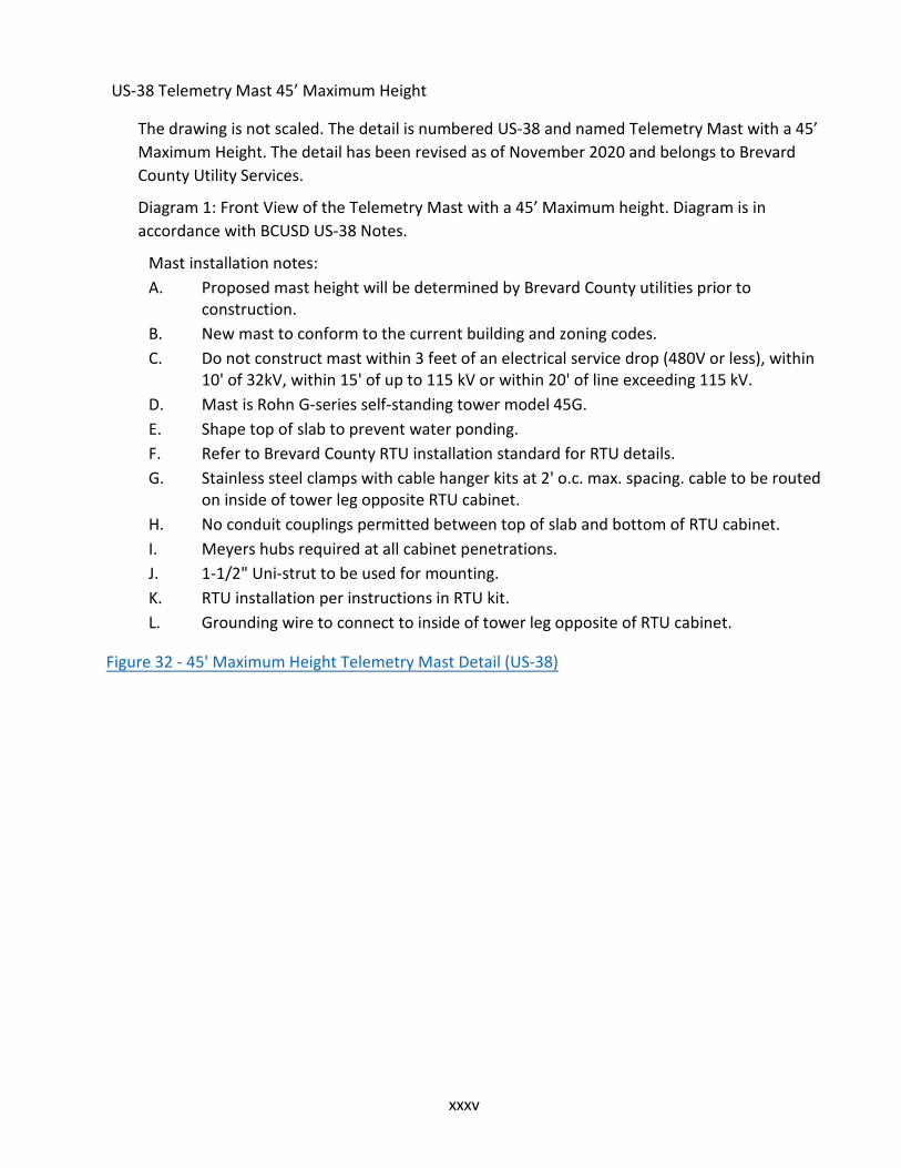
xxxv
US-38 Telemetry Mast 45’ Maximum Height
The drawing is not scaled. The detail is numbered US-38 and named Telemetry Mast with a 45’ Maximum Height. The detail has been revised as of November 2020 and belongs to Brevard County Utility Services.
Diagram 1: Front View of the Telemetry Mast with a 45’ Maximum height. Diagram is in accordance with BCUSD US-38 Notes.
Mast installation notes: A. Proposed mast height will be determined by Brevard County utilities prior to
construction.B. New mast to conform to the current building and zoning codes.C. Do not construct mast within 3 feet of an electrical service drop (480V or less), within
10' of 32kV, within 15' of up to 115 kV or within 20' of line exceeding 115 kV.D. Mast is Rohn G-series self-standing tower model 45G.E. Shape top of slab to prevent water ponding.F. Refer to Brevard County RTU installation standard for RTU details.G. Stainless steel clamps with cable hanger kits at 2' o.c. max. spacing. cable to be routed
on inside of tower leg opposite RTU cabinet.H. No conduit couplings permitted between top of slab and bottom of RTU cabinet.I. Meyers hubs required at all cabinet penetrations.J. 1-1/2" Uni-strut to be used for mounting.K. RTU installation per instructions in RTU kit.L. Grounding wire to connect to inside of tower leg opposite of RTU cabinet.
Figure 32 - 45' Maximum Height Telemetry Mast Detail (US-38)

xxxvi
US-39 Wet Well Pipe Bracing Detail
The drawing is scaled 1/2" = 1 foot. The detail is numbered US-39 and named Wet Well Pipe Bracing Detail. The detail has been revised as of November 2020 and belongs to Brevard County Utility Services.
Diagram: This diagram shows the plan view of the wet well bracing. The wet well bracing consists of tee shaped cross between two perpendicular 316 stainless steel 1-5/8” channels on one end of a wet well. The two channels are braced together by a stainless-steel gusset plate and braced to the wet well wall by a stainless-steel angle bracket and 1/2” stainless steel all thread embed 4-1/2”. Diagram is in accordance with the Notes below.
Notes: 1. Pipe clamps shall be constructed from minimum 1" x 1/8” 316 stainless steel flat
stock.2. All bracing system components shall be connected using 316 stainless steel fasteners.3. All threaded connections shall have stainless steel flat washers and stainless-steel
nylon insert lock nuts or stainless-steel double nuts.4. Maximum spacing of 7 feet between supports.
Figure 33 - Wet Well Pipe Bracing Detail (US-39)

xxxvii
US-40 Water Service General Notes
The drawing is not scaled. The detail is numbered US-40 and named Water Service General Notes. The detail has been revised as of November 2020 and belongs to Brevard County Utility Services.
Notes: 1. Meter box shall be plastic type; set to match finish grade, adjacent to property line or
sidewalk. Meter box shall be furnished to Utility Services by the contractor2. Curb stops shall have couplings suitable for the type of piping used.3. Piping shall be blue polyethylene DR-9 (copper tube size) as defined by ASTM D-
2737.Piping shall be NSF approved for potable water service and shall conform toAWWA C-901 latest revision.
4. All potable waterline tubing/pipe shall be blue in color with a clear virgin high densitypolyethylene center, with which the manufacturer shall furnish a certificate of purity.
5. The tubing/pipe shall have UV protection and shall not be affected by exposed Floridasun light for a minimum of five years.
6. For installation of services under existing pavement, HDPE DR-11 or SCH 80 PVCcasing, extending 1' beyond the edge of pavement shall be used.
7. Corporation stops shall be supplied with an outlet suitable for the type of pipe used.Corporation stops on PVC pipe must be installed with saddles.
8. For installation of services under proposed pavement, place a SCH 80 PVC sleeve atcrossing extending 1' beyond the edge of pavement.
9. Service saddles be stainless steel double strap saddles10. Electronic markers shall conform to Technical Specification 02080 of this criteria.11. The minimum water service size shall be 3/4-inch for a single service and 1-inch for a
double service.12. Service taps on the main shall be spaced a minimum distance of 18 inches. If two or
more taps are required at the minimum spacing, they shall be offset 45 degrees toeach side of the centerline of the crown of the main. Service taps are prohibitedwithin 18 inches of pipe joints.
13. Water service locations shall be marked along the outside of the curb with a sawcut"W" or by a metal tab set into the pavement for roadways without curb. The metaltab shall be set midway between the centerline of the road and the edge ofpavement.
14. Meter boxes are not permitted in sidewalks or driveways.
Figure 34 - Water Service General Notes (US-40)

xxxviii
US-41 Water Service Section View
The drawing is not scaled. The detail is numbered US-40 and named Water Service General Notes. The detail has been revised as of November 2020 and belongs to Brevard County Utility Services.
Diagram: Diagram depicts a profile view of a standard water service line, from the water meter to the connection to the water main. Diagram is in accordance with BCUSD US-40 Notes.
Table: Service Size Casing Size 3/4” 2” 1” 2” 1-1/2” 3” Larger as Necessary Larger as Necessary
Figure 35 - Water Service Section View Detail (US-41)

xxxix
US-42 Water Service Plan View
The drawing is not scaled. The detail is numbered US-42 and named Water Service Plan View. The detail has been revised as of November 2020 and belongs to Brevard County Utility Services.
Diagram: The diagram shows a plan view of a standard water service line with single service yoke. Diagram is in accordance with BCUSD US-40 Notes.
Diagram 2: The diagram shows a plan view of a standard water service line with double service yokes. Diagram is in accordance with BCUSD US-40 Notes.
Figure 36 - Water Service Plan View Detail (US-42)

xl
US-43 Fire Hydrant Assembly
The drawing is not scaled. The detail is numbered US-43 and named Fire Hydrant Assembly. The detail has been revised as of November 2020 and belongs to Brevard County Utility Services.
Diagram: Diagram is a profile view of a Fire Hydrant Assembly. The diagram depicts the sewer water main, connected to a gate valve, set upon a concrete support block 24” x 24” x4” thick. The proposed pipe is 36” below grade. Diagram is in accordance with BCUSD US-43 Notes.
Notes: 1. Fire hydrants shall conform to the latest AWWA specification C-502 and shall be the
traffic model type, dry barrel.2. All working parts shall be made of cast iron and high-grade bronze.3. All hose threads shall be ANSI standard threads.4. Fire hydrants shall be painted one coat of corrosion-resistant primer at the factory.
Two coats of finish color shall be applied to the hydrant after installation.5. Working pressure for the fire hydrants shall be a minimum of 150 psi.6. Valve boxes shall meet the specifications of the Valve Box detail contained in the
criteria.7. Hydrant shall be installed plumb and true.8. All mechanical joints shall be restrained.9. Fire hydrants shall meet all fire department set back and landscape requirements.10. Fire hydrants shall be within one year of date of manufacture upon delivery to site.11. Detail shown in profile view.12. Fire hydrant shall be located at minimum 4’ and at maximum 12’ off edge of curb.
Figure 37 - Fire Hydrant Assembly Detail (US-43)

xli
US-44 Blow Off Detail
The drawing is not scaled. The detail is numbered US-44 and named Blow Off Detail. The detail has been revised as of November 2020 and belongs to Brevard County Utility Services.
Diagram: This diagram depicts a profile view of a blow off detail. The diagram shows valve box below a concrete 18” x 18” x 4” thick. The valve box is located above the water main with all joints are restrained. A M.J. plug with a 2” tap is depicted at the end of the water main and connects to a 2” SCH 80 PVC pipe with a 2” brass gate valve at the end of the line. 4’ of #14 UF tracing wire is depicted around the underground utilities.
Note:
1. 4" pipe and gate valve required for main sizes greater than 12"
Figure 38 - Blow Off Detail (US-44)

xlii
US-45 Temporary Jumper Connection
The drawing is scaled 3/4" = 1 foot. The detail is numbered US-45 and named Temporary Jumper Connection. The detail has been revised as of November 2020 and belongs to Brevard County Utility Services.
Diagram: The diagram depicts a profile view of a Temporary Jumper connection. The diagram depicts an existing water main, below ground, connected to a Jumper connection consisting of the following; 2” corporation stop, a length of 2” DR 9 or SCH 80 PVC extending above ground, a 90° bend, another 2” DR 9 or SCH 80 PVC, a 2” county meter, a double check backflow
prevention assembly, 2” gate valve or curb stop (2- required), a tee with a locking ¾” hose bib and vacuum breaker on one end and a 2” DR 9 or SCH80 PVC on the other end extending below ground to a 2” corporation stop connecting to the water main. A valve box located in the middle of the Temporary Jumper Connection accompanied by an 18” x 18” x 4” thick concrete pad. A #14 UF tracing wire is located between all utilities.
Notes: 1. The contractor shall not operate any valve on the County owned water system except
under the direct supervision of a representative of the Utility Services Department.2. The valve on the water main between the existing main and the new main will remain
closed until FDEP clearance has been obtained and the new system has been acceptedby the County.
Figure 39 - Temporary Jumper Connection Detail (US-45)

xliii
US-46 Backflow Preventer 3/4" – 2”
The drawing is not scaled. The detail is numbered US-44 and named Blow Off Detail. The detail has been revised as of November 2020 and belongs to Brevard County Utility Services.
Diagram: The Diagram depicts a profile view of a Backflow Preventer. The diagram depicts a
pipe below ground connected to the following; a 2” 90° elbow, 2” hard copper riser pipe extending above ground, another 2” 90° elbow, a 2” brass nipple, a 2” backflow preventer
assembly, another 2” 90° elbow, a 2” hard coper riser pipe descending below grade, connected to another 2” 90° elbow. An 18”x18”x4” thick concrete pad is depicted on finished grade where 2” riser extending above ground.
Notes: 1. Installation shown above is for a 2” service. Change piping materials accordingly for
service size.
Table: Materials Item Quantity Description 1 1 2” Backflow Preventer Assembly 2 2 2” Nipple – Brass 3 2 2” x 90° Elbow – Hard Copper 4 2 2” Riser – Hard Copper
Figure 40 - 3/4" to 2" Backflow Preventer Detail (US-46)

xliv
US-47 Backflow Preventer with Meter for Fire Services 3”-8”
The drawing is not scaled. The detail is numbered US-47 and named Backflow Preventer
Without Meter for Services 3”-8”. The detail has been revised as of November 2020 and belongs to Brevard County Utility Services.
Diagram: The Diagram depicts a profile view of a Backflow Preventer. The diagram depicts a pipe below ground connected to a 45° bend, ductile iron piping extending above ground, another 45° bend, a rising stem gate valve, a backflow preventer assembly, another stem gate valve, another 45° bend, ductile iron piping descending below grade, another 45° bend. All joints depicted are restrained.
Notes: 1. All above ground hardware to be stainless steel.2. Pipe supports to be anchored to concrete slab.3. 12” minimum distance from pipes to edge of concrete slab.
Table: Materials Item Quant. Description 1 1 Backflow Preventer 2 2 Rising Stem Gate Valve (FL x FL) 3 4 45° bend (FL x FL & MJ x MJ) 4 1 12” spool 5 2 Ductile Iron Pipe (FL x MJ) 6 2 Concrete footers (8” x 8” x 24”) 7 2 Adjustable pipe supports
Figure 41 - Backflow Preventer with Meter for Fire Services 3" to 8" Detail (US-47)

xlv
US-50 Reclaimed Water Service General Notes
The drawing is not scaled. The detail is numbered US-50 and named Reclaimed Water Service General Notes. The detail has been revised as of November 2020 and belongs to Brevard County Utility Services.
Notes: 1. Meter box shall be standard Brevard County reclaimed water type; set to match finish
grade, adjacent to property line or sidewalk. Meter box shall be furnished by UtilityServices.
2. Curb stops shall have couplings suitable for the type of piping used.3. Piping shall be polyethylene DR-9 (copper tube size).4. For installation of services under existing pavement, HDPE DR-11 or SCH 80 PVC
casing, extending 1' beyond the edge of pavement shall be used.5. Corporation stops shall be supplied with an outlet suitable for the type of pipe used.
Corporation stops on PVC must be installed with saddles.6. For installation of services under proposed pavement, place a SCH 80 PVC sleeve at
crossing extending 1' beyond the edge of pavement.7. Service saddles shall be stainless steel double strap saddles.8. Electronic markers shall conform to technical specification 02080 of the criteria.9. The minimum reclaimed water service size shall be 1-inch for a single service and 1-
1/2 inch for a double service.10. All reclaimed services shall include a lockable curb stop with a non-corroding tag/label
with the words "Reclaimed Water DO NOT DRINK"11. Service taps on the main shall be spaced a minimum distance of 18 inches. If two or
more taps are required at the minimum spacing, they shall be offset 45 degrees toeach side of the centerline of the crown of the main. Service taps are prohibitedwithin 18 inches of pipe joints.
12. Reclaimed water service locations shall be marked along the outside of the curb witha sawcut "R" or by a metal tab set into the pavement for roadways without curb. Themetal tab shall be set midway between the centerline of the road and the edge ofpavement.
13. Meter boxes are not permitted in sidewalks or driveways.14. All connections to the reclaimed water system shall be below ground, through the
standard "reclaimed water meter box", supplied by Brevard County Utility ServicesDepartment.
Figure 42 - Reclaimed Water Service General Notes (US-50)
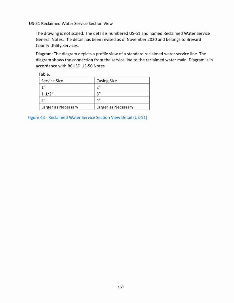
xlvi
US-51 Reclaimed Water Service Section View
The drawing is not scaled. The detail is numbered US-51 and named Reclaimed Water Service General Notes. The detail has been revised as of November 2020 and belongs to Brevard County Utility Services.
Diagram: The diagram depicts a profile view of a standard reclaimed water service line. The diagram shows the connection from the service line to the reclaimed water main. Diagram is in accordance with BCUSD US-50 Notes.
Table: Service Size Casing Size 1” 2” 1-1/2” 3” 2” 4” Larger as Necessary Larger as Necessary
Figure 43 - Reclaimed Water Service Section View Detail (US-51)

xlvii
US-52 Reclaimed Water Service Plan View
The drawing is not scaled. The detail is numbered US-52 and named Reclaimed Water Service Plan View. The detail has been revised as of November 2020 and belongs to Brevard County Utility Services.
Diagram: The diagram depicts a plan view of a standard reclaimed water service line with single service yoke. The diagram is in accordance with BCUSD Detail US-50 Notes.
Diagram 2: The diagram depicts a plan view of a standard reclaimed water service line with double service yokes. The diagram is in accordance with BCUSD Detail US-50 Notes.
Figure 44 - Reclaimed Water Service Plan View Detail (US-52)

xlviii
US-53 Reclaimed Water Sign
The drawing is not scaled. The detail is numbered US-53 and named Reclaimed Water Sign. The detail has been revised as of November 2020 and belongs to Brevard County Utility Services.
Diagram of Sign Type 1: Diagram depicts an example of Sign Type 1. This first sign is labeled “This area is irrigated with reclaimed water” on top and “Do not drink No Beber” on the bottom. Between the two sets of text there’s a diagram that shows a crossed-out hose bib and a glass of water below it. The diagram also shows a border of 3/8” width. The width, height and height of the lettering are marked as A, B and C respectively. The diagram of the crossed-out hose bib and glass of water below is labeled as D. All four borders of the sign have a radius identified as “R”.
Diagram of Sign Type 2: Diagram shows an example of Sign Type 2. The sign is labeled “Reclaimed Water” on top and “Do not drink Do (break) Not Swim (break) No Beber (break) No Nadar” on the bottom. Between the two sets of text there are two diagrams showing a crossed image of a person swimming and a crossed-out hose bib and glass of water below it. The diagram also depicts a border of 3/8” width. The width, height and height of the lettering are marked as A, B and C respectively. The two diagrams are labeled as D. All four borders of the sign have a radius identified as “R”.
Diagram of Sign Type 3: Diagram shows an example of Sign Type 3. The sign is labeled as “Reclaimed Water” on top and “Do Not Drink (break) No Beber” on the bottom. Between the two sets of text there is one diagram showing a crossed-out hose bib and glass of water below it. The diagram also shows a border of 3/8” width. The width, height and height of the lettering are marked as A, B and C respectively. The two diagrams are labeled as D. All four borders of the sign have a radius identified as “R”.
Notes: 1. Sign types 1 and 2 shall be 0.080-gauge aluminum with white letters and symbols on a
blue background, mounted on a "U" shaped galvanized post with the bottom of thesign 2' above grade.
2. Sign type 3 shall be of materials and design selected by the user so long as, at aminimum, it is 8" by 5" in size, contains all the words and symbols shown in the detailat the given dimensions, and is visible to the public.
3. Signs shall be placed at each entrance to the property to advise the public thatreclaimed water is used on the site.
4. Signs shall be placed at locations in sufficient number to advise the public thatreclaimed water is used on the site.
Figure 45 - Reclaimed Water Sign Detail (US-53)

xlix
Table: Occupancy Sign
Type A B C D R Notes
Subdivision/Multi-Fam Entrance
1 (R) 12” 18” 1” 4” 1.5” 1,3
Shopping Center Entrance
1 (R) 12” 18” 1” 4” 1.5” 1,3
Golf Course Entrance 1 (R) 12” 18” 1” 4” 1.5” 1,3 Individual Commercial Site *
1 9” 12” 0.75” 2.5” 1.5” 1,3
Individual Residential Site *
3 8” 5” 0.50” 1.25” 1.0” 2,4
Golf Course 1st and 10th Tees
3 8” 5” 0.50” 1.25” 1.0” 2
Stormwater Pond/Fountain
2 9” 12” 0.75” 2.5” 1.5” 1,4
Traffic Medians 1 9” 12” 0.75” 2.5” 1.5” 1,4 Rapid Infiltration Basins 2 9” 12” 0.75” 2.5” 1.5” 1,4

l
US-54 Reclaimed Water Service Connection
The drawing is scaled 1/2" = 1 foot. The detail is numbered US-54 and named Reclaimed Water Service Hose Bibb Connection. The detail has been revised as of November 2020 and belongs to Brevard County Utility Services.
Diagram 1: Diagram indicates piping as polyethylene DR-9 connected to a meter box The meter box is then connected to a 3/4" SCH 40 PVC Pantone 522C in color. The 3/4" brass bent nose garden valve is connected at the end of the SCH 40 PVC pipe locked in a 7” wide stainless-steel lockable hatch.
Diagram 2: Diagram indicates a profile view of the hose bib connection. The diagram shows an 18” tall concrete pad. The pole is about 12” within the concrete pad and 12” above ground. 12” above ground has a stainless-steel lockable hatch. The required signage is 13” high.
Notes: 1. Meter box shall be standard Brevard County reclaimed water type; set to match
finished grade, adjacent to sidewalk or property line. Meter box shall be supplied byUtility Services.
2. Reclaimed water hose bibb connections shall only be used for Brevard County UtilityServices lift stations. Hose bibb connections for any other use must be approved inwriting by Utility Services prior to installation.
Figure 46 - Reclaimed Water Service Connection Detail (US-54)

li
US-60 Pipe Separation
The drawing is not scaled. The detail is numbered US-60 and named Pipe Separation Table. The detail has been revised as of November 2020 and belongs to Brevard County Utility Services.
Table Description: Upper pipe for water must have 3 feet minimum horizontal clearance between pipes (outside
to outside), Note H; Lower pipe for water N/A Upper pipe for gravity sewer must have 10 feet minimum horizontal clearance between pipes
(outside to outside), Note A; Lower pipe for water must have 18 inches minimum vertical clearance between pipes (outside to outside), Note G
Upper pipe for Force Main must have 10 feet minimum horizontal clearance between pipes (outside to outside), Note A; Lower pipe for water must have 12 inches minimum vertical clearance between pipes (outside to outside), Note D
Upper pipe for reclaimed water must have 3 feet minimum horizontal clearance between pipes (outside to outside), Note D; Lower pipe for water must have 12 inches minimum vertical clearance between pipes (outside to outside), Note D
Upper pipe for storm water must have 3 feet minimum horizontal clearance between pipes (outside to outside), Note D; Lower pipe for water must have 2 feet minimum vertical clearance between pipes (outside to outside), Note E
Upper pipe for water must have 10 feet minimum horizontal clearance between pipes (outside to outside), Notes A & B; Lower pipe for gravity sewer must have 12 inches minimum vertical clearance between pipes (outside to outside), Note C
Upper pipe for gravity sewer must have 3 feet minimum horizontal clearance between pipes (outside to outside), Note H; Lower pipe for gravity sewer N/A
Upper pipe for Force Main must have 3 feet minimum horizontal clearance between pipes (outside to outside), Note H; Lower pipe for gravity sewer must have 6 inches minimum vertical clearance between pipes (outside to outside), Note J
Upper pipe for reclaimed water must have 6 feet minimum horizontal clearance between pipes (outside to outside), Note F; Lower pipe for gravity sewer must have 6 inches minimum vertical clearance between pipes (outside to outside), Note J
Upper pipe for storm water must have 3 feet minimum horizontal clearance between pipes (outside to outside), Note H; Lower pipe for gravity sewer must have 2 feet minimum vertical clearance between pipes (outside to outside), Note E
Upper pipe for water must have 10 feet minimum horizontal clearance between pipes (outside to outside), Note A; Lower pipe for Force Main must have 12 inches minimum vertical clearance between pipes (outside to outside), Note D
Upper pipe for gravity sewer must have 3 feet minimum horizontal clearance between pipes (outside to outside), Note H; Lower pipe for Force Main must have 6 inches minimum vertical clearance between pipes (outside to outside), Note J
Upper pipe for Force Main must have 3 feet minimum horizontal clearance between pipes (outside to outside), Note H; Lower pipe for Force Main N/A

lii
Upper pipe for reclaimed water must have 3 feet minimum horizontal clearance between pipes (outside to outside), Note G; Lower pipe for Force Main must have 6 inches minimum vertical clearance between pipes (outside to outside), Note J
Upper pipe for storm water must have 3 feet minimum horizontal clearance between pipes (outside to outside), Note H; Lower pipe for Force Main must have 2 feet minimum vertical clearance between pipes (outside to outside), Note E
Upper pipe for water must have 3 feet minimum horizontal clearance between pipes (outside to outside), Note D; Lower pipe for reclaimed water must have 12 inches minimum vertical clearance between pipes (outside to outside), Note D
Upper pipe for gravity sewer must have 3 feet minimum horizontal clearance between pipes (outside to outside), Note G; Lower pipe for reclaimed water must have 18 inches minimum vertical clearance between pipes (outside to outside), Note G
Upper pipe for Force Main must have 3 feet minimum horizontal clearance between pipes (outside to outside), Note G; Lower pipe for reclaimed water must have 18 inches minimum vertical clearance between pipes (outside to outside), Note G
Upper pipe for reclaimed water must have 3 feet minimum horizontal clearance between pipes (outside to outside), Note H; Lower pipe for reclaimed water N/A
Upper pipe for storm water must have 3 feet minimum horizontal clearance between pipes (outside to outside), Note H; Lower pipe for reclaimed water must have 2 feet minimum vertical clearance between pipes (outside to outside), Note E
Upper pipe for water must have 3 feet minimum horizontal clearance between pipes (outside to outside), Note D; Lower pipe for storm water must have 12 inches minimum vertical clearance between pipes (outside to outside), Note C
Upper pipe for gravity sewer must have 3 feet minimum horizontal clearance between pipes (outside to outside), Note H; Lower pipe for storm water must have 6 inches minimum vertical clearance between pipes (outside to outside), Note J
Upper pipe for Force Main must have 3 feet minimum horizontal clearance between pipes (outside to outside), Note H; Lower pipe for storm water must have 6 inches minimum vertical clearance between pipes (outside to outside), Note J
Upper pipe for reclaimed water must have 3 feet minimum horizontal clearance between pipes (outside to outside), Note H; Lower pipe for storm water must have 6 inches minimum vertical clearance between pipes (outside to outside), Note J
Upper pipe for storm water N/A; Lower pipe for storm water N/A Notes: A. 6-foot minimum separation (62-555.314 FAC)B. May be 3 feet if the water line is 6 inches above the gravity sewer (62-555.314 FAC)C. 6-inch minimum separation (62-555.314 FAC)D. 62-555.314 FACE. If less than 2 feet clearance is provided, support cradles are required (US-66)F. May be 3 feet if the reclaim line is 12 inches above the gravity sewer.G. Section 62-604.400 (2) (h), (i) FAC

liii
H. Or best engineering judgment.I. Minimum for repair purposes
Figure 47 - Pipe Separation Detail (US-60)

liv
US-61 Restraint Table PVC Pipe
The drawing is not scaled. The detail is numbered US-61 and named Restraint Table PVC Pipe. The detail has been revised as of November 2020 and belongs to Brevard County Utility Services.
Table: Fittings Size
4” Size 6”
Size 8”
Size 10”
Size 120”
Size 162”
Size 20”
Size 24”
Size 30”
90° Bend 58 82 107 128 149 189 227 262 309 45° Bend 24 34 45 53 62 78 93 108 128 22.5° Bend 12 16 22 26 30 38 45 53 62 11.25° Bend 5 8 11 12 15 19 23 26 31 Tee Branch 58 95 130 163 196 257 315 371 448 Dead End 90 128 166 201 235 298 359 419 500 In Line Valve 90 128 166 201 235 298 359 419 500
Notes: 1. All fittings shall be restrained joint type unless otherwise noted.2. Install full pipe length joints with total restrained length equal to, or greater than, the
length shown in the table.3. Where two or more fittings are together, use the fitting that requires the greatest
length of restrained pipe.4. In-line valves outside the limits of restrained joints from other fittings need only be
restrained at the valve, unless otherwise indicated.5. Length of restrained joint piping for reducers, reducing tees, and vertical position
fittings shall be designed on an individual basis, with design calculations for eachbeing submitted for review.
6. Lengths shown in the table have been calculated in accordance with the procedureoutlined in "Thrust Restraint Design for Iron Pipes" as published by DIPRA, with thefollowing assumptions:
a. Working Pressure: 70 psib. Design Pressure: 150 psic. Soil Designation: Silt 1d. Laying Conditions: Type 2e. Safety Factor: 2
Figure 48 - PVC Pipe Restraint Table Detail (US-61)

lv
US-62 Restraint Table Ductile Iron Pipe
The drawing is not scaled. The detail is numbered US-62 and named Restraint Table Ductile Iron Pipe. The detail has been revised as of November 2020 and belongs to Brevard County Utility Services.
Table: Fittings Size
4” Size 6”
Size 8”
Size 10”
Size 12”
Size 16”
Size 20”
Size 24”
Size 30”
90° Bend 43 (54)
61 (76)
79 (97)
95 (117)
110 (137)
140 (173)
168 (207)
194 (239)
229 (282)
45° Bend 18 (22)
25 (31)
33 (40)
39 (49)
46 (57)
58 (72)
69 (86)
80 (99)
95 (117)
22.5° Bend 9 (11) 12 (15)
16 (19)
19 (23)
22 (27)
28 (34)
33 (41)
39 (47)
46 (56)
11.25° Bend 4 (5) 6 (7) 8 (10) 9 (12) 11 (13)
14 (17)
17 (20)
19 (24)
23 (28)
Tee Branch 43 (61)
70 (99)
96 (137)
121 (172)
145 (207)
190 (272)
233 (333)
275 (393)
332 (475)
Dead End 67 (96)
95 (136)
123 (176)
149 (212)
174 (248)
221 (316)
266 (380)
310 (443)
370 (528)
In Line Valve 67 (96)
95 (136)
123 (176)
149 (212)
174 (248)
221 (316)
266 (380)
310 (443)
370 (528)
Notes: 1. All fittings shall be restrained joint type unless otherwise noted.2. Install full pipe length joints with total restrained length equal to, or greater than, the
length shown in the table.3. Where two or more fittings are together, use the fitting that requires the greatest
length of restrained pipe.4. In-line valves outside the limits of restrained joints from other fittings need only be
restrained at the valve, unless otherwise indicated.5. Length of restrained joint piping for reducers, reducing tees, and vertical position
fittings shall be designed on an individual basis, with design calculations for eachbeing submitted for review.
6. Lengths shown in the table have been calculated in accordance with the procedureoutlined in "Thrust Restraint Design for Iron Pipes" as published by DIPRA, with thefollowing assumptions:a. Working Pressure: 70 psib. Design Pressure: 150 psic. Soil Designation: Silt 1d. Laying Conditions: Type 2e. Safety Factor: 1.5
7. For pipe encased in polyethylene, use values shown in parenthesis or increase thegiven value by a factor of 1.2.

lvi
Figure 49 - Ductile Iron Pipe Restraint Table Detail (US-62)

lvii
US-63 Open Cut – Roadway
The drawing is scaled 1/2" = 1 foot. The detail is numbered US-63 and named Open Cut - Roadway. The detail has been revised as of November 2020 and belongs to Brevard County Utility Services.
Diagram: Diagram is a profile view of the Open Cut Roadway. The diagram indicates that the existing asphalt thickness should match or be 2” thickness, whichever is greater with FDOT Type SP 12.5. Below the top of layer of asphalt, 24” thickness of all roadway should be shown with flowable fill for all roadway open cuts. Diagram is in accordance with Notes below.
Notes: 1. "W" shall be a minimum of 6" wide and of sufficient width to accommodate necessary
compaction efforts. In the event the required minimum density is not achieved, loosematerial shall be removed, replaced and compacted to the required density orreplaced with full depth flowable fill. Density tests below the spring line of the pipeare required in addition to other testing requirements. In the event that full depthflowable fill is used as backfill, density requirements are waived.
2. Minimum allowable backfill density shall be 98% of the maximum density at optimummoisture content per AASHTO T-180.
3. Flowable fill shall comply with FDOT Standard Specifications for Road and BridgeConstruction, Section 121, latest edition.
4. These are minimum requirements. Additional restrictions may be necessary on a case- by-case basis, as approved by the roadway authority.
5. Contractor shall excavate bottom of trench to allow for bell section of pipe.6. All open cuts shall have flowable fill and temporary asphalt installed within 2 days of
excavation. Permanent asphalt including milling, if needed, shall be completed within30 days of excavation. Paving shall comply with applicable sections of FDOTspecifications for road and bridge construction, latest edition.
Figure 50 - Roadway Open Cut Detail (US-63)

lviii
US-64 Utility Crossing
The drawing is not scaled. The detail is numbered US-64 and named Utility Crossing. The detail has been revised as of November 2020 and belongs to Brevard County Utility Services.
Diagram: The diagram is a profile view of the Utility Crossing. Diagram depicts a sanitary sewer pipe of DIP or C900 PVC, followed by a three-band mission coupling encased in a minimum of 6” of concrete. Reclaimed or potable water main must meet the separation requirements outlined in BCUSD Detail US-60. The Diagram is in accordance with the Notes below.
Note: 1. Mission coupling shall be encased in a minimum of 6" of concrete.2. For clearance greater than 12" from water line, no special construction is required.3. Refer to US-60 for minimum required vertical separation.
Figure 51 - Utility Crossing Detail (US-64)

lix
US-65 Vertical Pipe Deflection
The drawing is not scaled. The detail is numbered US-65 and named Vertical Pipe Deflection. The detail has been revised as of November 2020 and belongs to Brevard County Utility Services.
Diagram: Diagram is a profile view of a County Standard Vertical Pipe Deflection. The diagram depicts an AWWA C900 DR 18 PVC pipe or approved equal below ground, followed by four (4) 45°-degree bends with portions of PVC pipe between them. The diagram depicts a utility perpendicular to the PVC pipe, the 45° bends are intended to deflect the pipe south of the utility perpendicular to it. #14 UF tracing wire is wrapped around the PVC pipe. Pipe separation between the PVC pipe and the perpendicular utility pipe shall meet the requirements outlined in BCUSD Detail US-60.
Notes: 1. Vertical pipe deflection to be used when insufficient cover exists to allow pressure
pipe to cross above storm sewer with 12" vertical separation and maintain 36"minimum cover to finish grade.
2. If vertical separation between pressure pipe and storm sewer is less than 24",concrete support cradles are required on the storm sewer.
3. Submit shop drawings for each particular situation.4. Joints for PVC and DIP shall be restrained.5. Air release valves shall not be installed on potable water or reclaimed water mains.
Figure 52 - Vertical Pipe Deflection Detail (US-65)

lx
US-66 Concrete Support Cradle
The drawing is scaled 3/8" = 1 foot. The detail is numbered US-66 and named Concrete Support Cradle Detail. The detail has been revised as of November 2020 and belongs to Brevard County Utility Services.
Diagram 1: Diagram 1 is a profile view of a concrete support cradle. The concrete cradles are placed over a storm sewer main that has clearance of 24” or less over a utility main.
Diagram 2: Diagram 2 is a cross sectional view of a concrete support cradle. The storm sewer is placed 18” from the edge and 12” within concrete pad.
Notes: 1. Minimum 3,000 psi Type I Portland Cement
Figure 53 - Concrete Support Cradle Detail (US-66)

lxi
US-67 Valve Box
The drawing is not scaled. The detail is numbered US-67 and named Valve Box. The detail has been revised as of November 2020 and belongs to Brevard County Utility Services.
Diagram: Diagram is a profile view of a Valve Box. Diagram depicts a piping set upon a concrete support block. Slightly above the piping is a 2” square operating nut. Just above that, is a cast iron adjustable valve box. A bronze or cast-iron cover is set at finish grade within an 18” x 18” x 4” thick concrete pad. 4’ of excess #14 UF tracing wire is wrapped around the adjustable valve box and piping. Diagram is in accordance with Notes below.
Notes: 1. Bronze or cast-iron cover marked "SEWER", "WATER", or "REUSE" as appropriate.2. Double wrap fittings in polyethylene sheeting prior to placing concrete.3. Valve boxes greater than 4' in length shall include an extension operator.4. Operating nut must be within 30" of top of valve box.5. Extension operator must be connected to valve operating nut with a 3/8" stainless
steel nut and bolt.6. Concrete blocking to be installed as to not interfere with the removal of MJ bolts.
Figure 54 - Valve Box Detail (US-67)

lxii
US-68 Subaqueous / Ditch Crossing
The drawing is not scaled. The detail is numbered US-68 and named Subaqueous / Ditch Crossing. The detail has been revised as of November 2020 and belongs to Brevard County Utility Services.
Diagram: Diagram is a profile view of a Subaqueous / Ditch Crossing. Diagram depicts a force main deflecting beneath an aqueous / ditch crossing with the use of four (4) 45° bends and stainless-steel straps. The diagram also depicts that concrete slabs of minimum 6” thickness shall be used at exposure point in ditch and a pipe encased in concrete that extends 2 feet beyond the toe of slope. Diagram is in accordance with Notes below.
Diagram 2: Diagram is a cross sectional view of the pipe segment encased in concrete. Diagram indicates that the pipe shall be 6” below and to the edge of the concrete.
Notes: 1. Warning signs required both sides of ditch (see Utility Main Crossing Sign detail)2. All joints shall be restrained.3. Air release valve shall not be installed on reclaimed water or potable water mains.
Figure 55 - Subaqueous / Ditch Crossing Detail (US-68)

lxiii
US-69 Utility Main Crossing Sign
The drawing is not scaled. The detail is numbered US-69 and named Utility Main Crossing Sign. The detail has been revised as of November 2020 and belongs to Brevard County Utility Services.
Diagram: The diagram is a sign. The text contains “Warning” (break) “Water main” (break) “Under Canal” (break) “for Location” (break) “Contact” (break) “633-2093”. The sign is 24” x 24”. The border has a white strip that is 3/8”. The text height is 2”. The text width is 0.25”. The background is blue and the text is white. The depth between lines of text is 1-1/4”. The four corners of the sign have a 1” radius. The diagram is in accordance with the Notes below.
Notes: 1. Signs shall 0.080-gauge aluminum with blue background, white letters and white
border.2. This sign shall be posted at both sides of subaqueous or ditch crossing.3. Post shall be "U" shaped and galvanized.4. Minimum 30" post embedment.5. Bottom of sign shall be 60" above grade.6. Force Main, Water Main, or Reuse Main (as appropriate).
Figure 56 - Utility Main Crossing Sign Detail (US-69)

lxiv
US-70 Casing Installation
The drawing is not scaled. The detail is numbered US-70 and named Casing Installation. The detail has been revised as of November 2020 and belongs to Brevard County Utility Services.
Diagram 1: Diagram is a profile view of pipes located below roadways, encased. Diagram depicts a roadway section and 10’ on either side of it. The roadway has a finished surface and a rock base. Below ground, a carrier pipe is shown, 36” below cover, with a steel casing. #14 UF tracing wire is wrapped around the pipe and casing.
Diagram 2: Diagram is a casing insulator detail in accordance with Note 3 below.
Diagram 3: Diagram is a cross sectional view of the casing insulator detail shown in Diagram 2. Detail is in accordance with Not 3 below.
Table: Carrier Pipe Size Steel Casing Min. wall Thickness 2” or less 4” .188 2.5” 4” .188 3” 6” .188 4” 12” .188 6” 14” .250 8” 16” .250 10” 18” .250 12” 22” .250 14” 24” .250 16” 26” .250 18” 30” .312 20” 30” .312 24” 36” .375 30” 42” .500 36” 48” .500 42” 54” .500 48” 72” .500
Notes: 1. All pipe joints in casing to be restrained.2. Casing pipe shall have a minimum yield strength of 35,000 psi3. Casing insulators may be utilized in lieu of skids. Casing insulators shall be fastened
with stainless steel hardware and shall have an outer diameter larger than that of therestrained joints. Casing insulators shall be installed on maximum of five-foot centersalong entire length of pipe.
4. C-900 PVC, HDPE DR-11, or D.I.P. required in casing.
Figure 57 - Casing Installation Detail (US-70)

lxv
US-71 Aerial Crossing Fan Guard
The drawing is scaled 1/2" = 1 foot. The detail is numbered US-71 and named Aerial Crossing Fan Guard. The detail has been revised as of November 2020 and belongs to Brevard County Utility Services.
Diagram: Front view of an aerial crossing fan guard. Fan Guards shall use 2”x1/2” flat bars as fans. The bars shall extend approximately 70 degrees on both sides of the center of the pipe. Rods shall have a 48” x 5/8” radial diameter. Diagram is in accordance with Notes below.
Diagram 2: Side view of an aerial crossing fan guard. Fan guards shall be 48” tall with a 36” wide 2”x2”x1/4” angle strut, all extending from the exposed pipe. Diagram is in accordance with Notes below.
Notes: 1. Steel shall be hot-dipped galvanized.2. Fan guard shall be primed and painted with two coats of alkyd exterior flat black
paint.3. All hardware to be hot-dipped galvanized.
Figure 58 - Aerial Crossing Fan Guard Detail (US-71)

lxvi
US-72 Aerial Canal Crossing
The drawing is not scaled. The detail is numbered US-72 and named Aerial Canal Crossing. The detail has been revised as of November 2020 and belongs to Brevard County Utility Services.
Diagram: Diagram is a profile view of an aerial canal crossing. Diagram depicts an exposed force main pipe across a body of water. Exposed piping is anchored by prestressed concrete piles Type 1A Min 12” x 12”. Diagram also indicates the use of rip rap on the shores. Air release valve shall be used at high points. Fan Guards shall also be used on either side of the Aerial Canal crossing. Diagram is in accordance with Notes below.
Notes: 1. Pipe shall be flanged ductile iron with stainless steel bolts.2. All exposed piping shall be blasted to near white metal. An inorganic zinc epoxy
primer and epoxy top coat shall be applied.3. Provision shall be made for expansion and contraction of the pipe by providing a
supported mechanical joint or other approved method.4. Pipes shall be tied to piles with stainless steel straps.5. Adequate anchoring and support shall be provided for pipes used in aerial crossings.
Pilings and anchoring are to be designed by a qualified engineer. Signed and sealedcalculations and design data are to be submitted by the engineer for approval.
Figure 59 - Aerial Canal Crossing Detail (US-72)

lxvii
US-73 Bollard Detail
The drawing is not scaled. The detail is numbered US-73 and named Bollard Detail. The detail has been revised as of November 2020 and belongs to Brevard County Utility Services.
Diagram: Diagram is profile view of bollards. The diagram depicts a 3.5’ deep by 1.5’ wide concrete pad. A 6’ tall bollard (approximately 3.5’ below grade) is shown. The bollard shall be an OSHA safety yellow color of finished coat. The bollard is a 6” SCH 40 steel pipe to be filled with concrete. Concrete pad shall be sloped for drainage. The top of the bollard should be of a domed concrete top.
Figure 60 - Bollard Detail (US-73)

lxviii
US-74 Utility Markers
The drawing is not scaled. The detail is numbered US-74 1 of 2 and named Tremie Wet Well Installation Detail. The detail has been revised as of November 2020 and belongs to Brevard County Utility Services.
Diagram 1: The diagram is a plan view of the utility marker. The utility marker is a 3” diameter identification disc with the following text “24”” “BCUSD” “GV-DI FM” “O/L – 50”. Additionally, below all lines of text is a flow arrow. The minimum space is 0.25” and the minimum letter size is 0.33”
Acceptable Notations: - GV - Gate Valve- ARV - Air Release Valve- FM - Force Main- RU - Reuse Main- RW - Raw Water- PW - Potable Water- PV - Plug Valve- CV - Check Valve- DI - Ductile Iron- PVC - Polyvinyl chloride- O/L - Open left- O/R - Open right
Notes: 1. 3" diameter bronze identification disc embedded in the concrete.2. Pipe Size connected to Valve.3. Brevard County Utility Services Department.4. Type of Valve - Type of Pipe that Valve is connected to.5. Open Left - Number of turns.6. Flow direction7. Minimum letter size 0.33", Minimum space 0.25"8. Place at NW corner with 2" minimum clearance from edge/joints in concrete.
Figure 61 - Utility Marker Detail (US-74)

APPROVED MANUFACTURERS AND PRODUCTS
Note: Products used in the utility must be produced domestically.
WASTEWATER SERVICE MATERIALS
Adhesive Marking Tape
MANUFACTURER MODEL or SPECIFICATION
Reef Industries Terra Tape
Harris Industries DU series
Air Release and Vacuum Valves
MANUFACTURER MODEL or SPECIFICATION
A.R.I. Flow Control D-025
Vent-O-Mat RBX Series
Casing Spacers
MANUFACTURER MODEL or SPECIFICATION
Cascade Water Works CCS
CCI Pipeline Systems CSS-8; CSS-12
Check Valves
MANUFACTURER MODEL or SPECIFICATION
American Weighted lever
Kennedy, Mueller Weighted lever
U.S. Pipe, Val-Matic Weighted lever

APPROVED MANUFACTURERS AND PRODUCTS
2 Note: Products used in the utility must be produced domestically
Concrete coatings (Spray On Liners)
MANUFACTURER MODEL or SPECIFICATION
Raven 405
Madewell Products Corp. Mainstay DS-5 (over ML-72)
Tnemec 218; 434, 435
Sherwin Williams Duraplate 6100
Quadex / Vortex Companies Structure Guard
Drop Bowls
MANUFACTURER MODEL or SPECIFICATION
Reliner N/A
Ductile Iron Fittings
MANUFACTURER MODEL or SPECIFICATION
American ANSI/AWWA C111/A21.10
Tyler Union ANSI/AWWA C111/A21.53
U.S. Pipe
Sigma
Star
Ductile Iron Pipe
MANUFACTURER MODEL or SPECIFICATION
Any manufacturer ANSI AWWA C116/A21.18-09; ANSI AWWA C150/A21.50-14; ANSI AWWA C1541/A21.51-09-14
not applicable

APPROVED MANUFACTURERS AND PRODUCTS
3 Note: Products used in the utility must be produced domestically
Ductile Iron Pipe Lining
MANUFACTURER MODEL or SPECIFICATION
Tnemec Protecto
431 401
Electronic Markers
MANUFACTURER MODEL or SPECIFICATION
3M 1404-XR (ball) 1253 (full range)
Fiberglass Liners
MANUFACTURER MODEL or SPECIFICATION
LFM-FRP AFE
Minimum 0.75-inch thickness
Gate Valves- Resilient Wedge
MANUFACTURER MODEL or SPECIFICATION
American ANSI/AWWA C509 or C515
Clow
Mueller
HDPE Liners for Wet Wells
MANUFACTURER MODEL or SPECIFICATION
AGRU Sure-grip (3mm)
Hansen Products PP-R (3 mm)

APPROVED MANUFACTURERS AND PRODUCTS
4 Note: Products used in the utility must be produced domestically
HDPE Pipe
MANUFACTURER MODEL or SPECIFICATION
Any manufacturer AWWA C-906-07 specifications; PE 4710 designation
Joint Sealing Compound
MANUFACTURER MODEL or SPECIFICATION
Any manufacturer Fed Spec SSS-210A Type 1; AASHTO M198 Type B
Joint Restraints
MANUFACTURER MODEL or SPECIFICATION
Nappco
Sigma
Ford Uniflange
EBAA Iron 2000PV, 2000SV, 1100, 1100HD,1500, 1700, 1900
Romac Grip Ring
Tyler Union Series 3000 Bell Restraint
Tyler Union Tuf-Grip Dual Wedge
Manhole Coatings
MANUFACTURER MODEL or SPECIFICATION
Pro-Tech Coatings Pro-Tech EW-1
Conseal CS-55

APPROVED MANUFACTURERS AND PRODUCTS
5 Note: Products used in the utility must be produced domestically
Manhole Exterior Shrink
MANUFACTURER MODEL or SPECIFICATION
WrapCansa-CPS WrapidSeal
GPT Riser-Wrap
Manhole Adjustment Rings - Concrete
MANUFACTURER MODEL or SPECIFICATION
Any manufacturer FDOT Section 949
Manhole Adjustmnent Rings - HDPE
MANUFACTURER MODEL or SPECIFICATION
Ladtech, Inc
Non-Shrink Grout
MANUFACTURER MODEL or SPECIFICATION
Embeco
Pipe Couplings
MANUFACTURER MODEL or SPECIFICATION
Dresser
Fernco 5000 Series "Strong Back" Couplings
Hymax
Mission 3 band
Romac

APPROVED MANUFACTURERS AND PRODUCTS
6 Note: Products used in the utility must be produced domestically
Plug Valves
MANUFACTURER MODEL or SPECIFICATION
DeZurik
Milliken/Pratt/Mueller
PVC Fittings
MANUFACTURER MODEL or SPECIFICATION
Any manufacturer ASTM D-3034
PVC Pipe - Force Main Integral Bell
MANUFACTURER MODEL or SPECIFICATION
Any manufacturer C-900 DR-18 (4"-12")
PVC Pipe - Gravity Main Integral Bell
MANUFACTURER MODEL or SPECIFICATION
Any manufacturer ASTM D-3034;
Resilient Connectors
MANUFACTURER MODEL or SPECIFICATION
NPC Kor-N-Seal
Substrate Patching Material
MANUFACTURER MODEL or SPECIFICATION
Fosroc Preco Patch
IPA Systems Octocrete
Quadex Hydra-Plug
Madewell Products Corp. Mainstay ML-10
Sauereisen Instaplug No. F-180

APPROVED MANUFACTURERS AND PRODUCTS
7 Note: Products used in the utility must be produced domestically
Stainless Ball Valve
MANUFACTURER MODEL or SPECIFICATION
Merit Brass 316SS
Tapping Saddle
MANUFACTURER MODEL or SPECIFICATION
Ford Brass alloy bodies / 304 Stainless Bands
Romac
Mueller
Tapping Sleeves
MANUFACTURER MODEL or SPECIFICATION
JCM Industries JCM 432 / JCM 452
Mueller H 304
Total Piping Solutions Triple Tap
Tracer Wire
MANUFACTURER MODEL or SPECIFICATION
Any manufacturer #14 UF Insulated Solid Copper Wire
Traffic Bearing Clean Out
MANUFACTURER MODEL or SPECIFICATION
US Foundry 7610

APPROVED MANUFACTURERS AND PRODUCTS
8 Note: Products used in the utility must be produced domestically
Valve Boxes
MANUFACTURER MODEL or SPECIFICATION
American Heavy Duty
Tyler Union Heavy Duty
Sigma Heavy Duty
Valve Extensions
MANUFACTURER MODEL or SPECIFICATION
Geneco Stainless Steel

APPROVED MANUFACTURERS AND PRODUCTS
9 Note: Products used in the utility must be produced domestically
LIFT STATION MATERIALS
Access Frames and Covers
MANUFACTURER MODEL or SPECIFICATION
U.S. Foundry
Halliday
Bilco
Drop Bowls
MANUFACTURER MODEL or SPECIFICATION
Reliner
Fall Protection
MANUFACTURER MODEL or SPECIFICATION
US Foundry Standard Dual Hatch Safety Grate
Halliday
Float Regulators
MANUFACTURER MODEL or SPECIFICATION
Anchor Scientific Inc S40NO-CPE
Pressure Gauges
MANUFACTURER MODEL or SPECIFICATION
Ashcroft Model 45 1009S 04L XSG 100#/FW
Winters PFP
Pressure Transducers
MANUFACTURER MODEL or SPECIFICATION
Contegra SLX 130-M-10-40R-B

APPROVED MANUFACTURERS AND PRODUCTS
10 Note: Products used in the utility must be produced domestically
Pressure Transducer Hanger
MANUFACTURER MODEL or SPECIFICATION
Contegra CH-SLX1
Submersible Pumps
MANUFACTURER MODEL or SPECIFICATION
ABS
Flygt
Waterstop
MANUFACTURER MODEL or SPECIFICATION
Sika
Avanti AV-202
DeNeef Swell Seal
Quadex / Vortex Companies I&I Guard

APPROVED MANUFACTURERS AND PRODUCTS
11 Note: Products used in the utility must be produced domestically
WATER SERVICE MATERIALS
Adhesive Marking Tape
MANUFACTURER MODEL or SPECIFICATION
Reef Industries Terra Tape
Harris Industries DU series
Backflow Prevention
MANUFACTURER MODEL or SPECIFICATION
Febco AWWA C506
Watts
Zurn Wilkins
Ball Valves
MANUFACTURER MODEL or SPECIFICATION
Allis-Chalmers ANSI/AWWA C507
Pratt
Mueller
Casing Spacers
MANUFACTURER MODEL or SPECIFICATION
Cascade Water Works CCS
CCI CSS-8, CSS-12
Corporation Stops
MANUFACTURER MODEL or SPECIFICATION
Mueller Ball Valve; Full Port
Ford

APPROVED MANUFACTURERS AND PRODUCTS
12 Note: Products used in the utility must be produced domestically
Curb Stops
MANUFACTURER MODEL or SPECIFICATION
Mueller Ball Valve; Full Port
Ford
Ductile Iron Fittings
MANUFACTURER MODEL or SPECIFICATION
American ANSI/AWWA C110/A21.10-12
Tyler Union
U.S. Pipe
Sigma
Star
Ductile Iron Pipe (cement lined)
MANUFACTURER MODEL or SPECIFICATION
Any manufacturer ANSI/AWWA C104/A21.10; ANSI AWWA C150/A21.50-14; ANSI AWWA C1541/A21.51-09-14; ANSI/AWWA A536
Electronic Markers
MANUFACTURER MODEL or SPECIFICATION
3M 1403-XR (ball)
Fire Hydrants
MANUFACTURER MODEL or SPECIFICATION
American ANSI/AWWA C-502
Clow
Mueller
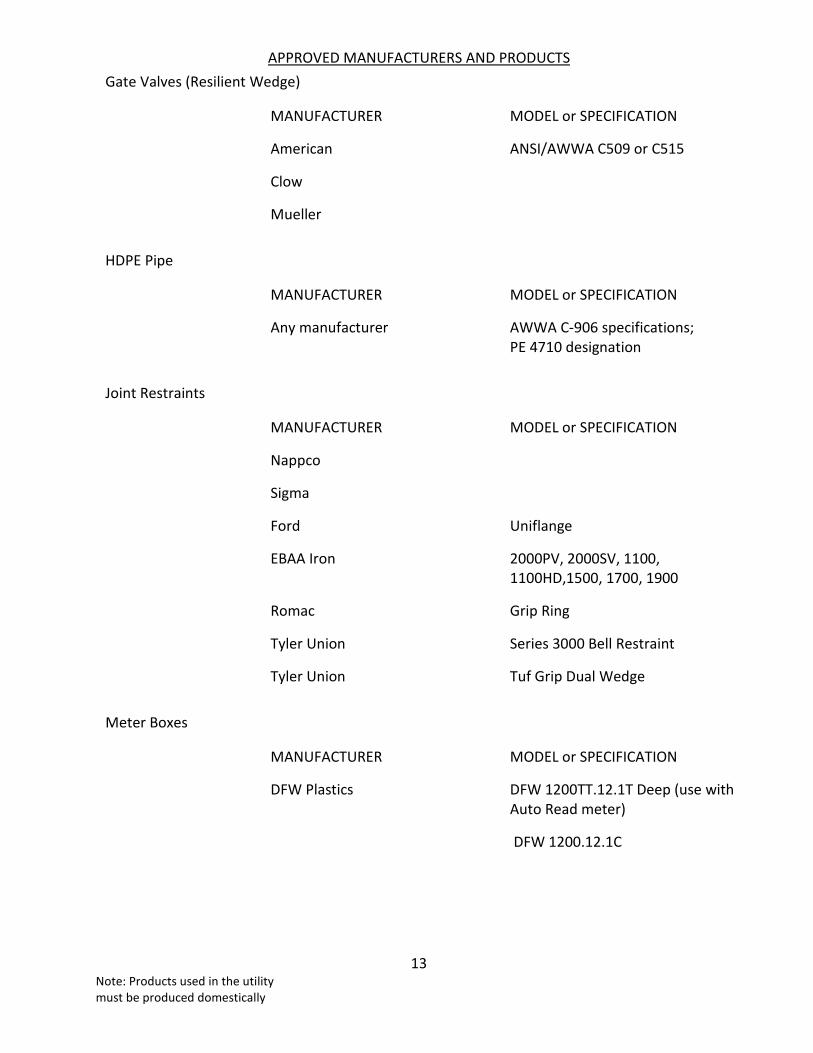
APPROVED MANUFACTURERS AND PRODUCTS
13 Note: Products used in the utility must be produced domestically
Gate Valves (Resilient Wedge)
MANUFACTURER MODEL or SPECIFICATION
American ANSI/AWWA C509 or C515
Clow
Mueller
HDPE Pipe
MANUFACTURER MODEL or SPECIFICATION
Any manufacturer AWWA C-906 specifications; PE 4710 designation
Joint Restraints
MANUFACTURER MODEL or SPECIFICATION
Nappco
Sigma
Ford Uniflange
EBAA Iron 2000PV, 2000SV, 1100, 1100HD,1500, 1700, 1900
Romac Grip Ring
Tyler Union Series 3000 Bell Restraint
Tyler Union Tuf Grip Dual Wedge
Meter Boxes
MANUFACTURER MODEL or SPECIFICATION
DFW Plastics DFW 1200TT.12.1T Deep (use with Auto Read meter)
DFW 1200.12.1C

APPROVED MANUFACTURERS AND PRODUCTS
14 Note: Products used in the utility must be produced domestically
Meter, Fire Services
MANUFACTURER MODEL or SPECIFICATION
Neptune Technology Group Neptune HPP IIIS Fire Service Compound Meter with Procoder R900i Pit Gallon Registers
Polyethylene Tubing
MANUFACTURER MODEL or SPECIFICATION
Endot Industries Endo Pure PE 4710 DR 9
Performance Pipe PE 4710
Pipe Couplings
MANUFACTURER MODEL or SPECIFICATION
Dresser
Fernco 5000 Series "Strong Back" Couplings
Hymax
Mission 3-band
Macro
PVC Pipe, Integral Bell
MANUFACTURER MODEL or SPECIFICATION
Any manufacturer C-900 DR-18 (4"-12"); C-905 DR-25 (+12")

APPROVED MANUFACTURERS AND PRODUCTS
15 Note: Products used in the utility must be produced domestically
Service Saddles
MANUFACTURER MODEL or SPECIFICATION
Ford Brass alloy bodies / 304 Stainless Bands
Kennedy
Mueller
Rockwell
Tapping Sleeves
MANUFACTURER MODEL or SPECIFICATION
American
JCM Industries JCM 432 / JCM 452
Mueller H 304
Total Piping Solutions Triple Tap
Tracer Wire
MANUFACTURER MODEL or SPECIFICATION
Any manufacturer #14 UF Insulated Solid Copper Wire
Valve Boxes
MANUFACTURER MODEL or SPECIFICATION
American Heavy Duty
Tyler Union Heavy Duty
Sigma Heavy Duty
Valve Extensions
MANUFACTURER MODEL or SPECIFICATION
Geneco Stainless Steel

APPROVED MANUFACTURERS AND PRODUCTS
16 Note: Products used in the utility must be produced domestically
RECLAIMED WATER SERVICE MATERIALS
Adhesive Marking Tape
MANUFACTURER MODEL or SPECIFICATION
Reef Industries Terra Tape
Harris Industries DU series
Casing Spacers
MANUFACTURER MODEL or SPECIFICATION
Cascade Water Works CCS
CCI CSS-8, CSS-12
Corporation Stops
MANUFACTURER MODEL or SPECIFICATION
Mueller Ball Valve, Full Port
Ford
Ball Corporation
Curb Stops
MANUFACTURER MODEL or SPECIFICATION
Mueller Ball Valve, Full Port
Hydrosoft
Ford
Ball Corporation

APPROVED MANUFACTURERS AND PRODUCTS
17 Note: Products used in the utility must be produced domestically
Ductile Iron Fittings
MANUFACTURER MODEL or SPECIFICATION
American ANSI/AWWA C111/A21.10
Tyler Union ANSI/AWWA C111/A21.53
U.S. Pipe
Sigma
Star
Ductile Iron Pipe
MANUFACTURER MODEL or SPECIFICATION
Any manufacturer ANSI/AWWA C104/A21.10; ANSI AWWA C150/A21.50-14; ANSI AWWA C1541/A21.51-09-14; ANSI/AWWA A536
Electronic Markers
MANUFACTURER MODEL or SPECIFICATION
3M 1408-XR (ball)
Gate Valves- Resilient Wedge
MANUFACTURER MODEL or SPECIFICATION
American ANSI/AWWA C509 or C515
Clow
Mueller
Hose Bibb Lockable Box
MANUFACTURER MODEL or SPECIFICATION
Allied Moulded Products AMP1206LF

APPROVED MANUFACTURERS AND PRODUCTS
18 Note: Products used in the utility must be produced domestically
HDPE Pipe
MANUFACTURER MODEL or SPECIFICATION
Any manufacturer AWWA C-906 specifications; PE 4710 designation
Joint Restraints
MANUFACTURER MODEL or SPECIFICATION
Nappco
Sigma
Ford Uniflange
EBAA Iron 2000PV, 2000SV, 1100, 1100HD,1500, 1700, 1900
Romac Grip Ring
Tyler Union Series 3000 Bell Restraint
Tyler Union Tuf-Grip Dual Wedge
Meter Box
MANUFACTURER MODEL or SPECIFICATION
DFW Plastics DFW1200.12.1C (purple)
Polyethylene Tubing
MANUFACTURER MODEL or SPECIFICATION
Endot Industries Endo Pure PE 4710
Performance Pipe PE 4710

APPROVED MANUFACTURERS AND PRODUCTS
19 Note: Products used in the utility must be produced domestically
Pipe Couplings
MANUFACTURER MODEL or SPECIFICATION
Dresser
Fernco 5000 Series "Strong Back" Couplings
Hymax
Mission 3 band
Romac
PVC Pipe - Integral Bell
MANUFACTURER MODEL or SPECIFICATION
Any manufacturer C-900 DR-18 (4"-12"); C-905 DR-25 (+12")
Service Saddles
MANUFACTURER MODEL or SPECIFICATION
Ford Bronze body/ 316 Stainless Bands
Kennedy
Mueller
Rockwell
Tapping Sleeves
MANUFACTURER MODEL or SPECIFICATION
American
JCM Industries JCM 432 / JCM 452
Mueller H304
Total Piping Solutions Triple Tap

APPROVED MANUFACTURERS AND PRODUCTS
20 Note: Products used in the utility must be produced domestically
Tracer Wire
MANUFACTURER MODEL or SPECIFICATION
Any manufacturer #14 UF Insulated Solid Copper Wire
Valve Boxes
MANUFACTURER MODEL or SPECIFICATION
American Heavy Duty
Tyler Union Heavy Duty
Sigma Heavy Duty
Valve Extensions
MANUFACTURER MODEL or SPECIFICATION
Geneco Stainless Steel

Cross Reference
GENERAL INFORMATION
General 2018 Criteria
2021 Criteria
Intention 1.1.1 1.1.1
Applicability 1.1.2 1.1.2
County Owned System 1.1.2 (1) 1.1.2 (1)
System Connected to County System 1.1.2 (2) 1.1.2 (2)
System Not Connected to County System Deleted Deleted
State Laws 1.1.1 1.1.1
Deviations 1.1.3 1.1.3
Private System Criteria 1.1.4 1.1.4
Master Plans 1.1.5 1.1.5
Plan Approval 1.1.12 1.1.12
Phased Construction 1.1.13 1.1.13
Capacity 1.1.14 1.1.14
Drawings and Calculations 2018 Criteria
2021 Criteria
Drawing Size 1.1.7 1.1.7.1
Plan and Profile; Scale 1.1.8 1.1.8
Signatures 1.1.9 1.1.9
Master Utility Plan 1.1.10 1.1.10
Calculations 1.1.11 1.1.11
Correlations Between Drawings and Specs. 1.3.1 1.3.1
Disclaimer 1.3.3 1.3.3
Engineer’s Responsibility 1.3.3 1.3.3

Cross Reference
CR-2
Drawings and Calculations 2018 Criteria
2021 Criteria
Omissions 1.4.7 1.4.7
Changes; Preconstruction Conference 1.4.8 1.4.8
Approved Drawings 1.9.1 1.9.1
Lines and Grades 1.9.4 1.9.4
Min. Elevations for Rear Lot Utilities 2.1.7 2.1.7
Easements and Rights-of-Way 2018 Criteria
2021 Criteria
Location of Utilities 1.2.1 1.2.1
Easement Width 1.2.2 1.2.2
Proof of Conformity 1.4.1 1.4.1
Approved Equal 1.4.1 1.4.1
Construction Methods 1.4.2 1.4.2
Repairs During Maintenance Bond 1.4.3 1.4.3
Special Materials 1.4.4 1.4.4
Protection of Existing Utilities 2018 Criteria
2021 Criteria
Protection of Existing Survey Monuments 1.4.9 1.4.9
Public Property 1.6.1 1.6.1
Roads 1.6.1 1.6.1
Existing Utilities 1.6.2 1.6.2
Coordination 1.6.3 1.6.3
Repair of Damaged Utilities 1.6.3 1.6.3
Operation of Valves and Controls 1.6.8 1.6.8
Connections 1.6.9 1.6.9

Cross Reference
CR-3
Inspection 2018 Criteria
2021 Criteria
Jurisdiction and Duties 1.7.1 1.7.1
Conformance to Plans, Specs and Criteria 1.7.2 1.7.2
Prohibited Activities 1.7.2 1.7.2
Rejection of Work and Materials 1.7.3 1.7.3
Scheduled Inspections 1.7.4 1.7.4
Final Inspection 1.7.5 1.7.5
Notice 1.7.6 1.7.6
Work Hours 1.7.7 1.7.7
Overtime 1.7.7 1.7.7
Holidays 1.7.9 1.7.9
Record Drawings 2005 Criteria
2021 Criteria
Locations and Elevations 1.12.1 1.12.1
Water and Reclaimed Water 1.12.2 1.12.2
Certification 1.12.3 1.12.3
Sewer 1.12.9 1.12.9
Review and Approval 1.12.1 1.12.1
State Plane Coordinate Requirements 1.12.4 1.12.4
Distances 1.12.5 1.12.5
Scale Requirements 1.12.7 1.12.7
Control Stations 1.12.4 1.12.4
Electronic Data File 1.12.8 1.12.8

Cross Reference
CR-4
Acceptance 2018 Criteria
2021 Criteria
Isolation 1.6.7 1.6.7
As-Built Drawings 1.12 1.12
Acquisition 1.13 1.13
Compliance with County Standards 1.13.2 1.13.2
Documentation 1.13.3 1.13.3
Maintenance Bond 1.13.3.1 1.13.3.1
Certification of Completion 1.13.3.2 1.13.3.2
Access to Gated Communities 1.13.3.3 1.13.3.3
Release of Lien 1.13.3.4 1.13.3.4
Warranty Deed and Survey 1.13.3.4 1.13.3.4
Other Items 1.13.3.4 1.13.3.4
Privately Owned Systems 2018 Criteria
2021 Criteria
Authorization 1.8.1 1.8.1
Connection Requirements 1.8.2 1.8.2
Letter of Responsibility 1.8.2.1 1.8.2.1
As-Built Drawings 1.8.2.2 1.8.2.2
Certificate of Completion; Bacteriological Clearance 1.8.2.3 1.8.2.3
Certificate of Completion; Multi-unit Connections 1.8.3 1.8.3
Connection 1.8.4 1.8.4
Acceptance for County Ownership 1.8.5 1.8.5

Cross Reference
CR-5
SANITARY SEWERAGE SYSTEM
General 2018 Criteria
2021 Criteria
Design Factors 2.1.4 2.1.4
Peak Flows 2.1.6 2.1.6
Industrial Waste 2.1.4 2.1.4
Hydraulics 2.1.4 2.1.4
Topography 2.1.4 2.1.4
Florida Administrative Code 2.1.1 2.1.1
"Ten States Standards" 2.1.3 2.1.3
Abandonment of On-Site Treatment 2.8 2.8
Bench Marks 1.9.5 1.9.5
DEP Permit Forms 2.1.5 2.1.5
System Adequacy 2.1.4 2.1.4
Markings 1.9.7 1.9.7
Cast in Place Concrete TS 03050 TS 03050
Cement TS 03050 TS 03050
Application TS 03050 TS 03050
Mixing TS 03050 TS 03050
Castings 1.4.5 1.4.5
Specification 1.4.5 1.4.5
Traffic Bearing Frames and Covers 1.4.5 1.4.5
Excavation and Backfill TS 02300 TS 02300
Machine Excavation -General TS 02300 TS 02300
Type "B" Material TS 02300 TS 02300
Type "D" Material TS 02300 TS 02300
Trees and Stumps TS 02300 TS 02300
Alignment TS 02300 TS 02300

Cross Reference
CR-6
General 2018 Criteria
2021 Criteria
Trench TS 02300 TS 02300
Unsuitable Material TS 02300 TS 02300
Initial Backfill TS 02300 TS 02300
Final Backfill TS 02300 TS 02300
Density Tests TS 02300 TS 02300
Street Restoration 1.9.8 1.9.8
Pipe laying and Joining TS 02080 TS 02080
Water Control TS 02240 TS 02240
Contractor's Responsibilities TS 02240 TS 02240
Boils and "Quick" Conditions TS 02240 TS 02240
Water Drawdown TS 02240 TS 02240
Material Handling 1.9.10 1.9.10
Gravity Sewer Systems 2018 Criteria
2021 Criteria
Size 2.3.1 2.3.1
Slopes 2.3.2 2.3.2
Stubbed Sewers 2.3.3 2.3.3
Future Service 2.3.3 2.3.3
Increasing Size 2.3.4 2.3.4
Pipe Materials TS 02080 TS 02080
Special Construction; 1.10 1.10
Subaqueous crossings US-68 US-68
Aerial Crossing US-72 US-72
Special Pipe Requirement from Lift Station to First Manhole
US-30 US-30

Cross Reference
CR-7
Gravity Sewer Systems 2018 Criteria
2021 Criteria
Horizontal and Vertical Separation 1.1.15 1.1.15
Vertical Separation of Water and Sanitary Sewer Mains
1.1.15 1.1.15
Vertical Separation of Reclaimed Water and Sanitary Sewer Mains
1.1.15 1.1.15
Joint Spacing Requirements for Crossings US-64 US-64
Horizontal Spacing Requirements 1.1.15 1.1.15
Separation Not Possible US-64 US-64
Storm Sewer Crossings US-66 US-66
Cover TS 02080 TS 02080
Flushing and Infiltration TS 02080 TS 02080
Field Testing TS 02080 TS 02080
Infiltration, Exfiltration, Inspection 2.7.1 2.7.1
Allowable Leakage 2.7.2 2.7.2
Cleanouts US-12 US-12
Building Service Manifolds 2.3.5 2.3.5
Lateral Staking US-11 US-11
Electronic Disks TS 02080 TS 02080
PVC Pipe TS 02080 TS 02080
Specifications TS 02080 TS 02080
Mission Couplings TS 02080 TS 02080
Joints TS 02080 TS 02080
Fittings TS 02080 TS 02080
Lateral Fittings TS 02080 TS 02080
Identification TS 02080 TS 02080
Ductile Iron Pipe TS 02080 TS 02080

Cross Reference
CR-8
Gravity Sewer Systems 2018 Criteria
2021 Criteria
Specifications TS 02080 TS 02080
Fittings TS 02080 TS 02080
Mechanical Joints TS 02080 TS 02080
Bolts TS 02080 TS 02080
Push-on Joints TS 02080 TS 02080
Identification TS 02080 TS 02080
Manholes 2.4 2.4
Spacing 2.4.1 2.4.1
Shop Drawings 1.3.4 1.3.4
Reinforcement and Wall Thickness US-20 US-20
Wall Thickness/Concrete US-20 US-20
Cement US-20 US-20
Joints US-20 US-20
Lifting US-20 US-20
Base US-21 US-21
Pipe Protrusion US-20 US-20
Invert Channels US-28 US-28
Cone US-21 US-21
Ring and Cover US-27 US-27
Lateral Connections US-20 US-20
Connectors US-20 US-20
Grout TS 03600 TS 03600
"Dog House" Manhole US-26 US-26
Core Drilling 2.6.9.4 2.6.9.4
Excavation 2.4.1 2.4.1
Elevation Checks Deleted Deleted
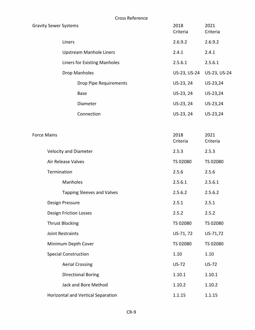
Cross Reference
CR-9
Gravity Sewer Systems 2018 Criteria
2021 Criteria
Liners 2.6.9.2 2.6.9.2
Upstream Manhole Liners 2.4.1 2.4.1
Liners for Existing Manholes 2.5.6.1 2.5.6.1
Drop Manholes US-23, US-24 US-23, US-24
Drop Pipe Requirements US-23, 24 US-23,24
Base US-23, 24 US-23,24
Diameter US-23, 24 US-23,24
Connection US-23, 24 US-23,24
Force Mains 2018 Criteria
2021 Criteria
Velocity and Diameter 2.5.3 2.5.3
Air Release Valves TS 02080 TS 02080
Termination 2.5.6 2.5.6
Manholes 2.5.6.1 2.5.6.1
Tapping Sleeves and Valves 2.5.6.2 2.5.6.2
Design Pressure 2.5.1 2.5.1
Design Friction Losses 2.5.2 2.5.2
Thrust Blocking TS 02080 TS 02080
Joint Restraints US-71, 72 US-71,72
Minimum Depth Cover TS 02080 TS 02080
Special Construction 1.10 1.10
Aerial Crossing US-72 US-72
Directional Boring 1.10.1 1.10.1
Jack and Bore Method 1.10.2 1.10.2
Horizontal and Vertical Separation 1.1.15 1.1.15

Cross Reference
CR-10
Force Mains 2018 Criteria
2021 Criteria
Vertical Separation of Water and Sanitary Sewer Mains
1.1.15 1.1.15
Vertical Separation of Reclaimed Water and Sanitary Sewer Mains
1.1.15 1.1.15
Joint Spacing Requirements for Crossings US-64 US-64
Storm Sewer Crossings US-66 US-66
Horizontal Spacing Requirements 1.1.15 1.1.15
Electronic Disks and Wire TS 02080 TS 02080
Hydrostatic Tests TS 02080 TS 02080
Duration and Pressure TS 02080 TS 02080
Leakage TS 02080 TS 02080
Test Pump TS 02080 TS 02080
Defects TS 02080 TS 02080
Notice TS 02080 TS 02080
When Test May Be Performed TS 02080 TS 02080
PVC Pipe TS 02080 TS 02080
4" thru 12" TS 02080 TS 02080
14" and Larger TS 02080 TS 02080
3½" and Smaller 2.5.4 Fittings 2.5.4 Fittings
2" and smaller TS 02080 Fittings
TS 02080 Fittings
2½" thru 12" TS 02080 TS 02080
Joints and Gaskets Larger than 2" TS 02080 TS 02080
Identification TS 02080 TS 02080
Ductile Iron Pipe TS 02080 TS 02080
Specifications TS 02080 TS 02080
Fittings TS 02080 TS 02080

Cross Reference
CR-11
Force Mains 2018 Criteria
2021 Criteria
Mechanical Joints TS 02080 TS 02080
Bolts TS 02080 TS 02080
Push-on Joints TS 02080 TS 02080
Identification TS 02080 TS 02080
High Density Polyethylene Pipe (HDPE) TS 02080 TS 02080
Specifications TS 02080 TS 02080
4” through 10” TS 02080 TS 02080
12” and Larger TS 02080 TS 02080
Stainless Steel Stiffener Inserts TS 02080 TS 02080
Molded Fitting Specifications TS 02080 TS 02080
HDPE Butt Fusion Joining TS 02080 TS 02080
Contractor Fusion Certification TS 02080 TS 02080
Butt Fusion Procedure TS 02080 TS 02080
Fittings and Valves TS 02080 TS 02080
Gate Valves TS 02080 TS 02080
Specifications TS 02080 TS 02080
Manufacturers App A App. A
Flanges TS 02080 TS 02080
Tapping Sleeves and Valves TS 02080 TS 02080
Specifications TS 02080 TS 02080
Manufacturers App. A App. A
Plug Valves TS 02080 TS 02080
Specifications TS 02080 TS 02080
Manufacturers App. A App. A
Steel Couplings TS 02080 TS 02080
Specifications TS 02080 TS 02080

Cross Reference
CR-12
Force Mains 2018 Criteria
2021 Criteria
Manufacturers App. A App. A
Air Release Valves TS 02080 TS 02080
Specifications TS 02080 TS 02080
Manufacturers App. A App. A
Check Valves TS 02080 TS 02080
Specifications TS 02080 TS 02080
Manufacturers App. A App. A
Low Pressure Sewer Systems TS 02080 TS 02080
Requirements for Approval TS 020801 TS 02080
System Connection Point TS 02080 TS 02080
Design Requirements TS 02080 TS 02080
Minimum Pipe Size TS 02080 TS 02080
Lot or Parcel Service Connection TS 02080 TS 02080
In-Line Flushing Stations TS 02080 TS 02080
Pump Requirements TS 02080 TS 02080
Required Documents TS 02080 TS 02080
Lift Stations 2018 Criteria
2021 Criteria
General 2.6 2.6
Type 2.6.1 2.6.1
Pumps 2.6.2 2.6.2
Pump Design 2.6.3 2.6.3
Location 2.6.4 2.6.4
Lift Station Site Plans US-32 US-32
Bolts and Fasteners US-30 US-30

Cross Reference
CR-13
Lift Stations 2018 Criteria
2021 Criteria
Cement and Concrete TS 03410 TS 03410
Wet wells 2.6.9 2.6.9
Reinforcement and Wall Thickness US-31 US-31
Minimum Wall Thickness US-31 US-31
Joints TS 03410 TS 03410
Lifting Loops 2.6.9.1 2.6.9.1
Excavation Deleted Deleted
Elevation Checks Deleted Deleted
Connectors US-30 US-30
Liner 2.6.9.2 2.6.9.2
Minimum Requirements for Liners 2.6.9.2 2.6.9.2
Base US-30 US-30
Pipe Openings US-30 US-30
Valves and Junction Boxes Prohibited 2.6.9.3 2.6.9.3
Cover US-30 US-30
Vent US-30 US-30
Guide Rails US-30 US-30
Pipe Protrusions US-20 US-20
Core Drilling 2.6.9.4 2.6.9.4
Piping 2.6.9.5 2.6.9.5
Valve Vaults US-34 US-34
Clearance US-34 US-34
Floor and Drain US-34 US-34
Piping US-34 US-34
Pipe Openings TS 03410 TS 03410
Pressure Gauge US-34 US-34

Cross Reference
CR-14
Lift Stations 2018 Criteria
2021 Criteria
Emergency Pump Connection US-34 US-34
Valves US-34 US-34
Control Panel US-35 US-35
Specifications TS 16480 TS 16480
Main Disconnect TS 16480 TS 16480
Service Meter Enclosures TS 16480 TS 16480
Service Conduit & Conductors TS 16120 TS 16120
Wetwell Conduit TS 16110 TS 16110
Seal-Off Trough TS 16110 TS 16110
Conduit TS 16110 TS 16110
High Leg Marking TS 16480 TS 16480
Voltages TS 16480 TS 16480
Components and Wiring TS 16480 TS 16480
Panel Brackets TS 16480 TS 16480
Brackets US-35 US-35
Electrical Component List TS 16480 TS 16480
Grease and Oil Separators 2018 Criteria
2021 Criteria
Requirement 2.2.1 2.2.1
Materials 2.2.1 2.2.1
Invert US-17 US-17
Baffles US-17 US-17
Design 2.2.1 2.2.1
Calculations 2.2.6 2.2.6
Restaurant 2.2.5 2.2.5

Cross Reference
CR-15
Commercial Kitchen 2.2.5 2.2.5
Cement and Concrete US-17 US-17
Shop Drawings 2.2.6 2.2.6
Oil Separators 2.2.2 2.2.2
Operation and Maintenance 2.2.8 2.2.8
Design Responsibility 2.2.7 2.2.7
Waiver 2.2.9 2.2.9
WATER SYSTEM
General 2018 Criteria
2021 Criteria
Cross Connections 3.1.4 3.1.4
Florida Administrative Code 3.1.1 3.1.1
"Ten States Standards" 3.1.2 3.1.2
Calculations 3.1.5 3.1.5
Markings 1.9.7 1.9.7
Water for Construction 3.2.2.1 3.2.2.1
Design and Construction Standards 2018 Criteria
2021 Criteria
Minimum Cover TS 02080 TS 02080
Dead Ends 3.1.910 3.1.910
Pipe Materials TS 02080 TS 02080
Minimum Pipe Size 3.1.8 3.1.8
Design Flow and Pressure 3.1.5 3.1.5
Fire Protection Plan Deleted Deleted
Fire Hydrant Location US-43 US-43
Pressure TS 02080 TS 02080

Cross Reference
CR-16
Design and Construction Standards 2018 Criteria
2021 Criteria
Friction Losses 3.1.7 3.1.7
Thrust Blocks TS 02080 TS 02080
Joint Restraints US-71,72 US-71,72
Sprinkler Systems Deleted Deleted
Valves TS 02080 TS 02080
Location TS 02080 TS 02080
Minimum Spacing 3.1.9 3.1.9
Valve Placement Criteria TS 02080 TS 02080
Service Lines and Taps US-40 US-40
Minimum Size US-40 US-40
Spacing US-40 US-40
Corporation Stops and Saddles US-40 US-40
Service Line Material US-40 US-40
Meter Installation 3.2.2 3.2.2
Typical Drawing 3.2.2.2 3.2.2.2
Purchase and Installation 3.2.2.3 3.2.2.3
Meter Placement 3.2.2.4 3.2.2.4
Master Water Meter Systems 3.2.2.5 3.2.2.5
Backflow Preventer Installation 3.2.2.6 3.2.2.6
Special Construction 1.10 1.10
Subaqueous Crossing US-68 US-68
Aerial Crossing US-72 US-72
Directional Boring 1.10.1 1.10.1
Jack and Bore 1.10.2 1.10.2
Horizontal and Vertical Separation 1.1.15 1.1.15

Cross Reference
CR-17
Design and Construction Standards 2018 Criteria
2021 Criteria
Vertical Separation of Water Mains and Sanitary Sewer Mains
1.61.15 1.61.15
Joint Spacing for Vertical Crossings US-64 US-64
Horizontal Separation of Water Mains and Sanitary Sewer Mains
1.1.15 1.1.15
Separation Not Possible US-64 US-64
Storm Sewer Crossings US-66 US-66
Electronic Disks and Wire TS 02080 TS 02080
Concrete TS 03050 TS 03050
Cement TS 03050 TS 03050
Mixing TS 03050 TS 03050
Castings 1.4.5 1.4.5
Specifications 1.4.5 1.4.5
Traffic Bearing Frames and Grates 1.4.5 1.4.5
Excavation and Backfill TS 02300 TS 02300
Machine Excavation -General TS 02300 TS 02300
Type "B" Material TS 02300 TS 02300
Type "D" Material TS 0230 TS 0230
Trees and Stumps TS 02300 TS 02300
Alignment and Grades TS 02300 TS 02300
Trench TS 02300 TS 02300
Unsuitable Material TS 02300 TS 02300
Initial Backfill TS 02300 TS 02300
Final Backfill TS 02300 TS 02300
Density Tests TS 02300 TS 02300
Street Restoration 1.9.8 1.9.8

Cross Reference
CR-18
Design and Construction Standards 2018 Criteria
2021 Criteria
Pipe Laying and Joining TS 02080 TS 02080
Water Control TS 02240 TS 02240
Contractor Responsibilities TS 02240 TS 02240
"Boils" or "Quick" Conditions TS 02240 TS 02240
Drawdown TS 02240 TS 02240
Material Handling 1.9.10 1.9.10
Hydrostatic Tests TS 02080 TS 02080
Duration and Pressure TS 02080 TS 02080
Allowable Leakage Formulas TS 02080 TS 02080
Test Pump TS 02080 TS 02080
Defects TS 02080 TS 02080
Notice TS 02080 TS 02080
When Test May be Performed TS 02080 TS 02080
Disinfection 3.3 3.3
General 3.3.1 3.3.1
Chlorination 3.3.1 3.3.1
Bacteriological Testing 3.3 3.3
Sample 3.3.2 3.3.2
Certification 3.3.3 3.3.3
Pipe 2018 Criteria
2021 Criteria
Polyvinyl Chloride (PVC) Pipe TS 02080 TS 02080
4" thru 12" TS 02080 TS 02080
14" and Larger TS 02080 TS 02080
2" and Smaller TS 02080 TS 02080

Cross Reference
CR-19
Pipe 2018 Criteria
2021 Criteria
Fittings 2" and Smaller TS 02080 TS 02080
Joints TS 02080 TS 02080
Fittings TS 02080 TS 02080
Identification TS 02080 TS 02080
Ductile Iron Pipe (DIP) TS 02080 TS 02080
Specifications TS 02080 TS 02080
Corrosion Protection TS 02080 TS 02080
Flanged Joints TS 02080 TS 02080
Joints TS 02080 TS 02080
Installation TS 02080 TS 02080
Identification TS 02080 TS 02080
High Density Polyethylene Pipe (HDPE) TS 02080 TS 02080
Specifications TS 02080 TS 02080
4” through 10” TS 02080 TS 02080
12” and Larger TS 02080 TS 02080
Stainless Steel Stiffener Inserts TS 02080 TS 02080
Molded Fitting Specifications TS 02080 TS 02080
HDPE Butt Fusion Joining TS 02080 TS 02080
Contractor Fusion Certification TS 02080 TS 02080
Butt Fusion Procedure TS 02080 TS 02080
Fittings, Valves and Hydrants 2018 Criteria
2021 Criteria
Gate Valves TS 02080 TS 02080
Specifications TS 02080 TS 02080
Manufacturers App. A App. A

Cross Reference
CR-20
Fittings, Valves and Hydrants 2018 Criteria
2021 Criteria
Flanges TS 02080 TS 02080
Sleeves and Valves TS 02080 TS 02080
Specifications TS 02080 TS 02080
Manufacturers App. A App. A
Ball Valves TS 02080 TS 02080
Specification TS 02080 TS 02080
Flanges TS 02080 TS 02080
Manufacturers App. A App. A
Butterfly Valves Deleted Deleted
Specifications Deleted Deleted
Operators Deleted Deleted
Surfaces and Tests Deleted Deleted
Manufacturers Deleted Deleted
Backflow Prevention Devices 3.2.1 3.2.1
Specifications 3.2.1 3.2.1
Manufacturers App. A App. A
Check Valves TS 02080 TS 02080
Specifications TS 02080 TS 02080
Manufacturers App. A App. A
Hydrant and Hydrant Connections 3.2.3 3.2.3
Specifications 3.2.3.2 3.2.3.2
Installation 3.2.3.4 3.2.3.4
Nozzle Caps 3.2.3.5 3.2.3.5
Manufacturer App. A App. A
Extensions 3.2.3.6 3.2.3.6
Branch 3.2.3.7 3.2.3.7

Cross Reference
CR-21
Fittings, Valves and Hydrants 2018 Criteria
2021 Criteria
Color 3.2.3.3 3.2.3.3
Connections to Existing County Water System 3.4 3.4
Valve Operation 3.4.1 3.4.1
Temporary Jumper Installation 3.4.2 3.4.2
Removal of Temporary Jumper 3.4.2 3.4.2
RECLAIMED WATER SYSTEM
General 2018 Criteria
2021 Criteria
Cross Connection Control 4.1.2 4.1.2
Florida Administrative Code 4.1.1 4.1.1
Calculations 4.1.3 4.1.3
Pipe Identification TS 02080 TS 02080
Sewer Plans Required 4.1.9 4.1.9
Applications 4.1.10 4.1.10
Permit 4.1.10 4.1.10
Application 4.1.10 4.1.10
Adjacent Owners 4.1.11 4.1.11
Hold Harmless Agreement 4.1.14 4.1.14
Signs 4.1.15 4.1.15
Fire Protection 4.1.16 4.1.16
Other Uses 4.1.20 4.1.20
Design and Construction Standards 2018 Criteria
2021 Criteria
Minimum Cover TS 02080 TS 02080

Cross Reference
CR-22
Design and Construction Standards 2018 Criteria
2021 Criteria
Pipe Materials TS 02080 TS 02080
Minimum Pipe Size 4.1.4 4.1.4
Wells 4.1.11 4.1.11
Survey 4.1.11 4.1.11
Future and Permitted 4.1.11 4.1.11
Public Potable Water Supply Wells 4.1.12 4.1.12
Dwellings 4.1.18 4.1.18
Above Ground Connections 4.1.19 4.1.19
Pressure Deleted Deleted
Friction Losses 4.1.8 4.1.8
Tank Trucks 4.1.17 4.1.17
Thrust Blocks TS 02080 TS 02080
Joint Restraints US-71,72 US-71,72
Valves TS 02080 TS 02080
Location TS 02080 TS 02080
Minimum Spacing 4.1.5 4.1.5
Valve Placement Criteria TS 02080 TS 02080
Service Lines and Taps US-50 US-50
Minimum Service Size US-50 US-50
Service Identification US-50 US-50
Spacing US-50 US-50
Corporation Stops and Saddles US-50 US-50
Meter Installation US-50 US-50
Connections US-50 US-50
Isolation Valve and Tag US-50 US-50
Typical Drawing Deleted Deleted

Cross Reference
CR-23
Design and Construction Standards 2018 Criteria
2021 Criteria
Installation Deleted Deleted
Location Deleted Deleted
Special Construction 1.10 1.10
Subaqueous Crossings US-68 US-68
Aerial Crossings US-72 US-72
Directional Boring 1.10.1 1.10.1
Jack and Bore 1.10.2 1.10.2
Horizontal and Vertical Separation 1.1.15 1.1.15
Vertical Separation of Reclaimed Water Mains, Sanitary Sewer, or/and Potable Water Mains
1.1.15 1.1.15
Joint Spacing for Vertical Crossings US-64 US-64
Horizontal Separation of Reclaimed Water Mains, Sanitary Sewer, or/and Potable Water Mains
1.1.15 1.1.15
Separation Not Possible US-64 US-64
Storm Sewer Crossings US-66 US-66
Electronic Disks and Wire TS 02080 TS 02080
Concrete TS 03050 TS 03050
Cement TS 03050 TS 03050
Mixing TS 03050 TS 03050
Castings 1.4.5 1.4.5
Specifications 1.4.5 1.4.5
Traffic Bearing Frames and Grates 1.4.5 1.4.5
Excavation and Backfill TS 02300 TS 02300
Machine Excavation -General TS 02300 TS 02300
Type "B" Material TS 02300 TS 02300
Type "D" Material TS 02300 TS 02300

Cross Reference
CR-24
Design and Construction Standards 2018 Criteria
2021 Criteria
Trees and Stumps TS 02300 TS 02300
Alignment and Grades TS 02300 TS 02300
Trench TS 02300 TS 02300
Unsuitable Material TS 02300 TS 02300
Initial Backfill TS 02300 TS 02300
Final Backfill TS 02300 TS 02300
Density Tests TS 02300 TS 02300
Street Restoration 1.9.8 1.9.8
Pipe Laying and Joining TS 02080 TS 02080
Water Control TS 02240 TS 02240
Contractor Responsibilities TS 02240 TS 02240
"Boils" or "Quick" Conditions TS 02240 TS 02240
Drawdown TS 02240 TS 02240
Material Handling 1.9.10 1.9.10
Cross Connection Tests 4.3.1 4.3.1
Hydrostatic Tests TS 02080 TS 02080
Duration and Pressure TS 02080 TS 02080
Leakage TS 02080 TS 02080
Test Pump TS 02080 TS 02080
Defects TS 02080 TS 02080
Notice TS 02080 TS 02080
When Test May be Performed TS 02080 TS 02080
Pipe 2018 Criteria
2021 Criteria
Polyvinyl Chloride Pipe (PVC) TS 02080 TS 02080

Cross Reference
CR-25
Pipe 2018 Criteria
2021 Criteria
4” thru 12” TS 02080 TS 02080
PVC Joining 14” and larger TS 02080 TS 02080
Fittings TS 02080 TS 02080
Identification TS 02080 TS 02080
2” and Smaller Deleted Deleted
Fitting for 2” and Smaller Deleted Deleted
Bell Joints TS 02080 TS 02080
Ductile Iron Pipe TS 02080 TS 02080
Specifications TS 02080 TS 02080
Corrosion Protection TS 02080 TS 02080
Flanged Joints TS 02080 TS 02080
Joints TS 02080 TS 02080
Installation TS 02080 TS 02080
Identification TS 02080 TS 02080
High Density Polyethylene Pipe (HDPE) TS 02080 TS 02080
Specifications TS 02080 TS 02080
4” through 10” TS 02080 TS 02080
12” and Larger TS 02080 TS 02080
Stainless Steel Stiffener Inserts TS 02080 TS 02080
Molded Fitting Specifications TS 02080 TS 02080
HDPE Butt Fusion Joining TS 02080 TS 02080
Contractor Fusion Certification TS 02080 TS 02080
Butt Fusion Procedure TS 02080 TS 02080
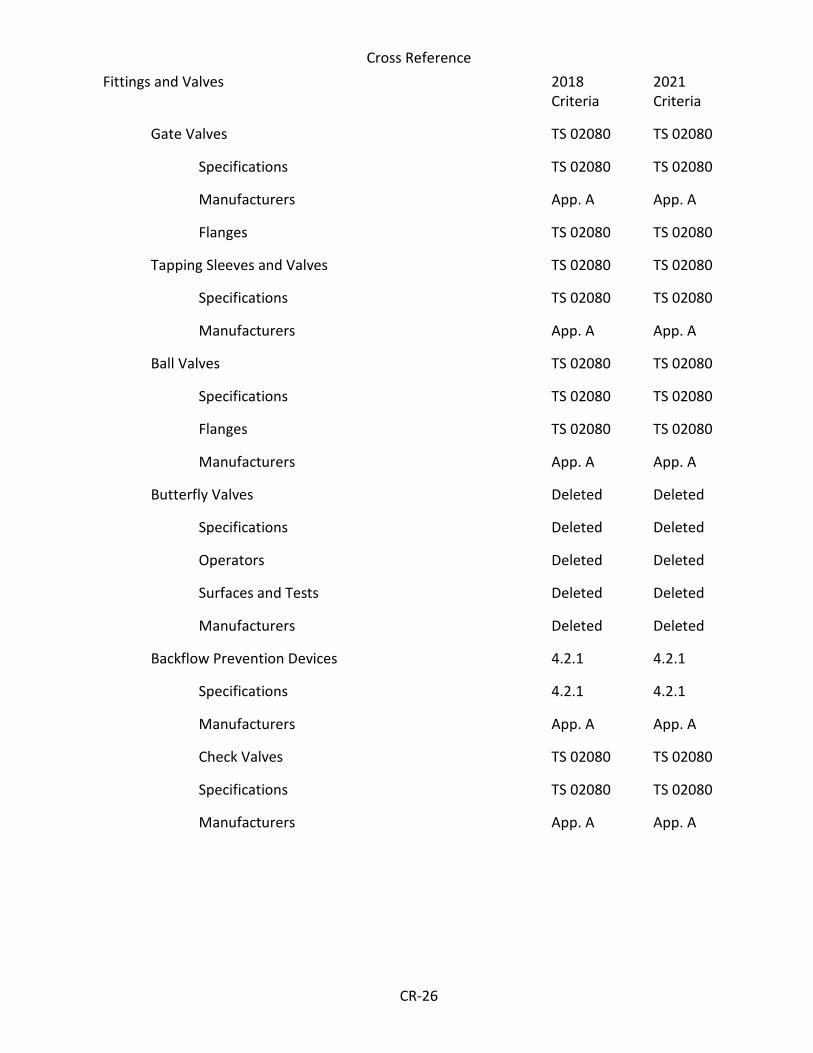
Cross Reference
CR-26
Fittings and Valves 2018 Criteria
2021 Criteria
Gate Valves TS 02080 TS 02080
Specifications TS 02080 TS 02080
Manufacturers App. A App. A
Flanges TS 02080 TS 02080
Tapping Sleeves and Valves TS 02080 TS 02080
Specifications TS 02080 TS 02080
Manufacturers App. A App. A
Ball Valves TS 02080 TS 02080
Specifications TS 02080 TS 02080
Flanges TS 02080 TS 02080
Manufacturers App. A App. A
Butterfly Valves Deleted Deleted
Specifications Deleted Deleted
Operators Deleted Deleted
Surfaces and Tests Deleted Deleted
Manufacturers Deleted Deleted
Backflow Prevention Devices 4.2.1 4.2.1
Specifications 4.2.1 4.2.1
Manufacturers App. A App. A
Check Valves TS 02080 TS 02080
Specifications TS 02080 TS 02080
Manufacturers App. A App. A