The Flinders Sewerage Project - Water New Zealand
21
SMART PRESSURE SEWER COLLECTION AND TRANSFER: THE FLINDERS SEWERAGE PROJECT M. Peril, MWH ABSTRACT The Flinders Sewerage Project is an innovative backlog sewerage scheme located on the Mornington Peninsula, south-east of Melbourne, Australia. The scheme is made up of two pressure sewer collection networks within the towns of Flinders and Shoreham, and an 18 kilometre long transfer system from Flinders to Balnarring. From Balnarring sewerage flows through an existing transfer system to the Somers sewage treatment plant. This paper outlines the Flinders Sewerage Project and the smart pressure sewer technology and networks developed as part of this project. The application of this technology combined with other innovations resulted in: capital savings, reduced operational risk, reduced environmental impact, improved service outcomes, and reduced loading of the downstream transfer systems. Focus is given to the major project innovations, and their benefits, including: The introduction of SCADA to pressure sewer systems; Pressure based pump and network control; Sealed pressure vessel wet wells; Dispersed emergency storage within the pressure sewer network and household pumping units; Low flow high head progressive cavity sewage pumping; Sewage pressure sustaining valves; Rapid hydraulic model building and network optimisation; and A fast track approvals strategy based on early adoption of trenchless technology and nominated construction impact zones. KEYWORDS Pressure sewer, smart network, transfer, high head pumping. 1 INTRODUCTION 1.1 BACKGROUND In 2003, Mornington Peninsula Shire Council, Fisheries Victoria, the Environment Protection Authority (EPA) and the Department of Human Services (DHS), along with South East Water (SEWL), identified concerns with sewage contamination on the coastal foreshore in the Flinders and Shoreham area, located on Victoria’s Mornington Peninsula. The pollution was attributed to a failure of some of the septic tank systems (1250 No.) servicing properties in Flinders and Shoreham. This pollution was a risk to the health and safety of residents and could affect the viability of local tourism and mussel farming. Therefore, addressing major pollution and environmental concerns was the primary driver to sewering Flinders and Shoreham.
-
Upload
khangminh22 -
Category
Documents
-
view
0 -
download
0
Transcript of The Flinders Sewerage Project - Water New Zealand
SMART PRESSURE SEWER COLLECTION AND
TRANSFER: THE FLINDERS SEWERAGE
PROJECT
M. Peril, MWH
ABSTRACT
The Flinders Sewerage Project is an innovative backlog sewerage scheme located on the Mornington Peninsula,
south-east of Melbourne, Australia. The scheme is made up of two pressure sewer collection networks within
the towns of Flinders and Shoreham, and an 18 kilometre long transfer system from Flinders to Balnarring.
From Balnarring sewerage flows through an existing transfer system to the Somers sewage treatment plant.
This paper outlines the Flinders Sewerage Project and the smart pressure sewer technology and networks
developed as part of this project. The application of this technology combined with other innovations resulted
in: capital savings, reduced operational risk, reduced environmental impact, improved service outcomes, and
reduced loading of the downstream transfer systems. Focus is given to the major project innovations, and their
benefits, including:
The introduction of SCADA to pressure sewer systems;
Pressure based pump and network control;
Sealed pressure vessel wet wells;
Dispersed emergency storage within the pressure sewer network and household pumping units;
Low flow high head progressive cavity sewage pumping;
Sewage pressure sustaining valves;
Rapid hydraulic model building and network optimisation; and
A fast track approvals strategy based on early adoption of trenchless technology and nominated
construction impact zones.
KEYWORDS
Pressure sewer, smart network, transfer, high head pumping.
1 INTRODUCTION
1.1 BACKGROUND
In 2003, Mornington Peninsula Shire Council, Fisheries Victoria, the Environment Protection Authority (EPA)
and the Department of Human Services (DHS), along with South East Water (SEWL), identified concerns with
sewage contamination on the coastal foreshore in the Flinders and Shoreham area, located on Victoria’s
Mornington Peninsula.
The pollution was attributed to a failure of some of the septic tank systems (1250 No.) servicing properties in
Flinders and Shoreham. This pollution was a risk to the health and safety of residents and could affect the
viability of local tourism and mussel farming. Therefore, addressing major pollution and environmental
concerns was the primary driver to sewering Flinders and Shoreham.

Figure 1: The Flinders Transfer System – Plan
1.2 THE FLINDERS SEWERAGE PROJECT
In 2004, SEWL selected MWH to undertake design for the Flinders Sewerage Project which involved a that
sewer system, six associated pumping stations and a 24 km long transfer system to Somers WWTP. In 2006,
after 18 months of planning, design and consultation, SEWL decided to scrap its proposed gravity sewerage
scheme due to its cost and concerns raised by residents regarding disruption during construction. Based on
previous successful experience with pressure sewer technology at Tooradin, Australia’s first pressure sewer
scheme, SEWL decided to pursue a pressure sewerage system (PSS) with a number of innovative components to
serve the Flinders and Shoreham. The scheme is comprised of two pressure sewer collection networks within
the towns of Flinders and Shoreham townships (800 and 450 properties respectively), and an 18 km long
transfer system from Flinders to Balnarring. From Balnarring sewage flows through an existing transfer system
on to the Somers sewage treatment plant. Figures 1 and 2 show the location and scale of the project.
Figure 2: Aerial View of the Flinders Sewerage Project
FlindersTransferSPS
ShorehamLow LevelSPS
ShorehamHigh LevelTank
BalnarringControlValveFacility
ExistingBalnarringTransferSPS 819
ProposedTransferPipelineAlignment
Flinders
Shoreham
Balnarring Somers

1.2.1 CHANGE FROM GRAVITY TO PRESSURE SEWER COLLECTION
Flinders was originally designed as a gravity sewerage system running predominantly through private property.
However, this was found to be unpopular and financially unviable primarily due to the need for open cut
construction of gravity sewers and the ensuing amenity disturbance that would occur. A large volume of
expensive on-grade trenchless construction would have been required to minimise this disturbance to the
environment and private property.
The adopted pressure sewer system consists of smaller diameter pressure mains in road reserves, constructed
cost-effectively by horizontal directional drilling (HDD), without the constraints of tight level and grade
tolerances. The proposed gravity sewer collection system for the Flinders township included four neighborhood
pump stations and was estimated to cost between $15 million and $18 million. The alternative PSS reduced the
capital cost to $12 million, including the cost of redesign. The change from gravity to pressure sewer also
greatly reduced the disturbance to the local environment and community during construction. Figure 2 shows
the gravity collection work originally proposed (left) and the PSS network adopted (right).
Figure 3: Flinders gravity collection work originally proposed (Left) and the PSS network adopted
(Right)
The financial benefit of PSS collection relative to gravity sewer collection extends beyond the raw capital cost.
Project cash flow and financial risk management were also improved. By its nature, a gravity system has a front
loaded spend profile. The majority of the scheme cost in the collection network, the full capital cost of a gravity
system must be spent even if no-one connects to it. Whereas with a PSS, the upfront capital spend and
associated risk is much less because the cost of a PSS is comprised of network and pump components. The
majority of the scheme cost is in the pump component. The network component must be spent upfront, but not
the pump component. The pump component only needs to be spent once a customer chooses to connect.
Hence, the financial exposure of a PSS proponent is less than that of a gravity sewer scheme proponent with
regard to low connection rates.
1.2.2 PRESSURE SEWER SYSTEMS
A PSS uses the pressure from individual pump units to collect and transport wastewater. Each property within
the PSS is provided with a small tank with a pump unit installed to which all household wastewater is diverted.
The tank fills until a predetermined level is reached, then the pump unit is activated to discharge wastewater into
the PSS network. The tanks can also have a relatively large emergency storage (24 hours for an average house),
to cater for inactive pumps. PSSs have a long history of use in the USA, where they are predominantly
employed to sewer low lying, flat and/or sandy areas with high water tables where conventional gravity
sewerage systems would not be feasible. In 2001, SEWL implemented the first Australian PSS to sewer the
Tooradin township backlog sewerage scheme. For further explanation of pressure sewer systems refer to the
WSAA Pressure Sewer Code referenced.
1.2.3 THE PROJECT TEAM
The project was delivered by the ‘us’ – Utility Services Alliance between South East Water Limited, Thiess
Services and Siemens. MWH carried out hydraulic modeling and design. Development and supply of the

Pressure Sewer Pump equipment was undertaken by NOV Mono, formerly Mono Pumps Australia. MWH
provided hydraulic modelling, design, environmental impact assessment and statutory planning services.
2 PRESSURE SEWER TECHNOLOGY AND SMART NETWORKS
The goal of this paper is to make a constructive contribution to the water industry pressure sewer body of
knowledge by outlining the key innovations developed in the course of delivering this project. It is not intended
to promote any particular brand of pressure sewer technology. Specifically the paper aims to:
Introduce the concept and objectives of a smart network;
Explain principles and associated benefits of the key innovations: pressure based pump and network
control, and the integration of Supervisory Control and Data Acquisition (SCADA) functionality into
pressure sewer equipment; and
Outline how smart network functionality is beginning to be incorporated into PSS technology and to
explain the benefits this is creating for PSS networks and downstream transfer systems.
The pressure sewer market and technology are evolving rapidly. At the time of writing, pressure-based pump
and network control and SCADA functionality were available from multiple pressure sewer pump
manufacturers. These features, combined with a network design verified by hydraulic modelling, are current
best practice and enable smart network functionality in pressure sewer networks.
2.1 WHAT ARE SMART OR INTELLIGENT NETWORKS?
A definition for a smart (or intelligent) network from the IT industry is “A network that is not passive. It
contains built-in diagnostics, management, fault tolerance and other capabilities that keep it running
smoothly.” - Computer Desktop Encyclopedia copyright ©1981-2012 by The Computer Language Company
Inc.
2.2 SMART PRESSURE SEWER NETWORKS
If typical smart network objectives are applied to PSS the objectives of a smart pressure sewer system might be
a network that:
Is ‘self healing’ under fault or emergency conditions by detecting and responding to problems
automatically;
Has greatly enhanced data gathering capabilities which enable real-time monitoring and control of
network performance at the global and local level;
Allows rapid fault diagnosis and response;
Optimises and reduces energy use; and
Is efficient.
These objectives are starting to be attained in PSS networks by using pressure based pump control and
incorporating full SCADA functionality.
3 PRESSURE SEWER COLLECTION NETWORKS
3.1 LESSONS LEARNED FROM FIRST GENERATION AUSTRALIAN PRESSURE
SEWER SCHEMES
Based on SEWL’s experience of installing and operating Australia’s first pressure sewerage system in Tooradin,
and subsequent backlog schemes in Warneet and Cannons Creek, a number of issues that could potentially
impede the viability of implementing pressure sewer at Flinders were identified. These issues included:
Customer involvement in operations;
Inadequate emergency storage at pump units;

Inadequate protection against high system pressures; and
Management of peak power outage recovery flows.
3.1.1 CUSTOMER INVOLVEMENT IN SYSTEM OPERATION
In these first generation pressure sewer systems, all control and monitoring is local to the individual pump. If
there is a problem at a pump, a red light flashes and a siren sounds. The system operator is reliant on the
customer to call the fault in for action; that is, the customers must be involved in system operation. The
customers know about problems before the operator does. Operations can only be reactive. Furthermore, to
shut down the network, operators must visit each property to isolate each pump. Then, once the work has been
carried out, they must go back to each property to switch the pumps back on again.
3.1.2 INADEQUATE EMERGENCY STORAGE AT PUMP UNITS
In the Tooradin pressure sewer system, the individual pumping units were found to have insufficient storage
above alarm level. The small amount of storage did not provide adequate time for operations to respond to
faults.
3.1.3 MANAGEMENT OF SYSTEM PEAK PRESSURES
Pressure sewer pumps are typically progressive cavity pumps. These pumps can produce extremely high shut-
off heads. These high shut-off heads can be hazardous for the pump and the downstream network. (These
damaging high heads can also occur during a power outage recovery event.) Pumps need to be protected from
high heads because the manufacturers only warrant their pumps up to a certain head, usually significantly lower
than the shut-off head. Pipe networks need to be protected from high pressures for obvious reasons!
Each pump requires a high pressure cut out. Conventionally, this was done using a thermal switch in the pump
stator to cut out the pump motor. This provides some protection to the pump, but not the network. This is due
to the time lag between generating high pressure in the system and creating sufficient heat in the pump stator to
trigger the thermal cut out switch. Also, once heat builds up in the pump, it will take some time to cool down,
creating subsequent nuisance trips. Operational experience in the Australian market has found this form of
over-pressure protection to be inadequate for both pump and network protection.
3.1.4 EFFECT OF HIGH POWER OUTAGE RECOVERY FLOWS ON DOWNSTREAM
INFRASTRUCTURE
When a town and PSS loses power, sewage accumulates in the house tanks. Once power is restored, all the
house pumps attempt to start and this results in huge peak flows at the network outlet. In the case of the
Flinders pressure sewer system, flows as high as 120 L/s [20 x Average Dry Weather Flow (ADWF)] were
predicted at the network outlet. These high power outage recovery (POR) can be problematic to handle. They
are typically managed using attenuation storage at the outlet of the collection network.
3.2 SECOND GENERATION PRESSURE SEWER SYSTEMS
Since completion of Australia’s first generation pressure sewer schemes, SEWL gained valuable experience and
knowledge of pressure sewer scheme implementation and operation. The requirements for the next generation
of PSS pumps to be installed for SEWL were developed from this heightened awareness and knowledge. The
revised PSS pump requirements included:
Knowing when there is a problem, before the customer via remote monitoring;
24 hours storage (above alarm level) within the individual pump units;
Improved over pressure protection; and
Operation as an integrated system with the transfer system.
SEWL went to market and found that no manufacturer met all of their requirements. The selected supplier
offered a more technically advanced control system including telemetry and self-diagnostic capabilities. This
manufacturer also committed to custom design their current pressure sewer pump to better meet SEWL’s
specific requirements. The suppliers research and development department developed the pump unit in

collaboration with SEWL operations and maintenance personnel, who provided test sites, feedback and design
enhancement suggestions.
3.2.1 IMPLEMENTATION OF TELEMETRY INTO PRESSURE SEWER SYSTEMS
The Flinders PSS has full SCADA functionality. This was the first fully integrated SCADA system
incorporated into a pressure sewer system. The SCADA system includes:
A two-way radio link to each pump in the system, removing the customer interface for pump operation;
A remote “global shutdown system” to be used during failure or leak events, to shut off all pumps
within a system remotely (significantly reducing system shut-off times which reduces the risk of any
potential sewerage spills to the environment); and
The ability for operations staff to obtain pump unit information remotely for fault diagnosis, prior to
attending pump “call outs” or for system performance monitoring.
3.2.2 ENHANCED OVER PRESSURE PROTECTION
To ensure that the pump doesn’t operate when it senses pressures above the pump’s rated design pressure, it has
an electronic current sensing over-pressure protection rather than just the stator over temperature device
conventionally used. It is instantaneous and it protects both the pump and the network.
Although electronic current sensing based over-pressure protection was initially installed simply as a pump
protection device, it was realised during system design that it could also be used as a system control device due
to the high degree of accuracy achieved in testing. Using this new form of over-pressure protection, the
pressure sewerage system can be easily controlled at one point (e.g. at isolation valves), and this allows simple
engagement of the individual storages in each property, rather than having to manually turn off individual
pumps. This feature is also used to throttle flows at the network outlet at the transfer pumping station which
assists greatly with handling peak flows in particular the predicted power outage recovery flow of 120 L/s in the
case of Flinders.
3.2.3 EMERGENCY STORAGE USING SEALABLE (PRESSURE VESSEL) WET WELLS
Rather than draining the collection network into a conventional open wet well, with large emergency storages to
buffer the potential peak flows, the Flinders pump station uses a Glass Reinforced Plastic (GRP) pressure vessel
as a sealable wet well. The wet well is a pressure vessel with a double acting air release valve. Figure 4 shows
the principal of operation. During normal operation, the pressure vessel works at atmospheric pressure as an
open wet well would. When inflow exceeds outflow, the wet well vessel and upstream network then fill and
pressurise. Eventually, the network pressure exceeds the PSS pump cut out pressure and this cuts out the house
pumps and engages the remote storage available in each house tank. Each tank holds the equivalent of 24 hours
of ADWF. In an emergency situation the dispersed storage available at the customer pots is automatically
engaged.
Figure 4: Sealable GRP pressure vessel wet well – Principle of Operation
NORMAL OPERATION EMERGENCY OPERATION
Constraining the PSS network outlet in this fashion eliminated the requirement to build a 150 KL emergency
storage at the Flinders transfer SPS. The use of pressure vessel wet wells in conjunction with the current

sensing over-pressure pump protection feature to engage the dispersed emergency storage available within the
pressure sewer network and pump unit tanks rather than building large emergency storage(s) at the transfer
pump stations, saved approximately $1 million.
3.2.4 FLOW THROTTLING AT THE NETWORK OUTLET
The use of enhanced over pressure protection and sealable pressure vessel wet wells has another important
benefit of throttling flows at the outlet of the pressure collection network and the start of the 18 km long transfer
system. Peak flow events, such as power outage recovery flows, are handled automatically. This feature was
used to minimise the transfer pumping flow rate and diameter of the transfer mains, creating substantial project
savings in the order of $3 Million. Figure 5 shows a simulated trace of flow at the PSS network outlet during a
POR event for a free network outlet and a constrained network outlet.
Figure 5: Hydraulic model simulation of Power Outage Recovery flow at PSS network outlet
4 PRESSURE SEWER NETWORK DESIGN USING HYDRAULIC
MODELLING
Traditionally, PSS networks have been installed in flat areas and simplified analysis has been used.
Historically, simple spreadsheet tools have been used for hydraulic analysis and design of pressure sewer
networks. On the Flinders Sewerage Project, dynamic hydraulic modelling was used to carry out PSS network
design and optimisation. The preliminary network layout was prepared using GIS software, this information
was then imported into Innovyze’s (formerly MWH Soft) hydraulic modelling software, H2OMap. Figures 5
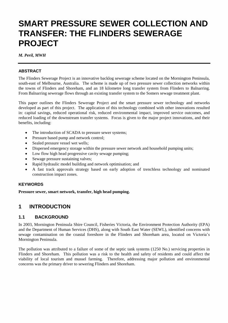
and 6 show typical hydraulic modelling outputs.
The advantages of using hydraulic models include:
Rapid network reconfiguration to assess competing design options, such as growth staging and
consideration of time variant design options (e.g. volumetric computations);
The ability to quickly analyse different operating scenarios such as system start up with low connection
rates
The optimisation of pipe sizes across the reticulation networks;
Improved quality assurance and data auditing capabilities, thereby minimising risk, particularly when
geospatially accurate models are employed; and
Simple identification of the most hydraulically disadvantaged pumps within the system during all peak
operating scenarios.
Figure 6: Typical Hydraulic Modeling outputs
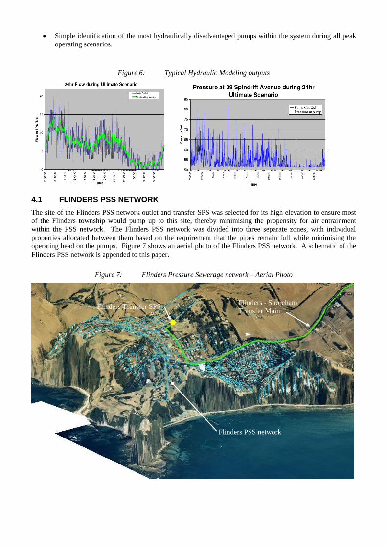
4.1 FLINDERS PSS NETWORK
The site of the Flinders PSS network outlet and transfer SPS was selected for its high elevation to ensure most
of the Flinders township would pump up to this site, thereby minimising the propensity for air entrainment
within the PSS network. The Flinders PSS network was divided into three separate zones, with individual
properties allocated between them based on the requirement that the pipes remain full while minimising the
operating head on the pumps. Figure 7 shows an aerial photo of the Flinders PSS network. A schematic of the
Flinders PSS network is appended to this paper.
Figure 7: Flinders Pressure Sewerage network – Aerial Photo
Flinders Transfer SPS
Flinders PSS network
Flinders - Shoreham
Transfer Main

4.2 SHOREHAM PSS NETWORK
The elevation of the Shoreham township ranges from 5 m RL to 80 m RL. Providing sewerage services to
Shoreham using PSS technology required two separate networks. The Shoreham low level PSS network
discharges to the Shoreham low level SPS, whilst the Shoreham high level PSS network discharges to the
Shoreham high level tank.
The Shoreham PSS network was divided into four separate zones, with individual properties allocated between
them based on the requirement that the pipes remain full, while minimising the operating head on the pumps. To
keep the pipes full, it is necessary to pump to an elevation higher then the household properties. Figure 8 shows
the connectivity of the low level PSS network (in red), the high level PSS network (in yellow) and the locations
of the Shoreham low level injection SPS and Shoreham high level tank. A schematic of the Shorehan PSS
networks is appended to this paper.
Figure 8: Shoreham Pressure Sewerage networks – Aerial Photo
Shoreham Low Level
Injection SPS
Flinders - Shoreham
Transfer Main
Shoreham – Balnarring Transfer
Main
Shoreham High
Level Tank
Shoreham Low
Level PSS
Shoreham High
Level PSS

5 TRANSFER SYSTEM
5.1 TRANSFER SYSTEM OVERVIEW
The Flinders SPS and Shoreham low level SPS pump to the Shoreham High Level Tank (SHLT). Flows from
the SHLT then gravitate via the Balnarring Control Valve to the existing Balnarring sewerage system and on to
the Somers WWTP. Figure 9 shows the connectivity between the three PSS networks and major transfer assets
in schematic and aerial photo form.
Figure 9: The Flinders Transfer System – Schematic and Aerial Photo
5.1.1 HYDRAULIC LOADING
Table 1 below shows the results of the PSS network hydraulic modelling. Flows at the outlet of each PSS
network are provided for various operative scenarios.
Table 1: Pressure Sewer Network Design Flows
LPSS
Network
Estimated Flow (L/s)
Peak Flow
Power Outage
Scenario
Peak Daily
Flow Normal
Operation (A)
(Ultimate
Development)
Average
Flow
Low
Season
Peak
Flow
Low Season
Mean Flow
(Permanent
Residents
only)
SPS Design
Flow Rate
Flinders
120 14.5(A)
6.4 5.5 1.8 16
Minimum (C)
Low
Shoreham
47 6.6(A)
2.5 2.2 0.6 7
High
Shoreham
36 3.8(A)
1.43 1.7 0.55 4 (B)
Notes:
(A) Corresponds to a 15 minute rolling average peak.
(B) Variable flowrate corresponding to a 15 minute rolling average peak.
(C) The design flow for the Flinders SPS was optimised in conjunction with the diameter and pressure rating of
the transfer pipeline.
Balnarring Control Valve facility
Shoreham low level
PSS network
Shoreham High Level
PSS Network Flinders PSS
Network
Flinders Transfer
Pump Station
Shoreham High
Level Tank
Existing Balnarring Transfer Pump Station
Shoreham Injection
Pump Station
Flinders Shoreham
Balnarring
5.1.2 SOLIDS LOADING
Sewage is macerated by the PSS grinder pump at each property prior to discharge into the PSS network.
Accordingly, the transfer system influent has a relatively low solids content. The only solids entering the
transfer system must come through the individual household PSS pumps. As such, the largest particle size
expected to enter the system through the household pumps was a 4 mm diameter solid. This is much smaller
than the solids typically allowed for in raw sewage. This proved to be a big advantage for the transfer system as
centrifugal pumps with large solid passing capacities were not required and low flow high head progressive
cavity pumps could be used.
5.2 ODOUR CONTROL
Odour generation from the sewage in the transfer system was considered likely because of the detention times in
the upstream PSS networks and the long detention time of the transfer system itself. For example, when the
sewage enters the Flinders Transfer Pump Station it was predicted to be 9 hours old at ADWF, and 15 hours at
low flow. Sewage was expected to be septic when it entered the transfer system. Left untreated high levels of
sulphide generation and associated odour and corrosion problems were predicted to occur. To mitigate odour
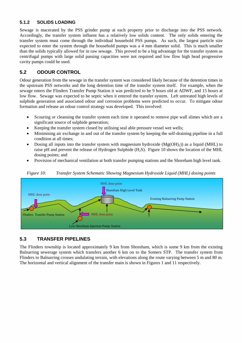
formation and release an odour control strategy was developed. This involved:
Scouring or cleansing the transfer system each time it operated to remove pipe wall slimes which are a
significant source of sulphide generation;
Keeping the transfer system closed by utilising seal able pressure vessel wet wells;
Minimising air exchange in and out of the transfer system by keeping the self-draining pipeline in a full
condition at all times;
Dosing all inputs into the transfer system with magnesium hydroxide (Mg(OH)2)) as a liquid (MHL) to
raise pH and prevent the release of Hydrogen Sulphide (H2S). Figure 10 shows the location of the MHL
dosing points; and
Provision of mechanical ventilation at both transfer pumping stations and the Shoreham high level tank.
Figure 10: Transfer System Schematic Showing Magnesium Hydroxide Liquid (MHL) dosing points
5.3 TRANSFER PIPELINES
The Flinders township is located approximately 9 km from Shoreham, which is some 9 km from the existing
Balnarring sewerage system which transfers another 6 km on to the Somers STP. The transfer system from
Flinders to Balnarring crosses undulating terrain, with elevations along the route varying between 5 m and 80 m.
The horizontal and vertical alignment of the transfer main is shown in Figures 1 and 11 respectively.
To Somers
Shoreham High Level Tank
Existing Balnarring Pump Station
Low Shoreham Injection Pump Station
Flinders Transfer Pump Station
MHL dose point
MHL dose point
MHL dose point

Figure 11: The Flinders Transfer Main – Long Section
As shown in Figure 11, from the Flinders Transfer SPS at approximately 55 m AHD the transfer main passes
through undulating terrain to the Shoreham low level SPS at 43 m AHD. Low Shoreham PSS flows enter the
transfer system at this point. From the Shoreham low level SPS the transfer main rises to the Shoreham high
level tank at approx. 80 m, the highest point in the system. High Shoreham PSS flows enter the Transfer System
at the high level tank.
From the Shoreham high level tank, the transfer main descends steeply to East Creek. Once over the next high
point, the terrain flattens and continues descending to Hanns Creek. After Hanns Creek, the transfer main
gradually rises until it discharges into the existing Balnarring Transfer SPS (SPS819). It is important to note
that the last 4.5 km of the transfer main is always filled, as it is lower than the discharge point.
5.3.1 MATERIAL
High density polyethylene (PE100) was selected as the preferred transfer main material due to its high degree of
chemical resistance, its resistance to degradation under cyclic loading and its suitability for trenchless
installation using horizontal directional drilling (HDD).
5.3.2 SIZING CRITERIA
The transfer mains were sized to self-cleanse during every operation. A minimum pipe wall shear stress of
2.87 Pa was adopted as self-cleansing (slime-stripping) design criteria. Shear stresses will increase as the pipe
ages and becomes rougher internally, whereas pipe hydraulic capacity will reduce. Therefore, to ensure that
slime-stripping will occur during the initial period of pipeline operation, a Colebrooke – White ks value of 0.1
mm was adopted for use in shear stress calculations. Conversely, to ensure the pipe has adequate long-term
hydraulic capacity, a higher ks value of 0.6 mm was used. The selected pipes had to satisfy both the hydraulic
and slime-shearing constraints to be deemed acceptable.
Shorham High Level Tank
Existing Balnarring Transfer SPS
Shoreham Low Level
Injection SPS
Flinders Transfer
SPS
Balnarring Flow Control Valve
Hanns Creek East Creek
Manton Creek

5.4 FLINDERS TO SHOREHAM HIGH LEVEL TANK PUMPED SYSTEM
This leg of the transfer system, shown in Figure 12, receives pumped flows from the Flinders transfer SPS and
the Shoreham low level injection SPS.
Figure 12: Aerial View of the Flinders-Shoreham Transfer System and Flinders and Shoreham PSS
Networks
The main was sized so that self-cleansing and slime-shearing conditions are created when only Flinders transfer
SPS is pumping to the Shoreham High Level Tank. Therefore, each time Flinders Transfer Pump Station
operates, the Flinders to Shoreham High Level Tank main is cleansed. A range of pipe diameters and flow rate
combinations were evaluated for the Flinders – Shoreham pipeline. Table 2 shows the pipe wall shear stresses
generated for a range of pipe and flow rate combinations. Acceptable pipe and flow rate combinations are
highlighted.
Table 2: Flinders to Shoreham High Level Tank Pipe Diameter and Flow rate Combinations
Nominal
diameter
(DN)
Internal
diameter
Flow Velocity Pipe
roughness
ks = 0.1
Shear
stress
(mm) (mm) (l/s) (m/s) (mm) (Pa)
180 138 16 1.070 0.1 2.95
180 138 17 1.137 0.1 3.31
180 138 18 1.203 0.1 3.69
180 138 19 1.270 0.1 4.09
180 138 20 1.337 0.1 4.51
200 154 16 0.859 0.1 1.89
200 154 17 0.913 0.1 2.12
200 154 18 0.966 0.1 2.37
200 154 19 1.020 0.1 2.62
200 154 20 1.074 0.1 2.89
200 154 21 1.127 0.1 3.17
The minimum design flow for the Flinders transfer SPS and transfer main is 16 L/s as described in Table 1.
Slime shearing conditions are achieved at 16 L/s in the DN 180 mm pipe (highlighted in red above), and at 20
L/s in the DN 200 mm pipe (highlighted in green above). However, the head required pump 16 L/s through a
180 mm pipe is greater than 200 m when transient conditions are considered. This is higher than the pressure
rating of PN 20 pipe used. Therefore the combination of a DN 200 mm pipeline and a duty flow of 20 L/s was
selected as the optimum pipe diameter and flow rate combination.
Flinders Shoreham
transfer main
Flinders PSS
network
Shoreham low
and high level
PSS networks
Shoreham low
level Injection SPS
Flinders Transfer
SPS
Shoreham high level
tank

5.5 TRANSFER PUMP STATIONS
The typical arrangement for the transfer pump stations is shown in Photograph 1 and Figure 13. The
functionality of the sealable pressure vessel wet well is explained in section 3.2.3.
Figure 13: Sealable GRP pressure vessel wet well and Flinders Transfer Pump Station - Section
5.5.1 PUMP DUTIES
Table 3 shows the pump duties for the Flinders and Shoreham transfer pump stations when each are operating
independently and when they are both operating at the same time. These pump duties are based on normal
operation within the upstream PSS networks as this is the most severe design case.
Table 3: Transfer Pump Station – Pump Duties
Pump Station
System Operating State Static Lift Fittings
Loss
Friction
Loss
Duty
Flinders
Transfer Pump
Station
Flinders pumping alone 31.4 m 2.2 m 97.8 m 20 l/s @ 131.4 m
Both Stations pumping 31.4 m 2.9 m 114.8 m 20 l/s @ 149.1 m
Shoreham CFA
Injection Pump
Station
Shoreham CFA
pumping alone
41.3 m 0.1 m 2.7 m 7 l/s @ 44.1 m
Both stations pumping 41.3 m 1.5 m 38.0 m 7 l/s @ 80.8 m
Note: Pump duties based on normal operation.
5.5.2 LOW FLOW HIGH HEAD PUMPING FROM FLINDERS TO SHOREHAM
This leg of the transfer system would have ordinarily been divided into a series of transfer stations because
conventional centrifugal sewage pumps employ large clearances and specially designed impellers (so that they
are able to handle sewage debris such as fibrous materials, grits and solids) and such centrifugal sewage pumps
are typically limited to low heads (typically in the order of 70 m).
Low flow high head progressive cavity pumps with small clearances were able to be used because all the raw
sewage solids and debris are macerated by the individual household pumps before they reach the transfer
stations. The use of these higher pumping pressures meant that it was possible to pump directly from Flinders to
the Shoreham high level tank with a single lift. This would not have been possible using typical centrifugal
sewage pumps. Fewer pump stations reduced both the capital and operating expenditure requirement.

Photograph 1: The Flinders Sewage SPS chamber (During Construction) showing progressive cavity pumps
5.5.3 VARIABLE HEAD BOOSTER PUMPING
The transfer pump stations face a broad range of duty heads, shown in Table 3. Both the suction head and
discharge head experienced by the transfer pumps are variable due to the various operating scenarios possible.
On the suction side, pressurisation of the PSS network and wet well pressure vessel can vary suction head by up
to 80 m. On the discharge side, the transfer system is an injection system, so the discharge head varies
depending on which transfer SPSs are operating at any given time.
Another advantage of using progressive cavity pumps is that they are rotary positive displacement pumps. They
are able to provide a stable flow rate as the system head changes. As such, they are particularly well suited to
this transfer system where total system head can vary dramatically due to two pump stations injecting into the
same transfer main and the method of engaging emergency storage within the PSS networks and household
tanks. On the other hand, the performance of centrifugal pumps and the stability of the duty flow produced are
highly sensitive to variations in system head making them unsuitable for use in this transfer system.
5.6 SHOREHAM HIGH LEVEL TANK TO BALNARRING FALLING SYSTEM
This leg of the transfer system receives pumped flows from the Flinders Transfer SPS, the Shoreham injection
SPS and the High Shoreham LPSS network. These flows are collected in the Shoreham High Level tank. The
transfer main includes a downstream control valve, which under normal operating conditions will keep the main
full. This control valve forms part of the odour control strategy. This pipeline has been sized so that self-
cleansing and slime-shearing conditions are created and the transfer main is scoured each time the downstream
control valve is opened. Figure 14 shows an aerial photo view of the Shoreham – Balnarring transfer system.

Figure 14: Aerial View of the Shoreham-Balnarring Transfer System
The Shoreham high level tank receives total flows of 31 L/s from the upstream systems of Flinders and
Shoreham. An additional allowance of 4 L/s was provided for a future connection for the town of Point Leo.
The flows are listed in Table 4.
Table 4: Shoreham High Level Tank to Balnarring - Induced Head Pipeline required capacity
Contributing System Flow
(L/s)
Flinders Transfer SPS 20
Shoreham Low Level SPS 7
High Shoreham High Level SPS 4
Allowance for future Point Leo connection 4
TOTAL 35
In order to pass forward all received flows, this pipeline would require an ultimate capacity of 35 L/s. Taking
all losses into account, the average pipe slope from the Shoreham High Point Tank to the Balnarring transfer
SPS is 0.555% (1 in 180). A range of pipe diameters were assessed for this pipeline. Table 5 shows the pipe
wall shear stresses generated for each pipe diameter at this slope. The selected pipe is highlighted in green.
Table 5: Shoreham High Level Tank to Balnarring Pipeline Diameter and Flow rate Combinations
Average
Slope of
Pipe
Nominal
Diameter
Internal
Diameter
Capacity Velocity Shear
Stress
(1 in …) (mm) (mm) (L/s) (m/s) (Pa)
1 in 180 250 192 25.3 0.875 2.61
1 in 180 280 215 34.2 0.942 2.92
1 in 180 315 242 46.8 1.017 3.29
A DN 280 mm pipe was the smallest pipe that achieved the minimum required pipe wall shear stress for creating
self-cleansing and slime-shearing conditions. The capacity of the pipe at 34.2 L/s was slightly less than the
required pipe capacity of 35 L/s given in Table 3. However, this short fall in capacity was deemed acceptable
due to the availability of buffer storage at the Shoreham high level tank to attenuate peak flows. The goal of
minimising system detention time to aid odour management also added weight to the decision to select a DN
280 mm pipe.
The DN 280 mm gravity pipeline from Shoreham High Level Tank to the Balnarring Outfall SPS falls
approximately 50 m over some 9 km of undulating terrain as shown in Figure 11. The SHLT location was
selected to maximise driving head, while minimising any impact on vegetation and nearby private residences.
As 200 m3 of odorous foul air would otherwise have been purged every time either the Flinders SPS or
Shoreham SPS operated, the Balnarring Control Valve Facility (BCV), employs sewage pressure-sustaining
valves to keep the transfer main full of fluid (i.e. without air), by controlling the flow between the SHLT and the
discharge point.
Shoreham high level tank
Shoreham PSS networks
Shoreham Balnarring
transfer main
Balnarring Control valve
Existing Balnarring
Transfer SPS

This arrangement also enhances system reliability by controlling sewer slime growth and flushing
sedimentation, which is especially important in the 4.5 km long flooded section shown in Figures 11 and 15.
The high level, flushing volume stored in the SHLT provides a high pressure, long duration flush when the BCV
opens, which maximises the pipe flow velocities and pipe wall shear stresses to self-cleanse the pipe, throughout
the period that the BCV is open. The SHLT also includes two hours of emergency storage to provide
operational flexibility.
Figure 15: Shoreham to Balnarring Transfer System - Schematic
5.7 IMPACT OF SMART PSS NETWORKS ON DOWNSTREAM TRANSFER SYSTEM
Table 6 illustrates the benefits to the transfer system created by the smart PSS networks upstream. The table
shows how the transfer flow rates and size and requirement of downstream infrastructure required was reduced
as the sewerage collection system was changed from gravity to first generation pressure sewer and finally to
second generation smart pressure sewer. Other benefits of utilising smart PSS networks include:
Engaging the emergency storage available within the pressure sewer network and pump unit tanks rather
than building large emergency storage(s) at the transfer pump stations, saving approximately $1 million.
Reducing the typical transfer pump flow rate peaking factor from the industry standard 6 x ADWF to 3x
ADWF;
Shortened the length of the transfer system by 5 km, resulting in a saving of $2 million. The transfer
system was originally intended to extend to the Somers STP. However as the outlet flow rate reduced,
the opportunity to shorten the transfer system was identified and adopted;
Minimised pipeline construction costs;
Minimised environmental impacts because smaller pipe diameters increased the cost competitiveness of
horizontal directional drilling thereby making trenchless construction more feasible; and
Minimised transfer system detention times thereby reducing odours.
Table 6: Flinders Transfer SPS Transfer design requirements against reticulation type
RETIC TYPE NORMAL
NETWORK
OUTFLOW
(PDWF)
PEAK
NETWORK
OUTFLOW
TRANSFER
PUMPING
FLOW RATE
TRANSFER
MAIN
DIAMETER
EMERGENCY
STORAGE
REQUIRED AT
SPS
Gravity N/Aa 45 L/s
(PWWF)
45 L/s PWWF ≈
6 x ADWF
256 Yes
1st
generation
pressure sewer
14.5 L/s 120 L/s (POR) 20 L/s PDWF ≈ 3
x ADWF
154 Yes
2nd
generation
pressure sewer
14.5 L/s 120 L/s (POR) 20 L/s PDWF ≈
3 x ADWF
154 No
(A) For original gravity option the Flinders Transfer SPS received a mix of gravity and intermittent pumped
flows.
X
Existing Balnarring Transfer
SPS Wet well
(SPS819)
Shoreham High
Level Tank
Tank Level - Cut In: Valve Opens (Normal operation)
Tank Level - Cut Out: Valve Closes (Normal operation)
Level B: Valve Closes
Balnarring Control
Valve Facility
Flooded Section

6 APPLICATION OF NOMINATED CONSTRUCTION IMPACT ZONES
The project area included significant stands of high value native vegetation. Planning approvals at Local and
State levels of government were required for the removal of vegetation. As approvals must be obtained before
any works can commence, the planning process poses the risk of significant delays to project construction. For
example, the Flinders PSS required a planning permit for vegetation removal which took seven months to be
approved from the time it was submitted.
The Flinders Sewerage Project was constructed in two stages; Flinders then Shoreham. Learning from the
delays experienced during the first stage of approvals, a new approach was developed for the second stage.
Although the works were to be undertaken predominately by directional drilling, excavation works were
required at all changes of pipeline direction, at connections, valves and at intervals of approximately 100 m
which is the standard length the directional drilling machines can drill per operation. These locations were
nominated as Construction Impact Zones (CIZ). All works were to be undertaken only from these CIZs, which
would be demonstrated (during the design development) to be clear of vegetation or cultural heritage sites. A
typical plan is shown in Figure 16. Edwards, French and Ogier (2009) provide further detailed explanation of
the application and use of the CIZ approach.
Figure 16: Plan showing proposed reticulation and CIZ locations
The early adoption of trenchless technology combined with nominated CIZs greatly simplified the
Environmental Impact Assessment process by focusing on approximately 100 CIZs. Detailed assessment was
only required within the nominated CIZs. Without this methodology, detailed assessment of 11 km of pipeline
alignments would have been required, which would not have been practical. Through best practice
environmental engineering and stakeholder consultation the project was able to:
Avoid vegetation removal, disturbance and minimise environmental impacts;
Improve timeframes for and reduce the risk associated with planning approvals; and
Improve customer and stakeholder relations.

7 CONCLUSIONS
The Flinders Sewerage Project was an innovative backlog sewerage scheme. This project was successfully
delivered. It received the following recognition from Industry:
Winner of the 2010 IWA Asia Pacific regional Project Innovation Award, Small Project category;
Highly commended at the 2009 Australian Water Association (Victorian) excellence awards in the
Infrastructure Project Innovation category; and
Highly commended at the 2009 Engineers Australia Victorian Engineering Excellence Awards in the
Engineering Technology category.
The project demonstrates the benefits of developing technical partnerships to deliver innovation. The
innovations implemented for this project have since been adopted and reused on subsequent projects by the
project participants and others. The key lessons learned on this project include:
Combining pressure sewer technology and trenchless technology early in the project life cycle can, in a
backlog context, provide a very cost-effective township sewer system;
Using pressure based PSS pump control can greatly improve handling of both peak system pressures
and peak system flows; and
Integrating SCADA functionality in PSS enhances network monitoring and control. This enables rapid
fault detection, diagnosis and response which effectively removes the customer from system operation.
Dynamic hydraulic modelling is a valuable optimisation and verification tool for PSS network design;
Pressure-based control of pressure sewer networks in emergency conditions can be used to facilitate
engagement of the emergency storage available within individual properties, and thus attenuate peak
power outage recovery flows;
Adoption of smart pressure sewer technology can create large savings and efficiencies in downsteam
transfer systems; and
Applying a nominated construction impact zone methodology and committing to trenchless construction
techniques can be high effective in obtaining stakeholder endorsement and reducing the delays and risk
typically associated with approvals;
8 ACKNOWLEDGEMENTS
I would like to acknowledge the following parties for their contribution to this project:
Our client South East Water Limited and in particular to Steven French for his trust and leadership.
Rather than focusing on design cost control, design was initially undertaken through a cost-plus
arrangement between MWH and SEWL, which focused on engineering innovation. This created a
collaborative environment in which trust and innovation flourished. Without this we would not have
achieved the results we did;
The ‘us’ construction and commissioning delivery team in particular Colin Feldtmann and Michael
Lowe;
Our technology partner NOV Mono (Australia);
Sydney Water and Priority Sewerage Program Alliance, in particular Ivan Lowe and Wayne Kennedy,
who hosted a SEWL-MWH delegation for a knowledge sharing workshop and site visits in May 2006
following the decision to adopt pressure sewer in lieu of gravity;
The MWH environmental, modelling and design teams for their efforts in helping deliver this result, in
particular: David Hicks, Peter Allen, David Angus, Ivan Lowe, Alex McKenzie, Dwayne Deprez, Chris
Povey, Brett Donaldson, Carly Martin, Richard Smith, and Kerry Brooksmith; and
Our sub-consultants in particular Mike Leggett of Oceania Composites Engineering and Dr Robert
Keller of R.J. Keller & Associates

REFERENCES
Australian Water Association (2007) Pressure Sewer Seminar Melbourne 22nd
April 2007
Crites R, and Tchobanoglous G. (1998) ‘Small and Decentralised Wastewater Management Systems’ McGraw-
Hill.
Edwards R., French S. and Ogier R. (2009) ‘Pressure Sewerage: Implementing best practice environmental
engineering and stakeholder consultation’ Water 36 2 24-27.
French S. (2008) ‘Pressure Sewerage: The Flinders Project’ Water 35 4 37-40.
French S. (2008) ‘Flinders / Shoreham Sewerage Project’ Paper presented at 33rd
QLD Water Industry
Operations Workshop Indoor Sports Centre, Carrara – Gold Coast (2008).
French S. (2009) ‘The increased use of trenchless construction for backlog sewer projects delivers significant
benefits’ Paper presented at the Australasian Society for Trenchless Technology, Trenchless Australasia 09
Conference, Melbourne September 2009.
Keller R.J. (2006) ‘Discussion Paper on surface roughness and slime stripping in sewers.” (Paper
commissioned by MWH).
MWH [Deprez D.] (2006) Flinders Pressurised Sewer Concept Modeling Report Flinders Backlog Sewer.
(Report prepared for South East Water Limited).
MWH [Deprez D.] (2006) Shoreham Pressurised Sewer Concept Modeling Report Shoreham Backlog Sewer.
(Report prepared for South East Water Limited).
MWH [Peril M.] (2006) Flinders Sewerage Project, Flinders to Balnarring Sewage Transfer System Functional
Design. (Report prepared for South East Water Limited).
MWH, NOV Mono, South East Water Limited (2009) ‘Submission for Engineering Excellence Award for
Technology – Development of Pressure Sewer Technology for the Flinders Sewerage Project’ (Submitted to
Engineers Australia, Victoria Division).
Water Services Association of Australia (2007) ‘Pressure Sewer Code of Australia, WSA 07 – 2007 1st Ed
version 1.1’

APPENDIX – FLINDERS AND SHOREHAM PSS NETWORKS - SCHEMATICS
Figure 17: Flinders Pressure Sewer Network - Schematic
Figure 16: Shoreham High and Low Level Pressure Sewer Networks
150mm Variable Grade Sewer
Flinders Southern Zone Operating HGL: 57 m 828
lots
Transfer Main to Shoreham
Flinders SPS
Stokes St Zone Operating HGL: 70 m 7 lots
King St Zone Operating HGL:70 m 16 Lots
150 mm Variable Grade Sewer
Transfer Main from Flinders
Shoreham South West Zone Operating HGL: 44 m 70 lots
Shoreham North Zone Operating HGL: 82.5 m
208 lots
Shoreham Central Zone Operating HGL: 60 m 239
lots
Shoreham SPS
Shoreham high level Tank
Direct Property Connections
Outfall Main to Somers via Balnarring
Transfer Main to Shoreham Tank