Cover Page - NP Series - Seresco Dehumidifiers
262
Installation, Operation & Maintenance Manual For the latest updated versions of this or other Seresco Installation, Operation & Maintenance Manuals contact Seresco Technologies Inc. Tel: (613) 741-3603 Visit: www.serescodehumidifiers.com Issue Date : 2011-09-30 NP Series Dehumidifiers
-
Upload
khangminh22 -
Category
Documents
-
view
3 -
download
0
Transcript of Cover Page - NP Series - Seresco Dehumidifiers

Installation, Operation & Maintenance Manual
For the latest updated versions of this or other Seresco
Installation, Operation & Maintenance Manuals contact Seresco Technologies Inc. Tel: (613) 741-3603
Visit: www.serescodehumidifiers.com
Issue Date : 2011-09-30
NP Series Dehumidifiers

Issue Date : 2011-09-30
THIS PAGE HAS BEEN INTENTIONALLY LEFT BLANK
2

Issue Date : 2011-09-30 Table of Contents
Section Section Title Page(s)
A Warnings, Cautions and Notices
Warnings, Cautions and Notices A-1
Refrigerant Handling Practices A-1
B NE/NP/NV Series General Information
General Information B-1
Unit Description B-1
Component Descriptions B-2
Product Nomenclature B-7
Unit Label B-11
Further Information B-12
C Pre-installation Requirements
Pre-installation Requirements C-1
Receiving Checklist C-1
Shipping Damage Instructions C-1
Storage C-2
D Mechanical Installation
Mechanical Installation D-1
Lifting and Rigging Procedures D-1
Unit Assembly D-1
Duct Connections D-1
Piping and Unit Connections D-2
Drain Pans – Condensate Drain D-2
Blower Motor Brace D-3
Field Installed OACs D-4
Factory Start-up Supervision D-7
E Electrical Installation
Electrical Installation E-1
Main Panel Power Connection E-1
Control Wiring E-2
Websentry Connection E-3
Remote Operator Panel E-4

Table of Contents Issue Date : 2011-09-30
F Start-up
Start-up F-1
Pre-Startup Checklist F-1
Start-up Procedure F-3
Factory Start-up Supervision F-6
G NE/NP/NV Series Operation
Sequence of Operation G-1
CommandCenter Operation G-5
H Routine Maintenance
Routine Maintenance H-1
Routine Maintenance Checklist H-1
Component Maintenance H-2
Refrigerant Charging Procedure H-4
Outdoor Air Balancing H-7
Mechanical Vestibule Access Steps H-9
X Troubleshooting
Troubleshooting X-1
Troubleshooting Steps X-1
Contacting Service and Technical Support X-1
Websentry Troubleshooting X-2
Y Warranty
Warranty Y-1
Z Annex

Issue Date : 2011-09-30 Section A - Warnings, Cautions and Notices
Warnings, Cautions and Notices
Throughout this manual, warnings, cautions and notes appear when special care must be taken to avoid potential hazards
that could result in mechanical or electrical damage, personal injury or death.
WARNING Indicates a potentially hazardous situation which could result in serious injury or
death if handled improperly.
CAUTION Indicates a potentially hazardous situation which could result in moderate injury or
equipment damage if handled improperly.
Note : Indicates a situation that could result in equipment damage if handled improperly.
Refrigerant Handling Practices
Refrigerants composed of chlorofluorocarbons (CFCs) and hydrochlorofluorocarbons (HCFCs) have a catastrophic effect on
the earth's protective ozone layer when released to the atmosphere. Seresco Technologies Inc. advocates the responsible
handling of all refrigerants. Consult the appropriate Material Safety Data Sheets (MSDS) for further information. Follow all
laws in your area that apply to the handling, reclaiming, recovering and recycling of refrigerants and associated equipment.
WARNING System contains oil and refrigerant under high pressure. Recover refrigerant to relieve
pressure before opening the system. Refer to the unit label to determine the refrigerant type. Do not use
non-approved refrigerants, refrigerant substitutes, or refrigerant additives. Failure to follow proper
procedures or the use of non-approved refrigerants, refrigerant substitutes, or refrigerant additives could
result in death, serious injury or equipment damage.
WARNING Use only dry nitrogen with a pressure regulator for pressurizing the unit. Do not use
acetylene, oxygen, compressed air or mixtures of the aforementioned for pressure testing. Do not use
fixtures of a hydrogen-containing refrigerant and air above atmospheric pressure for pressure testing as
they may become flammable and could result in an explosion. Refrigerant, when used as a trace gas should
only be mixed with dry nitrogen for pressurizing units. Failure to follow these recommendations could
result in death, serious injury or equipment damage.
A-1

Section A - Warnings, Cautions and Notices Issue Date : 2011-09-30
THIS PAGE HAS BEEN INTENTIONALLY LEFT BLANK
A-2

Issue Date : 2011-09-30 Section B - NP Series General Information
General Information
Use this manual to install, operate and maintain your Seresco Technologies Inc. (Seresco) NP Series dehumidification unit.
Carefully review the procedures and instructions in this manual to minimize installation and operation difficulties. Every
Seresco dehumidification unit is accompanied by a label that identifies the unit serial number, mechanical, refrigeration and
electrical operating information. This information is required when ordering parts or requesting service for a Seresco
dehumidification system. Seresco also publishes a comprehensive natatorium design guide which provides a wealth of
information on how to design a pool. See www.serescodehumidifiers.com for more information.
Unit Description
Seresco's NP Series advanced dehumidifiers are designed for residential or commercial indoor pools and other various
dehumidification requirements. The unit is comprised of components such as fans, compressors, refrigeration coils, filters,
dampers and pumps. The NP Series units reject heat to a glycol-water loop through two flat plate heat exchangers instead of
through a condenser coil. This allows for a system which requires substantially less refrigerant charge than a standard NE
Series unit. The heat transferred to the glycol-water solution is then rejected through a condenser coil located in the unit and
an outdoor air fluid cooler (OAFC).
Figure B-1. Typical refrigeration circuit for NP Series units
B-1

Section B - NP Series General Information Issue Date : 2011-09-30
Component Descriptions
The following components are commonly used on Seresco Technologies Inc.'s NP Series of dehumidifiers. Detailed
technical information can be found in the annex and in the respective manufacturer's IOM manual(s).
Check Valves
A single direction flow valve, typically installed on the discharge line of the compressor and used to prevent back-flow of
liquid refrigerant. Extends the life of the compressor.
ORD/ORI Valves (R-407C) or LAC Valve (R-410A)
Head pressure control valves, used as a means of controlling head pressure in the refrigeration system. Can either be fixed or
manually adjustable. By keeping the head pressure at stable conditions, the efficiency of the system increases.
Solenoid Valves
Two-way valves used as a means of controlling refrigerant flow through the system depending on mode of operation (e.g.
Air conditioning, or reheat).
Thermostatic Expansion Valve
Precisely selected to provide optimal refrigerant flow to the evaporator coils and factory adjusted to maintain superheat
conditions within 18-20 °F.
Ball Valves (2-way and 3-way)
Manual two-way valves are used as shut-off valves, most commonly used to shut off refrigerant flow to allow field
installation of remote condensers. Actuated three-way valves used to modulate flow when in different modes of operation.
Rotolock Valves
Manual shut-off valve used to isolate the compressor(s) and receiver to allow ease of serviceability and component
replacement.
B-2

Issue Date : 2011-09-30 Section B - NP Series General Information
Plate Heat Exchanger
Plate heat exchangers are compact in size and efficient at exchanging waste refrigerant heat to a secondary fluid loop. This
secondary fluid is then pumped to a fluid cooler or internal water coil.
Co-axial Heat Exchanger
Used as a condenser to exchange waste refrigerant heat to the pool water.
Receiver
Stores liquid portion of the refrigerant charge. They are equipped with external sight glasses to allow the refrigerant level to
be monitored. If the bottom sight glass is not floating, the system is undercharged. If the top sight glass is floating high, the
system is overcharged.
Suction Accumulator
Used to trap any potential liquid flood-back to the compressor, prolonging system life.
Filter Drier
Keeps moisture out of the system and contains potential contaminants that have entered the refrigeration system. Larger
units are equipped with removable filter-drier cores for ease of serviceability.
High / Low Pressure Switches
Hi/Lo pressure switches are installed as a safety mechanism to prevent the system pressures from leaving the normal
operating range.
B-3

Section B - NP Series General Information Issue Date : 2011-09-30
Figure B-2. Pressure transducer (3-wire) and switch (2-wire)
Oil Safeties
Safety device to monitor oil levels in the system. Proper oil levels in the compressor are vital to its proper operation and life.
Figure B-3. Example oil safety, actual model may vary
Relief Valve
Installed on liquid receivers and used as an emergency pressure release. Opens if component's maximum allowable pressure
is reached in the system to prevent damage.
Flow Switch
Safety device used to trigger a no water flow fault if no fluid flow is detected.
B-4

Issue Date : 2011-09-30 Section B - NP Series General Information
Sensors
Sensors mounted within the unit are key to Seresco's control systems which are capable of running the system without
human intervention.
Relative Humidity
Located between the filters and evaporator coil(s), measures the relative humidity of air entering the unit from the pool
space.
Temperature
Stainless steel sensors mounted throughout the unit to provide temperature data to the automated controls system. Sensors
measure the temperature of air leaving the evaporator coil(s), air being exhausted from the unit, air brought in from the
outdoors, and air returning to the pool space.
Figure B-4. Pool water sensor Figure B-5. Sensor in well Figure B-6. Evap coil sensor
Additionally, sensors mounted in copper wells determine the suction and discharge refrigerant line temperatures. On units
with pool water heating, pool water temperature is recorded both when entering and leaving the co-axial heat exchanger.
B-5

Section B - NP Series General Information Issue Date : 2011-09-30
Pressure Transducers
Figure B-7. Pressure switch (2-wire) and transducer (3-wire)
A low pressure transducer measures pressure on the suction line, while a high pressure transducer measures the pressure on
the (compressor) discharge line.
Product Nomenclature
The product nomenclature is a 27 character alpha-numeric sequence that completely describes the options present on the
dehumidification unit.
Table B-1. Seresco Technologies Inc. Nomenclature Definition Version 3.2
Series
Natatorium Environmental Control Series NE
Natatorium Protocol Series NP
Natatorium Ventilation Series NV
Dash Dash -
Tonnage
2 ton 002
...16 ton 016
18 ton 018
...80 ton 080
10 ton “double decker” 210
...32 ton “double decker” 232
Dash Dash -
Pool HeaterNo Pool Water Heater N
Pool Water Heater P
Cabinet
Configurations
Double walled - Return plenum - Bottom B
Double walled - Horizontal Return C
Horizontal -single wall Standard H
B-6

Issue Date : 2011-09-30 Section B - NP Series General Information
Horizontal - single wall - Mirrored M
Vertical - single wall Mirrored N
Double walled - Return plenum - Right Side R
Double walled - Return plenum - Left Side S
Double walled - Return plenum - Top T
Vertical - single wall Standard V
Special Z
Dash Dash -
Indoor/OutdoorIndoor Unit I
Exterior Unit X
Dash Dash -
AC Options
Outdoor Air Cooled Condenser A
Glycol Cooled By a Fluid Cooler G
Air Handler (Chilled Water Coil) H
Water Cooled - Variable Flow (< 65F Water Loop) M
No Air Conditioning (All AC components removed) N
Packaged/Integral Air Cooled Condenser P
Water Cooled - Variable Flow (70-85F Water Loop) V
Outdoor
Air Options
None 0
Duct Connection Collar Only 1
Duct Collar c/w Manual Damper & Filter 2
OA Inlet Motorized Damper & Filter 3
Purge/Economizer Motorized Damper (In addition to OA Motorized Damper Option) 4
Heat Recovery Package with Motorized Damper and Time Clock 5
Heat Recovery Package Option on OA with Additional Purge/Economizer Option 6
Exhaust Fan
Unit mounted Exhaust fan (Required with HR) E
Unit mounted Exhaust fan and Purge/Economizer Fan F
None N
Unit mounted Purge/Economizer Fan P
Supply Air
Orientation
Bottom Supply B
Top Right Supply D
Horizontal - Loopback E
Top Loopback End Supply F
Top Left Supply G
Horizontal (Straight Through) H
Top Horizontal End Supply J
Left (oriented with airflow air turns left out of unit) L
Right (oriented with airflow air turns right out of unit) R
Top Supply T
External
Static Pressure
0.5" 0
0.75" 4
B-7

Section B - NP Series General Information Issue Date : 2011-09-30
1.0" 1
1.5" 5
2.0" 2
Other 3
Supply Air CFM
X
XY times 10 to the N Y
N
Space Heating
Type
Unit mounted electric Heater - Separate power connection D
Unit mounted electric heater - Single point power connection E
Unit mounted gas heating G
Remote by others N
Unit mounted steam coil S
Remote electric heater supplied by Seresco T
Unit mounted hot water coil W
Remote electric modulating heater supplied by Seresco X
Remote hot water coil supplied by Seresco Y
Remote steam coil supplied by Seresco Z
Heating Control
Details
Standard control signals: Valve and power supply by others 0
2 stages factory wired electric heating control 1
Modulating - factory supplied and wired valve 2
On/Off - factory supplied and wired Valve 3
Supply isolated 50 VA power for remote valve ( valve by others) 4
Modulating factory wired electric heating control 5
Supply On/Off Valve & 50 VA power for remote valve installation 6
Supply Modulating Valve & 50 VA power for remote valve installation 7
Unit Supply
Voltage
208/1 A
230-240/1 B
208/3 C
230-240/3 D
460-480/3 E
575-600/3 G
Unit Controls
Electro-mechanical 0
Command Touch Screen 1
Command Center 2
Command Center c/w Building Communication 3
Command Center c/w Remote Panel 4
Command Center c/w Building Communications & Remote Panel 5
Refrigerant
R410A A
R407C C
R22 R
Non fused Disconnect D
B-8

Issue Date : 2011-09-30 Section B - NP Series General Information
DisconnectFused Disconnect F
No Disconnect N
Warranties
Standard - 2yrs on driveline, coils, and compressor 0
2 yrs on driveline and compresor, 5 yrs on coils 1
2 yrs on driveline and compressor, 10 yrs on electrofined coils 2
2 yrs on driveline and coils, 5 years on compressor 3
2 yrs on driveline, 5 yrs on compressor and coils 4
2yrs on driveline, 5 yrs on compressor, 10 yrs on electrofined coils 5
2yrs on driveline and coils, 10 yrs on compressor 6
2yrs on driveline, 10 yrs on compressor, 5 years on coils 7
2yrs on driveline 10 yrs on compressor and electrofined coils 8
5yrs on driveline, 2 yrs on compressor and coils 9
5yrs on driveline and coils, 2 yrs on compressor A
5yrs on driveline, 2 yrs on compressor, 10 years on electrofined coils B
5yrs on driveline and compressor, 2 yrs on coils C
5yrs on driveline, compressor and coils D
5 yrs on driveline and compressor, 10 yrs on electrofined coils E
5 yrs on driveline, 10 years on compressor, 2 yrs on coils F
5 yrs on driveline and coils, 10 yrs on compressor G
5 yrs on driveline, 10 years on compressor and electrofined coils H
B-9

Section B - NP Series General Information Issue Date : 2011-09-30
Unit Label
B-10

Issue Date : 2011-09-30 Section B - NP Series General Information
Further Information
For further information, please visit our website at www.serescodehumidifiers.com. Feel free to browse our
website and watch informative videos on every aspect of our products.
B-11

Issue Date : 2011-09-30 Section C - Pre-installation Requirements
Pre-installation Requirements
Seresco Technologies Inc. inspects and fully tests each dehumidifier in all operating modes before it ships from the factory.
The unit can suffer damage in transit. Check the equipment thoroughly for both visible and concealed damage before you
sign the receiving papers. Document any damage in writing on the carrier’s bill of lading to ensure that damage claims are
handled promptly. If the unit has been damaged, obtain a claim form from the carrier. Promptly fill out and return the form,
and notify Seresco Technologies Inc. of any damage.
Note : Damage claims or missing parts must be filed with the freight carrier.
Receiving Checklist
Note : The shipping protection provided by the factory is for transport purposes only and should not be
relied on to protect the unit in storage or on the job site.
Note : Seresco is not responsible for any shipping damages. Should your unit arrive damaged, please
follow the instructions in Shipping Damage Instructions to resolve the situation. Delivery cannot be refused
on the basis of shipping damages.
Upon receipt, please check the following components for damage:
Verify the proper operation of latches and hinges on all access doors
Inspect all coils for damage to the fin surface coating, headers or coil connections
Manually rotate the fan wheel to ensure free movement of the shaft, bearings and drive
Inspect the fan housings for any foreign objects
Inspect and test all piping for possible shipping damage
Check the tightness of bolts on the fan structure and coils
Inspect fan isolator shipping brackets
Shipping Damage Instructions
Seresco Technologies Inc. ships freight on board (FOB), meaning that the unit belongs to the customer as soon as the
delivery truck leaves the factory. If damage has occurred to the unit during shipment, follow these instructions:
1. Specifically note the extent of the damage in detail on the freight bill. Clear photographs of the damaged
C-1

Section C - Pre-installation Requirements Issue Date : 2011-09-30
components are required.
2. Report all claims of shipping damage to the delivering carrier immediately and coordinate a carrier
inspection if necessary.
3. Contact Seresco Technologies Inc. by email at [email protected] or by phone at (613)-741-
3603 and dial 2 for the soonest available tech support technician. Have the unit serial number (8-digit) and
nomenclature designation (23 digit alpha-numeric sequence starting with the series designation) on hand.
These may be found on the unit label along with other performance and electrical information.
4. Do not attempt to repair the unit without consulting the Seresco Technologies Inc. Service and Tech
Support Department. It is the receiver's responsibility to provide reasonable evidence that damage was not
incurred after delivery.
Storage
Protection from the elements is required for any unit that will be stored on the job site or a holding area before installation.
For long term storage, a controlled indoor environment is highly recommended. All factory-applied shipping protection
should be removed before the unit is put into storage. Shipping protection material is not suitable protection for short or
long-term storage.
Note : Standard Seresco warranties expire 24 months from the date of shipment.
See section Y – Warranties for further information.
C-2

Issue Date : 2011-09-30 Section D - Mechanical Installation
Mechanical Installation
WARNING Heavy objects ! Do not use cables (chains or slings) except as shown. Each of the
cables (chains or slings) used to lift the unit must be capable of supporting the entire weight of the unit.
Lifting cables (chains or slings) may not be of the same length. Adjust as necessary for an even unit lift.
Other lifting arrangements may cause damage to equipment, serious injury or death of personnel. Always
place, assemble, and suspend single sections. Do not lift units in windy conditions. Do not raise units
overhead with personnel below unit.
WARNING Improper lifting procedure ! Test lift the unit 24 inches to verify proper operation of
lifting equipment and positioning of lift points such that the unit is level. Failure to properly lift the unit
could result in equipment damage, serious injury or death. Seresco Technologies Inc. is not responsible for
the improper use of lifting equipment.
WARNING When lifting unit, appropriate personal protection equipment (PPE) such as steel-
toed boots and hard hats must be worn to avoid potentially serious injury.
Lifting and Rigging Procedures
Determine the approximate centre of gravity before lifting the unit. Consult unit design drawings provided in
the submittal documents to determine total weight and weight distribution.
Never assemble split sections before lifting them to the installation location. Always lift sections as received
from the factory.
Lift sections using the provided lifting lugs
To avoid damage, do not attach intake or exhaust hoods prior to lifting the unit into place.
Unit Assembly (Split Units Only)
Under special conditions, the unit may be split into two or more sections to ease the installation process. Base angles are
attached using 3/8” bolts, and inside angles are bolted using 5/16” bolts. Ensure that all provided holes are used. Caulk
seams on the outside of the unit to make the join air-tight. Install the standing seam roof rib.
D-1

Section D - Mechanical Installation Issue Date : 2011-09-30
Duct Connections
All duct connections should be installed in accordance with local and national standards. To ensure the highest fan
efficiency, duct turns and transitions should be made to minimize air friction losses and turbulence. See supplied unit
drawing from the submittal for location and size of unit duct connections. Use only flexible duct connectors to connect to
the unit.
Piping and Unit Connections
See the unit label for unit connection line sizes. The installer must endeavour to ensure that all industry standards for
refrigeration component installation are met. This includes but is not limited to; proper line sizing, materials, nitrogen
purging, brazing with Silfos 5 or better (NO SOFT SOLDER), evacuation, cleanliness, traps, long radius elbows and system
charging.
Drain Pans - Condensate Drain
The dehumidifier is a draw through configuration as a result the entire cabinet is under negative pressure. Without a P-trap,
condensate will not drain and the unit will overflow into your mechanical room.
Per Figure 5 pitch the condensate drain line a minimum of 1/8” per linear foot, and support the pipe with code-
approved hangers at least every 5 feet.
If the drain line passes through an unconditioned space, heat tracing is required to prevent the condensate in the
drain from freezing.
When gravity disposal is not possible, a condensate pump can be used. Follow the pump manufacturer’s installation
instructions.
Figure D-1. P Trap
D-2

Issue Date : 2011-09-30 Section D - Mechanical Installation
Blower Motor Brace
Upon installation remove ONLY lower bolt from all four corners shown in Figure D-2 (Detail A). The top of the bolt will
be spray-painted yellow for easy identification. The plug fan sits on spring dampers to minimize vibration translated to the
unit from the fan motor. During shipping, the fan assembly is fixed such that the springs are compressed and cannot
oscillate. Removing these bolts on installation ensures that the the fan vibrations will be dampened correctly.
Figure D-2. Blower Motor Brace
Figure D-3. Double motor assembly – remove horizontal brace on front wall
D-3

Section D - Mechanical Installation Issue Date : 2011-09-30
Field Installed Outdoor Air Cooled Condensers and Fluid Coolers
This condenser is used in air conditioning mode where it rejects unneeded heat from the space to outdoors. Proper
installation is essential to ensure it can function as intended. Proper airflow and refrigerant piping are paramount. Ensure an
appropriate maximum ambient air temperature has been specified. Ensure the unit has proper airflow per Figure D-4. A
perimeter of free area equal to its width must be provided. Use line sizes as specified by Seresco. To avoid potential seasonal
system charge problems, ensure the installed line lengths are never longer than indicated on the plans and specifications. If
the condenser is installed above the dehumidifier, ensure the hot gas line has proper oil traps. Contact Seresco if the
condenser is installed more than eight (8) feet below the dehumidifier. The installer must endeavour to ensure that all
industry standards for refrigeration component installation are met. This includes but is not limited to; proper line sizing,
materials, nitrogen purging, brazing with Silfos 5 or better (NO SOFT SOLDER), evacuation, cleanliness, traps, long radius
elbows and system charging. Install the remote condenser on a level, hard surface. Bolt the condenser in place.
Figure D-4. Typical Outdoor Condenser Installation
Refrigerant Piping of Remote Condensers
NE and NP series dehumidifiers are equipped with isolation valves and access valves located in the blower compartment. Do
not open the isolation valves until all exterior piping is leak checked and evacuated. The last outdoor condenser vacuum can
be broken with liquid refrigerant (R-407C or R-410A as applicable). Monitor the exact amount of refrigerant added, as the
total system charge must be per the unit nameplate. The NE and NP series dehumidifiers have refrigerant pipe stubs for the
line set connection inside the cabinet. Use standard commercial refrigeration piping practices when installing the
refrigeration piping between the dehumidifier and the remote air-cooled condenser.
Hot Gas and Liquid line sizes should be per unit nameplate. The stubs inside the unit will be the correct sizes
D-4
Issue Date : 2011-09-30 Section D - Mechanical Installation
for line lengths up to 50’
Do not exceed 50’ total line length or install the condenser more than 8’ below the unit. Consult Seresco before
installing the outdoor air-cooled condenser more then 8 feet below or more than 50 feet away from the
dehumidifier.
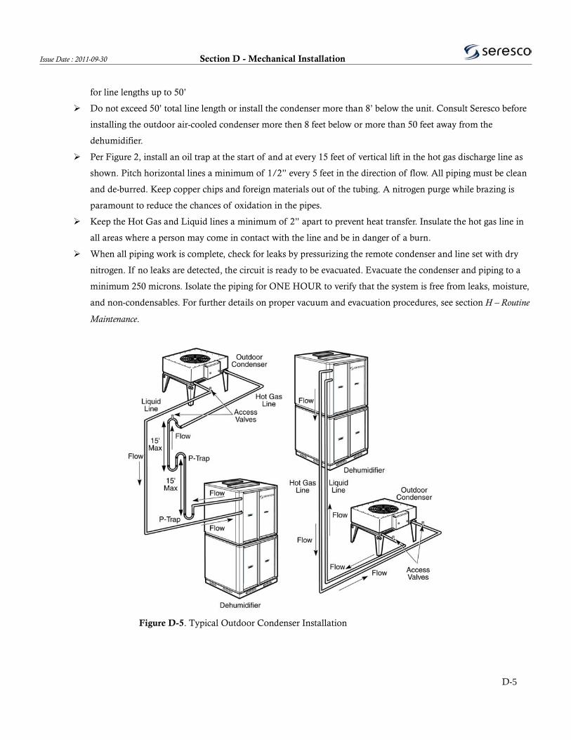
Per Figure 2, install an oil trap at the start of and at every 15 feet of vertical lift in the hot gas discharge line as
shown. Pitch horizontal lines a minimum of 1/2” every 5 feet in the direction of flow. All piping must be clean
and de-burred. Keep copper chips and foreign materials out of the tubing. A nitrogen purge while brazing is
paramount to reduce the chances of oxidation in the pipes.
Keep the Hot Gas and Liquid lines a minimum of 2” apart to prevent heat transfer. Insulate the hot gas line in
all areas where a person may come in contact with the line and be in danger of a burn.
When all piping work is complete, check for leaks by pressurizing the remote condenser and line set with dry
nitrogen. If no leaks are detected, the circuit is ready to be evacuated. Evacuate the condenser and piping to a
minimum 250 microns. Isolate the piping for ONE HOUR to verify that the system is free from leaks, moisture,
and non-condensables. For further details on proper vacuum and evacuation procedures, see section H – Routine
Maintenance.
Figure D-5. Typical Outdoor Condenser Installation
D-5

Section D - Mechanical Installation Issue Date : 2011-09-30
Charging of Remote Condensers
Once a proper evacuation has been accomplished the system is ready for charging. The outdoor air-cooled condenser
requires a field charge by the installing contractor. The field charge required depends on the size of the condenser and the
length of the piping. The unit nameplate will show the exact field charge required. The last vacuum can be broken with
liquid refrigerant. Monitor the exact amount of refrigerant added, as the total system charge must be per the unit nameplate.
Connect the control wiring to the terminals provided inside the electrical compartment of the dehumidifier and outdoor
condenser. Refer to the low voltage wiring schematic for details. The condenser fan(s) will not operate until this is complete.
Once you have charged and checked the condenser and line set for leaks, open the service valves located in the compressor
compartment of the dehumidifier. There is an access valve in the liquid line after the pump down valve. The pump down
valve can be manually closed during start-up mode via the controller. Add only as much refrigerant as is needed to get to the
total charge indicated on the nameplate. Never charge liquid into the suction line access valve! The receiver has 2 sight
glasses with float balls to help ensure the maximum and minimum refrigerant levels are easily met.
Fluid Cooler Installation
Fluid cooled units come with a separate pump for the fluid loop. NP Series units have an internal pump and expansion tank
for the glycol loop. PVC piping is highly recommended for fluid cooler installation.
D-6
Issue Date : 2011-09-30 Section D - Mechanical Installation
Factory Start-up Supervision
Seresco Technologies Inc. factory start-up supervision can be purchased with the equipment. A factory start-up
includes several key services:
The expertise of a factory-trained technician who will supervise the commissioning of the equipment.
This Seresco representative will assist the installing contractor with filling out the Start-Up Report.
They will also inspect the installation to make sure that the dehumidifier has been properly integrated with
the rest of the equipment on the job site.
Finally, they can train the maintenance personnel to operate and service the equipment if necessary.
A factory start-up does not include installation assistance. The installing contractor is responsible for ensuring
that the system is ready for start-up when the Seresco representative arrives. If the system is not ready, Seresco
reserves the right to bill the contractor for a second visit. When the installing contractor is confident the system
will be ready, contact the Seresco Sales representative to schedule the start-up. Please call at least two weeks
before the desired start-up date to prevent scheduling conflicts.
Items required for Start-Up
A service technician and a fully stocked service vehicle.
A set of refrigerant manifold gauges.
Air balancing equipment (magnehelic differential pressure gauge).
Volt/Amp/Ohm meters.
A digital thermometer w/clamp on sensors.
A halogen leak detector, R410a or R407c and a scale.
Items to be Completed Before Start-up
Refrigerant leak-check (with halogen leak detector) and inspect the unit for internal concealed damage.
Level and support the dehumidifier properly.
Install the outdoor air duct filters and damper (if applicable).
Install the condensate P- trap and drain lines and prime P-trap.
Pipe the remote condenser fan pressure controls to the condenser hot gas lines (if applicable).
Evacuate and leak-check the remote condenser line set (if applicable).
Tighten all electrical connections and verify that the line voltage is correct for the unit.
Install all controls and verify that all field wiring matches the schematic.
Fill and heat the pool and room to design conditions.
Install the pool water piping and a flow meter (if applicable). Purge all air from pool lines.
A complete system air balancing.
D-7

Section D - Mechanical Installation Issue Date : 2011-09-30
THIS PAGE HAS BEEN INTENTIONALLY LEFT BLANK
D-8

Issue Date : 2011-09-30 Section E - Electrical Installation
Electrical Installation
WARNING Disconnect all electric power, including remote disconnects, before servicing. Follow
proper lockout procedures to ensure that the unit is not accidentally powered. For variable frequency
drives, refer to the appropriate section of the manual. Verify with a voltmeter that all capacitors have
discharged. Failure to disconnect power and discharge capacitors before servicing could result in serious
injury or death.
Note : Use copper conductors only ! Unit terminals are not designed to accept other types of conductors.
Use of aluminium or other wiring may result in galvanic corrosion or overheating.
Note : Properly seal all penetrations made in the outer walls. Failure to due so may result in
unconditioned air entering the unit, water infiltrating the insulation or serious equipment damage. Ensure
that all metal shards and filings are swept to avoid possible corrosion or damage to electrical components.
Main Panel Power Connection
The field-installed power supply wires and over current devices must be sized to handle the minimum ampacity of the
dehumidifier without exceeding the maximum fuse size rating. Both the MCA and MOP are indicated on the unit
nameplate. Figure E-1 shows typical power wiring connections. Single-phase units require 3 wires, 2 power and one ground.
Three-phase units require 3 power wires and one ground wire. Connect the power supply wires to the main power
distribution block located inside the unit main electrical panel. For units with electric heaters and single-point power
connections, the power distribution block is located in the heater. For units with electric heaters and dual-point power
connections, the unit and heater must be powered independently. For units with mounted disconnects, ensure that the power
is brought first to the disconnect and then the power distribution block. Always verify the nameplate voltage before
connecting to the unit.
E-1
Section E - Electrical Installation Issue Date : 2011-09-30
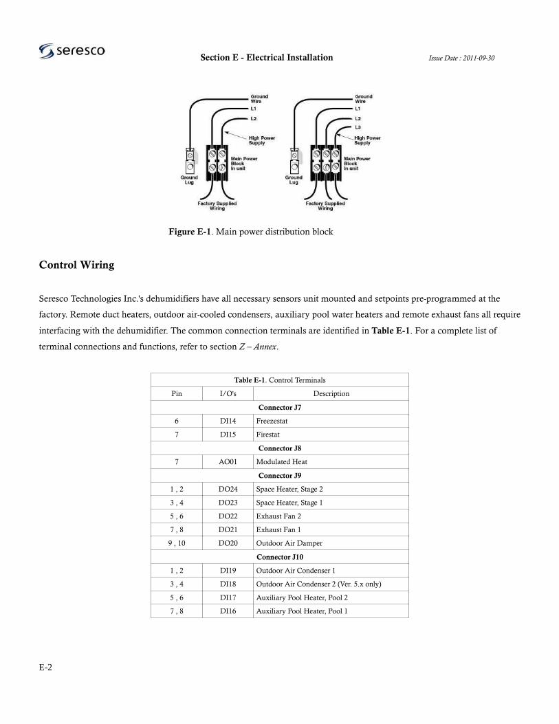
Figure E-1. Main power distribution block
Control Wiring
Seresco Technologies Inc.'s dehumidifiers have all necessary sensors unit mounted and setpoints pre-programmed at the
factory. Remote duct heaters, outdoor air-cooled condensers, auxiliary pool water heaters and remote exhaust fans all require
interfacing with the dehumidifier. The common connection terminals are identified in Table E-1. For a complete list of
terminal connections and functions, refer to section Z – Annex.
Table E-1. Control Terminals
Pin I/O's Description
Connector J7
6 DI14 Freezestat
7 DI15 Firestat
Connector J8
7 AO01 Modulated Heat
Connector J9
1 , 2 DO24 Space Heater, Stage 2
3 , 4 DO23 Space Heater, Stage 1
5 , 6 DO22 Exhaust Fan 2
7 , 8 DO21 Exhaust Fan 1
9 , 10 DO20 Outdoor Air Damper
Connector J10
1 , 2 DI19 Outdoor Air Condenser 1
3 , 4 DI18 Outdoor Air Condenser 2 (Ver. 5.x only)
5 , 6 DI17 Auxiliary Pool Heater, Pool 2
7 , 8 DI16 Auxiliary Pool Heater, Pool 1
E-2

Issue Date : 2011-09-30 Section E - Electrical Installation
WebSentry Connection
Requires RJ45 ethernet connection to the unit.
To get access to WebSentry® you need to register a user id with Seresco. Follow these instructions.
1) Go to the Seresco web page at http://www.serescodehumidifiers.com.
2) Select the Login link in the upper right corner.
3) Select the ‘Click here to register’ link in the WebSentry® login box.
4) Fill in the registration form and submit it. The email address will be your user id.
Follow these instructions to login to WebSentry® and view your Seresco unit.
1) Go to the Seresco web page at http://www. serescodehumidifiers.com.
2) Select the Login link in the upper right corner.
3) Enter login credentials in the WebSentry® login box and click Submit button.
4) Once you have logged in you will see a list of all Seresco units you have access to. The very first time you login
the list is empty since you do not yet have permission to see any unit (see Gain Access to Unit).
5) Too see more detailed information for a unit, click the job name link.
6) The main Conditions page shows you the current conditions including a trend graph showing the room
temperature, humidity and optionally the pool water temperature over the past 4 hours.
You can also see current setpoints, logs and some basic unit configuration by selecting the appropriate menu link.
Gain Access to Unit
To gain access to a Seresco unit you need to know the serial number of the unit and the last 6 characters of the MAC
address. The latter is printed on a bar code label on the control board where the network cable is plugged in. You can also
find this information from the System Info page from the key pad (accessible from User Settings). If you are not able to get
to this information you can also contact Seresco and someone will be able to help you get access to the unit.
Controlling Unit
To gain control of unit so that you can change setpoint, restart unit or modify some factory settings, you first have to
Connect to unit and have it maintain a live connection. By default the unit connects once a minute to upload latest sensors
readings and log entries and then disconnects again. Typically this does not take more than one second.
To get a live connection, click the Connect button on any page that has a Connect button. Keep pressing Connect button or
Web browser refresh button until Connect button changes to a Save and Refresh button.
E-3
Section E - Electrical Installation Issue Date : 2011-09-30
Another indication that unit is live is that the time stamp in the header under the job name changes to Live. Normally the
time stamp tells you the last time the unit connected to the WebSentry® server.
Once a live connection has been established you can change any unit parameter like setpoints and factory settings. From the
conditions page you can also start and stop the main blower and restart the unit. If unit is equipped with a purge feature, you
can also initiate purge from the conditions page.
Remote Operator Panel (ROP)
The Remote Operator Panel (ROP) looks identical to the local keypad but instead of being connected to the main control
board using a data ribbon cable, it uses a RS-485 serial port communication interface. Cat3 or Cat5 twisted pair cables must
be used between the ROP and the main CommandCenter control board.
The other difference between the local keypad and the ROP is that the ROP has its own processor and memory where the
menu system is stored opposed to the local keypad which just a “dumb” terminal displaying the menu system as controlled
by the main control board.
When installing or replacing the ROP you can run into several issues that will prevent the ROP from working properly. This
document covers all steps you need to take to ensure a good communication between ROP and main control board.
Testing Remote Operator Panel at the unit
To rule out any type of problem with the wiring between the unit and the ROP location, use a 3’-5’ wire and connect the
ROP to the main board right at the unit. All troubleshooting guides in this document applies to both testing ROP at the unit
and at its final location.
NOTE! When doing any rewiring like moving wires from J8 to JCOM or moving ROP between final location and testing it
at the unit, make sure the dip switches are in the off position (towards the 1 & 2 label on the dip switch socket). Do not move
to on position until powered up and red LED (L1) is lit up.
Using proper cable
We recommend using a twisted pair Cat3 or Cat5 cable. What is important is that the two signal wires are twisted together.
Twisting the signal wires together acts as a noise filter. If not using this type of cable you can run into communication issues.
E-4

Issue Date : 2011-09-30 Section E - Electrical Installation
Especially if the ROP is far away from the unit. For easier troubleshooting, use the following coloured wires.
Table E-2. ROP Connections
Cat3/Cat5 Wire Remote Keypad J8 JCOM
Orange J8-1 (+24V) Pin 1 Pin 5
White/Orange J8-2 (GND) Pin 2 Pin 4
Blue J8-5 (+ 485) Pin 5 Pin 6
White/Blue J8-6 (- 485) Pin 6 Pin 7
Connecting wires
Before doing any wiring, ensure there is no power over the wires. Either power unit off or unplug terminal (J8 or JCOM) to
where the ROP is connected. Connect wires to main control board terminal as listed in Table 1. By default you should be
using terminal J8. JCOM is only used as a backup RS-485 port or when more than one RS-485 port is needed. Open up the
back of the ROP and feed wires through the hole of the back plate and connect wires to terminals as listed in Table E-2.
Check communication
Power up unit or plug in terminal block again. If the two power wires are wired correctly you should now see the red L1
LED light lit up in the ROP. If there is power you can now safely activate the signal wires. You do this by moving the two
dip switches (SW1) next to the green terminal block towards the top of the ROP. This is easiest done by using a small flat
head screw driver.
If signal wires are wired up correctly you should see the main sensor screen within a few seconds (possibly the system
startup screen).
If the screen is blank, you see the Welcome screen for more than 10 seconds, or see other messages indicating the ROP is
trying to establish communication, continue reading this document to help you troubleshoot the problem.
No power to ROP (LED L1 not lit up)
First make sure unit is powered up and that the terminal block (J8 or JCOM) is plugged into the main control board.
Make sure wires are wired as listed in Table 1. Make sure that the terminal in the ROP is grabbing onto the copper and not
the insulation. Check this at the main control board as well. There could possible be a kink in the cable causing a broken
wire. Test ROP at unit using a short cable. Try both J8 and JCOM in case there still is no power connecting to J8. If still no
power you most likely have a failed ROP terminal board.
E-5

Section E - Electrical Installation Issue Date : 2011-09-30
Power to ROP but showing a blank screen
There should never be a blank screen when there is power to the ROP. At the minimum the ROP should show that it is trying
to connect to the main control board. There are only two reasons why there is a blank screen. The ROP has a contrast dial. It
might have been moved so that there is no contrast at all resulting in a blank screen. The contrast dial is a white dial in the
upper left corner next to the terminal board. Use a small screw driver to adjust it. If you see no change at all on the screen
when adjusting the dial, then this is not the problem. The second reason for a blank screen is if the menu program has been
erased from memory. A static chock could possible cause this. All ROP’s are tested at the factory so there should have been a
program installed when the ROP was shipped from factory. Once again, to really rule out a wiring issue, test the ROP using
a short cable right at the unit.
Power to ROP but not establishing a connection
First thing to check is that the two dip switches has been moved up to activate the signal wires. Make sure wires are wired as
listed in Table E-1. Make sure that the terminal in the ROP is grabbing onto the copper and not the insulation. Check this at
the main control board as well. There could possible be a kink in the cable causing a broken wire. Test ROP at unit using a
short cable. Try both J8 and JCOM in case there still is no communication when wired to J8. If still no communication, read
the next section to do one more last test.
Check for communication attempt
From the main control board you are able to look at data streams for anyone of the 3 serial ports. We can use this to
determine if the ROP at least is getting some message through to the main control board. Start up the unit in Service Mode.
Go to the Main Menu (1) and then Service (6) – Network (3) – Console (2). Use arrow keys to select port. Port D is RS-485
on J8 and Port C is RS-485 on JCOM. Select 1 to start serial port monitor console. If there is communication you should see
a bunch of characters within a few seconds. You should also see them changing every few seconds. Stop by pressing 2 or the
Back key. If there is no character stream them most likely the RS-485 communication chip on either the ROP or the main
controller board has failed. There is no way to check which one so if you do not have a second ROP a second board to test
with, there is no way to know. With our newer boards (4.1 and later) we have two RS-485 ports as discussed in this
document so the chances that both communication chips have failed are very small. For these boards we will replace the
ROP with a new one. For older units using a 3.1 board or older, there was only one RS-485 port so for these units we have to
replace both the main controller board and the ROP.
If there is a character stream but still no communication at the ROP, check the serial port communication settings to make
sure they have not been changed. See next section. Check serial port configuration settings. From the Main Menu, go to
E-6

Issue Date : 2011-09-30 Section E - Electrical Installation
Factory Settings (5) – Network (5) – Serial Ports (2). Then select either Port C (JCOM) or Port D (J8) depending on which
terminal you are testing. User should be set to Seresco, Baud Rate to 57600, Databits to 8, Parity to None. The timer Reply
Delay should be at least 500 but new recommendation is 750. The timer Invalid Data should be set to 1000.
Echo Test is by default set to Yes but you can try setting this to No to see if this will establish a connection. By default a RS-
485 is echoing back every sent message back to the sender. Our controller is using this to test for a robust connection. We
have however seen cases where the RS-485 communication chip partially has failed where it no longer echoes back sent
messages but otherwise functions just fine. By setting the Echo Test to No we can test for this fault.
If you did any configuration change but still no communication you can try doing a System Restart to see if it this will help.
Either power off unit in between or unplug ROP terminal from board to cycle the ROP. If you still are not being able to
establish communication after doing these steps, we have an unknown fault and the ROP needs to be replaced. If this already
is a new ROP, we need to replace the board.
ROP shows Version Mismatch
If the ROP display show Version Mismatch it means you are connecting a ROP to a unit running a software version with
which the ROP is not compatible. Get a new ROP with a version compatible with the software version on the unit.
E-7

Section E - Electrical Installation Issue Date : 2011-09-30
THIS PAGE HAS BEEN INTENTIONALLY LEFT BLANK
E-8

Issue Date : 2011-09-30 Section F - Startup
Start-Up
WARNING Disconnect all electric power, including remote disconnects and discharge all motor
start/run capacitors before servicing. Follow proper lockout procedures to endure the unit cannot
accidentally be powered. For variable frequency drives or other energy storing components, refer to the
appropriate manufacturer's literature for allowable waiting periods for discharge of capacitors. Verify with
a voltmeter that all capacitors have discharged. Failure to disconnect power and discharge capacitors
before servicing could result in serious injury or death.
WARNING Rotating components ! During installation, testing, servicing and troubleshooting of
this product it may be necessary to measure the speed of rotating components. Have a qualified or licensed
service individual who has been properly trained in handling exposed rotating components perform these
tasks. Failure to follow all safety precautions when exposed to rotating components could result in serious
injury or death.
WARNING Live electrical components ! During installation, servicing and troubleshooting of
this product, it may be necessary to work with live electrical components. Have a licensed electrician or
other qualified individual perform these tasks. Failure to follow all electrical safety precautions when
exposed to live electrical components could result in serious injury or death.
Pre-Startup Checklist
A complete start-up is required to ensure that all systems have been configured to ensure optimal and reliable unit operation.
Final adjustments should be made when all space and water temperatures are at design conditions. The use of auxiliary or
portable air heaters may be required to heat the room. Read this section thoroughly before attempting to commission the
Seresco Technologies Inc. dehumidifier. Ensure that the unit installation conforms to all recommendations made by Seresco
Technologies Inc. in this manual. Complete the pre start-up section of the warranty registration / start-up form provided in
section Z – Annex.
Note : Do not use the unit as a construction site heater. Construction material will infiltrate the unit and
can significantly deteriorate unit performance and lifespan.
F-1
Section F - Startup Issue Date : 2011-09-30
General Checks
Ensure that the unit has been installed on a level location
Check to ensure all packing materials and shipping brackets have been removed from the unit
Verify that any remote space heating coil is installed in the supply air duct (after the unit) and not in the
return air duct (before the unit)
Ensure supply and return air ducts have been connected
Verify damper operation and alignment, as damper blade position may change in shipment
Check that air filters are clean, in place and positioned properly
Remove any debris from the unit interior
Close and secure all unit access door in the airstream
Inspect electrical connections to the unit and unit controllers
Connections should be clean and secure
Compare the actual wiring with provided wiring diagrams
Reference the controls section of this manual for more details on factory mounted controls
Leave this manual with the unit
Fan/Motor-Related Checks
Ensure that fan assembly braces have been removed
Rotate all fan wheels manually to confirm they turn freely in the proper direction
Inspect fan motor and bearings for proper lubrication
Coil-Related Checks
Ensure coil and condensate drain piping connections are complete
Check the piping and valves for leaks. Open and close the valves to check operation
Remove all foreign material from the drain pan
Test the drainage and prime the P-trap by pouring water into the drain pan
Note : For units with water cooled air conditioning. The use of untreated or improperly treated water in
coils may result in scaling, corrosion, erosion, algae or slime. It is recommended that the services of a
qualified water treatment specialist be engaged to determine what water treatment, if any, is required.
F-2

Issue Date : 2011-09-30 Section F - Startup
Electrical Checks
Check nameplate for power requirements and confirm that it matches the available power supply
Voltage must be within ±10% of nameplate voltage. Verify that all field wiring matches provided wiring
schematics. Inspect and tighten all field and factory wiring
Leave power on and allow 24 hours of crankcase heater operation before attempting start-up.
Ensure that the control wiring has been installed to the outdoor condenser / cooler if applicable
Ensure all peripheral controls and sensors are connected and wired correctly
Pool Water Checks
For units with pool water heaters only. Energize the circulating pump and establish water flow. Inspect the
piping and repair any water leaks. Ensure that control wiring has been installed between the unit and the
auxiliary pool water heater
Refrigerant Line Checks
Verify that all service valves in the refrigeration lines are open
Leak test (with halogen leak detector) all factory and field piping. Shipping and handling may have caused
refrigerant leaks inside the dehumidifier
Start-up Procedure
All appropriate fields and sections of the warranty registration / start-up form should be completed. A proper start-up
requires that the unit be run and monitored in all modes of operation at design conditions with the operating data recorded
on the forms provided in section Z – Annex. Seresco's service technicians review every report to ensure all aspects of the
system are functioning within normal operating parameters. Carefully follow the process detailed in the start-up report. If
the space is not at design conditions at the time of start-up, a follow-up visit for final adjustment and balancing is required.
Mail or fax the completed warranty registration / start-up form back to Seresco to validate your unit's warranty See section
Y – Warranty for further information. If you do not have a start-up report, call Seresco for a new copy or download a PDF
version from www.serescodehumidifiers.com.
F-3

Section F - Startup Issue Date : 2011-09-30
Note : Warranty is void unless, upon start-up of the unit, the “Warranty Registration and Start-up
Report” is completed and sent to the factory within one week of initial start-up. This report will also
register the compressor warranty with the compressor manufacturer.
Power Turned ON (or after power failure)
When powered, the blower begins to operate immediately and will do so continuously. The microprocessor initiates a self-
test and runs systems diagnostics algorithms. If all systems check out, the microprocessor used sensor feedback to resume
normal unit operation. The microprocessor will confirm that the compressor has been off for at least five minutes using its
internal clock.
The CommandCenter keypad display should show current sensor readings and the main menu. For keypad layout and
function refer to section G – Nx Series Unit Operation, under CommandCenter operation.
Check time and set-points by doing the following:
Current Time: 1-Main Menu, 4-User Settings, 2-Date&Time
Set-points: 1-Main Menu, 1-Setpoints
Check remote operator panel response, if applicable, and record all data on the start-up forms.
Check Component Operation
To force component operation, do the following:
1-Main Menu, 6-Service, 2-Forced Contacts
To activate, switch component status from OFF/No to ON/Yes, to switch off do the reverse
Ventilation components (under 2-Ventilation) to check include (as applicable) the main blower, condenser fan(s), damper(s),
exhaust fan(s) and purge fan(s) (also known as exhaust 2). Ensure proper, uninhibited rotation of the fans, check and record
amperage readings on the start-up forms.
For heating components (3-Heating), first check whether the space heating option is staged or modulating. To activate
modulated heating, select the modulated option, then use the up and down arrows followed by Enter to select the desired
F-4
Issue Date : 2011-09-30 Section F - Startup
heating load. To activate Staged heating, enable stage 1 (and stage 2 if applicable).
Note : for units equipped with a gas water boiler and modulated valve, activate stage 1 first to start the
circulating pump(s), then activate modulated heating as described above.
CAUTION Ensure that the main blower is on while testing the heating system or compressor.
Enabling the Compressor(s)
Compressors are disabled after testing at the factory to prevent their accidental non-supervised start-up. To start the
compressor(s):
1-Main Menu, 5-Factory Settings, 4-Compressor, 1-Enabled and switch to Yes to enable the compressor
Ensure that design conditions (return air temperature and relative humidity) are established, the main blower is running, and
a gauge set is attached to verify compressor rotation and performance. Make sure that gauge readings correspond to unit
pressure sensor readings shown on the keypad.
Forced Modes
Check unit condition under different modes of operation by doing the following:
Set forced demands: 1-Main Menu, 6-Service, 1-Forced Demands, 1-Compressor 1
To run the unit in dehumidification mode, choose Dehumidify and check pressure, temperature readings. Allow the
compressor to run for 20-30 minutes and ensure that the superheat is within 19-22°F, making adjustments if required. Record
all data.
To run the unit in dehumidification and pool heat modes, select Pool Heat while the compressor is still running. Make sure
that design water flow is provided to the unit. Record actual water flow GPM and pressure.
Confirm and record superheat data. Deselect dehumidification and pool heat modes by selecting OFF/No and allow the
F-5

Section F - Startup Issue Date : 2011-09-30
compressor to pump down.
To run the unit in air conditioning mode, select 2-A/C, then air conditioning and pool heat modes. Follow procedure
outline above, recording all data on the start-up forms.
For units with two or more compressors, complete the process for each compressor individually, and finally both together.
To restart the unit in normal mode, do the following:
1-Main Menu, 6-Service, 6-Commission, 2-Commissioned and switch to ON/Yes
1-Main Menu, 3-System, 3-System Restart, 1-Yes
After the system shuts down and restarts, select Normal Mode
Submit the completed start-up report by Fax: 1-613-741-3375 or e-mail: [email protected].
Factory Start-up Supervision
Seresco Technologies Inc. factory start-up supervision can be purchased with the equipment. A factory start-up includes
several key services:
The expertise of a factory-trained technician who will supervise the commissioning of the equipment.
This Seresco representative will assist the installing contractor with filling out the Start-Up Report.
They will also inspect the installation to make sure that the dehumidifier has been properly integrated with
the rest of the equipment on the job site.
Finally, they can train the maintenance personnel to operate and service the equipment if necessary.
A factory start-up does not include installation assistance. The installing contractor is responsible for ensuring that the
system is ready for start-up when the Seresco representative arrives. If the system is not ready, Seresco reserves the right to
bill the contractor for a second visit. When the installing contractor is confident the system will be ready, contact the Seresco
Sales representative to schedule the start-up. Please call at least two weeks before the desired start-up date to prevent
scheduling conflicts.
F-6
Issue Date : 2011-09-30 Section F - Startup
Items required for Start-Up
A service technician and a fully stocked service vehicle.
A set of refrigerant manifold gauges.
Air balancing equipment (magnehelic differential pressure gauge).
Volt/Amp/Ohm meters.
A digital thermometer w/clamp on sensors.
A halogen leak detector, R410a or R407c and a scale.
Items to be Completed Before Start-up
Refrigerant leak-check (with halogen leak detector) and inspect the unit for internal concealed damage.
Level and support the dehumidifier properly.
Install the outdoor air duct filters and damper (if applicable).
Install the condensate P- trap and drain lines and prime P-trap.
Pipe the remote condenser fan pressure controls to the condenser hot gas lines (if applicable).
Evacuate and leak-check the remote condenser line set (if applicable).
Tighten all electrical connections and verify that the line voltage is correct for the unit.
Install all controls and verify that all field wiring matches the schematic.
Fill and heat the pool and room to design conditions.
Install the pool water piping and a flow meter (if applicable). Purge all air from pool lines.
A complete system air balancing.
F-7

Section F - Startup Issue Date : 2011-09-30
THIS PAGE HAS BEEN INTENTIONALLY LEFT BLANK
F-8

Issue Date : 2011-09-30 Section G - NP Series Unit Operation
NP Series Unit Operation
Sequence of Operation
The standard sequence of operation for a Seresco dehumidifier is relatively simple. Whenever the compressor operates, the
evaporator is always dehumidifying and cooling the return air. The heat removed from the air at the evaporator, as well as
the heat from the compressor's action, must be rejected to one of three heat sinks; room air, pool water (if applicable) or
outdoors. The microprocessor will direct the heat to where it is needed based on room conditions.
Dehumidification Mode
Dehumidification Mode occurs when the space requires dehumidification. The air discharged from the unit is drier and
approximately 20°F warmer than when it entered. This mode engages when the return air relative humidity is above the set-
point. The hot gas is condensed in the reheat coil, returning heat to the room air.
Air Conditioning Mode
Air Conditioning Mode occurs when the room air requires only cooling, all of the refrigerant hot gas is directed outdoors,
either directly (outdoor air cooled condenser, etc) or indirectly (water cooled, outdoor air fluid cooler, etc). The air
discharged from the unit has been dehumidified and is about 15°F cooler than when it entered. In stage one air
conditioning, the compressor starts (if not already operating in dehumidification mode), the evaporator sees nominal air
flow, and the hot gas condenses at the outdoor air cooled condenser or equivalent. In stage two air conditioning, the system
performs as in stage one air conditioning, except the evaporator bypass damper closes to maximize air moving across the
evaporator coil.
Pool Heating Mode
If the unit is in dehumidification or air conditioning mode, there is free heat available in the system to heat the pool water.
This pool water heating mode engages if the pool water drops below the set-point. Water heating alone will not start the
compressor, thus there must be a pre-existing demand for this mode to operate. When in pool water heating mode, the pool
water control valve directs hot refrigerant through the coaxial heat exchangers. This system also acts as a refrigerant
subcooler, increasing system efficiency and capacity. If there is no other demand for the compressor to operate, the
microprocessor sends a signal to the external auxiliary pool water heater (provided by others). No additional controls are
required to operate the auxiliary water heater.
G-1

Section G - NP Series Unit Operation Issue Date : 2011-09-30
Continuous Blower Operation
Units have been factory wired for continuous blower operation. This helps prevent air stratification and stagnation. This is
also required to ensure that the sensors produce accurate data.
Compressor Start Sequence
All Seresco NE/NP Series units have a pump down sequence and anti-short cycle timer. When a demand requires the
compressor to operate, the following sequence occurs: blower operation is confirmed by the microprocessor and anti short
cycling timer (ASCT) sequence completes, the pump down solenoid valve opens, the low pressure safety switch will activates
at 25psig, and the compressor starts.
Space Heating Option
The microprocessor control is designed to control a space-heating coil mounted locally or remotely. When the room
temperature drops below the set point, the microprocessor will send a signal to start the heating coil.
Purge
Used for complete air changeover in pool environment after super-chlorination. Return air damper is completely closed,
resulting in all air from the pool space being exhausted, while fresh air is brought in from the outdoors. Also used for
economizer cooling when conditions warrant.
Heat Recovery
The energy a room loses from the exhaust air, as a result of the fresh air requirements, can represent up to 50 % of the
room's heating requirements. Approximately 50-60 % of this exhaust heat can be recaptured with a heat recovery loop. By
doing so it supplies heat to warm the cold outside air and can provide generous energy savings to the room to reduce heating
costs. During freezing weather conditions the outdoor air can provide much of the dehumidification required, and
minimizing the time the compressors run offsetting some of the running electrical costs.
Our typical energy recovery loop consists of two glycol coils: one in the outside air intake and the other in the exhaust air-
stream. The coils are connected in counter-flow closed loop piping system. The system comprises an inline fluid cooled
pump, an air separator, and in some larger systems a pressure tank and pressure gauge. By circulating a glycol mixture,
G-2

Issue Date : 2011-09-30 Section G - NP Series Unit Operation
typically 30%, we can extract enough heat from exhaust air stream to preheat the outside air intake to about 50-60% of the
room temperature. Extracting more heat from the exhaust air stream is possible but would also lead to possibly freezing of
the exhaust air and would require a more complex and costly system of frost prevention. Keeping our effectiveness down to
50-60% reduces initial cost and keeps things simple.
Figure G-1. Heat recovery loop
Types of Solutions
We recommend and typically use ethylene glycol in our systems but local codes or building requirements may specify
propylene glycol mixtures. The higher viscosity of propylene means a stronger pump is required or a lower circulating water
flow will occur. So it is best to contact the factory if a switch from one glycol to another is preferred. It is important to use
corrosion inhibitors and in the correct amount. When adding the corrosion inhibitor solution please followed the suggested
instructions for the required quantity of fluid. Seresco strongly recommends that the glycol, if not already mixed, be mixed
with distilled water. Topping up and pressurizing the system can be done with clean tap water. In municipalities where local
tap water has a high mineral content, Seresco strongly advises the use of distilled water to prevent “sludging” and premature
failure.
Annual testing should be made of the fluid solution to ensure the adequate glycol concentrations and corrosion inhibitor
protection. Freeze point and PH test strips are available from your local plumbing supply house. It is important to ensure the
solution will not freeze in the case of a power failure or that it is not acidic and will corrode the system. The glycol mix
should be replaced after 5 years or when quality is deem unsatisfactory and cannot be restored.
G-3

Section G - NP Series Unit Operation Issue Date : 2011-09-30
Filling or Refilling the Glycol Loop
When filling the system please insure all air has been removed. Air in the system will cause corrosion and improper
functioning of the pump. Do not run the pump for any extent time with air in the system it will foam up the glycol and this
will make it difficult to remove the air. If this happens pressurize the system with some water to about 15 PSI and let stand
overnight. Before restarting vent as much air as possible running the pump for very short burst to move the water and any
possible air bubbles around slowly to the vents. For systems with a pressure tank keep the system under a 10-15 PSI positive
pressure to ensure no air get into the system. If the system is left dry for any period of time electrically disable the pump to
avoid it possible coming on without fluid in the system. Please keep record, near the unit, the type of glycol used; ethylene or
propylene, the two types should not be mixed. Keep careful track of what percentage by volume was used and when it was
changed. And the last time it was checked.
G-4

Issue Date : 2011-09-30 Section G - NP Series CommandCenter Operation
CommandCenter Operator Panel – Software Version 5.3.2
Introduction
This document describes the different features of the Operator Panel (installed locally or remotely) that is used with the NP
Series of dehumidification units.
Startup Screens
When the unit start up you will see the following menu screen. A 60 second timer is started and if no selection is made
before timer expires, Normal Mode will automatically be selected.
1. Normal Mode
2. Service Mode
Selecting Normal Mode will take you to the main sensor screen. If the voltage monitor fault signal is not active, blower will
start right away. If voltage monitor fault signal is active, 60 second timer will continue running. When timer expires, the
voltage monitor fault signal will be checked again. If signal now is cleared, the blower will start, otherwise blower will
remain off and there will be a voltage monitor fault alarm.
Navigation Mode and Edit Mode
The menu system implements two different modes where the keys have different meanings. Navigation mode is used to
navigate the menu system and Edit mode is used when changing data.
The following keys are used in Navigation mode:
Keys 1-3 (and 4-6) are used to select a menu item. If there are more than 6 menu items, menu items will be
listed 1-3 on every screen.
Up and Down arrows are used to scroll up or down a page. Arrows at the top right corner indicates which
direction you can scroll. If no more than 6 items either down or up arrow will be displayed (no scrolling
“around corner”). If more than 6 menu items, both arrows will be displayed and you can scroll “around the
corner”. Obviously no arrows when 3 or less menu items.
Back key takes you back to previous menu level.
G-6

Section G - NP Series CommandCenter Operation Issue Date : 2011-09-30
Enter key has a special meaning. From any menu screen it will take you directly back to the main screen (the
sensor screen). If you now press the Back key it will take you back to the screen where you were before pressing
Enter. On the sensor screen you can still use the Up and Down arrows to scroll up and down a page and the
Back key will still take you back to where you were before pressing Enter. If you press 1 however (Main Menu)
the back shortcut is lost (it’s not a true history list yet).
Key 3 on the sensor screen is another hidden feature. It will toggle sensor readings between displaying values
with a one decimal prevision and no precision. Default is no precision. This applies to all temperatures and the
humidity level.
To enter Edit mode you select the number key corresponding to the data item you want to edit on a navigation screen with
data items. To indicate that you are in edit mode, the data value is highlighted.
The following keys are used in Edit mode:
Keys 1-3 are not used.
Up and Down arrows are used to scroll up and down in the value list. More info about different types of data
items later in this document.
Back key takes you back to navigation mode and cancel any changed data. Data is with other words not saved
when you press the Back key.
Enter key will save the data and most of the time take you directly back to navigation mode (covered under data
types).
Data Types
Most of the data (properties) you can change are changed using values in a selection list. You use the Up and Down arrows
to scroll up and down in the selection list. You can scroll “around the corner”. For data items with only two selection items
(e.g. Yes/No), you can use either the up or down key to toggle between the two values.
Most Integer values are edited as lists with a min and max range. The value might also be restricted to be changed in specific
increments (e.g. 5, 10, 15, 20, …). In a few rare cases integer values are entered one digit a time. When entering edit mode,
the integer value will be displayed as a five digit zero padded number. To enter a number less than 5 digits, leave the first
digits at 0. Press Enter until all digits are set.
Date and Time values are edited in a special way. Using date as an example, when entering edit mode, the year (or last two
digits of the year) will be highlighted. Use Up and Down arrows to change year. When done, press Enter. Now the month
G-7

Issue Date : 2011-09-30 Section G - NP Series CommandCenter Operation
will be highlighted and you change it in the same way. Press Enter again and the day is highlighted. Pressing Enter a final
time will save the new date. Pressing Back at any time when editing the date will cancel the change operation and take you
back to navigation mode.
A time value is entered in the same way as a date. An IP address is entered the same way as date and time except that you
edit one digit at a time. Passwords are entered one digit at a time pressing Enter after each digit.
Information Messages
Certain actions and certain conditions will generate information messages. Information messages will popup over current
menu screen. The message can be cleared by pressing either key 1 or 2. Key 1 will clear current message and key 2 will clear
all queued messages. Messages can be of three different types. Short, Long or Confirmed. A short message will be cleared
automatically after 3 seconds (default). A long message will be cleared after 5 minutes (default). A confirmed message will
never be cleared (unless there is a system restart) and have to be cleared by pressing key 1 or 2.
Menu Structure Quick Reference
The root menu screen is where you see all the sensors and one menu option that takes you to the Main Menu. Some menu
selections are dependent on current unit configuration and will not always be displayed. These menu selections are marked
as Optional. For data menu items, the default value is displayed in the summary.
1. User Settings
1.1. Setpoints
1.1.1. Temperature
1.1.2. Humidity
1.1.3. Pool Temp
1.1.4. Pool 2 Temp
1.1.5. Freezestat
1.1.6. Purge Temp
1.1.7. Economizer
1.1.8. Disable A/C
1.1.9. Heat Recovery
1.2. Date & Time
1.2.1. Date
G-8

Section G - NP Series CommandCenter Operation Issue Date : 2011-09-30
1.2.2. Time
1.2.3. Zone
1.2.4. Date Format
1.2.5. Time Format
1.3. System Info
1.4. Occupied Schedule
1.4.1. Empty
1.4.1.1. Day(s)
1.4.1.2. On
1.4.1.3. Off
* 1.3.2 – 1.3.3 same as 1.3.1
1.5. Filter Schedule
1.5.1. Date
1.5.2. Interval
1.6. Display
1.6.1. Backlight
1.6.2. Temp Unit
1.6.3. Reset Display
1.7. User Password
1.7.1. Enabled
1.7.2. Password
1.7.3. Retention
1.8. Remote OP * Only visible on Remote OP
1.8.1. Version Info
1.8.2. Port Configuration
2. Alarms
2.1. Current Alarms
2.2. Alarm Log
3. System Control
3.1. Start/Stop Blower
3.2. System Restart
3.3. System Status
3.3.1. Environment
3.3.2. Compressor
3.3.3. Ventilation
G-9

Issue Date : 2011-09-30 Section G - NP Series CommandCenter Operation
3.3.4. Network
3.3.5. Serial Ports
3.3.6. Control Status
3.4. Purge
4. Factory Settings
4.1. Ventilation
4.1.1. Options
4.1.1.1. Purging
4.1.1.2. Economizer
4.1.1.3. Eco Offset OA
4.1.1.4. Eco Offset DP
4.1.1.5. Fire Reset
4.1.2. Blower
4.1.2.1. Normal Speed
4.1.2.2. Max Speed
4.1.3. Timers
4.1.3.1. Stabilize
4.1.3.2. Freezestat 1
4.1.3.3. Freezestat 2
4.1.3.4. No Airflow
4.1.3.5. Purge Time
4.1.3.6. Dirt Filt Dly
4.2. Compressors
4.2.1. Configuration
4.2.1.1. Compressor 1
4.2.1.1.1. Available
4.2.1.1.2. Resource ID
4.2.1.2. Compressor 2
4.2.1.2.1. Available
4.2.1.2.2. Resource ID
4.2.2. Options
4.2.2.1. Enabled
4.2.2.2. Design
4.2.2.3. Refrigerant
4.2.2.4. OACC Type
G-10

Section G - NP Series CommandCenter Operation Issue Date : 2011-09-30
4.2.2.5. Emergency Heat
4.2.2.6. Superheat
4.2.2.7. Reheat Steps
4.2.2.8. Reheat Time
4.2.2.9. Reheat Calib
4.2.2.10. BPD Steps
4.2.2.11. BPD Turn Time
4.2.2.12. BPD Stabilize
4.2.2.13. Partial Mode
4.2.2.14. Partial Transit
4.2.2.15. PD At Start
4.2.2.16. PSI Monitor
4.2.3. Timers
4.2.3.1. Min Startup
4.2.3.2. Stabilize
4.2.3.3. Min Run Time
4.2.3.4. Min Stop Time
4.2.3.5. Alarm Stop
4.2.3.6. Anti Block
4.2.3.7. Superheat Dly
4.2.3.8. SucTemp Dly
4.2.3.9. Oil Fault
4.2.4. Pressures
4.2.4.1. LP Vacuum
4.2.4.2. LP Alarm
4.2.4.3. LP Start
4.2.4.4. LP Normal
4.2.4.5. LP Deadband
4.2.4.6. LP Max
4.2.4.7. HP Min
4.2.4.8. HP Alarm
4.2.4.9. HP Relief
4.2.4.10. HP OACC Min
4.2.4.11. HP OACC Max
4.2.4.12. OACC HP Change
G-11

Issue Date : 2011-09-30 Section G - NP Series CommandCenter Operation
4.2.4.13. OACC Deadband
4.3. Space Control
4.3.1. Room Temperature
4.3.1.1. Deg*Min On
4.3.1.2. Deg*Min Off
4.3.1.3. Setpoint Adj
4.3.2. A/C
4.3.2.1. Operation
4.3.2.2. Deg*Min On
4.3.2.3. Deg*Min Off
4.3.2.4. Sensor
4.3.3. Heating
4.3.3.1. Type
4.3.3.2. Deg*Min On
4.3.3.3. Deg*Min Off
4.3.3.4. Sensor
4.3.3.5. Mod Step Size
4.3.3.6. Stage 2 On
4.3.4. Humidity
4.3.4.1. Deg*Min On
4.3.4.2. Deg*Min Off
4.3.4.3. Temp Offset
4.3.4.4. High Humidity
4.3.5. Deadbands
4.3.5.1. Air Temp Low
4.3.5.2. Air Temp High
4.3.5.3. Humidity Low
4.3.5.4. Humidity High
4.3.5.5. Heat Rec High
4.3.5.6. SA Temp Low
4.3.5.7. SA Temp High
4.4. Pool Control
4.4.1. Pool 1
4.4.2. Pool 2
4.4.3. Contact 2
G-12

Section G - NP Series CommandCenter Operation Issue Date : 2011-09-30
4.4.4. 100% Heating
4.4.5. Heat Sink
4.4.6. Min Out Temp
4.4.7. High Flow Dly
4.4.8. HP Pool Fault
4.4.9. HP Relief
4.4.10. Waterflow Rec
4.4.11. Max Trips Time
4.5. Network
4.5.1. TCP/IP
4.5.1.1. DHCP
4.5.1.2. IP
4.5.1.3. Mask
4.5.1.4. GW
4.5.1.5. DNS
4.5.1.6. Link Monitor
4.5.1.7. Start Device
4.5.1.8. Reboot Device
4.5.1.9. Reboot Delay
4.5.2. Serial Ports
4.5.2.1. Port B (RS-232)
4.5.2.1.1. User
4.5.2.1.2. Baud Rate
4.5.2.1.3. Databits
4.5.2.1.4. Parity
4.5.2.1.5. Flow Control
4.5.2.1.6. Reply Delay
4.5.2.2. Port C (RS-485)
4.5.2.2.1. User
4.5.2.2.2. Baud Rate
4.5.2.2.3. Databits
4.5.2.2.4. Parity
4.5.2.2.5. Echo Test
4.5.2.3. Port D (RS-485)
4.5.2.3.1. User
G-13

Issue Date : 2011-09-30 Section G - NP Series CommandCenter Operation
4.5.2.3.2. Baud Rate
4.5.2.3.3. Databits
4.5.2.3.4. Parity
4.5.2.3.5. Echo Test
4.5.3. WebSentry
4.5.3.1. Enabled
4.5.3.2. Use DNS
4.5.3.3. IP
4.5.3.4. Port
4.5.3.5. Comm Interval
4.5.3.6. Comm Segment
4.5.3.7. Stay Alive
4.5.4. BACnet [Optional]
4.5.4.1. Enabled
4.5.4.2. Interface
4.5.4.3. Device ID
4.5.4.4. Port
4.5.4.5. Heartbeat
4.5.5. Modbus [Optional]
4.5.5.1. Device ID
4.5.6. LON [Optional]
4.5.6.1. Enabled
4.5.6.2. Interface
4.5.6.3. Refresh Rate
4.6. Inputs/Outputs
4.6.1. Sensor Type
4.6.1.1. HP
4.6.1.2. LP
4.6.1.3. Superheat
4.6.1.4. HP 2
4.6.1.5. LP 2
4.6.1.6. Superheat 2
4.6.1.7. Return Air
4.6.1.8. RA Humidity
4.6.1.9. Outdoor Air
G-14

Section G - NP Series CommandCenter Operation Issue Date : 2011-09-30
4.6.1.10. OA Humidity
4.6.2. Sensor Usage
4.6.2.1. HP
4.6.2.2. LP
4.6.2.3. Superheat
4.6.2.4. Suct Temp
4.6.2.5. Discharge
4.6.2.6. Evap Temp
4.6.2.7. HP 2
4.6.2.8. LP 2
4.6.2.9. Superheat 2
4.6.2.10. Suct Temp 2
4.6.2.11. Discharge 2
4.6.2.12. Evap Temp 2
4.6.2.13. Return Air
4.6.2.14. RA Humidity
4.6.2.15. RA Dew Point
4.6.2.16. Outdoor Air
4.6.2.17. OA Humidity
4.6.2.18. OA Dew Point
4.6.2.19. Supply Air
4.6.2.20. Exhaust Air
4.6.2.21. Reheat Temp
4.6.2.22. Pool In
4.6.2.23. Pool Out
4.6.2.24. Pool 2 In
4.6.2.25. Pool 2 Out
4.6.3. Sensor Calibration
4.6.3.1. HP
4.6.3.2. LP
4.6.3.3. Superheat
4.6.3.4. Suct Temp
4.6.3.5. Discharge
4.6.3.6. Evap Temp
4.6.3.7. HP 2
G-15

Issue Date : 2011-09-30 Section G - NP Series CommandCenter Operation
4.6.3.8. LP 2
4.6.3.9. Superheat 2
4.6.3.10. Suct Temp 2
4.6.3.11. Discharge 2
4.6.3.12. Evap Temp 2
4.6.3.13. Return Air
4.6.3.14. RA Humidity
4.6.3.15. Outdoor Air
4.6.3.16. OA Humidity
4.6.3.17. OA Dew Point
4.6.3.18. Supply Air
4.6.3.19. Exhaust Air
4.6.3.20. Reheat Temp
4.6.3.21. Pool In
4.6.3.22. Pool Out
4.6.3.23. Pool 2 In
4.6.3.24. Pool 2 Out
4.6.4. AO Polarity
4.6.4.1. Modulated Heat
4.6.4.2. Blower Speed
4.6.4.3. Head Press 1
4.6.5. Digital Inputs
4.6.5.1. Blower On/Off
4.6.5.2. Compressors
4.6.5.3. Space Heater
4.6.5.4. Occupied
4.6.5.5. Pool 1 On/Off
4.6.5.6. Pool 2 On/Off
4.6.5.7. A/C Enabled
4.6.5.8. Emergency Heat
4.6.5.9. A/C Override
4.6.5.10. Heat Override
4.6.5.11. Freezestat
4.6.5.12. HP 1
4.6.5.13. HP 2
G-16

Section G - NP Series CommandCenter Operation Issue Date : 2011-09-30
4.6.5.14. LP 1
4.6.5.15. LP 2
4.6.5.16. Oil 1
4.6.5.17. Oil 2
4.6.5.18. Pump Fault
4.6.5.19. Exhaust 1 OL
4.6.5.20. Exhaust 2 OL
4.6.5.21. OACC 1 OL
4.6.5.22. OACC 2 OL
4.6.5.23. Heat Rec OL
4.6.6. Sample Rates
4.6.6.1. AI Samples
4.6.6.2. AI Samples 2
4.6.6.3. AI Sample Rate
4.6.6.4. DI Samples
4.6.6.5. DI Sample Rate
4.6.6.6. Refresh Sens
4.6.6.7. Refresh Sens2
4.6.7. Assignments
4.6.7.1. Analog Inputs
4.6.7.1.1. Return Air
4.6.7.1.2. RA Humidity
4.6.7.1.3. Supply Air
4.6.7.1.4. Outdoor Air
4.6.7.1.5. OA Humidity
4.6.7.1.6. Exhaust Air
4.6.7.1.7. Reheat Temp
4.6.7.1.8. Pool 2 In
4.6.7.1.9. Pool 2 Out
4.6.7.2. Analog Outputs
4.6.7.2.1. Modulated Heat
4.6.7.2.2. Blower Speed
4.6.7.2.3. Head Press 1
4.6.7.3. Digital Inputs
4.6.7.3.1. Blower On/Off
G-17

Issue Date : 2011-09-30 Section G - NP Series CommandCenter Operation
4.6.7.3.2. Compressors
4.6.7.3.3. Space Heater
4.6.7.3.4. Occupied
4.6.7.3.5. Pool 1 On/Off
4.6.7.3.6. Pool 2 On/Off
4.6.7.3.7. A/C Enabled
4.6.7.3.8. Emergency Heat
4.6.7.3.9. A/C Override
4.6.7.3.10. Heat Override
4.6.7.3.11. Freezestat
4.6.7.3.12. No Airflow
4.6.7.3.13. Dirty Filter
4.6.7.3.14. Pump Fault
4.6.7.3.15. Exhaust 2 OL
4.6.7.3.16. Heat Rec OL
4.6.7.4. Digital Outputs
4.6.7.4.1. Heat Recovery
4.6.7.4.2. OACC
4.6.7.4.3. OACC 2
4.6.7.4.4. Pool 2 Compr
4.6.7.4.5. Pool 2 Aux
4.6.7.4.6. System Status
4.6.7.4.7. Network Dev
5. Service [Optional]
5.1. Force Contacts
5.1.1. Reset All
5.1.2. Ventilation
5.1.2.1. Blower
5.1.2.2. Blower Speed
5.1.2.3. OA Damper
5.1.2.4. Exhaust Fan 1
5.1.2.5. Exhaust Fan 2
5.1.2.6. Heat Recovery
5.1.3. Space Heating
5.1.3.1. Heat Stage 1
G-18
Section G - NP Series CommandCenter Operation Issue Date : 2011-09-30
5.1.3.2. Heat Stage 2
5.1.3.3. Modulated Heat
5.1.4. Pool Heating
5.1.4.1. Pool 1 Compr
5.1.4.2. Pool 2 Compr
5.1.4.3. Pool 1 Aux
5.1.4.4. Pool 2 Aux
5.1.5. Compressor 1
5.1.5.1. Contactor
5.1.5.2. Pump Down
5.1.5.3. Compr Pump
5.1.5.4. OACC
5.1.5.5. OACC2
5.1.5.6. Head Pressure
5.1.5.7. More Reheat
5.1.5.8. Less Reheat
5.1.5.9. Bypass Open
5.1.5.10. Bypass Close
5.1.6. Compressor 2
5.1.6.1. Contactor
5.1.6.2. Pump Down
5.1.6.3. Compr Pump
5.1.6.4. OACC
5.1.6.5. OACC2
5.1.6.6. Head Pressure
5.1.6.7. More Reheat
5.1.6.8. Less Reheat
5.1.6.9. Bypass Open
5.1.6.10. Bypass Close
5.2. Network
5.2.1. Ping
5.2.2. Console
5.3. Clear Alarm Log
5.4. Clear All Logs
5.5. Commission
G-19

Issue Date : 2011-09-30 Section G - NP Series CommandCenter Operation
5.5.1. Tested
5.5.2. Commissioned
Menu Structure Description
This is a more detailed description of each menu item.
1. User Settings
1.1. Setpoints : If user password has been enabled, you will need to enter the password before you can change any
setpoint.
1.2. Date & Time : In this section you set system time properties. You can set the date, time and time zone.
You can also set what date time format that should be used. Date is always edited in Year-Month-Day syntax and the
time is always edited in 24-hour clock format not matter what the format settings are. Time zone can be set to -3:30,
-4:00 to -10:00 and GMT time. The following date formats are supported: Y-M-D, D/M/Y, M/D/Y and Full. The
last format will be spelled out as Jan 1, 2006. Clock is either a 12 or 24-hour clock. Note that if the unit is connected
to the Internet, you do not need to set the clock. The clock will automatically be synchronized with a time server.
Time zone and date/time formats still needs to be set.
1.3. System Info : The System Info screen lists some useful information when troubleshooting the system like
Software and Board version, current IP and MAC address and optional configuration settings.
1.4. Occupied Schedule : If user password has been enabled, you will need to enter the password before you can
change the schedule. You can enter up to 3 scheduled items. Each item determines when the room is Occupied by
specifying a start time and a stop time. You also specify which day of the week the scheduled item applies (Monday-
Sunday, Workdays, Weekends or All). If there are conflicting items then the priority goes to day items (Monday-
Sunday) followed by Workday and Weekends and last All. Use this to your advantage by specifying a default schedule
using All and then add a schedule item for days where the default does not apply (e.g. Weekends, Sunday).
1.5. Filter Schedule : Use the filter schedule to determine how often there will be a Dirty Filter alarm reminding you
that all filters should be replaced. Date shows the next date a Dirty Filter alarm will be tripped. You can manually
change this date to any date you like. Interval specifies number of months until next Dirty Filter alarm after the alarm
has been cleared. Note that the alarm will not be cleared on a system restart. You have to clear the alarm from the
G-20

Section G - NP Series CommandCenter Operation Issue Date : 2011-09-30
active alarms list. When cleared, the date for next alarm will automatically be changed to a date using this interval
and the current date.
1.6. Display : Use Backlight to enable/disable the keypad backlight. Use Temp Unit property to set temperature unit
to be used in the system (Celsius or Fahrenheit). Reset Display controls how long the operator panel will stay idle at a
menu screen before being returned to the main sensor screen.
1.7. User Password : Here you can enable user passwords (disabled by default). You can also change the user
password and set for how long the user password protected menu items should stay open after they have been
unlocked (retention time).
1.8. Remote OP : This menu selection is only visible on a remote OP (operator panel connected to the board using a
serial port). Under version info you can see the software version of the remote OP as well as the minimum main
board software version required to be able to communicate with a main board. Port Configuration is used to configure
the remote OP end of the serial port interface. Baud Rate sets the speed of the connection. Echo Test defines if we
will do an echo test every time we transmit data over the port. Normally all data should be echoed back and therefore
adding the echo test enable us to have one more test to ensure data was transmitted with no errors. However, if there
is a minor hardware problem with the port chip, this will cause the port not to work at all. Disabling the echo test
might enable us to still use the port even with the hardware error. Reply Delay defines for how long we will wait for a
reply message before considering it a communication fault.
2. Alarms
2.1. Current Alarms : The current alarm lists shows all alarms that have not been cleared. You can clear an alarm by
selecting the alarm using number key and then pressing the Enter key to clear the alarm. Note that some alarms are
tied to a physical device that automatically will clear the alarm when device clear the fault condition. You can still
clear this alarm from the alarm list but the alarm will trip right away if the device has not cleared the fault.
2.2. Alarm Log : The alarm log lists all alarms since the alarm log last was cleared (from the Service menu).
Most recent alarm at the top. The top line shows the date for selected alarm. Use arrow keys to select an
alarm. Selected alarm is indicated by an arrow in the left margin. The alarm log will scroll one alarm at a
time rather than a page at a time. If pressing the up key when the first alarm is selected, alarm log will be
refreshed.
G-21

Issue Date : 2011-09-30 Section G - NP Series CommandCenter Operation
3. System Control
3.1. Start/Stop Blower: Start and stop main blower. Note that the blower might not come when turning it on. There
can be an alarm condition preventing it from starting (e.g. blower overload, voltage monitor fault or firestat). When
selecting Normal Mode at startup, the blower will automatically be started. To not run the blower you will have to go
to this menu and turn blower off. There might be up to a minute delay before blower starts due to the voltage monitor
fault signal not being cleared. When selecting Service Mode at startup, the blower will not be started.
3.2. System Restart : When selecting System Restart you will see a confirmation screen where you have to confirm
that you want to restart the system. Pressing 2 or the Back button will cancel this request.
3.3. System Status : The status screen shows the status for different internal system components. Its main purpose is
for troubleshooting a running system where the information here can be passed back to tech support. The status
feature has been grouped into 6 areas. Environment shows status for the environment control (Air Temp, Humidity
and Pool Heat) including air heater and pool heater. The compressor area shows the status for all compressors in the
system. The ventilation area shows the status of the different ventilation related components (including heat
recovery). The network area shows the status for network related components. The serial ports area show serial port
status. The control status area shows internal control parameters.
3.4. Purge : By selecting the Purge menu item you will get to the Purge activation screen. At this screen you can set
the length of time the system will purge and start/stop purging. At the bottom of the screen you can see the current
status. It can show Off, PendingPurge or number of minutes remaining of ongoing purge. PendingPurge means that
we are waiting for the compressor(s) to stop before we can start purging. The compressors have been notified that they
need to stop. Note that you only can start purge if Purge has been enabled under Factory Settings.
4. Factory Settings : To reach these settings you need to enter a service password.
4.1. Ventilation
4.1.1. Options : Purging enables and disables the purging feature. The Economizer property determines how the
economizer feature will be used. Setting it to None disables the feature, setting it to A/C enables it for cooling only,
setting it to Dehum enables it for dehumidification only and sertting it to Full enables it for bot cooling and
dehumidification. Eco Offset OA is an offset below return air setpoint. The return air setpoint minus this offset is the
highest outdoor air temperature at which the economizer will start. The minimum outdoor air temperature is
G-22

Section G - NP Series CommandCenter Operation Issue Date : 2011-09-30
controlled by the economizer setpoint. Eco Offset DP is an offset below return air dew point. The return air dew point
minus this offset is the highest outdoor air dew point at which the economizer will start. Fire Reset property controls
how the system will recover after a Fire Alarm. When set to auto, system will automatically go back to normal once
the alarm is cleared. When set to Manual, a System Restart is required to make the system operational again.
4.1.2. Blower : Normal Speed sets the normal main blower running speed as a percentage of full capacity. Max Speed
sets the max main blower running speed as a percentage of full capacity. Blower will only switch to max speed if unit
is equipped with a high speed override input.
4.1.3. Timers : Stabilize is how long time system will wait for sensors to stabilize after blower has started. No other
components will start until sensors are stable. Freezestat 1 is the Freezestat 1 alarm debounce timer. Freezestat 1 is
tripped when supply air drops below the freezestat setpoint. Freezestat 2 is the Freezestat 2 alarm debounce timer.
Freezestat 2 is tripped if supply air drops stays below the freezestat setpoint after Freezestat 1 has been tripped. No
Airflow property is the No Airflow debounce timer. Purge Time is for how long time purge will run when started.
Setting it to 0 means purge will run until manually stopped. Dirt Filt Dly property is the Dirty Filter debounce timer if
the dirty filter switch has been enabled.
4.2. Compressors
4.2.1. Configuration : Up to two compressors can be configured. The following parameters can be set for each one.
Use Available property to make compressor available as a resource. Use Resource ID to determine in which order
compressors will be used.
4.2.2. Options : Use Enabled property to enable or disable usage of compressors. Compressors are disabled by default
when unit is shipped and still in Commission mode. The Design property defines what type of compressor circuit
design is used in this unit. Classic design uses Reheat and A/C valves to control reheat temperature. Protocol design
uses a modulating reheat valve. Refrigerant sets the type of Refrigerant used in the system. This will affect some of the
pressure levels used to control the compressors. OACC Type sets the type of OACC used in the system. The LowHigh
option is a 2 stage configuration where the two stage contacts are exclusive of each other (i.e. for stage 2, stage 1
contact is off and stage 2 contact is on). Compare this with the stage 2 option where both contacts are on for stage 2
fan speed. Emergency Heat determines if compressor can be used has a space heater. When set to Yes, compressor
will start on a heating demand. Note that the space heater will be disabled when this options is enabled. The
Superheat property defines the minimum superheat level. Reheat Steps defines the number of steps it takes to move
reheat valve from fully closed to fully opened. Divide reheat time with reheat steps to see how many seconds the valve
G-23

Issue Date : 2011-09-30 Section G - NP Series CommandCenter Operation
will move every time there is a demand for more or less reheat. Reheat Time is the time it takes the reheat valve to
move from fully closed to fully opened. Reheat Calib timer controls how long the reheat valve will continue moving
after it reaches either fully closed or fully opened. This is used to calibrate valve position to avoid any drifting. BPD
Steps defines the number of steps it takes to move bypass damper from fully closed to fully opened. BPD Turn Time is
the number of seconds the bypass damper will move in one step. Number of steps times this timer is the total time it
takes the bypass damper to move from fully closed to fully open. BPD Stabilize is the number of seconds the bypass
damper will wait after moving one step before allowing another request to move damper. Use the Partial Mode
property to control if unit will be using partial heating mode for compressors in a classic design unit. Partial heating
mode is when both the reheat and the A/C valves are open. The Partial Transit property should only be changed after
talking to a Seresco engineer. It is used to solve a problem where both the A/C and Reheat solenoids are open and
one of them closing but not closing properly. Set this property to 0 to disable this feature. PD At Start determines if
compressor will do an initial pump down at startup if LP is above start level. PSI Monitor is a timer used for
monitoring low and high pressure. Low pressure is monitored to not rise too high and high pressure is monitored to
not drop too low. A check is made every time this timer expires. If either low or high pressure indicates a bad pressure
7 times in a row, a compressor fault alarm will be tripped.
4.2.3. Timers : Min Startup timer controls the minimum time compressor will wait before starting compressor even if
minimum Low Pressure level is met. Stabilize timer controls for how long time the compressor will run before we
enable the Low Pressure alarm. During this time the system will still monitor for a low pressure level reaching
vacuum levels using the low pressure transducer. Min Run Time timer controls the minimum time the compressor has
to run before it can be stopped. Min Stop Time control the minimum time the compressor has to be stopped before
being started again after a normal stop. Alarm Stop control the minimum time the compressor has to be stopped
before being started again after an alarm. The Anti Block timer is used when deciding if the compressor should be
started even if the low pressure has not reached minimum level. It is also used decide for how long we will wait for the
low pressure to reach its shutoff level before stopping the compressor anyway. Superheat Dly timer is the superheat
debounce timer. Superheat alarm condition must persist for this amount of time before an alarm is tripped. SucTemp
Dly timer is the suction temperature debounce timer. High suction temperature alarm condition must persist for this
amount of time before an alarm is tripped. Oil Fault timer is the time after compressor startup before oil alarm
detection is enabled.
4.2.4. Pressures : LP Vacuum pressure setting controls at what Low Pressure level compressor will trip on Low
Pressure alarm while compressor is in stabilizing mode. LP Alarm pressure setting controls at what Low Pressure
level compressor will trip on Low Pressure alarm once it is past Stabilize state. LP Start pressure setting controls at
what minimum Low Pressure level compressor will start. Note that there also are some timers controlling when
compressor can start (Min Startup and Anti Block). LP Normal pressure is the normal low pressure runtime level.
G-24

Section G - NP Series CommandCenter Operation Issue Date : 2011-09-30
This pressure in conjunction with the LP Deadband is used to determine when bypass damper will open or close. LP
Deadband defines the deadband around the LP Normal pressure. When LP drops below deadband, bypass damper
will close, when rising above deadband, bypass damper will open. LP Max pressure setting controls the maximum
Low Pressure level we allow the compressor to run at. Pressure has to stay above this level for a short while and the
trend not showing any tendency to recover. HP Min pressure setting controls the minimum High Pressure level we
allow the compressor to run at. Pressure has to stay below this level for a short while and the trend not showing any
tendency to recover. HP Alarm pressure setting controls at what High Pressure level compressor will trip on High
Pressure alarm. HP Relief pressure setting controls at what High Pressure level compressor will engage HP relief
mode. HP OACC Min pressure setting controls at what High Pressure level Outdoor Air Condenser will start
(minimum capacity or stage 1). HP OACC Max pressure setting controls at what High Pressure level Outdoor Air
Condenser will run at maximum capacity (max capacity or stage 2). OACC HP Change determines the sensitivity of
the OACC head pressure control valve. Valve will only be adjusted if HP has changed at least as much as specified
with this property since the last adjustment. OACC Deadband is used to determine when to turn off an OACC stage.
OACC Min or Max pressure level minus deadband is when OACC stage will be turned off.
4.3. Space Control
4.3.1. Room Temperature : The Deg*Min On/Deg*Min Off properties controls for how long the control logic will
wait until increasing or decreasing the supply air setpoint. Setpoint Adj determines number of degrees to increase or
decrease the supply air setpoint every time setpoint is changed.
4.3.2. A/C : The Operation property determines when A/C mode will be used throughout the year. Default is All
Year. Set it to Disabled to completely disable the A/C feature. Set it to Summer Only to only use A/C mode in
summer time. Summer time is determined by the Disable A/C setpoint. Outside air temperature has to be above this
temperature for it to be considered summer. The Deg*Min On/Deg*Min Off properties controls for how long the
control logic will wait until adding or removing a Cooling stage after a stage has been added/removed. The Sensor
property determines how cooling will be controlled. Supply means that space temperature will be controlled by using
supply air sensor only. Return means that the space temperature will be controlled by the Room Temperature
controller using the return air sensor.
4.3.3. Heating : Type sets heating type. The Deg*Min On/Deg*Min Off properties controls for how long the control
logic will wait until adding or removing a Heating stage after a stage has been added/removed. The Sensor property
determines how heating will be controlled. Supply means that space temperature will be controlled by using supply air
sensor only. Return means that the space temperature will be controlled by the Room Temperature controller using
the return air sensor. Mod Step Size defines the increments for the modulated signal when heater is configured as
G-25

Issue Date : 2011-09-30 Section G - NP Series CommandCenter Operation
modulated heater. Stage 2 On controls when the second stage digital output will be turned on for a modulated heater.
First stage is turned on when heating is started.
4.3.4. Humidity : The Deg*Min On/Deg*Min Off properties controls for how long the control logic will wait until
adding or removing a Dehumidification stage after a stage has been added/removed. Temp Offset property is the
offset from the return air temperature where dehumidification will not operate. If temperature is outside this range,
dehumidification ill not come on even the humidity is above the high deadband. However, if dehumidification already
is running, the will keep on running even if the temperature moves outside the range. High Humidity property is the
offset above setpoint at which dehumidification will start no matter what the return air temperature is.
4.3.5. Deadbands : This section is used to configure setpoint deadbands. Space temperature setpoints can be set in
1/10th of a degree.
4.4. Pool Control : Use Pool 1 and Pool 2 properties to enable pool heating. Pool heating can be enabled for
compressor heating only, auxiliary heating only or to use both resources for heating. Contact 2 defines how the pool 2
heating contact will be used. Default means it will be used for pool 2 heating. Stage 2 means it will be used for units
where pool heating coil has been divided into two stages. Use bypass if this software version is used on an older unit
where a bypass valve was used. 100% Heating defines how pool heating can use compressor. Set it to Yes to let pool
heating run compressor with only pool heating valve open. Heat Sink determines at what reheat level pool heating can
be used as a heat sink feature. This property only applies to protocol design units. Min Out Temp defines the
minimum pool out temperature offset above pool in temperature when pool is heated using compressor pool heating
coil. If below this level, a high water flow alert will be tripped but pool heating will continue. High Flow Dly is a high
water flow alarm debounce timer. Pool out temperature has to be below minimum temperature level for this amount
of time before alarm is tripped. HP Pool Fault is a timer used in determining if a HP trip was caused by turning
compressor pool water heating. If HP trip occurs within this time frame, HP trip will be tagged as being caused by
pool water heating. There will also be a water flow fault alarm. HP Relief is a timer that defines for how long pool
heating will run in HP relief mode before going back to normal mode. Waterflow Rec property controls for how long
a waterflow alarm will stay active and pool heating will remain in recovery mode. After this time, the pool heating
control will go back trying to heat pool again if there still is a demand for it and compressor is running. Note that
auxiliary pool heater will still be used when recovering from a waterflow alarm. Max Trips Time determines in what
time frame you are allowed to have 3 water flow fault alarm trips without locking out pool water heating.
4.5. Network
G-26

Section G - NP Series CommandCenter Operation Issue Date : 2011-09-30
4.5.1. TCP/IP : Set DHCP to use Dynamic IP and set it to No to use Static IP. In the first case, the IP, Mask, GW and
DNS property will be set automatically and you will be able to see what they are set to (as soon as a network
connection has been detected and a DHCP server has been found). IP is the systems IP address. Mask is the network
mask. GW is the IP address for the gateway. DNS is the IP address for the Domain Name Server. Link Monitor is
how often the system will check that there still is a physical network link. If you unplug the Ethernet cable, it can take
up to this time before it is detected. Start Device is a timer that is used at startup of a network device. The Network
Device digital output has to be assigned to a terminal. Regular network setup will not start until this timer expires.
Reboot Device is the number of minutes the network can be down until unit will reboot the network device (if
assigned to a terminal). Reboot means turning off Network Device output and then turning it back on. Reboot Delay
is how long the network device will stay off on a reboot request before turning it back on again.
4.5.2. Serial Ports : Port properties are the same for all ports except where noted. User defines the user of the port.
Default is Seresco which means the port is opened for inbound traffic using the Seresco protocol. Other users are
other protocols like LON and Modbus as well as 3&4 compressor slave board communication. Baud Rate, Databits
and Parity defines your common serial port configuration parameters. Flow Control defines if hardware flow control
should be used. Can only be configured for the RS-232 port (port B). Echo Test defines if we will do an echo test
every time we transmit data over the port. Normally all data should be echoed back and therefore adding the echo test
enable us to have one more test to ensure data was transmitted with no errors. However, if there is a minor hardware
problem with the port chip, this will cause the port not to work at all. Disabling the echo test might enable us to still
use the port even with the hardware error. Reply Delay defines for how long we will wait for a reply message before
considering it a communication fault.
4.5.3. WebSentry : These properties controls WebSentry connection. Set Enabled to No to disable WebSentry. You
can do this if you temporarily want to disable WebSentry connections. Also you should do this if a unit is not
connected to the Internet to avoid unnecessary attempts trying to detect a physical network link. Use DNS controls if
DNS should be used to resolve the IP address associated with the hard coded WebSentry server name. You should set
this to No if there seems to be a problem resolving the IP address and instead use the IP property to define the IP
address. IP is the WebSentry server IP address. Use this property to configure the IP address or to see what it is if
DNS is enabled. Port is the WebSentry port to connect to. This is configurable in case the port will change in the
future. Comm Interval is how often the system will try to connect to the WebSentry server between disconnects.
Comm Segment is how often the system will try to connect to the WebSentry server between disconnects when we
can not transmit all non-sent data in one session. Stay Alive is how long the TCP connection will stay active from the
last time a message was received from the WebSentry server. Normally the WebSentry server should disconnect before
this time.
G-

Issue Date : 2011-09-30 Section G - NP Series CommandCenter Operation
4.5.4. BACnet : These properties controls BACnet connections and are only available if the CommandCenter has
been loaded with BACnet support. Set Enabled to ReadWrite to enable BACnet for read and write support. Set it to
ReadOnly to only let BACnet interface read data from unit (no changes allowed). Set Interface to BACnet interface
type. Currently only Ehernet and IP is supported. Use Device ID to set a unique device ID for unit on the BACnet
network. Port can be used to change the default port setting. The Heartbeat timer is used when BACnet interface is
controlling some sensors. If no message is received within this time, unit will rollback to system installed sensors.
Setting timer to 0 means that timer will not be used.
4.5.5. Modbus : Use these properties to configure Modbus communication.
4.5.6. LON : Use these properties to configure LON-Modbus gateway communication. Set Enabled to ReadWrite to
enable LON for read and write support. Set it to ReadOnly to only let LON interface read data from unit (no changes
allowed). Use Interface to define which serial port to use for gateway communication. Refresh Rate defines how often
unit will check gateway for changed data.
4.6. Inputs/Outputs
4.6.1. Sensor Type : The sensor types controls how an input signal is translated into a value. Note that some sensors
that are available under sensor calibration are not available under sensor types. These are temperature sensors that
never should be disabled and for which there are no other sensor type that can be used except Thrm. The following
sensor types are available:
Thrm, thermistor sensor to be used for all temperature sensors.
GSRA, Greystone return air sensor.
GSRH, Greystone RH sensor.
RH, General RH sensor.
SG145, Saginomiya transducer, max 145 psi.
SG200, Saginomiya transducer, max 200 psi.
SG435, Saginomiya transducer, max 435 psi.
SG500, Saginomiya transducer, max 500 psi.
JC100, Johnson Controls transducer, max 100 psi.
JC500, Johnson Controls transducer, max 500 psi.
BMS, Building Management System controlled sensor.
Calc, Calculated sensor.
4.6.2. Sensor Usage : The sensor usage option determines how a sensor is being used. There are four values that can
G-

Section G - NP Series CommandCenter Operation Issue Date : 2011-09-30
be set. None will disable sensor. It will not be used for control and will not be displayed on sensor screen. Dflt is the
default setting for most sensors. It means that that sensor will be used as determined by the system. For sensors used
for control, sensor will used both for control and it will also be displayed on sensor screen. Set sensor to View to
disable sensor for control but still have it displayed on sensor screen. Set sensor to Ctrl to not show it on sensor screen
but still have it enabled for control.
4.6.3. Sensor Calibration : All sensor calibration values are changed the same way. You use the up and down arrow to
change the value to a few steps above or below 0.
4.6.4. AO Polarity : These options are used to set the polarity of the analog outputs. 0V means that device is off or
closed at 0 volts. 10V means that device is off or closed at 10 volts.
4.6.5. Digital Inputs : These options are used to enable/disable some digital inputs. Several of them are optional
inputs that can be used to control certain components and features of the system.
4.6.6. Sample Rates : The AI Samples, AI Samples 2 and AI Sample Rate properties are used to fine tune the way
analog inputs are read and translated into sensor readings. A sensor reading is the average of all read samples. AI
Samples 2 is used for all compressor related sensors and AI Samples 1 is used for all other sensors. The Refresh Sens
and Refresh Sens2 properties determines how often sensors will be read. Sensor reading will also be generated when
there is a change in the sensor reading. Refreshing sensors on a regular basis prevents us from getting stuck with no
sensor readings for a long time when the system is stable. Refresh Sens2 is used for pool water related sensors and
Refresh Sens is used for room conditions sensors. The DI Samples and DI Sample Rate properties are used to fine
tune the way digital inputs are read and translated into alarms or other inputs. A digital input will signal a state
change when all samples are the same and are different from current saved state.
4.6.7. Assignments : These settings are used to assign an input or output signal to a physical input/output on the
board. The internal input/output id is being used to reference the physical input/output. A wiring diagram is needed
to determine the board terminal.
5. Service : To reach these settings you need to enter a service password.
5.1. Force Contacts : Force Contacts is used to test all the Analog and Digital Outputs. This overrides any internal
control of corresponding features and is just a way to physically test that a contact is working. Selecting Reset All will
reset all contacts back to the Off position.
G-

Issue Date : 2011-09-30 Section G - NP Series CommandCenter Operation
5.2. Network
5.2.1. Ping : The ping feature is used to test the IP network. To use ping, set the ping address and then select start. The
first result line shows the IP addresses you are pinging from (units IP address) and the second line will show 4 time
values in milliseconds. Ping will send 4 messages to specified address and measure in milliseconds how long it will
take to get a reply. If no reply within 5 seconds the result will show Fail for that particular ping request.
5.2.2. Console : The console is currently only used to monitor serial port messages. Select the serial port to monitor by
using the arrows keys. Select 1 to start monitoring. To stop/pause messages, you can press key 2 anytime. Press Enter
to clear the screen. Select back top stop console or to go back and select another serial port.
5.3. Clear Alarm Log : Selecting Clear Alarm Log will display a confirmation screen where you have to confirm that
you want to clear the alarm log. Pressing 2 or the Back button will cancel this request.
5.4. Clear All Logs : Even though you only can look at the alarm log from the control panel, there are several other
logs used as well. These logs can be read using WebSentry if the unit is connected to Internet. Use Clear All Logs to
clear all the logs and not just the alarm log.
5.5. Commission : When control board initially is configured loaded with the latest control software, unit is prepared
to make it safe and easy to use when testing unit before delivery to customer. When test completed, the Tested option
is changed to Yes and can never be changed back again. When unit has been tested, the compressor Enabled property
will be changed to No. When Commissioned option still is set to No, unit will start up in service mode. It is not
possible to start the unit in Normal Mode. The blower can be started anytime but to enable the compressors and to be
able to change the Commissioned option, a factory password is required. When changing Commissioned to Yes, all
the logs will be cleared and the unit will do a system restart. Now at startup you will see the normal startup screen
with 2 selections, Normal Mode and Service Mode. The Commissioned option can be changed back to No if needed.
G-

Section G - NP Series CommandCenter Operation Issue Date : 2011-09-30
THIS PAGE HAS BEEN INTENTIONALLY LEFT BLANK
G-

Issue Date : 2011-09-20 Section H - Routine Maintenance
Routine Maintenance
WARNING Disconnect all electrical power, including remote disconnect, and discharge all
energy storing devices before servicing. Follow proper lockout procedures to ensure the power cannot be
accidentally energized. Failure to follow provided safety warnings and labels could result in serious injury
or death.
WARNING When it is necessary to work with live electrical components, have a licenced
electrician or other qualified persons perform the required maintenance.
WARNING Danger or moving mechanical parts, high voltage power, elevated pressure and
temperature ! When performing maintenance activities, lock out the unit to prevent accidental start-up.
When service is required, call a qualified refrigeration mechanic.
Routine Maintenance Checklist
Seresco Technologies Inc.'s products are built for dependable and safe operation with minimum maintenance. Periodic
maintenance is required, however, to ensure continuous safety and maximum operating efficiency. Suggested maintenance
operations are listed in the table below with the recommended service intervals. Please note that these are general guidelines
and should be adjusted accordingly to match facility operating conditions.
Table 1. Routine Maintenance Requirements
Frequency Maintenance Operation
Weekly Observe unit weekly for any change in running condition and unusual noise
MonthlyClean or replace air filters if clogged or dirty
Verify that all set-points are correctly programmed as specified by the facility operator
Quarterly
Inspect and clean drain pans
Tighten electrical connections if required
Check and tighten, if requires, pool water hose clamps and sensor mounts
Inspect coils for dirt build-up
Check that the P-trap is primed (filled with water). It is good practice to to pour some water into the drain pan to ensure that the P-trap is primed and operational
Check and lubricate motor bearings. Refer to the motor manufacturer's instructions
Check outdoor air louvres for accumulation of dust and clean as required
H-1

Section H - Routine Maintenance Issue Date : 2011-09-20
Yearly
Inspect the unit casing for corrosion. If damage is found, clean and repaint the affected surface with a rust-resistant primer
Clean the fan wheel(s) and motor shaft(s)
Inspect and clean drain pans
Check damper operation
Inspect electrical components, wiring and insulation
Rotate the fan wheel(s) and check for obstructions and rubbing
Lubricate motors as directed by motor manufacturer
Check gasket condition on all doors to ensure an airtight seal
Check for loose external or internal parts, paying careful attention external components
Check bolts on compressors, motor mounts, unit bases and coils and tighten if required
Verify that the airflow around the remote condenser or dry cooler is unobstructed
Component Maintenance
Filters
Replace filters when dirty. Check filters located in main filter wall, outside air intake and exhaust fan opening. Filters should
slide out of their tracks without difficulty. Replace with filters of equivalent size and rating. See section Z - Annex for filter
sizes and quantities.
Drain Pans
WARNING Hazardous chemicals ! Cleaning agents can be highly acidic or alkaline. Handle all
chemicals carefully and use appropriate personal protective equipment (PPE). Refer to the cleaning agent
manufacturer's Materials Safety Data Sheet (MSDS) for safety and handling information. Failure to follow
all safety instructions could result in serious injury or death.
Note : Do not walk on the drain pans. Doing so will cause damage and impair drainage.
To clean drain pans:
1. Disconnect all electrical power to the unit
2. Remove any standing water
3. Scrape solid foreign material off of the drain pan and vacuum to remove particulate matter
H-2

Issue Date : 2011-09-20 Section H - Routine Maintenance
4. Thoroughly clean any contaminated area(s) with a mild bleach and water solution or an EPA approved
sanitizer designed for HVAC use. Immediately rinse with fresh water to prevent corrosion
5. Allow to dry completely before putting the unit back into service. Dispose of all contaminated
materials
Impellers / Fans
To clean fan blades:
1. Disconnect all electrical power to the unit
2. Scrape solid foreign material off of the fan blades and vacuum to remove particulate matter
3. Thoroughly clean any contaminated area(s) with a mild bleach and water solution or an EPA approved
sanitizer designed for HVAC use. Immediately rinse with fresh water to prevent corrosion
4. Allow to dry completely before putting the unit back into service. Dispose of all contaminated
materials
Motors
Inspect fan motors periodically for excessive vibration or temperature. For bearing lubrication and other maintenance
activities, see manufacturer's literature provided in the appendix.
Coils
WARNING Hazardous pressures ! Coils containing refrigerant under pressure must not be
cleaned using a solution over 150 ºF. Failure to follow these safety precautions could result in coil bursting,
which could result in serious injury or death.
To clean coils:
1. Disconnect all electrical power to the unit
2. Wearing the appropriate personal protective equipment (PPE), use a soft brush to remove loose debris
from the coil
3. Install a block-off to prevent spray from going through the coil and into a dry section of the unit and /
or system ductwork
4. Mix a high quality coil cleaning detergent with water according to the manufacturer's instructions
5. Place the mixed solution in a garden pump-up sprayer or high-pressure sprayer. If a high-pressure
H-3

Section H - Routine Maintenance Issue Date : 2011-09-20
sprayer is to be used:
a) Maintain minimum nozzle spray angle of 15 degrees
b) Spray perpendicular to the coil face
c) keep the nozzle at least 6 inches from the coil
d) Do not exceed 60 psi
6. Spray the leaving side of the coil first, then the entering air side
7. Thoroughly rinse both sides of the coil and the drain pan with cool, clean water
8. Straighten any coil fins that have been bent during the cleaning process
9. Confirm the drain line is clear
10. Replace all panels and parts and restore electrical power to the unit
11. Dispose of all contaminated materials
Insulation
Note : Microbial growth ! Wet interior insulation can become an amplification site for microbial growth
(mold), which may cause odours and damage to the equipment and building materials. If there is evidence
of microbial growth on the interior insulation, the insulation should be removed and replaced prior to
operating the system.
Accumulated dirt and other organic matter exposed to water or extended periods of high relative humidity (60 percent or
higher) can support microbial growth, which must be removed to prevent the unit from becoming a contaminant source. If
evidence of contamination exists, determine and eliminate the cause, remove the contamination and sanitize the affected
area.
Refrigerant Charging Procedure
Repairs or maintenance on refrigerant containing components or pipes will require reclaiming and then charging the unit.
The procedure outlined below demonstrates the correct method for charging refrigerant loops on Seresco Technologies Inc.'s
dehumidifiers.
Pressure Testing Procedure
Perform a pressure test before vacuuming and charging the system to ensure that there are no leaks.
Pressure test the pipes for at least four hours using nitrogen at 350 psi when using R-407C refrigerant or
H-4

Issue Date : 2011-09-20 Section H - Routine Maintenance
500 psi when using R-410A refrigerant
Perform soap tests at all joints
If the pressure drops by more than 10 psi over the four-hours, then the test has failed
Evacuate the nitrogen
Vacuuming Procedure
It is crucial to vacuum the system to ensure that there will be no contamination when the unit is charged with refrigerant.
The whole system or only a portion can be put under vacuum. Make sure to replace the oil in the vacuum pump before every
use.
Fasten hoses as shown in the attached diagram
Attach a Micron gauge to monitor vacuum levels in the system.
The vacuum should be below 500 microns. Check the gauge after 15 minutes, it should not have
increased by more than 15 – 20%.
If 500 microns is not reached after 1 hour, redo the pressure test. Soap test everything including the
hose connections.
Break the vacuum by opening the rotolock valve on the receiver or by charging the receiver using 5 – 10
lb of refrigerant.
Close the tank, all solenoid and ball valves before removing the vacuum gauge and vacuum hose.
Units 8 tons and larger feature a removable core filter drier. In order to clean the core only a portion of the system needs to
be evacuated.
Close the rotolock valve on the receiver outlet and pump down all the refrigerant in to the receiver
Remove, clean and replace the filter dryer core
Draw vacuum from the line as shown in the diagram.
Repeat the bullet points listed above, but note that vacuum may only reach 600 – 800 Microns due to small refrigerant leaks
through the rotolock valve at the receiver. There are several possible causes which could prevent the vacuum pump from
reaching 500 Microns. Ensure that all hose connections are tight. Contaminants in the lines could cause the vacuum pump to
reach full vacuum very slowly. Traces of refrigerant could also be impeding the vacuum.
Charging Procedure
Check the unit label for the proper refrigerant type (R-407C or R-410A)
Turn the stem on the receiver rotolock counter-clockwise to “back-seat” the stem (close the rotolock)
H-5

Section H - Routine Maintenance Issue Date : 2011-09-20
Partially connect the charging hose and purge the line before fully connecting the hose
Figure H-1. Rotolock valve with cap (left, highlighted) and without the cap exposing the stem (right)
If charging the unit:
“Front seat” the stem by turning clockwise.
Charge the system with the required amount of refrigerant. Watch the pressure closely because the
system will charge quickly.
Back seat the stem again before disconnecting disconnect the hose.
If only charging 5-10lb to break the vacuum:
Turn the stem counter-clockwise to the halfway position.
Charge the required amount of refrigerant. This will be very quick.
Back seat the stem again before disconnecting the hose.
H-6

Issue Date : 2011-09-20 Section H - Routine Maintenance
Outdoor Air Balancing
The amount of outdoor air introduced into the unit varies by season. Seresco Technologies Inc. provides manual balancing
dampers with all outdoor air equipped units. Even if a unit mounted motorized air damper is installed, the manual damper
will also be installed. There are two types of manual dampers depending on the size of the unit.
NE/NP-004 to -016 and NE/NP-2xx Series
Note that the Outdoor Air filter box contains two perforated sliding plates as shown in Figure H-1. Adjust the manual
damper by turning the black knob to slide one plate along the other. Align the holes for maximum air flow or misalign the
holes to block or dampen the airflow.
Figure H-2. Outdoor Air Filter Box
For NE/NP/NV-018 to NE/NP/NV-120
To adjust the outdoor air balance, first remove the filters. The manual damper consists of two perforated plates, one of which
slides on top of the other. To adjust the air balance loosen all the screws and slide the plate to obtain the desired setting. Re-
tighten all the screws.
H-7

Section H - Routine Maintenance Issue Date : 2011-09-20
Figure H-3. Outdoor Air Filter Box
Figure H-4. Outdoor Air Tightening Screw (highlighted)
H-8

Issue Date : 2011-09-20 Section H - Routine Maintenance
Mechanical Vestibule Access Steps
The service steps displayed in Figure H-5 act as a step ladder giving easy access to the mechanical vestibule. The best place
to store the steps is on right of the vestibule between the compressor stand and the unit wall. Place them into the slots at the
front of the vestibule stand as shown and make sure they are secure before stepping on or placing any weight on them.
Figure H-5. Compressor stand step
Note that for unit models NE-018 to NE030 there is a lower step placement available on the outside of the unit as shown
below.
Figure H-6. Mechanical vestibule step on base rail
H-9

Section H - Routine Maintenance Issue Date : 2011-09-20
THIS PAGE HAS BEEN INTENTIONALLY LEFT BLANK
H-10

Issue Date : 2011-09-20 Section X - Troubleshooting
Troubleshooting
This section is intended to be used as a diagnostic aid only. For detailed repair procedures, contact Seresco Technologies
Inc.'s service department.
Two user-friendly service tools are critical in troubleshooting any issues with Seresco's dehumidification systems: the
WebSentry remote monitoring software and automated system alarm logs. WebSentry remote monitoring software allows
the collection of comprehensive unit performance data and space conditions via the Internet. This option is default on all
units with CommandCenter controls and has proven to be an extremely effective service tool. To function correctly, this
requires the unit to be connected to a local network with Internet access. System Alarm Logs detail information on alarm
situations, including the type of alarm, faults and time to help service technicians narrow down possible cause(s) of the
problem(s).
Troubleshooting Steps
1. Collect information from unit owner/maintenance team about problem(s)
2. Refer to the provided Installation, Operation and Maintenance manual and the unit label for additional
information
3. Perform a basic visual inspection of the unit
4. Check the System Alarm Log for the latest alarm(s)
CAUTION If the unit is powered down: before powering up the system again, ensure that it is safe
to do so.
5. Refer to the list of common problems provided below for probable causes and suggested solutions
6. If you require further assistance, please feel free to contact Seresco's Service and Technical Support (STS)
department
Contacting Seresco Service and Technical Support (STS)
The next availible service technician can be reached by phone at (613)-741-3603, followed by 2, or by e-mail at
[email protected]. When contacting Seresco STS, please have the following information on hand:
− Your name
− Service company name
− Phone number
− Seresco unit serial number (8 digit number on the unit label i.e. 11011800)
X-1

Section X - Troubleshooting Issue Date : 2011-09-20
WebSentry Connection Troubleshooting Guide
Ethernet cable connected and operating
First thing to check is that the Ethernet cable has been hooked up properly and is operating normally. Use the LED’s by the
Ethernet socket to verify this. The LED’s are the two white square components on the mini board with the Ethernet socket.
The one closest to the socket should be solid green and indicates a solid physical connection. Unplug cable at the unit or at
the other end and this LED will go blank.
If cable is connected at both end and the LED still does not lit up, it is very possible the Ethernet socket itself is faulty.
Connecting a network cable between a laptop and unit can determine that indeed the Ethernet socket is faulty and that there
is not a faulty router port or faulty cable.
The second LED is yellow and will blink when there is communication.
Firewall settings
The unit will try to connect to the WebSentry server once a minute using port 1030. Server name is websentry.seresco.net.
Use ping to determine IP address associated with this IP address if this is needed for any firewall settings.
If network has a firewall, port 1030 must be open for communication or at least for the IP assigned to unit or the MAC
address for the unit or to/from the Seresco domain name or server IP.
The MAC address can be found under System Info using the local keypad. ‘*’ translates to 00:90:C2 so that if MAC shows
*:D1:2A:49 the full MAC address is 00:90:C2:D1:2A:49.
Checking network communication status
Check status of network communication from the local keypad. From main screen select Main Menu (1) - System (3) -
System Status (5) - Network (4).
TCP/IP should be saying Up. If it says PendingUp, there is a problem with establishing a physical connection. Network
cables and router/switch needs to be checked. Ensure light over port where unit is connected is lit up.
WebSentry will say Idle when waiting to connect to server (connects once a minute). When connected you will either see
Receive or Send. If it shows Connecting for several seconds it means there is a problem establishing a connection to the
server. Usually it will toggle between Idle and Connecting when a proper connection is not established. Check TCP/IP and
WebSentry configuration settings.
X-2

Issue Date : 2011-09-20 Section X - Troubleshooting
Checking TCP/IP configuration settings
Unit can be configured for dynamic or static IP. From main screen select Main Menu (1) - Factory Settings (5) - Network (5)
- TCP/IP (1). If asked for a password at Factory Settings selection, enter 813.
DHCP set to Yes is for dynamic IP and if set to no, unit is configured for Static IP.
Dynamic IP
You should see an IP and Mask assigned (* means 255). This is assigned by the router to which the unit is connected. On
second page you should also see IP's assigned to GW (Gateway) and DNS.
If any of these IP’s are not assigned properly (showing 0.0.0.0 for instance), there is a problem with the router assigning IP
info to the unit.
Static IP
IP, Mask, GW and DNS all have to be configured correctly or unit will not be able to communicate with the WebSentry
server. This information should be known by the IT group managing the local network.
Check WebSentry configuration settings
By default the unit is configured to use DNS (Domain Name Server) to translate the Seresco domain name to the
appropriate WebSentry IP address. Before software version 4.8.0, domain name www.seresco.net was used. Starting from
version 4.8.0, domain name websentry.seresco.net is used.
If the IP is changing between an IP address and 0.0.0.0, there is a problem with the domain name lookup. In this case you
can try to configure a static IP for the WebSentry server.
Change Use DNS to No and then change the IP address to IP of websentry.seresco.net (currently 97.74.200.218).
Testing Internet access from unit
Unit has a Ping feature that can be used to test that unit can connect to any IP address on the local network as well as to any
IP over Internet.
To use the Ping feature you have to start the unit in Service Mode. From main screen select Main Menu (1) - System (3) -
System Restart (3) and then press Yes (1) to confirm.
When unit starts up you will have a selection menu. Select Service (2).
X-3

Section X - Troubleshooting Issue Date : 2011-09-20
To access the Ping feature, select Main Menu (1) – Service (6) – Network (3) – Ping (1). If asked for a password at Service
selection, enter 813.
To test connection to WebSentry server, make sure IP (selection 1) is set to 97.74.200.218. Press 2 to start Ping request.
The 3rd line shows the current IP address assigned to the unit. The 4th line will either have 4 time values or the text Fail (up
to 4 times). The time values indicate number of milliseconds for Ping message to go to WebSentry server and back.
Testing Internet access and WebSentry access from unit Ethernet cable
A simple test you can do to make sure there is Internet access from the Ethernet cable connected to our unit is to connect
this cable into a laptop and accessing any web site using a web browser.
If unit is configured for static IP, you should configure the laptop with the exact same TCP/IP configuration. How this is
done is not covered in this document.
IMPORTANT! Make sure WiFi connection is disabled when testing Ethernet cable.
A secondary test to ensure you can communicate with the Seresco WebSentry server is to use the Telnet command to
establish a connection to the server.
Open up the Command Prompt window. Enter the command:
telnet 97.74.200.218 1030
You should now see a blank screen with a prompt. Hit any two characters. The text Seresco WebSentry should now be
displayed followed by Connection to host lost. This verifies that you can open up a connection to the port used by the
WebSentry server and that this port is not blocked by any firewall.
If the connection failed it most likely is a firewall issue. Port 1030 must be open for communication or at least for the IP
assigned to the Seresco unit.
Contact Factory
If everything in this document has been tested and everything indicates that the communication should be working, we are
dealing with an unknown fault. Contact Seresco for further advice.
X-4

Issue Date : 2011-09-30 Section Y - Warranty
Warranty
General Policy
This warranty applies to the original equipment owner and is not transferable. Seresco Technologies Inc.
warrants as set forth and for the time periods shown below that it will furnish, through a Seresco Technologies
Inc. authorized installing contractor or service organization, a new or rebuilt part for a factory installed part
which has failed because of defect in workmanship or material.
Warranty Void Unless Registered
Warranty is void unless, upon start-up of the unit, the “Warranty Registration and Start-up Report” is
completed and sent to the factory within one week of initial start-up. This report will also register the
compressor warranty with the compressor manufacturer.
Initial 90-day Warranty
During the first 90 days from initial start-up and prior to the completion of the 24th month from date of
shipment, whichever comes first and subject to prior written approval from the factory, Seresco Technologies
Inc. will provide and/or reimburse the required labour, materials, and shipping and handling costs incurred in
the replacement or repair of a factory installed defective part. Only the labour required to replace the defective
part is warrantied – travel time, diagnostic time, per diems, truck charges, etc. are not covered under this
warranty.
WebSentry Conditional One Year Extended Labour Warranty
The factory labour warranty shall be extended for a total of 12 months from initial start-up and prior to the
completion of the 24th month from date of shipment, whichever comes first and subject to prior written
approval from the factory. The provided equipment must be connected and communicating to Seresco's
WebSentry online control and monitoring service for the entire term of the warranty extension. Seresco
Technologies Inc. will provide and/or reimburse the required labour, materials, and shipping and handling
costs incurred in the replacement or repair of a factory installed defective part. Only the labour required to
replace the defective part is warrantied – travel time, diagnostic time, per diems, truck charges, etc. are not
covered under this warranty.
Two Year Parts Warranty
If any factory installed part supplied by Seresco Technologies Inc. fails because of a defect in workmanship or
material prior to the completion of the 24th month from date of shipment, Seresco Technologies Inc. will
Y-1

Section Y - Warranty Issue Date : 2011-09-30
furnish a new or rebuilt part F.O.B. factory. No labour reimbursement will be made for expenses incurred in
making field adjustments or parts replacement outside the Initial 90-day Warranty. Seresco Technologies Inc.
reserves the right to have the defective part returned to the factory in order to determine the warranty
applicability. Parts shipping and handling costs (to and from the factory) are not covered outside of the Initial
90-day Warranty.
Replacement Part Warranty
If a replacement part provided by Seresco Technologies Inc. under this warranty fails due to a material defect
prior to the end of the Two Year Parts Warranty (or the end of the extended warranty period if applicable) or 12
months from date of the replacement part shipment, whichever comes first, Seresco Technologies Inc. will
furnish a new or rebuilt part F.O.B. factory.
Applicability
This warranty is applicable only to products that are purchased and installed in the United States and Canada.
This warranty is NOT applicable to :
1. Products that have become defective or damaged as a result of the use of a contaminated water
circuit or operation at abnormal water temperatures and/or flow rates
2. Parts that wear out due to normal usage, such as air filters, belts and fuses. 2. Refrigerant lost during
the parts warranty will be reimbursed in accordance to the current market price of refrigerant at the
time of repair. Seresco Technologies Inc. will not be responsible for refrigerant lost from the system
due to improperly installed contractor piping to the remote outdoor air cooled condenser.
3. Refrigerant coils that corrode due to improperly balanced pool chemistry or corrosive air quality.
4. Components that have been relocated from their original placement at the factory.
5. Any portion of the system not supplied by Seresco Technologies Inc.
6. Products on which the model and/or serial number plates have been removed or defaced.
7. Products which have become defective or damaged as a result of unauthorized opening of
refrigeration circuit, improper wiring, electrical supply characteristics, poor maintenance, accidents,
transportation, misuse, abuse, fire, flood, alteration and/or misapplication of the product.
8. Products not installed, operated and maintained as per Seresco Technologies Inc. Owner’s Manual.
9. Products on which payment is in default.
Limitations
This warranty is given in lieu of all other warranties. Anything in the warranty notwithstanding, any implied
warranties of fitness for particular purpose and merchantability shall be limited to the duration of the express
warranty. Manufacturer expressly disclaims and excludes any liability for consequential or incidental damage
Y-2

Issue Date : 2011-09-30 Section Y - Warranty
for breach of any express or implied warranty.
Where a jurisdiction does not allow limitations or exclusions in a warranty, the foregoing limitations and
exclusions shall not apply to the extent of the legislation, however, in such case the balance of the above
warranty shall remain in full force and effect.
This warranty gives specific legal rights. Other rights may vary according to local legislation.
Force Majeure
Seresco Technologies Inc. will not be liable for delay or failure to provide warranty service due to government
restrictions or restraints, war, strikes, material shortages, acts of God or other causes beyond Seresco
Technologies Inc. control.
Optional Five Year Compressor Warranty
This extended warranty must be purchased before the shipment of the unit.
Seresco Technologies Inc. will provide a replacement compressor for 60 months from the date of shipment
provided the factory installed compressor fails as a result of manufacturing defect and is returned to the factory
with transportation prepaid. This extended compressor warranty is subject to all the terms of the standard
Seresco Technologies Inc. warranty but applied to the compressor only.
No charges attributed to the replacement of a component, except as detailed in above Initial 90-day Warranty,
will be allowed unless specifically granted in writing beforehand by Seresco Technologies Inc.
Optional Five Year Airside Coil Warranty
This extended warranty must be purchased before the shipment of the unit.
Seresco Technologies Inc. will provide a replacement Airside Coil for 60 months from the date of shipment
provided the failed coil is returned to the factory with transportation prepaid. This extended coil warranty is
subject to all the terms of the standard NE Series warranty but applied to the coil only.
No charges attributed to the replacement of a component, except as detailed in above Initial 90-day Warranty,
will be allowed unless specifically granted in writing beforehand by Seresco Technologies Inc.
This warranty is contingent to the proper maintenance of pool water chemistry including a pH of between 7.2
and 7.6 free chlorine not exceeding 2.0 ppm and combined chlorine maintained at less than 0.3 ppm. These
Y-3

Section Y - Warranty Issue Date : 2011-09-30
parameters are to be measured and recorded daily and be available for review upon request.
Optional 10 Year Airside Coil Warranty
This extended warranty must be purchased before the shipment of the unit.
Seresco Technologies Inc. will provide a replacement Airside Coil for 120 months from the date of shipment
provided the failed coil is returned to the factory with transportation prepaid. This extended coil warranty is
subject to all the terms of the standard NE Series warranty but applied to the coil only.
No charges attributed to the replacement of a component, except as detailed in above Initial 90-day Warranty,
will be allowed unless specifically granted in writing beforehand by Seresco Technologies Inc.
This warranty is contingent to the proper maintenance of pool water chemistry including a pH of between 7.2
and 7.6 free chlorine not exceeding 2.0 ppm and combined chlorine maintained at less than 0.3 ppm. These
parameters are to be measured and recorded daily and be available for review upon request.
Optional Five Year Driveline Warranty
This extended warranty must be purchased before the shipment of the unit.
Seresco Technologies Inc. will provide a replacement part for the following components:
Supply fan motor
Supply fan motor starter
Exhaust fan motor
Exhaust fan motor starter
Pool water heater solenoid valves & valve coils
Liquid expansion solenoid valves & valve coils
Air-cooled condenser solenoid valves & valve coils
Blowers
Driveline warranty exists for 60 months from the date of shipment provided the factory installed component
fails as a result of manufacturing defect and is returned to the factory with transportation prepaid. This
extended driveline warranty is subject to all the terms of the standard Seresco Technologies Inc. warranty but
applied to the listed parts only.
No charges attributed to the replacement of a component will be allowed unless specifically granted in writing
beforehand by Seresco Technologies Inc.
Y-4

Issue Date : 2011-09-30 Section Z - Annex
Unit Component Specifications
&
Component Service Sheets
Z-1

Rotating Electrical Machines
Totally enclosed fan-cooled (TEFC)three-phase motors with squirrel cage
for low voltage, with antifriction bearings.
Installation InstructionsNEMA - IECW Range

Installation & Maintenance
Introduction
All ac induction motors are designed for long life and
low running costs. Careful installation and mainte-
nance will ensure that you achieve reliable operation
and optimum efficiency. For motors with specific
duties, such as brake motors, single phase motors
and motors installed within hazardous areas, please
refer to your supplier.
Pre-installation requirements
Warning
Handling and lifting of electric motors must only be
undertaken by authorised personnel. Full product
documentation and operating instruction must be
available together with tools and equipment neces-
sary for safe working practice. If there are any safety
concerns, do not install or attempt to operate the
motor. Please contact your supplier for advice or
assistance.
Receipt
Before any motor is accepted on site, it should be
inspected carefully against the following checklist:
a) Check that the description on the
consignment note agrees with your order
specification.
b) Check that the rating, speed etc are in
accordance with your requirements.
c) Check for any damage, rust, dirt, foreign
substance etc. Where an instance of
droppage or loss is evident or suspected, it may
be necessary to unpack the goods to
establish the full extent of the problem.
Wherever possible, damage should be
recorded, photographed and witnessed.
Report any damage to the carriers and
your supplier as soon as possible, quoting
the motor and/or order number and
shipping reference.
d) Check that the direction of rotation, if
specified, is correct. Manually turn the
shaft and check for smooth, quiet rotation.
Electric motors should not be transported
by rail, as vibration from this method of
transport has been known to cause
brinelling of bearings.
Lifting
Eyebolts, lifting lugs and lifting trunnions supplied
with the motor are designed to support only the
weight of the motor, not the weight of the motor and
any ancillary equipment attached to it. Be absolutely
sure that cranes, jacks, slings and lifting beams are
capable of carrying the weight of equipment to be
lifted safely.
Where an eyebolt is provided with the motor, this
should be screwed down until its shoulder is firmly
seated against the face of the stator frame to be lift-
ed. Eyebolts are normally designed for a vertical lift.
For lifting lug or trunnion torques, see table below:
* Lifting lugs secured with bolts and nuts. High ten-
sile socket headed bolts and special square nuts
must be used. Aluminum frame motors should have
eyebolt firmly screwed down (without overtighten-
ing), to ensure that the collar is fully seated.
Where two eyebolts/lifting lugs are used with inclined
loading, the maximum safe working load quoted on
the lifting arrangement must not be exceeded.
Storage
If motors have to be stored before installation, pre-
cautions should be taken to prevent deterioration:
Environment
Depending on the site conditions, it may be neces-
sary to create a suitable stores area to hold the
motor prior to installation. Packing cases are not
waterproof.
Motors should be stored in a dry, vibration free and
clean area at normal ambients (-20°C to 40°C),
unless other arrangements have been agreed.
Where low temperature ambient storage is anticipat-
ed, special precautions should be taken with the
type of grease, no plastic parts etc to ensure trouble-
free start-up.
Motors must be stored away from corrosive or
chemically damaging fumes. Before placing motors
into storage, machined components should be care-
fully inspected. Bearings and shafts are normally
covered with a corrosion resistive barrier. If this
coating is damaged, it should be made good. The
component should be cleaned and the protective
coating reapplied. Under no circumstances should
rust be merely covered over.
Drain holes
Motors of frame size 160 /254T and above have
drain holes fitted with drain plugs as standard.
Alternatively, the drain plugs can be provided loose
in the terminal box if specifically requested.
Bearings
To avoid static indentation, the storage area should
be vibration free. if this is not possible, it is strongly
recommended that the motors be stood on thick
blocks of rubber or other soft material.
Where the exposure to some vibration is unavoid-
able, the shaft should be locked in position to avoid
static indentation of the bearings.
Shafts should be rotated by hand one quarter of a
revolution weekly.
Roller bearings may be fitted with a shaft locking
device. This should be kept in place during storage.
Grease
Factory-fitted bearings use a grease with a recom-
mended shelf life of two years. If stored for a longer
period the grease may need to be replaced*.
Shielded bearings have a storage life of five years
and a further two years operational life following
installation.
*Wash all bearing parts with a non-contaminating
solvent. Lightly pack the bearings with grease apply-
ing a 25% fill by volume into the bearing and hous-
ings. Run the motor on no-load to distribute grease
and reduce losses.
Heaters
Where heaters are fitted, and the storage environ-
ment has wide humidity and temperature variations,
it is strongly recommended they be energised.
Warnings should be placed on the motors to
make operatives aware of the live heaters.
Insulation resistance
During extended storage, a three-monthly insulation
test is recommended to avoid possible lengthy dry-
ing out periods when installing.
The insulation resistance between phases and
between the phase and earth should be checked
and maintained above 10 Megohm.
If a lower reading is measured, use one of the rec-
ommended drying out methods until an acceptable
reading is obtained. If heaters are fitted but not ener-
gised, they should be used in future.
1
Lifting lug bolt torques
63
71
80
90
100L112M
132S/M
160M/L
180M/L
200L
225S225M250S250M280S280M315S315M315L
355S/M/L
-
-
56
143/5T
-182/4T
213/5T
254/6T
284/6T
324T
326T364T365T404T405T444T445T504Z505Z
585/6/7Z
Type
-
-
-
-
-
M12*
M12*
M12*
M16*
M10*
M10*
M10*
M10*
M16*
M16*
M16*
M16*
M20*
M20*
M20*
-
-
-
-
-
-
-
-
-
52
52
52
52
220
220
220
220
400
400
400
-
-
-
-
-
-
-
-
-
38
38
38
38
162
162
162
162
295
295
295
Metric NEMA/CSA
Boltdia* Nm Lbf.FT
Torque

Installation & Maintenance
Installation
It is the users or certified electricians reponsibil-
ity to ensure correct earthing and protection in
accordance with applicable national and local
requirements and standards.
Location
Motors must be installed with adequate access for
routine maintenance. A minimum of 0.75m of work-
ing space around the motor is recommended, partic-
ular attention at the fan inlet (50mm) is necessary to
facilitate airflow. Ensure that there is sufficient free
area in front of the air intake.
Where several motors are installed in close proximi-
ty, care must be taken to ensure that there is no re-
circulation of exhausted warm air, as this will reduce
the effectiveness of the cooling system.
Foundations must be solid, rigid, level and where
possible free from any external vibration.
Mechanical
Drain holes
Prior to installation, remove drain plugs if fitted. If
any water has accumulated, the integrity of all gas-
kets, sealants etc should be checked. Drain plugs
should be put back into place after draining.
Alignment
When the application calls for direct coupling, the
shafts must be correctly aligned in all three planes.
Bad alignment can be a major source of noise and
vibration.
Allowance must be made for shaft end-float and
thermal expansion in both axial and vertical planes.
It is preferable to use flexible drive couplings.
Motors fitted with angular contact or duplex bear-
ings, must always be run loaded.
Slide rails and slide bases
Slide rails and bases are available for all motors in
the product range to provide adjustable mounting.
Fabricated steel rails and bases are the standard
offer as they are suitable for all relevant mounting
arrangements.
Installation:
1) They must be installed on a flat surface.
2) They must have a secure location.
3) Drive and driven shaft must be parallel.
Electrical connection
Connection diagrams
The connection diagram is shown on the leaflet
enclosed in the motor terminal box or diagram inside
the terminal box lid and provides supply details and
the required winding connection. The cables used
should be capable of carrying the full load current of
the motor (see motor nameplate), without
overheating or undue voltage drop.
Cable terminations
All cable terminations should be tightly secured.
Mains lead terminal lugs should be in face-to-face
contact with the motor lead lugs and securing nuts
and lockwashers screwed firmly over the connection.
There should be no nuts or lockwashers fitted
between the mains and motor lugs.
Wiring should be carried out or checked by a quali-
fied electrician and equipment must be earthed in
accordance with current regulations. The equipment
must be correctly fused and isolated. All covers must
be in position prior to running.
All fixing bolts and electrical connections should be
checked and tightened if necessary after 100-200
hours of operation.
Warning
Isolate power supply to motor before commencing
any routine cleaning or maintenance work.
Drying out procedures
It is preferable to dismantle the motor to the point
where the rotor is removed. This is not essential but
the drying out process will take longer in the assem-
bled state. The temperature of the windings and the
insulation resistance should be monitored at regular
intervals. On initial application of heat, the insulation
resistance will drop quickly and then start to rise
slowly until level. On discontinuation of the drying
process, a further rise in resistance will occur.
There are several methods which can be used:
1) Place the motor in a warm (typically 40°C),
dry airstream (fan or convector heater) or
in a warm oven with a temperature not
exceeding 80°C. This method is preferred if the
motor is dismantled.
2) Connect the motor to a low voltage* three
phase supply and inject a current not
exceeding 50% of the full load current into
the stator winding (*approximately 10% of
the line voltage). If this is carried out on an
assembled motor, it is possible though
unlikely that the motor will turn. If so, the
rotor should be locked in position.
3) Connect two phases in parallel, and the
third in series. Apply a low voltage ac or dc
suply up to a maximum of 50% of full load
current. The stator winding temperature must not
be allowed to exceed 80°C. In practice, the frame
should not be hot to the touch, to guard against
internal overheating and consequent damage to
the insulation.
4) Where heaters are fitted, these can be
energised.
Supply
It is important that a motor is operated within the lim-
its of its design voltage and frequency.
Standard motors will operate without damage on any
voltage within the range of the nameplate voltage.
The supply cables must be capable of carrying the
full load current of the motor (see motor nameplate)
without overheating or excessive voltage drop under
starting conditions.
Grounding
All motors fitted with an grounding terminal, in or
adjacent to the terminal box to enable connection to
an effective earthing bond. The terminal is designed
for connecting the correct size of copper earth con-
nector. If a different material is to be used, please
refer to your supplier.
An earthing bond should not be terminated
under the motor fixture bolts or terminal cover
screws. The ground lead could be overlooked
on reconnection after maintenance.
Auxiliary electrical items
Where auxiliaries are fitted, the characteristics
should be checked. Example: RTDs (Resistance
Temperature Detectors), should have their resistanc-
es checked against manufacturer’s figures.
Auxiliaries should be checked for continuity prior to
connection to the control circuitry.
Do not apply more than 6V across the thermistor for
continuity check.
Control gear
Ensure all control gear and associated metering/pro-
tection circuits have been checked fully.
It is imperative that any overload trip and emer-
gency shutdown circuits are working correctly
before the motor is energised. All covers must
be in position.
Where a motor is fitted with a separately driven fan
unit, the interlocks and thermal overload protection
circuits must be operative.
Rotation
Before coupling the motor to the drive, run the motor
briefly to check rotation.
All covers must be in place.
To reverse the direction of rotation, interchange any
two incoming supply leads.
2

Installation & Maintenance
Starting
Motors are rated by the output required, the number
of starts per hour, the load curve/inertia and environ-
mental considerations.
Operating outside the contractual parameters may
thermally overload the motor, eg too many starts per
hour, or mechanically stress components, eg over-
speeding.
Refer to starter literature for methods of start
and safety precautions to be taken.
Running
After one hour of running, check the general vibra-
tion levels. If these are excessive, check alignment
(and belt tensioning if belt driven).
Some initial bearing noise may be present during the
running-in period. This is normal because the grease
has to settle down within the bearing. This noise
should disappear after a few hours of operation.
Check that the motor runs up smoothly and within
the permitted run-up time. Note that repeated start-
ing in quick succession may lead to a thermal over-
load of the motor.
Fitting couplings and alignment
Extreme care must be exercised in lining up cou-
plings as misalignment can be detrimental to the
shaft and bearings. For direct drives, we recommend
that flexible couplings are used. Please ensure that
the alignment instructions given by the coupling
manufacturer are followed.
Do not at any time force in the fitting of couplings,
pulleys etc. All motors are provided with a threaded
hole in the drive end shaft to assist fitting and
removal. A bolt should be used in this hole and a nut
with a large washer used to press the coupling or
pulley against the shoulder of the shaft. Care must
also be taken to ensure that the motor bearings are
not subjected to end-thrust caused by the two halves
of the couplings being squeezed too tightly together.
Please ensure that all couplings, belts, pulleys etc
are properly and permanently guarded against acci-
dental contact while the motor is running.
Care should be taken to ensure fixing bolts are cor-
rectly tightened.
Belts drives
Please ensure that the V-belts are of the same man-
ufacture and have the same dimensions. Also
ensure that the belts are correctly tensioned in
accordance with the manufacturer’s recommenda-
tions. If the V-belts are not tensioned correctly, it can
cause belt and pulley wear and/or shaft and bearing
damage. When replacing belts, it is recommended
that all belts be replaced at the same time. It is also
not generally recommended to use two pole motors
for belt drive applications.
Motor modifications
Warning
All modifications should be carried out by a trained
operative. Do not work under suspended load and
use correct lifting equipment.
Changing terminal box position
(on multi-mount motors)
1) Lift motor, using eyebolt or lifting lugs
provided
2) Slacken / remove the foot fixing bolts
on one foot
3) Pull the foot away from the frame
4) Repeat stages 2 to 3 on the other foot
5) Lower the motor onto two pieces of
timber
6) Remove the eyebolt or lifting lugs
7) Rotate the motor until the terminal box is
in the correct position.
8) Refit the eyebolt or lifting lugs on the
machined pads at the top of the motor
(diagonally opposite corners for lifting
lugs). Ensure that lifting lugs are in
contact with all machined faces and that
the correct bolts and nuts are used.
Tighten the bolts to the correct torque.
9) Remove fan cover
10) Remove the endshield bolts at both ends
of the motor.
11) Slacken drive end bearing cap or
clamping screws to allow endshield
spigot to disengage.
12) If grease nipples are fitted, disengage
both endshield spigots and rotate the
endshields through 90° until the grease
nipples are at the top, or the desired
position.
13) Refit endshield bolts and tighten to the
correct torque.
14) Retighten the bearing cap screws at the
drive end, replacing the washers
under the bolt heads. Tighten screws to
the correct torque.
15) Lift motor using the eyebolt hooks or the
lifting lugs.
16) Strip paint from the pads where the feet
are to be fitted and apply a thin film of
grease for corrosion protection on bare
surfaces.
17) Refit the feet in the reverse order of
dismantling (steps 2 and 3).
18) Ensure the feet are fully in contact with
the machined faces. Tighten all bolts to
the correct torque.
19) Repeat stages 18 to 19 on the other foot.
20) Prime and paint all machined surfaces
left exposed by the changes.
21) Refit fan cover with the greasing hole in
the correct position (if in doubt, contact
your supplier).
Note:
If drain holes were present they may now be
positioned at the top of the motor.
Bearings, grease, bearing change
Grease
Regreasable bearings are pre-packed with a lithium
or lithium complex based grease.
Other lithium based greases of a similar consistency
would be compatible. See table below for some
alternatives:
Where a special grease has been supplied, this will
be indicated on the motor nameplate.
Regreasing
Standard regreasing facilities, where provided, are
situated on the periphery of the drive end and non-
drive endshields.
Grease relief is via a:
a) Diaphragm relief valve.
b) Rotating grease relief flinger.
c) Plugged grease chute.
For motors with open bearings and without grease
relief facilities, the old grease must be cleaned out
from time to time by removing the bearing cap
and/or endshield. The bearing and housing must
then be re-packed with grease and reassembled. Do
not overfill the bearing housing - it should not be
more than a quarter full of grease after reassembly.
Motors with sealed for life bearings usually employ a
polyurea EA6 grease. These should be fitted with
new bearings based on the bearing life stated in the
product catalogue.
An overgreased bearing will cause overheating of
the bearing with the possible escape of the grease,
loss of lubrication qualities, leading to ultimate bear-
ing failure.
Grease Reference Manufacturer
Alternative lithium complex greases
EnergreaseCastrolLuplexUnirexSovereignMobilgreaseLiplexHytexRetinaxLGHT3
LC2LMXM2
N2LSHP
EP2EP2LX-
BPCastrolCentury
EssoGulf
Mobil
ShellTexacoShellSKF
3

Installation & Maintenance
Lubrication procedure
The following procedure should be adopted:
1) Wipe clean the grease gun fitting and the
regions around the motor grease fittings.
2) Remove the grease relief plug if fitted.
Some motors will have one way grease
valves which should be left in place.
3) Add a small quantity of grease,
approximately 4 to 10 shots depending
on frame size.
4) Allow motor to run for approximately 10
minutes in order that excess grease may
be expelled before refitting the relief plug.
Bearings fitted with rotating grease relief
or through grease valves will relieve
automatically. Grease may not be
expelled from the motor during filling due to
internal cavities/pipes filling or relief via seals.
5) On initial start up or after relubrication,
‘bearing noise’ may result from the new
grease moving around the bearing. This
noise is normal and will disappear after a
few hours of running.
Bearing change
When fitting new bearings, the parts should be
lightly lubricated with grease.
The bearing should be driven onto the shaft by pres-
sure on the inner race only using a short length of
tube placed over the motor shaft.
On larger motors, it is easier to raise the tempera-
ture of the bearing using an oil bath, oven or induc-
tion heating. The temperature must be controlled to
120°C maximum. Suitable handling precautions
should be taken.
The bearing should then be quickly slipped into
place, ensuring that the bearing is in contact with the
shaft shoulder.
When cool, ensure that the bearing is clean and
charge the bearing with the recommended quantity
of grease. Bearings and housings should be approx-
imately a quarter full.
Fitting flange adaptor (where applicable)
1) If required, remove foot as detailed in
terminal box position change.
2) If required, reposition terminal box and
lifting lugs.
3) Clean paint off the drive end endshield
spigot and remove all the plastic bolt-hole
cover caps. Apply a film of non-setting
jointing compound on bare machined
surfaces for sealing and corrosion
protection.
4) Fit flange ring onto spigot positioning fixing holes,
where applicable, to provide either BS or DIN
flange hole positions.
5) Bolt ring into position, using the same
size socket head bolts as used on the feet.
These are supplied with the flange ring kit.
6) Tighten the bolts to correct torque.
Change from ball/ball to roller/ball construction
200 - 355 ~ 324T - 586 frame
1) Isolate motor before commencing work.
2) Remove fan cover and fan.
3) Remove bearing cap screws.
4) Remove endshield at both ends.
5) Remove bearing circlips at both ends.
6) Remove preload washer at non-drive end.
7) Replace drive end ball bearing with new
roller bearing and refit circlip.
8) Remove non-drive end ball bearing and
inner bearing cap.
9) Fit new non-drive end inner bearing cap
with shallow recess (identical to existing
drive end inner bearing cap.
10) Examine existing non-drive end ball
bearing and either refit or replace.
11) Refit non-drive end bearing circlip.
12) Re-pack bearings with new grease in
accordance with recommendations.
13) Ensure the lip on both oilseals is
greased.
14) Refit both endshields and check that:
a) spacer O/D is the same
as the bearing O/D
b) bearing spacer supplied is fitted into
the non-drive end and endshield
bearing recess
c) slots in inner bearing caps are
aligned with endshield grease chutes
d) correct location for bearing cap by
the use of a stud
e) bolts are torqued up to
recommended figures
Maintenance
Ongoing maintenance
Induction motors by their very nature require very lit-
tle maintenance. However a regular regime of
inspection is recommended to ensure minor prob-
lems do not escalate to breakdowns. Typical inter-
vals would be 2000 hours of operation or 3 months,
whichever is the sooner.
Checklist:
• No visible damage, ie fans cracked, fan
cowls bent, foot cracked etc
• No accumulation of dust or fibres on the
frame or around the fan inlet
• No significant corrosion of the lifting
lugs/eyebolts
• No excessive vibration
• No loose fasteners
• Cables and earth are sound
• Sealing of the motor and gland plate in
good condition
• Insulation resistance adequate, imperative this
is checked after a prolonged shut-down
• Regrease required, particularly large
output 2 pole motors
• Bearing condition
Note:
Smoke extraction motors or motors on safety
critical applications should be rewound, to the
original specification, after 40,000 hours of oper-
ation. If variable speed employing unipolar
switching the period is reduced to 30,000 hours
and reduced again to 20,000 hours for bipolar
switching. In all cases refer to your supplier.
Periodic maintenance
Remove the fan cover and the fan which is keyed,
clamped, pinned or knurl located to the shaft exten-
sion. Loosen and remove bearing cover screws and
endshield bolts/studs. The endshields should then
be eased off their spigots.
The rotor can now be carefully withdrawn from the
stator, taking care not to damage the stator bore
and both stator and rotor windings.
Having dismantled the motor, maintenance can be
carried out to remove all dirt. For this purpose, the
use of an air line supplying dry compressed air
under comparatively low pressure is best, as a high
velocity airstream can force dirt into the spaces
between the windings and insulation etc. Grease-
removing solvents should only be used very sparing-
ly to avoid damage to impregnating varnish or insu-
lation.
Motors should be re-assembled in the reverse order
from dismantling, remembering to ease endshields
onto bearings and spigots. Do not use force. On re-
assembly oilseals to mating faces should be lubricat-
ed. If oilseals are worn or damaged during disman-
tling then they should be replaced before continuing.
Before starting the motor, check that the rotor
revolves freely. Ensure that the electrical connec-
tions are correct and terminal nuts tight (see section
- Electrical Connection).
Spares and repairs
When ordering spares, it is important to state the
motor serial number to ensure that the correct
spares will be supplied.
Metric NEMARegreasing
facility
Standard regreasing facilities
63-180*
200-355
56-286
324-587
on request
standard
Type
* Bearings are double shielded and pre-packed with grease for life
4
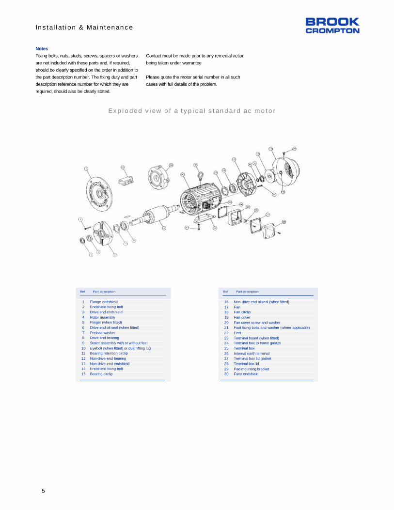
Installation & Maintenance
Notes
Fixing bolts, nuts, studs, screws, spacers or washers
are not included with these parts and, if required,
should be clearly specified on the order in addition to
the part description number. The fixing duty and part
description reference number for which they are
required, should also be clearly stated.
Contact must be made prior to any remedial action
being taken under warrantee
Please quote the motor serial number in all such
cases with full details of the problem.
Exploded view of a typical standard ac motor
12
3
45
6
78
9
1011
12
1314
15
Ref Part description
Flange endshieldEndshield fixing bolt
Drive end endshield
Rotor assemblyFlinger (when fitted)
Drive end oil seal (when fitted)
Preload washerDrive end bearing
Stator assembly with or without feet
Eyebolt (when fitted) or dual lifting lugBearing retention circlip
Non-drive end bearing
Non-drive end endshieldEndshield fixing bolt
Bearing circlip
16
1718
19
2021
22
2324
25
2627
28
2930
Ref Part description
Non-drive end oilseal (when fitted)
FanFan circlip
Fan cover
Fan cover screw and washerFoot fixing bolts and washer (where applicable)
Feet
Terminal board (when fitted)Terminal box to frame gasket
Terminal box
Internal earth terminalTerminal box lid gasket
Terminal box lid
Pad mounting bracketFace endshield
5

Bearing Information
63
7180M
90S/L
100L
112M
132S/M
160M/L180M/L
200LX
225S
225M
250ME
280SE
280ME
315SE
315ME
315M
315L
355S/M/L
Bearing references and oil seals for horizontally-mounted motors only
European
63
7180M
90S/L
100L
112M
132S/M
160M/L180M/L
200LX
225S
225M
250S
250M
280S
280M
315S
315M
315L
355S/M/L
BS
All
All
All
All
All
All
All
All
All
All
All
All
2
4 up
2
4 up
2
4 up
2
4 up
2
4 up
2
4 up
2
4 up
2
4 up
Polarity
Bearings(1)
Drive end Non-drive end
Oil seals(2)
62022Z
60032Z
62042Z
62052Z
62062Z
62062Z
62082Z
63092Z
63102Z
6312
6313
6314
6314
6316
6314
6318
6314
6318
6316
6319
6316
6319
6316
6319
6316
6319
N316
N324
62022Z
60032Z
60032Z
62032Z
62052Z
62052Z
63052Z
63072Z
63082Z
6312
6313
6314
6314
6316
6314
6318
6314
6318
6316
6319
6316
6319
6316
6319
6316
6319
6316
6324
15 x 24 x 5(3)
17 x 28 x 6(3)
20 x 30 x 7(3)
25 x 35 x 7(3)
30 x 42 x 7(3)
30 x 42 x 7(3)
40 x 52 x 7(3)
45 x 60 x 8(3)
50 x 65 x 8(3)
60 x 80 x 8(3)
65 x 90 x 10(4)
70 x 90 x 10(4)
70 x 90 x 10(4)
80 x 110 x 10(3)
70 x 90 x 10(4)
90 x 120 x 12(3)
70 x 90 x 10(4)
90 x 120 x 12(3)
70 x 90 x 10(4)
90 x 120 x 12(3)
70 x 90 x 10(4)
90 x 120 x 12(3)
70 x 90 x 10(4)
90 x 120 x 12(3)
70 x 90 x 10(4)
90 x 120 x 12(3)
75 x 100 x 10(4)
115 x 145 x 14(3)
Drive end
15 x 24 x 5(3)
17 x 28 x 6(3)
15 x 24 x 5(3)
17 x 28 x 6(3)
25 x 37 x 7(3)
25 x 37 x 7(3)
25 x 37 x 7(3)
35 x 47 x 7(3)
40 x 52 x 7(3)
60 x 80 x 8(3)
65 x 90 x 10(4)
70 x 90 x 10(4)
70 x 90 x 10(4)
80 x 110 x 10(3)
70 x 90 x 10(4)
90 x 120 x 12(3)
70 x 90 x 10(4)
90 x 120 x 12(3)
70 x 90 x 10(4)
90 x 120 x 12(3)
70 x 90 x 10(4)
90 x 120 x 12(3)
70 x 90 x 10(4)
90 x 120 x 12(3)
70 x 90 x 10(4)
90 x 120 x 12(3)
75 x 100 x 10(4)
115 x 145 x 14(3)
Non-drive end
(1) Frame sizes 80 and 90 have bearings with CN clearances, frame sizes 100 to 355 have bearings with C3 clearance ‘medium’ series(2) Sizes given are in mm, and represent bore x outside diameter x widthMaterial: (3) Nitrile rubber (4) Silicon rubber
IEC Type
Bearing references and oil seals for horizontally-mounted motors only
56143/5T
182/4T213/5T
254/6T
284/6T
324T326T
364T
365T
404/5T
444/7T
504/5
Frame
All
All
All
All
All
All
All
All
All
2
4 up
2
4 up
2
4 up
2
4 up
Polarity
Bearings(1)
Non-drive end
Oil seals(2)
62042Z
62052Z
62062Z
62082Z
63092Z
63102Z
6312
6313
6314
6314
6316
6314
6318
6316
6319
6316
6319
60032Z
62032Z
62052Z
63052Z
63072Z
63082Z
6312
6313
6314
6314
6316
6314
6318
6316
6319
6316
6319
15 x 24 x 5(3)
17 x 28 x 6(3)
30 x 42 x 7(3)
40 x 52 x 7(3)
45 x 60 x 8(3)
50 x 65 x 8(3)
60 x 80 x 8(3)
65 x 90 x 10(4)
70 x 90 x 10(4)
70 x 90 x 10(4)
70 x 90 x 10(4)
70 x 90 x 10(4)
90 x 120 x 12(3)
70 x 90 x 10(4)
90 x 120 x 12(3)
90 x 120 x 12(3)
90 x 120 x 12(3)
Drive end
15 x 24 x 5(3)
17 x 28 x 6(3)
25 x 37 x 7(3)
25 x 37 x 7(3)
35 x 47 x 7(3)
40 x 52 x 7(3)
60 x 80 x 8(3)
65 x 90 x 10(4)
70 x 90 x 10(4)
70 x 90 x 10(4)
70 x 90 x 10(4)
70 x 90 x 10(4)
90 x 120 x 12(3)
70 x 90 x 10(4)
90 x 120 x 12(3)
90 x 120 x 12(3)
90 x 120 x 12(3)
Non-drive end
(1) Frame sizes 56 to143/5T have bearings with CN clearances, frame sizes 182T to 505 have bearings with C3 clearance ‘medium’ series
(2) Sizes given are in mm, and represent bore x outside diameter x widthMaterial: (3) Nitrile rubber (4) Silicon rubber
NEMA Type
Drive end
6

Connection Diagrams - IEC Frames
7

Connect ion Diagrams - NEMA
8

Fault Finding - Three Phase Induction Motors
Motor will not start
Supply or starter trips out atstart
Motor starts but has no torque.Motor does not reach full speedor takes a long time to accelerate
Motor overheating
No load amps in excess of fullload amps.
1. Fault with supply.
2. Motor or load locked up.
3. Wrong connection in controlcircuit.
1. Wrong or loose connections.
2. Motor overloaded.
3. Inertia of load too high.
4. Low voltage due to volt dropin cables.
5. Overload or circuit breakerincorrectly set or sized.
1. Incorrect connection.
2. Delta wound motor connected in star.
3. Star/Delta starter staying instar.
4. Inertia of load too high.
5. Motor overloaded.
6. Low voltage due to drop incables.
1. Motor overloaded.
2. Ineffective cooling.Temperature of air.Look for build up of dirt
3. Excessiive ambient.
4. Wrong connections.
5. Delta wound motor in star.
6. Motor ‘Single Phasing”.
7. Wrong voltage or frequency.
8. Supply voltage unbalanced.
1. Incorrect connection.
2. Star wound motor connected Delta.
3. Voltage in excess of nameplate.
4. Motor supplied for a different voltage or frequency.
1. Check for correct voltage atmotor terminals.2. Make sure motor and loadare free to turn.3. Check to ensure contactorsoperate.
1. Check all lugs are properlycrimped or soldered, and connections are tight.2. Check load performancedata against motor performance data.3. Measure voltage at motorterminals while motor starting.4. Check settings of overloadand circuit breaker and allowfor starting current.
1. Check connection diagramand nameplate data.2. Check load performancedata against motor performance data.3. Measure voltage at motorterminals while motor starting.
1. Check load performancedata.2. Check fan and air flow.
3. Check connection diagramand nameplate data.4. Check volts and amps on allthree phases.5. Check nameplate
6. Check phase to phase voltage accurately.
1&2. Check connection diagram
3. Measure voltage at motorterminals.
4. Compare supply voltage andfrequency to nameplate.
1.. Fit new fuses, reset circuitbreakers, etc.2. Remove clamps, locks etc.
3. Sort out control circuit.
1. Fix up connections.
2. Change motor for correctsize.
3. Change cables for correctsize.4. Correct setting of overloador breaker or change.
1. Sort out and correct connections.2. Check timer and startercontrol circuit.
3. Change motor for correctsize.
4. Change cables for correctsize.
1. Fix problem with load or fit alarger motor.2. Clean motor. Sort out cool-ing of air temp. and flow.
3. Sort out connections.
4. Restore supply to all phases
5. Correct voltage or frequency
6. Balance supply or acceptunbalance
1&2. Sort out and correct connections at motor terminals.
3. Connect supply voltage.
4. Change motor for correctvoltage and frequency.
9

Fault Finding - Three Phase Induction Motors
Mechanical noise or vibration.Noisy bearings. Bearingsoverheating
Motor amps in excess of nameplate full load amps onload.
Excessive electrical noise
Unbalanced amps in differentphases when motor loaded
Motor runs in wrong direction
1. Thrust from load ormisalignment..
2. Damaged bearings, toomuch grease, no grease, or foreign matter in grease.
3. Rotor pulling or foreign matter in air gap.
4. Out of balance load, coupling or pulley.
5. Excessive belt pull.
6. Motor foundations not ridgid
1. Motor overloaded
2. Low voltage supply
3. Wrong voltage and frequency.
4. Wrong connections.
5. Motor “Single Phasing”.
6. Supply voltage unbalanced
7. Motor speed not matched toload.1. Wrong connections
2. Wrong voltage.
3. Motor “Single Phasing”
1. Unbalanced power supply.
1. Wrong connections.
1. Check gaps between cou-pling halves and alignment.
2&3. Turn shaft slowly by handand feel for roughness or stiffness. Check for bent shaftor fan rubbing.
4. Run motor disconnectedfrom load and then with pulleyor coupling removed.5. Run motor without belts.
6. Check design and construction foundations.performance data.
1. Check load and performance data.2. Measure voltage at motorterminals.3. Check nameplate data.
4. Check nameplate data..
5&6 Check volts and amps inall three phases.
7. Measure motor speed andcheck load requirements.1. Check connections.
2. Check voltage with nameplate.3. Check volts and amps on allthree phases.1. Measure phase to phase voltage accurately.
1. Watch shaft rotation.
1. Re-align couplings.
2&3. Clean bearing housing,change bearings and repackwith fresh grease.
4. Fix up out of balance items.
5. Loosen belt tension.
6. Increase strength of foundations.
1. Fix problem with load or fitlarger motor.2. Fix problem, maybe withlarger cables.3. Correct voltage or frequency
4. Sort out and correct.
5&6 Resore balanced supplyto all three phases.
7. Change motor for correctmotor speed.1. Fix connections.
2. Correct voltage.
3. Restore supply to all phases
1. Balance supply or acceptunbalance
1. Swap any two phases ofsupply.
10

Brook Crompton264 Attwell DriveToronto, Ontario M9W 5B2Tel: 416 675-3844Fax: 416 675-6885Internet: www.brookcromptonna.com
Printed in Canada15/09/04 - 2004.W.OI Issue 1
© Copyright 2002. Brook Crompton. All rights reserved
CALL TOLL FREE - NORTH AMERICA:
1-800-463-89171-800-463-8917OROR
1-800-668-67791-800-668-6779FAX:
416-675-6885847-253-9880
www.brookcromptonna.com
Customer Service
Quebec only:1-888-668-9843
Fax:514-636-4253
Every care has been taken to ensure the accuracy
of the information contained in this publication, but,
due to a policy of continuous development and
improvement the right is reserved to supply
products which may differ slightly from those
illustrated and described in this publication

Issue Date : 2011-09-30 Z - Electric Heaters
Electric Space Heaters
Electric space heaters can be mounted in one of two ways. Unit-mounted heaters are mounted inside the unit
or on the supply air opening. Remotely mounted heaters are mounted in the duct-work and are not supplied by
Seresco Technologies Inc. Electric heaters are offered in single or dual point power connection options. Single
point power means that a single power line is feeding both the electric heater and the unit. Power is brought to
the a power distributor block in the heater from which the unit is powered. This configuration is standard for
unit-mounted residential installations. A dual point power configuration means that the unit and electric heater
are powered from different sources. This is standard for larger installations. Refer to the unit nomenclature
located on the label to see which configuration is used for your unit.
The heater is controlled by an external signal, typically either dry contact, 24VAC power or 0-10 VDC signal,
but this may vary depending on the installation. Each heater is equipped with two bi-metal thermal switches to
protect heating elements from overheating (See Wiring Diagram). During installation, connection or servicing
exercise caution. Refer to local electrical codes and manufacturer's instructions when working with electric
heaters.
Staged Electric Heaters
Electric heaters can come in either single stage or two stage configurations. Single stage electric heaters energize
an external (closed contact) electric heater contactor, providing full output. These heaters are typically used for
small kW applications. Two stage electric heaters split the signal into two separate contacts which each
energize separate stage contactors. This gives better control over heater output (i.e. 50% or 100%) based on
temperature requirements.
Modulating Electric Heaters
Modulating electric heaters use both the modulating (SCR) and the fixed step controller to ensure precise
temperature control and high efficiency. Heater total output is divided between up to nine stages, including an
SCR modulating stage. The modulating heating stage, usually 25% larger than the other heating stages, is
proportionally controlled by CRISTAL CONTROLS SCR and the other heating stages are controlled by the
electronic step controller.
Based on an external control signal (usually 0 – 10 VDC), the step controller activates step controlled stages one
after another as needed. The SCR stage automatically fills the gaps between step controlled stages providing
fully proportional control over the heaters entire kW range.
1

Z - Electric Heaters Issue Date : 2011-09-30
Figure 1 : Single Phase 2 Stage Electric Heater
Figure 2 : Three Phase 2 Stage Electric Heater
2

Issue Date : 2011-09-20 Z - Electric Heaters
Figure 3 : Modulating Electric Heater
3

Z - Electric Heaters Issue Date : 2011-09-30
Technical Sheet – Steps Controller
Models: CCE-4 : 4 ON/OFF stages + 1 SCR stage
CCE-8 : 8 ON/OFF stages + 1 SCR stage
Power supply 24 Vac, 1 VA
Outputs (ON-OFF stages) 1 Amp max., 120Vac max.
Zero SCR Adjustable
Span SCR Adjustable
Span input Adjustable (Min 2 ON/OFF + 1 SCR)
Input signal 0-135 Ohms, 0-10 Vdc, 0-5 Vdc,
4@20mA
Operation temperature - 40 to +160 (- 40 @ +72 )
Storage temperature - 40 to +160 (- 40 @ +72 )
Dimensions : CCE-4 210 mm X 56 mm X 30 mm8 1/4” X 2 3/16’’ X 1 3/16’’
Dimensions : CCE-8 210 mm X 108 mm X 30 mm8 1/4” X 4 1/4” X 1 3/16”
Figure 4 : CCE Control Wiring
4

Issue Date : 2011-09-20 Z - Electric Heaters
Control signal:
0 – 10 VDC: put a jumper between pins 4 and 5,
bring control signal to pins 2 and 6 (pin 2 must be a ground, DCC, pin 6 is a 0-10 VDC signal)
4-20 mA: put a jumper between pins 2 and 5,
bring control signal to pins 2 and 5 (pin 2 must be a ground)
24 VAC power supply:
24 power: Pin 8
24 com: Pin 1 (pin 1 must be grounded)
Stages control:
SCR (modulating): Pins 9 and 10 (see diagram)
ON/OFF (steps): Respective pairs 11-12, 13-14 etc
5

Z - Electric Heaters Issue Date : 2011-09-30
Adjustment Procedure
Note that CCE step controllers are adjusted upon installation. If it is determined that an adjustment is necessary,
follow the following procedure.
Potentiometers' functions:
“SPAN D'ENTREE” - Used to adjust/enable number of stages/steps
“SPAN DU SCR” - Used to adjust the SCR's span between two stages. To adjust, turn clockwise
“ZERO DU SCR” - Used to set the starting (zero) point of the SCR
1. Set the step controller to the desired mode (0-10 VDC or 4-20mA).
2. Set the control signal to 50%.
3. Adjust the “Span d’entrée” until half the stages are lit.
4. Set the control signal at 100% and ensure all stages are lit, readjusting the “Span d’entrée” if needed.
5. If adjustments were necessary at point 4, repeat points 3 and 4 until no further adjustment is needed.
6. Set the control signal at 50% and, if necessary, adjust the “Zéro du SCR” to obtain a 50% modulation output.
7. Set the control signal at 0% and make sure that all stages and the modulating output are off. If the modulating
output does not turn off decrease “Span du SCR” and bring back the control signal to 50%. If needed adjust the
“Zéro du SCR” to obtain a 50% modulation output.
8. Set the control signal at 100% and make sure all stages and the modulating output are open (without modulation).
If the modulating output is still modulating, increase the “Span du SCR” , bring back the control signal to 50% and
if needed, re-adjust the “Zéro du scr” to obtain a 50% modulation on the modulating output.
9. If adjustments were necessary at point 8, repeat points 7 and 8 until no further adjustment is required.
10. Finally, set the control signal at 0% and make sure all stages are off. Set the control signal at 100% and make
sure all stages gradually turn on. Between each stage, the modulating output should be modulating from 0% to
100%. Also make sure that the modulating output does not take too long to begin after a stage kicked in or reaches
the 100% too quickly before the next stage kicks in. In the event that the modulating output is not acting
progressively (too long to begin or reaches 100% too quickly), increase the “Span du SCR” and repeat procedure
from point 6.
6

Perfection is Our Drive
E
G
F
A
C
B
G
B
C
A
F
SIZE
A: Length B:HEIGHT C:LENGTH
D:DEPTH (NOT SHOWN)
F:HEIGHT G:HEIGHT
FNPT FNPT FNPT FNPT FNPT
0.5 2.6 2.9 6.5 3.0 7.5 2.4
0.75 2.8 2.9 6.6 3.0 7.5 2.0
1 2.8 3.3 6.6 3.0 7.5 2.0
1 3.0 3.4 6.7 3.0 8.0 2.6
1 4.2 3.6 7.3 3.0 9.0 3.3
1.25 3.0 3.4 6.7 3.0 8.0 2.5
1.25 3.6 3.6 7.0 3.0 8.6 2.8
1.5 3.5 3.6 7.0 3.0 8.8 2.8
1.5 4.0 4.1 7.2 3.0 9.6 3.3
2 4.0 4.1 7.2 3.0 9.7 3.3
2 5.0 4.5 7.7 3.0 10.8 3.8
2.5 5.3 4.8 7.8 3.0 11.0 4.0
Dimensions (nominal) (measured in inches unless noted)
Ball Valve Product Data
Technical Data/Submittal
Three-way Threaded Equal Percentage Ball Valves with Fail-safe Actuators NEMA 4
Valve Specifications
Static Pressure/Temp: 360 PSI / 250°F (600 WOG)
Service: Chilled water, hot water, up to 50% Glycol
Flow Characterizing Disc: Glass Filled Polymer
Body Material: Forged Brass ASTM B283
End Connections: Brass NPT
Stem: Brass
Stem Seals: EPDM O-Rings
Ball: Nickel-plated brass
Ball Seals: Teflon Seals with EPDM O-Rings
Angle of Rotation: 0–90°
©Elodrive USA • 866-356-3748 • www.elodriveusa.com • Content subject to change without notice • Doc No.: 07-11/01/07-15
Three-way valve coil and bypass streams flow simultaneously through the ball. Bypass Cv is always 80% of coil Cv so there is always enough pressure drop in bypass mode. Three-way over-flow problems are eliminated.
Flow characterizing disc:
Equal percentage flow mirrors equal percentage coil characteristic.
Molded from GE NORYL, a blend of a polymide with reinforced modified polymer PPE for retention of mechanical properties, chemical resistance, and dimensional stability.
Because the disc is press fit into the ball where flow exits, the valve is able to modulate where differential pressure is over 160 psi without affecting the disc.
Tapered shape means the back of the disc is too large to be forced through the ball’s port.
Good chemical resistance to: alcohol, alkalis (base), cooling and heating system liquids (ethylene and propylene glycol), chlorinated water, detergents/cleaners. Poor chemical resistance to acids (high concentration), hydrocarbons, ketones, phenol.

Perfection is Our Drive
3-Way ValveCv
(1∆P)Full Port
Size Close-off
Fail-safe Actuator, 24 VAC
On/off Floating
Point 0/2-10 VDC
BSP-35A1U BSP-35F1U BSP-35P1U
Please check valve/actuator choice below
B3B.5-0.33N 0.33 1/2” 50 psiB3B.5-0.59N 0.59 1/2” 50 psiB3B.5-1.0N 1.0 1/2” 50 psiB3B.5-2.4N 2.4 1/2” 50 psiB3B.5-4.3N 4.3 1/2” 50 psiB3B.5-8.0N 8.0 1/2” 50 psi
B3B.75-0.40N 0.40 3/4” 50 psiB3B.75-0.66N 0.66 3/4” 50 psiB3B.75-1.4N 1.3 3/4” 50 psiB3B.75-2.4N 2.4 3/4” 50 psiB3B.75-3.8N 3.8 3/4” 50 psiB3B.75-11N 11 X 3/4” 50 psi
B3B1-0.40N 0.40 1” 50 psiB3B1-0.65N 0.65 1” 50 psiB3B1-1.3N 1.3 1” 50 psiB3B1-2.3N 2.3 1” 50 psiB3B1-3.5N 3.5 1” 50 psiB3B1-10N 10 1” 50 psiB3B1-8.6N 8.6 1” 50 psiB3B1-22.3N 22.3 1” 50 psiB3B1-14.9N 14.9 1” 50 psiB3B1-4.5N 4.5 1” 50 psiB3B1-30.8N 30.8 1” 50 psi
B3B1.25-19.4N 19.4 X 1-1/4” 40 psiB3B1.25-12.7N 12.7 1-1/4” 40 psiB3B1.25-4.1N 4.1 1-1/4” 40 psiB3B1.25-8.7N 8.7 1-1/4” 40 psiB3B1.25-34.1N 34.1 X 1-1/4” 40 psiB3B1.25-26.8N 26.8 1-1/4” 40 psi
B3B1.5-13.4N 13.4 1-1/2” 40 psiB3B1.5-4.0N 4.0 1-1/2” 40 psiB3B1.5-8.3N 8.3 1-1/2” 40 psiB3B1.5-32.0N 32.0 X 1-1/2” 40 psiB3B1.5-23.5N 23.5 1-1/2” 40 psiB3B1.5-61.1N 61.1 1-1/2” 40 psi
B3B2-23.9N 23.9 2” 40 psiB3B2-56.7N 56.7 2” 40 psiB3B2-38.2N 38.2 2” 40 psiB3B2-108.5N 108.5 2” 40 psiB3B2-82.6N 82.6 2” 40 psi
B3B2.5-38.1N 38.1 2-1/2” 40 psiB3B2.5-74.1N 74.1 2-1/2” 40 psiB3B2.5-99.5N 99.5 X 2-1/2” 40 psi
Accessories. Add to list price (part no. example).
Single aux. switch (B3B3-49N+BSP-35P1U+AB-AS1)
Double aux. switch (B3B3-49N+BSP-35P1U+AB-AS2)
1,000 Ohm Potentiometer (B3B3-49N+BSP-35P1U+AB-P1K)
10,000 Ohm Potentiometer (B3B3-49N+BSP-35P1U+AB-P10K)
Options. Add to list price (part no. example). Call for delivery.
120/230 VAC power supply (B3B3-49N+BSP-35P2U)
Stainless steel stem (B3S3-49N+BSP-35P1U)
Integrated 5,000 Ohm pot. (B3B3-49N+BSP-35P1U-P5K)
Integrated 4-20 mA working range (B3B3-49N+BSP-35P1U-I20)
10-ft cable (B3B3-49N+BSP-35P1U-C3M)
Note: For Actuator Detail, See Fail-Safe Actuator Product Data, Tab #4
A B
B
A
A B
B
A
Piping Configurations
Mixing - fluid enters through two inlets (A,B) and exits through one outlet (AB)
Diverting - fluid enters through one inlet (AB) and exits through two outlets (A,B)
Ball Valve Product Data
Technical Data/Submittal
Three-way Threaded Equal Percentage Ball Valves with Fail-safe Actuators NEMA 4
©Elodrive USA • 866-356-3748 • www.elodriveusa.com • Content subject to change without notice • Doc No.: 07-11/01/07-16
Select valve body (B3B.5-0.33N), then actuator (BSP-35A1U). Part no.: B3B.5-0.33N+BSP-35A1U.

Perfection is Our Drive
LINESIZE
MODELNO.
FULL1
PORTCLOSE-OFF∆P2
FLOWRATE (GPM) @ DIFFERENTIAL PRESSURE (PSI)
2-Position HVAC Apps HVAC Modulating Applications
Cv3
0.5 1.0 1.5 2.0 2.5 3.0 3.5 4.0 4.5 5.0 7.0 10.0
1/2”
B3B.5-0.33N
50 PSI
0.2 0.33 0.4 0.5 0.5 0.6 0.6 0.7 0.7 0.7 0.9 1.0
B3B.5-0.59N 0.4 0.59 0.7 0.8 0.9 1.0 1.1 1.2 1.3 1.3 1.6 1.9
B3B.5-1.0N 0.7 1.0 1.2 1.4 1.6 1.7 1.9 2.0 2.1 2.2 2.6 3.2
B3B.5-2.4N 1.7 2.4 2.9 3.4 3.8 4.2 4.5 4.8 5.1 5.4 6.3 7.6
B3B.5-4.3N 3.0 4.3 5.3 6.1 6.8 7.4 8.0 8.6 9.1 9.6 11.4 13.6
B3B.5-8.0N 5.7 8.0 9.8 11.3 12.6 13.9 15.0 16.0 17.0 17.9 21.2 25.3
3/4”
B3B.75-0.40N
50 PSI
0.3 0.40 0.5 0.6 0.6 0.7 0.7 0.8 0.8 0.9 1.1 1.3
B3B.75-0.66N 0.5 0.66 0.8 0.9 1.0 1.1 1.2 1.3 1.4 1.5 1.7 2.1
B3B.75-1.4N 0.9 1.3 1.6 1.8 2.1 2.3 2.4 2.6 2.8 2.9 3.4 4.1
B3B.75-2.4N 1.7 2.4 2.9 3.4 3.8 4.2 4.5 4.8 5.1 5.4 6.3 7.6
B3B.75-3.8N 2.7 3.8 4.7 5.4 6.0 6.6 7.1 7.6 8.1 8.5 10.1 12.0
B3B.75-11N • 7.8 11.0 13.5 15.6 17.4 19.1 20.6 22.0 23.3 24.6 29.1 34.8
1”
B3B1-0.40N
50 PSI
0.3 0.40 0.5 0.6 0.6 0.7 0.7 0.8 0.8 0.9 1.1 1.3
B3B1-0.65N 0.5 0.65 0.8 0.9 1.0 1.1 1.2 1.3 1.4 1.5 1.7 2.1
B3B1-1.3N 0.9 1.3 1.6 1.8 2.1 2.3 2.4 2.6 2.8 2.9 3.4 4.1
B3B1-2.3N 1.6 2.3 2.8 3.3 3.6 4.0 4.3 4.6 4.9 5.1 6.1 7.3
B3B1-3.5N 2.5 3.5 4.3 4.9 5.5 6.1 6.5 7.0 7.4 7.8 9.3 11.1
B3B1-10N 7.1 10.0 12.2 14.1 15.8 17.3 18.7 20.0 21.2 22.4 26.5 31.6
B3B1-8.6N 6.1 8.6 10.5 12.1 13.6 14.9 16.1 17.2 18.2 19.2 22.7 27.2
B3B1-22.3N 15.8 22.3 27.3 31.5 35.3 38.6 41.7 44.6 47.3 49.9 59.0 70.5
B3B1-14.9N 10.5 14.9 18.2 21.1 23.6 25.8 27.9 29.8 31.6 33.3 39.4 47.1
B3B1-4.5N 3.2 4.5 5.5 6.4 7.1 7.8 8.4 9.0 9.5 10.1 11.9 14.2
B3B1-30.8N 21.8 30.8 37.7 43.6 48.7 53.3 57.6 61.6 65.3 68.9 81.5 97.4
1-1/4”
B3B1.25-19.4N •
40 PSI
13.7 19.4 23.8 27.4 30.7 33.6 36.3 38.8 41.2 43.4 51.3 61.3
B3B1.25-12.7N 9.0 12.7 15.6 18.0 20.1 22.0 23.8 25.4 26.9 28.4 33.6 40.2
B3B1.25-4.1N 2.9 4.1 5.0 5.7 6.4 7.0 7.6 8.1 8.6 9.1 10.7 12.8
B3B1.25-8.7N 6.1 8.7 10.6 12.3 13.7 15.0 16.2 17.3 18.4 19.4 22.9 27.4
B3B1.25-34.1N • 24.1 34.1 41.8 48.2 53.9 59.1 63.8 68.2 72.3 76.2 90.2 107.8
B3B1.25-26.8N 19.0 26.8 32.8 37.9 42.4 46.4 50.1 53.6 56.9 59.9 70.9 84.7
1-1/2”
B3B1.5-13.4N
40 PSI
9.5 13.4 16.4 18.9 21.1 23.2 25.0 26.7 28.4 29.9 35.4 42.3
B3B1.5-4.0N 2.8 4.0 4.9 5.7 6.4 7.0 7.5 8.1 8.5 9.0 10.7 12.7
B3B1.5-8.3N 5.8 8.3 10.1 11.7 13.1 14.3 15.5 16.5 17.5 18.5 21.9 26.1
B3B1.5-32.0N • 22.6 32.0 39.2 45.3 50.6 55.5 59.9 64.0 67.9 71.6 84.7 101.3
B3B1.5-23.5N 16.6 23.5 28.8 33.3 37.2 40.8 44.0 47.1 49.9 52.6 62.3 74.4
B3B1.5-61.1N 43.2 61.1 74.8 86.4 96.6 105.8 114.3 122.2 129.6 136.6 161.6 193.2
2”
B3B2-23.9N
40 PSI
16.9 23.9 29.3 33.8 37.8 41.4 44.7 47.8 50.7 53.4 63.2 75.6
B3B2-56.7N 40.1 56.7 69.4 80.2 89.7 98.2 106.1 113.4 120.3 126.8 150.0 179.3
B3B2-38.2N 27.0 38.2 46.8 54.0 60.4 66.2 71.5 76.4 81.0 85.4 101.1 120.8
B3B2-108.5N 76.7 108.5 132.9 153.4 171.6 187.9 203 217 230 243 287 343
B3B2-82.6N 58.4 82.6 101.2 116.8 130.6 143.1 154.5 165.2 175.2 184.7 219 261
2-1/2”
B3B2.5-38.1N
40 PSI
26.9 38.1 46.7 53.9 60.2 66.0 71.3 76.2 80.8 85.2 100.8 120.5
B3B2.5-74.1N 52.4 74.1 90.8 104.8 117.2 128.3 138.6 148.2 157.2 165.7 196.1 234
B3B2.5-99.5N • 70.4 99.5 121.9 140.7 157.3 172.3 186.1 199.0 211 223 263 315
Ball Valve Product Data
Flow Rates
Three-way Threaded 1 These valves are full port and do not have the linearizing insert.2 Close-off pressures measured with 35 in-lb. actuator. The close-off pressure is the maximum allowable pressure drop across the valve body when the valve is fully closed.3 C
v is defined as the quantity of water in GPM at 60°F that will flow through a given valve with a pressure drop of
1PSI. The 1.0 PSI pressure differential column in the table below is equivalent to the Cv value.
©Elodrive USA • 866-356-3748 • www.elodriveusa.com • Content subject to change without notice • Doc No.: 07-11/01/07-18

Perfection is Our Drive
Valve Line Size
Size Through Cv 0.5 0.75 1 1.25 1.5 2 2.5 3 4
1/2”
0.33 -- 0.3 0.3
0.59 -- 0.6 0.6
1.0 -- 1.0 1.0
2.4 -- 2.3 2.3
4.3 -- 4.0 3.8 --
8.0 -- 7.9 5.7 --
3/4”
0.40 -- -- 0.4 0.4 0.4
0.66 -- 0.66 0.66 0.66
1.3 -- 1.3 1.3 1.3
2.4 -- 2.4 2.39 2.38
3.8 -- 3.8 3.74 3.7
11.0 -- 10.4 9.78 9.4
1”
0.40 -- 0.40 0.40 0.40 0.40 0.40
0.65 -- 0.65 0.65 0.65 0.65 0.65
1.3 -- 1.3 1.3 1.3 1.3 1.3
2.3 -- 2.3 2.3 2.3 2.3 2.3
3.5 -- 3.5 3.5 3.5 3.5 3.5
4.5 -- 4.5 4.5 4.5 4.4 4.4
8.6 -- 8.5 8.4 8.3 8.2 8.2
10.0 -- 9.9 9.7 9.6 9.5 9.4
14.9 -- 14.6 14.1 13.5 13.3 13.1
22.3 -- 21.2 19.9 18.4 17.7 17.3
30.8 -- 28.0 25.2 22.3 21.1 20.5
1-1/4”
4.1 -- 4.4 4.4 4.4 4.4 4.4
7.7 -- 8.3 8.2 8.2 8.2 8.1
8.7 -- 14.8 14.5 14.3 14.2 14.0
12.7 -- 35.0 31.5 29.6 28.6 27.6
19.4 -- 39.0 34.3 31.9 30.7 29.4
34.1 -- 79.1 53.3 45.5 42.0 39.0
1-1/2”
4.0 -- 4.0 4.0 4.0 4.0
8.3 -- 8.2 8.2 8.2 8.2
13.4 -- 13.3 13.2 13.2 13.1
23.5 -- 23.1 22.7 22.4 22.1
32.0 31.0 30.0 29.3 28.6
61.1 54.9 49.7 46.9 44.1
2”
23.9 -- 23.8 23.7 23.5
38.2 -- 37.8 37.3 36.62
56.7 -- 55.5 54.0 52.0
108.5 -- 100.7 92.3 83.3
Ball Valve Product Data
Flow Rates Adjusted for Piping Geometry
Three-way Threaded
©Elodrive USA • 866-356-3748 • www.elodriveusa.com • Content subject to change without notice • Doc No.: 07-11/01/07-20

Perfection is Our Drive
Elodrive type BE(P) actuators are designed and produced for long lasting, reliable and quiet operation of air control dampers and temperature control valves. BE(P) type actuators feature EloSafeTM electronic fail-safe technol-ogy which uses goldcap capacitors to drive the actua-tor to the fail-safe position in the event of an interruption of power. EloSafe capacitors store six times the energy required to drive the actuator to the fail-safe position under full torque load. Thermal compensation allows EloSafe actuators to deliver the full rated torque even at the lowest ambient temperature rating. A universal self-centering mounting clamp and anti-rotation strap are included with all models. All Elodrive models feature durable Elodrive brushless DC motor technology and easy manual positioning.
Highlights of the EloSafeseries of actuators: 100% self-locking even
without voltage. Full specified torque
through out the entire 90° fail-safe function Remains in a defined
fail-safe position with 100% self-locking Fail-safe function also
possible when control signal (2-10 V) is missing
Technical Data Electric Actuator Type BE(P)Characteristic 24 V 120/230 VNominal voltage AC 24 V +/-20%, 50/60 Hz, DC 24 to 36 V +/-10% AC 90-264 V, 50/60 Hz
Electrical connection 3-ft plenum rated cable, 1/2-inch conduit fitting
Starting current .5 A for approx. 40 SecSynchronization +/- 5%Rotation direction Selectable via switch L/R (CCW/CW) or by L/R mountingAngle of rotation Max. 95°Manual adjustment Standard allen key positioning without disengaging gearsShaft mounting Centered, Ø 0.3in [8mm]-0.8in [20mm]; ◊ 0.2in [6mm]-0.6in [14mm]
Running time 90 sec (+/- 5%), during normal operation; independent of load; Fail-safe operation approx. 30 sec
Position indicator MechanicalNoise emission level < 35 dB (A), Fail-safe operation < 60 dB (A)Ambient temperature -22 to +122°F [-30 to +50°C]Storage temperature -40 to +176°F [-40 to +80°C]Humidity 5 to 95% RH non-condensing (excludes NEMA 4 models)Quality Standard ISO - 9001
Agency listings (Listing for all 120/230 V power supply models is pending)
Weight 2.1 lb [950 g]Maintenance Maintenance free
ModelProtection
DegreeMin. Torque
(in-lb)
Power Supply 24VDC,
120/230VAC
Power Consumption
Max.
Power Consumption
Damper Area approx. sq-ft
BE SeriesOn/Off Control, 90 Second Running Time Drive, 60 Second Running Time Fail-safe
BE-88A1U NEMA 2 88 24 20.0VA 9.0VA 22BE-88A2U NEMA 2 88 120/230 20.0VA 12.0VA 22BEP-88A1U NEMA 4 88 24 20.0VA 9.0VA 22BEP-88A2U NEMA 4 88 120/230 20.0VA 12.0VA 22BE-132A1U NEMA 2 132 24 20.0VA 9.0VA 33BE-132A2U NEMA 2 132 120/230 20.0VA 12.0VA 33BEP-132A1U NEMA 4 132 24 20.0VA 9.0VA 33BEP-132A2U NEMA 4 132 120/230 20.0VA 12.0VA 33
Directional Control, 90 Second Running Time Drive, 30 Second Running Time Fail-safe
BE-88D1U NEMA 2 88 24 20.0VA 9.0VA 22BE-88D2U NEMA 2 88 120/230 20.0VA 12.0VA 22BEP-88D1U NEMA 4 88 24 20.0VA 9.0VA 22BEP-88D2U NEMA 4 88 120/230 20.0VA 12.0VA 22BE-132D1U NEMA 2 132 24 20.0VA 9.0VA 33BE-132D2U NEMA 2 132 120/230 20.0VA 12.0VA 33BEP-132D1U NEMA 4 132 24 20.0VA 9.0VA 33BEP-132D2U NEMA 4 132 120/230 20.0VA 12.0VA 33
Floating Point Control, 90 Second Running Time Drive, 30 Second Running Time Fail-safe
BE-88F1U NEMA 2 88 24 20.0VA 9.0VA 22BE-88F2U NEMA 2 88 120/230 20.0VA 12.0VA 22BEP-88F1U NEMA 4 88 24 20.0VA 9.0VA 22BEP-88F2U NEMA 4 88 120/230 20.0VA 12.0VA 22BE-132F1U NEMA 2 132 24 20.0VA 9.0VA 33BE-132F2U NEMA 2 132 120/230 20.0VA 12.0VA 33BEP-132F1U NEMA 4 132 24 20.0VA 9.0VA 33BEP-132F2U NEMA 4 132 120/230 20.0VA 12.0VA 33
Proportional Control 0/2-10VDC, 90 Second Running Time Drive, 30 Second Running Time Fail-safe
BE-88P1U NEMA 2 88 24 20.0VA 9.0VA 22BE-88P2U NEMA 2 88 120/230 20.0VA 12.0VA 22BEP-88P1U NEMA 4 88 24 20.0VA 9.0VA 22BEP-88P2U NEMA 4 88 120/230 20.0VA 12.0VA 22BE-132P1U NEMA 2 132 24 20.0VA 9.0VA 33BE-132P2U NEMA 2 132 120/230 20.0VA 12.0VA 33BEP-132P1U NEMA 4 132 24 20.0VA 9.0VA 33BEP-132P2U NEMA 4 132 120/230 20.0VA 12.0VA 33
©Elodrive USA • 866-356-3748 • www.elodriveusa.com • Content subject to change without notice • Doc No.: 04-11/01/07-7
Fail-Safe Actuator Product Data
Technical Data/Submittal
Electric Actuator Type BE(P)Electronic Fail-Safe, 88/132 in-lb Minimum Torque, BE NEMA 2 / BEP NEMA 4
Note: See binder tab no. 5 for actuator accessories/options product data.

Technical Data Electric Actuator Type BE(P)
On/Off
Wiring schematicsOn/Off
Directional
Wiring schematicsDirectional
Floating Point
Wiring schematicsFloating Point
Proportional 0/2-10 V
Input signal 0-10 V or 2-10 V selectable via switch
Input impedance >100 kΩ
Output signal DC 0/2-10 V for 0-100%
Wiring schematicsProportional 0/2-10 V
6.8 [173.6]
0.9[22.8]
0.3 [6.5]
2.1
[53.
6]0.3
[6.5]
0.3 [6.
5]
2.6
[66.
6]
0.3 [6.5]
7.8 [199]7.6 [194]
0.7
[19]
2.4
[60]
3.1
[7.9
]
All Dimensions in inches and metric [mm]
Fail-Safe Actuator Product Data
black
red
white
black
black
red
light blue
white
black
light blue
black
red
light blue
green
white
black
light blue
green
black
red
light blue
green
white
black
light blue
yellow
gray
©Elodrive USA • 866-356-3748 • www.elodriveusa.com • Content subject to change without notice • Doc No.: 04-11/01/07-8
Standard delivery includes:
Anti-rotation strap
Centric clamp adaptor
Allen key
Position indicator
Mechanical rotation limit stops
Operation manual

Refrigerant Compatibility
Compatibilidade do Refrigerante
Compatibilité du réfrigérant
R-11R-12R-22R-113R-114R-115
R-123R-124R-125R-134aR-401A
R-407BR-407CR-410AR-500R-502R-507
R-401BR-402AR-402BR-404AR-407A
Verify Coil
Verifique la Bobina
Verifique a bobina
1 2
Compatibilidad con Refrigerantes
ModelCoil
AM AH DM MM ASC2
100RB
200RB
240RA
500RB
540RA
üüü
üüü
üüüüü
üüüüü
üüüüüü ü
Vérifier la bobine
Valve Orientation
Orientación de Válvulas
Orientação da Válvula
Orientation de la valve
Do Not Bend Enclosing Tube
No doble el casquillo del Embolo de la Aguja
Não danifique o tubo de apoio da bobina
Flow Follows Arrow
Barra Indica Posição do Fluido
L’écoulement doit suivre la flèche
3 4 5
El Flujo sigue la Flecha
Ne pas plier le tube
6
Coil Installation
Instalación de la Bobina
Instalação da bobina
Solder Techniques
Técnicas para Soldar
Técnicas de Soldagem
Technique de soudure
7
l’installation de la bobine
Solenoid Valves200RD Model
T < 250°F (121°C)
Type T

AM Coil Electrical Data
VAC/HzMaximum Amps VA
HoldingInrush Holding
24/50 2.0 0.96 23
24/60 1.6 0.74 18
120/50 0.45 0.21 25
120/60 0.36 0.16 19
208/50 0.19 0.08 17
208/60 0.15 0.06 12
220/50 0.24 0.10 24
240/60 0.19 0.08 19
480/50 0.11 0.05 24
480/60 0.09 0.04 19
9
Transformer Selection
Selección del Transformador
Selecione transformador capacidade suficiente
Sélection du transformateur
Emerson Climate Technologies and the Emerson Climate Technologies logo are trademarks and service marks of Emerson Electric Co. © 2004 Emerson Electric Co. PA-00326 Apr 2009
Manual OverrideDisassembly - must use new gasket when reassembling - retorque per table above
Vástago de Operación Manual
Desmontagem - quando for remontar é necessáriousar uma nova gaxeta - reaperte utilizando a tabela acimaAcionamento manual
Desmontaje - cuando este remontando usar una nueva empaquetadora - reajuste utilizando la tabla encima
Désassemblé - doit utiliser un nouveau segment lors du réassemblage - rétorqué selon la table si dessusOuverture manuel de la tige
t
t
50 in.-lb.(5.6 N•m)t
t
350 in.-lb.(39.5 N•m)
200RD 7-12
225 in.-lb.(25.4 N•m)
200RD 2-6
10 11

2004FC-118 (Q4/09) 8
Solenoid Valves & Coils
Features• One coil fi ts all valve sizes• Extended ends for easy installation (standard)• Long-life molded coils• PTFE O-ring for superior external sealing
Options• Available in 5 orifi ce sizes• Manual stem or mounting stud• Bi-Flow operation-conversion either factory assembled or with kit except 200RD 7,9 & 12
Specifications• Maximum fl uid temperature: 250°F • Maximum working pressure: 680 psig• Minimum operating pressure drop: 2 psi• MOPD: 550 psig• UL/CUL fi le number: MP604
NOTE: Mounting enclosing tube more than 90o off vertical up position is not recommended.
The 200RD is a pilot-operated, 2-way, normally closed, R-410A valve. 200RD valves are used for liquid, discharge, or suc-tion gas refrigerant service.
Nomenclature example: 200RD 4T3M VLC
200R D 4 T 3 M VLCValve Series Design
SeriesPort Size (in 1/16”)
Connection TypeT = Copper Extended Ends
Connection Size(In 1/8”)
M = manual stemT = mounting stud
(optional)
Coil*
*NOTE: Valves are shipped without the solenoid coils (VLC = Valve Less Coil). See available coil assemblies.
Ordering Information and Nominal * Liquid Capacity - Tons (kW)PCN
Description Connection Size R-410AStandardValve
MountingStud1
ManualStem2
066158 066179 – 200RD 2 T 2 1/4 ODF3.2 (11.3)
066159 066180 – 200RD 2 T 3 3/8 ODF
066160 – – 200RD 3 T 2 1/4 ODF
4.5 (15.8)066161 066182 066203 200RD 3 T 3 3/8 ODF
066162 066183 066204 200RD 3 T 4 1/2 ODF
066163 066184 066205 200RD 4 T 3 3/8 ODF
7.3 (25.7)066164 066185 066206 200RD 4 T 4 1/2 ODF
066165 066186 006207 200RD 4 T 5 5/8 ODF
066166 066187 066208 200RD 5 T 3 3/8 ODF
7.7 (27.1)066167 066188 066209 200RD 5 T 4 1/2 ODF
066168 066189 066210 200RD 5 T 5 5/8 ODF
066169 066190 066211 200RD 6 T 4 1/2 ODF8.8 (30.9)
066170 066191 066212 200RD 6 T 5 5/8 ODF1 Add “T” to the end of description for Mounting Stud2 Add “M” to the end of the description for Manual Stem
Capacities based on ARI standard. *See Extended Capacity Tables for ratings at a wide range of conditions.
200RDR-410A

2004FC-118 (Q4/09) 9
Solenoid Valves & Coils200RD
With Extended Ends
Valve Port Size Conn. Size & Style A B C200RD 2T2 1/8 1/4 ODF
2.42 4.62
0.25200RD 2T3 3/8 ODF 0.31200RD 3T2
3/161/4 ODF 0.25
200RD 3T3 3/8 ODF 0.31200RD 3T4 1/2 ODF 0.38200RD 4T4 1/4 2.50 5.00200RD 4T5 5/8 ODF 3.25 6.50 0.50200RD 5T3
5/163/8 ODF 2.31 4.62 0.31
200RD 5T4 1/2 ODF 2.50 5.00 0.38200RD 5T5 5/8 ODF 3.25 6.50 0.50200RD 6T3
3/83/8 ODF 2.31 4.62 0.31
200RD 6T4 1/2 ODF 2.50 5.00 0.38200RD 6T5 5/8 ODF 3.25 6.50 0.50
1.77
0.85
3.41
A
B
C
0.59
2 IN. REQUIREDFOR COIL REMOVAL
With Extended Ends
Exploded View& Parts Kit Data
Valve Repair Kit“K” indicates part is supplied in
valve repair kit KS30386. (PCN 066223)
Gasket KitGasket Kit KG10025 (PCN 049190)
(contains 12 pieces - each of PTFE and neoprene O-rings)
Coil AssemblySee coil assemblies for availability.
Bi-Flow Conversion KitKS30387 (PCN 066224)

2008
TechnicalHelp Guide
Thermal Expansion ValvesSolenoid Valves
System ProtectorsRegulatorsOil Controls
Temperature Pressure ControlsBasic Rules of Good Practice
Troubleshooting Guide


2008
Introduction
This Technical Guide from Emerson Climate Technologies provides a de-tailed explanation on the operation of common refrigeration system components such as thermal expansion valves, solenoid valves, system protectors, regula-tors, oil controls and temperature pressure controls. Also included in this guide is a listing of the basic rules of good practice and a detailed troubleshooting guide. This guide is designed to fill a need which exists for a concise, elementary text to aid servicemen, salesmen, students and others interested in refrigeration and air conditioning. It is intended to cover only the fundamentals of refrigeration and air conditioning theory and practice. Detailed information for specific products is available from manufacturers of complete units and accessories. Used to supple-ment such literature, and to improve general knowledge of refrigeration and air conditioning, this guide should prove to be very helpful.
Emerson Climate Technologies, a business of Emerson, is the world’s leading provider of heating, ventilation, air conditioning and refrigeration solutions for residential, industrial and commercial applications. The group combines best-in-class technology with proven engineering, design, distribution, educational and monitoring services to provide customized, integrated climate-control solutions for customers worldwide. Emerson Climate Technologies’ innovative solutions, which include industry-leading brands such as Copeland Scroll and White-Rodgers, improve human comfort, safeguard food and protect the environment.
Emerson Climate Technologies - Flow Controls Division is a leading manufacturer of valves, controls and system protectors commonly applied in air conditioning and refrigeration systems worldwide. The company continues to pioneer the control of refrigerant flow through innovative, high performance components, such as thermal expansion valves and filter driers.

2008
Table of ContentsThermal Expansion Valves . . . . . . . . . . . . . . . . . . . . . . . . . . . . . . . . . 1 Internal Equalizer . . . . . . . . . . . . . . . . . . . . . . . . . . . . . . . . . . . . . . 2 Factory Setting of TXVs . . . . . . . . . . . . . . . . . . . . . . . . . . . . . . . . . 3 External Equalizer . . . . . . . . . . . . . . . . . . . . . . . . . . . . . . . . . . . . . . 3 Superheat . . . . . . . . . . . . . . . . . . . . . . . . . . . . . . . . . . . . . . . . . . . . 5 TXV Selection . . . . . . . . . . . . . . . . . . . . . . . . . . . . . . . . . . . . . . . . . 6 Application Tips . . . . . . . . . . . . . . . . . . . . . . . . . . . . . . . . . . . . . . . 7 Balanced Port TXVs . . . . . . . . . . . . . . . . . . . . . . . . . . . . . . . . . . . . 9 M .O .P . . . . . . . . . . . . . . . . . . . . . . . . . . . . . . . . . . . . . . . . . . . . . . . . . 9 Other TXV Considerations . . . . . . . . . . . . . . . . . . . . . . . . . . . . . . 11 Emerson TXVs . . . . . . . . . . . . . . . . . . . . . . . . . . . . . . . . . . . . . . . 11Solenoid Valves . . . . . . . . . . . . . . . . . . . . . . . . . . . . . . . . . . . . . . . . . 14 What are Solenoid Valves? . . . . . . . . . . . . . . . . . . . . . . . . . . . . . 15 Principles of Solenoid Operation . . . . . . . . . . . . . . . . . . . . . . . . 15 Types of Solenoids . . . . . . . . . . . . . . . . . . . . . . . . . . . . . . . . . . . . 16 Installation . . . . . . . . . . . . . . . . . . . . . . . . . . . . . . . . . . . . . . . . . . . 18 Emerson Solenoid Valves . . . . . . . . . . . . . . . . . . . . . . . . . . . . . . 18System Protectors . . . . . . . . . . . . . . . . . . . . . . . . . . . . . . . . . . . . . . . 19 Filter-driers . . . . . . . . . . . . . . . . . . . . . . . . . . . . . . . . . . . . . . . . . . 21 HFC Refrigerants and POE Lubricants . . . . . . . . . . . . . . . . . . . . 22 Clean-up Procedure for Compressor Motor Burnout . . . . . . . . 25 Emerson System Protectors . . . . . . . . . . . . . . . . . . . . . . . . . . . . 27Regulators . . . . . . . . . . . . . . . . . . . . . . . . . . . . . . . . . . . . . . . . . . . . . . 28 Suction Line Regulators . . . . . . . . . . . . . . . . . . . . . . . . . . . . . . . 29 Applications of EPRs . . . . . . . . . . . . . . . . . . . . . . . . . . . . . . . . . . 29 Crankcase Regulators . . . . . . . . . . . . . . . . . . . . . . . . . . . . . . . . . 31 Headmaster Pressure Control . . . . . . . . . . . . . . . . . . . . . . . . . . . 32 Hot Gas Bypass . . . . . . . . . . . . . . . . . . . . . . . . . . . . . . . . . . . . . . 34 Liquid Injection . . . . . . . . . . . . . . . . . . . . . . . . . . . . . . . . . . . . . . . 36Oil Controls . . . . . . . . . . . . . . . . . . . . . . . . . . . . . . . . . . . . . . . . . . . . . 38Temperature Pressure Controls . . . . . . . . . . . . . . . . . . . . . . . . . . . . 40Basic Rules of Good Practice . . . . . . . . . . . . . . . . . . . . . . . . . . . . . . 47Troubleshooting Guide . . . . . . . . . . . . . . . . . . . . . . . . . . . . . . . . . . . 50

2008
Thermal Expansion Valves

Thermal Expansion Valves
P1 = 45.4 PSIG
P2 = 35 PSIGP3 = 10.4 PSIG
35 PSIG = 40°F
35 PSIG = 40°F
35 PSIG = 50°F
B
C
TXV with internalequalizer on evaporator with
no pressure drop. Fig. 1
A
is charged with the same refrigerant as that in the sys-tem. The power assembly pressure (P1), which corre-sponds to the saturation pressure of the refrigerant gas temperature leaving the evaporator, moves the TXV pin in the opening direction. Opposed to this opening force on the underneath side of the diaphragm and acting in the closing direc-tion are two forces: the force exerted by the evaporator pressure (P2) and that exerted by the superheat spring (P3). In the first condition, the TXV will assume a stable control position when these three forces are in balance (P1 = P2 + P3). See figure 1A.
Thermal Expansion Valves
The most commonly used device for controlling the flow of liquid refrigerant into the evaporator is the ther-mostatic expansion valve (TXV). Also known as thermal expansion valves, TXVs are precision devices designed to regulate refrigerant liquid flow into the evaporator in exact proportion to evaporation of refrigerant liquid in the evaporator. Refrigerant gas leaving the evaporator can be regu-lated since the TXV responds to the temperature of the refrigerant gas leaving the evaporator and the pres-sure in the evaporator. This controlled flow prevents the return of refrigerant liquid to the compressor. The TXV controls the flow of refrigerant by maintaining a pre-de-termined superheat. An orifice in the TXV meters the flow into the evapo-rator. Flow is modulated as required by a needle type plunger and seat, which varies the orifice opening. The needle is controlled by a diaphragm subject to three forces:1. The power element and remote bulb pressure (P1)2. The evaporator pressure (P2)3. The superheat spring equivalent pressure (P3)These forces are shown in Figure 1.
Internal Equalizer
Three conditions are present in the operation of a TXV: . The balanced forces . An increase in superheat 3. A decrease in superheat The remote bulb and power element make up a closed system (power assembly), and in the following discussion, it’s assumed that the power assembly
If the temperature of the refrigerant gas at the evaporator outlet (remote bulb location) rises above the saturation temperature corresponding to the evaporator pressure as it becomes superheated (P1 greater than P2 + P3), the TXV pin moves in an opening direction. When the temperature of the refrigerant gas leaving the evaporator decreases, the pressure in the remote bulb and power assembly also decreases and the com-bined evaporator and spring pressure cause the TXV pin to move in a closing direction (P1 less than P2 + P3). For example, when the evaporator is operating with R-134a at a temperature of 40°F or a pressure of 35 psig and the refrigerant gas leaving the evaporator at the remote bulb location is 45°F a condition of 10°F superheat exists. Since the remote bulb and power as-sembly are charged with the same refrigerant as that used in the system R-134a, its pressure (P1) will follow its saturation pressure-temperature characteristics. With the liquid in the remote bulb at 45°F, the pressure inside the remote bulb and power assembly will be 40 psig acting in an opening direction. Beneath the diaphragm and acting in a closing direction are the evaporator pres-sure (P2) of 35 psig and the spring pressure (P3) for a 10°F superheat setting of 5 psig (35 psi + 5 psi = 40 psi) making a total of 40 psig. The TXV is balanced, 40 psig above and 40 psig below the diaphragm.
The following sections describe the operation and ap-plication of single-outlet TXVs in two general categories: internally equalized and externally equalized.

3
Thermal Expansion Valves
Changes in load cause the TXV pin to move:• Increasing the superheat will cause the TXV to open• Decreasing the superheat will cause the TXV to close
Factory Settings of TXVs
The factory superheat setting of TXVs is made with the TXV pin just starting to move away from the seat. The superheat necessary to get the pin ready to move is called static superheat. TXVs are designed so that an increase in superheat of refrigerant gas leaving the evaporator is needed for the TXV pin to open to its rated position. This added superheat is known as gradient. For ex-ample, if the factory static is 6°F superheat, the operat-ing superheat at the rated stroke or pin position (full load rating of TXV) will be 10°F to 14°F superheat (See fig. 2).
Manufacturers usually furnish the adjustable type TXV with a factory static superheat setting of 6°F to 10°F unless otherwise specified. When using non-adjustable TXVs, it’s important that they are ordered with the correct factory superheat setting. For manufacturer’s production lines it is recom-mended that an adjustable TXV be used in a pilot model lab test to determine the correct factory superheat set-ting before ordering the non-adjustable type TXV. If the operating superheat is raised unnecessarily high, the evaporator capacity decreases, since more of the evaporator surface is required to produce the super-heat needed to operate the TXV. A minimum change of superheat to open the TXV is important because it provides savings in first cost of the evaporator and cost of operation. The TXV described so far is internally equalized, where the evaporator pressure at the TXV outlet is admitted internally and allowed to exert its force beneath the diaphragm. In the next section the externally equal-ized TXV will be discussed.
External Equalizer
A TXV with an external equalizer is required when the pressure drop through the evaporator is substantial: • 3°F for residential air conditioning • 2°F for commercial air conditioning • 1°F for refrigeration low temperature range
This is because the pressure drop will hold the TXV in a fairly “restricted” position and reduce system capac-ity. The evaporator should be designed or selected for the operating conditions and the TXV selected and ap-plied accordingly.
For example, an evaporator is fed by a TXV with an internal equalizer, where a sizable pressure drop of 10 psi is present (See fig. 3). The pressure at point “C” is 25 psig or 10 psi lower than at the TXV outlet, point “A”, however, the pressure of 35 psig at point “A” is the pressure acting on the lower side of the diaphragm in a closing direction. With the TXV spring set at a compres-sion equivalent to 10°F superheat or a pressure of 10.4 psig, the required pressure above the diaphragm to equalize the forces is (35 + 10.4) or 45.4 psig. This pres-sure corresponds to a saturation temperature of 50°F. The refrigerant temperature at point “C” must be 50°F if the TXV is to be in equilibrium. Since the pressure at this point is only 25 psig and the corresponding satura-tion temperature is 28°F, a superheat of (50°F - 29°F) or 21°F is required to open the TXV.
This increase in superheat, from 10°F to 21°F means that more of the evaporator surface needs to be used to produce this higher superheated refrigerant gas. The evaporator surface available for absorption of heat is re-duced and the evaporator is starved before the required superheat is reached.
P1 = 45.4 PSIG
P2 = 35 PSIGP3 = 10.4 PSIG
35 PSIG = 40°F
25 PSIG = 29°F
25 PSIG = 50°F
B
C
TXV with internalequalizer on evaporator with
10 PSI drop. Fig. 3
A
Since the pressure drop across the evaporator in-creases with load, the restricting effect becomes worse when the demand on the TXV capacity is greatest.
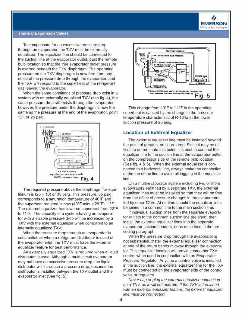
4
Thermal Expansion Valves
This change from 10°F to 11°F in the operating superheat is caused by the change in the pressure- temperature characteristic of R-134a at the lower suction pressure of 25 psig.
Location of External Equalizer
The external equalizer line must be installed beyond the point of greatest pressure drop. Since it may be dif-ficult to determinate this point, it is best to connect the equalizer line to the suction line at the evaporator outlet on the compressor side of the remote bulb location. (See fig. 4 & 5). When the external equalizer is con-nected to a horizontal line, always make the connection at the top of the line to avoid oil logging in the equalizer line.
On a multi-evaporator system including two or more evaporators each fed by a separate TXV, the external equalizer lines must be installed so that they will be free from the effect of pressure changes in the evaporators fed by other TXVs. At no time should the equalizer lines be joined in a common line to the main suction line.
If individual suction lines from the separate evapora-tor outlets to the common suction line are short, then install the external equalizer lines into the separate evaporator suction headers, or as described in the pre-ceding paragraph.
When the pressure drop through the evaporator is not substantial, install the external equalizer connection at one of the return bends midway through the evapora-tor. This equalizer location will provide smoother TXV control when used in conjunction with an Evaporator Pressure Regulator. Anytime a control valve is installed in the suction line, the external equalizer line for the TXV must be connected on the evaporator side of the control valve or regulator.
Never cap or plug the external equalizer connection on a TXV, as it will not operate. If the TXV is furnished with an external equalizer feature, the external equalizer line must be connected.
P1 = 35 PSIG
P2 = 25 PSIGP3 = 10 PSIG
35 PSIG = 40°F
25 PSIG = 29°F
25 PSIG & 40°F
B
C
TXV with externalequalizer on evaporator with
10 PSI pressure drop. Fig. 4
A
To compensate for an excessive pressure drop through an evaporator, the TXV must be externally equalized. The equalizer line should be connected to the suction line at the evaporator outlet, past the remote bulb location so that the true evaporator outlet pressure is exerted beneath the TXV diaphragm. The operating pressure on the TXV diaphragm is now free from any effect of the pressure drop through the evaporator, and the TXV will respond to the superheat of the refrigerant gas leaving the evaporator.
When the same conditions of pressure drop exist in a system with an externally equalized TXV (see fig. 4), the same pressure drop still exists through the evaporator, however, the pressure under the diaphragm is now the same as the pressure at the end of the evaporator, point “C”, or 25 psig.
The required pressure above the diaphragm for equi-librium is (25 + 10) or 35 psig. This pressure, 35 psig, corresponds to a saturation temperature of 40°F and the superheat required is now (40°F minus 29°F) 11°F. The external equalizer has lowered superheat from 22°F to 11°F. The capacity of a system having an evapora-tor with a sizable pressure drop will be increased by a TXV with the external equalizer when compared to an internally equalized TXV.
When the pressure drop through an evaporator is substantial, or when a refrigerant distributor is used at the evaporator inlet, the TXV must have the external equalizer feature for best performance.
An externally equalized TXV is required when a liquid distributor is used. Although a multi-circuit evaporator may not have an excessive pressure drop, the liquid distributor will introduce a pressure drop, because the distributor is installed between the TXV outlet and the evaporator inlet (See fig. 5).

5
Thermal Expansion Valves
P1 = 45.5 PSIG
P2 = 35 PSIGP3 = 10.4 PSIG
35 PSIG = 40°F
35 PSIG = 40°F
35 PSIG = 50°F
B
C
TXV with internalequalizer on evaporator with
no pressure drop. Fig. 6
A
Superheat
A vapor is said to be superheated whenever its temperature is higher than the saturation temperature corresponding to its pressure. The superheat equals the temperature increase above the saturation temperature at that pressure. For example, a refrigeration evapora-tor is operating with R-134a at 35 psig suction pressure (See fig. 6). The R-134a saturation temperature at 35 psig is 40°F. As long as any liquid exists at this pressure, the refrigerant temperature will remain 40°F as it evapo-rates or boils off in the evaporator.
suring superheat, install a calibrated pressure gauge in a gauge connection at the evaporator outlet. In the ab-sence of a gauge connection, a tee installed in the TXV external equalizer line can be used just as effectively.
A refrigeration type pocket thermometer with appro-priate bulb clamp or an electric thermometer with ther-mocouples may be used to measure gas temperature.
The temperature element from the thermometer should be taped to the suction line at the point of remote bulb location and must be insulated. Thermometers will give an average reading of suction line and ambient if not insulated. Assuming an accurate gauge and ther-mometer, this method will provide accurate superheat readings.
Approximate Methods of Reading Superheat
When a gauge connection is not available and the TXV is internally equalized there are two ways of esti-mating superheat. Neither of these methods will yield an exact superheat reading.
The first is the two-temperature method, which uses the difference in temperature between the evaporator inlet and outlet as the superheat. The error is caused by the pressure drop in the evaporator. When the pressure drop between the evaporator inlet and outlet is 1 psi or less, the two-temperature method will yield fairly accu-rate results. But evaporator pressure drop is usually not known and will vary with load. For this reason, the two-temperature method cannot be relied on for absolute superheat readings. The error in this method is negative and always shows a lower superheat.
The second method involves taking the temperature at the evaporator outlet and using the compressor suc-tion pressure as the evaporator saturation pressure. The error is caused by the pressure drop in the suction line between the evaporator outlet and the compressor suc-tion gauge. On packaged equipment and close-coupled installations, the pressure drop and resulting error are usually small. But on large built-up systems or systems with long runs of suction lines, considerable error can result. Since estimates of suction line pressure drop are usually not accurate enough to give a true picture of the superheat, this method cannot be relied on for absolute values. The error in this method is positive and always shows a higher superheat.
The only method for checking superheat that will yield an absolute value involves a pressure and tem-perature reading at the evaporator outlet .
By realizing the limitations of these approximate methods and the direction of the error, it is often pos-
As the refrigerant moves along in the coil, the liquid boils off into a vapor. The liquid is completely evapo-rated at point B because it has absorbed enough heat to change the refrigerant liquid to a vapor. The refrigerant gas continues along the coil and remains at the same pressure (35 psig); however, its temperature increases due to continued absorption of heat. When the refriger-ant gas reaches the end of the evaporator (point “C”) its temperature is 50°F. This refrigerant gas is now super-heated and the superheat is 10°F. (50°F minus 40°F).
The amount of superheat depends on how much re-frigerant is being fed into the evaporator by the TXV and the heat load to which the evaporator is exposed.
Superheat Adjustment
The function of a TXV is to control the superheat of the suction gas leaving the evaporator. If superheat is within reasonable limits, the TXV is operating in a satis-factory way. If superheat cannot be checked directly, it is important to know the size and direction of whatever error is present.
The pressure and temperature of the refrigerant suc-tion gas passing the TXV remote bulb are required for an accurate determination of superheat. When mea-

Thermal Expansion Valves
sible to determine that the cause of the trouble call is because of improper methods of instrumentation rather than any malfunction of the TXV.
When troubleshooting in mountain areas (such as Denver, Colorado or Salt Lake City, Utah) use a Pressure-Temperature chart that has correct readings such as Emerson Climate Technologies’ 5,000 ft. pocket chart. Gauge pressures will read lower than they would at sea level.
TXV Selection Proper TXV size is determined by the BTU/HR or
tons load requirement, the pressure drop across the TXV, and the evaporator temperature. Do not assume that the pressure drop across the TXV is equal to the difference between discharge and suction pressures at the compressor. This assumption could lead to incorrect sizing of the TXV.
The pressure at the TXV outlet will be higher than the suction pressure at the compressor because of the fric-tional losses through the distribution header, evaporator tubes, suction lines, fittings, and hand valves. On rack systems, the EPR valve also adds substantial pressure drop.
The pressure at the TXV inlet will be lower than the discharge pressure at the compressor because of fric-tional losses created by the length of liquid line, valves and fittings, and vertical lift. The only exception is if the TXV is installed considerably below the receiver and static head built up is more than enough to offset fric-tional loses. The liquid line should be properly sized for its actual length plus equivalent length due to fitting and hand valves. Vertical lift in the liquid line adds pressure drop and thus static head must be included.
The pressure drop across the TXV will be the differ-ence between the discharge and suction pressures at the compressor less the pressure drops in the liquid line, through the distributor, evaporator, and suction line.
ASHRAE tables should be consulted for determining pressure drops in liquid and suction line.
Here is the procedure for properly selecting a TXV:
1. Determine pressure drop across TXV: using the maximum and minimum condensing pressures, subtract the evaporating pressure from each to get the total high-to-low side pressure drop. From these values subtract the other possible pressure losses– piping and heat exchanger losses; pressure drop thru accessories; verti-cal lift pressure drop; and the pressure drop across the refrigerant distributor.
2. Consider the maximum and minimum liquid tempera-tures of the refrigerant entering the TXV and select the correction factors for those temperatures from the table below the capacity ratings. Determine the corrected ca-pacity requirement by dividing the maximum evaporator load in tons by the liquid correction factors.
3. Select the TXV size from the proper capacity table for the evaporator temperature, pressure drop available, and corrected capacity requirement.
4. Select the proper thermostatic charge based on the evaporator temperature, refrigerant, and whether a Maximum Operating Pressure (see MOP section) type charge is needed.
5. Determine connections and whether an externally equalized model is required. Always use an externally equalized TXV when a distributor is used.
A solid column of liquid refrigerant is required for proper TXV operation. Calculate the pressure drop in the liquid line to determine if there will be enough subcooling to prevent flash gas. If the subcooling of the liquid refrigerant from the condenser is not adequate, then a heat exchanger, liquid subcooler, or some other means must be used to get enough subcooling to en-sure solid liquid entering the TXV at all times.
Emerson Climate Technologies has prepared extended TXV capacity tables. These tables can be found in the Emerson catalog. Always select a TXV based on operating conditions rather than nominal TXV capacities.
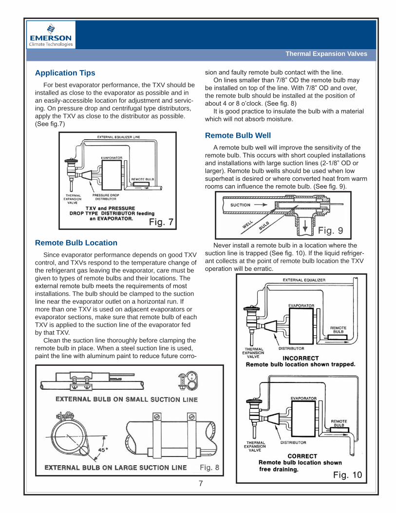
Thermal Expansion Valves
Application Tips
For best evaporator performance, the TXV should be installed as close to the evaporator as possible and in an easily-accessible location for adjustment and servic-ing. On pressure drop and centrifugal type distributors, apply the TXV as close to the distributor as possible. (See fig.7)
sion and faulty remote bulb contact with the line.On lines smaller than 7/8” OD the remote bulb may
be installed on top of the line. With 7/8” OD and over, the remote bulb should be installed at the position of about 4 or 8 o’clock. (See fig. 8)
It is good practice to insulate the bulb with a material which will not absorb moisture.
Remote Bulb Well
A remote bulb well will improve the sensitivity of the remote bulb. This occurs with short coupled installations and installations with large suction lines (2-1/8” OD or larger). Remote bulb wells should be used when low superheat is desired or where converted heat from warm rooms can influence the remote bulb. (See fig. 9).
Remote Bulb Location
Since evaporator performance depends on good TXV control, and TXVs respond to the temperature change of the refrigerant gas leaving the evaporator, care must be given to types of remote bulbs and their locations. The external remote bulb meets the requirements of most installations. The bulb should be clamped to the suction line near the evaporator outlet on a horizontal run. If more than one TXV is used on adjacent evaporators or evaporator sections, make sure that remote bulb of each TXV is applied to the suction line of the evaporator fed by that TXV.
Clean the suction line thoroughly before clamping the remote bulb in place. When a steel suction line is used, paint the line with aluminum paint to reduce future corro-
Never install a remote bulb in a location where the suction line is trapped (See fig. 10). If the liquid refriger-ant collects at the point of remote bulb location the TXV operation will be erratic.

Thermal Expansion Valves
Large fluctuations in superheat in the suction gas are usually the result of trapped liquid at the remote bulb location. Even on properly designed suction lines, it is sometimes necessary to move the remote bulb a few inches from the original location to improve TXV perfor-mance.
On multi-circuit evaporators fed by one TXV, install the remote bulb at a point where the suction gas has had an opportunity to mix in the suction header. Tighten clamps so that the remote bulb makes good contact with the suction line. NEVER APPLY HEAT NEAR THE REMOTE BULB LOCATION WITHOUT FIRST RE-MOVING THE REMOTE BULB.
Hunting
“Hunting” of TXVs is defined as the alternate over-feeding and starving of the refrigerant flow to the evaporator. Hunting is characterized by extreme cyclic changes in the superheat of the refrigerant gas leaving the evaporator and the evaporator or suction pressure.
Hunting is a function of the evaporator design, length and diameter of tubing in each circuit, load per circuit, refrigerant velocity in each circuit, temperature differ-ence (TD) under which the evaporator is operated, ar-rangements of suction piping and application of the TXV remote bulb. “Hunting” can be reduced or eliminated by the correct rearrangement of the suction piping, reloca-tion of the bulb and use of the recommended remote bulb and power assembly charge for the TXV.
Operation at Reduced Capacity
The conventional TXV is a self-contained direct oper-ated regulator which is inherently susceptible to hunting because of its design and the design of the system to which it is applied.
The ideal flow rate would require a TXV with perfect dynamic balance, capable of instantaneous response to any change in evaporation (anticipation) and with a means of preventing the TXV from over shooting the control point because of inertia (compensation). With these features a TXV would be in phase with the system demand at all times and hunting would not occur.
A conventional TXV does not have built in anticipating or compensating factors. A time lag will exist between demand and response, along with the tendency to over shoot the control point. The conventional TXV may get out of phase with the system and hunt. An example of overshooting occurs when the load increases, causing the superheat of the suction gas to increase. The time interval between the instant the remote bulb senses the increase and causes the TXV pin to move into opening
direction allows the superheat of the gas to increase still further.
In response to the rising superheat during the time lags, the TXV has moved further in the opening direc-tion, overshooting the control point and allowing more refrigerant to flow to the evaporator than can be boiled off by load.
When the TXV finally responds to the over-feeding of the evaporator coil, it closes and will tend to again over-shoot the control point and remain overly throttled until most of the liquid refrigerant has left the evaporator.
The ensuing time delay before the TXV moves in the opening direction allows superheat of the suction gas to again rise beyond the control point. This cycle, being self-propagating, continues to repeat.
Experience has shown that a TXV is more likely to hunt at low load conditions when the TXV pin is close to the valve seat. This is because of an unbalance be-tween the forces which operate the TXV.
Besides the three main forces that operate the TXV, the pressure difference across the TXV port also acts against the port area and depending on TXV construc-tion, tends to force the TXV either open or closed.
When operating with the pin close to seat, the follow-ing will occur:
With the TXV closed, there is liquid pressure on the inlet side of the pin and evaporator pressure on the outlet.
When the TXV starts to open allowing flow to take place, the velocity through the TXV throat will cause a point of lower pressure at the throat, raising the pressure difference across the pin and seat.
This sudden rise in pressure differential while acting on the port area will tend to force the TXV pin back into the seat. When the TXV again opens, the same type of action occurs and the pin bounces off the seat with a rapid frequency. This phenomenon is more frequently encountered with the larger conventional ported TXVs as compared to balance ported TXVs as the force caused by the pressure differential is magnified by the larger port area.
Most TXVs, when properly selected and applied, will overcome these factors and operate with virtual no hunt-ing over a fairly wide load range.
Conventional ported TXVs will operate satisfactory to somewhat below 50% of nominal capacity depending on evaporator design, refrigerant piping, size and length of evaporator, and rapid changes in loading.
Nothing will cause a TXV to hunt quicker than un-equal feeding of the parallel circuits by a distributor or unequal air loading across the evaporator circuits.

9
Thermal Expansion Valves
Balanced Port TXV Operation
In conventional TXVs, as the pressure drop across the TXV port changes due to changes in head pressure or suction pressure, the operating superheat of the TXV will vary.
Depending on the operating conditions under which the superheat was originally set, this “unbalance” can sometimes result in compressor flooding or evaporator starvation. A unique design concept called “Balanced Port” cancels the effect of this pressure unbalance, per-mitting the TXV to operate at a fairly constant superheat over a wide range of operating conditions.
There are 2 fundamental Balanced Port designs:Double Ported Design (Figure 11a) – In this design, there are 2 paths for the refrigerant to flow. One path creates a force that tends to push the pin in the “open” direction; whereas the other path creates a force push-ing the pin in the “closed” position. These paths are de-signed in such a way that the forces generated in each path are equal to one another, resulting in a “balanced” design.Single Ported Design (Figure 11b) – In this design, the valve pin has a shoulder added that is on the inlet side of the valve. The high pressure times the area of the shoulder results in an upward (closing) force. The pres-sure differential across the pin results in a “downward” force. By designing the shoulder carefully, the downward force is negated or “balanced”.
Any refrigeration system which experiences changes in operating pressures because of varying ambient, gas defrost, heat reclaim, or swings in evaporator load will benefit from using a balanced port TXV.
M .O .P .
Maximum Operating Pressure (sometimes referred to as Motor Overload Protection) is the ability of a TXV to close down, starve, or shut off if the suction pressure should approach a dangerously high predetermined limit condition. These conditions could overheat a suction cooled compressor or load the crankcase with too dense a vapor pressure. With the TXV in a closed condition the compressor has a chance to gain pull the suction back down to satisfactory operating conditions. Once below the MOP, the TXV will re-open and feed normally or until there is an overload again.
Power Element Charges
There are several basic types of charges in use today. Most common are the: liquid charge; gas charge; liquid cross-charge; gas cross-charge; and the adsorp-tion charge.
Liquid Charges
The power element contains the same refrigerant as the system in which the TXV is used. When manu-factured, it is put into the remote bulb in a liquid state. Volume is controlled so that within the design tempera-ture range some liquid always remains in the bulb. Therefore, the power element pressure is always the saturation pressure corresponding to the temperature of the remote bulb.
IN IN
ININ
OUTOUT
OUTOUTBALANCED CAGE
ASSEMBLY
CONVENTIONALCAGE ASSEMBLY
Fig. 11Fig. a
Balance Ported Pin
Equal AreasEqual Forces
Inlet Pressure
Eliminates Imbalance Forces
Fig. b

10
Thermal Expansion Valves
As in liquid charges, the remote bulb can be filled with the same refrigerant as the system refrigerant (pro-ducing a gas charge). Or, it can be filled with a different refrigerant, producing a gas cross-charge.
Adsorption Charges
The final type of charge is adsorption. In adsorption, solids hold large quantities of gas, not by taking them into the body of the solid, as in absorption, but by gath-ering them and holding them on the surface of the solid without chemical reaction.
The vapor penetrates into the cracks and furrows of the solid, allowing far greater capacity than possible with absorption.
The advantage of an adsorption charge is that in a fixed volume, the quantity of vapor adsorbed varies with the temperature and the system. So it can be used to exert operating pressure as a function of temperature.
Typical adsorbents include: charcoal, silica gel, acti-vated alumina.
Liquid charges have the following properties:• Not subject to cross-ambient control loss• Little or no superheat at start-up• Superheat increase at lower evaporator temperatures• Slow suction pressure pulldown after start-up
REFRIGERANT CODE NAMES
ARI Standard 750-2007 recommends the following color coding of the TXVs:
R- White R- Green R-502 Orchid R-134a Light Blue R-410A Rose R-404A Orange R-507A Blue Green (Teal)
Liquid Cross-Charges
Liquid cross-charges means that the power element contains a liquid refrigerant different from the system refrigerant in which the TXV is used. The pressure tem-perature curve of the charge crosses the curve of the system refrigerant.
Liquid cross-charge advantages are: • Moderately slow pull down• Insensitive to cross-ambient conditions. • Damped response to suction line temperature changes (reduces tendency for TXV hunting) • Superheat characteristics can be tailored for special applications
Gas & Gas Cross-Charges
Using a gas charge in place of a liquid alters the operational characteristics, because gas is compress-ible. At some predetermined temperature, the gas in the remote bulb becomes superheated, limiting the force it exerts. This produces higher superheats at higher evap-orator pressures and is labeled the Maximum Operating Pressure (MOP) effect.
Any MOP point temperature depends on how that bulb was charged and where it will be used. All gas charges are susceptible to cross-ambient control loss when the power element is colder than the remote bulb. They respond faster, but tend to hunt for the proper operating level, so a ballast is often added to the remote bulb to reduce that tendency.
What happens with an adsorption charge
Which Charge to Use?
Here are some typical examples of applications by refrigerant charge:
Liquid ChargeIce makers, pilots, liquid injection valves
Liquid Cross-ChargesCommercial refrigeration (low & medium temp.), ice makers, transport refrigeration and air conditioning
Gas ChargeAir conditioning (including mobile), water chillers
Gas Cross-ChargeHeat pumps and air conditioning
MOP Maximum Operating Pressure

Thermal Expansion Valves
Other TXV Considerations
Solenoid Liquid Stop Valves
The TXV is produced as a tight seating device. But if the TXV is exposed to dirt, moisture, corrosion, and erosion the TXV will not be able to positively shut off. If the remote bulb is installed in a location where during the “off’ cycle it is influenced by a higher ambient tem-perature than the evaporator, the valve will open and ad-mit liquid to the evaporator. Installing a Solenoid Liquid Stop Valve ahead of any TXV is highly recommended.
Filter-Driers for System Protection
To protect the precision working parts of control valves from dirt and chips which can damage them and make them inoperative, and to protect the entire system from the damaging affects of moisture, sludge and ac-ids, a filter-drier should be installed on every system.
Pressure Switch Setting
On TXVs with M.O.P., a Pressure Switch must be set to cut in at a pressure lower than M.O.P. rating of the TXV.
Emerson TXVs
Emerson’s TXVs are designed for a wide range of air conditioning, refrigeration, heat pump, and chiller ap-plications. Emerson uses stainless steel power elements that will not corrode.
Emerson’s integral TXV line includes valves for com-mercial and refrigeration applications, and heat pump and residential applications. The “Take-A-Part Series” TXVs are available for almost any type of application, temperature range, or refrigerant. Emerson also offers a complete line of specialty TXVs.
Factory Superheat Setting
Unless otherwise specified, all Emerson TXVs will be preset at the factory at a bath temperature which is pre- determined by the charge symbol or the MOP rat-ing. The bath temperature at which the TXV superheat is set is coded alphabetically in the superheat block on the TXV nameplate, as shown in Fig. 15.
Fig. 15
Degrees of SH Per TurnValve “Total R-22 R-134a R-404A/507A R-410AFamily Turns” +20°F -20°F +20°F +20°F -20°F +40°F
TCLE 32 0.8 1.5 1.0 0.5 1.0 N/A
HF 10 2.2 4.2 3.8 1.8 3.2 N/A
A 8 3.0 5.0 4.5 2.0 4.0 2
TRAE 10 2.2 4.2 3.8 1.8 3.2 N/A
C 12 – – – – – 4
TXV SUPERHEAT ADJUSTMENT
Turn adjustment clockwise to increase superheat, counter-clockwise to decrease superheat. To return to approximate original factory setting, turn adjustment stem counterclockwise until the spring is completely unloaded (reaches stop or starts to “ratchet”). Then, turn it back in one half of the “Total Turns” shown on the chart.
For example, a TXV with “10A” stamped in the name-plate superheat block is set for 10°F static superheat with a 32°F bath. A TXV stamped “10C” is set for 10° of static superheat with a 0°F bath.
When ordering a TXV for an exact replacement, specify the code letter and the superheat setting de-sired. When ordering for general stock, it is not neces-sary to specify either the superheat or the code letter, since the standard setting will cover most applications and minor superheat adjustments may be made in the field.
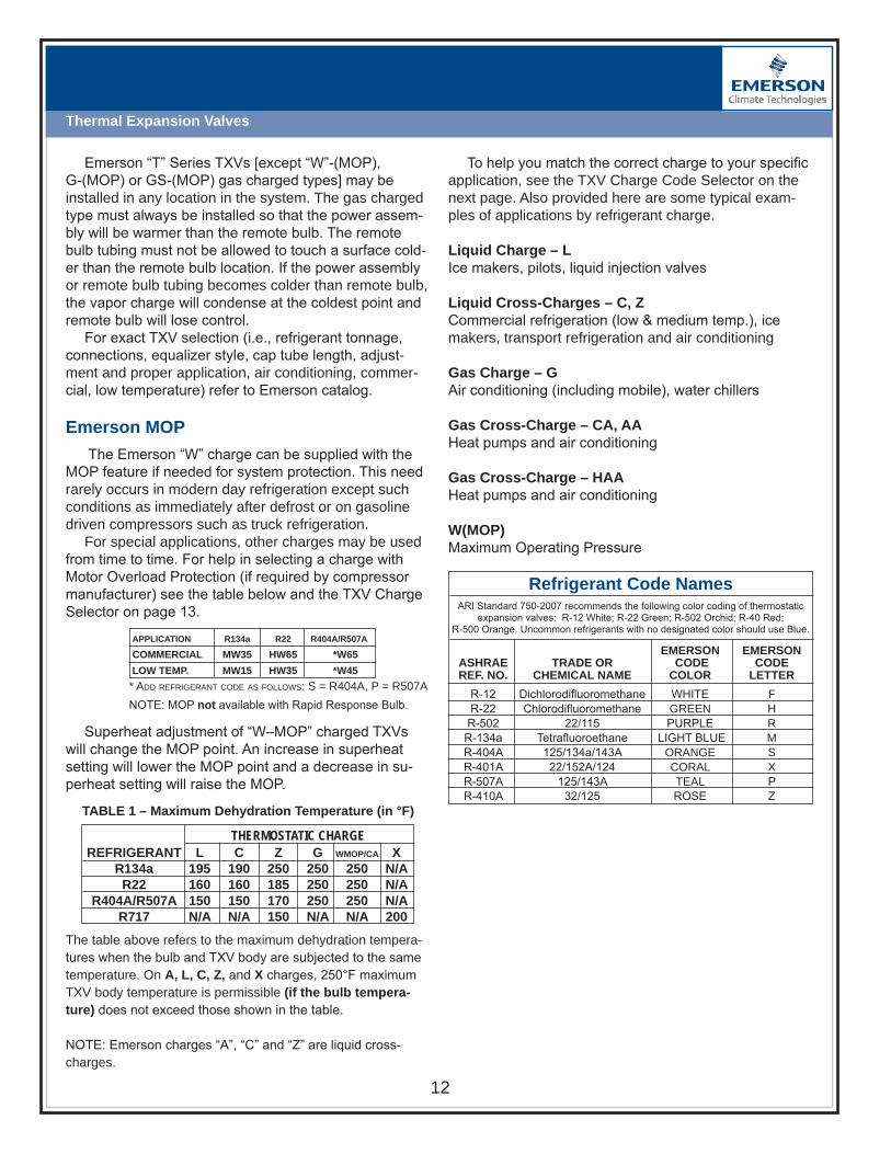
Thermal Expansion Valves
To help you match the correct charge to your specific application, see the TXV Charge Code Selector on the next page. Also provided here are some typical exam-ples of applications by refrigerant charge.
Liquid Charge – LIce makers, pilots, liquid injection valves
Liquid Cross-Charges – C, ZCommercial refrigeration (low & medium temp.), ice makers, transport refrigeration and air conditioning
Gas Charge – GAir conditioning (including mobile), water chillers
Gas Cross-Charge – CA, AAHeat pumps and air conditioning
Gas Cross-Charge – HAAHeat pumps and air conditioning
W(MOP)Maximum Operating Pressure
EMERSON EMERSON ASHRAE TRADE OR CODE CODE REF . NO . CHEMICAL NAME COLOR LETTER
R-12 Dichlorodifluoromethane WHITE F R-22 Chlorodifluoromethane GREEN H R-502 22/115 PURPLE R R-134a Tetrafluoroethane LIGHT BLUE M R-404A 125/134a/143A ORANGE S R-401A 22/152A/124 CORAL X R-507A 125/143A TEAL P R-410A 32/125 ROSE Z
ARI Standard 750-2007 recommends the following color coding of thermostaticexpansion valves: R-12 White; R-22 Green; R-502 Orchid; R-40 Red;
R-500 Orange. Uncommon refrigerants with no designated color should use Blue.
Refrigerant Code Names
Emerson “T” Series TXVs [except “W”-(MOP), G-(MOP) or GS-(MOP) gas charged types] may be installed in any location in the system. The gas charged type must always be installed so that the power assem-bly will be warmer than the remote bulb. The remote bulb tubing must not be allowed to touch a surface cold-er than the remote bulb location. If the power assembly or remote bulb tubing becomes colder than remote bulb, the vapor charge will condense at the coldest point and remote bulb will lose control.
For exact TXV selection (i.e., refrigerant tonnage, connections, equalizer style, cap tube length, adjust-ment and proper application, air conditioning, commer-cial, low temperature) refer to Emerson catalog.
Emerson MOP
The Emerson “W” charge can be supplied with the MOP feature if needed for system protection. This need rarely occurs in modern day refrigeration except such conditions as immediately after defrost or on gasoline driven compressors such as truck refrigeration.
For special applications, other charges may be used from time to time. For help in selecting a charge with Motor Overload Protection (if required by compressor manufacturer) see the table below and the TXV Charge Selector on page 13.
NOTE: MOP not available with Rapid Response Bulb.
APPLICATION R134a R22 R404A/R507A
COMMERCIAL MW35 HW65 *W65
LOWTEMP. MW15 HW35 *W45
* Add refrigerAnt code As follows: s = r404A, P = r507A
Superheat adjustment of “W–MOP” charged TXVs will change the MOP point. An increase in superheat setting will lower the MOP point and a decrease in su-perheat setting will raise the MOP.
THERMOSTATICCHARGE
The table above refers to the maximum dehydration tempera-tures when the bulb and TXV body are subjected to the same temperature. On A, L, C, Z, and X charges, 250°F maximum TXV body temperature is permissible (if the bulb tempera-ture) does not exceed those shown in the table.
NOTE: Emerson charges “A”, “C” and “Z” are liquid cross-charges.
REFRIGERANT L C Z G WMOP/CA X R134a 195 190 250 250 250 N/A R22 160 160 185 250 250 N/A R404A/R507A 150 150 170 250 250 N/A R717 N/A N/A 150 N/A N/A 200
TABLE1–Maximum Dehydration Temperature (in °F)

13
Thermal Expansion Valves
HW35
AIRCONDITIONING COMMERCIALREFRIGERATION LOWTEMPERATURE OLDCHARGE REPLACEMENT OLDCHARGE REPLACEMENT OLDCHARGE REPLACEMENT
REFRIGERANTR12/R134a FORFL — — FC FC — FW FW FWZ FG55 FC FG35 — — FW55 FW35 FW35 FW15 FQ55 FQ35 FW15 FGA FLA — — FGS FGS35 FGS35 FWS FWS FWS FWS FWS FWS FZ/MZ FZ/MZ FX FX
REFRIGERANTR22 HORHL — — HC HC — HW HCA HW HWZ HG100 HG65 — — HW100 HW65 HW65 HW35 HQ100 HC HQ65 HQ35 HGA HLA — — HW85 HW85 — — HGS HGS65 HGS65 HWS HWS HWS HWS HWS HWS HZ HZ HX HX
REFRIGERANTR502/R404A/R507A RL — — RW RC/SC/PC RW RWZ RZ RW110 RW65 RW65 RW35 RW45/SW45 RWS RWS RZ RZ/SZ/PZ
HZ HC
— —
FW15/MW15
RC/SC/PC
RWS RWS RWS RWS
FZ
TXV Replacement Charge Symbols Cross ReferenceOld Bulb Charges vs. New Replacement Bulb Charge
NOTE: ALL OTHER CHARGE SYMBOLS MUST BE REPLACED WITH AN IDENTICAL MODEL OR AT THE OPTION OF THE EMERSON TECHNICAL SERVICE DEPART-MENT WHO MAY MAKE ENGINEERING AUTHORIZED SUBSTITUTION OF EQUIVALENT TYPE TO PROVIDE EQUIVALENT OPERATION AND PERFORMANCE.NOTE: FOR FIELD REPLACEMENT PURPOSES, HC CAN BE USED TO REPLACE HCA.
TXV Charge Code Selector
Applications Operating Ranges
R-134a/R-12Domestic Refrigerators and Freezers, Ice Makers,Dehumidifiers,
Transport Refrigeration, Medium Temperature Supermarket Equipment,Medium Temperature Commercial Equipment
MC/FCMZ/FZ
MW15/FW15 (MOP)MW35/FW35 (MOP)
MW55
R-Residential Air Conditioners &Heat Pumps, Commercial and
Industrial Chillers, Medium Temperature Supermarket Equipment, Commercial Air Handlers
HCA/HAA AIR COND. & HEAT PUMPHW/HW100
HCHW65 (MOP)
HZ
R-404A/R-507A/R-502Low Temperature Cases, Ice Makers, Commercial Air Handlers,
Conditioners, Soft Ice Cream Machines, Environmental Chambers
SC/RCSZ/RZ
SW45/RW45 (MOP)R-410A ZW195
-50 -40 -30 -20 -10 0 +10 +20 +30 +40 +50

142008
Solenoid Valves

15
Solenoid Valves
Direct Acting Solenoid Anatomy
What Are Solenoid Valves?
A solenoid valve consists of two distinct but integral acting parts, a coil and a valve. See drawing below for complete valve anatomy.
Solenoid Valves
In most refrigeration applications, it is necessary to start or stop the flow in a refrigerant circuit to automati-cally control the fluids in the system. An electrically operated solenoid valve is usually used for this purpose. Its basic function is the same as a manually operated shut off valve, but by being solenoid actuated, it can be positioned in remote locations and may be conveniently controlled by simple electrical switches.
Solenoid valves can be operated by a thermostatic switch, float switches, low pressure switches, high pres-sure switches or any other device for making or breaking an electric circuit, with the thermostatic switch being the most common device used in refrigeration systems.
Principles of Solenoid Operation
Solenoids are either direct acting or pilot operated. The application determines the need for either of these types. The direct acting valve is used on valves with low capacities and small port sizes. The pilot operated type is used on the larger valves, eliminating the need for larger coils and plungers.
1 . Direct Acting
In the direct acting type valve, as discussed under Solenoid Valve operation, the plunger is mechanically connected to the needle valve. When the coil is ener-gized, the plunger pulling the needle off the orifice is raised into the center of the coil. A direct acting valve will operate from zero pressure differential to its maximum rated pressure differential, regardless of the line pres-sure.
The direct acting type valve is only used on small capacity circuits because of the increased coil size that would be required to counter the large pressure dif-ferential of large capacities. The required coil would be large, uneconomical, and not feasible for large capacity circuits. To overcome this problem on large systems, pilot operated solenoid valves are used.
The coil is nothing more than electrical wire wound around the surface of a cylindrical form usually of circu-lar cross section. When an electric current is sent thru the windings, they act as an electromagnet. The force field that is created in the center of the solenoid is the driving force for opening the valve. Inside is a moveable magnetic steel plunger that is drawn toward the center of the coil when energized.
The valve contains an orifice through which fluid flows when open. A needle or rod is seated on or in the orifice and is attached directly to the lower part of the plunger.
When the coil is energized, the plunger is forced toward the center of the coil, lifting the needle valve off of the orifice and allowing flow. With a normally-closed valve, when the coil is de-energized, the weight of the plunger and in some designs, a spring, causes it to fall and close off the orifice, thus stopping the flow through
the valve. Less common are normally-open valves which are open when the coil is de-energized.
Enclosing TubeTop PlugAssembly
Return Spring
Plunger Assembly
Collar
BodyAssemblyO-Ring

Solenoid Valves
Figures 1A and 1B show a simple schematic of a Direct Acting Solenoid Valve in operation.
2 . Pilot Operated Valve
The pilot operated solenoid valve uses a combination of the solenoid coil and the line pressure to operate. In this type valve the plunger is attached to a needle valve covering a pilot orifice rather than the main port. The line pressure holds an independent piston or diaphragm closed against the main port. See figures 2a and 2b. When the coil is energized, the plunger is pulled into the center of the coil, opening the pilot orifice. Once the pilot port is opened, the line pressure above the diaphragm is allowed to bleed off to the low side or outlet of the valve, thus relieving the pressure on the top of the diaphragm. The inlet pressure then pushes the diaphragm up and off of the main valve port and holds it there allowing full fluid flow. When the coil is de-energized, the plunger drops and closes the pilot orifice. Pressure starts to build up above the diaphragm by means of a bleed hole in the piston diaphragm until it and the diaphragm’s weight and spring cause it to close on the main valve port. A pilot operated solenoid valve requires a minimum pressure difference of several pounds between inlet and outlet to operate.
Types of Solenoids
There are different types of solenoid valves for differ-ent applications. The three main types of valves are the 2-way, 3-way, and 4-way valves. The 2-way valve is the most common.
2-Way Valves
The 2-way valve controls fluid flow in one line. It has an inlet and an outlet connection. This valve can be of the direct acting or pilot operated type of valve depend-ing on the need. When the coil is de-energized, the -way valve is normally closed. Although normally closed is the most widely used, two-way and three-way valves are manufactured to be normally open when the coil is de-energized. See Figure 3 for an example of a 2-way valve.
Figures 2A and 2B show a simple schematic of a Pilot Operated Solenoid Valve in operation.
NOTE: 2-way valves are usually designed to have flow in one direction only. Some valves may be modified to have flow in both directions. A “bi-flow” kit must be used.
Figure 3
FIG. 1A DE-ENERGIZED
FIG. 1B ENERGIZED
FIG. 2A DE-ENERGIZED
FIG. 2B ENERGIZED

Solenoid Valves
Solenoid Valve Selection
The selection of a Solenoid Valve for a control ap-plication requires the following information:. Fluid to be controlled2. Capacity required3. Maximum operating pressure differential (MOPD)4. Electrical characteristics5. Maximum working pressure required (MWP)
The capacities of Solenoid Valves for normal liquid or suction gas refrigerant service are given in tons of refrigeration at some nominal pressure drop and stan-dard conditions. Manufacturers’ catalogs provide ex-tended tables to cover nearly all operating conditions for common refrigerants. Follow the manufacturer’s sizing recommendations. Do not select a valve based on line size. Pilot operated valves require a pressure drop to operate and selecting an oversize valve will result in the valve failing to open. Undersized valves result in exces-sive pressure drops.
The solenoid valve selected must have a MOPD rat-ing equal to or greater than the maximum possible differ-ential against which the valve must open. The MOPD or Maximum Operating Pressure Differential considers the inlet and outlet valve pressures. If a valve has a 500 psi inlet pressure and a 250 outlet pressure, and a MOPD rating of 300 psi it will operate, since the pressure dif-ference (or 500-250) is less than the 300 MOPD rating. If the pressure difference is larger than the MOPD, the valve will not open.
Minimum Operating Pressure Differential
Consideration of the maximum working pressure required is also important for proper and safe operation. A solenoid valve should not be used for an application when the pressure is higher than the valve maximum working pressure. Solenoid valves are designed for a given type of fluid so that the materials of construction will be compatible with that fluid. Special seat materi-als and synthetics may be used for high temperature or ultra-low temperature service. Special materials are required for corrosive fluids. Special attention to the electrical characteristics is also important. Required voltage and Hertz must be specified to ensure proper selection. Valves for DC service often have different in-ternal construction than valves for AC applications, so it is important to study the manufacturer’s catalog informa-tion. Solenoid valves should never be used as a Safety Shut Off unless specifically designed and rated for that service.
NOTE: No minimum pressure differential – valve will not operate.
NOTE: Pressure differential greater than minimum – valve will operate.
50 psig 50 psig 194 psig 200 psig
sP = 0 psig sP = 6 psig

Solenoid Valves
Installation
Solenoid Valves having a spring loaded piston or dia-phragm may be installed and operated in any position, but installing more than 90° from vertical is not recom-mended since dirt or debris may collect in the solenoid area and prevent it from operating. An adequate strainer or filter drier should be installed ahead of each solenoid valve to keep scale, pipe dope, solder, and other foreign matter out of the valve.
When installing a solenoid valve, be sure the arrow on the valve body points in the direction of refrigerant flow.
When brazing valves with extended solder type con-nections do not use too hot a torch and point the flow away from the valve. These valves do not normally need to be disassembled before installation; if the valve does not have extended connections, disassemble the valve before brazing. Wet rags or chill blocks are recom-mended during brazing. They are needed to keep the valve body cool so that body distortion on close-coupled valves will not occur. Allow the valve body to cool before replacing the valve’s operating insides to ensure that the seat material and gaskets are not damaged by the heat. When reassembling, do not over torque.
Application Overview
Application Product Family
Liquid, Suction Line Service 240RA/540RA or Hot Gas By-Pass 50RB 100RB 200RB/500RB Pressure Differential Valve for Gas Defrost 710RA 713RA
Emerson Solenoid Valves
Emerson offers a complete line of refrigerant solenoid valves for refrigeration and air-conditioning applications. As part of Emerson’s commitment to the industry, each valve undergoes stringent Emerson testing to ensure fail-safe operation. And, with the lowest external leak rates in the industry, Emerson solenoid valves ensure precise refrigerant flow, preventing system failures and aiding in environmental protection.

192008
System Protectors

20
System Protectors
Acid Pick-Up Capability
Various organic acids result during the decomposition of the refrigerant and oil in a system. This decomposition can be the result of moisture in the system, excessive temperatures, air, or exposure to foreign substances in the system. It is important that acid in a system is ab-sorbed as soon as it is formed to prevent the acid from causing system damage. Activated alumina is the most popular of the desiccants used to remove acid.
Tests have shown that the amount of acid and resin pick-up of an adsorbing agent is almost proportional to the weight of the desiccant. Size or granulation makes little difference.
There is no industry-approved method for rating acid removal. So weight of the desiccant provides the handi-est measure.
Wax Removal
The ability of a filter-drier to remove wax and resins is important in low temperature applications that use R-22. Wax when present in a system tends to solidify on valve seats and pins, resulting in system malfunctions.
Flow Rate
Published flow rates for filter-driers are established in accord with ARI Standard 710 for liquid line driers, and ARI Standard 730 for suction line driers.
Liquid line and suction line filter-driers are often referred to as System Protectors because they remove harmful elements from the circulating refrigerant before serious damage results.
Keeping the system clean and free of foreign con-taminants that can restrict the operation of valves, block capillary tubes or damage compressors is the best way to assure trouble-free operation. These contaminants can be solids, such as metal filings, flux, dust and dirt. Other equally menacing contaminants are solubles, such as acid, water, resins and wax.
No matter how many precautions are taken during assembly and installation or servicing of a system, contaminants can find a way into the system. Filter- driers are designed to protect a system during operation. It is the function of this all important unit to remove those residual elements that can attack and eventually destroy the system components.
Filtration Capacity
Solid particles or semi-solids such as sludges circulating in a refrigerant system can destroy valve seats, plug control valves, and score cylinder walls or compressor bearings. These contaminants can be the result of manufacturing, servicing, or can be generated during normal system operation.
It is important to remove these contaminants as quickly as possible and prevent them from returning to the system. Properly specified filter-driers are designed to trap and hold large quantities of these contaminants while maintaining low pressure drop during their service life.
Moisture Capability
Moisture in a refrigeration system can cause frozen valves, copper plating, damaged motor insulation, corro-sion, and sludges. Filter-driers remove and retain mois-ture through one or more desiccants. The most popular and effective desiccant in use today for the removal of moisture is molecular sieve which can hold three to four times the water of other commercial absorbents.
Moisture capacity of a filter-drier is normally given in drops of water per ARI Standard 710. These rated capacities are in addition to any residual moisture that might be absorbed during manufacturing.
MWP-680

System Protectors
Compacted bead style filter-drier, Emerson’s EK-Plus
Absorption vs . Adsorption
One factor to consider in selection is ab- vs. ad-sorption. Absorption means a material’s ability to take another substance into its inner molecular structure.
An adsorbed substance doesn’t penetrate the mo-lecular structure. It simply starts building up on the sur-face of the adsorbent. Walls, cracks, crevices are part of the surface area and are able to hold other substances, greatly increasing capacity.
Modern desiccants are extremely porous and have a large surface area and internal pore volume of a size and shape to adsorb and retain water molecules.
Types of Filter-Driers
All the liquid line filter-driers on the market today are a variation of one of two types: the molded core type or the bead type.
Molded core type filter-driers are manufactured by mixing desiccants (which remove the soluble contami-nants) with a bonding agent, then baking them to give them permanent shape and to activate the drying ingre-dients. The results is a porous core which acts as filter and drying agent.
Compacted bead style filter-driers are manufactured with the active desiccant in bead or pellet form; no bond-ing material is used. Rather, compacting comes from mechanical pressure exerted by a spring. Compacted bead-style filter-driers usually include an additional filter network to trap solid contaminants from the refrigerant, unlike most core styles.
The separate and distinctive filter media can take various forms that permit depth filtration with greater solid contaminant capacity and contaminant retention during start-up and shut- down when turbulent condi-tions exist.
Compacted bead filter-driers offer the maximum vol-ume of desiccant because filtering and drying is done in one mass. But, because the core is porous, it does not hold all solid contaminants; often particles are washed through channels within in the core when pressures surge. Better holding power is possible with a more compacted core. But pressure drops increase inversely.
Fig 1. Proper placement of filter-drier in the system
Dirt, Waxes, Acid
Every system has contaminants in it as soon as it is opened. These contaminants may be insoluble, such as metal filings not removed in manufacturing, or airborne dirt that entered when the system was opened. Or they may be soluble, such as waxes, acids, water and resins that develop through reactions between air, the refriger-ant, or lubricant.
Any of these can cause system failure. Installing an all-purpose filter-drier can lessen chances for trouble.
There are basic differences to consider: type of filter, how it filters, and its true capacity.
Most manufacturers rate their filters to ARI Standard 710. But even though two clean filter-driers may be rated the same, there can be a vast difference in flow as the quantity of solids picked up increases.

System Protectors
Refrigerant Water Concentration (ppm)
0
0.05
0.1
0.15
0.2
0 100 200 300 400 500 600 700
Tota
l Aci
d N
umbe
r
HFC Refrigerants and POE Lubricants
The use of HFC refrigerants and Polyolester (POE) lubricants for air-conditioning and refrigeration has generated new system chemistry related problems. New and redesigned system protectors have been developed to counter these problems and provide a long, reliable life for the operating refrigeration system.
Moisture is the major problem causing contaminate for HFC/POE oil systems just as it was for CFC and HCFC systems using Mineral oil. Many HFCs can hold much more water than their CFC counterparts but the oil differences are much worse than those of the refriger-ant. POE oil can hold as much as 10 times more water than Mineral oils. Evacuation alone has proved ineffec-tive at removing this moisture so a filter-drier is required to perform this function.
Water poses a new problem for POE oils above and beyond those experienced with Mineral oil. POE oil will react with water to form organic acids at normal operat-ing conditions in refrigerating and air-conditioning sys-tems. This reaction starts at water levels as low as 75 ppm. These acids attack system components including motor insulation and metallic parts, reducing system life.
To combat the detrimental effects of water in HFC and POE oil systems it is imperative to hold moisture levels as low as possible. Water level must be main-tained less than 50 ppm in the refrigerant and the same for the oil.
Figure
Acid Generation in a 1.5 Ton POE Oil Containing System
Another aspect of POE oil is the ability to keep more solid particles in suspension than Mineral oil. This is important in retrofitted systems where pockets of solid contamination are now flushed from low flow areas and need to be removed before moving parts in the system are damaged. The filter-drier for POE oils needs to have higher solid particle holding capacity with little impact to refrigerant flow capacity or pressure drop.
The filter-drier should also have improved contami-nate removal efficiency as well to ensure that all par-ticles are captured the first time they enter the filter-drier. The ability to remove smaller particles is also advanta-geous. The Emerson EK series filter-driers provide a unique combination of these characteristics to provide outstanding filtration as shown in Figure 4.
0
25
50
75
100
125
75 100 125
HMI
TypicalSightglass
R-134a Refrigerant Temperature
Moi
stur
e Le
vel (
ppm
)
Figure 3Dry Indication Water Level
0
500
1000
1500
2000
2500
Water Content (ppm)
MineralOil
POE Oil R-12 R-134a R-22 R-502 R-404A R-410A

23
System Protectors
EKTypical drier
Solid Contamination Captured
Flow
Res
tric
tion
The filter-driers for use in HFC and POE oil systems must maintain the system dry and free of any acids gen-erated. However, since water capacity is of primary im-portance the filter-drier should contain a higher percent-age of molecular sieve than was required for CFC and HCFC systems. But molecular sieve alone is not enough since it has almost no organic acid capacity. An organic acid removal desiccant must be used such as activated alumina to ensure low acid levels are maintained. The filter-drier should also have higher filtration capacity and efficiency. The EK series of filter-driers provides the best combination of these properties to ensure the long, trouble-free life of any air-conditioning or refrigeration system.
The moisture indicating sightglass must also indicate moisture levels less than 50 ppm moisture. Also, it must be able to perform this function at the temperature of the liquid line on which it is placed. Many sightglasses can-not perform this function at all liquid line temperatures. This low level indication ability is needed to ensure that the system moisture never exceeds the level at which organic acid formation starts. The Emerson HMI mois-ture indicating sightglass provides this low level detec-tion ability.
Figure 4Filtration Capability of Filter-driers
Emerson ASD suction line filter-drier
Suction Filter-Driers
The function of filter-driers in refrigeration and air conditioning systems is to trap moisture and harmful contaminants. But their use in the liquid line still tends to be thought of as the “standard” application; including them also in the suction line hasn’t yet become stan-dard practice to the same degree.
A filter-drier in the liquid line essentially protects the system controls – solenoid valves, expansion valves, and pressure regulators. The function of the filter or filter-drier in the suction line is specifically to protect the compressor against contaminants.
Such protection is encouraged by compressor manu-facturers in any case, but there are two circumstances that make suction line filters or filter-driers advisable.
Field Built-up Systems
It is practically impossible to avoid contamination when assembling a refrigeration system in the field. Dirt, moisture, metal particles, and copper oxide from braz-ing all can be present in the system despite the greatest care, and all can damage are reduce the service life of the compressor.
In large and complex systems, such as a single system serving several food cases throughout a super-market, it is a generally accepted practice to install a cartridge-type filter in the suction line. Then, because of the virtual certainty of contamination during assembly of the system, the initial cartridge is removed and replaced after the first few days of system operation.
When considering the price of a compressor, the cost of protecting it with a suction line filter is insignificant.

24
System Protectors
Cross-section shows desiccant beads surrounding accordion-type filter element
Typical system arrangements show suction line filter-drier installed ahead of the compressor.
Internal Design
Internally, suction line filter-driers employ the same types of elements as liquid line units. One is the core type, in which the filter-drier consists of a rigid, cylindrical, porous core that may perform both the filter and drier functions, or be used in combination with a separate accordion-type filter element.
The core type filter-drier is available either in a hermetically sealed configuration or in take-apart designs with a replaceable element.
The latest advancement is the bead-type unit, in which the desiccant is compacted into the shell. This design offers several advantages over older types, including lower pressure drop, more desic-cant surface area, and greater capacity.
Application Tips
Using a liquid line filter-drier as a suction line filter-drier is not recommended. A suction line filter-drier should provide for greater capacity than a liquid line unit, for better compressor protection and for less pressure drop. Two access valves are required to measure pressure drop across the suction line filter-drier.

25
System Protectors
Clean-Up Procedure for Compressor Motor Burnout
1. Determine the extent of the burnout. For mild burnouts where contamination has not spread thru the system it may be economical to save the refrigerant charge, if the system has service valves on the compressor. A severe burnout exists if the oil is discolored, an acid odor is present, and contamination products are found on the high and low side. In this condition, caution should be exercised to avoid breathing the acid vapors. Also, avoid skin contact with the contaminated liquid.
. Thoroughly clean and replace all system controls such as TXVs, solenoids, check valves, and reversing valves. Remove all strainers and filter-driers.
3. Install replacement compressor and make a complete electrical check.
4. Make sure that the suction line near the compressor is clean. Install an over-sized liquid line filter-drier and a suction line filter-drier.
5. Pressure and leak-test the system according to unit manufacturer’s recommendations.
6. Triple evacuate to at least 200 microns. Break the vacuum with clean, dry refrigerant at 0 psig.
7. Charge the system through an Emerson EK filter-drier to equipment manufacturer’s recommendations.
8. Start the compressor and put the system in operation. Record the pressure drop across the suction line filter-drier on the enclosed label and apply label to the side of the shell.
9. Replace the suction line filter-drier if the pressure drop becomes excessive.
10. Observe the system during the first 4 hours. Repeat step 9 as often as required, until no further change in pres-sure drop is observed.
11. After the system has been in operation for 48 hours, check the condition of the oil with an acid test kit. If the oil test indicates an acid condition, replace the liquid and suction line filter-driers.
12. Check the system again after 2 weeks of operation. If the oil is still discolored, replace the liquid and suction line filter-drier.
13. Clean-up is finished when the oil is clean and odor-free, and is determined to be acceptable with the acid test kit.
For detailed burnout clean-up procedure and recommendations, consult the RSES Service Manual, Section 91.
Compressor Burnout
A compressor burnout can be expected to release a variety of pollutants into the system, including acids. The clean-up procedure below describes the use of system protectors in cleaning up a system.
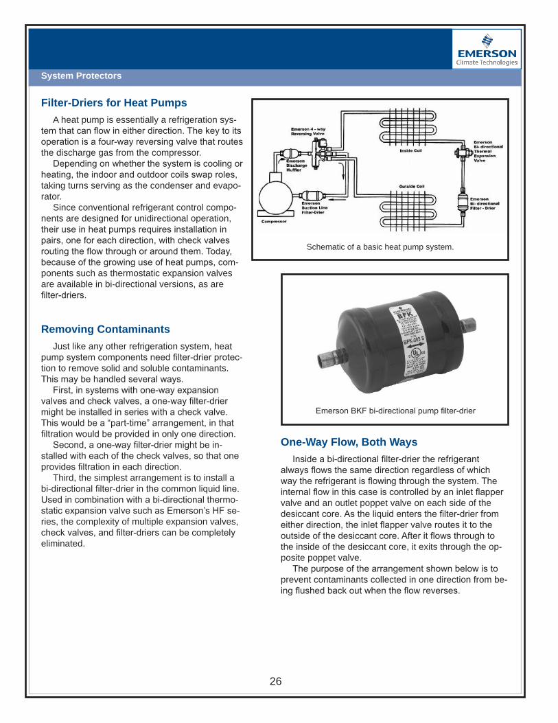
System Protectors
Schematic of a basic heat pump system.
Filter-Driers for Heat Pumps
A heat pump is essentially a refrigeration sys-tem that can flow in either direction. The key to its operation is a four-way reversing valve that routes the discharge gas from the compressor.
Depending on whether the system is cooling or heating, the indoor and outdoor coils swap roles, taking turns serving as the condenser and evapo-rator.
Since conventional refrigerant control compo-nents are designed for unidirectional operation, their use in heat pumps requires installation in pairs, one for each direction, with check valves routing the flow through or around them. Today, because of the growing use of heat pumps, com-ponents such as thermostatic expansion valves are available in bi-directional versions, as are filter-driers.
Removing Contaminants
Just like any other refrigeration system, heat pump system components need filter-drier protec-tion to remove solid and soluble contaminants. This may be handled several ways.
First, in systems with one-way expansion valves and check valves, a one-way filter-drier might be installed in series with a check valve. This would be a “part-time” arrangement, in that filtration would be provided in only one direction.
Second, a one-way filter-drier might be in-stalled with each of the check valves, so that one provides filtration in each direction.
Third, the simplest arrangement is to install a bi-directional filter-drier in the common liquid line. Used in combination with a bi-directional thermo-static expansion valve such as Emerson’s HF se-ries, the complexity of multiple expansion valves, check valves, and filter-driers can be completely eliminated.
Emerson BKF bi-directional pump filter-drier
One-Way Flow, Both Ways
Inside a bi-directional filter-drier the refrigerant always flows the same direction regardless of which way the refrigerant is flowing through the system. The internal flow in this case is controlled by an inlet flapper valve and an outlet poppet valve on each side of the desiccant core. As the liquid enters the filter-drier from either direction, the inlet flapper valve routes it to the outside of the desiccant core. After it flows through to the inside of the desiccant core, it exits through the op-posite poppet valve.
The purpose of the arrangement shown below is to prevent contaminants collected in one direction from be-ing flushed back out when the flow reverses.

System Protectors
Bi-directional components allow simplification of system
Cross section showing BFK internal componentsSimplifying While Servicing
When servicing or repairing heat pump systems, especially older units, it’s a good idea to simplify them by replacing unidirectional driers and check valves with bi-directional driers. When a bi-directional filter-drier is installed, check valves, and filter-driers can all be replaced at once with copper tubing.
Refrigerant flow either direction passes from outside to inside of desiccant core
Emerson System Protectors
Emerson filter-driers were redesigned for increased water removal capacity to reach these low moisture levels. However, since no system is entirely without water on startup some organic acids will be generated and must be removed. The desiccant formulation for the Emerson EK series of filter-driers was designed to provide the best mix of water capacity and acid capacity to ensure that harmful contaminates are removed. This desiccant mixture contains molecular sieve and activat-ed alumina. The molecular sieve is specifically designed to provide maximum drying in today’s systems. The activated alumina is ideal for capturing the large organic acids that the molecular sieve cannot.
Replace two check valves and twoexpansion valves with one EMERSONBi-directional Thermal Expansion Valve
Expansion Device
Filter-Drier
Check Valve
Check Valve
Filter-Drier
Expansion Device
Remove both filter-driers &replace each with a piece of
copper tube
Install One BFKin a convenientLocation in CommonLiquid Line
EmersonSuction LineFilter-Drier
EmersonDischargeMuffler
Emerson 4-wayReversing Valve
Compressor
Molded Desiccant Block InletFlapperValve
OutletPoppertValve
OutletPoppertValve
InletFlapperValve
InletFlapperValve
InletFlapperValve
Steel Retaining ScreenSteel Retaining Screen Final Filter Pad
INTERNALCONSTRUCTION
BASIC FLOWPATTERNS
HeatingCycle
CoolingCycle

2008
Regulators

29
Regulators
EVAPORATORPRESSUREREGULATOR EVAPORATOR
PRESSUREREGULATOR
EXTERNALSTRAINERRECOMMENDED
NOTE: HIGH SIDE PILOTPRESSURE REQUIRED
FOR EPRBS
NOTE: HIGH SIDE PILOTPRESSURE REQUIRED
FOR EPRBS
EXTERNALSTRAINERRECOMMENDED
60 PSIGHIGH
EVAPORATORPRESSURE
50 PSIGINTERMEDIATEEVAPORATORPRESSURE
20 PSIGLOW
EVAPORATORPRESSURE
Types of Regulators:Suction Line Regulators
Suction line regulators provide a wide variety of re-frigerant control functions, but are mainly used for regu-lating suction gas pressures. These regulators provide a method of balancing the output of the refrigeration system with the load requirements. Two basic types are covered here:1) Upstream pressure regulators, which control from an inlet pressure signal.2) Downstream pressure regulators, which control from an outlet pressure signal.
Application of Evaporator Pressure Regulators
Evaporator Pressure Regulators are normally used on multiple-compressor refrigeration systems fed by TXVs, low side floats or solenoid liquid valve and float switch combination. They are used whenever a mini-mum evaporator pressure or temperature is desired. Controlling from an inlet side pressure signal, they prevent upstream pressure from going below a pre-set point.
EPR valves are used on brine or water chillers to pre-vent freeze-up during low load periods, by keeping the refrigerant saturation pressure above the fluid freezing temperature. Similarly, they may be used to prevent frost formation on fan coil evaporators. They may also be used to provide a given evaporator saturation pressure to produce the required evaporation/room temperature difference, (especially useful where humidity control is required). On multiple evaporator systems where differ-ent evaporator temperatures are required, EPR valves will hold the saturation pressure at the required set point above the common system suction pressure. Here, the EPRs prevent lowering of the desired temperature in the warmer evaporators, while the compressor continues operating to satisfy the coldest evaporators. See figure 1.
Figure 1: Evaporator Pressure Regulators used in multiple system.
EPR Installation
EPRs may be installed at the compressor rack or close to the evaporator.
Suction line regulators can be direct acting or inter-nally piloted such as an Emerson IPR regulator. These are hermetically sealed, non-repairable valves for use on low capacity systems.
For higher sensitivity and accurate control, an exter-nally piloted EPRB regulator will provide control of larger units. These are repairable in the line. The EPRB valve is a lightweight, brass body valve which eliminates the need for normal system pressure drop needed to make the valve move through the full stroke. This is accom-plished by using compressor discharge gas to pilot the regulator.
Combining an EPRB with a suction stop or shut off is done with the EPRBS models. When the pilot solenoid is de-energized, the valve closes. This eliminates the cost of a separate suction solenoid and offers a tight shut off.
Figure 2: Cutaway view of an EPRBS.

30
Regulators
Upstream Regulators
The sole function of the Evaporator Pressure Regu-lator is to prevent the evaporator pressure from falling below a predetermined pressure setting. This enables the system to meet certain load requirements over a wide range of conditions and offers improvement over the simple “on-off” compressor control usually provided by thermostats or pressure switches.
Downstream Pressure Regulators
Suction pressure regulators are used to prevent compressor motor overload. By throttling the suction gas flow during high load conditions, the compressor motor is permitted to remain within current draw limitations. Often referred to as holdback valves, crankcase pres-sure regulators or suction pressure regulators, they also serve many other useful applications.
A downstream pressure regulator can be direct acting such as an OPR valve. These are hermetically sealed, non-repairable outlet pressure regulators for use on low capacity systems.
Figure 3: EPRB(S) Brass Body Upstream Pressure Regulator with Suction Stop Option
Valve Adjustable Range EPRB(S)-12 thru -20 0 to 110 psig 0 to 50 psig IPR-6, -10 30 to 100 psig 65 to 225 psig 0 to 60 psig OPR-6, -10 50 to 130 psig 100 to 225 psig
Adjustable Range Table
Voltage Cycles 24 120 50-60 Hz, AC 208-240
Standard Voltage & Frequencies Table
Series EPRB & IPR
These are all upstream regulators which can be selected from the capacity charts available. Combin-ing the regulator with a suction stop or shutoff solenoid will cause the regulator to act as a suction stop valve. Certain basic design operating condition data must be determined to properly apply the regulator. For best results, follow the simple procedure outlined below.
To select the proper regulator port size, the following information is required:1. System refrigerant (R134a, R22, R404A/R507A). 2. The required pressure setting (lowest allowable
evaporator pressure and corresponding refrigerant saturation temperature).
3. The system suction pressure at the regulator outlet (suction pressure where compressor capacity bal-ances with system load) making allowance for any common suction line pressure drop.
4. Pressure drop across regulator port. Subtract suction pressure (3) from regulator set point (2).
5. Evaporator load in tons at regulator setting (required minimum evaporator saturation temperature).
With the above information, select the proper regula-tor as follows:. Select the valve extended capacity table from that
page which covers the system refrigerant.2. Find the required evaporator saturation temperature
column.3. For the available regulator pressure drop, find the
rated capacity for each regulator port size.4. Select the proper port size from the capacity which
matches the evaporator load.

31
Regulators
Fig 4. Cutaway of crankcase pressure regulator (Emerson OPR)
Fig 5. Cutaway of evaporator pressure regulator (Emerson EPRB).
Crankcase Regulators
Normally open, the CPR (Fig. 4) closes when com-pressor pressure rises above the pre-set maximum, forcing the valve back onto its seat. As suction pressure drops, the valve starts to reopen, maintaining a balance.
Where to Apply Regulators
EPRs are most commonly used on multiple evapo-rator systems, installed in the branch lines close to the required control source. They are used for indirect temperature control. They also maintain evaporator pressure during defrost, conserving power, expediting the defrost and reducing flood back.
CPRs are usually only applied if the system is being continually “over-pressured,” causing the compressor to be overloaded. If you suspect that’s the case, check the amp draw on the compressor while it’s running. If it’s higher than the plate rating, the system may be a CPR candidate.
How to Apply Regulators
It isn’t normally necessary to apply both an EPR and a crankcase regulator. Most installations only utilize an EPR.
Typical installations of EPRs are in supermarket systems, large chillers, and industrial processes where large amounts of heat must be absorbed. Smaller (including residential) systems of less than 5 tons are usually equipped with compressors designed to operate well within 30°-40°F variations.
One of the advantages of suction line regulators in supermarkets is that by adding EPRs you can control the operating temperatures of the individual cases in a single loop system.

32
Regulators
HeadMaster Head Pressure Controls
The application of air-cooled condensers for year-round operation, or during periods of low ambient temperature, requires some means of control to main-tain adequate condensing pressures that ensure proper system performance. It is essential that proper liquid refrigerant pressure be controlled to:1) Maintain liquid subcooling and prevent liquid line
flash gas.2) Provide adequate pressure at the inlet side of the
Thermostatic Expansion Valve to get enough pres-sure drop across the valve port.
3) Properly operate systems with hot gas defrost or hot gas bypass.
4) Provide adequate temperature for operation of heat reclaim systems.
Without proper control of condensing pressure a refrigeration system might not perform properly and components can be damaged. Emerson’s HeadMaster Control offers an efficient and economical approach to this common industry problem on air cooled condensers.
The HeadMaster 3-Way Head Pressure Control eliminates the need for special piping or multiple con-trol valves. As a single unit it simplifies piping and cuts installation costs.
HeadMaster HP Operation
The HP control is a three-way modulating valve controlled by the discharge pressure. The charged dome exerts a constant pressure on top of the diaphragm. At high ambient air temperature, bypass gas entering Port B is allowed under the diaphragm where it counters the pressure of the dome charge. This upward push on the diaphragm allows the seat disc to seal against the top seat, preventing flow from Port B (discharge gas) while flow from Port C is unrestricted (see figure 6).
Figure 6: HeadMaster HP Valve CutAway View
As ambient air temperature falls, an uncontrolled air cooled condenser will exhibit a corresponding decrease in head pressure. As the discharge (bypass) pressure falls, it no longer counters the dome charge pressure and the diaphragm moves downward, moving the push-rod and seat disc toward the bottom seat. This allows discharge (bypass) gas to be metered into the receiver, creating a higher pressure at the condenser outlet. The higher pressure at the condenser outlet reduces the flow from Port C and causes the level of condensed liquid to rise in the condenser.
The flooding of the condenser with liquid cuts the available condensing surface. The result is to raise the pressure in the condenser and maintain an adequate high side pressure. Figure illustrates a typical appli-cation of the 3-way control valve. This system is per-haps the most economical and reliable way to control discharge pressure. The three-way valve as shown in figure 6 is a fixed, non-adjustable valve. The wholesaler replacement setting is normally furnished for a pressure corresponding to 95° to 98°F condensing temperature for the given system refrigerant.
Figure 7: Typical 3-Way Valve Head Pressure Control Application
As with all head pressure control applications, addi-tional liquid receiver capacity is required to prevent loss of a liquid seal in the receiver when the condenser is flooded. The receiver must be large enough to hold the total system charge. The total system charge consists of the following:1. An operating charge which is the amount of refriger-
ant needed to operate the system during summer (high ambient temperature) conditions.
2. An additional charge equaling the amount of refriger-ant required to flood the condenser with liquid. The condenser must be filled with liquid to a point where a minimum head pressure is created for cold weather (low ambient temperature) conditions.

33
Regulators
NOTE: Should the outdoor temperature fall below de-sign conditions, more refrigerant will be required.
The total above is the total charge needed for satis-factory system performance during the lowest expected ambient air temperature conditions. During summer operation the receiver must be sized to safely hold the total system charge. Good refrigeration practice states that the total system charge should not exceed 80% of the receiver capacity.
CAUTION:1. The HP control should not be used on a system
which does not have a liquid receiver or on one with a receiver which is too small. If the receiver does not have adequate storage space, the refrigerant will back up in the condenser to produce excessively high discharge pressures during high ambient air tempera-tures, with could cause system damage or personal injury.
2. The HP control should be used only on systems which employ a Thermostatic Expansion Valve.
Installation of HP HeadMaster Series
Head pressure control systems are used on refrig-eration systems that are temperature operated. The compressor is started by a thermostat or the system operates on a pump down cycle, where the thermostat controls the liquid line solenoid valve and the compres-sor starts on a rise in suction pressure with a low pres-sure switch.
On systems that are pressure operated, migration of the refrigerant to the cold condenser on the “off” cycle should be prevented. If the system does not oper-ate on a pump down cycle, migration can take place through some compressors, from the suction line to the condenser. Crankcase heaters will prevent liquid from condensing in the crankcase, but will not stop migration to the cold condenser. If the system is properly charged, the filled condenser will permit the excess to remain in the receiver and low side.
Under some conditions where the receiver is located in a warm ambient, a check valve in the liquid drain line between the HeadMaster control and the receiver may be required to prevent the liquid receiver pressure from equalizing to that of the condenser during the “off” cycle. This enables the system to start on a pressure switch. Some systems may require a time delay on the low pressure switch. Condenser fans should not be cycled when using the HeadMaster control. The sudden chang-es in high side pressure caused by fan cycling will result in erratic Thermostatic Expansion Valve performance, and shortened head pressure control life. To prevent this
from happening, make sure fan controls are set to oper-ate at pressures above the HP valve setting.
HP Series Capacity & Selection
The nominal HP control capacity in tons for various refrigerants is shown in Table 1 for R134a, R22 and R404A/R507A. The nominal capacity is based on 100°F liquid, 40°F evaporator and the pressure drop shown. To get capacities in tons at other liquid and evaporator conditions, multiply the nominal capacity at the desired pressure drop by the correction factor given in the catalog for the liquid temperature and evaporator temperature.
Pressure Drop – PSI Valve Refrigerant 1 2 3 4 5 HP-5 2.0 2.9 3.6 4.1 4.6 HP-8 R-134a 5.5 7.8 9.6 11.0 12.4 HP-14 14.0 19.8 24.2 28.3 31.7 HP-5 2.2 3.2 3.9 4.5 5.0 HP-8 R-22 6.0 8.5 10.5 12.0 13.5 HP-14 14.7 20.8 25.6 29.7 33.8 HP-5 1.5 2.1 2.6 3.0 3.3 HP-8 3.9 5.5 6.7 7.8 8.7 HP-14 10.1 14.3 17.6 20.5 23.0
Based on 100°F liquid and 40°F evaporator
Table 1 – Nominal Capacity (tons)
R-404A R-507A
NOTE: Not recommended for systems utilizing patented sub-cooling coils in conjunction with low head pressure systems or on sytems where the condensate line bypassses the receiver in order to maintain subcooling effect in the liquid line.
NOTE: Do not select a valve for a capacity rating ex-ceeding 5 psi pressure drop from Port C to Port B or for a system with more than 20 psi pressure drop across the condenser.
During normal ambient conditions, the available liquid subcooling in the condenser will be adequate to cover the pressure drop through the HeadMaster control.
If a valve is selected for a given flow rate, the result-ing pressure drop must not cause the liquid pressure to drop below saturation and produce flash gas. If enough sub-cooling is not available to cover this pressure drop, it is suggested that more than one valve be installed in parallel to lower the pressure drop to tolerable limits.
Do not parallel valves of different capacities. Liquid drain lines from the condenser to receiver are sized for a velocity of 150 ft./min. or less.

34
Regulators
HP Parallel PipingHot Gas Bypass
Demand continues to mount for improved comfort conditioning combined with lower operating costs. New architectural designs have created real problems for contractors and engineers to maintain humidity con-trol at reduced loads, and to control load variations. Refrigeration and air conditioning systems are usu-ally designed to provide a given capacity at maximum conditions. These operate with little fluctuation through-out a narrow load range. However, only the larger size machines make any provisions for operation at reduced capacity. In some systems, integral cylinder unloading, gas engine drives with variable speed control, or even several smaller systems, provide a logical solution.
Function – Hot Gas Bypass Method
Many manufacturers now recommend use of a modulating control valve to provide a metered flow of compressor discharge gas to the system low side, in a proportion that will balance the system capacity to the load demand. This is commonly known as the hot gas bypass method. It permits full modulation of capacity on all types of reciprocating compressors, and extends capacity reduction below the last step of cylinder unload-ing.
The system must provide a means of bypassing high pressure refrigerant to the system low pressure side, to maintain operation at a given minimum suction pres-sure. Proper bypass control can be accomplished by a modulating type pressure regulator, which opens on a decrease in valve outlet pressure.
Operation of Bypass Valves
Bypass pressure regulators are grouped into the fol-lowing categories:1. Direct acting conventional port valves (figure 3)2. Direct acting balanced port valves (figure 4). Any of
these regulators are available with either an adjust-able setting, or a fixed, non adjustable setting.
Figure 4: Balance port CPHE adjustable field-serviceable hot gas bypass regulator.
Additional Refrigerant
On most systems, an added refrigerant will be re-quired. It is essential to have enough to completely fill the condenser for the lowest ambient condition. To accu-rately determine the added refrigerant charge required to fill the condenser, find the total length of condenser tubing in feet, and multiply by pounds of refrigerant per foot for a given size tubing.
Factory Settings
The HeadMaster Control is factory-set to provide an average condensing temperature consistent with good system performance. The complete type number includes the service reference code, port size, connec-tion size and style. When ordering, be sure to specify the complete type number.
UL File No . SA5312CSA File No . LR44005
Figure 3: DGRE adjustable hot gas bypass regulator.

35
Regulators
Figure 7: Direct acting hot gas regulator admitting flow between TEV and venturi distributor.
Applications: Hot Gas Bypass to Compressor Suction Line
Figure 6 shows the most common hot gas bypass system. In this system, the bypass line is taken directly from the compressor discharge line, through a bypass regulator, and into the suction line at the compressor. Although the hot gas bypass regulator is considered a downstream control, there is a big difference in function between a Crankcase Regulator and a hot gas regulator.
Pilot operated bypass valve main regulators have a long stroke stem with a restrictor plug characterized by either a parabolic or vee port restrictor plug design. This prevents the valve from operating close to the seat where pressure differential unbalance may occur, elimi-nating the need for a balanced port design.
The characterized port will provide smooth bypass flow modulation. Pilot operated valves usually have the extra features of a manual opening stem for testing or emergency operation, flanged connections, synthetic tight seating seats, and replaceable parts. Hot gas bypass valves can be applied to a system in several ways, differing only in the point to which the hot gas is to be bypassed. Several mixing methods are available. The one recommended is piped so that discharge gas is admitted to the suction line to flow against the direction of the suction gas as in figure 6.
Applications: Bypass to Evaporator Inlet
Another method is to bypass the hot discharge gas to the evaporator inlet, usually between the Thermal Valve and the refrigerant distributor (see figure 7). This pro-vides distinct advantages. The artificial load imposed on the evaporator causes the Thermal Valve to respond to the rise in superheat, eliminating the need for the liquid injection valve. The evaporator serves as an excellent chamber to provide homogeneous mixing of the gases before reaching the compressor.
Hot gas bypass into the evaporator is suggested when the evaporator elevation is below the compres-sor, to prevent oil trapping caused by low velocity at low loads. This assures proper oil return. Although there are many advantages to this system, it is not used on a multiple coil system, or where the evaporator sections may be located a distance from the compressor. The coil should be a free draining circuiting design to prevent the increase in velocity, due to forcing a large quantity of trapped liquid out of the low side, which in some cases may have enough volume to flood the compressor crankcase. Separate regulators must be used for each evaporator when bypassing to multiple evaporators located below the compressor to help oil return.
Figure 6: Hot gas bypass using type LCL liquid injection valve.
liQUidinJection
solenoid VAlVe
Bypass to flooded evaporators and suction line accumulators also present special cases. Contact the equipment manufacturer or the bypass control valve manufacturer for specific, detailed information.
Solenoid Valve for Positive Shut-off & Pump-down Cycle
It is recommended that a solenoid valve be installed ahead of the bypass regulator. This permits the system to operate on an automatic pump-down cycle.

36
Regulators
Thermal Valves for Liquid Injection
When hot gas is bypassed directly into the suction line, it is necessary to make some provision for desuper-heating the gas returning to the compressor. Without a small Thermal valve to lower suction gas temperature to tolerable limits, compressor damage may occur. Stan-dard Thermal Valves cannot be adjusted for control over 20°F superheat and, therefore, are not recommended. Liquid Injection Thermal Valves with special adjustment ranges are used to conform to compressor manufacturer temperature recommendations.
To simplify selection, Emerson has developed Liquid Injection Thermal Valves with four basic adjustment ranges. These are designated as models A, B, C and D. The adjustable superheat range chart (page 11) shows the proper power assembly charge symbol suffix for a given saturated suction temperature and a given super-heated suction gas temperature entering the compres-sor.
Nearly all Thermal valves for liquid injection may be internally equalized. However, if pressure drop occurs at the valve outlet due to a distributor, spray nozzle or other restrictive device, externally equalized valves may be needed.
Model LER and LIR valves are furnished with a 1/4” SAE male flare external equalizer as standard. Other models must include the code letter “E” to specify the 1/4” SAE male flare external equalizer connection. Example: LCLE and LJLE.
Application and Installation
Liquid injected into a gas to be desuperheated should be injected in a way which provides a homogeneous mixing of the liquid and superheated gas. Desuperheat-ing hot gas bypass in the suction line may be accom-plished in several ways.
The preferred method is to bullhead the hot gas and liquid injection in a tee to permit good mixing before it enters the suction line. A good mix with the suction gas may be gained by injecting the liquid/hot gas mixture into the suction line at a 45° angle against the flow of suction gas to the compressor. See figure 6.
For suction lines 7/8” OD and smaller, the bypass mixture may be introduced into a tee rather than an angle connection. For lines larger than 2-5/8” OD, intro-duce the desuperheated bypass mixture into a 90° ell inserted against the flow of suction gas to the compres-sor.
Arranging a bypass directly into a suction accumula-tor is often a convenient way to get proper desuperheat-ing of suction gas.
Introducing the hot gas and liquid into the suction line with separate connections is not recommended.
NOTE: Excessive suction gas superheat can cause serious damage to the compressor. As a safety precau-tion, the bypass line solenoid valve should be wired in series with a discharge line thermostat.
Special Applications
On systems where evaporator pressure regulators are used, better control can be reached by installing the bypass regulator equalizer line on the downstream (outlet) side of the EPR so it responds to compressor suction pressure, not evaporator pressure. This results in nearly constant evaporator load balance. See figure 8.
Figure

37
Regulators
Application Tips
• In systems that use a Venturi type distributor, the bypass gas should be fed into the system between the outlet of the expansion valve and the inlet to the distributor. For pressure drop distributors that use an orifice, the inlet must be between the orifice and the inlet to the distributor.
• The hot gas bypass line should be insulated to mini-mize system heat loss.
• In systems with sequential compressor unloading, the valve should be set to start opening at two to three pounds below the last stage of unloading, because compressor unloading is considerably more efficient and should be used before resorting to bypassing.
• For oil return considerations, the bypass line must feed in ahead of the evaporator when the evaporator is installed below the compressor.
• The hot gas bypass valve should be installed as close as practical to the condensing unit, to reduce con-densing ahead of it.
• In systems that operate on a pump down cycle, there must be a solenoid valve or some other means of shutoff in the bypass line.
Adjusting the Set Point
The suction pressure at which the valve opens is selectable by increasing or decreasing the load on the spring by turning an adjusting screw. To set it, the evap-orator must be cooled down by shutting off the fans, blocking off the airflow, or some other means, until the suction pressure drops to at least five pounds below the desired set point. Then, by allowing the pressure to be raised by the bypass gas, the spring load can be varied until the valve closes at precisely the desired set point.
The pressure is set to maintain an evaporator tem-perature just above that at which frost forms.

382008
Oil Controls
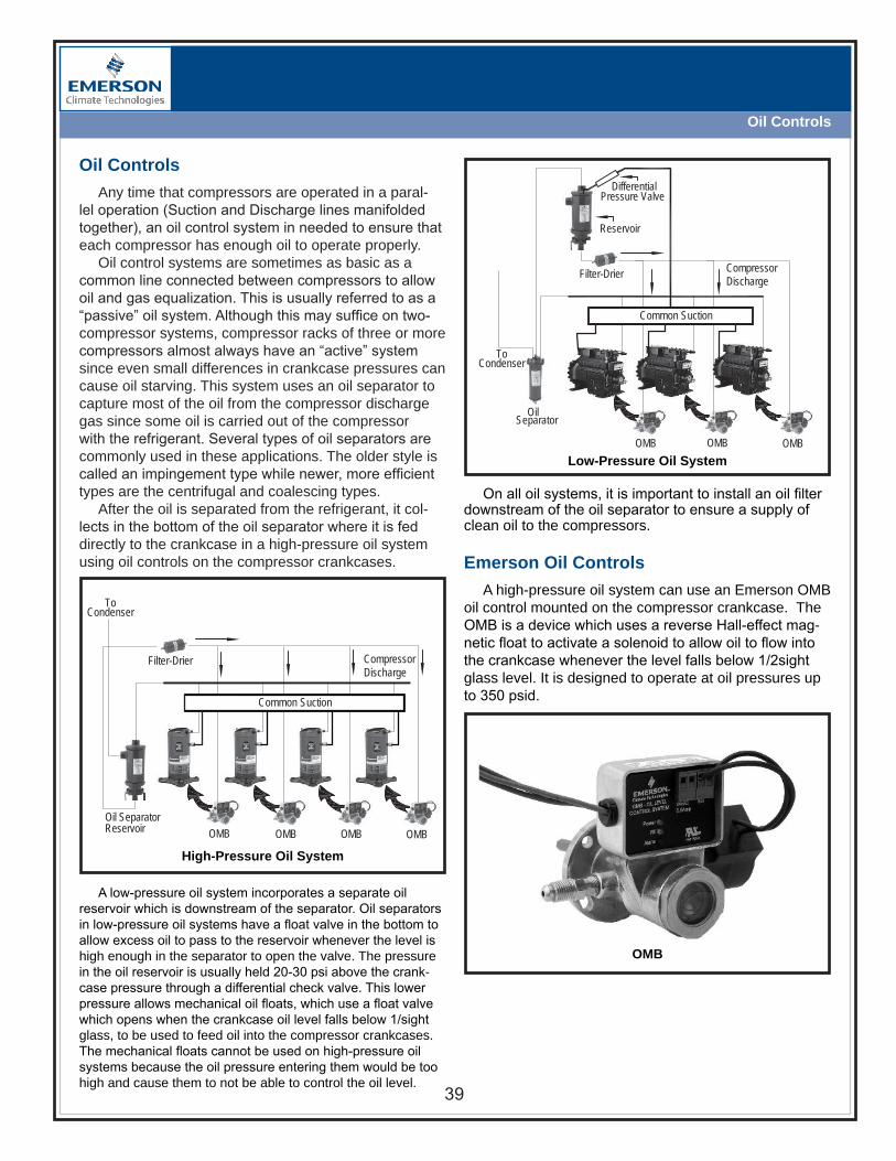
39
Oil Controls
OMB
Common Suction
ToCondenser
Filter-Drier CompressorDischarge
OMB OMB OMBOil SeparatorReservoir
Oil Controls
Any time that compressors are operated in a paral-lel operation (Suction and Discharge lines manifolded together), an oil control system in needed to ensure that each compressor has enough oil to operate properly.
Oil control systems are sometimes as basic as a common line connected between compressors to allow oil and gas equalization. This is usually referred to as a “passive” oil system. Although this may suffice on two-compressor systems, compressor racks of three or more compressors almost always have an “active” system since even small differences in crankcase pressures can cause oil starving. This system uses an oil separator to capture most of the oil from the compressor discharge gas since some oil is carried out of the compressor with the refrigerant. Several types of oil separators are commonly used in these applications. The older style is called an impingement type while newer, more efficient types are the centrifugal and coalescing types.
After the oil is separated from the refrigerant, it col-lects in the bottom of the oil separator where it is fed directly to the crankcase in a high-pressure oil system using oil controls on the compressor crankcases.
OMB
Low-Pressure Oil System
High-Pressure Oil System
A low-pressure oil system incorporates a separate oil reservoir which is downstream of the separator. Oil separators in low-pressure oil systems have a float valve in the bottom to allow excess oil to pass to the reservoir whenever the level is high enough in the separator to open the valve. The pressure in the oil reservoir is usually held 20-30 psi above the crank-case pressure through a differential check valve. This lower pressure allows mechanical oil floats, which use a float valve which opens when the crankcase oil level falls below 1/sight glass, to be used to feed oil into the compressor crankcases. The mechanical floats cannot be used on high-pressure oil systems because the oil pressure entering them would be too high and cause them to not be able to control the oil level.
On all oil systems, it is important to install an oil filter downstream of the oil separator to ensure a supply of clean oil to the compressors.
Emerson Oil Controls
A high-pressure oil system can use an Emerson OMB oil control mounted on the compressor crankcase. The OMB is a device which uses a reverse Hall-effect mag-netic float to activate a solenoid to allow oil to flow into the crankcase whenever the level falls below 1/2sight glass level. It is designed to operate at oil pressures up to 350 psid.
OMBOMB
Common Suction
ToCondenser
OilSeparator
Filter-Drier
Reservoir
DifferentialPressure Valve
OMB
CompressorDischarge

402008
TemperaturePressure Controls

41
Temperature-Pressure Controls
Temperature Pressure Controls
Temperature pressure controls serve a number of purposes in refrigeration systems, including the control of compressor cycling, pump-down, defrost control, pressure limiting, loss of charge freeze protection and fan speed control.
TS1 Introduction
The TS1 Series is Emerson’s adjustable thermostats for application in refrigeration and heat pump systems. In these systems, thermostats provide space tempera-ture control, high/low temperature alarming or defrost termination. By operating an electrical contact, a tem-perature value is kept inside a certain limit.
Housing Variants
TS controls are top operated. Top operated controls have adjustment spindles at the top and a display scale, showing temperature setpoint and dif-ferential, at the front. A knob which may be permanently plugged onto one of the adjustment spindles comes with every control. Frost monitors and room thermostats are derivatives of top operated thermostats. They differ by their sensors and other features to suit their target applications.
TS1 Top Operated
Vapor Charge – Sensor Type A, E, PThese sensing elements always sense from the cold-
est point on the capillary, coil, bulb or power element head. For proper operation, the coldest point must be at the part of the sensor which is exposed to the medium temperature to be sensed. The sensing location should be at least 4 degrees F colder than the other parts of the thermal system.
To avoid unwanted effects of heat transfer, for exam-ple from a cold wall, vapor charged thermostats come with an integrated bellows heater (not for frost monitors), which is rated for 230V applications. For other applica-tions, the heater must be disabled or a bellows heater with a different rating should be used.
Besides the bellows heater, room thermostats are supplied with an insulation console for the same reason.
Sensor type ‘A’ is a coiled bulb sensor with two meter capillary, which may be used with or without a bulb well. Style ‘E’ is a coil sensor for space temperature sensing, and type ‘P’ is a capillary type of sensor which can be wrapped around a heat exchanger’s surface to sense the coldest point on the heat exchanger for frost protec-tion applications.
Vapor charges respond faster to temperature chang-es than adsorption and liquid charges.
Vapour Charge
Adsorption Charge
Liquid Charge
-148°F -58 32 122 212 302 392°F
tion are capillary type of sensors, which do not have a bulb, instead, their capillary serves as the bulb directly.
Charges and sensor types are matched to tempera-ture ranges and other application specific characteris-tics. TS1 thermostats come with one of three charge types: vapor charges, adsorption charges or liquid charges. The application temperature range covered by each charge type is shown below:
Temperature Sensing
TS thermostats sense temperature by a thermal system, consisting of temperature charge, bulb, capillary and bellows. The temperature charge changes its pres-sure based on the refrigerant temperature to be sensed. The sensor is the part of the system which is in thermal contact with the refrigerant. The capillary connects the sensor with the bellows and the bellows contracts or expands depending on the temperature, causing the thermostat to operate the electrical contacts. An excep-

42
Temperature-Pressure Controls
+-
2 4
1
+-
2 4
1
Adsorption Charge – Sensor Type FAdsorption charged sensor types operate on a tem-
perature dependent adsorption material, which is inside the bulb only. These sensor types always respond to temperature changes at the bulb only. This makes them suitable to applications where it is not always defined which part of the thermal system the coldest point is (cross ambient applications). An example for such ap-plications is defrost control. Adsorption charges are slower in response to tempera-ture changes than vapor charges.
Liquid Charge – Sensor Type CLiquid charge sensors of type ‘C’ always sense from
the warmest point of the thermal system. The sensing location must always be 4 degrees F warmer than other parts of the thermal system.
Setpoints
TS1 are adjustable controls with adjustment spindles for range and differential. Note that manual reset con-trols and some other controls have a fixed differential and no differential spindle. By turning the range spindle, the upper setpoint is defined and by adjusting the dif-ferential spindle, the differential and the lower setpoint is defined.
The dependency between upper and lower setpoint is always as follows:
lower setpoint = upper setpoint – differentialThe following two rules should be kept in mind: an adjustment of the range spindle always affects both upper and lower setpoint. an adjustment of the differential spindle affects the lower setpoint only.
The controls are equipped with display scale and pointers to show the approximate settings.
Top operated controls have display scales in units °C and °F, front operated controls have a display scale in units °C.
For precise setting of the controls, external thermom-eters must be used.
Electrical Contacts
TS1 temperature controls are equipped with high rated double snap action contacts for shatter-free and reliable operation.
All contacts in these controls are designed as Single Pole Double Throw (SPDT) contacts. One contact may be used for control and the other contact for alarm/sta-tus indication or auxiliary control.
Gold plated contacts are available on request for low
electrical loads, for example in electronic signaling ap-plications.
For applications using a supply voltage other than 230V and for applications using gold plated contacts, the bellows heater of vapor charged thermostats (sensor style A, E or P – not for frost monitors function C or D) must be disabled.
Contact Function
Thermostat contacts TS1 are labeled 1-2-4 where ‘1’ refers to the common pole, ‘2’ refers to the lower set-point and ‘4’ refers to the upper setpoint.
The contact function for automatic and manual reset versions is as described below.
Automatic ResetOn temperature rise above the upper setpoint,
contacts 1-open and contacts 4 close. On decreasing temperature lower setpoint contacts 4 open and con-tacts close.
Automatic reset contact function
Manual Reset Low TemperatureOn decreasing temperature below the lower setpoint,
contacts 1-4 open, contacts close and latch. Only on temperature rise above upper setpoint and after press-ing the manual reset button contacts will open and contacts 4 will close again.
Manual reset low temperature contact function
Manual Reset High TemperatureOn increasing temperature above the upper setpoint,
contacts 1-open, contacts 4 close and latch. Only on falling temperature below lower setpoint and after press-ing the manual reset button, contacts 4 will open and contacts 1-will close again.
Manual reset high temperature contact function
+-
2 4
1
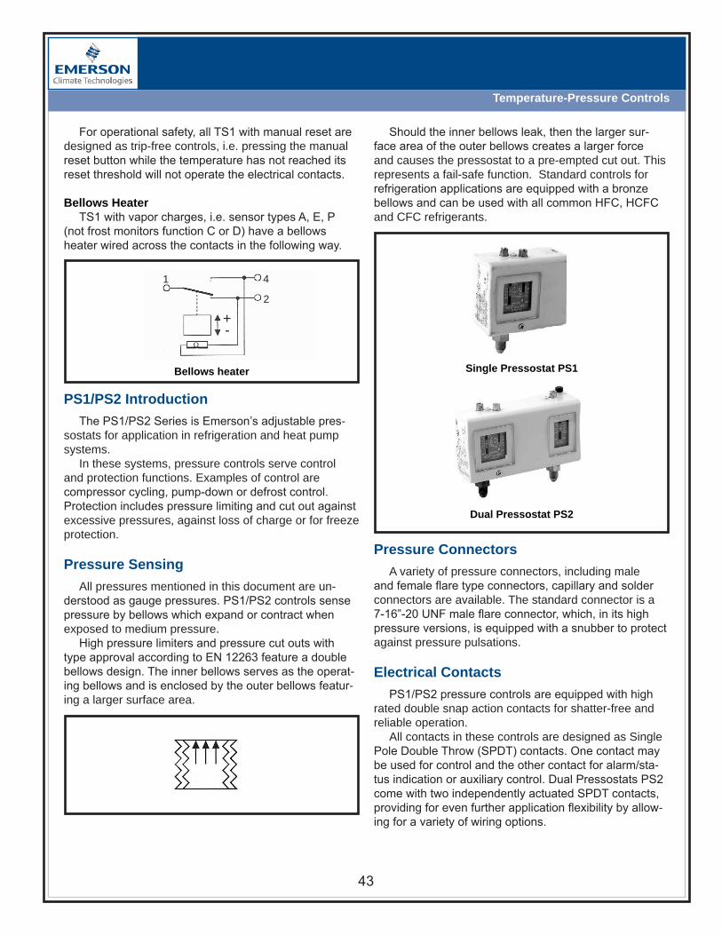
43
Temperature-Pressure Controls
For operational safety, all TS1 with manual reset are designed as trip-free controls, i.e. pressing the manual reset button while the temperature has not reached its reset threshold will not operate the electrical contacts.
Bellows HeaterTS1 with vapor charges, i.e. sensor types A, E, P
(not frost monitors function C or D) have a bellows heater wired across the contacts in the following way.
Bellows heater
PS1/PS2 Introduction
The PS1/PS2 Series is Emerson’s adjustable pres-sostats for application in refrigeration and heat pump systems.
In these systems, pressure controls serve control and protection functions. Examples of control are compressor cycling, pump-down or defrost control. Protection includes pressure limiting and cut out against excessive pressures, against loss of charge or for freeze protection.
Pressure Sensing
All pressures mentioned in this document are un-derstood as gauge pressures. PS1/PS2 controls sense pressure by bellows which expand or contract when exposed to medium pressure.
High pressure limiters and pressure cut outs with type approval according to EN 12263 feature a double bellows design. The inner bellows serves as the operat-ing bellows and is enclosed by the outer bellows featur-ing a larger surface area.
Single Pressostat PS1
Dual Pressostat PS2
Should the inner bellows leak, then the larger sur-face area of the outer bellows creates a larger force and causes the pressostat to a pre-empted cut out. This represents a fail-safe function. Standard controls for refrigeration applications are equipped with a bronze bellows and can be used with all common HFC, HCFC and CFC refrigerants.
Pressure Connectors
A variety of pressure connectors, including male and female flare type connectors, capillary and solder connectors are available. The standard connector is a 7-16”-20 UNF male flare connector, which, in its high pressure versions, is equipped with a snubber to protect against pressure pulsations.
Electrical Contacts
PS1/PS2 pressure controls are equipped with high rated double snap action contacts for shatter-free and reliable operation.
All contacts in these controls are designed as Single Pole Double Throw (SPDT) contacts. One contact may be used for control and the other contact for alarm/sta-tus indication or auxiliary control. Dual Pressostats PS2 come with two independently actuated SPDT contacts, providing for even further application flexibility by allow-ing for a variety of wiring options.
Ω
2
41
+-

44
Temperature-Pressure Controls
Setpoints
PS1/PS2 are adjustable controls with external ad-justment spindles for range and differential. Note that manual reset controls have a fixed differential and no differential spindle. By turning the range spindle, the upper setpoint is defined and by adjusting the differential spindle, the differential and the lower setpoint is defined.
The dependency between upper and lower setpoint is always as follows:
lower setpoint = upper setpoint – differential
The following two rules should be kept in mind: an adjustment of the range spindle always affects both upper and lower setpoint. an adjustment of the differential spindle affects the lower setpoint, only.The controls are equipped with display scale and point-ers to show the approximate settings. The display scales are printed in relative pressure units “bar” and “psi”. For precise setting of the controls, external gauges must be used.
Contact Function
Contacts on Dingle Pressostats, PS1 are labeled 1-2-4 where ‘1’ refers to the common pole, ‘2’ refers to the lower setpoint and ‘4’ refers to the upper setpoint. This is true for all types of controls, irrespective whether they are low pressure controls, high pressure controls, manual or automatic reset types.
The contact function for automatic and manual reset versions is as described below.
Automatic ResetWhen pressure rises above the upper setpoint,
contacts 1-2 open and contacts 1-4 close. On decreas-ing temperature lower setpoint contacts 1-4 open and contacts - close.
Automatic reset contact function
Manual Reset Low PressureWhen pressure drops below the lower setpoint,
contacts 1-4 open, contacts 1-2 close and latch. Only on pressure rise above upper setpoint and after press-ing the manual reset button contacts 1-2 will open and contacts 1-4 will close again.
Manual reset low pressure contact function
Manual Reset High PressureWhen pressure rises above the upper setpoint,
contacts 1-2 open, contacts 1-4 close and latch. Only on falling pressure below lower setpoint and after press-ing the manual reset button, contacts 1-4 will open and contacts 1-2 will close again.
Manual reset high pressure contact function
For operational safety, all PS1/PS2 with manual reset are designed as trip-free controls, i.e. pressing the manual reset button while the pressure has not reached its reset threshold will not operate the electrical contacts.
As Dual Pressostats PS2 have two sets of contacts, their function is the same as on Single Pressostats PS1 with the only difference that the contact labels are pre-ceded by an additional index. One side of the control is labeled 11-12-14 and the second side is 21-22-24.
The contact function of controls with convertible reset is as described above but depends on the position of the convertible reset toggle, i.e. automatic or manual reset position.
+-
2 4
1
+-
2 4
1
+-
2 4
1
P
P
P

45
Temperature-Pressure Controls
PSC Pressure Switch
The Flow PSC is a Pressure Switch with fixed switch-point settings.
Features• Maximum Operating Pressure up to 623 psig Test
Pressure up to 696 psig• Standard factory settings from stock in small volumes• High and low pressure switches• High temperature version with snubber for direct com-
pressor mounting (Range 6)• Direct mounting reduces the number of joints and thus
avoiding potential leakage• Precise setting and repeatability• IP 65 protection if used with the cables with plug
Options• For direct mounting on a pressure connection (free standing) or with a capillary tube• Direct compressor head mounting with high temperature bellows and snubber - reduces the number of joints - avoids potential leakage - saves high cost of flexible hose• TÜV approved versions for high and low pressure• Micro-switch for narrow pressure differentials• Gold plated contacts for low voltage/current applications• Cables with plug ordered separately
PSC Introduction
PSC is equipped with a SPDT snap action contact, switching from 1-2 to 1-4 on rising pressure and from 4 to on falling pressure (see diagram). Several models are available:
• Low pressure switch, with automatic or manual reset• High pressure switch, with automatic or manual reset• DIN/TÜV approved safety high pressure limiter with
automatic reset• DIN/TÜV approved safety high pressure cut-out, with
internal or external manual reset
TÜV approval for pressure switches can be reached either by using a double diaphragm (Pressure range 1-5) which acts in a fail-safe mode or by a single pres-sure element (Bellows, Pressure range 6) which is able to resist to >Mio. cycles between 50% and 100% of the maximum operating pressure (see 4.6.1 of EN 12263).
PSC
1
P
2
4
+
-
Bellows (Pressure Range 6)
Single Diaphragm

46
Temperature-Pressure Controls
FSX Introduction
FSX electronic speed controllers are designed to control the speed of fan motors in commercial refrigera-tion system depending on condensing pressure chang-es. It is suitable for single phase. FSX can be used in air-cooled condensers, air-cooled condensing units and air-conditioning units.
Using variable fan speed controllers offers the following benefits in commercial refrigeration or air- conditioning applications:• Head pressure can be kept high enough to ensure proper operation of the expansion valve, and sufficient mass flow through the expansion valve to feed the evaporator. This maintains the required cooling capacity.• Efficiency increase of the compressor by controlling the head pressure, improved performance and energy saving for the complete system.• The noise fan motors can be kept at a minimum by avoiding permanent on/off cycling.
Figure 1 – FSX Output Voltage Versus Input Pressure
SupplyVoltage230 V
OutputVoltage99% Maximum range
Minimumrange50%
Cut-off0%
Proportional range
Pressure (bar)Proportional range:FSX-41_: 2,5 barFSX-42_: 3,8 barFSX-43_: 4,6 bar
FSX-43S
Description of control behavior
FSX control behavior can be easily described by looking at the function of output voltage versus input pressure (see figure 1) and by dividing it into maximum, proportional and minimum range.
In the maximum range, the FSX provides a constant output voltage of about 1% below the supply voltage. The fan runs at maximum speed.
Along the proportional range the output voltage var-ies between maximum and minimum voltage of approxi-mately 50% of the supply voltage. This causes the fan speed to slow down from maximum speed to minimum speed.
Further decrease of pressure in the minimum range leads to cut-off of the fan motor. Increase of input pres-sure will start the motor with a hysteresis of approxi-mately 10 psig to avoid cycling (Fig. 1).
The pressure from which motor is cut off (FSX), see column “pressure range” in the selection chart. The pro-portional range is fixed at:
36 psig for FSX-41_/FSM-41_ 55 psig for FSX-42_/FSM-42_ 66 psig for FSX-43_/FSM-43_

472008
Basic Rules ofGood Practice

48
Basic Rules of Good Practice
DOs DO maintain test instruments in good working order and periodically check them against accurately calibrated instruments .
Good diagnoses can’t be made with faulty inputs.
DO familiarize yourself with the operation of a control before attempting to make adjustments or repairs .
If you don’t understand how a control is supposed to function, you can’t be sure if it’s defective or not. When you know what you’re doing, you achieve good results on purpose; when you don’t know what you’re doing, you achieve good results only by accident.
DO make it a practice to check suction gas superheat at the compressor .
Too low superheat may result in liquid flood-back, while high superheats cause high discharge temperatures. Always follow equipment manufacturers’ instructions.
DO replace filter-driers or replaceable cartridges whenever it’s necessary to open a system for service .
Regardless of how careful you are, it’s virtually impossible to prevent the entry of moisture and other contaminants while the system is open. Driers or cartridges cannot be successfully activated in the field for reuse. A new filter drier or cartridge is cheap insurance for a compressor.
DO use an accurate moisture indicator in the liquid line to watch out for moisture contamination .
It is the single most common contaminant, and it can lead to a variety of problems including acid, sludge, and freeze-ups.
DO check expansion valve superheat by using the temperature-pressure method .
This involves measuring the suction line pressure at the evaporator outlet and then referring to the appropriate temperature-pressure chart to determine the satura-tion temperature. Subtracting this temperature from the suction line temperature measured at the remote bulb gives you the operating superheat, which should be adjusted to the equipment manufacturer’s specifications.
Basic Rules of Good Practice
Doing a good job in any line of work almost always involves following some basic “good practice” rules, and ser-vicing refrigeration systems is no exception. Knowing and observing such basic rules, to the point that it becomes automatic, can prevent a lot of problems by cutting them off at the pass before they have a chance to happen.
A list of DO’s, procedures that should be followed, and a list of DON’Ts representing pitfalls that should be avoided are presented here to promote the general adoption of good servicing practices and a better understand-ing of the WHYs behind them. An occasional quick review may serve to reinforce awareness and help make their application second nature.

49
Basic Rules of Good Practice
DON’Ts DON’T be a “parts-changer .”
Analyze problems based on the symptoms, and determine the specific cause be-fore making any changes or repairs. Emerson’s Troubleshooting Guide describes a wide variety of problems that may be encountered, and their probable causes.
DON’T think of a TXV as a temperature or pressure control .
Thinking of it as a superheat control is basic to achieving optimum system perfor-mance.
DON’T attempt to use any control for any application other than the one it was designed for .
Using a pressure regulator for a pressure relief valve, or any similar substitution, is not good practice and almost certainly won’t deliver proper performance. Mis-applications can lead to equipment damage and even injury. When doubt exists, check with the manufacturer.
DON’T energize a solenoid coil while it is removed from the valve .
Without the magnetic effect of the solenoid core, the coil will burn out in a matter of seconds.
DON’T install a previously used filter-drier or replaceable cartridge.
It could introduce contaminants that it has picked up since its removal from a system.
DON’T select solenoid valves by line size or port size, but by valve capacity .
They must also be compatible with the intended application with regard to the specific refrigerant used, the maximum opening pressure differential (MOPD), the maximum working pressure (MWP), and the electrical characteristics. Never ap-ply a valve outside of its design limits or for uses not specifically catalogued.
DON’T rely on sight or touch for temperature measurements .
Use an accurate thermometer. Once again, you can’t get accurate diagnoses with faulty inputs.
502008
TroubleshootingGuide

51
SystemProblem
DischargePressure
SuctionPressure
Superheat Subcooling Amps
Overcharge
Undercharge
LiquidRestriction
(Drier)
LowEvaporator
Airflow
DirtyCondenser
Low OutsideAmbient
Temperature
InefficientCompressor
TXV BulbLoose
Mounted
TXV BulbLost
Charge
PoorlyInsulated
Bulb
SYSTEM TROUBLESHOOTING GUIDE

52
Superheat Is Too Low -- TXV Feeds Too MuchProblem Symptoms Causes Corrective Action
Valve FeedsToo Much
1) Liquid Slugging
2) Low Superheat
3) Suction Pressure Normal or High
Oversized Valve Replace with correct size valve
Incorrect Superheat Setting Adjust the superheat to correct setting
Moisture Replace the filter-driers; evacuate the systemand replace the refrigerant
Dirt or Foreign Material Clean out the material or replace the valveIncorrect Charge Selection Select proper charge based on refrigerant typeIncorrect Bulb Location Relocate the bulb to proper locationIncorrect Equalizer Location Relocate the equalizer to proper locationPlugged Equalizer (Balanced Port Valve) Remove any restriction in the equalizer tube
Superheat Is Too High -- TXV Doesn't Feed or Doesn't Feed EnoughProblem Symptoms Causes Corrective Action
ValveDoesn'tFeed orDoesn'tFeed
Enough
1) Evaporator Temperature Too High2) High Superheat3) Low Suction Pressure
Short of Refrigerant Add correct amount of refrigerant
High Superheat Change superheat setting
Flash Gas In Liquid Line Remove source of restriction
Low or Lost Bulb Charge Replace power element or valve
Moisture Replace driers or evacuate the system andreplace refrigerant
Plugged Equalizer (Conventional Valve) Remove restriction in equalizer tube
Insufficient Pressure Drop or Valve TooSmall Replace existing valve with properly sized valve
Dirt or Foreign Material Clean out material or replace valve
Incorrect Charge Selection Select correct charge
Incorrect Bulb Location Move bulb to correct location
Incorrect Equalizer Location Move equalizer to correct location
Charge Migration (MOP Only, VaporCharges)
Move valve to a warmer location or apply heattape to powerhead
Wax Use charcoal drier
Wrong equalizer Type Valve Use externally equalized valve
Rod Leakage (Balanced Port Valve) Replace valve
Heat Damaged Powerhead Replace powerhead or valve
No Superheat At Start Up OnlyProblem Symptoms Causes Corrective Action
Valve FeedsToo Much At
Start Up
1) Liquid Slugging2) Zero Superheat3) Suction Pressure Too High
Refrigerant Drainage Use pump down control; Install trap at the topof the evaporator
Compressor or Suction Line in a ColdLocation Install crankcase heater; Install suction solenoid
Partially Restricted or Plugged ExternalEqualizer (Balanced Port Valve) Remove restriction
Liquid Line Solenoid Won't Shut Replace powerhead or valve
Superheat Is Erratic Or HuntsProblem Symptoms Causes Corrective Action
SystemHunts orCycles
1) Suction Pressure Hunts2) Superheat Hunts3) Erratic Valve Feeding
Bulb Location Incorrect Reposition BulbValve Too Large Replace with correctly sized valveIncorrect Superheat Setting Adjust superheat to correct settingSystem Design Redesign system
TROublESHOOTInGExpAnSIOnVAlVES

53
TROublESHOOTInGSOlEnOIdVAlVESProblem Causes Corrective Action
Normally Closed Valve Will Not Open-or-
Normally Open Valve Will Not Close
Movement of plunger or diaphragm restricteda) Corroded partsb) Foreign material lodged in valvec) Dented or bent enclosing tubed) Warped or distorted body due to improperbrazing or crushing in vice
Clean affected parts and replace parts asrequired. Correct the cause of corrosion or sourceof foreign materials in the system.
Improper wiringCheck electrical circuit for loose or brokenconnections. Attach voltmeter to coil leads andcheck voltage, inrush and holding currents
Faulty contacts on relays or thermostats Check contacts in relays and thermostats. clean orreplace as required.
Voltage and frequency rating or solenoid coil notmatched to electrical supply:a) low voltageb) high voltagec) incorrect frequency
Check voltage and frequency stamped on coilassembly to make certain it matches electricalsource. If it does not, obtain new coil assemblywith proper voltage and frequency rating:a) Locate cause of voltage drop and correct.Install proper transformer, wire size as needed. Besure all connections are tight and that relaysfunction properly.b) Excessively high voltage will cause coil burnout.Obtain new coil assembly with proper voltagerating.c) Obtain new coil assembly with proper frequencyrating.
Oversized Valve Install correct sized valve. Consult extendedcapacities tables.
Valve improperly assembled. Assemble parts in proper position making certainnone are missing from valve assembly.
Coil Burnouta) Supply voltage at coil too low (below 85% ofrated coil voltage)b) Supply voltage at valve too high (more than10% above coil voltage rating)c) Valve located at high ambient
d) Plunger restricted due to: corroded parts,foreign materials lodged in valve, dented or bentenclosing tube or warped or distorted body due toimproper brazing or curshing in visee) With valve closed, pressure difference acrossvalve is too high preventing valve from openingf) Improper wiring. Inrush voltage drop causingplunger to fail to pull magnetic field due to:- Wiring the valve to the load side of the motorstarter- Wiring the valve in parallel with anotherappliance with high inrush current draw- Poor connetions, especially on low voltage,where connections should be soldered- Wire size of electrical supply too smallg) Electrical supply (voltage and frequency) notmatched to solenoid coil rating
a) Locate cause of low voltage and correct (checktransformer, wire size, and control rating)b) Locate cause of high voltage and correct(install proper transformer or service)c) Ventilate the area from high ambient. Removecovering from coil housingd) Clean affected parts and replace as required.Connect cause of corrosion or source of foreignmaterial in the system
e) Reduce pressure differential to less than300psif) Correct wiring according to valve manufacturers'instructions. Solder all low voltage connections.Use correct wire size.
g) Check coil voltage and frequency to ensure match to electrical service rating. Install new coil with proper voltage and frequency rating.
Superheat Appears Normal -- System Performs Poorly
Problem Symptoms Causes Corrective Action
Valve Doesn't Feed Properly1) Poor System Performance2) Low or Normal Superheat3) Low Suction Pressure
Unequal Circuit Loading Make modification to balance load
Flow From One Coil AffectingAnother Coil Correct piping
Low Load Correct conditions causing low load
Mismatched Coil/Compressor Correct match
Incorrect Distributor Install correct distributor
Evaporator Oil-Logged Increase gas velocity through coil

54
Symptoms Causes Corrective Action
Doesn't Flow Valve Isn't Open Turn Stem
Leak at Access Schrader Valve Schrader Valve Isn't Tight Tighten Schrader Valve
Leak at Stem Valve Stem is Leaking Replace Valve
Excessive Pressure Drop Valve Isn't Fully Open Turn Stem to Open Valve
TROublESHOOTInGbAllVAlVES
Special Considerations For Industrial Solenoid Valves
Symptoms Causes Corrective Action
High Internal Seat Leakage (high temperaturesteam up to 400°) Wrong Seat Elastomer Used (Buna N) Use Valve with Teflon Seat Elastomer
External Leakage (high temperature steam up to400°) Wrong Gasket Material Used (Neoprene) Use Ethylene Propylene Gasket
High Internal Seat Leakage (high temperaturesteam up to 250° or water up to 210°) Wrong Seat Elastomer Used (Buna N) Use Valve with Ethylene Propylene Seat
ElastomerExternal leakage (high temperature steam up to250° or water up to 210°) Wrong Gasket Material Used (Neoprene) Use Ethylene Propylene Gasket
Suction Line Accumulators
Problem Causes Corrective Action
Oil Not Returning to Compressor
Bleed Hole in U-Tube Plugged Replace Accumulator; Install Filter Ahead ofAccumulator
U-Tube Broken Off Replace Accumulator
Accumulator Too Large for Application Replace with Smaller Accumulator
Accumulator Installed Incorrectly Re-Install with Correct Inlet & Outlet Connections
TROublESHOOTInGSTORAGEdEVICES
Problem Causes Corrective Action
Normally Closed Valve Will Not Close-or-
Normally Open Valve Will Not Open
Diaphragm or plunger restricted due to: corrodedparts, foreign material lodged in valve, dented orbent closing tube, or warped body due toimproper brazing or crushing in vise
Clean affected parts and replace parts asrequired. Correct the cause of corrosion or sourceof foreign materials in the system. Install a filter-drier upstream of solenoid valve
Manual opening stem holding valve open With coil de-energized, turn manual stem incounter clockwise direction until valve closes
Closing spring missing or inoperative Re-assemble with spring in proper position
Electrical feedback keeping coil energized, orswitch contacts not breaking circuit to coil
Attach voltmeter at coil leads and check forfeedack or closed circuit. Correct faulty contactsor wiring
Reverse pressures (outlet pressure greater thaninlet pressure), or valve installed backwards
Install check valve at valve outlet, or install withflow arrow in proper direction
Problem Causes Corrective Action
Valve Closes, But Flow Continues (Seat Leakage)
Foreign material lodged under seat Clean internal parts and remove foreign material
Valve seat damaged Replace valve or affected parts
Synthetic seat materials chipped Replace valve or affected parts
Valve improperly applied or assembled Replace valve with proper valve or re-assemble
Allowable Pressure Drop -- Permanent Installation
RefrigerantEvaporator Temperature
40°F 20°F 0°F -20°F -40°F
R12, R134a 2.0 1.5 1.0 0.5 -
R22, R410A 3.0 2.0 1.5 1.0 0.5
R502, R404A/507 3.0 2.0 1.5 1.0 0.5
TROublESHOOTInGSySTEMpROTECTORS

55
TROublESHOOTInGOIlCOnTROlS-OMb
Liquid Refrigerant Receivers
Problem Causes Corrective Action
Flashing In Liquid Sight Glass Downstream OfReceiver
Receiver Outlet Not Fully Open Open Valve Fully
On Receivers with Top Outlet Connections, theDip Tube may be Broken Off Or Plugged Replace Receiver
Receiver Installed Upside Down Re-Install Receiver Correctly
TROublESHOOTInGOIlSEpARATORSProblem Causes Corrective Action
Reduced or No Oil Feed to Compressor
Oil outlet valve closed or partially closed Open oil outlet valve
Inadequate oil charge in system Add oil in system
Oil float defective or dirty (will not open)Disassemble and clean or replace defective floatcomponent (flanged versions); Replace oilseparator (welded version).
Separator too small for application Replace separator with larger size
Hot Gas Entering Compressor Oil float defective or dirty (will not close)Disassemble and clean or replace defective floatcomponent (flanged versions); Replace oilseparator (welded version).
Problem Causes Corrective Action
Oil Level Too High In Sight Glass
OMB out of calibration Replace OMB
Too much oil in system Remove oil from oil separator or reservoir untilproper level is maintained
Too much oil coming back from evaporator
Check system piping design for:- Proper velocities- P-traps at the bottom of all suction risers- Piping pitched to compressor- Overlapping or defrosts that are not staggered
Debris under solenoid valve seat Unscrew solenoid valve, clean & replace
Problem Causes Corrective Action
Oil Level Too Low In Sight Glass
Oil separator or reservoir empty Add oil to maintain a liquid seal in the bottom ofthe separator or reservoir
Plugged oil line filter Replace filter
Plugged inlet strainer(s) on OMB Remove and clean strainer on all affected OMB
Solenoid coil defective Replace coil
Power loss to OMB Check power to OMB. Green light should be lit.
Problem Causes Corrective Action
Foaming In Sight Glass
Liquid refrigerant in oil
Flood back through suction; Increase superheaton expansion valve; Refrigerant condensing in oilseparator - add heater to oil separator and/oradjust system setting to eliminate flood back
If so equipped, liquid injection overfeeding Correct liquid injection overfeed
Excess quantity of oil in crankcase Remove excess oil
Problem Causes Corrective Action
Nuisance Oil Alarms
"Filling" light remains on even though level is 1/2above sight glass Replace OMB
Alarm light on all the time Replace OMB
Intermittent oil return from system
Check system piping design for:- Proper veloicties- P-traps at the bottom of all suction risers- Piping pitched to compressor- Overlapping or defrosts that are not staggered

56
Problem Causes Corrective Action
Valve Won't Adjust or Is Erratic Dirt under seatWith system running, open the valve adjustmentto open the valve and flush away the contaminant.If this fails, replace valve.
Valve Throttles Constantly On system equipped with Hot Gas Bypas Valves,the bypass valve setting is higher than CPR
Re-adjust bypass and/or CPR valve so that theCPR setting is higher than the discharge bypassvalve
Temperature Pull-Down After Defrost is Too LongTXV with MOP feature used with the CPR To improve pull-down time, replace TXV with
equivalent without MOP feature
Valve setting is too low Re-adjust the CPR to a higher setting - seeadjustment procedure
TROublESHOOTInGCRAnkCASEREGulATORS
Problem Causes Corrective Action
Low Suction Pressure - Valve Open Valve undersized Replace valve with correct size
Will Not Bypass - Valve Not Open
1. Solenoid (if present) not energized2. Valve sticking closed3. Not set properly4. Bad pilot
1. Repair (replace solenoid coil)2. Replace3. Recalibrate4. Replace
Suction Pressure Swings Erratically Oversized valve Replace valve with correct size
Bypass Continuously - Suction Pressure High1. Manual stem screwed down2. Valve sticking open3. Bad pilot
1. Back stem out2. Repair/replace valve3. Replace pilot
Setpoint Drifts Bad pilot Replace pilot
TROublESHOOTInGHOTGASREGulATORS
TROublESHOOTInGREGulATORSProblem Causes Corrective Action
Erratic Pressure ControlPilot inlet filter screen obstructed Clean or replace.
Piston bleed hole restrictionDisassemble valve and clean. Replace ifnecessary.
Regulator Will Not Open(EPRBS Version)
Excessive dirt in pilot/solenoid
Piston bleed hole restriction
Coil is damaged or not energized Verify coil is energized. Replace if necessary.
Excessive Pressure Drop Across the Regulator
Piston bleed partially obstructed Disassemble and clean regulator.
Pilot or solenoid leaking internally Replace pilot assembly.
Regulator undersized Refer to extended capacities table. Install correctsized regulator.
Regulator Hunting(Fluctuations in Controlled Pressure)
Piston bleed port obstructedClean or replace.
Pilot inlet filter screen obstructed
Regulator oversized Refer to extended capacities table. Install correctsized regulator.
Regulator and TXV have control interactionTurn off pilot pressure. Ensure regulator is wideopen. Adjust superheat to required setting. Turnpilot pressure back on.
Regulator and cylinder unloaders have controlinteraction
The unloader should be set to control at least 5psig lower than regulator.
Regulator Will Not Provide Pressure Control
Pilot inlet filter screen obstructed Clean or replace.
Pilot inlet pressure is too low Increase pressure to a minimum of 25 psi higherthan the main valve outlet pressure.
Piston jammed due to excessive dirt; Inoperativepilot or broken diaphragm
Locate and remove the stoppage or dirt. Replacepilot. A broken diaphragm can be detected bychecking for leaks around the adjusting stem.
Regulator Will Not Close(EPRBS Version)
Dirt under seat Disassemble and clean.
Excessive piston seal leakage Replace bell piston assembly.
Plugged pilot filter Clean or replace.
Pilot supply turned off or restricted Verify pilot inlet pressure is at least 25 psiggreater than valve outlet.
Excessive dirt in pilot/solenoid Replace pilot assembly.
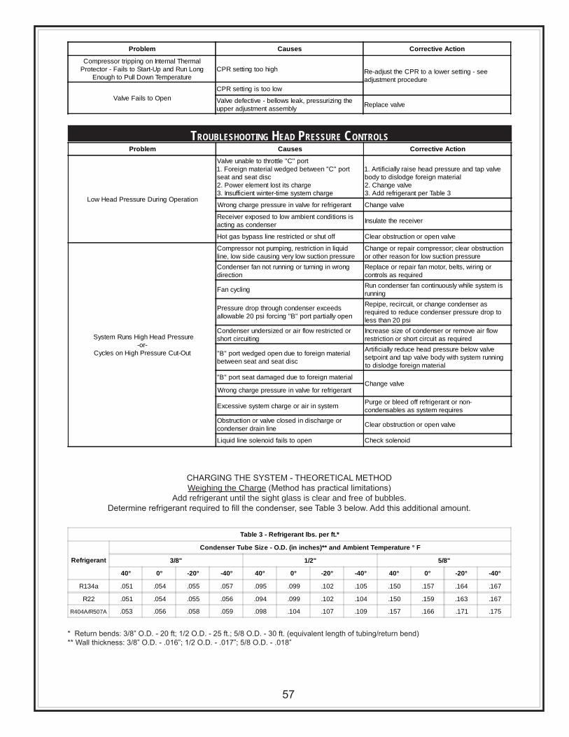
57
Problem Causes Corrective Action
Compressor tripping on Internal ThermalProtector - Fails to Start-Up and Run Long
Enough to Pull Down TemperatureCPR setting too high Re-adjust the CPR to a lower setting - see
adjustment procedure
Valve Fails to OpenCPR setting is too low
Valve defective - bellows leak, pressurizing theupper adjustment assembly Replace valve
Table 3 - Refrigerant lbs. per ft.*
Refrigerant
Condenser Tube Size - O.D. (in inches)** and Ambient Temperature ° F
3/8" 1/2" 5/8"
40° 0° -20° -40° 40° 0° -20° -40° 40° 0° -20° -40°
R134a .051 .054 .055 .057 .095 .099 .102 .105 .150 .157 .164 .167
R22 .051 .054 .055 .056 .094 .099 .102 .104 .150 .159 .163 .167
R404A/R507A .053 .056 .058 .059 .098 .104 .107 .109 .157 .166 .171 .175
Problem Causes Corrective Action
Low Head Pressure During Operation
Valve unable to throttle "C" port1. Foreign material wedged between "C" portseat and seat disc2. Power element lost its charge3. Insufficient winter-time system charge
1. Artificially raise head pressure and tap valvebody to dislodge foreign material2. Change valve3. Add refrigerant per Table 3
Wrong charge pressure in valve for refrigerant Change valve
Receiver exposed to low ambient conditions isacting as condenser Insulate the receiver
Hot gas bypass line restricted or shut off Clear obstruction or open valve
System Runs High Head Pressure-or-
Cycles on High Pressure Cut-Out
Compressor not pumping, restriction in liquidline, low side causing very low suction pressure
Change or repair compressor; clear obstructionor other reason for low suction pressure
Condenser fan not running or turning in wrongdirection
Replace or repair fan motor, belts, wiring orcontrols as required
Fan cycling Run condenser fan continuously while system isrunning
Pressure drop through condenser exceedsallowable 20 psi forcing "B" port partially open
Repipe, recircuit, or change condenser asrequired to reduce condenser pressure drop toless than 20 psi
Condenser undersized or air flow restricted orshort circuiting
Increase size of condenser or remove air flowrestriction or short circuit as required
"B" port wedged open due to foreign materialbetween seat and seat disc
Artificially reduce head pressure below valvesetpoint and tap valve body with system runningto dislodge foreign material
"B" port seat damaged due to foreign materialChange valve
Wrong charge pressure in valve for refrigerant
Excessive system charge or air in system Purge or bleed off refrigerant or non-condensables as system requires
Obstruction or valve closed in discharge orcondenser drain line Clear obstruction or open valve
Liquid line solenoid fails to open Check solenoid
TROublESHOOTInGHEAdpRESSuRECOnTROlS
CHARGING THE SYSTEM - THEORETICAL METHODWeighing the Charge (Method has practical limitations)
Add refrigerant until the sight glass is clear and free of bubbles.Determine refrigerant required to fill the condenser, see Table 3 below. Add this additional amount.
* Return bends: 3/8” O.D. - 20 ft; 1/2 O.D. - 25 ft.; 5/8 O.D. - 30 ft. (equivalent length of tubing/return bend)** Wall thickness: 3/8” O.D. - .016”; 1/2 O.D. - .017”; 5/8 O.D. - .018”

58
NOTES


Emerson Climate Technologies Flow Controls DivisionSt. Louis, Missouri 63141(314) 569-4500WEBSITE: www.emersonclimate.com/flowcontrolsE-MAIL: [email protected]
Form No. 2004FC-141 R4 (4/08)Emerson Climate Technologies and the Emerson Climate Technologies logo are service marks and trademarks of Emerson Electric Co. All other trademarks are property of their respective owner. © 2008 Flow Controls Division. Printed in the USA.

Installation, Operation & Application GuideFor more information on our complete range of American-made products – plus wiring diagrams, troubleshooting tips and more, visit us at www.icmcontrols.com
ICM 450Programmable Three Phase Voltage
Monitor with 25-Fault MemoryProtects motors from premature failure
and burnouts

Specification
Phase Unbalance Protection•Voltage Unbalance:2-20%adjustableOver/Under Voltage Protection•Under Voltage:2-25%adjustable•Over Voltage:2-25%adjustablePhase Loss Protection•Phase Loss Condition:Equals25%ofnominalforanygivenphase;system
willshutdownandafaultwillberecordedshouldthisoccurDelay on Break Timer•Control Voltage:18-240VAC•Time Delay:0to10minutesadjustableFault Interrogation Delay•Time Delay:0to15secondsadjustable•Providesadelaybetweenfaultdetectionandsystemshutdown-helpsto
eliminatenuisancetripsorunnecessaryshutdowns
Parameters
Installation of the ICM450 shall be performed by trained technicians only. Adhere to all local and national electric codes. Disconnect all power to the system before making any connections.
Caution
Input•Line Voltage:Universal,190-630VAC•Frequency:50-60Hz•Load Side Monitoring:Optional•Control Voltage:18-240VAC•Frequency:50-60HzOutput•Type:Relay,SPDT•Voltage Range:240VAC@10Amaximum•Frequency:50-60Hz
Control Operating Temperature•Operating Temperature:-40ºFto+167ºF(-40ºCto+75ºC)•Storage Temperature:-40ºFto+185ºF(-40ºCto+80ºC)LCD Operating Temperature•Operating Temperature:-4ºFto+167ºF(-20ºCto+75ºC)
Mechanical•Mounting:Surfacemountusing(2)#8screws•Terminations:Screwterminals•Weight:12ounces(341grams)
Dimensions •61/2”L,41/4”W,13/8”H(16.5cm.L,10.8cm.W,3.5cm.H)

Installation
•Terminals4and6are“dry,”normallyopencontacts
•Terminals4and6areclosedwhenpoweriswithinspecifications
•Terminals4and6openwhenthereisafaultconditionorlossofcontrolsignal
Contactor Voltage (18-240 VAC)
Contactor Coil
Figure 3
13
6 5 4
Incoming 3-phase voltage from load or
“back” side of contactor(optional)
LOAD 1
LOAD 2
LOAD 3
LINE 1
LINE 2
LINE 3
Figure 1
Incoming 3-phase voltage from line or “front” side of contactor
The incoming 3-phase voltage is used to power up the ICM450 as
well (190-600)
1.Using(2)#8screws,mounttheICM450inacool,dry,easilyaccessiblelocationinthecontrolpanel.
2.ConnectvoltageasshowninFigure1(below).Leaveexistinglineandloadsideconnectionsintactonthecontactor.
3.Loadsidemonitoringisoptional(unitmaybeusedtomonitorlinesideonly).WirethecontactorandoptionalcontrolvoltagemonitoringasinFigures2and3(below).
Note: Load/linewiremustberatedfor3-phasevoltagerating,20gaminimum.
4.Uponapplicationofpower,theICM450willbeonlineandwillbegintomonitorthesystem.
Control Voltage(18-240 VAC)
Short pins when using 24 VAC control voltage
Figure 2
* Switchcanbeathermostat,pressureswitch,etc.
13
6 5 4
•Terminals1and3arethecontrolsignalinputterminals•“ControlMode”isturnedONorOFFinsetup•With“ControlMode”setto“ON,”theremustbea
voltagepresentonterminals1and3fortherelayoutputterminals4and6toclose;thisvoltagecanbesuppliedfromathermostat,pressureswitch,etc.
•Whenthevoltageontheseterminalsisre-applied,theunitwillnotre-energizeuntilthedelayonbreak(0-10minutes)timehaselapsed
•Useofterminals1and3isoptional;theywillbeignoredifthe“ControlMode”issetto“OFF”

ICM450 Wiring Diagrams2-Pole Contactor 3-Pole Contactor
LINE3LINE1
LINE2
LOAD1
LOAD2
LOAD3
Control Voltage
L01
L02
L03
L0AD
LI1
LI3LI2
LINE3LINE1
LINE2
LOAD1
LOAD2
LOAD3
Control Voltage
L01
L02
L03
L0AD
LI1LI2
LI3
1. PressthegreenSETUPbuttontoenterSetupmode.SetupLEDwilllight.2. Usethe and arrowstochangeuserparameters.3. ScrollthroughsetupbypressingandreleasingtheSETUPbutton.4. Whenthelastparameterhasbeenset,thephaseaveragewillbe
displayedandtheSetupLEDwillautomaticallyturnOFF.
Setting the Parameters
Button Functions
Press arrows to scroll through and select user parameter
settings in Setup mode. HOLD down for fast edit.
Press to enter Setup mode
and select user parameters.
Hold for voltage display
a b, b c, a c(simultaneously).
Press to read faults. Hold for 5 seconds to clear faults and
reset memory.
* Thermostat, pressure switch, etc. * Thermostat, pressure switch, etc.

ParametersParameter Description Range Default Recommended
LineVoltage
Averagephasetophaselinevoltage
190-600 208 NameplateVoltage
DelayOnBreak
Amountoftimebetweentheloadde-energizingandre-energizing
0-10minutes
.1minute
4minutes**
FaultInter-rogation
Amountoftimebeforetheloadde-energizesduetoanon-criticalfault*
0-15seconds
15seconds
7-8seconds**
%Over/Under
Voltage
Maximum/minimumphasetophaseaveragevoltage,respectively
2-25% 20% 12-15%**
%PhaseUnbalance
Amountofallowablevoltageunbalance
2-20% 20% 4-5%**
ResetMode
AUTOornumberoftimestheloadcanbere-energizedafteraloadsidefaultbeforeamanualresetisnecessary
Note:Whenmonitoringlinesideonly,theresetmodewillalwaysbeAUTO
AUTO,0-10
AUTO AUTO
ControlMode
WithcontrolmodesettoOFF,theloadwillenergizeifno3-phasefaultconditionsexist;withcontrolmodeON,theloadwillenergizeifnofaultconditionsexistandcontrolvoltageispresentatterminals1and3oftheICM450
ONor
OFF
ON Basedonwiring
* Non-criticalfaultsarefaultssuchasHigh/LowVoltageandPhaseUnbalance.Criticalfaults,suchasPhaseLossandPhaseReversal,haveafaultinterrogationofunder2secondsanditisnotuseradjustable.
** Forbestrecommendations,consultmanufacturerofequipment.

Fault Conditions
* Onlyswapphasesduringinitialsetup,notaftertheICM450hasbeeninoperationwithouterrors.
Pressandreleasefaultbuttontoscrollthroughallsavedfaults.Note:Forinitialsetup,pressandholdFAULTfor5secondsto
removeanypreviouslystoredfaults.
Fault Problem Corrective ActionBackPhaseLoss
Notallthreeofthephasesontheloadsidearepresent
1.Re-energizethecontactor.2. Ifthefaultreappearsaftertheloadenergizes: a. TurnallpowerOFF b. Checkallloadsideconnections c. Checkthecontactsofthecontactorfordebris
orexcesscarbon.
BackPhaseRev
Loads1,2,or3arenotinsequence(not120ºphaseshifted)
1.TurnOFFallpower.2.Swapany2phasesontheloadsideofthe
ICM450only(example:swapload1andload2)*3.Re-applypower.
BackPhaseUnbal
Avoltageunbalancebetweenthethreeloadphasesexceedstheunbalancesetpoint
1.PresstheREADbuttontoobservethepresentloadvoltages.Checksystemforunbalancecause.
2. Increasethefaultinterrogationtimeifnecessary.3. Increasethepercentunbalancesettingif
necessary.
FrontOverVolt
Averagephase-phasevoltageexceedsthemaximumpercentage
1.Checksystemforover-voltagecause.2. Increasethepercentover-voltagesettingif
necessary.3. Increasethefaultinterrogationtimeifnecessary.
FrontPhaseLoss
Notallthreeofthephasesonthelinesidearepresent
1.PressandholdtheREADbuttononthephasemonitororuseanACvoltmetertocarefullymeasureallthreephase-phaselinevoltages(example:Line1 Line2,Line2 Line3,Line3 Line1).
2.Repairthemissingphase.
FrontPhaseRev
Lines1,2,or3arenotinsequence(not120ºphaseshifted)
1.TurnOFFallpower.2.Swapany2phasesonthelinesideoftheICM450
(example:swapload1andload2)*3.Re-applypower.
FrontPhaseUnbal
Avoltageunbalancebetweenthethreelinephasesexceedstheunbalancesetpoint
1.PresstheREADbuttontoobservethepresentloadvoltages.Checksystemforunbalancecause.
2. Increasethefaultinterrogationtimeifnecessary.3. Increasethepercentunbalancesettingif
necessary.
FrontUnderVolt
Averagephase-phasevoltageisbelowtheminimumpercentage
1.Checksystemforunder-voltagecause.2. Increasethepercentunder-voltagesettingif
necessary.3. Increasethefaultinterrogationtimeifnecessary.
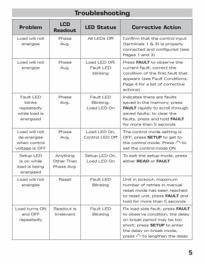
Troubleshooting
Problem LCD Readout LED Status Corrective Action
Loadwillnotenergize
PhaseAvg.
AllLEDsOff Confirmthatthecontrolinput(terminals1&3)isproperlyconnectedandconfigured(seePages1and3)
Loadwillnotenergize
PhaseAvg.
LoadLEDOff,FaultLEDblinking
PressFAULTtoobservethecurrentfault;correcttheconditionofthefirstfaultthatappears(seeFaultConditions,Page4foralistofcorrectiveactions)
FaultLEDblinks
repeatedlywhileloadisenergized
PhaseAvg.
FaultLEDBlinking,
LoadLEDOn
Indicatestherearefaultssavedinthememory,pressFAULTrapidlytoscrollthroughsavedfaults;toclearthefaults,pressandholdFAULTformorethan5seconds
Loadwillnotde-energize
whencontrolvoltageisOFF
PhaseAvg.
LoadLEDOn,ControlLEDOff
ThecontrolmodesettingisOFF;pressSETUPtogettothecontrolmode.Press tosetthecontrolmodeON
SetupLEDisonwhile
loadisbeingenergized
AnythingOtherThanPhaseAvg.
SetupLEDOn,LoadLEDOn
Toexitthesetupmode,presseitherREADorFAULT
Loadwillnotenergize
Reset FaultLEDBlinking
Unitinlockout;maximumnumberofretriesinmanualresetmodehasbeenreached;toresetunit,pressFAULTandholdformorethan5seconds
LoadturnsONandOFF
repeatedly
ReadoutisIrrelevant
FaultLEDBlinking
Fixloadsidefault;pressFAULTtoobservecondition;thedelayonbreakperiodmaybetooshort;pressSETUPtoenterthedelayonbreakmode;press tolengthenthedelay

ONE-YEAR LIMITED WARRANTYTheSellerwarrantsitsproductsagainstdefectsinmaterialorworkmanshipforaperiodofone(1)yearfromthedateofmanufacture.TheliabilityoftheSellerislimited,atitsoption,torepair,replaceorissueanon-casecreditforthepurchasepricesofthegoodswhichareprovidedtobedefective.ThewarrantyandremediessetforthhereindonotapplytoanygoodsorpartsthereofwhichhavebeensubjectedtomisuseincludinganyuseorapplicationinviolationoftheSeller’sinstructions,neglect,tampering,improperstorage,incorrectinstallationorservicingnotperformedbytheSeller.InordertopermittheSellertoproperlyadministerthewarranty,theBuyershall:1)NotifytheSellerpromptlyofanyclaim,submittingdatecodeinformationoranyotherpertinentdataasrequestedbytheSeller.2)PermittheSellertoinspectandtesttheproductclaimedtobedefective.ItemsclaimedtobedefectiveandaredeterminedbySellertobenon-defectivearesubjecttoa$30.00perhourinspectionfee.ThiswarrantyconstitutestheSeller’ssoleliabilityhereunderandisinlieuofanyotherwarrantyexpressed,impliedorstatutory.Unlessotherwisestatedinwriting,Sellermakesnowarrantythatthegoodsdepictedordescribedhereinarefitforanyparticularpurpose.
LIA164-4
7 William Barry Blvd., North Syracuse, NY (Toll Free) 800-365-5525 (Phone) 315-233-5266 (Fax) 315-233-5276
www.icmcontrols.com

ICM 450Programmable Three Phase Voltage Monitor
Parameters Default settingsLine voltage 208 V See Name Plate
.1 minute 1 minuteFault delay 15 sec 5 sec
20% 5%20% 5%
Phase unbalance 20% 3%Reset Mode AUTO AUTOControl Mode ON OFF
Settings for Seresco NE series dehumidifiersSeresco Settings
Dealay on break
OvervoltageUndervoltage
Note: Please reffer to ICM 450 manual. Consult Seresco if settings' change is required

SPOR
LAN
REF.
& A
/C P
RODU
CTS
Sporlan Refrigeration and Air Conditioning Products
Oil Level Controls
Suction Filters Oil Filters
See•All
Head Pressure Control Valves
Solenoids
Three-Way Heat Reclaim Valves
TEV
Crankcase Pressure Regulating Valves
Catch-All
Discharge Bypass Valves
Evaporator Pressure Regulating Valves
SPORLAN REF. & A/C PRODUCTS
632

THERMOSTATIC EXPANSION VALVES SPORLAN THERMOSTATIC EXPANSION VALVES
• Selective Thermostat Charges — Designed to provide optimum performance for all applications — air conditioning and heat pump, medium and Low temperature refrigeration.
• Thermostatic Element Design — Long lasting and field proven stainless steel diaphragm and welded element construction.
• Diaphragm Design — Large flat diaphragm permits precise valve control.
• Replaceable Thermostatic Elements — Field replaceable elements on all standard valves.
• Balanced Port Design — Provides perfect pin and port alignment, and prevents changes in pressure drop across the valve from influencing Valve operation. Provides excellent control on applications with widely varying operating conditions.
• Pin Carrier Design (Conventional Valves) — Provides precise pin and port alignment, and tighter seating.
• Accessible Internal Parts — Durable, leak proof body joint construction allows the valve to be disassembled, and the internal parts cleaned and inspected.
• Materials of Construction — Pin and port material offer maximum protection against corrosion and erosion.
• Silver Soldered Connections — For leak proof, high strength connection-to-body joints.
• Adjustable Superheat Design — All standard valves are externally adjustable. VALVE NOMENCLATURE/ORDERING INSTRUCTIONS
Combine the letters and numbers in the following manner to obtain the complete valve designation. Also include all connection Sizes and the capillary tube length. CONVENTIONAL VALVES:
S V E - 8 - GA 5/8”ODF Solder X 7/8”ODF
Solder X 1/4” ODF Solder X 5’
Sporlan Code - REFRIGERANT - Element Label Color Code Body
Type: FB,F, EF,G, EG,
RI,RC, S,
EBS*, O*, V**, W**
F - R-12 Yellow E - R-13 - Blue V - R-22 -Green G - R-23 - Blue M - R124 - Blue J- R134a -Blue X - R-401A Pink L - R-402ASand S- R-404A Orange
V - R-407A – Green N - R-407 Lt. Brown S - R-408A -Purple F - R-409A -Yellow R - R-502 - Purple W - R-503 - Blue P - R-507 - Teal W - R-508B - Blue A - R-717 – White
E” specifies external
equalizer. Omission of
letter “E” indicates valve with internal
equalizer. e.g.
EGV-1-C
Nominal Capacityin Tons
ThermostaticCharge
Inlet
Connection
Size and Style
Outlet Connection
Size and Style
External Equalizer
Connection
Size and
Style
CapillaryTubing Length (Inches or Feet)
BALANCE PORTED VALVES:
EBF
V
E
-
AA
-
C 3/8”
Extended ODF Solder
X
1/2” Extended
ODF Solder
X
1/4” Extended
ODF Solder
X
30”
Port Size
Nominal Capacity in Tons
AAA 1/8 thru 1/3 AA 1/2 thru 2/3 A 3/4 thru 1-1/2 B 1-3/4 thru 3
22 (V) 407C (N) 407A (V)
C 3-1/4 thru 5-1/2 AAA 1/8 thru 1/5 AA 1/4 thru 1/3 A 1/2 thru 1 B 1-1/4 thru 1-3/4
134a (J) 12 (F)
401A (X) 409A (F)
C 2 thru 3 AAA 1/8 thru 1/5 AA 1/4 thru 1/3 A 1/2 thru 1 B 1-1/4 thru 2
404A (S) 502 (R)
408A (S)
C 2-1/4 thru 3 AAA 1/8 thru 1/5 AA 1/4 thru 1/3 A 1/2 thru 1 B 1-1/4 thru 2
Body Type:
BF,SBF, EBF
507 (P) 402A (L)
“E” specifies external
equalizer. Omission of
letter “E” indicates
valve with internal equalizer.
C 2-1/4 thru 3
Thermostatic Charge
Inlet Connection
Size and Style
Outlet Connection
Size and
Style
External Equalizer
Connection
Size and Style
Capillary Tubing Length (Inches)
*EBS and O valves are balance ported valves, but follow conventional valve nomenclature. **V and W valves have dual port semi-balance design.
THERMOSTATIC EXPANSION VALVES
633

THER
MOST
ATIC
EXP
ANSI
ON V
ALVE
S SPORLAN SELECTIVE CHARGES ENGINEERED FOR PEAK PERFORMANCE FOR EACH SPECIFICAPPLICATIONRECOMMENDED THERMOSTATIC CHARGES*
REFRIGERANT
APPLICATION
12 409A
22 407A
134a
401A
402A
404A 408A
407C
502
507
717
ACTUAL THERMOSTATIC
CHARGES FCP60 — JCP60 XCP60 — — — — — — FCP60
— VCP100 — — — — NCP100 — — — VCP100 — VGA — — — — NGA — — — VGA
AIR CONDITIONING — — — — — SCP115 — RCP115 — — SCP115
FC — JC XC — — — — — — FC — VC — — — — NC — — — VC — — — — — SC — RC — — SC — — — — LC — — — PC — PC
COMMERCIAL REFRIGERATION 50°F
TO -10°F — — — — — — — — — AC, AL AC, AL
FZ — — — — — — — — — FZ FZP — — — — — — — — — FZP — VZ — — — — — — — — VZ — VZP40 — — — — — — — — VZP40 — — — — LZ SZ — RZ PZ — SZ — — — — LZP SZP — RZP PZP — SZP
LOW TEMPERATURE REFRIGERATION 0°F
TO -40°F — — — — — — — — — AZ, AL AZ, AL
— VX — — — — — — — — VX EXTREME LOW TEMP.REFRIGERATION
-40°F TO -100°F — — — — LX SX — RX PX — SX * APPLICATION FACTORS: 1. The Type ZP charges have essentially the same characteristics as the Type Z charge with one exception: they produce a pressure limit Maximum Operating Pressure (MOP). ZP charges are not intended as replacements for Z charges. Each should be selected for its own unique purpose.
2. All air conditioning and heat pump charges are intended for use with externally equalized valves.
3. Type L liquid charges are also available for most commonly used refrigerants in most element sizes.
4. If in doubt as to which charge to use, contact Sporlan Valve Company, Washington, Missouri with complete system data.
5. The Type X charges are not to be used with “EBS” and “O” valves. IMPORTANT NOTES:
A. R-134a air conditioning and commercial refrigeration applications are using R-12 or R-409A or R-401A valves.
B. R-404A commercial refrigeration applications are using R-502 or R-408A valves.
C. R-404A and R-507 low temperature refrigeration applications are using R-502 or R-402A or R-408A valves.
THERMOSTATIC EXPANSION VALVES
634

THERMOSTATIC EXPANSION VALVES QUICK REFERENCE GUIDE — REFRIGERATION VALVES
NOMINAL CAPACITY
RANGE (Tons)
VALUE TYPE
R-22
R-134a R-404A
& R-507
CONNECTION TYPES
VALVE DESCRIPTION AND APPLICATION
F
1/5 thru
3
1/8 thru
2
1/8 thru
2
SAE Flare
Small brass bar body, externally adjustable valve for small capacity refrigeration systems. SAE flare inlet
connection has a removable 100 mesh strainer. Typical applications: Refrigerated cases, coolers, freezers.
EF
1/5 thru
3
1/8 thru
2
1/8 thru
2
ODF Solder
Same as the Type F valve except it features ODF solder connections. The inlet connection has a 50 mesh strainer. Typical applications: Refrigerated
cases, coolers, freezers.
G
1/5 thru
3
1/8 thru
2
1/8 thru
2
SAE Flare
Forged brass bar body, externally adjustable valve for small capacity refrigeration systems. Inlet connection
has a removable 100 mesh strainer. Typical applications: Refrigerated cases, coolers, freezers and
small capacity air conditioners.
EG
1/5 thru
3
1/8 thru
2
1/8 thru
2
ODF Solder
Same as the Type G valve except it features ODF solder connections and a forged brass inlet fitting with a removable 100 mesh strainer which can be cleaned
and/or replaced without moving the valve from the line.
FB
1/4 thru
8
1/4 thru
5
1/4 thru
6
SAE Flare
or ODF Solder
Small brass body valve available only with straight through connections and external adjustment. Typical
applications: Small capacity air conditioning and refrigeration applications where an external adjustment
is desired
BF
1/3 thru
5
1/4 thru
3
1/4 thru
3
SAE Flare
Same physical size as the Type F valve with SAE flare connection except it features a balanced port
construction. Inlet connection has removable 100 mesh strainer. Typical applications: Small capacity refrigeration that operates over widely varying operating conditions.
SBF
1/3 thru
5
1/4 thru
3
1/4 thru
3
Extended
ODF Solder
Same as the Type BF valve except it features ODF solder connection and a forged brass inlet fitting with a
removable 100 mesh strainer which can be cleaned and/or replaced without removing the valve from
the line.
EBF
1/3 thru
5
1/4 thru
3
1/4 thru
3
Extended
ODF Solder
Same as the Type BF valve except it features ODF
solder connections.
S
2
thru 10
2
thru 6
2
thru 7
ODF Solder
Brass bar body, externally adjustable valve. General purpose valve for air conditioning and refrigeration
applications.
EMC
0.64 thru 2.34
0.46 thru 1.69
0.42 thru 1.51
ODF Solder
Multi-capacity two part valve designed to perform
effectively over the range of load conditions inherent with most refrigeration systems. Large port is for pull down load and smaller port to control holding loads.
THERMOSTATIC EXPANSION VALVES
635

THER
MOST
ATIC
EXP
ANSI
ON V
ALVE
S PART NO*
SPORLAN MODEL**
PART NO*
SPORLAN MODEL**
PART NO*
SPORLAN MODEL**
TYPE F
TYPE BF
TYPE FB
FF-1-1/2-C 3X4 SAE 30" BFF-A-C 3X4 SAE 30" FBS-1/4-C 3SX4 ODF 30"
FF-1-C 3X4 SAE 30" BFJE-A-C 3X4 SAE 30" FBS-1/4-Z 2SX4 ODF 30"
FFE-1-C 3X4 SAE 30" BFJE-B-C 3X4 SAE 30" FBS-1/4-ZP 3SX4 ODF 30"
FFE-2-C 3X4 SAE 30" BFR-A-C 3X4 SAE 30" FBSE-1/2-C 3SX4X2 ODF 30"
FJ-1/2-C 2X4 SAE 30" BFRE-A-Z 3X4 SAE 30" FBSE-1/4-C 3SX4X2 ODF 30"
FJ-1/4-C 2X4 SAE 30" BFRE-A-ZP 3X4 SAE 30" FBSE-1/4-ZP 3SX4X2 ODF 30"
FJ-1/4-Z 2X4 SAE 30" BFRE-B-C 3X4 SAE 30" FBSE-1\2-ZP 3SX4 ODF 30"
FR-1/4-Z 2X4 SAE 30" BFRE-B-Z 3X4 SAE 60" FBSE-1-1\2-C 3SX4 ODF 30"
FRE-1/2-C 3X4 SAE 30" BFRE-B-ZP 3X4 SAE 30" FBSE-1-1\2-ZP 3SX4 ODF 30"
FRE-1/2-Z 3X4 SAE 30" BFSE-AA-ZP 3X4 SAE 30" FBSE-1-C 3SX4 ODF 30"
FRE-1/2-ZP 3X4 SAE 30" BFSE-A-C 3X4 SAE 30" FBSE-1-Z 3X4X2 ODF 30"
FRE-1/4-Z 2X4 SAE 30" BFSE-C-ZP 3X4 SAE 30" FBSE-1-ZP 3SX4 ODF 30"
FRE-1-1/2-C 3X4 SAE 30" BFV-AA-C 3X4 SAE 30" FBSE-2-C 3SX4X2 ODF 30"
FRE-1-1/2-Z 3X4 SAE 30" BFV-A-C 3X4 SAE 30" FBSE-2-Z 3X4X2 ODF 30"
FRE-1-1/2-ZP35 2X4 SAE 30" BFVE-AAA-C 3X4 SAE 30" FBSE-2-ZP 3SX4X2 ODF 30"
FRE-1-ZP 3X4 SAE 30" BFVE-AA-C 3X4 SAE 30" FBSE-3.5-C 4X7X2 ODF 60"
FRE-2-Z 3X4 SAE 30" BFVE-A-C 3X4 SAE 30" FBSE-3.5-ZP 4X7X2 ODF 30"
FRE-2-ZP 3X4 SAE 30" BFVE-B-C 3X4 SAE 30" FBSE-3-C 4X7X2 ODF 60"
FS-1/2-C 2X4 SAE 30" FBSE-3-ZP 4X7X2 ODF 30"
FS-1/4-C 2X4 SAE 30" FBSE-4.5-C 4X7X2 ODF 60"
FS-1/4-ZP 2X4 SAE 30" FBSE-4.5-ZP 4X7X2 ODF 30"
FSE-1/2-Z 2X4 SAE 30" FBSE-6-C 5X7X2 ODF 60"
FSE-1/2-ZP35 2X4 SAE 30" FBSE-6-ZP 5X7X2 ODF 30"
FSE-1/4-ZP 2X4 SAE 30" FBV-1/4-C 2*SX4 ODF 30"
FSE-1/4-ZP30 2X4 SAE 30"
TYPE G
FBV-1/4-C 3*SX4 ODF 30"
FSE-1-C 3X4 SAE 30" GRE-1-1/2-ZP 3X4 SAE 5' FBV-1/4-ZP40 3SX4 ODF 30"
FV-1/4-C 2X4 SAE 30" GRE-1-ZP 3X4 SAE 5' FBVE-1/2-ZP40 3*SX4X2 ODF 30"
FVE-1/2-C 3X4 SAE 30" GVE-1-C 3X4 SAE 5' FBVE-1/4-C 3*SX4X2 ODF 30"
FVE-1/4-C 2X4 SAE 30" GVE-3/4-C 3X4 SAE 5' FBVE-1/4-ZP40 3*SX4X2 ODF 30"
FVE-1-1/2-C 3X4 SAE 30" GVE-3/4-ZP 3X4 SAE 5' FBVE-1\2-C 3*SX4 ODF 30"
FVE-1-C 3X4 SAE 30" GVE-3-C 3X4 SAE 5' FBVE-1-1/2-ZP40 3*SX4X2 ODF 30"
FVE-2-C 3X4 SAE 30" FBVE-1-1\2-C 3*SX4 ODF 30"
FVE-3-C 3X4 SAE 30" FBVE-1-C 3*SX4 ODF 30"
FBVE-1-ZP40 3*SX4X2 ODF 30"
FBVE-2.5-C 4X5X2 ODF 60"
FBVE-2.5-ZP40 4X5X2 ODF 30"
TYPE FB FBVE-2-C 4X5X2 ODF 30"
FBFE-1-C 3SX4X2 ODF 30" FBVE-2-ZP40 4X5X2 ODF 30"
TYPE EF
FBJE-1/2-CP60 3X4X2 ODF 30"
FBVE-3-C 4X5X2 ODF 60"
EFF-1/4-Z 2SX3 ODF 30" FBJE-1/2-Z 3X4X2 ODF 30" FBVE-3-ZP40 4X5X2 ODF 60"
EFJ-1/2-C 2SX3 ODF 30" FBR-1/2-Z 2X4 SAE 30" FBVE-4-C 4X7X2 ODF 60"
EFJ-1/4-C 2SX4 ODF 30" FBR-1/4-Z 2X4 SAE 30" FBVE-4-ZP40 4X7X2 ODF 60"
EFS-1/4-C 2SX3 ODF 30" FBS-1/2-C 3SX4 ODF 30" FBVE-5-C 4X7X2 ODF 60"
EFS-1/4-Z 2SX3 ODF 30" FBS-1/2-Z 2SX4 ODF 30" FBVE-5-ZP40 4X7X2 ODF 60"
EFS-1-Z 3X4 ODF 30" FBS-1/2-ZP 3SX4 ODF 30" FBVE-6-C 4X7X2 ODF 60"
EFSE-1/2-Z 3X4 ODF 30" FBVE-6-GA 4X5X2 ODF 30"
EFSE-1/4-Z 3X4 ODF 30" FBVE-6-ZP40 4X7X2 ODF 60"
EFSE-1/6-Z 2X4 ODF 30" FBVE-8-C 5X7X2 ODF 60"
EFVE-1/2-C 3X4 ODF 30" FBVE-8-ZP40 5X7X2 ODF 60"
EFVE-1/2-L1 3X4 ODF 30"
EFVE-1/3-C 2X4 ODF 30"
EFVE-1/3-C 3X4 ODF 30"
EFVE-1/3-L1 3X4 ODF 30"
EFVE-1/5-C 2X4 ODF 30"
EFVE-1-C 3X4 ODF 30"
IMPORTANT NOTE:
00*S - with Insert Strainer Connection Sizes are in eighths of inch – (3x4 means 3/8” inlet x 1/2” outlet).
*( ) Please contact your local Carlyle Certified Refrigeration Partner or RCD Customer Service Center for part number and pricing.
THERMOSTATIC EXPANSION VALVES
636

THERMOSTATIC EXPANSION VALVES PART NO*
SPORLAN MODEL** PART NO*
SPORLAN MODEL** PARTNO*
SPORLAN MODEL** PART NO*
SPORLAN MODEL**
EGV-1/2-ZP40 3X4 ODF 5' SBFP-AAA-Z 3X4 ODF 30"
EGV-1/3-C 3X4 ODF 5' SBFP-AA-C 3X4 ODF 30"
EGV-1/3-Z 3X4 ODF 5' SBFP-AA-Z 3X4 ODF 30"
EGV-1/5-C 3X4 ODF 5' SBFP-A-C 3X4 ODF 30"
EGV-1/5-Z 3X4 ODF 5' SBFP-B-C 3X4 ODF 30"
EGV-1-C 3X4 ODF 5' SBFPE-AAA-C 3X4 ODF 30"
TYPE EG
EGV-3/4-C 3X4 ODF 5'
SBFPE-AA-C 3X4 ODF 30"
TYPE EBF
EGFE-1/2-C 3X4 ODF 5' EGV-3/4-Z 3X4 ODF 5' SBFPE-AA-Z 3X4 ODF 30" EBFF-AAA-C 3X4 ODF 30"
EGFE-1/4-C 3X4 ODF 5' EGV-3/4-ZP 3X4 ODF 5' SBFPE-B-C 3X4 ODF 30" EBFF-A-C 3X4 ODF 30"
EGFE-1-C 3X4 ODF 5' EGV-3/4-ZP40 3X4 ODF 5' SBFPE-C-C 3X4 ODF 30" EBFFE-A-C 3VX4 ODF 30"
EGFE-2-C 3X4 ODF 5' EGVE-1/2-C 3X4 ODF 5' SBFR-AAA-Z 3X4 ODF 30" EBFFE-B-C 3X4 ODF 30"
EGJ-1/4-C 3X4 ODF 5' EGVE-1/2-L1 3X4 ODF 5' SBFR-AAA-ZP 3X4 ODF 30" EBFLE-A-C 3X4 ODF 30"
EGJ-1/6-C 3X4 ODF 5' EGVE-1/2-Z 3X4 ODF 5' SBFR-AA-C 3X4 ODF 30" EBFLE-A-Z 3X4 ODF 30"
EGJ-1/8-C 3X4 ODF 5' EGVE-1/2-ZP40 3X4 ODF 5' SBFR-AA-Z 3X4 ODF 30" EBFPE-C-C 3X4 ODF 30"
EGJE-1/6-C 3X4 ODF 5' EGVE-1/3-C 3X4 ODF 5' SBFR-AA-ZP 3X4 ODF 30" EBFPE-C-Z 3X4 ODF 30"
EGJE-1/8-C 3X4 ODF 5' EGVE-1/5-C 3X4 ODF 5' SBFR-A-C 3X4 ODF 30" EBFR-A-C 3EX4 ODF 30"
EGJE-1-1/2-C 3X4 ODF 5' EGVE-1-1/2-C 3X4 ODF 5' SBFR-A-ZP 3X4 ODF 30" EBFRE-AA-Z 3VX4 ODF 30"
EGP-1/2-C 3X4 ODF 5' EGVE-1-1/2-Z 3X4 ODF 5' SBFR-B-C 3X4 ODF 30" EBFRE-AA-ZP 3VX4 ODF 30"
EGP-1/4-C 3X4 ODF 5' EGVE-1-1/2-ZP40 3X4 ODF 5' SBFRE-AAA-C 3X4 ODF 30" EBFRE-A-Z 3EX4 ODF 30"
EGP-1/6-C 3X4 ODF 5' EGVE-1-C 3X4 ODF 5' SBFRE-AAA-Z 3X4 ODF 30" EBFRE-A-Z 3X4 ODF 30"
EGP-1/8-C 3X4 ODF 5' EGVE-1-Z 3X4 ODF 5' SBFRE-AA-Z 3X4 ODF 30" EBFRE-A-ZP 3EX4 ODF 30"
EGPE-1/2-C 3X4 ODF 5' EGVE-1-ZP40 3X4 ODF 5' SBFRE-A-Z 3X4 ODF 30" EBFS-AAA-ZP 2X4 ODF 30"
EGPE-1/4-C 3X4 ODF 5' EGVE-2-C 3X4 ODF 5' SBFRE-B-Z 3X4 ODF 30" EBFSE-AAA-Z 2SX4 ODF 30"
EGPE-1/8-C 3X4 ODF 5' EGVE-2-Z 3X4 ODF 5' SBFS-AAA-C 3X4 ODF 30" EBFSE-AAA-ZP 3VX4 ODF 30"
EGPE-1-1/2-C 3X4 ODF 5' EGVE-2-ZP40 3X4 ODF 5' SBFSE-AAA-ZP 3X4 ODF 30" EBFSE-AA-C 3X4 ODF 30"
EGPE-1-C 3X4 ODF 5' EGVE-3/4-C 3X4 ODF 5' SBFSE-AA-C 3X4 ODF 30" EBFSE-A-C 3VX4 ODF 30"
EGPE-2-C 3X4 ODF 5' EGVE-3/4-L1 3X4 ODF 5' SBFSE-AA-ZP 3X4 ODF 30" EBFSE-A-Z 3VX4 ODF 30"
EGR-1/2-C 3X4 ODF 5' EGVE-3/4-X 3X4 ODF 5' SBFSE-A-C 3X4 ODF 30" EBFSE-B-C 3VX4 ODF 30"
EGR-1/2-Z 3X4 ODF 5' EGVE-3/4-Z 3X4 ODF 5' SBFSE-A-ZP 3X4 ODF 30" EBFSE-B-Z 3VX4 ODF 30"
EGR-1/2-ZP 3X4 ODF 5' EGVE-3/4-ZP 3X4 ODF 5' SBFSE-B-C 3X4 ODF 30" EBFSE-B-ZP 3X4 ODF 30"
EGR-1/4-C 3X4 ODF 5' EGVE-3/4-ZP40 3X4 ODF 5' SBFSE-B-Z 3X4 ODF 30" EBFSE-C-C 3X4 ODF 30"
EGR-1/4-Z 3X4 ODF 5' EGVE-3-C 3X4 ODF 5' SBFSE-B-ZP 3X4 ODF 30" EBFSE-C-Z 3X4 ODF 30"
EGR-1/6-C 3X4 ODF 5' EGVE-3-Z 3X4 ODF 5' SBFSE-C-C 3X4 ODF 30" EBFSE-C-ZP 3VX4 ODF 30"
EGR-1/8-C 3X4 ODF 5' EGVE-3-ZP40 3X4 ODF 5' SBFSE-C-Z 3X4 ODF 30" EBFV-AAA-C 3EX4 ODF 30"
EGR-1/8-Z 3X4 ODF 5' EGX-1/2-C 3X4 ODF 5' SBFSE-C-ZP 3X4 ODF 30" EBFV-AA-C 3EX4 ODF 30"
EGR-1-C 3X4 ODF 5' SBFV-AAA-C 3X4 ODF 30" EBFV-AA-Z 3EX4 ODF 30"
EGRE-1/4-Z 3X4 ODF 5' SBFV-AAA-Z 3X4 ODF 30" EBFV-AA-ZP40 3EX4 ODF 30"
EGRE-1/6-C 3X4 ODF 5' SBFV-AA-C 3X4 ODF 30" EBFV-A-C 3EX4 ODF 30"
EGRE-1/8-C 3X4 ODF 5' SBFV-AA-Z 3X4 ODF 30" EBFV-B-C 3X4 ODF 30"
EGRE-1-ZP40 3X4 ODF 5' SBFV-AA-ZP40 3X4 ODF 30" EBFVE-AAA-C 3X4 ODF 30"
EGRE-2-C 3X4 ODF 5'
TYPE SBF SBFV-A-C 3X4 ODF 30" EBFVE-AA-C 3EX4 ODF 30"
EGRE-2-Z 3X4 ODF 5' SBFF-AA-ZP 3X4 ODF 30"
SBFV-B-C 3X4 ODF 30"
EBFVE-AA-CP100 3VX4 ODF 30"
EGSE-1/2-C 3X4 ODF 5' SBFF-A-ZP 3X4 ODF 30" SBFVE-AAA-C 3X4 ODF 30" EBFVE-AA-Z 3EX4 ODF 30"
EGSE-1/2-Z 3X4 ODF 5' SBFFE-AA-ZP 3X4 ODF 30" SBFVE-AAA-ZP40 3X4 ODF 30" EBFVE-AA-ZP40 3EX4 ODF 30"
EGSE-1/2-ZP 3X4 ODF 5' SBFFE-A-ZP 3X4 ODF 30" SBFVE-AA-C 3X4 ODF 30" EBFVE-A-C 3EX4 ODF 30"
EGSE-1/4-C 3X4 ODF 5' SBFFE-B-ZP 3X4 ODF 30" SBFVE-AA-Z 3X4 ODF 30" EBFVE-A-Z 3X4 ODF 30"
EGSE-1/4-ZP 3X4 ODF 5' SBFJ-AAA-C 3X4 ODF 30" SBFVE-AA-ZP40 3X4 ODF 30" EBFVE-A-ZP40 3VX4 ODF 30"
EGSE-1-1/2-C 3X4 ODF 5' SBFJ-AA-C 3X4 ODF 30" SBFVE-A-C 3X4 ODF 30" EBFVE-B-C 3X4 ODF 30"
EGSE-1-1/2-Z 3X4 ODF 5' SBFJ-A-C 3X4 ODF 30" SBFVE-A-Z 3X4 ODF 30" EBFVE-B-CP100 3X4 ODF 30"
EGSE-1-1/2-ZP 3X4 ODF 5' SBFJ-B-C 3X4 ODF 30" SBFVE-A-ZP 3X4 ODF 30" EBFVE-B-Z 3X4 ODF 30"
EGSE-1-C 3X4 ODF 5' SBFJE-AAA-C 3X4 ODF 30" SBFVE-A-ZP40 3X4 ODF 30" EBFVE-B-ZP40 3X4 ODF 30"
EGSE-1-X 3X4 ODF 5' SBFJE-AA-C 3X4 ODF 30" SBFVE-B-C 3X4 ODF 30" EBFVE-C-C 3X4 ODF 30"
EGSE-1-Z 3X4 ODF 5' SBFJE-A-C 3X4 ODF 30" SBFVE-B-Z 3X4 ODF 30" EBFVE-C-CP100 3X4 ODF 30"
EGSE-1-ZP 3X4 ODF 5' SBFJE-B-C 3X4 ODF 30" SBFVE-B-ZP40 3X4 ODF 30" EBFVE-C-ZP40 3VX4 ODF 30"
EGSE-2-C 3X4 ODF 5' SBFJE-C-C 3X4 ODF 30" SBFVE-C-C 3X4 ODF 30"
EGSE-2-ZP 3X4 ODF 5' SBFP-AAA-C 3X4 ODF 30" SBFVE-C-Z 3X4 ODF 60"
EGV-1/2-C 3X4 ODF 5' SBFVE-C-ZP40 3X4 ODF 30"
EGV-1/2-Z 3X4 ODF 5'
IMPORTANT NOTES:
E – Elbow Inlet
V – 877 Series (100 Mesh) Strainer
*( ) Please contact your local Carlyle Certified Refrigeration Partner or RCD Customer Service Center for part number and pricing.
THERMOSTATIC EXPANSION VALVES
637

THER
MOST
ATIC
EXP
ANSI
ON V
ALVE
S
PART NO*
SPORLAN MODEL** PART NO*
SPORLAN MODEL** PART NO*
SPORLAN MODEL**
TYPE KT KT-43-FC 5’(1.5M) ELEMENT
KT-43-FZ 5’(1.5M) ELEMENT
KT-43-FZP 5’(1.5M) ELEMENT
KT-43-PC 5’ ELEMENT
KT-43-RC 5’(1.5M) ELEMENT
KT-43-RZ 30"(.75M) ELEMENT
TYPE S
TYPE EMC
KT-43-RZP 5’(1.5M) ELEMENT
SRE-1/2-C 4X5 ODF 5' EMC-10-PC 3X4 ODF 5' KT-43-VC 5’(1.5M) ELEMENT
SRE-1/2-ZP 4X5 ODF 5' EMC-10-SC 3X4 ODF 5' KT-43-VZ 5’(1.5M) ELEMENT
SRE-1-1/2-C 4X5 ODF 5' EMC-10-SZ 3X4 ODF 5' KT-43-VZP 5’(1.5M) ELEMENT
SRE-1-1/2-Z 4X5 ODF 5' EMC-10-VC 3X4 ODF 5' KT-53-FC 5’ ELEMENT
SRE-1-1/2-ZP 4X5 ODF 5' EMC-10-VZ 3X4 ODF 5' KT-53-FZ 5’(1.5M) ELEMENT
SRE-1-C 4X5 ODF 5' EMC-11-SZ 3X4 ODF 5' KT-53-FZP 5’(1.5M) ELEMENT
SRE-1-ZP 4X5 ODF 5' EMC-20-PC 3X4 ODF 5' KT-53-RC 5’ ELEMENT
SRE-2-L1 4X5 ODF 5' EMC-20-SC 3X4 ODF 5' KT-53-SZ 5’ ELEMENT
SRE-4-Z 4X7 ODF 5' EMC-20-VC 3X4 ODF 5' KT-53-SZP 5’ ELEMENT
SSE-1/4-C 3X4 ODF 5' EMC-21-PC 3X4 ODF 5' KT-53-VC 5’ ELEMENT
SSE-10-ZP 5X7 ODF 5' EMC-21-SC 3X4 ODF 5' KT-53-VZ 5’(1.5M) ELEMENT
SSE-10-ZP 7X9 ODF 5' EMC-21-VC 3X4 ODF 5' KT-53-VZP 5’(1.5M) ELEMENT
SSE-2-C 4X5 ODF 5' EMCE-10-JC 3X4 ODF 5' KT-83-FC 5’ ELEMENT
SSE-2-ZP 4X5 ODF 5' EMCE-10-PC 3X4 ODF 5' KT-83-SC 5’ ELEMENT
SSE-3-C 4X7 ODF 5' EMCE-10-SC 3X4 ODF 5' KT-83-SZ 5’ ELEMENT
SSE-3-L1 4X7 ODF 5' EMCE-10-SZ 3X4 ODF 5' KT-83-SZP ELEMENT
SSE-3-ZP 4X7 ODF 5' EMCE-10-VC 3X4 ODF 5' KT-83-VC 5’ ELEMENT
SSE-3-ZP40 4X7 ODF 5' EMCE-10-VZ 3X4 ODF 5' KT-45-ZGA, 30" ELEMENT
SSE-4-C 4X7 ODF 5' EMCE-11-SZ 3X4 ODF 5'
SSE-4-ZP 4X7 ODF 5' EMCE-11-VZ 3X4 ODF 5'
SSE-6-C 4X7 ODF 5' EMCE-12-SC 3X4 ODF 5'
SSE-6-C 5X7 ODF 5' EMCE-12-SZ 3X4 ODF 5'
SSE-6-X 5X7 ODF 5' EMCE-12-VC 3X4 ODF 5'
SSE-6-Z 5X7 ODF 5' EMCE-12-VZ 3X4 ODF 5'
SSE-6-ZP 5X7 ODF 5' EMCE-13-SZ 3X4 ODF 5'
SSE-7-C 5X7 ODF 5' EMCE-13-VZ 3X4 ODF 5'
SSE-7-ZP 5X7 ODF 5' EMCE-20-JC 3X4 ODF 5'
SVE-1/2-C 4X5 ODF 5' EMCE-20-PC 3X4 ODF 5'
SVE-10-C 5X7 ODF 5' EMCE-20-SC 3X4 ODF 5'
SVE-1-1/2-C 4X5 ODF 5' EMCE-20-VC 3X4 ODF 5'
SVE-1-1/2-L1 3X4 ODF 5' EMCE-21-JC 3X4 ODF 5'
SVE-1-1/2-Z 3X4 ODF 5' EMCE-21-PC 3X4 ODF 5'
SVE-1-1/2-ZP40 4X5 ODF 5' EMCE-21-SC 3X4 ODF 5'
SVE-15-C 7X11 ODF 5' EMCE-21-VC 3X4 ODF 5'
SVE-15-CP100 7X9 ODF 5' EMCE-22-JC 3X4 ODF 5'
SVE-1-C 4X5 ODF 5' EMCE-22-PC 3X4 ODF 5'
SVE-1-ZP40 4X5 ODF 5' EMCE-22-SC 3X4 ODF 5'
SVE-2-C 4X5 ODF 5' EMCE-22-VC 3X4 ODF 5'
SVE-2-L1 4X5 ODF 5' EMCE-23-PC 3X4 ODF 5'
SVE-2-ZP40 4X5 ODF 5' EMCE-23-SC 3X4 ODF 5'
SVE-3-C 4X5 ODF 5' EMCE-23-VC 3X4 ODF 5'
SVE-3-L1 4X5 ODF 5'
SVE-3-L2 4X5 ODF 5'
SVE-3-ZP40 4X5 ODF 5'
SVE-4-C 4X7 ODF 5'
SVE-4-L1 4X7 ODF 5'
SVE-4-X 4X7 ODF 5'
SVE-4-ZP40 4X7 ODF 5'
SVE-5-C 4X7 ODF 5'
SVE-8-C 5X7 ODF 5'
SVE-8-L1 5X7 ODF 5'
SVE-8-Z 5X7 ODF 5'
IMPORTANT NOTES: A. R-134a air conditioning and commercial refrigeration applications are using R-12 or R-409A or R-401A elements. B. R-404A commercial refrigeration applications are using R-502 or R-408A elements. C. R-404A and R-507 low temperature refrigeration applications are using R-502 or R-402A or R-408A elements.
*( ) Please contact your local Carlyle Certified Refrigeration Partner or RCD Customer Service Center for part number and pricing.
THERMOSTATIC EXPANSION VALVES
638

THERMOSTATIC EXPANSION VALVES SPORLAN THERMOSTATIC EXPANSION VALVESQUICK REFERENCE GUIDE — AIR CONDITIONING VALVES
NOMINAL CAPACITY RANGE (Tons)
VALVE TYPE R-22
R-134a
R-404A &
R-507
CONNECTION
TYPES
VALVE DESCRIPTION AND APPLICATION
2 thru 6
—
—
ODF Solder
Compact and adjustable thermostatic expansion valve with an internal check valve to allow reverse flow on heat pump applications. Valve also can be used for
refrigerant 410A applications.(2 ton through 6 ton) RC valve replaces RI valve.
2 thru 10
2 thru 6
2 thru 7
ODF Solder
Brass bar body, externally adjustable valve. Inlet has a permanent 12 mesh strainer. General purpose valve for
air conditioning and refrigeration applications.
8 & 11
5 & 7
6 & 7-1/2
Extended ODFSolder
Same physical size as the Type S valve except it features extended ODF connections and a balanced
port construction.
15 thru 70
9 thru 40
9 thru 45
ODF Solder
Brass bar body, externally adjustable valve. Inlet has a permanent 12 mesh strainer. General purpose valve for
air conditioning and refrigeration applications.
52 thru 100
35 thru 55
38 thru 70
ODF Solder or FPT Flange
Cast bronze body, externally adjustable valve with flange connections. Inlet has a 12 mesh strainer. This valve type features a dual port semi-balanced design. This valve type provides valve capacities greater than
the Type M, and is suitable for air conditioning and refrigeration applications. Flanges for the Type V are
interchangeable with the Type M.
135 & 180
80 & 110
—
ODF Solder Flange
Cast bronze body, externally adjustable valve with flange connections. Inlet has a 12 mesh strainer. This valve type features a dual port semi-balanced design and it is primarily for large capacity chillers. This valve type provides the largest valve capacities available for
flange connection TEVs.
• R-22 M Valves With GA & CP 100 Thermostatic chargers are also available
THERMOSTATIC EXPANSION VALVES
639

THER
MOST
ATIC
EXP
ANSI
ON V
ALVE
S SPORLAN THERMOSTATIC EXPANSIONVALVESType-S
ELEMENT SIZE No. 83, Knife Edge Joint. Standard Tubing Length 5 Feet.
STANDARD CONNECTIONS (in. ODF Solder)
REFRIGERANT (Sporlan Code)
TYPE & CAPACITY
TH
ER
MO
ST
AT
IC
CH
AR
GE
S
AV
AIL
AB
LE
Inlet
Outlet
SVE-2 SVE-3
5/8
SVE-4 SVE-5
1/2
SVE-8
22 (V)
SVE-10
GA or CP100
5/8
7/8
Type-EBSBalanced Port Construction ELEMENT SIZE No. 83, Knife Edge Joint, Standard Tubing Length 5 Feet
TYPE &
CAPACITY
STANDARD CONNECTIONS (in. Extended ODF Solder)
REFRIGERANT (SPORLAN
CODE) External Equalizer
Only TH
ER
MO
ST
AT
IC
CH
AR
GE
S
AV
AIL
AB
LE
Inlet
Outlet
EBSVE-8 22 (V) EBSVE-11
GA or CP100
5/8
7/8
Type-OBalanced Port Construction ELEMENT SIZE No. 83 and 33, Knife Edge Joint, Standard Tubing Length 5 Feet
STANDARD CONNECTIONS
(in. ODF Solder)
REFRIGERANT (Sporlan
Code) TY
PE
&
CA
PA
CIT
Y
EL
EM
EN
T
SIZ
E
NU
MB
ER
TH
ER
MO
ST
AT
IC
CH
AR
GE
S
Inlet
Outlet
OVE-15 1-1/8 OVE-20
7/8
OVE-30
83
OVE-40 OVE-55
22 (V)
OVE-70
33
GA or CP100
1-1/8
1-3/8
With internal check valve. R-22 ELEMENT SIZE No. 43, Knife Edge Joint, Standard Tubing Length 30 Inches R-410A ELEMENT SIZE No. 45, Knife Edge Joint, Standard Tubing Length 30 Inches
TYPE &
CAPACITY
STANDARD CONNECTIONS(In. ODF Solder)
REFRIGERANT(Sporlan Code)
External Equalizer
Only
TH
ER
MO
ST
AT
IC
CH
AR
GE
S
AV
AIL
AB
LE
Inlet
Outlet
RCVE-2 RCVE-3
3/8
RCVE-4
1/2
RCVE-5
22 (V)
RCVE-6
1/2
5/8 RCZE-2 RCZE-3
3/8
RCZE-4
1/2
RCZE-5
410A (Z)
RCZE-6
GA Only
1/2
5/8
ELEMENT SIZE No. 63, Small Capacity No. 7 Large Capacity —Gasket Joint, Standard Tubing Length 10 Feet, Flange Ring Size —2-3/4” OD x 3-3/16” ID.
TY
PE
&
CA
PA
CIT
Y
STANDARD CONNECTIONS(in. ODF Solder)
REFRIGERANT(Sporlan
Code)
Ext
ern
al E
qu
aliz
er
On
ly
EL
EM
EN
T
SIZ
E
NU
MB
ER
TH
ER
MO
ST
AT
IC
CH
AR
GE
S
AV
AIL
AB
LE
Inlet
Outlet
WVE-135
63 GA or CP100
22(V)
WVE-180
7 G only
1-5/8
2-1/8
ELEMENT SIZE No. 63, Gasket Joint, Standard Tubing Length 5 Feet Flange Ring Size — 1-3/4” OD x 1-1/2” ID.
Type &
CAPACITY
STANDARD CONNECTIONS
(In. Extended ODF Solder)
REFRIGERANT (Sporlan Code) External
Equalizer Only
TH
ER
MO
ST
AT
IC
CH
AR
GE
S
AV
AIL
AB
LE
Inlet
Outlet
VVE-52 VVE-70
22 (V)
VVE-100
GA or CP10
0
1-3/8
1-3/8
TEV REPLACEMENT ELEMENTS
Item Descriptions
KT-43-VGA 30” KT-43-VCP100 30”
KT-33-VGA 60” KT-33-VCP100 60”
KT-53-VGA 60” KT-53-VCP100 60”
KT-83-VGA 60” KT-83-VCP100 60”
KT-63-VGA 10” KT-63-VCP100 10”
Type-RC
Type-W
Type-V
THERMOSTATIC EXPANSION VALVES
640

THERMOSTATIC EXPANSION VALVES THERMOSTATIC EXPANSION VALVE CAPACITIES FOR REFRIGERANTS (Tons of Refrigeration)AIR CONDITIONING AND HEAT PUMP APPLICATIONS
REFRIGERANT
22 410A
RECOMMENDED THERMOSTATIC CHARGES
VCP100, VGA N, ZGA
EVAPORATOR TEMPERATURE (°F)
VALVE TYPES
NOMINAL CAPACITY
40° 40°
RC 2 2.30 2.76
RC 3 3.20 3.83
RC 4 4.20 5.03
RC 5 5.00 5.99
RC 6 6.01 7.20
EBS 8 8.51 —
EBS 11 11.50 —
O 15 15.00 —
O 20 22.20 —
O 30 30.50 —
O 40 40.30 —
O 55 55.00 —
O 70 73.00 —
S 2 2.00 —
S 3 3.20 —
S 4 4.50 —
S 5 5.20 —
S 8 8.00 —
S 10 10.00 —
S 15 15.00
V 52 52.00 —
V 70 73.00 —
V 100 100.00 —
W 135 143.00 —
W 180 180.00 —
LIQUID TEMPERATURE ENTERING TEV (°F)
60° 70° 80° 90° 100° 110° 120° 130° 140° REFRIGERANT
CORRECTION FACTOR, CF LIQUID TEMPERATURE 22 1.23 1.17 1.12 1.06 1.00 0.94 0.88 0.82 0.76
410A 1.32 1.24 1.16 1.08 1.00 0.92 0.83 0.73 0.62
These factors include corrections for liquid refrigerant density and net refrigerating effect and are based on an evaporator temperature of 40° F.
PRESSURE DROP ACROSS TEV (PSI)
75 100 125 150 160 175 200 225 250 275
CORRECTION FACTOR, CF PRESSURE DROP REFRIGERANT
40°F EVAPORATOR TEMPERATURE 22 0.87 1.00 1.12 1.22 — 1.32 1.41 1.50 1.58 1.66
410A 0.68 0.79 0.88 0.97 1.00 1.05 1.12 1.19 1.25 1.31
TEV CAPACITY = TEV RATING X CF LIQUID TEMPERATURE X CF PRESSURE DROP —
Example: Calculate the actual capacity of a nominal 2 ton, R-22, Type RC valve at 40° F evaporator, 80° F liquid temperature enter-ing the TEV, and 75 psi pressure drop across the TEV:
TEV capacity = 2.30 (from rating chart) x 1.12 (CF liquid tempera- ture) x 0.87 (CF pressure drop) = 2.24 tons
THERMOSTATIC EXPANSION VALVES
641

THER
MOST
ATIC
EXP
ANSI
ON V
ALVE
S SPORLAN THERMOSTATIC EXPANSION VALVEPART NUMBERSType S Series ValvesPart No DESCRIPTIONSVE-10-GA5/8X7/8ODF SVE-10-GA 5/8X7/8 ODFSVE-15-GA7/8X1-1/8ODF SVE-15-CP100 7/8X1-1/8 ODFSVE-2-GA1/2/5/8ODF SVE-2-GA 1/2X5/8 ODFSVE-3-GA1/2X5/8ODF SVE-3-GA 1/2X5/8 ODFSVE-4-GA1/2X7/8ODF SVE-4-GA 1/2X7/8 ODFSVE-5-GA1/2X7/8ODF SVE-5-GA 1/2X7/8 ODFSVE-8-GA5/8X7/8ODF SVE-8-GA 5/8X7/8 ODFSVE10CP1005/8X7/8ODF SVE-10-CP100 5/8X7/8 ODFSVE15CP1007/8X11/8OD SVE-15-CP100 7/8X1-1/8 ODFSVE2-CP1001/2X5/8OD SVE-2-CP100 1/2X5/8 ODFSVE3-CP1001/2X5/8OD SVE-3-CP100 1/2X5/8 ODFSVE4-CP1001/2X7/8OD SVE-4-CP100 1/2X5/8 ODFSVE5-CP1001/2X7/8OD SVE-5-CP100 1/2X5/8 ODFSVE8CP1005/8X7/8ODF SVE-8-CP100 5/8X7/8 ODF
Type RC Series ValvesPart No DESCRIPTIONRCVE-2-GA3/8X1/2ODF RCVE-2-GA 3/8X1/2 ODFRCVE-3-GA3/8X1/2ODF RCVE-3-GA 3/8X1/2 ODFRCVE-4-GA1/2X1/2ODF RCVE-4-GA 1/2X1/2 ODFRCVE-4-GA1/2X5/8ODF RCVE-4-GA 1/2X5/8 ODFRCVE-5-GA1/2X1/2ODF RCVE-5-GA 1/2X1/2 ODFRCVE-5-GA1/2X5/8ODF RCVE-5-GA 1/2X5/8 ODFRCVE-6-GA1/2X1/2ODF RCVE-6-GA 1/2X1/2 ODFRCVE-6-GA1/2X5/8ODF RCVE-6-GA 1/2X5/8 ODFRCZE-2-GA3/8X1/2ODF RCZE-2-GA 3/8X1/2 ODFRCZE-3-GA3/8X1/2ODF RCZE-3-GA 3/8X1/2 ODFRCZE-4-GA1/2X1/2ODF RCZE-4-GA 1/2X1/2 ODFRCZE-5-GA1/2X5/8ODF RCZE-5-GA 1/2X5/8 ODFRCZE-6-GA1/2X5/8ODF RCZE-6-GA 1/2X5/8 ODF
Part No DESCRIPTIONEBSVE-11-GA5/8X7/8OD EBSVE-11-GA 5/8X7/8 ODFEBSVE-8-CP1005/8X7/8 EBSVE-8-C100 5/8X7/8 ODFEBSVE-8-GA5/8X7/8ODF EBSVE-8-GA 5/8X7/8 ODFEBSVE11CP1005/8X7/8O EBSVE-11-CP100 5/8X7/8 ODF
Part No DESCRIPTIONOVE-20-GA7/8X7/8ODF TXV, VALVE 7/8X7/8 ODFOVE15CP1007/8X11/8O OVE-15-CP100 7/8X1-1/8 ODFOVE15GA7/8X1-1/8ODF OVE-15-GA 7/8X1-1/8 ODFOVE20CP1007/8X1-3/8OD OVE-20-CP100 7/8X1-3/8 ODFOVE20GA7/8X1-1/8ODF OVE-20-GA 7/8X1-1/8 ODFOVE30CP1001-1/8X1-3/8O OVE-30-CP100 1-1/8X1-3/8 ODFOVE30GA1-1/8X1-3/8OD OVE-30-GA 1-1/8X1-3/8 ODFOVE40CP10011/8X13/8O OVE-40-CP100 1-1/8X1-3/8 ODFOVE40CP10011/8X15/8O OVE-40-CP100 1-1/8X1-5/8 ODFOVE40GA1-1/8X1-3/8OD OVE-40-GA 1-1/8X1-3/8 ODFOVE40GA1-1/8X1-5/8OD OVE-40-GA 1-1/8X1-5/8 ODFOVE55CP10011/8X13/8O OVE-55-CP100 1-1/8X1-3/8 ODFOVE55CP10011/8X15/8O OVE-55-CP100 1-1/8X1-5/8 OOVE55GA1-1/8X1-3/8OD OVE-55-GA 1-1/8X1-3/8 ODFOVE55GA1-1/8X1-5/8OD OVE-55-GA 1-1/8X1-5/8 ODFOVE70CP10011/8X13/8O OVE-70-CP100 1-1/8X1-3/8 ODFOVE70CP10011/8X15/8O OVE-70-CP100 1-1/8X1-5/8 ODFOVE70GA1-1/8X1-3/8OD OVE-70-GA 1-1/8X1-3/8 ODFOVE70GA1-1/8X1-5/8OD OVE-70-GA 1-1/8X1-5/8 ODF
Part No DESCRIPTIONVVE-100-GA13/8X13/8 VVE-100-GA 1-3/8X1-3/8 ODFVVE-52-GA13/8X138OD VVE-52-GA 1-3/8X1-3/8 ODFVVE-70-GA13/8X13/8OD VVE-70-GA 1-3/8X1-3/8 ODFVVE100CP10013/8X13/8 VVE-100-CP100 1-3/8X1-3/8 ODFVVE52CP10013/8X13/8 VVE-52-CP100 1-3/8X1-3/8 ODFVVE70CP10013/8X13/8O VVE-70-CP100 1-3/8X1-3/8 ODF
Part No DESCRIPTIONWVE-135-GA15/8X21/8 WVE-135GA 1-5/8X2-1/8 ODFWVE135CP10015/8X21/8 WVE-135-CP100 1-5/8X2-1/8 ODF
Type EBS Series Valves
Type O Series Valves
Type V Series Valves
Type W Series Valves
THERMOSTATIC EXPANSION VALVES
642

SOLENOID VALVES SPORLAN SOLENOID VALVES
Refrigerants 22, 134a, 402A, 404A, 407C, 502, 507 SPECIFICATIONS
6 Proven Benefits of Sporlan Solenoid Valves
• Molded coil for most sizes.
• Class “F” temperature rating – Coil types MKC-1, OMKC-1, MKC-2, and OMKC-2.
• Extremely rugged, simple design – few parts.
• “E” Series may be brazed without disassembly.
• Tight closing through use of synthetic seating material.
• Can be used on Refrigerants 22, 134a, 401A, 402A, 404A, 407C, 502 and 507 because of high MOPD ratings.
Sporlan Solenoid Valves are made in two general types, normally closed and normally open. The normally closed types may be further sub-divided into direct acting and pilot operated types.
The Sporlan “E” series solenoid valves feature extended solder type connections as standard. One important benefit to the user is that all valves in the “E” series can be installed without disassembly using either low or no silver content brazing alloy. The “E” series is interchangeable with the “B” series; solder type valves, providing the overall length can be accommodated.
All valves in the “E” series have the same capacities as the “B” series with the exception of the E42. Its capacity is approximately 15% greater than the MA42.
All Sporlan solenoid valves are designed for liquid, suction and discharge gas applications.
Most Sporlan Solenoid Valves are listed by Underwriters’ Laboratories, Inc. –Guide No. Y10Z – File No.MH4576 and Canadian Standards Association –Guide 440-A-O, Class 3221, File 19953 and CE provisions of the LVD 73/23/EEC.
LIQUID CAPACITY SELECTION TABLE
PART NO TONS OF REFRIGERATION** R-22 R-134a R-401A R-402A
PRESSURE DROP – psi* “E”
SERIES VALVE 1 2 3 4 5 1 2 3 4 5 1 2 3 4 5 1 2 3 4 5
E3 0.9 1.3 1.6 1.9 2.1 0.8 1.2 1.5 1.8 2.0 0.9 1.3 1.6 1.9 2.1 0.6 0.9 1.1 1.2 1.4 E5 1.6 2.3 2.8 3.3 3.6 1.5 2.1 2.6 3.0 3.4 1.6 2.3 2.8 3.3 3.7 1.1 1.5 1.9 2.1 2.4 E6 2.9 4.0 4.9 5.7 6.4 2.7 3.8 4.6 5.3 5.9 2.9 4.1 4.9 5.7 6.4 1.9 2.7 3.3 3.8 4.2 E9 4.7 6.6 8.1 9.3 10.4 4.4 6.2 7.5 8.7 9.7 4.7 6.6 8.1 9.3 10.4 3.1 4.4 5.3 6.2 6.9
E10 6.4 9.1 11.1 12.8 14.3 6.0 8.5 10.4 12.0 13.4 6.4 9.1 11.1 12.8 14.4 4.2 6.0 7.3 8.5 9.4 E14 9.1 12.9 15.8 18.2 20.3 8.5 12.0 14.7 17.0 18.9 9.1 12.9 15.8 18.2 20.4 6.0 8.5 10.4 12.0 13.4E19 13.9 19.8 24.2 28.0 31.4 13.0 18.4 22.6 26.1 29.2 14.0 19.8 24.3 28.1 31.4 9.2 13.0 16.0 18.5 20.7E25 23.8 33.8 41.4 47.8 53.5 22.2 31.5 38.6 44.6 49.9 23.9 33.8 41.4 47.9 53.6 15.7 22.2 27.3 31.5 35.3E34 33.2 47.0 57.6 66.5 74.4 31.0 43.8 53.7 62.0 69.4 33.3 47.1 57.7 66.6 74.5 21.9 31.0 38.0 43.9 49.0— 60.9 82.3 98.2 111 123 56.7 76.7 91.5 104 114 61.0 82.5 98.0 112 123 40.4 54.6 65.1 73.8 81.4
E42 73.5 104 127 147 164 68.6 96.9 119 137 153 73.6 104 127 147 165 48.5 68.5 83.9 96.9 108 — 109 147 175 199 219 101 137 163 185 204 109 147 176 199 220 72.1 97.5 116 132 145
PART NO TONS OF REFRIGERATION**
404A 407C 502 507 PRESSURE DROP – psi*
“E” SERIES VALVES 1 2 3 4 5 1 2 3 4 5 1 2 3 4 5 1 2 3 4 5
E3 0.6 0.9 1.1 1.2 1.4 0.8 1.2 1.5 1.7 1.9 0.6 0.8 1.0 1.2 1.4 0.6 0.8 1.0 1.2 1.4 E5 1.1 1.5 1.9 2.1 2.4 1.5 2.1 2.6 3.0 3.4 1.0 1.5 1.8 2.1 2.4 1.0 1.5 1.8 2.1 2.4 E6 1.9 2.7 3.3 3.8 4.2 2.6 3.7 4.5 5.2 5.8 1.9 2.6 3.2 3.7 4.1 1.9 2.6 3.2 3.7 4.1 E9 3.1 4.4 5.4 6.2 6.9 4.3 6.1 7.4 8.6 9.6 3.0 4.3 5.2 6.0 6.8 3.0 4.3 5.2 6.0 6.7 E10 4.2 6.0 7.3 8.5 9.5 5.9 8.3 10.2 11.8 13.2 4.2 5.9 7.2 8.3 9.3 4.2 5.9 7.2 8.3 9.3 E14 6.0 8.5 10.4 12.0 13.4 8.4 11.8 14.5 16.7 18.7 5.9 8.4 10.2 11.8 13.2 5.9 8.3 10.2 11.8 13.2E19 9.2 13.1 16.0 18.5 20.7 12.8 18.2 22.3 25.8 28.8 9.0 12.8 15.7 18.2 20.3 9.0 12.8 15.7 18.1 20.3E25 15.7 22.3 27.4 31.6 35.4 21.9 31.0 38.0 44.0 49.2 15.5 21.9 26.8 31.0 34.7 15.4 21.8 26.8 30.9 34.6E34 22.0 31.1 38.1 44.0 49.2 30.5 43.2 53.0 61.2 68.4 21.5 30.5 37.4 43.2 48.3 21.5 30.4 37.3 43.1 48.2— 40.8 55.2 65.8 74.6 82.2 56.4 76.3 91.1 103 114 39.5 53.4 63.7 72.2 79.5 39.8 53.8 64.2 72.8 80.2
E42 48.6 68.8 84.2 97.2 109 67.6 95.6 117 135 151 47.7 67.4 82.5 95.3 107 47.6 67.3 82.4 95.1 106 — 72.8 98.5 118 133 147 101 136 163 184 203 70.4 95.3 114 129 142 71.0 96.1 115 130 143
*Do not use below 1 psi pressure drop, except Types E3 and A3 valves. **Capacities are based on 40° F evaporator and 100° F liquid. Valve types whether Normally Closed or Normally Open have the same capacities, i.e., B10 or OB10, E10 or OE10.
Solenoid valves for brine applications – consult Sporlan Valve Company, Washington, MO.
SOLENOID VALVES
643

SOLE
NOID
VAL
VES
SPORLAN SOLENOID VALVESSPECIFICATIONSRefrigerants 22, 134a, 402A, 404A, 407C, 502, 507
PART NOE Series Extended Connections Without Manual Lift Stem With Manual Lift Stem Normally Closed CONNECTIONS (in) PORT SIZE (in) MOPD psi AC WATTSE3S120 — — .101 300 10E3S130 — 3/8 ODF Solder .101 300 10E5S120 — 1/4 ODF Solder .150 300 10E5S130 — 3/8 ODF Solder .150 300 10E6S130 ME6S130 3/8 ODF Solder 3/16 300 10E6S140 ME6S140 1/2 ODF Solder 3/16 300 10E9S240 ME9S240 1/2 ODF Solder 9/32 300 15E10S240 ME10S240 1/2 ODF Solder 5/16 300 15E10S250 ME10S250 5/8 ODF Solder 5/16 300 15E14S250 ME14S250 5/8 ODF Solder 7/16 300 15E19S250 ME19S250 5/8 ODF Solder 19/32 300 15E19S270 ME19S270 7/8 ODF Solder 19/32 300 15E25S270 ME25S270 7/8 ODF Solder 25/32 300 15E25S290 ME25S290 1-1/8 ODF Solder 25/32 300 15E34S290 ME34S290 1-1/8 ODF Solder 1 300 15E34S2110 ME34S2110 1-3/8 ODF Solder 1 300 15E42S2130 ME42S2130 1-5/8 ODF Solder 1-5/16 300 15E42S2170 ME42S2170 2-1/8 ODF Solder 1-5/16 300 15
SOLENOID PARTS KITS Part No.
KS-B6/E6 KS-B19/E19
KS-B9/E9 KS-B25/E25
KS-B10/E10 KS-B34/E34
KS-B14/E14 KS-B42/E42
SOLENOID COILS Coil Type and Voltage
MKC-1 and MKC-2 – 24 JAQ and CAQ
MKC-1 and MKC-2 – 120 JAM and CAM
MKC-1 and MKC-2 – 208-240 JAN and CAN MKC-1 and MKC-2 – Dual JAU and CAU
SOLENOID VALVES
644

THREE-WAY HEAT RECLAIM VALVES
THREE WAY HEAT RECLAIM VALVES
Sporlan Heat Reclaim Valves are tight synthetic seating three way valves designed specifically to divert hot gas from the normal to
auxiliary condenser.
OPERATION
“B” TYPE
Normal (Outdoor) Condenser – De-energized – With the pilot valve de-energized, high side pressure is prevented from entering the cavity above the piston-seat assembly. At the same time the upper pilot port is opened to suction pressure. The resulting pressure differential across the piston moves the piston-seat assembly to close the reclaim (upper) main port. When the upper pilot port is open, the cavity above the piston is open to suction. Pump out of the reclaim condenser is controlled by the bleed rate through the piston. After the reclaim condenser has been pumped out, and the valve continues to operate in the normal condenser mode, all flow ceases, thus eliminating high to low side bleed and the resulting capacity loss.
“C” TYPE Normal (Outdoor) Condenser – De-energized – With the pilot valve de-energized, high side pressure is prevented from entering cavity above the piston-seat assembly. At the same time the upper pilot port is opened to suction pressure. The resulting pressure differential across the piston moves the piston-seat assembly to close the reclaim (upper) main port. The non bleed piston prevents high to low side bleed with the system operating in the normal condenser mode. “B” AND “C” TYPE Reclaim (Reheat) Condenser – Energized – When the pilot valve is energized, high side pressure is permitted to flow thru the lower pilot port. At the same time the upper pilot port is closed to suction. High side pressure on top of the piston moves the piston-seat assembly to close the normal condenser port and open the reclaim (upper) main port. With the upper pilot port closed there is no high to low side bleed loss with the system operating in the reclaim mode.
HEAT RECLAIM SYSTEMS
PART NO* Sporlan Model
10G711B 120/50-60 JAM
10G79B 120/50-60 JAM
12D11B LESS COIL
12D11C LESS COIL
12D13B LESS COIL
12D13B-SC LESS COIL
12D13C LESS COIL
16D17B LESS COIL
16D17B-SC LESS COIL
16D17C LESS COIL
8D7B 208-240/50-60 JAN 8D7B DUAL JAU 8D7C LESS COIL 8D9B DUAL JAU 8D9B LESS COIL 8D9B-CV 24/50-60 LAQ
• With Head Pressure Control
• With Split Condenser Control
• With Integral Check Valve
When employing heat reclaim on a refrigeration system, the addition of head pressure controls is important not only to maintain liquid pressure at the expansion valve inlet, but also to assure availability of quality hot gas at the reclaim heat exchanger. Split condenser controls are important to minimize the required refrigerant charge for wintertime operation. And, integral check valves are important to minimize installation costs.
8D9C LESS COIL
Note: SC - split condenser; CV - check valve.
*( ) Please contact your local Carlyle Certified Refrigeration Partner or RCD Customer Service for P/N and Pricing.
THREE-WAY HEAT RECLAIM VALVES
645

FILT
ER D
RIER
S SPORLAN CATCH-ALL SEALED TYPEThe universal acceptance of the Catch-All Filter Drier is due to its unique molded porous core, consisting of a blend of highly effective desiccants. The quality features built into it assure years of service on any refrigeration system.
MOISTURE — The Catch-All Filter Drier removes moisture from the refrigerant by adsorbing and retaining it deep within the desiccant granules.
FOREIGN MATTER — The Catch-All Filter Drier will filter out scale, solder particles, carbon, sludge, dirt, or any other foreign matter with negligible pressure drop. Fine particles that would go through an ordinary strainer are removed down to a minimum size in one pass filtration. The large filtering area of the Catch-All Filter Drier core permits it to collect a large amount of dirt without plug up.
OIL SLUDGE AND VARNISH — Even the best refrigeration oils break down to produce varnish, sludge, and organic acids. Only the Catch-All Filter Drier is capable of removing these products of oil decomposition.
ACID — The Catch-All Filter Drier is unexcelled in acid removal ability. The hydrochloric, hydrofluoric, and various organic acids are adsorbed and held by the desiccant in a manner similar to the adsorption of moisture. Tests have demonstrated that the Catch-All Filter Drier will remove over 10 times as much acid as the desiccant used in most driers. This ability, along with its excellent ability to clean up the oil, is responsible for the excellent field performance in cleaning up severely contaminated systems.SPECIAL APPLICATIONS — A special “HH” core Catch-All Filter Drier is available to remove wax which frequently causes difficulty on low temperature Refrigerant 22 and 502 systems. For cap tube systems, use the C-032-CAP or CW-032-CAP Catch-All which has fittings suitable for attaching to any size capillary tube. Remember…It’s not how much moisture you remove from a refrigeration system that counts, it’s how little moisture is left
SEALED TYPE – Liquid Line and Suction Line
SPECIFICATIONS
Listed by Underwriters Laboratories Inc. – Guide SMGT-File No. SA-1756A& B. Maximum Rated Pressure of 650 psi, except for the C-140 Series which has a maximum pressure of 450 psi.
LIQUID LINE TYPE
SUCTION LINE TYPE
OVERALL LENGTH (in.)
SAE Flare ODF Solder ODF Solder
CONNECTION
SIZE (in.)
VOLUME OF DESICCANT
(cu in.) SAE Flare ODF Solder
SOLDER SOCKET
DEPTH (in.)
DIAMETER
of BODY (in.)
C-032 C-032-S — 1/4 4.19 3.81 0.38 C-033 C-033-S — 3/8
3 4.69 3.88 0.44
1.75
C-052 —
C-053
C-052-S C-0525-S C-053-S
—
1/4 5/16 3/8
5
4.75 —
5.19
4.19 4.38 4.31
0.38 0.44 0.44
2.44
C-082
— C-083 C-084
C-082-S C-0825-S C-083-S C-084-S
— — — C-084-S-T-HH
1/4 5/16 3/8 1/2
9
5.62 —
6.06 6.31
5.12 5.31 5.25 5.44
0.38 0.44 0.44 0.50
2.62
C-162 —
C-163 C-164 C-165
— —
C-162-S C-1625-S C-163-S C-164-S C-165-S
— C-167-S
— — — C-164-S-T-HH C-165-S-T-HH C-166-S-T-HH C-167-S-T-HH
1/4 5/16 3/8 1/2 5/8 3/4 7/8
16
6.25 —
6.75 6.94 7.25 — —
5.75 5.94 5.88 6.00 6.31 6.75 6.93
0.38 0.44 0.44 0.50 0.62 0.62 0.75
3.00
C-303 C-304 C-305
— — —
C-303-S C-304-S C-305-S C-306-S C-307-S C-309-S
— — C-305-S-T-HH C-306-S-T-HH C-307-S-T-HH C-309-S-T-HH
3/8 1/2 5/8 3/4 7/8
1-1/8
30
9.69 9.88 10.19
— — —
8.88 9.00 9.25 9.65 9.80 9.75
0.44 0.50 0.62 0.62 0.75 0.96
3.00
C-413 C-414 C-415
— —
— C-414-S C-415-S C-417-S C-419-S
— — — C-417-S-T-HH C-419-S-T-HH
3/8 1/2 5/8 7/8
1-1/8
41
9.56 9.94 10.25
— —
— 9.05 9.35 9.81 9.75
— 0.50 0.62 0.75 0.90
3.50
—
—
C-437-S-T-HH C-439-S-T-HH C-4311-S-T-HH C-4313-S-T-HH
7/8 1-1/8 1-3/8 1-5/8
48
— 10.34 10.62 10.94 10.94
0.75 0.94 1.00 1.06
4.75
— C-607-S C-609-S
C-607-S-T-HH C-609-S-T-HH
7/8 1-1/8
60
— 16.00 16.00
0.75 0.90
3.00
COMPACT STYLE
C-144-S-TT-HH C-145-S-TT-HH C-146-S-TT-HH C-147-S-TT-HH C-149-S-TT-HH
1/2 5/8 3/4 7/8
1-1/8
14
—
4.14 4.38 4.83 4.97 4.93
0.50 0.66 0.66 0.75 0.96
4.44
FILTER DRIERS
646

FILTER DRIERS SPORLAN CATCH-ALL REPLACEABLE CORE TYPE
The rugged construction of the Replaceable Core Catch-All has proven itself in the field for many years. The design features include:
1. The famous molded porous core for maximum contaminant removal. The core cannot swell, powder, or pack—assuring ease of installation and removal; 2. The bolt and nut attachment of the end plate provides simple and trouble free installation; 3. The internal construction gives a one piece assembly and assures proper core alignment;
4. A complete line of fitting sizes — all with copper fittings; 5. No plastic parts are used — all internal parts are plated steel; 6. A corrosion resistant powder paint protects the exterior of the shell.
REPLACEABLE CORE TYPETYPE CONNECTIONS (in)
ODF SolderNUMBER OF
CORESCORE PART NO VOLUME OF
DESICCANT (cu in)MOUNTINGBRACKETS
OVERALLLENGTH (in)
C-485,C-485-G 5/8 1 RCW-48, RC-4864, or RC-4864-HH 48 A-685 9.15 C-485-T 5/8 1 RCW-48, RC-4864, or RC-4864-HH 48 A-685 9.15 C-487,C-487-G 7/8 1 RCW-48, RC-4864, or RC-4864-HH 48 A-685 9.30 C-487-T 7/8 1 RCW-48, RC-4864, or RC-4864-HH 48 A-685 9.30 C-489-T,C-489-G 1-1/8 1 RCW-48, RC-4864, or RC-4864-HH 48 A-685 9.50 C-4811-T,C-4811-G 1-3/8 1 RCW-48, RC-4864, or RC-4864-HH 48 A-685 9.60 C-4813-T,C-4813-G 1-5/8 1 RCW-48, RC-4864, or RC-4864-HH 48 A-685 9.60 C-967,C-967-G 7/8 2 RCW-48, RC-4864, or RC-4864-HH 96 A-685 14.84 C-967-T 7/8 2 RCW-48, RC-4864, or RC-4864-HH 96 A-685 14.84 C-969,C-969-G 1-1/8 2 RCW-48, RC-4864, or RC-4864-HH 96 A-685 15.04 C-969-T 1-1/8 2 RCW-48, RC-4864, or RC-4864-HH 96 A-685 15.04 C-9611-T,C-9611-G 1-3/8 2 RCW-48, RC-4864, or RC-4864-HH 96 A-685 15.14 C-9613-T,C-9613-G 1-5/8 2 RCW-48, RC-4864, or RC-4864-HH 96 A-685 15.14 C-1449,C-1449-G 1-1/8 3 RCW-48, RC-4864, or RC-4864-HH 144 A-685 20.58 C-1449-T 1-1/8 3 RCW-48, RC-4864, or RC-4864-HH 144 A-685 20.58 C-14411,C-14411-G 1-3/8 3 RCW-48, RC-4864, or RC-4864-HH 144 A-685 20.68 C-14411-T 1-3/8 3 RCW-48, RC-4864, or RC-4864-HH 144 A-685 20.68 C-14413-T,C-14413-G 1-5/8 3 RCW-48, RC-4864, or RC-4864-HH 144 A-685 20.68 C-19211,C-19211-G 1-3/8 4 RCW-48, RC-4864, or RC-4864-HH 192 A-685 26.22 C-19211-T 1-3/8 4 RCW-48, RC-4864, or RC-4864-HH 192 A-685 26.22 C-19213,C-19213-G 1-5/8 4 RCW-48, RC-4864, or RC-4864-HH 192 A-685 26.22 C-19213-T 1-5/8 4 RCW-48, RC-4864, or RC-4864-HH 192 A-685 26.22 C-30013,C-30013-G 1-5/8 3 RCW-100, RC-10098, or RC-10098-HH 300 A-175-2 26.22 C-30013-T 1-5/8 3 RCW-100, RC-10098, or RC-10098-HH 300 A-175-2 27.94 C-30017-T,C-30017-G 2-1/8 3 RCW-100, RC-10098, or RC-10098-HH 300 A-175-2 28.06 C-40017,C-40017-G 2-1/8 4 RCW-100, RC-10098, or RC-10098-HH 400 A-175-2 28.06 C-40017-T 2-1/8 4 RCW-100, RC-10098, or RC-10098-HH 400 A-175-2 34.56 C-40021-T,C-40021-G 2-5/8 4 RCW-100, RC-10098, or RC-10098-HH 400 A-175-2 34.57 C-40025-T,C-40025-G 3-1/8 4 RCW-100, RC-10098, or RC-10098-HH 400 A-175-2 34.44 C-40029-T,C-40029-G 3-5/8 4 RCW-100, RC-10098, or RC-10098-HH 400 A-175-2 34.81 C-40033-T,-C-40033-G 4-1/8 4 RCW-100, RC-10098, or RC-10098-HH 400 A-175-2 35.12
OPTIONAL SECONDARY FILTER – ORDER SEPARATELY Filter Part No. Description Quantity Required
FS-480 FS-960
FS-1440 Filter for C-480 Series Shell 1
FS-19200
FILTER DRIERS
647

FILT
ER D
RIER
S SPORLAN CATCH-ALL FILTER DRIERSLIQUID LINE RATINGS AND SELECTION RECOMMENDATIONS
RATINGS AT ARI STANDARD CONDITIONS SELECTION RECOMMENDATIONS (Tons)Water Capacity-Drops Refrigeration Air Conditioning
Refrigerant 22
60 PPM
Refrigerant 134a
50PPM
Refrigerant404A/507 50
PPM
Refrigerant407C
50 PPM
Refrigerant410A
50 PPM
Refrigerant Flow
Capacity** (Tons at 1 psi ΔP)
Commercial & Low Temperature Equipment
Field Replacementor Field Built Up
Systems
TYPE
SURFACE FILTERING
AREA
75°F 125° F 75° F 125° F 75° F 125° F 75° F 125° F 75° F 125° F 22 134a 404A507
407C 410A 12 & 134a
22 404A, 502& 507
12 &134a
22, 407C & 410A
C-032 C-032-CAP C-032-S C-032-F C-032-FM
1.5
1.3
1.0
1.3
1.4
C-033 3.5 3.2 2.3 3.2 3.4
C-033-S
9
61
50
67
48
71
58
52
17
27
20
3.8 3.5 2.6 3.5 3.7
1/4
1/4
1/4
1/2
1/2
C-052 C-052-S C-052-F C-052-FM
2.1
1.9
1.4
1.9
2.0
C-0525-S 3.4 3.1 2.3 3.1 3.3 C-053 4.1 3.8 2.7 3.8 4.0 C-053-S
15
146
119
158
114
169
138
123
40
63
48
4.7 4.3 3.1 4.3 4.5
1/3
1/3
1/3
3/4 thru
1
3/4 thru
2
C-082 C-082-S
2.1
1.9
1.4
1.9
2.0
C-0825-S 3.7 3.3 2.4 3.3 3.5 C-083 4.5 4.2 3.0 4.2 4.4
C-083-S 5.2 4.7 3.4 4.7 5.0 C-084 8.7 7.9 5.9 8.0 8.5 C-084-S
21
240
196
261
188
279
227
202
65
104
78
9.6 8.8 6.4 8.8 9.4
1/2 thru 1-1/2
1/2 thru 1-1/2
1/2 thru
1
3/4 thru
2
1
thru 2
C-162 C-162-S
2.1
1.9
1.4
1.9
2.0
C-1625-S 3.7 3.3 2.4 3.3 3.5 C-163 4.5 4.2 3.0 4.2 4.4 C-163-S 5.2 4.7 3.4 4.7 5.0
C-164 10.1 9.3 6.8 9.3 9.8 C-164-S 11.0 10.1 7.3 10.1 10.7 C-165 13.8 12.6 9.2 12.7 13.4 C-165-S
33
346
297
396
285
424
345
307
100
158
119
15.9 14.5 10.6 14.6 15.5
1
thru 2
1-1/2 thru
3
3/4 thru
2
1
thru 5
1-1/2 thru
5
C-303 4.6 4.2 3.0 4.2 4.4 C-303-S 5.3 4.7 3.4 4.7 5.0 C-304 10.1 9.3 6.8 9.3 9.8 C-304-S 11.0 10.1 7.3 10.1 10.7
C-305 14.9 13.6 9.9 13.7 14.5 C-305-S 16.9 15.5 11.3 15.5 16.4 C-307-S
53
696
567
756
545
809
658
586
189
302
227
21.6 19.8 14.4 19.9 21.0
3
thru 5
3
thru 5
2
thru 5
3
thru 7-1/2
4
thru 10
C-414 11.5 10.5 7.6 10.5 11.1
C-414-S 12.4 11.4 8.3 11.4 12.1 C-415 15.8 14.5 10.6 14.6 15.4 C-415-S 17.5 16.1 11.8 16.2 17.1 C-417-S 22.1 20.3 14.8 20.4 21.5
C-419-S
67
936
713
1017
733
1088
885
788
254
407
305
24.3 22.3 16.3 22.4 23.7
5
thru 10
5
thru 12
5
thru 10
5
thru 12
7-1/2 thru 15
C-607-S 29.1 26.6 19.5 26.8 28.4 C-609-S
106
1392
1134
1512
1090
1618
1316
1172
378
604
454 33.2 30.4 22.3 30.7 32.4
15
15
10
15
20
*The filtration area is equal to the core surface area plus the large internal surface available for depth filtration. †20 drops = 1 gram = 1cc. **Based on 86 F liquid line temperature and a refrigerant flow of 3.1 pounds per minute per ton of Refrigerant 134a; 2.9 pounds per minute per ton of Refrigerant 22; 3.9 pounds per minute per ton for Refrigerant 404A; 2.9 pounds per minute per ton for Refrigerant 407C; 2.8 pounds per minute per ton for Refrigerant 410A and 4.1 pounds per minute per ton for Refrigerant 507. Ratings in accordance to ARI Standard 710. NOTES: 1. R-12 water capacity values are approximately 15 percent greater than R-134a. R-502 water capacities are similar to R-404A and R-507. 2. The variation in flow ratings of filter-driers having the same size core and shell is caused by the difference in connection sizes used.
FILTER DRIERS
648
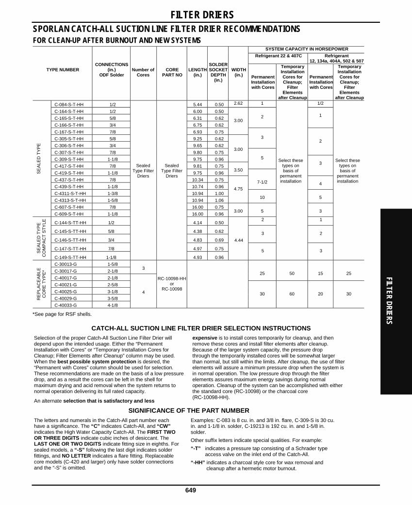
FILTER DRIERS SPORLAN CATCH-ALL SUCTION LINE FILTER DRIER RECOMMENDATIONSFOR CLEAN-UP AFTER BURNOUT AND NEW SYSTEMS
SYSTEM CAPACITY IN HORSEPOWER
Refrigerant 22 & 407C Refrigerant 12, 134a, 404A, 502 & 507
TYPE NUMBER
CONNECTIONS (in.)
ODF Solder
Number of Cores
CORE PART NO
LENGTH(in.)
SOLDERSOCKETDEPTH
(in.)
WIDTH(in.)
PermanentInstallationwith Cores
Temporary Installation Cores for Cleanup;
Filter Elements
after Cleanup
PermanentInstallationwith Cores
Temporary Installation Cores for Cleanup;
Filter Elements
after Cleanup
C-084-S-T-HH 1/2 5.44 0.50 2.62 1 1/2
C-164-S-T-HH 1/2 6.00 0.50
C-165-S-T-HH 5/8 6.31 0.62
C-166-S-T-HH 3/4 6.75 0.62
2
1
C-167-S-T-HH 7/8 6.93 0.75
3.00
C-305-S-T-HH 5/8 9.25 0.62
C-306-S-T-HH 3/4 9.65 0.62
3
C-307-S-T-HH 7/8 9.80 0.75
2
C-309-S-T-HH 1-1/8 9.75 0.96
3.00
C-417-S-T-HH 7/8 9.81 0.75
5
C-419-S-T-HH 1-1/8 9.75 0.96
3.50
3
C-437-S-T-HH 7/8 10.34 0.75
C-439-S-T-HH 1-1/8 10.74 0.96
7-1/2 4
C-4311-S-T-HH 1-3/8 10.94 1.00
C-4313-S-T-HH 1-5/8 10.94 1.06
4.75
10 5
C-607-S-T-HH 7/8 16.00 0.75
SE
ALE
D T
YP
E
C-609-S-T-HH 1-1/8 16.00 0.96
3.00
5
3
C-144-S-TT-HH 1/2 4.14 0.50 2 1
C-145-S-TT-HH 5/8 4.38 0.62
C-146-S-TT-HH 3/4 4.83 0.69
3
2
C-147-S-TT-HH 7/8 4.97 0.75
SE
ALE
D T
YP
E
CO
MP
AC
T S
TY
LE
C-149-S-TT-HH 1-1/8
Sealed Type Filter
Driers
Sealed Type Filter
Driers
4.93 0.96
4.44 5
Select these types on basis of
permanent installation
3
Select these types on basis of
permanent installation
C-30013-G 1-5/8
C-30017-G 2-1/8
3
C-40017-G 2-1/8
25
50
15
25
C-40021-G 2-5/8
C-40025-G 3-1/8
C-40029-G 3-5/8 RE
PLA
CE
AB
LE
CO
RE
TY
PE
*
C-40033-G 4-1/8
4
RC-10098-HH or
RC-10098
30
60
20
30
*See page for RSF shells.
CATCH-ALL SUCTION LINE FILTER DRIER SELECTION INSTRUCTIONS
Selection of the proper Catch-All Suction Line Filter Drier will depend upon the intended usage. Either the “Permanent Installation with Cores” or “Temporary Installation Cores for Cleanup; Filter Elements after Cleanup” column may be used. When the best possible system protection is desired, the “Permanent with Cores” column should be used for selection. These recommendations are made on the basis of a low pressure drop, and as a result the cores can be left in the shell for maximum drying and acid removal when the system returns to normal operation delivering its full rated capacity.
An alternate selection that is satisfactory and less
expensive is to install cores temporarily for cleanup, and then remove these cores and install filter elements after cleanup. Because of the larger system capacity, the pressure drop through the temporarily installed cores will be somewhat larger than normal, but still within the limits. After cleanup, the use of filter elements will assure a minimum pressure drop when the system is in normal operation. The low pressure drop through the filter elements assures maximum energy savings during normal operation. Cleanup of the system can be accomplished with either the standard core (RC-10098) or the charcoal core (RC-10098-HH).
SIGNIFICANCE OF THE PART NUMBER
The letters and numerals in the Catch-All part number each have a significance. The “C” indicates Catch-All, and “CW” indicates the High Water Capacity Catch-All. The FIRST TWO OR THREE DIGITS indicate cubic inches of desiccant. The LAST ONE OR TWO DIGITS indicate fitting size in eighths. For sealed models, a “-S” following the last digit indicates solder fittings, and NO LETTER indicates a flare fitting. Replaceable core models (C-420 and larger) only have solder connections and the “-S” is omitted.
Examples: C-083 is 8 cu. in. and 3/8 in. flare, C-309-S is 30 cu. in. and 1-1/8 in. solder, C-19213 is 192 cu. in. and 1-5/8 in. solder.
Other suffix letters indicate special qualities. For example:
“-T” indicates a pressure tap consisting of a Schrader type access valve on the inlet end of the Catch-All.
“-HH” indicates a charcoal style core for wax removal and cleanup after a hermetic motor burnout.
FILTER DRIERS
649

FILT
ER D
RIER
S REPLACEABLE CORES AND PLEATED FILTER ELEMENTS
Cores for replaceable core type filter-driers are molded with the same desiccants that are used in the popular sealed filter-driers.
Cores are individually packed in metal cans, fully activated and hermetically sealed against moisture and dirt.
Filter elements are dried and packed in individuals sealed metal cans. This method of packaging prevents the element from picking up moisture from the atmosphere
Each can contains a “triple gasket” consisting of a new end plate gasket, an end plate gasket for certain competitive filter-driers, and a core gasket where desired. See the specifications on Page * for the number of cores required for each type drier.
RC-4864 — Activated Core — Order as separate item —Fits types C-480 thru C-19200 Series Shells. This is the standard core suitable for most installations in the liquid or suction line.
RCW-48 — High Water Capacity Core — Order as separate item — Fits types C-480 thru C-19200 Series shell. Designed specially for use with POE lubricants. This core should be used on systems that have a ruptured water cooled condenser, or that have been exposed to the atmosphere, or for some reason have a high amount of moisture in the system.
RC-4864-HH— Activated Charcoal Core— Order as separate item — Fits types C-480 thru C-19200 Series Shells. This core should be used for wax removal, and for clean-up of systems that have had a hermetic motor burnout.
RPE-48-BD — Filter Element — Order as separate item — Fits types C-480 thru C-19200 Series Shells and Replaceable Suction Filter (RSF) Shells. This element should be used in RSF shells installed in the suction line to obtain the lowest possible pressure drop. In cleaning up a system after a hermetic motor burnout, cores should be used first. After clean-up, the filter element should be installed.
RC-10098 —Activated Core — Order as a separate item — Fits types C-30,000 and C-40,000 Series Shells. This is the standard core suitable for liquid and suction line applications.
RCW-100 — High Water Capacity Core — Order as separate item — Fits types C-30,000 and C-40,000 Series Shells. Designed specially for use with POE lubricants. This core should be used on systems that have a ruptured water cooled condenser, or that have been exposed to the atmosphere, or for some reason have a high amount of moisture in the system.
RC-10098-HH — Activated Charcoal Core — Order as separate item — Fits types C-30,000 and C-40,000 Series Shells. This core should be used for wax removal, and for clean-up of systems that have had a hermetic motor burnout.
RPE-100 — Filter Element — Order as separate item — Fits types C-30,000 and C-40,000 Series Shells. This filter element should be used in the suction line to obtain the lowest possible pressure drop after cores were used for system clean-up.
HH STYLE CATCH-ALL FOR WAX REMOVAL
U.S. PATENT NUMBER 3,407,617
Small amounts of wax are often a problem on low temperature systems. Even well engineered systems frequently contain minute quantities of wax which are sufficient to clog expansion valve screens or cause sticking of the valve. Sporlan has developed a special blend of desiccants including activated charcoal which removes small amounts of wax in the liquid line before this wax can cause trouble at the expansion valve. These Catch-All Filter Driers have been very successful in correcting trouble jobs in the field.
By installing HH Style Catch-All Filter Driers in the liquid line of all low temperature systems these wax problems can be entirely prevented. In addition to their wax removal ability, these filter driers will remove all of the other harmful contaminants that the standard filter driers remove.
The following Catch-All Filter Driers are available with the HH core to meet the needs of low temperature systems. For dimensions, refer to the specifications for standard filter driers or consult Bulletin 40-10.
PART NO. CONNECTIONS
(in.) PART NO. CONNECTIONS
(in.)
C-052-HH 1/4 SAE Flare C-303-HH 3/8 SAE Flare
C-082-HH 1/4 SAE Flare C-304-HH 1/2 SAE Flare
C-083-HH 3/8 SAE Flare C-304-S-HH 1/2 ODF Solder
C-162-HH 1/4 SAE Flare C-305-HH 5/8 SAE Flare
C-163-HH 3/8 SAE Flare C-305-S-HH 5/8 ODF Solder
C-163-S-HH 3/8 ODF Solder C-414-HH 1/2 SAE Flare
C-164-HH 1/2 SAE Flare C-415-HH 5/8 SAE Flare
C-164-S-HH 1/2 ODF Solder C-417-S-HH 7/8 ODF Solder
C-165-HH 5/8 SAE Flare RC-4864-HH
C-165-S-HH 5/8 ODF Solder RC-10098-HH
Replaceable Core
FILTER DRIERS
650

FILTER DRIERS REVERSIBLE HEAT PUMP FILTER-DRIER
DESIGN BENEFITS
• A short overall length for easy installation.
• Drier operates in either flow direction with low pressure drop.
• Proven metal check valves used in construction — no synthetic materials.
• The Sporlan dependable molded core used for maximum filtration ability. When the flow direction reverses, dirt already collected remains in the filter-drier.
• A carefully engineered blend of desiccants for maximum water capacity and acid removal ability. The HPC-160-HH Series also has the HH style core with activated charcoal which offers maximum ability to remove oleoresin and other reactive chemical constituents in the oil.
• Same rugged construction as used in the Catch-All.
SPECIFICATIONS -FOR NEW INSTALLATIONS AND HFC SYSTEM USE
Flow CapacityTons at 1 psi
ΔP Water Capacity
Dimensions
Refrigerant
Liquid Capacity Ounces (Wt.)
@100°F
R-22 Drops at 60 ppm
R-410A Drops at 80 ppm*
Part No
Connection Size Inches
Selection Recommendations
Tons
OverallLengthInches
DiameterInches
R-22
R-410A
75°F 125°F 75°F 125°F R-22
R-410A
HPC-103 3/8 Flare 6.75
HPC-103-S 3/8 Solder 5.88 3.4
3.3
HPC-104 1/2 Flare 6.94
HPC-104-S 1/2 Solder
1 thru 5 6.00
3.00
4.5
4.4
215
176
171
105
12.2
10.6
FOR CLEAN-UP AFTER BURNOUT
Dimensions
Water Capacity Refrigerant 22
Drops at 60 ppm Part No
Connection Size
Inches
Selection Recommendations
Tons
OverallLengthInches
DiameterInches
Flow CapacityR-22 Tons at 1
psi ΔP
75°F
125°F
Liquid Capacity Ounces (Wt.) R-22 @ 100°F
HPC-163-HH 3/8 Flare 1 thru 5 7.78 3.00 3.7 93 81 14.5
HPC-163-S-HH 3/8 Solder 1 thru 5 6.92 3.00 3.7 93 81 14.5
HPC-164-HH 1/2 Flare 1 thru 5 7.95 3.00 4.0 93 81 14.5
HPC-164-S-HH 1/2 Solder 1 thru 5 7.07 3.00 4.0 93 81 14.5
HPC-165-HH 5/8 Flare 1 thru 5 8.28 3.00 4.9 93 81 14.5
HPC-165-S-HH 5/8 Solder 1 thru 5 7.35 3.00 4.9 93 81 14.5
UL and ULc Listed — Guide-SMGT-File No. SA-1756A & B. Core volume is 10 cubic inches for HPC-100 Series and 14 cubic inches for the HPC-160-HH Series. Core surface filtering area is 18 sq. in. for the HPC-100 Series and 26 sq. in. for the HPC-160-HH Series. HPC-100 Series are rated for 650 psig; HPC-160-HH have a 500 psig rating. *As of this printing, ARI has not established an EPD for R-410A.
FILTER DRIERS
651

FILT
ER D
RIER
S SUCTION FILTER WITH THE EXCLUSIVE BI-DIRECTIONAL FEATURE
DESIGN BENEFITS • Protects the compressor from dirt
• A relief device opens if the filter plugs
• Suitable for use with all brazing alloys
• Maximum corrosion resistance
• Full flow design for low pressure drop
• Complete line of sizes
Sporlan offers an exclusive concept in Suction Filter design — a filter which is Bi-directional. When flow is in one direction, the bypass relief feature is active. If the pressure drop across the element becomes excessive the bypass relief will open slightly to maintain sufficient gas flow and assure proper cooling of the hermetic motor.
When the Suction Filter is installed with flow in the opposite direction, the bypass relief feature is inactive and will never open, regardless of the increase in pressure drop. The “-T” in the part number indicates that these models are equipped with an access valve to permit pressure drop readings. The access valve will be operational provided the Suction Filters are installed with the bypass feature inactive.
SPECIFICATIONSTypes with bypass relief feature (Bi-directional Flow)
Part No Dimensions WITHOUT AccessValve
WITH Access Valve CONNECTIONS (in) FILTER AREA Sq In Overall Length Inches SOCKET DEPTH Inches SHELL DIAMETERInches
SF-283-F — 3/8 SAE Flare 28 8.78 — 3.00— SF-285-T 5/8 ODF Solder 28 8.34 0.62 3.00— SF-286-T 3/4 ODF Solder 28 8.79 0.69 3.00— SF-287-T 7/8 ODF Solder 28 8.93 0.75 3.00— SF-289-T 1-1/8 ODF Solder 28 9.51 0.91 3.00— SF-489-T 1-1/8 ODF Solder 48 12.42 0.91 3.00— SF-4811-T 1-3/8 ODF Solder 48 13.10 0.97 3.00— SF-4813-T 1-5/8 ODF Solder 48 13.44 1.09 3.00
Types without bypass relief feature (Single Flow Direction)Part No Dimensions
WITHOUT AccessValve
WITH Access Valve CONNECTIONS (in) FILTER AREA Sq In Overall Length Inches SOCKET DEPTH Inches SHELL DIAMETERInches
SF-114 — 1/2 ODF Solder 11 4.36 0.50 2.00SF-114-F — 1/2 ODF Flare 11 5.25 — 2.00SF-115 — 5/8 ODF Solder 11 4.60 0.62 2.00SF-115-F — 5/8 ODF Flare 11 5.56 — 2.00— SF-6417-T 2-1/8 ODF Solder 388 1094 1.24 4.75— SF-6421-T 2-5/8 ODF Solder 388 1094 1.38 4.75
SELECTION RECOMMENDATIONSPart No NOMINAL SYSTEM HORSEPOWER* Refrigerant
WITHOUT Access Valve WITH Access Valve CONNECTIONS (in) 12, 134a, 404A, 502, 507 22, 407CSF-114 — 1/2 ODF 1/2 1SF-114-F — 1/2 SAE 1/2 1SF-115 — 5/8 ODF 1 2SF-115-F — 5/8 SAE 1 2SF-283-F — 3/8 SAE 1/2 1— SF-285-T 5/8 ODF 1-1/2 4— SF-286-T 3/4 ODF 1-1/2 5— SF-287-T 7/8 ODF 3 7-1/2— SF-289-T 1-1/8 ODF 5 7-1/2— SF-489-T 1-1/8 ODF 5 10— SF-4811-T 1-3/8 ODF 5 12— SF-4813-T 1-5/8 ODF 7 15— SF-6417-T 2-1/8 ODF 20 55— SF-6421-T 2-5/8 ODF 30 60*Use R-502 horsepower recommendations for R-502A & B and R-508A. Use R-12 horsepower recommendations for R-501A & B and R-509A. Ratings are in accordance with ARI Standard 730.
FILTER DRIERS
652

FILTER DRIERS REPLACEMENT SUCTION FILTER
The Replaceable Suction Filter shell, used with RPE-48-BD pleated filter element, is designed to be installed in the suction line of new systems to remove resident contaminants.
DESIGN BENEFITS:
• Low pressure drop
• Can be used with desiccant cores for clean-up after burnout
• Various fitting sizes up to 3-1/89line size
• Access valve supplied for pressure drop measurement or charging
HOW IT’S USED – Sporlan Replaceable Suction Filters are installed in the suction line of air conditioning systems to remove contaminants that may be in the system at start-up. The Replaceable Suction Filter has large fittings permitting the use of a small shell on a system with a large line size, resulting in considerable economy. The angle construction is suitable for flow in either direction, which results in easy installation even on compact racks. The Replaceable Suction Filters should be used with cores for cleaning up a system after a hermetic motor burnout. Select the RC-4864, RC-4864-HH or RCW-48 replaceable cores. After clean-up, install RPE-48-D elements in the shells.
SELECTION – The table below gives information for choosing the proper model for a given system. The filter elements are supplied in hermetically sealed metal cans.
SELECTION RECOMMENDATIONS WITH FILTER ELEMENTSNOMINAL SYSTEM HORSEPOWER
Refrigerant
PART NO
CONNECTIONS Inches
ODF Solder 12 & 134a 22 & 407C 404A, 502 & 507
NO. OF FILTER
ELEMENTS
NO. OF CORES
OVERALL LENGTH Inches
RSF-487-T 7/8 7 10 10 9.30 RSF-489-T 1-1/8 8 15 12 9.37
RSF-4811-T 1-3/8 10 20 15 9.60 RSF-4813-T 1-5/8 12 25 20 9.60 RSF-4817-T 2-1/8 20 35 25 9.37 RSF-4821-T 2-5/8 25 50 35
One
RPE-48-BD
One
RC-4864 or
RC-4864-HH
9.75 RSF-9617-T 2-1/8 20 40 30 14.96 RSF-9621-T 2-5/8 30 50 40 15.43 RSF-9625-T 3-1/8 40 80 55
Two RPE-48-BD
Two RC-4864
or RC-4864-HH 15.12
Safety screen Part No.: 6171-S is required when cores are used in the RSF shell. Remove the screen when RPE-48-BD elements are used. UL and ULc Listed — Guide-SMGT-File No. SA-1756A & B.
ACID TEST KIT
PART NO TA-1 One Time Acid Test Kit
FILTER DRIERS
653

MOIS
TURE
AND
LIQ
UID
INDI
CATO
RS
See -All Moisture and Liquid Indicators offers these 8 outstanding benefits
1. The See•All Moisture and Liquid Indicator provides a true moisture indication for Refrigerants 12, 134a, 22, 404A, 407C, 410A, 502 and 507. The See All is also suitable for Refrigerants 401A & B, 402A & B, 408A and 409A. The dark green indicates dry and a bright yellow indicates wet. The one indicator avoids the confusion found in models with two elements. You cannot pick the wrong element when checking the moisture content of the system.
2. RELIABLE and ACCURATELY CALIBRATED COLOR CHANGE POINTS. The See•All Moisture and Liquid Indicator is accurately calibrated in parts per million of moisture for each refrigerant. All moisture indicators change color on the basis of relative saturation of the refrigerant. Therefore, liquid line temperature must be considered if an accurate calibration is to be obtained. A color chart is part of the label, for easy comparison.
3. COLOR CHANGES ARE EASILY DISTINGUISHED and REVERSIBLE. The indicator’s color differs so widely between WET and DRY conditions that there is no possibility of confusion between the two. Colors will reverse as often as moisture concentration in the system changes.
4. LARGE FULL VIEW SIGHT GLASS. The See•All Moisture and Liquid Indicator has an extra large crystal clear sight glass for viewing the refrigerant. Bubbles indicate a shortage of refrigerant or a restriction in the liquid line.
5. INDICATOR PROTECTED from DISCOLORATION and DIRT. The indicator is protected by a filter pad and screen. This prevents washing of the indicator by the refrigerant and protects it from system contamination and turbulence.
6. REPLACEABLE INDICATOR ELEMENT. The color indicator paper can be changed on the new fused glass models without removing the See•All from the line. Replacement is thru the bottom (see SA-14SU below). Request the K-SA-4 kit.
7. DISASSEMBLY OF THE SMALLER SIZES NOT REQUIRED.The extended steel fittings on solder models in the smaller sizes make it unnecessary to disassemble for installation since steel conducts onl one eighth as much heat as copper.
8. A DOUBLE DUTY PLASTIC CAP is supplied to keep the glass free from dust, dirt, and grease. It also permits the service engineer to use his own discretion concerning instructions to his customers on observing the See•All Moisture and Liquid Indicator.
Specifications
MALE FLARE FEMALE & MALE
FLARE MALE FLARE X
SWIVEL NUT SWIVEL NUT X SWIVEL NUT
FEMALE FLARE X SWIVEL NUT
SWIVEL NUT X ODF SOLDER
ODF SOLDER CONNEC -TION SIZES Inches
Part No
Overall Length Inches
Part No
Overall Length Inches
Part No
Overall Length Inches
Part No
Overall Length Inches
Part No
Overall Length Inches
Part No
Overall Length Inches
Part No
Overall Length Inches
1/4 SA-12 2.87 SA-12FM 2.56 — — — — — — — — SA-12S
3/8 SA-13 3.37 SA-13FM 2.97 SA-13U 3.64 SA-13UU 3.95 SA-13UU 3.19 SA-13SU 4.19 SA-13S 4.62
1/2 SA-14 3.81 SA-14FM 3.44 SA-14U 4.13 SA-14UU 4.50 SA-14UU 3.75 SA-14SU 4.62 SA-14S
5/8 SA-15 4.13 — — SA-15U 4.44 SA-15UU 4.75 — — SA-15SU 4.89 SA-15S 4.87
7/8 — — — — — — — — — — — — SA-17S
1-1/8 — — — — — — — — — — — — SA-19S 6.31
1-3/8 — — — — — — — — — — — — SA-211
1-5/8 — — — — — — — — — — — — SA-213
2-1/8 — — — — — — — — — — — — SA-217
7.97
Listed by Underwriters’ Laboratories, Inc. - Guide SEYW - File No. SA3182 Maximum Rated Pressure – 650 psi. Overall width is: 1.31 in. for 1/4 in. and 3/8 in. sizes, 1.58 in. for 1/2 in. and 5/8 in. sizes, and 1.38 in. for 7/8 in. and 1-1/8 in. sizes. Most solder connections can be used as male fittings as well as female fittings. The 1/4 in. ODF is 3/8 in. ODM, the 3/8 in. ODF is 1/2 in. ODM, the 1/2 in. ODF is 5/8 in. ODM, and the 5/8 in. ODF is 3/4 in. ODM. Models with female flare and/or swivel nut connections are supplied with a copper gasket in the fitting.
Moisture Content PPM
REFRIGERANT 12 22 134a 502 404A & 507 407C 410A SEE•ALL
SHOWS
LIQUID LINE TEMP 75° F 100° F 75° F 100° F 75° F 100° F 75° F 100° F 75° F 100° F 75° F 75° F
Green Dry Below 5 Below 10 Below 30 Below 45 Below 50 Below 80 Below 10 Below 20 Below 15 Below 30 Below 120 Below 75Chartreuse CAUTION 5-15 10-30 30-90 45-130 50-200 80-225 10-45 20-65 15-90 30-140 120-280 75-150
Yellow WET Above 15
Above 30
Above 90
Above 130
Above 200
Above 225
Above 45
Above 65
Above 90
Above 140
Above 280
Above 150
NOTE: Change or add Catch-All Filter-Drier when paper turns from green to chartreuse.
MOISTURE AND LIQUID INDICATORS
654

DISCHARGE BYPASS VALVES SPORLAN DISCHARGE BYPASS VALVES
The Sporlan line of discharge bypass valves are designed to provide an economical method of compressor capacity control in place of cylinder Unloader or to handle unloading requirements below the last step of cylinder unloading. These modulating control valves automatically bypass the required amount of discharge gas to the low side to maintain the desired minimum evaporator pressure. The valves are applicable on any refrigeration or air conditioning system that operates during periods of low load, which can result in coil icing or short cycling. These valves respond to downstream pressure changes and open when the evaporator pressure falls below the valve setting. At normal loads and evaporator conditions, the valve remains closed and the system operates in a conventional manner.
The DR line of valves consists of three basic types of valves: the adjustable models, the adjustable remote bulb models, andthe non-adjustable models.
The SHGB valves are adjustable and pilot operated with a solenoid stop feature that eliminates the need for a hot gas solenoid valve. They were developed for use on larger capacity systems.
APPLICATION — The discharge bypass valve is normally applied in a branch line off the discharge line. To allow system pump down control, a solenoid valve or hand valve must be installed upstream of the discharge DR type bypass valves. The bypassed hot gas can enter the low side at several locations; however, two of the possible locations are preferred because of superior operating performance: into the side connection of a Sporlan side connection distributor or directly into the suction line. By using the side connection distributor method, the system TEV will act as a desuperheating valve to keep the compressor suction temperature below the recommended maximum temperature published by the compressor manufacturer. When the hot gas is bypassed directly into the suction line, an auxiliary desuperheating TEV may be required.
SELECTION and CAPACITY RATINGS —The capacities given in the table below are valve hot gas capacities and not the capacities of the system on which the valve is to be applied. To select a valve, first determine the compressor capacity at the minimum allowable evaporating temperature.
Then the discharge bypass valve must supply the difference between this compressor capacity and the minimum evaporator load at which the system is to be operated. The valve pressure setting will be that pressure at which the bypass valve must start to open.
Connections – (Standard Connections are in BOLD type). ADRS(E)-2 – 3/8 in., 1/2 in., 5/8 in. ODF Solder or 3/8 in., 1/2 in., 5/8 in. SAE Flare ADRP(E)-3 – 1/2 in., 5/8 in. ODF Solder on 1/2 in., 5/8 in. SAE Flare ADRHE-6 & DRHE-6 – 5/8 in., 7/8 in., 1-1/8 in. ODF Solder SHGB(E)-8 – 7/8 in. ODF, 1-1/8 in. ODF Solder SHGB(E)-15 – 1-1/8 in., 1-3/8 in. ODF Solder
Valves with ODF solder connections are supplied standard with 1/4 in. ODF external equalizer, 1/4 in. SAE Flare external equalizer available on special order. Pilot operated models are supplied with 1/4 in. SAE external equalizer.
DISCHARGE BYPASS VALVES
655

DISC
HARG
E BY
PASS
VAL
VES
SPORLAN DISCHARGE BYPASS VALVESDISCHARGE BYPASS VALVE CAPACITIES — Tons
Capacities based on 6° F evaporator temperature change from closed to rated opening (does not apply to pilot operated models), discharge temperature 30° F above isentropic compression, 100° F condensing temperature, 0° F subcooling, 25° F superheat at the compressor and includes both the hot gas bypassed and liquid refrigerant for desuperheating, regardless of whether the liquid is fed through the system thermostatic expansion valve or auxiliary desuperheating thermostatic expansion valve.
VALVE TYPE & ADJUSTMENT RANGE (psig) ADRI-1-1/4
ADRIE-1-1/4 ADRS-2
ADRSE-2 ADRP-3
ADRPE-3
ADRHE-6 DRHE-6
(Adjustable “Remote Bulb” Model)*SHGB-8
SHGBE-8SHGB-15
SHGBE-15
REFRIGERANT
MINIMUM ALLOWABLE
EVAPORATOR TEMPERATURE 0/55 0/75 0/100 0/30 0/80 0/30 0/80 0/30 0/80 25/35 32/44 55/70 65/80 0/100 0/75
40 — 0.58 0.53 — 3.51 — 5.99 — 9.16 — — 1 9.8 — 15.7 58 26 0.44 0.64 0.54 — 3.57 — 6.26 — 9.90 — — 1 6.9 — 15.9 62 0 0.63 0.60 0.49 3.90 3.66 7.38 6.61 13.9 10.9 — — — — 16.2 66
22
–20 0.59 0.50 0.44 3.75 3.65 7.45 6.64 14.1 11.0 — — — — 16.2 69 40 0.40 0.43 0.34 — 2.67 — 4.94 — 9.34 9.64 — — — 10.9 41 26 0.41 0.39 0.32 2.60 2.44 4.95 4.42 9.36 7.26 8.31 — — — 10.9 43
134a
0 0.38 0.31 0.28 2.46 — 4.89 — 9.41 — — — — — 11.0 46 40 0.45 0.48 0.39 — 2.76 — 4.95 — 7.99 — 11.0 — — 12.3 52 26 0.47 0.45 0.37 2.97 2.79 5.66 5.04 10.7 8.26 — 9.49 — — 1 .4 52
401A
0 0.44 0.36 0.32 2.83 2.74 5.62 5.01 10.8 8.32 — — — — 12.5 56 40 — — 0.54 — — — — — — — — — — 17.3 — 26 — 0.65 0.60 — 3.91 — 6.66 — 10.3 — — — — 17.7 63 0 0.66 0.72 0.57 — 4.00 — 7.16 — 11.7 — — — — 17.9 63
402A
–20 0.69 0.63 0.52 4.22 4.04 8.11 7.33 15.3 12.2 — — — — 18.0 64 40 — — 0.55 — — — — — — — — — — 17.5 — 26 — 0.67 0.60 — 3.91 — 6.70 — 10.4 — — — 21.4 17.7 64 0 0.67 0.71 0.56 — 4.00 — 7.16 — 11.7 — — — — 17.9 65
404A
–20 0.68 0.61 0.51 4.17 4.02 8.08 7.28 15.3 12.1 — — — — 17.9 65 40 — 0.78 0.65 — 4.25 — 7.50 — 12.1 — — 22.9 — 18.6 74 26 0.61 0.78 0.63 — 4.25 — 7.50 — 12.1 — 19.3 — — 18.7 75 0 0.74 0.68 0.56 4.51 4.31 8.63 7.81 16.3 13.0 — — — — 18.9 76
407C
–20 0.68 0.56 0.50 4.33 4.23 8.64 7.71 16.5 12.9 — — — — 19.1 77 40 — — 0.46 — 3.14 — 5.28 — 7.85 — — — 19.2 14.3 — 26 — 0.56 0.49 — 3.19 — 5.51 — 8.55 — — — 16.6 14.5 55 0 0.55 0.57 0.46 3.58 3.28 6.64 5.90 12.5 9.62 — — — — 14.7 59
502
–20 0.55 0.59 0.41 3.43 3.30 6.68 6.00 12.6 9.91 — — — — 14.8 61 40 — — 0.53 — — — — — — — — — — 17.4 — 26 — 0.65 0.59 — 3.87 — 6.60 — 10.2 — — — — 17.7 64 0 — 0.71 0.57 — 3.96 — 7.09 — 11.5 — — — — 17.8 64
507
–20 0.69 0.62 0.52 4.17 4.00 8.02 7.25 15.2 12.0 — — — — 17.9 65
PART NO DESCRIPTION
ADRS-20/30ODF ADRS-2 0/30 4 ODF
ADRS-20/305ODF ADRS-2 0/30 5 ODF
ADRSE-20/304ODF ADRSE-20/304ODF
ADRSE-20/305ODF ADRSE-20/305ODF
ADRS-20/804ODF ADRS-2 0/80 4 ODF
ADRS-20/805ODF ADRS-2 0/80 5 ODF
ADRSE-20/803ODF ADRSE-20/803ODF
ADRSE-20/804ODF ADRSE-20/804ODF
ADRSE-20/805ODF ADRSE-20/805ODF
ADRP-30/304ODF ADRP-3 0/30 4 ODF
ADRP-30/305ODF ADRP-3 0/30 5 ODF
ADRPE-30/304ODF ADRPE-30/304ODF
ADRPE-30/305ODF ADRPE-30/305ODF
ADRP-30/804ODF ADRP-3 0/80 4 ODF
ADRP-30/805ODF ADRP-3 0/80 5 ODF
ADRPE-30/804ODF ADRPE-30/804ODF
ADRPE-30/805ODF ADRPE-30/805ODF
ADRHE-60/305ODF ADRHE-60/305ODF
PART NO DESCRIPTION
ADRHE-60/805ODF ADRHE-6 0/80 5 ODF
ADRHE-60/807ODF ADRHE-6 0/80 7 ODF
ADRHE-60/809ODF ADRHE-6 0/80 9 ODF
DRHE-6-55/70AR7X7 DRHE-6-55/70AR 7 ODF
DRHE-6-55/70AR9X9 DRHE-6-55/70AR 9 ODF
SHGBE-8-0/1009ODF SHGBE-8-0/100 9 ODF LESS COIL
SHGBE-8-0/1007ODF SHGBE-8-0/100 7 ODF LESS COIL
SHGB-8-0/107ODF SHGB-8-0/100 7 ODF LESS COIL
SHGB-8-0/1009ODF SHGB-8-0/100 9 ODF LESS COIL
SHGB-15-0/759ODF SHGB-15-0/75 9 ODF LESS COIL
SHGB-15-0/7511ODF SHGB-15-0/75 11 ODF LESS COIL
SHGBE-15-0/759ODF SHGBE-15-0/75 9 ODF LESS COIL
SHGBE-15-0/7511 ODF SHGBE-15-0/75 11 ODF LESS COIL
DISCHARGE BYPASS VALVES
656

PRESSURE REGULATING VALVES CRANKCASE PRESSURE REGULATING VALVES
Crankcase Pressure Regulating Valves are designed to prevent overloading of the compressor motor by limiting the crankcase pressure to a predetermined maximum value during and after a defrost cycle or a normal shutdown period. These valves automatically throttle the vapor flow from the evaporator until the compressor can handle the load.
Sporlan manufactures five adjustable models… CRO-4, CRO-6, CROT-6, CRO-10 and CROT-10…all models respond only to their outlet pressure and modulate to prevent the suction pressure at the compressor from rising above the valve setting. Since these valves are adjustable, the setting may be altered to suit the specific system requirements. SELECTION and CAPACITY RATINGS
The ratings for these valves vary depending on three items: design suction pressure after pull down, maximum allowable suction pressure recommended by the compressor or unit manufacturer (this is the valve setting), and pressure drop across the valve. The difference between the design suction pressure and the valve setting determines how much of the valve stroke is used. Therefore, the valve setting should be kept as high as possible without exceeding the recommendation of the compressor or unit manufacturer.
PART NO* SPORLAN MODEL
CRO-4-0/20 4X4 ODF LS
CROT-10 30/110 9 ODF WS
CROT-10 30/110 11 ODF WS
CROT-10 0/6011ODF WS
CROT-10 0/60 1-1/8"ODF
CROT-10 0/60 7 ODF WS
CROT-10 30/110 7 ODF WS
CROT-12-65/225 9 ODF
CROT-15-65/225 11 ODF
CROT-6 0/60 5 ODF WS
CROT-6 0/60 1/2" SAE
CROT-6 0/60 5/8" SAE
CROT-6 0/60 7 ODF WS
CROT-6 30/110 5 ODF WS
CROT-6 30/110 7 ODF WS
*( ) Please contact your local Carlyle Certified Refrigeration Partner or RCD Customer Service for P/N and Pricing.
HEAD PRESSURE CONTROL VALVES
Sporlan Head Pressure Control for systems with air cooled condensers can be accomplished with several valve types or combinations. The valve types are: LAC-4, OROA-5, LAC-5, LAC-10, ORI/ORD combination and the ORIT/CROT combination.
The LAC, OROA, ORI and ORIT are designed for application in the liquid line and should not be applied in the discharge line for any reason. Compressor pulsations can greatly shorten the life of the valves. If any of the valves are applied in any manner other than described here, the Sporlan warranty is void.
PART NO* SPORLAN MODEL
ORD-4-20 5/8 ODF
ORD-4-20 7/8 ODF
ORD-4-25 5/8 ODF
ORD-4-30 5/8 ODF
ORD-4-35 5/8 ODF
ORI-10 65/225 1-1/8"
ORI-10 65/225 1-3/8"
ORI-10 65/225H 7ODF WS
ORI-10 65/225H 11 ODF WS
ORI-6 65/225 5/8" WS
ORI-6 0/50 5 ODF WS
ORI-6 65/225 7/8" WS
ORI-6 65/225H 9ODF WS
ORIT-15-65/225 11 ODF
ORIT-20-65/225 13 ODF
PART NO* SPORLAN MODEL
OROA-5-100 5/8 ODF WS
OROA-5-100 7/8 ODF WS
OROA-5-150 7/8 ODF WS
OROA-5-180 5/8 ODF WS
OROA-5-180 7/8 ODF WS
OROA-5-220 5/8 ODF WS
IMPORTANT NOTES: WS - With Strainer LS - Less Strainer
PART NO* SPORLAN MODEL
LAC-10-100 11X7 ODF LS
LAC-10-100 11X9 ODF LS
LAC-4-100 1/2 ODF LS
LAC-4-180 3/8 0DF LS
LAC-4-190 1/2 ODF LS
LAC-4-210 1/2 ODF LS
LAC-4-240 1/2 ODF LS
LAC-5-100 1-1/8 ODF LS
LAC-5-210 5/8 ODF WS
LAC-5-75 1/2 ODF LS
PART NO* SPORLAN MODEL
CROT-12-65/225 9 ODF
CROT-15-65/225 11ODF
*( ) Please contact your local Carlyle Certified Refrigeration Partner or RCD Customer Service for P/N and Pricing.
PRESSURE REGULATING VALVES
657

PRES
SURE
REG
ULAT
ING
VALV
ES
DEFROST DIFFERENTIAL PRESSURE REGULATING VALVESADJUSTMENT RANGE AND PRESSURESETTINGS
All defrost differential valves are set by turning the adjusting stem located under the cap on the pilot differential valve. The adjustment range is 5 to 50 psig. The (O)LDR has a factory setting of 18 psid and the DDR-20 has a factory setting of 30 psid. Turning the stem clockwise increases the setting, counterclockwise decreases the setting.
DDR-20 VALVE OPERATION
The DDR-20 is designed to create a differential pressure between its inlet (discharge) pressure and the receiver pressure. A solenoid bypass feature is incorporated in the valve so that the valve can be made to go full open when there is no need for a differential to be created. Energizing the solenoid coil opens the valve fully. LOCATION
The (O)LDR valve is located between the receiver and the liquid header. The DDR-20 is located in the discharge line before the condenser.
PART NO* SPORLAN MODEL
OLDR-15 11ODF LESS COIL
OLDR-15 9ODF LESS COIL
OLDR-20 13ODF LESS COIL
OLDR-20 17ODF LESS COIL
DDR-20 13 ODF LESS COIL
*( ) Please contact your local Carlyle Certified Refrigeration Partner or RCD Customer Service for P/N and Pricing.
EVAPORATOR PRESSURE REGULATING VALVES The Sporlan line of evaporator pressure regulating (EPR) valves are designed to provide an accurate and economical means of balancing system capacity and load requirements during “low” loads and/or while maintaining different evaporator conditions on multi-temperature evaporator systems. These valves control evaporator temperature by maintaining evaporator pressure. As the evaporator load increases the ORI valves will Open on Rise of I nlet pressure above the valve’s setting to provide more flow capacity to meet the evaporator load. When the evaporator load decreases the valves will modulate closed to maintain the pressure setting of the valve. Sporlan offers a number of EPR valve types in various sizes, and with optional features to accommodate almost any industry requirement. For more complete information on any of the EPR valve types see your Sporlan Wholesaler or contact your Sporlan Sales Engineer. APPLICATIONS
• Maintain minimum evaporator temperature to avoid frost on air coils and provide improved humidity control
• Evaporator temperature control for food merchandisers (single and multiple evaporator systems)
• Evaporator temperature control on water chilling units
PART NO*
SPORLAN MODEL PART NO*
SPORLAN MODEL
ORI-6 0/50 5 ODF WS SORIT-12 0/100 208-240VAC 9ODF
ORIT-10 0/50 7 ODF WS SORIT-12-0/100 LC 9ODF
ORIT-10 0/50 11 ODF WS SORIT-15-0/100 LC 11ODF
ORIT-10 0/50 9 ODF WS SORIT-20-0/100 LC 13ODF
ORIT-10 30/100 7 ODF WS SORIT-PI-211S-0/100 LC
ORIT-10 30/100 9 ODF WS SORIT-PI-25S-0/100 LESS COIL
ORIT-10 30/100 11 ODF WS SORIT-PI-25SE-0/100 LESS COIL
ORIT-12 0/100 9 ODF SORIT-PI-27S-0/100 LESS COIL
ORIT-15 0/100 11 ODF SORIT-PI-27SE-0/100 LESS COIL
ORIT-20 0/100 13 ODF SORIT-PI-29S-0/100 LESS COIL
ORIT-6 0/50 5/8" SAE SORIT-PI-29SE-0/100 LESS COIL
ORIT-6 0/50 1/2" SAE SORIT-PI-311S-0/100 LESS COIL
ORIT-6 0/50 5 ODF WS SORIT-PI-313S-0/100 LESS COIL
ORIT-6 0/50 7 ODF WS SORIT-PI-37S-0/100 LESS COIL
ORIT-6 30/100 5 ODF WS SORIT-PI-39S-0/100 LESS COIL
ORIT-6 30/100 7 ODF WS SORIT-PI-411S-0/100 LESS COIL
ORIT-PI-25-0/100 SORIT-PI-413S-0/100 LESS COIL
ORIT-PI-27-0/100 SORIT-PI-417S-0/100 LESS COIL
ORIT-PI-29-0/100 SORIT-PI-49S-0/100 LESS COIL
ORIT-PI-311-0/100 SORIT-PI-511S-0/100 LESS COIL
ORIT-PI-39-0/100 SORIT-PI-513S-0/100 LESS COIL
ORIT-PI-411-0/100 SORIT-PI-517S-0/100 LESS COIL
ORIT-PI-413-0/100
ORIT-PI-513-0/100 IMPORTANT NOTES:WS - With Strainer
*( ) Please contact your local Carlyle Certified Refrigeration Partner or RCD
Customer Service for P/N and Pricing.
PRESSURE REGULATING VALVES
658

ELECTRONIC TEMP CONTROL SYSTEMS/OIL FILTERS ELECTRONIC TEMPERATURE CONTROL SYSTEMS
Type CDS-9 and CDS-16
PART NO* SPORLAN MODEL
CDS-16 11ODF 10'-S ST
CDS-16 11ODF 20'-S ST
CDS-9 7ODF 20'-H
CDS-9 9ODF 20'-S
*( ) Please contact your local Carlyle Certified Refrigeration Partner or RCD Customer Service for P/N and Pricing.
SERIES OIL FILTERDESIGN BENEFITS
• Virtually eliminates the need for oil changes due to suspended particulate in circulation
• Unsurpassed filtering efficiency 99% removal of 3 micron sized particles 98% removal of 2 micron sized particles
• Element utilizes a pleated design for maximum surface area
• Unsurpassed filtration capacities ESIGN BENEFITS
• High flow capacities with low pressure drop
• Filter element utilizes an O-ring seal
• Inert micro glass filter material insures lubricant compatibility
• Dimensions allow for easy replacement of current filter
The Sporlan Catch-All or SF-283-F Suction Filter has been used for many years as an oil filter in refrigeration rack systems with mineral or alkylbenzene as the lubricant of choice.
With the use of the new polyolester (POE) oils, system chemistry has changed. Unlike mineral and alkylbenzene oils, POE oil has solvent like tendencies. POE oil has the ability to suspend and recirculate small, solid contaminants left from system installation or retrofit. Analysis of POE oil samples taken from actual systems have shown the oil to suspend and recirculate a high concentration of 2-20 micron sized particles, with the largest percentage between 2-10 microns. Although some particles are smaller than bearing tolerances, studies have shown bearing life can still be affected.
Bearing wear depends upon the size, hardness, and concentration of particles in circulation. To effectively remove these small particles, Sporlan developed a new type of oil filter.
The OF Series Oil Filters are designed to be 99% efficient in removing 3 micron sized particles and yet have sufficient flow capacity at a low pressure drop. The unsurpassed filtration ability of the oil filters will assure clean POE, mineral, or alkylbenzene oil is returned to the compressors. Clean oil insures proper operation of the oil level control and minimizes compressor wear. The Sporlan OF Series Oil Filters were designed to virtually eliminate the need for oil changes resulting from suspended solid contaminants in circulation.
PART NO* SPORLAN MODEL
OF-303 OIL FILTER
OF-303-T OIL FILTER
OF-303-BP OIL FILTER
ROF-413-T REPLACEABLE FILTER
OFE-1 OIL FILTER ELEMENT
*( ) Please contact your local Carlyle Certified Refrigeration Partner or RCD Customer Service for P/N and Pricing.
ELECTRONIC TEMP CONTROL SYSTEMS/OIL FILTERS
659

OIL
LEVE
L CO
NTRO
L SY
STEM
OIL LEVEL CONTROL SYSTEM
The OCV will only relieve pressure from the reservoir in excess of its fixed set point. Systems with fluctuating suction pressure as a result of compressor unlades, staging or other suction line controls must be fitted with an OCV with a differential greater than the suction pressure fluctuation to assure oil flow from the OR-1-1/2 through the oil level control to the compressor crankcase.
Sporlan offers OCV’s with a 5, 10, and 20 psi fixed differential setting. However, Sporlan recommends the use of an OCV-20 on all field built up applications.
OIL LEVEL CONTROLS
The purpose of the Sporlan Oil Level Control is to regulate the flow of oil to the compressor crankcase to maintain a minimum oil level as specified by the compressor manufacturer for any given application.
Sporran’s Oil Level Control System Components were developed to offer the refrigeration industry an oil level control system of the highest quality. The heart of the system is the Oil Level Control which when matched with the Oil Reservoir and Oil Differential Check Valve maintains a minimum oil level in the compressor crankcase during all phases of system operation.
OIL RESERVOIR Type OR-1-1/2
The Sporlan Oil Reservoir (OR-1-1/2) is a holding vessel to contain the oil that is not within the crankcase, the oil separator, or in circulation. The OR-1-1/2 has an inlet and an outlet service valve so it may be isolated from the rest of the system, or the oil supply from the oil reservoir to the Oil Level Control can be eliminated for service. The OR-1-1/2 also contains two sight glasses so the maximum and minimum oil level can be observed. The sight glasses are placed on the shell symmetrically so 1/4 gallon of oil is contained between the lower sight glass and the bottom of the shell; 1 gallon is contained between the sight glasses; and 1/4 gallon is contained between the upper sight glass and the top of the shell. This allows the shell to be mounted vertically with either service valve on top. Depending on which end of the OR-1-1/2 Oil Reservoir is mounted to the top, the oil service valves will be pointing either right or left for piping convenience.
OIL DIFFERENTIAL CHECK VALVE Types OCV-5, OCV-10, OCV-20
The Sporlan Oil Level Differential Check Valve (OCV) is installed on the 3/8 SAE fitting on top of the OR-1-1/2, and allows pressure to be relieved from the reservoir to the suction as required to maintain a pressure in the reservoir at a preset level above the suction pressure. The pressure differential created by the OCV assures oil flow from the reservoir to the Oil Level Control providing there is adequate oil in the reservoir. NOTE: OL-60CH replaces OL-1CH and OL-2CH; OL-60FH replaces OL-1FH and OL-2FH models.
PART NO* SPORLAN MODEL
OL-60CH OIL LEVEL CONTROL
OL-60FH OIL LEVEL CONTROL
OL-60XH OIL LEVEL CONTROL
OR-1-1/2 OIL RESERVOIR
OCV-10 CHECK VALVE
OCV-20 CHECK VALVE
OCV-30 CHECK VALVE
OCV-5 CHECK VALVE
S-OL OIL LEVEL SIGHT GLASS KIT
AOL-A COPELAND ADAPTOR
AOL-K-1 ADAPTOR KIT -OM-1
AOL-R-1 KIT
*( ) Please contact your local Carlyle Certified Refrigeration Partner or RCD Customer Service for P/N and Pricing.
TEMPERATURE RESPONSIVE MISCELLANEOUS VALVES, REPLACEMENT PARTS, PARTS KITS, SOLENOID COILS, AND STRAINER
PART NO*
SPORLAN MODEL
ADRHE-60/307 ODF
ADRHE-60/309 ODF
ADRIE-1-1/4-0/55 3X3 ODF ST
ADRIE-1-1/4-0/75 3X3 ODF ST
825-005 INLET STRAINER 5/8 ODF
825-007 INLET STRAINER 7/8 ODF
825-009 INLET STR 1-1/8 ODF
825-011 INLET STR 1-3/8 ODF
877-003 INLET STRAINER 3/8 ODF
877-004 INLET STRAINER 1/2 ODF
6034 Y-TYPE 1/2 FPT STRAINER
PART NO*
SPORLAN MODEL
K-PI-E KIT
RK-SORIT-PI-2 0/100
RK-SORIT-PI-3 0/100
RK-SORIT-PI-4 0/100
KS-12DB
KS-12DC
KS-16DB
KS-ORI/CDA-15 INT PARTS KIT
KS-ORI/CDA-20 INT PARTS KIT
K-SORIT-PI KIT
K-Y1005-1 0/100 PILOT ASSY KIT
OMKC-2 120/50-60 JAM
OMKC-2 208-240/50-60 JAN
PART NO*
SPORLAN MODEL
Y 1037-FV-1-1/2-190 3VX3 ODF 5’
Y 1037-FV-1-190 3VX3 ODF 30’
Y 1037-FV-2-190 3VX3 ODF 5’
Y 1037-FV-3-190 3VX3 ODF 5’
Y 1037-FV-5-190 3VX3 ODF 5’
Y 1037-FV-1/2-190 3VX3 ODF 5’
Y 1037-FV-1/2-220 3VX3 ODF 5’
Y 1037-FV-1/2-230 3VX3 ODF 5’
Y 1037-FV-1/2-250 3VX3 ODF 5’
Y 1037-FV-1/3-190 3VX3 ODF 5’
Y 1037-FV-1-1/2-220 3VX3 ODF 5’
Y 1037-FV-1-1/2-230 3VX3 ODF 5’
Y 1037-FV-1-1/2-250 3VX3 ODF 5’
Y 1037-FV-1-220 3VX3 ODF 5’
Y 1037-FV-1-230 3VX3 ODF 5’
Y 1037-FV-1-250 3VX3 ODF 5’
* ( ) Please contact your local Carlyle Certified Refrigeration Partner or RCD Customer Service for P/N and Pricing.
OIL LEVEL CONTROL SYSTEM
660

MISCELLANEOUS
PART NO*
SPORLAN MODEL
ADRHE-60/307 ODF
ADRHE-60/309 ODF
ADRIE-1-1/4-0/55 3X3 ODF ST
ADRIE-1-1/4-0/75 3X3 ODF ST
825-005 INLET STRAINER 5/8 ODF
825-007 INLET STRAINER 7/8 ODF
825-009 INLET STR 1-1/8 ODF
825-011 INLET STR 1-3/8 ODF
877-003 INLET STRAINER 3/8 ODF
877-004 INLET STRAINER 1/2 ODF
PART NO*
SPORLAN MODEL
K-PI-E KIT
RK-SORIT-PI-2 0/100
RK-SORIT-PI-3 0/100
RK-SORIT-PI-4 0/100
KS-12DB
KS-12DC
KS-16DB
KS-ORI/CDA-15 INT PARTS KIT
KS-ORI/CDA-20 INT PARTS KIT
K-SORIT-PI KIT
K-Y1005-1 0/100 PILOT ASSY KIT
PART NO*
SPORLAN MODEL
MKC-1 120/50-60 JAM
MKC-1 208-240/50-60 JAN
MKC-1 24/50-60 JAQ
MKC-1-DUAL/50-60 JAU
MKC-2 24/50-60 JAQ
MKC-2 120/50-60 JAM
MKC-2 208-240/50-60 JAN
MKC-2-DUAL/50-60 JAU
OMKC-2 120/50-60 JAM
OMKC-2 208-240/50-60 JAN
6034 Y-TYPE 1/2 FPT STRAINER
* ( ) Please contact your local Carlyle Certified Refrigeration Partner or RCD Customer Service for P/N and Pricing.
MISCELLANEOUS
661

Issue Date : 2011-09-30 Z - Variable Frequency Drives
Variable Frequency Drives
As variable frequency drives (VFDs) from multiple manufacturers are used in Seresco Technologies Inc.'s
products, please ensure that you are aware which model is used in your unit before consulting this guide.
Siemens MicroMaster VFDs
WARNING This equipment contains dangerous voltages and controls potentially dangerous
rotating mechanical parts. Non-compliance with Warnings failure to follow the instructions contained in
this manual can result in loss of life, severe personal injury or serious damage to property. Only suitable
qualified personnel should work on this equipment, and only after becoming familiar with all safety
notices, installation, operation and maintenance procedures contained in this manual. The successful and
safe operation of this equipment is dependent upon its proper handling, installation, operation and
maintenance.
WARNING The DC link of all MICROMASTER modules remains at a hazardous voltage level
for 5 minutes after all voltages have been disconnected. Therefore always wait for 5 minutes after
disconnecting the inverter from the power supply before carrying out work on any modules. The drive unit
discharges itself during this time.
This equipment is capable of providing internal motor overload protection in accordance with UL508C section
42. Refer to P0610 (level 3) and P0335. Motor overload protection can also be provided using an external PTC
via a digital input. This equipment is suitable for use in a circuit capable of delivering not more than 10,000
symmetrical amperes (rms), for a maximum voltage of 230/460 V when protected by an H or K type fuse, a
circuit breaker or self-protected combination motor controller controller (for more details see Operating
Instructions Appendix F). Use Class 1 60/75 °C copper wire only with the cross-sections as specified in the
Operating Instructions.
Before installing and commissioning, please read these safety instructions and warnings carefully and all the
warning labels attached to the equipment. Make sure that the warning labels are kept in a legible condition and
replace missing or damaged labels.
Table 1. Maximum permissible ambient temperature
Frame Sizes A-F50 °C at constant torque (CT) and 100 %
40 °C at variable torque (VT) and 100 %
1

Z - Variable Frequency Drives Issue Date : 2011-09-20
Frame Sizes FX and GX 40 °C at 100 % permissible output current
MM420 MM440
Figure 1. MM420 Block Diagram Figure 2. MM440 Block Diagram
Figure 3. MM420 LED Status Display Figure 4. MM440 LED Status Display
2

Issue Date : 2011-09-30 Z - Variable Frequency Drives
Table 2. Fault Messages
MM420 MM440
Fault Significance Fault Significance
F0001 Overcurrent
F0002 Overvoltage F0002 Overvoltage
F0003 Undervoltage F0003 Undervoltage
F0004 Inverter Overtemperature F0004 Inverter Overtemperature
F0005 Inverter I2t F0005 Inverter I2t
F0011 Motor Overtemperature I2t F0011 Motor Overtemperature I2t
F0012 Inverter temp. Signal lost
F0015 Motor temp. Signal lost
F0010 Mains Phase Missing
F0021 Earth Fault
F0022 HW Monitoring Active
F0023 Output Fault
F0024 Rectifier Overtemperature
F0030 Fan Has Failed
F0035 Auto Restart after n
F0040 Automatic Calibration Failure
F0041 Stator resistance measurement failure F0041 Motor Data Identification Failure
F0042 Speed Control Optimization Failure
F0051 Parameter EEPROM Fault F0051 Parameter EEPROM Fault
F0052 Powerstack Fault F0052 Powerstack Fault
F0053 IO EEPROM Fault
F0054 Wrong IO Board
F0060 Asic Timeout F0060 Asic Timeout
F0070 Communications board setpoint error F0070 Communications board setpoint error
F0071 No Data for USS (RS232 link) during Telegram Off Time F0071 USS (BOP Link) setpoint fault
F0072 No Data from USS (RS485 link) during Telegram Off Time F0072 USS (COM Link) setpoint fault
F0080 Analogue input - lost input signal F0080 Analogue input - lost input signal
F0085 External Fault F0085 External Fault
F0090 Encoder Feedback Loss
F0101 Stack Overflow F0101 Stack Overflow
F0221 PI Feedback below minimum value F0221 PI Feedback below minimum value
F0222 PI Feedback above maximum value F0222 PI Feedback above maximum value
F0450 BIST Tests Failure F0450 BIST Tests Failure
F0452 Belt Failure Detected
3

Z - Variable Frequency Drives Issue Date : 2011-09-20
Table 3. Alarm Messages
MM420 MM440
Alarms Significance Alarms Significance
A0501 Current Limit A0501 Current Limit
A0502 Overvoltage limit A0502 Overvoltage limit
A0503 Undervoltage Limit A0503 Undervoltage Limit
A0504 Inverter Overtemperature A0504 Inverter Overtemperature
A0505 Inverter I2t A0505 Inverter I2t
A0506 Inverter Duty Cycle A0506 Inverter Duty Cycle
A0511 Motor Overtemperature I2t A0511 Motor Overtemperature I2t
4

Issue Date : 2011-09-30 Z - Variable Frequency Drives
A0520 Rectifier Overtemperature
A0521 Ambient Overtemperature
A0522 I2C read out timeout
A0523 Output fault
A0535 Braking Resistor Output
A0541 Motor Data Identification Active A0541 Motor Data Identification Active
A0542 Speed Control Optimization Active
A0590 Encoder feedback loss warning
A0600 RTOS Overrun Warning A0600 RTOS Overrun Warning
A0700 - AO709 CB warning A0700 - AO709 CB warning
A0710 CB communication error A0710 CB communication error
A0711 CB configuration error A0711 CB configuration error
A0910 Vdc-max controller de-activated A0910 Vdc-max controller de-activated
A0911 Vdc-max controller active A0911 Vdc-max controller active
A0912 Vdc-min controller active
A0920 ADC parameters not set properly A0920 ADC parameters not set properly
A0921 DAC parameters not set properly A0921 DAC parameters not set properly
A0922 No load applied to inverter A0922 No load applied to inverter
A0923 Both JOG Left and JOG Right are
requested
A0923 Both JOG Left and JOG Right are
requested
A0952 Belt Failure Detected
A0936 PID Autotuning Active
5

Z - Variable Frequency Drives Issue Date : 2011-09-20
ABB VFDs
ACS 350
WARNING Ignoring the following instructions can cause physical injury or death, or damage to
the equipment. Only qualified electricians are allowed to install and maintain the drive! Never work on the
drive, motor cable or motor when input power is applied. After disconnecting the input power, always wait
for 5 minutes to let the intermediate circuit capacitors discharge before you start working on the drive,
motor or motor cable.
Before performing any maintenance activity, ensure by measuring with a multimeter (impedance at least 1
Mohm) that:
1. There is no voltage between the drive input phases U1, V1 and W1 and the ground.
2. There is no voltage between terminals BRK+ and BRK- and the ground.
Do not work on the control cables when power is applied to the drive or to the external control circuits.
Externally supplied control circuits may carry dangerous voltage even when the input power of the drive is
switched off.
Do not make any insulation or voltage withstand tests on the drive.
If a drive whose EMC filter is not disconnected is installed on an IT system [an ungrounded power system
or a high resistance-grounded (over 30 ohms) power system], the system will be connected to earth potential
through the EMC filter capacitors of the drive. This may cause danger or damage the drive.
If a drive whose EMC filter is not disconnected is installed on a corner grounded TN system, the drive will
be damaged.
WARNING Even when the motor is stopped, dangerous voltage is present at the power circuit
terminals U1, V1, W1 and U2, V2, W2 and BRK+ and BRK-
WARNING The drive is not field repairable. Never attempt to repair a malfunctioning drive;
contact your local ABB representative or Authorized Service Center for replacement. Make sure that dust
from drilling does not enter the drive during the installation. Electrically conductive dust inside the drive
may cause damage or lead to malfunction. Ensure sufficient cooling.
6

Issue Date : 2011-09-30 Z - Variable Frequency Drives
Operation and Start-up
Do not activate automatic fault reset functions if dangerous situations can occur. When activated, these
functions will reset the drive and resume operation after a fault.
Do not control the motor with an AC contactor or disconnecting device (disconnecting means); use instead
the control panel start and stop keys or external commands (I/O or fieldbus). The maximum allowed
number of charging cycles of the DC capacitors (i.e. power-ups by applying power) is two per minute and
the maximum total number of chargings is 15 000.
If an external source for start command is selected and it is ON, the drive will start immediately after an
input voltage break or fault reset unless the drive is configured for 3 wire (a pulse) start/stop.
When the control location is not set to local (LOC not shown on the display), the stop key on the control
panel will not stop the drive. To stop the drive using the control panel, press the LOC/REM key LOC and
then the stop key.
Figure 5. ACS 350 Block Diagram
7

Z - Variable Frequency Drives Issue Date : 2011-09-20
Table 4. Alarm and Fault Codes
8

Issue Date : 2011-09-30 Z - Variable Frequency Drives
9

Z - Variable Frequency Drives Issue Date : 2011-09-20
10

Issue Date : 2011-09-30 Z - Variable Frequency Drives
11

Z - Variable Frequency Drives Issue Date : 2011-09-20
12

Issue Date : 2011-09-30 Z - Variable Frequency Drives
13

Z - Variable Frequency Drives Issue Date : 2011-09-20
14

Issue Date : 2011-09-30 Z - Variable Frequency Drives
15

Z - Variable Frequency Drives Issue Date : 2011-09-20
16

Issue Date : 2011-09-30 Z - Variable Frequency Drives
ACH 550
WARNING The ACH550 adjustable speed AC drive should ONLY be installed by a qualified
electrician.
WARNING Even when the motor is stopped, dangerous voltage is present at the power circuit
terminals U1, V1, W1 (L1, L2, L3) and U2, V2, W2 (T1, T2 T3) and, depending on the frame size, UDC+
and UDC-, or BRK+ and BRK-
WARNING Dangerous voltage is present when input power is connected. After disconnecting the
supply, wait at least 5 minutes (to let the intermediate circuit capacitors discharge) before removing the
cover. Even when power is switched off from the input terminals of the ACH550, there may be dangerous
voltage (from external sources) on the terminals of the relay outputs.
WARNING When the control terminals of two or more drives are connected in parallel, the
auxiliary voltage for these control connections must be taken from a single source which can either be one
of the drives or an external supply. 1-4 ACH550-UH User’s Manual Safety
WARNING Disconnect the internal EMC filter when installing the drive on an IT system (an
ungrounded power system or a high-resistance-grounded [over 30 ohm] power system).
WARNING Do not attempt to install or remove EM1, EM3, F1 or F2 screws while
power is applied to the drive’s input terminals.
WARNING Do not control the motor with the disconnecting device (disconnecting means);
instead, use the control panel keys or commands via the I/O board of the drive. The maximum allowed
number of charging cycles of the DC capacitors (i.e. power-ups by applying power) is five in ten minutes.
WARNING Never attempt to repair a malfunctioning ACH550; contact the factory or your local
Authorized Service Center for repair or replacement.
17

Z - Variable Frequency Drives Issue Date : 2011-09-20
WARNING The ACH550 will start up automatically after an input voltage interruption if the
external run command is on.
Figure 6. Wiring Diagram ACH 550
18

Issue Date : 2011-09-30 Z - Variable Frequency Drives
Figure 7. Wiring Diagram ACH 550
19

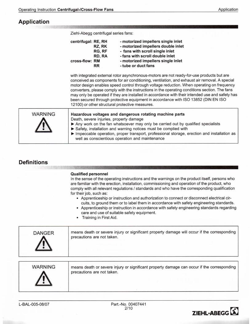


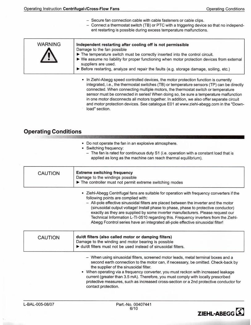


Issue Date : 2011-09-30 Z - Refrigerant Pressure Table
Table 1. Pressure – Temperature Relation
Temperature [F]Pressure [psi g]
R-410a R-407c
18 75.2 34.8
22 82.3 39.1
26 89.7 43.6
30 97.5 48.4
34 105.7 53.4
38 114.4 58.9
42 123.6 64.6
46 133.2 70.6
50 143.3 77.1
55 156.6 106.0
60 170.7 116.2
65 185.7 127.0
70 201.5 138.5
75 218.2 150.6
80 235.9 163.5
85 254.6 177.0
90 274.3 191.3
95 295.0 106.4
100 316.9 222.3
105 339.9 239.0
110 364.1 256.5
115 389.6 274.9
120 416.4 294.2
125 444.5 314.5
130 474.0 335.7
135 505.0 357.8
140 537.6 380.9
145 571.7 405.1
150 607.6 430.3
155 645.2 456.6
1

Issue Date : 2011-09-30 Z - Startup Report
Startup Report - Seresco Technologies Inc.
Project Name NE Series Model
Location Serial Number
Site Contact/Tel: Seresco Rep.
Unit Visual Inspection
Check Comments
Supply air blowing on exterior doors and windows?
No supply-return air short-circuiting?
Outdoor air connected to Seresco unit?
Exhaust fan installed and operating, away from intake?
Vapor Barrier installed?
Condensate P-Trap installed and filled?
Condensate line tested?
Pool Water piping properly installed?
Auxiliary pool water circulating pump installed?
Pool water flow to spec?
OACC or Dry Cooler installed and wired properly?
Nameplate voltages verified?
Main disconnect installed?
Wiring connections checked & tightened?
Control wiring to aux pool heater installed?
Floor drain in mechanical room?
Chemicals stored in separate ventilated room?
Air balance report on file?
List other external controlled components
WebSentry connected?
Blowers, compressors rotation checked?
Adequate service access provided?
Unit’s leveled and vibration isolated?
Flex connectors used at both duct connections?
What type of refrigerant is used?
** TO VALIDATE WARRANTY FILL OUT AND FAX to 1-613-741-3375 ** 1 of 4

Z - Startup Report Issue Date : 2011-09-30
Unit Electrical Data
L1 – L2 L1 – L3 L2 – L3 Nameplate
Unit Voltage (V)
Transformer secondary voltage (V)
Compressor 1 (A)
Compressor 2 (A)
Main Blower 1 (A)
Main Blower 2 (A)
Exhaust Blower 1 (A)
Exhaust Blower2 (A)
Purge Blower 1 (A)
Purge Blower 2 (A)
OACC Motor 1 (A)
OACC Motor 2 (A)
OACC Motor 3 (A)
OACC Motor 4 (A)
Heat Recovery Pump (A)
Hot Water Pump (A)
Hot Water Pump 2(A)
NOTE: Put ALL additional info/comments into Notes section.
Outdoor Air Condensing / Cooling Unit inspection
Check Comments/Data
OACC or dry cooler located how feet above/below/level with
Seresco Unit?
Oil traps installed for OACC?
Model number of condenser
Field charge added in pounds and refrigerant type
Fluid GPM
Glycol %
Glycol stabilizers added?
Distance from Seresco Unit to OACC or dry cooler (one-way line length), ft
Hot gas line size (in)
Liquid line size (in)
Pipe size to dry cooler (in)
2 of 4 For tech support call: 1-770-457-3392 ext.2# OR 1-613-741-3603 ext.4#

Issue Date : 2011-09-30 Z - Startup Report
Fluid Temperature entering main unit (F)
Fluid Temperature leaving main unit (F)
Piping and valves installed per spec?
Unit Operating Data and Configurations
Operating Data Unit Configuration
Sensor Reheat Reheat +
Pool heat
A/C A/C +
Pool heat
Setpoints Value
Return Air (F) Return Air (F)
Return Air (% RH) Return Air (RH)
Supply Air (F) Pool 1 (F)
Pool 1 In (F) Pool 2 (F)
Pool 1 Out (F) Purge (F)
Pool 2 In (F) HR (F)
Pool 2 Out (F) Economizer (F)
Outdoor Air (F)
Comp 1 HP (psi) Air Heating Type
Comp 1 LP (psi) Clock Set?
Comp 1 Suction (F) Board #
Comp 1 Discharge (F) MAC address
Evap 1 (F) IP address
Superheat 1 (F)
Comp 2 HP (psi) BACNET?
Comp 2 LP (psi) LON?
Comp 2 Suction (F) MODBUS?
Comp 2 Discharge (F)
Evap 2 (F)
Superheat 2 (F) NOTE: Check/verify superheat is within 18 – 22 F margin; refer to
Pressure -Temperature chart for proper refrigerant. Adjust if required.
Exhaust (F)
Reheat (F)
T/B Sight Glasess1
T/B Sight Glasses 2 NOTE: For Receiver Sight glasses:T(top)/B(bottom) make note whether
ball is “UP” or “DOWN”. Moisture Indicator 1
Moisture Indicator 2
** TO VALIDATE WARRANTY FILL OUT AND FAX to 1-613-741-3375 ** 3 of 4

Z - Startup Report Issue Date : 2011-09-30
Startup Date
Startup Company Name
Startup Company Contact #
Startup Technician Name
Startup Technician Contact #
Notes/Comments/Info
4 of 4 For tech support call: 1-770-457-3392 ext.2# OR 1-613-741-3603 ext.4#

Issue Date : 2011-09-30 Z - Startup Report
Startup Report - Seresco Technologies Inc.
Project Name NE Series Model
Location Serial Number
Site Contact/Tel: Seresco Rep.
Unit Visual Inspection
Check Comments
Supply air blowing on exterior doors and windows?
No supply-return air short-circuiting?
Outdoor air connected to Seresco unit?
Exhaust fan installed and operating, away from intake?
Vapor Barrier installed?
Condensate P-Trap installed and filled?
Condensate line tested?
Pool Water piping properly installed?
Auxiliary pool water circulating pump installed?
Pool water flow to spec?
OACC or Dry Cooler installed and wired properly?
Nameplate voltages verified?
Main disconnect installed?
Wiring connections checked & tightened?
Control wiring to aux pool heater installed?
Floor drain in mechanical room?
Chemicals stored in separate ventilated room?
Air balance report on file?
List other external controlled components
WebSentry connected?
Blowers, compressors rotation checked?
Adequate service access provided?
Unit’s leveled and vibration isolated?
Flex connectors used at both duct connections?
What type of refrigerant is used?
** TO VALIDATE WARRANTY FILL OUT AND FAX to 1-613-741-3375 ** 1 of 4

Z - Startup Report Issue Date : 2011-09-30
Unit Electrical Data
L1 – L2 L1 – L3 L2 – L3 Nameplate
Unit Voltage (V)
Transformer secondary voltage (V)
Compressor 1 (A)
Compressor 2 (A)
Main Blower 1 (A)
Main Blower 2 (A)
Exhaust Blower 1 (A)
Exhaust Blower2 (A)
Purge Blower 1 (A)
Purge Blower 2 (A)
OACC Motor 1 (A)
OACC Motor 2 (A)
OACC Motor 3 (A)
OACC Motor 4 (A)
Heat Recovery Pump (A)
Hot Water Pump (A)
Hot Water Pump 2(A)
NOTE: Put ALL additional info/comments into Notes section.
Outdoor Air Condensing / Cooling Unit inspection
Check Comments/Data
OACC or dry cooler located how feet above/below/level with
Seresco Unit?
Oil traps installed for OACC?
Model number of condenser
Field charge added in pounds and refrigerant type
Fluid GPM
Glycol %
Glycol stabilizers added?
Distance from Seresco Unit to OACC or dry cooler (one-way line length), ft
Hot gas line size (in)
Liquid line size (in)
Pipe size to dry cooler (in)
2 of 4 For tech support call: 1-770-457-3392 ext.2# OR 1-613-741-3603 ext.4#

Issue Date : 2011-09-30 Z - Startup Report
Fluid Temperature entering main unit (F)
Fluid Temperature leaving main unit (F)
Piping and valves installed per spec?
Unit Operating Data and Configurations
Operating Data Unit Configuration
Sensor Reheat Reheat +
Pool heat
A/C A/C +
Pool heat
Setpoints Value
Return Air (F) Return Air (F)
Return Air (% RH) Return Air (RH)
Supply Air (F) Pool 1 (F)
Pool 1 In (F) Pool 2 (F)
Pool 1 Out (F) Purge (F)
Pool 2 In (F) HR (F)
Pool 2 Out (F) Economizer (F)
Outdoor Air (F)
Comp 1 HP (psi) Air Heating Type
Comp 1 LP (psi) Clock Set?
Comp 1 Suction (F) Board #
Comp 1 Discharge (F) MAC address
Evap 1 (F) IP address
Superheat 1 (F)
Comp 2 HP (psi) BACNET?
Comp 2 LP (psi) LON?
Comp 2 Suction (F) MODBUS?
Comp 2 Discharge (F)
Evap 2 (F)
Superheat 2 (F) NOTE: Check/verify superheat is within 18 – 22 F margin; refer to
Pressure -Temperature chart for proper refrigerant. Adjust if required.
Exhaust (F)
Reheat (F)
T/B Sight Glasess1
T/B Sight Glasses 2 NOTE: For Receiver Sight glasses:T(top)/B(bottom) make note whether
ball is “UP” or “DOWN”. Moisture Indicator 1
Moisture Indicator 2
** TO VALIDATE WARRANTY FILL OUT AND FAX to 1-613-741-3375 ** 3 of 4

Z - Startup Report Issue Date : 2011-09-30
Startup Date
Startup Company Name
Startup Company Contact #
Startup Technician Name
Startup Technician Contact #
Notes/Comments/Info
4 of 4 For tech support call: 1-770-457-3392 ext.2# OR 1-613-741-3603 ext.4#

THIS PAGE HAS BEEN INTENTIONALLY LEFT BLANK

________________________________________________
Issue Date : 2011-09-30
www.serescodehumidifiers.com Supersedes : 2011-09-20
Seresco Technologies Inc. has a policy of continuous product and product data improvement and reserves the right to change
design and specifications at any time without prior notification. Only qualified technicians working within their area of
competence should perform the installation and maintenance of equipment referred to in this literature.