CounterACT 7.0 - Forescout
27
CounterACT 7.0 Quick Installation Guide Single CounterACT Appliance
-
Upload
khangminh22 -
Category
Documents
-
view
0 -
download
0
Transcript of CounterACT 7.0 - Forescout

CounterACT 7.0
Quick Installation GuideSingle CounterACT Appliance

Table of Contents
Welcome to CounterACT™ Version 7.0 . . . . . . . . . . . . . . . . . . . . . . . . . . . . . . . . . . . . 3Included in your CounterACT Package . . . . . . . . . . . . . . . . . . . . . . . . . . . . . . . . . . . 3
Overview . . . . . . . . . . . . . . . . . . . . . . . . . . . . . . . . . . . . . . . . . . . . . . . . . . . . . . . . . . . . . . . . . 4
1. Create a Deployment Plan . . . . . . . . . . . . . . . . . . . . . . . . . . . . . . . . . . . . . . . . . . . . . . 5Decide Where to Deploy the Appliance . . . . . . . . . . . . . . . . . . . . . . . . . . . . . . . . . . 5
Appliance Interface Connections . . . . . . . . . . . . . . . . . . . . . . . . . . . . . . . . . . . . . . . . 5
2. Set Up Your Switch . . . . . . . . . . . . . . . . . . . . . . . . . . . . . . . . . . . . . . . . . . . . . . . . . . . . . 8A . Switch Connection Options . . . . . . . . . . . . . . . . . . . . . . . . . . . . . . . . . . . . . . . . . . . 8
B . Switch Setting Notes . . . . . . . . . . . . . . . . . . . . . . . . . . . . . . . . . . . . . . . . . . . . . . . . . 9
3. Connect Network Cables and Power On . . . . . . . . . . . . . . . . . . . . . . . . . . . . . . . 11A . Unpack the Appliance and Connect Cables . . . . . . . . . . . . . . . . . . . . . . . . . . . 11
B . Record the Interface Assignments . . . . . . . . . . . . . . . . . . . . . . . . . . . . . . . . . . . . 12
C . Power On the Appliance . . . . . . . . . . . . . . . . . . . . . . . . . . . . . . . . . . . . . . . . . . . . . 12
4. Configure the Appliance . . . . . . . . . . . . . . . . . . . . . . . . . . . . . . . . . . . . . . . . . . . . . . 13
5. Remote Management . . . . . . . . . . . . . . . . . . . . . . . . . . . . . . . . . . . . . . . . . . . . . . . . . 16iDRAC7 Setup . . . . . . . . . . . . . . . . . . . . . . . . . . . . . . . . . . . . . . . . . . . . . . . . . . . . . . . . . 16
6. Verify Connectivity . . . . . . . . . . . . . . . . . . . . . . . . . . . . . . . . . . . . . . . . . . . . . . . . . . . 21Verify the Management Interface Connection . . . . . . . . . . . . . . . . . . . . . . . . . . . 21
Verify Switch/Appliance Connectivity . . . . . . . . . . . . . . . . . . . . . . . . . . . . . . . . . . . 21
Perform Ping Test . . . . . . . . . . . . . . . . . . . . . . . . . . . . . . . . . . . . . . . . . . . . . . . . . . . . . . 22
7. Set up the CounterACT Console . . . . . . . . . . . . . . . . . . . . . . . . . . . . . . . . . . . . . . . 23Install the CounterACT Console . . . . . . . . . . . . . . . . . . . . . . . . . . . . . . . . . . . . . . . . 23
Log In . . . . . . . . . . . . . . . . . . . . . . . . . . . . . . . . . . . . . . . . . . . . . . . . . . . . . . . . . . . . . . . . . 18
Perform Initial Setup . . . . . . . . . . . . . . . . . . . . . . . . . . . . . . . . . . . . . . . . . . . . . . . . . . . 18
Contact Information . . . . . . . . . . . . . . . . . . . . . . . . . . . . . . . . . . . . . . . . . . . . . . . . . . . . . 20

3
Welcome to CounterACT™ Version 7.0ForeScout’s Network Access Control (NAC) solution lets customers gain complete control over network security without disrupting corporate and end-user productivity . CounterACT combines cutting edge NAC and intrusion prevention technologies in a single Appliance . CounterACT performs complete endpoint inspection and access control of every network device—and seamlessly integrates with any existing IT infrastructure .
This guide describes the installation for a single stand-alone CounterACT Appliance.
For more detailed information or information about deploying multiple Appliances for enterprise-wide network protection, refer to the CounterACT Installation Guide and Console User Manual . These documents are located on the CounterACT CD in the /docs directory .
Additionally, you can navigate to the support website located at: http://www .forescout .com/support for the latest documentation, knowledge base articles, and updates for your Appliance .
Included in your CounterACT Package• CounterACT Appliance
• Quick Installation Guide
• CounterACT CD with Console software, CounterACT Console User Manual and Installation Guide
• Warranty document
• Mounting brackets
• Power cable
• DB9 Console connecting cable (for serial connections only)

4
OverviewPerform the following to set up CounterACT:
1 . Create a Deployment Plan
2 . Set Up your Switch
3 . Connect Network Cables and Power
4 . Configure the Appliance
5 . Remote Management
6 . Verify Connectivity
7 . Set Up the CounterACT Console
5
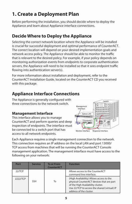
1. Create a Deployment PlanBefore performing the installation, you should decide where to deploy the Appliance and learn about Appliance interface connections .
Decide Where to Deploy the ApplianceSelecting the correct network location where the Appliance will be installed is crucial for successful deployment and optimal performance of CounterACT . The correct location will depend on your desired implementation goals and network access policy . The Appliance should be able to monitor the traffic that is relevant to the desired policy . For example, if your policy depends on monitoring authorization events from endpoints to corporate authentication servers, the Appliance will need to be installed so that it sees endpoint traffic flowing into authentication server(s) .
For more information about installation and deployment, refer to the CounterACT Installation Guide, located on the CounterACT CD you received with this package .
Appliance Interface ConnectionsThe Appliance is generally configured with three connections to the network switch .
Management Interface This interface allows you to manage CounterACT and perform queries and deep inspection of endpoints . The interface must be connected to a switch port that has access to all network endpoints .
Each Appliance requires a single management connection to the network . This connection requires an IP address on the local LAN and port 13000/TCP access from machines that will be running the CounterACT Console management application . The management interface must have access to the following on your network:
Port Service To or From CounterACT
Function
22/TCP
SSH To
Allows access to the CounterACT command line interface .
2222/TCP (High Availability) Allows access to the physical CounterACT devices that are part of the High Availability cluster .Use 22/TCP to access the shared (virtual) IP address of the cluster .
ManagementInterface
Switch
Admin LAN
CounterACT
Monitor Interface Response Interface

6
Port Service To or From CounterACT
Function
445/139 RPC From Allows CounterACT to perform deep investigation and control of Windows endpoints using RPC .
135 WMI From Allows CounterACT to perform deep investigation and control of Windows endpoints using WMI .
10003 Secure Connector
To Allows SecureConnector to create a se-cure (encrypted SSL) connection to the Appliance from Windows machines . SecureConnector receives inspection and action requests and responds to them via this connection; all Counter-ACT traffic between SecureConnector and the Appliance is transmitted via the secure connection .
2200/TCP Secure Connector
To Allows SecureConnector to create a secure (encrypted SSH) connection to the Appliance from Macintosh/Linux machines . SecureConnector enables access to unmanageable endpoints via a shell script that runs at the desktop while the host is connected to the network .
22 SSH From Allows CounterACT to perform deep investigation and control of Macintosh and Linux endpoints .
25/TCP SMTP From Used to send mail from CounterACT80/TCP HTTP To Allows HTTP redirection .443/TCP HTTPS To Allows HTTP redirection using SSL .13000/TCP CounterACT To Allows connection from the Console to
the Appliance .For systems with multiple CounterACT Appliances, allows connection from the Console to the Enterprise Manager and from the Enterprise Manager to each Appliance .
53/UDP DNS From Allows CounterACT to resolve internal IP addresses .
123/UDP NTP From Allows CounterACT access to an NTP time server . By default, CounterACT uses ntp .foreScout .net .
161/UDP SNMP From Allows CounterACT to communicate with network infrastructure gear, such as switches and routers .For information about configuring SNMP, refer to the CounterACT Console User Manual.

7
162/UDP SNMP To Allows CounterACT to receive SNMP traps from network infrastructure gear, such as switches and routers .For information about configuring SNMP, refer to the CounterACT Console User Manual.
Monitor InterfaceThis connection allows the Appliance to monitor and track network traffic .
Traffic is mirrored to a port on the switch and monitored by the Appliance . Depending on the number of VLANs being mirrored, the traffic may or may not be 802 .1Q VLAN tagged .
• Single VLAN (untagged): When monitored traffic is generated from a single VLAN, the mirrored traffic does not need to be VLAN tagged .
• Multiple VLANs (tagged): When monitored traffic is from more than one VLAN, the mirrored traffic must be 802 .1Q VLAN tagged .
When two switches are connected as a redundant pair, the Appliance must monitor traffic from both switches .
Typically, the monitoring interface does not require an IP address .
Response InterfaceThe Appliance responds to traffic using this interface . Response traffic is used to protect against malicious activity and carry out NAC policy actions . These actions may include, for example, redirecting Web browsers or performing firewall blocking . The related switch port configuration depends on the traffic being monitored .
• Single VLAN (untagged): When monitored traffic is generated from a single VLAN, the response interface must be configured to be part of the same VLAN . In this case, the Appliance requires a single IP address on that VLAN .
• Multiple VLANs (tagged): If monitored traffic is from more than one VLAN, the response interface must also be configured with 802 .1Q tagging for the same VLANs . The Appliance requires an IP address for each protected VLAN .

8
2. Set Up Your Switch
A. Switch Connection OptionsThe Appliance was designed to seamlessly integrate into a wide variety of network environments . To successfully integrate the Appliance into your network, verify that your switch is set up to monitor required traffic . Several options are available for connecting the Appliance to your switch .
1. Standard Deployment (Separate Management, Monitoring and Response Interfaces) The recommended deployment uses three separate ports . These ports are described in Appliance Interface Connections.
2. Passive Inline Tap Instead of connecting to a switch monitoring port, the Appliance can use an inline tap . A passive tap requires two monitor ports, except in the case of “recombination” taps, which will combine the two duplex streams into a single port . The traffic on the tapped port and response interface must be configured in the same way . For example, if the traffic on the tapped port is VLAN tagged (802 .1Q), the response interface must also be a VLAN tagged port .
3. Active (Injection-Capable) Inline Tap When the Appliance uses an inline tap that is injection capable, monitor and response interfaces can be combined . There is no need to configure a separate response port on the switch . This option can be used for any type of upstream or downstream switch configuration .
ManagementInterface
Switch
Admin LAN
CounterACT
Monitor Interface Response Interface
Injection-CapableActive Tap
Switch
Uplink
CounterACT
Management Combined Monitor and Response Interface
Passive Tap
Switch
Uplink
CounterACT
Monitor Interface Response Interface

9
4. IP Layer Response (for Layer-3 Switch Installations) The Appliance can use its own management interface to respond to traffic . Although this option can be used with any monitored traffic, it is recommended when the Appliance monitors ports that are not part of any VLAN, and thus the Appliance cannot respond to monitored traffic using any other switch port . This is typical when monitoring a link connecting two routers .
This option cannot respond to Address Resolution Protocol (ARP) requests, which limits the ability of the Appliance to detect scans aimed at the IP addresses included in the monitored subnet . This limitation does not apply when traffic between two routers is being monitored .
B. Switch Setting NotesVLAN (802.1Q) Tags
• Monitoring a Single VLAN (untagged traffic) If the monitored traffic is from a single VLAN, traffic does not need 802 .1Q tags .
• Monitoring Multiple VLANs (tagged traffic) If the monitored traffic is from two or more VLANs, then both the monitor and response interfaces must have 802 .1Q tagging enabled . Monitoring multiple VLANs is the recommended option as it provides the best overall coverage while minimizing the number of mirroring ports .
• If the switch cannot use an 802 .1Q VLAN tag on the mirroring ports, do one of the following:
- Mirror only a single VLAN - Mirror a single, untagged uplink port - Use the IP Layer response option
• If the switch can only mirror one port, then mirror a single uplink port . This may be tagged . In general, if the switch strips 802 .1Q VLAN tags, you will need to use the IP Layer response option .

10
Additional• If the switch cannot mirror both transmit and receive traffic, then
monitor the entire switch, complete VLANs (this provides transmit/receive), or just one interface (which does allow transmit/receive) . Verify that you do not overload the mirroring port .
• Some switches (e .g . Cisco 6509) may need former port configurations completely cleared out before entering new configurations . The most common result when not clearing out old port information is that the switch strips 802 .1Q tags .

11
3. Connect Network Cables and Power On
A. Unpack the Appliance and Connect Cables1 . Remove the Appliance and power cable from the shipping container .
2 . Remove the rail kit you received with the Appliance .
3 . Assemble the rail kit on the Appliance and mount the Appliance to the rack .
4 . Connect the network cables between the network interfaces on the Appliance rear panel and the switch ports .
Rear Panel Sample — CounterACT Device
Systemidenti�cation
connectorVideo
connector
PCIeexpansioncard slot
Power supply
iDRAC7Enterprise
port
Systemidenti�cation
button
Serialconnector
USBconnectors
Ethernetconnectors

12
B. Record the Interface AssignmentsAfter completing the Appliance installation at the data center and installing the CounterACT Console, you will be prompted to register interface assignments . These assignments, referred to as Channel definitions, are entered in the Initial Setup Wizard that opens when you first log on to the Console .
Record the physical interface assignments below and use them when completing the Channel setup at the Console .
Ethernet Interface
Interface Assignment (e.g. Management, Monitor, Response)
Eth0
Eth1
Eth2
Eth3
Eth4
Eth5
Eth6
Eth7
Eth8
C. Power On the Appliance1 . Connect the power cable to the power connector on the Appliance rear
panel .
2 . Connect the other end of the power cable to a grounded AC outlet .
3 . Connect the keyboard and monitor to the Appliance or set up the Appliance for serial connection . Refer to the CounterACT Installation Guide located on the CounterACT CD .
4 . Power on the Appliance from the front panel .
Important: Power off the machine before unplugging.

13
4. Configure the AppliancePrepare the following information before you configure the Appliance .
□ Appliance host name
□ CounterACT Admin password Keep the password in a secure location
□ Management interface
□ Appliance IP address
□ Network mask
□ Default Gateway IP address
□ DNS Domain Name
□ DNS server addresses
After power on, you will be prompted to start configuration with the following message:
1 . Press Enter to display the following menu:
2 . Select 1 – Configure CounterACT . At the prompt:
Continue: (yes/no)?
Press Enter to initiate the setup .
3 . The High Availability Mode menu opens . Press Enter to select Standard Installation .
4 . The CounterACT Initial Setup prompt is displayed . Press Enter to continue .
5 . The Select CounterACT Installation Type menu opens . Type 1 and press Enter to install a standard CounterACT Appliance . The setup is initialized . This may take a moment .
CounterACT Appliance boot is complete. Press <Enter> to continue.
1) Configure CounterACT2) Restore saved CounterACT configuration3) Identify and renumber network interfaces4) Configure keyboard layout5) Turn machine off6) Reboot the machineChoice (1-6) :1
14
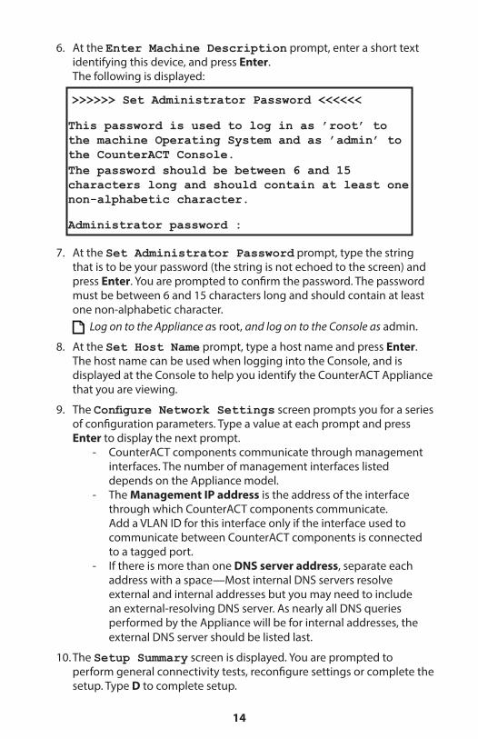
6 . At the Enter Machine Description prompt, enter a short text identifying this device, and press Enter . The following is displayed:
7 . At the Set Administrator Password prompt, type the string that is to be your password (the string is not echoed to the screen) and press Enter . You are prompted to confirm the password . The password must be between 6 and 15 characters long and should contain at least one non-alphabetic character .
Log on to the Appliance as root, and log on to the Console as admin .
8 . At the Set Host Name prompt, type a host name and press Enter . The host name can be used when logging into the Console, and is displayed at the Console to help you identify the CounterACT Appliance that you are viewing .
9 . The Configure Network Settings screen prompts you for a series of configuration parameters . Type a value at each prompt and press Enter to display the next prompt .
- CounterACT components communicate through management interfaces . The number of management interfaces listed depends on the Appliance model .
- The Management IP address is the address of the interface through which CounterACT components communicate . Add a VLAN ID for this interface only if the interface used to communicate between CounterACT components is connected to a tagged port .
- If there is more than one DNS server address, separate each address with a space—Most internal DNS servers resolve external and internal addresses but you may need to include an external-resolving DNS server . As nearly all DNS queries performed by the Appliance will be for internal addresses, the external DNS server should be listed last .
10 . The Setup Summary screen is displayed . You are prompted to perform general connectivity tests, reconfigure settings or complete the setup . Type D to complete setup .
>>>>>> Set Administrator Password <<<<<<
This password is used to log in as ’root’ to the machine Operating System and as ’admin’ to the CounterACT Console.The password should be between 6 and 15 characters long and should contain at least one non-alphabetic character.
Administrator password :

15
LicenseAfter installation, you must install the initial demo license provided by your CounterACT representative . The license is installed during the initial Console setup . This initial demo license is valid for a certain number of days . You must install a permanent license before this period expires . You will be contacted via e-mail regarding the expiration date . In addition, information about the expiration date and status license is displayed in the Console, Appliances/Devices pane .
Once you receive a permanent license, the license is validated daily by the ForeScout License Server . License alerts and violations are displayed in the Device Details pane .
Licenses that cannot be validated for an extended period of time will be revoked . Refer to the CounterACT Installation Guide for more details about licenses .
Network Connection RequirementsAt least one CounterACT device (Appliance or Enterprise Manager) must be able to access the Internet . This connection is used to validate CounterACT licenses against the ForeScout License server .
Licenses that can’t be authenticated for an extended period of time will be revoked . CounterACT will send a warning email once a day indicating there is a communication error with the server .

16
5. Remote Management
iDRAC7 SetupThe Integrated Dell Remote Access Controller 7 (iDRAC7) is an integrated server system solution that gives you location-independent/OS-independent remote access over the LAN or Internet to CounterACT Appliances/Enterprise Managers . Use the module to carry out KVM access, power on/off/reset and perform troubleshooting and maintenance tasks .
Perform the following to work with the iDRAC module:
• Enable and Configure the iDRAC Module
• Connect the Module to the Network
• Login to iDRAC
Enable and Configure the iDRAC ModuleChange the iDRAC settings to enable remote access on the CounterACT device . This section describes basic integration settings required for working with CounterACT .
To configure iDRAC:
1 . Turn on the managed system .
2 . Select F2 during Power-on Self-test (POST) .
3 . In the System Setup Main Menu page, select iDRAC Settings .

17
4 . In the iDRAC Settings page, select Network .
5 . Configure the following Network settings: - Network Settings. Verify that the Enable NIC field is set to
Enabled . - Common Settings. In the DNS DRAC Name field, you can update
a dynamic DNS (Optional) . - IPV4 Settings. Verify that the Enable IPv4 field is set to Enabled .
Set the Enable DHCP field to Enabled to use Dynamic IP Addressing or to Disabled to use Static IP Addressing . If enabled, DHCP will automatically assign the IP address, gateway and subnet mask to iDRAC7 . If disabled, enter values for the Static IP Address, Static Gateway and Static Subnet Mask fields .

18
6 . Select Back .
7 . Select User Configuration .
19
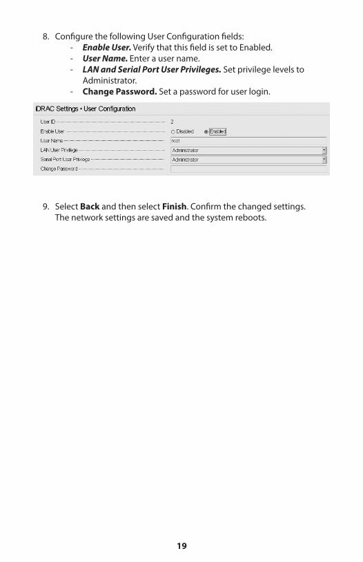
8 . Configure the following User Configuration fields: - Enable User. Verify that this field is set to Enabled . - User Name. Enter a user name . - LAN and Serial Port User Privileges. Set privilege levels to
Administrator . - Change Password. Set a password for user login .
9 . Select Back and then select Finish . Confirm the changed settings . The network settings are saved and the system reboots .

20
Connect the Module to the Network The iDRAC connects to an Ethernet network . It is customary to connect it to a management network . The following image shows the iDRAC port location on the rear panel of the CT-1000 appliance:
Login to iDRACTo login to iDRAC:
1 . Browse to the IP Address or domain name configured in iDRAC Settings > Network.
2 . Enter the Username and Password configured in the User Configuration page of the iDRAC system setup .
3 . Select Submit .
For further information about iDRAC, refer to the iDRAC 7 User’s Guide .
It is very important to update the default credentials .

21
6. Verify Connectivity
Verify the Management Interface ConnectionTo test the management interface connection, log in to the Appliance and run the following command:
fstool linktest
The following information is displayed:
Verify Switch/Appliance ConnectivityVerify that the switch is properly connected to the Appliance before leaving the data center . To do this, run the fstool ifcount command at the Appliance for each interface detected .
fstool ifcount eth0 eth1 eth2(Separate each interface by a space.)
This tool continuously displays network traffic on the specified interfaces . It works in two modes: per interface or per VLAN . The mode can be changed from the display . The total bits per second and the percentage of each of the following traffic categories is shown:
• The monitoring interface should primarily see mirrored traffic — above 90% .
• The response interface should primarily see broadcast traffic .
• Both the monitor and response interface should see the expected VLANs .
Command options:v – display in VLAN modeI – display in interface modeP – show previousN – show nextq – quit displaying
Management Interface statusPinging default gateway informationPing statisticsPerforming Name Resolution TestTest summary

22
VLAN Mode: update=[4] [eth3: 14 vlans]
Interface/Vlan Total Broadcast Mirrored *To my MAC *From my MAC
eth3.untagged 4Mbps 0.2% 99.8% 0.0% 0.0%
eth3.1 9Mbps 0.0% 100.0% 0.0% 0.0%
eth3.2 3Mbps 0.1% 99.9% 0.0% 0.0%
eth3.4 542bps 100.0% 0.0% 0.0% 0.0%
eth3.20 1Kbps 100.0% 0.0% 0.0% 0.0%
Show [v]lans [i]nterfaces <-[p]rev [n]ext-> [q]uit
Interface Mode: update=[31] [eth0: 32 vlans] [eth1: 1 vlans]
Interface Total Broadcast Mirrored *To my MAC *From my MAC
eth0 3Kbps 42.3% 0.0% 14.1% 43.7%
eth1 475bps 0.0% 100.0% 0.0% 0.0%
*To my MAC — Destination MAC is the Appliance’s MAC .
*From my MAC — Traffic sent by this Appliance (Source MAC is the Appliance’s MAC . Destination can be broadcast or unicast) .
If you do not see any traffic, verify that the interface is up . Use the following command at the Appliance:ifconfig [interface name] up
Perform Ping TestRun a ping test from the Appliance to a network desktop to verify connectivity .
To run the test:1 . Log in to the Appliance .
2 . Run the following command: Ping [network desktop IP] By default, the Appliance itself does not reply to ping .
23
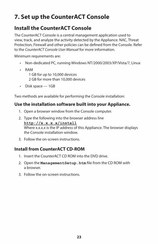
7. Set up the CounterACT Console
Install the CounterACT Console The CounterACT Console is a central management application used to view, track, and analyze the activity detected by the Appliance . NAC, Threat Protection, Firewall and other policies can be defined from the Console . Refer to the CounterACT Console User Manual for more information .
Minimum requirements are:
• Non-dedicated PC, running Windows NT/2000/2003/XP/Vista/7, Linux
• RAM 1 GB for up to 10,000 devices 2 GB for more than 10,000 devices
• Disk space — 1GB
Two methods are available for performing the Console installation:
Use the installation software built into your Appliance.1 . Open a browser window from the Console computer .
2 . Type the following into the browser address line http://x.x.x.x/install Where x .x .x .x is the IP address of this Appliance . The browser displays the Console installation window .
3 . Follow the on-screen instructions .
Install from CounterACT CD-ROM1 . Insert the CounterACT CD ROM into the DVD drive .
2 . Open the ManagementSetup.htm file from the CD ROM with a browser .
3 . Follow the on-screen instructions .

24
Log InAfter completing the installation, you can log in to the CounterACT Console .
1 . Select the CounterACT icon from the shortcut location you created .
2 . Enter the IP address or host name of the Appliance in the IP/Name field .
3 . In the User Name field, enter admin .
4 . In the Password field, enter the password you created during Appliance installation .
5 . Select Login to launch the Console .
Perform Initial SetupAfter logging in for the first time, the Initial Setup Wizard appears . The Wizard guides you through essential configuration steps to ensure that CounterACT is up-and-running quickly and efficiently .

25
Before You Start the Initial SetupPrepare the following information before working with the Wizard:
Information Values
□ NTP server address used by your organization (optional) .
□ Internal mail relay IP address . This allows delivery of email from CounterACT if SMTP traffic is not allowed from the Appliance (optional) .
□ CounterACT administrator’s e-mail address .
□ Monitor and response interface assignments defined at the Data Center .
□ For segments or VLANs with no DHCP, the network segment or VLANs to which the monitoring interface is directly connected and a permanent IP address to be used by CounterACT at each such VLAN . This information is not required for Enterprise Manager setup .
□ IP address ranges that the Appliance will protect (all the internal addresses, including unused addresses) .
□ User Directory account information and the User Directory server IP address .
□ Domain credentials, including domain administrative account name and password .
□ Authentication servers so that CounterACT can analyze which network hosts have successfully authenticated .
□ Core switch IP address, vendor and SNMP parameters .
Refer to the CounterACT Console User Manual or Online Help for information about working with the Wizard .

26
Contact InformationFor ForeScout technical support send email to support@forescout .com or call one of the following numbers:
• Toll-Free (US): 1 .866 .377 .8771
• Phone (Intl): 1 .408 .213 .3191
• Support: 1 .708 .237 .6591
• Fax: 1 .408 .371 .2284
Illustration courtesy of Dell Corporation .
©2014 ForeScout Technologies, Inc . Products protected by US Patents #6,363,489, #8,254,286, #8,590,004 and #8,639,800 . All rights reserved . ForeScout Technologies, the ForeScout logo are trademarks of ForeScout Technologies, Inc . All other trademarks are the property of their respective owners . The use of any ForeScout Product is subject to the terms of ForeScout’s End User License Agreement located at www .forescout .com/eula .
CT7 .0-QIG

27
ForeScout Technologies 900 E. Hamilton Ave., Suite 300 Campbell, CA 95008 USA
Toll Free: 1.866.377.8771 Phone (Intl): 1.408.213.3191 www.forescout.com
400-00020-00