Counter-Current Suspension Extraction Process of ... - MDPI
15
processes Article Counter-Current Suspension Extraction Process of Lignocellulose in Biorefineries to Reach Low Water Consumption, High Extraction Yields, and Extract Concentrations Marc Conrad * and Irina Smirnova Citation: Conrad, M.; Smirnova, I. Counter-Current Suspension Extraction Process of Lignocellulose in Biorefineries to Reach Low Water Consumption, High Extraction Yields, and Extract Concentrations. Processes 2021, 9, 1585. https://doi.org/ 10.3390/pr9091585 Academic Editor: José F.O. Granjo Received: 6 August 2021 Accepted: 2 September 2021 Published: 4 September 2021 Publisher’s Note: MDPI stays neutral with regard to jurisdictional claims in published maps and institutional affil- iations. Copyright: © 2021 by the authors. Licensee MDPI, Basel, Switzerland. This article is an open access article distributed under the terms and conditions of the Creative Commons Attribution (CC BY) license (https:// creativecommons.org/licenses/by/ 4.0/). Hamburg University of Technology, TUHH, Institute of Thermal Separation Processes, Eißendorfer Straße 38, 21073 Hamburg, Germany; [email protected] * Correspondence: [email protected] Abstract: The processing of large quantities of water in biorefining processes can lead to immense costs for heating, evaporation, and wastewater disposal. These costs may prohibit the exploitation of alternative products, e.g., xylooligosaccharides from straw, which are regarded as too costly. A new counter-current extractions method is proposed that aims at low solvent (water) consumption, as well as high yields and extract concentrations. This process was evaluated with suspension extraction experiments with steam pretreated wheat straw and the process window analysis based on a mass balance for a washing and a leaching scenario. The latter was conducted with two other suspension extraction processes as a comparison. The equilibration time was found to be well below 10 min. While the suspension extraction with and without recycling need to be designed to achieve a high yield or a high concentration and low solvent consumption, the proposed extraction method can reach all three simultaneously. Thus, this new process is evaluated as a potential method to spare water and downstream costs and allow new processing pathways in second-generation biorefineries. Keywords: continuous steam pretreatment; counter-current solid–liquid extraction; hemicellulose; water consumption 1. Introduction Solid–liquid extractions play an essential role in biorefining processes. They can be applied to remove the substrate’s contaminants or gain a product after (pre-) treatment. In both applications, solvent consumption, most often water, is a significant concern. Low water consumption will not allow a high extraction yield. Enormous water will dilute the product and cause further problems. In general, processing large quantities of water leads to space-consuming vessels, pumping capacity demand, heat demand to reach the process temperature and evaporation of dilute streams, and high wastewater costs. Recycling the excess water will be costly or even not feasible. The improvement of solid–liquid extraction processes can reduce operating costs and valorize the biomass constituents in more profitable pathways. This work proposes a new counter-current, solid–liquid extraction process that aims to reach high extractions yields, high extract concentrations, low solvent consumption, and small space demand. Solid–liquid extractions used to remove contaminants, also called washing, are in- vestigated for many materials and processes. For bioethanol production, the washing of lignocellulosic materials was investigated with animal bedding as a potentially cheaper substrate as opposed to fresh straw [1,2]. Moreover, straw washing before autohydrolysis pretreatment can improve product yields by removing ash [3,4]. The washing of straw biogas digestate for further use in biorefineries or fiber-based materials [5] is discussed. Fur- thermore, washing the substrate before pretreatment helps remove ash, fines, non-structural Processes 2021, 9, 1585. https://doi.org/10.3390/pr9091585 https://www.mdpi.com/journal/processes
-
Upload
khangminh22 -
Category
Documents
-
view
2 -
download
0
Transcript of Counter-Current Suspension Extraction Process of ... - MDPI

processes
Article
Counter-Current Suspension Extraction Process ofLignocellulose in Biorefineries to Reach Low WaterConsumption, High Extraction Yields, andExtract Concentrations
Marc Conrad * and Irina Smirnova
�����������������
Citation: Conrad, M.; Smirnova, I.
Counter-Current Suspension
Extraction Process of Lignocellulose
in Biorefineries to Reach Low Water
Consumption, High Extraction Yields,
and Extract Concentrations. Processes
2021, 9, 1585. https://doi.org/
10.3390/pr9091585
Academic Editor: José F.O. Granjo
Received: 6 August 2021
Accepted: 2 September 2021
Published: 4 September 2021
Publisher’s Note: MDPI stays neutral
with regard to jurisdictional claims in
published maps and institutional affil-
iations.
Copyright: © 2021 by the authors.
Licensee MDPI, Basel, Switzerland.
This article is an open access article
distributed under the terms and
conditions of the Creative Commons
Attribution (CC BY) license (https://
creativecommons.org/licenses/by/
4.0/).
Hamburg University of Technology, TUHH, Institute of Thermal Separation Processes, Eißendorfer Straße 38,21073 Hamburg, Germany; [email protected]* Correspondence: [email protected]
Abstract: The processing of large quantities of water in biorefining processes can lead to immensecosts for heating, evaporation, and wastewater disposal. These costs may prohibit the exploitation ofalternative products, e.g., xylooligosaccharides from straw, which are regarded as too costly. A newcounter-current extractions method is proposed that aims at low solvent (water) consumption, aswell as high yields and extract concentrations. This process was evaluated with suspension extractionexperiments with steam pretreated wheat straw and the process window analysis based on a massbalance for a washing and a leaching scenario. The latter was conducted with two other suspensionextraction processes as a comparison. The equilibration time was found to be well below 10 min.While the suspension extraction with and without recycling need to be designed to achieve a highyield or a high concentration and low solvent consumption, the proposed extraction method canreach all three simultaneously. Thus, this new process is evaluated as a potential method to sparewater and downstream costs and allow new processing pathways in second-generation biorefineries.
Keywords: continuous steam pretreatment; counter-current solid–liquid extraction; hemicellulose;water consumption
1. Introduction
Solid–liquid extractions play an essential role in biorefining processes. They can beapplied to remove the substrate’s contaminants or gain a product after (pre-) treatment. Inboth applications, solvent consumption, most often water, is a significant concern. Lowwater consumption will not allow a high extraction yield. Enormous water will dilute theproduct and cause further problems. In general, processing large quantities of water leadsto space-consuming vessels, pumping capacity demand, heat demand to reach the processtemperature and evaporation of dilute streams, and high wastewater costs. Recyclingthe excess water will be costly or even not feasible. The improvement of solid–liquidextraction processes can reduce operating costs and valorize the biomass constituentsin more profitable pathways. This work proposes a new counter-current, solid–liquidextraction process that aims to reach high extractions yields, high extract concentrations,low solvent consumption, and small space demand.
Solid–liquid extractions used to remove contaminants, also called washing, are in-vestigated for many materials and processes. For bioethanol production, the washing oflignocellulosic materials was investigated with animal bedding as a potentially cheapersubstrate as opposed to fresh straw [1,2]. Moreover, straw washing before autohydrolysispretreatment can improve product yields by removing ash [3,4]. The washing of strawbiogas digestate for further use in biorefineries or fiber-based materials [5] is discussed. Fur-thermore, washing the substrate before pretreatment helps remove ash, fines, non-structural
Processes 2021, 9, 1585. https://doi.org/10.3390/pr9091585 https://www.mdpi.com/journal/processes

Processes 2021, 9, 1585 2 of 15
carbohydrates, and other contaminants that may be unwanted in the subsequently pro-duced extract, e.g., for the purification of xylooligosaccharides [6]. Contaminants can beparticulate or water-soluble as in animal manure, fermentation residues, non-structuralsubstances, or soil.
In contrast to washing, solid–liquid extraction designed to gain a product from asolid is also called leaching. The type of processes regarded here is pretreatment oflignocellulose followed by leaching to produce an extract rich in hemicellulose-derivedcomponents. The remaining solids are hydrolyzed to dissolved glucose and solid lignin.These hemicellulose-rich extracts can be used as a substrate for fermentation to a variety ofproducts [7,8], the conversion to furfural [9–12], and the purification of components such asxylooligosaccharides [6]. Often, separate hemicellulose and glucose valorization pathwaysare deemed too expensive. Thus, an efficient extraction process is regarded as an enablingtechnology for the process discussed above. In industrial biorefineries, hemicelluloseextraction is avoided. Instead, the pretreated material is enzymatically treated in wholeslurry hydrolysis. A process layout to separate pentose, hexose, and lignin in high yieldsfor separate valorization pathways was proposed in previous studies [13,14]. One centralidea to avoid forming inhibitors in the reaction stage is to divide the reaction into two mildsteps and leach the dissolved components after the reactors. Here, an efficient leachingprocess is desired.
In any extraction process, the design parameters and process conditions should bechosen to find a suitable trade-off between the extraction yield on the one hand and thewater consumption and extract concentration on the other hand. Often, the extractionyield is prioritized, which is facilitated by increasing the water consumption, thus reduc-ing the extract concentration. This choice has drastic consequences on the downstreamprocessing. After leaching, thin streams increase the heat demand to increase the concen-tration and capital investment for evaporation stages. This issue is even more relevant forproducing pure xylooligosaccharides and fed-batch fermentation, which requires a highcarbohydrate concentration.
Lignocellulosic biomass possesses especially challenging properties that need to beconsidered to design improved extraction processes. These materials’ high porosity [15,16]and low bulk density [14] may lead to voluminous extractors. The cellular structure leadsto a high water holding capacity for wheat straw of up to four times its weight, and a longpath for solute diffusion from the particle center to the surface. Thus, slow internal masstransport is the result. The fibrous nature of annual lignocellulose and reduced materialflowability [15] increases forced transportation demand to avoid bridging in pipes andchutes. Finally, the product concentration on pretreated lignocellulose is relatively lowcompared to other leaching tasks such as beet sugar processing [16].
The literature on solid–liquid extraction, in general, is vast [17–22], but only sometypes of solid–liquid extraction units are used or considered in biorefinery processing basedon annual lignocellulose.
A simple process is the submersion of moist biomass with fresh water in a stirredtank and consequent mechanical dewatering [1]. Recycling a fraction of the extract isdiscussed [1]. These one-pot extractions with or without recycling can be operated contin-uously using screw or roll presses or in batch mode using a filter press as a dewateringdevice. The convective mass transport in submerged and stirred tanks may lead to a lowtransport residence outside the lignocellulose particles and thus a short time to reach anequilibrium between bulk and intra-particular concentration. However, there is a trade-offbetween yield and solvent consumption.
The belt extractor is a continuously operated counter-current extractor [17,23,24].The biomass is transferred to a water-permeable belt and spayed with fluid in severalstages. It displaces the fluid adhering to the solids and is collected in different vesselsbelow the belt. The fluid of each belt is spayed on the previous section facilitating afluid transport counter-current to the solid matter. In addition to the intra-particularmass transport resistance, extra particular mass transport resistances are added. At the
Processes 2021, 9, 1585 3 of 15
numerous particle-particle contacts, the transport from the inside to the outside cannottake place. The active surface area is reduced. Furthermore, the fluid velocity between theparticles is rather slow, especially near particle–particle contacts. Thus, the velocity layersare increased significantly, lowering the mass transport rate. The combined internal andexternal transport residence leads to an enormous extraction time and spacious extractors.
An inclined washing screw with counter-current water flow has been proposed [25],also combined with hydrothermal pretreatment [26,27]. It was found that large amountsof water are required to achieve a measurable extraction performance, and the extractconcentrations are low. The poor performance may be attributed to the short contact ofwater and biomass at each position.
In this work, we propose a new continuous counter-current, solid–liquid extractionprocess based on two or more stages of suspension extraction in stirred tanks and me-chanical dewatering devices, for example, screw presses. This process is designed forlignocellulosic material in biorefinery plants, high extraction yields, high extract concentra-tions, low solvent consumptions, expansive process windows, low space requirements, andcompact design based on widely available equipment. This extraction method is designedto be followed by a continuous screw conveyor reactor equipped with a high-pressureplug screw feeder, dewatering the moist biomass severely. The dewatering and recyclingof the filtrate are beneficial for the extraction. The performance of the extraction processwas modeled and compared with the suspension extraction processes with and withoutrecycling. The comparison was made for a washing and a leaching scenario. Experimentalinvestigation of the suspension extraction of steam pretreated material was shown todemonstrate the feasibility.
2. Materials and Methods2.1. Wheat Straw
Cut wheat straw pellets of 1–2 cm length from a local farm in Stelle, Germany, with amoisture content of 9.5 wt %, were used. The composition was determined according to theNREL procedure “Determination of structural carbohydrates and lignin in biomass” [28].The xylose and arabinose sugars are reported as hemicellulose. The dry matter compo-sition was lignin 27.7 wt %, cellulose 36.0 wt %, hemicellulose 28.0 wt %, and unknowncomponents 18.0 wt %.
Hammer-milled and pelleted wheat straw of the brand “Raiffeisen Bionesto” froma producer in central Germany was used as “ground straw”. The particle sizes were inthe range of 1–3 mm. The dry matter composition was lignin 20 wt %, cellulose 32 wt %,hemicellulose 21 wt %, ash 8 wt %, and unknown components 19 wt %.
2.2. Steam Pretreatment in 40 L Reactor
The experimental set-up consisted of the reactor, a removable cartridge with 40 Lvolume, a steam generator PS200-15 from Stritzel Dampftechnische Geräte GmbH, pressureand temperature sensor at the bottom and top, and a water-cooled condenser.
The cylindrical reactor with an oil heating jacket possessed a bayonet fast closing lit.The top was connected to the steam inlet, the top and bottom were connected to the vaporcondenser. The cartridge had an inner diameter of 320 mm and a length of 500 mm. Thetop and bottom were made of removable metal screens with 250 µm openings.
The biomass was washed with 20.0 kg demineralized water per kilogram of dry massand pressed in a Wiltec hydro press. The moisture content of less than 66 wt % afterpressing was reached. The wet biomass was prepared the same day of the hydrothermalpretreatment and stored in a closed container before usage.
The cartridge, filled with 5.000 kg wet biomass, was loaded into the preheated reactor,which was closed afterward. The reaction mixture was preheated for two minutes byflowing steam slowly in at the top to replace the air to the bottom outlet. Then, theoutlet to the condenser was closed, and the steam inlet was opened. After approximatelyfour minutes, the maximal pressure of 10 bar absolute, 180 ◦C, was reached, and the

Processes 2021, 9, 1585 4 of 15
reaction time of 35 min was started. The steam inlet was closed to stop the reaction, andthe two outlets to the condenser were opened. After approximately three minutes, thedepressurization was completed, and the cartridge was removed from the reactor.
2.3. Extraction in 10 L Stirred Tank
The mixing time to reach an equilibrium was measured in batch 10 L stirred tankwith an anchor stirrer. A total of 3.000 kg deionized water was heated to 70 ◦C at 150 rpm.After the temperature was reached, pretreated wet wheat straw was added. The dry solidsconcentration was 2 wt %. Samples were taken after 1, 2.5, 5, 10, 15, 20, 30, and 60 min.Each sample was settled for 30 s; the supernatant was taken and filtered in a 0.02 µmsyringe filter to remove particles. The sample was stored at −18 ◦C until analysis. Theconcentration of the total pentoses was converted to a dimensionless scale to accountfor different moisture contents and thus to feed concentrations in the pretreated biomass.The average of the last three concentrations in each experiment was used to define theequilibrium concentration. Here, the equilibrium was defined as the concentration in thebulk that was constant for at least three measurement points. In this state, it was assumedthat the particle interior and the bulk phase concentrations were identical, and no furthermass transport occurred.
2.4. Analytical Method
The TUHH central laboratory analyzes aqueous samples applying method M03.008Version 02: “Aqueous samples are centrifuged and directly analyzed by an HPLC systemcoupled to a refractive index detector to determine free carbohydrates such as cellobiose,glucose, xylose, and arabinose, and degradation products such as HMF and furfural. Boundcarbohydrates are extracted with acid hydrolysis (4% H2SO4) beforehand. Separation isperformed with an ion exclusion HPLC phase column”. This method is based on the sameNREL method as is that in Section 2.3 [28].
2.5. Calculation of Extraction Processes
To investigate the extraction of the new counter-current, solid–liquid extractionmethod, we calculated the process windows and compared them with two other pro-cesses: suspension extraction without recycling and suspension extraction with recycling.Two important design parameters for each process were varied, and the effect on the extractconcentration CE in gram solute in 1000 g liquid and the extraction yield YE in gram solutein extract per gram solute in feed was evaluated. For each extraction vessel, thermody-namic equilibrium was assumed. A washing and a leaching scenario were investigatedto account for these possible applications. Mass balance calculations and iterations wereperformed in Microsoft Excel 2016 using the solver function.
Each scenario was defined by its feed composition. Here, solids, solute, and solvent(water) were considered. The solute was defined as entirely soluble in water. In the washingscenario, water and solute contents were small in order to represent freshly harvestedlignocellulose. The solute represented ash, fine particles, and non-structural carbohydrates.The washing feed contained 86.4 wt % solids, 4.5 wt % solute, and 9.1 wt % solvent.The leaching scenario represented steam-pretreated wheat straw. The solute representedsoluble hemicellulose-derived components such as oligomeric and monomeric pentoses.The leaching feed contained 25.8 wt % solids, 7.5 wt % solute, and 66.7 wt % solvent.
2.5.1. Suspension Extraction without Recycling
In Figure 1, the block flow diagram of the suspension extraction with and withoutrecycling is displayed. In the extraction process without recycling, the recycling streamwas neglected. Feed and solvent (water) were mixed in a continuously stirred tank. Theoutflowing suspension was pressed in one or two consecutive presses, e.g., screw pressesor roll presses. The first one could represent a press near the extraction plant. The secondone represented a high-pressure plug screw feeder that dewatered the moist solids while

Processes 2021, 9, 1585 5 of 15
pushing the material into a continuous screw conveyor reactor. A possible presteamingunit to heat the biomass before the input into the reactor, which would be found betweenthe two presses and add a certain amount of water, was neglected. The two presses wereconsidered one press for the calculation since the effluents from both presses were mixedin one filtrate tank.
Processes 2021, 9, 1585 5 of 16
2.5.1. Suspension Extraction without Recycling In Figure 1, the block flow diagram of the suspension extraction with and without
recycling is displayed. In the extraction process without recycling, the recycling stream was neglected. Feed and solvent (water) were mixed in a continuously stirred tank. The outflowing suspension was pressed in one or two consecutive presses, e.g., screw presses or roll presses. The first one could represent a press near the extraction plant. The second one represented a high-pressure plug screw feeder that dewatered the moist solids while pushing the material into a continuous screw conveyor reactor. A possible presteaming unit to heat the biomass before the input into the reactor, which would be found between the two presses and add a certain amount of water, was neglected. The two presses were considered one press for the calculation since the effluents from both presses were mixed in one filtrate tank.
Figure 1. Suspension extraction with and without recycling. Diamonds represent streams. Rectangles represent process units. Arrows represent mass flows. Brown: solids, purple: slurry, blue: liquid.
The first design parameter was the dry matter content in the extraction tank, DM-tank. It was used to determine the water intake. The second parameter was the dry matter content of the pressed material, DM-out. It determined the amount of raffinate leaving the system. The solute mass and concentration were calculated by assuming the same concentrations in the extract and raffinate outflows. The specific solvent consumption 𝐿/𝑆 in grams of water input to grams of dry solids input was not displayed in the process window.
2.5.2. Suspension Extraction with Recycling The block flow diagram is represented in Figure 1 and is identical to the extraction
without recycling. The recycling stream was determined through the recycling split factor “y”. It was the mass flow ratio of the recycle stream to the filtrate tank inflow. The recycling split factor can take values from 0 to 1. In the case of y = 0, this process was identical to the suspension extraction without recycling. The largest possible value depended on the feed composition and the design parameters to be selected.
The recycling stream was defined as a tear stream to calculate the process by iteration. Initial positive values for the stream amount and concentration were chosen randomly. The water flow to the extractor was calculated on the basis of the dry matter content in the extractor DM-tank, which was set to 5 wt % and not varied in this study. The calculations were executed similarly to those in Section 2.5.1. The recycling split factor was chosen to calculate the recycle flow and concentration. The initially chosen fluid mass flow and solute concentration of the recycle stream were compared with the calculated values and changed to minimize the error calculated as the sum of the squared differences. The extraction yield, the extract concentration, and the solvent consumption are reported.
2.5.3. Counter-Current Extraction The new counter-current extraction process showed similarities to a mixer-settler
extraction process in liquid–liquid extraction systems (see Figure 2a). Solid and liquid phase flow in a counter-current manner through a series of suspension extractors (mixers) and mechanical dewatering devices (settlers) was organized as stages.
Figure 1. Suspension extraction with and without recycling. Diamonds represent streams. Rectanglesrepresent process units. Arrows represent mass flows. Brown: solids, purple: slurry, blue: liquid.
The first design parameter was the dry matter content in the extraction tank, DM-tank.It was used to determine the water intake. The second parameter was the dry matter contentof the pressed material, DM-out. It determined the amount of raffinate leaving the system.The solute mass and concentration were calculated by assuming the same concentrationsin the extract and raffinate outflows. The specific solvent consumption L/S in grams ofwater input to grams of dry solids input was not displayed in the process window.
2.5.2. Suspension Extraction with Recycling
The block flow diagram is represented in Figure 1 and is identical to the extractionwithout recycling. The recycling stream was determined through the recycling split factor“y”. It was the mass flow ratio of the recycle stream to the filtrate tank inflow. The recyclingsplit factor can take values from 0 to 1. In the case of y = 0, this process was identical to thesuspension extraction without recycling. The largest possible value depended on the feedcomposition and the design parameters to be selected.
The recycling stream was defined as a tear stream to calculate the process by iteration.Initial positive values for the stream amount and concentration were chosen randomly.The water flow to the extractor was calculated on the basis of the dry matter content in theextractor DM-tank, which was set to 5 wt % and not varied in this study. The calculationswere executed similarly to those in Section 2.5.1. The recycling split factor was chosen tocalculate the recycle flow and concentration. The initially chosen fluid mass flow and soluteconcentration of the recycle stream were compared with the calculated values and changedto minimize the error calculated as the sum of the squared differences. The extraction yield,the extract concentration, and the solvent consumption are reported.
2.5.3. Counter-Current Extraction
The new counter-current extraction process showed similarities to a mixer-settlerextraction process in liquid–liquid extraction systems (see Figure 2a). Solid and liquidphase flow in a counter-current manner through a series of suspension extractors (mixers)and mechanical dewatering devices (settlers) was organized as stages.
Processes 2021, 9, 1585 6 of 15
Processes 2021, 9, 1585 6 of 16
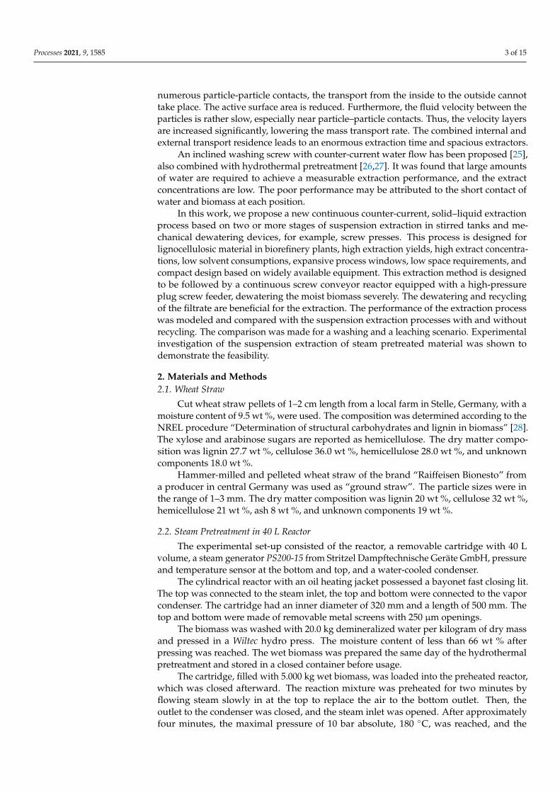
To facilitate a low solvent consumption, we recycled the fluid pressed out of the solids, called filtrate, mainly into the extractor, while we fed only a tiny amount of liquid to the next stage (see Figure 2b). A conveyor for the transport of pressed biomass to the next extractor may be required in large plants. In this case, it is suggested that the extract of the next stage is not fed directly to the extractor but the conveyor first. It is regarded as a means to contact the solids with a lower concentrated fluid stream. Therefore, less solute must diffuse from the particle inside to the surface. The conveyor is regarded as optional. Without a conveyor, the wet biomass is transferred directly into the extractor through gravity. To achieve a steady operation of the screw press, we kept the feed tank full at all times by overflowing. The excess amount of suspension was recycled back to the extractor. Additionally, it was a meaningful measure to increase the mixing residence time in a plug flow manner, promoting the achievement of an equilibrium. The residence time distribution in the continuous stirred tank was imperfect in terms of reaching an equilibrium. The filtrate recycle-stream decreased the extract amount fed to the previous stage and allowed for extraction in a suspension similar to the suspension extraction with recycling.
Figure 2c shows the block flow diagram of the extraction process in three stages. Here, it was integrated into a two-step pretreatment approach. The first reactor (SCR 1) produced the steam pretreated lignocellulose leached in the discussed process. The pressed material left the extractor and was pressed further in the second reactor’s high-pressure plug screw feeder (HP screw before SCR 2). The HP screw filtrate was fed to the filtrate tank, while only fresh solvent was fed to the extractor in the last stage. This integration to a high-pressure feeder was beneficial for the extraction process since the pressed out solute could be recovered. In Figure 2d, the exemplary integration of the last stage of the counter-current extraction and the following screw conveyor reactor is shown with 3D symbols.
(a) (b)
(c)
SCR 1
conveyor
extractor screw separator
filtrate tank conveyor
extractor screw separator
filtrate tank conveyor
extractor screw separator
filtrate tank HP Screw
SCR 2
extract solvent
raffinateSPBProcesses 2021, 9, 1585 7 of 16
(d)
Figure 2. Proposed counter-current solid-liquid extraction process for lignocellulosic material (a) Simplified process scheme of the proposed counter-current solids-liquid extraction process with three stages for the case of pretended wheat straw leaching. Alternating mixing and dewatering units, shown as screw presses, for solid and fluid flow. Solid containing stream (solid arrows). Mainly solid free stream (dashed arrows). (b) Block flow diagram of a single stage of the new counter-current extraction process. Diamonds represent overall input and output flows; steam pretreated biomass (SPB), raffinate, solvent, and extract. Rectangles represent the units of each stage, conveyor (optional) with initial mixing of moist solids and solvent, extractor as a continuous stirred tank, screw separator as mechanical dewatering device, and filtrate tank. Recycle streams are overflow from the screw press feed tank (not shown) back to the extractor and fluid from the filtrate tank to the extractor. (c) Block flow diagram of counter-current solid-liquid extraction with three stages for the usage as leaching process of steam pretreated biomass (SPB). Integration into a two-step autohydrolysis concept, including two screw conveyor reactors (SCR). (d) Graphic representation of the counter-current solids extraction integrated into the subsequent HP screw of the screw conveyor reactor.
For the overall mass balance, a component and total mass balance were performed to calculate the flow and composition of the raffinate and the extract, respectively. The overflow input (pure solvent) composition, its amount, and the feed composition were known. Choosing a random extraction yield allowed for the calculation of the solute mass flow in final underflow and overflow.
The stepwise mass balance started at the last stage for the underflow. Here, the underflow output and overflow input were already known from the overall mass balance. The underflow input was known via the screw press moisture content. With the assumption of thermodynamic equilibrium in every stage, the outflowing concentrations of each stage were equal. Thus, the input overflow concentration was equal to the output underflow concentration, which was already known. The missing overflow output was calculated by the stepwise mass balance. This calculation scheme was repeated for the previous stages. For a given stage number, the final overflow concentration must be equal to the overall mass balance's overflow output (extract). The extraction yield was varied in an iteration to minimize the error, expressed as the square of the stepwise and overall extract concentration difference. Thus, the extraction yield and extract concentration were calculated for a given number of stages and solvent usage.
3. Results In the following sections, first, the experimental results of the suspension extraction
are presented and discussed, and second, the design calculations for suspension extraction with and without recycling and the counter-current suspension extraction are
Figure 2. Proposed counter-current solid-liquid extraction process for lignocellulosic material (a) Simplified process schemeof the proposed counter-current solids-liquid extraction process with three stages for the case of pretended wheat strawleaching. Alternating mixing and dewatering units, shown as screw presses, for solid and fluid flow. Solid containing stream(solid arrows). Mainly solid free stream (dashed arrows). (b) Block flow diagram of a single stage of the new counter-currentextraction process. Diamonds represent overall input and output flows; steam pretreated biomass (SPB), raffinate, solvent,and extract. Rectangles represent the units of each stage, conveyor (optional) with initial mixing of moist solids and solvent,extractor as a continuous stirred tank, screw separator as mechanical dewatering device, and filtrate tank. Recycle streamsare overflow from the screw press feed tank (not shown) back to the extractor and fluid from the filtrate tank to the extractor.(c) Block flow diagram of counter-current solid-liquid extraction with three stages for the usage as leaching process of steampretreated biomass (SPB). Integration into a two-step autohydrolysis concept, including two screw conveyor reactors (SCR).(d) Graphic representation of the counter-current solids extraction integrated into the subsequent HP screw of the screwconveyor reactor.

Processes 2021, 9, 1585 7 of 15
To facilitate a low solvent consumption, we recycled the fluid pressed out of the solids,called filtrate, mainly into the extractor, while we fed only a tiny amount of liquid to thenext stage (see Figure 2b). A conveyor for the transport of pressed biomass to the nextextractor may be required in large plants. In this case, it is suggested that the extract ofthe next stage is not fed directly to the extractor but the conveyor first. It is regardedas a means to contact the solids with a lower concentrated fluid stream. Therefore, lesssolute must diffuse from the particle inside to the surface. The conveyor is regarded asoptional. Without a conveyor, the wet biomass is transferred directly into the extractorthrough gravity. To achieve a steady operation of the screw press, we kept the feed tankfull at all times by overflowing. The excess amount of suspension was recycled back tothe extractor. Additionally, it was a meaningful measure to increase the mixing residencetime in a plug flow manner, promoting the achievement of an equilibrium. The residencetime distribution in the continuous stirred tank was imperfect in terms of reaching anequilibrium. The filtrate recycle-stream decreased the extract amount fed to the previousstage and allowed for extraction in a suspension similar to the suspension extractionwith recycling.
Figure 2c shows the block flow diagram of the extraction process in three stages.Here, it was integrated into a two-step pretreatment approach. The first reactor (SCR 1)produced the steam pretreated lignocellulose leached in the discussed process. The pressedmaterial left the extractor and was pressed further in the second reactor’s high-pressureplug screw feeder (HP screw before SCR 2). The HP screw filtrate was fed to the filtratetank, while only fresh solvent was fed to the extractor in the last stage. This integrationto a high-pressure feeder was beneficial for the extraction process since the pressed outsolute could be recovered. In Figure 2d, the exemplary integration of the last stage ofthe counter-current extraction and the following screw conveyor reactor is shown with3D symbols.
For the overall mass balance, a component and total mass balance were performedto calculate the flow and composition of the raffinate and the extract, respectively. Theoverflow input (pure solvent) composition, its amount, and the feed composition wereknown. Choosing a random extraction yield allowed for the calculation of the solute massflow in final underflow and overflow.
The stepwise mass balance started at the last stage for the underflow. Here, theunderflow output and overflow input were already known from the overall mass balance.The underflow input was known via the screw press moisture content. With the assumptionof thermodynamic equilibrium in every stage, the outflowing concentrations of each stagewere equal. Thus, the input overflow concentration was equal to the output underflowconcentration, which was already known. The missing overflow output was calculated bythe stepwise mass balance. This calculation scheme was repeated for the previous stages.For a given stage number, the final overflow concentration must be equal to the overallmass balance’s overflow output (extract). The extraction yield was varied in an iteration tominimize the error, expressed as the square of the stepwise and overall extract concentrationdifference. Thus, the extraction yield and extract concentration were calculated for a givennumber of stages and solvent usage.
3. Results
In the following sections, first, the experimental results of the suspension extractionare presented and discussed, and second, the design calculations for suspension extrac-tion with and without recycling and the counter-current suspension extraction are given.The raw data and results can be found in Tables S1–S6 for the modelling results, and inTables S7 and S8 for the experimental results.
3.1. Batch Suspension Extraction Experiments
The solute mass transport rate from the particle interior to the particle outside is ofgreat importance in an extraction process. The concentration change over time in the bulk

Processes 2021, 9, 1585 8 of 15
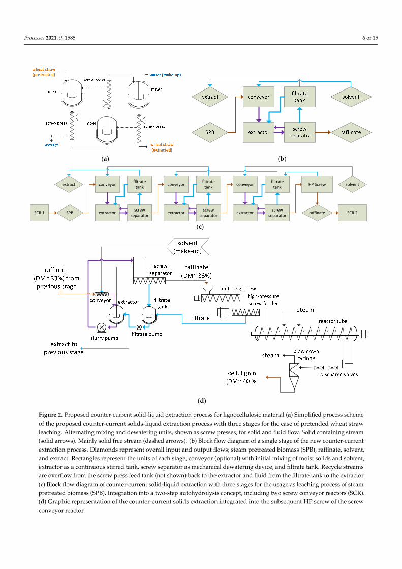
phase in a batch suspension extraction was investigated to determine the time to reach theequilibrium concentration for cut and ground pretreated wheat straw. In Figure 3, the totalpentose concentration is shown in a dimensionless scale from zero (no solids added) to 100(equilibrium concentration).
Processes 2021, 9, 1585 8 of 16
given. The raw data and results can be found in Tables S1–S6 for the modelling results, and in Tables S7 and S8 for the experimental results.
3.1. Batch Suspension Extraction Experiments The solute mass transport rate from the particle interior to the particle outside is of
great importance in an extraction process. The concentration change over time in the bulk phase in a batch suspension extraction was investigated to determine the time to reach the equilibrium concentration for cut and ground pretreated wheat straw. In Figure 3, the total pentose concentration is shown in a dimensionless scale from zero (no solids added) to 100 (equilibrium concentration).
The difference between the two shown samples was the particle size. The ground particles reached 87% of the equilibrium after one minute, while 58% was reached for the larger particles. The ground and coarse samples reached an equilibrium between 1 and 5 min and between 5 and 10 min, respectively.
Smaller particles possess a larger surface area and a shorter average distance inside the particles; thus, mass transfer rates were significantly larger. The oligomer nature of the pentoses after autohydrolysis stream pretreatment and the solute free bulk phase at the beginning of the batch extraction were expected to increase the equilibration time during the suspension extraction. However, the equilibration time was reasonably short for ground particles, which made a continuous extraction feasible. The residence time distribution of a batch extractor and a continuous stirred tank were not comparable. It was assumed that a bulk concentration close to the equilibrium concentration could be achieved by selecting a hydraulic residence time 5 to 10 times greater than the measured equilibrium time in a batch extractor. Therefore, the assumption to reach an equilibrium in the continuous stirred tank suspension extractor in the proposed counter-current extraction was considered feasible. In a continuous stream pretreatment process, the biomass particle size was reduced through the plug screw feeding, similar to a single screw extruder, and the unloading of the reactor, which could be realized as a continuous steam explosion. The composition of the ground pretreated wheat straw was taken as the feed in the leaching scenario.
Figure 3. Dimensionless concentration of total pentoses of a suspension extraction of steam pretreated wheat straw (180 °C, 35 min) in a stirred tank. Solid lines are shown for visual orientation only.
3.2. Design Calculation for Three Suspension Extraction Processes In this section, the process windows for the three discussed extraction processes are
presented. Here, the process window was the range of the extraction yield 𝑌 and the extract concentration 𝐶 that can be achieved by the individually selected design
0102030405060708090
100110
0 5 10 15 20 25 30 35
pent
oses
conc
entr
atio
n [%
]
time [min]
Suspension extraction of steam pretreated straw in water (70°C)
ground straw
cut straw
Figure 3. Dimensionless concentration of total pentoses of a suspension extraction of steam pretreatedwheat straw (180 ◦C, 35 min) in a stirred tank. Solid lines are shown for visual orientation only.
The difference between the two shown samples was the particle size. The groundparticles reached 87% of the equilibrium after one minute, while 58% was reached forthe larger particles. The ground and coarse samples reached an equilibrium between1 and 5 min and between 5 and 10 min, respectively.
Smaller particles possess a larger surface area and a shorter average distance insidethe particles; thus, mass transfer rates were significantly larger. The oligomer nature of thepentoses after autohydrolysis stream pretreatment and the solute free bulk phase at thebeginning of the batch extraction were expected to increase the equilibration time duringthe suspension extraction. However, the equilibration time was reasonably short for groundparticles, which made a continuous extraction feasible. The residence time distribution of abatch extractor and a continuous stirred tank were not comparable. It was assumed that abulk concentration close to the equilibrium concentration could be achieved by selecting ahydraulic residence time 5 to 10 times greater than the measured equilibrium time in a batchextractor. Therefore, the assumption to reach an equilibrium in the continuous stirred tanksuspension extractor in the proposed counter-current extraction was considered feasible. Ina continuous stream pretreatment process, the biomass particle size was reduced throughthe plug screw feeding, similar to a single screw extruder, and the unloading of the reactor,which could be realized as a continuous steam explosion. The composition of the groundpretreated wheat straw was taken as the feed in the leaching scenario.
3.2. Design Calculation for Three Suspension Extraction Processes
In this section, the process windows for the three discussed extraction processesare presented. Here, the process window was the range of the extraction yield YE andthe extract concentration CE that can be achieved by the individually selected designparameters. The design parameters range was chosen as technically possible values onthe basis of the authors’ experience. Figure 4 shows the process windows for the threeextraction processes and a combined process window for applying the leaching process.Figure 5 displays them in an analog manner for the washing process.
The performance targeted design goal for extraction was to simultaneously reach highextraction yield and extract concentration at a low solvent consumption.

Processes 2021, 9, 1585 9 of 15
Processes 2021, 9, 1585 9 of 16
parameters. The design parameters range was chosen as technically possible values on the basis of the authors' experience. Figure 4 shows the process windows for the three extraction processes and a combined process window for applying the leaching process. Figure 5 displays them in an analog manner for the washing process.
The performance targeted design goal for extraction was to simultaneously reach high extraction yield and extract concentration at a low solvent consumption.
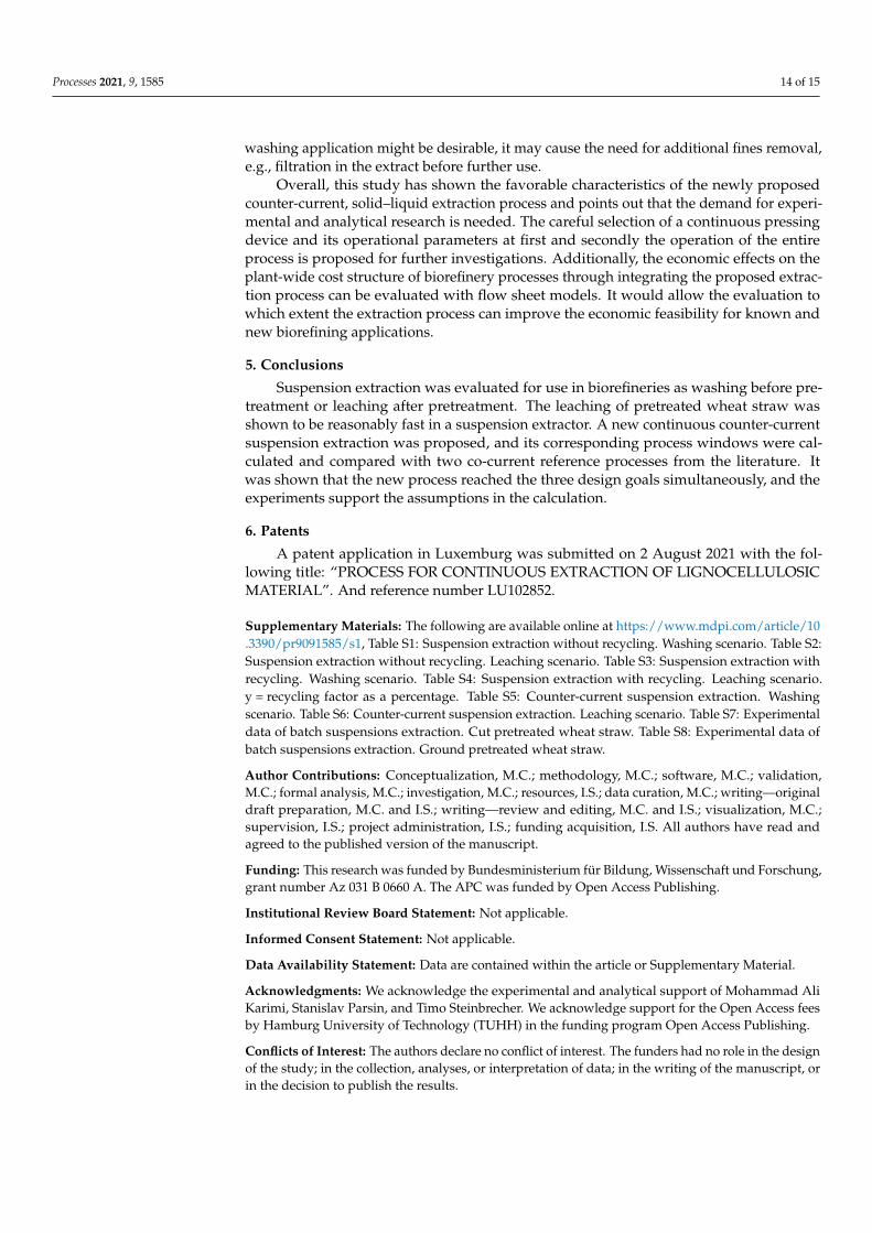
Figure 4. Process windows for the continuous suspension extraction processes for the leaching scenario. (a) Continuous suspension extraction without recycling. (b) Continuous suspension extraction with recycling. (c) New continuous counter-current suspension extraction. (d) All three suspension extraction processes. DM-tank = dry matter content in the extraction tank. DM-out = dry matter content at the stage outlet (press). y = recycling factor. N = number of stages. L/S = liquid to solid ratio (solvent consumption).
6065707580859095
100
0 10 20 30 40
Extr
actio
n yi
eld
YE[w
t%]
Extract concentration CE [g/1000g]
(a) Leaching - Continuous suspension extraction without recyling
DM-tank = 10 wt%DM-tank = 8 wt%DM-tank = 6 wt%DM-tank = 4 wt%DM-tank = 2 wt%DM-out = 55 wt%DM-out = 45 wt%DM-out = 35 wt%DM-out = 25 wt% 75
80
85
90
95
100
40 60 80 100
Extr
actio
n yi
eld
YE[w
t%]
Extract concentration CE [g/1000g]
(c) Leaching - New continuous counter-current suspension extraction
N = 5 N = 4 N = 3N = 2 L/S=4 L/S = 3L/S=2,25 L/S=2 L/S=1,75L/S=1,5 L/S=1,0
0
20
40
60
80
100
0 20 40 60 80 100
Extr
actio
n yi
eld
YE[w
t%]
Extract concentration CE [g/1000g]
(b) Leaching - Continuous suspension extraction with recyling
DM-out = 55 wt%DM-out = 45 wt%DM-out = 35 wt%DM-out = 25 wt%y = 90 %y = 80 %y = 70 %y = 30 %y = 0 % 30
40
50
60
70
80
90
100
0 50 100
Extr
actio
n yi
eld
YE[w
t%]
Extract concentration CE [g/1000g]
(d) Leaching - Three suspension extraction processes
Figure 4. Process windows for the continuous suspension extraction processes for the leaching scenario. (a) Continuoussuspension extraction without recycling. (b) Continuous suspension extraction with recycling. (c) New continuous counter-current suspension extraction. (d) All three suspension extraction processes. DM-tank = dry matter content in the extractiontank. DM-out = dry matter content at the stage outlet (press). y = recycling factor. N = number of stages. L/S = liquid tosolid ratio (solvent consumption).

Processes 2021, 9, 1585 10 of 15Processes 2021, 9, 1585 10 of 16
Figure 5. Process windows for the continuous suspension extraction processes for the washing scenario. (a) Continuous suspension extraction without recycling. (b) Continuous suspension extraction with recycling. (c) New continuous counter-current suspension extraction. (d) All three suspension extraction processes. DM-tank = dry matter content in the extraction tank. DM-out = dry matter content at the stage outlet (press). y = recycling factor. N = number of stages. L/S = liquid to solid ratio (solvent consumption).
3.2.1. Continuous Suspension Extraction without Recycling In Figures 4a and 5a, the process windows for the continuous suspension extraction
are displayed. The vertical lines refer to the variation in the dry matter content in the tank. As expected, the less the feed was diluted with the solvent, the higher the extract concentration. The near-horizontal lines represent constant values of DM-out. The dry matter content after the pressing DM-out showed no effect on the extract concentration. The drier the material after the press, the higher the extraction yield. The slope of the near-horizontal lines was affected by DM-out. The extraction yield was affected by both design parameters. The dilution of the solids in the tank reduced the raffinate concentration. Thus, the remaining solute in the final underflow—liquid in the pressed solid—was reduced. The dry matter content after pressing determined the amount of solute remaining at the solids in the outflow.
The leaching and the washing case differed in the position of the process window and not in its characteristics. The washing case showed a minor maximal concentration, which was expected to be a consequence of the lower solute amount in the feed. Moreover, a more comprehensive range of extraction yields was possible than in the leaching scenario. This was caused by lower solute content and larger solvent amount in the feed.
30
40
50
60
70
80
90
100
0 5 10 15
Extr
actio
n yi
eld
YE[w
t%]
Extract concentration CE [g/1000g]
(a) Washing - Continuous suspension extraction without recyling
DM-tank = 10 wt%DM-tant = 8 wt%DM-tank = 6 wt%DM-tank = 4 wt%DM-tank = 2 wt%DM-out = 55 wt%DM-out = 45 wt%DM-out = 35 wt%DM-out = 25 wt% 50
556065707580859095
100
0 20 40 60 80
Extr
actio
n yi
eld
YE[w
t%]
Extract concentration CE [g/1000g]
(c) Washing - New continuous counter-current suspension extraction
N=4N=3N=2L/S=4,0L/S=3,0L/S=2,25L/S=2L/S=1,75L/S=1,5
0
20
40
60
80
100
0 5 10 15 20 25
Extr
actio
n yi
eld
YE[w
t%]
Extract concentration CE [g/1000g]
(b) Washing - Continuous suspension extraction with recyling
DM-out = 55 wt%DM-out = 45 wt%DM-out = 35 wt%DM-out = 25 wt%y = 90 %y = 80 %y = 70 %y = 30 %y = 0 % 0
20
40
60
80
100
0 20 40 60 80
Extr
actio
n yi
eld
YE[w
t%]
Extract concentration CE [g/1000g]
(d) Washing - Three suspension extraction processes
Figure 5. Process windows for the continuous suspension extraction processes for the washing scenario. (a) Continuoussuspension extraction without recycling. (b) Continuous suspension extraction with recycling. (c) New continuous counter-current suspension extraction. (d) All three suspension extraction processes. DM-tank = dry matter content in the extractiontank. DM-out = dry matter content at the stage outlet (press). y = recycling factor. N = number of stages. L/S = liquid tosolid ratio (solvent consumption).
3.2.1. Continuous Suspension Extraction without Recycling
In Figures 4a and 5a, the process windows for the continuous suspension extractionare displayed. The vertical lines refer to the variation in the dry matter content in thetank. As expected, the less the feed was diluted with the solvent, the higher the extractconcentration. The near-horizontal lines represent constant values of DM-out. The drymatter content after the pressing DM-out showed no effect on the extract concentration.The drier the material after the press, the higher the extraction yield. The slope of the near-horizontal lines was affected by DM-out. The extraction yield was affected by both designparameters. The dilution of the solids in the tank reduced the raffinate concentration. Thus,the remaining solute in the final underflow—liquid in the pressed solid—was reduced. Thedry matter content after pressing determined the amount of solute remaining at the solidsin the outflow.
The leaching and the washing case differed in the position of the process window andnot in its characteristics. The washing case showed a minor maximal concentration, whichwas expected to be a consequence of the lower solute amount in the feed. Moreover, a

Processes 2021, 9, 1585 11 of 15
more comprehensive range of extraction yields was possible than in the leaching scenario.This was caused by lower solute content and larger solvent amount in the feed. Thesolvent consumption was in increasing order of DM-tank: 46, 21, 13, 9, and 6 for theleaching scenario, and 49, 24, 16, 11, and 9 for the washing scenario (compare with theSupplementary Material).
3.2.2. Continuous Suspension Extraction with Recycling
Figures 4b and 5b display the process windows for the continuous suspension extrac-tion with recycling. Here, a dry matter content in the tank was chosen to be 5 wt % and notvaried in this study. The dry matter content at the outlet after pressing and the recyclingfactor were varied to calculate the process window.
The line for a constant recycling rate was vertical at no recycling, and its slope de-creased with rising values of the recycling factor itself. The larger the recycling factor atconstant DM-out, the larger the concentration, the lower the solvent consumption andthe lower the yield. An increase in DM-out improved the extraction yield and extractconcentration at the same time if the recycling was larger than zero. Similar to the previousprocess, the lines for constant DM-out were nearly horizontal, and the slope decreasedwith decreasing DM-out. When increasing the recycling rate, the lines of constant DM-outwere extended towards higher concentrations and lower yields. Changing DM-tank didnot affect the position of the lines of constant DM-out but led to a shift of this line along itsdirection (not shown).
In Figure 6, the effect of the recycling factor is shown on the extraction yield, extractconcentration, and solvent consumption for the leaching scenario at DM-tank = 5 wt %and DM-out = 35 wt %. On the one hand, increasing the recycling factor decreased thesolvent consumption linearly and increased the extract concentration, which targetedthe performance-centered design. On the other hand, an increase in the recycling factordecreased the extraction yield progressively. That meant that the effect on the yield wassmall for small recycling factors and more significant for larger ones. A recycling factor of100% was not possible since the water input was larger than the water output adheringto the solids. Thus, some amount of extract needed to be removed from the system. Themaximal recycling factor depended on the feed composition and the selected processparameters (not shown).
Processes 2021, 9, 1585 11 of 16
The solvent consumption was in increasing order of DM-tank: 46, 21, 13, 9, and 6 for the leaching scenario, and 49, 24, 16, 11, and 9 for the washing scenario (compare with the Supplementary Material).
3.2.2. Continuous Suspension Extraction with Recycling Figures 4b and 5b display the process windows for the continuous suspension
extraction with recycling. Here, a dry matter content in the tank was chosen to be 5 wt % and not varied in this study. The dry matter content at the outlet after pressing and the recycling factor were varied to calculate the process window.
The line for a constant recycling rate was vertical at no recycling, and its slope decreased with rising values of the recycling factor itself. The larger the recycling factor at constant DM-out, the larger the concentration, the lower the solvent consumption and the lower the yield. An increase in DM-out improved the extraction yield and extract concentration at the same time if the recycling was larger than zero. Similar to the previous process, the lines for constant DM-out were nearly horizontal, and the slope decreased with decreasing DM-out. When increasing the recycling rate, the lines of constant DM-out were extended towards higher concentrations and lower yields. Changing DM-tank did not affect the position of the lines of constant DM-out but led to a shift of this line along its direction (not shown).
In Figure 6, the effect of the recycling factor is shown on the extraction yield, extract concentration, and solvent consumption for the leaching scenario at DM-tank = 5 wt % and DM-out = 35 wt %. On the one hand, increasing the recycling factor decreased the solvent consumption linearly and increased the extract concentration, which targeted the performance-centered design. On the other hand, an increase in the recycling factor decreased the extraction yield progressively. That meant that the effect on the yield was small for small recycling factors and more significant for larger ones. A recycling factor of 100% was not possible since the water input was larger than the water output adhering to the solids. Thus, some amount of extract needed to be removed from the system. The maximal recycling factor depended on the feed composition and the selected process parameters (not shown).
Figure 6. Suspension extraction with recycling for leaching scenario. Extraction yield, extraction concentration, and solvent consumption as a function of the recycling factor. DM-tank = 5 wt % and DM-out = 35 wt %.
3.2.3. Counter-Current Continuous Suspension Extraction In Figures 4c and 5c, the process windows for the continuous counter-current
suspension extraction are displayed. The near-vertical lines represent a constant solvent consumption L/S, while the near-horizontal lines represent the number of stages N. The DM-tank did not affect the process windows (not shown). Increasing the number of stages increased the extraction yield and the extract concentration simultaneously, without affecting the solvent consumption. Thus, it became evident that many stages were
01234567
0
20
40
60
80
100
0 20 40 60 80 100 L/S
solv
ent c
onsu
mpt
ion
[g/g
]
YE[w
t%],
CE
[g/1
000g
]
Recycle factor [%]
DM-tank = 5%; DM-out = 35%
Y E [wt%]C E [g/L]L/S [g/g]
Figure 6. Suspension extraction with recycling for leaching scenario. Extraction yield, extractionconcentration, and solvent consumption as a function of the recycling factor. DM-tank = 5 wt % andDM-out = 35 wt %.

Processes 2021, 9, 1585 12 of 15
3.2.3. Counter-Current Continuous Suspension Extraction
In Figures 4c and 5c, the process windows for the continuous counter-current sus-pension extraction are displayed. The near-vertical lines represent a constant solventconsumption L/S, while the near-horizontal lines represent the number of stages N. TheDM-tank did not affect the process windows (not shown). Increasing the number of stagesincreased the extraction yield and the extract concentration simultaneously, without affect-ing the solvent consumption. Thus, it became evident that many stages were favorable toreach the performance-centered design criteria. The higher the number of stages, the lowerthe effect of another stage on the yield and concentration. This effect was more pronouncedwith an increasing solvent consumption. With an increase in the solvent consumption,the yield was increased, and the extract concentration was decreased. At low solventconsumption, the effect of further stages on yield and concentration remained large.
For this process, the two regarded process parameters can be selected in a wide rangeof values. Choosing a stage number higher than five did not seem necessary. However, it ispossible. For both scenarios, it can be seen that a high yield, high concentration, and lowsolvent consumption can be achieved with the regarded dry matter contents after pressing.
3.2.4. Comparison of Three Continuous Suspension Extractions
Figures 4d and 5d show the process windows for the three regarded continuoussuspension extraction processes. The lines for constant DM-out were identical for theextraction with and without recycling for both scenarios. Thus, recycling a fraction ofthe extract opened a more extensive process window and allowed for more flexibility inselecting design parameters. Additionally, recycling allowed for achieving substantiallylarger extract concentrations. Unfortunately, the yield was reduced at the same time. Thiseffect was more pronounced in the leaching scenario than in the washing scenario. A lowerDM-tank or a larger recycling factor (>90 wt %) could be chosen to expand the lines ofconstant DM-out for the suspensions extraction with recycling.
The counter-current extraction process can be found further up and right in the processwindow diagrams, which means that the extraction yield and the extract concentrationswere improved simultaneously. In the counter-current process, the combination of extrac-tion yield and extract concentration was not defined by the DM-out but depended on thenumber of stages. Moreover, meager solvent consumption was possible with this process,with a comparatively mild decrease in the yield at a constant stage number. In the recy-cling process, low solvent consumption was possible but with generally worse extractionyields. The yield in the counter-current extraction process was approaching 100%, andconcentrations of up to 90 g/1000 g were possible. High performance was possible becausethe solvent was used to remain a medium but constant concentration difference to theraffinate in each stage. Thus, the underflow concentration was relatively low at the inputto the final pressing device. The extract concentration was enriched and approached thefeed concentration. The extract concentration can be further improved by choosing a lowersolvent consumption and a higher number of stages to compensate for the yield. The limitin yield and concentration were 100 wt % and the feed concentration, respectively.
4. Discussion
The suspension extraction without recycling possessed low flexibility in the selec-tion of design parameters and extraction performance. Very high extractions yields werepossible by a substantial dilution of the extract concentration and enormous solvent con-sumption. It was not possible to reach concentrations in the extract that were near the feedconcentration. However, this process does not require recycling streams; thus, a low effortin the set-up and operation is required.
The suspension extraction with recycling improved flexibility by selecting designparameters from a more comprehensive process window. The advantage of this processis the vastly reduced solvent consumption without a significant increase in the processcomplexity. Thus, it is suspected that the installation and operational costs are still low. The

Processes 2021, 9, 1585 13 of 15
application for washing and leaching is possible. The application of extreme recycling fac-tors enlarges the process window but is limited by practical constraints. With an increasingrecycling factor, the recycling stream increases immensely. A significant reason is that theinflow to the filtrate tank is increased. The amount of liquid recycled at extreme recyclingfactors becomes a multitude of process solids masses. Additionally, it is challenging to splita stream into two very differently large streams since fluctuations in all streams may belarger than the small outflow. Thus, it is not easy to maintain a steady operation.
It was demonstrated by Sanchis-Sebastiá et al. [1] that suspension extraction withrecycling is a feasible approach to wash straw after it is used as animal bedding to gaina straw-rich substrate for the production of bioethanol and one manure-rich stream forbio-methane production. Here, the advantages are an increased concentration for biogasproduction and reduced demand for costly wastewater treatment. The application ispossible due to the moderate requirements for the extraction yield [2].
The process engineer still has to find a trade-off between concentration and extractionyield for the leaching applications. If the two-step pretreatment process is considered, thevaluable solute should be removed before further treatment of the solid to avoid productdegradation. Thus, a high extraction yield is favored. In this case, there is no significantadvantage of the use of a recycling stream.
The continuous counter-current suspensions extraction process proposed in this workallowed us to reach the three desired extraction performance parameters, namely, extractionyield, extract concentration, and low solvent consumption, simultaneously. Thus, thisprocess is favorable for leaching and washing applications over the other two discussedreference processes. Already at two stages, the superiority was shown. There is anextensive range of values for the process parameters that can be chosen; thus, the processcan be flexibly adapted to the regarded separation task and processing requirements. Anadvantage over other counter-current extraction processes is the low solvent consumptionand highly concentrated extracts. At the same time, it uses only standard equipment thatis widely available and affordable. Furthermore, the spatial arrangement of the plant isflexible, e.g., it can be organized on two or more levels to spare ground area.
A disadvantage is the complexity of the process. The speed of the extraction isachieved by applying external forces in the mixing and pressing. Here, the electricalenergy demand must be considered carefully and at best with the help of experiments.The performance and process windows are different for each application and must beevaluated individually. In addition, the screw press must be selected and tested for eachmaterial. The throughput, dry matter content in the solids, and the liquid effluent’s finesmust be investigated experimentally. The mass of fines in the filtrate may be influencedby the dry matter content in the entrance of the screw press and the rotational speed ofthe screw. The latter also affects the dry matter content at the outlet and the throughput.As a rule of thumb, the lower the screw speed, the higher the dry matter content of thepressed solids, the lower the throughput, and the lower the content of fines in the filtrate.The amount and size of fines in the filtrate are essential for the plant design. Due to manypossible (screw) press configurations and the non-predictable behavior of the feed material,the apparatus size and energy demand require individual process development. Theprocess was not realized experimentally in its entirety. Thus, many essential characteristicsremain unknown, such as the stage efficiency, the energy demand for pressing, and thepressing throughput.
The stage efficiency is mainly determined by mass transport in the extractor. Therefore,the assumptions of equilibrium and thus an efficiency of 100% in every stage might notbe appropriate in every application. The main parameters affecting the efficiency are thesolids loading in the tank; the energy input by stirring; the residence time and residencetime distribution in the conveyor, extractor, and piping to the press; and the positions ofthe extract inlet. If the efficiency was less than 100%, the process windows were not correct.It was suspected that a reduced efficiency and a lower dry matter content after pressingcan be compensated by an increase in the number of stages. While the removal of fines in a
Processes 2021, 9, 1585 14 of 15
washing application might be desirable, it may cause the need for additional fines removal,e.g., filtration in the extract before further use.
Overall, this study has shown the favorable characteristics of the newly proposedcounter-current, solid–liquid extraction process and points out that the demand for experi-mental and analytical research is needed. The careful selection of a continuous pressingdevice and its operational parameters at first and secondly the operation of the entireprocess is proposed for further investigations. Additionally, the economic effects on theplant-wide cost structure of biorefinery processes through integrating the proposed extrac-tion process can be evaluated with flow sheet models. It would allow the evaluation towhich extent the extraction process can improve the economic feasibility for known andnew biorefining applications.
5. Conclusions
Suspension extraction was evaluated for use in biorefineries as washing before pre-treatment or leaching after pretreatment. The leaching of pretreated wheat straw wasshown to be reasonably fast in a suspension extractor. A new continuous counter-currentsuspension extraction was proposed, and its corresponding process windows were cal-culated and compared with two co-current reference processes from the literature. Itwas shown that the new process reached the three design goals simultaneously, and theexperiments support the assumptions in the calculation.
6. Patents
A patent application in Luxemburg was submitted on 2 August 2021 with the fol-lowing title: “PROCESS FOR CONTINUOUS EXTRACTION OF LIGNOCELLULOSICMATERIAL”. And reference number LU102852.
Supplementary Materials: The following are available online at https://www.mdpi.com/article/10.3390/pr9091585/s1, Table S1: Suspension extraction without recycling. Washing scenario. Table S2:Suspension extraction without recycling. Leaching scenario. Table S3: Suspension extraction withrecycling. Washing scenario. Table S4: Suspension extraction with recycling. Leaching scenario.y = recycling factor as a percentage. Table S5: Counter-current suspension extraction. Washingscenario. Table S6: Counter-current suspension extraction. Leaching scenario. Table S7: Experimentaldata of batch suspensions extraction. Cut pretreated wheat straw. Table S8: Experimental data ofbatch suspensions extraction. Ground pretreated wheat straw.
Author Contributions: Conceptualization, M.C.; methodology, M.C.; software, M.C.; validation,M.C.; formal analysis, M.C.; investigation, M.C.; resources, I.S.; data curation, M.C.; writing—originaldraft preparation, M.C. and I.S.; writing—review and editing, M.C. and I.S.; visualization, M.C.;supervision, I.S.; project administration, I.S.; funding acquisition, I.S. All authors have read andagreed to the published version of the manuscript.
Funding: This research was funded by Bundesministerium für Bildung, Wissenschaft und Forschung,grant number Az 031 B 0660 A. The APC was funded by Open Access Publishing.
Institutional Review Board Statement: Not applicable.
Informed Consent Statement: Not applicable.
Data Availability Statement: Data are contained within the article or Supplementary Material.
Acknowledgments: We acknowledge the experimental and analytical support of Mohammad AliKarimi, Stanislav Parsin, and Timo Steinbrecher. We acknowledge support for the Open Access feesby Hamburg University of Technology (TUHH) in the funding program Open Access Publishing.
Conflicts of Interest: The authors declare no conflict of interest. The funders had no role in the designof the study; in the collection, analyses, or interpretation of data; in the writing of the manuscript, orin the decision to publish the results.

Processes 2021, 9, 1585 15 of 15
References1. Sanchis-Sebastiá, M.; Gomis-Fons, J.; Galbe, M.; Wallberg, O. Techno-Economic Evaluation of Biorefineries Based on Low-Value
Feedstocks Using the BioSTEAM Software: A Case Study for Animal Bedding. Processes 2020, 8, 904. [CrossRef]2. Sanchis-Sebastiá, M.; Erdei, B.; Kovacs, K.; Galbe, M.; Wallberg, O. Introducing Low-Quality Feedstocks in Bioethanol Produc-
tion: Efficient Conversion of the Lignocellulose Fraction of Animal Bedding through Steam Pretreatment. Biotechnol. Biofuels2019, 12, 215. [CrossRef] [PubMed]
3. He, Y.; Fang, Z.; Zhang, J.; Li, X.; Bao, J. De-Ashing Treatment of Corn Stover Improves the Efficiencies of Enzymatic Hydrolysisand Consequent Ethanol Fermentation. Bioresour. Technol. 2014, 169, 552–558. [CrossRef] [PubMed]
4. Huang, C.; Wu, X.; Huang, Y.; Lai, C.; Li, X.; Yong, Q. Prewashing Enhances the Liquid Hot Water Pretreatment Efficiency ofWaste Wheat Straw with High Free Ash Content. Bioresour. Technol. 2016, 219, 583–588. [CrossRef] [PubMed]
5. Andersen, L.F.; Parsin, S.; Lüdtke, O.; Kaltschmitt, M. Biogas Production from Straw—The Challenge Feedstock Pretreatment.Biomass Conv. Bioref. 2020, 1–24. [CrossRef]
6. Carvalho, A.F.A.; Neto, P.d.O.; da Silva, D.F.; Pastore, G.M. Xylo-Oligosaccharides from Lignocellulosic Materials: ChemicalStructure, Health Benefits and Production by Chemical and Enzymatic Hydrolysis. Food Res. Int. 2013, 51, 75–85. [CrossRef]
7. Humbird, D.; Davis, R.; Tao, L.; Kinchin, C.; Hsu, D.; Aden, A.; Schoen, P.; Lukas, J.; Olthof, B.; Worley, M.; et al. Process Designand Economics for Biochemical Conversion of Lignocellulosic Biomass to Ethanol: Dilute-Acid Pretreatment and Enzymatic Hydrolysis ofCorn Stover; National Renewable Energy Lab.: Golden, CO, USA, 2011.
8. Larsen, J.; Haven, M.Ø.; Thirup, L. Inbicon Makes Lignocellulosic Ethanol a Commercial Reality. Biomass Bioenergy 2012, 46, 36–45. [CrossRef]9. Schmidt, L. Wertschöpfungssteigerung aus Lignocellulosen mittels thermisch-enzymatischer Hydrolyse im Hochdruck-Festbett
Ökonomische Bewertung am Beispiel von Getreidestroh. Ph.D. Thesis, Technische Universität Hamburg, Hamburg, Germany, 2019.10. Forstner, J.; Unkelbach, G.; Pindel, E.; Schweppe, R. Heterogen katalysierte Herstellung von Furfural aus Xylose. Chem.-Ing.-Tech.
2012, 84, 503–508. [CrossRef]11. Schmidt, L.M.; Pérez Martínez, V.; Kaltschmitt, M. Solvent-Free Lignin Recovered by Thermal-Enzymatic Treatment Using
Fixed-Bed Reactor Technology—Economic Assessment. Bioresour. Technol. 2018, 268, 382–392. [CrossRef] [PubMed]12. Gairola, K.; Smirnova, I. Hydrothermal Pentose to Furfural Conversion and Simultaneous Extraction with SC-CO2—Kinetics and
Application to Biomass Hydrolysates. Bioresour. Technol. 2012, 123, 592–598. [CrossRef] [PubMed]13. Conrad, M.; Smirnova, I. Two-Step Autohydrolysis Pretreatment: Towards High Selective Full Fractionation of Wheat Straw.
Chem. Ing. Tech. 2020, 92, 1723–1732. [CrossRef]14. Conrad, M.; Häring, H.; Smirnova, I. Design of an Industrial Autohydrolysis Pretreatment Plant for Annual Lignocellulose.
Biomass Conv. Bioref. 2019, 362, 1. [CrossRef]15. Crawford, N.C.; Nagle, N.; Sievers, D.A.; Stickel, J.J. The Effects of Physical and Chemical Preprocessing on the Flowability of
Corn Stover. Biomass Bioenergy 2016, 85, 126–134. [CrossRef]16. Asadi, M. Beet-Sugar Handbook; Wiley-Interscience: Hoboken, NJ, USA, 2007; ISBN 978-0-471-76347-5.17. Voeste, T.; Weber, K.; Hiskey, B.; Brunner, G. Liquid–Solid Extraction. In Ullmann’s Encyclopedia of Industrial Chemistry; American
Cancer Society, 2006; ISBN 978-3-527-30673-2. Available online: https://onlinelibrary.wiley.com/doi/10.1002/14356007.b03_07(accessed on 20 August 2021).
18. Conrad, S. Process of Extraction from Substances Containing Oil, Fat, Etc. U.S. Patent 1,862,945A, 14 June 1932.19. Appel, G.F.B. Juice Extraction by Hydraulic Displacement. U.S. Patent 3,248,262A, 26 April 1966.20. Bockisch, M. The Extraction of Vegetable Oils. In Fats and Oils Handbook; Elsevier: Amsterdam, The Netherlands, 1998; pp. 345–445.
ISBN 978-0-9818936-0-0.21. Fellows, P.J. Extraction and separation of food components. In Food Processing Technology; Elsevier: Amsterdam, The Netherlands,
2017; pp. 235–289. ISBN 978-0-08-101907-8.22. Krotscheck, A.W. Pulp Washing. In Handbook of Pulp; WILEY-VCH Verlag GmbH & Co. KGaA: Weinheim, Germany, 2006;
pp. 511–559. ISBN 978-3-527-61988-7.23. Sievers, D.A.; Tao, L.; Schell, D.J. Performance and Techno-Economic Assessment of Several Solid–Liquid Separation Technologies
for Processing Dilute-Acid Pretreated Corn Stover. Bioresour. Technol. 2014, 167, 291–296. [CrossRef] [PubMed]24. Sievers, D.A.; Kuhn, E.M.; Tucker, M.P.; McMillan, J.D. Effects of Dilute-Acid Pretreatment Conditions on Filtration Performance
of Corn Stover Hydrolyzate. Bioresour. Technol. 2017, 243, 474–480. [CrossRef] [PubMed]25. Kim, K.H.; Tucker, M.P.; Keller, F.A.; Aden, A.; Nguyen, Q.A. Continuous Countercurrent Extraction of Hemicellulose from
Pretreated Wood Residues. In Twenty-Second Symposium on Biotechnology for Fuels and Chemicals; Davison, B.H., McMillan, J.,Finkelstein, M., Eds.; ABAB Symposium; Humana Press: Totowa, NJ, USA, 2001; pp. 253–267. ISBN 978-1-4612-0217-2.
26. Thomsen, M.H.; Thygesen, A.; Thomsen, A.B. Hydrothermal Treatment of Wheat Straw at Pilot Plant Scale Using a Three-StepReactor System Aiming at High Hemicellulose Recovery, High Cellulose Digestibility and Low Lignin Hydrolysis. Bioresour.Technol. 2008, 99, 4221–4228. [CrossRef] [PubMed]
27. Thomsen, M.H.; Thygesen, A.; Jørgensen, H.; Larsen, J.; CHRISTENSEN, B.H.; THOMSEN, A.B. Preliminary Results onOptimization of Pilot Scale Pretreatment of Wheat Straw Used in Coproduction of Bioethanol and Electricity. Appl. Biochem.Biotech. 2006, 129, 13.
28. Sluiter, A. Determination of Structural Carbohydrates and Lignin in Biomass: Laboratory Analytical Procedure (LAP). Issue Date:17 July 2005; 2008; p. 16. Available online: https://www.nrel.gov/docs/gen/fy13/42618.pdf (accessed on 3 September 2021).