(Costing) An Integration Methodology for Automated ...
46
HAL Id: hal-00721640 https://hal.archives-ouvertes.fr/hal-00721640 Submitted on 29 Jul 2012 HAL is a multi-disciplinary open access archive for the deposit and dissemination of sci- entific research documents, whether they are pub- lished or not. The documents may come from teaching and research institutions in France or abroad, or from public or private research centers. L’archive ouverte pluridisciplinaire HAL, est destinée au dépôt et à la diffusion de documents scientifiques de niveau recherche, publiés ou non, émanant des établissements d’enseignement et de recherche français ou étrangers, des laboratoires publics ou privés. (Costing) An Integration Methodology for Automated Recurring Cost Prediction using Digital Manufacturing Technology Yan Jin, Ricky Curran, Robert Burke, Brian Welch To cite this version: Yan Jin, Ricky Curran, Robert Burke, Brian Welch. (Costing) An Integration Methodology for Auto- mated Recurring Cost Prediction using Digital Manufacturing Technology. International Journal of Computer Integrated Manufacturing, Taylor & Francis, 2011, pp.1. 10.1080/0951192X.2011.579171. hal-00721640
-
Upload
khangminh22 -
Category
Documents
-
view
3 -
download
0
Transcript of (Costing) An Integration Methodology for Automated ...

HAL Id: hal-00721640https://hal.archives-ouvertes.fr/hal-00721640
Submitted on 29 Jul 2012
HAL is a multi-disciplinary open accessarchive for the deposit and dissemination of sci-entific research documents, whether they are pub-lished or not. The documents may come fromteaching and research institutions in France orabroad, or from public or private research centers.
L’archive ouverte pluridisciplinaire HAL, estdestinée au dépôt et à la diffusion de documentsscientifiques de niveau recherche, publiés ou non,émanant des établissements d’enseignement et derecherche français ou étrangers, des laboratoirespublics ou privés.
(Costing) An Integration Methodology for AutomatedRecurring Cost Prediction using Digital Manufacturing
TechnologyYan Jin, Ricky Curran, Robert Burke, Brian Welch
To cite this version:Yan Jin, Ricky Curran, Robert Burke, Brian Welch. (Costing) An Integration Methodology for Auto-mated Recurring Cost Prediction using Digital Manufacturing Technology. International Journal ofComputer Integrated Manufacturing, Taylor & Francis, 2011, pp.1. �10.1080/0951192X.2011.579171�.�hal-00721640�
For Peer Review O
nly
(Costing) An Integration Methodology for Automated Recurring Cost Prediction using Digital Manufacturing
Technology
Journal: International Journal of Computer Integrated Manufacturing
Manuscript ID: TCIM-2010-IJCIM-0105
Manuscript Type: Special Issue Paper
Date Submitted by the Author:
26-Jul-2010
Complete List of Authors: Jin, Yan; Queen's University Belfast, School of Mechanical and Aerospace Engineering Curran, Ricky Burke, Robert Welch, Brian
Keywords: MANUFACTURING INFORMATION SYSTEMS, MANUFACTURING ENGINEERING, COST MANAGEMENT, COSTING, INTEGRATION
Keywords (user): Digital manufacturing, knowledge
URL: http://mc.manuscriptcentral.com/tandf/tcim Email:[email protected]
International Journal of Computer Integrated Manufacturing
For Peer Review O
nlySpecial issue on costing in IJCIM.
Reference no. no number, handled by Dr Linda Newnes Title: An Integration Methodology for Automated Recurring Cost Prediction using Digital Manufacturing
Technology
Authors: 1. Yan Jin: (corresponding author) School of Mechanical & Aerospace Engineering, Queen’s
University Belfast, UK BT9 5AH, email: [email protected], Tel: +44 (0)2890974102
2. Ricky Curran: Faculty of Aerospace Engineering, Delft Univ. of Technology, 2629 HS Delft,
The Netherlands, email: [email protected]
3. Robert Burke: Bombardier Aerospace Belfast, Airport Road, Belfast, UK BT3 9DZ, email:
4. Brian Welch: Bombardier Aerospace Belfast, Airport Road, Belfast, UK BT3 9DZ, email:
Abstract:
The need to account for the effect of design decisions on manufacture and the impact of
manufacturing cost on the life cycle cost of any product are well established. In this context, digital
design and manufacturing solutions have to be further developed to facilitate and automate the
integration of cost as one of the major driver in the product life cycle management. This paper is to
present an integration methodology for implementing cost estimation capability within a digital
manufacturing environment. A digital manufacturing structure of knowledge databases are set out
and the ontology of assembly and part costing that is consistent with the structure is provided.
Although the methodology is currently used for recurring cost prediction, it can be well applied to
other functional developments, such as process planning. A prototype tool is developed to integrate
both assembly time cost and parts manufacturing costs within the same digital environment. An
industrial example is used to validate this approach.
Keywords: cost; manufacturing; digital; integration; knowledge
Page 1 of 44
URL: http://mc.manuscriptcentral.com/tandf/tcim Email:[email protected]
International Journal of Computer Integrated Manufacturing
For Peer Review O
nly
An Integration Methodology for Automated Recurring Cost Prediction using
Digital Manufacturing Technology
Y. Jin1, R. Curran
2, R. Burke
3 and B. Welch
4
1
School of Mechanical & Aerospace Engineering, Queen’s University Belfast, UK BT9 5AH
Email: [email protected]
2
Faculty of Aerospace Engineering, Delft Univ. of Technology, 2629 HS Delft, The
Netherlands
3,4
Bombardier Aerospace Belfast, Airport Road, Belfast, UK BT3 9DZ
Abstract: The need to account for the effect of design decisions on manufacture and the impact of
manufacturing cost on the life cycle cost of any product are well established. In this context, digital
design and manufacturing solutions have to be further developed to facilitate and automate the
integration of cost as one of the major driver in the product life cycle management. This paper is to
present an integration methodology for implementing cost estimation capability within a digital
manufacturing environment. A digital manufacturing structure of knowledge databases are set out and
the ontology of assembly and part costing that is consistent with the structure is provided. Although
the methodology is currently used for recurring cost prediction, it can be well applied to other
functional developments, such as process planning. A prototype tool is developed to integrate both
assembly time cost and parts manufacturing costs within the same digital environment. An industrial
example is used to validate this approach.
Keywords: cost; manufacturing; digital; integration; knowledge
1. Introduction
Modern manufacturing enterprises are facing unprecedented competitive pressure to improve
productivity, migrate rework rate and make the right decision at first time, so as to reduce cost
and shorten the time for their products on markets. It is estimated that about seventy percent of
manufacturing cost is determined at the design stage, in which there is not enough production
information available. Many research efforts have been put into bring manufacturing knowledge
into design domain at the early design stage. Latest research shows that some DFMA tools which
facilitate to make design decisions for manufacturing and assembly have been developed
(Boothroyd et al. 2002, Curran et al. 2005, 2007a, Jin et al. 2008, 2009a, 2009b, Zha et al.
2001). But almost all of them are only pieces of the simulation or function modules, which have
not been effectively integrated into a comprehensive digital manufacturing environment which
covers the whole product life cycle. More and more manufacturing companies are resorting to
Page 2 of 44
URL: http://mc.manuscriptcentral.com/tandf/tcim Email:[email protected]
International Journal of Computer Integrated Manufacturing

For Peer Review O
nly
digital manufacturing software to implement truly lean enterprises (Curran et al. 2007a, 207c,
Dassault Systems 2002, Schmitt 2007).
Digital manufacturing is defined as the ability to describe every aspect of the design-to-
manufacturing process digitally – using tools that include digital design, CAD, office documents,
PLM systems, analysis software, simulation, CAM software and so on (CIMdata 2006, Dalton-
Taggart 2007). Digital manufacturing is an emerging software technology that will become a
fundamental and liberating component of product lifecycle management (Curran et al. 2007b). It
provides a concurrent engineering platform for integrated product teams to achieve optimal
product life cycle solutions. However, such tools cannot be embedded blindly and they often
need to be company-specific, which poses new challenges on knowledge capture, date definition
and transformation, and the development of effective and efficient decision making tools
(Freedman 1999, Seino et al. 2001). Digital manufacturing solutions have to be applied within a
framework of carefully developed and deployed closed-loop processes for both manufacturing
planning and information management.
The work in this paper focuses on the integration method for cost estimation capability,
which is part of a big project for implementing lean enterprises through digital manufacturing.
This paper considers the development of a digital design and manufacturing modeling platform
with integrated cost analysis capabilities, providing a truly collaborative methodology and
concurrent engineering tool for shortening aircraft assembly time, so as to reduce aircraft life
cycle cost. A digital manufacturing framework is analyzed and requirements of developing
assembly cost estimating functionalities within it are addressed. A digital manufacturing
structure of knowledge databases are set out and the ontology of assembly and part costing that is
consistent with the structure is provided. This will help design, manufacturing and IT engineers
Page 3 of 44
URL: http://mc.manuscriptcentral.com/tandf/tcim Email:[email protected]
International Journal of Computer Integrated Manufacturing
For Peer Review O
nly
to bridge their knowledge gap. A digital platform solution for implementing rapid and effective
assembly cost assessment is addressed. The assembly cost is composed of two sections. One
results from the assembly time costing, and another from parts manufacturing cost. A structure
oriented method, supported by an expert system and standard time library, has been proposed for
automated time analysis in our previous paper (Jin et al. 2009a). This paper will provide general
guidelines for function developments and integration methodology with a digital manufacturing
platform. Techniques for implementing parts costing and the integration methodology will also
be introduced.
This paper consists of six sections. Section 2 reviews literatures. Section 3 addresses
digital manufacturing frameworks and its development requirements. Sections 4 and 5 introduce
the integration methodology and application, respectively. Section 6 presents validation through
a case study, and Section 7 concludes the paper.
2. Literature Review
Cost metric are very important throughout design, planning and production. It is reported that
around seventy percent of the manufacturing cost is determined at the design phase (Freedman
1999, Curran 2004). Many companies and researchers have put their great efforts on developing
design for manufacturing/production tools by integrating cost metrics (Boothroyd et al. 2002,
Curran et al. 2005, Brown 2000, Herrmann and Chincholkar 2000, Maropoulos 2003,
Thannhuber et al. 2001, Grewal and Choi 2005). However, most of their works are only pieces
of the simulations or function modules, which cannot cover the whole product life cycle, so that
a comprehensive design environment is imperatively required. More and more manufacturing
companies, such as Airbus, Boeing and Bombardier, have recently started utilizing digital design
and manufacturing tools to implement truly lean enterprises (Curran et al. 2007a, Butterfield et
Page 4 of 44
URL: http://mc.manuscriptcentral.com/tandf/tcim Email:[email protected]
International Journal of Computer Integrated Manufacturing
For Peer Review O
nly
al. 2007, Herrmann and Chincholkar 2000, Maropoulos 2003). And many researcher groups are
currently looking at developing a more integrated approach to design and digital manufacturing
(Curran et al. 2007a, Butterfield et al. 2007, Freedman 1999, Maropoulos 2003). Freedman
(1999) compared the engineering process of traditional “physical” engineering and modern
virtual engineering, and discussed the benefits of digital manufacturing, such as collaborative
engineering and simulation based design resulting in significant cost/time reduction. He also
mentioned the challenges of implementing a fully digital enterprise, including the establishment
and management of product, process and resource knowledge base across the whole enterprise.
Curran et al. (2007a) proposed a concurrent approach for integrating cost capabilities into digital
design and manufacturing modeling at the conceptual design phase. This approach offers the user
to readily exploit the digital manufacturing simulation capabilities to get optimal solutions within
the context of the whole aircraft life cycle cost. However, the implementation techniques have
not been introduced yet, such as knowledge capture, transfer and storage. Scanlan et al. (2002)
introduced a cost estimation tool using multi-level-abstraction models in support of preliminary
design of aero structures, especially for an emerging design from initial conceptual phase to
detail design phase. This tool makes use of an object-oriented data structure to capture design
and manufacturing attributes and to ease the costing functionality development. Three levels are
classified in terms of depth of product definition, so that suitable cost estimating models, i.e.
parametric model for the initial high level conceptual design, generative model for the bottom
level with all design and process details, and hybrid model in between, can be utilized
respectively. Weustink et al. (2000) presented a generic framework for cost estimation and
control for product design. The framework is constructed by basis elements associated with all
cost attributes, including geometry, material, processes and production planning. The costs can
Page 5 of 44
URL: http://mc.manuscriptcentral.com/tandf/tcim Email:[email protected]
International Journal of Computer Integrated Manufacturing
For Peer Review O
nly
be determined at different aggregation level by adding up the values of the cost attribute of every
corresponding element. Zheng et al. (2008) introduced a six-level hierarchical model to facilitate
systematic knowledge implementation, so as to generate process plans rapidly and effectively.
By using this model, a variety of process knowledge at different granularity level can be easily
managed and reused for developing process plans for new products. Huang et al. (2008)
introduced a systematic methodology by integrating the Quality Function Deployment and
Design Structure Matrix for product design planning to satisfy quality, scheduling and costing
requirements. A framework, supported by a knowledge-based database is developed for
implementing the methodology. The capability has been validated through a practical example.
Elgh and Cederfeldt (2007) introduced a system engineering approach for the development of a
tool to facilitate the concurrent producibility studies of products. Both the system level
development and detailed functionalities for supporting the product development are addressed.
Yan et al. (2001) developed a knowledge based computer aided tool for early design synthesis. A
decision-making model is embedded in this tool to facilitate the designer’s decision commitment
for evolving design solutions. In the mean time, the casual relationships between the design
decision and its consequent effects on manufacturing and assembly can be foreseen by the
designer so as to justify his decision. Maropoulos et al. (2007) discussed the major problem in a
large and complex product design and integration, i.e. design is separated from the
manufacturing and assembly planning & control within an enterprise. The aggregate process
planning method and large-scale laser metrology approach was introduced for collaborative
design and production engineering under a digital enterprise framework. Butterfield et al. (2007)
investigated the benefits of using digital manufacturing tools by a case study on the assembly
process optimization of aircraft fuselage. It clearly shows that digital manufacturing can bring
Page 6 of 44
URL: http://mc.manuscriptcentral.com/tandf/tcim Email:[email protected]
International Journal of Computer Integrated Manufacturing

For Peer Review O
nly
many advantages, such as accelerating process and production planning, providing prerecorded
simulations for operation training, reducing the number of design iterations. It also admits that
various functional modules and tools are urgently required to be customized and developed for a
unique company. This requires much collaboration between IT engineers, manufacturing
engineers, and university researchers. In summary, knowledge and intelligence has become the
key challenges to evolve the manufacturing enterprises to modern lean enterprise, which requires
an effective, rapid and accurate cost assessment throughout the whole product life cycle
(Thannhuber et al. 2001). This paper will propose a generic methodology for developing
knowledge and intelligence within a digital manufacturing environment.
3. Digital Manufacturing Framework
More and more enterprises start using DM PLM software to lead their competitive advantage.
However, they are often meeting the challenges of making use of the full potential of DM
platform. In addition, most of them do not have enough resource and knowledge to develop their
company-specific functionalities, which is key to the successful usage of a DM platform.
Therefore, understanding DM framework and identifying requirements for to-be-developed
functionalities are always the first step to achieve modern digital enterprises.
Page 7 of 44
URL: http://mc.manuscriptcentral.com/tandf/tcim Email:[email protected]
International Journal of Computer Integrated Manufacturing
For Peer Review O
nly
Data Base
Product
Data
Process
Data
Resource
Data
Knowledge Base
Design
KnowledgeManufacturing
Knowledge
Production
Knowledge
Interface
Design
Manufacturing
Planning
Information
Management
Factory
Production
Application Objects
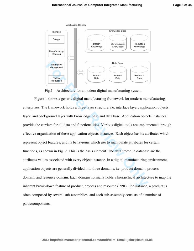
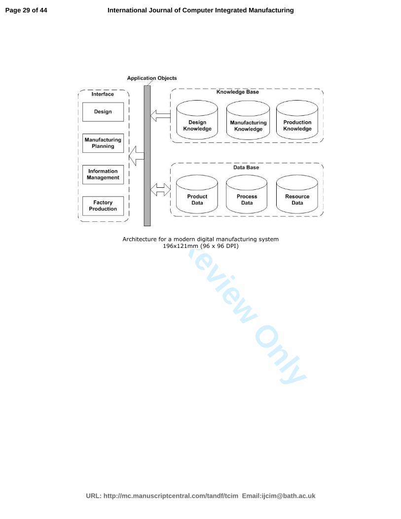
Fig.1 Architecture for a modern digital manufacturing system
Figure 1 shows a generic digital manufacturing framework for modern manufacturing
enterprises. The framework holds a three-layer structure, i.e. interface layer, application objects
layer, and background layer with knowledge base and data base. Application objects instances
provide the carriers for all data and functionalities. Various digital tools are implemented through
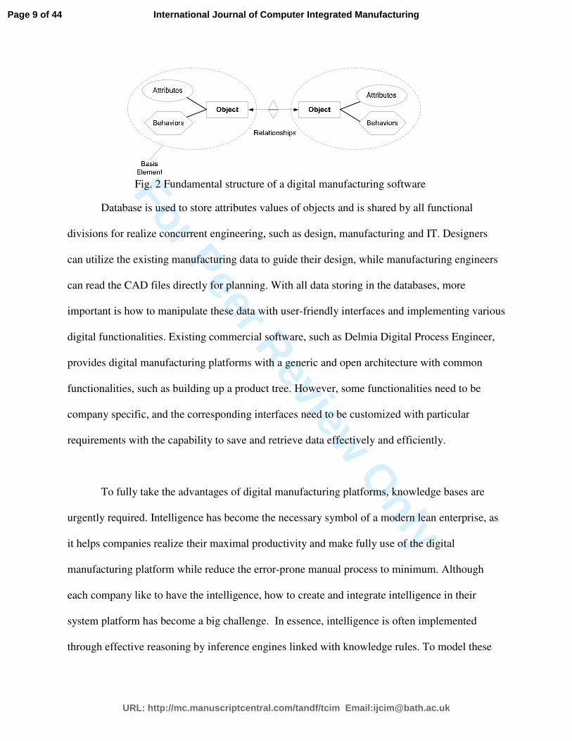
effective organization of these application objects instances. Each object has its attributes which
represent object features, and its behaviours which use to manipulate attributes for certain
functions, as shown in Fig. 2. This is the basis element. The data stored in database are the
attributes values associated with every object instance. In a digital manufacturing environment,
application objects are generally divided into three domains, i.e. product domain, process
domain, and resource domain. Each domain normally holds a hierarchical architecture to map the
inherent break-down feature of product, process and resource (PPR). For instance, a product is
often composed by several sub-assemblies, and each sub-assembly consists of a number of
parts/components.
Page 8 of 44
URL: http://mc.manuscriptcentral.com/tandf/tcim Email:[email protected]
International Journal of Computer Integrated Manufacturing
For Peer Review O
nly Fig. 2 Fundamental structure of a digital manufacturing software
Database is used to store attributes values of objects and is shared by all functional
divisions for realize concurrent engineering, such as design, manufacturing and IT. Designers
can utilize the existing manufacturing data to guide their design, while manufacturing engineers
can read the CAD files directly for planning. With all data storing in the databases, more
important is how to manipulate these data with user-friendly interfaces and implementing various
digital functionalities. Existing commercial software, such as Delmia Digital Process Engineer,
provides digital manufacturing platforms with a generic and open architecture with common
functionalities, such as building up a product tree. However, some functionalities need to be
company specific, and the corresponding interfaces need to be customized with particular
requirements with the capability to save and retrieve data effectively and efficiently.
To fully take the advantages of digital manufacturing platforms, knowledge bases are
urgently required. Intelligence has become the necessary symbol of a modern lean enterprise, as
it helps companies realize their maximal productivity and make fully use of the digital
manufacturing platform while reduce the error-prone manual process to minimum. Although
each company like to have the intelligence, how to create and integrate intelligence in their
system platform has become a big challenge. In essence, intelligence is often implemented
through effective reasoning by inference engines linked with knowledge rules. To model these
Page 9 of 44
URL: http://mc.manuscriptcentral.com/tandf/tcim Email:[email protected]
International Journal of Computer Integrated Manufacturing

For Peer Review O
nly
knowledge rules is to find out the casual relationships between design, manufacturing and
resource data, i.e. object attributes. Three levels of relationships between attributes are to be
modelled as follows.
• In one object: Relationships in between two or more attributes of one common object,
such that volume and material density of a part will determine its weight.
• In one domain: Relationships of two attributes in the same domain, e.g. the material cost
of an assembly will result from material costs of all its components/parts, while both the
assembly object and component/part object belong to the product domain.
• Cross domain: Relationships in between two attributes of two objects respectively, such
that size of a part will determine the time of its manufacturing operation, because a part
lies in the product domain while an operation stays in the process domain.
This paper is to provide automated and intelligent cost estimating capability for aircraft
assembly in a digital environment. The method used to achieve this will be to couple digital
engineering capabilities with manufacturing cost estimating models. Generally speaking, the
development will include cost breakdown analysis to identify required objects associated with
attributes and behaviors, knowledge modeling for intelligent reasoning from EBOM (engineering
bill of materials) to MBOM (manufacturing bill of materials), and seamless integration on the
DPE platform.
4. Methodology
The recurring cost is resulted from two aspects, i.e. assembly time cost and parts manufacturing
cost. The implementation methodology of these two will be addressed in this section.
Page 10 of 44
URL: http://mc.manuscriptcentral.com/tandf/tcim Email:[email protected]
International Journal of Computer Integrated Manufacturing
For Peer Review O
nly
4.1 Automated Assembly Time Costing
4.1.1 Time analysis and objects modelling
Process View
Process
Plan
Process
Plan
Process
Plan
GroupOperation
GroupOperation
GroupOperation
Operation Operation Operation
Sub-operation Sub-operation Sub-operation
Activity ActivityActivity Activity ActivityActivity Activity ActivityActivity
Process structure Time
Total Asy. / Line
Run & Setup
Total Asy. / EPR
Run & Setup
Total Asy. / GroupRun & Setup
Standard hrs/Operation
Runtime
Standard hrs in library
Basic MOST
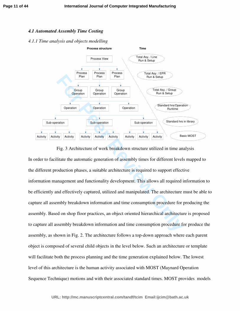
Fig. 3 Architecture of work breakdown structure utilized in time analysis
In order to facilitate the automatic generation of assembly times for different levels mapped to
the different production phases, a suitable architecture is required to support effective
information management and functionality development. This allows all required information to
be efficiently and effectively captured, utilized and manipulated. The architecture must be able to
capture all assembly breakdown information and time consumption procedure for producing the
assembly. Based on shop floor practices, an object oriented hierarchical architecture is proposed
to capture all assembly breakdown information and time consumption procedure for produce the
assembly, as shown in Fig. 2. The architecture follows a top-down approach where each parent
object is composed of several child objects in the level below. Such an architecture or template
will facilitate both the process planning and the time generation explained below. The lowest
level of this architecture is the human activity associated with MOST (Maynard Operation
Sequence Technique) motions and with their associated standard times. MOST provides models
Page 11 of 44
URL: http://mc.manuscriptcentral.com/tandf/tcim Email:[email protected]
International Journal of Computer Integrated Manufacturing
For Peer Review O
nly
for time measurements of manual operations based on pre-determined time standards associated
with human activity. As the speed of MOST is far from sufficient to compute every time
standard economically on a direct basis, a level of sub-operation, which is built up by the
activities, is required. The operation level is defined by the type of assembly operation and
relates to the basic ergonomic operations carried out on the shop floor. These basic elements that
are referred to in the work instructions are equated to operational objects. These become the
basic units for process planning, where generally only the runtime is associated with each
operation. Subsequently, sequential operations are designated as forming a group-operation, with
the setup time being input at this level. Each process plan consists of a sequence of group-
operations with an associated setup time; relating to the time taken to prepare tooling, etc. and
review instructional materials. Similarly, a sequence of process plans make up a process view,
where the setup time for building workstations will be taken into account. Finally, at each level
a network needs be built up for the next higher-level assembly. As the operation time is related to
the part attributes, such as size, weight and materials, the Part object associated with its attributes
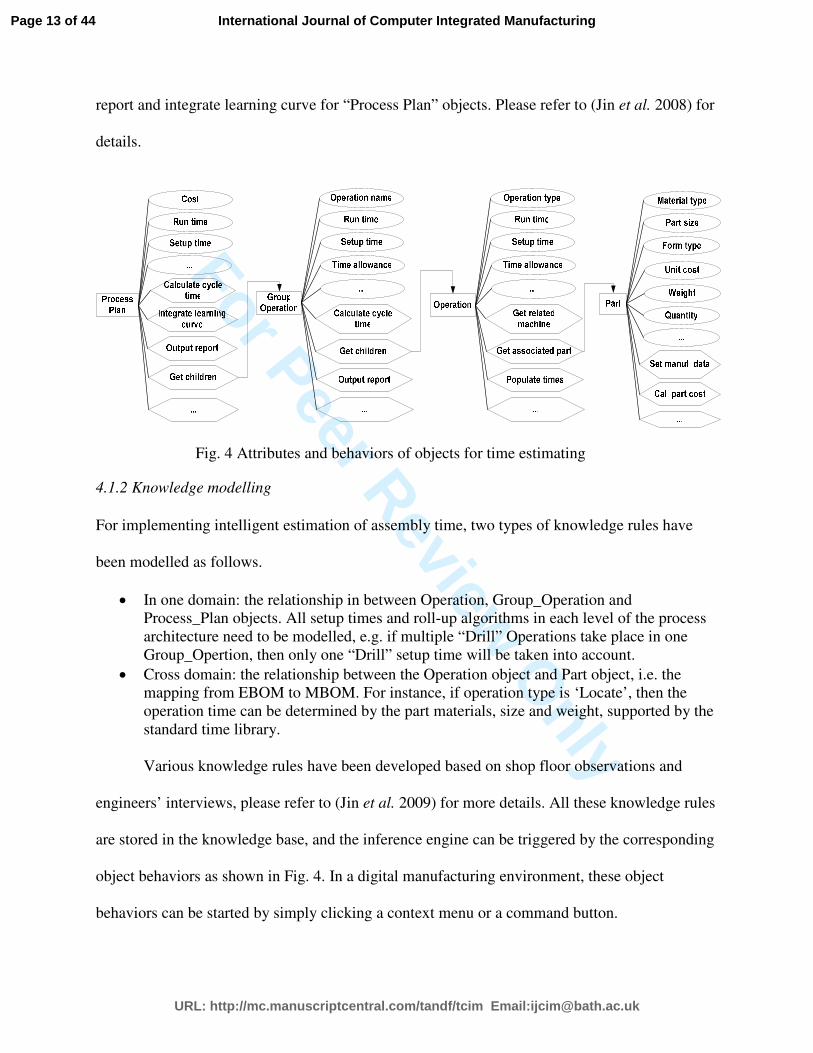
need to be modeled and linked to the Operation object. Based on the above analysis, the
necessary attributes and behaviors are modeled as shown in Fig. 4. These objects are linked
together by following the time generation logic. For example, the ‘Get associate part’ of the
Operation object is to get the corresponding part ID so that the part attributes can be retrieved.
The ‘Populating times’ is to trigger the expert system to populate Run time and Setup time
attributes through a heuristic method, and ‘Calculate cycle time’ of Group_Operation object is
used to roll up cycle times of all children operations in this group plus related setup time and
time allowance. Other functionalities have also been developed for each object, such as output
Page 12 of 44
URL: http://mc.manuscriptcentral.com/tandf/tcim Email:[email protected]
International Journal of Computer Integrated Manufacturing
For Peer Review O
nly
report and integrate learning curve for “Process Plan” objects. Please refer to (Jin et al. 2008) for
details.
Fig. 4 Attributes and behaviors of objects for time estimating
4.1.2 Knowledge modelling
For implementing intelligent estimation of assembly time, two types of knowledge rules have
been modelled as follows.
• In one domain: the relationship in between Operation, Group_Operation and
Process_Plan objects. All setup times and roll-up algorithms in each level of the process
architecture need to be modelled, e.g. if multiple “Drill” Operations take place in one
Group_Opertion, then only one “Drill” setup time will be taken into account.
• Cross domain: the relationship between the Operation object and Part object, i.e. the
mapping from EBOM to MBOM. For instance, if operation type is ‘Locate’, then the
operation time can be determined by the part materials, size and weight, supported by the
standard time library.
Various knowledge rules have been developed based on shop floor observations and
engineers’ interviews, please refer to (Jin et al. 2009) for more details. All these knowledge rules
are stored in the knowledge base, and the inference engine can be triggered by the corresponding
object behaviors as shown in Fig. 4. In a digital manufacturing environment, these object
behaviors can be started by simply clicking a context menu or a command button.
Page 13 of 44
URL: http://mc.manuscriptcentral.com/tandf/tcim Email:[email protected]
International Journal of Computer Integrated Manufacturing
For Peer Review O
nly
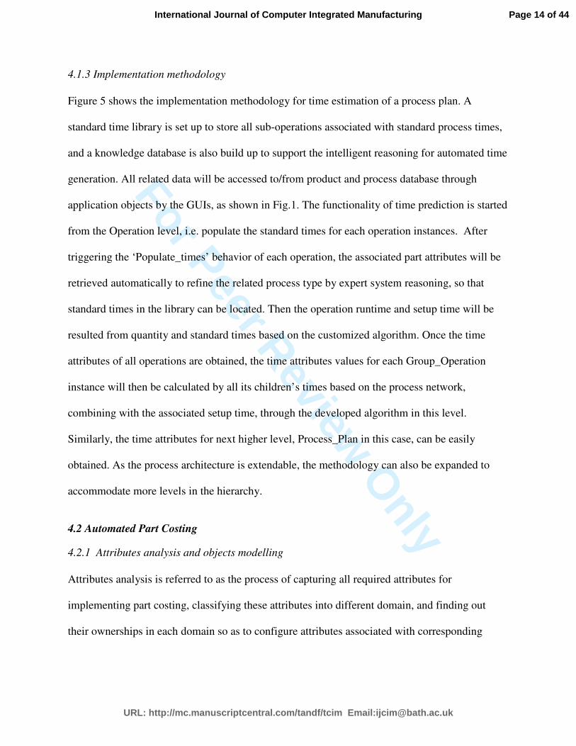
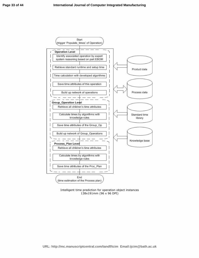
4.1.3 Implementation methodology
Figure 5 shows the implementation methodology for time estimation of a process plan. A
standard time library is set up to store all sub-operations associated with standard process times,
and a knowledge database is also build up to support the intelligent reasoning for automated time
generation. All related data will be accessed to/from product and process database through
application objects by the GUIs, as shown in Fig.1. The functionality of time prediction is started
from the Operation level, i.e. populate the standard times for each operation instances. After
triggering the ‘Populate_times’ behavior of each operation, the associated part attributes will be
retrieved automatically to refine the related process type by expert system reasoning, so that
standard times in the library can be located. Then the operation runtime and setup time will be
resulted from quantity and standard times based on the customized algorithm. Once the time
attributes of all operations are obtained, the time attributes values for each Group_Operation
instance will then be calculated by all its children’s times based on the process network,
combining with the associated setup time, through the developed algorithm in this level.
Similarly, the time attributes for next higher level, Process_Plan in this case, can be easily
obtained. As the process architecture is extendable, the methodology can also be expanded to
accommodate more levels in the hierarchy.
4.2 Automated Part Costing
4.2.1 Attributes analysis and objects modelling
Attributes analysis is referred to as the process of capturing all required attributes for
implementing part costing, classifying these attributes into different domain, and finding out
their ownerships in each domain so as to configure attributes associated with corresponding
Page 14 of 44
URL: http://mc.manuscriptcentral.com/tandf/tcim Email:[email protected]
International Journal of Computer Integrated Manufacturing
For Peer Review O
nly
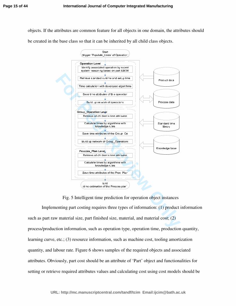
objects. If the attributes are common feature for all objects in one domain, the attributes should
be created in the base class so that it can be inherited by all child class objects.
Fig. 5 Intelligent time prediction for operation object instances
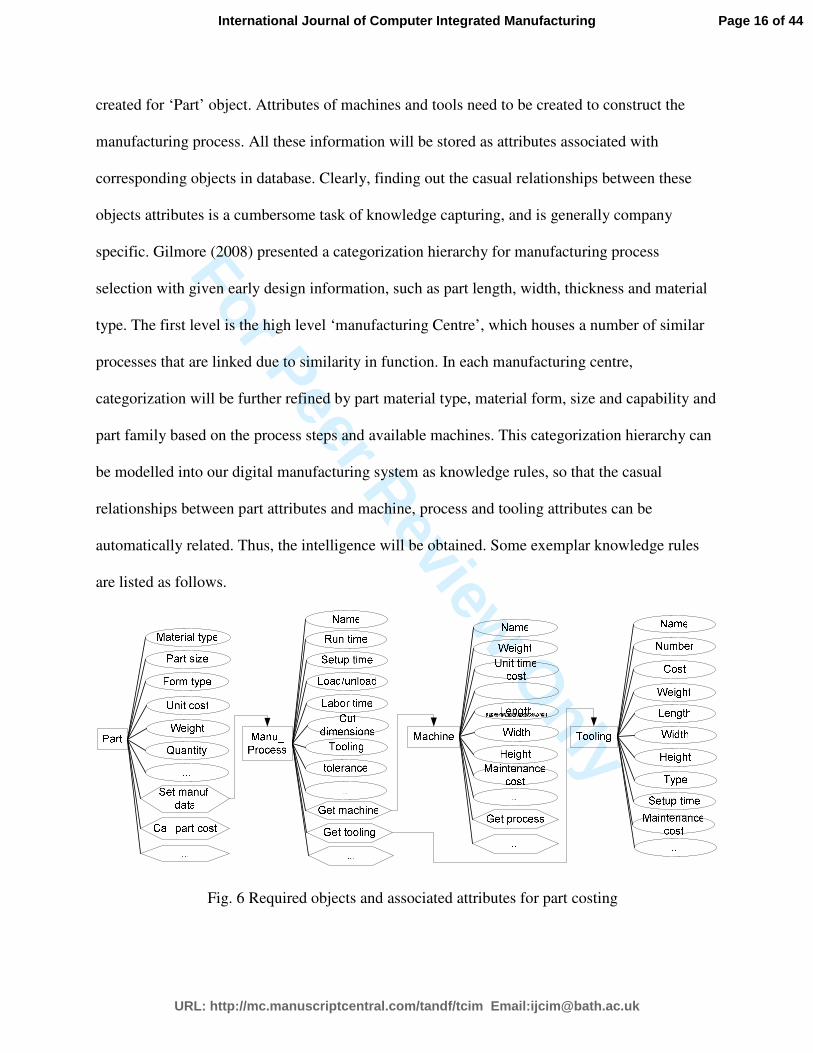
Implementing part costing requires three types of information: (1) product information
such as part raw material size, part finished size, material, and material cost; (2)
process/production information, such as operation type, operation time, production quantity,
learning curve, etc.; (3) resource information, such as machine cost, tooling amortization
quantity, and labour rate. Figure 6 shows samples of the required objects and associated
attributes. Obviously, part cost should be an attribute of ‘Part’ object and functionalities for
setting or retrieve required attributes values and calculating cost using cost models should be
Page 15 of 44
URL: http://mc.manuscriptcentral.com/tandf/tcim Email:[email protected]
International Journal of Computer Integrated Manufacturing
For Peer Review O
nly
created for ‘Part’ object. Attributes of machines and tools need to be created to construct the
manufacturing process. All these information will be stored as attributes associated with
corresponding objects in database. Clearly, finding out the casual relationships between these
objects attributes is a cumbersome task of knowledge capturing, and is generally company
specific. Gilmore (2008) presented a categorization hierarchy for manufacturing process
selection with given early design information, such as part length, width, thickness and material
type. The first level is the high level ‘manufacturing Centre’, which houses a number of similar
processes that are linked due to similarity in function. In each manufacturing centre,
categorization will be further refined by part material type, material form, size and capability and
part family based on the process steps and available machines. This categorization hierarchy can
be modelled into our digital manufacturing system as knowledge rules, so that the casual
relationships between part attributes and machine, process and tooling attributes can be
automatically related. Thus, the intelligence will be obtained. Some exemplar knowledge rules
are listed as follows.
Fig. 6 Required objects and associated attributes for part costing
Page 16 of 44
URL: http://mc.manuscriptcentral.com/tandf/tcim Email:[email protected]
International Journal of Computer Integrated Manufacturing

For Peer Review O
nly
If Part.Formtype = ‘Sheet ’ & Materialtype = ‘Alloy’ or ‘Titanium’ or ‘Steel’ then
MachiningCenter = ‘Sheet Metal Manufacturing Centre’
End if
If Part.Shape = ‘FlatRectangular’ then
Part.BlankLength = round(Part.Length + 2.5)
Part. BlankWidth = round(Part.Width + 2.5)
Part.BlankThickness = Part.Thickness
End if
…
Start
(trigger ‘Set manf. data’ of Part)
Retrieve design information, e.g. part shape, size &
materials
Save these data in database
Infer manu. Processes through a knowledge based system
Calculate process attributes values based on knowledge
rules
Populate these attributes on the GUIs
User editing if necessary
Design, manufacturing
and production
knowledge
Product, process and
resource data
Stop
Retrieve all manufacturing process data for this part
Step 1: Assign manufacturing process attributes
Calculate part manufacturing cost by existing models
Save cost results in database as part attributes
Step 2: Calculate part manufacturing cost
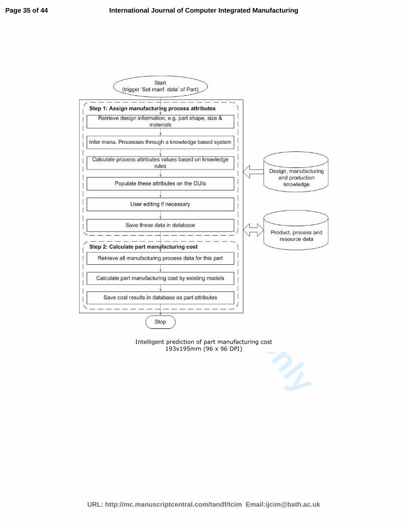
Fig. 7 Intelligent prediction of part manufacturing cost
4.2.2 Implementation methodology
Predicting part manufacturing cost requires two main steps as shown in Fig. 7. Step 1 is to
generate or assign all manufacturing processes attributes. By triggering the behaviour of ‘Set
manufacturing data’ of the Part object, the part design attributes will be automatically retrieved,
so that the manufacturing processes and associated attributes can be intelligently inferred through
knowledge based reasoning. Ideally, all these attributes should be automatically generated by
retrieving relevant design manufacturing and resource information with support from knowledge
Page 17 of 44
URL: http://mc.manuscriptcentral.com/tandf/tcim Email:[email protected]
International Journal of Computer Integrated Manufacturing
For Peer Review O
nly
systems. Even though some interactions with user may be indispensible, the interaction should
be minimised. Once all these attributes values are obtained, they will be saved in the databases
through application objects. The second step is to calculate part manufacturing cost with cost
models by using these attributes values obtained in Step 1. The cost results will be saved as part
attributes in the database.
5. Application
One popular software tool to realize digital manufacturing is Delmia Process Engineer (DPE),
which helps process planning by integrating product, process and resource (PPR) information
from the conceptual design phase through to the process planning phase and on to the production
phase. It utilizes an object-oriented PPR tree structure which is capable of modeling complete
project planning structures and all logical relationships between the PPR data. It provides users
an open architecture to create new objects associated with attributes and behaviors, which are
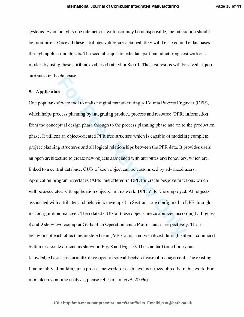
linked to a central database. GUIs of each object can be customized by advanced users.
Application program interfaces (APIs) are offered in DPE for create bespoke functions which
will be associated with application objects. In this work, DPE V5R17 is employed. All objects
associated with attributes and behaviors developed in Section 4 are configured in DPE through
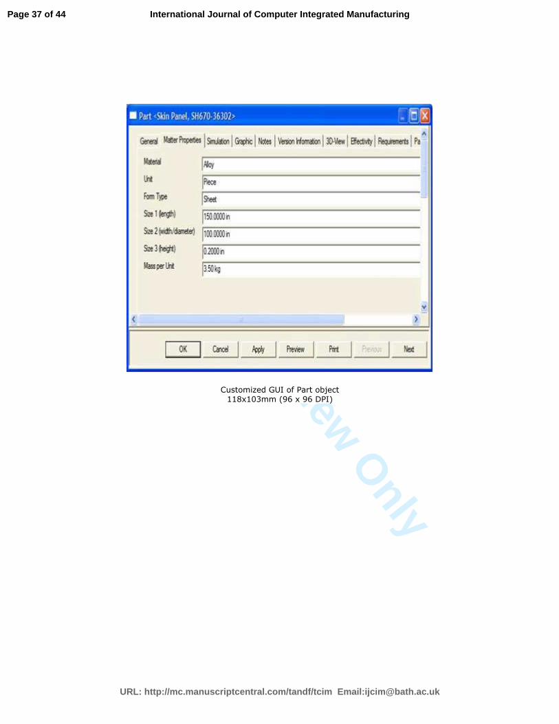
its configuration manager. The related GUIs of these objects are customized accordingly. Figures
8 and 9 show two exemplar GUIs of an Operation and a Part instances respectively. These
behaviors of each object are modeled using VB scripts, and visualized through either a command
button or a context menu as shown in Fig. 8 and Fig. 10. The standard time library and
knowledge bases are currently developed in spreadsheets for ease of management. The existing
functionality of building up a process network for each level is utilized directly in this work. For
more details on time analysis, please refer to (Jin et al. 2009a).
Page 18 of 44
URL: http://mc.manuscriptcentral.com/tandf/tcim Email:[email protected]
International Journal of Computer Integrated Manufacturing
For Peer Review O
nly
Fig. 8 Customized GUI of Operation object Fig. 9 Customized GUI of Part object
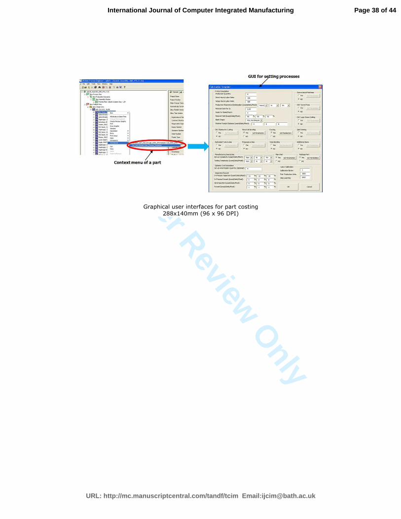
Fig. 10 Graphical user interfaces for part costing
To provide required data for part cost estimates, GUIs are created for users to visualize
and edit these cost required attributes in DPE by VB scripts as shown in Fig. 10. For rapidly
obtaining the capability of cost estimation for any components, SEER-DFM software is selected
as the computation engine for calculating part cost. SEER-DFM is a commercial software, which
provides cost estimation capability with parametric cost models based on manufacturing
processes. To utilize SEER-DFM, the user generally needs to have expert manufacturing
knowledge and manually input the required design and production information for accurate cost
Page 19 of 44
URL: http://mc.manuscriptcentral.com/tandf/tcim Email:[email protected]
International Journal of Computer Integrated Manufacturing
For Peer Review O
nly
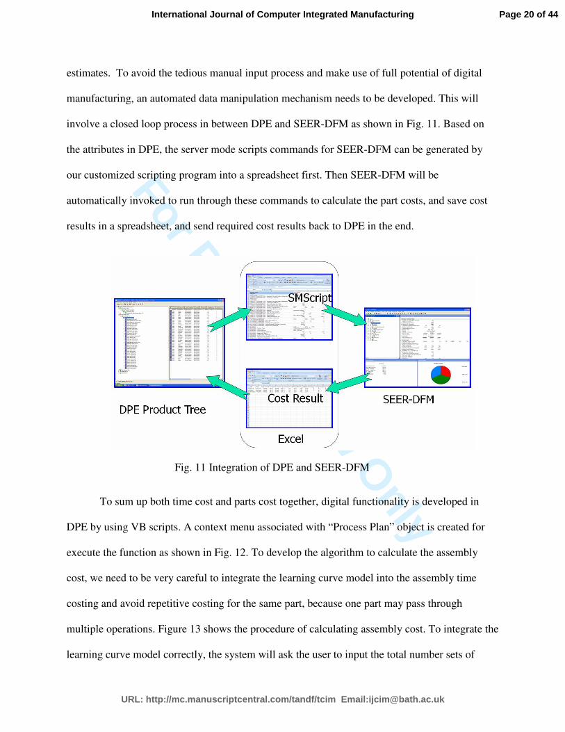
estimates. To avoid the tedious manual input process and make use of full potential of digital
manufacturing, an automated data manipulation mechanism needs to be developed. This will
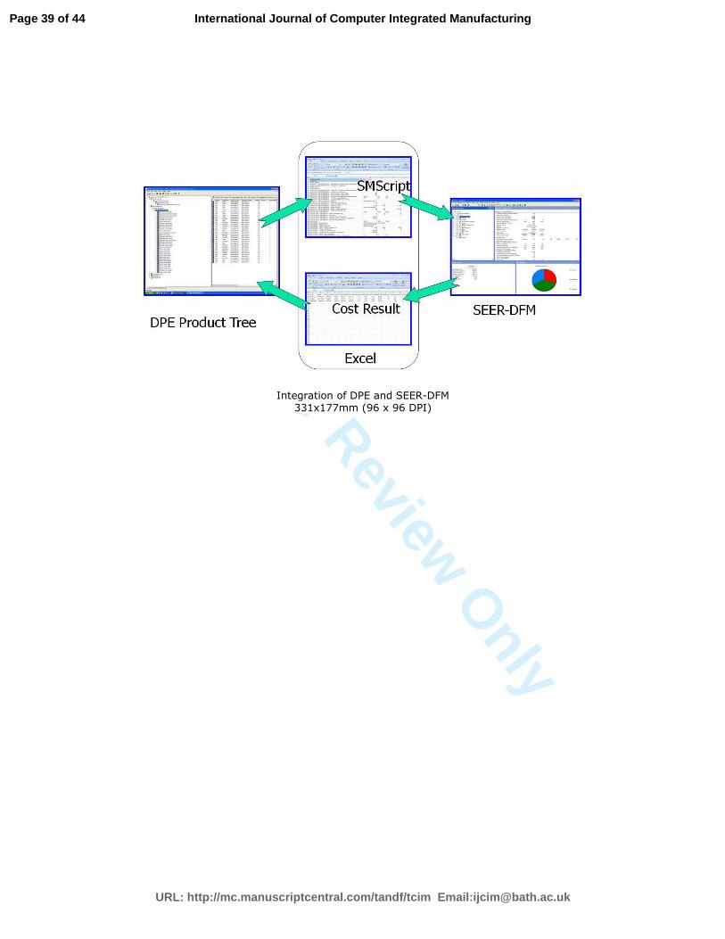
involve a closed loop process in between DPE and SEER-DFM as shown in Fig. 11. Based on
the attributes in DPE, the server mode scripts commands for SEER-DFM can be generated by
our customized scripting program into a spreadsheet first. Then SEER-DFM will be
automatically invoked to run through these commands to calculate the part costs, and save cost
results in a spreadsheet, and send required cost results back to DPE in the end.
Fig. 11 Integration of DPE and SEER-DFM
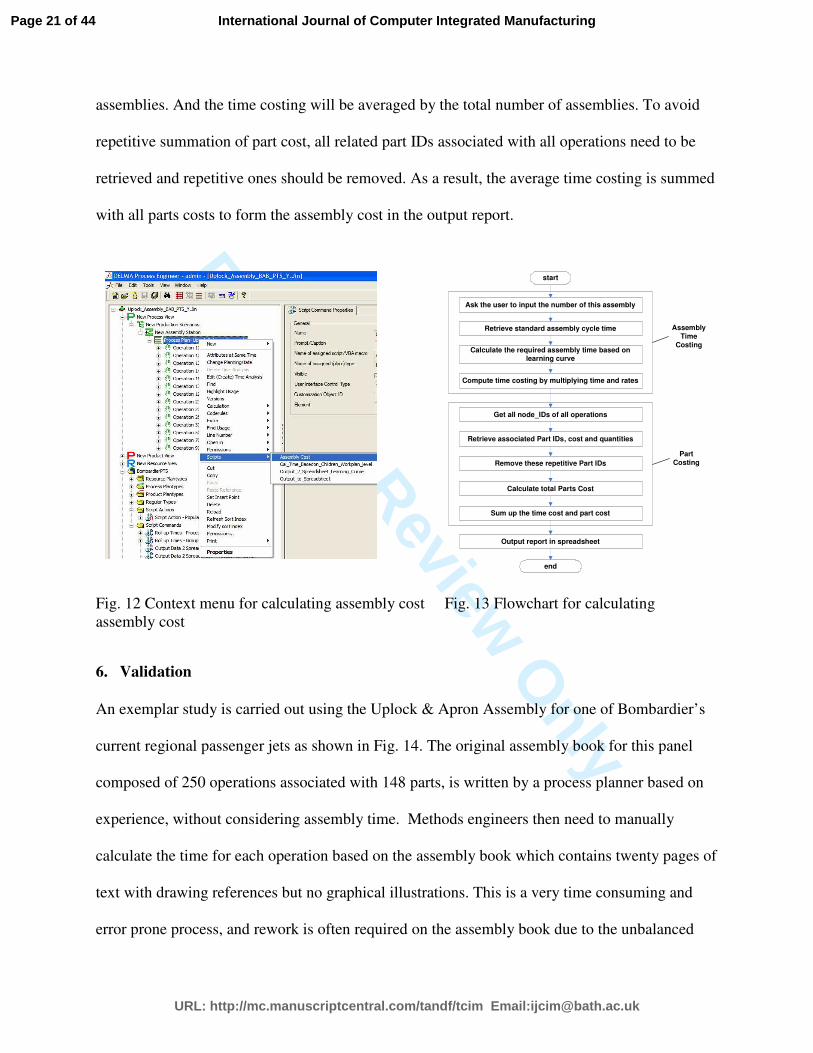
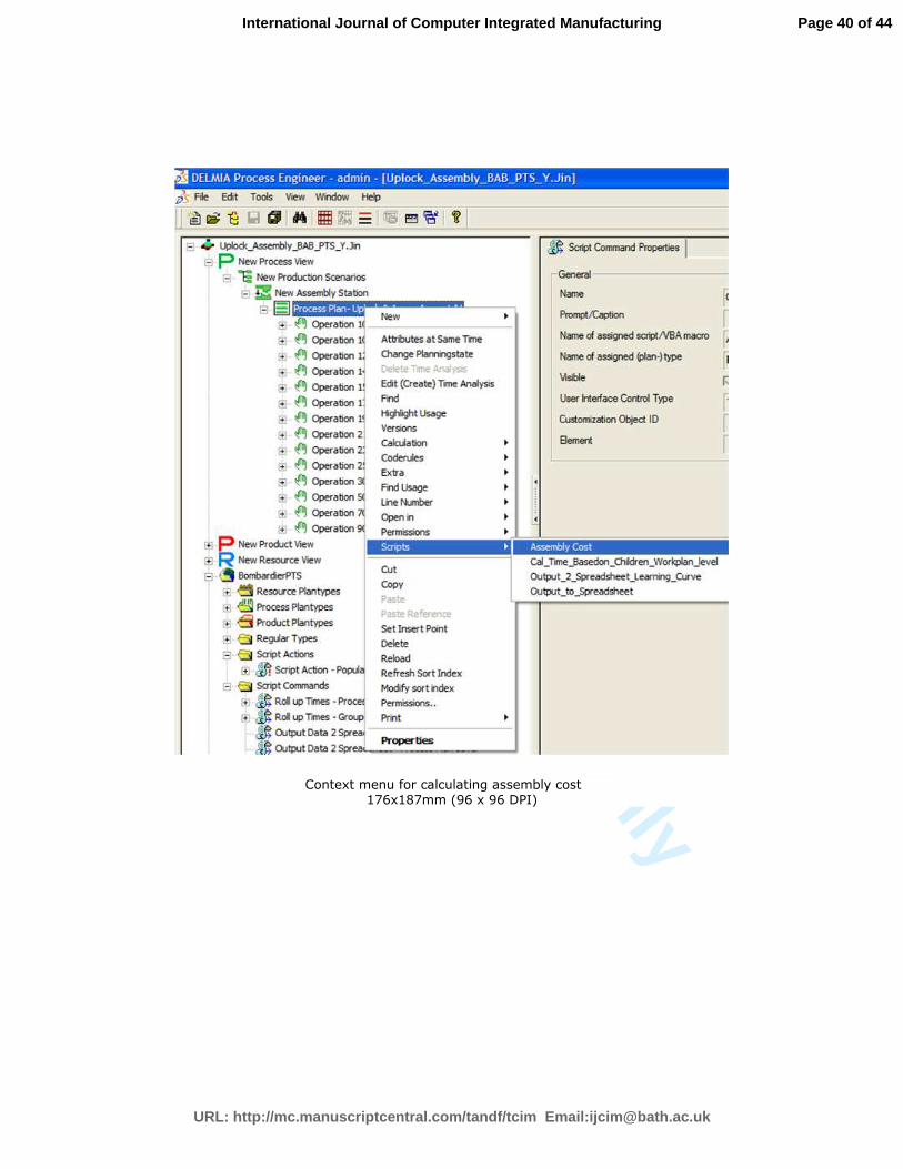
To sum up both time cost and parts cost together, digital functionality is developed in
DPE by using VB scripts. A context menu associated with “Process Plan” object is created for
execute the function as shown in Fig. 12. To develop the algorithm to calculate the assembly
cost, we need to be very careful to integrate the learning curve model into the assembly time
costing and avoid repetitive costing for the same part, because one part may pass through
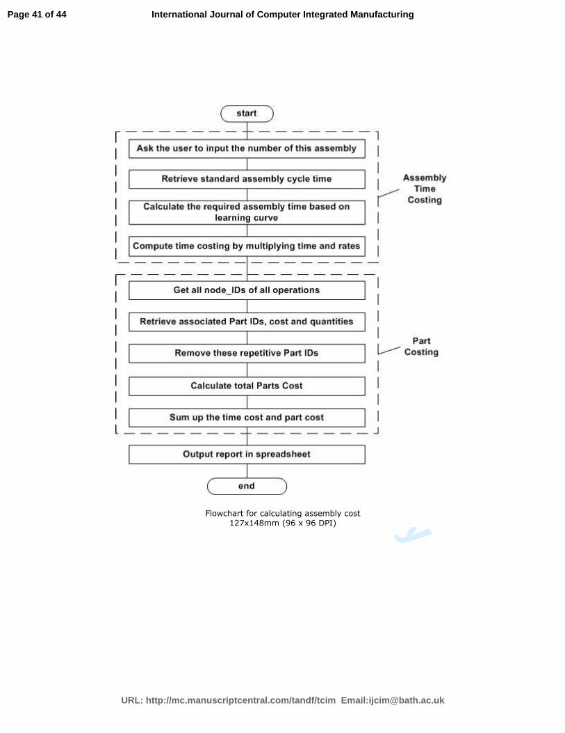
multiple operations. Figure 13 shows the procedure of calculating assembly cost. To integrate the
learning curve model correctly, the system will ask the user to input the total number sets of
Page 20 of 44
URL: http://mc.manuscriptcentral.com/tandf/tcim Email:[email protected]
International Journal of Computer Integrated Manufacturing
For Peer Review O
nly
assemblies. And the time costing will be averaged by the total number of assemblies. To avoid
repetitive summation of part cost, all related part IDs associated with all operations need to be
retrieved and repetitive ones should be removed. As a result, the average time costing is summed
with all parts costs to form the assembly cost in the output report.
Fig. 12 Context menu for calculating assembly cost Fig. 13 Flowchart for calculating
assembly cost
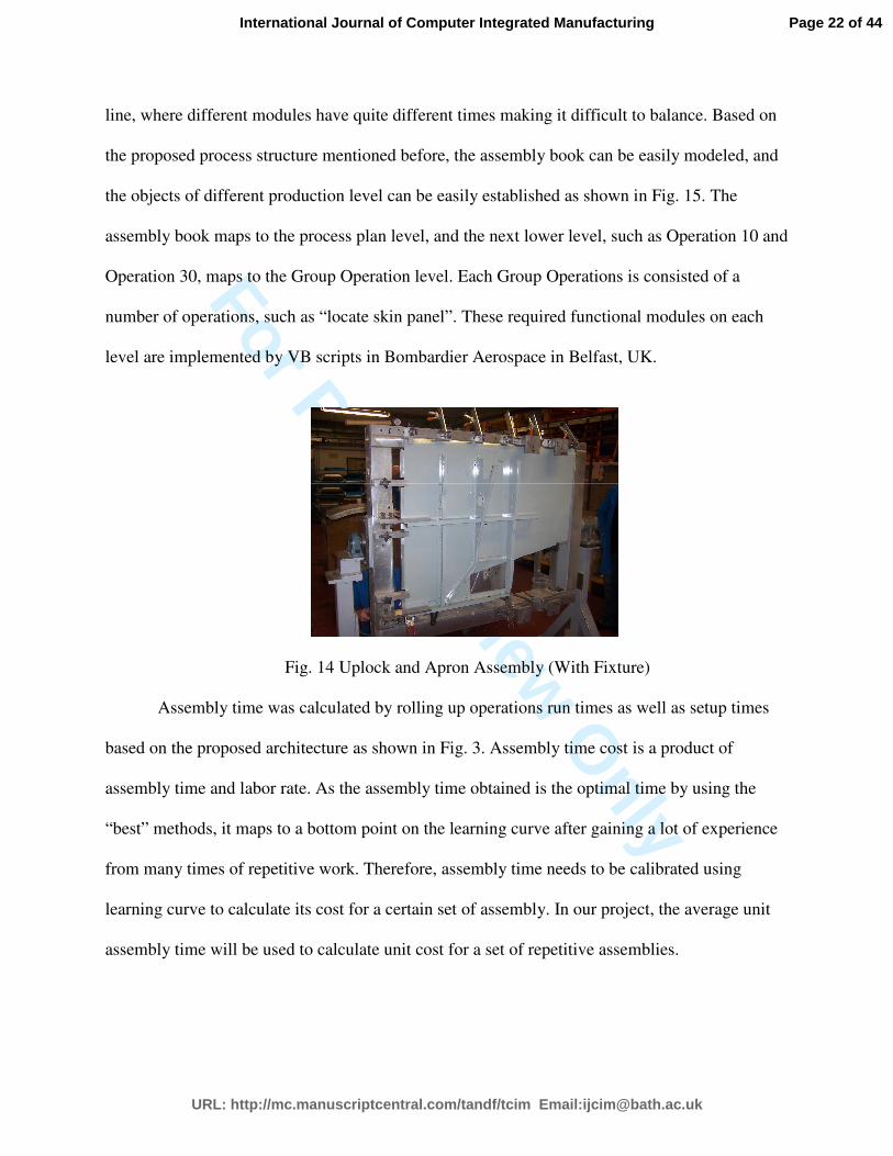
6. Validation
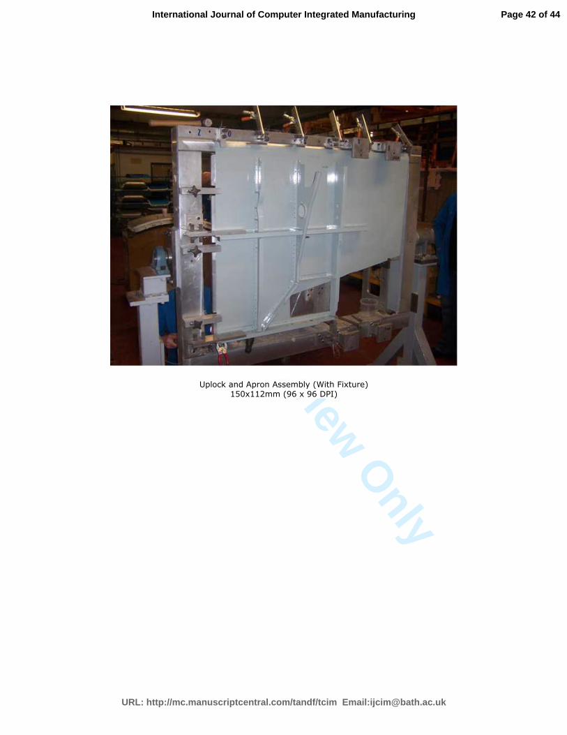
An exemplar study is carried out using the Uplock & Apron Assembly for one of Bombardier’s
current regional passenger jets as shown in Fig. 14. The original assembly book for this panel
composed of 250 operations associated with 148 parts, is written by a process planner based on
experience, without considering assembly time. Methods engineers then need to manually
calculate the time for each operation based on the assembly book which contains twenty pages of
text with drawing references but no graphical illustrations. This is a very time consuming and
error prone process, and rework is often required on the assembly book due to the unbalanced
Ask the user to input the number of this assembly
Compute time costing by multiplying time and rates
start
Get all node_IDs of all operations
Retrieve standard assembly cycle time
Calculate the required assembly time based on learning curve
Retrieve associated Part IDs, cost and quantities
Remove these repetitive Part IDs
Calculate total Parts Cost
end
Sum up the time cost and part cost
Output report in spreadsheet
Assembly
Time
Costing
Part
Costing
Page 21 of 44
URL: http://mc.manuscriptcentral.com/tandf/tcim Email:[email protected]
International Journal of Computer Integrated Manufacturing
For Peer Review O
nly
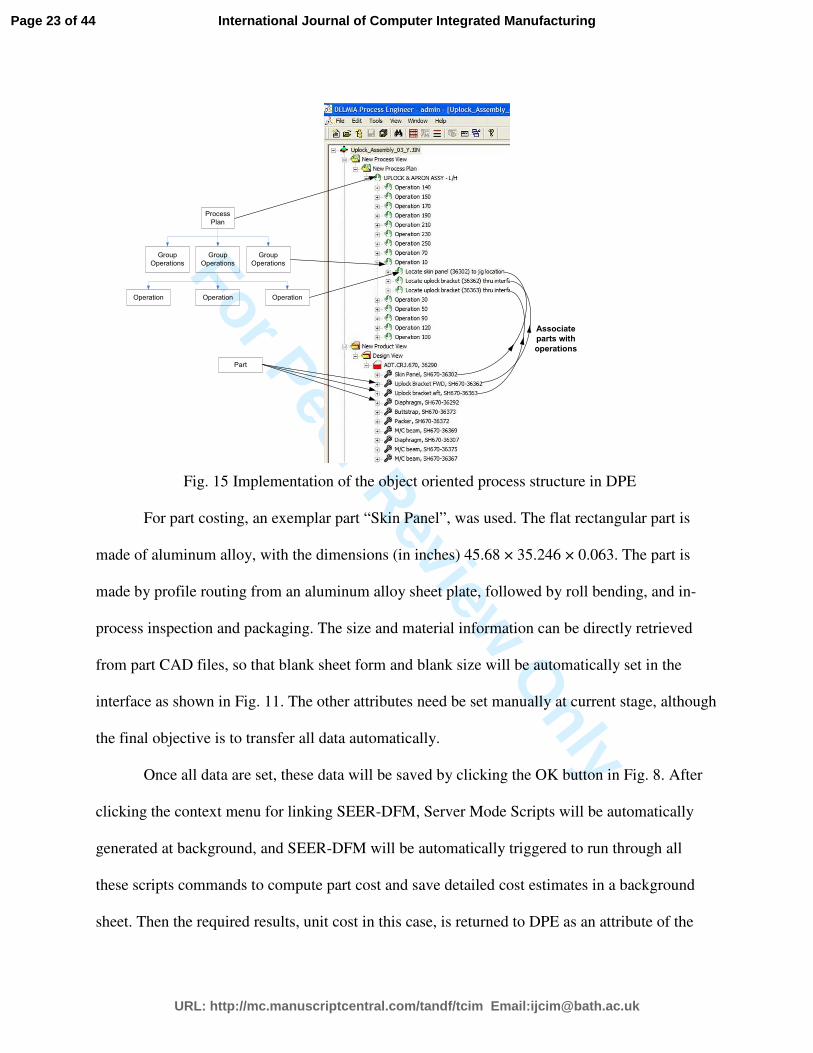
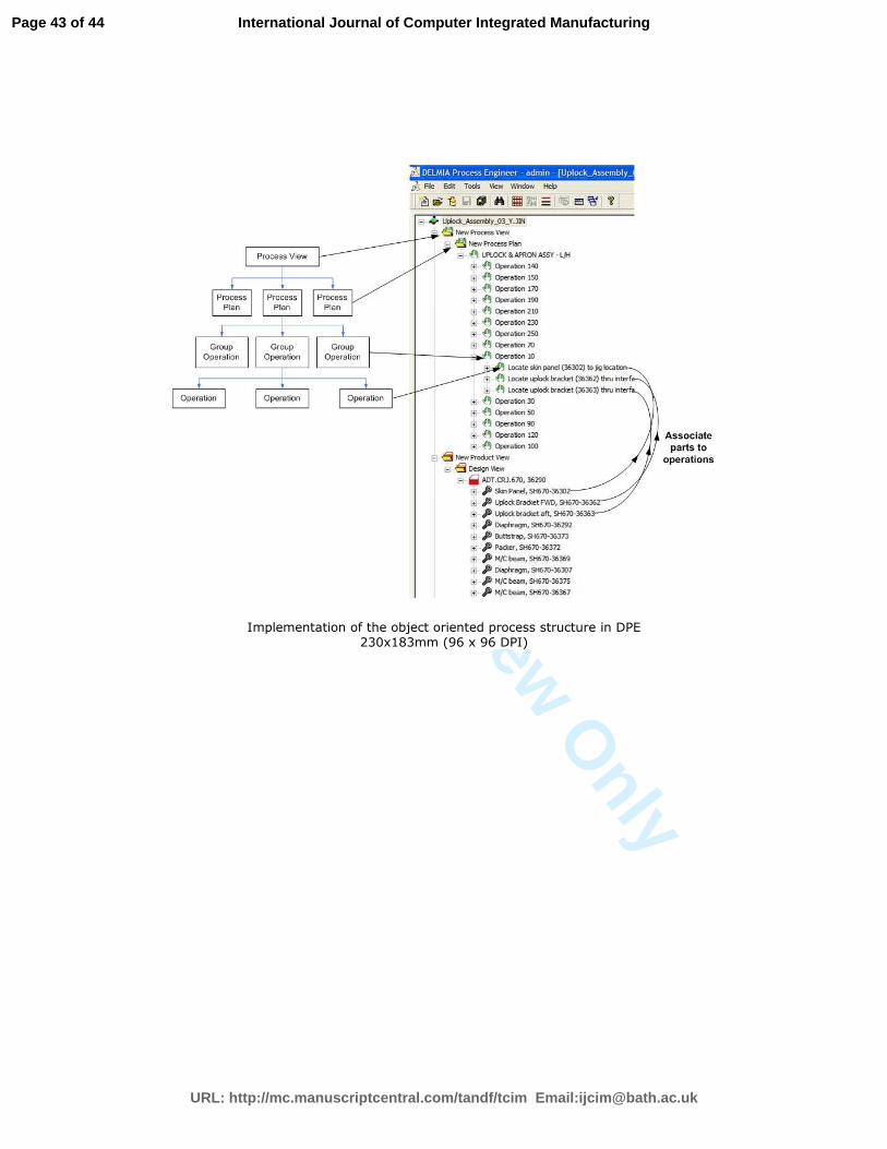
line, where different modules have quite different times making it difficult to balance. Based on
the proposed process structure mentioned before, the assembly book can be easily modeled, and
the objects of different production level can be easily established as shown in Fig. 15. The
assembly book maps to the process plan level, and the next lower level, such as Operation 10 and
Operation 30, maps to the Group Operation level. Each Group Operations is consisted of a
number of operations, such as “locate skin panel”. These required functional modules on each
level are implemented by VB scripts in Bombardier Aerospace in Belfast, UK.
Fig. 14 Uplock and Apron Assembly (With Fixture)
Assembly time was calculated by rolling up operations run times as well as setup times
based on the proposed architecture as shown in Fig. 3. Assembly time cost is a product of
assembly time and labor rate. As the assembly time obtained is the optimal time by using the
“best” methods, it maps to a bottom point on the learning curve after gaining a lot of experience
from many times of repetitive work. Therefore, assembly time needs to be calibrated using
learning curve to calculate its cost for a certain set of assembly. In our project, the average unit
assembly time will be used to calculate unit cost for a set of repetitive assemblies.
Page 22 of 44
URL: http://mc.manuscriptcentral.com/tandf/tcim Email:[email protected]
International Journal of Computer Integrated Manufacturing
For Peer Review O
nlyProcess
Plan
Group
Operations
Group
Operations
Group
Operations
Operation Operation Operation
Associate
parts with
operations
Part
Fig. 15 Implementation of the object oriented process structure in DPE
For part costing, an exemplar part “Skin Panel”, was used. The flat rectangular part is
made of aluminum alloy, with the dimensions (in inches) 45.68 × 35.246 × 0.063. The part is
made by profile routing from an aluminum alloy sheet plate, followed by roll bending, and in-
process inspection and packaging. The size and material information can be directly retrieved
from part CAD files, so that blank sheet form and blank size will be automatically set in the
interface as shown in Fig. 11. The other attributes need be set manually at current stage, although
the final objective is to transfer all data automatically.
Once all data are set, these data will be saved by clicking the OK button in Fig. 8. After
clicking the context menu for linking SEER-DFM, Server Mode Scripts will be automatically
generated at background, and SEER-DFM will be automatically triggered to run through all
these scripts commands to compute part cost and save detailed cost estimates in a background
sheet. Then the required results, unit cost in this case, is returned to DPE as an attribute of the
Page 23 of 44
URL: http://mc.manuscriptcentral.com/tandf/tcim Email:[email protected]
International Journal of Computer Integrated Manufacturing
For Peer Review O
nly
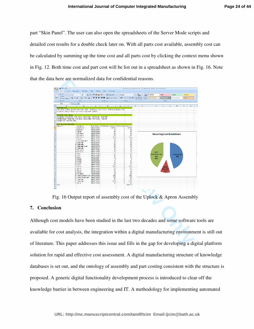
part “Skin Panel”. The user can also open the spreadsheets of the Server Mode scripts and
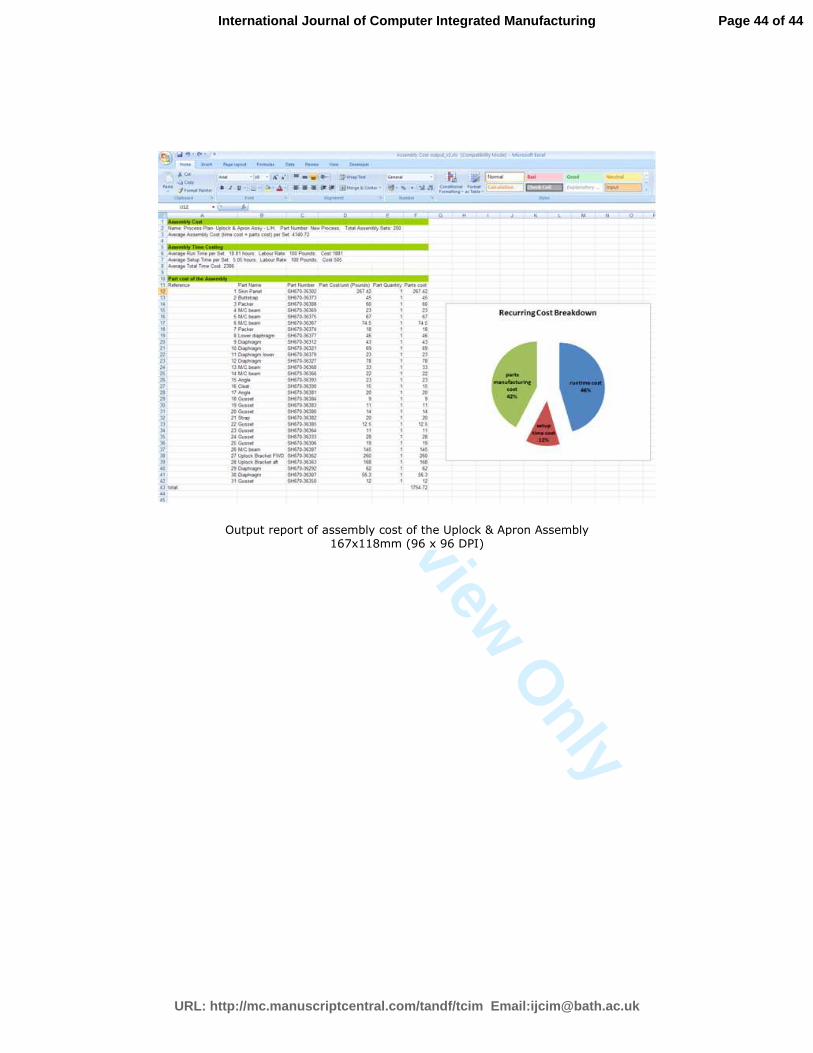
detailed cost results for a double check later on. With all parts cost available, assembly cost can
be calculated by summing up the time cost and all parts cost by clicking the context menu shown
in Fig. 12. Both time cost and part cost will be list out in a spreadsheet as shown in Fig. 16. Note
that the data here are normalized data for confidential reasons.
Fig. 16 Output report of assembly cost of the Uplock & Apron Assembly
7. Conclusion
Although cost models have been studied in the last two decades and some software tools are
available for cost analysis, the integration within a digital manufacturing environment is still out
of literature. This paper addresses this issue and fills in the gap for developing a digital platform
solution for rapid and effective cost assessment. A digital manufacturing structure of knowledge
databases is set out, and the ontology of assembly and part costing consistent with the structure is
proposed. A generic digital functionality development process is introduced to clear off the
knowledge barrier in between engineering and IT. A methodology for implementing automated
Page 24 of 44
URL: http://mc.manuscriptcentral.com/tandf/tcim Email:[email protected]
International Journal of Computer Integrated Manufacturing
For Peer Review O
nly
and intelligent cost estimation is presented. A prototype tool is developed to integrate both
assembly time cost and parts costs within a digital environment. An industrial example is used to
validate the method. This work helps to bridge the knowledge gap between design,
manufacturing and IT engineers. It also provides guidelines for developing bespoke
functionalities coupled with advanced digital manufacturing capabilities.
Acknowledgments
The authors gratefully acknowledge the help and guidance of Paul Smith, Gerry Mcgrattan, Donna Mcaleenan of
Bombardier Belfast, Tom Edgar, Colm Higgins and Rory Collins of the Northern Ireland Technology Centre,
William McEwan and Joseph Butterfield in School of Mechanical and Aerospace Engineering at Queen’s
University, and Jason Jones and Simon Allsop of DELMIA UK, without whom this work would not have been
possible.
References
Boothroyd, G., Dewhurst, P., and Knight, W., 2002. Product Design for Manufacture and
Assembly, Marcel Dekker Ltd. New York.
Brown, R.G., 2000. Driving Digital Manufacturing to Reality, Proceedings of the 2000 Winter
Simulation Conference, Orlando, FL, USA, Dec. 2000, 224 – 228.
Butterfield, J., et al., 2007. Optimization of Aircraft Fuselage Assembly Process Using Digital
Manufacturing. Journal of Computing and Information Science in Engineering, 7, 269–275.
CIMdata, 2006. The Value of Digital Manufacturing in a PLM Environment Case Study: Fiat
Auto S.p.A. Available from:
http://www2.warwick.ac.uk/fac/sci/wmg/ftmsc/content_store/dmm-
site/context/fiat_dig_mfg_benefits.pdf [Accessed 20 Sep. 2008].
Curran, R., Raghunathan, S., and Price, M., 2004. Review of Aerospace Engineering Cost
Modeling: The Generic Causal Approach, Progress in Aerospace Science, 40, 487-534.
Curran, R., et al., 2005. Integrating Aircraft Cost Modeling into Conceptual Design. Concurrent
Engineering: Research and Applications, 13 (4), 321–330.
Curran, R., et al., 2007a. Integrated digital design for manufacture for reduced life cycle cost.
Int. J. Production Economics 109, 27–40.
Curran, R., et al., 2007b. Digital Design Synthesis and Virtual Lean Manufacture, 45th
AIAA
Aerospace Sciences Meeting and Exhibition, Reno, Nevada, 8-11 Jan. 2007.
Page 25 of 44
URL: http://mc.manuscriptcentral.com/tandf/tcim Email:[email protected]
International Journal of Computer Integrated Manufacturing
For Peer Review O
nly
Curran, R., et al., 2007c. Digital Lean Manufacture (DLM) for Competitive Advantage, 7th
AIAA Aviation Technology, Integration and Operations Conference, 18 - 20 Sep., Belfast,
Northern Ireland.
Dalton-Taggart, R., 2007, The move to digital manufacturing [online], Available from:
http://www.manufacturingcenter.com/tooling/archives/0405/0405move_to_digital.asp [Accessed
10 Oct. 2007].
Dassault Systems Press Conferences, 2002. Delmia Solutions for the Airbus A380, Fellbach,
Germany, 26th
Febrary.
Elgh, F., and Cederfeldt, M., 2007. Concurrent cost estimation as a tool for enhanced
producibility—System development and applicability for producibility studies, International
Journal of Production Economics, 109 (1-2), 12-26.
Freedman, S., 1999. An Overview of Fully Integrated Digital Manufacturing Technology,
Proceedings of the 1999 Winter Simulation Conference, Squaw Peak, Phoenix, Dec. 1999, 281–
285.
Gilmour, M.W., 2008. Development of a Manufacturing Estimation Methodology for Early
Aero-Structure Design, Thesis (PhD), Queen’s University Belfast, UK.
Grewal, S., and Choi, C.K., 2005. An Integrated Approach to Manufacturing Process Design and
Costing, Concurrent Engineering: Research and Applications, 13 (3), 199–207.
Herrmann, J. W., and Chincholkar, M. M., 2000. Design for production: a tool for reducing
manufacturing cycle time, Proceedings of ASME Design Engineering Technical Conference,
Baltimore, Maryland, Sep. 2000, 1 – 10.
Hung, H.F., Kao, H.P., and Juang, Y.S., 2008. An integrated information system for product
design planning, Expert Systems with Applications, 35 (1-2), 338-349.
Jin,Y., et al., 2008. Automated Assembly Time Analysis Using a Digital Knowledge Based
Approach. The 26th Congress of International Council of the Aeronautical Sciences (ICAS) 14 -
19 September 2008, Anchorage, Alaska.
Jin,Y., et al., 2009a. Intelligent Assembly Time Analysis Using a Digital Knowledge Based
Approach. Journal of Aerospace Computing, Information, and Communication, 6, 506–522.
Jin,Y., et al., 2009b. An Integration Methodology for Automated Recurring Cost Prediction
using Digital Manufacturing Technology, International Conference of Manufacturing Research,
Warwick, UK.
Maropoulos, P.G., 2003. Digital enterprise technology-defining perspectives and research
priorities, Int. J. of computer integrated manufacturing, 16 (7-8), 467 – 478.
Page 26 of 44
URL: http://mc.manuscriptcentral.com/tandf/tcim Email:[email protected]
International Journal of Computer Integrated Manufacturing
For Peer Review O
nly
Maropoulos, P.G., et al., 2007. Key digital enterprise technology methods for large volume
metrology and assembly integration, Int. J. of Production Research, 45(7), 1539–1559.
Scanlan, J., et al., 2002. Cost modelling for aircraft design optimization, Journal of Engineering
Design, 13(3), 261-269.
Schmitt, P., 2007. Boeing, Others Rely on Digital Manufacturing. Dassault Systems – Design
News, 30th
April.
Seino, T., et al. 2001. The impact of ‘digital manufacturing’ on technology management,
Portland International Conference on Management of Engineering and Technology, PICMET
'01. Portland, 1, 31-32.
Thannhuber, M., Tseng, M.M., and Bullinger, H., 2001. An Autopoietic Approach for Building
Knowledge Management Systems in Manufacturing Enterprises, Annals of the CIRP, 50(1), 313
– 318.
Weustink, I.F., et al., 2000. A generic framework for cost estimation and cost control in product
design, Journal of Materials Processing Tech., 103 (1), 141-148.
Yan, X.T., Borg, J.C., and Juster, N.P., 2001. Concurrent modelling of components and
realization systems to support proactive design for manufacture/assembly. Proceedings of the
Institution of Mechanical Engineers, Part B: Journal of Engineering Manufacture, 215 (8),
1135–1141.
Zha, X.F., Du, H.J., and Qiu, J.H., 2001. Knowledge-based approach and system for assembly
oriented design, Part I: the approach. Engineering Applications of Artificial Intelligence 14, 61–
75.
Zheng, L.Y., et al., 2008. Systematic modeling and reusing of process knowledge for rapid
process configuration, Robotics and Computer Integrated Manufacturing. 24(6), 763–772.
Page 27 of 44
URL: http://mc.manuscriptcentral.com/tandf/tcim Email:[email protected]
International Journal of Computer Integrated Manufacturing
For Peer Review O
nly
Fig.1 Architecture for a modern digital manufacturing system
Fig. 2 Fundamental structure of a digital manufacturing software
Fig. 3 Architecture of work breakdown structure utilized in time analysis
Fig. 4 Attributes and behaviors of objects for time estimating
Fig. 5 Intelligent time prediction for operation object instances
Fig. 6 Required objects and associated attributes for part costing
Fig. 7 Intelligent prediction of part manufacturing cost
Fig. 8 Customized GUI of Operation object
Fig. 9 Customized GUI of Part object
Fig. 10 Graphical user interfaces for part costing
Fig. 11 Integration of DPE and SEER-DFM
Fig. 12 Context menu for calculating assembly cost
Fig. 13 Flowchart for calculating assembly cost
Fig. 14 Uplock and Apron Assembly (With Fixture)
Fig. 15 Implementation of the object oriented process structure in DPE
Fig. 16 Output report of assembly cost of the Uplock & Apron Assembly
Page 28 of 44
URL: http://mc.manuscriptcentral.com/tandf/tcim Email:[email protected]
International Journal of Computer Integrated Manufacturing
For Peer Review O
nly
Architecture for a modern digital manufacturing system 196x121mm (96 x 96 DPI)
Page 29 of 44
URL: http://mc.manuscriptcentral.com/tandf/tcim Email:[email protected]
International Journal of Computer Integrated Manufacturing

For Peer Review O
nly
Fundamental structure of a digital manufacturing software 174x65mm (96 x 96 DPI)
Page 30 of 44
URL: http://mc.manuscriptcentral.com/tandf/tcim Email:[email protected]
International Journal of Computer Integrated Manufacturing

For Peer Review O
nly
Architecture of work breakdown structure utilized in time analysis
205x115mm (96 x 96 DPI)
Page 31 of 44
URL: http://mc.manuscriptcentral.com/tandf/tcim Email:[email protected]
International Journal of Computer Integrated Manufacturing

For Peer Review O
nly
Attributes and behaviors of objects for time estimating
271x91mm (96 x 96 DPI)
Page 32 of 44
URL: http://mc.manuscriptcentral.com/tandf/tcim Email:[email protected]
International Journal of Computer Integrated Manufacturing
For Peer Review O
nly
Intelligent time prediction for operation object instances 138x191mm (96 x 96 DPI)
Page 33 of 44
URL: http://mc.manuscriptcentral.com/tandf/tcim Email:[email protected]
International Journal of Computer Integrated Manufacturing

For Peer Review O
nly
Required objects and associated attributes for part costing 200x82mm (96 x 96 DPI)
Page 34 of 44
URL: http://mc.manuscriptcentral.com/tandf/tcim Email:[email protected]
International Journal of Computer Integrated Manufacturing
For Peer Review O
nly
Intelligent prediction of part manufacturing cost 193x195mm (96 x 96 DPI)
Page 35 of 44
URL: http://mc.manuscriptcentral.com/tandf/tcim Email:[email protected]
International Journal of Computer Integrated Manufacturing

For Peer Review O
nly
Customized GUI of Operation object 76x67mm (96 x 96 DPI)
Page 36 of 44
URL: http://mc.manuscriptcentral.com/tandf/tcim Email:[email protected]
International Journal of Computer Integrated Manufacturing
For Peer Review O
nly
Customized GUI of Part object 118x103mm (96 x 96 DPI)
Page 37 of 44
URL: http://mc.manuscriptcentral.com/tandf/tcim Email:[email protected]
International Journal of Computer Integrated Manufacturing
For Peer Review O
nly
Graphical user interfaces for part costing 288x140mm (96 x 96 DPI)
Page 38 of 44
URL: http://mc.manuscriptcentral.com/tandf/tcim Email:[email protected]
International Journal of Computer Integrated Manufacturing
For Peer Review O
nly
Integration of DPE and SEER-DFM 331x177mm (96 x 96 DPI)
Page 39 of 44
URL: http://mc.manuscriptcentral.com/tandf/tcim Email:[email protected]
International Journal of Computer Integrated Manufacturing
For Peer Review O
nly
Context menu for calculating assembly cost 176x187mm (96 x 96 DPI)
Page 40 of 44
URL: http://mc.manuscriptcentral.com/tandf/tcim Email:[email protected]
International Journal of Computer Integrated Manufacturing
For Peer Review O
nly
Flowchart for calculating assembly cost 127x148mm (96 x 96 DPI)
Page 41 of 44
URL: http://mc.manuscriptcentral.com/tandf/tcim Email:[email protected]
International Journal of Computer Integrated Manufacturing
For Peer Review O
nly
Uplock and Apron Assembly (With Fixture)
150x112mm (96 x 96 DPI)
Page 42 of 44
URL: http://mc.manuscriptcentral.com/tandf/tcim Email:[email protected]
International Journal of Computer Integrated Manufacturing
For Peer Review O
nly
Implementation of the object oriented process structure in DPE 230x183mm (96 x 96 DPI)
Page 43 of 44
URL: http://mc.manuscriptcentral.com/tandf/tcim Email:[email protected]
International Journal of Computer Integrated Manufacturing
For Peer Review O
nly
Output report of assembly cost of the Uplock & Apron Assembly
167x118mm (96 x 96 DPI)
Page 44 of 44
URL: http://mc.manuscriptcentral.com/tandf/tcim Email:[email protected]
International Journal of Computer Integrated Manufacturing