COSEC NGT FCX Quick Installation Guide - ICON Support
28
COSEC NGT FCX The Next-Generation Terminal Quick Installation Guide
-
Upload
khangminh22 -
Category
Documents
-
view
1 -
download
0
Transcript of COSEC NGT FCX Quick Installation Guide - ICON Support
COSEC NGT FCX The Next-Generation Terminal
Quick Installation Guide

Trademarks WarrantyCOSEC NGT FCX is a product of Matrix Limited Warranty. Valid only if primary Comsec Pvt. Ltd. protection is provided, mains supply is
within limit and protected, and environment conditions maintained
Copyright within product specifications. All rights reserved. No part of this document may be copied or Complete warranty statement is reproduced in any form or by any available on our website:means without the prior written www.MatrixSecuSol.comconsent of Matrix Comsec.
Please read this guide first for correct installation and retain it for future reference. The information in this guide was current at the time of publication. However, Matrix Comsec reserves the right to make changes in product design and specifications without prior notice.
COSEC NGT FCX - Front View
TFT DisplayCapacitive
LED
Finger Sensor
Camera

COSEC NGT FCX - Back View
Card Reader Module
Exit Switch
Exit Reader
DoorLock
Aux. Output
Aux. Input
RS-485
COSEC NGT FCX - Bottom View
USB Ports (For Data Transfer, Firmware upgrade, Configuration upgrade, downloading event logs, Connecting 2G/3G Mobile Broadband dongle, Printer for Cafeteria Transactions)
What Your Package Contains
Ÿ COSEC NGT FCX Unit Ÿ Electromagnetic Lock Cable
Ÿ Mounting Plate Ÿ Exit Switch Cable
Ÿ Power Adapter 12V DC, 2 Amp Ÿ RS-485 Cable
Ÿ Four Screws M 7/30 Ÿ Quick Installation Guide
Ÿ Four Screw Grips Ÿ User Guide
Ÿ A Threaded Screw M 3x6 Ÿ Warranty Card
Ÿ Auxiliary Port Cable
Things You Will Need
Ÿ A power hand drill
Ÿ A wire stripper
Ÿ A screw driver set
Ÿ Insulation tape
Ÿ Access to the COSEC Server Application to configure COSEC NGT FCX on the Server.
Ÿ A stand-alone computer with a Web- browser to change the network settings of COSEC NGT FCX.
Slot to lock with Mounting Plate
Power
Ethernet
Ÿ Decide what connections you need to make to the COSEC NGT FCX. Make sure all the necessary cabling is in place.
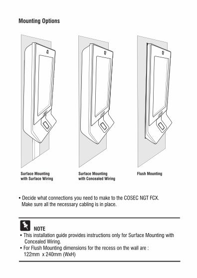
Mounting Options
Surface Mounting with Surface Wiring
Surface Mounting with Concealed Wiring
Flush Mounting
NOTEŸThis installation guide provides instructions only for Surface Mounting with Concealed Wiring.Ÿ For Flush Mounting dimensions for the recess on the wall are : 122mm x 240mm (WxH)
Prepare for InstallationStep 1
Ÿ Unpack COSEC NGT FCX and check your package contents.Ÿ Select a Location. It must be a flat surface such as a wall, close to the access point (door).Ÿ You can mount the COSEC NGT FCX on the wall surface or recessed in the wall. (See Mounting Options)Ÿ Recommended height from ground level: Upto 4.5 feet.Ÿ Concealed wiring is recommended.
CAUTION
Do not install the device:
Ÿ On unstable surfaces
Ÿ In very hot, cold, wet and humid environment temperatures
Ÿ Near heating/air conditioning equipment
Ÿ In dusty environment
Ÿ In direct sunlight
Ÿ Under direct light of incandescent or halogen lamps
Ÿ Near infra-red radiation emitting equipment
Ÿ Where ferromagnetic field or noise is induced
Ÿ Where static is created, such as desks made of plastic, carpets
Ÿ Near volatile inflammable materials or inflammable goods such as drapes
Ÿ Where volatile gas and/or inflammable gas is created
Ÿ Where corrosive chemicals are present or fumes are generated
Ÿ WARNINGŸ Installation and servicing should be done only by a qualified technician.Ÿ There are no user-serviceable parts inside. Ÿ Opening or removing the device cover may result in electric shock or exposure to other hazards.Ÿ Use this product only for the purpose for which it was designed.

Ÿ Decide what connections you need to make to the COSEC NGT FCX. Make sure all the necessary cabling is in place.
Mounting Options
Surface Mounting with Surface Wiring
Surface Mounting with Concealed Wiring
Flush Mounting
NOTEŸThis installation guide provides instructions only for Surface Mounting with Concealed Wiring.Ÿ For Flush Mounting dimensions for the recess on the wall are : 122mm x 240mm (WxH)
Prepare for InstallationStep 1
Ÿ Unpack COSEC NGT FCX and check your package contents.Ÿ Select a Location. It must be a flat surface such as a wall, close to the access point (door).Ÿ You can mount the COSEC NGT FCX on the wall surface or recessed in the wall. (See Mounting Options)Ÿ Recommended height from ground level: Upto 4.5 feet.Ÿ Concealed wiring is recommended.
CAUTION
Do not install the device:
Ÿ On unstable surfaces
Ÿ In very hot, cold, wet and humid environment temperatures
Ÿ Near heating/air conditioning equipment
Ÿ In dusty environment
Ÿ In direct sunlight
Ÿ Under direct light of incandescent or halogen lamps
Ÿ Near infra-red radiation emitting equipment
Ÿ Where ferromagnetic field or noise is induced
Ÿ Where static is created, such as desks made of plastic, carpets
Ÿ Near volatile inflammable materials or inflammable goods such as drapes
Ÿ Where volatile gas and/or inflammable gas is created
Ÿ Where corrosive chemicals are present or fumes are generated
Ÿ WARNINGŸ Installation and servicing should be done only by a qualified technician.Ÿ There are no user-serviceable parts inside. Ÿ Opening or removing the device cover may result in electric shock or exposure to other hazards.Ÿ Use this product only for the purpose for which it was designed.
Ÿ
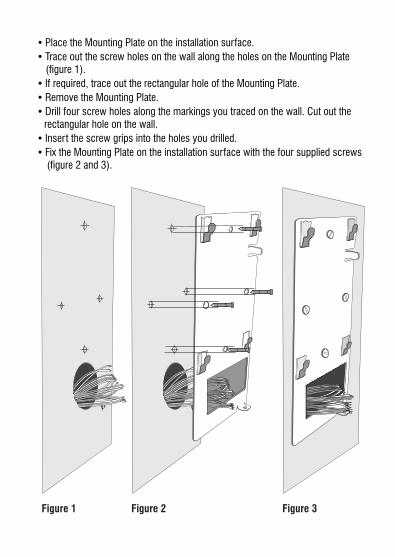
Ÿ Trace out the screw holes on the wall along the holes on the Mounting Plate (figure 1).
Ÿ If required, trace out the rectangular hole of the Mounting Plate.
Ÿ Remove the Mounting Plate.
Ÿ Drill four screw holes along the markings you traced on the wall. Cut out the rectangular hole on the wall.
Ÿ Insert the screw grips into the holes you drilled.
Ÿ Fix the Mounting Plate on the installation surface with the four supplied screws (figure 2 and 3).
Place the Mounting Plate on the installation surface.
Figure 1 Figure 2 Figure 3
Connect the CablesStep 2
Ÿ If your wiring is from behind the surface/through an electrical box, first draw out sufficient length of the cables from rectangular hole you have cut on the mounting surface.
ŸMake the electrical connections.
Ÿ Refer the wire color code mapping for the terminals.
CN1 CN2
CN3
CN4
CN5
CN2 EM LockPin 1 - LOCK RLY COM BluePin 2 - LOCK RLY NC YellowPin 3 - LOCK RLY NO Orange
Pin 4 - +12V LOCK RedPin 5 - GND BlackPin 6 - GND BlackPin 7- LOCK TMPR BrownPin 8 - GND BlackPin 9 - DOOR STS IN WhitePin 10 - GND Black
CN1 External Reader
Pin 1 - ALARM LED VioletPin 2 - STATUS LED Dark PinkPin 3 - RS-232-TX GreyPin 4 - RS-232-RX Light PinkPin 5 - TMPR NC/NO Light BluePin 6 - COM (GND) White-Red
Pin 7 - HOLD BluePin 8 - BEEPER YellowPin 9 - RED LED BrownPin 10 - GREEN LED OrangePin 11 - DATA RTN (GND) White-Blue
Pin 12 - DATA 1 WhitePin 13 - DATA 0 GreenPin 14 - GND BlackPin 15 - +12V RDR Red
CN3 Exit SwitchPin 1 - EXIT SWITCH WhitePin 2 - GND Black
CN4 AuxiliaryPin 1 - AUX RLY COM BrownPin 2 - AUX RLY NC Blue Pin 3 - AUX RLY NO YellowPin 4 - Not connected Pin 5 - AUX IN+ WhitePin 6 - GND Black
CN5 RS-485Pin 1 - RS-485 IN A Blue Pin 2 - RS-485 IN B Orange
Pin 3 - GND BlackPin 4 - RS-485 OUT-A BluePin 5 - RS-485 OUT-B Orange
Pin 6 - GND Black
Wire Color
Wire Color
Wire Color
Wire Color
Wire Color

Ÿ
Ÿ Trace out the screw holes on the wall along the holes on the Mounting Plate (figure 1).
Ÿ If required, trace out the rectangular hole of the Mounting Plate.
Ÿ Remove the Mounting Plate.
Ÿ Drill four screw holes along the markings you traced on the wall. Cut out the rectangular hole on the wall.
Ÿ Insert the screw grips into the holes you drilled.
Ÿ Fix the Mounting Plate on the installation surface with the four supplied screws (figure 2 and 3).
Place the Mounting Plate on the installation surface.
Figure 1 Figure 2 Figure 3
Connect the CablesStep 2
Ÿ If your wiring is from behind the surface/through an electrical box, first draw out sufficient length of the cables from rectangular hole you have cut on the mounting surface.
ŸMake the electrical connections.
Ÿ Refer the wire color code mapping for the terminals.
CN1 CN2
CN3
CN4
CN5
CN2 EM LockPin 1 - LOCK RLY COM BluePin 2 - LOCK RLY NC YellowPin 3 - LOCK RLY NO Orange
Pin 4 - +12V LOCK RedPin 5 - GND BlackPin 6 - GND BlackPin 7- LOCK TMPR BrownPin 8 - GND BlackPin 9 - DOOR STS IN WhitePin 10 - GND Black
CN1 External Reader
Pin 1 - ALARM LED VioletPin 2 - STATUS LED Dark PinkPin 3 - RS-232-TX GreyPin 4 - RS-232-RX Light PinkPin 5 - TMPR NC/NO Light BluePin 6 - COM (GND) White-Red
Pin 7 - HOLD BluePin 8 - BEEPER YellowPin 9 - RED LED BrownPin 10 - GREEN LED OrangePin 11 - DATA RTN (GND) White-Blue
Pin 12 - DATA 1 WhitePin 13 - DATA 0 GreenPin 14 - GND BlackPin 15 - +12V RDR Red
CN3 Exit SwitchPin 1 - EXIT SWITCH WhitePin 2 - GND Black
CN4 AuxiliaryPin 1 - AUX RLY COM BrownPin 2 - AUX RLY NC Blue Pin 3 - AUX RLY NO YellowPin 4 - Not connected Pin 5 - AUX IN+ WhitePin 6 - GND Black
CN5 RS-485Pin 1 - RS-485 IN A Blue Pin 2 - RS-485 IN B Orange
Pin 3 - GND BlackPin 4 - RS-485 OUT-A BluePin 5 - RS-485 OUT-B Orange
Pin 6 - GND Black
Wire Color
Wire Color
Wire Color
Wire Color
Wire Color

EthernetŸConnect the Ethernet cable into the 'ETHERNET' port.
Door LockŸUse the electromagnetic door lock cable (10-pin connector at one end and
free at the other) to connect a Door Lock to the’ EM LOCK’ terminal (CN2).
Power
ŸConnect the power adapter to the DC jack. Plug the adaptor into a power outlet.
[ ]If connecting Matrix PSBB-Universal Mains Power Supply (13.8 VDC@2A) with battery backup to COSEC NGT, be sure to maintain correct polarity.
NOTEŸAlways use a standard hydraulic door closer to ensure that the door closes
automatically after an entry or exit. This is to prevent “door open too long” or “door left open” alarms.
ŸThe NO or NC output can operate DC-powered locking devices like electro-mechanical strikes and magnetic locks. The maximum permitted current is 500 mA @ 12VDC per output.
ŸIf you are using a lock of higher capacity, you must use an external 12/24 VDC power supply, according to the technical specifications of themagnetic lock.
ŸTo use the 12VDC of the Door, short the terminals COM (CN2-1) and +ve (CN2-4)as shown in figure 4, before connecting the NC/NO and the -ve terminal (CN2-5 GND) to the Door lock.
Exit SwitchŸIf you are using an exit switch to open the door lock, connect the exit switch
cable (2-pin connector on one end and free on the other) in the 'EXIT SWITCH’ terminal (CN3).
Auxiliary Input
Ÿpair from the sensor device to the auxiliary input port 'AUXILIARY’ (CN4).If you are connecting a sensor for detecting alarm conditions, connect the wire
Ÿ To connect a lock of higher capacity using external power supply, connect the wires as shown in the figure 5, considering the technical specifications of the magnetic lock.
CN2 EM LOCK
Door Magnet
Using 12VDC of the DOOR
Figure 4
GND
GND
GND
Door Magnet
12V/24VUsing an External Power Supply
Figure 5
+-
GNDGND
GND
CN2 EM LOCK
CAUTIONDo not apply Power to the unit until you have completed all the connections.

Auxiliary Output
ŸThe Auxiliary output port can be used for activating alarm devices like hooter; energize some devices; control annunciation devices.
ŸIf you are connecting an alarm device like a hooter or an annunciation device, connect the wires from the alarm devices to the 'AUX RELAY' (CN4).
Exit Reader
Ÿ COSEC NGT FCX supports external Serial and Wiegand reader. The maximum recommended length of wiring for exit readers is 500 feet.
ŸConnect a Serial or a Wiegand reader to the 'EXTERNAL READER' terminal (CN1).
RF Reader ModuleŸIf you have ordered an RF Reader module, insert the module, matching the connector pins on the module with those provided on the Card Reader slot.
WARNINGDo not leave unused wires with stripped ends free. Seal them with insulation tape.
Mount COSEC NGT FCXStep 3
ŸAfter you have completed all the electrical connections, lead all the cables through the rectangular hole into the electrical box recessed in the wall (figure 6).
ŸAttach the COSEC NGT FCX to the mounting plate you fixed on the wall.
[ ]If your wiring is not concealed, lead all the cables through the bottom of the device before you attach it to the Mounting Plate.
Ÿ Match the mounting hooks C, D, E) on the plate with the respective mounting slots (1, 2, 3, 4, 5) at the back of the device. Refer figure 7.
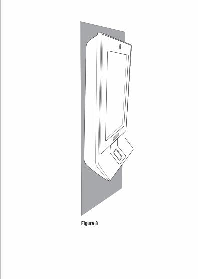
ŸTilt the device to allow mounting hook A into slot 1. Straighten the device and then slide it down on the plate (figure 8).
Ÿ Use the M 3x6 screw provided to you to secure the bottom mounting slot on the plate. Match E to 5 as in figure 7.
(A, B,
Figure 6
Figure 7
A
B
C
D
E
1 2
34
5

Auxiliary Output
ŸThe Auxiliary output port can be used for activating alarm devices like hooter; energize some devices; control annunciation devices.
ŸIf you are connecting an alarm device like a hooter or an annunciation device, connect the wires from the alarm devices to the 'AUX RELAY' (CN4).
Exit Reader
Ÿ COSEC NGT FCX supports external Serial and Wiegand reader. The maximum recommended length of wiring for exit readers is 500 feet.
ŸConnect a Serial or a Wiegand reader to the 'EXTERNAL READER' terminal (CN1).
RF Reader ModuleŸIf you have ordered an RF Reader module, insert the module, matching the connector pins on the module with those provided on the Card Reader slot.
WARNINGDo not leave unused wires with stripped ends free. Seal them with insulation tape.
Mount COSEC NGT FCXStep 3
ŸAfter you have completed all the electrical connections, lead all the cables through the rectangular hole into the electrical box recessed in the wall (figure 6).
ŸAttach the COSEC NGT FCX to the mounting plate you fixed on the wall.
[ ]If your wiring is not concealed, lead all the cables through the bottom of the device before you attach it to the Mounting Plate.
Ÿ Match the mounting hooks C, D, E) on the plate with the respective mounting slots (1, 2, 3, 4, 5) at the back of the device. Refer figure 7.
ŸTilt the device to allow mounting hook A into slot 1. Straighten the device and then slide it down on the plate (figure 8).
Ÿ Use the M 3x6 screw provided to you to secure the bottom mounting slot on the plate. Match E to 5 as in figure 7.
(A, B,
Figure 6
Figure 7
A
B
C
D
E
1 2
34
5
Power On COSEC NGT FCXStep 4
ŸApply power to COSEC NGT FCX and wait for the reboot cycle to complete.
Ÿ At power on, the LED will be turned glow blue accompanied by a long beep.
Ÿ The Matrix Security Solutions logo will appear on the display.
Ÿ At the end of the reboot cycle, the LED will flash once and then will be turned off.
Ÿ The home screen will appear on the display.
Figure 8

Network Status Indications
ICON LABEL COLOR MEANING
Grey
Grey
Grey
Grey
Green
Green
Green
Grey
LAN
Wi-Fi
Wi-Fi
Server
Server
Modem
Modem
USB
Ethernet Connection ON.
Wi-Fi Connection available, but not connected to Wi-Fi Hotspot.
Wi-Fi Connection available, and connected to Wi-Fi Hotspot.
Door is not connected to the COSEC Server.
Door is connected to the COSEC Server.
Broadband Connection available, but not connected to the Service Provider.
Broadband Connection available, and connected to the Service Provider.
USB device plugged.
Status Indications for Events in Normal State
ICON LABEL MEANING
Late In
Early Out
Door Lock
Door Unlock
Late In activated.
Early Out activated.
Door Lock activated.
Door Unlock activated.
Alarm Alarm Activated

Connect the COSEC NGT FCX to the Network/COSEC ServerStep 5
The COSEC NGT FCX can be connected to the network over Ethernet, Wi-Fi, and Mobile Broadband.
The COSEC NGT FCX is pre-configured with a default IP address and Subnet Mask.
Default IP Address: 192.168.50.1
Default Subnet Mask: 255.255.255.0
You need to change the IP Address to connect the Door to the network. You can do
this in one of the following ways:
1. From the DOOR display
2. From the DOOR Webpage
Ask your network administrator for an IP Address for the door. Also ask your network administrator, if you will need to change the Subnet Mask, or configure Gateway IP Address and DNS.
Configuring Network Settings from the DOOR Display
Ÿ Tap the Menu icon on the home screen.
Ÿ Tap Admin.
ŸTap the Admin Password field, the keypad will appear.
To access network settings from the door display menu,
ŸUse the keypad to enter the default Admin Password 1234.
ŸTap OK.
ŸOn the Admin screen, tap Settings, and then tap LAN.
ŸTap the Door IP Address field, the keypad will appear.
ŸUse the keypad to enter the IP Address you want to assign to the door.
ŸTap Save.
ŸIf required, you may change the Subnet Mask and enter the Gateway IP Address, configure the DNS. Tap on each field to invoke the keypad and tap Save to apply changes.
ŸTo configure Server settings, tap Back to return to Settings.
ŸIn Settings, tap Server.
ŸIn Connection via, select IP Address/Host Name.
ŸEnter the IP Address of the COSEC server using the keypad.
ŸTap Save.
You can go back one level on the menu by tapping the Back icon. To return to return to home screen, tap the Home icon.
You will need the MAC Address to connect the device to the COSEC monitoring Computer. To know the MAC Address,
ŸTap Menu on the home screen.
ŸTap About Device.
ŸMake note of the MAC Address.

Configuring Network Settings from the DOOR Web pageŸ
Ÿ Open a web browser window on your computer/laptop.
Ÿ Enter the default IP Address of the Door, http://192.168.50.1 in the address bar of the browser and press the Enter key on your computer keyboard.
Ÿ The COSEC NGT web page will open.
Ÿ In User Level, select Admin.
Ÿ In Login Password, type the default admin password 1234, and then click Login.
Connect a stand-alone computer/laptop to the Ethernet port of COSEC NGT FCX.
ŸOn the welcome page, click the Settings link on the left navigation bar.Ÿ Click Network Settings > LAN Settings.
ŸIn LAN Settings, enter the IP Address of the COSEC NGT FCX.
ŸIf required, change the Subnet Mask, configure the Gateway IP Address, the Preferred and Alternate DNS.
ŸNote down the MAC address of COSEC NGT FCX. You will need it to connect the device to the COSEC Server.
ŸClick Submit to save your settings.
ŸUnder Network Settings, click Server Communication.
Ÿ In IP Address, enter the IP Address of the COSEC Server.
ŸIn Network, select the appropriate network communication interface for the door: Ethernet, Wi-Fi or Mobile Broadband.

You can connect the COSEC NGT FCX either directly to the monitoring computer using an Ethernet Crossover/Straight cable.
Connecting to the Monitoring Computer
COSEC Monitor PC
Crossover/Straight Cable
You can connect the COSEC NGT FCX and the monitoring computer to an Ethernet Switch or hub using standard straight-through Ethernet cables.
ŸIf you are using Wi-Fi as communication interface, configure Wi-Fi Network Settings and Wi-Fi Access Point Settings.
ŸIf you are using Mobile Broadband, configure Mobile Broadband settings.
ŸClick the Submit button to save your settings.
COSEC Monitor PC
Ethernet Switch
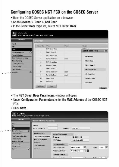
Configuring COSEC NGT FCX on the COSEC Server ŸOpen the COSEC Server application on a browser.
ŸGo to Devices > Door > Add Door
Ÿ In the Select Door Type list, select NGT Direct Door.
ŸThe NGT Direct Door Parameters window will open.
ŸUnder Configuration Parameters, enter the MAC Address of the COSEC NGT
FCX.
ŸClick Save.
You can connect the COSEC NGT FCX either directly to the monitoring computer using an Ethernet Crossover/Straight cable.
Connecting to the Monitoring Computer
COSEC Monitor PC
Crossover/Straight Cable
You can connect the COSEC NGT FCX and the monitoring computer to an Ethernet Switch or hub using standard straight-through Ethernet cables.
ŸIf you are using Wi-Fi as communication interface, configure Wi-Fi Network Settings and Wi-Fi Access Point Settings.
ŸIf you are using Mobile Broadband, configure Mobile Broadband settings.
ŸClick the Submit button to save your settings.
COSEC Monitor PC
Ethernet Switch
Configuring COSEC NGT FCX on the COSEC Server ŸOpen the COSEC Server application on a browser.
ŸGo to Devices > Door > Add Door
Ÿ In the Select Door Type list, select NGT Direct Door.
ŸThe NGT Direct Door Parameters window will open.
ŸUnder Configuration Parameters, enter the MAC Address of the COSEC NGT
FCX.
ŸClick Save.

Ÿ Create Users on the COSEC Server.
Ÿ Assign Users to COSEC NGT FCX.
Ÿ Enroll Users’ templates from the COSEC NGT FCX display or the web page or from the COSEC Server.
Refer the COSEC NGT FCX User Guide for instructions on how to enroll users from the COSEC NGT FCX display and web page.
For instructions on enrolling users from the COSEC Server, refer the COSEC System Manual.
For detailed instructions read the topic 'Network Options' in the COSEC System
Manual or use the Help provided on the COSEC Application user interface.
To access Help for the configuration parameters of a window, click the ?
(question mark) icon that appears on the top right of the window. To access the
COSEC System Manual, click the ? icon that appears on the banner of each web
page.
After you have successfully added the door, the door will go online. Network
connection status will appear on the status bar of the COSEC NGT FCX display.
Enroll UsersStep 6
Technical Specifications
Card + Finger + PIN
10,000
9600
2 (Any Type)
7” TFT Capacitive
Credential Support
User Capacity
Template Capacity
Cards per User
LCD
Speaker
Finger Sensor Module: SFM-3050, Sensor: TC1
Camera 3.2 Mega Pixel
Capacitive
1:1, 1:N
Smart and Proximity (MiFare, EM Prox, HID, iclass, HID Prox)
Touch Sense
Verification Method
Type of Card
2 ports (1 for Data Transfer, 1 for 3G/2G)
Ethernet/Wi-Fi/Mobile Broadband
1,00,000
10/100Mbps on Ethernet
1 Port for Card/Finger/UHF Reader
RS-232 and Wiegand
USB
Communication
Events Buffer
Communication Speed
External Reader
External Reader Interfaces
Yes
Programmable NO, NC, Supervised
Relay SPDT, Form C, 1A@30VDC
Internal [email protected] or External
Programmable NO, NC, Supervised
Relay SPDT, Form C, 1A@30VDC
Yes
Yes
Single LED, Blue
400 MHz ARM9 micro processor
128 MB Flash + 4 GB Micro SD Card +
128 MB RAM
12VDC@2A
100 × 220 × 55mm (3.9” 8.7” 2.2”) × ×
0.840 Kg 0 0 0 00 C to +50 C (32 F to 122 F),
5% to 95% RH Non-Condensing
Exit Switch Port
Door Status Sense
Door Lock Relay
Door Lock Power
Auxiliary Input Port
Auxiliary Output Relay
Tamper Detection
Buzzer
LED Indication
CPU
Memory
Input Power
Dimensions (WxHxD)
Weight
Environment
RS-485 IN/OUT/Shield
For Playing Greetings, Voice Guidance Messages


Head Office394-GIDC, Makarpura, Vadodara - 390010, IndiaPh: +91 265 2630555, Fax: +91 265 2636598Email: [email protected]
www.MatrixComSec.com
Customer CarePh: +91 265 2630555Email: [email protected]
MATRIX COMSECV.
1, J
une
‘13


![1986-12-25 - Newport Harbor Ensign[Icon]](https://static.fdokumen.com/doc/165x107/631b1d25f6a8ee1ff700a4c5/1986-12-25-newport-harbor-ensignicon.jpg)