Development and characterization of electrically conductive polyaniline coated fabrics
Upload
vinhuniversityCategory
view
1download
0
First published in: Journal of The Electrochemical Society. - 154 (2) C67 - C73 (2007)
Corrosion Protection Performance and Spectroscopic Investigations of Soluble Conducting Polyaniline-Dodecylbenzenesulfonate
Synthesized via Inverse Emulsion Procedure
Subrahmanya Shreepathi, Hung Van Hoang, Rudolf Holze
MONARCH – Dokument http://archiv.tu-chemnitz.de/
Copyright (c) The Electrochemical Society, reproduced with permission. www.electrochem.org

Corrosion Protection Performance and Spectroscopic Investi-
gations of Soluble Conducting Polyaniline-
Dodecylbenzenesulfonate Synthesized via Inverse Emulsion
Procedure
Subrahmanya Shreepathi, Hung Van Hoang and Rudolf Holze
Institut für Chemie, Technische Universität Chemnitz, AG Elektrochemie, D-09107 Chemnitz,
Germany
To whom correspondence should be addressed. E-mail: [email protected]
nitz.de
Abstract
Corrosion protection performance of a completely soluble polyaniline-dodecylbenzenesulfo-
nic acid salt (PANI-DBSA) on C45 steel has been studied with electrochemical impedance
and potentiodynamic measurements. Chloroform is the most suitable solvent to process the
pristine PANI-DBSA because of negligible interaction of the solvent with the polyaniline
(PANI) backbone. An anodic shift in the corrosion potential (E = ~70 mV), a decrease in the
corrosion current and a significant increase in the charge transfer resistance indicate a signifi-
cant anti-corrosion performance of the soluble PANI deposited on the protected steel surface.
Corrosion protection follows the mechanism of formation of a passive oxide layer on the sur-
face of C45 steel. In situ UV-Vis spectroscopy was used to investigate the differences in per-
meability of aqueous anions into PANI-DBSA. Preliminary results of electron diffraction
studies show that PANI-DBSA possesses an orthorhombic type of crystal structure. An in-
crease in the feed ratio of DBSA to aniline increases the tendency of aggregation of spherical
particles of PANI obvious in transmission electron microscopy. PANI-DBSA slowly loses its
electrochemical activity in acid free electrolyte without undergoing degradation.
2

Introduction
Conducting polymers, particularly polyaniline, have wide range of application in batteries,
corrosion protection, sensors, electrooptic and electrochromic devices.1 2 3 Over the last two
decades many studies have focused on the corrosion protection of ferrous materials using em-
eraldine form of PANI.4 Conducting polymer coatings are more tolerance to pinholes because
of their passivation ability. The mechanism of corrosion protection, influence of the substrate
preparation on corrosion protection and a direct comparison between PANI emeraldine salt
and PANI emeraldine base have been reviewed in detail.5 Previous reports also show that cor-
rosion performance of PANI is affected by a number of parameters such as coating method,
dopants used, electrolytes and their pH, etc.5 6 Three main methods of coating PANI on steel
are: direct electrochemical deposition, spin/drop coating of PANI from its solution/dispersion
and polymer coating containing PANI as additive.6 In the case of solution cast coating, usu-
ally the emeraldine base (EB) form of PANI dissolved in N-methyl pyrrolidone (NMP) is
used which is further re-doped with different acids.5 There are arguments regarding the com-
mercial applicability of NMP cast PANI because they are not effective as well as impractical.7
Counter ion induced solubility (secondary doping by camphorsulfonic acid or dodecylben-
zenesulfonic acid in chloroform or xylene) of PANI has also been used to coat steel surfaces
but such systems exhibit very poor efficiency of protection because of the presence of free
acid molecules in the solution.8
Use of bulky organic acids such as camphorsulfonic acid (CSA) and dodecylbenzenesulfonic
acid (DBSA) to protonate polyaniline (primary doping) has gained special attention following
the report of Cao et al.9 because of their enhanced solubility in common organic solvents.
DBSA being a bulky molecule functions both as surfactant and dopant and its large non-polar
chain facilitates the solubility of the resulting PANI. However, DBSA has poor water solubil-
3

ity and therefore a large volume of water is necessary to prepare anilinium-DBSA complex in
aqueous solution.10
Sathyanarayana et al.11,12 for the first time, have used benzoyl peroxide as the oxidizing agent
in the polymerization of aniline in presence of various organic sulfonic acids as dopants. They
reported that the organic peroxide (compared to the conventional ammonium persulfate) re-
duces the possibility of over-oxidation of PANI during exothermic reaction of aniline polym-
erization and the by-products of the oxidant can be easily removed by washing with acetone.
Recently Sai Ram and Palaniappan 13 have also used benzoyl peroxide for the synthesis of
polyaniline doped with mineral acids. Solubility of benzoyl peroxide in most of the organic
solvents offers many solvent systems for the polymerization of aniline which yield PANI with
different physicochemical properties and enhanced solubility.
We have recently investigated an inverse emulsion method for the synthesis of PANI-DBSA
which is completely soluble in solvents such as chloroform. Spectroelectrochemical, electro-
chemical and morphological studies of the resulting polymer have been reported elsewhere.14
In this paper, a pilot attempt towards the application of this soluble PANI has been carried
out. PANI-DBSA dissolved in chloroform was drop-coated onto a steel electrode surface and
its anti-corrosion performance is studied using electrochemical impedance measurements
(EIM) and anodic polarization measurements. Influence of feed ratio of monomer to dopant
on the corrosion protection is discussed. In addition, in situ UV-Vis spectroscopic and trans-
mission electron microscopic investigations are also reported which gives a better understand-
ing towards the ingress of aqueous anions into PANI film and its morphology.
4

Experimental
Chemicals.Aniline (VEB Laborchemie Apolda, analytical grade) was distilled under re-
duced pressure and stored under nitrogen. DBSA (70 wt % in 2-propanol, 70 % solution, Al-
drich), tetrabutylammoniumtetrafluoroborate (Bu4NBF4, Aldrich) and fluoroboric acid (as di-
ethylether complex, Fluka) were used as received. Ultrapure (18 MΩ) water (Seralpur pro 90
C) was used. All other chemicals were analytical grade reagents and used as procured. Indium
tin oxide (ITO) coated glass sheets (R = 20 cm2) were supplied by MERCK. Mild steel
cylinders (steel C45, Germany) of 1 cm height and 1.2 cm diameter were used in corrosion
studies (Electrode area = 1.13 cm2). Chemical composition of the C45 steel (wt %): C = 0.46,
Si = 0.4, Mn = 0.65, Cr = 0.4, Mo = 0.1, Ni = 0.4 and others = 0.63.
Synthesis of PANI-DBSA. Polymerization of aniline was carried out in an inverse emulsion
medium composed of toluene+2-propanol (2:1) and water in the presence of DBSA using
benzoyl peroxide as oxidant. Details of synthetic and purification procedure are described el-
sewhere.14 Polyanilines with different mole ratios of DBSA to aniline have been prepared by
keeping constant the oxidant-to-monomer ratio and by varying the concentration of DBSA.
The polymer samples were labeled as TIP-5, TIP-6 and TIP-7 where the mole ratios of
DBSA/aniline in the feed were 5:1, 7:1 and 10:1 respectively.
Characterization. UV-Vis spectra were recorded using a Shimadzu 2100 PC spectropho-
tometer. A quartz cell of 1 cm path length and PANI dissolved in different solvents were
used. For the in situ UV-Vis measurements, PANIs dissolved in CHCl3 are drop coated on a
clean ITO coated glass sheet subsequently used as working electrode. A quartz cell of 1 cm
path length fitted with a platinum wire as counter electrode and saturated calomel electrode
5

(SCE) connected via salt bridge as a reference electrode served as a three-electrode cell. In
situ measurements were carried out under ambient conditions.
Cyclic voltammograms (CVs) were recorded under nitrogen atmosphere in a three-electrode
single compartment cell using a custom built potentiostat connected to a computer with an
AD/DA converter. CVs were recorded in acetonitrile containing Bu4NBF4 as supporting elec-
trolyte. PANI dissolved in CHCl3 and drop coated onto a platinum sheet was used as working
electrode after evaporation of the solvent. A platinum sheet counter electrode and a Ag/AgCl
reference electrode (in acetonitrile containing Bu4NBF4) were used.
A combination of a Solartron SI1287 potentiostat and a SI1255 frequency response analyzer,
both connected to a PC via IEE488.2 connections, was used to record electrode impedance
data with a modulation amplitude of 5 mV in the frequency range of 0.1 Hz - 100 kHz.
Evaluation of the impedance data was performed using equivalent circuits with the software
packages Z-view and EQUIVCRT. Measurements were carried out in a three-electrode one
compartment cell with a C45 steel disc working electrode, a gold sheet counter electrode and
a saturated calomel reference electrode. PANIs dissolved in CHCl3 were drop coated on the
C45 steel discs which were previously polished with fine emery paper (P 1000) and with γ-
Al2O3 (13 µm). Impedance measurements were carried out at ambient conditions in 3.5 %
NaCl.
Anodic polarization measurements were carried out under ambient conditions in a three-elec-
trode single compartment cell with a gold sheet counter electrode and a saturated calomel ref-
erence electrode using a Solartron SI1287 potentiostat connected to a computer via IEE488.2
connections. The working electrode was the C45 steel sample (PANI drop coated or un-
coated) which was polished as described above prior to the measurements. 3.5 % (wt/wt)
NaCl solution was used as corrosion environment and the measurements were carried at a
scan rate of 5 mV/s.
6

Transmission electron microscopic (TEM) images were recorded on a Philips CM 20 FEG
transmission electron microscope. The samples were prepared by depositing a drop of well di-
luted PANI in chloroform on a carbon (1 0 0) coated copper grid and dried in an oven at 50
°C for two hours.
Results and Discussion
Solution State UV-Vis Spectroscopy. The clear green solution of PANI in the chloro-
form/2:1 mixture of toluene and 2-propanol can be spun or drop-coated as well-adhering films
on various metallic and glass substrates. Electronic absorption spectra of PANI-DBSA dis-
solved in both solvents and the band assignments were discussed previously.14 The influence
of the feed ratio of DBSA/aniline on the UV-Vis spectra was discussed. Further details of
polymer-solvent interactions and the voltammetric responses of chemically synthesized
PANI-DBSA in aqueous acid free electrolytes containing different anions are discussed here.
7

Figure 1a shows UV-Vis spectra of TIP-5 dissolved in the 2:1 mixture of toluene+2-propanol
at different concentrations of PANI. At lower concentrations of the polymer in the solution, a
new band characteristic of PANI-EB appears at ~650 nm and the low energy polaron band
(760-820 nm) shows a bathochromic shift (> 50 nm). The band at 345 nm indicative of the ex-
tent of conjugation in the polymer backbone undergoes a blue shift with decreasing concen-
tration of PANI.
Figure 1. Solution state UV-Vis spectra of TIP-5 dissolved in 2:1 mixture of toluene + 2-
propanol (a) and in chloroform (b).
8

However, such changes were not observed for PANI dissolved in chloroform except for a
small red shift of the low energy polaron band (~ 7 nm). These observations reveal the inter-
action of 2:1 mixture of toluene+2-propanol with the polymer. The possible interaction be-
tween PANI and solvent in this case is hydrogen bonding between N atoms of PANI and
OH group of the solvent. Athawale and coworkers15 observed such interactions for acrylic
acid doped polyaniline dissolved in m-cresol and in NMP where hydrogen bonding deproto-
nates the polymer chain. The ratio of absorbances of the bands at 330-350 nm and at 760-820
nm (A800/A350) reveals the extent of protonation of the polymer backbone and the influence of
the solvent on protonation. When chloroform is used as a solvent, this ratio does not depend
on the amount of PANI dissolved whereas in the case of 2:1 mixture of toluene+2-propanol,
the ratio increases as the amount of PANI in the solution is increased. For example, the ab-
sorbance ratio of TIP-5 increases from 0.6 to 1.4 in a 2:1 mixture of toluene+2-propanol but
shows a constant value of 1.6 in chloroform. A constant ratio suggests that PANI dissolved in
chloroform retains protonation and thus its electrical properties in solution. However, varying
the ratio of absorbance for PANI dissolved in 2:1 mixture of toluene+2-propanol proves its
non-suitability for diluted solutions. Absorbance ratios of 1.1-1.2 were reported for polyani-
line films on glass substrates and for PANI dispersions by Stejskal and Sapurina16 without any
further explanation.
9

Figure 2. Plot of ratio of absorbances at ~ 820 to ~ 350 nm as a function of feed ratio of
DBSA to aniline. Solution state spectra of PANI were recorded in chloroform
() and in 2:1 mixture of toluene + 2-propanol ().
Figure 2 shows the plot of ratio of absorbances (A800/A350) as a function of feed ratio of
DBSA to aniline. The absorbance ratio exhibits a linear increase with the feed ratio of DBSA
to aniline when chloroform is used as solvent whereas a sharp increase is noticed when the
feed ratio of DBSA to aniline is changed from 7 to 10 in case of the 2:1 mixture of toluene+2-
propanol. Higher values of the ratio of absorbances for chloroform indicate the absence of
solvent solute interaction.
In situ UV-Vis Spectroscopy in Acid Free Aqueous Electrolytes. It is well known that PANI
synthesized either chemically or electrochemically in presence of mineral acids does not ex-
hibit redox activity at pH > 4.17 However, the UV-Vis response of the chemically synthesized
PANI doped with bulky organic dopant as a function of applied potential in acid free electro-
lytes has not been reported.
10

Figure 3. In situ UV-Vis spectra of drop coated film of TIP-5 recorded in 0.1 M KCl as a
function of applied potential successively shifting to anodic direction. ESCE (V):
(1) 0.2 (2) 0, (3) 0.2, (4) 0.4, (5) 0.5, (6) 0.6 and (7) 0.8.
Figure 3 shows the in situ UV-Vis spectra of a drop coated film of TIP-5 as a function of ap-
plied potential successively shifted into anodic direction as recorded in 0.1 M KCl. The low
energy band at ~800 nm shows a blue shift when the applied potential is increased from ESCE
= 0.2 to 0.8 V. Its absorbance increases up to ESCE = 0.4 V and then decreases. The rapid
blue shift of this band at ESCE > 0.4 V can be attributed to the emeraldine to pernigraniline
transformation. Such changes were also observed for PANI-DBSA films studied in 0.5 M
H2SO4 but the oxidative transformation is observed at ESCE > 0.6 V.14 The band at ~400 nm
exhibit maximum absorbance for ESCE = 0.1 to 0.2 V indicating maximum protonation in this
potential range.18 This band is present even at ESCE = 0.2 V where, generally, PANI exists in
leucoemeraldine state which indicate that emeraldine-to-leucoemeraldine transformation of
chemically synthesized PANI-DBSA takes place slowly. A decrease in the absorbance and a
red shift is observed for the band at ~350 nm when the potential is increased from ESCE = 0.2
11

to 0.5 V indicating a decreased conjugation caused by the protonation, an opposite trend is
observed for ESCE > 0.5 V. In situ UV-Vis spectra of PANI-DBSA films as a function of ap-
plied potential were also recorded during a cathodic sweep to complete a potential cycle. The
spectrum shows only two bands at 330 nm and at 520-600 nm at all applied potentials. During
an electrochemical oxidation, counter ions enter the PANI film whereas they are expelled
from the film during reduction.19 The insertion of Cl ions into the film during an anodic
sweep is a slow process due to the repelling nature of long hydrophobic chain of DBSA and
thus, UV-Vis responses of PANI film recorded in KCl are similar to those in H2SO4.
The in situ UV-Vis spectra measured in another acid free electrolyte solution containing rela-
tively larger counter ions ( ) reveal that anion exchange rate between PANI-DBSA and
the electrolyte is influenced by the size of the anions. When larger anions are present in the
solution ( ), the bands corresponding to polaron transitions reappear during the negative
going potential sweep (Figure 4).
24SO
24SO
Figure 4. In situ UV-Vis spectra of drop coated film of TIP-6 recorded in 0.3 M Na2SO4 as a
function of applied potential successively shifting to cathodic direction. ESCE (V):
(1) 0.8 (2) 0.4, (3) 0.3, (4) 0.2, (5) 0, (6) 0.1 and (7) 0.2.
12

It is clear from the figure that at ESCE < 0.4 V, bands corresponding to protonated PANI-ES
(~800 nm) are broad and overlapping with the band corresponding to PANI-EB (~600 nm).
However, unlike in acidic electrolytes, electrochromic as well as electrochemical reversibility
in terms of position and absorbance of the low energy band could be observed neither in KCl
nor in Na2SO4 solution. The emeraldine to pernigraniline transformation during the anodic
sweep in 0.3 M Na2SO4 is positively shifted to ESCE > 0.5 V when compared to that in 0.1 M
KCl. A PANI-DBSA film cycled in neutral electrolyte was washed with water, re-immersed
in 0.5 M H2SO4 and cycled again to check for possible degradation/structural changes in neu-
tral electrolytes. The UV-Vis response of the PANI film re-immersed in acid is similar to the
one recorded for the fresh PANI film indicating the absence of structural modifications.
Cyclic Voltammetry. Cyclic voltammograms (CVs) of PANI in acetonitrile containing 0.1
M Bu4NBF4 + 0.075 M HBF4 show two pairs of well-defined redox waves similar to the ones
observed with electrosynthesized PANI aqueous acids.14 It is well established in the literature
that in the absence of protonic acids (i.e. in a neutral electrolyte solution), PANI reversibly
looses its redox activity and only one degenerated redox wave is observed.20 CVs of TIP6
drop coated on the Pt-sheet electrode as a function of cycle number in acetonitrile containing
0.1 M Bu4NBF4 at a scan rate of 50 mV/s are shown in Figure 5.
13

Figure 5. Cyclic voltammograms of TIP6 drop coated on Pt-sheet electrode in acetonitrile
containing 0.1 M Bu4NBF4 recorded at 1st, 2nd, 4th, 7th and 12th cycle at a scan rate
of 50 mV/s.
A peak in the region of EAg/AgCl = 1.2-1.3 V in the first cycle is negatively shifted to EAg/AgCl =
1.0-1.1 V in the second cycle and its peak current shows a steep decrease. During following
cycles the position of this peak shifts further towards negative potentials, its peak current de-
creases gradually. Electrochemical activity of the PANI film is retained up to 30 cycles. As
discussed in the preceding section on UV-Vis spectroscopy, such a gradual loss of electro-
chemical activity may be due to the slow exchange of bulky DBSA anions present in the film.
Cycling of PANI coated platinum electrodes in acid free electrolyte does not bring irreversi-
ble structural modifications of the film which is confirmed by the presence of two well-
defined redox peaks for a pre-treated (cycled in neutral electrolyte) PANI film in acetonitrile
containing Bu4NBF4 + 0.075 M HBF4.
14

Electrochemical Impedance Measurements (EIM). EIM is frequently employed as a power-
ful tool to investigate the corrosion protection performance of organic coatings on a metal.21
22 23 The Nyquist diagrams for the bare C45 steel electrode and PANI coated (with different
feed ratios of DBSA to aniline) electrodes recorded at OCP in 3.5 % NaCl are shown in Fig-
ure 6.
Figure 6. Nyquist diagrams of the bare C45 steel electrode ( ) and electrode coated with
TIP-5 (∆), TIP-6 () and TIP-7 () recorded at OCP in 3.5 % NaCl.. Solid lines indicate the
curve fitting and the magnified portion of TIP-6 at high frequencies is shown in the inset.
15

The charge transfer resistance (RCT), double layer capacitance (CDL) and coating resistance
(RF) values determined via curve fitting of impedance data using Z-view software are given in
Table 1.
Table 1. RS, RC, CC, RCT and CDL values from impedance data for bare and PANI-DBSA
coated C45 steel electrodes at various exposure times in 3.5 % NaCl.
Coating T* / h RS / CC / F RF / CDL / mF RCT /
Uncoated 0 3.5 4.2 84.5
TIP-5 0 4.1 16.4 1.58 2.9 696
24 4.5 3.9 1.69 3.2 650
48 4.3 4.9 1.80 2.2 635
72 4.3 4.9 1.76 2.5 378
TIP-6 0 4.5 11.9 1.12 4.3 880
24 4.6 13.5 1.17 4.3 586
48 4.6 10.6 1.18 4.1 559
72 4.7 10.5 1.12 3.4 356
TIP-7 0 4.3 8.3 1.44 3.1 505
24 3.4 1.9 0.75 1.6 449
48 3.3 2.2 0.76 1.6 440
72 4.6 4.7 1.13 2.7 425
* Measured at EOCP
16
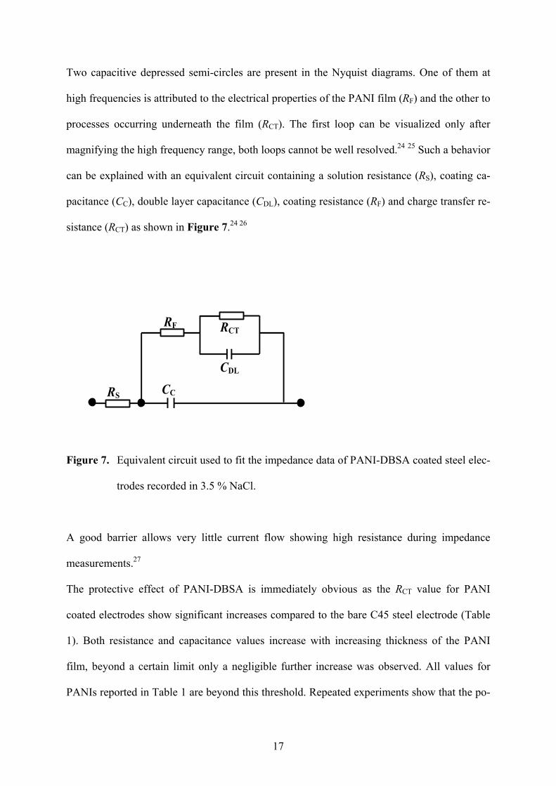
Two capacitive depressed semi-circles are present in the Nyquist diagrams. One of them at
high frequencies is attributed to the electrical properties of the PANI film (RF) and the other to
processes occurring underneath the film (RCT). The first loop can be visualized only after
magnifying the high frequency range, both loops cannot be well resolved.24 25 Such a behavior
can be explained with an equivalent circuit containing a solution resistance (RS), coating ca-
pacitance (CC), double layer capacitance (CDL), coating resistance (RF) and charge transfer re-
sistance (RCT) as shown in Figure 7.24 26
Figure 7. Equivalent circuit used to fit the impedance data of PANI-DBSA coated steel elec-
trodes recorded in 3.5 % NaCl.
A good barrier allows very little current flow showing high resistance during impedance
measurements.27
The protective effect of PANI-DBSA is immediately obvious as the RCT value for PANI
coated electrodes show significant increases compared to the bare C45 steel electrode (Table
1). Both resistance and capacitance values increase with increasing thickness of the PANI
film, beyond a certain limit only a negligible further increase was observed. All values for
PANIs reported in Table 1 are beyond this threshold. Repeated experiments show that the po-
17

larization resistance and thereby the corrosion efficiency is influenced by the amount of
DBSA in the feed. TIP-6, where DBSA to aniline ratio is 7, shows relatively better corrosion
protection. In conventional PANI coating, Cl ions and water can easily permeate due to the
porosity of the film leading to a lower film resistance.26 Bulk samples of PANI-DBSA show
fibrillar, porous and compact film morphology when the mole ratio of DBSA to aniline is 5, 7
and 10 respectively.14 However, RCT values in our case could not be correlated to the bulk
morphology of the polymer (TIP-6 with porous morphology shows higher RCT) indicating the
change in morphology during sample preparation which was later confirmed by TEM studies.
The values of CDL in Table 1 for PANI coated C45 steel electrodes lies in the range of 1.6 - 4
mF which are much higher than the standard double layer capacitance values. Higher values
of CDL observed in the present study are due to high electrochemical active surface.28 Correla-
tion of the values of EIM parameters such as RCT, CDL, etc. with the corrosion protection ef-
fect and with already reported results is a difficult task as results vary widely and are strongly
influenced by the composition of the steel, corrosion environment, nature of coating (ES or
EB) and top coat (if present).4 6 27 29
18
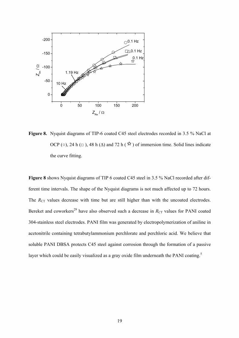
Figure 8. Nyquist diagrams of TIP-6 coated C45 steel electrodes recorded in 3.5 % NaCl at
OCP (), 24 h ( ), 48 h (∆) and 72 h ( ) of immersion time. Solid lines indicate
the curve fitting.
Figure 8 shows Nyquist diagrams of TIP 6 coated C45 steel in 3.5 % NaCl recorded after dif-
ferent time intervals. The shape of the Nyquist diagrams is not much affected up to 72 hours.
The RCT values decrease with time but are still higher than with the uncoated electrodes.
Bereket and coworkers29 have also observed such a decrease in RCT values for PANI coated
304-stainless steel electrodes. PANI film was generated by electropolymerization of aniline in
acetonitrile containing tetrabutylammonium perchlorate and perchloric acid. We believe that
soluble PANI DBSA protects C45 steel against corrosion through the formation of a passive
layer which could be easily visualized as a gray oxide film underneath the PANI coating.5
19
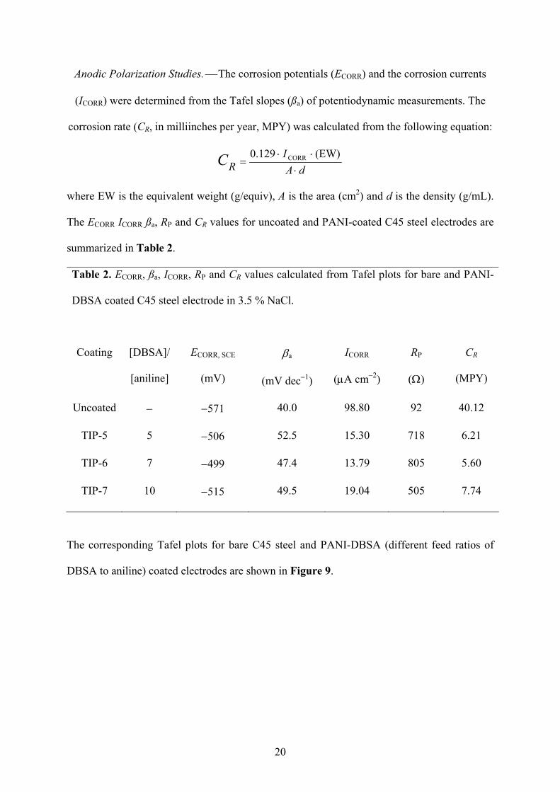
Anodic Polarization Studies. The corrosion potentials (ECORR) and the corrosion currents
(ICORR) were determined from the Tafel slopes (ßa) of potentiodynamic measurements. The
corrosion rate (CR, in milliinches per year, MPY) was calculated from the following equation:
dA
IRC
(EW) 0.129 CORR
where EW is the equivalent weight (g/equiv), A is the area (cm2) and d is the density (g/mL).
The ECORR ICORR ßa, RP and CR values for uncoated and PANI-coated C45 steel electrodes are
summarized in Table 2.
Table 2. ECORR, ßa, ICORR, RP and CR values calculated from Tafel plots for bare and PANI-
DBSA coated C45 steel electrode in 3.5 % NaCl.
Coating [DBSA]/
[aniline]
ECORR, SCE
(mV)
a
(mV dec1)
ICORR
(A cm2)
RP
()
CR
(MPY)
Uncoated 571 40.0 98.80 92 40.12
TIP-5 5 506 52.5 15.30 718 6.21
TIP-6 7 499 47.4 13.79 805 5.60
TIP-7 10 515 49.5 19.04 505 7.74
The corresponding Tafel plots for bare C45 steel and PANI-DBSA (different feed ratios of
DBSA to aniline) coated electrodes are shown in Figure 9.
20
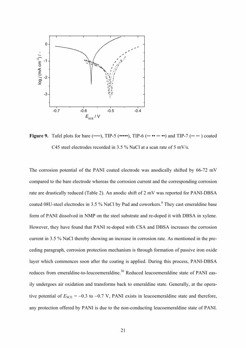
Figure 9. Tafel plots for bare (), TIP-5 (•••••), TIP-6 ( •• ••) and TIP-7 ( ) coated
C45 steel electrodes recorded in 3.5 % NaCl at a scan rate of 5 mV/s.
The corrosion potential of the PANI coated electrode was anodically shifted by 66-72 mV
compared to the bare electrode whereas the corrosion current and the corresponding corrosion
rate are drastically reduced (Table 2). An anodic shift of 2 mV was reported for PANI-DBSA
coated 08U-steel electrodes in 3.5 % NaCl by Pud and coworkers.8 They cast emeraldine base
form of PANI dissolved in NMP on the steel substrate and re-doped it with DBSA in xylene.
However, they have found that PANI re-doped with CSA and DBSA increases the corrosion
current in 3.5 % NaCl thereby showing an increase in corrosion rate. As mentioned in the pre-
ceding paragraph, corrosion protection mechanism is through formation of passive iron oxide
layer which commences soon after the coating is applied. During this process, PANI-DBSA
reduces from emeraldine-to-leucoemeraldine.30 Reduced leucoemeraldine state of PANI eas-
ily undergoes air oxidation and transforms back to emeraldine state. Generally, at the opera-
tive potential of ESCE = 0.3 to 0.7 V, PANI exists in leucoemeraldine state and therefore,
any protection offered by PANI is due to the non-conducting leucoemeraldine state of PANI.
21
However, in situ UV-Vis spectroscopy exhibit band at 420 nm corresponding to radical cation
at ESCE = 0.2 V and cyclic voltammetry studies reveal that anion exchange between PANI-
DBSA film and electrolyte solution is a slow process. Hence, we assume that at the operating
potential (ESCE = 0.3 to 0.7 V) and scan rate (5 mV s1) PANI-DBSA film is not completely
reduced. The better corrosion protection performance of PANI-DBSA in our case can there-
fore be attributed to the stronger complexation of DBSA with the N-atoms of the polymer
backbone. An increase in ECORR up to 1650 mV was reported by several investigators.5 31 The
magnitude of potential shift and corrosion current strongly depends on the processing tech-
nology, composition of the steel and an insulating polymer top-coat.
The polarization resistances (RP) calculated from Tafel plots (Table 2) are almost in agree-
ment with the RCT values calculated from impedance data (Table 1).* A significant increase in
RP after PANI coating confirms its protective nature against the corrosion of C45 steel. If the
PANI-DBSA film is in completely reduced state then such an agreement between RCT and RP
does not hold good. Hence, as mentioned earlier, corrosion protection is due to emeraldine
PANI-DBSA salt and not due to leucoemeraldine. The ECORR and ICORR values are influenced
by the ratio of DBSA to aniline in the feed. TIP-6 having a feed ratio of 10 shows better cor-
rosion performance over the others which was also confirmed by EIM studies. As described
under the sections of in situ UV-Vis spectroscopy and cyclic voltammetry, the hydrophobic
nature of the long non-polar chain of DBSA and its strong complexation with PANI backbone
hinders the rate of anion exchange which further reduces the ingress of hydrophilic (and pit-
ting) Cl ions into the polymer film thereby enhancing the corrosion performance.
* The agreement between polarization resistance RP (i.e. the slope of the current density vs. electrode potential
curve) and the sum of all Ohmic components in the electrode impedance deduced from impedance measure-
ments at the same electrode potential is expected, because at frequency zero the sum of all Ohmic components
22

Transmission Electron Microscopy (TEM). Figure 10 shows TEM images of PANI-DBSA
at different feed ratios of DBSA to aniline.
Figure 10. Transmission electron microscope images of TIP-5 (a), TIP-6 (b) and TIP-7 (c).
of the impedance is equal to said slope.21 The relatively small contribution of the film resistance RF and the so-
lution resistance RS results in the present case in the fairly good agreement between RP and RCT.
23
It is clear from the figures that the PANI particles are basically spherical in shape and their
size is strongly influenced by the feed ratio of DBSA to aniline. When the ratio is 5, particles
are organized in such a way which is normally exhibited by monolayers and the average par-
ticle size lies in the range of 1-7 nm. Increasing the feed ratio to 7 and then to 10 increases the
average particle size to 8.5-15 nm and then to 20-30 nm respectively. The feed ratio of DBSA
to aniline also influences the aggregation tendency of the PANI particles. In the case of TIP-6
and TIP-7 where the feed ratio is 7 and 10 respectively, the agglomeration tendency is higher
leading to the formation group of spherical particles overlapping with each other. Yang and
coworkers32 have reported that TEM images of PANI-DBSA directly cast from the emulsion
show entangled fibers of 1 µm width and a length of 1 mm. Nanocomposites of PANI-CSA
and acrylic acid show rice grain shaped particles with 70 nm width and 120 nm length
whereas electrochemically synthesized PANI-CSA exhibits agglomerated irregular shaped
particles.33 34 The tendency of aggregation monitored in TEM images could be correlated to
the bulk morphology (SEM) of the polymers. The well organized particles observed in the
Figure 10a for TIP-5 leads to more ordered fibrillar morphology. Increasing tendency of ag-
gregation as reflected from the TEM images for TIP-6 and TIP-7 (Figure 10b and 10c) leads
to the formation of porous and compact polymer flakes, respectively.14
24

Electron diffraction (ED) patterns were recorded for several agglomerated areas observed in
TEM images. At DBSA to aniline feed ratio of 5, ill defined ED patterns were observed indi-
cating the presence of both crystalline (not shown in the figure) and amorphous (Figure 11a)
regimes in the polymer. Well defined ED patterns having bright arcs of different lengths
could be seen at DBSA to aniline feed ratio of 10 (Figure 11b).
Figure 11. Electron diffraction patterns for selected agglomerated particles of TIP-5 (a) and
TIP-7 (b).
25

Similar ED patterns were also observed for PANI-DBSA synthesized via an emulsion path-
way and for an electrochemically synthesized PANI-CSA.32 33 Such a pattern is attributed to
an orthorhombic crystal structure. Further investigations to analyze the crystal structure of
PANI-DBSA using ED patterns are underway.
Conclusions
PANI-DBSA synthesized by an inverse emulsion polymerization is completely soluble in
chloroform in its pristine state and can be easily processed onto various metal substrates by
simple drop, spin or spray coating technique. Solution state electronic absorption spectros-
copy confirms the absence of interaction of chloroform with PANI backbone whereas 2:1
mixture of toluene+2-propanol forms hydrogen bonding with N atoms of PANI. PANI-DBSA
in its emeraldine salt form offers better protection against corrosion of C45 steel which was
confirmed by EIM where the charge transfer resistance for PANI coated electrode shows sig-
nificant increase compared to the uncoated one. The anodic shift in the corrosion potential
and lowering of the corrosion current for PANI-coated C45 steel electrode supports the im-
proved anti-corrosion performance of this new soluble PANI. The improved corrosion protec-
tion of our samples is due to the hydrophobic nature of the non-polar chain of DBSA which
hinders the permeability of aqueous anions into the polymer film. In situ UV-Vis spectros-
copy and cyclic voltammetry of PANI-DBSA in neutral electrolytes confirms the slow rate of
anion exchange. TEM images reveal that morphology of PANI at molecular level is different
than that of the bulk morphology. However, the bulk morphology (SEM) could be correlated
to the TEM images.
26

Acknowledgements
Financial support by the Deutsche Forschungsgemeinschaft (GRK 829/1) is gratefully ac-
knowledged. We thank Dr. S. Schulze, Institute of Physics, TU Chemnitz for help in re-
cording TEM images and ED patterns.
27

28
References
1 P. Chandrashekhar, Conducting Polymers, Fundamentals and Applications: A Practical
Approach, Kulwer Academic Publishers, Boston (1999).
2 T. J. Skotheim, R. L. Elsenbaumer and J. R. Reynolds, Handbook of Conducting Poly-
mers, Marcel Dekker, New York (1998).
3 P. S. Rao, D. N Sathyanarayana and T. Jeevananda, Advanced Functional Molecules and
Polymers, ed. Nalwa., H.S.Vol.3, p. 79, Gordon and Breach Science (2001).
4 A. Cook, A. Gabriel and N. Laycock, J. Electrochem. Soc., 151, B529 (2004).
5 G. M. Spinks, A. J. Dominis, G. G. Wallace and D. E. Tallman, J. Solid State Electro-
chem., 6, 85 (2002).
6 A. T Ozyilmaz, M. Erbil and B. Yazici, Curr. Appl. Phys., 6, 1 (2006).
7 B. J. Wessling, J. Corr. Sci. Eng., 1, paper 15 (1999).
8 A. A. Pud, G. S. Shapoval, P. Kamarchik, N. A. Ogurtsov, V. F. Gromovaya, I. E. Myro-
nyuk and Yu. V. Kontsur, Synth. Met., 107, 111 (1999).
9 Y. Cao, P. Smith and A. J. Heeger, Synth. Met., 48, 91 (1992).
10 Y. Haba, E. Segal, M. Narkis, G. I. Titelman and A. Siegmann, Synth. Met., 106, 59
(1999).
11 P. S. Rao, S. Subrahmanya and D. N. Sathyanarayana, Synth. Met., 128, 311 (2002).
12 P. S. Rao, S. Palaniappan and D. N. Sathyanarayana, Macromolecules, 35, 4988 (2002).
13 M. Sai Ram and S. J. Palaniappan, J. Mater. Sci., 39, 3069 (2004).
14 S. Shreepathi and R. Holze, Chem. Mater., 17, 4078 (2005).

15 A. A. Athawale, M. V. Kulkarni and V. V Chabukswar, Mater. Chem. Phys., 73, 106
(2002).
16 J. Stejskal, and I. Sapurina, Pure Appl. Chem., 77, 815 (2005).
17 R. Mazeikiene, G. Niaura and A. Malinauskas, Synth. Met., 139, 89 (2003).
18 M. C. Bernard, S. Joiret, A. H-L. Goff and P. D. Long, J. Electrochem. Soc., 148, B299
(2001).
19 D. A. Buttry and M. D. Ward, Chem. Rev., 92, 1355 (1992).
20 S. Mu, Synth. Met., 143, 259 (2004).
21 R. Holze, Bull. Electrochem., 10, 56 (1994).
22 N. Perez, Electrochemistry and Corrosion Science, p. 97, Kluwer Academic Publishers,
Boston (2004).
23 A. J. Bard and L. R. Fraulkner, Electrochemical methods: Fundamentals and Applica-
tions, p. 388, John Wiley & Sons, Inc. New York, (2001).
24 K. Belmokre, N. Azzouz, F. Kermiche, M. Wery and J. Pagetti, Mater. Corr., 49, 108
(1998).
25 T. Tuken, A. T. Ozyilmaz, B. Yazici, G. Kardas and M. Erbil, Progress Org. Coatings,
51, 27 (2004).
26 S. Sathiyanarayanan, S. Muthukrishnan, G. Venkatachari and D. C. Trivedi, Progress
Org. Coatings, 53, 297 (2005).
27 J. Posdorfer and B. Wessling, Fresenius J. Anal. Chem., 367, 343 (2000).
28 E. Barsonkov, J. R. Macdonald, Impedance Spectroscopy: Theory, Experiment and Ap-
plications, 2nd Ed., Wiley-Interscience (2005).
29

30
29 G. Bereket, E. Hür and Y. Sahin, Appl. Surf. Sci., 252, 1233 (2005).
30 R. J. Holness, G. Williams, D. A. Worsley and H. N. McMurray, J. Electrochem. Soc.,
152, B73 (2005).
31 A. Mirmohseni and A. Oladegaragoze, Synth. Met., 114, 105 (2000).
32 C. Y. Yang, P. Smith, A. J. Heeger, Y. Cao and J. E. Osterholm, Polymer, 35, 1142
(1994).
33 P. C. Innis, I. D. Norris, L. A. P. Kane-Maguire and G. G. Wallace, Macromolecules, 31,
6521 (1998).
34 P. A. McCarthy, J. Huang, S. C. Yang and H. L. Wang, Langmuir, 18, 259 (2002).
.
Copyright © 2022 FDOKUMEN