COROLLA Model Code - CIS Digital
18
TOYOTA MOTOR CORPORATION Overseas Customer Service Technical Division Area Application : General , G.C.C. Countries Model Name : COROLLA Model Code : NZE120, NZE121, ZZE121, ZZE122, CE120 Subject : SUPPLEMENTAL FOR REPAIR MANUAL (LIGHTING) This Service Bulletin provides the headlight assy repair procedure for COROLLA and comes into effect on September, 2002. The attached pages will be used with the following manuals. Pub. No. Publication Name RM821E COROLLA Repair Manual RM926E COROLLA Repair Manual Supplement Production Effective : Frame No. Production Date −−− From September, 2002 Ref. No. : BE−2028 Date : Aug., 2002 Page : 1 of 18 Section : Body Electrical
-
Upload
khangminh22 -
Category
Documents
-
view
5 -
download
0
Transcript of COROLLA Model Code - CIS Digital

TOYOTA MOTOR CORPORATION Overseas Customer Service Technical Division
Area Application : General, G.C.C. CountriesModel Name : COROLLAModel Code : NZE120, NZE121, ZZE121, ZZE122, CE120Subject : SUPPLEMENTAL FOR REPAIR MANUAL (LIGHTING)
This Service Bulletin provides the headlight assy repair procedure for COROLLA and comes intoeffect on September, 2002.
The attached pages will be used with the following manuals.
Pub. No. Publication Name
RM821E COROLLA Repair Manual
RM926E COROLLA Repair Manual Supplement
Production Effective :
Frame No. Production Date
−−− From September, 2002
Ref. No. : BE−2028
Date : Aug., 2002Page : 1 of 18
Section : BodyElectrical

I26240Connector connected
Ref. No. : BE−2028
Page : 2 of 18
TOYOTA MOTOR CORPORATION Overseas Customer Service Technical Division
LIGHTING SYSTEMPRECAUTION
(a) When any defect such as deformation, crack, dent, chipping, etc. is identified on the dischargeheadlight (especially, on the light control ECU), replace the headlight with a new one.
(b) Even if the operation seems to be normal, the fail−safe function may be defective.(c) Since bulbs of the discharge headlight and halogen bulbs (for headlights and fog lights) have
pressurized gas inside and can easily be broken if scratched or dropped, special care shouldbe taken. When handling, hold the plastic or metal part and do not touch the glass part withbare hands.
(d) Touching the HV socket of the discharge headlight with the headlight dimmer switch ON couldgenerate momentary high voltage of 20,000 V and lead to a serious accident.
(e) Never connect a tester to the high voltage socket of the discharge headlight for measurement,as this leads to a serious accident because of high voltage.
(f) When performing a operation related to the discharge headlight, keep it away from water suchas rain, turn off the light control switch, and disconnect the battery terminal and the connectorof the light control ECU in advance to avoid electric shock.
(g) When performing operation related to the discharge headlight, start it after assembling is com-pletely over, and never light up without a bulb installed.
(h) Do not light up the discharge headlight using another power source except vehicle’s.

Ref. No. : BE−2028
Page : 3 of 18
TOYOTA MOTOR CORPORATION Overseas Customer Service Technical Division
PROBLEM SYMPTOMS TABLE1. HEADLIGHT AND TAILLIGHT
Symptom Suspect Area See page
Only one headlight comes on.
1. Bulb2. LO LH fuse
LO RH fuse3. Light control ECU4. Wire harness
−−−−−
”LO−Beam” does not come on (All).1. HEAD MAIN fuse2. HEAD relay3. Light control switch
−−
7 of 17
”HI−Beam” does not come on (All).1. Headlight dimmer switch2. DIM relay3. Wire harness
7 of 17−−
”HI−Beam” does not come on(One side).
1. Bulb2. HI RH fuse
HI HL fuse3. Wire harness
−−−−
”Flash” does not come on.1. Headlight dimmer switch2. DIM relay3. Wire harness
7 of 17−−
Headlight is dark.1. Bulb2. Wire harness
−−
2. AUTOMATIC LIGHT CONTROL SYSTEM
Symptom Suspect Area See page
Automatic light control system doesnot operate.
1. Automatic light control sensor2. Light control switch3. Integration relay4. Wire harness
5 of 177 of 17
−−
3. HEADLIGHT BEAM LEVEL CONTROL SYSTEM
Symptom Suspect Area See page
Headlight beam level control systemdoes not operate.
1. Headlight leveling switch2. Headlight beam level control actuator3. Wire harness
8 of 176 of 17
−

Ref. No. : BE−2028
Page : 4 of 18
TOYOTA MOTOR CORPORATION Overseas Customer Service Technical Division
PRE−CHECK1. FAIL−SAFE FUNCTION(a) Light Control ECU
The fail−safe function operates as below when the light control ECU detects a malfunction.
Condition Symptom
Input error is detectedFWhen the input voltage is not within the range of the operational voltage(9−16V), the headlights are turned off. As soon as the input voltage returnsto within the range, the headlights are turned on again.FWhen the input voltage drops while the headlights operate, the lighting ismaintained until the voltage falls below 6V.
Output error is detected(open or short)Light blinking is detected(more than 60 sec.)
FWhen an error occurs in the output voltage or the bulb blinks continuouslyfor more than 60 sec, the headlights are turned off. The condition is main-tained until power is re−supplied again.(Light Control Switch: ON →→→→ OFF →→→→ ON)(Ignition Switch: ON →→→→ OFF →→→→ ON)
Light voltage abnormality is detected FWhen the voltage abnormality is detected, the headlights are turned off.The condition is maintained until power is re−supplied again.(Light Control Switch: ON →→→→ OFF →→→→ ON)(Ignition Switch: ON →→→→ OFF →→→→ ON)
2. AUTOMATIC LIGHT CONTROL SYSTEM OPERATION CHECK (AUTO ON)(a) Turn the ignition switch to ON.(b) Turn the light control switch to AUTO.(c) Gradually cover the top of the sensor.(d) Verify that the accessory lights and the headlights turn ON.3. AUTOMATIC LIGHT CONTROL SYSTEM OPERATION CHECK (AUTO OFF)(a) Gradually uncover the sensor.(b) Verify that the headlights and the accessory lights turn OFF.

I01254
1 2 3 4
Wire Harness Side:
I01255
1234
Ref. No. : BE−2028
Page : 5 of 18
TOYOTA MOTOR CORPORATION Overseas Customer Service Technical Division
INSPECTION1. INSPECTAUTOMATIC LIGHTCONTROLSEN-
SOR CIRCUIT(a) Disconnect the connector from the sensor and in-
spect the connector on the wire harness side, asshown in the chart.
Tester connection Condition Specified condition
3 − Ground Always Continuity
1 − Ground Ignition switch LOCK or ACC No voltage
1 − Ground Ignition switch ON Battery positive voltage
4 − Ground Ignition switch LOCK or ACC No voltage
4 − Ground Ignition switch ON Battery positive voltage
(b) Connect the connector from the sensor and in-spect the connector on the wire harness side, asshown in the chart.
HINT:S Ignition switch is ONS Light control switch is OFF.S Vehicle’s surroundings are bright.
Tester connection Condition Specified condition
3 − Ground Always Continuity
1 − Ground Ignition switch LOCK or ACC No voltage
1 − Ground Ignition switch ON Battery positive voltage
4 − Ground Ignition switch LOCK or ACC No voltage
4 − Ground Ignition switch ON Battery positive voltage

I25929
Ref. No. : BE−2028
Page : 6 of 18
TOYOTA MOTOR CORPORATION Overseas Customer Service Technical Division
2. INSPECT HEADLIGHT BEAM LEVEL CON-TROL ACTUATOR CIRCUIT (w/ DischargeHeadlight)
(a) Connect the connector from the actuator and in-spect the connector on the wire harness side, asshown in the chart.
Tester connection Condition Specified condition
1 − Ground Always Continuity
3 − Ground Ignition switch ON Battery positive voltage
(b) Measure the voltage between terminal 1 and 2.
Tester connection Switch position Specified condition
1 − 2 0 Approx. 10.8 V
1 − 2 1 Approx. 9.5 V
1 − 2 2 Approx. 8.2 V
1 − 2 3 Approx. 7.0 V
1 − 2 4 Approx. 5.7 V
1 − 2 5 Approx. 4.4 V

I25930
Ref. No. : BE−2028
Page : 7 of 18
TOYOTA MOTOR CORPORATION Overseas Customer Service Technical Division
3. INSPECT LIGHT CONTROL SWITCH CONTI-NUITY (w/ Discharge Headlight)
(a) Check that there is continuity between terminalsat each switch position as shown in the chart.
Switch operation Tester connection Specified condition
OFF − No continuity
TAIL 9 − 15 Continuity
HEAD 9 − 14 − 15 Continuity
AUTO 9 − 13 Continuity
4. INSPECT HEADLIGHT DIMMER SWITCHCONTINUITY (w/ Discharge Headlight)
(a) Check that there is continuity between terminalsat each switch position as shown in the chart.
Switch operation Tester connection Specified condition
FLASH 1 − 2 − 9 Continuity
LOW BEAM 9 − 10 Continuity
HI BEAM 2 − 9 Continuity
5. INSPECT TURN SIGNAL SWITCH CONTINU-ITY (w/ Discharge Headlight)
(a) Check that there is continuity between terminalsat each switch position as shown in the chart.
Switch operation Tester connection Specified condition
Right turn 7 − 8 Continuity
Neutral − No continuity
Left turn 6 − 7 Continuity
6. INSPECT FRONT FOGLIGHT SWITCHCONTI-NUITY (w/ Discharge Headlight)
(a) Check that there is continuity between terminalsat each switch position as shown in the chart.
Switch operation Tester connection Specified condition
OFF − No continuity
ON 12 − 16 Continuity

I25931
1 (+B)2 (GND)
6 (ILL−)
4 (LH)
500 −800 Ω
3 (ILL+)
I18635
1
2
3
4
5
Ref. No. : BE−2028
Page : 8 of 18
TOYOTA MOTOR CORPORATION Overseas Customer Service Technical Division
7. INSPECT HEADLIGHT LEVELING SWITCHRESISTANCE
(a) Inspect headlight leveling switch.(1) Connect the battery positive (+) lead to ter-
minal 1 and the battery negative (−) lead toterminal 2.
(2) Measure the voltage between terminal 4and terminal 2.
Standard:
Switch positionVoltage ratio against the voltagebetween terminal 1 − 2. (%)
0 85
1 74
2 63
3 53
4 42
5 31
(b) Inspect switch illumination.(1) Connect the battery positive (+) lead to ter-
minal 3 and the battery negative (−) lead toterminal 6, and check that the illuminationcomes on.
8. INSPECT HEAD RELAY CIRCUIT
Condition Tester connection Specified condition
C t t1 − 2 Continuity
Constant3 − 5 No continuity
Apply B+ betweenterminals 1 and 2.
3 − 5 Continuity
If continuity is not as specified, replace the relay.
I18559
1
2
3
4
5
Ref. No. : BE−2028
Page : 9 of 18
TOYOTA MOTOR CORPORATION Overseas Customer Service Technical Division
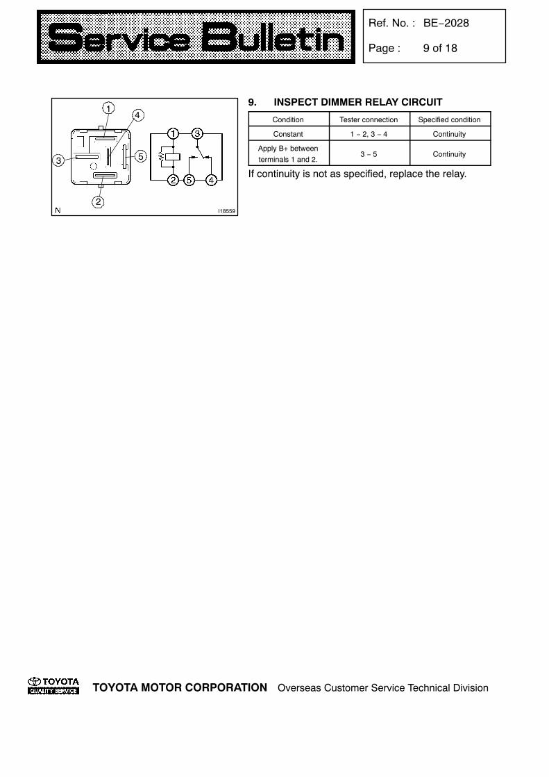
9. INSPECT DIMMER RELAY CIRCUIT
Condition Tester connection Specified condition
Constant 1 − 2, 3 − 4 Continuity
Apply B+ betweenterminals 1 and 2.
3 − 5 Continuity
If continuity is not as specified, replace the relay.

I26243
Halogen headlight:
Discharge headlight:
Headlight Unit
Headlight Cover No. 1
Clearance Light Bulb
Front Turn Signal Light Bulb
Headlight ControlECU
Headlight Cover
Discharge Headlight Bulb
Headlight Leveling Motor
Headlight ProtectorRetainer Upper
Headlight Bulb No. 1
Headlight Bulb No. 2
ClearanceLight Bulb
Front Turn SignalLight Bulb
Headlight Unit
Headlight Cover No. 2Headlight Cover No. 1
Headlight Bulb No. 1
Headlight BracketLower
Headlight Cover No. 2
Supply parts:
Headlight ProtectorRetainer Lower
Headlight Code
Ref. No. : BE−2028
Page : 10 of 18
TOYOTA MOTOR CORPORATION Overseas Customer Service Technical Division
HEADLIGHT ASSYCOMPONENTS

I26256Claw
I26257Inner Bracket
I26244
Ref. No. : BE−2028
Page : 11 of 18
TOYOTA MOTOR CORPORATION Overseas Customer Service Technical Division
REPLACEMENT1. REMOVE RADIATOR GRILLE(a) Remove the screw and the 2 bolts.(b) Pull out the radiator grill forward, then release the
6 claws.NOTICE:Be careful not to damage the 6 claws.
2. REMOVE HEADLIGHT UNIT ASSY LH(a) Disconnect the engine under cover, the front
fender liner LH and the front bumper cover.(b) Remove the 3 bolts.(c) Disconnect the connectors.(d) Pull out the headlight unit forward, then discon-
nect the bracket of body side.3. REMOVEFRONTTURNSIGNALLIGHTBULB,
CLEARANCE LIGHT BULB AND SOCKETS4. Halogen headlight:
REMOVE HEADLIGHT COVER NO. 1 ANDHEADLIGHT BULB NO. 1
5. Halogen headlight:REMOVE HEADLIGHT COVER NO. 2 ANDHEADLIGHT BULB NO. 2
6. Discharge headlight:REMOVE HEADLIGHT COVER NO. 1 ANDHEADLIGHT BULB NO. 1
7. Discharge headlight:REMOVE DISCHARGE HEADLIGHT BULB
(a) Remove the headlight cover No. 2 as shown inthe illustration.

I26537
I26246
I26247
I26248
Ref. No. : BE−2028
Page : 12 of 18
TOYOTA MOTOR CORPORATION Overseas Customer Service Technical Division
(b) Disconnect the headlight code from the headlightcover No. 2.
(c) Turn the bulb socket in the direction of the arrowand pull it off.
(d) Release the lock of the set spring and remove thedischarge headlight bulb.
8. Discharge headlight:REMOVE HEADLIGHT CONTROL ECU
(a) Remove the 4 screws and the headlight cover.(b) Remove the 3 screws.

I26258
Claw
I26250Adjusting Bolt ”B” Adjusting Bolt ”A”
Discharge headlight:
Ref. No. : BE−2028
Page : 13 of 18
TOYOTA MOTOR CORPORATION Overseas Customer Service Technical Division
(c) Release the claw and disconnect the connector.
(d) RH:Move the reflector by turning the adjusting bolt Aapprox. 4 − 8 revolution counterclockwise, andthen remove the bulb socket on the headlightcontrol ECU from the inside of the headlight unit.
NOTICE:Do not turn the adjusting bolt A counterclockwise10 revolution or more.(e) LH:
Move the reflector by turning the adjusting bolt Aapprox. 7 − 9 revolution counterclockwise andadjusting bolt B 10 revolution counterclockwise,and then remove the bulb socket on the headlightcontrol ECU from the inside of the headlight unit.
NOTICE:Do not turn the adjusting bolt A counterclockwise10 revolution or more.

I26249
Leveling Motor Shaft
Adjusting Bolt
I26259
BA
C
Ref. No. : BE−2028
Page : 14 of 18
TOYOTA MOTOR CORPORATION Overseas Customer Service Technical Division
9. Discharge headlight:REMOVE HEADLIGHT LEVELING MOTOR
(a) Turn the headlight leveling motor rightward asshown in the illustration.
(b) Unscrew the leveling motor shaft by turning theadjusting bolt leftward.
NOTICE:Do not pull the headlight leveling motor by force toprevent the leveling motor shaft and the joint parton the headlight from breakage.
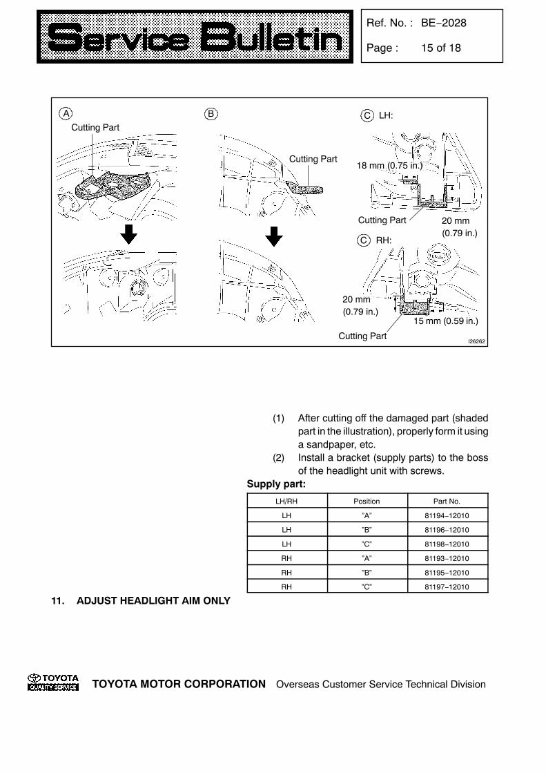
10. INSTALL HEADLIGHT ASSY LH(a) If the shown part (A, B, C) of the headlight assy
is damaged, the headlight assy can be reinstalledto the body by installing a bracket (supply parts)to the damaged part.
I26262
BA C
18 mm (0.75 in.)
20 mm(0.79 in.)
20 mm(0.79 in.)
15 mm (0.59 in.)
Cutting Part
Cutting Part
Cutting Part
Cutting Part
LH:
C RH:
Ref. No. : BE−2028
Page : 15 of 18
TOYOTA MOTOR CORPORATION Overseas Customer Service Technical Division
(1) After cutting off the damaged part (shadedpart in the illustration), properly form it usinga sandpaper, etc.
(2) Install a bracket (supply parts) to the bossof the headlight unit with screws.
Supply part:
LH/RH Position Part No.
LH ”A” 81194−12010
LH ”B” 81196−12010
LH ”C” 81198−12010
RH ”A” 81193−12010
RH ”B” 81195−12010
RH ”C” 81197−12010
11. ADJUST HEADLIGHT AIM ONLY

Ref. No. : BE−2028
Page : 16 of 18
TOYOTA MOTOR CORPORATION Overseas Customer Service Technical Division
ADJUSTMENT1. ADJUST HEADLIGHT AIM ONLY(a) Place the vehicle in the following conditions.
S The area around the headlight is not deformed.S The vehicle is parked on a level surface.S Tire inflation pressure is in the specified value.S A driver is in the driver’s seat and the vehicle is in a state ready for driving (with a tank
full).S The vehicle is bounced several times.
(b) Check the headlight aiming.(1) Prepare a thick white paper.(2) Stand the paper perpendicular to the ground at the position 9.84 ft away from the head-
lights.(3) Ensure that the center line of the vehicle and the paper face forms a 90−degree angle
as shown in the illustration.(4) Draw a horizontal line (H line) on the paper where the center of the low beam headlight
bulb is to be.(5) Draw a vertical line (V line) on the paper where the center line of the vehicle is to be.(6) Draw 2 vertical lines (VRHandV LH lines) on the paperwhere the center of the lowbeam
headlight bulbs are to be.(7) Draw a horizontal line (H RH and H LH lines) on the paper at 30 mm (1.18 in.) below the
horizontal line (H line).HINT:The H RH and H LH line is 0.57˚ below the horizontal line (H line) of the light axis.
(8) Take appropriate measures to prevent any influence of other lights.(9) Discharge headlight:
Set the headlights leveling position to ”0” position and adjust the angle of the headlightaxis.
(10) Start the engine.(11) Turn the headlights ON.(12) Check that the headlights properly strike the position shown in the illustration.(13) If not, adjust the lights in the vertical or horizontal direction.

I26261
Low Beam: Low Beam:
30 mm(1.18 in)
Vehicle Position:
3 m (9.84 ft)
V LH Line
V RH Line
f: Step No.
1,211 mm (47.68 in.) *H RH andH LH lines
0.57_
90_
V LH Line V Line V RH Line6 5 6
4H
7
30 mm(1.18 in)
H
I26260Adjusting Bolt ”B” Adjusting Bolt ”A”
Halogen headlight:
I26250
Discharge headlight:
Adjusting Bolt ”B” Adjusting Bolt ”A”
Ref. No. : BE−2028
Page : 17 of 18
TOYOTA MOTOR CORPORATION Overseas Customer Service Technical Division
HINT:As shown in the illustration, adjust each aim of the RH and LH lights.
(c) When adjusting the headlight aim in the horizon-tal direction:Using adjusting bolt B, adjust the headlight aim tobe within the specified range.
(d) When adjusting it in the vertical direction:Using adjusting bolt A, adjust the headlight aim tobe within the specified range.
HINT:The optical aim moves upward when turning a screw-driver clockwise, while it moves downward when turn-ing a screwdriver counterclockwise.

I26538
Ref. No. : BE−2028
Page : 18 of 18
TOYOTA MOTOR CORPORATION Overseas Customer Service Technical Division
2. ADJUST AUTOMATIC LIGHT CONTROLSENSOR
(a) Remove the meter hood sub−assy.(b) Remove the combination meter assy.(c) Insert a hand into the instrument panel sub−assy
upper, and push the automatic light control sen-sor upward.
(d) Turn the filter on the automatic light control sen-sor to adjust the sensitivity.
ConditionAdjustment method
(Filter turning direction)
If response is too slow Clockwise
If response is too quick Counter clockwise
HINT:Wipe the oil out on the filter.(e) Push the automatic light control sensor into the
instrument panel sub−assy upper.NOTICE:Do not push the automatic light control sensor intothe instrument panel sub−assy upper with exces-sive force.