CIS 4930. Digital System Testing Fault Modeling
79
CIS 4930. Digital System Testing Fault Modeling Dr. Hao Zheng Comp. Sci & Eng U of South Florida
-
Upload
khangminh22 -
Category
Documents
-
view
4 -
download
0
Transcript of CIS 4930. Digital System Testing Fault Modeling
CIS 4930. Digital System TestingFault Modeling
Dr. Hao ZhengComp. Sci & Eng
U of South Florida

Overview
➜ Logic Fault Models➜ Fault Detection & Redundancy➜ Fault Equivalence & Fault Location➜ Fault Dominance➜ Single Stuck-Fault (SSF) Model➜Multiple Stuck-Fault (MSF) Model➜ Summary
2
Recap: Testing Big Picture
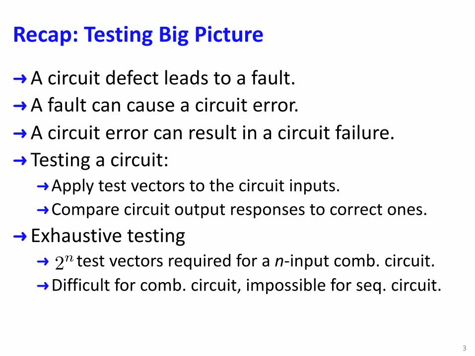
➜A circuit defect leads to a fault.➜A fault can cause a circuit error.➜A circuit error can result in a circuit failure.➜ Testing a circuit: ➜Apply test vectors to the circuit inputs.➜Compare circuit output responses to correct ones.
➜ Exhaustive testing➜ test vectors required for a n-input comb. circuit.➜Difficult for comb. circuit, impossible for seq. circuit.
3
2n
Recap: Testing Big Picture
➜Goal: find a small set of test vectors that target specific faults.➜ Ideally, no redundant test vectors for the same fault.➜The set contains enough test vectors to uncover all
target faults.➜ Impossible to achieve 100% fault coverage.➜Due to undetectable faults.
4
Recap: Physical Faults
5
Recall that we have 4 types of errors• Design Errors• Fabrication Errors• Fabrication Defects• Physical Failures
Physical Faults can be:• Permanent• Intermittent• Transient
Physical Faults
Recap: Logical Faults
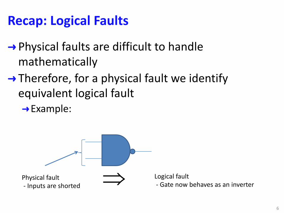
➜Physical faults are difficult to handle mathematically
➜ Therefore, for a physical fault we identify equivalent logical fault➜Example:
6
Physical fault - Inputs are shorted
Logical fault - Gate now behaves as an inverterÞ
4.1 Logic Fault Models
➜ Fault model: representation of physical faults and their natures at logic level.
➜Recall that Behavior = Function + Timing
➜ Therefore, we can talk about two types of faults:➜Logical Faults – modify circuit logic function.➜Delay Faults - modify circuit operating speed.
➜Our focus will be on Logical Faults
74.1 Logic Fault Models
Logical Fault Modeling - Advantages
➜ Fault analysis becomes a logical problem.➜Test can start before silicon is available.
➜ Fault analysis become less complex.➜ Many physical faults can be modeled by the same
logical fault➜ Technology independent➜ Tests derived for logical faults may be used for
physical faults whose effect➜ not completely understood➜ or too complex to analyze
84.1 Logic Fault Models
Structural and Functional Faults
➜ Structural faults➜Faults defined on a structural circuit model.➜Effect: modify interconnections
➜ Functional faults➜Faults defines on a functional circuit model➜Effect: modify truth table etc.
➜ Intermittent & Permanent Faults➜Statistical data on probability of occurrence of
transient/intermittent faults are difficult to have.➜Our focus in this discussion is on structural and
permanent faults94.1 Logic Fault Models
Single Fault Assumption - Justification
➜Assumption – one logical fault in the system.➜ Justification➜Frequent testing strategy (test often so that prob. of
multiple faults developing in between too low)➜Usually tests derived for individual single faults are
applicable for detecting multiple faults composed of the single ones.
104.1 Logic Fault Models
Structural Fault Models
➜Assumptions:➜Components are fault free and,➜Only interconnections are affected – shorts & opens.
➜ Stuck-at-v Fault:➜Short (with supply/gnd) or Open lines behave as
“stuck at” fixed logic value v (v Î {0,1}) ➜Bridging fault:➜Short between two lines ® usually new logic function
(AND or OR bridging)➜We will discuss bridging faults later
114.1 Logic Fault Models
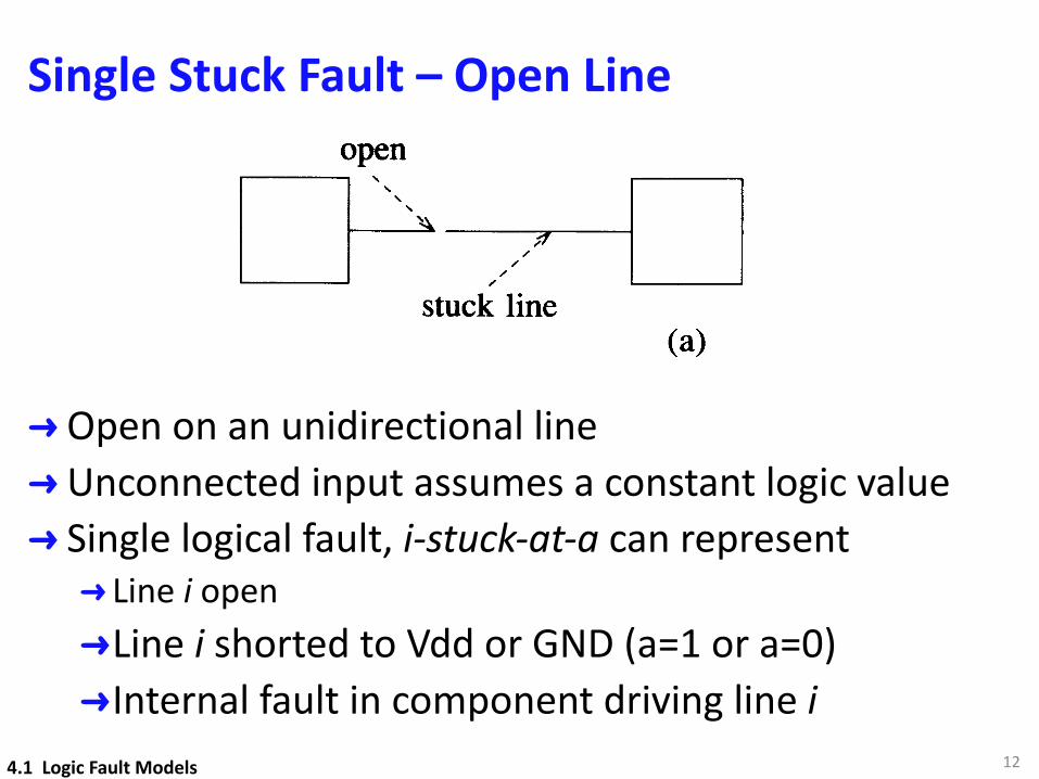
Single Stuck Fault – Open Line
➜Open on an unidirectional line➜Unconnected input assumes a constant logic value➜ Single logical fault, i-stuck-at-a can represent➜ Line i open➜Line i shorted to Vdd or GND (a=1 or a=0)➜Internal fault in component driving line i
12
Logical Fault Models
stuck line(a)
_______Istlm
footr,--C_h__open- --;>
95
II
II
stuck lines (\
\\
\
(b)
Figure 4.1 Stuck faults caused by opens (a) Single stuck fault (b) Multiple stuckfault
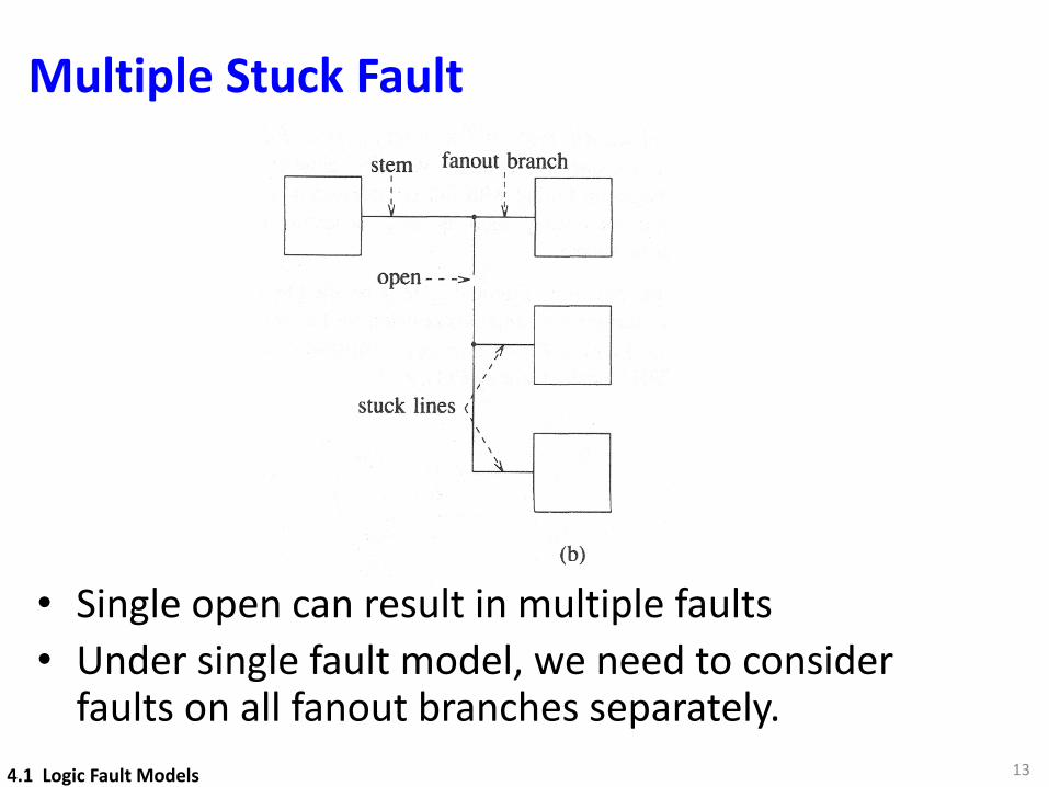
An open in a signal line with fanout may result in a multiple stuck fault involving asubset of its fanout branches, as illustrated in Figure 4.1(b). If we restrict ourselves tothe single stuck-fault model, then we have to consider any single fanout branch stuckfault separately from the stem fault.
In the macro approach for hierarchical modeling, every component is expanded to itsinternal structural model. However, if components are individually tested before theirassembly, then it may be enough to test only for faults affecting their interconnections.Then we do not want to consider the faults internal to components but only faultsassociated with their I/O pins. This restricted fault assumption is referred to as thepin-fault model.
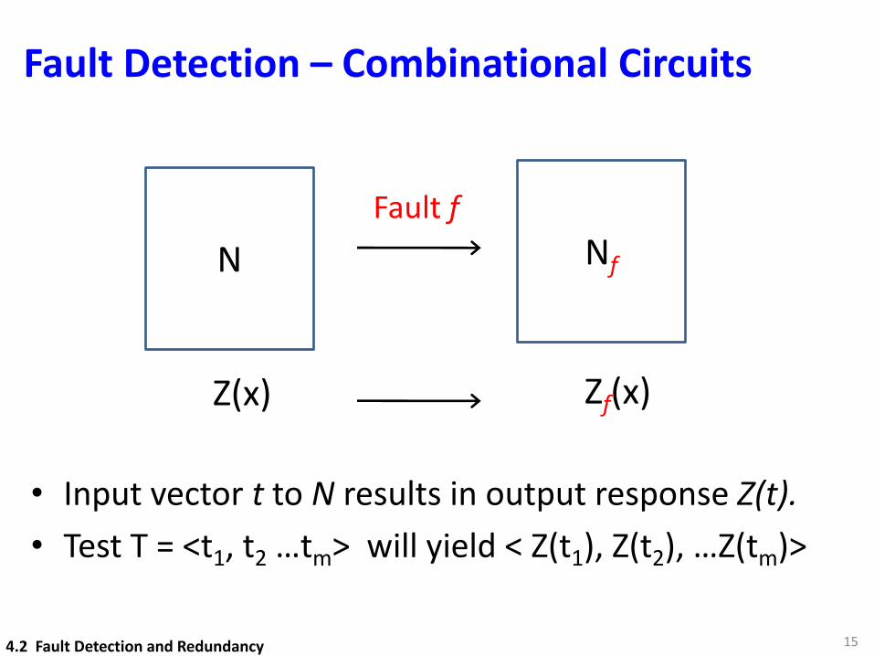
4.2 Fault Detection and Redundancy4.2.1 Combinational CircuitsLet Z(x) be the logic function of a combinational circuit N, where x represents anarbitrary input vector and Z(x) denotes the mapping realized by N. We will denote byt a specific input vector, and by Z(t) the response of N to t. For a multiple-output
4.1 Logic Fault Models
Multiple Stuck Fault
13
• Single open can result in multiple faults• Under single fault model, we need to consider
faults on all fanout branches separately. 4.1 Logic Fault Models
14
4.2 Fault Detection and Redundancy
Fault Detection – Combinational Circuits
15
N
Z(x)
Nf
Zf(x)
Fault f
• Input vector t to N results in output response Z(t).• Test T = <t1, t2 …tm> will yield < Z(t1), Z(t2), …Z(tm)>
4.2 Fault Detection and Redundancy

Fault Detection – Comb Circuits
Definition 4.1 A test (vector) t detects a fault fiff
➜Note the above is applicable to comb. circuits only.
➜ Test vectors in T can applied in any order, so T is set of tests
➜Applicable to edge-pin testing➜Components are assumed to be fault free.
16
zf (t) 6= z(t)
4.2 Fault Detection and Redundancy
Example 1
17
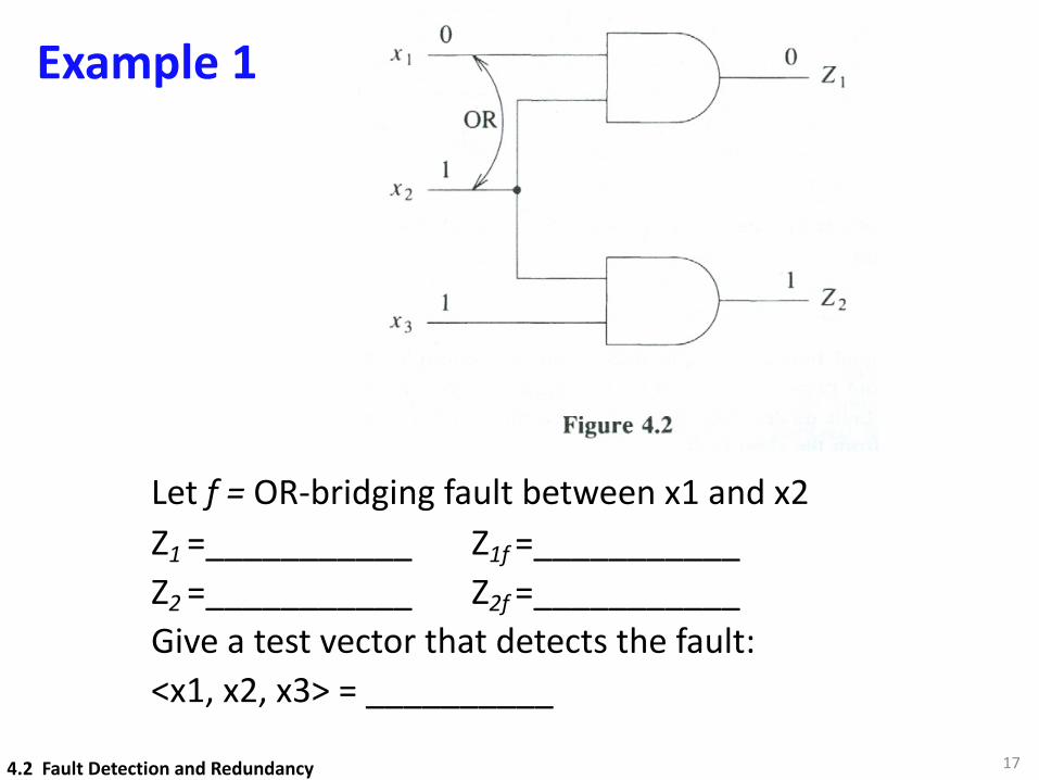
Let f = OR-bridging fault between x1 and x2Z1 =___________ Z1f =___________Z2 =___________ Z2f =___________Give a test vector that detects the fault:<x1, x2, x3> = __________
4.2 Fault Detection and Redundancy
Fault Detection and Test Vectors
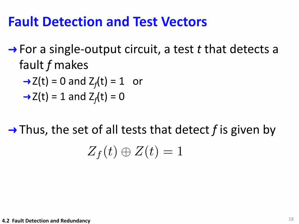
➜ For a single-output circuit, a test t that detects a fault f makes➜Z(t) = 0 and Zf(t) = 1 or➜Z(t) = 1 and Zf(t) = 0
➜ Thus, the set of all tests that detect f is given by
18
Zf (t)� Z(t) = 1
4.2 Fault Detection and Redundancy
Example 2
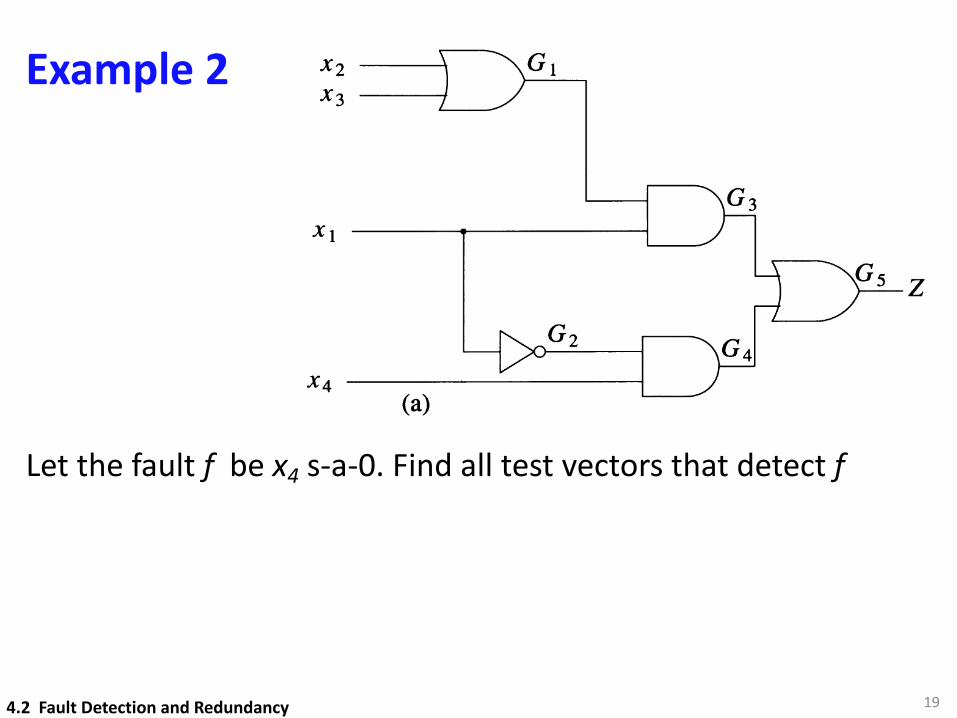
Let the fault f be x4 s-a-0. Find all test vectors that detect f
194.2 Fault Detection and Redundancy
Fault Detection and Redundancy 97
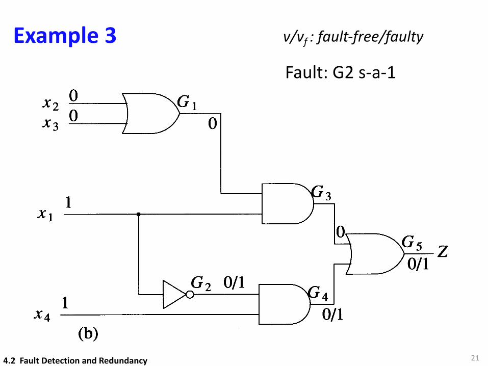
Example 4.2: The function realized by the circuit of Figure 4.3(a) isZ = (X2+X3)XI + XIX4. Let f be X4 s-a-O. In the presence of f the function becomesZf = (X2+X3)XI, and equation (4.1) reduces to XIX4 = 1. Thus any test in whichXl = 0 and X4 = 1 is a test for f. The expression XIX4 represents, in compact form,any of the four tests (0001, 0011, 0101, 0111) that detectf. D
X4(a)
X2 -'-0__----\
X3 _0__--+
1
1
(b)
Figure 4.3
Sensitization
Let us simulate the circuit of Figure 4.3(a) for the test t = 1001, both without and withthe fault G 2 s-a-1 present. The results of these two simulations are shown inFigure 4.3(b). The results that are different in the two cases have the form vlv], wherev and vf are corresponding signal values in the fault-free and in the faulty circuit. Thefault is detected since the output values in the two cases are different.
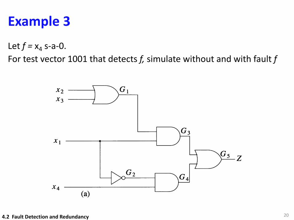
Example 3Let f = x4 s-a-0. For test vector 1001 that detects f, simulate without and with fault f
204.2 Fault Detection and Redundancy
Fault Detection and Redundancy 97
Example 4.2: The function realized by the circuit of Figure 4.3(a) isZ = (X2+X3)XI + XIX4. Let f be X4 s-a-O. In the presence of f the function becomesZf = (X2+X3)XI, and equation (4.1) reduces to XIX4 = 1. Thus any test in whichXl = 0 and X4 = 1 is a test for f. The expression XIX4 represents, in compact form,any of the four tests (0001, 0011, 0101, 0111) that detectf. D
X4(a)
X2 -'-0__----\
X3 _0__--+
1
1
(b)
Figure 4.3
Sensitization
Let us simulate the circuit of Figure 4.3(a) for the test t = 1001, both without and withthe fault G 2 s-a-1 present. The results of these two simulations are shown inFigure 4.3(b). The results that are different in the two cases have the form vlv], wherev and vf are corresponding signal values in the fault-free and in the faulty circuit. Thefault is detected since the output values in the two cases are different.
Example 3
21
v/vf : fault-free/faulty
4.2 Fault Detection and Redundancy
Fault Detection and Redundancy 97
Example 4.2: The function realized by the circuit of Figure 4.3(a) isZ = (X2+X3)XI + XIX4. Let f be X4 s-a-O. In the presence of f the function becomesZf = (X2+X3)XI, and equation (4.1) reduces to XIX4 = 1. Thus any test in whichXl = 0 and X4 = 1 is a test for f. The expression XIX4 represents, in compact form,any of the four tests (0001, 0011, 0101, 0111) that detectf. D
X4(a)
X2 -'-0__----\
X3 _0__--+
1
1
(b)
Figure 4.3
Sensitization
Let us simulate the circuit of Figure 4.3(a) for the test t = 1001, both without and withthe fault G 2 s-a-1 present. The results of these two simulations are shown inFigure 4.3(b). The results that are different in the two cases have the form vlv], wherev and vf are corresponding signal values in the fault-free and in the faulty circuit. Thefault is detected since the output values in the two cases are different.
Fault: G2 s-a-1
Fault Detection and Redundancy 97
Example 4.2: The function realized by the circuit of Figure 4.3(a) isZ = (X2+X3)XI + XIX4. Let f be X4 s-a-O. In the presence of f the function becomesZf = (X2+X3)XI, and equation (4.1) reduces to XIX4 = 1. Thus any test in whichXl = 0 and X4 = 1 is a test for f. The expression XIX4 represents, in compact form,any of the four tests (0001, 0011, 0101, 0111) that detectf. D
X4(a)
X2 -'-0__----\
X3 _0__--+
1
1
(b)
Figure 4.3
Sensitization
Let us simulate the circuit of Figure 4.3(a) for the test t = 1001, both without and withthe fault G 2 s-a-1 present. The results of these two simulations are shown inFigure 4.3(b). The results that are different in the two cases have the form vlv], wherev and vf are corresponding signal values in the fault-free and in the faulty circuit. Thefault is detected since the output values in the two cases are different.
Fault – Sensitization
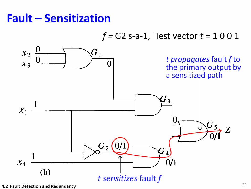
22t sensitizes fault f
t propagates fault f tothe primary output by a sensitized path
f = G2 s-a-1, Test vector t = 1 0 0 1
4.2 Fault Detection and Redundancy
Fault Sensitization – Terminology
➜ Fault Activation: A test t activates a fault on a line if it generates an error at the site of the fault.
➜ Fault Propagation: A test t propagates the error to a primary output by creating at least one path from fault site to the primary output.
➜ Line Sensitization: A line whose value under the test t changes in the presence of the fault f is said to be sensitized to the fault f by the test t
➜ Sensitized Path: A path composed of sensitive lines
234.2 Fault Detection and Redundancy
Gate Controlling and Enabling Values
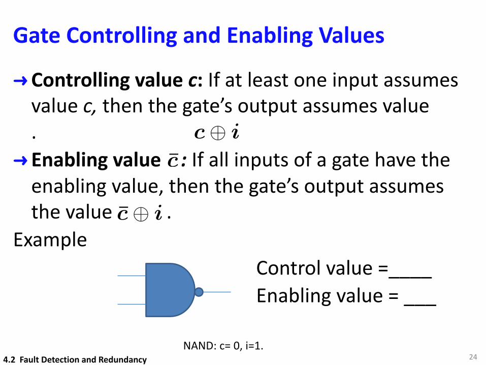
➜Controlling value c: If at least one input assumes value c, then the gate’s output assumes value .
➜ Enabling value : If all inputs of a gate have the enabling value, then the gate’s output assumes the value .
ExampleControl value =____Enabling value = ___
24
c̄c� i
c̄� i
NAND: c= 0, i=1.4.2 Fault Detection and Redundancy
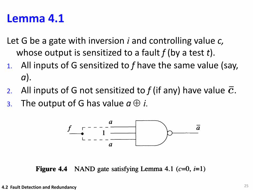
Lemma 4.1Let G be a gate with inversion i and controlling value c,
whose output is sensitized to a fault f (by a test t).1. All inputs of G sensitized to f have the same value (say,
a).2. All inputs of G not sensitized to f (if any) have value .3. The output of G has value a Å i.
25
c̄
4.2 Fault Detection and Redundancy
Fault Detection and Redundancy
Figure 4.4 NAND gate satisfying Lemma 4.1 (c=O, i=l)
99
2. If there are several sensitized paths between I and j, then all of them have thesame inversion parity. 0
Detectability
A fault f is said to be detectable if there exists a test t that detects f, otherwise, f is anundetectable fault. For an undetectable fault f, Zt(x) =Z(x) and no test cansimultaneously activate f and create a sensitized path to a primary output. In thecircuit of Figure 4.5(a) the fault a s-a-1 is undetectable. Since undetectable faults donot change the function of the circuit, it may appear that they are harmless and hencecan be ignored. However, a circuit with an undetectable fault may invalidate thesingle-fault assumption. Recall that based on the frequent testing strategy, we assumethat we can detect one fault before a second one occurs. But this may not be possibleif the first fault is undetectable.
When generating a set of tests for a circuit, a typical goal is to produce a completedetection test set, that is, a set of tests that detect any detectable fault. However, acomplete test set may not be sufficient to detect all detectable faults if an undetectableone is present in the circuit [Friedman 1967].
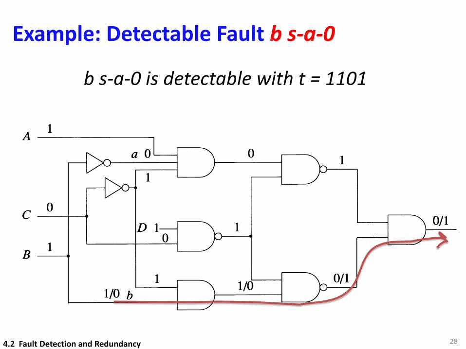
Example 4.3: Figure 4.5(a) shows how the fault b s-a-O is detected by t = 1101.Figure 4.5(b) shows that b s-a-O is no longer detected by the test t if the undetectablefault a s-a-1 is also present. Thus, if t is the only test that detects b s-a-O in acomplete detection test set T, then T is no longer complete in the presence of a s-a-1.D
The situation in which the presence of an undetectable fault prevents the detection ofanother fault by a certain test is not limited to faults of the same category; forexample, an undetectable bridging fault can similarly invalidate a complete test set forstuck faults.
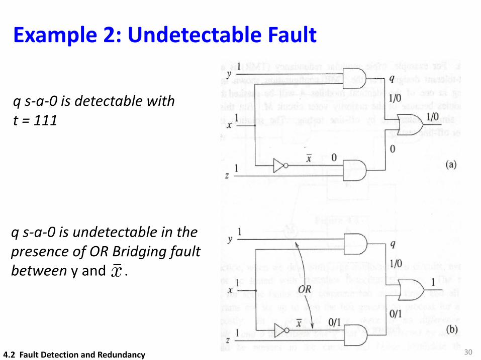
Example 4.4: [Kodandapani and Pradhan 1980]. Consider the circuit of Figure 4.6(a)that realizes the function xy + xz . The OR bridging fault between y and x isundetectable, since the function realized in the presence of the fault isxy + yz + zX = xy + zx. Figure 4.6 shows how the test 111 detects the fault q s-a-Obut no longer does so in the presence of the bridging fault. The test set T = {Ill, 010,001, 101} is a complete detection test set for single stuck faults, and 111 is the onlytest in T that detects q s-a-O. Hence T is no longer complete in the presence of theundetectable bridging fault. 0
Faults – Detectability
A fault f is said to be detectable if there exists a test t that detects f
Otherwise, f is undetectable.
For undetectable fault, no test exists that cansimultaneously activate and propagate the fault to
the primary output.
264.2 Fault Detection and Redundancy
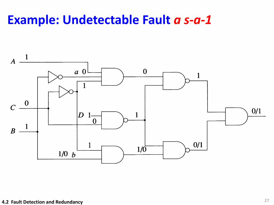
Example: Undetectable Fault a s-a-1
274.2 Fault Detection and Redundancy
100 FAULT MODELING
1
1
1
o
A--------
B
C --+----.
1/0 b
(a)
1D
1
1
o
A-------------.
B
C --+--.......
1/0 b
(b)
Figure 4.5
Redundancy
A combinational circuit that contains an undetectable stuck fault is said to beredundant, since such a circuit can always be simplified by removing at least one gateor gate input. For instance, suppose that a s-a-l fault on an input of an AND gate G isundetectable. Since the function of the circuit does not change in the presence of thefault, we can permanently place a 1 value on that input. But an n-input AND with aconstant 1 value on one input is logically equivalent to the (n-l)-input AND obtainedby removing the gate input with the constant signal. Similarly, if an AND input s-a-Ois undetectable, the AND gate can be removed and replaced by a 0 signal. Since now
Example: Detectable Fault b s-a-0
28
b s-a-0 is detectable with t = 1101
4.2 Fault Detection and Redundancy
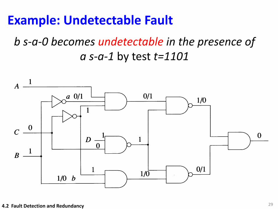
Example: Undetectable Fault
29
b s-a-0 becomes undetectable in the presence of a s-a-1 by test t=1101
100 FAULT MODELING
1
1
1
o
A--------
B
C --+----.
1/0 b
(a)
1D
1
1
o
A-------------.
B
C --+--.......
1/0 b
(b)
Figure 4.5
Redundancy
A combinational circuit that contains an undetectable stuck fault is said to beredundant, since such a circuit can always be simplified by removing at least one gateor gate input. For instance, suppose that a s-a-l fault on an input of an AND gate G isundetectable. Since the function of the circuit does not change in the presence of thefault, we can permanently place a 1 value on that input. But an n-input AND with aconstant 1 value on one input is logically equivalent to the (n-l)-input AND obtainedby removing the gate input with the constant signal. Similarly, if an AND input s-a-Ois undetectable, the AND gate can be removed and replaced by a 0 signal. Since now
4.2 Fault Detection and Redundancy
Example 2: Undetectable Fault
30
q s-a-0 is detectable with t = 111
q s-a-0 is undetectable in the presence of OR Bridging fault between y and .x̄
4.2 Fault Detection and Redundancy
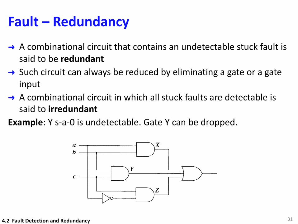
Fault – Redundancy ➜ A combinational circuit that contains an undetectable stuck fault is
said to be redundant➜ Such circuit can always be reduced by eliminating a gate or a gate
input➜ A combinational circuit in which all stuck faults are detectable is
said to irredundantExample: Y s-a-0 is undetectable. Gate Y can be dropped.
314.2 Fault Detection and Redundancy
Fault Detection and Redundancy
ab
C --+-----.----1
Figure 4.8
103
Note that in practice, when we deal with large combinational circuits, even irredundantcircuits may not be tested with complete detection test sets. The reason is thatgenerating tests for some faults may consume too much time, and all practical testgeneration programs are set up to 3tOP the test generation process for a fault when itbecomes too costly. In a practical sense, there is no difference between anundetectable fault f and a detectable one g that is not detected by an applied test set.Clearly, g could be present in the circuit and hence invalidate the single-faultassumption.
Identifying redundancy is closely related to the problem of test generation. To showthat a line is redundant means to prove that no test exists for the corresponding fault.The test generation problem belongs to a class of computationally difficult problems,referred to as NP-complete [Ibarra and Sahni 1975]. The traveling salesman problemis one famous member of this class [Horowitz and Sahni 1978]. Let n be the "size" ofthe problem. For the traveling salesman problem n is the number of cities to bevisited; for test generation n is the number of gates in a circuit. An important questionis whether there exists an algorithm that can solve any instance of a problem of size nusing a number of operations proportional to n r, where r is a finite constant. Atpresent, no such polynomial-time algorithm is known for any NP-complete problem.These problems are related in the sense that either all of them or none of them can besolved by polynomial-time algorithms.
Although test generation (and identification of redundancy) is a computationallydifficult problem, practical test generation algorithms usually run in polynomial time.The fact that the test generation problem is NP-complete means that polynomial timecannot be achieved in all instances, that is, any test generation algorithm mayencounter a circuit with a fault that cannot be solved in polynomial time. Experiencehas shown that redundant faults are usually the ones that cause test generationalgorithms to exhibit their worst-case behavior.
4.2.2 Sequential CircuitsTesting sequential circuits is considerably more difficult than testing combinationalcircuits. To detect a fault a test sequence is usually required, rather than a single inputvector, and the response of a sequential circuit is a function of its initial state.
Fault Interaction
➜ If f is a detectable fault and g is an undetectable fault, then f may become undetectable in the presence of g. Such a fault f is called a second-generation redundant fault.
➜ Two undetectable single faults f and g may become detectable if simultaneously present in the circuit. In other words, the multiple fault {f , g} may be detectable even if its single-fault components are not.
324.2 Fault Detection and Redundancy
Detecting Redundancy
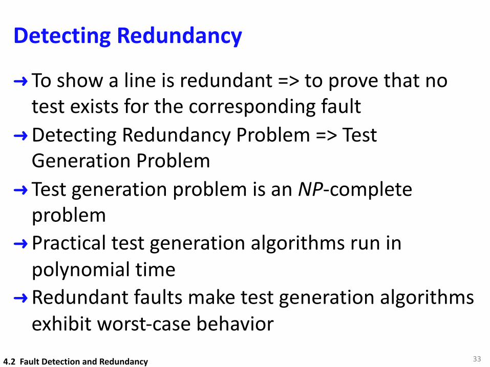
➜ To show a line is redundant => to prove that no test exists for the corresponding fault
➜Detecting Redundancy Problem => Test Generation Problem
➜ Test generation problem is an NP-complete problem
➜Practical test generation algorithms run in polynomial time
➜Redundant faults make test generation algorithms exhibit worst-case behavior
334.2 Fault Detection and Redundancy

Large Combinational Circuits
➜ Even if the circuit is irredundant, we may not have complete test set due to time limitations
➜ In such a case, the fault (say f) for which no test exists, is no different from an undetectable fault (say g)
➜Undetectable fault g may be present in the circuit and invalidate the single fault assumption.
344.2 Fault Detection and Redundancy
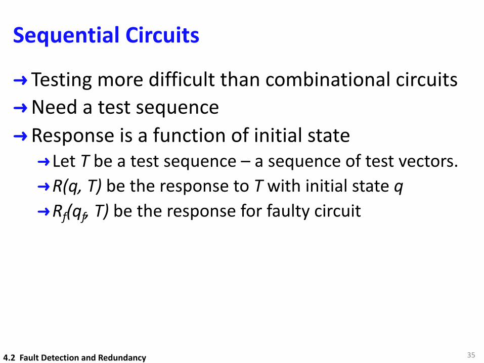
Sequential Circuits
➜ Testing more difficult than combinational circuits➜Need a test sequence➜Response is a function of initial state➜Let T be a test sequence – a sequence of test vectors.➜R(q, T) be the response to T with initial state q➜Rf(qf, T) be the response for faulty circuit
354.2 Fault Detection and Redundancy
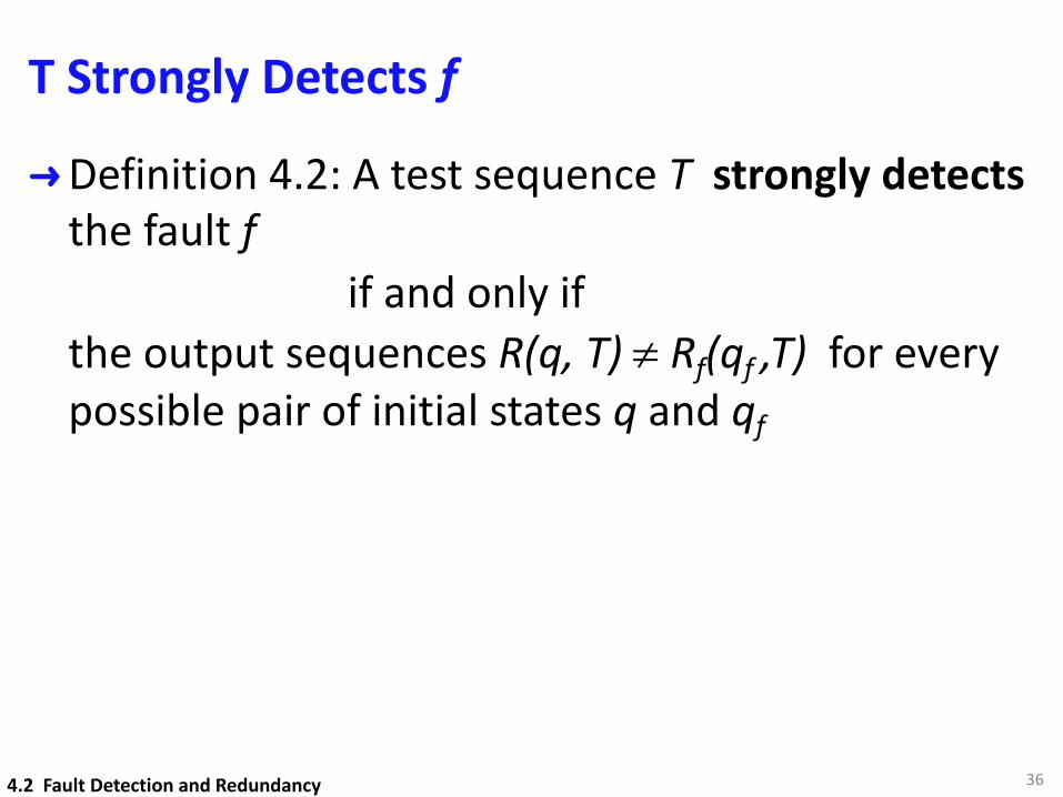
T Strongly Detects f
➜Definition 4.2: A test sequence T strongly detects the fault f
if and only ifthe output sequences R(q, T) ¹ Rf(qf ,T) for every possible pair of initial states q and qf
364.2 Fault Detection and Redundancy
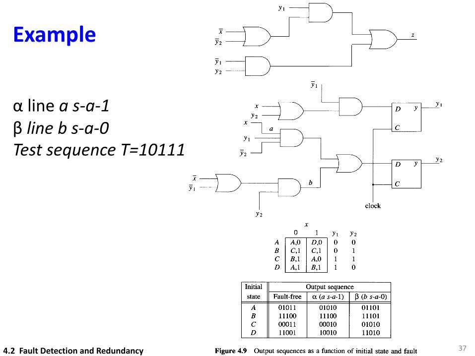
Example
37
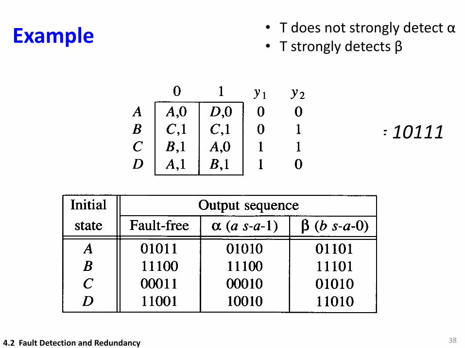
α line a s-a-1β line b s-a-0Test sequence T=10111
Fault Detection and Redundancy 105
YlY2
x D Y Yl
Y2X
C
Yl
Y2D Y
C
clockY2
A,O D,OC,l C,lB,l A,OA,l B,l
ABCD
ox
1 Yl Y2o 0o 11 11 0
Initial Output sequencestate Fault-free a (a s-a-1) J3 (b s-a-O)
A 01011 01010 01101B 11100 11100 11101C 00011 00010 01010D 11001 10010 11010
Figure 4.9 Output sequences as a function of initial state and fault
the circuit. However, an initialization sequence for the fault-free circuit N may fail toinitialize some faulty circuit Nt. Such a fault f is said to prevent initialization.
4.2 Fault Detection and Redundancy
Example
38
T = 10111
• T does not strongly detect α• T strongly detects β
4.2 Fault Detection and Redundancy
Fault Detection and Redundancy 105
YlY2
x D Y Yl
Y2X
C
Yl
Y2D Y
C
clockY2
A,O D,OC,l C,lB,l A,OA,l B,l
ABCD
ox
1 Yl Y2o 0o 11 11 0
Initial Output sequencestate Fault-free a (a s-a-1) J3 (b s-a-O)
A 01011 01010 01101B 11100 11100 11101C 00011 00010 01010D 11001 10010 11010
Figure 4.9 Output sequences as a function of initial state and fault
the circuit. However, an initialization sequence for the fault-free circuit N may fail toinitialize some faulty circuit Nt. Such a fault f is said to prevent initialization.
T Detects f
➜Definition 4.3: A test sequence T detects the fault f
if and only iffor every possible pair of initial states q and qf the output sequences R(q, T) ¹ Rf(qf ,T) for somespecified vector ti Î T
394.2 Fault Detection and Redundancy
Testing with Initialization
➜Phase I: Initialization sequence TI such that N and Nf are brought to known states qI and qIf➜Output responses ignored during initialization
➜Phase II: Apply T’ (output responses are predictable)➜ ti is first vector of T’ for which an error is observed
404.2 Fault Detection and Redundancy
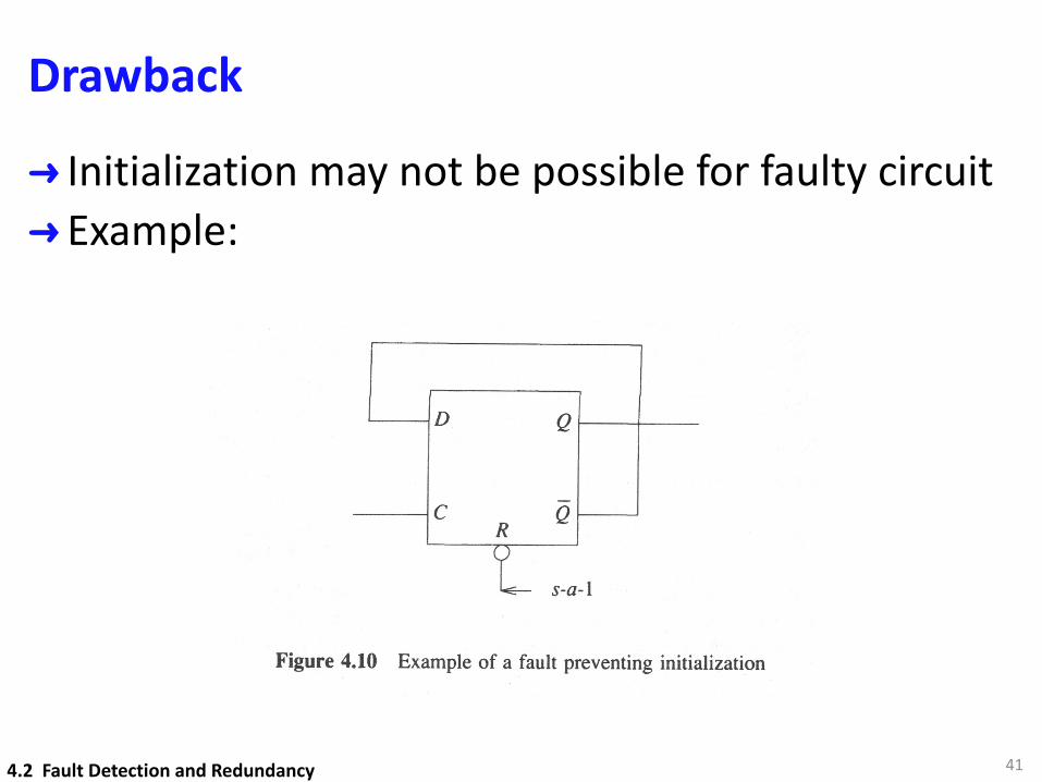
Drawback
➜ Initialization may not be possible for faulty circuit➜ Example:
414.2 Fault Detection and Redundancy

42
4.3 Fault Equivalence and Fault Location

Fault Equivalence – Combinational Circuits
➜Definition 4.4: Two faults f and g are said to be functionally equivalent iff
➜ A test t is said to distinguish between two faults f and g if Zf(t) ¹ Zg(t)➜ There exists no test that can distinguish
functionally equivalent faults➜ Faults are divided into equivalent classes.
434.3 Fault Equivalence and Fault Location
Zf (x) = Zg (x)<latexit sha1_base64="(null)">(null)</latexit><latexit sha1_base64="(null)">(null)</latexit><latexit sha1_base64="(null)">(null)</latexit><latexit sha1_base64="(null)">(null)</latexit>
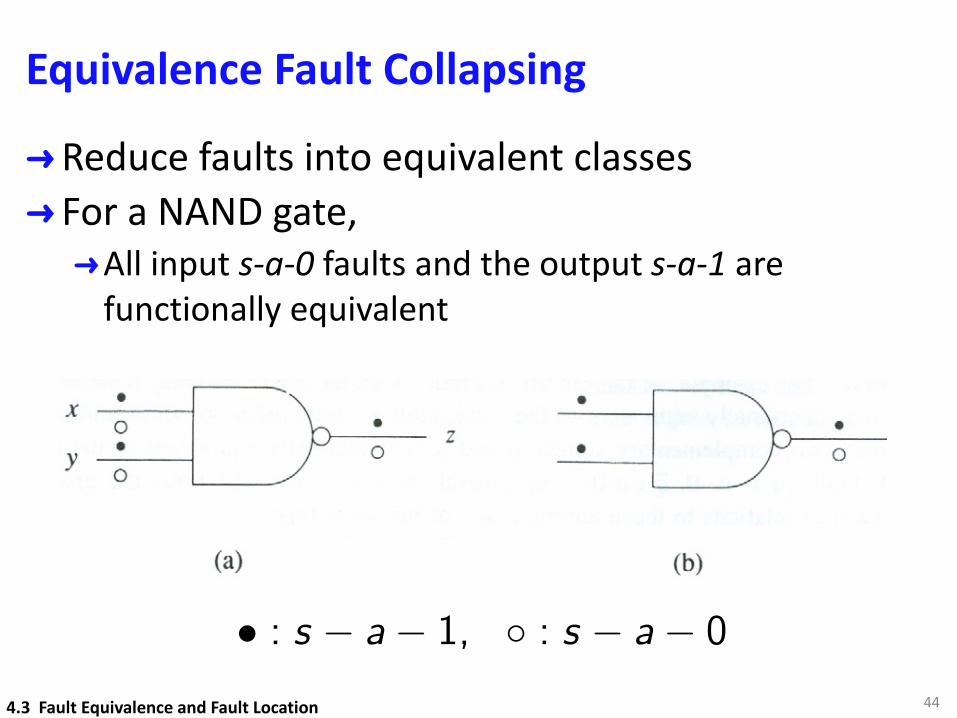
Equivalence Fault Collapsing
➜Reduce faults into equivalent classes➜ For a NAND gate,➜All input s-a-0 faults and the output s-a-1 are
functionally equivalent
444.3 Fault Equivalence and Fault Location
• : s � a� 1, � : s � a� 0<latexit sha1_base64="(null)">(null)</latexit><latexit sha1_base64="(null)">(null)</latexit><latexit sha1_base64="(null)">(null)</latexit><latexit sha1_base64="(null)">(null)</latexit>
Equivalence Fault Collapsing
➜ In general, for a gate with controlling value c and inversion i, ➜All input s-a-c faults are functionally equivalent to
output s-a-(cÅi) faults➜Reduce 2(n+1) faults to n+2 faults for a n-input NAND
gate.
454.3 Fault Equivalence and Fault Location
Fault Location
➜Goal of testing is to locate the fault besides detecting the fault
➜A complete location test distinguishes between every pair of distinguishable faults in a circuit
➜A fault-free circuit contains empty fault, denoted by F.➜Therefore ZF (x) = Z(x)
➜A fault detection is a particular case of fault location, since a test that detects f distinguishes between f and F.
464.3 Fault Equivalence and Fault Location
Functional Equivalence Under a Test
➜ In practice, test sets are not complete ➜Affect diagnostic resultion
➜Definition 4.5: Two f and g are functionally equivalent under a test set T,
iffZf(t) = Zg(t) for every test tÎT
Note:Functional equivalence implies functionalequivalence under any test set, but not vice versa.
474.3 Fault Equivalence and Fault Location
Fault Equivalence – Sequential Circuits
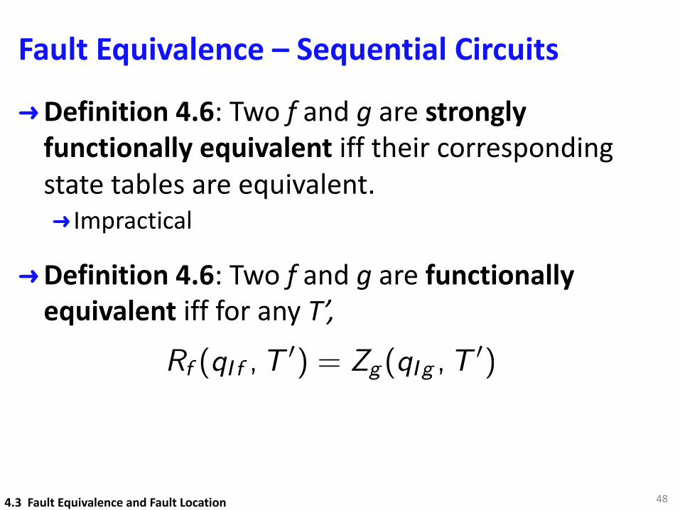
➜Definition 4.6: Two f and g are stronglyfunctionally equivalent iff their corresponding state tables are equivalent.➜ Impractical
➜Definition 4.6: Two f and g are functionally equivalent iff for any T’,
48
Rf (qI f ,T0) = Zg (qI g ,T
0)<latexit sha1_base64="(null)">(null)</latexit><latexit sha1_base64="(null)">(null)</latexit><latexit sha1_base64="(null)">(null)</latexit><latexit sha1_base64="(null)">(null)</latexit>
4.3 Fault Equivalence and Fault Location
49
4.4 Fault Dominance

Fault Dominance – Combinational Circuits
➜Another fault relation to reduce faults to be considered
➜Definition 4.8: Let Tg be the set of all tests that detect a fault g. We say that a fault f dominatesthe fault g
ifff and g are functionally equivalent under Tg.
504.4 Fault Dominance
Fault Dominance
51
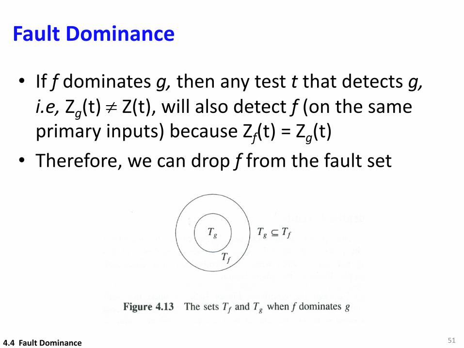
• If f dominates g, then any test t that detects g, i.e, Zg(t) ¹ Z(t), will also detect f (on the same primary inputs) because Zf(t) = Zg(t)
• Therefore, we can drop f from the fault set
4.4 Fault Dominance
Example
52
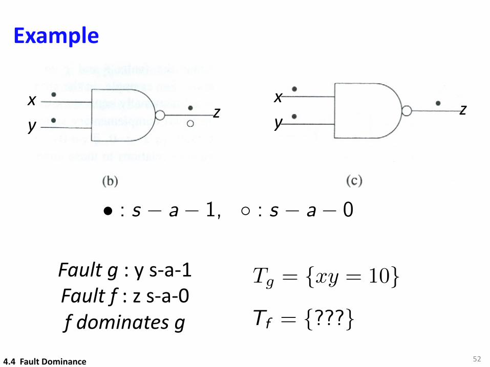
• : s � a� 1, � : s � a� 0<latexit sha1_base64="(null)">(null)</latexit><latexit sha1_base64="(null)">(null)</latexit><latexit sha1_base64="(null)">(null)</latexit><latexit sha1_base64="(null)">(null)</latexit>
Fault g : y s-a-1Fault f : z s-a-0f dominates g
Tg = {xy = 10}
4.4 Fault Dominance
xy
zxy
z
Tf = {???}<latexit sha1_base64="(null)">(null)</latexit><latexit sha1_base64="(null)">(null)</latexit><latexit sha1_base64="(null)">(null)</latexit><latexit sha1_base64="(null)">(null)</latexit>
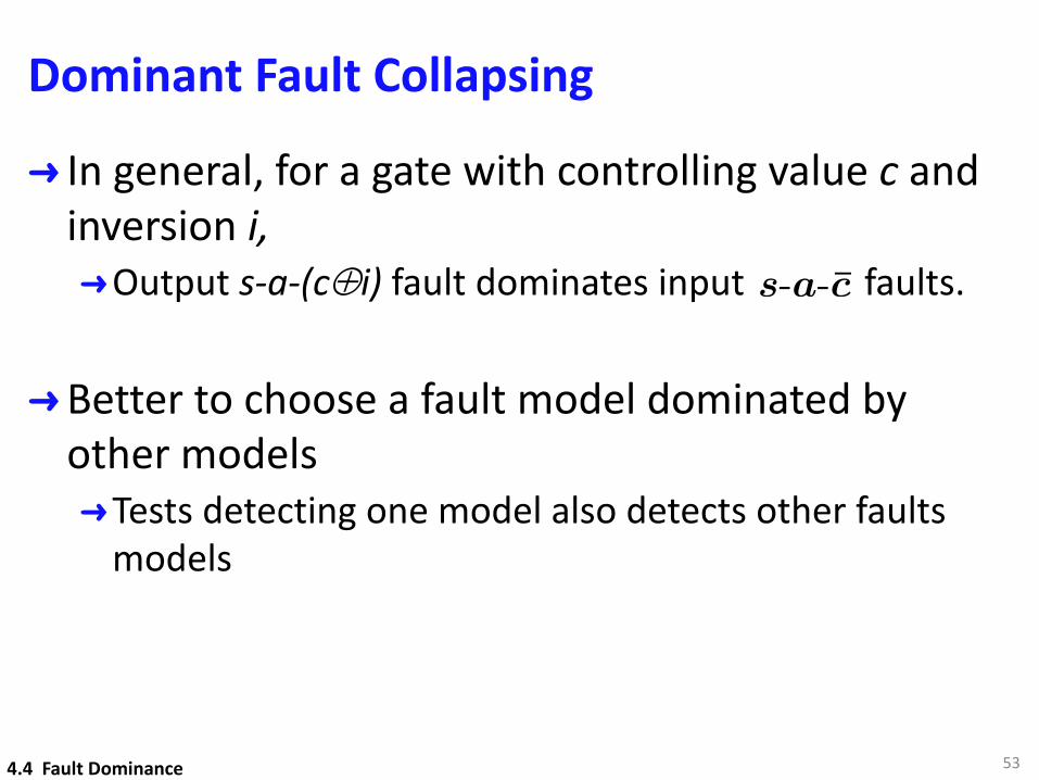
Dominant Fault Collapsing
➜ In general, for a gate with controlling value c and inversion i, ➜Output s-a-(cÅi) fault dominates input faults.
➜Better to choose a fault model dominated by other models➜Tests detecting one model also detects other faults
models
53
s-a-c̄
4.4 Fault Dominance
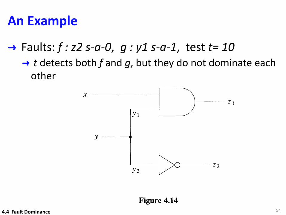
An Example
➜ Faults: f : z2 s-a-0, g : y1 s-a-1, test t= 10➜ t detects both f and g, but they do not dominate each
other
54
110
x-------------l
Yl
y -------.
yz
Figure 4.14
4.4.2 Sequential Circuits
FAULT MODELING
1------ ZI
Although the concept of dominance can be extended to sequential circuits, itsapplicability in practice is difficult, since dominance relations in a combinationalcircuit N may not remain valid when N is embedded in a sequential circuit. Thefollowing example illustrates this phenomenon.
Example 4.7: Consider the circuit of Figure 4.15. Assume that initially y=l andconsider the test sequence shown in the figure. For the fault-free circuit the outputsequence generated is 0000. For the fault a (x z s-a-1) the first input fails to reset yand the fourth input propagates this error to z. Thus the generated output sequence is0001 and Xz s-a-1 is detected. Now consider the same test sequence and the faultp (G 1 s-a-O), which dominates a in a combinational circuit sense. The first inputagain fails to reset y. However, the fourth input generates an erroneous 0 at G z andthe two effects of this single fault - the one stored in the F/F and the one propagatingalong the path (G 1, G z) - cancel each other, and the fault is not detected. D
While equivalence fault-collapsing techniques for combinational circuits remain validfor sequential circuits, dominance fault-collapsing techniques are no longer applicable.
4.5 The Single Stuck-Fault ModelThe single-stuck fault (SSF) model is also referred to as the classical or standard faultmodel because it has been the first and the most widely studied and used. Although itsvalidity is not universal, its usefulness results from the following attributes:
• It represents many different physical faults (see, for example, [Timoc et ale 1983]).
• It is independent of technology, as the concept of a signal line being stuck at alogic value can be applied to any structural model.
• Experience has shown that tests that detect SSFs detect many nonclassical faults aswell.
4.4 Fault Dominance
55
4.5 The Single Stuck-Fault Model
Fault Universe
➜ For n lines where SSFs can be defined, there are 2n stuck faults.
➜ For fanout-free circuits, the number of faults is 2(G+I).➜G: gate count➜ I: number of primary inputs
➜ For circuits with fanout, the estimate is 2Gf➜ f: average fanout count
564.5 The Single Stuck-Fault Model
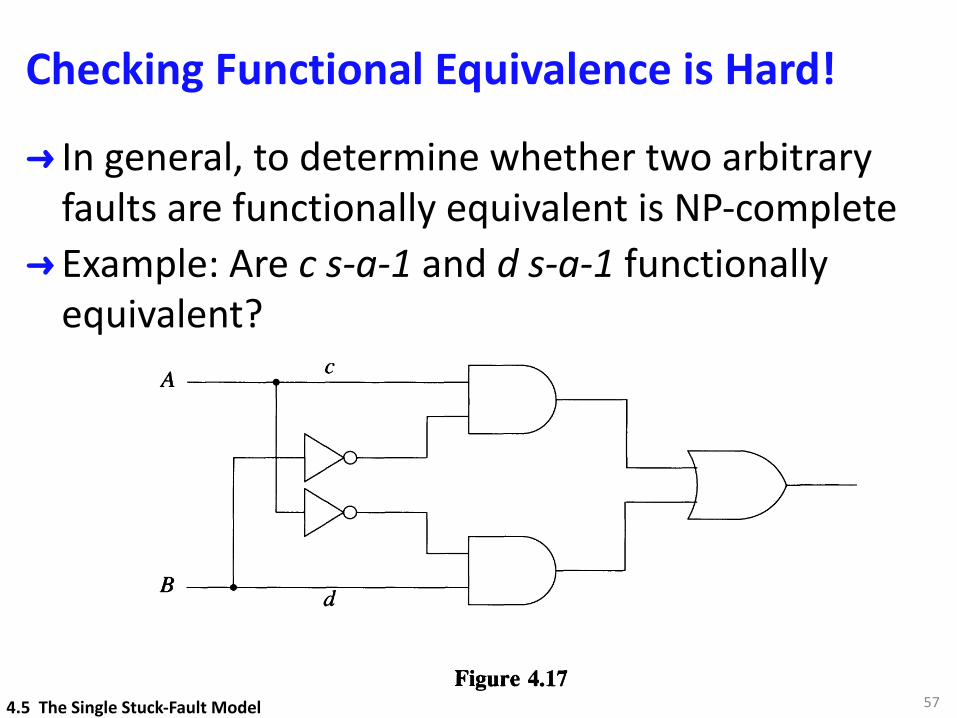
Checking Functional Equivalence is Hard!
➜ In general, to determine whether two arbitrary faults are functionally equivalent is NP-complete
➜ Example: Are c s-a-1 and d s-a-1 functionally equivalent?
57
The Single Stuck-Fault Model 113
In the previous section we noted that the number of faults to be analyzed can bereduced by fault collapsing based on equivalence and dominance relations. Functionalequivalence relations, however, cannot be directly applied for this purpose, becausedetermining whether two arbitrary faults are functionally equivalent is an NP-completeproblem [Goundan 1978]. For example, there is no simple way to determine that thefaults c s-a-l and d s-a-l in Figure 4.17 are functionally equivalent. (We can do thisby computing the two faulty functions and showing that they are identical.)
cA -----......---------1
dB
Figure 4.17
What we can do is to determine equivalent faults that are structurally related. Therelation on which this analysis relies is called structural equivalence, and it is definedas follows. In the circuit Nt, the presence of the stuck fault f creates a set of lines withconstant values. By removing all these lines (except primary outputs) we obtain asimplified circuit S (Nt), which realizes the same function as Nt. Two faults f and gare said to be structurally equivalent if the corresponding simplified circuits S (Nt) andS (Ng ) are identical. An example is shown in Figure 4.18. Obviously, structurallyequivalent faults are also functionally equivalent. But, as illustrated by c s-a-l andd s-a-l in Figure 4.17, there exist functionally equivalent faults that are not structurallyequivalent. The existence of such faults is related to the presence of reconvergentfanout [McCluskey and Clegg 1971] (see Problem 4.13).
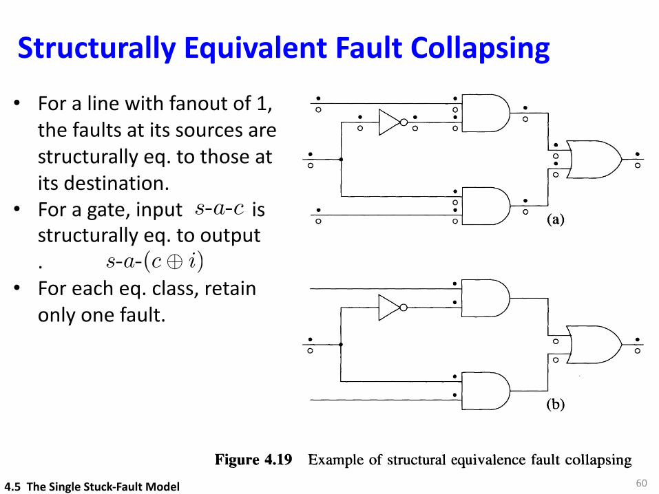
The advantage of structural equivalence relations is that they allow fault collapsing tobe done as a simple local analysis based on the structure of the circuit, whilefunctional equivalence relations imply a global analysis based on the function of thecircuit. Figure 4.19 illustrates the process of fault collapsing based on structuralequivalence relations. Conceptually, we start by inserting s-a-l and s-a-O faults onevery signal source (gate output or primary input) and destination (gate input). This isshown in Figure 4.19(a), where a black (white) dot denotes a s-a-1 (s-a-O) fault. Thenwe traverse the circuit and construct structural equivalence classes along the way. Fora signal line with a fanout count of 1, the faults inserted at its source are structurallyequivalent to the corresponding faults at its destination. For a gate with controllingvalue c and inversion i, any s-a-c input fault is structurally equivalent to the outputs-a-(c@i). A s-a-O (s-a-1) input fault of an inverter is structurally equivalent to the
4.5 The Single Stuck-Fault Model
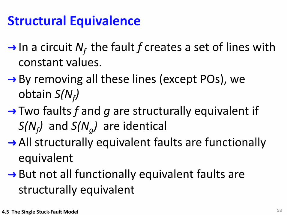
Structural Equivalence
➜ In a circuit Nf the fault f creates a set of lines with constant values.
➜By removing all these lines (except POs), we obtain S(Nf)
➜ Two faults f and g are structurally equivalent if S(Nf) and S(Ng) are identical
➜All structurally equivalent faults are functionally equivalent
➜But not all functionally equivalent faults are structurally equivalent
584.5 The Single Stuck-Fault Model
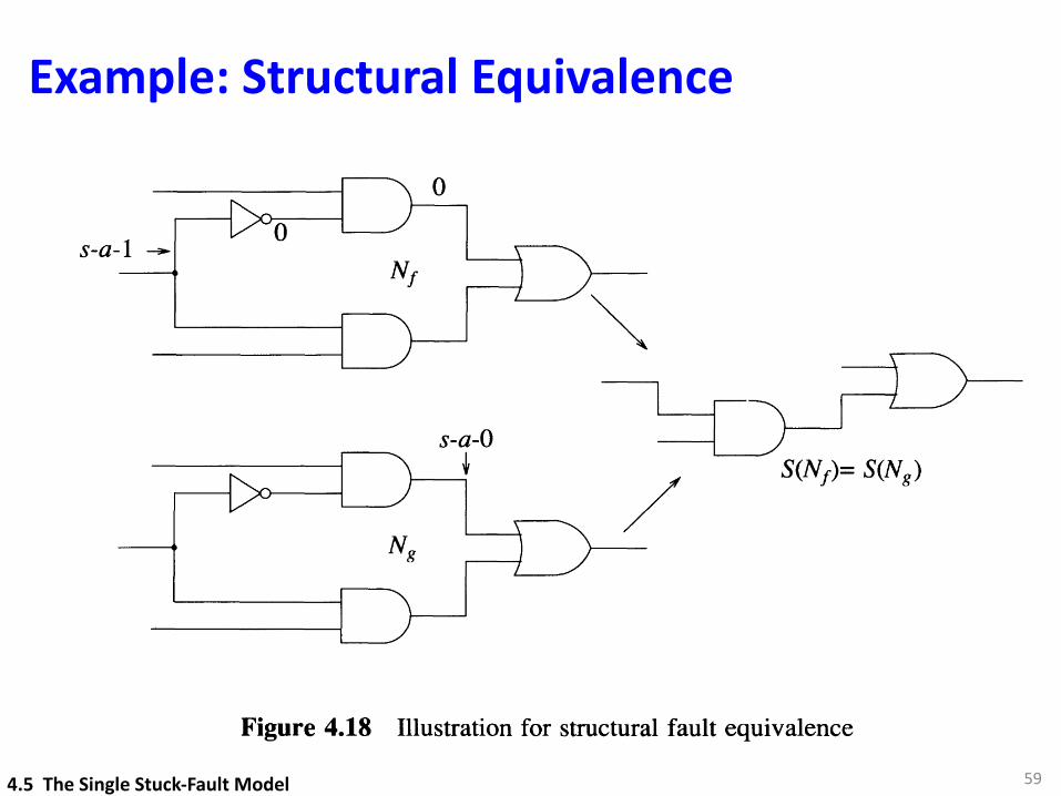
Example: Structural Equivalence
594.5 The Single Stuck-Fault Model
114
s-a-1
FAULT MODELING
/
Figure 4.18 Illustration for structural fault equivalence
output s-a-1 (s-a-O). Finally, from every equivalence class we retain one fault asrepresentative (Figure 4.19(b)).
A structural equivalence class determined in this way is confined to a fanout-freeregion of the circuit. The reason is that in general, a stem s-a-v fault is notfunctionally equivalent with a s-a-v fault on any of its fanout branches. Reconvergentfanout, however, may create structurally equivalent faults in different fanout-freeregions; Figure 4.20 illustrates such a case. Thus our method of equivalence faultcollapsing will not identify faults such as b s-a-O and f s-a-O as structurally equivalent.In such a case, the obtained structural equivalence classes are not maximal; Le., thereare at least two classes that can be further merged. However, the potential gainachievable by extending the fault collapsing across fanout-free regions is small anddoes not justify the cost of the additional analysis required.
Although the equivalence classes obtained by structural equivalence fault collapsing arenot maximal, this process nevertheless achieves a substantial reduction of the initial setof 2n faults, where n is given by (4.8). For every gate j with gj inputs, it eliminatesmj input faults, where
The number of faults eliminated is
if gj > 1
if gj = 1 (4.9)
(4.10)
The Single Stuck-Fault Model
o
o
o
o
115
Figure 4.19 Example of structural equivalence fault collapsing
Figure 4.20
where the summation is over all the gates in the circuit. Let us define a variable Pj by
{o if gj > 1
Pj= 1 ifgj = 1 (4.11)
Structurally Equivalent Fault Collapsing
60
• For a line with fanout of 1, the faults at its sources are structurally eq. to those at its destination.
• For a gate, input is structurally eq. to output .
• For each eq. class, retain only one fault.
s-a-c
s-a-(c� i)
4.5 The Single Stuck-Fault Model
The Single Stuck-Fault Model
o
o
o
o
115
Figure 4.19 Example of structural equivalence fault collapsing
Figure 4.20
where the summation is over all the gates in the circuit. Let us define a variable Pj by
{o if gj > 1
Pj= 1 ifgj = 1 (4.11)
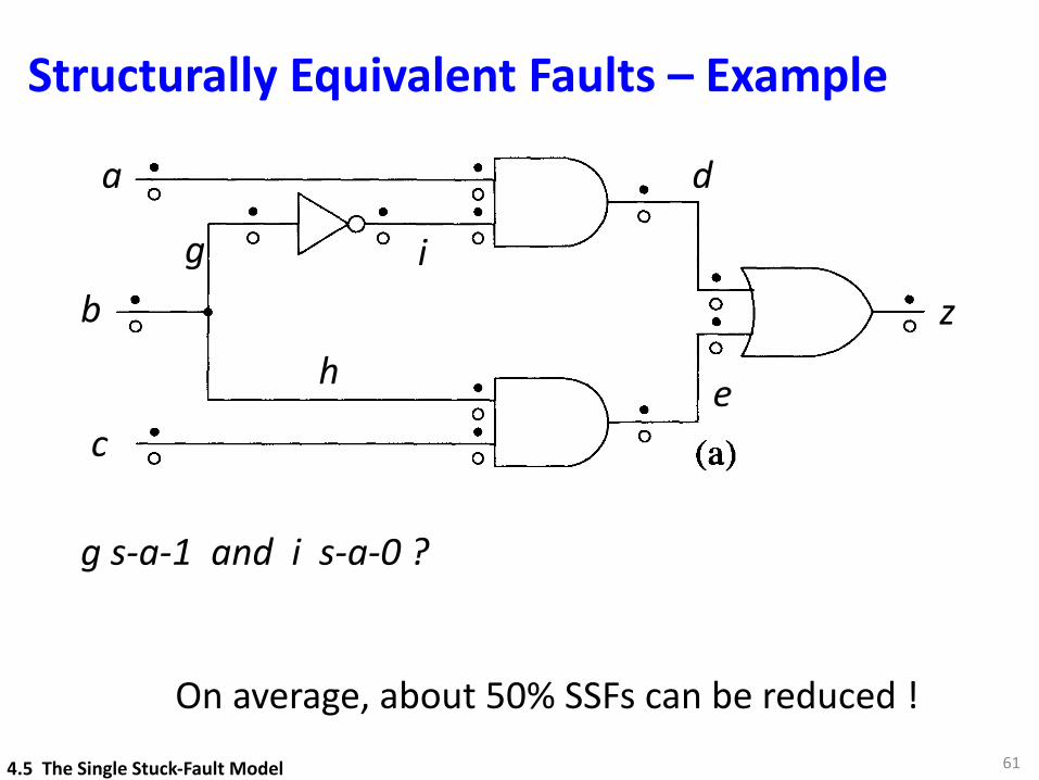
Structurally Equivalent Faults – Example
61
b
a
c
d
e
z
g s-a-1 and i s-a-0 ?
g
h
i
4.5 The Single Stuck-Fault Model
On average, about 50% SSFs can be reduced !
Fault Reduction by Dominance Relation
➜ Theorem 4.1: In a fanout-free combinational circuit C, any test set that detects all SSFs on the primary inputs of C detects all SSFs in C.
➜ Theorem 4.2: In a combinational circuit C any test set that detects all SSFs on the primary inputs and the fanout branches of C detects all SSFs in C.➜These faults can be further reduced by structural
equivalence and dominance relations.
624.5 The Single Stuck-Fault Model
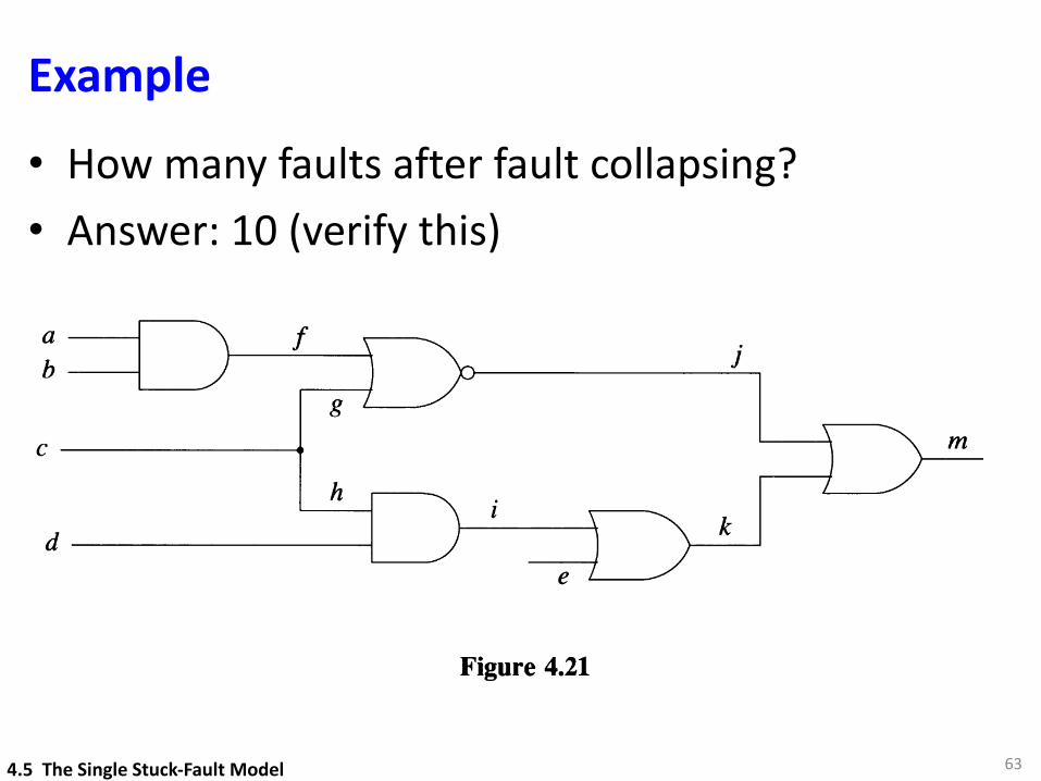
Example
63
• How many faults after fault collapsing?• Answer: 10 (verify this)
The Single Stuck-Fault Model
The fraction of faults eliminated is
117
1 - = 1 - f - q 1 (4.18)2n l+f-q l+f-q
For example, for typical values such as f = 2.5 and q = 0.7, we eliminate about40 percent of the faults. The set of checkpoint faults can be further collapsed by usingstructural equivalence and dominance relations, as illustrated in the following example.
Example 4.8: The circuit of Figure 4.21 has 24 SSFs and 14 checkpoint faults (10 onthe primary inputs - a, b, C, d, e - and 4 on the fanout branches g and h). Sincea s-a-O and b s-a-O are equivalent, we can delete the latter. Similarly, we can deleted s-a-O, which is equivalent to h s-a-O. The fault g s-a-1 is equivalent to f s-a-1,which dominates a s-a-1. Therefore, g s-a-1 can be eliminated. Similarly, e s-a-1 isequivalent to i s-a-1, which dominates h s-a-1; hence e s-a-1 can be eliminated. Theoriginal set of 24 faults has thus been reduced to 10. D
ab
C-----------.
d------------I
Figure 4.21
j
Based on Theorem 4.2, many test generation systems generate tests explicitly only forthe checkpoint faults of a circuit. But Theorem 4.2 is meaningful only for anirredundant circuit. In a redundant circuit, some of the checkpoint faults areundetectable. If we consider only checkpoint faults and we generate a test set thatdetects all detectable checkpoint faults, this test set is not guaranteed to detect alldetectable SSFs of the circuit; in such a case, additional tests may be needed to obtaina complete detection test set [Abramovici et ale 1986].
Understanding the relations between faults on a stem line and on its fanout branches isimportant in several problems that we will discuss later. Clearly a stem s-a-v isequivalent to the multiple fault composed of all its fanout branches s-a-v. But, ingeneral, neither equivalence nor dominance relations exist between a stem s-a-v and anindividual fanout branch s-a-v. Figure 4.22 shows an example [Hayes 1979] in whicha stem fault (j s-a-O) is detected, but the (single) faults on its fanout branches (k s-a-Oand m s-a-O) are not. Figure 4.23 illustrates the opposite situation [Abramovici et ale1984], in which faults on all fanout branches (Xl s-a-O and X2 s-a-O) are detected, butthe stem fault (x s-a-O) is not.
4.5 The Single Stuck-Fault Model
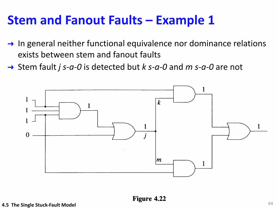
Stem and Fanout Faults – Example 1➜ In general neither functional equivalence nor dominance relations
exists between stem and fanout faults➜ Stem fault j s-a-0 is detected but k s-a-0 and m s-a-0 are not
64
118
o --+------------1 j
FAULT MODELING
x---
1o
Figure 4.22
Figure 4.23
1
4.6 The Multiple Stuck-Fault ModelThe multiple stuck-fault (MSF) model is a straightforward extension of the SSF modelin which several lines can be simultaneously stuck. If we denote by n the number ofpossible SSF sites (given by formula (4.8)), there are 2n possible SSFs, but there are3n- l possible MSFs (which include the SSFs). This figure assumes that any MSF canoccur, including the one consisting of all lines simultaneously stuck. If we assume thatthe multiplicity of a fault, i.e., the number of lines simultaneously stuck, is no greater
than a constant k, then the number of possible MSFs is [7] 2i . This is usually too1=1
large a number to allow us to deal explicitly with all multiple faults. For example, the
4.5 The Single Stuck-Fault Model
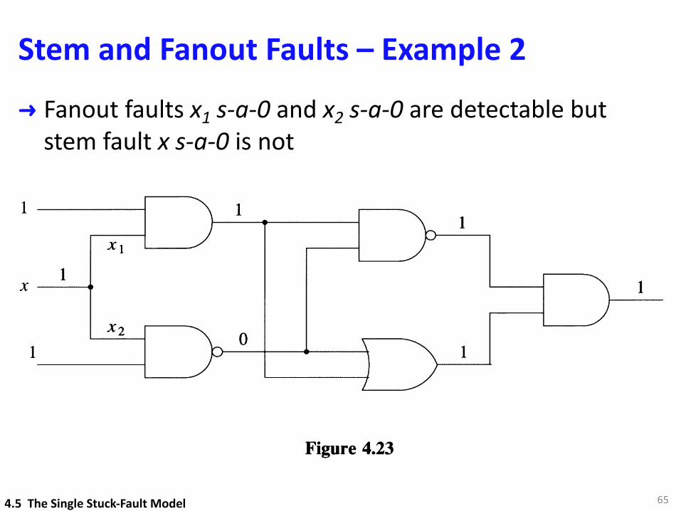
Stem and Fanout Faults – Example 2 ➜ Fanout faults x1 s-a-0 and x2 s-a-0 are detectable but
stem fault x s-a-0 is not
65
118
o --+------------1 j
FAULT MODELING
x---
1o
Figure 4.22
Figure 4.23
1
4.6 The Multiple Stuck-Fault ModelThe multiple stuck-fault (MSF) model is a straightforward extension of the SSF modelin which several lines can be simultaneously stuck. If we denote by n the number ofpossible SSF sites (given by formula (4.8)), there are 2n possible SSFs, but there are3n- l possible MSFs (which include the SSFs). This figure assumes that any MSF canoccur, including the one consisting of all lines simultaneously stuck. If we assume thatthe multiplicity of a fault, i.e., the number of lines simultaneously stuck, is no greater
than a constant k, then the number of possible MSFs is [7] 2i . This is usually too1=1
large a number to allow us to deal explicitly with all multiple faults. For example, the
4.5 The Single Stuck-Fault Model
66
4.6 The Multiple Stuck-Fault Model
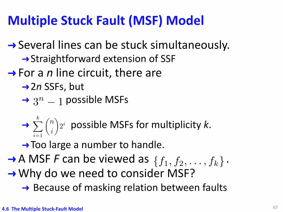
Multiple Stuck Fault (MSF) Model➜ Several lines can be stuck simultaneously.➜Straightforward extension of SSF
➜ For a n line circuit, there are ➜2n SSFs, but➜ possible MSFs
➜ possible MSFs for multiplicity k.
➜Too large a number to handle.➜A MSF F can be viewed as .➜Why do we need to consider MSF?➜ Because of masking relation between faults
67
3n � 1
{f1, f2, . . . , fk}
kX
i=1
✓n
i
◆2i
4.6 The Multiple Stuck-Fault Model
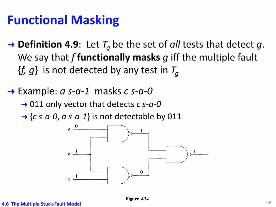
Functional Masking➜ Definition 4.9: Let Tg be the set of all tests that detect g.
We say that f functionally masks g iff the multiple fault {f, g} is not detected by any test in Tg
➜ Example: a s-a-1 masks c s-a-0➜ 011 only vector that detects c s-a-0➜ {c s-a-0, a s-a-1} is not detectable by 011
68
The Multiple Stuck-Fault Model 119
number of double faults (k=2) in a circuit with n=1000 possible fault sites is about halfa million.
Let us first consider the question of why we need to consider MSFs altogether. Sincea multiple fault F is just a set {fl,!2, ...,!k} of single faults h, why isn't F detected bythe tests that detect the single faults h? The explanation is provided by the maskingrelations among faults.
Definition 4.9: Let Tg be the set of all tests that detect a fault g. We say that a fault!functionally masks the fault g iff the multiple fault {f,g} is not detected by any test inTg •
Example 4.9: In the circuit of Figure 4.24 the test 011 is the only test that detects thefault c s-a-O. The same test does not detect the multiple fault {c s-a-O, a s-a-l}. Thusa s-a-l masks c s-a-O. D
oa --------1 1
11b---....
1o
C --------1
Figure 4.24
Masking can also be defined with respect to a test set T.
Definition 4.10: Let Tg'e:T be the set of all tests in T that detect a fault g. We saythat a fault! masks the fault g under a test set T iff the multiple fault {f,g} is notdetected by any test in Tg ' .
Functional masking implies masking under any test set, but the converse statement isnot always true.
Masking relations can also be defined among different type of faults. In Example 4.4we have an undetectable bridging fault that masks a detectable SSF under a completetest set for SSFs.
If! masks g, then the fault {f,g} is not detected by the tests that detect g alone. But{f,g} may be detected by other tests. This is the case in Example 4.9, where the fault{c s-a-O, a s-a-l} is detected by the test 010.
4.6 The Multiple Stuck-Fault Model
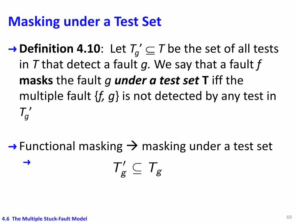
Masking under a Test Set
➜Definition 4.10: Let Tg’ Í T be the set of all tests in T that detect a fault g. We say that a fault f masks the fault g under a test set T iff the multiple fault {f, g} is not detected by any test in Tg’
➜ Functional masking à masking under a test set➜
69
T 0g ✓ Tg
<latexit sha1_base64="tJZeD/fb+ks3NSNjBJeScroUOds=">AAAC2XicbVJNbxMxEHWWj5bwlZYjlxERggNEuxUSPVYgJI5FStpK2VXk9c4mVv2x2LOl0SoHbogrd65w4/fwb/CmCSINI1l6mnkeP73nvFLSUxz/7kQ3bt66vbN7p3v33v0HD3t7+yfe1k7gSFhl3VnOPSppcESSFJ5VDrnOFZ7m52/b+ekFOi+tGdK8wkzzqZGlFJxCa9LbHz6bTCH1de6R8CMMJ9NJrx8P4mXBNkhWoM9WdTzZ6/xKCytqjYaE4t6Pk7iirOGOpFC46Ka1x4qLcz7FcYCGa/RZsxS/gKehU0BpXTiGYNn990bDtfdznQem5jTz12dt83+zcU3lYdZIU9WERlw9VNYKyELrBBTSoSA1D4ALJ4NWEDPuuKDgVzd1aPCTsFpzUzRpybVU8wJLXitaNKkv13hDj+dmLQjeGR5S8EC1M9JMwRpoxy89OllCywJtC3wB4QGo/ZJCM3SA5kI6a1o7g471yr8bt7a03jn0BLaEdQ7dDStaWtbk4ZMUhJe0CBEn1wPdBicHgyQeJB9e9Y/erMLeZY/ZE/acJew1O2Lv2TEbMcEu2Xf2g/2MxtHn6Ev09YoadVZ3HrGNir79AW1E5vc=</latexit><latexit sha1_base64="tJZeD/fb+ks3NSNjBJeScroUOds=">AAAC2XicbVJNbxMxEHWWj5bwlZYjlxERggNEuxUSPVYgJI5FStpK2VXk9c4mVv2x2LOl0SoHbogrd65w4/fwb/CmCSINI1l6mnkeP73nvFLSUxz/7kQ3bt66vbN7p3v33v0HD3t7+yfe1k7gSFhl3VnOPSppcESSFJ5VDrnOFZ7m52/b+ekFOi+tGdK8wkzzqZGlFJxCa9LbHz6bTCH1de6R8CMMJ9NJrx8P4mXBNkhWoM9WdTzZ6/xKCytqjYaE4t6Pk7iirOGOpFC46Ka1x4qLcz7FcYCGa/RZsxS/gKehU0BpXTiGYNn990bDtfdznQem5jTz12dt83+zcU3lYdZIU9WERlw9VNYKyELrBBTSoSA1D4ALJ4NWEDPuuKDgVzd1aPCTsFpzUzRpybVU8wJLXitaNKkv13hDj+dmLQjeGR5S8EC1M9JMwRpoxy89OllCywJtC3wB4QGo/ZJCM3SA5kI6a1o7g471yr8bt7a03jn0BLaEdQ7dDStaWtbk4ZMUhJe0CBEn1wPdBicHgyQeJB9e9Y/erMLeZY/ZE/acJew1O2Lv2TEbMcEu2Xf2g/2MxtHn6Ev09YoadVZ3HrGNir79AW1E5vc=</latexit><latexit sha1_base64="tJZeD/fb+ks3NSNjBJeScroUOds=">AAAC2XicbVJNbxMxEHWWj5bwlZYjlxERggNEuxUSPVYgJI5FStpK2VXk9c4mVv2x2LOl0SoHbogrd65w4/fwb/CmCSINI1l6mnkeP73nvFLSUxz/7kQ3bt66vbN7p3v33v0HD3t7+yfe1k7gSFhl3VnOPSppcESSFJ5VDrnOFZ7m52/b+ekFOi+tGdK8wkzzqZGlFJxCa9LbHz6bTCH1de6R8CMMJ9NJrx8P4mXBNkhWoM9WdTzZ6/xKCytqjYaE4t6Pk7iirOGOpFC46Ka1x4qLcz7FcYCGa/RZsxS/gKehU0BpXTiGYNn990bDtfdznQem5jTz12dt83+zcU3lYdZIU9WERlw9VNYKyELrBBTSoSA1D4ALJ4NWEDPuuKDgVzd1aPCTsFpzUzRpybVU8wJLXitaNKkv13hDj+dmLQjeGR5S8EC1M9JMwRpoxy89OllCywJtC3wB4QGo/ZJCM3SA5kI6a1o7g471yr8bt7a03jn0BLaEdQ7dDStaWtbk4ZMUhJe0CBEn1wPdBicHgyQeJB9e9Y/erMLeZY/ZE/acJew1O2Lv2TEbMcEu2Xf2g/2MxtHn6Ev09YoadVZ3HrGNir79AW1E5vc=</latexit><latexit sha1_base64="tJZeD/fb+ks3NSNjBJeScroUOds=">AAAC2XicbVJNbxMxEHWWj5bwlZYjlxERggNEuxUSPVYgJI5FStpK2VXk9c4mVv2x2LOl0SoHbogrd65w4/fwb/CmCSINI1l6mnkeP73nvFLSUxz/7kQ3bt66vbN7p3v33v0HD3t7+yfe1k7gSFhl3VnOPSppcESSFJ5VDrnOFZ7m52/b+ekFOi+tGdK8wkzzqZGlFJxCa9LbHz6bTCH1de6R8CMMJ9NJrx8P4mXBNkhWoM9WdTzZ6/xKCytqjYaE4t6Pk7iirOGOpFC46Ka1x4qLcz7FcYCGa/RZsxS/gKehU0BpXTiGYNn990bDtfdznQem5jTz12dt83+zcU3lYdZIU9WERlw9VNYKyELrBBTSoSA1D4ALJ4NWEDPuuKDgVzd1aPCTsFpzUzRpybVU8wJLXitaNKkv13hDj+dmLQjeGR5S8EC1M9JMwRpoxy89OllCywJtC3wB4QGo/ZJCM3SA5kI6a1o7g471yr8bt7a03jn0BLaEdQ7dDStaWtbk4ZMUhJe0CBEn1wPdBicHgyQeJB9e9Y/erMLeZY/ZE/acJew1O2Lv2TEbMcEu2Xf2g/2MxtHn6Ev09YoadVZ3HrGNir79AW1E5vc=</latexit>
4.6 The Multiple Stuck-Fault Model
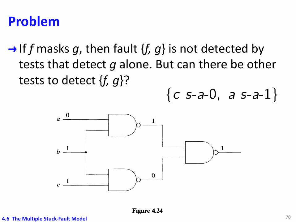
Problem
➜ If f masks g, then fault {f, g} is not detected by tests that detect g alone. But can there be other tests to detect {f, g}?
70
The Multiple Stuck-Fault Model 119
number of double faults (k=2) in a circuit with n=1000 possible fault sites is about halfa million.
Let us first consider the question of why we need to consider MSFs altogether. Sincea multiple fault F is just a set {fl,!2, ...,!k} of single faults h, why isn't F detected bythe tests that detect the single faults h? The explanation is provided by the maskingrelations among faults.
Definition 4.9: Let Tg be the set of all tests that detect a fault g. We say that a fault!functionally masks the fault g iff the multiple fault {f,g} is not detected by any test inTg •
Example 4.9: In the circuit of Figure 4.24 the test 011 is the only test that detects thefault c s-a-O. The same test does not detect the multiple fault {c s-a-O, a s-a-l}. Thusa s-a-l masks c s-a-O. D
oa --------1 1
11b---....
1o
C --------1
Figure 4.24
Masking can also be defined with respect to a test set T.
Definition 4.10: Let Tg'e:T be the set of all tests in T that detect a fault g. We saythat a fault! masks the fault g under a test set T iff the multiple fault {f,g} is notdetected by any test in Tg ' .
Functional masking implies masking under any test set, but the converse statement isnot always true.
Masking relations can also be defined among different type of faults. In Example 4.4we have an undetectable bridging fault that masks a detectable SSF under a completetest set for SSFs.
If! masks g, then the fault {f,g} is not detected by the tests that detect g alone. But{f,g} may be detected by other tests. This is the case in Example 4.9, where the fault{c s-a-O, a s-a-l} is detected by the test 010.
{c s-a-0, a s-a-1}<latexit sha1_base64="Hl8/50sXDDeWTnQK3MawaFH0TH8=">AAAC+HicbVJNb9NAEN2Yj5bwlcKRy4oIiUMb2RUSHCsQEscikbZSHEXj9ThZdT+s3XHbYIW/wZUb4oTEnSv8Bv4N6zRGpOlIlp7evJ2dfc9ZqaSnOP7TiW7cvHV7a/tO9+69+w8e9nYeHXlbOYFDYZV1Jxl4VNLgkCQpPCkdgs4UHmenb5r+8Rk6L635QPMSxxqmRhZSAAVq0kvSWnzyqc7sRb23gBbEuymHa/gkXUx6/XgQL4tvgmQF+mxVh5Odzvc0t6LSaEgo8H6UxCWNa3AkhcJFN608liBOYYqjAA1o9ON6+bYFfxaYnBfWhc8QX7L/n6hBez/XWVBqoJm/2mvI63qjiopX41qasiI04vKiolKcLG+M4rl0KEjNAwDhZNiVixk4EBTs7KYODZ4LqzWYvE4L0FLNcyygUrSoU1+0eG0fD6ZdiL81EELynCpnpJlya3jT3vPoZMEbFdc2x10eLuCVX0poho6jOZPOmsbOsEc78t/EjSmNdw49cVvwNofumhWNbFxn4R/KCS+oiTi5GugmONofJPEgef+if/B6FfY2e8KesucsYS/ZAXvHDtmQCfaZ/WS/2O/oY/Ql+hp9u5RGndWZx2ytoh9/Aa3X9Mc=</latexit><latexit sha1_base64="Hl8/50sXDDeWTnQK3MawaFH0TH8=">AAAC+HicbVJNb9NAEN2Yj5bwlcKRy4oIiUMb2RUSHCsQEscikbZSHEXj9ThZdT+s3XHbYIW/wZUb4oTEnSv8Bv4N6zRGpOlIlp7evJ2dfc9ZqaSnOP7TiW7cvHV7a/tO9+69+w8e9nYeHXlbOYFDYZV1Jxl4VNLgkCQpPCkdgs4UHmenb5r+8Rk6L635QPMSxxqmRhZSAAVq0kvSWnzyqc7sRb23gBbEuymHa/gkXUx6/XgQL4tvgmQF+mxVh5Odzvc0t6LSaEgo8H6UxCWNa3AkhcJFN608liBOYYqjAA1o9ON6+bYFfxaYnBfWhc8QX7L/n6hBez/XWVBqoJm/2mvI63qjiopX41qasiI04vKiolKcLG+M4rl0KEjNAwDhZNiVixk4EBTs7KYODZ4LqzWYvE4L0FLNcyygUrSoU1+0eG0fD6ZdiL81EELynCpnpJlya3jT3vPoZMEbFdc2x10eLuCVX0poho6jOZPOmsbOsEc78t/EjSmNdw49cVvwNofumhWNbFxn4R/KCS+oiTi5GugmONofJPEgef+if/B6FfY2e8KesucsYS/ZAXvHDtmQCfaZ/WS/2O/oY/Ql+hp9u5RGndWZx2ytoh9/Aa3X9Mc=</latexit><latexit sha1_base64="Hl8/50sXDDeWTnQK3MawaFH0TH8=">AAAC+HicbVJNb9NAEN2Yj5bwlcKRy4oIiUMb2RUSHCsQEscikbZSHEXj9ThZdT+s3XHbYIW/wZUb4oTEnSv8Bv4N6zRGpOlIlp7evJ2dfc9ZqaSnOP7TiW7cvHV7a/tO9+69+w8e9nYeHXlbOYFDYZV1Jxl4VNLgkCQpPCkdgs4UHmenb5r+8Rk6L635QPMSxxqmRhZSAAVq0kvSWnzyqc7sRb23gBbEuymHa/gkXUx6/XgQL4tvgmQF+mxVh5Odzvc0t6LSaEgo8H6UxCWNa3AkhcJFN608liBOYYqjAA1o9ON6+bYFfxaYnBfWhc8QX7L/n6hBez/XWVBqoJm/2mvI63qjiopX41qasiI04vKiolKcLG+M4rl0KEjNAwDhZNiVixk4EBTs7KYODZ4LqzWYvE4L0FLNcyygUrSoU1+0eG0fD6ZdiL81EELynCpnpJlya3jT3vPoZMEbFdc2x10eLuCVX0poho6jOZPOmsbOsEc78t/EjSmNdw49cVvwNofumhWNbFxn4R/KCS+oiTi5GugmONofJPEgef+if/B6FfY2e8KesucsYS/ZAXvHDtmQCfaZ/WS/2O/oY/Ql+hp9u5RGndWZx2ytoh9/Aa3X9Mc=</latexit><latexit sha1_base64="Hl8/50sXDDeWTnQK3MawaFH0TH8=">AAAC+HicbVJNb9NAEN2Yj5bwlcKRy4oIiUMb2RUSHCsQEscikbZSHEXj9ThZdT+s3XHbYIW/wZUb4oTEnSv8Bv4N6zRGpOlIlp7evJ2dfc9ZqaSnOP7TiW7cvHV7a/tO9+69+w8e9nYeHXlbOYFDYZV1Jxl4VNLgkCQpPCkdgs4UHmenb5r+8Rk6L635QPMSxxqmRhZSAAVq0kvSWnzyqc7sRb23gBbEuymHa/gkXUx6/XgQL4tvgmQF+mxVh5Odzvc0t6LSaEgo8H6UxCWNa3AkhcJFN608liBOYYqjAA1o9ON6+bYFfxaYnBfWhc8QX7L/n6hBez/XWVBqoJm/2mvI63qjiopX41qasiI04vKiolKcLG+M4rl0KEjNAwDhZNiVixk4EBTs7KYODZ4LqzWYvE4L0FLNcyygUrSoU1+0eG0fD6ZdiL81EELynCpnpJlya3jT3vPoZMEbFdc2x10eLuCVX0poho6jOZPOmsbOsEc78t/EjSmNdw49cVvwNofumhWNbFxn4R/KCS+oiTi5GugmONofJPEgef+if/B6FfY2e8KesucsYS/ZAXvHDtmQCfaZ/WS/2O/oY/Ql+hp9u5RGndWZx2ytoh9/Aa3X9Mc=</latexit>
4.6 The Multiple Stuck-Fault Model
Problem – Detection of Multiple Faults
➜Given a complete test set T that detects all single faults, can there exist a multiple fault F = {f1, f2, …, fk} such that F is not detected by T?
714.6 The Multiple Stuck-Fault Model

Example➜ T = {1111, 0111, 1110, 1001, 1010, 0101}➜ f = B s-a-1 and g = C s-a-1➜ 1001 is the only vector that detects f and g SSFs, but…
72
120 FAULT MODELING
An important problem is, given a complete test set T for single faults, can there exist amultiple fault F = {fl,/2, ...,/k} such that F is not detected by T? (Remember that Tdetects every Ii alone.) The answer is provided by the following example.
Example 4.10: The test set T = {1111, 0111, 1110, 1001, 1010, 0101} detects everySSF in the circuit of Figure 4.25. Let / be B s-a-1 and g be C s-a-1. The only test inT that detects the single faults/and g is 1001. However, the multiple fault {f,g} is notdetected because under the test 1001, / masks g and g masks f. 0
A10/1
B1
0/1
0
0/11
0/1C1
D
Figure 4.25
In the above example, a multiple fault F is not detected by a complete test set T forsingle faults because of circular masking relations under T among the components ofF. Circular functional masking relations may result in an undetectable multiple faultF, as shown in the following example [Smith 1978].
Example 4.11: In the circuit of Figure 4.26, all SSFs are detectable. Let / be D s-a-1and g be E s-a-1. One can verify that / functionally masks g and vice versa and thatthe multiple fault {f,g} is undetectable. (This represents another type of redundancy,called multiple-line redundancy.) 0
Note that the existence of circular masking relations among the SSF components Ii ofa MSF F is a necessary but not a sufficient condition for F to be undetectable[Smith 1979].
An important practical question is: What percentage of the MSFs can escape detectionby a test set designed to detect SSFs? The answer depends on the structure (but noton the size) of the circuit. Namely, the following results have been obtained forcombinational circuits:
1. In an irredundant two-level circuit, any complete test set for SSFs also detects allMSFs [Kohavi and Kohavi 1972].
4.6 The Multiple Stuck-Fault Model
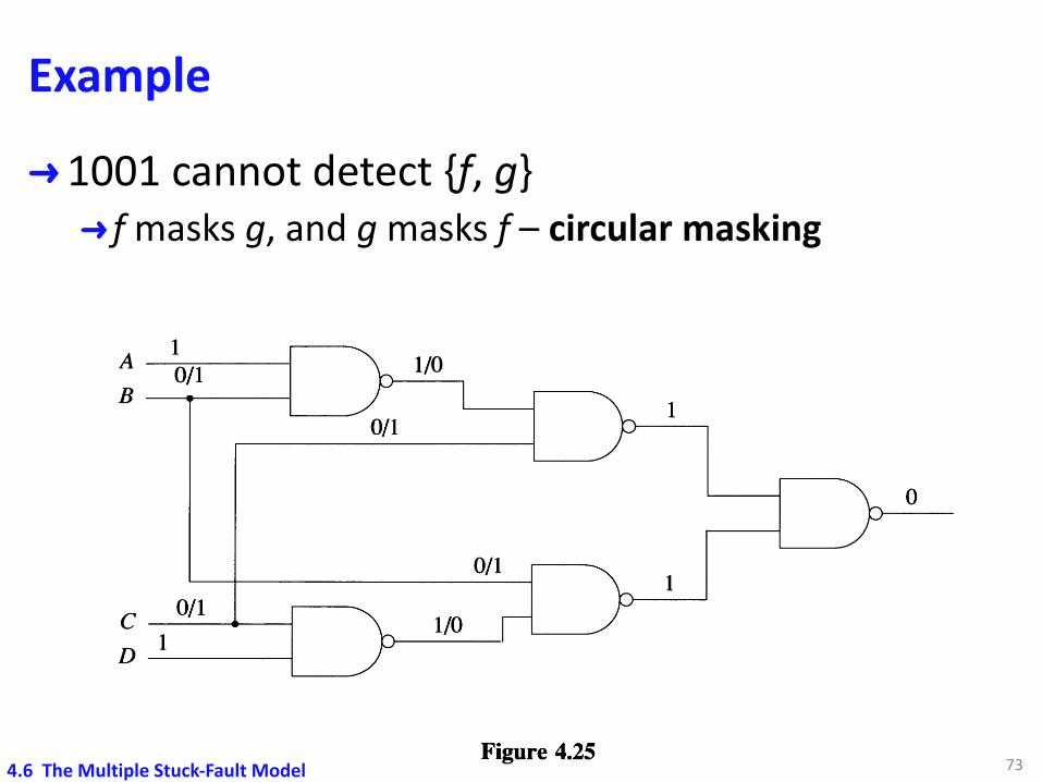
Example
➜1001 cannot detect {f, g}➜ f masks g, and g masks f – circular masking
73
120 FAULT MODELING
An important problem is, given a complete test set T for single faults, can there exist amultiple fault F = {fl,/2, ...,/k} such that F is not detected by T? (Remember that Tdetects every Ii alone.) The answer is provided by the following example.
Example 4.10: The test set T = {1111, 0111, 1110, 1001, 1010, 0101} detects everySSF in the circuit of Figure 4.25. Let / be B s-a-1 and g be C s-a-1. The only test inT that detects the single faults/and g is 1001. However, the multiple fault {f,g} is notdetected because under the test 1001, / masks g and g masks f. 0
A10/1
B1
0/1
0
0/11
0/1C1
D
Figure 4.25
In the above example, a multiple fault F is not detected by a complete test set T forsingle faults because of circular masking relations under T among the components ofF. Circular functional masking relations may result in an undetectable multiple faultF, as shown in the following example [Smith 1978].
Example 4.11: In the circuit of Figure 4.26, all SSFs are detectable. Let / be D s-a-1and g be E s-a-1. One can verify that / functionally masks g and vice versa and thatthe multiple fault {f,g} is undetectable. (This represents another type of redundancy,called multiple-line redundancy.) 0
Note that the existence of circular masking relations among the SSF components Ii ofa MSF F is a necessary but not a sufficient condition for F to be undetectable[Smith 1979].
An important practical question is: What percentage of the MSFs can escape detectionby a test set designed to detect SSFs? The answer depends on the structure (but noton the size) of the circuit. Namely, the following results have been obtained forcombinational circuits:
1. In an irredundant two-level circuit, any complete test set for SSFs also detects allMSFs [Kohavi and Kohavi 1972].
4.6 The Multiple Stuck-Fault Model
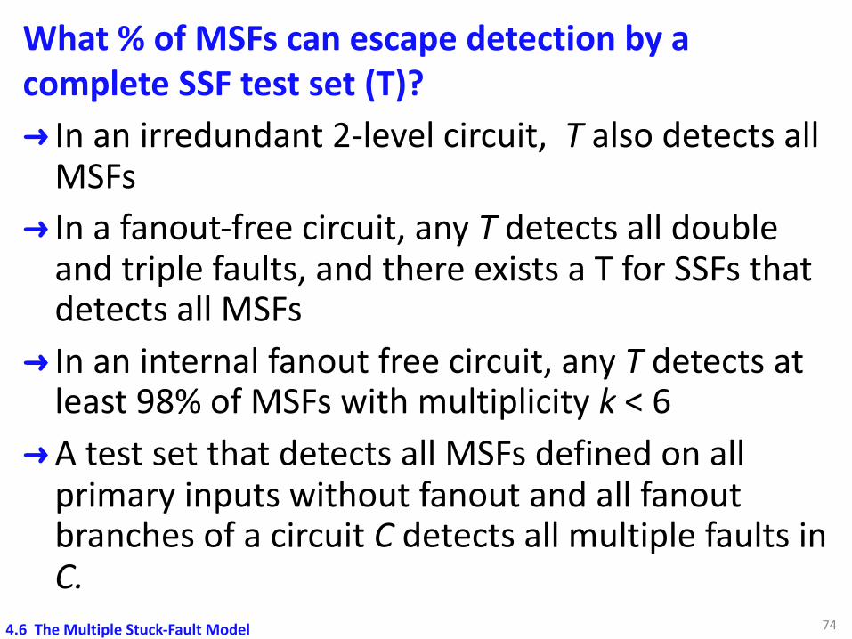
What % of MSFs can escape detection by a complete SSF test set (T)?➜ In an irredundant 2-level circuit, T also detects all
MSFs➜ In a fanout-free circuit, any T detects all double
and triple faults, and there exists a T for SSFs that detects all MSFs
➜ In an internal fanout free circuit, any T detects at least 98% of MSFs with multiplicity k < 6
➜A test set that detects all MSFs defined on all primary inputs without fanout and all fanoutbranches of a circuit C detects all multiple faults in C.
744.6 The Multiple Stuck-Fault Model
MSFs or Not?
➜A test set T for SSFs also detects most MSFs.➜Typically focus on MSFs not detectable by T.
➜Probability of MSFs is low.➜Modern semi-manufacturing is highly reliable
➜A SSF is guaranteed to be detected (GTBD) if it can be detected unconditionally.➜Any MSF that includes a GTBD SSF is also GTBD.
754.6 The Multiple Stuck-Fault Model
Summary
➜ Logic faults can represent various physical faults➜ Fault detection➜Find a test that causes deviation in output responses➜Undetectable faults à redundancy
➜ Fault collapsing➜Fault equivalence & dominance
➜ Single stuck-fault model➜Possible to find a complete test set
➜Multiple fault model➜A SSF detection test set can find many MSFs
76

77
Backup
Corollary 4.1
Let j be a line sensitized to the fault l s-a-v (by a test t), and let p be the inversion parity of a sensitized path between l and j.
1. The value of j in t is v Å p.2. If there are several sensitized paths between l
and j, then all of them have the same inversion parity.
78
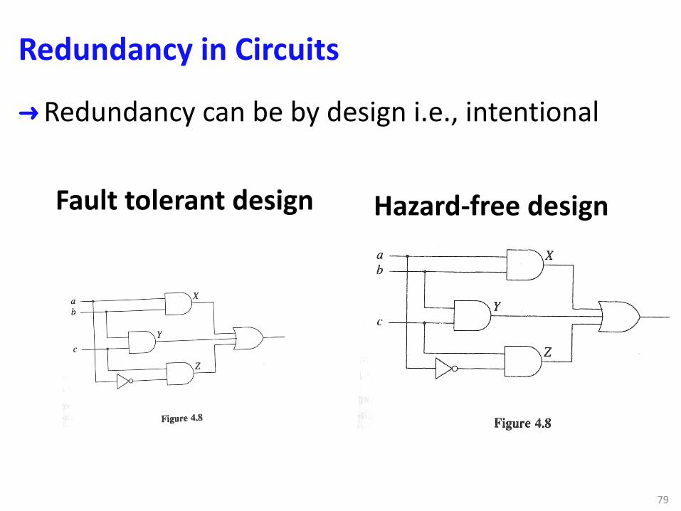
Redundancy in Circuits
➜Redundancy can be by design i.e., intentional
79
Hazard-free designFault tolerant design