F5 TRANSMISSION CONTROL - CIS Digital
77
AUTOMATIC TRANSAXLE (A4B) ------------- F5 - 1 TURBINE REVOLUTION SENSOR, OUTPUT REVOLUTION SENSOR -------- F5 - 1 REMOVAL AND INSTALLATION-------- F5 - 1 TRANSMISSION CONTROL COMPUTER ------------------------------------- F5 - 2 REMOVAL AND INSTALLATION-------- F5 - 2 TRANSMISSION CONTROL SYSTEM -- F5 - 3 ARTICLES TO BE PREPARED---------- F5 - 3 HANDLING INSTRUCTIONS OF CONTROL SYSTEM ----------------------- F5 - 3 HOW TO PROCEED WITH TROUBLE SHOOTING -------------------- F5 - 4 CONFIRMATION, RECORD AND ERASURE OF DIAGNOSIS CODE----- F5 - 7 SYMPTOM CONFIRMATION ------------ F5 - 9 SYSTEM WIRING DIAGRAM----------- F5 - 11 LOCATION OF COMPONENTS ------- F5 - 13 ARRANGEMENT OF VEHICLE HARNESS SIDE CONNECTOR TERMINALS -------------------------------- F5 - 15 ERASING OF LEARNING VALUE AND INITIAL LEARNING ---------------- F5 - 15 HOW TO PROCEED WITH TROUBLE SHOOTING------------------- F5 - 16 INQUIRY ------------------------------------- F5 - 18 FAIL-SAFE FUNCTION ------------------ F5 - 24 TROUBLE SHOOTING ACCORDING TO DIAGNOSIS CODE ------------------ F5 - 27 TROUBLE SHOOTING ACCORDING TO MALFUNCTION PHENOMENA--- F5 - 48 UNIT CHECK --------------------------------F5 - 67 ECU INPUT/OUTPUT SIGNAL CHECK ----------------------------------------F5 - 73 F5 TRANSMISSION CONTROL F5 TO INDEX
-
Upload
khangminh22 -
Category
Documents
-
view
0 -
download
0
Transcript of F5 TRANSMISSION CONTROL - CIS Digital

AUTOMATIC TRANSAXLE (A4B) ------------- F5 - 1TURBINE REVOLUTION SENSOR,OUTPUT REVOLUTION SENSOR-------- F5 - 1
REMOVAL AND INSTALLATION-------- F5 - 1TRANSMISSION CONTROLCOMPUTER ------------------------------------- F5 - 2
REMOVAL AND INSTALLATION-------- F5 - 2TRANSMISSION CONTROL SYSTEM -- F5 - 3
ARTICLES TO BE PREPARED---------- F5 - 3HANDLING INSTRUCTIONS OFCONTROL SYSTEM ----------------------- F5 - 3HOW TO PROCEED WITHTROUBLE SHOOTING -------------------- F5 - 4CONFIRMATION, RECORD ANDERASURE OF DIAGNOSIS CODE----- F5 - 7SYMPTOM CONFIRMATION ------------ F5 - 9SYSTEM WIRING DIAGRAM----------- F5 - 11LOCATION OF COMPONENTS ------- F5 - 13ARRANGEMENT OF VEHICLEHARNESS SIDE CONNECTORTERMINALS -------------------------------- F5 - 15ERASING OF LEARNING VALUEAND INITIAL LEARNING ---------------- F5 - 15HOW TO PROCEED WITHTROUBLE SHOOTING------------------- F5 - 16INQUIRY ------------------------------------- F5 - 18FAIL-SAFE FUNCTION ------------------ F5 - 24TROUBLE SHOOTING ACCORDINGTO DIAGNOSIS CODE ------------------ F5 - 27TROUBLE SHOOTING ACCORDINGTO MALFUNCTION PHENOMENA--- F5 - 48UNIT CHECK --------------------------------F5 - 67ECU INPUT/OUTPUT SIGNAL CHECK ----------------------------------------F5 - 73
F5 TRANSMISSION CONTROL
F5
TO INDEX

ÄÄ AUTOMATIC TRANSAXLE (A4B)1 TURBINE REVOLUTION SENSOR, OUTPUT REVOLUTION SEN-
SOR1-1 REMOVAL AND INSTALLATION1-1-1 ARTICLES TO BE PREPAREDInstrument
Lubricant,adhesive,others
1-1-2 OPERATION BEFORE REMOVAL 1.Remove the battery and battery carrier.
1-1-3 REMOVAL AND INSTALLATION PROCEDURES(1) Components
k:ATF application~:Non-reusable partsUnit N;m{kgf;cm}
(2) Removal and installation procedures
1-1-4 OPERATION AFTER INSTALLATION1.Install the battery and battery carrier.
1 a Sensor, T/M revolution (Turbine revolution sensor) 2 b Sensor, T/M revolution (Output revolution sensor)
3 c Ring, O 4 d Ring, O
T11K5048S25
a
b~c
~d
B
BT:8.4&1.4 {85&14}
ATF DexronOA
Torque wrench
F5–1
2 TRANSMISSION CONTROL COMPUTER2-1 REMOVAL AND INSTALLATION2-1-1 OPERATION BEFORE REMOVAL 1.Remove the lower instrument panel finish panel S/A and fuse box opening.
Refer to Page I2-23.
2.Remove the fuse block Ay.Refer to Page I4-1.
2-1-2 REMOVAL AND INSTALLATION PROCEDURES(1) Components
(2) Removal and installation procedures
2-1-3 OPERATION AFTER INSTALLATION1.Install the fuse block Ay.
Refer to Page I4-1.
2.Install the lower instrument panel finish panel S/A and fuse box opening.Refer to Page I2-23.
1 a Computer Ay, transmission control
T11K5051S25
a
B
B
F5–2

3 TRANSMISSION CONTROL SYSTEM3-1 ARTICLES TO BE PREPAREDSST
Instrument
3-2 HANDLING INSTRUCTIONS OF CONTROL SYSTEM3-2-1 INSTRUCTIONS ON USE OF THIS SERVICE MANUAL1.This service manual has been compiled in such a way that the manual may be used both in regions
where the type certification is implemented based on the EU exhaust emission approval, and otherregions.
2.Hence, with regard to the assignment, reading, erasing of diagnostic trouble codes and those steps ofchecks, repairs and confirmation, the service manual contains the procedures for both cases: One isa procedure that uses the diagnosis tester (DS-21/DS-@) or the OBD @ generic scan tool, and the otheris a procedure that does not use this tester or tool.Therefore, the following instructions given below must be observed.
3.About Use of diagnosis tester (DS-21/DS-@) or OBD @ Generic Scan Tool(1) Regions where type certification is implemented based on EC exhaust emission approval: Make
sure to use the diagnosis tester (DS-21/DS-@) or the OBD @ generic scan tool.(2) Other regions: You may use or not use the diagnosis tester (DS-21/DS-@) or the OBD @ generic
scan tool. You may perform the operation, employing whichever method that will be easier to you.
Electrical Tester,Oscillo scope
Shape Part No. Part name
09842-97215-000 Sub-harness,transmission control computer check
09991-87404-000 (09991-87401-000)
Wire,engine control system inspection
09991-87403-000 Wire,diagnosis check
09990-97201-000 Sub-harness,A/T solenoid wire check
F5–3

4.Instructions to be followed concerning Diagnosis Trouble CodesDiagnosis trouble codes, such as P0105/31 (Four-digit code/two-digit code) are posted additionally.(1) Regions where type certification is implemented based on EC exhaust emission approval
Make sure to use only four-digit trouble codes (E.G.P0105) whose have been assigned accord-ing to the ISO regulations.
(2) Other regions:You may perform the operation using the four-digit code, employing the diagnosis tester (DS-21/DS-@) or the OBD @ generic scan tool. Or you may perform the operation using the two-digitcodes (E.G.31), without the use of the tester or tool. You may perform the operation, employingwhichever method that will be easier to you.Or you may perform the operation using the two-digit codes (E.G.31), without the use of the testeror tool.You may perform the operation, employing whichever method that will be easier to you.
NOTE• The OBD @ generic scan tool means a scan tool complying with the ISO 14230 (KWP2000) format.• In cases where the OBD @ generic scan tool is employed, not all diagnostic trouble codes (Four-
digit codes) can be read out. It should be noted that only those diagnostic trouble codes in which"zero" follows after "P", for example, P0XXX, can be read out.
• The accuracy of the two-digit codes in diagnosing malfunctioning components is slightly inferior tothat of the four-digit codes.
• Hereinafter, those regions where the type certification is implemented based on the EU exhaustemission approval, is referred to as the "EU specifications".
3-2-2 PRECAUTIONARY MEASURES DURING TROUBLE-SHOOTING1.Before the diagnosis information memorized in the A/T ECU memory is confirmed, never disconnect
the connector from the A/TECU, the battery negative (-) terminal, the A/T ECU earth wire from theengine, or the main fuse.
2.The diagnosis information memorized in the A/T ECU memory can be erased by using the diagnosistester (DS-21/DS-@) or the OBD-II generic scan tool in the same way as the check. Therefore, beforeusing the tester, read its instruction manual so as to understand the functions furnished and how touse it.
3.Priority in trouble-shooting(1) If the priority in trouble-shooting for a number of diagnostic trouble codes is given in the concerned
DTC flow chart, make sure to follow the priority.3-3 HOW TO PROCEED WITH TROUBLE SHOOTING3-3-1 GENERAL INFORMATION1.The A/T control system of this vehicle are controlled by the A/T ECU. Furthermore, the vehicle is pro-
vided with the on-board diagnosis system.Therefore, when any abnormality takes place in the input/output systems (Sensors, actuators, har-nesses, connectors, etc.) of the engine control system, the A/T ECU memorizes the system concernedand informs the driver by making the malfunction indicator lamp (MIL) illuminate or flash.
2.Also the malfunction is informed to the operator by means of the malfunction indicator lamp (MIL).When trouble-shooting the engine, it is imperative for you to get the general idea of the onboard diag-nostic system, and fully understand the precautionary measures in trouble-shooting, the items diag-nostic system, and fully understand the precautionary measures in trouble-shooting, the items to beobserved and how to use testers.
3.Then, conduct the trouble-shooting following the flow chart that indicates the correct procedure for theengine troubleshooting.
F5–4

(1) On-board diagnostic system of vehicles for EU specifications1.The vehicles for Europe have the following functions that comply with the 1999/102/EC (Generally
called Euro-OBD) standards.2.When the ignition switch is turned "ON", the malfunction indicator lamp (MIL) goes on. When no mal-
function has been detected, the lamp will go out after the engine has started. (Check for a blown bulb)3.While the engine is running, if the EFI ECU detects any malfunction in the emission control system/com-
ponents that will affect the emissions from the vehicle, or in the power train control components, or ifany malfunction is detected in the ECU itself, the A/T ECU illuminates or flashes the MIL (Only whenmisfire is detected which will damage the catalyst). Then, the A/T ECU memorizes the malfunctionarea. (DTC by ISO15031-6/SAEJ2012)
4. If that malfunction will not occur in three successive running, the MIL is automatically turned off.However, the DTC will be recorded in the A/T ECU memory.
5.It is possible to read out various data from the engine ECU by connecting the OBD @ generic scan toolwhich complies with the ISO 14230 format or diagnosis tester (DS-21/DS-@) to the DLC of the vehicle.You can perform trouble-shooting efficiently by checking these data (DTC, freeze-frame data, currentdata, etc.).
6.The DTC is composed of the ISO standard code (Specified by ISO 15031-6) and the manufacturer'sdesignation code. The ISO standard code should be setpursuant to the ISO. On the other hand, the manufactur-er's designation code can be freely set forth by the man-ufacturer within a specified limit.
7.Many DTC have a two trip detection logic which assuresavoidance of wrong detection and functions only when amalfunction is surely occurring. However, another diagno-sis mode is provided, in which only a one-time final con-firmation test is necessary for a service mechanic to con-firm that the malfunction has been completely remediedafter the repair.
8.When a malfunction is detected, the engine and runningconditions at that moment are memorized as a freeze-frame data in the A/T ECU memory.
(2) On-board diagnostic system of vehicles for otherregions
1.When the ignition switch is turned "ON", the MIL goes on. When no malfunction has been detected, thelamp will go out after the engine has started. (Check for a blown bulb)While the engine is running, if the ECU detects any malfunction in the engine control system/compo-nents, or if any malfunction is detected in the A/T ECU itself, the A/T ECU illuminates the MIL.
F5–5
Diagnostic trouble code
B:BodyC:ChassisP:Power trainU:Net work
0:Regulation1:Maker
Designation troublecode
Vehicle’s system
P 0 1 1 6 (Power train)
1 & 2:Fuel and air metering3 :Ignition system or misfire 7 & 8:Transmission
...
L21E3708ET10
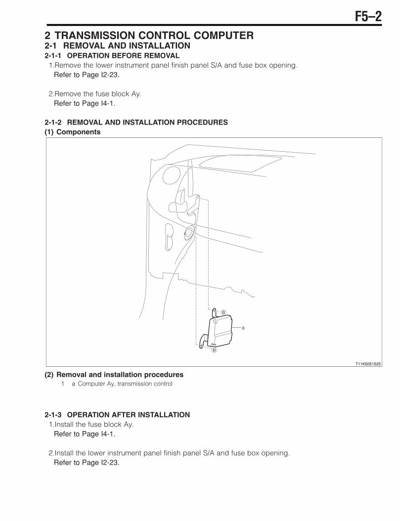
2.In addition to the illumination of the MIL, the correspond-ing diagnostic trouble code (DTC) is memorized in the A/TECU memory. When the malfunction has been remediedor the system returns to its normal state, the MIL automat-ically goes out. However, the DTC remains memorized inthe A/T ECU memory.
3.It is possible to read out various data from the A/T ECU byconnecting the diagnosis tester (DS-21/DS-@) to the DLCof the vehicle. You can perform trouble-shooting accu-rately and efficiently by checking these data (DTC, freeze-frame data, current data, oxygen sensor monitor data,etc). Only when diagnosis tester (DS-21/DS-@) is used.
4.The DTC (Diagnostic trouble code) is set to a four-digitcode in accordance with ISO standard. Furthermore, theconventional two-digit code is also provided. The four-digit code can be read out by the diagnosis tester (DS-21/DS-@). The two-digit code has been set forth by theDMC itself. This code can be read by observing the flash-ing pattern of the MIL.
5.When a malfunction is detected, the engine and runningconditions at that moment are memorized as a freeze-frame data in the A/T ECU memory.
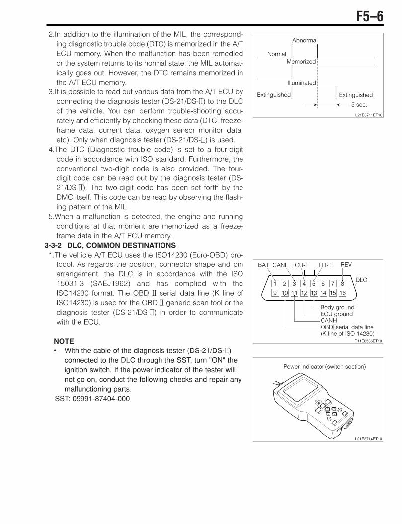
3-3-2 DLC, COMMON DESTINATIONS1.The vehicle A/T ECU uses the ISO14230 (Euro-OBD) pro-
tocol. As regards the position, connector shape and pinarrangement, the DLC is in accordance with the ISO15031-3 (SAEJ1962) and has complied with theISO14230 format. The OBD @ serial data line (K line ofISO14230) is used for the OBD @ generic scan tool or thediagnosis tester (DS-21/DS-@) in order to communicatewith the ECU.
NOTE• With the cable of the diagnosis tester (DS-21/DS-@)
connected to the DLC through the SST, turn "ON" theignition switch. If the power indicator of the tester willnot go on, conduct the following checks and repair anymalfunctioning parts.
SST: 09991-87404-000
F5–6
5 sec.
Abnormal
NormalMemorized
Illuminated
ExtinguishedExtinguished
L21E3711ET10
1 2 3 4 5 6 7 8
9 10 11 12 13 14 15 16
Body groundECU groundCANHOBD@serial data line(K line of ISO 14230)
REVEFI-TECU-TCANL
DLC
BAT
T11E6536ET10
Power indicator (switch section)
L21E3714ET10
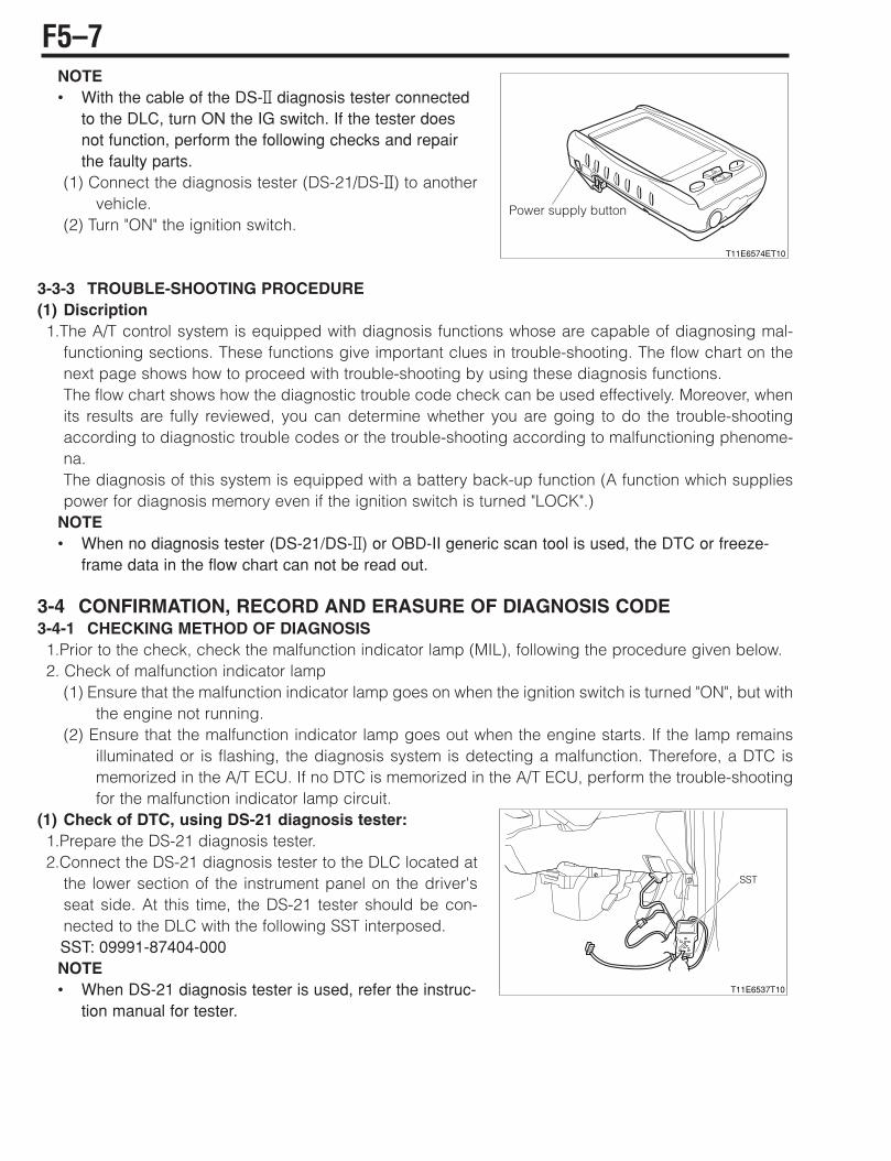
NOTE• With the cable of the DS-@ diagnosis tester connected
to the DLC, turn ON the IG switch. If the tester doesnot function, perform the following checks and repairthe faulty parts.
(1) Connect the diagnosis tester (DS-21/DS-@) to anothervehicle.
(2) Turn "ON" the ignition switch.
3-3-3 TROUBLE-SHOOTING PROCEDURE(1) Discription1.The A/T control system is equipped with diagnosis functions whose are capable of diagnosing mal-
functioning sections. These functions give important clues in trouble-shooting. The flow chart on thenext page shows how to proceed with trouble-shooting by using these diagnosis functions.The flow chart shows how the diagnostic trouble code check can be used effectively. Moreover, whenits results are fully reviewed, you can determine whether you are going to do the trouble-shootingaccording to diagnostic trouble codes or the trouble-shooting according to malfunctioning phenome-na.The diagnosis of this system is equipped with a battery back-up function (A function which suppliespower for diagnosis memory even if the ignition switch is turned "LOCK".)
NOTE• When no diagnosis tester (DS-21/DS-@) or OBD-II generic scan tool is used, the DTC or freeze-
frame data in the flow chart can not be read out.
3-4 CONFIRMATION, RECORD AND ERASURE OF DIAGNOSIS CODE3-4-1 CHECKING METHOD OF DIAGNOSIS1.Prior to the check, check the malfunction indicator lamp (MIL), following the procedure given below.2. Check of malfunction indicator lamp
(1) Ensure that the malfunction indicator lamp goes on when the ignition switch is turned "ON", but withthe engine not running.
(2) Ensure that the malfunction indicator lamp goes out when the engine starts. If the lamp remainsilluminated or is flashing, the diagnosis system is detecting a malfunction. Therefore, a DTC ismemorized in the A/T ECU. If no DTC is memorized in the A/T ECU, perform the trouble-shootingfor the malfunction indicator lamp circuit.
(1) Check of DTC, using DS-21 diagnosis tester:1.Prepare the DS-21 diagnosis tester.2.Connect the DS-21 diagnosis tester to the DLC located at
the lower section of the instrument panel on the driver'sseat side. At this time, the DS-21 tester should be con-nected to the DLC with the following SST interposed.SST: 09991-87404-000NOTE• When DS-21 diagnosis tester is used, refer the instruc-
tion manual for tester.
F5–7
T11E6574ET10
Power supply button
T11E6537T10
SST
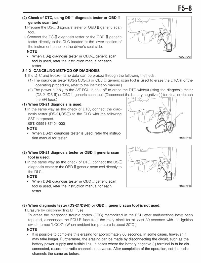
(2) Check of DTC, using DS-@ diagnosis tester or OBD @generic scan tool
1.Prepare the DS-@ diagnosis tester or OBD @ generic scantool.
2.Connect the DS-@ diagnosis tester or the OBD @ generictester directly to the DLC located at the lower section ofthe instrument panel on the driver's seat side.
NOTE• When DS-@ diagnosis tester or OBD-@ generic scan
tool is used, refer the instruction manual for eachtester.
3-4-2 CANCELING METHOD OF DIAGNOSIS1.The DTC and freeze-frame data can be erased through the following methods.
(1) The diagnosis tester (DS-21/DS-@) or OBD @ generic scan tool is used to erase the DTC. (For theoperating procedure, refer to the instruction manual.)
(2) The power supply to the A/T ECU is shut off to erase the DTC without using the diagnosis tester(DS-21/DS-@) or OBD @ generic scan tool. (Disconnect the battery negative (-) terminal or detachthe EFI fuse.)
(1) When DS-21 diagnosis is used:1.In the same way as the check of DTC, connect the diag-
nosis tester (DS-21/DS-@) to the DLC with the followingSST interposed.SST: 09991-87404-000NOTE• When DS-21 diagnosis tester is used, refer the instruc-
tion manual for tester.
(2) When DS-21 diagnosis tester or OBD @ generic scantool is used:
1.In the same way as the check of DTC, connect the DS-@diagnosis tester or the OBD @ generic scan tool directly tothe DLC.
NOTE• When DS-@ diagnosis tester or OBD @ generic scan
tool is used, refer the instruction manual for eachtester.
(3) When diagnosis tester (DS-21/DS-@) or OBD @ generic scan tool is not used:1.Erasure by disconnecting EFI fuse
To erase the diagnostic trouble codes (DTC) memorized in the ECU after malfunctions have beenrepaired, disconnect the ECU-B fuse from the relay block for at least 30 seconds with the ignitionswitch turned "LOCK". (When ambient temperature is about 20°C.)
NOTE• It is possible to complete this erasing for approximately 60 seconds. In some cases, however, it
may take longer. Furthermore, the erasing can be made by disconnecting the circuit, such as thebattery power supply and fusible link. In cases where the battery negative (-) terminal is to be dis-connected, record the radio channels in advance. After completion of the operation, set the radiochannels the same as before.
F5–8
T11E6573T10
T11E6537T10
SST
T11E6573T10

3-5 SYMPTOM CONFIRMATION3-5-1 CONFIRMATION OF REPRODUCTION OF MALFUNCTIONING PHENOMENA1.In the course of trouble-shooting, the operator can not pinpoint the cause for the malfunction unless he
confirms the phenomenon. For this purpose, it is indispensable to reproduce the malfunctioning phe-nomenon by creating conditions and environments that are similar to those customer.
2.As for phenomena whose can not be reproduced easily, it is necessary to produce running conditionsthat are similar to those when the malfunction occurred (Road surface condition, weather condition,driving condition). For this end, it is of great importance to try to reproduce the conditions that are sim-ilar to those when the malfunction occurred (Road surface condition, weather relays by hand), heat(applying hot air) and water (Applying moisture).
3.Vibration, heat or moisture can constitute causes for malfunction that are difficult to reproduce.4.Therefore, with the vehicle in a stationary state, you can perform the following malfunction reproduc-
tion simulation tests given below.Moreover, if you presume a section (Part) which can cause a malfunction and connect a tester, etc. tothat section so as to confirm the malfunctioning phenomenon, you can also achieve a function to thatsection so as to confirm the malfunctioning phenomenon, you can also achieve a function evaluationof that section (Part).
(1) Malfunction reproduction simulation test methods1 Vibration method:1.When vibration is thought to be the main cause
(1) ConnectorLightly shake the connector vertically and laterally.
(2) Wire harnessLightly shake the wire harness vertically and laterally.The points to be checked are connector joints, thevibrating point and the section where the wire har-ness is passing through the body.
(3) Parts, sensorsWith your finger, apply light vibrations to a part of thesensor which is presumed to be the cause for themalfunction. Check to see if the malfunction is repro-duced.
NOTE• Be careful not to apply too strong vibration to a relay,
for it can cause an open wire in the relay.
F5–9
L21E3726ET10
Shake lightlyL21E3727ET10
T11E6541T10

2 Cool/hot method:1.When a suspected section is likely causing the malfunc-
tion when it is cold or hot.(1) Heat a component which is presumed to be causing
the malfunction by using a dryer or the like. Check tosee if the malfunction occurs.
CAUTION• Do not heat the section beyond 60°C. (Temperature
limit to assure that no damage be made to the compo-nent.)
• Do not directly heat the parts inside the ECU.3 Water applying method:1.When the malfunction is believed to occur on rainy days or under humid conditions. Apply water to the
vehicle. Check to see if the malfunction occurs.NOTE• Never apply water directly to the engine compartment. By applying water to the front of the radia-
tor, you can indirectly change the temperature and humidity.• Never apply water directly to the electronic parts.• If rain leaks into the vehicle compartment, rain may get into the inside of the ECU through the wire
harnesses. If the vehicle has experienced any rain leakage before, utmost attention must be paidin respect to this point.
3-5-2 RECHECK AND MAKING RECORD OF DTC/FREEZE-FRAME DATA1.By checking the DTC/freeze-frame data after confirming the reproduction of the malfunctioning phe-
nomenon, it is possible to judge whether the system related to the DTC that was indicated before con-firmation of the reproduction is now functioning properly or not. Then, you are to proceed to one of thefollowing three steps.(1) When a DTC was indicated at the time of checking the DTC and the same DTC is indicated after
the confirmation of reproduction of the malfunction, it indicates that the malfunction is still per-sisting in the diagnosis circuit. Proceed to the trouble-shooting according codes.
(2) When no abnormal code is indicated, although the occurrence of malfunction was observed dur-ing the confirmation of reproduction of malfunction, a malfunction other than those related to thediagnosis system is likely taking place. Proceed to the trouble-shooting according to malfunc-tioning phenomena.
(3) When no malfunction is observed during the confirmation of reproduction of malfunction, and thenormal code is indicated at the check of the DTC, it is presumed that an abnormality, such as poorcontacts at the harnesses and connectors, occurred in the past, but now they are functioningproperly. Check the harnesses and connectors of those systems related to the DTC that was indi-cated before the confirmation of reproduction of the malfunctioning phenomenon.
F5–10
MalfunctionDryer Cooling agent
L21E3729ET10

3-6 SYSTEM WIRING DIAGRAM
T11K5524ES44
O/D OFF switchO/D1 B22
IG1 IG2
F/L
IG switchECU IG2
Neutral start switch
Back lamp
N
L
D
2
C15 P
R
C24
C25
C17
C16
B7
C9 VBTB
C20 ETBN
C10 RTBN
C7 VBOP
C18 EOPT
C8 ROPT
B24 E1
B5 E02
B6 E01
C14 OTMP
C13 ETMP
Transmission control com
puter
B3 +B1
B2 BAT1
B1 BAT2
AM2
ECU B
C2C3B2+
C1C3B2-
C23LUCC
C12SOLR
LUCR
C4C2+
C3C2-
C6B1+
C5B1-
Solenoid No.1
Solenoid No.2
Solenoid No.3
Duty solenoid
Switch solenoid
LUC solenoid
C11
To EFI ECUTo meter(CAN comunication)
To ABS ECU(CAN comunication)
STR B16
LCN1 B19
HCN1 B9
CANH B10
CANL B20
REG1 B8
SIO1 B17
EFI ECU
DLC
Turbine revolutionsensor
Outputrevolutionsensor
Fluid temperaturesensor
Battery
To starter relay magnetic
ABS equipped vehicles
F5–11

Transmission control computer terminal name
1.Connectors AThis connector is not used.2.Connectors B
3.Connectors C
Terminal No.
Termi-nal
code Terminal name
Terminal No.
Terminal code
Terminal name
1 C3B2(
Solenoid No.3 (() 14 OTMP Fluid temperature sensor
2 C3B2'
Solenoid No.3 (') 15 P Neutral start switch (P)
3 C2( Solenoid No.2 (() 16 2 Neutral start switch (2) 4 C2' Solenoid No.2 (') 17 D Neutral start switch (D) 5 B1( Solenoid No.1 (() 18 EOPT Output revolution sensor ground 6 B1' Solenoid No.1 (') 19 ( (
7 VBOP Output revolution sensor power supply 20 ETBN Turbine revolution sensor ground 8 ROPT Output revolution sensor 21 ( (
9 VBTB Turbine revolution sensor power supply 22 ( (
10 RTBN Turbine revolution sensor 23 LUCC Duty solenoid11 LUCR LUC solenoid 24 N Neutral start switch (N) 12 SOLR Switch solenoid 25 L Neutral start switch (L) 13 ETMP Fluid temperature sensor ground 26 ( (
Terminal No.
Terminal code
Terminal name Terminal
No. Terminal
code Terminal name
1 BAT2 Backup power supply 13 ( (
2 BAT1 Backup power supply 14 ( (
3 'B1 ECU power supply 15 ( (
4 ( ( 16 STR Starter relay output circuit 5 E02 A/T power system ground 17 SIO1 Diagnostic tester communication 6 E01 A/T power system ground 18 ( (
7 R Neutral start switch (R) 19 LCN1 CAN communication LO (1)
8 REG1 Engine revolution speed 20 CANL CAN communication LO (2)
9 HCN1 CAN communication HI (1) 21 ( (
10 CANH CAN communication HI (2) 22 O/D1 O/D OFF switch 11 ( ( 23 ( (
12 ( ( 24 E1 Sensor ground
T11K5006S10
A B C
22 21 20 19 18 17 16 15 14 13 12 11
30 29 28 27 26 25 24 23
10 19 8 7 6 5 4 3 2
16 15 14 13 12 11 10 9 8 7
24 23 22 21 18 1720 19
6 5 124 3
17 16 15 14 13 12 11 10 9 8 7
26 25 24 23 22 19 1821 20
6 5 4 13 2
F5–12
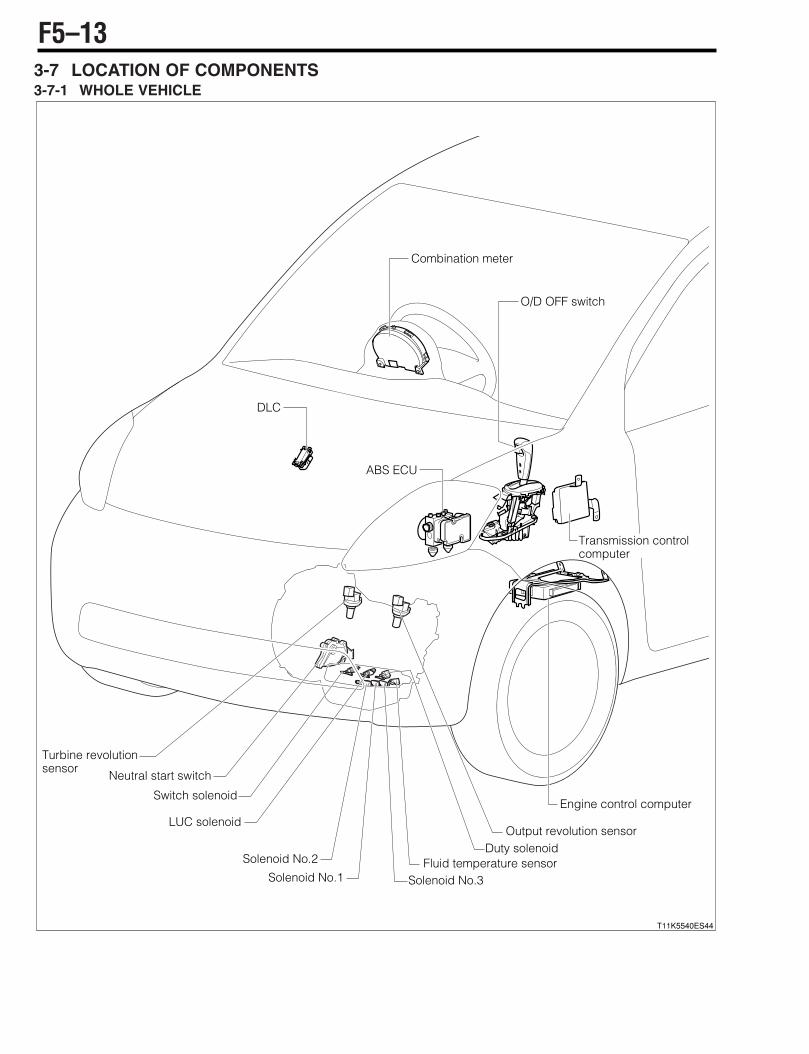
3-7 LOCATION OF COMPONENTS3-7-1 WHOLE VEHICLE
T11K5540ES44
Neutral start switch
Solenoid No.2
LUC solenoid
Solenoid No.1 Solenoid No.3Fluid temperature sensor
Duty solenoidOutput revolution sensor
Turbine revolutionsensor
DLC
Switch solenoid
O/D OFF switch
Transmission control computer
ABS ECU
Engine control computer
Combination meter
F5–13
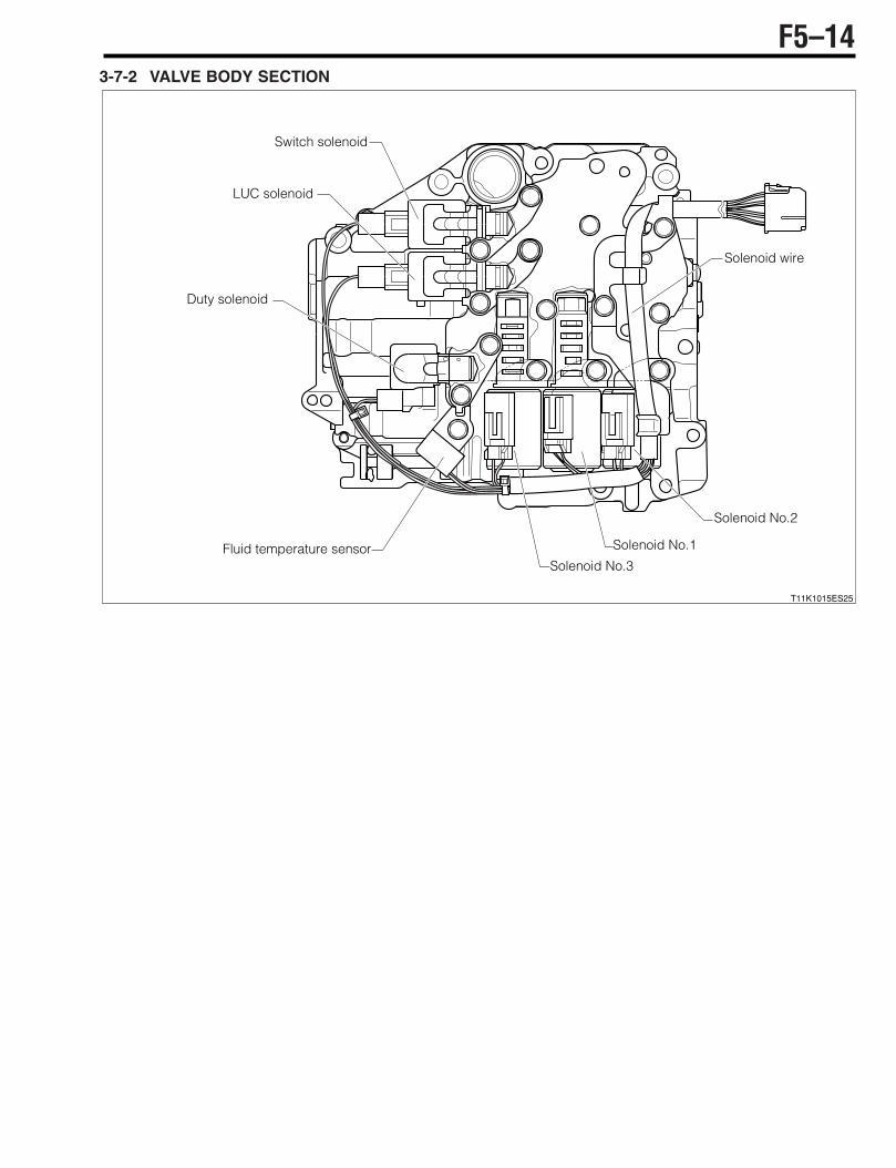
3-7-2 VALVE BODY SECTION
T11K1015ES25
Switch solenoid
LUC solenoid
Solenoid No.3
Solenoid No.1
Solenoid No.2
Solenoid wire
Duty solenoid
Fluid temperature sensor
F5–14

3-8 ARRANGEMENT OF VEHICLE HARNESS SIDE CONNECTOR TERMINALS
For the terminal names of transmission control computer vehicle harness side connectors, refer to the system wiring diagram.
3-9 ERASING OF LEARNING VALUE AND INITIAL LEARNINGWhen the automatic transaxle Ay, valve body Ay (Including the solenoid valve) have been replaced, it isnecessary to erase the transmission control computer learning values and to perform the initial learning,following the procedure given below.1.Short the ECU-T terminal and E terminal inside the DLC.
Refer to Page F5-22.
2.Within three seconds after turning ON the IG SW(Not starting the engine), depress the brake pedal andkeep depressing it. (Until the following operations 3 and 4 are completed).
3.Move the shift lever P!R!P within one second. (The time required for P!R!P is within one second.)4.Repeat the operation of Item 3 above eight times. (The O/D OFF lamp quickly flashes for 2.5 seconds
as a signal telling the completion of erasing operation.)5.Release the short-circuit of the ECU-T terminal and E terminal inside the DLC.6.Turn "LOCK" the IG SW and turn it "ON" again.7.Fully warm up the engine and transmission.
NOTE• The initial learning starts when the transmission oil temperature rises above 50°C.
8.Perform the initial learning (Urban running of about 15 minutes) (Go through the driving at variousgears and kickdowns.)
T11K5523ES25
21
43
Solenoid wire Turbine revolutionsensor
Output revolutionsensor
Nuutral startswitch
C3B2' SOLR
LUCC
4321
1 2 38765
1211109
OTMP E2
RTBN
V12
B1'
EB1(C3B2(C2(
C2'
LUCR
Transmission control computer
BC
Engine control computer
ABS control computer
1 2 3
E2
ROPT
V12
30 31 32 33 34 35 36 37
70 71 72 73 74 75 76 77
107108 109110 111112
21 3 4 5 6 7
2928
21
60 61 62 63 64 65 66 67 68 69
97 98 99 100 101 102 105 106
129130 133 134135
22 23 24 25 26 27
103 104
131132
38 39 40 41 42 43 44 45 46
78 79 80 81 82 83 86 87
113114 118119
8 9 10 11 12 13
84 85
115 116117
47
88
120
49 50 51 52 53 54 55 56 57
89 90 91 92
121122
14 15 16 17 18 19
48
93 94
123 124 125126
58
95
127
59
96
128
20
2R D P
N E RB L
3 4
5 7 86
21
ATNE CANL CANH
16151413121110987
242322211817 2019
651 2 43
1716151413121110987
26252423221918 2120
6541 32
2 3 4 5 6 7 8 9 10 11 12
15 16 17 18 19 20 21 22 23 24 25
1 13
14 26
O/D OFFswitch
O/D(O/D'
F5–15

3-10 HOW TO PROCEED WITH TROUBLE SHOOTINGThis system is equipped with a diagnosis function that diagnoses the defective sections and this providesimportant clues in performing trouble shooting.
è1. Bringing of malfunctioning vehicle in garageçGo to step è2.
è2. INQUIRY WITH CUSTOMER1.Thoroughly obtain information from the customer concerning the conditions, environment and phe-
nomena in which the malfunction took place.çGo to step è3.
è3. Confirm the normal indication of the diagnosis code of LCD inside the meter 1.Using the SST, short-circuit between the DLC4 (ECU-T) and the 13(E).
SST: 09991-87403-000
2.Confirm that the LCD inside the meter indicates the diagnosis codes (Including the normal code).SPECIFIED VALUE: Indicates.
NOTE• Codes other than the CAN-related codes are permissible.
çIf it is OK, go to step è4.çIf NG, conduct the following checks given below concerning the meter. If no problems are found,replace the meter.(1) Check the harnesses between the meter and the DLC as well as between the DLC and the body
ground.(2) Check the power supply system and ground system of the combination meter.(3) Check the power supply system and ground system of the meter.
è4. Confirm the diagnosis code of LCD inside the meter (CAN-related).1.Confirm that the LCD inside the meter will not indicate the CAN-related diagnosis codes (Codes 0051
through 0053).SPECIFIED VALUE: Will not indicate codes 0051 through 0053.
çIf it is OK, go to step è5.çIf NG, refer to the item of the CAN communication system.Refer to Page L2-1.
è5. Confirmation and recording of diagnosis code1.Using the SST, short-circuit between the DLC4 (ECU-T) and the 13(E).
SST: 09991-87403-000
çGo to step è6.
è6. Erasing of diagnosis codes1.Erase the diagnosis codes.
NOTE• Before erasing the codes, record the codes that are being outputted.
çGo to step è7.
F5–16

è7.Reproduction and confirmation of malfunction phenomenon1.Confirm the malfunctioning phenomenon and reproduce the malfunctioning situation.
SPECIFIED VALUE: The malfunctioning phenomenon has been reproduced.
çIf it is OK, go to step è8.çIf NG, presume the cause of malfunction, based on the diagnosis by interview to the customer or the
trouble-shooting according to malfunctioning phenomena.
è8. Reconfirmation of diagnosis code1.Reconfirm the diagnosis codes.
SPECIFIED VALUE: The abnormality code is outputted again.
çIf it is OK, go to step è9.çIf it is OK, go to step è10.
è9. Trouble-shooting according to diagnosis code1.Perform the check concerning the diagnosis codes that are currently outputted.
Refer to Page F5-29.
çAfter completion of the check, proceed to è11.
è10. Trouble-shooting according to malfunction phenomenon.1.Perform the check for the malfunctioning phenomena.
Refer to Page F5-50.
çAfter completion of the check, proceed to è11.
è11. Confirmation test1.Checks whether the problem that the customer described has been corrected and the operation is
back to normal.çIf OK, finish the trouble shooting.çIf NG, return to the è3 and redo the check.
F5–17

3-11 INQUIRYIn an effort to remove causes for malfunction from the vehicle concerned, it is impossible to determine thecause without confirming the malfunction phenomenon. If the phenomenon is not confirmed, the vehiclemay not be able to return to the normal conditions even if you continue your work. The diagnosis throughinterview is to collect information from the customer before confirming the malfunction phenomena. Thediagnosis through interview provides very important clues in reproducing malfunction phenomena.Since the information obtained by the diagnosis through interview is referred to during the trouble shoot-ing, it is imperative to make an inquiry of the customer, centering on the items related to the malfunction,instead of simply asking general questions.Please make use of the information on the next page, as it provides an example of the diagnosis by inter-view.
F5–18

3-11-1 DIAGNOSIS BY INTERVIEW SHEET FOR AUTOMATIC TRANSMISSION SYSTEM
Customer information
Details of vehicle
Date when vehicle was brought to workshop
Day Month
(Day of week)
Date when malfunction took place
Day Month
(Day of week)
Repair historyNo,
Yes (How many times? )
Frame No. Registration
date Day Month Year Vehicle model
Engine type Transmission Electronically controlled 4A/T Driving 2WD;4WDRunning dis-
tance km Equipment Tire [ ]; Wheel [Steel ; Aluminum]
Gender of customer (Male, female)
Age [Approx. ] Occupation [ ]Name of customer
Mr./Ms. Area where vehi-cle is mainly used
Urban, suburb, seashore, mountain, others
Parking place
Outdoor, indoor
Checked by Check date Day Month
(Day of week)
F5–19
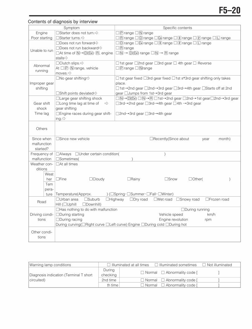
Contents of diagnosis by interview
Warning lamp conditions Illuminated at all times Illuminated sometimes Not illuminated During
checking Normal Abnormality code [ ]
2nd time Normal Abnormality code [ ] Diagnosis indication (Terminal T short circuited)
th time Normal Abnormality code [ ]
Symptom Specific contents Engine
Poor starting Starter does not turn.mStarter turns.m
H range G range I range D range E range M range L range F range
Unable to run
Does not run forwardmDoes not run backwardmAt time of G!D(E);I, engine
stallsm
D range E range M range L range F range I range G!D(E) range G!I range
Abnormal running
Clutch slips.mAt H;G range, vehicle moves.m
1st gear 2nd gear 3rd gear 4th gear Reverse H range Grange
Improper gear shifting
No gear shiftingm
Shift points deviatedm
1st gear fixed 3rd gear fixed 1st #3rd gear shifting only takes place.
1st!2nd gear 2nd!3rd gear 3rd!4th gear Starts off at 2nd gear Jumps from 1st!3rd gear
Large gear shifting shock Long time lag at time of
gear shifting m
G!D(E) G!I 1st!2nd gear 2nd!1st gear 2nd!3rd gear3rd!2nd gear 3rd!4th gear 4th !3rd gear Gear shift
shock Time lag Engine races during gear shift-
ing.m2nd!3rd gear 3rd!4th gear
Others
Since when malfunction
started?
Since new vehicle Recently(Since about year month)
Frequency of malfunction
Always Under certain condition( ) Sometimes( )
Weather con-ditions
Weather Tempera-ture
At all times
Fine Cloudy Rainy Snow Other( )
Temperature(Approx. ‚ ) ( Spring Summer Fall Winter)
Road Urban area Suburb Highway Dry road Wet road Snowy road Frozen road
Hill ( Uphill Downhill)
Driving condi-tions
Has nothing to do with malfunction During running During starting Vehicle speed km/hDuring racing Engine revolution rpm
During curving( Right curve Left curve) Engine During cold During hot
Other condi-tions
F5–20
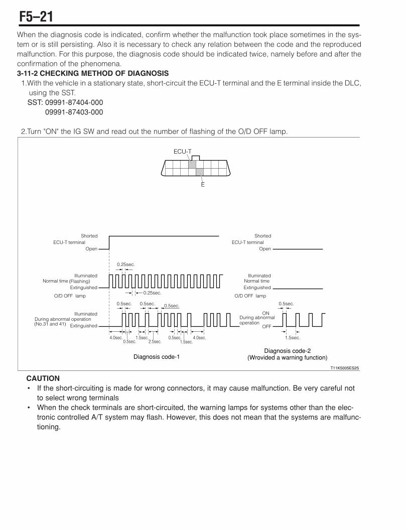
When the diagnosis code is indicated, confirm whether the malfunction took place sometimes in the sys-tem or is still persisting. Also it is necessary to check any relation between the code and the reproducedmalfunction. For this purpose, the diagnosis code should be indicated twice, namely before and after theconfirmation of the phenomena.3-11-2 CHECKING METHOD OF DIAGNOSIS1.With the vehicle in a stationary state, short-circuit the ECU-T terminal and the E terminal inside the DLC,
using the SST.SST: 09991-87404-000SST: 09991-87403-000
2.Turn "ON" the IG SW and read out the number of flashing of the O/D OFF lamp.
CAUTION• If the short-circuiting is made for wrong connectors, it may cause malfunction. Be very careful not
to select wrong terminals• When the check terminals are short-circuited, the warning lamps for systems other than the elec-
tronic controlled A/T system may flash. However, this does not mean that the systems are malfunc-tioning.
T11K5005ES25
E
ECU-T
Open
Extinguished
Illuminated
Extinguished
Illuminated
Extinguished
Illuminated
ECU-T terminal
Normal time Normal time
During abnormal operation During abnormal operation
Shorted
Open
Shorted
(Flashing)
(No.31 and 41)
0.25sec.
0.25sec.
0.5sec.
1.5sec.1.5sec.0.5sec.
0.5sec.2.5sec.
0.5sec. 0.5sec.
1.5sec.
0.5sec.
4.0sec. 4.0sec.
OFF
ON
ECU-T terminal
O/D OFF lamp
Diagnosis code-1Diagnosis code-2
(Wrovided a warning function)
O/D OFF lamp
F5–21

3-11-3 CANCELING METHOD OF DIAGNOSIS1.With the IG SW turned "LOCK", detach the ECU-B fuse located in the relay box inside the engine com-
partment at lease 30 seconds. (Normal temperature)CAUTION• When other backup circuit and ground circuit are disconnected, the diagnosis is cancelled
Example: Battery power supply, fusible link.• There are cases where the time required for erasing the diagnosis becomes longer during cold
time.
3-11-4 CONTENTS OF DIAGNOSISCodes specified by ISO/SAE
NOTE• 1 trip: 1 trip detection logic• 2 trip: 2 trip detection logic• MIL: Malfunction indicator lamp
When the "O" mark is shown in the MIL column, the lamp will go on for that DTC number, butwhen the "(" mark is shown, the lamp will not go on for that DTC No. Therefore, it is possible toread out the DTC No. by using the diagnosis tester (DS-21/DS-@). As for the DTC No. bearing themark, the MIL will go on except the EU specifications.
DTC No. Diagnosis contents Malfunction evaluation
method
Warning indica-tion
(Provided:<, Not provided:=)
Code memory(Provided:<,
Not provided:=)
MIL (Malfunction indicator lamp)
P0705/56 Neutral start switch multiple-input ( < < (
P0710/38 Oil temperature sensor circuit open wire or short-circuit
1 trip < < <
P0711/38 Abnormal oil temperature sensor charac-teristics
2 trip < < <
P0715/37 No turbine revolution input 2 trip < < <
P0720/42 No output revolution input 2 trip < < <
P0725/86 No engine revolution input 2 trip < < <
P0753/61 Solenoid No.1 circuit open wire and short-circuit
1 trip < < <
P0758/62 Solenoid No.2 circuit open wire and short-circuit
1 trip < < <
P0763/63 Solenoid No.3 circuit open wire and short-circuit
1 trip < < <
P0768/64 Duty solenoid circuit open wire and short-circuit
1 trip < < <
P0773/65 LUC solenoid circuit open wire and short-circuit
1 trip < < <
F5–22

Codes specified by DMC
NOTE• 1 trip: 1 trip detection logic• 2 trip: 2 trip detection logic• MIL: Malfunction indicator lamp
When the "O" mark is shown in the MIL column, the lamp will go on for that DTC number, butwhen the "(" mark is shown, the lamp will not go on for that DTC No. Therefore, it is possible toread out the DTC No. by using the diagnosis tester (DS-21/DS-@). As for the DTC No. bearing themark, the MIL will go on except the EU specifications.
DTC No. Diagnosis contents Malfunction evaluation
method
Warning indica-tion
(Provided:<, Not provided:=)
Code memory(Provided:<,
Not provided:=)
MIL (Malfunction indicator lamp)
P0705/55 No neutral start switch input ( = = (
P1703/72 Lockup revolution not matched 2 trip < < <
P1706/31 Abnormal engine torque ( < = (
P1711/41 EFI throttle sensor malfunctioning ( < = (
P1730/21 Abnormal battery power supply 2 trip < < <
P1731/22 Abnormal sensor system power supply 2 trip < < <
P1780/66 Switch solenoid circuit open wire and short-circuit
1 trip < < <
U0100/82 Abnormal communication receiving with EFI
1 trip < < <
U1001/85 Abnormal communication sending with EFI
1 trip < < <
F5–23
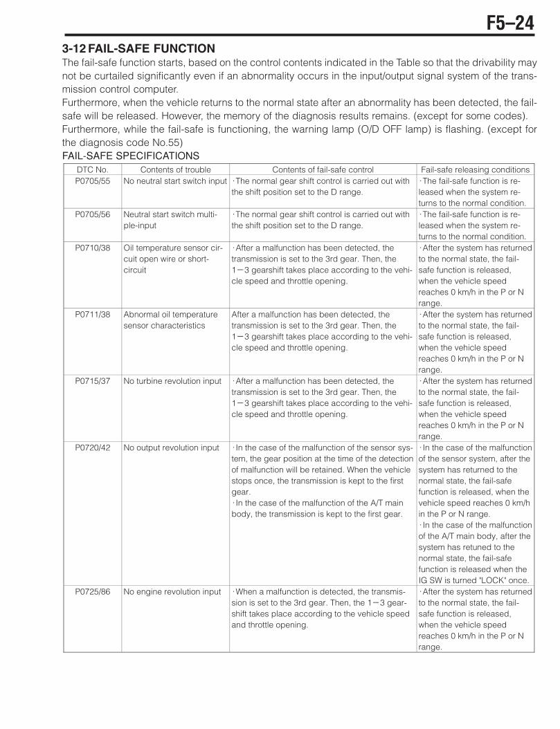
3-12 FAIL-SAFE FUNCTIONThe fail-safe function starts, based on the control contents indicated in the Table so that the drivability maynot be curtailed significantly even if an abnormality occurs in the input/output signal system of the trans-mission control computer.Furthermore, when the vehicle returns to the normal state after an abnormality has been detected, the fail-safe will be released. However, the memory of the diagnosis results remains. (except for some codes).Furthermore, while the fail-safe is functioning, the warning lamp (O/D OFF lamp) is flashing. (except forthe diagnosis code No.55)FAIL-SAFE SPECIFICATIONS
DTC No. Contents of trouble Contents of fail-safe control Fail-safe releasing conditionsP0705/55 No neutral start switch input ;The normal gear shift control is carried out with
the shift position set to the D range. ;The fail-safe function is re-leased when the system re-turns to the normal condition.
P0705/56 Neutral start switch multi-ple-input
;The normal gear shift control is carried out with the shift position set to the D range.
;The fail-safe function is re-leased when the system re-turns to the normal condition.
P0710/38 Oil temperature sensor cir-cuit open wire or short-circuit
;After a malfunction has been detected, the transmission is set to the 3rd gear. Then, the1(3 gearshift takes place according to the vehi-cle speed and throttle opening.
;After the system has returned to the normal state, the fail-safe function is released, when the vehicle speed reaches 0 km/h in the P or N range.
P0711/38 Abnormal oil temperature sensor characteristics
After a malfunction has been detected, the transmission is set to the 3rd gear. Then, the1(3 gearshift takes place according to the vehi-cle speed and throttle opening.
;After the system has returned to the normal state, the fail-safe function is released, when the vehicle speed reaches 0 km/h in the P or N range.
P0715/37 No turbine revolution input ;After a malfunction has been detected, the transmission is set to the 3rd gear. Then, the1(3 gearshift takes place according to the vehi-cle speed and throttle opening.
;After the system has returned to the normal state, the fail-safe function is released, when the vehicle speed reaches 0 km/h in the P or N range.
P0720/42 No output revolution input ;In the case of the malfunction of the sensor sys-tem, the gear position at the time of the detection of malfunction will be retained. When the vehicle stops once, the transmission is kept to the first gear. ;In the case of the malfunction of the A/T main body, the transmission is kept to the first gear.
;In the case of the malfunction of the sensor system, after the system has returned to the normal state, the fail-safe function is released, when the vehicle speed reaches 0 km/h in the P or N range. ;In the case of the malfunction of the A/T main body, after the system has retuned to the normal state, the fail-safe function is released when theIG SW is turned "LOCK" once.
P0725/86 No engine revolution input ;When a malfunction is detected, the transmis-sion is set to the 3rd gear. Then, the 1(3 gear-shift takes place according to the vehicle speed and throttle opening.
;After the system has returned to the normal state, the fail-safe function is released, when the vehicle speed reaches 0 km/h in the P or N range.
F5–24
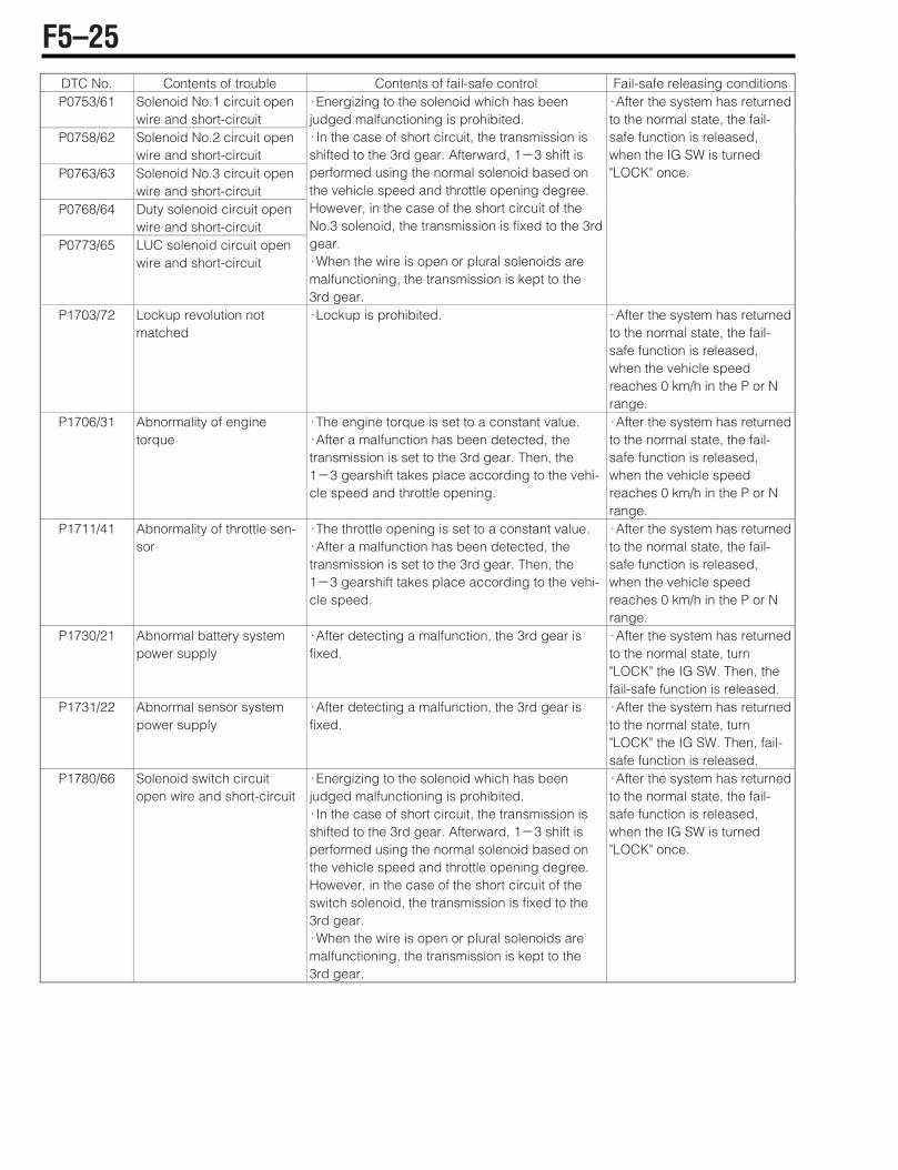
DTC No. Contents of trouble Contents of fail-safe control Fail-safe releasing conditionsP0753/61 Solenoid No.1 circuit open
wire and short-circuit P0758/62 Solenoid No.2 circuit open
wire and short-circuit P0763/63 Solenoid No.3 circuit open
wire and short-circuit P0768/64 Duty solenoid circuit open
wire and short-circuit P0773/65 LUC solenoid circuit open
wire and short-circuit
;Energizing to the solenoid which has been judged malfunctioning is prohibited. ;In the case of short circuit, the transmission is shifted to the 3rd gear. Afterward, 1(3 shift is performed using the normal solenoid based on the vehicle speed and throttle opening degree. However, in the case of the short circuit of the No.3 solenoid, the transmission is fixed to the 3rd gear. ;When the wire is open or plural solenoids are malfunctioning, the transmission is kept to the 3rd gear.
;After the system has returned to the normal state, the fail-safe function is released, when the IG SW is turned "LOCK" once.
P1703/72 Lockup revolution not matched
;Lockup is prohibited. ;After the system has returned to the normal state, the fail-safe function is released, when the vehicle speed reaches 0 km/h in the P or N range.
P1706/31 Abnormality of engine torque
;The engine torque is set to a constant value.;After a malfunction has been detected, the transmission is set to the 3rd gear. Then, the1(3 gearshift takes place according to the vehi-cle speed and throttle opening.
;After the system has returned to the normal state, the fail-safe function is released, when the vehicle speed reaches 0 km/h in the P or N range.
P1711/41 Abnormality of throttle sen-sor
;The throttle opening is set to a constant value. ;After a malfunction has been detected, the transmission is set to the 3rd gear. Then, the1(3 gearshift takes place according to the vehi-cle speed.
;After the system has returned to the normal state, the fail-safe function is released, when the vehicle speed reaches 0 km/h in the P or N range.
P1730/21 Abnormal battery system power supply
;After detecting a malfunction, the 3rd gear is fixed.
;After the system has returned to the normal state, turn "LOCK" the IG SW. Then, the fail-safe function is released.
P1731/22 Abnormal sensor system power supply
;After detecting a malfunction, the 3rd gear is fixed.
;After the system has returned to the normal state, turn "LOCK" the IG SW. Then, fail-safe function is released.
P1780/66 Solenoid switch circuit open wire and short-circuit
;Energizing to the solenoid which has been judged malfunctioning is prohibited. ;In the case of short circuit, the transmission is shifted to the 3rd gear. Afterward, 1(3 shift is performed using the normal solenoid based on the vehicle speed and throttle opening degree. However, in the case of the short circuit of the switch solenoid, the transmission is fixed to the 3rd gear. ;When the wire is open or plural solenoids are malfunctioning, the transmission is kept to the 3rd gear.
;After the system has returned to the normal state, the fail-safe function is released, when the IG SW is turned "LOCK" once.
F5–25
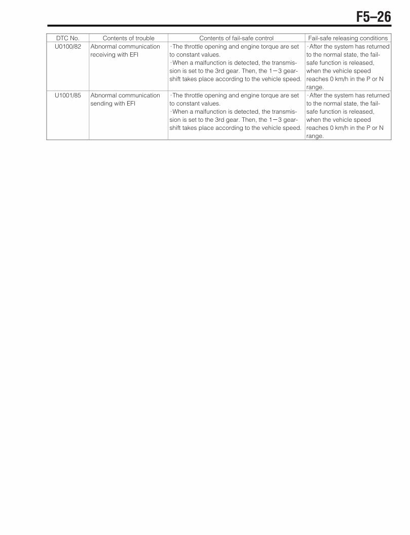
DTC No. Contents of trouble Contents of fail-safe control Fail-safe releasing conditionsU0100/82 Abnormal communication
receiving with EFI ;The throttle opening and engine torque are set to constant values. ;When a malfunction is detected, the transmis-sion is set to the 3rd gear. Then, the 1(3 gear-shift takes place according to the vehicle speed.
;After the system has returned to the normal state, the fail-safe function is released, when the vehicle speed reaches 0 km/h in the P or N range.
U1001/85 Abnormal communicationsending with EFI
;The throttle opening and engine torque are set to constant values. ;When a malfunction is detected, the transmis-sion is set to the 3rd gear. Then, the 1(3 gear-shift takes place according to the vehicle speed.
;After the system has returned to the normal state, the fail-safe function is released, when the vehicle speed reaches 0 km/h in the P or N range.
F5–26
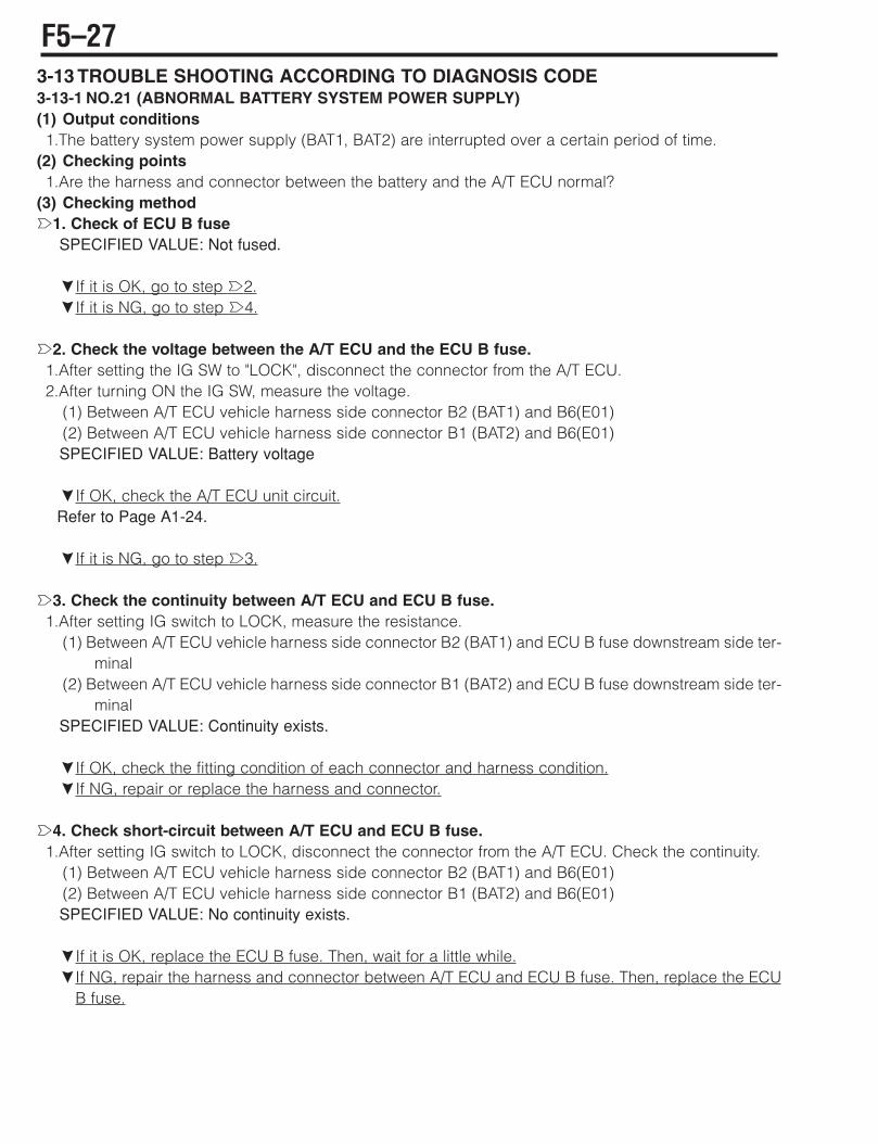
3-13 TROUBLE SHOOTING ACCORDING TO DIAGNOSIS CODE3-13-1 NO.21 (ABNORMAL BATTERY SYSTEM POWER SUPPLY)(1) Output conditions1.The battery system power supply (BAT1, BAT2) are interrupted over a certain period of time.
(2) Checking points1.Are the harness and connector between the battery and the A/T ECU normal?
(3) Checking methodè1. Check of ECU B fuse
SPECIFIED VALUE: Not fused.
çIf it is OK, go to step è2.çIf it is NG, go to step è4.
è2. Check the voltage between the A/T ECU and the ECU B fuse.1.After setting the IG SW to "LOCK", disconnect the connector from the A/T ECU.2.After turning ON the IG SW, measure the voltage.
(1) Between A/T ECU vehicle harness side connector B2 (BAT1) and B6(E01)(2) Between A/T ECU vehicle harness side connector B1 (BAT2) and B6(E01)SPECIFIED VALUE: Battery voltage
çIf OK, check the A/T ECU unit circuit.Refer to Page A1-24.
çIf it is NG, go to step è3.
è3. Check the continuity between A/T ECU and ECU B fuse.1.After setting IG switch to LOCK, measure the resistance.
(1) Between A/T ECU vehicle harness side connector B2 (BAT1) and ECU B fuse downstream side ter-minal
(2) Between A/T ECU vehicle harness side connector B1 (BAT2) and ECU B fuse downstream side ter-minal
SPECIFIED VALUE: Continuity exists.
çIf OK, check the fitting condition of each connector and harness condition.çIf NG, repair or replace the harness and connector.
è4. Check short-circuit between A/T ECU and ECU B fuse.1.After setting IG switch to LOCK, disconnect the connector from the A/T ECU. Check the continuity.
(1) Between A/T ECU vehicle harness side connector B2 (BAT1) and B6(E01)(2) Between A/T ECU vehicle harness side connector B1 (BAT2) and B6(E01)SPECIFIED VALUE: No continuity exists.
çIf it is OK, replace the ECU B fuse. Then, wait for a little while.çIf NG, repair the harness and connector between A/T ECU and ECU B fuse. Then, replace the ECU
B fuse.
F5–27

3-13-2 NO.22 (ABNORMAL SENSOR SYSTEM POWER SUPPLY)(1) Output conditions1.When the revolution sensor system power supply is short-circuited over a certain period of time.
(2) Checking points1.Are the harness and connector between A/T ECU and turbine revolution sensor, output revolution sen-
sor normal?2.Are the turbine revolution sensor and output revolution sensor normal?
(3) Checking methodè1. Check the short-circuit between A/T ECU and body ground.1.After setting IG SW to "LOCK", disconnect the connector from the A/T ECU. Check the continuity.
(1) Between A/T ECU vehicle harness side connector C9(VBTB) and body ground.(2) Between A/T ECU vehicle harness side connector C7(VBOP) and body ground.SPECIFIED VALUE: No continuity exists.
çIf it is OK, go to step è2.çIf NG, repair or replace the vehicle harness.
è2. Check the turbine revolution sensor unit.1.Disconnect the vehicle harness side connector of the turbine revolution sensor.2.After turning ON the IG switch, check that the code No.22 is extinguished.
NOTE• When the vehicle harness side connector of the turbine revolution sensor is disconnected, ensure
that the code No.37 is indicated.
SPECIFIED VALUE: The code No.22 is extinguished.
çIf OK, replace the turbine revolution sensor.Refer to Page F5-1.
çIf it is NG, go to step è3.
è3. Check of the output revolution sensor unit1.Disconnect the vehicle harness side connector of the output revolution sensor.2.After turning ON the IG switch, check that the code No.22 is extinguished.
NOTE• When the vehicle harness side connector of the output revolution sensor is disconnected, ensure
that the code No.42 is indicated.
SPECIFIED VALUE: The code No.22 is extinguished.
çIf OK, replace the output revolution sensor.Refer to Page F5-1.
çIf NG, check the A/T ECU unit circuit.Refer to Page A1-24.
F5–28
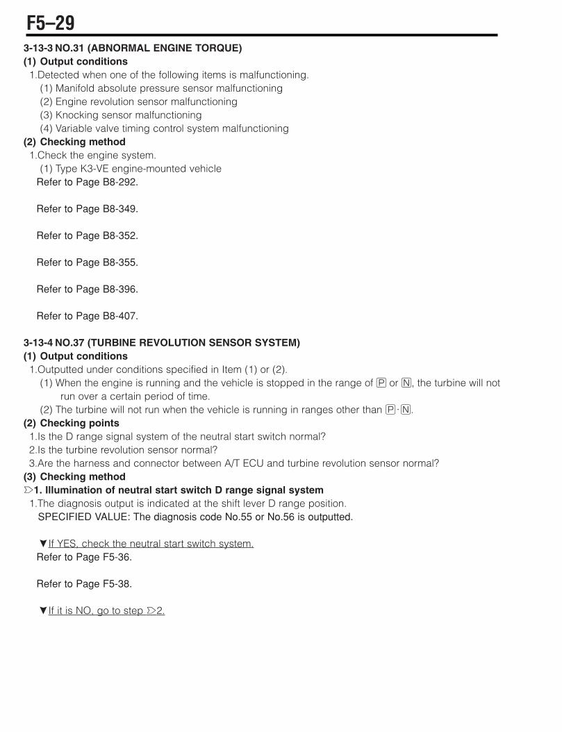
3-13-3 NO.31 (ABNORMAL ENGINE TORQUE)(1) Output conditions1.Detected when one of the following items is malfunctioning.
(1) Manifold absolute pressure sensor malfunctioning (2) Engine revolution sensor malfunctioning (3) Knocking sensor malfunctioning (4) Variable valve timing control system malfunctioning
(2) Checking method1.Check the engine system.
(1) Type K3-VE engine-mounted vehicleRefer to Page B8-292.
Refer to Page B8-349.
Refer to Page B8-352.
Refer to Page B8-355.
Refer to Page B8-396.
Refer to Page B8-407.
3-13-4 NO.37 (TURBINE REVOLUTION SENSOR SYSTEM)(1) Output conditions1.Outputted under conditions specified in Item (1) or (2).
(1) When the engine is running and the vehicle is stopped in the range of H or G, the turbine will notrun over a certain period of time.
(2) The turbine will not run when the vehicle is running in ranges other than H;G.(2) Checking points1.Is the D range signal system of the neutral start switch normal?2.Is the turbine revolution sensor normal?3.Are the harness and connector between A/T ECU and turbine revolution sensor normal?
(3) Checking methodè1. Illumination of neutral start switch D range signal system1.The diagnosis output is indicated at the shift lever D range position.
SPECIFIED VALUE: The diagnosis code No.55 or No.56 is outputted.
çIf YES, check the neutral start switch system.Refer to Page F5-36.
Refer to Page F5-38.
çIf it is NO, go to step è2.
F5–29
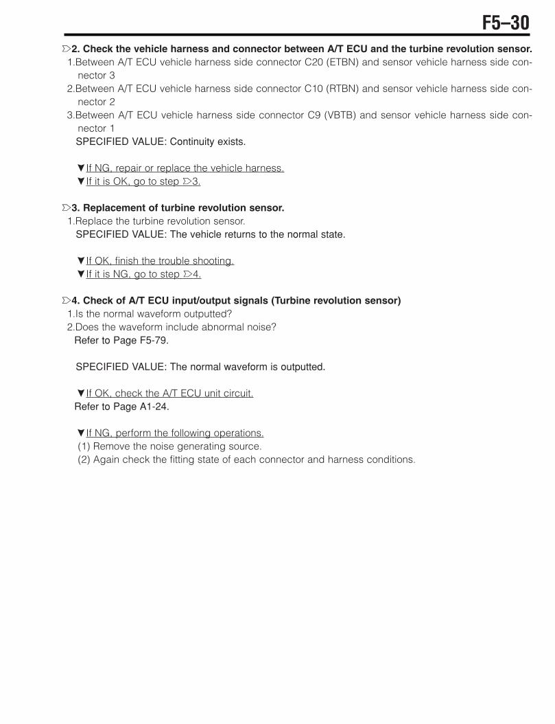
è2. Check the vehicle harness and connector between A/T ECU and the turbine revolution sensor.1.Between A/T ECU vehicle harness side connector C20 (ETBN) and sensor vehicle harness side con-
nector 32.Between A/T ECU vehicle harness side connector C10 (RTBN) and sensor vehicle harness side con-
nector 23.Between A/T ECU vehicle harness side connector C9 (VBTB) and sensor vehicle harness side con-
nector 1SPECIFIED VALUE: Continuity exists.
çIf NG, repair or replace the vehicle harness.çIf it is OK, go to step è3.
è3. Replacement of turbine revolution sensor.1.Replace the turbine revolution sensor.
SPECIFIED VALUE: The vehicle returns to the normal state.
çIf OK, finish the trouble shooting.çIf it is NG, go to step è4.
è4. Check of A/T ECU input/output signals (Turbine revolution sensor)1.Is the normal waveform outputted?2.Does the waveform include abnormal noise?
Refer to Page F5-79.
SPECIFIED VALUE: The normal waveform is outputted.
çIf OK, check the A/T ECU unit circuit.Refer to Page A1-24.
çIf NG, perform the following operations.(1) Remove the noise generating source.(2) Again check the fitting state of each connector and harness conditions.
F5–30

3-13-5 NO.38 (OIL TEMPERATURE SENSOR SYSTEM)(1) Output conditions1.When a voltage value which is not plausible in view of the sensor characteristics is detected for a cer-
tain length of time.(2) Checking points1.Is the oil temperature sensor (Solenoid wire) normal? 2.Are the harness and connector between A/T ECU and oil temperature sensor (Solenoid wire) normal?
(3) Checking methodè1. Check of vehicle harness and connector between A/T ECU and solenoid wire1.Between A/T ECU vehicle harness side connector C14 (OTMP) and solenoid wire vehicle harness side
connector 82.Between A/T ECU vehicle harness side connector C13 (ETMP) and solenoid wire vehicle harness side
connector 12SPECIFIED VALUE: Continuity exists.
çIf it is OK, go to step è2.çIf NG, repair or replace the vehicle harness.
è2. Check of solenoid wire unit (Oil temperature sensor system)Refer to Page F5-73.
çIf it is OK, go to step è3.çIf NG, replace the solenoid wire.
è3. Check of A/T ECU input/output signals (Oil temperature sensor system) Refer to Page F5-79.
çIf OK, check the A/T ECU unit circuit.Refer to Page A1-24.
çIf NG, again check the fitting state of each connector and harness conditions.3-13-6 NO.41 (ABNORMAL THROTTLE SENSOR)1.Check the engine ECU throttle sensor system.
Type K3-VE engine-mounted vehicleRefer to Page B8-306.
F5–31

3-13-7 NO.42 (OUTPUT REVOLUTION SENSOR SYSTEM)(1) Output conditions1.Outputted under conditions specified in Item (1) or (2).
(1) While the vehicle is running, the output revolution disappears suddenly. Or the ratio relative to theturbine revolution is abnormal (sensor system open wire or short-circuit).
(2) The vehicle can not start off due to failure of the C2 clutch engagement. (The turbine revolution onlyrises) (Malfunction of the A/T main body)
(2) Checking points1.Is the P, N range signal system of the neutral start switch normal?2.Is the output revolution sensor normal?3.Are the harness and connector between A/T ECU and output revolution sensor normal?4.Is the A/T main body normal?
(3) Checking methodè1. Check of neutral start switch P;N range signal system 1.The diagnosis code output is indicated at the shift lever P;N range position.
SPECIFIED VALUE: The diagnosis code No.55 or No.56 is outputted.
çIf YES, check the neutral start switch system.Refer to Page F5-36.
Refer to Page F5-38.
çIf it is NO, go to step è2.
è2. Check of neutral start switch signal 11.After turning "LOCK" the IG SW once, start the engine in the N range.2.With the accelerator set to OFF, move the shift lever from the N!D range.
SPECIFIED VALUE: The vehicle moves forward.
çIf it is OK, go to step è4.çIf it is NG, go to step è3.
è3. Check of neutral start switch signal 21.After turning "LOCK" the IG SW once, start the engine in the neutral range.2.With the accelerator set to OFF, move the shift lever in the sequence of the N!D!N!D range.
SPECIFIED VALUE: The vehicle moves forward.
çIf OK, replace the valve body Ay.çIf NG, replace the A/T Ay.
F5–32
è4. Check of vehicle harness and connector between A/T ECU and output revolution sensor1.Between A/T ECU vehicle harness side connector C18 (EOPT) and sensor vehicle harness side con-
nector 32.Between A/T ECU vehicle harness side connector C8 (ROPT) and sensor vehicle harness side con-
nector23.Between A/T ECU vehicle harness side connector C7 (VBOP) and sensor vehicle harness side con-
nector 1SPECIFIED VALUE: Continuity exists.
çIf OK, repair or replace the vehicle harness.çIf it is NG, go to step è5.
è5. Replace the output revolution sensor.1.Replace the output revolution sensor.
SPECIFIED VALUE: The vehicle returns to the normal state.
çIf OK, finish the trouble shooting.çIf it is NG, go to step è6.
è6. Check of A/T ECU input/output signals (Output revolution sensor system)1.Is the normal waveform outputted? 2.Does the waveform include abnormal noise?
Refer to Page F5-79.
SPECIFIED VALUE: The normal waveform is outputted.
çIf OK, check the A/T ECU unit circuit.Refer to Page A1-24.
çIf NG, perform the following operations,(1) Remove the noise generating source.(2) Again check the fitting state of each connector and harness conditions.
F5–33

3-13-8 NO.55 (NO NEUTRAL START SWITCH INPUT)(1) Output conditions1.When no signal input state is detected over a certain length of time:
(2) Checking points1.Is the neutral start switch normal?2.Are the harness and connector between A/T ECU and the neutral start switch normal?
CAUTION• The diagnosis code No.55 is not memorized. (The code is outputted only when a malfunction is
occurring.)
(3) Checking methodè1. Check of lighting of the shift indicator1.Check the illuminating state of the shift indicator inside the combination meter by operating the shift
lever .SPECIFIED VALUE: Illuminates normally.
çIf it is OK, go to step è2.çIf NG, check the neutral start switch unit.Refer to Page F5-78.
è2. Check of harness and connector between A/T ECU and sensor harness.1.With the vehicle in a stationary state, short-circuit the ECU-T terminal and the E terminal inside the DLC,
using the SST.SST: 09991-87404-000SST: 09991-87403-000
2.After turning ON the IG switch, move the shift lever progressively and hold it in each range (for about10 seconds). Check to see in which range the O/D OFF lamp flashes (the diagnosis code indication).
3.At the range where the O/D OFF lamp flashes, check the harness for fitting state and open wire.(1) Between A/T ECU vehicle harness side connector C15 (P) and switch vehicle harness side con-
nector 4 (P)(2) Between A/T ECU vehicle harness side connector B7 (R) and switch vehicle harness side con-
nector 1 (R)(3) Between A/T ECU vehicle harness side connector C24 (N) and switch vehicle harness side con-
nector 5 (N)(4) Between A/T ECU vehicle harness side connector C17 (D) and switch vehicle harness side con-
nector 3 (D)(5) Between A/T ECU vehicle harness side connector C16 (2) and switch vehicle harness side con-
nector 2 (2)(6) Between A/T ECU vehicle harness side connector C25 (L) and switch vehicle harness side con-
nector 8 (L)SPECIFIED VALUE: Continuity exists.
çIf it is OK, go to step è3.çIf NG, repair or replace the harness of the vehicle concerned.
F5–34

è3. Check of A/T ECU input/output signals (Neutral start switch system) Refer to Page F5-79.
çIf OK, check the A/T ECU unit circuit.Refer to Page A1-24.
çIf NG, again check the fitting state of each connector and harness conditions.
F5–35
3-13-9 NO.56 (NEUTRAL START SWITCH MULTIPLE INPUT)(1) Output conditions1.When multiple input of signals is detected over a certain length of time.
(2) Checking points1.Is the neutral start switch normal?2.Are the harness and connector between A/T ECU and neutral start switch normal?
(3) Checking methodè1. Check of lighting of shift indicator1.Check the illuminating state of the shift indicator inside the combination meter by operating the shift
lever .SPECIFIED VALUE: Illuminates normally.
çIf it is OK, go to step è2.çIf NG, check the neutral start switch unit.Refer to Page F5-78.
è2. Check of harness and connector between A/T ECU and sensor harness1.Check each harness for being pinched (Short-circuit).
(1) Between A/T ECU vehicle harness side connector C15 (P) and switch vehicle harness side con-nector 4 (P)
(2) Between A/T ECU vehicle harness side connector B7 (R) and switch vehicle harness side con-nector 1 (R)
(3) Between A/T ECU vehicle harness side connector C24 (N) and switch vehicle harness side con-nector 5 (N)
(4) Between A/T ECU vehicle harness side connector C17 (D) and switch vehicle harness side con-nector 3 (D)
(5) Between A/T ECU vehicle harness side connector C16 (2) and switch vehicle harness side con-nector 2 (2)
(6) Between A/T ECU vehicle harness side connector C25 (L) and switch vehicle harness side con-nector 8 (L)
SPECIFIED VALUE: Not pinched (Short-circuit)
çIf it is OK, go to step è3.çIf NG, repair or replace the vehicle harness.
è3. Check of A/T ECU input/output signals (Neutral start switch system) Refer to Page F5-79.
çIf OK, check A/T ECU unit circuit.Refer to Page A1-24.
çIf NG, again check the state of each connector and harness conditions.
F5–36
3-13-10 NO.61 (SOLENOID NO.1 SYSTEM)(1) Output conditions1.When the solenoid No.1 is energized, no current flowed or excessive current flowed over a certain
length of time.(2) Checking points1.Are the harness and connector between A/T ECU and solenoid No.1 normal?2.Is the solenoid No.1 normal?
(3) Checking methodè1. Check of vehicle harness and connector between the A/T ECU and solenoid wire 1.Between A/T ECU vehicle harness side connector C6 (B1') and solenoid wire vehicle harness side
connector 72.Between A/T ECU vehicle harness side connector C5 (B1-) and solenoid wire vehicle harness side
connector 11SPECIFIED VALUE: Continuity exists.
çIf it is OK, go to step è2.çIf NG, repair or replace the vehicle harness.
è2. Check of solenoid wire unit (Solenoid No.1 system)Refer to Page F5-73.
çIf it is OK, go to step è3.çIf NG, replace the solenoid wire.
è3. Check of solenoid No.1 unitRefer to Page F5-77.
çIf OK, check the A/T ECU unit circuit.Refer to Page A1-24.
çIf NG, replace the solenoid No.1.
F5–37
3-13-11 NO.62 (SOLENOID NO.2 SYSTEM)(1) Output conditions1.When the solenoid No.2 is energized, no current flowed or excessive current flowed over a certain
length of time.(2) Checking points1.Are the harness and connector between A/T ECU and solenoid No.2 normal?2.Is the solenoid No.2 normal?
(3) Checking methodè1. Check the vehicle harness and connector between A/T ECU and solenoid wire1.Between A/T ECU vehicle harness side connector C4 (C2') and solenoid wire vehicle harness side
connector 52.Between A/T ECU vehicle harness side connector C3 (C2-) and solenoid wire vehicle harness side
connector 9SPECIFIED VALUE: Continuity exists.
çIf it is OK, go to step è2.çIf NG, repair or replace the vehicle harness.
è2. Check of solenoid wire unit (Solenoid No.2 system)Refer to Page F5-73.
çIf it is OK, go to step è3.çIf NG, replace the solenoid wire.
è3. Check of solenoid No.2 unitRefer to Page F5-77.
çIf OK, check the A/T ECU unit circuit.Refer to Page A1-24.
çIf NG, replace the solenoid No.2.
F5–38
3-13-12 NO.63 (SOLENOID NO.3 SYSTEM)(1) Output conditions1.When the solenoid No.3 is energized, no current flowed or excessive current flowed over a certain
length of time.(2) Checking points1.Is the harness and connector between A/T ECU and solenoid No.3 normal?2.Is the solenoid No.3 normal?
(3) Checking methodè1. Check of vehicle harness and connector between A/T ECU and solenoid wire 1.Between A/T ECU vehicle harness side connector C2 (C3B2') and solenoid wire vehicle harness side
connector 62.Between A/T ECU vehicle harness side connector C1 (C3B2-) and solenoid wire vehicle harness side
connector 10SPECIFIED VALUE: Continuity exists.
çIf it is OK, go to step è2.çIf NG, repair or replace the vehicle harness.
è2. Check of solenoid wire unit (Solenoid No.3 system)Refer to Page F5-73.
çIf it is OK, go to step è3.çIf NG, replace the solenoid wire.
è3. Check of solenoid No.3 unitRefer to Page F5-77.
çIf OK, check the A/T ECU unit circuit.Refer to Page A1-24.
çIf NG, replace the solenoid No.3.
F5–39

3-13-13 NO.64 (DUTY SOLENOID SYSTEM)(1) Output conditions1.When the duty solenoid is energized, no current flowed or excessive current flowed over a certain
length of time.(2) Checking points1.Are the harness and connector between A/T ECU and duty solenoid normal?2.Is the duty solenoid normal?
(3) Checking methodè1. Check of vehicle harness and connector between A/T ECU and solenoid wire 1.Between A/T ECU vehicle harness side connector C23 (LUCC) and solenoid wire vehicle harness side
connector 2SPECIFIED VALUE: Continuity exists.
çIf it is OK, go to step è2.çIf NG, repair or replace the vehicle harness.
è2. Check of solenoid wire unit (Duty solenoid system)Refer to Page F5-73.
çIf it is OK, go to step è3.çIf NG, replace the solenoid wire.
è3. Check of duty solenoid unitRefer to Page F5-77.
çIf OK, check the A/T ECU unit circuit.Refer to Page A1-24.
çIf NG, replace the duty solenoid.3-13-14 NO.65 (LUC SOLENOID SYSTEM)(1) Output conditions1.When the LUC solenoid is energized, no current flowed or excessive current flowed over a certain
length of time.(2) Checking points1.Are the harness and connector between A/T ECU and LUC solenoid normal?2.Is the LUC solenoid normal?
(3) Checking methodè1. Check of vehicle harness and connector between A/T ECU and solenoid wire 1.Between A/T ECU vehicle harness side connector C11 (LUCR) and solenoid wire vehicle harness side
connector 3SPECIFIED VALUE: Continuity exists.
çIf it is OK, go to step è2.çIf NG, repair or replace the vehicle harness.
è2. Check of solenoid wire unit (LUC solenoid system)Refer to Page F5-73.
çIf it is OK, go to step è3.çIf NG, replace the solenoid wire.
F5–40
è3. Check of LUC solenoid unitRefer to Page F5-78.
çIf OK, check the A/T ECU unit circuit.Refer to Page A1-24.
çIf NG, replace the LUC solenoid.
F5–41
3-13-15 NO.66 (SWITCH SOLENOID SYSTEM)(1) Output conditions1.When the switch solenoid is energized, no current flowed or excessive current flowed over a certain
length of time.(2) Checking points1.Are the harness and connector between A/T ECU and switch solenoid normal?2.Is the switch solenoid normal?
(3) Checking methodè1. Check of vehicle harness and connector between A/T ECU and solenoid wire1.Between A/T ECU vehicle harness side connector C12 (SOLR) and solenoid wire vehicle harness side
connector 4SPECIFIED VALUE: Continuity exists.
çIf it is OK, go to step è2.çIf NG, repair or replace the vehicle harness.
è2. Check of solenoid wire unit (Switch solenoid system)Refer to Page F5-73.
çIf it is OK, go to step è3.çIf NG, replace the solenoid wire.
è3. Check of switch solenoid unitRefer to Page F5-78.
çIf OK, check the A/T ECU unit circuit.Refer to Page A1-24.
çIf NG, replace the switch solenoid.
F5–42

3-13-16 NO.72 (LOCK-UP REVOLUTION NOT MASTCHED) (1) Output conditions1.When the engine revolution differs from the lock-up revolution greatly during the direct lock-up opera-
tion.(2) Checking points1.Is the valve body Ay normal?2.Is the torque converter Ay normal?
(3) Checking methodè1. Check of hydraulic pressure
Refer to Page F3-6.
1.With the vehicle lifted up, slowly depress the accelerator pedal so that the transmission may be set tothe 3rd gear and further accelerate the vehicle until the direct lockup occurs. Measure the LUC ONpressure and LUC OFF pressure.SPECIFIED VALUE: 666&49kPa{6.8&0.5kgf/cm } (LUC ON pressure(LUC OFF pressure)
NOTE• When the direct lock-up occurs, the duty ratio of the LUC control solenoid is 100%. (Refer to the
A/T input/output signal check.) • When you want to measure the hydraulic pressure after the warning indication, stop the vehicle
and move the shift lever once to the neutral range (Releasing of the fail-safe). Then, again set theshift lever to the D range so as to perform the measurement.
çIf it is OK, go to step è2.çIf NG, replace the valve body Ay.
è2.Replace the torque converter Ay1.Replace the torque converter Ay.
SPECIFIED VALUE: The vehicle retunes to the normal state.
çIf OK, finish the trouble shooting.çIf NG, replace the A/T Ay.
F5–43
3-13-17 NO.82 (ABNORMAL COMMUNICATION RECEIVING WITH EFI)NO.85 (ABNORMAL COMMUNICATION SENDING WITH EFI)
(1) No.82 output conditions1.When the communication signal from the EFI ECU can not be received:
(2) No.85 output conditions1.When the communication signal to the EFI ECU can not be sent out:
(3) Checking points1.Is the harness between EFI ECU and A/T ECU normal?2.Does the connector section exhibit poor contact?
(4) Checking methodè1. CAN communication basic check1.Conduct the CAN communication basic check.
Refer to Page L2-14.
çIf OK for the R.H.D. vehicles, proceed to è2.çIf OK for the L.H.D. vehicles, proceed to è3.çIf NG, repair or replace the malfunctioning sections.
è2. Check of short-circuit in CAN line1.Conduct continuity check for between the following terminals given below.
(1) Between A/T ECU connection vehicle harness side connector B9 (HCN1) and A/T ECU connectionvehicle harness side connectorB19 (LCN1)
(2) Between EFI ECU connection vehicle harness side connector 6 (CANL) and EFI ECU connectionvehicle harness side connector 7 (CANH)
(3) Between EFI ECU connection vehicle harness side connector 8 (LCAN) and EFI ECU connectionvehicle harness side connector 9 (HCAN)
SPECIFIED VALUE: No continuity exists.
çIf it is OK, go to step è4.çIf NG, repair or replace the malfunctioning sections.
è3. Check of short-circuit in CAN line 1.Perform continuity check between the following terminals.
(1) Between A/T ECU connection vehicle harness side connector B9(HCN1) and A/T ECU connectionvehicle harness side connector B19(LCN1)
(2) Between meter connection vehicle harness side connector 1(CANH) and meter connection vehi-cle harness side connector 2(CANL) interval
(3) Between meter connection vehicle harness side connector 3(HCAN) and meter connection vehi-cle harness side connector 4(LCAN)
SPECIFIED VALUE: No continuity exists.
çIf it is OK, go to step è4.çIf NG, repair or replace the malfunctioning sections.
F5–44
è4. Check of CAN line for short circuit1.Conduct continuity check for between the following terminals given below.
(1) Between A/T ECU connection vehicle harness side connector B19 (LCN1) and battery positive ter-minal
(2) Between A/T ECU connection vehicle harness side connector B9 (HCN1) and battery positive ter-minal
(3) Between A/T ECU connection vehicle harness side connector B19 (LCN1) and body ground (4) Between A/T ECU connection vehicle harness side connector B9 (HCN1) and body groundSPECIFIED VALUE: No continuity exists.
çIf it is OK, go to step è5.çIf NG, repair or replace the malfunctioning sections.
è5. Check of EFI ECU voltage 1.Turn ON the IG SW.2.Measure the voltage between the following terminals given below.
(1) Between EFI ECU connection vehicle harness side connector 27 ('B) and body ground (2) Between EFI ECU connection vehicle harness side connector 38 (BAT) and body ground (3) Between EFI ECU connection vehicle harness side connector 39 (MRO) and body ground SPECIFIED VALUE: Battery voltage
çIf OK for the R.H.D. vehicles, proceed to è7.çIf OK for the R.H.D. vehicles, proceed to è6.çIf NG, repair or replace the malfunctioning sections.
è6. Check of meter voltage1.Measure the voltage between the following terminals given below.
SPECIFIED VALUE: Battery voltage
çIf it is OK, go to step è7.çIf NG, repair or replace the malfunctioning sections.
è7. Check of A/T ECU voltage1.Measure the voltage between the following terminals given below.
(1) Between A/T ECU connection vehicle harness side connector B2 (BAT2) and body ground (2) Between A/T ECU connection vehicle harness side connector 2(BAT2) and body ground (3) Between A/T ECU connection vehicle harness side connector B3('B) and body ground SPECIFIED VALUE: Battery voltage
çIf OK for the R.H.D. vehicles, proceed to è8.çIf OK for the R.H.D. vehicles, proceed to è9.çIf NG, repair or replace the malfunctioning sections.
F5–45

è8. Check of ECU ground1.Set the IG SW to the "LOCK" position.2.Conduct continuity check for between the following terminals given below.
(1) Between EFI ECU connection vehicle harness side connector 20 (E01) and body ground(2) Between EFI ECU connection vehicle harness side connector 125(E1) and body ground(3) Between A/T ECU connection vehicle harness side connector B5(E02) and body ground(4) Between A/T ECU connection vehicle harness side connector B6(E01) and body ground(5) Between A/T ECU connection vehicle harness side connector B24(E1) and body groundSPECIFIED VALUE: Continuity exists.
çIf OK, check the unit circuits of the EFI ECU and A/T ECU.Refer to Page A1-24.
çIf NG, repair or replace the malfunctioning sections.
è9. Check of ECU ground1.Set the IG SW to the "LOCK" position.2.Conduct continuity check for between the following terminals given below.
(1) Between EFI ECU connection vehicle harness side connector 20 (E01) and body ground(2) Between EFI ECU connection vehicle harness side connector 125(E1) and body ground(3) Between A/T ECU connection vehicle harness side connector B5(E02) and body ground(4) Between A/T ECU connection vehicle harness side connector B6(E01) and body ground(5) Between A/T ECU connection vehicle harness side connector B24(E1) and body ground(6) Between meter connection vehicle harness side connector 18(GND) and body groundSPECIFIED VALUE: Continuity exists.
çIf OK, check the unit circuits of the EFI ECU and A/T ECU.Refer to Page A1-24.
çIf NG, repair or replace the malfunctioning sections.
F5–46
3-13-18 NO.86 (NO ENGINE REVOLUTION INPUT)(1) Output conditions1.When the engine revolution signal from the EFI ECU is not inputted into the A/T ECU over a certain
length of time:(2) Checking points1.Is the engine revolution sensor signal of the EFI ECU normal?2.Is the EFI ECU normal?
(3) Checking methodè1. Check of harness and connector between A/T ECU and EFI ECU1.After setting IG switch to LOCK, disconnect the connector from the A/T ECU. Conduct the continuity
check.(1) Between A/T ECU vehicle harness side connector B8(REG1) and EFI ECU vehicle harness side
connector 4 (AYNE) SPECIFIED VALUE: Continuity exists.
çIf it is OK, go to step è2.çIf NG, repair or replace the vehicle harness.
è2. Check of EFI ECU unit circuitRefer to Page A1-24.
çIf OK, replace the EFI ECU.çIf NG, repair the malfunctioning sections.
F5–47

3-14 TROUBLE SHOOTING ACCORDING TO MALFUNCTION PHENOMENA3-14-1 TABLE SHOWING POSSIBLE CAUSES ACCORDING TO MALFUNCTION PHENOMENA
Possible causes
Malfunction phenomena
Idle
sp
eed
faul
tyP
oor
eng
ine
per
form
ance
V
alve
bod
y m
alfu
nctio
ning
(ex
cep
t for
sol
enoi
d v
alve
)
Sol
enoi
d N
o.2
mal
func
tioni
ng
Sol
enoi
d N
o.3
mal
func
tioni
ng
Sol
enoi
d N
o.1
mal
func
tioni
ng
Dut
y so
leno
id m
alfu
nctio
ning
LUC
sol
enoi
d m
alfu
nctio
ning
Sw
itch
sole
noid
mal
func
tioni
ng
Str
aine
r O
-rin
g b
roke
n or
wor
n ou
t
2nd
& 4
th b
rake
cyl
ind
er s
eal f
aulty
Torq
ue c
onve
rter
mal
func
tioni
ng
Oil
pum
p m
alfu
nctio
ning
Man
ual v
alve
leve
r im
pro
per
ly a
dju
sted
Neu
tral
sta
rt s
witc
h im
pro
per
ly a
dju
sted
Tran
smis
sion
Ay
mal
func
tioni
ng
Driv
e p
late
cra
cked
, bol
ts lo
ose
Imp
rop
er o
il le
vel
Con
trol
cab
le im
pro
per
ly a
dju
sted
A/T
EC
U m
alfu
nctio
ning
Sto
p la
mp
sw
itch
syst
em o
pen
wire
or
shor
t-ci
rcui
t
(1) Starter inoperative < < <
(2) The vehicle can not move forward nor back-ward.
< < < < < < < <
(3) The vehicle can not move forward. < < < < < <
(4) The vehicle can not move backward. < < < <
(5) The engine stalls during G!D;I. < < < < < <
(6) The clutch is slipping during the 1st gear run-ning.
< < < < < < < <
(7) The clutch is slipping during the 2nd gear run-ning.
< < < <<
< < < <
(8) The clutch is slipping during the 3rd gear run-ning.
< < < < < < < < <
(9) The clutch is slipping during the 4th gear run-ning.
< < < < <<
< < < <
(10) The clutch is slipping during the I range running.
< < < < < < < < <
(11) The vehicle starts moving in the H or Grange.
< < <
(12) When the engine speed is raised in the Grange, the vehicle starts to move.
<
(13) The engine starts in ranges other than H;G . < <
(14) No gear shifting takes place. (kept in the 1st gear)
< <
(15) No gear shifting takes place. (kept in the 3rd gear)
<
(16) The vehicle starts off from the 2nd gear. < <
(17) Gear shifting shock;time lag large (G!D) < < < < < < < <
(18) Gear shifting shock;time lag large (G!I) < < < < < < <
(19) Gear shifting shock;time lag large (1st#2nd) < < < < < < <
(20) Gear shifting shock;time lag large (2nd#3rd) < < < < < < < <
(21) Gear shifting shock;time lag large (3rd#4th) < < < < < < < < <
(22) Engine racing during gear shifting (2nd!3rd) < < < < <
(23) Engine racing during gear shifting (3rd!4th) < < < < <
(24) Gear shifting takes place only in (1st#3rd) < <
F5–48

3-14-2 TROUBLE-SHOOTING ACCORDING TO MALFUNCTION PHENOMENON ITEMS(1) Starter inoperative 1.CHECK AND ADJUSTMENT OF CONTROL CABLE
Refer to Page F3-2.
2.CHECK AND ADJUSTMENT OF NEUTRAL START SWITCHRefer to Page F3-3.
3.Check of engine cranking system4.Check of oil pump system
(2) The vehicle will not move forward nor backward.è1. Check of oil level
Refer to Page F3-1.
çIf it is OK, go to step è2.çIf NG, adjust the oil level.
è2. Check and adjustment of control cableRefer to Page F3-2.
çIf it is OK, go to step è3.çIf NG, adjust the control cable.
è3. Manual running test1.Disconnect the A/T ECU connector. Check the gear position at each range.
SPECIFIED VALUE:
çIf it is OK, go to step è4.çIf it is NG, go to step è5.
è4. Check of ECU power supply circuit Refer to Page A1-24.
çIf OK, replace the A/T ECU. After the replacement, if the malfunction persists, proceed to è5.çIf NG, repair the connector or circuit concerned.
è5. Check and adjustment of manual valve1.Remove the oil pan. Check that the manual valve groove is aligned with the hole at the valve body in
the G range.Refer to Page F3-25.
CAUTION• The oil pan is a non-reusable part.
çIf it is OK, go to step è6.çIf NG, adjust the manual valve.
Range H;G D I
Gear position Neutral 3rd Reverse
F5–49

è6. Replacement of valve bodyRefer to Page F3-25.
SPECIFIED VALUE: The vehicle returns to the normal state.
çIf OK, finish the trouble shooting.çIf it is NG, go to step è7.
è7. Hydraulic pressure measurement1.Measure the LUC OFF pressure when the lockup is OFF.
Refer to Page F3-6.
çIf OK, replace the torque converter Ay.çIf it is NG, go to step è8.
è8. Check of drive plate1.Remove the A/T from the vehicle. Check the drive plate for cracks; the bolts for looseness.çIf OK, replace the oil pump Ay.çIf NG, replace the drive plate or tighten the bolts.
(3) The vehicle can not move forward.è1. Check and adjustment of control cable
Refer to Page F3-2.
çIf it is OK, go to step è2.çIf NG, adjust the control cable.
è2. Manual running test1.Disconnect the connector of the A/T ECU. Check the gear position of each range.çIf it is OK, go to step è3.çIf it is NG, go to step è4.
è3. Check of ECU power supply circuitRefer to Page A1-24.
çIf OK, replace the A/T ECU. After the replacement, if the malfunction persists, proceed to è5.çIf NG, repair the connector or circuit concerned.
è4. Check and adjustment of manual valve1.Remove the oil pan. Check that the manual valve groove is aligned with the hole at the valve body in
the G range.Refer to Page F3-25.
çIf it is OK, go to step è5.çIf NG, adjust the manual valve.CAUTION• The oil pan is a non-reusable part.
Range H;G D I
Gear position Neutral 3rd Reverse
F5–50
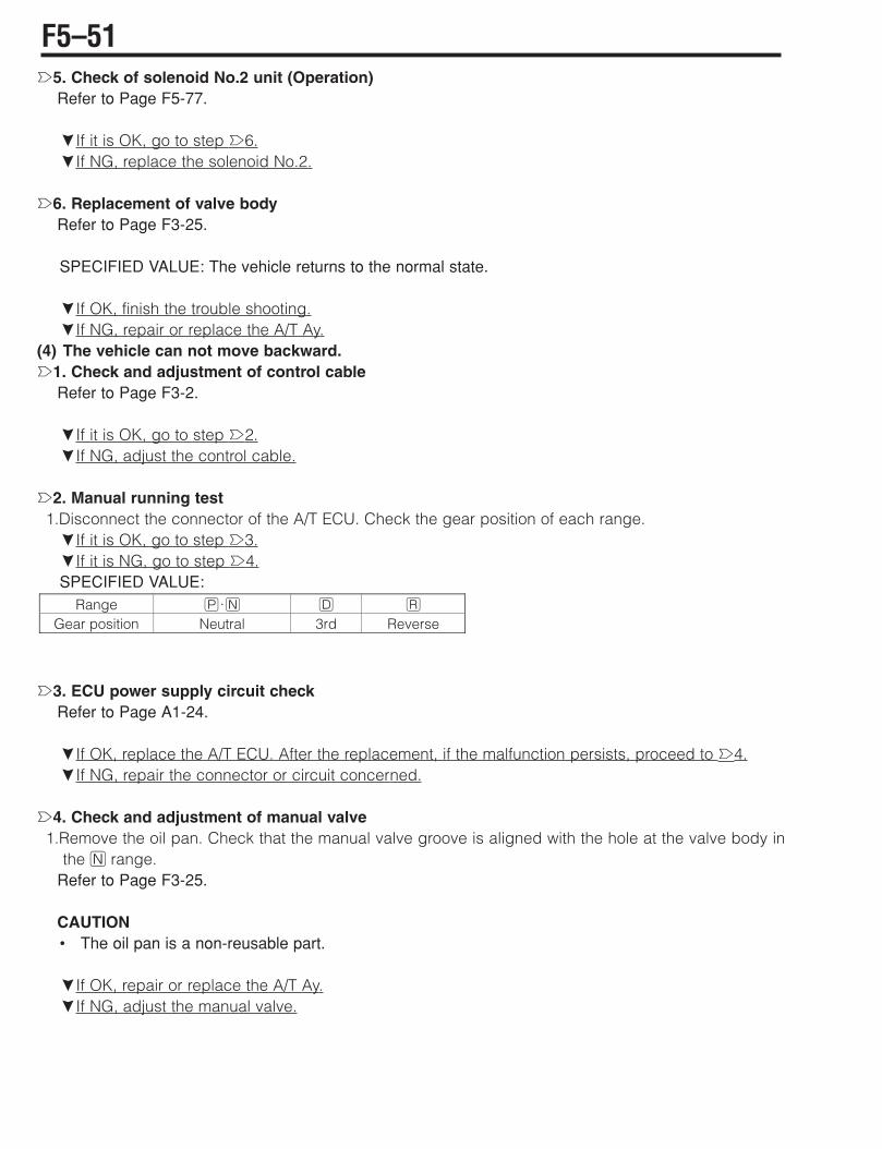
è5. Check of solenoid No.2 unit (Operation)Refer to Page F5-77.
çIf it is OK, go to step è6.çIf NG, replace the solenoid No.2.
è6. Replacement of valve bodyRefer to Page F3-25.
SPECIFIED VALUE: The vehicle returns to the normal state.
çIf OK, finish the trouble shooting.çIf NG, repair or replace the A/T Ay.
(4) The vehicle can not move backward.è1. Check and adjustment of control cable
Refer to Page F3-2.
çIf it is OK, go to step è2.çIf NG, adjust the control cable.
è2. Manual running test1.Disconnect the connector of the A/T ECU. Check the gear position of each range.çIf it is OK, go to step è3.çIf it is NG, go to step è4.SPECIFIED VALUE:
è3. ECU power supply circuit checkRefer to Page A1-24.
çIf OK, replace the A/T ECU. After the replacement, if the malfunction persists, proceed to è4.çIf NG, repair the connector or circuit concerned.
è4. Check and adjustment of manual valve1.Remove the oil pan. Check that the manual valve groove is aligned with the hole at the valve body in
the G range.Refer to Page F3-25.
CAUTION• The oil pan is a non-reusable part.
çIf OK, repair or replace the A/T Ay.çIf NG, adjust the manual valve.
Range H;G D I
Gear position Neutral 3rd Reverse
F5–51

(5) The engine stalls during G!D;Iè1. Check of idle speed1.Check the idle speed.
(1) Type K3-VE engine-mounted vehicleRefer to Page B1-25.
çIf it is OK, go to step è2.çIf NG, repair the engine idle system.
è2. Check of duty solenoid, LUC solenoid unit (Operation)Refer to Page F5-77.
Refer to Page F5-78.
çIf it is OK, go to step è2.çIf NG, replace the solenoid concerned.
è3. Replacement of valve bodyRefer to Page F3-25.
SPECIFIED VALUE: The vehicle returns to the normal state.
çIf OK, finish the trouble shooting.çIf NG, replace the torque converter Ay.
(6) The clutch is slipping during the 1st gear running.è1. Check of oil level
Refer to Page F3-1.
çIf it is OK, go to step è2.çIf NG, adjust the oil level.
è2. Check and adjustment of control cableRefer to Page F3-2.
çIf it is OK, go to step è3.çIf NG, adjust the control cable.
è3. Manual running test1.Disconnect the connector of the A/T ECU. Check the gear position of each range.çIf it is OK, go to step è4.çIf it is NG, go to step è5.SPECIFIED VALUE:
è4. Check of ECU power supply circuit Refer to Page A1-24.
çIf OK, replace the A/T ECU. After the replacement, if the malfunction persists, proceed to è5.çIf NG, repair the connector or circuit concerned.
Range H;G D I
Gear position Neutral 3rd Reverse
F5–52

è5. Check of strainer1.Replace the oil pan and strainer. Check the O-ring of the strainer for cut and wear.çIf it is OK, go to step è6.çIf NG, replace the O-ring of the strainer.CAUTION• The O-ring is a non-reusable part. Hence, even in the case of OK, replace the O-ring.• The oil pan is a non-reusable part.
è6. Check and adjustment of manual valve1.Check that the manual valve groove is aligned with the hole at the valve body in the G range.
Refer to Page F3-25.
çIf it is OK, go to step è7.çIf NG, adjust the manual valve.
è7. Check of solenoid No.2 unit (Operation)Refer to Page F5-77.
çIf it is OK, go to step è8.çIf NG, replace the solenoid No.2.
è8. Replacement of valve bodyRefer to Page F3-25.
SPECIFIED VALUE: The vehicle returns to the normal state.
çIf OK, finish the trouble shooting.çIf NG, repair or replace the A/T Ay.
(7) The clutch is slipping during the 2nd gear running.è1. Check of oil level
Refer to Page F3-1.
çIf it is OK, go to step è2.çIf NG, adjust the oil level.
è2. Manual running test1.Disconnect the connector of the A/T ECU. Check the gear position of each range.çIf it is OK, go to step è3.çIf it is NG, go to step è4.SPECIFIED VALUE:
è3. Check of ECU power supply circuitRefer to Page A1-24..................................
çIf OK, replace the A/T ECU. After the replacement, if the malfunction persists, proceed to è4.çIf NG, repair the connector or circuit concerned.
Range H;G D I
Gear position Neutral 3rd Reverse
F5–53
è4. Check of strainer1.Remove the oil pan and strainer. Check the strainer O-ring for cut and wear.çIf it is OK, go to step è5.çIf NG, replace the strainer O-ring.CAUTION• The O-ring is a non-reusable part. Hence, even in the case of OK, replace the O-ring.• The O-ring is a non-reusable part.
è5. Check and adjustment of manual valve1.Check that the manual valve groove is aligned with the hole at the valve body in the G range.çIf it is OK, go to step è6.çIf NG, adjust the manual valve.
è6. Check of solenoid No1, solenoid No.2 units (Operation)Refer to Page F5-77.
Refer to Page F5-77.
çIf it is OK, go to step è7.çIf NG, replace the solenoid concerned.
è7. Check of the 2nd & 4th brake cylinder sealRefer to Page F3-25.
1.Check the 2nd & 4th brake cylinder seal for cut or wear.çIf it is OK, go to step è8.çIf NG, replace the 2nd & 4th brake cylinder seal.CAUTION• The 2nd & 4th brake cylinder seal is a non-reusable part. Hence, even in the case of OK, replace
the seal.
è8. Replacement of valve bodyRefer to Page F3-25.
SPECIFIED VALUE: The vehicle returns to the normal state.
çIf OK, finish the trouble shooting.çIf NG, repair or replace the A/T Ay.
(8) The clutch is slipping during the 3rd gear running.è1. Check of oil level
Refer to Page F3-1.
çIf it is OK, go to step è2.çIf NG, adjust the oil level.
F5–54

è2. Manual running test1.Disconnect the connector of the A/T ECU. Check the gear position of each range.çIf it is OK, go to step è3.çIf it is NG, go to step è4.SPECIFIED VALUE:
è3. Check of ECU power supply circuitRefer to Page A1-24.
çIf OK, replace the A/T ECU. After the replacement, if the malfunction persists, proceed to è4.çIf NG, repair the connector or circuit concerned.
è4. Check of strainer1.Remove the oil pan and strainer. Check the strainer O-ring for cut and wear.çIf it is OK, go to step è5.çIf NG, replace the strainer O-ring.CAUTION• The O-ring is a non-reusable part. Hence, even in the case of OK, replace the O-ring.
è5. Check and adjustment of manual valve1.Check that the manual valve groove is aligned with the hole at the valve body in the G range.
Refer to Page F3-25.
çIf it is OK, go to step è6.çIf NG, adjust the manual valve.
è6. Check of solenoid No2, solenoid No.3 and switch solenoid unit (Operation)Refer to Page F5-77.
Refer to Page F5-78.
çIf it is OK, go to step è7.çIf NG, replace the solenoid concerned.
è7. Replacement of valve bodyRefer to Page F3-25.
SPECIFIED VALUE: The vehicle returns to the normal state.
çIf OK, finish the trouble shooting.çIf NG, repair or replace the A/T Ay.
(9) The clutch is slipping during the 4th gear running.è1. Check of oil level
Refer to Page F3-1.
çIf it is OK, go to step è2.çIf NG, adjust the oil level.
Range H;G D I
Gear position Neutral 3rd Reverse
F5–55
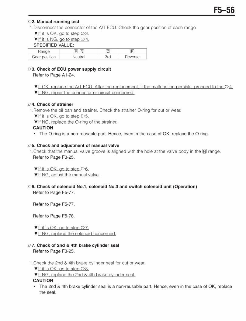
è2. Manual running test1.Disconnect the connector of the A/T ECU. Check the gear position of each range.çIf it is OK, go to step è3.çIf it is NG, go to step è4.SPECIFIED VALUE:
è3. Check of ECU power supply circuitRefer to Page A1-24.
çIf OK, replace the A/T ECU. After the replacement, if the malfunction persists, proceed to the è4.çIf NG, repair the connector or circuit concerned.
è4. Check of strainer1.Remove the oil pan and strainer. Check the strainer O-ring for cut or wear.çIf it is OK, go to step è5.çIf NG, replace the O-ring of the strainer.CAUTION• The O-ring is a non-reusable part. Hence, even in the case of OK, replace the O-ring.
è5. Check and adjustment of manual valve1.Check that the manual valve groove is aligned with the hole at the valve body in the G range.
Refer to Page F3-25.
çIf it is OK, go to step è6.çIf NG, adjust the manual valve.
è6. Check of solenoid No.1, solenoid No.3 and switch solenoid unit (Operation)Refer to Page F5-77.
Refer to Page F5-77.
Refer to Page F5-78.
çIf it is OK, go to step è7.çIf NG, replace the solenoid concerned.
è7. Check of 2nd & 4th brake cylinder sealRefer to Page F3-25.
1.Check the 2nd & 4th brake cylinder seal for cut or wear.çIf it is OK, go to step è8.çIf NG, replace the 2nd & 4th brake cylinder seal.CAUTION• The 2nd & 4th brake cylinder seal is a non-reusable part. Hence, even in the case of OK, replace
the seal.
Range H;G D I
Gear position Neutral 3rd Reverse
F5–56

è8. Replacement of valve bodyRefer to Page F3-25.
SPECIFIED VALUE: The vehicle returns to the normal state.
çIf OK, finish the trouble shooting.çIf NG, repair or replace the A/T Ay.
(10) The clutch is slipping during the I range running.è1. Check of oil level
Refer to Page F3-1.
çIf it is OK, go to step è2.çIf NG, adjust the oil level.
è2. Check and adjustment of control cableRefer to Page F3-2.
çIf it is OK, go to step è3.çIf NG, adjust the control cable.
è3. Manual running test1.Disconnect the connector of the A/T ECU. Check the gear position of each range.çIf it is OK, go to step è4.çIf it is NG, go to step è5.SPECIFIED VALUE:
è4. Check of ECU power supply circuitRefer to Page A1-24.
çIf OK, replace the A/T ECU. After the replacement, if the malfunction persists, proceed to the è5.çIf NG, repair the connector or circuit concerned.
è5. Check of strainer1.Remove the oil pan and strainer. Check the strainer O-ring for cut or wear.çIf it is OK, go to step è6.çIf NG, replace the O-ring of the strainer.CAUTION• The O-ring is a non-reusable part. Hence, even in the case of OK, replace the O-ring.
è6. Check and adjustment of manual valve1.Check that the manual valve groove is aligned with the hole at the valve body in the G range.
Refer to Page F3-25.
çIf it is OK, go to step è7.çIf NG, adjust the manual valve.
Range H;G D I
Gear position Neutral 3rd Reverse
F5–57

è7. Check of solenoid No.3 and duty solenoid unit (Operation)Refer to Page F5-77.
Refer to Page F5-77.
çIf it is OK, go to step è8.çIf NG, replace the solenoid concerned.
è8. Replacement of valve bodyRefer to Page F3-25.
SPECIFIED VALUE: The vehicle returns to the normal state.
çIf OK, finish the trouble shooting.çIf NG, repair or replace the A/T Ay.
(11) The vehicle starts to move in the H or G range.è1. Check and adjustment of control cable
Refer to Page F3-2.
çIf it is OK, go to step è2.çIf NG, adjust the control cable.
è2. Check and adjustment of manual valve1.Remove the oil pan. Check that the manual valve groove is aligned with the hole at the valve body in
the G range.Refer to Page F3-25.
CAUTION• The oil pan is a non-reusable part.
çIf OK, replace the A/T Ay.çIf NG, adjust the manual valve.
(12) When the engine speed is raised in the G range, the vehicle starts to move.1.Repair or replace the A/T Ay.
(13) The engine starts in ranges other than H;G.è1. Check and adjustment of neutral start switch
Refer to Page F3-3.
çIf it is OK, go to step è2.çIf NG, adjust the neutral start switch position.
è2. Check and adjustment of control cableRefer to Page F3-2.
F5–58
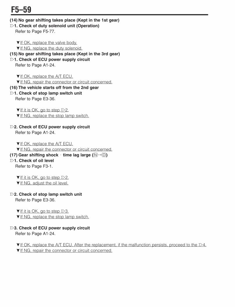
(14) No gear shifting takes place (Kept in the 1st gear)è1. Check of duty solenoid unit (Operation)
Refer to Page F5-77.
çIf OK, replace the valve body.çIf NG, replace the duty solenoid.
(15) No gear shifting takes place (Kept in the 3rd gear)è1. Check of ECU power supply circuit
Refer to Page A1-24.
çIf OK, replace the A/T ECU.çIf NG, repair the connector or circuit concerned.
(16) The vehicle starts off from the 2nd gearè1. Check of stop lamp switch unit
Refer to Page E3-36.
çIf it is OK, go to step è2.çIf NG, replace the stop lamp switch.
è2. Check of ECU power supply circuitRefer to Page A1-24.
çIf OK, replace the A/T ECU.çIf NG, repair the connector or circuit concerned.
(17) Gear shifting shock ; time lag large (G!D)è1. Check of oil level
Refer to Page F3-1.
çIf it is OK, go to step è2.çIf NG, adjust the oil level.
è2. Check of stop lamp switch unitRefer to Page E3-36.
çIf it is OK, go to step è3.çIf NG, replace the stop lamp switch.
è3. Check of ECU power supply circuitRefer to Page A1-24.
çIf OK, replace the A/T ECU. After the replacement, if the malfunction persists, proceed to the è4.çIf NG, repair the connector or circuit concerned.
F5–59
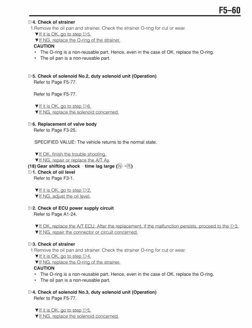
è4. Check of strainer1.Remove the oil pan and strainer. Check the strainer O-ring for cut or wear.çIf it is OK, go to step è5.çIf NG, replace the O-ring of the strainer.CAUTION• The O-ring is a non-reusable part. Hence, even in the case of OK, replace the O-ring.• The oil pan is a non-reusable part.
è5. Check of solenoid No.2, duty solenoid unit (Operation)Refer to Page F5-77.
Refer to Page F5-77.
çIf it is OK, go to step è6.çIf NG, replace the solenoid concerned.
è6. Replacement of valve bodyRefer to Page F3-25.
SPECIFIED VALUE: The vehicle returns to the normal state.
çIf OK, finish the trouble shooting.çIf NG, repair or replace the A/T Ay.
(18) Gear shifting shock ; time lag large (G!I)è1. Check of oil level
Refer to Page F3-1.
çIf it is OK, go to step è2.çIf NG, adjust the oil level.
è2. Check of ECU power supply circuitRefer to Page A1-24.
çIf OK, replace the A/T ECU. After the replacement, if the malfunction persists, proceed to the è3.çIf NG, repair the connector or circuit concerned.
è3. Check of strainer1.Remove the oil pan and strainer. Check the strainer O-ring for cut or wear.çIf it is OK, go to step è4.çIf NG, replace the O-ring of the strainer.CAUTION• The O-ring is a non-reusable part. Hence, even in the case of OK, replace the O-ring.• The oil pan is a non-reusable part.
è4. Check of solenoid No.3, duty solenoid unit (Operation)Refer to Page F5-77.
çIf it is OK, go to step è5.çIf NG, replace the solenoid concerned.
F5–60
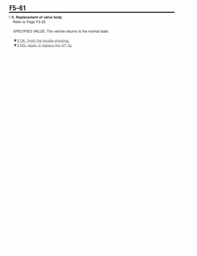
è5. Replacement of valve bodyRefer to Page F3-25.
SPECIFIED VALUE: The vehicle returns to the normal state.
çIf OK, finish the trouble shooting.çIf NG, repair or replace the A/T Ay.
F5–61
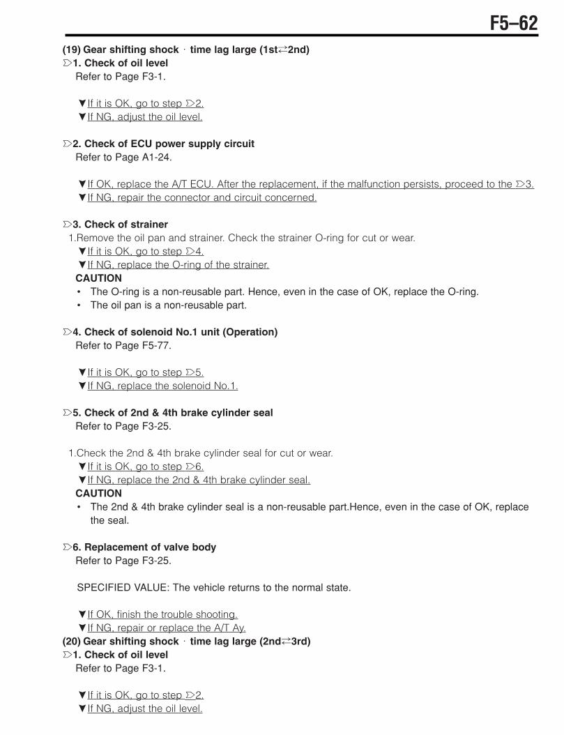
(19) Gear shifting shock ; time lag large (1st#2nd)è1. Check of oil level
Refer to Page F3-1.
çIf it is OK, go to step è2.çIf NG, adjust the oil level.
è2. Check of ECU power supply circuitRefer to Page A1-24.
çIf OK, replace the A/T ECU. After the replacement, if the malfunction persists, proceed to the è3.çIf NG, repair the connector and circuit concerned.
è3. Check of strainer1.Remove the oil pan and strainer. Check the strainer O-ring for cut or wear. çIf it is OK, go to step è4.çIf NG, replace the O-ring of the strainer.CAUTION• The O-ring is a non-reusable part. Hence, even in the case of OK, replace the O-ring.• The oil pan is a non-reusable part.
è4. Check of solenoid No.1 unit (Operation)Refer to Page F5-77.
çIf it is OK, go to step è5.çIf NG, replace the solenoid No.1.
è5. Check of 2nd & 4th brake cylinder sealRefer to Page F3-25.
1.Check the 2nd & 4th brake cylinder seal for cut or wear.çIf it is OK, go to step è6.çIf NG, replace the 2nd & 4th brake cylinder seal.CAUTION• The 2nd & 4th brake cylinder seal is a non-reusable part.Hence, even in the case of OK, replace
the seal.
è6. Replacement of valve bodyRefer to Page F3-25.
SPECIFIED VALUE: The vehicle returns to the normal state.
çIf OK, finish the trouble shooting.çIf NG, repair or replace the A/T Ay.
(20) Gear shifting shock ; time lag large (2nd#3rd)è1. Check of oil level
Refer to Page F3-1.
çIf it is OK, go to step è2.çIf NG, adjust the oil level.
F5–62

è2. Check of ECU power supply circuitRefer to Page A1-24.
çIf OK, replace the A/T ECU. After the replacement, if the malfunction persists, proceed to the è3.çIf NG, repair the connector or circuit concerned.
è3. Check of strainer1.Remove the oil pan and strainer. Check the strainer O-ring for cut or wear.çIf it is OK, go to step è4.çIf NG, replace the O-ring of the strainer.CAUTION• The O-ring is a non-reusable part. Hence, even in the case of OK, replace the O-ring.• The oil pan is a non-reusable part.
è4. Check of solenoid No.3 and solenoid No.1 unit (Operation)Refer to Page F5-77.
Refer to Page F5-77.
çIf it is OK, go to step è5.çIf NG, replace the solenoid concerned.
è5. Check of 2nd & 4th brake cylinder sealRefer to Page F3-25.
1.Check the 2nd & 4th brake cylinder seal for cut or wear.çIf it is OK, go to step è6.çIf NG, replace the 2nd & 4th brake cylinder seal.CAUTION• The 2nd & 4th brake cylinder seal is a non-reusable part. Hence, even in the case of OK, replace
the seal.
è6. Replacement of valve bodyRefer to Page F3-25.
SPECIFIED VALUE: The vehicle returns to the normal state.
çIf OK, finish the trouble shooting.çIf NG, repair or replace the A/T Ay.
(21) Gear shifting shock; time lag large (3rd#4th)è1. Check of oil level
Refer to Page F3-1.
çIf it is OK, go to step è2.çIf NG, adjust the oil level.
F5–63
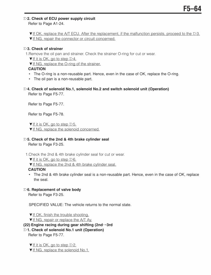
è2. Check of ECU power supply circuitRefer to Page A1-24.
çIf OK, replace the A/T ECU. After the replacement, if the malfunction persists, proceed to the è3.çIf NG, repair the connector or circuit concerned.
è3. Check of strainer1.Remove the oil pan and strainer. Check the strainer O-ring for cut or wear.çIf it is OK, go to step è4.çIf NG, replace the O-ring of the strainer.CAUTION• The O-ring is a non-reusable part. Hence, even in the case of OK, replace the O-ring.• The oil pan is a non-reusable part.
è4. Check of solenoid No.1, solenoid No.2 and switch solenoid unit (Operation)Refer to Page F5-77.
Refer to Page F5-77.
Refer to Page F5-78.
çIf it is OK, go to step è5.çIf NG, replace the solenoid concerned.
è5. Check of the 2nd & 4th brake cylinder sealRefer to Page F3-25.
1.Check the 2nd & 4th brake cylinder seal for cut or wear.çIf it is OK, go to step è6.çIf NG, replace the 2nd & 4th brake cylinder seal.CAUTION• The 2nd & 4th brake cylinder seal is a non-reusable part. Hence, even in the case of OK, replace
the seal.
è6. Replacement of valve bodyRefer to Page F3-25.
SPECIFIED VALUE: The vehicle returns to the normal state.
çIf OK, finish the trouble shooting.çIf NG, repair or replace the A/T Ay.
(22) Engine racing during gear shifting (2nd!3rdè1. Check of solenoid No.1 unit (Operation)
Refer to Page F5-77.
çIf it is OK, go to step è2.çIf NG, replace the solenoid No.1.
F5–64

è2. Check of ECU power supply circuitRefer to Page A1-24.
çIf OK, replace the A/T ECU. After the replacement, if the malfunction persists, proceed to the è3.çIf NG, repair the connector or circuit concerned.
è3. Check of 2nd & 4th brake cylinder sealRefer to Page F3-25.
1.Check the 2nd & 4th brake cylinder seal for cut or wear.çIf it is OK, go to step è4.çIf NG, replace the 2nd & 4th brake cylinder seal.CAUTION• The 2nd & 4th brake cylinder seal is a non-reusable part. Hence, even in the case of OK, replace
the seal.
è4. Replacement of valve bodyRefer to Page F3-25.
SPECIFIED VALUE: The vehicle returns to the normal state.
çIf OK, finish the trouble shooting.çIf NG, repair or replace the A/T Ay.
(23) The engine racing during the gear shifting (3rd!4th)è1. Check of solenoid No.2 unit (Operation)
Refer to Page F5-77.
çIf it is OK, go to step è2.çIf NG, replace the solenoid No.2.
è2. Check of ECU power supply circuitRefer to Page A1-24.
çIf OK, replace the A/T ECU. After the replacement, if the malfunction persists, proceed to the è3.çIf NG, repair the connector or circuit concerned.
è3. Check of 2nd & 4th brake cylinder sealRefer to Page F3-25.
1.Check the 2nd & 4th brake cylinder seal for cut or wear.çIf it is OK, go to step è4.çIf NG, replace the 2nd & 4th brake cylinder seal.CAUTION• The 2nd & 4th brake cylinder seal is a non-reusable part. Hence, even in the case of OK, replace
the seal.
F5–65

è4. Replacement of valve bodyRefer to Page F3-25.
SPECIFIED VALUE: The vehicle returns to the normal state.
çIf OK, finish the trouble shooting.çIf NG, repair or replace the A/T Ay.
(24) The gear shifting takes place only for 1st#3rdè1. Check of ECU power supply circuit
Refer to Page A1-24.
çIf OK, replace the A/T ECU. After the replacement, if the malfunction persists, proceed to the è2.çIf NG, repair the connector or circuit concerned.
è2. Replacement of valve bodyRefer to Page F3-25.
SPECIFIED VALUE: The vehicle returns to the normal state.
çIf OK, finish the trouble shooting.çIf NG, repair or replace the A/T Ay.
F5–66
3-15 UNIT CHECK3-15-1 TURBINE REVOLUTION SENSOR,OUTPUT REVOLUTION SENSOR1.As for the turbine revolution sensor and output revolution sensor, it is impossible to evaluate good/bad
of their individual performance because of their construction. Hence, make a total evaluation, usingthe trouble-shooting according to diagnosis codes (No.37, 42) and transmission control computerinput / output signal check (Oscilloscope waveform ).
Refer to Page F5-31.
Refer to Page F5-34.
Refer to Page F5-79.
F5–67
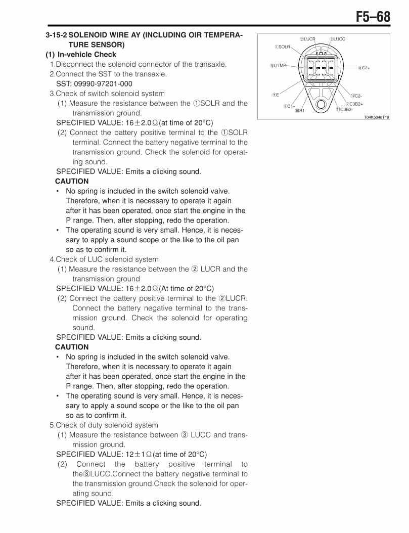
3-15-2 SOLENOID WIRE AY (INCLUDING OIR TEMPERA-TURE SENSOR)
(1) In-vehicle Check1.Disconnect the solenoid connector of the transaxle.2.Connect the SST to the transaxle.
SST: 09990-97201-0003.Check of switch solenoid system
(1) Measure the resistance between the 1SOLR and thetransmission ground.
SPECIFIED VALUE: 16&2.0+(at time of 20°C)(2) Connect the battery positive terminal to the 1SOLR
terminal. Connect the battery negative terminal to thetransmission ground. Check the solenoid for operat-ing sound.
SPECIFIED VALUE: Emits a clicking sound.CAUTION• No spring is included in the switch solenoid valve.
Therefore, when it is necessary to operate it againafter it has been operated, once start the engine in theP range. Then, after stopping, redo the operation.
• The operating sound is very small. Hence, it is neces-sary to apply a sound scope or the like to the oil panso as to confirm it.
4.Check of LUC solenoid system(1) Measure the resistance between the 2 LUCR and the
transmission groundSPECIFIED VALUE: 16&2.0+(At time of 20°C)(2) Connect the battery positive terminal to the 2LUCR.
Connect the battery negative terminal to the trans-mission ground. Check the solenoid for operatingsound.
SPECIFIED VALUE: Emits a clicking sound.CAUTION• No spring is included in the switch solenoid valve.
Therefore, when it is necessary to operate it againafter it has been operated, once start the engine in theP range. Then, after stopping, redo the operation.
• The operating sound is very small. Hence, it is neces-sary to apply a sound scope or the like to the oil panso as to confirm it.
5.Check of duty solenoid system(1) Measure the resistance between 3 LUCC and trans-
mission ground.SPECIFIED VALUE: 12&1+(at time of 20°C)(2) Connect the battery positive terminal to
the3LUCC.Connect the battery negative terminal tothe transmission ground.Check the solenoid for oper-ating sound.
SPECIFIED VALUE: Emits a clicking sound.
F5–68
T04K5048T10
1SOLR
6B1+!0B1-
5OTMP
9E
2LUCR 3LUCC
7C3B2+!1C3B2-
!2C2-
8C2+

6.Check of oil temperature sensor system(1) Measure the resistance between 5OTMP and 9E.SPECIFIED VALUE: 5.63&0.56k+(0°C)
0.072&0.0022k+(140°C)
NOTE• About 2.4k+(20°C)
about 0.313k+(80°C)
CAUTION• The final evaluation shall be carried out in the next unit check given below.
7.Check of solenoid No.1 system(1) Measure the resistance between 6B1' and !B1(.SPECIFIED VALUE: 5.3&0.3+(At time of 20°C)
(2) Connect the battery positive terminal to the 6B1' with a bulb of 12V(21W interposed.Connectthe battery negative terminal to the !B1(. Check for the operating sound of the solenoid.
SPECIFIED VALUE: Emits a clicking sound.
CAUTION• Never directly apply the battery voltage. (Do not allow a current of 1A or more to flow) Carry out
the operation check through the specified bulb (resistance).• If a current of 1A or more is allowed to flow, the solenoid characteristics will be changed.
8.Check of solenoid No.2 system(1) Measure the resistance between the 8C2' and the #C2(.SPECIFIED VALUE: 5.3&0.2+(at time of 20°C)
(2) Connect the battery positive terminal to the 8C2' with a bulb of 12V(21W interposed. Connectthe battery negative terminal to the #C2(. Check for the operating sound of the solenoid.
SPECIFIED VALUE: Emits a clicking sound.
CAUTION• Never directly apply the battery voltage. (Do not allow a current of 1A or more to flow.) Carry out
the operation check through the specified bulb (Resistance).• If a current of 1A or more is allowed to flow, the solenoid characteristics will be changed.
9.Check of solenoid No.3 system(1) 7C3B2' - "C3B2(SPECIFIED VALUE: 5.3&0.2+(At time of 20°C)
(2) Connect the battery positive terminal to the 7C3B2' with a bulb of 12V(21W interposed.Connect the battery negative terminal to the "C3B2(. Check for the operating sound of the sole-noid.
SPECIFIED VALUE: Emits a clicking sound.
F5–69

CAUTION• Never directly apply the battery voltage. (Do not allow a current of 1A or more to flow.) Carry out
the operation check through the specified bulb (Resistance).• If a current of 1 A or more is allowed to flow, the solenoid characteristics will be changed.
(2) Unit Check1.Remove the solenoid wire Ay from the transaxle.
Refer to Page F3-25.
2.Check continuity between the following terminals given below.SPECIFIED VALUE: Continuity exists.
(1) Switch solenoid systemBetween solenoid connector 1 and switch solenoid connector 1 (SOLR)
(2) LUC solenoid systemBetween solenoid connector 2 and LUC solenoid connector 1 (LUCR)
(3) Duty solenoid systemBetween solenoid connector 3 and duty solenoid connector 1 (LUCC)
(4) Solenoid No.1 systemBetween solenoid connector 6 and solenoid No.1 connector 1 (B1')Between solenoid connector ! and solenoid No.1 connector 2 (B1()
(5) Solenoid No.2 systemBetween solenoid connector 8 and solenoid No.2 connector 1 (C2')Between solenoid connector # and solenoid No.2 connector 2 (C2()
(6) Solenoid No.3 systemBetween solenoid connector 7 and solenoid No.3 connector 1 (C3B2')Between solenoid connector " and solenoid No.3 connector 2 (C3B2()3.Oil temperature sensor system
(1) Measure the resistance between solenoid connectors 5OTMP and 9E.SPECIFIED VALUE: 5.63&0.56k+(0°C)
0.072&0.0022k+(140°C)
4.Ensure that there is no short-circuit between connector terminals.
1211109
5
1 2 3
6 7 8
1 1 1 1
1
1
222
SOLR
SOLR
OTMP
LUCR
LUCR
LUCCLUCC
E
B1-
B1+
B1+ B1-
C2-C2+
C2+ C2-
C3B2-C3B2+
C3B2+ C3B2-
Solenoid connector
Solenoid No.2connector(Black)
Solenoid No.1connector(White)
Solenoid No.3connector(Black)
T0NK5002ES16
Fluid temperaturesensor
Duty solenoid connector(Yellow)
LUC solenoid connector(Blue)
Switch solenoid connector(Gray)
F5–70

3-15-3 SOLENOID NO.1 1.Operation check
(1) Connect the battery positive terminal to the terminal 1with a bulb of 12V(21W interposed. Connect thebattery negative terminal to the terminal 2. Check thatthe valve inside the solenoid is working.
CAUTION• Never directly apply the battery voltage. (Do not allow
a current of 1A or more to flow.) Carry out the opera-tion check through the specified bulb (Resistance)
• If a current of 1A or more is allowed to flow, the sole-noid characteristics will be changed.
2.Resistance check (1) Measure the resistance between terminals 1 and 2.SPECIFIED VALUE: 5.3&0.3+(At time of 20°C)
3-15-4 SOLENOID NO.2, SOLENOID NO.31.Operation check
(1) Connect the battery positive terminal to the terminal 1with a bulb of 12V(21W interposed. Connect thebattery negative terminal to the terminal 2. Check thatthe valve inside the solenoid is working.
CAUTION• Never directly apply the battery voltage. (Do not allow
a current of 1A or more to flow.) Carry out the opera-tion check through the specified valve (Resistance)
• If a current of 1 A or more is allowed to flow, the sole-noid characteristics will be changed.
2.Resistance check (1) Measure the resistance between the terminals 1 and 2.SPECIFIED VALUE: 5.3&0.2+(At time of 20°C)
3-15-5 DUTY SOLENOID1.Operation check
(1) Connect the battery positive terminal to the solenoid terminal. Connect the battery negative termi-nal to the solenoid body. Check that the valve inside the solenoid is working.
2.Resistance check (1) Check the resistance between the solenoid terminal and solenoid body.SPECIFIED VALUE: 12&1+(At time of 20°C)
F5–71
T04K5034T10
2 1
'
'
(
(
T04K5033T10
2
'
'
(
(
1

3-15-6 LUC SOLENOID, SWITCH SOLENOID1.Operation check
(1) Connect the battery positive terminal to the solenoid terminal. Connect the battery negative termi-nal to the solenoid body. Check that the valve inside the solenoid is working.
CAUTION• No spring is included in the LUC solenoid, switch solenoid valve. Therefore, when you want to
operate it again after it has been operated, shake the solenoid or return the valve position by push-ing the ball. (When you want to return the valve position on the vehicle, start the engine in the Prange.)
2.Resistance check (1) Check the resistance between the solenoid terminal and solenoid body.SPECIFIED VALUE: 16&2.0+(at time of 20°C)
3-15-7 NEUTRAL START SWITCH1.Carry out the continuity check, based on the connection
table.
3-15-8 O/D OFF SWITCH1.Carry out the continuity check, based on the connection
table.
P
R
N
D
2
L
Shift positionTerminal No. E
:Continuity should exist
R11K6110EL10
R RB P N D 2 L
F5–72
R11K6021T10
P D 2 R
L RB E N
O/D switch
12
34
T11K5525ET16
O/D( O/D'
O/D ON
Selection
O/D OFF
O/D+ O/D-Terminal name

3-16 ECU INPUT/OUTPUT SIGNAL CHECK3-16-1 CHECKING METHOD1.Check the voltage, pulse and continuity between each terminal, using the SST.
SST: 09842-97215-000
2.As for those items where no specific measuring conditions are provided, perform checks with theengine stopped and the IG SW turned ON.
F5–73
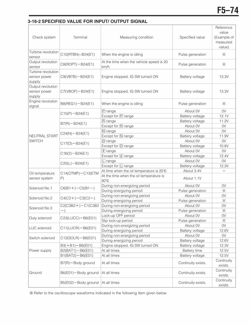
3-16-2 SPECIFIED VALUE FOR INPUT/ OUTPUT SIGNAL
~:Refer to the oscilloscope waveforms indicated in the following Item given below.
Check system Terminal Measuring condition Specified value
Reference value
(Example of measured
value) Turbine revolution sensor
C10(RTBN)~B24(E1) When the engine is idling Pulse generation ~
Output revolution sensor
C8(ROPT)(B24(E1) At the time when the vehicle speed is 20 km/h
Pulse generation ~
Turbine revolution sensor power supply
C9(VBTB)(B24(E1) Engine stopped, IG SW turned ON Battery voltage 13.3V
Output revolution sensor power supply
C7(VBOP)(B24(E1) Engine stopped, IG SW turned ON Battery voltage 13.3V
Engine revolution signal
B8(REG1)(B24(E1) When the engine is idling Pulse generation ~
H range About 0V 0V C15(P)(B24(E1)
Except for H range Battery voltage 12.1V I range Battery voltage 11.2V
B7(R)(B24(E1) Except for I range About 0V 0V G range About 0V 0V
C24(N)(B24(E1) Except for G range Battery voltage 11.9V D range About 0V 0V
C17(D)(B24(E1) Except for D range Battery voltage 10.8V L range About 0V 0V
C16(2)(B24(E1) Except for L range Battery voltage 12.4V F range About 0V 0V
NEUTRAL START SWITCH
C25(L)(B24(E1) Except for F range Battery voltage 12.3V At time when the oil temperature is 20 About 3.4V (
Oil temperature sensor system
C14(OTMP)(C13(ETMP)
At the time when the oil temperature is 80
About 1.1V
During non-energizing period About 0V 0V Solenoid No.1 C6(B1')(C5(B1()
During energizing period Pulse generation ~
During non-energizing period About 0V 0V Solenoid No.2 C4(C2')(C3(C2()
During energizing period Pulse generation ~
During non-energizing period About 0V 0V Solenoid No.3
C2(C3B2')(C1(C3B2() During energizing period Pulse generation ~
Lock-up OFF period About 0V 0V Duty solenoid C23(LUCC)(B6(E01)
Slip lock-up period Pulse generation ~
During non-energizing period About 0V 0V LUC solenoid C11(LUCR)(B6(E01)
During energizing period Battery voltage 12.6V During non-energizing period About 0V 0V
Switch solenoid C12(SOLR)(B6(E01) During energizing period Battery voltage 12.6V
B3('B1)(B6(E01) Engine stopped, IG SW turned ON Battery voltage 12.3V B2(BAT1)(B6(E01) At all times Battery time 12.5V Power supply B1(BAT2)(B6(E01) At all times Battery voltage 12.5V
B7(R)(Body ground At all times Continuity exists. Continuity
exists.
B6(E01)(Body ground At all times Continuity exists. Continuity
exists. Ground
B5(E02)(Body ground At all times Continuity exists. Continuity
exists.
F5–74
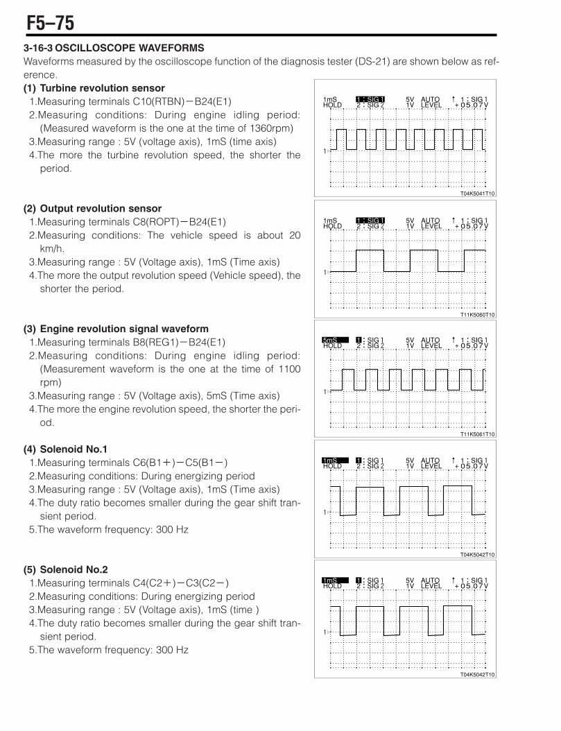
3-16-3 OSCILLOSCOPE WAVEFORMSWaveforms measured by the oscilloscope function of the diagnosis tester (DS-21) are shown below as ref-erence.(1) Turbine revolution sensor 1.Measuring terminals C10(RTBN)(B24(E1)2.Measuring conditions: During engine idling period:
(Measured waveform is the one at the time of 1360rpm)3.Measuring range : 5V (voltage axis), 1mS (time axis) 4.The more the turbine revolution speed, the shorter the
period.
(2) Output revolution sensor1.Measuring terminals C8(ROPT)(B24(E1)2.Measuring conditions: The vehicle speed is about 20
km/h.3.Measuring range : 5V (Voltage axis), 1mS (Time axis) 4.The more the output revolution speed (Vehicle speed), the
shorter the period.
(3) Engine revolution signal waveform1.Measuring terminals B8(REG1)(B24(E1)2.Measuring conditions: During engine idling period:
(Measurement waveform is the one at the time of 1100rpm)
3.Measuring range : 5V (Voltage axis), 5mS (Time axis) 4.The more the engine revolution speed, the shorter the peri-
od.
(4) Solenoid No.11.Measuring terminals C6(B1')(C5(B1()2.Measuring conditions: During energizing period 3.Measuring range : 5V (Voltage axis), 1mS (Time axis) 4.The duty ratio becomes smaller during the gear shift tran-
sient period.5.The waveform frequency: 300 Hz
(5) Solenoid No.21.Measuring terminals C4(C2')(C3(C2()2.Measuring conditions: During energizing period 3.Measuring range : 5V (Voltage axis), 1mS (time ) 4.The duty ratio becomes smaller during the gear shift tran-
sient period.5.The waveform frequency: 300 Hz
F5–75
T04K5041T10
T11K5060T10
T11K5061T10
T04K5042T10
T04K5042T10
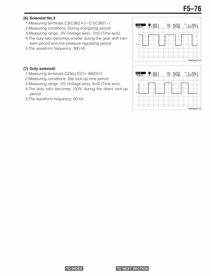
(6) Solenoid No.31.Measuring terminals C2(C3B2')(C1(C3B2()2.Measuring conditions: During energizing period3.Measuring range : 5V (Voltage axis), 1mS (Time axis) 4.The duty ratio becomes smaller during the gear shift tran-
sient period and line pressure regulating period 5.The waveform frequency: 300 Hz
(7) Duty solenoid 1.Measuring terminals C23(LUCC)(B6(E01)2.Measuring conditions: Slip lock-up time period 3.Measuring range : 5V (Voltage axis), 5mS (Time axis) 4.The duty ratio becomes 100% during the direct lock-up
period.5.The waveform frequency: 60 Hz
F5–76
T04K5042T10
T04K5043T10
TO INDEX TO NEXT SECTION