Copyright Declaration - Statcon Energiaa
76
MANUAL_HBD_EN_071220_V1.0 Page 1 of 76 VERSION 1.0 Copyright Declaration The copyright of this manual exclusively belongs to STATCON ENERGIAA PVT. LTD. Any corporation of individual should not plagiarize, partially copy or fully copy (including software, etc.) it and reproduction or distribution of it any from or by any means is not permitted. All rights reserved STATCON ENERGIAA PVT. LTD. Reserves the right of final interpretation. This document is subject to changes without notice. This is valid only for HBD model machines. It is not other custom built model/rating.
-
Upload
khangminh22 -
Category
Documents
-
view
9 -
download
0
Transcript of Copyright Declaration - Statcon Energiaa
MANUAL_HBD_EN_071220_V1.0 Page 1 of 76 VERSION 1.0
Copyright Declaration The copyright of this manual exclusively belongs to STATCON ENERGIAA PVT. LTD. Any corporation of individual should not plagiarize, partially copy or fully copy (including software, etc.) it and reproduction or distribution of it any from or by any means is not permitted. All rights reserved STATCON ENERGIAA PVT. LTD. Reserves the right of final interpretation. This document is subject to changes without notice. This is valid only for HBD model machines. It is not other custom built model/rating.
MANUAL_HBD_EN_071220_V1.0 Page 2 of 76 VERSION 1.0
Contents Copyright Declaration............................................................................................................................................. 1
1. NOTES ON THE MANUAL .................................................................................................................................... 5
1.1 SCOPE OF VALIDITY ........................................................................................................................................... 5
1.2 TARGET AUDIENCE ............................................................................................................................................ 5
1.3 SYMBOLS USED................................................................................................................................................. 5
2. INTRODUCTION .................................................................................................................................................. 6
2.1 PRODUCT DESCRIPTION..................................................................................................................................... 6
2.2 KEY ELEMENTS OF MACHINE ............................................................................................................................. 7
2.1.a MPPT BASED SOLAR CHARGE CONTROLLER ............................................................................................... 7
2.1.b BIDIRECTIONAL INVERTER ......................................................................................................................... 7
2.1.c AUTO BYPASS ARRANGEMENT ................................................................................................................... 7
2.1.d DISPLAY KEYPAD UNIT ............................................................................................................................... 7
2.1.e EMERGENCY STOP ..................................................................................................................................... 7
2.1.f Remote Monitoring System (Optional) ....................................................................................................... 7
2.3 PRODUCT NOMENCLATURE ............................................................................................................................... 8
2.4 RATING PLATE & ITS TERMS............................................................................................................................... 9
2.5 PHYSICAL APPEARANCE & TERMINATION DETAILS OF INVERTERS.................................................................... 10
2.6 1KVA-4KVA SINGLE PHASE INVERTER WITH SINGLE CHANNEL MPPT CHARGE CONTROLLER ........................... 11
2.6.1 4KVA-6KVA SINGLE PHASE INVERTER WITH SINGLE CHANNEL MPPT CHARGE CONTROLLER ........................ 11
2.6.2 8KVA-15KVA SINGLE PHASE INVERTER WITH SINGLE CHANNEL MPPT CHARGE CONTROLLER ...................... 12
2.6.3 10KVA-20KVA THREE PHASE/20KVA-25KVA SINGLE PHASE INVERTER WITH SINGLE CHANNELMPPT CHARGE CONTROLLER......................................................................................................................................................... 13
2.6.4 25KVA-40KVA 3-PHASE INVERTER WITH SINGLE MPPT CHARGE CONTROLLER ............................................. 14
2.6.5 50KVA-75KVA THREE PHASE INVERTER WITH SINGLE/THREE MPPT CHARGE CONTROLLER ........................... 14
2.6.6 80KVA-100KVA THREE PHASE INVERTER WITH SINGLE/THREE MPPT CHARGE CONTROLLER ....................... 16
2.6.7 ABOVE THAN 100KVA THREE PHASE INVERTER WITH THREE CHANNEL MPPT CHARGE ................................. 16
CONTROLLER......................................................................................................................................................... 16
3. INSTALLATION ...................................................................................................................................................... 17
3.1 UNPACKING & CONTENTS INSIDE .................................................................................................................... 17
3.2 PLACEMENT & LOCATION ................................................................................................................................ 18
3.3 WIRING PROCEDURES & ROUTES..................................................................................................................... 19
3.4 EARTHING OR GROUNDING THE MACHINE ...................................................................................................... 20
4. COMMISSIONING ................................................................................................................................................. 21
4.1 PRECHECKS BEFORE ENERGIZING .................................................................................................................... 21
4.2 FIRST TIME ENERGIZING THE MACHINE ........................................................................................................... 21
4.3 SETTINGS UPLOAD ........................................................................................................................................... 21
4.4 CHART-1 (LM BATTERY SETTINGS CHART) ........................................................................................................ 23
4.5 CHART-2 (VRLA BATTERY SETTINGS CHART) ..................................................................................................... 25
MANUAL_HBD_EN_071220_V1.0 Page 3 of 76 VERSION 1.0
4.6 CHART-3 (TUBLER GEL VRLA BATTERY SETTINGS CHART) ................................................................................. 27
4.7 POWER UP & LOAD TRANSFER ........................................................................................................................ 29
5. DISPLAY KEYPAD UNIT .......................................................................................................................................... 30
5.1 BUTTON DEFINATION ...................................................................................................................................... 30
5.2 DKU LED DESCRIPTION .................................................................................................................................... 30
5.3 DATE & TIME SETTINGS ................................................................................................................................... 31
5.4 SCROLLING PAGES ........................................................................................................................................... 31
5.4.1 HOME PAGE ............................................................................................................................................ 31
5.4.2 BATTERY AND PV STATUS SCREEN ........................................................................................................... 32
5.4.3 TEMPERATURE STATUS SCREEN .............................................................................................................. 33
5.4.4 AC PARAMETERS (PHASE-NEUTRAL) ........................................................................................................ 33
5.4.5 LINE TO LINE PARAMETER STATUS........................................................................................................... 34
5.4.6 CURRENT SCREEN .................................................................................................................................... 34
5.4.7 POWER SCREEN ....................................................................................................................................... 35
5.4.8 GENERATION SCREEN .............................................................................................................................. 36
5.4.9 ENVIRONMENTAL .................................................................................................................................... 36
5.5 TURN ON AND TURN OFF THE INVERTER UNIT................................................................................................. 36
5.6 FAULT RESET OF INVERTER .............................................................................................................................. 37
5.7 CHANGE OF SETTINGS ..................................................................................................................................... 37
5.8 BATTERY BOOST CYCLE/SETUP ........................................................................................................................ 40
5.9 PV DISPLAY ...................................................................................................................................................... 40
6. BATTERY & BATTERY CHARGING .......................................................................................................................... 41
6.1 BATTERY CHARGING TECHNIQUE IN SSSI RANGE OF INVERTERS ...................................................................... 41
6.2 MPPT BASED SOLAR CHARGE CONTROLLER ..................................................................................................... 41
6.3 GRID BASED CHARGER ..................................................................................................................................... 42
6.4 COMMON FEATURES ....................................................................................................................................... 42
6.5 BATTERY CURRENT LIMITING (BCL) .................................................................................................................. 42
6.6 THREE STAGE CHARGING (FLOAT, BULK AND EQUALIZE).................................................................................. 43
6.7 TEMPERATURE COMPENSATION FOR VRLA ..................................................................................................... 43
6.8 BOOST CYCLE ON START UP ............................................................................................................................. 43
6.9 BATTERY OVER VOLTAGE PROTECTION ............................................................................................................ 43
6.1.0 BATTERY UNDER VOLTAGE PROTECTION ...................................................................................................... 43
6.1.1 BATTERY TEST FACILITY ................................................................................................................................ 44
6.1.2 BATTERY CHARGING CURVE EXPLAINATION .................................................................................................. 44
STAGE 1: BULK CHARGE PERIOD .................................................................................................................... 44
STAGE 2: ABSORPTION OR EQUALIZE CHARGE PERIOD .................................................................................. 44
STAGE 3: TAPER TO FLOAT PERIOD ................................................................................................................ 44
STAGE 4: FLOAT TAPER CHARGE PERIOD........................................................................................................ 44
7. OPERATING MODES.............................................................................................................................................. 45
MANUAL_HBD_EN_071220_V1.0 Page 4 of 76 VERSION 1.0
7.1 OFF-GRID MODE .............................................................................................................................................. 46
7.2 HYBRID MODE ................................................................................................................................................. 48
7.3 HYBRID WITH EXPORT MODE .......................................................................................................................... 50
APPENDIX-1 .............................................................................................................................................................. 52
DISPLAY FAULT ANALYSIS ...................................................................................................................................... 52
APPENDIX-2 .............................................................................................................................................................. 55
SYSTEM CONFIGURATION ..................................................................................................................................... 55
1. FLOAT & BOOST CHARGING SETUP .................................................................................................................... 55
2. ALARM & TRIP SETTING ..................................................................................................................................... 55
3. BATTERY TEST SETUP ......................................................................................................................................... 56
4. INHIBIT & LATCH SETTINGS................................................................................................................................ 56
5. SYSTEM DEFINATION SETUP .............................................................................................................................. 56
6. METER CALIBRATION ......................................................................................................................................... 57
7. COMMUNICATION SETUP .................................................................................................................................. 57
8. AUTO SCHEDULE SETTINGS ............................................................................................................................... 58
9. FACTORY SETTINGS ........................................................................................................................................... 59
APPENDIX-3 .............................................................................................................................................................. 60
HOW TO SELECT OPERATING MODE OF YOUR CHOICE .......................................................................................... 60
A. OFF-GRID MODE ............................................................................................................................................ 60
B. HYBRID MODE ............................................................................................................................................... 60
C. HYBRID MODE WITH EXPORT ........................................................................................................................ 60
APPENDIX-4 .............................................................................................................................................................. 62
FORMULAE TO DETERMINE VARIOUS INPUTS/ OUTPUT PARAMETERS .................................................................. 62
APPENDIX-5 .............................................................................................................................................................. 63
CABLE SIZING CHART FOR INPUT/ OUTPUT CONNECTIONS .................................................................................... 63
APPENDIX-6 .............................................................................................................................................................. 64
PV MODULE ARRAY SERIES-PARALLEL ARRANGEMENT .......................................................................................... 64
APPENDIX-7 .............................................................................................................................................................. 66
BATTERY CHARGING CURRENT AS PER BANK SIZE ................................................................................................. 66
APPENDIX-8 .............................................................................................................................................................. 67
SINGLE PHASE SMART STORAGE SOLAR INVERTER DATASHEET ............................................................................. 67
APPENDIX-9 .............................................................................................................................................................. 69
THREE PHASE SMART STORAGE SOLAR INVERTER DATASHEET .............................................................................. 69
GENERAL WARRANTY APPLICABLE FOR STATCON ENERGIAA PRODUCTS ................................................................ 73
APPENDIX-10 ............................................................................................................................................................ 75
CUSTOMER FEEDBACK FORM ................................................................................................................................... 75

MANUAL_HBD_EN_071220_V1.0 Page 5 of 76 VERSION 1.0
1. NOTES ON THE MANUAL
1.1 SCOPE OF VALIDITY This manual is an integral part of inverter, and it describes the assembly, installation, commissioning, maintenance and failure analysis/ troubleshooting of hybrid inverters. List of inverters for which this operation manual is valid have been mentioned in the below list. This manual is valid for HBD inverters dispatched after 25. Sep. 2016. This manual is not applicable for Eco-HBD and other custom built ratings.
Table 1
keep this manual close to the machine where it is easily accessible for the operator/ end user.
1.2 TARGET AUDIENCE This manual is for qualified electricians. The tasks described in this manual can be performed by qualified electricians only.
1.3 SYMBOLS USED Following symbols will be used throughout the manual wherever applicable:
VERSION: The version of this manual is Version-1V1. This is valid only for HBD machines dispatched after
S. No Model S. No Model 1 HBD-048-003K-1P-003M1-11 16 HBD-240-010K-3P-010M1-11
2 HBD-096-005K-1P-005M1-11 17 HBD-240-12.5K-3P-12.5M1-11
3 HBD-096-006K-1P-006M1-11 18 HBD-240-015K-3P-015M1-11
4 HBD-096-008K-1P-008M1-11 19 HBD-240-020K-3P-020M1-11
5 HBD-120-008K-1P-008M1-11 20 HBD-240-025K-3P-025M1-11
6 HBD-120-010K-1P-010M1-11 21 HBD-240-030K-3P-030M1-11
7 HBD-240-010K-1P-010M1-11 22 HBD-240-040K-3P-040M1-11
8 HBD-240-12.5K-1P-12.5M1-11 23 HBD-240-050K-3P-050M1-11
9 HBD-240-015K-1P-015M1-11 24 HBD-240-060K-3P-060M3-11
10 HBD-240-020K-1P-020M1-11 25 HBD-240-080K-3P-080M3-11
11 HBD-240-025K-1P-025M1-11 26 HBD-240-100K-3P-100M3-11 12 HBD-120-010K-3P-010M1-11 27 HBD-360-100K-3P-100M3-11 13 HBD-120-12.5K-3P-12.5M1-11 28 HBD-360-150K-3P-150M3-11 14 HBD-120-015K-3P-015M1-11 29 HBD-360-200K-3P-200M3-11 15 HBD-120-020K-3P-020M1-11
NOTE: This manual may be applicable for other models as well on selective basis. In case your model of Inverter is not mentioned in the
above list, please contact manufacturer before using this manual.
DANGER! "Danger" indicates a hazardous situation which, if avoided, will result in death or serious injury.
Caution! Risk of electric shock!! Machine is working on high voltage. Do not touch, it may be burn or shocked the nearest person
WARNING! "Warning" indicates a hazardous situation which could result in death or serious injury if avoided
"Caution" indicates a hazardous situation which, if not followed could result in minor or moderate injury.
NOTE! "Note" provides tips that are valuable for the optimal operation of your product.
MANUAL_HBD_EN_071220_V1.0 Page 6 of 76 VERSION 1.0
2. INTRODUCTION
2.1 PRODUCT DESCRIPTION
Smart storage Solar Inverters (referred as SSSI from now) are also known as HBD range Inverters. These machines are mechanically and electrically robust with a wide operating temperature range and hence suitable for operation in harsh environments. These machines are a perfect fit for low maintenance, off grid/ Hybrid installations of both industrial and residential nature.
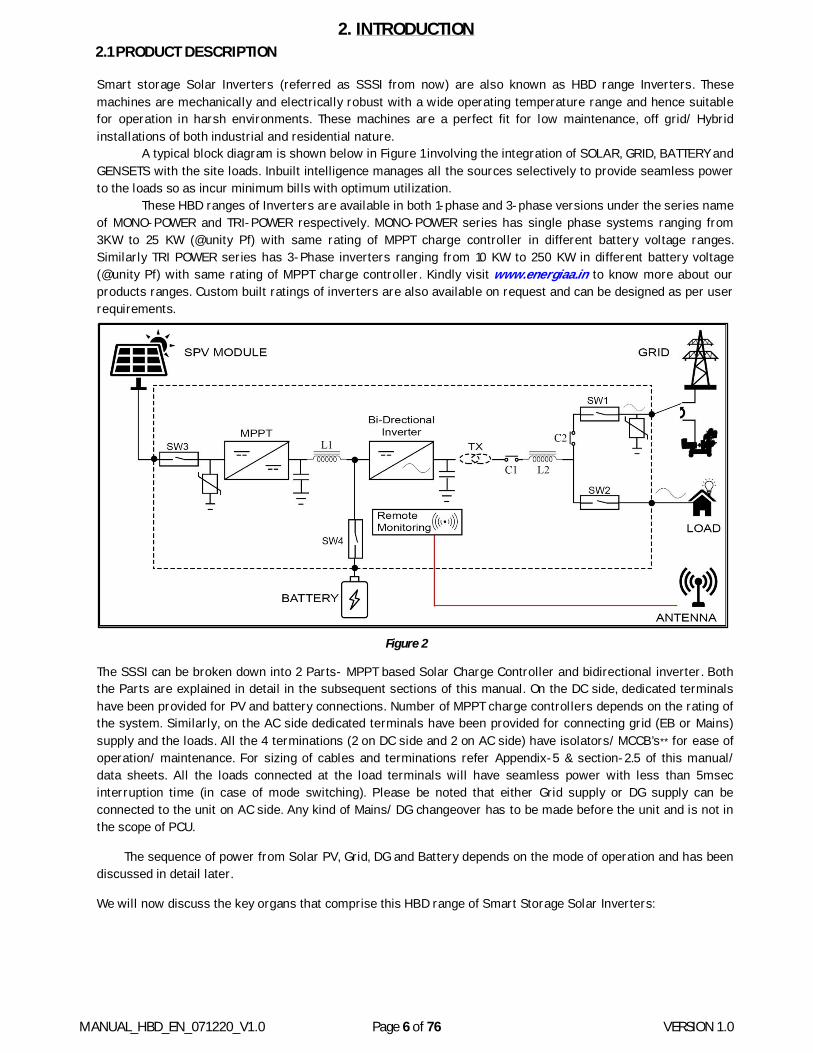
A typical block diagram is shown below in Figure 1 involving the integration of SOLAR, GRID, BATTERY and GENSETS with the site loads. Inbuilt intelligence manages all the sources selectively to provide seamless power to the loads so as incur minimum bills with optimum utilization.
These HBD ranges of Inverters are available in both 1-phase and 3-phase versions under the series name of MONO-POWER and TRI-POWER respectively. MONO-POWER series has single phase systems ranging from 3KW to 25 KW (@unity Pf) with same rating of MPPT charge controller in different battery voltage ranges. Similarly TRI POWER series has 3-Phase inverters ranging from 10 KW to 250 KW in different battery voltage (@unity Pf) with same rating of MPPT charge controller. Kindly visit www.energiaa.in to know more about our products ranges. Custom built ratings of inverters are also available on request and can be designed as per user requirements.
Figure 2
The SSSI can be broken down into 2 Parts- MPPT based Solar Charge Controller and bidirectional inverter. Both the Parts are explained in detail in the subsequent sections of this manual. On the DC side, dedicated terminals have been provided for PV and battery connections. Number of MPPT charge controllers depends on the rating of the system. Similarly, on the AC side dedicated terminals have been provided for connecting grid (EB or Mains) supply and the loads. All the 4 terminations (2 on DC side and 2 on AC side) have isolators/ MCCB’s** for ease of operation/ maintenance. For sizing of cables and terminations refer Appendix-5 & section-2.5 of this manual/ data sheets. All the loads connected at the load terminals will have seamless power with less than 5msec interruption time (in case of mode switching). Please be noted that either Grid supply or DG supply can be connected to the unit on AC side. Any kind of Mains/ DG changeover has to be made before the unit and is not in the scope of PCU.
The sequence of power from Solar PV, Grid, DG and Battery depends on the mode of operation and has been discussed in detail later.
We will now discuss the key organs that comprise this HBD range of Smart Storage Solar Inverters:
MANUAL_HBD_EN_071220_V1.0 Page 7 of 76 VERSION 1.0
2.2 KEY ELEMENTS OF MACHINE
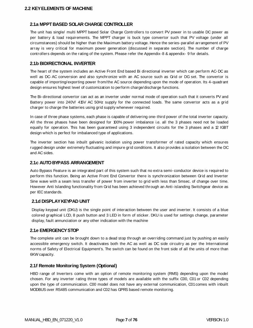
2.1.a MPPT BASED SOLAR CHARGE CONTROLLER The unit has single/ multi MPPT based Solar Charge Controllers to convert PV power in to usable DC power as per battery & load requirements. The MPPT charger is buck type convertor such that PV voltage (under all circumstances) should be higher than the Maximum battery voltage. Hence the series-parallel arrangement of PV array is very critical for maximum power generation (discussed in separate section). The number of charge controllers depends on the rating of the system. Please refer the Appendix-8 & appendix- 9 for details.
2.1.b BIDIRECTIONAL INVERTER The heart of the system includes an Active Front End based Bi directional inverter which can perform AC-DC as well as DC-AC conversion and also synchronize with an AC source such as Grid or DG set. The convertor is capable of importing/exporting power from/the AC source depending upon the mode of operation. Its 4-quadrant design ensures highest level of customization to perform charge/discharge functions.
The Bi-directional convertor can act as an inverter under normal mode of operation such that it converts PV and Battery power into 240V/ 415V AC 50Hz supply for the connected loads. The same convertor acts as a grid charger to charge the batteries using grid supply whenever required.
In case of three phase systems, each phase is capable of delivering one-third power of the total inverter capacity. All the three phases have been designed for 100% power imbalance i.e. all the 3 phases need not be loaded equally for operation. This has been guaranteed using 3 independent circuits for the 3 phases and a 12 IGBT design which is perfect for imbalanced type of applications.
The inverter section has inbuilt galvanic isolation using power transformer of rated capacity which ensures rugged design under extremely fluctuating and impure grid conditions. It also provides a isolation between the DC and AC sides.
2.1.c AUTO BYPASS ARRANGEMENT Auto Bypass Feature is an integrated part of this system such that no extra semi-conductor device is required to perform this function. Being an Active Front End Convertor there is synchronization between Grid and Inverter Sine wave with a seam less transfer of power from inverter to grid with less than 5msec. of change over time. However Anti Islanding functionality from Grid has been achieved through an Anti-islanding Switchgear device as per IEC standards.
2.1.d DISPLAY KEYPAD UNIT
Display keypad unit (DKU) is the single point of interaction between the user and inverter. It consists of a blue colored graphical LCD, 8 push button and 3 LED in form of sticker. DKU is used for settings change, parameter display, fault annunciation or any other indication with the machine
2.1.e EMERGENCY STOP The complete unit can be brought down to a dead stop through an overriding command just by pushing an easily accessible emergency switch. It deactivates both the AC as well as DC side circuitry as per the International norms of Safety of Electrical Equipment’s. The switch can be found on the front side of all the units of more than 6KW capacity. 2.1.f Remote Monitoring System (Optional) HBD range of Inverters come with an option of remote monitoring system (RMS) depending upon the model chosen. For any inverter rating three types of models are available with the suffix C00, C01 or C02 depending upon the type of communication. C00 model does not have any external communication, C01 comes with inbuilt MODBUS over RS485 communication and C02 has GPRS based remote monitoring.
MANUAL_HBD_EN_071220_V1.0 Page 8 of 76 VERSION 1.0
2.3 PRODUCT NOMENCLATURE
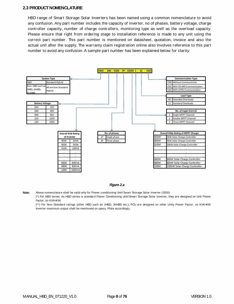
HBD range of Smart Storage Solar Inverters has been named using a common nomenclature to avoid any confusion. Any part number includes the capacity of inverter, no of phases, battery voltage, charge controller capacity, number of charge controllers, monitoring type as well as the overload capacity. Please ensure that right from ordering stage to installation reference is made to any unit using the correct part number. This part number is mentioned on datasheet, quotation, invoice and also the actual unit after the supply. The warranty claim registration online also involves reference to this part number to avoid any confusion. A sample part number has been explained below for clarity:
Figure 2.a
Note: Above nomenclature shall be valid only for Power conditioning Unit/Smart Storage Solar Inverter (SSSI) (*) For HBD series: As HBD series is standard Power Conditioning Unit/Smart Storage Solar Inverter, they are designed on Unit Power Factor, so KVA=KW; (**) For Non-Standard ratings (other HBD such as JHBD, JKHBD etc.), PCU are designed on other Unity Power Factor, so KVA=KW. Inverter maximum output shall be mentioned on specs. Plate accordingly.
MANUAL_HBD_EN_071220_V1.0 Page 9 of 76 VERSION 1.0
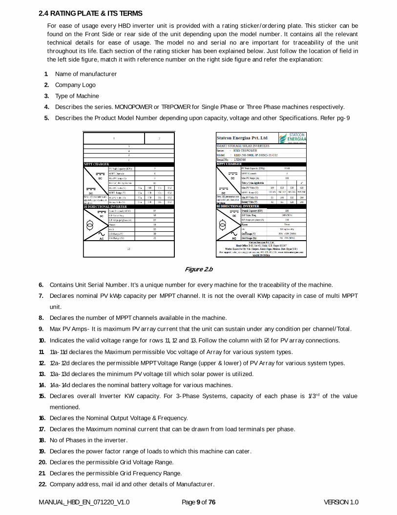
2.4 RATING PLATE & ITS TERMS For ease of usage every HBD inverter unit is provided with a rating sticker/ordering plate. This sticker can be found on the Front Side or rear side of the unit depending upon the model number. It contains all the relevant technical details for ease of usage. The model no and serial no are important for traceability of the unit throughout its life. Each section of the rating sticker has been explained below. Just follow the location of field in the left side figure, match it with reference number on the right side figure and refer the explanation:
1. Name of manufacturer
2. Company Logo
3. Type of Machine
4. Describes the series. MONOPOWER or TRIPOWER for Single Phase or Three Phase machines respectively.
5. Describes the Product Model Number depending upon capacity, voltage and other Specifications. Refer pg-9
Figure 2.b
6. Contains Unit Serial Number. It’s a unique number for every machine for the traceability of the machine.
7. Declares nominal PV kWp capacity per MPPT channel. It is not the overall KWp capacity in case of multi MPPT
unit.
8. Declares the number of MPPT channels available in the machine.
9. Max PV Amps- It is maximum PV array current that the unit can sustain under any condition per channel/Total.
10. Indicates the valid voltage range for rows 11, 12 and 13. Follow the column with ☑ for PV array connections.
11. 11a-11d declares the Maximum permissible Voc voltage of Array for various system types.
12. 12a-12d declares the permissible MPPT Voltage Range (upper & lower) of PV Array for various system types.
13. 13a-13d declares the minimum PV voltage till which solar power is utilized.
14. 14a-14d declares the nominal battery voltage for various machines.
15. Declares overall Inverter KW capacity. For 3-Phase Systems, capacity of each phase is 1/3rd of the value
mentioned.
16. Declares the Nominal Output Voltage & Frequency.
17. Declares the Maximum nominal current that can be drawn from load terminals per phase.
18. No of Phases in the inverter.
19. Declares the power factor range of loads to which this machine can cater.
20. Declares the permissible Grid Voltage Range.
21. Declares the permissible Grid Frequency Range.
22. Company address, mail id and other details of Manufacturer.
MANUAL_HBD_EN_071220_V1.0 Page 10 of 76 VERSION 1.0
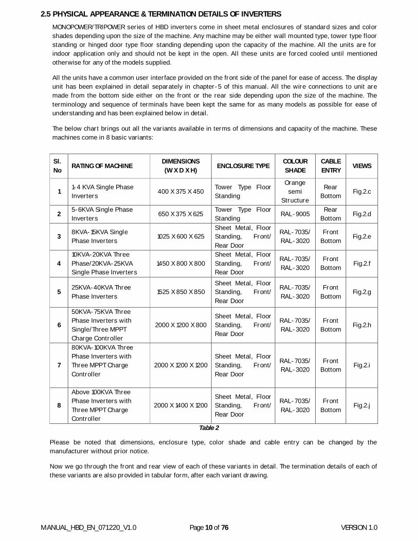
2.5 PHYSICAL APPEARANCE & TERMINATION DETAILS OF INVERTERS MONOPOWER/TRIPOWER series of HBD inverters come in sheet metal enclosures of standard sizes and color shades depending upon the size of the machine. Any machine may be either wall mounted type, tower type floor standing or hinged door type floor standing depending upon the capacity of the machine. All the units are for indoor application only and should not be kept in the open. All these units are forced cooled until mentioned otherwise for any of the models supplied.
All the units have a common user interface provided on the front side of the panel for ease of access. The display unit has been explained in detail separately in chapter-5 of this manual. All the wire connections to unit are made from the bottom side either on the front or the rear side depending upon the size of the machine. The terminology and sequence of terminals have been kept the same for as many models as possible for ease of understanding and has been explained below in detail.
The below chart brings out all the variants available in terms of dimensions and capacity of the machine. These machines come in 8 basic variants:
Sl. No RATING OF MACHINE
DIMENSIONS (W X D X H) ENCLOSURE TYPE
COLOUR SHADE
CABLE ENTRY VIEWS
1 1-4 KVA Single Phase Inverters 400 X 375 X 450 Tower Type Floor
Standing
Orange semi
Structure
Rear Bottom Fig.2.c
2 5-6KVA Single Phase Inverters 650 X 375 X 625 Tower Type Floor
Standing RAL-9005 Rear Bottom Fig.2.d
3 8KVA-15KVA Single Phase Inverters 1025 X 600 X 625
Sheet Metal, Floor Standing, Front/ Rear Door
RAL-7035/ RAL-3020
Front Bottom Fig.2.e
4 10KVA-20KVA Three Phase/20KVA-25KVA Single Phase Inverters
1450 X 800 X 800 Sheet Metal, Floor Standing, Front/ Rear Door
RAL-7035/ RAL-3020
Front Bottom Fig.2.f
5 25KVA-40KVA Three Phase Inverters
1525 X 850 X 850 Sheet Metal, Floor Standing, Front/ Rear Door
RAL-7035/ RAL-3020
Front Bottom
Fig.2.g
6
50KVA-75KVA Three Phase Inverters with Single/Three MPPT Charge Controller
2000 X 1200 X 800 Sheet Metal, Floor Standing, Front/ Rear Door
RAL-7035/ RAL-3020
Front Bottom Fig.2.h
7
80KVA-100KVA Three Phase Inverters with Three MPPT Charge Controller
2000 X 1200 X 1200 Sheet Metal, Floor Standing, Front/ Rear Door
RAL-7035/ RAL-3020
Front Bottom Fig.2.i
8
Above 100KVA Three Phase Inverters with Three MPPT Charge Controller
2000 X 1400 X 1200 Sheet Metal, Floor Standing, Front/ Rear Door
RAL-7035/ RAL-3020
Front Bottom
Fig.2.j
Table 2
Please be noted that dimensions, enclosure type, color shade and cable entry can be changed by the manufacturer without prior notice.
Now we go through the front and rear view of each of these variants in detail. The termination details of each of these variants are also provided in tabular form, after each variant drawing.
MANUAL_HBD_EN_071220_V1.0 Page 11 of 76 VERSION 1.0
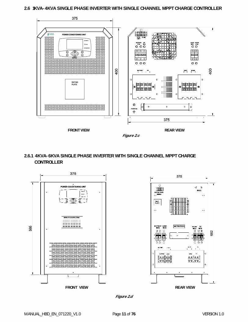
2.6 1KVA-4KVA SINGLE PHASE INVERTER WITH SINGLE CHANNEL MPPT CHARGE CONTROLLER
FRONT VIEW REAR VIEW
Figure 2.c
2.6.1 4KVA-6KVA SINGLE PHASE INVERTER WITH SINGLE CHANNEL MPPT CHARGE CONTROLLER
FRONT VIEW REAR VIEW
Figure 2.d
MANUAL_HBD_EN_071220_V1.0 Page 12 of 76 VERSION 1.0
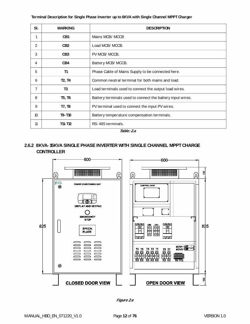
Terminal Description for Single Phase Inverter up to 6KVA with Single Channel MPPT Charger
Table: 2.a
2.6.2 8KVA-15KVA SINGLE PHASE INVERTER WITH SINGLE CHANNEL MPPT CHARGE CONTROLLER
Figure 2.e
Sl. MARKING DESCRIPTION
1 CB1 Mains MCB/ MCCB
2 CB2 Load MCB/ MCCB.
3 CB3 PV MCB/ MCCB.
4 CB4 Battery MCB/ MCCB.
5 T1 Phase Cable of Mains Supply to be connected here.
6 T2, T4 Common neutral terminal for both mains and load.
7 T3 Load terminals used to connect the output load wires.
8 T5, T6 Battery terminals used to connect the battery input wires.
9 T7, T8 PV terminal used to connect the input PV wires.
10 T9-T10 Battery temperature compensation terminals.
11 T11-T12 RS-485 terminals.
MANUAL_HBD_EN_071220_V1.0 Page 13 of 76 VERSION 1.0
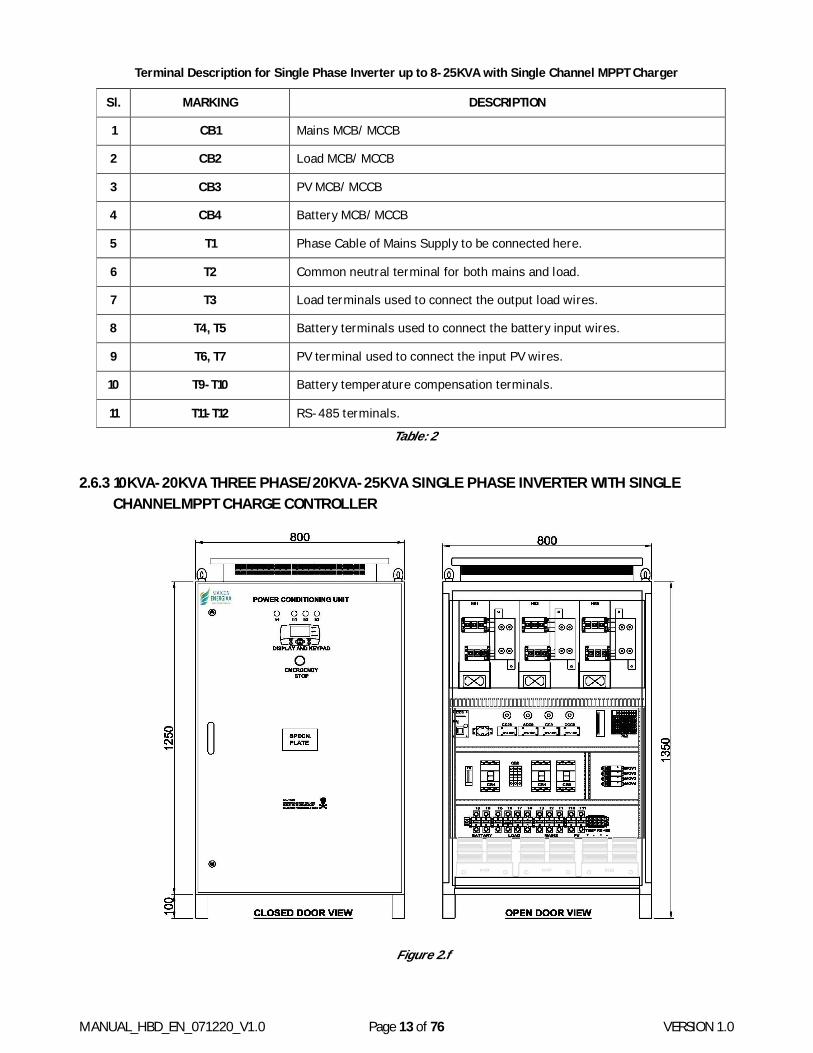
Terminal Description for Single Phase Inverter up to 8-25KVA with Single Channel MPPT Charger
Table: 2
2.6.3 10KVA-20KVA THREE PHASE/20KVA-25KVA SINGLE PHASE INVERTER WITH SINGLE CHANNELMPPT CHARGE CONTROLLER
Figure 2.f
Sl. MARKING DESCRIPTION
1 CB1 Mains MCB/ MCCB
2 CB2 Load MCB/ MCCB
3 CB3 PV MCB/ MCCB
4 CB4 Battery MCB/ MCCB
5 T1 Phase Cable of Mains Supply to be connected here.
6 T2 Common neutral terminal for both mains and load.
7 T3 Load terminals used to connect the output load wires.
8 T4, T5 Battery terminals used to connect the battery input wires.
9 T6, T7 PV terminal used to connect the input PV wires.
10 T9-T10 Battery temperature compensation terminals.
11 T11-T12 RS-485 terminals.
MANUAL_HBD_EN_071220_V1.0 Page 14 of 76 VERSION 1.0
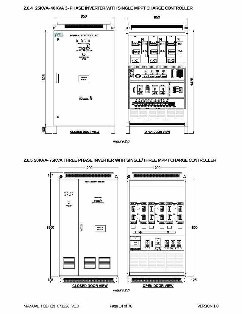
2.6.4 25KVA-40KVA 3-PHASE INVERTER WITH SINGLE MPPT CHARGE CONTROLLER
Figure 2.g
2.6.5 50KVA-75KVA THREE PHASE INVERTER WITH SINGLE/THREE MPPT CHARGE CONTROLLER
Figure 2.h
MANUAL_HBD_EN_071220_V1.0 Page 15 of 76 VERSION 1.0
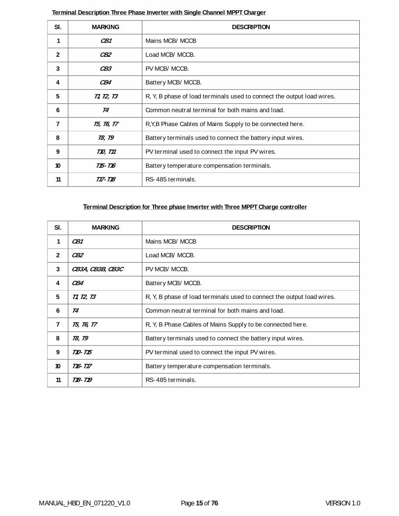
Terminal Description Three Phase Inverter with Single Channel MPPT Charger
Terminal Description for Three phase Inverter with Three MPPT Charge controller
Sl. MARKING DESCRIPTION
1 CB1 Mains MCB/ MCCB
2 CB2 Load MCB/ MCCB.
3 CB3 PV MCB/ MCCB.
4 CB4 Battery MCB/ MCCB.
5 T1, T2, T3 R, Y, B phase of load terminals used to connect the output load wires.
6 T4 Common neutral terminal for both mains and load.
7 T5, T6, T7 R,Y,B Phase Cables of Mains Supply to be connected here.
8 T8, T9 Battery terminals used to connect the battery input wires.
9 T10, T11 PV terminal used to connect the input PV wires.
10 T15-T16 Battery temperature compensation terminals.
11 T17-T18 RS-485 terminals.
Sl. MARKING DESCRIPTION
1 CB1 Mains MCB/ MCCB
2 CB2 Load MCB/ MCCB.
3 CB3A, CB3B, CB3C PV MCB/ MCCB.
4 CB4 Battery MCB/ MCCB.
5 T1, T2, T3 R, Y, B phase of load terminals used to connect the output load wires.
6 T4 Common neutral terminal for both mains and load.
7 T5, T6, T7 R, Y, B Phase Cables of Mains Supply to be connected here.
8 T8, T9 Battery terminals used to connect the battery input wires.
9 T10-T15 PV terminal used to connect the input PV wires.
10 T16-T17 Battery temperature compensation terminals.
11 T18-T19 RS-485 terminals.
MANUAL_HBD_EN_071220_V1.0 Page 16 of 76 VERSION 1.0
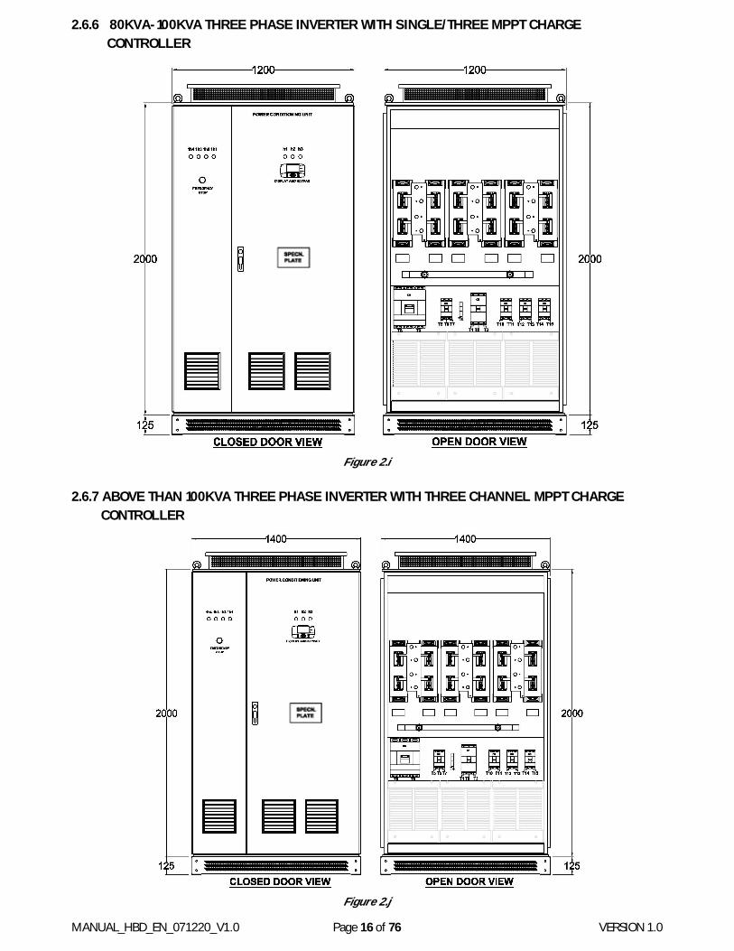
2.6.6 80KVA-100KVA THREE PHASE INVERTER WITH SINGLE/THREE MPPT CHARGE CONTROLLER
Figure 2.i
2.6.7 ABOVE THAN 100KVA THREE PHASE INVERTER WITH THREE CHANNEL MPPT CHARGE CONTROLLER
Figure 2.j
MANUAL_HBD_EN_071220_V1.0 Page 17 of 76 VERSION 1.0
3. INSTALLATION
3.1 UNPACKING & CONTENTS INSIDE
These HBD range of inverters are supplied in standard cardboard/ wooden packing depending upon the size of the machine. Proper thermocol and salaphin sheet/bubble wrap is provided for protection against impact and water ingress. Still proper precautions are mandatory to prevent any damage due to mishandling or water ingress. Manufacturer shall not be responsible for any such damage during transport, unloading or storage at site.
Please take a few moments to unpack your new HBD range of Smart Storage Solar Inverter by following the below given steps:
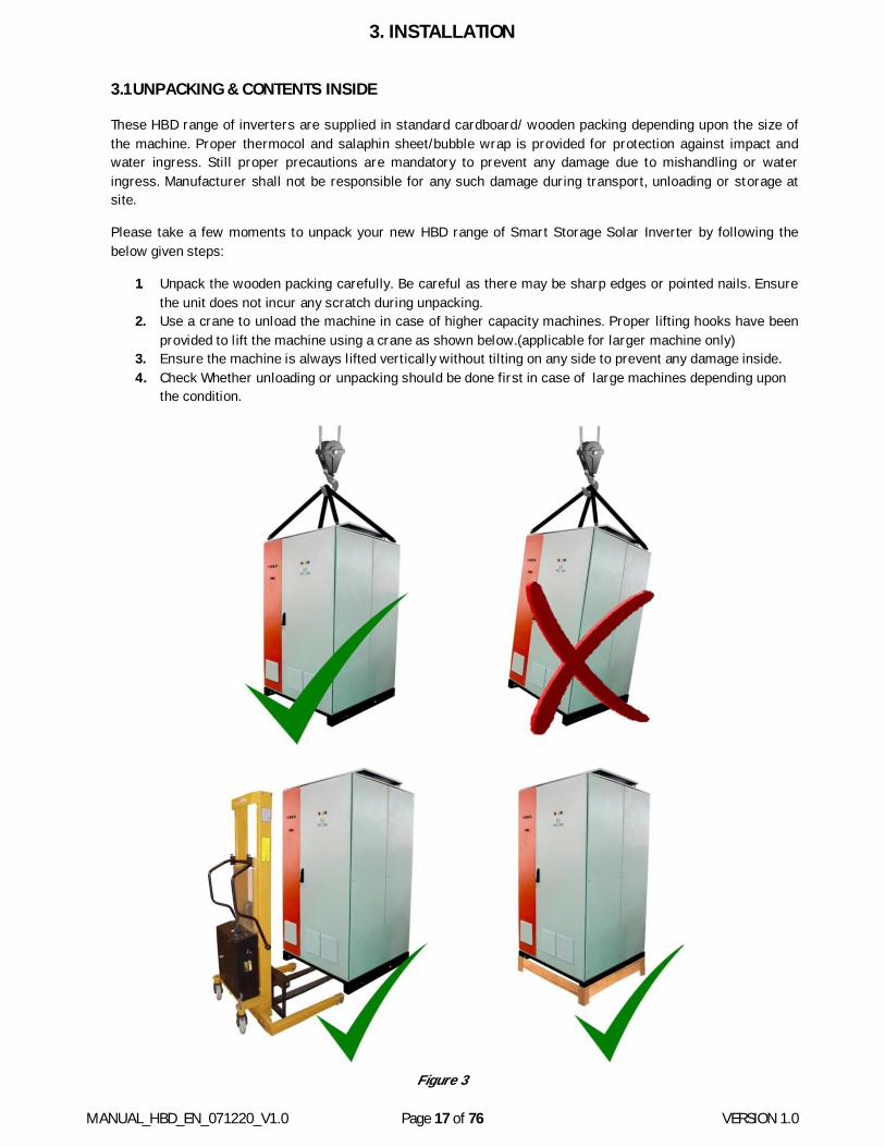
1. Unpack the wooden packing carefully. Be careful as there may be sharp edges or pointed nails. Ensure the unit does not incur any scratch during unpacking.
2. Use a crane to unload the machine in case of higher capacity machines. Proper lifting hooks have been provided to lift the machine using a crane as shown below.(applicable for larger machine only)
3. Ensure the machine is always lifted vertically without tilting on any side to prevent any damage inside. 4. Check Whether unloading or unpacking should be done first in case of large machines depending upon
the condition.
Figure 3
MANUAL_HBD_EN_071220_V1.0 Page 18 of 76 VERSION 1.0
5. Use always fork lift to move the inverters from one location to other location as shown in Figure. 6. Ensure the unit is placed on some raised wooden pallet. It will ensure better cable entry through bottom
and also give an increased level of insulation as shown in figure - 3.a 7. Verify the contents inside. It should include the SSSI unit and a hard copy of Installation &
Commissioning Manual. please note that any extra accessories such as communication cable, mounting/grouting hardware, or termination hardware is a not a part of supply and is under the scope of customer.
8. Go through the rating plate and verify that the model No. matches the model No. that was ordered. In case of any issue related to model No. or rating, refer the relevant section -2.3 of this manual.
9. Please open the doors of the inverter to check there are no hanging wires/connectors that may have resulted during the transport. This is just to be sure about the readiness of the unit before being powered up. In case something does not look ok, please contact to after sales department.
3.2 PLACEMENT & LOCATION
Placement and location of the machine is very important both for the machine and the plant:
Below points should be kept in mind while placing this machine:
1. This machine has high voltages of both AC and DC nature inside and hence should be kept away from access of children, infants or pets. Proper caution marks should be displayed close by to avoid any accidental conditions. Location should be chooses accordingly.
2. This machine may be hot during operation and location should be such that any accidental, contact to this should be avoided.
3. The room where this machine is placed should be of stationary nature with firm walls, base and roof. It should be well ventilated with a proper mechanism of fresh air entry and exhaust. Air conditioned room will ensure a more reliable functioning of this machine.
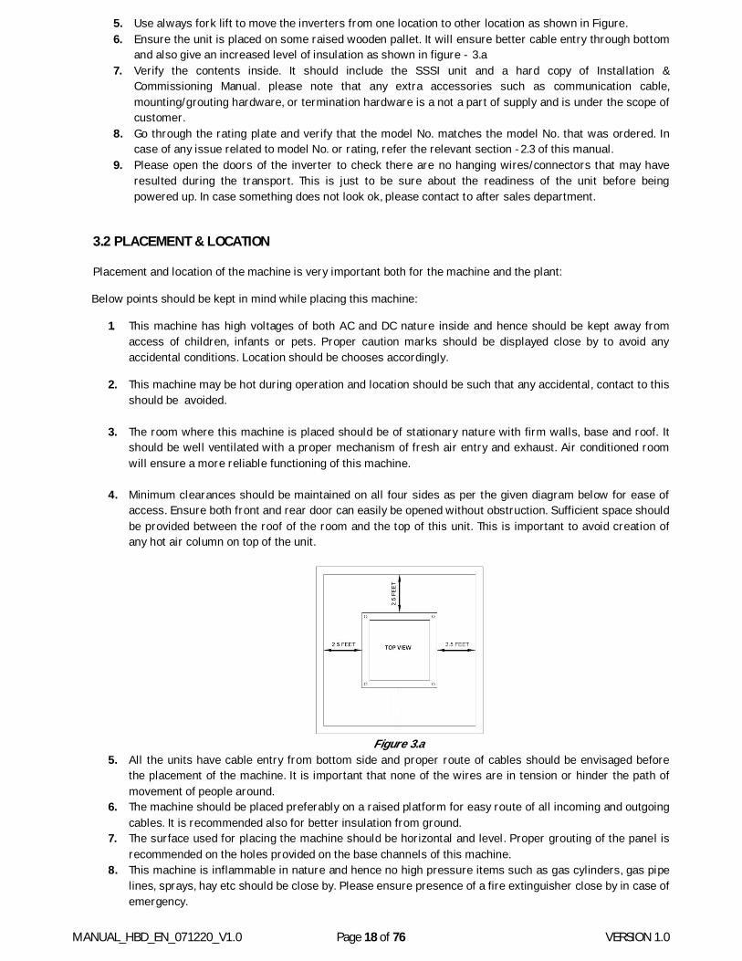
4. Minimum clearances should be maintained on all four sides as per the given diagram below for ease of
access. Ensure both front and rear door can easily be opened without obstruction. Sufficient space should be provided between the roof of the room and the top of this unit. This is important to avoid creation of any hot air column on top of the unit.
Figure 3.a
5. All the units have cable entry from bottom side and proper route of cables should be envisaged before the placement of the machine. It is important that none of the wires are in tension or hinder the path of movement of people around.
6. The machine should be placed preferably on a raised platform for easy route of all incoming and outgoing cables. It is recommended also for better insulation from ground.
7. The surface used for placing the machine should be horizontal and level. Proper grouting of the panel is recommended on the holes provided on the base channels of this machine.
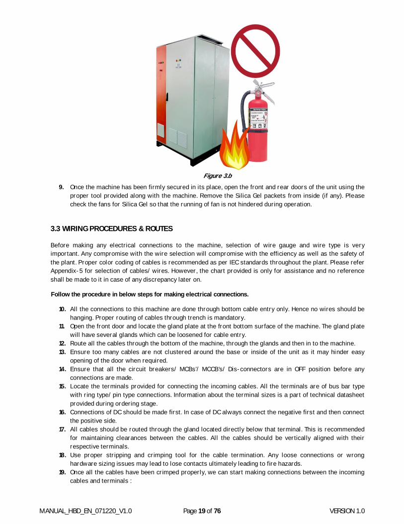
8. This machine is inflammable in nature and hence no high pressure items such as gas cylinders, gas pipe lines, sprays, hay etc should be close by. Please ensure presence of a fire extinguisher close by in case of emergency.
MANUAL_HBD_EN_071220_V1.0 Page 19 of 76 VERSION 1.0
Figure 3.b
9. Once the machine has been firmly secured in its place, open the front and rear doors of the unit using the proper tool provided along with the machine. Remove the Silica Gel packets from inside (if any). Please check the fans for Silica Gel so that the running of fan is not hindered during operation.
3.3 WIRING PROCEDURES & ROUTES
Before making any electrical connections to the machine, selection of wire gauge and wire type is very important. Any compromise with the wire selection will compromise with the efficiency as well as the safety of the plant. Proper color coding of cables is recommended as per IEC standards throughout the plant. Please refer Appendix-5 for selection of cables/ wires. However, the chart provided is only for assistance and no reference shall be made to it in case of any discrepancy later on.
Follow the procedure in below steps for making electrical connections.
10. All the connections to this machine are done through bottom cable entry only. Hence no wires should be hanging. Proper routing of cables through trench is mandatory.
11. Open the front door and locate the gland plate at the front bottom surface of the machine. The gland plate will have several glands which can be loosened for cable entry.
12. Route all the cables through the bottom of the machine, through the glands and then in to the machine. 13. Ensure too many cables are not clustered around the base or inside of the unit as it may hinder easy
opening of the door when required. 14. Ensure that all the circuit breakers/ MCBs’/ MCCB’s/ Dis-connectors are in OFF position before any
connections are made. 15. Locate the terminals provided for connecting the incoming cables. All the terminals are of bus bar type
with ring type/ pin type connections. Information about the terminal sizes is a part of technical datasheet provided during ordering stage.
16. Connections of DC should be made first. In case of DC always connect the negative first and then connect the positive side.
17. All cables should be routed through the gland located directly below that terminal. This is recommended for maintaining clearances between the cables. All the cables should be vertically aligned with their respective terminals.
18. Use proper stripping and crimping tool for the cable termination. Any loose connections or wrong hardware sizing issues may lead to lose contacts ultimately leading to fire hazards.
19. Once all the cables have been crimped properly, we can start making connections between the incoming cables and terminals :
MANUAL_HBD_EN_071220_V1.0 Page 20 of 76 VERSION 1.0
Refer the figure as per enclosure as to locate the various terminals provided. A common sequence of terminals is provided in all the machines with same type of numbering.
Always start with battery connections. Locate DC (-) terminal to make connections followed by DC(+) terminals.
Now connect the PV (-) followed by PV (+) cables. There may be one or three nos. of MPPT chargers depending upon the capacity of system. In case of multi MPPT charger machine, repeat PV connection for all 3 MPPT sections.
Connect the AC Line and neutral terminals now. In case of three phase systems, ensure proper phase sequence is followed. Neutral should always be connected to Neutral terminal only.
Lastly, connect the load terminals in proper sequence.
Neutral of Grid and Neutral of Loads is connected to a common point to maintain the continuity of Neutral under all circumstances.
20. Use proper nut/ bolts/ washers for connecting the cables to the Terminals provided in the machine. Please be noted that use hardware of recommended sizes only. Proper contact is required between the cable, cable lugs and the terminals. Any issues may lead to heating of contacts ultimately leading to fire hazards.
21. All terminals provided are of copper material only. Hence lugs used should be of copper only for homogeneity of contact. In case of Aluminium cable, bimetallic lugs are mandatory.
22. Use proper spanners to tighten the nut/ bolts. Ensure that once tightened, all the lugs should be vertical. The conductors are carrying high currents and voltages; hence clearances between them should be maintained.
23. Double check all the connections for polarity and type to avoid any malfunction later on. 24. Double check the tightness of all the nut and bolts. 25. It is recommended to route AC and DC cables with some minimum clearances in between.
3.4 EARTHING OR GROUNDING THE MACHINE
Connecting the Inverter machine to earth is not only recommended but mandatory to avoid any electrical shock as well as proper functioning of the electronics. The primary reason for earthing any equipment is to ensure that the chassis of the equipment is always at ground potential and there is no experience of shock in case of human contact. The same is valid of these inverters as well. All the inverters are provided with a proper connection point in form of a earth bus bar or a terminal. The location of this point may vary from inverter to inverter. Please note the below points with respect to the grounding of the equipment.
1. Hybrid inverters have an isolation transformer inbuilt and hence can have a common AC side and DC side grounding.
2. Always ground the inverter using a minimum of 6mm2 copper cables. Avoid using aluminum cable for grounding of inverters.
3. All the shields of shielded cables inside the machine are also connected to the same ground. It is important to ground these shields for the EMI/ EMC compatibility of the inverter.
4. SPD/MOV provided inside may not perform the intended function in case the inverters are not grounded properly.
5. The inverter ground should be connected to the earth potential of the site to which all the other appliances of the site are connected.
6. Inverter ground should not be connected to the PV structure ground or the lightening arrestor ground.
Avoid the contact with inverter if bare feet even if the machine is grounded properly. The body of the inverter may still be live with AC and DC voltages.
MANUAL_HBD_EN_071220_V1.0 Page 21 of 76 VERSION 1.0
4. COMMISSIONING
Once the unit has been firmly secured and all the incoming/ outgoing cables properly connected, this machine is ready for being powered up. But before we start please perform a couple of pre checks which are mandatory:
4.1 PRECHECKS BEFORE ENERGIZING
Now the unit is ready to be turned on, but to be double sure. Let’s just perform a couple of checks:
Body machine should be firmly connected to building earth. Check the battery connections as both positive and negative cables should be tight. Check the polarity of the connections visually or preferably through a multi meter. Check the value of battery voltage and it should match with the nominal battery voltage mentioned on
the rating sticker of this machine. In case of discrepancy in any of the above rectify it or refer troubleshooting manual.
4.2 FIRST TIME ENERGIZING THE MACHINE
Now turn on the battery breaker and with a pause of 1 second the machine should become live. There should be a sound of contactor and display should lit up with possibly a buzzer sound.
Ensure that all the other circuit breakers (PV, Load and Grid) are in OFF position only.
Before we proceed further and energize the loads we have to ensure that the settings in the machine supplied are correct to suit the site conditions. Please be noted that these machines are supplied with default settings and hence may or may not suit your requirements. The default settings are a part of this manual and discussed in the following sections.
To change any kind of settings of this machine, the user needs to interact with the Display Keypad Unit (DKU) provided on the front side of this machine. In case you are not familiar with the DKU unit please refer Display Keypad Unit (DKU) section (Chapter-5) before moving forward.
Understanding the DKU unit is an essential part of the Installation and Commissioning.
4.3 SETTINGS UPLOAD
We hope that you have made yourself familiar with the DKU to feed the settings as per your requirements in to the machine.
HBD range of inverters as supplied with standard factory settings. These settings may or may not suit the site conditions and hence need to be updated as per the actual site specifications. Some of the reasons why settings need to be updated and verified are as follows:
What is the Battery Type and the Battery AH connected? What is the Float, Boost and Bulk Voltage settings of the Battery connected?
What is the Mode of Operation Required-Off Grid, Hybrid or Hybrid with Export Enabled?
When do you want to connect and disconnect the Grid supply?
IF required, how much power do you want to export?
Do you want to set any scheduled events?
To implement the change of settings we need to follow the below procedure in order:
MANUAL_HBD_EN_071220_V1.0 Page 22 of 76 VERSION 1.0
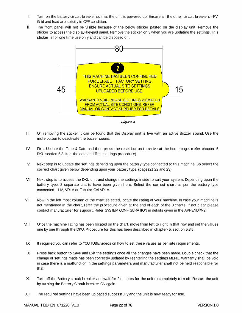
I. Turn on the battery circuit breaker so that the unit is powered up. Ensure all the other circuit breakers -PV, Grid and load are strictly in OFF condition.
II. The front panel will not be visible because of the below sticker pasted on the display unit. Remove the sticker to access the display-keypad panel. Remove the sticker only when you are updating the settings. This sticker is for one time use only and can be disposed off.
Figure 4
III. On removing the sticker it can be found that the Display unit is live with an active Buzzer sound. Use the
mute button to deactivate the buzzer sound.
IV. First Update the Time & Date and then press the reset button to arrive at the home page. (refer chapter-5 DKU section 5.3.1 for the date and Time settings procedure)
V. Next step is to update the settings depending upon the battery type connected to this machine. So select the
correct chart given below depending upon your battery type. (pages21, 22 and 23) VI. Next step is to access the DKU unit and change the settings inside to suit your system. Depending upon the
battery type, 3 separate charts have been given here. Select the correct chart as per the battery type connected – LM, VRLA or Tubular Gel VRLA.
VII. Now in the left most column of the chart selected, locate the rating of your machine. In case your machine is
not mentioned in the chart, refer the procedure given at the end of each of the 3 charts. If not clear please contact manufacturer for support. Refer SYSTEM CONFIGURATION in details given in the APPENDIX-2
VIII. Once the machine rating has been located on the chart, move from left to right in that row and set the values one by one through the DKU. Procedure for this has been described in chapter-5, section 5.3.5
IX. If required you can refer to YOU TUBE videos on how to set these values as per site requirements.
X. Press back button to Save and Exit the settings once all the changes have been made. Double check that the change of settings made has been correctly updated by reentering the settings MENU. Warranty shall be void in case there is a malfunction in the settings parameters and manufacturer shall not be held responsible for that.
XI. Turn off the Battery circuit breaker and wait for 2 minutes for the unit to completely turn off. Restart the unit by turning the Battery Circuit breaker ON again.
XII. The required settings have been uploaded successfully and the unit is now ready for use.

MANUAL_HBD_EN_071220_V1.0 Page 23 of 76 VERSION 1.0
4.4 CHART-1 (LM BATTERY SETTINGS CHART)
INITIAL SETTINGS CHART BATTERY TYPE Low Maintenance (LM)
MODEL
BATTERY VOLTAGES BCL AC Charge Start Volts AC Charge Stop Volts
Max
Exp
ort
Pow
er
NOM
INAL
FLOA
T
BULK
BULK
RE
STAR
T TE
MP
COM
P
Defa
ult
Max
Off-
grid
M
ode
Hyb
rid
Mod
e
Hyb
rid +
Ex
port
Off-
grid
M
ode
Hyb
rid
Mod
e
Hyb
rid +
Ex
port
3KW/1P with 3KW MPPT 48 52.8 58.8 49
OFF*
40 50 46.1 46.1 46.1 57.4 61.9 61.9 1500 HBD-048-003K-1P-003M1-11-Cxx 5KW/1P with 5KW MPPT
96
105.6 117.6 97 40 40 92.2 92.2 92.2 114.7 123.8 123.8 2500 HBD-096-005K-1P-005M1-11-Cxx 6KW/1P with 6KW MPPT
105.6 117.6 97 40 50 92.2 92.2 92.2 114.7 123.8 123.8 3000 HBD-096-006K-1P-006M1-11-Cxx 8KW/1P with 8KW MPPT
105.6 117.6 97 40 60 92.2 92.2 92.2 114.7 123.8 123.8 4000 HBD-096-008K-1P-008M1-11-Cxx 8KW/1P with 8KW MPPT
120 132 147 121 40 50 115.2 115.2 115.2 143.4 154.8 154.8 4000
HBD-120-008K-1P-008M1-11-Cxx 10KW/1P with 10KW MPPT 132 147 121 50 60 115.2 115.2 115.2 143.4 154.8 154.8 5000 HBD-120-010K-1P-010M1-11-Cxx 10KW/1P with 10KW MPPT
240
264 294 241 30 30 230.4 230.4 230.4 286.8 309.6 309.6 5000 HBD-240-010K-1P-010M1-11-Cxx 12.5KW/1P with 12.5KW MPPT
264 294 241 30 40 230.4 230.4 230.4 286.8 309.6 309.6 6250 HBD-240-012.5K-1P-012.5M1-11-Cxx 15KW/1P with 15KW MPPT 264 294 241 40 50 230.4 230.4 230.4 286.8 309.6 309.6 7500 HBD-240-015K-1P-015M1-11-Cxx 20KW/1P with 20KW MPPT
264 294 241 50 60 230.4 230.4 230.4 286.8 309.6 309.6 10000 HBD-240-020K-1P-020M1-11-Cxx 25KW/1P with 25KW MPPT
264 294 241 60 80 230.4 230.4 230.4 286.8 309.6 309.6 12500 HBD-240-025K-1P-025M1-11-Cxx 10KW/3P with 10KW MPPT
120
132 147 121 17 20 115.2 115.2 115.2 143.4 154.8 154.8 833 HBD-120-010K-3P-010M1-11-Cxx 12.5KW/3P with 12.5KW MPPT
132 147 121 17 26.6 115.2 115.2 115.2 143.4 154.8 154.8 1042
HBD-120-012.5K-3P-012.5M1-11-Cxx 15KW/3P with 15KW MPPT 132 147 121 20 30 115.2 115.2 115.2 143.4 154.8 154.8 1250 HBD-120-015K-3P-015M1-11-Cxx 20KW/3P with 20KW MPPT
132 147 121 27 44 115.2 115.2 115.2 143.4 154.8 154.8 1667 HBD-120-020K-3P-020M1-11-Cxx 10KW/3P with 10KW MPPT
240
264 294 241 10 10 230.4 230.4 230.4 286.8 309.6 309.6 833 HBD-240-010K-3P-010M1-11-Cxx 12.5KW/3P with 12.5KW MPPT
264 294 241 10 14 230.4 230.4 230.4 286.8 309.6 309.6 1042 HBD-240-012.5K-3P-012.5M1-11-Cxx 15KW/3P with 15KW MPPT
264 294 241 10 17 230.4 230.4 230.4 286.8 309.6 309.6 1250 HBD-240-015K-3P-015M1-11-Cxx 20KW/3P with 20KW MPPT
264 294 241 13 20 230.4 230.4 230.4 286.8 309.6 309.6 1667 HBD-240-020K-3P-020M1-11-Cxx 25KW/3P with 25KW MPPT
264 294 241 17 27 230.4 230.4 230.4 286.8 309.6 309.6 2083 HBD-240-025K-3P-025M1-11-Cxx 30KW/3P with 30KW MPPT
264 294 241 20 30 230.4 230.4 230.4 286.8 309.6 309.6 2500 HBD-240-030K-3P-030M1-11-Cxx 40KW/3P with 40KW MPPT
264 294 241 27 44 230.4 230.4 230.4 286.8 309.6 309.6 3333 HBD-240-040K-3P-040M1-11-Cxx 50KW/3P with 50KW MPPT
264 294 241 33 54 230.4 230.4 230.4 286.8 309.6 309.6 4167 HBD-240-050K-3P-050M1-11-Cxx 60KW/3P with 60KW MPPT
264 294 241 40 64 230.4 230.4 230.4 286.8 309.6 309.6 5000 HBD-240-060K-3P-060M3-11-Cxx 80KW/3P with 80KW MPPT
264 294 241 53 85 230.4 230.4 230.4 286.8 309.6 309.6 6667 HBD-240-080K-3P-080M3-11-Cxx 100KW/3P with 100KW MPPT
264 294 241 70 103 230.4 230.4 230.4 286.8 309.6 309.6 8333 HBD-240-100K-3P-100M3-11-Cxx 100KW/3P with 100KW MPPT
360
396 441 361 45 70 345.6 345.6 345.6 430.2 464.4 464.4 8333 HBD-360-100K-3P-100M3-11-Cxx 150KW/3P with 150KW MPPT HBD-360-150K-3P-150M3-11-Cxx 396 441 361 70 104 345.6 345.6 345.6 430.2 464.4 464.4 12500
200KW/3P with 200KW MPPT HBD-360-200K-3P-200M3-11-Cxx 396 441 361 93 140 345.6 345.6 345.6 430.2 464.4 464.4 16667
Note: Above settings is valid only for standard ratings. Use Instruction given up coming up page to set Non-standard ratings

MANUAL_HBD_EN_071220_V1.0 Page 24 of 76 VERSION 1.0
Float Voltage = 2.20 X Battery Voltage/2 Bulk Voltage = 2.45 X Battery Voltage/2 Bulk Restart Voltage = Battery Voltage + 1 AC Charge Start = Off-Grid/Hybrid/Hybrid with Export Mode: 1.92 X Battery Voltage/2 AC Charge Stop = Off-Grid: 2.39 X Battery Voltage/2; Hybrid/Hybrid with Export: 2.58*Battery Voltage/2
BCL =
For Single Phase →Default: AH capacity/10; Max: SSSI kW Capacity*0.92/ Battery Bulk Voltage
For Three Phase →Default: AH capacity/30; Max: SSSI kW Capacity*0.92/ Battery Bulk Voltage/3
Temp Comp = It is OFF by default. Set ON when temp compensation probe is provided on terminal
Export = Single Phase-SSSI KW Capacity/2; Three Phase→ SSSI KW Capacity/12 Table 3
MANUAL_HBD_EN_071220_V1.0 Page 25 of 76 VERSION 1.0
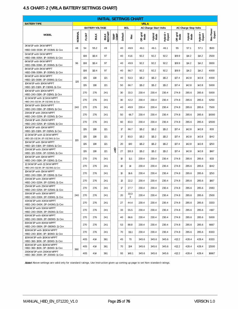
4.5 CHART-2 (VRLA BATTERY SETTINGS CHART)
INITIAL SETTINGS CHART BATTERY TYPE VRLA
MODEL
BATTERY VOLTAGE BCL AC Charge Start Volts AC Charge Stop Volts
Max
Pow
er
Expo
rt
NOM
INAL
FLOA
T
BULK
BULK
RE
STAR
T
TEM
P CO
MP
Defa
ult
Max
Off-
grid
M
ode
Hyb
rid
Mod
e
Hyb
rid +
Ex
port
Off-
grid
M
ode
Hyb
rid
Mod
e
Hyb
rid +
Ex
port
3KW/1P with 3KW MPPT 48 54 55.2 49
OFF*
40 49.9 46.1 46.1 46.1 55 57.1 57.1 1500 HBD-048-003K-1P-003M1-11-Cxx 5KW/1P with 5KW MPPT
96
108 110.4 97 40 41.6 92.2 92.2 92.2 109.9 114.2 114.2 2500 HBD-096-005K-1P-005M1-11-Cxx 6KW/1P with 6KW MPPT
108 110.4 97 40 49.9 92.2 92.2 92.2 109.9 114.2 114.2 3000 HBD-096-006K-1P-006M1-11-Cxx 8KW/1P with 8KW MPPT
108 110.4 97 40 66.7 92.2 92.2 92.2 109.9 114.2 114.2 4000 HBD-096-008K-1P-008M1-11-Cxx 8KW/1P with 8KW MPPT
120 135 138 121 40 53.3 115.2 115.2 115.2 137.4 142.8 142.8 4000
HBD-120-008K-1P-008M1-11-Cxx 10KW/1P with 10KW MPPT
135 138 121 50 66.7 115.2 115.2 115.2 137.4 142.8 142.8 5000 HBD-120-010K-1P-010M1-11-Cxx 10KW/1P with 10KW MPPT
240
270 276 241 30 33.3 230.4 230.4 230.4 274.8 285.6 285.6 5000 HBD-240-010K-1P-010M1-11-Cxx 12.5KW/1P with 12.5KW MPPT
270 276 241 30 42.2 230.4 230.4 230.4 274.8 285.6 285.6 6250 HBD-240-012.5K-1P-012.5M1-11-Cxx
15KW/1P with 15KW MPPT 270 276 241 40 49.9 230.4 230.4 230.4 274.8 285.6 285.6 7500
HBD-240-015K-1P-015M1-11-Cxx 20KW/1P with 20KW MPPT
270 276 241 50 66.7 230.4 230.4 230.4 274.8 285.6 285.6 10000 HBD-240-020K-1P-020M1-11-Cxx 25KW/1P with 25KW MPPT
270 276 241 60 83.3 230.4 230.4 230.4 274.8 285.6 285.6 12500 HBD-240-025K-1P-025M1-11-Cxx 10KW/3P with 10KW MPPT
120
135 138 121 17 66.7 115.2 115.2 115.2 137.4 142.8 142.8 833 HBD-120-010K-3P-010M1-11-Cxx 12.5KW/3P with 12.5KW MPPT
135 138 121 17 83.3 115.2 115.2 115.2 137.4 142.8 142.8 1042 HBD-120-012.5K-3P-012.5M1-11-Cxx
15KW/3P with 15KW MPPT 135 138 121 20 100 115.2 115.2 115.2 137.4 142.8 142.8 1250
HBD-120-015K-3P-015M1-11-Cxx 20KW/3P with 20KW MPPT
135 138 121 27 133.3 115.2 115.2 115.2 137.4 142.8 142.8 1667 HBD-120-020K-3P-020M1-11-Cxx 10KW/3P with 10KW MPPT
240
270 276 241 10 11.1 230.4 230.4 230.4 274.8 285.6 285.6 833 HBD-240-010K-3P-010M1-11-Cxx 12.5KW/3P with 12.5KW MPPT
270 276 241 10 14 230.4 230.4 230.4 274.8 285.6 285.6 1042 HBD-240-012.5K-3P-012.5M1-11-Cxx
15KW/3P with 15KW MPPT 270 276 241 10 16.6 230.4 230.4 230.4 274.8 285.6 285.6 1250
HBD-240-015K-3P-015M1-11-Cxx 20KW/3P with 20KW MPPT
270 276 241 13 22.2 230.4 230.4 230.4 274.8 285.6 285.6 1667 HBD-240-020K-3P-020M1-11-Cxx 25KW/3P with 25KW MPPT
270 276 241 17 27.7 230.4 230.4 230.4 274.8 285.6 285.6 2083 HBD-240-025K-3P-025M1-11-Cxx 30KW/3P with 30KW MPPT
270 276 241 20 33.33 230.4 230.4 230.4 274.8 285.6 285.6 2500
HBD-240-030K-3P-030M1-11-Cxx 40KW/3P with 40KW MPPT
270 276 241 27 44.4 230.4 230.4 230.4 274.8 285.6 285.6 3333 HBD-240-040K-3P-040M1-11-Cxx 50KW/3P with 50KW MPPT
270 276 241 33 55.5 230.4 230.4 230.4 274.8 285.6 285.6 4167 HBD-240-050K-3P-050M1-11-Cxx 60KW/3P with 60KW MPPT
270 276 241 40 66.6 230.4 230.4 230.4 274.8 285.6 285.6 5000 HBD-240-060K-3P-060M3-11-Cxx 80KW/3P with 80KW MPPT
270 276 241 53 88.8 230.4 230.4 230.4 274.8 285.6 285.6 6667 HBD-240-080K-3P-080M3-11-Cxx 100KW/3P with 100KW MPPT
270 276 241 70 111.1 230.4 230.4 230.4 274.8 285.6 285.6 8333 HBD-240-100K-3P-100M3-11-Cxx 100KW/3P with 100KW MPPT
360
405 414 361 45 70 345.6 345.6 345.6 412.2 428.4 428.4 8333 HBD-360-100K-3P-100M3-11-Cxx 150KW/3P with 150KW MPPT HBD-360-150K-3P-150M3-11-Cxx 405 414 361 70 104 345.6 345.6 345.6 412.2 428.4 428.4 12500
200KW/3P with 200KW MPPT HBD-360-200K-3P-200M3-11-Cxx 405 414 361 93 148.1 345.6 345.6 345.6 412.2 428.4 428.4 16667
Note# Above settings are valid only for standard ratings. Use Instruction given up coming up page to set Non-standard ratings.

MANUAL_HBD_EN_071220_V1.0 Page 26 of 76 VERSION 1.0
Float Voltage = 2.25 X Battery Voltage/2
Bulk Voltage = 2.30 X Battery Voltage/2
Bulk Restart Voltage = Battery Voltage + 1
AC Charge Start = Off-Grid/Hybrid/ Hybrid with export: 1.92 X Battery Voltage/2
AC Charge Stop = Off-Grid: 2.29 X Battery Voltage/2; Hybrid/Hybrid with export: 2.38*Battery Voltage/2
BCL = For Single Phase→ Default: AH capacity/10; Max: SSSI kW Capacity*.92/ Battery Bulk Voltage
For Three Phase→ Default: AH capacity/30; Max: SSSI kW Capacity*.92/ Battery Bulk Voltage/3
Temp Comp = It is off by default. Set ON when temp compensation probe is provided on terminal.
Export = Single Phase: SSSI KW Capacity/2; Three Phase: SSSI KW Capacity/12
Table 4
MANUAL_HBD_EN_071220_V1.0 Page 27 of 76 VERSION 1.0
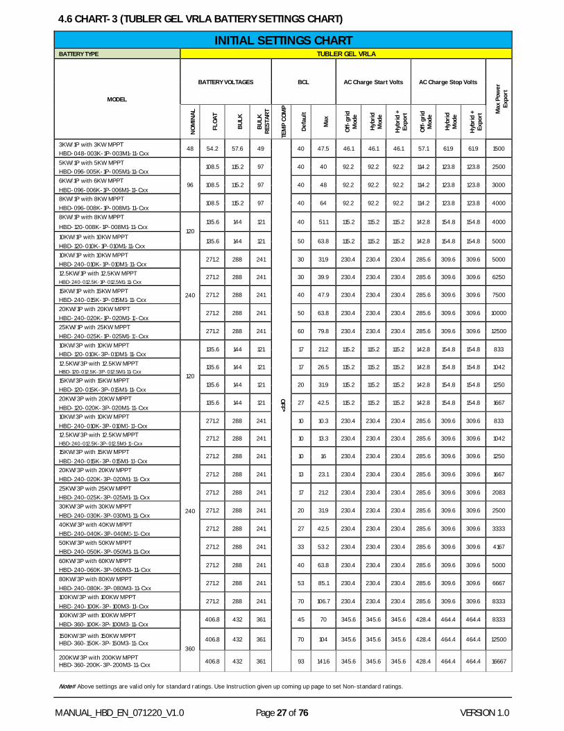
4.6 CHART-3 (TUBLER GEL VRLA BATTERY SETTINGS CHART)
INITIAL SETTINGS CHART BATTERY TYPE TUBLER GEL VRLA
MODEL
BATTERY VOLTAGES BCL AC Charge Start Volts AC Charge Stop Volts
Max
Pow
er
Expo
rt
NOM
INAL
FLOA
T
BULK
BULK
RE
STAR
T
TEM
P CO
MP
Defa
ult
Max
Off-
grid
M
ode
Hybr
id
Mod
e
Hyb
rid +
Ex
port
Off-
grid
M
ode
Hybr
id
Mod
e
Hyb
rid +
Ex
port
3KW/1P with 3KW MPPT 48 54.2 57.6 49
OFF*
40 47.5 46.1 46.1 46.1 57.1 61.9 61.9 1500 HBD-048-003K-1P-003M1-11-Cxx 5KW/1P with 5KW MPPT
96
108.5 115.2 97 40 40 92.2 92.2 92.2 114.2 123.8 123.8 2500 HBD-096-005K-1P-005M1-11-Cxx 6KW/1P with 6KW MPPT
108.5 115.2 97 40 48 92.2 92.2 92.2 114.2 123.8 123.8 3000 HBD-096-006K-1P-006M1-11-Cxx 8KW/1P with 8KW MPPT
108.5 115.2 97 40 64 92.2 92.2 92.2 114.2 123.8 123.8 4000 HBD-096-008K-1P-008M1-11-Cxx 8KW/1P with 8KW MPPT
120 135.6 144 121 40 51.1 115.2 115.2 115.2 142.8 154.8 154.8 4000
HBD-120-008K-1P-008M1-11-Cxx 10KW/1P with 10KW MPPT
135.6 144 121 50 63.8 115.2 115.2 115.2 142.8 154.8 154.8 5000 HBD-120-010K-1P-010M1-11-Cxx 10KW/1P with 10KW MPPT
240
271.2 288 241 30 31.9 230.4 230.4 230.4 285.6 309.6 309.6 5000 HBD-240-010K-1P-010M1-11-Cxx 12.5KW/1P with 12.5KW MPPT 271.2 288 241 30 39.9 230.4 230.4 230.4 285.6 309.6 309.6 6250 HBD-240-012.5K-1P-012.5M1-11-Cxx
15KW/1P with 15KW MPPT 271.2 288 241 40 47.9 230.4 230.4 230.4 285.6 309.6 309.6 7500 HBD-240-015K-1P-015M1-11-Cxx 20KW/1P with 20KW MPPT 271.2 288 241 50 63.8 230.4 230.4 230.4 285.6 309.6 309.6 10000 HBD-240-020K-1P-020M1-11-Cxx 25KW/1P with 25KW MPPT 271.2 288 241 60 79.8 230.4 230.4 230.4 285.6 309.6 309.6 12500 HBD-240-025K-1P-025M1-11-Cxx 10KW/3P with 10KW MPPT
120
135.6 144 121 17 21.2 115.2 115.2 115.2 142.8 154.8 154.8 833 HBD-120-010K-3P-010M1-11-Cxx 12.5KW/3P with 12.5KW MPPT 135.6 144 121 17 26.5 115.2 115.2 115.2 142.8 154.8 154.8 1042 HBD-120-012.5K-3P-012.5M1-11-Cxx
15KW/3P with 15KW MPPT 135.6 144 121 20 31.9 115.2 115.2 115.2 142.8 154.8 154.8 1250
HBD-120-015K-3P-015M1-11-Cxx 20KW/3P with 20KW MPPT 135.6 144 121 27 42.5 115.2 115.2 115.2 142.8 154.8 154.8 1667 HBD-120-020K-3P-020M1-11-Cxx 10KW/3P with 10KW MPPT
240
271.2 288 241 10 10.3 230.4 230.4 230.4 285.6 309.6 309.6 833 HBD-240-010K-3P-010M1-11-Cxx 12.5KW/3P with 12.5KW MPPT 271.2 288 241 10 13.3 230.4 230.4 230.4 285.6 309.6 309.6 1042 HBD-240-012.5K-3P-012.5M1-11-Cxx 15KW/3P with 15KW MPPT
271.2 288 241 10 16 230.4 230.4 230.4 285.6 309.6 309.6 1250 HBD-240-015K-3P-015M1-11-Cxx 20KW/3P with 20KW MPPT
271.2 288 241 13 23.1 230.4 230.4 230.4 285.6 309.6 309.6 1667 HBD-240-020K-3P-020M1-11-Cxx 25KW/3P with 25KW MPPT 271.2 288 241 17 21.2 230.4 230.4 230.4 285.6 309.6 309.6 2083 HBD-240-025K-3P-025M1-11-Cxx 30KW/3P with 30KW MPPT 271.2 288 241 20 31.9 230.4 230.4 230.4 285.6 309.6 309.6 2500 HBD-240-030K-3P-030M1-11-Cxx 40KW/3P with 40KW MPPT 271.2 288 241 27 42.5 230.4 230.4 230.4 285.6 309.6 309.6 3333 HBD-240-040K-3P-040M1-11-Cxx 50KW/3P with 50KW MPPT 271.2 288 241 33 53.2 230.4 230.4 230.4 285.6 309.6 309.6 4167 HBD-240-050K-3P-050M1-11-Cxx 60KW/3P with 60KW MPPT
271.2 288 241 40 63.8 230.4 230.4 230.4 285.6 309.6 309.6 5000 HBD-240-060K-3P-060M3-11-Cxx 80KW/3P with 80KW MPPT 271.2 288 241 53 85.1 230.4 230.4 230.4 285.6 309.6 309.6 6667 HBD-240-080K-3P-080M3-11-Cxx 100KW/3P with 100KW MPPT
271.2 288 241 70 106.7 230.4 230.4 230.4 285.6 309.6 309.6 8333 HBD-240-100K-3P-100M3-11-Cxx 100KW/3P with 100KW MPPT
360
406.8 432 361 45 70 345.6 345.6 345.6 428.4 464.4 464.4 8333 HBD-360-100K-3P-100M3-11-Cxx
150KW/3P with 150KW MPPT HBD-360-150K-3P-150M3-11-Cxx 406.8 432 361 70 104 345.6 345.6 345.6 428.4 464.4 464.4 12500
200KW/3P with 200KW MPPT HBD-360-200K-3P-200M3-11-Cxx 406.8 432 361 93 141.6 345.6 345.6 345.6 428.4 464.4 464.4 16667
Note# Above settings are valid only for standard ratings. Use Instruction given up coming up page to set Non-standard ratings.

MANUAL_HBD_EN_071220_V1.0 Page 28 of 76 VERSION 1.0
Float Voltage = 2.26 X Battery Voltage/2 Bulk Voltage = 2.40 X Battery Voltage/2 Bulk Restart Voltage = Battery Voltage + 1 AC Charge Start = Off-Grid/Hybrid/ Hybrid + Export: 1.92 X Battery Voltage/2 AC Charge Stop = Off-Grid/Hybrid:2.38 X Battery Voltage/2; Hybrid+Export:2.58*Battery Voltage/2
BCL = Single Phase: Default: AH capacity/10; Max: SSSI kW Capacity*92/ Battery Bulk Voltage Three Phase: Default: AH capacity/30; Max: SSSI kW Capacity*92/ Battery Bulk Voltage/3
Temp Comp = It is OFF by default. Set ON when temp compensation probe is provided on terminal Export = Single Phase: SSSI KW Capacity/2; Three Phase: SSSI KW Capacity/12
Table 5
MANUAL_HBD_EN_071220_V1.0 Page 29 of 76 VERSION 1.0
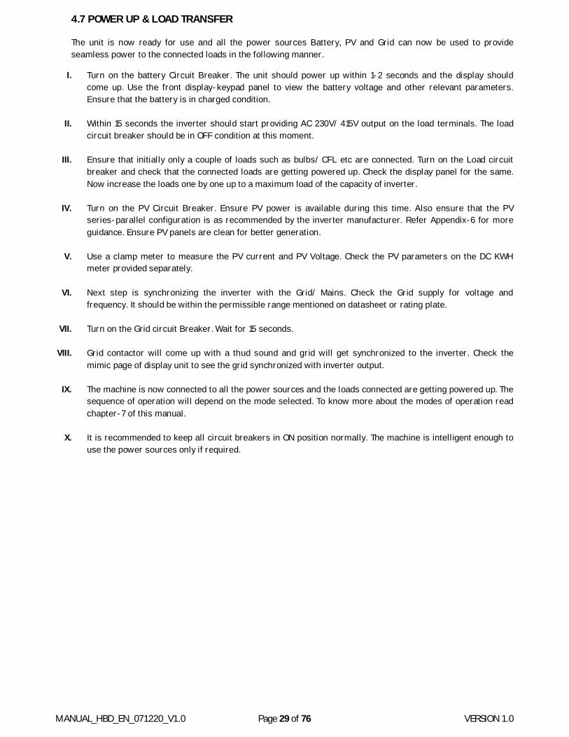
4.7 POWER UP & LOAD TRANSFER
The unit is now ready for use and all the power sources Battery, PV and Grid can now be used to provide seamless power to the connected loads in the following manner.
I. Turn on the battery Circuit Breaker. The unit should power up within 1-2 seconds and the display should come up. Use the front display-keypad panel to view the battery voltage and other relevant parameters. Ensure that the battery is in charged condition.
II. Within 15 seconds the inverter should start providing AC 230V/ 415V output on the load terminals. The load circuit breaker should be in OFF condition at this moment.
III. Ensure that initially only a couple of loads such as bulbs/ CFL etc are connected. Turn on the Load circuit breaker and check that the connected loads are getting powered up. Check the display panel for the same. Now increase the loads one by one up to a maximum load of the capacity of inverter.
IV. Turn on the PV Circuit Breaker. Ensure PV power is available during this time. Also ensure that the PV series-parallel configuration is as recommended by the inverter manufacturer. Refer Appendix-6 for more guidance. Ensure PV panels are clean for better generation.
V. Use a clamp meter to measure the PV current and PV Voltage. Check the PV parameters on the DC KWH meter provided separately.
VI. Next step is synchronizing the inverter with the Grid/ Mains. Check the Grid supply for voltage and frequency. It should be within the permissible range mentioned on datasheet or rating plate.
VII. Turn on the Grid circuit Breaker. Wait for 15 seconds.
VIII. Grid contactor will come up with a thud sound and grid will get synchronized to the inverter. Check the mimic page of display unit to see the grid synchronized with inverter output.
IX. The machine is now connected to all the power sources and the loads connected are getting powered up. The sequence of operation will depend on the mode selected. To know more about the modes of operation read chapter-7 of this manual.
X. It is recommended to keep all circuit breakers in ON position normally. The machine is intelligent enough to use the power sources only if required.

MANUAL_HBD_EN_071220_V1.0 Page 30 of 76 VERSION 1.0
5. DISPLAY KEYPAD UNIT Here we shall explain in detail, the user interface unit or the DISPLAY-KEYPAD UNIT (DKU) which is the single point of interaction between the user and the machine. This DKU has been provided on the front facing side of all machine for easy access. DKU consists of a blue colored graphical display along with 8 pushbuttons and 3 LED all in form of a sticker on the front door. The graphical display is responsive to the keypad and all the scrolling, settings change and fault viewing can be done using the correct combination of these pushbuttons. Below is how the DKU looks like:
Figure 5
Before moving forward lets educate our slaves on the functions of various pushbuttons provided.
5.1 BUTTON DEFINATION
MUTE Mute Active Alarms.
MODE Acknowledge Alarms/ Scroll to Next Display Screen BACK Previous Display Screen/ Move out of Sub Menu
PLUS Increase Parameter Value/ Turn On System (if pressed for >3 sec.)
MINUS Decrease Parameter Value/ Turn Off System (if pressed for >3 sec.) BOOST For internal use
TEST For internal use RESET Turn off Alarm Mute/ Clear Fault/ Latch Reset Battery.
MODE, PLUS+MINUS Enter Factory Settings Table 5
5.2 DKU LED DESCRIPTION
Table 5.a
LABEL INDICATION MEANINGS
MAINS ON Green Green: Mains voltage is present within acceptable limits.
ALARM Red
No Flash: Normal condition. Red: Abnormal condition occurs. Note: Light will flash on and a buzzer will sound. The operator can acknowledge new alarms by pressing the MODE/ACK key. The light will then remain lit until the fault has cleared and the RESET key has been pressed to clear the latched alarms. See Appendix-1 “Display fault Analysis “for details.
BUZZER MUTE Yellow Yellow: It lit up when the MUTE key has been pressed, indicates that the alarm is silent. Note: The muting function will cancel by itself after 24 hours, or it may be manually cancelled by pressing the RESET key.
MANUAL_HBD_EN_071220_V1.0 Page 31 of 76 VERSION 1.0
HOW TO IMPLEMENT OPERATIONS USING DISPLAY KEYPAD UNIT
All the operations, settings change and parameter viewing on display are performed using pushbuttons or combination of pushbuttons. In this section we describe some of the events that can be performed using the pushbutton keys provided on the DKU. Some these operations include:
Date & Time Settings Scrolling through the various screens Turn ON and Turn OFF the Inverter Unit Resetting the Unit in case of fault occurrence Change of Settings Battery Boost Cycle/ Test Cycle Enable (Not applicable for solar Inverter)
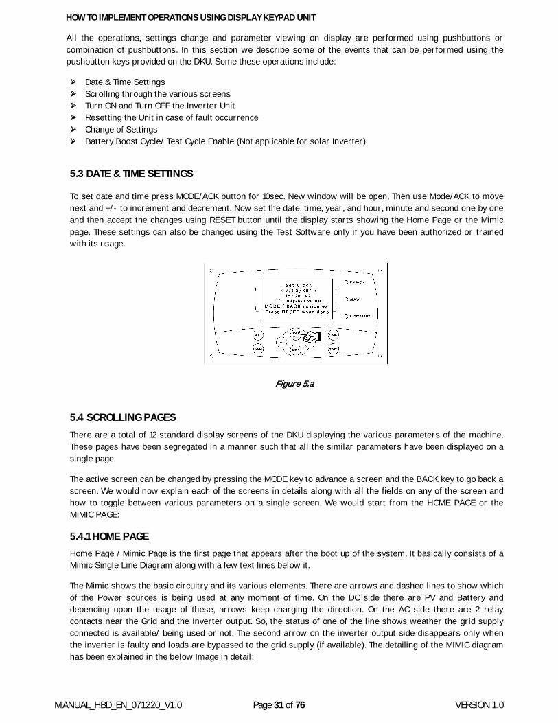
5.3 DATE & TIME SETTINGS
To set date and time press MODE/ACK button for 10sec. New window will be open, Then use Mode/ACK to move next and +/- to increment and decrement. Now set the date, time, year, and hour, minute and second one by one and then accept the changes using RESET button until the display starts showing the Home Page or the Mimic page. These settings can also be changed using the Test Software only if you have been authorized or trained with its usage.
Figure 5.a
5.4 SCROLLING PAGES There are a total of 12 standard display screens of the DKU displaying the various parameters of the machine. These pages have been segregated in a manner such that all the similar parameters have been displayed on a single page.
The active screen can be changed by pressing the MODE key to advance a screen and the BACK key to go back a screen. We would now explain each of the screens in details along with all the fields on any of the screen and how to toggle between various parameters on a single screen. We would start from the HOME PAGE or the MIMIC PAGE:
5.4.1 HOME PAGE Home Page / Mimic Page is the first page that appears after the boot up of the system. It basically consists of a Mimic Single Line Diagram along with a few text lines below it.
The Mimic shows the basic circuitry and its various elements. There are arrows and dashed lines to show which of the Power sources is being used at any moment of time. On the DC side there are PV and Battery and depending upon the usage of these, arrows keep charging the direction. On the AC side there are 2 relay contacts near the Grid and the Inverter output. So, the status of one of the line shows weather the grid supply connected is available/ being used or not. The second arrow on the inverter output side disappears only when the inverter is faulty and loads are bypassed to the grid supply (if available). The detailing of the MIMIC diagram has been explained in the below Image in detail:
MANUAL_HBD_EN_071220_V1.0 Page 32 of 76 VERSION 1.0
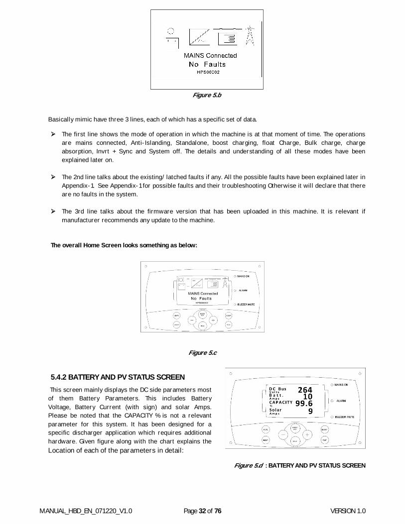
Figure 5.b
Basically mimic have three 3 lines, each of which has a specific set of data.
The first line shows the mode of operation in which the machine is at that moment of time. The operations are mains connected, Anti-Islanding, Standalone, boost charging, float Charge, Bulk charge, charge absorption, Invrt + Sync and System off. The details and understanding of all these modes have been explained later on.
The 2nd line talks about the existing/ latched faults if any. All the possible faults have been explained later in Appendix-1. See Appendix-1 for possible faults and their troubleshooting Otherwise it will declare that there are no faults in the system.
The 3rd line talks about the firmware version that has been uploaded in this machine. It is relevant if manufacturer recommends any update to the machine.
The overall Home Screen looks something as below:
Figure 5.c
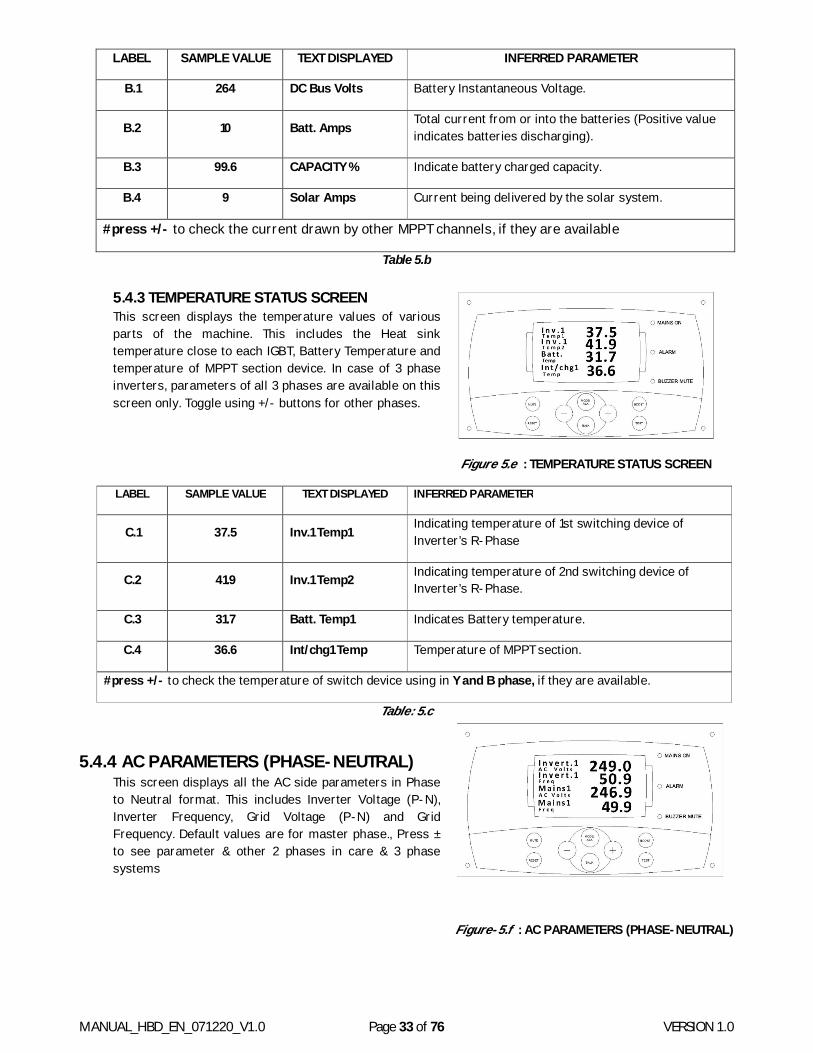
5.4.2 BATTERY AND PV STATUS SCREEN This screen mainly displays the DC side parameters most of them Battery Parameters. This includes Battery Voltage, Battery Current (with sign) and solar Amps. Please be noted that the CAPACITY % is not a relevant parameter for this system. It has been designed for a specific discharger application which requires additional hardware. Given figure along with the chart explains the Location of each of the parameters in detail:
Figure 5.d : BATTERY AND PV STATUS SCREEN
MANUAL_HBD_EN_071220_V1.0 Page 33 of 76 VERSION 1.0
LABEL SAMPLE VALUE TEXT DISPLAYED INFERRED PARAMETER
B.1 264 DC Bus Volts Battery Instantaneous Voltage.
B.2 10 Batt. Amps Total current from or into the batteries (Positive value indicates batteries discharging).
B.3 99.6 CAPACITY % Indicate battery charged capacity.
B.4 9 Solar Amps Current being delivered by the solar system.
#press +/- to check the current drawn by other MPPT channels, if they are available
Table 5.b
5.4.3 TEMPERATURE STATUS SCREEN This screen displays the temperature values of various parts of the machine. This includes the Heat sink temperature close to each IGBT, Battery Temperature and temperature of MPPT section device. In case of 3 phase inverters, parameters of all 3 phases are available on this screen only. Toggle using +/- buttons for other phases.
Figure 5.e : TEMPERATURE STATUS SCREEN
LABEL SAMPLE VALUE TEXT DISPLAYED INFERRED PARAMETER
C.1 37.5 Inv.1 Temp1 Indicating temperature of 1st switching device of Inverter’s R-Phase
C.2 41.9 Inv.1 Temp2 Indicating temperature of 2nd switching device of Inverter’s R-Phase.
C.3 31.7 Batt. Temp1 Indicates Battery temperature.
C.4 36.6 Int/chg1 Temp Temperature of MPPT section.
#press +/- to check the temperature of switch device using in Y and B phase, if they are available.
Table: 5.c
5.4.4 AC PARAMETERS (PHASE-NEUTRAL) This screen displays all the AC side parameters in Phase to Neutral format. This includes Inverter Voltage (P-N), Inverter Frequency, Grid Voltage (P-N) and Grid Frequency. Default values are for master phase., Press ± to see parameter & other 2 phases in care & 3 phase systems
Figure-5.f : AC PARAMETERS (PHASE-NEUTRAL)
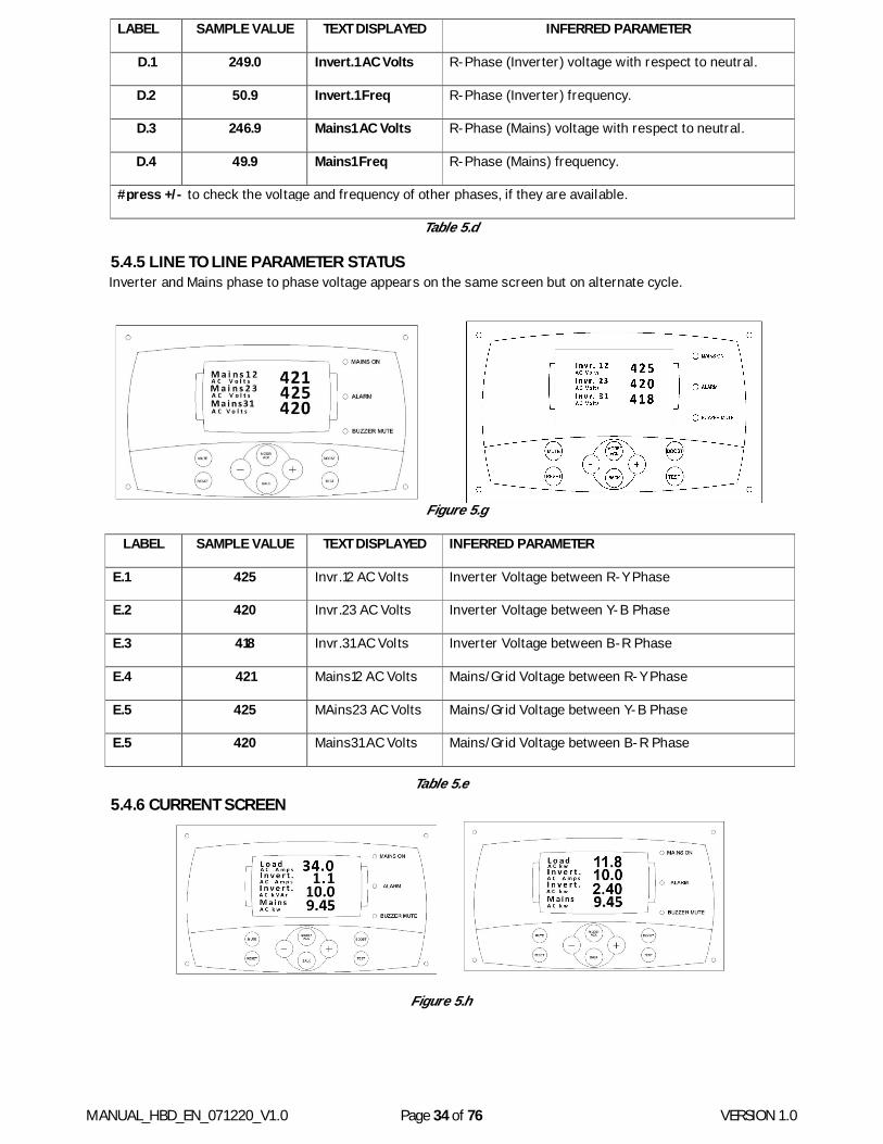
MANUAL_HBD_EN_071220_V1.0 Page 34 of 76 VERSION 1.0
LABEL SAMPLE VALUE TEXT DISPLAYED INFERRED PARAMETER
D.1 249.0 Invert.1 AC Volts R-Phase (Inverter) voltage with respect to neutral.
D.2 50.9 Invert.1 Freq R-Phase (Inverter) frequency.
D.3 246.9 Mains1 AC Volts R-Phase (Mains) voltage with respect to neutral.
D.4 49.9 Mains1 Freq R-Phase (Mains) frequency.
#press +/- to check the voltage and frequency of other phases, if they are available.
Table 5.d
5.4.5 LINE TO LINE PARAMETER STATUS Inverter and Mains phase to phase voltage appears on the same screen but on alternate cycle.
Figure 5.g
LABEL SAMPLE VALUE TEXT DISPLAYED INFERRED PARAMETER
E.1 425 Invr.12 AC Volts Inverter Voltage between R-Y Phase
E.2 420 Invr.23 AC Volts Inverter Voltage between Y-B Phase
E.3 418 Invr.31 AC Volts Inverter Voltage between B-R Phase
E.4 421 Mains12 AC Volts Mains/Grid Voltage between R-Y Phase
E.5 425 MAins23 AC Volts Mains/Grid Voltage between Y-B Phase
E.5 420 Mains31 AC Volts Mains/Grid Voltage between B-R Phase
Table 5.e 5.4.6 CURRENT SCREEN
Figure 5.h
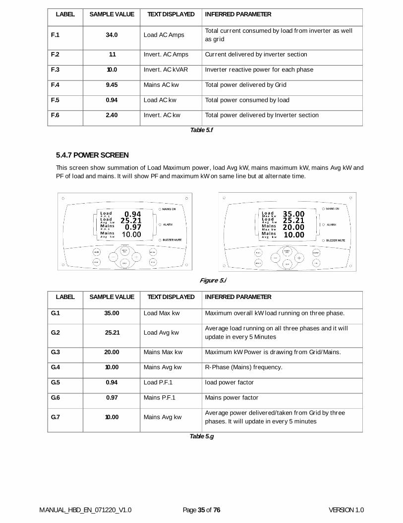
MANUAL_HBD_EN_071220_V1.0 Page 35 of 76 VERSION 1.0
LABEL SAMPLE VALUE TEXT DISPLAYED INFERRED PARAMETER
F.1 34.0 Load AC Amps Total current consumed by load from inverter as well as grid
F.2 1.1 Invert. AC Amps Current delivered by inverter section
F.3 10.0 Invert. AC kVAR Inverter reactive power for each phase
F.4 9.45 Mains AC kw Total power delivered by Grid
F.5 0.94 Load AC kw Total power consumed by load
F.6 2.40 Invert. AC kw Total power delivered by Inverter section
Table 5.f
5.4.7 POWER SCREEN This screen show summation of Load Maximum power, load Avg kW, mains maximum kW, mains Avg kW and PF of load and mains. It will show PF and maximum kW on same line but at alternate time.
Figure 5.i
LABEL SAMPLE VALUE TEXT DISPLAYED INFERRED PARAMETER
G.1 35.00 Load Max kw Maximum overall kW load running on three phase.
G.2 25.21 Load Avg kw Average load running on all three phases and it will update in every 5 Minutes
G.3 20.00 Mains Max kw Maximum kW Power is drawing from Grid/Mains.
G.4 10.00 Mains Avg kw R-Phase (Mains) frequency.
G.5 0.94 Load P.F.1 load power factor
G.6 0.97 Mains P.F.1 Mains power factor
G.7 10.00 Mains Avg kw Average power delivered/taken from Grid by three phases. It will update in every 5 minutes
Table 5.g
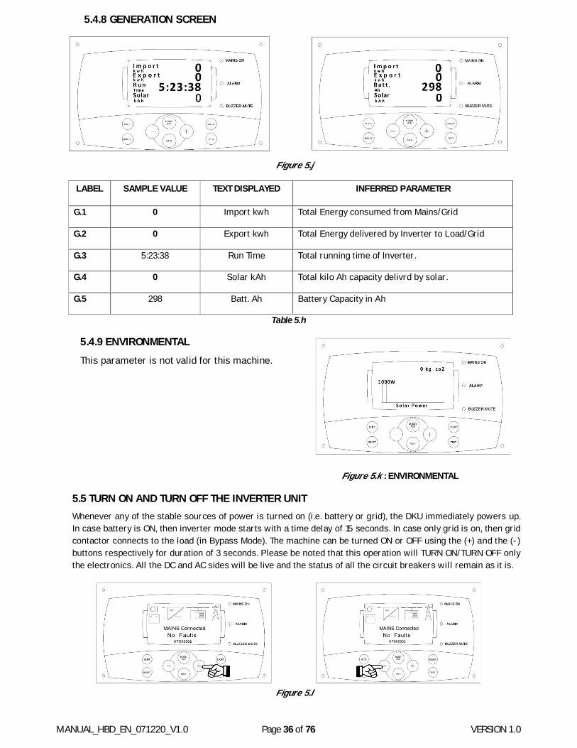
MANUAL_HBD_EN_071220_V1.0 Page 36 of 76 VERSION 1.0
5.4.8 GENERATION SCREEN
Figure 5.j
LABEL SAMPLE VALUE TEXT DISPLAYED INFERRED PARAMETER
G.1 0 Import kwh Total Energy consumed from Mains/Grid
G.2 0 Export kwh Total Energy delivered by Inverter to Load/Grid
G.3 5:23:38 Run Time Total running time of Inverter.
G.4 0 Solar kAh Total kilo Ah capacity delivrd by solar.
G.5 298 Batt. Ah Battery Capacity in Ah
Table 5.h
5.4.9 ENVIRONMENTAL This parameter is not valid for this machine.
Figure 5.k : ENVIRONMENTAL
5.5 TURN ON AND TURN OFF THE INVERTER UNIT Whenever any of the stable sources of power is turned on (i.e. battery or grid), the DKU immediately powers up. In case battery is ON, then inverter mode starts with a time delay of 15 seconds. In case only grid is on, then grid contactor connects to the load (in Bypass Mode). The machine can be turned ON or OFF using the (+) and the (-) buttons respectively for duration of 3 seconds. Please be noted that this operation will TURN ON/TURN OFF only the electronics. All the DC and AC sides will be live and the status of all the circuit breakers will remain as it is.
Figure 5.l
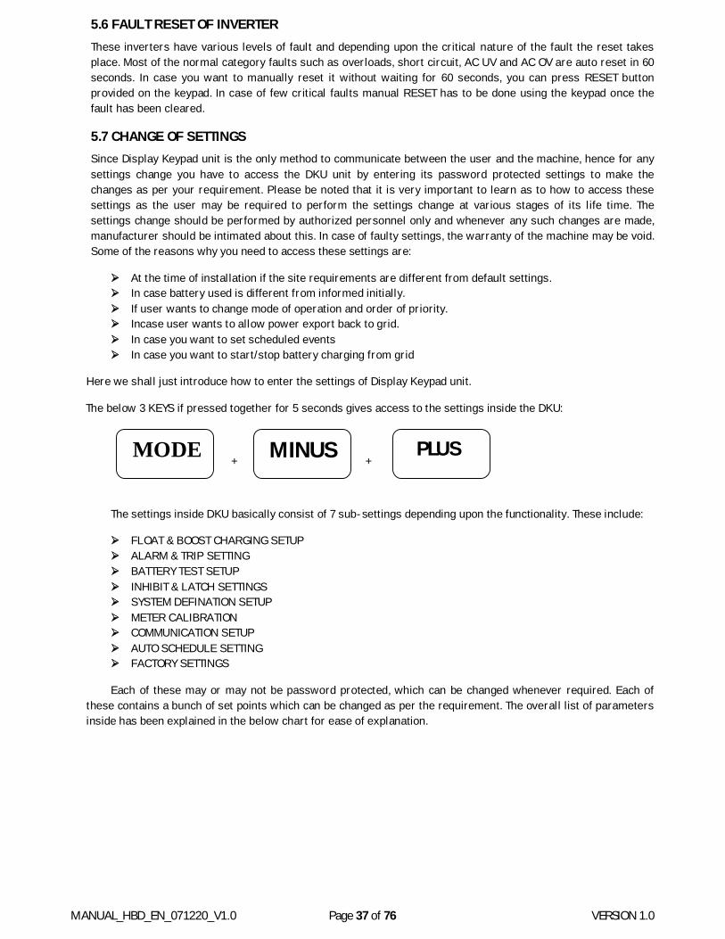
MANUAL_HBD_EN_071220_V1.0 Page 37 of 76 VERSION 1.0
5.6 FAULT RESET OF INVERTER These inverters have various levels of fault and depending upon the critical nature of the fault the reset takes place. Most of the normal category faults such as overloads, short circuit, AC UV and AC OV are auto reset in 60 seconds. In case you want to manually reset it without waiting for 60 seconds, you can press RESET button provided on the keypad. In case of few critical faults manual RESET has to be done using the keypad once the fault has been cleared.
5.7 CHANGE OF SETTINGS Since Display Keypad unit is the only method to communicate between the user and the machine, hence for any settings change you have to access the DKU unit by entering its password protected settings to make the changes as per your requirement. Please be noted that it is very important to learn as to how to access these settings as the user may be required to perform the settings change at various stages of its life time. The settings change should be performed by authorized personnel only and whenever any such changes are made, manufacturer should be intimated about this. In case of faulty settings, the warranty of the machine may be void. Some of the reasons why you need to access these settings are:
At the time of installation if the site requirements are different from default settings. In case battery used is different from informed initially. If user wants to change mode of operation and order of priority. Incase user wants to allow power export back to grid. In case you want to set scheduled events In case you want to start/stop battery charging from grid
Here we shall just introduce how to enter the settings of Display Keypad unit.
The below 3 KEYS if pressed together for 5 seconds gives access to the settings inside the DKU:
+ +
The settings inside DKU basically consist of 7 sub-settings depending upon the functionality. These include:
FLOAT & BOOST CHARGING SETUP ALARM & TRIP SETTING BATTERY TEST SETUP INHIBIT & LATCH SETTINGS SYSTEM DEFINATION SETUP METER CALIBRATION COMMUNICATION SETUP AUTO SCHEDULE SETTING FACTORY SETTINGS
Each of these may or may not be password protected, which can be changed whenever required. Each of these contains a bunch of set points which can be changed as per the requirement. The overall list of parameters inside has been explained in the below chart for ease of explanation.
MINUS MODE PLUS
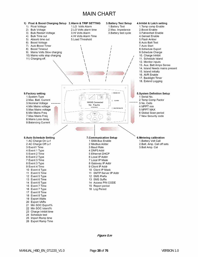
MANUAL_HBD_EN_071220_V1.0 Page 38 of 76 VERSION 1.0
Figure 5.m
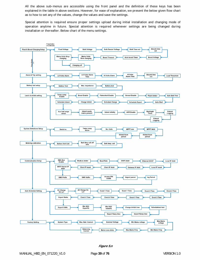
MANUAL_HBD_EN_071220_V1.0 Page 39 of 76 VERSION 1.0
All the above sub-menus are accessible using the front panel and the definition of these keys has been explained in the table in above sections. However, for ease of explanation, we present the below given flow chart as to how to set any of the values, change the values and save the settings.
Special attention is required ensure proper settings upload during initial installation and changing mode of operation anytime in future. Special attention is required whenever settings are being changed during installation or thereafter. Below chart of the menu settings.
Figure 5.n
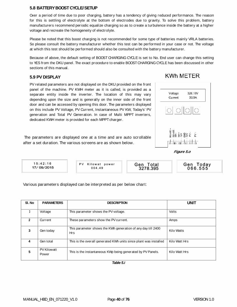
MANUAL_HBD_EN_071220_V1.0 Page 40 of 76 VERSION 1.0
5.8 BATTERY BOOST CYCLE/SETUP Over a period of time due to poor charging, battery has a tendency of giving reduced performance. The reason for this is settling of electrolyte at the bottom of electrodes due to gravity. To solve this problem, battery manufacturers recommend periodic equalize charging so as to create a turbulence inside the battery at a higher voltage and recreate the homogeneity of electrolyte.
Please be noted that this boost charging is not recommended for some type of batteries mainly VRLA batteries. So please consult the battery manufacturer whether this test can be performed in your case or not. The voltage at which this test should be performed should also be consulted with the battery manufacturer.
Because of above, the default setting of BOOST CHARGING CYCLE is set to No. End user can change this setting to YES from the DKU panel. The exact procedure to enable BOOST CHARGING CYCLE has been discussed in other sections of this manual.
5.9 PV DISPLAY PV related parameters are not displayed on the DKU provided on the front panel of the machine. PV KWH meter as it is called, is provided as a separate entity inside the inverter. The location of this may vary depending upon the size and is generally on the inner side of the front door and can be accessed by opening this door. The parameters displayed on this include PV Voltage, PV Current, Instantaneous PV KW, Today’s’ PV generation and Total PV Generation. In case of Multi MPPT inverters, dedicated KWH meter is provided for each MPPT charger.
The parameters are displayed one at a time and are auto scrollable after a set duration. The various screens are as shown below.
Figure 5.o
Various parameters displayed can be interpreted as per below chart:
Sl. No PARAMETERS DESCRIPTION UNIT
1 Voltage This parameter shows the PV voltage. Volts
2 Current These parameters show the PV current. Amps
3 Gen today This parameter shows the KWh generation of any day till 2400 Hrs Kilo Watts
4 Gen total This is the overall generated KWh units since plant was installed Kilo Watt Hrs
5 PV Kilowatt Power
This is the instantaneous KWp being generated by PV Panels. Kilo Watt Hrs
Table 5.i
MANUAL_HBD_EN_071220_V1.0 Page 41 of 76 VERSION 1.0
6. BATTERY & BATTERY CHARGING
Although Batteries are not a part of the equipment supplied in this consignment, but since this machine works only with the batteries connected, it’s important to discuss about its selection and usage.
Please be noted that SSSI range of inverters are designed for:
Flooded LM Batteries Sealed Maintenance VRLA Batteries Sealed Maintenance Tubular gel VRLA Batteries
All the SSSI machines supplied have been configured for a common battery type and in case of mismatch; the settings need to be checked at the time of installation. So, it’s always recommended to check the battery charging parameters at the time of installation for better performance.
Before we proceed lets discuss a few important things about batteries and their connections in any storage based installation. These are standard Industrial practices and inverter manufacturer shall not be responsible for any conflict in opinion with the recommendations of the battery manufacturer:
1. Never select the battery blindly as it is very important to study the application to which the battery is subjected. Main points of consideration include discharging rate, depth of discharge, rate of charging, ambient temperature, source of charging etc.
2. Do not ignore or bypass any recommendations of the battery manufacturer as battery life is very specific to the conditions under which it can survive the said life.
3. Interconnection method of various cells is very important and preferably copper bus bars should be used for interconnections.
4. Battery bank should always be insulated to avoid an electrical shock. 5. In case of flooded batteries, regular top up of distilled water is very important. 6. Specific Gravity check should be a part of regular maintenance and whenever required an equalized
charging cycle should be initiated. 7. Batteries should always we placed in a separate room to avoid acidic fumes. 8. Length of cables from Battery to PCU should be kept to minimum to avoid the losses. Cable sizing should
also be done keeping in mind to minimize the losses. 9. Never connect more than 2 battery banks in parallel to a single system. This may lead to imbalanced
charge discharge cycles of the 2 banks ultimately causing stress to one of the banks. 10. Never discharge your batteries beyond 70% DOD as it may damage your batteries permanently. 11. A battery designed to give back up of 10 hours and discharge rate D, will not give a back up of 20 hours at
discharge rate of 0.5 D. The relationship is never linear. 12. Always charge the batteries at the voltages prescribed by the battery manufacturer. Always double check
the charging voltages in the Inverter machine during installation. 13. Battery is a passive but very demanding in nature. Use battery only as recommended to get the full life of
the battery.
6.1 BATTERY CHARGING TECHNIQUE IN SSSI RANGE OF INVERTERS Entire range of SSSI range of inverters have inbuilt Solar Charger as well as Grid charger. These chargers are capable of charging the battery connected at rated voltage and current. These battery charging sources have been discussed separately below:
6.2 MPPT BASED SOLAR CHARGE CONTROLLER This is used to charge the batteries using Solar Power. This Solar Charger works on MPPT Algorithom which is better as compared to the conventional PWM charging method. Not only does it perform the MPPT (Maximum Power Point Tracking) function but also carry out the proper 3 stage charging cycle on the connected batteries.
Unlike the Battery less Inverters, here in storage based machines, separate power electronic switching device performs the function of charging through PV power. This has inbuilt reverse polarity protection in form of a series diode to avoid damages in case of wrong polarity connections. Input of Solar Charger also has Surge Protection device in form of Metal Oxide Variostors (MOVs’).

MANUAL_HBD_EN_071220_V1.0 Page 42 of 76 VERSION 1.0
MPPT chargers provided in these machines follow the Perturb & Observe (P&O) algorithm to track the Maximum Power Point of the solar panel curve.
In case of higher capacity inverters, the number of charge controllers is three instead of one. Please refer product datasheet to check the number of MPPT chargers in your machine. The purpose of providing more number of MPPT charges in bigger machines is because single MPPT charger cannot cater to PV fields of very large sizes and hence the generation becomes poor.
Rate at which the MPPT charger charges the battery is highly dependent on the PV power available and the loads connected. PV power can charge batteries only with the PV power available at that instant and cannot create power on its own. Similarly, in case loads connected on the AC side demand power and PV power is available, then preference will be given to the AC loads and not the battery charging (in case of standalone mode only).
All MPPT chargers are permitted a certain degree of overload for the PV capacity that can be connected to any machine. Refer product datasheet for detailed specifications of MPPT charger.
6.3 GRID BASED CHARGER All the HBD machines consist of bi-directional convertor modules which can act as inverter as well as battery charger. The battery charger mode of this convertor is used to provide battery charging feature through the Grid supply.
In this mode, machine bypasses Grid supply to the loads and at the same time charge the batteries using grid power.
The Input to the grid charger can be single phase or three phase depending upon the 1-Phase/ 3-Phase nature of the machine. Using all the phases (in case of 3-Phase machines) is very important to avoid imbalanced loading of the 3 phases at site.
Capacity of Grid charger can be changed using the set point MAX. IMPORT POWER of test software. The default power of the Grid Charger is set to the rated power of the machine. This power defines the total power imported from the grid terminals-both for the loads as well as for battery charging. Hence batteries are charged at rated power only when the connected loads are connected to zero. In case connected loads draw power then only the balance power will be used to charge the batteries. This is important to avoid unnecessary loading on the Grid connection at site.
Even if the connected loads are zero, the actual power available at the battery terminals will be lesser than the import power because of the convertor efficiencies as mentioned in the datasheet.
In case of weak grid areas where drawing grid power leads to dip in the voltages, Grid charging can be controlled using the same set point.
All the battery charging voltages and currents are fed through the Display-Keypad-Unit (DKU) provided on the front door and are discussed in other sections-6.3 of this manual. Please be noted that all these parameters are common for both the chargers and automatic priority is given to the MPPT charger as compared to the Grid charger.
6.4 COMMON FEATURES Some of the common features of charging profile for both these chargers have been discussed as under:
6.5 BATTERY CURRENT LIMITING (BCL) In case deep discharge batteries are put to charge, they have a tendency to draw huge amounts of current to get charged. This often leads to very high temperatures inside the batteries and hence this current has to be regulated. This feature is called Battery current limiting and this is inbuilt in all the HBD range of Inverters both for the MPPT charger and the Grid charger.
The value of this BCL current is a default setting value depending upon the size of the machine as mentioned in the chart on Section-4.3. It can be changed from the DKU as explained on chart in figure#5.m of chapter-5. This value is generally set at C/10 of the battery capacity that is connected and the selection of this value has been
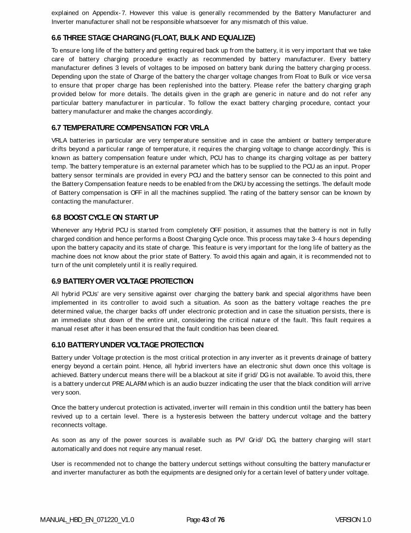
MANUAL_HBD_EN_071220_V1.0 Page 43 of 76 VERSION 1.0
explained on Appendix-7. However this value is generally recommended by the Battery Manufacturer and Inverter manufacturer shall not be responsible whatsoever for any mismatch of this value.
6.6 THREE STAGE CHARGING (FLOAT, BULK AND EQUALIZE) To ensure long life of the battery and getting required back up from the battery, it is very important that we take care of battery charging procedure exactly as recommended by battery manufacturer. Every battery manufacturer defines 3 levels of voltages to be imposed on battery bank during the battery charging process. Depending upon the state of Charge of the battery the charger voltage changes from Float to Bulk or vice versa to ensure that proper charge has been replenished into the battery. Please refer the battery charging graph provided below for more details. The details given in the graph are generic in nature and do not refer any particular battery manufacturer in particular. To follow the exact battery charging procedure, contact your battery manufacturer and make the changes accordingly.
6.7 TEMPERATURE COMPENSATION FOR VRLA VRLA batteries in particular are very temperature sensitive and in case the ambient or battery temperature drifts beyond a particular range of temperature, it requires the charging voltage to change accordingly. This is known as battery compensation feature under which, PCU has to change its charging voltage as per battery temp. The battery temperature is an external parameter which has to be supplied to the PCU as an input. Proper battery sensor terminals are provided in every PCU and the battery sensor can be connected to this point and the Battery Compensation feature needs to be enabled from the DKU by accessing the settings. The default mode of Battery compensation is OFF in all the machines supplied. The rating of the battery sensor can be known by contacting the manufacturer.
6.8 BOOST CYCLE ON START UP Whenever any Hybrid PCU is started from completely OFF position, it assumes that the battery is not in fully charged condition and hence performs a Boost Charging Cycle once. This process may take 3-4 hours depending upon the battery capacity and its state of charge. This feature is very important for the long life of battery as the machine does not know about the prior state of Battery. To avoid this again and again, it is recommended not to turn of the unit completely until it is really required.
6.9 BATTERY OVER VOLTAGE PROTECTION All hybrid PCUs’ are very sensitive against over charging the battery bank and special algorithms have been implemented in its controller to avoid such a situation. As soon as the battery voltage reaches the pre determined value, the charger backs off under electronic protection and in case the situation persists, there is an immediate shut down of the entire unit, considering the critical nature of the fault. This fault requires a manual reset after it has been ensured that the fault condition has been cleared.
6.1.0 BATTERY UNDER VOLTAGE PROTECTION Battery under Voltage protection is the most critical protection in any inverter as it prevents drainage of battery energy beyond a certain point. Hence, all hybrid inverters have an electronic shut down once this voltage is achieved. Battery undercut means there will be a blackout at site if grid/ DG is not available. To avoid this, there is a battery undercut PRE ALARM which is an audio buzzer indicating the user that the black condition will arrive very soon.
Once the battery undercut protection is activated, inverter will remain in this condition until the battery has been revived up to a certain level. There is a hysteresis between the battery undercut voltage and the battery reconnects voltage.
As soon as any of the power sources is available such as PV/ Grid/ DG, the battery charging will start automatically and does not require any manual reset.
User is recommended not to change the battery undercut settings without consulting the battery manufacturer and inverter manufacturer as both the equipments are designed only for a certain level of battery under voltage.
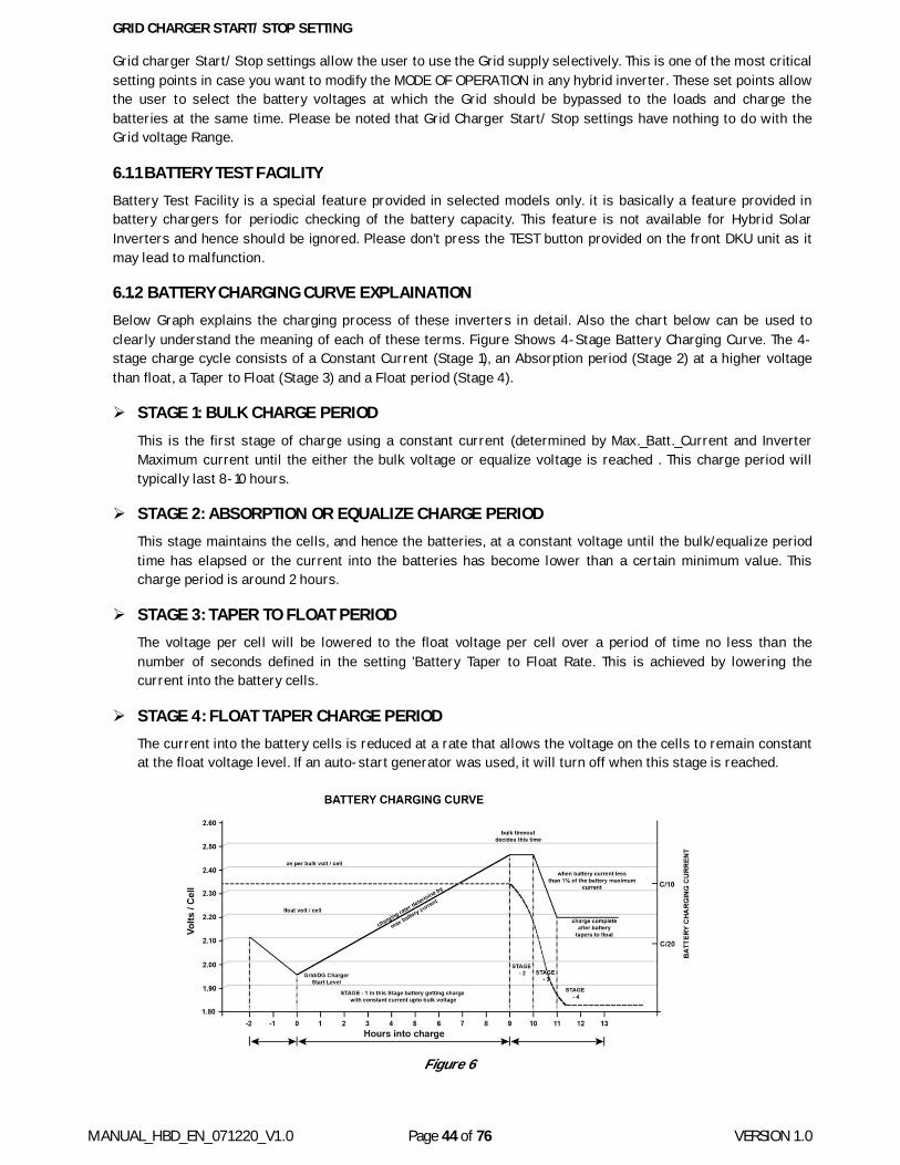
MANUAL_HBD_EN_071220_V1.0 Page 44 of 76 VERSION 1.0
GRID CHARGER START/ STOP SETTING
Grid charger Start/ Stop settings allow the user to use the Grid supply selectively. This is one of the most critical setting points in case you want to modify the MODE OF OPERATION in any hybrid inverter. These set points allow the user to select the battery voltages at which the Grid should be bypassed to the loads and charge the batteries at the same time. Please be noted that Grid Charger Start/ Stop settings have nothing to do with the Grid voltage Range.
6.1.1 BATTERY TEST FACILITY Battery Test Facility is a special feature provided in selected models only. it is basically a feature provided in battery chargers for periodic checking of the battery capacity. This feature is not available for Hybrid Solar Inverters and hence should be ignored. Please don’t press the TEST button provided on the front DKU unit as it may lead to malfunction.
6.1.2 BATTERY CHARGING CURVE EXPLAINATION Below Graph explains the charging process of these inverters in detail. Also the chart below can be used to clearly understand the meaning of each of these terms. Figure Shows 4-Stage Battery Charging Curve. The 4-stage charge cycle consists of a Constant Current (Stage 1), an Absorption period (Stage 2) at a higher voltage than float, a Taper to Float (Stage 3) and a Float period (Stage 4).
STAGE 1: BULK CHARGE PERIOD This is the first stage of charge using a constant current (determined by Max._Batt._Current and Inverter Maximum current until the either the bulk voltage or equalize voltage is reached . This charge period will typically last 8-10 hours.
STAGE 2: ABSORPTION OR EQUALIZE CHARGE PERIOD This stage maintains the cells, and hence the batteries, at a constant voltage until the bulk/equalize period time has elapsed or the current into the batteries has become lower than a certain minimum value. This charge period is around 2 hours.
STAGE 3: TAPER TO FLOAT PERIOD The voltage per cell will be lowered to the float voltage per cell over a period of time no less than the number of seconds defined in the setting ’Battery Taper to Float Rate. This is achieved by lowering the current into the battery cells.
STAGE 4: FLOAT TAPER CHARGE PERIOD The current into the battery cells is reduced at a rate that allows the voltage on the cells to remain constant at the float voltage level. If an auto-start generator was used, it will turn off when this stage is reached.
Figure 6
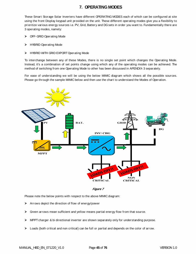
MANUAL_HBD_EN_071220_V1.0 Page 45 of 76 VERSION 1.0
7. OPERATING MODES
These Smart Storage Solar Inverters have different OPERATING MODES each of which can be configured at site using the front Display keypad unit provided on the unit. These different operating modes give you a flexibility to prioritize various energy sources i.e. PV, Grid, Battery and DG sets in order you want to. Fundamentally there are 3 operating modes, namely:
OFF-GRID Operating Mode
HYBRID Operating Mode
HYBRID WITH GRID EXPORT Operating Mode
To interchange between any of these Modes, there is no single set point which changes the Operating Mode. Instead, it’s a combination of set points change using which any of the operating modes can be achieved. The method of switching from one Operating Mode to other has been discussed in APENDIX-3 separately.
For ease of understanding we will be using the below MIMIC diagram which shows all the possible sources. Please go through the sample MIMIC below and then use the chart to understand the Modes of Operation.
Figure 7
Please note the below points with respect to the above MIMIC diagram:
Arrows depict the direction of flow of energy/power
Green arrows mean sufficient and yellow means partial energy flow from that source.
MPPT charger & bi directional inverter are shown separately only for understanding purpose.
Loads (both critical and non critical) can be full or partial and depends on the color of arrow.
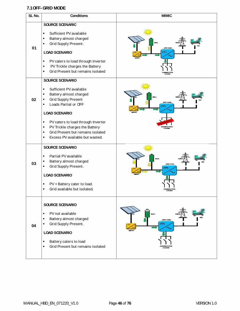
MANUAL_HBD_EN_071220_V1.0 Page 46 of 76 VERSION 1.0
7.1 OFF-GRID MODE SL No. Conditions MIMIC
01
SOURCE SCENARIO
Sufficient PV available Battery almost charged Grid Supply Present.
LOAD SCENARIO
PV caters to load through Inverter PV Trickle charges the Battery Grid Present but remains isolated
02
SOURCE SCENARIO
Sufficient PV available Battery almost charged Grid Supply Present Loads Partial or OFF
LOAD SCENARIO
PV caters to load through Inverter PV Trickle charges the Battery Grid Present but remains isolated Excess PV available but wasted.
03
SOURCE SCENARIO
Partial PV available Battery almost charged Grid Supply Present.
LOAD SCENARIO
PV + Battery cater to load. Grid available but isolated.
04
SOURCE SCENARIO
PV not available Battery almost charged Grid Supply Present.
LOAD SCENARIO
Battery caters to load Grid Present but remains isolated

MANUAL_HBD_EN_071220_V1.0 Page 47 of 76 VERSION 1.0
05
SOURCE SCENARIO
PV not available Battery @ discharge LEVEL-1 Grid Supply Present.
LOAD SCENARIO
battery discharge up to level - 2 battery caters the load Grid present but remain isolated
06
SOURCE SCENARIO
PV not available Battery @ discharge LEVEL-1 Grid Supply Absent.
LOAD SCENARIO
Battery Discharge till LEVEL-2
07
SOURCE SCENARIO
PV not available Battery @ discharge LEVEL-2 Grid Supply Present.
LOAD SCENARIO
Battery discharge stopped. Grid Supply bypassed to Loads Grid supply charges the Battery.
08
SOURCE SCENARIO
PV not available Battery @ discharge LEVEL-2 Grid Supply Absent DG Supply present.
LOAD SCENARIO
Battery discharge stopped. DG Start Command Triggered DG Supply Chargers Battery DG Supply Bypassed to Loads
09
SOURCE SCENARIO
PV available Battery @ discharge LEVEL-2 Grid Supply Present
LOAD SCENARIO
Battery discharge stopped. PV Power Charger Battery Grid Supply Bypassed to Loads Grid Supply charges the Battery
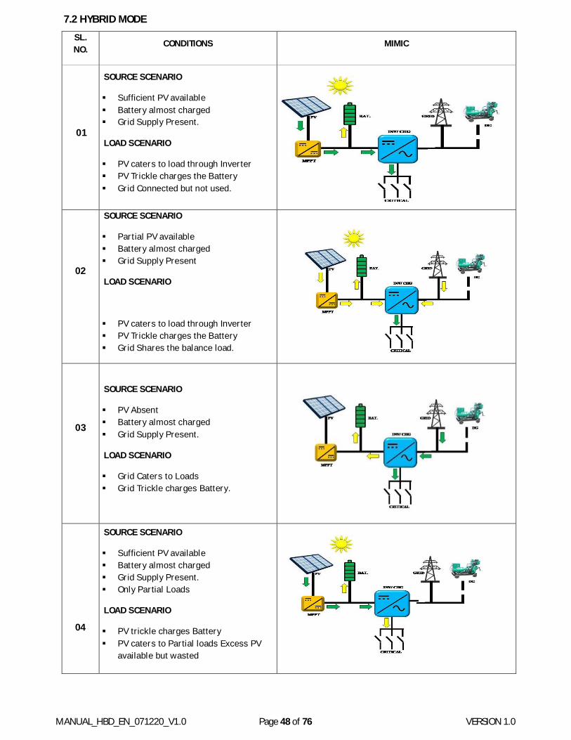
MANUAL_HBD_EN_071220_V1.0 Page 48 of 76 VERSION 1.0
7.2 HYBRID MODE SL. NO. CONDITIONS MIMIC
01
SOURCE SCENARIO
Sufficient PV available Battery almost charged Grid Supply Present.
LOAD SCENARIO
PV caters to load through Inverter PV Trickle charges the Battery Grid Connected but not used.
02
SOURCE SCENARIO
Partial PV available Battery almost charged Grid Supply Present
LOAD SCENARIO
PV caters to load through Inverter PV Trickle charges the Battery Grid Shares the balance load.
03
SOURCE SCENARIO
PV Absent Battery almost charged Grid Supply Present.
LOAD SCENARIO
Grid Caters to Loads Grid Trickle charges Battery.
04
SOURCE SCENARIO
Sufficient PV available Battery almost charged Grid Supply Present. Only Partial Loads
LOAD SCENARIO
PV trickle charges Battery PV caters to Partial loads Excess PV
available but wasted
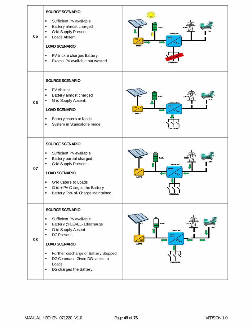
MANUAL_HBD_EN_071220_V1.0 Page 49 of 76 VERSION 1.0
05
SOURCE SCENARIO
Sufficient PV available Battery almost charged Grid Supply Present. Loads Absent
LOAD SCENARIO
PV trickle charges Battery Excess PV available but wasted.
06
SOURCE SCENARIO
PV Absent Battery almost charged Grid Supply Absent.
LOAD SCENARIO
Battery caters to loads System in Standalone mode.
07
SOURCE SCENARIO
Sufficient PV available Battery partial charged Grid Supply Present.
LOAD SCENARIO
Grid Caters to Loads Grid + PV Charges the Battery Battery Top-of-Charge Maintained.
08
SOURCE SCENARIO
Sufficient PV available Battery @ LEVEL-1 discharge Grid Supply Absent DG Present.
LOAD SCENARIO
Further discharge of Battery Stopped. DG Command Given DG caters to
Loads DG charges the Battery.

MANUAL_HBD_EN_071220_V1.0 Page 50 of 76 VERSION 1.0
7.3 HYBRID WITH EXPORT MODE SL. No CONDITIONS MIMIC
01
SOURCE SCENARIO
Sufficient PV available Battery almost charged Grid Supply Present.
LOAD SCENARIO
PV caters to load through Inverter PV Trickle charges the Battery Grid Connected but not used.
02
SOURCE SCENARIO
Partial PV available Battery almost charged Grid Supply Present
LOAD SCENARIO
PV and Grid both caters to load. PV Trickle charges the Battery Grid Connected.
03
SOURCE SCENARIO
Excess PV available Battery almost charged Grid Supply Present.
LOAD SCENARIO
PV caters to load through Inverter PV Trickle charges the Battery Grid Connected. Excess power will be feed to non-
critical load
04
SOURCE SCENARIO
Excess PV available Battery almost charged Grid Supply Present. Critical load absent
LOAD SCENARIO
PV Trickle charges the Battery Grid Synchronized but not used. Excess power will go to non-critical
load as well as to grid.
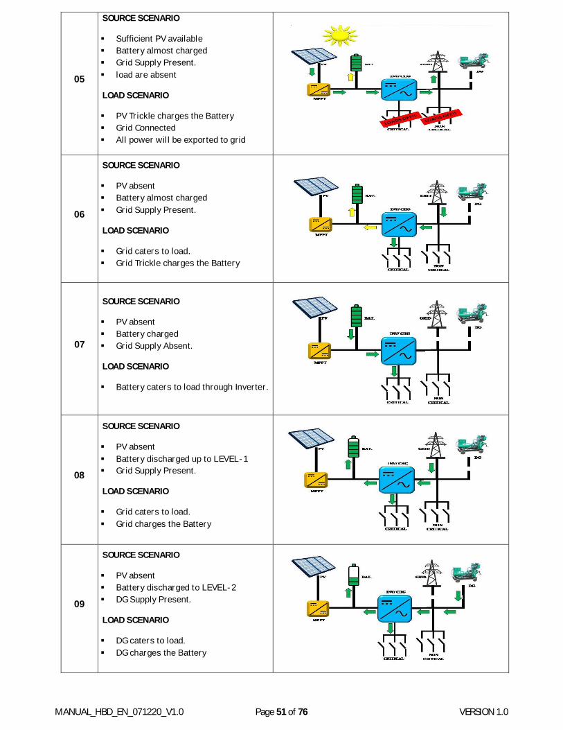
MANUAL_HBD_EN_071220_V1.0 Page 51 of 76 VERSION 1.0
05
SOURCE SCENARIO
Sufficient PV available Battery almost charged Grid Supply Present. load are absent
LOAD SCENARIO
PV Trickle charges the Battery Grid Connected All power will be exported to grid
06
SOURCE SCENARIO
PV absent Battery almost charged Grid Supply Present.
LOAD SCENARIO
Grid caters to load. Grid Trickle charges the Battery
07
SOURCE SCENARIO
PV absent Battery charged Grid Supply Absent.
LOAD SCENARIO
Battery caters to load through Inverter.
08
SOURCE SCENARIO
PV absent Battery discharged up to LEVEL-1 Grid Supply Present.
LOAD SCENARIO
Grid caters to load. Grid charges the Battery
09
SOURCE SCENARIO
PV absent Battery discharged to LEVEL-2 DG Supply Present.
LOAD SCENARIO
DG caters to load. DG charges the Battery
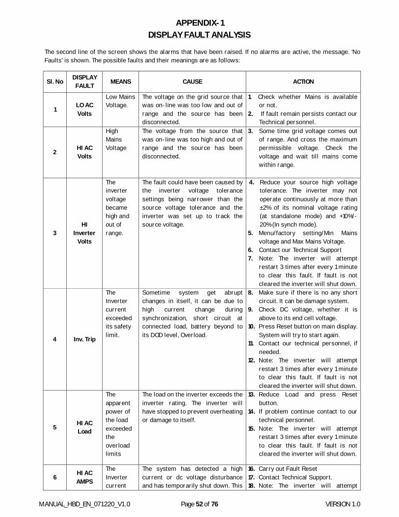
MANUAL_HBD_EN_071220_V1.0 Page 52 of 76 VERSION 1.0
APPENDIX-1 DISPLAY FAULT ANALYSIS
The second line of the screen shows the alarms that have been raised. If no alarms are active, the message. ‘No Faults’ is shown. The possible faults and their meanings are as follows:
Sl. No DISPLAY FAULT MEANS CAUSE ACTION
1 LO AC Volts
Low Mains Voltage.
The voltage on the grid source that was on-line was too low and out of range and the source has been disconnected.
1. Check whether Mains is available or not.
2. If fault remain persists contact our Technical personnel.
2 HI AC Volts
High Mains Voltage
The voltage from the source that was on-line was too high and out of range and the source has been disconnected.
3. Some time grid voltage comes out of range. And cross the maximum permissible voltage. Check the voltage and wait till mains come within range.
3 HI
Inverter Volts
The inverter voltage became high and out of range.
The fault could have been caused by the inverter voltage tolerance settings being narrower than the source voltage tolerance and the inverter was set up to track the source voltage.
4. Reduce your source high voltage tolerance. The inverter may not operate continuously at more than ±2% of its nominal voltage rating (at standalone mode) and +10%/-20% (In synch mode).
5. Menu/factory setting/Min Mains voltage and Max Mains Voltage.
6. Contact our Technical Support 7. Note: The inverter will attempt
restart 3 times after every 1 minute to clear this fault. If fault is not cleared the inverter will shut down.
4 Inv. Trip
The Inverter current exceeded its safety limit.
Sometime system get abrupt changes in itself, it can be due to high current change during synchronization, short circuit at connected load, battery beyond to its DOD level, Overload.
8. Make sure if there is no any short circuit. It can be damage system.
9. Check DC voltage, whether it is above to its end cell voltage.
10. Press Reset button on main display. System will try to start again.
11. Contact our technical personnel, if needed.
12. Note: The inverter will attempt restart 3 times after every 1 minute to clear this fault. If fault is not cleared the inverter will shut down.
5 HI AC Load
The apparent power of the load exceeded the overload limits
The load on the inverter exceeds the inverter rating. The inverter will have stopped to prevent overheating or damage to itself.
13. Reduce Load and press Reset button.
14. If problem continue contact to our technical personnel.
15. Note: The inverter will attempt restart 3 times after every 1 minute to clear this fault. If fault is not cleared the inverter will shut down.
6 HI AC AMPS
The Inverter current
The system has detected a high current or dc voltage disturbance and has temporarily shut down. This
16. Carry out Fault Reset 17. Contact Technical Support. 18. Note: The inverter will attempt
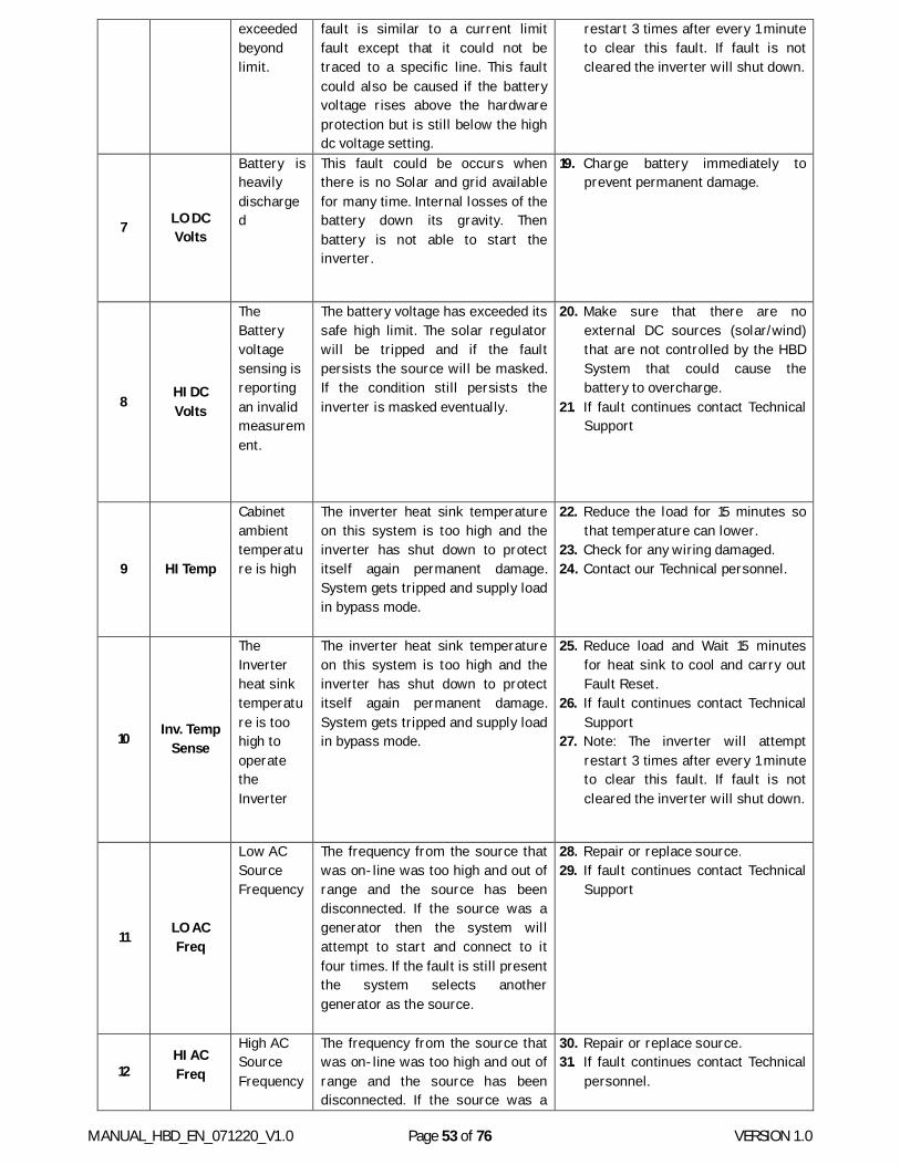
MANUAL_HBD_EN_071220_V1.0 Page 53 of 76 VERSION 1.0
exceeded beyond limit.
fault is similar to a current limit fault except that it could not be traced to a specific line. This fault could also be caused if the battery voltage rises above the hardware protection but is still below the high dc voltage setting.
restart 3 times after every 1 minute to clear this fault. If fault is not cleared the inverter will shut down.
7 LO DC Volts
Battery is heavily discharged
This fault could be occurs when there is no Solar and grid available for many time. Internal losses of the battery down its gravity. Then battery is not able to start the inverter.
19. Charge battery immediately to prevent permanent damage.
8 HI DC Volts
The Battery voltage sensing is reporting an invalid measurement.
The battery voltage has exceeded its safe high limit. The solar regulator will be tripped and if the fault persists the source will be masked. If the condition still persists the inverter is masked eventually.
20. Make sure that there are no external DC sources (solar/wind) that are not controlled by the HBD System that could cause the battery to overcharge.
21. If fault continues contact Technical Support
9 HI Temp
Cabinet ambient temperature is high
The inverter heat sink temperature on this system is too high and the inverter has shut down to protect itself again permanent damage. System gets tripped and supply load in bypass mode.
22. Reduce the load for 15 minutes so that temperature can lower.
23. Check for any wiring damaged. 24. Contact our Technical personnel.
10 Inv. Temp Sense
The Inverter heat sink temperature is too high to operate the Inverter
The inverter heat sink temperature on this system is too high and the inverter has shut down to protect itself again permanent damage. System gets tripped and supply load in bypass mode.
25. Reduce load and Wait 15 minutes for heat sink to cool and carry out Fault Reset.
26. If fault continues contact Technical Support
27. Note: The inverter will attempt restart 3 times after every 1 minute to clear this fault. If fault is not cleared the inverter will shut down.
11 LO AC Freq
Low AC Source Frequency
The frequency from the source that was on-line was too high and out of range and the source has been disconnected. If the source was a generator then the system will attempt to start and connect to it four times. If the fault is still present the system selects another generator as the source.
28. Repair or replace source. 29. If fault continues contact Technical
Support
12 HI AC Freq
High AC Source Frequency
The frequency from the source that was on-line was too high and out of range and the source has been disconnected. If the source was a
30. Repair or replace source. 31. If fault continues contact Technical
personnel.
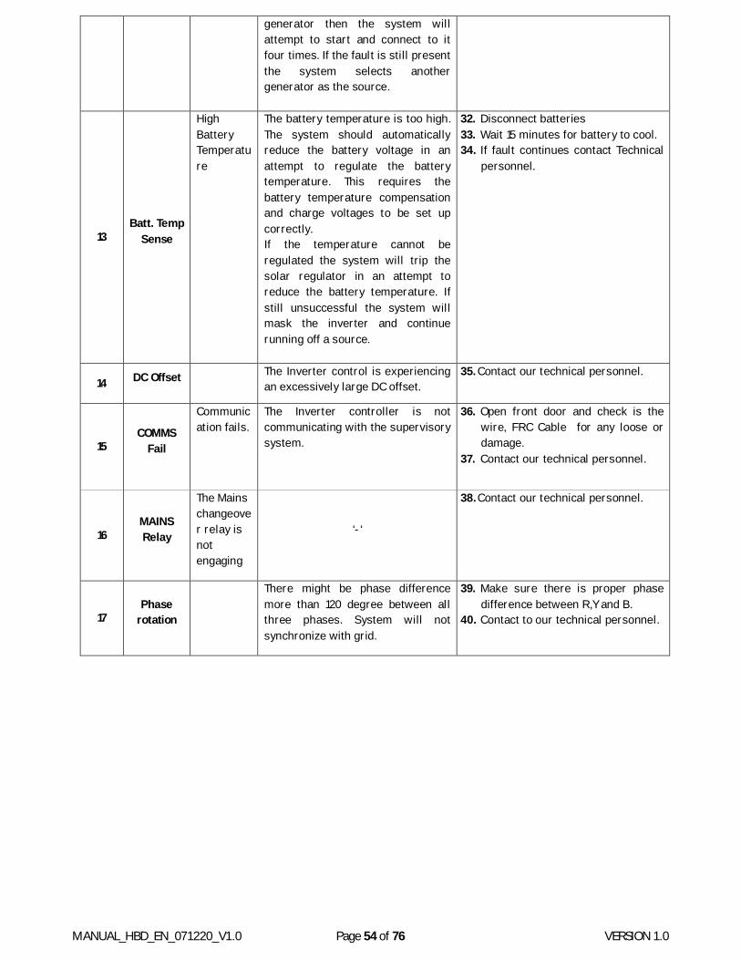
MANUAL_HBD_EN_071220_V1.0 Page 54 of 76 VERSION 1.0
generator then the system will attempt to start and connect to it four times. If the fault is still present the system selects another generator as the source.
13 Batt. Temp
Sense
High Battery Temperature
The battery temperature is too high. The system should automatically reduce the battery voltage in an attempt to regulate the battery temperature. This requires the battery temperature compensation and charge voltages to be set up correctly. If the temperature cannot be regulated the system will trip the solar regulator in an attempt to reduce the battery temperature. If still unsuccessful the system will mask the inverter and continue running off a source.
32. Disconnect batteries 33. Wait 15 minutes for battery to cool. 34. If fault continues contact Technical
personnel.
14 DC Offset The Inverter control is experiencing an excessively large DC offset.
35. Contact our technical personnel.
15 COMMS
Fail
Communication fails.
The Inverter controller is not communicating with the supervisory system.
36. Open front door and check is the wire, FRC Cable for any loose or damage.
37. Contact our technical personnel.
16 MAINS Relay
The Mains changeover relay is not engaging
‘-‘
38. Contact our technical personnel.
17 Phase
rotation
There might be phase difference more than 120 degree between all three phases. System will not synchronize with grid.
39. Make sure there is proper phase difference between R,Y and B.
40. Contact to our technical personnel.
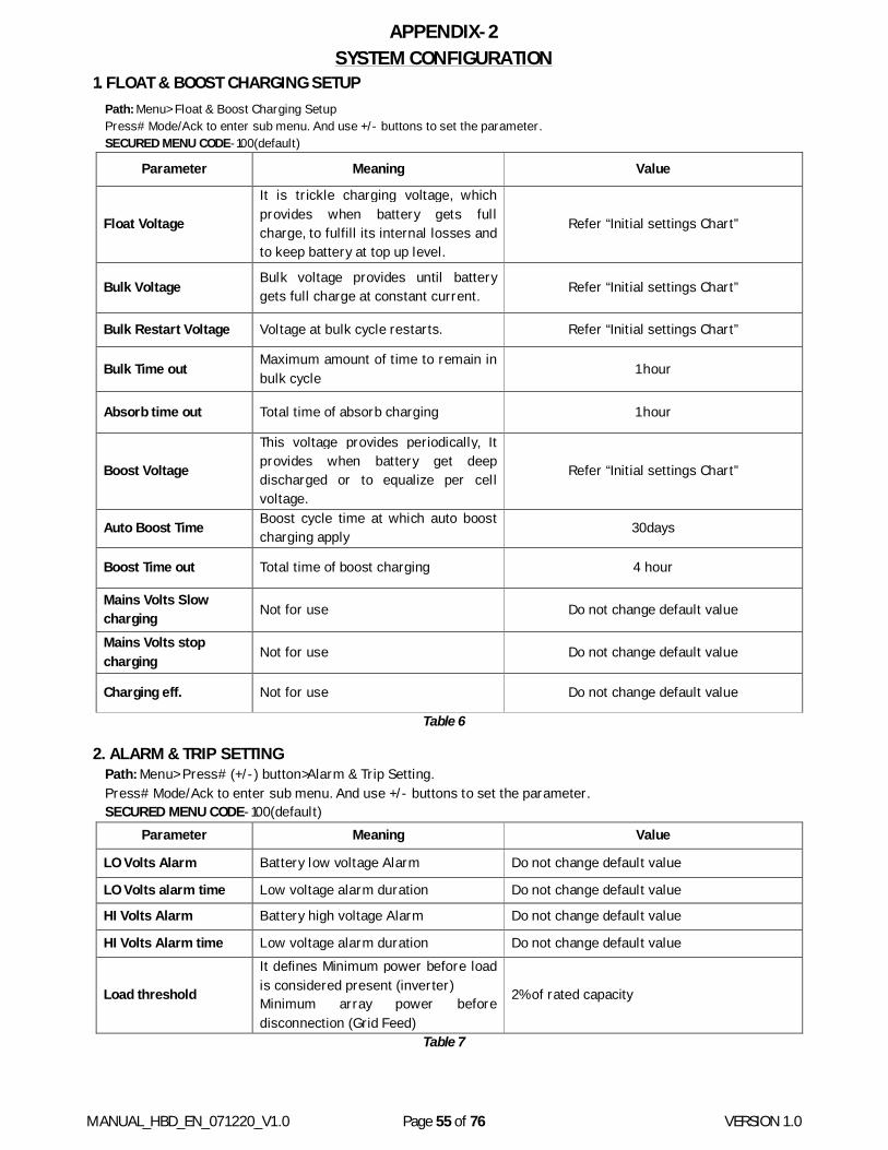
MANUAL_HBD_EN_071220_V1.0 Page 55 of 76 VERSION 1.0
APPENDIX-2 SYSTEM CONFIGURATION
1. FLOAT & BOOST CHARGING SETUP Path: Menu> Float & Boost Charging Setup Press# Mode/Ack to enter sub menu. And use +/- buttons to set the parameter. SECURED MENU CODE-100(default)
Parameter Meaning Value
Float Voltage
It is trickle charging voltage, which provides when battery gets full charge, to fulfill its internal losses and to keep battery at top up level.
Refer “Initial settings Chart”
Bulk Voltage Bulk voltage provides until battery gets full charge at constant current. Refer “Initial settings Chart”
Bulk Restart Voltage Voltage at bulk cycle restarts. Refer “Initial settings Chart”
Bulk Time out Maximum amount of time to remain in bulk cycle 1 hour
Absorb time out Total time of absorb charging 1 hour
Boost Voltage
This voltage provides periodically, It provides when battery get deep discharged or to equalize per cell voltage.
Refer “Initial settings Chart”
Auto Boost Time Boost cycle time at which auto boost charging apply 30days
Boost Time out Total time of boost charging 4 hour
Mains Volts Slow charging Not for use Do not change default value
Mains Volts stop charging Not for use Do not change default value
Charging eff. Not for use Do not change default value
Table 6
2. ALARM & TRIP SETTING Path: Menu> Press# (+/-) button>Alarm & Trip Setting. Press# Mode/Ack to enter sub menu. And use +/- buttons to set the parameter. SECURED MENU CODE-100(default)
Parameter Meaning Value
LO Volts Alarm Battery low voltage Alarm Do not change default value
LO Volts alarm time Low voltage alarm duration Do not change default value
HI Volts Alarm Battery high voltage Alarm Do not change default value
HI Volts Alarm time Low voltage alarm duration Do not change default value
Load threshold
It defines Minimum power before load is considered present (inverter) Minimum array power before disconnection (Grid Feed)
2% of rated capacity
Table 7
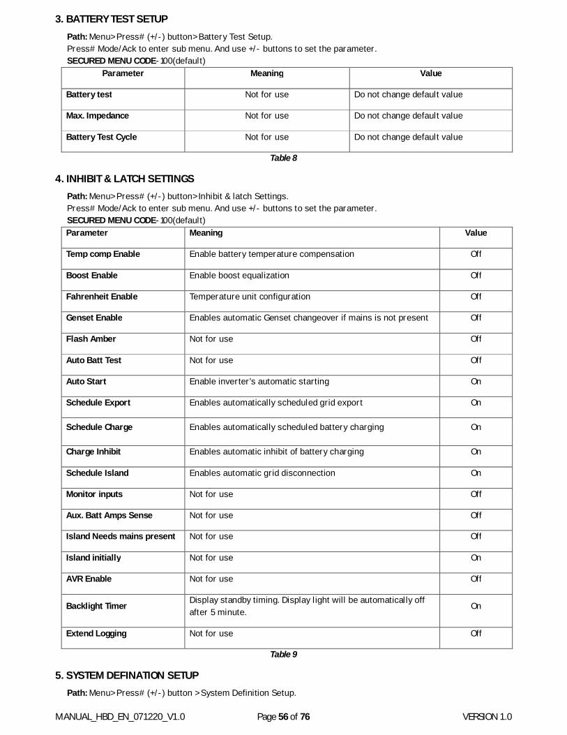
MANUAL_HBD_EN_071220_V1.0 Page 56 of 76 VERSION 1.0
3. BATTERY TEST SETUP Path: Menu> Press# (+/-) button> Battery Test Setup. Press# Mode/Ack to enter sub menu. And use +/- buttons to set the parameter. SECURED MENU CODE-100(default)
Parameter Meaning Value
Battery test Not for use Do not change default value
Max. Impedance Not for use Do not change default value
Battery Test Cycle Not for use Do not change default value
Table 8
4. INHIBIT & LATCH SETTINGS Path: Menu> Press# (+/-) button> Inhibit & latch Settings. Press# Mode/Ack to enter sub menu. And use +/- buttons to set the parameter. SECURED MENU CODE-100(default) Parameter Meaning Value
Temp comp Enable Enable battery temperature compensation Off
Boost Enable Enable boost equalization Off
Fahrenheit Enable Temperature unit configuration Off
Genset Enable Enables automatic Genset changeover if mains is not present Off
Flash Amber Not for use Off
Auto Batt Test Not for use Off
Auto Start Enable inverter’s automatic starting On
Schedule Export Enables automatically scheduled grid export On
Schedule Charge Enables automatically scheduled battery charging On
Charge Inhibit Enables automatic inhibit of battery charging On
Schedule Island Enables automatic grid disconnection On
Monitor inputs Not for use Off
Aux. Batt Amps Sense Not for use Off
Island Needs mains present Not for use Off
Island initially Not for use On
AVR Enable Not for use Off
Backlight Timer Display standby timing. Display light will be automatically off after 5 minute.
On
Extend Logging Not for use Off
Table 9
5. SYSTEM DEFINATION SETUP Path: Menu> Press# (+/-) button > System Definition Setup.
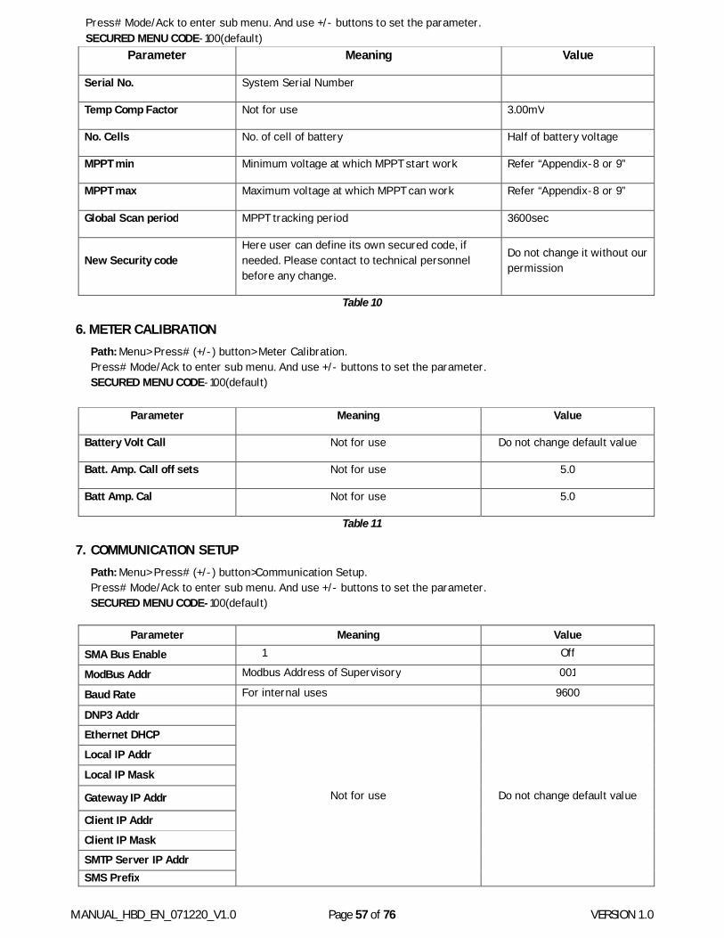
MANUAL_HBD_EN_071220_V1.0 Page 57 of 76 VERSION 1.0
Press# Mode/Ack to enter sub menu. And use +/- buttons to set the parameter. SECURED MENU CODE-100(default)
Parameter Meaning Value
Serial No. System Serial Number
Temp Comp Factor Not for use 3.00mV
No. Cells No. of cell of battery Half of battery voltage
MPPT min Minimum voltage at which MPPT start work Refer “Appendix-8 or 9”
MPPT max Maximum voltage at which MPPT can work Refer “Appendix-8 or 9”
Global Scan period MPPT tracking period 3600sec
New Security code Here user can define its own secured code, if needed. Please contact to technical personnel before any change.
Do not change it without our permission
Table 10
6. METER CALIBRATION Path: Menu> Press# (+/-) button> Meter Calibration. Press# Mode/Ack to enter sub menu. And use +/- buttons to set the parameter. SECURED MENU CODE-100(default)
Parameter Meaning Value
Battery Volt Call Not for use Do not change default value
Batt. Amp. Call off sets Not for use 5.0
Batt Amp. Cal Not for use 5.0
Table 11
7. COMMUNICATION SETUP Path: Menu> Press# (+/-) button>Communication Setup. Press# Mode/Ack to enter sub menu. And use +/- buttons to set the parameter. SECURED MENU CODE-100(default)
Parameter Meaning Value
SMA Bus Enable 1 Off
ModBus Addr Modbus Address of Supervisory 001
Baud Rate For internal uses 9600
DNP3 Addr
Not for use Do not change default value
Ethernet DHCP
Local IP Addr
Local IP Mask
Gateway IP Addr
Client IP Addr
Client IP Mask
SMTP Server IP Addr SMS Prefix
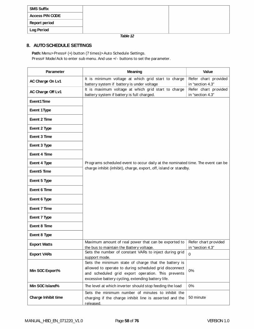
MANUAL_HBD_EN_071220_V1.0 Page 58 of 76 VERSION 1.0
SMS Suffix
Access PIN CODE
Report period
Log Period Table 12
8. AUTO SCHEDULE SETTINGS Path: Menu> Press# (+) button (7 times)> Auto Schedule Settings. Press# Mode/Ack to enter sub menu. And use +/- buttons to set the parameter.
Parameter Meaning Value
AC Charge On Lv1 It is minimum voltage at which grid start to charge battery system if battery is under voltage
Refer chart provided in “section 4.3”
AC Charge Off Lv1 It is maximum voltage at which grid start to charge battery system if battery is full charged.
Refer chart provided in “section 4.3”
Event1 Time
Programs scheduled event to occur daily at the nominated time. The event can be charge inhibit (inhibit), charge, export, off, island or standby.
Event 1 Type
Event 2 Time
Event 2 Type
Event 3 Time
Event 3 Type
Event 4 Time
Event 4 Type
Event5 Time
Event 5 Type
Event 6 Time
Event 6 Type
Event 7 Time
Event 7 Type
Event 8 Time
Event 8 Type
Export Watts Maximum amount of real power that can be exported to the bus to maintain the Battery voltage.
Refer chart provided in “section 4.3”
Export VARs Sets the number of constant VARs to inject during grid support mode.
0
Min SOC Export%
Sets the minimum state of charge that the battery is allowed to operate to during scheduled grid disconnect and scheduled grid export operation. This prevents excessive battery cycling, extending battery life.
0%
Min SOC Island% The level at which inverter should stop feeding the load 0%
Charge Inhibit time Sets the minimum number of minutes to inhibit the charging if the charge inhibit line is asserted and the released.
50 minute
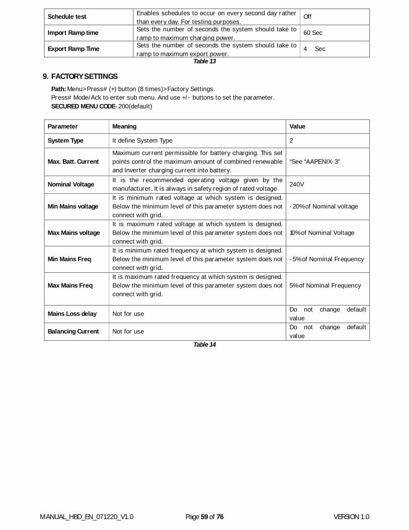
MANUAL_HBD_EN_071220_V1.0 Page 59 of 76 VERSION 1.0
Schedule test Enables schedules to occur on every second day rather than every day. For testing purposes.
Off
Import Ramp time Sets the number of seconds the system should take to ramp to maximum charging power.
60 Sec
Export Ramp Time Sets the number of seconds the system should take to ramp to maximum export power.
4 Sec
Table 13
9. FACTORY SETTINGS Path: Menu> Press# (+) button (8 times)> Factory Settings. Press# Mode/Ack to enter sub menu. And use +/- buttons to set the parameter. SECURED MENU CODE-200(default)
Parameter Meaning Value
System Type It define System Type 2
Max. Batt. Current Maximum current permissible for battery charging. This set points control the maximum amount of combined renewable and Inverter charging current into battery.
“See “AAPENIX-3”
Nominal Voltage It is the recommended operating voltage given by the manufacturer. It is always in safety region of rated voltage 240V
Min Mains voltage It is minimum rated voltage at which system is designed. Below the minimum level of this parameter system does not connect with grid.
-20% of Nominal voltage
Max Mains voltage It is maximum rated voltage at which system is designed. Below the minimum level of this parameter system does not connect with grid.
10% of Nominal Voltage
Min Mains Freq It is minimum rated frequency at which system is designed. Below the minimum level of this parameter system does not connect with grid.
-5% of Nominal Frequency
Max Mains Freq It is maximum rated frequency at which system is designed. Below the minimum level of this parameter system does not connect with grid.
5% of Nominal Frequency
Mains Loss delay Not for use Do not change default value
Balancing Current Not for use Do not change default value
Table 14
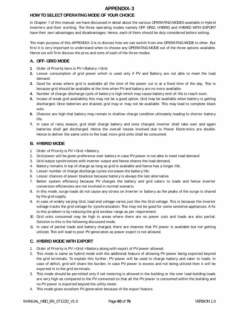
MANUAL_HBD_EN_071220_V1.0 Page 60 of 76 VERSION 1.0
APPENDIX-3 HOW TO SELECT OPERATING MODE OF YOUR CHOICE In Chapter 7 of this manual, we have discussed in detail about the various OPERATING MODES available in Hybrid Inverters and their working. The three operating modes namely OFF GRID, HYBRID and HYBRID WITH EXPORT have their own advantages and disadvantages. Hence, each of them should be duly considered before setting. The main purpose of this APPENDIX-3 is to discuss how we can switch from one OPERATING MODE to other. But first it is very important to understand when to choose any OPERATING MODE out of the three options available. Hence we will first discuss the pros and cons of each of the three modes:
A. OFF-GRID MODE 1. Order of Priority here is PV > Battery > Grid. 2. Lesser consumption of grid power which is used only if PV and Battery are not able to meet the load
demand. 3. Good for areas where grid is available all the time of the power cut is at a fixed time of the day. This is
because grid should be available at the time when PV and battery are no more available. 4. Number of charge-discharge cycle of battery is high which may cause battery end-of-life to reach soon. 5. Incase of weak grid availability this may not be a good option. Grid may be available when battery is getting
discharged. Once batteries are drained, grid may or may not be available. This may lead to complete black outs.
6. Chances are high that battery may remain in shallow charge condition ultimately leading to shorter battery life.
7. In case of rainy season, grid shall charge battery and once charged, inverter shall take over and again batteries shall get discharged. Hence the overall losses involved due to Power Electronics are double. Hence to deliver the same units to the load, more grid units shall be consumed.
B. HYBRID MODE 1. Order of Priority is PV > Grid > Battery. 2. Grid power will be given preference over battery in case PV power is not able to meet load demand 3. Grid output synchronizes with inverter output and hence shares the load demand. 4. Battery remains in top of charge as long as grid is available and hence has a longer life. 5. Lesser number of charge discharge cycles increases the battery life. 6. Lesser chances of power blackout because battery is always the last alternative. 7. Better system efficiency because PV charges the battery and grid caters to loads and hence inverter
conversion efficiencies are not involved in normal scenario. 8. In this mode, surge loads do not cause any stress on inverter or battery as the peaks of the surge is shared
by the grid supply. 9. In case of widely varying Grid, load end voltage varies just like the Grid voltage. This is because the inverter
voltage tracks the grid voltage for synchronization. This may not be good for some sensitive appliances. A fix to this problem is by reducing the grid window range as per requirement.
10. Grid units consumed may be high in areas where there are no power cuts and loads are also partial. Solution to this is the following discussed mode.
11. In case of partial loads and battery charged, there are chances that PV power is available but not getting utilized. This will lead to poor PV generation as power export is not allowed.
C. HYBRID MODE WITH EXPORT 1. Order of Priority is PV > Grid > Battery along with export of PV power allowed. 2. This mode is same as hybrid mode with the additional feature of allowing PV power being exported beyond
the grid terminals. To explain this further, PV power will be used to charge battery and cater to loads. In case of deficit, grid will share the burden. In case PV power is excess and not being utilized then it will be exported in to the grid terminals.
3. This mode should be permitted only if net metering is allowed in the building or the over load building loads are very high as compared to the PV connected so that all the PV power is consumed within the building and no PV power is exported beyond the utility meter.
4. This mode gives excellent PV generation because of the export feature.
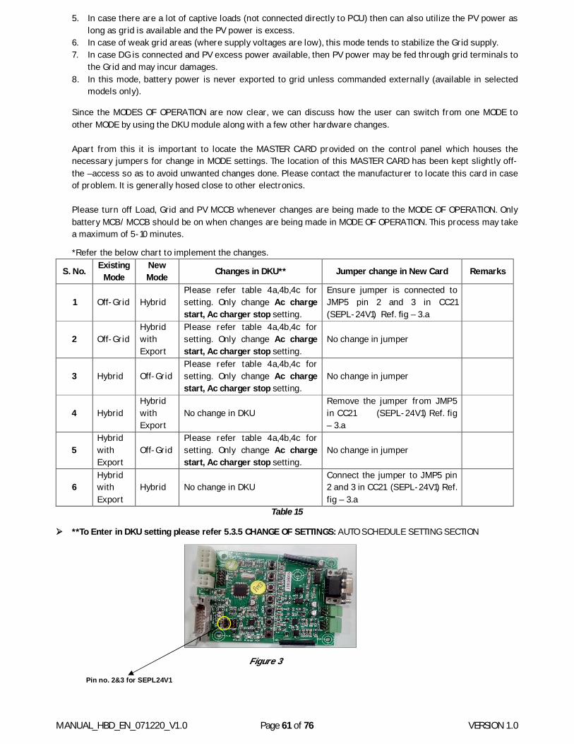
MANUAL_HBD_EN_071220_V1.0 Page 61 of 76 VERSION 1.0
5. In case there are a lot of captive loads (not connected directly to PCU) then can also utilize the PV power as long as grid is available and the PV power is excess.
6. In case of weak grid areas (where supply voltages are low), this mode tends to stabilize the Grid supply. 7. In case DG is connected and PV excess power available, then PV power may be fed through grid terminals to
the Grid and may incur damages. 8. In this mode, battery power is never exported to grid unless commanded externally (available in selected
models only).
Since the MODES OF OPERATION are now clear, we can discuss how the user can switch from one MODE to other MODE by using the DKU module along with a few other hardware changes.
Apart from this it is important to locate the MASTER CARD provided on the control panel which houses the necessary jumpers for change in MODE settings. The location of this MASTER CARD has been kept slightly off-the –access so as to avoid unwanted changes done. Please contact the manufacturer to locate this card in case of problem. It is generally hosed close to other electronics.
Please turn off Load, Grid and PV MCCB whenever changes are being made to the MODE OF OPERATION. Only battery MCB/ MCCB should be on when changes are being made in MODE OF OPERATION. This process may take a maximum of 5-10 minutes.
*Refer the below chart to implement the changes.
S. No. Existing Mode
New Mode Changes in DKU** Jumper change in New Card Remarks
1 Off-Grid Hybrid Please refer table 4a,4b,4c for setting. Only change Ac charge start, Ac charger stop setting.
Ensure jumper is connected to JMP5 pin 2 and 3 in CC21 (SEPL-24V1) Ref. fig – 3.a
2 Off-Grid Hybrid with Export
Please refer table 4a,4b,4c for setting. Only change Ac charge start, Ac charger stop setting.
No change in jumper
3 Hybrid Off-Grid Please refer table 4a,4b,4c for setting. Only change Ac charge start, Ac charger stop setting.
No change in jumper
4 Hybrid Hybrid with Export
No change in DKU Remove the jumper from JMP5 in CC21 (SEPL-24V1) Ref. fig – 3.a
5 Hybrid with Export
Off-Grid Please refer table 4a,4b,4c for setting. Only change Ac charge start, Ac charger stop setting.
No change in jumper
6 Hybrid with Export
Hybrid No change in DKU Connect the jumper to JMP5 pin 2 and 3 in CC21 (SEPL-24V1) Ref. fig – 3.a
Table 15
**To Enter in DKU setting please refer 5.3.5 CHANGE OF SETTINGS: AUTO SCHEDULE SETTING SECTION
Pin no. 2&3 for SEPL24V1 (CC21)
Figure 3
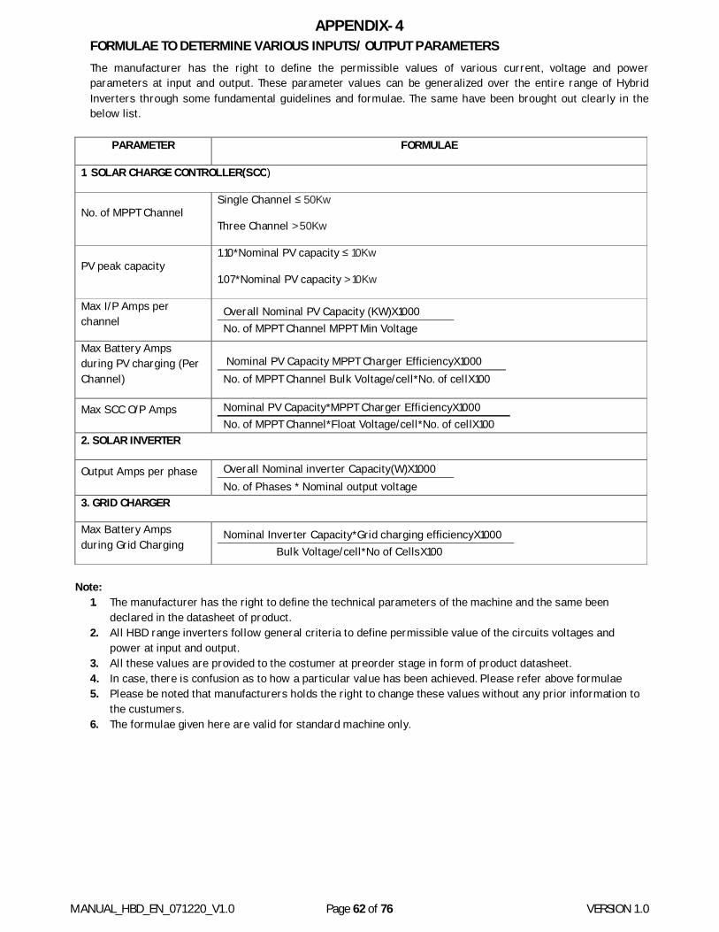
MANUAL_HBD_EN_071220_V1.0 Page 62 of 76 VERSION 1.0
APPENDIX-4 FORMULAE TO DETERMINE VARIOUS INPUTS/ OUTPUT PARAMETERS The manufacturer has the right to define the permissible values of various current, voltage and power parameters at input and output. These parameter values can be generalized over the entire range of Hybrid Inverters through some fundamental guidelines and formulae. The same have been brought out clearly in the below list.
PARAMETER FORMULAE
1. SOLAR CHARGE CONTROLLER(SCC)
No. of MPPT Channel Single Channel ≤ 50Kw
Three Channel > 50Kw
PV peak capacity 1.10*Nominal PV capacity ≤ 10Kw
1.07*Nominal PV capacity > 10Kw
Max I/P Amps per channel
Overall Nominal PV Capacity (KW)X1000 No. of MPPT Channel MPPT Min Voltage
Max Battery Amps during PV charging (Per Channel)
Nominal PV Capacity MPPT Charger EfficiencyX1000 No. of MPPT Channel Bulk Voltage/cell*No. of cellX100
Max SCC O/P Amps Nominal PV Capacity*MPPT Charger EfficiencyX1000 No. of MPPT Channel*Float Voltage/cell*No. of cellX100
2. SOLAR INVERTER
Output Amps per phase Overall Nominal inverter Capacity(W)X1000 No. of Phases * Nominal output voltage
3. GRID CHARGER
Max Battery Amps during Grid Charging
Nominal Inverter Capacity*Grid charging efficiencyX1000 Bulk Voltage/cell*No of CellsX100
Note:
1. The manufacturer has the right to define the technical parameters of the machine and the same been declared in the datasheet of product.
2. All HBD range inverters follow general criteria to define permissible value of the circuits voltages and power at input and output.
3. All these values are provided to the costumer at preorder stage in form of product datasheet. 4. In case, there is confusion as to how a particular value has been achieved. Please refer above formulae 5. Please be noted that manufacturers holds the right to change these values without any prior information to
the custumers. 6. The formulae given here are valid for standard machine only.
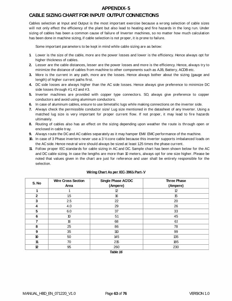
MANUAL_HBD_EN_071220_V1.0 Page 63 of 76 VERSION 1.0
APPENDIX-5 CABLE SIZING CHART FOR INPUT/ OUTPUT CONNECTIONS Cables selection at Input and Output is the most important exercise because a wrong selection of cable sizes will not only effect the efficiency of the plant but also lead to heating and fire hazards in the long run. Under sizing of cables has been a common cause of failure of Inverter machines, so no matter how much calculation has been done in machine sizing, if cable selection is not proper, it is prone to failure.
Some important parameters to be kept in mind while cable sizing are as below:
1. Lower is the size of the cable, more are the power losses and lower is the efficiency. Hence always opt for higher thickness of cables.
2. Lesser are the cable distances, lesser are the power losses and more is the efficiency. Hence, always try to minimize the distance of cables from machine to other components such as AJB, Battery, ACDB etc.
3. More is the current in any path, more are the losses. Hence always bother about the sizing (gauge and length) of higher current paths first.
4. DC side losses are always higher than the AC side losses. Hence always give preference to minimize DC side losses through #1, #2 and #3.
5. Inverter machines are provided with copper type connectors. SO, always give preference to copper conductors and avoid using aluminum conductors.
6. In case of aluminum cables, ensure to use bimetallic lugs while making connections on the inverter side. 7. Always check the permissible conductor size/ Lug size mentioned in the datasheet of any Inverter. Using a
matched lug size is very important for proper current flow. If not proper, it may lead to fire hazards ultimately.
8. Routing of cables also has an effect on the sizing depending upon weather the route is through open or enclosed in cable tray.
9. Always route the DC and AC cables separately as it may hamper EMI/ EMC performance of the machine. 10. In case of 3 Phase inverters never use a 3 ½ core cable because this inverter supports imbalanced loads on
the AC side. Hence neutral wire should always be sized at least 1.25 times the phase current. 11. Follow proper IEC standards for cable sizing in AC and DC. Sample chart has been shown below for the AC
and DC cable sizing. In case the lengths are more than 10 meters, always opt for one size higher. Please be noted that values given in the chart are just for reference and user shall be entirely responsible for the selection.
Wiring Chart As per IEC-3961-Part-V
S. No Wire Cross Section Area
Single Phase AC/DC (Ampere)
Three Phase (Ampere)
1 1 12 12 2 1.5 16 15 3 2.5 22 20 4 4.0 29 26 5 6.0 37 33 6 10 51 45 7 16 68 61 8 25 86 78 9 35 110 99 10 50 145 135 11 70 215 185 12 95 260 230
Table 16

MANUAL_HBD_EN_071220_V1.0 Page 64 of 76 VERSION 1.0
APPENDIX-6 PV MODULE ARRAY SERIES-PARALLEL ARRANGEMENT Hybrid Inverter machines are basically DC coupled Solar inverters which have an inbuilt but separate MPPT solar Charger between the PV and the Battery. This Solar MPPT charger is of Buck type which strictly means that PV power will be extracted only when the PV voltage is higher than the battery voltage at that instant. Hence, the series parallel arrangement becomes very important for proper functioning and best generation results.
So, before we present the PV sizing chart, we would like to highlight a few points about the series-parallel arrangement of PV modules.
1. Always keep information handy about the PV module you are going to use. This includes: Open-Circuit Voltage (Voc), MPPT Voltage (Vmp), Short-Circuit Current (Isc), MPPT Current (Imp), Module Power (Pmp) and no. of cells in PV module used.
2. Always refer the Inverter datasheet while designing the series parallel arrangement. The parameters of importance include: PV Nominal Capacity (Total) No of MPPT Channels Per Channel PV Capacity (Nominal/ Peak) Max. Open Circuit PV Volts (Voc) MPPT Voltage Range PV Minimum Voltage Max I/P Amps per channel
3. More are the number of modules in series, higher is the plant efficiency and higher is the generation from PV modules. But there is a limit to maximum number of modules mentioned in the inverter datasheet.
4. Never exceed the Max. Open circuit Voltage permitted by the inverter datasheet. This value is mentioned as Max. Open circuit PV Volts (Voc) in the inverter datasheet
5. Open circuit voltage of PV module increases in cold season due to module characteristics and hence always keep a margin between the System Voc and permissible Voc mentioned in the datasheet.
6. The number of strings in parallel should always be kept as low as possible. Also, the summation of all the string currents should always be less than than the Max I/P amps per channel mentioned in the datasheet of inverter.
7. In case of multi MPPT channel designs (above 50KVA generally) distribute the no of modules equally among
all the 3 MPPT channels for better generation.
8. In case of multi MPPT channels ensure 3 separate PV fields are made. That is, do not combine all the PV modules in a single AJB and then bring 3 separate set of cables for 3 MPPT chargers in Multi MPPT inverters. This will hamper the PV generation as MPPT function will not take place at all.
9. Series parallel arrangement of PV modules is dependent on the inverter being used. It may differ from one make of inverter to other. Please consult the Inverter manufacturer before usage for proper generation.
10. Below is a general chart for series parallel arrangement depending upon the capacity of Hybrid Inverter.
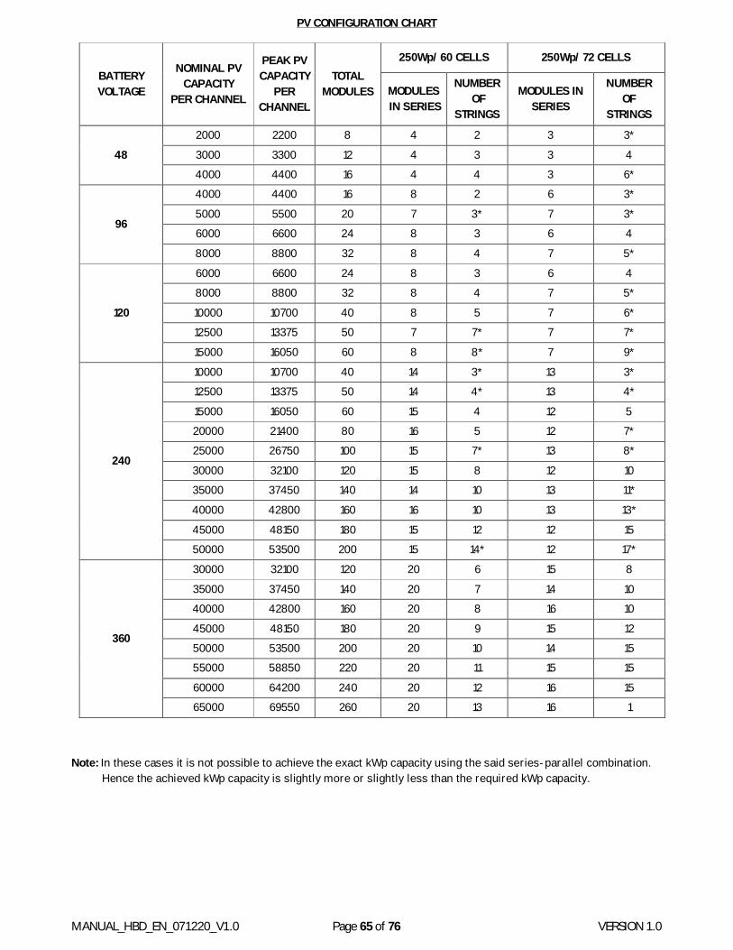
MANUAL_HBD_EN_071220_V1.0 Page 65 of 76 VERSION 1.0
PV CONFIGURATION CHART
BATTERY VOLTAGE
NOMINAL PV CAPACITY
PER CHANNEL
PEAK PV CAPACITY
PER CHANNEL
TOTAL MODULES
250Wp/ 60 CELLS 250Wp/ 72 CELLS
MODULES IN SERIES
NUMBER OF
STRINGS
MODULES IN SERIES
NUMBER OF
STRINGS
48
2000 2200 8 4 2 3 3*
3000 3300 12 4 3 3 4 4000 4400 16 4 4 3 6*
96
4000 4400 16 8 2 6 3*
5000 5500 20 7 3* 7 3* 6000 6600 24 8 3 6 4
8000 8800 32 8 4 7 5*
120
6000 6600 24 8 3 6 4 8000 8800 32 8 4 7 5*
10000 10700 40 8 5 7 6* 12500 13375 50 7 7* 7 7*
15000 16050 60 8 8* 7 9*
240
10000 10700 40 14 3* 13 3* 12500 13375 50 14 4* 13 4*
15000 16050 60 15 4 12 5 20000 21400 80 16 5 12 7* 25000 26750 100 15 7* 13 8*
30000 32100 120 15 8 12 10 35000 37450 140 14 10 13 11*
40000 42800 160 16 10 13 13*
45000 48150 180 15 12 12 15 50000 53500 200 15 14* 12 17*
360
30000 32100 120 20 6 15 8
35000 37450 140 20 7 14 10 40000 42800 160 20 8 16 10
45000 48150 180 20 9 15 12 50000 53500 200 20 10 14 15 55000 58850 220 20 11 15 15
60000 64200 240 20 12 16 15 65000 69550 260 20 13 16 1
Note: In these cases it is not possible to achieve the exact kWp capacity using the said series-parallel combination. Hence the achieved kWp capacity is slightly more or slightly less than the required kWp capacity.
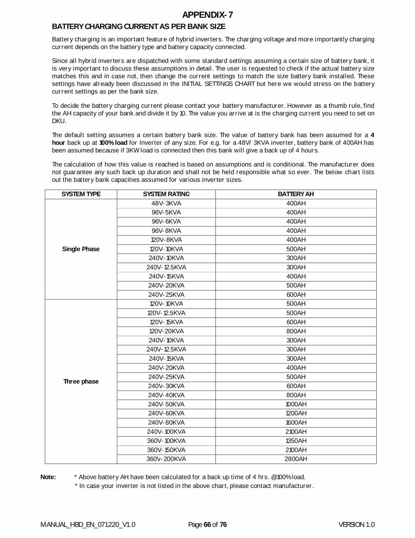
MANUAL_HBD_EN_071220_V1.0 Page 66 of 76 VERSION 1.0
APPENDIX-7 BATTERY CHARGING CURRENT AS PER BANK SIZE Battery charging is an important feature of hybrid inverters. The charging voltage and more importantly charging current depends on the battery type and battery capacity connected.
Since all hybrid inverters are dispatched with some standard settings assuming a certain size of battery bank, it is very important to discuss these assumptions in detail. The user is requested to check if the actual battery size matches this and in case not, then change the current settings to match the size battery bank installed. These settings have already been discussed in the INITIAL SETTINGS CHART but here we would stress on the battery current settings as per the bank size.
To decide the battery charging current please contact your battery manufacturer. However as a thumb rule, find the AH capacity of your bank and divide it by 10. The value you arrive at is the charging current you need to set on DKU.
The default setting assumes a certain battery bank size. The value of battery bank has been assumed for a 4 hour back up at 100% load for Inverter of any size. For e.g. for a 48V/ 3KVA inverter, battery bank of 400AH has been assumed because if 3KW load is connected then this bank will give a back up of 4 hours.
The calculation of how this value is reached is based on assumptions and is conditional. The manufacturer does not guarantee any such back up duration and shall not be held responsible what so ever. The below chart lists out the battery bank capacities assumed for various inverter sizes.
SYSTEM TYPE SYSTEM RATING BATTERY AH
Single Phase
48V-3KVA 400AH 96V-5KVA 400AH 96V-6KVA 400AH 96V-8KVA 400AH 120V-8KVA 400AH 120V-10KVA 500AH 240V-10KVA 300AH
240V-12.5KVA 300AH 240V-15KVA 400AH 240V-20KVA 500AH 240V-25KVA 600AH
Three phase
120V-10KVA 500AH 120V-12.5KVA 500AH 120V-15KVA 600AH 120V-20KVA 800AH 240V-10KVA 300AH
240V-12.5KVA 300AH 240V-15KVA 300AH 240V-20KVA 400AH 240V-25KVA 500AH 240V-30KVA 600AH 240V-40KVA 800AH 240V-50KVA 1000AH 240V-60KVA 1200AH 240V-80KVA 1600AH 240V-100KVA 2100AH 360V-100KVA 1350AH 360V-150KVA 2100AH 360V-200KVA 2800AH
Note: * Above battery AH have been calculated for a back up time of 4 hrs. @100% load.
* In case your inverter is not listed in the above chart, please contact manufacturer.
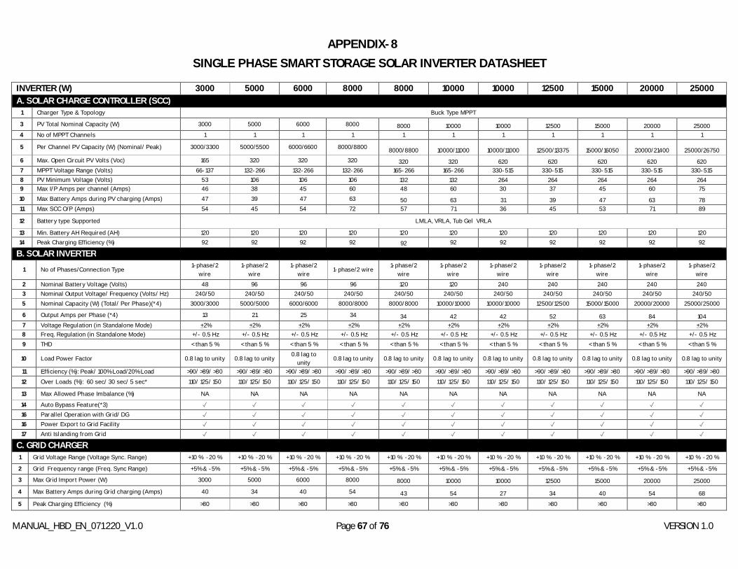
MANUAL_HBD_EN_071220_V1.0 Page 67 of 76 VERSION 1.0
APPENDIX-8
SINGLE PHASE SMART STORAGE SOLAR INVERTER DATASHEET
INVERTER (W) 3000 5000 6000 8000 8000 10000 10000 12500 15000 20000 25000 A. SOLAR CHARGE CONTROLLER (SCC)
1 Charger Type & Topology Buck Type MPPT
3 PV Total Nominal Capacity (W) 3000 5000 6000 8000 8000 10000 10000 12500 15000 20000 25000 4 No of MPPT Channels 1 1 1 1 1 1 1 1 1 1 1
5 Per Channel PV Capacity (W) (Nominal/ Peak) 3000/3300 5000/5500 6000/6600 8000/8800 8000/8800 10000/11000 10000/11000 12500/13375 15000/16050 20000/21400 25000/26750 6 Max. Open Circuit PV Volts (Voc) 165 320 320 320 320 320 620 620 620 620 620 7 MPPT Voltage Range (Volts) 66-137 132-266 132-266 132-266 165-266 165-266 330-515 330-515 330-515 330-515 330-515 8 PV Minimum Voltage (Volts) 53 106 106 106 132 132 264 264 264 264 264 9 Max I/P Amps per channel (Amps) 46 38 45 60 48 60 30 37 45 60 75 10 Max Battery Amps during PV charging (Amps) 47 39 47 63 50 63 31 39 47 63 78 11 Max SCC O/P (Amps) 54 45 54 72 57 71 36 45 53 71 89
12 Battery type Supported LMLA, VRLA, Tub Gel VRLA
13 Min. Battery AH Required (AH) 120 120 120 120 120 120 120 120 120 120 120 14 Peak Charging Efficiency (%) 92 92 92 92 92 92 92 92 92 92 92
B. SOLAR INVERTER 1 No of Phases/Connection Type
1-phase/2 wire
1-phase/2 wire
1-phase/2 wire
1-phase/2 wire 1-phase/2
wire 1-phase/2
wire 1-phase/2
wire 1-phase/2
wire 1-phase/2
wire 1-phase/2
wire 1-phase/2
wire 2 Nominal Battery Voltage (Volts) 48 96 96 96 120 120 240 240 240 240 240 3 Nominal Output Voltage/ Frequency (Volts/ Hz) 240/50 240/50 240/50 240/50 240/50 240/50 240/50 240/50 240/50 240/50 240/50 5 Nominal Capacity (W) (Total/ Per Phase)(*4) 3000/3000 5000/5000 6000/6000 8000/8000 8000/8000 10000/10000 10000/10000 12500/12500 15000/15000 20000/20000 25000/25000
6 Output Amps per Phase (*4) 13 21 25 34 34 42 42 52 63 84 104 7 Voltage Regulation (in Standalone Mode) +2% +2% +2% +2% +2% +2% +2% +2% +2% +2% +2% 8 Freq. Regulation (in Standalone Mode) +/- 0.5 Hz +/- 0.5 Hz +/- 0.5 Hz +/- 0.5 Hz +/- 0.5 Hz +/- 0.5 Hz +/- 0.5 Hz +/- 0.5 Hz +/- 0.5 Hz +/- 0.5 Hz +/- 0.5 Hz 9 THD < than 5 % < than 5 % < than 5 % < than 5 % < than 5 % < than 5 % < than 5 % < than 5 % < than 5 % < than 5 % < than 5 %
10 Load Power Factor 0.8 lag to unity 0.8 lag to unity 0.8 lag to
unity 0.8 lag to unity 0.8 lag to unity 0.8 lag to unity 0.8 lag to unity 0.8 lag to unity 0.8 lag to unity 0.8 lag to unity 0.8 lag to unity
11 Efficiency (%): Peak/ 100% Load/20% Load >90/ >89/ >80 >90/ >89/ >80 >90/ >89/ >80 >90/ >89/ >80 >90/ >89/ >80 >90/ >89/ >80 >90/ >89/ >80 >90/ >89/ >80 >90/ >89/ >80 >90/ >89/ >80 >90/ >89/ >80 12 Over Loads (%): 60 sec/ 30 sec/ 5 sec* 110/ 125/ 150 110/ 125/ 150 110/ 125/ 150 110/ 125/ 150 110/ 125/ 150 110/ 125/ 150 110/ 125/ 150 110/ 125/ 150 110/ 125/ 150 110/ 125/ 150 110/ 125/ 150
13 Max Allowed Phase Imbalance (%) NA NA NA NA NA NA NA NA NA NA NA
14 Auto Bypass Feature(*3) ✓ ✓ ✓ ✓ ✓ ✓ ✓ ✓ ✓ ✓ ✓ 16 Parallel Operation with Grid/ DG ✓ ✓ ✓ ✓ ✓ ✓ ✓ ✓ ✓ ✓ ✓ 16 Power Export to Grid Facility ✓ ✓ ✓ ✓ ✓ ✓ ✓ ✓ ✓ ✓ ✓ 17 Anti Islanding from Grid ✓ ✓ ✓ ✓ ✓ ✓ ✓ ✓ ✓ ✓ ✓
C. GRID CHARGER 1 Grid Voltage Range (Voltage Sync. Range) +10 % -20 % +10 % -20 % +10 % -20 % +10 % -20 % +10 % -20 % +10 % -20 % +10 % -20 % +10 % -20 % +10 % -20 % +10 % -20 % +10 % -20 %
2 Grid Frequency range (Freq. Sync Range) +5% & -5% +5% & -5% +5% & -5% +5% & -5% +5% & -5% +5% & -5% +5% & -5% +5% & -5% +5% & -5% +5% & -5% +5% & -5%
3 Max Grid Import Power (W) 3000 5000 6000 8000 8000 10000 10000 12500 15000 20000 25000
4 Max Battery Amps during Grid charging (Amps) 40 34 40 54 43 54 27 34 40 54 68 5 Peak Charging Efficiency (%) >80 >80 >80 >80 >80 >80 >80 >80 >80 >80 >80
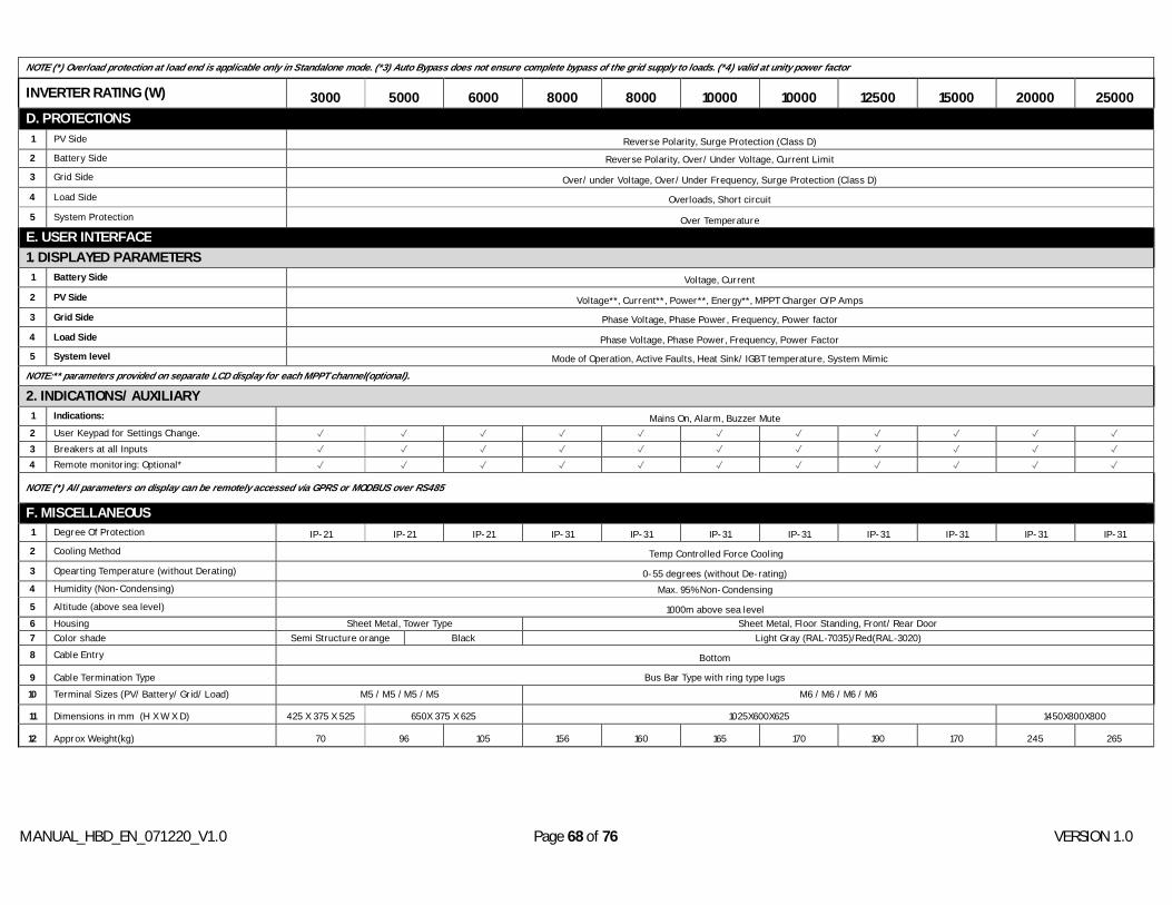
MANUAL_HBD_EN_071220_V1.0 Page 68 of 76 VERSION 1.0
NOTE (*) Overload protection at load end is applicable only in Standalone mode. (*3) Auto Bypass does not ensure complete bypass of the grid supply to loads. (*4) valid at unity power factor
INVERTER RATING (W) 3000 5000 6000 8000 8000 10000 10000 12500 15000 20000 25000 D. PROTECTIONS
1 PV Side Reverse Polarity, Surge Protection (Class D) 2 Battery Side Reverse Polarity, Over/ Under Voltage, Current Limit
3 Grid Side Over/ under Voltage, Over/ Under Frequency, Surge Protection (Class D)
4 Load Side Overloads, Short circuit
5 System Protection Over Temperature
E. USER INTERFACE
1. DISPLAYED PARAMETERS 1 Battery Side Voltage, Current
2 PV Side Voltage**, Current**, Power**, Energy**, MPPT Charger O/P Amps 3 Grid Side Phase Voltage, Phase Power, Frequency, Power factor
4 Load Side Phase Voltage, Phase Power, Frequency, Power Factor 5 System level Mode of Operation, Active Faults, Heat Sink/ IGBT temperature, System Mimic
NOTE:** parameters provided on separate LCD display for each MPPT channel(optional).
2. INDICATIONS/ AUXILIARY 1 Indications: Mains On, Alarm, Buzzer Mute 2 User Keypad for Settings Change. ✓ ✓ ✓ ✓ ✓ ✓ ✓ ✓ ✓ ✓ ✓ 3 Breakers at all Inputs ✓ ✓ ✓ ✓ ✓ ✓ ✓ ✓ ✓ ✓ ✓ 4 Remote monitoring: Optional* ✓ ✓ ✓ ✓ ✓ ✓ ✓ ✓ ✓ ✓ ✓
NOTE (*) All parameters on display can be remotely accessed via GPRS or MODBUS over RS485
F. MISCELLANEOUS 1 Degree Of Protection IP-21 IP-21 IP-21 IP-31 IP-31 IP-31 IP-31 IP-31 IP-31 IP-31 IP-31 2 Cooling Method Temp Controlled Force Cooling
3 Opearting Temperature (without Derating) 0-55 degrees (without De-rating) 4 Humidity (Non-Condensing) Max. 95% Non-Condensing
5 Altitude (above sea level) 1000m above sea level 6 Housing Sheet Metal, Tower Type Sheet Metal, Floor Standing, Front/ Rear Door 7 Color shade Semi Structure orange Black Light Gray (RAL‐7035)/Red(RAL‐3020) 8 Cable Entry Bottom
9 Cable Termination Type Bus Bar Type with ring type lugs 10 Terminal Sizes (PV/ Battery/ Grid/ Load) M5 / M5 / M5 / M5 M6 / M6 / M6 / M6
11 Dimensions in mm (H X W X D) 425 X 375 X 525 650X 375 X 625 1025X600X625 1450X800X800
12 Approx Weight(kg) 70 96 105 156 160 165 170 190 170 245 265
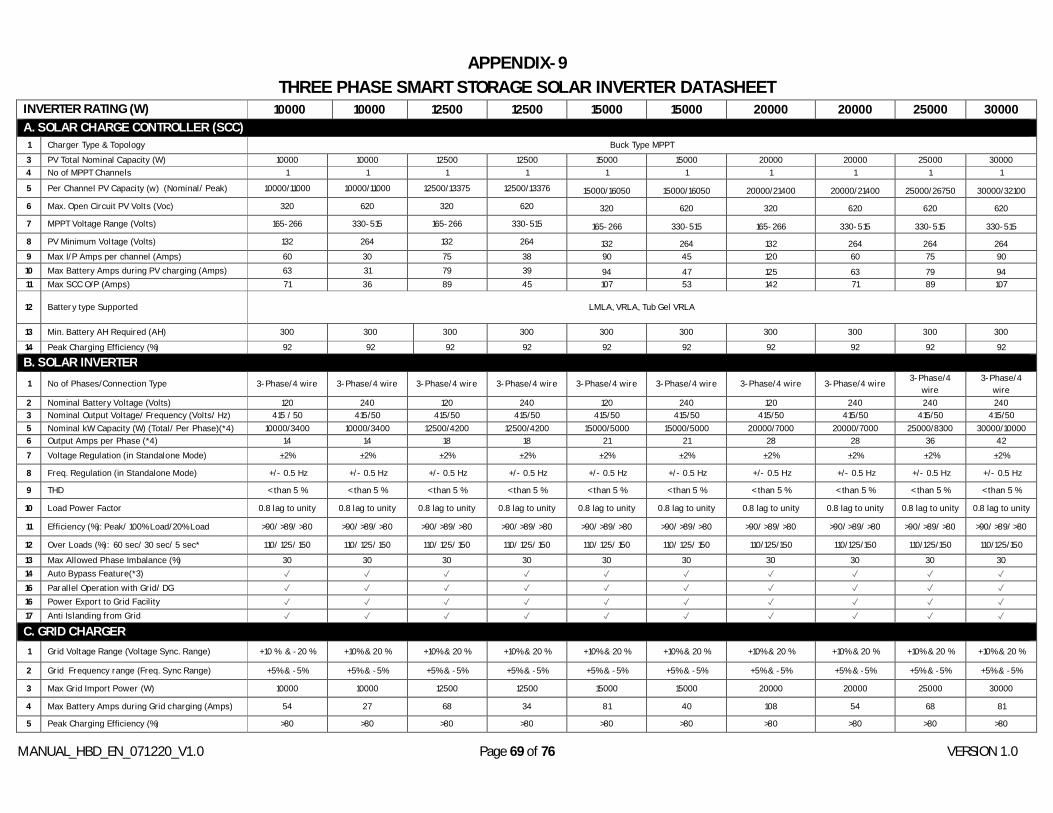
MANUAL_HBD_EN_071220_V1.0 Page 69 of 76 VERSION 1.0
APPENDIX-9 THREE PHASE SMART STORAGE SOLAR INVERTER DATASHEET
INVERTER RATING (W) 10000 10000 12500 12500 15000 15000 20000 20000 25000 30000 A. SOLAR CHARGE CONTROLLER (SCC) 1 Charger Type & Topology Buck Type MPPT 3 PV Total Nominal Capacity (W) 10000 10000 12500 12500 15000 15000 20000 20000 25000 30000 4 No of MPPT Channels 1 1 1 1 1 1 1 1 1 1
5 Per Channel PV Capacity (w) (Nominal/ Peak) 10000/11000 10000/11000 12500/13375 12500/13376 15000/16050 15000/16050 20000/21400 20000/21400 25000/26750 30000/32100
6 Max. Open Circuit PV Volts (Voc) 320 620 320 620 320 620 320 620 620 620
7 MPPT Voltage Range (Volts) 165-266 330-515 165-266 330-515 165-266 330-515 165-266 330-515 330-515 330-515 8 PV Minimum Voltage (Volts) 132 264 132 264 132 264 132 264 264 264 9 Max I/P Amps per channel (Amps) 60 30 75 38 90 45 120 60 75 90 10 Max Battery Amps during PV charging (Amps) 63 31 79 39 94 47 125 63 79 94 11 Max SCC O/P (Amps) 71 36 89 45 107 53 142 71 89 107
12 Battery type Supported LMLA, VRLA, Tub Gel VRLA
13 Min. Battery AH Required (AH) 300 300 300 300 300 300 300 300 300 300
14 Peak Charging Efficiency (%) 92 92 92 92 92 92 92 92 92 92
B. SOLAR INVERTER
1 No of Phases/Connection Type 3-Phase/4 wire 3-Phase/4 wire 3-Phase/4 wire 3-Phase/4 wire 3-Phase/4 wire 3-Phase/4 wire 3-Phase/4 wire 3-Phase/4 wire 3-Phase/4 wire
3-Phase/4 wire
2 Nominal Battery Voltage (Volts) 120 240 120 240 120 240 120 240 240 240 3 Nominal Output Voltage/ Frequency (Volts/ Hz) 415 / 50 415/50 415/50 415/50 415/50 415/50 415/50 415/50 415/50 415/50 5 Nominal kW Capacity (W) (Total/ Per Phase)(*4) 10000/3400 10000/3400 12500/4200 12500/4200 15000/5000 15000/5000 20000/7000 20000/7000 25000/8300 30000/10000 6 Output Amps per Phase (*4) 14 14 18 18 21 21 28 28 36 42 7 Voltage Regulation (in Standalone Mode) +2% +2% +2% +2% +2% +2% +2% +2% +2% +2%
8 Freq. Regulation (in Standalone Mode) +/- 0.5 Hz +/- 0.5 Hz +/- 0.5 Hz +/- 0.5 Hz +/- 0.5 Hz +/- 0.5 Hz +/- 0.5 Hz +/- 0.5 Hz +/- 0.5 Hz +/- 0.5 Hz
9 THD < than 5 % < than 5 % < than 5 % < than 5 % < than 5 % < than 5 % < than 5 % < than 5 % < than 5 % < than 5 %
10 Load Power Factor 0.8 lag to unity 0.8 lag to unity 0.8 lag to unity 0.8 lag to unity 0.8 lag to unity 0.8 lag to unity 0.8 lag to unity 0.8 lag to unity 0.8 lag to unity 0.8 lag to unity
11 Efficiency (%): Peak/ 100% Load/20% Load >90/ >89/ >80 >90/ >89/ >80 >90/ >89/ >80 >90/ >89/ >80 >90/ >89/ >80 >90/ >89/ >80 >90/ >89/ >80 >90/ >89/ >80 >90/ >89/ >80 >90/ >89/ >80
12 Over Loads (%): 60 sec/ 30 sec/ 5 sec* 110/ 125/ 150 110/ 125/ 150 110/ 125/ 150 110/ 125/ 150 110/ 125/ 150 110/ 125/ 150 110/125/150 110/125/150 110/125/150 110/125/150
13 Max Allowed Phase Imbalance (%) 30 30 30 30 30 30 30 30 30 30 14 Auto Bypass Feature(*3) ✓ ✓ ✓ ✓ ✓ ✓ ✓ ✓ ✓ ✓ 16 Parallel Operation with Grid/ DG ✓ ✓ ✓ ✓ ✓ ✓ ✓ ✓ ✓ ✓ 16 Power Export to Grid Facility ✓ ✓ ✓ ✓ ✓ ✓ ✓ ✓ ✓ ✓ 17 Anti Islanding from Grid ✓ ✓ ✓ ✓ ✓ ✓ ✓ ✓ ✓ ✓
C. GRID CHARGER
1 Grid Voltage Range (Voltage Sync. Range) +10 % & -20 % +10% & 20 % +10% & 20 % +10% & 20 % +10% & 20 % +10% & 20 % +10% & 20 % +10% & 20 % +10% & 20 % +10% & 20 %
2 Grid Frequency range (Freq. Sync Range) +5% & -5% +5% & -5% +5% & -5% +5% & -5% +5% & -5% +5% & -5% +5% & -5% +5% & -5% +5% & -5% +5% & -5%
3 Max Grid Import Power (W) 10000 10000 12500 12500 15000 15000 20000 20000 25000 30000
4 Max Battery Amps during Grid charging (Amps) 54 27 68 34 81 40 108 54 68 81
5 Peak Charging Efficiency (%) >80 >80 >80 >80 >80 >80 >80 >80 >80 >80
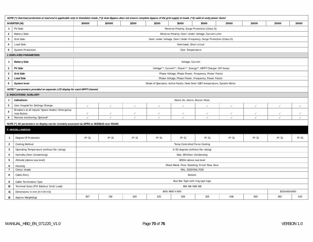
MANUAL_HBD_EN_071220_V1.0 Page 70 of 76 VERSION 1.0
NOTE (*) Overload protection at load end is applicable only in Standalon mode. (*3) Auto Bypass does not ensure complete bypass of the grid supply to loads. (*4) valid at unity power factor
INVERTER (W) 100000 100000 12500 12500 15000 15000 20000 20000 25000 30000
1 PV Side: Reverse Polarity, Surge Protection (Class D)
2 Battery Side: Reverse Polarity, Over/ Under Voltage, Current Limit
3 Grid Side: Over/ under Voltage, Over/ Under Frequency, Surge Protection (Class D)
4 Load Side: Overloads, Short circuit
5 System Protection: Over Temperature
1. DISPLAYED PARAMETERS
1 Battery Side Voltage, Current
2 PV Side Voltage**, Current**, Power**, Energy**, MPPT Charger O/P Amps
3 Grid Side Phase Voltage, Phase Power, Frequency, Power Factor
4 Load Side Phase Voltage, Phase Power, Frequency, Power Factor
5 System level Mode of Operation, Active Faults, Heat Sink/ IGBT temperature, System Mimic
NOTE:** parameters provided on separate LCD display for each MPPT channel.
2. INDICATIONS/ AUXILIARY
1 Indications: Mains On, Alarm, Buzzer Mute.
2 User Keypad for Settings Change. ✓ ✓ ✓ ✓ ✓ ✓ ✓ ✓ ✓ ✓
3 Breakers at all Inputs/ Space Heater/ Emergency stop Button. ✓ ✓ ✓ ✓ ✓ ✓ ✓ ✓ ✓ ✓
4 Remote monitoring: Optional* ✓ ✓ ✓ ✓ ✓ ✓ ✓ ✓ ✓ ✓
NOTE (*) All parameters on display can be remotely accessed via GPRS or MODBUS over RS485
F. MISCELLANEOUS
1 Degree Of Protection IP-31 IP-31 IP-31 IP-31 IP-31 IP-31 IP-31 IP-31 IP-31 IP-31
2 Cooling Method Temp Controlled Force Cooling
3 Operating Temperature (without De-rating) 0-55 degrees (without De-rating)
4 Humidity (Non-Condensing) Max. 95% Non-Condensing
5 Altitude (above sea level) 1000m above sea level
6 Housing Sheet Metal, Floor Standing, Front/ Rear Door
7 Colour shade RAL-3020/RAL7035
8 Cable Entry Bottom
9 Cable Termination Type Bus Bar Type with ring type lugs
10 Terminal Sizes (PV/ Battery/ Grid/ Load) M6/ M6 /M6/ M6
11 Dimensions in mm (H X W X D) 1450 X800 X 800 1525x850x850
12 Approx Weight(kg) 307 310 320 325 328 325 438 355 392 420
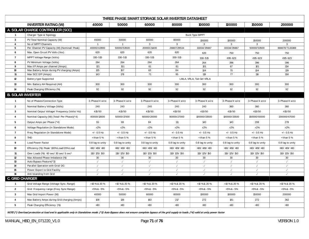
MANUAL_HBD_EN_071220_V1.0 Page 71 of 76 VERSION 1.0
THREE PHASE SMART STORAGE SOLAR INVERTER DATASHEET
INVERTER RATING (W) 40000 50000 60000 80000 100000 100000 150000 200000 A. SOLAR CHARGE CONTROLLER (SCC)
1 Charger Type & Topology Buck Type MPPT
3 PV Total Nominal Capacity (W) 40000 50000 60000 80000 100000 100000 150000 200000 4 No of MPPT Channels 1 1 3 3 3 3 3 3 5 Per Channel PV Capacity (W) (Nominal/ Peak) 40000/42800 50000/53500 20000/21400 26667/28534 33334/35667 33334/35667 50000/53500 666670/71.33369 6 Max. Open Circuit PV Volts (Voc) 620 620 620 620 620 750 750 750 7 MPPT Voltage Range (Volts) 330-515 330-515 330-515 330-515 330-515 495-623 495-623 495-623 8 PV Minimum Voltage (Volts) 264 264 264 264 264 396 396 396 9 Max I/P Amps per channel (Amps) 121 151 61 81 101 67 101 134 10 Max Battery Amps during PV charging (Amps) 125 157 63 84 104 70 104 139 11 Max SCC O/P (Amps) 143 178 71 95 119 77 116 158
12 Battery type Supported LMLA, VRLA, Tub Gel VRLA
13 Min. Battery AH Required (AH) 300 300 300 300 300 300 300 300
14 Peak Charging Efficiency (%) 92 92 92 92 92 92 92 92
B. SOLAR INVERTER
1 No of Phases/Connection Type 3-Phase/4 wire 3-Phase/4 wire 3-Phase/4 wire 3-Phase/4 wire 3-Phase/4 wire 3-Phase/4 wire 3-Phase/4 wire 3-Phase/4 wire
2 Nominal Battery Voltage (Volts) 240 240 240 240 240 360 360 360
3 Nominal Output Voltage/ Frequency (Volts/ Hz) 415/50 415/50 415/50 415/50 415/50 415/50 415/50 415/50
4 Nominal Capacity (W) (Total/ Per Phase)(*4) 40000/13500 50000/17000 60000/20000 80000/27000 100000/33500 100000/33500 150000/50000 200000/67000
5 Output Amps per Phase (*4) 55 69 84 111 140 140 208 278
6 Voltage Regulation (in Standalone Mode) +2% +2% +2% +2% +2% +2% +2% +2%
7 Freq. Regulation (in Standalone Mode) +/- 0.5 Hz +/- 0.5 Hz +/- 0.5 Hz +/- 0.5 Hz +/- 0.5 Hz +/- 0.5 Hz +/- 0.5 Hz +/- 0.5 Hz
8 THD < than 5 % < than 5 % < than 5 % < than 5 % < than 5 % < than 5 % < than 5 % < than 5 %
9 Load Power Factor 0.8 lag to unity 0.8 lag to unity 0.8 lag to unity 0.8 lag to unity 0.8 lag to unity 0.8 lag to unity 0.8 lag to unity 0.8 lag to unity
10 Efficiency (%): Peak/ 100% Load/20% Load >90/ >89/ >80 >90/ >89/ >80 >90/ >89/ >80 >90/ >89/ >80 >90/ >89/ >80 >90/ >89/ >80 >90/ >89/ >80 >90/ >89/ >80
11 Over Loads (%): 60 sec/ 30 sec/ 5 sec* 110/ 125/ 150 110/ 125/ 150 110/ 125/ 150 110/ 125/ 150 110/ 125/ 150 110/ 125/ 150 110/ 125/ 150 110/ 125/ 150 12 Max Allowed Phase Imbalance (%) 30 30 30 30 30 30 30 30 13 Auto Bypass Feature(*3) ✓ ✓ ✓ ✓ ✓ ✓ ✓ ✓ 14 Parallel Operation with Grid/ DG ✓ ✓ ✓ ✓ ✓ ✓ ✓ ✓ 15 Power Export to Grid Facility ✓ ✓ ✓ ✓ ✓ ✓ ✓ ✓ 16 Anti Islanding from Grid ✓ ✓ ✓ ✓ ✓ ✓ ✓ ✓
C. GRID CHARGER 1 Grid Voltage Range (Voltage Sync. Range) +10 % & 20 % +10 % & 20 % +10 % & 20 % +10 % & 20 % +10 % & 20 % +10 % & 20 % +10 % & 20 % +10 % & 20 %
2 Grid Frequency range (Freq. Sync Range) +5% & -5% +5% & -5% +5% & -5% +5% & -5% +5% & -5% +5% & -5% +5% & -5% +5% & -5%
3 Max Grid Import Power (W) 40000 50000 60000 80000 100000 100000 150000 200000
4 Max Battery Amps during Grid charging (Amps) 108 136 163 217 272 181 272 362
5 Peak Charging Efficiency (%) >80 >80 >80 >80 >80 >80 >80 >80
NOTE (*) Overload protection at load end is applicable only in Standalone mode. (*3) Auto Bypass does not ensure complete bypass of the grid supply to loads. (*4) valid at unity power factor

MANUAL_HBD_EN_071220_V1.0 Page 72 of 76 VERSION 1.0
INVERTER RATING (W) 40000 50000 60000 80000 100000 100000 150000 200000 E. USER INTERFACE
1. DISPLAYED PARAMETERS 1 Battery Side Voltage, Current 2 PV Side Voltage**, Current**, Power**, Energy**, MPPT Charger O/P Amps 3 Grid Side Phase Voltage, Phase Power, Frequency, Power Factor 4 Load Side Phase Voltage, Phase Power, Frequency, Power Factor
5 System level Mode of Operation, Active Faults, Heat Sink/ IGBT temperature, System Mimic
NOTE:** parameters provided on separate LCD display for each MPPT channel.
2. INDICATIONS/ AUXILIARY
1 Indications: Mains On, Alarm, Buzzer Mute.
2 User Keypad for Settings Change. ✓ ✓ ✓ ✓ ✓ ✓ ✓ ✓
3 Breakers at all Inputs/ Space Heater/ Emergency stop Button.
✓ ✓ ✓ ✓ ✓ ✓ ✓ ✓
4 Remote monitoring: Optional* ✓ ✓ ✓ ✓ ✓ ✓ ✓ ✓
NOTE (*) All parameters on display can be remotely accessed via GPRS or MODBUS over RS485
F. MISCELLANEOUS
1 Degree Of Protection IP-31 IP-31 IP-31 IP-31 IP-31 IP-31 IP-31 IP-31
2 Cooling Method Temp Controlled Force Cooling
3 Operating Temperature (without De-rating) 0-55 degrees (without Derating)
4 Humidity (Non-Condensing) Max. 95% Non-Condensing
5 Altitude (above sea level) 1000m above sea level
6 Housing Sheet Metal, Floor Standing, Front/ Rear Door
7 Color shade RAL-3020/RAL7035
8 Cable Entry Bottom
9 Cable Termination Type Bus Bar Type with ring type lugs
10 Terminal Sizes (PV/ Battery/ Grid/ Load) M6/ M6/ M6 /M6 M6/ M8/ M6 /M6 M6/ M8/ M6 /M8 M8/ M8/ M8 /M8 M8/ M8/ M8 /M8 M8/ M8/ M8 /M8
11 Dimensions in mm (H X W X D) 1525X850X850 1950X1200X800 2250X1200X1200 2250X1400X1200
12 Weight(kg) 495 689 750 850 1120

MANUAL_HBD_EN_071220_V1.0 Page 73 of 76 VERSION 1.0
GENERAL WARRANTY APPLICABLE FOR STATCON ENERGIAA PRODUCTS
Statcon Energiaa Pvt. Ltd warrants to the end purchaser, provided the purchaser is able to provide valid and legal invoice receipt as well as warranty card duly signed by dealer/ Manufacturer
The warranty stands on all manufactured products (except LEDs, switches, Consumables* and external body) for Statcon Energiaa manufactured Products. Warranty for Spares order will be separate
The warranty will be automatically terminated on the expiry of the warranty period, even in case of the product not being in use in the specified period.
The purchaser shall intimate any change of address to the concerned Authorized Service Centre & warranty will be applicable only after the inspection of the unit & clearance of condition by Authorized Service Centre personnel.
Only authorized representatives / dealers of the company, anywhere in India, will provide free service under the terms of warranty.
For a guarantee claim to be valid, the warranty card of the respective product bearing the date of manufacturing / purchase must be fully legible, the guarantee seal undamaged and the end customer Invoice must be available.
The company will not be held liable in any condition for any loss or injury or damage caused to life or property or death and disability caused to any form of life for any reason whatsoever
The company expressly denies the right of any person to incur or assure for it any other liability or obligation in connection with the sale of its manufactured products
Register your product or launch online complaints at www.energiaa.in for prompt after sales service, or write an email to [email protected] . You can also call directly at the listed customer care no. or inform with proper details through Whatsapp. A ticket no. will be generated and provided to you. Please mention that no. for any further communication.
Consumable items in the products like string fuses, SPD, MOV, switches, plugs, door locks and sockets are excluded from warranty and will be replaced on a company-defined chargeable basis.
If within the guarantee period a product exhibits a defect which compromises functioning of the product (a guarantee claim), Energiaa will, at its discretion, either repair the product at the premises or replace (if deemed necessary by the manufacturer) with a used or new one, of equivalent type and age. Purely aesthetic defects which have no effect on product functionality or operability are not covered by the guarantee.
If ENERGIAA decides that a defective product is to be repaired at the end customer’s premises, ENERGIAA arranges the repair date with the customer. ENERGIAA then sends out an authorized service engineer to the customer’s premises at the arranged date and time.
If the product is to be repaired at the end customer’s premises, the guarantee covers related travel costs for Energiaa’s service personnel.
The guarantee is valid only for end customers residing in India and within a 100 km radius of the distributor purchased from, unless a written letter or mail by the manufacturer is provided for longer distances. Places not covered under warranty Andaman Nicobar, Kerala, Leh, Tamil Nadu, Andhra, Tripura, Mizoram or any other place not accessible by Indian Railways or Govt Bus.
Claims if any, to this warranty shall be made only before courts having jurisdiction in New Delhi.
The warranty will not apply if the original seals are found broken or tampered with.
MANUAL_HBD_EN_071220_V1.0 Page 74 of 76 VERSION 1.0
Warranty in case of defects caused by household pets, rats, cockroaches or other animals or insects is invalid.
The warranty will be invalidated if defects arising in company’s opinion by reasons of accident, abuse, misuse, neglect, improper transport, improper installation (if not undertaken by the company or its representative), fire, flood, other acts of GOD, natural calamities and any other unauthorized repairs done or carried out will have to be borne by the purchaser. Services given for the same will be paid service.
The regular warranty period for product is 24 Months from date of dispatch unless mentioned differently in the signed Warranty Card. (Not applicable for Spares or consumables)
Repairs are performed at site for ratings = > 5 kVA.
Guarantee claims are only valid for product defects not resulting from any of these circumstances
1. Force majeure (in particular storm damage, lightning, fire, thunderstorm, flood etc.) 2. Incorrect use or operation / installation and commissioning (for example: loose
connections of AC and DC wires, unclean panels, Fluctuating or low voltage from grid, Overload at customer end, Improper String connection, angle of panels, low gravity of batteries).
3. Failure to comply with the operating, installation and/or maintenance manual 4. Incorrect ventilation and cooling 5. Heavy soiling with dirt or dust 6. Transport damage 7. Changes to the product or repair attempts without prior approval from Statcon
ENERGIAA 8. Failure to comply with the applicable safety regulations.
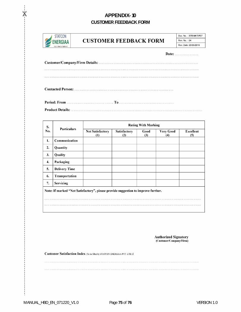
MANUAL_HBD_EN_071220_V1.0 Page 75 of 76 VERSION 1.0
APPENDIX-10 CUSTOMER FEEDBACK FORM

MANUAL_HBD_EN_071220_V1.0 Page 76 of 76 VERSION 1.0
Dear Sir/Madam,
Here by requested you to, kindly fill the attached “Customer Feedback Form” – Page No. - 75, Sign, Stamp on it and separate from manual through cut as directed area.
Please send it to below Address:
STATCON ENERGIAA PVT. LTD.
B-81, Sector-63, Noida (Gautam Buddha Nagar)
201307, Uttar Pradesh - India
Ph.: +91 120 3891600 | 11, Fax: +91 120 4308507
With Regards
STATCON ENERGIAA PVT. LTD.