Copper in Architecture – Design Handbook
163
Copper In Architecture A comprehensive compilation of designs, details and specifications copper in architecture design handbook.indd 1 copper in architecture design handbook.indd 1 2/14/22 4:43 PM 2/14/22 4:43 PM
-
Upload
khangminh22 -
Category
Documents
-
view
0 -
download
0
Transcript of Copper in Architecture – Design Handbook

Copper In ArchitectureA comprehensive compilation of designs, details and specifications
copper in architecture design handbook.indd 1copper in architecture design handbook.indd 1 2/14/22 4:43 PM2/14/22 4:43 PM

CONTENTS
INTRODUCTION 6
TECHNICAL
1. FUNDAMENTALS 101.1. Types of Copper and Properties 101.2. Dimensions of Copper 121.3. Architectural Considerations 131.4. Structural Considerations 171.5. Radio Frequency Shielding 181.6. Lightning Protection 181.7. Cost Effectiveness 191.8. Recyclability 20
2. COPPER ALLOYS 212.1. Introduction 212.2. Forming 232.3. Joining 25
3. FINISHES 273.1. Mechanical Finishes 273.2. Chemical Finishes 303.3. Protective Coatings 323.4. Laminated Finishes 343.5. Standard Finish Designations 353.6. Copper Alloys Color Chart 373.7. Finishes Tables 38
4. REHABILITATION OF COPPER 41Maintenance 41
DESIGNS
5. FEATURED PROJECTS 43
ARCHITECTURAL DETAILSAutoCAD Details 45
6. GENERAL DESIGN ISSUES 46
7. BASIC DETAILS 48Introduction 48Attachments 487.1. Attachments 497.2. Joints and Seams 51Rigid Seams 51Loose Seams 52Expansion Seams 53Corner Seams & Edges 547.3. Additional Loose Lock Seams 55
3CDA Publication A4050-12/21: Copper In Architecture Design Handbook
copper in architecture design handbook.indd 2-3copper in architecture design handbook.indd 2-3 2/14/22 4:43 PM2/14/22 4:43 PM

8. ROOFING SYSTEMS 57Introduction 57Typical Requirements 578.1. Special Roofing Design and Installation Considerations 588.2. Standing Seam Roofing 618.3. Batten Seam Roofing 668.4. Chevron Roofing 708.5. Flat Seam Roofing 728.6. Horizontal Seam Roofing 758.7. Mansard Roofing 798.8. Long Pan Systems 82
9. FLASHINGS AND COPINGS 88Introduction 88General Requirements 899.1. Through-Wall Flashing 909.2. Counterflashing 959.3. Coping Covers 999.4. Ridges and Hips 1049.5. Valleys 1069.6. Changes in Roof Slopes 1089.7. Gravel Stops and Fascias 1109.8. Stepped and Chimney Flashings 1149.9. Roof Penetrations 1169.10. Dormers 1189.11. Eave Snow Flashing 1209.12. Eave Conditions 1229.13. Roof Area Divider 127
10. GUTTERS AND DOWNSPOUTS 12810.1. Hung Gutters and Downspouts Basics 13710.2. Hung Gutters 13910.3. Built-in Gutter Linings 14410.4. Water Diverters 14910.5. Scuppers 15110.6. Roof Sumps and Drains 15410.7. Downspouts 15510.8. Downspout Hangers 157
11. BUILDING EXPANSION JOINTS 15811.1. Roof Conditions 15811.2. Roof Edges 16311.3. Floor Conditions 16611.4. Wall Conditions 167
12. WALL CLADDING 16912.1. Profiled Panels 17012.2. Horizontal Siding 17212.3. Beveled Systems 17412.4. Flat Siding 17612.5. Structural Systems 17812.6. Diagonal Flat Lock Systems 18012.7. Horizontal Flat Lock Systems 18112.8. Copper Clad Honeycomb Systems 18312.9. Copper Screen Panels 18512.10. Curtain Wall Systems 18712.11. Standing Seam 18912.12. Fenestration 192
13. DOMES, SPIRES AND VAULTS 19513.1. Circular Dome with Diagonal Flat Seam System 19613.2. Circular Dome with Standing Seam System 19913.3. Circular Dome with Flat Seam System 20213.4. Standing Seam Roof on Conical Spire 20413.5. Flat Seam Roofing on Octagonal Spire 20713.6. Arched Barrel Vault with Standing Seam 20913.7. Barrel Vault With Flat Seam 21213.8. Steps for Dome Panel Layout 215
SPECIFICATIONS AND TESTS
14. ARCHITECTURAL SPECIFICATIONS 22014.1. Antimicrobial Copper 22114.2. Copper Wall Cladding 23614.3. Copper Roofing 24814.4. Manufactured Copper Roofing Specialties 26114.5. Copper Flashing and Trim 26914.6. Copper Gutters and Downspouts 27914.7. Copper Expansion Joint Cover Assemblies 287
15. TEST REPORTS 29515.1. Standing Seam Roof Panel Test 29615.2. Batten Seam Roof Panel Test 29815.3. Uplift Resistance of Roof Assemblies Test-Standing Seam 30015.4. Uplift Resistance of Roof Assemblies Test-Flat Locked Seam 30215.5. Roof Cladding Fire Resistance: Class A 30515.6. Performance Testing of Copper Wall Cladding 306
GLOSSARY, INDEX AND REFERENCES
16. GLOSSARY 314
17. INDEX 319
18. REFERENCE SOURCES 322
4 5CDA Publication A4050-12/21: Copper In Architecture Deisgn Handbook CDA Publication A4050-12/21: Copper In Architecture Design Handbook
copper in architecture design handbook.indd 4-5copper in architecture design handbook.indd 4-5 2/14/22 4:43 PM2/14/22 4:43 PM

Published 2022 by Copper Development Association Inc., 7918 Jones Branch Drive Suite 300 McLean, VA 22102
NOTICE: This Handbook has been prepared for the use of architects and other design and construction professionals. It has been compiled from information supplied by testing, reserch, manufacturing, standards, and consulting organizations that Copper Development Association Inc. believes to be competent sources for such data. However, recognizing that each system must be designed and installed to meet the particular circumstances, CDA assumes no responsibility or liability of any kind in connection with this handbook or its use by any person or organization, and makes no representations or warranties of any kind hereby.
AutoCAD is a registered trademark symbol of Autodesk, Inc.
INTRODUCTION
Copper in Architecture - Design Handbook is a comprehensive resource presenting as much information about copper’s properties, existing technology and application to the educational design and construction field as presently exists. The handbook is part of a multi-faceted program geared to the student, architect or contractor who is involved in the design or installation of copper, brass or bronze as an architectural element.
CDA maintains extensive publications, catalogs and libraries available to assist architects, engineers, contractors, builders and all others who are involved in the selection and use of copper, brass and bronze products. CDA’s Technical Library provides up-to-date access to the world’s technical literature on copper and its alloys. These are fundamental resources for the Associations’ on-going research programs and advisory services.
Finally, the Association administers an on-going architectural program for designers, specifiers and installers seeking aid in detailing or installing copper architectural products. This program is available to all segments of the industry via document review sessions, seminars or individualized technical sessions. This service has proven to be invaluable in ensuring good design practices leading to trouble-free installations of architectural copper and copper alloys products.
6 7CDA Publication A4050-12/21: Copper In Architecture Deisgn Handbook CDA Publication A4050-12/21: Copper In Architecture Design Handbook
copper in architecture design handbook.indd 6-7copper in architecture design handbook.indd 6-7 2/14/22 4:43 PM2/14/22 4:43 PM

TECHNICAL � 1. Fundamentals
� 2. Copper Alloys
� 3. Finishes
� 4. Rehabilitation of Copper
This section provides a broad background of copper knowledge which serves as a foundation of technical information for the specifier or designer of copper installations.
Aperture 538, Photo Credit: Halstead Property
9CDA Publication A4050-12/21: Copper In Architecture Design Handbook
TECH
NIC
AL
copper in architecture design handbook.indd 8-9copper in architecture design handbook.indd 8-9 2/14/22 4:43 PM2/14/22 4:43 PM

1. FUNDAMENTALS
� 1.1. Types of Copper and Properties
� 1.2. Dimensions of Copper
� 1.3. Architectural Considerations
� 1.4. Structural Considerations
� 1.5. Radio Frequency Shielding
� 1.6. Lightning Protection
� 1.7. Cost Effectiveness
� 1.8. Recyclability
NOTE: Architectural Considerations covers the following topics: Weathering, Corrosion, Staining, Substrate, Solder, and Sealants.
1.1. Types of Copper and Properties
The copper most commonly used for sheet and strip applications complies with ASTM B370. It consists of 99.9 percent copper, and is available in six tempers designated by ASTM B370 as: 060 (soft), H00 (cold rolled), H01 (cold rolled, high yield), H02 (half hard), H03 (three quarter hard), and H04 (hard).
Soft temper copper is extremely malleable and best suited for applications such as intricate ornamental work. It was historically used in building construction. Because of its low strength, heavy gauge material was required. As a result, the use of soft temper copper is not recommended for most building applications.
With the development of cold rolled copper many years ago, the gauge of the material could be reduced without compromising its low maintenance and long life. Cold rolled temper is less malleable than soft temper copper, but is much stronger. It is by far the most popular copper temper currently used in construction. The properties of cold rolled copper are summarized in Table 1.1A.
Table 1.1A. Properties of Cold Rolled CopperSpecific Gravity 8.89 - 8.94
Density 0.322lb./cu. in. at 68°F
Thermal Conductivity 226 BTU/Sq Ft/Ft/Hr °F at 68°F
Coefficient of Thermal Expansion
0.0000098/°F from 68°F to 572°F
Modulus of Elasticity (Tension) 17,000,000 psi
Tensile Strength 32,000 psi min.
Yield Strength (0.5% Extension) 20,000 psi min.
Elongation in 2" - approx. 30%
Shear Strength 25,000 psi
Hardness - Rockwell (F Scale) Rockwell (T Scale)
54 min. 15 min.
The significant properties of the six ASTM B370 designated tempers are summarized in Table 1.1B.
In general, cold rolled 1/8 hard temper (H00) copper
heat. In fact, copper is used for these purposes more often than any other metal. Alloying invariably decreases electrical conductivity and to a lesser extent, thermal conductivity. Coppers and high-copper alloys are preferred over copper alloys containing more than a few percent total alloy content when high electrical or thermal conductivity is required.
Ease of Fabrication: Copper and its alloys are generally capable of being shaped to the required form and dimensions by any of the common fabricating processes. They are routinely rolled, stamped, drawn and headed cold; they are rolled, extruded, forged and formed at elevated temperature.
Copper and its alloys are readily assembled by any of the various mechanical or bonding processes commonly used to join metal components. Crimping, staking, riveting, and bolting are mechanical means of maintaining joint integrity. Soldering, brazing and welding are the most widely used processes for bonding copper metals. Selection of the best joining process is governed by service requirements, joint configuration, thickness of the components, and alloy composition(s).
is recommended for most roofing and flashing installations. Soft copper may be used where extreme forming is required such as in complicated thru-wall flashing conditions. However, it should be noted that cold rolled copper offers far more resistance than does soft to the stresses induced by expansion and contraction. Copper roof sheet of higher temper should be specified only if indicated for specific and engineering applications requiring such higher tempers.
Table 1.1B. Mechanical Properties
Temper Designation
Standard
Tensile Strength (Ksi)
Yield Strength (Ksi) Min.Min. Max.
060 Soft 30 38 --
H00 Cold-Rolled 1/8 Hard 32 40 20
H01 Cold-Rolled, high yield 1/4 Hard
34 42 28
H02 Half Hard 37 46 30
H03 Three quarter Hard 41 50 32
H04 Hard 43 52 35
The yield strength of cold-rolled high yield (H01) copper is significantly higher than standard cold rolled (H00) copper, up to 33,000 p.s.i. This allows the use of 12 ounce high yield copper in many applications where 16 ounce cold rolled copper is normally used.
The major use for high yield copper is flashing products, where malleability and strength are both important.
Good resistance to corrosion, good electrical and thermal conductivity, ease of fabrication coupled with strength and resistance to fatigue are criteria by which copper or one of its alloys is selected.
Corrosion Resistance: Copper is a noble metal able to resist attack quite well under most corrosive environmental conditions. In the presence of moisture, salt and high sulfur pollution, copper quickly begins to oxidize and progress through the weathering cycle. Its high resistance to corrosion is due to its ability to react to its environment and reach weathering equilibrium.
Electrical and Thermal Conductivity: Copper and its alloys are excellent conductors of electricity and
10 11CDA Publication A4050-12/21: Copper In Architecture Deisgn Handbook CDA Publication A4050-12/21: Copper In Architecture Design Handbook
1. FUNDAM
ENTALS 1.
FUN
DAM
ENTA
LS
copper in architecture design handbook.indd 10-11copper in architecture design handbook.indd 10-11 2/14/22 4:43 PM2/14/22 4:43 PM

1.2. Dimensions of Copper
In building construction, copper is generally used in sheet and strip. Strip is 24 inches or less in width, while copper sheet is over 24 inches in width. Table 1.2A shows the standard dimensions of sheet and strip copper.
Table 1.2A. Typical Dimensions of Copper Sheet and Strip
Weight per S.F. in Ounces
Width Inches
Length Inches
Sheet Copper 12 30, 36 96, 120
16 30, 36 96, 120
20 30, 36 96, 120
24 30, 36 96, 120
32 30, 36 96, 120
48 30, 36 96, 120
Strip Copper 16 10, 12, 14, 15, 16, 18, 20, 24
96, 120
20 20, 24 96, 120
24 20, 24 96, 120
32 20, 24 96, 120
The thickness of sheet and strip copper is measured by its weight in ounces per square foot. For example, the thickness of 12 ounce copper is such that every square foot weighs 12 ounces. The thicknesses commonly used in construction are between 8 and 32 ounces.
Since the industry often uses gauge numbers or actual thicknesses for sheet metal or other building materials, it is often necessary to convert between the different systems. Table 1.2B shows the relationship between the copper weight, thickness, and gauge number.
Table 1.2B. Copper Weight, Thickness, and Gauge
Weight per Sq. Ft.
Nearest Gauge
No. (B&S)
Thickness inches (mm)
Ounces Pounds Nominal Minimum6 .375 32 .0081
(.206).0071 (.180)
8 .500 29 .0108 (.274)
.0097 (.246)
10 .625 27 .0135 (.343)
.0124 (.315)
12 .750 26 .0162 (.411)
.0150 (.381)
16 1.00 23 .0216 (.549)
.0204 (.518)
20 1.25 21 .0270 (.686)
.0258 (.655)
24 1.50 20 .0323 (.820)
.0308 (.782)
32 2.00 17 .0431 (1.09)
.0411 (1.04)
48 3.00 14 .0646 (1.64)
.0621 (1.58)
1.3. Architectural ConsiderationsWeathering, Corrosion, Staining, Substrate, Solder, Sealants
One of the most important issues concerning the use of copper is the chemical reaction between copper and other materials. Chemical reactions are responsible for corrosion, staining, and even the green patina that develops on copper surfaces over time.
Weathering and Patination:
The oxidation process that gives copper its characteristic green patina is a result of exposure to an acidic atmosphere. The process is, therefore, faster in some metropolitan, marine, and industrial areas, where higher concentrations of pollutants exist. When acidic moisture comes in contact with exposed copper surfaces, it reacts with the copper to form copper sulfate. The acid is neutralized during the reaction with the copper. This patina eventually covers the surface and adheres tightly to it, thus providing a protective layer against further weathering.
Natural Weathering Color Chart - Typical for Moist Industrial Climates, Timespan Varies
Unexposed
4 Months 8 Months 1 Year
2 Years 3 Years 4 Years 5 Years
7 Years 10 Years 15 Years 25-30 Years
12 13CDA Publication A4050-12/21: Copper In Architecture Deisgn Handbook CDA Publication A4050-12/21: Copper In Architecture Design Handbook
1. FUNDAM
ENTALS 1.
FUN
DAM
ENTA
LS
copper in architecture design handbook.indd 12-13copper in architecture design handbook.indd 12-13 2/14/22 4:43 PM2/14/22 4:43 PM
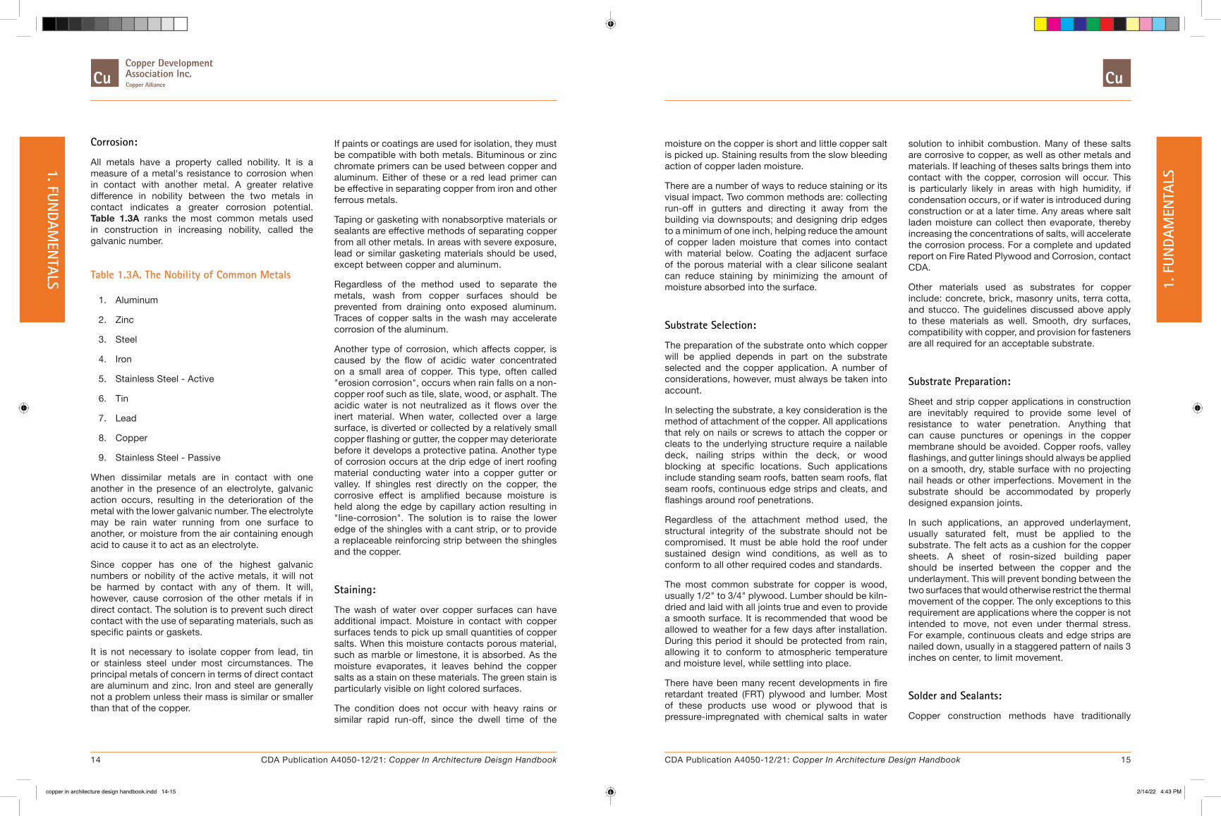
Corrosion:
All metals have a property called nobility. It is a measure of a metal's resistance to corrosion when in contact with another metal. A greater relative difference in nobility between the two metals in contact indicates a greater corrosion potential. Table 1.3A ranks the most common metals used in construction in increasing nobility, called the galvanic number.
Table 1.3A. The Nobility of Common Metals
1. Aluminum
2. Zinc
3. Steel
4. Iron
5. Stainless Steel - Active
6. Tin
7. Lead
8. Copper
9. Stainless Steel - Passive
When dissimilar metals are in contact with one another in the presence of an electrolyte, galvanic action occurs, resulting in the deterioration of the metal with the lower galvanic number. The electrolyte may be rain water running from one surface to another, or moisture from the air containing enough acid to cause it to act as an electrolyte.
Since copper has one of the highest galvanic numbers or nobility of the active metals, it will not be harmed by contact with any of them. It will, however, cause corrosion of the other metals if in direct contact. The solution is to prevent such direct contact with the use of separating materials, such as specific paints or gaskets.
It is not necessary to isolate copper from lead, tin or stainless steel under most circumstances. The principal metals of concern in terms of direct contact are aluminum and zinc. Iron and steel are generally not a problem unless their mass is similar or smaller than that of the copper.
If paints or coatings are used for isolation, they must be compatible with both metals. Bituminous or zinc chromate primers can be used between copper and aluminum. Either of these or a red lead primer can be effective in separating copper from iron and other ferrous metals.
Taping or gasketing with nonabsorptive materials or sealants are effective methods of separating copper from all other metals. In areas with severe exposure, lead or similar gasketing materials should be used, except between copper and aluminum.
Regardless of the method used to separate the metals, wash from copper surfaces should be prevented from draining onto exposed aluminum. Traces of copper salts in the wash may accelerate corrosion of the aluminum.
Another type of corrosion, which affects copper, is caused by the flow of acidic water concentrated on a small area of copper. This type, often called "erosion corrosion", occurs when rain falls on a non-copper roof such as tile, slate, wood, or asphalt. The acidic water is not neutralized as it flows over the inert material. When water, collected over a large surface, is diverted or collected by a relatively small copper flashing or gutter, the copper may deteriorate before it develops a protective patina. Another type of corrosion occurs at the drip edge of inert roofing material conducting water into a copper gutter or valley. If shingles rest directly on the copper, the corrosive effect is amplified because moisture is held along the edge by capillary action resulting in "line-corrosion". The solution is to raise the lower edge of the shingles with a cant strip, or to provide a replaceable reinforcing strip between the shingles and the copper.
Staining:
The wash of water over copper surfaces can have additional impact. Moisture in contact with copper surfaces tends to pick up small quantities of copper salts. When this moisture contacts porous material, such as marble or limestone, it is absorbed. As the moisture evaporates, it leaves behind the copper salts as a stain on these materials. The green stain is particularly visible on light colored surfaces.
The condition does not occur with heavy rains or similar rapid run-off, since the dwell time of the
moisture on the copper is short and little copper salt is picked up. Staining results from the slow bleeding action of copper laden moisture.
There are a number of ways to reduce staining or its visual impact. Two common methods are: collecting run-off in gutters and directing it away from the building via downspouts; and designing drip edges to a minimum of one inch, helping reduce the amount of copper laden moisture that comes into contact with material below. Coating the adjacent surface of the porous material with a clear silicone sealant can reduce staining by minimizing the amount of moisture absorbed into the surface.
Substrate Selection:
The preparation of the substrate onto which copper will be applied depends in part on the substrate selected and the copper application. A number of considerations, however, must always be taken into account.
In selecting the substrate, a key consideration is the method of attachment of the copper. All applications that rely on nails or screws to attach the copper or cleats to the underlying structure require a nailable deck, nailing strips within the deck, or wood blocking at specific locations. Such applications include standing seam roofs, batten seam roofs, flat seam roofs, continuous edge strips and cleats, and flashings around roof penetrations.
Regardless of the attachment method used, the structural integrity of the substrate should not be compromised. It must be able hold the roof under sustained design wind conditions, as well as to conform to all other required codes and standards.
The most common substrate for copper is wood, usually 1/2" to 3/4" plywood. Lumber should be kiln-dried and laid with all joints true and even to provide a smooth surface. It is recommended that wood be allowed to weather for a few days after installation. During this period it should be protected from rain, allowing it to conform to atmospheric temperature and moisture level, while settling into place.
There have been many recent developments in fire retardant treated (FRT) plywood and lumber. Most of these products use wood or plywood that is pressure-impregnated with chemical salts in water
solution to inhibit combustion. Many of these salts are corrosive to copper, as well as other metals and materials. If leaching of theses salts brings them into contact with the copper, corrosion will occur. This is particularly likely in areas with high humidity, if condensation occurs, or if water is introduced during construction or at a later time. Any areas where salt laden moisture can collect then evaporate, thereby increasing the concentrations of salts, will accelerate the corrosion process. For a complete and updated report on Fire Rated Plywood and Corrosion, contact CDA.
Other materials used as substrates for copper include: concrete, brick, masonry units, terra cotta, and stucco. The guidelines discussed above apply to these materials as well. Smooth, dry surfaces, compatibility with copper, and provision for fasteners are all required for an acceptable substrate.
Substrate Preparation:
Sheet and strip copper applications in construction are inevitably required to provide some level of resistance to water penetration. Anything that can cause punctures or openings in the copper membrane should be avoided. Copper roofs, valley flashings, and gutter linings should always be applied on a smooth, dry, stable surface with no projecting nail heads or other imperfections. Movement in the substrate should be accommodated by properly designed expansion joints.
In such applications, an approved underlayment, usually saturated felt, must be applied to the substrate. The felt acts as a cushion for the copper sheets. A sheet of rosin-sized building paper should be inserted between the copper and the underlayment. This will prevent bonding between the two surfaces that would otherwise restrict the thermal movement of the copper. The only exceptions to this requirement are applications where the copper is not intended to move, not even under thermal stress. For example, continuous cleats and edge strips are nailed down, usually in a staggered pattern of nails 3 inches on center, to limit movement.
Solder and Sealants:
Copper construction methods have traditionally
14 15CDA Publication A4050-12/21: Copper In Architecture Deisgn Handbook CDA Publication A4050-12/21: Copper In Architecture Design Handbook
1. FUNDAM
ENTALS 1.
FUN
DAM
ENTA
LS
copper in architecture design handbook.indd 14-15copper in architecture design handbook.indd 14-15 2/14/22 4:43 PM2/14/22 4:43 PM

1.4. Structural Considerations
Structural considerations play an important role in the proper design of copper applications. They affect the spacing of 7.1. Attachments, location and design of 7.2. Joints and Seams, and the configuration of other joints. The requirements may be calculated with the same formulas used in the structural analysis of other materials, such as steel and wood. Table 1.1A contains information that is useful in these calculations.
Although there are other structural concerns, the primary focus is upon thermal effects. Movement and stresses related to temperature variations must be accommodated. There are two fundamental methods to do this: prevent the movement and resist the cumulative stresses within the copper; or allow movement at predetermined locations, thereby relieving thermal stresses.
In a limited number of applications, such as gravel stops, base flashings at built-up roofs, and flashings around windows and doors, it is possible and often desirable to prevent movement. These tend to involve narrow copper strips that do not cover large areas. The strips should be nailed frequently to effectively transfer stresses to the underlying substrate before causing buckling in the copper. Nails spaced 3 inches maximum on center in a staggered pattern are recommended.
In most other situations it is impractical and undesirable to restrain a copper section so frequently.
In the interest of watertightness, puncturing the copper membrane should be avoided. It is also better, where possible, to allow the copper to move in order to reduce the chance of metal fatigue.
The yield strength of copper is the same for compression as it is for tension. Since buckling is likely to occur when relatively thin sections of sheet copper are in compression, sections should be designed to resist compressive loads. The compressive strength in sheet copper is the product of two factors: the thickness of the copper and the shape of the section. These factors create "columnar strength" which resists accumulated stresses up to a certain length. Beyond this point, expansion joints must be introduced to prevent buckling.
Once an expansion joint is introduced, the section no longer has to resist the cumulative stresses caused by thermal expansion along its whole length. It need only keep its shape and resist the friction between itself, its fasteners, and adjacent materials. The structural design of sheet copper, for the most part, involves the determination of expansion joint spacing. Each section of copper is designed as a "column" capable of transmitting stresses from a fixed point to the free end or expansion joint.
Table 10B shows the maximum allowable column length for "U"-shaped sections. This is the section most frequently used for such applications as gutters, gutter linings, and fascias. The requirements for standing and batten seam roofs can also be determined, since their pans derive their strength from the flanges that form the longitudinal seams.
relied on solder to ensure water-tightness and to strengthen joints and seams. The solder used is common 50-50 tin-lead bar solder for uncoated copper. Alternative tin based solders are available for those who prefer a lead free installation. Solder is typically applied to mechanically fastened or formed, rigid joints. Soldered seams and joints are permanent; they should last the life of the copper. Continuous, long runs of soldered seams should be avoided to limit stress fractures.
In the weathering process, the solder turns from a shiny to a dull tone. Exposed solder in the finished joints can be minimized with the use of blind soldering. In this technique, solder is applied to the back or concealed edge of copper surfaces.
An alternative to solder, where its additional strength is not required, is the use of sealants. Sealant filled joints have been used successfully for standing seam and batten seam roofing applications where roof slopes are less than three inches per foot. Sealants can also be used in joints that are primarily designed to accommodate thermal movement of the copper.
The sealants used should be tested by the manufacturer and designated as compatible for use with copper. Many elastomeric polyurethane, silicone, butyl, polysulfide or other inorganic or rubber based sealants have shown acceptable performance. Acrylic, neoprene, and nitrile based sealants have been observed to actively corrode copper. The use of such sealants is, therefore, not recommended.
16 17CDA Publication A4050-12/21: Copper In Architecture Deisgn Handbook CDA Publication A4050-12/21: Copper In Architecture Design Handbook
1. FUNDAM
ENTALS 1.
FUN
DAM
ENTA
LS
copper in architecture design handbook.indd 16-17copper in architecture design handbook.indd 16-17 2/14/22 4:43 PM2/14/22 4:43 PM
1.5. Radio Frequency Shielding
Radio frequency (RF) shielding involves the construction of enclosures for the purpose of reducing the transmission of electric or magnetic fields from one space to another. With the increase in sensitive computer and electronic equipment, the issues of interference, unauthorized surveillance, and protection from high voltages have become increasingly important.
All electronic and computer systems radiate certain frequencies of radio and magnetic waves. These signals can be received by special surveillance equipment, compromising the privacy of their source. In some cases, they can interfere with, or may be affected by, other equipment in the vicinity. Radio frequency shielding enclosures are used in these situations to reduce the levels of RF radiation that enters or leaves the enclosed space.
One of the characteristics of copper is its high electrical conductivity. This feature, combined with its other physical properties, ductility, malleability, and ease of soldering, make it an ideal material for RF shielding. Sheet copper can be formed into essentially any shape and size, and electrically connected to a grounding system to provide an effective RF enclosure.
RF shielding enclosures are usually designed to filter a range of frequencies under specified conditions. Most often, they are constructed for government or corporate groups with particular requirements. Properly designed and constructed copper enclosures can provide a high degree of effectiveness to suit practically any demand.
1.6. Lightning Protection
When lightning protection is desired, it is usually achieved by providing a path of low resistance to ground. Copper roofs offer ideal lightning protection where the copper roofing, gutters and rain leaders are electrically interconnected and reliably grounded. The specified thickness of materials, i.e., roof covering sheets, wall claddings, gutters and leaders are usually adequate for lightning protection and in these circumstances additional conductors are unnecessary.
Additional protection may be necessary with lighter gauge copper bonded panels or when some components of the grounding system are made from less conductive materials.
In the absence of adequate grounding through the copper system, additional lightning protection may be required.
It should be pointed out that, due to its excellent electrical conductivity and resistance to corrosion, copper maintains an important role in lightning protection applications. Its use for the grounding of copper roofing overcomes problems associated with mixed metal corrosion. When using copper for grounding in combination with other materials, instructions concerning corrosion protection should be followed.
Those not familiar with lightning protection systems seem to believe that copper components, including roofs, actually attract lightning. Needless to say this assumption is not based on fact.
It is true however, that the high conductivity of copper facilitates the rapid transmission of lightning energy. Lightning takes the path of least resistance and no damage is done to a building if there is a low resistance path to earth. This path can consist of the copper roof, lightning conductor and grounding device.
To ensure proper lightning protection in an installed copper roof system, a separate lightning conductor system should be used including air terminals and intercepting conductors on the roof; a system of ground electrodes; and a system of down conductors connecting the roof and ground components. It is recommended that the copper roof be bonded to the system of conductors. This bonding ensures that the
conductors and roof remain at approximately equal potential and reduce side flashing and possible roof damage.
The Copper Development Association makes no representation as to the proper, correct or safe design of any lightning protection system. This information is presented as a guide only and the reader is cautioned that the design of any lightning protection system and devices is the responsibility of the electrical engineer. All such system design should be based on local applicable code requirements and sound engineering practice.
1.7. Cost Effectiveness
The cost of building components, such as copper roofing, flashing, gutters, and downspouts, must be evaluated in the context of their use, performance, maintenance, and service life. Many applications of copper involve uses that are critical in maintaining the integrity of the building envelope. Copper performs these functions economically for a long time. There are many examples of copper roofs that have been in service for many decades; even centuries.
In specific applications, economic criteria vary. For example, in selecting flashing material, the initial material cost may be insignificant compared to the cost of repair if the flashing fails. With a roofing system, the cost of maintenance, which may prevent water damage to the interior, must be considered. Copper components typically offer extremely low maintenance and long life, even in coastal or industrial environments. Copper is therefore an economical material for these and many other applications.
When life cycle costs are evaluated, these factors should be quantified. Initial costs, maintenance costs, and the life expectancy of the systems must be estimated, as should the salvage value of the material. Copper is an inherently recyclable material that retains much of its primary metal cost. This is far greater than competing materials whose scrap values range from about 60% down to zero. The results make copper an outstanding material in terms of life cycle costs.
18 19CDA Publication A4050-12/21: Copper In Architecture Deisgn Handbook CDA Publication A4050-12/21: Copper In Architecture Design Handbook
1. FUNDAM
ENTALS 1.
FUN
DAM
ENTA
LS
copper in architecture design handbook.indd 18-19copper in architecture design handbook.indd 18-19 2/14/22 4:43 PM2/14/22 4:43 PM

2. COPPER ALLOYS
2.1. Introduction
A wide variety of copper alloys are available for use in construction. The variations in color stem primarily from differences in chemical composition. Production and forming methods may affect alloy selection. Additional information is available upon request. The CDA publication Copper Brass Bronze - Architectural Applications (PDF 4MB) covers the selection process in greater detail.
Technically, alloys primarily of copper and tin are considered bronzes, while those chiefly of copper and zinc are brasses. In practice, however, the term bronze is commonly used for a variety of copper alloys, including those with little or no tin. This is because they resemble true bronzes in both natural and weathered colors. Table 2.1A lists the characteristics of some of the more popular copper alloys and their common names.
A Unified Numbering System has been developed for metals and alloys by ASTM and SAE. CDA administers the section on copper and its alloys. This system is based on wrought alloy numbers ranging from C10000 through C79999. Cast alloy numbers range between C80000 and C99999.
Nickel-silver alloys C74500 and C79600 are usually called "white bronze"; all others are considered "yellow bronze". "Statuary bronze" and "green bronze" do not refer to specific alloys, but to their naturally weathered or chemically induced colors. The former is used to describe brown to black surfaces; the latter is used for patinas.
In general, most copper alloys eventually weather to the gray-green patina. There are, however, significant variations in their natural colors and in the rate at which they form a patina. The last two columns in Table 2.1A contain information about the natural and weathered colors of the alloys. Table 2.1B is a color matching table. It depicts which alloys, in various forms, are reasonably well matched in color with the sheet, strip, and plate copper alloys.
1.8. Recyclability
Will there be enough copper today and tomorrow? Yes. The United States is virtually self-sufficient in its reserves and resources of copper. The U.S. Bureau of Mines and the U.S. Geological Survey provide documented data about the future supply of this metal that is most encouraging. Known worldwide copper resources are estimated at nearly 5.8 trillion pounds of which only about 0.7 trillion pounds (12%) have been mined throughout history...and nearly all of that is still in circulation, because the recycling rate for copper is higher than that of any other engineering metal.
Each year in the U.S.A., nearly as much copper is recovered from recycled material as is derived from newly mined ore. And when you exclude wire production, most of which uses newly refined copper, the amount of copper used by copper and brass mills, ingot makers, foundries, powder plants and other industries shows that nearly three-fourths (72%) comes from recycled scrap. More than half of this scrap is "new". scrap, such as chips and turnings from screw machine production. The remainder is "old" scrap, such as discarded electrical cable, junked automobile radiators or ancient Egyptian plumbing. (Yes, it's been around that long!)
Copper's recycling value is so great that premium-grade scrap normally has at least 95% of the value of the primary metal from newly mined ore.
All mining and processing of minerals require the expenditure of energy in extracting a metal from its natural ores. Fortunately, copper production is conservative of energy. A recent study concluded that the energy content of a pound of copper totals from 12 to 16 kilowatt-hours depending on the copper content of the ore. Competing materials require three to five times as much energy to produce.
This is the amount of energy required for the entire operation - from moving off the overburden to uncovering the ore at the mine site through the casting of ready-to-fabricate copper refinery shapes.
The range of attractive natural colors of copper and copper alloys, along with their corrosion resistance and other outstanding properties, give today's architects a variety of options in the planning and design of enduring commercial, industrial, public and residential structures. Moreover, at a time of changing world material supplies and energy shortages, users can depend on U.S. self-sufficiency in copper-one of the earth's most recyclable resources. It can be extracted from ores and recycled from scrap with a relatively small expenditure of energy compared to competing metals.
20 21CDA Publication A4050-12/21: Copper In Architecture Deisgn Handbook CDA Publication A4050-12/21: Copper In Architecture Design Handbook
2. C
OPP
ER A
LLOY
S1. FUN
DAMEN
TALS
copper in architecture design handbook.indd 20-21copper in architecture design handbook.indd 20-21 2/14/22 4:43 PM2/14/22 4:43 PM

Copper Alloy Table
Table 2.1A. Common Copper Alloys
Alloy Common Term CompositionColor
Natural WeatheredC11000 / C12500 Copper 99.90% Copper Salmon Red Reddish-Brown to Gray-
Green Patina
C12200 Copper 99.90% Copper 0.02% Phosphorous
Salmon Red Reddish-Brown to Gray-Green Patina
C22000 Commercial Bronze 90% Copper 10% Zinc
Red Gold Brown to Gray-Green Patina in Six Years
C23000 Red Brass 85% Copper 15% Zinc
Reddish Yellow Chocolate Brown to Gray-Green Patina
C26000 Cartridge Brass 70% Copper 30% Zinc
Yellow Yellowish, Gray-Green
C28000 Muntz Metal 60% Copper 40% Zinc
Reddish Yellow Red-Brown to Gray-Brown
C38500 Architectural Bronze 57% Copper 3% Lead 40% Zinc
Reddish Yellow Russet Brown to Dark Brown
C65500 Silicon Bronze 97% Copper 3% Silicon
Reddish Old Gold Russet Brown to finely mottled Gray-Brown
C74500 Nickel Silver 65% Copper 25% Zinc
10% Nickel
Warm Silver Gray-Brown to finely mottled Gray-Green
C79600 Leaded Nickel Silver 45% Copper 42% Zinc
10% Nickel 2% Manganese
1% Lead
Warm Silver Gray-Brown to finely mottled Gray-Green
Color Matching Chart
Table 2.1B. Color Matching Chart
Forms to be Matched in ColorSheet and Plate
Alloys Extrusions Castings Fasteners Tube& Pipe Rod & Wire Filler Metals
C11000 / C12500 Copper
C11000 / C12500 (simple
shapes)
Copper (99.9% Min.)
C65100 Low Silicon Bronze
C12200 C11000 / C12500
C18900 Copper
C12200 Copper C11000 / C12500 (simple
shapes)
Copper (99.9% Min.)
C65100 Low Silicon Bronze
C12200 C11000 / C12500
C18900 Copper
C22000 Commercial Bronze, 90%
C31400 Leaded Commercial
Bronze
C83400 C65100 Low Silicon Bronze
C22000 C22000 C65500
C23000 Red Brass, 95%
C38500 Architectural
Bronze
C83600 C28000 C65100 Low Silicon Bronze
C23000 C23000 C65500
C26000 Cartridge Brass, 70%
C26000 (simple shapes)
C85200, C85300
C26000, C36000, C46400, C46500
C26000 C26000 C68100 Low Fuming Bronze
C28000 Muntz Metal C38500 Architectural
Bronze
C85500, C85700
C28000 C65100 Low Silicon Bronze
C23000 C28000 C68100 Low Fuming Bronze
C65500 High Silicon Bronze
C65500 (simple shapes)
C87500 C65100, C65500
C65100, C65500
C65100, C65500 C65500
C74500 Nickel-Silver C79600 Leaded Nickel-Silver
C97300 C74500 C74500 C74500 C77300
2.2. Forming
Numerous methods can be used to form copper alloys into sheet, plate, rod, wire, and irregular shapes. Table 2.2A indicates forming methods appropriate for use with common alloys. The following is a brief description of each method:
Bending: A mechanical forming process performed at room or at elevated temperatures. Bending is accomplished with the aid of rollers, bending shoes and mandrels. Its primary purpose is to produce curved sections from straight lengths of tube, rod, or extruded shapes.
Brake Forming: A mechanical bending operation usually performed on metal sheet, strip, or plate.
Castings: These are produced by pouring molten
metal into a mold and allowing it to cool and solidify. This method is used to form irregular shapes. Only specially formulated alloys C80000 through C99999 can be cast.
Explosive Forming: A high energy rate forming method by which shapes are produced using only a single die. The energy is supplied by chemical explosives. Large shapes can be formed without the need for heavy equipment.
Extrusion: The process of producing a metal shape of constant cross-section by forcing the heated metal through an appropriately shaped die. In general, cross-section diagonals should not exceed six inches. The average thickness of copper alloy extrusions should be about 1/8 inch. The resulting shape can be almost any length, limited mostly by the structural requirements of the final object.
22 23CDA Publication A4050-12/21: Copper In Architecture Deisgn Handbook CDA Publication A4050-12/21: Copper In Architecture Design Handbook
2. COPPER ALLOYS 2.
CO
PPER
ALL
OYS
copper in architecture design handbook.indd 22-23copper in architecture design handbook.indd 22-23 2/14/22 4:43 PM2/14/22 4:43 PM

Forming Chart
Table 2.2A. Forming Methods
Forming Method
Alloys C11000 / C12500
C12200 C22000 C23000 C26000 C28000 C38500 C65100 C65500 C74500 C77400 C79600
Bending + + + + + + + + +
Brake Forming + + + + + + + + +
Casting All Alloys C80000 - C99999
Explosive Forming
+ + + + + + + +
Extrusion + + +
Cold Forging + + + + + + +
Hot Forging + + + + + + + +
Hydroforming + + + + + + + +
Laminating All Copper Sheet and Strip Alloys
Roll Forming + + + + + + + +
Spinning + + + + + +
Stamping + + + + + + + +
Cold Forging: A forming process in which a metal object at room temperature is shaped by repeated hammering.
Hot Forging: A method of forming metal objects in which a heated slug or blank cut from wrought material is pressed into a closed cell impression die.
Hydroforming: A forming process in which a sheet alloy is pressed between a male die and a rubber piece subjected to hydraulic pressure.
Laminating: Bonding of sheet or strip alloys to various substrates such as steel, plywood, aluminum, or rigid insulating material. The bond is typically achieved with the use of adhesives. The resulting panel can be quite strong, even with thin copper alloy material.
Roll Forming: Shapes made from sheet or strip material by passing it between multiple stands of contoured rolls. Generally, the corners are not as sharp as those achieved by extrusion.
Spinning: A mechanical forming process in which sheet or strip alloy is shaped under pressure applied by a smooth hand tool or roller while the material is revolved rapidly.
Stamping: Shaping sheet or strip alloy by means of a die in a press or power hammer.
2.3. Joining
Mechanical fasteners, such as screws, bolts, and rivets provide the simplest and most common joining technique. They typically do not require specialized tools for installation, and many can be removed for disassembly. Table 2.2A lists the companion fasteners for each sheet or plate alloy by simplifying color matching and reducing the risk of material incompatibility.
Adhesives can also be used in certain applications. The lamination process of a sheet alloy onto a substrate is dependent on adhesive bonding. Relatively thin sheet alloys can be bonded to steel, plywood, aluminum, or certain types of foam, which act as rigid insulation. The strength and rigidity of the resulting composite panel is often achieved by the combined section acting as one unit.
The integrity of the bond is dependent on surface preparation, adhesive selection, bonding procedure, and joint design. Laminated panels for exterior applications should use a thermosetting or high quality thermoplastic adhesive. Edges and joints are the most vulnerable areas on a panel, as they are the most likely entry points for moisture.
There are three commonly used metallurgical methods for joining alloys: soldering, brazing, and welding. Table 2.3A summarizes the joining characteristics of each alloy for these methods.
Where the joining material is required mostly for watertightness, soldering may be used. Lead or tin-based filler metals with melting temperatures below 500 degrees Fahrenheit are typically used. Soldered joints typically depend on mechanical fasteners for strength. This method is commonly used for sealing joints in gutter, roofing, and flashing applications. Since the filler material does not match copper alloys in color, soldering should only be used in concealed joints when appearance is critical.
Brazing is a preferred metallurgical method for joining pipe and tube copper alloys. Two metal sections are joined with a non-ferrous filler material with a melting point above 800 degrees Fahrenheit, but below the melting point of the base metals. Blind or concealed joints are recommended, since the color match of filler material varies. Where this is not possible, mechanical removal of excess material may be necessary.
The final metallurgical joining method, welding, is seldom used with copper alloys because of problems with joint distortion and color matching. Welding uses high temperature or pressure to fuse the base metals together, often with an additional filler metal. Silicon bronzes are the only copper alloys which can be readily welded.
With modern equipment and processes, gas shielded arc welding is gaining acceptance for many copper alloys and use.
24 25CDA Publication A4050-12/21: Copper In Architecture Deisgn Handbook CDA Publication A4050-12/21: Copper In Architecture Design Handbook
2. COPPER ALLOYS 2.
CO
PPER
ALL
OYS
copper in architecture design handbook.indd 24-25copper in architecture design handbook.indd 24-25 2/14/22 4:43 PM2/14/22 4:43 PM

3. FINISHES
� 3.1. Mechanical Finishes
� 3.2. Chemical Finishes
� 3.3. Protective Coatings
� 3.4. Laminated Finishes
� 3.5. Standard Finish Designations
� 3.6. Copper Alloys Color Chart
� 3.7. Finishes Tables
The wide variety of textures and colors available with copper alloys provide architects with an almost limitless palette of visual effects. In order to systematize this colorful collection and provide a basis for specification, the National Association of Architectural Metal Manufacturers (NAAMM) and the National Ornamental & Miscellaneous Metals Association (NOMMA) describe frequently used finishes in the Metal Finishes Manual for Architectural and Metal Products.1
Field application is occasionally necessary for colored or oxidized finishes and for items such as large immobile statuary. Choice of worksite is normally reserved for the fabricator with consent of the architect.
There are four recognized classes of finishes for copper alloys: mechanical, chemical, protective coatings and laminated finishes. The following paragraphs, abstracted from the NAAMM/NOMMA Manual, describe these and a few other finishes. Use the alpha-numeric codes in Table 3.7B, Table 3.7C and Table 3.7D to specify these finishes.
3.1. Mechanical Finishes
Mechanical finishes are imparted by physical rather than chemical means. As examples, buffing and grinding are mechanical operations; whereas, oxidizing and patinating are chemical in nature.
As-fabricated
These finishes are the mechanical surface conditions resulting from primary production processes, e.g., hot and cold rolling, extrusion, drawing and casting. They are the least expensive finishes, and, while they may contain imperfections, they are uniform enough with sheet goods for applications such as roofing and wall cladding. The term “mill finish” is commonly used for an “as fabricated” finish.
As-fabricated finishes can be marred by secondary operations such as bending, milling and welding, in which case, they may require additional finishing operations. They can also vary in appearance, both intentionally and accidentally. Rolled finishes, for example, will replicate the surface of the final roll in the mill, and as-cast surfaces will betray the nature of the foundry method employed. As-fabricated finishes include:
Figure 3A. This lobby in Anchorage, Alaska, artfully displays panels of copper alloys using a variety of colorful chemical and mechanical finishes.
Photograph courtesy of CDA.
1. NAAMM/NOMMA Metal Finishes Manual, Chapter 2: “Finishes for the Copper Alloys,” National Association of Architectural Metal Manufacturers, AMP 500-06, 2006
Joining Chart
Table 2.3A. Metallurgical Joining Characteristics
Joining Method
Alloys C11000 / C12500
C12200 C22000 C23000 C26000 C28000 C38500 C65100 C65500 C74500 C79600
Brazing G E E E E E G E E E G
Soldering E E E E E E E E G E E
Welding
Oxyacetylene NR G G G G G NR G G G NR
Gas Shielded Arc
F E G G F F NR E E F NR
Coated Metal Arc
NR NR NR NR NR NR NR F F NR NR
Spot Resistance
NR NR NR F G G NR E E G NR
Seam Resistance
NR NR NR NR NR NR NR G E F NR
Butt Resistance
G G G G G G F E E G F
E = Excellent G = Good F = Fair NR = Not Recommended
26 27CDA Publication A4050-12/21: Copper In Architecture Deisgn Handbook CDA Publication A4050-12/21: Copper In Architecture Design Handbook
3. F
INIS
HES
2. COPPER ALLOYS
copper in architecture design handbook.indd 26-27copper in architecture design handbook.indd 26-27 2/14/22 4:43 PM2/14/22 4:43 PM

Produced by sequential grinding, polishing and buffing operations, polished and buffed are extremely smooth and bright. Their relatively high cost reflects the added value of preparation. They are frequently used for hardware and small decorative objects. Their high reflectivity imparts a tendency to reveal even slight distortions and lack of flatness. Polished and buffed finishes on interior surfaces are often protected from tarnishing using lacquers. The two subclassifications of buffed finishes are:
Smooth specular, a very bright, mirror-like surface produced by abrasive belt-grinding followed by polishing with progressively finer abrasives and buffing with extremely fine compounds. This is the most costly mechanical finish applied to copper metals. It is especially important to protect smooth specular finishes during installation because they are challenging to apply or touch-up once installed.
Specular is a somewhat less-bright surface. It is also produced by polishing and buffing, but to a lesser extent than that for smooth specular. Surfaces may contain minor scratches and imperfections. Specular finishes are also shop-applied. Field repair is possible but expensive, since it involves extensive hand operations.
Directionally Textured
These finishes are the most frequently used mechanical treatments for architectural copper metals. Their smooth, satin sheen is produced by wheel- or belt-polishing with fine abrasives that leave closely spaced, nearly parallel scratches. The six standard directionally textured finishes are:
Fine, medium and coarse satin, which reflect the coarseness of the final polishing abrasive. Final grits range from 240 mesh to 320 mesh for fine satin and 80 mesh for coarse satin.
Figure 3.1A. As natural a look as you can get: unfinished copper cathode, 99.9% pure. Typically shipped as melting stock to mills or foundries, cathodes may also be cast into wire rod, billets, cakes or ingots and alloyed with other metals.
Photograph courtesy of CDA.
Figure 3.1B. The specular or mirror finish on this facade reflects the colors and images of its environment.
Photograph courtesy of CDA.
Figure 3.1D. Complementing or enhancing interior spaces, mechanically finished copper alloy surfaces can take on an infinite array of patterns. Their classy look and durability adds value whether in baths, elevators, lobbies or other locations.
Photograph courtesy of CDA.
Hand-applied sand blasted surfaces have non-uniform textures and are generally not suitable for large areas. Also, the surface deformation caused by blasting leaves residual stresses that can warp thin elements. The process is, therefore, not recommended for flat elements less than ¼-in (6-mm) thick. Even fine-grit blasted surfaces are rough enough to retain oils and dirt, and will show fingerprints. For an untarnished finish, sand blasted surfaces require protective treatment.
The three grades of fineness for sandblasted surfaces are fine matte, medium matte and coarse matte; produced by appropriately sized silica sand or aluminum oxide. Degrees of grit fineness range from 100–200 mesh for fine textures to 20 mesh for coarse.
Shot blasted surfaces are not as rough as sand blasted, but minimum sheet thickness recommendations still apply. Metal shot (usually steel) ranges from S-70 for fine texture to S-550 for coarse. There are three standard grades for shot blasted surfaces: fine, medium and coarse.
Unspecified, which place no preconditions on the as-rolled, -extruded, -drawn or -cast metal. For example, unspecified rolled finishes can range from dull to bright and might contain stains imparted by the residues of rolling oils.
Specular, which are bright mirror-like finishes in cold-rolled sheet, strip and plate produced by passing the metal between highly polished steel rolls. Chemical, heat-treated and mechanical design on copper.
Matte, dull finishes produced by hot rolling, extruding, casting or cold rolling followed by annealing.
Polished and Buffed
Figure 3.1C. Directionally textured example: C11000, brush finished.
Photograph courtesy of CDA.
Uniform, a cost-effective finish produced by a single pass of a No. 80 grit belt. Uniform finishes are less expensive than satin finishes and are suitable for many architectural applications.
Hand-rubbed finishes are produced by rubbing with No. 0 pumice and solvent on a fine brass wire brush or a woven, nonabrasive pad. This is a relatively expensive, labor-intensive process. It is used where other processes are impractical or where there is a need to smooth and blend other satin finishes.
Brushed finishes are produced by power-driven wire- wheel brushes, wire-backed sander heads, abrasive- impregnated fiber pads or abrasive cloth wheels. Scratches produced using brushes are not as uniform as those made with abrasive belts, but brushing offers the advantages that it can be applied to objects with curved or irregular contours. Brushed finishes are difficult to maintain, and their use is normally restricted to small areas or for highlighting.
Nondirectional Textured
These are matte finishes produced by spraying sand or metal shot against the metal surface. Roughness is controlled by size of sand or shot particles. The process is often used to clean castings and improve appearance of an as-cast surface. Sand blasted surfaces are fairly rough, but smoother finishes can be produced by vapor honing with fine abrasive slurries.
28 29CDA Publication A4050-12/21: Copper In Architecture Deisgn Handbook CDA Publication A4050-12/21: Copper In Architecture Design Handbook
3. FINISH
ES 3. F
INIS
HES
copper in architecture design handbook.indd 28-29copper in architecture design handbook.indd 28-29 2/14/22 4:43 PM2/14/22 4:43 PM

Patterned
Textured, patterned and embossed finishes are produced in light-gauge material by passing sheet between two engraved match-design rolls, impressing patterns on both sides of the sheet (embossing) or between a design roll and a smooth one, thus coining only one side of the sheet. Embossing increases the stiffness of the sheet. It also disperses reflections and minimizes marring in service.
3.2. Chemical Finishes
Conversion Coatings
These comprise the most important class of final chemical finishes. The metal surface is chemically converted to a stable, protective compound, usually an oxide or a sulfide or another compound, to mimic natural weathering. Common conversion coatings include patinas (commonly called "verdegris"), and statuary (oxidized) finishes.2
Figure 3.2A. Chemical treatment opens a wide-ranging palette of colors and possibilities:a) artificial finish light bronze on naval brass at the Oklahoma City National Memorial, Oklahoma City, Oklahoma [left image]b) custom chemical treatment of a naval brass panel [right image]
Photograph courtesy of CDA.
Copper alloy surfaces can be chemically altered to produce a wide range of colored finishes. Application is as much a craft as it is a science, and results can vary with such factors as temperature, humidity, surface preparation and skill. Such variability is not necessarily detrimental; it can, in fact, contribute to a finish’s charm.
Some chemical treatments are simply for cleaning, as in removing process oils or preparation for subsequent operations. Acid-etching can remove oxides formed during annealing or welding, or to produce a matte surface. “Bright-dip” or “pickled” finishes involve immersing the metal in an acidic bath. They are normally used as intermediate steps before final finishing operations.
Figure 3.2B. The oxidized finish on this cast silicon bronze lockset produces a stable compound that inhibits corrosion and maintains its color.
Photograph courtesy of Rocky Mountain Hardware.
Figure 3.2C. Natural patinas are seen throughout the world where architects have chosen to use a living metal that projects beauty in any environment and preserves itself for centuries to come. a) One Atlantic Center, Atlanta, Georgia; copper roof after more than 20 years’ exposure in a humid environment. [left most image]b) Druid Hills Baptist Church, Atlanta, Georgia, mature copper patina, characteristic of over 80 years’ exposure in a humid location. [vertical center image]c) Jewish Federation of Tulsa, Oklahoma, newly installed copper. [top right image]d) Jewish Federation of Tulsa after five years’ exposure in a semi-arid climate. [bottom right image]
Photograph courtesy of CDA.
in which the reagents are applied by brushing, sponging, stippling or spraying. Many patinating processes exist, including proprietary, mill-applied versions applied by sheet and strip suppliers. Patented preparations are also available. When large-area uniformity is not critical, two processes found to be suitable for field- or shop-application are:
� Acid chloride treatments are based on solutions of sal ammoniac (ammonium chloride) or on cuprous chloride-hydrochloric acid mixtures. Several applications of the sal ammoniac solution may be needed to achieve the desired effect.
� Ammonium sulfate treatment finishes contain copper sulfate and ammonia. Treatments are applied by spraying and require six to eight applications to achieve the required density.
In addition to atmospheric composition, such factors as temperature, humidity, drainage, insolation and roof slope can affect formation rate and appearance. It would not be unusual for the north- and south-facing surfaces of the same roof to patinate differently or at different rates. A synthetic patina can mitigate these effects; although, one that appears too uniform might look contrived until further, natural weathering takes its course.
Synthetic patinas are normally produced by the action of acid-chloride or acid-sulfate treatments
Figure 3.2D. Skillful use of chemical treatment techniques provide a great variety of color tones from a given copper alloy.
Photograph courtesy of Stuart Dean.
Note on chemical weathering in field environments:Chemical coloring of exposed flashings, chimney caps and similar small surface areas are possible with reasonable expectation of success. Chemical weathering of large surface areas, such as roofs, spires, domes and walls, is impractical and should be avoided. Realistic color tone, uniformity and durability is difficult to control, and the hand methods employed are expensive. Where large areas are involved, either natural weathering or use of factory patinated copper sheet material provides superior results.
Patinas are normally reserved for non-traffic areas and areas that will receive little or no maintenance. If placed in a traffic area, a clear organic coating may provide protection, but can alter the color.
Patinas are formed by a variety of methods, all accomplishing in minutes what occurs over years in nature. Synthetic patination replicates the initial period of the natural process to the point where a pleasing color develops. Once placed in service, the natural process continues, reinforcing the applied finish. Early field applied synthetic patination methods yielded coatings that were prone to flaking off, nonuniformity in color and staining of adjacent materials. But, the technology has improved considerably, and modern mill-finished products are more uniform and durable. (See some examples in Table 3.5A)
Natural patinas are predominantly mixtures of basic copper carbonate and basic copper sulfate (the latter being the mineral, brochantite). However, compositions are variable and depend strongly on the type and concentration of atmospheric constituents. Thus, patinas formed near the sea contain slightly different percentages of copper sulfates, chlorides and carbonates than those formed in industrial or rural areas. Natural patinas are therefore far from uniform, and architects have learned to take this fact into account.
30 31CDA Publication A4050-12/21: Copper In Architecture Deisgn Handbook CDA Publication A4050-12/21: Copper In Architecture Design Handbook
3. FINISH
ES 3. F
INIS
HES
copper in architecture design handbook.indd 30-31copper in architecture design handbook.indd 30-31 2/14/22 4:43 PM2/14/22 4:43 PM

Sulfide treatments are similar in color to oxide finishes but are produced by dipping, spraying or brushing the surface with reagents such as potassium sulfide, sodium sulfide, ammonium sulfide and, less frequently, antimony pentasulfide, the latter applied as a paste. Oxide treatments may be applied as a preliminary step to improve adherence.
Selenide treatments produce deep colors. Formation is rapid with use of appropriate selenide solutions, many of which are proprietary. Application can involve exposure to hazardous reagents.
Figure 3.2E. Statuary bronze finishes are popular for many uses, including building entries.
Photograph courtesy of Stuart Dean.
3.3. Protective Coatings
Coatings are finishes applied over copper metals that may or may not have received mechanical or chemical treatment. Coatings are usually applied for protection but, in some cases, may also provide visual effects.
Coatings take two general forms: transparent coatings that preserve natural color, texture and metallic luster of copper metals, and opaque coatings that impart corrosion and abrasion resistance while retaining formability.
Clear Organic Coatings
Copper metals are inherently corrosion-resistant, but thin tarnish films and/or patinas can form over time. Clear organic coatings can retard formation of such films and thus preserve the metals’ natural colors by acting as physical and/or chemi-cal barriers to atmospheric chemicals. These coatings degrade over time, especially in fully exposed exterior applications. When specifying a clear coating, consider effort required to periodically remove the clear coating, refinish the underlying metal and apply a new coating.
Figure 3.3A. The Anchor Center office building in Scottsdale, Arizona, chose to boast its location in the Copper State by preserving the natural color of freshly milled copper sheet with a clear coating. Due to sun and heat, the finish requires reapplication every few years to maintain its pristine look.
Photograph courtesy of CDA.
Clear coatings are compounded from synthetic or natural resins, oils or combinations of the three, usually applied as solutions in a volatile solvent. They can be brush- or dip-applied but are most often sprayed and air-dried (i.e., cured or polymerized), especially for large-area applications. They can also be baked, in which case, a harder, more durable (and a more difficult-to-strip) coating results. Finishing processes are straightforward, but any organic coating will perform best when the underlying surface is properly cleaned and prepared as soon as practical before application.
Inhibited acrylic coatings include those containing protective chemicals in addition to the base resin(s). INCRALAC®-type coatings are the most effective in this class. Based on acrylic lacquers, INCRALAC coatings contain an organic oxygen scavenger, usually benzotriazole or a related compound. The basic composition was developed by the International Copper Research Association, and a number of licensed commercial versions are available. The coatings are normally sprayed and air-dried, although dipping and baking are also approved. Sprayed and air-dried films are normally specified for exterior uses. Baked films are more abrasion resistant and are preferred for interior applications, although periodic maintenance is required.
Prepare surfaces by washing with a cleaning solvent and, for non-specular finishes, abrasive pads. Avoid steel wool (a general precaution for all copper metals) since it sometimes contains a rust inhibitor that can stain copper over time if not thoroughly removed. Alkali cleaning is also effective.
Acrylic coatings without inhibitors provide good abrasion resistance at somewhat lower cost than inhibited versions. They are useful for both exterior and interior applications where wear and exposure to chemical reagents are design considerations.
Alkyd coatings have limited serviceability and tend to yellow outdoors unless modified. They are relatively inexpensive, but must be slow-dried or baked. Exterior performance is improved by compounding with melamine resins. Resistance to chemicals is usually good.
Cellulose acetate butyrate coatings are air-drying, inexpensive and, for interior use, provide fair to good service. They tend to darken when exposed to sunlight.
Epoxy coatings have excellent resistance to impact, abrasion and many chemicals. They are relatively expensive, and application can involve additional costs in that some compositions are two-part compositions requiring compounding on-site, while other versions require heat curing. Interior performance is exceptional, but coatings may darken and chalk when exposed outdoors.
Nitrocellulose coatings are the least expensive, easiest to apply and most common air-drying coatings for mild interior service. Although some of these coatings have limited service life, formulations with alkyd or acrylic resins show improved performance. Exterior use requires stripping and reapplication at approximately yearly intervals depending on exposure conditions. Chemical resistance is low.
Urethane coatings have excellent chemical and abrasion resistance. Cost is moderate to relatively high. The coatings were originally intended for interior use, but modified versions may also be suitable for exterior use. Application entails health risks, and appropriate precautions are absolutely necessary.
Silicone coatings are also relatively expensive, although they provide the best service at elevated temperatures and under severe exposure conditions. Abrasion resistance is moderate, so a topcoat of a more resistant coating may be needed. When exposed to ultraviolet radiation, silicone coatings may discolor unless the composition includes a suitable inhibitor.
Pigmented clear coatings, Pigments are occasionally added to a clear coating to fine tune color match between different alloys.
Oils and Waxes
These coatings can be applied over most chemical finishes to enhance their appearance with richer luster and greater depth of color. The finishes are almost always applied to statuary bronzes, in which case they also protect the underlying oxide/sulfide surface treatment.
Oxide or statuary bronze treatments are based on cuprous oxide, sometimes combined with a mixture of copper sulfides. They are commonly applied to bronzes used as artistic, decorative or, architectural elements. Their brownish colors range from light to medium to dark, depending on the copper alloy, fineness of surface texture and concentration and number of applications of coloring solutions. Popular reagents include potassium permanganate and copper salt solutions.
Finishes are often augmented by mechanical abrasion to produce highlights. Statuary finishes are commonly hand-applied and hand-rubbed periodically with wax or oils to maintain a stable appearance.
32 33CDA Publication A4050-12/21: Copper In Architecture Deisgn Handbook CDA Publication A4050-12/21: Copper In Architecture Design Handbook
3. FINISH
ES 3. F
INIS
HES
copper in architecture design handbook.indd 32-33copper in architecture design handbook.indd 32-33 2/14/22 4:43 PM2/14/22 4:43 PM

The most common oils are lemon oil (U.S.P.), lemon grass oil (Citratus or East Indian), paraffin oils, linseed oil and castor oil. Popular waxes include carnauba wax and beeswax, either of which can be applied as a mixture with wood turpentine. Quality commercial waxes also give good results.
Oil newly installed metals weekly for the first month to build up a sound base. Apply oils and waxes by hand rubbing with a well-saturated cloth, followed by a second rubbing with a clean cloth to remove excess finish. Application frequency depends on the severity of service: every one or two weeks for heavy traffic areas; monthly for moderate and light duty areas.
Vitreous Enamels
These coatings have their place in artwork, decorative objects and some small architectural elements. They are seldom applied to larger architectural works.
This approach is occasionally used with copper metals, two common examples being tinned and tin-zinc coatings used mainly on copper for roofing, flashing and exterior wall panels. Another example is gilding, whereby a thin layer of gilt (typically gold) is applied to the copper surface.
Other examples include chromium and nickel electroplating given to copper and brass hardware, fasteners and plumbing goods. Some high-end plumbing fixtures are finished with electroplated gold. Plated layers are normally thin enough to replicate the underlying surface texture.
Heat Treatment
This is usually a custom artistic treatment accomplished by gas-torching the metal surface to create patterns of colors. The gas in the torch combines with the air to cause a chemical reaction with the copper alloy surface.
3.4. Laminated Finishes
Laminated finishes are not common for copper metals, since most are opaque. Clear polyvinyl fluoride (PVF) and polyvinylidene fluoride (PVDF) coatings provide corrosion and abrasion resistance and demonstrate long-time resistance to degradation by sunlight.
Figure 3.3B. Oil-rubbed bronze gates prepared for installation at the State Capital in Harrisburg, Pennsylvania.
Photograph courtesy of Weimann Metalcraft.Figure 3.3C. Gilded copper dome crowns the Chapel of St. Basil in Houston, Texas; Niko Contracting, sheet metal installer.
Photograph courtesy of CDA.
3.5. Standard Finish Designations
Classification of metal finishes has evolved over the years, but even early systems are still occasionally used. One of these is the U.S. Finishes Designations System, developed by the U.S. Department of Commerce. It mainly defines finishes for brass and bronze hardware. Although it was officially discontinued decades ago, it is still used by some hardware manufacturers and architects today. Ultimately, the Builders Hardware Manufacturers Association (BHMA) established an industrywide numerical system, which is now widely used for hardware items. In deference to common practice, BHMA cross-referenced its designations to the nearest U.S. Finishes numbers, as shown in Table 3.7A.
Figure 3.5A. Heat and chemical treatments applied to a bronze statue by experienced metals restoration firm Stuart Dean.
Photograph courtesy of Stuart Dean.
In 1967, the Copper Development Association adopted a system of designations widely used by architects that offers simplicity and uniformity. The system recognizes four most common types
Metallic Coatings of finishes: mechanical, chemical, clear organic coatings and laminated coatings, each designated by the letters M, C, O and L, respectively. A specific finish is identified by one of these letters followed by a two-digit number. Table 3.7B, Table 3.7C and Table 3.7D list specific designations for mechanical, chemical and laminated finishes, respectively. Metal finishing being as much a craft as a technology, the “Examples of Method of Finishing” listed in the tables are merely suggestions and are not to be taken as mandatory. Alternate methods are acceptable in all cases.
Specify finishes by their designation code(s), with preparatory and final steps listed sequentially. Thus, M36-C51 defines a uniform, directionally textured mechanical finish treated with a cuprous chloride-hydrochloric acid conversion coating, in this case a synthetic patina. Specifications need not be that detailed, however, and designers can call out only the final finish, leaving the preparatory operations to the discretion of the fabricator or finisher.
The letter “x” appearing in a designation listed in the tables implies that no number, other than the first digit, has yet been assigned to the finish in question.
34 35CDA Publication A4050-12/21: Copper In Architecture Deisgn Handbook CDA Publication A4050-12/21: Copper In Architecture Design Handbook
3. FINISH
ES 3. F
INIS
HES
copper in architecture design handbook.indd 34-35copper in architecture design handbook.indd 34-35 2/14/22 4:43 PM2/14/22 4:43 PM
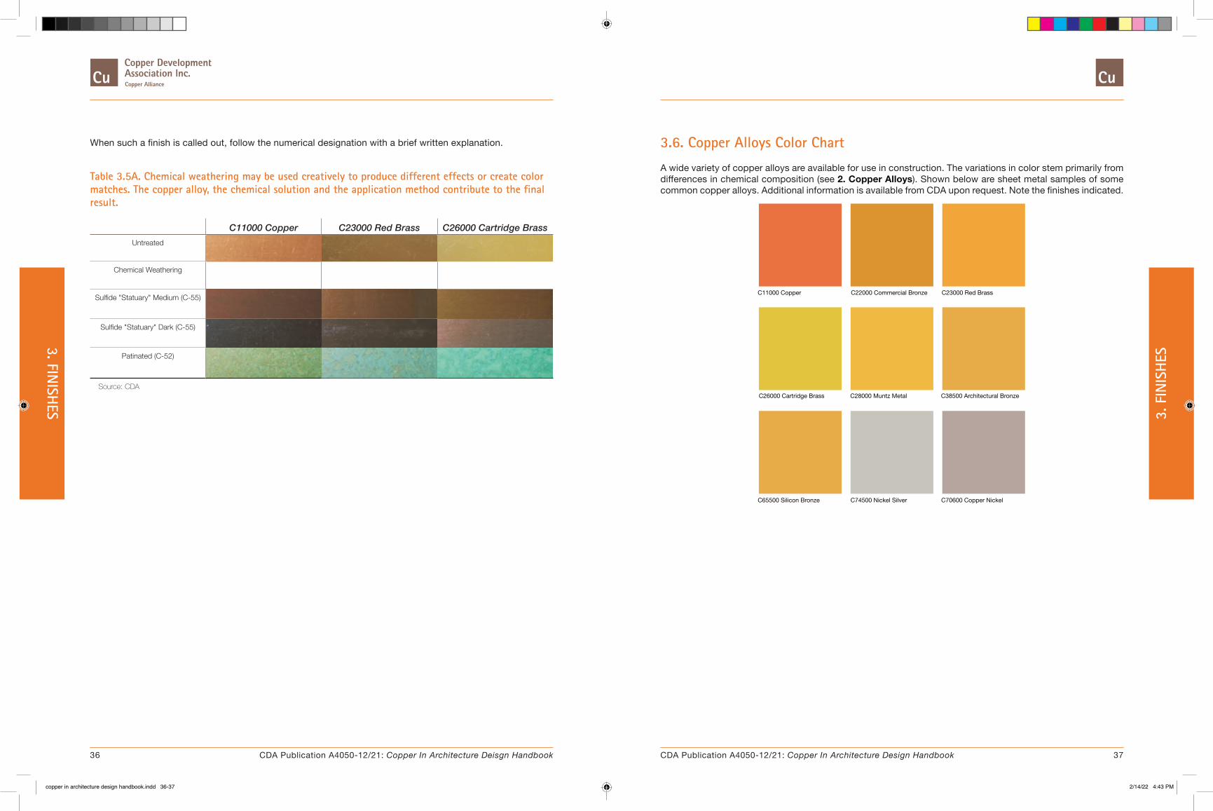
When such a finish is called out, follow the numerical designation with a brief written explanation.
Table 3.5A. Chemical weathering may be used creatively to produce different effects or create color matches. The copper alloy, the chemical solution and the application method contribute to the final result.
C11000 Copper C23000 Red Brass C26000 Cartridge BrassUntreated
Chemical Weathering
Sulfide "Statuary" Medium (C-55)
Sulfide "Statuary" Dark (C-55)
Patinated (C-52)
Source: CDA
3.6. Copper Alloys Color Chart
A wide variety of copper alloys are available for use in construction. The variations in color stem primarily from differences in chemical composition (see 2. Copper Alloys). Shown below are sheet metal samples of some common copper alloys. Additional information is available from CDA upon request. Note the finishes indicated.
C11000 Copper C22000 Commercial Bronze C23000 Red Brass
C26000 Cartridge Brass C28000 Muntz Metal C38500 Architectural Bronze
C65500 Silicon Bronze C74500 Nickel Silver C70600 Copper Nickel
36 37CDA Publication A4050-12/21: Copper In Architecture Deisgn Handbook CDA Publication A4050-12/21: Copper In Architecture Design Handbook
3. FINISH
ES 3. F
INIS
HES
copper in architecture design handbook.indd 36-37copper in architecture design handbook.indd 36-37 2/14/22 4:43 PM2/14/22 4:43 PM
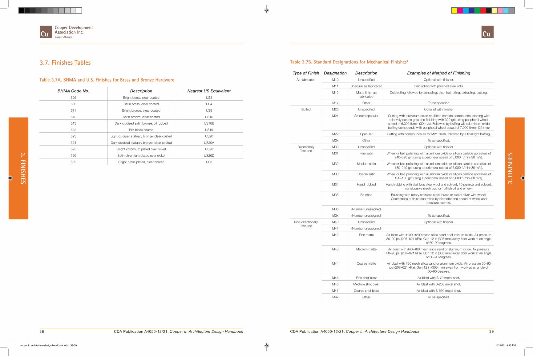
3.7. Finishes Tables
Table 3.7A. BHMA and U.S. Finishes for Brass and Bronze Hardware
BHMA Code No. Description Nearest US Equivalent605 Bright brass, clear coated US3
606 Satin brass, clear coated US4
611 Bright bronze, clear coated US9
612 Satin bronze, clear coated US10
613 Dark oxidized satin bronze, oil rubbed US10B
622 Flat black coated US19
623 Light oxidized statuary bronze, clear coated US20
624 Dark oxidized statuary bronze, clear coated US20A
625 Bright chromium plated over nickel US26
626 Satin chromium plated over nickel US26D
632 Bright brass plated, clear coated US3
Table 3.7B. Standard Designations for Mechanical Finishes1
Type of Finish Designation Description Examples of Method of FinishingAs-fabricated M10 Unspecified Optional with finisher.
M11 Specular as fabricated Cold rolling with polished steel rolls.
M12 Matte finish as fabricated
Cold rolling followed by annealing; also: hot rolling, extruding, casting.
M1x Other To be specified
Buffed M20 Unspecified Optional with finisher
M21 Smooth specular Cutting with aluminum oxide or silicon carbide compounds, starting with relatively coarse grits and finishing with 320 grit using peripheral wheel
speed of 6,000 ft/min (30 m/s). Followed by buffing with aluminum oxide buffing compounds with peripheral wheel speed of 7,000 ft/min (36 m/s)
M22 Specular Cutting with compounds as for M21 finish, followed by a final light buffing.
M2x Other To be specified.
Directionally Textured
M30 Unspecified Optional with finisher.
M31 Fine satin Wheel or belt polishing with aluminum oxide or silicon carbide abrasives of 240–320 grit using a peripheral speed of 6,000 ft/min (30 m/s).
M32 Medium satin Wheel or belt polishing with aluminum oxide or silicon carbide abrasives of 180–240 grit using a peripheral speed of 6,000 ft/min (30 m/s).
M33 Coarse satin Wheel or belt polishing with aluminum oxide or silicon carbide abrasives of 120–180 grit using a peripheral speed of 6,000 ft/min (30 m/s).
M34 Hand rubbed Hand rubbing with stainless steel wool and solvent, #0 pumice and solvent, nonabrasive mesh pad or Turkish oil and emery.
M35 Brushed Brushing with rotary stainless steel, brass or nickel silver wire wheel. Coarseness of finish controlled by diameter and speed of wheel and
pressure exerted.
M36 (Number unassigned)
M3x (Number unassigned) To be specified.
Non-directionally Textured
M40 Unspecified Optional with finisher.
M41 (Number unassigned)
M42 Fine matte Air blast with #100–#200 mesh silica sand or aluminum oxide. Air pressure 30–90 psi (207–621 kPa). Gun 12 in (305 mm) away from work at an angle
of 60–90 degrees.
M43 Medium matte Air blast with #40–#80 mesh silica sand or aluminum oxide. Air pressure 30–90 psi (207–621 kPa). Gun 12 in (305 mm) away from work at an angle
of 60–90 degrees.
M44 Coarse matte Air blast with #20 mesh silica sand or aluminum oxide. Air pressure 30–90 psi (207–621 kPa). Gun 12 in (305 mm) away from work at an angle of
60–90 degrees.
M45 Fine shot blast Air blast with S-70 metal shot.
M46 Medium shot blast Air blast with S-230 metal shot.
M47 Coarse shot blast Air blast with S-550 metal shot.
M4x Other To be specified.
38 39CDA Publication A4050-12/21: Copper In Architecture Deisgn Handbook CDA Publication A4050-12/21: Copper In Architecture Design Handbook
3. FINISH
ES 3. F
INIS
HES
copper in architecture design handbook.indd 38-39copper in architecture design handbook.indd 38-39 2/14/22 4:43 PM2/14/22 4:43 PM
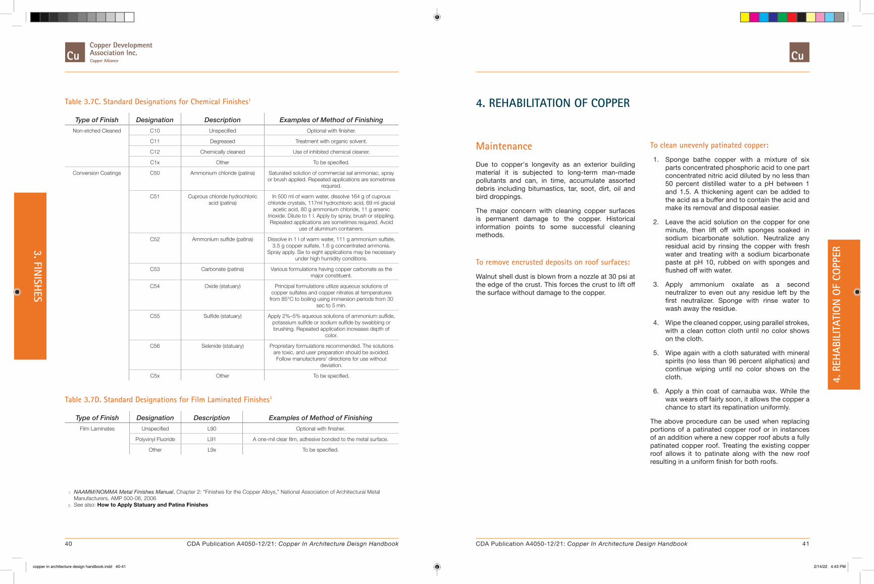
4. REHABILITATION OF COPPER
Maintenance
Due to copper's longevity as an exterior building material it is subjected to long-term man-made pollutants and can, in time, accumulate assorted debris including bitumastics, tar, soot, dirt, oil and bird droppings.
The major concern with cleaning copper surfaces is permanent damage to the copper. Historical information points to some successful cleaning methods.
To remove encrusted deposits on roof surfaces:
Walnut shell dust is blown from a nozzle at 30 psi at the edge of the crust. This forces the crust to lift off the surface without damage to the copper.
To clean unevenly patinated copper:
1. Sponge bathe copper with a mixture of six parts concentrated phosphoric acid to one part concentrated nitric acid diluted by no less than 50 percent distilled water to a pH between 1 and 1.5. A thickening agent can be added to the acid as a buffer and to contain the acid and make its removal and disposal easier.
2. Leave the acid solution on the copper for one minute, then lift off with sponges soaked in sodium bicarbonate solution. Neutralize any residual acid by rinsing the copper with fresh water and treating with a sodium bicarbonate paste at pH 10, rubbed on with sponges and flushed off with water.
3. Apply ammonium oxalate as a second neutralizer to even out any residue left by the first neutralizer. Sponge with rinse water to wash away the residue.
4. Wipe the cleaned copper, using parallel strokes, with a clean cotton cloth until no color shows on the cloth.
5. Wipe again with a cloth saturated with mineral spirits (no less than 96 percent aliphatics) and continue wiping until no color shows on the cloth.
6. Apply a thin coat of carnauba wax. While the wax wears off fairly soon, it allows the copper a chance to start its repatination uniformly.
The above procedure can be used when replacing portions of a patinated copper roof or in instances of an addition where a new copper roof abuts a fully patinated copper roof. Treating the existing copper roof allows it to patinate along with the new roof resulting in a uniform finish for both roofs.
Table 3.7C. Standard Designations for Chemical Finishes1
Type of Finish Designation Description Examples of Method of FinishingNon-etched Cleaned C10 Unspecified Optional with finisher.
C11 Degreased Treatment with organic solvent.
C12 Chemically cleaned Use of inhibited chemical cleaner.
C1x Other To be specified.
Conversion Coatings C50 Ammonium chloride (patina) Saturated solution of commercial sal ammoniac, spray or brush applied. Repeated applications are sometimes
required.
C51 Cuprous chloride hydrochloric acid (patina)
In 500 ml of warm water, dissolve 164 g of cuprous chloride crystals, 117ml hydrochloric acid, 69 ml glacial
acetic acid, 80 g ammonium chloride, 11 g arsenic trioxide. Dilute to 1 l. Apply by spray, brush or stippling. Repeated applications are sometimes required. Avoid
use of aluminum containers.
C52 Ammonium sulfide (patina) Dissolve in 1 l of warm water, 111 g ammonium sulfate, 3.5 g copper sulfate, 1.6 g concentrated ammonia.
Spray apply. Six to eight applications may be necessary under high humidity conditions.
C53 Carbonate (patina) Various formulations having copper carbonate as the major constituent.
C54 Oxide (statuary) Principal formulations utilize aqueous solutions of copper sulfates and copper nitrates at temperatures
from 85°C to boiling using immersion periods from 30 sec to 5 min.
C55 Sulfide (statuary) Apply 2%–5% aqueous solutions of ammonium sulfide, potassium sulfide or sodium sulfide by swabbing or brushing. Repeated application increases depth of
color.
C56 Selenide (statuary) Proprietary formulations recommended. The solutions are toxic, and user preparation should be avoided. Follow manufacturers’ directions for use without
deviation.
C5x Other To be specified.
Table 3.7D. Standard Designations for Film Laminated Finishes1
Type of Finish Designation Description Examples of Method of FinishingFilm Laminates Unspecified L90 Optional with finisher.
Polyvinyl Fluoride L91 A one-mil clear film, adhesive bonded to the metal surface.
Other L9x To be specified.
1. NAAMM/NOMMA Metal Finishes Manual, Chapter 2: “Finishes for the Copper Alloys,” National Association of Architectural Metal Manufacturers, AMP 500-06, 2006
2. See also: How to Apply Statuary and Patina Finishes
40 41CDA Publication A4050-12/21: Copper In Architecture Deisgn Handbook CDA Publication A4050-12/21: Copper In Architecture Design Handbook
4. R
EHAB
ILIT
ATIO
N O
F CO
PPER
3. FINISH
ES
copper in architecture design handbook.indd 40-41copper in architecture design handbook.indd 40-41 2/14/22 4:43 PM2/14/22 4:43 PM

DESIGNS
Our Featured Projects gallery is available online at Copper.org. It highlights a wide array of architectural copper, brass and bronze applications.
Transcending any limitations of style or classification, our selection of original and creative works includes both modern and classically influenced installations, and each project is complete with narrative descriptions from the architects and project owners themselves.
We hope that these illustrative examples of dynamic and creative uses of copper, brass and bronze materials in architecture will serve to inspire students, designers, installers and builders alike.
If you are an architect, installer, contractor, or building owner, we encourage you to submit any built projects located in the United States or Canada for consideration and potential inclusion in our Featured Projects section.
SUBMIT YOUR PROJECT for a chance to be featured on Copper.org!
Photo Credits opposite page (clockwise from top-right):
Royal Military College, Photo Credit: Colbourne & Kembel
St. Patrick’s Cathedral, Photo Credit: G & L POPIAN, INC
Columbus Museum of Art, Photo Credit: Brad Feinknopf
5. FEATURED PROJECTS
43CDA Publication A4050-12/21: Copper In Architecture Design Handbook
5. F
EATU
RED
PRO
JECT
S
copper in architecture design handbook.indd 42-43copper in architecture design handbook.indd 42-43 2/14/22 4:43 PM2/14/22 4:43 PM

ARCHITECTURAL DETAILS
Maricopa County Downtown Court Tower, Photo Credit: Bill Timmerman
� 6. General Design Issues
� 7. Basic Details
� 8. Roofing Systems
� 9. Flashings and Copings
� 10. Gutters and Downspouts
� 11. Building Expansion Joints
� 12. Wall Cladding
� 13. Domes, Spires and Vaults
This section contains drawings for the proper design and construction of sheet copper details. It is divided into subsections by topic, such as "8. Roofing Systems".
Each subsection has an introduction that gives general information for that topic. Within each subsection, there are divisions that cover variations of that topic. For example, in the 8. Roofing Systems, there are divisions for standing seam, batten seam, flat seam roofing and more. These divisions are comprised of one or more drawings each with a facing page of descriptive text.
The drawings are presented in two colors. Copper materials are shown in copper color, all other building materials are shown in black. The drawings are intended to show the relationships of the materials.
Although the drawings show the components in detail, some items, such as nails, may not be shown for the sake of clarity. The specifications and descriptive text should always be consulted before using the details in any specific application.
AutoCAD Details
All of the details shown in this section of the Handbook are available as AutoCAD Detail Files. The details have been developed using AutoCAD. They may be inserted onto a sheet as stand-alone details, or incorporated into larger drawings.
� Download AutoCAD Detail Files [Complete set, ZIP - 4.5MB]
Some steps have been taken to simplify the use of these files:
1. All components are drawn actual size in "model space".
2. The dimensions of some elements, such as transverse seams, have been exaggerated to make them more readable in printed form.
3. All details have been drawn in two dimensions. Although many drawings use axonometric views, the views are actually constructed in two dimensions. It is felt that full threedimensional models of the elements would be much more complicated than necessary for construction documents.
4. Five layers are used in these files: Layer Name Color DescriptionAXON-COPPER 5 Copper material in
axonometric view.
AXON-OTHER 6 All other material in axonometric view.
BASE-COPPER 10 Copper material in plan or section.
BASE-OTHER 9 All other material in plan or section.
CDATEXT 3 Text, leaders, dimensions, and dimension lines
This layer naming convention allows the user to easily turn off and on the axonometric layers, or to separate copper from other materials.
AutoCAD is a registered trademark of Autodesk, Inc.
45CDA Publication A4050-12/21: Copper In Architecture Design Handbook
ARCH
ITEC
TURA
L DE
TAIL
S
copper in architecture design handbook.indd 44-45copper in architecture design handbook.indd 44-45 2/14/22 4:43 PM2/14/22 4:43 PM

6. GENERAL DESIGN ISSUES
This section provides a summary of major issues that should be considered by the designer. Much of the information is based on successful historic practice. The majority of the issues presented are related to the climatic conditions of the site and the configuration of the building.
� High Winds In areas where high winds occur, the design of roofing systems must be carefully evaluated. High winds can place extreme positive or negative pressures on roof edges, such as, ridges, ridge vents, eaves, rakes, copings, gutters, and fascias. Under these conditions it is particularly important to ensure that the edges of roofing and flashing are securely fastened. In areas of high winds and rain special care must be exercised in designing transverse seams and flashing. The headlap may be increased in these conditions, to reduce the likelihood that moisture will be driven past the roofing membrane.
� Heavy Rain Where heavy rain is expected, special attention should be given to roof slopes, headlap, seam details, valleys, gutters and downspouts. Unless soldered flat seam roofing is used, low slopes, which do not promote positive drainage, should be avoided. The headlap of transverse seams or overlapping roofing components (at a valley, for example) can be increased for improved protection. Increased seam heights can help prevent water infiltration. Seams may also be filled with sealant or fully soldered, to provide a watertight barrier. Valleys, gutters, and downspouts should be sized adequately, and their design should account for the volume, speed, and direction of the expected water flow.
� Ice and Snow In areas where ice and snow may be severe, the designer should carefully consider their effect on all components. Many of the problems associated with ice and snow are caused by damming. This often occurs when snow on a roof, over heated space, melts and flows to the eaves. The roof temperature at the eaves can be significantly lower, especially
if the roof has an overhang. The flowing water can freeze and form a dam which prevents proper roof drainage. These conditions can be intensified by roof shapes, such as valleys. Eave snow flashing may be used to make the roof perimeter watertight. The headlap of roofing material over valley flashing, roof edge strips, gutter aprons, and other elements may be increased by extending the underlying copper material higher up the roof. The amount of increase is related to the slope of the roof or valley and the likelihood of a dam condition. Other steps that increase protection under these circumstances include: increased seam height and the use of solder or sealant in seams. In areas of extreme ice and snow conditions, heating elements can be installed on eaves and in gutters to help prevent ice build-up. Another potential problem with ice and snow build-up is its weight. If snow accumulates on a sloped roof, it can slide down its surface with tremendous force, damaging the roof, eaves, or gutters. In areas where ice can accumulate in gutters, the proper design of gutter support is very important. The use of snow guards is neither supported nor opposed, rather their use must be determined and evaluated for each specific application.
� Temperature Range When designing copper roofing systems or accessories, the effect of temperature changes should be considered. The expansion and contraction of copper material, as well as that of any other adjacent material, is a function of variations in temperature. The temperature during installation can also play an important role, since future thermal expansion and contraction will occur as the temperature rises and falls relative to this initial value. This is particularly important when installing components with potential restrictions to movement in one direction. For more information on expansion and contraction, see 8.8. Long Pan Systems.
The effects of direct solar gain should be carefully considered. The surface temperature of exposed copper can be significantly higher, by 70 to 80 degrees or more, than the surrounding ambient temperature. The effects of this additional gain, commonly called "superheat", must be anticipated, as increased thermal movement will occur.
� Building Orientation Consideration should be given to the relationships between roof components, such as the ridge, eave, parapet, and the direction of prevailing wind, rain, and sun. The intensity of many issues discussed above will depend on the exposure of each roof component. For example, ice build-up on a gutter is more likely to occur on the North side of a building or a partially shaded area of an eave. Wind can exert extreme positive pressure on a coping in one area and negative in another.
� Staining With good design, staining from run-off can be minimized or eliminated. In brief, staining occurs when moisture that has been in contact with copper, drips off onto adjacent porous or reactive materials. The primary methods of preventing staining include the use of gutters, architectural overhangs, drip edges, careful material selection and sealers. In addition, the designer can try to divert water away from places where it may cause stains. Where parapet covers or copings are used, for example, the top surface should be sloped toward the roof side, to minimize the amount of water that drips off the outside face.
� Patination The natural weathering process that leads to the patination of exposed copper surfaces usually takes many years to complete. A number of processes have been developed to quickly produce a patina. Although the industry has continued its development efforts in this area, and occasionally new methods and products are introduced. Please contact CDA Project Managers & Architectural Applications Specialists for current information.
46 47CDA Publication A4050-12/21: Copper In Architecture Deisgn Handbook CDA Publication A4050-12/21: Copper In Architecture Design Handbook
6. GENERAL DESIGN
ISSUES 6. G
ENER
AL D
ESIG
N IS
SUES
copper in architecture design handbook.indd 46-47copper in architecture design handbook.indd 46-47 2/14/22 4:43 PM2/14/22 4:43 PM

7. BASIC DETAILS
� 7.1. Attachments
� 7.2. Joints and Seams
� 7.3. Additional Loose Lock Seams
Introduction
Copper has been used as a construction material for centuries. During this time, it has achieved an excellent record for low maintenance and durability. Proper design and construction are essential to ensure high quality, long-lasting installations.
This section contains details and descriptions of the basic components commonly used in sheet copper construction. These include various seams, expansion joints, edges, hold-downs, and cleats.
Attachments
All fasteners should be of galvanically compatible metals, such as copper, copper alloys, like brass or bronze or neutral stainless steel alloy. Washers or Expansion shields, when necessary, must also be of galvanically compatible or neutral materials. Copper, copper alloy, lead, rubber and plastics are all common.
� Cleating: This is the most commonly used method, because it allows the copper to move, minimizing the potential for buckling. Cleats are usually made of 16 oz. copper, although they need not be heavier than the material being secured. Cleats made of compatible stainless steel are also acceptable. Two types of cleats are used. Fixed cleats allow a small amount of movement, while expansion cleats typically allow up to 3/4" total movement. Fixed cleats are usually suitable for short pan construction. Long pans require the use of expansion cleats, see 8.8. Long Pan Systems. Cleats are typically
spaced at a minimum of 12" on center.
� Nailing: This method is predominantly used where movement is not desired, such as at a base flashing at built-up roofs, gravel stops, and eave strips. Nailing is used only on cleats and copper strips up to 12" wide. Only one edge of a strip should be nailed, to allow movement perpendicular to the line of nailing. Nails should be spaced no more than 3" O.C. to provide continuous resistance to thermal stresses. All nails should be flathead, wire slating nails, at least 1" long, of not less than 12 gauge hard copper, brass, or bronze. Those used in wood should be barbed; nails used in concrete or gypsum should not. Surfaces with poorer nail-holding qualities require longer, stronger nails. For the right nail to use with such material, contact the manufacturer.
� Screwing: This method is used where the copper must be held rigidly in place, such as at a ridge cap subject to the severe vibrations caused by wind, or as a hold-down for large, flat copper areas. It is also used to secure copper to masonry when expansion shields are required. Screws should be made of stainless steel, bronze, or brass. They should have round heads, and flat seats which will not puncture the copper. Galvanically compatible metal washers may be used for additional protection. Where watertightness is required, a small copper cap is soldered over the screw head, see Detail 7.1B.
7.1. Attachments7.1A. Typical Copper Cleats
The typical copper cleats shown are usually 16 oz. copper, at least 2" wide. They are attached to the deck or nailable inserts with two copper, brass, bronze, or compatible stainless steel nails or screws. When cleats are used on flat or nearly flat surfaces, the end of each cleat should be folded back over the nail heads to prevent possible damage to the covering sheet by expansion and contraction, traffic or other forces. When fixed cleats are used on vertical surfaces or not exposed to traffic, this is not necessary.
TYPICAL FIXED CLEATS, STANDING SEAM
2"MIN.2"MIN.
Detail 1 Detail 2
Detail 1: is used to form a hook over the upstanding flange of the lower pan only, allowing some differential movement between pans in a standing seam roofing system. Detail 2 is used to form hooks over both upstanding flanges of the pans in a standing seam roofing system, locking them both together to minimize differential movement.
TYPICAL COPPER CLEAT INSTALLED, HEMMED EDGE
2"
2"APPROX.
1/2" MIN.
7.1B. Typical Copper Hold-Downs
Copper hold-downs are used to prevent the lifting of large, flat portions of copper from the substrate, while allowing thermal movement. They are typically used on wide gutters, extended gutter apron pieces, and wide apron flashings. For the through fastener hold-down, the maximum recommended spacing is 4 feet longitudinally, and 18" transversely. The screw should be brass No. 12 x 3/4" round head, with an expansion shield if used in masonry. A large brass or copper washer, 1-1/4" diameter, should be placed under the screw head. The screw should be tightened sufficiently to keep the metal flat, but not restrict its movement. After the hold-down is in place, a 16 oz. copper cap should be soldered over the assembly to provide watertightness.
COPPER CAP
SOLDERED
BRASS OR COPPER
BRASS SCREW
48 49CDA Publication A4050-12/21: Copper In Architecture Deisgn Handbook CDA Publication A4050-12/21: Copper In Architecture Design Handbook
7. BASIC DETAILS 7. B
ASIC
DET
AILS
copper in architecture design handbook.indd 48-49copper in architecture design handbook.indd 48-49 2/14/22 4:43 PM2/14/22 4:43 PM

7.1C. Expansion Cleats
Expansion cleats are typically used on long runs of standing seam roofing. Movement caused by thermal expansion and contraction is transmitted towards the ridge and eaves. Expansion cleats relieve the stresses that weaken the holding power of fixed cleats on long runs.
TYPICAL EXPANSION CLEAT
ALTERNATE EXPANSION CLEAT
Two types of expansion cleats are shown. One utilizes a full-width sliding tab. The other is formed into a in "V", so that the cleat legs do not fold over onto each other. This reduces the build-up of copper material in the finished joint. Various other types of expansion cleats are available throughout the industry.
7.1D. Lock Strips
Two restraining methods are illustrated. Both are designed to prevent vertical wind uplift of roof pan edges, but allow horizontal expansion and contraction. The lock strip is a continuous strip usually of 20 oz. copper, soldered or fastened to a substrate. Its leading edge is raised to allow the end of a copper sheet to be locked over into a 3/4 inch lock.
LOCK STRIP3/4"
SOLDERED
The double-fold is utilized in areas where conditions are limited in space. The copper base sheet is folded into a raised lip to allow the end of a "top sheet" to be locked over into a 3/4 inch lock.
DOUBLE FOLD3/4"
7.2. Joints and Seams
� Rigid Seams
� Loose Seams
� Expansion Seams
� Corner Seams & Edges
� 7.3. Additional Loose Lock Seams
Rigid Seams
7.2A. Lap Seam, Soldered
This seam should only be used on copper sheets with weights up to 20 ounces.
1" MIN.
7.2C. Lap Seam, Riveted
This seam provides a strong mechanical connection for copper sheets. It should only be used where watertightness is not required.
1 1/2"
Where strength of seam is a major consideration, solid rivets should be copper or copper alloy, 1/8" to 3/16" in diameter and spaced 3" O.C. in two rows in a staggered pattern. The use of 1/8" pop rivets of either copper or copper alloy should be restricted to applications where strength of seam is not a major consideration.
7.2D. Single Lock Standing Seam, Button Punched
This is one type of standing seam. Both copper sheets are bent up where they meet. One is longer than the other. The longer one is folded over the shorter one. They are then button punched to provide a more rigid, mechanical connection. Only suitable for small, noncritical areas—not a roofing system.
1" M
IN.
7.2B. Flat Lock Seam, Soldered
This seam provides a positive mechanical connection between adjacent sheets. It should not be used for copper sheets weighing more than 20 ounces per square foot. It should be used where watertightness is required.
3/4" MIN.
50 51CDA Publication A4050-12/21: Copper In Architecture Deisgn Handbook CDA Publication A4050-12/21: Copper In Architecture Design Handbook
7. BASIC DETAILS 7. B
ASIC
DET
AILS
copper in architecture design handbook.indd 50-51copper in architecture design handbook.indd 50-51 2/14/22 4:43 PM2/14/22 4:43 PM

7.2E. Lap Seam Riveted and Soldered
This seam offers a strong, watertight joint. The rivets provide strength, while the solder provides a watertight seal.
1 1/2"
Loose Seams
This type of seam allows thermal expansion and contraction by sliding or flexing. It can be made watertight by the use of high quality flexible sealants, such as butyl, polysulfide, silicone, or urethane, which do not restrict movement.
7.2F. Lap Seam
This seam is not used where water-tightness is required. It allows free movement of the copper sheets.
3" MIN.
7.2G. Flat Lock Seam, Cleated
The cleats are used to secure the sheets to the understructure. Cleats should (in general) be spaced a maximum of 12" O.C.
3/4" MIN.
CLEAT
7.2H. Double Lock Seam, Cleated
This seam is essentially a single lock seam with an additional fold. It develops increased mechanical strength and watertightness.
CLEAT
3/4" MIN.
7.2I. Common Lock
(also referred to as a hook seam or single lock seam) This seam provides for a mechanical connection between the copper sheets. The hook in the lower sheet provides a degree of security against water penetration as long as it is not submerged. It also provides a good place for sealant when used.
3/4" MIN.
Expansion Seams
This type of seam is used wherever significant movement of the copper sheets is expected. Expansion and contraction are a function of temperature change, material properties, and the dimensions of the material. The amount of movement can be calculated with the following general formula:
dL = L x E x dT
Where:
dL = change in length (expansion or contraction)
L = Length of copper material
E = coefficient of linear expansion of copper = 0.0000098 per degree Fahrenheit
dT = temperature change in degrees Fahrenheit
Calculation of movement is rarely required in short roof pan construction, since the details shown here can accommodate thermal movement of short pans.
7.2K. Slip Expansion Seam
The tail piece of the formed lock section may be nailed to secure it more firmly to the substrate. The joint is filled with sealant for watertightness.
SEALANT
2" 2" EXPANSION SPACE
7.2J. Clevis Seam
This seam is similar to the slip expansion seam. The difference is in forming the lock. Where as the slip expansion lock is formed by braking a sheet of copper, the lock on this seam is formed by soldering a small strip of copper below the sheet.
SEALANT
3"
EXPANSION SPACE
SOLDERED
3/4"
7.2L. Loose Lock With Sealant
This expansion seam is formed by filling a loose lock seam with a non-hardening, elastic sealant. The space between locks is required to allow for expansion and contraction.
EXPANSION SPACE
SEALANT
52 53CDA Publication A4050-12/21: Copper In Architecture Deisgn Handbook CDA Publication A4050-12/21: Copper In Architecture Design Handbook
7. BASIC DETAILS 7. B
ASIC
DET
AILS
copper in architecture design handbook.indd 52-53copper in architecture design handbook.indd 52-53 2/14/22 4:43 PM2/14/22 4:43 PM
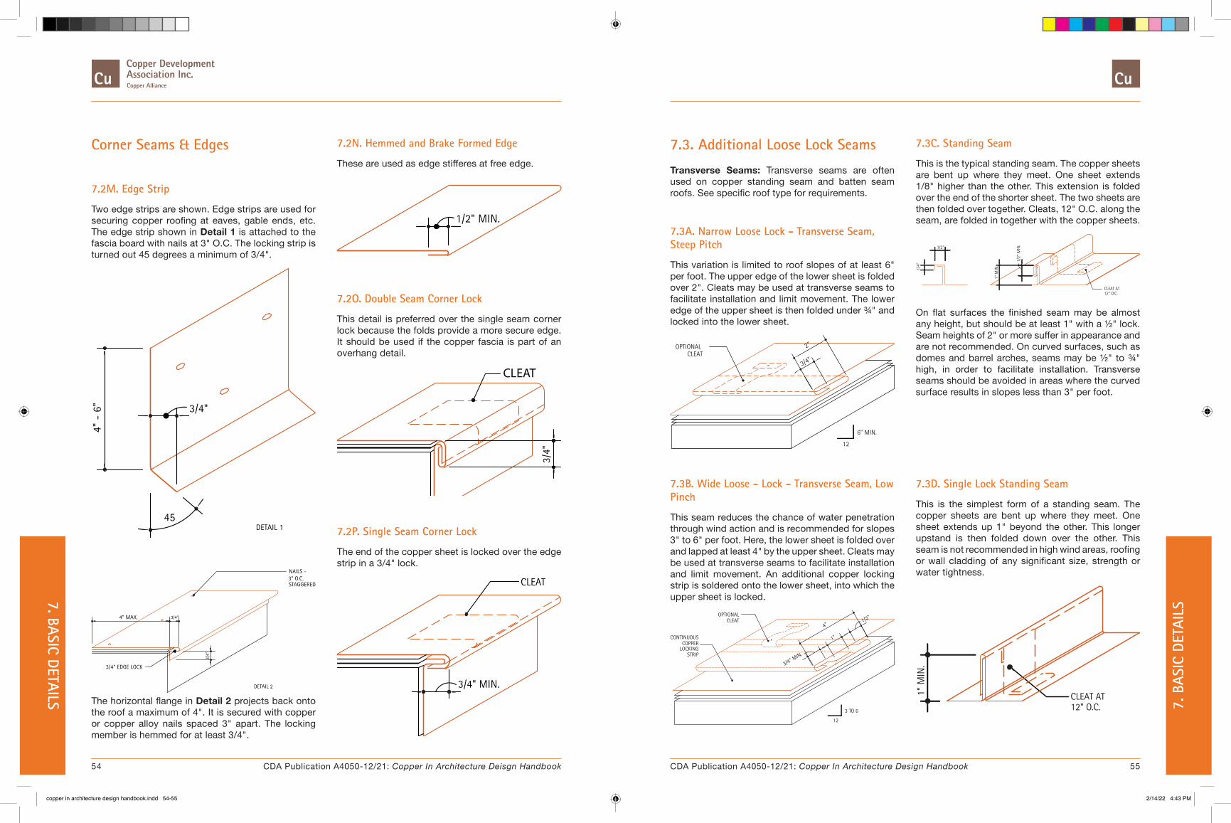
Corner Seams & Edges
7.2M. Edge Strip
Two edge strips are shown. Edge strips are used for securing copper roofing at eaves, gable ends, etc. The edge strip shown in Detail 1 is attached to the fascia board with nails at 3" O.C. The locking strip is turned out 45 degrees a minimum of 3/4".
3/4"
45
4" -
6"
DETAIL 1
3/4" EDGE LOCK
3/4"
4" MAX.
STAGGERED3" O.C.NAILS -
3/4"
DETAIL 2
The horizontal flange in Detail 2 projects back onto the roof a maximum of 4". It is secured with copper or copper alloy nails spaced 3" apart. The locking member is hemmed for at least 3/4".
7.2N. Hemmed and Brake Formed Edge
These are used as edge stifferes at free edge.
1/2" MIN.
7.2O. Double Seam Corner Lock
This detail is preferred over the single seam corner lock because the folds provide a more secure edge. It should be used if the copper fascia is part of an overhang detail.
3/4"
CLEAT
7.2P. Single Seam Corner Lock
The end of the copper sheet is locked over the edge strip in a 3/4" lock.
3/4" MIN.
CLEAT
7.3C. Standing Seam
This is the typical standing seam. The copper sheets are bent up where they meet. One sheet extends 1/8" higher than the other. This extension is folded over the end of the shorter sheet. The two sheets are then folded over together. Cleats, 12" O.C. along the seam, are folded in together with the copper sheets.
1/4"
1/2"
1/2"
MIN
.
1" M
IN.
CLEAT AT12" O.C.
On flat surfaces the finished seam may be almost any height, but should be at least 1" with a ½" lock. Seam heights of 2" or more suffer in appearance and are not recommended. On curved surfaces, such as domes and barrel arches, seams may be ½" to ¾" high, in order to facilitate installation. Transverse seams should be avoided in areas where the curved surface results in slopes less than 3" per foot.
7.3. Additional Loose Lock Seams
Transverse Seams: Transverse seams are often used on copper standing seam and batten seam roofs. See specific roof type for requirements.
7.3A. Narrow Loose Lock - Transverse Seam, Steep Pitch
This variation is limited to roof slopes of at least 6" per foot. The upper edge of the lower sheet is folded over 2". Cleats may be used at transverse seams to facilitate installation and limit movement. The lower edge of the upper sheet is then folded under ¾" and locked into the lower sheet.
CLEATOPTIONAL
3/4"
2"
6" MIN.
12
7.3B. Wide Loose - Lock - Transverse Seam, Low Pinch
This seam reduces the chance of water penetration through wind action and is recommended for slopes 3" to 6" per foot. Here, the lower sheet is folded over and lapped at least 4" by the upper sheet. Cleats may be used at transverse seams to facilitate installation and limit movement. An additional copper locking strip is soldered onto the lower sheet, into which the upper sheet is locked.
4"
LOCKINGCOPPER
CONTINUOUS
STRIP
3/4" MIN.
3 TO 6
12
1"
OPTIONALCLEAT 1/2"
7.3D. Single Lock Standing Seam
This is the simplest form of a standing seam. The copper sheets are bent up where they meet. One sheet extends up 1" beyond the other. This longer upstand is then folded down over the other. This seam is not recommended in high wind areas, roofing or wall cladding of any significant size, strength or water tightness.
1" M
IN.
CLEAT AT12" O.C.
54 55CDA Publication A4050-12/21: Copper In Architecture Deisgn Handbook CDA Publication A4050-12/21: Copper In Architecture Design Handbook
7. BASIC DETAILS 7. B
ASIC
DET
AILS
copper in architecture design handbook.indd 54-55copper in architecture design handbook.indd 54-55 2/14/22 4:43 PM2/14/22 4:43 PM
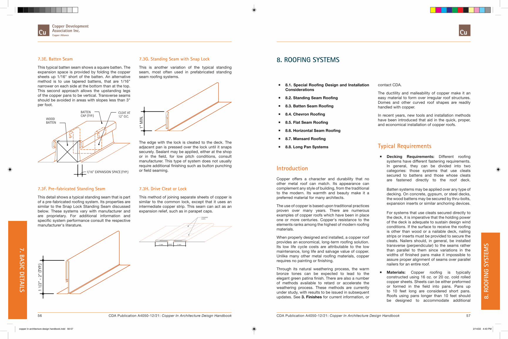
7.3E. Batten Seam
This typical batten seam shows a square batten. The expansion space is provided by folding the copper sheets up 1/16" short of the batten. An alternative method is to use tapered battens, that are 1/16" narrower on each side at the bottom than at the top. This second approach allows the upstanding legs of the copper pans to be vertical. Transverse seams should be avoided in areas with slopes less than 3" per foot.
WOODBATTEN
1/16" EXPANSION SPACE (TYP.)
CAP (TYP.)BATTEN
12" O.C.CLEAT AT
7.3G. Standing Seam with Snap Lock
This is another variation of the typical standing seam, most often used in prefabricated standing seam roofing systems.
1" M
IN.
The edge with the lock is cleated to the deck. The adjacent pan is pressed over the lock until it snaps securely. Sealant may be applied, either at the shop or in the field, for low pitch conditions, consult manufacturer. This type of system does not usually require additional finishing such as button punching or field seaming.
7.3F. Pre-fabricated Standing Seam
This detail shows a typical standing seam that is part of a pre-fabricated roofing system. Its properties are similar to the Snap Lock Standing Seam discussed below. These systems vary with manufacturer and are proprietary. For additional information and specific system performance consult the respective manufacturer's literature.
1 1/
2" -
2"
(TYP
.)
7.3H. Drive Cleat or Lock
This method of joining separate sheets of copper is similar to the common lock, except that it uses an intermediate copper strip. This seam can act as an expansion relief, such as in parapet caps.
STAGGEREDCLEATS
3" MIN.3" MIN. VARIES
8. ROOFING SYSTEMS
� 8.1. Special Roofing Design and Installation Considerations
� 8.2. Standing Seam Roofing
� 8.3. Batten Seam Roofing
� 8.4. Chevron Roofing
� 8.5. Flat Seam Roofing
� 8.6. Horizontal Seam Roofing
� 8.7. Mansard Roofing
� 8.8. Long Pan Systems
Introduction
Copper offers a character and durability that no other metal roof can match. Its appearance can complement any style of building, from the traditional to the modern. Its warmth and beauty make it a preferred material for many architects.
The use of copper is based upon traditional practices proven over many years. There are numerous examples of copper roofs which have been in place one or more centuries. Copper's resistance to the elements ranks among the highest of modern roofing materials.
When properly designed and installed, a copper roof provides an economical, long-term roofing solution. Its low life cycle costs are attributable to the low maintenance, long life and salvage value of copper. Unlike many other metal roofing materials, copper requires no painting or finishing.
Through its natural weathering process, the warm bronze tones can be expected to lead to the elegant green patina finish. There are also a number of methods available to retard or accelerate the weathering process. These methods are currently under study, with results to be issued in subsequent updates. See 3. Finishes for current information, or
contact CDA.
The ductility and malleability of copper make it an easy material to form over irregular roof structures. Domes and other curved roof shapes are readily handled with copper.
In recent years, new tools and installation methods have been introduced that aid in the quick, proper, and economical installation of copper roofs.
Typical Requirements
� Decking Requirements: Different roofing systems have different fastening requirements. In general, they can be divided into two categories: those systems that use cleats secured to battens and those whose cleats are fastened directly to the roof deck. Batten systems may be applied over any type of decking. On concrete, gypsum, or steel decks, the wood battens may be secured by thru-bolts, expansion inserts or similar anchoring devices. For systems that use cleats secured directly to the deck, it is imperative that the holding power of the deck is adequate to sustain design wind conditions. If the surface to receive the roofing is other than wood or a nailable deck, nailing strips or inserts must be provided to secure the cleats. Nailers should, in general, be installed transverse (perpendicular) to the seams rather than parallel to them since variations in the widths of finished pans make it impossible to assure proper alignment of seams over parallel nailers for an entire roof.
� Materials: Copper roofing is typically constructed using 16 oz. or 20 oz. cold rolled copper sheets. Sheets can be either preformed or formed in the field into pans. Pans up to 10 feet long are considered short pans. Roofs using pans longer than 10 feet should be designed to accommodate additional
56 57CDA Publication A4050-12/21: Copper In Architecture Deisgn Handbook CDA Publication A4050-12/21: Copper In Architecture Design Handbook
8. R
OO
FIN
G SY
STEM
S7. BASIC DETAILS
copper in architecture design handbook.indd 56-57copper in architecture design handbook.indd 56-57 2/14/22 4:43 PM2/14/22 4:43 PM

movement at the ends of the pans. For additional information, see 8.8. Long Pan Systems. The copper pans rest on 4 lb., minimum, rosin-sized smooth building paper. The underlayment is typically 30 lb., minimum, saturated roofing felts. Other materials may be substituted in specific applications. See the specifications and manufacturers' recommendations.
� Surface Preparation: The surface preparation for copper roofing systems is similar. The deck should be thoroughly dry, smooth, and free from projecting screws, nail heads or other imperfections. The entire surface should be covered with an approved underlayment secured with copper nails and washers. The underlayment, which is often saturated roofing felt, acts as a cushion, as well as providing temporary weather protection for the roof deck. A sheet of building paper must be applied over the felt. Because copper has a tendency to conduct heat, elevated temperatures can cause asphalt in the underlayment to bond the copper to the roof deck. This inhibits the movement of the copper roof and can result in premature fatigue. The building paper acts as a slip sheet to prevent such bonding.
� Equipment: A variety of power pan formers and power seamers are available to assist in the construction of copper roofs. Power pan formers can take flat or coiled, sheet or strip copper and produce roofing pans on site. They result in high quality, uniform pans whose length is limited only by the contractor's ability to transport and handle the material (pan lengths should not exceed the recommendations in the 8.8. Long Pan Systems). Pan formers typically have the ability to produce pans of varying width with 1" high standing seams. Power seamers are used to produce finished standing or batten seams. The seamers are engaged onto an unfinished seam and propel themselves under electrical power the length of the seam. They can form seams of virtually any length.
8.1. Special Roofing Design and Installation Considerations
One of the most important issues in the use of copper is the relative movement of components. Movement can occur as a result of internal stresses due to temperature changes, or from external sources such as wind, ice, or movement in the substrate. Since copper is most often used as a water barrier, installations must account for the anticipated movement as well as prevent the infiltration of water.
This section presents key information on practical limits and Special Conditions. For additional information on thermal stresses see 1.4. Structural Considerations.
Providing an effective path for water to flow in a controlled direction is one of the most important principles in design and construction. Table 8.1A shows the recommended minimum slopes for various copper roofing systems using the details shown throughout this Handbook. Lower slopes are possible under certain conditions, using modified details. Table 8.1B shows the minimum recommended slopes using these special details. The modified details are discussed below. Only flat seam roofing is constructed to be completely watertight, and therefore can sustain standing water. Table 8.1C outlines the recommendations regarding flat seam construction.
Mansard roofs are usually steep, but they often have changes in their slope. They are based on either standing or batten seam roofing. The minimum recommendations, are therefore, the same as the "base" standing or batten seam roof.
8.1A. Standing Seams
Before the two pans are locked, a compatible quality rubber or synthetic based sealant should be applied to the top of the flange of the lower pan. Transverse seams should be based on the "low pitch" option. See Detail 8.2C.
DURING CONSTRUCTION
UPPER PAN
SEALANT
LOWER PAN
8.1B. Batten Seams
A compatible quality rubber or synthetic based sealant should be applied to the top flange of each pan prior to installation of the batten cap.
DURING CONSTRUCTION
TYPICAL PAN
BATTEN CAP
SEALANT
1/2"MIN.
SEALANT
COMPLETED SEAM
COMPLETED SEAM
BATTEN CAP
TYPICAL PAN
C
8.1C. Batten Cap
Where batten caps join, a 3" lapped seam is required
BATTEN CAP
3"
ROOF SLOPE
58 59CDA Publication A4050-12/21: Copper In Architecture Deisgn Handbook CDA Publication A4050-12/21: Copper In Architecture Design Handbook
8. ROO
FING SYSTEM
S 8. R
OO
FIN
G SY
STEM
S
copper in architecture design handbook.indd 58-59copper in architecture design handbook.indd 58-59 2/14/22 4:43 PM2/14/22 4:43 PM

8.1D. Transverse Seam for Batten Roof
A continuous compatible sealant must be applied in the lock formed by the soldered locking strip immediately before placing the upper pan on the roof. After engaging the ends of the pans, seams should be dressed down to a thickness of not less than 1/8”, and a continuous bead of sealant should be visible the entire width of the pan. The lap of the upstanding legs of the pans should also be set in sealant.
SET IN SEALANT
OPTIONAL CLEAT
The optional cleat shown can be used to hold the roofing pans during installation. This is particularly helpful on a steep roof.
Table 8.1A. Minimum Recommended Roof Slopes Using Standard Details
Conditions Standing Seam
Batten Seam Chevron Horiz.
Seam Mansard
Where ice, snow, and heavy rain do not occur 3 3 3 3 See Batten or Standing Seam
Ice and snow conditions 4 4 4 4 See Batten or Standing Seam
Heavy rain conditions 4 4 4 4 See Batten or Standing Seam
Slopes are in inches per foot.
Table 8.1B. Minimum Recommended Roof Slopes Using Special Details - See Details 8.1A, 8.1B, 8.1C, or 8.1D above
Conditions Standing Seam
Batten Seam Chevron Horiz.
Seam Mansard
Where ice, snow, and heavy rain do not occur 1 2 2 N/R See Batten or Standing Seam
Ice and snow conditions 3 3 3 N/R See Batten or Standing Seam
Heavy rain conditions 3 3 3 N/R See Batten or Standing Seam
Slopes are in inches per foot. N/R = Not Recommended
Table 8.1C. Recommendations for Flat Seam ConstructionSlope Remarks
0-3 Seams fully soldered
3-6 Seams may be fully sealed
>6 Neither sealant nor solder is required in seams
Slopes are in inches per foot.
8.2. Standing Seam Roofing
Description: Standing seam roofing is composed of preformed or field formed pans, usually between 14 to 18 inches wide when finished. The recommended dimensions should be specified from the table below. These pans run parallel to the slope of the roof, and are joined to adjacent pans with double locked standing seams. Fixed copper cleats, spaced 12" apart and locked into these seams, secure the roofing to the deck. This method limits slippage between pans, and is recommended for use with pans up to 10' long.
When preformed pans are used, they are joined at their upper and lower ends by transverse seams. These seams should be staggered for adjacent pans to avoid excessive thickness of copper at the standing seam.
Field forming involves the use of copper in flat sheets or rolls which are formed into pans by power panformers. Long rafter-length pans can be made, eliminating the need for transverse seams, however eave and ridge details must allow for copper expansion and contraction characteristics. See 8.8. Long Pan Systems, for additional information.
Special Conditions: The details shown are for roof slopes of at least 4" per foot. For roof slopes less than 4" per foot, and areas where ice, snow or heavy rain conditions occur, see 8.1. Special Roofing Design and Installation Considerations section.
8.2B. Typical Standing Seam
A typical standing seam with cleats. Alternative gable rake and ridge seam are also shown in this detail. The gable detail shown in Detail A is generally preferred since it minimizes water washing down the gable end. All ridges should be cleated at 12" O.C.
CLEAT 12" O.C. MAX.
TYP. STANDING SEAM
NAILABLE ROOF DECK, TYP.
TRANVERSE SEAM
SEAMS LAID OVER APPROX.6" FROM HIP OR RIDGE
OPPOSING SEAMLAID OVER
4"
1"
COPPER EDGE STRIP, 20 O.Z., NAIL/SCREW AT 3" O.C.STAGGERED
4"
RAKE ELEVATION AT TYPICAL STANDING SEAM
STANDING SEAMBEYOND
RAKE
4" MIN.
1" T
YP.
For standing seam roofing using pan lengths greater than 10 feet in length see 8.8. Long Pan Systems, for discussion.
Decking Requirements: Nailable deck or nailing strips.
8.2A. Gable Rake
This detail shows a typical gable rake and ridge seam. Adjacent lengths of rake strips should be lapped at least 3" in the direction of flow. Opposing standing seams are staggering to avoid excessive thickness of copper at the ridge.
COPPER EDGE STRIP
1"
1"
ALTERNATE RIDGE SEAMSOPPOSING SEAMLAID OVER
OPPOSING ROOFSURFACE
60 61CDA Publication A4050-12/21: Copper In Architecture Deisgn Handbook CDA Publication A4050-12/21: Copper In Architecture Design Handbook
8. ROO
FING SYSTEM
S 8. R
OO
FIN
G SY
STEM
S
copper in architecture design handbook.indd 60-61copper in architecture design handbook.indd 60-61 2/14/22 4:43 PM2/14/22 4:43 PM
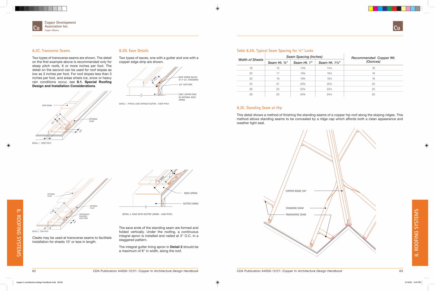
8.2C. Transverse Seams
Two types of transverse seams are shown. The detail on the first example above is recommended only for steep pitch roofs, 6 or more inches per foot. The detail on the second can be used for roof slopes as low as 3 inches per foot. For roof slopes less than 3 inches per foot, and areas where ice, snow or heavy rain conditions occur, see 8.1. Special Roofing Design and Installation Considerations.
OPTIONALCLEAT
DETAIL 1. STEEP PITCH
LOCK SEAM
1"
3/4"
2"
3/4"
8.2D. Eave Details
Two types of eaves, one with a gutter and one with a copper edge strip are shown.
4" M
IN.
3/4" LOCK MIN.
DETAIL 1. TYPICAL EAVE WITHOUT GUTTER - STEEP PITCH
ROOF APRON NAILED AT 3" O.C. STAGGERED
CONT. COPPER EDGE W/ INTEGRAL ROOF APRON
OPTIONAL
3/4"
DETAIL 2. LOW PITCH
1"
4" M
IN.
CLEAT
CLEATOPTIONAL
LOCK STRIPSOLDEREDCONTINUOUS
Cleats may be used at transverse seams to facilitate installation for sheets 10' or less in length.
ROOF APRON
GUTTER LINING
DETAIL 2. EAVE WITH GUTTER LINING - LOW PITCH
4" M
IN.
8" M
AX.
The eave ends of the standing seam are formed and folded vertically. Under the roofing, a continuous integral apron is installed and nailed at 3" O.C. in a staggered pattern.
The integral gutter lining apron in Detail 2 should be a maximum of 8" in width, along the roof.
Table 8.2A. Typical Seam Spacing for ½" Locks
Width of SheetsSeam Spacing (Inches) Recommended Copper Wt.
(Ounces)Seam Ht. ⅞" Seam Ht. 1” Seam Ht. 1¼”18 15 14¾ 14¼ 16
20 17 16¾ 16¼ 16
22 19 18¾ 18¼ 16
24 21 20¾ 20¼ 20
26 23 22¾ 22¼ 20
28 25 24¾ 24¼ 20
8.2E. Standing Seam at Hip
This detail shows a method of finishing the standing seams of a copper hip roof along the sloping ridges. This method allows standing seams to be concealed by a ridge cap which affords both a clean appearance and weather tight seal.
COPPER RIDGE CAP
STANDING SEAM
TRANSVERSE SEAM
62 63CDA Publication A4050-12/21: Copper In Architecture Deisgn Handbook CDA Publication A4050-12/21: Copper In Architecture Design Handbook
8. ROO
FING SYSTEM
S 8. R
OO
FIN
G SY
STEM
S
copper in architecture design handbook.indd 62-63copper in architecture design handbook.indd 62-63 2/14/22 4:43 PM2/14/22 4:43 PM

8.2F. Alternative Ridge Caps
Two alternative methods of detailing a ridge are shown. Both can be used at a gable ridge and/or a sloping hip ridge. The standing seams are laid over a minimum of 6" from the ridge.
ALTERNATIVE 1
STANDING SEAM
6" FROMLAID OVER
RIDGE
In Alternative 1, a continuous copper cap is used to secure standing seams along the ridge. The ridge cap is loose locked into the upper edges of the roofing pans allowing for expansion and contraction. See Detail 8.2D for similar termination at eave.
ALTERNATIVE 2
SPACEEXPANSION
LAID OVER6" FROM
STANDING SEAM
RIDGE.
In Alternative 2, the ridge is formed by a wood batten clad with a copper cap. The standing seams fold and lock into the batten cap along the vertical batten face. See Detail 8.2C for similar termination at eave.
8.2G. Detail at Valley
This detail shows a method of detailing a valley condition on a standing seam roof. The copper roofing laps the 9.5. Valleys a minimum of 6" and is folded and locked into a continuous copper locking strip. The continuous locking strip is soldered to the valley flashing.
6"-1
0"
CONT. COPPER LOCK STRIP SOLDERED
CLEATS AT12" O.C. MAX
6" M
IN.
STANDING SEAM
3/4" LOCK, TYPICAL
DOUBLE FOLD
An Alternate method is to use a double fold in the valley flashing, instead of a locking strip. Both methods are shown in the detail.
8.2H. Overall View of Standing Seam Roof
This overall view of a standing seam roof shows the basic concept.
VALLEY
HIP
RIDGE
SEE DETAIL 'C'
SEE DETAILS 'A' AND 'B'
SEE DETAIL 'A'
SEE DETAIL 'C'
SEE TEXT
For Additional Information:
� 9. Flashings and Copings, under the appropriate sections for flashing details.
� 7. Basic Details, for information on seams, fixed and expansion cleats, hold-downs, edge strips and transverse seams.
� 8.8. Long Pan Systems, for requirements when using pans greater than 10' in length.
64 65CDA Publication A4050-12/21: Copper In Architecture Deisgn Handbook CDA Publication A4050-12/21: Copper In Architecture Design Handbook
8. ROO
FING SYSTEM
S 8. R
OO
FIN
G SY
STEM
S
copper in architecture design handbook.indd 64-65copper in architecture design handbook.indd 64-65 2/14/22 4:43 PM2/14/22 4:43 PM

8.3. Batten Seam Roofing
Description: Batten seam roofing consists of copper pans running parallel to the roof slope, separated by wood battens. The battens are covered with copper caps that are loose locked into adjacent pans. The width of these preformed or field formed pans may vary. The recommended maximum depends on the weight of copper, see below.
The battens, which can have a wide variety of shapes and sizes, provide not only a means of securing the roofing, but also permit a wide variety of design expressions. Transverse seams are required to join the ends of preformed pans (see Detail 8.3D).
There are two methods of accommodating expansion movement of the pans. Both rely on a space of 1/16" between the upstanding leg of a pan and batten. Both use battens that are nominally 2" x 2". In the preferred method, the battens are tapered so their base is 1/16" narrower on each side than at the top. The upstanding leg of the pan is then formed vertically. The alternative method uses square battens. The pans are formed 1/16" narrower on each side, with their upstanding legs bent at an angle greater than 90 degrees to meet the batten cap.
Copper Weight Requirements for Batten Seam
Roofing:
1. 16 oz. sheets for pans not exceeding 20" wide
2. 20 oz. sheets for pans exceeding 24" wide
Batten caps are joined at their ends with 1/2" locks or lapped at least 3" in the direction of flow. Batten caps should be formed of the same weight as the underlying pan.
Special Conditions: For roof slopes less than 4" per foot, or areas where ice, snow or heavy rain conditions occur see 8.1. Special Roofing Design and Installation Considerations.
Decking Requirements: Any type of smooth, flat roof deck.
8.3A. Gable Rake
A typical gable rake is shown. This detail shows the preferred method where a batten is set flush with the edge of the roof. In this case the cap is extended, effectively becoming a rake strip, and locked into the edge strip. An alternative method is shown in Detail 8.2B.
3/4" LOCK
RIDGE CAP
8.3B. Ridge and Typical Batten Seam
This detail shows typical ridge and batten seams.
1/16" EXPANSION,LATERAL
COPPER CLEAT12" O.C.
BATTEN CAP
8.3C. Finished Batten End — Process
The finishing process of the ends of battens is shown. The eave details for batten seams are otherwise similar to those for standing seam, as shown in Detail 8.2D.
1/2" 1"
8.3D. Transverse Seams
The steep slope transverse seam shown is for roof slopes of at least 6" per foot. The low slope detail is for slopes less than 6" and greater than 3" or where additional protection desired.
3/4"
STEEP PITCH
1"
2"
3/4"
OPTIONALCLEAT
CLEATOPTIONAL
1"
LOW PITCH
3/4"
4"
Cleats may be used at transverse seams to facilitate installation and restrict movement for pans 10' or less in length.
66 67CDA Publication A4050-12/21: Copper In Architecture Deisgn Handbook CDA Publication A4050-12/21: Copper In Architecture Design Handbook
8. ROO
FING SYSTEM
S 8. R
OO
FIN
G SY
STEM
S
copper in architecture design handbook.indd 66-67copper in architecture design handbook.indd 66-67 2/14/22 4:43 PM2/14/22 4:43 PM

8.3E. Detail at Ridge and Batten
This detail shows two alternative methods of finishing the joint between a vertical batten and a ridge batten. Both details achieve the proper seal with extensions to the upstanding legs of the pans.
ALTERNATIVE 1
1/2" FOLDED
SOLDEREDLAPPED AND
ALTERNATIVE 2
1/2"
COMPLETED JOINT
In Alternative 1, shown in the middle, this extension is folded. This fold diverts water that has penetrated the vertical joint out onto the roof. Alternative 2 shows this extension lapped and soldered. The solder provides a watertight seal.
8.3F. Detail at Valley
Two alternative methods of detailing a valley condition are shown. Both require a 6" minimum lap of the roofing over the valley flashing. The one shown on the left uses a continuous locking strip soldered to the valley flashing. The other uses a double fold in the flashing to receive the ends of the roofing.
The ends of the wood battens terminating at the valley are undercut to allow the folded edges of the valley flashing to pass underneath. The ends of the battens are covered with copper as described in Detail 8.2C.
METHODSALTERNATIVE3/4" LOCK,
STRIP, SOLDERED
18" O.C. MAX.
COPPER LOCKCONTINUOUS
CLEATS AT
6" MIN.
6"-1
0"
6" M
IN.
DOUBLE FOLD
8.3G. Alternate Cleat Types
These types of cleats may be used with batten seam roofs. The type shown on the left must be placed during batten installation. The type on the right is attached to the installed battens with copper nails before or after batten installation.
Table 8.3A. Typical Batten Spacing for 1/2" Locks
Width of SheetsBatten Spacing (Inches)
Recommended Copper Wt. (Ounces)Square Battens Tapered Battens
18 14-1/8 14 16
20 16-1/8 16 16
24 20-1/8 20 20
30 26-1/8 26 20
36 32-1/8 32 20
Assuming 1-1/2" high battens
For Additional Information:
� 8. Roofing Systems, for general roofing system descriptions and requirements.
� 9. Flashings and Copings, under the appropriate sections for flashing details.
� 7. Basic Details for information on seams, fixed and expansion cleats, hold-downs, edge strips and transverse seams.
� 8.2. Standing Seam Roofing for similar gable rake, and additional eave details.
68 69CDA Publication A4050-12/21: Copper In Architecture Deisgn Handbook CDA Publication A4050-12/21: Copper In Architecture Design Handbook
8. ROO
FING SYSTEM
S 8. R
OO
FIN
G SY
STEM
S
copper in architecture design handbook.indd 68-69copper in architecture design handbook.indd 68-69 2/14/22 4:43 PM2/14/22 4:43 PM

8.4A. Typical Chevron Roof
This drawing illustrates a typical application of decorative battens on a batten seam roof. The auxiliary battens are dimensioned to maintain 1/4" clearance above and to each side of the functional roof. Copper U-clips are soldered onto the copper roofing at 24" O.C., maximum, then the inverted channels are secured to them with blind rivets.
For Additional Information:
� 8. Roofing Systems, for general roofing system descriptions and requirements.
8.4. Chevron Roofing
Description: Chevron roofs come in a wide variety of configurations. A common design is based on typical batten seam construction, to which auxiliary battens are attached.
These additional battens are decorative and do not contribute to the functionality of the roof. They are usually formed as inverted copper channels that are attached to the roof with copper U-clips.
With proper design, decorative battens can have almost any shape or size and run in any direction. The unobstructed flow of water, expansion and contraction of the copper, and the effects of Ice and Snow and High Winds must all be considered.
Special Conditions: Other chevron roof designs can have fully functional wood battens, which are arranged in a chevron pattern. These rely on specially shaped preformed pans that fit between the battens. However, these designs must be carefully detailed to maintain weathertight performance.
Decking Requirements: Any type of smooth, flat roof deck.
H+1
/4"
W
H
1/4"
PAN 24" O.C. MAX.SOLDERED TOCOPPER U-CLIPS
3/4"
2"
W-1/4"
3/4"
1/4"
TYP.RIVETS,COPPER
BATTENSAUXILIARY
BATTENSSTANDARD
BLIND
� 9. Flashings and Copings, under the appropriate sections for flashing details.
� 7. Basic Details for information on seams, fixed and expansion cleats, hold-downs, edge strips and transverse seams.
� 8.3. Batten Seam Roofing for information on the underlying batten seam roofing.
70 71CDA Publication A4050-12/21: Copper In Architecture Deisgn Handbook CDA Publication A4050-12/21: Copper In Architecture Design Handbook
8. ROO
FING SYSTEM
S 8. R
OO
FIN
G SY
STEM
S
copper in architecture design handbook.indd 70-71copper in architecture design handbook.indd 70-71 2/14/22 4:43 PM2/14/22 4:43 PM

8.5A. Standard Roofing Square
Shown are the typical roofing square and the formed pans. The corners of the sheet are clipped before the edges are folded.
18"
3/4"
24"
3/4"
8.5. Flat Seam Roofing
Description: Flat seam roofing systems are typically used on roofs that are flat or have a low pitch or alternatively on very steep slopes. They are also used on curved surfaces such as 13.3. Circular Dome with Flat Seam System and 13.7. Barrel Vault With Flat Seam.
Flat seam roofing is constructed of 18" by 24", 20 oz. rectangular cold rolled copper sheets. Two adjacent sides of the sheets are folded over and two are folded under to form 3/4" locks. Copper 7.1. Attachments of 16 or 20 oz. cold rolled copper are installed in each of the longitudinal and transverse seams. The finished pans are interlocked longitudinally and transversely, with staggered transverse seams. For applications of this system to 12. Wall Cladding, see Section 12.7. Horizontal Flat Lock Systems.
Where slopes are 3:12 or less, seams are soldered, see Section 8.1. Special Roofing Design and Installation Considerations. The edges of the sheets should be cleaned, wire brushed, fluxed and pretinned to a width of 1-1/2" before folding. After locked seams are engaged they should be malleted or dressed down and thoroughly sweated full with solder. For furnace heated coppers, each pair of coppers should weigh at least 5 pounds. Heavier coppers retain heat better, typically resulting in more efficient soldering of flat seam joinery. The head of a torch-heated soldering copper should weigh at least 3 pounds.
To accommodate the accumulation of expansion, roofs over 30 feet in the direction of continuous, longitudinal seams should be divided by expansion battens. These tapered battens should be spaced no more than 30 feet apart. They are covered with 20 oz. copper sheets in 8 to 10 feet lengths, locked and soldered together. See Detail 8.5E for additional information.
Special Conditions: Where roof slopes are greater than 4" per foot, seams may be filled with a rubber or synthetic based sealant instead of solder. See Section 8.1. Special Roofing Design and Installation Considerations.
Decking Requirements: Nailable deck or nailing strips.
8.5B. Typical Flat Seam Roof
This drawing illustrates the overall concept of flat seam roofing. The longitudinal seams are typically continuous, whereas the transverse seams are staggered. Each pan is cleated to the roof deck. The pans should be installed so that water always sheds from one pan to the underlying pan.
C
EDGE STRIP 6"
SEAM
12"
LONGITUDINAL
3/4" SOLDEREDSEAM
3/4" LOCK
8.5C. Edge Detail
A typical edge detail is shown. This design allows water to shed from the roof at this edge. Other methods, preventing this flow, use battens similar to the gable rake detail for batten seam roofs (Detail 8.3A).
3/4" SOLDEREDSEAM
3/4" LOCK
8.5E. Expansion Batten
The tapered expansion batten shown is typically 3" wide at the top and 2-1/4" at the bottom. The height should be at least 1-1/2". The 20 oz. copper cover sheets are continuous from 4" on one side of the batten to 4" on the other. They are bent at right angles where they meet the tapered batten, leaving some room for movement. These sheets are locked and soldered into the flat seam roofing.
SEAM3/4" SOLDERED
4" MAX.
8.5D. Eave and Gable End
This detail shows the 20 oz. copper rake or eave sheet. The lower edge of this sheet hooks over the edge strip. The upper edge is locked and soldered into the typical roof sheets.
20 OZ. EDGE STRIP3/4"
4" MAX.
SEAM3/4" SOLDERED
8.5F. Detail at Valley
The copper flashing is laid into the valley and its upper edges held by cleats spaced no more than 12" O.C. The flat seam roofing laps the flashing at least 6". Two methods are shown for engaging the lower edge of the roofing. The one on the right uses a continuous lock strip soldered to the valley flashing. The one on the left uses a double fold in the valley flashing.
6"-1
0"
DOUBLE FOLD3/4" LOCK
CONT. COPPERLOCK STRIP,SOLDERED
6" M
IN.
CLEAT AT 12" O.C.
72 73CDA Publication A4050-12/21: Copper In Architecture Deisgn Handbook CDA Publication A4050-12/21: Copper In Architecture Design Handbook
8. ROO
FING SYSTEM
S 8. R
OO
FIN
G SY
STEM
S
copper in architecture design handbook.indd 72-73copper in architecture design handbook.indd 72-73 2/14/22 4:43 PM2/14/22 4:43 PM
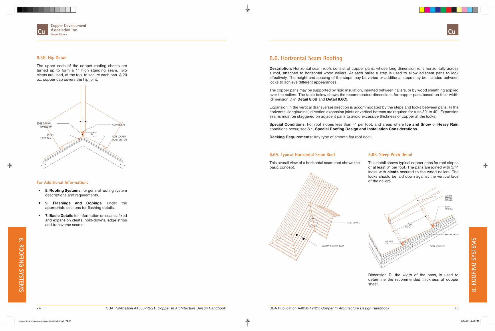
8.5G. Hip Detail
The upper ends of the copper roofing sheets are turned up to form a 1" high standing seam. Two cleats are used, at the top, to secure each pan. A 20 oz. copper cap covers the hip joint.
TURNED UP
CLEAT,2 PER PAN
1"
EDGE OF PAN1"
FLAT LOCKEDROOF SYSTEM
COPPER CAP
For Additional Information:
� 8. Roofing Systems, for general roofing system descriptions and requirements.
� 9. Flashings and Copings, under the appropriate sections for flashing details.
� 7. Basic Details for information on seams, fixed and expansion cleats, hold-downs, edge strips and transverse seams.
8.6. Horizontal Seam Roofing
Description: Horizontal seam roofs consist of copper pans, whose long dimension runs horizontally across a roof, attached to horizontal wood nailers. At each nailer a step is used to allow adjacent pans to lock effectively. The height and spacing of the steps may be varied or additional steps may be included between locks to achieve different appearances.
The copper pans may be supported by rigid insulation, inserted between nailers, or by wood sheathing applied over the nailers. The table below shows the recommended dimensions for copper pans based on their width (dimension D in Detail 8.6B and Detail 8.6C).
Expansion in the vertical (transverse) direction is accommodated by the steps and locks between pans. In the horizontal (longitudinal) direction expansion joints or vertical battens are required for runs 30' to 40'. Expansion seams must be staggered on adjacent pans to avoid excessive thickness of copper at the locks.
Special Conditions: For roof slopes less than 4" per foot, and areas where Ice and Snow or Heavy Rain conditions occur, see 8.1. Special Roofing Design and Installation Considerations.
Decking Requirements: Any type of smooth flat roof deck.
8.6B. Steep Pitch Detail
This detail shows typical copper pans for roof slopes of at least 6" per foot. The pans are joined with 3/4" locks with cleats secured to the wood nailers. The locks should be laid down against the vertical face of the nailers.
OPTIONALBATTENS,VERTICAL
3/4" LOCK,TYP.
8.6ASEE TABLED
WOOD NAILER, TYP.
AT 12" O.C.CLEAT
RIGID INSULATION
Dimension D, the width of the pans, is used to determine the recommended thickness of copper sheet.
8.6A. Typical Horizontal Seam Roof
This overall view of a horizontal seam roof shows the basic concept.
SEE DETAILS B AND C BELOW
SEE 8.7 DETAIL C
74 75CDA Publication A4050-12/21: Copper In Architecture Deisgn Handbook CDA Publication A4050-12/21: Copper In Architecture Design Handbook
8. ROO
FING SYSTEM
S 8. R
OO
FIN
G SY
STEM
S
copper in architecture design handbook.indd 74-75copper in architecture design handbook.indd 74-75 2/14/22 4:43 PM2/14/22 4:43 PM

8.6C. Low Pitch Detail
The detail shown is for low pitch conditions. See Special Conditions for recommendations.
VERTICALBATTENS,OPTIONAL
SEE TABLE
8.6A
D
MIN.4"
AT 12" O.C.CLEAT
Under these conditions the lower pans are formed with a 3/4" lock and extended at least 4" onto the next higher step, where they are secured by cleats. The lower edge of the upper pan is folded under 3/4" and hooked over the locking edge of the lower pan. The lock should be laid down against the vertical face of the nailers.
Dimension D, the width of the pans, is used to determine the recommended gage of copper sheet.
Table 8.6A Typical Horizontal Seam Roofing Pan Dimensions
Width of Sheet
(inches)
Width of Pan, "D"Copper
(Ounces)Steep Pitch
(Inches)Low Pitch (Inches)
18 14-1/2 10-1/4 16
20 16-1/2 12-1/4 16
22 18-1/2 14-1/4 16
24 20-1/2 16-1/4 20
26 22-1/2 18-1/4 20
28 24-1/2 20-1/4 20
Note: Assuming step height of 1-1/2"
8.6D. Change of Slope Without Step
The detail shown is one method of handling a change in roof slope. The adjacent pans are joined with a seam similar to a typical transverse seam for low slope conditions. The cleats securing the pans are attached to wood nailers at 12" O.C.
TYP.WOOD NAILER,
8.6E. Change of Slope With Step
This detail is for conditions similar to Detail 8.6A, except that a step exists below the upper nailer. This detail shows a lock similar to that used on typical steep pitch horizontal roofs.
3/4" LOCK
8.6F. Valley Detail - Steep Pitch
The valley detail shown is for roofs with a slope of least 6" per foot. The low slope detail is similar.
1/4" HOOK DAM
WOOD NAILER,
RIGID INSULATION, TYP.
4" M
IN.
TYP.
TOP OF VALLEYBATTEN, MIN. 4"ABOVE NAILER
CUT BACK FORBATTEN CAP,
ILLUSTRATION
SOLDERED
A valley batten, with a height at least 4" higher than adjacent wood nailers, runs the full length of the valley. A small sheet of copper, 4" wide, is used for additional protection. This piece extends at least 6" onto the nailers, rigid insulation, or wood sheathing and is terminated with a 1/4" dam. The lower edge must be soldered to the copper pans below.
76 77CDA Publication A4050-12/21: Copper In Architecture Deisgn Handbook CDA Publication A4050-12/21: Copper In Architecture Design Handbook
8. ROO
FING SYSTEM
S 8. R
OO
FIN
G SY
STEM
S
copper in architecture design handbook.indd 76-77copper in architecture design handbook.indd 76-77 2/14/22 4:43 PM2/14/22 4:43 PM

8.6G. Expansion Seam Detail
This detail shows a typical transverse seam. Transverse seams are used instead of vertical battens to allow for expansion on roofs that run more than 25 feet horizontally.
3/4"
6"
SLOPE
3/4"
1"
1/2"
One pan has a 1" lock double-folded 6" from the end and a 3/4" fold at the edge, into which a cleat is locked. The adjacent pan is folded under 1" at the end, and hooked into the matching lock of the lower pan.
Transverse seams should be staggered to avoid excessive thickness of material at the horizontal locks.
For Additional Information:
� 8. Roofing Systems, for general roofing system descriptions and requirements.
� 9. Flashings and Copings, under the appropriate sections for flashing details.
� 7. Basic Details for information on seams, fixed and expansion cleats, hold-downs, edge strips and transverse seams.
� 8.3. Batten Seam Roofing, for information on battens, and similar eave, hip, and ridge conditions.
� 8.1. Special Roofing Design and Installation Considerations - Tables 8.1A, and 8.1B.
8.7A. Top of Mansard - Coping Cover
This detail shows a condition where the top of the mansard meets a coping cover. The top edge of the pans are folded out to the height of the standing or batten seam, then bent down 3/4". The coping cover is hooked over this edge, effectively forming a drip.3/4" LOCK
STANDING SEAMSBEYOND
BATTEN OR
TWO PER PANCLEAT,
3/4" LOCK
8.7. Mansard Roofing
Description: Mansard roofs are, for the most part, based on 8.2. Standing Seam Roofing or 8.3. Batten Seam Roofing construction.
The lower ends of the pans are typically hooked over an edge strip to form a drip. The ends may alternately attach to the base flashing where a change in roof slope occurs.
The recommended detail for the upper edges of the pans is to fold them out the height of the batten or standing seam and terminate them with a 3/4" fold. The lower edge of the gravel stop or coping flashing is then hooked over this fold (see Detail 8.7A and Detail 8.7B).
Special Conditions: Since mansards are inherently used on vertical or nearly vertical surfaces, most of the special provisions for low slope standing and batten seams are not necessary.
Decorative battens may be added in the same manner as for 8.4. Chevron Roofing.
If the standing seams or battens are to continue over the top edge of the mansard, special steps must be taken. The pans should be continuous over the top edge. The upstanding legs of the standing or batten seams must be slit where they are bent. After bending, small pieces of copper must be soldered over the legs to restore continuity. The seams are then finished in the conventional manner.
Decking Requirements: A continuous sheathing substrate is required, compatible with the roofing system used.
8.7B. Top of Mansard - Gravel Stop
The top of a mansard at a gravel stop is illustrated. The top edge of the pans are treated similar to Detail 8.7A, with the gravel stop engaging the folded pan edge.
STANDING SEAMSBATTEN OR
TWO PER PAN
BEYOND
CLEAT,
78 79CDA Publication A4050-12/21: Copper In Architecture Deisgn Handbook CDA Publication A4050-12/21: Copper In Architecture Design Handbook
8. ROO
FING SYSTEM
S 8. R
OO
FIN
G SY
STEM
S
copper in architecture design handbook.indd 78-79copper in architecture design handbook.indd 78-79 2/14/22 4:43 PM2/14/22 4:43 PM

8.7C. Bottom of Mansard
This is a typical condition for the lower edge of a mansard. The bottom edge of the pans are hooked over the edge strip to form a drip. The horizontal dimension of the edge strip should not exceed 4" if it is not fastened to the soffit.
3/4" LOCK
3" O.C.NAILED ATEDGE STRIP20 OZ. COPPER
SEAM BEYONDSTANDINGBATTEN OR
CONTINUOUS
4"MAX.
SEE TEXT
8.7E. Continuous Over Roof Batten Detail
The detail illustrates the installation for batten seams which are continuous over the roof. Standing seams under the same conditions are detailed in a similar method.
ILLUSTRATION ONLY)
BATTEN CAP
OF UPSTANDINGTO BACK SIDESOLDER PIECE
(CUT BACK FOR
LEG
PANSCOPPER
WOOD BATTEN
8.7D. Change in Mansard Slope
This detail shows the condition where the bottom of the mansard meets another roof. At the lower roof, the standing seams are laid flat 8" from the roof break, folded 3/4" and secured with copper cleats spaced 12" O.C. Copper locking strips of the same weight as the flashing are soldered to the pans between seams at least 6" from the roof break and engage the base flashing in a 3/4" lock. At the upper roof, the upper edge of the base flashing is folded 3/4" and secured with copper cleats spaced 12" O.C. A continuous locking strip is soldered to the base flashing and secures the mansard roof edge.
COPPER LOCK STRIP
CLEAT AT TWO PER PAN
BASE FLASHING
CONT. COPPER LOCK STRIP
CLEAT AT 12" O.C.
TYP. SEAM BEYOND
6" MIN.
The pans shown are continuous from the face of the mansard over the edge onto the roof. The upstanding legs of the seams must be slit where they are bent. After bending, small pieces of copper must be soldered to the back side of these legs. Batten caps are then added in the conventional manner, except that their legs must also be slit and soldered where they are bent.
For Additional Information:
� Roofing Systems - Introduction, for general roofing system descriptions and requirements.
� Flashing and Copings, under the appropriate sections for flashing details.
� Basic Details for information on seams, fixed and expansion cleats, hold-downs, edge strips and transverse seams.
� Roofing Systems - Standing Seams or Roofing Systems - Batten Seams for information on the respective roof types.
� Roofing Systems - Chevron for additional information on decorative battens.
80 81CDA Publication A4050-12/21: Copper In Architecture Deisgn Handbook CDA Publication A4050-12/21: Copper In Architecture Design Handbook
8. ROO
FING SYSTEM
S 8. R
OO
FIN
G SY
STEM
S
copper in architecture design handbook.indd 80-81copper in architecture design handbook.indd 80-81 2/14/22 4:43 PM2/14/22 4:43 PM
8.8. Long Pan Systems
Description: Potential problems with standing seam roofs due to expansion and contraction stem from three conditions:
1. Racking of cleats due to cyclical expansion/contraction
2. Structural strength of the formed pans
3. Seam lock-up
Typically, racking of cleats and subsequent loosening of fasteners is a greater problem, and can result from inappropriate installation of fixed cleats for long runs of copper roofing utilizing a double locked standing seam system. As this system expands and contracts, fixed cleats, locked tightly into the seam, are flexed and can loosen their deck fasteners.
Some of this movement can be accommodated by the copper pans as indicated by the "oil-canning" of the pans. If aesthetically objectionable, "oil-canning" may be minimized by the use of expansion cleats, and by limiting the use of fixed cleats to pans 10 feet maximum in length. Fixed cleats should be installed at the midpoint of the respective pan in the patternindicated. The dimension "E" in the respective details denotes the total amount of expected relative movement of the components in the details.
Historical details and installation procedures have recommended the installation of continuous roof seam lengths up to 30' utilizing fixed cleats. For seam lengths exceeding 30', the recommendation has been to utilize expansion cleats. Although such recommended techniques have proven effective with satisfactory historical roof performance, contemporary building design and construction practices require a more careful approach. Insulated roof systems potentially leading to higher roof temperatures, and light weight roof decks leading to higher differential movement all require careful design.
On reviewing historical and contemporary design and installation conditions, this Handbook has adopted a conservative approach and is referencing all pans and seam lengths greater than 10' as Long Pan construction.
The second issue, structural strength of the formed shape, relates to the ability of roof pans to transfer
accumulated expansion stresses to a pre-determined point of release. This ability becomes limited as the roof pan becomes longer and a 45 foot limit should be set for individual roof pans.
The third issue deals with short lengths of pans, under 10 feet, in standing seam installations, locked together so tightly as to prevent free expansion and contraction movement between pans. This "locking" together may result from multiple thicknesses of metal in the seam (seven at the transverse seam) and deformation through malleting and in particular through the use of mechanical seamers.
The end result may lead to expansion being transferred from pan to pan resulting in a long-pan installation in spite of short pan utilization.
This condition can be mitigated by requiring the following:
� Omit any cleats in the transverse seam.
� Review all transverse seam locations carefully to ensure sufficient off-set.
� Use expansion release points for very long seam runs
� Correct use and location of fixed and expansion type cleats.
Note: Expansion release points can be loose locked seams that allow expansion and contraction of adjacent pans relative to each other.
Long Pan construction details are designed to accommodate the cumulative expansion stress which develops over long spans of copper sheets. The points of stress relief are typically accommodated at eaves, transverse joints, and ridge and base conditions by ensuring that the copper sheet is provided with proper clearances and is secured by expansion fastening devices that will not hinder thermal movement.
Long Pan construction requires the use of expansion cleats and installation details substantially different than short pan construction where pans are less than 10 feet in length.
The proper alignment of pans is critical for both appearance and function as is the proper placement of expansion cleats and the design of all associated seams.
Adjacent pans should be layed out symmetrically to a common centerline, to allow for ease of installation of the fixed cleats. See Long Pan Layout on Table 8.8A.
Particular building dynamics should be considered before specific copper details are established. Building expansion joints must be accommodated and properly detailed. Similarly, Building Orientation should be taken into consideration. A south sloping roof will incur greater heat gain differentials than a north sloping roof.
Under certain conditions, for a southerly sloping roof with clear skies and no wind, it is possible for the copper roof temperature to exceed the ambient air temperature by 75° to 85°F. Ultimate temperature may also be influenced by reflection from adjacent materials and other factors. Seam design should take into consideration the maximum temperature extremes. Under most conditions, the minimum (lowest) temperature will occur approximately 1 hour before sunrise under clear skies and no wind. Depending upon building construction and heat loss, the lowest roof temperature may be somewhat higher than air temperature. Prudent design suggests designing for minimum rather than roof air temperatures.
All roof penetrations should allow for expansion in the same amounts as the roof panels, voids or spaces should be filled with loose insulation or compressible joint filler.
82 83CDA Publication A4050-12/21: Copper In Architecture Deisgn Handbook CDA Publication A4050-12/21: Copper In Architecture Design Handbook
8. ROO
FING SYSTEM
S 8. R
OO
FIN
G SY
STEM
S
copper in architecture design handbook.indd 82-83copper in architecture design handbook.indd 82-83 2/14/22 4:43 PM2/14/22 4:43 PM
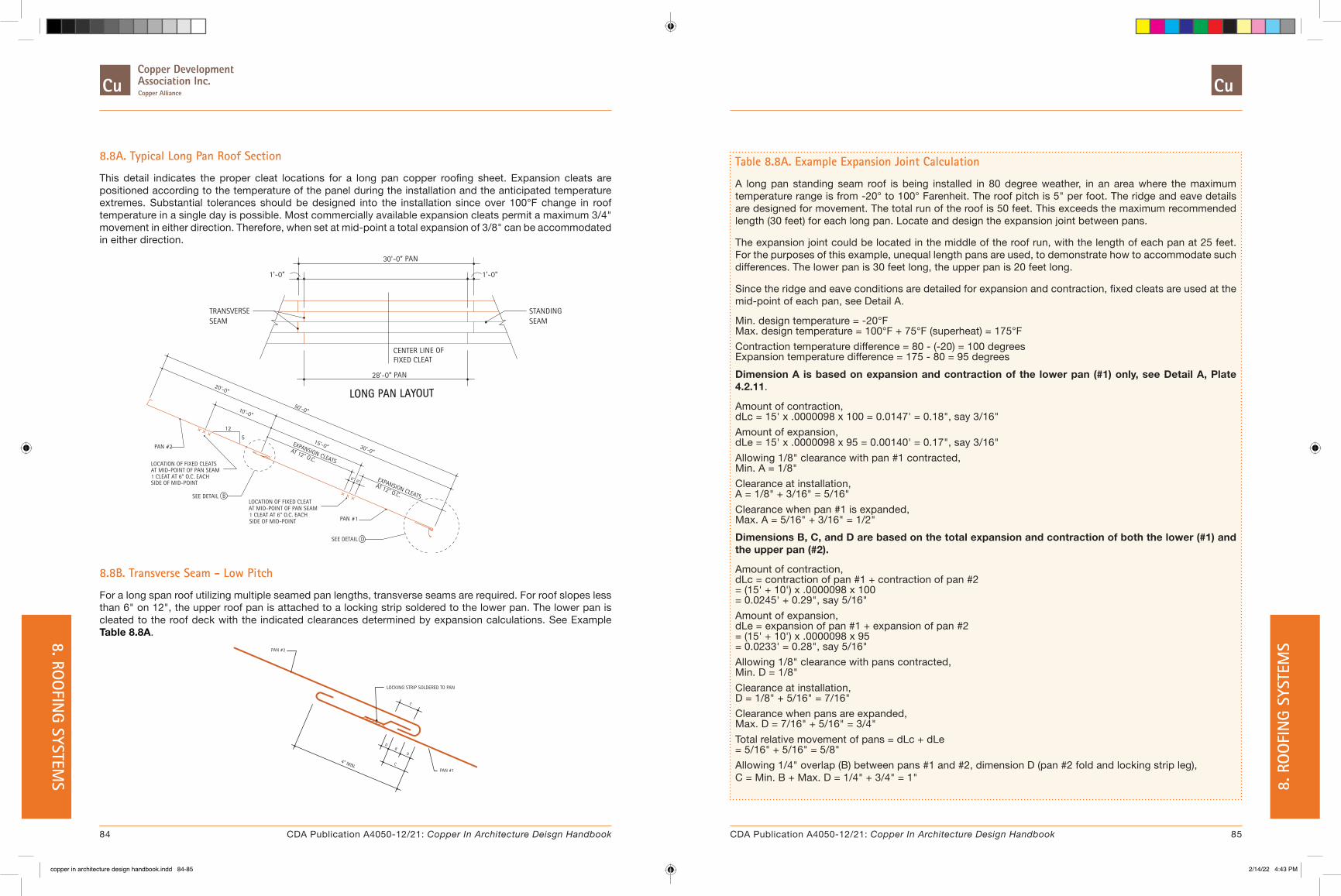
Table 8.8A. Example Expansion Joint Calculation
A long pan standing seam roof is being installed in 80 degree weather, in an area where the maximum temperature range is from -20° to 100° Farenheit. The roof pitch is 5" per foot. The ridge and eave details are designed for movement. The total run of the roof is 50 feet. This exceeds the maximum recommended length (30 feet) for each long pan. Locate and design the expansion joint between pans.
The expansion joint could be located in the middle of the roof run, with the length of each pan at 25 feet. For the purposes of this example, unequal length pans are used, to demonstrate how to accommodate such differences. The lower pan is 30 feet long, the upper pan is 20 feet long.
Since the ridge and eave conditions are detailed for expansion and contraction, fixed cleats are used at the mid-point of each pan, see Detail A.
Min. design temperature = -20°F Max. design temperature = 100°F + 75°F (superheat) = 175°FContraction temperature difference = 80 - (-20) = 100 degrees Expansion temperature difference = 175 - 80 = 95 degreesDimension A is based on expansion and contraction of the lower pan (#1) only, see Detail A, Plate 4.2.11.
Amount of contraction, dLc = 15' x .0000098 x 100 = 0.0147' = 0.18", say 3/16"Amount of expansion, dLe = 15' x .0000098 x 95 = 0.00140' = 0.17", say 3/16"Allowing 1/8" clearance with pan #1 contracted, Min. A = 1/8"Clearance at installation, A = 1/8" + 3/16" = 5/16"Clearance when pan #1 is expanded, Max. A = 5/16" + 3/16" = 1/2"Dimensions B, C, and D are based on the total expansion and contraction of both the lower (#1) and the upper pan (#2).
Amount of contraction, dLc = contraction of pan #1 + contraction of pan #2 = (15' + 10') x .0000098 x 100 = 0.0245' + 0.29", say 5/16"Amount of expansion, dLe = expansion of pan #1 + expansion of pan #2 = (15' + 10') x .0000098 x 95 = 0.0233' = 0.28", say 5/16"Allowing 1/8" clearance with pans contracted, Min. D = 1/8"Clearance at installation, D = 1/8" + 5/16" = 7/16"Clearance when pans are expanded, Max. D = 7/16" + 5/16" = 3/4"Total relative movement of pans = dLc + dLe = 5/16" + 5/16" = 5/8"Allowing 1/4" overlap (B) between pans #1 and #2, dimension D (pan #2 fold and locking strip leg), C = Min. B + Max. D = 1/4" + 3/4" = 1"
8.8A. Typical Long Pan Roof Section
This detail indicates the proper cleat locations for a long pan copper roofing sheet. Expansion cleats are positioned according to the temperature of the panel during the installation and the anticipated temperature extremes. Substantial tolerances should be designed into the installation since over 100°F change in roof temperature in a single day is possible. Most commercially available expansion cleats permit a maximum 3/4" movement in either direction. Therefore, when set at mid-point a total expansion of 3/8" can be accommodated in either direction.
CENTER LINE OFFIXED CLEAT
EXPANSION CLEATS
1 CLEAT AT 6" O.C. EACHAT MID-POINT OF PAN SEAMLOCATION OF FIXED CLEATS
PAN #2
SIDE OF MID-POINT
SIDE OF MID-POINT
LOCATION OF FIXED CLEAT
1 CLEAT AT 6" O.C. EACHAT MID-POINT OF PAN SEAM
B
12
5
50'-0”
AT 12" O.C.
15'-0”
1'-0"
TRANSVERSESEAM
20'-0”
28'-0” PAN
30'-0” PAN
AT 12" O.C.
EXPANSION CLEATS
6"
PAN #1
SEE DETAIL D
6"
30'-0”
SEAMSTANDING
1'-0"
LONG PAN LAYOUT10'-0”
SEE DETAIL
8.8B. Transverse Seam - Low Pitch
For a long span roof utilizing multiple seamed pan lengths, transverse seams are required. For roof slopes less than 6" on 12", the upper roof pan is attached to a locking strip soldered to the lower pan. The lower pan is cleated to the roof deck with the indicated clearances determined by expansion calculations. See Example Table 8.8A.
PAN #2
4" MIN.
D
C
BD
PAN #1
LOCKING STRIP SOLDERED TO PAN
C
84 85CDA Publication A4050-12/21: Copper In Architecture Deisgn Handbook CDA Publication A4050-12/21: Copper In Architecture Design Handbook
8. ROO
FING SYSTEM
S 8. R
OO
FIN
G SY
STEM
S
copper in architecture design handbook.indd 84-85copper in architecture design handbook.indd 84-85 2/14/22 4:43 PM2/14/22 4:43 PM

8.8C. Transverse Seam - High Pitch
For slopes greater than 4" per foot, the lower pan is folded under the upper pan. The lower pan is installed, before the second pan is installed. The detail shows the completed seam.
4" MIN.
PAN # 1
PAN # 2
HEMMED EDGE
8.8E. Eave with Gutter
This is an alternate eave detail and is recommended in snow areas when using a gutter. The gutter is extended to the roof to form a flashing apron fastened to the roof with cleats at 12" O.C. A 20 oz. copper locking strip is soldered to the apron and engages the end of the copper roof pan. The locking strip prevents vertical wind up-lift of the roof pan, but allows horizontal expansion and contraction. Proper clearances must be maintained as outlined in the above example.
FOR SIM. CONDITIONSEE DETAIL B
CLEAT AT 12" O.C.
LAP
6" MIN.
CONT. LOCKSTRIP
FLASHINGAPRON
8.8D. Eave Detail
This detail indicates a method for terminating a copper roof at the eave. The fascia trim is bent to extend onto the roof deck to become an integral flashing apron nailed to the roof. The copper pan is secured to the apron lip in order to achieve vertical restraint. Horizontal movement of the copper roof sheet is accommodated by the loose-lock fold of the pan over the fascia lip.
20 OZ. COPPERFLASHING APRON
LOOSE LOCK
A
COPPER ROOF PAN
A
CONT. EDGE STRIP.
8.8F. Gable Rake Edge
Compensation for expansion and contraction at a rake edge is shown using a double lock seam detail. A continuous edge strip is fastened to the fascia board followed by the installation of an expansion cleat.. The moveable tabs of the cleat hook onto the edge of the roof pan, as shown in the detail.
AT 12" O.C.
EDGE STRIP
CLEATEXPANSION
BEFORE RAKE INSTALLATION
COPPER STANDINGSEAM PAN
RAKE EDGE
DOUBLE LOCK
LOOSE LOCK
FINISHED EDGE
1"
The Finished Edge detail shows the completed joint. The fascia rake edge is engaged into the edge strip and all 3 components are formed into a double lock seam. The lower end of the rake edge is formed into a loose lock around the edge strip to accommodate unrestrained movement.
8.8G. Non-Venting Ridge
For the installation of a non-vented ridge, a blocking framework is formed as indicated. The copper roofing is formed into a "bread pan" with the required expansion space as indicated. Ridge Cap pieces are typically joined along the crest of the ridge with a double-lock standing seam.
EXPANSION SPACE
COPPER16 OR 20 OZ.
FOLD"BREAD PAN"
1"
DOUBLE LOCK SEAM
8.8H. Venting Ridge
This detail shows the installation of a ridge cap where venting is a requirement. A sub-frame of plywood and blocking is formed to follow the slope of the roof. This frame is covered with copper which is allowed to float freely from the copper roof pan. The pan is terminated in a folded "bread-pan" with the required expansion space as indicated. Ridge Cap pieces are typically joined along the crest of the ridge with a double-lock standing seam.
INSECT SCREENEXPANSION SPACE
WOOD BLOCKING
"BREAD PAN"
16 OR 20 OZ.
AT 16" O.C.
FOLD
COPPER 1"
SEAM BEYONDSTANDINGBATTEN OR
DOUBLE LOCK SEAM
For Additional Information:
� 8. Roofing Systems, for general roofing systems descriptions and requirements.
� 9. Flashings and Copings, under the appropriate sections for flashing details.
� 8.2. Standing Seam Roofing or 8.3. Batten Seam Roofing, for additional information on the respective roofing types.
86 87CDA Publication A4050-12/21: Copper In Architecture Deisgn Handbook CDA Publication A4050-12/21: Copper In Architecture Design Handbook
8. ROO
FING SYSTEM
S 8. R
OO
FIN
G SY
STEM
S
copper in architecture design handbook.indd 86-87copper in architecture design handbook.indd 86-87 2/14/22 4:43 PM2/14/22 4:43 PM

9. FLASHINGS AND COPINGS
� 9.1. Through-Wall Flashing
� 9.2. Counterflashing
� 9.3. Coping Covers
� 9.4. Ridges and Hips
� 9.5. Valleys
� 9.6. Changes in Roof Slopes
� 9.7. Gravel Stops and Fascias
� 9.8. Stepped and Chimney Flashings
� 9.9. Roof Penetrations
� 9.10. Dormers
� 9.11. Eave Snow Flashing
� 9.12. Eave Conditions
� 9.13. Roof Area Divider
Introduction
Most modern construction materials are fairly resistant to moisture penetration. However, many joints between masonry units, panels, or architectural features are not. The effects of natural movement due to settlement, expansion, and contraction tend to compound the problems and may eventually lead to leaks. Flashing is used to prevent moisture from entering at such locations. It is also used to divert to the exterior moisture that has already entered various components of a structure.
Moisture that penetrates into a building may cause serious damage to its interior. In freezing temperatures, it can also cause severe damage to the exterior of the building. Cracking, spalling, and disintegration can result. Over a long period of time, moisture can also weaken structural elements.
Copper is an excellent material for flashing because of its malleability, strength, and high resistance to the caustic effects of mortars and hostile environments. Flashing, in general, is expensive to replace if it fails. The long life copper flashing offers, is a major asset in this application.
General Requirements
� Support Requirements: Copper wall flashing in new masonry is typically held in place by setting the upper edge into the mortar joint between the courses in the backing material. In a retrofit condition, the upper edge of the copper flashing can usually be inserted into a reglet or an existing joint that has been raked. If the backing is not masonry it must be a nailable material. Wood blocking must be provided for the attachment and support of copper copings, gravel stops, edge strips, roof sumps, scuppers, and other copper roof accessories. These are shown in the accompanying details.
� Materials: Flashings and copings are fabricated from cold rolled copper in weights ranging between 16 and 20 ounces per square foot. The required weight depends on the application and is outlined in the discussion related to each detail. Wherever sealant is used that comes into contact with copper a rubber or synthetic-base sealant that is compatible with copper must be specified.
� Description: The wide variety of uses for copper as a flashing material makes it impossible to discuss installations for all specific conditions. However, the principles behind good applications can be summarized. Copper movement must always be anticipated. It should be accommodated with proper details, but in circumstances where movement cannot be tolerated, it should be limited. The latter condition is often encountered with edge strips, gravel stops, and continuous cleats. The flow of water must be planned for and not impeded. Flashing should, typically, have at least an 8" vertical drop from its upper to its lower edge. The ends of discontinuous flashings, such as at window sills, must be dammed to prevent moisture from flowing into the wall cavity. Pea gravel should be used on throughwall flashing to help prevent construction debris from blocking flow. Where a sealant is used in conjunction with flashing, as at a shelf angle for example, it should be installed
below the flashing so that moisture diverted by the flashing will not be trapped by the sealant. Contact between copper and non compatible metals should be avoided. Where this is not possible, such as at a steel shelf angle, some method of material separation is required. This condition is most often solved with the use of a bituminous coating applied to the metals to prevent direct contact.
The details shown in this section illustrate these and other important points.
88 89CDA Publication A4050-12/21: Copper In Architecture Deisgn Handbook CDA Publication A4050-12/21: Copper In Architecture Design Handbook
9. FLASHIN
GS AND CO
PINGS 9.
FLA
SHIN
GS A
ND
COPI
NGS
copper in architecture design handbook.indd 88-89copper in architecture design handbook.indd 88-89 2/14/22 4:43 PM2/14/22 4:43 PM

9.1. Through-Wall Flashing
Description: Through-wall flashing is used to divert moisture, which has entered the wall, to the outside, before it can cause damage. This flashing method is considered the most satisfactory method of preventing leaks except in areas exposed to earthquakes.
Through-wall flashing is used at all points where moisture may enter the wall, and in selected places particularly susceptible to water damage.
The flashing must typically rise at least 8" from the low point at the exterior face of the building to the high point inside the wall. Weeps spaced a maximum of 24" O.C. must be included. Use of pea gravel is recommended behind brick veneer. The ends of the flashing must be dammed to prevent water that has been caught from draining back into the wall.
Through-wall flashing is commonly fabricated by deforming the metal in such a way as to provide bond strength in mortar joints. All through-wall flashing should be set with a bed of mortar above and below the flashing in strict compliance with the flashing manufacturer's specifications.
On nailable sheathing, the flashing should be fastened with wide head nails or cleats. Nailing through flashing prohibits movement and should be avoided when movement is expected. The nail should be driven just above the upper edge of the flashing, allowing its wide head to hold the copper sheet. Nails or cleats should be spaced no more than 12" O.C.
The minimum recommended weight for copper through-wall flashing is 12 oz. using "High Yield", or 16 oz. using standard cold rolled copper.
Special Conditions: If copper flashing is used adjacent to other metals, proper care should be taken to account for separation of the materials. These conditions often arise at brick shelf angles, and under metal window and door frames. They are typically handled with the use of bituminous paint, zinc chromate or red lead primers on the contact surfaces.
Although copper flashing is not adversely affected by the corrosive alkalies present in masonry mortar, it's long term performance can be compromised by excessive chlorides. Therefore, chloride based
additives in the mortar should be avoided.
See Detail 9.1I for more information on flashing special brick veneer conditions.
9.1A. Brick Veneer on CMU at Decking
This detail illustrates a condition where the top edge of the flashing is held by the CMU backup. This is the typical method of holding the flashing in a cavity wall.
FLASHINGCOPPER
8" M
IN.
FINISH, TYP.ARCHITECTURAL
9.1B. Brick Veneer on CMU at Steel Spandrel
This condition is similar to Detail 9.1A, except that the brick veneer is supported by a steel plate. The flashing detail is essentially identical.
FINISH, TYPICALARCHITECTURAL
8" M
IN.
FLASHINGCOPPER
9.1C. Brick Veneer on CMU at Window Head & Sill
It is particularly important to provide flashing at the head and sill of a window or door. Moisture can promote corrosion in the steel lintel, and may stain or damage the window.
FLASHINGCOPPER
FLASHINGCOPPER
8" M
IN.
FINISH, TYPICALARCHITECTURAL
At the sill, the risk of moisture entering the wall is especially high. Here, a backer rod and sealant are applied below the flashing to prevent moisture penetration. The ends of the flashing are dammed to prevent water penetration behind the sealant below.
9.1D. Brick Veneer on CMU at Grade
This detail shows the typical method for flashing a cavity wall at grade.
8" M
IN.
FLASHINGCOPPER
FINISH, TYPICALARCHITECTURAL
9.1E. Brick Veneer on CMU at Concrete Spandrel
Shown is one way of flashing over the shelf angle at a concrete spandrel. This detail can be used where the distance from the top of the concrete to the shelf angle is at least 8". If the distance is less than this, then a detail similar to Detail 9.1A should be used. If the distance is large, then a detail similar to Detail 9.1H should be used.
FINISH, TYPICALARCHITECTURAL
FLASHING
8" M
IN.
COPPER
9.1F. Brick Veneer on Metal Studs
As with brick on CMU, proper flashing at window and door heads and sills is very important. With brick veneer on studs, the flashing at the head must be extended up along the sheathing and lapped by the building paper at least 4". The sill flashing detail requires that a backer rod and sealant be applied below the flashing. The flashing must be dammed at the ends. A bituminous coating or a strip of asphalt saturated felt should be applied to prevent contact between dissimilar metals.
FOR SEPARATIONBITUMINOUS COATING
FLASHING
FINISH, TYPICALARCHITECTURAL
FLASHING
8" M
IN.
COPPER
COPPER
4" M
IN.
LAP
90 91CDA Publication A4050-12/21: Copper In Architecture Deisgn Handbook CDA Publication A4050-12/21: Copper In Architecture Design Handbook
9. FLASHIN
GS AND CO
PINGS 9.
FLA
SHIN
GS A
ND
COPI
NGS
copper in architecture design handbook.indd 90-91copper in architecture design handbook.indd 90-91 2/14/22 4:43 PM2/14/22 4:43 PM

9.1G. Typical Flashing Joint and End Dam
Wherever long runs of copper flashing are required, multiple sheets of copper flashing are used. Adjacent pieces are lapped at least 6" and sealed (see Solder and Sealants (page 15) section for sealant recommendations). At the ends, the flashing is detailed as shown to provide an effective dam, preventing moisture from draining back into the wall.
6" MIN. SEALED
LAP
9.1H. Brick Veneer on Metal Studs at Concrete Spandrel
This concrete spandrel condition can be used if there is a large distance from the top of the concrete to the shelf angle. The flashing at the shelf angle is inserted into a reglet cast into the concrete and held with lead wedges.
SEPARATIONCOATING FORBITUMINOUS
REGLET
FINISH, TYPICALARCHITECTURAL
CAST
MIN
.
8" M
IN.
4"
Dissimilar metals should not be in contact. A bituminous coating or a strip of asphalt saturated felt can be used to achieve this separation.
9.1I. Brick Veneer Flashing
The first detail shows the typical method of flashing a brick wythe. The flashing must extend up at least 8", weeps spaced a maximum of 24" O.C., and pea gravel are rec-ommended. The lower edge of the flashing should extend about 1/2" beyond the face of the brick, and have a downward bend to provide a drip.
DETAIL 2. ALTERNATE FLASHING
DETAIL 4. LIPPED BRICK SHELF ANGLE
1/2"
COATING FOR
METALS, TYP.OF DISSIMILAR
DETAIL 3. TYP. SHELF ANGLE
SEALANT &BACKERROD, TYPICAL
1/2"
SEPARATION
BITUMINOUS
1/2"
DETAIL 1. TYPICAL FLASHING
8" M
IN.
1/2"
PEA GRAVEL,TYPICAL
WEEP
The alternate flashing method shown is primarily for use with asphalt coated copper flashing. Because the coating exposed to the weather is likely to flow and stain the surfaces below, this flashing is held back from the face of the brick. With hollow brick, the flashing must fully cover the internal holes. The coating may also not be compatible with most currently available sealants. If this flashing material is used at a shelf angle, a proper seal below it may not be possible. For this reason it is recommended that the flashing be installed a brick course above the shelf angle.
The last two details show typical shelf angle flashing. These follow the same principles outlined in the first detail.
The detail on the left shows the copper flashing resting on the shelf angle. Direct contact of dissimilar metals must be avoided. This can be achieved by the application of a bituminous coating on the shelf angle or the insertion of a strip of asphalt saturated felt.
9.1J. Brick Veneer on Wood Studs at Window Head and Sill
The head condition shows a row lock course of brick. This detail is essentially the same as that for brick veneer on metal studs. The flashing is extended up the sheathing and lapped 4" minimum by the building paper. Weeps at 24" O.C. maximum must be included. The copper flashing must not be in direct contact with the shelf angle. A bituminous coating or a strip of asphalt saturated felt can be applied to the angle to provide a separation.
FLASHINGCOPPER
AT 24" O.C.WEEP HOLE
4" LAP
MIN
.
SEPARATION OF
ARCHITECTURAL
DISSIMILARMETALS
COATING FORBITUMINOUS
FINISH, TYPICAL
FLASHINGCOPPER
The sill condition for a wood framed window is considerably different to that of a metal window. The flashing extends from the inside face of the sill piece, under the sill, then down and under the brick sill. It should project out about 1/2" beyond the face of the brick below and be bent to form a drip.
The ends of both head and sill flashings should be dammed to prevent moisture penetration.
9.1K. Wood Siding at Window Head and Sill
The top edge of the flashing at the head is attached to the sheathing and is lapped a minimum of 4" by the building paper. The lower edge of the flashing is bent over the wood trim and turned down to form a drip.
MIN
.LA
P
FLASHINGCOPPER
FLASHINGCOPPER
4"
FINISH, TYPICALARCHITECTURAL
At the sill, the flashing is turned up against and is attached to the inside face of the sill piece. Then it runs under the sill and laps over the siding below. A wood trim piece covers the copper flashing.
92 93CDA Publication A4050-12/21: Copper In Architecture Deisgn Handbook CDA Publication A4050-12/21: Copper In Architecture Design Handbook
9. FLASHIN
GS AND CO
PINGS 9. F
LASH
INGS
AN
D CO
PIN
GS
copper in architecture design handbook.indd 92-93copper in architecture design handbook.indd 92-93 2/14/22 4:43 PM2/14/22 4:43 PM
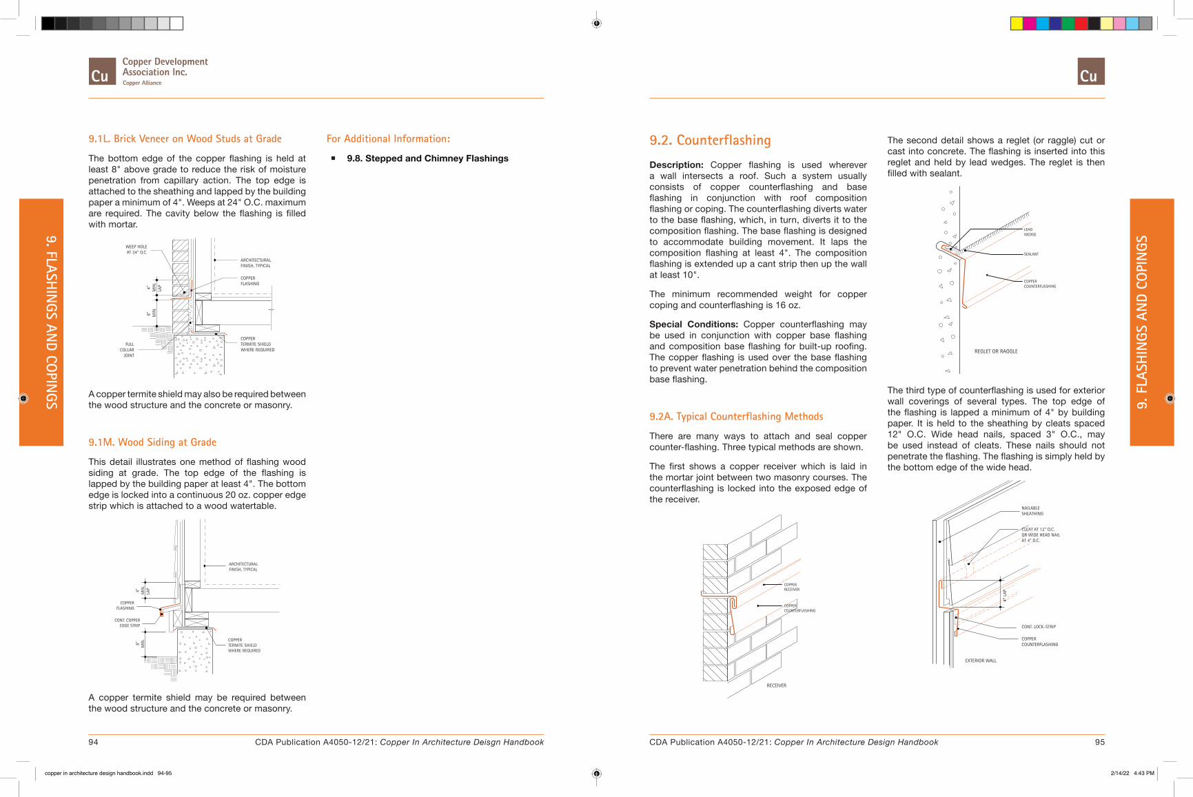
9.1L. Brick Veneer on Wood Studs at Grade
The bottom edge of the copper flashing is held at least 8" above grade to reduce the risk of moisture penetration from capillary action. The top edge is attached to the sheathing and lapped by the building paper a minimum of 4". Weeps at 24" O.C. maximum are required. The cavity below the flashing is filled with mortar.
JOINTCOLLAR
FULL
AT 24" O.C.WEEP HOLE
MIN
.LA
P
8" MIN
.4"
TERMITE SHIELDWHERE REQUIRED
COPPER
ARCHITECTURALFINISH, TYPICAL
FLASHINGCOPPER
A copper termite shield may also be required between the wood structure and the concrete or masonry.
9.1M. Wood Siding at Grade
This detail illustrates one method of flashing wood siding at grade. The top edge of the flashing is lapped by the building paper at least 4". The bottom edge is locked into a continuous 20 oz. copper edge strip which is attached to a wood watertable.
MIN
.8"
EDGE STRIPCONT. COPPER
FLASHINGCOPPER
MIN
.4" LAP
WHERE REQUIREDTERMITE SHIELDCOPPER
FINISH, TYPICALARCHITECTURAL
A copper termite shield may be required between the wood structure and the concrete or masonry.
For Additional Information:
� 9.8. Stepped and Chimney Flashings
The second detail shows a reglet (or raggle) cut or cast into concrete. The flashing is inserted into this reglet and held by lead wedges. The reglet is then filled with sealant.
COUNTERFLASHINGCOPPER
SEALANT
WEDGELEAD
REGLET OR RAGGLE
The third type of counterflashing is used for exterior wall coverings of several types. The top edge of the flashing is lapped a minimum of 4" by building paper. It is held to the sheathing by cleats spaced 12" O.C. Wide head nails, spaced 3" O.C., may be used instead of cleats. These nails should not penetrate the flashing. The flashing is simply held by the bottom edge of the wide head.
4" L
AP
COUNTERFLASHINGCOPPER
OR WIDE HEAD NAILAT 4" O.C.
CLEAT AT 12" O.C.
CONT. LOCK-STRIP
EXTERIOR WALL
NAILABLESHEATHING
9.2. Counterflashing
Description: Copper flashing is used wherever a wall intersects a roof. Such a system usually consists of copper counterflashing and base flashing in conjunction with roof composition flashing or coping. The counterflashing diverts water to the base flashing, which, in turn, diverts it to the composition flashing. The base flashing is designed to accommodate building movement. It laps the composition flashing at least 4". The composition flashing is extended up a cant strip then up the wall at least 10".
The minimum recommended weight for copper coping and counterflashing is 16 oz.
Special Conditions: Copper counterflashing may be used in conjunction with copper base flashing and composition base flashing for built-up roofing. The copper flashing is used over the base flashing to prevent water penetration behind the composition base flashing.
9.2A. Typical Counterflashing Methods
There are many ways to attach and seal copper counter-flashing. Three typical methods are shown.
The first shows a copper receiver which is laid in the mortar joint between two masonry courses. The counterflashing is locked into the exposed edge of the receiver.
RECEIVER
COPPER
COUNTERFLASHING
RECEIVER
COPPER
94 95CDA Publication A4050-12/21: Copper In Architecture Deisgn Handbook CDA Publication A4050-12/21: Copper In Architecture Design Handbook
9. FLASHIN
GS AND CO
PINGS 9. F
LASH
INGS
AN
D CO
PIN
GS
copper in architecture design handbook.indd 94-95copper in architecture design handbook.indd 94-95 2/14/22 4:43 PM2/14/22 4:43 PM
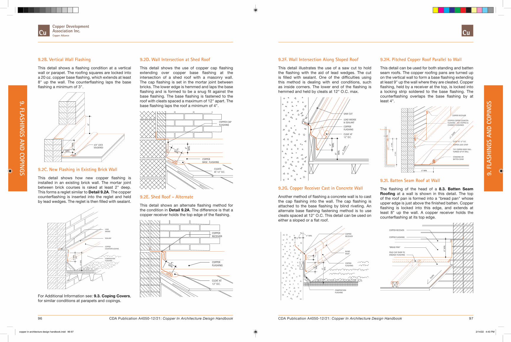
9.2B. Vertical Wall Flashing
This detail shows a flashing condition at a vertical wall or parapet. The roofing squares are locked into a 20 oz. copper base flashing, which extends at least 8" up the wall. The counterflashing laps the base flashing a minimum of 3".
4" MAX.
SOLDERED3/4" LOCK
3" M
IN.
8"
9.2C. New Flashing in Existing Brick Wall
This detail shows how new copper flashing is installed in an existing brick wall. The mortar joint between brick courses is raked at least 2" deep. This forms a reglet similar to Detail 9.2A. The copper counterflashing is inserted into the reglet and held by lead wedges. The reglet is then filled with sealant.
LAP
4" M
IN.
9" M
IN. FLASHING
COMPOSITION
COUNTERFLASHINGCOPPER
SEALANT
WEDGELEAD
For Additional Information see: 9.3. Coping Covers, for similar conditions at parapets and copings.
9.2D. Wall Intersection at Shed Roof
This detail shows the use of copper cap flashing extending over copper base flashing at the intersection of a shed roof with a masonry wall. The cap flashing is set in the mortar joint between bricks. The lower edge is hemmed and laps the base flashing and is formed to be a snug fit against the base flashing. The base flashing is fastened to the roof with cleats spaced a maximum of 12" apart. The base flashing laps the roof a minimum of 4".
MIN.
4" MIN
.4"
AT 12" O.C.CLEATS
FLASHINGBASECOPPER
FLASHINGCOPPER CAP
9.2E. Shed Roof - Alternate
This detail shows an alternate flashing method for the condition in Detail 9.2A. The difference is that a copper receiver holds the top edge of the flashing.
MIN.
4"
CLEAT AT12" O.C.
FLASHINGCOPPER
RECEIVERCOPPER
9.2H. Pitched Copper Roof Parallel to Wall
This detail can be used for both standing and batten seam roofs. The copper roofing pans are turned up on the vertical wall to form a base flashing extending at least 9" up the wall where they are cleated. Copper flashing, held by a receiver at the top, is locked into a locking strip soldered to the base flashing. The counterflashing overlaps the base flashing by at least 4".
COPPER RECEIVER
STEPPED COPPER COUNTER-FLASHING - SEE STEPPED & CHIMNEY FLASHINGS
CLEAT AT 12" O.C.
COPPER LOCK STRIP
TYP. COPPER ROOF PAN -
SLOPE
TURNED UP AT WALL
STANDING ORBATTEN SEAM
9" M
IN.
4" M
IN.
6” MIN.
9.2I. Batten Seam Roof at Wall
The flashing of the head of a 8.3. Batten Seam Roofing at a wall is shown in this detail. The top of the roof pan is formed into a "bread pan" whose upper edge is just above the finished batten. Copper flashing is locked into this edge, and extends at least 8" up the wall. A copper receiver holds the counterflashing at its top edge.
SLOPE
COPPER FLASHING
ENGAGE FLASHINGFOLD CAP OVER TO
"BREAD PAN"
COPPER RECEIVER
8" M
IN.
9.2F. Wall Intersection Along Sloped Roof
This detail illustrates the use of a saw cut to hold the flashing with the aid of lead wedges. The cut is filled with sealant. One of the difficulties using this method is dealing with end conditions, such as inside corners. The lower end of the flashing is hemmed and held by cleats at 12" O.C. max.
9"M
IN.
4"
COPPER
SLOP
E
MIN
.
12" O.C.CLEAT AT
FLASHING
& SEALANTLEAD WEDGE
SAW CUT
9.2G. Copper Receiver Cast in Concrete Wall
Another method of flashing a concrete wall is to cast the cap flashing into the wall. The cap flashing is attached to the base flashing by blind riveting. An alternate base flashing fastening method is to use cleats spaced at 12" O.C. This detail can be used on either a sloped or a flat roof.
2 1/
2"
MIN
.
MIN
.
9"
4"
4" MIN.
COMPOSITIONFLASHING
FLASHINGCOPPER
RIVETBLIND
RECEIVERCOPPER
96 97CDA Publication A4050-12/21: Copper In Architecture Deisgn Handbook CDA Publication A4050-12/21: Copper In Architecture Design Handbook
9. FLASHIN
GS AND CO
PINGS 9. F
LASH
INGS
AN
D CO
PIN
GS
copper in architecture design handbook.indd 96-97copper in architecture design handbook.indd 96-97 2/14/22 4:43 PM2/14/22 4:43 PM

9.2J.Standing Seam Roof at Wall
The detail shows the method of flashing the head of a 8.2. Standing Seam Roofing. The standing seams are laid flat 8" from the vertical wall, folded 3/4" and secured with copper cleats spaced 12" O.C. Copper locking strips of the same weight as the flashing are soldered to the pans between seams at least 6" from the wall and engage the base flashing in a 3/4" lock. Copper base flashing extends at least 8" up the wall to a copper receiver.
CONT. COPPER LOCK STRIP
CLEAT AT 12" O.C.
SLOPE
6"
8" M
IN.
COPPER FLASHING
COPPER RECEIVER
8" M
IN.
LAID
OVER
SEAM
"Bread-Pan" construction details similar to Detail 9.2I can also be used.
For Additional Information:
� 9.8. Stepped and Chimney Flashings, for information on stepped flashing methods.
� 8.2. Standing Seam Roofing or 8.3. Batten Seam Roofing, for information on the respective roofing types.
� 8.8. Long Pan Systems, for details and requirements on pans over 10 feet in length.
9.3A. Typical Copper Coping
The detail illustrates a copper cap flashing installed over a masonry wall. Continuous wood blocking is first securely anchored to the top of the masonry and covered by a layer of building paper. Continuous copper edge strips are then fastened to the wood blocking. The cap flashing is then locked over the edge strips.
3" O.C.SLOPE
NAILED
CONTINUOUSCOPPEREDGE STRIP
FLASHINGCOPPER CAP
EDGE STRIP
9.3B. Two Walls of Same Height
This detail can be used when a new wall is constructed adjacent to an existing wall of the same height. The principle is the same as that for Detail 9.3A.
SLOPESLOPE
COPPER COPING
EDGE STRIP
CONTINUOUSCOPPER
LAPPED SEAM
MIN.3"
COPPER FLASHING W/ 1/2" HEM(UP) AT EA. EDGE
9.3. Coping Covers
Description: The horizontal top surfaces of walls are the most vulnerable point for water to enter the wall. There are a number of ways of protecting this surface with copper flashing alone, or in combination with stone or precast concrete.
In general, copper flashing for copings comes in lengths of 8 or 10 feet. Adjacent sheets are joined with standing seams or transverse seams that are locked and soldered. The width of the coping, the weight and the location of expansion joints can all be determined by utilizing Table 10B.
For example, assume 20 oz. cold rolled copper is specified as a flat coping cover on an 8" thick parapet wall. The copper coping is bent down 4" on both sides of the wall at an angle of 90 degrees. The lower edges of the copper coping are hooked over an edge strip and are free to move. Referring to Table 10B for 20 oz. copper: first, find 8" in the column "width of gutter bottom"; then, travel horizontally to the right and in the column "90° MAX 90° MIN" find the dimension 24'-6"; the maximum allowable distance between expansion joints is 2 x 24'-6" or 49'-0".
Special Conditions: For areas where ice and snow conditions occur see the 8.1. Special Roofing Design and Installation Considerations.
On roofs with short parapet walls, positive roof drainage must be provided. The water level on the roof must not reach any point where the the roofing membrane terminates or has been punctured, such as at cleats.
98 99CDA Publication A4050-12/21: Copper In Architecture Deisgn Handbook CDA Publication A4050-12/21: Copper In Architecture Design Handbook
9. FLASHIN
GS AND CO
PINGS 9. F
LASH
INGS
AN
D CO
PIN
GS
copper in architecture design handbook.indd 98-99copper in architecture design handbook.indd 98-99 2/14/22 4:43 PM2/14/22 4:43 PM

9.3C. Alternate Coping Seams - Section
The first two depictions are alternative transverse seams for joining adjacent sheets of copper cap flashing. These seams are typically locked and soldered. Expansion joints must be used if the coping is more than 30 feet long.
SOLDERED, TYPICALEXPANSION JOINT SEALANTSEALANT
The third is an expansion joint composed of a flat lock seam filled with sealant.
9.3D. Complete Cover at Short Parapet
This coping is fully covered by a copper cap flashing. The roof composition flashing extends up the cant strip, over the coping, and part-way down its face, under the copper flashing. The roof side of the copper is cleated to the nailable cant strip. On the opposite side, a continuous copper edge strip is attached to the coping, and the lower edge is bent to form a drip. The cap flashing is then locked to the edge strip.
COPPERCOPING COVER
CLEATS AT 12" O.C.
ROOF COMPOSITIONBASE FLASHING
DRIVE CLEATEXPANSION JOINT
CONTINUOUSCOPPEREDGESTRIP
Expansion joints typically use a drive cleat (see 7. Basic Details) set in 2 beads of sealant, 1/4" to 3/8" wide on each side of the joint.
See note under Special Conditions regarding short parapet walls.
9.3E. Partial Cover at Short Parapet
This detail is used where the copper cap flashing should not be visible on the building facade. The cap flashing, therefore, does not fully cover the coping. The roof side of the coping is detailed similar to Detail 9.3D.
GROUT SOLID OR WEDGE AND SEALANT
CLEATS AT 12" O.C.COPPER COPING
SLOPE
SINGLE LOOSE LOCK
FLASHINGBASECOMPOSITIONROOF
The upper edge of the copper flashing is locked into a continuous copper lock strip. This strip is inserted into a reglet cut or cast into the top of the coping. The strip can be grouted in, or held by lead wedges and sealed.
See note under Special Conditions regarding short parapet walls.
9.3F. Coping Cover
This detail illustrates a copper cap flashing installed over a masonry wall. Continuous wood blocking is securely anchored to the top of the stone coping, along both edges, and covered with building paper. A continuous copper cleat, of 20 oz. cold rolled copper, is nailed to the blocking on the outside face. The copper coping cover is locked over the cleat to form a drip. On the roof side, 20 oz copper counterflashing is nailed to the blocking. The coping cover is locked onto the upper edge of the counterflashing.
EDGEDRIPCOPING
EDGE STRIPCOPPER CONT.20 OZ.
STONE COPING
COPPER COPING COVER
COUNTERFLASHING
MIN. 20 OZ.
20 OZ. COPPER
See note under Special Conditions, regarding short parapet walls.
9.3G. Coping Cover
In this detail, a reglet is formed in the stone or precast coping. This provides a suitable means by which to anchor (grout solid or wedge and seal) the continuous copper cleat. The counterflashing at the roof side of the coping is nailed to the wood blocking. The coping cover is locked into place.
COUNTERFLASHING20 OZ. COPPER
COPPER COPING COVERMIN. 20 OZ.
STONE COPING
FASTEN 3" O.C.
CLEAT IN REGLET20 OZ. CONT.
See note under Special Conditions, regarding short parapet walls.
9.3H. Coping Cover
This cap flashing detail combines elements of Detail 9.3F and Detail 9.3G. A reglet is used to hold the continuous cleat in place, thus eliminating the need for wood blocking. This cleat is bent down over front face of the coping. The coping cover is locked onto the cleat.
EDGE
COPINGDRIP
COPPER CONT.CLEAT
20 OZ.
STONE COPING
COUNTERFLASHING
COPPER COPING COVER
20 OZ. COPPER
MIN. 20 OZ.
See note under Special Conditions, regarding short parapet walls.
100 101CDA Publication A4050-12/21: Copper In Architecture Deisgn Handbook CDA Publication A4050-12/21: Copper In Architecture Design Handbook
9. FLASHIN
GS AND CO
PINGS 9. F
LASH
INGS
AN
D CO
PIN
GS
copper in architecture design handbook.indd 100-101copper in architecture design handbook.indd 100-101 2/14/22 4:43 PM2/14/22 4:43 PM

9.3I. Cover - Where New Wall is Higher Than Old
Shown is a condition where a new wall is constructed adjacent to an existing lower wall. A combination coping with a base and counterflashing is used.
NEW WALL OLD WALL
MIN
.9"
COUNTERFLASHING
EDGE STRIP
BASE AND
COPPERCONTINUOUS
FLASHINGCOPING
AT 12" O.C.CLEATS
COMBINEDCOPPER
2" EDGE
COPPER
AT 12" O.C.CLEATS
A continuous copper edge strip is fastened to wood blocking which has been anchored to the top of the old wall. The coping flashing locks into this strip then runs over the old wall. A common lock seam joins it to the base flashing which runs up the face of the new wall at least 9". The top edge of the base flashing is cleated to the new wall.
Through-wall flashing is installed in the new wall, then bent down to lap the base flashing and cleats. The combined base and coping flashing must be installed to provide positive drainage away from the new wall. Its lower edge should be formed into a drip, either by projecting out over the wall as shown here or by introducing a bent drip edge as shown in See Detail 9.3J.
9.3J. Cover - Where Old Wall is Higher Than New
This condition is similar to See Detail 9.3I, except it is not possible to install through-wall flashing in the old wall. A reglet is formed by raking the mortar joint between brick courses. Counterflashing is inserted into the reglet and held by lead wedges. The reglet is then filled with sealant.
AT 12" O.C.CLEAT
EDGE STRIPCOPPERCONTINUOUS
FLASHINGCOPINGBASE ANDCOMBINEDCOPPER
AT 12" O.C.CLEATS
COUNTERFLASHINGCOPPER
OLD WALL NEW WALL
9"M
IN.
SEALANT
LEADWEDGE
The base and coping flashing are installed similar to See Detail 9.3I.
9.3L. High Parapet - Copper Roof
A combination of elements are used in this detail. The top of the wall is covered by a copper coping cover, similar to Detail 9.3A. On the roof side, the cover is locked into a standing seam parapet cover. This cover, in turn, laps over base flashing which is cleated to the roof deck or a nailing strip.
4"
MIN
.
MIN
.9"
6" MIN.
SLOPE
LOCKING STRIP
COPPER ROOF
COPPER
SOLDERED TO
ROOF
AT 12" O.C.CLEATS
FLASHING
COPPERBASE
AT 12" O.C.CLEATS
STANDING
COVERSEAM
COPPER
FLASHING
COPPERCAP
EDGE STRIPCOPPERCONTINUOUSSLOPE
The lower edge of the parapet cover is joined to the upper edge of the copper roof with a transverse seam.
For Additional Information:
� 7. Basic Details for information on expansion joints, and transverse seams.
� 9.2. Counterflashing, for additional information on flashing methods.
9.3K. Masonry or Precast Coping
This detail illustrates the use of copper through-wall flashing to protect the wall under a stone or precast concrete coping. The flashing is continuous and projects beyond the face on both sides of the wall. The projections provide drips.
COUNTERFLASHINGCOPPER
BASE FLASHINGCOMPOSITION
RECEIVERCOPPER
FLASHINGCOPPER
COPPERCAP
CLEATSAT 12" O.C.
STONECOPING
SEE DETAILA -A
CLEATS AT 12" O.C.
DETAIL A-A
The dowel securing the masonry coping is fully covered by a copper cap soldered to the flashing. If this is not possible, the penetrations through the flashing should be properly sealed.
102 103CDA Publication A4050-12/21: Copper In Architecture Deisgn Handbook CDA Publication A4050-12/21: Copper In Architecture Design Handbook
9. FLASHIN
GS AND CO
PINGS 9. F
LASH
INGS
AN
D CO
PIN
GS
copper in architecture design handbook.indd 102-103copper in architecture design handbook.indd 102-103 2/14/22 4:43 PM2/14/22 4:43 PM
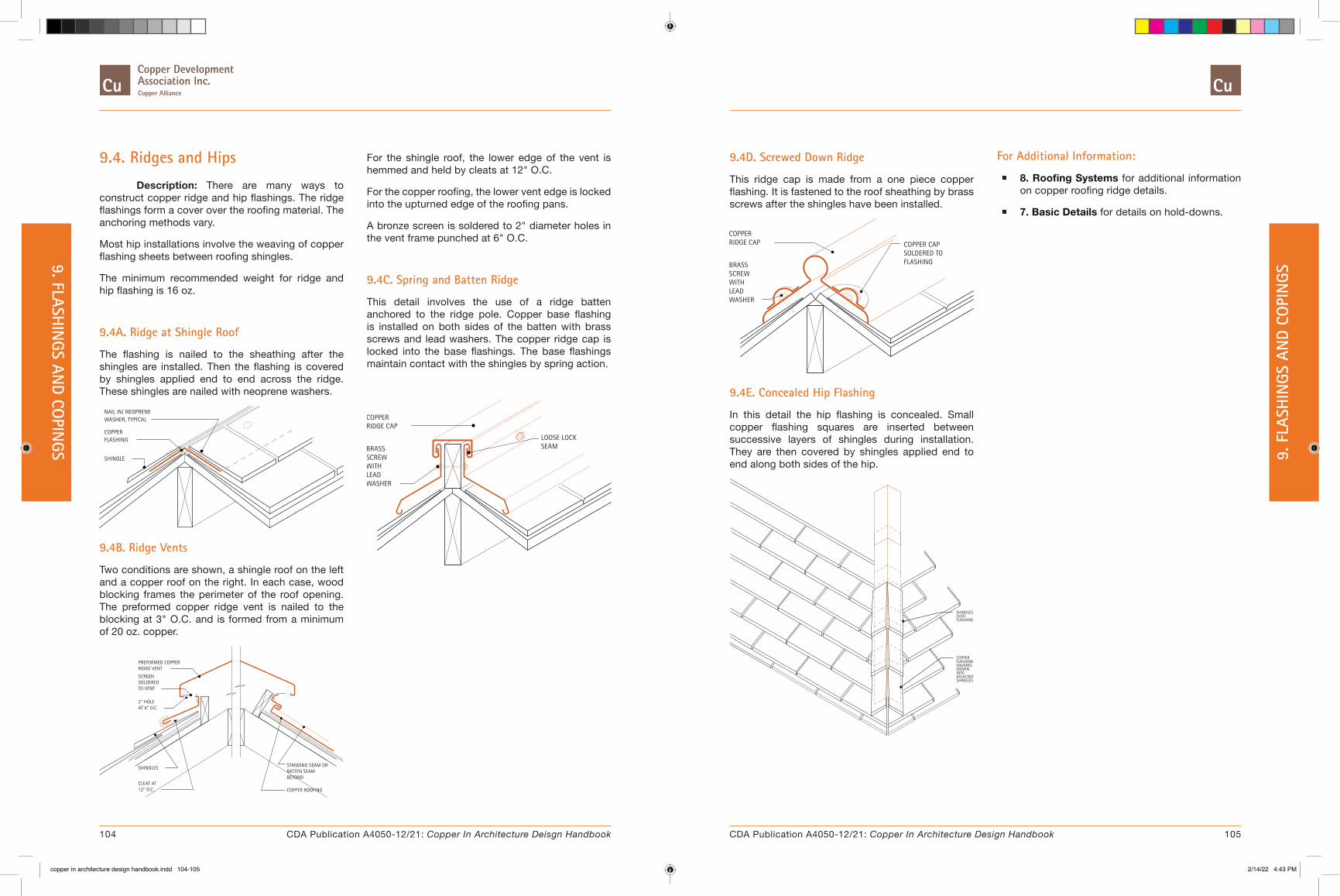
9.4. Ridges and Hips
Description: There are many ways to construct copper ridge and hip flashings. The ridge flashings form a cover over the roofing material. The anchoring methods vary.
Most hip installations involve the weaving of copper flashing sheets between roofing shingles.
The minimum recommended weight for ridge and hip flashing is 16 oz.
9.4A. Ridge at Shingle Roof
The flashing is nailed to the sheathing after the shingles are installed. Then the flashing is covered by shingles applied end to end across the ridge. These shingles are nailed with neoprene washers.
NAIL W/ NEOPRENEWASHER, TYPICAL
SHINGLE
FLASHINGCOPPER
9.4B. Ridge Vents
Two conditions are shown, a shingle roof on the left and a copper roof on the right. In each case, wood blocking frames the perimeter of the roof opening. The preformed copper ridge vent is nailed to the blocking at 3" O.C. and is formed from a minimum of 20 oz. copper.
COPPER ROOFING
BEYONDBATTEN SEAMSTANDING SEAM OR
AT 6" O.C.
12" O.C.
SHINGLES
CLEAT AT
PREFORMED COPPER
2" HOLE
TO VENTSOLDEREDSCREEN
RIDGE VENT
For the shingle roof, the lower edge of the vent is hemmed and held by cleats at 12" O.C.
For the copper roofing, the lower vent edge is locked into the upturned edge of the roofing pans.
A bronze screen is soldered to 2" diameter holes in the vent frame punched at 6" O.C.
9.4C. Spring and Batten Ridge
This detail involves the use of a ridge batten anchored to the ridge pole. Copper base flashing is installed on both sides of the batten with brass screws and lead washers. The copper ridge cap is locked into the base flashings. The base flashings maintain contact with the shingles by spring action.
SEAMLOOSE LOCK
WASHER
SCREWBRASS
RIDGE CAPCOPPER
LEADWITH
9.4D. Screwed Down Ridge
This ridge cap is made from a one piece copper flashing. It is fastened to the roof sheathing by brass screws after the shingles have been installed.
FLASHINGSOLDERED TOCOPPER CAP
WASHER
SCREWBRASS
RIDGE CAPCOPPER
LEADWITH
9.4E. Concealed Hip Flashing
In this detail the hip flashing is concealed. Small copper flashing squares are inserted between successive layers of shingles during installation. They are then covered by shingles applied end to end along both sides of the hip.
SHINGLESADJACENTINTOWOVENSQUARESFLASHINGCOPPER
FLASHINGOVERSHINGLES
For Additional Information:
� 8. Roofing Systems for additional information on copper roofing ridge details.
� 7. Basic Details for details on hold-downs.
104 105CDA Publication A4050-12/21: Copper In Architecture Deisgn Handbook CDA Publication A4050-12/21: Copper In Architecture Design Handbook
9. FLASHIN
GS AND CO
PINGS 9. F
LASH
INGS
AN
D CO
PIN
GS
copper in architecture design handbook.indd 104-105copper in architecture design handbook.indd 104-105 2/14/22 4:43 PM2/14/22 4:43 PM

9.5. Valleys
Description: Valley flashings are usually categorized as open or closed. The former is visible when completed, the latter is not. The main difference is that for open valleys, long sheets of 16 oz. (minimum) copper are cleated to the sheathing and underlayment before the shingles are applied. Adjacent sheets of copper are lapped a minimum of 8". The sheets are nailed at the top only with copper or bronze nails.
Closed valleys are constructed during shingle installation by inserting copper flashing squares between successive layers of shingles. These flashing squares are folded on the diagonal. The recommended square dimensions for slate and shingle roofs are shown in Table 9.5A.
Table 9.5A. Recommended Copper Square Dimension Sizes for Slate and Shingle Roofing
Square Size, Inches Roof SlopeSlate Size,
Inches6" or greater
per footless than 6"
per foot12 9 x 18 9 x 24
14 10 x 18 10 x 24
16 11 x 18 11 x 24
18 12 x 18 12 x 24
20 13 x 18 13 x 24
Cant strips are used to raise the shingles, thus breaking contact with the copper surface which minimizes line corrosion.
If slate or tile is used for the roof covering, 20 oz. copper is recommended for valley flashing.
Special Conditions: The details shown are for roof intersections resulting in valley slopes of at least 4-1/2" per foot.
9.5A. Open Valley
The detail shows a typical open valley flashing for a shingle or slate roof. Two different cants are illustrated. The cant strip can also be constructed as shown in Detail 9.5D. The shingles or slate must lap the flashing at least 6".
TYP.FLASHING,COPPER
STRIPCANTWOOD
MIN.
6"
6"
SOLDEREDTO FLASHING
COPPER CANTALTERNATE
AT 12" O.C.CLEAT
9.5B. Equal Slopes - Unequal Water Flow
Where unequal water flow is expected, a baffle, 1-1/2" high, should be installed as shown to prevent water of higher velocity from forcing its way past the opposite edge of the valley flashing. The baffle can also be constructed as shown in Detail 9.5D.
CLEATAT 12" O.C.
1 1/
2"SOLDEREDTO FLASHING
BAFFLECOPPER
TO FLASHINGSOLDEREDSTRIPCANTCOPPER
9.5C. Closed Valley
Intersecting roofs using a closed valley must have the same slopes so that the shingle butts line up at the valley intersection. For roof pitches of 6" or more per foot the flashing extends at least 9" under the roof covering on each side. For roof pitches less then 6" per foot the flashing extends at least 12".
SHINGLESWOVEN INTOSQUAREFLASHINGCOPPER
The lower edge of the flashing should be held 1/2" short of the butt line of the slate, tile or shingle in the succeeding course. The upper edge is fastened to the sheathing with copper or bronze nails.
9.5D. Unequal Slopes
This condition requires a baffle for the same reason as Detail 9.5B. It can be constructed as shown in either detail. This detail also shows a different cant strip. Other methods of raising the shingles away from the copper are shown in Detail 9.5A and Detail 9.5B.
BAFFLE
AT 12" O.C.
FORMED
CLEAT
WOODCANT STRIP
FLASHINGSOLDERED TOCOPPER STRAP
CONTINUOUS
For additional information on copper roofing valley details see: 8. Roofing Systems.
106 107CDA Publication A4050-12/21: Copper In Architecture Deisgn Handbook CDA Publication A4050-12/21: Copper In Architecture Design Handbook
9. FLASHIN
GS AND CO
PINGS 9. F
LASH
INGS
AN
D CO
PIN
GS
copper in architecture design handbook.indd 106-107copper in architecture design handbook.indd 106-107 2/14/22 4:43 PM2/14/22 4:43 PM

9.6. Changes in Roof Slopes
Description: Flashing a change in roof slope usually involves copper sheets 8 or 10 feet in length. They lap over the lower roof and are lapped by the upper roof. A cant of some kind is used to raise the roofing material and keep it from direct contact with the copper surface, to minimize line corrosion.
There are many combinations of roofing materials and corresponding numbers of appropriate details for each condition. The details shown are valid for shingle, tile, and slate roofing. The conditions are representative of typical installations.
The recommended minimum thickness of copper is 16 oz. unless slate or tile roofing is used in which case 20 oz. copper is used.
9.6A. Change of Roof Slope - Wood Cant
This detail shows a shallower pitched roof joining a steeper pitched roof below. The copper flashing extends under the upper roofing at least 6". It laps the lower roofing a minimum of 4". The ends of each sheet should lap over the preceding one at least 4". The lower edge of the flashing is hemmed for stiffness.
6" MIN.
AT 2'-0" O.C.
FLASHINGCOPPER
STRIPWOOD CANT
STRAPCOPPERSOLDERED
AT 12" O.C.CLEAT
4" MIN.
The cant strip shown is wood fastened by copper straps, spaced 2'-0" apart, soldered to the copper flashing. A copper cant can be used instead, as shown in Detail 9.6B.
9.6B. Change of Roof Slope - Copper Cant
In this detail the steeper pitched roof is above the one of lower pitch. The flashing method is similar to the one shown in Detail 9.6A.
4" MIN.
COPPER FLASHING
COPPER CANT
AT 12" O.C.CLEAT
MIN.4”
12”
6" MIN.
9.6C. Flat to Sloped Roof with Gravel Stop
This detail shows a flat built-up roof joining a lower pitched roof. Here the flashing extends a maximum 4" under the built-up roofing. It also has a built-in, formed gravel stop.
COPPER FLASHING
AT 12" O.C.CLEAT
STAGGEREDNAILS AT 3" O.C.
3/4"
MAX.APRON 4"
4" MIN.
The lower edge of the flashing is hemmed and cleated to the sheathing at 12" O.C. As an alternate, a lock clip can be used as shown in Detail 9.6D.
9.6D. Change of Roof Slope - Alternate Wood Cant
This detail shows an alternate cant. The wood cant is nailed to the sheathing. It is then covered by the copper flashing. The lower edge of the flashing is hemmed and held by a lock clip. Alternately, cleats at 12" O.C. can be used as shown in Detail 9.6C.
CLIP AT 12" O.C.COPPER LOCK
COPPER FLASHING
WOOD CANT STRIP
CLEAT AT 12" O.C.
6" MIN.
4" M
IN.
For Additional Information:
� 9.7. Gravel Stops and Fascias, for additional information on gravel stops.
� 9.4. Ridges and Hips, for related conditions.
� 9.5. Valleys, for additional information on valley conditions.
108 109CDA Publication A4050-12/21: Copper In Architecture Deisgn Handbook CDA Publication A4050-12/21: Copper In Architecture Design Handbook
9. FLASHIN
GS AND CO
PINGS 9. F
LASH
INGS
AN
D CO
PIN
GS
copper in architecture design handbook.indd 108-109copper in architecture design handbook.indd 108-109 2/14/22 4:43 PM2/14/22 4:43 PM
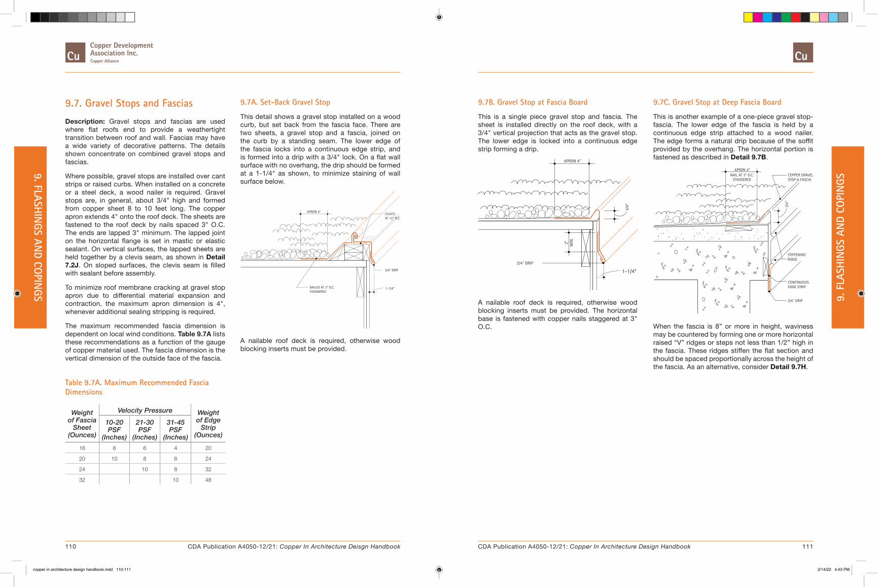
9.7. Gravel Stops and Fascias
Description: Gravel stops and fascias are used where flat roofs end to provide a weathertight transition between roof and wall. Fascias may have a wide variety of decorative patterns. The details shown concentrate on combined gravel stops and fascias.
Where possible, gravel stops are installed over cant strips or raised curbs. When installed on a concrete or a steel deck, a wood nailer is required. Gravel stops are, in general, about 3/4" high and formed from copper sheet 8 to 10 feet long. The copper apron extends 4" onto the roof deck. The sheets are fastened to the roof deck by nails spaced 3" O.C. The ends are lapped 3" minimum. The lapped joint on the horizontal flange is set in mastic or elastic sealant. On vertical surfaces, the lapped sheets are held together by a clevis seam, as shown in Detail 7.2J. On sloped surfaces, the clevis seam is filled with sealant before assembly.
To minimize roof membrane cracking at gravel stop apron due to differential material expansion and contraction, the maximum apron dimension is 4", whenever additional sealing stripping is required.
The maximum recommended fascia dimension is dependent on local wind conditions. Table 9.7A lists these recommendations as a function of the gauge of copper material used. The fascia dimension is the vertical dimension of the outside face of the fascia.
Table 9.7A. Maximum Recommended Fascia Dimensions
Weight of Fascia
Sheet (Ounces)
Velocity Pressure Weight of Edge
Strip (Ounces)
10-20 PSF
(Inches)
21-30 PSF
(Inches)
31-45 PSF
(Inches)16 8 6 4 20
20 10 8 6 24
24 10 8 32
32 10 48
9.7A. Set-Back Gravel Stop
This detail shows a gravel stop installed on a wood curb, but set back from the fascia face. There are two sheets, a gravel stop and a fascia, joined on the curb by a standing seam. The lower edge of the fascia locks into a continuous edge strip, and is formed into a drip with a 3/4" lock. On a flat wall surface with no overhang, the drip should be formed at a 1-1/4" as shown, to minimize staining of wall surface below.
NAILED AT 3" O.C.STAGGERED
APRON 4"
3/4" DRIP
AT 12" O.C.CLEATS
1-1/4”
A nailable roof deck is required, otherwise wood blocking inserts must be provided.
9.7B. Gravel Stop at Fascia Board
This is a single piece gravel stop and fascia. The sheet is installed directly on the roof deck, with a 3/4" vertical projection that acts as the gravel stop. The lower edge is locked into a continuous edge strip forming a drip.
3/4" DRIP
MIN
.2"
APRON 4"
3/4"
1-1/4”
A nailable roof deck is required, otherwise wood blocking inserts must be provided. The horizontal base is fastened with copper nails staggered at 3" O.C.
9.7C. Gravel Stop at Deep Fascia Board
This is another example of a one-piece gravel stop-fascia. The lower edge of the fascia is held by a continuous edge strip attached to a wood nailer. The edge forms a natural drip because of the soffit provided by the overhang. The horizontal portion is fastened as described in Detail 9.7B.
APRON 4"
3/4" DRIP
EDGE STRIPCONTINUOUS
3/4"
STIFFENINGRIDGE
STOP & FASCIACOPPER GRAVELNAIL AT 3” O.C.
STAGGERED
When the fascia is 8” or more in height, waviness may be countered by forming one or more horizontal raised “V” ridges or steps not less than 1/2” high in the fascia. These ridges stiffen the flat section and should be spaced proportionally across the height of the fascia. As an alternative, consider Detail 9.7H.
110 111CDA Publication A4050-12/21: Copper In Architecture Deisgn Handbook CDA Publication A4050-12/21: Copper In Architecture Design Handbook
9. FLASHIN
GS AND CO
PINGS 9. F
LASH
INGS
AN
D CO
PIN
GS
copper in architecture design handbook.indd 110-111copper in architecture design handbook.indd 110-111 2/14/22 4:43 PM2/14/22 4:43 PM

9.7D. Set-Back Gravel Stop on Concrete
A separate gravel stop and fascia are illustrated. As in Detail 9.7A, the two copper sheets are joined by a standing seam cleated at 12" O.C. Since the roof deck is concrete, wood nailer is provided for securing the various elements.
SLOPE
STOP & FASCIACOPPER GRAVEL
CLEATS AT 12" O.C.APRON 4"
LOCK STRIPCOPPERCONTINUOUS
3/4" DRIP
The lower edge of the fascia is held by a continuous edge strip, which also serves as the soffit for the underside of the concrete deck and is fastened with a continuous lock strip. The horizontal portion of the gravel stop is fastened as described in Detail 9.7B.
9.7E. Gravel Stop on Raised Curb
This detail shows the typical one piece gravel stop-fascia. It is installed on a raised, canted wood curb. Its lower edge is formed into a drip. A continuous edge strip is not required if the fascia dimension is less than the recommendations in Table 9.7A. The horizontal apron portion of the gravel stop is fastened with copper nails staggered at 3" O.C.
MAX.APRON 4"
3/4"
9.7F. Gravel Stop at Tapered Insulation
This combined gravel stop and fascia is shown on a curb with preformed tapered insulation. The continuous edge strip at the lower edge is formed into a small soffit covering the wood blocking and nailed at 3" O.C. The horizontal apron portion of the gravel stop is fastened with copper nails staggered at 3" O.C.
CLEATED AT 3" O.C.EDGE STRIPCONTINUOUS
STOP & FASCIACOPPER GRAVEL
MAX.APRON 4"
3/4"
9.7G. Gravel Stop at Concrete Cornice
This gravel stop is installed over a precast concrete cornice and joined to a copper cover. The roof side apron of the cover is locked into the gravel stop using a standing seam, cleated and anchored to a raggle in the cornice. The outer edge of the cornice cover is hooked over a one-piece continuous combination edge strip and drip edge.
GROUT SOLID
STOP & COVERCOPPER GRAVEL
WITH DRIP EDGECOPPER FASCIA
STAGGEREDNAILED AT 3" O.C.
MAX.APRON 4"
9.7H. Two Piece Gravel Stop and Fascia
Illustrated is a two-piece gravel stop and fascia installed on a raised curb. The lower edge of the fascia is formed into a soffit and drip edge. It is held by a continuous copper lock strip which is nailed at 3" O.C., staggered.
LOCK STRIP
COPPER FASCIA
CONTINUOUS
CLEAT AT 12" O.C.
COPPER GRAVEL STOP
3/4"
The upper piece is nailed to the curb through its horizontal flange. Its lower edge is also formed into a drip.
For Additional Information:
� 7. Basic Details, for information on seams, exp ansion seams, and cleats.
� 9.6. Changes in Roof Slopes, for additional information on gravel stops at changes in roof slopes.
� 9.3. Coping Covers, for more information on parapet and coping conditions.
� Table 9.7A, for recommended fascia dimensions and thicknesses.
112 113CDA Publication A4050-12/21: Copper In Architecture Deisgn Handbook CDA Publication A4050-12/21: Copper In Architecture Design Handbook
9. FLASHIN
GS AND CO
PINGS 9. F
LASH
INGS
AN
D CO
PIN
GS
copper in architecture design handbook.indd 112-113copper in architecture design handbook.indd 112-113 2/14/22 4:43 PM2/14/22 4:43 PM

9.8. Stepped and Chimney Flashings
Description: Stepped flashing is used where a sloped roof meets a masonry wall. A typical occurrence is where a brick chimney rises above a roof. The details shown concentrate on such chimney flashings, but apply to other wall conditions.
There are two approaches to stepped flashings. One type uses pieces of copper base flashing installed with each course of shingles. The upper edge of each flashing piece extends 2" above each course of shingles. The lower edge is held 1/2" above the butts of the succeeding course. The base flashing extends a minimum of 4" up the wall and onto the roof. The one piece cap flashing is inserted into a reglet and held by lead wedges. The reglet is filled with sealant. The length of each piece of cap flashing varies with the pitch of the roof; no step should be more than 3 bricks high. The width also varies but should always be wide enough to cover 4" of the base flashing.
The second type uses a single copper runner under the shingles, tile or slate. This type is attached before the roofing material is installed. The roof portion of this runner flashing has a hooked edge and is cleated at 12" O.C. The base flashing is extended up the wall a minimum of 8". This requires the cap flashing to be in two pieces, a receiver and a counterflashing.
If the chimney straddles the ridge of the roof, this stepped flashing is used on the two sloped sides. The lower sides are flashed with a copper apron that covers the next course of shingles.
If the chimney is entirely on one side of the ridge, a copper cricket must be used on the high side to divert the water to either sloped side.
Apron and cap flashing should be of at least 16 oz. Base flashing for shingles can also be 16 oz., but for slate or tile roofs 20 oz. is recommended.
The apron joint with the base sheets is soldered horizontally and vertically.
The minimum weight for the cap and base flashing used at chimneys and other stepped flashing conditions is 16 oz. Crickets should also be formed from 16 oz. copper.
9.8A. Flashing at Base of Chimney
This detail shows a typical installation using individual copper base sheets, as described above.
SOLDERED,TYP.
4"MIN.
INDIVIDUAL COPPER
APRONCOPPER
1/2" HEMMEDEDGE
MIN
.8"
SEE DETAIL
BASE SHEETS
B1(ONE PIECE CAP)
9.8B. Alternate Step Flashing Methods
These sections illustrate two methods of stepped flashing. The one on the left uses individual copper base flashing sheets, and a one-piece cap. The other one uses the single piece base flashing with a two-piece cap flashing. Note the hooked edge on the base flashing to prevent water from running under the roofing material. The water is conducted instead to the end of the base flashing, over the apron, and onto the roof below.
CAP FLASHING
SHEETSFLASHINGBASE
ONE PIECE
AT 12" O.C.CLEATS
BASE FLASHINGSINGLE PIECE
CAP FLASHINGTWO PIECE
1. ONE PIECE CAP 2. TWO PIECE CAP
9.8C. Chimney Flashing - Alternate
This detail shows a second method of stepped flashing as described above.
SEE DETAIL
B.2
AT 12" O.C.CLEATS
FLASHINGCOPPER BASESINGLE PIECE
FORMED CANT STRIP IN BASE FLASHING
TYPICALSOLDERED,
(TWO PIECE CAP)
9.8D. Chimney Cricket Flashing
This detail illustrates the use of a cricket to divert water above the chimney to either side. The cricket can be a one piece design or a two piece, joined by a standing seam at its ridge.
PIECE
FLASHINGCRICKET
ONE TWOOR
9.8E. Chimney Flashing - Flat Roof
Copper base flashing is attached to the roof deck before installation of the roofing. It extends at least 8" up the wall and at least 4" onto the roof, on all sides of the chimney. Copper cap flashing then covers the upper edge.
MAX.
FLASHINGCOPPER CAP
TYPICALSOLDERED,
MIN
.8"
4"
FLASHINGCOPPER BASE
All joints between base flashing sheets are soldered.
For Additional Information:
� 9.2. Counterflashing
114 115CDA Publication A4050-12/21: Copper In Architecture Deisgn Handbook CDA Publication A4050-12/21: Copper In Architecture Design Handbook
9. FLASHIN
GS AND CO
PINGS 9. F
LASH
INGS
AN
D CO
PIN
GS
copper in architecture design handbook.indd 114-115copper in architecture design handbook.indd 114-115 2/14/22 4:43 PM2/14/22 4:43 PM
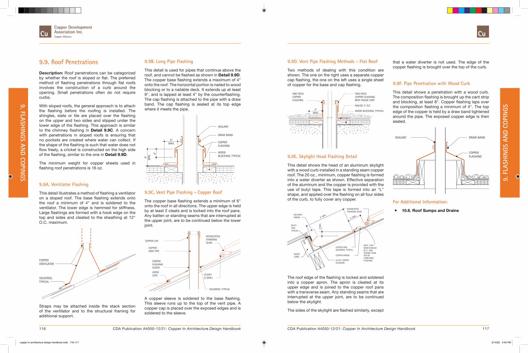
9.9. Roof Penetrations
Description: Roof penetrations can be categorized by whether the roof is sloped or flat. The preferred method of flashing penetrations through flat roofs involves the construction of a curb around the opening. Small penetrations often do not require curbs.
With sloped roofs, the general approach is to attach the flashing before the roofing is installed. The shingles, slate or tile are placed over the flashing on the upper and two sides and slipped under the lower edge of the flashing. This approach is similar to the chimney flashing in Detail 9.9C. A concern with penetrations in sloped roofs is ensuring that no pockets are created where water can collect. If the shape of the flashing is such that water does not flow freely, a cricket is constructed on the high side of the flashing, similar to the one in Detail 9.9D.
The minimum weight for copper sheets used in flashing roof penetrations is 16 oz.
9.9A. Ventilator Flashing
This detail illustrates a method of flashing a ventilator on a sloped roof. The base flashing extends onto the roof a minimum of 4" and is soldered to the ventilator. The lower edge is hemmed for stiffness. Large flashings are formed with a hook edge on the top and sides and cleated to the sheathing at 12" O.C. maximum.
VENTILATOR
TYPICALSOLDERED,
COPPER
Straps may be attached inside the stack section of the ventilator and to the structural framing for additional support.
9.9B. Long Pipe Flashing
This detail is used for pipes that continue above the roof, and cannot be flashed as shown in Detail 9.9D. The copper base flashing extends a maximum of 4" onto the roof. The horizontal portion is nailed to wood blocking or to a nailable deck. It extends up at least 9", and is lapped at least 4" by the counterflashing. The cap flashing is attached to the pipe with a draw band. The cap flashing is sealed at its top edge where it meets the pipe.
BLOCKING, TYPICALWOOD
FLASHINGCOPPER
DRAW BAND
SEALANT
MIN
.9"
4"
MAX.4"
9.9C. Vent Pipe Flashing - Copper Roof
The copper base flashing extends a minimum of 6" onto the roof in all directions. The upper edge is held by at least 2 cleats and is locked into the roof pans. Any batten or standing seams that are interrupted at the upper joint, are to be continued below the lower joint.
(2 MIN.)CLEATS
SOLDERED, TYPICAL
LOCKLOOSE
SEAMSTANDINGINTERCEPTED
COPPER CAP
VENT PIPECOPPER
SLEEVEFLASHINGCOPPER
A copper sleeve is soldered to the base flashing. This sleeve runs up to the top of the vent pipe. A copper cap is placed over the exposed edges and is soldered to the sleeve.
9.9D. Vent Pipe Flashing Methods - Flat Roof
Two methods of dealing with this condition are shown. The one on the right uses a separate copper cap flashing, the one on the left uses a single sheet of copper for the base and cap flashing.
WOOD BLOCKING, TYPICAL
NAILED 3" O.C.
BENT INSIDE VENTCOPPER FLASHINGTWO PIECE
MAX.
FLASHINGCOPPERONE PIECE
4"
9.9E. Skylight Head Flashing Detail
This detail shows the head of an aluminum skylight with a wood curb installed in a standing seam copper roof. The 20 oz., minimum, copper flashing is formed into a water diverter as shown. Effective separation of the aluminum and the copper is provided with the use of butyl tape. This tape is formed into an "L" shape, and applied over the flashing on all four sides of the curb, to fully cover any copper.
FLASHING20 OZ. COPPER
SOLDERED, TYPICALLOCKED AND
COPPER APRONCURBWOOD
BUTYL
TYPICALTAPE
FRAMESKYLIGHT
6" MIN.
2"M
IN.
FLASHINGCURB BASETOP OFHIGHER THANBE 2" MIN.SEAM SHOULDNOTE: THIS
STANDING SEAMINTERRUPTED
4" MIN.
The roof edge of the flashing is locked and soldered into a copper apron. The apron is cleated at its upper edge and is joined to the copper roof pans with a transverse seam. Any standing seams that are interrupted at the upper joint, are to be continued below the skylight.
The sides of the skylight are flashed similarly, except
that a water diverter is not used. The edge of the copper flashing is brought over the top of the curb.
9.9F. Pipe Penetration with Wood Curb
This detail shows a penetration with a wood curb. The composition flashing is brought up the cant strip and blocking, at least 8". Copper flashing laps over the composition flashing a minimum of 4". The top edge of the copper is held by a draw band tightened around the pipe. The exposed copper edge is then sealed.
FLASHINGCOPPER
DRAW BANDSEALANT
For Additional Information:
� 10.6. Roof Sumps and Drains
116 117CDA Publication A4050-12/21: Copper In Architecture Deisgn Handbook CDA Publication A4050-12/21: Copper In Architecture Design Handbook
9. FLASHIN
GS AND CO
PINGS 9. F
LASH
INGS
AN
D CO
PIN
GS
copper in architecture design handbook.indd 116-117copper in architecture design handbook.indd 116-117 2/14/22 4:43 PM2/14/22 4:43 PM
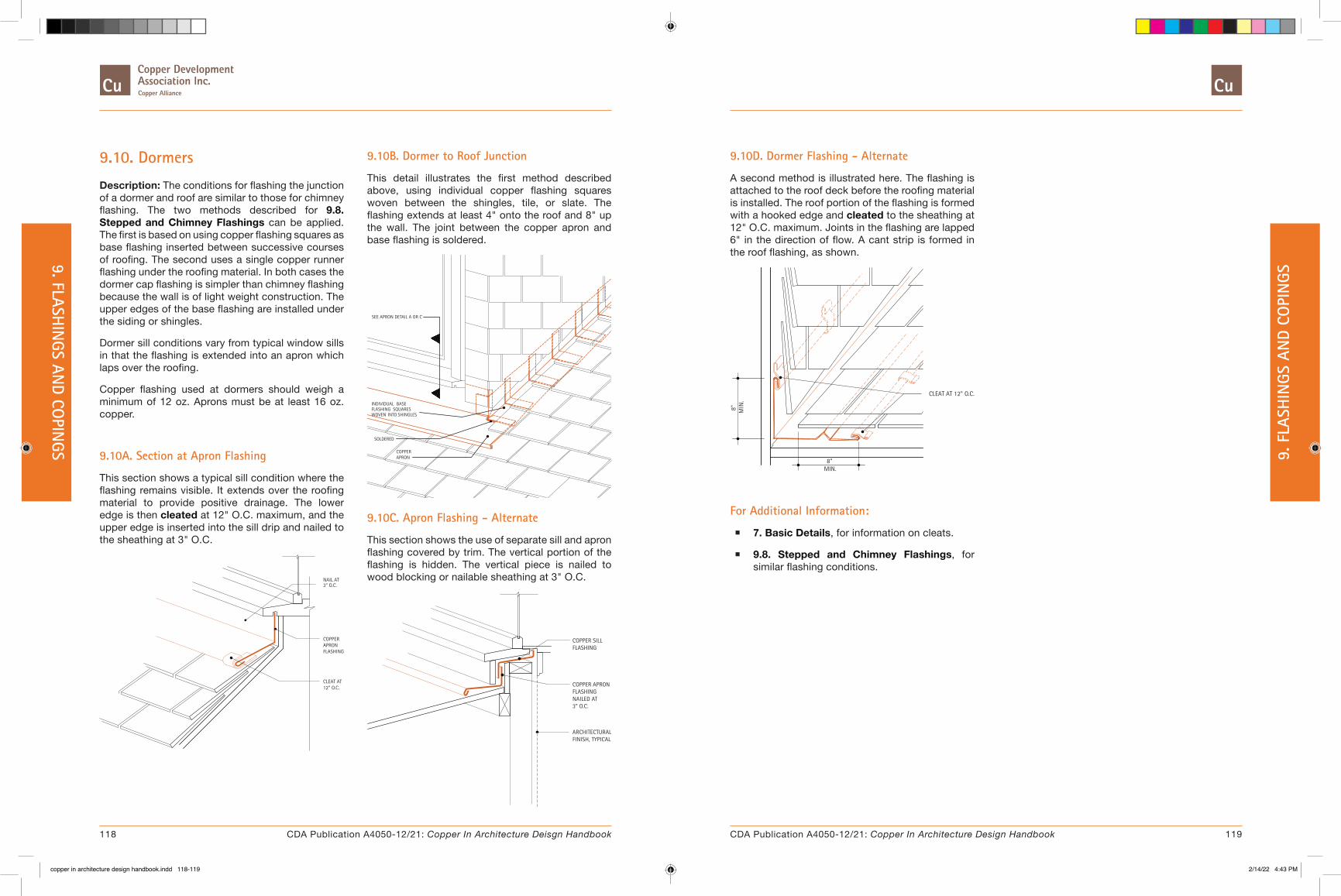
9.10. Dormers
Description: The conditions for flashing the junction of a dormer and roof are similar to those for chimney flashing. The two methods described for 9.8. Stepped and Chimney Flashings can be applied. The first is based on using copper flashing squares as base flashing inserted between successive courses of roofing. The second uses a single copper runner flashing under the roofing material. In both cases the dormer cap flashing is simpler than chimney flashing because the wall is of light weight construction. The upper edges of the base flashing are installed under the siding or shingles.
Dormer sill conditions vary from typical window sills in that the flashing is extended into an apron which laps over the roofing.
Copper flashing used at dormers should weigh a minimum of 12 oz. Aprons must be at least 16 oz. copper.
9.10A. Section at Apron Flashing
This section shows a typical sill condition where the flashing remains visible. It extends over the roofing material to provide positive drainage. The lower edge is then cleated at 12" O.C. maximum, and the upper edge is inserted into the sill drip and nailed to the sheathing at 3" O.C.
12" O.C.CLEAT AT
FLASHINGAPRONCOPPER
NAIL AT3” O.C.
9.10B. Dormer to Roof Junction
This detail illustrates the first method described above, using individual copper flashing squares woven between the shingles, tile, or slate. The flashing extends at least 4" onto the roof and 8" up the wall. The joint between the copper apron and base flashing is soldered.
APRONCOPPER
SOLDERED
SHINGLESINTOWOVENSQUARESFLASHING
BASEINDIVIDUAL
SEE APRON DETAIL A OR C
9.10C. Apron Flashing - Alternate
This section shows the use of separate sill and apron flashing covered by trim. The vertical portion of the flashing is hidden. The vertical piece is nailed to wood blocking or nailable sheathing at 3" O.C.
3" O.C.
FLASHINGCOPPER SILL
NAILED ATFLASHINGCOPPER APRON
FINISH, TYPICALARCHITECTURAL
9.10D. Dormer Flashing - Alternate
A second method is illustrated here. The flashing is attached to the roof deck before the roofing material is installed. The roof portion of the flashing is formed with a hooked edge and cleated to the sheathing at 12" O.C. maximum. Joints in the flashing are lapped 6" in the direction of flow. A cant strip is formed in the roof flashing, as shown.
8" MIN
.
CLEAT AT 12" O.C.
MIN.8"
For Additional Information:
� 7. Basic Details, for information on cleats.
� 9.8. Stepped and Chimney Flashings, for similar flashing conditions.
118 119CDA Publication A4050-12/21: Copper In Architecture Deisgn Handbook CDA Publication A4050-12/21: Copper In Architecture Design Handbook
9. FLASHIN
GS AND CO
PINGS 9. F
LASH
INGS
AN
D CO
PIN
GS
copper in architecture design handbook.indd 118-119copper in architecture design handbook.indd 118-119 2/14/22 4:43 PM2/14/22 4:43 PM

9.11. Eave Snow Flashing
Description: In areas where snow remains on the roof for extended periods, the snow over heated spaces thaws first. When the run-off reaches the exposed eave overhang, it freezes and forms an ice dam. As this ice dam collects more melting snow, the water backs up under the roofing material causing a leak.
Eave snow flashing is designed to prevent roof leaks under these conditions. It does this by providing a waterproof layer around the perimeter of the roof. The flashing extends at least 18" beyond the face of the exterior wall, and is lapped by the roofing a minimum of 6".
The flashing described in the details is formed with 1/2" steps running horizontally, spaced no more than 8" apart, for rigidity. 8.2. Standing Seam Roofing is also suitable.
The minimum weight of copper used for eave snow flashing is 16 oz.
9.11A. Gable Detail
Vertical steps, 1/2" high, are formed and installed approximately 8" apart. These steps provide sheet rigidity as well as creating the horizontal lines simulating the shingle butt line. This detail shows that the 1/2" steps are malleted down within 2" of the gable end. The flashing is hooked over a continuous edge strip into a loose lock, 3/4" wide.
RIVET, & SOLDER1 1/2" LAP,TRANSVERSE JOINT,
NEAR GABLE ENDMALLETED DOWN1/2" STEPS
B1
B2
9.11B. Typical Sections
These sections show that the upper edge of the flashing is folded over and cleated at 12" O.C. A cant strip is used to elevate slate or wood shingles at the edge. The eave detail shows how the flashing is hooked over the continuous edge strip to form a drip.
B1. CANT DETAIL
SOLDEREDCOPPER CANT
AT 12" O.C.CLEAT
COPPER
B2. EAVE DETAIL
3/4" LOCK, TYP.
EDGE STRIP
CONTINUOUS
9.11C. Valley Detail
At the valley, the valley sheet is installed first. The flashing is cut to lap 1-1/2" over the valley sheet. After the 1/2" steps are flattened, the valley and flashing sheets are joined together by a lapped, riveted and soldered seam.
RIVET, & SOLDER1 1/2" LAP,
EXPANSION JOINT
D2
D1
COPPER VALLEY FLASHING
9.11D. Sections
The alternate cant detail shows a different copper shape that can be used for elevating slate and wood shingles. The expansion joint uses a clevis seam filled with sealant to make it waterproof.
D1. ALTERNATE CANT
SOLDEREDCOPPER CANT
D2. EXPANSION JOINT
ELASTIC SEALANTFILLED WITH
SOLDERED
For Additional Information:
� 7. Basic Details, for information on seams, transverse joints, and cleats.
� 8. Roofing Systems for similar conditions.
120 121CDA Publication A4050-12/21: Copper In Architecture Deisgn Handbook CDA Publication A4050-12/21: Copper In Architecture Design Handbook
9. FLASHIN
GS AND CO
PINGS 9. F
LASH
INGS
AN
D CO
PIN
GS
copper in architecture design handbook.indd 120-121copper in architecture design handbook.indd 120-121 2/14/22 4:43 PM2/14/22 4:43 PM

9.12. Eave Conditions
Description: The details contained in this section are intended to show a variety of eave conditions and roofing materials. One key concern that is common to all eaves is the ability to withstand wind forces. This is a very vulnerable part of the exterior of a building. In many cases, it is the ability of this and other roof edges to withstand suction forces that keeps the entire roofing from being peeled off during high wind conditions.
For this reason, it is recommended that a continuous edge strip be used to secure the lower edge of eave flashing. The strip should be nailed to a secure part of the roof, fascia, or eave with nails spaced no more than 3" apart, in a staggered pattern.
The upper edge of the eave flashing, the apron, may be similarly nailed, as shown in Detail 9.12A, or cleated at 12" O.C., as shown in Detail 9.12B. In general the apron should extend a minimum of 4" onto the roof.
When designing the eave, consideration should be given to the drip line provided for water draining off the roof. This is particularly important if porous material, which is liable to stain, is used below. See Detail 9.12A, for drip design discussion. See Table 9.7A for fascia design considerations.
9.12A. Eave at Standing Seam Roofing Without Gutter
This detail shows a typical copper apron that is nailed to the roof. The apron may also be cleated as shown in Detail 9.12B. The lower end of the standing seam may also be folded down as in Detail 9.12C.
APRON NAILEDCONT. COPPER
AT 3" O.C.
4" MIN.
EDGE STRIP NAILEDAT 3" O.C.
CONT. COPPER
This detail should be avoided where gutters are used, as it does not offer much protection if the gutter gets clogged, or if ice and snow prevent proper drainage.
9.12B. Typical Eave Flashing
This detail is typically used for flashing eaves of non-copper roofs. The copper flashing is extended a minimum of 4" onto the roof to form an apron. The upper edge of the apron is cleated at 12" O.C. max., or it may be nailed as shown in Detail 9.12A. The apron width should take into account local conditions such as wind, rain, snow, and ice build-up.
TRIMNAILABLE WOOD
AT 3" O.C.EDGE STRIP NAILEDCONT. COPPER
COPPER APRON
COPPER CLEATAT 12" O.C.
4" MIN.
9.12C. Eave at Standing Seam Roofing With or Without Gutter
This detail may be used with or without a gutter. The upper edge of the continuous apron is cleated at 12" O.C. A continuous lock strip is soldered a minimum of 4" away from this upper edge. The copper roofing is locked into the strip. The distance from the lock strip to the edge of the roof depends on the roof pitch, whether or not a gutter is used, the likelihood of water damming from ice or snow, and architectural design considerations. The lower end of the 8.2. Standing Seam Roofing may be terminated vertically, as shown in Detail 9.12D.
LAP
4" MIN.
AT 12" O.C.COPPER CLEAT
EDGE STRIP NAILEDCONT. COPPER
AT 3" O.C.
STRIP, SOLDEREDCONT. COPPER LOCK
COPPER APRON
9.12D. Eave at Standing Seam Roofing With or Without Gutter
This detail is similar to Detail 9.12C, except that the standing seam roof is locked into a double fold in the apron, instead of a soldered lock strip. The lower end of the standing seam may be folded over, as shown in Detail 9.12C.
EDGE STRIP NAILEDAT 3" O.C.
CONT. COPPER
3/4" LOCKDOUBLE FOLDED
LAP
4" MIN.
COPPER CLEATAT 12" O.C.
9.12E. Eave at Batten Seam Roofing
This is a typical detail for flashing the eave of a 8.3. Batten Seam Roofing. This detail is not recommended for eaves with gutters, see Detail 9.12H.
AT 3" O.C.APRON NAILEDCONT. COPPER
4" MIN.
EDGE STRIP NAILEDAT 3" 0.C.
CONT. COPPER
SEAM ROOFINGCOPPER BATTEN
The copper apron extends a minimum of 4" onto the roof. Its upper edge is nailed at 3" O.C., in a staggered pattern, or may be cleated at 12" O.C. max. At the edge of the roof, the apron is formed into a 3/4" lock. The pans of the batten seam roof are folded over this lock. The process is shown in Detail 8.3C. The lower edge of the flashing is held by a continuous copper edge strip.
122 123CDA Publication A4050-12/21: Copper In Architecture Deisgn Handbook CDA Publication A4050-12/21: Copper In Architecture Design Handbook
9. FLASHIN
GS AND CO
PINGS 9. F
LASH
INGS
AN
D CO
PIN
GS
copper in architecture design handbook.indd 122-123copper in architecture design handbook.indd 122-123 2/14/22 4:43 PM2/14/22 4:43 PM

9.12F. Eave at Horizontal Seam Roofing
The technique for flashing the eave of a horizontal seam roof is similar to that of a batten seam. The copper apron extends a minimum of 4" onto the roof. The upper edge of the apron is nailed or cleated to the wood nailer at the eave. The nailer must be wide enough to provide nailable surface under the apron or cleats. The lower edge of the roofing is locked into a 3/4" lock formed by the copper apron. The lower edge of the flashing is locked into a continuous edge strip.
DECORATIVE WOOD
AT 3" 0.C.
CONT. COPPEREDGE STRIP NAILED
FASCIA
AT 3" O.C.
CONT. COPPERAPRON NAILED4" MIN.
This detail also shows a decorative wood trim.
9.12G. Standing Seam Roofing and Fascia
This detail shows the eave condition where standing seam copper is used for the roof and fascia. The construction process is shown, with the completed eave on the right. This detail is not intended for use with gutters.
CLEAT MAY BEREQUIRED. SEE TEXT
COPPER ROOFINGSTANDING SEAM
COMPLETED EAVE
STRIP NAILED @ 3" O.C.CONT. COPPER LOCK
#1 #2
#3 #4
#5 #6
This detail may also be used to construct a standing seam mansard. If the vertical dimension of the fascia exceeds 12", cleats spaced no more than 12" O.C. are required, as shown in step 1.
The bottom of the fascia pans are locked onto a continuous copper lock strip. The top of the fascia pans are bent out to form a lock. The roof pans are folded over this lock.
The two following details are intended to show how to flash the same eave with and without a gutter.
9.12H. Decorative Eave With Gutter
A decorative copper cornice is attached to the wood fascia board with cleats spaced no more than 12" O.C. The upper edge of the cornice should be positioned high enough so that it will be concealed by the gutter. Its lower edge is held by a continuous copper edge, secured to the building wall. A 3/4" drip is formed into the shape of the cornice, to ensure that water is kept away from the building facade and reduce the chance of staining. This is particularly important if the building exterior is a light color porous material.
GUTTER BRACE20 OZ. COPPER
BRASS OR COPPER STRAPS MAYBE REQUIRED
AT 30" O.C.COPPER BRACKET
ROOF APRONINTEGRAL COPPER
STANDING SEAMTYPICAL BATTEN OR
CONT. COPPER
DECORATIVE COPPER CORNICE TRIM
EDGE STRIP
COPPER CLEATAT 12" O.C.
CONT. COPPER
COPPER CLEAT
LOCK STRIP
AT 12" O.C.
LAP
4" MIN.
6" MIN.
3/4" DRIP
The apron, which is an integral part of the gutter, extends onto the roof a minimum of 6". It is attached to the roof with cleats spaced a maximum of 12" O.C. A continuous copper lock strip is soldered a minimum of 4" below the upper edge. The batten or standing seams are terminated at this lock strip, and the roofing pans are locked onto it.
The gutter is supported by brass brackets spaced a maximum of 30" O.C. in snow areas, and 36" O.C. in non-snow areas. Brass or copper straps may be required, see 10. Gutters and Downspouts section for additional gutter information.
124 125CDA Publication A4050-12/21: Copper In Architecture Deisgn Handbook CDA Publication A4050-12/21: Copper In Architecture Design Handbook
9. FLASHIN
GS AND CO
PINGS 9. F
LASH
INGS
AN
D CO
PIN
GS
copper in architecture design handbook.indd 124-125copper in architecture design handbook.indd 124-125 2/14/22 4:43 PM2/14/22 4:43 PM

9.13. Roof Area Divider
Description: Roofing material on flat roofs is subjected to extreme temperature changes. As a result, the material experiences significant thermal expansion and contraction. All roofing types are designed to accomodate a certain amount of movement. This adjustment occurs at the roof perimeter. However, with large flat roofs, it may be necessary to divide the area into smaller parts, in order to keep the total movement within acceptable limits. Roof area dividers perform this task. The roofing manufacturer's recommendations should be followed in determining the need for and placement of roof area dividers.
Roof area dividers rely on wood curbs to effectively frame areas of the roof. The roofing material extends up the curb, much the same as it does at the roof perimeter. Copper cap flashing is used to cover the curbs and the ends of the roofing.
The minimum recommended weight for the copper caps is 16 oz.
9.13A. Typical Roof Area Divider
The copper cap flashing is held on each side of the wood curb by continuous copper lock strips. Adjacent caps are joined with drive cleats or single flat lock seams.
9.13B. Roof Area Divider at Perimeter Wall
This detail shows how an area divider is terminated at a wall. The top surface of the copper cap is extended and bent up under the continuous counterflashing of the roof perimeter. Small copper flashing sheets are formed and inserted under the adjacent flashing to complete the corners.
COPPER FLASHING
COUNTERFLASHINGCONTINUOUS COPPER
COPPER CAP FLASHINGCOMPOSITION BASE
10"
MIN
.
FLASHING
SHEETS
3/4" HEMMED DRIP
For sections greater than 10 feet, cap seams must be designed to accomodate expansion and contraction, see 8.8. Long Pan Systems for additional information.
COMPOSITION BASE
CONT. EDGE STRIP
COPPER CAP FLASHING
10"
MIN
.
FLASHING
9.12I. Decorative Eave Without Gutter
This detail is very similar to Detail 9.12H, except that the copper apron extends down along the fascia, and locks onto the decorative cornice. This 3/4” lock forms a drip for water shedding from the roof.
COPPER CLEAT
TYPICAL BATTEN ORSTANDING SEAM
COMBINATION COPPERROOF APRON & FASCIA
CONT. COPPEREDGE STRIP DECORATIVE COPPER CORNICE TRIM
3/4" LOCK
4" MIN.LAP
AT 12" O.C.
Special Conditions: For areas prone to ice and potential gutter damage, refer to a two piece gutter-apron design as noted in Section 10.2. Hung Gutters.
For Additional Information:
� 7. Basic Details, for additional seams, transverse joints, and clests
� 8. Roofing Systems for similar conditions.
126 127CDA Publication A4050-12/21: Copper In Architecture Deisgn Handbook CDA Publication A4050-12/21: Copper In Architecture Design Handbook
9. FLASHIN
GS AND CO
PINGS 9. F
LASH
INGS
AN
D CO
PIN
GS
copper in architecture design handbook.indd 126-127copper in architecture design handbook.indd 126-127 2/14/22 4:43 PM2/14/22 4:43 PM
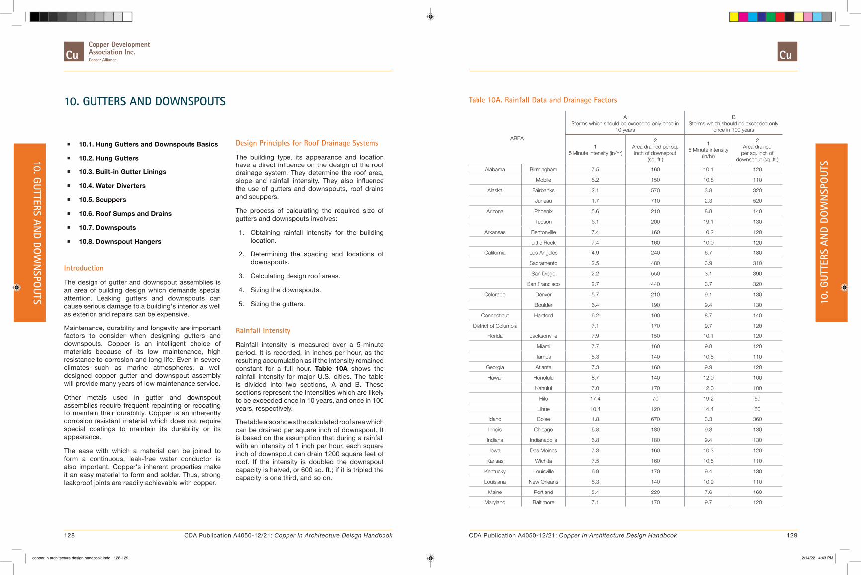
10. GUTTERS AND DOWNSPOUTS
� 10.1. Hung Gutters and Downspouts Basics
� 10.2. Hung Gutters
� 10.3. Built-in Gutter Linings
� 10.4. Water Diverters
� 10.5. Scuppers
� 10.6. Roof Sumps and Drains
� 10.7. Downspouts
� 10.8. Downspout Hangers
Introduction
The design of gutter and downspout assemblies is an area of building design which demands special attention. Leaking gutters and downspouts can cause serious damage to a building's interior as well as exterior, and repairs can be expensive.
Maintenance, durability and longevity are important factors to consider when designing gutters and downspouts. Copper is an intelligent choice of materials because of its low maintenance, high resistance to corrosion and long life. Even in severe climates such as marine atmospheres, a well designed copper gutter and downspout assembly will provide many years of low maintenance service.
Other metals used in gutter and downspout assemblies require frequent repainting or recoating to maintain their durability. Copper is an inherently corrosion resistant material which does not require special coatings to maintain its durability or its appearance.
The ease with which a material can be joined to form a continuous, leak-free water conductor is also important. Copper's inherent properties make it an easy material to form and solder. Thus, strong leakproof joints are readily achievable with copper.
Design Principles for Roof Drainage Systems
The building type, its appearance and location have a direct influence on the design of the roof drainage system. They determine the roof area, slope and rainfall intensity. They also influence the use of gutters and downspouts, roof drains and scuppers.
The process of calculating the required size of gutters and downspouts involves:
1. Obtaining rainfall intensity for the building location.
2. Determining the spacing and locations of downspouts.
3. Calculating design roof areas.
4. Sizing the downspouts.
5. Sizing the gutters.
Rainfall Intensity
Rainfall intensity is measured over a 5-minute period. It is recorded, in inches per hour, as the resulting accumulation as if the intensity remained constant for a full hour. Table 10A shows the rainfall intensity for major U.S. cities. The table is divided into two sections, A and B. These sections represent the intensities which are likely to be exceeded once in 10 years, and once in 100 years, respectively.
The table also shows the calculated roof area which can be drained per square inch of downspout. It is based on the assumption that during a rainfall with an intensity of 1 inch per hour, each square inch of downspout can drain 1200 square feet of roof. If the intensity is doubled the downspout capacity is halved, or 600 sq. ft.; if it is tripled the capacity is one third, and so on.
Table 10A. Rainfall Data and Drainage Factors
AREA
A Storms which should be exceeded only once in
10 years
B Storms which should be exceeded only
once in 100 years
1 5 Minute intensity (in/hr)
2 Area drained per sq. inch of downspout
(sq. ft.)
1 5 Minute intensity
(in/hr)
2 Area drained
per sq. inch of downspout (sq. ft.)
Alabama Birmingham 7.5 160 10.1 120
Mobile 8.2 150 10.8 110
Alaska Fairbanks 2.1 570 3.8 320
Juneau 1.7 710 2.3 520
Arizona Phoenix 5.6 210 8.8 140
Tucson 6.1 200 19.1 130
Arkansas Bentonville 7.4 160 10.2 120
Little Rock 7.4 160 10.0 120
California Los Angeles 4.9 240 6.7 180
Sacramento 2.5 480 3.9 310
San Diego 2.2 550 3.1 390
San Francisco 2.7 440 3.7 320
Colorado Denver 5.7 210 9.1 130
Boulder 6.4 190 9.4 130
Connecticut Hartford 6.2 190 8.7 140
District of Columbia 7.1 170 9.7 120
Florida Jacksonville 7.9 150 10.1 120
Miami 7.7 160 9.8 120
Tampa 8.3 140 10.8 110
Georgia Atlanta 7.3 160 9.9 120
Hawaii Honolulu 8.7 140 12.0 100
Kahului 7.0 170 12.0 100
Hilo 17.4 70 19.2 60
Lihue 10.4 120 14.4 80
Idaho Boise 1.8 670 3.3 360
Illinois Chicago 6.8 180 9.3 130
Indiana Indianapolis 6.8 180 9.4 130
Iowa Des Moines 7.3 160 10.3 120
Kansas Wichita 7.5 160 10.5 110
Kentucky Louisville 6.9 170 9.4 130
Louisiana New Orleans 8.3 140 10.9 110
Maine Portland 5.4 220 7.6 160
Maryland Baltimore 7.1 170 9.7 120
128 129CDA Publication A4050-12/21: Copper In Architecture Deisgn Handbook CDA Publication A4050-12/21: Copper In Architecture Design Handbook
10. GUTTERS AND DO
WN
SPOUTS 10
. GUT
TERS
AN
D DO
WN
SPO
UTS
copper in architecture design handbook.indd 128-129copper in architecture design handbook.indd 128-129 2/14/22 4:43 PM2/14/22 4:43 PM

AREA
A Storms which should be exceeded only once in
10 years
B Storms which should be exceeded only
once in 100 years
1 5 Minute intensity (in/hr)
2 Area drained per sq. inch of downspout
(sq. ft.)
1 5 Minute intensity
(in/hr)
2 Area drained
per sq. inch of downspout (sq. ft.)
Massachusetts Boston 5.3 230 7.2 170
Michigan Detroit 6.4 190 8.9 130
Minnesota Minneapolis 7.0 170 10.0 120
Missouri Kansas City 7.4 160 14.4 80
St. Louis 7.1 170 9.9 120
Montana Helena 1.8 670 3.1 390
Missoula 1.8 670 2.4 500
Nebraska Omaha 7.4 160 10.5 110
Nevada Reno 2.3 520 4.5 270
Las Vegas 2.1 570 5.2 230
New Jersey Trenton 6.7 180 9.3 130
New Mexico Albuquerque 4.0 300 6.7 180
Santa Fe 4.5 270 6.4 190
New York Albany 6.5 180 9.1 130
Buffalo 6.0 200 8.4 140
New York City 6.7 180 9.2 130
North Carolina Raleigh 7.3 160 9.8 120
North Dakota Bismarck 6.6 180 9.8 120
Ohio Cincinnati 6.8 180 9.3 130
Cleveland 6.3 190 8.8 140
Oklahoma Oklahoma City 7.6 160 10.5 110
Oregon Baker 2.2 550 3.8 320
Portland 2.1 570 3.0 400
Pennsylvania Philadelphia 6.8 180 9.4 130
Pittsburgh 6.4 190 8.8 140
Rhode Island Providence 5.6 210 7.8 150
South Carolina Charleston 7.2 170 9.4 130
Tennessee Memphis 7.4 160 10.0 120
Knoxville 6.7 180 9.0 130
Texas Fort Worth 7.6 160 10.5 110
Dallas 7.6 160 10.5 110
Houston 8.2 150 10.8 110
San Antonio 7.6 160 10.5 110
Utah Provo 3.0 400 5.2 230
AREA
A Storms which should be exceeded only once in
10 years
B Storms which should be exceeded only
once in 100 years
1 5 Minute intensity (in/hr)
2 Area drained per sq. inch of downspout
(sq. ft.)
1 5 Minute intensity
(in/hr)
2 Area drained
per sq. inch of downspout (sq. ft.)
Salt Lake City 2.8 430 4.3 280
Virginia Norfolk 7.1 170 9.5 130
Washington Seattle 2.1 570 3.3 360
Spokane 2.1 570 3.5 340
West Virginia Parkersburg 6.6 180 9.1 130
Wisconsin Madison 6.8 180 9.5 130
Milwaukee 6.6 180 9.1 130
Wyoming Cheyenne 5.7 210 9.9 120
Downspout Locations
The locations of down-spouts depends on the configuration, architectural features and appearance of the building. The technical considerations include:
1. Each downspout should drain a maximum of 50 feet of gutter. Gutter expansion characteristics may further limit the distances, since water cannot flow past an expansion joint.
2. Avoid locations where water must flow around a corner to reach a downspout.
3. In locations where icing occurs, downspouts on the north side of the building should be avoided, if possible.
Expansion Joint Spacing
Expansion joints in copper gutters must be provided to allow for the natural expansion and contraction of copper caused by thermal changes. In general, long straight runs should have joints spaced a maximum of 48 feet apart. Expansion joints may also be required at changes in gutter width or depth, at corners and at end conditions. Based upon the desired joint spacing, designers should consult Table 10B to determine the required gauge of copper gutter, width of gutter bottom and angle of gutter sides.
130 131CDA Publication A4050-12/21: Copper In Architecture Deisgn Handbook CDA Publication A4050-12/21: Copper In Architecture Design Handbook
10. GUTTERS AND DO
WN
SPOUTS 10
. GUT
TERS
AN
D DO
WN
SPO
UTS
copper in architecture design handbook.indd 130-131copper in architecture design handbook.indd 130-131 2/14/22 4:43 PM2/14/22 4:43 PM
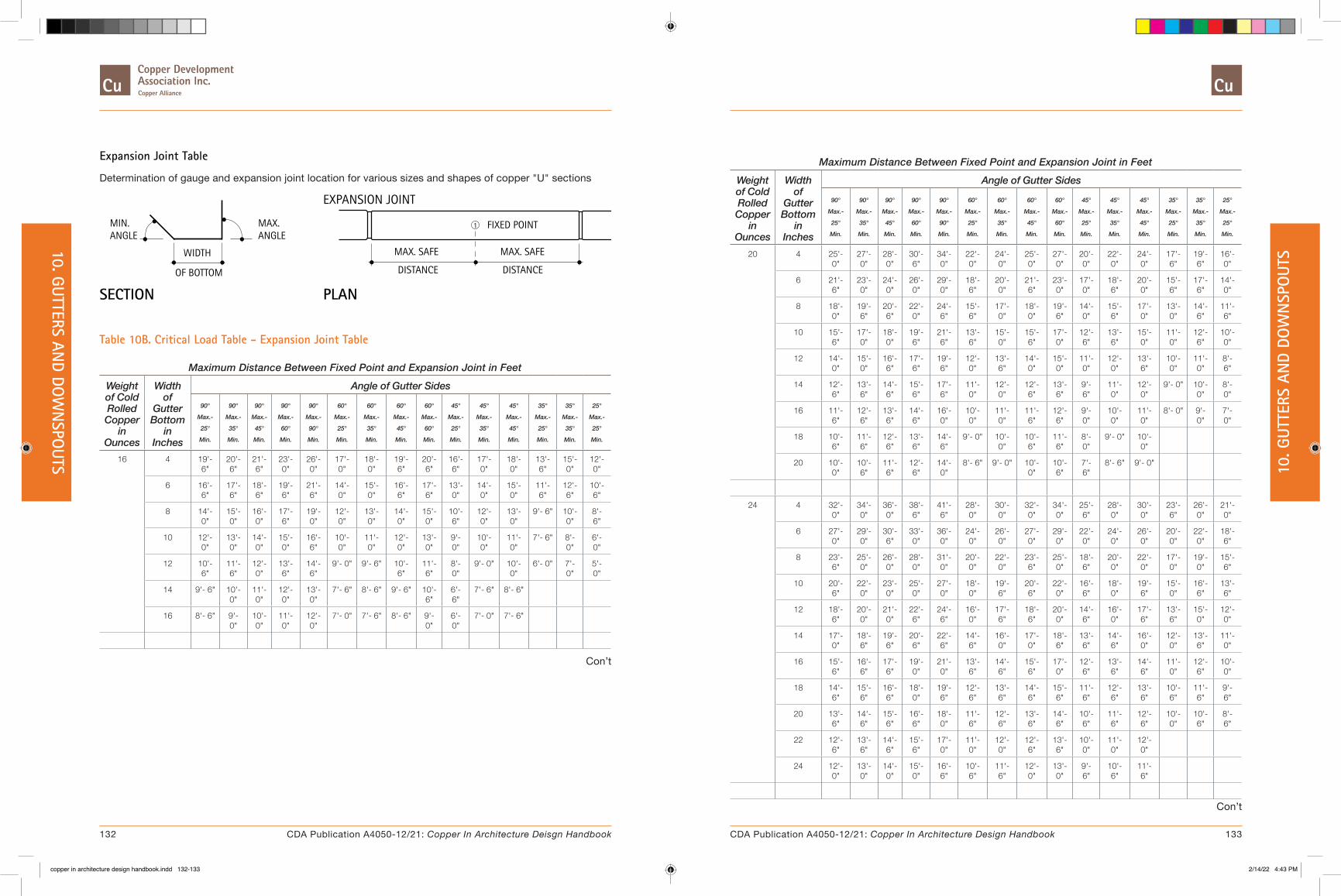
Expansion Joint Table
Determination of gauge and expansion joint location for various sizes and shapes of copper "U" sections
SECTION PLAN
EXPANSION JOINT
FIXED POINT
MAX. SAFE MAX. SAFE
DISTANCE DISTANCE
1MAX.ANGLE
MIN.ANGLE
WIDTH
OF BOTTOM
Table 10B. Critical Load Table - Expansion Joint Table
Maximum Distance Between Fixed Point and Expansion Joint in FeetWeight of Cold Rolled Copper
in Ounces
Width of
Gutter Bottom
in Inches
Angle of Gutter Sides
90°
Max.-
25°
Min.
90°
Max.-
35°
Min.
90°
Max.-
45°
Min.
90°
Max.-
60°
Min.
90°
Max.-
90°
Min.
60°
Max.-
25°
Min.
60°
Max.-
35°
Min.
60°
Max.-
45°
Min.
60°
Max.-
60°
Min.
45°
Max.-
25°
Min.
45°
Max.-
35°
Min.
45°
Max.-
45°
Min.
35°
Max.-
25°
Min.
35°
Max.-
35°
Min.
25°
Max.-
25°
Min.
16 4 19'- 6"
20'- 6"
21'- 6"
23'- 0"
26'- 0"
17'- 0"
18'- 0"
19'- 6"
20'- 6"
16'- 6"
17'- 0"
18'- 0"
13'- 6"
15'- 0"
12'- 0"
6 16'- 6"
17'- 6"
18'- 6"
19'- 6"
21'- 6"
14'- 0"
15'- 0"
16'- 6"
17'- 6"
13'- 0"
14'- 0"
15'- 0"
11'- 6"
12'- 6"
10'- 6"
8 14'- 0"
15'- 0"
16'- 0"
17'- 6"
19'- 0"
12'- 0"
13'- 0"
14'- 0"
15'- 0"
10'- 6"
12'- 0"
13'- 0"
9'- 6" 10'- 0"
8'- 6"
10 12'- 0"
13'- 0"
14'- 0"
15'- 0"
16'- 6"
10'- 0"
11'- 0"
12'- 0"
13'- 0"
9'- 0"
10'- 0"
11'- 0"
7'- 6" 8'- 0"
6'- 0"
12 10'- 6"
11'- 6"
12'- 0"
13'- 6"
14'- 6"
9'- 0" 9'- 6" 10'- 6"
11'- 6"
8'- 0"
9'- 0" 10'- 0"
6'- 0" 7'- 0"
5'- 0"
14 9'- 6" 10'- 0"
11'- 0"
12'- 0"
13'- 0"
7'- 6" 8'- 6" 9'- 6" 10'- 6"
6'- 6"
7'- 6" 8'- 6"
16 8'- 6" 9'- 0"
10'- 0"
11'- 0"
12'- 0"
7'- 0" 7'- 6" 8'- 6" 9'- 0"
6'- 0"
7'- 0" 7'- 6"
Con’t
Maximum Distance Between Fixed Point and Expansion Joint in FeetWeight of Cold Rolled Copper
in Ounces
Width of
Gutter Bottom
in Inches
Angle of Gutter Sides
90°
Max.-
25°
Min.
90°
Max.-
35°
Min.
90°
Max.-
45°
Min.
90°
Max.-
60°
Min.
90°
Max.-
90°
Min.
60°
Max.-
25°
Min.
60°
Max.-
35°
Min.
60°
Max.-
45°
Min.
60°
Max.-
60°
Min.
45°
Max.-
25°
Min.
45°
Max.-
35°
Min.
45°
Max.-
45°
Min.
35°
Max.-
25°
Min.
35°
Max.-
35°
Min.
25°
Max.-
25°
Min.
20 4 25'- 0"
27'- 0"
28'- 0"
30'- 6"
34'- 0"
22'- 0"
24'- 0"
25'- 0"
27'- 0"
20'- 0"
22'- 0"
24'- 0"
17'- 6"
19'- 6"
16'- 0"
6 21'- 6"
23'- 0"
24'- 0"
26'- 0"
29'- 0"
18'- 6"
20'- 0"
21'- 6"
23'- 0"
17'- 0"
18'- 6"
20'- 0"
15'- 6"
17'- 6"
14'- 0"
8 18'- 0"
19'- 6"
20'- 6"
22'- 0"
24'- 6"
15'- 6"
17'- 0"
18'- 0"
19'- 6"
14'- 0"
15'- 6"
17'- 0"
13'- 0"
14'- 6"
11'- 6"
10 15'- 6"
17'- 0"
18'- 0"
19'- 6"
21'- 6"
13'- 6"
15'- 0"
15'- 6"
17'- 0"
12'- 6"
13'- 6"
15'- 0"
11'- 0"
12'- 6"
10'- 0"
12 14'- 0"
15'- 0"
16'- 6"
17'- 6"
19'- 6"
12'- 0"
13'- 6"
14'- 0"
15'- 0"
11'- 0"
12'- 0"
13'- 6"
10'- 0"
11'- 0"
8'- 6"
14 12'- 6"
13'- 6"
14'- 6"
15'- 6"
17'- 6"
11'- 0"
12'- 0"
12'- 6"
13'- 6"
9'- 6"
11'- 0"
12'- 0"
9'- 0" 10'- 0"
8'- 0"
16 11'- 6"
12'- 6"
13'- 6"
14'- 6"
16'- 0"
10'- 0"
11'- 0"
11'- 6"
12'- 6"
9'- 0"
10'- 0"
11'- 0"
8'- 0" 9'- 0"
7'- 0"
18 10'- 6"
11'- 6"
12'- 6"
13'- 6"
14'- 6"
9'- 0" 10'- 0"
10'- 6"
11'- 6"
8'- 0"
9'- 0" 10'- 0"
20 10'- 0"
10'- 6"
11'- 6"
12'- 6"
14'- 0"
8'- 6" 9'- 0" 10'- 0"
10'- 6"
7'- 6"
8'- 6" 9'- 0"
24 4 32'- 0"
34'- 0"
36'- 0"
38'- 6"
41'- 6"
28'- 0"
30'- 0"
32'- 0"
34'- 0"
25'- 6"
28'- 0"
30'- 0"
23'- 6"
26'- 0"
21'- 0"
6 27'- 0"
29'- 0"
30'- 6"
33'- 0"
36'- 0"
24'- 0"
26'- 0"
27'- 0"
29'- 0"
22'- 0"
24'- 0"
26'- 0"
20'- 0"
22'- 0"
18'- 6"
8 23'- 6"
25'- 0"
26'- 0"
28'- 0"
31'- 0"
20'- 0"
22'- 0"
23'- 6"
25'- 0"
18'- 6"
20'- 0"
22'- 0"
17'- 0"
19'- 0"
15'- 6"
10 20'- 6"
22'- 0"
23'- 0"
25'- 0"
27'- 0"
18'- 0"
19'- 6"
20'- 6"
22'- 0"
16'- 6"
18'- 0"
19'- 6"
15'- 0"
16'- 6"
13'- 6"
12 18'- 6"
20'- 0"
21'- 0"
22'- 6"
24'- 6"
16'- 0"
17'- 6"
18'- 6"
20'- 0"
14'- 6"
16'- 0"
17'- 6"
13'- 6"
15'- 0"
12'- 0"
14 17'- 0"
18'- 6"
19'- 6"
20'- 6"
22'- 6"
14'- 6"
16'- 0"
17'- 0"
18'- 6"
13'- 6"
14'- 6"
16'- 0"
12'- 0"
13'- 6"
11'- 0"
16 15'- 6"
16'- 6"
17'- 6"
19'- 0"
21'- 0"
13'- 6"
14'- 6"
15'- 6"
17'- 0"
12'- 6"
13'- 6"
14'- 6"
11'- 0"
12'- 6"
10'- 0"
18 14'- 6"
15'- 6"
16'- 6"
18'- 0"
19'- 6"
12'- 6"
13'- 6"
14'- 6"
15'- 6"
11'- 6"
12'- 6"
13'- 6"
10'- 6"
11'- 6"
9'- 6"
20 13'- 6"
14'- 6"
15'- 6"
16'- 6"
18'- 0"
11'- 6"
12'- 6"
13'- 6"
14'- 6"
10'- 6"
11'- 6"
12'- 6"
10'- 0"
10'- 6"
8'- 6"
22 12'- 6"
13'- 6"
14'- 6"
15'- 6"
17'- 0"
11'- 0"
12'- 0"
12'- 6"
13'- 6"
10'- 0"
11'- 0"
12'- 0"
24 12'- 0"
13'- 0"
14'- 0"
15'- 0"
16'- 6"
10'- 6"
11'- 6"
12'- 0"
13'- 0"
9'- 6"
10'- 6"
11'- 6"
Con’t
132 133CDA Publication A4050-12/21: Copper In Architecture Deisgn Handbook CDA Publication A4050-12/21: Copper In Architecture Design Handbook
10. GUTTERS AND DO
WN
SPOUTS 10
. GUT
TERS
AN
D DO
WN
SPO
UTS
copper in architecture design handbook.indd 132-133copper in architecture design handbook.indd 132-133 2/14/22 4:43 PM2/14/22 4:43 PM

Maximum Distance Between Fixed Point and Expansion Joint in FeetWeight of Cold Rolled Copper
in Ounces
Width of
Gutter Bottom
in Inches
Angle of Gutter Sides
90°
Max.-
25°
Min.
90°
Max.-
35°
Min.
90°
Max.-
45°
Min.
90°
Max.-
60°
Min.
90°
Max.-
90°
Min.
60°
Max.-
25°
Min.
60°
Max.-
35°
Min.
60°
Max.-
45°
Min.
60°
Max.-
60°
Min.
45°
Max.-
25°
Min.
45°
Max.-
35°
Min.
45°
Max.-
45°
Min.
35°
Max.-
25°
Min.
35°
Max.-
35°
Min.
25°
Max.-
25°
Min.
32 6 46'- 0"
48'- 6"
51'- 0"
54'- 6"
59'- 6"
40'- 6"
43'- 0"
46'- 0"
48'- 6"
37'- 0"
40'- 6"
43'- 0"
36'- 0"
39'- 6"
33'- 6"
8 41'- 0"
44'- 0"
46'- 0"
49'- 0"
53'- 6"
36'- 6"
39'- 0"
41'- 0"
44'- 0"
33'- 6"
36'- 6"
39'- 0"
31'- 0"
34'- 0"
28'- 6"
10 36'- 6"
39'- 0"
40'- 6"
43'- 6"
47'- 6"
32'- 6"
34'- 6"
36'- 6"
39'- 0"
30'- 0"
32'- 6"
34'- 6"
27'- 6"
30'- 0"
25'- 0"
12 33'- 6"
35'- 6"
37'- 6"
39'- 6"
43'- 0"
29'- 6"
31'- 6"
33'- 6"
35'- 6"
27'- 0"
29'- 6"
31'- 6"
25'- 6"
27'- 0"
23'- 0"
14 30'- 6"
32'- 6"
34'- 6"
36'- 6"
40'- 0"
27'- 0"
29'- 0"
30'- 6"
32'- 6"
25'- 0"
27'- 0"
29'- 0"
23'- 0"
25'- 0"
21'- 0"
16 28'- 6"
30'- 6"
32'- 0"
34'- 0"
37'- 0"
25'- 0"
27'- 0"
28'- 6"
30'- 6"
23'- 0"
25'- 0"
27'- 0"
21'- 0"
23'- 0"
19'- 6"
18 27'- 0"
28'- 6"
30'- 0"
32'- 0"
35'- 0"
23'- 6"
25'- 6"
27'- 0"
28'- 6"
21'- 6"
23'- 6"
25'- 6"
20'- 0"
22'- 0"
18'- 0"
20 25'- 6"
27'- 0"
28'- 0"
30'- 0"
33'- 0"
22'- 0"
24'- 0"
25'- 6"
27'- 0"
20'- 6"
22'- 0"
23'- 6"
19'- 0"
20'- 6"
17'- 6"
22 24'- 0"
25'- 6"
27'- 0"
28'- 6"
31'- 6"
21'- 0"
22'- 6"
24'- 0"
25'- 6"
19'- 6"
21'- 0"
22'- 6"
18'- 0"
19'- 6"
16'- 6"
24 23'- 0"
24'- 6"
25'- 6"
27'- 6"
30'- 0"
20'- 0"
21'- 6"
23'- 0"
24'- 6"
18'- 6"
20'- 0"
21'- 6"
17'- 0"
18'- 6"
15'- 6"
26 22'- 0"
23'- 6"
24'- 6"
26'- 0"
28'- 6"
19'- 0"
20'- 6"
22'- 0"
23'- 6"
17'- 6"
19'- 0"
20'- 6"
16'- 6"
18'- 0"
15'- 0"
28 21'- 0"
22'- 6"
23'- 6"
25'- 0"
27'- 6"
18'- 6"
20'- 0"
21'- 0"
22'- 6"
17'- 0"
18'- 6"
20'- 0"
16'- 0"
17'- 6"
14'- 6"
Design Area for Pitched Roofs
The roof area to be drained is a key factor in designing gutters and downspouts. The area of roof contributing runoff to each gutter and downspout should be determined. The maximum accumulation of rainfall occurs when it falls perpendicular to the roof plane. With flat roofs, it is a simple matter of calculating area, since the true roof area is equal to plan area.
When a roof is pitched, its plan area is less than its true area. However, using the true area in the calculations has typically resulted in oversized gutters, downspouts and drains. Table 10C shows the factors that should be used to determine the design area for pitched roofs. The plan roof area should be multiplied by this factor. The result is the
design roof area that is used to calculate the required sizes of downspouts.
Table 10C. Area Factor for Pitched Roofs
Pitch, in/ft B Area Factor
Level to 3 1.00
4 to 5 1.05
6 to 8 1.10
9 to 11 1.20
12 1.30
Downspout Sizing
Downspouts should have a cross-sectional area of at least 7 square inches, except for small areas such as porches and canopies. Their size should be constant throughout their length.
The design roof area is divided by the area of roof shown in Table 10A, column A2 or B2 (see discussion above), to give the minimum required area for each downspout. See Table 10.7A for standard downspout sizes.
Gutter Sizing
The minimum required size of a gutter is related to the intensity of rainfall and the area of roof that drains into the gutter. The latter depends on the length of the gutter, which is related to locations of
downspouts, expansion joints, and gutter ends.
Other factors considered in the design of gutters, include the size and spacing of outlets, the shape of the gutter, and the pitch of the roof. The gutter size must be capable of handling even fast moving water from a steep roof.
Table 10D is used to determine the required width and depth of a gutter. To do this, a ratio, M which equals the depth divided by the width, is initially assumed. Starting with the length of the gutter, L, follow a vertical line until the ratio, M, is reached. At this point follow a horizontal line to the left until the vertical line of rainfall intensity x design area, IA, is crossed. The required gutter width can be read from the diagonal lines. If the intersection lies between two lines, use the higher value. Finally, the width is multiplied by the ratio, M, to determine the depth.
Table 10D. Gutter Sizes for Given Roof Area and Rainfall Intensity
W = 11”
10”
9”
8”
WIDTH OF G
UTTER -
7”
6”
5”
4”
3”
2”
M = D / W
M =
DEP
TH /
WID
TH
L = LENGTH OF GUTTER-FEET(SERVED BY A DOWNSPOUT)
IA = RAINFALL INTENSITY X AREA(DESIGN AREA THAT RELATES TO “L”)
0.50
0.60
0.70
0.80
0.90
1.00
1.25
1.50
1.75
2.00
2.252.50
5000
0
4000
0
3000
0
2000
0
1500
0
1000
0
5000
4000
3000
2000
1500
IA =
100
0
L =
10 15 20 30 40 50 60
The size of gutters with an irregular shape can be determined by calculating the required size of a rectangular gutter which closely matches in profile and cross-sectional area, the irregularly shaped gutter.
Table 10E shows an example of the complete process.
134 135CDA Publication A4050-12/21: Copper In Architecture Deisgn Handbook CDA Publication A4050-12/21: Copper In Architecture Design Handbook
10. GUTTERS AND DO
WN
SPOUTS 10
. GUT
TERS
AN
D DO
WN
SPO
UTS
copper in architecture design handbook.indd 134-135copper in architecture design handbook.indd 134-135 2/14/22 4:43 PM2/14/22 4:43 PM

Table 10E. Example Calculation
Select round downspouts and size rectangular gutters for a building in Chicago, Illinois. The building is 120' x 80' with a gable roof having a pitch of 5 in. per foot. The slope is toward the long side. Maximum rainfall conditions will be used to determine downspout size.
Downspout spacing is restricted by two factors: each downspout should drain no more than 50 feet of gutter; and gutter expansion joints should be spaced no more than 48 feet (see 10.2. Hung Gutters). Three downspouts will be used on each side, with expansion joints in the gutters 40 feet from the ends. Each downspout therefore, will drain 40 feet of gutter.
Downspout Selection:
The roof plan area that is drained by each downspout is,
PLAN AREA = 40' x 40' = 1600 SF
Given the Area Factor, B, in Table 10C, the design area is,
DESIGN AREA = PLAN AREA x B = 1600 x 1.05 = 1680 SF
From Table 10A, column B2, the area drained per square inch of downspout is 130 SF. The minimum downspout size is,
MIN. DOWNSPOUT AREA = 1680 / 130 = 12.9 SQ. IN.
From Table 10.7A, plain round 5" downspouts, with an area of 19.63 square inches, will be used.
Gutter Sizing:
The roof area that is drained by each gutter is,
AREA = 40' x 40' = 1600 SF
From Table 10A, column B1, the rainfall intensity is,
I = 9.3 in/hr.
Therefore,
IA = 9.3 X 1600 = 14880
On Table 10D, draw a vertical line representing IA = 14880.
Initially assume the gutter width ratio, M, is 0.75. On Table 10D, find the vertical line representing L = 40'. Follow the vertical line to its intersection with the oblique line representing M = 0.75. Follow a horizontal line to the left to the intersection with the vertical line drawn previously representing IA = 14880.
This intersection occurs on the oblique line representing a gutter width of 7".
The gutter depth should be at least,
MIN. GUTTER DEPTH = WIDTH x M = 7 x .75 = 5.25"
10.1. Hung Gutters and Downspouts Basics
Description: Hung copper gutters are typically supported by brass or copper brackets or hangers, spaced a maximum of 30” O.C. in snow areas, or 36” O.C. in non-snow areas. Brass or copper straps, used in conjunction with a gutter bead stiffening brass bar, are recommended for gutter widths greater than 6” or where severe ice or snow conditions exist. Braces, to stiffen the gutter, are made of 20 oz. copper.
An alternate support method uses brass straps, fastened to 32 oz. copper braces, spaced a maximum of 30" O.C. A brass stiffening bar is required in the gutter bead. This method does not require the use of brackets.
Regardless of the support method, gutters must be hung to intercept the flow of water off the roof. This usually means that the surface to which the gutter is attached is vertical.
Special Conditions: The details shown are based on gutters with rectangular shapes. Half round gutters are also available but are usually supported by straps with spring clips or by special brackets.
10.1A. Gutter Brackets
Brackets are attached to the exterior wall at intervals of 30” to provide the support needed for the gutter. They are fastened by two brass screws in lead sleeves or two brass wood screws if a wood fascia exists. Brackets are formed into various shapes to fit the profile of the gutter. In high wind areas, brackets should be fastened to the face of the gutter.
10.1B. Gutter Straps
Where gutter width exceeds 6” or in areas with severe ice or snow conditions, straps are used in conjunction with brackets to provide additional support.
WATER DRIPTO PROVIDESTRAP TWISTED
Gutter straps should be spaced 30" apart and extend 6" up onto the roof. Brass screws are used to secure the straps onto the roof sheathing. The end of the strap is fastened to the gutter at the bead. A continuous 3/4" x 3/16" brass stiffening bar is inserted into gutter beads to stiffen the gutter edge and allow better fastening of the strap.
When copper roofing is used, areas around screws and straps should be soldered for watertightness.
Brass gutter straps can also be used in conjunction with heavy (32 oz.) copper braces to support the gutter. (see typical description above)
10.1C. Gutter Brace
Gutter braces are made of 20 oz. cold rolled copper. Gutter braces are soldered, riveted or bolted to the top edge of the gutter to prevent spreading.
3/4"
1 1/2"
BEND TABSCUT AND
Where the braces are used as hangers to support the gutter, they should be made of 32 oz. cold rolled copper.
136 137CDA Publication A4050-12/21: Copper In Architecture Deisgn Handbook CDA Publication A4050-12/21: Copper In Architecture Design Handbook
10. GUTTERS AND DO
WN
SPOUTS 10
. GUT
TERS
AN
D DO
WN
SPO
UTS
copper in architecture design handbook.indd 136-137copper in architecture design handbook.indd 136-137 2/14/22 4:43 PM2/14/22 4:43 PM
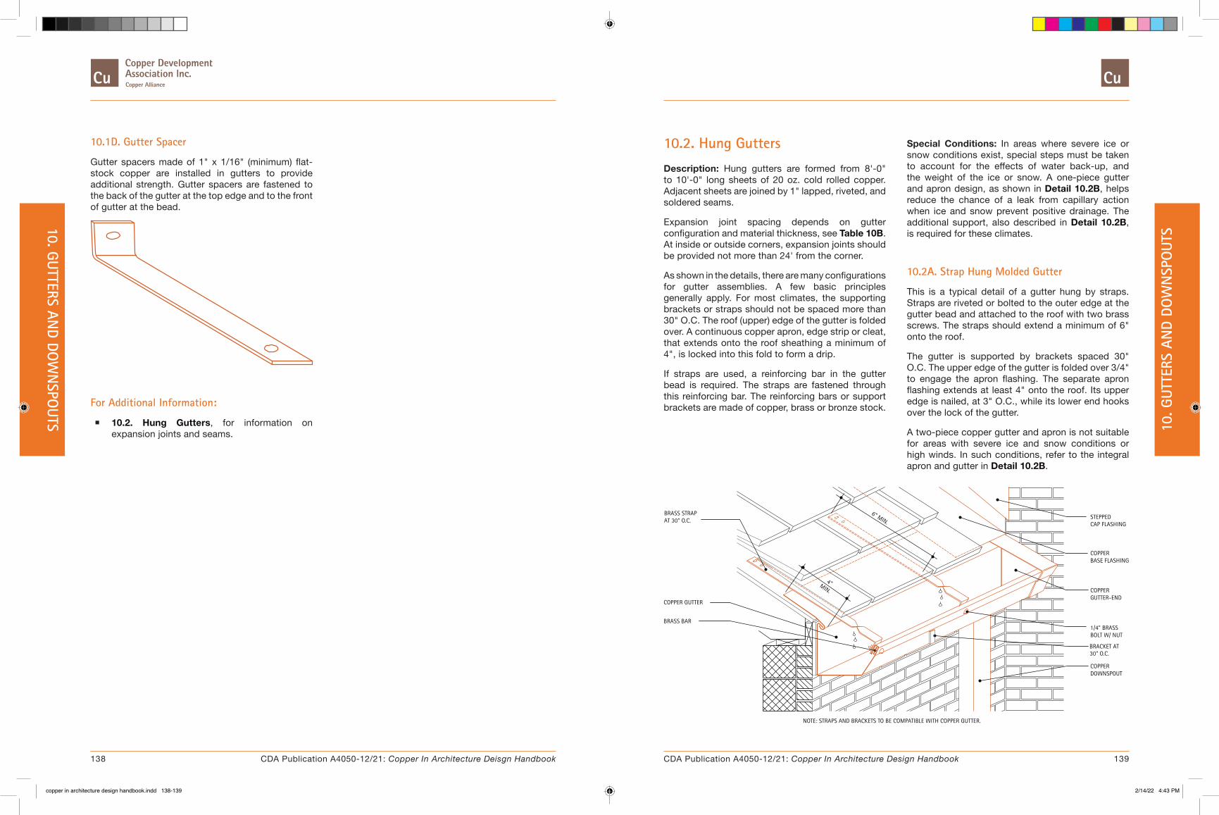
10.1D. Gutter Spacer
Gutter spacers made of 1" x 1/16" (minimum) flat-stock copper are installed in gutters to provide additional strength. Gutter spacers are fastened to the back of the gutter at the top edge and to the front of gutter at the bead.
For Additional Information:
� 10.2. Hung Gutters, for information on expansion joints and seams.
10.2. Hung Gutters
Description: Hung gutters are formed from 8'-0" to 10'-0" long sheets of 20 oz. cold rolled copper. Adjacent sheets are joined by 1" lapped, riveted, and soldered seams.
Expansion joint spacing depends on gutter configuration and material thickness, see Table 10B. At inside or outside corners, expansion joints should be provided not more than 24' from the corner.
As shown in the details, there are many configurations for gutter assemblies. A few basic principles generally apply. For most climates, the supporting brackets or straps should not be spaced more than 30" O.C. The roof (upper) edge of the gutter is folded over. A continuous copper apron, edge strip or cleat, that extends onto the roof sheathing a minimum of 4", is locked into this fold to form a drip.
If straps are used, a reinforcing bar in the gutter bead is required. The straps are fastened through this reinforcing bar. The reinforcing bars or support brackets are made of copper, brass or bronze stock.
Special Conditions: In areas where severe ice or snow conditions exist, special steps must be taken to account for the effects of water back-up, and the weight of the ice or snow. A one-piece gutter and apron design, as shown in Detail 10.2B, helps reduce the chance of a leak from capillary action when ice and snow prevent positive drainage. The additional support, also described in Detail 10.2B, is required for these climates.
10.2A. Strap Hung Molded Gutter
This is a typical detail of a gutter hung by straps. Straps are riveted or bolted to the outer edge at the gutter bead and attached to the roof with two brass screws. The straps should extend a minimum of 6" onto the roof.
The gutter is supported by brackets spaced 30" O.C. The upper edge of the gutter is folded over 3/4" to engage the apron flashing. The separate apron flashing extends at least 4" onto the roof. Its upper edge is nailed, at 3" O.C., while its lower end hooks over the lock of the gutter.
A two-piece copper gutter and apron is not suitable for areas with severe ice and snow conditions or high winds. In such conditions, refer to the integral apron and gutter in Detail 10.2B.
COPPER GUTTER
MIN.
4"
6" MIN.
BOLT W/ NUT
DOWNSPOUTCOPPER
1/4" BRASS
GUTTER-ENDCOPPER
BASE FLASHINGCOPPER
CAP FLASHINGSTEPPED
BRACKET AT30" O.C.
NOTE: STRAPS AND BRACKETS TO BE COMPATIBLE WITH COPPER GUTTER.
BRASS BAR
BRASS STRAPAT 30" O.C.
138 139CDA Publication A4050-12/21: Copper In Architecture Deisgn Handbook CDA Publication A4050-12/21: Copper In Architecture Design Handbook
10. GUTTERS AND DO
WN
SPOUTS 10
. GUT
TERS
AN
D DO
WN
SPO
UTS
copper in architecture design handbook.indd 138-139copper in architecture design handbook.indd 138-139 2/14/22 4:43 PM2/14/22 4:43 PM
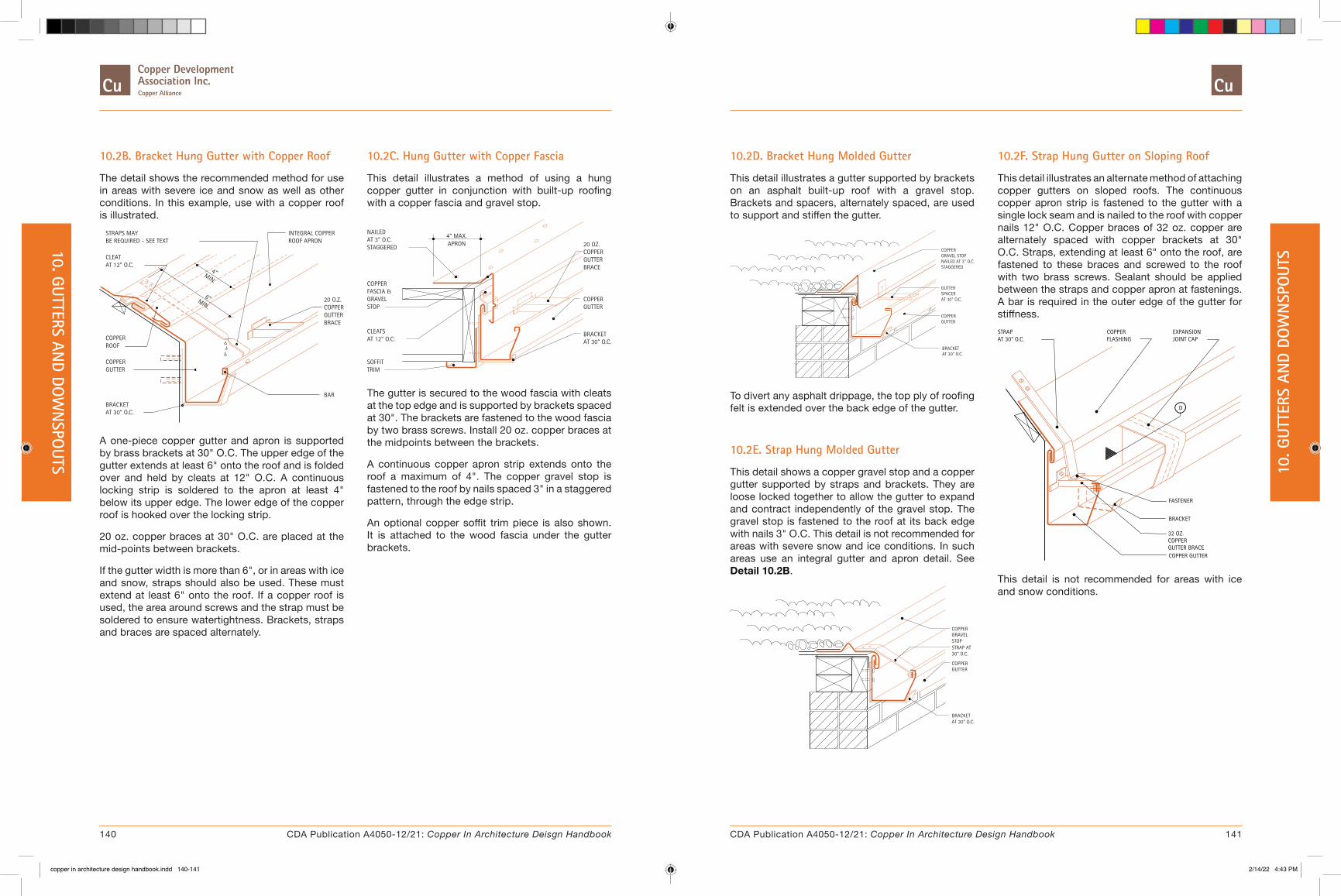
10.2B. Bracket Hung Gutter with Copper Roof
The detail shows the recommended method for use in areas with severe ice and snow as well as other conditions. In this example, use with a copper roof is illustrated.
AT 30" O.C. BRACKET
BE REQUIRED - SEE TEXTSTRAPS MAY
AT 12" O.C.CLEAT
GUTTERCOPPER
ROOFCOPPER
6"MIN.
MIN.
4"
BAR
20 O.Z.
BRACEGUTTERCOPPER
INTEGRAL COPPERROOF APRON
A one-piece copper gutter and apron is supported by brass brackets at 30" O.C. The upper edge of the gutter extends at least 6" onto the roof and is folded over and held by cleats at 12" O.C. A continuous locking strip is soldered to the apron at least 4" below its upper edge. The lower edge of the copper roof is hooked over the locking strip.
20 oz. copper braces at 30" O.C. are placed at the mid-points between brackets.
If the gutter width is more than 6", or in areas with ice and snow, straps should also be used. These must extend at least 6" onto the roof. If a copper roof is used, the area around screws and the strap must be soldered to ensure watertightness. Brackets, straps and braces are spaced alternately.
10.2C. Hung Gutter with Copper Fascia
This detail illustrates a method of using a hung copper gutter in conjunction with built-up roofing with a copper fascia and gravel stop.
TRIMSOFFIT
AT 12" O.C.CLEATS
STOPGRAVEL
STAGGERED
FASCIA &COPPER
AT 3" O.C.NAILED
APRON4" MAX.
AT 30" O.C.
20 OZ.
BRACKET
GUTTERCOPPER
BRACEGUTTERCOPPER
The gutter is secured to the wood fascia with cleats at the top edge and is supported by brackets spaced at 30". The brackets are fastened to the wood fascia by two brass screws. Install 20 oz. copper braces at the midpoints between the brackets.
A continuous copper apron strip extends onto the roof a maximum of 4". The copper gravel stop is fastened to the roof by nails spaced 3" in a staggered pattern, through the edge strip.
An optional copper soffit trim piece is also shown. It is attached to the wood fascia under the gutter brackets.
10.2D. Bracket Hung Molded Gutter
This detail illustrates a gutter supported by brackets on an asphalt built-up roof with a gravel stop. Brackets and spacers, alternately spaced, are used to support and stiffen the gutter.
AT 30" O.C.
GUTTERCOPPER
SPACERGUTTER
STAGGEREDNAILED AT 3" O.C.GRAVEL STOPCOPPER
AT 30" O.C.BRACKET
To divert any asphalt drippage, the top ply of roofing felt is extended over the back edge of the gutter.
10.2E. Strap Hung Molded Gutter
This detail shows a copper gravel stop and a copper gutter supported by straps and brackets. They are loose locked together to allow the gutter to expand and contract independently of the gravel stop. The gravel stop is fastened to the roof at its back edge with nails 3" O.C. This detail is not recommended for areas with severe snow and ice conditions. In such areas use an integral gutter and apron detail. See Detail 10.2B.
STOP
30" O.C.STRAP AT
COPPERGUTTER
GRAVEL COPPER
BRACKETAT 30" O.C.
10.2F. Strap Hung Gutter on Sloping Roof
This detail illustrates an alternate method of attaching copper gutters on sloped roofs. The continuous copper apron strip is fastened to the gutter with a single lock seam and is nailed to the roof with copper nails 12" O.C. Copper braces of 32 oz. copper are alternately spaced with copper brackets at 30" O.C. Straps, extending at least 6" onto the roof, are fastened to these braces and screwed to the roof with two brass screws. Sealant should be applied between the straps and copper apron at fastenings. A bar is required in the outer edge of the gutter for stiffness.
COPPER GUTTER
FASTENER
D
FLASHINGAT 30" O.C.STRAP COPPER
JOINT CAPEXPANSION
BRACKET
32 OZ. COPPER GUTTER BRACE
This detail is not recommended for areas with ice and snow conditions.
140 141CDA Publication A4050-12/21: Copper In Architecture Deisgn Handbook CDA Publication A4050-12/21: Copper In Architecture Design Handbook
10. GUTTERS AND DO
WN
SPOUTS 10
. GUT
TERS
AN
D DO
WN
SPO
UTS
copper in architecture design handbook.indd 140-141copper in architecture design handbook.indd 140-141 2/14/22 4:43 PM2/14/22 4:43 PM

10.2G. Expansion Joint Sections
Expansion joints should be provided on gutters to allow movement caused by thermal changes. Long straight runs should have joints spaced a maximum of 48' apart. They should also be provided no more than 24' from any corner. See the expansion calculation example in Table 10.2A.
COPPER COVER PLATE
COPPER GUTTER
COPPER GUTTER END
EXPANSION CAP
B C
BUTT TYPE EXPANSION JOINT
D
MIN.1/2"
A
BD E
This detail illustrates two types of expansion joints. For the butt type gutter expansion joint, gutter ends are flanged, then riveted and soldered into the ends of gutter sections to be joined. A cover plate is then placed over the expansion joint to improve the appearance of the gutter. Installation of the cover plate should not restrict the movement of gutter sections.
An expansion joint cap is placed on top, over the gutter-end flanges and the cover plate.
COPPER GUTTER
COPPER GUTTER END
EXPANSION CAP
LAP TYPE EXPANSION JOINT
CB
1/2"
D
MIN.
D B
2 1/2"
E
A
For the lap type gutter expansion joint, a gutter-end is recessed 2-1/2" minimum into the gutter on one gutter section and fitted flush on the other. Gutter-ends are flanged, then riveted and soldered into the gutter sections. The flush end of the gutter section is then slipped into the recessed end of the next section. The expansion joint cap is then placed on top, in a manner similar to the fabrication of butt type gutter expansion joints.
Table 10.2A. Example Gutter Expansion Calculation
A 60 foot copper hung gutter is being installed in 65 degree weather in a locality where the maximum temperature range is from 0 degrees to 100 degrees Fahrenheit. The ends are fixed because they contain downspouts. One end is at a corner the other is at another wall.
Expansion joints must be spaced a maximum of 48' on a straight run, but not more than 24' from a corner. Conforming to these limits results in two sections of gutter, 36' and 24'. The calculations should be based on the dimensions of the longer section.
Min. design temperature = 0 degrees Fahrenheit Max. design temperature = 100 + 50 (superheat) degrees F.
Contraction temperature difference = dTc = 65 - 0 = 65 Expansion temperature difference = dTe = 150 - 65 = 85
The general formula for calculating the change in Length is (see Plate 4.1.3 for more information):
dL = Length x Expansion coef. x Temperature change dL = L x 0.0000098 x dT
For the longer section:
Amount of contraction, dLc = 36 x .0000098 x 65 = .0229' = .28" say 1/4"
Amount of expansion, dLe = 36 x .0000098 x 85 = .0300' = .36" say 3/8"
For both sections combined: Total contraction = dLc x 2 = 1/4" x 2 = 1/2" Total expansion = dLe x 2 = 3/8" x 2 = 3/4" Total relative movement = dLc + dLe = 1/2" + 3/4" = 1 1/4"
Allowing 1/4" clearance with heads expanded Min. C = 1/4",
Clearance of heads at installation, C = Min. Clearance + Total Expansion C = 1/4" + 3/4"= 1"
Clearance when contracted, Max. C = C at installation + Total Contraction Max. C = 1" + 1/2" = 1 1/2"
Amount of movement in long section, dL = dLe + dLc = 1/4 + 3/8 = 5/8"
Allowing 1/4" laps (dimension E) with cap at top angles when expanded, and 1/8" clearances (dimension D) when contracted,
Leg of each top angle, B = D + E + dL = 1/4" + 1/8" + 5/8" = 1" Fold-back of cap, also = 1"
Total width of cap, A = Max. C + 2 x B + 2 x D = 1 1/2" + 2 x 1" + 2 x 1/8" = 3 3/4"
142 143CDA Publication A4050-12/21: Copper In Architecture Deisgn Handbook CDA Publication A4050-12/21: Copper In Architecture Design Handbook
10. GUTTERS AND DO
WN
SPOUTS 10
. GUT
TERS
AN
D DO
WN
SPO
UTS
copper in architecture design handbook.indd 142-143copper in architecture design handbook.indd 142-143 2/14/22 4:43 PM2/14/22 4:43 PM

10.3. Built-in Gutter Linings
Description: Copper gutter linings are most often built into wood framed supporting structures. Although the copper lining conforms closely to the gutter frame profile, it should not fit tightly. The lining must be free to move. The bottom of the frame may be pitched to provide positive drainage to the downspout. The inner edge of the lining should finish not less than 2” above the outside edge.
Copper linings should be constructed of sheets 10' maximum in length without longitudinal seams. The ends of the sheets must be pre-tinned 1-1/2". Adjacent sheets are joined by 1-1/2" lapped, riveted and soldered seams. If the girth of the gutter is more than a sheet of copper (typically 36" in some cases 48"), the cross seams should not be more than the sheet width apart (36" or 48").
Expansion joints are placed at intervals to accommodate thermal movement of the gutter lining. See Table 10C for spacing of expansion joints and downspouts. Expansion joints should also be provided within a short distance of the downspout if the gutter lining forms the leg of an inside or outside corner. If an expansion joint must be accommodated at the corner itself, it should be constructed as shown in Detail 10.3B.
Clearance for downspouts through the wood framing, is a minimum 1/2" all around.
Special Conditions: The details shown are for the lining of a wood box gutter frame. When lining a masonry cornice, the edge strip can be secured to the masonry cornice with brass screws and lead shields 12" apart. If a reglet is used, the edge strip is secured into the reglet with lead wedges and sealant.
Note: For ease of soldering, whenever possible, built-in gutters should be fabricated outside of the gutter framing to allow soldered seams inspection and watertightness testing of the gutter, prior to final gutter system installation.
10.3A. Built-In Gutter at Inside Corner
This detail shows a one piece copper gutter lining and apron design that is suitable for use in areas with ice or snow conditions. The apron extends a minimum of 6" onto the roof.
Where the lining meets the vertical wall, provide at least 1/2" for expansion. Section 1 of Detail 10.3A shows this dimension, along with two methods of flashing. Method A shows a typical end condition with an expansion joint cap, recommended in areas with ice and snow conditions. Method B is used in areas with no ice and snow conditions.
Section 2 of Detail 10.3A illustrates a flashing method for the portion of the apron that rests on the roof.
A continuous edge strip of 20 oz. cold rolled copper is formed and attached along the outer edge of the gutter frame with copper nails or brass screws. The copper gutter lining hooks over the edge strip forming a 3/4" loose lock.
A2. SECTION AT ROOFA1. SECTION AT GUTTER A1. SECTION AT GUTTER
BASE FLASHING
COPPER APRON1/2"
STEPPEDCAPFLASHING
COPPERGUTTERLINING
1/2"
GUTTERLINING
1/2"
PIECECOPPERAPRON &GUTTERLINING
SOLDERED
COPPER
COPPERSTEPPEDCAP FLASHING
CLEATSAT 12" O.C.
ONE
CONTINUOUS COPPEREDGE STRIP
BASEFLASHING
A1
A2
SEALANT
1"
CANT
METHOD A METHOD B
144 145CDA Publication A4050-12/21: Copper In Architecture Deisgn Handbook CDA Publication A4050-12/21: Copper In Architecture Design Handbook
10. GUTTERS AND DO
WN
SPOUTS 10
. GUT
TERS
AN
D DO
WN
SPO
UTS
copper in architecture design handbook.indd 144-145copper in architecture design handbook.indd 144-145 2/14/22 4:43 PM2/14/22 4:43 PM
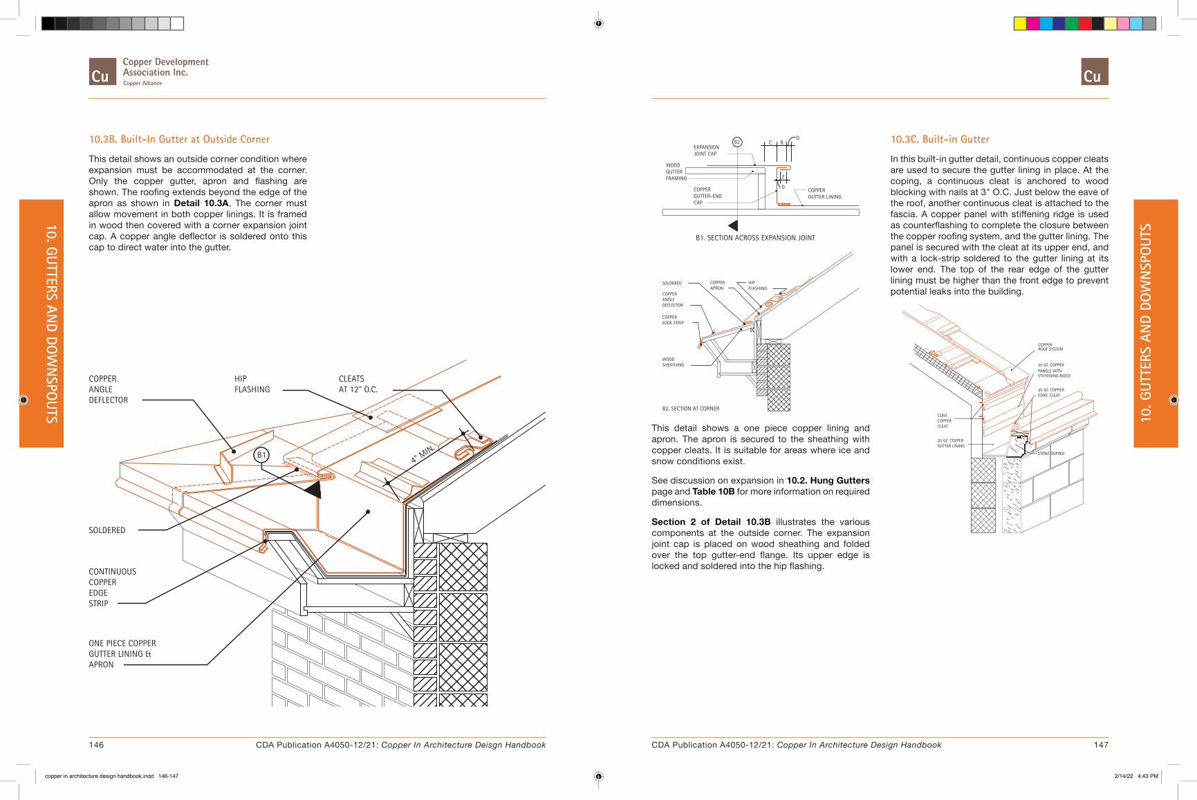
10.3B. Built-In Gutter at Outside Corner
This detail shows an outside corner condition where expansion must be accommodated at the corner. Only the copper gutter, apron and flashing are shown. The roofing extends beyond the edge of the apron as shown in Detail 10.3A. The corner must allow movement in both copper linings. It is framed in wood then covered with a corner expansion joint cap. A copper angle deflector is soldered onto this cap to direct water into the gutter.
COPPERANGLE DEFLECTOR
SOLDERED
ONE PIECE COPPERGUTTER LINING &APRON
HIPFLASHING
CLEATSAT 12" O.C.
B1
COPPEREDGESTRIP
CONTINUOUS
4" MIN.
EXPANSIONJOINT CAP
COPPERGUTTER LINING
COPPER GUTTER-END
B2
WOODGUTTERFRAMING
C B
E
D
D
CAP
B1. SECTION ACROSS EXPANSION JOINT
SOLDERED
COPPEREDGE STRIP
WOODSHEATHING
HIPFLASHING
COPPERAPRON
ANGLEDEFLECTOR
COPPER
B2. SECTION AT CORNER
This detail shows a one piece copper lining and apron. The apron is secured to the sheathing with copper cleats. It is suitable for areas where ice and snow conditions exist.
See discussion on expansion in 10.2. Hung Gutters page and Table 10B for more information on required dimensions.
Section 2 of Detail 10.3B illustrates the various components at the outside corner. The expansion joint cap is placed on wood sheathing and folded over the top gutter-end flange. Its upper edge is locked and soldered into the hip flashing.
10.3C. Built-in Gutter
In this built-in gutter detail, continuous copper cleats are used to secure the gutter lining in place. At the coping, a continuous cleat is anchored to wood blocking with nails at 3" O.C. Just below the eave of the roof, another continuous cleat is attached to the fascia. A copper panel with stiffening ridge is used as counterflashing to complete the closure between the copper roofing system, and the gutter lining. The panel is secured with the cleat at its upper end, and with a lock-strip soldered to the gutter lining at its lower end. The top of the rear edge of the gutter lining must be higher than the front edge to prevent potential leaks into the building.
20 0Z. COPPERPANELS WITH
20 0Z. COPPERCONT. CLEAT
STONE COPING
20 0Z. COPPERGUTTER LINING
COPPERROOF SYSTEM
STIFFENING RIDGE
CONT.COPPERCLEAT
146 147CDA Publication A4050-12/21: Copper In Architecture Deisgn Handbook CDA Publication A4050-12/21: Copper In Architecture Design Handbook
10. GUTTERS AND DO
WN
SPOUTS 10
. GUT
TERS
AN
D DO
WN
SPO
UTS
copper in architecture design handbook.indd 146-147copper in architecture design handbook.indd 146-147 2/14/22 4:43 PM2/14/22 4:43 PM

10.3D. Built-in Gutter
This detail is similar to Detail 10.3C except that a continuous reglet in the stone coping is used to anchor a continuous cleat. This eliminates the need for wood blocking, and in some cases may simplify the installation of the gutter lining. The cleat is inserted into the reglet, grouted in, held by lead wedges and sealed, or fastened with bronze screws and expansion shields and sealed.
COPPERROOF SYSTEM
GUTTER LINING20 0Z. COPPER
STONE COPING
CONT. CLEAT20 0Z. COPPER
PANELS WITH20 0Z. COPPER
STIFFENING RIDGE
COPPERCONT.
CLEAT
10.3E. Built-in Gutter
In this detail, a one-piece copper gutter lining and apron is used in conjunction with a standing seam roof. The upper edge of the gutter apron extends at least 6" onto the roof and is folded over and held by cleats at 12" O.C. A continuous lock strip is soldered to the apron at least 4" below its upper edge. The lower edge of the copper roof is hooked over the locking strip.
ONE PIECECOPPER GUTTER
STANDING SEAMCOPPER ROOF SYSTEM
CLEATS AT12" O.C.
CONT. COPPEREDGE STRIP
4" LAP
LINING
CONT.COPPERLOCK STRIP
This detail is recommended for roofs with a pitch of at least 6 inches per foot. For roofs with lower pitches, see Detail 10.3D.
10.3F. Transverse Seams in Gutter Lining
Where seams occur in the copper gutter lining, a locked and soldered or riveted and soldered are required to maintain a watertight gutter condition. The seam should be oriented to allow the water to flow away from the joint. Rivets are installed in a staggered pattern at 3” O.C.
WATER FLOW
RIVETED & SOLDERED SEAM
1-1/2"
TINNERS RIVETS AT 3" O.C. IN A STAGGERED PATTERN
10.4. Water Diverters
Description: At entranceways or on sloping canopies, where the appearance of a gutter is not desired or the installation of the gutter is difficult, drainage can be handled by installing water diverters.
The minimum suitable gauge for the fabrication of water diverters is 16 oz. cold rolled copper.
The height of the front face of the water diverter, which extends vertically, varies with the roof pitch and the area of roof to be drained; a 4" minimum is suggested. The back edge of the water diverter extends up the roof far enough so it is at least 3" higher in elevation than the front edge.
10.4A. Strap Hung Water Diverter
This detail illustrates a method of installing a water diverter using straps. The diverter is held in place by cleats spaced 12" O.C., maximum. Straps, attached to the roof and fastened to the diverter at the bead, provide additional support. The spacing of these straps should not exceed 2'-6" O.C.
CLEATS AT 12" O.C.
COPPERWATER DIVERTER
COPPER STRAPAT 30" O.C.
3" MIN
.M
IN.
4"
CANT STRIPSOLDERED
10.4B. Strip Supported Water Diverter
Water diverters can also be constructed with wood strips placed on the roof.
CLEATS A 12" O.C.
COPPERWATER DIVERTER
COPPER APRON
LOOSELOCK
DIVERTERSUPPORTSTRIP
CONTINUOUSCOPPER LOCK STRIPNAILED AT 3" O.C.
1/2" MIN.
A continuous copper lock strip is attached to the roof, below the diverter support strip. Apron flashing is then hooked onto this strip. The copper water diverter is held in place by cleats at the top back edge and loose locked to the apron flashing.
The inverted V cant should be formed into the diverter when used in conjunction with rigid roofing material.
148 149CDA Publication A4050-12/21: Copper In Architecture Deisgn Handbook CDA Publication A4050-12/21: Copper In Architecture Design Handbook
10. GUTTERS AND DO
WN
SPOUTS 10
. GUT
TERS
AN
D DO
WN
SPO
UTS
copper in architecture design handbook.indd 148-149copper in architecture design handbook.indd 148-149 2/14/22 4:43 PM2/14/22 4:43 PM

10.4C. Strip Supported Water Diverter - Alternate
This detail is similar to Detail 10.4C, except that the copper apron is held by lock clips or cleats which are nailed to the wood supporting strip. Both are shown for illustration purposes.
CLEATS AT 12" O.C.
COPPERWATER DIVERTER
COPPER APRON
LOOSELOCK
LOCK CLIPAT 1'-6"O.C.
DIVERTERSUPPORTSTRIP
ALTERNATECLEAT
10.5. Scuppers
Description: Scuppers are used to provide an outlet through parapet walls or gravel stops on flat and built-up roofs to allow drainage of excess water. They can be used in conjunction with gutters and downspouts to divert the flow to the desired location.
Scuppers can be installed to carry water into gutters or directly into downspouts through conductor heads. When a conductor head is used, it should be at least 2" wider than the scupper. When neither conductor heads nor gutters are used to catch the water, scupper spouts should extend past the exterior surface of the building to avoid wetting the building surface.
The minimum recommended weight for the construction of scuppers is 16 oz. copper. Scuppers are fabricated with flanges on the roof side which extend 4" onto the roof. Wood blocking is required under scuppers to provide a nailable surface. Scuppers should be spaced no greater than 10 feet apart depending on the roof area drained.
Special Conditions: In areas with severe ice and snow conditions and/or excessive debris, conductor heads with overflow openings should be used.
Where a roof is completely surrounded by parapet walls and drainage is provided by scuppers or internal drains, overflow scuppers should be provided.
The roof-side flange of the gravel stop is nailed at 3" O.C. to the perimeter blocking.
10.5A. Scupper at Raised Roof Curb
This detail illustrates the installation of a scupper through a raised roof curb with a gravel stop. Since no gutters or conductor heads are provided, the scupper spout should extend beyond the exterior face of the building.
GRAVEL STOP
SCUPPER SPOUT
COPPER FASCIA &GRAVEL STOP
EXTEND SCUPPER SPOUTBEYOND FACE OF
SOLDERED
4"
SCUPPER FLANGE
SOLDERED, TYPICAL
EXTERIOR WALL
NOTCHED COPPER
SLOPE
All joints of the scupper should be soldered. The edge of the copper fascia and gravel stop at the scupper should also be soldered.
10.5B. Scupper at Gutter
This detail shows a scupper used in conjunction with a gutter. The scupper spout is soldered into the copper fascia and gravel stop.
NOTCHEDCOPPER
COPPERFASCIA &GRAVELSTOP
COPPERGUTTER -
4"
SCUPPERFLANGE
SEE HUNGGUTTERDETAILS
SOLDERED,TYPICAL
SOLDERED,TYPICAL
GRAVEL STOP
The drip edge of the fascia should extend over the back edge of the gutter by 1" minimum. The scupper and gravel stop flanges are nailed to the blocking. The gutter should be allowed to move independently of the fascia/gravel stop.
150 151CDA Publication A4050-12/21: Copper In Architecture Deisgn Handbook CDA Publication A4050-12/21: Copper In Architecture Design Handbook
10. GUTTERS AND DO
WN
SPOUTS 10
. GUT
TERS
AN
D DO
WN
SPO
UTS
copper in architecture design handbook.indd 150-151copper in architecture design handbook.indd 150-151 2/14/22 4:43 PM2/14/22 4:43 PM

10.5C. Scupper at Conductor Head
The conductor head must be at least 2" wider than the scupper. It is attached to the wood nailer through the fascia. The scupper spout is locked and soldered to the conductor head. All joints between scupper, conductor head, downspout, fascia and gravel stop are soldered.
NOTCHEDCOPPER
COPPERFASCIA &GRAVELSTOP
CONDUCTORHEAD
COPPER
SOLDERED
SCUPPERFLANGE
DOWNSPOUT
COPPER
GRAVELSTOP
SOLDERED
The minimum weight of copper suitable for conductor heads is 16 oz.
10.5D. Scupper at Parapet Wall
Shown is the installation of a copper scupper through a parapet wall in conjunction with conductor head and downspout.
SOLDERED
CONDUCTORHEAD
DOWNSPOUT
CLOSUREFLANGE
GRAVELSTOP
LOCKED &
SEALED
COPPER
COPPER
ROOF-SIDEFLANGE
LOCKEDSEAM
CONTINUOUSCOPPERCLEAT
SOLDERED,TYPICAL
SEALED
FLASHING
SECTION AT SCUPPER
ROOFSIDEFLANGE
GRAVELSTOP
SOLDERED
4"
COPPERFLASHING
SEALED
VIEW FROM ROOF SIDE
The conductor head is attached to the exterior wall using masonry fasteners. The scupper spout is locked and soldered onto the back edge of the conductor head. If conductor heads without overflow are used, the rim of the head should be set 1" below the scupper.
A closure flange is inserted and sealed into a masonry joint above the scupper. The sides are also sealed against the masonry. The scupper is locked and soldered onto the flange at the top and two sides.
On the roof side, the flange is covered by copper flashing. The flange is formed and soldered to the roof side of the scupper, leaving at least 4" of material around the opening. A continuous sheet of copper counterflashing is inserted into a masonry joint above this flange. This flashing extends at least 2" beyond the ends of the flange and laps the soldered joint between the flange and the scupper.
The bottom edge of the scupper on the roof side is locked and soldered into a continuous copper cleat. A copper gravel stop is soldered in the scupper.
10.5E. Overflow Scupper
This detail illustrates the installation of an overflow scupper. Overflow scuppers should be carefully positioned to prevent excess water from remaining on the roof if the regular scuppers become clogged. They should, therefore, be placed at an elevation higher than the regular scuppers.
LOCKED &
CLOSUREFLANGE
LOCKED &
ROOF-SIDEFLANGE
SOLDERED,TYPICAL
SOLDERED,TYPICAL
SOLDERED
SEALED
SECTION AT SCUPPER
The outside detail is similar to Detail 10.5D, except that conductor heads and downspouts are not required. The scupper is locked and soldered to the closure flange on all sides.
ROOFSIDEFLANGE
SOLDERED4"
SEALED
VIEW FROM ROOF SIDE
On the roof side, overflow scuppers can be detailed similar to Detail 10.5D. The detail shows an alternate method of constructing either type of scupper. The top of the roof side flange is extended into a masonry joint. The sides of the flange are sealed against the masonry.
152 153CDA Publication A4050-12/21: Copper In Architecture Deisgn Handbook CDA Publication A4050-12/21: Copper In Architecture Design Handbook
10. GUTTERS AND DO
WN
SPOUTS 10
. GUT
TERS
AN
D DO
WN
SPO
UTS
copper in architecture design handbook.indd 152-153copper in architecture design handbook.indd 152-153 2/14/22 4:43 PM2/14/22 4:43 PM

10.6. Roof Sumps and Drains
Description: Copper roof sumps are generally used for draining small roof areas such as canopies. Their size depends on the roof area, the numbers of roof sumps used on the roof, the drainage outlet size, and the location of the sump on the roof.
The form of the roof sump should conform to the form of the roof. On a roof composed of a series of arches, for example, roof sumps should be placed in the valleys between the arches. The flange should conform to the shape of the arches.
Roof sump drains are not recommended for use as a general roof drainage system.
Special Conditions: Formed copper roof sumps may also be used on flat roofs with copper flat seam construction. The details differ in that gravel stops are not required, and the horizontal flanges of the sump are joined to the copper roofing with soldered flat seams.
10.6A. Formed Roof Sump at Parapet Wall
This detail illustrates the installation of a roof sump at the corner formed by parapet walls.
Wood framing for the curb around the sump is provided as required. The horizontal flanges should be a maximum 4" wide and should be fastened to the roof through the roofing felts.
Vertical flanges of 8" minimum are provided on the sides of the roof sump and fastened to the wall with brass screws and lead shields. The top edges of the vertical flanges are lapped by counterflashing. The brass screws should be overlapped by the flashing.
Water collected in the sump is drained through an outlet tube into the downspout or other drainage stack. An outlet tube strainer is installed to minimize clogging. The use of a 1/2", minimum, copper or copper alloy mesh removable screen is also suggested. The top of the screen should be a minimum of 4" above the roof level.
Gravel stop angles are notched and soldered onto the horizontal sump flange to prevent gravel and tar from entering the drain.
10.6B. Prefabricated Roof Drain
This detail shows a prefabricated copper roof drain installed in a steel deck. Wood blocking is required for support of the 48 oz. copper drain flange. The copper roof pan is fastened to the flange with a continuous soldered joint. A prefabricated bronze strainer is shown.
COPPER PIPE
48 oz. COPPERDRAIN FLANGE
COPPERROOF PAN
BRAZED
PREFABRICATEDBRONZEDRAIN STRAINER
CONTINUOUSSOLDER
COPPERBRASS OR
COPPERRECEIVER
COPPERFLASHING
OUTLETTUBE
GRAVELSTOP
COPPERROOFSUMP
COPPERSUMP SCREENSUPPORTBRACKET
SUMPSCREEN4"
MIN.
4" MIN
.
8" MIN
.
COPPER
STRAINERTUBEOUTLET
NOTCHED
SOLDEREDTOSUMPFLANGE
SUMPFLANGE
SOLDERED
10.7. Downspouts
Description: Copper downspouts are usually shop fabricated using 16 or 20 oz. cold rolled copper. Plain and corrugated, round and rectangular downspouts are typical. Other decorative downspout designs can also be fabricated.
Special Conditions: Downspouts should be installed vertically wherever possible. All horizontal offsets should be sloped in the direction of flow.
10.7A. Typical Downspout Sections
This drawing shows typical downspout cross-sections. Downspouts can be fabricated in any size. Table 10.7A shows the dimensions of standard sizes.
ROUND RECTANGULAR
Table 10.7A. Recommended Sizes for Downspouts
Type Area (Sq. In.)
Nominal Size
(Inches)Actual Size
(Inches)
Plain Round 7.07 3 Dia. 3 Dia.
12.57 4 Dia. 4 Dia.
19.63 5 Dia. 5 Dia.
28.27 6 Dia. 6 Dia.
Corrugated Round
5.91 3 Dia. 3 Dia.
11.01 4 Dia. 4 Dia.
17.72 5 Dia. 5 Dia.
25.97 6 Dia. 6 Dia.
Corrugated Rectangular
3.8 2 1 3/4 x 2 1/4
7.73 3 2 3/8 x 3 1/4
11.70 4 2 3/4 x 4 1/4
18.75 5 3 3/4 x 5
Plain Rectangular
3.94 2 1 3/4 x 2 1/4
6.00 3 2 x 3
12.00 4 3 x 4
20.00 5 3 3/4 x 4 3/4
24.00 6 4 x 6
154 155CDA Publication A4050-12/21: Copper In Architecture Deisgn Handbook CDA Publication A4050-12/21: Copper In Architecture Design Handbook
10. GUTTERS AND DO
WN
SPOUTS 10
. GUT
TERS
AN
D DO
WN
SPO
UTS
copper in architecture design handbook.indd 154-155copper in architecture design handbook.indd 154-155 2/14/22 4:43 PM2/14/22 4:43 PM

10.7B. Downspout Assembly
This detail illustrates the various components of an installed downspout assembly.
OUTLETTUBE
COPPER
SOLDEREDMITEREDELBOWS
COPPERDOWNSPOUT
HANGER
The downspout is joined to the gutter with an outlet tube, see Detail 10.7C. The flanges of the outlet tube are soldered to the gutter. Downspout sections are joined together by soldering. The bottom end of the upper section is inserted into the top of the section below it. Copper straps are used to hold the downspout against the building or structure.
Note: Copper drainage tubes can be substituted for the downspouts in all indicated details.
10.7C. Outlet Tube in Gutter Lining
The length of the outlet tube is a minimum of 4" from the flange edge to the bottom edge. The flange is 3/8" wide. The outside dimension of the outlet tube is 1/8" less than the inside dimension of the downspout.
COPPER GUTTER LININGCOPPER OUTLET TUBE
SOLDERED
COPPER DOWNSPOUNT
3/8"FLANGE
The outlet tube is inserted through a hole at the gutter bottom. The hole size equals the outside dimension of the tube. The flange of the tube is soldered to the gutter.
For Additional Information:
� 10.2. Hung Gutters, for information on downspout hangers.
� 10.8. Downspout Hangers, for additional information on hung copper gutters.
10.8. Downspout Hangers
Description: Hangers are used to hold downspouts in position. Copper used for the fabrication of hangers should be 2 gauges heavier than the copper used for downspouts.
The form of the hanger should conform to the shape of the downspout. Selection of the proper hanger includes the following considerations: the size and type of downspout, the construction type of the building, appearance, and ease of removal for painting and repair.
Fasteners used for the attachment of downspouts to hangers vary; the most typical are screws, bolts, and blind rivets. Fasteners with minimal penetration length are used to reduce clogging.
When light colored porous wall materials are used, gaskets may be placed between the downspout straps and the wall to minize potential wall staining.
10.8A. Downspout Hangers
Two typical factory-made downspout hangers are illustrated.
PLAN SECTION
MORTAR JOINTDRIVEN INTOHANGER
DOWNSPOUT
WIREBRASS
COPPERCOVER
PLAN SECTION
MORTAR JOINT
HANGERDRIVEN INTO
DOWNSPOUT
WIREBRASS
COPPERCOVER
SECTION
COVER
HANGER
SOLDERED
DOWNSPOUT
SECTION
HANGER
WIRE
COVER
SOLDERED
DOWNSPOUT
The downspout is inserted in the hanger after the hanger has been driven into the mortar joint. A wire is used to hold the downspout in place.
A shop-fabricated copper cover may be used to protect the hanger. The cover is placed over the hanger and soldered onto the downspout.
A variation uses a hinged hanger which is wired shut after the downspout is inserted.
10.8B. Downspout Hangers
This detail illustrates some typical strap hangers. The minimum dimensions for these copper straps are 1/16" x 1". The straps are attached to the building with copper or bronze fasteners appropriate to the wall material.
HANGER
FASTENERS
COPPERDOWNSPOUT
COPPER DOWNSPOUT
DOWNSPOUT
FASTENERS
HANGER
DOWNSPOUTCOPPER
COPPER
HANGERDOWNSPOUTCOPPER
FASTENERS
DOWNSPOUTCOPPER
The bottom left figure illustrates a light gauge hanger for a round downspout. This type of hanger is installed after the downspout is in place.
For Additional Information:
� 10.7. Downspouts
156 157CDA Publication A4050-12/21: Copper In Architecture Deisgn Handbook CDA Publication A4050-12/21: Copper In Architecture Design Handbook
10. GUTTERS AND DO
WN
SPOUTS 10
. GUT
TERS
AN
D DO
WN
SPO
UTS
copper in architecture design handbook.indd 156-157copper in architecture design handbook.indd 156-157 2/14/22 4:43 PM2/14/22 4:43 PM

11. BUILDING EXPANSION JOINTS
� 11.1. Roof Conditions
� 11.2. Roof Edges
� 11.3. Floor Conditions
� 11.4. Wall Conditions
Introduction
Designing for the movement of building components is an important part of architectural detailing. The movement can be the result of temperature changes, imposed loads, settlement, or other causes. Building expansion joints are used to cover the space between components, and provide a barrier to the exterior.
Expansion joints can follow complicated paths along varying materials. Copper is an excellent material for such joints, since it is easy to form and lasts a long time.
When detailing an expansion joint for a specific application, it is important to consider the magnitude and direction of movement. Some dimensions of details presented in this section are based on the expected maximum amount of expansion (labeled "E" in the details). Most expansion joints are optimized to accommodate movement in only one direction. Their ability to accommodate movement in other directions varies with their design. The designer should review the details and select the appropriate design based on particular requirements.
One issue that must be addressed in the proper design of expansion joints, is the height of curbs. This dimension depends largely on whether or not a cant strip is used at these locations. Normally, the minimum recommended curb height, measured above adjacent roofing, is 8 inches. However, if a cant strip is used, this dimension must be increased. If a typical 4" cant is used, the height of the curb should be a minimum of 10 inches above the adjacent roof. This leaves room for a minimum counterflashing lap of 4" and 1" to 2" space between the cant and the counterflashing.
11.1. Roof Conditions
Description: Expansion joints in roofs require wood curbs around each roof area. The curbs should extend at least 8", or 10" if a cant is used, above the adjacent roof. In general, the top surface of the curbs should be sloped away from the joint, to shed condensation and moisture onto the roof. Insulation is often used in the expansion space, but is left out of the details for clarity.
The minimum recommended gauge for copper used on roof expansion joints is 16 ounces.
The following plates outline some common building expansion joint details. The noted dimension "E" is the total expected movement within the joint.
Special Conditions: When comparing details for roof expansion joints, it is important to consider the risk of physical damage to the joint. For example, if a catwalk is adjacent to or crosses a joint, the joint is more likely to be exposed to damage from people kicking or stepping on the joint, or from equipment being dropped or dragged over it. Some joint designs are inherently better at resisting these impacts, while others can be modified to improve their performance.
11.1B. Building Expansion Joint at Roof - Alternate
This design relies on manufactured elastomeric bellows secured to copper flanges. The bottom of the flanges are secured to each curb with a continuous copper edge strip. The size of the bellows depends on the maximum expansion movement and must be selected from the manufacturer's literature.
CONT. EDGE STRIP, TYP.
COMPOSITION BASE
COPPER FLANGES
ELASTOMERIC BELLOWS
10"
MIN
.
SLOPESLOPE
FLASHING
E
11.1A. Building Expansion Joint at Roof
This detail shows a typical symmetrical copper roof expansion joint. It uses a copper cap to span the expansion space. Copper counterflashing is attached to the top surface of each curb with nails spaced no more than 3" O.C. A continuous copper lock strip holds the bottom of the counterflashing. The copper cap is loose locked onto the counterflashing, as shown to accommodate expansion and contraction movement.
NAILED AT 3" O.C.
20 OZ. COPPERCOUNTERFLASHING
COMPOSITION BASE
CONT. EDGE STRIP, TYP.
OR COVER PLATESINGLE LOCK SEAM
10"
MIN
.
COPPER CAP
E
SLOPE
E/2E
FLASHING
E/2E/2 E E/2
158 159CDA Publication A4050-12/21: Copper In Architecture Deisgn Handbook CDA Publication A4050-12/21: Copper In Architecture Design Handbook
11. BUILDING EXPAN
SION
JOIN
TS 11. B
UILD
ING
EXPA
NSI
ON
JO
INTS
copper in architecture design handbook.indd 158-159copper in architecture design handbook.indd 158-159 2/14/22 4:43 PM2/14/22 4:43 PM

11.1C. Building Expansion Joint at Parapet
This detail illustrates an expansion joint designed to accomodate the unequal movement of two portions in a building. The basic principle is that copper cap is attached to one curb while the other side is designed to accomodate movement. The end of the expansion joint cap is bent up where it meets the wall. A continuous lock strip is attached to the wall on each side of the expansion space. A vertical copper cap is folded into each lock strip. The lock strip on one side is designed to accommodate the maximum movement, while the cap is locked onto the other side (see section).
1" LOCK
CLEAT AT JOINT
CONT. LOCK STRIP
SLOPE
E
E
E+1" E
ON TOP OF CURBNAILED AT 3" O.C. 20 OZ. COPPER
COPPER CAP
COPPER CAP
CONT. CLEAT
E+1"E E
E
A copper cap is also formed to match the contours of the coping cover, and locked over the cover drip edge.
11.1D. Building Expansion Joint Intersection
This detail shows an expansion joint intersection. The cover for the intersection is made of a single piece of copper. It is joined to the other caps with a 2" loose lock filled with elastic sealant.
INTERSECTION COVER
INTERSECTION COVER
E
1" LOCK
CONT. LOCK STRIP
EE+1"E
SLOPE COUNTERFLASHING NAILEDAT 3" O.C. ON TOP OF CURB
10"
MIN
.
SEALANT
SECTION
2"
160 161CDA Publication A4050-12/21: Copper In Architecture Deisgn Handbook CDA Publication A4050-12/21: Copper In Architecture Design Handbook
11. BUILDING EXPAN
SION
JOIN
TS 11. B
UILD
ING
EXPA
NSI
ON
JO
INTS
copper in architecture design handbook.indd 160-161copper in architecture design handbook.indd 160-161 2/14/22 4:43 PM2/14/22 4:43 PM

11.1E. Building Expansion Joint at Roof
This detail illustrates an asymmetrical design which uses wood blocking to help support the copper cap flashing. The blocking on each side is fastened to the curbs.
ATTACHED TO CURBCOPPER FLASHING
COPPER CAP
FLASHINGCOMPOSITION BASE
E
WOOD BLOCKING
10"
MIN
.COPPER EDGE STRIP
FASTENED TO CURB
OR SINGLE LOCK SEAMCOPPER DRIVE CLEAT
SLOPE
E E
E+1"
EE
The copper cap is locked onto a continuous edge strip on one side. It extends over the expansion space, then down and underneath the other blocking. It is loose locked into a continuous edge strip. The dimensions should be calculated as shown to accomodate the expected movement.
11.1F. Building Expansion Joint at Roof
This design for an expansion joint relies on flexing of the copper material to accomodate movement. This approach is acceptable as long as the radii of all bends that flex are at least 1/4".
CONT. COPPER EDGE
3" LAP JOINT WITH
1/4" MIN. RADIUS
10"
MIN
.
SLOPE
2E
E
SEALANT
STRIP, TYPICAL
The copper cap is formed into an inverted "V". Its height should be twice its width, as shown. The lower edges of the flashing are hooked onto continuous edge strips. Adjacent caps are joined with 3" sealant filled lap joints.
11.2. Roof Edges
Description: Expansion joints at roof edges usually occur where an independently supported roof meets a wall. This condition is often the result of a new structure adjacent to an existing one.
A continuous wood curb is required along the roof perimeter. It should extend at least 10" above the adjacent roof. The top surface of the curbs should be sloped away from the joint, to shed condensation and moisture onto the roof. Insulation is often used in the expansion space, but is left out of the details for clarity.
11.2A. Expansion Joint Between Flat Roof and Wall
Copper base flashing is double-folded and nailed to the top surface of the curb which is cut to a slope of 3" per foot. Its lower edge is held by a continuous edge strip. Its upper edge is folded over, and long enough to accommodate maximum movement. Copper counterflashing is folded into this edge. The upper edge of the counterflashing is held by a copper receiver, which is set in the brick joints. If the wall is an existing one, the mortar joint is raked to a depth of 1" and the copper receiver is inserted, wedged, and sealed.
COMPOSITION BASE
3" LAP JOINT WITH
COPPER RECEIVER
EE+1"
E
10"
MIN
. FLASHING
SEALANT
SLOPE
NAILED 3" O.C.
CONT. COPPER EDGE STRIP
COPPER BASE FLASHING
The curb shown is double width to provide a broad enough surface for the expansion and contraction in the copper joint and to allow for the nailing of the base. Depending on the width of the expansion joint, it may be necessary to widen the curb further.
11.2B. Expansion Joint Between Flat Roof and Wall
A continuous lower copper base flashing is nailed to the top surface of the wood curb. Its lower edge is locked onto a continuous edge strip. The lower base flashing is formed into a lock large enough to accommodate the maximum expansion, as shown. the upper copper base flashing is loose locked onto the edge strip. Its upper edge is held to the wall by cleats, spaced no more than 12" O.C. Copper counterflashing laps the upper base flashing a minimum of 4". It is secured to the wall in a reglet or in a joint in masonry, and sealed.
CLEAT AT 12" O.C.
COPPER COUNTER-FLASHING
3" LAP SEAM WITHSEALANT
COMPOSITION BASEFLASHING
CONTINUOUS COPPER FLASHING STRIP NAILEDAT 3" O.C.
SLOPE
4" M
IN.
LAP
E
E
EE+1"
EDGE STRIPCONTINUOUS COPPER
UPPER COPPER BASE
SEALANT3" LAP SEAM WITH
FLASHING
10"
MIN
.10
" M
IN.
162 163CDA Publication A4050-12/21: Copper In Architecture Deisgn Handbook CDA Publication A4050-12/21: Copper In Architecture Design Handbook
11. BUILDING EXPAN
SION
JOIN
TS 11. B
UILD
ING
EXPA
NSI
ON
JO
INTS
copper in architecture design handbook.indd 162-163copper in architecture design handbook.indd 162-163 2/14/22 4:43 PM2/14/22 4:43 PM

11.2C. Expansion Joint at Standing Seam Shed Roof
This condition shows the expansion joint between the head of an independently supported shed roof and a wall. Three alternate details are shown.
TYPICAL STANDINGSEAM
CONT. COPPER LOCK STRIP
COPPER CLEAT AT 2 PER PAN
8" M
IN.
10" MIN.
4" MIN.LAP
EE+1"
E
SEALEDWEDGED &
COPPER COUNTER -FLASHING
COPPER BASEFLASHING
CONT.CLEAT
The roofing pans are terminated several inches below the top of the roof. Each pan is secured to the roof substrate with 2 cleats. A continuous copper lock strip is soldered to the pans at least 4" below the pan's upper edge. The standing seams are laid flat to this point. Copper base flashing is locked into the lock strip. The upper edge of the base flashing is formed into a loose lock large enough to accommodate the maximum movement and fastened with cleats at 12" O.C. Copper counterflashing is folded into the loose lock.
� Alternate 1 The copper base flashing's upper edge is formed into a double fold large enough to accommodate the maximum movement. It is fastened with cleats spaced a maximum of 12" O.C. The copper counterflashing is folded and loose locked into the double fold. It extends at least 8" up the wall, where it is inserted into a reglet or in the joint between masonry courses.
COUNTER -FLASHING
CLEAT AT12" O.C.
BASEFLASHING
E+1"E
� Alternate 2 The copper base flashing's upper edge is formed into a lock and fastened with cleats spaced a maximum of 12" O.C. A continuous copper lock strip is soldered to the base flashing and receives the end of the counterflashing.
FLASHINGCOUNTER -
CONT. LOCK STRIPSOLDERED TO BASEFLASHING
FLASHINGBASE
E+1"E
� Alternate 3 The copper base flashing's upper edge is formed into a "bread pan". Its upper edge is large enough to accommodate the maximum movement. The copper counterflashing is loose locked into this edge.
BASEFLASHING
BREAD PAN
EE
E+1"
Special Conditions:
If the design is for long pan, then expansion of the roof pan relative to the base flashing must also be accommodated at the lock strip and cleat. See 8.8. Long Pan Systems.
164 165CDA Publication A4050-12/21: Copper In Architecture Deisgn Handbook CDA Publication A4050-12/21: Copper In Architecture Design Handbook
11. BUILDING EXPAN
SION
JOIN
TS 11. B
UILD
ING
EXPA
NSI
ON
JO
INTS
copper in architecture design handbook.indd 164-165copper in architecture design handbook.indd 164-165 2/14/22 4:43 PM2/14/22 4:43 PM
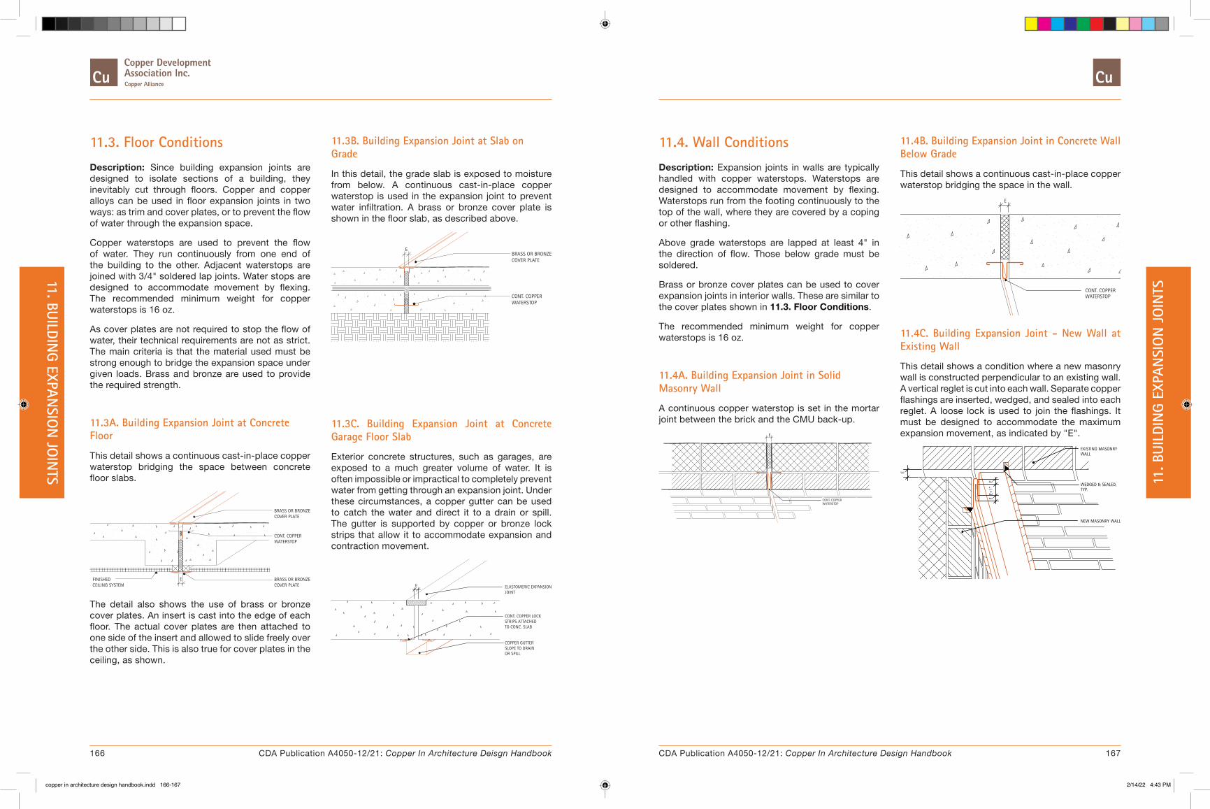
11.3. Floor Conditions
Description: Since building expansion joints are designed to isolate sections of a building, they inevitably cut through floors. Copper and copper alloys can be used in floor expansion joints in two ways: as trim and cover plates, or to prevent the flow of water through the expansion space.
Copper waterstops are used to prevent the flow of water. They run continuously from one end of the building to the other. Adjacent waterstops are joined with 3/4" soldered lap joints. Water stops are designed to accommodate movement by flexing. The recommended minimum weight for copper waterstops is 16 oz.
As cover plates are not required to stop the flow of water, their technical requirements are not as strict. The main criteria is that the material used must be strong enough to bridge the expansion space under given loads. Brass and bronze are used to provide the required strength.
11.3A. Building Expansion Joint at Concrete Floor
This detail shows a continuous cast-in-place copper waterstop bridging the space between concrete floor slabs.
BRASS OR BRONZECOVER PLATE
CONT. COPPERWATERSTOP
ECOVER PLATEBRASS OR BRONZEFINISHED
CEILING SYSTEM
The detail also shows the use of brass or bronze cover plates. An insert is cast into the edge of each floor. The actual cover plates are then attached to one side of the insert and allowed to slide freely over the other side. This is also true for cover plates in the ceiling, as shown.
11.3B. Building Expansion Joint at Slab on Grade
In this detail, the grade slab is exposed to moisture from below. A continuous cast-in-place copper waterstop is used in the expansion joint to prevent water infiltration. A brass or bronze cover plate is shown in the floor slab, as described above.
BRASS OR BRONZE
CONT. COPPERWATERSTOP
COVER PLATE
E
11.3C. Building Expansion Joint at Concrete Garage Floor Slab
Exterior concrete structures, such as garages, are exposed to a much greater volume of water. It is often impossible or impractical to completely prevent water from getting through an expansion joint. Under these circumstances, a copper gutter can be used to catch the water and direct it to a drain or spill. The gutter is supported by copper or bronze lock strips that allow it to accommodate expansion and contraction movement.
ELASTOMERIC EXPANSIONJOINT
COPPER GUTTERSLOPE TO DRAIN OR SPILL
E
TO CONC. SLABSTRIPS ATTACHEDCONT. COPPER LOCK
11.4. Wall Conditions
Description: Expansion joints in walls are typically handled with copper waterstops. Waterstops are designed to accommodate movement by flexing. Waterstops run from the footing continuously to the top of the wall, where they are covered by a coping or other flashing.
Above grade waterstops are lapped at least 4" in the direction of flow. Those below grade must be soldered.
Brass or bronze cover plates can be used to cover expansion joints in interior walls. These are similar to the cover plates shown in 11.3. Floor Conditions.
The recommended minimum weight for copper waterstops is 16 oz.
11.4A. Building Expansion Joint in Solid Masonry Wall
A continuous copper waterstop is set in the mortar joint between the brick and the CMU back-up.
WATERSTOPCONT. COPPER
E
11.4B. Building Expansion Joint in Concrete Wall Below Grade
This detail shows a continuous cast-in-place copper waterstop bridging the space in the wall.
WATERSTOPCONT. COPPER
E
11.4C. Building Expansion Joint - New Wall at Existing Wall
This detail shows a condition where a new masonry wall is constructed perpendicular to an existing wall. A vertical reglet is cut into each wall. Separate copper flashings are inserted, wedged, and sealed into each reglet. A loose lock is used to join the flashings. It must be designed to accommodate the maximum expansion movement, as indicated by "E".
WEDGED & SEALED,
EXISTING MASONRY
NEW MASONRY WALL
E+1"
E
TYP.
E
WALL
E
166 167CDA Publication A4050-12/21: Copper In Architecture Deisgn Handbook CDA Publication A4050-12/21: Copper In Architecture Design Handbook
11. BUILDING EXPAN
SION
JOIN
TS 11. B
UILD
ING
EXPA
NSI
ON
JO
INTS
copper in architecture design handbook.indd 166-167copper in architecture design handbook.indd 166-167 2/14/22 4:43 PM2/14/22 4:43 PM

12. WALL CLADDING
� 12.1. Profiled Panels
� 12.2. Horizontal Siding
� 12.3. Beveled Systems
� 12.4. Flat Siding
� 12.5. Structural Systems
� 12.6. Diagonal Flat Lock Systems
� 12.7. Horizontal Flat Lock Systems
� 12.8. Copper Clad Honeycomb Systemss
� 12.9. Copper Screen Panels
� 12.10. Curtain Wall Systems
� 12.11. Standing Seam
� 12.12. Fenestration
Introduction
Copper, brass, bronze are uniquely suited for wall cladding applications. These materials are strong, light weight highly corrosion resistant and are available in numerous factory applied and alloy finishes and colors.
In addition to the systems outlined in this section, many of the 8. Roofing Systems detailed in Section 8 can be adapted for use as wall claddings.
Most copper wall cladding systems are in many ways similar to copper roofing systems. They are generally installed over a continuous nailable substrate which is covered with 30 pound asphalt saturated felt. Rosin-sized building paper is laid over the felt to
keep the copper siding or panels from bonding to the felt. Flat, circular, and other shaped walls can easily be covered with copper cladding systems.
The majority of the copper cladding systems can be field formed from sheet material. Many can also be pre-manufactured and transported to the site. In addition, there are a number of engineered systems from a variety of US and foreign manufacturers. These systems include insulated panels, non-insulated honeycomb panels, and copper screen panels.
Structural wall claddings have also been developed. Such systems become an integral part of a wall and must be properly engineered to satisfy all structural and building code requirements.
The following pages contain descriptive information and copper wall cladding system details. The described systems are generic in scope and are meant to convey basic design concepts. Other systems may vary to some degree.
The terms "siding" and "panel" have been used throughout this section as a convenient way to refer to components in the details. Their use may not reflect established regional definitions.
11.4D. Building Expansion Joint at Corner
This detail illustrates how to accommodate expansion in both directions at a building corner. A copper two-piece waterstop that allows movement in two directions is required. The dimensions of each piece should be designed to accommodate the total amount of movement expected.
E+1"
3 1/2"
LOCK STRIPCONT. COPPER
COPPER FLASHING20 oz. COLD ROLLED
E
E
ROLLED COPPER16 oz. COLD
WATERSTOP
LOCK STRIPCONT. COPPER
One side of the waterstop is held in place by brass bolts through a copper bar, while the other side is built into the masonry. The top of the waterstop is lapped by a coping cover. Each 8 to 10 foot length of the waterstop is lapped 4".
The exterior side of the walls is covered by 20 oz. copper flashing, which is held by continuous lock strips. The lock strips should also be designed to accommodate movement.
168 169CDA Publication A4050-12/21: Copper In Architecture Deisgn Handbook CDA Publication A4050-12/21: Copper In Architecture Design Handbook
12. W
ALL
CLAD
DIN
G11. BUILDIN
G EXPANSIO
N JO
INTS
copper in architecture design handbook.indd 168-169copper in architecture design handbook.indd 168-169 2/14/22 4:43 PM2/14/22 4:43 PM
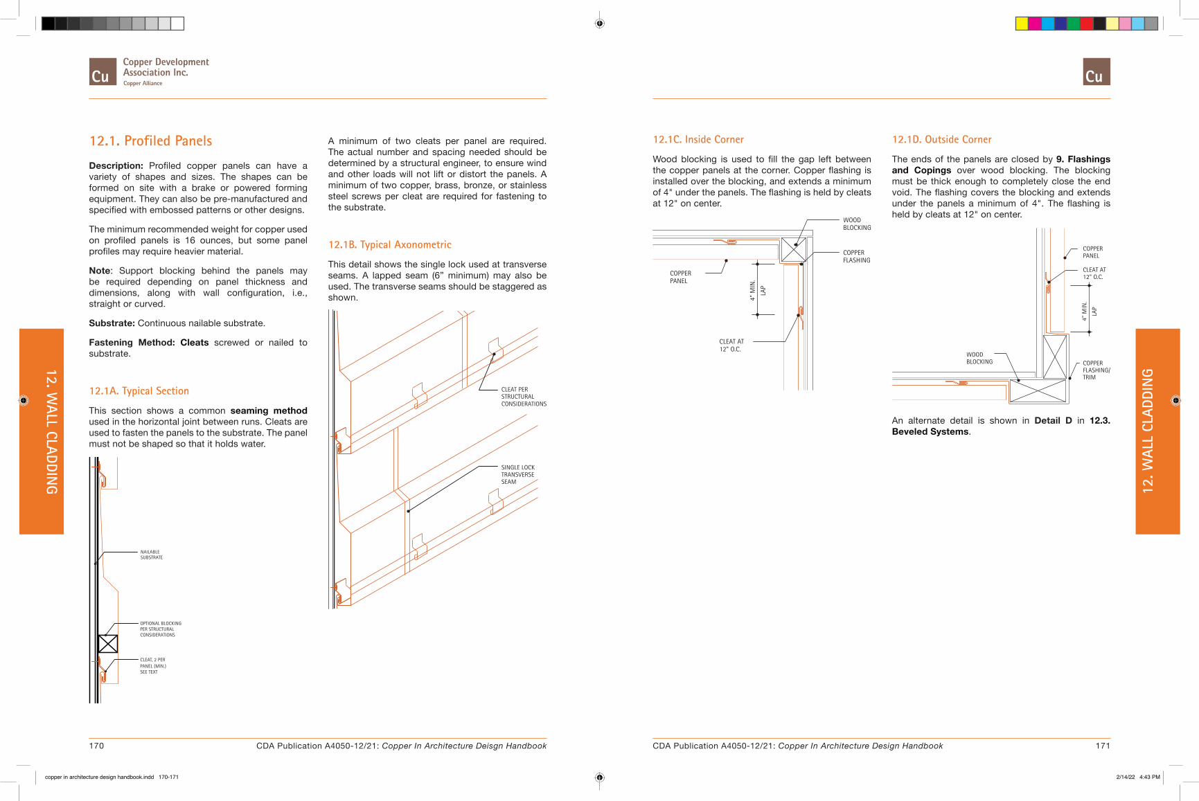
12.1. Profiled Panels
Description: Profiled copper panels can have a variety of shapes and sizes. The shapes can be formed on site with a brake or powered forming equipment. They can also be pre-manufactured and specified with embossed patterns or other designs.
The minimum recommended weight for copper used on profiled panels is 16 ounces, but some panel profiles may require heavier material.
Note: Support blocking behind the panels may be required depending on panel thickness and dimensions, along with wall configuration, i.e., straight or curved.
Substrate: Continuous nailable substrate.
Fastening Method: Cleats screwed or nailed to substrate.
12.1A. Typical Section
This section shows a common seaming method used in the horizontal joint between runs. Cleats are used to fasten the panels to the substrate. The panel must not be shaped so that it holds water.
NAILABLESUBSTRATE
OPTIONAL BLOCKING PER STRUCTURAL CONSIDERATIONS
CLEAT, 2 PER PANEL (MIN.) SEE TEXT
A minimum of two cleats per panel are required. The actual number and spacing needed should be determined by a structural engineer, to ensure wind and other loads will not lift or distort the panels. A minimum of two copper, brass, bronze, or stainless steel screws per cleat are required for fastening to the substrate.
12.1B. Typical Axonometric
This detail shows the single lock used at transverse seams. A lapped seam (6” minimum) may also be used. The transverse seams should be staggered as shown.
TRANSVERSE SINGLE LOCK
SEAM
CONSIDERATIONSSTRUCTURALCLEAT PER
12.1C. Inside Corner
Wood blocking is used to fill the gap left between the copper panels at the corner. Copper flashing is installed over the blocking, and extends a minimum of 4" under the panels. The flashing is held by cleats at 12" on center.
4" M
IN.
12" O.C.
PANELCOPPER
CLEAT AT
LAP
FLASHING
BLOCKING
COPPER
WOOD
12.1D. Outside Corner
The ends of the panels are closed by 9. Flashings and Copings over wood blocking. The blocking must be thick enough to completely close the end void. The flashing covers the blocking and extends under the panels a minimum of 4". The flashing is held by cleats at 12" on center.
BLOCKINGWOOD
COPPER
CLEAT AT12" O.C.
COPPER FLASHING/TRIM
PANEL
4" M
IN.
LAP
An alternate detail is shown in Detail D in 12.3. Beveled Systems.
170 171CDA Publication A4050-12/21: Copper In Architecture Deisgn Handbook CDA Publication A4050-12/21: Copper In Architecture Design Handbook
12. WALL CLADDIN
G 12. W
ALL
CLAD
DIN
G
copper in architecture design handbook.indd 170-171copper in architecture design handbook.indd 170-171 2/14/22 4:43 PM2/14/22 4:43 PM

12.2. Horizontal Siding
Description: This type of copper siding provides a relatively flat appearance with fine horizontal lines. The length of each piece of siding is usually limited to 10 feet. The height varies but is typically 12" to 18". Transverse seams are 6" minimum, lap joints. The joints are staggered on successive runs to improve water resistance. This also helps reduce the stacking of multiple layers of copper at one place, which can make it difficult to fold the horizontal joints. Panels are installed shingle fashion, from the bottom up.
The minimum recommended gauge for copper used on flat siding is 16 ounces.
For more information on Horizontal Siding Testing, see Section 15.6. Performance Testing of Copper Wall Cladding.
Substrate: Continuous nailable substrate.
Fastening Method: Cleats screwed to substrate.
12.2A. Typical Section
This section shows the 7.2. Joints and Seams used in the horizontal joint between runs. Cleats are used to fasten the siding to the substrate. The cleats are spaced at 12" on center.
SEAMLOCKSINGLE
12"-
18"
TYP.
COPPERSIDING
SUBSTRATENAILABLE
16" O.C.CLEATS AT
12.2B. Typical Axonometric
The 6" minimum, lap is shown at the transverse seams. The transverse seams should be staggered, as shown.
CLEATS
COPPER
TRANSVERSESEAMSSTAGGERED
SIDING
6" MIN.
LAP
12.2C. Top and Base Details
The top condition can be handled in many ways, depending on the material above the copper siding. The copper flashing is typically lapped a minimum of 4" by the material above.
TOP
4"
COPPER SIDING
COPPER FLASHING
CLEAT AT 12" O.C.
MIN
. LAP
BASE
CONTINUOUS COPPERLOCK STRIP
COPPER SIDING
CLEAT AT 12" O.C.
COPPER FLASHING
In the bottom detail, wood blocking is used to provide a drip and a protected place for fastening the continuous copper lock strip.
12.2D. Parapet Detail
Cleats are fastened into the blocking at the top of the parapet framing. A copper coping cover is attached to the upper most run of copper siding using a single lock seam. The cover extends over the parapet and is locked into a continuous lock strip on the back side of the parapet.
COPPER COPING
CLEAT AT 12" O.C.
CONTINUOUS COPPER
COVER
COPPER SIDING
EDGE STRIP
172 173CDA Publication A4050-12/21: Copper In Architecture Deisgn Handbook CDA Publication A4050-12/21: Copper In Architecture Design Handbook
12. WALL CLADDIN
G 12. W
ALL
CLAD
DIN
G
copper in architecture design handbook.indd 172-173copper in architecture design handbook.indd 172-173 2/14/22 4:43 PM2/14/22 4:43 PM
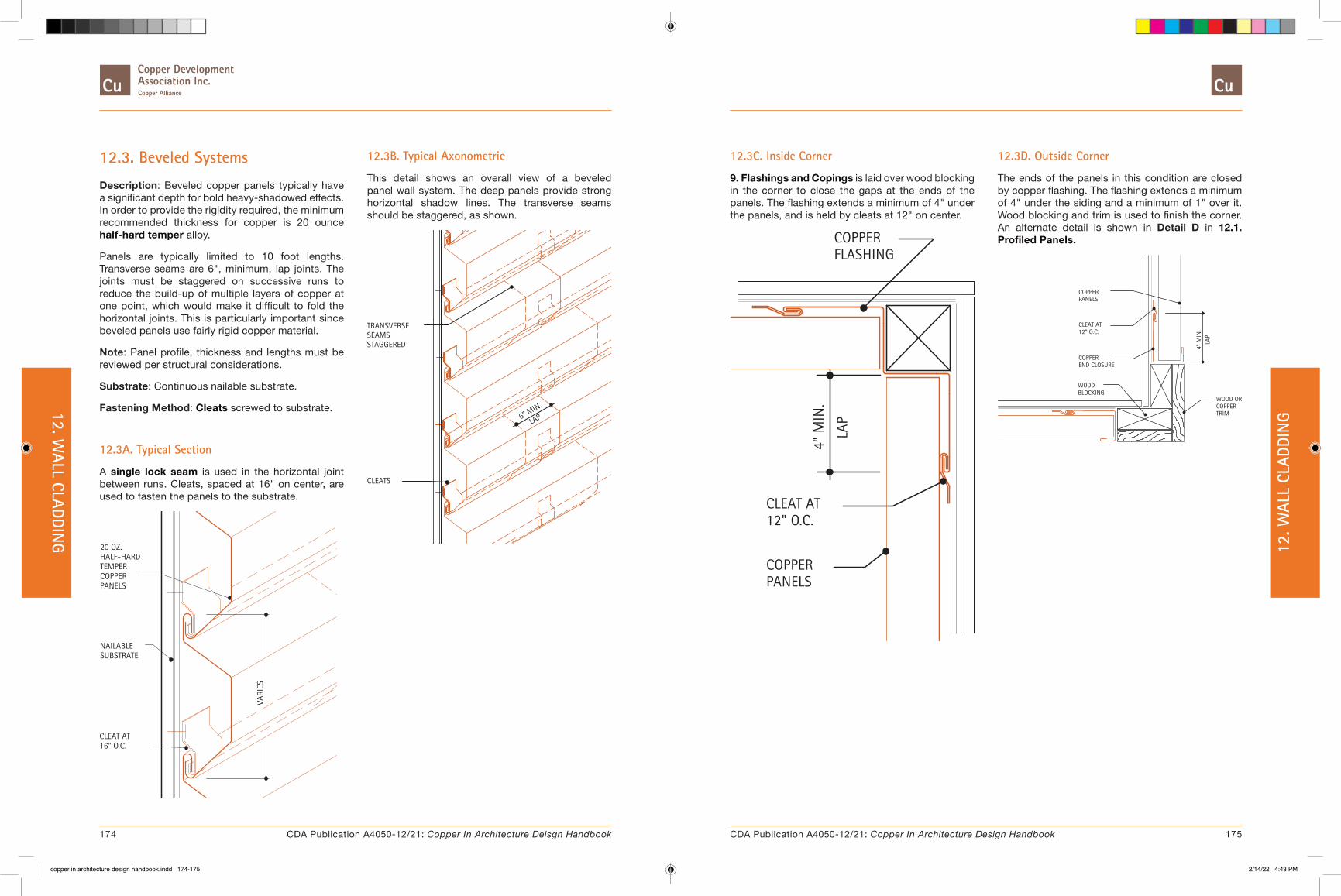
12.3. Beveled Systems
Description: Beveled copper panels typically have a significant depth for bold heavy-shadowed effects. In order to provide the rigidity required, the minimum recommended thickness for copper is 20 ounce half-hard temper alloy.
Panels are typically limited to 10 foot lengths. Transverse seams are 6", minimum, lap joints. The joints must be staggered on successive runs to reduce the build-up of multiple layers of copper at one point, which would make it difficult to fold the horizontal joints. This is particularly important since beveled panels use fairly rigid copper material.
Note: Panel profile, thickness and lengths must be reviewed per structural considerations.
Substrate: Continuous nailable substrate.
Fastening Method: Cleats screwed to substrate.
12.3A. Typical Section
A single lock seam is used in the horizontal joint between runs. Cleats, spaced at 16" on center, are used to fasten the panels to the substrate.
VARI
ES
20 OZ.
SUBSTRATE
HALF-HARD
CLEAT AT16" O.C.
NAILABLE
COPPERTEMPER
PANELS
12.3B. Typical Axonometric
This detail shows an overall view of a beveled panel wall system. The deep panels provide strong horizontal shadow lines. The transverse seams should be staggered, as shown.
TRANSVERSESEAMS
CLEATS
STAGGERED
6" MIN.
LAP
12.3C. Inside Corner
9. Flashings and Copings is laid over wood blocking in the corner to close the gaps at the ends of the panels. The flashing extends a minimum of 4" under the panels, and is held by cleats at 12" on center.
CLEAT AT
COPPERPANELS
12" O.C.
COPPERFLASHING
4" M
IN.
LAP
12.3D. Outside Corner
The ends of the panels in this condition are closed by copper flashing. The flashing extends a minimum of 4" under the siding and a minimum of 1" over it. Wood blocking and trim is used to finish the corner. An alternate detail is shown in Detail D in 12.1. Profiled Panels.
BLOCKING
PANELSCOPPER
CLEAT AT12" O.C.
WOOD
COPPEREND CLOSURE
WOOD ORCOPPERTRIM
LAP
4" M
IN.
174 175CDA Publication A4050-12/21: Copper In Architecture Deisgn Handbook CDA Publication A4050-12/21: Copper In Architecture Design Handbook
12. WALL CLADDIN
G 12. W
ALL
CLAD
DIN
G
copper in architecture design handbook.indd 174-175copper in architecture design handbook.indd 174-175 2/14/22 4:43 PM2/14/22 4:43 PM
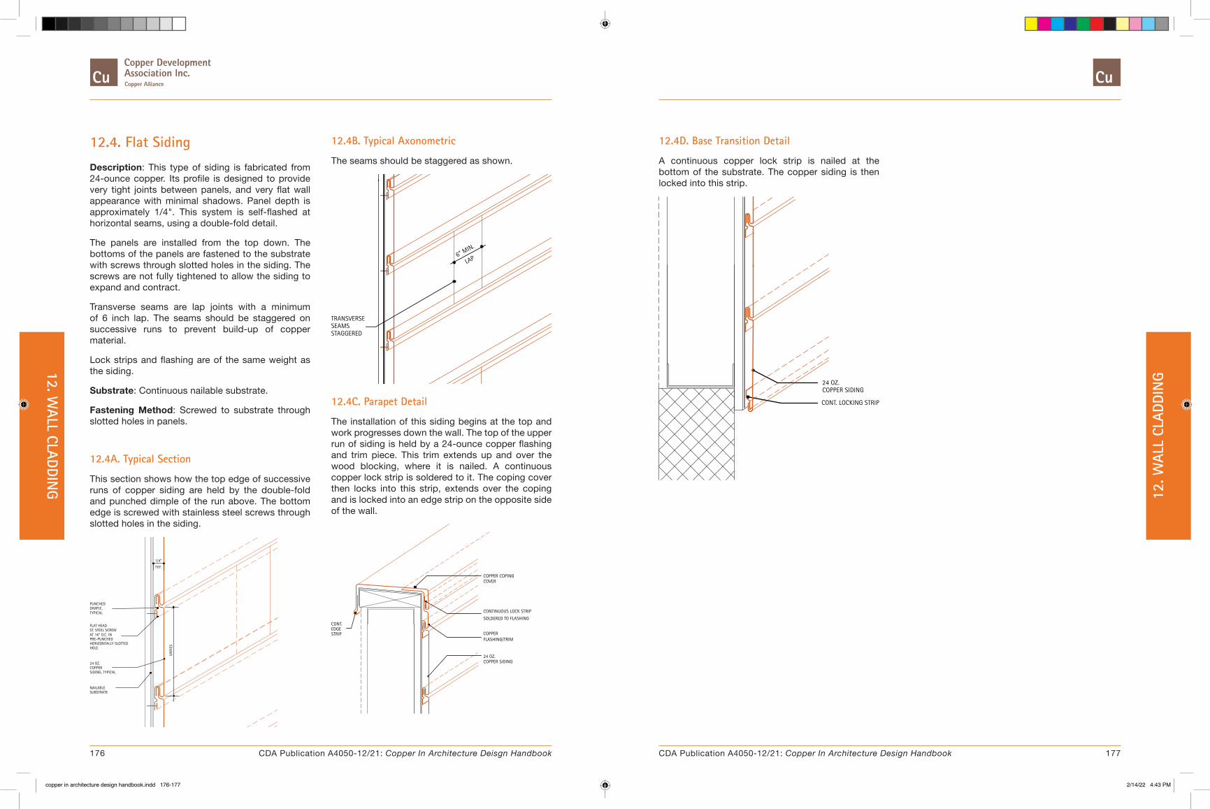
12.4. Flat Siding
Description: This type of siding is fabricated from 24-ounce copper. Its profile is designed to provide very tight joints between panels, and very flat wall appearance with minimal shadows. Panel depth is approximately 1/4". This system is self-flashed at horizontal seams, using a double-fold detail.
The panels are installed from the top down. The bottoms of the panels are fastened to the substrate with screws through slotted holes in the siding. The screws are not fully tightened to allow the siding to expand and contract.
Transverse seams are lap joints with a minimum of 6 inch lap. The seams should be staggered on successive runs to prevent build-up of copper material.
Lock strips and flashing are of the same weight as the siding.
Substrate: Continuous nailable substrate.
Fastening Method: Screwed to substrate through slotted holes in panels.
12.4A. Typical Section
This section shows how the top edge of successive runs of copper siding are held by the double-fold and punched dimple of the run above. The bottom edge is screwed with stainless steel screws through slotted holes in the siding.
ST. STEEL SCREW
HORIZONTALLY SLOTTED
NAILABLE SUBSTRATE
VARI
ES
COPPERSIDING, TYPICAL
24 OZ.
AT 16" O.C. INPRE-PUNCHED
HOLE
TYP.
FLAT HEAD
DIMPLE,PUNCHED
TYPICAL
1/4"
12.4B. Typical Axonometric
The seams should be staggered as shown.
STAGGEREDSEAMSTRANSVERSE
6" MIN.
LAP
12.4C. Parapet Detail
The installation of this siding begins at the top and work progresses down the wall. The top of the upper run of siding is held by a 24-ounce copper flashing and trim piece. This trim extends up and over the wood blocking, where it is nailed. A continuous copper lock strip is soldered to it. The coping cover then locks into this strip, extends over the coping and is locked into an edge strip on the opposite side of the wall.
COPPER COPINGCOVER
24 OZ.COPPER SIDING
FLASHING/TRIMCOPPER
CONTINUOUS LOCK STRIP
SOLDERED TO FLASHING
EDGECONT.
STRIP
12.4D. Base Transition Detail
A continuous copper lock strip is nailed at the bottom of the substrate. The copper siding is then locked into this strip.
CONT. LOCKING STRIP
24 OZ.COPPER SIDING
176 177CDA Publication A4050-12/21: Copper In Architecture Deisgn Handbook CDA Publication A4050-12/21: Copper In Architecture Design Handbook
12. WALL CLADDIN
G 12. W
ALL
CLAD
DIN
G
copper in architecture design handbook.indd 176-177copper in architecture design handbook.indd 176-177 2/14/22 4:43 PM2/14/22 4:43 PM

12.5. Structural Systems
Description: These panels are designed to be attached directly to the wall structure, without the use of a continuous substrate. The panels must withstand all forces and transfer those forces to the structure. Therefore, the panel dimensions and thicknesses, z-clip and structure designs must be reviewed by a structural engineer to ensure that all codes and structural requirements are satisfied.
Substrate: Structural system. A continuous substrate is not required.
Fastening Method: Stainless steel z-clips and rubber isolators.
12.5A. Typical Section
This section shows the rubber isolator clips and the stainless steel z-clip required to hold the copper panels and prevent direct contact with the structural system.
METALSTUD
PANELS, TYPICAL
VARI
ES
STAINLESS STEEL
RUBBER ISOLATOR
32 OZ. COPPER
VERTICAL STRUCTUREZ-CLIP AT
CLIP
12.5B. Typical Axonometric
Staggering the transverse seams, as shown, is required to avoid having many layers of the copper panels at one point. It also helps improve weather resistance.
6" MIN.
LAP
STAGGERED
TRANSVERSESEAMS
12.5C. Parapet Detail
A continuous copper trim/lock strip is nailed to the wood blocking. This strip holds the top edge of the copper panels. The coping cover locks into this strip, extends over the wood blocking and is locked into a continuous edge strip on the opposite side of the wall.
CONTINUOUSEDGESTRIP
CONTINUOUS TRIM/LOCK-STRIP
COPPER COPINGCOVER
12.5D. Base Detail
Wood blocking is attached to the structure at the base of the wall. A continuous copper flashing/lock strip is nailed to the bottom of the blocking. The bottom edge of the copper panel is locked into the strip.
COPPER PANELS
WOOD BLOCKING
COPPER FLASHING/ LOCK STRIP NAILED TO BLOCKING AND LOCKED INTO FLASHING.
178 179CDA Publication A4050-12/21: Copper In Architecture Deisgn Handbook CDA Publication A4050-12/21: Copper In Architecture Design Handbook
12. WALL CLADDIN
G 12. W
ALL
CLAD
DIN
G
copper in architecture design handbook.indd 178-179copper in architecture design handbook.indd 178-179 2/14/22 4:43 PM2/14/22 4:43 PM

12.6. Diagonal Flat Lock Systems
Description: Diagonal flat lock panels are usually constructed of relatively small, 8 to 12 inch, square copper pieces. They are very often used on curved surfaces, such as domes, spires and vaults.
There are two slightly different patterns of panels. Their differences are presented below. All panels can be attached to the substrate with cleats or they can be nailed at their upper vertex with a single copper, brass, bronze, or stainless steel nail.
Corner and base conditions use transition and termination strips, respectively.
The minimum recommended thickness for these panels is 16 ounce copper.
The number of cleats per panel is determined by panel size.
For more information on Diagonal Flat Seam Wall Cladding Testing, see Section 15.6. Performance Testing of Copper Wall Cladding.
Substrate: Continuous nailable substrate.
Fastening Method: Cleats or nails.
12.6A. Flat Seam - Diagonal Lock
The corners of the square panels are trimmed as shown. Notice the corners on the right and left are cut deeper than the top and bottom. This small difference results in the joints aligning as shown in the elevation. Sections 1 and 2 show that copper flashing is used at transitions, such as corners and base conditions.
ELEVATION
TERMINATIONSTRIP
FLASHINGCOPPER
2
1JOINTS,ALIGN
PAPER
CLEATS, TYP.
FELT
TYP. PANEL - UNFOLDED
1/2"
TYP. PANEL - FOLDED
EQ.
EQ.
EQ. EQ.
SECTION 1 - CORNER
FLASHINGTRANSITIONSTRIP
COPPER
NAILABLE SUBSTRATE
CLEAT
LOCK STRIP
SECTION 2 - BASE
COPPER FLASHING
STRIPTERMINATION
CONT.
SUBSTRATENAILABLE
12.6B. Flat Seam - Diagonal Lock - Alternate
These panels are trimmed equally at all four corners. The result is joints that are offset, as shown in the elevation. Sections 1 and 2 from Detail A, also apply to this panel pattern.
ELEVATION
2
1
FLASHING
STRIPTERMINATION
COPPER
JOINTS,OFFSET
STRIPTRANSITIONFLASHINGCOPPER
PAPER
CLEATS, TYPICAL
FELT
EQ.EQ.
TYP. PANEL - FOLDED TYP. PANEL - UNFOLDED
1/2" 1/2"
12.7. Horizontal Flat Lock Systems
Description: This type of wall panel is basically identical to 8.5. Flat Seam Roofing applied on a vertical surface. However, neither solder nor sealant is required in the joints, since the vertical surface provides positive drainage.
The panels are typically 18 x 24 inches, with 3/4 inch folds on all four sides. Two sides are folded over and two folded under. All corners are trimmed at a 45 degree angle.
The single lock seams are typically hammered flat. The minimum recommended gauge is 16 ounce copper.
Cleats are fastened with two stainless steel screws per cleat.
Substrate: Continuous nailable substrate.
Fastening Method: Cleats screwed to substrate.
12.7A. Typical Section
This section shows the single lock seam and cleats used for both horizontal and vertical joints.
CLEATS, TYPICAL
NAILABLE
18"x24"
SUBSTRATE
COPPER PANEL
12.7B. Typical Axonometric
This detail shows that one side and the lower edge of each panel lock into adjacent panels. The other side and upper edge are held by two cleats each. Vertical joints are always staggered for weather resistance.
CLEATS, TYP.
12.7C. Typical Copper Panel
These elevations show the typical panel, before and after the edges are folded.
3/4"
18"
24"
3/4"
180 181CDA Publication A4050-12/21: Copper In Architecture Deisgn Handbook CDA Publication A4050-12/21: Copper In Architecture Design Handbook
12. WALL CLADDIN
G 12. W
ALL
CLAD
DIN
G
copper in architecture design handbook.indd 180-181copper in architecture design handbook.indd 180-181 2/14/22 4:43 PM2/14/22 4:43 PM

12.7D. Typical Window Head and Sill
Wood blocking can be used at the head as shown. It provides a solid surface for attaching the copper head flashing and continuity around the window opening. The lower edge of the copper wall panels is locked into the head flashing to provide a drip.
BITUMINOUSCOATING FORSEPARATION OFDISSIMILAR METALS COPPER SILL
DAMMED AT ENDS
BLOCKINGWOOD
FLASHING,
FLASHINGHEADCOPPER
DRIP
COPPER FLASHING
BLOCKINGWOOD
At the sill, the wood blocking is covered with copper sill flashing which is locked into the upper edge of the copper wall panels. The ends of the sill flashing must be dammed to prevent water leaks into the wall cavity. If aluminum or other metal window frames are used, a bituminous coating or other isolating material must be applied to the sill flashing to prevent direct metal-to-metal contact.
For corner and base details, refer to 12.6. Diagonal Flat Lock Systems.
12.8. Copper Clad Honeycomb Systems
Description: Copper clad honeycomb panels are engineered and fabricated by a variety of manufacturers. They are light weight, strong, and offer a very flat copper panel appearance. Total panel thickness is variable to suit project requirements.
The honeycomb material varies depending on manufacturer and whether it is an interior or exterior application. Copper is bonded to the front side of the honeycomb and a backer panel is bonded to the back side. The backer panel is required, to ensure the rigidity of the assembly, thereby minimizing warping. The backer panel is usually of a material compatible with the structural system.
The details shown are generic, and do not represent a particular system. The details illustrate a system attached to a steel structure. With proper detailing, copper clad honeycomb panels can be installed on virtually any kind of structure or wall. For information on specific systems, contact the manufacturer.
Substrate: Any substrate or structure as required by the specific system manufacturer.
Fastening Method: Typically screws or bolts, as required by the specific system manufacturer.
12.8A. Typical Elevation
This diagrammatic elevation indicates the locations of Sections B and C.
B
C PANELCOPPER
12.8B. Horizontal Joint Section
These panels are shaped to provide hidden surfaces for the compressible gaskets. The joint shape is designed to prevent water penetration.
COMPRESSIBLESUPPORT
STRUCTURALSTEEL
ANGLE
CONTINUOUSSUPPORT
ANGLEBRACKET
GASKET
BACKERPANEL
BE REQUIRED
COPPERPANEL
SHIMS MAY
HONEYCOMBCORE
VARIES
Separation of dissimilar metals is an important consideration in the design of copper clad honeycomb panels. Manufacturers have engineered a variety of solutions, depending on the honeycomb and backer panel material, and the method of attachment to the structure.
In the system shown, the backer panel is not copper. Separation is maintained between the copper cladding and the backer panel. Steel or aluminum support angle brackets are bolted to the backer panel. The support brackets are bolted to continuous support angles which are welded or bolted to the steel structure. Shims or other leveling devices may be required for proper panel alignment.
182 183CDA Publication A4050-12/21: Copper In Architecture Deisgn Handbook CDA Publication A4050-12/21: Copper In Architecture Design Handbook
12. WALL CLADDIN
G 12. W
ALL
CLAD
DIN
G
copper in architecture design handbook.indd 182-183copper in architecture design handbook.indd 182-183 2/14/22 4:43 PM2/14/22 4:43 PM

12.8C. Vertical Joint Section
The vertical joint is detailed the same as the horizontal joint, with an additional compressible gasket to reduce water penetration.
COPPER CLADPANEL SUPPORT
ANGLE BRACKET
COMPRESSIBLEGASKET
ADDITIONAL
COMPRESSIBLE
SUPPORT ANGLECONTINUOUS
GASKET
STEELSTRUCTURAL
12.8D. Axonometric View
This view shows the relationship of the various parts. Note the use of structural support angles and alignment support angle brackets.
STEEL
CONTINUOUS
ANGLESUPPORT
PANELS
COPPERCLAD
SUPPORT
BRACKETANGLE
STRUCTURAL
12.9. Copper Screen Panels
Description: Copper screen panels are part of a manufacturer's engineered system. The details shown here illustrate the main concepts in the design of copper screen panels. The system shown uses metal support brackets and channel tracks to carry the copper panels. The support brackets can be attached to virtually any kind of building structure.
The copper screen panels act as a lightweight, finish screen. The system shown is designed to be a water shedding rain screen. Alternatively, the panels can be perforated or have shaped openings acting as sun or decorative screens. The backup wall system should always be designed to be watertight.
Isolator clips are used between the metal support system and the copper panels to separate dissimilar metals. The minimum gauge of the copper panels is dependent on the size of the panels and the design of the specific system used. Manufacturer's recommendations should be followed.
Substrate: Any substrate or structure as required by the specific system manufacturer.
Fastening Method: Typically screws or bolts, as required by the specific system manufacturer.
12.9A. Typical Elevation
This diagrammatic elevation indicates the locations of Sections B and C.
CCOPPERPANEL
B
12.9B. Vertical Section - Horizontal Joint
This section is cut through the vertical channel track to show the support bar that carries the copper panels. This system uses one stainless steel screw per panel to ensure panels are not lifted by wind. Isolation tape or a bituminous coating must be applied where the back of the copper panel contacts the channel track, to separate dissimilar metals. In addition, isolation clips are used between the support bars and the copper panels.
ISOLATION MATERIAL
METALS
SUPPORT BAR
SCREWSAFETY
CLIP FORISOLATOR
SEPARATIONOF DISSIMILAR
BRACKET
WALLWATERTIGHT
SUPPORTPANELCOPPER
AT CHANNEL TRACK
12.9C. Horizontal Section - Vertical Joint
The support brackets are fastened to the structure. Channel tracks are bolted to the support brackets. The copper screen panels are hung onto the support bar in the channel track.
SUPPORTBAR
EDGEPANEL
INSULATIONLOCATION
OPTIONAL
ISOLATOR
PANELCOPPER
CLIP
B
BRACKETSUPPORT
STUDSSTRUCTURAL
WALLWATERTIGHT
TRACKCHANNEL
Although such a system does not necessarily have any insulation, insulation may be added within the cavity, as shown.
184 185CDA Publication A4050-12/21: Copper In Architecture Deisgn Handbook CDA Publication A4050-12/21: Copper In Architecture Design Handbook
12. WALL CLADDIN
G 12. W
ALL
CLAD
DIN
G
copper in architecture design handbook.indd 184-185copper in architecture design handbook.indd 184-185 2/14/22 4:43 PM2/14/22 4:43 PM

12.9D. Isometric View
This detail shows the relationship of the various parts. Once all the panels are in place, any water that passes between vertical joints is channeled down the channel track.
COPPERPANEL
SUPPORT BAR
BRACKET
CLIPISOLATOR
SUPPORT
CHANNELTRACK
12.10. Curtain Wall Systems
Description: The details shown in this plate are from the Seagram Building in New York City, completed in 1957. They represent the methods used in the bronze and glass curtain wall system. The bronze mullions run the full height of the building. Brown-colored plate glass spans between the mullions, and 1/8" thick Muntz Metal spandrel panels are used at each floor slab. The result is a very uniform color among the exterior materials.
These details demonstrate the approach used to construct a copper alloy curtain wall in a historically significant building. Today's standards would require a higher level of moisture and thermal control. Modern construction methods and materials would certainly improve the moisture and thermal control of the exterior skin.
Substrate: This system supports itself from floor slab to floor slab. No substrate is required.
Fastening Method: Steel brackets are used at every floor slab.
12.10A. Typical Elevation
This diagrammatic elevation shows the relationship of the various curtain wall components to the floor slabs, and indicates the locations of Sections 12.10B and 12.10C.
C
B
FLOOR
SPANDRELMUNTZ METAL
LINE
PLATE GLASS
FLOORLINE
MUNTZ METALSPANDREL
12.10B. Section At Horizontal Joint
The muntz metal spandrel panels are used to conceal the floor slab and spandrel beam at each floor. Expansion Seams in the bronze mullions are required to accommodate vertical movement.
JOINT
SPACEEXPANSION
BRONZE STOPSEXTRUDED
PLATE GLASS
BRONZE MULLION
EXPANSION
SPANDREL1/8" MUNTZ METAL
FLOORLINE
12.10C. Section At Vertical Joint
This section shows two different conditions. The left side is cut through the spandrel panel. The steel structure is used to support the curtain wall at every floor slab. The bronze Tee-bar is bolted to the steel angles. The Tee-bar is plug welded to the continuous bronze mullions.
TEE-BAR
MUNTZ METALSPANDREL PANEL
BRONZE MULLIONCONTINUOUS
PLATE GLASS
FLOOR LEVELAT EACH
MUNTZ METALMULLION COVER
STEEL
STEEL ANGLE
BRONZE
STRUCTUREAT EACHFLOOR LEVEL
186 187CDA Publication A4050-12/21: Copper In Architecture Deisgn Handbook CDA Publication A4050-12/21: Copper In Architecture Design Handbook
12. WALL CLADDIN
G 12. W
ALL
CLAD
DIN
G
copper in architecture design handbook.indd 186-187copper in architecture design handbook.indd 186-187 2/14/22 4:43 PM2/14/22 4:43 PM

The right side of the detail shows the condition at the window. A muntz metal panel is used to cover the inside face of the curtain wall.
In both cases, the spandrel panels and glass are held by extruded bronze frames.
12.10D. Isometric View
This detail shows how the structural steel bracket and angles hold the bronze Tee-bar, and their relationship to the bronze mullion.
FLOORSLAB
STEEL ANGLE
STEEL BRACKET
BRONZE TEE-BARAT EACH FLOOR LEVEL
BRONZEMULLION
12.11. Standing Seam
Description: Standing Seam wall cladding utilizes the same proven joinery as Standing Seam roofing but applied to a vertical wall surface. Seams may be oriented vertically, horizontally, or diagonally. With horizontal or diagonal options, it is important to ensure panel seams are positioned so the seam "opening" is placed on the downward facing side of the seam to insure water sheds over, not into, the seam. Short panel construction (8-10' long pans maximum typical) is more common, due to ease of handling and assembly on a vertical surface. If longer panels are preferred, coordinate with the installer to ensure proper handling under typical construction conditions.
With Standing Seams oriented vertically, transverse seams are per 8.2C Transverse Seam, Detail 1 Steep Pitch. Horizontally oriented Standing Seams on walls require greater transverse seam overlap, similar to 8.2C Transverse Seam, Detail 2 Low Pitch, but with 6" minimum lap. If long panels are preferred, follow attachment and thermal movement guidelines presented in Section 8.8. Long Pan Systems.
There are two variations to Standing Seam Wall Cladding, Double Lock (as with roofing), and Single Lock. Double Lock is preferred.
For more information on Standing Seam Wall Cladding Testing, see Section 15.6. Performance Testing of Copper Wall Cladding.
Window, Door or other Fenestration Penetrations, see Section 12.12.
For transverse seam detail see: 8.2C Transverse Seam, Detail 1 Steep Pitch.
The minimum recommended gauge for Standing Seam Wall Cladding is 16 ounces.
When Standing Seams are oriented horizontally, some prefer to include a copper or stainless-steel stiffening angle within the seam.
Substrate: Continuous nailable substrate
Fastening Method: Cleats screwed or nailed to substrate.
12.11A. Typical Section Double Lock Standing Seam Wall Cladding
This section shows the double lock seam as used for wall cladding, section rotated depending on seam orientation, but, if not vertical, always with seam "opening" to downslope side.
OPTIONALCLEAT
CLEATS 12” O.C. Max
1"
3/4"
2"
3/4"
Cleats spaced a maximum of 12" o/c
188 189CDA Publication A4050-12/21: Copper In Architecture Deisgn Handbook CDA Publication A4050-12/21: Copper In Architecture Design Handbook
12. WALL CLADDIN
G 12. W
ALL
CLAD
DIN
G
copper in architecture design handbook.indd 188-189copper in architecture design handbook.indd 188-189 2/14/22 4:43 PM2/14/22 4:43 PM

12.11B. Typical Section, Single Lock Standing Seam Wall Cladding
This section shows the single lock standing seam as used for wall cladding, section rotated depending on seam orientation, but, if not vertical, always with seam “opening” to downslope side.
Cleats spaced a maximum of 12” o/c
12.11C. Parapet Detail “Pan End” Style Non-Vented
The non-vented detail is very similar to Detail 4.2.9A "Top of Mansard-Coping Cover".
3/4" LOCK
STANDING SEAMSBEYOND
TWO PER PANCLEAT,
3/4" LOCK
PAN-END
12.11D. Parapet Detail “Pan End” Vented
A perforated heavier gauge copper "Z" closure positioned near the top end of each panel provides ventilation. As this "Z" provides positive attachment for the Coping, it should be thicker material. If desired, the design professional can provide an additional lock strip to best support the coping.
3/4” LOCK
CONTINUOUSCLEAT
CONT. CLEAT,COPPER OR S.S.
COPPER CLEAT,TWO PER PAN
“Z”-CLEAT WITH PERFORATED WEB
STANDING SEAMS BEYOND
12.11E. Inside Corner Detail
Inside Corner Flashing, showing options for both horizontally or vertically oriented Standing Seam Wall Cladding.
2"-6"
4" MIN.HORIZONTALSTANDING SEAM
CLEATS AT 12” O.C. MAX
3/4” MIN.DOUBLE FOLD
VERTICALSTANDING SEAM
12.12. Fenestration
Description: Window and other Wall Opening Flashing presents special challenges. Flashing must function to protect these critical areas from water infiltration while accommodating thermal movement. Wall panel and flashing dimensions should be coordinated with penetration placement to provide for desired (generally symmetrical) layout. These details are meant to supplement 12.7D. Typical Window Head and Sill
Ideally, fenestration flashing should be installed before the windows or door frames. This allows for the frames to rest on the flashing with a bed of sealant between. If frames are hollow or slotted, one may design the flashing edge to fit into this cavity, providing an additional barrier to water infiltration.
For smaller openings, Sill, Jamb and Head flashing pieces are often formed from one continuous longitudinal strip. If a multiple piece option is necessary, flashing pieces are commonly overlapped 4-6” with dual beads of sealant placed within the lap.
Symmetry: Exact Panel width and height rarely coincides perfectly with edges of the window penetration. The exposed dimension of sill or head flashing is often easier to change to suit conditions.
Options include, but are not necessarily limited to:
A. Form panels with width more appropriate to actual coverage requirements.
B. With standing or batten seam systems, spread some seams (slight flare at base of seam, up to ¼”) for minor coverage adjustment. Do not try to compress seams together, as the flat of the panel may bow, causing exceptional oil canning while restricting thermal movement.
C. Make some panels runs slightly narrower or position the narrow panel runs at building corners, directly at window jambs or directly above a penetration.
D. Design with vertical battens at edges of window or door penetrations.
Substrate: Continuous Nailable Substrate
Fastening Method: Cleats screwed or nailed to substrate.
12.12A. "Outside" Flush Style Jamb Flashing
CUTTING PLANE
SECTION 2 - TOP VIEWSECTION 1 - ISOMETRIC VIEW (TO INNER JAMB, SILL)
JAMB
EXTERIOR WALL CLADDING
SEE DETAIL 12.12EFOR SILL DAM PIECE
12.12B. "Inside" Flush Style Jamb Flashing
CUTTING PLANE
SECTION 2 - TOP VIEWSECTION 1 - ISOMETRIC VIEW (TO INNER JAMB, SILL)
JAMB
EXTERIOR WALL CLADDING
190 191CDA Publication A4050-12/21: Copper In Architecture Deisgn Handbook CDA Publication A4050-12/21: Copper In Architecture Design Handbook
12. WALL CLADDIN
G 12. W
ALL
CLAD
DIN
G
copper in architecture design handbook.indd 190-191copper in architecture design handbook.indd 190-191 2/14/22 4:43 PM2/14/22 4:43 PM
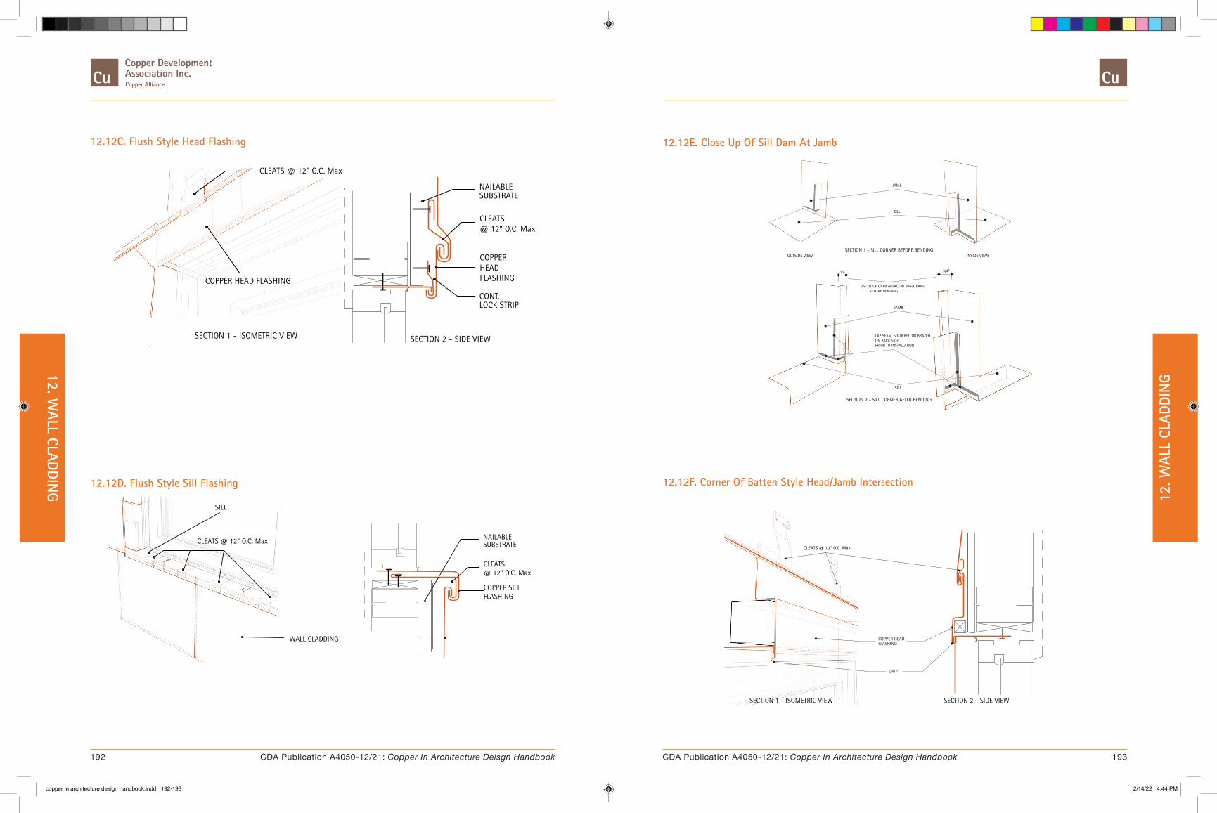
12.12C. Flush Style Head Flashing
LOCK STRIP
SECTION 2 - SIDE VIEW
CLEATS@ 12” O.C. Max
CONT.
SUBSTRATENAILABLE
SECTION 1 - ISOMETRIC VIEW
CLEATS @ 12” O.C. Max
COPPERHEADFLASHINGCOPPER HEAD FLASHING
12.12E. Close Up Of Sill Dam At Jamb
SECTION 2 - SILL CORNER AFTER BENDING
SECTION 1 - SILL CORNER BEFORE BENDING
JAMB
LAP SEAM, SOLDERED OR BRAZEDON BACK SIDE PRIOR TO INSTALLATION
OUTSIDE VIEW INSIDE VIEW
JAMB
SILL
SILL
Lorem ipsum
3/4” LOCK OVER ADJACENT WALL PANEL BEFORE BENDING
3/4”3/4”
12.12D. Flush Style Sill Flashing
SECTION 2 - SIDE VIEW
CLEATS@ 12” O.C. Max
SUBSTRATENAILABLE
SECTION 1 - SILL FLASHING
CLEATS @ 12” O.C. Max
COPPER SILLFLASHING
WALL CLADDING
SILL
12.12F. Corner Of Batten Style Head/Jamb Intersection
FLASHINGCOPPER HEAD
DRIP
SECTION 2 - SIDE VIEWSECTION 1 - ISOMETRIC VIEW
CLEATS @ 12” O.C. Max
192 193CDA Publication A4050-12/21: Copper In Architecture Deisgn Handbook CDA Publication A4050-12/21: Copper In Architecture Design Handbook
12. WALL CLADDIN
G 12. W
ALL
CLAD
DIN
G
copper in architecture design handbook.indd 192-193copper in architecture design handbook.indd 192-193 2/14/22 4:44 PM2/14/22 4:44 PM

13. DOMES, SPIRES AND VAULTS
� 13.1. Circular Dome with Diagonal Flat Seam System
� 13.2. Circular Dome with Standing Seam System
� 13.3. Circular Dome with Flat Seam System
� 13.4. Standing Seam Roof on Conical Spire
� 13.5. Flat Seam Roofing on Octagonal Spire
� 13.6. Arched Barrel Vault with Standing Seam
� 13.7. Barrel Vault With Flat Seam
� 13.8. Steps for Dome Panel Layout
Introduction
Domes, spires, and vaults are designed in a wide variety of shapes. They are not limited to simple geometry, such as circular domes and conical spires. Complex curved surfaces and multi-faceted designs can easily be formed in copper. The concepts shown in this section, can be adapted to any of these situations.
The details shown in this section are based on the principles of standing seam, batten seam, flat seam, and diagonal flat seam roofing. When detailing a dome, spire, or vault, the substrate, underlayment, fastening, and seam design recommendations given in the 8. Roofing Systems section generally apply. The designer should also consider the effects of variations in slope. For example, a transverse seam detail near the base of a dome (which is at a high pitch) is not recommended for the top of the dome (where the pitch is low).
Special attention should be given to the areas where domes and spires intersect adjoining roof surfaces. The resulting valleys require details to prevent "back-up" of water, especially in cold climates prone to ice and snow.
The proper ventilation of the underside of domes, spires, and barrel vaults is particularly important.
The location of vents at the bases of cupolas and at the caps terminating domes and spires must be addressed.
The location and design of vents is dependent on project location, climate, and use. The designer is urged to address these issues on a project-by-project basis.
For both simple and complex shapes, it is usually easier to lay out the roofing pans and panels directly on the dome than it is to develop them from drawings. The pans or panels can be field or shop fabricated, but the dimensions should be generated and dictated by the size and shape of the dome.
Equipment Available:
Special equipment is available to form copper into curved shapes. Such equipment is particularly useful in fabricating spherical copper caps and for “stretching” portions of copper flashing to accommodate curved surfaces.
13.1. Circular Dome with Diagonal Flat Seam System
Description: The details show a circular dome capped with a ventilated copper cap. The cap is designed to allow for air to flow out of the dome, while preventing any water, from entering. The cap must also be designed to withstand local wind loads.
On the low-pitch areas near the top of the dome, the seams must be soldered to ensure water- tightness. As the pitch of the dome increases, sealant may be used in the seams. Near the base of the dome, where the pitch exceeds 6" per foot, no solder or sealant is required. See 8.1. Special Roofing Design and Installation Considerations for more information.
At the base, the copper panels are usually 8 to 12 inches square. The practical panel sizes that can be efficiently fabricated and installed are 4 to 6 inches minimum and 16 to 18 inches square, maximum. There are a constant number of panels around the perimeter of the dome. They diminish in size as they get closer to the top.
Diagonal flat lock panels are particularly well- suited for covering irregular curved surfaces.
A cornice is shown at the base of the dome. A built-in copper gutter can be used, to control run-off as shown in Detail 13.1E. A copper cap, like the one shown in Detail 13.2A, can be used at the top as an alternative.
The minimum recommended weight for the panels is 16 ounce copper.
Substrate: Continuous nailable substrate.
Fastening Method: Cleats
13.1A. Elevation
This detail shows the continuous panel seam that runs from cornice to cap, and the spiral effect of the diagonal copper panels on a circular dome.
D
COPPER CORNICE
E
DIAGONAL FLATSEAM PANELS
COPPER CAP
BUILT-IN COPPERGUTTER ALTERNATE
F
13.1B. Plan
The diminishing size of the copper panels is clearly visible. When designing this type of dome, consideration should be given to the size of the panels, as they can get very small. If their size becomes too small to construct, panel sizes can be modified by deleting every other seam and doubling the resulting panel size, as shown in the left half of the detail.
ALTERNATE COURSINGCAN BE USED WHERESTANDARD COURSINGWOULD BE TOO SMALL BUILT-IN COPPER
GUTTER ALTERNATE
STANDARD COURSING TO TOPALTERNATE COURSING NEAR TOP
194 195CDA Publication A4050-12/21: Copper In Architecture Deisgn Handbook CDA Publication A4050-12/21: Copper In Architecture Design Handbook
13. DOM
ES, SPIRES AND VAULTS 13
. DO
MES
, SPI
RES
AND
VAUL
TS
copper in architecture design handbook.indd 194-195copper in architecture design handbook.indd 194-195 2/14/22 4:44 PM2/14/22 4:44 PM
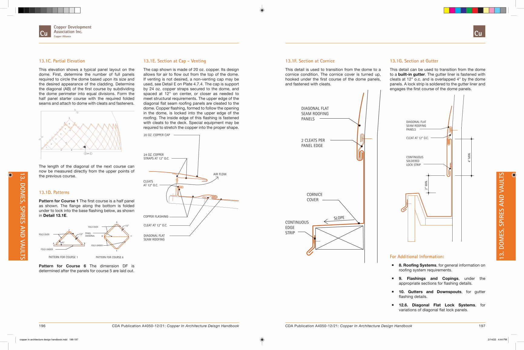
13.1C. Partial Elevation
This elevation shows a typical panel layout on the dome. First, determine the number of full panels required to circle the dome based upon its size and the desired appearance of the cladding. Determine the diagonal (AB) of the first course by subdividing the dome perimeter into equal divisions. Form the half panel starter course with the required folded seams and attach to dome with cleats and fasteners.
A
2
1
3
4
5
B
C
E
E OR F
D 6
G
F
The length of the diagonal of the next course can now be measured directly from the upper points of the previous course.
13.1D. Patterns
Pattern for Course 1 The first course is a half panel as shown. The flange along the bottom is folded under to lock into the base flashing below, as shown in Detail 13.1E.
PATTERN FOR COURSE 1
FOLD UNDER
FOLD OVER
A 45°
C
1/2"
B
1/2"FOLD OVER
PATTERN FOR COURSE 6
FOLD UNDER
PANELDIAGONAL D
E
F
G
Pattern for Course 6 The dimension DF is determined after the panels for course 5 are laid out.
13.1E. Section at Cap - Venting
The cap shown is made of 20 oz. copper. Its design allows for air to flow out from the top of the dome. If venting is not desired, a non-venting cap may be used, see Detail E on Plate 4.7.4. The cap is support by 24 oz. copper straps secured to the dome, and spaced at 12" on center, or closer as needed to meet structural requirements. The upper edge of the diagonal flat seam roofing panels are cleated to the dome. Copper flashing, formed to follow the opening in the dome, is locked into the upper edge of the roofing. The inside edge of this flashing is fastened with cleats to the deck. Special equipment may be required to stretch the copper into the proper shape.
CLEAT AT 12" O.C.
DIAGONAL FLATSEAM ROOFING
24 OZ. COPPERSTRAPS AT 12" O.C.
COPPER FLASHING
CLEATSAT 12" O.C.
20 OZ. COPPER CAP
AIR FLOW
13.1F. Section at Cornice
This detail is used to transition from the dome to a cornice condition. The cornice cover is turned up, hooked under the first course of the dome panels, and fastened with cleats.
CONTINUOUSEDGESTRIP
SLOPE
CORNICECOVER
DIAGONAL FLATSEAM ROOFINGPANELS
PANEL EDGE2 CLEATS PER
13.1G. Section at Gutter
This detail can be used to transition from the dome to a built-in gutter. The gutter liner is fastened with cleats at 12" o.c. and is overlapped 4" by the dome panels. A lock strip is soldered to the gutter liner and engages the first course of the dome panels.
LOCK STRIP
CONTINUOUSSOLDERED
2" M
IN.
PANELSSEAM ROOFINGDIAGONAL FLAT
CLEAT AT 12" O.C.
4" M
IN.
For Additional Information:
� 8. Roofing Systems, for general information on roofing system requirements.
� 9. Flashings and Copings, under the appropriate sections for flashing details.
� 10. Gutters and Downspouts, for gutter flashing details.
� 12.6. Diagonal Flat Lock Systems, for variations of diagonal flat lock panels.
196 197CDA Publication A4050-12/21: Copper In Architecture Deisgn Handbook CDA Publication A4050-12/21: Copper In Architecture Design Handbook
13. DOM
ES, SPIRES AND VAULTS 13
. DO
MES
, SPI
RES
AND
VAUL
TS
copper in architecture design handbook.indd 196-197copper in architecture design handbook.indd 196-197 2/14/22 4:44 PM2/14/22 4:44 PM
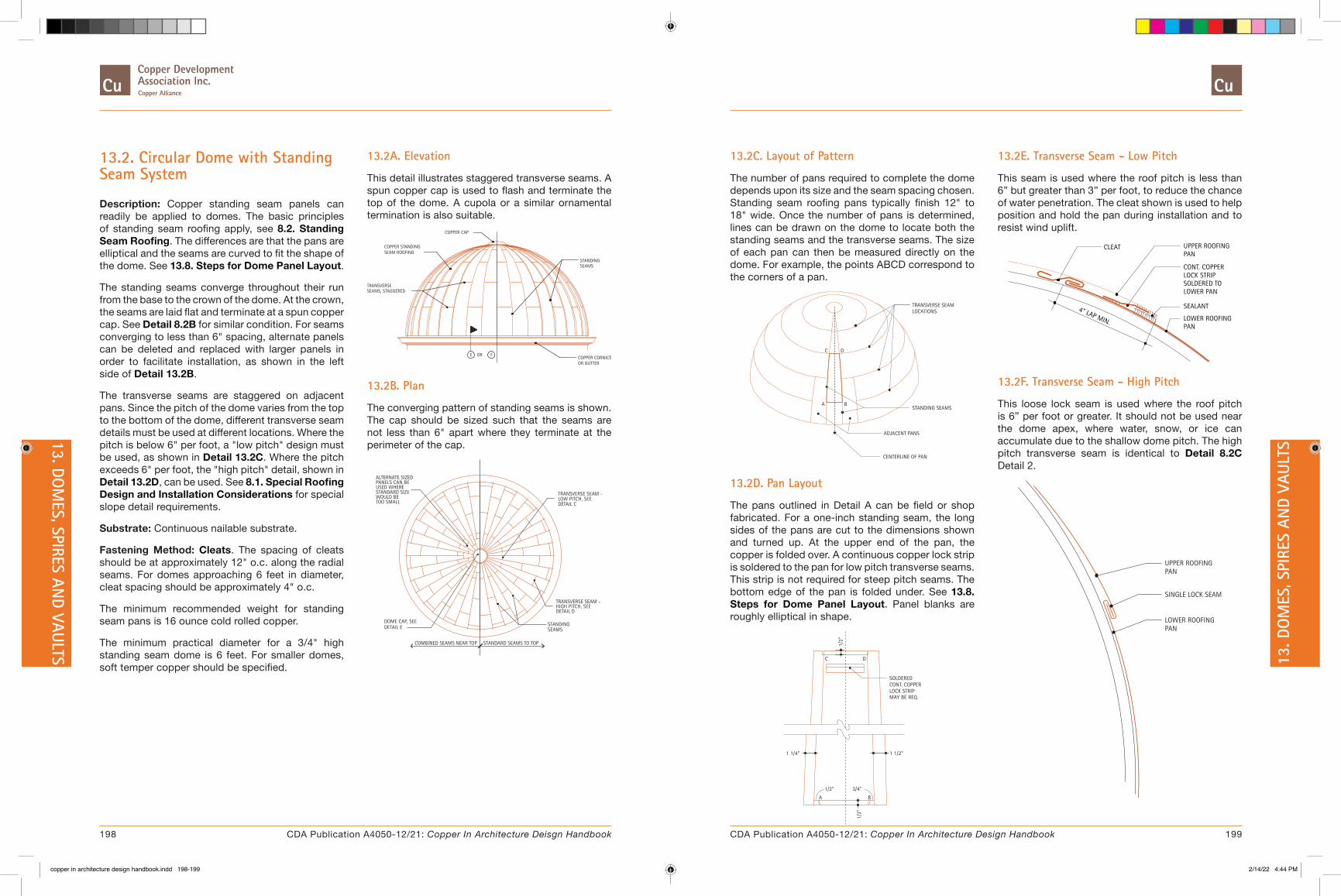
13.2. Circular Dome with Standing Seam System
Description: Copper standing seam panels can readily be applied to domes. The basic principles of standing seam roofing apply, see 8.2. Standing Seam Roofing. The differences are that the pans are elliptical and the seams are curved to fit the shape of the dome. See 13.8. Steps for Dome Panel Layout.
The standing seams converge throughout their run from the base to the crown of the dome. At the crown, the seams are laid flat and terminate at a spun copper cap. See Detail 8.2B for similar condition. For seams converging to less than 6" spacing, alternate panels can be deleted and replaced with larger panels in order to facilitate installation, as shown in the left side of Detail 13.2B.
The transverse seams are staggered on adjacent pans. Since the pitch of the dome varies from the top to the bottom of the dome, different transverse seam details must be used at different locations. Where the pitch is below 6" per foot, a "low pitch" design must be used, as shown in Detail 13.2C. Where the pitch exceeds 6" per foot, the "high pitch" detail, shown in Detail 13.2D, can be used. See 8.1. Special Roofing Design and Installation Considerations for special slope detail requirements.
Substrate: Continuous nailable substrate.
Fastening Method: Cleats. The spacing of cleats should be at approximately 12" o.c. along the radial seams. For domes approaching 6 feet in diameter, cleat spacing should be approximately 4" o.c.
The minimum recommended weight for standing seam pans is 16 ounce cold rolled copper.
The minimum practical diameter for a 3/4" high standing seam dome is 6 feet. For smaller domes, soft temper copper should be specified.
13.2A. Elevation
This detail illustrates staggered transverse seams. A spun copper cap is used to flash and terminate the top of the dome. A cupola or a similar ornamental termination is also suitable.
COPPER CORNICEOR GUTTER
COPPER CAP
TRANSVERSESEAMS, STAGGERED
SEAM ROOFINGCOPPER STANDING
E OR F
STANDINGSEAMS
13.2B. Plan
The converging pattern of standing seams is shown. The cap should be sized such that the seams are not less than 6" apart where they terminate at the perimeter of the cap.
COMBINED SEAMS NEAR TOP
PANELS CAN BEALTERNATE SIZED
USED WHERESTANDARD SIZEWOULD BETOO SMALL
DETAIL EDOME CAP, SEE
STANDARD SEAMS TO TOP
STANDINGSEAMS
HIGH PITCH, SEEDETAIL D
TRANSVERSE SEAM -
DETAIL CLOW PITCH, SEETRANSVERSE SEAM -
13.2C. Layout of Pattern
The number of pans required to complete the dome depends upon its size and the seam spacing chosen. Standing seam roofing pans typically finish 12" to 18" wide. Once the number of pans is determined, lines can be drawn on the dome to locate both the standing seams and the transverse seams. The size of each pan can then be measured directly on the dome. For example, the points ABCD correspond to the corners of a pan.
LOCATIONSTRANSVERSE SEAM
ADJACENT PANS
STANDING SEAMS
CENTERLINE OF PAN
A B
DC
13.2D. Pan Layout
The pans outlined in Detail A can be field or shop fabricated. For a one-inch standing seam, the long sides of the pans are cut to the dimensions shown and turned up. At the upper end of the pan, the copper is folded over. A continuous copper lock strip is soldered to the pan for low pitch transverse seams. This strip is not required for steep pitch seams. The bottom edge of the pan is folded under. See 13.8. Steps for Dome Panel Layout. Panel blanks are roughly elliptical in shape.
A
1/2"
1/2"
B
3/4"
1/2"
1 1/4"
C D
1 1/2"
SOLDERED
LOCK STRIPCONT. COPPER
MAY BE REQ.
13.2E. Transverse Seam - Low Pitch
This seam is used where the roof pitch is less than 6” but greater than 3” per foot, to reduce the chance of water penetration. The cleat shown is used to help position and hold the pan during installation and to resist wind uplift.
4" LAP MIN.
CLEAT
LOWER ROOFINGPAN
LOWER PANSOLDERED TO
SEALANT
LOCK STRIPCONT. COPPER
UPPER ROOFINGPAN
13.2F. Transverse Seam - High Pitch
This loose lock seam is used where the roof pitch is 6” per foot or greater. It should not be used near the dome apex, where water, snow, or ice can accumulate due to the shallow dome pitch. The high pitch transverse seam is identical to Detail 8.2C Detail 2.
SINGLE LOCK SEAM
LOWER ROOFINGPAN
UPPER ROOFINGPAN
198 199CDA Publication A4050-12/21: Copper In Architecture Deisgn Handbook CDA Publication A4050-12/21: Copper In Architecture Design Handbook
13. DOM
ES, SPIRES AND VAULTS 13
. DO
MES
, SPI
RES
AND
VAUL
TS
copper in architecture design handbook.indd 198-199copper in architecture design handbook.indd 198-199 2/14/22 4:44 PM2/14/22 4:44 PM
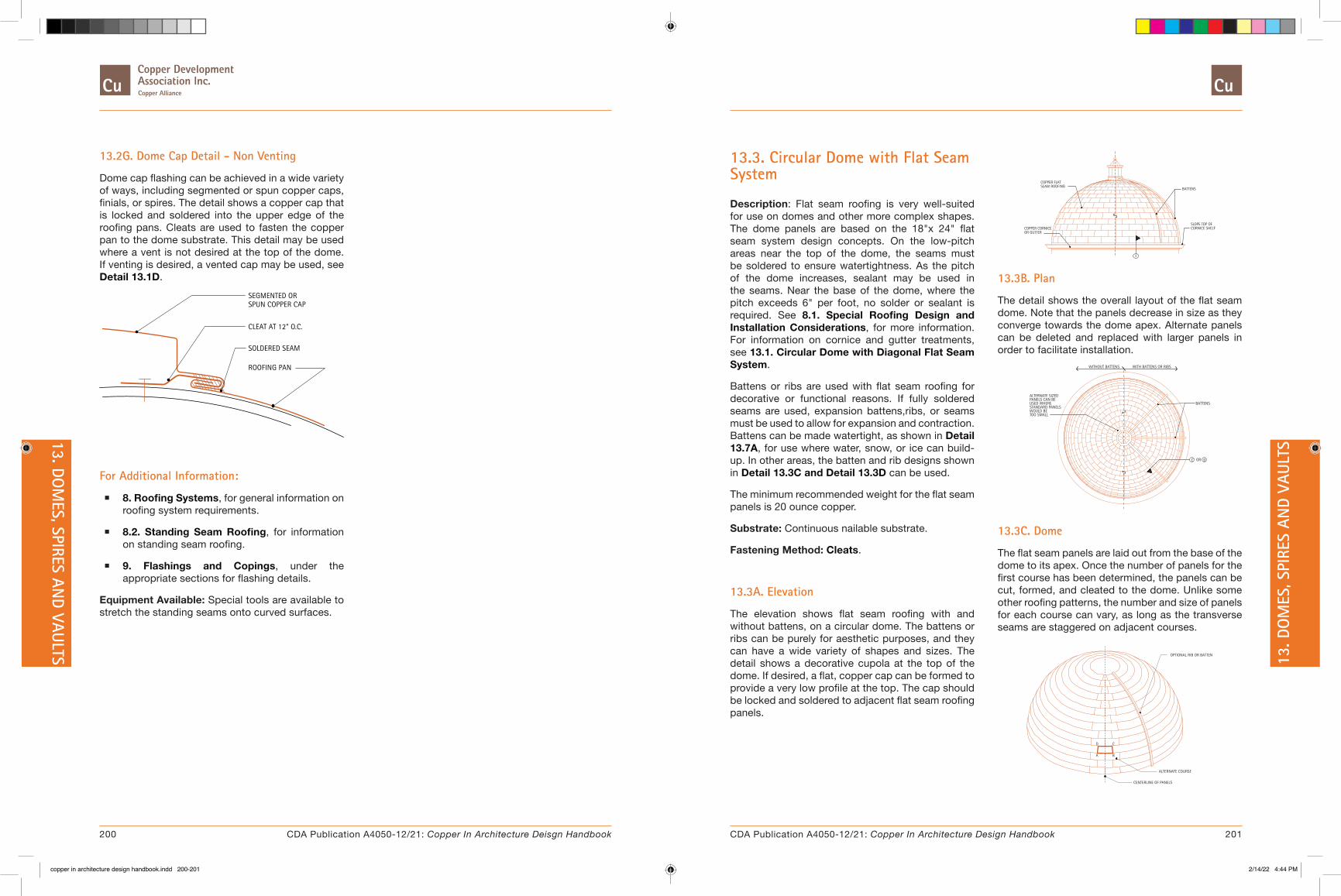
13.2G. Dome Cap Detail - Non Venting
Dome cap flashing can be achieved in a wide variety of ways, including segmented or spun copper caps, finials, or spires. The detail shows a copper cap that is locked and soldered into the upper edge of the roofing pans. Cleats are used to fasten the copper pan to the dome substrate. This detail may be used where a vent is not desired at the top of the dome. If venting is desired, a vented cap may be used, see Detail 13.1D.
SPUN COPPER CAP
CLEAT AT 12" O.C.
ROOFING PAN
SOLDERED SEAM
SEGMENTED OR
For Additional Information:
� 8. Roofing Systems, for general information on roofing system requirements.
� 8.2. Standing Seam Roofing, for information on standing seam roofing.
� 9. Flashings and Copings, under the appropriate sections for flashing details.
Equipment Available: Special tools are available to stretch the standing seams onto curved surfaces.
13.3. Circular Dome with Flat Seam System
Description: Flat seam roofing is very well-suited for use on domes and other more complex shapes. The dome panels are based on the 18"x 24" flat seam system design concepts. On the low-pitch areas near the top of the dome, the seams must be soldered to ensure watertightness. As the pitch of the dome increases, sealant may be used in the seams. Near the base of the dome, where the pitch exceeds 6" per foot, no solder or sealant is required. See 8.1. Special Roofing Design and Installation Considerations, for more information. For information on cornice and gutter treatments, see 13.1. Circular Dome with Diagonal Flat Seam System.
Battens or ribs are used with flat seam roofing for decorative or functional reasons. If fully soldered seams are used, expansion battens,ribs, or seams must be used to allow for expansion and contraction. Battens can be made watertight, as shown in Detail 13.7A, for use where water, snow, or ice can build-up. In other areas, the batten and rib designs shown in Detail 13.3C and Detail 13.3D can be used.
The minimum recommended weight for the flat seam panels is 20 ounce copper.
Substrate: Continuous nailable substrate.
Fastening Method: Cleats.
13.3A. Elevation
The elevation shows flat seam roofing with and without battens, on a circular dome. The battens or ribs can be purely for aesthetic purposes, and they can have a wide variety of shapes and sizes. The detail shows a decorative cupola at the top of the dome. If desired, a flat, copper cap can be formed to provide a very low profile at the top. The cap should be locked and soldered to adjacent flat seam roofing panels.
BATTENS
CORNICE SHELFSLOPE TOP OF
COPPER CORNICEOR GUTTER
COPPER FLATSEAM ROOFING
E
13.3B. Plan
The detail shows the overall layout of the flat seam dome. Note that the panels decrease in size as they converge towards the dome apex. Alternate panels can be deleted and replaced with larger panels in order to facilitate installation.
BATTENSPANELS CAN BEALTERNATE SIZED
USED WHERESTANDARD PANELSWOULD BETOO SMALL
ORC D
WITHOUT BATTENS WITH BATTENS OR RIBS
13.3C. Dome
The flat seam panels are laid out from the base of the dome to its apex. Once the number of panels for the first course has been determined, the panels can be cut, formed, and cleated to the dome. Unlike some other roofing patterns, the number and size of panels for each course can vary, as long as the transverse seams are staggered on adjacent courses.
CENTERLINE OF PANELS
D
A B
C
ALTERNATE COURSE
OPTIONAL RIB OR BATTEN
200 201CDA Publication A4050-12/21: Copper In Architecture Deisgn Handbook CDA Publication A4050-12/21: Copper In Architecture Design Handbook
13. DOM
ES, SPIRES AND VAULTS 13
. DO
MES
, SPI
RES
AND
VAUL
TS
copper in architecture design handbook.indd 200-201copper in architecture design handbook.indd 200-201 2/14/22 4:44 PM2/14/22 4:44 PM

13.3D. Typical Panel
The panels are trapezoidal to fit the dome's curved surface. The upper edge and one side are folded over; the lower edge and second side are folded under. A minimum of 3/4" fold is required to ensure interlocking of adjacent panels.
OVEREDGES FOLDED
3/4"
A
3/4"
D
3/4"
UNDEREDGES FOLDED
B
C
3/4"
TRAPEZOIDALPANEL
45°TYP.
13.3E. Typical Batten
Where battens are used, a wide range of sizes and shapes can be designed. This detail shows a typical batten. An important consideration is space for expansion, which can be accommodated as shown, or by tapering the battens as shown in the 8.3. Batten Seam Roofing.
SPACE
EXP.
ROOF PAN
BATTEN APRON
BATTEN COVER
13.3F. Alternate Ribs
These designs provide the space for expansion.
EXP.
SPACE
VARI
ES
MIN
. 1" ROOF PAN
DETAIL 2
EXP.
SPACE
1"-2"
RIB COVER
3/4"
DETAIL 1
Detail 1 is recommended for warm climates with low wind conditions. Detail 2 is recommended in climates with high winds, or ice or snow accumulations. In both cases, the ribs should be filled with sealant for slopes less than 6 inches per foot.
For Additional Information:
� 8. Roofing Systems, for general information on roofing system requirements.
� 8.5. Flat Seam Roofing, for information on flat seam roofing.
� 8.1. Special Roofing Design and Installation Considerations, for information on solder and sealant requirements.
� 9. Flashings and Copings, under the appropriate sections for flashing details.
� Table 8.1C, for soldering and minimum slope requirements.
13.4. Standing Seam Roof on Conical Spire
Description: The details show a conical spire clad with copper standing seam roofing. Spires usually have long seam runs (see Detail 13.4C). However, due to the difficulty of handing long pans on steep slopes, the pans are typically constructed using shorter lengths.
The minimum recommended weight for standing seam spire roofing is 16-ounce copper.
Substrate: Continuous nailable substrate.
Fastening Method: Cleats.
13.4A. Elevation
This detail shows the "short". pans of copper standing seam roofing, with transverse seam joining successive pans. A finial is used to cap the top of the spire. Alternate coursing of the pans may be used near the top, to simplify construction. See the plan on Detail 13.4B.
COPPER CORNICE
C
COPPER FINIAL
COPPER STANDING
COURSINGALTERNATE
SEAM ROOFING
B
13.4B. Plan
This detail shows the 28 pans used on this particular spire. The number of pans depends on the diameter and height of the spire and on the desired seam spacing Since the pans taper towards the spire apex, special attention is required to limit the seam spacing to 6" or more. For seams converging to less than 6" spacing, alternate panels can be deleted and replaced with larger panels in order to facilitate installation, as shown in the left side of Details 13.4A and 13.4B. The copper finial should be sized such that the standing seams are not less than 6" apart where they terminate at the perimeter of the finial.
ALTERNATE COURSING NEAR TOP
ALTERNATE COURSINGCAN BE USED WHERESTANDARD COURSINGWOULD BE TOO SMALL
STANDARD COURSING TO TOP
202 203CDA Publication A4050-12/21: Copper In Architecture Deisgn Handbook CDA Publication A4050-12/21: Copper In Architecture Design Handbook
13. DOM
ES, SPIRES AND VAULTS 13
. DO
MES
, SPI
RES
AND
VAUL
TS
copper in architecture design handbook.indd 202-203copper in architecture design handbook.indd 202-203 2/14/22 4:44 PM2/14/22 4:44 PM

13.4C. Pattern Layout
The detail shows the layout of a single seam run. Note the tapered shape of the pan. The minimum pan width is 6". If the standard seam layout would result in narrower pans, then alternate pan coursing should be used, see Detail 13.4A and Detail 13.4B.
TRANSVERSE SEAM
TAPERED PAN
CENTERLINEOF PAN
1-1/4" 1 1/2"
SEAM
RU
N
SEE NARROW LOOSE-LOCK
TRANSVERSE SEAM
IN BASIC DETAILS:ADDITIONAL LOOSE LOCK SEAMS
STEEP PITCH DETAILTRANSVERSE SEAM,
6" MIN.
In order to minimize thermal movement, the maximum length of a single pan is 10 feet. The sides of the pan are turned up to form the standing seam. At the base, the roofing pan is turned down to form a lock.
13.4D. Section
This detail shows the transition between the copper finial and the copper standing seam roofing. The finial can be fabricated out of decorative elements, such as the copper tubing shown.
LAP
6" M
IN.
COPPER ROOF
STANDING SEAM
PAN
EACH STANDINGOF FINIAL ATNOTCH BOTTOM
SEAM
SOLDER AT JOINTS
20 OZ. LOCK STRIPSOLDERED TO PAN
COPPER TUBING
STRUCTURALSUPPORT
24 OZ.
CLEAT
The roofing pans extend at least 6" under the finial. Copper lock strips are soldered to each pan and engage the lower edge of the finial. Notches must be cut into the bottom of the finial to accommodate each standing seam. Due to the steep slopes on most spires, the pans may, during construction, be suspended from cleats at their upper edge. Such cleats should therefore be designed as structural support elements and their size, weight, spacing, and fastening determined by a structural engineer.
13.4E. Section
A continuous copper lock strip is nailed to the lower edge of the spire at 3" o.c. The copper roofing pans and cornice closure strip are locked onto this strip. A copper cornice is used at the base of the spire.
CLOSURE, NAILED24 OZ. COPPER
COPPER CORNICE
AT 3" O.C.
12" O.C.CLEAT AT
CONT. COPPERLOCK STRIP
3" O.C.NAILED AT
24 OZ.
For Additional Information:
� 8. Roofing Systems, for general information on roofing system requirements.
� 8.2. Standing Seam Roofing, for information on standing seam roofing.
� 9. Flashings and Copings, under the appropriate sections for flashing details.
204 205CDA Publication A4050-12/21: Copper In Architecture Deisgn Handbook CDA Publication A4050-12/21: Copper In Architecture Design Handbook
13. DOM
ES, SPIRES AND VAULTS 13
. DO
MES
, SPI
RES
AND
VAUL
TS
copper in architecture design handbook.indd 204-205copper in architecture design handbook.indd 204-205 2/14/22 4:44 PM2/14/22 4:44 PM

13.5. Flat Seam Roofing on Octagonal Spire
Description: Flat seam roofing is used on all the segments of the spire. Battens are used between segments. A copper finial flashes and tops the spire.
The minimum recommended weight for the panels is 20-ounce copper.
Substrate: Continuous nailable substrate.
Fastening Method: cleats.
13.5A. Elevation
The copper finial can be simple or decorated. It is constructed similar to Detail 13.4B. The flat seam panels are designed similar to flat seam roofing. The size of the panels is determined by the size of the spire segments.
ROOFING WITH BATTENSFLAT SEAM COPPER
COPPER FINIAL
COPPER CORNICE
C
D
D
13.5B. Plan
An octagonal spire is shown, but practically any number of segments can be used to form a spire. Each segment is separated from adjacent segments by battens.
COPPERROOFING WITHBATTENS, TYPICAL
FLAT SEAM
13.5C. Section at Cornice
The upper edge of the cornice is locked into a 24 oz. copper lock strip with a 2" leading edge fold. The bottom edges of the roofing panels are folded and locked around the lock strip. The bottom edge of the cornice is supported by wood blocking and a continuous 20 to 24 oz. cleat.
COPPER CORNICE
COPPER ROOFING
20-24 OZ.
BLOCKING AS REQ.
CONT. CLEAT
NAILS AT 3" O.C.
BUTTON PUNCHEDCLEATCONT. COPPER
24 OZ. CONT. COPPER
2" LOCK
LOCK STRIP
13.5D. Batten Detail
The battens are shaped to accommodate the change in angle between segments. The outer face of the battens and the caps can have virtually any profile. The batten cap is double locked into the roof panel and cleats.
CLEATS AT 12" O.C.
WOOD BATTEN
BATTEN SEAM - 1/2"
BATTEN CAP
ROOFING PAN
For Additional Information:
� 8. Roofing Systems, for general information on roofing system requirements.
� 8.5. Flat Seam Roofing, for information on flat seam roofing.
� 8.3. Batten Seam Roofing, for information on batten seam roofing.
� 9. Flashings and Copings, under the appropriate sections for flashing details.
206 207CDA Publication A4050-12/21: Copper In Architecture Deisgn Handbook CDA Publication A4050-12/21: Copper In Architecture Design Handbook
13. DOM
ES, SPIRES AND VAULTS 13
. DO
MES
, SPI
RES
AND
VAUL
TS
copper in architecture design handbook.indd 206-207copper in architecture design handbook.indd 206-207 2/14/22 4:44 PM2/14/22 4:44 PM

13.6. Arched Barrel Vault with Standing Seam
Description: Copper standing seam roofing can be readily applied to barrel vaults, by following a number of guidelines. The guidelines, described in Detail 13.6B below, address issues of expansion and contraction, and watertightness. The basic details are the same as those for regular standing seam roofing, see 8.2. Standing Seam Roofing.
The minimum recommended weight for standing seam roofing is 16-ounce copper.
Substrate: Continuous nailable substrate.
Fastening Method: cleats.
13.6A. Axonometric of Barrel Vault
This detail shows an overall view of a barrel vault that abuts a brick wall. The key elements of the copper roof are indicated - the standing seams and staggered transverse seams. Also illustrated is the stepped flashing used at the wall.
STAGGEREDTRANSVERSE SEAMS
FOR TRANVERSE SEAMSSEE DETAILS C & D
STANDING SEAMS
D
C
13.6B. Plan
This detail addresses a number of issues critical to achieving a durable, functional, and good looking standing seam roof on a barrel vault. Lay out the roofing pans so that the pattern is centered on the centerline on the vault. Do not locate transverse seams in areas where the pitch of the vault is less than 3 inches per foot. Fill the standing seams in those areas of the vault where the pitch is less than 3 inches per foot with sealant. Stagger transverse seams in adjacent runs. Use fixed cleats to anchor the roofing pans at mid-length at the centerline of the vault. Use expansion cleats to facilitate thermal movement from this mid-length point of anchorage to the end of each run. The maximum pan run should be maintained at approximately 30 feet, see 8.8. Long Pan Systems for more information.
FIXED CLEATSAT 6" O.C.
CENTERLINE OF VAULT
MAX
. STA
GG
ER
ORE F
C
PAN
S CE
NTE
RED
ON
VAU
LT
MAX
. CO
NT.
RUN
IS 3
0'
NO
TRA
NSV
ERSE
SEA
MS
EQ.
EQ.
WH
ERE
SLO
PE <
3"/F
T.
12"
13.6C. Section at Wall
The copper roofing pan and copper base flashing are formed as shown in Detail 13.6E. The base flashing extends a minimum of 9" up the wall, where it is held by cleats, spaced a maximum of 12". In brick or other unit masonry walls, stepped counter flashing can be used. The counter flashing is held by a copper receiver laid into the wall, as shown.
LOCK STRIP - SOLDERED
G
COUNTER FLASHING
CLEAT AT 12" O.C.
BASE FLASHING
RECEIVER IN REGLET
SEE BARREL VAULT WITH FLAT SEAMSDETAIL
13.6D. Elevation at Wall
This detail shows a close-up of the stepped flashing method used on unit masonry walls.
COPPER LOCK STRIP
SOLDERED TO LOWER
SOLDERED TO BASE
VERTICAL EDGEUPPER FLASHING AND CLEATED TO
TURNED UPROOFING PAN
COPPER CLEAT
STEPPED FLASHING
FLASHING
9" MIN.
FLASHING PANELCOPPER STEPPED
CLEAT AT 12" O.C.
13.6E. Section at Eave
If the roofing pans are longer than 10 feet, then long pan roofing details must be used to accommodate expansion and contraction, see 8.8. Long Pan Systems.
3/4" LOCK
SUBSTRATEFASTENED TOEDGE STRIPCONT. COPPER
208 209CDA Publication A4050-12/21: Copper In Architecture Deisgn Handbook CDA Publication A4050-12/21: Copper In Architecture Design Handbook
13. DOM
ES, SPIRES AND VAULTS 13
. DO
MES
, SPI
RES
AND
VAUL
TS
copper in architecture design handbook.indd 208-209copper in architecture design handbook.indd 208-209 2/14/22 4:44 PM2/14/22 4:44 PM

13.6F. Section
This detail shows one method of incorporating a gutter at the base of a vault. The basic principles of gutter design are described in the 10. Gutters and Downspouts section. The copper roofing pans are terminated a few inches above the upper edge of the gutter. Copper flashing is used between the pans and the gutter. The flashing is held at its upper edge by cleats, where it locks into the roofing pans. The bottom edge of the flashing is locked onto a continuous copper lock strip, which is soldered to the gutter. This method permits replacement or repair of the various components with minimal disturbance to other components.
GUTTERCOPPER
SOLDERED LOCKCONT. COPPER
STRIP
COPPERFLASHING
12" O.C.CLEAT AT
12" O.C.CLEAT AT
For Additional Information:
� 8. Roofing Systems, for general information on roofing system requirements.
� 8.2. Standing Seam Roofing, for information on standing seam roofing.
� 8.8. Long Pan Systems, for information on long pan details.
� 9. Flashings and Copings, under the appropriate sections for flashing details.
Equipment Available: Special tools are available to stretch the standing seams and the wall flashing over the barrel vault.
13.7. Barrel Vault With Flat Seam
Description: Copper flat seam roofing is an excellent material for covering barrel vaults. Flat seam roofing can be made watertight, where required, see 8.1. Special Roofing Design and Installation Considerations.
At their crowns, vaults are essentially flat; soldered seams are used in this area and for some distance down each side of the vault. Expansion battens are used to divide the length of the vault into areas not to exceed 30 feet in order to accommodate thermal movement.
The minimum recommended weight for flat seam roofing is 20-ounce copper.
Substrate: Continuous nailable substrate.
Fastening Method: cleats.
13.7A. Axonometric of Barrel Vault
This detail shows a barrel vault abutting a wall. The flat seam roofing is divided by expansion battens spaced no more than 30 feet apart.
LONGITUDINAL
AT 30' MAXIMUM
EXPANSION BATTENTRANSVERSE
EXPANSION BATTENS
E
F
13.7B. Plan
Longitudinal Expansion battens should be positioned so that no more than 30 feet of fully soldered flat seam roofing. The eave conditions can be detailed similar to Detail 13.6E.
E
30' MAX
CENTERLINEOF VAULT
C
D
EXPANSION BATTENAT 30' MAXIMUM
LONGITUDINAL
TRANSVERSEEXPANSION BATTEN
30' M
AX.
13.7C. Section
For very large vaults, transversely located expansion battens may also be required. Their shape must be designed to allow positive drainage, as shown in the detail. These transverse seams are required to be soldered on low slope application.
EXPANSIONBATTEN
TRANSVERSE
SLOPE
210 211CDA Publication A4050-12/21: Copper In Architecture Deisgn Handbook CDA Publication A4050-12/21: Copper In Architecture Design Handbook
13. DOM
ES, SPIRES AND VAULTS 13
. DO
MES
, SPI
RES
AND
VAUL
TS
copper in architecture design handbook.indd 210-211copper in architecture design handbook.indd 210-211 2/14/22 4:44 PM2/14/22 4:44 PM
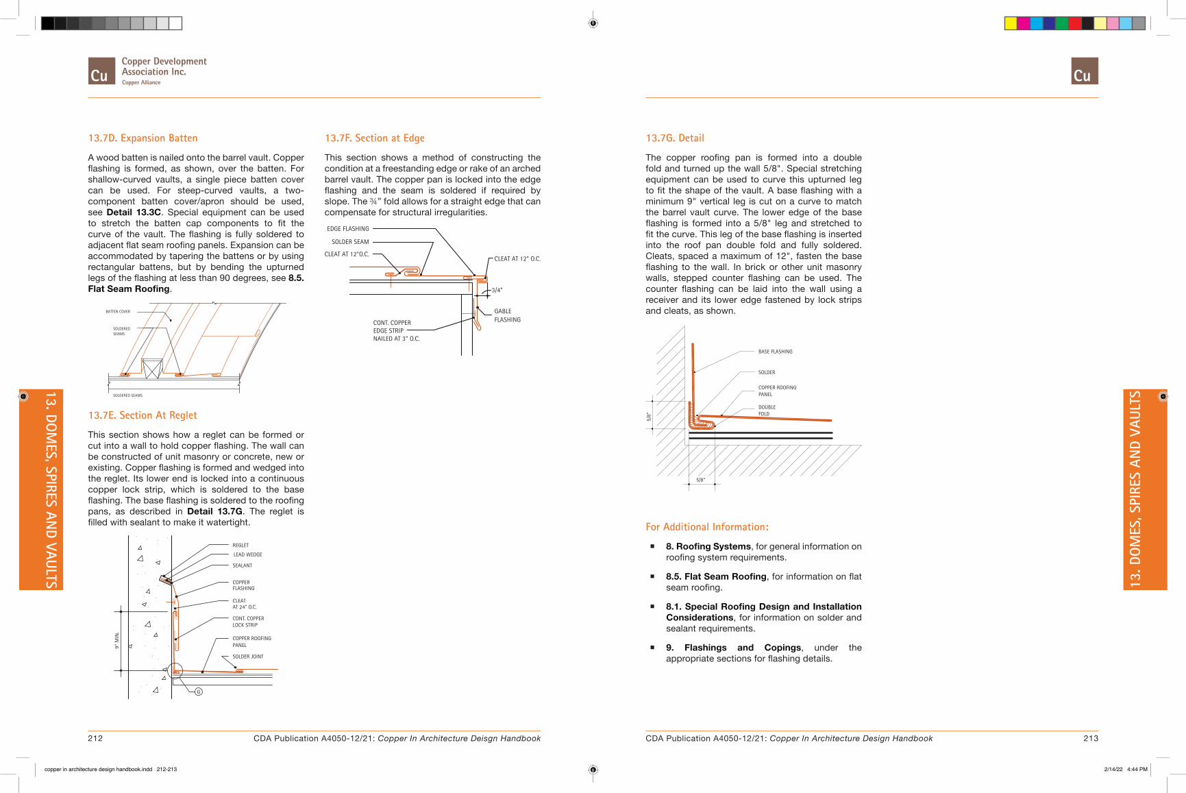
13.7D. Expansion Batten
A wood batten is nailed onto the barrel vault. Copper flashing is formed, as shown, over the batten. For shallow-curved vaults, a single piece batten cover can be used. For steep-curved vaults, a two-component batten cover/apron should be used, see Detail 13.3C. Special equipment can be used to stretch the batten cap components to fit the curve of the vault. The flashing is fully soldered to adjacent flat seam roofing panels. Expansion can be accommodated by tapering the battens or by using rectangular battens, but by bending the upturned legs of the flashing at less than 90 degrees, see 8.5. Flat Seam Roofing.
SOLDERED SEAMS
BATTEN COVER
SEAMSSOLDERED
13.7E. Section At Reglet
This section shows how a reglet can be formed or cut into a wall to hold copper flashing. The wall can be constructed of unit masonry or concrete, new or existing. Copper flashing is formed and wedged into the reglet. Its lower end is locked into a continuous copper lock strip, which is soldered to the base flashing. The base flashing is soldered to the roofing pans, as described in Detail 13.7G. The reglet is filled with sealant to make it watertight.
9" M
IN.
G
SOLDER JOINT
COPPER
CONT. COPPERLOCK STRIP
COPPER ROOFING
FLASHING
AT 24" O.C.
PANEL
CLEAT
SEALANT
REGLET
LEAD WEDGE
13.7F. Section at Edge
This section shows a method of constructing the condition at a freestanding edge or rake of an arched barrel vault. The copper pan is locked into the edge flashing and the seam is soldered if required by slope. The ¾” fold allows for a straight edge that can compensate for structural irregularities.EDGE FLASHING
SOLDER SEAM
CLEAT AT 12"O.C.
CONT. COPPER
NAILED AT 3" O.C.EDGE STRIP
3/4"
GABLEFLASHING
CLEAT AT 12" O.C.
13.7G. Detail
The copper roofing pan is formed into a double fold and turned up the wall 5/8". Special stretching equipment can be used to curve this upturned leg to fit the shape of the vault. A base flashing with a minimum 9" vertical leg is cut on a curve to match the barrel vault curve. The lower edge of the base flashing is formed into a 5/8" leg and stretched to fit the curve. This leg of the base flashing is inserted into the roof pan double fold and fully soldered. Cleats, spaced a maximum of 12", fasten the base flashing to the wall. In brick or other unit masonry walls, stepped counter flashing can be used. The counter flashing can be laid into the wall using a receiver and its lower edge fastened by lock strips and cleats, as shown.
5/8"
FOLDDOUBLE
5/8"
COPPER ROOFINGPANEL
SOLDER
BASE FLASHING
For Additional Information:
� 8. Roofing Systems, for general information on roofing system requirements.
� 8.5. Flat Seam Roofing, for information on flat seam roofing.
� 8.1. Special Roofing Design and Installation Considerations, for information on solder and sealant requirements.
� 9. Flashings and Copings, under the appropriate sections for flashing details.
212 213CDA Publication A4050-12/21: Copper In Architecture Deisgn Handbook CDA Publication A4050-12/21: Copper In Architecture Design Handbook
13. DOM
ES, SPIRES AND VAULTS 13
. DO
MES
, SPI
RES
AND
VAUL
TS
copper in architecture design handbook.indd 212-213copper in architecture design handbook.indd 212-213 2/14/22 4:44 PM2/14/22 4:44 PM

13.8. Steps for Dome Panel Layout
� 13.8A. Determine Dome Circumference and Panel Width at Base
� 13.8B. Establish Dome Height and Panel Layout Concept
� 13.8C. Establish the Number of Dome Panel Stations, Quarter Dome Section
� 13.8D. Typical Panel Layout
� 13.8E. Dome Assembly
� 13.8F. Alternative Dome Assembly
Formulas:
Full Circle Circumference = 2 x Radius x Pi. Half Circle Circumference = Radius x Pi. Pi = 3.141592
Domes come in many heights, radii, diameters, shapes and sizes. For our layout example, consider entry canopy designed as a true hemispherical half dome. The height is also the radius “R” and is one half of the base diameter. The base of the dome is the dome equator.
13.8A. Determine Dome Circumference and Panel Width at Base
Calculating the complete dome circumference at the base and dividing that amount by the number of panels will establish the width of each panel at the base.
R =
36”
8 EQUAL DIVISIONS
FLASHING CAP
Dome Radius "R" = 36" Dome Base Circumference "C" = 2 x Pi x R = 2 x 3.141592 x 36 = 226.194624 inches
If one half of a dome is built, the number of total dome panels should be an even number.
Assuming 16 dome panels for the full dome, each panel base dimension at the equator is therefore 226.194624 / 16 = 14.137" wide.
13.8B. Establish Dome Height and Panel Layout Concept
In a perfectly hemispherical dome, the dome height will be equal to its radius, 36 inches. Each of the eight panels will run from the base to the top center (vertex) of the dome. The shape of each panel will gradually decrease from its widest point at the base to its narrowest point at the vertex.
STATION 1
STATION 2
STATION 3
H = 36”
TYP.PANEL
The shape of the panel is determined by two items: The panel length from base to vertex and the decreasing panel widths from base to vertex. The panel length can be determined by calculation. This length is equal to one fourth of the dome circumference or 226.194624 / 4 = 56.549". Since it is difficult to fabricate dome panels to a complete point, each panel length will be stopped approximately 2" short of the dome vertex and fabricated at 54 inches in length.
The panel widths can be determined by slicing the dome in parallel horizontal slices or Stations, each slice represents a full circle of decreasing size. The radius of each of the circles will allow calculating the circumference at that Station. Dividing that Station circumference by 16 will give the width of each panel at that Station. This process is similar to the base panel width calculation.
We now have established that our panels are 14.137 inches wide at the base and 54 inches long. Depending on the dome rib design, additional widths will be added to each panel (See Table 13.8A).
Table 13.8A. Dome Panel Calculations: Calculations for Dome With 36-Inch Radius and Stations at 6 inches Dome Radius = 36" Panels quantity = 16 Pi = 3.141592 Circumference = 2 x Pi x Radius
For Double Locked SeamFor “T” Style
or Dbl. Locked Cap Seam
Station Radius DecimalCircle
Circumference ÷ 16
Measure from Guide
Line
Add 1.5" from Guide
Line
Add 2.125" from Guide
LineAdd 1.75" from Guide Line To
Each SideA. Points B. Points
1 36 36.000 14.137164 7.0685 8.5685 9.1935 8.8185
2 35 7/16 35.4375 13.91627081 6.9581 8.4581 9.0831 8.7081
3 33 31/32 33.96875 13.33949416 6.6697 8.1697 8.7947 8.4197
4 31 17/32 31.53125 12.38229034 6.911 7.6911 8.3161 7.9411
5 28 7/32 28.21875 11.08147491 5.5407 7.0407 7.6657 7.2907
6 24 3/32 24.09375 9.461591531 4.73079 6.23079 6.85579 6.48079
7 19 5/16 19.3125 7.583999438 3.7919 5.2919 5.9169 5.5419
8 13 31/32 13.96875 5.485514156 2.7427 4.2427 4.8677 4.4927
9 8 1/4 8.2500 3.23976675 1.61988 3.1198 3.7448 3.36988
10 5 5/16 5.3125 2.086213438 1.0431 2.5431 3.1681 2.7931
13.8C. Establish the Number of Dome Panel Stations, Quarter Dome Section
The shape of the panels can be determined by plotting their width at various points up the dome. We will call these points Stations. For a 36-inch radius dome, Stations every 4 to 6 inches apart give accurate results. Larger domes can have stations spaced farther apart and smaller domes, closer together. We will use 6 inches. A partial section of a quarter dome simulates a typical panel section. Make a full scale layout of the dome arc using the 36-inch radius on a sheet of metal. Divide this arc with Stations every 6 inches along the length of the arc. Number the stations from the base up, Number 1 through 10.
1
2
3
4
5
6
78
910
36”
36”
56.52”
9 DI
VISI
ONS
AT 6
” O.C.
ALO
NG ARC
214 215CDA Publication A4050-12/21: Copper In Architecture Deisgn Handbook CDA Publication A4050-12/21: Copper In Architecture Design Handbook
13. DOM
ES, SPIRES AND VAULTS 13
. DO
MES
, SPI
RES
AND
VAUL
TS
copper in architecture design handbook.indd 214-215copper in architecture design handbook.indd 214-215 2/14/22 4:44 PM2/14/22 4:44 PM
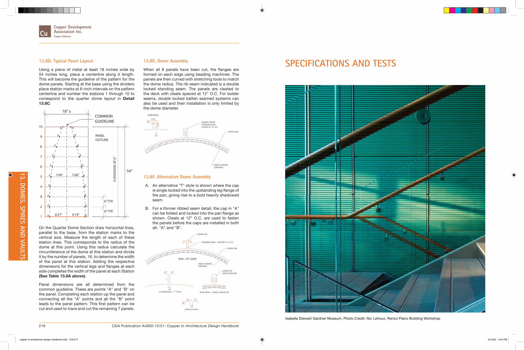
SPECIFICATIONS AND TESTS
Isabella Stewart Gardner Museum, Photo Credit: Nic Lehoux, Renzo Piano Building Workshop
13.8D. Typical Panel Layout
Using a piece of metal at least 18 inches wide by 54 inches long, place a centerline along it length. This will become the guideline of the pattern for the dome panels. Starting at the base using the dividers place station marks at 6-inch intervals on the pattern centerline and number the stations 1 through 10 to correspond to the quarter dome layout in Detail 13.8C.
3
18” ±COMMONGUIDELINE
54”
PANELOUTLINE
6” TYP.
6” TYP.
1
2
3
4
5
6
7
8
9
10
9 D
IVIS
ION
S AT
6”
8.57” 9.19”
7.66”7.04”
A
A
A
A
A
A
A
A
A
A B
B
B
B
B
B
B
B
B
B
On the Quarter Dome Section draw horizontal lines, parallel to the base, from the station marks to the vertical axis. Measure the length of each of these station lines. This corresponds to the radius of the dome at this point. Using this radius calculate the circumference of the dome at this station and divide it by the number of panels, 16, to determine the width of the panel at this station. Adding the respective dimensions for the vertical legs and flanges at each side completes the width of the panel at each Station (See Table 13.8A above).
Panel dimensions are all determined from the common guideline. These are points "A" and "B" on the panel. Completing each station up the panel and connecting all the "A" points and all the "B" point leads to the panel pattern. This first pattern can be cut and used to trace and cut the remaining 7 panels.
13.8E. Dome Assembly
When all 8 panels have been cut, the flanges are formed on each edge using beading machines. The panels are then curved with stretching tools to match the dome radius. The rib seam indicated is a double locked standing seam. The panels are cleated to the deck with cleats spaced at 12" O.C. For bolder seams, double locked batten seamed systems can also be used and their installation is only limited by the dome diameter.
COPPER PAN
DOME PLYWOODSUBSTRATE
DOUBLE LOCKEDSTANDING SEAMCLEATED AT 12” O.C.
SEAM DETAIL
11/16”
1/8”
1/2”
3/8”
1 1/
16”
1”
13.8F. Alternative Dome Assembly
A. An alternative "T" style is shown where the cap is single locked into the upstanding leg flange of the pan, giving rise to a bold heavily shadowed seam.
B. For a thinner ribbed seam detail, the cap in "A" can be folded and locked into the pan flange as shown. Cleats at 12" O.C. are used to fasten the panels before the caps are installed in both alt. "A" and "B".
COPPER CAP DETAIL
1/4”
3/4”3/4”
3/8”
COPPER PAN
DOME PLYWOODSUBSTRATE
STANDING SEAM - CLEATED AT 12” O.C.
PLAN - TYP. SEAM
3/4”
1/8”
A. SEAM DETAIL - “T” STYLE
3/4”
1”
B. RIB DETAIL - DOUBLE LOCKED CAP
COPPER CAP LOCKED INTO PAN
COPPER CAP
216 CDA Publication A4050-12/21: Copper In Architecture Deisgn Handbook
13. DOM
ES, SPIRES AND VAULTS
copper in architecture design handbook.indd 216-217copper in architecture design handbook.indd 216-217 2/14/22 4:44 PM2/14/22 4:44 PM

14. ARCHITECTURAL SPECIFICATIONS
� 14.1. Antimicrobial Copper
� 14.2. Copper Wall Cladding
� 14.3. Copper Roofing
� 14.4. Manufactured Copper Roofing Specialties
� 14.5. Copper Flashing and Trim
� 14.6. Copper Gutters and Downspouts
� 14.7. Copper Expansion Joint Cover Assemblies
Specifications for copper construction are presented in this section. These documents conform to the CSI MasterFormat 2004 and are presented in an edit/delete format.
� 14. Architectural Specifications
� 15. Test Reports
Specifications for copper construction are presented in this section. These documents conform to the CSI MasterFormat 2004 and are presented in an edit/delete format. Test reports on various copper systems are also included.
218 219CDA Publication A4050-12/21: Copper In Architecture Deisgn Handbook CDA Publication A4050-12/21: Copper In Architecture Design Handbook
SPECIFATION
S AND TESTS
14. A
RCH
ITEC
TURA
L SP
ECIF
ACAT
ION
S
copper in architecture design handbook.indd 218-219copper in architecture design handbook.indd 218-219 2/14/22 4:44 PM2/14/22 4:44 PM
14.1. Antimicrobial CopperSECTION 050405
Download Word format [8.6 Kb]
THIS SECTION IS NOT A STANDALONE SECTION. IT IS INTENDED TO BE USED WITH OTHER PRODUCT ORIENTED SECTIONS THAT CONTAIN ANTIMICROBIAL COPPER AS A BUILDING PRODUCT. TEXT IN BOLD ORANGE REQUIRES EDITING.
EVERY DAY PEOPLE MAKE CONTACT WITH A VARIETY OF TOUCH SURFACES. FROM SUBWAY GRAB RAILS TO DOORKNOBS, KEYBOARDS, AND TELEPHONES. TOUCH IS A FUNDAMENTAL PART OF DAILY LIVES. UNFORTUNATELY, THESE SAME OBJECTS ARE ALSO TOUCHED BY OTHERS WHO MAY LEAVE BEHIND INFECTIOUS BACTERIA ON THESE SURFACES, PUTTING THE NEXT USER AT RISK.
FREQUENTLY TOUCHED SURFACES IN HEALTHCARE FACILITIES, SUCH AS DOORKNOBS, PUSH PLATES, BED RAILS, FAUCET HANDLES, IV POLES AND SIMILAR ITEMS, HAVE BEEN FOUND TO SERVE AS RESERVOIRS FOR THE SPREAD OF PATHOGENIC MICROBES.
THE INHERENT ANTIMICROBIAL PROPERTIES OF SOLID COPPER ALLOYS ARE WELL DOCUMENTED, AND PRODUCTS MADE FROM THESE MATERIALS ARE CURRENTLY REGISTERED WITH U.S. ENVIRONMENTAL PROTECTION AGENCY (EPA) TO MAKE PUBLIC HEALTH CLAIMS (E.G. "THIS SURFACE CONTINUOUSLY KILLS >99.9% OF MRSA WITHIN 2 HOURS"). THE POTENTIAL BENEFIT OF INCORPORATING PASSIVE, ANTIMICROBIAL SURFACES INTO THE BUILT ENVIRONMENT HAS BEEN QUANTIFIED BY A MULTI-SITE CLINICAL TRIAL FUNDED BY THE DEPARTMENT OF DEFENSE INVESTIGATING THE ABILITY OF ANTIMICROBIAL COPPER SURFACES TO REDUCE ENVIRONMENTAL MICROBIAL LEVELS AND SUBSEQUENT INFECTION RATES. SIX COPPER OBJECTS (BEDRAIL, I.V. POLE, NURSE'S CALL DEVICE, OVERBED TRAY TABLE, VISITOR'S CHAIR ARMS, AND DATA INPUT DEVICE) WERE INTRODUCED INTO PATIENTS' ROOMS, WHICH REPRESENTED LESS THAN 10% OF THE AVAILABLE SURFACE AREA IN THE ROOM. THE LIMITED INTRODUCTION OF THESE SIX COPPER OBJECTS REDUCED THE SITE-SPECIFIC LEVELS OF CONTAMINATION BY MORE THAN 83 PERCENT, CONSISTENTLY ACHIEVING THE RECOMMENDED TERMINAL CLEANING LEVEL (250 CFU/100CM2).
ANTIMICROBIAL COPPER (60% MINIMUM COPPER CONTENT) IS THE ONLY SOLID TOUCH SURFACE MATERIAL THAT HAS BEEN CLINICALLY TESTED AND REGISTERED WITH THE EPA AND THEREFORE ALLOWED TO HAVE PUBLIC HEALTH CLAIMS MADE IN THE USA. ANTIMICROBIAL COPPER IS THE MOST EFFECTIVE ANTIMICROBIAL TOUCH SURFACE MATERIAL, KILLING MORE THAN 99.9% OF SIX DISEASE CAUSING BACTERIA WITHIN TWO HOURS OF EXPOSURE.
DESIGNING HEALTHCARE SURFACES THAT ARE EASY TO CLEAN IS IMPORTANT. INCORPORATION OF SURFACE MATERIALS WITH INHERENT ANTIMICROBIAL PROPERTIES, USED IN SYNERGY WITH CURRENT DESIGN INTERVENTIONS AND HYGIENIC PRACTICES, OFFERS A NEW PARADIGM FOR HEALTHCARE DESIGN THAT WILL LEAD TO BETTER OUTCOMES AND LOWER COSTS.
ADDING ANTIMICROBIAL SURFACES INTO A CLINICAL SETTING IS LIKELY TO INCREASE THE INITIAL COST OF CONSTRUCTION OR COMPONENT PURCHASE, HOWEVER THE MAGNITUDE OF THE INITIAL INVESTMENT INCREASE IS COMPLETELY DEPENDENT ON THE NUMBER AND TYPES OF SURFACES AND COMPONENTS INCORPORATED. BUSINESS CASE ANALYSIS OF INCORPORATION OF THOSE SURFACES STUDIED IN THE CLINICAL TRIAL, AS WELL AS OTHER TYPICAL SURFACES (HANDRAILS, GRAB BARS, DOOR HARDWARE, PUSH PLATES, ETC.) SUGGESTS A POTENTIAL RETURN ON INVESTMENT TO THE FACILITY DUE TO REDUCTION OF HOSPITAL ACQUIRED INFECTION (HAI) TREATMENT COSTS, OF SIGNIFICANTLY LESS THAN ONE-YEAR.
U.S. ENVIRONMENTAL PROTECTION AGENCY PUBLIC HEALTH REGISTRATIONS 82012-1 THROUGH
82012-6. FEDERAL INSECTICIDE, FUNGICIDE, AND RODENTICIDE ACT. 2008. AVAILABLE FROM: HTTP://WWW.EPA.GOV/OPP00001/FACTSHEETS/COPPER-ALLOY-PRODUCTS.HTM.
CURRENTLY, THERE ARE OVER 479 ALLOYS OF COPPER (60% COPPER AND GREATER) THAT WILL CONTINUOUSLY KILL SIX DIFFERENT DEADLY BACTERIA WITHIN 2 HOURS AT A 99.9% KILL RATE. THE LIST OF APPROVED ALLOYS CAN BE FOUND AT, HTTP://WWW.ANTIMICROBIALCOPPER.ORG/US/ANTIMICROBIAL-COPPER-RANGE.
Part 1: General
1.1 SUMMARY
A. Section Includes:
1. Antimicrobial copper for human touch surfaces made of uncoated surface copper material as registered with the US Environmental Protection Agency (EPA).
ADD TO OR REMOVE FROM ITEMS BELOW USING ANTIMICROBIAL COPPER PRODUCTS. LISTING OF POTENTIAL ITEMS IS IN ARTICLE 2.1.
2. Antimicrobial copper is being used on this Project for:
a. Hand rails
b. Grab bars
c. Door hardware
d. Bed rails
e.
LIST RELATED SECTIONS BELOW REFERENCING SECTIONS CONTAINING ANTIMICROBIAL COPPER PRODUCTS.
B. Related Sections:
1. Section XXXXXX:
1.2 DEFINITIONS
A. Antimicrobial Surface Material: a solid, engineering material that has been approved by the US EPA under Section 3 of the Federal Insecticide, Fungicide, and Rodenticide Act (FIFRA); and listed in the EPA's Pesticide Product Label System (PPLS). Any application and usage of solid antimicrobial surface materials must conform to EPA guidelines set forth in labeling and usage guidelines.
B. Six Bacteria Types Referenced in the Section:
1. E. coli O157:H7, a food-borne pathogen that has been associated with large-scale food recalls.
220 221CDA Publication A4050-12/21: Copper In Architecture Deisgn Handbook CDA Publication A4050-12/21: Copper In Architecture Design Handbook
14. ARCHITECTURAL SPECIFACATIO
NS 14
. ARC
HIT
ECTU
RAL
SPEC
IFAC
ATIO
NS
copper in architecture design handbook.indd 220-221copper in architecture design handbook.indd 220-221 2/14/22 4:44 PM2/14/22 4:44 PM

2. Methicillin-Resistant Staphylococcus Aureus (MRSA), is a "staph" bacteria that is resistant to first-line antibiotics that usually cure staph infections; one of the most virulent strains of antibiotic-resistant bacteria and common in hospital- and community-acquired infections.
3. Staphylococcus Aureus , the most common of all bacterial staphylococcus (i.e. staph) infections that can cause life-threatening diseases, including pneumonia and meningitis.
4. Vancomycin-Resistant Enterococcus Faecalis (VRE), an antibiotic resistant organism responsible for 4% of all Healthcare-Associated Infections.
5. Enterobacter Aerogenes , a pathogenic bacterium commonly found in hospitals that causes opportunistic skin infections and impacts other body tissues; and,
6. Pseudomonas Aeruginosa , a bacterium that infects the pulmonary tracts, urinary tracts, blood, and skin of immuno-compromised individuals.
1.3 PERFORMANCE REQUIREMENTS
A. Laboratory testing has shown that when cleaned regularly:
2. Antimicrobial Copper surfaces continuously reduce bacterial* contamination, achieving 99.9% reduction within two hours of exposure.
3. Antimicrobial Copper surfaces kill greater than 99.9% of Gram-negative and Gram-positive bacteria* within two hours of exposure.
4. Antimicrobial Copper surfaces deliver continuous and ongoing antibacterial* action, remaining effective in killing greater than 99.9% of bacteria* within two hours.
5. Antimicrobial Copper surfaces kill greater than 99.9% of bacteria* within two hours, and continues to kill more than 99% of bacteria* even after repeated contamination.
6. Antimicrobial Copper surfaces help inhibit the buildup and growth of bacteria* within two hours of exposure between routine cleaning and sanitizing steps.
*Testing demonstrates effective antibacterial activity against the following six bacteria: Methicillin-Resistant Staphylococcus Aureus (MRSA), Vancomycin-resistant Enterococcus Faecalis (VRE), Staphylococcus Aureus, > Enterobacter Aerogenes, Pseudomonas Aeruginosa, and E. coli O157:H7 .
B. Frequently touched surfaces, furnishings and equipment in health care patient environments shall be planned and designed to facilitate cleaning and disinfection. To supplement infection control practices, antimicrobial copper registered by EPA shall be permitted for use.
DELETE ITEMS BELOW NOT APPLICABLE TO PROJECT.
C. Plumbing Fixtures/Fittings:
1. Materials. Plumbing fixtures and fittings shall be nonabsorptive and acid-resistant. To supplement infection control practices, antimicrobial copper approved by EPA will be permitted for use.
2. Sinks and hand-washing basins/countertops shall be made of porcelain, stainless steel, copper alloy, or solid surface materials.
D. Grab Bars:
1. Provide in patient toilets, showers, bathtubs, and sitz baths with wall clearance of 1-1/2 inches.
2. Anchor grab bars, including those that are part of such fixtures as soap dishes, to sustain concentrated load of 250 pounds.
3. To supplement infection control practices, antimicrobial copper approved by EPA will be permitted for use.
E. Handrails:
1. As determined by functional program, handrails shall be provided to assist mobility-impaired persons. Return rail ends to wall.
2. Provide handrails or lean rails and fasteners smooth and free of rough edges.
3. Provide handrails or lean rails with eased edges and corners if mitered corner condition exists.
4. To supplement infection control practices, antimicrobial copper approved by EPA will be permitted for use.
F. Door Hardware:
1. Lever hardware shall be selected for ease of use.
2. Door and door hardware finishes shall be selected to withstand cleaning and impact damage.
3. To supplement infection control practices, antimicrobial copper approved by EPA will be permitted for use.
G. Refer to related sections for product performance requirements other than antimicrobial requirements.
REFER TO ACTUAL RELATED PRODUCT SECTION FOR SUBMITTAL REQUIREMENTS OTHER THAN ANTIMICROBIAL REQUIREMENTS.
1.4 SUBMITTALS
A. General: Submit each item in this Article according to the Conditions of the Contract and Division 01 Specifications Sections.
1. Make submittals of this Section simultaneously with submittals of sections with components using antimicrobial copper specified in this Section.
B. Product data for antimicrobial copper.
1. Submit EPA registration number for each product showing material made from antimicrobial copper continuously kills >99.9% of MRSA within 2 hours.
C. Informational Submittals
1. Qualifications:
a. Proof of manufacturer EPA registration number.
b. Copy of EPA product labeling.
2. Certifications: Copy of certifications required under Quality Assurance Article.
222 223CDA Publication A4050-12/21: Copper In Architecture Deisgn Handbook CDA Publication A4050-12/21: Copper In Architecture Design Handbook
14. ARCHITECTURAL SPECIFACATIO
NS 14
. ARC
HIT
ECTU
RAL
SPEC
IFAC
ATIO
NS
copper in architecture design handbook.indd 222-223copper in architecture design handbook.indd 222-223 2/14/22 4:44 PM2/14/22 4:44 PM

3. Manufacturer's installation and cleaning instructions
D. Closeout Submittals: Submit maintenance data for cleaning antimicrobial copper.
1.5 QUALITY ASSURANCE
A. Manufacturer Qualifications: Registered with EPA as supplier of Antimicrobial Copper Alloys with EPA Registration Numbers.
B. Certifications: Submit manufacturer's certification stating "If used as intended, this product is wear-resistant and the durable antibacterial properties will remain effective for as long as the product remains in place and is used as directed."
1.6 DELIVERY, STORAGE, AND HANDLING
A. Packing, Shipping, Handling, and Unloading: Protect finish metal faces.
B. Acceptance at Site: Examine each component and accessory as delivered and confirm that material and finish is undamaged. Do not accept or install damaged materials.
PART 2 - PRODUCTS
2.1 MATERIALS
A. Antimicrobial Copper: EPA registration acknowledging the efficacy of Antimicrobial Copper products against the six disease-causing bacteria listed under PART 1 Article for Definitions.
LIST BELOW THE ALLOYS USED FOR THIS PROJECT - CLICK ON THIS HYPERLINK FOR LISTNG OF APPROVED ALLOYS: HTTP://WWW.ANTIMICROBIALCOPPER.ORG/US/ANTIMICROBIAL-COPPER-RANGE.
1.
B. Surface materials for which public health claims are made based on antimicrobial properties shall be selected based on current U.S. EPA public health registration under the Federal Insecticide Fungicide and Rodenticide Act (FIFRA).
1. Such registration must specifically include registration of public health claims.
2. Product/material registration can be verified by visiting the EPA's Pesticide Product Label System
3. Do not use materials or surfaces impregnated with antimicrobials which do not carry a public health registration but only indicate an approved article of use exemption to the FIFRA.
THE EPA REQUIRES THE FOLLOWING STATEMENT TO BE INCLUDED WHEN MAKING PUBLIC HEALTH CLAIMS RELATED TO THE USE OF ANTIMICROBIAL COPPER ALLOYS:
4. Antimicrobial copper surfaces are a supplement to and not a substitute for standard infection control practices; users must continue to follow all current infection control practices, including those practices related to cleaning and disinfection of environmental surfaces. Antimicrobial copper surfaces have been shown to reduce microbial contamination, but it does not necessarily prevent cross-contamination.
C. Antimicrobial copper alloys are only intended for the manufacture and fabrication of touch surface components for use in hospitals, healthcare facilities, and various public, commercial, and residential buildings.
D. Products made from Antimicrobial Copper Alloys are not approved for direct food contact or food packaging uses.
E. The Antimicrobial Copper Alloys fabricated products listed below may be sold and distributed if they possess current EPA Registration Numbers.
EDIT LISTING BELOW TO SUIT PROJECT REQUIREMENTS.
F. Touch Surface Components - Healthcare Facilities:
1. Bedrails, footboards
2. Over-bed tables
3. Bed-side tables in hospitals, extended care facilities, senior housing etc. (knobs, pulls, handles; surfaces)
4. Handrails, (corridor/hallways) ( Senior housing), automatic door push plates
5. Stair rails, handrails, tubular railing, and supports, rail fittings T's, elbows and brackets
6. Bedrails, assistance rails,
7. Toilet safety rails
8. Carts
a. Hospital carts (table surfaces, handles, legs)
b. Computer carts
c. Record carts
d. Phlebotomy carts
e. Other Carts (tables/surfaces, shelving, railings, handles, pulls)
f. Equipment carts (horizontal surfaces, frames, handles)
9. Door push plates, kick plates, mop plates, stretcher plates
10. Sinks: spigots, drains, sinks themselves
11. Faucet: handles, spigot, drain control lever
12. Water fountains: bubbler head, drain strainer, handle
13. Alcohol sanitizer dispenser, handle
224 225CDA Publication A4050-12/21: Copper In Architecture Deisgn Handbook CDA Publication A4050-12/21: Copper In Architecture Design Handbook
14. ARCHITECTURAL SPECIFACATIO
NS 14
. ARC
HIT
ECTU
RAL
SPEC
IFAC
ATIO
NS
copper in architecture design handbook.indd 224-225copper in architecture design handbook.indd 224-225 2/14/22 4:44 PM2/14/22 4:44 PM
14. Paper towel holders, facial tissue holders, toilet paper holders
15. Air hand dryer, controls and push buttons on air hand dryers
16. Hydrotherapy tanks (whirlpool tanks): shells, covers, headrests, drain fittings (outer surfaces without water contact)
17. Door handles, doorknobs (outer touch surfaces)
18. Grab bars in bathrooms showers and bathtubs
19. Panic bars on emergency room doors
20. Towel bars
21. Showerheads
22. Countertops and tabletops (non-food use only)
23. Hinges, locks, latches, and trim
24. Door stops, door pulls, and protector guards
25. Toilet and urinal hardware, levers, push buttons
26. Toilet seat inlay for lifting of seat
27. Closures
28. Vertical locking arms
29. Vertical cover guards
30. Protection bars
31. Light switches, switch plates
32. Visitor chairs: armrests, metal frames
33. Thermostat covers, control knobs and wheels
34. Telephone handsets and surfaces (housings), keypad
35. Kitchen surfaces (non-food contact only): table tops, counter tops, handles (microwave, refrigerator, stove), cabinet doors, cabinet hinges, pulls, backsplash, hoods, control knobs (appliances, fans)
36. Floor tiles
37. Ceiling tiles (non-porous
38. Wall tiles
39. Instrument handles
a. Medical equipment knobs, pulls and handles for:
ii. Drug delivery systems
iii. Monitoring systems
iv. Hospital beds
v. Office equipment
vi. Operating room equipment
vii. Stands and fixtures
b. Types of knobs: e.g., Prong, fluted, knurled, push/pull, T-handle, tapered, and ball knobs
40. Intravenous (IV) poles, bases, hangers, clips
41. Trays (instruments, non-food contact)
42. Pans (bed)
43. Walkers, wheelchair handles, and tubular components
44. Computer keyboards: keys, housings, computer mouse surfaces
45. Exercise and rehabilitation equipment, handles, bars
46. Physical therapy equipment: physical therapy tables, treatment chairs and portable taping tables
47. Chairs (shower chairs, patient chairs, visitor chairs): rails, backs, legs, seats
48. Lighting products: X-ray illuminators, operating rooms, patient examination rooms, surgical suites, and reading lamps for hospital rooms and assisted living facilities etc. Components can include bases, arms, housings, handles, hinges)
49. Headwall systems: the unit themselves, outlet covers, knobs and dials, lighting units (lamp housings and adjustable arms), CRT monitors with rotating knobs and levers and adjustments. Baskets, monitor housings, knobs, baskets, tables, IV poles
50. Critical care cart: Table top, drawer, drawer pull, lock, copper wire baskets for storage of equipment and charts.
51. Bedside lavatory: sink, faucet, handles, drawer pulls, toilet seat, toilet seat cover, toilet handle, door and cabinet facings, counter tops
52. Medical records: Chart holders, clipboards, filing systems
53. Storage Shelving: wire shelving etc. for medical supplies
54. Grab handles on privacy curtains
55. Lids of laundry hampers, trash canisters, and other containers
56. Bedside pitchers
57. Closet rods and hangers
58. Television controls: knobs, buttons, remote
59. Monitor (television, computer, etc.) housing
60. Cup Holder
61. Toothbrush holder
226 227CDA Publication A4050-12/21: Copper In Architecture Deisgn Handbook CDA Publication A4050-12/21: Copper In Architecture Design Handbook
14. ARCHITECTURAL SPECIFACATIO
NS 14
. ARC
HIT
ECTU
RAL
SPEC
IFAC
ATIO
NS
copper in architecture design handbook.indd 226-227copper in architecture design handbook.indd 226-227 2/14/22 4:44 PM2/14/22 4:44 PM

62. Soap holder
63. Magazine rack
64. Signage
65. Coat rack and hooks
66. Shower curtain rings
67. Radiator cover
68. Bracelets
69. Pens
70. Badge clips
71. Name tags
72. Patient gown snaps
73. Window sills, pulls and locks
74. Electrical wallplates
G. Community Facilities (including various public and commercial buildings)
1. Shopping cart handles, child seats, handrails
2. Cash registers: housing, keypads
3. ATM machines: keys, housing
4. Gym/Health club lockers, locker handles, locker shelving, trainers' tables,
5. Ice and water dispensers (outer surfaces without water contact)
6. Elevator: handrail, control panel, buttons, interior walls, floor tiles, exterior call button plate
7. Paper towel dispensers. Housing itself, (turn) handle, (push) handle
8. Soap holder
9. Soap dispenser (wall mounted): push bar and dispenser itself
10. Soap dispenser (sitting on counter): dispenser housing itself, push mechanism
11. Toilet paper dispenser (housing)
12. Windows (crank), Locking mechanism, pull handles
13. Window treatments (cord pulls), Venetian blinds (wands, cord pulls)
14. Jalousie Windows (crank)
15. Casement (cranks, levers, hinges)
16. Single and double-hung windows (locks and pulls)
17. Light switches, switch plates
18. Lids of laundry hampers, trash canisters, and other containers
19. Magazine rack
20. Signage
21. Coat rack and hooks
22. Shower curtain rings
23. Radiator cover
24. Bracelets
25. Badge clips
26. Name tags
27. Vending machines (non-food contact only)
28. Window sills
29. Electrical wallplates
30. Clip boards
31. Office supplies: paper clips, staplers, tape dispensers
H. Residential Buildings (including homes, apartments, apartment buildings and other residences)
1. Kitchen surfaces (non-food contact only): table tops, counter tops, handles (microwave, refrigerator, stove), cabinet doors, cabinet hinges, pulls, backsplash, hoods, control knobs (appliances, fans)
2. Bedrails, footboards
3. Handrails
4. Stair rails
5. Door push plates
6. Sinks: spigots, drains, sinks themselves
7. Faucet: handles, spigot, drain control lever o Paper towel holders, facial tissue holders, toilet paper holders
8. Door handles, doorknobs (outer touch surfaces)
9. Grab bars in bathrooms showers and bathtubs
10. Towel bars
11. Showerheads
12. Countertops and tabletops
13. Hinges, locks, latches, and trim
228 229CDA Publication A4050-12/21: Copper In Architecture Deisgn Handbook CDA Publication A4050-12/21: Copper In Architecture Design Handbook
14. ARCHITECTURAL SPECIFACATIO
NS 14
. ARC
HIT
ECTU
RAL
SPEC
IFAC
ATIO
NS
copper in architecture design handbook.indd 228-229copper in architecture design handbook.indd 228-229 2/14/22 4:44 PM2/14/22 4:44 PM

14. Door stops, door pulls, and protector guards
15. Toilet and urinal hardware, levers, push buttons
16. Toilet seat inlay for lifting of seat
17. Light switches, switch plates
18. Thermostat covers, control knobs and wheels
19. Telephone handsets and surfaces (housings), keypad
20. Floor tiles
21. Ceiling tiles (non-porous)
22. Wall tiles
23. Computer keyboards: keys, housings, computer mouse surfaces
24. Exercise equipment, handles, bars
25. Windows (crank), Locking mechanism, pull handles
26. Window treatments (cord pulls), Venetian blinds (wands, cord pulls)
27. Jalousie Windows (crank)
28. Casement (cranks, levers, hinges)
29. Single and double-hung windows (locks and pulls)
30. Television control knobs and buttons
31. Lids of laundry hampers, trash canisters, and other containers
32. Bedside pitchers
33. Closet rods and hangers
34. Television remote
35. Cup Holder
36. Toothbrush holder
37. Soap holder
38. Magazine rack
39. Coat rack and hooks
40. Shower curtain rings
41. Radiator cover
42. Window sills
43. Electrical wallplates
44. Baby cribs: rails, fittings, brackets, supports
45. Bowl stands
46. Office supplies: paper clips, staplers, tape dispensers
47. Monitor (television, computer, etc.) housing
I. Mass Transit Facilities
1. Handrails
2. Stair rails, tubular railing, and supports; elbows and brackets
3. Door push plates, kick plates
4. Door handles, door knobs (outer touch surfaces)
5. Grab bars and handles
6. Tiles: wall, floor, ceiling (non-porous)
7. Chairs and benches: rails, backs, legs, seats
8. Window sills, pulls, and handles
9. Signage
10. Vending machines (non-food contact only)
J. Other
1. Play area equipment (indoor only): bars, handles, chains, push plates, handrails, stair rails and risers, wheels, knobs, flooring
2. Chapel pews
3. Eye glass frames and protective eye wear
4. Pens
5. Combs
6. Ashtrays
FABRICATION
A. Refer to related sections for actual product fabrication requirements.
B. Labeling: Products fabricated with Antimicrobial Copper Alloys must bear current EPA approved fabricated product label similar to example below with one or more of the listed claims.
230 231CDA Publication A4050-12/21: Copper In Architecture Deisgn Handbook CDA Publication A4050-12/21: Copper In Architecture Design Handbook
14. ARCHITECTURAL SPECIFACATIO
NS 14
. ARC
HIT
ECTU
RAL
SPEC
IFAC
ATIO
NS
copper in architecture design handbook.indd 230-231copper in architecture design handbook.indd 230-231 2/14/22 4:44 PM2/14/22 4:44 PM

FRONT [This (touch surface) (product)]made from
Antimicrobial Copper Alloys Group IActive Ingredient: Copper ……………96.2% Other……………… 3.8% [Total 100.0%] See [Back/Side Panel][Insert] for Directions for Use Net Weight: XXX lbs XXX ounces of [brand name]
BACKANTIMICROBIAL COPPER ALLOYS
Laboratory testing has shown that when cleaned regularly this surface:
- Continuously reduces bacteria* contamination, achieving 99.9% reduction within 2 hours of exposure.
- Kills greater than 99.9% of Gram-negative and Gram-positive bacteria* within 2 hours of exposure.
- Delivers continuous and ongoing antibacterial* action, remaining effective in killing greater than 99.9% of bacteria* within 2 hours.
- Kills greater than 99.9% of bacteria* within two hours and continues to kill 99% of bacteria* even after repeated contaminations.
- Helps inhibit the buildup and growth of bacteria* within 2 hours of exposure between routine cleaning and sanitizing steps.
- [This product/component name] is made (out of)(from) a (copper)(touch) surface that continuously kills bacteria left behind [by dirty hands][on the surface] killing more than 99.9% of bacteria within 2 hours.
* Staphylococcus aureus, Enterobacter aerogenes, Methicillin-Resistant Staphylococcus aureus (MRSA), Escherichia coli O157:H7, Pseudomonas aeruginosa and, Vancomycin-Resistant Enterococcus faecalis (VRE).
DIRECTIONS FOR USEIt is a violation of Federal law to use this product in a manner inconsistent with its labeling.
Proper Care and Use. Clean and sanitize according to standard practice. Healthcare facilities must maintain the product in accordance with infection control guidelines. The use of this surface is a supplement to and not a substitute for standard infection control practices; users must continue to follow all current infection control practices, including those practices related to cleaning and disinfection of environmental surfaces. This surface has been shown to reduce microbial contamination, but does not necessarily prevent cross contamination.
This surface may be subject to recontamination and the level of active bacteria at any time will depend on the frequency and timing of recontamination and cleanliness of the surface (among other factors). In order to have proper antimicrobial effect, this product must be cleaned and maintained according to the directions for use.
Do not wax, paint, lacquer, varnish, or otherwise coat this product.Routine cleaning to remove dirt and filth is necessary for good sanitation and to assure the effective antibacterial performance of this surface. Cleaning agents typically used for traditional hard, non-porous touch surfaces are permissible. The appropriate cleaning agent depends on the type of soiling and the measure of sanitization required. Normal tarnishing or wear of this surface will not impair antibacterial effectiveness.
Not approved for direct food contact or food packaging uses.[Items exposed to outdoor environmental conditions are not representative of indoor laboratory test conditions, and, therefore, may impart reduced efficacy if not cleaned when visibly soiled.]
STORAGE AND DISPOSALDispose of by recycling or put in trash.
WARRANTY STATEMENTIf used as intended, this product is wear-resistant and the durable antibacterial properties will remain effective for as long as the product remains in place and is used as directed.
EPA Reg. No. 82012-1 EPA Est. No. [Product Manufacturer Number] 82012-NY-001 Manufactured by: [Product Manufacturer Company Name and Address]
FINISHES
A. Natural copper. No applied finish.
B. Do not wax, paint, lacquer, varnish, or otherwise coat touch surfaces.
C. Normal tarnishing or wear of surface will not impair antibacterial properties.
PART 3 - EXECUTION
3.1 EXAMINATION
A. General: Examine conditions and proceed with work when substrates are ready.
INSTALLATION
1. Refer to related sections for actual product installation requirements.
CLEANING
A. Remove protective film (if any) from surfaces of copper promptly upon installation. Strip with care to avoid damage to finishes.
B. Clean exposed copper surfaces, removing substances that might inhibit antimicrobial properties of metal.
CLOSEOUT ACTIVITIES
A. Training: Instruct Owner's designated personnel of proper cleaning procedures that must be used following current infection control practices including those practices related to cleaning and disinfection of antimicrobial copper surfaces.
PROTECTION
A. Protect antimicrobial copper from damage during construction period with temporary protective coverings that will not interfere with antimicrobial properties of copper and as approved by fabricator. Remove protective covering at time of Substantial Completion.
B. Restore antimicrobial copper surfaces damaged during installation and construction so that no evidence remains of corrective work. Return items that cannot be refinished in field to shop; make required alterations and refinish entire unit; or provide new units.
232 233CDA Publication A4050-12/21: Copper In Architecture Deisgn Handbook CDA Publication A4050-12/21: Copper In Architecture Design Handbook
14. ARCHITECTURAL SPECIFACATIO
NS 14
. ARC
HIT
ECTU
RAL
SPEC
IFAC
ATIO
NS
copper in architecture design handbook.indd 232-233copper in architecture design handbook.indd 232-233 2/14/22 4:44 PM2/14/22 4:44 PM
USE FOLLOWING TO SCHEDULE ITEMS CONTAINED WITHIN SECTION THAT CAN BE EASILY DESCRIBED IN WORDS. SCHEDULE OR INDICATE ON DRAWINGS WHEN TOO COMPLICATED FOR WORD DESCRIPTION.
[SCHEDULE
A. [ : .]
B. [ : .]
C. [ : .]]
END OF SECTION
14.2. Copper Wall CladdingSECTION 074210
Download Word Format [70 Kb]
THIS SECTION USES THE TERM "ARCHITECT." CHANGE THIS TERM AS NECESSARY TO MATCH THE ACTUAL TERM USED TO IDENTIFY DESIGN PROFESSIONAL AS DEFINED IN THE GENERAL AND SUPPLEMENTARY CONDITIONS.
WALL PANELS ARE PART OF A SYSTEM. COORDINATE WALL PANELS WITH SHEATHING AND AIR BARRIERS COVERING SHEATHING OR WALL SYSTEMS.
FLAT SEAM WALL PANELS ARE USUALLY INSTALLED WITH DRY JOINTS - NO SEALANT OR SOLDER.
PART 1-GENERAL
1.1 SUMMARY
A. Section Includes:
EDIT LIST BELOW TO SUIT PROJECT.
1. Horizontal siding.
2. Horizontal profiled wall cladding.
3. Flat-seam copper wall cladding.
4. Beveled panel cladding.
5. Corrugated panel cladding.
6. Standing seam cladding.
7. Batten seam cladding.
8. Horizontal seam cladding.
9. Soffit panels and cladding.
RETAIN BELOW FOR FIELD PAINTING (ALSO FOR OTHER FINISHING).
B. Related Requirements:
1. Drawings and general provisions of Contract, including General and Supplementary Conditions and Division 01 Specification Sections, apply to this Section.
2. Division 05 Sections for structural and light-gauge framing.
3. Division 06 Section for wall sheathing.
4. Division 07 Section "Thermal Insulation" for wall insulation.
234 235CDA Publication A4050-12/21: Copper In Architecture Deisgn Handbook CDA Publication A4050-12/21: Copper In Architecture Design Handbook
14. ARCHITECTURAL SPECIFACATIO
NS 14
. ARC
HIT
ECTU
RAL
SPEC
IFAC
ATIO
NS
copper in architecture design handbook.indd 234-235copper in architecture design handbook.indd 234-235 2/14/22 4:44 PM2/14/22 4:44 PM

5. Section 076110 - Copper Roofing.
6. Section 076210 - Manufactured Copper Roofing Specialties: Accessories on roof other than mechanical and structural items.
7. Section 076215 - Copper Flashing and Trim: Flashing and other trim not part of roofing.
8. Section 076220 - Copper Gutters and Downspouts: Gutters and downspouts associated with roofing.
9. Section 079514 - Copper Expansion Joint Cover Assemblies.
ABOVE MAY BE EDITED TO IDENTIFY SPECIFIC ITEMS SUCH AS REGLETS, RELIEF VENTS, ROOF EXPANSION ASSEMBLIES, ORNAMENTAL ITEMS, ETC.
10. Division 07 Section "Joint Sealants" for field-applied panel sealants.
11. Wood framing and decking is specified in a Division 06 Section.
DELETE ANY OF THE FOLLOWING PROVISIONS WHICH ARE NOT APPLICABLE TO THE TYPE OF WALL CLADDING REQUIRED.
1.2 COORDINATION
A. Coordinate copper wall cladding with wall air retarders and rain drainage work, including, flashing, gutters, downspouts, trim and construction to provide permanently watertight, secure, and noncorrosive installation.
1.3 PERFORMANCE REQUIREMENTS
DESIGN PROFESSIONAL IS RESPONSIBLE FOR DESIGNING SYSTEM, INCLUDING ANCHORAGE, FASTENER SIZE, AND SPACING.
A. Installation Requirements: Fabricator is responsible for installing system, including anchorage to substrate and necessary modifications to meet specified and drawn requirements and maintain visual design concepts in accordance with Contract Documents and following installation methods as stipulated in the "Copper in Architecture" handbook published by the Copper Development Association Inc. (CDA)
1. Drawings are diagrammatic and are intended to establish basic dimension of units, sight lines, and profiles of units.
2. Make modifications only to meet field conditions and to ensure fitting of system components.
3. Obtain Architect's approval of modifications.
4. Provide concealed fastening wherever possible.
5. Attachment considerations: Account for site peculiarities and expansion and contraction movements so there is no possibility of loosening, weakening and fracturing connection between units and building structure or between components themselves.
6. Obtain Architect's approval for connections to building elements at locations other than indicated in Drawings.
7. Accommodate building structure deflections in system connections to structure.
B. Performance Requirements:
1. System shall accommodate movement of components without buckling, failure of joint seals, undue stress on fasteners, or other detrimental effects when subjected to seasonal temperature changes and live loads.
2. Design system capable of withstanding building code requirements for negative wind pressure.
C. Interface With Adjacent Systems:
1. Integrate design and connections with adjacent construction.
2. Accommodate allowable tolerances and deflections for structural members in installation.
1.4 SUBMITTALS
A. General: Submit the following in accordance with Conditions of Contract and Division 01 Specification Sections.
B. Product data including copper manufacturer's specifications, installation instructions, and general recommendations for wall cladding applications. Include certification or other data substantiating that materials comply with requirements.
DELETE BELOW IF DETAILS OF NO IMPORTANCE OR COVERED ADEQUATELY BY WORKING DRAWINGS.
C. Shop Drawings:
1. Provide elevations showing seam layout and pattern.
2. Show manner of forming, joining, and securing copper cladding to Project substrate.
3. Show expansion joint details and waterproof connections to adjoining work and at obstructions and penetrations.
DELETE BELOW IF WORK is FULLY CONCEALED, TO BE UNFINISHED, OR FIELD PAINTED, OR IF EXPOSURE is OF NO VISUAL IMPORTANCE OR IS WELL-KNOWN.
D. Samples consisting of 6-inch (150 mm) or 12-inch (300 mm) square specimens of specified copper wall cladding material.
E. Certificates: Fabricator's certification that products furnished for Project meets or exceeds specified requirements.
1.5 CLOSEOUT SUBMITTALS
A. Provide maintenance data in Operations and Maintenance manual for maintaining applied coatings on copper panels.
1.6 QUALITY ASSURANCE
A. Fabricator's Qualifications: Company specializing in copper sheet metal wall cladding work with three years experience in similar size and type of installations.
236 237CDA Publication A4050-12/21: Copper In Architecture Deisgn Handbook CDA Publication A4050-12/21: Copper In Architecture Design Handbook
14. ARCHITECTURAL SPECIFACATIO
NS 14
. ARC
HIT
ECTU
RAL
SPEC
IFAC
ATIO
NS
copper in architecture design handbook.indd 236-237copper in architecture design handbook.indd 236-237 2/14/22 4:44 PM2/14/22 4:44 PM

B. Installer: A firm with 3 years of successful experience with installation of copper wall cladding of type and scope equivalent to Work of this Section.
C. Industry Standard: Except as otherwise shown or specified, comply with applicable recommendations and details of the "Copper in Architecture " handbook published by the Copper Development Association Inc. (CDA). Conform to dimensions and profiles shown.
DELETE ENTIRE MOCK-UP PROVISION BELOW UNLESS THE EXPENDITURE IS JUSTIFIED BY AN EXTENSIVE, UNUSUAL, OR CRUCIAL APPLICATION OF COPPER WALL CLADDING.
D. Mock-Up: Before proceeding with final purchase of materials and fabrication of copper wall cladding components, prepare a mock-up of work. Incorporate materials and methods of fabrication and installation identical with project requirements. Install mock-up at wall cladding area location directed by Architect. Retain accepted mock-up as quality standard for acceptance of completed copper wall cladding. If accepted, mock-up may be incorporated as part of copper wall cladding work.
1. Mock-up area is indicated on Drawings.
DELETE EITHER ABOVE OR BELOW.
2. Provide mock-up of sufficient size and scope to show typical pattern of seams, fastening details, edge construction.
1.7 DELIVERY, STORAGE, AND HANDLING
A. Packing, Shipping, Handling, and Unloading: Protect finish panel faces.
B. Acceptance at Site: Examine each panel and accessory as delivered and confirm that finish is undamaged. Do not accept or install damaged panels.
C. Storage and Protection:
1. Stack pre-formed material to prevent twisting, bending, and abrasions.
2. Provide ventilation.
3. Prevent contact with materials which may cause discoloration or staining.
1.8 WARRANTY
A. Warrant installed system and components to be free from defects in material and workmanship for period of 2 years.
B. Include coverage against leakage and damages to finishes.
PART 2-PRODUCTS
2.1 MANUFACTURERS
DELETE THIS ARTICLE IF OWNER-IMPOSED OR OTHER PROJECT REQUIREMENTS PROHIBIT MENTION OF MANUFACTURERS' NAMES.
A. Available Manufacturers: Subject to compliance with requirements, manufacturers offering materials that may be incorporated in the Work include, but are not limited to, the following:
RETAIN ABOVE FOR NONPROPRIETARY OR BELOW FOR SEMIPROPRIETARY SPECIFICATION. REFER TO DIVISION-1 SECTION "MATERIALS AND EQUIPMENT."
B. Manufacturers: Subject to compliance with requirements, provide materials by one of the following:
BELOW ARE EXAMPLES ONLY. RETAIN OR INSERT ONLY THOSE MANUFACTURERS BELOW WHOSE MATERIALS CORRESPOND WITH OTHER REQUIREMENTS AND WHOSE AVAILABILITY AND SUITABILITY FOR APPLICATION INDICATED HAVE BEEN VERIFIED.
1. Hussey Copper, Ltd.
2. KME America
3. Aurubis Buffalo, Inc.
4. PMX Industries Inc.
5. Revere Copper Products, Inc.
2.2 MATERIALS
A. Copper Wall Cladding Sheets: Cold-rolled copper sheet complying with ASTM B 370 temper H00, unless otherwise indicated, and as follows:
1. Weight: 16 oz. per sq. ft. (0.0216-inch thick) (0.55 mm) unless otherwise indicated.
DELETE ABOVE OR BELOW OR EDIT AS APPROPRIATE. REFER TO MANUFACTURERS' LITERATURE FOR SELECTION OF THICKNESS APPROPRIATE TO APPLICATION INDICATED.
2. Weight: 20 oz. per sq. ft. (0.0270-inch thick) (0.69 mm) unless otherwise indicated.
B. Miscellaneous Materials: Provide materials and types of fasteners, protective coatings, separators, sealants and accessory items as recommended by copper sheet manufacturer for copper wall cladding work, except as otherwise indicated.
REVISE BELOW WITH SPECIFIC REQUIREMENTS WHERE DESIRED FOR PROJECT.
C. Accessories: Except as indicated as work of another specification Section, provide components required for a complete wall cladding system, including trim, copings, fascias, ridge closures, cleats, seam covers, battens, flashings, gutters, louvers, sealants, gaskets, vents, and closure strips. Match materials and finishes of wall cladding .
1. Sealing Tape: Pressure-sensitive 100 percent solids polyisobutylene compound sealing tape with release paper backing. Provide permanently elastic, nonsag, nontoxic, nonstaining tape.
238 239CDA Publication A4050-12/21: Copper In Architecture Deisgn Handbook CDA Publication A4050-12/21: Copper In Architecture Design Handbook
14. ARCHITECTURAL SPECIFACATIO
NS 14
. ARC
HIT
ECTU
RAL
SPEC
IFAC
ATIO
NS
copper in architecture design handbook.indd 238-239copper in architecture design handbook.indd 238-239 2/14/22 4:44 PM2/14/22 4:44 PM

2. Joint Sealant: One-part, copper compatible elastomeric polyurethane, polysulfide, butyl or silicone rubber sealant as tested by sealant manufacturer for copper substrates. Refer to Division 07.
SELECT WALL CLADDING TYPE BELOW.
3. Cleats:
a. Concealed type as indicated in the "Copper in Architecture" handbook published by the Copper Development Association Inc. (CDA) for [wall panels] [flat-seam wall cladding] to resist negative wind pressure.
b. Fabricate cleats to allow thermal movement of copper wall cladding panels while preventing copper panel distortion due to negative wind pressure.
4. Trim, [Soffits,] Closure Pieces, and Accessories:
a. Same material, thickness, and finish as adjacent copper wall cladding panels, formed to required profiles.
b. Comply with standards conforming to recognized industry standard sheet metal practice.
5. Flashings: Formed copper sheet, minimum 16 oz. per sq. ft. (0.0216 inch thick) (0.55 mm) unless otherwise indicated; finished to match panels.
D. Bituminous Coating: SSPC-Paint 12, Cold-Applied Asphalt Mastic (Extra Thick Film), nominally free of sulfur, compounded for 15-mil dry film thickness per coat.
COORDINATE WITH BUILDING AIR BARRIER SYSTEM. DELETE BELOW IF NOT REQUIRED.
E. Building Paper: Grade D, 60-minute water resistance minimum, ASTM D779.
USE BELOW UNDER COPPER INSTALLED ON building paper SHEETS.
F. Paper Slip Sheet: Minimum 4-lb. red rosin-sized building paper.
G. Nails for Wood Substrates: Copper or hardware bronze, 0.109 inch minimum not less than 7/8-inch (22 mm) long barbed with large head.
H. Screws & Bolts: Copper, bronze, brass, or passivated stainless steel (300 Series) of sufficient size and length to sustain imposed stresses.
1. Neoprene (resilient) gasketed washers tested to be compatible with copper and exposed screw head color matched to adjacent panel where exposed. Use exposed fasteners only where absolutely necessary to attach trim and at corrugated metal panels.
I. Fixed cleats: Same weight as wall cladding. 2-inch (50-mm) wide x 3-inch (75-mm) long.
J. Rivets:
1. Pop Rivets: 1/8-inch (3-mm) to 3/16-inch (4.5-mm) diameter, with solid brass mandrels.
2. Provide solid copper rivet (tinner's rivets) where structural integrity of seam is required.
2.3 FABRICATION
A. General Metal Fabrication: Shop-fabricate work to greatest extent possible. Comply with details shown and with recognized industry standards as shown in the "Copper in Architecture" handbook published by the Copper Development Association Inc. (CDA) and other recognized industry practices. Fabricate for waterproof and weather-resistant performance with expansion provisions for running work, sufficient to permanently prevent leakage, damage, or deterioration of the work. Form work to fit substrate. Comply with material manufacturer's instructions and recommendations for forming material. Form exposed copper work without excessive oil-canning, buckling, and tool marks, true to line and levels indicated, with exposed edges folded back to form hems.
1. Fabricate to allow for adjustments in field for proper anchoring and joining.
2. Form sections true to shape, accurate in size, square, free from distortion and defects.
3. Cleats: Fabricate cleats and starter strips of same or thicker material as sheet, interlockable with sheet in accordance with CDA recommendations.
4. Flat Seam Panel Seams:
a. Fabricate seams for panels to be installed in overlapped, interlocking shingle manner.
b. Fold two adjacent edges over 180 degrees for width of 3/4 inch and other two adjacent edges under 3/4 inch (19 mm). Refer to CDA "Copper in Architecture" handbook.
c. Fabricate flat seam wall cladding from pans 18 inches (450 mm) by 24 inches (600 mm) in size.
d. Form interlocking seams with cleats folded into seam
5. Flat Siding Panels:
a. Interlocking flat panel without stiffener ribs.
b. Factory tongue and groove type interlock to receive concealed fasteners.
c. Profile and size as indicated on Drawings.
d. Form interlocking seams with cleats folded into seam
6. Beveled Metal Panel:
a. Overlapping and interlocking beveled panel.
b. Factory fabricated for concealed cleats and fasteners.
c. Profile and size as indicated on Drawings.
d. Form interlocking seams with cleats folded into seam
7. Corrugated Panels: Overlapping panels for exposed fasteners.
a. Match selected profile.
b. Corrugations sizes as indicated.
8. Standing Seam Panels:
a. Fabricate pans to interlock standing seam with center to center seam spacing as indicated on Drawings.
240 241CDA Publication A4050-12/21: Copper In Architecture Deisgn Handbook CDA Publication A4050-12/21: Copper In Architecture Design Handbook
14. ARCHITECTURAL SPECIFACATIO
NS 14
. ARC
HIT
ECTU
RAL
SPEC
IFAC
ATIO
NS
copper in architecture design handbook.indd 240-241copper in architecture design handbook.indd 240-241 2/14/22 4:44 PM2/14/22 4:44 PM

b. Fabricate interlocking seams to heights and patterns indicated.
c. Form interlocking seams with cleats folded into seam
d. Form overlapping and interlocking transverse joints.
9. Batten Seam Panels:
a. Fabricate pans to create center to center batten seam spacing as indicated on Drawings.
b. Fabricate battens to sizes indicated.
c. Form interlocking seams with cleats folded into seam
d. Form overlapping and interlocking transverse joints.
e. Provide ½-inch (13-mm) single lock seam at batten caps.
10. Horizontal Seam Panels:
a. Fabricate pans with long runs and pan size as indicated on Drawings.
b. Form interlocking seams with cleats folded into seam.
c. Form overlapping transverse joints.
B. Seams: Fabricate seams in copper sheet with flat seams.
C. Expansion Provisions: Where lapped or bayonet-type expansion provisions in work cannot be used, or would not be sufficiently water/weatherproof, form expansion joints of intermeshing hooked flanges, not less than 1-inch (25-mm) deep, filled with mastic sealant (concealed within joints).
D. Sealant Joints: Where movable, non-expansion-type joints are indicated or required for proper performance of work, form copper to provide for proper installation of elastomeric sealant, in compliance with CDA standards.
E. Separations: Provide for separation of copper from noncompatible metal or corrosive substrate by coating concealed surfaces at locations of contact, with bituminous coating or other permanent separation as recommended by manufacturer/fabricator.
2.4 FINISHES
A. Natural weathering mill finished copper. No applied finish. ***** OR *****
REVIEW PAINT SELECTION WITH COATINGS MANUFACTURER, REFER TO DIVISION 09.
B. To retard natural weathering, apply a uniform coating of high-grade paraffin oil, or a clear lacquer coat.
CLEAR COATINGS TO RETARD WEATHERING NOT RECOMMENDED DUE TO MAINTENANCE REQUIREMENTS.
C. Clear Lacquer Coating:
1. Clear, Organic Coating: Clear, air-drying, acrylic lacquer specially developed for coating copper alloy products, equivalent to Incralac by StanChem applied by air spray in 2 coats per manufacturer's directions, with interim drying, to total thickness of 1.0 mil.
PART 3-EXECUTION
3.1 EXAMINATION
A. General: Examine conditions and proceed with work when substrates are ready.
B. Confirm that substrate system is even, smooth, sound, clean, dry, and free from defects.
C. Verify wall openings, pipes, sleeves, ducts, and vents through wall assembly are solidly set, and fastener strips located.
3.2 PREPARATION
A. Clean surfaces to receive copper wall cladding . Substrate to be smooth and free of defects. Drive all projecting nails or other fasteners flush with substrate.
COORDINATE WITH BUILDING AIR BARRIER SYSTEM OR USE BUILDING PAPER AS FOLLOWS.
B. Building Paper:
1. Weather lap sheets 2 inches (50 mm).
2. Lap sheet 6 inches (150 mm) at ends.
3. Attach to sheathing in accordance with sheathing manufacturer's recommendations to prevent leaks and sheathing deterioration.
4. Provide 2 layers with joints shingled for overlaps.
C. Install building paper and paper slip sheet on substrate under copper wall cladding to greatest extent possible unless otherwise recommended by manufacturer of sheet metal. Paper slip sheets must be installed over underlayment. Use adhesive for temporary anchorage to minimize use of mechanical fasteners under copper wall cladding. Lap joints 2 inch (50 mm) minimum.
3.3 INSTALLATION
A. Manufacturer's Recommendations: Except as otherwise shown or specified, comply with recommendations and instructions of manufacturer of copper being fabricated and installed.
B. General:
1. Separate dissimilar metals by painting each metal surface in area of contact with a bituminous coating, by applying rubberized asphalt or butyl underlayment to each metal surface, or by other permanent separation as recommended by manufacturers of dissimilar metals.
2. Form and fabricate sheets, seams, strips, cleats, flashings, edge treatments, and other components of copper wall cladding to profiles, patterns, and drainage arrangements shown and as required for permanently leak proof construction. Provide for thermal expansion and contraction of the work, as indicated. Seal joints as shown and as required for leak proof construction. Shop-fabricate materials to greatest extent possible.
242 243CDA Publication A4050-12/21: Copper In Architecture Deisgn Handbook CDA Publication A4050-12/21: Copper In Architecture Design Handbook
14. ARCHITECTURAL SPECIFACATIO
NS 14
. ARC
HIT
ECTU
RAL
SPEC
IFAC
ATIO
NS
copper in architecture design handbook.indd 242-243copper in architecture design handbook.indd 242-243 2/14/22 4:44 PM2/14/22 4:44 PM

3. Sealant-Type Joints: Where sealant-filled joints are used, embed hooked flanges of joint members not less than 1 inch (25 mm) into sealant. Form joints to conceal sealant completely. When ambient temperature is moderate at time of installation, 40 degrees to 70 degrees F (4 degrees to 21 degrees C), set joint members for 50 percent movement either way. Adjust setting proportionately for installation at higher ambient temperatures. Do not install sealant-type joints at temperatures below 40 degrees F (4 degrees C). Comply with requirements of Division 07 "Joint Sealant" Sections for handling and installing sealants.
4. Fabricate and install work with lines and corners of exposed units true and accurate. Form exposed faces flat and free of buckles, excessive waves, and avoidable tool marks considering temper and reflectivity of metal. Provide uniform, neat seams. Except as otherwise shown, fold back sheet metal to form a hem on concealed side of exposed edges.
5. Conceal fasteners and expansion provisions where possible in exposed work, and locate so as to minimize possibility of leakage. Cover and seal fasteners and anchors as required for a tight installation.
DELETE FLAT SEAM CLADDING TYPE BELOW IF NOT USED.
C. Flat Seam Wall Cladding:
1. Install copper work in accordance with the "Copper in Architecture " handbook published by the Copper Development Association Inc. (CDA) for flat seam joints.
2. Flat Seam Metal Wall Cladding Panels: Fasten system to substrate with concealed metal cleats and screws/nails at spacing required to resist negative wind pressure.
3. Align, level, and plumb system with structure.
4. Set panels with horizontal [diagonal] orientation.
5. Fasten cleats using cleats mated to folded flat seams and fastener pattern to resist design loads with screws or barbed nails of sufficient length to penetrate substrate.
6. Fully seat adjacent panel to on two sides to achieve continuous engagement of seam joint.
DELETE STANDING SEAM CLADDING TYPE BELOW IF NOT USED.
D. Standing Seam Cladding:
1. Fold lower end of each pan under ¾-inch (19-mm). Slit fold one inch (25-mm) away from corner to form tab where pan turns up to make standing seam. Fold upper end of each pan over 2-inches (50-mm). Hook fold on lower end of upper pan into fold on upper end of underlying pan.
2. Apply pans beginning at bottom of wall.
3. Finish standing seams 1-inch (25-mm) [1 ½-inch (38-mm)] high. Bend up one side edge 1 ½-inch (38-mm) [ 2-inch (50-mm) ] and other 1 ¾-inch (44-mm) [ 2 ¼-inch (66-mm )] . Make first fold ¼-inch (6-mm) wide single fold and second fold ½-inch (13-mm) wide, providing locked portion of standing seam with 5 plies in thickness.
DELETE BATTEN SEAM CLADDING TYPE BELOW IF NOT USED.
E. Batten Seam Cladding:
1. Turn up sides of sheets to extend above top of battens ½-inch (13-mm). Turn this ½-inch (13-mm) at right angles to battens.
2. Form cross seams with ¾-inch (19-mm) fold under on lower end and 2-inch (50-mm) fold over on upper end. Slit folds in cross seams at each corner 1-inch (25-mm) in from batten to form tab. Hook fold on lower end of pan into fold on upper end of underlaying pan.
3. Apply pans beginning at bottom of wall.
4. Place cover strips over battens, locking edges with flanges of pan malletted down against sides of battens. Cover batten ends with cap folded and locked into extensions of batten covers and vertical legs of pans.
DELETE HORIZONTAL SEAM CLADDING TYPE BELOW IF NOT USED.
F. Horizontal Seam Panels:
1. Install copper work in accordance with the “Copper in Architecture” handbook published by the Copper Development Association (CDA) for horizontal seam joints.
2. Horizontal Seam Metal Wall Cladding Panels: Fasten system to substrate with concealed metal cleats and screws at spacing required by the “Copper in Architecture” handbook published by the Copper Development Association (CDA) to resist negative wind pressure.
3. Align, level, and plumb system with structure.
4. Set panels with horizontal [diagonal] orientation.
5. Fasten cleats using cleats mated to folded flat seams and fastener pattern to resist design loads with screws or barbed nails of sufficient length to penetrate substrate.
6. Fully seat adjacent panel to on two sides to achieve continuous engagement of seam joint.
G. Fastening:
1. Provide expansion and contraction movement capability as necessary.
2. Permanently shim and fasten panel system to substrate system at spacing required by panel manufacturer.
3. Align, level, and plumb, within specified tolerances.
4. Use concealed fasteners for flat panels; exposed fasteners may only be used on portions of applied trim if necessary.
5. Locate and space exposed fasteners in true vertical and horizontal alignment, unless indicated otherwise by Architect.
6. Use proper tools to obtain controlled uniform compression for positive seal without rupture of resilient washer.
H. Install accessories, flashings, closures, and related trim to provide complete watertight system.
I. Coordinate installation of panels with adjacent construction to ensure watertight enclosure.
J. Tolerances:
1. Maximum offset from true alignment between adjacent members butting or in line: 1/8-inch (3-mm).
2. Maximum variation from plane or location indicated on Drawings: ¼-inch (6-mm).
K. Field adjust and align using adjustments within fastening methods.
244 245CDA Publication A4050-12/21: Copper In Architecture Deisgn Handbook CDA Publication A4050-12/21: Copper In Architecture Design Handbook
14. ARCHITECTURAL SPECIFACATIO
NS 14
. ARC
HIT
ECTU
RAL
SPEC
IFAC
ATIO
NS
copper in architecture design handbook.indd 244-245copper in architecture design handbook.indd 244-245 2/14/22 4:44 PM2/14/22 4:44 PM

3.4 CLEANING
A. Remove protective film (if any) from exposed surfaces of copper wall cladding promptly upon installation. Strip with care to avoid damage to finishes.
B. Upon completion of each area of soldering, carefully remove flux and other residue from surfaces. Neutralize acid flux by washing with baking soda solution, and then flushing clean water rinse. Use special care to neutralize and clean crevices.
C. Clean exposed metal surfaces of substances that would interfere with normal oxidation and weathering.
3.5 PROTECTION
A. Provide final protection in a manner acceptable to installer that ensures that copper wall cladding is without damage or deterioration at time of Substantial Completion.
14.3. Copper Roofing
SECTION 076110
Download Word Format [75 Kb]
THIS SECTION USES THE TERM "ARCHITECT." CHANGE THIS TERM AS NECESSARY TO MATCH THE ACTUAL TERM USED TO IDENTIFY DESIGN PROFESSIONAL AS DEFINED IN THE GENERAL AND SUPPLEMENTARY CONDITIONS.
ROOFING IS PART OF A SYSTEM. COORDINATE ROOF COVERING WITH ROOF DECK AND INSULATION SYSTEMS.
FLAT SEAM ROOFING RECOMMENDATIONS:
� SLOPES GREATER THAN 6:12 - DRY SEAMS WITHOUT SEALANT OR SOLDER.
� SLOPES GREATER THAN 3:12 UP TO 6:12 - SEALANT OR BUTYL TAPES CONCEALED IN SEAMS.
� FLAT AND SLOPES UP TO 3:12 - FULLY SOLDER SEAMS.
PART 1-GENERAL
1.1 SUMMARY
A. Section Includes:
EDIT LIST BELOW TO SUIT PROJECT.
1. Flat seam copper roofing.
2. Flat locked and soldered (flat seam soldered) roofing.
3. Standing-seam copper roofing.
4. Batten-seam copper roofing.
5. Horizontal-seam (Bermuda type) copper roofing.
6. Custom-designed copper roofing.
RETAIN BELOW FOR FIELD PAINTING (ALSO FOR OTHER FINISHING).
B. Related Requirements:
1. Drawings and general provisions of Contract, including General and Supplementary Conditions and Division 01 Specification Sections, apply to this Section.
2. Copper Roofing Finishes: Refer to the Division 09 "Painting" Sections for requirements for priming and finishing installed copper roofing; not work of this Section.
3. Division 05 Sections for structural and light-gauge framing.
4. Division 07 Section "Thermal Insulation" for roof insulation.
246 247CDA Publication A4050-12/21: Copper In Architecture Deisgn Handbook CDA Publication A4050-12/21: Copper In Architecture Design Handbook
14. ARCHITECTURAL SPECIFACATIO
NS 14
. ARC
HIT
ECTU
RAL
SPEC
IFAC
ATIO
NS
copper in architecture design handbook.indd 246-247copper in architecture design handbook.indd 246-247 2/14/22 4:44 PM2/14/22 4:44 PM
5. Section 074210 - Copper Wall Cladding.
6. Section 076210 - Copper Roofing Specialties: Accessories on roof other than mechanical and structural items.
7. Section 076215 - Copper Flashing and Trim: Flashing and other trim not part of roofing.
8. Section 076220 - Copper Gutters and Downspouts: Gutters and downspouts associated with roofing.
9. Section 079514 - Copper Expansion Joint Cover Assemblies.
ABOVE MAY BE EDITED TO IDENTIFY SPECIFIC ITEMS SUCH AS REGLETS, RELIEF VENTS, ROOF EXPANSION ASSEMBLIES, ORNAMENTAL ITEMS, ETC.
10. Division 07 Section "Joint Sealants" for field-applied panel sealants.
11. Wood framing and decking is specified in a Division 06 Section.
DELETE ANY OF THE FOLLOWING PROVISIONS WHICH ARE NOT APPLICABLE TO THE TYPE OF ROOFING REQUIRED.
1.2 COORDINATION
A. Coordinate copper roofing with rain drainage work, flashing, gutters, downspouts, trim and construction of decks, parapets, walls, and other adjoining work to provide permanently watertight, secure, and noncorrosive installation.
1.3 PERFORMANCE REQUIREMENTS
DESIGN PROFESSIONAL IS RESPONSIBLE FOR DESIGNING SYSTEM, INCLUDING ANCHORAGE, FASTENER SIZE, AND SPACING.
A. Installation Requirements: Fabricator is responsible for installing system, including anchorage to substrate and necessary modifications to meet specified and drawn requirements and maintain visual design concepts in accordance with Contract Documents and following installation methods as stipulated in the "Copper in Architecture" handbook published by the Copper Development Association Inc. (CDA)
1. Drawings are diagrammatic and are intended to establish basic dimension of units, sight lines, and profiles of units.
2. Make modifications only to meet field conditions and to ensure fitting of system components.
3. Obtain Architect's approval of modifications.
4. Provide concealed fastening wherever possible.
5. Attachment considerations: Account for site peculiarities and expansion and contraction movements so there is no possibility of loosening, weakening and fracturing connection between units and building structure or between components themselves.
6. Obtain Architect's approval for connections to building elements at locations other than indicated in Drawings.
7. Accommodate building structure deflections in system connections to structure.
B. Performance Requirements:
1. System shall accommodate movement of components without buckling, failure of joint seals, undue stress on fasteners, or other detrimental effects when subjected to seasonal temperature changes and live loads.
2. Design system capable of withstanding building code requirements for negative wind pressure.
C. Interface With Adjacent Systems:
1. Integrate design and connections with adjacent construction.
2. Accommodate allowable tolerances and deflections for structural members in installation.
1.4 SUBMITTALS
A. General: Submit the following in accordance with Conditions of Contract and Division 01 Specification Sections.
B. Product data including metal manufacturer's specifications, installation instructions, and general recommendations for roofing applications. Include certification or other data substantiating that materials comply with requirements.
DELETE BELOW IF DETAILS OF NO IMPORTANCE OR COVERED ADEQUATELY BY WORKING DRAWINGS.
C. Shop drawings showing manner of forming, joining, and securing copper roofing, and pattern of seams. Show expansion joint details and waterproof connections to adjoining work and at obstructions and penetrations.
DELETE BELOW IF WORK is FULLY CONCEALED, TO BE UNFINISHED, OR FIELD PAINTED, OR IF EXPOSURE is OF NO VISUAL IMPORTANCE OR IS WELL-KNOWN.
D. Samples consisting of 6-inch (150 mm) or 12-inch (300 mm) square specimens of specified copper roofing material.
E. Certificates: Fabricator's certification that products furnished for Project meets or exceeds specifie d requirements.
1.5 CLOSEOUT SUBMITTALS
A. Provide maintenance data in Operations and Maintenance manual for maintaining applied coatings on copper panels.
1.6 QUALITY ASSURANCE
A. Fabricator's Qualifications: Company specializing in copper sheet metal roofing work with three years experience in similar size and type of installations.
B. Installer: A firm with 3 years of successful experience with installation of copper roofing of type and scope equivalent to Work of this Section.
248 249CDA Publication A4050-12/21: Copper In Architecture Deisgn Handbook CDA Publication A4050-12/21: Copper In Architecture Design Handbook
14. ARCHITECTURAL SPECIFACATIO
NS 14
. ARC
HIT
ECTU
RAL
SPEC
IFAC
ATIO
NS
copper in architecture design handbook.indd 248-249copper in architecture design handbook.indd 248-249 2/14/22 4:44 PM2/14/22 4:44 PM
C. Industry Standard: Except as otherwise shown or specified, comply with applicable recommendations and details of the "Copper in Architecture" handbook published by the Copper Development Association Inc. (CDA). Conform to dimensions and profiles shown.
D. Wind Uplift: Provide roof assemblies meeting wind uplift ratings as required by code.
DELETE ENTIRE MOCK-UP PROVISION BELOW UNLESS THE EXPENDITURE IS JUSTIFIED BY AN EXTENSIVE, UNUSUAL, OR CRUCIAL APPLICATION OF METAL ROOFING.
E. Mock-Up: Before proceeding with final purchase of materials and fabrication of copper roofing components, prepare a mock-up of work. Incorporate materials and methods of fabrication and installation identical with project requirements. Install mock-up at roof area location directed by Architect. Retain accepted mock-up as quality standard for acceptance of completed copper roofing. If accepted, mock-up may be incorporated as part of copper roofing work.
1. Mock-up area is indicated on Drawings.
DELETE EITHER ABOVE OR BELOW.
2. Provide mock-up of sufficient size and scope to show typical pattern of seams, fastening details, edge construction, and finish texture and color.
1.7 DELIVERY, STORAGE, AND HANDLING
A. Packing, Shipping, Handling, and Unloading: Protect finish panel faces.
B. Acceptance at Site: Examine each panel and accessory as delivered and confirm that finish is undamaged. Do not accept or install damaged panels.
C. Storage and Protection:
1. Stack pre-formed material to prevent twisting, bending, and abrasions.
2. Provide ventilation.
3. Prevent contact with materials which may cause discoloration or staining.
1.8 WARRANTY
A. Warrant installed system and components to be free from defects in material and workmanship for period of 2 years.
B. Include coverage against leakage and damages to finishes.
PART 2-PRODUCTS
2.1 MANUFACTURERS
DELETE THIS ARTICLE IF OWNER-IMPOSED OR OTHER PROJECT REQUIREMENTS PROHIBIT MENTION OF MANUFACTURERS' NAMES.
A. Available Manufacturers: Subject to compliance with requirements, manufacturers offering materials that may be incorporated in the Work include, but are not limited to, the following:
RETAIN ABOVE FOR NONPROPRIETARY OR BELOW FOR SEMIPROPRIETARY SPECIFICATION. REFER TO DIVISION-1 SECTION "MATERIALS AND EQUIPMENT."
B. Manufacturers: Subject to compliance with requirements, provide materials by one of the following:
BELOW ARE EXAMPLES ONLY. RETAIN OR INSERT ONLY THOSE MANUFACTURERS BELOW WHOSE MATERIALS CORRESPOND WITH OTHER REQUIREMENTS AND WHOSE AVAILABILITY AND SUITABILITY FOR APPLICATION INDICATED HAVE BEEN VERIFIED.
1. Hussey Copper, Ltd.
2. KME America
3. Aurubis Buffalo, Inc.
4. PMX Industries Inc.
5. Revere Copper Products, Inc.
2.2 MATERIALS
A. Copper Roofing Sheets: Cold-rolled copper sheet complying with ASTM B 370 temper H00, unless otherwise indicated, and as follows:
1. Weight: 16 oz. per sq. ft. (0.0216-inch thick) (0.55-mm) unless otherwise indicated.
DELETE ABOVE OR BELOW OR EDIT AS APPROPRIATE. REFER TO MANUFACTURERS' LITERATURE FOR SELECTION OF THICKNESS APPROPRIATE TO APPLICATION INDICATED.
2. Weight: 20 oz. per sq. ft. (0.0270-inch thick) (0.69-mm) unless otherwise indicated.
RETAIN BELOW FOR BATTEN ROOFING.
3. Batten Caps: 16 [20] oz. per sq. ft.
B. Miscellaneous Materials: Provide materials and types of fasteners, solder, protective coatings, separators, sealants and accessory items as recommended by copper sheet manufacturer for copper roofing work, except as otherwise indicated.
REVISE BELOW WITH SPECIFIC REQUIREMENTS WHERE DESIRED FOR PROJECT.
C. Accessories: Except as indicated as work of another specification Section, provide components required for a complete roof system, including trim, copings, fascias, ridge closures, cleats, seam covers, battens, flashings, gutters, louvers, sealants, gaskets, and closure strips. Match materials and finishes of roof.
250 251CDA Publication A4050-12/21: Copper In Architecture Deisgn Handbook CDA Publication A4050-12/21: Copper In Architecture Design Handbook
14. ARCHITECTURAL SPECIFACATIO
NS 14
. ARC
HIT
ECTU
RAL
SPEC
IFAC
ATIO
NS
copper in architecture design handbook.indd 250-251copper in architecture design handbook.indd 250-251 2/14/22 4:44 PM2/14/22 4:44 PM

1. Sealing Tape: Pressure-sensitive 100 percent solids polyisobutylene compound sealing tape with release paper backing. Provide permanently elastic, nonsag, nontoxic, nonstaining tape.
2. Joint Sealant: One-part, copper compatible elastomeric polyurethane, polysulfide, butyl or silicone rubber sealant as tested by sealant manufacturer for copper substrates. Refer to Division 07.
SELECT ROOFING TYPE BELOW.
3. Cleats:
a. Concealed type as indicated in the "Copper in Architecture " handbook published by the Copper Development Association Inc. (CDA) for flat seam [flat lock seam] [standing seam], [and batten seam] spaced on 12-inch (300-mm) centers.
b. Fabricate cleats to allow thermal movement of copper roof panels while preventing copper panel distortion due to wind uplift forces.
4. Trim, Closure Pieces, and Accessories:
DETERMINE IF SAME WEIGHT AS ROOF PANEL OR HEAVIER WEIGHT IS DESIRED FOR TRIM.
a. Same material, thickness [heavier weight], and finish as adjacent copper roof panels, brake formed to required profiles.
b. Comply with standards conforming to recognized industry standard sheet metal practice.
D. Bituminous Coating: SSPC-Paint 12, Cold-Applied Asphalt Mastic (Extra Thick Film), nominally free of sulfur, compounded for 15-mil dry film thickness per coat.
BASED ON ACTUAL ROOF DESIGN, DO NOT USE " PEEL AND STICK " SELF-ADHERING TYPE MEMBRANES IF A DOUBLE VAPOR BARRIER WILL BE CREATED IN THE ROOF/INSULATION ASSEMBLY.
E. High Temperature Grade Water Barrier Underlayment: Cold applied, self-adhering membrane composed of a high density, cross laminated polyethylene film coated on one side with a layer of butyl rubber or high temperature asphalt adhesive. Provide primer when recommended by water barrier manufacturer.
1. Minimum Thickness: 30 mil.
2. Tensile Strength: ASTM D 412 (Die C Modified); 250 psi.
3. Membrane Elongation: ASTM D412 (Die C Modified); 250%.
4. Permeance (Max): ASTM E96; 0.05 Perms.
5. Acceptable Products:
a. Blueskin PE 200 HT, Henry.
b. Ultra, W.R. Grace Company.
c. CCW MiraDRI WIP 300 High Temperature, Carlisle Coatings and Waterproofing.
DELETE ABOVE AND RETAIN BELOW IF ALTERNATIVE UNDERLAYMENT IS USED.
F. Roofing Felt Underlayment: Asphalt saturated felt weighing not less than 30 lbs per 100 square feet.
USE BELOW UNDER COPPER INSTALLED ON roofing felt underlayment.
G. Paper Slip Sheet: Minimum 4-lb. red rosin-sized building paper.
RETAIN BELOW IF BATTENS ARE INTENDED AS PART OF ROOFING WORK.
H. Batten Bars and Strips: If size is not indicated, provide battens of nominal 2-inch (50-mm) by 2 - inch (50 - mm) size [1 ½-inch (38-mm) by 1 ½-inch (38-mm) minimum].
1. Copper Batten Caps: 20-ounce cold-rolled copper.
DELETE IF NO BATTEN-TYPE ROOFING REQUIRING WOOD STRIPS OR IF BATTENS TO BE PART OF DIVISION-6 "CARPENTRY" WORK.
2. Wood Batten Strips: Fabricated to size indicated from lumber complying with requirements of Division 06 Section "Rough Carpentry" and preservative treated by pressure process using a chemical solution that is nonhygroscopic and noncorrosive to type of copper roofing.
INSERT OTHER MATERIALS AS NEEDED FOR ROOFING WORK (ELASTOMERIC SEALANTS, INSULATION, SOLDER, REGLETS, GASKETS, ETC.)
I. Nails for Wood Substrates: Copper or hardware bronze, 0.109-inch minimum not less than 7/8-inch (22-mm) long barbed with large head.
J. Screws & Bolts: Copper, bronze, brass, or passivated stainless steel (300 Series) of sufficient size and length to sustain imposed stresses .
K. Cleats: 16 or 20 oz ounce cold rolled copper, as required to sustain loads 2-inch (50 mm) wide x 3-inch (75-mm) long.
L. Solder: ASTM B32; Provide 50-50 tin/lead or lead free alternative of similar or greater strength solder. Killed acid flux.
M. Flux: Muriatic acid neutralized with zinc or approved brand of soldering flux.
N. Rivets:
1. Pop Rivets: 1/8-inch (3-mm) to 3/16-inch (4.5-mm) diameter, with solid brass mandrels.
2. Provide solid copper rivet (tinner ' s rivets) where structural integrity of seam is required.
2.3 FABRICATION
A. General Metal Fabrication: Shop-fabricate work to greatest extent possible. Comply with details shown and with applicable requirements of the "Copper in Architecture" handbook published by the Copper Development Association (CDA) and other recognized industry practices. Fabricate for waterproof and weather-resistant performance with expansion provisions for running work, sufficient to permanently prevent leakage, damage, or deterioration of the work. Form work to fit substrate. Comply with material manufacturer's instructions and recommendations for forming material. Form exposed copper work without excessive oil-canning, buckling, and tool marks, true to line and levels indicated, with exposed edges folded back to form hems.
1. Fabricate to allow for adjustments in field for proper anchoring and joining.
2. Form sections true to shape, accurate in size, square, free from distortion and defects.
252 253CDA Publication A4050-12/21: Copper In Architecture Deisgn Handbook CDA Publication A4050-12/21: Copper In Architecture Design Handbook
14. ARCHITECTURAL SPECIFACATIO
NS 14
. ARC
HIT
ECTU
RAL
SPEC
IFAC
ATIO
NS
copper in architecture design handbook.indd 252-253copper in architecture design handbook.indd 252-253 2/14/22 4:44 PM2/14/22 4:44 PM

3. Cleats: Fabricate cleats and starter strips of same material as sheet, interlockable with sheet in accordance with CDA recommendations.
4. Tin edges of copper sheets and cleats at soldered joints for flat lock and soldered system.
5. Flat Seam Panel Seams (unsoldered, high slope):
SELECT APPROPRIATE FLAT SEAM JOINT TYPE. REFER TO NOTE AT BEGINNING OF SECTION FOR USE OF SOLDER AND SEALANT IN SEAMS.
a. Fabricate flat seams for loose lock [sealant in] [dry] joints.
b. Fabricate seams for panels to be installed in overlapped, interlocking shingle manner.
c. Fold two adjacent edges over 180 degrees for width of 3/4 inch and other two adjacent edges under 3/4 inch (19 mm). Refer to CDA "Copper in Architecture" handbook.
d. Fabricate flat seam roofing from pans 18 inches (450 mm) by 24 inches (600 mm) in size.
6. Flat Locked and Soldered (Flat Seam Soldered) Panel Seams:
SELECT APPROPRIATE FLAT SEAM JOINT TYPE. REFER TO NOTE AT BEGINNING OF SECTION FOR USE OF SOLDER AND SEALANT IN SEAMS.
FLAT LOCKED PANELS ARE LOCKED TO CLEATS BY USE OF MALLET TO ENGAGE SEAMS.
a. Fabricate flat seams for solid soldered joints.
b. Fabricate flat seam roofing from pans 18 inches (450 mm) by 24 inches (600 mm) in size.
c. Fold two adjacent edges over 180 degrees for width of 3/4 inch and other two adjacent edges under 3/4 inch (19 mm). Refer to CDA “Copper in Architecture Handbook”.
d. Tin edges of panels at least 1 ½ inch prior to forming seams, and as soon as possible prior to installation.
e. Fabricate seams for panels to be installed in overlapped, interlocking shingle manner for locked down engaged seams.
7. Standing Seam Panels:
a. Fabricate pans to interlock standing seam with center to center seam spacing as indicated on Drawings.
b. Fabricate interlocking seams to heights and patterns indicated.
c. Form overlapping and interlocking transverse joints.
8. Batten Seam Panels:
a. Fabricate pans to create center to center standing and batten seam spacing as indicated on Drawings.
b. Fabricate battens to sizes indicated.
c. Form overlapping and interlocking transverse joints.
d. Provide 1/2 inch (13-mm) single lock seam at batten caps.
9. Horizontal Seam (Bermuda) Panels:
a. Fabricate pans with long runs and pan size as indicated on Drawings.
b. Form interlocking seams with cleats folded into seam.
c. Seam height of ¾-inch (19-mm) [__________] offset from adjacent panel.
d. Form overlapping transverse joints.
B. Seams: Fabricate nonmoving seams in copper sheet with flat-lock seams. Tin edges and cleats to be soldered, form seams, and solder.
C. Expansion Provisions: Where lapped or bayonet-type expansion provisions in work cannot be used, or would not be sufficiently water/weatherproof, form expansion joints of intermeshing hooked flanges, not less than 1-inch (25-mm) deep, filled with mastic sealant (concealed within joints).
D. Sealant Joints: Where movable, non-expansion-type joints are indicated or required for proper performance of work, form copper to provide for proper installation of elastomeric sealant, in compliance with the "Copper in Architecture" handbook published by the Copper Development Association Inc. (CDA) .
E. Separations: Provide for separation of copper from noncompatible metal or corrosive substrate by coating concealed surfaces at locations of contact, with bituminous coating or other permanent separation as recommended by manufacturer/fabricator.
F. Solder:
1. Solder and seal non-moving copper joints on slopes up to 3:12, except those indicated or required to be expansive type joints.
2. After soldering, remove flux. Wipe and wash solder joints clean. Refer to CLEANING Article in PART 3.
2.4 FINISHES
A. Natural weathering mill finished copper. No applied finish. ***** OR *****
REVIEW PAINT SELECTION WITH COATINGS MANUFACTURER, REFER TO DIVISION 09.
B. To retard natural weathering, apply a uniform coating of high grade paraffin oil, or a clear lacquer coat.
CLEAR COATINGS TO RETARD WEATHERING NOT RECOMMENDED DUE TO MAINTENANCE REQUIREMENTS.
C. Clear Lacquer Coating:
1. Clear, Organic Coating: Clear, air-drying, acrylic lacquer specially developed for coating copper alloy products, equivalent to Incralac by StanChem applied by air spray in 2 coats per manufacturer's directions, with interim drying, to total thickness of 1.0 mil.
254 255CDA Publication A4050-12/21: Copper In Architecture Deisgn Handbook CDA Publication A4050-12/21: Copper In Architecture Design Handbook
14. ARCHITECTURAL SPECIFACATIO
NS 14
. ARC
HIT
ECTU
RAL
SPEC
IFAC
ATIO
NS
copper in architecture design handbook.indd 254-255copper in architecture design handbook.indd 254-255 2/14/22 4:44 PM2/14/22 4:44 PM

PART 3-EXECUTION
3.1 EXAMINATION
A. General: Examine conditions and proceed with work when substrates are ready.
B. Confirm that substrate system is even, smooth, sound, clean, dry, and free from defects.
C. Verify roof openings, pipes, sleeves, ducts, and vents through roof are solidly set, cant strips and reglets in place, and nailing strips located.
3.2 PREPARATION
A. Clean surfaces to receive copper roofing. Substrate to be smooth and free of defects. Drive all projecting nails or other fasteners flush with substrate.
MOST SUBSTRATE CONDITIONS REQUIRE UNDERLAYMENT AND SLIP SHEETS. DELETE BELOW ONLY UPON RECOMMENDATION OF METAL MANUFACTURER FOR SPECIFIC PROJECT CONDITION.
B. Water Barrier Underlayment:
1. Install high temperature grade water barrier on clean, dry roof substrate.
2. Remove dust, dirt, and loose fasteners.
3. Remove protrusions from the deck area.
4. Verify substrate has no voids, damaged, or unsupported areas.
5. Repair voids or unacceptable areas before installing membrane.
6. Prime substrates with manufacturer's approved primer if required for proper installation of membrane over substrate.
7. Install membrane in strict accordance with manufacturer's printed application procedures, precautions, and limitations.
8. Start application at low points and lap membrane shingle fashion to prevent water penetration.
9. Membrane Underlayment: Apply horizontally, lapping preceding layer not less than 4-inches (100 mm). End lap membrane not less than 6-inches (150-mm) .
a. Maximize adhesion to substrate by brooming or rolling membrane in place after placement.
b. Center membrane at valleys, hips, and ridges.
DELETE ABOVE AND RETAIN BELOW TO AGREE WITH UNDERLAYMENT SELECTION IN PART 2 ABOVE.
C. Roofing Felt Underlayment:
1. Install underlayment over solid substrates with horizontal overlaps and endlaps staggered.
2. Lay parallel to ridge line with 2 ½-inch (63-mm) sidelaps and 6-inch (150-mm) endlaps.
3. Start application at low point, working up deck laying plies in shingle fashion.
4. Fasten underlayment with copper roofing nails spaced on 12-inch (300-mm) centers maximum.
D. Install underlayment and paper slip sheet on substrate under copper roofing to greatest extent possible unless otherwise recommended by manufacturer of sheet metal. Paper slip sheets must be installed over the underlayment. Use adhesive for temporary anchorage, where possible, to minimize use of mechanical fasteners under copper roofing. Lap joints 2 inch (50 mm) minimum.
3.3 INSTALLATION
A. Manufacturer's Recommendations: Except as otherwise shown or specified, comply with recommendations and instructions of manufacturer of copper being fabricated and installed.
B. General:
1. Separate dissimilar metals by painting each metal surface in area of contact with a bituminous coating, by applying rubberized asphalt or butyl underlayment to each metal surface, or by other permanent separation as recommended by manufacturers of dissimilar metals.
2. Form and fabricate sheets, seams, strips, cleats, valleys, ridges, edge treatments, integral flashings, and other components of copper roofing to profiles, patterns, and drainage arrangements shown and as required for permanently leakproof construction. Provide for thermal expansion and contraction of the work, as indicated. Seal joints as shown and as required for leakproof construction. Shop-fabricate materials to greatest extent possible.
3. Sealant-Type Joints: Where sealant-filled joints are used, embed hooked flanges of joint members not less than 1 inch (25 mm) into sealant. Form joints to conceal sealant completely. When ambient temperature is moderate at time of installation, 40 degrees to 70 degrees F (4 degrees to 21 degrees C), set joint members for 50 percent movement either way. Adjust setting proportionately for installation at higher or lower ambient temperatures. Do not install sealant-type joints at temperatures below 40 degrees F (4 degrees C). Comply with requirements of Division 07 "Joint Sealant" Sections for handling and installing sealants.
4. Fabricate and install work with lines and corners of exposed units true and accurate. Form exposed faces flat and free of buckles, excessive waves, and avoidable tool marks considering temper and reflectivity of metal. Provide uniform, neat seams with minimum exposure of solder, and sealant. Except as otherwise shown, fold back sheet metal to form a hem on concealed side of exposed edges.
5. Conceal fasteners and expansion provisions where possible in exposed work, and locate so as to minimize possibility of leakage. Cover and seal fasteners and anchors as required for a tight installation.
6. Tin uncoated copper surfaces and cleats at edges of flat seam panel sheets to be soldered, for a width of 1-1/2 inch (38 mm), using solder recommended for copper work.
SELECT ROOFING TYPE BELOW.
C. Flat Seam Roofing:
1. Install copper work in accordance with the "Copper in Architecture " handbook published by the Copper Development Association (CDA).
2. Flat Seam Metal Roof Panels: Fasten system to substrate with concealed metal cleats and screws/nails at spacings required to resist code required wind uplift.
3. Align, level, and plumb system with structure.
256 257CDA Publication A4050-12/21: Copper In Architecture Deisgn Handbook CDA Publication A4050-12/21: Copper In Architecture Design Handbook
14. ARCHITECTURAL SPECIFACATIO
NS 14
. ARC
HIT
ECTU
RAL
SPEC
IFAC
ATIO
NS
copper in architecture design handbook.indd 256-257copper in architecture design handbook.indd 256-257 2/14/22 4:44 PM2/14/22 4:44 PM

4. Fasten cleats using cleats mated to folded flat seams and fastener pattern to resist design loads with screws or barbed nails of sufficient length to penetrate substrate.
5. Fully seat adjacent panel to on two sides to achieve continuous engagement of seam joint.
SEE ITEM D (BELOW) IF SEAMS ARE TO BE SOLDERED (LOW SLOPE).
D. Flat Lock Soldered (“Flat Seam Soldered”) Seam Roofing:
1. Install copper work in accordance with CDA "Copper in Architecture Handbook."
2. Flat Seam Metal Roof Panels: Fasten system to substrate with concealed metal cleats and screws at spacings required by fabricator to resist code required wind uplift.
3. Align, level, and plumb system with structure.
4. Fasten cleats or nails using cleats mated to folded flat seams and fastener pattern to resist design loads with screws or barbed nails of sufficient length to penetrate substrate.
5. Tin and prepare panels as described in specification Section 2.3 “Fabrication”.
6. Only install the number of panels in a day that can be field soldered before the end of the day’s work. Install overnight protection on the unsoldered tinned edges of panel seams to prevent contamination before the start of the next work day.
7. Fully seat adjacent panel to on two sides to achieve continuous engagement of seam joint.
8. Mallet or dress down engaged seams.
9. Apply flux and fully sweat seams with solder to achieve watertight installation.
10. Install expansion battens at 25 to 30 feet (7500 mm to 9000 mm) in both directions.
E. Standing Seam Roofing:
1. Fold lower end of each pan under 3/4 inch (19 mm). Slit fold 1-inch (25-mm) away from corner to form tab where pan turns up to make standing seam. Fold upper end of each pan over 2-nches (50 mm). Hook fold on lower end of upper pan into fold on upper end of underlying pan.
2. Apply pans beginning at eaves. Loose lock pans to valley flashing and edge strips at eaves and gable rakes.
3. Finish standing seams one inch (25-mm) 1 ½-inch (38mm)] high. Bend up one side edge 1 ½-inch (38-mm) [2-inch (50-mm)] and other 1-3/4 inch (44 mm) [2-1/4 (66mm)]. Make first fold ¼-inch (6-mm) wide single fold and second fold ½-inch (13-mm) wide, providing locked portion of standing seam with 5 plies in thickness. Fold lower ends of seams at eaves over at 45 degree angle. Terminate standing seams at ridge and hips by turning down in tapered fold.
4. Form valleys of sheets not exceeding 10 '-0" (3000-mm) in length. Lap joints 8-nches (200 mm) in direction of drainage. Extend valley sheet minimum 6-inches (150-mm) under roofing sheets. At valley, double fold valley and roofing sheets and secure with cleats spaced 12-inch (300-mm) centers.
F. Batten Seam Roofing:
1. Turn up sides of sheets to extend above top of battens ½-inch (13-mm). Turn this ½-inch (13-mm) at right angles to battens.
2. Form cross seams with ¾-inch (19-mm) fold under on lower end and 2-inch (50-mm) fold over on upper end. Slit folds in cross seams at each corner one inch (25-mm) in from batten to form tab. Hook fold on lower end of pan into fold on upper end of underlaying pan.
3. Apply pans beginning at eaves.
4. Place cover strips over battens, locking edges with flanges of pan malletted down against sides of battens. Cover batten ends with cap folded and locked into extensions of batten covers and vertical legs of pans.
5. At intersections of roof slope with ridge and hip battens, turn up edges of roof pans against sides of battens and terminate in ½-inch (13-mm) flange at top of battens. Install cover strips over top of hip and ridge battens.
6. Form valleys of sheets not exceeding 10 ' -0" (3000-mm) in length. Lap joints 8-inches (200-mm) in direction of drainage. Extend valley sheet minimum 6-inches (150-mm) under roofing sheets. At valley, double fold valley and roofing sheets and secure with cleats spaced 12-inch (300-mm) centers.
7. At eaves without gutters, hook pan over edge strip. Extend edge strip up under metal roofing 4-inches (100 mm) and secure with nails at 3-inch (75-mm) centers, at 1-inch (25-mm) from upper end.
8. Install batten flush with gable. Extend batten cover down exterior face and lock into edge strip.
G. Horizontal Seam (Bermuda) Panels:
1. Install wood nailers parallel to long seam.
2. Infill between nailers with tapered insulation or fiberboard.
3. Start panel installation at eave.
4. Interlock cleat into joints of adjacent panel.
5. Fasten cleats to wood nailers on 12-inch (300-mm) centers.
6. Install overlapping transverse joints in accordance with the "Copper in Architecture " handbook published by the Copper Development Association Inc. (CDA). Install accessories, flashings, closures, and related trim to provide complete watertight system.
H. Coordinate installation of panels with adjacent construction to ensure watertight enclosure.
3.4 CLEANING
A. Remove protective film (if any) from exposed surfaces of copper roofing promptly upon installation. Strip with care to avoid damage to finishes.
B. Upon completion of each area of soldering, carefully remove flux and other residue from surfaces. Neutralize acid flux by washing with baking soda solution, and then flushing clear water rinse. Use special care to neutralize and clean crevices.
C. Clean exposed metal surfaces of substances that would interfere with uniform oxidation and weathering.
3.5 PROTECTION
A. Provide final protection in a manner acceptable to installer that ensures that copper roofing is without damage or deterioration at time of Substantial Completion.
258 259CDA Publication A4050-12/21: Copper In Architecture Deisgn Handbook CDA Publication A4050-12/21: Copper In Architecture Design Handbook
14. ARCHITECTURAL SPECIFACATIO
NS 14
. ARC
HIT
ECTU
RAL
SPEC
IFAC
ATIO
NS
copper in architecture design handbook.indd 258-259copper in architecture design handbook.indd 258-259 2/14/22 4:44 PM2/14/22 4:44 PM

14.4. Manufactured Copper Roofing Specialties
SECTION 076210
Download Word Format [55 Kb]
THIS SECTION USES THE TERM "ARCHITECT." CHANGE THIS TERM AS NECESSARY TO MATCH THE ACTUAL TERM USED TO IDENTIFY DESIGN PROFESSIONAL AS DEFINED IN THE GENERAL AND SUPPLEMENTARY CONDITIONS.
SECTION TYPICALLY INCLUDES ITEMS THAT ARE FACTORY FABRICATED - NOT FIELD FABRICATED.
PART 1-GENERAL
1.1 SUMMARY
EDIT EXAMPLES BELOW BY DELETING ITEMS NOT REQUIRED, ADDING OTHERS, OR REVISING TEXT TO CLARIFY DESCRIPTIONS.
A. Section Includes: Copper roofing specialties and accessories of standard manufactured components. Includes accessories installed on and in roofing other than mechanical and structural items, such as:
1. Factory-manufactured curbset wall counterflashing and expansion joints.
2. Factory-manufactured miscellaneous sheet copper fascia, copings, trim and accessories.
FOLLOWING ARE EXAMPLES OF SEVERAL POSSIBLE CROSS REFERENCES WHICH MAY BE NECESSARY TO CLARIFY WHAT WORK IS SPECIFIED WHERE.
B. Related Requirements:
1. Drawings and general provisions of Contract, including General and Supplementary Conditions and Division 01 Specification Sections, apply to work of this Section.
2. Integral masonry flashings are specified as masonry work in sections of Division 04.
3. Roofing flashing and trim installed integral with roofing membrane are specified in roofing system sections as roofing work.
4. Coordinate installation with mechanical equipment specified in Division 23.
1.2 COORDINATION
A. Coordinate work of this section with interfacing and adjacent work for proper sequencing. Ensure weather resistance and durability of work and protection of materials and finishes.
1.3 PERFORMANCE REQUIREMENTS
DESIGN PROFESSIONAL IS RESPONSIBLE FOR DESIGNING SYSTEM, INCLUDING ANCHORAGE, FASTENER SIZE, AND SPACING.
A. Installation Requirements: Installation contractor is responsible for installing system, including anchorage to substrate and necessary modifications to meet specified and drawn requirements and maintain visual design concepts in accordance with Contract Documents and following installation methods as stipulated by the manufacturer.
B. Drawings are diagrammatic and are intended to establish basic dimension of units, sight lines, and profiles of units.
1. Make modifications only to meet field conditions and to ensure fitting of system components.
2. Obtain Architect's approval of modifications.
3. Provide concealed fastening wherever possible.
4. Attachment considerations: Account for site peculiarities and expansion and contraction movements so there is no possibility of loosening, weakening and fracturing connection between units and building structure or between components themselves.
5. Obtain Architect's approval for connections to building elements at locations other than indicated in Drawings.
6. Accommodate building structure deflections in system connections to structure.
C. Performance Requirements:
1. System shall accommodate movement of components without buckling, failure of joint seals, undue stress on fasteners, or other detrimental effects when subjected to seasonal temperature changes and live loads.
2. Design system capable of withstanding building code requirements for negative wind pressure.
1.4 SUBMITTALS
A. General: Submit the following in accordance with Conditions of Contract and Division 01 Specification Sections.
B. Product Data: Manufacturer's technical product data, installation instructions, and general recommendations for each specified sheet material and fabricated product.
DELETE BELOW IF NONE OF WORK SUFFICIENTLY COMPLEX TO JUSTIFY SHOP DRAWINGS; EDIT TO DELETE NONAPPLICABLE UNITS. POSSIBLY INSERT PRODUCT-HANDLING ARTICLE WHERE SUBSTANTIAL VOLUME OF HIGHLY FINISHED WORK IS REQUIRED.
C. Shop drawings showing layout, profiles, methods of joining, and anchorage details, including major trim systems. Provide layouts at ¼-inch (1:50) scale and details at 3-inch (1:4) scale.
RETAIN ABOVE AND INSERT SPECIFIC DATA SUBMITTALS AS DESIRED.
D. Samples of the following items:
1. 6-inch (150-mm) or 12-inch (300-mm) square samples of specified sheet materials to be exposed as finished surfaces.
DELETE ABOVE AND BELOW IF NO CONTROL REQUIRED ON SHEET MATERIALS. DELETE BELOW IF VISUAL CONTROL OF TRIM UNITS, ETC. IS NOT DESIRED.
260 261CDA Publication A4050-12/21: Copper In Architecture Deisgn Handbook CDA Publication A4050-12/21: Copper In Architecture Design Handbook
14. ARCHITECTURAL SPECIFACATIO
NS 14
. ARC
HIT
ECTU
RAL
SPEC
IFAC
ATIO
NS
copper in architecture design handbook.indd 260-261copper in architecture design handbook.indd 260-261 2/14/22 4:44 PM2/14/22 4:44 PM
2. 6-inch (150-mm) or 12-inch (300-mm) long samples of factory-fabricated products exposed as finished work. Provide complete with specified factory finish.
1.5 CLOSEOUT SUBMITTALS
A. Provide maintenance data in Operations and Maintenance manual for maintaining applied coatings on copper panels.
POSSIBLY INSERT QUALITY ASSURANCE ARTICLE HERE FOR LIMITATIONS ON FABRICATORS OR INSTALLERS OF COMPLEX SYSTEMS OF FLASHING, RAIN DRAINAGE, EXPANSION JOINTS, ETC.
1.6 QUALITY ASSURANCE
A. Fabricator's Qualifications: Company specializing in copper sheet metal roof specialties work with three years experience in similar size and type of installations.
B. Installer: A firm with 3 years of successful experience with installation of copper roof specialties of type and scope equivalent to Work of this Section.
C. Industry Standard: Except as otherwise shown or specified, comply with applicable recommendations and details of the "Copper in Architecture" handbook published by the Copper Development Association Inc. (CDA). Conform to dimensions and profiles shown.
DELETE ENTIRE MOCK-UP PROVISION BELOW UNLESS THE EXPENDITURE IS JUSTIFIED BY AN EXTENSIVE, UNUSUAL, OR CRUCIAL APPLICATION OF METAL ROOFING.
D. Mock-Up: Before proceeding with final purchase of materials and fabrication of copper roof specialty components, prepare a mock-up of work. Incorporate materials and methods of fabrication and installation identical with project requirements. Install mock-up at location directed by Architect. Retain accepted mock-up as quality standard for acceptance of completed copper work. If accepted, mock-up may be incorporated as part of copper work.
1. Mock-up area is indicated on Drawings.
DELETE EITHER ABOVE OR BELOW.
2. Provide mock-up of sufficient size and scope to show typical pattern of seams, fastening details, edge construction, and finish texture and color.
1.7 DELIVERY, STORAGE, AND HANDLING
A. Packing, Shipping, Handling, and Unloading: Protect finish metal faces.
B. Acceptance at Site: Examine each component and accessory as delivered and confirm that material and finish is undamaged. Do not accept or install damaged materials.
C. Storage and Protection:
1. Stack preformed material to prevent twisting, bending, and abrasions.
2. Provide ventilation.
3. Prevent contact with materials which may cause discoloration or staining.
POSSIBLY INSERT HERE SPECIAL PROJECT WARRANTY REQUIREMENTS FOR EXTENSIVE/ ELABORATE (ESPECIALLY PREFAB) SYSTEMS.
PART 2-PRODUCTS
2.1 MATERIALS
A. Copper: ASTM B 370; temper H00 (cold-rolled) except where temper 060 is required for forming; 16 oz. per sq. ft. (0.0216-inch thick) (0.55-mm) except as otherwise indicated.
INSERT OTHER PRIMARY MATERIALS AS REQUIRED FOR PROJECT. ACCESSORIES LISTED LATER IN THIS SECTION.
2.2 ACCESSORIES:
REVISE ABOVE IF CELLULAR PLASTIC OR OTHER TYPES DESIRED.
A. Wood Nailers: Softwood lumber, pressure treated with water-borne preservatives for above-ground use, complying with AWPB LP-2; not less than 1-1/2-inch (38-mm) thick.
B. Solder: ASTM B 32; Provide 50-50 tin/lead or lead free alternative of similar or greater strength solder. Killed acid flux.
C. Flux: Muriatic acid neutralized with zinc or approved brand of soldering flux.
D. Fasteners: Same metal as flashing/sheet metal or other non-corrosive metal as recommended by sheet manufacturer. Match finish of exposed heads with material being fastened.
E. Bituminous Coating: SSPC-Paint 12, Cold-Applied Asphalt Mastic (Extra Thick Film), nominally free of sulfur, compounded for 15-mil dry film thickness per coat.
F. Joint Sealant: One-part, copper compatible elastomeric polyurethane, polysulfide, butyl or silicone rubber sealant as tested by sealant manufacturer for copper substrates. Refer to Division 07.
G. Sheet Copper Accessories: Provide sheet copper cleats, straps, anchoring devices, and similar accessory units as required for installation of work, matching or compatible with material being installed, noncorrosive, size and gauge required for performance.
H. Roofing Cement: ASTM D 2822, asphaltic.
I. High Temperature Grade Water Barrier Underlayment: Cold applied, self-adhering membrane composed of a high density, cross laminated polyethylene film coated on one side with a layer of butyl rubber or high temperature asphalt adhesive. Provide primer when recommended by water barrier manufacturer.
1. Minimum Thickness: 30 mil.
2. Tensile Strength: ASTM D 412 (Die C Modified); 250 psi.
3. Membrane Elongation: ASTM D 412 (Die C Modified); 250%.
262 263CDA Publication A4050-12/21: Copper In Architecture Deisgn Handbook CDA Publication A4050-12/21: Copper In Architecture Design Handbook
14. ARCHITECTURAL SPECIFACATIO
NS 14
. ARC
HIT
ECTU
RAL
SPEC
IFAC
ATIO
NS
copper in architecture design handbook.indd 262-263copper in architecture design handbook.indd 262-263 2/14/22 4:44 PM2/14/22 4:44 PM

4. Permeance (Max): ASTM E96; 0.05 Perms.
5. Acceptable Products:
a. Blueskin PE 200 HT, Henry.
b. Ultra, W.R. Grace Company.
c. CCW MiraDRI WIP 300 High Temperature, Carlisle Coatings and Waterproofing.
DELETE ABOVE AND RETAIN BELOW IF ALTERNATIVE UNDERLAYMENT IS USED.
J. Roofing Felt Underlayment: Asphalt saturated felt weighing not less than 30 lbs per 100 square feet.
USE BELOW UNDER COPPER INSTALLED ON ROOFING FELT UNDERLAYMENT.
K. Paper Slip Sheet: Minimum 4-lb. red rosin-sized building paper.
L. Rivets:
1. Pop Rivets: 1/8-inch (3-mm) to 3/16-inch (4.5-mm) diameter, with solid brass mandrels.
2. Provide solid copper rivet (tinner's rivets) where structural integrity of seam is required.
INSERT OTHER MATERIALS AS REQUIRED FOR PROJECT.
2.3 FABRICATION
A. General Sheet Copper Fabrication: Provide materials of standard factory fabrication to greatest extent possible. Comply with details shown and with applicable requirements of CDA "Copper in Architecture Handbook" and other recognized industry practices. Fabricate for waterproof and weather-resistant performance, with expansion provisions for running work, sufficient to permanently prevent leakage, damage, or deterioration of the work. Form work to fit substrates. Comply with material manufacturer instructions and recommendations for forming material. Form exposed sheet copper work without excessive oil-canning, buckling, and tool marks, true to line and levels indicated, with exposed edges folded back to form hems.
1. Fabricate to allow for adjustments in field for proper anchoring and joining.
2. Form sections true to shape, accurate in size, square, free from distortion and defects.
3. Cleats: Fabricate cleats of same material as sheet, interlockable with sheet in accordance with CDA recommendations.
B. Seams: Fabricate nonmoving seams in sheet copper with flat-lock seams. Tin edges and cleats to be seamed, form seams, and solder. Use 1-inch (25-mm) wide lapped rivet and soldered joints where required.
C. Expansion Provisions: Where lapped or bayonet-type expansion provisions in work cannot be used or would not be sufficiently water/weatherproof, form expansion joints of intermeshing hooked flanges, not less than 1-inch (25-mm) deep, filled with mastic sealant (concealed within joints).
D. Sealant Joints: Where movable, nonexpansion type joints are indicated or required for proper performance of work, form copper to provide for proper installation of elastomeric sealant, in compliance with CDA standard details.
INSERT SPECIFIC LISTING (BELOW) OF SEPARATIONS KNOWN TO BE REQUIRED FOR WORK AS DETAILED. ATTEMPT SHOULD BE MADE (IN DETAILING AND SELECTING MATERIALS) TO AVOID THIS NEED.
E. Separations: Provide for separation of metal from noncompatible metal or corrosive substrates by coating concealed surfaces at locations of contact, with bituminous coating or other permanent separation as recommended by manufacturer/fabricator.
F. Preformed Gravel Stop/Fascia:
1. Copper water dam with fascia.
2. Provide with continuous cleat mechanically fastened to be secured and engaged against roofing membrane.
3. Secure to obtain wind uplift resistance to comply with code.
4. Provide with flowover scupper [spillout scupper] [downspout starter].
5. Provide with splice plates to conceal and weatherseal joints between sections of dam and fascia.
G. Preformed Coping:
1. Coping: 16 oz. per sq. ft. (0.0216-inch thick) (0.55-mm) unless otherwise indicated.
2. Anchor Cleat: 20 oz. per sq. ft. (0.0270-inch thick) (0.69-mm) unless otherwise indicated.
3. Gutter/Splice Plate: Anchor cleat with integral drainable gutter or manufacturer ' s standard closed cell composition compressible material gasket between anchor plate and coping finish top match coping.
4. Secure to obtain wind uplift resistance to comply with code.
5. Slope coping towards roof.
6. Provide gutter/splice plates at joints between sections of coping.
H. Fabrication:
1. Form sections true to shape, accurate in size, square, free from distortion and defects, to profiles indicated.
2. Shop fabricate intersections, inside corners, and outside corners with miters welded in factory prior to finishing.
3. [Shop fabricate radius curved corners].
2.4 FINISHES
A. Natural weathering mill finished copper. No applied finish. ***** OR *****
REVIEW PAINT SELECTION WITH COATINGS MANUFACTURER, REFER TO DIVISION 09.
B. To retard natural weathering, apply a uniform coating of high grade paraffin oil (brown tones), or a clear lacquer coat.
CLEAR COATINGS TO RETARD WEATHERING NOT RECOMMENDED DUE TO MAINTENANCE REQUIREMENTS.
264 265CDA Publication A4050-12/21: Copper In Architecture Deisgn Handbook CDA Publication A4050-12/21: Copper In Architecture Design Handbook
14. ARCHITECTURAL SPECIFACATIO
NS 14
. ARC
HIT
ECTU
RAL
SPEC
IFAC
ATIO
NS
copper in architecture design handbook.indd 264-265copper in architecture design handbook.indd 264-265 2/14/22 4:44 PM2/14/22 4:44 PM

C. Clear Lacquer Coating:
1. Clear, Organic Coating: Clear, air-drying, acrylic lacquer specially developed for coating copper alloy products, equivalent to Incralac by StanChem applied by air spray in 2 coats per manufacturer's directions, with interim drying, to total thickness of 1.0 mil.
PART 3-EXECUTION
3.1 EXAMINATION
A. General: Examine conditions and proceed with work when substrates are ready.
B. Confirm that substrate system is even, smooth, sound, clean, dry, and free from defects.
3.2 INSTALLATION
A. General: Except as otherwise indicated, comply with manufacturer's installation instructions and recommendations and with CDA "Copper in Architecture Handbook." Anchor units of work securely in place by methods indicated, providing for thermal expansion of copper units; conceal fasteners where possible, and set units true to line and level as indicated. Install work with laps, joints, and seams that will be permanently watertight and weatherproof.
1. Install units plumb, level, square, and free from warp or twist while maintaining dimensional tolerances and alignment with surrounding construction.
2. Securely anchor roof specialties to supporting substrates with appropriate type fasteners.
3. Coordinate with installation of roofing system and related flashings.
B. Parapet Cap Water Barrier Membrane Underlayment:
1. Clean substrate of dirt, dust, and materials which may impair adhesion.
2. Apply primer, when required, in accordance with manufacturer's requirements.
3. Apply to top of parapet wall under coping and gravel stops.
4. Turn membrane down exterior wall face and parapet wall face 2 inches (50 mm).
5. Install without fishmouths and wrinkles.
6. Press tape into firm contact with substrate.
7. Lap tape ends minimum of 2 inches (50 mm).
DELETE ABOVE AND RETAIN BELOW IF ALTERNATIVE UNDERLAYMENT IS USED.
C. Underlayment: Where units are to be installed directly on cementitious or wood substrates, install a slip sheet of red rosin paper on a course of asphalt saturated felt.
D. Bed flanges of work in a thick coat of bituminous roofing cement where required for waterproof performance.
E. Fascia:
1. Secure in place with concealed fasteners and cleats using methods as recommended by manufacturer and CDA to maintain sightlines and wind resistance.
2. Seal joints and splice plates watertight.
F. Coping:
1. Secure in place with concealed fasteners and cleats using methods as recommended by manufacturer and CDA to maintain sightlines and wind resistance.
2. Seal joints and splice plates watertight.
3.3 CLEANING
A. Remove protective film (if any) from exposed surfaces of copper promptly upon installation. Strip with care to avoid damage to finishes.
B. Clean exposed copper surfaces, removing substances that might cause corrosion of copper or deterioration of finishes.
C. Upon completion of each area of soldering, carefully remove flux and other residue from surfaces. Neutralize acid flux by washing with baking soda solution, and then flushing clear water rinse. Use special care to neutralize and clean crevices.
D. Clean exposed metal surfaces of substances that would interfere with uniform oxidation and weathering.
3.4 PROTECTION
A. Protection: Advise Contractor of required procedures for surveillance and protection of flashings and sheet copper work during construction to ensure that work will be without damage or deterioration other than natural weathering at time of Substantial Completion.
266 267CDA Publication A4050-12/21: Copper In Architecture Deisgn Handbook CDA Publication A4050-12/21: Copper In Architecture Design Handbook
14. ARCHITECTURAL SPECIFACATIO
NS 14
. ARC
HIT
ECTU
RAL
SPEC
IFAC
ATIO
NS
copper in architecture design handbook.indd 266-267copper in architecture design handbook.indd 266-267 2/14/22 4:44 PM2/14/22 4:44 PM
14.5. Copper Flashing and Trim
SECTION 076215
Download Word Format [61 Kb]
THIS SECTION USES THE TERM "ARCHITECT." CHANGE THIS TERM AS NECESSARY TO MATCH THE ACTUAL TERM USED TO IDENTIFY DESIGN PROFESSIONAL AS DEFINED IN THE GENERAL AND SUPPLEMENTARY CONDITIONS.
PART 1-GENERAL
1.1 SUMMARY
EDIT EXAMPLES BELOW BY DELETING ITEMS NOT REQUIRED, ADDING OTHERS, OR REVISING TEXT TO CLARIFY DESCRIPTIONS.
A. Section Includes shop and field formed copper accessories and trim, such as:
1. Counterflashing and base flashing.
2. Wall flashing.
3. Gravel stops.
4. Copings.
5. Valley flashing.
6. Exposed trim/fascia units.
7. Miscellaneous accessories.
8. Laminated flashing.
FOLLOWING ARE EXAMPLES OF SEVERAL POSSIBLE CROSS REFERENCES WHICH MAY BE NECESSARY TO CLARIFY WHAT WORK IS SPECIFIED WHERE.
B. Related Requirements:
1. Drawings and general provisions of Contract, including General and Supplementary Conditions and Division 01 Specification Sections, apply to work of this Section.
2. Integral masonry flashings are specified as masonry work in sections of Division 04.
3. Roofing accessories installed integral with roofing membrane are specified in roofing system sections as roofing work.
4. Section 074210 - Copper Wall Cladding.
5. Section 076110 - Copper Roofing.
6. Section 076210 - Copper Roofing Specialties: Roof accessory units of premanufactured, set-on type.
7. Section 076220 - Copper Gutters and Downspouts: Gutters and downspouts associated with roofing.
8. Section 079514 - Copper Expansion Joint Cover Assemblies: Building expansion joint covers.."
9. Sealants are generally specified in Division 07 Section, "Joint Sealants."
10. Coordinate installation with HVAC mechanical equipment specified in Division 23.
1.2 COORDINATION
A. Coordinate work of this section with interfacing and adjacent work for proper sequencing. Ensure weather resistance and durability of work and protection of materials and finishes.
1.3 PERFORMANCE REQUIREMENTS
DESIGN PROFESSIONAL IS RESPONSIBLE FOR DESIGNING SYSTEM, INCLUDING ANCHORAGE, FASTENER SIZE, AND SPACING.
A. Installation Requirements: Fabricator is responsible for installing system, including anchorage to substrate and necessary modifications to meet specified and drawn requirements and maintain visual design concepts in accordance with Contract Documents and following installation methods as stipulated in the "Copper in Architecture" handbook published by the Copper Development Association Inc. (CDA).
1. Drawings are diagrammatic and are intended to establish basic dimension of units, sight lines, and profiles of units.
2. Make modifications only to meet field conditions and to ensure fitting of system components.
3. Obtain Architect's approval of modifications.
4. Provide concealed fastening wherever possible.
5. Attachment considerations: Account for site peculiarities and expansion and contraction movements so there is no possibility of loosening, weakening and fracturing connection between units and building structure or between components themselves.
6. Obtain Architect ' s approval for connections to building elements at locations other than indicated in Drawings.
7. Accommodate building structure deflections in system connections to structure.
B. Performance Requirements:
1. System shall accommodate movement of components without buckling, failure of joint seals, undue stress on fasteners, or other detrimental effects when subjected to seasonal temperature changes and live loads.
2. Design system capable of withstanding building code requirements for negative wind pressure.
1.4 SUBMITTALS
A. General: Submit the following in accordance with Conditions of Contract and Division 01 Specification Sections.
268 269CDA Publication A4050-12/21: Copper In Architecture Deisgn Handbook CDA Publication A4050-12/21: Copper In Architecture Design Handbook
14. ARCHITECTURAL SPECIFACATIO
NS 14
. ARC
HIT
ECTU
RAL
SPEC
IFAC
ATIO
NS
copper in architecture design handbook.indd 268-269copper in architecture design handbook.indd 268-269 2/14/22 4:44 PM2/14/22 4:44 PM

B. Product data for flashing, metal, and accessories: Manufacturer's technical product data, installation instructions and general recommendations for each specified sheet material and fabricated product.
DELETE BELOW IF NONE OF WORK SUFFICIENTLY COMPLEX TO JUSTIFY SHOP DRAWINGS; EDIT TO DELETE NONAPPLICABLE UNITS. POSSIBLY INSERT PRODUCT-HANDLING ARTICLE WHERE SUBSTANTIAL VOLUME OF HIGHLY FINISHED WORK IS REQUIRED.
C. Shop drawings showing layout, profiles, methods of joining, and anchorage details, including major counterflashings, copings, trim/fascia units, and gravel stops systems. Provide layouts at ¼-inch (1:50) scale and details at 3-inch (1:4) scale.
RETAIN ABOVE AND INSERT SPECIFIC DATA SUBMITTALS AS DESIRED.
D. Samples of the following flashing, sheet metal, and accessory items:
1. 6-inch (150-mm) or 12-inch (300-mm) square samples of specified sheet materials to be exposed as finished surfaces.
DELETE ABOVE AND BELOW IF NO CONTROL REQUIRED ON SHEET MATERIALS. DELETE BELOW IF VISUAL CONTROL OF TRIM UNITS, GUTTERS, DOWNSPOUTS, EXPANSION JOINT UNITS, ETC. IS NOT DESIRED.
2. 6-inch (150-mm) or 12-inch (300-mm) long samples of fabricated products exposed as finished work. Provide complete with specified finish.
1.5 CLOSEOUT SUBMITTALS
A. Provide maintenance data in Operations and Maintenance manual for maintaining applied coatings on copper panels.
POSSIBLY INSERT QUALITY ASSURANCE ARTICLE HERE FOR LIMITATIONS ON FABRICATORS OR INSTALLERS OF COMPLEX SYSTEMS OF FLASHING, RAIN DRAINAGE, EXPANSION JOINTS, ETC.
1.6 QUALITY ASSURANCE
A. Fabricator's Qualifications: Company specializing in copper flashing and trim work with three years experience in similar size and type of installations.
B. Installer: A firm with 3 years of successful experience with installation of copper flashing and trim work of type and scope equivalent to Work of this Section.
C. Industry Standard: Except as otherwise shown or specified, comply with applicable recommendations and details of the "Copper in Architecture" handbook published by the Copper Development Association Inc. (CDA). Conform to dimensions and profiles shown.
DELETE ENTIRE MOCK-UP PROVISION BELOW UNLESS THE EXPENDITURE IS JUSTIFIED BY AN EXTENSIVE, UNUSUAL, OR CRUCIAL APPLICATION OF METAL ROOFING.
D. Mock-Up: Before proceeding with final purchase of materials and fabrication of copper flashing and trim work components, prepare a mock-up of work. Incorporate materials and methods of fabrication and installation identical with project requirements. Install mock-up at location directed by Architect. Retain accepted mock-up as quality standard for acceptance of completed copper work. If accepted, mock-up may be incorporated as part of copper work.
1. Mock-up area is indicated on Drawings.
DELETE EITHER ABOVE OR BELOW.
2. Provide mock-up of sufficient size and scope to show typical pattern of seams, fastening details, edge construction, and finish texture and color.
1.7 DELIVERY, STORAGE, AND HANDLING
A. Packing, Shipping, Handling, and Unloading: Protect finish metal faces.
B. Acceptance at Site: Examine each component and accessory as delivered and confirm that material and finish is undamaged. Do not accept or install damaged materials.
C. Storage and Protection:
1. Stack preformed material to prevent twisting, bending, and abrasions.
2. Provide ventilation.
3. Prevent contact with materials which may cause discoloration or staining.
1.8 WARRANTY
A. Warrant installed flashing, copings, gravel stops, and trim components to be free from defects in material and workmanship for period of 2 years.
B. Include coverage against leakage and damages to finishes.
PART 2-PRODUCTS
2.1 FLASHING AND TRIM MATERIALS
A. Copper: ASTM B 370; temper H00 (cold-rolled) except where temper 060 is required for forming;
1. 16 oz. per sq. ft. (0.0216-inch thick) (0.55-mm) except as otherwise indicated.
2.2 LAMINATED COMPOSITION SHEET FLASHING
A. Copper/Fiberglass Laminated Flashing.
1. Description: Asphalt free copper fabric flashing, 3 [5] [7] ounce minimum weight.
2. Material: Copper sheet with 060 temper conforming to ASTM B 370 bonded with a proprietary rubber based adhesive, between two layers of fiberglass fabric weighing not less than 0.3 oz per sq. ft. per layer with a minimum of 20x20 threads per inch.
B. Available Products: Subject to compliance with requirements, products that may be incorporated in the Work include, but are not limited to, the following:
270 271CDA Publication A4050-12/21: Copper In Architecture Deisgn Handbook CDA Publication A4050-12/21: Copper In Architecture Design Handbook
14. ARCHITECTURAL SPECIFACATIO
NS 14
. ARC
HIT
ECTU
RAL
SPEC
IFAC
ATIO
NS
copper in architecture design handbook.indd 270-271copper in architecture design handbook.indd 270-271 2/14/22 4:44 PM2/14/22 4:44 PM
RETAIN ABOVE FOR NONPROPRIETARY OR BELOW FOR SEMIPROPRIETARY SPECIFICATION. REFER TO DIVISION-1 SECTION "MATERIAL AND EQUIPMENT."
C. Products: Subject to compliance with requirements, provide one of the following:
1. Copper Sealtite 2000, Advanced Building Products, Inc.
2. Multi-Flash 500 Series Asphalt Free, York Manufacturing, Inc.
2.3 ACCESSORIES
A. Solder: ASTM B 32; Provide 50-50 tin/lead or lead free alternative of similar or greater strength solder. Killed acid flux.
B. Flux: Muriatic acid neutralized with zinc or approved brand of soldering flux.
C. Fasteners: Same metal as flashing/sheet metal or other non-corrosive metal as recommended by sheet manufacturer. Match finish of exposed heads with material being fastened.
D. Bituminous Coating: SSPC-Paint 12, Cold-Applied Asphalt Mastic (Extra Thick Film), nominally free of sulfur, compounded for 15-mil dry film thickness per coat.
E. Joint Sealant: One-part, copper compatible elastomeric polyurethane, polysulfide, butyl or silicone rubber sealant as tested by sealant manufacturer for copper substrates. Refer to Division 07.
POSSIBLY INSERT SPECIFIC PERFORMANCE REQUIREMENTS BELOW OR ACCEPTABLE PRODUCT LISTING FOR CRUCIAL APPLICATIONS OF SEALANTS. (COORDINATE WITH DIV-7 SECTION "JOINT SEALERS.")
F. Adhesives: Type recommended by flashing sheet manufacturer for waterproof/weather-resistant seaming and adhesive application of and compatibility with flashing sheet.
G. High Temperature Grade Water Barrier Underlayment: Cold applied, self-adhering membrane composed of a high density, cross laminated polyethylene film coated on one side with a layer of butyl rubber or high temperature asphalt adhesive. Provide primer when recommended by water barrier manufacturer.
1. Minimum Thickness: 30 mil.
2. Tensile Strength: ASTM D 412 (Die C Modified); 250 psi.
3. Membrane Elongation: ASTM D 412 (Die C Modified); 250%
4. Permeance (Max): ASTM E96; 0.05 Perms.
5. Acceptable Products:
a. Blueskin PE 200 HT, Henry.
b. Ultra, W.R. Grace Company.
c. CCW MiraDRI WIP 300 High Temperature, Carlisle Coatings and Waterproofing.
DELETE ABOVE AND RETAIN BELOW IF ALTERNATIVE UNDERLAYMENT IS USED.
H. Roofing Felt Underlayment: Asphalt saturated felt weighing not less than 30 lbs per 100 square feet.
USE BELOW UNDER COPPER INSTALLED ON ROOFING FELT UNDERLAYMENT.
I. Paper Slip Sheet: Minimum 4-lb. red rosin-sized building paper.
J. Reglets: Units of type and profile indicated, compatible with copper, noncorrosive.
K. Metal Accessories: Provide cleats, straps, anchoring devices, and similar accessory units as required for installation of work, noncorrosive, size and gauge required for performance.
L. Roofing Cement: ASTM D 2822, asphaltic.
M. Rivets:
1. Pop Rivets: 1/8-inch (3-mm) to 3/16-inch (4.5-mm) diameter, with solid brass mandrels.
2. Provide solid copper rivet (tinner ' s rivets) where structural integrity of seam is required.
INSERT OTHER MATERIALS AS REQUIRED FOR PROJECT.
2.4 FABRICATION
A. General Metal Fabrication: Shop-fabricate work to greatest extent possible. Comply with details shown and with applicable requirements of Copper Development Association (CDA) "Copper in Architecture" handbook and other recognized industry practices. Fabricate for waterproof and weather-resistant performance, with expansion provisions for running work, sufficient to permanently prevent leakage, damage, or deterioration of the work. Form work to fit substrates. Comply with material manufacturer instructions and recommendations for forming material. Form exposed copper work without excessive oil-canning, buckling, and tool marks, true to line and levels indicated, with exposed edges folded back to form hems.
1. Fabricate to allow for adjustments in field for proper anchoring and joining.
2. Form sections true to shape, accurate in size, square, free from distortion and defects.
3. Cleats: Fabricate cleats of same material as sheet, interlockable with sheet in accordance with CDA recommendations.
4. Fabricate corners from one piece with minimum 18-inch (450-mm) long legs; solder for rigidity if required; seal non-soldered weather joints with sealant.
B. Seams: Fabricate nonmoving seams with flat-lock seams where possible. Tin edges and cleats to be seamed, form seams, and solder. Where soldered flat-lock seams are not possible, use soldered riveted lap seams joints for additional strength.
C. Expansion Provisions: Where lapped or bayonet-type expansion provisions in work cannot be used or would not be sufficiently water/weatherproof, form expansion joints of intermeshing hooked flanges, not less than 1-inch (25-mm) deep, filled with mastic sealant (concealed within joints).
D. Sealant Joints: Where movable, nonexpansion type joints are indicated or required for proper performance of work, form metal to provide for proper installation of elastomeric sealant, in compliance with CDA standards.
272 273CDA Publication A4050-12/21: Copper In Architecture Deisgn Handbook CDA Publication A4050-12/21: Copper In Architecture Design Handbook
14. ARCHITECTURAL SPECIFACATIO
NS 14
. ARC
HIT
ECTU
RAL
SPEC
IFAC
ATIO
NS
copper in architecture design handbook.indd 272-273copper in architecture design handbook.indd 272-273 2/14/22 4:44 PM2/14/22 4:44 PM

INSERT SPECIFIC LISTING (BELOW) OF SEPARATIONS KNOWN TO BE REQUIRED FOR WORK AS DETAILED. ATTEMPT SHOULD BE MADE IN DETAILING TO AVOID THIS NEED.
E. Separations: Provide for separation of metal from noncompatible metal or corrosive substrates by coating concealed surfaces at locations of contact, with bituminous coating or other permanent separation as recommended by manufacturer/fabricator.
F. Solder
1. Solder and seal metal joints except those indicated or required to be expansive type joints.
2. Tin edges of copper sheets and cleats at soldered joints.
3. After soldering, carefully remove flux and other residue from surfaces. Neutralize acid flux by washing with baking soda solution, and then flushing clear water rinse. Wipe and wash solder joints clean.
VERIFY SEAM TYPE DESIRED FOR EACH USE AND MODIFY PARAGRAPH BELOW AS REQUIRED.
G. Seams:
1. Provide following seam types unless noted or detailed otherwise.
2. Flat: Drive cleat [Flat lock].
3. Corner: Double lock corner [Single lock corner].
4. Standing: Double lock standing [Single lock standing] lap seam.
H. Copper Thickness: Comply with CDA recommendations for copper size and shape.
SELECT FLASHING, COPING, FASCIA/GRAVEL STOP, SCUPPERS, OR CONDUCTOR HEADS BELOW AS APPROPRIATE FOR PROJECT.
I. Flashing and Counter Flashing:
1. Fabricate as indicated on Drawings and in accordance with the CDA "Copper in Architecture" handbook.
2. Hem exposed flashings on underside ½-inch (13-mm); miter and seam corners.
3. Fabricate vertical faces with bottom edge formed outward ¼-inch (6-mm) and hemmed to form drip.
4. Fabricate flashings to allow toe to extend minimum 2-inches (50-mm) over wall surfaces.
J. Coping: As indicated on Drawings and in accordance with the CDA "Copper in Architecture" handbook.
K. Fascia/Gravel Stop: As indicated on Drawings and in accordance with the CDA "Copper in Architecture " handbook.
L. Valley Flashing:
1. Fabricate valley flashing according to details and specified requirements.
2. Fabricate metal flashings at open valleys with a minimum 1-inch (25-mm) high standing rib at center of valley to break force of water flow.
M. Masonry Through Wall Flashings: Refer to Division 04 section on masonry.
2.5 FINISHES
A. Natural weathering mill finished copper. No applied finish. ***** OR *****
REVIEW PAINT SELECTION WITH COATINGS MANUFACTURER, REFER TO DIVISION 09.
B. To retard natural weathering, apply a uniform coating of high grade paraffin oil (brown tone), or a clear lacquer coat (shiny).
CLEAR COATINGS TO RETARD WEATHERING NOT RECOMMENDED DUE TO MAINTENANCE REQUIREMENTS.
C. Clear Lacquer Coating
1. Clear, Organic Coating: Clear, air-drying, acrylic lacquer specially developed for coating copper alloy products, equivalent to Incralac by StanChem applied by air spray in 2 coats per manufacturer's directions, with interim drying, to total thickness of 1.0 mil.
PART 3-EXECUTION
3.1 EXAMINATION
A. General: Examine conditions and proceed with work when substrates are ready.
B. Confirm that substrate system is even, smooth, sound, clean, dry, and free from defects.
3.2 INSTALLATION
A. General: Except as otherwise indicated, comply with manufacturer's installation instructions and recommendations and with the "Copper in Architecture" handbook published by the Copper Development Association Inc. (CDA). Anchor units of work securely in place by methods indicated, providing for thermal expansion of units; conceal fasteners where possible, and set units true to line and level as indicated. Install work with laps, joints, and seams that will be permanently watertight and weatherproof.
1. Install units plumb, level, square, and free from warp or twist while maintaining dimensional tolerances and alignment with surrounding construction.
2. Apply asphalt mastic on copper surfaces of units in contact with dissimilar metals.
3. Fit flashings tight in place. Make corners square, surfaces true and straight in planes, and lines accurate to profiles.
4. Miter, lap seam and close corner joints with solder. Seal seams and joints watertight.
5. Install expansion joints at frequency recommended by CDA. Do not fasten moving seams such that movement is restricted.
6. Coordinate with installation of roofing system and roof accessories.
274 275CDA Publication A4050-12/21: Copper In Architecture Deisgn Handbook CDA Publication A4050-12/21: Copper In Architecture Design Handbook
14. ARCHITECTURAL SPECIFACATIO
NS 14
. ARC
HIT
ECTU
RAL
SPEC
IFAC
ATIO
NS
copper in architecture design handbook.indd 274-275copper in architecture design handbook.indd 274-275 2/14/22 4:44 PM2/14/22 4:44 PM

B. Parapet Cap Water Barrier Membrane Underlayment:
1. Clean substrate of dirt, dust, and materials which may impair adhesion.
2. Apply primer, when required, in accordance with manufacturer's requirements.
3. Apply to top of parapet wall under coping and gravel stops.
4. Turn membrane down exterior wall face and parapet wall face 2 inches (50 mm).
5. Install without fishmouths and wrinkles.
6. Press tape into firm contact with substrate.
7. Lap tape ends minimum of 2 inches (50 mm).
DELETE ABOVE AND RETAIN BELOW IF ALTERNATIVE UNDERLAYMENT IS USED.
C. Underlayment: Where installation is to be directly on cementitious or wood substrates, install red rosin paper slip sheet over layer of asphalt saturated felt.
D. Bed flanges of work in a thick coat of bituminous roofing cement where required for waterproof performance.
E. Install reglets to receive counterflashing in manner and by methods indicated. Where shown in concrete, furnish reglets to trades of concrete work for installation as work of Division 03 sections. Where shown in masonry, furnish reglets to trades of masonry work, for installation as work of Division 04 sections.
DELETE ABOVE IF NO REGLETS REQUIRED. ADJUST PROVISIONS OF TEXT TO CONFORM WITH LOCAL PRACTICE AND TRADE JURISDICTIONS.
F. Counterflashing and Reglets:
1. Fabricate counterflashings and reglets as 2 piece assemblies to permit installation of counterflashing after base flashings are in place.
2. Fabricate reglets of same metal and thickness as counterflashings.
3. Overlap roof base flashing 4 inches (100 mm) minimum.
4. Install bottom edge tight against base flashing.
5. Lap seam vertical joints 3 inches (75 mm) minimum and apply sealant.
G. Install counterflashing in reglets, either by snap-in seal arrangement, lock seal in accordance with the "Copper in Architecture" handbook published by the Copper Development Association (CDA) , or by soldering in place for anchorage and filling reglet with mastic or elastomeric sealant, as indicated and depending on degree of sealant exposure.
H. Install laminated flashing in accordance with manufacturer's recommendations. Where required, provide for movement at joints by forming loops or bellows in width of flashing. Locate cover or filler strips at joints to facilitate complete drainage of water from flashing. Seam adjacent flashing sheets with adhesive, seal and anchor edges in accordance with manufacturer's recommendations.
I. Fasten flashing to curb nailers at maximum spacing of 3 inches (75 mm) O.C. Fabricate seams at joints between units with minimum 4-inch (100 mm) overlap, to form continuous, waterproof system in accordance with the "Copper in Architecture " handbook published by the Copper Development Association (CDA).
J. Coping, and Fascia/Gravel Stops:
1. Space seams: 10 '-0" (3000-mm) o.c. maximum.
2. Lock exterior edges over continuous cleats to secure to substrate.
3. Slope towards inside of parapet, ½-inch (13-mm) minimum, unless indicated otherwise.
4. Lock interior edges to substrate with cleats spaced at 12-inch (300-mm) centers.
5. Provide drainage system at seams to prevent water infiltration.
K. Valley Flashing:
1. Extend metal flashing a minimum of 12-inches (300-mm) onto roof deck on each side of valley.
2. If valley length exceeds 12-feet (3600-mm), increase width of valley flashing by 1-inch (25-mm) on each side per 96 inches (2400-mm) of valley length.
INSERT OTHER SPECIFIC INSTALLATION REQUIREMENTS FOR OTHER SYSTEMS AND SHEET METAL ACCESSORY ITEMS SPECIFIED AS WORK OF THIS SECTION.
3.3 CLEANING
A. Remove protective film (if any) from exposed surfaces of copper promptly upon installation. Strip with care to avoid damage to finishes.
B. Clean exposed copper surfaces, removing substances that might cause abnormal discoloration of metal.
C. Upon completion of each area of soldering, carefully remove flux and other residue from surfaces. Neutralize acid flux by washing with baking soda solution, and then flushing with clear water rinse. Use special care to neutralize and clean crevices.
D. Clean exposed metal surfaces of substances that would interfere with normal oxidation and weathering.
3.4 PROTECTION
A. Advise Contractor of required procedures for surveillance and protection of flashings and sheet metal work during construction to ensure that work will be without damage or deterioration other than natural weathering at time of Substantial Completion.
276 277CDA Publication A4050-12/21: Copper In Architecture Deisgn Handbook CDA Publication A4050-12/21: Copper In Architecture Design Handbook
14. ARCHITECTURAL SPECIFACATIO
NS 14
. ARC
HIT
ECTU
RAL
SPEC
IFAC
ATIO
NS
copper in architecture design handbook.indd 276-277copper in architecture design handbook.indd 276-277 2/14/22 4:44 PM2/14/22 4:44 PM

14.6. Copper Gutters and DownspoutsSECTION 076220
Download Word Format [55 Kb]
THIS SECTION USES THE TERM "ARCHITECT." CHANGE THIS TERM AS NECESSARY TO MATCH THE ACTUAL TERM USED TO IDENTIFY DESIGN PROFESSIONAL AS DEFINED IN THE GENERAL AND SUPPLEMENTARY CONDITIONS.
PART 1-GENERAL
1.1 SUMMARY
EDIT EXAMPLES BELOW BY DELETING ITEMS NOT REQUIRED, ADDING OTHERS, OR REVISING TEXT TO CLARIFY DESCRIPTIONS.
A. Section includes shop and field formed copper roofing accessories and trim, such as:
1. Built-in gutters.
2. Hung gutters.
3. Downspouts (rain drainage).
4. Through-wall scuppers and conductor heads.
5. Miscellaneous accessories such as downspout strainers and gutter covers.
FOLLOWING ARE EXAMPLES OF SEVERAL POSSIBLE CROSS REFERENCES WHICH MAY BE NECESSARY TO CLARIFY WHAT WORK IS SPECIFIED WHERE.
B. Related Requirements:
1. Drawings and general provisions of Contract, including General and Supplementary Conditions and Division 01 Specification Sections, apply to work of this Section.
2. Roofing accessories installed integral with roofing membrane are specified in roofing system sections as roofing work.
3. Section 076110 - Copper Roofing.
4. Section 076210 - Copper Roofing Specialties: Roof accessory units of pre-manufactured, set-on type.
5. Section 079514 - Copper Expansion Joint Cover Assemblies: Building expansion joint covers.
6. Sealants are generally specified in Division 07 Section, "Joint Sealants."
7. Coordinate installation of built-in gutters with Plumbing drain lines specified in Division 22.
1.2 COORDINATION
A. Coordinate work of this section with interfacing and adjacent work for proper sequencing. Ensure weather resistance and durability of work and protection of materials and finishes.
1.3 PERFORMANCE REQUIREMENTS
DESIGN PROFESSIONAL IS RESPONSIBLE FOR DESIGNING SYSTEM, INCLUDING ANCHORAGE, FASTENER SIZE, AND SPACING.
A. Installation Requirements: Fabricator is responsible for installing system, including anchorage to substrate and necessary modifications to meet specified and drawn requirements and maintain visual design concepts in accordance with Contract Documents and following installation methods as stipulated in the "Copper in Architecture" handbook published by the Copper Development Association (CDA).
1. Drawings are diagrammatic and are intended to establish basic dimension of units, sight lines, and profiles of units.
2. Make modifications only to meet field conditions and to ensure fitting of system components.
3. Obtain Architect's approval of modifications.
4. Provide concealed fastening wherever possible.
5. Attachment considerations: Account for site peculiarities and expansion and contraction movements so there is no possibility of loosening, weakening and fracturing connection between units and building structure or between components themselves.
6. Obtain Architect's approval for connections to building elements at locations other than indicated in Drawings.
7. Accommodate building structure deflections in system connections to structure.
B. Performance Requirements:
1. System shall accommodate movement of components without buckling, failure of joint seals, undue stress on fasteners, or other detrimental effects when subjected to seasonal temperature changes and live loads.
2. Design system capable of withstanding building code requirements for negative wind pressure.
1.4 SUBMITTALS
A. General: Submit the following in accordance with Conditions of Contract and Division 01 Specification Sections.
B. Product data for gutters, downspouts, and accessories: Manufacturer's technical product data, installation instructions and general recommendations for each specified sheet material and fabricated product.
DELETE BELOW IF NONE OF WORK SUFFICIENTLY COMPLEX TO JUSTIFY SHOP DRAWINGS; EDIT TO DELETE NONAPPLICABLE UNITS. POSSIBLY INSERT PRODUCT-HANDLING ARTICLE WHERE SUBSTANTIAL VOLUME OF HIGHLY FINISHED WORK IS REQUIRED.
C. Shop drawings showing layout, profiles, expansion provisions, gutter slopes, methods of joining, and anchorage details, including downspout strainers, gutter covers, scuppers, and conductor head, and
278 279CDA Publication A4050-12/21: Copper In Architecture Deisgn Handbook CDA Publication A4050-12/21: Copper In Architecture Design Handbook
14. ARCHITECTURAL SPECIFACATIO
NS 14
. ARC
HIT
ECTU
RAL
SPEC
IFAC
ATIO
NS
copper in architecture design handbook.indd 278-279copper in architecture design handbook.indd 278-279 2/14/22 4:44 PM2/14/22 4:44 PM

attachments to built-in plumbing drain lines, scuppers, and conductor head systems. Provide layouts at ¼-inch (1:50) scale and details at 3-inch (1:4) scale.
RETAIN ABOVE AND INSERT SPECIFIC DATA SUBMITTALS AS DESIRED.
D. Samples of the following flashing, sheet metal, and accessory items:
1. 6-inch (150-mm) or 12-inch (300-mm) square samples of specified sheet materials to be exposed as finished surfaces.
DELETE ABOVE AND BELOW IF NO CONTROL REQUIRED ON SHEET MATERIALS. DELETE BELOW IF VISUAL CONTROL OF TRIM UNITS, GUTTERS, DOWNSPOUTS, EXPANSION JOINT UNITS, ETC. IS NOT DESIRED.
2. 6-inch (150-mm) or 12-inch (300-mm) long samples of fabricated products exposed as finished work. Provide complete with specified finish.
1.5 CLOSEOUT SUBMITTALS
A. Provide maintenance data in Operations and Maintenance manual for maintaining applied coatings on copper panels.
POSSIBLY INSERT QUALITY ASSURANCE ARTICLE HERE FOR LIMITATIONS ON FABRICATORS OR INSTALLERS OF COMPLEX SYSTEMS OF FLASHING, RAIN DRAINAGE, EXPANSION JOINTS, ETC.
1.6 QUALITY ASSURANCE
A. Fabricator's Qualifications: Company specializing in copper gutter and downspout work with three years experience in similar size and type of installations.
B. Installer: A firm with 3 years of successful experience with installation of copper gutter and downspout work of type and scope equivalent to Work of this Section.
C. Industry Standard: Except as otherwise shown or specified, comply with applicable recommendations and details of the "Copper in Architecture" handbook published by the Copper Development Association (CDA). Conform to dimensions and profiles shown.
DELETE ENTIRE MOCK-UP PROVISION BELOW UNLESS THE EXPENDITURE IS JUSTIFIED BY AN EXTENSIVE, UNUSUAL, OR CRUCIAL APPLICATION OF METAL ROOFING.
D. Mock-Up: Before proceeding with final purchase of materials and fabrication of copper gutter and downspout work components, prepare a mock-up of work. Incorporate materials and methods of fabrication and installation identical with project requirements. Install mock-up at location directed by Architect. Retain accepted mock-up as quality standard for acceptance of completed copper work. If accepted, mock-up may be incorporated as part of copper work.
1. Mock-up area is indicated on Drawings.
DELETE EITHER ABOVE OR BELOW.
2. Provide mock-up of sufficient size and scope to show typical pattern of seams, fastening details, edge construction, and finish texture and color.
1.7 DELIVERY, STORAGE, AND HANDLING
A. Packing, Shipping, Handling, and Unloading: Protect finish metal faces.
B. Acceptance at Site: Examine each component and accessory as delivered and confirm that material and finish is undamaged. Do not accept or install damaged materials.
C. Storage and Protection:
1. Stack pre-formed material to prevent twisting, bending, and abrasions.
2. Provide ventilation.
3. Prevent contact with materials which may cause discoloration or staining.
1.8 WARRANTY
A. Warrant installed gutters, downspouts, and trim components to be free from defects in material and workmanship for period of 2 years.
B. Include coverage against leakage and damages to finishes.
PART 2-PRODUCTS
2.1 GUTTER AND DOWNSPOUT MATERIALS
A. Copper: ASTM B 370; minimum temper H00 (cold-rolled) except where temper 060 is required for forming;
1. Hung Gutters and Downspouts: 16 oz. per sq. ft. (0.0216-inch thick) (0.55-mm) except as otherwise indicated.
2. Built-in Gutters: 20 oz. per sq. ft. (0.0270-inch thick) (0.69-mm) unless otherwise required by guidance indicated in the Copper Development Association (CDA) "Copper in Architecture Handbook" and other recognized industry practices.
B. Gutter Cover Guards: 20-gage bronze mesh or fabricated units, with selvaged edges and noncorrosive fasteners. Select materials for compatibility with gutters and downspouts.
C. Bronze wire ball downspout strainer meeting the Copper Development Association Inc details.
2.2 ACCESSORIES
A. Solder: ASTM B 32; Provide 50-50 tin/lead or lead free alternative of similar or greater strength solder. Killed acid flux.
B. Flux: Muriatic acid neutralized with zinc or approved brand of soldering flux.
C. Fasteners: Same metal as flashing/sheet metal or other non-corrosive metal as recommended by sheet manufacturer. Match finish of exposed heads with material being fastened.
280 281CDA Publication A4050-12/21: Copper In Architecture Deisgn Handbook CDA Publication A4050-12/21: Copper In Architecture Design Handbook
14. ARCHITECTURAL SPECIFACATIO
NS 14
. ARC
HIT
ECTU
RAL
SPEC
IFAC
ATIO
NS
copper in architecture design handbook.indd 280-281copper in architecture design handbook.indd 280-281 2/14/22 4:44 PM2/14/22 4:44 PM

D. Bituminous Coating: SSPC-Paint 12, Cold-Applied Asphalt Mastic (Extra Thick Film), nominally free of sulfur, compounded for 15-mil dry film thickness per coat.
E. Joint Sealant: One-part, copper compatible elastomeric polyurethane, polysulfide, butyl or silicone rubber sealant as tested by sealant manufacturer for copper substrates. Refer to Division 07.
F. Metal Accessories: Provide cleats, straps, hangers, anchoring devices, and similar accessory units as required for installation of work, noncorrosive, size and gage required for performance.
G. Rivets:
1. Pop Rivets: 1/8-inch (3-mm) to 3/16-inch (4.5-mm) diameter, with solid brass mandrels.
2. Provide solid copper rivet (tinner ' s rivets) where structural integrity of seam is required.
2.3 FABRICATION
A. General Metal Fabrication: Shop-fabricate work to greatest extent possible. Comply with details shown and with applicable requirements of Copper Development Association Inc. (CDA) "Copper in Architecture" handbook and other recognized industry practices. Fabricate for waterproof and weather-resistant performance, with expansion provisions for running work, sufficient to permanently prevent leakage, damage, or deterioration of the work. Form work to fit substrates. Comply with material manufacturer instructions and recommendations for forming material. Form exposed copper work without excessive oil-canning, buckling, and tool marks, true to line and levels indicated, with exposed edges folded back to form hems.
1. Fabricate to allow for adjustments in field for proper anchoring and joining.
2. Form sections true to shape, accurate in size, square, free from distortion and defects.
3. Cleats, Spacers, Straps, and Hanger Brackets: Fabricate of same material as gutters and downspouts, interlockable with sheet in accordance with CDA recommendations.
4. Fabricate corners from one piece with minimum 18-inch (450-mm) long returns; solder corners for rigidity.
B. Seams: Fabricate nonmoving seams with 1-inch (25-mm) lapped riveted and soldered seams. Tin edges to be seamed, lap seams, rivet seams, and solder.
C. Expansion Provisions: Follow CDA Copper in Architecture Handbook guidance and provisions to accommodate expansion and contraction of gutter systems.
INSERT SPECIFIC LISTING (BELOW) OF SEPARATIONS KNOWN TO BE REQUIRED FOR WORK AS DETAILED. ATTEMPT SHOULD BE MADE IN DETAILING TO AVOID THIS NEED.
D. Separations: Provide for separation of metal from noncompatible metal or corrosive substrates by coating concealed surfaces at locations of contact, with bituminous coating or other permanent separation as recommended by manufacturer/fabricator.
E. Solder:
1. Solder metal joints except those indicated or required to be movement type joints in accordance with the "Copper in Architecture" handbook published by the Copper Development Association Inc. (CDA).
2. Tin edges of copper sheets and cleats at soldered joints.
3. After soldering, remove flux. Wipe and wash solder joints clean with fresh water and baking soda to neutralize flux.
F. Copper Thickness: Comply with CDA recommendations for copper size and shape.
G. Gutters and Downspouts:
1. Fabricate as indicated on Drawings and in accordance with the "Copper in Architecture" handbook published by the Copper Development Association (CDA).
2. Fabricate front edge at least 1 inch (25-mm) lower than back edge.
3. Transverse Seams in Gutter Liners: lapped, riveted and soldered for watertight gutter condition.
4. Provide spacers, hanger brackets and straps, and fasteners as indicated and as recommended by CDA.
5. Fabricate gutters and downspouts to sizes and profiles shown on Drawings.
H. Through Wall Scupper: As indicated on Drawings and in accordance with the "Copper in Architecture" handbook published by the Copper Development Association (CDA). Fabricate scuppers of dimensions required with closure flange trim to exterior, 4 inches (100 mm) wide wall flanges to interior, and base extending 4 inches (100 mm) beyond cant or tapered strip into field of roof.
1. Fasten gravel guard angles to base of scupper.
I. Conductor Head: As indicated on Drawings and in accordance with CDA "Copper in Architecture" handbook. Coordinate with Section 076220 for connection to downspout.
2.4 FINISHES
A. Natural weathering mill finished copper. No applied finish. ***** OR *****
REVIEW PAINT SELECTION WITH COATINGS MANUFACTURER, REFER TO DIVISION 09.
B. To retard natural weathering, apply a uniform coating of high grade paraffin oil (brown tones), or a clear lacquer coat (shiny).
CLEAR COATINGS TO RETARD WEATHERING NOT RECOMMENDED DUE TO MAINTENANCE REQUIREMENTS.
C. Clear Lacquer Coating:
1. Clear, Organic Coating: Clear, air-drying, acrylic lacquer specially developed for coating copper alloy products, equivalent to Incralac by StanChem applied by air spray in 2 coats per manufacturer's directions, with interim drying, to total thickness of 1.0 mil.
282 283CDA Publication A4050-12/21: Copper In Architecture Deisgn Handbook CDA Publication A4050-12/21: Copper In Architecture Design Handbook
14. ARCHITECTURAL SPECIFACATIO
NS 14
. ARC
HIT
ECTU
RAL
SPEC
IFAC
ATIO
NS
copper in architecture design handbook.indd 282-283copper in architecture design handbook.indd 282-283 2/14/22 4:44 PM2/14/22 4:44 PM

PART 3-EXECUTION
3.1 EXAMINATION
A. General: Examine conditions and proceed with work when substrates are ready.
B. Confirm that substrate system is even, smooth, sound, clean, dry, and free from defects.
3.2 INSTALLATION
A. General: Except as otherwise indicated, comply with manufacturer's installation instructions and recommendations and with the "Copper in Architecture" handbook published by the Copper Development Association (CDA). Anchor units of work securely in place by methods indicated, providing for thermal expansion of units; conceal fasteners where possible, and set units true to line and level as indicated. Install work with laps, joints, and seams that will be permanently watertight and weatherproof.
1. Install units plumb, level, square, and free from warp or twist while maintaining dimensional tolerances and alignment with surrounding construction; except install gutters with required slope.
2. Apply asphalt mastic on copper surfaces of units in contact with cementitious materials and dissimilar metals.
3. Fit gutters to downspouts and flashings for watertight connections. Make corners square, surfaces true and straight in planes, and lines accurate to profiles.
4. Miter, lap seam and close corner joints with solder. Seal seams and joints watertight with solder
5. Install expansion joints at frequency recommended by the CDA "Copper in Architecture" handbook. Do not fasten moving seams such that movement is restricted.
6. Coordinate with installation of roofing system and roof accessories.
B. Gutters and Downspouts:
1. Flash and seal gutter to downspout.
2. Slope gutters not less than 1/8 inch per foot (1:100).
3. Provide expansion joints at 48 ' -0" (14,400-mm) maximum, not more than 24 feet (7200 mm) from corners.
4. Hang gutter with copper straps spaced 30-inches (750-mm) centers maximum. Closer spacing may be required to handle system loads.
5. Integrate gutter flashing conditions with requirements of adjacent roofing for watertight installation.
C. Install continuous gutter guards on gutters, arranged as hinged units to swing open for cleaning gutters. Install "beehive"-type strainer-guard at downspouts in open gutters; removable for cleaning downspouts.
D. Install counterflashing as indicated to prevent water from migrating behind gutter system.
E. Parapet Scuppers:
1. Install scuppers where indicated through parapet.
2. Continuously support scupper, set to correct elevation, and seal flanges to interior wall face, over cants or tapered edge strips, and under roofing membrane.
3. Anchor scupper closure trim flange to exterior wall and seal or solder to scupper.
4. Loosely lock front edge of scupper with conductor head.
5. Seal or solder exterior wall scupper flanges into back of conductor head.
F. Conductor Heads: Flash and seal conductor head to scupper.
INSERT OTHER SPECIFIC INSTALLATION REQUIREMENTS FOR OTHER SYSTEMS AND SHEET METAL ACCESSORY ITEMS SPECIFIED AS WORK OF THIS SECTION.
3.3 CLEANING
A. Remove protective film (if any) from exposed surfaces of copper promptly upon installation. Strip with care to avoid damage to finishes. Do not allow protective film to fuse to copper.
B. Clean exposed copper surfaces, removing substances that might cause abnormal discoloration of metal.
C. Upon completion of each area of soldering, carefully remove flux and other residue from surfaces. Neutralize acid flux by washing with baking soda solution, and then flushing clear water rinse. Use special care to neutralize and clean crevices.
D. Clean exposed metal surfaces of substances that would interfere with uniform oxidation and weathering.
3.4 PROTECTION
A. Advise Contractor of required procedures for surveillance and protection of flashings and sheet metal work during construction to ensure that work will be without damage or deterioration other than natural weathering at time of Substantial Completion.
284 285CDA Publication A4050-12/21: Copper In Architecture Deisgn Handbook CDA Publication A4050-12/21: Copper In Architecture Design Handbook
14. ARCHITECTURAL SPECIFACATIO
NS 14
. ARC
HIT
ECTU
RAL
SPEC
IFAC
ATIO
NS
copper in architecture design handbook.indd 284-285copper in architecture design handbook.indd 284-285 2/14/22 4:44 PM2/14/22 4:44 PM

14.7. Copper Expansion Joint Cover AssembliesSECTION 079514
Download Word Format [60 Kb]
THIS SECTION USES THE TERM "ARCHITECT." CHANGE THIS TERM AS NECESSARY TO MATCH THE ACTUAL TERM USED TO IDENTIFY DESIGN PROFESSIONAL AS DEFINED IN THE GENERAL AND SUPPLEMENTARY CONDITIONS.
PART 1 - GENERAL
1.1 SUMMARY
A. Section Includes:
EDIT LIST BELOW TO SUIT PROJECT.
1. Copper roof expansion assemblies.
2. Seismic expansion assemblies.
3. Copper expansion joint assemblies in exterior walls.
4. Copper waterstops for exterior expansion joints.
5. Covers for floor expansion joints.
6. Copper gutters for under floor slab expansion assemblies.
7. Covers for wall and ceiling expansion joints.
B. Related Requirements: The following Sections contain requirements that relate to this Section.
LIST BELOW ONLY PRODUCTS, CONSTRUCTION, AND EQUIPMENT FOR THIS PROJECT THAT THE READER MIGHT EXPECT TO FIND IN THIS SECTION BUT ARE SPECIFIED ELSEWHERE. VERIFY THAT THE SECTION TITLES LISTED BELOW FOR THIS PROJECT'S SPECIFICATIONS ARE CORRECT.
1. Drawings and general provisions of the Contract, including General and Supplementary Conditions and Division 01 Specification Sections, apply to this Section.
2. Expansion joints integrated into masonry assemblies: Coordinate with masonry work in sections of Division 04.
3. Division 06 Section "Rough Carpentry" for wood curbs for mounting roof expansion assemblies.
4. Division 07 Section for roofing system.
5. Section 074210 - Copper Wall Cladding.
6. Section 076110 - Copper Roofing.
7. Section 076210 - Copper Roofing Specialties: Roof accessory units of premanufactured, set-on type.
8. Section 076215 - Copper Flashing and Trim: Copper assemblies associated with roofing.
9. Section 076220 - Copper Gutters and Downspouts: Gutters and downspouts associated with roofing.
NEXT THREE PARAGRAPHS ARE FOR INTERIOR FINISH CONSTRUCTION. EDIT TO SUIT PROJECT.
10. Division 09 Section "Acoustical Ceilings" for ceiling assemblies.
11. Division 09 Section "Gypsum Board" for wall assemblies.
12. Division 09 Section "Plaster" for wall assemblies.
13. Copper Roofing Finishes: Refer to the Division 09 Section "Painting" for requirements for priming and finishing installed copper roofing.
DELETE PARAGRAPH ABOVE IF NO FIELD FINISHING REQUIRED.
1.2 COORDINATION
A. Coordinate work of this section with interfacing and adjacent work for proper sequencing. Ensure weather resistance and durability of work and protection of materials and finishes.
1.3 PERFORMANCE REQUIREMENTS
A. General:
1. Provide roof [wall] expansion assemblies that, when installed, remain watertight within movement limitations specified.
2. Provide wall and roof expansion joints with exterior copper expansion joint moving cover and interior elastomeric moisture barrier membrane.
DESIGN PROFESSIONAL IS RESPONSIBLE FOR DESIGNING SYSTEM, INCLUDING ANCHORAGE, FASTENER SIZE, AND SPACING.
B. Installation Requirements: Fabricator is responsible for installing system, including anchorage to substrate and necessary modifications to meet specified and drawn requirements and maintain visual design concepts in accordance with Contract Documents and following installation methods as stipulated in the "Copper in Architecture" handbook published by the Copper Development Association Inc. (CDA).
1. Drawings are diagrammatic and are intended to establish basic dimension of units, sight lines, and profiles of units.
2. Make modifications only to meet field conditions and to ensure fitting of system components.
3. Obtain Architect's approval of modifications.
4. Provide concealed fastening wherever possible.
5. Attachment considerations: Account for site peculiarities and expansion and contraction movements so there is no possibility of loosening, weakening and fracturing connection between units and building structure or between components themselves.
6. Obtain Architect's approval for connections to building elements at locations other than indicated in Drawings.
286 287CDA Publication A4050-12/21: Copper In Architecture Deisgn Handbook CDA Publication A4050-12/21: Copper In Architecture Design Handbook
14. ARCHITECTURAL SPECIFACATIO
NS 14
. ARC
HIT
ECTU
RAL
SPEC
IFAC
ATIO
NS
copper in architecture design handbook.indd 286-287copper in architecture design handbook.indd 286-287 2/14/22 4:44 PM2/14/22 4:44 PM
7. Accommodate building structure deflections in system connections to structure.
C. Performance Requirements:
1. System shall accommodate movement of components without buckling, failure of joint seals, undue stress on fasteners, or other detrimental effects when subjected to seasonal temperature changes and live loads.
2. Design system capable of withstanding building code requirements for negative wind pressure.
1.4 SCHEDULING
A. Schedule delivery and installation of expansion joint assemblies to prevent damage and ensure timely integration with other units of Work.
1.5 SUBMITTALS
A. General: Submit each item in this Article according to the Conditions of the Contract and Division 01 Specifications Sections.
B. Product data for each type of copper expansion assembly specified.
C. Shop drawings showing fabrication and installation of copper expansion assemblies including plans, sections, details of components, anchorage details, intersections, transitions, and fittings and attachments to other units of Work
1.6 QUALITY ASSURANCE
DELETE THIS ARTICLE FOR MINOR APPLICATIONS.
A. Installer Qualifications: Engage experienced Installer who has completed installation of copper expansion assemblies similar in material, design, and extent to that indicated for this Project and with a record of successful in-service performance.
B. Fabricator's Qualifications: Company specializing in copper expansion joint and trim work with three years experience in similar size and type of installations.
C. Industry Standard: Except as otherwise shown or specified, comply with applicable recommendations and details of the "Copper in Architecture" handbook published by the Copper Development Association Inc. (CDA) . Conform to dimensions and profiles shown.
1.7 DELIVERY, STORAGE, AND HANDLING
A. Packing, Shipping, Handling, and Unloading: Protect finish metal faces.
B. Acceptance at Site: Examine each component and accessory as delivered and confirm that material and finish is undamaged. Do not accept or install damaged materials.
C. Storage and Protection:
1. Stack pre-formed material to prevent twisting, bending, and abrasions.
2. Provide ventilation.
3. Prevent contact with materials which may cause discoloration or staining.
1.8 WARRANTY
A. Special Warranty: Submit written warranty signed by expansion assemblies fabricator and Installer agreeing to repair or replace expansion assemblies that leak, deteriorate in excess of deterioration rates specified in manufacturer's published product literature, or otherwise fail to perform within specified warranty period.
REVISE WARRANTY TO PERIOD REQUIRED AND VERIFY AVAILABILITY.
B. Warranty Period: 5 [___] years after date of Substantial Completion.
PART 2-PRODUCTS
2.1 MANUFACTURERS
A. Available products: Subject to compliance with requirements, products that may be incorporated in the Work include, but are not limited to, the following:
RETAIN ABOVE FOR NONPROPRIETARY OR BELOW FOR SEMIPROPRIETARY SPECIFICATION. REFER TO DIVISION-1 SECTION "MATERIALS AND EQUIPMENT."
B. Products: Subject to compliance with requirements, provide one of the following:
1. Bellows Type, Metal-Flanged, Roof Expansion Joint Assemblies:
a. Roof Bellows, Balco Inc.
b. Expand-O-Flash, Johns Manville Corporation.
2.2 MATERIALS
A. Copper: ASTM B3 70, temper H00 (cold-rolled) except where temper 060 is required for forming; minimum 16 oz. per sq. ft. (0.0216-inch thick) (0.55-mm thick) except as otherwise indicated.
2.3 ELASTIC SHEET, BELLOWS-TYPE ROOF EXPANSION ASSEMBLIES
DELETE TYPES OF UNITS AND MATERIALS NOT REQUIRED.
A. General: Provide manufacturer's factory-fabricated units of sizes and types indicated, including prefabricated corner and joint-intersection units, splicing materials, adhesives, coatings, and other components as recommended by joint unit manufacturer for complete installation. Fabricate assemblies specifically for required applications (roof to roof, roof to wall, curb mounted).
288 289CDA Publication A4050-12/21: Copper In Architecture Deisgn Handbook CDA Publication A4050-12/21: Copper In Architecture Design Handbook
14. ARCHITECTURAL SPECIFACATIO
NS 14
. ARC
HIT
ECTU
RAL
SPEC
IFAC
ATIO
NS
copper in architecture design handbook.indd 288-289copper in architecture design handbook.indd 288-289 2/14/22 4:44 PM2/14/22 4:44 PM

B. Metal-Flanged, Elastic Sheet, Bellows-Type Roof Expansion Assemblies: Provide assemblies consisting of exposed elastic sheet over foam bellows, securely anchored at both edges to 3- to 4-inch (75- to 100-mm) wide sheet metal nailing flanges, either flat or angle formed to fit curbs as required. Insulate bellows from below with adhesively applied, closed-cell, flexible rubber or plastic foam not less than 5/16 inch (8-mm) thick, and adhere to elastic sheet.
1. Metal Flanges: Copper, minimum 16 oz. (0.55-mm thick).
DELETE BELOW IF NOT REQUIRED.
2. Mortar Flanges: Where flanges will be embedded in concrete or mortar, provide manufacturer's standard perforated mortar flanges.
C. Type: Copper flanged edges, 3-inch to 4-inch wide, formed to profiles as indicated to fit curbs and designed for nailing to curb substrate. Provide 16 oz. copper flanges.
D. Looped Bellows Width: Sized by manufacturer for building joint size, exclusive of flanges.
INSERT CORRECT BUILDING EXPANSION JOINT WIDTH
E. Building Expansion Joint Size: 2 [____] inches (50 [___] mm).
2.4 SEISMIC ROOF EXPANSION JOINT SYSTEM
A. Seismic Seals: Two single-layered elastomeric profiles, one interior and one exterior, as classified under ASTM D2000, retained in a set of copper frames.
DELETE ARTICLE ABOVE OR BELOW OR BOTH ACCORDING TO PROJECT REQUIREMENTS.
2.5 INNER SEAL
A. Moisture Barrier: Neoprene, EPDM, or chlorosulfonated polyethylene to capture and safely drain water infiltration under roof expansion assembly covers at locations indicated.
2.6 FABRICATION
A. General Metal Fabrication: Shop-fabricate work to greatest extent possible. Comply with details shown and with applicable requirements of the "Copper in Architecture" handbook published by the Copper Development Association Inc. (CDA) and other recognized industry practices. Fabricate for waterproof and weather-resistant performance, with provisions for building movement expansion sufficient to permanently prevent leakage, damage, or deterioration of the work. Form work to fit substrates. Comply with material fabricator ' s instructions and recommendations for forming material. Form exposed copper work without oil-canning, buckling, and tool marks, true to line and levels indicated, with exposed edges folded back to form hems.
1. Fabricate to allow for adjustments in field for proper anchoring and joining.
2. Form sections true to shape, accurate in size, square, free from distortion and defects.
3. Edge Strips: Fabricate edge strips of same material as sheet, interlockable with sheet in accordance with CDA recommendations.
B. Seams: Fabricate nonmoving seams with flat-lock seams. Tin edges and cleats to be seamed, form seams, and solder.
C. Expansion Provisions: Where lapped or bayonet-type expansion provisions in work cannot be used or would not be sufficiently water/weatherproof, form expansion joints of intermeshing hooked flanges, not less than 1-inch (25-mm) deep, filled with mastic sealant (concealed within joints).
D. Sealant Joints: Where movable, nonexpansion type joints are indicated or required for proper performance of work, form metal to provide for proper installation of elastomeric sealant, in compliance with CDA standards.
INSERT SPECIFIC LISTING (BELOW) OF SEPARATIONS KNOWN TO BE REQUIRED FOR WORK AS DETAILED. ATTEMPT SHOULD BE MADE IN DETAILING TO AVOID THIS NEED.
E. Separations: Provide for separation of metal from noncompatible metal or corrosive substrates by coating concealed surfaces at locations of contact, with bituminous coating or other permanent separation as recommended by manufacturer/fabricator.
F. Solder
1. Solder and seal copper joints except those indicated or required to be expansive type joints.
2. Tin edges of copper sheets and cleats at soldered joints.
3. After soldering, neutralize acid flux by washing with baking soda solution, and then flushing with clean water rinse. Wipe and wash solder joints clean.
G. Copper Thickness: Comply with CDA recommendations for copper thickness.
H. Copper Expansion Joint Covers: As indicated on Drawings and in accordance with CDA "Copper in Architecture" handbook.
I. Masonry Expansion Joint Fillers: Coordinate with Division 04 section on masonry.
2.7 ACCESSORIES:
A. Wood Nailers: Softwood lumber, pressure treated with water-borne preservatives for above-ground use, complying with AWPB LP-2; not less than 1-1/2-inch (38-mm) thick.
B. Solder: ASTM B 32; Provide 50-50 tin/lead or lead free alternative of similar or greater strength solder. Killed acid flux.
C. Flux: Muriatic acid neutralized with zinc or approved brand of soldering flux.
D. Fasteners: Same metal as flashing/sheet metal or other non-corrosive metal as recommended by sheet manufacturer. Match finish of exposed heads with material being fastened.
E. Bituminous Coating: SSPC-Paint 12, Cold-Applied Asphalt Mastic (Extra Thick Film), nominally free of sulfur, compounded for 15-mil dry film thickness per coat.
F. Joint Sealant: One-part, copper compatible elastomeric polyurethane, polysulfide, butyl or silicone rubber sealant as tested by sealant manufacturer for copper substrates. Refer to Division 07.
290 291CDA Publication A4050-12/21: Copper In Architecture Deisgn Handbook CDA Publication A4050-12/21: Copper In Architecture Design Handbook
14. ARCHITECTURAL SPECIFACATIO
NS 14
. ARC
HIT
ECTU
RAL
SPEC
IFAC
ATIO
NS
copper in architecture design handbook.indd 290-291copper in architecture design handbook.indd 290-291 2/14/22 4:44 PM2/14/22 4:44 PM

G. Sheet Copper Accessories: Provide sheet copper edge strips, cleats, straps, anchoring devices, and similar accessory units as required for installation of work, matching or compatible with material being installed, noncorrosive, size and gauge required for performance.
H. Roofing Cement: ASTM D 2822, asphaltic.
I. Rivets:
1. Pop Rivets: 1/8-inch (3-mm) to 3/16-inch (4.5-mm) diameter, with solid brass mandrels.
2. Provide solid copper rivet (tinner's rivets) where structural integrity of seam is required.
INSERT OTHER MATERIALS AS REQUIRED FOR PROJECT.
2.8 FINISHES
A. Natural weathering mill finished copper. No applied finish. ***** OR *****
REVIEW PAINT SELECTION WITH COATINGS MANUFACTURER, REFER TO DIVISION 09.
B. To retard natural weathering, apply a uniform coating of high grade paraffin oil (brown tones), or a clear lacquer coat (shiny).
CLEAR COATINGS TO RETARD WEATHERING NOT RECOMMENDED DUE TO MAINTENANCE REQUIREMENTS.
C. Clear Lacquer Coating
1. Clear, Organic Coating: Clear, air-drying, acrylic lacquer specially developed for coating copper alloy products, equivalent to Incralac by StanChem applied by air spray in 2 coats per manufacturer's directions, with interim drying, to total thickness of 1.0 mil.
PART 3-EXECUTION
3.1 EXAMINATION
A. General: Examine conditions and proceed with work when substrates are ready.
B. Confirm that substrate system is even, smooth, sound, clean, dry, and free from defects.
3.2 INSTALLATION
A. Comply with manufacturer's instructions for handling and installing copper expansion assemblies and materials, except where more stringent requirements are indicated.
B. Coordinate installation of copper expansion assembly materials and associated work so that complete assemblies comply with assembly performance requirements.
C. Extend roof expansion assemblies over curbs, parapets, cornices, gutters, valleys, fascia, and other elements in the construction profile, with factory-fabricated transitions to provide continuous, uninterrupted, waterproof roof expansion assemblies.
D. Provide uniform profile throughout length of each installation; do not stretch elastic sheets.
DELETE BELOW IF ONLY WALL UNITS OR ADHESIVELY APPLIED UNITS ARE REQUIRED.
E. Fasten anchorage flanges securely to curbs and cant strips as recommended by manufacturer but at a maximum spacing of 6 inches (150 mm) O.C.
DELETE OR REVERSE BELOW TO MATCH PROJECT REQUIREMENTS.
F. Anchor expansion assemblies in the manner indicated, complying with manufacturer's instructions.
G. Expansion Joints:
1. Anchor expansion joint units in manner indicated, complying with manufacturer's and CDA instructions. Provide counterflashing with not less than 4-inch (100-mm) overlap over roof membranes.
2. Splice sections in accordance with manufacturer ' s instructions producing a watertight installation.
3. Utilize shop fabricated intersections and transitions wherever possible. Field fabricate where shop fabricated sections are not possible.
4. Maintain uniform profile.
DELETE FOLLOWING IF BELLOWS NOT USED.
5. Do not stretch or compress bellows.
3.3 CLEANING
A. Remove protective film (if any) from exposed surfaces of copper promptly upon installation. Under no conditions allow strippable film to fuse to copper. Strip with care to avoid damage to finishes.
B. Clean exposed copper surfaces, removing substances that might cause discoloration of metal.
C. Upon completion of each area of soldering, carefully remove flux and other residue from surfaces. Neutralize acid flux by washing with baking soda solution, and then flushing clean water rinse. Use special care to neutralize and clean crevices.
D. Clean exposed metal surfaces of substances that would interfere with normal oxidation and weathering.
3.4 PROTECTION
DELETE THIS ARTICLE FOR MINOR WORK.
A. Provide final protection and maintain conditions in a manner acceptable to manufacturer and Installer that ensures that copper expansion assemblies are without damage or deterioration at the time of Substantial Completion.
292 293CDA Publication A4050-12/21: Copper In Architecture Deisgn Handbook CDA Publication A4050-12/21: Copper In Architecture Design Handbook
14. ARCHITECTURAL SPECIFACATIO
NS 14
. ARC
HIT
ECTU
RAL
SPEC
IFAC
ATIO
NS
copper in architecture design handbook.indd 292-293copper in architecture design handbook.indd 292-293 2/14/22 4:44 PM2/14/22 4:44 PM

15. TEST REPORTS
� 15.1. Standing Seam Roof Panel Test
� 15.2. Batten Seam Roof Panel Test
� 15.3. Uplift Resistance of Roof Assemblies Test-Standing Seam
� 15.4. Uplift Resistance of Roof Assemblies Test-Flat Locked Seam
� 15.5. Roof Cladding Fire Resistance: Class A
� 15.6. Performance Testing of Copper Wall Cladding
15.1. Standing Seam Roof Panel Test
Report Number: C.C.L. Performance Test Report #90-1056
Report Date: 1 February 1991 Revised: 7 March 1991
Introduction
A Mock-Up Test Specimen consisted of a 16 oz. copper, cold rolled temper, 1" high standing seam roof section, sloped to a 4" in 12" pitch. The specimen was tested in accordance with SMACNA Roof Panel Test clarifications at the direction of SMACNA. The following text is an abbreviated description of the testing procedures, refer to original document for a complete report.
Specimen DescriptionSubstrate 15/32" CDX Plywood
Cleats 5" in length, double nailed, 12" o.c.
Nails 1 ¼" Ring Shanked, two per cleat.
Seams 20 ¾"o.c. in Center Pans, 15 ¼" in End Pans
Test Date: 14 January 1991
Preload - Prior to testing, the specimen was subjected to a positive static pressure differential of 26.0 p.s.f., 50% of the assumed design load. The load was maintained for 10 seconds then released. No visible deformation or damage to the specimen was observed after the load was released.
Air Infiltration Test Similar to ASTM E283-84 - The exterior face of the specimen was covered with an impervious visqueen material. Edges and corners were sealed to allow no air movement through the specimen. The exterior face of the specimen and chamber were subjected to a positive static pressure differential of 5.20 p.s.f. The measured amount of air infiltration through the chamber was 92.0 c.f.m. The impervious material was removed and the same test was performed and measured for gross air infiltration at the rate of 111.5 c.f.m. The net amount of air infiltration through the specimen was the difference between the specimen with the impervious material (chamber only) and the specimen without it.
Net Air Infiltration: 19.5 c.f.m.
Air Exfiltration Test Similar E283-84 - The exterior face of the specimen was covered with an impervious visqueen material. Edges and corners were sealed to allow no air movement through the specimen. The exterior face and chamber were subjected to a negative static pressure differential of 5.20 p.s.f. The measured amount of air exfiltration through the chamber was 141.0 c.f.m. The impervious material was removed and the same test was performed and measured for gross air exfiltration at the rate of 144.5 c.f.m. The net amount of air exfiltration through the specimen was the difference between specimen with impervious material (chamber only) and specimen without it.
Net Air Exfiltration: 3.5 c.f.m.
Static Water Penetration Test Similar to ASTM E331.86 - Water was applied with complete and continuous coverage to the exterior face panel of the test specimen, at a minimum rate of five gallons per hour, per square foot. Simultaneously, a negative static pressure differential of 10.4 p.s.f. from below the roof was applied against the face. The combined application of water and pressure was maintained for a period of 15 minutes.
294 295CDA Publication A4050-12/21: Copper In Architecture Deisgn Handbook CDA Publication A4050-12/21: Copper In Architecture Design Handbook
15. TEST REPORTS 15
. TES
T RE
PORT
S
copper in architecture design handbook.indd 294-295copper in architecture design handbook.indd 294-295 2/14/22 4:44 PM2/14/22 4:44 PM

RESULTS: Specimen passed the test. No uncontrolled water penetration was observed during or at the conclusion of the test.
Dynamic Water Penetration Test Similar to AAMA 501.1-83 - Water was applied with complete and continuous coverage to the exterior face panel of the test specimen, at a minimum rate of five gallons per hour, per square foot. Simultaneously, the panel was subjected to an 80-85 m.p.h. slipstream airflow generated by a device situated approximately 20 feet away from the front eave on the specimen. The combined application of water and wind was maintained for a period of 15 minutes.
RESULTS: Specimen passed the test. No water penetration was observed during or at the conclusion of test.
Uniform Structural Deflection Test - A specially designed "lift-off-chamber" was installed over the test specimen. All structural test loads were applied from the exterior face of the panel. Dial indicator gauges were installed to measure deflection and residual deformation at ends and midspan of the panel. The tests were performed for both negative and positive static pressure of 26.0 p.s.f., equal to 50% of assumed design load. The load was held for 10 seconds then released. The same test was performed for negative and positive static pressure of 40 p.s.f., 60 p.s.f, and 90 p.s.f. Dial indicators were set to zero before each new load was applied.
RESULTS: Specimen passed the test. No deformation or damage was observed.
The Uniform Structural Test to Failure - This test was performed but not as a requirement to previous testing. The test specimen was subjected to an increasing negative load until maximum capabilities of the blower system were reached or failure of the specimen occurred. At a negative static pressure of 190.0 p.s.f., excessive deflection was observed at the panel midspan. Isolated areas of the standing seams had folded over after the panel exceeded "limitations of cavity" between the specimen and the chamber support steel.
RESULTS: No other deformation, damage, fastener pullout or disengagement of specimen was observed.
15.2. Batten Seam Roof Panel Test
Report Number: C.C.L. Performance Test Report #91-9218
Report Date: 26 September 1991
Introduction
A Mock-Up Test Specimen consisted of a 16 oz. copper, cold rolled temper, 1 ½" high batten seam roof section, sloped to a 4" in 12" pitch. The specimen was tested in accordance with SMACNA Roof Panel Test clarifications at the direction of SMACNA. The following text is an abbreviated description of the testing procedures, refer to original document for a complete report.
Specimen DescriptionSubstrate 15/32" CDX Plywood
Wood Battens 1 ½" x 1 ½" at 20"o.c.
Fasteners 2 ½" x .120" Copper Ring Shank, Nails, 12" o.c. for Edge Battens, 8" o.c. for Field
Battens.
Test Date: 28 August 1991
Preload - Prior to testing, the specimen was subjected to a positive static pressure differential of 26.0 p.s.f., 50% of the assumed design load. The load was maintained for 10 seconds then released. No visible deformation or damage was observed in the specimen after the load was released.
Test Date: 23 September 1991
Air Infiltration Test Similar to ASTM E283-84 - The exterior face of the specimen was covered with an impervious visqueen material and sealed at the edges and corners. The complete perimeter joint (specimen to chamber) was taped over to eliminate this joint from the test specimen. A positive static pressure differential of 5.20 p.s.f. was applied to the face of the specimen and chamber. The measured amount of air infiltration through the chamber was 52.0 c.f.m. The impervious material was removed and the same test was performed and measured for gross air infiltration at the rate of 66.5 c.f.m. The net amount of air infiltration through the specimen was the difference between the specimen with the impervious material (chamber only) and the specimen without it.
Net Air Infiltration: 14.5 c.f.m.
Air Exfiltration Test Similar E283-84 - The exterior face of the specimen was covered with an impervious visqueen material and sealed at the edges and corners. The complete perimeter joint (specimen and chamber) was taped over to eliminate this joint from the test specimen. A negative static pressure differential of 5.20 p.s.f. was applied to the face of the specimen. Upon achieving a negative pressure of 5.0 p.s.f. the tape covering the perimeter joint lost adhesion.
296 297CDA Publication A4050-12/21: Copper In Architecture Deisgn Handbook CDA Publication A4050-12/21: Copper In Architecture Design Handbook
15. TEST REPORTS 15
. TES
T RE
PORT
S
copper in architecture design handbook.indd 296-297copper in architecture design handbook.indd 296-297 2/14/22 4:44 PM2/14/22 4:44 PM
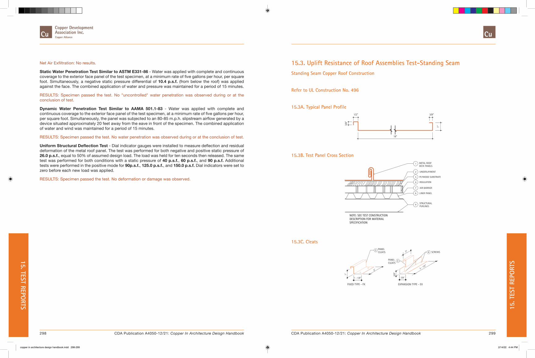
Net Air Exfiltration: No results.
Static Water Penetration Test Similar to ASTM E331-86 - Water was applied with complete and continuous coverage to the exterior face panel of the test specimen, at a minimum rate of five gallons per hour, per square foot. Simultaneously, a negative static pressure differential of 10.4 p.s.f. (from below the roof) was applied against the face. The combined application of water and pressure was maintained for a period of 15 minutes.
RESULTS: Specimen passed the test. No "uncontrolled" water penetration was observed during or at the conclusion of test.
Dynamic Water Penetration Test Similar to AAMA 501.1-83 - Water was applied with complete and continuous coverage to the exterior face panel of the test specimen, at a minimum rate of five gallons per hour, per square foot. Simultaneously, the panel was subjected to an 80-85 m.p.h. slipstream airflow generated by a device situated approximately 20 feet away from the eave in front of the specimen. The combined application of water and wind was maintained for a period of 15 minutes.
RESULTS: Specimen passed the test. No water penetration was observed during or at the conclusion of test.
Uniform Structural Deflection Test - Dial indicator gauges were installed to measure deflection and residual deformation of the metal roof panel. The test was performed for both negative and positive static pressure of 26.0 p.s.f., equal to 50% of assumed design load. The load was held for ten seconds then released. The same test was performed for both conditions with a static pressure of 40 p.s.f., 60 p.s.f., and 90 p.s.f. Additional tests were performed in the positive mode for 90p.s.f., 125.0 p.s.f., and 150.0 p.s.f. Dial indicators were set to zero before each new load was applied.
RESULTS: Specimen passed the test. No deformation or damage was observed.
15.3. Uplift Resistance of Roof Assemblies Test-Standing SeamStanding Seam Copper Roof Construction
Refer to UL Construction No. 496
15.3A. Typical Panel Profile
18”
3/8”1/2”
3/8”
1”
15.3B. Test Panel Cross Section
1
2
5
6
7
8
9
METAL ROOF DECK PANELS
UNDERLAYMENT
PLYWOOD SUBSTRATE
INSULATION
AIR BARRIER
LINER PANEL
STRUCTURALPURLINES
NOTE: SEE TEST CONSTRUCTION DESCRIPTION FOR MATERIAL SPECIFICATION
15.3C. Cleats
FIXED TYPE - FX EXPANSION TYPE - EX
4
3
3
1 - 1/8”
1”
2”
7/8”
5/8”
2”
3 - 1/2”
SCREWS
PANELCLEATS
PANELCLEATS
298 299CDA Publication A4050-12/21: Copper In Architecture Deisgn Handbook CDA Publication A4050-12/21: Copper In Architecture Design Handbook
15. TEST REPORTS 15
. TES
T RE
PORT
S
copper in architecture design handbook.indd 298-299copper in architecture design handbook.indd 298-299 2/14/22 4:44 PM2/14/22 4:44 PM
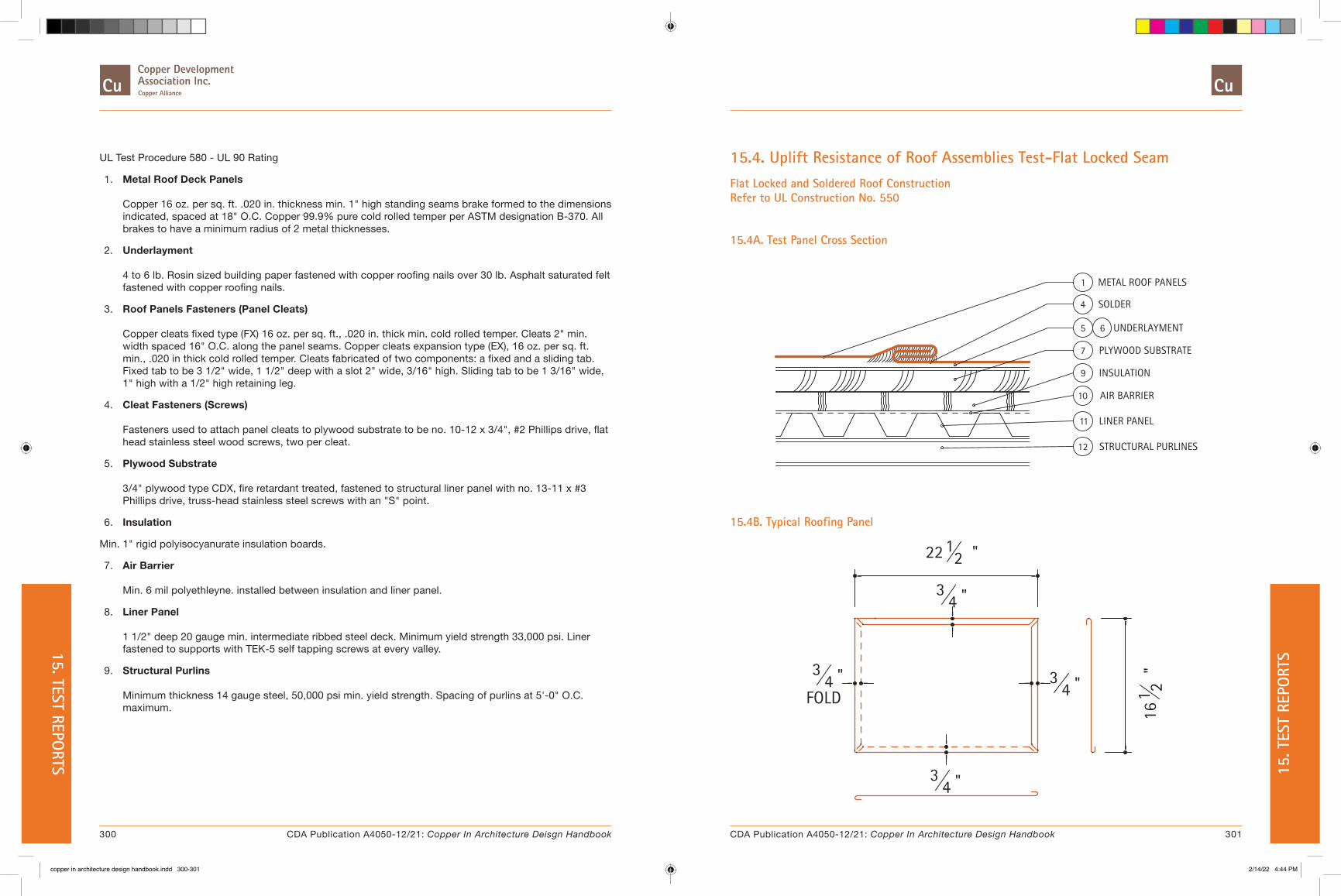
UL Test Procedure 580 - UL 90 Rating
1. Metal Roof Deck Panels Copper 16 oz. per sq. ft. .020 in. thickness min. 1" high standing seams brake formed to the dimensions indicated, spaced at 18" O.C. Copper 99.9% pure cold rolled temper per ASTM designation B-370. All brakes to have a minimum radius of 2 metal thicknesses.
2. Underlayment 4 to 6 lb. Rosin sized building paper fastened with copper roofing nails over 30 lb. Asphalt saturated felt fastened with copper roofing nails.
3. Roof Panels Fasteners (Panel Cleats) Copper cleats fixed type (FX) 16 oz. per sq. ft., .020 in. thick min. cold rolled temper. Cleats 2" min. width spaced 16" O.C. along the panel seams. Copper cleats expansion type (EX), 16 oz. per sq. ft. min., .020 in thick cold rolled temper. Cleats fabricated of two components: a fixed and a sliding tab. Fixed tab to be 3 1/2" wide, 1 1/2" deep with a slot 2" wide, 3/16" high. Sliding tab to be 1 3/16" wide, 1" high with a 1/2" high retaining leg.
4. Cleat Fasteners (Screws) Fasteners used to attach panel cleats to plywood substrate to be no. 10-12 x 3/4", #2 Phillips drive, flat head stainless steel wood screws, two per cleat.
5. Plywood Substrate 3/4" plywood type CDX, fire retardant treated, fastened to structural liner panel with no. 13-11 x #3 Phillips drive, truss-head stainless steel screws with an "S" point.
6. Insulation
Min. 1" rigid polyisocyanurate insulation boards.
7. Air Barrier Min. 6 mil polyethleyne. installed between insulation and liner panel.
8. Liner Panel 1 1/2" deep 20 gauge min. intermediate ribbed steel deck. Minimum yield strength 33,000 psi. Liner fastened to supports with TEK-5 self tapping screws at every valley.
9. Structural Purlins Minimum thickness 14 gauge steel, 50,000 psi min. yield strength. Spacing of purlins at 5'-0" O.C. maximum.
15.4. Uplift Resistance of Roof Assemblies Test-Flat Locked SeamFlat Locked and Soldered Roof Construction Refer to UL Construction No. 550
15.4A. Test Panel Cross Section
1
4
5 6
7
9
10
11
12
METAL ROOF PANELS
SOLDER
UNDERLAYMENT
PLYWOOD SUBSTRATE
INSULATION
AIR BARRIER
LINER PANEL
STRUCTURAL PURLINES
15.4B. Typical Roofing Panel
22 12 "
161 2
"
34 "
34 "
34 "
FOLD3
4 "
300 301CDA Publication A4050-12/21: Copper In Architecture Deisgn Handbook CDA Publication A4050-12/21: Copper In Architecture Design Handbook
15. TEST REPORTS 15
. TES
T RE
PORT
S
copper in architecture design handbook.indd 300-301copper in architecture design handbook.indd 300-301 2/14/22 4:44 PM2/14/22 4:44 PM

15.4C. Typical Cleat Location
6"
6"
CLEAT CL
PANELSEAM
15.4D. Typical Cleat
UL Test Procedure 580 - UL 90 Rating
1. Metal Roof Deck Panels Copper panel, max. width 16 ½", 22 ½" long with ¾" wide field formed folds. Fabricated from 16 oz., 0.21" thick, 99.9% pure cold rolled copper per ASTM B370. Corners cut off at a 45-degree angle. All sides of panels to be pre-tinned with 50/50 tin/lead solder. All seams to be hammered down with rubber mallet. Seams to be completely soldered, including panel cleats (Item 2).
2. Roof Panels Cleats One-piece assembly, fabricated from16 oz, 0.0215" thick, 99.9% pure, cold rolled copper per ASTM B370. Width 2", length 3" with two 1/8" diameter guide holes for screws. Cleats to be folded into panel folds. Two cleats to be used at each panel side located along panel seams, 6" from edge.
3. Cleat Fasteners (Screws) For attaching panel cleats (Item 2) to plywood (Item 7) to be no. 10-12 by ¾: long, #2 Phillips drive, flat head, head, stainless steel wood screws, two per cleat.
4. Solder 50/50tin/lead bar stock, 7/32" x 7/32".
5. Red Rosin Paper Rosin paper 36" wide, 4lb. minimum. Side laps 3" wide, fastened with copper nails, random spacing.
6. Underlayment One ply of Type 30 asphalt saturated felt. Side laps 4", fastened with copper nails, random spacing.
7. Plywood APA rated sheathing, exposure 1, nominal ¾" thick (actual 23/32"), square edged.
8. Fasteners (Screws) Fasteners used to attach plywood (Item 7) to steel deck liner panel (Item 11) to be no. 13-11, #3 Phillips drive truss head, coated steel screws with an "S" point.
9. Insulation Polyisocyanurate, loose laid, 1" min. thickness, 2 ½" max. thickness with a glass fiber face bonded to each side. Butt joints staggered.
10. Air Barrier Polycthylene sheeting loose laid 6 mil. Min. thickness installed between liner panel (Item 11) and insulation (Item 9).
11. Liner Panels Min. no. 22 MSG steel deck, 1 ½" min. depth, 36" wide, with overlapping side joints (33,000 psi min. yield strength). Liner fastened to purlins (Item 12) with no. 12-24 x 1" long, self-drilling, self-tapping, hex-washer head, plated steel screws at each valley.
12. Purlins No. 16 MSG min. steel, (50,000 psi min yield strength), spaced 5'-1" O.C. maximum
302 303CDA Publication A4050-12/21: Copper In Architecture Deisgn Handbook CDA Publication A4050-12/21: Copper In Architecture Design Handbook
15. TEST REPORTS 15
. TES
T RE
PORT
S
copper in architecture design handbook.indd 302-303copper in architecture design handbook.indd 302-303 2/14/22 4:44 PM2/14/22 4:44 PM
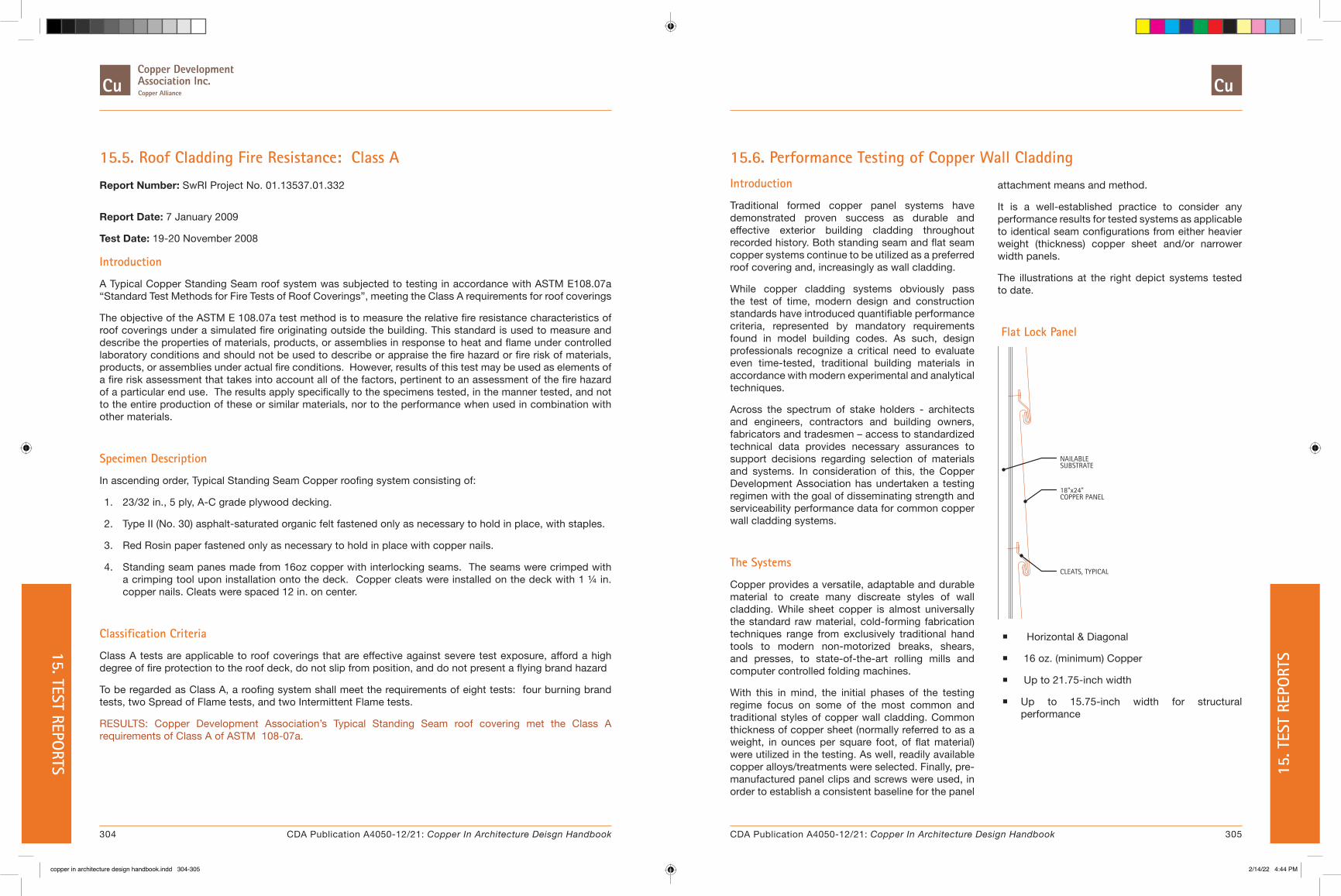
15.5. Roof Cladding Fire Resistance: Class A
Report Number: SwRI Project No. 01.13537.01.332
Report Date: 7 January 2009
Test Date: 19-20 November 2008
Introduction
A Typical Copper Standing Seam roof system was subjected to testing in accordance with ASTM E108.07a “Standard Test Methods for Fire Tests of Roof Coverings”, meeting the Class A requirements for roof coverings
The objective of the ASTM E 108.07a test method is to measure the relative fire resistance characteristics of roof coverings under a simulated fire originating outside the building. This standard is used to measure and describe the properties of materials, products, or assemblies in response to heat and flame under controlled laboratory conditions and should not be used to describe or appraise the fire hazard or fire risk of materials, products, or assemblies under actual fire conditions. However, results of this test may be used as elements of a fire risk assessment that takes into account all of the factors, pertinent to an assessment of the fire hazard of a particular end use. The results apply specifically to the specimens tested, in the manner tested, and not to the entire production of these or similar materials, nor to the performance when used in combination with other materials.
Specimen Description
In ascending order, Typical Standing Seam Copper roofing system consisting of:
1. 23/32 in., 5 ply, A-C grade plywood decking.
2. Type II (No. 30) asphalt-saturated organic felt fastened only as necessary to hold in place, with staples.
3. Red Rosin paper fastened only as necessary to hold in place with copper nails.
4. Standing seam panes made from 16oz copper with interlocking seams. The seams were crimped with a crimping tool upon installation onto the deck. Copper cleats were installed on the deck with 1 ¼ in. copper nails. Cleats were spaced 12 in. on center.
Classification Criteria
Class A tests are applicable to roof coverings that are effective against severe test exposure, afford a high degree of fire protection to the roof deck, do not slip from position, and do not present a flying brand hazard
To be regarded as Class A, a roofing system shall meet the requirements of eight tests: four burning brand tests, two Spread of Flame tests, and two Intermittent Flame tests.
RESULTS: Copper Development Association’s Typical Standing Seam roof covering met the Class A requirements of Class A of ASTM 108-07a.
15.6. Performance Testing of Copper Wall CladdingIntroduction
Traditional formed copper panel systems have demonstrated proven success as durable and effective exterior building cladding throughout recorded history. Both standing seam and flat seam copper systems continue to be utilized as a preferred roof covering and, increasingly as wall cladding.
While copper cladding systems obviously pass the test of time, modern design and construction standards have introduced quantifiable performance criteria, represented by mandatory requirements found in model building codes. As such, design professionals recognize a critical need to evaluate even time-tested, traditional building materials in accordance with modern experimental and analytical techniques.
Across the spectrum of stake holders - architects and engineers, contractors and building owners, fabricators and tradesmen – access to standardized technical data provides necessary assurances to support decisions regarding selection of materials and systems. In consideration of this, the Copper Development Association has undertaken a testing regimen with the goal of disseminating strength and serviceability performance data for common copper wall cladding systems.
The Systems
Copper provides a versatile, adaptable and durable material to create many discreate styles of wall cladding. While sheet copper is almost universally the standard raw material, cold-forming fabrication techniques range from exclusively traditional hand tools to modern non-motorized breaks, shears, and presses, to state-of-the-art rolling mills and computer controlled folding machines.
With this in mind, the initial phases of the testing regime focus on some of the most common and traditional styles of copper wall cladding. Common thickness of copper sheet (normally referred to as a weight, in ounces per square foot, of flat material) were utilized in the testing. As well, readily available copper alloys/treatments were selected. Finally, pre-manufactured panel clips and screws were used, in order to establish a consistent baseline for the panel
attachment means and method.
It is a well-established practice to consider any performance results for tested systems as applicable to identical seam configurations from either heavier weight (thickness) copper sheet and/or narrower width panels.
The illustrations at the right depict systems tested to date.
Flat Lock Panel
CLEATS, TYPICAL
NAILABLE
18"x24"
SUBSTRATE
COPPER PANEL
� Horizontal & Diagonal
� 16 oz. (minimum) Copper
� Up to 21.75-inch width
� Up to 15.75-inch width for structural performance
304 305CDA Publication A4050-12/21: Copper In Architecture Deisgn Handbook CDA Publication A4050-12/21: Copper In Architecture Design Handbook
15. TEST REPORTS 15
. TES
T RE
PORT
S
copper in architecture design handbook.indd 304-305copper in architecture design handbook.indd 304-305 2/14/22 4:44 PM2/14/22 4:44 PM

Single Lock Standing Seam Panel
� Horizontal
� 16 oz. (minimum) Copper
� Up to 21.25-inch width
� Up to 15.25-inch width for structural performance
Double Lock Standing Seam Panel
� Vertical & Horizontal
� 16 oz. (minimum) Copper
� Up to 21.25-inch width
� Up to 15.25-inch width for structural performance
Test Standards
Each copper wall cladding system was tested to evaluate serviceability and structural performance. Serviceability includes the determination of rates of water and air infiltration through the cladding. Structural performance determines the system’s resistance negative wind pressures, as the wall cladding systems may be susceptible to suction forces, potentially causing “blow-off” during extreme wind events.
Rain Screen Design Since the early 2000’s, design of exterior cladding systems according to the Rain Screen Principle has become a preferred design method. This principle, in short, considers the cladding to be an element of the exterior wall assembly that resists wind, ultra violet radiation, and other environmental conditions, while limiting moisture ingress into the wall assembly and promoting the drying of incidental moisture through drainage and ventilation of the wall cavity.
In recognition of this, the serviceability performance of these wall cladding systems was evaluated by the American Architectural Manufacturer’s Association (AAMA ) 509 testing protocol entitled, Voluntary Test and Classification Method for Drained and Back Ventilated Rain Screen Wall Cladding Systems.
AAMA 509 results in classification of the cladding system based on both volume of water penetrating the cladding and contacting the air and water barrier element within the wall assembly, and the rate of air flow through the cladding joints and terminations. The water ingress is reported as a volume of water per unit area of cladding surface over a fixed time, expressed in units of ml/m2 (oz/ft2) and subsequently given a classification of W1 (least water penetration) to W11 (most water penetration). Ventilation is reported as a rate of air flow per unit area of cladding, expressed in units of L/s/m2 (cfm/ft2) and given a classification of V1 (least air flow) to V11 (most air flow). The AAMA 509 protocol consists of three separate testing procedures, detailed as follows.
American Society of Testing and Materials (ASTM ) E283 Standard Test Method for Air Leakage through Exterior Windows, Curtain Walls, and Doors Under Specified Pressure Differences Across the Specimen determines the AAMA 509 air ventilation classification. For this procedure, each of four cladding element conditions are isolated and tested
for air leakage. The conditions are vertical panel joints, horizontal panel joints, head flashing, and sill flashing.
Figure 15.6.1: Horizontal copper flat lock panel with taped joints to isolate joinery elements for ASTM E283 air flow testing.
While higher ratings, representing higher rates of air infiltration, are desirable for rain screen cladding systems (as they promote greater potential for drying), lower ratings are preferable for traditional face-sealed cladding systems. Furthermore, the ventilation rating of a rain screen cladding system is generally evaluated to be “in balance” with the water penetration rating, i.e. a cladding that allows more water penetration may require a higher ventilation rating to adequately dry the wall cavity, whereas a cladding that allows virtually no water penetration may only require a minimal rate of air ventilation to dry the wall cavity.
ASTM E331 Standard Test Method for Water Penetration of Exterior Windows, Skylights, Doors, and Curtain Walls by Uniform Static Air Pressure Difference, is the first of two test methods used to determine the water penetration classification of a wall cladding, per the AAMA 509 protocol. This procedure applies a static inward (suction) pressure to the wall assembly, while subjecting the cladding to a direct water spray of 5 gallons per minute per square foot of cladding surface. The test is performed twice, once at 6.24 psf of static air pressure, and again at 12.0 psf of static air pressure. These pressures approximate the wind pressures associated with a severe thunderstorm and near-hurricane wind speeds, respectively. In order to
306 307CDA Publication A4050-12/21: Copper In Architecture Deisgn Handbook CDA Publication A4050-12/21: Copper In Architecture Design Handbook
15. TEST REPORTS 15
. TES
T RE
PORT
S
copper in architecture design handbook.indd 306-307copper in architecture design handbook.indd 306-307 2/14/22 4:44 PM2/14/22 4:44 PM
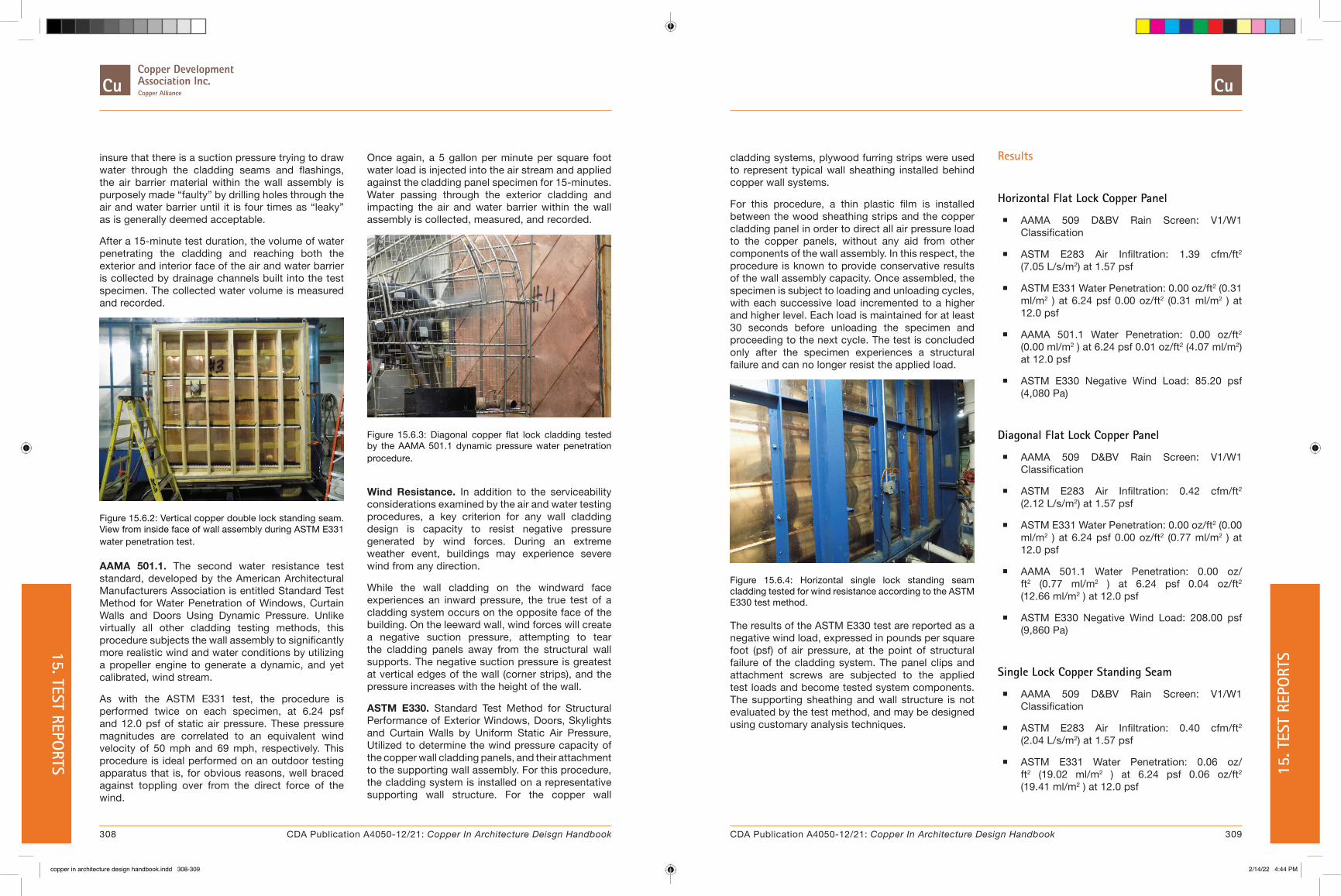
insure that there is a suction pressure trying to draw water through the cladding seams and flashings, the air barrier material within the wall assembly is purposely made “faulty” by drilling holes through the air and water barrier until it is four times as “leaky” as is generally deemed acceptable.
After a 15-minute test duration, the volume of water penetrating the cladding and reaching both the exterior and interior face of the air and water barrier is collected by drainage channels built into the test specimen. The collected water volume is measured and recorded.
Figure 15.6.2: Vertical copper double lock standing seam. View from inside face of wall assembly during ASTM E331 water penetration test.
AAMA 501.1. The second water resistance test standard, developed by the American Architectural Manufacturers Association is entitled Standard Test Method for Water Penetration of Windows, Curtain Walls and Doors Using Dynamic Pressure. Unlike virtually all other cladding testing methods, this procedure subjects the wall assembly to significantly more realistic wind and water conditions by utilizing a propeller engine to generate a dynamic, and yet calibrated, wind stream.
As with the ASTM E331 test, the procedure is performed twice on each specimen, at 6.24 psf and 12.0 psf of static air pressure. These pressure magnitudes are correlated to an equivalent wind velocity of 50 mph and 69 mph, respectively. This procedure is ideal performed on an outdoor testing apparatus that is, for obvious reasons, well braced against toppling over from the direct force of the wind.
Once again, a 5 gallon per minute per square foot water load is injected into the air stream and applied against the cladding panel specimen for 15-minutes. Water passing through the exterior cladding and impacting the air and water barrier within the wall assembly is collected, measured, and recorded.
Figure 15.6.3: Diagonal copper flat lock cladding tested by the AAMA 501.1 dynamic pressure water penetration procedure.
Wind Resistance. In addition to the serviceability considerations examined by the air and water testing procedures, a key criterion for any wall cladding design is capacity to resist negative pressure generated by wind forces. During an extreme weather event, buildings may experience severe wind from any direction.
While the wall cladding on the windward face experiences an inward pressure, the true test of a cladding system occurs on the opposite face of the building. On the leeward wall, wind forces will create a negative suction pressure, attempting to tear the cladding panels away from the structural wall supports. The negative suction pressure is greatest at vertical edges of the wall (corner strips), and the pressure increases with the height of the wall.
ASTM E330. Standard Test Method for Structural Performance of Exterior Windows, Doors, Skylights and Curtain Walls by Uniform Static Air Pressure, Utilized to determine the wind pressure capacity of the copper wall cladding panels, and their attachment to the supporting wall assembly. For this procedure, the cladding system is installed on a representative supporting wall structure. For the copper wall
cladding systems, plywood furring strips were used to represent typical wall sheathing installed behind copper wall systems.
For this procedure, a thin plastic film is installed between the wood sheathing strips and the copper cladding panel in order to direct all air pressure load to the copper panels, without any aid from other components of the wall assembly. In this respect, the procedure is known to provide conservative results of the wall assembly capacity. Once assembled, the specimen is subject to loading and unloading cycles, with each successive load incremented to a higher and higher level. Each load is maintained for at least 30 seconds before unloading the specimen and proceeding to the next cycle. The test is concluded only after the specimen experiences a structural failure and can no longer resist the applied load.
Figure 15.6.4: Horizontal single lock standing seam cladding tested for wind resistance according to the ASTM E330 test method.
The results of the ASTM E330 test are reported as a negative wind load, expressed in pounds per square foot (psf) of air pressure, at the point of structural failure of the cladding system. The panel clips and attachment screws are subjected to the applied test loads and become tested system components. The supporting sheathing and wall structure is not evaluated by the test method, and may be designed using customary analysis techniques.
Results
Horizontal Flat Lock Copper Panel
� AAMA 509 D&BV Rain Screen: V1/W1 Classification
� ASTM E283 Air Infiltration: 1.39 cfm/ft2 (7.05 L/s/m2) at 1.57 psf
� ASTM E331 Water Penetration: 0.00 oz/ft2 (0.31 ml/m2 ) at 6.24 psf 0.00 oz/ft2 (0.31 ml/m2 ) at 12.0 psf
� AAMA 501.1 Water Penetration: 0.00 oz/ft2 (0.00 ml/m2 ) at 6.24 psf 0.01 oz/ft2 (4.07 ml/m2) at 12.0 psf
� ASTM E330 Negative Wind Load: 85.20 psf (4,080 Pa)
Diagonal Flat Lock Copper Panel
� AAMA 509 D&BV Rain Screen: V1/W1 Classification
� ASTM E283 Air Infiltration: 0.42 cfm/ft2 (2.12 L/s/m2) at 1.57 psf
� ASTM E331 Water Penetration: 0.00 oz/ft2 (0.00 ml/m2 ) at 6.24 psf 0.00 oz/ft2 (0.77 ml/m2 ) at 12.0 psf
� AAMA 501.1 Water Penetration: 0.00 oz/ft2 (0.77 ml/m2 ) at 6.24 psf 0.04 oz/ft2 (12.66 ml/m2 ) at 12.0 psf
� ASTM E330 Negative Wind Load: 208.00 psf (9,860 Pa)
Single Lock Copper Standing Seam
� AAMA 509 D&BV Rain Screen: V1/W1 Classification
� ASTM E283 Air Infiltration: 0.40 cfm/ft2 (2.04 L/s/m2) at 1.57 psf
� ASTM E331 Water Penetration: 0.06 oz/ft2 (19.02 ml/m2 ) at 6.24 psf 0.06 oz/ft2 (19.41 ml/m2 ) at 12.0 psf
308 309CDA Publication A4050-12/21: Copper In Architecture Deisgn Handbook CDA Publication A4050-12/21: Copper In Architecture Design Handbook
15. TEST REPORTS 15
. TES
T RE
PORT
S
copper in architecture design handbook.indd 308-309copper in architecture design handbook.indd 308-309 2/14/22 4:44 PM2/14/22 4:44 PM

� AAMA 501.1 Water Penetration: 0.03 oz/ft2 (9.66 ml/m 2 ) at 6.24 psf 0.04 oz/ft2 (12.66 ml/m2 ) at 12.0 psf
� ASTM E330 Negative Wind Load: 80.00 psf (3,830 Pa)
Double Lock Copper Standing Seam
� AAMA 509 D&BV Rain Screen: V1/W1 Classification
� ASTM E283 Air Infiltration: 0.42 cfm/ft2 (2.14 L/s/m2) at 1.57 psf
� ASTM E331 Water Penetration: 0.00 oz/ft2 (0.00 ml/m2 ) at 6.24 psf 0.00 oz/ft2 (0.00 ml/m2 ) at 12.0 psf
� AAMA 501.1 Water Penetration: 0.01 oz/ft2 (2.30 ml/m2 ) at 6.24 psf 0.02 oz/ft2 (6.06 ml/m2 ) at 12.0 psf
� ASTM E330 Negative Wind Load: 127.70 psf (6,1150 Pa)
Table 15.6.1: Maximum Wall Height Based on Negative Wind Pressure
This chart is provided for general illustrative purposes only. A qualified design professional must evaluate project specific applications. Project specific performance testing and/or wind tunnel modeling may be for design loads which exceed the limits of current testing. Increased capacity may be achieved through heavier copper material, narrower panel width, and/or alternate means of attachment, please contact the Copper Development Association for additional assistance.
The maximum building height is based upon a Component and Cladding Zone 5 wind pressure of a Risk Category II building in an Exposure Category B as per ASCE-7-16.
The system design capacity is based upon ASTM E330 test results. A resistance factor of 0.80 has been applied to the maximum tested load.
Refer to specific ASTM E330 test for system details such as max. panel width, max. clip spacing and min. material thickness.
310 311CDA Publication A4050-12/21: Copper In Architecture Deisgn Handbook CDA Publication A4050-12/21: Copper In Architecture Design Handbook
15. TEST REPORTS 15
. TES
T RE
PORT
S
copper in architecture design handbook.indd 310-311copper in architecture design handbook.indd 310-311 2/14/22 4:44 PM2/14/22 4:44 PM
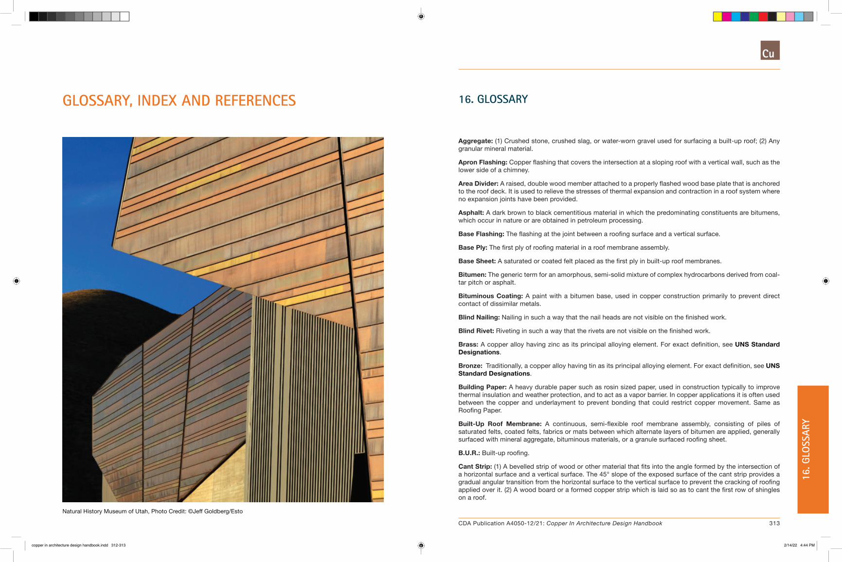
16. GLOSSARY
Aggregate: (1) Crushed stone, crushed slag, or water-worn gravel used for surfacing a built-up roof; (2) Any granular mineral material.
Apron Flashing: Copper flashing that covers the intersection at a sloping roof with a vertical wall, such as the lower side of a chimney.
Area Divider: A raised, double wood member attached to a properly flashed wood base plate that is anchored to the roof deck. It is used to relieve the stresses of thermal expansion and contraction in a roof system where no expansion joints have been provided.
Asphalt: A dark brown to black cementitious material in which the predominating constituents are bitumens, which occur in nature or are obtained in petroleum processing.
Base Flashing: The flashing at the joint between a roofing surface and a vertical surface.
Base Ply: The first ply of roofing material in a roof membrane assembly.
Base Sheet: A saturated or coated felt placed as the first ply in built-up roof membranes.
Bitumen: The generic term for an amorphous, semi-solid mixture of complex hydrocarbons derived from coal-tar pitch or asphalt.
Bituminous Coating: A paint with a bitumen base, used in copper construction primarily to prevent direct contact of dissimilar metals.
Blind Nailing: Nailing in such a way that the nail heads are not visible on the finished work.
Blind Rivet: Riveting in such a way that the rivets are not visible on the finished work.
Brass: A copper alloy having zinc as its principal alloying element. For exact definition, see UNS Standard Designations.
Bronze: Traditionally, a copper alloy having tin as its principal alloying element. For exact definition, see UNS Standard Designations.
Building Paper: A heavy durable paper such as rosin sized paper, used in construction typically to improve thermal insulation and weather protection, and to act as a vapor barrier. In copper applications it is often used between the copper and underlayment to prevent bonding that could restrict copper movement. Same as Roofing Paper.
Built-Up Roof Membrane: A continuous, semi-flexible roof membrane assembly, consisting of piles of saturated felts, coated felts, fabrics or mats between which alternate layers of bitumen are applied, generally surfaced with mineral aggregate, bituminous materials, or a granule surfaced roofing sheet.
B.U.R.: Built-up roofing.
Cant Strip: (1) A bevelled strip of wood or other material that fits into the angle formed by the intersection of a horizontal surface and a vertical surface. The 45° slope of the exposed surface of the cant strip provides a gradual angular transition from the horizontal surface to the vertical surface to prevent the cracking of roofing applied over it. (2) A wood board or a formed copper strip which is laid so as to cant the first row of shingles on a roof.
GLOSSARY, INDEX AND REFERENCES
Natural History Museum of Utah, Photo Credit: ©Jeff Goldberg/Esto
313CDA Publication A4050-12/21: Copper In Architecture Design Handbook
16. G
LOSS
ARY
copper in architecture design handbook.indd 312-313copper in architecture design handbook.indd 312-313 2/14/22 4:44 PM2/14/22 4:44 PM

Cap Flashing: Same as Counterflashing.
Caulking: A resilient mastic compound often having a silicone or rubber base, used to fill cracks and joints, that remains plastic for an extended period of time.
Cleat: A small strip of copper, usually 16 ounce material, used to fasten sheet copper components, such as roofing or flashing to the supporting understructure. Expansion cleats allow the components to move to account for thermal variations, fixed cleats do not.
C.M.U.: Concrete masonry unit or concrete block.
Collar Joint: The vertical joint between masonry wythes.
Composition Flashing: Base flashing that is constructed by extending the plies of a built-up roof.
Condensation: The conversion of water vapor or other gas to liquid as the temperature drops or the atmospheric pressure rises.
CONT.: Continuous.
Coping: The covering piece placed on top of a wall that is exposed to the weather. It is usually sloped to shed water.
Copper Cold Rolled: A strong yet still fairly malleable type of copper that is very well suited to building construction. It has a yield strength of 26,000-28,000 psi.
Copper Soft Temper: A type of extremely malleable copper used only for intricate ornamental applications. It is not recommended for general use in construction.
Counterflashing: Formed sheet copper secured on or into a wall, curb, pipe, rooftop unit or other surface to cover and protect the upper edge of a base flashing and its associated fasteners.
Course: (1) The term used for each application of material that forms the waterproofing system or the flashing; (2) a layer of masonry units running horizontally in a wall bonded with mortar.
Cricket: A small saddle-shaped projection on a sloped roof used to divert water around an obstacle such as a chimney.
Dampproofing: Treatment of a surface or structure to resist the passage of water in the absence of hydrostatic pressure.
Deck: The structural surface to which the roofing or waterproofing system is applied
Delamination: Separation of the plies in a roof membrane system or separation of laminated layers of insulation.
Dew Point: The temperature at which water vapor starts to condense in cooling air at the existing atmospheric pressure and vapor content.
Edge Sheets: Felt strips that are cut to widths narrower than the standard width of the full felt roll. They are used to start the felt-shingling pattern at a roof edge.
Edge Strip: A long narrow copper flashing used to protect the edge of a roof or other surface.
Erosion Corrosion: Where concentrated amounts of water hit a copper roof causing erosion of copper material.
Expansion Joint: A structural separation between two building elements designed to minimize the effect of the stresses and movements of a building's components and to prevent these stresses from splitting or ridging the roof membrane.
Exposure: The transverse dimension of a roofing element not overlapped by an adjacent element in any roof system.
Factory Square: 108 square feet (10 square meters) of roofing material. See Square.
Felt: A fabric manufactured from vegetable fibers (organic felts), or glass fibers (glass fiber felts). The manufacturing process involves mechanically interlocking the fibers of the particular felt material in the presence of moisture and heat.
Flashing: Sheet copper material placed in construction, such as in mortar joints, to prevent water penetration and/or to divert water which has already penetrated.
Full Collar Joint: A vertical joint between masonry wythes that has been grouted solid.
Gauge: The thickness of copper material. Can be designated by a number, or more commonly for copper, by the weight of material per square foot, in ounces.
Girth: The width of sheet copper material (in the flat) used to form a gutter.
Gravel: Coarse, granular aggregate, containing pieces approximately 5/8 inch to 1/2 inch in size and suitable for use in aggregate surfacing on built-up roofs.
Gravel Stop: A flanged copper device, designed to provide a continuous finished edge for roofing materials and to prevent loose aggregate from washing off the roof.
Headlap: The minimum distance, measured at 90 degrees to the eaves along the face of a shingle or felt, from the upper edge of a shingle or felt to the nearest exposed surface.
Hemmed Edge: The edge of sheet copper which has been folded under completely. All exposed sheet copper edges should have 1/2" nominal hem.
"High Yield" Copper: A specially developed sheet copper defined in ASTM B370 as cold rolled high yield temper copper. It's yield strength is 31,000-33,000 psi.
Hold Down: A method of fastening sheet copper that involves the use of a brass screw with a large copper or brass washer. The screw is tightened sufficiently to keep the metal flat, but not restrict its lateral movement. The entire assembly is usually covered with a copper cap, fully soldered to provide watertightness.
Line Corrosion: The linear degradation and pitting of copper placed under a drip edge. This is often the result of acidic moisture deposited on an inert (non-copper) which directs water to a valley or gutter. Under severe conditions, this concentration of acidic moisture can corrode copper flashing and gutters before they can form a copper sulfate patina. Protection from line corrosion is achieved by raising the shingle edges slightly by means of a cant, in order to break capillarity, or by providing a replaceable reinforcing strip between the shingle line and the copper valley flashing.
Max.: Maximum.
Membrane: A flexible or semi-flexible roof covering or waterproofing layer, whose primary function is the exclusion of water.
Min.: Minimum.
Muntz Metal: A copper-zinc metal having 60% copper and 40% zinc.
314 315CDA Publication A4050-12/21: Copper In Architecture Deisgn Handbook CDA Publication A4050-12/21: Copper In Architecture Design Handbook
16. GLOSSARY 16
. GLO
SSAR
Y
copper in architecture design handbook.indd 314-315copper in architecture design handbook.indd 314-315 2/14/22 4:44 PM2/14/22 4:44 PM

Nailer: A wood strip, attached to a surface, used as a base for nailing or attaching other material.
O.C.: On center.
Patina: The naturally protective coating that results from the mild corrosive attack of airborne sulfur compounds. The sulfate patina significantly increases the durability and service life of copper roofing and flashing.
Pea Gravel: Small diameter (1/4 to 3/8 inch) natural gravel, used in conjunction with through-wall flashing to help prevent debris from blocking the flow of moisture.
Pein: The end of a hammer opposite the flat hammering face. It may be cone-shaped, rounded, or sharply pointed: it is used to create a textured finish on copper and other materials.
Pitch: The tangent of the angle between the roof surface and the horizontal. It is measured in inches per foot. For copper construction pitch is ranked as follows:
Low Pitch: 3 to 6 inches per foot.
Steep Pitch: 6 inches and higher per foot.
Ply: A layer of felt in a built-up roof membrane system. A four-ply membrane system has four plies of felt.
Rake: The sloped edge of a roof at first or last rafter.
Raked Joint: A mortar joint which, during construction or at a later date, has been tooled to provide a deep recess. This recess is used as a reglet into which copper cap or counterflashing may be inserted.
Raggle: Same as Reglet.
Receiver: A copper flashing, built into a wall, that locks into the upper edge of base or counterflashing.
Reglet: A groove in a wall or other surface adjoining a roof surface for use in the attachment of counterflashing. Same as Raggle.
Ridging: An upward, "tenting" displacement of a roof membrane, frequently occurring over insulation joints, deck joints and base sheet edges.
Roofing Paper: Same as Building Paper.
Roof System: A system of interacting roof components (NOT including the roof deck), designed to weather-proof and, normally, to insulate a building's top surface.
Rosin Sized Paper: A heavy building paper impregnated with rosin.
Saturated Felt: A felt that has been partially saturated with low softening point bitumen.
Scupper: An opening in a wall or parapet that allows water to drain from a roof.
Sealant: A mixture of polymers, fillers, and pigments used to fill and seal joints. Used to prevent the penetration of water or air.
Seamer: Mechanical seamers are available for both standing seam and batten seam roof systems. They create precise, uniform seams without the hammer marks typical of manual seaming techniques.
Shingle: (1) A small unit of prepared roofing material designed to be installed with similar units in overlapping rows on inclines normally exceeding 25%; (2) to cover with shingles; (3) to apply any sheet material in overlapping rows like shingles.
Slip Sheet: A lightweight rosin sized paper inserted between sheet copper and underlayment to prevent bonding. See Building Paper.
Slope: See Pitch.
Square: The term used to describe 100 square feet of roof area. See Factory Square.
Sq. Ft.: Square feet.
Stack Vent: The extension (to the open air) of a soil or waste stack through the roof membrane.
Step Flashing: Discontinuous flashing in masonry walls which follows the elevation of a sloped roof, and is therefore inserted into successive courses, forming steps.
Substrate: The surface upon which the roofing or waterproofing membrane is applied (i.e., the structural deck or insulation).
Tapered Edge Strip: A tapered strip used to (1) elevate the roof at the perimeter and at curbs that extend through the roof; or (2) provide a gradual transition from one layer of insulation to another.
Through-Wall: A water-resistant membrane of sheet copper which extends through a wall and its cavities, positioned to divert moisture to the exterior.
TYP.: Typical.
Underlayment: A material, such as saturated No. 15 felt, placed on the roof deck to improve weather resistance.
U.O.N.: Unless otherwise noted.
Waterproofing: Treatment of a surface or structure to prevent the passage of water under hydrostatic pressure.
Weep: A small opening in a wall, through which accumulated moisture may drain to the exterior.
316 317CDA Publication A4050-12/21: Copper In Architecture Deisgn Handbook CDA Publication A4050-12/21: Copper In Architecture Design Handbook
16. GLOSSARY 16
. GLO
SSAR
Y
copper in architecture design handbook.indd 316-317copper in architecture design handbook.indd 316-317 2/14/22 4:44 PM2/14/22 4:44 PM

17. INDEX
A
Adhesives 25alloys. see copperarea divider. see flashing
B
barrel vaults. see vaultsbatten seams. see seams, roofing systemsbrass 21–26bronze 21–26building expansion joints 156
floor conditions 164roof conditions 156roof edges 161wall conditions 165
built-in gutters. see gutters
C
chimney flashing. see flashingcleats 48, 49, 50conductivity 11copings. see flashingcopper
alloys 21–26chemical properties 10corrosion 11expansion 17, 50, 53, 78fundamentals 10–20physical properties 10
copper cladding systemscurtain wall 185–186
cornice 124, 199corrosion. see coppercounterflashing. see flashing
D
domes 187dormer flashing. see flashingdownspouts 126–134
hangers 155locations 126–134outlet tubes 154
sizing 126–134table 10E 134
ductility 18, 57
E
eaves. see flashingeave snow flashing. see flashingedge strips 54end dam. see flashingexpansion. see copperexpansion battens 73expansion joints. see building expansion jointsexpansion seams. see seams
F
fascias. see flashingfasteners 25, 48finishes. see copperflashing 87–88
brick veneer 89, 90, 91, 92, 93, 113chimney 113coping covers 98–102counterflashing 94–97dormers 117eave conditions 121eave snow 119end dam 91fascias 109grade 90, 93gravel stops 79, 107, 109, 138parapet 99receiver 94ridges 61, 86, 103roof area divider 125roof penetrations 115spandrel 89, 90stepped 113through-wall 89valleys 64, 77, 105, 120ventilator 115vent pipe 115window head and sill 92, 117
flat seam roofing 188, 194, 199, 204forming 23
bending 23casting 23extrusion 23laminating 24spinning 24stamping 24
G
gable 61, 66, 86, 119gauge 12general design issues 46–47gravel stops. see flashinggutters 126–155
braces 135brackets 135, 138, 139built-in 142, 144design principles 126expansion joints 129, 140
Table 10B 130hung 135, 137rainfall intensity 126
Table 10A 127Table 10D 133
roof drains 152roof sumps 152scuppers 149sizing 126
Table 10E 134straps 135, 137, 139
H
hangers. see downspoutshold-downs 48, 49horizontal seam roofs. see roofing systemshung gutters. see gutters
J
joining 25–26
L
long pan 82loose seams. see seams
M
malleability 10, 57
mansard roofs. see roofing systemsmechanical fasteners 25, 48
N
nickel silver 21, 22
O
outlet tubes. see downspouts
P
panels. see wall cladding systemsparapet flashing. see flashingpatina 41
R
rainful intensity. see guttersrain screens. see wall cladding systemsrake 61receivers. see flashingridge flashing. see flashingridge roofing details 61–64, 82–86, 103–104ridge seams. see seamsroof drains. see guttersroofing systems 57–58
batten seam 66–69chevron 70–71flat seam 72–74horizontal seam 75–78long pan 82–86mansard 79–81standing seam 61–65
roof penetration flashing. see flashingroof sumps. see gutters
S
scuppers. see guttersseams
batten 56, 59, 66corner 54expansion 53loose 52, 55ridge 61, 66, 68rigid 51standing 51, 55, 59, 61–65transverse 55, 60, 62, 67, 83, 85, 146
318 319CDA Publication A4050-12/21: Copper In Architecture Deisgn Handbook CDA Publication A4050-12/21: Copper In Architecture Design Handbook
17. INDEX 17
. IN
DEX
copper in architecture design handbook.indd 318-319copper in architecture design handbook.indd 318-319 2/14/22 4:44 PM2/14/22 4:44 PM

18. REFERENCE SOURCES
1. Copper Development Association Inc.
� Sheet Copper Applications, [1990] (401/0).
� Copper Brass Bronze Design Handbook: Architectural Applications, [1987] (405/7R).
� Contemporary Copper, A Handbook of Sheet Copper Fundamentals, [1976] (410/6).
� Copper Brass Bronze Design Handbook: Solar Energy Systems, [1979] (403/9S).
2. Revere Copper Products, Inc. Copper and Common Sense, 1982.
3. SMACNA. Architectural Sheet Metal Manual, 1979.
4. Deutsches Kupfer-Institut. Kupfer im Hochbau, 1987, Berlin.
5. National Concrete Masonry Institute. NCMA-TEK Bulletin 126, Flashing Concrete Masonry, 1982.
6. National Association of Corrosion Engineers. Process Industries Corrosion-Theory and Practice, 1986.
7. National Concrete Masonry Institute. NCMA-TEK Bulletin 13A, Design for Dry Concrete Masonry Walls, 1983.
8. Brick Institute of America, Technical Notes:
� No. 7 Revised, Water Resistance of Brick Masonry: Design and Detailing, Part I of III, Feb. 1985.
� No. 7A Revised, Water Resistance of Brick Masonry: Materials, Part II of III, Mar. 1985.
� No. 21 Revised, Brick Masonry Cavity Walls, Jan/Feb. 1977.
� No. 21B, Brick Masonry Cavity Walls: Detailing, Jan/Feb. 1978.
� No. 28 Revised, Brick Veneer: New Construction, July 1986.
� No. 28A, Brick Veneer: Existing Construction, Sep/Oct. 1978.
� No. 28B Revised, Brick Veneer: Panel and Curtain Walls, Feb. 1980.
� No. 36A Revised, Brick Masonry Details: Caps and Copings, Corbels and Racking, Jan. 1988.
siding. see wall cladding systemssnow flashing. see flashing - eave snowsolder 15specifications 212, 213, 228, 240, 253, 261, 271, 279spires 187, 196, 199standing seams 191, 196. see also seams - standingstepped flashing. see flashing
T
test reports 287, 288, 290, 292, 294through-wall flashing. see flashingtransverse seams. see seams
U
Unified Numbering System (UNS) 21
V
valley flashing. see flashingvalley roofing details 64, 68, 77, 105, 120vaults 187, 201, 204ventilator flashing. see flashingvent pipe flashing. see also flashing - vent pipe
W
wall cladding systems 167beveled 172–173copper clad honeycomb 181–182copper screen panels 183–184diagonal flat lock 178flat siding 174–175horizontal flat lock 179–180horizontal siding 170–171profiled panels 168–169structural 176–177
water diverters 147–148waxing 33, 34, 41weathering 13, 16, 31, 36window head and sill flashing. see flashing
320 321CDA Publication A4050-12/21: Copper In Architecture Deisgn Handbook CDA Publication A4050-12/21: Copper In Architecture Design Handbook
18. R
EFER
ENCE
SO
URCE
S17. IN
DEX
copper in architecture design handbook.indd 320-321copper in architecture design handbook.indd 320-321 2/14/22 4:44 PM2/14/22 4:44 PM

322 323CDA Publication A4050-12/21: Copper In Architecture Deisgn Handbook CDA Publication A4050-12/21: Copper In Architecture Design Handbook
copper in architecture design handbook.indd 322-323copper in architecture design handbook.indd 322-323 2/14/22 4:44 PM2/14/22 4:44 PM
7918 Jones Branch Drive Suite 300 McLean, VA 22102 www.copper.org
A4050-04/18
copper in architecture design handbook.indd 324copper in architecture design handbook.indd 324 2/14/22 4:44 PM2/14/22 4:44 PM