Conversion of a Jack-up Drilling Rig to a Production Platform
103
Picture of the Paragon C463 (former Noble Ronald Hoope) drilling in the North Sea Conceptual Design & Feasibility Study: Conversion of a Jack-up Drilling Rig to a Production Platform M.H.H. Brouwer
-
Upload
khangminh22 -
Category
Documents
-
view
1 -
download
0
Transcript of Conversion of a Jack-up Drilling Rig to a Production Platform

Picture of the Paragon C463 (former Noble Ronald Hoope) drilling in the North Sea
Conceptual Design & Feasibility Study:
Conversion of a Jack-up Drilling Rig to a
Production Platform M.H.H. Brouwer

Master Thesis Offshore Engineering
Conceptual Design & Feasibility Study: Conversion of a Jack-up Drilling Rig to a
Production Platform
MSC CJ46 Drilling Jack-up Conversion to Fixed Production Platform
By
Machgielis H.H. Brouwer
in partial fulfilment of the requirements for the degree of
Master of Science in Offshore and Dredging Engineering
at the Delft University of Technology,
to be defended on Tuesday January 31st, 2016 at 13:00.
Thesis committee: Ir. P.G.F. Sliggers TU Delft Ir. J.S. Hoving, TU Delft
Prof. dr. A. Metrikine TU Delft T.J.M.A. Bergers Oranje-Nassau Energie B.V

Master Thesis Offshore Engineering
This thesis is confidential and cannot be made public until January 31, 2022. An electronic version of this thesis is available at http://repository.tudelft.nl/.

Master Thesis Offshore Engineering
I
Abstract
Overall depletion in the North Sea has freed processing capacity on many offshore platforms. To avoid building more infrastructure than required, these platforms are often used as hubs for nearby satellite fields. Oranje-Nassau Energie (ONE) has developed and successfully employs a standard low cost design for satellite platforms in the Dutch North Sea, the Oranje-Nassau Standard Satellite (ONSS). For production of fields with no nearby existing infrastructure, however, a new central gas processing and exporting platform is needed. Because the ONSS is not suited to this requirement, an alternative concept must be developed. Due to low oil and gas prices since 2015 the occupation of jack-up drilling rigs has declined. Some of these idle rigs are in line to be scrapped and could be potentially acquired for a low price. The idea was suggested within ONE to convert an idle drilling rig into a production platform. Worldwide there are various examples of the conversion of a jack-up unit into a Processing Platform. Weather conditions and regulation in the North Sea however are not comparable to those where these developments are most commonly found, such as West Africa and Southeast Asia. Case studies show that in the North Sea either new high specification jack-ups are used for drilling and production simultaneously or bespoke self-elevating units are employed. The concept of converting a used jack-up drilling rig into a production platform suitable for operation in the Dutch North Sea (25-50 meters water depth) must therefore first be assessed for feasibility. In this thesis, the key challenges of the concept are identified and addressed. Following this a conceptual design for the conversion is made. What was found to be the main challenge, the design and technical assessment of the conductor support structure for use with the Mobile Offshore Production Platform (MOPU), has formed the bulk of the analysis. Finally, the capability of the MOPU to remain on location for 20 years is assessed. ONE has identified the GEms prospect in the N blocks as a potential target for the concept. Topside design has been dimensioned for the expected size of the prospect. The assessment of the conductor support and jack-up integrity is based on conceptual data that is applicable for the entire Dutch North Sea. Market analysis resulted in the MSC designed CJ46 jack-up being selected for the concept. Design and assessment work was carried-out with support of the rig designers GustoMSC. It has been found that with minor modifications to the preload capacity of the jack-up unit, the concept using the jack-up supported conductors is feasible up to 30 meters’ water depth. Beyond 30 meters the initial constraints are: risk of vortex induced vibrations (VIV) of the conductors, the bearing capacity of the jack-up and jack-up fatigue. Initially, mitigation of these issues is straightforward. However, detailed studies will need to be done to verify the effectiveness and further implications of the VIV mitigation measures. Further study on fatigue sensitive areas could increase the design fatigue factor achievable by reducing conservatisms or prompt local joint reinforcement as solution. Between 30 and 50 meters’ water depth mitigation of the constraints becomes increasing costly and technically challenging. Beyond 50 meters’ water depth, jack-up and conductor stability all become critical constraints and major design changes are required. Site-specific parameters will also affect the feasibility. Therefore, the findings above must be validated in a site-specific study. The conclusion of the research has verified that, converting a used jack-up drilling rig into a jack-up mobile offshore production unit is a technically and economically feasible concept for the development of a standalone gas field on the Dutch continental shelf. It has also demonstrated the conductor support design to be a feasible solution for this jack-up MOPU concept. The body of the work can form a basis to initiate detailed engineering and design when the concept is to be implemented.

Master Thesis Offshore Engineering
II
Acknowledgements
Hereby I would like to gratefully acknowledge ONE for this opportunity and the support during the project. Input from various people at GustoMSC, Paragon, Liberty Drilling Equipment, Fugro, Seafox, Frames, Carlyle, BPC, and Koole has also made a valuable contribution. The committee, including Frank Sliggers, Theo Bergers, and Jeroen Hoving have provided excellent guidance and support throughout.
Master Thesis Offshore Engineering
III
Table of Contents
Abstract ............................................................................................................................................ I
Acknowledgements ......................................................................................................................... II
List of Abbreviations, Acronyms, and Definitions ........................................................................... V
1 Introduction ............................................................................................................................. 1
1.1 Research Objectives ...................................................................................................................... 2
1.2 Thesis Outline ................................................................................................................................ 2
2 State of the Art ........................................................................................................................ 3
2.1 General Design of Jack-up Units ................................................................................................... 3
2.2 Types of Jack-up Units ................................................................................................................... 4
2.3 History of Jack-up Rigs .................................................................................................................. 5
2.4 Jack-up Market Analysis ................................................................................................................ 6
2.5 Historic Cases of Jack-up MOPUs .................................................................................................. 8
2.6 Requirements for the Conversion ................................................................................................ 16
2.7 ‘SWOT’ Analysis ........................................................................................................................... 17
2.8 Classification of Mobile Offshore Production Units .................................................................... 20
3 Conceptual Design of Jack-up MOPU .................................................................................... 24
3.1 Topsides, Risers & Jacking System Design................................................................................... 24
3.2 Spudcan Design ........................................................................................................................... 28
3.3 Conductor Design ........................................................................................................................ 29
3.4 Jack-up Unit Data ........................................................................................................................ 34
3.5 Conversion Scope ........................................................................................................................ 36
3.6 Installation Scope ........................................................................................................................ 37
3.7 Cost Estimate and Comparison ................................................................................................... 38
3.8 Design Schematic of Jack-up MOPU ........................................................................................... 40
4 Assessment of Conceptual Design ......................................................................................... 41
4.1 Metocean Data and Model ......................................................................................................... 42
4.2 Foundation Data and Model ....................................................................................................... 48
4.3 Structural Assessment Procedure................................................................................................ 51
4.4 Fatigue Model ............................................................................................................................. 61
4.5 Vortex Induced Vibrations ........................................................................................................... 66
4.6 Accidental and Serviceability Limit States ................................................................................... 67

Master Thesis Offshore Engineering
IV
5 Results of Assessment ........................................................................................................... 68
5.1 Ultimate Limit State .................................................................................................................... 68
5.2 Fatigue Limit State ...................................................................................................................... 75
5.3 Vortex Induced Vibrations ........................................................................................................... 78
5.4 Capacity Extension ...................................................................................................................... 80
6 Conclusions and Recommendations ..................................................................................... 81
6.1 Initial Feasibility and Design ....................................................................................................... 81
6.2 Conductor Assessment ................................................................................................................ 82
6.3 Jack-up MOPU Assessment ......................................................................................................... 83
6.4 Conclusion ................................................................................................................................... 84
6.5 Recommendations ...................................................................................................................... 84
7 References ............................................................................................................................. 85
8 Appendix .................................................................................................................................. 1
8.1 Appendix 1: Omni-Directional 1-year Joint Frequency Distribution .............................................. 2
8.2 Appendix 2: Design Drawings of a CJ46 Class Jack-up .................................................................. 4
8.3 Appendix 3: Metocean Charts Dutch North Sea ........................................................................... 7
8.4 Appendix 4: Main soil condition Dutch North Sea ........................................................................ 9

Master Thesis Offshore Engineering
V
List of Abbreviations, Acronyms, and Definitions
ABEX Abandonment Expenditure MODU Mobile Offshore Drilling Unit
ABS American Bureau of Shipping MOPU Mobile Offshore Production Unit
AISC American Institute of Steel Construction
MOPUstor Mobile Offshore Production Unit and Storage
ALS Accidental Limit State MPP Multi Purpose Platform
API American Petroleum Institute MSC Marine Structure Consultants
BOP Blowout Preventer MSL Mean Sea Level
BV Bureau Veritas Nm3 Normal cubic meters
CAPEX Capital Expenditure NUI Normally Unmanned Installation
CF Cross-Flow ONE Oranje-Nassau Energie
CoG Centre of Gravity ONSS Oranje-Nassau Standard Satellite
CSP Conductor Supported Platform OPEX Operational Expenditure
DFF Design Fatigue Factor PoB Persons on Board
DHSV Downhole Safety Valve ppm Parts per million
DNV GL Det Norske Veritas Germanischer Lloyd
PUQ Production Utilities and Quarters
DP Dynamically Positioned RCU Remote Control Unit
ESP Electrical Submersible Pump SCF Stress Concentration Factor
EWT Extended Well Test SG Specific Gravity
FEED Front-End Engineering Design SLS Serviceability Limit State
FEM Finite Element Model Sm3 Standard cubic meters
FLS Fatigue Limit State SMF Stress Modification Factor
FPSO Floating Production Storage Offloading
SNAME Society of Naval Architects and Marine Engineers
FSO Floating Storage Offloading SSA Site Specific Assessment
FWKO Free Water Knock-Out SWOT Strengths, Weaknesses, Opportunities and Threats
HIPPS High-integrity Pressure Protection System
te Tonnes equivalent
HPU Hydraulic Power Unit TEG Triethylene Glycol
HVAC Heating Ventilation Air Conditioning TTR Top Tensioned Riser
IL In-Line ULS Ultimate Limit State
ISO International Standard Organisation UPS Uninterruptible Power Supply
ksi Kilo pound per Square Inch UWILD Underwater Inspection in Lieu of Dry-docking
LR Lloyds Register VIV Vortex Induced Vibrations
LRFD Load and Resistance Facto Design VSD Variable Speed Drive
MCC Motor Control Centre WACO Water Condensate
MLS Mudline Suspension System WHP Wellhead Platform
MMbbl Million Barrels

Master Thesis Offshore Engineering
PAGE 1 of 86
1 Introduction
An increasing proportion the large oil & gas fields in the North Sea have been depleted, a relatively large amount of small and marginal fields remain to be developed. Production development of offshore reservoirs in the Southern North Sea, has traditionally been accomplished by means of rigid structures that are installed in fixed positions on the seafloor. Typically, these offshore structures remain in place for a number of decades. Fabrication, installation and decommissioning of these structures is a time consuming and costly process.
For production of fields with no nearby existing infrastructure a new central gas processing and exporting platform is needed. Cost effective satellite facilities, like the Oranje-Nassau Standard Satellite (ONSS), that tie-in to existing processing platforms are generally only equipped with free water knock-out (FWKO) capability. They are less suitable to accommodate processing facilities, such as larger scale gas drying and compression, due to weight and space restraints. Therefore, field developments with no nearby infrastructure, require another concept approach.
Along with the recent commodity price decline there has been a sharp decline in development and exploration drilling operations. As result, occupation of jack-up drilling rigs is low. A lot of these unused rigs are in line to be scrapped and could be potentially acquired. To keep the cost for a large offshore processing facility low, the idea was suggested within Oranje-Nassau Energie (ONE) to acquire a jack-up mobile offshore drilling unit (MODU) and convert it into a jack-up mobile offshore production unit (MOPU).
Worldwide there are various examples of conversion of a Jack-up into a Processing Platform. There is even an example within ONE’s own portfolio, the MOPU-A at the Tchatamba field operated by Perenco in Gabon. In the Dutch North Sea, there are more bespoke examples of jack-ups used for production, such as the Multi-Purpose Platform (Wintershall, P6-S & Q1-D) and the Self-Installing Platform (Centrica, F3-FA). In the UK, the Ardmore field was produced for a few years by the Rowan Gorilla VII jack-up rig as was Volve in the southern sector of the Norwegian sea by the Maersk Inspirer. These examples occurred in deeper water with high specification and new jack-ups. ONE's proposal of designing a jack-up rig conversion that could potentially be used in the Dutch North Sea for water depths ranging from 25 to 50 meters is however an unproven concept. The aim of this thesis is to validate the following statement: “Converting a used jack-up drilling rig into a jack-up mobile offshore production unit is a technically and economically feasible concept for the development of a standalone gas field on the Dutch continental shelf.”
Master Thesis Offshore Engineering
PAGE 2 of 86
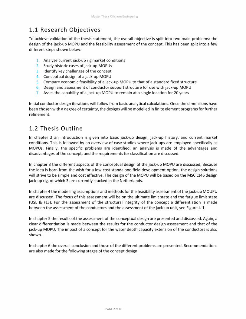
1.1 Research Objectives
To achieve validation of the thesis statement, the overall objective is split into two main problems: the design of the jack-up MOPU and the feasibility assessment of the concept. This has been split into a few different steps shown below:
1. Analyse current jack-up rig market conditions 2. Study historic cases of jack-up MOPUs 3. Identify key challenges of the concept 4. Conceptual design of a jack-up MOPU 5. Compare economic feasibility of a jack-up MOPU to that of a standard fixed structure 6. Design and assessment of conductor support structure for use with jack-up MOPU 7. Asses the capability of a jack-up MOPU to remain at a single location for 20 years
Initial conductor design iterations will follow from basic analytical calculations. Once the dimensions have been chosen with a degree of certainty, the designs will be modelled in finite element programs for further refinement.
1.2 Thesis Outline
In chapter 2 an introduction is given into basic jack-up design, jack-up history, and current market conditions. This is followed by an overview of case studies where jack-ups are employed specifically as MOPUs. Finally, the specific problems are identified, an analysis is made of the advantages and disadvantages of the concept, and the requirements for classification are discussed. In chapter 3 the different aspects of the conceptual design of the jack-up MOPU are discussed. Because the idea is born from the wish for a low cost standalone field development option, the design solutions will strive to be simple and cost effective. The design of the MOPU will be based on the MSC CJ46 design jack-up rig, of which 3 are currently stacked in the Netherlands. In chapter 4 the modelling assumptions and methods for the feasibility assessment of the jack-up MOUPU are discussed. The focus of this assessment will be on the ultimate limit state and the fatigue limit state (USL & FLS). For the assessment of the structural integrity of the concept a differentiation is made between the assessment of the conductors and the assessment of the jack-up unit, see Figure 4-1. In chapter 5 the results of the assessment of the conceptual design are presented and discussed. Again, a clear differentiation is made between the results for the conductor design assessment and that of the jack-up MOPU. The impact of a concept for the water depth capacity extension of the conductors is also shown. In chapter 6 the overall conclusion and those of the different problems are presented. Recommendations are also made for the following stages of the concept design.

Master Thesis Offshore Engineering
PAGE 3 of 86
2 State of the Art
In this chapter an introduction is given into basic jack-up design, jack-up history, and current market conditions. This is followed by an overview of case studies where jack-ups are employed specifically as MOPUs. Finally, the specific problems are identified, an analysis is made of the advantages and disadvantages of the concept, and the requirements for classification are discussed.
2.1 General Design of Jack-up Units
A self-elevating unit more commonly known as a jack-up is a structure used in the offshore industry. The main components of a jack-up are the hull and the legs. The hull is a buoyant structure that has openings through which the legs can be moved up and down. The floating unit can be towed, piggybacked, or self-propel to the location where it needs to operate. Once in position, the legs are lowered to the seabed and the hull can lift itself out of the water. In this position the hull is no longer directly affected by the wave conditions and the window of operation is widened considerably. To ensure the legs have a stable soil penetration, the rig is preloaded before it is raised out of the water. Preload is a procedure where ballast is taken on to a point where the loading exceeds the maximum expected load on any leg during an extreme event (storm). The distance between the bottom of the hull and the water level is known as the “airgap”.
Figure 2-1: Jack-up installation
In the industry jack-ups are used for different operations. The major use is drilling, in this case the rig is also known as a Mobile Offshore Drilling Unit (MODU). A lot of jack-ups are also used as construction vessels, these are more commonly referred to as jack-up barges. Smaller applications are accommodation jack-ups and Mobile Offshore Production Units (MOPU).

Master Thesis Offshore Engineering
PAGE 4 of 86
2.2 Types of Jack-up Units
Jack-up units, can be split into categories based on certain features. The most important features to be distinguished are evaluated below: Functionality:
– Drilling jack-up rigs or MODUs are used for drilling wells to find and produce hydrocarbons from subsurface reservoirs. The deck layout includes drilling facilities and accommodation. The large majority of jack-up units are used for drilling.
– Production jack-ups or MOPUs are used to produce hydrocarbons from the reservoir. Once the well has been drilled a production jack-up can be used to process and export the hydrocarbons. Design of these jack-ups include deck space for production facilities and an area for conductor entrance.
– Accommodation jack-ups are used to house additional crew offshore when activities requiring a lot of manpower are taking place. The jack-ups are generally designed in a similar way to the drilling rigs but only have no facilities on deck aside from accommodation.
– Construction/service jack-ups are used for construction and maintenance of offshore windfarms and other offshore structures. Due to the different functionality, aside from a large crane and basic accommodation, a lot of free deck space is required.
Leg design:
– Open-truss legs are made of tubular steel sections that are crisscrossed, making them strong and lightweight. Jack-up units with these legs are generally designed to operate in rough weather conditions in varying water depths.
– Columnar legs are made of large steel tubes. While columnar legs are less expensive than open-truss legs to fabricate and leave more usable deck space, they are less stable and cannot adapt to stresses caused by environmental loading as well as open-truss legs. Therefore, they are less capable of enduring heavy weather and cannot operate in deeper water depths.
Foundation design:
– Independent legs are mostly fitted with spudcans. Spudcans are inverted cones which provide stability to lateral forces on the jack-up rig when deployed into ocean-bed systems. They also increase the area of contact between the rig and the ocean floor, which prevents the legs from penetrating the soil too far. This type of foundation is most common in the typically sandy seabed of the Southern North Sea.
– Mat-supported jack-ups have a barge-like lower hull to which the legs are fixed at the lower end. When the legs are lowered the whole rig rests on a mat. This ensures the legs cannot penetrate the ocean floor. However, it is important that the mat has an even surface to rest on or the rig will not be stable. This foundation is generally used on a soft/muddy seabed.
Figure 2-2: Columnar leg mat-supported jack-up & open-truss independent leg jack-up [1]

Master Thesis Offshore Engineering
PAGE 5 of 86
2.3 History of Jack-up Rigs
Offshore drilling began in 1897 of a wooden pier in the Santa Barbara channel in California. In the early nineteen hundreds, pontoons reaching out to sea from the shore were commonly used to support drilling above water. As drilling moved further from land, the need for a mobile floating rig was born. The Breton Rig 20 was a large submersible barge with a steel structure supporting the platform above. Two stability pontoons could be jacked up and down to stabilize the rig when the barge was sunk, much like a modern mat-supported jack-up. It was capable of drilling in protected bays in water no deeper than 7 meters. The rig has a claim on being the first MODU and includes some aspects of a modern jack-up rig. The first true mobile offshore jack-up unit was realized when De Long spudcan jacks were installed on barges used for construction and/or docks. The first one used for drilling was the GUS 1, built in 1954. The unit had consisted of two barges, each with 6 legs, and was rated for water depths up to 30 meters. In 1956 the first 3-legged trussed leg jack-up rig was built. Le Tourneau Co. built the Scorpion for Zapata Corp. ran by the then still to become US president, George H.W. Bush. Le Tourneau continues to build these types of jack-up rigs to this day.
Figure 2-3: From left to right; Breton Rig 20 (1949), GUS 1 (1954), Scorpion (1956) [2]
In its 60-year history the jack-up drilling rigs have had spurts of construction and design improvements. After conception in the 1950’s a mild building period followed through the 1960’s. Building intensity increased in 1970s and at the end of the decade a large number of rigs were being commissioned. Simultaneous with this boom in production the cantilevered drill floor was introduced. This enabled the rigs to drill above larger platforms. Rigs were also upgraded to be able to operate in deeper water depths and harsher environments. The driver behind upgrading the rigs was that delivery time and cost could be halved, compared to new builds. Some contractors made this their core business. The mid 1980’s oil and gas bust halted the rig construction boom and since then, rigs have been constructed steadily with the exception of increases in late 1990s and early 2010s. Historically, when oil prices were low, rig construction levels were low and as consequence M&A activity in the rig market picked up. Rigs changed owners and were upgraded or converted to remain useful.

Master Thesis Offshore Engineering
PAGE 6 of 86
2.4 Jack-up Market Analysis
The jack-up drilling rig market is by far the largest and best defined jack-up unit market. Other types of jack-up units have a much smaller and poorly defined market. Because accommodation and production jack-ups are often converted jack-up drilling rigs, their markets are reflected by the drilling rig market. In December 2015, there were 433 existing competitive jack-up drilling rigs globally. Fleet utilization was at 58 percent with 250 units under contract. Of the 183 idle jack-up drilling rigs, 128 were ready go to work and 55 were “cold stacked”, which means all systems have been shut down and the hatches welded shut. On top of this, there were 97 rigs under construction, of which only 11 had contracts in place. [3] Currently, there is a high rate of attrition. By June 2016 13 jack-ups were retired, in 2015 14 jack-ups were removed from service, four more than the 2014 total. Between 2000 and 2013 in total 54 jack-ups were retired. This illustrates a significant rise in jack-up retirement. It is doubtful that most of the 55 cold stacked jack-up rigs will ever return to work, making them prime retirement candidates. It is believed that between 75 and 100 more jack-ups will be removed from service in the next few years.
2016 2017 2018
Rig Co. Current nr. Rigs
Rig Months (Contracted)
Utilisation Rig Months (Contracted)
Utilisation Rig Months (Contracted)
Utilisation
Ensco 11 132 (94) 71% 132 (40) 30% 132 (26) 19%
Hercules 1 12 (0) 0% 12 (0) 0% 12 (0) 0%
Maersk 12 148 (121) 82% 165 (94) 61% 168 (85) 51%
NAD 3 36 (36) 100% 36 (15) 41% 36 (12) 33%
Noble 3 39 (27) 69% 48 (36) 75% 48 (28) 58%
North Off. 2 24 (0) 0% 24 (0) 0% 24 (0) 0%
Paragon 9 108 (56) 52% 108 (22) 20% 108 (0) 0%
Rowan 6 72 (51) 71% 72 (14) 19% 72 (3) 4%
Swift Drilling
1 12 (5) 42% 12 (0) 0% 12 (0) 0%
Transocean 4 48 (12) 25% 48 (6) 12% 48 (0) 0%
TOTALS 52 631 (402) 64% 657 (227) 35% 660 (154) 23%
Table 2-1: North Sea Jack-up Rig Utilization [4]
As seen in Table 2-1 the rig utilization rates in the North Sea are similar to the global rates. It is expected that jack-up drilling rigs can be sourced locally at competitive prices due to the mass retirement described above. A lot less information about jack-up units used for construction or accommodation is available. A survey of two leading jack-up barge contractors illustrates that it is a small market compared to jack-up drilling rigs. These types of jack-ups currently have a higher utilization as they are suitable for the installation of offshore wind turbines. Preliminary investigation has been done into the condition and compatibility of rigs that are potentially for sale in the Netherlands. The Atlantic Rotterdam, a third-generation accommodation rig which is in relatively poor condition can be acquired for € 3 mln, according to a commercial discussion with the current owner. Sister rigs of the Paragon C461, currently under contract with ONE, are both idle and are therefore liabilities for Paragon at the moment. Based on discussions with Paragon representatives, it is

Master Thesis Offshore Engineering
PAGE 7 of 86
likely they will be keen to sell, on the condition that the drilling equipment is removed. These rigs are suitable for the proposed conversion due to the fact they are well maintained, have a well documented history and possess certain structural features. A peer company of ONE also considering this concept, have identified a couple of suitable units in Houston that can be bought for $ 5 mln. Preference by ONE is given to North Sea based jack-up rigs.
Contractor Rig Year Max depth (ft/m)
Design Class Location Status
Northern Energy Endeavour 1982 300 / 91 Gusto 3 Leg JU DNV GL Rotterdam, NL Stacked
Northern Energy Enhancer 1982 300 / 91 CFEM T-2005 DNV GL Rotterdam, NL Stacked
Ensco Ensco 70 1981 250 / 76 Hitachi K1032N ABS UK Stacked
Ensco Ensco 72 1981 225 / 68 Hitachi K1025N ABS UK Stacked
Ensco Ensco 101 2000 400 / 122 KFELS MOD V-A ABS Teesside, UK Idle
Transocean GSF Galaxy II 1998 394 / 120 F&G L-780 ABS Invergordon, UK Stacked
Transocean GSF Galaxy III 1999 394 / 120 F&G L-780 ABS Invergordon, UK Stacked
Transocean GSF Monarch 1986 361 / 110 F&G L-780 ABS Invergordon, UK Stacked
Hercules Hercules Triumph 2013 400 / 122 KFELS Super A ABS Rotterdam, NL Stacked
Maersk Maersk Resolute 2008 350 / 106 MSC CJ 50 ABS Esbjerg, DEN Idle
Maersk Maersk Resolve 2009 350 / 106 MSC CJ 50 ABS DEN Idle
Noble Noble Regina Allen 2013 400 / 122 F&G JU3000N ABS Esbjerg, DEN Stacked
Paragon Paragon C462 1982 250 / 76 MSC CJ 46 DNV GL Den Helder, NL Stacked
Paragon Paragon C463 1982 250 / 76 MSC CJ 46 ABS Ijmuiden, NL Stacked
Paragon Paragon C20051 1982 360 / 109 CFEM T-2005 DNV GL Esbjerg, DEN Idle
Paragon Paragon C20052 1982 300 / 91 CFEM T-2005 DNV GL Eemshaven, NL Stacked
Paragon Paragon B391 1981 390 / 118 BM Class MOD ABS NL Idle
Rowan Rowan Norway 2011 400 / 122 KFELS N-Class DNV GL Dundee, UK Idle
Rowan Rowan Stavanger 2011 400 / 122 KFELS N-Class DNV GL Dundee, UK Idle
Table 2-2: Overview of stacked and idle jack-up rigs in the North Sea [5]
December 2016 Paragon announced that the Paragon C461 & C462 will be cold stacked in January 2017. Normally once a rig is cold stacked it will not return to the market.
2.4.1 Jack-up Recycling Of the three main types of mobile offshore drilling units, jack-ups are the most difficult to recycle. Drill ships and semi-submersibles have significantly more steel and can in many cases, unlike jack-ups, be mobilized under their own propulsion. Mobilization of jack-ups requires either a towing spread or a heavy lift vessel. Because of this the ratio of steel value to transport cost is much higher for floating units. In addition, the market for second hand rig equipment is saturated and there is little opportunity to recover value in that area. Mechanical issues such as a not operational jacking system, due to neglected maintenance when cold stacked, adds extra risk and cost. On the recycling side, removal of the jack-up legs requires special equipment and is a time-consuming process. Yards are not prepared to pay the same amount for jack-up steel, or are completely unwilling to do the job. [6]

Master Thesis Offshore Engineering
PAGE 8 of 86
2.5 Historic Cases of Jack-up MOPUs
In Table 2-3 below an overview of some historic cases of jack-up MOPU’s is given. Mainly conversions have been included, however, a few purpose build MOPU’s are also noted because they have important common ground with the proposed concept. A few of the cases below will be explored in more depth, based on similarities with the proposed concept.
Field Jack-Up Rig Operator Water Depth (m)
Year
F3-FA (NL) “ Self-installing platform (SIP) Centrica 41 2010-
P6-S, Q1-D (NL)* “ Multi-purpose platform (MPP) Wintershall 25-30 2000-
West seahorse (Australia)
GSP Brittania Hibiscus 39 2013-
Ebok (Nigeria) Veer Prem Oriental 41 2010-
Songkhla (Thailand) Seafox 3/ Seafox 6 Coastal Energy
25 2009
Tchatamba (Gabon) MOPU-A Perenco 55 2005-
Maleo (Indonesia) Maleo Producer Santos 57 2004-2006
Ardmore (UK)* Rowan Gorilla VII Tuscan Energy
70 2003-2005
Al Shaheen (Qatar) Cliffs Drilling N.10 Maersk Oil 55 1995-1997
Volve (Norway)* Maersk Inspirer Statoil 80 2008-2016
Bentley (UK)* Rowan Norway Xcite Energy 112 2012
Halk el Menzel (Tunisia) Jawhara 05 (ex ENSCO-60) Topic SA 76 2016
Wandoo (Australia) Hakuryu VII Ampolex 55 1993-1996
Block CI-11 (Ivory Coast) Gulftide Abijan 76 1994-1995
Bombay High (India) Sagar Samrat ONGC India 57 2011-2013
Elgin & Franklin (UK)* “ TGP 500 Total 93 2001-
Various* Various Seafox jack-ups Seafox 20-40m -
Table 2-3: Historic MOPUs; * detailed case study in this chapter; “ purpose build MOPU
2.5.1 Ardmore, Tuscan Energy In January 2002, Tuscan Energy (65%) and Acorn North Sea (35%) were awarded the North Sea block 30/24 the Argyll development had taken place. Argyll was the UK’s first offshore oilfield development which started production in 1975 operated by Hamilton Brothers. Production had ceased and the field had been abandoned in 1991 – 1992 due to downhole failures in the well. Roughly 30% of the reserves had been extracted. Tuscan Energy was focused on operating mature or marginal discoveries in the North Sea using innovative strategies. Tuscan renamed the Argyll field and planned a phased development for the field now called Ardmore, drilling four high angle production wells to produce up to 25 MMbbl over a two-year period in the first phase, with a further 15 MMbbl targeted over later phases through tiebacks to satellite wells. The initial four production wells were all equipped with Electrical Submersible Pumps (ESPs). Tuscan elected to develop the field using a Mobile Offshore Drilling and Production Unit (MODPU), the Rowan Gorilla VII (see Figure 2-4), due to the high CAPEX required for a moored FPSO. At the time, the MODPU was considered a very large jack-up and had been originally designed with sufficient space for dual drilling and production. The MODPU was taken on an 18-month lease with an optional extension of

Master Thesis Offshore Engineering
PAGE 9 of 86
42 months to cover the later phases. At the time the rig market was depressed and rates were low. The lease deal was reported to be linked to the oil price, giving Rowan exposure to the upside of an oil price increase. The Rowan Gorilla VII was built in 2001 and entered service in 2002 with Tuscan Ardmore as its first job. The topsides processing module and rig modifications were undertaken in a yard in Northern England. Expro were contracted to supply a production module for the Rowan Gorilla. The production module was used to degas and dewater the incoming fluid, stabilise the hydrocarbons and then pump via export lines for tandem offloading to dedicated shuttle tankers. The design overall flowrate of the module was 60,000 barrels per day. The deal was reported as a £17 million contract in 2002 on a five year operate, maintain and lease basis. The Phase 1 topsides were arranged on three levels. On the main deck level, the equipment comprised a four well inlet manifold, a large first stage separator and the crude oil export system – pumps, coolers, and export metering. A multiphase flow meter was used instead of a test separator. Also included on this level were the flare knock-out vessels, the fuel gas conditioning skid, the chemical injection system and a purpose-built control room complete with an office and HVAC system. Two associated 100-ft flare booms were installed on the jack-up's port and starboard sides for continuous burning of gas. Power generation, required primarily for the ESPs, was provided by a 2-MW gas-fired turbine. The production risers, 13-5/8-inch tieback risers were tension supported by the jack-up, with both subsea and surface wellheads. The production riser string used Grant Prideco threaded couplings in P110 steel, with forged 80 ksi lower stress and tension joints. The riser joints were coated with thermal sprayed aluminium for corrosion protection and fitted with strakes to suppress fatigue damage due to vortex induced vibration. Between 2003 and 2005, the field produced 5.2 million barrels of oil. In 2005 Tuscan experienced technical difficulties and cash flow problems (rising oil prices increasing the rig rate paid). The rig rate was renegotiated and this extended production for a while but eventually they went into administration after approximately 2 years of production. In 2008, the field was decommissioned again by partner Acorn. The field has since been redeveloped by EnQuest (the field is now renamed again, to Alma) using a FPSO.
Figure 2-4: Rowan Gorilla VII at Ardmore [7]

Master Thesis Offshore Engineering
PAGE 10 of 86
2.5.2 Volve, Statoil The Statoil Volve oil field lies about 200 km west of Stavanger at the southern end of the Norwegian sector of the North Sea. Recoverable reserves are estimated at 78.6 MMbbl of oil and 1.5 billion cubic metres of gas. The development is based on production from the Maersk Inspirer jack-up rig (see Figure 2-5: Maersk Inspirer ), claimed to be the world’s largest and most advanced jack-up drilling rig, designed for ultra-harsh environments. The Inspirer is a MSC CJ70-150 MC class rig that was built in 2004. The Navion Saga FSO is used as a storage ship to hold crude oil before export, positioned 2 km from the jack-up. Gas is piped to the Sleipner A platform for final processing and export. Production at Volve started on the 12th February 2008. The field was originally expected to produce for only four to five years but the life has been extended and the current plan is to cease production at the end of 2016, at the same time the Maersk Inspirer contract with Statoil is due to end. It has recently been reported that Norwegian start-up company Okea are looking at the possibility of using the Maersk Inspirer on the Yme field offshore Norway (the previous Talisman Energy Mobile Offshore Production and Storage (MOPUstor) development here was abandoned after structural issues with the grout around the steel legs). An integrated production module is located on the Maersk Inspirer. At plateau, Volve was expected to produce approximately 50,000 barrels per day. The process module was installed in 2006 and is capable of producing 56,000 barrels of oil and 53 million cubic feet of gas per day. The facilities include capability for water injection (16,000 Sm³/day), oil export (9,000 Sm³/day) and gas injection (1,500,000 Sm³/day). The Production facilities contain a pressurised power generator sub-module that supplies the additional power requirements for production. Space is made for the process module by skidding the drilling rig to the side (rig can skid 30 ft each way). This creates a free area of around 20 x 60 m on the starboard side. Even though dual production and drilling role was anticipated during the original design, some vessel modifications were still required. The transom had to be strengthened to withstand combined loading of the cantilever with hook load, setback, and BOP tensioning; the wellhead module with the conductor tension; and the heavily cantilevered process module. The process and power module together weigh approximately 5,000 tonnes. A 15 slot drilling template was installed for the production risers, arranged in three banks of five, Figure 2-6.
Figure 2-5: Maersk Inspirer [8]

Master Thesis Offshore Engineering
PAGE 11 of 86
Figure 2-6: Subsea Template Installation & Tensioned Production Risers Volve
2.5.3 Bentley, Xcite Energy
In 2012, Xcite Energy carried out an Extended Well Test (EWT) on their Bentley field in the North Sea using the Rowan Norway jack-up rig, Figure 2-7. The Bentley field is located in UK Block 9/3B approximately 160 km East of the Shetland Islands at a water depth of 113 m. The field has 10⁰ to 12⁰ API heavy oils. During the EWT, the reservoir fluids were produced from a multilateral well utilising an ESP to a process plant on the MODPU and then exported via a subsea pipeline to a DP shuttle tanker. Drilling commenced in March 2012 and, over a 68-day period from July until mid-September 2012, a total of 148,559 barrels of Bentley crude was produced from both wells flowing independently and together. The oil flowed at an average rate of 2,600 barrels per day, reaching a maximum production rate of 3,500 barrels per day and with sustained flow periods in excess of 3,000 barrels per day. The Phase 1A direct net cost was US$215 million and the overall gross cost of the EWT including the direct project costs and indirect costs was approximately US$250 million.
Figure 2-7: Rowan Norway at Bentley [9]

Master Thesis Offshore Engineering
PAGE 12 of 86
2.5.4 MPP, Clyde Petroleum/Wintershall About 20 years ago KCI introduced its innovative Multi Purpose Platform (MPP) concept to the North Sea. The platform has been used on multiple marginal gas fields in the southern sector of the Dutch North Sea. At the time 3 MPP’s were built and installed for Clyde Petroleum. The current owner, Wintershall Noordzee BV, has relocated all 3 MPP’s to new locations which was exactly the intention of this flexible type of platform. The MPP design is a self-installing re-usable platform designed for harsh North Sea environments and water depths ranging from 10 to 50 metres. At installation, the complete deck is self-elevating using strand jack systems. These systems are removed after platform installation. The legs have integrated suction anchors, which are embedded in the seabed for platform installation. On these platforms gas is produced through a single well. The well conductor was laterally supported at deck level to avoid buckling at the mudline.
Figure 2-8: Multi Purpose Platform in Transit [10]
2.5.5 Horizon, Unocal & Songkhla, Coastal Energy Seafox has a history of supplying and operating jack-ups for extended periods of time at one location. At the Horizon oil field, which started production in 1993, the Seafox 1 was bridge linked to the platform. Until 2000, the jack-up unit Seafox 1 was leased from Workfox to provide utility support for the Horizon field including power generation, living quarters, helicopter deck, control room and various safety equipment. The initial contract was for two years with yearly extensions. During 2000, the field partners purchased the Seafox 1 jack-up unit. In 2008, the required facilities were transferred to the wellhead platform, and the Seafox 1 was sold back to Workfox. During it’s time at the Horizon field, the Seafox 1 needed to be jacked-up once a year on average. This was mainly due to leaking in the hydraulic jacking system but could also have been caused by scour or settlement under extreme loading. In the gulf of Thailand, at the Songkhla oil field, the Seafox 3 is used as a MOPU after previously being converted from a support jack-up. Space has been made available for the production unit skids, which include a manifold, test separator, separator, air compressor unit, wellhead control panel, ESPs, step-up transformers and VSD control and drives. To accommodate all this equipment, the helideck had to be

Master Thesis Offshore Engineering
PAGE 13 of 86
converted to an ESP yard. Also by space constraints the vertical water injection pumps by GE are installed on Texas deck. A cantilever deck has been built to attach all the conductors to the jack-up.
Figure 2-9: Seafox 3 at Songkhla [11]
In an interview held in August 2016 Seafox have given a few recommendations on rig conversion and operation, based on their experience:
– Most North Sea locations are sandy and because the spudcans do not completely submerge under the mudline scouring can have a big effect on fixity. It is beneficial to install skirts on the spudcans to mitigate this effect. Rock dumping is also a common solution.
– Skirts with suction has not delivered satisfactory results. – There were no issues with liquefaction of soil caused by platform motions. – Settlement, which means the foundation sinking into the soil, can occur during extreme loading. – Use classification society as a last stop check. Do not be dependent on them to make the rules, but
propose guidelines. – Get input from all the stakeholders. – For conversion projects make sure the rig is free of asbestos, or know where it is.

Master Thesis Offshore Engineering
PAGE 14 of 86
2.5.6 Elgin and Franklin, Total Although not specifically a MOPU, because the foundation mats are piled into the seabed, the development of Elgin and Franklin is still an interesting case. The Elgin and Franklin fields started production in 2001. The development utilises a TGP-500 jack-up design production, utilities and quarters (PUQ) platform located on Elgin (Figure 2-10). The PUQ is bridge-linked to a satellite wellhead platform - WHP A. A normally unmanned wellhead platform is located on Franklin, with production transported via subsea flow lines to the Elgin PUQ. The West Franklin field was developed via an extended reach well drilled from the Franklin wellhead platform, with first production in 2007. Elf's selection of the TPG 500 was basically cost-driven. It acknowledged that the concept employs low cost construction techniques and eliminates the need for major offshore hook-up work. Furthermore, the platform's self-installation, which allows commissioning work to be undertaken onshore, also renders unnecessary the use of heavy crane barges for module installation. The 32,000 tonne structure was built at Barmac's redeveloped facility in Nigg, Scotland where a new graving deck will allow a free-floating wet tow directly to Elgin. Technip-Geoproduction, which is the proprietary inventor of the TPG 500, was responsible for project management, procurement and design of the hull, legs and foundations, including the jacking and locking system. It also managed the platform installation. Harding, which is an oil production platform that also is developed by a TPG-500, sits on a concrete base used for crude storage. The Elgin/Franklin facility, however, is secured to the seabed by steel piles driven in directly from the TPG 500. Distance between the legs will be identical to Harding's, but there will be 20% higher lifting capacity, due to the new platform's larger hull. TPG 500s can operate in 150 meters of water in two basic ways - either as a central PDQ unit with up to 32 wellheads, mainly for marginal field development. Or alternately, as a tender drilling and production platform linked to a wellhead facility, where well numbers exceed 32. In either mode it can be withdrawn and reused at the end of the field's life, minimizing decommissioning costs.
Figure 2-10: The TPG 500 at Elgin & TPG 500 Sketch [12]

Master Thesis Offshore Engineering
PAGE 15 of 86
2.5.7 Insights Based on Case Studies Based on the case studies in this chapter a few insights in previous design choices can be made:
– The use of a jack-up as a MOPU is not a common development concept, however it has previously been carried out in a North Sea environment in water depths deeper than the proposed developments by ONE. Therefore, it can be concluded that no new technology or development of technology is required.
– A jack-up has sufficient space and deck load capacity to cater for the process modules and support the production risers or conductors.
– The jack-ups used previously in the North Sea were relatively new - for both Tuscan Ardmore and Xcite Bentley, they were the first job for the rig, avoiding issues with possible fatigue/repairs to the jack-up legs etc.
– At deep water depths (> 60m) tie back of the wells is best done with tensioned production risers or a wellhead platform if a lot of wells are to be drilled (> 10-15). In shallow water (< 50m) laterally supported conductors can be used.
– MOPUs typically have not remained on location for long (> 5 years) periods of time. – Additional settlement can occur during storms due to extreme loading or high particle velocities at
the seabed (scour).

Master Thesis Offshore Engineering
PAGE 16 of 86
2.6 Requirements for the Conversion
Based on the requirements below and due to difference in markets between the different types of jack-units, this thesis will focus on the conversion of independent trussed-leg jack-up drilling rigs. The main requirements for a conversion are highlighted below:
1. The MOPU must be suitable to withstand the maximum and periodic force that can be exerted by
the wind, waves and current conditions found in the southern North Sea. 2. The MOPU must be suitable to withstand the loads exerted by platform operations and accidental
loading (e.g. vessel collision) 3. The bottom bearing structure of the jack-up unit must be suitable for long-term position and
altitude stability while resting on the seabed material in the designated area. 4. The leg length of the jack-up unit must be adequate to achieve a suitable air gap (i.e. the distance
between the bottom of the hull and the water level). 5. The jack-up unit must have adequate weight bearing capacity in floating, jacking and elevated
mode for all required facilities. 6. The deck area must be large enough to accommodate the required facilities. 7. The jack-up unit must be built and maintained in accordance with code requirements of a major
classification society. 8. The combined effect of the unit’s age, its operating history and its condition must be such that
minimal or no modifications are required to combat fatigue. 9. The jack-up unit must be available for purchase at a price suitable to the economics and timeline
of the first development it is intended to be used for.

Master Thesis Offshore Engineering
PAGE 17 of 86
2.7 ‘SWOT’ Analysis
A ‘SWOT’ analysis is a method to assist the formulation of a strategy concerning a certain problem. The acronym SWOT stands for Strengths, Weaknesses, Opportunities and Threats. To formulate strategies from the SWOT, it is important to realize what actions are required to address the different characteristics. Strengths should be build on, since these positive aspects are already present in the jack-up unit. If possible the weaknesses need to be mitigated. Opportunities need to be exploited to add more value to the project. And finally, threats should be countered if possible, because they bring a certain level of uncertainty to the project. The SWOT matrix consists of two rows and two columns. The upper row includes the characteristics with an internal origin (strengths and weaknesses), the bottom row includes the characteristics with an external origin (opportunities and threats). The left column contains the helpful characteristics to achieve the objective (strengths and opportunities), the right column contains the harmful ones (weaknesses and threats). For this project, all four of them were identified as shown below in Table 2-4.
Strengths Weaknesses
1. Deck space 2. Weight capacity 3. Self-installation 4. Self-removal 5. Suitable for multiple locations
1. Foundation footing 2. Preload capacity 3. Fatigue life 4. No conductor support 5. No riser support 6. Structural degradation & corrosion
Opportunities Threats
1. Low cost development 2. Fast-track development 3. Potentially reusable platform 4. Construction in dock instead of yard
1. Rising rig utilization, leading to more expensive rigs
2. Classification 3. Dynamic behavior
Table 2-4: SWOT matrix
The strengths of the project are also the drivers of the concept:
1,2 Because of the large deck space & weight capacity, a full gas drying plant can be accommodated. This makes the platform suitable for standalone field developments.
3,4 Self-installation and removal will save significantly on costs since no specialized heavy lifting equipment will be required.
5. Inherent to the design of a jack-up drilling rig is that it is suitable for a large number of offshore locations. As result the MOPU will also have this property.
The weaknesses will be further elaborated on in the remainder of the report. A brief overview is given below:
1. Site Specific Assessment is required to assess bearing capacity of foundation for 100-year extreme environmental loading. Adequate preloading will mitigate storm settlement and prove bearing capacity. Skirting the spudcans or rock dumping around the legs will help mitigate scouring if spudcan is not fully below the mudline. The only sure way to prevent scour is for the spudcan to be fully below the mudline. Contingency plans should be made to accommodate long-term settlement, should it occur.
2. Preload capacity is always in short supply for deeper water or high load locations. It can be added by converting all tanks not yet assigned as preload tanks. Also, bags can be hung of the side of the hull and temporary tanks placed on deck around the legs.

Master Thesis Offshore Engineering
PAGE 18 of 86
3. Because the jack-up unit is second hand, a significant portion of design fatigue life is already used. Due to the nature of the design of jack-ups, their natural period is in range of high occurrence wave periods. Design fatigue life must be proven for classification for the lifetime of the structure.
4. For the support of the conductors there are different structural solutions, which are applicable to different water depths.
5. Risers can be fitted inside the legs of the jack-up. They should be predesigned for specific airgap, water depth and foundation penetration.
6. To prevent issues with corrosion, ensure the jack-up is in good condition and analyse special survey reports before acquisition. Steel wastage will affect the stresses and therefore the fatigue life. Once the jack-up is acquired, full refurbishment, coating of structural elements and anode installation is advised. Steel wastage will affect the stresses and therefore the fatigue life.
To maximize the benefit of the opportunities, it must be clear what they are:
1. Low cost development is driven by the fact that the structure, essentially acting as a jacket, has a large deck area, weight bearing capacity and can be acquired for scrap value.
2. Fast-track development can be realised since the engineering, procurement and construction phase of the jacket is replaced by a shorter refurbishment of the jack-up.
3. Because the jack-up is designed to operate in a variation of water depths the MOPU is potentially reusable. Also, there is potential for life extension of the unit.
4. Since the jack-up can install itself at a quayside, there will no requirement for yard space for refurbishment and topsides installation. This could have a positive influence on the cost and timeline of the development. Although for spudcan modifications a drydock will be required.
Threats must also be monitored and if possible countered:
1. Rising rig utilization is a factor that can’t be influenced by a single party. Since the concept is dependent on a low rig utilization it generally will only be feasible in a low oil price environment.
2. Because the concept is not common practice, classification is not as straightforward as a more conventional field development. To avoid unexpected setbacks, it is important to involve the classification societies as early as possible in the design of the facility.
3. Dynamic behaviour of the jack-up becomes an issue when the natural period of the unit coincides with the frequency of the motion exciting forces. When this happens, resonance will occur and the motions and stresses will be significantly amplified. This can effect long term structural integrity.

Master Thesis Offshore Engineering
PAGE 19 of 86
2.7.1 ‘Showstoppers ’ Not specifically (although inherently) noted in the SWOT analysis, are the potential “showstoppers”:
Showstoppers Description Result
Site unsuitable The soil conditions at the proposed site are not suitable for jack-up placement because the risk of punch through is too high.
Extensive foundation studies would need to be done to mitigate geotechnical risks. Solutions include gravel dumping or excavation of the top layer.
Rig Utilization The market conditions change and jack-up rigs sale prices have risen.
Rising rig rates will corresponding with rising cost of yard space. If a suitable rig can still be found for a modest price increase, it could be possible.
Classification Classification societies do not agree with conceptual design items such as conductor support or jacking system decommissioning for classification as a mobile unit and the jack-up does not have the correct structural properties to be classed as a fixed installation.
Involve class from very beginning of FEED so that changes can be made to the concept or that there is enough time to prove structural integrity of the concept.
Table 2-5: Potential showstoppers
All the above will have different financial impact on the project and could make it unfeasible compared to a conventional fixed platform.

Master Thesis Offshore Engineering
PAGE 20 of 86
2.8 Classification of Mobile Offshore Production Units
“The purpose of a classification society is to provide classification and statutory services and assistance to
the maritime industry and regulatory bodies regarding maritime safety and pollution prevention, based
on the accumulation of maritime knowledge and technology.” [13]
To ensure safe operations and for regulatory and insurance reasons it is important that the MOPU receives
a classification from a recognized classification society. Without classification, regulatory bodies will not
allow production to commence. The four largest and most used classification societies are:
– Bureau Veritas (‘BV’) – Det Norske Veritas Germanischer Lloyd (‘DNV GL’) – American Bureau of Shipping (‘ABS’) – Lloyds Register (‘LR’)
Classification societies are mainly concerned on the safety aspects of an offshore unit, from the marine
point of view for both the personnel on-board and the asset, e.g.:
– Structural integrity (afloat and elevated) – Stability of the asset (afloat and elevated) – Machinery safety (machinery equipment, piping, leak prevention (water, gas, fuel, etc), measures
to cope with leaks when they occur (draining system), etc.) – Safety measures for the electrical system and equipment. – Fire protection, firefighting, lifesaving appliances and other safety aspects.
2.8.1 Fixed vs. Mobile Each classification society has their own set of standards to which a MODU or a Fixed Offshore Installation
must comply. They are similar in many aspects and are based on the International Organisation of
Standards (‘ISO’) codes.
Before elaborating on design issues related to long term use of jack-ups it may be helpful to have a look
at the main purpose of the ISO 19905-1 [14] jack-up assessment standard and how it differs from the
standard for fixed structures defined in ISO 19902-1.
The purpose of the jack-up assessment standard is to provide guidance on assessing jack-ups for operation
at a specific site. It is not a design standard and an essential condition for its use is that the jack-up is
designed, built, and maintained under the survey of a recognised classification society. This represents an
important difference when comparing the jack-up assessment standard ISO 19905-1 with the fixed steel
offshore structures standard ISO 19902-1. ISO 19902-1 is to be seen as a design and fabrication standard
while ISO 19905-1 refers to an existing structure, that is already designed, built, and maintained in
compliance with a recognised classification society’s rules.
According to Kudsk and Stadsgaard (2012) [15], this important difference in the starting point became
subject of some discussion between the two working groups during the development of the standards.
Initially it was proposed by the “fixed structures” working group that a jack-up operated in a production
mode should be considered a fixed platform and thereby be subject to a verification against the ISO
19902-1 standard. After some exchanges of views between the two work groups agreement was however
reached that a “classed” jack-up in production mode could continue to be assessed in accordance with

Master Thesis Offshore Engineering
PAGE 21 of 86
ISO 19905-1 subject to the conditions in that standard dealing specifically with long-term operation. In
case a major structural upgrade of the jack-up legs or jacking systems is required to allow it to function as
a production unit, the verification may have to refer to ISO 19902-1. This would typically be the case
where, as a result of the upgrade, the jack-up will no longer be a “mobile unit” and may not remain under
a class survey regime.
The major classification society's dealing with jack-up conversion to MOPU are ABS, DNV and BV. Within
the industry, ABS are considered the leader in MOPU classification. The details on the survey requirements
mentioned below are based on ABS guidelines.
In addition to certain design requirements classification societies also mandate a list of regular inspection
and maintenance programs. For a MOPU to retain its classification as a mobile unit, it must be assessed
as a MODU. MODUs are required to dry-dock once every 5 years for a reclassification survey. In many
cases this cannot be done by a MOPU. To accommodate this limitation, all surveys must be done onsite.
Parts of the unit that cannot be accessed when the unit is in place, such as legs under the mudline, need
to have a remaining fatigue life with a large factor of safety. This should be assessed and calculated before
the unit goes offshore.
The MOPU could potentially abandon its classification as a mobile unit and become a Fixed Offshore
Installation. This has advantages regarding survey requirements. Research has shown this has been
previously considered by other parties and, studies were performed. The studies were carried out towards
establishing the feasibility of the new class notation and presented, considering all the implications due
to the applicability of new installation rules and subsequent rule changes to the MODU rules used for the
original classification and the study findings were as follows:
– Leg strength was found to be not satisfactory – Leg storm holding capacity was found to be not satisfactory – Preload tank capacity of the unit was also found to be not satisfactory to cater the revised preload
requirements It was concluded and presented to the owners that the mentioned reclassification is not possible without extensive modification to the units and the owners decided to refurbish and reinstate the previous classification of MOPU rather than re-classing as Offshore Installation. It should be noted that the actual design conditions for the above project are not known.
2.8.2 Surveys Below is an overview of the data assessments and surveys that are required by ABS for MOPU
classification. The requirements are similar for the other classification societies, although minor
differences might be found.
Classification Requirements
Data
Environmental Site specific data for wind, wave, current, tide and other relevant factors. Return period must be no less than 100 years.
Foundation Results of site investigation, including: sea floor survey and subsurface investigation and testing according to ABS rules. Should provide data needed for foundation assessment and scouring potential.

Master Thesis Offshore Engineering
PAGE 22 of 86
Material and Welding Specification
Specification should cover structural steel types and welding procedures used in the modification of the unit. All structural steel and welding should comply with relevant recognized codes.
Seismic If the unit is to be installed in a seismically active area, the effects of an earthquake should be included.
Structural Drawings
A complete set of structural drawings and the drawings showing the arrangements and details of the modifications (risers, production facilities etc.) should be submitted.
Corrosion Protection System
All steel must be protected from corrosion by a corrosion protection system. The details of the corrosion protection systems (coatings, sacrificial anodes etc.) must be submitted and should comply with the relevant recognized codes.
Assessments
Structural The structural assessment should indicate the adequacy of the structure to withstand all the applicable loadings and overturning resistance.
Foundation The foundation assessment should include checks of the bearing capacity, sliding resistance and preload requirements.
Fatigue The fatigue assessment should include an evaluation of the remaining fatigue life and the adequacy thereof. A fatigue assessment utilizing long term hot spot stress and allowable fatigue stress can be used.
Surveys
Condition Survey
A condition survey is carried out to assess the current condition of the unit. It will include the following:
– Visual examination of all above water structure. Special attention be given to the splash zone;
– Verification of the condition of the jacking system; – Confirmation of adequate provisions for access to and egress from unit; – Internal examination of preload tanks; – Assess continued effectiveness of cathodic protection system; – Thorough non-destructive testing of the leg to spudcan connections; – Internal examination of the spudcans; – Gauging to assess the extent of steel wastage and determine the necessity of
steel renewal; – Survey of the unit relative to the approved plans for modifications.
Construction Modification Surveys
Surveyors will be assigned at the builder’s yard to verify that the modifications are in accordance with the approved plans and that all work is in accordance with the relevant recognized standards.
Installation Surveys
A site condition survey is required upon installation to establish the global condition of the jack-up unit in a way that allows yearly monitoring. The aspects that should be included are:
– The topography of the sea bottom in the immediate vicinity of the jack-up for the purpose of monitoring yearly scour;
– Verification of the height of a fixed reference point above the sea bottom, orientation and the inclination of the jack-up for the purpose of monitoring any movement;
– Marine growth thickness to determine conformance with the assumptions; – Cathodic protection system potential measurement; – Securing of the unit's jacking system.

Master Thesis Offshore Engineering
PAGE 23 of 86
Annual Survey Annual surveys should be made three months either way of the annual anniversary date of the installation. General survey requirements include all above water condition and installation survey requirements.
Underwater Inspection in Lieu of Dry-docking
UWILD is require twice every five years. It is typically carried out at year 3 and 5 of the 5-year cycle. General survey requirements include all under water and above mudline condition and installation survey requirements, excluding gauging of the legs.
Special Surveys
A special survey must be completed once every 5 years. It can be done in conjunction with the Annual Survey and the UWILD. In addition to the requirements of the other periodic surveys, the special survey requires gauging of the legs. Special attention is given to the splash zone. Each subsequent special survey is progressively more extensive to reflect the increasing age of the unit.
Table 2-6: ABS MOPU Classification Requirements [16]
Class surveys during the operational phase of a MOPU converted from a jack-up are to be in accordance with the combined requirements of the rules for classification of topsides and MODUs. These include annual surveys UWILDs (twice every five years) and special periodical surveys (once every five years). Foundation structures that will be located below the mud line will be inaccessible. Therefore, fatigue structural and corrosion analyses shall be required to justify the integrity of these inaccessible areas for the design life of the MOPU.

Master Thesis Offshore Engineering
PAGE 24 of 86
3 Conceptual Design of Jack-up MOPU
In this chapter the different aspects of the conceptual design of the jack-up MOPU are discussed. Because the idea is born from the wish for a low cost standalone field development option, the design solutions will strive to be simple and cost effective. The design of the MOPU will be based on the MSC CJ46 design jack-up rig, of which 3 are currently stacked in the Netherlands.
3.1 Topsides, Risers & Jacking System Design
Considering the fact that the jack-up rigs that are being assessed for this MOPU concept are very large and heavy compared to regular platforms and hundreds of tonnes of excess drilling equipment will be removed, initially there would be no reason to believe there will be a critical weight or space restraint. In addition to all the drilling equipment the current accommodation will also be removed, because the accommodation is oversized and outdated. It will be replaced with a new modular containerized accommodation unit, suitable for 20 Persons on Board (PoB). This will also free up additional space and weight for processing skids. The topsides have been designed to condition the hydrocarbons for export via the NGT pipeline, which would be the export route in case it is used to develop the GEms prospect. Technical requirements have been defined as follows:
– Gas flow rate: 4x10⁶ Nm3/d at 100 bar and 60-80 °C. – Liquids: 100 m3 condensate per million Nm3 and 10 m3 water (condensed water, not much
formation water is expected). The condensate from the inlet separator is spiked into the export gas stream and removed at the landing facility. The water should be removed (required water dew point -10 °C)
– Wellhead pressure is 345 bar, design temperature 90 °C. HIPPS is used for pressure protection. – Methanol injection is used for hydrate inhibition at start up. Injection of other chemicals should be
avoided. – All equipment should preferably be electrical. If high voltage power is not available (Waddenzee),
power generation should be done on the platform. – Aside from the standard process, space should be reserved for:
o Temporary power generation for jacking up of platform o Depletion compressors o Slug catcher (for possible satellite platforms) o Control room
– The export pipelines will be 16-20” – Overboard water may contain 30 parts per million (ppm) hydrocarbons – Low pressure vessels may be made of (fibre reinforced) polymer – There will be no flare: blow-down will be vented to atmosphere – The available space is given on the dimensioned drawings of the deck of the MSC CJ46 – Required lifetime is 20 years – The platform has a 60-tonne crane
The main challenges for the conversion of the platform with regards to the topsides are:

Master Thesis Offshore Engineering
PAGE 25 of 86
– Space on the platform: to ensure that the equipment fits on the topsides deck with regards to weight (and crane capacity) and dimensions. This needs to be in compliance with offshore requirements and suitable for the North Sea.
– Power consumption: sufficient and reliable power supply. – Chemical consumption: methanol injection is used for hydrate inhibition at start-up. Other
chemicals shall be avoided as much as possible. To reduce costs and to minimise environmental impact.
– Energy for equipment: preferably electrical power supply to all equipment (e.g. reboiler, compressor, pumps). Reliable power supply is key to keep the unmanned platform running.
– Water removal: water is to be discharged overboard and may contain 30 ppm of hydrocarbons.
The processing train will consist of an inlet separator, in which condensate and liquid water are separated
from the gas. The gas is dried in a Triethylene Glycol (TEG) contactor. The condensate is separated and
reintroduced (“spiked”) into the export gas stream. The water is degassed and treated to reduce the
hydrocarbon content to below 30 ppm. The dimensions and weights of the different components of the
topsides are specified in Table 3-1, and Figure 3-1 shows a schematic overview of the process.
Equipment Dimension (m) Weight (te)
HIPPS LxWxH 2.0 x 2.0 x 1.8 5
Inlet Separation / WACO LxWxH 6.0 x 3.0 x 5.0 10
Degasser LxWxH 6.0 x 3.0 x 3.0 10
TEG Contactor T/T x ID 14.0 x 1.5 40
TEG Regeneration LxWxH 10.0 x 4.0 x 8.0 (11 with stack)
65
Recycle Compressor LxWxH 12.0 x 6.0 x 3.0 40
Fiscal Metering LxWxH 4.0 x 1.0 x 3.0 5
MCC equipment, switchgear, transformers
LxWxH 12.0 x 3.0 x 4.0 15
Gas Turbine & Generator LxWxH 10.0 x 3.0 x 3.0 15
Depletion Compressor LxWxH 12.0 x 6.0 x 3.0 40
Slug Catcher LxWxH 6.0 x 3.0 x 3.0 10
Control Room LxWxH 6.0 x 3.0 x 3.0 10
Emergency generator & UPS LxWxH 6.0 x 3.0 x 3.0 15
Accommodation LxWxH 15.3 x 11.5 x 6.5 70
Total Area: 530 m2 350
Table 3-1: Topsides equipment
The following aspects are also in the scope of the topsides design, although they are not yet assigned
specific dimensions:
– Interconnecting piping in between modules and to existing equipment – Lighting, Lightning protection – Mechanical handling – Fire and gas detection equipment, Deluge piping, Fire proofing – Local work switches / RCU,
The weight for all these parts is estimated to be ~50 tonnes. Which brings the total weight of the production and utility equipment including a 50% contingency to ~600 tonnes. Adding the weight of the

Master Thesis Offshore Engineering
PAGE 26 of 86
risers, J-Tubes, sumps, and a vent will bring the total up to 650 tonnes, which covers all the heavy newly added equipment. This is well within the variable load allowance of the rig (section 3.4) and similar to the weight of all the drilling related equipment to be removed.
Figure 3-1: Schematic of topsides process
To calculate the total area needed for the production and utility equipment 50% is added to the total above to account for auxiliary, manoeuvring and repair space around the equipment. This brings the area requirement to 765 m2 which is well within the 1000 m2 available area, without the need to stack any equipment. The estimated delivery time for this equipment is 12 months, including design, excluding works [17].

Master Thesis Offshore Engineering
PAGE 27 of 86
3.1.1 Risers Import and export risers are an addition to the jack-up that are required if the unit is to operate as a
production platform. Two 8-inch import risers and a 16-inch export riser will be fitted on the legs of the
jack-up, see Figure 3-2. Before installation of the risers, an assessment should be made on the required
length. For this it is important to know the airgap, water depth and seabed penetration. The risers should
exit the leg a few meters above the seabed so that the connection can accommodate long-term
settlement (design value < 0.5m). The pipeline will be attached to the risers via tie-in spools.
Figure 3-2: Riser supported by jack-up leg & engaged fixation system
3.1.2 Jacking System Since the jacking system will only be used once for installation and once for removal, it is deemed economical (space, weight, and cost wise) to supply the jacking system with power from temporary generators rather than permanent ones. The temporary generators will be removed once the platform has been installed. In case of settlement the emergency generator will have enough capacity to jack one leg at a time. Because the platform will remain on location for an extended period of time a fixation system (rack chocks) is critical and must be installed if not already present. Once the fixation system is engaged (Figure 3-2) the jacking system will in principle not be used until decommissioning and can be protected accordingly. Removal of the system and storage in a controlled environment for reuse when decommissioning or re-jacking is an option to be explored.

Master Thesis Offshore Engineering
PAGE 28 of 86
3.2 Spudcan Design
When the site specific geotechnical conditions are available the suitability of existing spud cans can be assessed (see 4.2 for conceptual design assumptions). It is unlikely that no modifications would be required to the existing spud cans due to considerations of bearing capacity and long term seabed stability. Spudcan penetration will depend on the soil conditions. Additional penetration will lead to higher fixity of the spudcan, which will increase loads in the spudcan leg connection. Higher stress ranges will have a negative impact on the fatigue life of those connections. In order to keep the design fatigue factor of the leg to spudcan connection low, the joints should be accessible for inspection. In high penetration cases this would require a large (deep) spudcan. A larger spudcan will also increase the bearing capacity of the unit. In order to achieve the target design, one of the following approaches could be required:
– Modification: using skirts or other extension system to existing cans. – Replacement: complete re-design of leg loads to soil interface system.
Design Fatigue Factor (DFF)
Full access for inspection and repair
Access for inspection, no repair during
operation
No access for inspection, no repair
during operation
Full redundancy 2 3 5
No redundancy 3 5 10
Table 3-2: DFFs according to ISO 19905-1 [14]
The option of modification of the existing spudcans to fulfil the design requirements would require a significant amount of additional weight to the spudcans. Depending on the bearing capacity chart additional weight could be beneficial. However, it is more likely that it would be only be beneficial to add weight to the spudcan that is to windward for the direction of the maximum waves (North & North-West). This could also be achieved by filling it with concrete. Compared to modifying the existing spudcans, replacement would offer the following advantages:
– Integrity issues associated with the condition (corrosion, other damage/deterioration) of the existing spudcans would be avoided.
– For a deep footing system, the design could ensure that the load paths from the legs to the soil interface are direct and efficient.
– The fatigue sensitive interface of the legs to can connection can be replaced and made ‘fatigue efficient’.
– Design for more spudcan (leg) fixity in the system can be readily achieved, thereby reducing the dynamics due to wave action and the leg stresses at the hull interface.
– Modification would add a significant amount of weight to the current spudcan weight. This (excluding any strengthening to existing cans) is a less than optimum use of these resources. Dependant on the required penetration depth, it would be anticipated that complete replacement would marginally exceed the existing spud can weight.
– Modifications would require, additional work to the existing spud cans, complete replacement excludes this activity.
Depending on the difference between CAPEX in combination with the points above a complete replacement could be justifiable. Inspection and modifications/replacement of the spudcan should be undertaken in a drydock.

Master Thesis Offshore Engineering
PAGE 29 of 86
3.3 Conductor Design
The design of the conductors is one of the aspects that will be highlighted in this thesis, because it is a critical aspect of the design that does not have similar historic examples. In Table 3-3 below an overview of the different options for conductor design are given.
Option Advantages Disadvantages
Free standing conductor (Environmental conductors) (Figure 3-3)
– Minimal engineering required – Flexible amount can be installed – No additional loading on jack-up
unit
– Large diameter and wall thickness pipe needed
– Only feasible in shallow water depth (< 25 meters)
– Space for conductor/rig deflections required at cantilever deck
Jack-up supported conductor (Lateral support at cantilever deck) (Figure 3-4)
– Jack-up and conductors move in unison
– Standard conductors (30’ x 1.5’) could be strong enough
– Some support to suppress Vortex induced vibration and fatigue could be required
– Support brace requires 4 conductors to be installed at once
– Lateral loading on cantilever deck caused by conductors
– Not feasible in deep water (> 40 meters)
Jack-up supported conductor (Fixed support between cantilever and keel) (Figure 3-4)
– Potentially no need for a subsea template for conductor stabbing
– Standard conductors (30’ x 1.5’) could be strong enough
– Shorter effective length than only pinned support
– Significant lateral loading on cantilever deck caused by conductors
– Steel support points needed between cantilever and bottom of the hull
– Could be constrained by jack-up deflections at extreme loads or waves near natural period
Conductor supported platform (CSP)
– Limits additional weight on jack-up unit to bridge landing
– Can be installed separate to jack-up installation campaign
– No additional systems required on jack-up
– No proven track record in Metocean conditions (Aquaterra design was for benign sea states)
– More steel required compared to top tensioned risers
– Additional bridge facility required for access – more steel/fabrication.
– Fabrication/Installation will form a separate work scope from the overall MOPU
Wellhead platform (WHP) (Figure 2-10)
– Proven concept – Can be installed separate to jack-
up installation campaign – No additional systems required
on jack-up
– Requires a complete new jacket – Additional bridge facility required for
access – more steel/fabrication – Fabrication/Installation will form a
separate work scope from the overall MOPU
Top tensioned risers (TTR) (Figure 2-6)
– Proven track record in high water depths (60-100m) and non-benign Metocean conditions
– Low overall steel weight
– Additional (eccentric) tension load on jack-up unit
– Subsea wellhead and topsides trees required

Master Thesis Offshore Engineering
PAGE 30 of 86
– No additional systems required on jack-up
– Well bay module fabricated and installed within with overall MOPU modifications scope.
– Hydraulic system required to maintain tension
– Potentially vulnerable to ship impacts – Must be fitted on jack-up prior to
installation – Will require as minimum local
strengthening to hull internal framing – Requires expensive tensioning
equipment
Subsea trees – No well bay structure required – Wells not vulnerable to ship
impacts – Proven concept
– High capital expenditure Subsea support systems (HPU, controls, etc.) required
– Additional riser and umbilical required for platform
– More complex subsea layout around platform and susceptibility to dropped objects
Table 3-3: Conductor design options
Since the feasibility of this concept is based on it being a low-cost solution the bottom three options will not be analyzed further, since they involve significant expense. In addition, these concepts are all proven at water depths beyond the capability of the jack-up unit. Since the other concepts all rely on the structural strength of the conductor itself, they are all very sensitive to the dimensions, strength and weight of the conductor. These are elaborated on in the sections below. Figure 3-3 below shows schematics of a free-standing conductor and the conductor supported platform concept.
Figure 3-3: Free standing conductor & conductor supported platform

Master Thesis Offshore Engineering
PAGE 31 of 86
Figure 3-4 shows the jack-up supported conductor with fixed support. A large single conductor is depicted, in reality the design will be done for 6 conductors arranged in 2 rows of 3. The structure hanging off the cantilever beams is designed to give the conductors a moment fixation at the jack-up level. To that effect there will be a lateral support at keel level and at deck level. The spread between the supports should be determined based on site specific data, as to emulate the soil fixity as much as possible. The weight of the support structure is estimated at 200 tonnes. Using a price of 5 EUR per kg including fabrication results in a cost estimate of 1,000,000 EUR.
Figure 3-4: Jack-up supported conductor concept

Master Thesis Offshore Engineering
PAGE 32 of 86
3.3.1 Conductor Weight Two main types of wells can be distinguished. A well drilled from a free standing location and a well drilled from a platform. The main difference between the two is that the well drilled at the free standing location will be plugged and left behind after it is drilled. In both cases a mudline suspension system (MLS) is installed in the conductor at the mudline. For the free standing wells the advantage is that the casings can be easily disconnected when the well is suspended and left behind. For a platform well the advantage is that the wellhead can be installed on the 13 3/8” casing without having to wait for the cement between the conductor and the casing to dry. After the conductor is installed the 13 3/8” is run through it and hung on the MLS and the top of the conductor. The wellhead is installed and a spacing ring is used to pull 50 klbs of tension on the 13 3/8” casing which is supported by the conductor. Then the 9 5/8” casing is run through the 13 3/8”and also hung on the MLS and the wellhead. The final internal string at water level is the 4 ½” tubing which is hung only the wellhead. Between all these strings different types of drilling fluids are trapped. These vary in weight between 1 - 1.5 SG (Specific gravity). On top of the wellhead, which weighs approximately 1000 kg, a x-mas tree is installed. The weight of the x-mas tree is approximately 5000 kg. After a free standing well has been tied-back to the platform (after development), the only significant difference is the connection of the conductor. The internal strings have all be disconnected using special connectors and can thus be easily reconnected. The conductor however, will have been cut 1.5 meters above the mudline. To reconnect the conductor a smaller diameter tip can be inserted into the remaining pipe or a larger diameter tip can be put around it. To create a connection that can be regarded as a moment fixation the length of the overlap must be sufficient.
Figure 3-5: Schematic of wellhead and Mud-Line Suspension system (MLS)

Master Thesis Offshore Engineering
PAGE 33 of 86
3.3.2 Conductor Properties 30” conductor pipe is typically available in three grades, X52, X56 and X65. The number in the label is the yield strength in MPSI. Higher grades are available against higher cost. Note however, that above a certain yield strength standard design rules no longer apply. Standard available wall thicknesses are 1”, 1.25” or 1.5”. Since the proposed use benefits greatly from a high yield strength and large wall thickness, the highest values for both of these parameters are used in the base case analysis. Should the conductor still not be strong enough, a custom pipe can be ordered with a larger diameter and wall thickness. Or the structural configuration of the support can be altered. The drawbacks of a larger conductor diameter are additional loading of the jack-up, additional cost of steel and custom fabrication cost. Fabrication of the conductor pipe involves plate forming and seam welding, so called line pipe. The pipe is seam welded along the length. Standard mechanical connectors are then welded onto the ends for easy installation offshore. The standard mechanical connectors have poor fatigue resistance properties and might therefore not be adequate for the proposed concepts. Connectors with a high level of fatigue resistance are also commercially available. The GMC Mechanical Connector [18] is depicted in Figure 3-6.
Figure 3-6: Seam welded conductor pipe with connectors attached at LDE yard, standard connector schematic and GMC mechanical connector
The standard connectors used are RunSafeTM RS-65 connectors. The time it takes to connect the pin and box of both connectors are similar. Table 3-4 shows a high level cost comparison of the connectors. These numbers are based on a small amount ordered and exclude offshore installation support.
Connector Cost (€)
RS-65 5000
GMC Mechanical Connector 12000
Table 3-4: Cost of conductor connectors

Master Thesis Offshore Engineering
PAGE 34 of 86
3.4 Jack-up Unit Data
The principal dimensions of the CJ46 type jack-up units are presented in Table 3-5.
Particular Value (m)
Hull Length 55.40
Hull Width 62.00
Hull Depth 7.50
Longitudinal Leg Spacing 40.00
Transverse Leg Spacing 46.00
Leg Length (incl. spudcan) 104.30
Table 3-5 Principal Dimensions
The storm survival weights and centres of gravity presented in Table 5-2 are the values assumed for recent site specific assessments of the CJ46 class drilling rigs.
Particular C461 C462 C463
Before Conversion
Hull Lightship Weight (te) 7,110 6,956 7,320
Maximum Variable Load (te) 2,790 2,944 2,580
Constant
Total Hull LCG (m) 0 0 0
Total Hull TCG (m) 0 0 0
Total Hull VCG Above Keel (m) 7.80 7.80 7.80
Single Leg & Spudcan Weight (te) 734 734 734
Table 3-6: Current Hull Weights and CoG
For the conversion, a new hull lightship weight has been calculated. The required variable deck load will be much smaller because no drilling activities will be performed from the rig. The reduction in lightship weight will most likely be beneficial to the concept because it will reduce the natural period, which will have a positive impact on the fatigue life. The downsides of a weight reduction are the impact on the overturning stability check and the sliding check. Since however the concept is being designed for water depths below the rated depth this shouldn’t be a showstopper. If the weight is not sufficient to fulfil the overturning stability and sliding checks sea water ballast can be pumped into the tanks. It will be assumed that the centres of gravity (CoG) will remain the same (this could be an easy to fulfil design condition). Alternatively, weight could be added to the windward side of the unit. The data in Table 3-7 is taken from the original design of the CJ46 jack-up [19]. Since there have likely been additions to the structure and equipment the lightship weight has been compared to the current lightship weight and the difference has been added. All drilling related equipment is to be removed along with most of the hull equipment and piping (some is left because it’s probably not worth the trouble of removal). The accommodation unit is also to be removed. The conductor support structure will be placed below the partly extended cantilever beams and made fast to the hull. Topsides include all newly to be added processing and utility equipment. As expected the total weight of the converted jack-up including a small variable load is smaller than the lightship weight of the current jack-up unit.
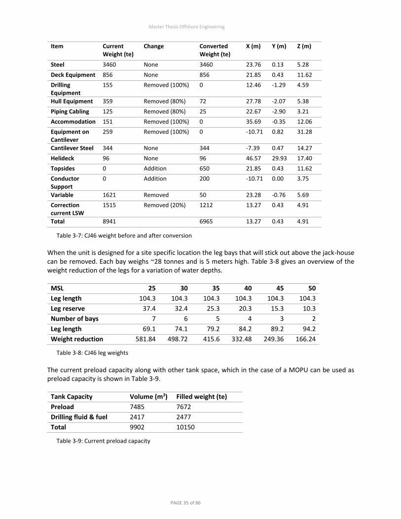
Master Thesis Offshore Engineering
PAGE 35 of 86
Item Current Weight (te)
Change Converted Weight (te)
X (m) Y (m) Z (m)
Steel 3460 None 3460 23.76 0.13 5.28
Deck Equipment 856 None 856 21.85 0.43 11.62
Drilling Equipment
155 Removed (100%) 0 12.46 -1.29 4.59
Hull Equipment 359 Removed (80%) 72 27.78 -2.07 5.38
Piping Cabling 125 Removed (80%) 25 22.67 -2.90 3.21
Accommodation 151 Removed (100%) 0 35.69 -0.35 12.06
Equipment on Cantilever
259 Removed (100%) 0 -10.71 0.82 31.28
Cantilever Steel 344 None 344 -7.39 0.47 14.27
Helideck 96 None 96 46.57 29.93 17.40
Topsides 0 Addition 650 21.85 0.43 11.62
Conductor Support
0 Addition 200 -10.71 0.00 3.75
Variable 1621 Removed 50 23.28 -0.76 5.69
Correction current LSW
1515 Removed (20%) 1212 13.27 0.43 4.91
Total 8941
6965 13.27 0.43 4.91
Table 3-7: CJ46 weight before and after conversion
When the unit is designed for a site specific location the leg bays that will stick out above the jack-house can be removed. Each bay weighs ~28 tonnes and is 5 meters high. Table 3-8 gives an overview of the weight reduction of the legs for a variation of water depths.
MSL 25 30 35 40 45 50
Leg length 104.3 104.3 104.3 104.3 104.3 104.3
Leg reserve 37.4 32.4 25.3 20.3 15.3 10.3
Number of bays 7 6 5 4 3 2
Leg length 69.1 74.1 79.2 84.2 89.2 94.2
Weight reduction 581.84 498.72 415.6 332.48 249.36 166.24
Table 3-8: CJ46 leg weights
The current preload capacity along with other tank space, which in the case of a MOPU can be used as preload capacity is shown in Table 3-9.
Tank Capacity Volume (m3) Filled weight (te)
Preload 7485 7672
Drilling fluid & fuel 2417 2477
Total 9902 10150
Table 3-9: Current preload capacity

Master Thesis Offshore Engineering
PAGE 36 of 86
3.5 Conversion Scope
Prior to purchase of the selected jack-up, it is recommended that the jack-up designer is contracted to review the historic and future fatigue characteristics of the unit, taking into consideration the weight and environmental loads imposed by the conversion. The certifying authority should be involved in this review to ensure that the analysis meets their requirements. Irrespective of the rig selected, a certain amount of yard work will be necessary. The major works are listed below:
– To install topsides; assumed to be part modular and part stick built, with grillage framework under the modules (dependent on layout and existing deck members/strength).
– Local strengthening to hull. – Installation of support structure for jack-up supported conductors. – Installation of a cold vent boom. – Fire walls and other protection structures as identified by the technical safety review. – Installation of hard piping for risers and J-Tubes within the legs of the jack-up. – Upgrade and/or replacement of existing corrosion protection systems. – Conduct a 5-year survey and clear all necessary faults to maintain the rig class under transit and
installation conditions. Depending on site specific parameters and results of the jack-up fatigue assessment, the following works could also be required: – Upgrades to the leg fixation system (jacking tower and mechanisms). – Dependant on the outcome of the fatigue assessment, remedial works to the fatigue sensitive areas
of the legs and hull structure. – Conversion of lower section legs/spudcans to foundations designed for the site specific and in-
service conditions. – Modifications (sea fastening, major temporary supports) required for sea transit.

Master Thesis Offshore Engineering
PAGE 37 of 86
3.6 Installation Scope
The installation of the MOPU will follow the standard site specific installation procedure for a jack-up mobile drilling unit under wet tow conditions, with due allowance during manoeuvring, anchoring and set down for any pre-installed subsea infrastructure. Monitoring of the MOPU foundation penetrations at the seabed will be done with ROVs. Dependant on the final design of the foundation system, other control systems may be required for the installation:
– Foundation mounted water jetting systems – Scour protection devices – Dredging vessel
The minimum marine spread for installation includes:
– Tow tug – 2 Anchor handling vessels – Support vessel with ROV spread
The 6-slot subsea template is envisaged to be installed after the MOPU. This can be achieved by one of the following options.
– Template underslung from well bay module during transport to the field, lowered to seabed using attendant drill rig lift gear and internal lifting tool connected to template structure, lift tool engaged with template through module volume, lower and set down on seabed.
– Template transported to field on supply boat, set down in sea under floatation, towed to underside of well bay module. Using drill rig lift devices as per option a.
The positioning of the template must be precisely above the conductor stump of the exploration/appraisal well. For the tie-back of the exploration well different design conditions apply. The moment fixity at the mudline is critical and must be replicated. To achieve this a 36” conductor should be piled outside the 30” conductor to a depth that ensures moment fixity of the 36” piece. Above the mudline, a conical section allows a connection to the standard 30” conductor. The conductor support structure at the jack-up must be designed to allow a 36” conductor to pass through on a certain number of well slots. Once the conductor is installed wedges will be used to fix it in the support structure.

Master Thesis Offshore Engineering
PAGE 38 of 86
3.7 Cost Estimate and Comparison
To test at an early stage whether the concept is commercially interesting, a comparison with respect to similar conventional platforms is made. With correspondence with experienced professionals within ONE a high-level CAPEX estimate has been made for the MOPU concept, see Table 3-10.
Two conventional platforms and an ONSS concept have been selected for comparison. All have similar metrics to the MOPU concept (Six well slots, ~4 mln Nm3/d capacity, NUI (Normally unmanned installation), Southern North Sea gas basin):
– Wingate (Wintershall); Wellhead and FWKO. 31-meter water depth. Installed in 2011. No processing, large portion of OPEX is OPEX share from the nearby processing platform.
– F15-A (Total); Wellhead and production platform. 42-meter water depth. Installed in 1992, costs are likely out of date.
– 3 ONSS platforms; Wellhead and FWKO. Two wellhead platforms bridge linked with a process platform. Variable depth. Requires wet gas pipeline and onshore processing. Additional OPEX for onshore processing.
MOPU Wingate F15-A ONSS (3x)
CAPEX 57 80 125 70
OPEX 8 12 7 7
ABEX 5 25 48 15
Table 3-11: Comparison of offshore developments. CAPEX & ABEX (Abandonment expenditure) in MM EUR, OPEX in MM EUR/year. Values given in RT ’16. Includes only platform and processing facilities, no pipeline included. Sources: Woodmac & ONE internal
Note: The target with the most potential for this development, N-Block GEms prospect, is a special case for two reasons.
– It is not located near any existing infrastructure; – A wet gas export line cannot be installed because it would have to be laid through the Waddenzee,
which poses significant environmental and regulatory issues. These factors make development via a satellite unfeasible, therefore a platform that can bring gas to NGT specifications is required. For this specific case, only the F15-A platform and the ONSS concept is comparable. Because there will be space on deck for a hydraulic workover unit and a coiled tubing reel, well interventions and abandonment will not require a drilling rig. This can significantly reduce costs.
CAPEX MOPU Conversion € MM
Jack-up rig 5
Refurbishment & Upgrade 9
Process Equipment 8.5
Utility Equipment 11.5
Construction Process & Utility 8
Installation 2
Engineering & Design 4
G&A / Overhead 9
Total Specific Project Cost 57
Table 3-10: CAPEX MOPU (mln EUR)

Master Thesis Offshore Engineering
PAGE 39 of 86
Abandonment of the platform itself will be nothing more than decommissioning the wells, disconnecting the subsea pipeline, burying the pipeline, lowering of the platform, raising the legs and towing the unit away. After revision, the unit could potentially be reused for a new development. If successful, the concept could save a large amount of CAPEX an ABEX with only a slightly increased offshore OPEX and is a highly effective way of developing a small stand-alone field.

Master Thesis Offshore Engineering
PAGE 40 of 86
3.8 Design Schematic of Jack-up MOPU
The figure below shows a schematic 3D design of the concept.
Figure 3-7: 3D schematic design

Master Thesis Offshore Engineering
PAGE 41 of 86
4 Assessment of Conceptual Design
In this chapter the modelling assumptions and methods for the feasibility assessment of the jack-up MOUPU are discussed. The focus of this assessment will be on the ultimate limit state and the fatigue limit state (USL & FLS). For the assessment of the structural integrity of the concept a differentiation is made between the assessment of the conductors and the assessment of the jack-up unit, see Figure 4-1. The limit states of the conductors will be evaluated using DNV guidelines. However, the conductor buckling code checks are based on the method proposed by Baur & Stahl, as mentioned in 4.3.1, which is the same as the method used in the IOGP recommended guidelines for well conductor design [20]. Although the concept will be designed for 6 conductors, it must also be possible to have only 1 conductor initially and add the others later. Therefore, the conductor limit states are evaluated without shielding effects. In the concept, all conductors a supported independently of one other. The limit states of the jack-up will be evaluated using the ISO guidelines for jack-ups [14]. An array of 6 conductors has been included for the jack-up assessment. No stiffness has been attributed to the conductors for the calculation of the jack-up ULS. The stiffness of the conductors is negligible w.r.t. the jack-up legs. Fatigue assessment of the jack-up has been done by GustoMSC. Inputs were based on the MOPU design, and the same conceptual wave data has been used as for the conductor fatigue assessment. A summary of the results has been included and linked to the overall conclusions.
Figure 4-1: Assessment guidelines used for evaluations

Master Thesis Offshore Engineering
PAGE 42 of 86
4.1 Metocean Data and Model
For the conceptual design of the ONSS, Fugro has done a study for ONE to summarize the metocean conditions in the Dutch North Sea [21]. The metocean criteria is for 'worst case' conditions such that the gas platform could be placed anywhere within this sector, which has water depths between 20 and 60 m. However, because of the spatial variability of metocean conditions within the Dutch North Sea, worst case conditions are instead derived for two subsectors of the Dutch sector of the North Sea. These subsectors (northern and southern) are separated by the southernmost 30 m bathymetry contour in this region. A spatial assessment of wind, wave and surface current was carried out over the whole block, enabling grid points to be selected representative of the "worst case conditions" for each subsector. This approach allows the design of a foundation for the subsector with the worst-case conditions such that the structure could sustain metocean conditions anywhere within the Dutch North Sea. The omni-directional wind, wave, current and level criteria are summarised in Table 4-1 and Table 4-2.
Northern Subsector Southern Subsector
Return period 1-year 10-year 100-year 1-year 10-year 100-year
Waves
Hmax (m) 13.6 17.60 20.8 11.8 14.13 16.7
THmax (s) 13.4 16.46 17.5 13.7 14.75 17.1
Wind
Ws1-min (m/s) 27.0 38.0 49.7 26.4 34.2 42.3
Current
Near surface (m/s) 1.31 1.70 2.09 1.68 2.18 3.68
Mid depth (m/s) 1.01 1.32 1.63 1.43 1.88 3.21
Near bed (m/s) 0.87 1.13 1.40 1.12 1.48 2.57
Table 4-1: Maximum environmental data for 3 return periods in the Northern and Southern subsectors
Northern Subsector Southern Subsector
Max depth case Min depth case Max depth case Min depth case
Return period 100-year 100-year 100-year 100-year
Surge 2.65 -1.6 2.92 -1.79
Tolerance 0.5 -0.5 0.5 -0.5
Tidal 1.32 -1.21 1.53 -1.21
Seabed settlement 0.25 -0.25 0.25 -0.25
Total (m) 4.72 -3.56 5.20 -3.75
Table 4-2: Sea level data in the Northern and Southern subsectors
4.1.1 Water Depths and Airgap For the conceptual assessment two different water depths are used. These are taken as the approximate MSLs of the prospective sites for the MOPU which conveniently also cover the low and high end scope for depth.
Northern Subsector Southern Subsector
Depth (m) MSL 50 30
Table 4-3: Low and high end depths used

Master Thesis Offshore Engineering
PAGE 43 of 86
In addition to the wave height and sea level rise as per ISO 19905-1, a 1.5-meter extra airgap is reserved. In the operations manual of the rig a multiple of 0.7 is specified for the maximum wave height. Compared to ISO 19905-1 this is a conservative value that covers the different wave crest theories.
To assess whether there is adequate leg length for the chosen location the airgap, water depth and unit data must be compared. A minimum reserve leg length above the jackhouse of 1.5 meter is required. At this stage a penetration of 5 meters is assumed. This corresponds with full penetration of the spudcan and 1 meter of the leg. This is a conservative value for the generally sandy bottom of the Dutch North Sea.
Table 4-5 above illustrates that the rig can achieve an adequate airgap for the chosen water depths.
4.1.2 Coefficients and Loads Scenarios
The combined wave and current loads on the jacket shall be calculated using Morison’s equation in conjunction with the applicable wave theory. Morison’s equation for drag has also been used to model the effect of the one-minute mean wind speed on the conductors. Drag and mass coefficients for the conductors were defined as shown in Table 4-6. To simulate the maximum loading case no shielding factors have been used. The mass coefficient of the conductor with marine growth was set to 2.0 for the calculations, which corresponds to the mass coefficient that should be used for the fatigue analysis. This error has caused a conservative view on the total conductor load amounting to 0.4% additional loading.
Drag Coefficient (Cd) Mass Coefficient (Cm)
Conductor without marine growth 0.65 1.6
Conductor with marine growth 1.05 1.2 (used 2.0)
Table 4-6: Hydrodynamic coefficients as defined per DNV OS-C101 (section 6) [22]
For the drag and mass coefficients of the jack-up, the “equivalent” leg model [14] was used. Tbl shows the difference between the coefficients of the original legs and the legs of the jack-up MOPU, which include risers, a j-tube, fire water lines, and jetting lines. These items were spread as evenly as possible across the
Northern Subsector Southern Subsector
Extra clearance 1.5 1.5
0.7 X Hmax 14.5 11.7
Sea level rise (MSL) 4.7 5.2
Airgap (m) 20.7 18.4
Table 4-4: Airgap calculation
Northern Subsector Southern Subsector
Reserve 1.5 1.5
Jackhouse/Hull 15.6 15.6
Airgap 20.7 18.4
MSL 50 25
Penetration 5 5
Total (m) 94 66.9
Leg length 104.6 104.6
Leg reserve (m) 10.6 37.7
Table 4-5: Remaining leg length calculation

Master Thesis Offshore Engineering
PAGE 44 of 86
different legs, after which the highest found drag coefficient was applied to the other legs. Marine growth is applied with a multiplication factor on the Cd & Cm, for the overall equivalent leg diameter of 10m.
Drag Coefficient (Cd) Mass Coefficient (Cm)
CJ46 Basis of Design [19] 0.400 0.040
Jack-up MOPU smooth 0.509 0.060
MOPU with Marine growth (100mm) 0.974 0.117
MOPU with Marine growth (50mm) 0.903 0.038
Table 4-7: Equivalent leg drag and mass coefficients for the CJ46 10m diameter leg.
Member diameters were augmented by marine growth thicknesses as follows in Table 4-8. This data is based on the Viking Platform Area (Block 49/17) Environmental Data [23], which is deemed representative and appropriate for the entire Dutch Sector.
Depth relative to LAT (m) Marine Growth Thickness (mm) Density kg/m³
Above +3 0
-10 to +3 100 1400
Mudline to -10 50 1400
Table 4-8: Marine growth thickness at different depths
When applicable data are available joint probability of environmental load components, at the specified probability level, may be considered. Alternatively however, in accordance with the guidance in DNV OS-C101 Table F1 [24], joint probability of environmental loads may be approximated by combination of characteristic values for different load types as shown in Table 4-9 (if ice is excluded). The latter is used for this assessment.
Wind Waves Current
Scenario 1 100-year return 100-year return 10-year return
Scenario 2 10-year return 10-year return 100-year return
Table 4-9: Extreme loading scenarios
For the assessment of the conductors no current blockage factor will be used. For the assessment of the jack-up unit a current blockage factor of 0.88 is used. This value conforms to ISO guidelines [14].
4.1.3 Wave Theory Because the conceptual 100-year wave is high relative to the water depth, at certain sites the wave is near the breaking limit. As consequence, linear Airy wave theory is not applicable to these extreme waves. For waves close to the breaking limit it is prudent to use a high order stream function. An assessment of the wave height vs. the water depth according to Figure 4-2, leads to the use of the 9th order stream function for the 100-year wave. ‘Stream function wave theory was developed by Dean (J. Geophys. Res., 1965) to examine fully nonlinear water waves numerically. The method involves computing a series solution to the fully nonlinear water wave problem, involving the Laplace equation with two nonlinear free surface boundary conditions (constant pressure, and a wave height constraint (Dalrymple, J.Geophys. Res., 1974)).’ [25]

Master Thesis Offshore Engineering
PAGE 45 of 86
Compared to Airy waves the particle velocity and the crests are significantly higher. As the water gets shallower, assuming the same wave, the maximum load increases. Because of this, not using site specific wave heights, which can only be smaller, results in a conservative output. A kinematics reduction factor of 0.86, as found in SNAME [26], has been used in the deterministic wave calculations. DNV and ISO guidelines stipulate a slightly higher factor, in the order of 0.90 for North Sea storm conditions. This error in the order of 3% for the loads should be considered and rectified in future assessments.
Figure 4-2: Wave theory graph, with 100-year and 1-year waves plotted for 25-50m (MSL)
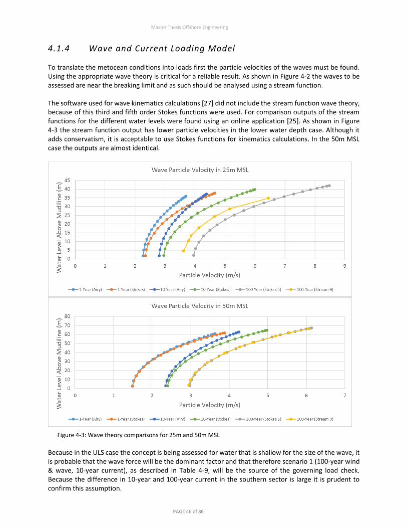
Master Thesis Offshore Engineering
PAGE 46 of 86
4.1.4 Wave and Current Loading Model To translate the metocean conditions into loads first the particle velocities of the waves must be found. Using the appropriate wave theory is critical for a reliable result. As shown in Figure 4-2 the waves to be assessed are near the breaking limit and as such should be analysed using a stream function. The software used for wave kinematics calculations [27] did not include the stream function wave theory, because of this third and fifth order Stokes functions were used. For comparison outputs of the stream functions for the different water levels were found using an online application [25]. As shown in Figure 4-3 the stream function output has lower particle velocities in the lower water depth case. Although it adds conservatism, it is acceptable to use Stokes functions for kinematics calculations. In the 50m MSL case the outputs are almost identical.
Figure 4-3: Wave theory comparisons for 25m and 50m MSL
Because in the ULS case the concept is being assessed for water that is shallow for the size of the wave, it is probable that the wave force will be the dominant factor and that therefore scenario 1 (100-year wind & wave, 10-year current), as described in Table 4-9, will be the source of the governing load check. Because the difference in 10-year and 100-year current in the southern sector is large it is prudent to confirm this assumption.

Master Thesis Offshore Engineering
PAGE 47 of 86
When the stretched delta of the currents is added to the 10-year wave profile of the 30m wave (the deepest section using the Southern sector current) the result is as shown in Figure 4-4. Although velocities of the 10-year wave plus current delta are higher over most of the wet surface, because the crest of the 100-year wave has more wet surface, the integral over the whole length of the velocity of the 100-year wave is higher than that of the 10-year wave plus current delta. In the 50m water depth scenario the 100-year wave particle velocities are higher over the whole wet surface. No integration is needed to show the critical scenario.
Figure 4-4: Scenario comparison 30m and 50m MSL

Master Thesis Offshore Engineering
PAGE 48 of 86
4.2 Foundation Data and Model
The foundation penetration of a jack-up unit spudcan is generally quite shallow. In the soil conditions of the North Sea spudcan penetration rarely exceeds 5 meters. Since different locations all have different soil properties at shallow depths it is not possible to make a useful generalisation. Also, depending on the depth of penetration different problems may occur. Once the site location is chosen a full site specific assessment will be done for the foundation. For the conceptual ULS assessment of the jack-up, dense sand (φ = 35 degrees) is used. This will not provide much fixity at the spudcans, which will give conservative results for the jack-up checks. For the conceptual assessment of the conductor design a lower and upper bound soil case will be used. Typically, in the North Sea the top layers consist of medium dense sand with occasionally some clay layers in-between. Underneath the medium dense sand and clay there is generally a section of very dense sand. For conductor design it is necessary to look at soil layers at depths greater than 10 meters. Conductors are piled to final refusal which is generally in the order of 150m; therefore, the focus will be on the lateral response as adequate axial bearing is assumed. The lower bound soil profile is extracted from Fugro report on soil condition assessment for conceptual pile foundation design in the Dutch sector of the North Sea [28]. Based on the report these profiles represent the worst-case conditions for lateral pile resistance that can be found in the Dutch sector and are therefore taken as the lower bound profile. The top layer consists of 20 meters of normally consolidated clay below which sand with some clay layers can be found.
Depth (m) Soil type γ’ (kN/m3)
ϕ’ (deg)
Cu (kPa)
ε50 (%)
0.0 – 20.0 Clay 6 15 2
20.0 – 40.0 Sand with clay layers 9.5 30
Table 4-10: Lower bound soil profile and parameters; γ’- Submerged unit weight, ϕ’ - Angle of internal friction, Cu - Undrained shear strength and ε50 - Strain which occurs at one-half of the maximum stress in laboratory undrained compression test
The upper bound soil profile is based on the soil data from a Fugro report of the L9-FF-1 location, which is 25 km north-west of Terschelling [29]. The data, recommended soil profiles including friction angles and undrained shear strength, have been interpreted to derive the design soil profile and parameters required to perform a conceptual penetration analysis. The effective soil weight is estimated at 10 kN/m3. The soil profile is defined below. The depth is relative to the seabed at local water depth.
Depth (m) Soil type γ’ (kN/m3)
ϕ’ (deg)
Cu (kPa)
ε50 (%)
0.0 – 5.0 Seabed sediments & medium dense sand
10 25
5.0 – 20.0 Dense sand 10 35
20.0 – 40.0 Very stiff clay 10 150 2
Table 4-11: Upper bound soil profile and parameters

Master Thesis Offshore Engineering
PAGE 49 of 86
4.2.1 Equivalent Spring Model LatPile (GustoMSC tool) was used to simulate p-y stiffness’s for the soil profiles given in section 4.2. From this equivalent spring stiffness’s were derived to create a foundation model of mutually independent linearly elastic springs in the finite element package [30]. Plots of the equivalent springs for varying displacements are shown in Figure 4-5 & Figure 4-6. The displacements are described in the legend. Orders of magnitude for very small are ~1 mm and for large 1 meter. The figures show that the equivalent springs for clay are not linear. Therefore, different stiffness’s must be modelled for different displacements. A displacement plot of the conductor was made at the lower bound soil to check if value of the correct order of magnitude were used.
Figure 4-5: Lower Bound Soil Equivalent Springs
Figure 4-6: Upper Bound Soil Equivalent Springs

Master Thesis Offshore Engineering
PAGE 50 of 86
The beam moments depicted in Figure 4-7 show that the effective fixity used at 6 times the outside diameter of the conductor is similar to the upper bound soil. This justifies the used of the equivalent fixity method for the analytical calculations of the eigenvalue and unsupported length assumptions.
Figure 4-7: Beam moments Fixed-Fixed and Fixed-Pinned for equivalent fixity and lower and upper bound soil
Because the main soil condition in the North Sea (see Appendix 4: Main soil condition Dutch North Sea [28]) is sand, the upper bound fixity will be the condition used for the bulk of the analysis.

Master Thesis Offshore Engineering
PAGE 51 of 86
4.3 Structural Assessment Procedure
Due to the addition of members below the waterline, additional loads are placed on the jack-up, whereas no structural integrity is added. Because of this static integrity of the unit is not guaranteed at the high-end water depths. A conceptual site specific assessment will be done to verify this. This assessment will be done according to the ISO 19905-1 standard [14], the theory of which will not be explained in this chapter, as it is clearly presented in the ISO standard. The structural calculations for the jack-up unit have been modelled in LegLoad [27], a GustoMSC in-house software package. The basis of the conductor integrity model has been looked at in more detail and is explained in the sections below.
4.3.1 Design Method The design of conductors is generally perceived as a special problem. This is mainly because the effects of the internal loads are different from the external loads. The majority of the loading is generally caused by the internal drill strings. The fundamental principal of conductor design is that loading caused by the internals do not produce buckling tendencies. If a normal member stability check is used, which is designed for used with only external loads, the results will be much too conservative. The separation of the loads and the development of the equations was initially done by Stahl and Baur [31] and has since been reanalysed by Lang and Wood [32]. They modified the AISC plastic design equations to be compatible with the separation. The equations for stability and strength are as follows:
Stability:
𝑓𝑐𝑒𝑥𝑡𝜙𝑐 𝐹𝑐𝑟𝑚
+ 𝑓𝑐𝑖𝑛𝑡𝜙𝑐 𝐹𝑥𝑐
+
𝐶𝑀 𝑓𝑏
(1 −𝑓𝑐𝑖𝑛𝑡𝜙𝑐 𝐹𝑒
)
𝜙𝑏 𝐹𝑏𝑛 ≤ 1
Strength:
1 − cos [(𝜋
2 ) (𝑓𝑐𝑒𝑥𝑡 + 𝑓𝑐𝑖𝑛𝑡𝜙𝑐 𝐹𝑥𝑐
)] + 𝑓𝑏
𝜙𝑏 𝐹𝑏𝑛 ≤ 1
The equation for stability is applicable to the section of the conductor that has a large unsupported length, i.e. between the mudline and the jack-up. The strength equation is used to assess the structural integrity in the sections where global buckling is not seen as an issue, i.e. at the mudline and jack-up support.
The equations consist of different components: factored applied stresses (𝑓), resistance factors (𝜙), a column curvature factor (𝐶𝑀) and critical resistance stresses (𝐹).
𝑓𝑐𝑒𝑥𝑡 = axial compressive stress due to factored external loads
𝑓𝑐𝑖𝑛𝑡 = axial compressive stress due to factored internal loads
𝑓𝑏 = bending stress due to factored internal and external loads
𝜙𝑐 = 0.85 | resistence factor for axial compressive strength 𝜙𝑏 = 0.95 | resistence factor for bending strenght 𝐶𝑀 = 0.85 | column curvature factor for platform, jackup and freestanding conductors

Master Thesis Offshore Engineering
PAGE 52 of 86
How the critical resistance stresses are calculated is dependent on a variety of parameters, including material properties, geometry and applied stresses. The formulas are shown below.
𝐹𝑐𝑟𝑚 = 𝐹𝑐𝑟𝑏
(
1
1 −𝑓𝑐𝑢𝑖𝑛𝑡𝐹𝑦 )
| modified critical buckling strength
𝐹𝑐𝑟𝑏 =𝐹𝑦
2(𝐵 + √𝐵2 + 𝐶) for𝐾𝐿 𝑟⁄ ≤ 𝐶𝑐𝑚 ∨
𝐹𝑒 for𝐾𝐿 𝑟⁄ > 𝐶𝑐𝑚 | critical buckling strength
𝐹𝑥𝑐 = 𝐹𝑦 for𝐷 𝑡⁄ ≤ 60 ∨
{1.64 − 0.23(𝐷 𝑡⁄ )1 4⁄ }𝐹𝑦 𝑓𝑜𝑟 𝐷 𝑡⁄ ≥ 60 | nominal inelastic buckling strength
𝐹𝑒 =𝐹𝑦
𝜆2 | Euler buckling strength
𝐹𝑏𝑛 = 𝑘 𝐹𝑦 for𝐷 𝑡⁄ ≤ 1500 𝐹𝑦⁄ ∨
{1.13 − 2.58[𝐹𝑦𝐷 𝐸𝑡⁄ ]}𝑘 𝐹𝑦 for 1500 𝐹𝑦⁄ < 𝐷 𝑡⁄ ≤ 1500 𝐹𝑦⁄ ∨
{0.94 − 0.76[𝐹𝑦𝐷 𝐸𝑡⁄ ]}𝑘 𝐹𝑦 for 3000 𝐹𝑦⁄ < 𝐷 𝑡⁄ ≤ 300
| nominal bending strength
In these formulas the following parameters are defined.
𝐹𝑦 = yield strength of steel 𝐿 = unbraced length of conductor
𝐸 = Youngs modulus of steel 𝐾 = effective length factor 𝐷 = outside diameter of the pipe 𝑟 = radius of gyration of member cross section 𝑡 = wall thickness of the pipe
𝑘 =𝑍
𝑆 | shape factor, plastic section modulus divided by the elastic section modulus
𝐶𝑐𝑚 = √𝜋2𝐸
𝐹𝑦2 − 𝑓𝑐𝑢𝑖𝑛𝑡
for 𝑓𝑐𝑢𝑖𝑛𝑡 ≤𝐹𝑦
2 ∨
∞ for 𝑓𝑐𝑢𝑖𝑛𝑡 >𝐹𝑦
2 | modified column slenderness ratio
𝐵 = 1 − (2𝑓𝑐𝑢𝑖𝑛𝑡 𝐹𝑦)⁄ − 𝜆2 4⁄
𝐶 = 4(𝑓𝑐𝑢𝑖𝑛𝑡 𝐹𝑦)⁄ (1 − 𝑓𝑐𝑢𝑖𝑛𝑡 𝐹𝑦) | buckling stress parameters⁄
𝜆 =𝐾𝐿
𝜋𝑟√𝐹𝑦
𝐸 | column slenderness parameter

Master Thesis Offshore Engineering
PAGE 53 of 86
If the internal strings have been cemented all the way to the surface they can be considered as a composite section of the conductor. It is however prudent to not account for this unless it is sure that the cement has reached the wellhead, which is rarely the case.
4.3.2 Definition of Loads The loads effecting a conductor can be split into axial loads and bending loads. These can then be split into internal and external loads.
Internal axial loads contribute to the overall stress in the conductor but do not cause instability failures such as buckling. The internal axial loads are applied to a conductor in two ways;
1. Hanging and pre-tensioning the internal casing and tubing strings.
2. Thermal expansion that occurs in the internal string.
For the sake of conservatism thermal loads are typically neglected in calculations as they are tensile loads, caused by expansion, which reduce the overall internal load. This is because the expansion loads work in the direction opposite the gravity loads. The internal load for each casing string should include the buoyancy and the tensioning of internals. When a conductor uses a MLS it is assumed that the internal strings are supported by the hanger ring, which is typically 3 – 5 meters below the mudline. In this case the internal axial load only includes the weight of the strings from the MLS to the surface.
The load on the conductor specifically can be calculated by the principal of elastic shortening, which is a method of distributing the axial loads between combined strings. Since all the internal strings that are supported at the MLS (configuration without the tubing shown in Figure 3-5) will experience similar axial deflections the proportions of internal axial load will be governed by the cross sections and the tensile strengths. In this calculation pretension must also be accounted for.
Internal loads at any point along the conductor should exclude the buoyant weight of the internal strings above that point. The loads should be included in the external axial loads. Additionally, the buoyant weight of the drilling fluids should be considered. This will only be significant for the section of the conductor that is not submerged.
External axial loads contribute to the instability of the conductor and can cause buckling failure. These loads also consist of two main components:
1. Dead weight of the equipment physically located on top of the conductor, such as the wellhead,
valves, hoses and other production equipment.
2. As noted above, the buoyant weight of everything above the point being analysed.
The external load can be reduced by pulling tension on the conductor. This technique is sometimes used while drilling but is uncommon when the conductor is in production.
Internal bending loads are caused by eccentricity of internal casing strings. Since a centralizer is used just beneath the wellhead, the MLS also functions as a centralizer and the length in-between theses centralizers is relatively small (50 meters), the loads will be neglected.
External bending loads are caused by environmental loading of the wind, waves and current on the conductor. These loads can be determined with computer software or by a stick model of the conductor.

Master Thesis Offshore Engineering
PAGE 54 of 86
The P-Delta effect should also be considered, this entails that the external axial load and the deflection at the point in question should also be considered.
4.3.3 Design Factors Since the LRFD method is used, all applied loads must be factored. In DNV [24] load factors for use on offshore installations can be found, but not for conductors specifically. A set of load factors has been developed, by Geyer and Stahl in 1984, which guarantees reliability for the conductors consistent with that of offshore structures [33]. The load factors below are applicable to the internal axial loads, external axial loads and environmental loads respectively. These factors should be increased if the loads are not well known. The resistance factors will remain unchanged.
𝛾𝑖 = 1.6, 𝛾𝑒 = 1.2, 𝛾𝑤 = 1.2 (𝑜𝑝𝑒𝑟𝑎𝑡𝑖𝑛𝑔 𝑙𝑜𝑎𝑑𝑠)
𝛾𝑖 = 1.3, 𝛾𝑒 = 1.1, 𝛾𝑤 = 1.6 (𝑒𝑥𝑡𝑟𝑒𝑚𝑒 𝑒𝑛𝑣𝑖𝑟𝑜𝑛𝑚𝑒𝑛𝑡𝑎𝑙 𝑙𝑜𝑎𝑑𝑠)
The theory states that there is a difference in safety factor between platforms and conductors, when standard load factors are used. This is caused by a difference in the ratio between the gravity and environmental loads. Geyer [33] observes that the safety index for the ratio typical to conductors is lower than that of platforms. To compensate this reduction in safety index the load factors are increased.
Figure 4-8: Safety index β plotted against load ratios in Geyer & Stahl [33]
A check of the calibration parameters as mentioned in Geyer shows (Table 4-12) that the parameters for the conductor concepts in this report are in the same regime, which justifies the increase in this case. The ‘LFD’ plot refers to the design factors used in Baur and Stahl [31], the ‘LRFD-Plat’ plot refers to the standard for offshore structures at the time (𝛾𝑖 = 1.1, 𝛾𝑒 = 1.1, 𝛾𝑤 = 1.35; 𝜑𝑦 = 0.95, 𝜑𝑐 = 0.90, 𝜑𝑏 = 0.92).
Pe/Pi (30m) W/G (30m) Pe/Pi (50m) W/G (50m)
Jack-up fixation 0.15 0.48 0.15 0.54
Load center 0.42 0.25 0.54 0.38
Fixity depth 0.79 0.21 1.04 0.34
Table 4-12: Load ratios of conductor for 30m and 50m water depths

Master Thesis Offshore Engineering
PAGE 55 of 86
4.3.4 Structural Model Initial structural calculations were done using simple beam formulas. However, because it is complex for the ‘softness’ (i.e. displacement due to loading) of the soil to be modelled analytically, Sesam GeniE an offshore structural engineering software tool was used for the structural modelling of the conductor. As the 6 conductors all have the same support parameters and are not in contact with each other, the structural integrity of a single conductor will be assessed. For the ULS blockage factors are not applicable because the outside conductor will be critical. As shown in Figure 4-7 six different support options were modelled, 3 with a moment fixity at the jack-up level and 3 with a pinned support at the jack-up level. At the mudline an effective fixity and an upper and lower bound soil Winkler foundation was modeled. The loads were applied using a series of point loads, extracted from a stick model in the spreadsheet. For every water depth assessed, different loads at different heights were inserted and the height of the supports was adjusted. From this model beam moments and reaction forces can be derived, which can then be used to check the strength and stability of the structure. In Figure 4-7 an example is given of the beam moments of the finite element model for 25 meters MSL. These beam moments were used to perform stability and strength checks on the conductor according to the theory in section 4.3.1. An important parameter in the buckling strength and stability of the beam is the effective length of the conductor. The effective length factor is defined by the support conditions. The k values corresponding to (a), (b) and (e) in Figure 4-9 have been used. For the calculations, the recommended design values are used. The unsupported length is taken from the modelled effective fixity depth (6 times the diameter of the pipe) to the support. The moment fixity point in the case of the fixed support is modelled halfway between the two pinned support points that makeup the fixed support.
Figure 4-9: Effective length factors. [34]

Master Thesis Offshore Engineering
PAGE 56 of 86
Figure 4-10: Sketch of the jack-up fixed option
The P-Delta effect on the conductors has been accounted for in the cases that there is a deflection at the jack-up support point. An assumption is made that normalized two thirds of the weight of the system has the same deflection as the jack-up unit. The P-Delta effect is only applied to the maximum moment at the mudline. At the load center, there is a small contribution in the case that there is no deflection at the support. When the deflection at the support exceeds that of the load center, the effect reduces the bending moment. These contributions are small and considering that the load center is not the critical buckling area in any of the cases, no contributions have been included in the model.

Master Thesis Offshore Engineering
PAGE 57 of 86
4.3.5 Jack-up Deflection The deflection of the jack-up is an important factor to consider when analysing the integrity of the conductor. There are a few different factors that cause jack-up deflection:
– Wave loading – Current loading – Wind loading – Leg inclination – Gap between guide and leg
Of these factors the bottom two are in principal static. However, they both have a second order effect, the p-Δ effect.
The p-Δ effect is essentially the moment created by the self-weight of the jack-up and the deflection. Because this moment causes an increase in deflection which then causes a new increase in moment, it is a so called second order effect and must be calculated iteratively. The elevated weight of the jack-up is ~60 MN. Considering that an initial inclination of the legs can cause a deflection in the order of 10 cm. This effect can cause a significant additional moment when the deflection becomes large. The effect must therefore be accounted for. However, the initial no-load deflection from the centreline should be subtracted from the values found after the loads are applied. This is because the conductors will only be piled after the jack-up is installed, and will therefore not be effected by the initial permanent deflection. Therefore, for the ULS check the low case deflection will be modelled with no inclination and the high case with a large initial inclination.
The gap between the leg and guides normally also causes a static deflection. For example: if the gap between the leg and guide is 5 mm, length of the leg under the fixation point is 50 meters and the distance between the fixation point and guide is 7.5 meters, the deflection will add up to 50/7.5*5=~33 mm. This deflection will also be reversed when the centre of gravity of the hull crosses the centreline. Because the gap also influences the stiffness of the whole unit it is recommended that this gap be eliminated by placing wedges between the leg and the guide.
Current and wind have a quasi-static contribution. The wind force on the jack-up has a high centre of effort and is therefore a large factor of the deflection. For the maximum case the 10-year current and 100-year wind loads will be used. For the minimum deflection, a conservative case of no wind current will be modelled.
Deflection Component Minimum Case Maximum Case
Waves See below See below
Wind No wind 100-year return period
Current No current 10-year return period
Inclination No initial inclination 0.25 % incline in legs
Leg/Guide Gap No gap No gap
Table 4-13: Minimum and maximum deflection scenarios
The wave loading has a quasi-static and a dynamic effect on the deflection. As we are considering an extreme wave, with a period far from the Eigen period of the jack-up, the dynamic effect with be minimal (see Figure 4-11). In principal, the quasi-static deflection of the jack-up should be maximal around the same time as the maximum load on the conductor. But, because the centre of effort of the environmental loading of the jack-up is not in phase with that of the conductor for certain wave angles an assessment must be made of the different cases.

Master Thesis Offshore Engineering
PAGE 58 of 86
Figure 4-11: Dynamic amplification factor of jack-up for a range of wave periods
The maximum distance between the centre of effort of the jack-up hydrodynamic loading (including the conductor) and the conductor is ~23 meters. This distance is different for different wave angles of attack. The maximum stated above is applicable to a wave angle of attack of 210 degrees, which is 30 degrees to port or starboard of the bow or stern of the rig (due to symmetry). The minimum distance is 0 meters. This occurs when the wave comes broadside to the jack-up, i.e. 270 or 90 degrees.
Figure 4-12: Wave angles of attack
Since it is plausible that the maximum wave angle of attack could be both broadside or 30 degrees of the bow/stern, depending on the initial orientation, both situations should be considered for the ULS. The consequence of this is that the high and low end jack-up deflection should be considered for the maximum wave. Depending on the wave length and the gradient of the wave the difference in distance will be equal to a difference in hydrodynamic force on the jack-up when the force on the conductor is at its maximum. This is illustrated in Figure 4-13 for a 100-year wave coming at 210 degrees in 30 meters of water (MSL).

Master Thesis Offshore Engineering
PAGE 59 of 86
Figure 4-13: Hydrodynamic forces during a maximum wave with 210-degree angle of attack (no wind, no current)
The interval between the maximum loads is 0.075 of the wave period, which at a wavelength of 312.5 meters is equal to 23 meters. Due to the non-linearity of the wave, because of the shallow water, this distance can have a significant impact on the load. As mentioned above, when the wave angle of attack is broadside the conductor maximum load occurs at the same time as the maximum load on the jack-up.
The model of the jack-up, built in LegLoad [27], accounts for dynamic effects of the loading. Because the Eigen-period of the unit is ~2.5 seconds at 30 meters (MSL) the dynamic amplification factor is low (Figure 4-11). It therefore does not have a significant impact on the unit. By running LegLoad for every time-step, a plot of the deflections can be added to the forces chart. It is clear that the deflection plot is very similar to the total load plot.
The deflection of the jack-up has a significant influence on the beam moments, from which the beam strength and stability checks follow. The range of deflections that are applicable to the maximum wave force on the conductor differ for different wave periods. When the wave period is shorter the wave also becomes shorter. A shorter wave also means a smaller wave, because of the breaking limit.
For instance, a 7 second wave could have a maximum wave height of approximately 10 meters, according the breaking limit. Theses parameters lead to a wave length of ~85 meters. This wave length would cause the largest relative difference in conductor vs. jack-up load in the 180-degree case. Therefore, this case has also been examined, see Figure 4-14.
Although the phase difference in this waves almost matches the minimum leg load with the maximum conductor load it can be observed that the difference in deflection between the minimum and maximum case for the 10-meter wave is one third of that of the 16.7-meter (maximum) wave, see Table 4-14. In addition to a much smaller deflection range (1/3), the maximum load on the conductor is also a quarter of that of the maximum wave case. Because of this, for the ULS, only the maximum wave will be considered. All the jack-up deflections have been modelled with upper bound soil foundation support.

Master Thesis Offshore Engineering
PAGE 60 of 86
Figure 4-14: Hydrodynamic forces during a 7s, 10-meter wave with 210-degree angle (no wind, no current)
Deflection Minimum Maximum Delta
Wave height Angle (deg) Value (m) Angle (deg) Value (m) Value (m)
10m 180 0.006 270 0.021 0.015
16.7m 210 0.118 270 0.168 0.05
Table 4-14: Minimum and maximum deflection in different wave cases for 30m MSL
The maximum deflection of the jack-up during maximum conductor load occurs when the wave angle is broadside to the rig (i.e. 270 degrees). This is because at that point the centre of effort of the hydrodynamic load on the rig, coincides with that of the conductor. The values for maximum deflection shown in Table 4-14 above, are the maxima when the rig is only displaced by wave loading. The maximum cases as described in Table 4-13, including current, wind and leg inclination, are shown in Table 5-2. For this analysis, a jack-up hull weight of 57 MN was used. Later due to the stability of the jack-up the hull weight was adjusted to 70 MN. The maximum eigen period increase cause by this change was 0.3 seconds. Figure 4-11 shows that the impact on the DAF for the 100-year wave is small. Second order deflections will increase. The total moment caused by the environment is in the order ~500 MNm. The impact of a maximum (1-meter deflection) second order moment of 13 MNm is not significant in this case.
WD 70 MN 57.32 MN Delta
30 2.70 2.48 0.22
40 3.09 2.83 0.26
50 3.55 3.25 0.30
Table 4-15: Natural period (s) increase for different hull weights

Master Thesis Offshore Engineering
PAGE 61 of 86
4.4 Fatigue Model
The wave height occurrence data for use in a deterministic fatigue assessment can be found in Appendix
1. A summary of the data is shown in Figure 4-15.
Figure 4-15: Omni-Directional 1-year Joint Frequency Distribution of Individual Wave Height and Period; Southern Subsector
The main driver for fatigue is wave loading. The nature of the loading causes periodic stress variations
during the entire lifetime of the structure. These variations can cause crack initiation and propagation
which will ultimately lead to failure.
MSL Cantilever Fixed - Hinged Fixed - Fixed Jack-up MOPU
30 8.7 2.0 1.2 2.7
40 12.6 2.9 1.8 3.1
50 16.3 3.7 2.3 3.5
Table 4-16: Natural Period (Tn) is seconds (s) of the different conductor concepts and jack-up MOPU
The wave loading will also cause the jack-up to swing around its mean static deflection. When the natural period of the wave is not near the natural period of the structure most of this behaviour is quasi-static, however when the period of the waves coincides with the natural frequency of the structure, dynamic amplification will intensify the deflections and stresses significantly. This statement is also applicable to the conductor. As seen in Figure 4-15 above, once the natural period of the structure is above 2 seconds a significant number of waves will dynamically excite the structure. Table 4-16 above shows an overview of the natural periods of the different structures to be assessed. The simplified fatigue analysis does not account for dynamics specifically, but accounts for it due to its inherent conservatism. Another driver for fatigue can be vortex induced vibrations (VIV), see section 4.5.
H [m] 0-<2 2-<4 4-<6 6-<8 8-<10 10-<12 12-<14 14-<16 16-<18 Total
0.0-<0.5 7.34% 19.84% 9.35% 2.28% 0.58% 0.19% 0.07% 0.02% 0.00% 39.68%
0.5-<1.0 0.13% 9.68% 14.82% 5.17% 1.23% 0.37% 0.13% 0.04% 0.01% 31.57%
1.0-<1.5 0.00% 1.64% 7.36% 4.20% 1.03% 0.28% 0.10% 0.03% 0.01% 14.65%
1.5-<2.0 0.00% 0.29% 2.82% 2.86% 0.72% 0.20% 0.06% 0.01% 0.00% 6.98%
2.0-<2.5 0.00% 0.04% 0.96% 1.65% 0.50% 0.15% 0.04% 0.01% 0.00% 3.36%
2.5-<3.0 0.00% 0.01% 0.38% 0.87% 0.35% 0.10% 0.03% 0.01% 0.00% 1.75%
3.0-<3.5 0.00% 0.00% 0.12% 0.44% 0.26% 0.07% 0.02% 0.00% 0.00% 0.91%
3.5-<4.0 0.00% 0.00% 0.04% 0.22% 0.17% 0.05% 0.01% 0.00% 0.00% 0.50%
4.0-<4.5 0.00% 0.00% 0.01% 0.11% 0.11% 0.04% 0.01% 0.00% 0.00% 0.28%
4.5-<5.0 0.00% 0.00% 0.00% 0.04% 0.06% 0.02% 0.01% 0.00% 0.00% 0.14%
5.0-<5.5 0.00% 0.00% 0.00% 0.02% 0.04% 0.02% 0.00% 0.00% 0.00% 0.08%
5.5-<6.0 0.00% 0.00% 0.00% 0.01% 0.02% 0.01% 0.00% 0.00% 0.00% 0.05%
6.0-<6.5 0.00% 0.00% 0.00% 0.00% 0.01% 0.01% 0.00% 0.00% 0.00% 0.03%
6.5-<7.0 0.00% 0.00% 0.00% 0.00% 0.01% 0.00% 0.00% 0.00% 0.00% 0.01%
Total 7.47% 31.51% 35.86% 17.86% 5.11% 1.53% 0.49% 0.12% 0.03% 100.00%
T [s]

Master Thesis Offshore Engineering
PAGE 62 of 86
4.4.1 Wave Induced Fatigue When assessing the fatigue damage to the conductor the locations with the highest local stresses should be analysed. In a conductor, these generally occur at the connectors. According to DNV [35] examples of different design approaches of connectors can be listed as:
1. A linear elastic finite element analysis approach combined with S-N curve B1 without requirement to additional fatigue testing
2. Advanced finite element analysis approach with non-linear analysis to determine initial behavior before an elastic state is achieved. Then the stress range may be combined with the high strength S-N curve. These analyses may be supported by additional fatigue testing depending on consequences of a fatigue failure.
For the wave fatigue analysis on the conductor initially the first approach is used, which gives a conservative outcome of the fatigue life. For assessment of a fatigue design curve for connectors derived from testing, the stress modification factor (SMF) accounts for a number of different parameters:
– Stress concentration factor in connection. – Stress gradient at threads. – Fabrication tolerances in connecting parts. – Make-up torque. – Local yielding at thread roots. – Mean stress effects when the testing is performed with part of the stress cycle as compressive
The service life time of the conductor will be 20 years. The conductor is considered to be inaccessible. Depending on the perception of the consequence of fatigue failure of the conductor, critical or non-critical for the overall integrity of the platform, the safety factor for fatigue life will be taken as 10 or 3 respectively, as per DNV guidelines [24]. The so-called ‘simplified’ method is also sometimes referred to as the ‘permissible’ or ‘allowable’ stress range method, which can be categorized as an indirect fatigue assessment method because the result of the method’s application is not necessarily a value of fatigue damage or a fatigue life value. Often a ‘pass/fail’ answer results depending on whether the acting stress range is below or above the permissible value. This method is often used as the basis of a fatigue screening technique. A screening technique is typically a rapid, but usually conservatively biased, check of structural adequacy. If the structure’s strength is adequate when checked with the screening criterion, no further analysis may be required. If the structural detail fails the screening criterion, the proof of its adequacy may still be pursued by analysis using more refined techniques. Also, a screening approach is quite useful to identify fatigue sensitive areas of the structure, thus providing a basis to develop fatigue inspection planning for future periodic inspections of the structure and Condition Assessment surveys of the structure. In the simplified fatigue assessment method, the two-parameter Weibull distribution is used to model the long-term distribution of fatigue stresses. The cumulative distribution function of the stress range can be expressed as:
𝐹𝑠(𝑠) = 1 − 𝑒𝑥𝑝 [− (𝑆
𝛿)𝛾
] for 𝑆 > 0
Where, 𝑆 = a random variable denoting stress range 𝛾 = the Weibull shape parameter 𝛿 = the Weibull scale parameter

Master Thesis Offshore Engineering
PAGE 63 of 86
Based on the long-term distribution of stress range, a closed form expression for fatigue damage can be derived. A major feature of the simplified method is that appropriate application of experience data can be made to establish or estimate the Weibull shape parameter, thus avoiding a lengthy spectral analysis. The other major assumptions underlying the simplified approach are that the linear cumulative damage (Palmgren-Miner) rule applies, and that fatigue strength is defined by the S-N curves. To define the scale parameter a reference stress range must be used, which characterizes the largest anticipated range for the in the reference number of cycles. For a reliable single reference, a long-term maximum must be used. Because the nonlinear effects of the waves increase with the wave height, the 1-year maximum is taken as reference point. Airy wave theory is used to model the wave particle velocities. This, because the majority of the waves will be in the regime where linear wave theory is applicable. The maximum stresses in the different critical areas are found with the finite element model of the conductor. The found stress amplitude is doubled to result in the reference stress range. The reference number of stress cycles is calculated by dividing the reference frequency by the average zero up-crossing frequency, which is taken as 0.2 Hz, an average of the Northern and Southern sectors (based on the data in Appendix 1: Omni-Directional 1-year Joint Frequency Distribution). The Weibull shape parameter also has a significant influence on the outcome of the assessment. Normally, the shape parameter can be established from a detailed stress spectral analysis or its value may be assumed based on experience. For this assessment, a conservative value of 1.1 is used. The explanation of this simplified method was derived from ABS [36] but is also applicable to the DNV guidelines [35] (i.e. the methods and results are identical, only formulation differs). This method is widely used in offshore engineering, and may also be used for the assessment of jacket structures. It is however prudent not to use this method in water depths greater than 120m, because of possible significant dynamic amplification.

Master Thesis Offshore Engineering
PAGE 64 of 86
4.4.2 Fatigue Model A GustoMSC tool was used for the simplified fatigue analysis. It is based on the theory explained in section 4.4.1. Different S-N curves, shown in Figure 4-16, with different SCF’s were assessed. Table 4-17 list the category used to classify the different parts of the conductor. As mentioned, conductor connectors are typically assigned an SCF that is referenced to the B1 curve. Two SCF’s applied to the B1 curve are shown:
– Standard ONE connectors (SCF = 5) – Fatigue resistant connectors (SCF = 2.2) [37] The B1 curve is used for the conductor itself and the C1 curve for the GMC Mechanical Connector, which has proven to be more fatigue resistant than the DNV Type C1 S-N curve [18].
Category Construction Details Description Requirement
B1
Non-welded section
Sharp edges and surface flaws to be improved by grinding
B2
Automatic longitudinal seam welds
No stop/start positions, and free from defects outside the tolerances of DNV OS-C401 Fabrication and Testing of Offshore Structures
C1
Circumferential butt weld, made up from two sides and dressed flush
The applied stress must include the stress concentration factor to allow for any thickness changes and fabrication tolerances. The weld may be classed as Category C when high quality welding is achieved and the weld is proved free from significant defects by non-destructive examination.
Table 4-17: Classification of structural details [35].
The magnitude of the unfactored stresses resulting from the 1-year maximum wave height are used to define the associated stress range. The range defined as double the variable component (i.e. no current or wind) of the maximum stress found in the conductor during the 1-year maximum wave. The shape parameter is taken as 1.1, which is a conservative value per DNV guidelines [35]. The lifetime requirement is 20 year excluding the DFF. DFF requirements should be confirmed with classification authorities. The requirement should range from 3 to 10, depending on the consequence of conductor failure.

Master Thesis Offshore Engineering
PAGE 65 of 86
Figure 4-16: DNV S-N Curves
Figure 4-17: Simplified fatigue analysis tool.

Master Thesis Offshore Engineering
PAGE 66 of 86
4.5 Vortex Induced Vibrations
Vortex shedding is an oscillating flow that takes place when a fluid such as air or water flows past a bluff (as opposed to streamlined) body at certain velocities, depending on the size and shape of the body. In this flow, vortices are created at the back of the body and detach periodically from either side of the body. Important effects of VIV on slender elements are:
– The system may experience significant fatigue damage due to VIV. – VIV may increase the mean drag coefficient of the member, affecting the global analysis of the
member and possible interference with other members. – VIV may influence Wake Induced Oscillations (WIO) of cylinder arrays (onset and amplitude).
Guidance on wake induced oscillations are given in DNV-RP-F203. – VIV may contribute significantly to the relative collision velocity of two adjacent cylinders.
Current speeds in the Dutch sector of the North Sea vary significantly with location. Therefore, the conceptual assessment will be limited to illustrating at which depths and current speeds VIV can potentially become an issue. If a location is chosen that has a risk of VIV, this must be taken into account in the design of the fatigue life. VIV may be split into:
– Cross-Flow (‘CF’) vibrations with vibration amplitudes in the order of 1 diameter – CF induced In-Line (‘IL’) vibrations with amplitudes of 30-50% of CF amplitude and – Pure IL VIV with amplitudes in the order of 10-15% of diameter.
According to DNV’s recommended practice for riser fatigue [38], pure IL VIV is not normally considered
for risers. Cross flow vortex shedding excitation may occur when 3 ≤ VR ≤ 16. The maximum response is
normally found in the range 5 ≤ VR ≤ 9. These values are applicable for all Reynolds numbers.
𝑉𝑅 =𝑢
𝑓𝑖𝐷
u = instantaneous flow velocity normal to the member axis (m/s)
fi = the i'th natural frequency of the member (Hz)
D = member diameter (m)
Multiplying the critical reduced velocity boundary by the outside diameter and the natural frequency of
the conductor results in the critical velocity.

Master Thesis Offshore Engineering
PAGE 67 of 86
4.6 Accidental and Serviceability L imit States
Besides the ULS & FLS there are two more limit states on which design requirements are based. For MOPU’s the SLS is normally covered by limits specified in the operations manual. As the operational configuration will differ from that specified in the manual, the limits that are still applicable should be reassessed for the converted design. The situation is similar for the ALS, although it is typically addressed in the design stage, with exception of unusual site specific risks. A reassessment should be made based in design changes and site specific parameters. Below are examples of the limit states as noted in DNV Design of Offshore Steel Structures [24]: Accidental limit states (ALS)
– Structural damage caused by accidental loads – Ultimate resistance of damaged structures – Maintain structural integrity after local damage or flooding.
Serviceability limit states (SLS) – Deflections that may alter the effect of the acting forces – Deformations that may change the distribution of loads between supported rigid objects and the
supporting structure – Excessive vibrations producing discomfort or affecting non-structural components – Motion that exceed the limitation of equipment – Temperature induced deformations. Both limit states are applicable to the conductors and the jack-up unit. ALS assessments have been carried out for the original design of the jack-up unit, these should be updated. For the conductor, the main risk is ship collision. Assessments of ship collision on unprotected conductors is not uncommon. It is important that the deformations do not impact the productions string and that the conductor still has enough integrity to withstand environmental conditions associated with a 1-year storm. The main site specific consideration would be the orientation of the platform in the event of proximity to shipping routes. For the SLS, it is for instance important to note that the length between the conductor support and the wellhead is adequate to accommodate conductor length reduction due to deflections. Also, an amount additional settlement of the jack-up should be accounted for in the connection. ALS & SLS are not perceived to be critical for the design at this stage and have therefore not been assessed in depth. A detailed analysis of the limit states should be included in the next phase of design.
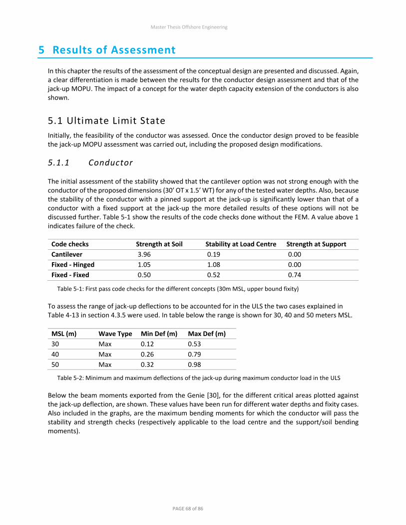
Master Thesis Offshore Engineering
PAGE 68 of 86
5 Results of Assessment
In this chapter the results of the assessment of the conceptual design are presented and discussed. Again, a clear differentiation is made between the results for the conductor design assessment and that of the jack-up MOPU. The impact of a concept for the water depth capacity extension of the conductors is also shown.
5.1 Ultimate Limit State
Initially, the feasibility of the conductor was assessed. Once the conductor design proved to be feasible the jack-up MOPU assessment was carried out, including the proposed design modifications.
5.1.1 Conductor The initial assessment of the stability showed that the cantilever option was not strong enough with the conductor of the proposed dimensions (30’ OT x 1.5’ WT) for any of the tested water depths. Also, because the stability of the conductor with a pinned support at the jack-up is significantly lower than that of a conductor with a fixed support at the jack-up the more detailed results of these options will not be discussed further. Table 5-1 show the results of the code checks done without the FEM. A value above 1 indicates failure of the check.
Code checks Strength at Soil Stability at Load Centre Strength at Support
Cantilever 3.96 0.19 0.00
Fixed - Hinged 1.05 1.08 0.00
Fixed - Fixed 0.50 0.52 0.74
Table 5-1: First pass code checks for the different concepts (30m MSL, upper bound fixity)
To assess the range of jack-up deflections to be accounted for in the ULS the two cases explained in Table 4-13 in section 4.3.5 were used. In table below the range is shown for 30, 40 and 50 meters MSL.
MSL (m) Wave Type Min Def (m) Max Def (m)
30 Max 0.12 0.53
40 Max 0.26 0.79
50 Max 0.32 0.98
Table 5-2: Minimum and maximum deflections of the jack-up during maximum conductor load in the ULS
Below the beam moments exported from the Genie [30], for the different critical areas plotted against the jack-up deflection, are shown. These values have been run for different water depths and fixity cases. Also included in the graphs, are the maximum bending moments for which the conductor will pass the stability and strength checks (respectively applicable to the load centre and the support/soil bending moments).

Master Thesis Offshore Engineering
PAGE 69 of 86
Figure 5-1: Fixed-Fixed, Effective fixity (50m)
Figure 5-2: Fixed-Fixed, Upper bound soil (50m)

Master Thesis Offshore Engineering
PAGE 70 of 86
Figure 5-3: Fixed-Fixed, Lower bound soil (50m)
Figure 5-4: Fixed-Fixed, Upper bound soil (30m)
By the figures above, in addition to those for 30 (of which the upper bound soil scenario is shown in Figure 5-4) & 40 meters MSL, the following observations can be made:
– The deflection of the jack-up has a linear effect on the bending moments in the conductor. – For the cases where the soil is not modelled with an effective fixity, but with a Winkler foundation,
the deflection has a positive effect of the overall maximum bending moment as it reduces the bending moment at the support, while the bending moment at the soil is increased.

Master Thesis Offshore Engineering
PAGE 71 of 86
– The strength check at the soil level only becomes critical w.r.t. the strength check at the support level at an extremely high soil fixity.
– The highest bending moment in the centre of the conductor used for the global buckling check is not critical up to 50 meter MSL regardless of fixity.
– At higher water depths, the impact of the jack-up displacement on the bending moment becomes small. More critical is the fixity of the soil. For the northern sector wave (i.e. MSL>30m) the support does not pass the local buckling check in the lower bound soil. It does however pass the buckling check for all the reasonable displacements with the upper bound soil.
Figure 5-5: Forced deflection of conductor with corresponding beam moments
Figure 5-5 above demonstrates the effect described in the second observation above. Pairs of two conductors (one modelled with an effective fixity and one with an upper bound soil model) are forced to deflect 1 meter opposite the direction of the environmental load and 1 meter in the direction of the environmental load at the jack-up support. The two conductors in the center are modelled without a deflection at the support. It can be observed that deflections in the direction of the environmental load increase the bending moment at the soil, while decreasing the bending moment at the support. In the case that the bending moment at the support is the highest load this effect is beneficial for the maximum bending stress in the conductor.

Master Thesis Offshore Engineering
PAGE 72 of 86
5.1.2 Jack-up MOPU When the strength and stability of the jack-up is investigated, it becomes clear that the bearing capacity of the foundation is a critical element. Other checks that must be performed include:
– Overturning Stability – Preload Capacity – Leg Sliding – Leg Strength – Fixation System Strength – Spudcan Capacity
In practice, some of the checks are similar and are covered by other checks. Preload capacity and leg sliding are both included in the bearing capacity check (Figure 5-6). Spudcan capacity and fixation system strength are both maximum weight constraints where the spudcan capacity is more critical. Leg strength is generally critical at the guides and includes an axial compression factor and bending moment. According to the basis of design [19], the design of the fixation system is based on the maximum compression of 4600 tonnes force per chord. Every leg has 3 chords, which means the axial loading capacity of the fixation system is 137.5 MN per leg. The maximum spudcan reaction capacity is specified in the unit’s operations manual as 56.4 MN. The leg is designed to handle this axial load during an ULS wave, which implies that the same axial force during preloading conditions (i.e. minimal moments) will not be an issue. From this it follows that the maximum preload capacity is limited by the elevated weight in combination with the preload tanks or by the spudcan capacity. When a preload of 55 MN is applied (just under the spudcan capacity), which is equivalent to 5100 te of hull weight per leg (including preload) plus a wet leg weight of ~500 te (accounting for a reduction in leg length), the bearing capacity for a hard sand (ϕ = 35°) is as in Figure 5-6. To achieve this preload, the total elevated weight of the unit must be brought up to 15300 te. As discussed in section 3.4 the weight after conversion will be ~7000 te. 8300 te of preload capacity is therefore required. This capacity can be achieved by converting some of the tanks used for drilling fluids into preload tanks (Table 3-9). ISO 19905-1 also prescribes a resistance factor of 1.10 applicable to preload, which mean that the actual preload will need to be 10% higher than the required amount. This safety factor is also to be used in the bearing capacity curves. The bearing capacity is very dependent on the horizontal force on the unit (i.e. shear force). When all the environmental elements have their respective maximum values for the Dutch North Sea as explained in section 4.1, it becomes clear that the horizontal force is often too high for the bearing capacity. To avoid taking an overly conservative view in this conceptual phase, for this check the 100-year current speed has been reduced to 1.5 & 1.0 m/s for the Southern & Northern sector respectively. Also, the wind area is reduced by one third, to account for the removal of the derrick, leg reserve and accommodation. Note that the footing reactions shown in Figure 5-6 and Figure 5-8 are based on lower bound fixity (sand, ϕ = 35°). Increasing the fixity will decrease the vertical and horizontal loading on the soil. As can be seen in Figure 5-6 the bearing capacity is inadequate for the 55 MN preload case. To at least include all the 30m MSL footing reactions for 35-degree sand, the preload must be increased to 63 MN per leg. This requires a preload capacity of 10700 te, which is 550 te more than the available in current tanks. Since most of the inside of the hull won’t be used, there is no problem expected in adding an additional 550 te (or more) of preload capacity. However, at this point, the spudcan capacity check fails. It is not expected that creating additional loading capacity in the spudcan will be an issue, however, it

Master Thesis Offshore Engineering
PAGE 73 of 86
should be taken into consideration. By increasing the preload, the spudcan penetrates the soil deeper, which increases the load carrying area. It is important for the spudcan to be at least fully seated at the seafloor to provide maximum bearing and fixity (Figure 5-7).
Figure 5-6: V-H bearing capacity.
Figure 5-7: Spudcan outline, partial penetration on hard sand
As the soil gets softer, the bearing capacity is increased. Figure 5-6 show this for 25 & 35-degree sand. Figure 5-8 below shows the V-H bearing capacity of clay. The properties of clay are better suited for bearing capacity, however it is important that there is no risk of punch through.

Master Thesis Offshore Engineering
PAGE 74 of 86
Figure 5-8: V-H Bearing Capacity Clay
A Leg strength check (Table 5-3) on the most critical leg shown in Figure 5-6 confirms that leg strength is not a critical factor in the ULS. Overturning stability becomes an issue when the Fv of one of the legs becomes negative. Figure 5-6 shows that this does not occur in any of the test cases. Overturning stability is therefore not a critical capacity check.
Leg strength Fx [MN] Mz [MN.m]
Critical leg 43.768 280.985
Design value 49.82 298.92
Table 5-3: Leg strength check at lower guide

Master Thesis Offshore Engineering
PAGE 75 of 86
5.2 Fatigue Limit State
In this section the results of the simplified fatigue assessment of the conductor design and the fatigue assessment of the jack-up MOPU, including modifications, are discussed. The jack-up MOPU fatigue assessment has been researched and reported by GustoMSC [39]. Therefore, only a summary of the results is included in this report.
5.2.1 Conductor Only wave induced stress variations have been accounted for in the simplified model. Stresses caused by current and wind are deemed to have an insignificant amount of variations. Jack-up movements caused by wave forces have a small impact on the stresses. However, in the cases where the soil fixation is less stiff then the jack-up fixation, these movements reduce the maximum overall stress variations and would thus be beneficial to the fatigue life of the conductor. Because this is the case for almost all possible soil types, the jack-up movements will not be considered. Because the location of the connector cannot be accurately determined, the fatigue assessment is carried out at the three high stress locations, including: (1) Jack-up fixation; (2) Mudline fixation; and (3) at the midspan elevation. The fatigue life at the jack-up fixation and the mudline can be assessed with the DNV curves in ‘air’. The connectors around the splash zone are assed with the ‘free corrosion’ curves.
Figure 5-9: Fatigue damage for 50m MSL, load centre, DNV ‘free corrosion’ C1 curve, 20-year design life
The fatigue life of the conductor is evaluated for different connector types:
– Standard ONE connectors (SCF = 5), DNV Type B1 S-N curve – GMC Mechanical Connector [18], DNV Type C1 S-N curve (cathodic protection)

Master Thesis Offshore Engineering
PAGE 76 of 86
Figure 5-10: Fatigue life of connectors with different SCFs for upper bound soil
For the simplified fatigue check the design life is shown on the graph for a design fatigue factor (‘DFF’) of 3 and 10. It is clear that the standard ONE connector will not have an adequate fatigue lifetime for the concept at any water depths. The GMC mechanical connector shown much better fatigue resistance with a design life of 100+ years for all assessed water depths.
Figure 5-11: Maximum bending stress caused by 1-year max wave using linear wave theory
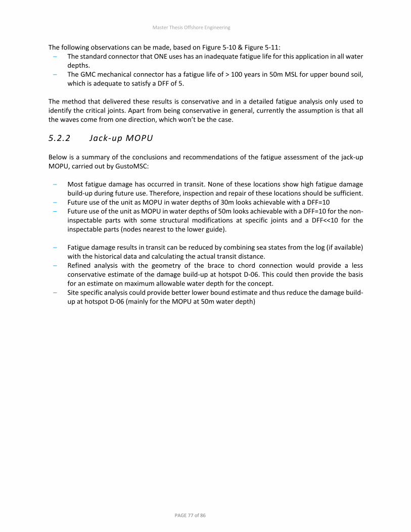
Master Thesis Offshore Engineering
PAGE 77 of 86
The following observations can be made, based on Figure 5-10 & Figure 5-11: – The standard connector that ONE uses has an inadequate fatigue life for this application in all water
depths. – The GMC mechanical connector has a fatigue life of > 100 years in 50m MSL for upper bound soil,
which is adequate to satisfy a DFF of 5.
The method that delivered these results is conservative and in a detailed fatigue analysis only used to identify the critical joints. Apart from being conservative in general, currently the assumption is that all the waves come from one direction, which won’t be the case.
5.2.2 Jack-up MOPU Below is a summary of the conclusions and recommendations of the fatigue assessment of the jack-up MOPU, carried out by GustoMSC:
– Most fatigue damage has occurred in transit. None of these locations show high fatigue damage build-up during future use. Therefore, inspection and repair of these locations should be sufficient.
– Future use of the unit as MOPU in water depths of 30m looks achievable with a DFF=10 – Future use of the unit as MOPU in water depths of 50m looks achievable with a DFF=10 for the non-
inspectable parts with some structural modifications at specific joints and a DFF<<10 for the inspectable parts (nodes nearest to the lower guide).
– Fatigue damage results in transit can be reduced by combining sea states from the log (if available)
with the historical data and calculating the actual transit distance. – Refined analysis with the geometry of the brace to chord connection would provide a less
conservative estimate of the damage build-up at hotspot D-06. This could then provide the basis for an estimate on maximum allowable water depth for the concept.
– Site specific analysis could provide better lower bound estimate and thus reduce the damage build-up at hotspot D-06 (mainly for the MOPU at 50m water depth)

Master Thesis Offshore Engineering
PAGE 78 of 86
5.3 Vortex Induced Vibrations
The conductor is checked for the potential occurrence of VIV by a simplified procedure as given in the DNV recommended practice for environmental loading [22]. The analyses are performed under two conditions:
– Under 1 Year Current Alone – Under 1 Year Wave + 1 Year Associated Current
Results from the screening check for current alone, show that a high current speed is required for the vortex induced vibrations to occur (Figure 5-12). As can be seen in Appendix 3: Metocean Charts Dutch North Sea, the current speed has a correlation with the bathymetry. The current is higher in the shallow areas and lower in the deeper areas. Therefore, it is unlikely that the chosen site will have a strong enough current. If it does it is recommended to account for current induced VIV in the fatigue analysis. Depending on local site data, it is recommended to perform a time-domain assessment of fatigue damage when the 1-year current speeds surpass the critical velocity. For the conceptual analysis, this is applicable for the fixed support case with no marine growth starting at 40m MSL.
Figure 5-12: Critical flow velocity when VIV becomes a concern
According to the screening, VIV may become a problem under the action of large waves + associated current velocity. It is accepted that the theory for the prediction the formation of the VIV under the combined action of wave and current has not yet been fully developed. The procedure as given by in the current recommended practice serves only as screening check. Considering the velocity needed to achieve lock-in is higher than the current flows for all the sites, an additional wave particle velocity will be required to achieve resonance. The lock-in region created by wave induced VIV will be small because of the nature of the decay of the wave particle velocities along the depth profile (i.e. highly sheared flow), see Figure 4-3. The current theory on VIV is that only in the lock-
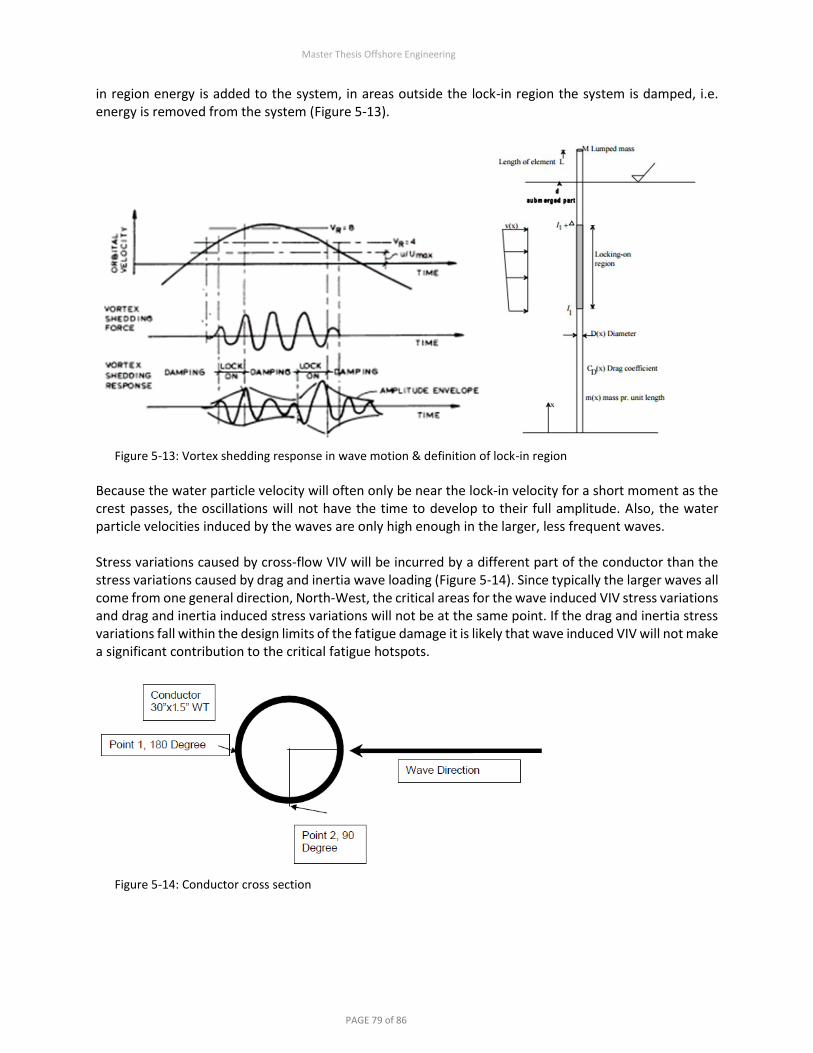
Master Thesis Offshore Engineering
PAGE 79 of 86
in region energy is added to the system, in areas outside the lock-in region the system is damped, i.e. energy is removed from the system (Figure 5-13).
Figure 5-13: Vortex shedding response in wave motion & definition of lock-in region
Because the water particle velocity will often only be near the lock-in velocity for a short moment as the crest passes, the oscillations will not have the time to develop to their full amplitude. Also, the water particle velocities induced by the waves are only high enough in the larger, less frequent waves. Stress variations caused by cross-flow VIV will be incurred by a different part of the conductor than the stress variations caused by drag and inertia wave loading (Figure 5-14). Since typically the larger waves all come from one general direction, North-West, the critical areas for the wave induced VIV stress variations and drag and inertia induced stress variations will not be at the same point. If the drag and inertia stress variations fall within the design limits of the fatigue damage it is likely that wave induced VIV will not make a significant contribution to the critical fatigue hotspots.
Figure 5-14: Conductor cross section

Master Thesis Offshore Engineering
PAGE 80 of 86
5.4 Capacity Extension
To extend the water depth capacity of the concept, a subsea brace, that interconnects the conductors, could be installed. The conductor moments would be reduced by transferring environmental loads into axial loads in the conductor. This concept is a mix between the CSP described in section 3.3 and the jack-up supported conductors. An overview of pros and cons is given in
Pros Cons
Increased water depth capacity for ULS & FLS Relatively complex installation & decommissioning
Smaller portion of the loads transferred to the jack-up
Requires at least 4 conductors to be installed at once
Cheaper than a WHP Additional metocean loads on the system
Table 5-4: Pros & Cons of subsea bracing
The methodology of installation of a subsea brace would be most efficient if the brace initially has the function of subsea template and is lifted to the required height once conductors have been piled. When the brace is at the desired height it should be clamped to the conductor in a way that the loads are effectively transferred. Figure 5-15 below shows the moments and axial stresses in the conductors with a subsea brace compared to the conductors without a subsea brace. Conductor 1 & 4 are modelled with effective fixity for reference. It can be observed that the moments at the support point are significantly lowered which will have a big impact on the local buckling unity checks. A design like this has been used by Unocal in Indonesia in the 1990’s. [40]
Figure 5-15: Subsea brace concept for conductor support

Master Thesis Offshore Engineering
PAGE 81 of 86
6 Conclusions and Recommendations
In this chapter the overall conclusion and those of the different problems are presented. Recommendations are also made for the following stages of the concept design. The conceptual assessment of the MOPU has encompassed a broad spectrum of topics. The design stage identified the conductor support structure to be the most critical design issue. It was important to first decide on conductor design and verify the structural integrity of the support concept before an assessment of overall integrity of the MOPU could be made.
6.1 Initial Feasibility and Design
Analysis of the jack-up market led to the fundamental design choices of focusing on jack-up drilling rigs and specifically on the MSC CJ46 design, which coincidentally, was initially designed in 1981 to be an optimal rig for the NAM fields on the Dutch continental shelf. The various case studies helped identify the different design issues and solutions. Research done on classification has shown this to be largely uncharted territory where the requirements are not yet set in stone. If adequate design is done following relevant recommended practices, then in collaboration with the classification society, operator, and rig designer bespoke requirements (e.g. DFF, surveys) can be formulated. Basic design was carried out for the topsides to estimate the weight and space requirement. It was found that there is ample space and weight capacity available, although CoG must be considered. It is however important that the elevated weight of the hull is not below 7000 tonnes. Risers will be added inside the legs and designed to allow up to half a meter of settlement. Out of the many options for well tie-back, jack-up supported conductors where found to be most suitable to the concept. Foundation issues are very site specific. Increasing the preload capacity will however most likely be required for all locations. Modification of the spudcans to cater to the site-specific conditions is also recommended and possibly required. Cost wise the concept is very competitive and significantly cheaper than platforms with similar capabilities.

Master Thesis Offshore Engineering
PAGE 82 of 86
6.2 Conductor Assessment
For the conductor design it was found that depending on soil conditions the current design of the jack-up supported conductors passes the unity checks for ULS & FLS up to 50m MSL. If the soil is less stiff, the jack-up support should also be made more forgiving as to balance out the maximum stresses. This can be done by increasing the distance between the support points. Doing this will however increase the distance between the inflection points and thus increase the effective length. Nevertheless, it is expected that the optimisation of a site-specific design will be possible up to 50m MSL, regardless of soil conditions. Cross-flow VIV lock-in is not an acceptable occurrence for the conductors and must be avoided. Lock-in will cause the conductors to vibrate with amplitudes in the order of the diameter of the conductor. This will increase the drag coefficient which will in turn make the ULS case more critical. Also, the stress variations caused by the oscillations could be critical for the FLS. VIV could become an issue at water depths of 40 meters or more, according to section 5.3. It is recommended that VIV suppression techniques are employed above 30 meters, to make an allowance for interference between the conductors and wave induced VIV. Alternatively, more detailed study can be done to see if there is room to increase this value. Suppression techniques such as: helical strakes or wires will also effect the drag coefficient and the diameter of the conductor. Since the ULS case has been analysed with the drag coefficient and diameter for marine growth it is plausible that the 50m MSL boundary will still be achievable. This will however need to be confirmed by further analysis. The costs of the concept that are incremental to the standard well costs for a jacket support structure are: a support structure on the jack-up hull, thicker and higher grade conductor steel above the waterline, and high fatigue resistant connectors above the water line. Of these only the former has significant impact. Estimated at ~1 million euros (see section 3.3), this is significantly more economic than a wellhead platform or top tensioned risers. In water deeper than 50m MSL it is recommended that a structure is used to brace the conductors together approximately 10-15m above the mudline. The structure will ensure that a portion of the environmental loads are transferred into axial beam stresses instead of moments. This measure will increase the capacity in the ULS & FLS. At deeper water depths, the amplitude of the quasi-static motions and natural period of the jack-up will increase. The effect of this aspect should be assessed for the ULS case and in a time-domain fatigue analysis.

Master Thesis Offshore Engineering
PAGE 83 of 86
6.3 Jack-up MOPU Assessment
Assessment of the ultimate limit state of the jack-up MOPU show that for bearing capacity of the soil and the spudcan capacity exceed their allowance for in most scenarios. A larger preload will increase the bearing capacity. This will however cause the load on the spudcan to exceed its maximum rated capacity during preloading. Another way to increase the bearing capacity, is by installing a larger or alternatively shaped spudcan. It is unlikely that the bearing capacity check will pass for the site-specific parameters without modifications to the jack-up. In Table 6-1 below measures against bearing capacity over-utilizations are shown.
Solutions for bearing capacity over-utilization
Increase preload – Jack-ups can achieve preload in excess of design value by preloading leg-by-leg or carrying additional ballast and/or variable load.
– If jacking system does not have adequate capacity, the fixation system can be engaged during preloading.
– Generally increased preload will increase penetration and spudcan contact area which is beneficial for fixity, reduced dynamics, etc.
Change variable load or CoG
– Used to combat overloads and/or windward leg sliding issues. – This could be either a fixed or a variable solution. For fixed an analysis would
need to be made on prevailing storm direction and impact. Variable could be employed before incoming heavy weather.
Modify spudcan – Make spudcan buoyant after installation (only on lee legs if sliding also an issue).
– Fit spudcan extension or skirts (or new larger spudcan) to improve bearing capacity and fixity (which improves general over-utilization)
Table 6-1: Measures against bearing capacity over-utilization
Scour is a common issue in shallow water areas. On short drilling jobs, rock dumping and monitoring is
typically used as the solution. However, as a long-term solution this is not satisfactory. The current will
continually cause scour to the spudcan until it is submerged below the mudline. Seabed preparation in
the form of dredging holes for the spudcan to settle into is an option that should be considered. Multiple
benefits could be gained from dredging holes for the spudcans including:
– Increased fixity – Increased bearing capacity – Effective scour mitigation – Potential punch trough risk mitigation

Master Thesis Offshore Engineering
PAGE 84 of 86
6.4 Conclusion
It has been found that with minor modifications to the preload capacity of the jack-up unit, the concept using the jack-up supported conductors is feasible up to 30 meters’ water depth. Beyond 30 meters the initial constraints are: risk of vortex induced vibrations (VIV) of the conductors, the bearing capacity of the jack-up and jack-up fatigue. Initially, mitigation of these issues is straightforward. However, detailed studies will need to be done to verify the effectiveness and further implications of the VIV mitigation measures. Further study on fatigue sensitive areas could increase the design fatigue factor achievable by reducing conservatisms or prompt local joint reinforcement as solution. Between 30 and 50 meters’ water depth mitigation of the constraints becomes increasing costly and technically challenging. Beyond 50 meters’ water depth, jack-up and conductor stability all become critical constraints and major design changes are required. Site-specific parameters will also affect the feasibility. Therefore, the findings above must be validated in a site-specific study. The conclusion of the research has verified that, converting a used jack-up drilling rig into a jack-up mobile offshore production unit is a technically and economically feasible concept for the development of a standalone gas field on the Dutch continental shelf. It has also demonstrated the conductor support design to be a feasible solution for this jack-up MOPU concept. The body of the work can form a basis to initiate detailed engineering and design when the concept is to be implemented.
6.5 Recommendations
During the research, it has become evident that conceptual design for multiple locations is generally conservative. The maximum 100-Year wave conditions found in the Northern and Southern subsector of the Dutch North Sea are higher than those specific to most locations within those blocks. As water depths decline observed wave heights generally also decline. The non-linearity of the shallow water waves causes the force conveyed by the wave particles to be highly concentrated in time. When waves that can be found in 50-meter water depth are modelled in 35 meters, the forces are highly concentrated and nonlinear. Therefore, a conservative view on structural integrity is taken compared to an assessment that uses site specific data. A site-specific assessment is crucial to the design parameters of the concept and must be carried out once the site is known. Once the site and all the site-specific parameters are known a frond-end engineering design (FEED) should be done. In addition to the making the calculations in this report site specific it is recommended to complete the actions below:
– Design conductor fixation structure and assess structural capacity of jack-up hull and cantilever. – Assess limit states for exploration well tie-back conductor if required. – Perform detailed accidental impact assessment & post-accidental impact assessment. – Define and analyse serviceability limit state constraints. – Orientation of the jack-up, depending on nearby shipping lanes and environmental conditions.
Within GustoMSC there is enthusiasm for the concept and they are eager to be partake in the engineering when this is followed up. In correspondence with GustoMSC (rig designer) and the classification society that has classed the rig (ABS for the Paragon C463) a detailed scope of work should be compiled.

Master Thesis Offshore Engineering
PAGE 85 of 86
7 References
[1] Netwas Group, “Chronology Of Submersible Rigs,” [Online]. Available: http://www.netwasgroup.us/.
[2] PetroWiki, “History of offshore drilling units,” [Online]. Available: http://petrowiki.org/.
[3] T. Childs, “Rig Trends: Jackup Market Still Looking For Recovery,” 2015. [Online]. Available: http://www.rigzone.com.
[4] J. Kendall, “Rig Market,” North Sea Reporter, 22 June 2016.
[5] J. Kendall, “Rig Market,” North Sea Reporter, 26 October 2016.
[6] D. Carter Shinn, “Owners still reluctant to recycle old jackups,” [Online]. Available: http://www.bassoe.no/.
[7] J. Beckman, “UK's first abandoned oilfield restored to active service,” [Online]. Available: http://www.offshore-mag.com/.
[8] Offshore Technology, “Volve Oil Field, North Sea, Norway,” [Online]. Available: http://www.offshore-technology.com/.
[9] Xcite Energy Limited, “Annual Report 2013”.
[10] Offshore Energy Today, “KCI Supervises the 6th Installation of Their MPP Concept for Wintershall,” [Online]. Available: http://www.offshoreenergytoday.com/.
[11] Seafox, Interviewee, Seafox 1 at Horizon. [Interview]. 17 August 2016.
[12] Offshore Technology, “Elgin-Franklin Offshore Field, North Sea, United Kingdom,” [Online]. Available: http://www.offshore-technology.com/.
[13] Inernational Association of Classification Societies, “Classification Societies - What, Why and How?”.
[14] ISO 19905-1, “Petroleum and Natural Gas Industries - Site Specific Assessment of Mobile Offshore Units -Part 1: Jack-ups,” 2016.
[15] G. Kudsk and H. Stadsgaard, “Long-term Applications in the ISO Standard for Site Specific Assessment of Mobile Jack-Up Units and the use of Skirted Spudcans,” in OTC 23337, Houston, 2012.
[16] Y. Rajapaksa, K. Chang and P.-L. Tan, “A Classification Society’s Approach and Requirements for Conversion of Mobile Jack-up Units to Site-Specific Production Units,” in OTC 7532, Houston, 1994.
[17] Frames Oil & Gas Processing, “Gas Treatment Equipment,” Alphen aan den Rijn, 2016.
[18] J. Pollack and D. Riggs, “Improved Concentric Thread Connectors for SCRs and Pipelines,” in OTC, Houston, 2011.
[19] MSC, “Overall basic design of a jack-up drilling rig MSC type CJ 46,” 1981.
[20] The Institute of Petroleum, “Guidelines for the Analysis of Jack-up and Fixed Platform Well Conductor Systems,” 2001.
[21] Fugro GEOS LTD, “Additional Metocean Criteria for the North Sea,” Wallingford, 2014.
[22] DNV-RP-C205, “Environmental Conditions and Environmental Loads,” 2007.
[23] KH Engineering, “Generic Structural Basis of Design for Topsides and Modular Jacket,” 2015.
[24] DNV-OS-C101, “Design of Offshore Steel Structures, General (LRFD Method),” 2011.
[25] R. A. Dalrymple, “Stream Function Wave Theory,” [Online]. Available: http://www.coastal.udel.edu/faculty/rad/streamless.html.
[26] SNAME, “Guidelines for Site Specific Assessment of Mobile Jack-Up Units,” 2008.
[27] Marine Structure Consultants, “LegLoad v 5.12,” Schiedam.
Master Thesis Offshore Engineering
PAGE 86 of 86
[28] Fugro Engineers B.V., “Soil Conditions Assessment for Conceptional Pile Foundation Design Dutch Sector, North Sea,” Leidschendam, 2014.
[29] Fugro Engineers B.V., “Geotechnical Engineering Location L9-FF-1,” 1995.
[30] Det Norske Veritas, Sesam User Manual, GeniE Vol. 1.
[31] B. Stahl and M. Baur, “Design Methodology for Offshore Platform Conductors,” in Offshore Technology Conference, Houston, 1980.
[32] G. Lang and B. Wood, “Structural Design, Fabrication, and Installation of Offshore Conductor Pipe,” in Offshore Technology Conference, Houston, 1994.
[33] J. Geyer and B. Stahl, “Load & Resistantce Factor Design of Platform Conductors,” in ASCE Specialty Conference, Berkeley, CA, 1984.
[34] J. Doshi, “The Structural Madness,” 2014. [Online]. Available: http://www.thestructuralmadness.com/2014/03/charlie-chaplin-and-his- buckled-stick.html.
[35] DNV-RP-C203, “Fatigue Design of Offshore Steel Structures,” 2011.
[36] ABS, “Fatigue Assessment of Offshore Structures,” 2014.
[37] T. King Lim, E. Tellier and H. Howells, “Wellhead, Conductor and Casing Fatigue - Causes and Mitigation,” 2012.
[38] DNV-RP-F204, “Riser Fatigue,” 2010.
[39] GustoMSC, “Fatigue Calculations for the Noble CJ46 Units,” Schiedam, 2017.
[40] C. Landeck and F. Gery, “Development, optimization of the stacked template structure,” 1999. [Online]. Available: http://www.offshore-mag.com.
[41] ISO 19901-1, “Petroleum and Natural Gas Industries - Specific Requierments for Offshore Structures - Part 1: Metocean Design and Operating Considerations,” 2015.
[42] IOGP, “Standards and Guidelines for Well Construction and Well Operations,” 2016.

Master Thesis Offshore Engineering
1
8 Appendix

2
8.1 Appendix 1: Omni-Directional 1-year Joint Frequency Distribution
Omni-Directional 1-year Joint Frequency Distribution of Individual Wave Height and Period; Southern Subsector

3
Omni-Directional 1-year Joint Frequency Distribution of Individual Wave Height and Period; Northern Subsector

4
8.2 Appendix 2: Design Drawings of a CJ46 Class Jack-up

5

6

7
8.3 Appendix 3: Metocean Charts Dutch North Sea

8

9
8.4 Appendix 4: Main soil condition Dutch North Sea