Contrast enhancement in visualisation of woven composite architecture using a MicroCT Scanner. Part...
13
Contrast enhancement in visualisation of woven composite tow architecture using a MicroCT Scanner. Part 1: Fabric coating and resin additives Luke P. Djukic a, * , Israel Herszberg b , William R. Walsh c , Gregory A. Schoeppner d , B. Gangadhara Prusty a , Don W. Kelly a a The University of New South Wales, School of Mechanical and Manufacturing Engineering, Sydney, NSW 2052, Australia b Cooperative Research Centre for Advanced Composite Structures Ltd., 506 Lorimer Street, Fishermans Bend, Vic. 3207, Australia c The University of New South Wales, Surgical and Orthopaedic Research Laboratories, Division of Surgery, NSW 2052, Australia d Air Force Research Laboratories, Wright-Patterson Air Force Base, Dayton, OH, USA article info Article history: Received 21 July 2008 Received in revised form 13 December 2008 Accepted 27 December 2008 Keywords: Micro-Computed Tomography A. Fabrics/textiles A. Polymer matrix composites (PMCs) B. Microstructures abstract MicroCT scanning is a non-destructive inspection method which was used to visualise tow architecture in woven composites with the ultimate goal of three-dimensional model generation. This has been achieved in the past for glass fabric composites, but is problematic when applied to carbon fabrics. Using X-rays, it is difficult to discriminate between elements of the composite, particularly the region between co-aligned neighbouring tows. This presents difficulty when viewing such composites using X-ray MicroCT scanning. Additives were used to enhance contrast during scanning. The most successful tech- niques were coating of fabrics with gold, copper, and an iodine contrast agent. Resin particle additive techniques were also trialled, with limited success. Good visualisations of glass fabrics were possible without contrast enhancement. Three-dimensional reconstructions of interior tow architectures were then made from the scans of contrast enhanced specimens. This research can be viewed as a starting point in developing methods for generating contrast between neighbouring tows within a three-dimen- sional woven preform using MicroCT scanning. Ó 2009 Elsevier Ltd. All rights reserved. 1. Introduction Composite structures manufactured from three-dimensional woven preforms have improved through-thickness properties compared to those manufactured from unidirectional lamina; however, their in-plane properties are reduced [1]. In order to model the mechanical properties and failure of such structures it is essential to determine the tow architecture, and in particular any local deformations due to the interaction of adjacent tows dur- ing compaction [2]. In-situ tow visualisation has been achieved in the past by a labour intensive serial sectioning technique [3]. Images of the specimen edge are obtained using an Optical or Scan- ning Electron Microscope. Progressive removal of a small depth of edge material allows the production of a series of section images which can be reconstructed to display the tow architectures. Mi- cro-Computed Tomography (MicroCT) is an alternative method to this process. It has the benefit of being non-destructive and allows a large amount of the internal geometry to be determined with a single scan. Internal cross-sections are visualised, which in turn al- lows the reconstruction of three-dimensional volumes. The pur- pose of this study was to investigate tow architecture within woven carbon composites, whilst preserving deformations which would generally result from consolidation under pressure during manufacture, and hence preserve the final tow architectures. In the MicroCT scanning process contrast is generated based on differences in X-ray attenuation of materials, which is related to density [4]. Internal cross-sectional visualisations and three- dimensional models of the sample can then be generated from the point cloud data. This method has been used previously on woven glass-fibre composites to investigate dimensional variabil- ity of tow architecture [5], and to generate three-dimensional visualisations [6,7]. Additionally, the technique has been used to investigate microcracking in carbon-fibre and glass-fibre compos- ites [7], and for determining material composition based on den- sity difference [8]. When used on carbon composites it is difficult to discriminate between tow and resin interfaces due to the in- fused carbon-fibres and resins have similar densities. It is even more difficult to discriminate between different tows at contact- ing interfaces, particularly if the fibres in the respective tows are aligned in the same direction. Thus, there is a need for contrast enhancement. This is the first paper in a two part series. In this investigation, scans were performed on regular carbon-fibre composites for the purpose of benchmarking. A broad evaluation of existing X-ray contrast enhancement techniques was made. These methods were 1359-835X/$ - see front matter Ó 2009 Elsevier Ltd. All rights reserved. doi:10.1016/j.compositesa.2008.12.016 * Corresponding author. Tel.: +61 2 9385 5127. E-mail address: [email protected] (L.P. Djukic). Composites: Part A 40 (2009) 553–565 Contents lists available at ScienceDirect Composites: Part A journal homepage: www.elsevier.com/locate/compositesa
Transcript of Contrast enhancement in visualisation of woven composite architecture using a MicroCT Scanner. Part...

Composites: Part A 40 (2009) 553–565
Contents lists available at ScienceDirect
Composites: Part A
journal homepage: www.elsevier .com/locate /composi tesa
Contrast enhancement in visualisation of woven composite tow architectureusing a MicroCT Scanner. Part 1: Fabric coating and resin additives
Luke P. Djukic a,*, Israel Herszberg b, William R. Walsh c, Gregory A. Schoeppner d, B. Gangadhara Prusty a,Don W. Kelly a
a The University of New South Wales, School of Mechanical and Manufacturing Engineering, Sydney, NSW 2052, Australiab Cooperative Research Centre for Advanced Composite Structures Ltd., 506 Lorimer Street, Fishermans Bend, Vic. 3207, Australiac The University of New South Wales, Surgical and Orthopaedic Research Laboratories, Division of Surgery, NSW 2052, Australiad Air Force Research Laboratories, Wright-Patterson Air Force Base, Dayton, OH, USA
a r t i c l e i n f o
Article history:Received 21 July 2008Received in revised form 13 December 2008Accepted 27 December 2008
Keywords:Micro-Computed TomographyA. Fabrics/textilesA. Polymer matrix composites (PMCs)B. Microstructures
1359-835X/$ - see front matter � 2009 Elsevier Ltd. Adoi:10.1016/j.compositesa.2008.12.016
* Corresponding author. Tel.: +61 2 9385 5127.E-mail address: [email protected] (L.P
a b s t r a c t
MicroCT scanning is a non-destructive inspection method which was used to visualise tow architecture inwoven composites with the ultimate goal of three-dimensional model generation. This has been achievedin the past for glass fabric composites, but is problematic when applied to carbon fabrics. Using X-rays, itis difficult to discriminate between elements of the composite, particularly the region betweenco-aligned neighbouring tows. This presents difficulty when viewing such composites using X-rayMicroCT scanning. Additives were used to enhance contrast during scanning. The most successful tech-niques were coating of fabrics with gold, copper, and an iodine contrast agent. Resin particle additivetechniques were also trialled, with limited success. Good visualisations of glass fabrics were possiblewithout contrast enhancement. Three-dimensional reconstructions of interior tow architectures werethen made from the scans of contrast enhanced specimens. This research can be viewed as a startingpoint in developing methods for generating contrast between neighbouring tows within a three-dimen-sional woven preform using MicroCT scanning.
� 2009 Elsevier Ltd. All rights reserved.
1. Introduction
Composite structures manufactured from three-dimensionalwoven preforms have improved through-thickness propertiescompared to those manufactured from unidirectional lamina;however, their in-plane properties are reduced [1]. In order tomodel the mechanical properties and failure of such structures itis essential to determine the tow architecture, and in particularany local deformations due to the interaction of adjacent tows dur-ing compaction [2]. In-situ tow visualisation has been achieved inthe past by a labour intensive serial sectioning technique [3].Images of the specimen edge are obtained using an Optical or Scan-ning Electron Microscope. Progressive removal of a small depth ofedge material allows the production of a series of section imageswhich can be reconstructed to display the tow architectures. Mi-cro-Computed Tomography (MicroCT) is an alternative method tothis process. It has the benefit of being non-destructive and allowsa large amount of the internal geometry to be determined with asingle scan. Internal cross-sections are visualised, which in turn al-lows the reconstruction of three-dimensional volumes. The pur-pose of this study was to investigate tow architecture within
ll rights reserved.
. Djukic).
woven carbon composites, whilst preserving deformations whichwould generally result from consolidation under pressure duringmanufacture, and hence preserve the final tow architectures.
In the MicroCT scanning process contrast is generated basedon differences in X-ray attenuation of materials, which is relatedto density [4]. Internal cross-sectional visualisations and three-dimensional models of the sample can then be generated fromthe point cloud data. This method has been used previously onwoven glass-fibre composites to investigate dimensional variabil-ity of tow architecture [5], and to generate three-dimensionalvisualisations [6,7]. Additionally, the technique has been used toinvestigate microcracking in carbon-fibre and glass-fibre compos-ites [7], and for determining material composition based on den-sity difference [8]. When used on carbon composites it is difficultto discriminate between tow and resin interfaces due to the in-fused carbon-fibres and resins have similar densities. It is evenmore difficult to discriminate between different tows at contact-ing interfaces, particularly if the fibres in the respective tows arealigned in the same direction. Thus, there is a need for contrastenhancement.
This is the first paper in a two part series. In this investigation,scans were performed on regular carbon-fibre composites for thepurpose of benchmarking. A broad evaluation of existing X-raycontrast enhancement techniques was made. These methods were
554 L.P. Djukic et al. / Composites: Part A 40 (2009) 553–565
adapted to suit the role of enhancing the visualisation of tows incarbon-fibre composites, and were applied in the form of fabriccoatings and resin additives. Techniques common in the field ofclinical and medical sciences have been investigated, includinggold [9], iodine, gadolinium [10], and barium [11]. Barium sulphateis also used as a radiopaque additive for in-vivo imaging of bonecement [12]. In addition, tow dimensions in the various sampleswere measured in order to quantify the effect of enhancementtreatment on consolidated geometries. Modified carbon-fibre com-posites were also compared visually to unmodified glass-fibrecomposites. The second paper will discuss further developmentof some of the methods described in this paper, applied to pre-forms and tows prior to weaving, in order to improve the visualisa-tion quality [13].
Sample manufacturing techniques are discussed, followed by theresults of cross-sectional and three-dimensional reconstructions.
2. Specimen manufacture
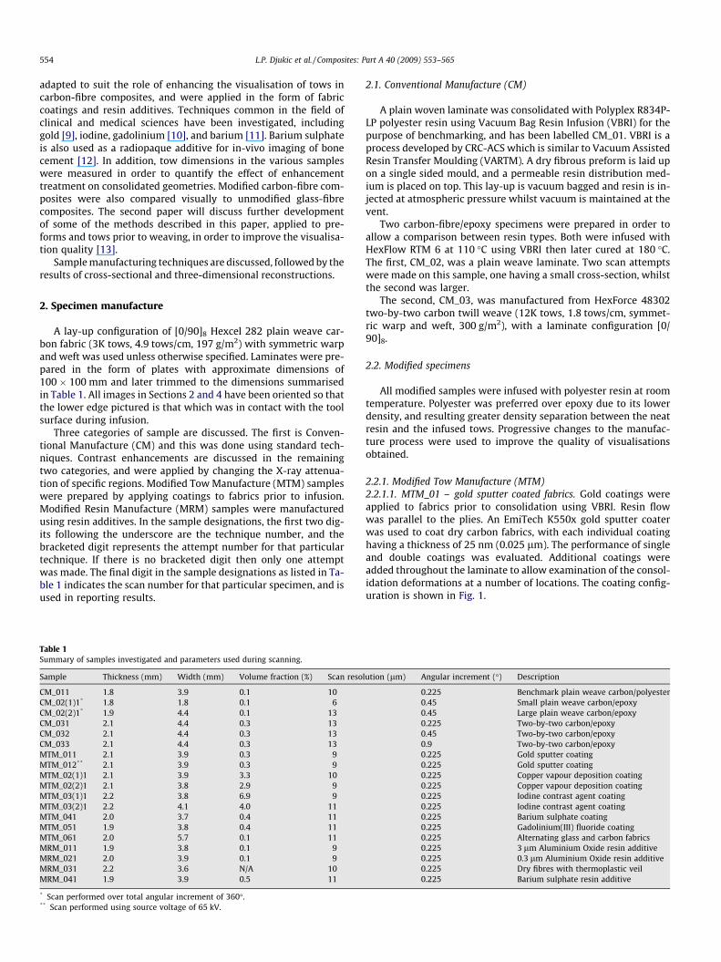
A lay-up configuration of [0/90]8 Hexcel 282 plain weave car-bon fabric (3K tows, 4.9 tows/cm, 197 g/m2) with symmetric warpand weft was used unless otherwise specified. Laminates were pre-pared in the form of plates with approximate dimensions of100 � 100 mm and later trimmed to the dimensions summarisedin Table 1. All images in Sections 2 and 4 have been oriented so thatthe lower edge pictured is that which was in contact with the toolsurface during infusion.
Three categories of sample are discussed. The first is Conven-tional Manufacture (CM) and this was done using standard tech-niques. Contrast enhancements are discussed in the remainingtwo categories, and were applied by changing the X-ray attenua-tion of specific regions. Modified Tow Manufacture (MTM) sampleswere prepared by applying coatings to fabrics prior to infusion.Modified Resin Manufacture (MRM) samples were manufacturedusing resin additives. In the sample designations, the first two dig-its following the underscore are the technique number, and thebracketed digit represents the attempt number for that particulartechnique. If there is no bracketed digit then only one attemptwas made. The final digit in the sample designations as listed in Ta-ble 1 indicates the scan number for that particular specimen, and isused in reporting results.
Table 1Summary of samples investigated and parameters used during scanning.
Sample Thickness (mm) Width (mm) Volume fraction (%) Scan reso
CM_011 1.8 3.9 0.1 10CM_02(1)1* 1.8 1.8 0.1 6CM_02(2)1* 1.9 4.4 0.1 13CM_031 2.1 4.4 0.3 13CM_032 2.1 4.4 0.3 13CM_033 2.1 4.4 0.3 13MTM_011 2.1 3.9 0.3 9MTM_012** 2.1 3.9 0.3 9MTM_02(1)1 2.1 3.9 3.3 10MTM_02(2)1 2.1 3.8 2.9 9MTM_03(1)1 2.2 3.8 6.9 9MTM_03(2)1 2.2 4.1 4.0 11MTM_041 2.0 3.7 0.4 11MTM_051 1.9 3.8 0.4 11MTM_061 2.0 5.7 0.1 11MRM_011 1.9 3.8 0.1 9MRM_021 2.0 3.9 0.1 9MRM_031 2.2 3.6 N/A 10MRM_041 1.9 3.9 0.5 11
* Scan performed over total angular increment of 360�.** Scan performed using source voltage of 65 kV.
2.1. Conventional Manufacture (CM)
A plain woven laminate was consolidated with Polyplex R834P-LP polyester resin using Vacuum Bag Resin Infusion (VBRI) for thepurpose of benchmarking, and has been labelled CM_01. VBRI is aprocess developed by CRC-ACS which is similar to Vacuum AssistedResin Transfer Moulding (VARTM). A dry fibrous preform is laid upon a single sided mould, and a permeable resin distribution med-ium is placed on top. This lay-up is vacuum bagged and resin is in-jected at atmospheric pressure whilst vacuum is maintained at thevent.
Two carbon-fibre/epoxy specimens were prepared in order toallow a comparison between resin types. Both were infused withHexFlow RTM 6 at 110 �C using VBRI then later cured at 180 �C.The first, CM_02, was a plain weave laminate. Two scan attemptswere made on this sample, one having a small cross-section, whilstthe second was larger.
The second, CM_03, was manufactured from HexForce 48302two-by-two carbon twill weave (12K tows, 1.8 tows/cm, symmet-ric warp and weft, 300 g/m2), with a laminate configuration [0/90]8.
2.2. Modified specimens
All modified samples were infused with polyester resin at roomtemperature. Polyester was preferred over epoxy due to its lowerdensity, and resulting greater density separation between the neatresin and the infused tows. Progressive changes to the manufac-ture process were used to improve the quality of visualisationsobtained.
2.2.1. Modified Tow Manufacture (MTM)2.2.1.1. MTM_01 – gold sputter coated fabrics. Gold coatings wereapplied to fabrics prior to consolidation using VBRI. Resin flowwas parallel to the plies. An EmiTech K550x gold sputter coaterwas used to coat dry carbon fabrics, with each individual coatinghaving a thickness of 25 nm (0.025 lm). The performance of singleand double coatings was evaluated. Additional coatings wereadded throughout the laminate to allow examination of the consol-idation deformations at a number of locations. The coating config-uration is shown in Fig. 1.
lution (lm) Angular increment (�) Description
0.225 Benchmark plain weave carbon/polyester0.45 Small plain weave carbon/epoxy0.45 Large plain weave carbon/epoxy0.225 Two-by-two carbon/epoxy0.45 Two-by-two carbon/epoxy0.9 Two-by-two carbon/epoxy0.225 Gold sputter coating0.225 Gold sputter coating0.225 Copper vapour deposition coating0.225 Copper vapour deposition coating0.225 Iodine contrast agent coating0.225 Iodine contrast agent coating0.225 Barium sulphate coating0.225 Gadolinium(III) fluoride coating0.225 Alternating glass and carbon fabrics0.225 3 lm Aluminium Oxide resin additive0.225 0.3 lm Aluminium Oxide resin additive0.225 Dry fibres with thermoplastic veil0.225 Barium sulphate resin additive
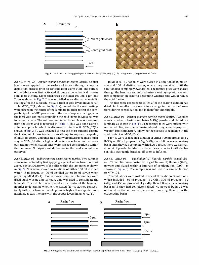
25nm gold coats
50nm gold coats
Resin flow
Tool
Fig. 1. Laminate containing gold sputter coated plies (MTM_01): (a) ply configuration; (b) gold coated fabric.
L.P. Djukic et al. / Composites: Part A 40 (2009) 553–565 555
2.2.1.2. MTM_02 – copper vapour deposition coated fabrics. Copperlayers were applied to the surface of fabrics through a vapourdeposition process prior to consolidation using VBRI. The surfaceof the fabrics was first activated through a non-chemical processsimilar to etching. Layer thicknesses included 0.5 lm, 1 lm and2 lm as shown in Fig. 2. This was trialled as an alternative metalliccoating after the successful visualisation of gold layers in MTM_01.
In MTM_02(1), shown in Fig. 2(a), two of the thickest coatingswere placed in the centre of the laminate in order to test the com-patibility of the VBRI process with the use of copper coatings, afterthe local void content surrounding the gold layers in MTM_01 wasfound to increase. The void content for each sample was measuredfrom the scans and is reported in Table 1. This was done using avolume approach, which is discussed in Section 6. MTM_02(2),shown in Fig. 2(b), was designed to test the most suitable coatingthickness out of those trialled. In an attempt to improve the qualityof infusion, coated and uncoated plies were interleaved in a similarway to MTM_01 after a high void content was found in the previ-ous attempt when coated plies were stacked consecutively withinthe laminate. No significant difference in the void content wasobserved.
2.2.1.3. MTM_03 – iodine contrast agent coated fabrics. Two sampleswere manufactured by first applying layers of iodine based contrastagent, Isovue 370, to two of the plies within the laminates as shownin Fig. 3. Plies were soaked in solutions of either 100 ml distilledwater: 15 ml Isovue, or 100 ml distilled water: 30 ml Isovue, whenpreparing MTM_03(1). Upon removal from the solution they weredried quickly using a hot air gun. VBRI was used to consolidate thelaminate. Treated plies were placed at the centre of the laminatein order to determine whether the coated fabrics stacked consecu-tively within the laminate would promote higher than expected voidfractions, as was the case with the copper layers in MTM_02(1).
2 µm
Resin flow
Fig. 2. Configurations of laminates with copper vapour dep
In MTM_03(2), two plies were placed in a solution of 15 ml Iso-vue and 100 ml distilled water, where they remained until thesolution had completely evaporated. The treated plies were spacedthrough the laminate and infused using a wet lay-up with vacuumbag compaction in order to determine whether this would reducethe void fraction.
The plies were observed to stiffen after the coating solution haddried. Such an effect may result in a change in the tow deforma-tions during consolidation and is therefore undesirable.
2.2.1.4. MTM_04 – barium sulphate particle coated fabrics. Two plieswere coated with barium sulphate (BaSO4) powder and placed in alaminate as shown in Fig. 4(a). The treated plies were spaced withuntreated plies, and the laminate infused using a wet lay-up withvacuum bag compaction, following the successful reduction in thevoid content of MTM_03(2).
Fabrics were soaked in a solution of either 100 ml propanol: 5 gBaSO4, or 100 ml propanol: 2.5 g BaSO4, then left on an evaporatingbasin until they had completely dried. As a result, there was a smallamount of powder build-up on the surfaces in contact with the ba-sin. This was gently brushed off prior to infusion.
2.2.1.5. MTM_05 – gadolinium(III) fluoride particle coated fab-rics. Three plies were coated with gadolinium(III) fluoride (GdF3)powder and placed within a laminate of configuration [0/90]7 asshown in Fig. 4(b). The sample was infused in a similar fashionto MTM_04.
Treated fabrics were soaked in one of three different solutions,which included 150 ml propanol: 1 g GdF3, 300 ml propanol: 1 gGdF3, and 450 ml propanol: 1 g GdF3, then left on an evaporatingbasin until they had completely dried. No powder build-up wasobserved on the surface of plies upon removing them from theevaporating basin.
2µm
0.5µm
Resin flow
1µm
osition coated plies: (a) MTM_02(1); (b) MTM_02(2).
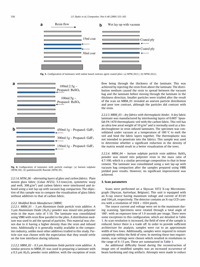
30ml coat
Resin flow
15ml coat Coated ply
Coated ply
Wet lay-up with vacuum
Fig. 3. Configuration of laminates with iodine based contrast agent coated plies: (a) MTM_03(1); (b) MTM_03(2).
450ml:1g – Propanol: GdF3
300ml:1g – Propanol: GdF3
150ml:1g – Propanol: GdF3
100ml:5g – Propanol: BaSO4
100ml:2.5g – Propanol: BaSO4
Fig. 4. Configuration of laminates with particle coatings: (a) barium sulphate(MTM_04); (b) gadolinium(III) fluoride (MTM_05).
556 L.P. Djukic et al. / Composites: Part A 40 (2009) 553–565
2.2.1.6. MTM_06 – alternating layers of glass and carbon fabrics. Plainwoven glass fabric (Colan AF252, 5.5 tows/cm, symmetric warpand weft, 308 g/m2) and carbon fabrics were interleaved and in-fused using a wet lay-up with vacuum bag compaction. The objec-tive of this sample was to compare the visualisation of glass fabricwithout additives to that of carbon fabric.
2.2.2. Modified Resin Manufacture (MRM)2.2.2.1. MRM_01 – 3 lm Aluminium Oxide particle resin additive. A3 lm Aluminium Oxide (Al2O3) powder was mixed into polyesterresin in the mass ratio of 1:10. The laminate was consolidatedusing VBRI with resin flow parallel to the plies. A distribution med-ium was used to aid the spread of particles. This material was cho-sen due to it having a higher density than the resin and infusedtows. Additionally it is generally readily available in the compos-ites industry, unlike most other additives trialled in this study. Par-ticle size was chosen with the expectation that they would settleon the tow interfaces during infusion.
2.2.2.2. MRM_02 – 0.3 lm Aluminium Oxide particle resin additive. Asimilar process to MRM_01 was used in preparing a laminate witha 0.3 lm Al2O3 powder resin additive, with the exception of resin
flow being through the thickness of the laminate. This wasachieved by injecting the resin from above the laminate. The distri-bution medium caused the resin to spread between the vacuumbag and the laminate before moving through the laminate in thethickness direction. Smaller particles were trialled after the resultof the scan on MRM_01 revealed an uneven particle distributionand poor tow contrast, although the particles did contrast withthe resin.
2.2.2.3. MRM_03 – dry fabrics with thermoplastic binder. A dry fabriclaminate was manufactured by interleaving layers of 0.00500 Spun-fab PA 1470 thermoplastic veil with the carbon fabric. This veil hasan ultra low areal weight of 10 g/m2 and is normally used as a bin-der/toughener in resin infused laminates. The specimen was con-solidated under vacuum at a temperature of 180 �C to melt theveil and bind the fabric layers together. The thermoplastic wasnot intended to penetrate into the fabrics. This sample was usedto determine whether a significant reduction in the density ofthe matrix would result in a better visualisation of the tows.
2.2.2.4. MRM_04 – barium sulphate particle resin additive. BaSO4
powder was mixed into polyester resin in the mass ratio of4.7:100, which is a similar percentage composition to that in bonecement. The laminate was consolidated using a wet lay-up withvacuum bag compaction after the samples prepared using VBRIyielded poor results. However, no significant improvement wasachieved.
3. Scan parameters
Scans were performed on a Skyscan 1072 X-ray Microtomo-graph (Skyscan, Aartselaar, Belgium). This unit is equipped withan X-ray source having maximum voltage and current of 83 kVand 104 lA, respectively. The detector contains an X-ray CCD cam-era with a resolution of 1024 � 1024 pixels.
The source current and voltage were set to the maximum dur-ing scanning. Specimens were rotated through a total angle of180�, with an exposure time of 1.9 seconds per image. There weresome exceptions to this configuration, which are detailed in Table1. As scan resolution is increased, the field of view of the sample isreduced, hence there is a trade off. In order to provide sufficientarchitecture for analysis, samples were cut to an approximatewidth of two tows. Additionally, samples were required to remaincompletely within the field of view. In meeting these two require-ments, scan settings were chosen which resulted in resolutions inthe range of 6–13 lm. These are summarised in Table 1.
An additional difficulty found during the reconstruction ofimage sets of modified samples was an increased occurrence ofbeam hardening and ring artifacts. Attempts were made to reduce

Fig. 5. Cross-sectional images of plain weave carbon/polyester benchmark (CM_01): (a) consolidation deformations; (b) region with poor contrast.
L.P. Djukic et al. / Composites: Part A 40 (2009) 553–565 557
the associated effects on images through correction algorithmscontained in NRecon (SkyScan), which is the program used in thereconstruction of images. Artifacts appear as features or character-istics of a sample, but are purely products of the CT process. Theydo not represent an actual physical feature of the sample. CT pro-cess artifacts are discussed in greater detail elsewhere [8,14].
4. Results
4.1. Conventional manufacture
4.1.1. CM_01 – benchmark carbon-fibre/polyesterThe difficulties in scanning of carbon-fibre composites will be
explained with reference to Fig. 5. The tows and their respectivedeformations are clearly visible in Fig. 5(a). There is, however,some difficulty in performing the binary image thresholding [15]necessary to automate creation of three-dimensional reconstruc-tions. This point will be given further explanation in Section 6.
Tows oriented across the page appear marginally lighter thanthose oriented out of the page. The interfaces between tows and re-sin rich areas are identifiable. However, when the tows are in con-tact, particularly if they are oriented in the same direction, thevisibility of the interface is greatly reduced, as shown in Fig. 5(b).This is the major concern in this study of contrast enhancement.
4.1.2. CM_02 – carbon/epoxy plain weaveSimilar visualisations were obtained when using epoxy and
polyester resins as shown in Fig. 6. The resulting contrast fromthe scan on the smaller cross-section is better than that of thelarge, as is seen when comparing Fig. 6(a) to (b).
Fig. 6. Cross-sectional images of plain weave carbon/epoxy: (a) small
The larger specimen shown in Fig. 6(b) has a reduced brightnessat the corners. This is the effect of beam hardening artifact. Beamhardening is typically characterised by a change in X-ray attenua-tion within a region of the sample, where there is not necessarily achange in density. Two materials of different density appear tohave an intermediate density between them. Thus, the corners ofthe sample appear to have a density between that of the surround-ing air and the composite.
4.1.3. CM_03 – carbon/epoxy twill weaveThe effect of angular increment during rotation on contrast was
determined by performing three scans on the same sample. A totalrotation of 180� was used, with angular increments of 0.23�, 0.45�,and 0.9�. The same cross-sectional location has been selected fromeach dataset and is shown in Fig. 7. Smaller angular increments re-sult in a clearer indication of tow direction; however, this comes atthe expense of longer scan and reconstruction times. Tow direc-tions can be seen in Fig. 7(a) and (b). It is difficult to determinethe direction of tows in Fig. 7(c) where the scan was taken at0.9� increments. The white spots appearing in the images are pre-sumed to be high density microscopic dust particles, which wereattracted to the dry fabric before infusion. Dark circles representvoids.
4.2. Modified manufacture
4.2.1. Modified tow manufacture4.2.1.1. MTM_01 – gold sputter coated fabrics. Two scans were per-formed on MTM_01 with all parameters in image acquisition andreconstruction being the same with the exception of accelerating
cross-section (CM_02(1)1); (b) large cross-section (CM_02(2)1).
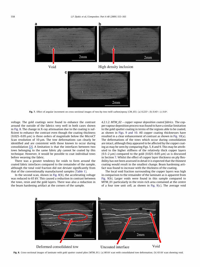
Fig. 7. Effect of angular increment on cross-sectional images of two-by-two twill carbon/epoxy (CM_03): (a) 0.225�; (b) 0.45�; (c) 0.9�.
558 L.P. Djukic et al. / Composites: Part A 40 (2009) 553–565
voltage. The gold coatings were found to enhance the contrastaround the outside of the fabrics very well in both cases shownin Fig. 8. The change in X-ray attenuation due to the coating is suf-ficient to enhance the contrast even though the coating thickness(0.025–0.05 lm) is three orders of magnitude below the MicroCTScan resolution of 10 lm. The tow deformations can clearly beidentified and are consistent with those known to occur duringconsolidation [2]. A limitation is that the interfaces between twotows belonging to the same fabric ply cannot be coated by thistechnique. However, it would be possible to coat individual towsbefore weaving the fabric.
There was a greater tendency for voids to form around thecoated fabric interfaces compared to the remainder of the sample,although the total void fraction did not deviate significantly fromthat of the conventionally manufactured samples (Table 1).
In the second scan, shown in Fig. 8(b), the accelerating voltagewas reduced to 65 kV. This caused a reduction in contrast betweenthe tows, resin and the gold layers. There was also a reduction inthe beam hardening artifact at the corners of the sample.
Fig. 8. Cross-sectional images of laminate with gold sputter coated plies (MTM_01):
4.2.1.2. MTM_02 – copper vapour deposition coated fabrics. The cop-per vapour deposition process was found to have a similar limitationto the gold sputter coating in terms of the regions able to be coated,as shown in Figs. 9 and 10. All copper coating thicknesses haveresulted in a clear enhancement of contrast as shown in Fig. 10(a).The deformations of the tows which occur during consolidationare intact, although they appeared to be affected by the copper coat-ing as may be seen by comparing Figs. 5, 8 and 9. This may be attrib-uted to the higher stiffness of the relatively thick copper layers(0.5–2 lm) compared to the gold (0.025–0.05 lm) as is discussedin Section 7. Whilst the effect of copper layer thickness on ply flex-ibility has not been assessed in detail it is expected that the thinnestcoating would result in the smallest change. Beam hardening arti-fact was found to increase with the thickness of the coating.
The local void fraction surrounding the copper layers was highin comparison to the remainder of the laminate as is apparent fromFig. 9(b). Larger voids were found in this sample compared toMTM_01 particularly in the resin rich area contained at the centreof a four tow unit cell, as shown in Fig. 9(c). The average void
(a) 80 kV scan with consolidated tow deformation; (b) 65 kV scan showing void.
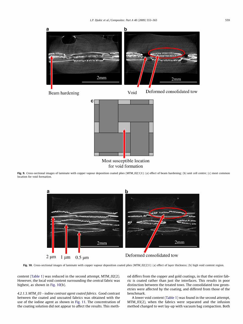
Fig. 9. Cross-sectional images of laminate with copper vapour deposition coated plies (MTM_02(1)1): (a) effect of beam hardening; (b) unit cell centre; (c) most commonlocation for void formation.
Fig. 10. Cross-sectional images of laminate with copper vapour deposition coated plies (MTM_02(2)1): (a) effect of layer thickness; (b) high void content region.
L.P. Djukic et al. / Composites: Part A 40 (2009) 553–565 559
content (Table 1) was reduced in the second attempt, MTM_02(2).However, the local void content surrounding the central fabric washighest, as shown in Fig. 10(b).
4.2.1.3. MTM_03 – iodine contrast agent coated fabrics. Good contrastbetween the coated and uncoated fabrics was obtained with theuse of the iodine agent as shown in Fig. 11. The concentration ofthe coating solution did not appear to affect the results. This meth-
od differs from the copper and gold coatings, in that the entire fab-ric is coated rather than just the interfaces. This results in poordistinction between the treated tows. The consolidated tow geom-etries were affected by the coating, and differed from those of thebenchmark.
A lower void content (Table 1) was found in the second attempt,MTM_03(2), when the fabrics were separated and the infusionmethod changed to wet lay-up with vacuum bag compaction. Both
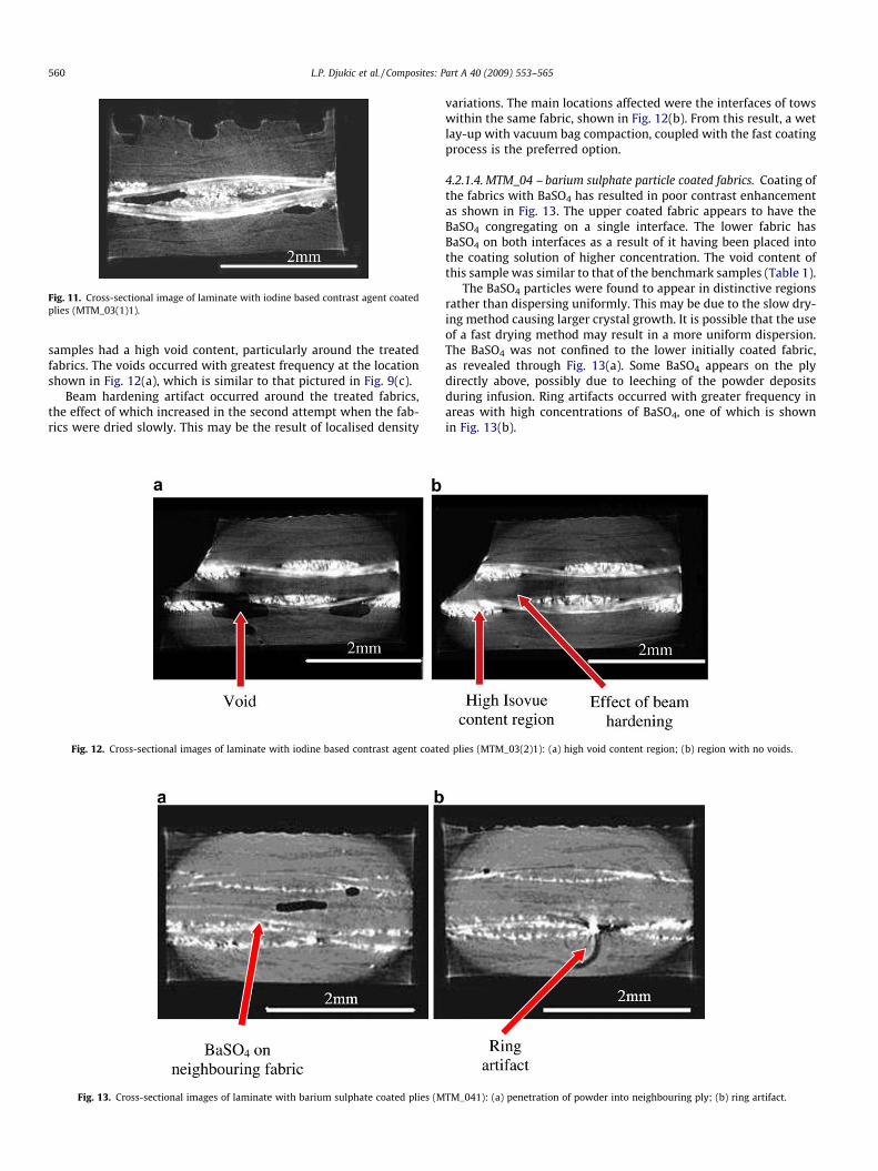
Fig. 11. Cross-sectional image of laminate with iodine based contrast agent coatedplies (MTM_03(1)1).
560 L.P. Djukic et al. / Composites: Part A 40 (2009) 553–565
samples had a high void content, particularly around the treatedfabrics. The voids occurred with greatest frequency at the locationshown in Fig. 12(a), which is similar to that pictured in Fig. 9(c).
Beam hardening artifact occurred around the treated fabrics,the effect of which increased in the second attempt when the fab-rics were dried slowly. This may be the result of localised density
Fig. 12. Cross-sectional images of laminate with iodine based contrast agent coate
Fig. 13. Cross-sectional images of laminate with barium sulphate coated plies (M
variations. The main locations affected were the interfaces of towswithin the same fabric, shown in Fig. 12(b). From this result, a wetlay-up with vacuum bag compaction, coupled with the fast coatingprocess is the preferred option.
4.2.1.4. MTM_04 – barium sulphate particle coated fabrics. Coating ofthe fabrics with BaSO4 has resulted in poor contrast enhancementas shown in Fig. 13. The upper coated fabric appears to have theBaSO4 congregating on a single interface. The lower fabric hasBaSO4 on both interfaces as a result of it having been placed intothe coating solution of higher concentration. The void content ofthis sample was similar to that of the benchmark samples (Table 1).
The BaSO4 particles were found to appear in distinctive regionsrather than dispersing uniformly. This may be due to the slow dry-ing method causing larger crystal growth. It is possible that the useof a fast drying method may result in a more uniform dispersion.The BaSO4 was not confined to the lower initially coated fabric,as revealed through Fig. 13(a). Some BaSO4 appears on the plydirectly above, possibly due to leeching of the powder depositsduring infusion. Ring artifacts occurred with greater frequency inareas with high concentrations of BaSO4, one of which is shownin Fig. 13(b).
d plies (MTM_03(2)1): (a) high void content region; (b) region with no voids.
TM_041): (a) penetration of powder into neighbouring ply; (b) ring artifact.

Fig. 14. Cross-sectional images of laminate with gadolinium(III) fluoride coated plies (MTM_051): (a) high artifact area; (b) low artifact area.
Fig. 16. Cross-sectional image of laminate infused with polyester resin containing3 lm Aluminium Oxide additive (MRM_011).
L.P. Djukic et al. / Composites: Part A 40 (2009) 553–565 561
4.2.1.5. MTM_05 – gadolinium(III) fluoride particle coated fab-rics. Coating of the fabrics with GdF3 results in poor contrastenhancement, as shown in Fig. 14. The concentration of the coatingsolution had little effect on the visualisation. Similarly to the BaSO4
on the upper fabric in MTM_04, the GdF3 particles have settledonto a single surface and are confined to the plies that were ini-tially coated. The coated surface alternates between that closestto and that furthest from the tool during the infusion. It is likelythat the coated fabric surface was that in contact with the basingduring drying, although this was not visible as stated in Section2.2.1.5.
From a visualisation perspective, the GdF3 has similar appear-ance to high density inclusions found in conventionally manufac-tured specimens. This resulted in some locations having a highfrequency of ring artifacts, such as that pictured in Fig. 14(a).
4.2.1.6. MTM_06 – alternating layers of glass and carbon fabrics. Glassfabrics were found to contrast well with the carbon fabrics and theresin rich areas without the use of additives, as shown in Fig. 15.This is due to the greater difference in density between the glassand polyester, compared to carbon and polyester.
4.2.2. Modified Resin Manufacture4.2.2.1. MRM_01 – 3 lm Aluminium Oxide particle resin additive. It isdifficult to determine the tow orientation in the specimen contain-ing 3 lm Al2O3 resin additive shown in Fig. 16, and the resultingcontrast is poor. The particles have settled on some of the towinterfaces, although these locations are not consistent throughoutthe specimen. Settling locations may have been affected by thedirection of infusion, which was parallel to the plies. Very littleof the powder was found within the tows. The void content forall infused MRM samples was similar to that of the conventionallymanufactured specimens (Table 1).
Fig. 15. Cross-sectional image laminate composed of alternating layers of glass andcarbon fabrics (MTM_061).
4.2.2.2. MRM_02 – 0.3 lm Aluminium Oxide particle resin additive. A0.3 lm Al2O3 powder resin additive was used in an attempt to im-prove upon the result of MRM_01. The particle distribution is moreuniform than that of the 3 lm powder, albeit there is still someinconsistency as shown in Fig. 17. The finer powder allows somepenetration into the tows, which effectively decreases the contrastbetween the resin and tows. The primary settling location is stillthe tow surfaces.
4.2.2.3. MRM_03 – dry fabrics with thermoplastic binder. The dry car-bon fabric was found to contrast well with air as shown in Fig. 18.This is the greatest difference considered possible in the resin andtow density. No clear distinction between the thermoplastic binderand tows can be made. The scattering of X-rays at the corners andinside of the sample has reduced the clarity of the visualisation.
Fig. 17. Cross-sectional image of laminate infused with polyester resin containing0.3 lm Aluminium Oxide additive (MRM_021).
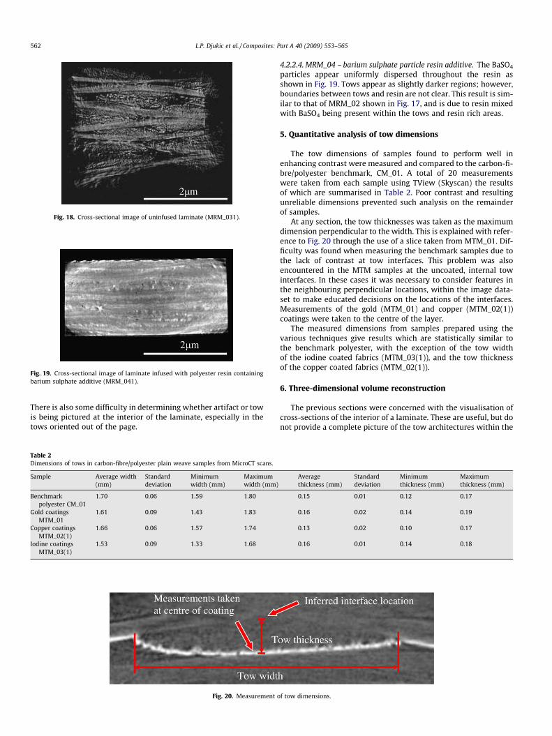
Fig. 18. Cross-sectional image of uninfused laminate (MRM_031).
Fig. 19. Cross-sectional image of laminate infused with polyester resin containingbarium sulphate additive (MRM_041).
562 L.P. Djukic et al. / Composites: Part A 40 (2009) 553–565
There is also some difficulty in determining whether artifact or towis being pictured at the interior of the laminate, especially in thetows oriented out of the page.
Table 2Dimensions of tows in carbon-fibre/polyester plain weave samples from MicroCT scans.
Sample Average width(mm)
Standarddeviation
Minimumwidth (mm)
Maximumwidth (mm)
Benchmarkpolyester CM_01
1.70 0.06 1.59 1.80
Gold coatingsMTM_01
1.61 0.09 1.43 1.83
Copper coatingsMTM_02(1)
1.66 0.06 1.57 1.74
Iodine coatingsMTM_03(1)
1.53 0.09 1.33 1.68
Fig. 20. Measurement o
4.2.2.4. MRM_04 – barium sulphate particle resin additive. The BaSO4
particles appear uniformly dispersed throughout the resin asshown in Fig. 19. Tows appear as slightly darker regions; however,boundaries between tows and resin are not clear. This result is sim-ilar to that of MRM_02 shown in Fig. 17, and is due to resin mixedwith BaSO4 being present within the tows and resin rich areas.
5. Quantitative analysis of tow dimensions
The tow dimensions of samples found to perform well inenhancing contrast were measured and compared to the carbon-fi-bre/polyester benchmark, CM_01. A total of 20 measurementswere taken from each sample using TView (Skyscan) the resultsof which are summarised in Table 2. Poor contrast and resultingunreliable dimensions prevented such analysis on the remainderof samples.
At any section, the tow thicknesses was taken as the maximumdimension perpendicular to the width. This is explained with refer-ence to Fig. 20 through the use of a slice taken from MTM_01. Dif-ficulty was found when measuring the benchmark samples due tothe lack of contrast at tow interfaces. This problem was alsoencountered in the MTM samples at the uncoated, internal towinterfaces. In these cases it was necessary to consider features inthe neighbouring perpendicular locations, within the image data-set to make educated decisions on the locations of the interfaces.Measurements of the gold (MTM_01) and copper (MTM_02(1))coatings were taken to the centre of the layer.
The measured dimensions from samples prepared using thevarious techniques give results which are statistically similar tothe benchmark polyester, with the exception of the tow widthof the iodine coated fabrics (MTM_03(1)), and the tow thicknessof the copper coated fabrics (MTM_02(1)).
6. Three-dimensional volume reconstruction
The previous sections were concerned with the visualisation ofcross-sections of the interior of a laminate. These are useful, but donot provide a complete picture of the tow architectures within the
Averagethickness (mm)
Standarddeviation
Minimumthickness (mm)
Maximumthickness (mm)
0.15 0.01 0.12 0.17
0.16 0.02 0.14 0.19
0.13 0.02 0.10 0.17
0.16 0.01 0.14 0.18
f tow dimensions.
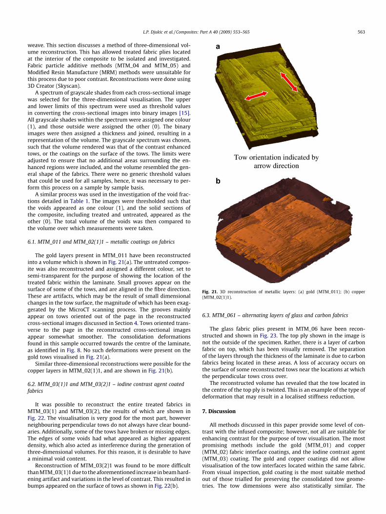
Fig. 21. 3D reconstruction of metallic layers: (a) gold (MTM_011); (b) copper(MTM_02(1)1).
L.P. Djukic et al. / Composites: Part A 40 (2009) 553–565 563
weave. This section discusses a method of three-dimensional vol-ume reconstruction. This has allowed treated fabric plies locatedat the interior of the composite to be isolated and investigated.Fabric particle additive methods (MTM_04 and MTM_05) andModified Resin Manufacture (MRM) methods were unsuitable forthis process due to poor contrast. Reconstructions were done using3D Creator (Skyscan).
A spectrum of grayscale shades from each cross-sectional imagewas selected for the three-dimensional visualisation. The upperand lower limits of this spectrum were used as threshold valuesin converting the cross-sectional images into binary images [15].All grayscale shades within the spectrum were assigned one colour(1), and those outside were assigned the other (0). The binaryimages were then assigned a thickness and joined, resulting in arepresentation of the volume. The grayscale spectrum was chosen,such that the volume rendered was that of the contrast enhancedtows, or the coatings on the surface of the tows. The limits wereadjusted to ensure that no additional areas surrounding the en-hanced regions were included, and the volume resembled the gen-eral shape of the fabrics. There were no generic threshold valuesthat could be used for all samples, hence, it was necessary to per-form this process on a sample by sample basis.
A similar process was used in the investigation of the void frac-tions detailed in Table 1. The images were thresholded such thatthe voids appeared as one colour (1), and the solid sections ofthe composite, including treated and untreated, appeared as theother (0). The total volume of the voids was then compared tothe volume over which measurements were taken.
6.1. MTM_011 and MTM_02(1)1 – metallic coatings on fabrics
The gold layers present in MTM_011 have been reconstructedinto a volume which is shown in Fig. 21(a). The untreated compos-ite was also reconstructed and assigned a different colour, set tosemi-transparent for the purpose of showing the location of thetreated fabric within the laminate. Small grooves appear on thesurface of some of the tows, and are aligned in the fibre direction.These are artifacts, which may be the result of small dimensionalchanges in the tow surface, the magnitude of which has been exag-gerated by the MicroCT scanning process. The grooves mainlyappear on tows oriented out of the page in the reconstructedcross-sectional images discussed in Section 4. Tows oriented trans-verse to the page in the reconstructed cross-sectional imagesappear somewhat smoother. The consolidation deformationsfound in this sample occurred towards the centre of the laminate,as identified in Fig. 8. No such deformations were present on thegold tows visualised in Fig. 21(a).
Similar three-dimensional reconstructions were possible for thecopper layers in MTM_02(1)1, and are shown in Fig. 21(b).
6.2. MTM_03(1)1 and MTM_03(2)1 – iodine contrast agent coatedfabrics
It was possible to reconstruct the entire treated fabrics inMTM_03(1) and MTM_03(2), the results of which are shown inFig. 22. The visualisation is very good for the most part, howeverneighbouring perpendicular tows do not always have clear bound-aries. Additionally, some of the tows have broken or missing edges.The edges of some voids had what appeared as higher apparentdensity, which also acted as interference during the generation ofthree-dimensional volumes. For this reason, it is desirable to havea minimal void content.
Reconstruction of MTM_03(2)1 was found to be more difficultthan MTM_03(1)1 due to the aforementioned increase in beam hard-ening artifact and variations in the level of contrast. This resulted inbumps appeared on the surface of tows as shown in Fig. 22(b).
6.3. MTM_061 – alternating layers of glass and carbon fabrics
The glass fabric plies present in MTM_06 have been recon-structed and shown in Fig. 23. The top ply shown in the image isnot the outside of the specimen. Rather, there is a layer of carbonfabric on top, which has been visually removed. The separationof the layers through the thickness of the laminate is due to carbonfabrics being located in these areas. A loss of accuracy occurs onthe surface of some reconstructed tows near the locations at whichthe perpendicular tows cross over.
The reconstructed volume has revealed that the tow located inthe centre of the top ply is twisted. This is an example of the type ofdeformation that may result in a localised stiffness reduction.
7. Discussion
All methods discussed in this paper provide some level of con-trast with the infused composite; however, not all are suitable forenhancing contrast for the purpose of tow visualisation. The mostpromising methods include the gold (MTM_01) and copper(MTM_02) fabric interface coatings, and the iodine contrast agent(MTM_03) coating. The gold and copper coatings did not allowvisualisation of the tow interfaces located within the same fabric.From visual inspection, gold coating is the most suitable methodout of those trialled for preserving the consolidated tow geome-tries. The tow dimensions were also statistically similar. The

Fig. 22. 3D reconstruction of laminates with iodine based contrast agent coated plies (MTM_03): (a) MTM_03(1)1; (b) MTM_03(2)1.
Fig. 23. 3D reconstruction of glass plies from MTM_061.
564 L.P. Djukic et al. / Composites: Part A 40 (2009) 553–565
average thickness of the copper coated tows differed marginallyfrom that of the benchmark (Table 2), and there was some devia-tion from the consolidated shapes. The iodine contrast agent coat-ing was different from the gold and copper coatings, in that itallowed both the interior and exterior of the treated fabrics to bevisualised. Fast drying resulted in a more uniform coating thanthe slow evaporation method. The reduction in the flexibility ofthe fabric after coating resulted in some differences in consolidatedtow shapes and average widths compared to the benchmark. Therewas also poor distinction of tow interfaces within the same fabricbecause the tows were coated in the same solution. Visualisationsof glass fabrics (MTM_06) were possible without the use of addi-tives, and were comparable to those obtained from carbon fabricswith contrast enhancements applied.
An increase in the void fractions (Table 1) of the composites di-rectly surrounding the treated fabrics was caused by gold, copperand iodine coatings. The total void fraction of the composite withgold sputter coatings did not deviate significantly from that ofthe benchmark. The copper coatings (0.5–2 lm) were substantiallythicker than the gold coatings (0.025–0.05 lm) and resulted in thesamples having a higher total void fraction. No differentiation be-tween the effect of copper layer thicknesses was observed. Theiodine coatings also caused an increase in the total void fraction.There was no significant difference in the void content due to thethrough thickness spacing of copper coated layers. However, therewas a drop in the void content for the second attempt at using
iodine contrast agent. This may be a result of infusion via wetlay-up with vacuum bag compaction allowing greater control overplacement of resin, and gradual wetting out of plies. Spacing theplies through the thickness of the laminate may also have contrib-uted to the lower void fraction. In general, the change in void frac-tion surrounding the coated plies is thought to be the result ofreduced allowable resin flow through the fabric. The coatings ap-plied to the fabrics result in a change to the surface tension ofthe tows, which may have also affected the void content.
The BaSO4 (MTM_04) and GdF3 (MTM_05) fabric coating meth-ods were deemed unsuccessful in enhancing contrast. However, ifthe surface of the fibres were to be activated prior to coating withthe powder, then the method may prove to be successful. The Mod-ified Resin Manufacture techniques were also unsuccessful. Theuse of larger particles settling on tow interfaces is thought to showsome promise, although greater control over particle settling loca-tions is required.
All reconstructions required consideration of artifacts of the CTprocess, such as ring and beam hardening. Beam hardening at theinterior of the samples was the main artifact which needed to beaccounted for, and occurred due to the difference in density be-tween additives and the surrounding composite. Hardening arti-facts at the corners of the samples were less of a problem sincethe architectures of interest were generally located at the centreof the laminates. The thin, uniform gold layers present inMTM_01 were found most suitable for allowing hardening correc-tion whilst maintaining contrast.
It is possible to adapt the methods of fabric coating which havebeen discussed for use with three-dimensional preforms. However,if applied in their current form, it is likely that similar shortcom-ings will be seen, namely it is difficult to generate contrast attow interfaces not exposed during application of the coating. Onesolution is to coat the tows prior to weaving, allowing the internaltow interfaces visualised. The benefits of the tow visualisationmethods will be seen through a better understanding of the towarchitecture within two-dimensional fabrics and three-dimen-sional preforms. A greater understanding of deformation and fail-ure characteristics of structures made with these materials isalso expected.
8. Conclusions
MicroCT scanning is a useful method for non-destructive testingand characterisation of materials. It was found that in order toapply this technique effectively to an investigation of the towarchitecture in carbon-fibre/polyester and carbon-fibre/epoxy
L.P. Djukic et al. / Composites: Part A 40 (2009) 553–565 565
composites, it is first necessary to improve the contrast betweenelements of the composite, particularly the region betweenco-aligned neighbouring tows. This was achieved using modifiedsample manufacture techniques in which plain weave fabrics werecoated with higher density materials prior to consolidation of thelaminate. Particle resin additive methods were also attempted,but with little success. The methods which were seen as mosteffective included coating of the fabrics prior to infusion with gold,copper, and an iodine contrast agent. Although visualisations wereimproved, difficulties were encountered in differentiating the towsat their interfaces, where the tows were contained within the samefabric ply. These methods were improved in the second part of thisinvestigation, reported in paper 2, in which coating methods wereapplied to the tows prior to weaving [13]. Cross-sectional imagesand subsequent three-dimensional reconstructions of the fabricarchitecture have been generated. Visualisation of glass fabricswas also attempted, and it was possible to do this without theuse of additives. This work can be viewed as a starting point indeveloping methods for generating contrast between neighbouringtows within a three-dimensional woven preform using MicroCT asa tool.
Acknowledgements
This work was supported by the AFOSR/AOARD Grant AOARD-07-4003 ‘‘Enhancement of tow visualisation in 3-D woven compos-ites”, program manager, Dr. J.P. Singh. Grateful acknowledgementis also given to Rod Sweeting, Wayne Hillier, Michael Marelli,Ben Qi and Van Bui from CRC-ACS Bankstown for assisting in sam-ple preparation. Jenny Norman from UNSW and Owen Wayman,Sydney South West Private Hospital are acknowledged for helpfuldiscussions in radiographic methods. John Pettitt from the RegionalHealth Care Group is acknowledged for providing the Isovue 370samples.
References
[1] Mouritz AP, Bannister M, Falzon PJ, Leong KH. Review of applications foradvanced three-dimensional fibre textile composites. Composites A1999;30:1445–61.
[2] Saunders RA, Lekakou C, Bader MG. Compression and microstructure of fibreplain woven cloths in the processing of polymer composites. Compos A ApplSci Manuf 1998;29(4):443–54.
[3] Bannister M, Herszberg I, Nicolaidis A, Coman F, Leong KH. The manufacture ofglass/epoxy composites with multilayer woven architectures. Composites A1998;29:293–300.
[4] Stock SR. X-ray microtomography of materials. Int Mater Rev 1999;44(4):141–64.
[5] Desplentere F, Lomov SV, Woerdeman DL, Verpoest I, Wevers M, BogdanovichA. Micro-CT characterization of variability in 3D textile architecture. ComposSci Technol 2005;65:1920–30.
[6] Schell JSU, Renggli M, van Lenthe GH, Muller R, Ermanni P. Micro-computedtomography determination of glass-fibre reinforced polymer meso-structure.Compos Sci Technol 2006;66:2016–22.
[7] Schilling PJ, Karelda BR, Tatiparthi AK, Verges MA, Herrington PD. X-raycomputed microtomography of internal damage in fibre reinforced polymermaterials. Compos Sci Technol 2005;65:2071–8.
[8] Remeysen K, Swennen R. Beam hardening artifact reduction in microfocuscomputed tomography for improved quantitative coal characterization. Int JCoal Geol 2006;67:101–11.
[9] Hainfeld JF, Slatkin DN, Smilowitz HM. The use of gold nanoparticles toenhance radiotherapy in mice. Phys Med Biol 2004;49:N309–15.
[10] Ruth C, Joseph PM. A comparison of beam-hardening artifacts in X-raycomputerized tomography with gadolinium and iodine contrast agents. MedPhys 1995;22(12):1977–82.
[11] Low RN, Francis IR. MR imaging of the gastrointestinal tract with IVgadolinium and diluted barium oral contrast media compared withunenhanced mr imaging and CT. AJR 1997;169:1051–9.
[12] Keen CE, Philip G, Brady K, Spencer JD, Levison DA. Histopathological andmicroanalytical study of zirconium dioxide and barium sulphate in bonecement. J Clin Pathol 1992;45:984–9.
[13] Djukic LP, Herszberg I, Walsh WR, Schoeppner GA, Prusty BG. Contrastenhancement in visualisation of woven composite architecture using aMicroCT Scanner. Part 2: tow and preform coating. Composites A, underreview.
[14] Sijbers J, Postnov A. Reduction of ring artefacts in high resolution micro-CTreconstructions. Phys Med Biol 2004;49:N247–53.
[15] Shapiro LG, Stockman GC. Computer vision. Upper Saddle River (NJ): Prentice-Hall; 2001.