Contents Top - GATE and UPSC exam materials
100
288 A Textbook of Machine Design p b . Fig. 9.9. Double riveted double strap (equal) butt joints. Fig. 9.10. Double riveted double strap (unequal) butt joint with zig-zag riveting. 9.10 Important Terms Used in Riveted Joints The following terms in connection with the riveted joints are important from the subject point of view : 1. Pitch. It is the distance from the centre of one rivet to the centre of the next rivet measured parallel to the seam as shown in Fig. 9.6. It is usually denoted by p. 2. Back pitch. It is the perpendicular distance between the centre lines of the successive rows as shown in Fig. 9.6. It is usually denoted by p b . 3. Diagonal pitch. It is the distance between the centres of the rivets in adjacent rows of zig-zag riveted joint as shown in Fig. 9.6. It is usually denoted by p d . 4. Margin or marginal pitch. It is the distance between the centre of rivet hole to the nearest edge of the plate as shown in Fig. 9.6. It is usually denoted by m.
-
Upload
khangminh22 -
Category
Documents
-
view
0 -
download
0
Transcript of Contents Top - GATE and UPSC exam materials

288 A Textbook of Machine Design
pb.
Fig. 9.9. Double riveted double strap (equal) butt joints.
Fig. 9.10. Double riveted double strap (unequal) butt joint with zig-zag riveting.
9.10 Important Terms Used in Riveted JointsThe following terms in connection with the riveted joints are important from the subject point
of view :1. Pitch. It is the distance from the centre of one rivet to the centre of the next rivet measured
parallel to the seam as shown in Fig. 9.6. It is usually denoted by p.2. Back pitch. It is the perpendicular distance between the centre lines of the successive rows
as shown in Fig. 9.6. It is usually denoted by pb.
3. Diagonal pitch. It is the distance between the centres of the rivets in adjacent rows of zig-zagriveted joint as shown in Fig. 9.6. It is usually denoted by pd.
4. Margin or marginal pitch. It is the distance between the centre of rivet hole to the nearestedge of the plate as shown in Fig. 9.6. It is usually denoted by m.
Riveted Joints 289
Fig. 9.11. Triple riveted double strap (unequal) butt joint.
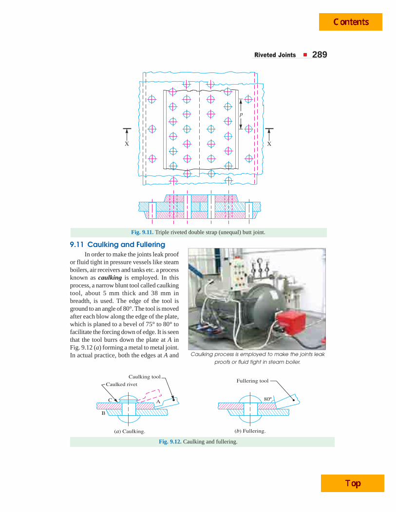
9.11 Caulking and FulleringIn order to make the joints leak proof
or fluid tight in pressure vessels like steamboilers, air receivers and tanks etc. a processknown as caulking is employed. In thisprocess, a narrow blunt tool called caulkingtool, about 5 mm thick and 38 mm inbreadth, is used. The edge of the tool isground to an angle of 80°. The tool is movedafter each blow along the edge of the plate,which is planed to a bevel of 75° to 80° tofacilitate the forcing down of edge. It is seenthat the tool burrs down the plate at A inFig. 9.12 (a) forming a metal to metal joint.In actual practice, both the edges at A and
Caulking tool
Caulked rivet
C A
B
( ) Caulking.a ( ) Fullering.b
80º
Fullering tool
Fig. 9.12. Caulking and fullering.
Caulking process is employed to make the joints leak
proofs or fluid tight in steam boiler.
290 A Textbook of Machine Design
B are caulked. The head of the rivets as shown at C are also turned down with a caulking tool to makea joint steam tight. A great care is taken to prevent injury to the plate below the tool.
A more satisfactory way of making the joints staunch is known as fullering which has largelysuperseded caulking. In this case, a fullering tool with a thickness at the end equal to that of the plateis used in such a way that the greatest pressure due to the blows occur near the joint, giving a cleanfinish, with less risk of damaging the plate. A fullering process is shown in Fig. 9.12 (b).
9.12 Failures of a Riveted JointA riveted joint may fail in the following ways :
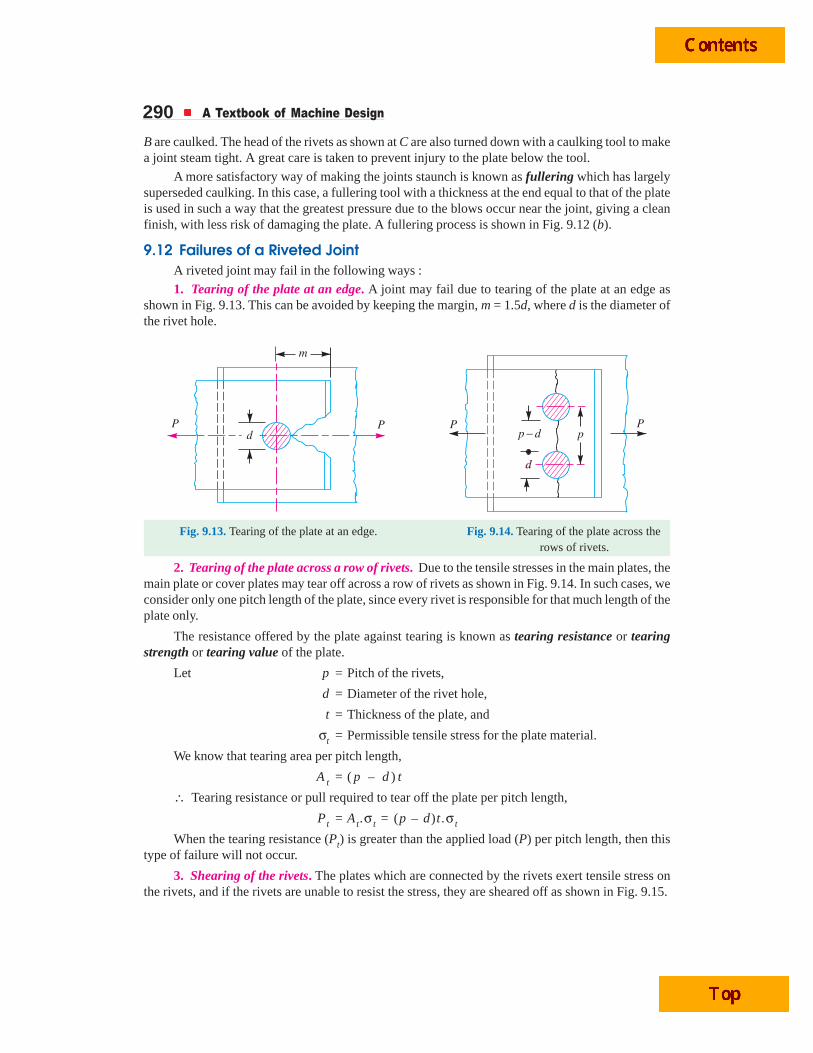
1. Tearing of the plate at an edge. A joint may fail due to tearing of the plate at an edge asshown in Fig. 9.13. This can be avoided by keeping the margin, m = 1.5d, where d is the diameter ofthe rivet hole.
p d�
d
m
P PP Ppd
Fig. 9.13. Tearing of the plate at an edge. Fig. 9.14. Tearing of the plate across the rows of rivets.
2. Tearing of the plate across a row of rivets. Due to the tensile stresses in the main plates, themain plate or cover plates may tear off across a row of rivets as shown in Fig. 9.14. In such cases, weconsider only one pitch length of the plate, since every rivet is responsible for that much length of theplate only.
The resistance offered by the plate against tearing is known as tearing resistance or tearingstrength or tearing value of the plate.
Let p = Pitch of the rivets,
d = Diameter of the rivet hole,
t = Thickness of the plate, and
σt = Permissible tensile stress for the plate material.
We know that tearing area per pitch length,
A t = ( p – d ) t
∴ Tearing resistance or pull required to tear off the plate per pitch length,
Pt = At.σ t = (p – d)t .σ t
When the tearing resistance (Pt) is greater than the applied load (P) per pitch length, then thistype of failure will not occur.
3. Shearing of the rivets. The plates which are connected by the rivets exert tensile stress onthe rivets, and if the rivets are unable to resist the stress, they are sheared off as shown in Fig. 9.15.
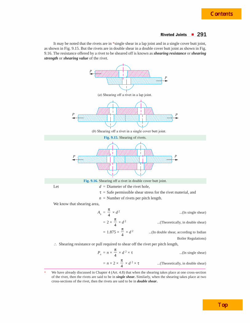
Riveted Joints 291It may be noted that the rivets are in *single shear in a lap joint and in a single cover butt joint,
as shown in Fig. 9.15. But the rivets are in double shear in a double cover butt joint as shown in Fig.9.16. The resistance offered by a rivet to be sheared off is known as shearing resistance or shearingstrength or shearing value of the rivet.
Fig. 9.15. Shearing of rivets.
Fig. 9.16. Shearing off a rivet in double cover butt joint.
Let d = Diameter of the rivet hole,
τ = Safe permissible shear stress for the rivet material, and
n = Number of rivets per pitch length.
We know that shearing area,
As =4
π × d 2 ...(In single shear)
= 2 × 4
π × d 2 ...(Theoretically, in double shear)
= 1.875 × 4
π × d 2 ...(In double shear, according to Indian
Boiler Regulations)
∴ Shearing resistance or pull required to shear off the rivet per pitch length,
Ps = n × 4
π × d 2 × τ ...(In single shear)
= n × 2 × 4
π × d 2 × τ ...(Theoretically, in double shear)
* We have already discussed in Chapter 4 (Art. 4.8) that when the shearing takes place at one cross-sectionof the rivet, then the rivets are said to be in single shear. Similarly, when the shearing takes place at twocross-sections of the rivet, then the rivets are said to be in double shear.
292 A Textbook of Machine Design
= n × 1.875 × 4
π × d2 × τ ...(In double shear, according to Indian
Boiler Regulations)
When the shearing resistance (Ps) is greater than the applied load (P) per pitch length, then thistype of failure will occur.
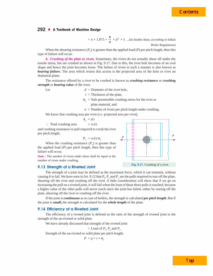
4. Crushing of the plate or rivets. Sometimes, the rivets do not actually shear off under thetensile stress, but are crushed as shown in Fig. 9.17. Due to this, the rivet hole becomes of an ovalshape and hence the joint becomes loose. The failure of rivets in such a manner is also known asbearing failure. The area which resists this action is the projected area of the hole or rivet ondiametral plane.
The resistance offered by a rivet to be crushed is known as crushing resistance or crushingstrength or bearing value of the rivet.
Let d = Diameter of the rivet hole,
t = Thickness of the plate,
σc = Safe permissible crushing stress for the rivet or
plate material, and
n = Number of rivets per pitch length under crushing.
We know that crushing area per rivet (i.e. projected area per rivet),
Ac = d.t
∴ Total crushing area = n.d.t
and crushing resistance or pull required to crush the rivetper pitch length,
Pc = n.d.t.σc
When the crushing resistance (Pc) is greater thanthe applied load (P) per pitch length, then this type offailure will occur.Note : The number of rivets under shear shall be equal to thenumber of rivets under crushing.
9.13 Strength of a Riveted JointThe strength of a joint may be defined as the maximum force, which it can transmit, without
causing it to fail. We have seen in Art. 9.12 that Pt, Ps and Pc are the pulls required to tear off the plate,shearing off the rivet and crushing off the rivet. A little consideration will show that if we go onincreasing the pull on a riveted joint, it will fail when the least of these three pulls is reached, becausea higher value of the other pulls will never reach since the joint has failed, either by tearing off theplate, shearing off the rivet or crushing off the rivet.
If the joint is continuous as in case of boilers, the strength is calculated per pitch length. But ifthe joint is small, the strength is calculated for the whole length of the plate.
9.14 Efficiency of a Riveted JointThe efficiency of a riveted joint is defined as the ratio of the strength of riveted joint to the
strength of the un-riveted or solid plate.
We have already discussed that strength of the riveted joint
= Least of Pt, Ps and Pc
Strength of the un-riveted or solid plate per pitch length,
P = p × t × σt
PP
Fig. 9.17. Crushing of a rivet.
Riveted Joints 293∴ Efficiency of the riveted joint,
η =Least of , andt s c
t
P P P
p t× × σwhere p = Pitch of the rivets,
t = Thickness of the plate, and
σt = Permissible tensile stress of the plate material.
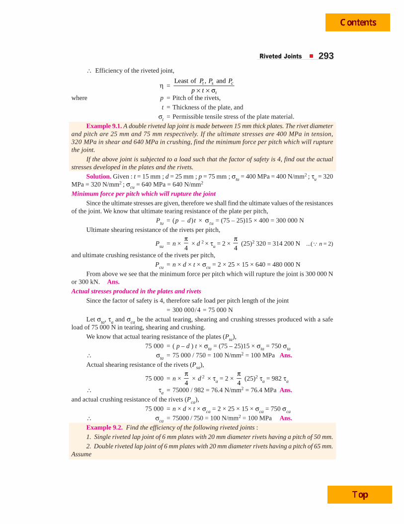
Example 9.1. A double riveted lap joint is made between 15 mm thick plates. The rivet diameterand pitch are 25 mm and 75 mm respectively. If the ultimate stresses are 400 MPa in tension,320 MPa in shear and 640 MPa in crushing, find the minimum force per pitch which will rupturethe joint.
If the above joint is subjected to a load such that the factor of safety is 4, find out the actualstresses developed in the plates and the rivets.
Solution. Given : t = 15 mm ; d = 25 mm ; p = 75 mm ; σtu = 400 MPa = 400 N/mm2 ; τu = 320MPa = 320 N/mm2 ; σcu = 640 MPa = 640 N/mm2
Minimum force per pitch which will rupture the jointSince the ultimate stresses are given, therefore we shall find the ultimate values of the resistances
of the joint. We know that ultimate tearing resistance of the plate per pitch,
Ptu = (p – d) t × σ tu = (75 – 25)15 × 400 = 300 000 N
Ultimate shearing resistance of the rivets per pitch,
Psu = n × 4
π × d 2 × τu = 2 ×
4
π (25)2 320 = 314 200 N ...(Q n = 2)
and ultimate crushing resistance of the rivets per pitch,
Pcu = n × d × t × σcu = 2 × 25 × 15 × 640 = 480 000 N
From above we see that the minimum force per pitch which will rupture the joint is 300 000 Nor 300 kN. Ans.Actual stresses produced in the plates and rivets
Since the factor of safety is 4, therefore safe load per pitch length of the joint
= 300 000/4 = 75 000 N
Let σta, τa and σca be the actual tearing, shearing and crushing stresses produced with a safeload of 75 000 N in tearing, shearing and crushing.
We know that actual tearing resistance of the plates (Pta),
75 000 = ( p – d ) t × σta = (75 – 25)15 × σta = 750 σta
∴ σta = 75 000 / 750 = 100 N/mm2 = 100 MPa Ans.Actual shearing resistance of the rivets (Psa),
75 000 = n × 4
π × d 2 × τa = 2 ×
4
π (25)2 τa = 982 τa
∴ τa = 75000 / 982 = 76.4 N/mm2 = 76.4 MPa Ans.and actual crushing resistance of the rivets (Pca),
75 000 = n × d × t × σca = 2 × 25 × 15 × σca = 750 σca
∴ σca = 75000 / 750 = 100 N/mm2 = 100 MPa Ans.Example 9.2. Find the efficiency of the following riveted joints :
1. Single riveted lap joint of 6 mm plates with 20 mm diameter rivets having a pitch of 50 mm.
2. Double riveted lap joint of 6 mm plates with 20 mm diameter rivets having a pitch of 65 mm.Assume
294 A Textbook of Machine Design
Permissible tensile stress in plate = 120 MPa
Permissible shearing stress in rivets = 90 MPa
Permissible crushing stress in rivets = 180 MPa
Solution. Given : t = 6 mm ; d = 20 mm ; σt = 120 MPa = 120 N/mm2 ; τ = 90 MPa = 90 N/mm2 ;σc = 180 MPa = 180 N/mm2
1. Efficiency of the first jointPitch, p = 50 mm ...(Given)
First of all, let us find the tearing resistance of the plate, shearing and crushing resistances of therivets.
(i) Tearing resistance of the plateWe know that the tearing resistance of the plate per pitch length,
Pt = ( p – d ) t × σt = (50 – 20) 6 × 120 = 21 600 N
(ii) Shearing resistance of the rivetSince the joint is a single riveted lap joint, therefore the strength of one rivet in single shear is
taken. We know that shearing resistance of one rivet,
Ps =4
π × d 2 × τ =
4
π (20)2 90 = 28 278 N
(iii) Crushing resistance of the rivetSince the joint is a single riveted, therefore strength of one rivet is taken. We know that crushing
resistance of one rivet,
Pc = d × t × σc = 20 × 6 × 180 = 21 600 N
∴ Strength of the joint
= Least of Pt, Ps and Pc = 21 600 N
We know that strength of the unriveted or solid plate,
P = p × t × σt = 50 × 6 × 120 = 36 000 N
∴ Efficiency of the joint,
η =Least of , andt s cP P P
P =
21 600
36 000 = 0.60 or 60% Ans.
2. Efficiency of the second jointPitch, p = 65 mm ...(Given)
(i) Tearing resistance of the plate,We know that the tearing resistance of the plate per pitch length,
Pt = ( p – d ) t × σt = (65 – 20) 6 × 120 = 32 400 N
(ii) Shearing resistance of the rivetsSince the joint is double riveted lap joint, therefore strength of two rivets in single shear is
taken. We know that shearing resistance of the rivets,
Ps = n × 4
π × d2 × τ = 2 ×
4
π (20)2 90 = 56 556 N
(iii) Crushing resistance of the rivetSince the joint is double riveted, therefore strength of two rivets is taken. We know that crushing
resistance of rivets,Pc = n × d × t × σc = 2 × 20 × 6 × 180 = 43 200 N
∴ Strength of the joint= Least of Pt, Ps and Pc = 32 400 N
Riveted Joints 295We know that the strength of the unriveted or solid plate,
P = p × t × σt = 65 × 6 × 120 = 46 800 N
∴ Efficiency of the joint,
η =Least of , andt s cP P P
P =
32 400
46 800 = 0.692 or 69.2% Ans.
Example 9.3. A double riveted double cover butt joint in plates 20 mm thick is made with25 mm diameter rivets at 100 mm pitch. The permissible stresses are :
σt = 120 MPa; τ = 100 MPa; σc = 150 MPaFind the efficiency of joint, taking the strength of the rivet in double shear as twice than that of
single shear.
Solution. Given : t = 20 mm ; d = 25 mm ; p = 100 mm ; σt = 120 MPa = 120 N/mm2 ;τ = 100 MPa = 100 N/mm2 ; σc = 150 MPa = 150 N/mm2
First of all, let us find the tearing resistance of the plate, shearing resistance and crushingresistance of the rivet.
(i) Tearing resistance of the plateWe know that tearing resistance of the plate per pitch length,
Pt = ( p – d ) t × σt = (100 – 25) 20 × 120 = 180 000 N
(ii) Shearing resistance of the rivetsSince the joint is double riveted butt joint, therefore the strength of two rivets in double shear is
taken. We know that shearing resistance of the rivets,
Ps = n × 2 × 4
π × d 2 × τ = 2 × 2 ×
4
π (25)2 100 = 196 375 N
(iii) Crushing resistance of the rivetsSince the joint is double riveted, therefore the strength of two rivets is taken. We know that
crushing resistance of the rivets,
Pc = n × d × t × σc = 2 × 25 × 20 × 150 = 150 000 N
∴ Strength of the joint
= Least of Pt, Ps and Pc
= 150 000 N
Efficiency of the joint
We know that the strength of the unriveted or solid plate,
P = p × t × σt = 100 × 20 × 120
= 240 000 N
∴ Efficiency of the joint
=Least of , andt s cP P P
P =
150 000
240 000 = 0.625 or 62.5% Ans.
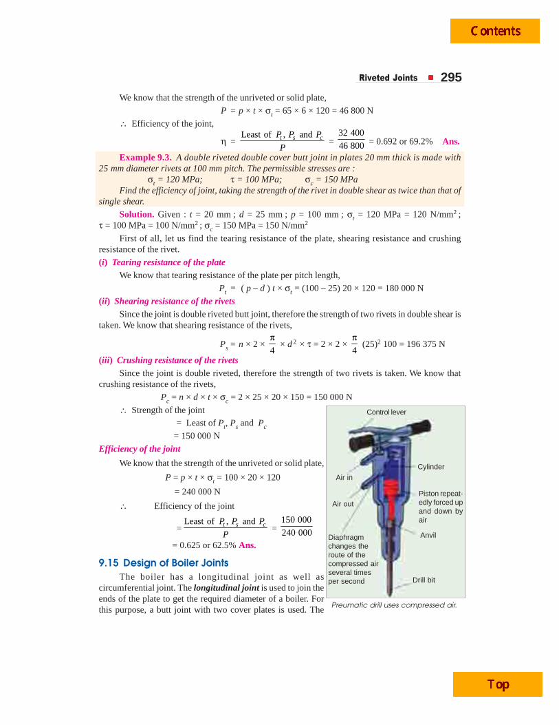
9.15 Design of Boiler JointsThe boiler has a longitudinal joint as well as
circumferential joint. The longitudinal joint is used to join theends of the plate to get the required diameter of a boiler. Forthis purpose, a butt joint with two cover plates is used. The Preumatic drill uses compressed air.
Control lever
Air in
Air out
Cylinder
Piston repeat-edly forced upand down byair
Anvil
Drill bit
Diaphragmchanges theroute of thecompressed airseveral timesper second

296 A Textbook of Machine Design
circumferential joint is used to get the required length of the boiler. For this purpose, a lap joint withone ring overlapping the other alternately is used.
Since a boiler is made up of number of rings, therefore the longitudinal joints are staggered forconvenience of connecting rings at places where both longitudinal and circumferential joints occur.
9.16 Assumptions in Designing Boiler JointsThe following assumptions are made while designing a joint for boilers :
1. The load on the joint is equally shared by all the rivets. The assumption implies that theshell and plate are rigid and that all the deformation of the joint takes place in the rivetsthemselves.
2. The tensile stress is equally distributed over the section of metal between the rivets.
3. The shearing stress in all the rivets is uniform.
4. The crushing stress is uniform.
5. There is no bending stress in the rivets.
6. The holes into which the rivets are driven do not weaken the member.
7. The rivet fills the hole after it is driven.
8. The friction between the surfaces of the plate is neglected.
9.17 Design of Longitudinal Butt Joint for a BoilerAccording to Indian Boiler Regulations (I.B.R), the following procedure should be adopted for
the design of longitudinal butt joint for a boiler.1. Thickness of boiler shell. First of all, the thickness of the boiler shell is determined by using
the thin cylindrical formula, i.e.
t =.
2 σ × ηt l
P D + 1 mm as corrosion allowance
where t = Thickness of the boiler shell,P = Steam pressure in boiler,D = Internal diameter of boiler shell,σt = Permissible tensile stress, and
ηl = Efficiency of the longitudinal joint.
The following points may be noted :(a) The thickness of the boiler shell should not be less than 7 mm.(b) The efficiency of the joint may be taken from the following table.
Table 9.1. Efficiencies of commercial boiler joints.
Lap joints Efficiency *Maximum Butt joints Efficiency *Maximum(%) efficiency (Double strap) (%) efficiency
Single riveted 45 to 60 63.3 Single riveted 55 to 60 63.3
Double riveted 63 to 70 77.5 Double riveted 70 to 83 86.6
Triple riveted 72 to 80 86.6 Triple riveted 80 to 90 95.0
(5 rivets per
pitch with unequal
width of straps)
Quadruple riveted 85 to 94 98.1
* The maximum efficiencies are valid for ideal equistrength joints with tensile stress = 77 MPa,shear stress = 62 MPa and crushing stress = 133 MPa.
Riveted Joints 297Indian Boiler Regulations (I.B.R.) allow a maximum efficiency of 85% for the best joint.
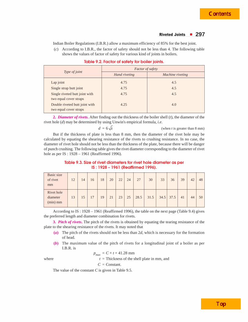
(c) According to I.B.R., the factor of safety should not be less than 4. The following tableshows the values of factor of safety for various kind of joints in boilers.
Table 9.2. Factor of safety for boiler joints.
Factor of safetyType of joint
Hand riveting Machine riveting
Lap joint 4.75 4.5
Single strap butt joint 4.75 4.5
Single riveted butt joint with 4.75 4.5two equal cover straps
Double riveted butt joint with 4.25 4.0two equal cover straps
2. Diameter of rivets. After finding out the thickness of the boiler shell (t), the diameter of therivet hole (d) may be determined by using Unwin's empirical formula, i.e.
d = 6 t (when t is greater than 8 mm)
But if the thickness of plate is less than 8 mm, then the diameter of the rivet hole may becalculated by equating the shearing resistance of the rivets to crushing resistance. In no case, thediameter of rivet hole should not be less than the thickness of the plate, because there will be dangerof punch crushing. The following table gives the rivet diameter corresponding to the diameter of rivethole as per IS : 1928 – 1961 (Reaffirmed 1996).
Table 9.3. Size of rivet diameters for rivet hole diameter as perIS : 1928 – 1961 (Reaffirmed 1996).
Basic sizeof rivet 12 14 16 18 20 22 24 27 30 33 36 39 42 48mm
Rivet holediameter 13 15 17 19 21 23 25 28.5 31.5 34.5 37.5 41 44 50(min) mm
According to IS : 1928 – 1961 (Reaffirmed 1996), the table on the next page (Table 9.4) givesthe preferred length and diameter combination for rivets.
3. Pitch of rivets. The pitch of the rivets is obtained by equating the tearing resistance of theplate to the shearing resistance of the rivets. It may noted that
(a) The pitch of the rivets should not be less than 2d, which is necessary for the formationof head.
(b) The maximum value of the pitch of rivets for a longitudinal joint of a boiler as perI.B.R. is
pmax = C × t + 41.28 mm
where t = Thickness of the shell plate in mm, and
C = Constant.
The value of the constant C is given in Table 9.5.
298 A Textbook of Machine Design
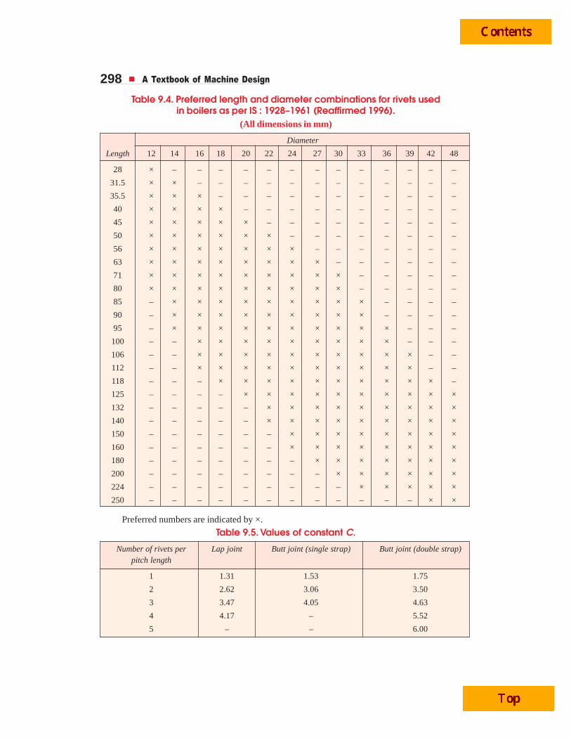
Table 9.4. Preferred length and diameter combinations for rivets usedin boilers as per IS : 1928–1961 (Reaffirmed 1996).
(All dimensions in mm)
Diameter
Length 12 14 16 18 20 22 24 27 30 33 36 39 42 48
28 × – – – – – – – – – – – – –
31.5 × × – – – – – – – – – – – –
35.5 × × × – – – – – – – – – – –
40 × × × × – – – – – – – – – –
45 × × × × × – – – – – – – – –
50 × × × × × × – – – – – – – –
56 × × × × × × × – – – – – – –
63 × × × × × × × × – – – – – –
71 × × × × × × × × × – – – – –
80 × × × × × × × × × – – – – –
85 – × × × × × × × × × – – – –
90 – × × × × × × × × × – – – –
95 – × × × × × × × × × × – – –
100 – – × × × × × × × × × – – –
106 – – × × × × × × × × × × – –
112 – – × × × × × × × × × × – –
118 – – – × × × × × × × × × × –
125 – – – – × × × × × × × × × ×
132 – – – – – × × × × × × × × ×
140 – – – – – × × × × × × × × ×
150 – – – – – – × × × × × × × ×
160 – – – – – – × × × × × × × ×
180 – – – – – – – × × × × × × ×
200 – – – – – – – – × × × × × ×
224 – – – – – – – – – × × × × ×
250 – – – – – – – – – – – – × ×
Preferred numbers are indicated by ×.
Table 9.5. Values of constant C.
Number of rivets per Lap joint Butt joint (single strap) Butt joint (double strap)pitch length
1 1.31 1.53 1.75
2 2.62 3.06 3.50
3 3.47 4.05 4.63
4 4.17 – 5.52
5 – – 6.00
Riveted Joints 299
Note : If the pitch of rivets as obtained by equating the tearing resistance to the shearing resistance is more thanpmax, then the value of pmax is taken.
4. Distance between the rows of rivets. The distance between the rows of rivets as specified byIndian Boiler Regulations is as follows :
(a) For equal number of rivets in more than one row for lap joint or butt joint, the distancebetween the rows of rivets ( pb) should not be less than
0.33 p + 0.67 d, for zig-zig riveting, and
2 d, for chain riveting.(b) For joints in which the number of rivets in outer rows is half the number of rivets in inner
rows and if the inner rows are chain riveted, the distance between the outer rows and thenext rows should not be less than
0.33 p + 0.67 or 2 d, whichever is greater.
The distance between the rows in which there are full number of rivets shall not be lessthan 2d.
(c) For joints in which the number of rivets in outer rows is half the number of rivets in innerrows and if the inner rows are zig-zig riveted, the distance between the outer rows and thenext rows shall not be less than 0.2 p + 1.15 d. The distance between the rows in whichthere are full number of rivets (zig-zag) shall not be less than 0.165 p + 0.67 d.
Note : In the above discussion, p is the pitch of the rivets in the outer rows.
5. Thickness of butt strap. According to I.B.R., the thicknesses for butt strap (t1) are as givenbelow :
(a) The thickness of butt strap, in no case, shall be less than 10 mm.
(b) t1 = 1.125 t, for ordinary (chain riveting) single butt strap.
t1 = 1.125 t –
– 2
p d
p d
⎛ ⎞⎜ ⎟⎝ ⎠
, for single butt straps, every alternate rivet in outer rows
being omitted.
t1 = 0.625 t, for double butt-straps of equal width having ordinary riveting (chain riveting).
t1 = 0.625 t –
– 2
p d
p d
⎛ ⎞⎜ ⎟⎝ ⎠
, for double butt straps of equal width having every
alternate rivet in the outer rows being omitted.
(c) For unequal width of butt straps, the thicknesses of butt strap are
t1 = 0.75 t, for wide strap on the inside, and
t2 = 0.625 t, for narrow strap on the outside.
6. Margin. The margin (m) is taken as 1.5 d.
Note : The above procedure may also be applied to ordinary riveted joints.
9.18 Design of Circumferential Lap Joint for a BoilerThe following procedure is adopted for the design of circumferential lap joint for a boiler.
1. Thickness of the shell and diameter of rivets. The thickness of the boiler shell and thediameter of the rivet will be same as for longitudinal joint.
2. Number of rivets. Since it is a lap joint, therefore the rivets will be in single shear.
∴ Shearing resistance of the rivets,
Ps = n × 4
π × d 2 × τ ...(i)
300 A Textbook of Machine Design
where n = Total number of rivets.
Knowing the inner diameter of the boiler shell (D), and the pressure of steam (P), the totalshearing load acting on the circumferential joint,
Ws =4
π × D2 × P ...(ii)
From equations (i) and (ii), we get
n × 4
π × d 2 × τ =
4
π × D2 × P
∴ n =2
D P
d⎛ ⎞⎜ ⎟ τ⎝ ⎠
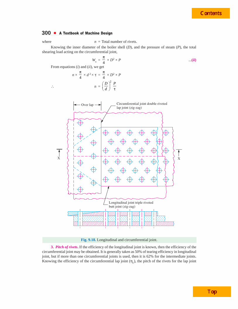
Fig. 9.18. Longitudinal and circumferential joint.
3. Pitch of rivets. If the efficiency of the longitudinal joint is known, then the efficiency of thecircumferential joint may be obtained. It is generally taken as 50% of tearing efficiency in longitudinaljoint, but if more than one circumferential joints is used, then it is 62% for the intermediate joints.Knowing the efficiency of the circumferential lap joint (ηc), the pitch of the rivets for the lap joint

Riveted Joints 301( p1) may be obtained by using the relation :
ηc = 1
1
–p d
p4. Number of rows. The number of rows of rivets for the circumferential joint may be obtained
from the following relation :
Number of rows =Total number of rivets
Number of rivets in one rowand the number of rivets in one row
1
( )=
D t
p
π +
where D = Inner diameter of shell.
5. After finding out the number of rows, the type of the joint (i.e. single riveted or doubleriveted etc.) may be decided. Then the number of rivets in a row and pitch may be re-adjusted. Inorder to have a leak-proof joint, the pitch for the joint should be checked from Indian BoilerRegulations.
6. The distance between the rows of rivets (i.e. back pitch) is calculated by using the relationsas discussed in the previous article.
7. After knowing the distance between the rows of rivets (pb), the overlap of the plate may befixed by using the relation,
Overlap = (No. of rows of rivets – 1) pb + m
where m = Margin.
There are several ways of joining the longitudinal joint and the circumferential joint. One of themethods of joining the longitudinal and circumferential joint is shown in Fig. 9.18.
9.19 Recommended Joints for Pressure VesselsThe following table shows the recommended joints for pressure vessels.
Table 9.6. Recommended joints for pressure vessels.
Diameter of shell (metres) Thickness of shell (mm) Type of joint
0.6 to 1.8 6 to 13 Double riveted
0.9 to 2.1 13 to 25 Triple riveted
1.5 to 2.7 19 to 40 Quadruple riveted
Example 9.4. A double riveted lap joint with zig-zag riveting is to be designed for 13 mmthick plates. Assume
σt = 80 MPa ; τ = 60 MPa ; and σc = 120 MPa
State how the joint will fail and find the efficiency of the joint.
Solution. Given : t = 13 mm ; σt = 80 MPa = 80 N/mm2 ; τ = 60 MPa = 60 N/mm2 ;σc = 120 MPa = 120 N/mm2
1. Diameter of rivetSince the thickness of plate is greater than 8 mm, therefore diameter of rivet hole,
d = 6 t = 6 13 = 21.6 mm
From Table 9.3, we find that according to IS : 1928 – 1961 (Reaffirmed 1996), the standard sizeof the rivet hole (d ) is 23 mm and the corresponding diameter of the rivet is 22 mm. Ans.
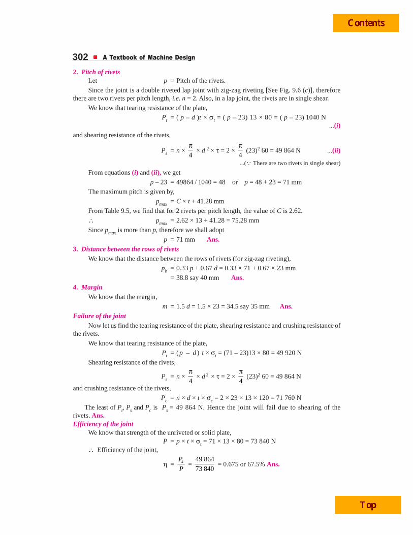
302 A Textbook of Machine Design
2. Pitch of rivetsLet p = Pitch of the rivets.
Since the joint is a double riveted lap joint with zig-zag riveting [See Fig. 9.6 (c)], thereforethere are two rivets per pitch length, i.e. n = 2. Also, in a lap joint, the rivets are in single shear.
We know that tearing resistance of the plate,
Pt = ( p – d )t × σt = ( p – 23) 13 × 80 = ( p – 23) 1040 N...(i)
and shearing resistance of the rivets,
Ps = n × 4
π × d 2 × τ = 2 ×
4
π (23)2 60 = 49 864 N ...(ii)
...(Q There are two rivets in single shear)
From equations (i) and (ii), we get
p – 23 = 49864 / 1040 = 48 or p = 48 + 23 = 71 mm
The maximum pitch is given by,
pmax = C × t + 41.28 mm
From Table 9.5, we find that for 2 rivets per pitch length, the value of C is 2.62.
∴ pmax = 2.62 × 13 + 41.28 = 75.28 mm
Since pmax is more than p, therefore we shall adopt
p = 71 mm Ans.3. Distance between the rows of rivets
We know that the distance between the rows of rivets (for zig-zag riveting),
pb = 0.33 p + 0.67 d = 0.33 × 71 + 0.67 × 23 mm
= 38.8 say 40 mm Ans.4. Margin
We know that the margin,
m = 1.5 d = 1.5 × 23 = 34.5 say 35 mm Ans.Failure of the joint
Now let us find the tearing resistance of the plate, shearing resistance and crushing resistance ofthe rivets.
We know that tearing resistance of the plate,
Pt = (p – d ) t × σt = (71 – 23)13 × 80 = 49 920 N
Shearing resistance of the rivets,
Ps = n × 4
π × d 2 × τ = 2 ×
4
π (23)2 60 = 49 864 N
and crushing resistance of the rivets,
Pc = n × d × t × σc = 2 × 23 × 13 × 120 = 71 760 N
The least of Pt, Ps and Pc is Ps = 49 864 N. Hence the joint will fail due to shearing of therivets. Ans.Efficiency of the joint
We know that strength of the unriveted or solid plate,P = p × t × σt = 71 × 13 × 80 = 73 840 N
∴ Efficiency of the joint,
η = sP
P =
49 864
73 840 = 0.675 or 67.5% Ans.
Riveted Joints 303Example 9.5. Two plates of 7 mm thick
are connected by a triple riveted lap joint ofzig-zag pattern. Calculate the rivet diameter,rivet pitch and distance between rows ofrivets for the joint. Also state the mode offailure of the joint. The safe working stressesare as follows :
σt = 90 MPa ; τ = 60 MPa ; andσc = 120 MPa.
Solution. Given : t = 7 mm ; σt = 90MPa = 90 N/mm2 ; τ = 60 MPa = 60 N/mm2 ;σc = 120 MPa = 120 N/mm2
1. Diameter of rivetSince the thickness of plate is less than
8 mm, therefore diameter of the rivet hole (d)is obtained by equating the shearing resistance(Ps) to the crushing resistance (Pc) of therivets. The triple riveted lap joint of zig-zagpattern is shown in Fig. 9.7 (b). We see thatthere are three rivets per pitch length (i.e.n = 3). Also, the rivets in lap joint are in singleshear.
We know that shearing resistance of therivets,
Ps = n × 4
π × d2 × τ
= 3 × 4
π × d 2 × 60 = 141.4 d 2 N ...(i)
...(Q n = 3)
and crushing resistance of the rivets,
Pc = n × d × t × σc = 3 × d × 7 × 120 = 2520 d N ...(ii)From equations (i) and (ii), we get
141.4 d2 = 2520 d or d = 2520 / 141.4 = 17.8 mm
From Table 9.3, we see that according to IS : 1928 – 1961 (Reaffirmed 1996), the standarddiameter of rivet hole (d ) is 19 mm and the corresponding diameter of rivet is 18 mm. Ans.2. Pitch of rivets
Let p = Pitch of rivets.
We know that tearing resistance of the plate,
Pt = ( p – d ) t × σt = ( p – 19 ) 7 × 90 = 630 ( p – 19 ) N ...(iii)and shearing resistance of the rivets,
Ps = 141.4 d 2 = 141.4 (19)2 = 51 045 N ...[From equation (i)] ...(iv)Equating equations (iii) and (iv), we get
630 ( p – 19 ) = 51 045
p – 19 = 51 045 / 630 = 81 or p = 81 + 19 = 100 mm
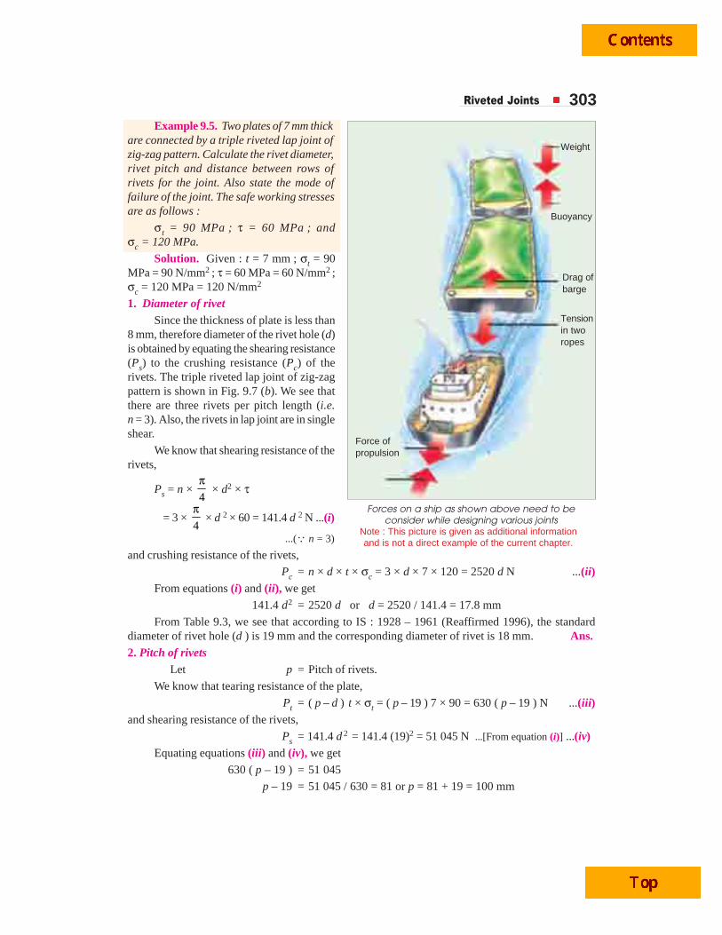
Forces on a ship as shown above need to beconsider while designing various joints
Note : This picture is given as additional informationand is not a direct example of the current chapter.
Weight
Buoyancy
Drag ofbarge
Tensionin tworopes
Force ofpropulsion

304 A Textbook of Machine Design
According to I.B.R., maximum pitch,
pmax = C.t + 41.28 mm
From Table 9.5, we find that for lap joint and 3 rivets per pitch length, the value of C is 3.47.
∴ pmax = 3.47 × 7 + 41.28 = 65.57 say 66 mm
Since pmax is less than p, therefore we shall adopt p = pmax = 66 mm Ans.3. Distance between rows of rivets
We know that the distance between the rows of rivets for zig-zag riveting,
pb = 0.33 p + 0.67 d = 0.33 × 66 + 0.67 × 19 = 34.5 mm Ans.Mode of failure of the joint
We know that tearing resistance of the plate,
Pt = ( p – d ) t × σt = (66 – 19) 7 × 90 = 29 610 N
Shearing resistance of rivets,
Ps = n × 4
π × d 2 × τ = 3 ×
4
π (19)2 60 = 51 045 N
and crushing resistance of rivets.
Pc = n × d × t × σc = 3 × 19 × 7 × 120 = 47 880 N
From above we see that the least value of Pt, Ps and Pc is Pt = 29 610 N. Therefore the joint willfail due to tearing off the plate.
Example 9.6. Two plates of 10 mm thickness each are to be joined by means of a single riveteddouble strap butt joint. Determine the rivet diameter, rivet pitch, strap thickness and efficiency of thejoint. Take the working stresses in tension and shearing as 80 MPa and 60 MPa respectively.
Solution. Given : t = 10 mm ; σt = 80 MPa = 80 N/mm2 ; τ = 60 MPa = 60 N/mm2
1. Diameter of rivetSince the thickness of plate is greater than 8 mm, therefore diameter of rivet hole,
d = 6 t = 6 10 = 18.97 mm
From Table 9.3, we see that according to IS : 1928 – 1961 (Reaffirmed 1996), the standarddiameter of rivet hole ( d ) is 19 mm and the corresponding diameter of the rivet is 18 mm. Ans.2. Pitch of rivets
Let p = Pitch of rivets.
Since the joint is a single riveted double strap butt joint as shown in Fig. 9.8, therefore there isone rivet per pitch length (i.e. n = 1) and the rivets are in double shear.
We know that tearing resistance of the plate,
Pt = ( p – d ) t × σt = ( p – 19 )10 × 80 = 800 ( p – 19) N ...(i)and shearing resistance of the rivets,
Ps = n × 1.875 × 4
π × d 2 × τ ...(Q Rivets are in double shear)
= 1 × 1.875 × 4
π (19)2 60 = 31 900 N ...(Q n = 1) ...(ii)
From equations (i) and (ii), we get
800 ( p – 19) = 31 900
∴ p – 19 = 31 900 / 800 = 39.87 or p = 39.87 + 19 = 58.87 say 60 mm
According to I.B.R., the maximum pitch of rivets,
pmax = C.t + 41.28 mm
Riveted Joints 305From Table 9.5, we find that for double strap butt joint and 1 rivet per pitch length, the value of
C is 1.75.
∴ pmax = 1.75 × 10 + 41.28 = 58.78 say 60 mm
From above we see that p = pmax = 60 mm Ans.3. Thickness of cover plates
We know that thickness of cover plates,
t1 = 0.625 t = 0.625 × 10 = 6.25 mm Ans.Efficiency of the joint
We know that tearing resistance of the plate,
Pt = ( p – d ) t × σt = (60 – 19) 10 × 80 = 32 800 N
and shearing resistance of the rivets,
Ps = n × 1.875 × 4
π × d2 × τ = 1 × 1.875 ×
4
π (19)2 60 = 31 900 N
∴ Strength of the joint
= Least of Pt and Ps = 31 900 N
Strength of the unriveted plate per pitch length
P = p × t × σt = 60 × 10 × 80 = 48 000 N
∴ Efficiency of the joint,
η =Least of andt sP P
P =
31 900
48 000 = 0.665 or 66.5% Ans.
Example 9.7. Design a double riveted butt joint with two cover plates for the longitudinalseam of a boiler shell 1.5 m in diameter subjected to a steam pressure of 0.95 N/mm2. Assume jointefficiency as 75%, allowable tensile stress in the plate 90 MPa ; compressive stress 140 MPa ; andshear stress in the rivet 56 MPa.
Solution. Given : D = 1.5 m = 1500 mm ; P = 0.95 N/mm2 ; ηl = 75% = 0.75 ; σt = 90 MPa= 90 N/mm2 ; σc = 140 MPa = 140 N/mm2 ; τ = 56 MPa = 56 N/mm2
1. Thickness of boiler shell plateWe know that thickness of boiler shell plate,
t =.
2 t l
P D
σ × η + 1 mm =
0.95 1500
2 90 0.75
×× ×
+ 1 = 11.6 say 12 mm Ans.
2. Diameter of rivetSince the thickness of the plate is greater than 8 mm, therefore the diameter of the rivet hole,
d = 6 t = 6 12 = 20.8 mm
From Table 9.3, we see that according to IS : 1928 – 1961 (Reaffirmed 1996), the standarddiameter of the rivet hole ( d ) is 21 mm and the corresponding diameter of the rivet is 20 mm. Ans.3. Pitch of rivets
Let p = Pitch of rivets.
The pitch of the rivets is obtained by equating the tearing resistance of the plate to the shearingresistance of the rivets.
We know that tearing resistance of the plate,
Pt = ( p – d ) t × σt = ( p – 21)12 × 90 = 1080 ( p – 21)N ...(i)Since the joint is double riveted double strap butt joint, as shown in Fig. 9.9, therefore there are
two rivets per pitch length (i.e. n = 2) and the rivets are in double shear. Assuming that the rivets in
306 A Textbook of Machine Design
double shear are 1.875 times stronger than in single shear, we have
Shearing strength of the rivets,
Ps = n × 1.875 × 4
π × d 2 × τ = 2 × 1.875 ×
4
π (21)2 × 56 N
= 72 745 N ...(ii)From equations (i) and (ii), we get
1080 ( p – 21) = 72 745
∴ p – 21 = 72 745 / 1080 = 67.35 or p = 67.35 + 21 = 88.35 say 90 mm
According to I.B.R., the maximum pitch of rivets for longitudinal joint of a boiler is given by
pmax = C × t + 41.28 mm
From Table 9.5, we find that for a double riveted double strap butt joint and two rivets per pitchlength, the value of C is 3.50.
∴ pmax = 3.5 × 12 + 41.28 = 83.28 say 84 mm
Since the value of p is more than pmax, therefore we shall adopt pitch of the rivets,
p = pmax = 84 mm Ans.4. Distance between rows of rivets
Assuming zig-zag riveting, the distance between the rows of the rivets (according to I.B.R.),
pb = 0.33 p + 0.67 d = 0.33 × 84 + 0.67 × 21 = 41.8 say 42 mm Ans.5. Thickness of cover plates
According to I.B.R., the thickness of each cover plate of equal width is
t1 = 0.625 t = 0.625 × 12 = 7.5 mm Ans.6. Margin
We know that the margin,
m = 1.5 d = 1.5 × 21 = 31.5 say 32 mm Ans.Let us now find the efficiency for the designed joint.
Tearing resistance of the plate,
Pt = ( p – d ) t × σt = (84 – 21)12 × 90 = 68 040 N
Shearing resistance of the rivets,
Ps = n × 1.875 × 4
π × d 2 × τ = 2 × 1.875 ×
4
π (21)2 × 56 = 72 745 N
and crushing resistance of the rivets,
Pc = n × d × t × σc = 2 × 21 × 12 × 140 = 70 560 N
Since the strength of riveted joint is the least value of Pt, Ps or Pc, therefore strength of theriveted joint,
Pt = 68 040 N
We know that strength of the un-riveted plate,
P = p × t × σt = 84 × 12 × 90 = 90 720 N
∴ Efficiency of the designed joint,
η =68 040
90 720tP
P= = 0.75 or 75% Ans.
Since the efficiency of the designed joint is equal to the given efficiency of 75%, therefore thedesign is satisfactory.
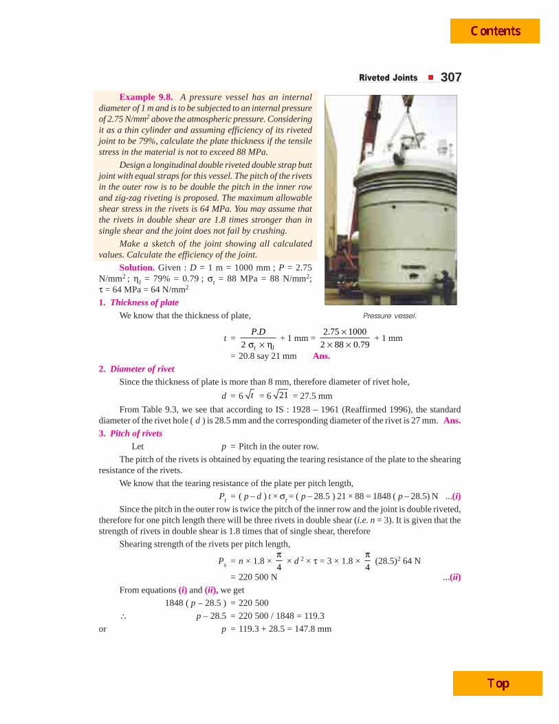
Riveted Joints 307Example 9.8. A pressure vessel has an internal
diameter of 1 m and is to be subjected to an internal pressureof 2.75 N/mm2 above the atmospheric pressure. Consideringit as a thin cylinder and assuming efficiency of its rivetedjoint to be 79%, calculate the plate thickness if the tensilestress in the material is not to exceed 88 MPa.
Design a longitudinal double riveted double strap buttjoint with equal straps for this vessel. The pitch of the rivetsin the outer row is to be double the pitch in the inner rowand zig-zag riveting is proposed. The maximum allowableshear stress in the rivets is 64 MPa. You may assume thatthe rivets in double shear are 1.8 times stronger than insingle shear and the joint does not fail by crushing.
Make a sketch of the joint showing all calculatedvalues. Calculate the efficiency of the joint.
Solution. Given : D = 1 m = 1000 mm ; P = 2.75N/mm2 ; ηl = 79% = 0.79 ; σt = 88 MPa = 88 N/mm2;τ = 64 MPa = 64 N/mm2
1. Thickness of plateWe know that the thickness of plate,
t =.
2 t l
P D
σ × η + 1 mm =
2.75 1000
2 88 0.79
×× ×
+ 1 mm
= 20.8 say 21 mm Ans.2. Diameter of rivet
Since the thickness of plate is more than 8 mm, therefore diameter of rivet hole,
d = 6 t = 6 21 = 27.5 mm
From Table 9.3, we see that according to IS : 1928 – 1961 (Reaffirmed 1996), the standarddiameter of the rivet hole ( d ) is 28.5 mm and the corresponding diameter of the rivet is 27 mm. Ans.3. Pitch of rivets
Let p = Pitch in the outer row.
The pitch of the rivets is obtained by equating the tearing resistance of the plate to the shearingresistance of the rivets.
We know that the tearing resistance of the plate per pitch length,
Pt = ( p – d ) t × σt = ( p – 28.5 ) 21 × 88 = 1848 ( p – 28.5) N ...(i)Since the pitch in the outer row is twice the pitch of the inner row and the joint is double riveted,
therefore for one pitch length there will be three rivets in double shear (i.e. n = 3). It is given that thestrength of rivets in double shear is 1.8 times that of single shear, therefore
Shearing strength of the rivets per pitch length,
Ps = n × 1.8 × 4
π × d 2 × τ = 3 × 1.8 ×
4
π (28.5)2 64 N
= 220 500 N ...(ii)From equations (i) and (ii), we get
1848 ( p – 28.5 ) = 220 500
∴ p – 28.5 = 220 500 / 1848 = 119.3
or p = 119.3 + 28.5 = 147.8 mm
Pressure vessel.
308 A Textbook of Machine Design
According to I.B.R., the maximum pitch,
pmax = C × t + 41.28 mm
From Table 9.5, we find that for 3 rivets per pitch length and for double strap butt joint, thevalue of C is 4.63.
∴ pmax = 4.63 × 21 + 41.28 = 138.5 say 140 mm
Since the value of pmax is less than p, therefore we shall adopt the value of
p = pmax = 140 mm Ans.∴ Pitch in the inner row
= 140 / 2 = 70 mm Ans.4. Distance between the rows of rivets
According to I.B.R., the distance between the rows of rivets,
pb = 0.2 p + 1.15 d = 0.2 × 140 + 1.15 × 28.5 = 61 mm Ans.5. Thickness of butt strap
According to I.B.R., the thickness of double butt straps of equal width,
t1 =– 140 – 28.5
0.625 0.625 21 mm– 2 140 – 2 28.5
⎛ ⎞ ⎛ ⎞= ×⎜ ⎟ ⎜ ⎟×⎝ ⎠ ⎝ ⎠
p dt
p d= 17.6 say 18 mm Ans.
6. MarginWe know that the margin,
m = 1.5 d = 1.5 × 28.5 = 43 mm Ans.Efficiency of the joint
We know that tearing resistance of the plate,
Pt = ( p – d ) t × σt = (140 – 28.5) 21 × 88 = 206 050 N
Shearing resistance of the rivets,
Ps = n × 1.8 × 4
π × d 2 × τ = 3 × 1.8 ×
4
π (28.5)2 64 = 220 500 N
Strength of the solid plate,
= p × t × σt = 140 × 21 × 88 = 258 720 N
∴ Efficiency of the joint
=Least of and 206 050
Strength of solid plate 258 720t sP P
= = 0.796 or 79.6% Ans.
Since the efficiency of the designed joint is more than the given efficiency, therefore the designis satisfactory.
Example 9.9. Design the longitudinal joint for a 1.25 m diameter steam boiler to carry asteam pressure of 2.5 N/mm2. The ultimate strength of the boiler plate may be assumed as 420 MPa,crushing strength as 650 MPa and shear strength as 300 MPa. Take the joint efficiency as 80%.Sketch the joint with all the dimensions. Adopt the suitable factor of safety.
Solution. Given : D = 1.25 m = 1250 mm; P = 2.5 N/mm2 ; σtu = 420 MPa = 420 N/mm2;σcu = 650 MPa = 650 N/mm2 ; τu = 300 MPa = 300 N/mm2 ; ηl = 80% = 0.8
Assuming a factor of safety (F.S.) as 5, the allowable stresses are as follows :
σt =420
. . 5tu
F S
σ= = 84 N/mm2
σc =650
. . 5cu
F S
σ= = 130 N/mm2
Riveted Joints 309
and τ =300
. . 5u
F S
τ= = 60 N/mm2
1. Thickness of plateWe know that thickness of plate,
t =.
2 σ × ηt l
P D + 1 mm =
2.5 1250
2 84 0.8
×× ×
+ 1 mm
= 24.3 say 25 mm Ans.2. Diameter of rivet
Since the thickness of the plate is more than 8 mm, therefore diameter of the rivet hole,
d = 6 t = 6 25 = 30 mm
From Table 9.3, we see that according to IS : 1928 – 1961 (Reaffirmed 1996), the standarddiameter of the rivet hole is 31.5 mm and the corresponding diameter of the rivet is 30 mm. Ans.3. Pitch of rivets
Assume a triple riveted double strap butt joint with unequal straps, as shown in Fig. 9.11.
Let p = Pitch of the rivets in the outer most row.
∴ Tearing strength of the plate per pitch length,
Pt = ( p – d ) t × σt = ( p – 31.5) 25 × 84 = 2100 ( p – 31.5 ) N ...(i)Since the joint is triple riveted with two unequal cover straps, therefore there are 5 rivets per
pitch length. Out of these five rivets, four rivets are in double shear and one is in single shear.Assuming the strength of the rivets in double shear as 1.875 times that of single shear, therefore
Shearing resistance of the rivets per pitch length,
Ps = 4 × 1.875 × 4
π × d2 × τ +
4
π × d2 × τ = 8.5 ×
4
π × d 2 × τ
= 8.5 × 4
π (31.5)2 60 = 397 500 N ...(ii)
From equations (i) and (ii), we get
2100 ( p – 31.5) = 397 500
∴ p – 31.5 = 397 500 / 2100 = 189.3 or p = 31.5 + 189.3 = 220.8 mm
According to I.B.R., maximum pitch,
pmax = C × t + 41.28 mm
From Table 9.5, we find that for double strap butt joint with 5 rivets per pitch length, the valueof C is 6.
∴ pmax = 6 × 25 + 41.28 = 191.28 say 196 mm Ans.Since pmax is less than p, therefore we shall adopt p = pmax = 196 mm Ans.∴ Pitch of rivets in the inner row,
p' = 196 / 2 = 98 mm Ans.4. Distance between the rows of rivets
According to I.B.R., the distance between the outer row and the next row,
= 0.2 p + 1.15 d = 0.2 × 196 + 1.15 × 31.5 mm
= 75.4 say 76 mm Ans.and the distance between the inner rows for zig-zag riveting
= 0.165 p + 0.67 d = 0.165 × 196 + 0.67 × 31.5 mm
= 53.4 say 54 mm Ans.
310 A Textbook of Machine Design
5. Thickness of butt strapsWe know that for unequal width of butt straps, the thicknesses are as follows :
For wide butt strap, t1 = 0.75 t = 0.75 × 25 = 18.75 say 20 mm Ans.and for narrow butt strap, t2 = 0.625 t = 0.625 × 25 = 15.6 say 16 mm Ans.
It may be noted that wide and narrow butt straps are placed on the inside and outside of the shellrespectively.
6. MarginWe know that the margin,
m = 1.5 d = 1.5 × 31.5 = 47.25 say 47.5 mm Ans.Let us now check the efficiency of the designed joint.
Tearing resistance of the plate in the outer row,
Pt = ( p – d ) t × σt = (196 – 31.5) 25 × 84 = 345 450 N
Shearing resistance of the rivets,
Ps = 4 × 1.875 × 4
π × d 2 × τ +
4
π × d 2 × τ = 8.5 ×
4
π × d 2 × τ
= 8.5 × 4
π (31.5)2 × 60 = 397 500 N
and crushing resistance of the rivets,
Pc = n × d × t × σc = 5 × 31.5 × 25 × 130 = 511 875 N ...(Q n = 5)
The joint may also fail by tearing off the plate between the rivets in the second row. This is onlypossible if the rivets in the outermost row gives way (i.e. shears). Since there are two rivet holes perpitch length in the second row and one rivet is in the outer most row, therefore combined tearing andshearing resistance
= ( p – 2d ) t × σt + 4
π × d 2 × τ
= (196 – 2 × 31.5) 25 × 84 + 4
π (31.5)2 60 = 326 065 N
From above, we see that strength of the joint
= 326 065 N
Strength of the unriveted or solid plate,
P = p × t × σt = 196 × 25 × 84 = 411 600 N
∴ Efficiency of the joint,
η = 326 065 / 411 600 = 0.792 or 79.2%
Since the efficiency of the designed joint is nearly equal to the given efficiency, therefore thedesign is satisfactory.
Example 9.10. A steam boiler is to be designed for a working pressure of 2.5 N/mm2 with itsinside diameter 1.6 m. Give the design calculations for the longitudinal and circumferential jointsfor the following working stresses for steel plates and rivets :
In tension = 75 MPa ; In shear = 60 MPa; In crushing = 125 MPa.
Draw the joints to a suitable scale.
Solution. Given : P = 2.5 N/mm2 ; D = 1.6 m = 1600 mm ; σt = 75 MPa = 75 N/mm2 ;τ = 60 MPa = 60 N/mm2 ; σc = 125 MPa = 125 N/mm2
Design of longitudinal jointThe longitudinal joint for a steam boiler may be designed as follows :
Riveted Joints 3111. Thickness of boiler shell
We know that the thickness of boiler shell,
t =.
2 σt
P D + 1 mm =
2.5 1600
2 75
×× + 1 mm
= 27.6 say 28 mm Ans.2. Diameter of rivet
Since the thickness of the plate is more than 8 mm, therefore diameter of rivet hole,
d = 6 t = 6 28 = 31.75 mm
From Table 9.3, we see that according to IS : 1928 – 1961 (Reaffirmed 1996), the standarddiameter of rivet hole (d ) is 34.5 mm and the corresponding diameter of the rivet is 33 mm. Ans.3. Pitch of rivets
Assume the joint to be triple riveted double strap butt joint with unequal cover straps, as shownin Fig. 9.11.
Let p = Pitch of the rivet in the outer most row.
∴Tearing resistance of the plate per pitch length,
Pt = ( p – d ) t × σt = ( p – 34.5) 28 × 75 N
= 2100 (p – 34.5 ) N ...(i)Since the joint is triple riveted with two unequal cover straps, therefore there are 5 rivets per
pitch length. Out of these five rivets, four are in double shear and one is in single shear. Assuming thestrength of rivets in double shear as 1.875 times that of single shear, therefore
Shearing resistance of the rivets per pitch length,
Ps = 4 × 1.875 × 4
π × d 2 × τ +
4
π × d 2 × τ
= 8.5 × 4
π × d 2 × τ
= 8.5 × 4
π (34.5)2 60 = 476 820 N ...(ii)
Equating equations (i) and (ii), we get
2100 ( p – 34.5) = 476 820
∴ p – 34.5 = 476 820 / 2100 = 227 or p = 227 + 34.5 = 261.5 mm
According to I.B.R., the maximum pitch,
pmax = C.t + 41.28 mm
From Table 9.5, we find that for double strap butt joint with 5 rivets per pitch length, the valueof C is 6.
∴ pmax = 6 × 28 + 41.28 = 209.28 say 220 mm
Since pmax is less than p, therefore we shall adopt
p = pmax = 220 mm Ans.∴ Pitch of rivets in the inner row,
p' = 220 / 2 = 110 mmAns.4. Distance between the rows of rivets
According to I.B.R., the distance between the outer row and the next row
= 0.2 p + 1.15 d = 0.2 × 220 + 1.15 × 34.5 mm
= 83.7 say 85 mm Ans.
312 A Textbook of Machine Design
and the distance between the inner rows for zig-zig riveting
= 0.165 p + 0.67 d = 0.165 × 220 + 0.67 × 34.5 mm
= 59.4 say 60 mm Ans.5. Thickness of butt straps
We know that for unequal width of butt straps, the thicknesses are :
For wide butt strap, t1 = 0.75 t = 0.75 × 28 = 21 mm Ans.and for narrow butt strap, t2 = 0.625 t = 0.625 × 28 = 17.5 say 18 mm Ans.
It may be noted that the wide and narrow butt straps are placed on the inside and outside of theshell respectively.
6. MarginWe know that the margin,
m = 1.5 d = 1.5 × 34.5 = 51.75 say 52 mm Ans.Let us now check the efficiency of the designed joint.
Tearing resistance of the plate in the outer row,
Pt = ( p – d ) t × σt = (220 – 34.5) 28 × 75 = 389 550 N
Shearing resistance of the rivets,
Ps = 4 × 1.875 × 4
π × d2 × τ +
4
π × d2 × τ = 8.5 ×
4
π × d 2 × τ
= 8.5 × 4
π (34.5)2 60 = 476 820 N
and crushing resistance of the rivets,
Pc = n × d × t × σc = 5 × 34.5 × 28 × 125 = 603 750 N
The joint may also fail by tearing off the plate between the rivets in the second row. This is onlypossible if the rivets in the outermost row gives way (i.e. shears). Since there are two rivet holes perpitch length in the second row and one rivet in the outermost row, therefore
Combined tearing and shearing resistance
= ( p – 2d ) t × σt + 4
π × d 2 × τ
= (220 – 2 × 34.5) 28 × 75 + 4
π (34.5)2 60
= 317 100 + 56 096 = 373 196 N
From above, we see that the strength of the joint
= 373 196 N
Strength of the unriveted or solid plate,
P = p × t × σt = 220 × 28 × 75 = 462 000 N
∴ Efficiency of the designed joint,
η =373 196
462 000 = 0.808 or 80.8% Ans.
Design of circumferential jointThe circumferential joint for a steam boiler may be designed as follows :
1. The thickness of the boiler shell ( t ) and diameter of rivet hole ( d ) will be same as forlongitudinal joint, i.e.
t = 28 mm ; and d = 34.5 mm
Riveted Joints 3132. Number of rivets
Let n = Number of rivets.We know that shearing resistance of the rivets
= n × 4
π × d 2 × τ ...(i)
and total shearing load acting on the circumferential joint
=4
π × D 2 × P ...(ii)
From equations (i) and (ii), we get
n × 4
π × d 2 × τ =
4
π × D 2 × P
∴ n =2 2
2 2
(1600) 2.5
(34.5) 60
D P
d
× =×τ
= 89.6 say 90 Ans.
3. Pitch of rivetsAssuming the joint to be double riveted lap joint with zig-zag riveting, therefore number of
rivets per row= 90 / 2 = 45
We know that the pitch of the rivets,
p1 =( ) (1600 28)
Number of rivets per row 45
D tπ + π += = 113.7 mm
Let us take pitch of the rivets, p1 = 140 mm Ans.4. Efficiency of the joint
We know that the efficiency of the circumferential joint,
ηc = 1
1
– 140 – 34.50.753 or 75.3%
140
p d
p= =
5. Distance between the rows of rivetsWe know that the distance between the rows of rivets for zig-zag riveting,
= 0.33 p1 + 0.67 d = 0.33 × 140 + 0.67 × 34.5 mm= 69.3 say 70 mm Ans.
6. MarginWe know that the margin, m = 1.5 d = 1.5 × 34.5
= 51.75 say 52 mm Ans.
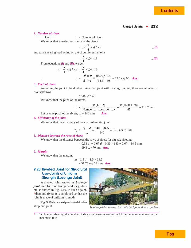
9.20 Riveted Joint for StructuralUse–Joints of UniformStrength (Lozenge Joint)
A riveted joint known as Lozengejoint used for roof, bridge work or girdersetc. is shown in Fig. 9.19. In such a joint,*diamond riveting is employed so that thejoint is made of uniform strength.
Fig. 9.19 shows a triple riveted doublestrap butt joint.
* In diamond riveting, the number of rivets increases as we proceed from the outermost row to theinnermost row.
Riveted joints are used for roofs, bridge work and girders.
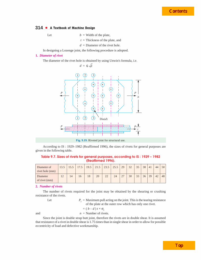
314 A Textbook of Machine Design
Let b = Width of the plate,
t = Thickness of the plate, and
d = Diameter of the rivet hole.
In designing a Lozenge joint, the following procedure is adopted.
1. Diameter of rivet
The diameter of the rivet hole is obtained by using Unwin's formula, i.e.
d = 6 t
Fig. 9.19. Riveted joint for structural use.
According to IS : 1929–1982 (Reaffirmed 1996), the sizes of rivets for general purposes aregiven in the following table.
Table 9.7. Sizes of rivets for general purposes, according to IS : 1929 – 1982(Reaffirmed 1996).
Diameter of 13.5 15.5 17.5 19.5 21.5 23.5 25.5 29 32 35 38 41 44 50rivet hole (mm)
Diameter 12 14 16 18 20 22 24 27 30 33 36 39 42 48of rivet (mm)
2. Number of rivets
The number of rivets required for the joint may be obtained by the shearing or crushingresistance of the rivets.
Let Pt = Maximum pull acting on the joint. This is the tearing resistanceof the plate at the outer row which has only one rivet.
= ( b – d ) t × σt
and n = Number of rivets.
Since the joint is double strap butt joint, therefore the rivets are in double shear. It is assumedthat resistance of a rivet in double shear is 1.75 times than in single shear in order to allow for possibleeccentricity of load and defective workmanship.
Riveted Joints 315∴ Shearing resistance of one rivet,
Ps = 1.75 × 4
π × d 2 × τ
and crushing resistance of one rivet,
Pc = d × t × σc
∴ Number of rivets required for the joint,
n =Least of or
t
s c
P
P P3. From the number of rivets, the number of rows and the number of rivets in each row is decided.
4. Thickness of the butt straps
The thickness of the butt strap,
t1 = 1.25 t, for single cover strap
= 0.75 t, for double cover strap
5. Efficiency of the jointFirst of all, calculate the resistances along the sections 1-1, 2-2 and 3-3.
At section 1-1, there is only one rivet hole.
∴ Resistance of the joint in tearing along 1-1,
Pt1 = (b – d ) t × σt
At section 2-2, there are two rivet holes.
∴ Resistance of the joint in tearing along 2-2,
Pt2 = (b – 2d ) t × σt + Strength of one rivet in front of section 2-2
(This is due to the fact that for tearing off the plate at section 2-2, the rivet in front of section2-2 i.e. at section 1-1 must first fracture).
Similarly at section 3-3 there are three rivet holes.
∴ Resistance of the joint in tearing along 3-3,
Pt3 = (b – 3d ) t × σt + Strength of 3 rivets in front of section 3-3
The least value of Pt1, Pt2, Pt3, Ps or Pc is the strength of the joint.
We know that the strength of unriveted plate,
P = b × t × σt
∴ Efficiency of the joint,
η =1 2 3Least of , , , ort t t s cP P P P P
PNote : The permissible stresses employed in structural joints are higher than those used in design of pressurevessels. The following values are usually adopted.
For plates in tension ... 140 MPa
For rivets in shear ... 105 MPa
For crushing of rivets and plates
Single shear ... 224 MPa
Double shear ... 280 MPa
6. The pitch of the rivets is obtained by equating the strength of the joint in tension to thestrength of the rivets in shear. The pitches allowed in structural joints are larger than those of pressurevessels. The following table shows the values of pitch due to Rotscher.
316 A Textbook of Machine Design
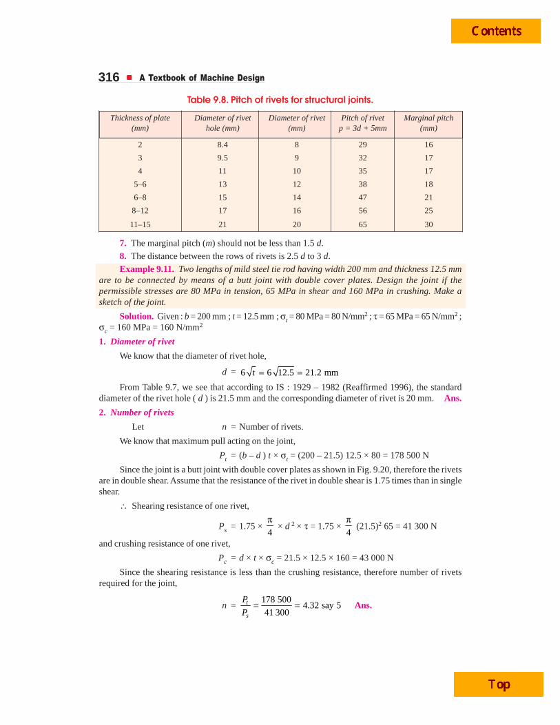
Table 9.8. Pitch of rivets for structural joints.
Thickness of plate Diameter of rivet Diameter of rivet Pitch of rivet Marginal pitch(mm) hole (mm) (mm) p = 3d + 5mm (mm)
2 8.4 8 29 16
3 9.5 9 32 17
4 11 10 35 17
5–6 13 12 38 18
6–8 15 14 47 21
8–12 17 16 56 25
11–15 21 20 65 30
7. The marginal pitch (m) should not be less than 1.5 d.
8. The distance between the rows of rivets is 2.5 d to 3 d.
Example 9.11. Two lengths of mild steel tie rod having width 200 mm and thickness 12.5 mmare to be connected by means of a butt joint with double cover plates. Design the joint if thepermissible stresses are 80 MPa in tension, 65 MPa in shear and 160 MPa in crushing. Make asketch of the joint.
Solution. Given : b = 200 mm ; t = 12.5 mm ; σt = 80 MPa = 80 N/mm2 ; τ = 65 MPa = 65 N/mm2 ;σc = 160 MPa = 160 N/mm2
1. Diameter of rivet
We know that the diameter of rivet hole,
d = 6 6 12.5 21.2 mm= =t
From Table 9.7, we see that according to IS : 1929 – 1982 (Reaffirmed 1996), the standarddiameter of the rivet hole ( d ) is 21.5 mm and the corresponding diameter of rivet is 20 mm. Ans.
2. Number of rivets
Let n = Number of rivets.
We know that maximum pull acting on the joint,
Pt = (b – d ) t × σt = (200 – 21.5) 12.5 × 80 = 178 500 N
Since the joint is a butt joint with double cover plates as shown in Fig. 9.20, therefore the rivetsare in double shear. Assume that the resistance of the rivet in double shear is 1.75 times than in singleshear.
∴ Shearing resistance of one rivet,
Ps = 1.75 × 4
π × d 2 × τ = 1.75 ×
4
π (21.5)2 65 = 41 300 N
and crushing resistance of one rivet,
Pc = d × t × σc = 21.5 × 12.5 × 160 = 43 000 N
Since the shearing resistance is less than the crushing resistance, therefore number of rivetsrequired for the joint,
n =178 500
4.32 say 541 300
t
s
P
P= = Ans.
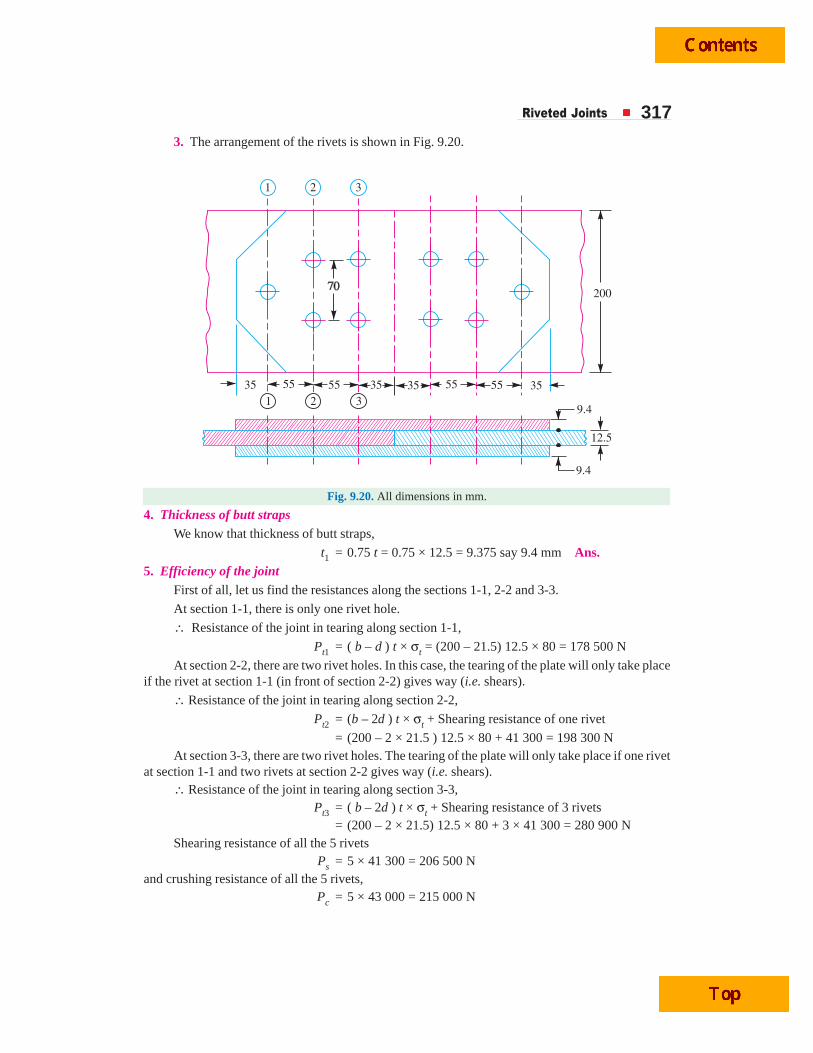
Riveted Joints 3173. The arrangement of the rivets is shown in Fig. 9.20.
Fig. 9.20. All dimensions in mm.
4. Thickness of butt strapsWe know that thickness of butt straps,
t1 = 0.75 t = 0.75 × 12.5 = 9.375 say 9.4 mm Ans.5. Efficiency of the joint
First of all, let us find the resistances along the sections 1-1, 2-2 and 3-3.
At section 1-1, there is only one rivet hole.
∴ Resistance of the joint in tearing along section 1-1,
Pt1 = ( b – d ) t × σt = (200 – 21.5) 12.5 × 80 = 178 500 N
At section 2-2, there are two rivet holes. In this case, the tearing of the plate will only take placeif the rivet at section 1-1 (in front of section 2-2) gives way (i.e. shears).
∴ Resistance of the joint in tearing along section 2-2,
Pt2 = (b – 2d ) t × σt + Shearing resistance of one rivet
= (200 – 2 × 21.5 ) 12.5 × 80 + 41 300 = 198 300 NAt section 3-3, there are two rivet holes. The tearing of the plate will only take place if one rivet
at section 1-1 and two rivets at section 2-2 gives way (i.e. shears).∴ Resistance of the joint in tearing along section 3-3,
Pt3 = ( b – 2d ) t × σt + Shearing resistance of 3 rivets= (200 – 2 × 21.5) 12.5 × 80 + 3 × 41 300 = 280 900 N
Shearing resistance of all the 5 rivetsPs = 5 × 41 300 = 206 500 N
and crushing resistance of all the 5 rivets,Pc = 5 × 43 000 = 215 000 N
318 A Textbook of Machine Design
Since the strength of the joint is the least value of Pt1, Pt2, Pt3, Ps and Pc, therefore strength ofthe joint
= 178 500 N along section 1-1
We know that strength of the un-riveted plate,
= b × t × σt = 20 × 12.5 × 80 = 200 000 N
∴ Efficiency of the joint,
η =Strength of the joint 178 500
Strength of the unriveted plate 200 000=
= 0.8925 or 89.25% Ans.6. Pitch of rivets, p = 3 d + 5 mm = (3 × 21.5) + 5 = 69.5 say 70 mm Ans.7. Marginal pitch, m = 1.5 d = 1.5 × 21.5 = 33.25 say 35 mm Ans.8. Distance between the rows of rivets
= 2.5 d = 2.5 × 21.5 = 53.75 say 55 mm Ans.Example 9.12. A tie-bar in a bridge consists of flat 350 mm wide and 20 mm thick. It is
connected to a gusset plate of the same thickness by a double cover butt joint. Design an economicaljoint if the permissible stresses are :
σt = 90 MPa, τ = 60 MPa and σc = 150 MPa
Solution. Given : b = 350 mm ; t = 20 mm ; σt = 90 MPa = 90 N/mm2 ; τ = 60 MPa = 60 N/mm2 ;σc = 150 MPa = 150 N/mm2
Riveted, screwed and welded joints are employed in bridges.

Riveted Joints 3191. Diameter of rivet
We know that the diameter of rivet hole,
d = 6 6 20 26.8 mmt = =From Table 9.7, we see that according to IS : 1929–1982 (Reaffirmed 1996), the standard
diameter of rivet hole ( d ) is 29 mm and the corresponding diameter of rivet is 27 mm. Ans.2. Number of rivets
Let n = Number of rivets.
We know that the maximum pull acting on the joint,
Pt = ( b – d ) t × σt = (350 – 29) 20 × 90 = 577 800 N
Since the joint is double strap butt joint, therefore the rivets are in double shear. Assume that theresistance of the rivet in double shear is 1.75 times than in single shear.
∴ Shearing resistance of one rivet,
Ps = 1.75 × 4
π × d 2 × τ = 1.75 ×
4
π (29)2 60 = 69 360 N
and crushing resistance of one rivet,
Pc = d × t × σc = 29 × 20 × 150 = 87 000 N
Since the shearing resistance is less than crushing resistance, therefore number of rivets requiredfor the joint,
n =577 800
8.33 say 969 360
t
s
P
P= = Ans.
3. The arrangement of rivets is shown in Fig. 9.21.
15
15
20
1
1
2 3 4
2 3 4
75 7575 7575 7545 4545 45
35095
Fig. 9.21. All dimensions in mm.
4. Thickness of butt strapsWe know that the thickness of butt straps,
t1 = 0.75 t = 0.75 × 20 = 15 mm Ans.
320 A Textbook of Machine Design
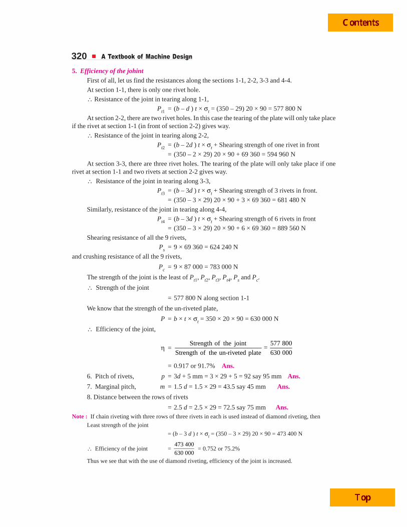
5. Efficiency of the johintFirst of all, let us find the resistances along the sections 1-1, 2-2, 3-3 and 4-4.
At section 1-1, there is only one rivet hole.
∴ Resistance of the joint in tearing along 1-1,
Pt1 = (b – d ) t × σt = (350 – 29) 20 × 90 = 577 800 N
At section 2-2, there are two rivet holes. In this case the tearing of the plate will only take placeif the rivet at section 1-1 (in front of section 2-2) gives way.
∴ Resistance of the joint in tearing along 2-2,
Pt2 = (b – 2d ) t × σt + Shearing strength of one rivet in front
= (350 – 2 × 29) 20 × 90 + 69 360 = 594 960 N
At section 3-3, there are three rivet holes. The tearing of the plate will only take place if onerivet at section 1-1 and two rivets at section 2-2 gives way.
∴ Resistance of the joint in tearing along 3-3,
Pt3 = (b – 3d ) t × σt + Shearing strength of 3 rivets in front.
= (350 – 3 × 29) 20 × 90 + 3 × 69 360 = 681 480 N
Similarly, resistance of the joint in tearing along 4-4,
Pt4 = (b – 3d ) t × σt + Shearing strength of 6 rivets in front
= (350 – 3 × 29) 20 × 90 + 6 × 69 360 = 889 560 N
Shearing resistance of all the 9 rivets,
Ps = 9 × 69 360 = 624 240 N
and crushing resistance of all the 9 rivets,
Pc = 9 × 87 000 = 783 000 N
The strength of the joint is the least of Pt1, Pt2, Pt3, Pt4, Ps and Pc.
∴ Strength of the joint
= 577 800 N along section 1-1
We know that the strength of the un-riveted plate,
P = b × t × σt = 350 × 20 × 90 = 630 000 N
∴ Efficiency of the joint,
η =Strength of the joint 577 800
=Strength of the un-riveted plate 630 000
= 0.917 or 91.7% Ans.
6. Pitch of rivets, p = 3d + 5 mm = 3 × 29 + 5 = 92 say 95 mm Ans.
7. Marginal pitch, m = 1.5 d = 1.5 × 29 = 43.5 say 45 mm Ans.
8. Distance between the rows of rivets
= 2.5 d = 2.5 × 29 = 72.5 say 75 mm Ans.Note : If chain riveting with three rows of three rivets in each is used instead of diamond riveting, then
Least strength of the joint
= (b – 3 d ) t × σt = (350 – 3 × 29) 20 × 90 = 473 400 N
∴ Efficiency of the joint = 473 400
630 000 = 0.752 or 75.2%
Thus we see that with the use of diamond riveting, efficiency of the joint is increased.
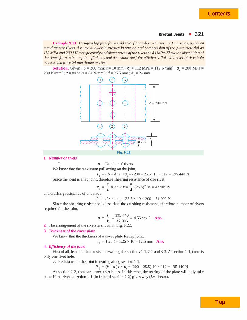
Riveted Joints 321Example 9.13. Design a lap joint for a mild steel flat tie-bar 200 mm × 10 mm thick, using 24
mm diameter rivets. Assume allowable stresses in tension and compression of the plate material as112 MPa and 200 MPa respectively and shear stress of the rivets as 84 MPa. Show the disposition ofthe rivets for maximum joint efficiency and determine the joint efficiency. Take diameter of rivet holeas 25.5 mm for a 24 mm diameter rivet.
Solution. Given : b = 200 mm; t = 10 mm ; σt = 112 MPa = 112 N/mm2 ; σc = 200 MPa =200 N/mm2 ; τ = 84 MPa = 84 N/mm2 ; d = 25.5 mm ; d1 = 24 mm
1
1
2
2
3
3
b = 200 mm
10 mm
t1
Fig. 9.22
1. Number of rivetsLet n = Number of rivets.
We know that the maximum pull acting on the joint,Pt = ( b – d ) t × σt = (200 – 25.5) 10 × 112 = 195 440 N
Since the joint is a lap joint, therefore shearing resistance of one rivet,
Ps =4
π × d2 × τ =
4
π (25.5)2 84 = 42 905 N
and crushing resistance of one rivet,Pc = d × t × σc = 25.5 × 10 × 200 = 51 000 N
Since the shearing resistance is less than the crushing resistance, therefore number of rivetsrequired for the joint,
n =195 440
4.56 say 542 905
t
s
P
P= = Ans.
2. The arrangement of the rivets is shown in Fig. 9.22.
3. Thickness of the cover plateWe know that the thickness of a cover plate for lap joint,
t1 = 1.25 t = 1.25 × 10 = 12.5 mm Ans.4. Efficiency of the joint
First of all, let us find the resistances along the sections 1-1, 2-2 and 3-3. At section 1-1, there isonly one rivet hole.
∴ Resistance of the joint in tearing along section 1-1,Pt1 = (b – d ) t × σt = (200 – 25.5) 10 × 112 = 195 440 N
At section 2-2, there are three rivet holes. In this case, the tearing of the plate will only takeplace if the rivet at section 1-1 (in front of section 2-2) gives way (i.e. shears).

322 A Textbook of Machine Design
∴ Resistance of the joint in tearing along section 2-2,
Pt2 = (b – 3d) t × σt + Shearing resistance of one rivet
= (200 – 3 × 25.5) 10 × 112 + 42 905 = 181 285 N
At section 3-3, there is only one rivet hole. The resistance of the joint in tearing along section3-3 will be same as at section 1-1.
Pt3 = Pt1 = 195 440 N
Shearing resistance of all the five rivets,
Ps = 5 × 42 905 = 214 525 N
and crushing resistance of all the five rivets,
Pc = 5 × 51 000 = 525 000 N
Since the strength of the joint is the least value of Pt1, Pt2, Pt3, Ps and Pc, therefore strength ofthe joint
= 181 285 N at section 2-2
We know that strength of the un-riveted plate
= b × t × σt = 200 × 10 × 112 = 224 000 N
∴ Efficiency of the joint,
η =Strength of the joint 181 225
=Strength of the un-riveted plate 224 000
= 0.809 or 80.9% Ans.
9.21 Eccentric Loaded Riveted JointWhen the line of action of the load does not pass through the centroid of the rivet system and
thus all rivets are not equally loaded, then the joint is said to be an eccentric loaded riveted joint, asshown in Fig. 9.23 (a). The eccentric loading results in secondary shear caused by the tendency offorce to twist the joint about the centre of gravity in addition to direct shear or primary shear.
Let P = Eccentric load on the joint, and
e = Eccentricity of the load i.e. the distance between the line ofaction of the load and the centroid of the rivet system i.e. G.
The following procedure is adopted for the design of an eccentrically loaded riveted joint.
Load
Hydraulic
rams
Exhaust waste
heat
Engine
Note : This picture is given as additional information and is not a direct example of the current chapter.
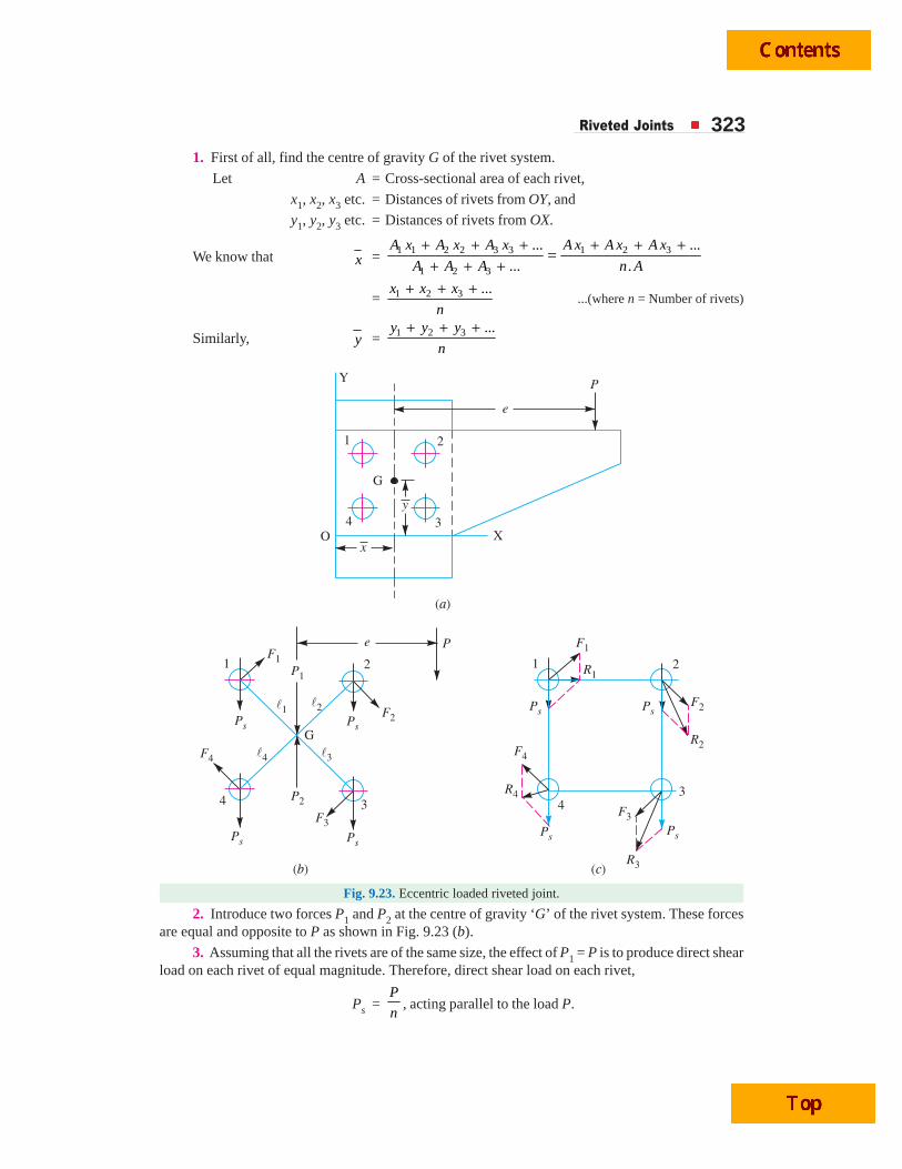
Riveted Joints 3231. First of all, find the centre of gravity G of the rivet system.
Let A = Cross-sectional area of each rivet,
x1, x2, x3 etc. = Distances of rivets from OY, and
y1, y2, y3 etc. = Distances of rivets from OX.
We know that x = 1 1 2 2 3 3 1 2 3
1 2 3
... ...
... .
A x A x A x A x A x A x
A A A n A
+ + + + + +=
+ + +
= 1 2 3 ...x x x
n
+ + +...(where n = Number of rivets)
Similarly, y = 1 2 3 ...y y y
n
+ + +
Fig. 9.23. Eccentric loaded riveted joint.
2. Introduce two forces P1 and P2 at the centre of gravity ‘G’ of the rivet system. These forcesare equal and opposite to P as shown in Fig. 9.23 (b).
3. Assuming that all the rivets are of the same size, the effect of P1 = P is to produce direct shearload on each rivet of equal magnitude. Therefore, direct shear load on each rivet,
Ps =P
n, acting parallel to the load P.
324 A Textbook of Machine Design
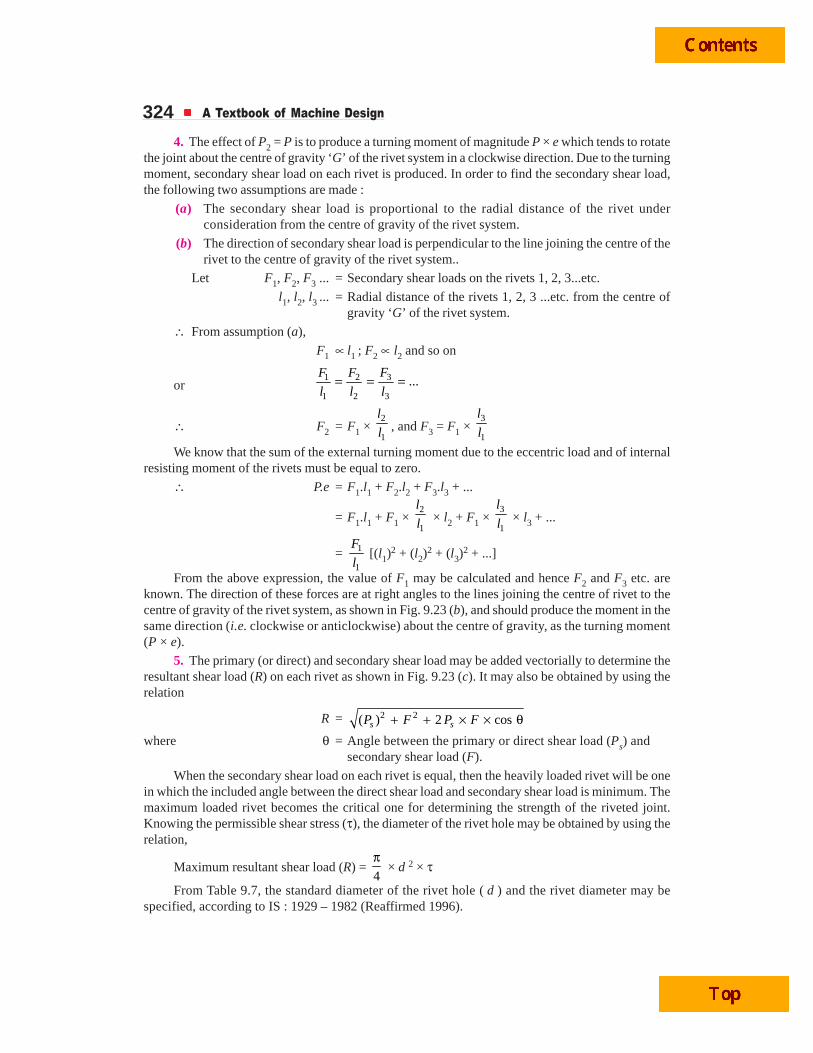
4. The effect of P2 = P is to produce a turning moment of magnitude P × e which tends to rotatethe joint about the centre of gravity ‘G’ of the rivet system in a clockwise direction. Due to the turningmoment, secondary shear load on each rivet is produced. In order to find the secondary shear load,the following two assumptions are made :
(a) The secondary shear load is proportional to the radial distance of the rivet underconsideration from the centre of gravity of the rivet system.
(b) The direction of secondary shear load is perpendicular to the line joining the centre of therivet to the centre of gravity of the rivet system..
Let F1, F2, F3 ... = Secondary shear loads on the rivets 1, 2, 3...etc.
l1, l2, l3 ... = Radial distance of the rivets 1, 2, 3 ...etc. from the centre ofgravity ‘G’ of the rivet system.
∴ From assumption (a),
F1 ∝ l1 ; F2 ∝ l2 and so on
or31 2
1 2 3
...FF F
l l l= = =
∴ F2 = F1 × 2
1
l
l , and F3 = F1 × 3
1
l
l
We know that the sum of the external turning moment due to the eccentric load and of internalresisting moment of the rivets must be equal to zero.
∴ P.e = F1.l1 + F2.l2 + F3.l3 + ...
= F1.l1 + F1 × 2
1
l
l × l2 + F1 × 3
1
l
l × l3 + ...
= 1
1
F
l [(l1)2 + (l2)
2 + (l3)2 + ...]
From the above expression, the value of F1 may be calculated and hence F2 and F3 etc. areknown. The direction of these forces are at right angles to the lines joining the centre of rivet to thecentre of gravity of the rivet system, as shown in Fig. 9.23 (b), and should produce the moment in thesame direction (i.e. clockwise or anticlockwise) about the centre of gravity, as the turning moment(P × e).
5. The primary (or direct) and secondary shear load may be added vectorially to determine theresultant shear load (R) on each rivet as shown in Fig. 9.23 (c). It may also be obtained by using therelation
R = 2 2( ) 2 coss sP F P F+ + × × θwhere θ = Angle between the primary or direct shear load (Ps) and
secondary shear load (F).
When the secondary shear load on each rivet is equal, then the heavily loaded rivet will be onein which the included angle between the direct shear load and secondary shear load is minimum. Themaximum loaded rivet becomes the critical one for determining the strength of the riveted joint.Knowing the permissible shear stress (τ), the diameter of the rivet hole may be obtained by using therelation,
Maximum resultant shear load (R) = 4
π × d 2 × τ
From Table 9.7, the standard diameter of the rivet hole ( d ) and the rivet diameter may bespecified, according to IS : 1929 – 1982 (Reaffirmed 1996).
Riveted Joints 325Notes : 1. In the solution of a problem, the primary and shear loads may be laid off approximately to scale andgenerally the rivet having the maximum resultant shear load will be apparent by inspection. The values of theload for that rivet may then be calculated.
2. When the thickness of the plate is given, then the diameter of the rivet hole may be checked againstcrushing.
3. When the eccentric load P is inclined at some angle, then the same procedure as discussed above maybe followed to find the size of rivet (See Example 9.18).
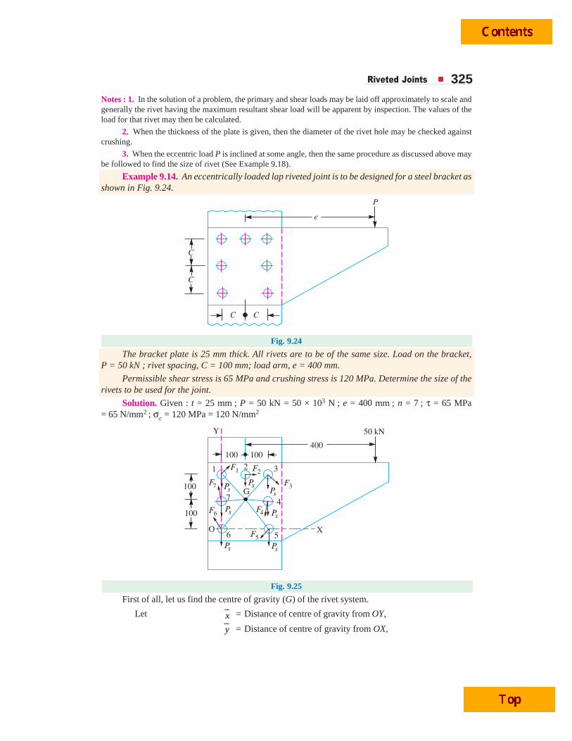
Example 9.14. An eccentrically loaded lap riveted joint is to be designed for a steel bracket asshown in Fig. 9.24.
P
e
C
C
C
C
Fig. 9.24
The bracket plate is 25 mm thick. All rivets are to be of the same size. Load on the bracket,P = 50 kN ; rivet spacing, C = 100 mm; load arm, e = 400 mm.
Permissible shear stress is 65 MPa and crushing stress is 120 MPa. Determine the size of therivets to be used for the joint.
Solution. Given : t = 25 mm ; P = 50 kN = 50 × 103 N ; e = 400 mm ; n = 7 ; τ = 65 MPa= 65 N/mm2 ; σc = 120 MPa = 120 N/mm2
100
100
Y
G
F1 F2
F7
F6
F5
F4
F3PsPs
Ps
Ps Ps
Ps
Ps
1
7
6O
5
4
32
100 100400
X
50 kN
Fig. 9.25
First of all, let us find the centre of gravity (G) of the rivet system.
Let x = Distance of centre of gravity from OY,
y = Distance of centre of gravity from OX,
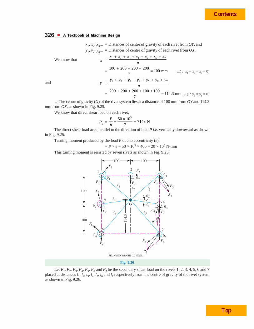
326 A Textbook of Machine Design
x1, x2, x3... = Distances of centre of gravity of each rivet from OY, and
y1, y2, y3... = Distances of centre of gravity of each rivet from OX.
We know that x = 1 2 3 4 5 6 7x x x x x x x
n
+ + + + + +
=100 200 200 200
100 mm7
+ + + = ...(Q x1 = x6 = x7 = 0)
and y = 1 2 3 4 5 6 7y y y y y y y
n
+ + + + + +
=200 200 200 100 100
114.3 mm7
+ + + + = ...(Q y5 = y6 = 0)
∴ The centre of gravity (G) of the rivet system lies at a distance of 100 mm from OY and 114.3mm from OX, as shown in Fig. 9.25.
We know that direct shear load on each rivet,
Ps =350 10
7143 N7
P
n
×= =
The direct shear load acts parallel to the direction of load P i.e. vertically downward as shownin Fig. 9.25.
Turning moment produced by the load P due to eccentricity (e)
= P × e = 50 × 103 × 400 = 20 × 106 N-mm
This turning moment is resisted by seven rivets as shown in Fig. 9.25.
Fig. 9.26
Let F1, F2, F3, F4, F5, F6 and F7 be the secondary shear load on the rivets 1, 2, 3, 4, 5, 6 and 7placed at distances l1, l2, l3, l4, l5, l6 and l7 respectively from the centre of gravity of the rivet systemas shown in Fig. 9.26.
Riveted Joints 327From the geometry of the figure, we find that
l1 = 2 23 (100) (200 – 114.3) 131.7 mml = + =
l2 = 200 – 114.3 = 85.7 mm
l4 = 2 27 (100) (114.3 – 100) 101 mml = + =
and l5 = 2 26 (100) (114.3) 152 mml = + =
Now equating the turning moment due to eccentricity of the load to the resisting moment of therivets, we have
P × e =2 2 2 2 2 2 21
1 2 3 4 5 6 71
( ) ( ) ( ) ( ) ( ) ( ) ( )F
l l l l l l ll
⎡ ⎤+ + + + + +⎣ ⎦
= 2 2 2 211 2 4 5
1
2( ) ( ) 2( ) 2( )F
l l l ll
⎡ ⎤+ + +⎣ ⎦....(Q l1 = l3; l4 = l7 and l5 = l6)
50 × 103 × 400 = 2 2 2 21 2(131.7) (85.7) 2(101) 2(152)131.7
F ⎡ ⎤+ + +⎣ ⎦20 × 106 × 131.7 = F1(34 690 + 7345 + 20 402 + 46 208) = 108 645 F1
∴ F1 = 20 × 106 × 131.7 / 108 645 = 24 244 NSince the secondary shear loads are proportional to their radial distances from the centre of
gravity, therefore
F2 = 21
1
85.724 244 15 776 N
131.7
lF
l× = × =
F3 = 31 1
1
24 244 Nl
F Fl
× = = ...(Q l1 = l3)
F4 = 41
1
10124 244 = 18 593 N
131.7
lF
l× = ×
Ram movesoutwards
Oil pressureon lower sideof piston
Loadmovesinwards
Ram movesinwards
Oil pressureon lower sideof piston
Loadmovesoutwards
Note : This picture is given as additional information and is not a direct example of the current chapter.Arms of a digger.
328 A Textbook of Machine Design
F5 = 51
1
15224 244 = 27 981 N
131.7
lF
l× = ×
F6 = 61 5
1
27 981 Nl
F Fl
× = = ...(Q l6 = l5)
F7 = 71 4
1
18 593 Nl
F Fl
× = = ...(Q l7 = l4)
By drawing the direct and secondary shear loads on each rivet, we see that the rivets 3, 4 and 5are heavily loaded. Let us now find the angles between the direct and secondary shear load for thesethree rivets. From the geometry of Fig. 9.26, we find that
cos θ3 =3
100 1000.76
131.7l= =
cos θ4 =4
100 1000.99
101l= =
and cos θ5 =5
100 1000.658
152l= =
Now resultant shear load on rivet 3,
R3 = 2 23 3 3( ) ( ) 2 coss sP F P F+ + × × θ
= 2 2(7143) (24 244) 2 7143 24 244 0.76 30 033 N+ + × × × =
Resultant shear load on rivet 4,
R4 = 2 24 4 4( ) ( ) 2 coss sP F P F+ + × × θ
= 2 2(7143) (18 593) 2 7143 18 593 0.99 25 684 N+ + × × × =and resultant shear load on rivet 5,
R5 = 2 25 5 5( ) ( ) 2 coss sP F P F+ + × × θ
= 2 2(7143) (27 981) 2 7143 27 981 0.658 33 121 N+ + × × × =The resultant shear load may be determined graphically, as shown in Fig. 9.26.
From above we see that the maximum resultant shear load is on rivet 5. If d is the diameter ofrivet hole, then maximum resultant shear load (R5),
33 121 =4
π × d 2 × τ =
4
π × d 2 × 65 = 51 d 2
∴ d 2 = 33 121 / 51 = 649.4 or d = 25.5 mm
From Table 9.7, we see that according to IS : 1929–1982 (Reaffirmed 1996), the standarddiameter of the rivet hole (d ) is 25.5 mm and the corresponding diameter of rivet is 24 mm.
Let us now check the joint for crushing stress. We know that
Crushing stress = 5Max. load 33 121
Crushing area 25.5 25
R
d t= =
× ×
= 51.95 N/mm2 = 51.95 MPa
Since this stress is well below the given crushing stress of 120 MPa, therefore the design issatisfactory.
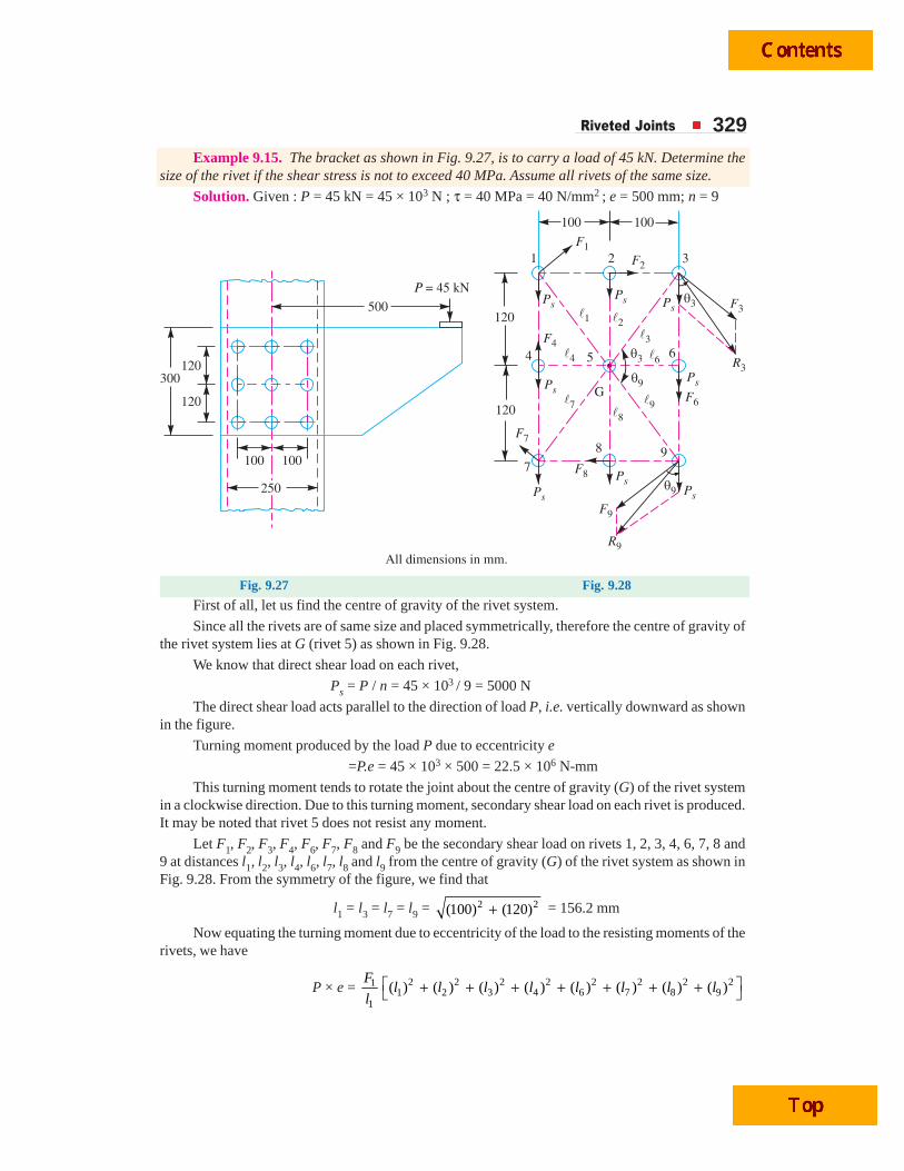
Riveted Joints 329Example 9.15. The bracket as shown in Fig. 9.27, is to carry a load of 45 kN. Determine the
size of the rivet if the shear stress is not to exceed 40 MPa. Assume all rivets of the same size.
Solution. Given : P = 45 kN = 45 × 103 N ; τ = 40 MPa = 40 N/mm2 ; e = 500 mm; n = 9
Fig. 9.27 Fig. 9.28
First of all, let us find the centre of gravity of the rivet system.
Since all the rivets are of same size and placed symmetrically, therefore the centre of gravity ofthe rivet system lies at G (rivet 5) as shown in Fig. 9.28.
We know that direct shear load on each rivet,
Ps = P / n = 45 × 103 / 9 = 5000 N
The direct shear load acts parallel to the direction of load P, i.e. vertically downward as shownin the figure.
Turning moment produced by the load P due to eccentricity e
=P.e = 45 × 103 × 500 = 22.5 × 10⁶ N-mm
This turning moment tends to rotate the joint about the centre of gravity (G) of the rivet systemin a clockwise direction. Due to this turning moment, secondary shear load on each rivet is produced.It may be noted that rivet 5 does not resist any moment.
Let F1, F2, F3, F4, F6, F7, F8 and F9 be the secondary shear load on rivets 1, 2, 3, 4, 6, 7, 8 and9 at distances l1, l2, l3, l4, l6, l7, l8 and l9 from the centre of gravity (G) of the rivet system as shown inFig. 9.28. From the symmetry of the figure, we find that
l1 = l3 = l7 = l9 = 2 2(100) (120)+ = 156.2 mm
Now equating the turning moment due to eccentricity of the load to the resisting moments of therivets, we have
P × e = 2 2 2 2 2 2 2 211 2 3 4 6 7 8 9
1
( ) ( ) ( ) ( ) ( ) ( ) ( ) ( )F
l l l l l l l ll
⎡ ⎤+ + + + + + +⎣ ⎦
330 A Textbook of Machine Design
= 2 2 211 2 4
1
4( ) 2( ) 2( )F
l l ll
⎡ ⎤+ +⎣ ⎦ ....(Q l1 = l3 = l7 = l9; l2 = l8 and l4 = l6)
∴ 45 × 103 × 500 = 2 2 2114(156.2) 2(120) 2(100) 973.2
156.2
FF⎡ ⎤+ + =⎣ ⎦
or F1 = 45 × 103 × 500 / 973.2 = 23 120 N
Since the secondary shear loads are proportional to their radial distances from the centre ofgravity (G), therefore
F2 = F1 × 2
1
l
l = F8 = 23 120 × 120
156.2 = 17 762 N ...(Q l2 = l8)
F3 = F1 × 3
1
l
l = F1 = F7 = F9 = 23 120 N ...(Q l3 = l7 = l9 = l1)
and F4 = F1 × 4
1
l
l = F6 = 23 120 × 100
156.2 = 14 800 N ...(Q l4 = l6)
The secondary shear loads acts perpendicular to the line joining the centre of rivet and thecentre of gravity of the rivet system, as shown in Fig. 9.28 and their direction is clockwise.
By drawing the direct and secondary shear loads on each rivet, we see that the rivets 3, 6 and 9are heavily loaded. Let us now find the angle between the direct and secondary shear loads for theserivets. From the geometry of the figure, we find that
cos θ3 = 93
100 100cos 0.64
156.2lθ = = =
∴ Resultant shear load on rivets 3 and 9,
R3 = 2 39 3 3 3( ) ( ) 2 coss sR P F P F= + + × × θ
= 2 2(5000) (23 120) 2 5000 23 120 0.64 26 600 N+ + × × × =...(Q F3 = F9 and cos θ3 = cos θ9)
and resultant shear load on rivet 6,
R6 = Ps + F6 = 5000 + 14 800 = 19 800 N
The resultant shear load (R3 or R9) may be determined graphically as shown in Fig. 9.28.
From above we see that the maximum resultant shear load is on rivets 3 and 9.
If d is the diameter of the rivet hole, then maximum resultant shear load (R3),
26 600 = 4
π × d 2 × τ =
4
π × d 2 × 40 = 31.42 d 2
∴ d 2 = 26 600 / 31.42 = 846 or d = 29 mm
From Table 9.7, we see that according to IS : 1929 – 1982 (Reaffirmed 1996), the standarddiameter of the rivet hole (d ) is 29 mm and the corresponding diameter of the rivet is 27 mm. Ans.
Example 9.16. Find the value of P for the joint shown in Fig. 9.29 based on a working shearstress of 100 MPa for the rivets. The four rivets are equal, each of 20 mm diameter.
Solution. Given : τ = 100 MPa = 100 N/mm2 ; n = 4 ; d = 20 mm
We know that the direct shear load on each rivet,
Ps = 0.254
P PP
n= =
The direct shear load on each rivet acts in the direction of the load P, as shown in Fig. 9.30. Thecentre of gravity of the rivet group will lie at E (because of symmetry). From Fig. 9.30, we find that
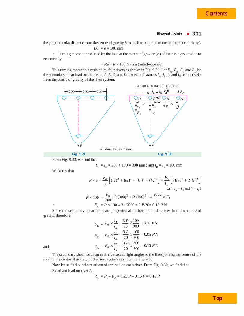
Riveted Joints 331the perpendicular distance from the centre of gravity E to the line of action of the load (or eccentricity),
EC = e = 100 mm
∴ Turning moment produced by the load at the centre of gravity (E) of the rivet system due toeccentricity
= P.e = P × 100 N-mm (anticlockwise)
This turning moment is resisted by four rivets as shown in Fig. 9.30. Let FA, FB, FC and FD bethe secondary shear load on the rivets, A, B, C, and D placed at distances lA, lB, lC and lD respectivelyfrom the centre of gravity of the rivet system.
All dimensions in mm.
200
200
200
100 100
200
200
P P
lC lBFB FA
FDFC
D APs
Ps PsPs
D C B AE
Fig. 9.29 Fig. 9.30
From Fig. 9.30, we find that
lA = lD = 200 + 100 = 300 mm ; and lB = lC = 100 mm
We know that
P × e = 2 2 2 2 2 2A AA B C D A B
A A
( ) ( ) ( ) ( ) 2( ) 2( )⎡ ⎤ ⎡ ⎤+ + + = +⎣ ⎦ ⎣ ⎦F F
l l l l l ll l
...(Q lA = lD and lB = lC)
P × 100 =2 2A
A2000
2 (300) 2 (100)300 3
⎡ ⎤+ = ×⎣ ⎦F
F
∴ FA = P × 100 × 3 / 2000 = 3 P/20= 0.15 P N
Since the secondary shear loads are proportional to their radial distances from the centre ofgravity, therefore
FB =B
AA
3 1000.05 N
20 300× = × =l P
F Pl
FC =C
AA
3 1000.05 N
20 300× = × =
l PF P
l
and FD =D
AA
3 3000.15 N
20 300× = × =l P
F Pl
The secondary shear loads on each rivet act at right angles to the lines joining the centre of therivet to the centre of gravity of the rivet system as shown in Fig. 9.30.
Now let us find out the resultant shear load on each rivet. From Fig. 9.30, we find that
Resultant load on rivet A,
RA = Ps – FA = 0.25 P – 0.15 P = 0.10 P
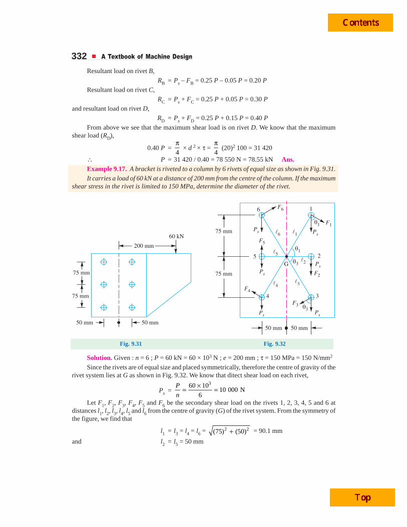
332 A Textbook of Machine Design
Resultant load on rivet B,
RB = Ps – FB = 0.25 P – 0.05 P = 0.20 P
Resultant load on rivet C,
RC = Ps + FC = 0.25 P + 0.05 P = 0.30 P
and resultant load on rivet D,
RD = Ps + FD = 0.25 P + 0.15 P = 0.40 P
From above we see that the maximum shear load is on rivet D. We know that the maximumshear load (RD),
0.40 P =4
π × d 2 × τ =
4
π (20)2 100 = 31 420
∴ P = 31 420 / 0.40 = 78 550 N = 78.55 kN Ans.Example 9.17. A bracket is riveted to a column by 6 rivets of equal size as shown in Fig. 9.31.
It carries a load of 60 kN at a distance of 200 mm from the centre of the column. If the maximumshear stress in the rivet is limited to 150 MPa, determine the diameter of the rivet.
Fig. 9.31 Fig. 9.32
Solution. Given : n = 6 ; P = 60 kN = 60 × 103 N ; e = 200 mm ; τ = 150 MPa = 150 N/mm2
Since the rivets are of equal size and placed symmetrically, therefore the centre of gravity of therivet system lies at G as shown in Fig. 9.32. We know that ditect shear load on each rivet,
Ps =360 10
10 000 N6
P
n
×= =
Let F1, F2, F3, F4, F5 and F6 be the secondary shear load on the rivets 1, 2, 3, 4, 5 and 6 atdistances l1, l2, l3, l4, l5 and l6 from the centre of gravity (G) of the rivet system. From the symmetry ofthe figure, we find that
l1 = l3 = l4 = l6 = 2 2(75) (50)+ = 90.1 mm
and l2 = l5 = 50 mm
Riveted Joints 333Now equating the turning moment due to eccentricity of the load to the resisting moments of the
rivets, we have
P × e = 2 2 2 2 2 211 2 3 4 5 6
1
( ) ( ) ( ) ( ) ( ) ( )F
l l l l l ll
⎡ ⎤+ + + + +⎣ ⎦
= 2 211 2
1
4( ) 2( )F
l ll
⎡ ⎤+⎣ ⎦
∴ 60 × 103 × 200 = 1
90.1
F [4(90.1)2 + 2(50)2] = 416 F1
or F1 = 60 × 103 × 200 / 416 = 28 846 N
Since the secondary shear loads are proportional to the radial distances from the centre ofgravity, therefore
F2 = 21
1
5028 846 16 008 N
90.1
lF
l× = × =
F3 = 31 1
1
28 846 Nl
F Fl
× = = ...(Q l3 = l1)
F4 = 41 1
1
28 846 Nl
F Fl
× = = ...(Q l4 = l1)
F5 = 51 2
1
16 008 Nl
F Fl
× = = ...(Q l5 = l2)
and F6 = 61 1
1
28 846 Nl
F Fl
× = = ...(Q l6 = l1)
By drawing the direct and secondary shear loads on each rivet, we see that the rivets 1, 2 and 3are heavily loaded. Let us now find the angles between the direct and secondary shear loads for thesethree rivets. From the geometry of the figure, we find that
cos θ1 = 31
50 50cos 0.555
90.1lθ = = =
Excavator in action
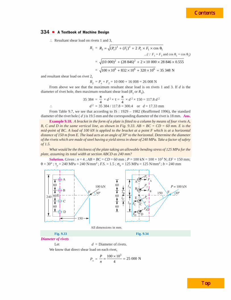
334 A Textbook of Machine Design
∴ Resultant shear load on rivets 1 and 3,
R1 = 2 23 1 1 1( ) ( ) 2 coss sR P F P F= + + × × θ
...(Q F1 = F3 and cos θ1 = cos θ3)
= 2 2(10 000) (28 846) 2 10 000 28 846 0.555+ + × × ×
= 6 6 6100 10 832 10 320 10 35 348 N× + × + × =and resultant shear load on rivet 2,
R2 = Ps + F2 = 10 000 + 16 008 = 26 008 N
From above we see that the maximum resultant shear load is on rivets 1 and 3. If d is thediameter of rivet hole, then maximum resultant shear load (R1 or R3),
35 384 =4
π × d 2 × τ =
4
π × d 2 × 150 = 117.8 d 2
∴ d 2 = 35 384 / 117.8 = 300.4 or d = 17.33 mm
From Table 9.7, we see that according to IS : 1929 – 1982 (Reaffirmed 1996), the standarddiameter of the rivet hole ( d ) is 19.5 mm and the corresponding diameter of the rivet is 18 mm. Ans.
Example 9.18. A bracket in the form of a plate is fitted to a column by means of four rivets A,B, C and D in the same vertical line, as shown in Fig. 9.33. AB = BC = CD = 60 mm. E is themid-point of BC. A load of 100 kN is applied to the bracket at a point F which is at a horizontaldistance of 150 m from E. The load acts at an angle of 30° to the horizontal. Determine the diameterof the rivets which are made of steel having a yield stress in shear of 240 MPa. Take a factor of safetyof 1.5.
What would be the thickness of the plate taking an allowable bending stress of 125 MPa for theplate, assuming its total width at section ABCD as 240 mm?
Solution. Given : n = 4 ; AB = BC = CD = 60 mm ; P = 100 kN = 100 × 103 N; EF = 150 mm;θ = 30° ; τy = 240 MPa = 240 N/mm2 ; F.S. = 1.5 ; σb = 125 MPa = 125 N/mm2 ; b = 240 mm
Fig. 9.33 Fig. 9.34
Diameter of rivetsLet d = Diameter of rivets.
We know that direct shear load on each rivet,
Ps =3100 10
25 000 N4
P
n
×= =
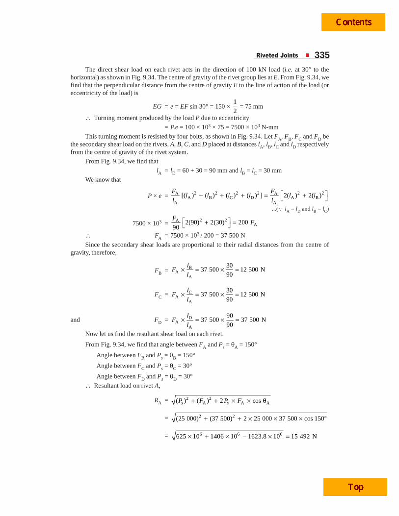
Riveted Joints 335The direct shear load on each rivet acts in the direction of 100 kN load (i.e. at 30° to the
horizontal) as shown in Fig. 9.34. The centre of gravity of the rivet group lies at E. From Fig. 9.34, wefind that the perpendicular distance from the centre of gravity E to the line of action of the load (oreccentricity of the load) is
EG = e = EF sin 30° = 150 × 1
2 = 75 mm
∴ Turning moment produced by the load P due to eccentricity
= P.e = 100 × 103 × 75 = 7500 × 103 N-mm
This turning moment is resisted by four bolts, as shown in Fig. 9.34. Let FA, FB, FC and FD bethe secondary shear load on the rivets, A, B, C, and D placed at distances lA, lB, lC and lD respectivelyfrom the centre of gravity of the rivet system.
From Fig. 9.34, we find that
lA = lD = 60 + 30 = 90 mm and lB = lC = 30 mm
We know that
P × e = 2 2 2 2 2 2A AA B C D A B
A A
[( ) ( ) ( ) ( ) ] 2( ) 2( )⎡ ⎤+ + + = +⎣ ⎦F F
l l l l l ll l
...(Q lA = lD and lB = lC)
7500 × 103 =2 2A
A2(90) 2(30) 20090
⎡ ⎤+ =⎣ ⎦F
F
∴ FA = 7500 × 103 / 200 = 37 500 N
Since the secondary shear loads are proportional to their radial distances from the centre ofgravity, therefore,
FB = BA
A
3037 500 12 500 N
90× = × =l
Fl
FC = CA
A
3037 500 12 500 N
90× = × =
lF
l
and FD = DA
A
9037 500 37 500 N
90× = × =l
Fl
Now let us find the resultant shear load on each rivet.
From Fig. 9.34, we find that angle between FA and Ps = θA = 150°
Angle between FB and Ps = θB = 150°
Angle between FC and Ps = θC = 30°
Angle between FD and Ps = θD = 30°
∴ Resultant load on rivet A,
RA = 2 2A A A( ) ( ) 2 coss sP F P F+ + × × θ
= 2 2(25 000) (37 500) 2 25 000 37 500 cos 150+ + × × × °
= 6 6 6625 10 1406 10 – 1623.8 10 15 492 N× + × × =

336 A Textbook of Machine Design
Resultant shear load on rivet B,
RB = 2 2B B B( ) ( ) 2 coss sP F P F+ + × × θ
= 2 2(25 000) (12 500) 2 25 000 12 500 cos 150+ + × × × °
= 6 6 6625 10 156.25 10 – 541.25 10 15 492 N× + × × =Resultant shear load on rivet C,
RC = 2 2C C C( ) ( ) 2 coss sP F P F+ + × × θ
= 2 2(25 000) (12 500) 2 25 000 12 500 cos 30+ + × × × °
= 6 6 6625 10 156.25 10 541.25 10 36 366 N× + × + × =and resultant shear load on rivet D,
RD = 2 2D D D( ) ( ) 2 coss sP F P F+ + × × θ
= 2 2(25 000) (37 500) 2 25 000 37 500 cos 30+ + × × × °
= 6 6 6625 10 1406 10 1623.8 10 60 455 N× + × + × =
The resultant shear load on each rivet may be determinedgraphically as shown in Fig. 9.35.
From above we see that the maximum resultant shear load ison rivet D. We know that maximum resultant shear load (RD ),
60 455 = 2 2
4 4 . .yd d
F S
τπ π× × τ = × ×
=2 2240
125.74 1.5
d dπ × × =
∴ d 2 = 60 455 / 125.7 = 481
or d = 21.9 mm
From Table 9.7, we see that the standard diameter of the rivethole (d ) is 23.5 mm and the corresponding diameter of rivet is22 mm. Ans.Thickness of the plate
Let t = Thickness of the plate inmm,
σb = Allowable bending stressfor the plate
= 125 MPa = 125 N/mm2 ...(Given)
b = Width of the plate = 240 mm ...(Given)Consider the weakest section of the plate (i.e. the section where it receives four rivet holes of
diameter 23.5 mm and thickness t mm) as shown in Fig. 9.36. We know that moment of inertia of theplate about X-X,
IXX = M.I. of solid plate about X-X – *M.I. of 4 rivet holes about X-X
Fig. 9.35
Ps
A
B
E
C
D
Ps
Ps
Ps
Ps
Ps
Ps
Ps
RA
RB
FC
FD
RD
RC
FA
FB
30º
30º
30º
30º
* M.I. of four rivet holes about X-X= M.I. of four rivet holes about their centroidal axis + 2 A(h1)
2 + 2 A(h2)2
where A = Area of rivet hole.
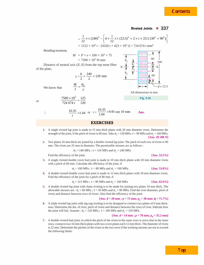
Riveted Joints 337
= 3 3 2 21 1
(240) – 4 (23.5) 2 23.5 (30 90 )12 12
t t t⎡ ⎤× × × + × × +⎢ ⎥⎣ ⎦
= 1152 × 103 t – [4326 t + 423 × 103 t] = 724 674 t mm4
Bending moment,
M = P × e = 100 × 103 × 75
= 7500 × 103 N-mm
Distance of neutral axis (X–X) from the top most fibreof the plate,
y =240
120 mm2 2
b = =
We know that bM
I y
σ=
or 37500 10 125
724 674 120t
× =
∴ 10.351.04
t= or t =
10.359.95 say 10 mm
1.04= Ans.
EEEEEXEXEXEXEXERRRRRCISECISECISECISECISESSSSS
1. A single riveted lap joint is made in 15 mm thick plates with 20 mm diameter rivets. Determine thestrength of the joint, if the pitch of rivets is 60 mm. Take σt = 120 MPa; τ = 90 MPa and σc = 160 MPa.
[Ans. 28 280 N]
2. Two plates 16 mm thick are joined by a double riveted lap joint. The pitch of each row of rivets is 90mm. The rivets are 25 mm in diameter. The permissible stresses are as follows :
σt = 140 MPa ; τ = 110 MPa and σc = 240 MPa
Find the efficiency of the joint. [Ans. 53.5%]
3. A single riveted double cover butt joint is made in 10 mm thick plates with 20 mm diameter rivetswith a pitch of 60 mm. Calculate the efficiency of the joint, if
σt = 100 MPa ; τ = 80 MPa and σc = 160 MPa. [Ans. 53.8%]
4. A double riveted double cover butt joint is made in 12 mm thick plates with 18 mm diameter rivets.Find the efficiency of the joint for a pitch of 80 mm, if
σt = 115 MPa ; τ = 80 MPa and σc = 160 MPa. [Ans. 62.6%]
5. A double riveted lap joint with chain riveting is to be made for joining two plates 10 mm thick. Theallowable stresses are : σt = 60 MPa ; τ = 50 MPa and σc = 80 MPa. Find the rivet diameter, pitch ofrivets and distance between rows of rivets. Also find the efficiency of the joint.
[Ans. d = 20 mm ; p = 73 mm; pb = 38 mm; ηηηηη = 71.7%]
6. A triple riveted lap joint with zig-zag riveting is to be designed to connect two plates of 6 mm thick-ness. Determine the dia. of rivet, pitch of rivets and distance between the rows of rivet. Indicate howthe joint will fail. Assume : σt = 120 MPa ; τ = 100 MPa and σc = 150 MPa.
[Ans. d = 14 mm ; p = 78 mm; pb = 35.2 mm]
7. A double riveted butt joint, in which the pitch of the rivets in the outer rows is twice that in the innerrows, connects two 16 mm thick plates with two cover plates each 12 mm thick. The diameter of rivetsis 22 mm. Determine the pitches of the rivets in the two rows if the working stresses are not to exceedthe following limits:
24060
60
30
30
t d = 23.5
h2
h1X
h1
h2
X
All dimensions in mm.
Fig. 9.36
338 A Textbook of Machine Design
Tensile stress in plates = 100 MPa ; Shear stress in rivets = 75 MPa; and bearing stress in rivets andplates = 150 MPa.
Make a fully dimensioned sketch of the joint by showing at least two views.
[Ans. 107 mm, 53.5 mm]8. Design a double riveted double strap butt joint for the longitudinal seam of a boiler shell, 750 mm in
diameter, to carry a maximum steam pressure of 1.05 N/mm2 gauge. The allowable stresses are :s
σt = 35 MPa; τ = 28 MPa and σc = 52.5 MPa
Assume the efficiency of the joint as 75%.
[Ans. t = 16 mm ; d = 25 mm ; p = 63 mm ; pb = 37.5 mm ; t1 = t2 = 10 mm ; m = 37.5 mm]9. Design a triple riveted double strap butt joint with chain riveting for a boiler of 1.5 m diameter and
carrying a pressure of 1.2 N/mm2. The allowable stresses are :
σt = 105 MPa ; τ = 77 MPa and σc = 162.5 MPa [Ans. d = 20 mm; p = 50 mm]10. Design a triple riveted longitudinal double strap butt joint with unequal straps for a boiler. The inside
diameter of the longest course of the drum is 1.3 metres. The joint is to be designed for a steampressure of 2.4 N/mm2. The working stresses to be used are :
σt = 77 MPa; τ = 62 MPa and σc = 120 MPa
Assume the efficiency of the joint as 81%.
[Ans. t = 26 mm; d = 31.5 mm ; p = 200 mm ; t1 = 19.5 mm ; t2 = 16.5 mm ; m = 47.5 mm]11. Design the longitudinal and circumferential joint for a boiler whose diameter is 2.4 metres and is
subjected to a pressure of 1 N/mm2. The longitudinal joint is a triple riveted butt joint with an effi-ciency of about 85% and the circumferential joint is a double riveted lap joint with an efficiency ofabout 70%. The pitch in the outer rows of the rivets is to be double than in the inner rows and thewidth of the cover plates is unequal. The allowable stresses are :
σt = 77 MPa ; τ = 56 MPa and σc = 120 MPa
Assume that the resistance of rivets in double shear is 1.875 times that of single shear. Draw thecomplete joint.
12. A triple riveted butt joint with equal double cover plates (zig-zag riveting) is used for the longitudinaljoint of a Lancashire boiler of 2.5 m internal diameter. The working steam pressure is 1.12 N/mm2 andthe efficiency of the joint is 85 per cent. Calculate the plate thickness for mild steel of 460 MPaultimate tensile strength. Assume ratio of tensile to shear stresses as 7/6 and factor of safety 4. Theresistance of the rivets in double shear is to be taken as 1.875 times that of single shear. Design asuitable circumferential joint also.
13. Two lengths of mild steel flat tie bars 200 mm × 10 mm are to be connected by a double riveted doublecover butt joint, using 24 mm diameter rivets. Design the joint, if the allowable working stresses are 112MPa in tension, 84 MPa in shear and 200 MPa in crushing.
[Ans. n = 5; ηηηηη = 88%]14. Two mild steel tie bars for a bridge structure are to be joined by a double cover butt joint. The
thickness of the tie bar is 20 mm and carries a tensile load of 400 kN. Design the joint if the allowablestresses are : σt = 90 MPa ; τ = 75 MPa and σc = 150 MPa.
Assume the strength of rivet in double shear to be 1.75 times that of in single shear.
[Ans. b = 150 mm ; d = 27 mm ; n = 6 ; ηηηηη = 90%]15. Two lengths of mild steel tie rod having width 200 mm are to be connected by means of Lozenge joint
with two cover plates to withstand a tensile load of 180 kN. Completely design the joint, if the permis-sible stresses are 80 MPa in tension; 65 MPa in shear and 160 MPa in crushing. Draw a neat sketch ofthe joint.
[Ans. t = 13 mm ; d = 22 mm ; n = 5 ; ηηηηη = 86.5%]16. A bracket is supported by means of 4 rivets of same size, as shown in Fig. 9.37. Determine the
diameter of the rivet if the maximum shear stress is 140 MPa. [Ans. 16 mm]
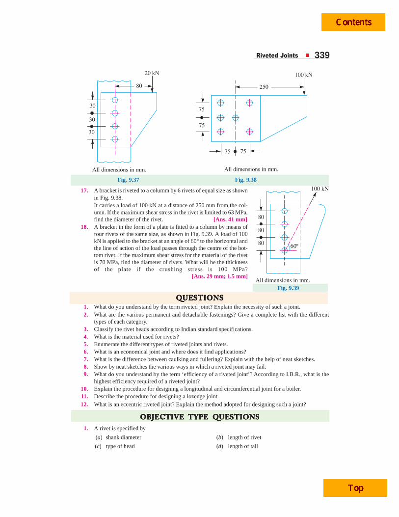
Riveted Joints 339
3075
75
75 75
30
30
80
20 kN
250
100 kN
All dimensions in mm. All dimensions in mm.
Fig. 9.37 Fig. 9.38
17. A bracket is riveted to a columm by 6 rivets of equal size as shownin Fig. 9.38.It carries a load of 100 kN at a distance of 250 mm from the col-umn. If the maximum shear stress in the rivet is limited to 63 MPa,find the diameter of the rivet. [Ans. 41 mm]
18. A bracket in the form of a plate is fitted to a column by means offour rivets of the same size, as shown in Fig. 9.39. A load of 100kN is applied to the bracket at an angle of 60° to the horizontal andthe line of action of the load passes through the centre of the bot-tom rivet. If the maximum shear stress for the material of the rivetis 70 MPa, find the diameter of rivets. What will be the thicknessof the plate if the crushing stress is 100 MPa? [Ans. 29 mm; 1.5 mm]
QQQQQUEUEUEUEUESTSTSTSTSTIONSIONSIONSIONSIONS1. What do you understand by the term riveted joint? Explain the necessity of such a joint.2. What are the various permanent and detachable fastenings? Give a complete list with the different
types of each category.3. Classify the rivet heads according to Indian standard specifications.4. What is the material used for rivets?5. Enumerate the different types of riveted joints and rivets.6. What is an economical joint and where does it find applications?7. What is the difference between caulking and fullering? Explain with the help of neat sketches.8. Show by neat sketches the various ways in which a riveted joint may fail.9. What do you understand by the term ‘efficiency of a riveted joint’? According to I.B.R., what is the
highest efficiency required of a riveted joint?10. Explain the procedure for designing a longitudinal and circumferential joint for a boiler.11. Describe the procedure for designing a lozenge joint.12. What is an eccentric riveted joint? Explain the method adopted for designing such a joint?
OBJECTOBJECTOBJECTOBJECTOBJECTIVEIVEIVEIVEIVE TTTTTYPYPYPYPYPE E E E E QQQQQUEUEUEUEUESTSTSTSTSTIONSIONSIONSIONSIONS1. A rivet is specified by
(a) shank diameter (b) length of rivet
(c) type of head (d) length of tail
Fig. 9.39
80
80
80
All dimensions in mm.
100 kN
60º
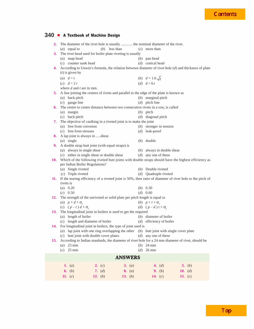
340 A Textbook of Machine Design
2. The diameter of the rivet hole is usually ............ the nominal diameter of the rivet.(a) equal to (b) less than (c) more than
3. The rivet head used for boiler plate riveting is usually(a) snap head (b) pan head(c) counter sunk head (d) conical head
4. According to Unwin’s formula, the relation between diameter of rivet hole (d) and thickness of plate(t) is given by
(a) d = t (b) d = 1.6 t(c) d = 2 t (d) d = 6 twhere d and t are in mm.
5. A line joining the centres of rivets and parallel to the edge of the plate is known as(a) back pitch (b) marginal pitch(c) gauge line (d) pitch line
6. The centre to centre distance between two consecutive rivets in a row, is called(a) margin (b) pitch(c) back pitch (d) diagonal pitch
7. The objective of caulking in a riveted joint is to make the joint(a) free from corrosion (b) stronger in tension(c) free from stresses (d) leak-proof
8. A lap joint is always in .....shear.(a) single (b) double
9. A double strap butt joint (with equal straps) is(a) always in single shear (b) always in double shear(c) either in single shear or double shear (d) any one of these
10. Which of the following riveted butt joints with double straps should have the highest efficiency asper Indian Boiler Regulations?(a) Single riveted (b) Double riveted(c) Triple riveted (d) Quadruple riveted
11. If the tearing efficiency of a riveted joint is 50%, then ratio of diameter of rivet hole to the pitch ofrivets is(a) 0.20 (b) 0.30(c) 0.50 (d) 0.60
12. The strength of the unriveted or solid plate per pitch length is equal to(a) p × d × σt (b) p × t × σt(c) ( p – t ) d × σt (d) ( p – d ) t × σt
13. The longitudinal joint in boilers is used to get the required(a) length of boiler (b) diameter of boiler(c) length and diameter of boiler (d) efficiency of boiler
14. For longitudinal joint in boilers, the type of joint used is(a) lap joint with one ring overlapping the other (b) butt joint with single cover plate(c) butt joint with double cover plates (d) any one of these
15. According to Indian standards, the diameter of rivet hole for a 24 mm diameter of rivet, should be(a) 23 mm (b) 24 mm(c) 25 mm (d) 26 mm
ANSWEANSWEANSWEANSWEANSWERRRRRSSSSS
1. (a) 2. (c) 3. (a) 4. (d) 5. (b)
6. (b) 7. (d) 8. (a) 9. (b) 10. (d)
11. (c) 12. (b) 13. (b) 14. (c) 15. (c)
Riveted Joints 341We know that the strength of the unriveted or solid plate,
P = p × t × σt = 65 × 6 × 120 = 46 800 N
∴ Efficiency of the joint,
η =Least of , andt s cP P P
P =
32 400
46 800 = 0.692 or 69.2% Ans.
Example 9.3. A double riveted double cover butt joint in plates 20 mm thick is made with25 mm diameter rivets at 100 mm pitch. The permissible stresses are :
σt = 120 MPa; τ = 100 MPa; σc = 150 MPaFind the efficiency of joint, taking the strength of the rivet in double shear as twice than that of
single shear.
Solution. Given : t = 20 mm ; d = 25 mm ; p = 100 mm ; σt = 120 MPa = 120 N/mm2 ;τ = 100 MPa = 100 N/mm2 ; σc = 150 MPa = 150 N/mm2
First of all, let us find the tearing resistance of the plate, shearing resistance and crushingresistance of the rivet.
(i) Tearing resistance of the plateWe know that tearing resistance of the plate per pitch length,
Pt = (p – d) t × σt = (100 × 25) 20 × 120 = 180 000 N
(ii) Shearing resistance of the rivetsSince the joint is double riveted butt joint, therefore the strength of two rivets in double shear is
taken. We know that shearing resistance of the rivets,
Ps = n × 2 × 4
π × d 2 × τ = 2 × 2 ×
4
π (25)2 100 = 196 375 N
(iii) Crushing resistance of the rivetsSince the joint is double riveted, therefore the strength of two rivets is taken. We know that
crushing resistance of the rivets,
Pc = n × d × t × σc = 2 × 25 × 20 × 150 = 150 000 N
∴ Strength of the joint
= Least of Pt, Ps and Pc
= 150 000 N
Efficiency of the joint
We know that the strength of the unriveted or solid plate,
P = p × t × σt = 100 × 20 × 120
= 240 000 N
∴ Efficiency of the joint
=Least of , andt s cP P P
P =
150 000
240 000 = 0.625 or 62.5% Ans.
9.15 Design of Boiler JointsThe boiler has a longitudinal joint as well as
circumferential joint. The longitudinal joint is used to join theends of the plate to get the required diameter of a boiler. Forthis purpose, a butt joint with two cover plates is used. The
Control lever
Air in
Air out
Cylinder
Piston repeat-edly forced upand down byair
Anvil
Drill bit
Diaphragmchanges theroute of thecompressed airseveral timesper second
Pt = ( p – d ) t × σt = (100 × 25) 20 × 120 = 180 000 N

342 A Textbook of Machine Design
(c) d = 2 t (d) d = 6 t
(c) either in single shear or double shear (d) any one of these
(c) ( p – t ) d × σt (d) ( p – d ) t × σt
(c) butt joint with double cover plates (d) any one of these
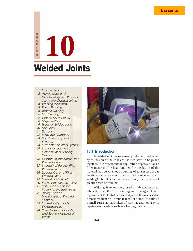
Welded Joints 341
10.1 IntroductionA welded joint is a permanent joint which is obtained
by the fusion of the edges of the two parts to be joinedtogether, with or without the application of pressure and afiller material. The heat required for the fusion of thematerial may be obtained by burning of gas (in case of gaswelding) or by an electric arc (in case of electric arcwelding). The latter method is extensively used because ofgreater speed of welding.
Welding is extensively used in fabrication as analternative method for casting or forging and as areplacement for bolted and riveted joints. It is also used asa repair medium e.g. to reunite metal at a crack, to build upa small part that has broken off such as gear tooth or torepair a worn surface such as a bearing surface.
Welded Joints
341
1. Introduction.2. Advantages and
Disadvantages of WeldedJoints over Riveted Joints.
3. Welding Processes.4. Fusion Welding.5. Thermit Welding.6. Gas Welding.7. Electric Arc Welding.8. Forge Welding.9. Types of Welded Joints.
10. Lap Joint.11. Butt Joint.12. Basic Weld Symbols.13. Supplementary Weld
Symbols.14. Elements of a Weld Symbol.15. Standard Location of
Elements of a WeldingSymbol.
16. Strength of Transverse FilletWelded Joints.
17. Strength of Parallel FilletWelded Joints.
18. Special Cases of FilletWelded Joints.
19. Strength of Butt Joints.20. Stresses for Welded Joints.21. Stress Concentration
Factor for Welded Joints.22. Axially Loaded
Unsymmetrical WeldedSections.
23. Eccentrically LoadedWelded Joints.
24. Polar Moment of Inertiaand Section Modulus ofWelds.
10CHAPTER
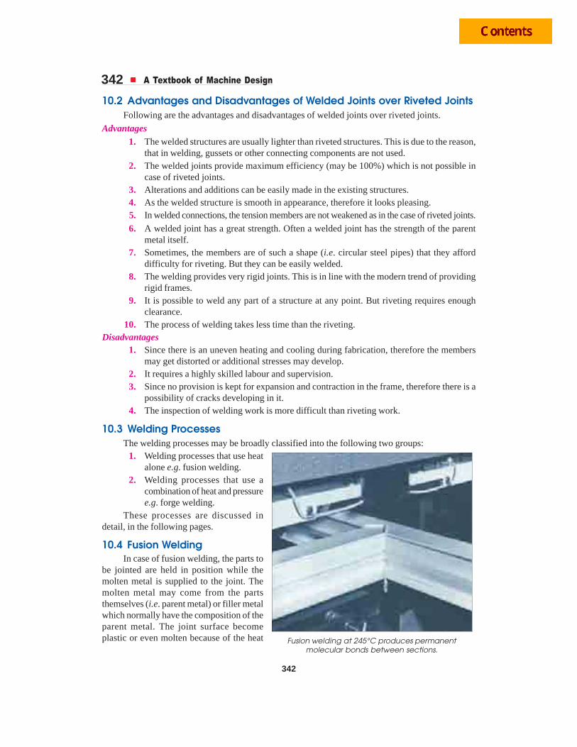
342 A Textbook of Machine Design
342
10.2 Advantages and Disadvantages of Welded Joints over Riveted JointsFollowing are the advantages and disadvantages of welded joints over riveted joints.
Advantages1. The welded structures are usually lighter than riveted structures. This is due to the reason,
that in welding, gussets or other connecting components are not used.2. The welded joints provide maximum efficiency (may be 100%) which is not possible in
case of riveted joints.3. Alterations and additions can be easily made in the existing structures.4. As the welded structure is smooth in appearance, therefore it looks pleasing.5. In welded connections, the tension members are not weakened as in the case of riveted joints.
6. A welded joint has a great strength. Often a welded joint has the strength of the parentmetal itself.
7. Sometimes, the members are of such a shape (i.e. circular steel pipes) that they afforddifficulty for riveting. But they can be easily welded.
8. The welding provides very rigid joints. This is in line with the modern trend of providingrigid frames.
9. It is possible to weld any part of a structure at any point. But riveting requires enoughclearance.
10. The process of welding takes less time than the riveting.Disadvantages
1. Since there is an uneven heating and cooling during fabrication, therefore the membersmay get distorted or additional stresses may develop.
2. It requires a highly skilled labour and supervision.3. Since no provision is kept for expansion and contraction in the frame, therefore there is a
possibility of cracks developing in it.4. The inspection of welding work is more difficult than riveting work.
10.3 Welding ProcessesThe welding processes may be broadly classified into the following two groups:
1. Welding processes that use heatalone e.g. fusion welding.
2. Welding processes that use acombination of heat and pressuree.g. forge welding.
These processes are discussed indetail, in the following pages.
10.4 Fusion WeldingIn case of fusion welding, the parts to
be jointed are held in position while themolten metal is supplied to the joint. Themolten metal may come from the partsthemselves (i.e. parent metal) or filler metalwhich normally have the composition of theparent metal. The joint surface becomeplastic or even molten because of the heat Fusion welding at 245°C produces permanent
molecular bonds between sections.
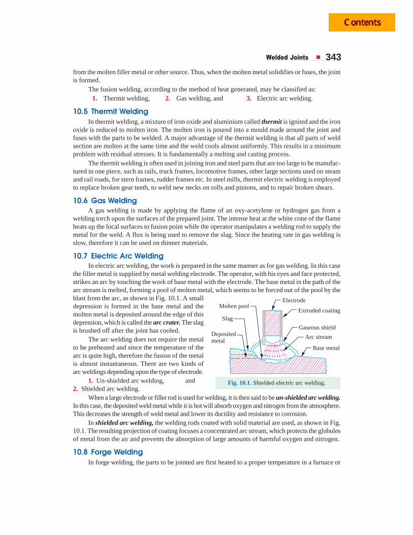
Welded Joints 343from the molten filler metal or other source. Thus, when the molten metal solidifies or fuses, the jointis formed.
The fusion welding, according to the method of heat generated, may be classified as:1. Thermit welding, 2. Gas welding, and 3. Electric arc welding.
10.5 Thermit WeldingIn thermit welding, a mixture of iron oxide and aluminium called thermit is ignited and the iron
oxide is reduced to molten iron. The molten iron is poured into a mould made around the joint andfuses with the parts to be welded. A major advantage of the thermit welding is that all parts of weldsection are molten at the same time and the weld cools almost uniformly. This results in a minimumproblem with residual stresses. It is fundamentally a melting and casting process.
The thermit welding is often used in joining iron and steel parts that are too large to be manufac-tured in one piece, such as rails, truck frames, locomotive frames, other large sections used on steamand rail roads, for stern frames, rudder frames etc. In steel mills, thermit electric welding is employedto replace broken gear teeth, to weld new necks on rolls and pinions, and to repair broken shears.
10.6 Gas WeldingA gas welding is made by applying the flame of an oxy-acetylene or hydrogen gas from a
welding torch upon the surfaces of the prepared joint. The intense heat at the white cone of the flameheats up the local surfaces to fusion point while the operator manipulates a welding rod to supply themetal for the weld. A flux is being used to remove the slag. Since the heating rate in gas welding isslow, therefore it can be used on thinner materials.
10.7 Electric Arc WeldingIn electric arc welding, the work is prepared in the same manner as for gas welding. In this case
the filler metal is supplied by metal welding electrode. The operator, with his eyes and face protected,strikes an arc by touching the work of base metal with the electrode. The base metal in the path of thearc stream is melted, forming a pool of molten metal, which seems to be forced out of the pool by theblast from the arc, as shown in Fig. 10.1. A smalldepression is formed in the base metal and themolten metal is deposited around the edge of thisdepression, which is called the arc crater. The slagis brushed off after the joint has cooled.
The arc welding does not require the metalto be preheated and since the temperature of thearc is quite high, therefore the fusion of the metalis almost instantaneous. There are two kinds ofarc weldings depending upon the type of electrode.
1. Un-shielded arc welding, and2. Shielded arc welding.
When a large electrode or filler rod is used for welding, it is then said to be un-shielded arc welding.In this case, the deposited weld metal while it is hot will absorb oxygen and nitrogen from the atmosphere.This decreases the strength of weld metal and lower its ductility and resistance to corrosion.
In shielded arc welding, the welding rods coated with solid material are used, as shown in Fig.10.1. The resulting projection of coating focuses a concentrated arc stream, which protects the globulesof metal from the air and prevents the absorption of large amounts of harmful oxygen and nitrogen.
10.8 Forge WeldingIn forge welding, the parts to be jointed are first heated to a proper temperature in a furnace or
Fig. 10.1. Shielded electric arc welding.
Electrode
Extruded coating
Gaseous shield
Arc stream
Base metal
Molten pool
Slag
Depositedmetal
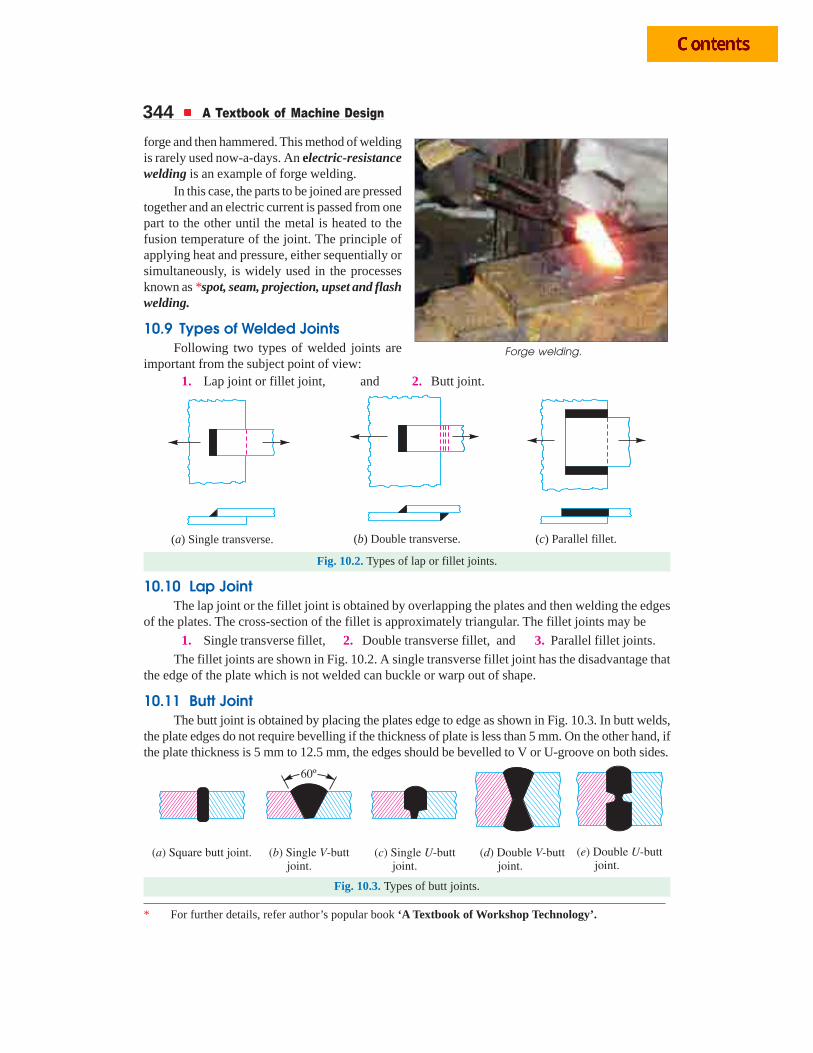
344 A Textbook of Machine Design
forge and then hammered. This method of weldingis rarely used now-a-days. An electric-resistancewelding is an example of forge welding.
In this case, the parts to be joined are pressedtogether and an electric current is passed from onepart to the other until the metal is heated to thefusion temperature of the joint. The principle ofapplying heat and pressure, either sequentially orsimultaneously, is widely used in the processesknown as *spot, seam, projection, upset and flashwelding.
10.9 Types of Welded JointsFollowing two types of welded joints are
important from the subject point of view:1. Lap joint or fillet joint, and 2. Butt joint.
( ) Single transverse.a ( ) Double transverse.b ( ) Parallel fillet.c
Fig. 10.2. Types of lap or fillet joints.
10.10 Lap JointThe lap joint or the fillet joint is obtained by overlapping the plates and then welding the edges
of the plates. The cross-section of the fillet is approximately triangular. The fillet joints may be
1. Single transverse fillet, 2. Double transverse fillet, and 3. Parallel fillet joints.
The fillet joints are shown in Fig. 10.2. A single transverse fillet joint has the disadvantage thatthe edge of the plate which is not welded can buckle or warp out of shape.
10.11 Butt JointThe butt joint is obtained by placing the plates edge to edge as shown in Fig. 10.3. In butt welds,
the plate edges do not require bevelling if the thickness of plate is less than 5 mm. On the other hand, ifthe plate thickness is 5 mm to 12.5 mm, the edges should be bevelled to V or U-groove on both sides.
Fig. 10.3. Types of butt joints.
* For further details, refer author’s popular book ‘A Textbook of Workshop Technology’.
Forge welding.

Welded Joints 345The butt joints may be
1. Square butt joint, 2. Single V-butt joint 3. Single U-butt joint,
4. Double V-butt joint, and 5. Double U-butt joint.
These joints are shown in Fig. 10.3.
The other type of welded joints are corner joint, edge joint and T-joint as shown in Fig. 10.4.
( ) Corner joint.a ( ) Edge joint.b ( ) -joint.c T
Fig. 10.4. Other types of welded joints.
The main considerations involved in the selection of weld type are:
1. The shape of the welded component required,2. The thickness of the plates to be welded, and3. The direction of the forces applied.
10.12 Basic Weld SymbolsThe basic weld symbols according to IS : 813 – 1961 (Reaffirmed 1991) are shown in the
following table.Table 10.1. Basic weld symbols.
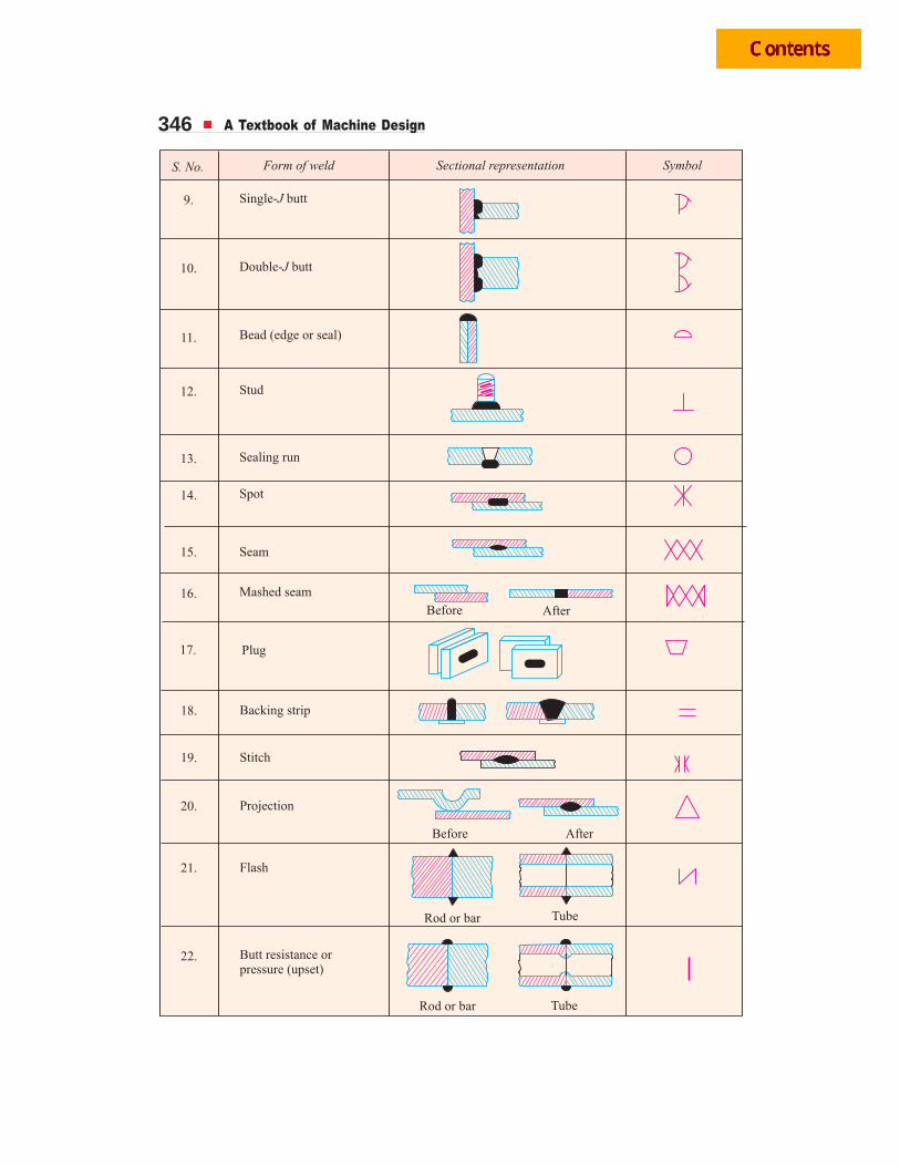
346 A Textbook of Machine Design
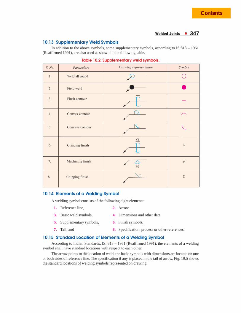
Welded Joints 347
10.13 Supplementary Weld SymbolsIn addition to the above symbols, some supplementary symbols, according to IS:813 – 1961
(Reaffirmed 1991), are also used as shown in the following table.
Table 10.2. Supplementary weld symbols.
10.14 Elements of a Welding Symbol
A welding symbol consists of the following eight elements:
1. Reference line, 2. Arrow,
3. Basic weld symbols, 4. Dimensions and other data,
5. Supplementary symbols, 6. Finish symbols,
7. Tail, and 8. Specification, process or other references.
10.15 Standard Location of Elements of a Welding SymbolAccording to Indian Standards, IS: 813 – 1961 (Reaffirmed 1991), the elements of a welding
symbol shall have standard locations with respect to each other.
The arrow points to the location of weld, the basic symbols with dimensions are located on oneor both sides of reference line. The specification if any is placed in the tail of arrow. Fig. 10.5 showsthe standard locations of welding symbols represented on drawing.
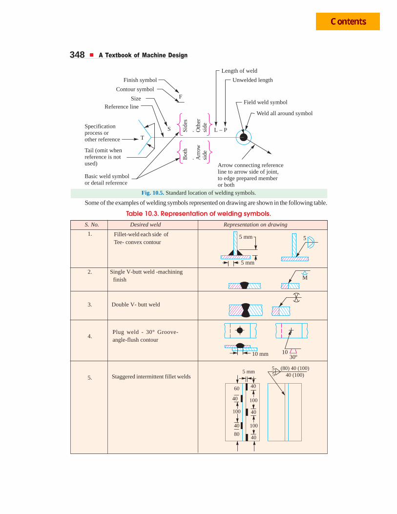
348 A Textbook of Machine Design
Both
. Arr
ow
side
Sid
es. O
ther
side
Field weld symbol
Weld all around symbol
Unwelded length
Length of weld
Finish symbol
Contour symbol
Reference line
Specificationprocess orother reference
Tail (omit whenreference is notused)
Basic weld symbolor detail reference
Arrow connecting referenceline to arrow side of joint,to edge prepared memberor both
L P�
S
F
T
Size
Fig. 10.5. Standard location of welding symbols.
Some of the examples of welding symbols represented on drawing are shown in the following table.
Table 10.3. Representation of welding symbols.
S. No. Desired weld Representation on drawing
1.
2. Single V-butt weld -machining finish
3. Double V- butt weld
4.
5.
Fillet-weld each side ofTee- convex contour
Staggered intermittent fillet welds
Plug weld - 30° Groove-angle-flush contour
40
40
60
40
40
40
80
100
100
100
5 mm(80) 40 (100)
40 (100)
55
5 mm
5 mm 5
M
10 mm 1030º
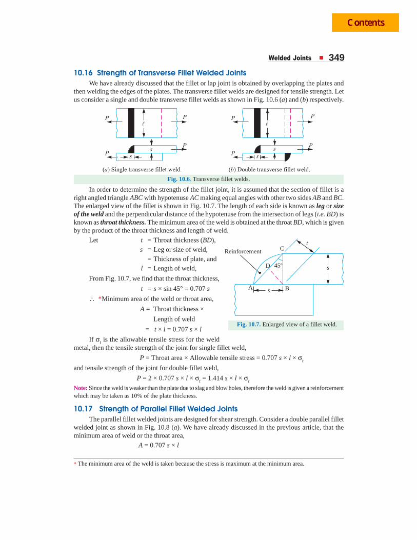
Welded Joints 349
10.16 Strength of Transverse Fillet Welded JointsWe have already discussed that the fillet or lap joint is obtained by overlapping the plates and
then welding the edges of the plates. The transverse fillet welds are designed for tensile strength. Letus consider a single and double transverse fillet welds as shown in Fig. 10.6 (a) and (b) respectively.
Fig. 10.6. Transverse fillet welds.
In order to determine the strength of the fillet joint, it is assumed that the section of fillet is aright angled triangle ABC with hypotenuse AC making equal angles with other two sides AB and BC.The enlarged view of the fillet is shown in Fig. 10.7. The length of each side is known as leg or sizeof the weld and the perpendicular distance of the hypotenuse from the intersection of legs (i.e. BD) isknown as throat thickness. The minimum area of the weld is obtained at the throat BD, which is givenby the product of the throat thickness and length of weld.
Let t = Throat thickness (BD), s = Leg or size of weld,
= Thickness of plate, andl = Length of weld,
From Fig. 10.7, we find that the throat thickness,
t = s × sin 45° = 0.707 s
∴ *Minimum area of the weld or throat area,
A = Throat thickness ×
Length of weld
= t × l = 0.707 s × l
If σt is the allowable tensile stress for the weldmetal, then the tensile strength of the joint for single fillet weld,
P = Throat area × Allowable tensile stress = 0.707 s × l × σt
and tensile strength of the joint for double fillet weld,
P = 2 × 0.707 s × l × σt = 1.414 s × l × σt
Note: Since the weld is weaker than the plate due to slag and blow holes, therefore the weld is given a reinforcementwhich may be taken as 10% of the plate thickness.
10.17 Strength of Parallel Fillet Welded JointsThe parallel fillet welded joints are designed for shear strength. Consider a double parallel fillet
welded joint as shown in Fig. 10.8 (a). We have already discussed in the previous article, that theminimum area of weld or the throat area,
A = 0.707 s × l
s
s
t
45ºD
BA
ReinforcementC
Fig. 10.7. Enlarged view of a fillet weld.
* The minimum area of the weld is taken because the stress is maximum at the minimum area.
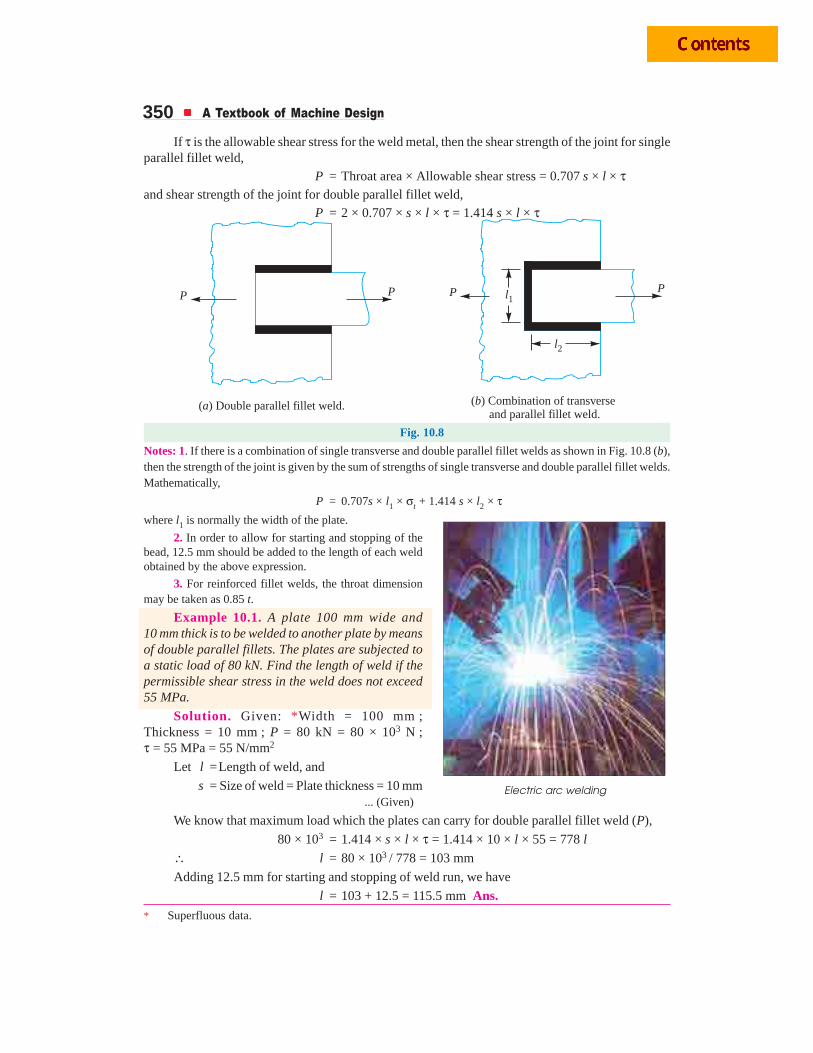
350 A Textbook of Machine Design
If τ is the allowable shear stress for the weld metal, then the shear strength of the joint for singleparallel fillet weld,
P = Throat area × Allowable shear stress = 0.707 s × l × τand shear strength of the joint for double parallel fillet weld,
P = 2 × 0.707 × s × l × τ = 1.414 s × l × τ
P PP P
( ) Double parallel fillet weld.a ( ) Combination of transverseand parallel fillet weld.
b
l1
l2
Fig. 10.8
Notes: 1. If there is a combination of single transverse and double parallel fillet welds as shown in Fig. 10.8 (b),then the strength of the joint is given by the sum of strengths of single transverse and double parallel fillet welds.Mathematically,
P = 0.707s × l1 × σt + 1.414 s × l2 × τwhere l1 is normally the width of the plate.
2. In order to allow for starting and stopping of thebead, 12.5 mm should be added to the length of each weldobtained by the above expression.
3. For reinforced fillet welds, the throat dimensionmay be taken as 0.85 t.
Example 10.1. A plate 100 mm wide and10 mm thick is to be welded to another plate by meansof double parallel fillets. The plates are subjected toa static load of 80 kN. Find the length of weld if thepermissible shear stress in the weld does not exceed55 MPa.
Solution. Given: *Width = 100 mm ;Thickness = 10 mm ; P = 80 kN = 80 × 103 N ;τ = 55 MPa = 55 N/mm2
Let l =Length of weld, and
s = Size of weld = Plate thickness = 10 mm ... (Given)
We know that maximum load which the plates can carry for double parallel fillet weld (P),
80 × 103 = 1.414 × s × l × τ = 1.414 × 10 × l × 55 = 778 l
∴ l = 80 × 103 / 778 = 103 mm
Adding 12.5 mm for starting and stopping of weld run, we have
l = 103 + 12.5 = 115.5 mm Ans.
Electric arc welding
* Superfluous data.
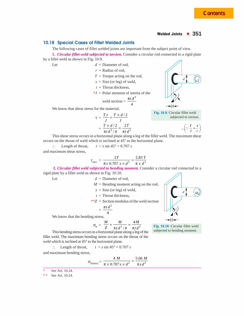
Welded Joints 351
10.18 Special Cases of Fillet Welded JointsThe following cases of fillet welded joints are important from the subject point of view.
1. Circular fillet weld subjected to torsion. Consider a circular rod connected to a rigid plateby a fillet weld as shown in Fig. 10.9.
Let d = Diameter of rod,
r = Radius of rod,
T = Torque acting on the rod,
s = Size (or leg) of weld,
t = Throat thickness,
*J = Polar moment of inertia of the
weld section = 3
4
t dπ
We know that shear stress for the material,
τ =. / 2T r T d
J J
×=
= 3 2
/ 2 2
/ 4
T d T
t d t d
× =π π
...τ⎛ ⎞=⎜ ⎟
⎝ ⎠Q
T
J r
This shear stress occurs in a horizontal plane along a leg of the fillet weld. The maximum shearoccurs on the throat of weld which is inclined at 45° to the horizontal plane.
∴ Length of throat, t = s sin 45° = 0.707 sand maximum shear stress,
τmax = 2 2
2 2.83
0.707
T T
s d s d=
π× × π 2. Circular fillet weld subjected to bending moment. Consider a circular rod connected to a
rigid plate by a fillet weld as shown in Fig. 10.10.
Let d = Diameter of rod,
M = Bending moment acting on the rod,
s = Size (or leg) of weld,
t = Throat thickness,
**Z = Section modulus of the weld section
=2
4
t dπ
We know that the bending stress,
σb = 2 2
4
/ 4
M M M
Z t d t d= =
π πThis bending stress occurs in a horizontal plane along a leg of the
fillet weld. The maximum bending stress occurs on the throat of theweld which is inclined at 45° to the horizontal plane.
∴ Length of throat, t = s sin 45° = 0.707 s
and maximum bending stress,
σb(max) = 2 2
4 5.66
0.707
M M
s d s d=
π × × π
Fig. 10.9. Circular fillet weld subjected to torsion.
* See Art, 10.24.* * See Art, 10.24.
Fig. 10.10. Circular fillet weldsubjected to bending moment.
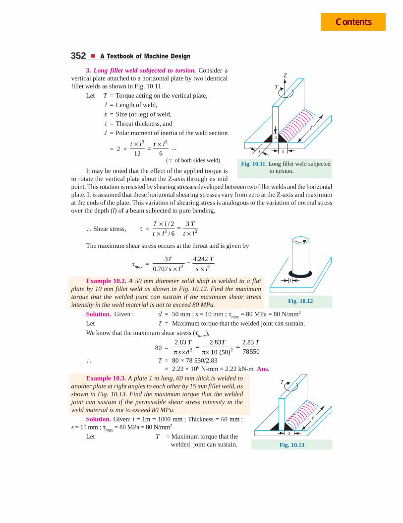
352 A Textbook of Machine Design
3. Long fillet weld subjected to torsion. Consider avertical plate attached to a horizontal plate by two identicalfillet welds as shown in Fig. 10.11.
Let T = Torque acting on the vertical plate,
l = Length of weld,
s = Size (or leg) of weld,
t = Throat thickness, and
J = Polar moment of inertia of the weld section
= 2 × 3 3
12 6
t l t l× ×= ...
(Q of both sides weld)
It may be noted that the effect of the applied torque isto rotate the vertical plate about the Z-axis through its midpoint. This rotation is resisted by shearing stresses developed between two fillet welds and the horizontalplate. It is assumed that these horizontal shearing stresses vary from zero at the Z-axis and maximumat the ends of the plate. This variation of shearing stress is analogous to the variation of normal stressover the depth (l) of a beam subjected to pure bending.
∴ Shear stress, τ = 3 2
/ 2 3
/ 6
T l T
t l t l
× =× ×
The maximum shear stress occurs at the throat and is given by
τmax = 2 2
3 4.242
0.707
T T
s l s l=
× ×
Example 10.2. A 50 mm diameter solid shaft is welded to a flatplate by 10 mm fillet weld as shown in Fig. 10.12. Find the maximumtorque that the welded joint can sustain if the maximum shear stressintensity in the weld material is not to exceed 80 MPa.
Solution. Given : d = 50 mm ; s = 10 mm ; τmax = 80 MPa = 80 N/mm2
Let T = Maximum torque that the welded joint can sustain.
We know that the maximum shear stress (τmax),
80 = 2 2
2.83 2.83 2.83
7855010 (50)
T T T
s d= =
π × π×∴ T = 80 × 78 550/2.83
= 2.22 × 10⁶ N-mm = 2.22 kN-m Ans.Example 10.3. A plate 1 m long, 60 mm thick is welded to
another plate at right angles to each other by 15 mm fillet weld, asshown in Fig. 10.13. Find the maximum torque that the weldedjoint can sustain if the permissible shear stress intensity in theweld material is not to exceed 80 MPa.
Solution. Given: l = 1m = 1000 mm ; Thickness = 60 mm ;s = 15 mm ; τmax = 80 MPa = 80 N/mm2
Let T = Maximum torque that the welded joint can sustain.
Fig. 10.11. Long fillet weld subjected to torsion.
s
Fig. 10.12
Fig. 10.13
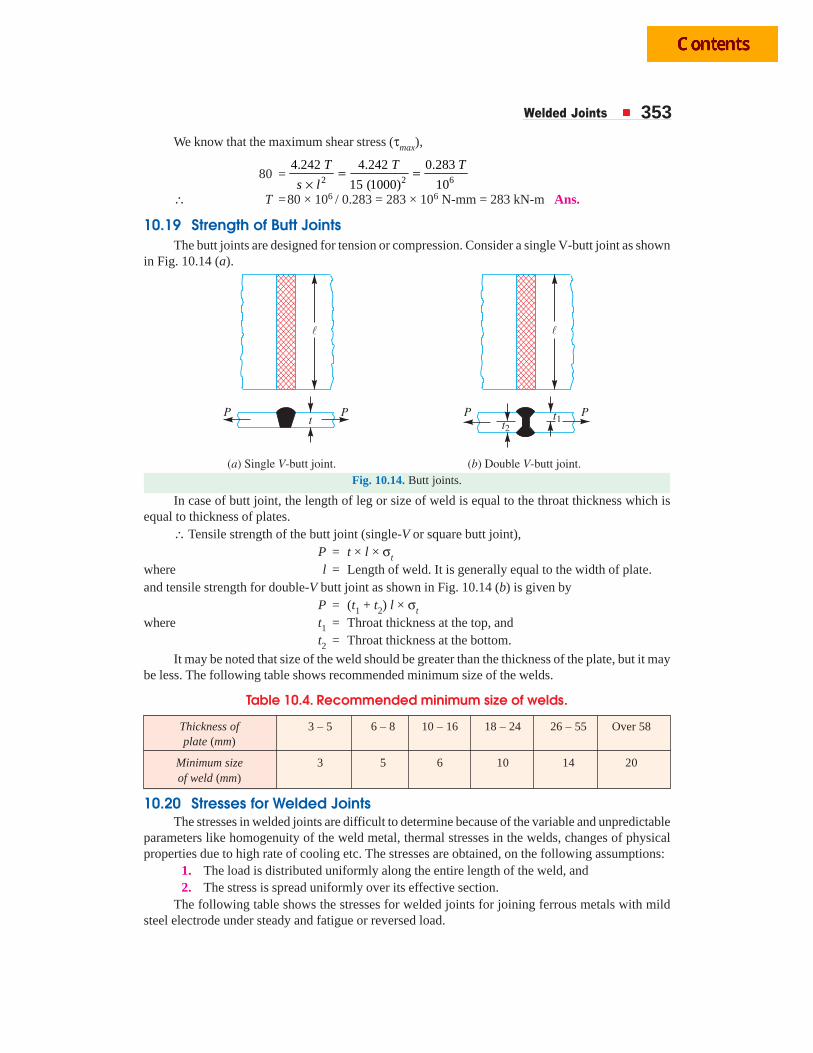
Welded Joints 353We know that the maximum shear stress (τmax),
80 = 2 2 6
4.242 4.242 0.283
15 (1000) 10
T T T
s l= =
×∴ T =80 × 106 / 0.283 = 283 × 106 N-mm = 283 kN-m Ans.
10.19 Strength of Butt JointsThe butt joints are designed for tension or compression. Consider a single V-butt joint as shown
in Fig. 10.14 (a).
Fig. 10.14. Butt joints.
In case of butt joint, the length of leg or size of weld is equal to the throat thickness which isequal to thickness of plates.
∴ Tensile strength of the butt joint (single-V or square butt joint),P = t × l × σt
where l = Length of weld. It is generally equal to the width of plate.and tensile strength for double-V butt joint as shown in Fig. 10.14 (b) is given by
P = (t1 + t2) l × σt
where t1 = Throat thickness at the top, andt2 = Throat thickness at the bottom.
It may be noted that size of the weld should be greater than the thickness of the plate, but it maybe less. The following table shows recommended minimum size of the welds.
Table 10.4. Recommended minimum size of welds.
Thickness of 3 – 5 6 – 8 10 – 16 18 – 24 26 – 55 Over 58plate (mm)
Minimum size 3 5 6 10 14 20of weld (mm)
10.20 Stresses for Welded JointsThe stresses in welded joints are difficult to determine because of the variable and unpredictable
parameters like homogenuity of the weld metal, thermal stresses in the welds, changes of physicalproperties due to high rate of cooling etc. The stresses are obtained, on the following assumptions:
1. The load is distributed uniformly along the entire length of the weld, and2. The stress is spread uniformly over its effective section.
The following table shows the stresses for welded joints for joining ferrous metals with mildsteel electrode under steady and fatigue or reversed load.
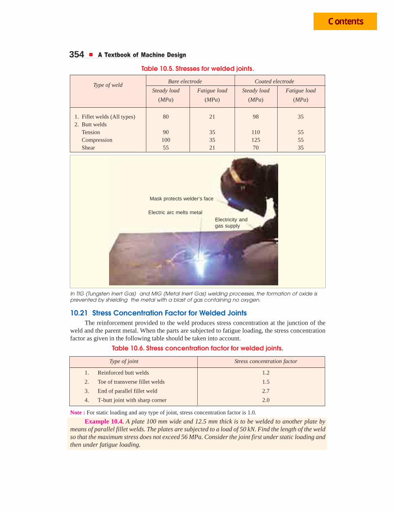
354 A Textbook of Machine Design
Table 10.5. Stresses for welded joints.
Bare electrode Coated electrodeType of weld
Steady load Fatigue load Steady load Fatigue load
(MPa) (MPa) (MPa) (MPa)
1. Fillet welds (All types) 80 21 98 352. Butt welds
Tension 90 35 110 55Compression 100 35 125 55Shear 55 21 70 35
Electric arc melts metal
Mask protects welder’s face
Electricity andgas supply
In TIG (Tungsten Inert Gas) and MIG (Metal Inert Gas) welding processes, the formation of oxide isprevented by shielding the metal with a blast of gas containing no oxygen.
10.21 Stress Concentration Factor for Welded JointsThe reinforcement provided to the weld produces stress concentration at the junction of the
weld and the parent metal. When the parts are subjected to fatigue loading, the stress concentrationfactor as given in the following table should be taken into account.
Table 10.6. Stress concentration factor for welded joints.
Type of joint Stress concentration factor
1. Reinforced butt welds 1.2
2. Toe of transverse fillet welds 1.5
3. End of parallel fillet weld 2.7
4. T-butt joint with sharp corner 2.0
Note : For static loading and any type of joint, stress concentration factor is 1.0.
Example 10.4. A plate 100 mm wide and 12.5 mm thick is to be welded to another plate bymeans of parallel fillet welds. The plates are subjected to a load of 50 kN. Find the length of the weldso that the maximum stress does not exceed 56 MPa. Consider the joint first under static loading andthen under fatigue loading.
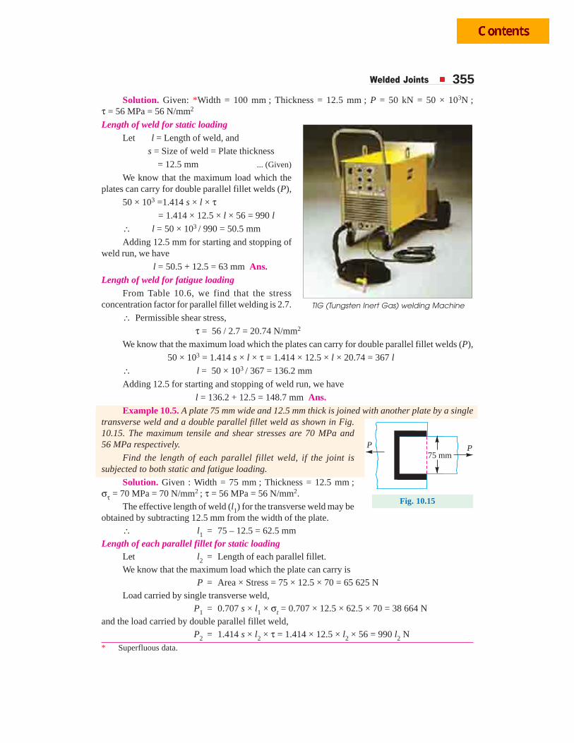
Welded Joints 355Solution. Given: *Width = 100 mm ; Thickness = 12.5 mm ; P = 50 kN = 50 × 103N ;
τ = 56 MPa = 56 N/mm2
Length of weld for static loadingLet l = Length of weld, and
s = Size of weld = Plate thickness
= 12.5 mm ... (Given)
We know that the maximum load which theplates can carry for double parallel fillet welds (P),
50 × 103 =1.414 s × l × τ = 1.414 × 12.5 × l × 56 = 990 l
∴ l = 50 × 103 / 990 = 50.5 mm
Adding 12.5 mm for starting and stopping ofweld run, we have
l = 50.5 + 12.5 = 63 mm Ans.Length of weld for fatigue loading
From Table 10.6, we find that the stressconcentration factor for parallel fillet welding is 2.7.
∴ Permissible shear stress,
τ = 56 / 2.7 = 20.74 N/mm2
We know that the maximum load which the plates can carry for double parallel fillet welds (P),
50 × 103 = 1.414 s × l × τ = 1.414 × 12.5 × l × 20.74 = 367 l
∴ l = 50 × 103 / 367 = 136.2 mm
Adding 12.5 for starting and stopping of weld run, we have
l = 136.2 + 12.5 = 148.7 mm Ans.Example 10.5. A plate 75 mm wide and 12.5 mm thick is joined with another plate by a single
transverse weld and a double parallel fillet weld as shown in Fig.10.15. The maximum tensile and shear stresses are 70 MPa and56 MPa respectively.
Find the length of each parallel fillet weld, if the joint issubjected to both static and fatigue loading.
Solution. Given : Width = 75 mm ; Thickness = 12.5 mm ;στ = 70 MPa = 70 N/mm2 ; τ = 56 MPa = 56 N/mm2.
The effective length of weld (l1) for the transverse weld may beobtained by subtracting 12.5 mm from the width of the plate.
∴ l1 = 75 – 12.5 = 62.5 mmLength of each parallel fillet for static loading
Let l2 = Length of each parallel fillet.We know that the maximum load which the plate can carry is
P = Area × Stress = 75 × 12.5 × 70 = 65 625 NLoad carried by single transverse weld,
P1 = 0.707 s × l1 × σt = 0.707 × 12.5 × 62.5 × 70 = 38 664 Nand the load carried by double parallel fillet weld,
P2 = 1.414 s × l2 × τ = 1.414 × 12.5 × l2 × 56 = 990 l2 N
* Superfluous data.
75 mm
P P
Fig. 10.15
TIG (Tungsten Inert Gas) welding Machine
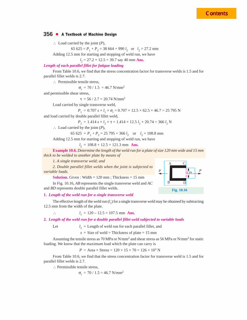
356 A Textbook of Machine Design
∴ Load carried by the joint (P), 65 625 = P1 + P2 = 38 664 + 990 l2 or l2 = 27.2 mmAdding 12.5 mm for starting and stopping of weld run, we have l2 = 27.2 + 12.5 = 39.7 say 40 mm Ans.
Length of each parallel fillet for fatigue loadingFrom Table 10.6, we find that the stress concentration factor for transverse welds is 1.5 and for
parallel fillet welds is 2.7.
∴ Permissible tensile stress,
σt = 70 / 1.5 = 46.7 N/mm2
and permissible shear stress,
τ = 56 / 2.7 = 20.74 N/mm2
Load carried by single transverse weld,
P1 = 0.707 s × l1 × σt = 0.707 × 12.5 × 62.5 × 46.7 = 25 795 N
and load carried by double parallel fillet weld,
P2 = 1.414 s × l2 × τ = 1.414 × 12.5 l2 × 20.74 = 366 l2 N
∴ Load carried by the joint (P),
65 625 = P1 + P2 = 25 795 + 366 l2 or l2 = 108.8 mm
Adding 12.5 mm for starting and stopping of weld run, we have
l2 = 108.8 + 12.5 = 121.3 mm Ans.Example 10.6. Determine the length of the weld run for a plate of size 120 mm wide and 15 mm
thick to be welded to another plate by means of
1. A single transverse weld; and
2. Double parallel fillet welds when the joint is subjected tovariable loads.
Solution. Given : Width = 120 mm ; Thickness = 15 mm
In Fig. 10.16, AB represents the single transverse weld and ACand BD represents double parallel fillet welds.
1. Length of the weld run for a single transverse weld
The effective length of the weld run (l1) for a single transverse weld may be obtained by subtracting12.5 mm from the width of the plate.
∴ l1 = 120 – 12.5 = 107.5 mm Ans.
2. Length of the weld run for a double parallel fillet weld subjected to variable loads
Let l2 = Length of weld run for each parallel fillet, and
s = Size of weld = Thickness of plate = 15 mm
Assuming the tensile stress as 70 MPa or N/mm2 and shear stress as 56 MPa or N/mm2 for staticloading. We know that the maximum load which the plate can carry is
P = Area × Stress = 120 × 15 × 70 = 126 × 103 N
From Table 10.6, we find that the stress concentration factor for transverse weld is 1.5 and forparallel fillet welds is 2.7.
∴ Permissible tensile stress,
σt = 70 / 1.5 = 46.7 N/mm2
120
A C
B D
PP
Fig. 10.16

Welded Joints 357and permissible shear stress,
τ = 56 / 2.7 = 20.74 N/mm2
∴ Load carried by single transverse weld,
P1 = 0.707 s × l1 × σt = 0.707 × 15 × 107.5 × 46.7 = 53 240 N
and load carried by double parallel fillet weld,
P2 = 1.414 s × l2 × τ = 1.414 × 15 × l2 × 20.74 = 440 l2 N
∴ Load carried by the joint (P),
126 × 103 = P1 + P2 = 53 240 + 440 l2 or l2 = 165.4 mm
Adding 12.5 mm for starting and stopping of weld run, we have
l2 = 165.4 + 12.5 = 177.9 say 178 mm Ans.Example 10.7. The fillet welds of equal legs are used to fabricate a `T' as shown in Fig. 10.17
(a) and (b), where s is the leg size and l is the length of weld.
Fig. 10.17
Locate the plane of maximum shear stress in each of the following loading patterns:
1. Load parallel to the weld (neglect eccentricity), and
2. Load at right angles to the weld (transverse load).
Find the ratio of these limiting loads.
Solution. Given : Leg size = s ; Length of weld = l
1. Plane of maximum shear stress when load acts parallel to the weld (neglecting eccentricity)Let θ = Angle of plane of maximum shear stress, and
t = Throat thickness BD.
From the geometry of Fig. 10.18, we find that
BC = BE + EC
= BE + DE ...(Q EC = DE)
or s = BD cos θ + BD sin θ= t cos θ + t sin θ= t (cos θ + sin θ)
∴ t =cos sin
s
θ + θWe know that the minimum area of the weld or throat area,
A = 2 t × l = 2
(cos sin )
s l×θ + θ
...(Q of double fillet weld)
�
�
45º
45º
s
s
A
B E C
Dt
Fig. 10.18
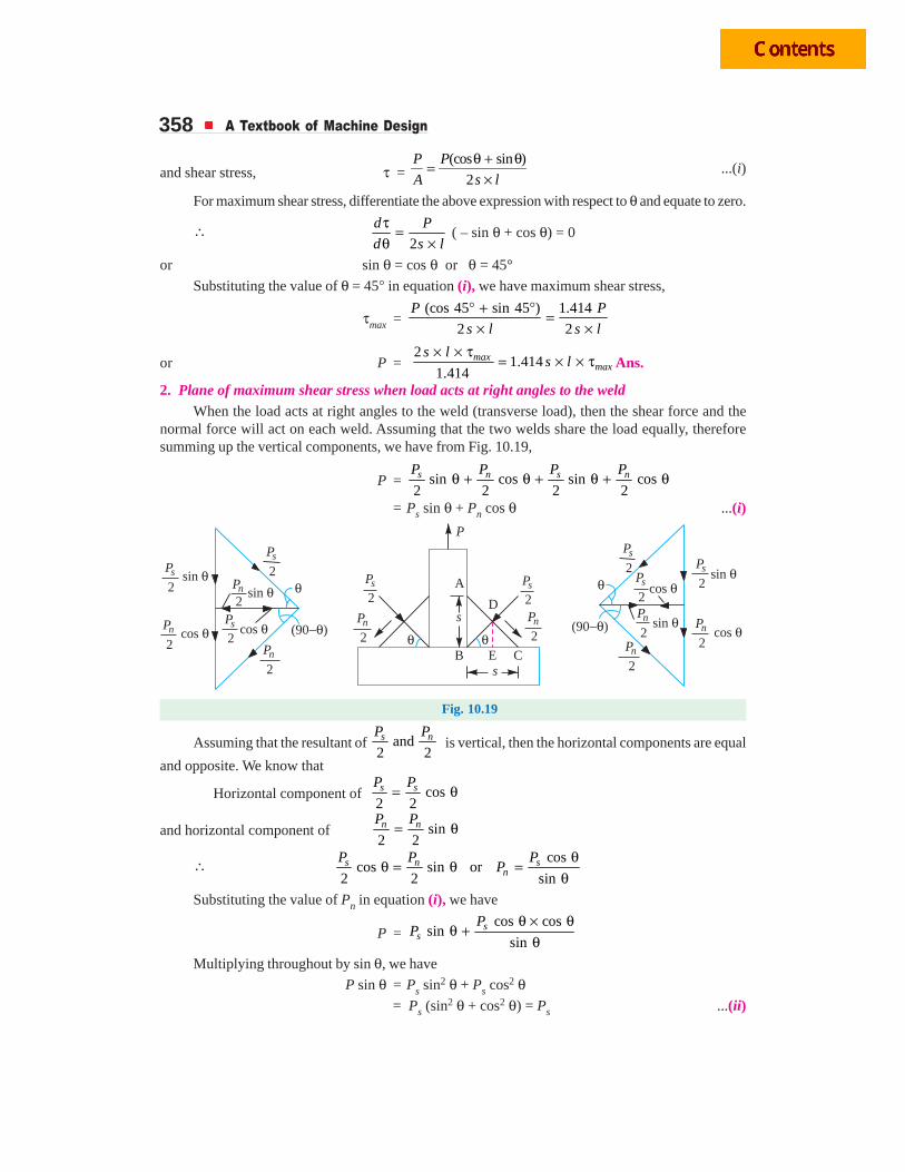
358 A Textbook of Machine Design
and shear stress, τ = (cos sin )
2
θ + θ=×
P P
A s l...(i)
For maximum shear stress, differentiate the above expression with respect to θ and equate to zero.
∴ 2
d P
d s l
τ =θ × ( – sin θ + cos θ) = 0
or sin θ = cos θ or θ = 45°
Substituting the value of θ = 45° in equation (i), we have maximum shear stress,
τmax =(cos 45 sin 45 ) 1.414
2 2
P P
s l s l
° + ° =× ×
or P = 2
1.4141.414
maxmax
s ls l
× × τ= × × τ Ans.
2. Plane of maximum shear stress when load acts at right angles to the weldWhen the load acts at right angles to the weld (transverse load), then the shear force and the
normal force will act on each weld. Assuming that the two welds share the load equally, thereforesumming up the vertical components, we have from Fig. 10.19,
P = sin cos sin cos2 2 2 2s n s nP P P P
θ + θ + θ + θ
= Ps sin θ + Pn cos θ ...(i)
�
�
(90 )��
(90 )��
Pn
2
Pn
2
Ps
2
Ps
2
Pn
2
Pn
2
Pn
2
Pn
2
Pn
2Pn
2
Ps
2
Ps
2Ps
2
Ps
2
Ps
2
Ps
2
cos �
cos �
cos �
cos �
sin �
sin �
sin �
sin �
��
A
P
B E C
D
s
s
Fig. 10.19
Assuming that the resultant of and2 2s nP P
is vertical, then the horizontal components are equal
and opposite. We know that
Horizontal component of cos2 2s sP P
= θ
and horizontal component of sin2 2n nP P
= θ
∴ coscos sin or
2 2 sins n s
nP P P
Pθ
θ = θ =θ
Substituting the value of Pn in equation (i), we have
P =cos cos
sinsin
ss
PP
θ × θθ +
θMultiplying throughout by sin θ, we have
P sin θ = Ps sin2 θ + Ps cos2 θ = Ps (sin2 θ + cos2 θ) = Ps ...(ii)
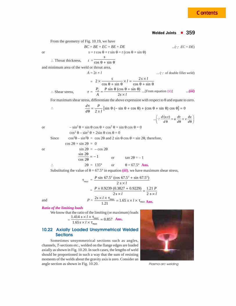
Welded Joints 359From the geometry of Fig. 10.19, we have
BC = BE + EC = BE + DE ...(Q EC = DE)
or s = t cos θ + t sin θ = t (cos θ + sin θ)
∴ Throat thickness, t = cos sin
s
θ + θand minimum area of the weld or throat area,
A = 2t × l ... (Q of double fillet weld)
=2
2cos sin cos sin
s s ll
×× × =θ + θ θ + θ
∴ Shear stress, τ =sin (cos sin )
2sP P
A s l
θ θ + θ=× ...[From equation (ii)] ...(iii)
For maximum shear stress, differentiate the above expression with respect to θ and equate to zero.
∴ [ ]sin ( sin cos ) (cos sin ) cos 02
d P
d s l
τ = θ − θ + θ + θ + θ θ =θ
( . )...⎛ ⎞= +⎜ ⎟θ θ θ⎝ ⎠Q
d u v dv duu v
d d d
or – sin2 θ + sin θ cos θ + cos2 θ + sin θ cos θ = 0
cos2 θ – sin2 θ + 2sin θ cos θ = 0
Since cos2θ – sin2θ = cos 2θ and 2 sin θ cos θ = sin 2θ, therefore,
cos 2θ + sin 2θ = 0
or sin 2θ = – cos 2θsin 2
1cos 2
θ = −θ or tan 2θ = – 1
∴ 2θ = 135° or θ = 67.5° Ans.Substituting the value of θ = 67.5° in equation (iii), we have maximum shear stress,
τmax = sin 67.5 (cos 67.5 sin 67.5 )
2
P
s l
° ° + °×
= 0.9239 (0.3827 0.9229) 1.21
2 2
P P
s l s l
× + =× ×
and P = 2
1.651.21
maxmax
s ls l
× × τ= × × τ Ans.
Ratio of the limiting loadsWe know that the ratio of the limiting (or maximum) loads
=1.414
0.8571.65
max
max
s l
s l
× × τ=
× × τ Ans.
10.22 Axially Loaded Unsymmetrical WeldedSections
Sometimes unsymmetrical sections such as angles,channels, T-sections etc., welded on the flange edges are loadedaxially as shown in Fig. 10.20. In such cases, the lengths of weldshould be proportioned in such a way that the sum of resistingmoments of the welds about the gravity axis is zero. Consider anangle section as shown in Fig. 10.20. Plasma arc welding
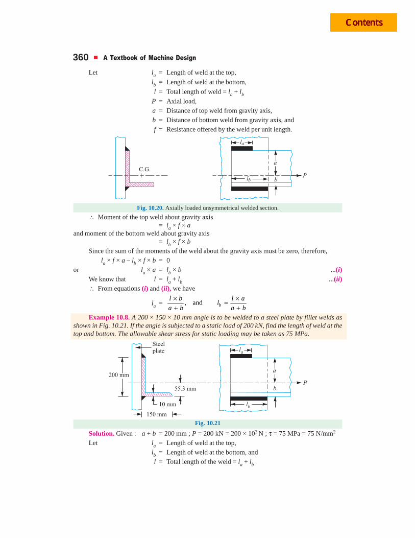
360 A Textbook of Machine Design
Let la = Length of weld at the top,
lb = Length of weld at the bottom,
l = Total length of weld = la + lb
P = Axial load,a = Distance of top weld from gravity axis,b = Distance of bottom weld from gravity axis, andf = Resistance offered by the weld per unit length.
Fig. 10.20. Axially loaded unsymmetrical welded section.
∴ Moment of the top weld about gravity axis= la × f × a
and moment of the bottom weld about gravity axis= lb × f × b
Since the sum of the moments of the weld about the gravity axis must be zero, therefore,la × f × a – lb × f × b = 0
or la × a = lb × b ...(i)We know that l = la + lb ...(ii)∴ From equations (i) and (ii), we have
la = , and bl b l a
la b a b
× ×=+ +
Example 10.8. A 200 × 150 × 10 mm angle is to be welded to a steel plate by fillet welds asshown in Fig. 10.21. If the angle is subjected to a static load of 200 kN, find the length of weld at thetop and bottom. The allowable shear stress for static loading may be taken as 75 MPa.
Fig. 10.21
Solution. Given : a + b = 200 mm ; P = 200 kN = 200 × 103 N ; τ = 75 MPa = 75 N/mm2
Let la = Length of weld at the top,lb = Length of weld at the bottom, andl = Total length of the weld = la + lb
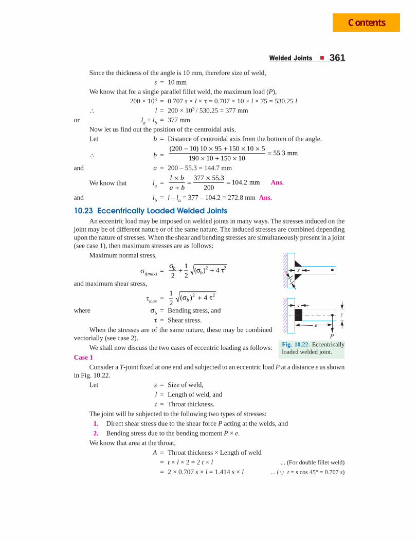
Welded Joints 361Since the thickness of the angle is 10 mm, therefore size of weld,
s = 10 mmWe know that for a single parallel fillet weld, the maximum load (P),
200 × 103 = 0.707 s × l × τ = 0.707 × 10 × l × 75 = 530.25 l∴ l = 200 × 103 / 530.25 = 377 mm
or la + lb = 377 mmNow let us find out the position of the centroidal axis.Let b = Distance of centroidal axis from the bottom of the angle.
∴ b =(200 10) 10 95 150 10 5
55.3 mm190 10 150 10
− × + × ×=
× + ×and a = 200 – 55.3 = 144.7 mm
We know that la =377 55.3
104.2 mm200
l b
a b
× ×= =
+Ans.
and lb = l – la = 377 – 104.2 = 272.8 mm Ans.
10.23 Eccentrically Loaded Welded JointsAn eccentric load may be imposed on welded joints in many ways. The stresses induced on the
joint may be of different nature or of the same nature. The induced stresses are combined dependingupon the nature of stresses. When the shear and bending stresses are simultaneously present in a joint(see case 1), then maximum stresses are as follows:
Maximum normal stress,
σt(max) = 2 21( ) 4
2 2b
bσ
+ σ + τ
and maximum shear stress,
τmax = 2 21( ) 4
2 bσ + τ
where σb = Bending stress, and
τ = Shear stress.
When the stresses are of the same nature, these may be combinedvectorially (see case 2).
We shall now discuss the two cases of eccentric loading as follows:
Case 1Consider a T-joint fixed at one end and subjected to an eccentric load P at a distance e as shown
in Fig. 10.22.
Let s = Size of weld,
l = Length of weld, and
t = Throat thickness.
The joint will be subjected to the following two types of stresses:
1. Direct shear stress due to the shear force P acting at the welds, and
2. Bending stress due to the bending moment P × e.
We know that area at the throat,
A = Throat thickness × Length of weld
= t × l × 2 = 2 t × l ... (For double fillet weld)
= 2 × 0.707 s × l = 1.414 s × l ... (Q t = s cos 45° = 0.707 s)
Fig. 10.22. Eccentricallyloaded welded joint.
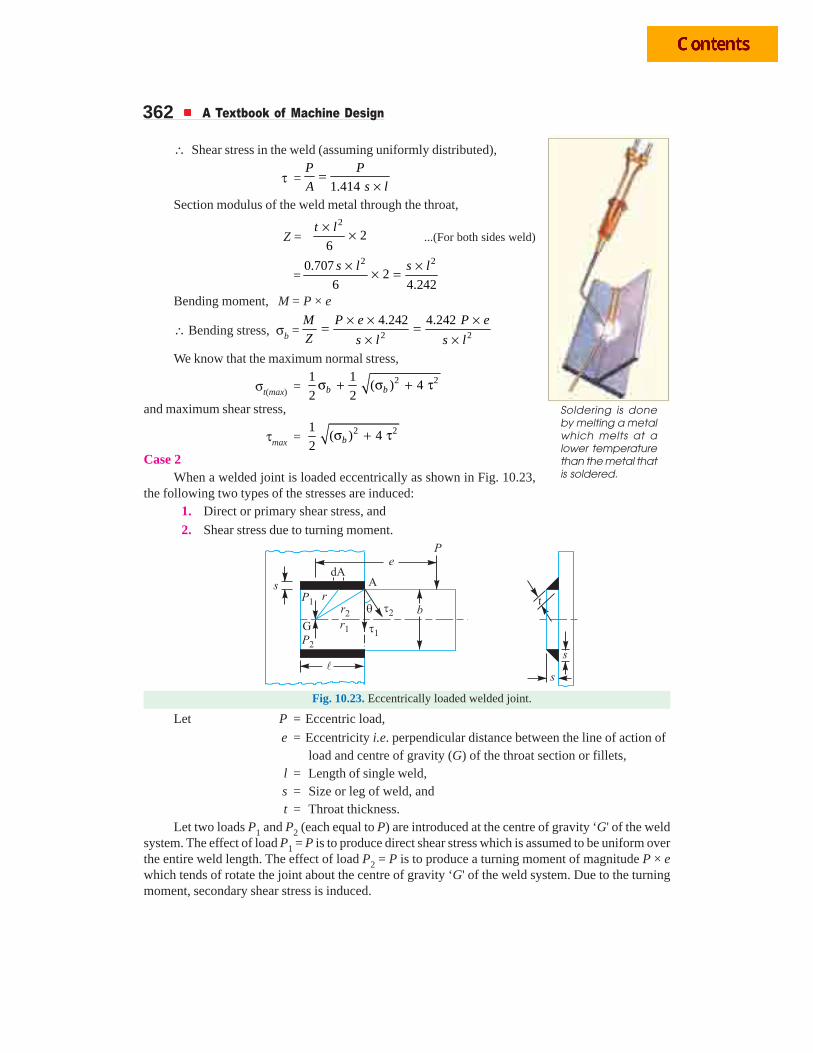
362 A Textbook of Machine Design
∴ Shear stress in the weld (assuming uniformly distributed),
τ =1.414
P P
A s l=
×Section modulus of the weld metal through the throat,
Z =2
26
t l× × ...(For both sides weld)
=2 20.707
26 4.242
s l s l× ×× =
Bending moment, M = P × e
∴ Bending stress, σb = 2 2
4.242 4.242M P e P e
Z s l s l
× × ×= =× ×
We know that the maximum normal stress,
σt(max) = 2 21 1( ) 4
2 2b bσ + σ + τ
and maximum shear stress,
τmax = 2 21( ) 4
2 bσ + τ
Case 2When a welded joint is loaded eccentrically as shown in Fig. 10.23,
the following two types of the stresses are induced:1. Direct or primary shear stress, and
2. Shear stress due to turning moment.
Fig. 10.23. Eccentrically loaded welded joint.
Let P = Eccentric load,
e = Eccentricity i.e. perpendicular distance between the line of action of load and centre of gravity (G) of the throat section or fillets,
l = Length of single weld,s = Size or leg of weld, andt = Throat thickness.
Let two loads P1 and P2 (each equal to P) are introduced at the centre of gravity ‘G' of the weldsystem. The effect of load P1 = P is to produce direct shear stress which is assumed to be uniform overthe entire weld length. The effect of load P2 = P is to produce a turning moment of magnitude P × ewhich tends of rotate the joint about the centre of gravity ‘G' of the weld system. Due to the turningmoment, secondary shear stress is induced.
Soldering is doneby melting a metalwhich melts at alower temperaturethan the metal thatis soldered.
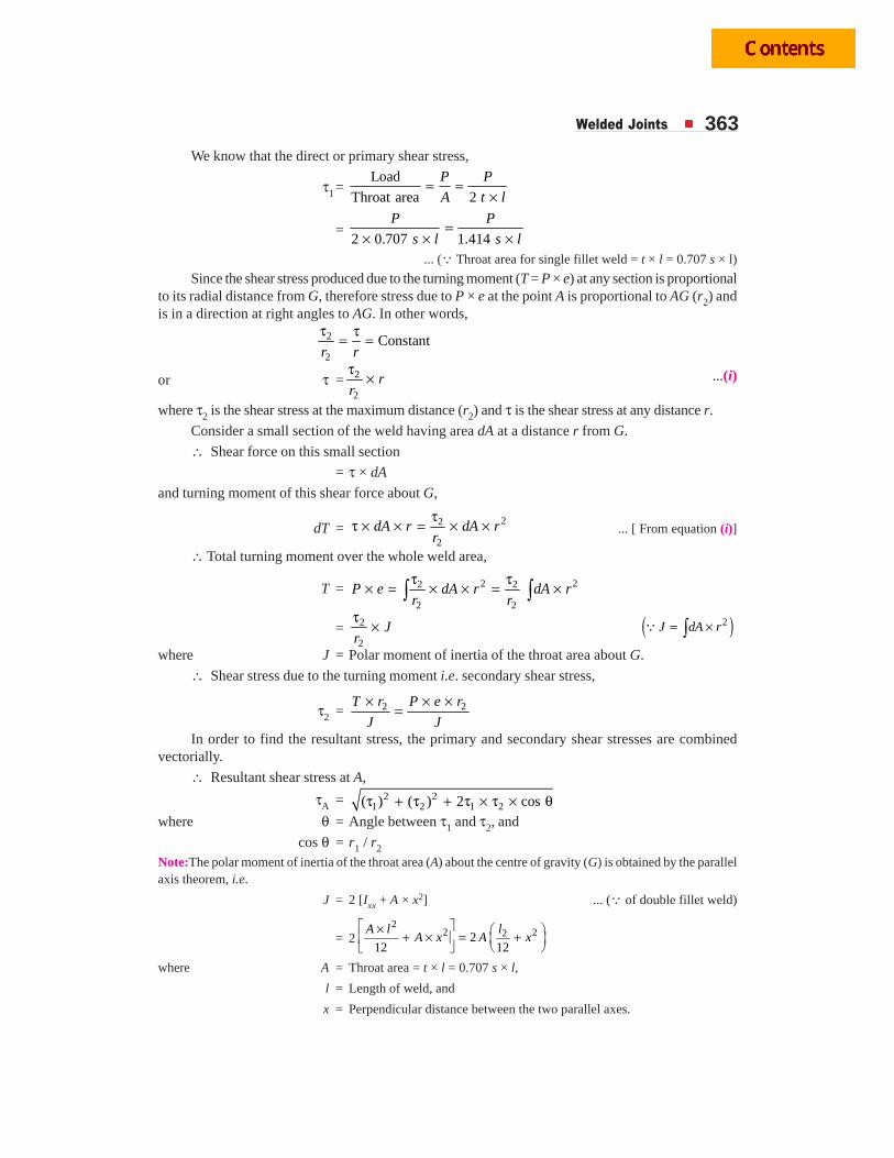
Welded Joints 363We know that the direct or primary shear stress,
τ1 = Load
Throat area 2
P P
A t l= =
×
= 2 0.707 1.414
P P
s l s l=
× × ×... (Q Throat area for single fillet weld = t × l = 0.707 s × l)
Since the shear stress produced due to the turning moment (T = P × e) at any section is proportionalto its radial distance from G, therefore stress due to P × e at the point A is proportional to AG (r2) andis in a direction at right angles to AG. In other words,
2
2
Constantr r
τ τ= =
or τ = 2
2
rr
τ × ...(i)
where τ2 is the shear stress at the maximum distance (r2) and τ is the shear stress at any distance r.
Consider a small section of the weld having area dA at a distance r from G.
∴ Shear force on this small section
= τ × dA
and turning moment of this shear force about G,
dT =22
2
dA r dA rr
ττ × × = × × ... [ From equation (i)]
∴ Total turning moment over the whole weld area,
T = 2 22 2
2 2
P e dA r dA rr r
τ τ× = × × = ×∫ ∫
= 2
2
Jr
τ × ( )2= ×∫Q J dA r
where J = Polar moment of inertia of the throat area about G.
∴ Shear stress due to the turning moment i.e. secondary shear stress,
τ2 = 2 2× × ×=
T r P e r
J JIn order to find the resultant stress, the primary and secondary shear stresses are combined
vectorially.
∴ Resultant shear stress at A,
τA = 2 21 2 1 2( ) ( ) 2 cosτ + τ + τ × τ × θ
where θ = Angle between τ1 and τ2, and
cos θ = r1 / r2
Note:The polar moment of inertia of the throat area (A) about the centre of gravity (G) is obtained by the parallelaxis theorem, i.e.
J = 2 [Ixx + A × x2] ... (Q of double fillet weld)
= 22
2 22212 12
⎡ ⎤× ⎛ ⎞+ × = +⎢ ⎥ ⎜ ⎟⎣ ⎦ ⎝ ⎠
A l lA x A x
where A = Throat area = t × l = 0.707 s × l,
l = Length of weld, and
x = Perpendicular distance between the two parallel axes.
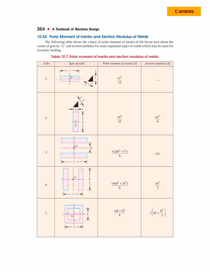
364 A Textbook of Machine Design
10.24 Polar Moment of Inertia and Section Modulus of WeldsThe following table shows the values of polar moment of inertia of the throat area about the
centre of gravity ‘G’ and section modulus for some important types of welds which may be used foreccentric loading.
Table 10.7. Polar moment of inertia and section modulus of welds.
S.No Type of weld Polar moment of inertia (J) Section modulus (Z)
1. 3.
12
t l—
2.3.
12
t b 2.
6
t b
3.2 2. (3 )
6
+t l b lt.b.l
4.2 2. ( 3 )
6
+t b b l 2.
3
t b
5.3( )
6
+t b l 2
.3
⎛ ⎞+⎜ ⎟
⎝ ⎠b
t b l
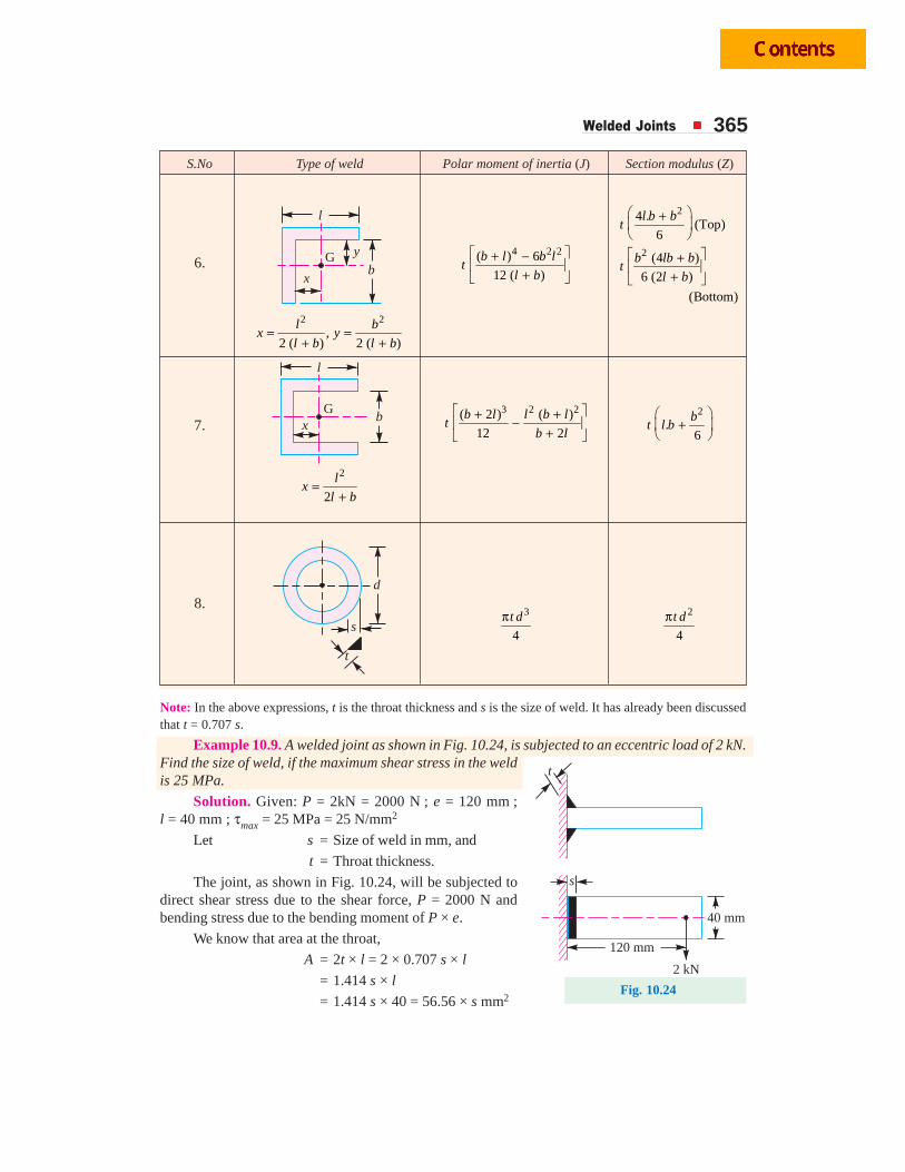
Welded Joints 365
S.No Type of weld Polar moment of inertia (J) Section modulus (Z)
6.b
x
y
l
G4 2 2( ) 6
12 ( )
⎡ ⎤+ −⎢ ⎥
+⎣ ⎦
b l b lt
l b
2
2
4 .(Top)
6
(4 )
6 (2 )
(Bottom)
⎛ ⎞+⎜ ⎟⎝ ⎠⎡ ⎤+⎢ ⎥
+⎣ ⎦
l b bt
b lb bt
l b
2 2,
2 ( ) 2 ( )= =
+ +l b
x yl b l b
7.b
x
l
G 3 2 2( 2 ) ( )
12 2
⎡ ⎤+ +−⎢ ⎥+⎣ ⎦
b l l b lt
b l
2
.6
⎛ ⎞+⎜ ⎟
⎝ ⎠b
t l b
2
2=
+l
xl b
8.d
s
t
3
4
πt d 2
4
πt d
Note: In the above expressions, t is the throat thickness and s is the size of weld. It has already been discussedthat t = 0.707 s.
Example 10.9. A welded joint as shown in Fig. 10.24, is subjected to an eccentric load of 2 kN.Find the size of weld, if the maximum shear stress in the weldis 25 MPa.
Solution. Given: P = 2kN = 2000 N ; e = 120 mm ;l = 40 mm ; τmax = 25 MPa = 25 N/mm2
Let s = Size of weld in mm, and
t = Throat thickness.
The joint, as shown in Fig. 10.24, will be subjected todirect shear stress due to the shear force, P = 2000 N andbending stress due to the bending moment of P × e.
We know that area at the throat,
A = 2t × l = 2 × 0.707 s × l
= 1.414 s × l
= 1.414 s × 40 = 56.56 × s mm2
t
s
40 mm
120 mm
2 kN
Fig. 10.24
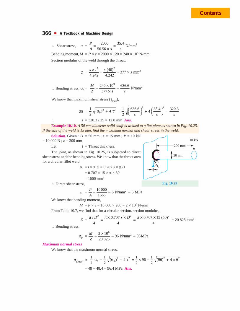
366 A Textbook of Machine Design
∴ Shear stress, τ = 22000 35.4N/mm
56.56
P
A s s= =
×Bending moment, M = P × e = 2000 × 120 = 240 × 103 N-mm
Section modulus of the weld through the throat,
Z =2 2
3(40)377 mm
4.242 4.242
s l ss
× = = ×
∴ Bending stress, σb = 3
2240 10 636.6N/mm
377
M
Z s s
×= =×
We know that maximum shear stress (τmax),
25 = 2 21( ) 4
2 bσ + τ = 2 2
1 636.6 35.4 320.34
2 s s s⎛ ⎞ ⎛ ⎞+ =⎜ ⎟ ⎜ ⎟⎝ ⎠ ⎝ ⎠
∴ s = 320.3 / 25 = 12.8 mm Ans.Example 10.10. A 50 mm diameter solid shaft is welded to a flat plate as shown in Fig. 10.25.
If the size of the weld is 15 mm, find the maximum normal and shear stress in the weld.
Solution. Given : D = 50 mm ; s = 15 mm ; P = 10 kN= 10 000 N ; e = 200 mm
Let t = Throat thickness.
The joint, as shown in Fig. 10.25, is subjected to directshear stress and the bending stress. We know that the throat areafor a circular fillet weld,
A = t × π D = 0.707 s × π D= 0.707 × 15 × π × 50
= 1666 mm2
∴ Direct shear stress,
τ = 210000
6 N/mm 6 MPa1666
P
A= = =
We know that bending moment,M = P × e = 10 000 × 200 = 2 × 10⁶ N-mm
From Table 10.7, we find that for a circular section, section modulus,
Z = 2 2 20.707 0.707 15 (50)
4 4 4
t D s Dπ π × × π × ×= = = 20 825 mm3
∴ Bending stress,
σb = 6
22 1096 N/mm 96MPa
20 825
M
Z
×= = =
Maximum normal stressWe know that the maximum normal stress,
σt(max) = 2 2 2 21 1 1 1
2 2 2 2( ) 4 96 (96) 4 6σ + σ + τ = × + + ×b b
= 48 + 48.4 = 96.4 MPa Ans.
Fig. 10.25
50 mm
200 mm
10 kN
s
t
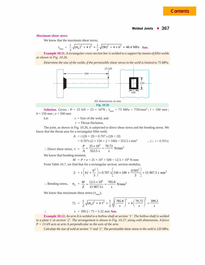
Welded Joints 367Maximum shear stress
We know that the maximum shear stress,
τmax = 2 2 2 21 1
2 2( ) 4 (96) 4 6 48.4 MPaσ + τ = + × =b Ans.
Example 10.11. A rectangular cross-section bar is welded to a support by means of fillet weldsas shown in Fig. 10.26.
Determine the size of the welds, if the permissible shear stress in the weld is limited to 75 MPa.
500
25 kN
100
150
All dimensions in mm
Fig. 10.26
Solution. Given : P = 25 kN = 25 × 103N ; τmax = 75 MPa = 75N/mm2 ; l = 100 mm ;b = 150 mm ; e = 500 mm
Let s = Size of the weld, and t = Throat thickness.
The joint, as shown in Fig. 10.26, is subjected to direct shear stress and the bending stress. Weknow that the throat area for a rectangular fillet weld,
A = t (2b + 2l) = 0.707 s (2b + 2l)
= 0.707s (2 × 150 + 2 × 100) = 353.5 s mm2 ... (Q t = 0.707s)
∴ Direct shear stress, τ = 3
225 10 70.72N/mm
353.5
P
A s s
×= =
We know that bending moment,M = P × e = 25 × 103 × 500 = 12.5 × 10⁶ N-mm
From Table 10.7, we find that for a rectangular section, section modulus,
Z =2 2
3(150). 0.707 150 100 15 907.5 mm
3 3
bt b l s s⎛ ⎞ ⎡ ⎤
+ = × + =⎜ ⎟ ⎢ ⎥⎝ ⎠ ⎣ ⎦
∴ Bending stress, σb =6
212.5 10 785.8N/mm
15 907.5
M
Z s s
×= =
We know that maximum shear stress (τmax),
75 = 2 2
2 21 1 785.8 70.72 399.2( ) 4 4
2 2b s s s⎛ ⎞ ⎛ ⎞σ + τ = + =⎜ ⎟ ⎜ ⎟⎝ ⎠ ⎝ ⎠
∴ s = 399.2 / 75 = 5.32 mm Ans.Example 10.12. An arm A is welded to a hollow shaft at section ‘1’. The hollow shaft is welded
to a plate C at section ‘2’. The arrangement is shown in Fig. 10.27, along with dimensions. A forceP = 15 kN acts at arm A perpendicular to the axis of the arm.
Calculate the size of weld at section ‘1’ and ‘2’. The permissible shear stress in the weld is 120 MPa.
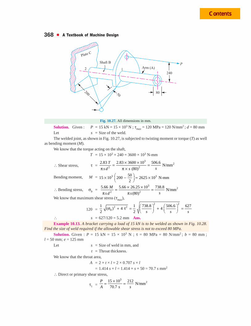
368 A Textbook of Machine Design
Fig. 10.27. All dimensions in mm.
Solution. Given : P = 15 kN = 15 × 103 N ; τmax = 120 MPa = 120 N/mm2 ; d = 80 mmLet s = Size of the weld.The welded joint, as shown in Fig. 10.27, is subjected to twisting moment or torque (T) as well
as bending moment (M).We know that the torque acting on the shaft,
T = 15 × 103 × 240 = 3600 × 103 N-mm
∴ Shear stress, τ =3
22 2
2.83 2.83 3600 10 506.6N/mm
(80)
T
ss d s
× ×= =π π ×
Bending moment, M = 3 35015 10 200 2625 10 N-mm
2⎛ ⎞× − = ×⎜ ⎟⎝ ⎠
∴ Bending stress, σb = 3
22 2
5.66 5.66 26.25 10 738.8N/mm
(80)
M
ss d s
× ×= =π π
We know that maximum shear stress (τmax),
120 =
2 22 21 1 738.8 506.6 627
( ) 4 42 2b s s s
⎛ ⎞ ⎛ ⎞σ + τ = + =⎜ ⎟ ⎜ ⎟⎝ ⎠ ⎝ ⎠
∴ s = 627/120 = 5.2 mm Ans.Example 10.13. A bracket carrying a load of 15 kN is to be welded as shown in Fig. 10.28.
Find the size of weld required if the allowable shear stress is not to exceed 80 MPa.
Solution. Given : P = 15 kN = 15 × 103 N ; τ = 80 MPa = 80 N/mm2 ; b = 80 mm ;l = 50 mm; e = 125 mm
Let s = Size of weld in mm, and
t = Throat thickness.
We know that the throat area,
A = 2 × t × l = 2 × 0.707 s × l
= 1.414 s × l = 1.414 × s × 50 = 70.7 s mm2
∴ Direct or primary shear stress,
τ1 =3
215 10 212N/mm
70.7
P
A s s
×= =
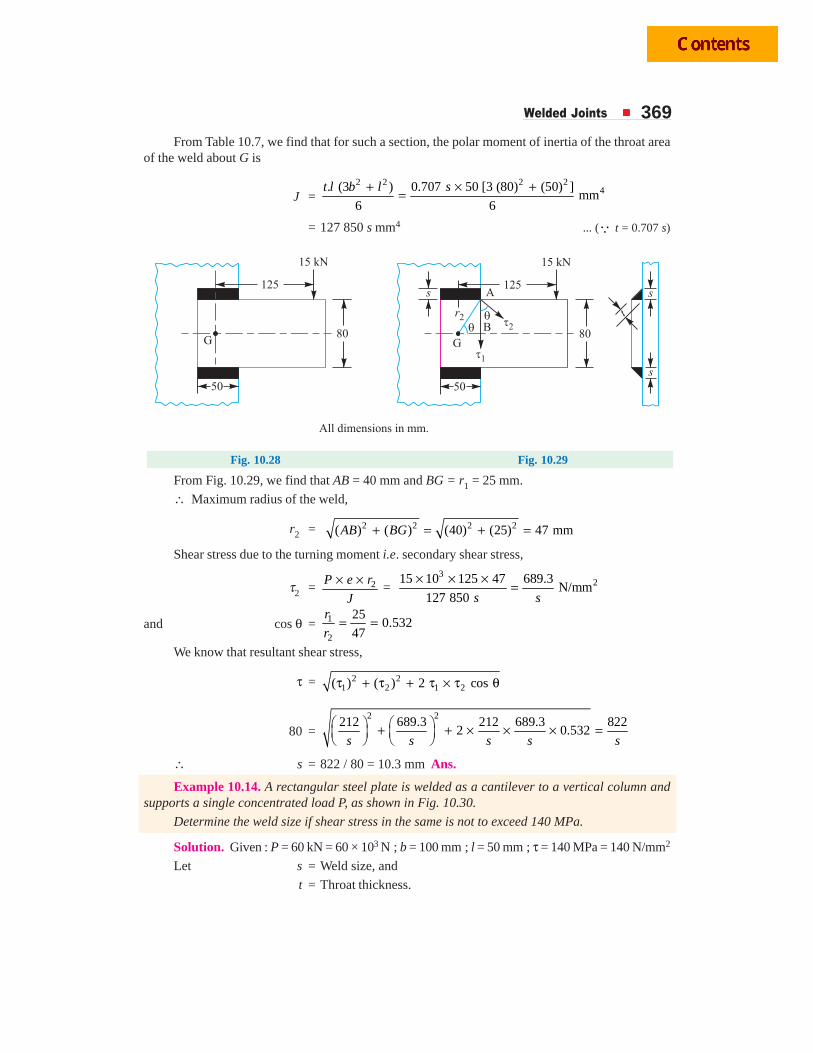
Welded Joints 369From Table 10.7, we find that for such a section, the polar moment of inertia of the throat area
of the weld about G is
J =2 2 2 2
4. (3 ) 0.707 50 [3 (80) (50) ]mm
6 6
t l b l s+ × +=
= 127 850 s mm4 ... (Q t = 0.707 s)
Fig. 10.28 Fig. 10.29
From Fig. 10.29, we find that AB = 40 mm and BG = r1 = 25 mm.
∴ Maximum radius of the weld,
r2 = 2 2 2 2( ) ( ) (40) (25) 47 mmAB BG+ = + =
Shear stress due to the turning moment i.e. secondary shear stress,
τ2 = 2P e r
J
× ×=
3215 10 125 47 689.3
N/mm127 850 s s
× × × =
and cos θ = 1
2
250.532
47
r
r= =
We know that resultant shear stress,
τ = 2 21 2 1 2( ) ( ) 2 cosτ + τ + τ × τ θ
80 =2 2
212 689.3 212 689.3 8222 0.532
s s s s s⎛ ⎞ ⎛ ⎞+ + × × × =⎜ ⎟ ⎜ ⎟⎝ ⎠ ⎝ ⎠
∴ s = 822 / 80 = 10.3 mm Ans.
Example 10.14. A rectangular steel plate is welded as a cantilever to a vertical column andsupports a single concentrated load P, as shown in Fig. 10.30.
Determine the weld size if shear stress in the same is not to exceed 140 MPa.
Solution. Given : P = 60 kN = 60 × 103 N ; b = 100 mm ; l = 50 mm ; τ = 140 MPa = 140 N/mm2
Let s = Weld size, and
t = Throat thickness.
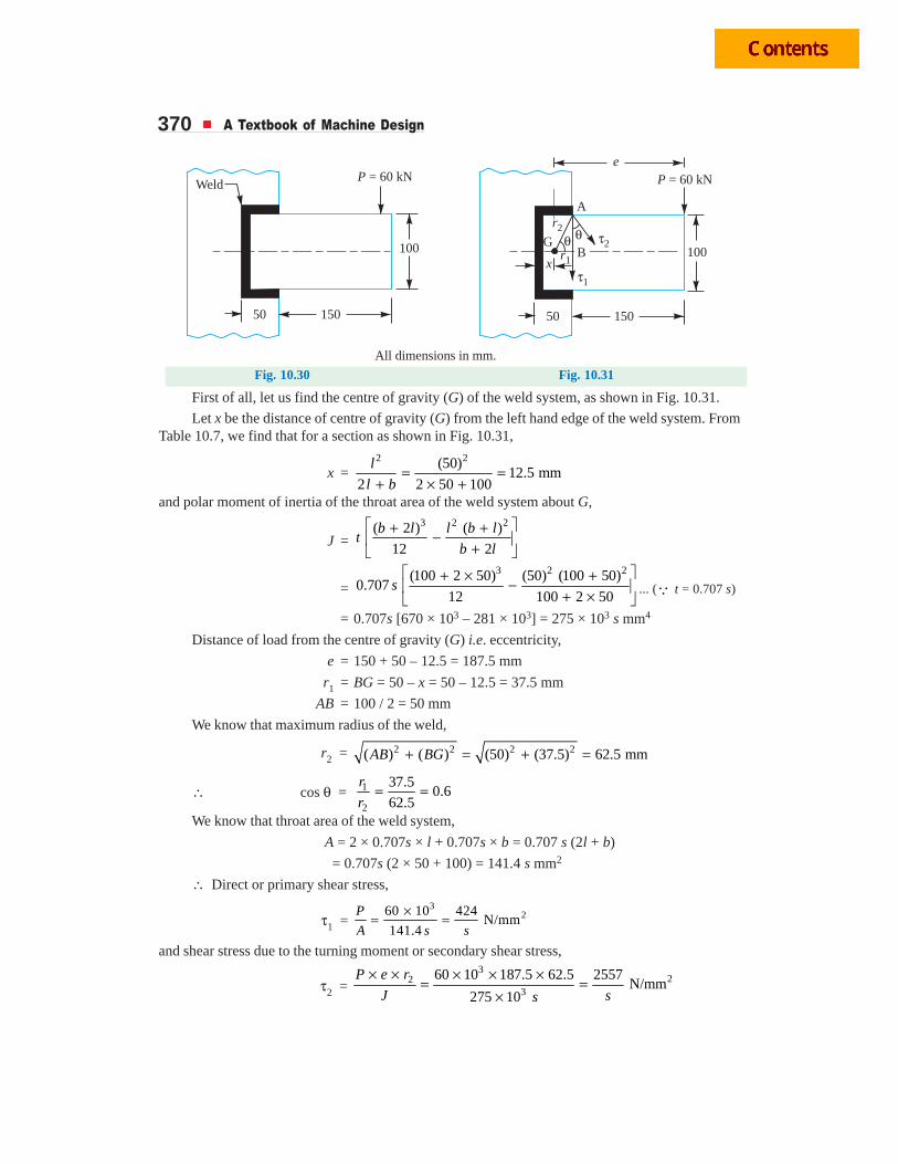
370 A Textbook of Machine Design
Weld
50 50150 150
100 100
P = 60 kN P = 60 kN
All dimensions in mm.
�2
�1
r2
r1
e
x
�
�
GB
A
Fig. 10.30 Fig. 10.31
First of all, let us find the centre of gravity (G) of the weld system, as shown in Fig. 10.31.
Let x be the distance of centre of gravity (G) from the left hand edge of the weld system. FromTable 10.7, we find that for a section as shown in Fig. 10.31,
x =2 2(50)
12.5 mm2 2 50 100
l
l b= =
+ × +and polar moment of inertia of the throat area of the weld system about G,
J =3 2 2( 2 ) ( )
12 2
b l l b lt
b l
⎡ ⎤+ +−⎢ ⎥+⎣ ⎦
=3 2 2(100 2 50) (50) (100 50)
0.70712 100 2 50
s⎡ ⎤+ × +−⎢ ⎥+ ×⎣ ⎦
... (Q t = 0.707 s)
= 0.707s [670 × 103 – 281 × 103] = 275 × 103 s mm4
Distance of load from the centre of gravity (G) i.e. eccentricity,
e = 150 + 50 – 12.5 = 187.5 mm
r1 = BG = 50 – x = 50 – 12.5 = 37.5 mm
AB = 100 / 2 = 50 mm
We know that maximum radius of the weld,
r2 = 2 2 2 2( ) ( ) (50) (37.5) 62.5 mmAB BG+ = + =
∴ cos θ = 1
2
37.50.6
62.5
r
r= =
We know that throat area of the weld system,
A = 2 × 0.707s × l + 0.707s × b = 0.707 s (2l + b)
= 0.707s (2 × 50 + 100) = 141.4 s mm2
∴ Direct or primary shear stress,
τ1 = 3
260 10 424N/mm
141.4
P
A s s
×= =
and shear stress due to the turning moment or secondary shear stress,
τ2 = 3
223
60 10 187.5 62.5 2557N/mm
275 10
P e r
J ss
× × × × ×= =×
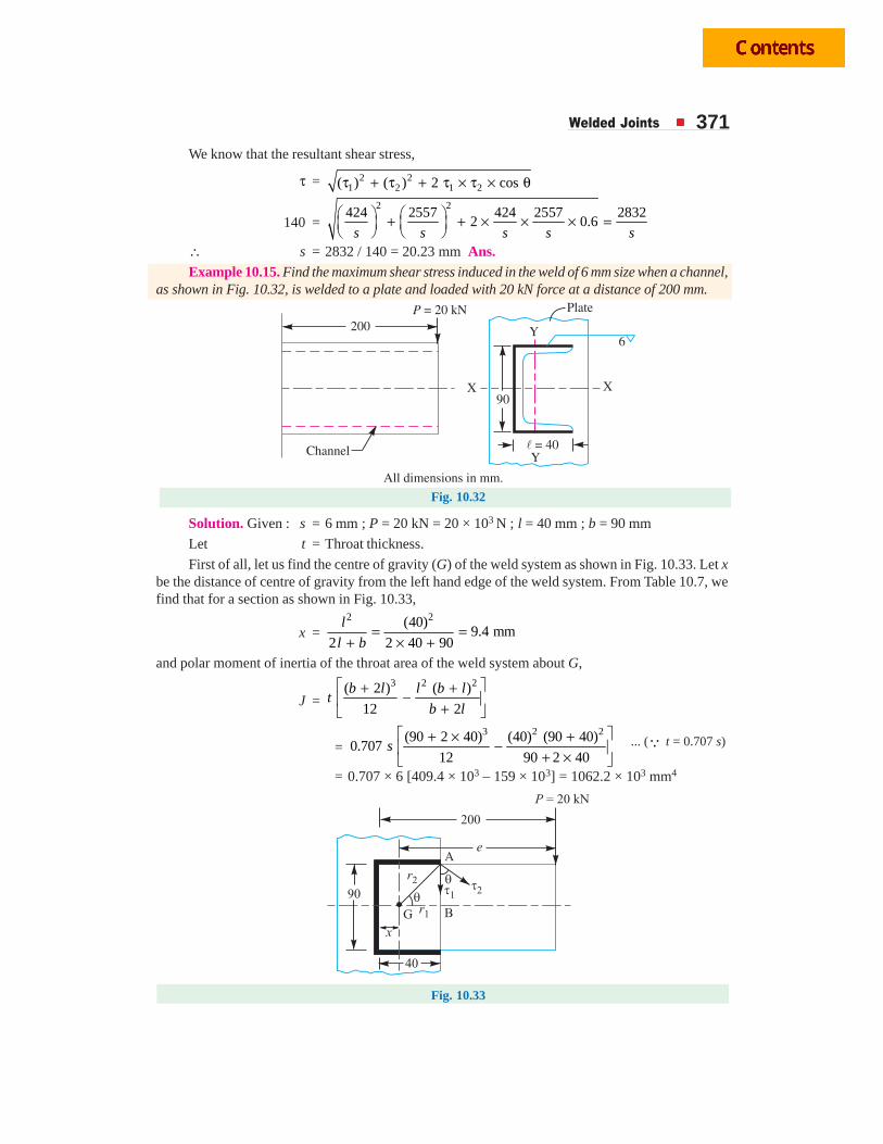
Welded Joints 371We know that the resultant shear stress,
τ = 2 21 2 1 2( ) ( ) 2 cosτ + τ + τ × τ × θ
140 =2 2
424 2557 424 2557 28322 0.6
s s s s s⎛ ⎞ ⎛ ⎞+ + × × × =⎜ ⎟ ⎜ ⎟⎝ ⎠ ⎝ ⎠
∴ s = 2832 / 140 = 20.23 mm Ans.Example 10.15. Find the maximum shear stress induced in the weld of 6 mm size when a channel,
as shown in Fig. 10.32, is welded to a plate and loaded with 20 kN force at a distance of 200 mm.
Fig. 10.32
Solution. Given : s = 6 mm ; P = 20 kN = 20 × 103 N ; l = 40 mm ; b = 90 mm
Let t = Throat thickness.
First of all, let us find the centre of gravity (G) of the weld system as shown in Fig. 10.33. Let xbe the distance of centre of gravity from the left hand edge of the weld system. From Table 10.7, wefind that for a section as shown in Fig. 10.33,
x =2 2(40)
9.4 mm2 2 40 90
= =+ × +
l
l b
and polar moment of inertia of the throat area of the weld system about G,
J =3 2 2( 2 ) ( )
12 2
b l l b lt
b l
⎡ ⎤+ +−⎢ ⎥+⎣ ⎦
=3 2 2(90 2 40) (40) (90 40)
0.70712 90 2 40
s⎡ ⎤+ × +−⎢ ⎥+ ×⎣ ⎦
... (Q t = 0.707 s)
= 0.707 × 6 [409.4 × 10³ – 159 × 103] = 1062.2 × 103 mm4
Fig. 10.33
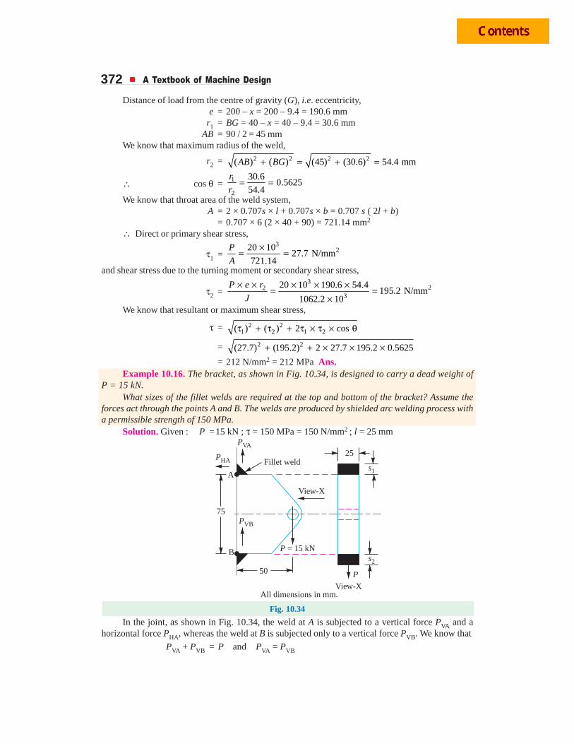
372 A Textbook of Machine Design
Distance of load from the centre of gravity (G), i.e. eccentricity,e = 200 – x = 200 – 9.4 = 190.6 mm
r1 = BG = 40 – x = 40 – 9.4 = 30.6 mmAB = 90 / 2 = 45 mm
We know that maximum radius of the weld,
r2 = 2 2 2 2( ) ( ) (45) (30.6) 54.4 mmAB BG+ = + =
∴ cos θ = 1
2
30.60.5625
54.4
r
r= =
We know that throat area of the weld system,A = 2 × 0.707s × l + 0.707s × b = 0.707 s ( 2l + b)
= 0.707 × 6 (2 × 40 + 90) = 721.14 mm2
∴ Direct or primary shear stress,
τ1 =3
220 1027.7 N/mm
721.14
P
A
×= =
and shear stress due to the turning moment or secondary shear stress,
τ2 =3
223
20 10 190.6 54.4195.2 N/mm
1062.2 10
P e r
J
× × × × ×= =×
We know that resultant or maximum shear stress,
τ = 2 21 2 1 2( ) ( ) 2 cosτ + τ + τ × τ × θ
= 2 2(27.7) (195.2) 2 27.7 195.2 0.5625+ + × × ×= 212 N/mm2 = 212 MPa Ans.
Example 10.16. The bracket, as shown in Fig. 10.34, is designed to carry a dead weight ofP = 15 kN.
What sizes of the fillet welds are required at the top and bottom of the bracket? Assume theforces act through the points A and B. The welds are produced by shielded arc welding process witha permissible strength of 150 MPa.
Solution. Given : P =15 kN ; τ = 150 MPa = 150 N/mm2 ; l = 25 mm
25
s2
s1
View-X
P = 15 kN
50
75
P
View-X
PHA
A
B
PVA
PVB
Fillet weld
All dimensions in mm.
Fig. 10.34
In the joint, as shown in Fig. 10.34, the weld at A is subjected to a vertical force PVA and ahorizontal force PHA, whereas the weld at B is subjected only to a vertical force PVB. We know that
PVA + PVB = P and PVA = PVB
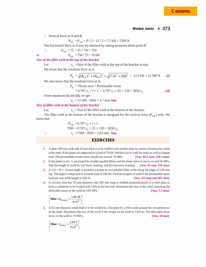
Welded Joints 373∴ Vertical force at A and B,
PVA =PVB = P / 2 = 15 / 2 = 7.5 kN = 7500 N
The horizontal force at A may be obtained by taking moments about point B.
∴ PHA × 75 =15 × 50 = 750
or PHA =750 / 75 = 10 kN
Size of the fillet weld at the top of the bracketLet s1 =Size of the fillet weld at the top of the bracket in mm.
We know that the resultant force at A,
PA = 2 2 2 2VA HA( ) ( ) (7.5) (10)+ = +P P = 12.5 kN = 12 500 N ...(i)
We also know that the resultant force at A,
PA = Throat area × Permissible stress
= 0.707 s1 × l × τ = 0.707 s1 × 25 × 150 = 2650 s1 ...(ii)From equations (i) and (ii), we get
s1 =12 500 / 2650 = 4.7 mm Ans.Size of fillet weld at the bottom of the bracket
Let s2 =Size of the fillet weld at the bottom of the bracket.
The fillet weld at the bottom of the bracket is designed for the vertical force (PVB ) only. Weknow that
PVB =0.707 s2 × l × τ7500 =0.707 s2 × 25 × 150 = 2650 s2
∴ s2 =7500 / 2650 = 2.83 mm Ans.
EEEEEXEXEXEXEXERRRRRCISECISECISECISECISESSSSS
1. A plate 100 mm wide and 10 mm thick is to be welded with another plate by means of transverse weldsat the ends. If the plates are subjected to a load of 70 kN, find the size of weld for static as well as fatigueload. The permissible tensile stress should not exceed 70 MPa. [Ans. 83.2 mm; 118.5 mm]
2. If the plates in Ex. 1, are joined by double parallel fillets and the shear stress is not to exceed 56 MPa,find the length of weld for (a) Static loading, and (b) Dynamic loading. [Ans. 91 mm; 259 mm]
3. A 125 × 95 × 10 mm angle is joined to a frame by two parallel fillet welds along the edges of 150 mmleg. The angle is subjected to a tensile load of 180 kN. Find the lengths of weld if the permissible staticload per mm weld length is 430 N. [Ans. 137 mm and 307 mm]
4. A circular steel bar 50 mm diameter and 200 mm long is welded perpendicularly to a steel plate toform a cantilever to be loaded with 5 kN at the free end. Determine the size of the weld, assuming theallowable stress in the weld as 100 MPa. [Ans. 7.2 mm]
( ) 2
5.66⎡ ⎤σ =⎢ ⎥π⎣ ⎦Hint : b max
M
s d
5. A 65 mm diameter solid shaft is to be welded to a flat plate by a fillet weld around the circumferenceof the shaft. Determine the size of the weld if the torque on the shaft is 3 kN-m. The allowable shearstress in the weld is 70 MPa. [Ans. 10 mm]
( ) 2
2.83⎡ ⎤τ =⎢ ⎥π⎣ ⎦Hint : max
T
s d
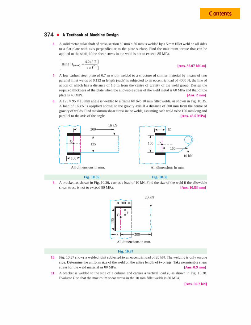
374 A Textbook of Machine Design
6. A solid rectangular shaft of cross-section 80 mm × 50 mm is welded by a 5 mm fillet weld on all sidesto a flat plate with axis perpendicular to the plate surface. Find the maximum torque that can beapplied to the shaft, if the shear stress in the weld is not to exceed 85 MPa.
( ) 2
4.242⎡ ⎤τ =⎢ ⎥×⎣ ⎦Hint : max
T
s l [Ans. 32.07 kN-m]
7. A low carbon steel plate of 0.7 m width welded to a structure of similar material by means of twoparallel fillet welds of 0.112 m length (each) is subjected to an eccentric load of 4000 N, the line ofaction of which has a distance of 1.5 m from the centre of gravity of the weld group. Design therequired thickness of the plate when the allowable stress of the weld metal is 60 MPa and that of theplate is 40 MPa. [Ans. 2 mm]
8. A 125 × 95 × 10 mm angle is welded to a frame by two 10 mm fillet welds, as shown in Fig. 10.35.A load of 16 kN is apsplied normal to the gravity axis at a distance of 300 mm from the centre ofgravity of welds. Find maximum shear stress in the welds, assuming each weld to be 100 mm long andparallel to the axis of the angle. [Ans. 45.5 MPa]
G G
100
125 100
150
300 60
16 kN
10 kN
All dimensions in mm. All dimensions in mm.
Fig. 10.35 Fig. 10.36
9. A bracket, as shown in Fig. 10.36, carries a load of 10 kN. Find the size of the weld if the allowableshear stress is not to exceed 80 MPa. [Ans. 10.83 mm]
Fig. 10.37
10. Fig. 10.37 shows a welded joint subjected to an eccentric load of 20 kN. The welding is only on oneside. Determine the uniform size of the weld on the entire length of two legs. Take permissible shearstress for the weld material as 80 MPa. [Ans. 8.9 mm]
11. A bracket is welded to the side of a column and carries a vertical load P, as shown in Fig. 10.38.Evaluate P so that the maximum shear stress in the 10 mm fillet welds is 80 MPa.
[Ans. 50.7 kN]
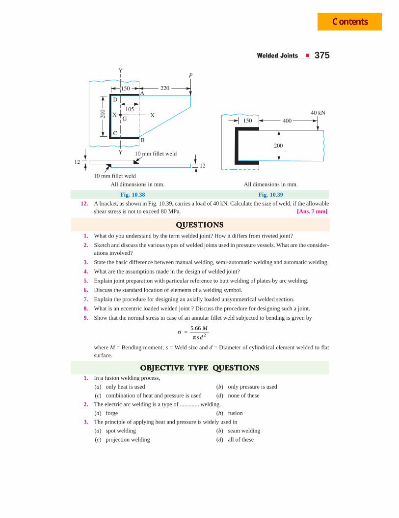
Welded Joints 375
Fig. 10.38 Fig. 10.39
12. A bracket, as shown in Fig. 10.39, carries a load of 40 kN. Calculate the size of weld, if the allowableshear stress is not to exceed 80 MPa. [Ans. 7 mm]
QQQQQUEUEUEUEUESTSTSTSTSTIONSIONSIONSIONSIONS1. What do you understand by the term welded joint? How it differs from riveted joint?
2. Sketch and discuss the various types of welded joints used in pressure vessels. What are the consider-ations involved?
3. State the basic difference between manual welding, semi-automatic welding and automatic welding.
4. What are the assumptions made in the design of welded joint?
5. Explain joint preparation with particular reference to butt welding of plates by arc welding.
6. Discuss the standard location of elements of a welding symbol.
7. Explain the procedure for designing an axially loaded unsymmetrical welded section.
8. What is an eccentric loaded welded joint ? Discuss the procedure for designing such a joint.
9. Show that the normal stress in case of an annular fillet weld subjected to bending is given by
σ = 2
5.66
πM
s d
where M = Bending moment; s = Weld size and d = Diameter of cylindrical element welded to flatsurface.
OBJECTOBJECTOBJECTOBJECTOBJECTIVE IVE IVE IVE IVE TTTTTYPYPYPYPYPE QE QE QE QE QUEUEUEUEUESTSTSTSTSTIONSIONSIONSIONSIONS1. In a fusion welding process,
(a) only heat is used (b) only pressure is used
(c) combination of heat and pressure is used (d) none of these
2. The electric arc welding is a type of ............. welding.
(a) forge (b) fusion
3. The principle of applying heat and pressure is widely used in
(a) spot welding (b) seam welding
(c) projection welding (d) all of these
376 A Textbook of Machine Design
4. In transverse fillet welded joint, the size of weld is equal to
(a) 0.5 × Throat of weld (b) Throat of weld
(c) 2 × Throat of weld (d) 2 × Throat of weld
5. The transverse fillet welded joints are designed for
(a) tensile strength (b) compressive strength
(c) bending strength (d) shear strength
6. The parallel fillet welded joint is designed for
(a) tensile strength (b) compressive strength
(c) bending strength (d) shear strength
7. The size of the weld in butt welded joint is equal to
(a) 0.5 × Throat of weld (b) Throat of weld
(c) 2 × Throat of weld (d) 2 × Throat of weld
8. A double fillet welded joint with parallel fillet weld of length l and leg s is subjected to a tensile forceP. Assuming uniform stress distribution, the shear stress in the weld is given by
(a)2
.
P
s l(b)
2 .
P
s l
(c) 2 .
P
s l (d)2
.
P
s l
9. When a circular rod welded to a rigid plate by a circular fillet weld is subjected to a twisting momentT, then the maximum shear stress is given by
(a) 2
2.83
πT
s d (b) 2
4.242
πT
s d
(c) 2
5.66
πT
s d (d ) none of these
10. For a parallel load on a fillet weld of equal legs, the plane of maximum shear occurs at
(a) 22.5° (b) 30°
(c) 45° (d) 60°
ANSWEANSWEANSWEANSWEANSWERRRRRSSSSS
1. (a) 2. (b) 3. (d) 4. (c) 5. (a)
6. (d) 7. (b) 8. (c) 9. (a) 10. (c)
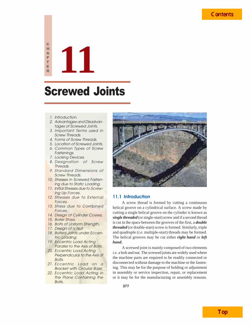
Screwed Joints 377
11.1 IntroductionA screw thread is formed by cutting a continuous
helical groove on a cylindrical surface. A screw made bycutting a single helical groove on the cylinder is known assingle threaded (or single-start) screw and if a second threadis cut in the space between the grooves of the first, a doublethreaded (or double-start) screw is formed. Similarly, tripleand quadruple (i.e. multiple-start) threads may be formed.The helical grooves may be cut either right hand or lefthand.
A screwed joint is mainly composed of two elementsi.e. a bolt and nut. The screwed joints are widely used wherethe machine parts are required to be readily connected ordisconnected without damage to the machine or the fasten-ing. This may be for the purpose of holding or adjustmentin assembly or service inspection, repair, or replacementor it may be for the manufacturing or assembly reasons.
Screwed Joints
377
1. Introduction.2. Advantages and Disadvan-
tages of Screwed Joints.3. Important Terms used in
Screw Threads.4. Forms of Screw Threads.5. Location of Screwed Joints.6. Common Types of Screw
Fastenings.7. Locking Devices.8. Designation of Screw
Threads.9. Standard Dimensions of
Screw Threads.10. Stresses in Screwed Fasten-
ing due to Static Loading.11. Initial Stresses due to Screw-
ing Up Forces.12. Stresses due to External
Forces.13. Stress due to Combined
Forces.14. Design of Cylinder Covers.15. Boiler Stays.16. Bolts of Uniform Strength.17. Design of a Nut.18. Bolted Joints under Eccen-
tric Loading.19. Eccentric Load Acting
Parallel to the Axis of Bolts.20. Eccentric Load Acting
Perpendicular to the Axis ofBolts.
21. Eccentric Load on aBracket with Circular Base.
22. Eccentric Load Acting inthe Plane Containing theBolts.
11CHAPTER
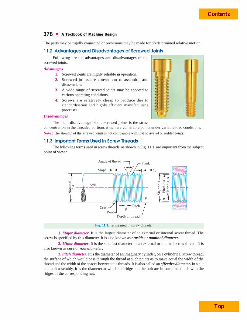
378 A Textbook of Machine Design
The parts may be rigidly connected or provisions may be made for predetermined relative motion.
11.2 Advantages and Disadvantages of Screwed JointsFollowing are the advantages and disadvantages of the
screwed joints.
Advantages1. Screwed joints are highly reliable in operation.2. Screwed joints are convenient to assemble and
disassemble.3. A wide range of screwed joints may be adopted to
various operating conditions.4. Screws are relatively cheap to produce due to
standardisation and highly efficient manufacturingprocesses.
Disadvantages
The main disadvantage of the screwed joints is the stressconcentration in the threaded portions which are vulnerable points under variable load conditions.
Note : The strength of the screwed joints is not comparable with that of riveted or welded joints.
11.3 Important Terms Used in Screw ThreadsThe following terms used in screw threads, as shown in Fig. 11.1, are important from the subject
point of view :
Fig. 11.1. Terms used in screw threads.
1. Major diameter. It is the largest diameter of an external or internal screw thread. Thescrew is specified by this diameter. It is also known as outside or nominal diameter.
2. Minor diameter. It is the smallest diameter of an external or internal screw thread. It isalso known as core or root diameter.
3. Pitch diameter. It is the diameter of an imaginary cylinder, on a cylindrical screw thread,the surface of which would pass through the thread at such points as to make equal the width of thethread and the width of the spaces between the threads. It is also called an effective diameter. In a nutand bolt assembly, it is the diameter at which the ridges on the bolt are in complete touch with theridges of the corresponding nut.
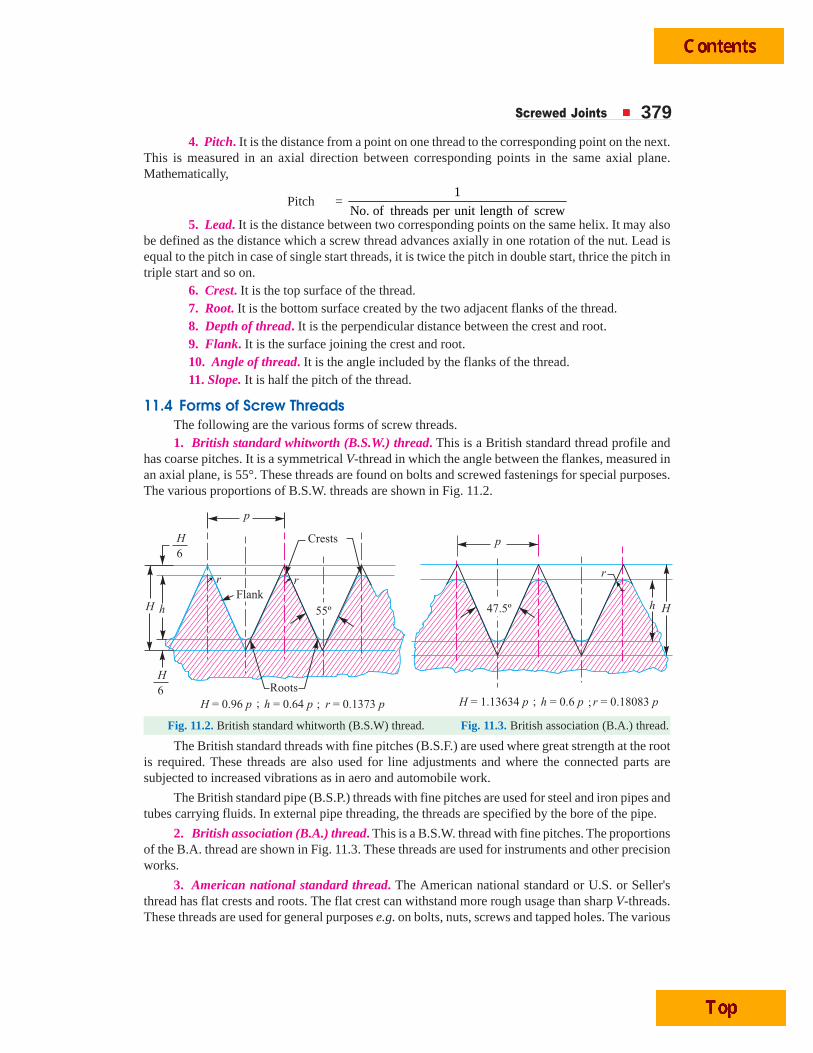
Screwed Joints 3794. Pitch. It is the distance from a point on one thread to the corresponding point on the next.
This is measured in an axial direction between corresponding points in the same axial plane.Mathematically,
Pitch = 1
No. of threads per unit length of screw5. Lead. It is the distance between two corresponding points on the same helix. It may also
be defined as the distance which a screw thread advances axially in one rotation of the nut. Lead isequal to the pitch in case of single start threads, it is twice the pitch in double start, thrice the pitch intriple start and so on.
6. Crest. It is the top surface of the thread.7. Root. It is the bottom surface created by the two adjacent flanks of the thread.8. Depth of thread. It is the perpendicular distance between the crest and root.9. Flank. It is the surface joining the crest and root.10. Angle of thread. It is the angle included by the flanks of the thread.11. Slope. It is half the pitch of the thread.
11.4 Forms of Screw ThreadsThe following are the various forms of screw threads.1. British standard whitworth (B.S.W.) thread. This is a British standard thread profile and
has coarse pitches. It is a symmetrical V-thread in which the angle between the flankes, measured inan axial plane, is 55°. These threads are found on bolts and screwed fastenings for special purposes.The various proportions of B.S.W. threads are shown in Fig. 11.2.
Fig. 11.2. British standard whitworth (B.S.W) thread. Fig. 11.3. British association (B.A.) thread.
The British standard threads with fine pitches (B.S.F.) are used where great strength at the rootis required. These threads are also used for line adjustments and where the connected parts aresubjected to increased vibrations as in aero and automobile work.
The British standard pipe (B.S.P.) threads with fine pitches are used for steel and iron pipes andtubes carrying fluids. In external pipe threading, the threads are specified by the bore of the pipe.
2. British association (B.A.) thread. This is a B.S.W. thread with fine pitches. The proportionsof the B.A. thread are shown in Fig. 11.3. These threads are used for instruments and other precisionworks.
3. American national standard thread. The American national standard or U.S. or Seller'sthread has flat crests and roots. The flat crest can withstand more rough usage than sharp V-threads.These threads are used for general purposes e.g. on bolts, nuts, screws and tapped holes. The various
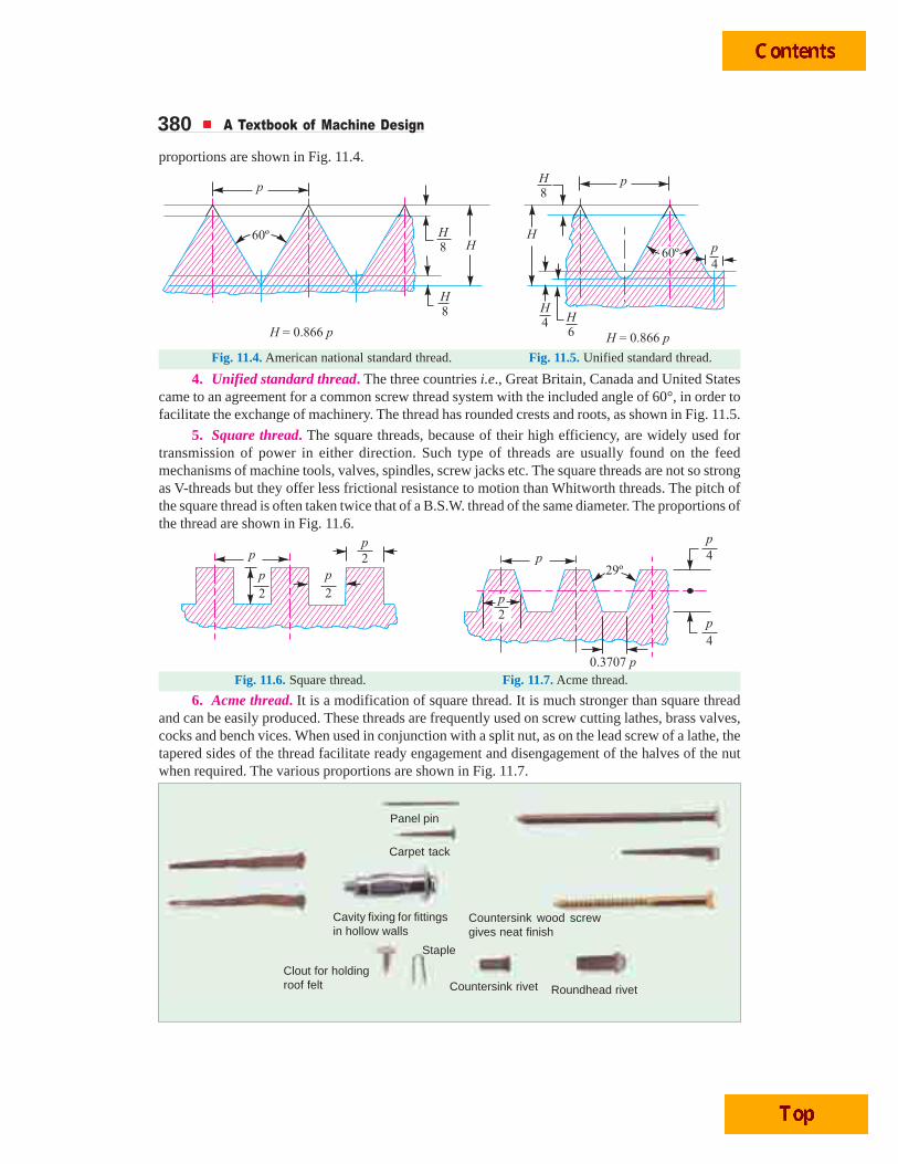
380 A Textbook of Machine Design
proportions are shown in Fig. 11.4.
Fig. 11.4. American national standard thread. Fig. 11.5. Unified standard thread.
4. Unified standard thread. The three countries i.e., Great Britain, Canada and United Statescame to an agreement for a common screw thread system with the included angle of 60°, in order tofacilitate the exchange of machinery. The thread has rounded crests and roots, as shown in Fig. 11.5.
5. Square thread. The square threads, because of their high efficiency, are widely used fortransmission of power in either direction. Such type of threads are usually found on the feedmechanisms of machine tools, valves, spindles, screw jacks etc. The square threads are not so strongas V-threads but they offer less frictional resistance to motion than Whitworth threads. The pitch ofthe square thread is often taken twice that of a B.S.W. thread of the same diameter. The proportions ofthe thread are shown in Fig. 11.6.
Fig. 11.6. Square thread. Fig. 11.7. Acme thread.
6. Acme thread. It is a modification of square thread. It is much stronger than square threadand can be easily produced. These threads are frequently used on screw cutting lathes, brass valves,cocks and bench vices. When used in conjunction with a split nut, as on the lead screw of a lathe, thetapered sides of the thread facilitate ready engagement and disengagement of the halves of the nutwhen required. The various proportions are shown in Fig. 11.7.
Panel pin
Carpet tack
Cavity fixing for fittingsin hollow walls
Countersink wood screwgives neat finish
Countersink rivet
Staple
Roundhead rivet
Clout for holdingroof felt
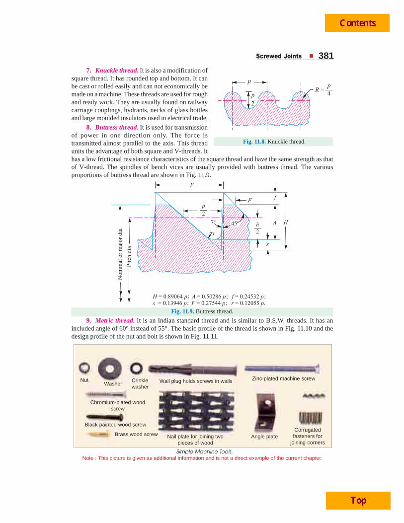
Screwed Joints 3817. Knuckle thread. It is also a modification of
square thread. It has rounded top and bottom. It canbe cast or rolled easily and can not economically bemade on a machine. These threads are used for roughand ready work. They are usually found on railwaycarriage couplings, hydrants, necks of glass bottlesand large moulded insulators used in electrical trade.
8. Buttress thread. It is used for transmissionof power in one direction only. The force istransmitted almost parallel to the axis. This threadunits the advantage of both square and V-threads. Ithas a low frictional resistance characteristics of the square thread and have the same strength as thatof V-thread. The spindles of bench vices are usually provided with buttress thread. The variousproportions of buttress thread are shown in Fig. 11.9.
Fig. 11.9. Buttress thread.
9. Metric thread. It is an Indian standard thread and is similar to B.S.W. threads. It has anincluded angle of 60° instead of 55°. The basic profile of the thread is shown in Fig. 11.10 and thedesign profile of the nut and bolt is shown in Fig. 11.11.
Fig. 11.8. Knuckle thread.
Simple Machine Tools.Note : This picture is given as additional information and is not a direct example of the current chapter.
WasherNut Crinkle
washer
Chromium-plated woodscrew
Black painted wood screw
Brass wood screw Nail plate for joining twopieces of wood
Angle plateCorrugatedfasteners for
joining corners
Zinc-plated machine screwWall plug holds screws in walls
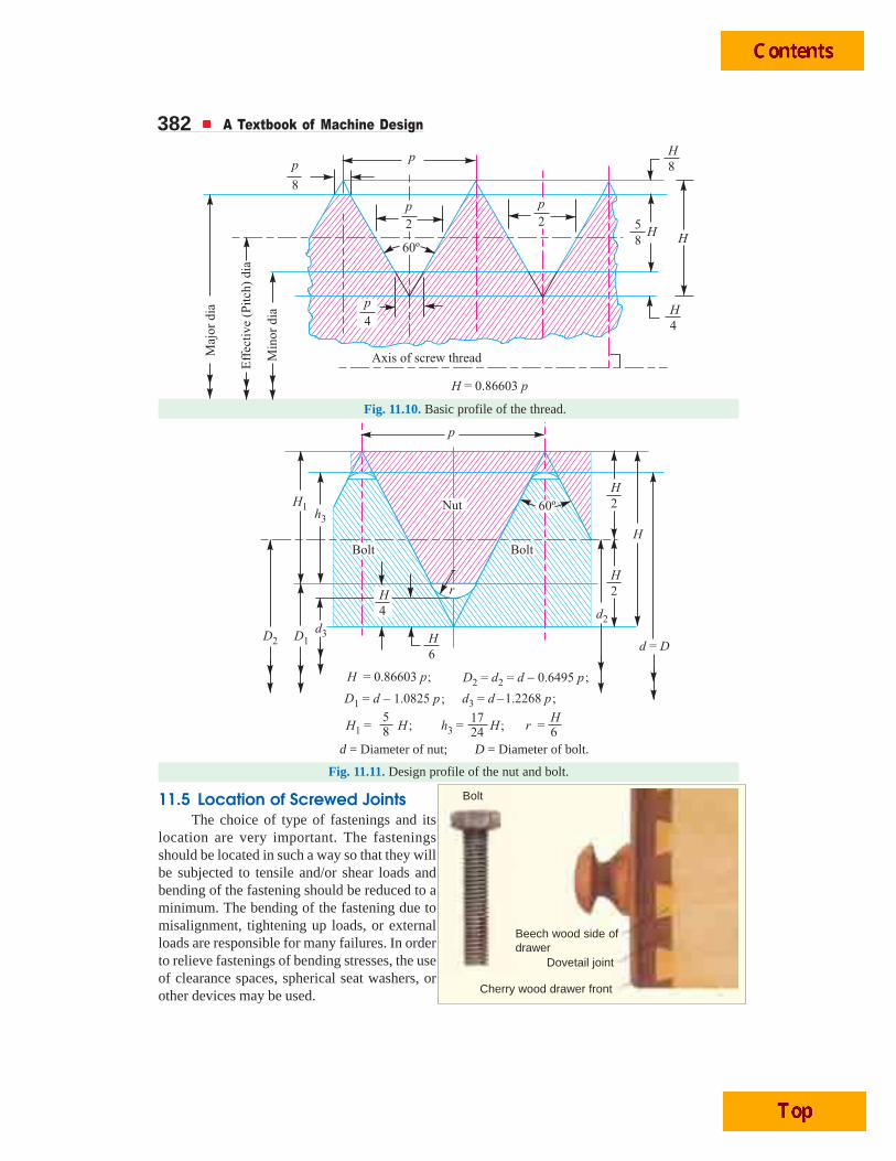
382 A Textbook of Machine Design
Fig. 11.10. Basic profile of the thread.
d = Diameter of nut; D = Diameter of bolt.
Fig. 11.11. Design profile of the nut and bolt.
11.5 Location of Screwed JointsThe choice of type of fastenings and its
location are very important. The fasteningsshould be located in such a way so that they willbe subjected to tensile and/or shear loads andbending of the fastening should be reduced to aminimum. The bending of the fastening due tomisalignment, tightening up loads, or externalloads are responsible for many failures. In orderto relieve fastenings of bending stresses, the useof clearance spaces, spherical seat washers, orother devices may be used.
Beech wood side ofdrawer
Dovetail joint
Cherry wood drawer front
Bolt
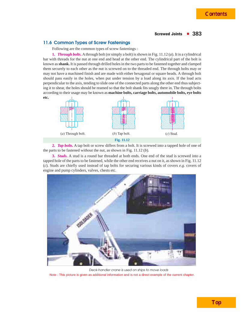
Screwed Joints 383
11.6 Common Types of Screw FasteningsFollowing are the common types of screw fastenings :
1. Through bolts. A through bolt (or simply a bolt) is shown in Fig. 11.12 (a). It is a cylindricalbar with threads for the nut at one end and head at the other end. The cylindrical part of the bolt isknown as shank. It is passed through drilled holes in the two parts to be fastened together and clampedthem securely to each other as the nut is screwed on to the threaded end. The through bolts may ormay not have a machined finish and are made with either hexagonal or square heads. A through boltshould pass easily in the holes, when put under tension by a load along its axis. If the load actsperpendicular to the axis, tending to slide one of the connected parts along the other end thus subject-ing it to shear, the holes should be reamed so that the bolt shank fits snugly there in. The through boltsaccording to their usage may be known as machine bolts, carriage bolts, automobile bolts, eye boltsetc.
Fig. 11.12
2. Tap bolts. A tap bolt or screw differs from a bolt. It is screwed into a tapped hole of one ofthe parts to be fastened without the nut, as shown in Fig. 11.12 (b).
3. Studs. A stud is a round bar threaded at both ends. One end of the stud is screwed into atapped hole of the parts to be fastened, while the other end receives a nut on it, as shown in Fig. 11.12(c). Studs are chiefly used instead of tap bolts for securing various kinds of covers e.g. covers ofengine and pump cylinders, valves, chests etc.
Deck-handler crane is used on ships to move loads
Note : This picture is given as additional information and is not a direct example of the current chapter.
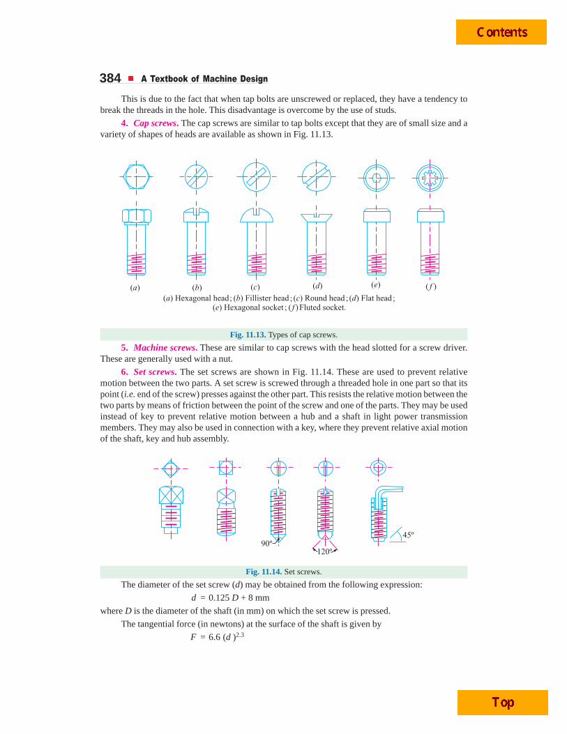
384 A Textbook of Machine Design
This is due to the fact that when tap bolts are unscrewed or replaced, they have a tendency tobreak the threads in the hole. This disadvantage is overcome by the use of studs.
4. Cap screws. The cap screws are similar to tap bolts except that they are of small size and avariety of shapes of heads are available as shown in Fig. 11.13.
Fig. 11.13. Types of cap screws.
5. Machine screws. These are similar to cap screws with the head slotted for a screw driver.These are generally used with a nut.
6. Set screws. The set screws are shown in Fig. 11.14. These are used to prevent relativemotion between the two parts. A set screw is screwed through a threaded hole in one part so that itspoint (i.e. end of the screw) presses against the other part. This resists the relative motion between thetwo parts by means of friction between the point of the screw and one of the parts. They may be usedinstead of key to prevent relative motion between a hub and a shaft in light power transmissionmembers. They may also be used in connection with a key, where they prevent relative axial motionof the shaft, key and hub assembly.
Fig. 11.14. Set screws.
The diameter of the set screw (d) may be obtained from the following expression:
d = 0.125 D + 8 mm
where D is the diameter of the shaft (in mm) on which the set screw is pressed.
The tangential force (in newtons) at the surface of the shaft is given by
F = 6.6 (d )2.3
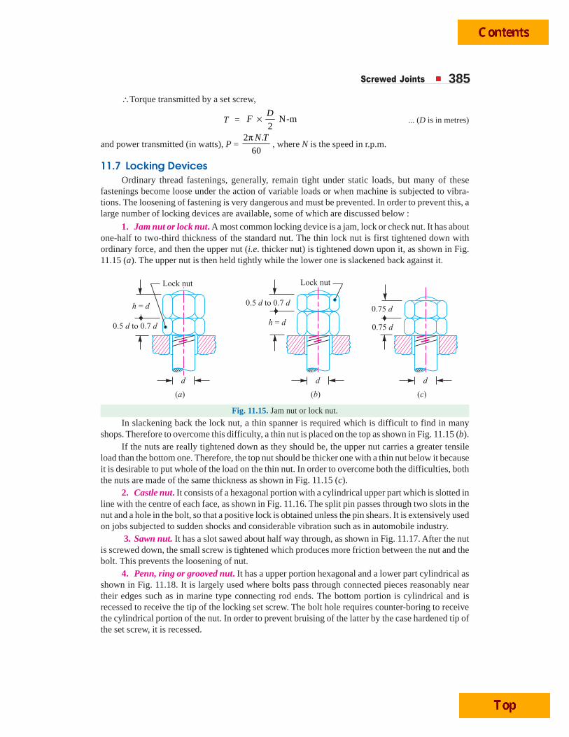
Screwed Joints 385∴Torque transmitted by a set screw,
T = N-m2
DF × ... (D is in metres)
and power transmitted (in watts), P = 2 .
60
N Tπ, where N is the speed in r.p.m.
11.7 Locking DevicesOrdinary thread fastenings, generally, remain tight under static loads, but many of these
fastenings become loose under the action of variable loads or when machine is subjected to vibra-tions. The loosening of fastening is very dangerous and must be prevented. In order to prevent this, alarge number of locking devices are available, some of which are discussed below :
1. Jam nut or lock nut. A most common locking device is a jam, lock or check nut. It has aboutone-half to two-third thickness of the standard nut. The thin lock nut is first tightened down withordinary force, and then the upper nut (i.e. thicker nut) is tightened down upon it, as shown in Fig.11.15 (a). The upper nut is then held tightly while the lower one is slackened back against it.
Fig. 11.15. Jam nut or lock nut.
In slackening back the lock nut, a thin spanner is required which is difficult to find in manyshops. Therefore to overcome this difficulty, a thin nut is placed on the top as shown in Fig. 11.15 (b).
If the nuts are really tightened down as they should be, the upper nut carries a greater tensileload than the bottom one. Therefore, the top nut should be thicker one with a thin nut below it becauseit is desirable to put whole of the load on the thin nut. In order to overcome both the difficulties, boththe nuts are made of the same thickness as shown in Fig. 11.15 (c).
2. Castle nut. It consists of a hexagonal portion with a cylindrical upper part which is slotted inline with the centre of each face, as shown in Fig. 11.16. The split pin passes through two slots in thenut and a hole in the bolt, so that a positive lock is obtained unless the pin shears. It is extensively usedon jobs subjected to sudden shocks and considerable vibration such as in automobile industry.
3. Sawn nut. It has a slot sawed about half way through, as shown in Fig. 11.17. After the nutis screwed down, the small screw is tightened which produces more friction between the nut and thebolt. This prevents the loosening of nut.
4. Penn, ring or grooved nut. It has a upper portion hexagonal and a lower part cylindrical asshown in Fig. 11.18. It is largely used where bolts pass through connected pieces reasonably neartheir edges such as in marine type connecting rod ends. The bottom portion is cylindrical and isrecessed to receive the tip of the locking set screw. The bolt hole requires counter-boring to receivethe cylindrical portion of the nut. In order to prevent bruising of the latter by the case hardened tip ofthe set screw, it is recessed.