Owen Kirby, IRI Regional Director, Middle East and North Africa
Upload
khangminh22Category
view
0download
0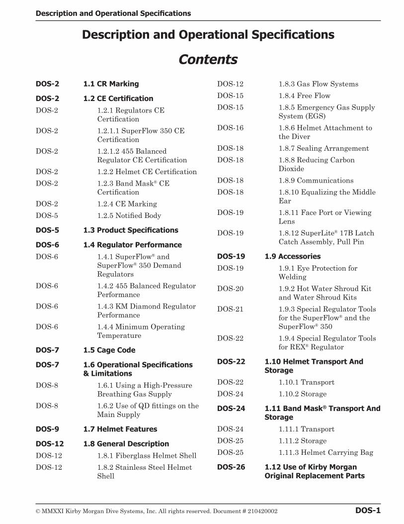
© MMXXI Kirby Morgan Dive Systems, Inc. All rights reserved. Document # 210420002 DOS-1
Description and Operational Specifications
Contents
DOS-2 1.1 CR Marking
DOS-2 1.2 CE Certification
DOS-2 1.2.1 Regulators CE Certification
DOS-2 1.2.1.1 SuperFlow 350 CE Certification
DOS-2 1.2.1.2 455 Balanced Regulator CE Certification
DOS-2 1.2.2 Helmet CE Certification
DOS-2 1.2.3 Band Mask® CE Certification
DOS-2 1.2.4 CE Marking
DOS-5 1.2.5 Notified Body
DOS-5 1.3 Product Specifications
DOS-6 1.4 Regulator Performance
DOS-6 1.4.1 SuperFlow® and SuperFlow® 350 Demand Regulators
DOS-6 1.4.2 455 Balanced Regulator Performance
DOS-6 1.4.3 KM Diamond Regulator Performance
DOS-6 1.4.4 Minimum Operating Temperature
DOS-7 1.5 Cage Code
DOS-7 1.6 Operational Specifications & Limitations
DOS-8 1.6.1 Using a High-Pressure Breathing Gas Supply
DOS-8 1.6.2 Use of QD fittings on the Main Supply
DOS-9 1.7 Helmet Features
DOS-12 1.8 General Description
DOS-12 1.8.1 Fiberglass Helmet Shell
DOS-12 1.8.2 Stainless Steel Helmet Shell
DOS-12 1.8.3 Gas Flow Systems
DOS-15 1.8.4 Free Flow
DOS-15 1.8.5 Emergency Gas Supply System (EGS)
DOS-16 1.8.6 Helmet Attachment to the Diver
DOS-18 1.8.7 Sealing Arrangement
DOS-18 1.8.8 Reducing Carbon Dioxide
DOS-18 1.8.9 Communications
DOS-18 1.8.10 Equalizing the Middle Ear
DOS-19 1.8.11 Face Port or Viewing Lens
DOS-19 1.8.12 SuperLite® 17B Latch Catch Assembly, Pull Pin
DOS-19 1.9 Accessories
DOS-19 1.9.1 Eye Protection for Welding
DOS-20 1.9.2 Hot Water Shroud Kit and Water Shroud Kits
DOS-21 1.9.3 Special Regulator Tools for the SuperFlow® and the SuperFlow® 350
DOS-22 1.9.4 Special Regulator Tools for REX® Regulator
DOS-22 1.10 Helmet Transport And Storage
DOS-22 1.10.1 Transport
DOS-24 1.10.2 Storage
DOS-24 1.11 Band Mask® Transport And Storage
DOS-24 1.11.1 Transport
DOS-25 1.11.2 Storage
DOS-25 1.11.3 Helmet Carrying Bag
DOS-26 1.12 Use of Kirby Morgan Original Replacement Parts
Description and Operational Specifications

DOS-2 © MMXXI Kirby Morgan Dive Systems, Inc. All rights reserved. Document # 210420002
CR Marking Description and Operational Specifications
B WARNINGThis manual is our effort to explain the operation, maintenance and use of the Kirby Morgan helmet. We do not herein make any effort to teach the principles of diving. It is our assumption the reader is a qualified diver. We highly recommend that all divers should train, under con-trolled conditions, in the use of any model of commercial diving helmet that they have not pre-viously used or trained in, prior to use on the job, until they have mastered the skills required to use their helmet correctly. Kirby Morgan helmets are intended for professional use only and are not intended for recreational use by persons not trained in surface supplied procedures and practices.
This section includes detailed descriptions of Kir-by Morgan helmets, as well as important opera-tional specifications.
1.1 CR MarkingThe helmet meets or exceeds all standards es-tablished by Dive Lab of Panama City, Florida, and is CR (Commercially Rated) rated with the SuperFlow®, with SuperFlow® 350 non balanced regulator and with 455 balanced regulator.
COM
MERCIALLY RATED - PROFESSIONAL DIVING GEAR - DIVELAB TE
STED
-
TM
TM
1.2 CE Certification1.2.1 Regulators CE Certification
1.2.1.1 SuperFlow 350 CE Certification
SuperFlow 350 regulator has been tested and conforms to the performance requirements as set forth in Annex II of Regulation (EU) 2016/425.
1.2.1.2 455 Balanced Regulator CE Certification
455 Balanced Regulator has been tested and con-forms to the performance requirements as set forth in Annex II of Regulation (EU) 2016/425.
1.2.2 Helmet CE Certification
The helmet has been tested and conforms to the performance requirements as set forth in Annex II of Regulation (EU) 2016/425 and, as far as ap-
plicable, the EN15333-1 (class B). It is fully CE marked with the 455 balanced demand regulator or SuperFlow® 350 and oral nasals P/N 510-690 and P/N 510-747.
Category of PPE: III
1.2.3 Band Mask® CE Certification
The Band Mask® has been tested and conforms to the performance requirements as set forth in Annex II of Regulation (EU) 2016/425 and, as far as applicable, the EN 15333-1 (Class C). It is fully CE marked with demand regulator 455 bal-anced, SuperFlow® 350 and oral nasal masks P/N 510-690 and P/N 510-747.
Category of PPE: III
B WARNINGThe helmet or Band Mask® has been tested with air and CE certificated for use with air up to 50 meters. Com-pressed air must be compliant with the EN 12021.
All the tables reporting the technical data and the pressure of use are rela-tive to compressed air.
1.2.4 CE Marking
On the inside of the helmet shell the CE mark is affixed.

© MMXXI Kirby Morgan Dive Systems, Inc. All rights reserved. Document # 210420002 DOS-3
Description and Operational Specifications CE Certification
0477
HELMET MODEL:
KIRBY MORGANDIVE SYSTEMS. INC.
1430 Jason Way,Santa Maria, CA 93455
YEAR OF PRODUCTION:
EN15333-1CLASS B
CE Mark on Helmets
In the mark on the helmets the following data is reported:
1. The name and the address of the manu-facturer
2. Harmonized reference standard: EN 15333-1
3. PPE model
The above diagram depicts the location of the serial number on fiberglass helmets.
The above diagram depicts the location of the serial number on stainless steel helmets.
The above diagram depicts the location of the serial number on KMB 18 BandMasks.
The above diagram depicts the location of the serial number on KMB 28 BandMasks.

DOS-4 © MMXXI Kirby Morgan Dive Systems, Inc. All rights reserved. Document # 210420002
CE Certification Description and Operational Specifications
The diagram to the left depicts the location of the
notifying body number and reference standard
on the exterior of the 455 Balanced Regulator.
NOTIFYING BODY NUMBERREFERENCE STANDARD
SERIAL NUMBER
The diagram to the left depicts the location of the notifying body
number and reference standard on the exterior
of the SuperFlow® 350 Regulator.
NOTIFYING BODY NUMBER
SERIAL NUMBER
REFERENCE STANDARD

© MMXXI Kirby Morgan Dive Systems, Inc. All rights reserved. Document # 210420002 DOS-5
Description and Operational Specifications Product Specifications
4. The year of production
5. CE marking:
6. Number of notified body
On the frame of the Band Mask® the CE mark is affixed.
0477
KIRBY MORGANDIVE SYSTEMS, INC.
1430 Jason Way,Santa Maria, CA 93455
EN15333-1CLASS C
BANDMASK® MODEL:
YEAR OF PRODUCTION:
CE Mark on Band Masks®
In the mark on the Band Masks® the following data is reported:
2. The name and the address of the manu-facturer
3. Harmonized reference standard: EN 15333-1
4. CLASS C = NO protection
5. Band Mask® model
6. Serial number (stamp on the BandMask®
frame)
7. The year of production
8. CE marking:
9. Notifying Body number
NOTICEThe user cannot:
• Remove the mark from the shell of the helmet
• Modify or counterfeit the data report-ed on the mark.
NOTICEThe mark must be visible and legible throughout the life of the PPE. If the mark deteriorates or is not legible the user should contact the manufacturer.
1.2.5 Notified Body
The Notified Body is: Eurofins Product Testing Italy Srl
Address: Via Courgné 21-10156 Torino, ITALY
Identification number: 0477.
1.3 Product SpecificationsWeight:SL 17B - 29.03 poundsSL 17C - 30.6 poundsSL 27 - 28.5 poundsKM 37 - 32.6 poundsKM 37SS - 30.96 poundsKM 47 - 30.96 poundsKM 77 - 32.43 poundsKM 97 - 31.09 poundsKM Diamond - 34.8 pounds
KMB 18 - 13.63 poundsKMB 28 - 12.73 pounds
For KM 37SS, 77, 97 and KM Diamond Hel-metsHelmet Shell: Stainless steel
For SL 17B, 17C, 27, 37, and 47 HelmetsHelmet Shell: Fiberglass, polyester resin, and carbon fibers
For SL 17B, 17C, 27, 37, and 37SSRegulator Body - Chrome Plated Brass
For KM 47, 77, 97 and KM Diamond HelmetsRegulator Body - Stainless steel
For BandMasksMask Frame KMB 18: Fiberglass, polyester res-in, polyester gel coat, carbon fiber
Mask Frame KMB 28: Xenoy® thermoplastic
DOS-6 © MMXXI Kirby Morgan Dive Systems, Inc. All rights reserved. Document # 210420002
Regulator Performance Description and Operational Specifications
Control Knobs: ABS plastic
Lens: Clear polycarbonate
Hood: Neoprene.
O-rings: Buna-N
For all helmetsControl Knobs: Polyurethane
Lens: Clear polycarbonate
Neck Dam: Neoprene. Optional latex neck dam available.
O-rings: Buna-N
Head Cushion: Nylon bag filled with #4 Polyester foam
Recommended Lubricants: Molykote® 111 Sili-cone Lubricant. Christo-Lube®, Krytox®, and Halocarbon® are also acceptable.
B WARNINGNever use aerosol-propelled sprays near the face port of any Kirby Morgan diving helmet. The propellant used in these aerosols can invisibly damage the face port and cause it to shatter on impact from any strong blow. If the face port fails underwater, injury or death may result.
If you have any questions regarding proper set-up, operation, or maintenance of your Kirby Mor-gan helmet contact KMDSI (805) 928-7772 or at [email protected] or Dive Lab Inc. (850) 235-2715 or at [email protected]. There are also detailed checklists for the set-up and main-tenance of your helmet on the Dive Lab web site at www.divelab.com, or the Kirby Morgan web-site under “Support” www.kirbymorgan.com.
1.4 Regulator Performance1.4.1 SuperFlow® and SuperFlow® 350 Demand Regulators
The SuperFlow® 350 non balanced regulator is the standard demand regulator found on the SL
17C, SL 27, KM 37, KM 37SS and KMB 18/28 Band Masks. NOTE: Pre Sep. 2004 KMB 28 plastic frames will only accept the smaller mount tube found on the SuperFlow® (non 350) regulator. The SuperFlow® 350 is fully CE marked and CR rated.
1.4.2 455 Balanced Regulator Performance
The 455 Balanced Regulator is an all Stainless Steel regulator of a balanced design that offers far greater overall breathing performance than the non-balanced SuperFlow® and SuperFlow® 350 regulator. The 455 has virtually the same breathing performance as the REX® regulator, but is designed to be used with the SL 27®, 17C, KM 37 and KM 37SS helmets. The overall perfor-mance of this regulator is outstanding and sets a new performance standard for commercial diving helmets.
1.4.3 KM Diamond Regulator Performance
The inhalation regulator is based on the Bal-anced 455 demand regulator P/N 505-455. All individual parts inside the main tube assembly, but NOT THE MAIN TUBE, are interchange-able.
1.4.4 Minimum Operating Temperature
Kirby Morgan helmets can be used in water tem-peratures as low as 34 °F (1 °C) without the use of a hot water shroud and hot water to prevent freezing. However it is strongly recommended that the hot water shroud be used for the comfort of the diver. At the time of this writing a specific part number hot water shroud is not available for the KM 47 or KM 77. For all other helmets the hot water shroud may be purchased as a kit, part number 525-100, water shroud part number 525-390 (for the KM 37SS), water shroud part number 525-756 (for the KM Diamond) or water shroud part number 525-761 (for the KM 97).

© MMXXI Kirby Morgan Dive Systems, Inc. All rights reserved. Document # 210420002 DOS-7
Description and Operational Specifications Cage Code
B WARNINGDiving in cold water, i.e., at tempera-tures below 50 degrees F, may subject the diver to severe respiratory heat loss. This may lead to a decrease in body core temperature also known as “hypothermia.” Hypothermia is extremely dangerous and can lead to a loss of reasoning ability, decreased manual dexterity, uncontrollable shiv-ering, unconsciousness, and death.
-Temperature Limitations: Use at water tem-peratures below 33 °F (1 °C) requires the use of hot water shroud part number 525-100, water shroud part number 525-390 (for the KM 37SS), water shroud part number 525-756 (for the KM Diamond) or water shroud part number 525-761 (for the KM 97) and hot water to help prevent ic-ing of the demand regulator.
NOTE: The Hot Water Shroud (part number 525-100) or Water Shroud (part number 525-390, 525-756 or 525-761) in conjunction with hot wa-ter to the diver should be used whenever diving operations are conducted using HeO2 at water temperatures less than 60 °F (15.56 °C) for the comfort of the diver.
KMDSI further recommends that the shroud be used in conjunction with hot water to the diver whenever diving operations are conducted us-ing air or mixed gas, in waters colder than 33 °F (1 °C) to reduce the possibility of demand regula-tor icing.
NOTE: Usually the greatest danger of demand regulator icing will be encountered on deck when the surrounding air temperature is less than 32 °F (0 °C). This effect is primarily due to the re-frigeration effect of breathing air pressure reduc-tion, and the addition of moisture from the divers exhalation coming in contact with the topside air temperature.
If diving where the water temperature is 33 °F (1 °C) or warmer but the topside air temperature is below freezing, 32 °F (0 °C) icing of the demand regulator is possible. To help eliminate the pos-sibility of freezing on the surface, warm water should be run over the exterior of the demand regulator prior to water entry, if the hot water system is not used.
1.5 Cage CodeThe cage code for identifying KMDSI products for U.S. government purposes is 58366.
1.6 Operational Specifications & LimitationsEvery model of KMDSI helmet and mask under-goes extensive testing to fully document the per-formance capability and required supply pres-sures when using various umbilical and pressure combinations. All users should take the time to become knowledgeable on supply requirements to ensure proper performance and for the comfort and safety of the diver.
The required supply pressures for Kirby Morgan helmets are listed in the appropriate supply pres-sure tables in “Supply Pressure Requirements & Tables” on page APNDX-4.
B WARNINGWhen the helmet is used for air diving in coun-tries that conform to C.E. regulations it must not be used deeper than a maximum depth of 164fsw (50msw). I.A.W. EN 15333-1.
The supply pressures listed in the supply ta-bles were derived by breathing simulator trials. There are multiple tables for each regulator. It is important that users understand how to use the tables. For further information on supply re-quirements for the your Kirby Morgan helmet or mask check the Kirby Morgan website at www.kirbymorgan.com.
-Umbilical minimum I.D. 3/8" (9.5 mm) of not more than two sections, total length not to exceed 600 feet (183m).
The umbilical assembly should be composed of good quality diving hose that meets industry standards. Generally, gas hose will be married to the communications wire, pneumofathometer hose, and strength member in a manner that will allow the strength member to receive all the strain.

DOS-8 © MMXXI Kirby Morgan Dive Systems, Inc. All rights reserved. Document # 210420002
Operational Specifications & Limitations Description and Operational Specifications
There are also good quality umbilicals available that are assembled at the factory using a twisted method which does not require marrying. Re-gardless of the system used, the umbilical is the diver’s life line and should always be of excellent quality and maintained carefully.
If you have any questions regarding proper set-up, operation, or maintenance of your Kirby Mor-gan helmet contact KMDSI (805) 928-7772 or at [email protected] or Dive Lab Inc. (850) 235-2715 or at [email protected].
B DANGERDecompression diving always in-volves the risk of decompression sickness. Omitted decompression due to a loss of the breathing gas supply or other accidents can cause serious injury or death. Use of a Kirby Morgan helmet or mask cannot prevent this type of injury.
1.6.1 Using a High-Pressure Breathing Gas Supply
High pressure (HP) control consoles are capable of suppling air or mixed gas at pressures and vol-umes much greater than low pressure air com-pressors, and are often preferred by military and and scientific divers. HP air systems are often used as back up supply for LP compressor diving.
When using HP air or mixed gas systems, The regulator is normally loaded to 100-150 psig on the surface and increased to the bottom setting as the diver descends or when the diver reaches the bottom. During ascent the pressure is reduced to between 100-150 p.s.i.g. once the diver is shal-lower than 100 feet. A high-pressure gas supply is typically used under the following conditions:
• When the work load exceeds the capabilities of the compressor to supply a sufficient volume and pressure of breathing gas, regardless of the depth.• When the diver is using pre-mixed gas.• As a back-up for a low-pressure compressor• Any time a high-pressure supply is available
The regulator is loaded as the diver increasingly descends and unloaded as the diver returns to
the surface. If the diver experiences a free-flow with his regulator, when the bias adjustment knob is properly set and the regulator has been maintained correctly, the pressure setting on the high-pressure regulator may be set too high and may need to be decreased.
For recommended pressures when using a high-pressure breathing gas supply and a dome loaded regulator, see “Supply Pressure Requirements & Tables” on page APNDX-4. Generally speaking, the topside regulator should be set at 140 p.s.i.g. over bottom pressure for optimum regulator per-formance.
B WARNINGThe demand regulator and side block assem-blies have a maximum design pressure of 225 p.s.i.g. (15.5 bar) over-bottom. Higher pres-sures could lead to component failure and serious personal injury.
B WARNINGGas systems used to supply Kirby Morgan helmets and masks must be capable of supplying gas to the diver at the required pressure and flow rates as stated in the operational specifications. The use of unregulated gas sources is extremely dangerous.
The use of standard SCUBA type regulators is unacceptable, as there are no provisions for adjusting the in-termediate pressure to the diver. Only proven systems that allow for varying the gas supply pressure to the diver should be used for umbilical diving.
1.6.2 Use of QD fittings on the Main Supply
Kirby Morgan strongly recommends that only umbilicals designed and manufactured specifical-ly for Surface Supply Diving be used with KMD-SI surface supplied helmets and full-face masks. The umbilical fittings used should be those rec-ommended by the umbilical manufacturer.

© MMXXI Kirby Morgan Dive Systems, Inc. All rights reserved. Document # 210420002 DOS-9
Description and Operational Specifications Helmet Features
Interface fittings attaching the umbilical to the side block one-way valve should be of good qual-ity, made of brass or stainless steel or other non-corrosive material and rated for the required pressure. KMDSI recommends that the umbilical and interface fittings be visually inspected prior to each diving day for signs of striped or damaged threads, signs of crimp slippage as well as any other signs of damage. Umbilical should be pres-sure tested at least once a year and / or whenever the integrity of the hose is in question for any reason.
KMDSI does not recommend using Quick Con-nect (QD) fittings as a connection of the main gas umbilical to the helmet side block. Attach-ing a quick connect fitting directly to the Helmet or BandMask® can pose a serious impact failure point due to the length of the QD attachment. Impact damage at the side block could result in the complete loss umbilical gas supply.
General industry practice, both commercial and military, often use an EGS whip assembly with QD fittings to attach the Emergency Gas Sup-ply (EGS) Bailout System to the Helmet or Band Mask®. KMDSI recommends that EGS QD whip assemblies be of a locking or index type, good quality, and made up internally and externally of non- corrosive materials such as brass or stain-less steel. Any EGS whip and regulator assembly with or without a QD should be capable of flow-ing a minimum 35 scfm (1000 lpm) when mea-sured at one atmosphere (on the surface) using a minimum dynamic steady intermediate supply pressure of at least 120 psig. Thirty-five (35) scfm (1000 lpm) at the surface, will allow the diver us-ing a KMDSI helmet of BandMask® to to breath at minimum of 40 RMV to depths to 200 fsw (60 msw) on air, in the event main gas supply is in-terrupted or lost.
The first stage used for the EGS system should be of good quality and maintained IAW the man-ufactures recommendations. EGS interface whip assemblies should be pressure tested to 1.5% of their rated working pressure at least once a year and/or whenever the integrity of the hose is in question for any reason.
The size of the EGS cylinder/cylinders should be determined by the hazards of the diving condi-tions and the amount of time necessary for the
diver to surface, or get to a place where breath-ing gas can be restored. KMDSI surface supply Helmets and BandMasks® should never be used without a fully functional EGS system attached. The EGS cylinder valve should be open with the gas supply pressurized to the shut EGS valve on the side block. The EGS supply system should include an overpressure relief valve installed up-stream of the side block EGS valve.
1.7 Helmet FeaturesAll Kirby Morgan diving helmets are manufac-tured by hand. Each step of the manufacturing process is carefully controlled to assure the cus-tomer receives a high quality, durable helmet that functions properly in all aspects.
All Kirby Morgan helmets, with the exception of the SL 17B, incorporate the innovative locking collar system. For the SL 17B helmet, the head cushion and the neck clamp/yoke assembly give the diver a secure fit in the helmet.
SL 17B, 17C, 27, KM 37 and 37SS Helmets:These helmets feature the SuperFlow® adjust-able demand regulator which provides ample breathing gas flow during peak work output.
KM 47 and 77 Helmets:The 47 and 77 feature the REX® adjustable de-mand regulator which provides superior breath-ing gas flow during peak work output.
KM 97 Helmet:The 455 Balanced Regulator on this helmet is a balanced design that offers far greater overall breathing performance than the non-balanced SuperFlow® and SuperFlow® 350 regulator. The overall performance of this regulator is outstand-ing and sets a new performance standard for commercial diving helmets.
Following the same design configuration of all our helmets the helmet consists of two main pieces; the helmet shell assembly and the neck dam/ring assembly. The machined helmet bot-tom ring houses the sealed pull pins and locking collar, and provides protection for the bottom end of the helmet shell. The adjustable neck pad on the locking collar, in combination with the inter-nal chin strap and adjustable head cushion, gives the diver a secure, custom tailored fit in the hel-

DOS-10 © MMXXI Kirby Morgan Dive Systems, Inc. All rights reserved. Document # 210420002
Helmet Features Description and Operational Specifications
met. The superior fit and balance makes the hel-met sit comfortably for long periods of time even when working in the face down position.
A quick change communications module, avail-able in either bare wire posts or a waterproof con-nector, allows for easy, efficient maintenance of the communications in the helmet.
SL 17B, 17C, KM 37, 37SS and 97 Helmets:These helmets feature the Quad exhaust system which keeps the inside of the helmets dry and has low exhalation resistance. This exhaust sys-tem helps to limit exposure during contaminated water diving.
SL 27 Helmet:The Tri-Valve® exhaust system is standard equip-ment for the SL 27®. This superior exhaust sys-tem has exceptionally low exhalation resistance, and helps to keep the helmet free of contami-nants in polluted water. The Tri-Valve® isolates the breathing system from the surrounding wa-ter with a three valve, low breathing resistance design.
KM 47 and 77 Helmets:These helmets feature the REX® exhaust system. This exhaust system helps to limit exposure dur-ing contaminated water diving.
KM Diamond Helmet:Features a two stage regulator that controls and routs the exhaled gas. Rapid removal and replacement is possible with clear access to all fasteners.
The bypass equalizer tube stabilizes the supply regulator, creates a protective bubble layer to the exposed valve and deflects exhaust bubbles from the diver’s field of view when operating in open circuit mode.
The overpressure relief valve automatically ac-tivates if internal helmet pressure becomes too great. It can also be manually adjusted to im-prove breathing when operating in the open cir-cuit mode or it can act as a standalone feature to dump exhaled gas directly into the surrounding water.
The surface bypass valve allows effortless switch-ing from surface vent, (or reclaim), to standard
open circuit diving mode. Switching back and forth from diving modes is instant with a single action.
B WARNINGBefore attempting any diving in any type of contaminated water, a complete diving and top-side course in hazardous materials emergencies should be completed. The divers and the top-side team must be prop-erly trained and have the proper safety equipment. All helmets and suits can leak water under certain conditions. Div-ers should use extreme caution when diving in contaminated waters.
Helmet features which are common to all Kirby Morgan helmets include:
• The face port
• Communications components
Helmet features which are shared on certain Kir-by Morgan helmets include:
• The oral/nasal mask is the same on: 17C, 17B, 37, 37SS and 97.
• The oral/nasal mask is the same on: KM 47 and 77.
• Unique oral/nasal mask: 27.
• Unique oral/nasal mask: KM Diamond.
• The bent tube is the same on: SL 17B, 17C, 27, KM 37, 37SS and 97
• The bent tube is the same on: KM 47 and 77
• Unique bent tube: KM Diamond
• Same nose block device on all except the 27.
• Same head and chin cushion in all except the 17B.

© MMXXI Kirby Morgan Dive Systems, Inc. All rights reserved. Document # 210420002 DOS-11
Description and Operational Specifications Helmet Features
• Same Neck Ring/Neck Dam Assembly on all excluding the 17B: has a neck clamp/yoke.
• Units with shells in common: The 37SS, 77, 97 and KM Diamond. All others in current production have shells unique to their model.
The Kirby Morgan BandMask® KMB 18 and the Kirby Morgan BandMask® KMB 28 compare as follows:
• The face port (or view port) on the KMB 18 remains unchanged in shape from the Super-Lite® 17A/B. The face port in the KMB 28 is a slightly different size than the KMB 18.
• The water dump body is molded into the mask frame in the KMB 28.
• The exhaust covers on the two masks are slightly different.
• There is a vacuum formed comfort insert in the KMB 18.
• The air train in the KMB 28 requires a spe-cial standoff for proper mounting of the side block.
• The bent tube assembly that transports air/gas to the demand regulator from the side block is the same on both masks and on most Kirby Morgan helmets.
Many of the breathing system components on these helmets are also compatible with the KMB 18 and 28 BandMasks®. This helps reduce the in-ventory of spare parts that must be carried by commercial diving companies.
Each step of the manufacturing process is care-fully controlled to assure the customer of a high quality, durable helmet that will function prop-erly. The following is a general description of the features on the specified helmets.
KM 37SS, 77, 97 and KM Diamond Helmets:The helmet is cast as a single piece and finished using computer controlled machinery. The bot-tom helmet ring receives the neck dam ring which seals to the helmet with an O-ring. The seal is very air/water tight. The metal bottom is quite durable in normal use, but care should be taken not to drag the helmet bottom on the deck.
The handle on top of the helmet can be used as a
mounting bracket for lights, video cameras, etc. Removal of the handle is quick and easy and does not require sealing to the helmet shell, as on the fiberglass models.
SL 17C, 27, KM 37, and 47 Helmets:The handle on top of the helmet can be used as a mounting bracket for lights, video cameras, etc. The port weight on the 27, 37, and 47 may be used for this as well. The 17C features mounting brackets, one on each side of the handle.
SL 17C, 27, KM 37, 37SS, 47, 77, 97 and KM Diamond Helmets:The neck dam is sandwiched between the neck dam rings, securely holding it in place. Replace-ment neck dams install easily. Latex or foam neoprene neck dams are available.
When the neck dam/neck ring is locked into place on the helmet, it is located up inside the protec-tive helmet ring (that the neck ring O-ring seals to) which protects the neck ring and neck dam from side impact damage during the dive.
The neck dam design (latex or neoprene foam) helps position the helmet correctly. Replacement neck dams should only be genuine KMDSI/Kirby Morgan neck dams to assure proper operation and comfort. An internal adjustable chin strap helps to secure the diver’s head in the helmet.
The locking collar design holds the neck ring in the sealed position. The O-ring seal is continuous once the neck ring is placed into the helmet ring.
Attached to the locking collar is an adjustable neck pad that should be adjusted to the diver prior to diving. This will improve the fit and per-formance of the helmet.
A system of two sealed pull pin locks is on the SL 17C, 27, 37, 37SS, 47, 77, 97 and KM Diamond. One lock is located on each side of the helmet. The spring and sliding shaft of these locks are inside an O-ring sealed main body. The interior of the main body is filled with silicone fluid. No fine sand or other debris can reach the interior of these locks to interfere with their operation.
The head cushion attaches just inside the bottom of the helmet, keeping it in place when the diver dons the hat. The standard head cushion consists
DOS-12 © MMXXI Kirby Morgan Dive Systems, Inc. All rights reserved. Document # 210420002
General Description Description and Operational Specifications
of a reinforced nylon bag with an open cell foam inside.
SL 17B Helmet:The neck dam on the SL 17B is secured by the neck clamp. Replacement neck dams install eas-ily.
The head cushion attaches just inside the bottom of the helmet, keeping it in place when the diver dons the hat. The standard head cushion consists of a brushed nylon bag with an open cel polyester foam inside. Only genuine Kirby Morgan SL 17B head cushions should be used to ensure proper operation and comfort.
B CAUTIONThe 17B head cushion should not be used in other Kirby Morgan helmets because the design of the head cush-ion is different. Only genuine Kirby Morgan head cushions designed for the helmets should be used to assure proper operation and comfort.
SL 27, KM 37, 37SS, 47, 77 and 97 Helmets:The communications system is a modular, quick change design.
SL 17C, KM 37, 37SS and 97 Helmets:The unique design of the Quad-Valve™ exhaust system helps keep exhalation resistance low while maintaining excellent watertight integrity.
47 and 77 Helmets:The exhaust system is a three valve design, the REX®, that helps to keep the helmet exception-ally dry.
KM Diamond Helmet:Features a two stage regulator that controls and routs the exhaled gas. Rapid removal and replacement is possible with clear access to all fasteners.
1.8 General Description1.8.1 Fiberglass Helmet Shell
The helmet shell is fabricated of noncorrosive, rigid fiberglass which will not carry an electri-cal charge. This shell is the central structure for mounting all the components that make up the
complete helmet. It is designed to allow easy re-placement of parts when necessary. Any repair to the helmet shell must be done at an approved KMDSI repair center.
The mask frame on the KMB 28 is made from Xenoy®, a thermoplastic that also will not carry an electrical charge.
1.8.2 Stainless Steel Helmet Shell
The helmet shell is fabricated of high grade corro-sive resistant 316L stainless steel as a one piece unit. Along with the all steel material, what also sets this shell apart from fiberglass is that the large“bottom ring” is not a separate piece, but is an integral part of the overall shell. The stainless steel shells also do not require separate weights mounted to them, and the threaded inserts that accept the port retainer screws, have also been done away with as a separate part needing spe-cial maintenance and eventual replacement. This shell is the central structure for mounting all the components that make up the complete helmet. It is designed to allow easy replacement of parts when necessary. Any repair to the hel-met shell must be done at an approved KMDSI repair center.
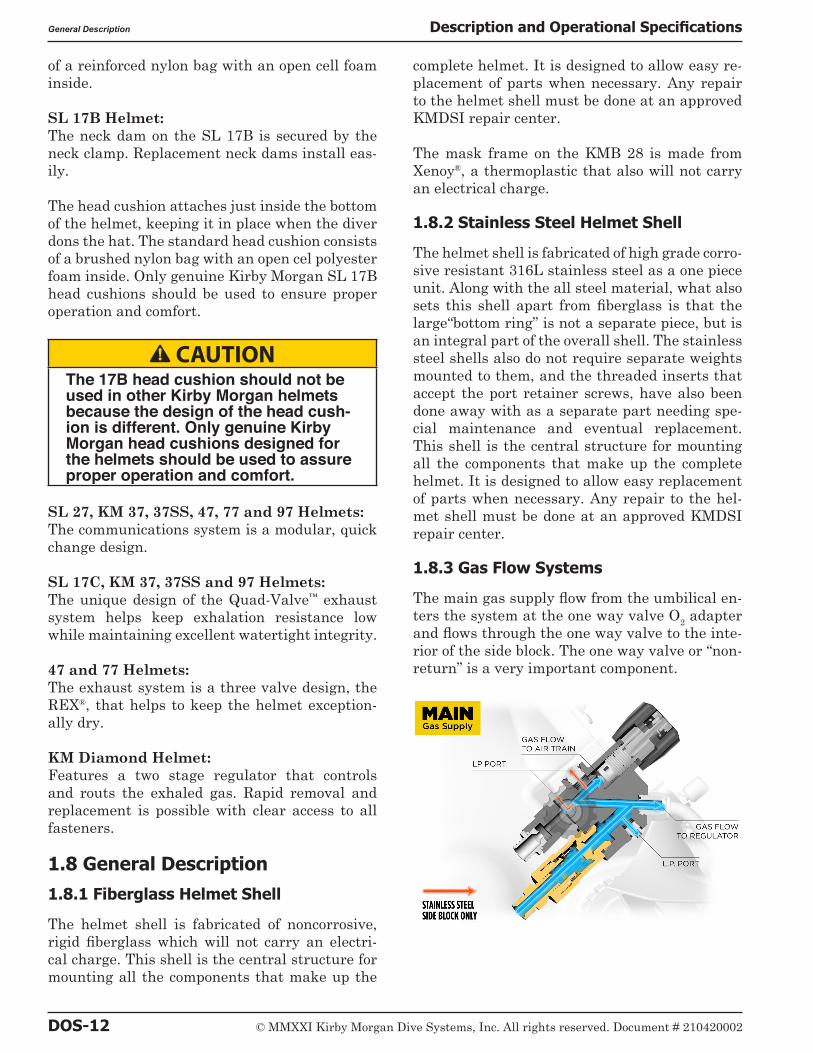
1.8.3 Gas Flow Systems
The main gas supply flow from the umbilical en-ters the system at the one way valve O2 adapter and flows through the one way valve to the inte-rior of the side block. The one way valve or “non-return” is a very important component.

© MMXXI Kirby Morgan Dive Systems, Inc. All rights reserved. Document # 210420002 DOS-13
Description and Operational Specifications General Description
The one way valve prevents the flow of gas out of the helmet to the umbilical in the event of a sud-den lowering of pressure in the umbilical. This can happen due to an accidental break in the hose or fitting near the surface. Not only would the emergency gas be lost if the one way valve failed (concurrent with a hose or fitting break on deck), but the diver could suffer from a serious “squeeze” that could cause injury or death.
B WARNINGThe bent tube assembly for the KM 47 and 77 is a unique design and is not interchangeable with or other bent tubes. Modifying to interchange could cause serious injury or death.
Although we have selected the one way valve for its reliability and quality, inspection and mainte-nance of this valve must be done regularly. It is very easy to disassemble and inspect. (A rebuild kit for this valve is available, order P/N 525-330).
B WARNINGThe one way valve must be tested daily, prior to the commencement of diving operations. Failure of one way valve could cause serious injury or death. Follow the procedures for test-ing the valve in this manual.
The emergency gas comes from a tank of com-pressed gas worn by the diver. It enters the sys-tem through the Emergency Gas valve when the diver turns the control knob on. The flow then enters the side block.
B DANGERNever connect the umbilical main gas supply hose from the diving station to the helmet emergency valve. There is no one way valve in the emergency gas valve. If this mistake is made, any break in the supply hose could possibly result in a “squeeze”. This could result in serious injury or death.
Both sources of gas flow through the same pas-sage in the side block body to three exits. One exit is always open to supply gas to the demand regu-lator assembly. The second exit is to the defogger valve (also known as the free-flow or steady-flow valve) assembly. The third is to the port on the side block to connect a dry suit inflator hose.
On the stainless steel side blocks only, a sec-ond and third port are located on the top of the side block. These ports are controlled by the de-fogger control knob and only supplies air when the defogger knob is in the open position. These ports are not for dry suit or buoyancy compensa-tor use.
The diver controls the flow of gas through the defogger system with the control knob. The gas enters the helmet and flows through the air train which directs the gas onto the face port to help eliminate or clear fogging that forms on the port from the diver’s warm breath. In the event water gets inside, the helmet needs to be purged. Some of the air from the air train will force this water out through the main exhaust/water dump valve found just below the oral nasal mask, or to the port side, as in the SL 27® helmet.
The gas flow continues into the oral nasal mask by means of the oral/nasal valve. The diver can breathe from this flow of gas if the demand regu-lator malfunctions. The gas then flows into the regulator and out through the regulator exhaust. From there it can exit through either of the ex-haust valves and out through the whiskers.
Returning to the side block assembly: the other passage for gas is to the demand regulator. It goes to a bent tube assembly that connects to the inlet nipple of the demand regulator. The flow of gas in the demand regulator assembly is con-trolled by the inlet valve that supplies gas to the

DOS-14 © MMXXI Kirby Morgan Dive Systems, Inc. All rights reserved. Document # 210420002
General Description Description and Operational Specifications
diver on inhalation “demand” only, and shuts off during the exhalation cycle.
The side block on the helmet is drilled and tapped to accept low-pressure inflator hoses. This allows the diver the capability to inflate variable vol-ume dry suits and buoyancy compensators. It is tapped with a 3/8-24 thread orifice, standard for American first stage scuba regulator low-pres-sure auxiliary fittings.
As an added precaution, the orifice for dry suit/buoyancy compensator inflation is restricted to supply only enough air for suit or BC inflation.
B WARNINGThe side block inflator port is intend-ed for dry suits and buoyancy com-pensators only - NOT air tools. When using the side block low-pressure inflator port, only good quality hoses and fittings should be used and must incorporate an in-line flow restrictor to reduce gas flow in the event of hose failure. Any hose or fitting failure in this arrangement will subject the diver to a decreased air supply.
B WARNINGWhen using the side block low pres-sure inflator port, the diver should only use high quality hoses with an integrated flow restrictor.
The low pressure inflator port is shipped plugged at delivery. This inflation capability does not sig-nificantly interfere in any way with the breath-ing characteristics of the regulator during nor-mal use providing a limiting hose is used. The low-pressure inflation hose should be one that is restricted to flow less than 100 LPM.
The demand regulator senses the start of the div-er’s inhalation and opens the inlet valve, match-ing the diver’s need. The regulator continues to match the diver’s inhalation as the rate increas-es, peaks, then ebbs and stops. When the diver exhales, the supply gas stays off as the exhaled gas flows through the regulator body, out the reg-ulator exhaust valve, through the whisker, and out into the water. The whisker wings deflect the
exhaust bubbles away from the face port to keep the diver’s view clear.
Low pressure hoses may be connected to the side block.
All KMDSI Helmets and Band Masks are equipped with a multi-turn demand regulator adjustment knob. This adjustment knob allows the diver to make corrections to compensate for a wide range of incoming gas supply pressures.
The adjustment knob operates by simply increas-ing or decreasing the amount of spring bias ten-sion on the demand regulator inlet valve. The adjustment knob has a range of approximately 13 turns from full in to full out. The intent of this bias adjustment device is strictly to allow the diver to make adjustments for variations in um-bilical supply pressure.
This adjustment device is not intended as a mini-mum-maximum device. Minimum and maximum applies to supply pressure only. The adjustment knob should be adjusted by the diver to be at the easiest breathing setting at all times. The exact number of turns required is dependent on the supply pressure.

© MMXXI Kirby Morgan Dive Systems, Inc. All rights reserved. Document # 210420002 DOS-15
Description and Operational Specifications General Description
B CAUTIONDiving a KMDSI helmet or band mask with a bias setting greater than the smallest amount necessary to keep the demand valve from free flowing increases the work of breathing and reduces the diver’s ability to perform heavy work.
B CAUTIONThe regulator adjustment knob should be adjusted to the easiest breath-ing setting at all times. Adjusting the regulator further in than necessary to keep from free-flowing increases breathing resistance.
1.8.4 Free Flow
All KMDSI helmets and band masks can be used in a free flow mode through the use of the defog-ger valve (also known as the free flow or steady flow valve), or by the use of the demand regulator bias setting. Sometimes both are used together.
Using the helmet in the free flow dive mode in-creases noise levels and uses much more gas than when using in normal demand mode. However, it is recommended that the diver set up a very slight free flow when at rest and during decom-pression. A very slight free flow will keep CO2 levels very low. Typically, with all dive helmets, CO2 can build up inside the helmet during peri-ods of inactivity due to the ratio of CO2 produced compared to the amount of gas being breathed by the diver. By adjusting the helmet to a very slight free flow, just enough flow so it does not affect communications or become an annoyance, this will keep CO2 levels very low when the diver is inactive and at rest.
Running a continuous HEAVY FREE FLOW IS NOT RECOMMENDED because it makes com-munications difficult and subjects the diver to high levels of noise.
1.8.5 Emergency Gas Supply System (EGS)
KMDSI strongly recommends that the working diver carry an independent supply of compressed gas (or air) fitted with a first stage regulator and
hose that is connected to the inlet of the Emer-gency Gas Supply Valve (EGS).
The KMDSI Overpressure Relief Valve, (part number 200-017) is fully adjustable and service-able and has been designed to relieve any over-pressurization of the first stage regulator greater than the desired setting.
Every bailout (Emergency Gas System or EGS) first stage regulator must be fitted with an over-pressure relief valve to prevent over pressuriza-tion of the EGS L.P hose in the event the first stage develops a “creep” (i.e., leaks pressure).
B WARNINGBe sure the Emergency air/gas first stage regulator is fitted with a relief valve for over-pressurization of the emergency gas supply hose. A leaky first stage can overpressure the hose resulting in hose rupture. This would cause a loss of the entire emergency gas supply, with possible serious in-jury or death.
The over-pressure relief valve should be installed on every first stage used for bailout.
KMDSI Part #200-017

DOS-16 © MMXXI Kirby Morgan Dive Systems, Inc. All rights reserved. Document # 210420002
General Description Description and Operational Specifications
NOTE: This valve can be adjusted for various relief pressures.
The diver should always be equipped with an emergency gas system.
B CAUTIONYour emergency air/gas supply on a deep mixed-gas dive is extremely limited. All divers must be aware of exactly how long their bailout bottle will last at depth. For example, a diver breathing one cubic foot of air a min-ute at the surface will use up a 50 cu-bic foot bailout bottle in approximately 7 minutes at 198 FSW while at rest.
1.8.6 Helmet Attachment to the Diver
SL 17C, 27, KM 37, 37SS, 47, 77, 97 and KM Diamond Helmets:The ring on the base of the helmet shell has a machined O-ring sealing surface. The O-ring that seals against this surface sits inside the neck dam ring assembly. The neck dam ring is actually a multi piece assembly, consisting of the upper split rings and the lower stepped ring. The neck dam is captured (sandwiched) between these parts.
The locking collar and neck pad assembly has an opening smaller than most divers’ heads, so the helmet is almost impossible to accidentally dislodge. The neck pad pushes against the neck
dam and lower portion of the head cushion firm-ly securing the helmet to the diver’s head. The neck pad also helps prevent neck dam balloon-ing. Each diver must personally adjust the fit of their helmet by adjusting the neck pad, the head cushion, and the head cushion spacer. All of these parts together help provide a good fit.
Both sides of the helmet locking collar have a latch catch block to receive the locking sealed pull pins. If the sealed pull pins are turned to the locking position while the locking collar is open, the locking collar will snap into the locked posi-tion when it is pushed up into the helmet neck ring. The sealed pull pin on each side must be pulled to release the locking collar to remove the helmet. This system provides an extremely se-cure method of attaching the helmet to the diver.
The special locking sealed pull pins mentioned above are filled with silicone fluid. This helps to prevent fine sand or mud from entering the mechanism so as to avoid jamming.
The head cushion is made from layers of open cell foam inserted into a head shaped nylon bag. Add-ing or subtracting foam layers from the bag can adjust the fit of the head cushion. Extra cushion-ing and better fit may also be obtained by the use of the head cushion foam spacer. The head cush-ion must be adjusted correctly for the helmet to fit properly.
The relationship between the locking collar as-sembly, head cushion, head cushion foam spacer, chin cushion, and helmet shell all affect the fit of the helmet.

© MMXXI Kirby Morgan Dive Systems, Inc. All rights reserved. Document # 210420002 DOS-17
Description and Operational Specifications General Description
NECK PAD
T-WASHER
SCREW
LOCKING COLLAR
ADJUSTMENT NUT, NECK PAD
LOCK NUT
WASHERWASHER
HINGE BOLT
The Locking Collar assembly.
SPLIT RING
NEOPRENE NECK DAM,
MEDIUM
O-RING, NECK RING
STEPPED NECK DAM
RING
PULL STRAP ASSEMBLY
STRAP PLATE
SCREW
SCREW
SCREW
The Neck Dam/Ring Assembly
SL 17B HelmetOn the SuperLite® 17B, the helmet shell has an O-ring seal around the base of the fiberglass rim. The helmet is held in place on the diver’s head by the neck clamp/yoke assembly, which mounts on the diver’s neck and seals to the bottom rim of the helmet.
The adjustment of this clamp is critical to the safe use of the helmet. Periodic adjustments to the clamp MUST be made as the neck dam ages or if you convert to a dry suit mount. The ad-justment should always be checked if the neck clamp/yoke assembly is used on different hel-mets. YOU SHOULD NEVER HAVE TO FORCE THE CLAMP SHUT.

DOS-18 © MMXXI Kirby Morgan Dive Systems, Inc. All rights reserved. Document # 210420002
General Description Description and Operational Specifications
B WARNINGBe sure the Emergency air/gas first stage regulator is fitted with a relief valve in case of over-pressurization of the emergency gas supply hose. A leaky first stage can overpressure the hose resulting in hose rupture. This would cause a loss of the entire emer-gency gas supply, with possible seri-ous injury or death.
B CAUTIONThe fit of the Kirby Morgan helmets is partially determined by the adjustment of the neck pad. If the neck pad is not properly adjusted it may be very un-comfortable on the diver’s neck. Take the time to adjust the neck pad prop-erly and check the fit prior to each dive to ensure the adjustment has not changed.
1.8.7 Sealing Arrangement
The neck dam is available in several sizes and is fabricated in a cone shape. The standard neck dam on Kirby Morgan helmets is made of foam neoprene. Optional latex neck dams are avail-able.
The neck dam seals against the diver’s neck. The fit of the neoprene neck dam may be made larger by trimming. Only trim a maximum of ¼” at a time; trimming too much will result in a loose fit.
B WARNINGPulling the neck dam over the diver’s head can be difficult. Stretching (ex-panding) the seal and placing it part way over the head can help reduce the force needed to install the seal. Prop-er training is necessary to install the neck seal over the diver’s head and onto his neck. Although the possibil-ity is very remote, injury may result if this procedure is not done properly. If a diver does not know how to don the neck dam, he must seek proper instruction before proceeding.
NOTE: If you must trim the neck dam, be careful not to trim off too much material. The neck dam must fit snugly. While it may be a bit uncomfort-
able out of the water, and may feel snug, once in the water the neck dam will loosen slightly due to compression of the neoprene foam.
1.8.8 Reducing Carbon Dioxide
It is important to reduce the volume of air/gas space that the diver is breathing through. To en-able this, a rubber oral nasal mask is located in-side the helmet to fit over the diver’s nose and mouth. The oral nasal attaches to the regulator mount nut. This separates the breathing gas flow from the larger gas space on the interior of the helmet, and this in turn reduces carbon dioxide buildup. Carbon Dioxide (CO2) can also build up inside the helmet if regular ventilation does not take place.
B WARNINGAlways be sure the oral nasal valve is properly mounted in the oral nasal mask. If the valve is mounted improp-erly or is absent this can lead to a higher CO2 level inside the helmet. A higher CO2 level can cause dizziness, nausea, headaches, shortness of breath, or blackout.
1.8.9 Communications
In Kirby Morgan helmets (with the exception of the SL 17B and 17C), both earphones and micro-phone are wired in parallel to the communica-tions module. This module allows for rapid re-placement of the entire communications system. The module can be equipped with either a wa-terproof connector, or binding posts for bare wire connection.
Kirby Morgan uses only high quality speakers and microphones in its communication system, to help ensure the clearest possible communica-tions.
1.8.10 Equalizing the Middle Ear
A nose block device allows the diver to block his nose to provide an overpressure in his middle ear for equalization. The blocking pad on the in-side of the oral nasal mask is attached to a shaft which passes through a packing gland to the out-side of the helmet. A knob attached to the end of the shaft can be pushed in to slide the pad under the diver’s nose.

© MMXXI Kirby Morgan Dive Systems, Inc. All rights reserved. Document # 210420002 DOS-19
Description and Operational Specifications Accessories
ORAL NASAL MASK
PORT RETAINER
NOSE BLOCK KNOB
O-RING
NOSE BLOCK DEVICE
O-RING
PACKING NUT
When not needed, the knob is pulled out so the pad does not rub under the diver’s nose. The pad may also be turned upside down (to provide more clearance under the diver’s nose) by rotating the shaft.
1.8.11 Face Port or Viewing Lens
The face port or viewing lens is extremely strong clear polycarbonate plastic which is easily re-movable for replacement. An O-ring, located un-der the lens, seals the lens to the viewport recess in the helmet shell.
B DANGERThe port retainer screws must be tight-ened to proper torque specifications per the instructions in this manual. See “Torque Specs” on page APNDX-19 for proper torque specifications. Do not over tighten. This could lead to port failure and helmet flooding. Drowning could result.
1.8.12 SuperLite® 17B Latch Catch Assembly, Pull Pin
The latch catch assembly includes the pull pin and safety pin. The purpose of this assembly is to ensure that the neck clamp assembly remains se-curely fastened around the base of the helmet, so the helmet remains on the diver. This arrange-ment functions in a similar manner to the old “dummy pin” on a heavy gear helmet.
All SuperLite® 17B helmets currently manufac-tured by KMDSI have the Pull Pin Latch Catch Assembly, part number 505-010 (brass) or 505-011 (chrome)on the helmet to lock the Yoke in position. The mounting system for the Pull Pin Latch Catch Assembly is identical to the old style Push Pin Latch Catch Assembly, P/N 505-015 which has been obsolete since early 1995.
Each Pull Pin Latch Catch Assembly is shipped with a Safety Pin, Part Number 535-900 which we recommend be used when the user requires a two step release system on the helmet. It can be used with or without a cord attached to prevent loss of the Safety Pin when not in use. All Pull Pin Latch Catch Assemblies, P/N 505-010 or 505-011, which are sold as spare or replacement parts include this Safety Pin, P/N 535-900.
The Latch Catch is designed so that in the event that the pin is pulled and the yoke drops down, the neck clamp will remain closed. It acts as two separate locks.
Old latch catch assembly. This device should no longer be used.
Current latch catch assembly with safety pin.
1.9 Accessories1.9.1 Eye Protection for Welding
The Welding Lens assembly (Part #525-403) or the Weld Shield Assembly (Part #525-400) may be installed on the port retainer using the pre-drilled and tapped holes that are provided. These holes are plugged with blanking screws when a new helmet is shipped from the factory.

DOS-20 © MMXXI Kirby Morgan Dive Systems, Inc. All rights reserved. Document # 210420002
Accessories Description and Operational Specifications
The KMDSI Welding Lens for Kirby Morgan helmets (KMDSI P/N 525-403)
B CAUTIONBe sure to use only the mount screws provided with the weld lens assembly. Longer screws can damage the port retainer mounting inserts and cause the face port O-ring to leak.
The weld lenses are standard 2 × 4 ½ inches or 4 ½ × 5 ½, identical to the lenses used in topside welding hoods. They may be replaced quickly without tools.
The KMDSI Weld Shield Assembly (KMDSI P/N 525-400)
1.9.2 Hot Water Shroud Kit and Water Shroud Kits
KMDSI manufactures a hot water shroud kit suitable for most helmet models, due to the size and shape differences. Helmets that won’t accept this hot water shroud are the KM 37SS, KM 47, KM 77, KM 97 and KM Diamond. For other hel-mets there are specific water shrouds, part num-ber 525-390 (for the KM 37SS), water shroud part number 525-756 (for the KM Diamond) or water shroud part number 525-761 (for the KM 97) For the 17B, 17C, 27 and 37, the shroud completely encases the side block, bent tube assembly, and demand regulator to provide efficient gas heat-ing for especially deep or cold dives. Heating the diver’s breathing gas is especially important in cold water or when breathing mixtures of helium and oxygen.

© MMXXI Kirby Morgan Dive Systems, Inc. All rights reserved. Document # 210420002 DOS-21
Description and Operational Specifications Accessories
The hot water shroud, P/N 525-100 is recommended for deep mixed gas diving.
(Not compatible with all models)
The water shroud kit for the KM 37SS P/N 525-390 can be used for both traditional hot water
applications and in dirty or debris laden water, using a constant water supply for increased
protection of key helmet components.
The water shroud kit for the KM Diamond P/N 525-756 can be used for both traditional hot water applications and in dirty or debris
laden water, using a constant water supply for increased protection of key helmet components.
The water shroud kit for the KM 97 P/N 525-761 can be used for both traditional hot water
applications and in dirty or debris laden water, using a constant water supply for increased
protection of key helmet components.
1.9.3 Special Regulator Tools for the SuperFlow® and the SuperFlow® 350
Five special tools are available for internal ad-justment of the demand regulator assembly: the inlet valve holder, regulator adjustment wrench,
DOS-22 © MMXXI Kirby Morgan Dive Systems, Inc. All rights reserved. Document # 210420002
Helmet Transport And Storage Description and Operational Specifications
socket wrench, regulator mount nut socket wrench and castle wrench. These three wrench-es make regulator adjustment much easier. The tools come in a convenient, wallet sized pouch with instructions. (P/N 525-620). This tool kit ships standard with every Kirby Morgan helmet equipped with the SuperFlow® or the SuperFlow® 350 regulator.
The Regulator Tool Kit for the SuperFlow® or the SuperFlow® 350 regulator, Part #525-620.
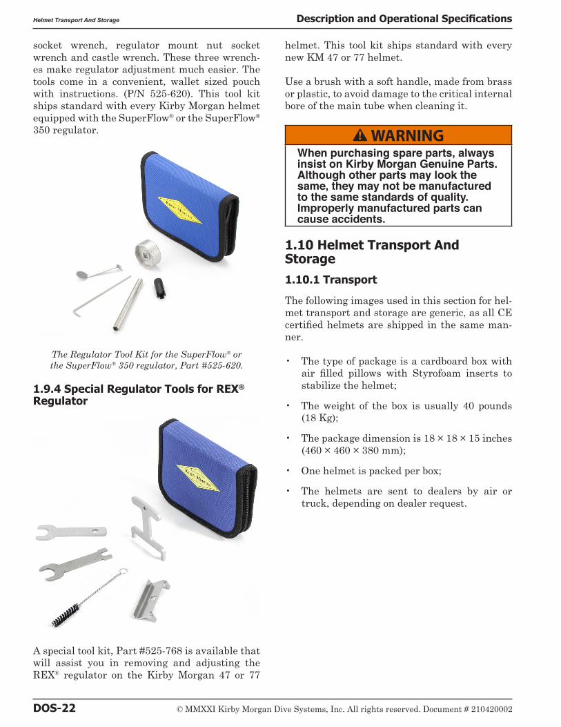
1.9.4 Special Regulator Tools for REX® Regulator
A special tool kit, Part #525-768 is available that will assist you in removing and adjusting the REX® regulator on the Kirby Morgan 47 or 77
helmet. This tool kit ships standard with every new KM 47 or 77 helmet.
Use a brush with a soft handle, made from brass or plastic, to avoid damage to the critical internal bore of the main tube when cleaning it.
B WARNINGWhen purchasing spare parts, always insist on Kirby Morgan Genuine Parts. Although other parts may look the same, they may not be manufactured to the same standards of quality. Improperly manufactured parts can cause accidents.
1.10 Helmet Transport And Storage1.10.1 Transport
The following images used in this section for hel-met transport and storage are generic, as all CE certified helmets are shipped in the same man-ner.
• The type of package is a cardboard box with air filled pillows with Styrofoam inserts to stabilize the helmet;
• The weight of the box is usually 40 pounds (18 Kg);
• The package dimension is 18 × 18 × 15 inches (460 × 460 × 380 mm);
• One helmet is packed per box;
• The helmets are sent to dealers by air or truck, depending on dealer request.

© MMXXI Kirby Morgan Dive Systems, Inc. All rights reserved. Document # 210420002 DOS-23
Description and Operational Specifications Helmet Transport And Storage
Packaging step 1
Packaging step 2
Packaging step 3
Packaging step 4
Packaging step 5
Packaging step 6

DOS-24 © MMXXI Kirby Morgan Dive Systems, Inc. All rights reserved. Document # 210420002
Band Mask® Transport And Storage Description and Operational Specifications
1.10.2 Storage
NOTE: For your records: (Company equipment log and/or diver’s personal log) be aware that the first day a helmet is used is its 1st DIVE DATE. This date begins the time clock for maintenance and inspections. This date should be the first en-try into the maintenance and repair log book that comes with the KMDSI helmet/mask. It is also recommended to add the entry into the diver’s log book.
For new helmets in the box (inspected upon re-ceipt, but never dived), stored in inventory longer than one year, a “Monthly Inspection” in accor-dance with Check List Appendices A2.2 should be performed.
For post-dived helmets in storage longer than eight months, an “Annual Inspection” in accor-dance with Check List Appendices A2.1 is recom-mended for the helmet/mask after storage, prior to diving.
For post-dived helmets in storage longer than three weeks, a “Monthly Inspection” in accor-dance with Check List Appendices A2.2 is recom-mended for the helmet/mask after storage, prior to diving.
1.11 Band Mask® Transport And Storage1.11.1 Transport
• The type of package is a cardboard box with air pillows or packing pillows paper packag-ing to stabilize the Band Mask®.
The weight of the box is usually:
• 15 pounds (6.8 Kg);
The package dimensions are:
• A 12 × 12 × 12 inches (305 × 305 × 305 mm) goes into a 14 × 14 × 14 inches (357 × 357 × 357 mm);
• The Band Masks® are sent to dealers by air or truck, depending on dealer request.
Packaging of the BandMask, step 1.
Packaging of the BandMask, step 2.

© MMXXI Kirby Morgan Dive Systems, Inc. All rights reserved. Document # 210420002 DOS-25
Description and Operational Specifications Band Mask® Transport And Storage
Packaging of the BandMask, step 3.
Packaging of the BandMask, step 4.
Final packaging of the BandMask
1.11.2 Storage
NOTE: For your records: (Company equipment log and/or diver’s personal log) be aware that the first day a helmet is used is its 1st DIVE DATE. This date begins the time clock for maintenance and inspections. This date should be the first en-try into the maintenance and repair log book that comes with the KMDSI helmet/mask. It is also recommended to add the entry into the diver’s log book.
For new BandMasks® in the box (inspected upon receipt, but never dived), stored in inventory longer than one year, a “Monthly Inspection” in accordance with Check List Appendices A2.2 should be performed.
For post-dived BandMasks® in storage longer than eight months, an “Annual Inspection” in accordance with Check List Appendices A2.1 is recommended for the helmet/mask after storage, prior to diving.
For post-dived BandMasks® in storage longer than three weeks, a “Monthly Inspection” in ac-cordance with Check List Appendices A2.2 is recommended for the helmet/mask after storage, prior to diving.
1.11.3 Helmet Carrying Bag
To help protect your helmet, the helmet carrying bag should be used to transport and store your helmet between jobs.

DOS-26 © MMXXI Kirby Morgan Dive Systems, Inc. All rights reserved. Document # 210420002
Use of Kirby Morgan Original Replacement Parts Description and Operational Specifications
The KMDSI Helmet Bag, Part #500-901.
The KMDSI bag is made from extra heavy duty, black, ripstop nylon. The bottom of the bag is padded for additional protection. Grommeted drain holes allow the bag to breathe. The bag is also equipped with large carrying straps and side pockets. The bag is not intended for shipping your helmet as air cargo.
1.12 Use of Kirby Morgan Original Replacement PartsUsers of Kirby Morgan life support equipment are cautioned to always use Kirby Morgan origi-nal replacement parts. Parts manufactured by third party companies can cause accidents.
Look for the Kirby Morgan logo on Kirby Morgan products. This is your assurance that you are
getting genuine Kirby Morgan replacement parts.
Copyright © 2022 FDOKUMEN