Construction of Security complex at MDL, Mumbai. - Mazagon ...
539
Tender No. 1800000056 1 MAZAGON DOCK SHIPBUILDERS LIMITED (Formerly known as Mazagon Dock Ltd.) CIN : U35100MH1934GOI002079 (A Government of India Undertaking) Shipbuilders to the Nation Dockyard Road, Mazagon, Mumbai 400 010. INDIA Construction of Security complex at MDL, Mumbai. VOLUME-IV Preferred Make & Technical Specification
-
Upload
khangminh22 -
Category
Documents
-
view
1 -
download
0
Transcript of Construction of Security complex at MDL, Mumbai. - Mazagon ...

Tender No. 1800000056
1
MAZAGON DOCK SHIPBUILDERS LIMITED (Formerly known as Mazagon Dock Ltd.)
CIN : U35100MH1934GOI002079 (A Government of India Undertaking)
Shipbuilders to the Nation Dockyard Road, Mazagon,
Mumbai 400 010. INDIA
Construction of Security complex at MDL,
Mumbai.
VOLUME-IV
Preferred Make
&
Technical Specification

Tender No. 1800000056
2
TENDER DOCUMENT
FOR
Construction of Security complex at Main Gate,
MDL, Mumbai.
Civil & Interior, Plumbing, Fire Fighting,
Electrical, HVAC & Lift Works For Security complex.
ARCHITECT
RATAN J. BATLIBOI - CONSULTANTS PVT. LTD.
233/D, BHARAT RICE MILL COMPOUND
DR. S.S. RAO ROAD, LALBAUG
ADJOINING HILLA TOWER
MUMBAI – 400 012.

Tender No. 1800000056
3
Civil & Interior, Plumbing, Fire Fighting, Electrical ,
HVAC & Lift Works For Security complex.
I N D E X
Sr. No. Description Page Nos.
TECHNICAL SPECIFICATIONS From To
I CIVIL & INTERIOR WORKS 4 336
II PLUMBING 337 389
III ELECTRICAL 390 450
IV FIRE FIGHTING 451 482
V HVAC 483 529
VI LIFT 530 539

Tender No. 1800000056
4
I
CIVIL & INTERIOR WORKS
TECHNICAL
SPECIFICATIONS

Tender No. 1800000056
5
INDEX
SR. NO. TITLE PAGE NO.
GENERAL 7
LIST OF INDIAN STANDARDS 9
MANDATORY TESTS 24
1 EARTH WORK 32
2 ANTITERMITE TREATMENT 39
3 HARD CORE / SOLING UNDER FLOORS / FOUNDATIONS 43
4 PLAIN / REINFORCED CONCRETE AND ALLIED WORKS 44
5 FORM WORK 96
6 STEEL FOR CONCRETE REINFORCEMENT 104
7 PILE FOUNDATION 114
8 READY MIX CONCRETE 118
9 FLY ASH CONCRETE NOTES 121
10 DAMP PROOF COURSE 128
11 PRECAST REINFORCED CEMENT CONCRETE JALLI 129
12 STRUCTURAL STEEL 130
13 BRICK WORK 134
14 STONE MASONRY 138
15 PRECAST CEMENT CONCRETE SOLID BLOCK MASONRY 140
16 CEMENT CONCRETE FLOORING (IPS) 141
17 IRONITE (OR HARDONATE) FLOORING 144
18 CEMENT CONCRETE FLOORING WITH RED OXIDE TOPPING 145
19 TERRAZZO / CEMENT TILE FLOORING, SKIRTING/ DADO ETC 146
20 IN-SITU TERRAZZO FLOORS, SKIRTING, TREADS OF STAIRCASE, WINDOW SILLS ETC
151
21 KOTAH STONE FLOORING/ SKIRTING/ FACIA / SHELVES 152
22 GLAZED TILE FLOORING, DADO/ SKIRTING/ FACIA 155
23 CHEQUERED TILES IN STAIR TR EADS AND LANDINGS 157
24 MARBLE STONE FLOORING, TREADS, RISERS, SILLS, CLADDING, DADO ETC
158
25 CERAMIC TILE FLOORING, DADO / SKIRTING / FACIA 162
26 VITRIFIED TILE FLOORING, DADO / SKIRTING / FACIA 164
27 RED OR WHITE ROUGH DRESSED SAND STONE FLOORING 168
28 PVC SHEET / TILES FLOORING 169
29 LINOLEUM FLOORING 173
30 WOODEN FLOORING 175
31 WOOD WORK IN FRAMES, SHUTTERS AND PANELLING 177
32 PRESSED STEEL DOOR FRAME 181
33 FACTORY MADE PARTICLES BOARD PANELLED DOOR SHUTTERS 183
34 GLASS FIBRE REINFORCED PLASTIC (GRP) PANEL TYPE DOOR SHUTTERS
185

Tender No. 1800000056
6
35 FITTINGS AND FIXTURES 192
36 GLASS AND GLAZING 195
37 STEEL DOORS, WINDOWS AND VENTILATORS 197
38 ROLLING SHUTTERS 200
39 M. S. GRILLS / RAILINGS 201
40 ALUMINIUM ENTRANCE DOORS, WALL SPANS, GLAZING ETC 203
41 ALUMINIUM WINDOWS, VENTILATORS, COMPOSITE UNIT ETC 207
42 ALUMINIUM CURTAIN WALL SYSTEM 209
43 STRUCTURAL GLAZING 218
44 CEMENT PLASTERING FOR WALLS & CEILINGS AND SAND FACE / ROUGH CAST PLASTERS
219
45 SAND FACED CEMENT PLASTER 225
46 ROUGH CAST PLASTER 226
47 CEMENT POINTING 228
48 WALL CARE PUTTY 229
49 PAINTING 232
50 VINERATEX OR VITROBRITE DECORATIVE TEXTURE COAT 247
51 TUBULAR TRUSSES, PURLINS ETC 248
52 ASBESTOS CEMENT CORRUGATED / TRAFFORD SHEET ROOFING 250
53 MANGALORE PATTERN TILE ROOFING 253
54 WATER PROOFING 264
55 INTEGRAL CEMENT BASED WATER PROOFING TREATMENT OF UNDER GROUND WATER TANKS, SWIMMING POOLS, BASEMENTS ETC. FROM OUTSIDE
273
56 EXPANSION JOINTS 281
57 RAILING, BALUSTERS AND NEWELS 282
58 RUBBER / P.V.C. WATER STOPS 283
59 DISMANTLING AND DEMOLITION 284
60 ROAD AND PAVEMENTS 285
61 FENCING WORK WITH BARBED WIRE, CHAIN LINK ETC 300
62 M. S. CRIMPNET GATE 304
63 DRAINAGE WORK WITH NP2 CLASS RCC HUME PIPES 305
64 ROUGH / NATURAL FACED SHAHABAD STONE PAVEMENT 307
65 AUTOCLAVED CELLULAR (AREATED) CONCRETE BLOCK MASONRY 318
LIST OF APPROVED MAKE / MODEL 319

Tender No. 1800000056
7
I CIVIL & INTERIOR WORKS TECHNICAL SPECIFICATIONS
GENERAL
i. The detailed specifications given hereinafter are for the items of works described in the
schedule of quantities attached herein & shall be guidance for proper execution of
work to the required standards.
ii. It may also be noted that the specification are of generalized nature & these shall be
read in conjunction with the description of item in schedule of quantities & drawings.
The work also includes all minor details of construction which are obviously & fairly
intended & which may not have been referred to in these documents but are essential
for the entire completion in accordance with standard Engineering practice.
iii. Unless specifically otherwise mentioned, all the applicable Latest codes & standards
published by the Indian standard Institution & all other standard which may be
published by them before the date of receipt of tenders, shall govern in all respects of
dosing workmanship quality & propitious of materials & methods of testing, method of
measurements etc. Wherever any reference to any Indian Standard specifications
occurs in the documents relating to this contract, the same shall be inclusive of all
amendments issued to or revisions thereof, if any, up to the date of receipt of tenders.
iv. In case there is no I.S.I specification for the particular work, such work shall be
carried out in accordance with the instructions in all respects, & requirements of the
Engineers-in-Charge. Wherever any reference to any Indian standard specification
occurs in the documents relating to this contract, the same shall be inclusive of all
amendment issued there to or revisions thereof, if any, up to the date of receipt of
tenders. Materials shall be conforming to Indian Standard / BSI /ASTM Latest codes
as applicable.
v. The work shall be carried out in a manner complying in all respects with the
requirements of relevant bye-laws of MDL /Municipal Corporation under the
jurisdiction of which the work is to be executed or as directed by the Engineer-in-
Charge and, unless otherwise mentioned, nothing extra shall be paid on this account.
vi. Samples of various materials, fitting etc. proposed to be incorporated in the work shall
be submitted by the contractor for approval of the Engineers-in-Charge before order
for bulk supply is placed.
vii. The contractor shall take instructions from the Engineer-in-Charge regarding
collection and stacking of materials in any place. No excavated earth or building
materials shall be stacked on areas where other buildings, roads, services, compound
walls etc. are to be constructed.
viii. The contractor shall maintain in perfect condition all works executed till the
completion of the entire work allotted to him. Where phased delivery is contemplated,
this provision shall apply to each Phase.
ix. The contractor shall give a performance test of the entire installation(s) as per
standard specifications before the work is finally accepted & nothing extra whatsoever

Tender No. 1800000056
8
shall be payable to the contractor for the test.
x. The contractor shall clear the site thoroughly of all scaffolding materials & rubbish
etc. left out of his work & dress the site around the building to the satisfactions of the
EIC & his decision in writing shall be final & binding on all concerned.
xi. Post construction inspection and testing: After completion of the work and during
maintenance period liability of the contractor, the work shall also be subjected to 'Post
construction inspection and testing'. In case the materials or articles incorporated in
the work are found to be inferior, though the sample collected for the same might have
been passed at the time of execution, it shall be the responsibility of the contractor to
replace the same at his own cost., failing which the cost be adjusted from the
outstanding security deposit, as per the terms and conditions of the contract for the
work.
xii. MDL concerned Engineering Division , shall be the sole deciding authority as to the
meaning, interpretations and implications for various provisions of the specifications
and its decision in writing shall be final and binding on all concerned.
xiii. In case any different or discrepancy between the specification & the description
in the schedule of quantities, the schedule of quantities shall take precedence. In case
of any difference or discrepancy between specification & drawing, the specification
shall take precedence. Any discrepancy shall be brought to the notice of Engineer In
Charge, resolved mutually prior to implementation of that work. All works shall be
carried out as per the Latest working drawings ,specification, Indian standard codes &
work done to the satisfaction of EIC.

Tender No. 1800000056
9
II – LIST OF INDIAN STANDARDS:
Following are the various pertinent Indian Standards, relevant to
buildings work :
(All Latest Versions of I.S. codes shall be referred)
I. S. CODE
NO. S U B J E C T
A. CIVIL WORKS
1. CARRIAGE OF MATERIALS
4082-1996 Recommendations on stacking & storage of construction materials and
components at site.
2. EARTH WORK
1200 Pt. I-
1992
Method of measurement of Earth work.
4081-2013 Safety code for Blasting and related drilling operations.
6313 (Part 2)
2013
Anti Termite Measures in Buildings Part – 2 Pre-constructional
chemical treatment .
3. MORTAR
196-1966 Atmospheric conditions for testing (Reaffirmed - 2006)
269-2015 Ordinary Portland cement Specification. (Sixth Revision)
383-2016 Coarse and fine aggregates from natural sources for concrete.
455-2015 Portland slag cement
650-1991 Standard sand for testing of cement
712-1984 Building Limes
1489-2015 Portland pozzolana cement Fly ash based
1514-1990 Methods of sampling & Test for Quick Lime & Hydrated Lime.
(Reaffirmed - 2010)
1542-1992 Sand for Plastering(Reaffirmed – 2009)
1727-1967 Methods of tests for pozzolanic materials(Reaffirmed – 2008)
2250-1981 Code of practice for preparation and use of masonry mortar. (Reaffirm-
2010)
2386-1963 Methods of Test for Aggregates for Concrete
2386 Pt.I-
1963
Particle size and shape(Reaffirm- 2016)
2386 Pt. II-
1963
Estimation of deleterious materials and organic impurities(Reaffirm-
2016)

Tender No. 1800000056
10
I. S. CODE
NO. S U B J E C T
2386 Pt.III-
1963
Specific gravity, density, voids, absorption and bulking(Reaffirm- 2016)
2686-1977 Cinder as fine aggregate for use of Lime Concrete. (Reaffirmed – 2009)
3025-1987 Methods of sampling & test (Physical & Chemical) for water & waste
water (Reaffirmed-2014)
3068-1986 Broken brick (burnt clay) coarse aggregate for use in lime concrete (II-
R.) (Reaffirmed – 2009)
3182-1986 Broken brick (Burnt clay) fine aggregate for use in lime mortar.)
(Reaffirmed – 2009)
3812-2013
(Part1)
Pulverized Fuel Ash - For Use as Pozzolana in Cement, Cement Mortar
and Concrete
4031-1996 Methods of physical tests for hydraulic cement (Reaffirmed – 2016)
4032-1985. Method of chemical analysis of hydraulic cement (Reaffirmed - 2009)
4098-1983 Lime pozzolana mixture (Reaffirmed - 2009)
6932 (Pt.I to
X)
Methods of Test for Building Lime
6932 (Pt.I)-
1973
Determination of insoluble residue, loss of ignition, silicon-dioxide,
ferric & Alum. Oxide,
6932 (Pt.II)-
1973
Determination of carbon dioxide content
6932 (Pt.III)-
1973 Determination of residue on slaking of quick lime.
6932 (Pt.IV)-
1973
Determination of fineness of hydrated lime
6932 (Pt.V)-
1973
Determination of unhydrated oxide
6932 (Pt.VI)-
1973
Determination of volume yield of quick lime
6932 (Pt.VII)-
1 973
Determination of compressive and transverse strength.
6932(Pt.VIII)-
1 973 Determination of workability
6932 (Pt.IX)-
1973 Determination of soundness
6932 (Pt.X)-
1973
Determination of popping and pitting of hydrated Lime.
4 . C ONCRETE WORK
383 Coarse and fine aggregate from natural sources for concrete (Reaffirm
- 2016)
456-2000 Code of practice for plain and reinforced concrete(Reaffirm - 2016)
516-1959 Method of test for strength of concrete (Reaffirmed in 2013)

Tender No. 1800000056
11
I. S. CODE
NO. S U B J E C T
1199-1959 Method of sampling and analysis of concrete(Reaffirmed in 2013)
1200 (Pt.II)-
1974 Methods of measurements of cement concrete work. (Reaffirm - 2007)
1322-1993 Bitumen felts for water proofing and damp proofing. (Reaffirm - 2008)
1661- 1972 Code of practice for application of cement lime plaster
finishes.(Reaffirm- 2016)
2386-1963
(Pt.1 to 8) Methods of test for aggregate for concrete.(Reaffirm- 2016)
2386 (Pt.I)-
1963 Test for particle size and shape.(Reaffirm- 2016)
2386 (Pt.II)-
1963
Test for estimation of deleterious materials and organic
impurities.(Reaffirm- 2016)
2386 (Pt.III)-
1 963
Test for specific gravity, density, voids, absorption and
bulking.(Reaffirm- 2016)
2386 (Pt.IV)-
1963 Mechanical properties.(Reaffirm- 2016)
2645-2003 Specification for integral water proofing compounds (Reaffirm- 2017)
2686-1977 Specification for cinder aggregate for use in lime concrete. (Reaffirm -
2009)
3812-2013
Part2
Fly Ash using as admixtures in cement ,mortar , concrete.
7861-1975
(Pt.I)
Hot weather concreting. .(Reaffirmed -2011)
7861-1981
(Pt.II) Cold weather concreting. .(Reaffirmed -2011)
9103-1999 Admixture for concrete. .(Reaffirmed -2013)
5. R.C.C. WORK
432-1982
Part 1
Mild Steel and Medium Tensile Steel Bars and Hard-Drawn Steel Wire
for Concrete Reinforcement: Part 1 Mild Steel and Medium
Tensile Steel Bars.(Reaffirmed -2015)
432-1982
Part II
Mild Steel and Medium Tensile Steel Bars and Hard-Drawn Steel Wire
for Concrete Reinforcement: Part 2 Hard-Drawn Steel Wires.(Reaffirmed
-2009) 456-2000 Code of practice for plain and reinforced concrete.(Reaffirmed -2016)
457-1957 COP for general const. of plain & reinforced concrete for dams & other
massive structure. .(Reaffirmed -2009)
516-1959 Methods of test for strength of concrete.(Reaffirmed -2013)

Tender No. 1800000056
12
1161-2014 Specifications for steel tubes for structural purposes
I. S. CODE
NO.
S U B J E C T
1199-1959 Methods of sampling and analysis of concrete. (Reaffirmed - 2013)
1200 (Pt.II) -
1974 Method of measurement of cement concrete work (Reaffirmed -2007)
1200(Pt.V) -
2007
Method of measurement of form work. (Reaffirmed - 2013)
1343-2012 Code of practice for pre-stressed concrete.
1566-1982 Hard drawn steel wire fabric for concrete reinforcements (Reff. 2009)
1785-1983
(Part-I& II)
Specifications for plain hard-drawn steel wire for prestressed concrete:
Part 1 Cold drawn stress-relieved wire (Reaffirmed - 2013)
1786-2008 High strength deformed steel bars and wires for concrete
reinforcement (Reaffirmed - 2013)
2090-1983 Specifications for high tensile steel bars used in prestressed concrete.
(Reaffirmed – 2009)
2204-1962 Code of practice for construction of reinforced concrete shell roof.
(Reaffirmed - 2010)
2210-1988 Criteria for the design of shell structure and folded plates (Reaffirmed -
2008)
2502-1963 COP for bending and fixing of bars for concrete reinforcement.
(Reaffirmed - 2008)
2750-1964 Specifications for steel scaffoldings(Reaffirmed - 2010)
2751-1979
(Reaf-2008)
COP for welding of mild steel bars & Deformed bars for reinforced
concrete construction.
2911-(Pt.I)-
SEC 1 -2010
Code of practice for design & Constn. of pile foundations- Driven
Cast In-situ Concrete Piles
2911(Pt.I)-
SEC 2 -2010
Design & construction of Pile Foundations - Bored precast concrete
piles.
2911 (Pt.III)-1
980 Under reamed pile foundations(Reaffirmed – 2010)
2911 (Pt.IV)-
2013
Load test on Piles
3201-1988 Criteria for design and construction of precast trusses & Purlins.
(Reaffirmed - 2009)
3370.(Part I)-
2009
Code of practice for concrete structures for storage of liquids-General
requirements.
3370.(Part II
)-2009
Code of practice for concrete structures for storage of liquids-
Reinforced concrete structures

Tender No. 1800000056
13
3414-1968 Code of practice for design and installation of joints in buildings.
(Reaffirmed - 2010)
I. S. CODE
NO. S U B J E C T
3558-
1983(Reaf-
Code of practice for use of immersion vibrators for consolidating
concrete
3696 (Pt.I &
II) I-1987: Safety code of scaffolds; II-1991: Safety code of ladders
3935-1966 Code of practice for composite construction. (Reaffirmed – 2008)
4014-1967
(Pt. I & II)
COP for steel tubular scaffolding (I: Definition/Material; II: Safety
provision) (Reaffirmed 2010)
4926-2003 Code of practice for Ready Mix Concrete(Reaffirmed – 2017)
4990-2011 Specifications for plywood for concrete shuttering work.
10262-2009 Guidelines for concrete mix design proportioning (Reaffirmed - 2017)
6. EQUIPMENTS
460-1985
(Pt-I,II& III)
Specification for test sieves. (Reaffirmed - 1998)
1791-1985 Specification for batch type concrete mixer. (Reaffirmed – 2015)
2430-1986 Methods for sampling of Aggregates for concrete. (Reaffirmed – 2009)
2505-1992 General requirement for concrete vibrators, immersion type(Reaffirmed
– 2008)
2506-1985 General requirements for screed board concrete vibrators(Reaffirmed –
2016)
2514-1963 Specification for concrete vibrating tables. (Reaffirmed - 2017)
2722-
1964(Reaf-
2016)
Specification for portable swing weighbatchers for concrete (single and
double bucket type).
2750-1964 Specification for steel scaffolding. (Reaffirmed – 2010)
7. BRICK WORK:
1077-1992 Common burnt clay building bricks(Reaffirmed – 2011)
1200 (Pt.III)-
1976 Method of measurements of brick work. (Reaffirmed - 2007)
2116-1980 Sand for masonry mortars. (Reaffirmed - 2007)
2212-1991 Code of practice for brick work(Reaffirmed - 2009)
2250-1981 Code of practice for preparation & use of masonry mortar. (Reaffirmed
- 2010)

Tender No. 1800000056
14
3495
(Pt.ItoIV)-
1992
Methods of tests of burnt clay building bricks: Part 1 Determination of
compressive strength Part 2 Determination of water absorption Part 3
Determination of efflorescence Part 4 Determination of
warpage(Reaffirmed - 2011)
5454-1978 Method for sampling of clay building bricks. (Reaffirmed - 2010)
I. S. CODE
NO. S U B J E C T
2185 (Part 3)
1984 Auto claved cellular (Areated) Concrete Blocks. (Reaffirmed - 2010)
8. STONE WORK:
1121 (Pt.I)-
2013
Methods of test for determination of strength properties of natural
building stones: Part I Compressive strength
1122-1974 Method of test for determination of true specific gravity of natural
building stones
1123-1975 Methods for identification of natural building stones(Reaffirmed –
2008)
1124-1974 Method of test for determination of water absorption, apparent specific
gravity and porosity of natural building stones(Reaffirmed - 2013)
1125-2013 Determination of weathering of Natural building stones - Method of
Test
1126-2013 Determination of durability of natural building stones - Method of test
1129-1972 Recommendation of dressing of natural building stones
(Reaffirmed - 2013)
1200 (Pt.IV)-
1976
Method of measurement of stone masonry. (Reaffirmed - 2007)
1597. (Pt.I)-
1992
Code of practice for construction of Rubble stone masonry. (Reaffirmed
-2011)
1597 (Pt.II)-
1992
Code of practice for construction of ashlar masonry (Reaffirmed -
2011)
1805-1973 Glossary of Terms relating to stone Quarrying and dressing.
Reaffirmed - 2008)
4101 (Pt.I)-
1967
Stone facing. (Reaffirmed - 2010)
9. MARBLE WORK:
1122-1974 Methods for determination of specific gravity and porosity of natural
building stones (Reaffirmed - 2008)
1124-1974 Method of test for determination of water absorption, apparent specific
gravity and porosity of natural building stones (Reaffirmed - 2013)
1130-1969 Marble (blocks, slabs and tiles) (Reaffirmed - 2008)
10. WOOD WORK:
204-1991/92 Tower bolts (Part I-1991: ferrous metals; Part II - 1992 : Non ferrous
metals).

Tender No. 1800000056
15
205-1992 Non-ferrous metal butt hinges(Reaffirmed - 2012)
206-2010 Tee and strap hinges(Reaffirmed - 2012)
207-1964 Gate and shutter hooks and eyes. (Reaffirmed - 2011)
208-1996 Door handles
I. S. CODE
NO. S U B J E C T
281-2009 Mild steel sliding door bolts for use with padlocks
287-1993(Reaf-
2008)
Recommendation for maximum permissible moisture contents of timber
used for Different purposes.
303-1989 Plywood for general purpose (Reaffirmed - 2013)
362-1991 Parliament hinges(Reaffirmed - 2010)
363-1993 Hasps and staples(Reaffirmed - 2008)
364-1993 Fanlight catch(Reaffirmed - 2008)
401-2001 Code of practice for preservation of timber(Reaffirmed - 2011)
419 - 1967 Putty for use on window frame (Reaffirmed - 2009)
451-1999 Technical supply condition for wood screws(Reaffirmed - 2010)
452-1973 Door springs, rat-tail type (Reaffirmed 2010)
453-1993 Double acting spring hinges. (Reaffirmed – 2008)
723-1972 Steel counter sunk head wire nails. (Reaffirmed - 2011)
729.1979 Drawer locks, cup board locks, and box locks (Reaffirmed 2012)
848-2006 Synthetic resin adhesive for plywood (phenolic and aminoplastic).
(Reaffirmed - 2011)
851-1978 Synthetic resin adhesive for construction work ( Non-structural)
in wood (Reaffirmed 2009)
852-1994 Specifications for animal glue for general wood working purposes.
(Reaffirmed 2009)
1003-1994 Timber panelled and glazed shutters
1003(Pt.I)-2003 Door shutters . (Reaffirmed – 2008)
1003 (Pt.II)-
1994 Window and ventilator shutters (Reaffirmed - 2011)
1019-1974 Rim latches. (Reaffirmed - 2012)
1141-1993 Code of practice for seasoning of timber (Reaffirmed 2009)
1200 Method of measurement of Building and Civil Engineering works
1200 (Pt.XIV)-
1984 Glazing. (Reaffirmed - 2007)

Tender No. 1800000056
16
1200 (Pt.XXI)-
1973 Wood work and joinery. (Reaffirmed - 2007)
1322-1993 Bitumen felts for water proofing and damp proofing.
(Reaffirmed – 2008)
1328-1996 Veneered decorative plywood(Reaffirmed - 2011)
I. S. CODE
NO. S U B J E C T
1341-1992 Steel Butt hinges (Reaffirmed - 2012)
1378-1987 Oxidized copper finishes. (Reaffirmed - 2016)
1568-1970 Wire cloth for general purposes. (Reaffirmed - 2013)
1658-2006 Fiber hard board. (Reaffirmed - 2011)
1659-2004 Block boards(Reaffirmed 2009)
1823-1980 Floor door stoppers. (Reaffirmed - 2012)
1868-1996 Anodic coating on Aluminium & its alloy (II Rev.) (Reaffirmed 2016)
875- 1987
Part1
Dead loads –Unit weight of bldg. & stored materials(Reaffirmed –
2008)
2191-1983 Wooden flush door shutter (cellular and hollow core type).
(Reaffirmed - 2011) 1837 - 1966 Fan light pivots (Reaffirmed 2010)
2095-2011 Plain Gypsum Plaster Boards
3828 - 1966 Ventilator chains (Reaf. 2010)
4835 - 1979 Polyvinyl acatete dispssion base adhasive for wood (2009)
2191 (Pt.I)-
1983
Plywood face panels. (Reaffirmed - 2011)
2191 (Pt.II)-
1983
Particle board face panels and hard board face panels. (Reaffirmed-
1991)
2202-1999 Wooden flush door shutters (solid core type)
2202 (Pt.I)-
1999
Plywood face panels for wooden flush door shutters
2202 (Pt.II)-
1983
Particle board face panels for wooden flush door shutters.
(Reaffirmed - 1991)
2209(Pt.I)-1976 Mortise locks (vertical type) (Reaffirmed 1992)
2380-1981 Method of test for wood particle board and boards from
lignocellulosic materials (Reaf.1993)
2681-1993 Non ferrous metal sliding door bolts(aldrop) for use with pad locks
2835-1987 Flat transparent sheet glass (3rd Revision). (Reaffirmed - 1992)
3087-1985 Wood particle boards (medium density) for general purpose (1990)
3097-2006 Veneered particle boards (1st Revision).

Tender No. 1800000056
17
3400 (Part I )-
1987 Method of test for vulcanized rubbers (1991)
3400-(Pt.II)-
2003
Hardness (1981)
I. S. CODE
NO. S U B J E C T
3400-(Pt.IV)-1
987
Accelerated aging (1993)
3400 (Pt.IX)-
2003 Relative density and density. (Reaffirmed - 1990)
3564-1995 Door closers (Hydraulically regulated)
3618-1966 Phosphate treatment of iron and steel for protection against
corrosion. (Reaffirmed - 1991) 3813-1967 'C' hooks for use with swivels (1992)
3818-1992 Continuous (Piano) hinges
3847-1992 Mortise night latches
4020-1998 (1
to 16) Methods of tests for wooden flush Doors (Type tests)
4021-1995 Timber door, window and ventilator frames
4827-1983 Electroplated coating of nickel and chromium on copper and copper
alloys
4948-2002 Welded steel wire fabric for general use. (Reaffirmed - 1992)
4992-1975 Door Handles for mortise locks (vertical type). (Reaffirmed - 1990)
51 87-1972 Flush bolts (1990)
5523-1983 Method of testing anodic coating on aluminium & its alloys.
(Reaffirmed -1991)
5930-1970 Mortise latch (vertical types) (1991)
6318-1971 Plastic window stays & fasteners
6607-1972 Rebated mortise locks (vertical type)
6760-1972 Slotted countersunk head wood screws. (Reaffirmed - 1988)
71 96-1974 Hold fasts (1992)
71 97-1974 Double action floor springs (without oil check) for heavy doors
7534-1985 Sliding loacking bolt for use with padlocks. (Reaffirmed – 1991)
8756 - 1978 Mortice bell catches for use in wooden almirah (1992)
14856-2000 Glass fibre reinforced plastic (GRP) panel type door shutters for
internal use – Specifications
1 1 . S T E E L W O R K

Tender No. 1800000056
18
63-1978 Whiting for paints. (Reaffirmed - 1994)
198-1978 Varnish, gold size. (Reaffirmed - 1991)
12406 - 1988 Medium density fibre board for general purpose - (1992)
I. S. CODE
NO.
S U B J E C T
277-2003 Specification for galvanised steel sheets (plain and corrugated)
278-1978 Galvanised steel barbed wire for fencing. (Reaffirmed - 1991)
800-2007 Code of practice for use of structural steel in general building
construction(Reaffirmed - 2013)
806-1968 Code of practice for use of steel tube in general building
construction
813-1986 Scheme of symbols for welding. (Reaffirmed – 2008).
814-2004 Covered electrodes for metal arc welding of structural steel
(Reaffirmed 2010)
814 (Pt-I) For welding products other than sheets. *
814 (Pt-II) For welding sheets. *
817-1966 Code of practice for training and testing of metal arc welders.
(Reaffirmed – 2003) 818-1968 (Reaf-
03)
COP for safety & healthy requirements in electric & gas welding &
cutting operation.
1038-1983 Steel doors, windows and ventilators
1081-1960(Reaf-
2011)
COP for fixing & glazing of metal (steel & aluminium) doors,
windows & ventilators 1148-1982(Reaf-
92)
Hot rolled steel rivet bars (upto 40 mm diameters)for structural
purposes (Reaffirmed 2001)
1161-1998 Steel tubes for structural purposes
1182-1
983(Reaf-00)
Recommended practice for radiographic examination of fusion
welded butt joints in steel plates.
1200 (Pt-VIII)-
1993 Method of measurements of steel work and iron works
1363-1992 (Pt.
1- 3)
Hexagon bolts, nuts & lock nuts (dia. 6 to 39 mm) & black hexagon
screws (dia. 6 to 24 mm).(Reaf-98)
1599-1
985(Reaf-9 1)
Method for bend test for steel products other than sheet, strip,
wire & tube (reaffirmed 1996).
1608-1995 Method for tensile testing of steel products (Reaffirmed 2001)
1821-1987 Dimensions for clearance holes for metric bolts. (Reaffirmed - 2003)
1852-1985 Rolling and cutting tolerance for hot rolled steel products.
(Reaffirmed - 1991)
2062-2011 Structural steel (fusion welding quality). (Reaffirmed – 2016)

Tender No. 1800000056
19
4351-2003 Steel door frames. (Reaffirmed – 1991)
4736-1986 Hot-dip zinc coatings on steel tubes. (Reaffirmed – 2001)
6248-1979 Metal rolling shutters and rolling grills (Reaffirmed – 2011)
I. S. CODE
NO.
S U B J E C T
7452-1990 Hot rolled steel sections for doors, windows & ventilators.
12 . FL OOR ING :
210-2009 Grey iron casting (Reaffirmed 1999)
653-1992 Sheet linoleum
809-1992 Rubber flooring materials for general purpose
1122-1974 Methods for determination of specific gravity (*and porosity of
natural building stones)
1124-1974 Method of test for water absorption of natural building stones
1130-1969 Marble (blocks, slabs and tiles). (Reaffirmed – 2008)
1197-1970 Code of practice for laying of rubber floors. (Reaffirmed – 1990)
1198-1982 Code of practice for laying and maintenance of linoleum floors
1200 (Pt.XI)-
1977 Method of measurements of pavings and floor finishes.
1237-2012 Cement concrete flooring tiles. (Reaffirmed – 2016)
1443-1972 Code of practice for laying and finishing of cement concrete flooring
tiles
1661-1972 Code of practice for application of cement and cement lime plaster
finishes
2114-1984 Code of practice for laying in situ terrazzo floor finish
2571-1970 Code of practice for laying in situ cement concrete flooring
3400-1 987
(Part 1 to 22) Method of Test of vulcanized rubbers. (Reaffirmed – 2003)
3400 (Pt.II)-2003 Hardness
3400 (Pt.X)-1977 Compression set at constant strain. (Reaffirmed – 2003)
3462-1986 Flexible P.V.C. Flooring. (Reaffirmed – 1991)
4631-1986 Code of practice for laying of resin floor toppings (Reaffirmed –
2001) 5318-1969 Code of practice for laying of flexible P.V.C. sheet & tiles flooring
5389-1969 Code of practice for laying of hardwood parquet and wood block
floors. (Reaffirmed – 2007)

Tender No. 1800000056
20
9197-1979 Specifications for epoxy resin, hardeners and epoxy resin
compositions for floor topping (Reaffirmed – 2016)
13 . ROOF I NG :
73-1 992 Paving Bitumen (Reaffirmed 1998)
I. S. CODE
NO.
S U B J E C T
277-2003 Galvanised steel sheets (plain and corrugated)
I. S. CODE
NO.
S U B J E C T
458-2003 Concrete pipes (with and without reinforcement)
459-1992 Unreinforced corrugated and semicorrugated asbestos cement
sheets
651-2007 Salt glazed stone ware pipes and fittings
702-1988 Industrial Bitumen
1199-1959 Method of Sampling & Analysis of concrete. (Reaffirmed - 1991)
1200 (Pt.IX)-
1973
Method of measurements of roof covering (including cladding)
1200 (Pt.X)-
1973
Method of measurements of ceiling and lining
13607 - 1992 Ready Mixed Paint, Finishing, General Purposes, Synthetic
(Reaffirmed 2009)
1322-1993 Bitumen felts for water proofing and damp-proofing. (Reaffirmed -
1988) 1346-1991 Code of practice for waterproofing of roof with bitumen felts
1609-1991 Code of practice for laying damp proof treatment using bitumen
felts 1626-1994(Part
I-III)
Asbestos cement building pipes, gutters and fittings (Spigot and
socket types)
1834-1984 Specification for hot applied sealing compounds for joints in
concrete. (Reaffirmed - 2010) 1838-(Pt.I & II)-
1983
Preformed filler for expansion joints in concrete- non-extruding
and resilient type Bitumen impregnated fiber). (Reaffirmed - 2015)
2115-1980 Code of practice for flat roof finish:mud phuska. (Reaffirmed - 1998)
2633-1986 Method of testing uniformity of coating on zinc coated articles.
(Reaffirmed – 2001)
3007-(Pt.I)-1999 Code of practice for laying of corrugated asbestos cement sheets.
(Reaffirmed – 1991)
3007-(Pt.II)-1
965
Code of practice for laying of semi corrugated asbestos cement
sheet. (Reaffirmed - 1991) 3348-1965 Fiber insulation boards. (Reaffirmed - 1990)
3607-1979 Magnesite for chemical Industry. (Reaffirmed – 2003)

Tender No. 1800000056
21
71 93-1994 Specifications for glass fiber base coal tar Pitch & Bitumen felts.
8183-1993 Bonded mineral wool. (Reaffirmed 2004)
14. FINISHING
75-1973 Linseed oil, raw and refined. (Reaffirmed – 2010)
77-1976 Linseed oil, boiled, for paints. (Reaffirmed - 2009)
104-1979 Specification for ready mixed paint, brushing, zinc chrome,
priming. (Reaffirmed - 1999)
NO.I.S. CODE S U B J E C T
133-1993 Enamel, interior (a) under coating (b) finishing colour as required
137-1965 Ready mixed paint, brushing, matt or egg-shell flat, finishing,
interior, to Indian Standard Colour, as required. (Reaffirmed –
1999)
158-1981 Ready mixed paint, brushing, bituminous, black lead free acid
alkali, water and heat
168-1993 Ready mixed paint, air drying for general purpose.(Reaffirmed
2002)
217-1988 Cut back bitumen (reaffirmed 1999)
218-1983 Creosote and anthracene oil for use as wood preservatives
(Reaffirmed 1998)
290-1961 Coal tar black paint. (Reaffirmed – 1996)
337-1975 Varnish, finishing interior. (Reaffirmed – 2001)
341-1973 Black Japan, types A, B, and C (Reaffirmed 2002)
347-1975 Varnish, shellac for general purpose. (Reaffirmed – 2001)
348-1968 French polish. (Reaffirmed – 2001)
419-1967 Putty for use of window frames. (Reaffirmed – 2001)
427-1965 Distemper, dry, colour as required. (Reaffirmed – 1999)
428-2000 Washable distember
524-1983 Varnish, finishing, exterior, synthetic. (Reaffirmed – 2000)
525-1968 Varnish, finishing, exterior and general purposes. (Reaffirmed –
2001)

Tender No. 1800000056
22
533-1998 Gum spirit of turpentine (oil of turpentine) (Reaffirmed 2003)
712-1984 Specification for building limes. (Reaffirmed - 1995)
1200 (Pt. XII)-1976 Method of measurements of plastering and pointing
1200 (Pt.XIII)-1994 Method of measurements of white washing, colour washing,
distempering and other finishes
I. S. CODE NO. S U B J E C T
1200 (Pt.XV)-1987 Methods of measurements of painting, polishing & varnishing.
2095-2011-Pt.I ;
2001-PT II-1996-
PT III)
Gypsum plaster boards
2096-1992 Asbestos cement flat sheets.
2339-1963 Aluminium paint for general purposes, in dual container.
(Reaffirmed – 1999)
2547-1976 (Pt I &
II)
Gypsum building plaster (Part I-Reaff. 2007)
2933-1975 Enamel, Exterior (a) Under coating (b) Finishing
5410-2013 Cement paint

Tender No. 1800000056
23
I. S. CODE
NO. S U B J E C T
6278-1971 Code of practice for white washing & colour washing. (Reaffirmed -
1991) 14276-195 Cement particle board
15. DEMOLITION AND DISMANTLING:
1200(Pt.XVIII)-
1974 Method of measurements of demolition and dismantling
16. SAFETY CODES
818-1968 (Reaf-
03)
Safety and healthy requirements in Electric and gas welding and
cutting operations.
3696 (Pt.I)-1 987 Safety code for scaffolds
3696 (Pt.II)-1991 Safety code for ladders
3764-1992 Safety code for Excavation works
4081-1986 Safety code for blasting and related drilling operation
4130-1991 Safety code for Demolition of Building
5916-2013 Safety code for construction involving use of hot bituminous
materials
6922-1973 Structural subject to underground blasts code of practice for
safety and design of structure subject to underground blasts.
7293-1974 safety code for Working with construction machinery
IRC:15-2011 Specifications and Code of Practice for Construction of Concrete
Roads
IRC:44-2008 Guidelines for Cement Concrete Mix Design for Pavement”
IRC:SP:63-2004 Guidelines for the Use of Interlocking Concrete Block Pavement
IRC 58 -2015 Guidelines for the design of Plain Jointed Rigid Pavements for
Highways
MORTH Specification for Road & Bridge works
SSPC-SP3 (SSI-
St3)
Surface Preparation of Structural steel surface -Power Tool Cleaning–
Swedish standard ST 3
SSPC-SP10(SSI-
Sa2 ½),
Surface Preparation of Structural steel surface – Shot Blasting -
Swedish standard Sa 2 1/2

Tender No. 1800000056
24
III – MANDATORY TESTS
NOTES:
The mandatory tests shall be carried out when the quantity of materials to incorporated in the work exceeds the minimum quantity specified.
Optional tests specified or any other tests, shall be carried out in case of specialised works or important structures as per direction of the Engineer-in-Charge.
Testing charges, including incidental charges and cost of sample for testing shall be born by the contractor for all mandatory tests.
In case of non-IS materials, it shall be the responsibility of the contractor to establish the conformity of material with relevant IS specification by carrying out necessary tests. Testing charges including incidental charge and cost of sample for testing shall be borne by the contractor for such tests.
THE MANDATORY TESTS SHALL BE AS FOLLOWS:
Material Test Field /
laboratory
test
Test
procedure
Minimum
quantity of
material /
Work
Frequency of
testing
Reinforced cement concrete work
Note:- IS no. refered shall be the latest revision applicable.
Water for
Construct
ion
purposes
Ph value Limits
of Acidity
Limits of
Alkality
Percentage of
solids
Chlorides
Suspended
matter
Sulphates
Inorganic
solids Organic
solids
Lab IS 3025
Water from
each
source
Before
commencement of
work & thereafter
: Mandatory –
Once in one year
from each
source;Optional:
once in 3 months
from eachsource;
Municipal supply
- optional.

Tender No. 1800000056
25
Reinforce
d
cement
concrete
b) slump test Field IS: 1199 a) 20 cu.m.
for slabs,
beams
and
connected
columns .
b) 5 Cu.m
in
a) 20 cu.m. Part
there of or more
frequently as
required by the
Engr.-in-Charge.
b) Every 5 Cu.m.
c) cube test Lab IS : 516 a) 20 cu.m.
In
slab, beams,
& connected
columns.
b) 5 cum in
case of
columns
a) every 20 cum of
a day's concreting
.(Ref. as per
frequency of
sampling).
b) Every 5 cum.
Ready
mixed
cement
(IS-4926)
Cube test Lab
IS-516
and as
per para
6.3.2 of IS-
4926-2003
50 cum
One for every
50cum
of production or
every
50 batches, Note : for all other small items and where RCC done in a day is less than 5 cum, test
may be carried out as required by Engineer-in-Charge.
Mortars:
Lime
Chemical &
physical
properties of
lime
Laborator
y
IS; 6932 (part
1
to x)
5 M.T.
10 M.T. or part
there
of as decided by
the
Engineer-in-
Charge
Sand Bulking of
Sand Field 20 CU.M.
Every 20 cu.m or
part thereof or
more frequently as
decided by
Engineer-In-
Charge

Tender No. 1800000056
26
Silt content Field IS:383 20 CU.M.
Every 20 cu.m or
part thereof or
more frequently as
decided by
Particle
size
and
distribution
Field
Laboratory
decided by
Engr -in-
Charge
IS:383 40 CU.M. Every 40 cu.m. of
fine aggregate /
sand required in
RCC. work only.
Organic
Impurities Field .. DO.. 20 CU.M.
Every 20 cu.m. or
part thereof or
more frequently as
decided by the
Engineer-in-Charge
Chloride &
sulphate Optional
Once in three
months.

Tender No. 1800000056
27
Material Test Field /
laboratory
test
Test
procedure
Minimum
quantity of
material /
Work
Frequency of
testing
Cement Test
requirement
Fineness
(m²/kg)
IS 4031
(Part-II)
Each
fresh lot
Every 50 MT or
part
Thereof Normal
consistenc
y
IS 4031
(Part-IV)
Setting
time
(minutes)
a) Initial
b) Final
IS 4031
(Part-V)
Soundnes
s a)Le-
Chat
expansion
(mm)
b)
Autoclave
(%)
IS 4031
(Part-III)
Compressi
ve
Strength
(Mpa)
IS 4031
(Part-VI)
Stone
Aggregate
a) Percentage
of
soft or
deleterious
materials
General
visual
inspection
/ Lab test
where
required by
the Engr-
in-Charge
IS 2386 Part
II
One test for
each source
One test for each
source
Particle size
distribution
Field / Lab - 10 cu.m Every 40 cum. Or
part thereof and
Once in three months for each source for coarse and fine aggregates
required in RCC works, for a minimum quantity - 10 cum for coarse
aggregate and 40 cum for fine aggregate.

Tender No. 1800000056
28
a) Estimationof
Organic
impurities
Field /
Lab
IS 2386 Part
II
10 Cum -do-
b) Specific
Gravity
Field /
Lab
IS 2386 10 Cum -do-
Bulk Density Field /
Lab
IS 2386 10 Cum -do-
Material Test
Field /
laboratory
test
Test
procedure
Minimum
quantity of
material /
Work
Frequency of
testing
b) Aggregate
crushing
strength
Field / Lab IS 2386 10 Cum -do-
c) Aggregate
impact value
Field / Lab IS 2386 10 Cum -do-
Timber Moisture Field (by
moisture
meter)
Laborator
y test as
required
by
Engineer-
in-Ch.
1 Cu.M. Every one Cum or
part thereof
Flush
Door
End immersion
test Knife test
Adhesion test
Laboratoy IS: 2202
(Part 1) &
(Part II)
26 shutters As per sampling
and testing as
instructed by
the Engineer-in-
Charge.

Tender No. 1800000056
29
Bricks Testing of
bricks /
brick tiles for
dimensions
Compressive
strength
Water
absorption
Efflorescence
Laborator
y
IS 3495
Part I to
IV
No. of bricks
to be
selected &
bricks lot
20 : 2001 to
10000
32 : 10001 to
35000
50 : 35001 to
50000
20 : for every
addl. 50000
or part
thereof.
If < 20000,
As per
decision of
EIC.
Permissible
defective bricks in
the sample
1
2
3
1

30
Material Test Field /
laborato
ry test
Test
procedur
e
Minimum
quantity of
material /
Work for
carrying out
the test
Frequency of testing
Concrete
Blocks
Dimensions
of block
Block Density
Compressive
strength
Water
absorption
Drying
shrinkage
Moisture
movement
Field
Laborator
y
IS 2185 –
Part 1
20 blocks
from every
consignment
of 5000
blocks.
As per sampling and
testing as instructed by
the Engineer-in-Charge.
Steel for
RCC
Physical tests
a) Tensile
strength
b) Retest
c) Re-bound
test
d) Nominal
mass
e) Bend test
f) Elongation
test
g) Proof
stress
La
b
/
fiel
d
IS 1608
IS 1786
IS 1786
IS 1786
IS 1599
IS 1786
IS 1786
Eac
h
lot
fro
m
eac
h
sou
rce
fro
m
eac
h
dia
met
er
of
bar
Below 100
Tonnes
Dia < 10
mm one
sample for
each 25
tonnes or
part thereof
If dia is >10
mm but less
than 16
mm: One
sample each
35 tonnes or
part thereof.
If dia >16
mm one
sample for
each 45
tonnes
Above 100 Tonnes
Dia < 10 mm one
sample for each 40
tonnes or part
thereof
If dia is >10 mm but
less than 16 mm
One sample for each
45 tonnes or part
thereof.
If dia >16 mm
one sample for
each 50 tonnes.

31
Chemical
Composition
IS 1786 s
as per
latest
amendmen
ts
For every batch
no.and diameter
wise to be tested
and as
directed by the
Engineer-in-
Charge.
Soil core
test
OMC
Proctor density
As per IS
12175
Two for
every 50
sqm
As per para 1.10 &
1.11 of this book
Mosaic
tiles
As per IS
13801 Para
14.6
5000 tiles and more for each
manufacturer & thereafter for
every
Ceramic
tiles
As per IS
13630
3000 tiles and more for each
manufacturer and thereafter for
every 3000 tiles or part thereof.
OTHER MANDATORY TESTS: Soil core tests; Testing aggregate - particle size
distribution; Ceramic tiles, Mosaic tiles
CI pipes: Dimensional, mass, Hydrostatic; GI pipes; Lead; RCC hume pipes;
Stoneware pipes
ROAD WORK: Soil core tests; Grading of metal for WBM; Bitumen grade; Bitumen
content; Load test on concrete gratings.
OPTIONAL TESTS: Testing aggregate-surface moisture, impact value pectrographic;
alkali reaction; Dimensional tests of bricks; Testing the mass of zinc coating on GI
door frame, steel windows, test for chemical and physical properties; Anodic coating
on aluminium fittings and aluminium sections, Unit weight of aluminium sections;
Testing structural steel; Chequered plate, Unit weight, Thickness, Chemical and
physical properties
Presence of preservative on factory made panelled door, kiln seasoned chemically
treated wood products, Moisture content in wood products.
TESTING, TOLERANCE, ACCEPTANCE AND MODE OF PAYMENT:
a) The material should pass all tests and tolerance in dimensional, chemical, physical
properties should be within the limit as stipulated in relevant IS for acceptance.
Such materials shall be accepted as standard.
b) Payment shall be restricted to standard unit mass, or as specified in the schedule
of work, without making any cost adjustment towards mass or any other
properties, provided the material pass all the tests and tolerances are within the
specified limits.In case of non-standard materials, materials not covered under
any IS Specifications, such as aluminium sections, the payment shall be made
based on the actual unit weight basis as determined by testing at random
sampling.

32
SECTION ‘A’- CIVIL WORKS
1. EARTH WORK
1.1. SCOPE OF WORK:
The scope of work covered under this specifications pertains to excavation of
foundations, trenches, pits and over areas, in all sorts of soils, soft and hard
rock, correct to dimensions given in the drawing including shoring, protections of
existing underground utilities if any, such as water lines, electric cables etc.,
dewatering and shoring if necessary, stacking the useful materials as directed
within the lead specified, refilling around the foundation and into the plinth with
selected useful excavated earth and disposing off the surplus earth/materials
within specified lead and finishing the surface to proper levels, slopes and
camber etc. all complete.
1.2. SITE CLEARANCE:
Before the earth work is started the area coming under cutting and filling shall
be cleared of all obstructions, loose stones, shrubs, rank vegetation, grass,
brush-wood, trees and saplings of girth upto 30 cm. measured at a height of one
metre above ground and rubbish removed upto a distance of 150 metres outside
the periphery of the area under clearance. The roots of trees shall be removed to
a minimum depth of 60 cm. below ground level, or a minimum of 30cm. below
formation level whichever is lower, and the hollows filled up with earth, levelled
and rammed. This work is deemed to be included in the earth work items and no
separate payment will be admissible for the work.
The trees of girth above 30 cm. measured at a height of one meter above ground,
shall only be cut after permission of the Engineer-in-charge is obtained in
writing. The roots shall also be removed as described in the preceding sub-para.
Payment for cutting and removing roots of such trees shall be made separately.
Any material obtained from the site will be the property of the MDL and the useful
materials as decided by the Engineer-incharge will be conveyed and properly
stacked as directed within the lead specified.
1.3. SETTING OUT AND MAKING PROFILES :
Masonry or concrete pillars will be erected at suitable points in the area to serve
as bench marks for the execution of the work. These bench marks shall be
connected with G. T. S. or any other permanent bench mark approved by the
Engineer-in-charge. Necessary profiles with pegs, bamboos and strings or Burjis
shall be made to show the correct formation levels before the work is started.
The contractor shall supply labour and materials for setting out and making
profiles and Burjis for the work at his own cost and the same shall be
maintained during the excavation work. The grid Co-ordinate or other reference
points Shall be confirmed along with E.I.C. It shall be the responsibility of the
contractor to set out centre lines correctly with reference to the drawings and
install substantial reference marks. Checking of such alignment by the E.I.C will
not absolve the contractor from his responsibility to execute the work strictly in
accordance with the drawings.

33
1.4. EXCAVATION :
The contractor shall notify the Engineer-in-charge before starting excavation and
before the ground is disturbed, to enable him to take existing levels for the
purpose of measurements. The ground levels shall be taken at 5 to 15 metres
intervals in uniformly sloping ground and at closer distance where local mounts,
pits or undulations are met with, as directed by the Engineer-in-charge. The
ground levels shall be recorded in field books and plotted on plans, which shall
be signed by the Contractor and the Engineer-in-charge, before the earth work is
actually started. The labour required for taking levels, shall be supplied by the
Contractor at his own cost. The Contractor shall perform excavation in all types
of soils, murrum, soft and hard rock, boulders etc. in foundation, over areas and
in trenches to widths, lines, levels, grades and curves as shown in the drawing
or lesser widths, lines and levels as directed by the Engineer-in-charge and as
per items in the schedule of quantities.
1.4.1. The item in the schedule of quantities shall specify the excavation in
trenches or over areas. For this purpose, the excavation for any depth in
trenches for foundation not exceeding 1.5 m. in width or 10 sqm. on plan
shall be described as Excavation in foundation trenches.
1.4.2. Excavation exceeding 1 .5m in width as well as 10 sqm. on plan
(excluding trenches for pipes, cables etc.) and exceeding 30 cm in depth
shall be described as Excavation over areas.
1.4.3. Excavation exceeding 1.5m in width as well as 10 sqm. on plan but not
exceeding 30 cm. in depth shall be described as Surface Excavation.
1.5. Classification of Earth Work: The earth work shall be classified under the
following main categories and measured separately for each category.
a) All types of soils, murrum, boulders.
b) Soft rock.
c) Hard rock.
1.5.1.
a) All types of Soils, Murrum, Boulders : This includes earth, murrum, top
deposits of agricultural soil, reclaimed soil, clay, sand or any combination thereof
and soft and hard murrum, shingle etc. which is loose enough to be removed with
spades, shovel and pick axes. Boulders not more than 0.03 cum. in volume found
during the course of excavation shall also fall under this classification.
b) Excavation in Soft Rock : This shall include all materials which are rock or
hard conglomerate, all decomposed weathered rock, highly fissured rock, old
masonry, boulders bigger than 0.03 cum. in volume but not bigger than 0.5 cum.
and other varieties of soft rock which can be removed only with pick axes, crow
bars, wedges and hammers with some difficulty. The mere fact that the contractor
resorts to blasting and/or wedging and chiselling for reasons of his own, shall not
mean the rock is classificable as hard rock.

34
c) Excavation in Hard Rock : This includes all rock other than soft rock mentioned
in para 1.5.1 (b) viz. soft rock, occurring in masses, boulders having approximate
volume more than 0.5 cum. plain or reinforced cement concrete, which can best
be removed by blasting or chiselling and wedging where blasting cannot be
permitted owing to any restriction at site.
i) Excavation in Hard Rock by Blasting : Where blasting is permitted the
excavation in rock shall be done by means of blasting. No heavy blasting will
be permitted and only controlled/muffled blasting will be permitted at the
discretion of the Engineer-in-Charge. The Contractor shall be governed by the
relevant statutory laws, rules and regulations on explosives, pertaining to the
acquisition, transport, storage, handling and use of explosive which shall be
rigidly followed and shall obtain himself all necessary materials and
equipment for blasting. Blasting shall be executed through a licensed blaster
with prior permission from police authorities. Prior to blasting sufficient
notice shall be given to concerned parties to avoid danger to people, materials
and nearby structures. All the damages caused by careless blasting if any
shall be made good by the contractor at his own expenses.
ii) Excavation in Hard Rock by Chiselling and Wedging : Where blasting is not
permitted and if the Engineer-in-Charge so desires, the excavation shall be
done by chiselling and wedging or any other agreed method.
NOTE : All the excavated hard rock obtained shall be stacked properly and
neatly within the specified lead by the contractor as directed by the Engineer-in-
Charge.
1.6. EXCAVATION PARAMETERS : The excavation under all classifications in
areas in trenches or in pits shall be carried out systematically. Cutting shall be
done from top to bottom and no under-pining or undercutting will be allowed.
The bottom and sides of excavation shall be dressed to proper level, slopes,steps,
camber etc. by removing high spots, and ramming thoroughly as directed by the
Engineer-in-charge.
All the excavation shall be carried out strictly to the dimensions given in the
drawing. The width shall generally be of the width of mudmat concrete and depth
as shown in drawing or as directed by the Engineer-in-Charge, according to
availability of the desired bearing capacity of soil below. Any excavation if taken
below the specified depths and levels, the contractor shall at his own cost fill up
such overcut to the specified level with cement concrete 1:4:8 in case of
excavation in all types of soils and with cement concrete 1:2:4 in case of
excavation in soft and hard rock.
After the excavation is completed, the contractor shall notify the Engineer-in-
Charge to that effect and no further work shall be taken up until the Engineer-in-
Charge has approved the depth and dimensions and also the nature of
foundation materials. Levels and measurements shall also be recorded prior to
taking up any further work. Contractor has to ensure Proper temporary
barricading around the excavated area till backfilling in pits is completed.

35
1.7. SHORING :
Unless separately provided for in the schedule of quantities, the quoted rate for
excavation shall include excavation of slopes to prevent falling in soil by providing
and/or fixing, maintaining and removing of shoring, bracing etc. The contractor
would be responsible for the design of shoring for proper retaining of sides of
trenches, pits etc. with due consideration to the traffic, superimposed loads etc.
Shoring shall be of sufficient strength to resist the pressure and ensure safety
from slips and to prevent damage to work and property and injury to persons. It
shall be removed as directed after items for which it is required are completed.
Should the slips occur, the slipped material shall be removed and slope dressed
to a modified stable slope. Removal of the slipped earth will not be measured for
payment.
DEWATERING :
Unless specifically provided for as a separate item in the schedule of quantities,
rate shall also include bailing or pumping out all water which may accumulate in
the excavation during the progress of further works such as mud mat concrete,
R.C. footings, shuttering etc. either due to seepage, springs, rain or any other
cause and diverting surface flow by bunds or other means. Care shall be taken to
ensure that the water discharged sufficiently away from the foundations to keep
it free from nuisance to other works in the neighbourhood.
1.8. DISPOSAL OF EXCAVATED MATERIALS :
a) ANTIQUITES : Any finds of archaeological interest such as relics of antiquity,
coins, fossils or other articles of value shall be delivered to the Engineer-in-
Charge and shall be the property of the Government.
b) USEFUL MATERIALS : Any material obtained from the excavatiion which in
the opinion of the Engineer-in-Charge is useful, shall be stacked separately in
regular stacks as directed by the Engineer-in-Charge and shall be the property
of the Government.
No material excavated from foundation trenches of whatever kind they may be are
to be placed even temporarily nearer than about 3 m. from the outer edge of
excavation. Discretion of the Engineer-in-Charge in such cases is final. All
materials excavated will remain the property of the MDL. Rate for excavation
includes sorting out of the useful materials and stacking them separately as
directed within the specific lead.
Materials suitable and useful for backfilling or other use shall be stacked in
convenient place but not in such a way as to obstruct free movement of
materials, workers and vehicles or encroach on the area required for
constructional purposes. It shall be used to the extent required to completely
backfill the structure to original ground level or other elevation shown on the plan
or as directed by the Engineer-in-Charge. Materials not useful in anyway shall
be disposed off, levelled and compacted as directed by the Engineer-in-

36
charge within a specified lead. The site shall be left clean of all debris and
levelled on completion.
1.9. BACKFILLING IN SIDES OF FOUNDATIONS, PLINTH, UNDER FLOOR ETC. :
The back filling shall be done after the concrete or masonry has fully set and shall
be done in such a way as not to cause under-thrust on any part of the structure.
Where suitable excavated material is to be used for back filling, it shall be brought
from the place where it was temporarily deposited and shall be used in backfilling.
The scope of work for back filling/filling in foundation, plinth, under floors etc.
shall include filling for all the buildings covered under the contract. Surplus earth
available from one building, if required, shall be used for backfilling/filling for
other buildings also within the specified lead mentioned in the item.
All timber shoring and form work left in the trenches, pits, floors etc. shall be
removed after their necessity ceases and trash of any sort shall be cleared out
from the excavation. All the space between foundation masonry or concrete and
the sides of excavation shall be backfilled to the original surface with approved
materials in layers not exceeding 150 mm. in thickness, watered and well
consolidated by means of rammers to atleast 90% of the consolidation obtainable
at optimum moisture content (Proctor density). Flooding with water for
consolidation will not be allowed. Areas inaccessible to mechanical equipment
such as areas adjacent to walls and columns etc. shall be tamped by hand
rammer or by hand held power rammers to the required density. The backfill
shall be uniform in character and free from large lumps, stones, shingle or
boulder not larger than 75 mm. in any direction,salt, clods, organic or other
foreign materials which might rot. The backfilling in plinth and under floors
shall be done in similar way in layers not exceeding 150 mm. thick and shall be
well consolidated by means of mechanical or hand operated rammers as specified
to achieve the required density.
Test to establish proper consolidation as required will be carried out by the
Contractor from MDL approved Testing Lab . Two tests per 50 sqm. will be taken
to ascertain the proper consolidation.
1.10. FILLING IN PLINTH AND UNDER FLOORS:
After the available suitable excavated materials are exhausted as backfilling, the
contractor shall notify the Engineer-in-Charge, of the fact and levels taken
jointly with Engineer-in-Charge. The earth, murrum, sand, gravel etc. or such
materials suitable for filling proposed to be filled under floors and so mentioned in
the item of schedule of quantities shall then be brought to site from approved
locations and sources.
i) Earth Filling : The earth, soft murrum etc. so brought shall be filled up in
layers of 15 cm depth, each layer being well watered and consolidated by
approved hand or mechanical tampers or other suitable means to achieve the
required density.

37
ii) Gravel or Sand Filling : Gravel if required to be filled under floors, shall be
single washed gravel of approved quality and of size varying from 12 mm. to
20 mm. it shall be uniformly blinded with approved type of soil and/or sand
to obtain full compaction. Gravel shall be filled in specified thickness and
shall be well watered and rammed entirely to the satisfaction of the Engineer-
in-Charge.
If sand is required to be filled under floors,it shall be clean, medium grained and
free from impurities. The filled in sand shall be kept flooded with water for 24
hrs. to ensure maximum consolidation. Any temporary work required to maintain
sand under flooded condition shall be done by the contractor at his own cost. The
surface shall then be well dressed and got approved from Engineer-in-Charge
before any other work is taken over the fill.
1.11. LEAD & LIFT
LEAD : The lead for disposal/deposition of excavated materials shall be as
specified in the respective item of work. For the purpose of measurements of
lead, the area to be excavated or filled or area on which excavated material
is to be deposited/disposed off shall be divided in suitable blocks and for
each of the block, the distance between centre lines shall be taken as the
lead which shall be measured by the shortest straight line route on the plan
and not the actual route adopted.
LIFT : Lift shall be measured from ground level. Excavation up to 1.5 m depth
below ground level and depositing excavated material on the ground shall be
included in the item of earthwork for various kinds of soil. Extra lift shall be
measured in unit of 1.5 m or part thereof. Obvious lift shall only be measured;
that is lifts inherent in the lead due to ground slope shall not be measured except
for lead upto 250 m. All excavation shall be measured in successive stages of 1 .5
m stating the commencing level. This shall not apply to cases where no lift is
involved as in hill side cutting.
1.12. MODE OF MEASUREMENTS:
1.12.1. All excavation in areas shall be measured net. The dimensions for the
purpose of payment shall be reckoned on the horizontal area of the
excavation at the base for foundations of the walls, columns, footings, rafts
or other foundations, multiplied by the mean depth from the surface of
ground determined by levels. Excavation for side slopes will not be paid
for. Excavation in areas having depths less than 30 cms. shall be
measured as surface excavation on square metre basis,mentioning the
average depth of excavation.
Reasonable working space beyond concrete dimensions shall be allowed for
waterproofing and shuttering works in underground water tanks, sumps, septic
tanks etc., where considered necessary in the opinion of the Engineer-in-Charge.
However the same shall be limited to the following:

38
i) Waterproofing
and
works upto 2M
depth
Maximum upto 600mm from face of concrete
surface
ii) Waterproofing
and
works beyond 2M
depth
Maximum upto 900mm from face of concrete
surface.
1.12.2. Wherever direct measurements of rock excavation are not possible,
volume of rock be calculated on the basis of length, breadth and depth of
stacks made at site as mentioned in para 1.5.1 (c). The net volume shall be
worked out by reducing it by 50%, taking the voids into consideration as
50%. Similarly to arrive at net quantity to be paid in the case of soil,
reduction @ 20% of corresponding stack/truck measurements shall be
made.
1.12.3. The rate for excavation shall include carting and disposing and
levelling the excavated materials within the specified lead. The rate
shall also be inclusive of cost of all tools, plants, explosives, shoring,
dewatering at various stages, labour, materials etc. to complete all the
operations specified.
1.12.4. The backfilling and consolidation in sides of foundation and in plinth
with excavated material will be paid separately as per the rates in schedule
of quantities. Actual quantity of consolidated filling shall be measured and
paid in cubic metres upto two places of decimal. conveying within the
specified lead, picking of selected stacked materials, conveying it to the
place of final backfill, compaction to the required proctor density etc.
1.12.5. Payment for filling and consolidation inside the trenches, sides of
foundations, plinth etc. with selected materials brought by the contractor
other than the excavated material, shall be paid for separately as per the
rates in schedule of quantities which includes cost of such
materials/excavation, royalty, its conveyance within the specified lead,
watering, consolidating, dressing etc. Actual quantity of consolidated filling
shall be measured and paid in cubic metres upto two places of decimal.

39
1.12.6. The rate quoted in cum. for items of excavation is deemed to include the
necessary additional quantity of excavation involved beyond the authorized
dimensions of para no 1.13 ( for waterproofing and shuttering works in
underground watertanks, sumps, septic tanks, Raft etc.) which may be
necessary to be carried out for carrying out the work in an engineering
manner, decided upon by the contractor. Therefore no extra payment will be
made for any excavation done other than the required quantity as per the
plan dimension indicated in the drawings.
1.12.7. Measurements for excavation over areas shall be determined by levels
or by “Dead men” or both at the discretion of the Engineer-in-Charge. If
however the Engineer-in-Charge decides on measurement by levels, levels of
site shall be jointly taken and recorded by the Engineer-in-Charge or his
representatives and the contractor, before commencement of the work and
after completion of the work and the quantity of work done shall be
computed based on these levels. The volume of earth work shall be
computed based on “Simpsons formula” or any other approved method at
the discretion of the Engineer-in-Charge.
* * * *
2. ANTITERMITE TREATMENT:
2.1. GENERAL :
Preconstructional anti-termite treatment is a process in which soil treatment is
applied to a building in early stages of its construction. The purpose of
antitermite treatment is to provide the building with a chemical barrier against
the sub-terranean termites.
Antitermite treatment being a specialized job, calls for thorough knowledge of the
chemicals, soils, termite to be dealt with and the environmental conditions, in
order to give effective treatment and lasting protection to the property undergoing
treatment. It is, therefore, imperative that the works of antitermite treatment
should be got executed through specialized agencies only. The specialized agency
should be preferably a member of the Indian Pest Control Association and shall
have sufficient experience of carrying out similar works of magnitude envisaged
in this tender.
The preconstructional soil treatment is required to be applied during the
construction stages of the sub-structure upto plinth level. The contractor has to be
watchful of the various stages of sub-structure works and arrange to carry out the
soil treatment in time after proper co-ordination with E.I.C and other contractors if
any, working at site.

40
2.2. SCOPE :
The scope of preconstructional antitermite treatment covers the soil treatment with
approved chemicals in water emulsion in foundation trenches for columns, plinth
beams, pile caps, brick walls, service trenches, lift pits, steps, ramps etc. in top
surfaces of plinth filling, at junction of walls and floor,in expansion joints etc. in
stages as detailed in this specifications and drawings. Unless otherwise
stipulated, the antitermite treatment will be carried out as per I.S.6313 (part II)
1981 and/or as per direction of the Engineer-in-Charge.
2.3. SITE PREPARATION :
In order to ensure uniform distribution of the chemical emulsion and to assist
penetration, the following site preparation shall be carried out:
a) Remove all trees, stumps, logs or roots from the building site.
b) Remove all concrete form work if left anywhere, levelling pegs, timber off-cuts
and other builders debris from the area to be treated.
c) If the soil to be treated is sandy or porous, preliminary moistening will be
required to fill capillary spaces in soil in order to prevent the loss of emulsion
through piping or excessive percolations.
d) In the event of water logging of foundation, the water shall be pumped out
before application of chemical emulsion and it should be applied only when the
soil is absorbent.
e) On clays and other heavy soils where penetration is likely to be slow and on
sloping sites, where run-off of the treating solution is likely to occur, the
surface of the soil should be scarified to a depth of 75 mm. atleast.
f) All sub-floor levelling and grading should be completed, all cutting, trenches
and excavations should be completed with backfilling in place, borrowed fill
must be free from organic debris and shall be well compacted. If this is not done
supplementary treatments should be made to complete the barrier.
2.4. CHEMICAL TO BE USED :
The effectiveness of chemical depends upon the choice of the chemical, the
dosage adopted and the thoroughness of application. The chemical solutions or
emulsions are required to be dispersed uniformly in the soil and to the required
strength so as to form an effective chemical barrier which is lethal and repellent
to termites.
Soil Treatment : One of the approved chemicals in water emulsion,
recommended by the Indian Pest Control Association (IPCA), and approved by the
Engineer-in-Charge, shall be used uniformly over the area to be treated.
The contractor should produce voucher(s) for the chemical purchased and should
get verified the sealed container(s) of the specified chemical from the Engineer-in-
Charge before preparing the emulsion/use for the treatment.

41
2.5. MODE AND RATE OF APPLICATION :
The chemical emulsion as stated above will be applied uniformly by sprayers at the
prescribed rates as detailed below in all the stages of the treatment.
2.5.1. Treatment in Foundation Trenches : In case of normal wall load bearing
structures, column pits, wall trenches and basement, the treatment shall be @ 5
ltrs./sqm. of surface area of the bottom and sides to a height of atleast 300 mm.
After the foundation work, the sides shall be treated @ 7.5 ltrs./sqm. of vertical
surface of substructure on each side. After the earth filling is done, treatment
shall be done by rodding the earth at 150 mm. centers close to wall surface and
spraying the chemical with the above dose i.e. 7.5 ltrs./sqm.
In case of framed structure, the treatment shall start at a depth of 500 mm. below
ground level. From this depth the backfill around the columns, beams and R.C.C.
basement walls shall be treated @ 7.5 ltrs./sqm. of the vertical surface and @ 5
ltrs./sqm. for the horizontal surface at the bottom in the trenches/pits.
2.5.2. Treatment on Top Surfaces of Plinth Filling : The top surface of the filled earth
within plinth walls shall be treated with chemical emulsion at the rate of 5
litres/sqm. of the surface area before sub-base to floor is laid. If filled earth has
been well rammed and the surface does not allow the emulsion to seep through,
holes upto 50 to 75mm. deep at 150 mm. centers both ways shall be made with
crow bars on the surface to facilitate saturation of the soil with the emulsion
2.5.3. Treatment at Junction of Walls and Floors : Special care shall be taken to
establish continuity of the vertical chemical barrier on the inner wall surfaces
from the finished ground level (or from level where the treatment had stopped)
upto the level of the filled earth surface. To achieved this a small channel 30 x 30
mm. shall be made at all the junctions of wall/column with floor (before laying
sub-grade) and rod holes made in the channel upto the finished ground level at
150 mm apart and the iron rod moved backward and forward to break the earth
and chemical emulsion poured along the channel @ 7.5 litres (or at recommended
quantity) per sqm. of the vertical wall/column surfaces so as to soak the soil right
upto the bottom. The soil shall be tamped back into place after this operation.
2.5.4. Treatment for Expansion Joints : The soil beneath the expansion joints shall
receive special attention when the treatment under 2.5.1 above is in progress.
This treatment shall be supplemented by treating through the expansion joint
after sub-grade has been laid at the rate of 2 litres per metre length of expansion
joint.
2.6. PRECAUTIONS DURING TREATMENT :
a) Utmost care shall be taken to see that the chemical barrier is complete and
continuous. Each part of the area shall receive the prescribed dosage of
chemical emulsion.
b) The treatment should not be carried out when it is raining or when the soil is
wet with rain or sub-soil water.

42
c) Once formed, the treated soil barrier shall not be disturbed. If by chance,
treated soil barriers are disturbed, immediate steps shall be taken to restore
the continuity and completeness of the barrier system.
2.7. PRECAUTIONS FOR HEALTH HAZARDS AND SAFETY MEASURES :
2.7.1. All the chemicals mentioned above are poisonous and hazardous to health.
These chemicals can have an adverse effect upon health when absorbed through
the skin, inhaled as vapours or spray mist or swallowed. Persons handling or
using these chemicals should be warned of these dangers and advised that
absorption through the skin is the most likely source of accidental poisoning.
They should be cautioned to observe carefully the safety precautions given in
2.7.2 to 2.7.5 particularly when handling these chemicals in the form of
concentrates
2.7.2. These chemicals are usually brought to the site in the form of emulsifiable
concentrates. The containers should be clearly labelled and should be stored
carefully so that children and pets cannot get at them. They should be kept
securely closed.
2.7.3. Particular care should be taken to prevent skin contact with concentrates.
Prolonged exposure to dilute emulsions should also be avoided. Workers should
wear clean clothing and should wash thoroughly with soap and water specially
before eating and smoking. In the event of severe contamination, clothing should
be removed at once and the skin washed with soap and water. If chemicals splash
into the eyes they shall be flushed with plenty of soap and water and immediate
medical attention should be sought.
2.7.4. The concentrates are oil solutions and present a fire hazard owing to the use
of petroleum solvents. Flames should not be allowed during mixing.
2.7.5. Care should be taken in the application of chemicals/soil-toxicants to see that
they are not allowed to contaminate wells or springs which serve as source of
drinking water.
2.8. GUARANTEE :
The contractor has to furnish the guarantee for 10 (ten) years from the date of
completion of work, stating that in case of reappearance of termites within the
building area due to defective materials or workmanship or due to any other
reasons, the contractor will carry out the necessary post constructional
treatment to keep the entire area free from termite, once again, without any extra
cost during the guarantee period.
2.9. MODE OF MEASUREMENT :
The payment will be made on the basis of plinth area measurements at ground
floor only for all the stages of treatment in sqm. correct to two places of decimals.
Rate includes the cost of materials, labour and all tools,plants, sprayers required
for complete operation.
* * * *

43
3. HARD CORE / SOLING UNDER FLOORS / FOUNDATIONS :
3.1. SCOPE OF WORK :
The work covered under this specification includes all type of soling work either by
bricks or by rubble stones laid under floors/foundations, hand packed, complete
as per under mentioned specification and applicable drawings.
3.2.1. RUBBLE STONE SOLING :The rubble stone shall be of best variety of black
trap/granite/basalt or other approved variety of stone available locally. The stone
shall be hard, durable, free from defects and of required size and shall be
approved by the Engineer-in-Charge before incorporation in the work.
3.2.2. Preparation of Surface : The bed on which rubble soling is to be laid shall be
cleared of all loose materials, levelled, watered and compacted and got approved
by the Engineer-in-Charge before laying rubble soling. Cable or pipe trenches if
shown in the drawing and as required by the Engineer-in-Charge shall be got
done before the soling is started.
3.2.3. Workmanship : Over the prepared surface, the stone shall be set as closely as
possible and well packed and firmly set. The stones shall be of full height and
shall be laid so as to have their bases of the largest area resting on the sub-
grade. Soling shall be laid in one layer of 230 mm. or 150 mm. or other specified
thickness and no stones shall be less than 230 mm. or 150 mm. depth or
specified thickness of soling with a tolerance of 25mm.
After packing the stones properly in position, the interstices between them shall
be carefully filled with quarry spoils or stone chips of larger size possible, to
obtain a hard, compact surface. Spreading of loose spoils or stone chips is
prohibited.
The entire surface shall be examined for any protrusions and the same shall be
knocked off by a hammer and all interstices shall be filled with approved
murrum. Excess murrum if any over the surfaces shall be removed. Unless
otherwise specified, the murrum shall be supplied by the contractor at his own
cost from the selected areas. The surfaces shall then be watered and
consolidated with mechanical or sufficiently heavy wooden tampers and log-
rammers as approved by the Engineer-in-Charge to give the required slope or
level and dense sub-base. After compaction, the surface shall present clean look.
Adequate care shall be taken by the contractor while laying and compacting the
rubble soling to see that concrete surfaces in contact with soling are not
damaged.

44
3.3. MODE OF MEASUREMENT :
The quoted rate shall be per square metre of the soling of specified thickness or
in cu.m basis as per the BOQ (schedule of quantities). The linear dimensions
shall be measured upto two places of decimals of a metre and are worked out
correct to the two places of decimals of a square metre. Plan areas of soling work
actually done limiting to the dimensions as per drawings shall be measured for
payment. The rate shall include all the materials, labour, transport etc. and no
extra payment shall be made for work done at different levels. The rate shall also
include the cost of preparation of surface, all materials and labour, watering,
consolidation etc. all complete.
* * *
4. PLAIN / REINFORCED CONCRETE AND ALLIED WORKS:
4.1. SCOPE :
Scope of the specification deals with the structural and general use of plain and
reinforced cement concrete.. The specifications cover the qualitative and
quantitative requirements in respect of selection of ingredients, proportioning,
manufacture of concrete, transport, placing, consolidation, curing, finishing,
acceptance criteria etc., These specifications also cover the requirement of form
work and reinforcement.
4.2. Unless otherwise specified, the manufacture and placing of concrete shall be
done by weigh batching. However, in the specific cases where mechanized
batching system (Ready mix concrete), mechanical transport and pumping is
specified the same shall be followed as per the terms of the contract.
4.3. CEMENT CONCRETE (PLAIN AND REINFORCED):
4.3.1. The quality of materials and method and control of manufacture and
transportation of all concrete work in respect of mix, whether reinforced or
otherwise, shall conform to the applicable portions of these specifications.
4.3.2. Mandatory tests: The Engineer-in-Charge shall have the right to inspect the
sources of materials, the layout and operation of procurement and storage of
materials, the concrete batching and mixing equipments and the quality control
system. The contractor shall arrange such an inspection and the Engineer-in-
Charge approval shall be obtained prior to starting the concrete work. List of
mandatory test for RCC to be carried out is enclosed as Annexure "A".
4.3.3. Materials for Standard Concrete : The ingredients to be used in the
manufacture of standard concrete shall consist solely of a standard type
Portland/Portland puzzolana cement, clean sand, natural coarse aggregate, clean
water, ice and admixtures if specially called for on drawings or schedule of
quantities.

45
4.3.3.1. Cement: Unless otherwise specified or called for in the contract specifications,
cement shall be any of the following and the type selected should be appropriate
for the intended use and as per the contract conditions, specifications and
drawings.
a) 33 Grade Ordinary Portland cement conforming to IS 269
b) 43 Grade ordinary Portland cement conforming to IS 8112
c) 53 Grade ordinary Portland Cement conforming to IS 12269
d) Portland slag cement conforming to IS 455.
e) Porland pozzolana cement (fly ash based ) conforming to IS 1489 (Part I)
f) Portland pozzolona cement (calcined clay based conforming to IS 1489 (Part 2)
g) Sulphate resisting Portland cement conforming to IS 12330.
In case the job requires specific use of any of the following cements the same
shall be used with the prior approval of the EIC and necessary precautions with
regard to their setting and hardening time, time required for de-shuttering, curing
etc., shall be taken after carefully complying with specific literature with regard
to those types.
1. High Alumina cement - conforming to IS 6452
2. Low heat cement - conforming to IS 12600
3. Super sulphate cement - conforming to IS 6909
4. Rapid Hardening cement - conforming to IS 8041
5. Blended Cement for finishing work as below
Other combinations of Portland Cement with mineral admixtures of quality
conforming to relevant Indian Standards laid down may also be used in the
manufacture of concrete provided that there are satisfactory data on their
suitability, such as performance test on concrete containing them and only in such
case where in specifically called for in the contract.
4.3.3.1(A). Mineral Admixtures
Pozzolana: Pozzolanic materials conforming to relevant Indian Standards
may be used with the permission of Engineer-in-charge, provided uniform
blending with cement is ensured.
Fly ash (pulverized fuel ash): Fly ash conforming to Grade 1 of IS 3812
may be used as part replacement of ordinary Portland cement provided
uniform blending with cement is ensured.

46
Silica fume: Silica fume conforming to a standard approved by the
deciding authority can be used as part replacement of cement provided
uniform blending with the cement is ensured.
Note: The silica fume (very fine non –crystalline silicon dioxide)is a by-
product of the manufacture of silicon,ferrosilicon or the like, from quartz
and carbon in electric arc furnace. It is usually used in proportion of 5 to
10 percent of the cement content of a mix.
Rice husk ash: Rice husk ash giving required performance and uniformity
characteristics may be used with the approval of the deciding authority.
Note: Rice husk ash is produced by burning rice husk and contain large
proportion of silica. To achieve amorphous state, rice husk may be burnt
at controlled temperature. It is necessary to evaluate the product from a
particular source for performance and uniformity since it can range from
being as deleterious as silt when incorporated in concrete. Water demand
and drying shrinkage should be studied before using rice husk.
Metakaoline: Metakaoline having fineness between 700 to 900m²/kg may
be used as pozzolanic material in concrete.
Note: Metakaoline is obtained by calcination of pure or refined kaolintic
clay at a temperature between 650 0C and 8500C, followed by grinding to
achieve a fineness of 700 to 900 m²/kg. The resulting material has high
pozzolanicity.
Ground Granulated Blast Furnace Slag: Ground granulated blast
Furnace slag obtained by grinding granulated blast furnace slag
conforming to IS 12089 may be used as part replacement of ordinary
Portland cement provided uniform blending with cement is assured.
A certified report attesting to the conformity of the cement to I.S.
specifications by the cement manufacturers chemist shall be furnished to
the Engineer-in-Charge, if demanded. The Contractor, shall make his own
arrangements for the storage of adequate quantity of cement at no extra
cost at the site of work as per instructions and approval of the Engineer-in-
Charge.
Specification for Storage:
Cement in bags shall be stored and stacked in a shed, which is dry, leak-
proof and moisture proof as far as possible. Storage under tarpaulins will
not be permitted. Flooring of the shed shall consists of the two layers of
dry bricks laid on well consolidated earth to avoid contact of cement bags
with the floor. Stacking shall be done about 150 to 200 mm clear above
the floor using wooden planks. Cement bags shall be stacked at least 450
mm clear off the walls and in rows of two bags leaving in a space of at least
600 mm between two consecutive rows. In each row the cement bags shall
be kept closed together so as to reduce air circulation. Stacking shall not
be more than ten bags high to avoid lumping under pressure. In stacks
more than eight bags high, the cement bags shall be arranged in header

47
and stretcher fashion i.e alternately lengthwise and crosswise so as to tie
the stacks together and minimize the danger of toppling over.
Damaged or reclaimed or partly set cement will not be permitted to be used
and shall be removed from the site. The storage arrangements shall be
such that there is no dead storage consignments in cement shall be stored
as received and shall be consumed in the order of their delivery.
Cement held in store for a period of ninety (90) days or longer shall be
retested before use in work. Should at any time the Engineer-in-Charge
have reasons to consider that any cement is defective, then irrespective of
its origin and/or manufacturers test certificate, such cement shall be
tested immediately at a National Test Laboratory/Approved Laboratory (As
Approved by MDL), and until the results of such tests are found
satisfactory, it shall not be used in any work.
4.3.3.2. Aggregates :
a) “Aggregate” in general designates both fine and coarse inert materials used in
the manufacture of concrete.
b) “Fine Aggregate” is aggregate most of which passes through 4.75 mm I.S.
sieve.
c) “Coarse Aggregate” is aggregate most of which is retained on 4.75 mm I.S.
sieve. Aggregate shall comply with requirement of IS 383. As far as possible
preference shall be given to machine broken and graded aggregate.
All fine and coarse aggregates proposed for use in the work shall be subject to
the Engineer-in-Charge’s approval and after specific materials have been
accepted, the source of supply of such materials shall not be changed without
prior approval of the Engineer-in-Charge.
Aggregate shall, except as noted above, consists of natural sand, crushed stone
and gravel from a source known to produce satisfactory aggregate for concrete
and shall be chemically inert, strong, hard, durable against weathering, of
limited porosity and free from deleterious materials that may cause corrosion to
the reinforcement or may impair the strength and/or durability of concrete. The
grading of aggregates shall be such as to produce a dense concrete of specified
strength and consistency that will work readily into position without segregation
and shall be based on the “mix design” and preliminary test on concrete specified
herein-after.
Sampling and testing : Sampling of the aggregates for mix design and
determination of suitability shall be taken under the supervision of the Engineer-
in-Charge and delivered to the laboratory, well in advance of the schedule for
placing of concrete. Records of tests which have been made on proposed
aggregates and on concrete made from this source of aggregates shall be
furnished to the Engineer-in-Charge in advance of the work for use, in
determining suitability of the proposed aggregate.

48
Storage of aggregates : All coarse and fine aggregates shall be stacked separately
in stock piles in the material yard near the work site in bins properly constructed
to avoid inter mixing of different aggregates. Contamination with foreign materials
and earth during storage and while heaping the materials shall be avoided. The
aggregate must be of specified quality not only at the time of receiving at site but
also at the time of loading into mixer. Rakers shall be used for lifting the coarse
aggregate from bins or stock piles. Coarse aggregate shall be piled in layers not
exceeding 1.00 metres in height to prevent conning or segregation. Each layer
shall cover the entire area of the stock pile before succeeding layers are started.
Aggregates that have become segregated shall be rejected. Rejected material after
re-mixing may be accepted, if subsequent tests demonstrate conformity with
required gradation.
Specific Gravity : Aggregates having a specific gravity below 2.6 (saturated
surface dry basis) shall not be used without special permission of the Engineer-
in-Charge.
4.3.3.2.1. Fine Aggregate: Fine aggregate except as noted above, and for other than
light weight concrete shall consist of River natural or crushed sand conforming to
I.S. 383. The sand shall be clean, sharp, hard, strong and durable and shall be
free from dust, vegetable substances, adherent coating, clay, loam, alkali, organic
matter, mica, salt or other deleterious substances which can be injurious to the
setting qualities/strength/durability of concrete.
4.3.3.2.2. Machine Made Sand : Machine made sand will be acceptable, provided the
constituent rock composition is sound, hard, dense, non-organic, uncoated and
durable against weathering. Machine made sand shall be accepted provided
grading & finer particle limits conform to IS 383.
4.3.3.2.3. Screening and Washing : Sand shall be prepared for use by such screening
or washing or both, as necessary, to remove all objectionable foreign matter while
separating the sand grains to the required size fractions. Sand with silt content
more than 3 percent will not be permitted to be used unless the same is washed
and silt content is brought within 3% by weight.
Foreign Material Limitations : The percentages of deleterious substances in
sand, delivered to the mixer shall not exceed the following:
Percent by weight
Sl.No Substances Uncrushed Crushed
i) Material finer than
75
micron
3.00 15.00
ii) Shale 1.00 --
iii) Coal and lignite 1.00 1.00
iv) Clay lumps 1.00 1.00

49
v)
Total of all above
substances
including items (i)
to (iv) for
5.00 2.00
GRADATION : Unless otherwise directed or approved, the grading of sand shall be
within the limits indicated hereunder.
I.S. Sieve
Designation
Percentage passing for
Grading
Zone -I
Grading
Zone -II
Grading
Zone -III
Grading
Zone -IV
9.5 mm 100 100 100 100
4.75mm 90-100 90-100 90-100 95-100
2.36mm 60-95 75-100 85-100 95-100
1.18 mm 30-70 55-90 75-100 90-100
600 micron 15-34 35-59 60-79 80-1 00
300 micron 5-20 8-30 8-30 20-65
150 micron 0-10 0-10 0-10 0-15
Where the grading falls outside the limits of any particular grading zone of sieves,
other than 600 micron (I.S.) sieve by not more than 5%, it shall be regarded as
falling within that grading zone. This tolerance shall not be applied to percentage
passing the 600 micron (I.S.) sieve or to percentage passing any other sieve size
on the coarser limit of grading zone I or the finer limit of grading zone IV. Fine
aggregates conforming to Grading Zone IV shall not be used unless mix designs
and preliminary tests have shown its suitability for producing concrete of
specified strength and workability.
Fineness Modulus : The sand shall have a fineness modulus of not less than 2.2
or more than 3.2. The fineness modulus is determined by adding
the cumulative percentages retained on the following I.S. sieve sizes (4.75 mm,
2.36 mm, 1.18 mm, 600 micron, 300 micron and 150 micron) and dividing the
sum by 100.
4.3.3.2.4. Coarse Aggregate : Coarse aggregate for concrete, except as noted above and
for other than light weight concrete shall conform to I.S. 383. This shall consist of
natural or crushed stone and gravel, and shall be clean and free from elongated,
flaky or laminated pieces, adhering coatings, clay lumps, coal residue, clinkers,
sag, alkali, mica, organic matter or other deleterious matter.
The coarse aggregate and fine aggregate shall be tested from time to time as
required by the Engineer-in-Charge to ascertain its suitability for use in
construction and the charges for testing aggregate shall be born by the
contractor as specified herein after.

50
Screening and Washing : Crushed rock shall be screened and/or washed for the
removal of dirt or dust coating, if so demanded by Engineer-in-Charge.
Grading : Coarse aggregates shall be either in single or graded, in both the cases.
The grading shall be within the following limits:
I.S. Sieve
Designati
on
Percentage passing for single sized
aggregates of
Percentage passing for
graded
63
mm
40
mm
20
mm 16mm
12
.5mm 10 mm 40 mm 20 mm
16
mm
12.5
mm
75 mm 100 - - - - - - - - -
53 mm 85-
100
100 - - - - 100 - - -
37.5 mm 0-30 85-
100
100 - - - 95-100 100 - -
19 mm 0-5 0-20 85-
100
100 - - 30-70 95-100 100 100
13.2 mm - - - 85-100 100 - - - 90-1
00
-
11.2 mm - - - - 85-100 100 - - - 90-
100 9.5 mm - 0-5 0-20 0-30 0-45 85-100 10-35 25-55 30-70 40-85
4.75 mm - 0-5 0-5 0-10 0-20 0-20 0-5 0-10 0-10 0-10
2.36 mm - - - - 0-5 0-5 - - - -
The pieces shall be angular in shape and shall have granular or crystalline
surfaces. Friable, flaky and laminated pieces, mica and shale, if present, shall be
only in such quantities that will not, in the opinion of Engineer-in-Charge, affect
adversely the strength and/or durability of concrete, the maximum size of coarse
aggregate shall be the maximum size specified above, but in no case greater than
1/4 of the minimum thickness of the member, provided that the concrete can be
placed without difficulty so as to surround all reinforcement thoroughly and fill the
corners of form. Plums above 160 mm. and upto any reasonable size can be used
in plain mass concrete work of large dimensions upto a maximum limit of 20% by
volume of concrete when specifically approved by Engineer-in-Charge. For heavily
reinforced concrete members, the nominal maximum size of the aggregate shall
be 5 mm. less than the minimum clear distance between the reinforcing main bars
or 5mm less than the minimum cover to the reinforcement whichever is smaller.
The amount of fine particles occurring in the Free State or as loose adherent shall
not exceed 1% when determined by laboratory sedim entation tests as per I.S.
2386. After 24 hours immersion in water, a previously dried sample shall not
have gained more than 10% of its oven dry weight in air, as determined by
I.S.2386.
Foreign Material Limitations : The percentages of deleterious substances in the
coarse aggregate delivered to the mixer shall not exceed the following :

51
Percentage by weight of
aggregates Sl.No. Substances Uncrushed Crushed
i) Material finer than 75 micron I.S.
Sieve
3.00 3.00
ii) Coal and lignite 1.00 1.00
iii) Clay lumps 1.00 1.00
iv) Soft fragments 3.00 --
v) Total of all the above substances 5.00 5.00
4.3.3.3. WATER :
Water used for both mixing and curing shall be clean and free from injurious
amounts of deleterious materials.viz oils, acids, alkalis, salts, sugar, organic
materials or other substances that may be deleterious to concrete or steel. Potable
waters are generally satisfactory for mixing and curing concrete. In case of doubt,
the suitability of water for making concrete shall be ascertained by the
compressive strength and initial setting time test specified in I.S. 456 - 2000. The
sample of water taken for testing shall be typical of the water proposed to be used
for concreting, due account being paid to seasonal variation. The samples shall
not receive any treatment before testing other than that envisaged in the regular
supply of water proposed for use in concrete. The sample shall be stored in a
clean container previously rinsed out with similar water.
Average 28 days compressive strength of at least three 150 mm. concrete cubes
prepared with water proposed to be used shall not be less than 90% of the average
strength of three similar concrete cubes prepared with distilled water as per IS -
516.
The initial setting time of test block made with the appropriate cement and the
water proposed to be used shall not be less than 30 minutes and shall not differ by
more than (+/-) 30 minutes from the initial setting time of control test block
prepared with the same cement and distilled water. The test blocks shall be
prepared and tested in accordance with the requirements of I.S. 4031 (Part 5).
Where water can be shown to contain an excess of acid, alkali, sugar or salt,
Engineer-in-Charge may refuse to permit its use. As a guide, the following
concentrations represent the maximum permissible values:
a) Limits of acidity : To neutralize 100 ml sample of water, using
phenolphthalein as an indicator, it should not require more than 5 ml. of 0.02
normal NaOH. The details of test shall be as per I.S. 3025 (Part 22)
b) Limits of alkalinity : To neutralize 100 ml sample of water, using mixed
indicator , it should not require more than 25 ml. of 0.02 normal H2SO4. The
details of test shall be as per I.S. 3025 (Part 23).

52
c) Permissible limits for solids shall be as under (water):
Sl.No
.
Type of solid Tested as
per
Permissible limit (Max.)
i) Organic IS 3025 (Part
18) 200 mg / l
ii) Inorganic IS 3025 (Part
18) 3000 mg / l
Iii) Sulphates (as
SO2)
IS 3025 (Part
24) 400 mg / l
iv) Chlorides (asCl) IS 3025 (Part
32)
2000 mg / l for concrete not
containing
embedded steel and
500 mg/l for
v) Suspended
matter
IS 3025 (Part
17) 2000mg / l
d) The PH value of water shall be not less than 6.
DESIGN MIX CONCRETE :
All reinforced concrete in the works shall be “Design Mix Concrete” as defined in
I.S. 456-2000.
4.4.1. Mix Design : This is to investigate the grading of aggregates, water cement ratio,
workability and the quantity of cement required to give works cubes of the
characteristic strength specified. The proportions of the mix shall be determined
by weight. Adjustment of aggregate proportions due to moisture present in the
aggregate shall be made. Mix proportioning shall be carried out according to the
ACI standard designation ACI- 613 or Design of concrete mixes - Road research
Note No.4, Department of Scientific and Industrial Research U.K. or I.S. 10262 -
2009.
After award of the work, if so desired by the contractor, he/they may be allowed
by the Engineer-in-Charge, till the designed mix is obtained, to carry out the
reinforced concrete work in foundation and plinth as per equivalent nominal mix
against the specified design mix concrete as per I.S. Codes. However, all other
specification for design mix shall govern for nominal mix also and nothing extra
shall be paid for use of extra cement . Where the quantity of RCC is very small,
under such circumstance equivalent nominal mix can also be permitted by the
Engineer-in-Charge.

53
GRADES OF CONCRETE : The concrete shall be in grades designated as
below.
Group Grade Specified Characteristic compressive
strength of Ordinary concrete M 10 10
M 15 15
M 20 20
Standard Concrete M 25 25
M 30 30
M 35 35
M 40 40
M 45 45
M 50 50
M 55 55
High strength
concrete
M 60 60
M 65 65
M 70 70
M 75 75
M 80 80
NOTE :
1. The characteristic strength is defined as the strength of material below
which not more than 5% of the test results are expected to fall.
2. In the designation of a concrete mix, letter "M" refers to the mix and the
number to the specified characteristic compressive strength of 150 mm.
size cubes at 28 days expressed in N/ mm2.
3. Minimum Cement Content, Maximum Water Cement Ratio and Minimum Grade of Concrete for Different Exposures with Normal Weight Aggregates of 20 mm Nominal Maximum size.

54
Plain concrete Reinforced concrete
Sl
No. Exposure
Minimum
cement
content
Maximu
m
Free
Water
Minimum
grade of
concrete
Minimum
Cement
Content
Maximu
m
Free
Water
Minimum
Grade of
concrete
(1) (2) (3) (4) (5) (6) (7) (8)
i) Mild 220 0.60 - 300 0.55 M-20
ii) Moderate 240 0.60 M-15 300 0.50 M-25
iii) Severe 250 0.50 M-20 320 0.45 M-30
iv) Very
severe
260 0.45 M-20 340 0.45 M-35
v) Extreme 280 0.40 M-25 360 0.40 M-40
NOTE:
1. Cement content prescribed in this table is irrespective of the grades of
cement and it is inclusive of additions mentioned in mineral admixtures.
The additions such as fly ash or ground granulated blast furnace slag may
be taken into account in the concrete composition with respect to the
cement content and water-cement ratio if the suitability is established and
as long as the maximum amounts taken into account do not exceed the
limit of pozzolona and slag specified in IS 1489 (Part 1) and IS 455
respectively.
2. Minimum grade for plain concrete under mild exposure condition is not
specified.
Nominal cover to meet Durability Requirements
Exposure Nominal concrete cover in mm not
less than Mild 20
Moderate 30
Severe 45
Very severe 50
Extreme 75
NOTES
1. For main reinforcement up to 12 mm diameter bar for mild exposure the
nominal cover may be reduced by 5 mm.
2. Unless specified otherwise, actual concrete cover should not deviate from
the required nominal cover by + 10 mm
3. For exposure conditions ‘severe’ and ‘ very severe’ , reduction of 5 mm may
be made, where concrete grade is M 35 and above.
4.

55
Nominal cover to meet specified period of fire resistance
Fire
resis-
-tance
Nominal cover
BEAMS SLABS RIBS COLUMN
S Simply
Supported
Continuo
us
Simply
Supporte
Continuo
us
Simply
Supporte
Continuo
us
H mm mm mm mm mm mm mm
0.5 20 20 20 20 20 20 40
1 20 20 20 20 20 20 40
1.5 20 20 25 20 35 20 40
2 40 30 35 25 45 35 40
3 60 40 45 35 55 45 40
4 70 50 55 45 65 55 40
NOTES
1. The nominal covers given relate specifically to the minimum member dimensions as per drawing
2. Cases that lie below the bold line require attention to the additional measures necessary to reduce the risks of spalling.
Adjustments to Minimum cement contents for Aggregates other than 20 mm
Nominal Maximum size:
Sl.No Nominal maximum
Aggregate size mm
Adjustments to
Minimum cement
content kg/ m3
(1) (2) (3)
i) 10 +40
ii) 20 0
iii) 40 -30
For concrete of compressive strength greater than M55 design parameters given
in the standard may not be applicable and the values may be obtained from
specialized Literatures and experimental results.
The mix shall be designed to produce the grade of concrete having the required
workability and characteristic strength not less than appropriate values given in
the table above.
DEGREE OF CONTROL:
Selection of Water Cement Ratio : Since different cements and aggregates of
different maximum size, grading, surface texture, shape and other characteristics
may produce concretes of different compressive strength for the same free water
cement ratio, the relationship between strength and free water-cement ratio should
preferably be established for the materials actually to be used. In the absence of

56
such data, the preliminary free water-cement ratio (by mass) corresponding to the
target strength at 28 days may be selected from the relationship shown in Fig.1 of
I.S. 10262 .
Alternately, the preliminary free water cement ratio (by mass) corresponding to the
target average strength may be selected from the relationship in Fig.2- I.S. 10262,
using the curve corresponding to the 28 days cement strength to be used for the
purpose.
Other relevant items to be used with design of mix should strictly conform to the
relevant clauses and appendices of I.S. 10262 .
The calculated mix proportions shall be checked by means of trial batches as per
IS 10262
The free water cement ratio selected as above, should be checked against the
limiting water cement ratio for the requirement of durability and the lower of the
two values should be adopted.
Whenever there is a change either in required strength of concrete or water
cement ratio or workability or the source of aggregates and/or cement, fresh tests
shall be carried out to determine the revised proportion of the mix to suit the
altered conditions. While designing mix proportions, over wet mixes shall always
be avoided.
While fixing the value for water cement ratio for Design Mix assistance may be
derived from the standard graph showing the relationship between the 28 days
compressive strength of concrete mixes with different water-cement ratios and
the 7 days compressive strength of cement tested in accordance with I.S.269.
It will be contractors sole responsibility to establish the concrete mix designs for
different grades of concrete specified in the work consistent with the workability
required for nature of work and also taking into consideration the assumed
standard deviation which will be expected at site or by establishing the standard
deviation based on 30 test results at site for each grade of concrete so as to
produce concrete of required strength, durability and surface finish. The materials
and proportions used in making the tests to be carried out either at site or under
laboratory, conditions shall be similar in all respects to those to be actually
employed in the works, as the object of these tests is to determine the
proportions of cement, aggregates and water necessary to produce the concrete of
the required consistency to give such specified strength.
4.4.2. STANDARD DEVIATION:
The standard Deviation for each grade of concrete shal be calculated separately.
STANDARD DEVIATION BASED ON TEST RESULTS :
a) Number of test results - The total number of test results required to
constitute and acceptable record for calculation of standard deviation shall
be not less than 30. Attempts should be made to obtain the 30 test results,
as early as possible, when a mix is used for the first time.

57
b) Standard deviation to be brought up to date - The calculation of the
standard deviation shall be brought upto date after every change of mix
design and at least once a month.
Determination of standard deviation :
i) Concrete of each grade shall be analysed separately to determine its
standard deviation.
The standard deviation of concrete of a given grade shall be calculated
using the following formula from the results of individual tests of concrete
of that grade obtained as specified for test strength of sample:
ii) Estimated standard deviation S = √{ Σ ∆² ÷ (n-1)}
iii) Where ∆ = Deviation of the individual test strength from the average
strength of a sample and n = Number of sample test results.
iv) When significant changes are made in the production of concrete (for
example changes in the materials used, mix design, equipments or
technical control), the standard deviation value shall be separately
calculated for such batches of concrete.
Assumed Standard Deviation:
Where sufficient test results for a particular grade of concrete are not available, the
value of standard deviation given in table below may be assumed for design of mix
in the first instance. As soon as the results of samples are available, actual
calculated standard deviation shall be used and the mix designed properly.
However, when adequate past records for a similar grade exist and justify to the
designer a value of standard deviation different from that shown in table below, it
shall be permissible to use that value.
Grade of
Concrete
Assumed Standard
Deviation
N/
mm²
M 10
M 15
3.5
M 20
M25
4.0
M30
M35
M40
5.0
Note: The above values correspond to the site control having proper storage of
cement: weigh batching of all materials: controlled addition of water: regular
checking of all materials: aggregate gradings and moisture contents : and
periodical checking of workability: and strength. Where there is deviation from
the above the values given in the above table shall be increased by 1 N / mm.2

58
4.4.3. Proportioning, Consistency, Batching and Mixing of Concrete:
4.4.3.1. Proportioning :
Aggregate : The proportions which shall be decided by conducting preliminary
tests shall be by weight. These proportions of cement, fine and coarse aggregates
shall be maintained during subsequent concrete batching by means of weigh
batchers conforming to I.S. 2722, capable of controlling the weights within one
percent of the desired value. Except where it can be shown to the satisfaction of
the Engineer-in-Charge that supply of properly graded aggregate of uniform
quality can be maintained over the period of work, the grading of aggregate shall be
controlled by obtaining the coarse aggregate in different sizes and blending them
in the right proportions. The different sizes shall be stacked in separate stock
piles. The gradings of coarse and fine aggregates shall be checked as frequently as
possible, as determined by the Engineer-in-Charge, to ensure maintaining of
grading in accordance with samples used in preliminary mix design. The
materials shall be stock piled well in advance of use.
Cement : The cement shall be measured by weight. Every facility should be
provided to the Engineer-in-Charge for sampling and inspection of stored cement
at site of work.
Exposure conditions: General environment:
S.No: Environment Exposure Conditions
(1) (2) (3)
i) Mild
Concrete surfaces protected against weather or
aggressive conditions,
except those situated in coastal area.
ii) Moderate
Concrete surfaces sheltered from severe rain or freezing
whilst wet
Concrete exposed to condensation and rain
Concrete continuously under water
iii) Severe
Concrete surfaces exposed to severe rain, alternate
wetting and drying or
occasional freezing whilst wet or severe condensation.
iv) Very severe
Concrete surfaces exposed to seawater spray, corrosive
fumes or severe
freezing conditions whilst wet.
v) Extreme
Surface of members in tidal zone
Members in direct contact with liquid/solid aggressive
chemicals.
WATER : Only such quantity of water shall be added to the cement and aggregate
in the concrete mix as to ensure dense concrete, specified surface finish,

59
satisfactory workability, consistent with strength stipulated for each class of
concrete. The water added to the mix shall be such as not to cause segregation of
materials or the collection of excessive free water on the surface of the concrete.
Definition of water cement ratio :The water cement (W/C) ratio is defined as
the weight of water in mix (including the surface moisture of the aggregates)
divided by the weight of the cement in the mix.
Water cement ratio :The actual water cement ratio to be adopted shall be
determined in each instance by contractor and approved by the Engineer-in-
charge.
Proportioning by water-cement ratio :The W/C ratio specified for use by the
Engineer-in-Charge shall be maintained. Contractor shall determine the water
content of the aggregate as frequently as directed by the Engineerin-Charge as the
work progresses and as specified in I.S. 2386 part III and the amount of mixing
water added at the mixer shall be adjusted as directed by the Engineer-in-charge
so as to maintain the specified W/C ratio. To allow for the variation in their
moisture content, suitable adjustments in the weights of aggregates shall also be
made.
4.4.3.2. Consistency and slump : Concrete shall be of a consistency and workability
suitable for the conditions of the job. After the amount of water required is
determined, the consistency of mix shall be maintained throughout the progress of
the corresponding parts of the work and approved tests e.g. slump tests,
compacting factor tests etc. in accordance with I.S. 1199, shall be conducted
from time to time to ensure the maintenance of such consistency.
The following tabulation gives a range of workability which shall generally be
used for various types of construction unless other wise instructed by the
Engineer-in-Charge.
Workability of concrete :
Placing condition Degree of
workability
Slump
(mm) (1) (2) (3)
Blinding Concrete;
Shallow Sections;
Very low See note 1.
Mass concrete; Lightly reinforced Sections in
slabs, Beams,
walls, columns; Floors; Hand placed
pavements; Canal lining;
Low 25-75
Heavily Reinforced sections In slabs, beams,
walls, columns,
Medium 50-1 00
75-100

60
Trench fill, In-situ piling High 100-1 50
Tremie Concrete Very High See note 2.
Note :
1. For most of the placing conditions, internal vibrators (needle vibrators) are
suitable. The diameter of the needle shall be determined based on the
density and spacing of reinforcement bars and thickness of sections. For
tremie concrete, vibrators are not required to be used.
2. the ’very low’ category of workability where strict control is necessary, for
example pavement quality concrete, measurement of workability by
determination of compacting factor will be more appropriate than slump (see
IS 1199) and a value of compacting factor of 0.75 to 0.80 is suggested.
3. In the ‘Very high’ category of workability, measurement of workability by
determination of flow will be appropriate (see IS 9103).
PRODUCTION OF CONCRETE:
QUALITY ASSURANCE MEASURES:
In order that the properties of the completed structure be consistent with the
requirements and the assumptions made during the planning and the design,
adequate quality assurance measures shall be taken. The construction should
result in satisfactory strength, serviceability and long term durability so as to
lower the overall life-cycle cost. Quality assurance in construction activity relates
to proper design use of adequate materials and components to be supplied by the
producers, proper workmanship in the execution of works by the contractor and
ultimately proper care during the use of structure including timely maintenance
and repair by the owner.
Quality assurance measures are both technical and organizational. Some common
cases should be specified in a general Quality Assurance Plan which shall identify
the key elements necessary to provide fitness of the structure and the means by
which they are to be provided and measured with the overall purpose to provide
confidence that the realized project will work satisfactorily in service fulfilling
intended needs. The job of quality control and quality assurance would involve
quality audit of both the inputs as well as the outputs. Inputs are in the form of
materials for concrete; workmanship in all stages of batching, mixing,
transportation; placing, compaction and curing; and the related plant, machinery
and equipments; resulting in the output in the form of concrete in place. To
ensure proper performance, it is necessary that each step in concreting which
will be covered by the next step is inspected as the work proceeds.
Each party involved in the realization of a project should establish and implement
a Quality Assurance Plan, for its participation the project. Suppliers and
contractors activities shall be covered in the plan. The individual quality
assurance plans shall fit into the general Quality Assurance Plan. A quality
assurance plan shall define the tasks and responsibilities of all persons involved
,adequate control and checking procedures, and the organization maintaining

61
adequate documentation of building process and its results. Such documentation
should generally include:
a) test reports and manufacturers certificate for materials, concrete mix design
details;
b) pour cards for site organization and clearance for concrete placement;
c) record of site inspection of workmanship, field tests
d) non-conformance reports, change orders;
e) quality control charts;
f) statistical analysis.
NOTE – Quality control charts are recommended wherever the concrete is in
continuous production over considerable period.
4.4.3.3. Batching and mixing of concrete :
BATCHING
To avoid confusion and error in batching, consideration should be given to using
the smallest practical number of different concrete mixes on any site or in any one
plant. In batching concrete, the quantity of both cement and aggregate shall be
determined by mass; admixture, if solid, by mass; liquid admixture may however be
measured in volume or mass; water shall be weighed or measured by volume in a
calibrated tank ( see also IS4925)
Ready mixed concrete supplied by ready-mixed concrete plant shall be preferred.
For large and medium project sites the concrete shall be sourced from ready-mixed
concrete plants or from on site or off site batching and mixing plants ( see IS
4926)
Except where it can be shown to the satisfaction of the engineer-in-charge that
supply of properly graded aggregate of uniform quality can be maintained over a
period of work, the grading of aggregate should be controlled by obtaining the
coarse aggregate in different sizes and blending them in the right proportions
when required, the different sizes being stocked in separate stock – piles. The
material should be stock-piled for several hours preferably a day before use. The
grading of coarse and fine aggregate should be checked as frequently as possible ,
the frequency for a given job being determined by the engineer-in-charge to ensure
that the specified grading is maintained.
The accuracy of the measuring equipment shall be within +/- 2 % of the quantity of
cement being measured and within +/- 3 percent of the quantity of aggregate,
admixtures and water being measured.
Proportion / Type and grading of aggregate shall be made by trial in such a way so
as to obtain densest possible concrete. All ingredients of the concrete should be
used by mass only.

62
Volume batching may be allowed only where weigh-batching is not practical and
provided accurate bulk densities of materials to be actually used in concrete have
earlier been established. Allowance for bulking shall be made in accordance with
IS 2386 (Part 3). The mass volume relationship should be checked as frequently as
necessary, the frequency for the given job being determined by engineer-in-charge
to ensure that the specified grading is maintained.
It is important to maintain the water-cement ratio constant at its correct value. To
this end determination of moisture contents in both fine and coarse aggregates
shall be made as frequently as possible the frequency for a given job being
determined by the engineer-in-charge according to weather conditions. The
amount of the added water shall be adjusted to compensate for any observed
variations in the moisture content. For the determination of moisture content in the
aggregates IS 2386 (Part 3) may be referred to. To allow for the variation in mass of
aggregate due to variation in their moisture content, suitable adjustments in the
masses of aggregates shall also be made. In the absence of exact data only in the
case of nominal mixes the amount of surface water may be estimated from the
values given in table below.
Surface water carried by aggregate
Sr.
No. Aggregate
Approximate quantity of
surface water Percent by
mass
l/m3
(1) (2) (3) (4)
i) Very wet sand 7.5 120
ii) Moderately wet sand 5.0 80
iii) Moist sand 2.5 40
iv) Moist gravel or crushed rock 1.25 –2.5 20 – 40
Coarser aggregate less the water it
No substitutions in materials used on the work or alterations in the established
propositions except as permitted as above shall be made without additional tests
to show that the quality and strength of concrete are satisfactory.
MIXING:
Concrete shall be mixed in a mechanical mixer. The mixer should with IS 1791
and IS 12119. The mixers shall be fitted with water measuring (metering) devices.
The mixing shall be continued until there is a uniform distribution of the materials
and the mass is uniform in colour and consistency. If there is segregation after
unloading from the mixer, the concrete should be remixed.
For guidance, the mixing time shall be at least 2 min. For other types of more
efficient mixers, manufacturers recommendations shall be followed; for
hydrophobic cement it maybe decided by the Engineer-in-Charge.
Workability should be checked at frequent intervals.
Dosage of retards, plasticisers and superplsticisors shall be restricted to 0.50,1.0
and 2.0 % respectively by weight of cementecious materials and unless higher

63
value is agreed upon between the manufacturer and constructor based on
performance test.
Each time the work stops, the mixer shall be cleaned out and when next
commencing the mixing, the first batch shall have 10% additional cement to allow
for sticking in the drum.
4.5. SAMPLING AND TESTING CONCRETE IN THE FIELD: Facilities required for
sampling materials and concrete in the field, if Engineer-in-Charge so desires,
shall be provided by contractor at no extra cost. The following equipment with
operator shall be made available at Engineers request (all must be in serviceable
condition):
1. Cast iron cube moulds 15 cm. Size 12 Nos.(min.)
2. Slump cone complete with tamping rod 1 Set
3. Lab. balance to weigh upto 5 kg. with sensitivity of 1 No.
4. Laboratory balance of 2 kg. capacity and of sensitivity
of 1 gm.
1 No.
5. I.S. sieves for coarse and fine aggregates. 1 Set
6. A set of measures from 5 ltrs. to 0.1 ltr. 1 Set
7. Electric oven with thermostat upto 120 0C. 1 No.
8. Pycnometer 1 No.
9. Calibrated glass jar 1 ltr. Capacity 2 Nos.
10 Glass flasks and metal containers As required
11 Concrete cube testing machine (optional) 1 No.
4.6. TESTING : Different tests required to be carried out for concrete works
including the mix design, cube tested as per the above specifications shall be got
done by the contractor at his own cost in one of the approved laboratories. The
choice of Approved Testing laboratory shall rest with MDL. All incidental
charges / cost shall be borne by the contractor. All test as per Bureau of Indian
standard code.
The contractor has to arrange to transport all the materials, cubes etc. to be
tested, to the laboratory at his own cost.
4.7. SAMPLING AND STRENGTH TEST OF CONCRETE:
Samples from fresh concrete shal be taken as per I.S. 1199 and cubes shal be made, cured and tested at 28 days in accordance with I.S. 516 .
In order to get a relatively quicker idea of the quality of concrete, option tests on
beams for modulus of rupture at 72 (+/-) 2 hours or at 7 days or compressive
strength tests at 7 days may be carried out in addition to 28 days compressive
strength tests. For this purpose, the values given in table below may be taken for
general guidance in the case of concrete made with ordinary cement. In all cases,
the 28 days compressive strength specified shall alone be the criterion for
acceptance or rejection of the concrete. If however, from test carried out in
particular job over a reasonably long period, it has been established to the
satisfaction of the Engineer-in-Charge that a suitable ratio between 28 days
compressive strength and modulus of rupture at 72 (+/-) 2 hours or 7 days or

64
compressive strength at 7 days may be accepted, the Engineer-in-Charge may
suitably relax the frequency of 28 days compressive strength, provided the
expected strength values at the specified early age are consistently met.
Optional Tests Requirements of Concrete:
Grade of
Concrete
Compressive strength on
15 cm cubes min. at 7
days
Modulus of rupture by
beam At 72 (+/-)
2
At 7 days
N / mm2 N / mm²
M 10 7.0 1.2 1.7
M 15 10.0 1.5 2.1
M 20 13.5 1.7 2.4
M 25 17.0 1.9 2.7
M 30 20.0 2.1 3.0
M 35 23.5 2.3 3.2
M 40 27.0 2.5 3.4
4.7.2. Frequency of Sampling :
Sampling Procedure : A random sampling procedure shall be adopted to ensure
that each concrete batch shall have a reasonable chance of being tested, i.e. the
sampling should be spread over the entire period of concreting and cover all
mixing units.
Frequency : The minimum frequency of sampling of concrete of each grade shall
be in accordance with following:
Quantity of concrete Number of samples
in the work (in cum.) 1-5 1
6-15 2
16-30 3
31-50 4
51 and above 4 plus one additional for each
additional
At least one sample shall be taken from each shift. Where concrete is continuous
production unit, such as ready - mixed concrete plant, frequency of sampling may
be agreed upon mutually by suppliers and purchasers.
4.7.3. Test Specimen : Three test specimen shall be made from each sample for testing
at 28 days. Additional cubes may be required for various purposes such as to
determine the strength of concrete at 7days or at the time of striking the form
work or to determine the duration of curing or to check the testing error.
Additional cubes may also be required for testing cubes cured by accelerated
methods as described in I.S. 9013 - 1978. The specimen shall be tested as
described in I.S. 516 - 1959.

65
4.7.4. Test Strength of Samples : The test strength of the samples shall be the average
of the strength of three specimen. The individual variation should not be more
than (+/-) 15 percent of the average.
4.7.5. Consistency : Slump test shall be carried out as often as demanded by the
Engineer-in-Charge and invariably from the same batch of concrete from which
the test cubes are made. Slump tests shall be done immediately after sampling.
4.7.6. Standard Deviation : Vide clause 4.4.2 of this specification.
4.8. ACCEPTANCE CRITERIA :
The concrete shall be deemed to comply with the strength requirements when
both the following conditions are met:
(a) The mean strength determined from any group of four consecutive test
results complies with the appropriate limits in column 2 of Table below
(b) Any individual test result complies with the appropriate limits in column of
Table below.
Characteristic Compressive Strength Compliance Rquirement:
Specified
grade
Mean of the Group of 4
Non-
overlapping
consecutive test
Individual test
results in
N/mm²
(1) (2) (3)
M 15 = / > fck+ 0.825 x
established
standard deviation
(rounded off
= / >fck –3 N/ mm²
0.5 N/mm2
or
= / > fck + 3 N / mm²
M 20
Or
Above
= / > > fck + 0.825 x
established
standard deviation
(rounded off
to nearest 0.5 N/ mm²
or
= / > fck – 4 N / mm²

66
Note – In the absence of established value of standard deviation, the values given
in (assumed standard deviation) may be assumed, and attempt should be made to
obtain results of 30 samples as early as possible to establish the value of
standard deviation.
Flexural Strength
When both the following conditions are met, the concrete complies with the
specified flexural strength.
(a) The mean strength determined from any group of four consecutive test
results exceeds the specified characteristic strength by at least 0.3 N/mm2
(b) The strength determined from any test result is not less than the specified
characteristic strength less 0.3N/mm2
Quantity of Concrete Represented by Strength Test Results.
The quantity of concrete represented by a group of four consecutive test results
shall include the batches from which the first and last samples were taken
together with all intervening batches.
For the individual test result requirements given in column 2 of above table or in
item (b) of flexural strength, only the particular batch from which the sample was
taken shall be at risk.
Where the mean rate of sampling is not specified the maximum quantity of
concrete that four consecutive test results represent shall be limited to 60m3
If the concrete is deemed not to comply pursuant to above the structural adequacy
of the parts affected shall be investigated and any consequential action as needed
shall be taken.
Concrete of each grade shall be assessed separately
Concrete is liable to be rejected if it is porous or honey-combed, its placing has
been interrupted without providing a proper construction joint, the reinforcement
has been displaced beyond the tolerances specified, or construction tolerances
have not been met. However, the hardened concrete may be accepted after carrying
out suitable remedial measures to the satisfaction of the Engineer-in-Charge.
4.9. ADMIXTURES :
Admixtures, if used shall comply with IS 9103. Previous experience with and data
on such materials should be considered in relation to the likely standards of
supervision & workmanship to the work being specified. Admixtures should not
impair durability of the concrete not combined with the constituent to form
harmful compounds nor increase the risk of corrosion of reinforcement.
The workability, compressive strength and the slump loss of concrete with &
without the use of admixtures shall be established during the trial mixes before
use of admixtures.

67
The relative density of liquid admixtures shall be checked for such drum
containing admixtures and compared with the specified value before acceptance.
The chloride content of the admixtures shall be independently tested for each
batch before acceptance. If two or more admixtures are used simultaneously in
the same concrete mix data should be obtained to assess their interaction and to
ensure their compatibility.
General :
Admixture may be used in concrete only with the approval of Engineer-in-charge
based upon evidence that, with the passage of time neither the compressive
strength nor its durability reduced. When admixtures are used, the designed
concrete mix shall be corrected accordingly. Admixtures shall be used as per
manufacturers instructions and in the manner and with the control specified by
Engineer-in-Charge.
i) Calcium Chloride : Calcium chloride shall not be used for accelerating set of
the cement for any concrete containing reinforcement or embedded steel
parts. When calcium chloride is permitted to be used, such as in mass
concrete works, it shall be dissolved in water and added to the mixing water in
an amount not to exceed 1 .5 percent of the weight of cement in each batch of
concrete.
ii) Air Entraining Agents : Where specified and approved by Engineer-in-charge,
neutralized vinsol resin or any other approved air entraining agent may be
used to produce the specified amount of air in the concrete mix and these
agents shall conform to the requirements of ASTM standard 6.260, Air
Entraining admixtures for concrete. The recommended total air content of the
concrete is 4% (+/-) 1%. The method of measuring air content shall be as per
I.S.1199.
iii) Retarding Admixtures : Where specified and approved by Engineer-in-
Charge, retarding agents shall be added to the concrete mix in quantities
specified by Engineer-in-Charge.
iv) Water Reducing Admixtures : Where specified and approved by Engineer-in-
Charge, water reducing lignosulfonate mixture shall be added in quantities
specified by Engineer-in-Charge. The admixtures shall be added in the form of
a solution.
v) Water Proofing Agents : Where specified and approved by Engineer-in-
Charge, chloride and sulphate free water proofing agents shall be added in
quantities specified by Engineer-in-Charge.
vi) Other Admixtures : Engineer-in-Charge may at his discretion, instruct
contractor to use any other admixture in the concrete.
4.10. INSPECTION OF STRUCTURES :

68
Immediately after stripping the form work, all concrete shall be carefully
inspected and any defective work or small defects, either removed or made good
before concrete has thoroughly hardened, as instructed by Engineer-in-Charge.
In case of doubt regarding the grade of concrete used or results of cube strength
are observed to be lower than the designed strength as per specifications at 28
days, compressive strength test of concrete based on core test, ultrasonic test
and/or load test shall be carried out by the digital ultrasonic concrete tester by an
approved agency as directed by the Engineer-in-Charge all at the cost of the
contractor. In case these tests do not satisfy the requirements, the E.I.C will be
at liberty to reject the concrete, and the contractor, at his own cost, has to
dismantle and re-do the same or carry out such remedial measures as approved
by the E.I.C.
4.11. TESTING OF STRUCTURES :
4.11.1. Optional Tests : Engineer-in-charge, if he so desires, may order for tests to
be carried out on cement, sand, coarse aggregate, water etc. in accordance with
the relevant Indian Standards.
Tests on cement will be carried out by the Contractor from approved lab and
shall include (i) fineness test, (ii) test for normal consistency, (iii) test for setting
time, (iv) test for soundness, (v) test for compressive strength, (vi) test for heat of
hydration (by experiment and by calculations) in accordance with I.S.269.
Tests on sand shall include (i) sieve test, (ii) test for organic impurities, (iii)
decantation test for determining clay and silt content, (iv) specific gravity test, (v)
test for unit weight and bulkage factor, (vi) test for sieve analysis and fineness
modulus.
Tests on coarse aggregate shall include (i) sieve analysis, (ii) specific gravity and
unit weight of dry, loose and rodded aggregate, (iii) soundness and alkali
aggregate reactivity, (iv) petrographic examination, (v) deleterious materials and
organic impurities, (vi) test for aggregate crushing value.
The test on aggregates would normally be ordered to be carried out only if
Engineer-in-charge feels the materials are not in accordance with the
specifications or if the specified concrete strengths are not obtained and shall be
performed by contractor at an approved test laboratory. Contractor shall have to
pay all the charges of optional tests. If the work cubes do not give the stipulated
strengths, Engineer-in-Charge reserves the right to ask contractor to dismantle
such portions of the work, which in his opinion are unacceptable and re-do the
work to the standards stipulated at contractors cost.
The unit rate for concrete shall be all inclusive including making preliminary mix
design and test cubes, works cubes, testing them as per specifications, slump
tests, optional tests etc. Complete. The contractor will have to make arrangements
for transportation to the laboratory and testing charges will be borne by the
contractor.
The contractor should also conduct conclusive tests such as ultrasonic pulse
test, core test etc. to prove the suitability of concrete, in case cube tests give

69
unsatisfactory results. The cost of the conclusive test should be borne by the
contractor.
4.11.2. Core Test : The points from which cores are to be taken and the number of
cores required, shall be at the discretion of the Engineer-in-Charge and shall be
representative of the whole of concrete concerned.
In no case, however, shall fewer than three cores be tested. Cores shall be
prepared and tested as described in I.S. 516
4.11.3. Concrete in the member represented by a core test shall be considered
acceptable if the average equivalent cube strength of the cores is equal to at least
85% of the cube strength of the grade of concrete specified for the corresponding
age and no individual core has a strength less than 75%.
In case the core test results do not satisfy the requirements as above or where
such tests have not been done, load test (see 4:11:3) may be resorted to.
4.11.4. LOAD TESTS ON PARTS OF STRUCTURE :
Load tests should be carried out as soon as possible after expiry of 28 days from
the time of placing of concrete.
The structure should be subjected to a load equal to full dead load of the structure
plus 1.25 times the imposed load for a period of 24 hours and then the imposed
load shall be removed.
Note: Dead load includes weight of the structural members plus weight of finishes
and walls or partitions, if any, as considered in the design.
The deflection due to imposed load only shall be recorded. If within 24 hours of
removal of the imposed load, the structure does not recover at least 75% of the
deflection under super imposed load, the test may be repeated after a lapse of 72
hours. If the recovery is less than 80%, the structure shall be deemed to be
unacceptable.
If the maximum deflection in mm. shown during 24 hours under load is less than
40L2/D, where L is the effective span in M. and D the overall depth of the section
in mm, it is not necessary for recovery to be measured and the recovery provision
as above will not apply.
4.11.5. Other non-destructive test methods may be adopted, in which case the
acceptance criteria shall be agreed upon between the Engineer-in-Charge and the
Contractor and the test shall be done under expert guidance.
MEMBERS OTHER THAN FLEXURAL MEMBERS:
Members other than flexural members should be preferably investigated by
analysis.
Non – destructive tests:

70
Non-destructive tests are used to obtain estimation of properties of concrete in
the structure. The methods adopted include ultrasonic pulse velocity [see IS
13311 (Part 1)] and rebound hammer [IS 13311 (Part 2)], probe penetration, pull
out and maturity. Non destructive tests provide alternatives to core tests for
estimating the strength of concrete in a structure, or can supplement the data
obtained from a limited number of cores. These methods are based on measuring a
concrete property that bears some relationship to strength/ the accuracy of these
methods, in part is determined by the degree of correlation between strength and
the physical quality measured by the non-destructive tests.
Any of these methods may be adopted, in which case the acceptance criteria shall
be agreed upon prior to testing.
4.11.6. TESTING OF UNDERGROUND WATER TANK/SEPTIC TANK/UNDERGROUND
STRUCTURES :
The tank will be tested after the completion according to the procedure laid down
here:
The middle compartment shall be filled first to its full height and the leakage if any
shall be checked on its outer surfaces and if found, the same shall be examined
carefully and defects rectified/grouted if necessary. The drop in level of surface of
water shall also be recorded for 48 hours. If this drop in level exceeds 20 mm.
and shows any leakage in the said walls, necessary steps shall be taken in
consultation with the Engineer-in-Charge.
After this compartment is tested to the satisfaction of the Engineer-in-Charge, all
water from middle compartment shall be pumped into side compartment to the
full height and checked for water leakages from the outer surfaces of the tank as
well as inner surface of the middle compartment. The drop in level of surface of
water shall also be checked as stated above and defects rectified.
The external surface of the tank shall then be plastered and cured as per the
specifications and back filling shall be taken up thereafter. The water from the
compartments shall then be pumped out and the inner surface of the tank in all
compartments then be checked and defects rectified.
After satisfactory completion of checks, internal plaster shall be taken up as
specified in the specifications.
The contractor shall be responsible for carrying out the complete test, rectifying
the leakages if any. The cost of providing all equipments, labour for carrying out
tests shall be borned by the contractor. The rates quoted for concreting items for
constructing under ground water tank shall be inclusive of testing of RCC tank for
water tightness as per above specifications. The contractor shall make his own
arrangement to tap the water as per the contract . If supply of water not stipulated
under Schedule ‘A’, the contractor shall make his own arrangement as per contract
conditions at his own cost.
4.11.7. UNSATISFACTORY TESTS :

71
Should the results of any test prove unsatisfactory, or the structure shows signs of
weakness, undue deflection or faulty construction, contractor shall remove and
rebuild the member or members involved or carry out such other remedial
measures as may be required by Engineer-in-Charge. Contractor shall bear the
cost of so doing, unless the failure of the member or members to fulfill the test
conditions is proved to be solely due to faulty design. The cost of load and other
tests shall be borne by Contractor.
4.12. CONCRETE IN ALKALI SOILS WATER & AGGREGATES:
Some aggregates containing particular varieties of silica may be susceptible to
attack by alkalis (Na20 and K20) originating from cement and other sources,
producing an expansive reaction which can cause cracking and disruption of
concrete. Damage to concrete from this reaction will normally only occur when all
the following are present together.
a) A high moisture level, within the concrete.
b) A cement with high alkali content, or another source of alkali;
c) Aggregate containing an alkali reactive constituent.
Where the service records of particular cement / aggregate combination are well
established, and do not include any instances of cracking due to alkali-aggregate
reaction, no further precautions should be necessary. When the materials are
unfamiliar, precautions should take one or more of the following forms:
a) Use of non-reactive aggregate from alternate sources
b) Use of low alkali ordinary Portland cement having total alkali content
not more than 0.6 percent (as Na2O equivalent).
Further advantage can be obtained by use of fly ash (Grade I) conforming to IS
381 2or granulated blast furnace slag conforming to IS 12089 as part
replacement of ordinary Portland cement (having total alkali content as Na2O
equivalent not more than 0.6 percent) provided fly ash content is at least 20 % or
slag content is at least 50 percent.
a) Measures to reduce the degree of saturation of the concrete during service
such as use of impermeable membranes
b) Limiting the cement content in the concrete mix and thereby limiting total
alkali content in the concrete mix as per approval of Engineer- in-charge.
Chlorides in the concrete
Whenever there is chlorides in concrete there is an increased risk of corrosion of
embedded metal. The higher the chloride content or if subsequently exposed to
warm moist conditions, the greater the risk of corrosion. All constituents may
contain chlorides and concrete may be contaminated by chlorides from the
external environment. To minimise the chance of deterioration of concrete from
harmful chemical salts, the levels of such harmful salts in concrete materials, that
is, cement, aggregates, water and admixtures, as well as by diffusion from the

72
environment should be limited. The total amount of chloride content (as Cl) in
the concrete at the time of placing shall be as given below in the table.
Limits of Chloride Content of Concrete
Sl.
No Type or Use of Concrete
Maximum Total Acid
soluble
Chloride Content
Expressed as (1) (2) (3)
i) Concrete containing metal and steam
cured at 0.4
ii) Reinforced concrete or plain concrete
containing 0.6
iii) Concrete not containing embedded
metal or any 3.0
The total acid soluble chloride content should be calculated from the mix
proportions and the major chloride contents of each of the constituents.
Whenever possible the total chloride content of the concrete should be
determined as per the approval of the Engineer-in-Charge.
Sulphates in concrete:
Sulphates are present in most cements and in some aggregates; excessive
amounts of water-soluble sulphate from these or other mix constituents can
cause expansion and disruption of concrete. To prevent this, the total water-
soluble sulphate content of the concrete mix, expressed as SO3, should not exceed
4 per cent by mass of the cement in the mix. The sulphate content should be
calculated as the total from the various constituents of the mix as per the
approval of the Engineer-in-Charge.
The 4 percent limit does not applied to concrete made with super sulphated cment
complying with IS 6909 or as approved by the Engineer-in-Charge.
4.13. PREPARATION PRIOR TO CONCRETE PLACEMENT, FINAL INSPECTION &
APPROVAL :
Before the concrete is actually placed in position, the inside of the form work shall
be inspected to see that they have been cleaned and oiled. Temporary openings
shall be provided to facilitate inspection, especially at bottom of columns and wall
forms, to permit removal of saw dust, wood shavings, binding wire, rubbish, dirt
etc. Opening shall be placed or holes drilled so that these materials and water
can be removed easily. Such openings / holes shall be later suitably plugged.
The various traders shall be permitted ample time to install drainage and
plumbing lines, floor and trench drain, conduits, hangers, anchors, inserts,
sleeves, bolts, frames and other miscellaneous embedments to be cast in the
concrete as indicated on the drawing or as necessary for the proper execution of
the work. All such embedments shall be correctly positioned and securely held in
the forms to prevent displacement during depositing and vibrating of concrete.

73
Slots, openings, holes, pockets etc. shall be provided in the concrete work in the
positions indicated in the drawings or as directed by the Engineer-in-Charge.
Reinforcement and other items to be cast in concrete shall have clean surfaces
that will not impair bond.
Prior to concrete placement, all works shall be inspected and approved by
Engineer-in-Charge, and if found unsatisfactory, concrete shall not be poured
until all defects have been corrected at contractors cost.
Approval by Engineer-in-Charge of any and all materials and work as required
herein shall not relieve contractor from his obligations to produce finished
concrete in accordance with the drawings and specifications.
4.13.1. RAIN OR WASH WATER :
No concrete shall be placed in wet weather or on a water covered surface. Any
concrete that has been washed by heavy rain shall be entirely removed,if there is
any sign of cement and sand having been washed from the concrete mixture. To
guard against damage which may be caused by rain, the works shall be covered
with tarpaulins immediately after the concrete has been placed and compacted
before leaving the work unattended. Any water accumulating on the surface of
the newly placed concrete shall be removed by approved means and no further
concrete shall be placed thereon until such water is removed. To avoid flow of
water over/around freshly placed concrete, suitable drains and sumps shall be
provided.
4.13.2. BONDING MORTAR :
Immediately before concrete placement begins, prepared surfaces, except form
work, which will come in contact with concrete to be placed, shall be covered with
a bonding mortar of same strength of concrete.
4.13.3. TRANSPORTATION :
All buckets, containers or conveyers used for transporting concrete shall be
mortar-tight. All means of conveyance shall be adopted to deliver concrete of the
required consistency and plasticity without segregation or loss of slump whatever
method of transportation is employed. Chute shall not be used to transport the
concrete without the written permission of the Engineer-in-Charge and concrete
shall not be rehandled before placing.
4.13.4. Retempered or Contaminated Concrete :
Concrete must be placed in its final position before it becomes too stiff to work. On
no account water shall be added after the initial mixing. Concrete which has
become stiff or has been contaminated with foreign materials and which has not
been placed within half an hour of mixing water with cement shall be rejected.
4.13.5. CLEANING OF EQUIPMENT :

74
All equipments used for mixing, transporting and placing of concrete shall be
maintained in clean condition. All pans, buckets, hoppers, chutes, pipe lines and
other equipments shall be thoroughly cleaned after each period of placement.
4.13.6. PROCEDURE FOR PLACING OF CONCRETE :
1. Engineers Approval of Equipment and Methods : Before any concrete is placed,
the entire placing programme, consisting of equipment, layout proposed
procedures and methods shall be submitted to Engineer-in-Charge and no
concrete shall be of such size and design to ensure a practically continuous flow of
concrete during depositing without segregation of materials, considering the size of
the job and placement location.
2. Time Interval Between Mixing and Placing : Concrete shall be placed in its final
position before the cement reaches its initial set and concrete shall normally be
compacted in its final position within thirty minutes of leaving the mixer and once
compacted it shall not be disturbed.
3. Avoiding Segregation : Concrete shall in all the cases be deposited as nearly as
practicable directly in its final position and shall not be rehandled or caused to
flow in a manner which will cause segregation, loss of materials, displacement of
reinforcement, shuttering or embedded inserts or impair its strength. For locations
where direct placement is not possible, and in narrow forms, contractor shall
provide suitable prop and Elephant Trunks to confine the movement of concrete.
Special care shall be taken when concrete is dropped from a height, especially if
reinforcement is in the way, particularly in columns and thin walls.
4. Placing by Manual Labour : Except when otherwise approved by Engineer-in-
Charge, concrete shall be placed in the shuttering by shovels or other approved
implements and shall not be dropped from a height more than 1.0 m. or handle in
a manner which will cause segregation.
5. Placing by Mechanical Equipment : The following specifications shall apply when
placing of concrete by sue of mechanical equipment is specially called for while
inviting bids or is warranted, considering the nature of work involved.
The control of placing shall begin at the mixer discharge. Concrete shall be
discharged by a vertical drop into the middle of the bucket of hopper and this
principle of a vertical discharge of concrete shall be adhered-to through out all
stages of delivery until the concrete comes to rest in its final position.
Type of buckets : All concrete shall be conveyed from the mixer to the place of
final deposit in suitable buckets, dumpers, containers which shall be leak-tight.
All means of conveyance shall be adopted for delivering concrete to the required
consistency/ workability and plasticity without segregation.
Central bottom dump buckets of a type that provides for positive regulation of the
amount and rate deposition of concrete in all dumping position shall be employed.
Operation of Bucket : In placing concrete in large open areas, the bucket shall
be spotted directly over the position designated and then lowered for dumping.
The open bucket shall clear the concrete already in place and the height of drop

75
shall not exceed 1.0 m. The bucket shall be opened slowly to avoid high vertical
bounce. Dumping of buckets on the swing or in any manner which results in
separation of ingredients or disturbance of previously placed concrete will not be
permitted.
6. Placement in Restricted Forms : Concrete placed in restricted forms by borrows,
buggies, cars, short chutes or hand shovelling shall be subject to the requirement
for vertical delivery of limited height to avoid segregation and shall be deposited as
nearly as practicable in its final position.
7. Chutting : Where it is necessary to use transfer chutes, specific approval of
Engineer-in-Charge must be obtained to type, length, slopes, baffles, vertical
terminal and timing of operations. These shall be so arranged that almost
continuous flow of concrete is obtained at the discharge and without segregation.
To allow for the loss of mortar against the sides of the chutes, the first mixes
shall have less coarse aggregate. During cleaning of chutes, the waste water shall
be kept clear of the forms. The concrete shall not be permitted to fall from the
end of the chutes by more than 1.0 m. Chutes, when approved for use, shall have
slopes not flatter than 1 vertical to 3 horizontal and not steeper than 1 vertical to
2 horizontal, chutes shall be of metal or metal line and of rounded cross section.
The slopes of all chute sections shall be approximately same. The discharge end
of the chutes shall be maintained above the surfaces of the concrete in the forms.
8. Placing by Pumping/ Pneumatic Placers : Concrete may be conveyed and
placed by mechanically operated equipment e.g. pumps or pneumatic placers,
only with the written permission of Engineer-in-Charge. The slump shall be held
to the minimum, necessary for conveying concrete by this method.
When pumping is adopted, before pumping of concrete is started, the pipelines
shall be lubricated with one or two batches of mortar composed of one part
cement and two parts sand. The concrete mix shall specially designed to suit
pumping. Care shall be taken to avoid stoppages in work once pumping has
started.
When pneumatic placer is used, the manufacturers advice on layout of pipeline
shall be followed to avoid blockages and excessive wear. Restraint shall be
provided at the discharge box to cater for the reaction at the end.
Manufacturers advice shall be followed regarding concrete quality and all other
related matters when pumping/ pneumatic placing equipments are used.
9. Concrete in Layers : Concreting, once started, shall be continuous until the
pour is completed. Concrete shall be placed in successive horizontal layers of
uniform thickness ranging from 15 cm. to 90 cm. as directed by Engineer-in-
Charge. These shall be placed as rapidly as practicable to prevent the formation
of cold joints or planes of weakness between each succeeding layers within the
pour. The thickness of each layer shall be such that it can be deposited before
the previous layer has stiffened. The bucket loads or other units of deposit, shall
spotted progressively along the face of the layer with such overlap as will
facilitate spreading the layer to uniform depth and texture with a minimum of
shovelling stones into mortar rather than mortar on to stones. Such a condition
shall be corrected by redesign of mix or other means, as directed by Engineer-in-

76
Charge.
Bedding of Layers : The top surface of each pour and bedding planes shall be
approximately horizontal unless otherwise instructed.
COMPACTION :
4.13.7. COMPACTION : Concrete shall be compacted during placing, with approved
vibrating equipment, until the concrete has been consolidated to the maximum
practicable density, is free of pockets of coarse aggregate and fits tightly against
all form surfaces, reinforcement and embedded fixtures. Particular care shall be
taken to ensure that all concrete placed against the form faces and into corners
of forms or against hardened concrete at joints is free from voids or cavities. The
use of vibrators shall be consistent with the concrete mix and caution is to be
exercised not to over vibrate the concrete to the point of segregation.
1. Type of Vibrators : Vibrators shall conform to I.S. specifications. Type of
vibrators to be used shall depend upon the structure where concrete is to be
placed. Shutter vibrators, to be effective, shall be firmly secured to the form
work which must be sufficiently rigid to transmit the vibrations and strong
enough not to be damaged by it. Immersion vibrators shall have No load
frequency amplitude and acceleration as per I.S.2505 depending on the size of
the vibrator. Immersion vibrators in sufficient numbers and each of adequate
size shall be used to properly consolidate all concrete. Tapping or external
vibrating of forms by hand tools or immersion vibrators will not be permitted.
2. Use of Vibrators : The exact manner application and the most suitable
machines for the purpose must be carefully considered and operated by
experienced men. Immersion vibrators shall be inserted vertically at points
not more than 450 mm. apart and withdrawn when air bubbles cease to come
to the surface. Immersion vibrators shall be withdrawn very slowly. In no case
shall immersion vibrators be used to transport concrete inside the forms.
Particular attention shall be paid to vibration at the top of lift, e.g. in a
column or wall.
3. Melding successive batches : When placing concrete in layers, which are
advancing horizontally as the work progress, great care shall be exercised to
ensure adequate vibration, blending and melding of the concrete between the
successive layers.
4. Penetration of vibrators : The immersion vibrator shall penetrate the layer
being placed and also penetrate the layer below while the under layer is still
plastic to ensure good bond and homogeneity between the two layers and
prevent the formation of cold joints.
5. Vibrating against reinforcement : Care shall be taken to prevent contact of
immersion vibrators against reinforcement steel. Immersion vibrators shall not
be allowed to come in contact with reinforcement steel after start of initial set.
They shall also not be allowed to come in contact with forms or finished
surfaces.
6. Use of Form Attached Vibrators : Form attached vibrators shall be used only

77
with specific authorisation of Engineer-in-Charge.
7. Use of surface vibrators : The use of surface vibrators will not be permitted
under normal conditions. However, for thin slabs, such as highways, runways
and similar construction, surface vibrations by specifically designed vibrators
may be permitted, upon approval of Engineer-in-Charge.
4.13.8. STONE POCKETS AND MORTAR PONDAGES : Formation of stone pockets or
mortar pondages in corners and against faces of forms shall not be permitted.
Should these occur, they shall be dug out, reformed and refilled to a sufficient
depth and shape for thorough bounding as directed by Engineer-in-Charge.
4.13.9. PLACEMENT INTERVAL : Except when placing with slip forms, each
placement of concrete in multiple lift work, shall be allowed to set for at least 24
hours after the final set of concrete and before the start of a subsequent
placement.
1. Special Provision in Placing : When placing concrete in walls with openings, in
floors of integral slab and beam construction and other similar conditions, the
placing shall stop when the concrete reaches the top of the opening in walls or
bottom horizontal surface of the slabs as the case may be. Placing shall be
resumed before the concrete in place takes initial set, but not until it has had
time to settle as determined by Engineerin-charge.
2. Placing Concrete Through Reinforcing Steel : While placing concrete through
reinforcing steel, care shall be taken to prevent segregation of the coarse
aggregate. Where the congregation of steel make placing difficult, it may be
necessary to temporarily move the top steel aside to get proper placement and
restore reinforcing steel to design position.
4.13.10. BLEEDING : Bleeding or free water on top of concrete being deposited in to
the forms, shall be caused to stop the concrete pour and the conditions causing
this defect corrected before any further concreting is resumed.
4.14. CONSTRUCTION JOINTS AND KEYS :
Concrete shall be placed without interruption until completion of the part of the
work between predetermined construction joints, as specified therein after. Time
lapse between the pouring of adjoining units shall be as specified in the drawings
or as directed by Engineer-in-Charge.
Construction joints and cold joints:
Joints are a common source of weakness and therefore it is desirable to avoid
them. If this is not possible, their number shall be minimized . Concreting shall
be carried out continuously up to construction joints the position and
arrangement of which shall be indicated by the designer. Construction joints
should comply with IS 11817.
Construction joints shall be placed at accessible locations to permit cleaning out of
laitance, cement slurry and unsound concrete, in order to create rough/uneven
surface . It is recommended to clean out laitance and cement slurry by using wire

78
brush on the surface of joint immediately after initial setting of concrete and to
clean at the same immediately thereafter. The prepared surface should be in a
clean saturated surface dry condition when fresh concrete is placed, against it. In
the case of construction joints at locations where the previous pour has been
cast against shuttering the recommended method of obtaining a rough surface
for the previously poured concrete is to expose the aggregate with a high pressure
water jet or any other appropriate means.
Fresh concrete should be thoroughly vibrated near construction joints so that
mortar from the new concrete flows between large aggregates and develop proper
bond with old concrete.
Where high shear resistance is required at the construction joints, shear keys
may be provided.
Sprayed curing membranes and release agent s should be thoroughly removed from
joint surfaces.
If stopping of concreting becomes unavoidable anywhere, a properly formed
construction joint shall be made where the work is stopped. Joints shall be either
vertical or horizontal, unless shown otherwise in drawing. In case of an inclined
or curved member, the joints shall be at right angles to the axis of the member.
Vertical joints in walls shall be kept to a minimum. Vertical joints shall be formed
against a stop board, horizontal joints shall be level and wherever possible,
arranged, so that the joint lines coincide with the architectural features of the
finished work. Battens, shall be nailed to the form work to ensure a horizontal
line and if directed, shall also be used to form a grooved joint. For tank walls,
similar work joints shall be formed as per I.S. 3370. Concrete that is in the
process of setting shall not be disturbed or shaken by traffic either on the
concrete itself or upon the shuttering. Horizontal and vertical construction joints
and shear keys shall be located and shall conform in detail to the requirements of
the plans unless otherwise directed by Engineer-in-Charge. Where not described,
the joints shall be in accordance with the following:
1. Column Joints : In a column, the joint shall be formed 75 mm. below the lowest
soffit of the beams including haunches if any. In flat slab construction the joint
shall be 75 mm. below the soffit of column capital. At least 2 hours shall elapse
after depositing concrete in column, piers or walls, before depositing in beams,
girders or slabs supported thereon.
2. Beam and Slab Joints : Concrete in a beam shall be placed throughout without a
joint but if the provision of a joint is unavoidable, the joint shall be vertical and at
the centre or within the middle third of the span unless otherwise shown in
drawing. Where a beam intersects a girder, the joints in the girder shall be offset a
distance equal to twice the width of the beam and additional reinforcement
provided for shear. The joints shall be vertical throughout the full thickness of the
concrete member. A joint in a slab shall be vertical and parallel to the principal
reinforcement. Where it is unavoidable at right angles to the principle
reinforcement, the joint shall be vertical and at the middle of span.
3. Joints in Liquid Retaining Structures : Vertical construction joints in
watertight construction will not be permitted unless indicated on the drawings.

79
Where a horizontal construction joint is required to resist water pressure, special
care shall be taken in all phases of its construction to ensure maximum
watertightness.
4. Dowels : Dowels for concrete work, not likely to be taken up in the near future,
shall be wrapped in tar paper and burlap.
5. Mass Foundations : Mass foundations shall be poured in lifts not exceeding 1.5
m. in height unless, otherwise indicated on the drawings and approved by
Engineer-in-Charge.
6. Treatment of Construction Joints on Resuming Concreting : Drier shall be
used for the top lift or horizontal pours to avoid a laitance. All laitance and loose
stones shall be thoroughly and carefully removed by wire brushing/ hacking and
surface washed.
Just before concreting is resumed, the roughened joint surface shall be
thoroughly cleaned and loose matter removed and then treated with a thin layer
of cement grout of proportion specified by Engineer-in-Charge and worked well
into the surface. The new concrete shall be well worked specially against the
prepared face before the grout mortar sets. Special care shall be taken to obtain
thorough compaction and to avoid segregation of the concrete along the joint
plane.
4.15. CURING, PROTECTING, REPAIRING, AND FINISHING:
1. Curing : All concrete shall be cured by keeping it continuously damp for the
period of time required for complete hydration and hardening to take place.
Preference shall be given to the use of continuous sprays or ponded water,
continuously saturated covering of sacking, canvas, hessain or other absorbent
materials, or approved effective curing compounds applied with spraying
equipment capable of producing a smooth, even textured coat. Extra precautions
shall be exercised in curing concrete during cold and hot weather as outlined
hereinafter. The quality of curing water shall be the same as that used for mixing
concrete.
Certain types of finish or preparation for overlaying concrete must be done at
certain stages of curing process and special treatment may be required for
specific concrete surface finish.
Curing of concrete made of high alumina cement and supersulphated cement
shall be carried out as directed by Engineer-in-Charge.
1. Curing with Water : Fresh concrete shall be kept continuously wet for a
minimum period of 14 days from the date of placing of concrete, following a lapse
of 12 to 24 hours after laying concrete. The curing of horizontal surfaces exposed
to the drying winds shall however begin immediately the concrete has hardened.
Water shall be applied to unformed concrete surfaces within 1 hour after
concrete has set. Water shall be applied to formed surfaces immediately upon
removal of forms. Quantity of water applied shall be controlled so as to prevent
erosion of freshly placed concrete.

80
2. Continuous Spraying : Curing shall be assured by use of an ample water supply
under pressure in pipes, with all necessary appliances of hose sprinklers and
spraying devices. Continuous fine mist spraying or sprinkling shall be used,
unless otherwise specified or approved by Engineer-in-Charge.
3. Alternate Curing Methods : Whenever in the judgment of Engineer-in-Charge, it
may be necessary to omit the continuous spray method, covering of clean sand or
other approved means such as wet gunny bags, which will prevent loss of
moisture from the concrete, may be used. Any type of covering which would stain
or damage the concrete during or after the curing period, will not be permitted.
Covering shall be kept continuously wet during the curing period.
For curing of concrete in pavements, side-walks, floors, flat roofs or other level
surfaces, the ponding method of curing is preferred. The method of containing
the ponded water shall be approved by Engineer-in-Charge. Special attention
shall be given to edges and corners of the slab to ensure proper protection to
these areas. The ponded areas shall be kept continuously filled with water during
the curing period.
4. Curing Compounds : Surface coating type curing compound shall be used only
on special permission of Engineer-in-Charge. Curing compounds shall be liquid
type while pigmented, conforming to U.S. Bureau of Reclamation Specification.
No curing compound shall be used on surface where future blending with
concrete, water or acid proof membrane or painting is specified.
5. Curing Equipment : All equipments and materials required for curing shall be
on hand and ready for use before concrete is placed.
6. Moist Curing: Exposed surfaces of concrete shall be kept continuously in a
damp or wet condition by ponding or by covering with a layer of sacking , canvas,
hassian or similar materials and kept constantly wet for at least seven days from
the date of placing concrete. In case of ordinary Portland cement and at least ten
days where mineral admixtures or blended cement are used. The period of curing
shall not be less than ten days of concrete exposed to dry and hot wheather
conditions. In the case of concrete the mineral admixtures or blended cement are
used, it is recommended that the above minimum periods may be extended to
fourteen days as per the approval of the Engineer-in-Charge.
7. Membrane Curing: Approved curing compounds may be used in lieu of moist
curing with the permission of Engineer-in-charge. Such compounds shall be
applied to all exposed surfaces of the concrete as soon as possible after the
concrete has set. Impermeable membranes such as poly ethylene sheeting
covering, closely the concrete surface may also be used to provide effective
barrier against evaporation.
For the concrete containing Portland pozzolona cement, Portland slag cement or
mineral admixtures increased period of curing may be decided by Engineer-in-
charge.
The rate of strength development at early age of concrete made with super
sulphated cement is significantly reduced at lower temperatures. Super sulphated
cement concrete is seriously affected by inadequate curing and the surface has to

81
be kept moist for at least seven days or more as per the approval of the Engineer-
in-Charge.
4.16. PROTECTING FRESH CONCRETE :
Fresh concrete shall be protected from the elements, from defacements and
damage due to construction operations by leaving forms in place for ample period
as specified later in this specification. Newly placed concrete shall be protected
by approved means such as tarpaulins from rain, sun and winds. Steps as
approved by Engineer-in-Charge, shall also be taken to protect immature
concrete from damage by debris, excessive loading, vibrations, abrasion or
contact with other materials etc. that may be warned against and prevented from
disturbing green concrete during its setting period. If it is necessary that
workmen enter the area of freshly placed concrete, Engineer-in-Charge may
require that bridges be placed over the area.
4.17. REPAIR AND REPLACEMENT OF UNSATISFACTORY CONCRETE :
Immediately after the shuttering is removed, the surface of concrete shall be very
carefully gone over and all defective areas called to the attention of Engineer-in-
Charge who may permit patching of the defective areas or else reject the concrete
unit either partially or entirely. Rejected concrete shall be removed and replaced
by Contractor at no additional expense. Holes left by form bolts etc. shall be filled
up and made good with mortar composed of one part of cement to one and half
parts of sand passing through 2.36 mm. I.S. sieve after removing any loose stones
adhering to the concrete. Mortar filling shall be struck off flush at the face of the
concrete. Concrete surface shall be finished as described under the particular
item of work.
Superficial honey combed surfaces and rough patches shall be similarly made
good immediately after removal of shuttering, in the presence of Engineer-in-
Charge and superficial water and air holes shall be filled in. The mortar shall be
well worked into the surface with wooden float. Excess water shall be avoided.
Unless instructed otherwise by Engineer-in-Charge, the surface of the exposed
concrete placed against shuttering shall be rubbed down immediately on removal
of shuttering to remove fine or other irregularities, care being taken to avoid
damaging the surfaces. Surface irregularities shall be removed by grinding.
If reinforcement is exposes or the honey combing occurs at vulnerable position
e.g. ends of beams or columns, it may be necessary to cut out the member
completely or in part and reconstruct. The decision of Engineer-in-Charge shall
be final in this regard. If only patching is necessary, the defective concrete shall be
cut out till solid concrete is reached (or to a minimum depth of 25 mm.), the
edges being cut perpendicular to the affected surface or with a small under cut if
possible, anchors, tees or dowels shall be provided in slots whenever necessary to
attach the new concrete securely in place. An area extending several centimetres
beyond the edges and the surfaces of the prepared voids shall be saturated with
water for 24 hours immediately before the patching material is placed.
1. Use of Epoxy : The use of epoxy for bonding fresh concrete used for repairs will
be permitted upon written approval of Engineer-in-Charge. Epoxies shall be
applied in strict accordance with the instruction of the manufacturer.

82
2. Method of Repair : Small size holes having surface dimensions about equal to
the depth of the hole, holes left after removal of form bolts, grout insert holes and
slots cut for repair of cracks shall be repaired as follows:
The hole to be patched shall be roughened and thoroughly soaked with clean
water until absorption stops.
A 5 mm. thick layer of grout of equal parts of cement and sand shall be well
brushed into the surface to be patched followed immediately by the patching
concrete which shall be well consolidated with a wooden float and left slightly
proud of the surrounding surface. The concrete patch shall be built up in 10 mm.
thick layers. After an hour or more, depending upon weather conditions, it shall
be worked off flush with a wooden float and a smooth finish obtained by wiping
with hessian. Steel trowel shall not be used for this purpose. The mix for
patching shall be of the same materials and in the same proportions as that used
in the concrete being repaired, although some reduction in the maximum size of
the coarse aggregates may be necessary and the mix shall be kept as dry as
possible.
Mortar filling by air pressure (guniting) shall be used for repair of areas to large
and/ or too shallow for patching with mortar. Patched surfaces shall be given a
final treatment to match the colour and texture of the surrounding concrete.
White cement shall be substituted for ordinary cement, if so directed by
Engineering-in-Charge, to match the shade of the patch with the original
concrete.
3. Curing of Patched Work : The patched area shall be covered immediately with
an approved non-staining water-saturated material such as gunny bags, which
shall be kept continuously wet and protected against sun and wind for a period
of 24 hours. Thereafter, the patched area shall be kept wet continuously by a fine
spray of sprinkling water for not less than 10 days.
4. Approval by Engineer-in-Charge : All materials, procedures and operations used
in the repair of concrete and also the finished repair work shall be subject to the
approval of Engineer-in-Charge. All fillings shall tightly bonded to the concrete
and shall be sound, free from shrinkage cracks after the fillings have been cured
and dried.
4.18. FINISHING :
This specification is intended to cover the treatment of concrete surfaces of all
structures.
1. Finish for Formed Surfaces : The type of finish for formed concrete surfaces
shall be as follows, unless otherwise specified by the Engineer in charge:
For surfaces against which backfill or concrete is to be placed, no treatment is
required except repair of defective areas.
For surfaces below grade, which will receive waterproofing treatment, the
concrete shall be free of surface irregularities which would interfere with proper
application of the water-proofing materials which is specified for use.

83
Unless specified, surfaces which will be exposed when the structure is in service
shall receive no special finish, except repair of damaged or defective concrete,
removal of fins and abrupt irregularities, filling of holes left by form ties and rods
and clean up of loose or adhering debris.
Surfaces which will be exposed to the weather and which would normally be
levelled, shall be sloped for drainage. Unless the drawing specify a horizontal
surface or shows the slope required, the tops of narrow surfaces such as
staircase treads, walls, curbs and parapets shall be sloped across the width
approx. as 1 in 30. Broader surfaces such as walkways, roads, parking areas and
platforms shall be sloped about 1 in 50. Surfaces that will be covered by backfill
or concrete, sub floors to be covered with concrete topping, terrazzo or quarry tile
and similar surfaces shall be smooth, screeded and leveled to produce even
surfaces. Surface irregularities shall not exceed 6mm. Surfaces which will not be
covered by backfill, concrete or tile topping such as outside decks, floors of
galleries and sumps, parapets, gutters, sidewalks, floors and slabs shall be
consolidated, screeded and floated.
Excess water and laitance shall be removed before final finishing. Floating may be
done with hand or power tools and started as soon as the screeded surface has
attained a stiffness to permit finishing operations and these shall be the minimum
required to produce a surface uniform in texture and free from screed marks or
other imperfections. Joints and edges shall be tooled as called for on the drawings
or as directed By Engineer-in-Charge.
2. Standard Finish for Exposed Concrete : Exposed concrete shall mean any
concrete other than floors or slabs exposed to view upon completion of the job.
Unless otherwise specified on the drawings, the standard finish for exposed
concrete shall be of smooth finish.
A smooth finish shall be obtained with use of lined or plywood forms having
smooth and even surfaces and edges. Panels and form linings shall be of uniform
size and be as large as practicable and installed with closed joints. Upon removal
of forms, the joint marks shall be smoothed off and all blemishes, projections etc.
removed, leaving the surfaces reasonably smooth and unmarred.
3. Integral Cement Concrete Finish : When specified on the drawings, an integral
cement concrete finish of specified thickness for floors and slabs shall be applied
either monolithic or bonded, as specified in the drawings and as per I.S.2571. The
surface shall be compacted and then floated with a wooden float or power floating
machine. The surface shall be tested with a straight edge and any high and low
spots eliminated. Floating or trowelling of the finish shall be permitted only after
all surface water has evaporated. Dry cement or a mixture of dry cement and
sand shall not be sprinkled directly on the surface of the cement finish to absorb
moisture or to stiffen the mix.
4. Rubbed Finish : A rubbed finish shall be provided only on exposed concrete
surfaces as specified on the drawings. Upon removal of forms, all fins and other
projections on the surfaces shall be carefully removed, off sets leveled and voids
and/ or damaged sections immediately saturated with water and repaired by
filling with concrete or mortar of the same composition as was used in the

84
surfaces. The surfaces shall then be thoroughly wetted and rubbed with
carborandum or other abrasive. Cement mortar may be used in the rubbing, but
the finished surfaces shall not be brush coated with either cement or grout after
rubbing. The finished surfaces shall present a uniform and smooth appearance.
4.19. PROTECTION :
All concrete shall be protected against damage until final acceptance by Engineer-
in-Charge.
4.20. FOUNDATION BEDDING, BONDING AND JOINTING :
All surfaces upon or against which concrete will be placed shall be suitably
prepared by thoroughly cleaning, washing and dewatering as may be indicated in
the plans or as Engineer-in-Charge may direct to meet the various situations
encountered in the work.
Soft or spongy areas shall be cleaned out and back filled with either a soil cement
mixture, lean concrete or clean sand fill compacted to minimum density of 90%
Modified Proctor, unless otherwise mentioned in schedule of quantities.
Prior to construction of form work for any item where soil will not act as bottom
form, approval shall be obtained from Engineer-in-Charge as to the suitability of
the soil.
4.21. PREPARATION OF ROCK STRATA OF FOUNDATIONS :
To provide tight bond with rock foundations, the rock surface shall be prepared
and the following general requirements shall be observed:
Concrete shall not be deposited on large sloping rock surface. Where required by
Engineer-in-Charge or as indicated on the plans, the rock shall be cut to form
rough steps or benches to provide roughness or a more suitable bearing surface.
Rock foundation stratum shall be prepared by picking, barring, wedging and
similar methods which will leave the rock in an entirely sound and unshattered
condition.
Shortly before concrete is placed, the rock surface shall be cleaned with high
pressure water and air jet even though it may have been previously cleaned in
that manner.
Prior to placing concrete, the rock surface shall be kept wet for a period of 2 to 4
hours unless otherwise directed by the Engineer-in-Charge.
Before placing concrete on rock surfaces, all water shall be removed from
depressions to permit through inspection and proper bonding of the concrete to
the rock.
4.22. PREPARATION OF EARTH STRATA OF FOUNDATIONS :
All earth surfaces upon which or against which concrete is to be placed, shall be
well compacted and free from standing water, mud or debris. Soft, yielding soils

85
shall be removed and replaced with suitable earth and well compacted as
directed by the Engineer-in-Charge. Where specified, lean concrete shall be
provided in the earth stratum for eceiving concrete. The surface of absorptive soil
against which concrete is to be placed shall be moistened thoroughly so that no
moisture will be drawn form the freshly placed concrete and later shall help to
cure the concrete.
4.23. PREPARATION OF CONCRETE SURFACES :
Preparation of concrete surface upon which additional concrete is to be placed
later, shall preferably be done by scarifying and cleaning while the concrete is
between its initial and final set. This method shall be used wherever practicable
and shall consist of cutting the surface with picks and stiff brooms and by use of
an approved combination of air and water jet as directed by Engineer-in-charge.
Great care shall be taken in performing this work to avoid removal of too much
mortar and the weakening of the surface by loosening of aggregate. When it is not
practicable to follow the above method, it will be necessary to employ air tools to
remove laitance and roughen the surface.
The final required result shall be a pitted surface from which all dirt, unsound
concrete, laitance and glazed mortar have been removed.
4.24. BONDING TREATMENT (MORTAR) :
After rock or concrete surfaces upon which new concrete is to be placed have
been scarified, cleaned and wetted as specified herein, it shall receive a bonding
treatment, immediately before placement of the concrete.
The bonding medium shall be a coat of cement sand mortar. The mortar shall
have the same cement-sand proportion as the concrete which shall be placed on
it. The water cement ratio shall be determined by placing conditions and as
approved by Engineer-in-Charge.
Bonding mortar shall be placed in sufficient quantity to completely cover the
surface about 10 mm. thick for rock surface and about 5 mm. thick for concrete
surfaces. It shall be brushed or broomed over the surface and worked thoroughly
into all cracks, crevices and depressions. Accumulations or puddles of mortar
shall not be allowed to settle in depressions and shall be brushed out to a
satisfactory degree as determined by Engineer-in-Charge.
Mortar shall be placed at such a rate that it can be brushed over the surface just
in advance of placement of concrete. Only as much area shall be covered with
mortar as can be covered with concrete before initial set in the mortar takes
place. The amount of mortar that will be permitted to be placed at any one-time, or
the area which is to cover, shall be in accordance with Engineer-in-Charge.
4.25. CLEANING AND BONDING OF FORMED CONSTRUCTION JOINTS :
Vertical construction joints shall be cleaned as specified above or by other
methods approved by Engineer-in-Charge. In placing concrete against formed
construction joints, the surfaces of the joints, where accessible, shall be coated
thoroughly with the specified bed-joint bonding mortar immediately before they

86
are covered with concrete or by scrubbing with wire brooms, dipped into the
fresh concrete. Where it is impracticable to apply such a mortar coating, special
precautions shall be taken to ensure that the new concrete is brought into
intimate contact with the surface of the joint by carefully puddling and spading
with aid of vibrators and suitable tools.
4.26. EXPANSION AND CONTRACTION :
Provision shall be made for expansion and contraction in concrete by use of
special type joints located as shown in the drawings. Construction joint surfaces
shall be treated as specified in the specifications, shown in the drawings or as
directed by Engineer-in-Charge.
4.27. HOT WEATHER REQUIREMENTS :
All concrete work performed in hot weather shall be in accordance with I.S. 456,
except as herein modified.
Admixtures may be used only when approved by Engineer-in-Charge.
Adequate provision shall be made to lower concrete temperatures by cool
ingredients, eliminating excessive mixing, preventing exposure of mixers and
conveyers to direct sunlight and the use of reflective paint, on mixers etc. The
temperature of the freshly placed concrete shall not be permitted to exceed 300C.
Consideration shall be given to shading aggregate stock piles from direct rays of
the sun and spraying stock piles with water, use of cold water available and
burying, insulation, shading and/ or painting white the pipe lines and water
storage tanks and conveyances.
In order to reduce loss of mixing water, the aggregates, wooden forms, subgrade,
adjacent concrete and other moisture absorbing surfaces, shall be well wetted
prior to concreting. Placement and finishing shall be done as quickly as possible.
Extra precautions shall be taken for the protection and curing of concrete.
Consideration shall be given to continuous water curing and protection against
high temperatures and drying hot wind for a period of at least 7 days
immediately after concrete has set and after which normal curing procedures
may be resumed.
4.28. PLACING CONCRETE UNDER WATER :
Under all ordinary conditions all foundations shall be completely dewatered and
concrete placed in the dry. However, when concrete placement under water is
necessary, all work shall conform to I.S.456 and procedure shall be as follows:
Method of Placement : Concrete shall be deposited under water by means of
tremies or drop bottom buckets of approved type.
4.29. DIRECTION, INSPECTION AND APPROVAL :
All work requiring placement of concrete underwater shall be designed, directed
and inspected with regard to the local circumstances and purposes. All under

87
water concrete shall be placed according to the plans or specifications and as
directed and approved by Engineer-in-Charge.
4.30. PRECAST CONCRETE & 4.31 PRECAST REINFORCED CONCRETE
Precast concrete & precast reinforced concrete shall comply with I.S. 456, and
with the following requirements:
General requirements : Precast reinforced concrete units such as columns, fencing
posts, door and window frames, lintels, chajjas, copings, sills, shelves, slabs,
louvers etc. shall be of grade of mix as specified and cast in forms or moulds. The
forms / moulds shall be of fiber glass or of steel sections for better finish. Provision
shall be made in the forms and moulds to accommodate fixing devices such as nibs,
clips, hooks, bolts and forming of notches and holes. Precast concrete shall be cast
on suitable bed or platform with firm foundation and free from wind. The contractor
may precast the units on a cement or steel platform which shall be adequately oiled
provided the surface finish is of the same standard as obtained in the forms. Each
unit shall be cast in one operation. Contractor shall be responsible for the accuracy
of the level or shape of the bed or platform. A suitable serial number and the date of
casting shall be impressed or painted on each unit.
Concrete used for precasting the units should be well proportioned, mixed, placed
and thoroughly compacted by vibrations or tamping to give a dense concrete free
from voids and honeycombing.
Precast articles shall have a dense surface finish showing no coarse aggregate and
shall have no cracks or crevices likely to assist in disintegration of concrete or rusting
of steel or other defects that would interfere with the proper placing of the units. All
angles of the precast units with the exception of the angles resulting from the splayed
or chamfered faces shall be true right angles. The arises shall be clean and sharp
except those specified or shown to be rounded. The wearing surface shall be true to
the lines. On being fractured, the interior of the units should present a clean
homogenous appearance.
The longitudinal reinforcement shall have a minimum cover of 12 mm or twice the
diameter of the main bar, whichever is more, unless otherwise directed in respect of
all items except fencing posts or electric posts where the minimum cover shall be 25
mm.
CURING
After having been cast in the mould or form the concrete shall be adequately
protected during setting in the first stages of hardening from shocks and from
harmful effects of frost, sunshine, drying winds and cold. The concrete shall be
cured at least for 7 days from the date of casting.
The precast articles shall be matured for 28 days before erection or being built in so
that the concrete shall have sufficient strength to prevent damage to units when first
handled. Side shutters shall not be struck in less than 24 hours after depositing
concrete and no precast unit shall be lifted until the concrete reaches a strength of

88
at least twice the stress to which the concrete may be subjected at the time of lifting.
MARKING
Precast units shall be clearly marked to indicate the top of member and its
location and orientation in the structure.
Precast units shall be stored, transported and placed in position in such a manner
that they will not be overstressed or damaged. The lifting and removal of precast
units shall be undertaken without causing shocks, vibration or under bending
stresses to or in the units. Before lifting and removal takes place, contractor shall
satisfy Engineer-in-Charge or his representative that the methods he proposes to
adopt for these operations will not over-stress or otherwise affect seriously the
strength of the precast units. The reinforced side of the units shall be distinctly
marked.
4.32 PRECAST CEMENT CONCRETE JALI :
The Jali shall be of cement concrete 1:2:4 (1 cement : 2 coarse sand : 4 stone
aggregate 6 mm nominal size) reinforced with 1 .6 mm thick mild steel wire, unless
otherwise specified.
Fixing : The Jali shall be set in position true to plumb and level before the joints,
sills and soffits of the openings are plastered. It shall then be properly grouted with
cement mortar 1:3 (1 cement : 3 coarse sand) and rechecked for levels. Finally the
jambs, sills and soffits shall be plastered embedding the jali uniformly on all sides.
Measurement : The Jali shall be measured for its gross superficial area. The length
and breadth shall be measured correct to a cm. The thickness shall not be less than
that specified.
Rate : The rate shall be inclusive of materials and labour involved in all the
operations described above except plastering of jambs, sill and soffits, which will be
paid for under relevant items of plastering.
CURING :
All precast work shall be protected from the direct rays of the sun for at least 7
days after casting and during that period each units shall be kept constantly
watered or preferably by completely immersed in water if the size of unit so
permits. Otherwise curing practices as given in clauses stated earlier shall be
followed.
1. SLOTS, OPENINGS ETC. :
Slots, openings or holes, pockets etc. shall be provided in the concrete work in
the positions indicated in the drawings or as directed by the Engineer-in-Charge.
Any deviation from the approved drawings shall be made good by contractor at
his own expenses without damaging any other work. Sleeves, bolts, inserts etc.
shall also be provided in concrete work where so specified.
2. GROUTING :

89
2.1 Standard Grout : Grout shall be provided as specified in the drawing.
The proportions of grout shall be such as to produce a flowable mixture
consistent with minimum water content and shrinkage. The grout proportions
shall be limited as follows:
Use Grout thickness Mix. proportions W/C. Ratio in
(Max.) a)Fluid
mix
Under 25 mm. One part Portland
cement
0.44
b) General 25 mm. and over
but less than 50
mm.
One part Portland
cement
to 2 parts of sand.
0.53
c) Stiff
mix.
50 mm. and over One part Portland
cement to
0.53
Sand shall be such as to produce a flowable grout without any tendency to
segregate. Sand, for general grouting purposes, shall be graded within the
following limits:
Passing I.S. sieve 2.36 mm. 95 to 100%
Passing I.S. sieve 1.18 mm. 65 to 95%
Passing I.S. sieve 300 micron above 10 to 30%
Passing I.S. sieve 150 micron above 3 to 10%
Sand for fluid grouts shall have the fine material passing the 300 and 150 micron
sieves at the upper limits specified above.
Sand for stiff grouts, shall meet the usual grading specifications and concrete.
Surface to be grouted shall be thoroughly roughened and cleaned of all foreign
matter and laitance.
Anchor bolts, anchor bolt holes and bottom of equipment and column base plates
shall be cleaned of all oil, grease, dirt and loose material. The use of hot, strong,
caustic solution for this purpose will be permitted.
Prior to grouting, the hardened concrete surfaces to be grouted, shall be saturated
with water. Water in anchor bolt holes shall be removed before grouting is started.
Forms around base plates shall be, reasonably, tightened to prevent leakage of
the grout.
Adequate clearance shall be provided between forms and base plate to permit
grout to be worked properly into place.
Grouting, once started shall be done quickly and continuously to prevent
segregation, bleeding and breakdown of initial set. Grout shall be worked from

90
one side of one end to the other to prevent entrapment of air. To distribute the
grout and to ensure more release from entrapped air, link chains can be used to
work the grout into place.
Grouting through holes in base plate shall be by pressure grouting.
Variations in grout mixes and procedures shall be permitted if approved by the
Engineer-in-Charge.
2.2 Special Grout : Special grout where specified on the drawing shall be provided in
strict accordance with the manufacturers instructions/ specifications on the
drawings.
3. INSPECTION :
All materials, workmanship and finished construction shall be subject to the
continuous inspection and approval of Engineer-in-Charge.
All rejected materials supplied by contractor and all rejected work or construction
performed by contractor, as is not in conformance with the specifications and
drawings, shall immediately be replaced at no additional expense.
Approval of any preliminary material or phase of work shall in no way relieve the
contractor from the responsibility of supplying concrete and/ or producing
finished concrete in accordance with the specifications and drawings.
All concrete shall be protected against damage until final acceptance by the
E.I.C.
4. CLEAN UP :
Upon the completion of concrete work, all forms, equipments, construction tools,
protective coverings and any debris resulting from the work shall be removed
from the premises.
All debris i.e. empty containers, scrap wood etc. shall be removed to dump daily
or as directed by the Engineer-in-Charge.
The finished concrete surfaces shall be left in a clean condition to the
satisfaction of the Engineer-in-Charge.
5. PLAIN CEMENT CONCRETE FOR GENERAL WORK :
For plain cement concrete work, the specification for materials viz. cement, sand,
fine and coarse aggregates and water shall be the same as that specified in
reinforced concrete work specification.
But the proportion of mix will be nominal and the ratio of fine and coarse
aggregate may be slightly adjusted within limits, keeping the total value of
aggregates to a given volumes of cement constant to suit the sieve analysis of both
the aggregates. Cement shall on no account be measured by volume, but it shall
always be used directly from the bags (i.e. 50 kg/bag).

91
The proportion of cement, sand, aggregate and water for concrete of proportion
1:5:10, 1:4:8, 1:3:6 & 1:2:4 by volume shall generally consist of quantities as
given below :
Proportio
n
of
Cement Quantity of materials used per bag of
cement
Fine
aggregate
(sand)
Coarse
aggregate
Total of fine
sand
coarse
Water
1:5:10 1 175 ltrs. 350
ltrs.
800
kgs.
60 ltrs.
1:4:8 1 140 ltrs. 280 625 45 ltrs.
1:3:6 1 105 ltrs. 210
ltrs.
480
kgs.
34 ltrs.
1:2:4 1 70 ltrs. 140
ltrs.
330
kgs.
32 ltrs.
The quantity of water used shall be such as to produce concrete of consistency
required by the particular class of work and shall be decided by the use of a
slump cone. Sufficient care should be taken to see that no excess quantity of
water is used. The final proportion of the aggregate and quantity of water shall be
decided by the Engineer-in-charge on the basis of test in each case.
Mix proportion Cement
in bags
Sand
in cum
Coarse Aggregate in CUM Water
Ordinary mix in
volume 40 mm 20 mm 12 mm
1:5:10 2.60 0.475 0.6623 0.2583 - 156
1:4:8 3.40 0.500 0.688 0.6883 - 153
1:3:6 (with 40mm
aggr.)
4.4 0.485 0.672 0.672 0.262 176
1:3:6 (with 20 mm 4.4 0.485 - 0.727 0.242 162.5
1:2:4 (with 20 mm
aggr.)
6.4 0.47 - 0.705 0.235 205
1:2:4 (with 40 mm
aggr.)
6.4 0.47 0.544 0.241 0.126 235
1:1.5:3 8.0 0.441 - 0.6615 0.2205 240
1:1:2 12.2
0
0.45 - 0.675 0.225 330
The slump shall be specified for each class of work and shall in general be as
follows:
Type of concrete Max. slump (in
mm.) Mass concrete 50
Concrete below water proofing treatment 50
Coping 25
Floor paving 50
All plain concrete should be preferably mixed in a drum type powder driven
machine with a loading hopper which will permit the accurate measure of various
ingredients. If hand mixing is authorised, it should be done on a water tight
platform.

92
The mixing of each batch in the concrete mixer shall continue for not less than
1.5 minutes after the materials and water are in the mixer. The volume is mixed
materials per batch shall not exceed the manufacturers rated capacity of the
mixer. The mixer shall rotate at a peripheral speed of about 60 metres per
minute.
Concrete shall be poured and consolidated in its final position within half an hour
of mixing. The retempering of concrete which has partially hardened, that is
remixing with or without additional cement aggregate or water shall not be
permitted. Concrete of mix 1:3:6 and 1:2:4 will be required to be vibrated if
specified and directed by the Engineer. In case of the thickness of concrete is
more than 150 mm., it may be vibrated as directed by the Engineer.
The concrete shall be cured for 10 days in ordinary weather and 15 days in hot
weather.
Measurements for the work done shall be exact length, breadth and depth shown
in figures on the drawings or as directed by the Engineer and after the concrete is
consolidated. No extra shall be paid for excess quantity resulting from faulty
workmanship.
6. SPECIFIC REQUIREMENTS FOR CONCRETE AND ALLIED WORKS :
The following specific requirements shall be met within addition to those provided
in the clause of specification for Concrete and allied works.
General : The contractor shall be solely responsible for supplying mixed concrete in
accordance with the specification for concrete and allied works and also this
specification.
Water : Clean water in pipes under pressure shall be provided by the contractor
with all necessary equipment for giving a nozzle pressure of not less than 2.0 kg/
sqcm. for the convenient and effective jetting of rock foundations and concrete
surfaces, for cooling aggregate required for concrete, for curing concrete and other
requirements.
Fire Protection System : The contractor shall provide and maintain at all times in
adequate fire protection system to protect his equipment, materials and construction
In case of an emergency, the contractor shall permit the Engineer-in-Charge to use
the system for protecting equipment, works etc. on the project.
Concrete : The rates for all concrete work should be based as per specifications and
taking into consideration the guidelines indicated in special instruction under
relevant clause.
The Placement Intervals : Each placement of concrete shall be allowed to set for a
period of 48 hours and longer when required, before the start of subsequent
placement. A time gap between the two adjoining pours in the horizontal plane and
the two adjacent pours in the vertical plane shall be 7 days and 3 days respectively.
FINISHING OF CONCRETE :
1. General : Unless otherwise specified, concrete finishes shall conform to the

93
following specifications: Finish F1, F2 and F3 shall describe formed
surface.
Finish U1, U2 and U3 shall describe un-formed surface.
Off sets or fins caused by disposed or misplaced form sheathing lining or form
sections or by defective form lumber shall be referred to as abrupt irregularities.
All other irregularities shall be referred to as gradual irregularities. Gradual
irregularities shall be measured as deviation from a plane surface with a
template 1.5 m. long for formed surface and 3 m. long for unformed surfaces.
2. Formed Surfaces :
Finish F1—shall apply to all formed surfaces for which finish F2, F3 or any other
special finish is not specified and shall include filling up all form tie holes.
Finish F2—shall apply to all formed surfaces so shown on the drawings or
specified by the Engineer-in-Charge. This shall include filling all form tie-holes,
repair of gradual irregularities exceeding 6 mm., removal of ridges and abrupt
irregularities by grinding.
Finish F3—shall apply to all formed surfaces exposed to view or where shown in
the drawings or specified by the Engineer-in-Charge. Finish F3 - shall include all
measures specified for Finish-F2 and in addition, Filling air holes with mortar
and treatment of the entire surface with sack rubbed finish. It shall also include
clean up of loose and adhering debris. Where a sack rubbed finish is specified,
the surfaces shall be prepared within two days after removal of the forms.
The surface shall be wetted and allowed to dry slightly before mortar is applied
by sack rubbing. The mortar used shall consist of one part cement to one and
half parts by volume of fine (minus No. 16 mesh) sand. Only sufficient mixing
water to give the mortar a workable consistency shall be used. The mortar shall
then be rubbed over the surface with a fine burlap or linen cloth so as to fill all
the surface voids. The mortar rubbed in the voids shall be allowed to stiffen and
solidify after which the whole surface shall be wiped clean so that the surface
presents a uniform appearance without air holes, irregularities etc.
Curing of the surface shall be continued for a period of ten (10) days.
3. Unformed Surfaces :
Finish U1—shall apply to all unformed surfaces for which the finish U2, U3 or
any other special finish is not specified and shall include screeding the surface of
the concrete to the required slope and grade. Unless the drawing specifies a
horizontal surface or shows the slope required, the tops of narrow surfaces such
as stair, treads, walls, curbs and parapets shall be sloped approximately 10 mm.
per 300 mm. width. Surfaces to be covered by backfill or concrete sub-floors to
be covered with concrete topping, terrazzo and similar surfaces shall be smooth
screeded and leveled to produce even surface, irregularities not exceeding 6 mm.

94
Finish U2—shall apply to all unformed surfaces as shown in the drawing or
specified by the Engineer-in-Charge and shall include screeding and applying a
wood float finish to the surface of the concrete to the required slopes and grade.
Repair of abrupt irregularities unless a roughened texture is specified. Repair of
gradual irregularities exceeding 6 mm.
Finish U3—shall apply to unformed surfaces for which a high degree of surface
smoothness is required, where shown on the drawing or specified by the
Engineer-in-Charge. This shall include screeding, floating and applying a steel
trowel finish to the surface of the concrete to the required slopes and grade.
Repair of abrupt irregularities.
Repair of gradual irregularities exceeding 6 mm., finishing joints and edges of
concrete with edging tools.
MODE OF MEASUREMENT FOR CONCRETE WORK :
General : Concrete as actually done shall be measured for payment, subject to
the following tolerances, unless otherwise stated hereinafter. Any work done
extra over the specified dimensions shall not be measured for payment.
a) Linear dimensions shall be measured in full centimetres except for the
thickness of slab which shall be measured to the nearest half centimetre.
b) Areas shall be worked out to the nearest 0.01 sqm.
c) Cubic contents shall be worked out to the nearest 0.001 cum.
d) The concrete shall be measured for its length, breadth and height/ depth
limiting dimensions to those specified on drawings or as directed by the
Engineer-in-Charge.
NOTE : The sizes of RCC members as assumed in the estimate are based on
preliminary drawings and are likely to be changed. The contractor is not entitled
to any extra claim due to such changes.
Deductions:
No deductions shall be made for the following :
a) Ends of dissimilar materials e.g. joists, beams, posts, girders, rafters, purlins,
trusses, corbels, steps etc. upto 500 sq cm. in cross section.
b) Opening upto 0.1 sqm. (1000 sq cm)
c) Volume occupied by reinforcement.
d) Volume occupied by pipes, conduits, sheathing etc. not exceeding 25 sq cm.
each in cross sectional area. Nothing extra shall be paid for leaving and
finishing such cavities and holes.
i. COLUMN FOOTING :

95
R.C.C. in foundation and footings shall be measured for its length, breadth and
depths limiting dimensions to those specified in drawing or as ordered in writing
by the Engineer-in-Charge. In case of tapering portions of column footings, the
quantities shall be calculated by the Formula : Volume V = H/3 x [ A1 + A2 +
sqrt {A1 x A2}] ; where A1 = Area at top of footing, A2 = Area at bottom of footing
and H = Height of footing.
ii. COLUMN :
Column shall be measured from top of footings to the plinth level and from plinth
level to the structural slab level and to the subsequent structural slab levels.
Measurements for higher grade concrete in columns at its junction with lower
grade concrete beams shall be restricted to the column section supporting the
beam in question.
iii. WALL
All walls shall be measured from top of the wall footing to the plinth level and
from plinth level to the top of structural first floor and to subsequent floors.
iv. BEAM AND LINTEL :
Beam shall be measured from face to face of the columns, walls, cross beams
including haunches if any. The depth of the beams shall be measured from the
top of the slab to the bottom of the beam except in the case of inverted beam
where it shall be measured from top of slab to top of beams. The beams and lintels
with narrow width even though acting as facia in elevation in some cases, will be
measured as beams and lintels only.
v. SLAB :
The length and breadth of slab laid to correct thickness as shown in the detailed
drawings or as ordered by the Engineer-in-Charge shall be measured between
beams, walls and columns.
vi. CHAJJAS, FACIAS, FINS AND MULLIONS:
a) Chajjas shall be measured net from supporting faces upto the edges of chajjas
without any facia.
b) Facia shall be measured full excluding chajja thickness.
c) End fins shall be measured full.
d) Intermediate fins, mullions shall be measured between chajjas or other
supporting structural members.
e) Parapets shall be measured from top of slab/ chajja.
vii. STAIRCASE :

96
The concrete in all members of staircase like waist slabs, steps, cantilever steps,
stringer beams etc. shall be measured for their length, breadth and depth, limiting
dimensions to those specified on drawings. No deductions shall be made for
embedded plugs, pockets.
Rates: The rate for P.C.C/ R.C.C. shall include the cost of all materials, labour,
transport, tools and plants and all the operations mentioned hitherto, including
or excluding the cost of form work and/ or reinforcement as mentioned in the
schedule of quantities. The rates also shall include the cost of testing materials,
mix design, cube test and allied incidental expenses.
* * *
5. FORM WORK :
5.0. GENERAL :
The form work shall consist of Film faced shuttering plywood ,shores, bracings,
sides of beams and columns, bottom of slabs etc. including ties, anchors, hangers,
inserts etc. complete which shall be properly designed and planned for the work.
The false work shall be so constructed that up and down vertical adjustment can
be made smoothly. Wedges may be used at the top or bottom of timber shores, but
not at both ends, to facilitate vertical adjustment or dismantling of form work. The
forwork shall be clean,smooth & straight .
5.1. DESIGN OF FORM WORK :
The design and engineering of form work as well as its construction shall be the
responsibility of Contractor. If so instructed, the drawings and calculations for
the design of the form work shall be submitted well in advance to the Engineer-
in-Charge for approval before proceeding with work, at no extra cost . Engineer-
in-Charges approval shall not however, relieve Contractor of the full
responsibility for the design and construction of the form work. The design shall
take into account all the loads vertical as well as lateral that the forms will be
carrying including live and vibration leadings.
5.2. TOLERANCES :
Tolerances are a specified permissible variation from lines, grade or dimensions
given in drawings. No tolerances specified for horizontal or vertical building lines
or footings shall be constructed to permit encroachment beyond the legal
boundaries. Unless otherwise specified, the following tolerances will be
permitted:
5.2.1. TOLERANCES FOR R.C. BUILDINGS :
i. Variation from the plumb:
a. In the line and surfaces of columns, piers, walls and in buttresses: 5 mm. per
2.5 m., but not more than 25 mm
b. For exposed corner columns and other conspicuous lines.
In any bay or 5 m. maximum: (+/-) 5 mm.

97
In 10 m. or more: (+/-) 10 mm.
ii. Variation from the level or from the grades indicated on the drawings.
a. In slab soffits, ceilings, beam soffits and in arrises.
In 2.5 m.: (+/-) 5 mm.
In any bay or 5 m. maximum: (+/-) 8 mm.
In 10 m. or more: (+/-) 15 mm.
b. For exposed lintels, sills, parapets, horizontal grooves and other conspicuous
lines.
In any bay or 5 m. maximum: (+/-) 15 mm.
In 10 m or more: (+/-) 10 mm.
iii. Variation of the linear building lines from established position in plan and
related position of columns, walls and partitions.
In any bay or 5 m. maximum: (+/-) 10 mm.
In 10 m or more: (+/-) 20 mm.
iv. Variations in the sizes and locations of sleeves, openings in walls and floors
except in the case of and for anchor bolts: (+/-) 5 mm.
v. Variation in cross-sectional dimensions of columns and beams and in the
thickness of slabs and walls: (+) 10 mm./(-) 5 mm.
vi. Footings:
a) Variation in dimensions in plan: (+) 50 mm./(-) 5 mm.
b) Misplacement or eccentricity: 2% of footing within the direction of
misplacement but not more than 50 mm.
c) Reduction in thickness: (-) 5% of specified thickness subject to maximum of 50
mm.
vii. Variation in steps.
a) In a flight of stairs.
Rise:
Tread:

98
b) In consecutive steps. (+/-) 3.0 mm. (+/-) 5.0 mm.
Rise: (+/-) 1.5 mm.
Tread: (+/-) 3 mm.
5.2.2. TOLERANCES IN OTHER CONCRETE
STRUCTURE :
A) All structures:
i) Variation of the constructed linear outline from established position in plan.
In 5 m.: (+/-) 10 mm.
In 10 m. or more: (+/-) 15 mm.
ii) Variation of dimensions to individual structure features from established
positions in plan.
In 20 m. or more: (+/-) 25 mm.
In buried constructions: (+/-)150 mm.
iii) Variation from plumb, from specified batter or from curved surfaces of all
structures.
In 2.5 m.: (+/-) 10 mm.
In 5.0 m.: (+/-) 15 mm.
In 10.0 m. or more: (+/-) 25 mm.
In buried constructions: (+/-) Twice the above limits
iv) Variation from level or grade indicated on drawings in slabs, beams, soffits,
horizontal grooves and visible arises.
In 2.5 m.: (+/-) 5 mm.
In 7.5 m. or more: (+/-) 10 mm.
In buried constructions: (+/-) Twice the above limits.
v) Variation in cross-sectional dimensions of columns, beams, buttresses, piers
and similar members. (+)12 mm./(-) 6 mm.
vi) Variation in the thickness of slabs, walls, arch sections and similar members. :
(+)12 mm./(-) 6 mm.
B) Footings for columns, piers, walls, buttresses and similar members:

99
i) Variation of dimensions in plan: (+)50 mm./(-)12 mm.
ii) Misplacement or eccentricity: 2% of footing within the direction of
misplacement but not more than 50 mm.
iii) Reduction in thickness: 5% of specified thickness subject to a maximum of 50
mm.
Tolerances in other types of structures shall generally conform to those given in
Clause 2.4 of Recommended Practice for concrete form work (ACI 347)
5.3. TYPE OF FORMWORK :
Form work may be of timber, Film faced plywood, metal, plastic or concrete. For
special finishes, the formwork may be lined with plywood, steel sheets, oil
tempered hard board etc. Sliding forms and slip forms may be used with the
approval of Engineer-in- Charge.
5.4. FORMWORK REQUIREMENTS :
Forms shall conform to the shapes, lines, grades and dimensions including camber
of the concrete as called for in the drawings. Ample studs, waler braces, straps,
shores etc. shall be used to hold the forms in proper position without any
distortion whatsoever until the concrete has set sufficiently to permit removal of
forms. Forms shall be strong enough to permit the use of immersion vibrators. In
special cases, from vibrators may also be used. The shuttering shall be close
boarded. Timber shall be well seasoned, free form sap, shakes, loose knots, worm
holes, warps or other surface defects in contact with concrete. Faces coming in
contact with concrete shall be free from adhering grout, plaster, paint, projecting
nails, splits or other defects. Joints shall be sufficiently tight to prevent loss of
water and fine material from concrete.
Plywood shall be used for exposed concrete surfaces, where called for. Sawn and
wrought timber may be used for unexposed surfaces. Inside faces of forms for
concrete surfaces which are to be rubbed finished shall be planed to remove
irregularities or unevenness in the face. Form work with lining will be permitted.
All new and used from lumber shall be maintained in a good condition with
respect to shape, strength, rigidity, water tightness, smoothness and cleanliness
of surfaces. Form lumber unsatisfactory in any respect shall not be used and if
rejected by Engineer-in-Charge shall be removed from the site.
Shores supporting successive stories shall be placed directly over those below or
be so designed and placed that the load will be transmitted directly to them.
Trussed supports shall be provided for shores that cannot be secured on
adequate foundation.
Formwork, during any stage of construction showing signs of distortion or
distorted to such a degree that the intended concrete work will not conform to
the exact contours indicated on the drawings, shall be repositioned and
strengthened. Poured concrete affected by the faulty formwork, shall be entirely
removed and the formwork corrected prior to placing new concrete.

100
Excessive construction camber to compensate for shrinkage settlement etc. that
may impair the structural strength of members will not be permitted.
Forms for substructure concrete may be omitted when, in the opinion of
Engineer-in-Charge, the open excavation is firm enough to act as the form. Such
excavations shall be slightly larger than required by the drawings to compensate
for irregularities in excavation and to ensure the design requirement.
Forms shall be so designed and constructed that they can be stripped in the order
required and their removal do not damage the concrete. Face formwork shall
provide true vertical and horizontal joints, conforming to the architectural
features of the structure as to location of joints and be as directed by Engineer-
in-Charge.
Where exposed smooth or rubbed concrete finishes are required, the forms shall
be constructed with special care so that the desired concrete surfaces could be
obtained which require a minimum finish.
BRACINGS, STRUTS AND PROPS :
Shuttering shall be braced, strutted, propped and so supported that it shall not
deform under weight and pressure of the concrete and also due to the movement
of men and other materials. Bamboos shall not be used as props or cross
bracings.
The shuttering for beams and slabs shall be so erected that the shuttering on the
sides of beams and under the soffit of slab can be removed without disturbing the
beam bottoms.
Repropping of beams shall not be done except when props have to be reinstated
to take care of construction loads anticipated to be in excess of the design load.
Vertical props shall be supported on wedges or other measures shall be taken
whereby the props can be gently lowered vertically while striking the shuttering.
If the shuttering for a column is erected for the full height of the column, one
side shall be left open and built upon sections as placing of concrete proceeds, or
windows may be left for pouring concrete from the sides to limit the drop of
concrete to 1.0 m. or as directed by Engineer-in-Charge.
5.5. INSPECTION OF FORM WORK :
Following points shall be borne in mind while checking during erection of form
work and form work got approved by the Engineer-in-charge before placing of
reinforcement bars :
a. Any member which is to remain in position after the general dismantling is
done, should be clearly marked.
b. Material used should be checked to ensure that, wrong items / rejects are not
used.
c. If there are any excavations nearby which may influence the safety of form
works, corrective and strengthening action must be taken.

101
d.
i. The bearing soil must be sound and well prepared and the sole plates shall
bear well on the ground.
ii. Sole plates shall be properly seated on their bearing pads or sleepers.
iii. The bearing plates of steel props shall not be distorted.
iv. The steel parts on the bearing members shall have adequate bearing areas.
e. Safety measures to prevent impact of traffic, scour due to water etc. should be
taken. Adequate precautionary measures shall be taken to prevent accidental
impacts etc.
f. Bracing, struts and ties shall be installed along with the progress of form work
to ensure strength and work at intermediate stage. Steel sections (especially
deep sections) shall be adequately restrained against tilting, over turning and
form work should be restrained against horizontal loads. All the securing
devices and bracing shall be tightened.
g. The stacked materials shall be placed as catered for, in the design.
h. When adjustable steel props are used, they should :
i) be undamaged and not visibly bent.
ii) have the steel pins provided by the manufacturers for use.
iii) be restrained laterally near each end.
iv) have means for centralising beams placed in the forkheads.
i. Screw adjustment of adjustable props shall not be over extended.
j. Double wedges shall be provided for adjustment of the form to the required
position wherever any settlement / elastic shortening of props occurs. Wedges
should be used only at the bottom end of single prop. Wedges should not be too
steep and one of the pair should be tightended / clamped down after
adjustment to prevent their shifting.
k. No member shall be eccentric upon vertical member.
l. The number of nuts and bolts shall be adequate.
m. All provisions of the design and / or drawings shall be complied with.
n. Cantilever supports shall be adequate.
o. Props shall be directly under one another in multistage constructions as far
as possible.
p. Guy ropes or stays shall be tensioned properly.

102
q. There shall be adequate provision for the movement and operation of vibrators
and other construction plant and equipment.
r. Required camber shall be provided over long spans.
s. Supports shall be adequate, and in plumb within the specified tolerances.
5.6. FORM OIL :
Use of form oil shall not be permitted on the surface which require painting. If the
contractor desire to use form oil on the inside of formwork of the other concrete
structures, a non staining mineral oil or Mould Releasing agent of Sika/Fosroc or
approved equivalent make or other approved oil CEMOL-35 of Ms. Hindustan
Petroleum Co. Ltd. may be used, provided it is applied before placing reinforcing
steel and embedded parts. All excess oil on the form surfaces and any oil on
metal or other parts to be embedded in the concrete shall be carefully removed.
Before treatment with oil, forms shall be thoroughly cleared of dried splatter of
concrete from placement of previous lift.
5.7. CHAMFERS AND FILLERS :
All corners and angles exposed in the finished structure shall be formed with
mouldings to form chamfers or fillers on the finished concrete. The standard
dimensions of chamfers and fillets, unless otherwise specified, shall be 20 x 20
mm. Care shall be exercised to ensure accurate mouldings. The diagonal face of
the moulding shall be planed or surfaced to the same texture as the forms to
which it is attached.
5.8. VERTICAL CONSTRUCTION JOINT CHAMFERS
:
Vertical construction joints on faces which will be exposed at the completion of the
work shall be chamfered as above except where not permitted by Engineer-in-
Charge for structural or hydraulic reasons.
5.9. WALL TIES :
Wire ties passing through the walls, shall not be allowed. Also through bolts shall
not be permitted. For fixing of formwork, alternate arrangements such as coil
nuts shall be adopted at the contractors cost.
5.10. REUSE OF FORMS :
Before reuse, all forms shall be thoroughly scraped, cleaned, nails removed, holes
that may leak suitably plugged and joints examined and when necessary repaired
and the inside retreated to prevent adhesion, to the satisfaction of Engineer-in-
charge. Warped lumber shall be resized. Contractor shall equip himself with
enough shuttering to complete the job in the stipulated time.
5.11. REMOVAL OF FORMS :

103
Contractors shall record on the drawings or a special register, the date upon
which the concrete is placed in each part of the work and the date on which the
shuttering is removed there from.
In no circumstances shall forms be struck until the concrete reaches a strength
of the at least twice the stress due to self weight and any construction erection
loading to which the concrete may be subjected at the time of striking formwork.
In normal circumstances (generally where temperatures are above 15 0C.) forms
may be struck after expiry of the following periods :
Stripping time:
Sl.No. Type of form work Minimum
period
before
a) Vertical form work to columns,
walls beams 16 – 24 h
b)
Soffit form work to slabs
(Props to be refixed
immediately after
3 days
c)
Soffit form work to beams
(Props to be refixed
immediately after
7 days
d) Props to slabs:
1) Spanning up to 4.5 m
2) Spanning over 4.5 m
7 days
14 days
e) Props to beams and arches;
1) spanning up to 6 m
14 days
21 days
For other cements and lower temperature, the stripping time recommended above
may be suitably modified.
The number of props left under the sizes and the position shall be such as to
able to safey carry the full dead load of the slab, beam or arch., as the case may
be together with any live load likely to occur during curing or further
constructions.
Where the shape of the element is such that the form work has the reentrant
angles the form work shall be removed as soon as possible. After the concrete has
set, to avoid shrinkage cracking occurring due to the restraint imposed.

104
Striking shall be done slowly with utmost care to avoid damage to arise and
projection and without shock or vibration, by gently easing the wedges. If after
removing the formwork, it is found that timber has been embedded in the
concrete, it shall be removed and made good as specified earlier.
Reinforced temporary openings shall be provided, as directed by Engineer-in-
Charge, to facilitate removal of formwork which otherwise may be in-accessible.
Tie rods, clamps, form bolts etc. which must be entirely removed from walls or
similar structures shall be loosened not sooner than 24 hours nor later than 40
hours after concrete has been deposited. Ties, except those required to hold
forms in place, may be removed at the same time. Ties withdrawn from walls and
grade beams shall be pulled towards the inside face. Cutting ties back from the
faces of walls and grade beams will not be permitted. Work damaged due to
premature or careless removal of forms shall be re-constructed at contractors cost.
5.12. MODE OF MEASUREMENT :
In case the items of concreting are inclusive of cost of form work, no separate
measurements shall be taken for form work. However, if the form work is to be
paid separately and the item exists in the Schedule of Quantities for various
types of form work, the net area of exposed surface of concrete members as
shown in drawings coming in contact with form work shall be measured under
item of formwork in square meters.
All temporary formwork such as bulk heads, stop boards provided at
construction joints which are not shown in the drawings shall not be measured.
No deductions shall be made for openings/ obstructions upto an area of 0.1 sqm.
and nothing extra shall be paid for forming such openings.
The rate shall include the cost of erecting, centering, shuttering materials,
transport, deshuttering and removal of materials from site and labour required
for all such operations etc.
6 . STEEL FOR CONCRETE REINFORCEMENT :
Please refer special ‘’APPENDIX-F’’ for steel reinforcement
6.1. SCOPE OF MATERIAL:
The contractor shall make his own arrangement for procurement of
Reinforcement steel bars and wires for use in Reinforced Cement Concrete works.
Unless otherwise specified in drawings / Schedule of quantities, the steel bars
shall be of “High strength deformed steel bars and wires” conforming to the IS
1786 (latest revision), in the following strength grades:
a) Fe 415, Fe 415D;
b) Fe 500, Fe 500D;
c) Fe 550, Fe 550D; and

105
d) Fe 600.
Where “Fe” stands for specified minimum 0.2% proof / yield stress in N/mm2 and
“D” stands for same specified minimum 0.2% proof / yield stress but with
enhanced specified minimum percentage elongation.
6.2. TERMINOLOGY:
Elongation: The increase in length of a tensile test piece under stress, expressed
as a percentage of the original gauge of a standard piece.
Longitudinal Rib -A uniform continuous protrusion, parallel to the axis of the
bar/wire (before cold-working, if any).
Nominal Diameter or Size- The diameter of a plain round bar/wire having the
same mass per metre length as the deformed bar/wire.
Nominal Mass -The mass of the bar/wire of nominal diameter and of density
0.00785 kg/cumm per meter.
Nominal Perimeter - 3.14 times the nominal diameter of a deformed bar/Wire.
Percent Proof Stress -The stress at which a non-proportional elongation equal to
0.2% of the original gauge length takes place.
Uniform elongation - The elongation corresponding to the maximum load
reached in a tensile test (also termed as percentage total elongation at maximum
force).
Tensile Strength - The maximum load reached in a tensile test divided by the
effective cross-sectional area of the gauge length portion of the test piece (also
termed as ultirnate tensile stress).
Transverse Rib - Any rib on the surface of a bar/wire other than a longitudinal
rib.
Yield Stress - Stress (that is, load per unit cross sectional area) at which
elongation first occurs in the test piece without increasing the load during the
tensile test. In the case of steels with no such definite yield point, proof stress
shall be applicable.
The high strength deformed steel bars and wires for concrete reinforcement shall
be hot rolled steel without subsequent treatment or hot rolled steel with controlled
cooling and tempering and cold worked steel, and reinforcing bars and wires
which may be subsequently coated.
6.3. TESTS:
The contractor shall submit the test certificate of manufacturer. Regular tests on
steel supplied by the contractor shall be performed by the contractor at the
approved lab, in presence of the MDL Engineers as per relevant Indian Standards.
Engineer-in-charge may require Contractor to perform necessary tests of samples
at random as per relevant B.I.S. All cost of such tests and incidentals to such

106
tests shall be borne by the Contractor. The quality, grade, colour coding
embossing marks etc. all shall be to the entire satisfaction of the Engineer-in-
Charge. Steel not conforming to above test criteria shall be rejected.
The Chemical, Physical & Mechanical properties of the steel reinforcement bars
shall be as per IS 1786. Unless otherwise specified, Selection and Preparation of
Test Sample shall be as per the requirements of IS 2062.
All test pieces shall be selected either from the cuttings of bars / wires; or from
any bar/wire after it has been cut to the required or specified size and the test
piece taken from any part of it. In neither case, the test piece shall be detached
from the bar/wire except in the presence of the EIC or his authorized
representative.
The test pieces shall be full sections of the bars/wires and shall be subjected to
physical tests without any further modifications. No reduction in size by
machining or otherwise shall be permissible, except in case of bars of size 28 mm
and above. No test piece shall be annealed or otherwise subjected to heat
treatment. Any straightening which a test piece may require shall be done cold.
For the purpose of carrying out tests for tensile strength, proof stress, percentage
elongation and percentage elongation at maximum force for bars 28 mm in
diameter and above, deformations of the bars only may be machined. For such
bars, the physical properties shall be calculated using the actual area obtained
after machining. The following IS codes shall be referred for test methods:
SN Title IS No ISO No.
i Mechanical testing of metals -Tensile 1608 6892
ii Methods for bend test 1599 7438 &
1786
15630-1
iii Method for re-bend test for metallic wires &
bars
1786 15630-1
THE PROPERTIES AS PER IS 1786 – 2008 ARE REPRODUCED BELOW:
Chemical Composition of the bars produce shall conform to the following
requirement:
Constituen
ts
Maximum Permissible
Percent Permissibl
e
max. Fe
415
Fe 415D Fe 500 Fe 500D Fe 550 Fe
550D
Fe
600 Carbon 0.300 0.250 0.300 0.250 0.300 0.250 0.300 0.020%
Sulphur 0.060 0.045 0.055 0.040 0.055 0.040 0.040 0.005%
Phosphoru 0.060 0.045 0.055 0.040 0.050 0.040 0.040 0.005%
Sulphur &
Phosphoru
0.110 0.085 0.105 0.075 0.100 0.075 0.075 0.010%
Notes:
1. For guaranteed weldability, the carbon equivalent, CE using the formula:
CE = C + Mn/6 + (Cr+Mo+V)/5 + (Ni+Cu)/15

107
Shall not be more than 0.53 percent, when micro-alloy/low alloys are used. When
micro-alloy/low alloys are not used, carbon equivalent using the formula:
2. CE = C + Mn/6
Shall not be more than 0.42 percent. Reinforcement bars/wires carbon equivalent
above 0.42 percent should, however be welded with precaution. Use of low
hydrogen basic coated electrodes with matching strengths bars/wires is
recommended.
Contractor shall satisfied above notes 1&2.
Mechanical Properties of High Strength Deformed Bars and Wires
Sl.
No. Property
Maximum Permissible
Fe 415 Fe
415D
Fe
500
Fe
500D
Fe
550
Fe
550D
Fe
600
1 2 3 4 5 6 7 8 9
i 0.2 percent proof
stress / yield
stress,
415.0 415.0
500.0 550.0 550.0 600.0
ii Elongation, percent,
Min. on gauge
length
5.65 ;A, where
A is
14.5 18.0 12.0 16.0 10.0 14.5 10.0

108
iii Tensile
strength, Min
10%
more
than the
actual
0.2%
proof
stress/y
ield
stress
but
not less
than
485.0
N/mm2
12%
more
than the
actual
0.2%
proof
stress/y
ield
stress
but
not less
than
500.0
N/mm2
8%
more
than
the
actual
0.2%
proof
stress/y
iel
d stress
but not
less
than
545.0
N/mm2
10%
more
than the
actual
0.2%
proof
stress/y
ield
stress
but
not less
than
565.0
N/mm2
6%
more
than
the
actual
0.2%
proof
stress/
yiel
d stress
but not
less
than
585.0
N/mm2
8%
more
than the
actual
0.2% proof
stress/y
ield
stress
but
not less
than
600.0
N/mm2
6%
more
than
the
actual
0.2%
proof
stress/
yiel
d stress
but not
less
than
660.0
N/mm2
iv Total
elongation at
maximum
force,
percent,
Min of gauge
length 5.65 ;A,
where A is the
cross sectional
area of the test piece
- 5 - 5 - 5 -
Note: To satisfy Clause 26 of IS 456 -2000, no mixing of different types of grades
of bars shall be allowed in the same structural members as main reinforcement,
without prior written approval of the Engineer-in-Charge.
6.4. QUALITY :
Steel not conforming to specifications shall be rejected. All reinforcement shall be
clean, free from grease, oil, paint, dirt, loose mill, scale, loose rust, dust,
bituminous material or any other substances that will destroy or reduce the
bond. All rods shall be thoroughly cleaned before being fabricated. Pitted and
defective rods shall not be used. All bars shall be rigidly held in position before

109
concreting. No welding of rods to obtain continuity shall be allowed unless
approved by the Engineer-in-Charge. If welding is approved, the work shall be
carried as per I.S. 2751, according to best modern practices and as directed by the
Engineer-in-Charge. In all cases of important connections, tests shall be made to
prove that the joints are of the full strength of bars welded. Substitution of
reinforcement will not be permitted except upon written approval from Engineer-
in-charge.
6.5. STACKING & STORAGE :
Steel for reinforcement shall be stored in such a way as to prevent distorting and
corrosion. The steel for reinforcement shall not be kept in direct contact with
ground. Fresh / Fabricated reinforcement shall be carefully stored to prevent
damage, distortion, corrosion and deteriorations. Care shall be taken to protect
steel from exposure to saline atmosphere during storage, fabrication and use. It
may be achieved by treating the surface of reinforcement with cement wash or by
suitable methods. Bars of different classifications, sizes and lengths shall be
stored separately to facilitate issue in such sizes and lengths to cause minimum
wastage in cutting from standard length.
6.6. NOMINAL SIZES
The nominal sizes of bars/wires shall be 4mrn, 5mrn, 6mrn, 8mrn, 10mrn, 12mrn,
16mrn, 20mrn, 25 mm, 28mrn, 32mrn, 36mrn, 40 mm. (Other sizes viz. 7mrn,
18mrn, 22 mm, 45 mm and 50 mm may be procured on specific stipulations).
6.7. NOMINAL MASS
For the purpose of checking the nominal mass, the density of steel shall be taken
as 0.00785 kg/mm3 of the cross-sectional area per metre. Unless otherwise
specified, the tolerances on nominal mass shall be as per following Table.
Tolerances on Nominal Mass
SN Nominal Size in mm Tolerance on the nominal mass in
Batch Individual
sample
Individual
sample for coils
only 1 2 3 4 5
i) Up to and including 10 ± 7 - 8 ± 8
ii) Over 10 up to and ± 5 - 6 ± 6
iii) Over 16 ± 3 - 4 ± 4
6.8. LAPS :

110
Laps and splices for reinforcement shall be shown on the drawings. Splices in
adjacent bars shall be staggered and the locations of all splices, except those
specified on the drawings, shall be approved by the Engineer-in-Charge. The bars
shall not be lapped unless the length required exceeds the maximum available
lengths of bars at site.
6.9. BENDING :
All bars shall be accurately bent according to the sizes and shapes shown on the
detailed working drawing / bar bending schedules. They shall be bent gradually
by machine or other approved means. Reinforcing bars shall not be straightened
and re-bent in a manner that will injure the materials. Bars containing cracks or
splits shall be rejected. They shall be bent cold, except bars of over 25 mm. in
diameter which may be bent hot if specifically approved by the Engineer-in-
Charge. Bars that depend for their strength on cold working shall not be bent hot.
Bars bent hot shall not be heated beyond cherry red colour (not exceeding 6450C)
and after bending shall be allowed to cool slowly with out quenching. Bars
incorrectly bent shall be used only after straightening and re-bending be such as
shall not, in the opinion of the Engineer-in-Charge, injure the material. No
reinforcement bar shall be bent when in position in the work without approval,
whether or not it is partially embedded in hardened concrete. Bars having kinks or
bends other than those required by design shall not be used.
BENDING AT CONSTRUCTION JOINTS :
Where reinforcement bars are bent aside at construction joints and afterwards
bent back into their original position, care should be taken to ensure that at no
time the radius of the bend is less than 4 bar diameters for plain mild steel or 6
bar diameters for deformed bars. Care shall also be taken when bending back
bars to ensure that the concrete around the bar is not damaged.
6.10. FIXING / PLACING AND TOLERANCE ON
PLACING :
Reinforcement shall be accurately fixed by any approved means maintained in
the correct position as shown in the drawings by the use of blocks, spacers and
chairs as per I.S. 2502 to prevent displacement during placing and compaction of
concrete. Bars intended to be in contact at crossing point shall be securely bound
together at all such points with number 16 gauge annealed soft iron wire. The
vertical distances required between successive layers of bars in beams or similar
members shall be maintained by the provision of spacer bars at such intervals
that the main bars do not perceptibly sag between adjacent spacer bars.
TOLERANCE ON PLACING OF REINFORCEMENT :
Unless otherwise specified, reinforcement shall be placed within the following
tolerances :

111
Tolerance in spacing
a) For effective depth, 200 mm or less + /- 10 mm
b) For effective depth, more than 200 mm + /- 10 mm
6.11. COVER TO REINFORCEMENT :
Nominal cover is the design depth of concrete cover to all steel reinforcements,
including links. It is the dimension used in design and indicated in the drawings.
It shall be not less than the diameter of the bar. Unless otherwise specified, cover
to reinforcement shall be provided generally as per guidelines of IS 456.
Nominal cover to meet durability requirement:
Minimum values for the nominal cover of normal weight aggregate concrete which
should be provided to all reinforcement, including links depending on the
condition of exposure described in 4.4 above and as per (nominal cover to meet
durability requirements).
However for a longitudinal reinforcing bar in a column nominal cover shall in any
case not be less than 40 mm or less than the diameter of such bar. In the case of
columns of minimum dimension of 200 mm or under, whose reinforcing bar do not
exceed 12 mm , a nominal cover of 25 mm may be used.
For footings minimum cover shall be 50 mm.
Nominal cover to meet specified period of fire resistance
Minimum values of nominal cover of normal-weight aggregate concrete to be
provided to all reinforcement including links to meet specified period of the
resistance as per the tables given under clause of this specifications.
The cover shall in no case be reduced by more than one third of specified cover or
5 mm whichever is less.
Unless indicated otherwise on the drawings, clear concrete cover for
reinforcement (exclusive of plaster or other decorative finish shall be as follows:
a) At each end of reinforcing bar not less than 25mm., nor less than twice the
diameter of such, bar.
b) For a longitudinal reinforcing bar not less than 25 mm., nor more than 40
mm., nor less than the diameter of such bar. In the case of column of
maximum dimensions of 200 mm. or under, whose reinforcing bars do not
exceed 12 mm., a cover of 25 mm. may be used.
c) For longitudinal reinforcing bar in a beam, not less than 25mm., nor less than
diameter of such bar.
d) For tensile, compressive, shear, or other reinforcement in a slab, not less than
25 mm, nor less than the diameter of such bar, and

112
e) For any other reinforcement not less than 15 mm., nor less than the diameter
of such bar.
f) Increased cover thickness may be provided when surfaces of concrete members
are exposed to the action of harmful chemicals (as in the case of concrete in
contact with earth faces contaminated with such chemicals), acid, vapour,
saline atmosphere, sulphurous smoke (as in the case of steam-operated
railways) etc. and such increase of cover may be between 15 mm. and 50 mm.
beyond the figures given in (a to e) above as may be specified by the Engineer-
in-Charge.
g) For reinforced concrete members, totally immersed in sea water, the cover
shall be 40 mm. more than specified (a to e) above.
h) For reinforced concrete members, periodically immersed in sea water or
subject to sea spray, the cover of concrete shall be 50 mm. more than that
specified (a to e) above.
i) For concrete of grade M 25 and above, the additional thickness of cover
specified in (f), (g) and (h) above may be reduced to half. In all such cases the
cover should not exceed 75 mm.
j) Protection to reinforcement in case of concrete exposed to harmful surroundings
may also be given by providing dense impermeable concrete with approved
protective coating, as specified on the drawings. In such case the extra cover,
mentioned in (h) and (i) above, may be reduced by the Engineer-in-Charge, to
those shown on the drawing.
k) The correct cover shall be maintained by cement mortar briquettes or other
approved means. Reinforcement for footings, grade beams and slabs on
subgrade shall be supported on precast concrete blocks as approved by the
Engineer-in-Charge. The use of pebbles or stones shall not be permitted.
l) The minimum clear distance between reinforcing bars shall be in accordance
with I.S. 456 or as shown in drawing.
6.12. THE BARS SHALL BE KEPT IN CORRECT
POSITION BY THE FOLLOWING METHODS.
a) In case of beam and slab construction precast cover blocks in cement concrete
of M50 or more Grade of concrete about 4 x 4 cm section and of thickness
equal to the specified cover shall be placed between the bars and shuttering, so
as to secure and maintain the requisite cover of concrete over reinforcement.
b) In case of cantilevered and doubly reinforced beams or slabs, the vertical
distance between the horizontal bars shall be maintained by introducing
chairs, spacers or support bars of steel at 1.0 metre or at shorter spacing to
avoid sagging.
c) In case of columns and walls, the vertical bars shall be kept in position by
means of timber templates with slots accurately cut in them; or with block of
M50 or more Grade of concrete of required size suitably tied to the

113
reinforcement to ensure that they are in correct position during concreting.
d) In case of other R.C.C. structure such as arches, domes, shells, storage tanks
etc. a combination of cover blocks, spacers and templates shall be used as
directed by Engineer-in-Charge.
6.13. INSPECTION :
Erected and secured reinforcement shall be inspected and approved by Engineer-
in-Charge prior to placement of concrete.
6.14. MODE OF MEASUREMENT FOR
REINFORCEMENT FOR R.C.C. WORKS :
Reinforcement as detailed in schedule of quantities shall be measured for payment
lineally as per the cutting length nearest to a centimetre shown in bar bending
schedule submitted by the contractor and approved by the Engineer-in-Charge
and weight calculated based on the standard weights as per I.S.1786, as
indicated in the following table:
Nominal size in
mm
6 7 8 10 12 16 18 20
Cross Sectional area
in mm2.
28.30 38.50 50.30 78.60 113.1
0
201.2
0
254.
60
314.30
Mass / Weight in Kg
/ RM
0.222 0.302 0.395 0.617 0.888 1.580 2 .000 2 .47
Nominal size in
mm
22 25 28 32 36 40 45 50
Cross Sectional area
in mm²
380.3
0
491.1
0
614.0
0
804.6
0
1018.
30
1257.
20
1591.1
0
1964.30
Mass / Weight in Kg
/ RM
2
.980
3.850 4.830 6.310 7.990 9.850 12.500 15.420
No allowance shall be made/ be measured in the weight for rolling margin. If
weight of bar(s) found to be more than the standard weights, the measurement /
payment shall be restricted to the standard weights as above. However, if weight
of bar(s) found to be less than the standard weights (but within the permissible
limit), the measurements / payment for the same shall be as per standard
weights.
Only authorized laps shall be measured. The cost of steel used by the contractor
in the reinforcement of beams, slabs and columns etc. will be paid as per the rate
of reinforcement only upto the extent shown in the drawings. As far as possible
laps in bars shall be avoided. Any laps and hooks provided by the contractor other
than authorised as per approved bar bending schedule will be considered to have
been provided by the contractor for his own convenience and shall not be measured
for payment. Pins, chairs, spacers shall be provided by the contractor wherever
required as per drawing and bar bending schedule and as directed by the
Engineer-in-Charge and shall be measured for payment. Fan hooks as required
shall be provided by the contractor under this item and shall be measured for
payment.
The rate shall include the cost of all materials and labour required for all above
operations including transport, wastage, straightening, cutting, bending, binding
and the binding wire required.

114
* * * *
7. PILE FOUNDATION
(TECHNICAL SPECIFICATIONS FOR BORED CAST-IN-SITU R.C.C. PILES)
7.0. SCOPE :
This specification covers the design and construction of load bearing concrete
bored cast-in-situ piles of appropriate diameter which can transmit the load of the
structure to the soil by both resistance developed at the tip by end bearing and
along the surface of the pile shaft by friction.
This specification also covers the design and construction of R.C.C. pile caps and
plinth beams appropriate for the piles offered and structure to be supported.
Tenderer shall be responsible for the construction of the entire pile foundation
system as proposed as per drawing and schedule /soil report recommendations
and shall guarantee the stability of the pile foundation system offered against the
risks of settlement and other type of damage to the structure.
The Tenderer shall submit his offer as per BOQ/ schedule of Quantities,
specifications and drawings.
7.1. EQUIPMENT & ACCESSORIES :
The equipment and accessories shall depend on the type of bored cast-in-situ
piles chosen for the job and shall be selected giving due consideration to the sub-
soil strata, ground water conditions, type of founding materials and the required
penetration, manner of operation etc. For Bored cast-in-situ piles percussion
boring by suitable drilling rigs using direct mud circulation (DMC) methods is to be
adopted and the size of the cutting tool shall not be less than the diameter of the
pile by more than 75mm Bentonite shall be used as drilling mud and its basic
properties shall conform to Appendix - `A’ of I.S. 2911 (Part-I/Section-2) 1987.
Tremie shall be used for placing concrete into the bore holes.
7.2. GENERAL CONSIDERATIONS :
The construction of pile foundation shall be in such a way that the load from the
structure it supports, can be transmitted to the soil without causing any soil
failure & without causing such settlement, differential or total under permanent
transient loading as may result in structural damage and/or functional distress to
the buildings.
When working near the existing structures, any damage to such structures shall be
made good at no extra cost. The contractor shall, therefore, take adequate care to
avoid any damage to the existing structures.
In case of deep excavations adjacent to piles proper shoring or other suitable
arrangement shall be done at no extra cost to guard against the lateral movement
of soil or releasing the confining soil stress.

115
As per loading details, piles will be required to withstand vertical load axial or
otherwise and horizontal load associated with moments. Axial load from a pile
should be transmitted to the soil through skin friction along the shaft and end-
bearing at its tip. A horizontal load shall be transmitted to the sub-soil by
horizontal sub-grade reaction generated in the upper part of the pile shaft.
Coarse Aggregate, Fine Aggregate & Water:
Coarse aggregate fine aggregate and water shall conforming to IS 456 (L.R) and
I.S 383 (L.R)
Concrete : Concrete to be used for the pile shaft shall be M 20. Materials and
method of manufacture for cement concrete shall, in general, be in accordance
with the method of concrete under the condition of pile installation. Consistency of
concrete mix for cast-in-situ piles shall be suitable to the method of installation of
piles. Concrete mix shall be so designed as to have a homogeneous mix having a
flowable character consistent with the method of concreting of pile. The slump of
concrete shall range between 100 to 180 mm depending on the method/manner
of concreting. Minimum cement content shall be 400 kg per cubic metre. In case
of piles where concreting is done under water or drilling mud using methods
other than tremie 10% extra cement over that required for the design grade of
concrete at specified slump shall be used subject to a minimum quantities of
cement specified above. Cost of excess cement over the minimum quantity
specified shall be borne by the contractor. For mix design, manufacture, placing
etc. specification for cement concrete given hereinafter shall be referred.
7.3. WORKMANSHIP :
a) Control of piling installation: Bored cast-in-situ piles shall be installed by
employing suitable drilling rigs using a combination of bailer and a suitable
chisel with DMC method. Bore hole shall be stabilised by bentonite as drilling
mud and concreting shall be done by use of tremie.
b) Control of Alignment : Piles shall be installed as accurately as possible as
per the designs and drawings. Greater care should be exercised in respect of
installation of single pile or piles in two pile groups. The piles shall be installed
vertically with tolerance as stipulated by I.S 2911 (Part-I/Section-2) (Latest
revision). Piles shall not deviate more than 75mm or D/6 whichever is less in
case of piles having diameter less than 600mm, 75 mm or D/10 whichever is
more in the case of piles having diameters more than 600mm from their
designed positions at the working level. In the case of a single pile in a column,
positional tolerance should not be more than 50mm or D/6 which ever is less
(100 mm in case of piles having diameter more than 600 mm). In case of piles
deviating beyond these limits, contractor shall carry out necessary remedial
measures duly approved by the E.I.C at no extra cost. Piles that are deviated
to such an extent that the resulting eccentricity cannot be taken care of by a
redesign of the pile cap or plinth beams, the piles should be re-placed or
supplemented by one or more additional piles at no extra cost.
A minimum length of two/three metres of temporary guide casing upto piling
platform shall be inserted in each bored pile after completion of bailer driving.

116
Additional length or temporary casing may be used depending on the condition
of the strata, ground water level etc.
c) Founding Level : The bore hole shall be advanced by chisel and direct mud
circulation method after installation of guide casing till the required founding
level is reached. The founding level shall be as per the drawings and as directed
by the Engineer-in-Charge.
In case, drilling mud within the hole stabilizes a bored pile, the bottom of the
hole shall be cleaned very carefully before concreting work is taken up. The
cleaning of the hole shall be ensured by careful operation of boring tool and/or
flushing of the drilling mud through the bottom of the hole by tremie for half an
hour minimum.
In case, a hole is bored by use of drilling mud, the specific gravity of the mud
suspension near about the bottom of the hole shall, wherever practicable, be
determined by suitable, slurry sampler and recorded. Consistency of the drilling
mud suspension shall be controlled throughout the boring as well as concreting
operations in order to keep the hole stabilized as well as to avoid concrete getting
mixed up with the thicker suspension of the mud. The concreting operations
should not be taken up when the specific gravity of bentonite slurry is more
than 1 .2.
In addition to the normal precautions to be taken in tremie concreting, the
following requirements shall be applicable to the use of tremie concrete in piles:
i) The concrete should be coherent, rich in cement (not less than 400 kg/cum)
& of slump not less than 150mm.
ii) When concreting is carried out under water, a temporary casing should be
installed to the full depth of the bore hole or 2 to 3 M into the top stratum, so
that fragments of ground cannot drop from the sides of the hole into the
concrete as it is placed.
iii) The hopper & tremie should be a closed system embedded in the placed
concrete, through which water can’t pass.
iv) The first charge of concrete should be placed with a sliding plug pushed down
the tube ahead of it or with a steel plate of adequate charge to prevent mixing
of concrete and water. However, the plug should not be left in the concrete as
a lump.
v) The tremie pipe should always penetrate well into the concrete with an
adequate margin of safety against accidental withdrawal of the pipe is surged
to discharge the concrete.
vi) The pile should be concreted wholly by tremie and the method of deposition
should not be changed part way up the pile, to prevent the laitance from
being entrapped within the piles.
vii) All tremie tubes should be scrupulously cleaned after use.

117
Normally concreting of the piles should be uninterrupted. In the exceptional
case of interruption of concreting, but which can be resumed within 1 or 2
hours, the tremie shall not be taken out of the concrete. Instead it shall be raised
and lowered slowly, from time to time to prevent the concrete around the tremie
from setting. Concreting should be resumed by introducing a little richer
concrete with a slump of about 200 mm for easy displacement of the partly set
concrete.
If the concreting cannot be resumed before final set of concrete already placed,
the pile so cast may be rejected.
In case of withdrawal of tremie out of the concrete either accidentally or to
remove a choke in the tremie, the tremie may be reintroduced in the following
manner to prevent impregnation of laitance or scum lying on the top of the
concrete already deposited in the bore.
The tremie shall be gently lowered on to the old concrete with very little
penetration initially. A vermiculite plug should be introduced in the tremie.
Fresh concrete of slump between 150mm and 175 mm should be filled in the
tremie, which will push the plug forward and will emerge out of the tremie
displacing the laitance/scum. The tremie will be pushed further in steps
making fresh concrete sweep away laitance/scum in its way. When tremie is
buried by about 60 to 100 cm, concreting may be resumed.
During installation bored cast-in-situ piles, the convenience of installation
may be taken into account while determining the sequence of piling in a
group.
The top of concrete in a pile shall generally be brought above the cut-off level,
upto ground level to permit removal of all laitance and weak concrete before
capping and to ensure good concrete at the cut-off level for proper embedment
into the pile cap. When concrete is placed by tremie method, concrete shall be
cast to the piling platform level at ground level to permit overflow of concrete
for visual inspection.
d) Defective Pile : In case defective piles are formed, they shall be removed or
left in place whichever is convenient without affecting, performance of the
adjacent piles or the cap as a whole without any extra cost . Additional piles
shall be provided to replace them as directed.
Any deviation from the designed location alignment or load capacity of any pile
shall be noted and adequate measures taken well before the concreting of the
pile cap and plinth beam if the deviations are beyond the permissible limit.
During chipping of the pile top manual chipping maybe permitted after three
days of pile casting, pneumatic tools for chipping shall not be used before
seven days after pile casting.
After concreting the actual quantity of concrete shall be compared with the
average obtained from observations actually made in the case of a few piles
initially cast. If the actual quantity is found to be considerably less, special
investigations shall be conducted and appropriate measures taken.

118
7.4. ROUTINE LOAD TEST :
The contractor shall be required to carry out routine load tests as directed by the
Engineer-in-charge on an individual pile or on a group of piles or on both. The
routine load tests shall be carried out generally as per IS 2911 (Part-IV) – 1985.
Report on routine load tests shall be submitted in an approved format for E.I.C
approval at no extra cost. In case the tests on the routine piles reveal safe capacity
less than specified, the contractor shall, at his own cost, provide suitable
modifications to the pile or other remedial measures after obtaining approval of
the Engineer-in-Charge. In case of an unsatisfactory results being revealed on any
routine tests it shall be the contractor’s responsibility to carry out additional
routine tests, at his own cost till the criteria laid down are fulfilled.
Rate for routine load test shall be inclusive of providing kentledges, making other
arrangements for the test loading platforms, providing tools and plants,
equipments like hydraulic jack, dial gauges etc. other measuring instruments and
all labour involved in carrying out tests.
7.5. MODE OF MEASUREMENT OF PILES :
The piles shall be measured in running metres from the pile cut-off level to the
founding level. The rates quoted for piling work shall include the cost of concrete,
hire charges of tools and plants, bailing out of water, breaking of pile heads to
required level and shape, breaking, cutting through and removing the boulders or
any other obstructions, if met with before reaching the required founding level
etc. completed.
7.6. GUARANTEE FOR THE PILE FOUNDATION SYSTEM :
The contractor shall guarantee the stability of the pile foundation system and
against risks of settlement and against all damages caused to building erected on
the pile foundation system for a period of 5(five) years from the certified date of
completion. Certificate of completion shall be issued by the Engineer-in-Charge
after the satisfactory completion of the job.
NOTE: Proforma for guarantee to be executed by contractors for stability of pile
foundation system against risk of settlement & other type of distress to the
building(s) is attached in this book as Appendix – “D”.
* * * *
8. READY MIX CONCRETE :
(SPECIFICATIONS FOR READY MIXED CONCRETE, CONFORMING TO IS
4926)
8.1. Ready mix Concrete shall conform to latest revision of IS : 4926 following are the
requirement for supply of R.M.C
8.1.A. Concrete delivered at site shall be in a plastic condition and requiring no further
treatment before being placed in the position in which it is to set and harden
8.1.B. The process of continuing the mixing of concrete at a reduced speed during

119
transportation to prevent segregation.
8.1.C. Truck mounted equipment designed to agitate concrete during transportation to
the site of delivery.
8.1.D. Concrete produced by completely mixing cement, aggregates, admixtures if any
and water at a stationary central mixing plant and delivered in containers fitted
with agitating devices. The concrete may also be transported without being
agitated as a special case and as requested.
8.1.E. Concrete produced by placing cement, aggregates and admixtures, if any other
than those to be added with mixing water, in a truck mixer at the batching plant ,
the addition of water and admixtures to be added along with mixing water, and the
mixing being carried out entirely in the truck mixer either during the journey or on
arrival at the site of delivery. No water shall be added to the aggregate and cement
until the mixing of concrete commences.
8.2. MATERIALS :
8.2.A. The cement used shall be of specified grade ordinary Portland cement or low heat
Portland cement conforming to IS: 269 or Portland slag cement conforming to IS:
455 or Portland-pozzolana cement conforming to IS: 1489 or rapid hardening.
Portland cement conforming to IS: 8041 as may be specified at the time of placing
the order. If the type is not specified, ordinary Portland cement shall be used.
8.2.B. Fly ash when used for partial replacement of cement, shall conform to the
requirements of IS-3812 (Part I) and as specified by the users.
8.2.C. The aggregate shall conform to IS: 383. Fly ash when used as fine aggregate
shall conform to the requirements of IS 3812 – (Part - II).
8.2.D. Water used for concrete shall conform to the requirement of IS 456-2000.
8.2.E. The admixtures shall conform to the requirements of IS : 456-2000 and their
nature, quantities and methods of use shall also be specified. Fly ash when used
as an admixture for concrete shall conform to IS : 3812 (Part II) – 1981. However,
partial replacement of cement by fly ash shall not be more than 15% of designed
requirement.
In case if fly ash is used more than 15%, the same shall be guided under table 5.1
of the IS, and in which case specific care shall be taken in terms of curing,
protecting, repairing, finishing, de-shuttering etc. as detailed in the Chapter “FLY
ASH CONCRETE”, here in after.
8.3. SUPPLY :
The ready-mixed concrete shall be manufactured and supplied on either of
the following basis :
i) Specified strength based on 28-day compressive strength of 15 -cm cubes
tested in accordance with IS : 456-2000.
ii) Specified mix proportion.

120
NOTE : Under special circumstances and as specified the strength of concrete in
(a) above may be based on 28-day or 7-day flexural strength of concrete instead of
compressive strength of 15-cm cube tested in accordance with IS : 456-2000.
8.3.A. When the concrete is manufactured and supplied on the basis of specified strength,
the responsibility for the design of mix shall be that of the manufacturer and the
concrete shall conform to the requirements specified.
8.3.B. When the concrete is manufactured and supplied on the basis of specified mix
proportions, the responsibility for the design of the mix shall be that of the
purchaser and the concrete shall conform to the requirements specified.
8.4. GENERAL REQUIREMENTS:
8.4.A. When a truck mixer or agitator is used for mixing or transportation concrete, no
water from the truck-water system or from elsewhere shall added after the initial
introduction of the mixing water for the batch, when no arrival at the site of the
work, the slump of the concrete is less that specified, such additional water to
bring the slump within limits shall be injected into the mixer under such pressure
and direct flow that the requirements for uniformity specified.
8.4.B. Unless otherwise specified when a truck or agitator is used for transporting
concrete, the concrete shall be delivered to the site of the work and discharge shall
be complete within 1 ½ hour (when the prevailing atmospheric temperature above
200C) and within 2 hours (when the prevailing atmosphere temperature is at or
below 20 0C) of adding the mixing water to the mix of cement and aggregate or
adding the cement to the aggregate which ever is earlier.
8.4.C. The temperature of the concrete at the place and time of delivery shall be not less
than 50C. Unless otherwise required by the purchaser, the concrete shall be
delivered when the site temperature is less than 2.50 C.
8.4.D. Adequate facilities shall be provided by the manufacturer/supplier to inspect the
materials used the process of manufacture and methods of delivery of concrete. He
shall also provide adequate facilities to take samples of the materials used.
8.4.E. The tests for consistency or workable shall be carried out in accordance with
requirements of IS 1199 by such other method as may be agreed to between the
purchaser and manufacturer.
8.4.F. The sampling and testing of concrete shall be done in accordance with the relevant
requirements of IS 456, IS 1199 and IS 516.
8.4.G. The compressive strength and flexural strength tests shall be carried out in
accordance with the requirement of IS: 516 and the acceptance criteria for
concrete whether supplied on the basis of specified strength or on the basis of mix
proportion, shall conform to the requirements and other related requirements of
IS: 456 -2000.
8.4.H. The testing shall be carried out in accordance with the requirements and the cost
shall be borne by the Contractor.
8.4.I. The manufacturer shall keep batch records of the quantities by mass all the solid

121
materials, of the total amount of water used in mixing and of the results of all
tests. If required insisted, the manufacturer shall furnish certificates, at agreed
intervals, giving this information.
8.4.J. Mode of measurement for ready mixed concrete (RMC) will be the same as mode of
measurement for concrete work already mentioned .However, consumption of RMC
shall be maintained at site. Wastage, spillover, wastage due to pump blockage etc.
shall not be considered for payment.
* * * *
9. FLY ASH CONCRETE
NOTES:
a) The fly ash should have consistent quality satisfying the requirements of Grade-1
FA of IS 3812 and Class-F of ASTM C-618.
b) The source of fly ash should be so selected that test results of fly ash samples
collected from these sources during last one year at frequency of maximum one
month interval should satisfy the requirements of above codes.
c) The characterization of fly ash which will be used should be done as per above
two codes for each batch of fly ash.
d) The fly ash should be stored in bins at the plant.
e) All concrete should be manufactured at RMC plant.
f) The mix proportion should be approved by competent authority. The information
to be supplied for approval would be identified by the competent authority.
g) Any change in mix proportion, after approval, should be concurred by appropriate
authority.
h) Samples to be taken, at each time of casting, for 7 days and 28 days.
i) All ingredients of concrete should satisfy the requirements of relevant IS codes
and specifications.
9.1.0. Curing, Protecting, Repairing and Finishing
9.1.1. Curing: All concrete shall be cured by keeping it continuously damp for the period
of time required for complete hydration and hardening to take place. Preference
shall be given to the use of continuous sprays or ponded water, continuously
saturated covering of sacking, canvas, hessain or other absorbent materials, or
approved effective curing compounds applied with spraying equipment capable of
producing a smooth, even textured coat. Extra precautions shall be exercised in
curing concrete during cold and hot weather as outlined hereinafter the quality of
curing water shall be the same as that used for mixing concrete.
Certain types of finish or preparation for overlaying concrete must be done at
certain stages of curing process and special treatment may be required for
specific concrete surface finish.

122
Curing of concrete made of high alumina cement and super sulphated cement
shall be carried out as directed by Engineer-in-charge.
9.1.2. Curing of concrete with low water binder ratios having partial replacement of
cement by pozzolanic materials.
9.1.3. The structural elements with concrete having water binder ratio less than or equal
to 0.4 or partial replacement of cement by pozzolanic materials (5% or above
replacement by silica fume or high reactivity metakaoline, or 15% or above by fly
ash) shall be cured in two stages, initial curing and final curing.
i) The initial curing should be started not later than 3 hours or initial setting
time, whichever is lower, after placement of concrete. The concrete surface
exposed to environment should be covered by plastic sheet or other type of
impermeable covers. The initial curing should be continued upto a minimum
period of 12 hours or 2 hours plus final setting time of concrete, whichever is
higher.
ii) Final curing should be done with water. It should commence immediately
after initial curing and continue upto a minimum period of 14 days.
9.1.4. CURING WITH WATER
Fresh concrete shall be kept continuously wet for a minimum period of 14 days
from the date of placing of concrete, following a lapse of 12 to 24 hours after
laying concrete. The curing of horizontal surfaces exposed to the drying winds
shall however begin immediately the concrete has hardened. Water shall be
applied to uniformed concrete surfaces within 1 hour after concrete has set.
Water shall be applied to formed surfaces immediately upon removal of forms .
Quantity of water applied shall be controlled so as to prevent erosion of freshly
placed concrete.
9.1.5. CONTINUOUS SPRAYING
Curing shall be assured by use of ample water supply under pressure in pipes,
with all necessary appliances of hose sprinklers and spraying devices.
Continuous fine mist spraying or sprinkling shall be used, unless otherwise
specified or approved by Engineer-in-charge.
9.1.6. ALTERNATE CURING METHODS:
Whenever in the judgement of Engineer-in-charge, it may be necessary to omit the
continuous spray method, covering of clean sand or other approved means such as
wet gunny bags, which will prevent loss of moisture from the concrete, may be
used. Any type of covering which would slain or damage the concrete during or
after the curing period, will not be permitted. Covering shall be kept continuously
wet during the curing period.
For curing of concrete in pavements, side walks, floors, flat roofs or other level
surfaces, the ponding method of curing is preferred. The method of containing the
ponded water shall be approved by Engineer-in-charge. Special attention shall be
given to edge and corner of the slab to ensure proper protection to these areas. The

123
ponded areas shall be kept continuously filled with water during the curing
period.
9.1.7. CURING COMPOUNDS :
Surface coating type curing compound shall be used only on special permission
of Engineer-in-charge. Curing compounds shall be liquid type while pigmented,
conforming to U.S Bureau of Reclamation Specification. No curing compound shall
be used on surface where future blending with concrete water or acid proof
membrane or painting is specified.
9.1.8. Curing Equipment: All equipments and materials required for curing shall be on
hand and ready for use before concrete is placed.
9.2.0. Form Work
9.2.1. General: The form work shall consist of shores, bracings, sides of beams and
columns, bottom of slabs etc. including ties, anchors, hangers, inserts etc.
complete which shall be properly designed and planned for the work. The false
work shall be so constructed that up and down vertical adjustment can be made
smoothly. Wedges may be used at the top or bottom of timber shores, but not at
both ends, to facilitate vertical adjustment or dismantling of form work.
9.2.2. Design of Form Work: The design and engineering of form work as well as its
construction shall be the responsibility of Contractor. If so instructed the drawings
and calculations for the design of the form work shall be submitted well in advance
to the Engineer-in-charge for approval before proceeding with work, at no extra
cost. Engineer-in-charge approval shall not however, relieve Contractor of the full
responsibility for the design and construction of the form work. The design shall
take into account all the loads vertical as well as lateral that the forms will be
carrying including live and vibration headings.
9.2.3. Type of Form Work: Form work may be of timber, plywood, metal, plastic or
concrete. For special finishes, the form work may be lined with plywood, steel
sheets, oil tempered hard board etc. Sliding forms and slip forms may be used
with the approval of Engineer-in-charge.
9.2.4. Formwork Requirements: Forms shall conform to the shapes, lines grooves and
dimensions including camber of the concrete as called for in the drawings. Ample
studs, water braces, straps,shores etc. shall be used to hold the forms in proper
position without any distortion whatsoever until the concrete has set sufficiently
to permit removal of forms. Forms shall be strong enough to permit the use of
immersion vibrators. In special cases, form vibrators may also be used. The
shuttering shall be close boarded. Timber shall be well seasoned, free form sap,
shakes, loose knots, worm holes, wraps or other surface defects in contact with
concrete. Faces coming in contact with concrete shall be free from adhering grout,
plaster, paint, projecting nails, splits or other defects. Joints shall be sufficiently
light to prevent loss of water and fine material from concrete.

124
Ply wood shall be used for exposed concrete surfaces, where called for Sawn and
wrought timber may be used for unexposed surfaces. Inside faces of forms for
concrete surfaces which are to be rubbed finished shall be planned to remove
irregularities or unevenness in the face. Form work with lining will be permitted.
All new and used form lumber shall be maintained in a good condition with respect
to shape, strength, rigidity, water lightness, smoothness and cleanliness of
surfaces. Form lumber unsatisfactory in any respect shall not be used and if
rejected by Engineer-in-charge shall be removed from the site.
Shores supporting successive stories shall be placed directly over those below or
be so designed and placed that the load will be transmitted directly to them.
Trussed supports shall be provided for shores that cannot be secured on adequate
foundation.
Form work, during any stage of construction showing signs of distortion of
distorted to such a degree that the intended concrete work will not conform to the
exact contours indicated on the drawings, shall be repositioned and
strengthened. Poured concrete affected by the faulty formwork, shall be entirely
removed and the formwork corrected prior to placing new concrete.
Excessive construction camber to compensate for shrinkage settlement etc. that
may impair the structural strength of members will not be permitted.
Forms for substructure concrete may be omitted when, in the opinion of
Engineer-in-charge, the open excavation is firm enough to act as the form. Such
excavations shall be slightly larger than required by the drawings to compensate
for irregularities in excavation and to ensure the design requirement.
Forms shall be so designed and constructed that they can be stripped in the order
required and their removal do not damage the concrete. Face form work shall
provide true vertical and horizontal joints, conforming to the architectural
features of the structure as to location of joints and be as directed by Engineer-
in-charge.
Where exposed smooth or rubbed concrete finishes are required, the forms shall be
constructed with special care so that the desired concrete surfaces could be
obtained which require a minimum finish.
9.2.5. Bracings, Struts and Props: Shuttering shall be braced, strutted, propped and
so supported that it shall not deform under weight and pressure of the concrete
and also due to the movement of men and other materials. Bamboos shall not be
used as props or cross bracings.
The shuttering for beams and slabs shall be so erected that the shuttering on the
sides of beams and under the offits of slab can be removed without disturbing
the beam bottoms.
Repropping of beams shall not be done except when props have to be reinstated to
take care of construction loads anticipated to be in excess of the design load.
Vertical props shall be supported on wedges or other measures shall be taken
whereby the props can be gently lowered vertically while striking the shuttering.

125
If the shuttering for a column is erected for the full height of the column, one side
shall be left open and built upon sections as placing of concrete proceeds, or
windows may be left for pouring concrete from the sides to limit the drop of
concrete to 1.0 m or as directed by Engineer-in-charge.
9.2.6. Inspection of Form Work
Following points shall be borne in mind while checking during erection of form
work and form work got approved by the Engineer-in-charge before placing of
reinforcement bars.
a) Any members which is to remain in position after the general dismantling is
done, should be clearly marked.
b) Material used should be checked to ensure that wrong items/rejects are not
used.
c) If there are any excavations nearby which may influence the safety of form
works, corrective and strengthening action must be taken.
d) i)The bearing soil must be sound and well prepared and the sole plates
shall bear well on the ground. ii)Sole plates shall be properly seated on
their bearing pads or sleepers.
iii)The bearing plates of steel props shall not be distorted.
iv)The steel parts on the bearing members shall have adequate bearing
areas.
e) Safety measures to prevent impact of traffic, scour due to water etc. should
be taken. Adequate precautionary measures shall be taken to prevent
accidental impacts etc.
f) Bracing, struts and ties shall be installed along with the progress of form
work to ensure strength and stability of form work at intermediate stage.
Steel sections (especially deep sections) shall be adequately restrained
against tilting, over turning and form work should be restrained against
horizontal loads. All the securing devices and bracing shall be tightened.
g) The stacked materials shall be placed as catered for, in the design.
h) When adjustable steel props are used, they should
i) Be undamaged and not visibly bent.
ii) Have the steel pins provided by the manufacturers for used
iii) Be restrained laterally near each end.
iv) Have means for centralising beams placed in the fork heads
v) Screw adjustment of adjustable props shall not be over extended
j) Double wedges shall be provided for adjustment of the form to the required

126
position wherever any settlement/elastic shortening of props occurs. Wedges
should be used only at the bottom end of single prop. Wedges should not be
too steep and one of the pair should be tightened/clamped down after
adjustment to prevent their shifting.
k) No member shall be eccentric upon vertical member
l) The number of nut sand bolts shall be adequate.
m) Provisions of the design and/or drawings shall be complied
n) Cantilever supports shall be adequate
o) Props shall be directly under one another in multistage constructions as far
as possible.
p) Guy ropes or stays shall be tensioned properly
q) There shall be adequate provision for the movement and operation of
vibrators and other construction plant and equipment.
r) Required camber shall be provided over long spans
s) Supports shall be adequate, and in plumb within the specified tolerances.
9.2.7. Form Oil : Use of form oil shall not be permitted on the surface, which require
painting. If the contractor desire to use form oil on the inside of form work of the
other concrete structures, Mould Releasing agent of Sika/Fosroc or approved
equivalent make /a non staining mineral oil or other approved oil CEMOL-35 of
M/s. Hindustan Petroleum Co. Ltd may be used, provided it is applied before
placing reinforcing steel and embedded parts. All excess oil on the form surfaces
and any oil on metal or other parts to be embedded in the concrete shall be
carefully removed. Before treatment with oil, forms shall be thoroughly cleared of
dried splatter of concrete from placement of previous lift.
Any loss of water through the shuttering should be strictly prevented from
placement specially for concrete mix with low water binder ratio or having partial
replacement of cement by pozzoonas. In case of wooden shutter approved quality
of form oil or plastic sheet can be use for this purpose.
9.2.8. Chamfers and Fillers : All corners and angles exposed in the finished structure
shall be formed with mouldings to form chamfers or fillers on the finished
concrete. The standard dimensions of chamfers and fillets, unless otherwise
specified, shall be 20 x 20mm. Care shall be exercised to ensure accurate
mouldings. The diagonal face of the moulding shall be planed or surfaces to the
same texture as the forms to which it is attached.
9.2.8.1. Vertical Construction Joint Chamfers: Vertical construction joints on faces
which will be exposed at the completion of the work shall be chamfered as above
except where not, permitted by Engineer-in-charge for structural or hydraulic
reasons.
9.2.8.2. Wall Ties : Wire ties passing through the walls, shall not be allowed. Also

127
through bolts shall not be permitted. For fixing of form work, alternate
arrangements such as coil nuts shall be adopted at the contractors cost.
9.2.8.3. Reuse of Forms : Before reuse, all forms shall be thoroughly scraped, cleaned,
nails removed, holes that may leak suitably plugged and joints examined and
when necessary repaired and the inside retreated to prevent adhesion, to the
satisfaction of Engineer-in-charge. Warped lumber shall be resized. Contractor
shall equip himself with enough shuttering to complete the job in the stipulated
time.
9.2.8.4. Removal of Forms : Contractors shall record on the drawings or a special
register,the date upon which the concrete is placed in each part of the work and
the date on which the shuttering is removed there from.
In no circumstances shall forms be struck until the concrete reaches a strength of
the at least twice the stress due to self weight and any construction erection
loading to which the concrete may be subjected at the time of striking form work.
In normal circumstances (generally where temperatures are above 200 C.) forms
may be struck after expiry of the following periods.
S.
N
Part of Structure
Earliest concrete age at stripping
Cement with low
and
having pozzolonas
Ordinary
Portland
cement
concrete
Portland
Pozzolana
C.C
Fly Ash a) Walls, columns and
vertical sides
of beams
3 days 24 to 48
hours
as directed
by
3 days
b) Slabs(Props left Under) 14 days 3 days 7 days
c) Beam, soffits (Props left
under) 14 days 7 days 10 days
d) Removal of props
i)Spanning upto 4.5m
14 days
14 days
7 days
14 days
10 days
14 days
e) Removal of props in
beams &
arches
14 days
14 days
14 days
21 days
14 days
21 days
f) For perforated 120mm
thick 14 days 14 days 14 days

128
Skirting shall be done slowly with utmost care to avoid damage to arise and
application and without shock or vibration by gently easing the wedge etc. After
removing the form work, if it is found that timber has been embedded in the
concrete, it shall be removed and made good as specified earlier.
Reinforced temporary openings shall be provide as directed by Engineer-in-charge,
to facilitate removal of form work which otherwise may be in accessible.
Tie, rods, clamps form-bolts etc. which must be entirely removed from walls or
similar structures shall be loosened not sooner that 24 hours not later than 40
hours after concrete has been deposited. Ties, except those required to hold
forms in place, may be removed at the same time. Ties withdrawn from walls and
grade beams shall be pulled towards the inside face. Cutting ties back from the
faces of walls and grade beams will not be permitted. Work damaged due to
premature or careless removal of forms shall be re-constructed at contractor's
cost.
* * *
10. DAMP PROOF COURSE :
10.1. SCOPE OF WORK : The work covered under this specifications consists supplying
and laying plain cement concrete as damp proof course with or without
waterproofing admixture in accordance with this specification and applicable
drawings.
10.2. WORKMANSHIP : Surface to receive damp proof course shall be cleaned and
carefully swept to remove all dust, laitance etc. and shall be approved by the
Engineer-in-Charge. Damp proof course shown shall be cement concrete as per
proportion indicated in the schedule. Approved water proofing compound @ 3% by
weight of cement or as directed by the manufacturer shall be mixed in cement
mortar for this concrete. The damp proof course shall be laid to the full width of
the wall and the edges shall be straight, even and truly vertical. Wooden forms
shall be used to obtain good edges. No masonry work shall be commenced on
freshly laid damp proof course unless it is cured for 48 hours of its laying but the
curing of cement concrete shall be continued along with the masonry work.
Specifications for cement, sand, aggregate and water shall be as described herein
before for concrete works.
10.3. MODE OF MEASUREMENT : The work shall be measured in Sqm. area actually
laid limited to sizes as shown in drawing. The rate shall include cost of all the
materials, labour etc.
* * *

129
11. PRECAST REINFORCED CEMENT CONCRETE JALLI :
GENERAL :
The item refers to manufacturing, supplying and fixing in position reinforced
cement concrete jalli with thickness, proportion, design and pattern as specified in
the description of item of schedule of quantities.
MATERIALS :
The concrete shall consist of a mix as specified in the item and specifications for
cement concrete shall be similar to that specified under cement concrete.
Reinforcement shall be as specified in the item description or as shown in the
drawing or as directed by the Engineer-in-charge.
MANUFACTURE :
Precast jalli of approved design and thickness as specified in description of item
shall be cast at site and fixed in position at all floors and levels by the contractor.
Steel moulds to manufacture approved size, design and thickness of reinforced
jalli as per drawings shall be manufactured and got approved before starting large
scale casting. Reinforced jalli shall be cast at site. M.S. reinforcement of 6 mm.
dia. or as specified shall be bent to the exact shape of jalli to run vertically and
horizontally along centre of all walls and suitably kept in position. Use of teak
wood/shuttering plywood moulds can be allowed at the discretion of the Engineer-
in-charge. Precast Jalli shall be made by filling the moulds of the approved design,
pattern with complete batch of 1:2:2 (using 10 mm. down graded stone aggregate)
cement concrete so that the entire work may set in one time. If one batch is
sufficient to complete a unit, each succeeding batch should follow the preceding
batch as quickly as possible. The specifications for reinforced cement concrete
shall conform to I.S. 456-1964 and as specified earlier. The jalli shall be cast
according to drawing, design and as approved by the Engineer-in-charge. Necessary
holes and keys for M.S. dowels to house in the jalli shall be left for fixing. Jallies
shall be cured in a curing tank for a minimum period of 14 days. All the
imperfection in surfaces and edges shall be repaired with neat cement paste to
finish with sharp and smooth edges. The jalli so manufactured shall be perfectly at
right angles when checked with straight edge. Jallies which are not approved due
to defective pattern, shape, finish etc. shall be removed forthwith from the site of
work.
FIXING :
The jalli shall be fixed in position in cement mortar 1:2 in preformed opening true
to line, level and plumb with 6 mm. M.S. pins, all as per drawing or as directed by
the Engineer-in-charge. Jalli with damaged edges of surfaces shall not be fixed.
The joints shall be cured for a minimum period of 7 days. After grouting the sides
with cement mortar etc., the jalli shall be rechecked for its levels and alignment.
Finally the jambs, sills and soffits shall be plastered embedding the jalli uniformly
on sides. The jalli shall be cleaned off all the mortar splashes, dirt etc.

130
MODE OF MEASUREMENT:
The jalli shall be measured in square metre and shall be measured between the
limiting dimensions of unplastered sides, base and top. Any portion of jalli
embedded in the supporting wall shall not be measured for payment. Dimensions
shall be measured correct upto two places of decimal of a metre and the area
worked out upto two places of a decimal of square metre. No deduction shall be
made for the openings in the jalli. The thickness shall not be less than that
specified.
RATES :
Rate to include the cost of the following :
i) Providing the precast jalli of approved design conforming to specifications
detailed above including concrete reinforcement, moulds etc.
ii) All materials, equipment, labour for handling, transporting, hoisting and fixing
the jalli in position including scaffolding, forming grooves if necessary,
touching up all sides wherever necessary as per drawing and specifications.
* * * *
1 2 . STRUCTURAL STEEL :
SCOPE OF WORK :
The work covered by this specification consists of furnishing and erecting of
structural steel complete in strict accordance with this specifications and the
applicable drawings.
MATERIALS :
12.1.1. All structural steel shall be of standard sections as marked on the drawings
and shall be free of scale, blisters, laminations, cracked edges and defects of any
sort. The Contractor shall furnish duplicate copies of all mill orders and/ or also
the test report received from the mills, for the structural steel sections to satisfy
the Engineer-in-Charge.
12.1.2. All structural steel and electrodes shall comply in all respects with I.S. for
structural steel.
WORKMANSHIP :
All workmanship shall be of first class quality in every respect to the greatest
accuracy being observed to ensure that all parts will fit together properly on
erection.

131
All ends shall be cut true to planes. They must fit the abutting surfaces closely. All
stiffeners shall be fit tightly at both ends.
All butt ends of compression members shall be in close contact through the area
of the joints.
All holes in plates and section between 12 mm. and 20 mm. thick shall be punched
to such diameter that 3 mm. of metal is left all around the hole to be cleaned out
to correct size by reamer.
The base connection shall be provided as shown on drawings and the greatest
accuracy of workmanship shall be ensured to provide the best connections.
Figured dimensions on the drawings shall be taken.
ERECTION AND MARKING :
Erection and fabrication shall be according to I.S. 800-2007 . During erection, the
work shall be securely braced and fastened temporarily to provide safety for all
erection stresses etc. No permanent welding shall be done until proper alignment
has been obtained.
Any part which do not fit accurately or which are not in accordance with the
drawings and specifications shall be liable to rejection and if rejected, shall be at
once be made good.
Engineer-in-Charge shall have full liberty at all reasonable times to enter the
contractors premises for the purpose of inspecting the work and no work shall be
taken down, painted or despatched until it has been inspected and passed. The
contractor shall supply free of charge all labour and tools required for testing of
work.
DELIVERY AT SITE :
The contractor shall deliver the component parts of the steel work in an
undamaged state at the site of the works and the Engineer-in-Charge shall be
entitled to refuse acceptance of any portion which has been bent or other wise
damaged before actual delivery on work.
SHOP DRAWINGS :
The shop drawings of structural steel based on contract drawings shall be
submitted to the Engineer-in-Charge. The necessary information for fabrication,
erection, painting of structure etc. must be furnished immediately after acceptance
of the tender.
PAINTING :
Painting should be strictly according to I.S. 1477-1971 (PartI-Pretreatment) and I.S.
1477-1 971 (Part II-painting).

132
Painting should be carried out on dry surfaces free from dust, scale etc. The paint
shall be approved by the Engineer-in-Charge. The painting system for main
framework trusses,columns,steel staircase structural steel shall be Surface
preparation by shot blasting & epoxy painted or as specified in the drawings &
requirement of EIC. Surface preparation shall be by mechanical means for insert
plates, corner angles & enamel /epoxy painted all as specified in the drawings &
requirement of EIC.
One coat of shop paint shall be applied on steel, except where it is to be encased
in concrete or where surfaces are to be field welded.
WELDING :
Welding shall be in accordance with I.S. 816-1969, I.S. 819-1957, I.S. 1024-1979,
I.S. 1261-1959, I.S. 1323-1982 and I.S. 9595-1980 as appropriate. For welding of
any particular type of joint, welders shall give evidence of having satisfactory
completed appropriate tests as described in any of I.S. 817-1966, I.S. 1393-1961,
I.S. 7307 (Part-I)-1 974, I.S. 7310 (Part-I)-1974 and I.S. 7318 (Part-I)-1 974 as
relevant.
12.1.3. Welding Consumables : Covered electrodes shall conform to I.S. 814 (Part-I)-
1974 and I.S.814 (Part-II)-1974 or I.S. 1395-1 982 as appropriate.
Filler rods and wires for gas welding shall conform to I.S. 1278-1972.
The bare wire electrodes for submerged arc welding shall conform to I.S. 7280-1
974. The combination of arc and flash shall satisfy the requirements of I.S. 3613-1
974.The filler rods and bare electrodes for gas shielded metal, arc welding shall
conform to I.S. 6419-1971 and I.S. 6560-1972 as appropriate.
12.1.4. Types of Welding: Arc welding (direct or alternating current) or Oxyacetylene
welding may be used. Field welding may be used. Field welding shall be by D.C.
12.1.5. Size of Electrode Runs: The maximum gauge of the electrodes for welding any
work and the size of run shall be based on the following tables.
Average thickness of plate
or section
Maximum gauge or diameter of
electrodes to be used. Less than 3/16" 10 S.W.G.
3/16" and above but less than 8 S.W.G.
5/16" and above but less than
3/8"
6 S.W.G.
3/8" and above but less than
5/8"
4 S.W.G.
5/8" and above but less than
1"
5/1 6"dia.
1" and above thick section 3/8" dia.
Note : On any straight weld the first run shall not ordinarily be deposited with a
larger gauge electrode than No. 8 S.W.G. For subsequent runs the electrode shall
not be increased by more than two electrode size between consecutive runs.
12.1.6. Welding Contractors : The contractor shall ensure that each welding operator
employed on fabrication or erection is an efficient and dependable welder, who has
passed qualifying tests on the types of welds which will be called upon to make.

133
Sample test shall have to be given by the contractor to the entire satisfaction of
the Engineer-in-charge.
12.1.7. Welding Procedure :
a) Welding should be done with the structural steel in flat position in a down
hand manner wherever possible. Adequate steps shall be taken to maintain the
correct arc length, rate of travel, current and polarity for the type of electrode
and nature of work. Welding plant capacity shall be adequate to carry out the
welding procedure laid down. Adequate means of measuring the current shall
be available either as a part of the welding plant or by the provision of a
portable ammeter. In checking the welding current, a tolerance of 10% or 30
amperes from the specified value whichever is less shall be permitted.
b) The welding procedure shall be such as to ensure that the weld metal can be
fully and satisfactory deposited through the length and thickness of all joints
so that distortion and shrinkage stresses are reduced to the minimum and
thickness of welds meet the requirements of quality specified.
WORKMANSHIP :
12.1.8. Preparation of Fusion Faces : Fusion faces shall be cut by stearing machine
or gas cutting and later dressed by filling or grinding so that they shall be free
from irregularities such as would interfere with the deposition of the specified size
of weld to cause the defects. Fusion faces and the surrounding surfaces shall be
free from heavy slag, oil paint or any substance which might affect the quality of
the weld or impede the progress of welding. The welding face shall be free of rust
and shall have metal shine surfaces.
The parts to be welded shall be brought into as close contact as possible and the
gap due to faulty workmanship or incorrect fit up shall not exceed 1/16". If
separation of 1/16" or more occurs locally, the size of the fillet weld shall be
increased at such position by an amount of equal to the width of the gap.
The parts to be welded shall be maintained to their correct position during welding.
They shall be securely held in position by means of tack welds, service bolts,
clamps or rings before commencing welding so as to prevent and relative
movement due to distortion, wind or any other cause.
12.1.9. Step Back Method Should be Used to Avoid Distortion : The minimum leg
length of a fillet weld as deposited should not be less than the specified size and
the throat thickness as deposited should be not less than that tabulated below:
Throat Thickness of Fillet
Angle between fusion
faces 60 0-90 0
91 0-
100 0
101 0-
106 0
107 0-
113 0
114 0-
120 0
Throat thickness in
cms.
0.70 0.65 0.60 0.55 0.50
In no case should a concave weld be deposited without the specific approval of the
Engineer-in-Charge unless the leg length is increased above the specified length

134
so that the resultant throat thickness is as great as would have been obtained by
the deposition of a flat.
All welds shall be deposited in a pre-arranged order and sequence taking due
account of the effects of distortion and shrinkage stresses.
After making each run of welding, all slag shall be removed and final run shall be
protected by clean boiled linseed oil till approved.
The weld metal, as deposited, shall be free from crack, slag,excessive porosity,
cavities and other faults.
The weld metal shall be properly fused with the parent metal without overlapping or
serious undercutting at the toes of the weld.
The surfaces of the weld shall have a uniform and consistent contour and regular
appearance.
In welds containing crack, porosity or cavities in which the weld metal tends to
overlap on the parent metal without proper fusion, the defective portions of the
welds shall be out cut and re-welded. Where serious under cutting occurs,
additional weld metal shall be deposited to make good reduction. Testing of welded
joints shall be done as per relevant IS codes 3600, 3613, 4260, 7205, 7215, 7307,
7310, 7318.
MODE OF MEASUREMENT:
All structural steel shall be measured on weight basis of kgs or in metric tonnes
or quintals as mentioned in the schedule of quantities. The length or areas of
various members including gusset plates shall be measured correct to two places of
decimals and the net weight worked out from the standard steel tables approved
by Indian Standard Institution. No separate measurements shall be taken for
welding, riveting, bolting, field connections etc. The rate shall include cost of all
labour, materials, scaffolding, transport and also cost of welding, riveting and
bolting, field connections if any all to complete the job as per specifications.
* * * *
13. BRICK WORK :.
SCOPE OF WORK :
The work covered under this specification pertains to procurement of well burnt
clay bricks of class 35 unless otherwise specified and workmanship in building
walls of various thickness, in strict compliance with the specifications and
applicable drawings.
MATERIALS:
Brick shall be well burnt clay bricks of designated class and shall satisfy the
strength criteria and shall be got approved by the Engineer-in-Charge before
incorporation in the work. The bricks shall be hand moulded or machine moulded

135
and shall be free from nodules of free lime, visible cracks, flaws, warpage and
organic matter.
In general, the nominal size of bricks (F.P.S.) shall be 22.9 x 11.4 x 7 cm.
(9”x4.5”x2.75”). Permissible tolerance on dimensions shall not be more than (+/-)
8%. The contractor shall get approved the sample and source of bricks from
Engineer-in-Charge before procurement on large scale and shall maintain the
same for the entire work. The bricks shall have smooth rectangular faces with
sharp corner and shall be uniform in colour.
Bricks for Mumbai / Pune and surrounding areas, unless otherwise specified, shall
be as per relevant IS of class designation 35 of size 22.5 x 11.1 x 7 cm. Permissible
tolerance on dimensions shall not be more than (+/-) 8%.
Unless otherwise specified, bricks for Eastern Zone works (Kolkata /
Bhubneshwar / Shillong etc.) shall be of class designation 75 of size 25 x 12.5 x
7.5 cm. Permissible tolerance on dimensions shall be as per relevant IS.
In case the size of bricks used in the work is found lesser than the specified one
but within the permissible tolerance i.e. {-} 8% , the following shall apply:
i. Extra cement consumed due to more number of joints and due to additional
thickness of plaster than the specified in the tender to match with adjoining
columns and beams, shall be borne by the contractor without any extra cost .
ii. If the plastering to be done is more than the specified thickness to maintain
the plaster surface to perfect line, level and plumb with adjoining columns,
beams, walls etc., the contractor shall be responsible to provide more
thickness of plaster at his own cost and nothing extra will be paid on this
account.
In case the size of bricks used in the work is found more than the permissible, the
contractor shall chip out the exposed edges of bricks upto the required level of wall
to receive specified thickness of plaster.
Bricks shall generally conform to I.S. 1077-1992. In any case minimum crushing
strength shall not be less than 35 kg/cm2 and water absorption shall not be more
than 25% by weight. The Engineer-in-Charge shall have the right to reject bricks
obtained from any field where the soil has an appreciable quantity of sulphates
and chlorides. The specifications for cement, sand and water shall be same as
described herein before under cement concrete. Bricks shall be thoroughly soaked
in water before using till the bubbles ceases to come up. No half or quarter brick
shall be used except as closer. The closer shall be cut to required size and used near
the end of the walls. The walls shall be raised truly to plumb. The type of bond to
be adopted shall be decided by the Engineer-in-Charge, but vertical joints shall be
laid staggered.
WORKMANSHIP :
Four courses of brick work with four joints should not exceed by more than 40 mm.,
the same bricks piled one over the other without mortar.

136
Brick work shall not be raised more than 10 courses a day unless otherwise
approved by the Engineer-in-Charge. The brick work shall be kept wet for at least 7
days. Brick work shall be uniformly raised alround and no part shall be raised more
than 1.0 metre above another at any time.
All joints shall be thoroughly flushed with mortar of mix as specified in the
schedule of quantities, at every courses. Care shall be taken to see that the bricks
are bedded effectively and all joints completely filled to the full depth.
The joints of brick work to be plastered shall be raked out to a depth not less than
10 mm. as the work proceeds. The surface of brick work shall be cleaned down and
watered properly before the mortar sets.
The adhesion between the brick masonry surface and the concrete surface of
columns, beams, chajjas, lintels etc. should be proper by ensuring that the
concrete surface coming in contact with brick masonry is hacked/ chipped/ keyed,
cleaned and cement slurry is applied so that a proper bond is achieved between
the two dissimilar materials. It is the responsibility of the contractors to ensure
that there will not be any cracks/ fissures anywhere in the brick masonry.
In case the cracks appear subsequently in those areas, they should be made good
by cement grouting or epoxy putty grouting/ poly sulphide compound grouting or
as per standard modern specifications/ methods with the prior approval of the
Engineer-in-Charge, at the cost of the contractor.
All the courses shall be laid truly horizontal and all vertical joints shall be truly
vertical. Specified mortar of good and approved quality shall be used. Lime shall not
be used where reinforcement is provided in brick work. The mortar should
completely cover the bed and sides of the bricks. Proper care should be taken to
obtain uniform mortar joint throughout the construction. the walls should be
raised uniformly in proper, approved bond. In construction of the wall, first of all
two end corners are carefully laid to line and level and then in between portion is
built, with a cord stretching along the headers or stretchers held in position at the
ends. This helps in keeping the alignment of the courses and maintaining them in
level. Similarly all other courses are built. Care shall be taken to keep the
perpends properly aligned within following maximum permissible tolerances :
a. Deviation from vertical within a storey shall not exceed 6 mm per 3 m height.
b. Deviation in verticality in total height of any wall of building more than one
storey in height shall not exceed 12.5mm.
c. Deviation from position shown on plan of any brick work shall not exceed 12.5
mm.
d. Relative displacement between load bearing wall in adjacent storeys intended to
be vertical alignments shall not exceed 6 mm.
e. A set of tools comprising of wooden straight edge, masonic spirit levels, square,
1 meter rule line and plumb shall be kept on the site of work for every 3
masons for proper check during the progress of work.

137
No brick work shall be carried on during frosty weather except with the written
permission of the Engineer-in-Charge, who will give special directions as to the
manner in which the work is to be performed. All brick work laid during the day,
shall, in seasons liable to frost, be properly covered up at night as directed by the
Engineer-incharge. Should any brick work be damaged by frost, the brick work
shall, at the discretion of the Engineer-in-Charge, be pulled down and made good,
at the cost of the contractor.
Concrete surfaces of columns, beams, lintels, chajjas etc. coming in contact with
masonry work shall be include wire brushing and cleaning brickwork covered with
fungus or deleterious materials.
Brick work shall be well watered/ cured throughout the day for at least a week from
the date of building and the work shall be protected from sun and rain.
HALF BRICK WORK:
Materials and workmanship for a half brick or brick on edge partition wall shall be
as specified above. The wall shall be stiffened by R.C.C. stiffeners of size 115 mm.
wide x 80 mm. thickness to the full length of wall and shall be provided with 2 Nos.
6 mm. diameter M.S. bars or as specified in the schedule as bottom reinforcement
(only the M.S. reinforcement will be paid separately under relevant item). These bars
shall be securely anchored at their end where the partition end. The free ends of the
reinforcement shall be keyed into the mortar of the main brick work to which the
half brick work is joined. Overlaps in reinforcement, if any, shall not be less than
30 cm.
The rates for brick work shall include the cost of the following:
i. Providing and fixing necessary single or double scaffolding and removing the
same after the work is completed.
ii. Form work for stiffeners concrete as required.
iii. Watering, curing, lifting of materials to any height.
iv. Raking out of joints to receive plaster.
v. Forming slab sittings, cutting or leaving holes for lugs of windows, doors, sills,
switch boxes etc.
vi. Making good all holes, chases, etc. to any depth due to conduit pipes,
holdfasts, bolts, switch & plug boxes etc.
vii. Bedding and pointing precast lintels, sills etc. in or on walls. For the purpose of
measurements, the thickness of one brick wall and over shall be taken in terms of
multiples of half brick.
SAMPLING AND TESTS:
Samples of bricks shall be subjected to the following mandatory tests :

138
a) Dimensional tolerance b) Water absorption c) Efflorescence d)
Compressive strength
Note : 1. Cost of above tests shall be borne by the contractor.
2. Frequency of test shall be as per relevant IS specifications.
MODE OF MEASUREMENT :
13.5 a) For Brick Work Measured in Cubic Metres :
The contract rate shall be for a unit of one cubic metre of brick masonry as actually
done. 230 mm. thick (or as specified in schedule) brick walls shall be taken as one
brick thick.
All openings in brick work for doors, windows and ventilators shall be deducted to
get the net quantity of actual brick work done.
Openings or chases required for P.H. or electrical inserts less than 0.1 sqm. and
bearing of precast concrete members shall not be deducted.
No extra payment shall be made for any extra work involved in making the above
openings or placements.
13.5 b) For brick work measured in square metre :
Half brick thick masonry walls shall be measured in sqm. All openings in brick
work for doors and windows and ventilators shall be deducted to get the net
quantity of actual work done. Openings or chases required for P.H. or Electric
inserts less than 0.1 sqm. and bearing of precast concrete members shall not be
deducted. No extra payment shall be made for extra work involved in making the
above openings or placements.
* * *
14. STONE MASONRY :
SCOPE OF WORK :
The work covered under this specifications consists of supplying and erecting stone
masonry walls with available best quality of stone in strict compliance with this
specifications and applicable drawings.
RANDOM RUBBLE MASONRY :
14.1.1. Material : The rubble shall be of the best quality trap/granite/ballast stones
obtained from the approved quarry. The sample of the stone, to be used shall be got
approved from the Engineer-in-Charge. All stones shall, generally, be freshly
quarried and shall be sound, dense, hard, free from segregation, cracks, weathered
portions and other structural defects or imperfections, tending to off set soundness
and strength. The percentage of water absorption shall generally not exceed 5% by
weight. All stones shall be wetted before use. Stones shall be neatly worked to
requisite sections and forms and shall have fully dressed beds and joints. At least

139
50% of the stones shall be 0.015 cum in content when reckoned individually. The
length of stones for stone masonry shall not exceed three times the height and the
breadth or base shall not be greater than three fourth the thickness of wall, or not
less than 15 cm. The height of stone may be upto 30 cm. Stones shall be laid on the
natural beds and shall run sufficiently inside the wall thickness. No hollow space
shall be left out and inter spaces of stones being filled with mortar and stone chips,
driven hard & not with mortar only.
All mortar to be used shall be of the type and proportion mentioned in the item.
Cement, sand and water to be used shall conform to their relevant specifications as
described under cement concrete. The masonry shall be laid to plumb, lines levels,
curves, shapes as shown in drawings. All required holes for passage of water or
pipes are to be embedded during construction as specified.
All stones shall be wetted before laying in masonry. Concrete surfaces of columns,
beams, lintels, chajjas etc. coming in contact with masonry shall be properly
chipped, washed and wetted before start of masonry work. The concrete surface
coming in contact of masonry shall be given a thick coat of cement slurry as the
masonry work progresses in height. Clean chips and sprawls carefully selected to fit
in the space shall be wedged into the mortar joints and beds wherever necessary to
avoid thick beds or joints or mortar. However, proper shaping and dressing of stones
shall be done prior to their laying in masonry and hammering shall not be resorted to
often after the stones are laid in position. The bond stones shall be used in every
square meter area of masonry wall and shall extend from front to back to thin walls
having width of 600mm and shall overlap by at least 150mm in walls having
thickness more than 600mm when laid from both sides. Engineer-in-Charge may
permit cement concrete 1:2:4, in-situ / pre-cast, to act as bond stone, as required.
When the work has to be started on the old or the one completed a long while ago or
in the previous working seasons, care shall be taken to roughen and clean old
surface satisfactorily without disturbing the masonry before laying the new. It shall
be wetted before laying the bedding mortar.
When practicable, the whole masonry in any structure shall be carried out upto a
uniform level throughout. But when breaks are unavoidable in carrying the work
continuously in uniform level, sufficiently long steps shall be left. All junction of
walls shall be formed at the time when walls are being built. Cross walls should be
carefully bonded into the main walls. All masonry built in cement mortar shall be kept
continuously wet for 14 days from the date of laying. Should the mortar perish i.e.
becomes dry, white or powder through neglect of watering and if the masonry shows
hollow joints or non adherence of mortar to the stones or if the work does not conform
to drawings and specifications, the work shall be pulled down and rebuilt by the
contractor at his own cost and risk. All masonry shall be thoroughly cleaned and
washed down on completion and all stains, adhering mortar removed from the surface
and raking of joints carried out as the scaffolding is being lowered and removed.
Holes left in masonry for supporting scaffolding shall be filled and made good before
pointing/ plastering.
KHANDKI FACING STONE MASONRY :
The specifications for Random rubble masonry as given in item No. 14.2 shall generally
apply to these for quality of stones, workmanship etc. except for the following:

140
The face of the stones shall be square/ rectangular in shape and shall be so dressed
alround that those can be set on proper bases and shall render uniform joints. The
stones may have bushing on the face but shall not project more than 40 mm. The
external faces shall be laid in courses of about 200 mm. height or as specified and the
internal face shall be finished with rubble backing.
The other specifications, mode of measurements etc. shall be same as per
specifications for R.R. Masonry mentioned above.
MODE OF MEASUREMENT :
All stone masonry shall be measured in cubic metres as actually done. All openings
for windows, doors, lintels etc. shall be deducted to get the net quantity of actual
work done. Openings or chases required for P.H. and electrical inserts less than 0.1
sqm. and bearings of precast concrete members shall not be deducted. The rate
shall also include cost of corner stones, bond stones, scaffolding ,labour, curing etc.
* * * *
15. PRECAST CEMENT CONCRETE SOLID BLOCK MASONRY:
Scope of Work : The work covered under this specifications pertains to procurement
of best quality locally available or locally manufactured precast cement concrete
solid block and workmanship in building walls of various thickness in strict
compliance with the specifications and applicable drawings.
Material : Precast cement concrete solid blocks shall be of best quality locally
available/ manufactured at site and should be approved by the Engineer-in-Charge
before incorporation in the work. The ingredient and the cement concrete used shall
confirm to relevant I.S. as stipulated in specification for cement concrete works
herein before.
Minimum crushing strength of the solid blocks shall be 40 to 60 Kg/ sqcm. at 28th
day after curing. The type of the bond to be adopted will be decided by the Engineer-
in-Charge but vertical joints shall be staggered. The size of the blocks shall be 390 x
190 x 140 mm. and 390 x 190 x 100 mm. and the proportion used in making the
blocks shall be 1:11 (1 cement : 11 fine and coarse aggregates). The blocks shall be
cured well at least for 14 days before incorporation in to the work. The cement
mortar for concrete blocks masonry shall be 1:4 and joints shall not be more than
10 mm. thick.
Workmanship and Mode of Measurement : The workmanship and mode of
measurement shall be as stipulated in the specification for brick work as applicable
stated earlier and concrete block masonry with 140 mm. thick block shall be
measured in sqm. nearest to two places of decimals of a metre. The rate quoted shall
include cost of all materials, labour including form work in casting the blocks, curing,
transporting, handling, hoisting the blocks to proper level, curing masonry etc.
complete.
* * *

141
16 CEMENT CONCRETE FLOORING (IPS) :
SCOPE OF WORK :
The work covered under this specification consists of providing and laying at all
levels and floors, flooring of different types, strictly in accordance with these
specifications and relevant drawings.
CEMENT CONCRETE FLOORING (INDIAN PATENT STONE) :
Materials : The specifications for materials, grading, mixing and the
quantity of water to be added shall generally conform to their relevant
specifications described under plain and reinforced concrete. The maximum
size of coarse aggregate shall be 10 mm. The fine aggregate shall consist of
properly graded sand. Concrete shall be mixed preferably by machine, and
hand mixing shall be avoided as far as practicable.
Preparation of Base : The base concrete surface shall be thoroughly
chipped to remove laitance, caked mortar, loose sand, dirt etc. cleaned with
wire brush and washed clean and watered until no more water is absorbed.
Where the base concrete has hardened so much that roughening the
surface by wire brushes is not possible, the same shall be roughened by
chipping or hacking at close intervals. The surface shall be soaked with
water for at least 12 hours and surface water removed and dried before
laying the topping. Before laying the concrete, cement slurry at 2.75 kg./
sqm. of surface shall be applied for better bond. Concrete flooring shall
then be laid in alternate bays in pattern and joints, wide/ flush as per
drawing. The edge of each panel into which the floor is divided shall be
supported by wooden or metal strips duly oiled to prevent sticking. The
panels shall be of uniform size and, unless otherwise specified, no
dimension of panel shall exceed 2 m. and the area of a panel shall not be
more than 2 sqm. However, the exact size of panel shall be decided by the
Engineer-in-Charge to suit the size of the room. The joints in the floor finish
shall extend through the borders and skirting/dado. The border shall have
mitred joints at the corners of the room. Where glass/ aluminium dividing
strips are proposed to be provided, the same shall be fixed in cement mortar
1:2 @ 600 mm. centres or as specified in the schedule for full depth of the
finished floor.
The depth of dividing strips shall be the thickness as proposed for the finished
floor in the item. In the case of flush joins, alternate panels only may be cast
on same day. At least 48 hours shall elapse before the concreting of adjacent
bay is commenced.
Mixing : The topping concrete shall be of mix of one part of cement, two
parts of sand and 4 parts of well graded stone chips of 10 mm. maximum
size. The ingredients shall be thoroughly mixed with just sufficient water to
the required plasticity, having water cement ratio not more than 0.4.
Laying : The free water on the surface of the base shall be removed and a
coat of cement slurry to the consistency of thick cream shall be brushed on
the surface. On this fresh grouted base, the prepared cement concrete shall

142
be laid immediately after mixing. The concrete shall be spread evenly and
laid immediately after mixing. The concrete shall be spread and levelled
carefully. The concrete shall be completed and brought to the specified
levels by means of a heavy straight edge resting on the side forms and down
ahead with a sawing motion in combination with a series of lifts and drops
alternatively with small lateral shifts, either mechanically or manually as
directed by the Engineer-in-Charge.
While concreting the adjacent bays, care shall be taken to ensure that the
edges of the previously laid bays are not broken by carelessness or hand
tamping. Immediately after laying the concrete, the surface shall be inspected
for high or low spots and any needed correction made up by adding or
removing the concrete and whole surface is again levelled. When the layer is
made even, the surface shall be completed by ramming or beating and then
screed to a uniform line and level. Before the initial set commences, the
surface shall be trowelled to smooth and even surface free from defects and
blemishes and tested with straight edges. No dry cement or mixture of dry
cement and sand shall be sprinkled directly or empty gunny bags spread over
the surface of the concrete to absorb excess water coming on top due to
floating.
Finishing the Surface : After the concrete has been fully compacted, it
shall be finished by trowelling or floating. Finishing operations shall start
shortly after the compaction of concrete and shall be spread over a period of
one to six hours depending upon the temperature and atmospheric
conditions. The surface shall be trowelled intermittently at intervals for
several times so as to produce a uniform and hard surface. The satisfactory
resistance of floor to wear depends largely upon the care with which
trowelling is carried out. The object of trowelling is to produce as hard and
close knit a surface as possible. The time interval allowed between
successive trowelling is very important. Immediately after laying only just
sufficient trowelling shall be done to give a level surface. Excessive
trowelling in the earlier stages shall be avoided as this tends to work a layer
rich in cement to the surface, some time. After the first trowelling, the
duration depending upon the temperature, atmospheric conditions and the
rate of setting of cement used, the surface shall be retrowelled many times
at intervals to close any pores in the surface, and to bring to surface and
scrap off any excess water in concrete or laitance (it shall not be trowelled
back into the topping). The final trowelling shall be done well before the
concrete has become too hard but at such a time that considerable pressure
is required to make any impression on the surface. Trowelling of rich mix of
dry cement and fine aggregate on to the surface shall not be permitted.
Trowel marks should not be seen on the finished surface.
Where broom finish is specified, after the concrete has been thoroughly
compacted, and when most of the surface water has disappeared, the surface
shall be given broom finish with an approved type of brass or M.S. fiber. The
broom shall be pulled gently over the surface from edge to edge in such a
manner that corrugation shall be uniform in width and depth, the depth shall
be not more than 1.5 mm. Brooming shall be done when the concrete is in such
a condition that the surface will not be torn or unduly roughened by the

143
operation. Coarse or long bristles which cause irregularities or deep
corrugation shall be trimmed out. Brooms which are worn or otherwise
unsatisfactory shall be discarded.
After the concrete in the bays has set, the joints of the panels should be filled
with cement cream and neatly floated smooth or jointed. Care should be taken
that just the minimum quantity of cream for joint is used and excess spilling
over the already finished surface shall be removed when the cream is still
green.
In case of wide joints the same shall be filled with pigmented cement concrete
(1:2:4) using approved pigment and the joint shall be finished in perfectly
straight line.
Steel Trowel Finish : Areas where Marblex tiles are proposed to be used
are required to have base concrete finished smooth by steel trowel.
Curing : The completed flooring shall be protected from sun, wind and rain
for the first two days and movement of persons over the floor is prohibited
during this period. The finished surface shall be covered and cured
continuously form the next day after finishing, at least for a period of 7
days. Bunding with murrum for curing is prohibited as it will leave
permanent stain on the finished floor.
Curing shall be done by spreading sand and kept damp throughout the curing
period of seven days minimum. The surface shall be protected from any
damage to it whatsoever. The surface shall then be allowed to dry slowly. All
corners, junctions of floor with plastered wall surface shall be rounded off
when required at no extra cost.
Mode of Measurement : The rate for flooring and skirting shall be in
square metre of the area covered.
The length and width of the flooring shall be measured net between the faces
of skirting or dado or plastered faces of walls which is the proudest.
All openings in flooring exceeding 0.1 sqm. in area where flooring is not done
shall be deducted and net areas only shall be measured and paid for. Flooring
under dado, skirting or plaster shall not be measured for payment.
Nothing extra shall be paid for laying the floor at different levels in the same
room.
The dimensions shall be measured upto two places of decimals of a metre and
area worked out upto two places of decimal of a square metre.
* * * *

144
17. IRONITE (OR HARDONATE) FLOORING.
17.1. GENERAL :
To withstand heavy wear and tear, concrete flooring with metallic concrete
hardening compound such as Ironite/ hardonate shall be laid as wearing layer as
detailed below:
17.2. METALLIC / NON METALLIC CONCRETE HARDENING COMPOUND :
The metallic compound shall be Non Metallic / Ironite/ Hardonate of approved
quality consisting of uniformly graded iron particles, free from non-ferrous metal
particles, oil, grease and soluble alkaline compound.
17.3. CEMENT CONCRETE UNDER LAYER :
Cement concrete flooring of specified thickness and mix shall be laid as specified
and generally conforming to specifications laid down for cement concrete flooring.
The top surface shall be roughened with brushes while the concrete is still green and
the form shall be kept projecting up 12 mm. over the concrete surfaces, to receive the
metallic hardening compound topping.
17.4. METALLIC / NON METALLIC CONCRETE HARDENER TOPPING :
This shall consist of 12mm. thick layer of mix 1:2 (1 part of cement mixed with
hardener: 2 parts of stone aggregate of 6 mm. nominal size by volume). The metallic /
Non Mettalic concrete hardener compound being mixed with cement in the ratio of
1:4 (1 metallic concrete hardener: 4 cement used by weight) or as specified by the
manufacturer. Concrete hardener shall be dry mixed thoroughly with cement on a
clean dry pucca platform. This dry mixture shall then mixed with stone aggregate
6mm. nominal size or as otherwise specified in the ratio of 1:2 (1 cement mixed with
hardener: 2 stone aggregate) by volume, and well turned over. Just enough water
shall then be added to this dry mix as required for floor concrete, water cement ratio
not exceeding 0.4.
The mixture so obtained shall be laid in 12mm. thickness, on cement concrete floor
within 1 to 4 hours of its laying. The topping shall be laid true to provide a uniform
and even surface. It shall be firmly pressed into the bottom concrete so as to have
good bond with it. The concrete shall be compacted well mechanically. Manual
compaction will not be permitted unless approved by the Engineer-in-charge. After
the initial set has started, the surface shall be finished smooth and true to slope
with steel floats.
17.5. CURING, PRECAUTIONS, MEASUREMENTS ETC. :
Specifications for curing, precautions, quantity measurements etc. shall be same as
specified for cement concrete flooring.
* * * *

145
18. CEMENT CONCRETE FLOORING WITH RED OXIDE TOPPING
18.1. GENERAL :
Red oxide of iron when used, gives an improved appearance to concrete flooring. The
specifications shall be as under.
18.2. RED OXIDE OF IRON :
Red oxide powder as the name indicates is a fine powder of iron oxide, red in colour
normally available in market shall be obtained in adequate quantity and stores in
clean dry place.
18.3. PREPARATION OF BASE :
The specifications for cement concrete flooring (I.P.S.) shall be followed for this work
also.
18.4. UNDER LAYERS :
The under layer of flooring of specified thickness shall be of cement concrete 1:2:4
mix using 10mm. maximum size coarse aggregate. The dividing strips of aluminium
or glass if required to be retained shall not be removed and kept in position
properly. After the consolidation is over, the top surface shall be left rough by
drawing diagonal lines 2 mm. deep at 75 mm. centres both ways.
18.5. TOP LAYER :
18.5.1. Mortar: The top layer shall consist of uniform and smooth layer of
specified thickness and of mix 1.3 ( 1 cement: 3 coarse sand) and finished with
a floating coat of neat cement. The cement shall be mixed dry with red oxide
powder in the proportion of 3.5 kg. of red oxide to 50kg. (1 bag) of cement.
This mixture shall be used in both the cases i.e. for mixing mortar for top layer
and also for floating coat. Full quantity of materials required for one room
shall be mixed and kept ready to ensure uniform colour. Net mortar shall be
prepared in usual manner.
18.5.2. Laying of Top Layer: The top plaster shall be done the following day
after the under layer is laid. The plaster shall be done to specified thickness
(normally 10 mm.) and finished smooth with cement and red oxide slurry at 2.2
kg. of cement red oxide mix per sqm. The surface shall be polished smooth
with polishing stones.
Alternate panels shall then be taken in hand for laying under layers, top
layers as process repeated. Rounding at the junction with the wall shall be
done, if required, to a radius of 25 mm.
18.6. CURING: Similar to Cement concrete flooring (IPS)..
18.7. MODE OF MEASUREMENT: Similar to Cement concrete flooring (IPS).
* * * *

146
GENERAL NOTE FOR ALL TILING WORKS:
Where the size of flooring files and height of risers, skirting or dado does not admit
full size of other finished size tiles, the tile(s) are to be cut / sawn to the required
size and nothing extra shall be paid for the same. Sand should not be stacked
adjacent to constructed walls, but away if in rooms while tiling. Full cement paste
should be pasted to back of wall tiles prior to pressing against the wall. Tile should
be laid on roughned wall plastered/concrete surface. Tile should be dipped in water
prior to laying as per standard construction practices . Coloured readymade grout /
White cement with coloured pigment shall be used of approved make for jointing
location of colour matching the tiles ,sample for this activity shall be firstly
conducted at one location got it approved from the EIC prior to proceding with the
rest of the tiling work. Sample of the tiles shall be brought by the contractor got it
approved from Architect/EIC prior to order.
19. TERRAZZO / CEMENT TILE FLOORING, SKIRTING/ DADO ETC.:
19.1. MORTARS :
19.1.1. Lime Mortar : Deleted
19.1.2. Cement Mortar : This shall be prepared by mixing cement and sand in
specified proportions given in schedule of quantities, in a mixer. Hand mixing
will not be allowed.
19.1.2.1. Proportioning : The unit of measurement for cement shall be a bag of
cement weighing 50 kg. and this shall be taken as 0.035 cum.. Sand in
specified proportion shall be measured in boxes of suitable size. It shall be
measured on the basis of its dry volume. In case of damp sand, its quantity
shall be increased suitably to allow for bulkage which shall be determined as
per IS specifications and as per the method given herein before.
19.1.2.2. Mixing : The mixing of mortar shall be done at site of work in
mechanical mixer. Hand mixing, if permitted, shall be done as directed by the
Engineer-in-charge.
19.1.2.3. Mixing in Mechanical Mixer : Cement and sand in the specified
proportion shall be mixed dry Care shall be taken not to add more water than
that shall bring the mortar to the consistency of a stiff paste.
Only the quantity of mortar, which can be used within 30 minutes of its
mixing shall be prepared at a time. Mixer shall be cleaned with water each
time, before suspending the work.
19.1.2.4. Hand Mixing : The measured quantity of sand shall be levelled on clean
masonry platform and cement bags emptied on top. In hand mixing the
quantity of cement shall be increased by 5% above the specified, with no extra
cost. The cement and sand shall be thoroughly mixed dry by being turned over
and over backwards and forwards several time till the mix is of a uniform
colour. The quantity of dry mix which shall be used within 30 minutes shall
then be mixed in thoroughly with just sufficient quantity of water to bring the
mortar to the consistency of a stiff paste. Mixing of mortar on floor slabs or

147
landings of staircase shall not be allowed.
19.1.3. General : Mortar shall be used as soon as possible after mixing and
before it has begun to set, and in any case within 30 minutes after the water is
added to the dry mixture. Mortar unused for more than 30 minutes shall be
rejected and removed from the site of work.
19.2. MATERIALS :
The terrazzo/ cement tiles for flooring and skirting shall be hydraulically pressed
under a minimum pressure of 140 kg./sqcm. and shall conform to I.S. 1237-1959 in
respect of constituent materials, manufacture, shape, tolerances, wearing layers,
colour, appearance, general quality of tiles, strength, resistance to wear, water
absorption and other tests. The tile shall be nominal size and thickness as specified
in the schedule for flooring, skirting, dado work etc. and shall be of approved make.
E.I.C or his representative shall be at liberty to inspect the manufacture of tiles even
at the factory to ascertain whether the manufacture is as per the approved tiles for
its quality of materials and manufacture. Tiles to be used for skirting and dado shall
be semipolished before placing in position. Contractor shall submit samples for
flooring and skirting tile for approval of the Engineer-in-charge. The Engineer-in-
charge may direct new samples made with varying proportions, sizes and colour of
terrazzo chips against varying base before conveying his decision about the approved
samples. No claims will be entertained for rejected samples. The contractor shall
ensure the terrazzo finish as per approved sample for the entire qty. of tiles, by dry
mixing of the cement, marble chips, powder, white cement, pigments etc. in the
same proportions. For wearing layer of all tiles, the contractor shall use the cement
from one consignment only to ensure uniformity in background colour/ shade.
If there is a doubt about the quality of the tiles, they shall be tested from each
consignment as specified in I.S. 1237-1959 and cost of testing shall be borne by the
contractor. Sample tiles after being approved shall be kept with the Engineer-in-
Charge for reference till the completion of the work. All tiles which are to be
incorporated in the work shall strictly conform to the approved samples.
The tiles shall be stored in room or under such cover as will prevent exposure to
dampness, sun, rain, accidental injury or staining. Tiles to be incorporated in the
work shall be immersed in water for a minimum period of 6 hours before use.
19.3. BEDDING/ BACKING COAT :
In case of flooring / skirting, the mortar bedding / backing shall be of cement mortar
of specified thickness and mix as specified in the schedule of work.. All the
ingredients of cement mortar shall be got approved by the Engineer-incharge before
incorporating in the work.
19.4. CLEANING OF SURFACE & LAYING OF CEMENT MORTAR
BEDDING :
Before laying the cement mortar bedding the concrete floor surface shall be
thoroughly hacked, cleaned of all mortar scales, concrete lumps etc. brushed,
washed with water to remove mud, dirt etc. from the surface and shall be thoroughly

148
wetted. Until and unless the surface is approved by the Engineer-in-charge, the
flooring shall not be started. A bedding of cement mortar (1:4 of specified thickness
or more if required to make up the level or grade) shall be laid evenly and to the
required slopes as directed. The terrazzo tiles shall then be laid immediately after
laying the mortar. All tiles shall be truly and evenly set in a thick slurry of cement of
honey like consistency applied to the sides and bottom and over the prepared base at
the rate of 4.4 kg/sqm over such an area would accommodate about 20 tiles. The
tiles shall then be tamped down with wooden mallet until they are properly bedded
and exactly in true plane and line, with the adjacent tiles. Care shall be taken to
ensure that the tiles are solidly bedded without voids and air pockets. All tiles shall
be extended upto the unplastered surfaces of masonry walls/ RCC columns/ RCC
walls. Wherever full tiles / half tiles can not be fixed, tiles shall be cut /sawn from
full tile to the required size and their edges rubbed smooth to ensure a straight and
true joint. The tiles shall be close jointed in matching cement slurry and the cement
slurry oozing out through the thin joints shall be immediately wiped clean. The joints
between the tiles shall not be greater than 1.5 mm. and shall be kept in straight
lines or to suit the required pattern. The junction between wall plaster and tile work
shall be finished neatly and without any waviness. All tiles shall be laid as to have
continuous lines from various rooms to the passage. No change of lines shall be
permitted at junction between rooms and passage. The joints shall be fine and made
neatly indistinguishable by grouting of the joints @ 2.20 kg/sqm of grey cement
slurry mixed with suitable colouring pigments to match with the tiles. People should
not be allowed to walk over the freshly laid tiles.
Adjustment of levels in thickness of mortar bedding due to different type of flooring if
any, shall be done by the contractor within a reasonable limit/distance as directed
by the Engineer-in-Charge without any extra cost .
19.5. CURING, POLISHING & FINISHING:
The day after the tiles are laid, all joints shall be cleaned of the grey cement grout
with a wire brush or trowel to a depth of 5mm. and all dust and loose mortar
removed and cleaned. Joints shall then be grouted with grey or white cement mixed
with or without pigment to match the shade of the topping of the wearing layer of
the tiles.
The floor shall then be kept wet for a minimum period of 7 days. The surface shall
thereafter be ground evenly with machine fitted with coarse grade grit blocks (No. 60
). Water shall be used profusely with grinding. After grinding, the surface shall be
thoroughly washed, remove all grindings, mud cleaned and mopped, and the joints
opened out during grinding shall be grouted once again wherever necessary with
matching cement. The surface shall be again cured. The second grinding shall then
be carried out with machine fitted with fine grade grit blocks (No. 120) and shall be
grouted again the opened out joints with matching cement.
The final grinding with machine fitted with the finest grade grit blocks (NO.320)
shall be carried out the day after the second grinding described in the preceding
para or before handing over the floor as ordered by the Engineer-in-charge.
For small areas or where circumstances so required, hand polishing may be
permitted in lieu of machine polishing after laying, entirely at the discretion of the

149
Engineer-in-charge. For hand polishing, the following carborundum stone shall be
used. The polishing shall be done in such a manner that there are no visible
scratches on the terrazzo tiles. If scratches are observed, the tiles shall be removed
and replaced by new tiles.
1st Grinding Coarse Grade stone (
No. 60)
2nd
Grinding
Coarse Grade stone (
No. 60)
Final
Grinding
Fine grade stone (No.
120)
In all other respects, the process shall be similar as for machine polishing. After the
final polish, oxalic acid crystals ground into powder shall be dusted over the surface
(@ 2/3 1b per 100 sft. or 32.5 gm. per sqm.), sprinkled water and rubbed hard with
Namdah” block (pad of woolen rags). The following day the floor shall be wiped with
a moist rag and dried with a soft cloth and finished clean. If any tile is disturbed or
damaged, it shall be refitted or replaced, properly jointed and polished.
The finished floor shall not sound hollow when tapped with a wooden mallet.
19.6. TERRAZZO / CEMENT TILE SKIRTING :
Terrazzo tile in skirting shall be of size as specified in schedule of quantities or as
directed by the Engineer-incharge, hydraulically pressed and shall be obtained from
the same source as for the terrazzo/ cement tiles for flooring. The design and shade
of the skirting tiles shall be exactly similar to that of flooring tiles. The specifications
for materials and workmanship shall be same as for flooring except that the skirting
tile shall be laid against a 12 mm. thick backing of cement mortar 1:3 to the full
height of skirting, thus allowing uniform projection beyond the plastered surfaces.
In case of dado, the back of tiles shall be buttered with a coat of grey cement
slurry/paste and edges with grey or white cement slurry/paste as the case may be,
with or without pigment to match the shade of tiles and set in the backing/bedding
mortar. Any cutting of brick work, concrete etc. required due to unevenness of brick
surface shall be carried out at no extra cost to maintain this uniform projection
beyond the plastered surfaces.
The skirting tiles shall be true in plane, line, level and plumb or in slope. The vertical
lines of skirting tiles should be in line with that of flooring tile lines. The colour of
the skirting tile and floor tile shall match. The undone portion of plaster work left
above the terrazzo tile skirting work shall be finished round or as directed by the
Engineer-incharge in the matching plaster. The item of plastering shall be inclusive
of this plaster finishing above the skirting tiles, required to be done after laying of
skirting tiles. No additional payment will be admissible for this extra operation.
19.7. SAMPLING AND TEST:
Tiles required for carrying out tests described below shall be taken by “random
sampling”. Each tile samples shall be marked to identify the consignment from which

150
it was selected. Minimum quantity of tiles for carrying out the test and frequency of
test shall be as per IS : 13801. Cost of these tests shall be borne by the contractor.
Mandatory Tests No. of
Samples Results
a) For conformity to
requirements of
shape and dimensions,
12 tiles Concavity & Convexity shall not exceed 1
mm.
Perpendicularity shall not exceed 2% of the b) For wet transverse
strength test
6 tiles Strength shall not be less than 30 kgf/cm2
c) For resistance to wear
test
6 tiles Average wear shall not exceed 3.50 mm and
wear on
d) For water absorption test 6 tiles Shall not be more than 10%
19.8. MODE OF MEASUREMENT :
The length and / or width of the flooring / skirting / dado shall be measured net
between the faces of skirting or dado or plaster faces of walls which is the proudest,
and height of skirting / dado shall be measured from the finished level of floor. All
openings exceeding 0.1 sqm. in area where tiling is not done shall be deducted and
net areas only shall be measured and paid for. Flooring under dado, skirting or
plaster shall not be measured for payment. Nothing extra shall be paid for use of cut
tiles nor for laying the floor at different levels in the same room.
All dimensions shall be measured correct upto 2 places of decimal of a meter and
area so worked out shall be correct upto two places of decimal of a sqm. for flooring,
skirting, dado etc.
Note: Wastage in tile cutting to get the required dimension of rooms etc. as specified
in drawing or as directed by the Engineer-in-charge shall have to be taken into
consideration by contractor while quoting the rate for work to be measured as above.
No extra claim on this account will be entertained.
19.9. PLAIN CEMENT TILE FLOORING & SKIRTING :
The specifications, mode of measurements etc. in respect of terrazzo tiles in flooring and
skirting shall be applicable in general to plain cement tiles except that no marble
chips & white cement shall be used in tile manufacture.
* * *

151
20. IN-SITU TERRAZZO FLOORS, SKIRTING, TREADS OF STAIRCASE, WINDOW
SILLS ETC.
20.1. FLOORING :
In situ terrazzo flooring, the underlayer shall consists of cement concrete mix 1:2:4
(the maximum size of aggregate used shall not exceed 10 mm.) the thickness of
which shall be as specified in item of schedule of quantities.
The terrazzo topping shall consist of white cement or grey cement wherever specified
in the schedule of quantity with or without pigment and marble chips of best
approved quality, shade and grade all mixed in proper proportion as provided in I.S.
2114 and/ or approved by the Engineer-in-charge. The total combined thickness of
the underlayer and topping shall as provided in the I.S. Specification and as
specified and approved by the Engineer-in-Charge.
The floor surface shall be thoroughly cleaned of all dirt, dust, laitance and loose
material, thoroughly wet with water and then smeared with cement slurry. Cement
concrete under layer immediately be laid in regular bays not exceeding 1.5 sqm. in
area or as directed and allowed to harden. The surface of screed shall be well
scratched whilst it is not sufficiently hard to form key for terrazzo topping. 25 x 1 .5
mm. aluminium dividing strips or 3mm. thick glass dividing strips whichever
specified in the item of schedule of quantities shall be placed to form bays as
directed. When the screed has sufficiently hardened but not later than 24 hours, it
shall be thoroughly cleaned down, washed with water and brushed over with neat
cement slurry of about the consistency of thick cream. Terrazzo top layer shall then
be laid in alternative bays in plastic condition, well troweled into position. Surplus
moisture and cement slurry from surface shall be removed and allowed to set
sufficiently hard to stand machine or hand grinding, thoroughly cleaned to reveal
surface voids, and grouted with neat cement of the same tint as used in terrazzo.
When dry and hard, machine grinding with grit blocks as per specifications for
terrazzo tiles shall be done with 3 to 5 days between successive grinding during
which the terrazzo shall be cured and grouted with neat cement of same tint, if
required. The entire surface shall then be kept wet for at least seven days. The edges
of treads and window sills shall have straight edges and corners properly rounded
up. In case of window sills, only top layers is covered under the relevant item and
concrete base layer under RCC item. The window sills and treads of staircase shall
be hand polished instead of machine polished.
Cleaning and applying oxalic acid shall be same as specified for terrazzo tile flooring.
20.2. IN-SITU SKIRTING & DADO ETC. :
In situ skirting and dado shall be as specified in the schedule of finishes.
The surface shall be prepared as per plastering work where required by the
architects, the dado or skirting shall be sectionalised as for in situ floor. If shown
and required, the junction of the floor and dado shall be rounded to a proper, neat
and uniform round to the satisfaction of the Engineer-in-charge. After the work is
complete, the surface shall be kept continuously wet for 7 days. Unless otherwise
specified, skirting and dado shall match the floor.

152
Terrazzo skirting and dado shall consist of under coat of 1:4 cement- sand plaster of
the thickness specified. This shall be laid simultaneously with the borders of the
flooring and same joints as in the floor shall continue. The topping shall be terrazzo
as per specifications for in-situ terrazzo flooring except that in-situ polishing shall be
done by hand to the satisfaction of Engineer-in-charge. 1 .5 mm. thick aluminium
strip joint ( wherever mentioned 3mm. glass strips shall be fixed) shall be provided
in situ terrazzo in both direction or as directed. Care shall be taken to see that the
terrazzo in skirting and dado matches the floors. The dado work in columns shall be
done in one operation for the full height of the column. The shape of the finished
surface shall be uniform for all such columns treated and checked for its accuracy
during the progress of work.
20.3. MODE OF MEASUREMENT :
Mode of measurement for cast-in-situ terrazzo flooring and dado shall be same as per
terrazzo tile flooring and skirting.
The rate shall include all materials, curing, rounding of junctions, labour,
scaffoldings etc..
* * *
21 KOTAH STONE FLOORING/ SKIRTING/ FACIA / SHELVES :
MATERIALS : . The stone shall be hard, sound, durable, homogeneous in texture and
resistant to wear. These shall be without any soft veins, cracks or flaws and shall have
uniform colour. They shall have natural surface free from broken flakes on top. Hand
cut/ machine cut for exposed edges and machine polished. Kotah stone shall be of the
best quality and of the specified thickness, size and the shade, which shall be got
approved by the Engineer-in-charge. The contractor shall get it one time polished at
vendor shop and only the similar colour & texture Kota stones shall be sorted and
delivered at site.
The slabs / tiles shall be rectangular or square in shape or as per pattern shown in
drawing and as directed by the Engineer-in-charge. The sizes given in schedule of
quantities are tentative and can vary only slightly as per the availability in the
market. The thickness of the slab after it is dressed shall be 20, 25, 30 or 40 mm as
specified in the item. Tolerance of (+/-) 2 mm shall be allowed for the thickness. In
respect of length & width, tolerance in length & width shall be permissible upto (+/-) 5
mm for hand cut slabs & (+/-) 2 mm for machine cut slabs. At its thinnest, no stone
shall be thinner than the specified thickness.
Uniformity of size and colour / shade shall generally be maintained for the stones
used in any one room. The exposed surface shall be machine polished to a smooth,
even and true plane and the edges hand cut and dressed true and squares. The
evenness of the surface of slabs and edges of the slab shall not be marred by careless
dressing or handling and no patching up shall be allowed for the slab. The edges shall
be quite straight. The under face may be left as required or rough dressed. Before
taking up the work, samples of stone slabs to be used and their dressing and
polishing shall be got approved by the Engineer-in-charge and kept in his office as
approved sample and the stone slabs to be used shall conform to the same.

153
BEDDING/ BACKING COAT : In case of flooring / skirting / dado, the mortar
bedding / backing shall be of cement mortar of thickness and mix specified in the
schedule of work.
CEMENT MORTAR: Cement mortar bedding shall be as specified under relevant
specification for terrazzo / plain cement tile flooring.
CONSTRUCTION DETAILS: Cement mortar as specified for bedding shall be
uniformly mixed. The amount of water added shall be the minimum necessary to give
just sufficient plasticity for laying and satisfactory bedding. Care shall be taken in
preparing the mortar to ensure that there are no hard lumps that would interfere with
the even bedding of the stones. Before spreading the mortar, the sub-floor or base
shall be cleaned of all dirt, set mortar scum or laitance and of loose materials by
hacking and brought to original levels and then well wetted without forming pool of
water on surfaces.
FIXING THE STONE SLAB/ TILE : Before laying, the stone shall be thoroughly
wetted with clean water, neat cement grout (2.75 kg/ sqm.) of honey like consistency
shall be spread on the mortar bed over as much areas as could be covered with the
slabs within half an hour. The specified type of stone shall be laid on the neat cement
float and shall be evenly and firmly bedded to the required level and slope in the
mortar bed. Each stone shall be gently tapped with wooden mallet till it is firmly and
properly bedded.
There shall be no hollows left. If there is a hollow sound on gently tapping off the slab,
such slab shall be removed and reset properly. The joints shall be grouted with
matching cement slurry. Approved pigment shall be used in cement slurry to match
with shade of stone. Pigment required to match the shade of stone shall be supplied
by the contractor at no extra cost. The stone adjoining the wall shall go about 12mm.
under the plaster, skirting or dado for the wall. All stone slabs, tiles shall be so laid as
to have continuous lines from various rooms to the corridors. No change of lines shall
be permitted at junction between rooms and corridors. Only one piece machine cut,
Kotah stone shall be used for treads and risers, unless otherwise specified in the
tender schedule..
CURING : The work shall be kept well wetted with damp sand or water for seven days.
POLISHING AND CLEANING : When the bedding and joints have completely set and
attained required strength, the surface shall be machine polished to give smooth, even
and true plane to the flooring. All flooring shall be thoroughly cleaned and handed
over free from any mortar stains etc. Polishing shall be done as per relevant IS and IS-
14223 (Specification for polished building stones).
SKIRTING AND DADO/ FACIA : The quality and type of stone shall be same as
mentioned for flooring except of their height and thickness or backing coat which
shall be as mentioned in item schedule. The backing shall conform to the
specifications for cement mortar specified for item of terrazzo tiles. Contractor should
take into consideration the fact that touching up of the plaster at the junction of
skirting / dado is invariably done after the skirting/ dado/ facia work is completed
and quote rates accordingly. Nothing extra for the same shall be entertained.

154
Fixing, curing, polishing and cleaning shall be as specified herein before under
cement/ terrazzo tile skirting. Polishing may be done by hand, but a smooth surface
and fine polishing shall be obtained. Joints shall be finished in neat matching cement
slurry. The junction of plaster and the upper edges of the dado/ skirting shall be
finished smoothly as directed by the Engineer-in-charge without any extra cost.
MODE OF MEASUREMENTS : Flooring, skirting and dado/ facia shall be measured
same as that for terrazzo cement tile, flooring/ skirting/ dado. Unless otherwise
specified, shelves shall be paid on area basis in sqm. calculated to two places of
decimal, where length and breadth shall be measured inclusive of bearings correct to
a cm. The permissible tolerance in the specified thickness shall be (+/-) 2 mm.
Note : Wastage in obtaining the required machine cut, hand cut sizes as
specified from the commercial sizes available in market shall be taken into
consideration by contractor while quoting the rate for work and no extra claim
on this account shall be entertained.
TANDUR STONE / CUDDAPPA STONE / POLISHED SHAHABAD STONE
/ BLUE WADI STONE FLOORING / SKIRTING / DADO:
The specifications for these items shall be similar to those for Kotah stone as above.
* * * *

155
22. GLAZED TILE FLOORING, DADO/ SKIRTING/ FACIA.
22.1. MATERIALS :
White Glazed Tiles : The tiles shall be of approved make and shall generally conform
to IS :13712. They shall be flat and true to shape and free from cracks, blisters,
welts, crawling, crazing spots, chipped edges, corners or other imperfections
detracting from their appearance. The glazing shall be of uniform shade.
The wall tiles shall be of square or rectangular of nominal sizes such as 450x300
mm, 300x200mm, 150x150mm, 100x100mm, 100x200mm or other as directed by
the EIC. The length of all four sides shall be measured correct to 0.1 mm and
average length-breadth shall not vary more than (+ / -) 0.8 mm from specified
dimensions. The variation of individual dimensions from average value of
length/breadth shall not exceed (+ / -) 0.5 mm. Tolerance in thickness shall be (+ / -
) 0.4 mm. Size of tiles different form the specified one, may be allowed to be used
with prior approval of the EIC.
The thickness of the tiles shall not be less than 5 mm or as specified in the items and
shall confirm to I.S. 13712 in all respects. Samples of tiles shall be got approved by
the Engineer-in-charge before use on the work. Top surface of tile shall be glossy or
matt as specified. The underside of tiles shall not have glaze on more than 5% of the
area in order to have proper adherence to the back.
22.2. PREPARATION OF SURFACE & LAYING :
Sub grade concrete or RCC slab or side brick wall/ or plastered surfaces on which
tiles are to be laid shall be cleaned, wetted and mopped as specified for tile flooring.
The bedding/backing for the tile shall be of C.M. 1.3 or as specified and shall be
applied and allowed to harden. The mortar shall be roughened with wire brushes or
by scratching diagonal lines 1.5mm. deep at 7.5mm. centre both ways.
The back of tiles shall be buttered with a coat of grey cement slurry paste and edges
with white cement slurry/coloured ready grout of approved make and set in the
bedding mortar. The tiles shall be tapped gently with wooden mallet and corrected to
proper planes and lines. The tile shall be butt jointed in pattern and joints shall be
as fine as possible. The top of skirting/ dado shall be truly horizontal and joints
truly vertical.
After a period of curing of 7 days minimum, the tiles shall be cleaned and shall not
sound hollow when tapped.
The surface during laying shall be checked with a straight edge 2 m. long. Where full
size tiles cannot be fixed, these shall be cut/sawn to the required size & their edges
rubbed smooth to ensure straight and true joints.
Tiles shall enter not less than 10mm. under side skirting.
After the tiles have been laid, surplus cement grout shall be cleaned off.

156
22.3. MORTAR AND BEDDING :
Cement mortar for bedding shall be of proportion specified in items schedule and
shall conform to the specification for materials, preparations etc. as specified under
cement mortar. The amount of water added while preparing mortar shall be the
minimum necessary to give sufficient plasticity for laying. Care shall be taken in
preparation of the mortar to ensure that there are no hard lumps that would interfere
withe even bedding of the tiles. Before spreading the mortar bed the base shall be
cleaned of all dirt, scum or laitance and loose materials and well wetted without
forming any pools of water on the surface. The mortar of specified proportion and
thickness shall then be even and smoothly spread over the base by use of screed
battens to proper level or slope.
Cement mortar of thickness and proportion as specified in the schedule for dado
shall be applied to the wall after preparing the wall surface as specified under
cement plaster 20mm. thick and brought to correct line and plumb and the surface
left rough to receive the tiles.
22.4. FIXING OF TILES FOR FLOORING :
The tiles before laying shall be soaked in water for atleast 2 hours. The tiles shall be
laid on the bedding mortar when it is still plastic but has become sufficiently stiff to
offer a fairly firm cushion for the tiles. Tiles which are fixed on the flooring adjoining
the wall shall be so arranged that the surface on the round edge tiles shall correspond
to the skirting or dado. Neat cement mortar grout 1:2, using fine sand (table III,
zone-IV and as per I.S. 383 ) of honey like consistency shall be spread over the
bedding mortar just to cover as much area as can be tiled within half an hour. The
edges of the tiles shall be smeared with neat white cement slurry and fixed in this
grout one after the other, each tile being well pressed and gently tapped with a
wooden mallet till it is properly bedded and in level with the adjoining tiles. There
shall be no hollows in bed or joints. The joints shall be kept as close as possible and
in straight line. The surface of the flooring during laying shall be frequently checked
with a straight edge about 2M long to obtain a true surface with the required slope.
The joints between tiles shall not exceed 1.00 mm. in width. The joint shall be
grouted with white/matching colour cement slurry. After fixing the tiles, finally in an
even plane or slope, the flooring shall be covered with wet sand and allowed
undisturbed for 14 days.
22.5. FIXING TILES FOR DADO & SKIRTING/FACIA :
The dado work, shall be done only after fixing the tiles/slabs on the floor. The
approved white glazed tiles before laying shall be soaked in water for atleast 2
hours. Tiles shall be fixed when the cushioning mortar is still plastic and before it
gets very stiff.
The back of the tile shall be covered with this layer of cement mortar 1:2 using fine
sand (table III, zone IV, I.S. 383-1963) and the edge of the tile smeared with neat
white cement slurry. The tile shall then be pressed in the mortar and gently tapped
against the wall with a wooden mallet. The fixing shall be done from bottom of wall
upwards without any hollows in the bed of joints. Each tile shall be as close as
possible to one adjoining. The tiles shall be jointed with white cement slurry. Any
thickness difference in the thickness of the tiles shall be arranged out in cushioning

157
mortar so that all tiles faces are in one vertical plane. The joints between the tile
shall not exceed 1.00 mm. in width and they shall be uniform.
While fixing tiles in dado work, care shall be taken to break the joints vertically. The
top of the dado shall be touched up neatly with the rest of the plaster above.
After fixing the dado/skirting etc. they shall be kept continuously wet for 7 days.
If doors, windows or other openings are located within the dado area, the corners,
sills, jambs etc. shall be provided with true right angles without any specials. The
contractor will not be entitled to any extra claims on this account for cutting of tiles
if required.
22.6. CLEANING :
After the tiles have been laid in a room or the days fixing work is completed, the
surplus cement grout that may have come out of the joints shall be cleaned off before
it sets. After the complete curing, the dado or skirting over shall be washed
thoroughly clean. In the case of flooring, once the floor has set, the floor shall be
carefully washed clean and dried. When dry, the floor shall be covered with oil free
dry saw dust. It shall be removed only after completion of the construction work and
just before the floor is used.
22.7. POINTING AND FINISHING :
The joints shall be cleaned off with wire brush to a depth of 3 mm. and all dust and
loose mortar removed. Joints shall then be flush pointed with white cement and floor
kept wet for 7 days and then cleaned. Finished floor shall not sound hollow when
tapped with a wooden mallet.
22.8. MODE OF MEASUREMENT :
Dado/flooring/skirting shall be measured in sqm. correct to two places of decimal.
Length and breadth shall be measured correct to 1 cm. between the exposed
surfaces of skirting or dado. No deductions shall be made nor extra paid for any
opening of area upto 0.1 sqm.
The rate shall include all the cost of labour and materials involved.
* * *
23 CHEQUERED TILES IN STAIR TR EADS AND LANDINGS:
a. SCOPE OF WORK :
The work envisaged under these specifications consists of supplying and laying
chequered cement tiles in the treads of staircase steps and over landings.
b. MATERIALS :
Chequered Tiles: The size of tiles including nosing shall be as shown in drawing and
shall have the thickness not less than 28 mm.

158
The nosing edge of the tile shall be rounded and the front portion of the tiles for a
minimum length of 75 mm. from and including the nosing shall have groves running
parallel to the nosing and at centres not exceeding 25 mm. Beyond that the nosing
tiles shall have normal chequered pattern, centre to centre distance being not less
than 25 mm. and not more than 50 mm. The nosing shall have the same wearing
layers as the top portion of the tile.
The overall thickness of the tile as mentioned earlier shall not be less than 28 mm.
with the top layer measured from the top of the chequers which shall not be less
than 6 mm. The tiles shall be given the first grinding before delivery to site. The tiles
shall conform to the specification for terrazzo tiles/cement tiles, in respect of
method of manufacture and the mix of the backing and wearing layers, as specified
in the item.
c. PREPARATION OF SURFACE AND LAYING :
The method of preparation of surface and laying shall generally be similar to as
specified herein before under terrazzo tile flooring.
d. CURING, POLISHING AND FINISHING :
The specifications shall be the same as specified herein before under terrazzo tile
flooring except that polishing of the treads nosing and chequered grooves, after
laying shall be done by hand. Special care shall be taken to polish the nosing and
the grooves in such a manner as to get a uniform erection for the grooves and the
nosing and their finish shall match with the finish of the flat portion of the tiles.
e. MODE OF THE MEASUREMENT :
Length shall be measured from finished face of skirting, dado or wall plaster correct
to a centimetre and the width shall be measured from the outer edge of the tread to
the finished face of riser. In the case of tiles laid over the landing, the mode of
measurement shall be as per terrazzo tiles specifications. The area shall be in
square metres correct to two places of a decimal.
The rate shall include the cost of all materials and labour, transport, scaffolding etc.
required in all the operations described above.
* * *
24 MARBLE STONE FLOORING, TREADS, RISERS, SILLS, CLADDING, DADO ETC. :
a. MARBLE STONE SLABS :
The colour and quality of marble slabs shall be of the kind of marble specified in
item/drawings/as directed by the Engineer-in-charge. The marble from which the
slabs are made, shall be of selected quality, hard, sound, dense and homogenous in
texture, free from cracks, decay, weathering and flaws. Before starting the work, the
contractor shall get the samples of marble slabs approved by the Engineer-in-charge.
All slabs which goes into work shall strictly conform to the samples, failing which the
entire materials are likely to be rejected.

159
The slabs shall be machine polished and machine cut to the dimensions specified in
items of schedules of quantities/drawings and as directed by the Engineer-in-
charge.
b. DRESSING OF SLABS :
Every stone shall be cut to the required size and shape, fine dressed on all sides to
the full depth so that a straight edge laid along the side of the stone is full in contact
with it. The top surface shall also be fine dressed to remove all waviness. The top
surface of slabs shall be machine polished and exposed edges machine cut, or as
specified in the item and as directed by the Engineer-in-charge. All visible angles
and edges of the slabs shall be true, square or as required, and free from chippings
and the surface shall be true and plane.
The thickness of the slabs shall be 25 mm. or as specified in the description of item.
The minimum size of stone to be used for various items shall be as mentioned in the
schedule of quantities/drawings of this tender. Marble stones of approved smaller
sizes other than mentioned in the schedule of quantities, if required for bands,
borders, flooring etc. shall be provided and laid as directed by the Engineer-in-
charge.
Any opening of required size and shape at any desired place in flooring, bands,
borders etc. shall be made in such a way that marble bounded by number of marble
stones/slabs. No broken or defaced stone shall be permitted in the work.
c. BEDDING/BACKING MORTAR :
The bedding/backing shall be of cement mortar/lime mortar of mix and thickness as
specified in the description of the item.
i. Mixing : The mixing of mortar shall be done in mechanical
mixer or hand mixing as specified/as directed by the
Engineer-in-Charge.
a) Mixing in Mechanical Mixer : Cement and sand in the specified proportion
shall be mixed dry thoroughly in a mixer. Water shall then be added gradually
and wet mixing continued for at least one minute. Care shall be taken not to
add more water than that which shall bring the mortar to the consistency of
stiff paste.
Only the quantity of mortar, which can be used within 30 minutes of its mixing
shall be prepared at a time.
Mixer shall be cleaned with water each time, before suspending the work.
b) Hand Mixing : If approved by Engineer-in-Charge, hand mixing shall be
allowed. The measured quantity of sand shall be levelled on clean masonry
platform and cement bags emptied on top. In hand mixing, the quantity of
cement shall be increased by 5% over the approved constant, with no extra
cost. The cement and sand shall be thoroughly mixed dry by being turned
over and over, backwards and forwards, several times till the mixture gives an
uniform colour. The quantity or dry mix which can be used within 30 minutes

160
shall then be mixed on masonry through with just sufficient quantity of water
to bring the mortar to the consistency of stiff paste.
c) General : Mortar shall be used as soon as possible after mixing and before it
has begun to set, and in any case within 30 minutes after the water is added
to the dry mixture. Mortar unused for more than 30 minutes shall be rejected
and removed from the site of work immediately.
d. LAYING - FLOORING :
Before laying the cement mortar bedding/backing, the concrete/brick, floor/wall
surfaces shall be thoroughly hacked, cleaned of all mortar scales, concrete lumps
etc., brushed, washed with water to remove mud, dirt etc. from the surface and shall
be thoroughly wetted. Until and unless the surface is approved by the Engineer-in-
Charge, the flooring shall not be started. A bedding of cement mortar of 20 mm.
average thickness with the minimum thickness at any place under the slab not less
than 13mm. shall be laid evenly and to the required slopes as directed. The marble
slabs shall be thoroughly washed and cleaned and then be laid on the bedding/
backing with cement floating at the rate of 4.39 kg./sqm. All slabs shall be truly
and evenly set in a thick cement slurry or paste like consistency applied to the sides
and bottom and over the prepared base. The slabs shall then be tamped down with a
wooden mallet until they are exactly in true plane and line with adjacent slabs. All
slabs shall be extended upto the unplastered surface of masonry walls/RCC
columns/RCC walls. The slabs shall be close jointed in matching cement slurry and
the cement slurry coming out through the thin joints shall be immediately wiped
clean. The grains of marble stone shall be matched as shown in drawing or as
directed by the Engineer-in-Charge. All slabs shall be so laid as to have continuous
lines from various rooms to the corridors. No change of lines shall be permitted at
junction between rooms and corridor, if the same flooring is specified in both the
places.
e. MARBLE SILLS, TREADS ETC. :
Marble stone for sills shall be of approved quality. Dressing of stone slab, mortar
mix. for bedding/backing, laying etc. shall be similar to as described above as far as
applicable. Marble slabs of specified thickness and width shall only be provided.
The length of the each slab required for the sill shall be of the pattern which shall
coincide with the lines of the mullions of windows where it is laid or as directed by
the Engineer-in-Charge. Normally it shall not be less than 1.0 m. length.
f. 24.6 MARBLE STONE DADO & CLADDING :
Only machine cut and machine polished marble stone will be used. Brass cramps
and brass pins of approved quality, size and make shall be provided. The brass pins
shall be provided at the meeting of two marble slabs both ways horizontally and
vertically. The brass cramps shall be provided at the places approved by the
Engineer-in-Charge. Marble to be used shall be of approved size, colour, type of
veins and laid as specified in schedule of quantities or to the pattern shown in
drawings or as directed by the Engineer-in-Charge. Laying of marble stone shall be
similar as stated above as far as applicable.
g. POLISHING AND FINISHING :

161
The polishing and finishing shall be carried out in the similar manner as specified
under chapter “TERRAZZO / CEMENT TILES FLOORING, SKIRTING / DADO ETC.”
as far as it is applicable.
h. MEASUREMENT :
Marble stone flooring, sills, treads, risers, dado cladding etc. shall be measured in
square metre correct to two places of decimal. The length and breadth shall be
measured between the finished faces correct to two places of decimal of metre. No
deduction shall be made nor extra paid for any opening of area upto 0.05 sqm.
Nothing extra shall be paid for working at different levels.
NOTE : Wastage in marble slab cutting to get the required dimensions, as specified
in drawing or as directed by the Engineer-in-Charge shall be deemed to be
considered by the contractor while quoting the rate for work. The work shall be
measured as above and no extra claim will be entertained on this account.
i. RATE :
The rate shall include the cost of all materials, transport tools, plants, scaffolding
and labour involved in all operations described above.
* * *

162
25 CERAMIC TILE FLOORING, DADO / SKIRTING / FACIA.
a. MATERIALS :
Ceramic Tiles : The tiles shall be of approved make and shall generally conform to
IS : 13712-2006. They shall be flat and true to shape and free from cracks, blisters,
welts, crawling, crazing spots, chipped edges, corners or other imperfections
detracting from their appearance. The glazing shall be of uniform shade.
The tiles shall be of square or rectangular of nominal sizes as mentioned in schedule
of quantities and as directed by the EIC. The length of all four sides shall be
measured correct to 0.1 mm and average length-breadth shall not vary more than (+
/ -) 0.8 mm from specified dimensions. The variation of individual dimensions from
average value of length/breadth shall not exeed (+ / -) 0.5 mm. Tolerance in
thickness shall be (+ / -) 0.4 mm. Size of tiles different form the specified one, may be
allowed to be used with prior approval of the EIC.
The thickness of the tiles shall not be less than 6 mm or as specified in the items and
shall confirm to I.S. 13712 in all respects. Samples of tiles shall be got approved by
the Engineer-in-charge before use on the work. Top surface of tile shall be glossy or
matt as specified. The underside of tiles shall not have glaze on more than 5% of the
area in order to have proper adherence to the back.
b. PREPARATION OF SURFACE & LAYING :
Sub grade concrete or RCC slab or side brick wall/ or plastered surfaces on which
tiles are to be laid shall be cleaned, wetted and mopped as specified for terrazzo tile
flooring.
The bedding/backing for the tile shall be of C.M. 1.3 or as specified and shall be
applied and allowed to harden. The mortar shall be roughened with wire brushes or
by scratching diagonal lines 1.5mm. deep at 7.5mm. centre both ways.
The back of tiles shall be buttered with a coat of grey cement slurry paste and edges
with cement slurry and set in the bedding mortar. The tiles shall be tapped gently
with wooden mallet and corrected to proper planes and lines. The tile shall be butt
jointed in pattern and joints shall be as fine as possible. The top of skirting/ dado
shall be truly horizontal and joints truly vertical.
After a period of curing of 7 days minimum, the tiles shall be cleaned and shall not
sound hollow when tapped.
The surface during laying shall be checked with a straight edge 2 m. long. Where full
size tiles cannot be fixed, these shall be cut/sawn to the required size & their edges
rubbed smooth to ensure straight and true joints.
Tiles shall enter not less than 10mm. under side skirting.
After the tiles have been laid, surplus cement grout shall be cleaned off.

163
c. MORTAR AND BEDDING :
Cement mortar for bedding shall be of proportion specified in items schedule and
shall conform to the specification for materials, preparations etc. as specified under
cement mortar. The amount of water added while preparing mortar shall be the
minimum necessary to give sufficient plasticity for laying. Care shall be taken in
preparation of the mortar to ensure that there are no hard lumps that would interfere
withe even bedding of the tiles. Before spreading the mortar bed the base shall be
cleaned of all dirt, scum or laitance and loose materials and well wetted without
forming any pools of water on the surface. The mortar of specified proportion and
thickness shall then be even & smoothly spread over the base by use of screed
battens to proper level or slope.
Cement mortar of thickness and proportion as specified in the schedule for dado
shall be applied to the wall after preparing the wall surface as specified under
cement plaster as specified in schedule of quantities and brought to correct line and
plumb and the surface left rough to receive the tiles.
d. FIXING OF TILES FOR FLOORING :
The tiles before laying shall be soaked in water for atleast 2 hours. The tiles shall be
laid on the bedding mortar when it is still plastic but has become sufficiently stiff to
offer a fairly firm cushion for the tiles. Tiles which are fixed on the flooring adjoining
the wall shall be so arranged that the surface on the round edge tiles shall correspond
to the skirting or dado. Neat cement mortar grout 1:2, using fine sand (table III,
zone-IV and as per I.S. 383 ) of honey like consistency shall be spread over the
bedding mortar just to cover as much area as can be tiled within half an hour. The
edges of the tiles shall be smeared with neat cement slurry and fixed in this grout
one after the other, each tile being well pressed and gently tapped with a wooden
mallet till it is properly bedded and in level with the adjoining tiles. There shall be no
hollows in bed or joints. The joints shall be kept as close as possible and in straight
line. The surface of the flooring during laying shall be frequently checked with a
straight edge about 2M long to obtain a true surface with the required slope. The
joints between tiles shall not exceed 1.00 mm. in width. The joint shall be grouted
with /matching colour cement slurry. After fixing the tiles, finally in an even plane
or slope, the flooring shall be covered with wet sand and allowed undisturbed for 14
days.
e. FIXING TILES FOR DADO & SKIRTING/FACIA :
The dado work, shall be done only after fixing the tiles/slabs on the floor. The
approved ceramic tiles before laying shall be soaked in water for atleast 2 hours. Tiles
shall be fixed when the cushioning mortar is still plastic and before it gets very stiff.
The back of the tile shall be covered with this layer of cement mortar 1:2 using fine
sand (table III, zone IV, I.S. 383-1963) and the edge of the tile smeared with neat
cement slurry. The tile shall then be pressed in the mortar and gently tapped against
the wall with a wooden mallet. The fixing shall be done from bottom of wall upwards
without any hollows in the bed of joints. Each tile shall be as close as possible to
one adjoining. The tiles shall be jointed with cement slurry. Any thickness difference
in the thickness of the tiles shall be arranged out in cushioning mortar so that all

164
tiles faces are in one vertical plane. The joints between the tile shall not exceed 1.00
mm. in width and they shall be uniform.
While fixing tiles in dado work, care shall be taken to break the joints vertically. The
top of the dado shall be touched up neatly with the rest of the plaster above.
After fixing the dado/skirting etc. they shall be kept continuously wet for 7 days.
If doors, windows or other openings are located within the dado area, the corners,
sills, jambs etc. shall be provided with true right angles without any specials. The
contractor will not be entitled to any extra claims on this account for cutting of tiles if
required.
f. CLEANING :
After the tiles have been laid in a room or the days fixing work is completed, the
surplus cement grout that may have come out of the joints shall be cleaned off before
it sets. After the complete curing, the dado or skirting over shall be washed
thoroughly clean. In the case of flooring, once the floor has set, the floor shall be
carefully washed clean and dried. When dry, the floor shall be covered with oil free
dry saw dust. It shall be removed only after completion of the construction work and
just before the floor is used.
g. POINTING AND FINISHING :
The joints shall be cleaned off with wire brush to a depth of 3 mm. and all dust and
loose mortar removed. Joints shall then be flush pointed with cement and floor kept
wet for 7 days and then cleaned. Finished floor shall not sound hollow when tapped
with a wooden mallet.
h. MODE OF MEASUREMENT :
Dado/flooring/skirting shall be measured in sqm. correct to two places of decimal.
Length and breadth shall be measured correct to 1 cm. between the exposed
surfaces of skirting or dado. No deductions shall be made nor extra paid for any
opening of area upto 0.1 sqm.
The rate shall include all the cost of labour and materials involved.
* * *
26 VITRIFIED TILE FLOORING, DADO / SKIRTING / FACIA :
a. MATERIALS :
Vitrified Tiles: The tiles shall be of approved make like Fully Vitrified / Marbonite /
Granamite or equivalent and shall generally conform to the approved standards.
They shall be flat and true to shape, free from cracks, crazing spots, chipped edges
and corners. Unless otherwise specified, the nominal sizes of tiles shall be as under:
The Floor tiles shall be square or rectangular of nominal sizes such as: 600 x 600
mm; 900 x 900 mm, 300x300mm or as per tender schedule / drawings or as
directed by the Engineer-in-Charge. Thickness shall be as per recommendations of

165
the approved manufacturers. Anti Skid tiles shall be for Toilet areas or as per
Architectural drawings
Technical specifications of the tiles shall be generally conforming
to the following standards:
TECHNICAL SPECIFICATIONS FOR VITRIFIED TILES
NO PROPERTY EXPECTED
STANDARDS 1 Deviation in length (+/-) 0.6%
2 Straightness of sides (+/-) 0.5%
3 Rectangularity (+/-) 0.6%
4 Surface flatness (+/-) 0.5%
5 Water absorption < 0.50%
6 Mohs. hardness > 6
7 Flexural strength > 27 N / mm²
8 Abrasion resistance < 204 mm²
9 Skid resistance (friction > 0.4
10 Glossiness Min. 85% reflection
The tiles shall conform to the relevant standards in all respects. Samples of tiles
shall be got approved from the Engineer-in-charge before bulk procurement for
incorporation in the work.
b. PREPARATION OF SURFACE FOR FLOORING: Following procedure shall be
followed:
• Sub grade concrete or RCC slab or side brick wall / or plastered surfaces on
which tiles are to be laid shall be cleaned, wetted and mopped as specified for
terrazzo tile flooring.
• Mortar and bedding: Cement mortar for bedding shall be prepared of mix 1:4 or
as specified in the schedule of items, to a consistent paste and shall conform to
the specification for materials, preparations etc. as specified under cement
mortar. The amount of water added while preparing mortar shall be the minimum
necessary to give sufficient plasticity for laying. Care shall be taken in
preparation of the mortar to ensure that there are no hard lumps that would
interfere with even bedding of the tiles. Before spreading the mortar bed the base
shall be cleaned off all dirt, scum or laitance and loose materials and well wetted
without forming any pools of water on the surface. The mortar of specified
proportion and thickness shall then be evenly and smoothly spread over the base
by use of screed battens to proper level or slope.
• Once the mix is prepared, no further water be added and the same shall be used
within one hour of adding water. Apply on an average 20 mm thick bedding of
mortar over an area of 1 sqm. at a time over surface of the area for laying tiles, in
proper level and allowed to harden sufficiently to offer a fairly good cushion for
the tiles to set..

166
c. LAYING OF TILES FOR FLOORING : The tiling work shall be done as per the pattern
shown in the drawing or as directed by the Engineer-in-Charge. As a general practice
laying of tiles shall be commenced from the centre of the area and advanced towards
the walls. Cut tiles, if any, shall be laid along wall with necessary border pattern as
shown / directed by the Engineer-in-Charge. Tiling work shall be completed by
pressing tiles firmly into place along the wall / floor. A white cement slurry to the
back of the tile to be applied to ensure proper and full bedding. The tiles shall be laid
on the bedding mortar when it is still plastic but has become sufficiently stiff to offer
a fairly firm cushion for the tiles. Tiles, which are fixed on the flooring adjoining the
wall, shall be so arranged that the surface on the round edge tiles shall correspond to
the skirting or dado. Press gently the tile with wooden mallet for even adherence at the
back of the tile. Do not use an iron hammer or some heavy material to press the tile.
The edges of the tiles shall be smeared with neat white cement slurry and fixed in this
grout one after the other, each tile being well pressed and gently tapped with a
wooden mallet till it is properly bedded and in level with the adjoining tiles. There
shall be no hollows in bed or joints. The joints shall be kept as close as possible and
in straight line. Unless otherwise specified, joint-less tiling shall be done butting the
tiles with each other. If joint is specified, the same shall not exceed 1.00 mm. in
width. The joint shall be grouted with white / matching colour cement slurry. After
fixing the tiles, finally in an even plane or slope, the flooring shall be covered with
wet sand and allowed undisturbed for 14 days.
d. FIXING TILES FOR DADO & SKIRTING / FACIA : : The fixing of tiles on wall
surfaces shall be done only after completing fixing of the tiles on the floor. Following
procedure shall be followed:
• The back of tiles shall be cleaned off and covered with layer of approved adhesive
like BAL-ENDURA or equivalent with proper trowelling as per manufacturers
recommendations.
• The edges of the tiles shall be smeared with the adhesive and fixed on the wall
one after the other, each tile being well pressed and gently tapped with a wooden
mallet till it is properly fixed in level with the adjoining tiles. There shall be no
hollows on the back or in joints. Unless otherwise specified, joint-less tiling shall be
done butting the tiles with each other. If joint is specified, the same shall not
exceed 1.00 mm. in width. The joint shall be grouted with approved adhesive. The
joints shall be kept in straight line or as per the approved pattern.
• While fixing tiles in dado / skirting work, care shall be taken to break the joints
vertically. The top line shall be touched up neatly with the rest of the plaster
above. If doors, windows or other openings are located within the dado area, the
corners, sills, jambs etc. shall be provided with true right angles without any
specials. The contractor will not be entitled to any extra claims on this account
for cutting of tiles if required.
• The fixing shall be done from bottom of wall to upward without any hollows in the
bed of joints. Each tile shall be as close as possible to one adjoining. All tiles faces
shall be in one vertical plane.
e. GROUTING OF JOINTS IN FLOOR / SKIRTING / DADO: The joints, if specified, shall

167
be cleaned off and all dust and loose particles removed. Joints shall then be filled with
approved adhesive like BAL-ENDURA or equivalent grouts. After finishing the grouting
process, after 15 minute, wipe off excess grout with a damp sponge and polish the tiles
with a soft & dry cloth for a clean surface. The Finished work shall not sound hollow
when tapped with a wooden mallet.
f. CLEANING : As directed by the Engineer-in-Charge, the tiles shall be cleaned by
mild acid (However, Hydrofluoric acid and its derivatives should not be used). After
the tiles have been laid in a room or the days fixing work is completed, the surplus
cement grout / adhesive that may have come out of the joints shall be cleaned off
before it sets. The dado / skirting shall be thoroughly cleaned. In the case of flooring,
once the floor has set, the floor shall be carefully washed clean and dried. When
drying, the floor shall be covered with oil free dry sawdust. It shall be removed only
after completion of the construction work and just before the floor is used.
g. MODE OF MEASUREMENT AND RATE: Dado / flooring / skirting shall be measured
in sqm correct to two places of decimal. Length and breadth shall be measured correct
to 1 cm. between the exposed surfaces of skirting or dado. No deductions shall be
made nor extra paid for any opening of area upto 0.1 sqm. The rate shall include all
the cost of labour and materials involved.
h. CLEANING AGENTS FOR VITRIFIED TILES:: Vitrified tiles are resistant to all
chemicals (except hydrofluoric acid and its derivatives), hence commercially available
detergents and cleaning agents can also be used for regular maintenance. Any spills
and stains must be removed immediately. If left dry they may leave stains, which
may be difficult to remove completely.
CLEANING AGENTS FOR VITRIFIED TILES
STAINS CLEANING AGENT
Robin Blue Household detergent / Warm water
Marker ink Turpentine / Acetone / Trichloroethylene
Pen ink Acetone / Isopropyl alcohol
Methylene blue Isopropyl alcohol / Acetone
Sauce Ammonia solution
Cement Turpentine / Acetone / Trichloroethylene /
Tea Hydrochloric acid / Bleaching powder
Coffee Sodium hydroxide / Potassium hydroxide
Beer Sodium hydroxide / Potassium hydroxide
Diesel Acetone / Petrol
Lab indicator Acetone / Isopropyl alcohol
Cement and grouting Hydrochloric acid
Pencil mark Benzene or Toluene or Xylene
Plaster of Paris (POP) Ammonium sulphate solution
Iodine (Tincture iodine) Sodium hydroxide / Potassium hydroxide
Hair dye Per chloric acid
Paan Lemon juice or citric acid
Marker pen Acetone
OT (other tiles). 9 TANDUR STONE/CUDDAPPA STONE/POLISHED SHAHABAD
STONE / BLUE WADI STONE FLOORING / SKIRTING / DADO : The specifications

168
for Tandur, Cudappa, polished Shahabad and blue Wadi stone flooring / skirting /
dado shall be similar to those respecting specifications for Kotah stone flooring /
skirting / dado specified herein before in all respects.
* * *
27 RED OR WHITE ROUGH DRESSED SAND STONE FLOORING
a. Stone Slabs: The slabs shall be red or white as specified in the description of the item. The stone slabs shall be hard, sound, durable and tough, free from cracks,
decay and weathering. In case of red sand stone, white patches or streaks shall not
be allowed. However, scattered spots upto 10 mm diameter will be permitted. Before
starting the work the contractor shall get samples of slabs approved by the
Engineer-in-charge. The slabs shall be hand or machine cut to the requisite
thickness along planes parallel to the natural bed of stone and should be of uniform
size if required.
b. Dressing of Slabs: Every slab shall be cut to the required size and shape, and
rough chisel dressed on the top, so that the dressed surface shall not be more than 6
mm from a straight edge when placed on it. The edge of depressions or projections
shall be chisel dressed in a slant so that the surface does not have sharp
unevenness. The edges shall also chisel dressed to a minimum depth of 20mm so that
the dressed edge shall at no place be more than 30 mm from a straight edge butted
against it. Beyond this depth the sides may be dressed slightly splayed so as to form
inverted `V` shaped joint with adjoining slabs. All angles and edges of the slabs shall
be true, square and free from chipings & the surface reasonably true and plane.
Where slabs are used for treads without nosing, the exposed edges shall be rough
chisel dressed to full depth and cut to uniform thickness. The thickness of the slabs
after it is dressed shall be 40 mm or as specified in the description of the item with
a permissible tolerance of (+/- 2mm).
c. Laying
i. Base concrete on which the slabs are to be laid shall be
cleaned, wetted and mopped. The bedding for the slabs
shall be of cement mortar 1:5 (1 cement : 5 coarse sand) or
as given in description of the item.
ii. The average thickness of the bedding mortar under the
slabs shall be 20 mm and the thickness at any place under
the slabs shall not be less than 12 mm.
iii. The slab shall be laid in the following manner: Mortar of
specified mix shall be spread under each slab. The slab
shall be washed clean before laying. It shall then be laid on
top, pressed and larried, so that all hollows underneath get
filled and surplus mortar works up through the joints. The
top shall be tapped with a wooden mallet and brought to
level and close to the adjoining slabs, with thickness of
joint not exceeding 5mm. Subsequent slabs shall be laid in
the same manner. After laying each slab surplus mortar on
the surface of slabs shall be cleaned off and joints finished

169
flush.
iv. In case pointing with other mortar mix is specified, the joint
shall be left raked out uniformly and to a depth of not less
than 12 mm when the mortar is still green. The pointing
shall be cured for a minimum period of 7 days. The surface
of the flooring as laid shall be true to levels and slopes as
instructed by the Engr.-in-charge.
v. Slabs that are fixed in the floor adjoining the wall, shall
enter not less than 12 mm under the plaster, skirting or
dado. The junction between wall plaster skirting and floor
shall be finished neatly and without waviness.
vi. The finished floor shall not sound hollow when tapped with
wooden mallet.
d. Finishing: Any unevenness existing between the edges of slab joints shall be removed
by chiselling in a slant.
e. Measurements: The flooring work shall be measured in square metre correct to
two places of decimal. Length and breadth shall be measured correct to a cm before
laying skirting, dado or wall plaster. No deduction shall be made nor extra paid for
voids not exceeding 0.20 sqm. Deductions for ends of dissimilar materials or other
articles embedded shall not be made for areas not exceeding 0.10 sqm. Nothing extra
shall be paid for laying the floor at different levels in the same room / area.
f. Rate: The rate shall include the cost of all materials and labour involved in all the
operations described above. Where pointing is to be done, this will be paid extra unless
specifically included in the description of the item.
* * *
28 PVC SHEET / TILES FLOORING :
28.0. P.V.C Flooring material gives a resilient and non-porous surface which can be
easily cleaned with a wet cloth as dust and grime do not penetrate the surface. Since
a burning cigarette will damage the neat surface of the PVC sheet, special care
should be taken to prevent burning cigarette stumps to come in contact with the
PVC flooring materials. It shall be laid on a base that is finished even and smooth
such as concrete, metal or timber boarding. Unevenness or undulations in the base
will show badly on the surface and are liable to damage the P.V.C sheet / tiles.
28.1. Materials
28.1.1. The PVC flooring material shall conform IS : 3462. It may be in the form
of tiles, sheets or rolls as specified. It shall consist a thoroughly blended
composition of thermoplastic binder, filler and pigments. The thermoplastic
binder shall consist substantially of one or both of a) Vinyl chloride polymer
and b) Vinyl chloride copolymer The polymetric material shall be compounded
with suitable plasticizers and stabilizers

170
Thickness : The preferred thickness of PVC tiles for normal floor covering
shall be 1.5, 2.0, 2.5, 3.0 or 4.0 mm.
28.1.2. Thickness of PVC sheets shall be measured with micrometer or
Ratechet type or a dial gauge graduated to 0.02 mm. The micrometer shall
have flat bearing surfaces of at least 6.5 mm diameter at both contact points.
• For sheets and rolls the thickness of the specimen shall be measured at
twenty scattered points.
• For polystyrene wall tiles, the cavity depth of the test specimen shall be
measured at five points taken at random on the rear surface of each tile
with a suitable depth gauge.
28.1.3. The width of flooring sheets and rolling in continuous length shall be
1000, 1500 and 2000 mm. When supplied in rolls the length of the rolls shall
not be less than 10 metre. The measurement shall be carried out with a
travelling microscope or suitable scale graduated to 0.02 mm. Each tile shall be
measured for length and width at the three quarter point in each direction.
28.1.4. Tolerance
(a) In Thickness (+/-) 0.15 mm
(b) In Width: as
under:
(i) 300 mm square (+/-) 0.2mm
(ii) 600 mm square (+/-) 0.4mm
(iii) 900 mm square (+/-) 0.6mm
(iv) Sheets and (+/-) 0.1 per
28.1.5. Adhesive: Rubber based adhesives are suitable for fixing PVC flooring
over concrete, wooden and metal sub-floors. PVA based adhesives shall be
used for concrete and wooden sub floors. PVA based adhesives are not
suitable for metallic surfaces and also for locations where there is constant
spillage of water.
28.2. Preparation of Sub-Floors: Before laying PVC sheets / tiles, it is essential to
ensure that the base is thoroughly dry and damp proof as evaporation of moisture
can not take place once the PVC flooring is laid. Moisture slowly damages the
adhesive resulting in PVC sheet / tiles being separated from the base and curled up.
In case of new work a period of 4 to 8 weeks shall be allowed for drying the sub-floor
under normal conditions. Concrete sub-floors on the ground floor shall be laid in two
layers. The top of the lower layer of concrete shall be painted with two coats of A-90
grade (conforming to IS: 1580) applied at the rate of 1.5 kg/sqm. The top surface of
the lower layer shall be finished smooth while laying the concrete so that the bitumen
can be applied uniformly. The bitumen shall be applied after the concrete has set and
is sufficiently hard. Bitumen felt conforming to IS : 1322 shall be sandwiched in the
sub-floor laid in two layers.
In new concrete floor, the smooth finish required shall be produced by using cement
slurry spread on fresh concrete floor and finished smooth. If the concrete floor is old

171
and surface not even, the surface should be made smooth by first cleaning it free of
all foreign material and then a layer of cement mortar 1:2 of average thickness of 6
mm shall be applied on the surface finishing the surface smooth. The finished surface
shall be cured for 7 days and then allowed to dry thoroughly.
Where it is expected that the dampness may find its way from the surrounding walls,
the same shall also be effectively damp-proofed upto atleast 150 mm above the level
of the sub-floor and the damp proof treatment below the floor shall be extended over
the walls.
28.3. Laying and Fixing
28.3.1. Prior to laying, the flooring tiles / rolls / sheets shall be brought to the
temperature of the area in which it is to be laid by stacking in a suitable
manner within or near the laying area for a period of about 24 hours.
28.3.2. Where air-conditioning is installed, the flooring shall not be laid on the
sub-floor until the conditioning units have been in operation for at least seven
days. During this period the temperature shall neither fall below 20OC nor
exceed 300C. These conditions shall be maintained during laying and for 48
hours, there after.
28.3.3. Before commencing the laying operations, the sub-floor shall be
examined for evenness and dryness. The sub-floor shall then be cleaned with a
dry cloth. The PVC flooring shall not be laid on a sub-floor unless the sub-floor
is perfectly dry. Dryness of the sub-floor shall be tested conforming to
relevant IS codes and manufacturers recommendations as directed by the
Engineer-in-Charge.
28.3.4. The layout of the PVC flooring on the sub-floor to be covered should be
marked with guidelines. The PVC flooring shall be first laid for trial, without
using the adhesive, according to the required layout.
28.3.5. The adhesive shall be applied by using a notched trowel to the sub-floor
and to the back side of the PVC sheet tile flooring. When set sufficiently for
laying, the adhesive will be sticky to touch, but will not mark the fingers. In
general, the adhesive will require about half an hour for setting. It should not
be left after setting for too long a period as the adhesive properties will be lost
owing to dust films and other causes.
28.3.6. Care should be taken while laying the flooring under high humidity
conditions so that condensation does not take place of the adhesive. It is
preferable to avoid laying under high humidity conditions.
28.3.7. The area of adhesive to be spread at one time on the sub-floor depends
entirely upon local circumstances. In case of a small room, adhesive may be
spread over the entire area but relatively small areas of tiles/sheets flooring
should be treated in a larger room.
28.3.8. When the adhesive is just tack free the PVC flooring sheet shall be
carefully taken and placed in position from one end onwards slowly so that the
air will be completely squeezed out between the sheet and the background

172
surface. After laying the sheet in position, it shall be pressed with suitable
roller weighing about 5 kg to develop proper contract with the sub-floor. The
next sheet with its back side applied with the adhesive shall be `[laid edge to
edge] with the sheet already laid and fixed in exactly the same manner as the
first sheet was fixed. The sheets shall be laid edge to edge so that there is
minimum gap between joints.
28.3.9. The alignment should be checked after laying of each row of sheet is
completed. If the alignment is not perfect, the sheets may be trimmed by using
a straight edge.
28.3.10. The tiles shall be fixed in exactly the same manner as for the sheets. It
is preferable to start laying of the tiles from the centre of the area. Care
should be taken that the tiles are laid close to each other with minimum gap
between joints. The tiles should always be lowered in position and pressed
firmly on to the adhesive. Care should be taken not to slide them as this may
result in adhesive being squeeze up between the joints. PVC tiles after laying
shall be rolled with a light wooden roller weighing about 5 kg to ensure full
contact with the under layer. Any undulations noticed on the PVC surface
shall be rectified by removing and relaying the tiles after thorough cleaning of
the underside of the affected tiles. The adhesives applied earlier in such places
shall be thoroughly removed by using proper solvents and the surface shall be
cleaned to remove the traces of solvents used. Work should be constantly
checked against guidelines in order to ensure that all the four edges of
adjacent tiles meet accurately.
28.3.11. Any adhesive which may squeeze up between sheets or tiles should be
wiped off immediately with a wet cloth before the adhesive hardens. If, by
chance, adhesive dries up and hardens on the surface of the sheet or tile, it
should be removed with a suitable solvent. A solution of one part of
commercial butyleacetate and three parts of turpentine oil is a suitable
solvent for the purpose.
28.3.12. A minimum period of 24 hours shall be given after laying the flooring
for developing proper bond of the adhesive. During this period, the flooring
shall not be put to service. It is preferable to lay the PVC flooring after
completion of plastering, painting and other decorative finish works so as to
avoid any accidental damage to the flooring.
28.3.13. When the flooring has been securely, fixed, it shall be cleaned with a wet
cloth soaked in warm soap solution (two spoons of soap in 5 litres of warm
water).
28.3.14. When the edges of the PVC sheets or tiles are exposed, as for example, in
doorways and on stair treads, it is important to provide protection against
damage of flooring materials. Metallic edge strips may be used and should be
securely fastened to the sub floor to protect edges of the flooring.
28.4. Precaution for Maintenance
28.4.1. PVC flooring subject to normal usage may be kept clean by mopping
with soap solution using a clean damp cloth. Water shall not be poured on the

173
PVC flooring for cleaning purpose as the water may tend to seep through the
joints and cause the adhesive to fail. To maintain a good wearing surface a
good appearance, the flooring may be periodically polished. When polish is
applied frequently, a thick layer builds up which collects dirt and dust and is
tacky to walk on.
28.4.2. If the traffic is light, the floor shall be given frequent brushing regular
polishing by an application of new polish every 4 to 6 weeks. Under moderate
traffic conditions the floor shall be given an occasional wash with a wet mop
but no detergents shall be used so that the polish is not removed.
Application of polish may be done every one to three weeks. PVC flooring
should not be over waxed. When this condition develops, the coatings should
be cleared off with white spirit or paraffin and a light even coat of polish
applied. When the PVC flooring has been polished, it will remain bright for a
considerable period if dry mop is applied each day. It is this daily `dry polish`
that maintains the glossy surface. After exceptionally heavy traffic PVC
flooring should be swept with a hair broom, rubbed with a mop or cloth
frequently rinsed in clean water and finally rubbed dry.
28.5. Measurements: Length and breadth shall be measured correct to a cm and its
area shall be calculated in sqm correct to two places of decimal. No deduction shall
be made nor extra paid for voids not exceeding 0.20 sqm. Deductions for ends of
dissimilar materials or other articles embedded shall not be made for areas not
exceeding 0.10 sqm. Nothing extra shall be paid for providing PVC flooring in
borders and margins, irrespective of their width.
28.6. Rate: The rate shall include the cost of all materials and labour involved in all
the operations described above, except those described under “Precaution for
Maintenance”. The rate does not include the cost of sub floor or damp proof treatment
if any. It also does not include the cost of metallic edge strip to protect edge of
flooring, wherever provided, it shall be paid separately.
28.7. PVC Asbestos Floor Tiles: Material, Dimensions and Tolerance, colour and
finish, physical requirements and test shall be as per IS:3461 and the rest shall be
as per specification for “PVC Sheet / Tile Flooring” as described above.
* * *
29 LINOLEUM FLOORING
29.0. Linoleum may be used on any base that is finished even and smooth, such as
concrete, timber boarding or mastic asphalt. Unevenness or undulations in the base
will show badly on the surface even and are liable to damage the linoleum. Linoleum
flooring is suitable only for locations wholly inside the building. Linoleum is not
resistant to indentations from heels or static load. Heavy objects left in one position
may leave indentations. As linoleum flooring can become dangerously slippery when
highly polished or wet, care should be taken to use polish with reduced tendency to
slipperiness. If full damp proofing of the base surface can not be ensured, the
linoleum should not be used for floor covering. Linoleum is a combustible material
and should not be used where an incombustible flooring is required. Linoleum
flooring is a specialised work, which shall be carried out through specialist firms.

174
29.1. Materials
29.1.1. Linoleum: Linoleum shall conform in all respects to IS: 653. Linoleum
shall be of thickness specified in the description of the item. Linoleum shall
be of either plain, moire, jaspe or marble type or a combination of the above
types as shown in drawings or as directed by the Engineer-in-charge.
Linoleum shall be stored in a clean, dry & well-ventilated place without
exposure to direct sunlight as directed by the Engineer-in-charge. Before
starting the work the contractor shall get the samples of Linoleum approved by
the Engrin-ch.
Recommended thickness: Linoleum used shall be of a thickness adequate
for the conditions of surface and situation. The following thickness shall
generally be used.
S
N
SITUATION THICKNES
S a) For public buildings, cinemas, restaurants, ships and 6 to 6.7 mm b) For offices, shops and the like, depending upon the 3.2 to 4.5
c) For residential house 3.2 mm
29.1.2. Adhesive: The adhesive used for laying the linoleum shall be those
recommended by manufacturers of the floor covering and shall conform to
specifications laid down for adhesive in IS: 1198. It shall be of heavy
consistency and of reasonably short drying time.
29.2. Laying: It shall conform to IS: 1198.
29.2.1. Before laying linoleum it is essential to ensure that the base is
thoroughly dry and damp proof as per relevant IS and/or as directed by the
Engineer-in-Charge, as moisture slowly rots the base and damage the adhesive
resulting in the linoleum being separated from the base and curled up. Damp
proofing where required may be either with an impervious membrane
incorporated in the thickness of the base or with a layer of mastic asphalt of
12.5 mm minimum thickness spread and finished even and smooth on the
concrete or other base.
29.2.2. Linoleum shall be kept at a temperature of not less than 200C for at
least 48 hours before it is unrolled. Linoleum shall be unrolled and loose laid
out flat for 2 to 3 days before it is cut to size, as it shrinks in length and
expands in width after rolling. Till the expansion of spread roll stops, the two
widths of linoleum should be allowed overlap and after the expansion stops it
should be cut to fit. Laying should be taken up only after the sheets are finally
cut to size after expansion is stopped. Linoleum pieces shall be cut to the
required size and shapes with a sharp straight edge and gauge as explained
below and laid dry to the margin and pattern as shown in the drawings or as
directed by the Engineer-in-charge.
29.2.3. The length for borders shall be first cut and adjusted. Linoleum shall
then be adjusted in the central portion with their edges overlapping the
adjacent pieces by about 12 mm. The edges shall then be cut with the help of

175
a special instrument called the `Gauge` which enables the marking of the edge
of the top pieces exactly over edge of the adjacent piece, so that when the
overlapping is cut along the line, the edges of adjacent sheets butt against each
other without any gap, what so ever.
29.2.4. Adhesive shall then be brushed over the base, which shall have been
thoroughly cleaned in advance, and shall be allowed to become tacky. The
sheets shall then be firmly pressed down and rolled with a light cast iron 70 kg
roller, to ensure that they stick evenly to the base and no air pockets are left
under them. If any air pockets are left, the sheets shall be removed and re-laid
after brushing more adhesive on the base and roll. The sheets shall be laid with
butt joints throughout and the joints shall be very fine. Sandbags shall be
placed over the edges and joints to keep the sheets pressed down and prevent
curling. Linoleum shall not be used for coves, skirting and dado.
29.2.5. Coves of wood or metal may be formed to cover or mask the joints
between the linoleum flooring and the wall facing where so required, but this
shall be paid for separately.
29.3. Finishing: After laying, any adhesive contaminating the face of the sheets shall
be removed immediately with kerosene oil or spirit. The flooring shall be cleaned with
soap and wet cloth wiped dry. It shall then be wax polished to give a smooth shining
surface, taking care to endure that the flooring does not become slippery due to
excessive polish.
29.4. Precautions: Linoleum shall not be creased, as it will crack. Excess water,
which is liable to creep into the joints and strongly alkaline soaps, shall not be used
for cleaning. Mild bar soap may be used. Linoleum shall be handled carefully with
its exposed face protected from damage by sharp points.
29.5. Measurements: Length and breadths of superficial area of the finished work
shall be measured correct to a cm. The area shall be calculated in square metre
correct to two places of decimal. No deductions shall be made nor extra paid for voids
not exceeding 0.20 sqm. Deductions for ends of dissimilar materials or other articles
embedded shall not be made for areas not exceeding 0.10 sqm.
29.6. Rate: The rate shall include the cost of all materials and labour involved in all
the operations described above but will not include the cost of sub-base floor or
damp proof treatment stated above.
* * * *
30 WOODEN FLOORING
30.0. Seasoning and Preservation: All timber used for timber floors shall be
thoroughly seasoned in accordance with IS : 1141. After seasoning, the timber shall
be treated with preservative in accordance with IS : 401. Seasoning and preservative
treatment shall not be paid for separately and the rate quoted for the item shall be
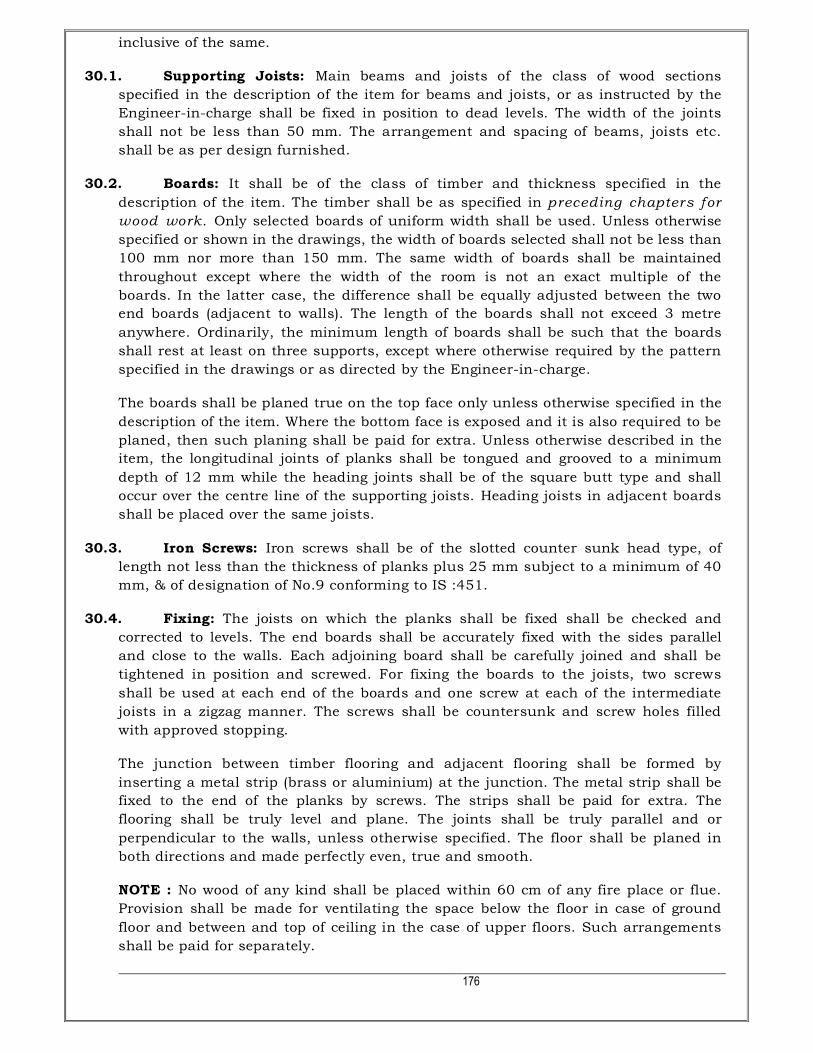
176
inclusive of the same.
30.1. Supporting Joists: Main beams and joists of the class of wood sections
specified in the description of the item for beams and joists, or as instructed by the
Engineer-in-charge shall be fixed in position to dead levels. The width of the joints
shall not be less than 50 mm. The arrangement and spacing of beams, joists etc.
shall be as per design furnished.
30.2. Boards: It shall be of the class of timber and thickness specified in the
description of the item. The timber shall be as specified in preceding chapters for wood work. Only selected boards of uniform width shall be used. Unless otherwise
specified or shown in the drawings, the width of boards selected shall not be less than
100 mm nor more than 150 mm. The same width of boards shall be maintained
throughout except where the width of the room is not an exact multiple of the
boards. In the latter case, the difference shall be equally adjusted between the two
end boards (adjacent to walls). The length of the boards shall not exceed 3 metre
anywhere. Ordinarily, the minimum length of boards shall be such that the boards
shall rest at least on three supports, except where otherwise required by the pattern
specified in the drawings or as directed by the Engineer-in-charge.
The boards shall be planed true on the top face only unless otherwise specified in the
description of the item. Where the bottom face is exposed and it is also required to be
planed, then such planing shall be paid for extra. Unless otherwise described in the
item, the longitudinal joints of planks shall be tongued and grooved to a minimum
depth of 12 mm while the heading joints shall be of the square butt type and shall
occur over the centre line of the supporting joists. Heading joists in adjacent boards
shall be placed over the same joists.
30.3. Iron Screws: Iron screws shall be of the slotted counter sunk head type, of
length not less than the thickness of planks plus 25 mm subject to a minimum of 40
mm, & of designation of No.9 conforming to IS :451.
30.4. Fixing: The joists on which the planks shall be fixed shall be checked and
corrected to levels. The end boards shall be accurately fixed with the sides parallel
and close to the walls. Each adjoining board shall be carefully joined and shall be
tightened in position and screwed. For fixing the boards to the joists, two screws
shall be used at each end of the boards and one screw at each of the intermediate
joists in a zigzag manner. The screws shall be countersunk and screw holes filled
with approved stopping.
The junction between timber flooring and adjacent flooring shall be formed by
inserting a metal strip (brass or aluminium) at the junction. The metal strip shall be
fixed to the end of the planks by screws. The strips shall be paid for extra. The
flooring shall be truly level and plane. The joints shall be truly parallel and or
perpendicular to the walls, unless otherwise specified. The floor shall be planed in
both directions and made perfectly even, true and smooth.
NOTE : No wood of any kind shall be placed within 60 cm of any fire place or flue.
Provision shall be made for ventilating the space below the floor in case of ground
floor and between and top of ceiling in the case of upper floors. Such arrangements
shall be paid for separately.

177
30.5. Finishing: The surface of the floor shall be bees waxed or finished otherwise
as directed by the Engineer-incharge. The lower face shall be painted or treated with
wood preservative as directed. The finishing shall be paid separately unless
specifically included in description of the flooring item.
30.6. Measurements: Length and breadth of superficial area of the finished work
shall be measured correct to a cm. The area shall be calculated in sqm correct to two
places of decimal. No deduction shall be made nor extra paid for voids not exceeding
0.20 sqm. Deductions for ends of dissimilar materials or other articles embedded
shall not be made for areas not exceeding 0.10 sqm.
30.7. Rate: The rate shall include the cost of labour and materials involved in all the
operations described above, with the exceptions noted in the relevant sub paras.
* * *
31 WOOD WORK IN FRAMES, SHUTTERS AND PANELLING :
a. WOOD WORK :
All timber mentioned in the item in schedule of quantities shall be from the heart of a
sound tree of nature growth entirely free from sap wood. It shall be uniform in
texture, straight in fiber and shall be well and properly seasoned. It will be free from
large, loose, dead or cluster knots, wedges, injuries, open shakes, borer holes, rot,
decay date, discoloration, soft or spongy spot, hollow pockets, pith or centre bore
and all other defects or any other damages of harmful nature which will affect the
strength, durability, appearance and its usefulness for the purpose for which it is
required. Only properly seasoned timber shall be used.
TEAK WOOD:
First Class Teak Wood: Individual hard and sound knot shall not be more than
25mm in diameter and aggregate area of all knots shall not exceed one percent of
the area of the piece. Sapwood shall not be allowed.
Second Class Teak Wood: Individual hard and sound knot shall not be more than
40 mm in diameter and aggregate area of all knots shall not exceed one and half
percent of the area of the piece. Wood shall be generally free from sapwood, but
traces of sapwood may be allowed.
HARD WOOD:
No individual hard and sound knot shall exceed 25mm in diameter and aggregate
area of all knots shall not exceed one percent of the area of the piece. Sapwood is
very perishable and should not be used.
The samples of species to be used shall be deposited by the contractor with the
Engineer-in-Charge before commencement of the work. The contractor shall produce
cash vouchers and certificate from standard kiln seasoning plant operator about the
timber section to be used on the work having been kiln seasoned by them, failing
which it would not be so accepted as kiln seasoned. Seasoning of timber shall be

178
judged from its moisture content as laid down in I.S. 287. The seasoning of timber
shall conform to I.S.1141 -1 993. Scantling of all types of timber shall be straight.
Warped scantling shall not be used. Before use in works, the scantling shall be kept
in covered and well-ventilated place and shall be got approved.
The workmanship shall be of best quality. All wrought timber is to be sawn, planed,
drilled or otherwise machine worked to the correct sizes and shall be as indicated in
drawing or as specified. All joinery work shall fit truly and without wedging or filling.
Wood work in frames shall be wrought. All frame joints shall be put together with
white lead and pinned with hard wood pins securing with corrosion resistant star
shaped metal pins as approved by the Engineer-in-charge. If after fixing in position,
any shrinking or substandard materials or bad workmanship is detected, the
contractor shall, forthwith remove them and replace the same at his own cost, all as
directed by the Engineer-in-charge.
Individual members shall be of continuous length. The finished size and sections
shall be as per drawing or as specified. The heads and posts of frames shall be
through tennoned into the mortises to the full widths as shown in the drawing. All
necessary mortising, tennoning, grooving, matching, tonguing, housing rebate and
other necessary works for correct jointing shall be carried out, in the best
workmanship like manner. Joints not specifically indicated shall be recognised form
of approved joints for each position. The door frames shall be provided with 6 nos.
approved iron hold fasts, fabricated out of 30 x 3 mm. section, 300 mm. long (150
mm. long for cross partitions) M.S. flats with spliced end in case they are abutting
brick masonry works. These M.S. hold fasts shall be embedded in plain cement
concrete 1:3:6 block of size 300 x 75 mm. depth (100 x 75 mm. for cross partitions)
and for full width of brick masonry. For frames abutting concrete surfaces, 6 nos.,
100 mm. long coach screws with sunk heads minimum 10 mm. from face of frames,
shall be provided. Each screw shall be secured in concrete with lead wool
sufficiently stuffed in the pre-drilled holes to receive the screws. Top member of door
frames for opening exceeding 1.25 m. in width, shall be secured with a coach screw
100 mm. long in centre of member. All other T.W. scantlings shall be fixed to
structural openings with wood screws of suitable size & rawl plug so as to get in
effective hold of at least 40 mm. Suitable teak wood plugs shall be provided to
conceal the screw heads. The door frame shall rest on concrete sub- base in ground
floor or structural floor slab in case of upper floors, the extra length of sides of
frames thus embedded below finished floors shall not be measured for payment. All
parts of wood work resting on or set in masonry or concrete shall be well painted
with two coats of bituminous paint or solignum as directed by the Engineer-in-
charge, prior to installations. All nails, screws, hold fasts, plates, plugs, pins
required for wood work joinery and fixing work, shall be provided by the contractor,
at his own cost. All materials shall be approved by Engineer-in-charge before using
in works. Painting of door frames shall be carried out as per specifications for
painting for wood work.
All the embedded timber shall be given two coats of hot tar or solignum before
erection. This is incidental to the item and shall not be measured for payment.
b. TEAK WOOD PANELLED SHUTTERS :

179
Teak wood door shutter shall generally conform to standard laid in I.S. 1002 or the
latest revision for requirements of materials, construction workmanship and shall be
of specified thickness and of 1st class C.P. teak wood of approved design with stiles,
top, bottom and lock rail generally as per drawing. Wherever shown, each panel
shall be in a single width piece, but when two or more pieces have to be used and
are permitted, all of them shall be of equal width and shall be jointed with a tongue
and groove joint with chamfered edges glued together and reinforced with metal
dowels.
c. TEAK WOOD GLAZED SHUTTERS :
The specifications for teak wood panelled shutter shall generally apply to glazed
shutters for frame, stiles etc.
The sash and beading required for glazing shall be of the best teak wood and shall
be fixed as per the design shown in relevant drawing. Any mouldings, carvings shown
shall be worked out from the teak wood member of bigger size.
d. GLAZING :
Glazing shall be generally with 4 mm. thick plain sheet glass/bajra glass unless
otherwise mentioned in the schedule of quantities. The detailed specifications for
glazing given hereafter shall be followed generally.
e. FLUSH DOOR SHUTTERS :
Solid core flush door shutters shall be of 5 ply construction and approved make
generally conforming to the I.S. specification 2202-1991 (specification for wooden
flush door shutter- solid core type). The finished thickness of the shutter shall be as
mentioned in the schedule of items.
f. FACE VENEERS :
Commercial face veneers used in flush door shutter shall conform to the
requirements laid down in I.S. 303 -1989 specifications for ply wood for general
purposes (revised) interior grade.
Decorative face veneers used in flush door shutters shall be of grade - I and shall
conform to the requirements of decorative veneer specified for grade - I decorative ply
wood in I.S. 1328 - 1982 specifications for veneered decorative ply wood interior
grade. Thickness of veneers shall not exceed 1 mm.
g. ADHESIVES :
Phenol formaldehyde synthetic resin (liquid type adhesives) conforming to I.S. 848
specifications for synthetic resins shall be used for bonding.
h. LIPPING :
The lipping shall be of best quality hard wood variety unless otherwise mentioned.
In case teak wood lipping is mentioned in the schedule of quantities, it shall
conform the specification for best quality teak wood. The internal lipping alround
the shutter sides shall be one piece of size not less than 25 mm. wide and depth

180
equal to the thickness of core. In case of double leaf shutters, the meeting stiles
shall have lipping of not less than 35 mm. deep. Thickness of external lipping,
wherever specified in the item, shall not be more than 10mm and not less than
6mm.
i. WORKMANSHIP AND FINISH :
All the faces of the door shutter shall be at right angles. The shutter shall be free from
twist and warp in its plane. Both faces of the door shutters shall be sanded to a
smooth even texture. The workmanship and finish of the face panels shall be in
conformity with those specified in I.S. 303 - 1989 specification for plywood for
general purpose (revised) for commercial type and I.S. 1659 - 1990 specification for
block boards for decorative type.
j. TESTS :
Tests shall be conducted as per mandatory test requirement, by the Contractor at
Approved Lab at contractors cost and acceptance criteria shall be as per I.S. 2202.
The flush door shutters manufactured shall be inspected for its quality and
workmanship and tested at the factory before dispatching. All facilities shall be
extended for such inspection and testing. The sampling and testing shall be as per the
IS requirements and all costs towards test including sample for destructive tests shall
be borne by the contractor.
k. TOLERANCE :
Tolerance on nominal width and height shall be (+/-) 3 mm. Tolerance on nominal
thickness shall be (+/-) 1.5mm. The thickness of the individual shutter shall be
uniform throughout.
l. MISCELLANEOUS :
Wherever mentioned in the Schedule of quantities, vision panels, venetians, plastic
laminates, push plates etc. shall be provided in the flush doors.
The vision panels shall be of size mentioned in the drawing and shall be provided with
teak wood lipping alround the glass. The glass shall be 4 mm. thick or as specified of
best quality (M/s. Triveni, I.A.G., Shree Vallabh or equivalent approved), free from
defects.
Teak wood venetians or louvers shall generally conform to relevant specifications of
timber. Necessary grooves and rebate in frames shall be provided as per drawing.
Formica or approved equivalent plastic laminate of required design, required shade
and colour shall be provided and fixed on flush door to the required size on any side
of the shutter as shown in drawing. It shall be fixed with Fevicol or any other
approved adhesive. Fixing shall be done in such a way that there shall not be any
air gap, warpage or undulations on the surface. Finished surface of formica shall be
cleaned with wax polish.
The shutters shall be painted on commercial facing side with two coats of
synthetic/flat oil paint of approved shade and make over an approved coat of primer.

181
The decorative veneer side of the shutter shall be wax or french polished with two or
more coats so as to render a satisfactory surface.
The flush doors shall be single leaf or double leaf type as mentioned in the schedule
of quantities. In case of double leaf shutters, the meeting of the stiles shall be rebated
20 mm. and shall be either splayed or square type and the T.W. lipping around the
meeting shall not be less than 35 mm. deep. The meeting stiles shall be in single
piece.
Sufficient care shall be taken to prevent any damage and loss of shape during
handling, transporting, stacking, fixing etc. The door shutters shall be handled with
utmost care to prevent any surface damage, warping etc.
m. MODE OF MEASUREMENT :
The work covered under the respective items in schedule and the above
specifications shall be measured as follows :
The cubic contents for wood work shall be measured for the finished size, limiting to
those shown in the drawings or ordered by the Engineer-in-charge. The cross
sectional dimensions shall be measured equivalent to nearest enclosing rectangle
(least rectangle/square) for wrought and planed sizes. The cubical content shall be
worked out correct upto three places of decimals of a cubic metre. The frames
embedded below finished floor shall not be measured.
The square meter areas for shutters shall be measured for the exposed surfaces of
shutter between frames from inside or outside whichever is more. The linear
dimensions shall be measured upto two places of decimals of a metre. The area for
payment shall be worked out correct upto two places of decimals of a square metre.
The rate for shutters shall include:
i. Cost of supply assembly and erecting in position.
ii. Cost of polishing, painting, supplying wood preservative, screws, nails, hold fasts
etc.
iii. Cost of labour for making adjustments in frames, if required, shutters and also
for fixing required fittings and fixtures.
iv. In case of flush doors, the rate for individual item mentioned in the schedule of
quantities shall include cost of shutters, labour for provision of glass for vision
panel, plastic laminate sheet push plate, teak wood louvers etc., transporting
charges and labour for fixing of fixtures and fastenings except fixing of door
closers and painting and polishing as specified.
* * *
32 PRESSED STEEL DOOR FRAME :
a. Scope of work : This specification lays down the requirements regarding material,
dimensions and construction of steel door frames for internal and external use.
b. Material : Steel door frames shall be manufactured from commercial mild steel
sheets of 1.25 mm. thickness, conforming to I.S. 513 (Spn. for cold rolled carbon
steel sheets) or I.S. 1079 (Spn. for hot rolled carbon steel sheet and strip). Sheets
shall be galvanised for 240 g / Sqm. Zinc deposit on its surface including both sides

182
as per IS 277 – 2003. Fire Rated steel door of Fire Rating as per requirement shall
be of approved make and complete as per manufacturers specification.
c. Standard sizes, Tolerances and Designations :
Sizes : The overall sizes and types of door frames shall be as shown in drawings. 5
mm. clearance on all the four sides shall be allowed for the purpose of fitting the
frame into modular openings.
Tolerances : The sizes indicated in drawings for door frames shall not vary by more
than (+/-) 2 mm.
d. Profile : Steel door frames with or without fanlight shall be made in the profile as
per I.S. 4351 (latest version) as per drawings. Any of the three profiles mentioned in
I.S. 4351 or sizes specified in the schedule of work may be supplied to suit doors of
either hand, opening inwards or outwards, as specified or directed.
e. Construction : Each door frame shall consist of hinge jamb, lock jamb, head and, if
required, angle threshold. The whole shall be rigidly fixed together by mechanical
means. Where no angle threshold is required, temporary base tie shall be screwed to
the feet of frames in order to form a rigid unit.
f. Base ties and angle thresholds : Base ties shall be of pressed mild steel 1.25 mm.
thick adjustable to suit floor thickness of 25, 30, 35 or 40 mm. and removable, or
alternatively, thresholds of mild steel angle of section 50 x 25 mm., minimum, shall
be provided for external door frames.
g. Fittings: Fixing Lugs: There shall be three adjustable lugs with split end tail to each
jamb without fanlight, and four for jamb with fanlight. The head of the fixing lug
shall be of 120 mm. long and shall be made from flat steel strip 25 mm. wide and not
less than 1 .60 mm. thick.
The tail of the lugs for use with door frame profile shall be 200 mm. long and shall be
made of steel strip not less than 40 mm. wide and not less than 1.0 mm. thick.
Mortar Guards: Mortar guards specified in the tender shall be provided. These shall
be welded to the frame at the head of the frame for double shutter doors to make
provision for bolts.
Note: The term ‘double-shutter doors’ indicates ‘Pairs of side-hung doors’, that is, two
side-hung doors mounted in one frame thus forming a two-leaf door rebated together
at the lock strike.
Lock Strike Plate: There shall be an adjustable lock-strike plate of steel, complete
with mortar guard, to make provision for locks or latches complying with the relevant
Indian Standards. Lock-strike plates may be of brass when so specified in the tender;
otherwise they shall be of galvanised mild steel and fixed at 75 cm. to 90 cm. from
finished floor level.
Shock Absorbers: For side-hung door, there shall not be less than three buffers of
rubber or other suitable material inserted in holes in the rebate and one shall be
located on the centre line of the lock-strike plate and the other two at least 45 cm.
above and below the centre line of the lock-strike plate. For double-shutter doors,

183
there shall be two buffers of rubber or similar suitable material inserted in holes in
the rebate in the lock jamb only at the head and spaced 15 cm. at either side of the
centre line of the door.
h. Mode of Measurements : The length shall be measured in running metres correct to
a cm. out to out of the frames. Threshold angle/base tie will not be measured for
payment, cost of which shall be included in pressed steel frame.
* * *
33 FACTORY MADE PARTICLES BOARD PANELLED DOOR SHUTTERS.
a. GENERAL : Factory made particle board panelled door shutters shall be made of
kiln seasoned and chemically treated timber as specified generally with stiles and top
rails of 100 mm. in width, bottom rail and lock rails of 150/1 75 mm. width and
panels made of 12 mm. thick both side commercial veneered teak wood particle board
or as specified in schedule of quantities, bonded with phenol formaldehyde synthetic
resin adhesive and generally conforming to I.S. 3091.
Factory made shutters, as specified shall be obtained from factories to be approved by
the Engineer-in-Charge and shall conform to I.S. 2202 (Part-I). The contractor shall
inform well in advance to the Engineer-in-Charge the name and address of the
factory where from the contractor intends to get the shutters manufactured. The
contractor will place order for manufacture of shutters only after written approval of
the Engineer-in-Charge in this regard is given. The contractor is bound to abide by
the decision of the Engineer-in-Charge and recommend the name of another factory
from the approved list, in case the factory already proposed by the contractor is not
found competent to manufacture quality shutters.
The contractor will also arrange stage-wise inspection of the shutters at factory of the
Engineer-in-Charge or his authorised representative. Contractor will have no claim if
the shutters brought at site are rejected by Engineer-in-Charge in part or in full lot
due to bad workmanship/quality. Such shutters will not be measured and paid and
the contractor shall remove the same from the site of the work within seven days
after the written instructions in this regard are issued by Engineer-in-Charge or his
authorised representative.
b. TIMBER :
The timber to be used in door shutters shall generally conform to relevant I.S.
specifications for materials, moisture content, seasoning, preservation and
workmanship. Seasoned Timber shall only be used.
All timber shall be from the heart of a sound tree of mature growth, entirely free
from sapwood. It shall be uniform in texture, straight in fiber and shall be well and
properly seasoned. It shall be free from large, loose, dead or cluster knots, soft or
spongy spots, hollow pockets, pith or centre heart, waves, injurious open shakes,
borer holes, rot, decay date, discoloration and all other defects or any other damages
of harmful nature which will affect the strength, durability, appearance of its
usefulness for the purpose for which it is required.

184
c. PARTICLE BOARD PANELS :
It shall be of well seasoned teak timber particles of uniform thickness, bonded with
liquid phenol formaldehyde synthetic resin adhesive of the hot press type. The
particle board shall be either flat plate on press or extrusion type as approved by the
E.I.C conforming to the latest I.S. specifications. Panels shall be embedded into
frames to a minimum of 12 mm. with 1.5 mm. air gaps.
d. SEASONING AND TREATMENT :
All timber to be used for sills and rails shall be kiln seasoned to the required
standards as per I.S. 1141 -1 973.
e. ADHESIVE :
The adhesive for bonding of stiles, rails etc. shall be of highly water resistant type
synthetic resins (liquid type) adhesive conforming to relevant specifications for
synthetic resins.
f. WORKMANSHIP AND FINISH :
The workmanship shall be of best quality. All members shall be in continues length.
All the faces of the door shutter shall be secured and in true planes. All wrought
timber is to be sawn, planed, drilled or otherwise moulded work to the correct size
and shapes indicated in drawing or as specified. All joinery work shall fit truly and
without wedging or filling. All the faces of the shutters shall be sanded to smooth even
texture. The finished sizes and sections shall be as per drawing or as specified. The
shutters shall be got approved from the Engineer-in-Charge at factory site before
carting the same to the site of work. The shutters damaged during the cartage and if
any sub-standard materials or bad workmanship is detected, the contractor, shall
forthwith remove them and replace the same at his own cost, all as directed by the
Engineer-in-charge.
g. 33.7 PRIMER COAT :
All factory made panel door shutters with seasoned teak wood/hard wood frame shall
be painted with approved Primer coat as per I.S. specifications 1003 (Part-I).
h. TESTS :
Tests shall be conducted as per mandatory test requirement by the E.I.C at the
contractors cost. All shutters shall have manufacturer’s trade marks.
i. TOLERANCES :
Tolerances on nominal width and height shall be (+/-) 3 mm. Tolerance on nominal
thickness shall be (+/-) 1 .5 mm. The thickness of the shutter frame shall be uniform
through out with a variation not exceeding 1 mm., when measured at two points.
j. SAMPLES :

185
Sample of door shutter shall be got approved before manufacturing on large scale.
k. FIXING:
The shutter shall be fixed to teak wood or rolled M.S./EZ door frame (teak
wood/rolled steel in door frames paid under relevant items) with necessary fittings
as per drawing (cost of fittings and fixtures paid under relevant items). The shutter
shall be painted as specified. The shutters of specified thickness and of required
sizes as fixed in position as shown in drawing/schedule of quantities shall be
measured for payment. The length and width of the shutter fixed in position shall be
measured correct upto three places of decimal of a metre and the areas so worked
out shall be corrected upto two places of decimal of a square metre. The area of the
shutter shall be measured for the exposed surfaces of shutter between frames from
inside or outside whichever is more.
l. RATE TO INCLUDE :
The rate quoted by the contractor shall be :
i) or supplying and fixing in position of finished shutters with necessary fittings
and fixtures as per drawings (excluding cost of fittings and fixtures which shall
be paid under relevant items).
ii) painting/polishing as specified and as directed by the Engineer-in-charge.
* * * *
34 GLASS FIBRE REINFORCED PLASTIC (GRP) PANEL TYPE DOOR SHUTTERS
(FOR INTERNAL USE)
a. SCOPE
The specification for Glass Fibre Reinforced Plastic (GRP) Panel Type Door Shutters
shall generally conforming to IS 14856 and other associated IS Codes as regards to
types, sizes, material, construction, workmanship, finish, performance requirements
and sampling etc. for use in residential and industrial buildings, except the large size
door shutters for industrial and special buildings like workshops, garages, godowns,
etc.
b. REFERENCES: The above cited IS 14856 shall be referred with its associated codes.
c. TERMINOLOGY
Aggregate Defects: Presence of impurities such as pin holes, impurities and traces
of mending more than 5 each or 5 in aggregate for defects at localized place.
Blistering: Air or solvent entrapped during moulding.
Colour Blots: Colour blots occurring on account of uneven distribution of colouring
material.
Crazing: Fine hair cracks on the surface.

186
Defective Impregnation: Imperfect impregnation of glass fibre with unsaturated
polyester resin.
Gelcoat: A gelcoat of UV stabilized, fire retardant, isophthalic quality mixed with 1
5’percentby weight, aerosil powder ( 500 micron ground silica) suitably formulated
to high viscosity given to exposed exterior sections of the moulded door shutter to
provide a smooth glossy finish, enhance aesthetics and improve weathering and
water resistant properties of the moulded door shutter. The thickness of the coat
shall be between 0.35 to 0.40 mm.
Impurities: Foreign matter present, other than specified.
Laminate: A reinforced resin sheet or moulding.
Pin Holes: Pores of size less than 1mm appearing on the surface.
Small Pores: Pores of size more than 1mm appearing on the surface.
Wrinkle: A slight ridge or furrow on surface.
Base Block: A wooden or suitable material provided within the door/shutter frame to
facilitate fixing of fittings and other accessories.
RTM Process: Resin Transfer Moulding includes all forms of resin injections, resin
infusion vacuum infusion and vacuum press moulding. Moulding is done in a closed
mould under differential pressure.
Hand Lay Up: Hand Lay up process consist of laying gelcoat with appropriate layers
of Chop Strand Mat ( CSM ) and resin in open moulds.
d. HANDING: Handing and direction of closing of shutters shall be designated in
accordance with IS 4043.
e. MATERIAL
Glass Fibre Chopped Strand Mat ( CSM ): The glass fibre chopped strand mat used
shall be as per IS 11551.
Glass Fibre Rovings: The glass fibre rovings shall be as per IS 11320.
Isophthalic Resin: Isophthaiic resin shall be of fire retardant grade as per IS 6746.
Curing Agents
1. Catalyst used shall be Methyl Ethyl Ketone Peroxide (MEKP), benzyl peroxide,
acetyl aceto peroxide, etc.
2. Accelerator used shall be cobalt napthalate, cobalt octonate, N.N. dinethyl
anilene, etc.
Fillers and Additives
1. Permissible fillers are fiench chalk powder (Talc) and calcium carbonate.

187
2. Aluminium trihydrite, antimony trioxide, minimum 5 percent, by weight of
isophthalic resin, shall be used for fire retardancy.
3. The fillers and additives content shall not exceed 10 percent by weight of
isophthalic resin.
Auxiliary Chemical: Polyvinyl alcohol ( PVA ) or other semipenetrant release agents
and wax shall be used as a mould release agent.
Pigments: Pigments compatible with isophthalic resin and gelcoat shall be used to
obtain the shade of finish as mutually agreed between the manufacturer and the
purchaser.
Base Blocks: Base blocks for fixing fixtures in shutter with screws shall be of
seasoned and treated hard wood or any other suitable material.
Polyurethane Foam: Slabs of minimum density of 32 kg/cum and of thickness 4
mm less than the shutter thickness with (+/-) 0.5 mm tolerance shall be used.
f. CONSTRUCTION / FABRICATION
i. The GRP shutter shall have hollow rails and stiles
monolithically cast with panels.
ii. The shutters shall be contact moulded by either hand lay up
or Resin Transfer Moulding (RTM) process in two pieces as
shown in Fig. 1. The process shall consist of laying gelcoat of
0.35 mm to 0.40 mm thickness laid over with three layers of
GRP mat (one layer of 300 CSM mat and two layers of 450
CSM) for each of the web (panel) portion and four layers of
GRP mat for the flange (rails and stiles) portion (one layer of
300 CSM mat and three layers of 450 CSM mat ). While
closing the two pieces, additional layer of 450 CSM mat shall
be provided in the web portion. The CSM mat shall be
bonded with isophthalic resin in the ratio not less than 1:2
(one part of mat to two parts of isophthalic resin and fillers
and additives) by weight. The edges shall be sealed with
gelcoat and FRP mat to obtain smooth finish. Sufficient
rovings shall be laid in the corners to have smooth curve
while laying the CSM mat. If the shutter is moulded using
the RTM process, then moulding shall be done either by
laying gelcoat followed by laying of the GRP mat. Core
material shall be placed in location in the hollow sections.
The GRP mat shall be bonded by injecting under pressure
isophthalic resin in a ratio not less than 1:2 (one part of mat
to two parts of isophthalic resin ). Alternatively, if the
shutter is moulded without using gelcoat then the process is
to lay the FRP mat in the mould with the core material
blocks in location in the hollow section. The GRP mat shall
then be bonded by injecting under pressure, isophthalic
resin in a ratio not less than 1:2 ( one part of mat to two
parts of isophthalic resin ).

188
iii. Blocks of any seasoned hardwood of bulk density not less
than 450 kg/m3 at 12 percent moisture content or any other
material of sufficient thickness and length shall be provided
inside the shutter at suitable place to hold fittings and
fixtures such as aldrops, tower bolt, handle sliding door bolt,
mortice lock, etc. Blocks for hinges shall be provided at three
locations, unless otherwise specified by the purchaser. One
at the centre and other two at 200 mm from the top and the
bottom of the shutter.
iv. Blocks shall be provided at predetermined places in the
shutter so as to fix hinges, mortice locks, tower bolts,
aldrops, door closures, etc.
v. The finished surface shall be buffed and polished 3 IS
14856:2000 with wax.
g. DIMENSIONS, SIZES AND TOLERANCES
i. Dimensions of Components and Tolerances: The finished
dimensions and tolerances of the different components of
door shutter shall be as given below:
Dimensions and Tolerances of Components of Door Shutters
SN Description Width (in mm) Thickness (in
i Vertical stile, top and freeze 90 (+/-) 3 30 (+/-) or 35
ii Lock rail 120 (+/-) 3 30 (+/-) or 35
iii Bottom rail 150 (+/-) 3 30 (+/-) or 35
Minimum thickness of GRP laminate of hollow rails and stiles shall be 3
mm.
Minimum thickness of GRP laminate used for panel in the shutter shall be 5
mm.
ii. Sizes and Types: Sizes and types of the shutters shall be
generally as per working drawings issued for the work or
shall conform to the modular sizes as per IS 14856.
iii. Tolerances: Tolerances on the sizes of door shutters shall
be _~mm.
h. LOCATIONS OF FI’ITINGS AND ACCESSORIES
i. The lock rail of door shutters shall be so placed that its

189
centre line is at a height 850 + 5 mm from the bottom of the
shutter.
ii. Each door shutter shall be fixed to the frame with three
hinges of the type specified, unless otherwise specified.
These location shall be, one at the centre and other two at
200 mm from the top and the bottom of the shutter, where
blocks have already been provided and suitable indication,
by depressing the profile has been made.
iii. Other fixtures shall also be provided at the locations where
blocks have already been provided
i. FINISH
i. The surface of the moulded shutters shall be free from any
visible defects such as small pores, crazing, blistering,
wrinkling, impurities, defective impregnation, colour blots
and aggregate defects.
ii. Scattered pin holes duly repaired and finished by applying
resin and not noticeable shall be acceptable.
iii. Panels, rails and stiles of the door shutters shall be flat and
shall have smooth and level surface.
iv. Shutter shall be finished in colour & design as specified in
the agreement item.
j. TESTS
i. Tests on Material: Following tests shall be conducted on
FRP laminate (without removing gel coat) cut from door
shutter. The method of carrying out the test shall be as per
the reference code mentioned against each test. Acceptable
criteria shall be as mentioned against each test.
Tests on GRP Laminate
SI No. Tests (as per IS requirement) Acceptable Value
i) Fibre glass content Annex B 25 percent (Min ) ii) Barcol hardness Annex C 30 BHU (Min ) iii) Tensile strength Annex D (MPa) 100 (Min ) iv) Bending strength Annex E (MPa) 120 (Min ) v) Elastic modulus Annex F in bend 1 500 (Min ) vi) Water absorption Annex G 0.5 percent (Max)
vii) Fire retardancy Annex H 100 mm length of the
specimen
ii. Requirements on Shutters

190
The following tests in accordance with IS 4020 (Parts 1 to 16) shall be
conducted on the door shutters:
1. Dimensions and Squareness Test: Door shutters,
when tested in accordance with 1S 4020 (Part 2), the
dimensions of nominal width and height shall be
within a limit of (+/-) 5mm. The door shutter shall not
deviate by more than 1mm on a length of 500 mm.
The thickness of the door shutter shall be uniform
throughout with the permissible variation of not more
than 0.8 mm between any two points. The nominal
thickness of the shutter shall be within a limit of (+/-
) 1.5mm.
2. General Flatness Test Door shutters, when tested in
accordance with IS 4020 (Part 3), the twist, cupping
and warping shall not exceed 6 mm.
3. Local Planeness Test: Door shutters, when tested in
accordance with 1S 4020 (Part 4), the depth of
deviation measured at any point shall not be more
than 0.5 mm.
4. Impact Indentation Test: Door shutters, when tested
in accordance with IS 4020 (Part 5), shall have no
defects such as cracking, tearing or delamination and
the depth of indentation shall not be more than 0.2
mm.
5. Edge Loading Test: Door shutters, when tested in
accordance with IS4020 (Part 7), the deflection of the
edge at the maximum load shall not be more than 5
mm. On removal of the loads, the residual deflection
shall not be more than 0.5 mm, failing which the test
may be repeated on the other edge in the reverse
direction. Also there shall be no lateral buckling by
more than 2 mm during loaded condition and no
residual lateral buckling after removal of the load.
6. Shock Resistance Test
1. Door shutters, when tested in accordance with 2.1 of IS 4020 (Part 8), there
shall be no visible damage in any part of the door after twenty-five blows on
each end.
2. Door shutters, when tested in accordance with 3.1 of IS 4020 (Part 8), the
normally hung shutter, with hangings, fixings and fastenings should withstand
without any significant permanent deformation and without deterioration the
five impacts on both sides of the shutter.
7. Buckling Test: Door shutters, when tested in
accordance with IS 4020 ( Part 9 ), shall not show

191
any deterioration and any residual deformation more
than 5 mm after 15 min of unloading and the initial
deflection also shall not be more than 50 mm.
8. Slamming Test
Anyone of the following tests shall be used.
1. Door shutters, when tested in accordance with 2.1 of IS 4020 (Part 10), shall
not have any visible damage in any part of the door at the end of 50
successive impacts.
2. Door shutters, when tested in accordance with 3.1 of IS 4020 (Part 10), shall
not have any visible damage in any part of the door at the end of I00
successive impacts.
9. Misuse Test
Door shutters, when tested in accordance with 1S4020 ( Part 11 ), there shall
not be any permanent deformation of the fixing or any other part of the door
set in hindering its normal working after the test.
k. SAMPLING AND CRITERIA FOR CONFORMITY: The sampling and criteria for
conformity shall be in accordance with IS 4020 (Part 1).
l. MARKING
1 All door shutters conforming to this specification shall be marked with the
following information:
a) Name of manufacturer or trade-mark, if any.
b)Lot number/date of manufacture for identification.
c) ISI Certification mark if any.
m. MODE OF MEASUREMENT: Square metre area for shutters shall be measured for
the exposed surfaces of shutter between frame work from inside or outside, whichever
is more. The linear dimensions shall be measured upto two places of decimals of a
metre. The area for payment shall be worked out correct upto two places of decimal of
a square metre.
n. RATE TO INCLUDE: The rate quoted by the contractor shall include supplying and
fixing the shutters including supplying and fixing all fittings and fixtures as per item
and / or drawing. Unless otherwise specified, frame work for the shutters shall be
measured and paid separately under relevant item.
* * *

192
35 FITTINGS AND FIXTURES:
a. SCOPE OF WORK :
The work covered under these specifications consist of supplying different types of
fittings and fixtures required for doors, windows, ventilators etc. The supply shall be
in accordance with the specification, drawings / approved samples. Samples of
various fittings and fixtures proposed to be incorporated in the work shall be
submitted by the contractor for approval of the Engineer-in-charge before order for
bulk supply is placed.
b. GENERAL :
All fittings and fixtures shall conform to relevant IS code and made of brass,
nodized aluminium, iron oxidised (M.S.) or as specified. These shall be well made
reasonably smooth and free from sharp edges, corners, flaws and other defects.
Screw holes shall be counter sunk to suit the heads of the specified screws. All hinges
pins shall be of steel for brass hinges and aluminium alloy NR-6 or steel pins for
aluminium hinges with nylon washers or as specified. All riveted heads pertaining to
hinge pins shall be well formed. Screws supplied for fittings shall be of the same
metal and finish as the fittings. However brass cadmium plated/chromium plated
screws shall be supplied with aluminium fittings. Samples of each fixture/ fitting
shall be furnished by the contractor for approval of the Engineer-in-Charge. Order
for procurement of fittings and fixtures in bulk shall be placed only after approval by
the Engineer-in-Charge.
The fittings and fixtures to be incorporated in the work shall be strictly according to
the approved sample. Fittings shall be fixed in proper position as shown in the
drawing and as directed by the Engineer-in-Charge. These shall be truly vertical or
horizontal as the case may be. Screws shall be driven home with a screwdriver and
not hammered in. Recess shall be cut to the exact size and depth for the counter
sinking of hinges. The fittings and fixtures shall be fixed in a workman like manner
and any damages done either to fittings and fixtures or to the shutter frames etc.
should be rectified by the contractor at his own cost.
Fittings shall be of Mild steel, Stainless steel, aluminium, brass or as specified. The
fittings shall be well made, smooth, and free from sharp edges and corners, flaws
and other defects.
Mild steel fittings shall be bright satin finish black stone nodized or copper
oxidised (black finish), nickel chromium plated or as specified.
Brass fittings shall be finished bright satin finish or nickel chromium plated or
copper oxidised or as specified.
Aluminium fittings shall be nodized to natural matt finish or dyed anodic coating
less than grade AC 10 of IS: 1868
Stainless steel fittings shall be non-magnetic, rust & moisture proof, strong &
sturdy. Pin of hinges shall also be of stainless steel.
c. BUTT HINGES : Brass and aluminium hinges shall be manufactured from the

193
extruded sections and shall be free from cracks and other defects. M.S. butt hinges
shall be cranked and manufactured from M.S. sheets. All butt hinges shall conform
to latest I.S. specifications butt hinges shall generally condorm to releval I.S viz IS
1341 (M.S.) IS : 205 (Cast brass & aluminium, IS : 362 (Parliament hinges); IS : 453
sprig higes, IS : 3818 (Piano higes) etc. The size of butt hinges shall be taken as the
length of the hinge. Width of the hinge shall be measured from the centre line of
hinge pin to end of flange.
d. PARLIAMENTARY HINGES : These shall be manufactured from extruded section for
brass and aluminium and from M.S. sheets for iron oxidised and shall be free from
cracks and other defects. The size of the parliamentary hinges shall be taken as the
width between open flanges, while the depth shall be as specified.
e. PIANO HINGES :
These shall be generally conformed to I.S. 3818 and shall be made of either brass
oxidised, aluminium nodized, iron oxidised (M.S.) or as specified. Piano hinges shall
be fixed in the entire length of the cupboard shutters in a single piece. No joints shall
be allowed.
f. TOWER BOLTS : These shall generally conform to IS 204 (Part II & I). They shall be
well made and shall be free from defects.
The tower bolts shall be of the following types :
i. MS semi barrel tower bolt with ms sheet pressed barrel and G.I. bolt or with ms
barrel and ms Sheet bolt.
ii. Oxidised brass barrel tower bolt with brass sheet barrel and rolled or drawn
brass bolt.
iii. Anodised aluminium tower bolt with barrel and bolt of extruded sections of
aluminium alloy.
In case of M.S. tower bolt plates and straps after assembly shall be firmly nodize or
spot welded properly.
The knobs of brass tower bolts shall be cast and the bolt fixed into the knob firmly
as per I.S. specifications. The tower bolt shall be finished to correct shape and
pattern so as to have a smooth action. Wherever specified, aluminium barrel tower
bolts shall be manufactured from extruded sections of barrel & bolts.
Knobs shall be properly screwed to the bolt and riveted at the back. The size of the
tower bolt shall be taken as the length of barrel without top socket.
g. Door Letch :
This shall be of MS, cast brass or as specified shall have smooth sliding action. MS
Latch shall be copper oxidised (black finish) or as specified. Brass Latch shall be
finished bright, CP or oxidised or as specified
h. ALDROPS :

194
These shall be oxidised brass or nodized aluminium, iron oxidised or as specified
and shall be capable of smooth sliding action and shall be as per relevant I.S. Brass
sliding door bolt (aldrop) shall be made from rolled brass generally confirming to IS :
2681. M.S. sliding door bolt shall generally conform to I.S.281. The hasp shall be of
cast brass and screwed to the bolt in a workman like manner. Alternatively the hasp
and the bolt may be in one piece. Bolts shall be finished to shape and threaded with
worth standard and provided with round brass washers and nuts of square or
hexagonal shape. All components shall be smooth and polished. The leading
dimensions of aldrop shall be as the length of the bolt and specified diameter.
i. DOOR HANDLES- BOW/PLATE HANDLES :
These should generally conform to IS : 208. Unless otherwise specified door handles
shall be of 100 mm size & windows handles of 75 mm size. These shall be of cast
brass of specified size, shape and pattern as approved by the Engineer-in-charge. All
edges and corners shall be finished smooth and correct to shape and dimensions.
Brass handles shall be finished bright, chromium plated or oxidised as specified.
Anodised aluminium or iron oxidised (m.s.) handles shall be of specified size, shape
and pattern. The size of the handle is taken as the inside grip of the handle. In case
of iron oxidised handles, the same shall be manufactured from m.s. sheet pressed
into oval section as per I.S.
j. MORTISE LOCK & LATCH :
This should generally conform to I.S. 2209. Handles shall conform to IS 4992.
Mortise lock with latches and a pair of level handles shall be 6 levers, with zinc alloy
pressure die cast/brass or as specified body of approved quality, and shall be right
or left handed as specified. The pair of handles shall be either brass chromium
plated or nodized aluminium of approved shape and pattern or as specified. It shall
be of the best Indian make of approved quality. The size of the lock shall be
determined by its length. The lock for single leaf door shall have plain face and that
for double leaf door a rebated face. Level handles with springs shall be mounted on
plates and shall be of approved quality, nodized aluminium or as specified.
k. HYDRAULIC DOOR CLOSER :
This shall be generally conform to IS : 3564. Hydraulic door closer shall be of
approved quality and make. The operation of the Hydraulic door closer shall be very
smooth.
This should be of H.D.-66 for external/main doors and elegant - 63 for all internal
doors. The overall height should not be more than 170 mm. for H.D.-66 and 160 mm.
for elegant - 63, base shall be 110 x 60 mm. for H.D.-66 and 100 x 55 mm. for elegant
- 63 weighing not less than 4.5 kg. for H.D.-66 and 4 Kg. for elegant - 63. Speed of the
Hydraulic door closer shall be adjustable and latch closing also shall be adjustable
type. Suspension and lubrication of door closer shall be in perfect line and level.
l. The contractor shall provide for all the incidentals required for fixing these fixtures
and fittings such as cadmium plated screws etc. Fittings and fixtures shall be fixed
securely in a workman like manner all as directed by the Engineer-in-charge. Any of
the fixtures damaged during the fixing shall be removed and new one fixed in their

195
place and the surface of joinery made good where affected, at his own expense.
Mortise plates shall be used over holes where the bolts enter in the wood work. Metal
sockets shall be provided to all bolts where the shoot enter brick, stone, concrete etc.
The incidental Fixtures like mortise plates, metal sockets, screws etc. shall not be
paid for separately.
m. MORTICE NIGHT LATCH : This is a mortice lock having a single spring bolt
withdrawn from the outside by using the key and from inside by turning the knob
and with an arrangement whereby the lock can be prevented from being opened by
its key from outside while the night latch is used from inside the room.
This should generally conform to IS: 3847. It shall be cast or sheet brass, cast or
sheet aluminium alloy or mild steel as specified and of approved make. These shall
be bright finished or copper oxidised (black) finish as specified. Normal size of the
latch shall be denoted by the length of the face over the body in millimetres.
n. FLOOR DOOS STOPPER: The floor door stopper shall conform to IS: 1823. This
shall be made of cast brass of overall size as specified and shall have rubber cushion.
The shape and pattern of stopper shall be approved by the Engineer-in-Charge. It shall
be of brass finished bright, chromium plated or oxidised or as specified. The size of
door stopper shall be determined by the length of its plate. The body of the door
stopper shall be cast in one piece. All parts of the door stopper shall be of good
workmanship and finish and free from surface and casting defects. Aluminium
stopper shall have anodic coating of not less than grade AC-10 of IS 1868.
o. MODE OF MEASUREMENT AND RATE : Unless otherwise specified, all fittings
including all necessary accessories shall be measured in numbers and the rate shall
include the cost of all materials including taxes, octroi, excise duty, if any, loading,
unloading, transporting, cost of screws, bolts and other accessories and fixing the
same complete.
* * * *
36 GLASS AND GLAZING :
a. SCOPE OF WORK :
The work covered by this specification include furnishing and fixing the glass panes
to teak wood or steel doors and windows, strictly in accordance with these
specifications and drawings.
b. MATERIALS :
i) Glass : The glass shall be special selected / selected ordinary quantity glass of
M/s. Saint Gobain India or of equivalent manufacture, as specified. Toughened
float glass of approved manufacturer shall be used wherever specified. The glass
shall be free from bubbles, flaws specks, waves, air holes, distortion, scratches,
cracks or other defects. The glasses in bulk quantities shall be brought to site in
Makers original packings and Makers guarantee shall be produced if called for by
the Engineer-in-charge. The glass shall be of required thickness as mentioned in
the items of schedule of quantities and/or drawing or as directed by the
Engineer-in-charge. The contractor shall submit the sample of the glass which he

196
proposes to use on the work and only such approved quality of glass shall be used
in the works. The glass brought to site shall be protected against damages.
Wherever frosted (obscure) glass is mentioned in the item of schedule of
quantities and / or shown in drawings, the glass shall be of sand blown pattern
and shall also be got approved from the Engineer-in-charge.
ii) Beading : The beading shall be of teak wood of superior quality timber in case of
teak wood doors and windows and/or required sizes mentioned in the items of
schedule of quantities and/or shown in drawing. In case of steel / Aluminium
doors and windows, the beading shall be anodised aluminium beading of channel
section as per sizes mentioned in the item and / or shown in the drawing. The
junction of the beadings shall be mitre jointed.
iii) Dimensions, Thickness and weight of the glass: Unless otherwise specified,
these shall be as per table given below. All panes shall have properly squared
corner and straight edges
Normal
thickness
Range of
thickness
Weight in kg /
sqm 3.0 mm 2.8 to 3.2 mm 07.5
4.0 mm 3.8 to 4.2 mm 10.0
4.8 mm 4.6 to 5.1 mm 11.9
5.5 mm 5.2 to 5.8 mm 13.5
6.3 mm 6.0 to 6.6 15.5
c. WORKMANSHIP :
The glass shall be cut to the required sizes of panels where it is to be fitted, and it
shall be so cut that it fits properly in the frames without rattling. Pre-measurement
of each panel prior to the cutting of glass is essential.
The beading shall then be fixed to glass panes and screwed at close intervals not
more than 10 cm. from each corner and the intermediate not more than 20 cm. apart.
When the glass panes are fixed with aluminium beading having mitred joints, epoxy
resin or silicon sealant shall be applied covering the area in contact between the
glass panes and sash bars and also between glass panes and the beading. In case of
louvers, all the exposed edges of the glass shall be ground properly.
All glass panes shall be fixed within the aluminium framing by use of CP brass or SS
screws and the joints sealed with epoxy resin or silicon sealant to make the unit
completely waterproof. Glazing or caulking compound around the perimeter of glass
shall not be permitted. Fixed glass panes shall be supported by setting blocks. There
shall be no whistling or rattling.
d. GENERAL :
After the inspection is over and permitted by the Engineer-in-charge, glass panes
shall be cleaned off any labels, paints smears and spots and shall be washed from
both the sides and all glazing left clear, perfect and free from rattling. The contractor
shall provide all the scaffolding, tools and plants for fixing the glass panes at his
own cost. In case of steel windows, any hardware if fixed in position, shall be

197
removed temporarily before fixing the glass panes and which shall be re-fixed back
in position, all at the contractors cost.
e. MODE OF MEASUREMENT :
The rate for teak wood door/window shutters and/or steel door/window shall
normally cover the cost of glass and glazing also, unless otherwise mentioned. In case
the glazing is carried out as a separate item, the measurement shall be taken out to
cut size of teak wood/steel door/window frames forming the sides of glass panes and
area calculated to two places of decimal of a square meter.
The rate shall include the cost of supplying and fixing the glass panes, all materials,
labour, transport, scaffolding etc.
* * *
37 STEEL DOORS, WINDOWS AND VENTILATORS:
SCOPE OF WORK :
The work covered under these specifications consist of supplying steel windows and
doors and ventilators, fixing, glazing etc. complete in strict accordance with the
specifications and relevant detailed/shop drawings.
a. GENERAL :
The contractor shall submit 6 copies of shop drawing covering all types of work
under this specification before manufacture. The drawing shall show all dimensions,
details of construction, installation, relating to adjoining and related work etc.
b. MATERIAL :
Shutters, frames etc. as dimensioned in the drawing shall be fabricated from I.S.
standard sections rolled . No glazing bars shall be provided unless otherwise shown
in drawing. Glazing used will be clear sheet glass of special selected quality
manufactured by Saint Gobain India or approved equivalent, unless otherwise
specified. Steel sections shall be free from rolling or other defects. They shall be easily
welded and punched and shall be cold straightened and shall conforming to latest
I.S. 1038 - 1983. The anticorrosive shop coat of paint shall be given before the
materials are brought to site.
c. COUPLING BARS FOR COMPOSITE DOORS,WINDOWS AND VENTILATORS :
All doors window, ventilators units shall be so constructed that those if required
may be coupled together by means of the standard mullion and weathered transom
bars and coupling pieces.
All steel hinges shall be projected steel hinges with non magnetic stainless steel pins
and washers to permit complete ease in cleaning the glass and shall be welded or
rivetted to the frame.
d. FABRICATION :

198
The frames shall be square and flat and shall be constructed of sections cut to
length, mitred and welded at corners. All welding shall be electrical flash butt
welding excepting for the welding of steel sheets for the shutters.
Sections shall be formed true to details with clean straight, sharply defined profiles
and free from defects that may impair its durability. All works shall be accurately
formed to the required dimensions, line and level. All joints shall be continuously
reinforced, fitted and continuously welded at the edges. Surface along joints shall be
ground to attain a smooth level surface even and flush with adjoining surfaces. All
frames shall be properly reinforced for the attachment of hardware. The heads of
frames for openings wider than 1.2 m. shall be reinforced to prevent sagging or
deflection when installed.
e. INSTALLATION :
The doors, windows and ventilators brought to site shall be stacked up site down on
wooden runner under cover. Fixing shall be done as per latest Indian Standard
Specifications. The size of the prepared openings shall be checked first and these
should be cleaned off all obstructions.
The doors/windows/ventilators shall not be forced into the walls but shall fixed into
prepared openings in workmen like manner.
All joints between masonry/concrete and the metal shall be fully filled with
approved mastic filler/putty in order to ensure water tightness. The joints shall be
neatly pointed with matching cement and excess material shall be removed.
All brick jambs and sill holes shall be cut 50 mm. square and 100 mm. deep for
fixing hold fasts. All concrete jambs and lintels, holes shall also be carefully drilled
and if reinforcing steel is encountered, the length of the hold fasts may be decreased
and existing surface made good to the original condition.
Any hard ware if fixed in position shall be removed before fixing the frames in the
structural openings and moving parts shall be secured with wire or string during
erection and while the building work is being completed to prevent damage to the
part. Hardware shall be fixed as late as possible preferably just before the final coat
of paint is applied. It shall be fitted in workmanlike manner so that it may not be
marked and mutilated by hammers and screws and pins are not marked and
mutilated by hammers and screwdrivers. It shall be tested for correct operations to
the satisfaction of the Engineer-in-charge.
f. DETAILS OF COMPONENT PARTS :
i. Doors : Door shutters shall be hung on projecting hinges of
67 mm size and shall be fitted with mortise lock and two
brass or bronze lever handles. In case of double leaf doors,
the first closing leaf of double leaf doors shall also be
provided with brass or bronze tower bolts concealed in the
section at top and bottom. These shall be so constructed as
not to work loose or drop by their own weight and necessary
lugs, fittings, screws etc. shall be provided and fitted
properly at site.

199
ii. Windows : Window shutters shall be hung on projecting
hinges. One leaf of the hinges shall be welded into a slot in
the outer frame and the other leaf of the hinges riveted to
the opening shutters. Hinges may be of the friction type in
which case the window shall not be fitted with peg stay. In
case of non-friction projecting hinges, a brass or bronze
three holes peg stays 300 mm. long with pegs and brackets,
welded or rivetted to the frame shall also be provided.
Handles shall be of brass or bronze and shall be of brass or
bronze, and shall be mounted on a mild steel handle plate
welded to the shutter in such a way that it should be fixed
after the shutter is glazed. The handles shall have a two
point nose which shall engage with brass, bronze or
aluminium alloy as specified, striking plate, on the fixed
frame so that it can hold the shutters in a slightly openable
as well in a fast position.
iii. VENTILATORS : a) Top hung ventilators : These shall be
fixed with plain hinges, riveted to the fixed frames or welded
to it after cutting a slot in it. A peg stay 300 mm. long of
brass or bronze with three holes, as in case of windows shall
be provided.
The locking bracket shall either be fitted to the fixed frame or to the
ventilators.
b) Centre Hung Ventilators : These shall be hung on two pairs of brass of
lead/tin/bronze cup pivots, riveted to the inner and outer frame of the
ventilators to permit these to swing through an angle of approximately 85 deg.
The opening portion of the ventilators shall be so balanced that it remains
open at any desired angle under normal weather condition.
A bronze or brass spring catch shall be provided at the top centre of the
ventilator. A brass cord pully wheel in a mild steel or malleable iron brackets,
shall be fitted with screws or welded at the sill and a cord eye shall be fixed to
inner frame of ventilators to facilitate opening of ventilators.
iv. Composite Units : Composite units consist of a
combination of two or more units of doors, windows,
ventilators etc. as the case may be. The different units shall
be coupled by using coupling sections. The coupling
sections shall be made from M.S. sheet 3.15 mm. in
thickness and 56 mm. wide as per I.S. 1038-1957 para 5.2
and these shall be fixed with bolts and nuts.
Wherever the ventilators, windows and doors shall have coupling section,
mastic cement shall be applied between the junctions to make the joints
watertight.
To calculate height or width of composite units, add 2.5 cm. for each mullion
or transom coupling bar for each unit.

200
g. FINISHING : All steel surfaces shall be thoroughly cleaned of rust, scale and dirt by
pickling and marking. A shop priming coat of superior quality red oxide or
equivalent shall then be given before despatch. Alternatively, where so specified, the
steel surfaces shall be treated for rust proofing by the hot dip zinc spray or electro
galvanising process, having a coating of not less than 60 microns thickness or as
specified. Zinc spray articles shall be given one coat of priming coat of superior
quality red oxide or equivalent.
Final finishing with two coats of synthetic enamel/flat oil paint of approved make and
shade shall be given after the doors,windows and ventilators are erected/fixed in final
position. The rate shall be inclusive of final finishing coats including the priming
coat.
In case of galvanised doors, windows and sashes, their surfaces shall be treated with
copper acetate solution or other approved mordant solution to ensure proper
adherence of paint, unless the galvanised surface has weathered adequately at the
time of final painting.
Non-ferrous parts and working parts such as handle stays, catches, handle pins,
hinge pins etc. shall not be painted.
h. GLASS AND GLAZING : Specifications for glazing given in this book under chapter
Glass and Glazing, shall also be applicable for steel doors / windows / ventilators.
i. MODE OF MEASUREMENT : The mode of measurements for steel doors, windows
and ventilators for complete item of supply and fixing in position shall be on area
basis calculated in sqm. correct to two places of decimal. The height and width of
members shall be measured outer to outer edge of the members correct to 1 mm.
The rate for steel door, window and ventilator shall include cost of all fittings,
materials, hold fasts, glazing, painting, labour etc.
* * *
38 ROLLING SHUTTERS :
a. SCOPE OF WORK & GENERAL :
Item refers to supplying and fixing rolling shutters of size and type as specified
in the description of item.
b. MATERIALS :
Rolling shutters complete with accessories shall be of approved quality and as
specified. These shall be suitable for fixing in position as specified i.e. outside or
inside; on or below lintel or between jambs of the opening. Rolling shutter shall be
hand/gear operated as specified in the item of schedule of quantities. For hand
operated shutters, it shall be push and pull type. For gear operated shutters, it shall
be provided with reduction gear operated by mechanical device with chain, crank,
shaft and handle. The shutter shall consist of 80 mm. wide MS laths 1.25 mm thick
or gauge as specified of best quality mild steel sheet machine rolled. Laths shall be

201
inter-locked together throughout their entire length and jointed together at the end
with end locks. These shall be mounted on specially designed pipe shaft. The spring
shall be of best quality and shall be manufactured from the tested tensile spring
steel wire or strip of adequate strength to balance the shutter in all positions. The
spring, pipe shaft etc. shall be supported on strong mild steel or malleable cast iron
brackets. Both the side guides and bottom rails shall be jointless and of single piece
of pressed steel of minimum 16 gauge thickness. The top cover of shaft, spring etc.
shall be of the same materials as that of lath. No extra payment shall be made for the
hood, brackets etc. to cover the shaft etc. The reduction gear arrangement operated
by the mechanical device shall be of the best quality and shall be easy in operation.
c. FIXING :
Brackets shall be fixed on the lintel/beam or under the lintel/beam as specified in
item with rawl plugs and screws, bolts, washers etc. The shaft along with the spring
shall then be fixed on the brackets. The lath portion (shutters) shall be laid on
ground and the side guide channels shall be bound with it. The shutter shall then be
placed in position. The side guide channels shall be fixed to the wall through the
plates welded to the guides. These plates and brackets shall be fixed by means of
steel screws, bolts and rawl plugs drilled into the wall. The plates and screws, bolts
shall be concealed in plaster to make their locations invisible. Fixing shall be done
accurately in a workman like manner that the operation of the shutter is easy and
smooth. All grout holes and damages on the wall while fixing of shutters shall be
made good by the contractor at no extra cost . The contractor shall ensure smooth
and easy working of shutters. All the members of the rolling shutter shall be
thoroughly cleaned off dust, scales, rust etc. and shall be given approved priming coat
of red oxide paint before fixing the shutter in position and then shall be painted with
two coats of flat/synthetic enamel paint of approved quality and shade.
d. MODE OF MEASUREMENT :
The area of rolling shutters shall be measured in square metre correct upto two
places of decimal. Width and height shall be taken for net opening correct to a
centimeter.
e. RATE :
The rate shall include the cost of materials,labour involved in all the operations
described above.
* * *
39 M. S. GRILLS / RAILINGS :
a. GENERAL :
The contractor shall submit 6 copies of shop drawings covering all types of work
under this specifications before manufacture. The drawing shall show all dimensions,
details of construction, installation relating to the adjoining work.
b. MATERIALS :

202
All structural steel shall conform to I.S. 226 sections for grills and shall be free from
loose mill scales, rusts, pittings or any other defects affecting its strength and
durability.
c. FABRICATION :
The grill shall be fabricated to the design and pattern shown in the drawings. All
joints shall be made in best workman like manner with slotting and welding as
required to the specified size and shape. The edge of the M.S. flats shall be suitably
mitred before welding to get the desired shape. The joints shall be filled to remove
excess stay after welding. Screws, nuts, washers, bolts, rivets and any other
miscellaneous fastenings, devices shall be of steel and shall be provided by the
contractor.
Manufactured M.S. grills then be fixed in between the posts, balusters, M.S. frame
work etc. to correct alingnment. Any undulations, bends etc.found shall be rectified
by the contractor at his own cost. The complete assembly of grill/railing so fixed
shall be firm and there shall not be any lateral movements.
d. SAMPLES :
Samples of grill and railings shall be submitted for approval of the Engineer-in-
Charge and to be got approved before taking up for mass fabrication.
e. INSTALLATION :
The approved grills shall be fixed in position where specified and shown in drawings
including in masonry walls, teakwood frames, hand railings etc. Any damages to
walls, frames etc. caused during fixing the grills shall be made good by grouting with
cement mortar/packing/repairing properly at the contractors cost.
f. PAINTING :
Painting shall be done as per the specifications specified under painting.
g. MODE OF MEASUREMENT :
Actual area of M.S. grill manufactured and fixed in position shall only be measured in
square metre for payment. All measurements shall be taken to two places of decimal
of a metre and area shall be calculated to second place of decimals of a square metre.
The rate is to include the cost of all materials, labour, transporting, fabricating,
installing, scaffolding if necessary, grouting etc. complete.
h. FINISHING/PAINTING/POLISHING FOR RAILING :
Teak wood hand rail shall be polished with wax polish/ french polish/solignum with
two or more coats over one coat of wood primer or painted with two coats of
synthetic enamel paint/flat oil paint of approved make and shade over one coat of
approved primer. M.S. grills, balusters etc. also to be painted as per specifications
specified under painting/polishing.

203
i. MODE OF MEASUREMENTS (HAND RAILS) :
Hand railing shall be measured for payment in running metre. The length shall be
measured along the top centre line of the hand rail and shall be measured between
ends of balusters, newels, posts as the case may be upto two places of decimals of a
metre. Rate shall include fabrication, leaving suitable pockets, grouting the same,
providing and fixing suitable teak wood plugs, fixing, all labour, materials, transport,
painting/polishing, finishing and scaffolding if necessary.
* * *
40 ALUMINIUM ENTRANCE DOORS, WALL SPANS, GLAZING ETC.
a. SCOPE OF WORK :
The scope of work in the present tender item includes fabrication, supply and
installation of white anodised matt finished aluminium entrance doors, glazing etc.
strictly in accordance with these specifications and relevant detailed approved shop
drawings.
b. GENERAL :
The material, fabrication and hardware shall conform to the IS 1948. The contractor
shall submit 6 copies of shops drawings covering all type/details of work as
generally shown in Architectural drawing and envisaged under these specifications
before manufacture. The drawing shall show all dimensions, details of construction,
installation of fixtures and relation to adjoining and related works. No fabrication
work shall be undertaken prior to obtaining approval of the shop drawings from the
Engineer-in-Charge. The tenderer shall intimate at the time of tendering, the type of
sections he proposes to use on the works.
c. MATERIALS :
Aluminium alloy for extruded sections for the above work shall correspond to I.S.
733 & 737 specifications or any further revision thereof(extruded sections shall
conform to I.S. Designation HE 9- WP. Hollow sections shall conform to I.S.
Designation HV9-WP) and shall be anodised before incorporating in the work. Anodic
coating shall conform to IS 1868. The frame work, stiles, mullions, beadings,
transoms and handles etc. shall be of aluminium anodised sections as shown in
detailed approved drawings. All aluminium sections shall be of INDAL or other
equivalent make as per drawing. The contractors can also propose nearest
alternative sections they manufacture/posses without changing the elevation,
structural stability & functional requirement. E.I.C reserves the right to accept the
alternative section or otherwise. The sections shall be structurally suitable to
withstand all the loads, the members have to sustain. Counter sunk screws, nuts,
bolts, washers, rivets and other miscellaneous fastenings devices shall be of
approved brass cadmium plated or stainless as specified in the approved drawing.
Each door leaf shall be prepared to receive glazed panel of required thickness.
Glazing shall be done with neoprene dry set glazing gasket (of best quality and
approved make) with snap-in-bevelled white anodised matt finish aluminium metal
glazing stops inside and outside. All doors shall have off- set pivots, double action
(1800 minimum swing) floor springs with oil check boxes of approved manufacture.

204
All doors shall have 4 lever concealed brass body mortise lock without handles as
per manufacturers design, with concealed flush C.P. brass tower bolts provided at
suitable locations. All doors shall have push plates of design shown in the approved
drawing as described in the schedule of quantities. All entrances shall be without
thresholds. All aluminium surfaces in contact with masonry or concrete shall be
given a thick coat of bitumastic paint. After fabrication, aluminium sections shall be
protected from construction hazards that may damage their appearance or finish. All
exposed surfaces of aluminium door entrance shall be protected by masking tape
during transshipment and erection. All sections and hardware shall have anodic film
and cover a minimum thickness of 0.015 mm.
d. FABRICATION :
The frames shall be manufactured square and flat, the corners of the frame being
fabricated to true right angle. All the fixed, sliding and opening frames shall be
constructed of sections which have been cut to length, mitred, welded and
mechanically fixed at the corners. Where hollow sections are used with welded joints,
argon-arc welding or flash butt welding shall be employed (Gas welding or brazing
not to be done). In case welded joints are used, anodising shall be done after
fabrication as a whole. All welding shall be on unexposed sides in order to prevent
pitting/discolouration of other surface imperfections after fixing etc. Necessary
allowance shall be made while manufacturing the aluminium door entrances, wall
spans and glazing for receiving plaster. No field fabrication of frames is permitted. A
thick layer of clear transparent lacquer based on methacrylates or cellulose butyrate
shall be applied on the finished sections of the aluminium work by the contractor to
protect the surfaces from wet cement, lime, dirts, dust etc. during the construction
activities. The size for door, window or ventilator frames shall not vary by more than
(+/-) 1.5 mm.
e. HARDWARE :
All cut outs, recesses, mortising or milling and operations required for fixing the
hardware shall be accurately made reinforced with packing plate as required to
ensure adequate strength of the connection. All the hardware accessories shall be of
best approved type and of anodised finish same as for the frames and other sections.
Each lock shall be supplied with two stainless steel keys and each key shall be with
number stamped thereon according to the number on doors so installed. All hardware
shall be free from defects, which may affect the appearance and serviceability. All
hardware shall be fixed after obtaining the prior approval of the Engineer-in-Charge.
Approved samples of hardware shall be kept in the custody of the Engineer-in-Charge.
Working and moving parts of locksets shall be accurately fitted to smooth, close
bearings and shall be free from rattle. The floor springs shall be of heavy-duty type
and should allow door operation smoothly and shall conform to IS 6315. The
contractor shall furnish a guarantee for all finishing and quality of hardware covered
under this section and which shall remain free from defects of any kind, either
materials and/or workmanship for a period of one year (unless otherwise specified)
from the date of completion/handing over of work. The contractor shall repair or
replace any and all defective work and damage caused, at any time or times during
that period within 3 days from the written notice. This shall be done without any
extra cost and to the complete satisfaction of the Engineer-in-Charge.

205
f. FIXING :
Fixing and glazing of doors, windows and ventilators shall be conforming to IS 1081,
unless otherwise specified. The frames shall be accurately fixed in the flooring / brick
masonry or R.C.C. works. The fixing of the frame shall be done with cadmium plated
brass counter sunk screws driven on to the teak wood rough ground, or fixed to the
wall with hold fasts as directed by the Engineer-in-charge, and as shown in
approved drawings. All aluminium works shall be fixed in position as per relevant
Indian Standard Specifications and code of practice for fixing and glazing of
aluminium work. Joints between metal and masonry shall be fully caulked with
mastic / polysulphide compound in order to ensure water tight joints as directed by
the Engineer-in-Charge. Joints shall be neatly painted with matching cement and
excess materials shall be removed. Fixing of aluminium door entrances, hardware
etc. shall be done in best workmanship like manner true to line, level, plane, plumb
etc. and all as directed by the Engineer-in-Charge. Breaking of floor for providing
floor springs and restoration of the floor finishes to the original specification and
finishes and minor additions and alterations to the openings shall be deemed to
have been included in the quoted rates.
g. GLASS AND GLAZING :
i. Glass : The glass shall be of selected quality/special
selected quality of M/s. Saint Gobain or equivalent
manufacture, as specified under the chapter GLASS AND
GLAZING.
ii. Glazing Clips/Beading : The glazing clips/beading where
specified in drawings for aluminium/steel doors and
windows shall be anodised aluminium beading of channel
section or as specified & as per sizes mentioned in the item
and/or shown in the drawing.
The junction of the beadings shall be mitre jointed. Holes for glazing clips shall
be drilled prior to fabrication and shall not be done at any later stage.
iii. The glass shall be cut to the required sizes of panels where
it is to be fitted and it shall be so cut that it fits properly in
the frames without rattling. Premeasurement of each panel
prior to the cutting of glass is essential.
The clips/beading shall then be fixed to glass panes and screwed at close
intervals not more than 10 cm. from each corner and the intermediate not
more than 20 cm. apart. When glass panes are fixed with wooden beadings
having mitred joints or aluminium beading, a thin layer of glaziers putty shall
be applied covering the area in contact between the glass and sash-bars and
beadings. In case of louvers all the exposed edges of the glass shall be ground
properly.
iv. Glazing : The glass panes shall be fixed to the frame as
mentioned above with approved Neoprene dry set glazing
gasket (of best quality and approved make) with snap-in-
bevelled white anodised matt finished aluminium metal

206
glazing stops inside and outside. In the fixed side and
transom light, the thickness of glass or panel shall be
accommodated by the screw down glazing stops. The glass
panels shall be fixed firmly and truly parallel to the plane of
frames. All damages or breakages during glazing shall be
made good at the contractors own cost till the work is
properly taken over by the Engineer-in-Charge. All wall
spans glazing and entrances, fixed glazing etc. shall be
tested for water tightness. Any leakage found during
testing, it is the responsibility of the contractor to rectify
the same without any extra claim.
v. General : After the inspection is over and permitted by the
Engineer-in-Charge, the glass panes shall be cleaned off
any labels, paint smears and spots and shall be washed
from both the side and all glazing left clear, perfect and free
from rattling. The contractor shall provide all the
scaffolding, tools and plants for fixing the glass panes at his
own cost. In case of aluminium/steel doors/windows any
hardware if fixed in position shall be removed temporarily
before fixing the glass panes and which shall be re-fixed
back in position all at the contractors cost.
h. MODE OF MEASUREMENT :
a) Aluminium work: The measurement of aluminium sections shall be taken only
after the frames along with shutters are fixed in its final finished position in
line, level and plumb. Length of each extruded section used for fabrication shall
be measured outer to outer of cut length correct upto 1 mm
b) The weight of material used shall be calculated on the basis of actual weight of
extruded sections used for fabrication and shall be compared with the weights
given in the catalogue of the approved manufacturer subject to the condition that
the variation in actual weight should not exceed (+ / -) 10% than the approved
catalogue weights. The payment shall be made for the actual weight of the
extruded section after anodising. The final weight shall be calculated in kgs
upto two places of decimal.
c) Glazing work: The length and width of opening for glazing inserts shall be
measured correct to a centimetre and area for payment shall be calculated in
square metre nearest to 0.01 sqm.
i. RATE :
Unless otherwise specified, Fittings and fixtures such as window handles, hinges,
peg stays, friction stays, concealed window lock, cleat angles, stiffener plates etc.
shall not be measured for payment and rate quoted shall include cost of all such
fittings, accessories and hardware. However, door handles, mortise lock, dead lock,
door closer, floor springs, concealed door tower bolts shall be measured separately
as specified in the item and paid for.

207
The rate quoted shall include all taxes, duties etc. tools, plants, labour involved in
all the operations described above, fixing in final position including submitting shop
drawings etc. and all incidentals to the job involved.
j. TESTING :
Aluminium sections shall be tested for its unit weight, anodic coating etc. as per
relevant IS codes.
k. GUARANTEE :
All materials used in above work shall be guaranteed for one year (unless otherwise
specified) from the date of handing over the work. Any defect found in the guarantee
period shall be replaced/repaired to original condition/position entirely at the
contractors cost.
* * *
41 ALUMINIUM WINDOWS, VENTILATORS, COMPOSITE UNIT ETC. :
a. SCOPE OF WORK :
The scope of work in the tender item includes fabrication, supply and installation of
anodised finished aluminium windows, ventilators, composite units, glazing etc.
strictly in accordance with these specifications and relevant detailed approved shop
drawings.
b. GENERAL :
The material, fabrication and hardware shall conform to IS 1948 & 1949. The
contractor shall submit six copies of shop drawings covering all types/details of work
as generally shown in Architectural drawing and envisaged under these
specifications before manufacture. The drawing shall show all dimensions, details of
construction, installation, fixtures and relation to adjoining and related works. No
fabrication work shall be under- taken prior to the approval of the shop drgs. from the
Engineer-in-Charge. The tenderer shall intimate at the time of tendering, the types of
sections he proposes to use on the works.
c. MATERIALS :
The aluminium alloy used in the manufacture for extruded window section shall
correspond to I.S. 733 (or any further revision thereof). Extruded sections shall
conform to I.S. designation HE9-WP and Hollow sections shall conform to I.S.
Designation HV9-WP. The frame work, stiles, mullions, beadings, transoms, hinges,
pegstays, handles etc. shall be of aluminium anodised sections as shown in the
detailed drawings. All sections and hardware shall have minimum anodic film
thickness of 0.015 mm. All sections shall be of JINDAL or other equivalent make as
per drg. The contractor can also propose nearest alternative sections they
manufacture/posses without changing the elevations and functional requirements.

208
E.I.C reserves the right to accept the alternative sections or otherwise. The sections
shall be structurally suitable to withstand all the load, the members have to sustain.
Countersunk screws, nuts, bolts, washers, rivets and other miscellaneous fastening
devices shall be of approved cadmium plated or stainless steel as specified in the
approved drawings.
d. FABRICATION :
The frames shall be manufactured square and flat. The corners of the frames shall
be fabricated to true right angles. All the fixed, sliding, openable frames shall be
constructed from sections which have been cut to length, mitred and mechanically
jointed or welded at the corners. Where hollow sections are used with welded joints,
argon arc welding or flash butt welding shall be employed (Gas welding or brazing not
to be done). Sub-dividing bars of units shall be tennoned and rivetted into the
frames. In case welded joints are used, all welding shall be on unexposed sides in
order to prevent pitting, discolouration and other surface imperfections after
finishing. The dimensions shown in the drawing are overall heights and widths to
the outside of frames of aluminium windows. The side hung shutters shall have
projected friction type hinges of aluminium alloy. Concealed projected hinges having
structural stability and of good quality will also be considered only after the
inspection of the sample submitted by the tenderer. The necessary pegstays,
handles, window fasteners etc. shall be of aluminium. The handle shall be mounted
on a handle plate rivetted to the opening frame. The pegstays shall be 300 mm. long
or as required complete with peg and locking bracket and shall have holes for keeping
the shutter open in three different positions. No field fabrication of frames is
permitted. The complete fabricated assembly shall be anodised in approved satin
finish with minimum film thickness of 0.0 15 mm. for the entire surface. A thick layer
of clear transparent lacquer based on methacrylate or cellulose butyrate shall be
applied on the finished sections of the aluminium windows etc. by the supplier to
protect the surfaces from wet cement, lime, dirt, dust etc. during the installation. This
lacquer coating shall be removed after installation is complete, if approved by the
Engineer-in-Charge and all sections of the windows shall be protected by P.V.C. film
covering.
e. HARDWARE :
All cut outs, recesses, mortising or milling and operations required for fixing the
hardware shall be accurately made, reinforced with packing plate as required to
ensure adequate strength of the connection. All the hardware, accessories shall be of
best approved type and of anodised finish same as for the frame and other sections.
All hardware shall be free from defects which may affect the appearance and
serviceability. All hardware shall be fixed after obtaining the prior approval of the
Engineer-in-Charge. Approved samples of hardware shall be kept in the custody of
Engineer-in-Charge.
f. FIXING :
The window frames shall be accurately fixed in the brick masonry or R.C.C. work.
The fixing of the frame shall be done with cadmium plated brass counter sunk
screws driven on the teak wood rough grounds if required or fixed to the wall with

209
holdfasts. All aluminium windows shall be fixed in position as per I.S. 1081-1960 (or
any revision thereof): Code of practice for fixing and glazing of aluminium windows.
All joints between metal and masonry/rough ground wooden frame shall be fully
caulked with mastic or polysulphide compound in order to ensure water tight joints.
Joints shall be neatly painted with matching cement and excess materials shall be
removed. Hardware shall be fixed in workman like manner all as directed by the
Engineer-in-Charge.
g. SAMPLES :
The samples of different windows shall be submitted to the Engineer-in-charge, for
approval.
h. GLAZING :
The glazing shall be of Indian make plain sheet/frosted figured glass of special
selected quality and size as mentioned in item description and drawings and shall be
of M/S. Saint Gobain or equivalent manufacture. The specifications specified here-
in-before shall hold good as far as applicable.
i. MODE OF MEASUREMENT :
Similar to as described under chapter “Aluminium Windows, Ventilators, Composite
Unit Etc.”
j. GUARANTEE :
All materials and workmanship in above work shall be guaranteed for a period of
one year (unless otherwise specified) from the date of handing over the work.
Unqualified performance guarantee for smooth operation of the windows, doors, wall
spans and precautionary measures against leakages etc. shall be furnished by the
contractor on stamped paper, if so specified in schedule of quantities. Any defect
found during the guarantee period shall be replaced/made good to the original
conditions/positions entirely at the cost of the contractor.
k. TESTING :
All windows shall be tested for water tightness. Any leakage found during testing
shall be rectified by the contractor without any extra charge.
* * *
42. ALUMINIUM CURTAIN WALL SYSTEM
42.1. General
1) Aluminium Curtain Wall System shall be designed for the following effects:
(a) Permanent Deformation, thermal expansion.
(b) Wind and seismic load

210
(c) Air and water infilteration or leakage.
(d) Lateral deflection per floor height
2) Unless otherwise specified the design of the system shall be prepared by the
specialized firm for executing such works and submitted to the EIC for approval
after detailed scrutiny and checking design calculations and drawings.
3) The work shall bear five years guarantee. It will be obligatory on the part of the
contractor to execute the work systematically and conduct the necessary mock-up
unit tests, before taking up the work to the satisfaction of EIC.
42.2. Specification for Materials used for Curtain Wal
1 Glazing
Glazing work shall be as specified in the description of the item
and / or as described under the chapter Glass & Glazing of this
book.
2 Framing
system
Aluminium anodized extruded sections manufactured by reputed
approved manufacturers,
for all types of members like brackets, mullions, transom etc.
3 Sealant As specified in the item or silicon sealant
4 Insulation
50 mm thick glass wool of minimum density 48 kg/cum
sandwiched with black polythene
sheet 100 micron on one side and aluminium foil of 100 micron
on the other side or as
specified by manufacturer at spandrel area. The surface after
fixing insulation shall be
plain without any distortion
5
Heat
Reflective
Toughened
Glass
(a) St. Gobain - Reflectosolar as specified.
(b) Glaverbel / Glavermass - Super Siliver.
(c) Visteon Ford
Brown or Grey Colour of any shade approved by the Engineer-in-
Charge.
42.3. Aluminium Alloy Extruded Sections: Extruded sections to be used for
fabrication of framing system for curtain walls shall be manufactured and supplied by
approved reputed companies. In absence of specific extruded section, sections
available conforming to BIS specification, manufactured by approved reputed
companies, shall be used in the works. Dimensions and weights of the sections shall
be as per approved drawings.
42.4. Components, General specifications, Glazing, Panelling etc. for Curtain
Wall System: These shall be generally as per relevant Chapters in this book.

211
42.5. Scope of Work
42.5.1. Preliminary Requirements
i) The contractor shall design, test, fabricate, deliver, install and guarantee all
construction necessary to provide a complete curtain wall system, all in
conformity with the drawings and approval of the Engineer-in-Charge.
ii) Specification and all relevant construction regulations including providing
any measures that may be required to that end, notwithstanding any
omissions or inadequacies of the drawings,
iii) The curtain wall system shall also include the following activities :
(a) Metal frames, glass glazing, spandrels, ventilators, finish hardware, copings,
metal closure, windows etc.
(b) All anchors attachments, reinforcement and steel reinforcing for the systems
required for the complete installations.
(c) All thermal insulation associated with the system.
(d) All fire protection associated with the system.
(e) All copings and closure and metal cladding to complete the system.
(f) All sealing and flushing including sealing at junctions with other trades to
achieve complete water tightness in the system.
(g) Isolation of dissimilar metals and moving parts,
(h) Anticorrosive treatment on all metals used in the system,
(i) Polyester powder coating aluminium sections,
(iv) The contractor shall also be responsible for providing the following :
(a) Engineering proposal, shop drawings, engineering data and structural
calculations in connection with the design of the curtain wall system.
(b) Mock-ups, samples and test units.
(c) Performance testing of the curtain wall framing and glazing assembly.
(d) Co-ordination with the work of other trade.
(e) Insulation with glass wool 48 kg/cum at spandrels area.
(f) Protection.
(g) All final exterior and interior cleaning and finishing of the curtain wall
system.
(h) As built record drawings and photographs.

212
(i) Guarantees and warranties.
(j) All hoisting, scaffolding, staging and temporary services.
(k) Conceptualising and design of a suitable maintenance system for curtain
glazing,
(v) The water tightness and structural stability of the whole curtain wall system
shall be the prime responsibility of the contractor. Any defect or leakage found
within the guarantee period shall be sealed and made good all at the risk and
cost of the contractor.
(vi) The curtain wall system shall be designed to provide for expansion and
contraction of components which will be caused by an ambient temperature
range without causing buckling, stress on glass, failure of joint sealants, undue
stress on structural elements or other detrimental effects, specific details should
be designed to accommodate thermal and building movements.
42.5.2. Design Requirements
(i) Curtain wall shall comply with all government codes and regulations, building
bye-laws, if any.
(j) All curtain walling, individual aluminium and glass components and all completed
work shall be designed and erected to comply with the following requirements.
42.5.2.1. Basic requirement: The basic design and architectural requirements
shall consist of the size of window, net glass area, ventilator, configuration of
windows and spandrels to be retained. However the contractor may propose
alternatives on the construction details for approval of the Engineer-in-Charge,
provided that all basic functional and architectural requirements are fulfilled.
42.5.2.2. Quality Consideration and other Activities
(j) The contractor while submitting the detailed design calculations should submit the folowing information on the quality of materials to be used and other aspects as detailed below:
(1) Metal quality, finishes and thickness
(2) Glass quality, coating and thickness and proposed manufacturer’s brand
names.
(3) Aluminium extruded sections including mullions and transoms together
with structural calculations and proposed manufacturer’s brand name and
also the name of agency proposed for fabrication work.
(4) Arrangement and jointing of components.
(5) Field connections especially mullion to mullion and transom to mullion.
(6) Fixing and anchorage system of typical wall unit together with structural
calculations.

213
(7) Drainage system and provision in respect of water leakage in the curtain
wall system.
(8) Provisions for thermal movements.
(9) Sealant and sealing methods.
(10) Glazing Method
(11) Wind load and seismic load and any other specific load considered in the
design
(ii) Design concept over lighting protection link-up system of the curtain wall for
connection and incorporation into the lighting conductor system of the
building (Lighting conductor system of the building shall be done by other
approved specialized agency).
(iii)The maximum permissible structural tolerances of the building that the
system has been designed to accommodate in case these tolerances exceed
those specified in the specification.
42.5.2.3. Tolerances: Any parts of the curtain wall, when completed, shall be
within the following tolerances:
(1) Deviation from plumb level or dimensioned angle must not exceed 3 mm per
3.5 m length of any member, or 6 mm in any total run in any line.
(2) Deviation from theoretical position on plan or elevation, including deviation
from plumb, level or dimensioned angle must not exceed 9mm total at any
location.
(3) Change in deviation must not exceed 3mm for any 3.5 m run in any direction.
42.5.2.4. Samples : The contractor shall also submit samples of aluminium
extruded sections; mullion and transom sections in lengths of 300 mm with the
same finish and workmanship as per the tender proposals and 300 mm x 300
mm samples of glass for approval of the EIC. (samples to include exposed
screws and other exposed securing devices if any).
42.5.2.5. Ancilary Requirements to be fulfiled by the contractor
(i) The contractor / approved specialized agency shall submit a maintenance
manual for the curtain wall system inclusive of all metal parts, glass and
finish etc.
(ii) During detailed design scrutiny and also during the actual execution of the
work any additions and extra provisions that will have to be made as per
theoretical requirements or site conditions shall be implemented and executed
by the contractor at his own cost, without claiming any thing extra under any
circumstances.
42.6. Execution of work –

214
42.6.1. Performance Testing - General Requirements
i) Mock-up units shall be constructed by the contractor and tested to determine
the structural stability as well as air and water infiltration or leakage at
glazing beads and all other joints designed into the face of the building.
ii) After the approval of structural calculations and the drawing for construction
of the curtain wall, one test unit for performance testing of the curtain wall
shall be constructed by the contractor at an independent laboratory or at a
laboratory approved by the Engineer-in-Charge.
iii) Erect mock-up under manufacturer's / Fabricator's direct supervision and
employ workmen as they would be employed during the actual erection at the
job site.
iv) The contractor shall submit to the Engineer-in-Charge the test procedures to
be adopted, test schedule and location for testing before the work of actual
testing is taken up.
v) Prior to the fabrication of test units, the contractor shall submit shop
drawings and design calculations of the test unit for approval of the Engineer-
in-Charge.
vi) The contractor shall not start the work of erection of curtain wall on site till the
approval for the successful completion of the mock up test and clear
instruction in writing to start the work is received from the Engineer-in-
Charge.
vii) The decision of the Engineer-in-charge in respect of the procedure to be
adopted, in conducting the mock-up test and the judgment over the net
results, shall be final and binding on the contractor.
42.6.2. Test of Wind Pressure
(i) The equivalent load of wind pressure or wind suction shall be given to the test
unit as increasing or decreasing the inside pressure in the "pressure
chamber" at which the test unit is fixed.
(ii) The static wind pressure shall be applied up to 1.5 kpa at maximum wind
pressure.
(iii) The variation of dynamic pressure shall be of any approximate sine curve line.
(iv) Deflection on each observational points of the test unit shall be observed and
recorded under static pressure as described above.
(v) Any damage and harmful permanent deformation on any parts except sealing
materials shall not be found at maximum wind pressure.
(vi) The deflection on the main structural parts in this condition shall not
exceed :
(1) 1/175 of the span between supports or 20 mm, whichever is less for

215
vertical elements.
(2) 1/250 of the span between supports for horizontal elements.
(3) The extent of recovery of deformation, 15 minutes after the removal of the
test load, is to be at least 95%.
42.6.3. Test of Lateral Deflection per floor height
(i) Lateral deflection per floor height shall occur on the test unit, when the
structural frame which fixes the test unit is deflected horizontally.
(ii) The deflection of every ± 2.5 mm shall be increased up to ± 13 mm on the test
unit (static deflection test)
(iii) The dynamic deflection shall be applied up to ± 13 mm.
(iv) The variation of dynamic deflection shall be of an approximate sine curve line,
one period of 3 seconds.
(v) The dimensions of the deflection on each observational point of the test unit
shall be measured under the condition as described above and the damage
shall be observed.
(vi) Any damage and harmful permanent deformation shall not be found in any
parts of the curtain wall except the damage to sealant at maximum deflection.
42.6.4. Water-tightness Test
(i) Water shall be sprinkled to the Test Unit' under wind pressure.
(ii) Pressure shall not be applied to the test unit.
(iii) The volume of the sprinkling water in one minute shall be 5 litres per sqm
minimum.
(iv) All water leakage and drainage system at the joint and the openable sash of
the curtain wall system shall be observed from the outside of the chamber.
(v) Hold the test two times, in sequence as described below, conforming to the
above mentioned conditions.
(vi) Water leakage shall not be observed inside at all parts of the test unit during
first water-tightness test.
(1) Install the test unit.
(2) Hold first water-tightness test.
(3) Hold test of wind pressure as described above.
(4) Hold second water-tightness test.
(5) Lateral deflection test.

216
42.6.5. Test Report: The contractor shall submit five copies of test report to the
Engineer-in-charge.
42.6.6. Cost of Performance Test
(i) The contractor shall allow in his tender for the cost of the performance
testing and fabrication, erection, corrections to and demolition of the test
units including any special provision required in the testing laboratory for the
tests mentioned above.
(ii) The contractor shall allow for amendments and adjustments to the mock-up
unit as instructed and required by the Engineer-in-Charge / Architect or the
consultant.
(iii) If the mock-up test unit fails to pass the initial testing, the contractor shall
make the necessary corrections to the test unit and shall get the test unit
retested by the testing laboratory until it passes the test.
(iv) Cost of corrections to the test unit and the cost of retesting shall be borne by
the contractor.
(v) The contractor shall be allowed six calendar months time after the work is
awarded to set up the test unit and conduct the required test as described
above to the satisfaction of the Engineer-in-charge.
(vi) In case the contractor fails to conduct the necessary tests as described above
or fails to meet the required test results, without any genuine cause within
the allotted period of six months, the Engineer-in-charge shall be free to
rescind the contract with all costs including the forfeiture of E.M.D. and any
other securities deposited by the contractor under the condition of contract.
42.6.7. Record of Test and Drawings
(i) The testing laboratory shall keep the approved copy of the shop drawing and
calculations of the test unit at testing laboratory during testing of test unit.
(ii) The testing laboratory shall accurately and nearly record on the above
mentioned shop drawings all changes, revisions, modifications etc. made to
test unit, which shall become the record drawing.
(iii) On completion of testing and after approval of the test reports the testing
laboratory shall submit the final record drawings to the Engineer-in-charge.
42.6.8. Fabrication and Erection
(i) Frames shall be square and flat, both the fixed and openable frames shall be
constructed of sections, which have been cut to length, mitred and
mechanically jointed at the corners, Sub-dividing bar of units shall be tenoned
and riveted into frames.
All frames shall have corners welded to true right angles. For jointing hollow
sections flash butt welding, argon arc welding or mechanical jointing by inserts

217
shall be used. (Gas welding or brazing shall not be done). Concealed screws shall
be used for joining the sub-units.
(ii) The grid for the curtain wall system shall be fabricated carefully with
aluminium extruded sections like mullions and transom in the exactly same
pattern as per the final drawings with amendments if any received from the
laboratory after conducting the mock-up unit test.
(iii)The sizes of different members of the curtain wall system shall be exactly as
adopted for the mock-up unit tests and the grid shall be fixed to the building
member as shown in the drawing, received after conducting the mock-up unit
test.
(iv) Care should be taken to see that any gap between the frame and support and
the frame itself is sealed with silicon sealant.
(v) Finish of grid frame shall be either anodized, organic coating, backed enamel
finish or as specified in the item of work, no visual variation in anodizing /
colour shall be accepted.
(vi) Care shall be taken to see that the curtain wall system is not deformed,
damaged during erection and it shall be protected from direct contact with wet
or intermittent wet cement concrete mortar etc.
42.7. Representative of the contractor
Full time attendance of a qualified civil engineer with sufficient experience in
construction of curtain wall system shall be provided for erection of test unit, all
testing and later on actual construction.
42.8. Performance Guarantee
The contractor shall provide a performance guarantee as indicated in the Schedule of
Quantities for a period of five years, to provide for expenses to cover the risk and
cost of rectification of defect, noticed during the five years guarantee period.
Guarantee period shall start from the date of completion and handing over of the
project.
42.9. Measurements
(i) The breadth and the height of the finished work including the openable windows
shall be measured in metres and cm and the net quantity for payment shall be
calculated in sqm up to two places of decimal.
(ii) The area to be considered for measurement shall be the net area of the exterior
face of the curtain wall as fixed including the openable windows, if any, as part
of the curtain wall.
42.10. Rate
The rate shall include the cost of all operations described above including the cost of
materials, labour, design, shop drawings, erection and testing, mock-up test units,

218
fabrication, erection, finishing, scaffolding, undertaking performance guarantee
etc.. No other claims of any kind pertaining to this work shall be entertained.
* * *
43. STRUCTURAL GLAZING
l. Specification for Materials to be used In Structural Glazing
This shall be same as described for Aluminium Curtain Wall System.
m. Specification for Materials to be used In Structural Glazing
Aluminium extruded sections shall be from approved and reputed / renowned
manufacturer. In absence of specific extruded section, sections available conforming
to BIS specification, manufactured by approved reputed companies, shall be used in
the works.
n. General Specification and Tolerances for Aluminium Extrusions Dimensions and
weights of the sections shall be as per approved drawings.
Circumscribing Circle Diameter (CCD)
i) The product range shall be broadly as categorized below;
a) For solids upto 190mm.
b) For hollows upto 135mm
ii) Sections with higher CCD, if required, shall be produced from reputed /
renowned manufacturer as approved by the Engineer-in-Charge.
Manufacturing Tolerance: Dimensional extrusions shall be normally as per IS /
BSS. Special tolerances shall be mutually agreed upon.
Tolerance on cut length:
i) The standard cut length is 3.66M the tolerance on cut length shall be as follows:
Length Upto 6 metres Over 6 metres
Tolerance + 5 mm + 7 mm
ii) Sections shall also be acceptable in random lengths between 1500 to 5000mm
depending upon actual requirements. Tolerance in Weights: A tolerance of ±
10% shall be acceptable on Sectional weight per metre
o. Glazing:

219
Glazing work shall be as specified in the description of the item and / or as described
under chapter : Glass & Glazing.
p. Scope of Work
This shall be same as described in the para “Scope of work” for Aluminium Curtain
Wall System.
q. Execution of Work
i. This shall be similar to the Specifications for Aluminium Curtain Wall System as
far as applicable.
Notes on Aluminium Curtain Wall System and structural glazing
1) Though both the systems i.e. curtain wall system and structural glazing are very much similar, stil the type and shape of aluminium extruded sections, that are used in this case are totaly different.
2) Another noted difference between the two systems is that in elevation the structural glazing looks as total glass surface without any beading visible externaly, whereas in case of curtain wal system the cover plate used on the surface is clearly visible in elevation.
3) A large quantity of sealant has to be used for the execution of the work of structural glazing with the result the cost per sqm. of structural glazing works out to be much on higher side.
4) There is also a slight difference in the actual fabrication of the two systems though quantity of materials required for execution in both the cases is same except the quantity of sealant.
r.
Representative of the
Contractor
These shall be similar to
the
s. Performance Guarantee Specifications for Aluminium
Curtain
Wall System as far as
applicable
t. Measurements
u. Rate
* * *
44. CEMENT PLASTERING FOR WALLS & CEILINGS AND SAND FACE /
ROUGH CAST PLASTERS :
v. SCOPE OF WORK :

220
The work covered under these specifications consists of supplying all materials and
rendering all types of plaster/pointing finishes strictly in accordance with these
specifications, applicable drawings etc. For all finishing works mentioned above, only
blended cement shall be a used.
w. GENERAL :
Blended cement, sand and water required for the work shall conform to
specifications laid down herein before under chapter 4 i.e. Plain and reinforced
cement concrete, except that sand for finishing coat shall be fine sand conforming to
I.S. 1542. The plastering works shall generally conform to I.S. 1661 (Pt. III) (Code of
practice for cement and cement plaster finish on walls and ceilings). All general
precautions as specified in I.S. 1661 (Pt. III) clause-8, shall be taken and
preparation of the back ground shall be done as laid down in I.S. 1661 clause 12
and I.S. 2402 shall be generally followed for rough cast and sand faced plaster work.
Scaffolding required for facility of working shall be provided by the contractor at his
own cost. This may be double or single according to the requirement and shall be
approved by the Engineer-in-Charge. Stage scaffolding shall be erected when ceiling
plastering is done. The contractor shall be responsible for accidents, if any, take
place. The contractor shall co-operate with the other agencies also. Whenever
electrical contractor/agency has to fix up switch boxes in walls, necessary Thiyyas,
Tapanish or Dhadas shall be arranged to be given in advance of actual plastering
process at these locations so that the boxes are fixed properly in line with finished
plaster surface. All finishing in and around these boxes as also around the conduit
boxes in ceiling shall be done by plastering contractor without any extra cost . The
decision of the Engineer-in-Charge in this regard shall be final and binding on the
contractor. NO DRY CEMENT TO BE USED WHILE PLASTERING IT SHOULD BE IN
MIXED STAGE. Portland Pozzolana cement (Fly Ash) shall be used for Plastering.
Ready mix cement plaster of approved make shall be mixed and laid as per
manufacturers specification.
x. PREPARATION OF SURFACE :
The surface to be plastered shall first be thoroughly cleaned of all muck and cleaned
down. All joints shall be raked out in case of brick work / stone masonry and closely
hacked in case of concrete, under the relevant masonry / concrete items. The
surface to be plastered shall be well wetted for a minimum period of 6 hours before
commencing the work. The mortar for all plaster work shall be blended cement
mortar of mix as specified in the schedule of quantities.
After erection of scaffolding and before commencement of plastering work, top most
junctions/joints/sides with beam/column shall be thoroughly packed with blended
cement mortar to prevent cracks.
Before commencement of plastering operation, the contractor shall ensure that all
the service pipes, electrical conduits, boxes, switch boxes etc. have been installed in
position by other agencies and the plastering surface is duly approved by the
Engineer-in-Charge. In order to enable other service contractors to fix the electrical
conduits, conduit boxes, EDBs, pipes, outlets etc. in proper level and line with
reference to the finished surface of the plaster, Thiyyas and Tapanis i.e. finished
plaster patches shall be given by the main civil contractor on walls, ceiling at

221
regular intervals well in advance of his plaster work at no extra cost . The entire
work of preparation of surface before plastering shall thus be co-ordinated by the
main civil contractor with all other agencies working at site.
Just before actual plastering work is taken up in hand, all the ceilings and walls etc.
shall be marked with Tapanis or Thiyyas indicating the thickness of plaster required
and which shall be in true line, level and plumb. The contractor shall get these
marks approved by the Engineer-in-Charge before starting the plastering work. The
contractor shall also be responsible to render the final surface true to line, level and
plumb etc.
All building operations like construction of walls, concreting etc. shall have been
completed before plastering is taken up. The plastering operation should be taken
up only after the service pipes etc. that are to be embedded in the wall or ceiling are
completed and suitably protected against erosion by other agencies and okayed by
the Engineer-in-charge. Damage if caused to any of the existing fittings, fixtures,
including doors and windows etc. during the plastering operation shall be made
good by the contractor at his own cost.
If the surface which is to be plastered either internally or externally is out of plumb
and not in line and level and if the plastering to be done is more than specified
thickness to bring the plastered surface to perfect line and levels, in such specific
cases, chicken wire mesh is to be provided by the contractor at his own cost and the
plaster should be done to required line and level with no extra cost whatsoever.
The finished plastered surface shall be free from cracks, fissures, crevices, hair
cracks, blisterings, local swellings and flakings. The finished surface shall be true to
line, level, plumb & plain and durable. The adhesion of the mortar with the
background surface is of prime importance as this affects durability of plaster.
Preparation of surface which has to take plastering is of great importance. Before
starting the plastering work the surface should be got approved by the Engineer-in-
charge.
In order to avoid the formation of deep and side cracks and for dispersion of cracks
at the junctions between concrete surfaces and brick masonry work as also between
junction of windows/door frames and brick masonry works, cautionary measures
such as fastening and lapping of chicken mesh over the junction areas should be
carried out over which the plastering work has to be taken up as required by the
Engineer-in-charge.
The minute gap between window/door frames with cills and jambs should be filled
up/caulked by plaster of paris/epoxy putty/silicon sealants, Rubber based sealants
(brand name TECHMAT/TECHCOAT) by caulking guns or by approved methods as
instructed/approved by Engineer-in-Charge.
y. GROOVES :
The grooves shall be of required dimensions. The same shall be made to turn
wherever necessary. The finish, inside, shall be of the same finish as that of the
plaster. The lines of the grooves shall be well defined and rounded. The grooves are
to be provided in plastering in internal and external surfaces and shall be paid extra
in the rates given in schedule of quantities.

222
z. MIX PROPORTIONS :
The mortar for plastering shall be of proportion as specified in the item schedule.
The mixes specified in the schedule are volumetric.
aa. MIXING :
Cement and fine aggregates shall be mixed dry in the required proportions to obtain
a uniform colour. Water shall then be added to get the required consistency for the
plaster.
Mixing shall be done mechanically. However, manual mixing will be allowed only in
exceptional circumstances at the discretion of the Engineer-in-Charge. Manual
mixing, where adopted, shall be carried out on a clean water tight platform. After
water is added during mixing, the mix shall be held back and forth for 10 to 15
minutes.
In machine mixing, the mixer shall run atleast five minutes after placing all the
ingredients in the drum. Only so much quantity of mortar which can be used within
half an hour after the addition of water shall be prepared at a time. Any mortar for
plaster which is set or partially set shall be rejected & shall be removed forthwith
from the site.
6 / 12 / 15 MM. PLASTER :
The plaster shall be laid with somewhat more than 12 mm. thickness and pressed and
levelled with wooden ruler to a finished thickness of 12 mm. Straight edges shall be
freely used to ensure a perfectly even surface. All exposed angles and junctions of
walls, doors, windows, beams, slabs etc. shall be carefully finished so as to furnish a
neat and even surface.
Note: For 6mm plaster, approved bonding agent shall be used as per manufacturer’s
specifications, wherever specified in the Schedule of Items.
20 MM PLASTER :
The proportions of sand and cement shall be as specified and shall cover all
irregularities, undulations, depressions due to chasing etc. in the surface to be
plastered. The mortar shall be applied slightly more than 20 mm. thick and pressed
and levelled with wooden ruler or straight edge to finished thickness of 20 mm.
Straight edges shall be freely used to ensure a perfectly even surface. The finished
surface shall be true and even and present uniform texture throughout and all
joining marks shall be eliminated. All corners, edges and angles shall be made
perfectly to line, plane and plumb. All exposed angles and junctions of walls, doors,
windows, beams, slabs etc. shall be carefully finished so as to furnish a neat and
even surface.
Plastering items amongst all other things as described in various items also include:
i) Preparation of surfaces to receive the plaster, providing cement plaster of the
specified average thickness and proportions with specified number of coats.
ii) All labour, materials, scaffolding, use of tools and equipment to complete the

223
plastering work as per specifications.
iii) Curing for 10 days.
iv) Cleaning the surface of doors, windows, floors or any other surfaces where
plastering might have splashed.
v) Finishing the portion of plaster left above the terrazo, plain cement tiles, ironite
or any type of skirting work to be finished rounded or as directed by the
Engineer-in-Charge, in a separate operation after laying of floor tiles skirting.
bb. (A) NEERU FINISH :
Wherever specified, the surface rendered shall be finished smooth with good quality
lime neeru class ‘C’ conforming to I.S. 712-1956. The lime shall be tested in an
approved testing laboratory for the chemical analysis of the lime and test certificate
submitted regarding suitability of lime for plaster work. The cost of testing shall be
borne by the contractor. Neeru shall be prepared at site out of best quality pure fat
lime slaked at site with fresh water and slaked in accordance with the relevant I.S.
code for slaking of lime. The slaked and sifted lime shall be reduced to a fine paste by
grinding 150 turns in a mortar mill. Sufficient quantity, which can be used within
10 days only shall be prepared at a time. Chopped hessian or jute fibre in the
required quantity may also be added to neeru and properly ground to pure paste as
per directions of the Engineer-in-Charge.
An entire unobstructed area shall be plastered in one operation. Neeru shall be
applied to the prepared and partially set but somewhat plastic surface with steel
trowel to a thickness slightlty exceeding 1.5 mm. (1/16") and rubbed down to 1.5
mm. It shall be polished to perfectly smooth and even finish working from top to
bottom for at least 3 days. All corners shall be truly brought to desired lines and
levels in the base plaster along and the thickness of neeru shall not exceed 1.5 mm.,
at these locations. Moistening shall be commenced as soon as the plaster has
hardened sufficiently and is not susceptable to injury. The surfaces shall be kept
sprinkled with water for 7 days to prevent excessive evaporation. On the sunny or
wind-ward side of the building in hot dry weather, matting or gunny bags may be
hung over on the outside of the plaster and kept them wet. If blow holes are
observed in neeru plaster at any time during the contract period and during the
defect liability period, the contractor will have to rectify the defective neeru plaster
work including redoing of the white washing/colour washing/distempering work etc.
as the case may be, entirely at his own cost.
It shall be the contractors responsibility to ensure that cracks do not develop during
the execution or subsequently during the defect liability period and the cracks if any
observed shall be rectified including finishing, white washing/painting as specified,
without any extra cost, to the entire satisfaction of the Engineer-in-charge.
44.7. (B)TEROL FINISH OF TERRACO :
Wherever specified, the surface rendered shall be finished smooth with 0.5 to 3 mm.
thick coat of TEROL of TERRACO as per manufacturers specification. It shall be
ensured that the surface to be covered is free of loose particles, dust, dirt, grease, oil
and paint. TERROL shall be applied on top of finished coat of plaster which should be

224
levelled without any scratch/key marks. Adequate care should be taken that the
first coat is levelled well to enable the thin layer TEROL plaster to give smooth
finish, substrata/sub base should be moistened with water prior to the application
of TEROL thin layer plaster.
1. Mixing : Put water into a clean empty drum. Add TEROL start stirring with
paddle. Gradually add water and TEROL alternatively in the required proportion
to get desired creamy consistency, convenient for application and stir
continuously and ensure that no lumps remain. TEROL should not be allowed to
stand without stirring for longer than 60 minutes. In normal condition let TEROL
set for 5 minutes then stir and use. Where rapid drying conditions are prevalent,
it is advisable to mix TEROL 20 minutes before using.
2. Application : TEROL is sprayed or hand applied and smoothened with a steel
float. Smooth finishing shall be achieved with wooden floating or troweling when
TEROL has set. The float should be moistened during the smoothening operation.
Curing the surface shall be carried out after 24 hours of application at least for 4 days
using light water spray.
44.7 (C) PLASTER OF PARIS (POP – CaSO4 , 1 / 2H2O) FINISH :
Wherever specified, the wall / ceiling surfaces shall be finished smooth with
approved quality Plaster of Paris (POP). POP shall be mixed in water for dehydration
at site. Sufficient quantity, which can be used within half an hour only, shall be
prepared at a time.
POP shall be applied immediately after the under coat of cement plaster has set. An
entire unobstructed area shall be finished in one operation. POP shall be applied on
top of finished coat of plaster which should be levelled without any scratch/key
marks to the prepared and partially set. It shall be ensured that the surface to be
covered is free of loose particles, dust, dirt, grease, oil and paint.It shall be applied
with steel trowel to a thickness slightly exceeding 2 mm and rubbed down to 2 mm. It
shall be polished to perfectly silk smooth and even finish working from top to bottom.
All corners shall be truly brought to desired lines and levels in the base plaster along
and the thickness of POP shall not exceed 2 mm, at these locations.
If blow holes / cracks are observed in POP plaster at any time during the contract
period and during the defects liability period, the contractor will have to rectify the
same including redoing painting to match with the adjacent surface etc., all at his
own cost to the entire satisfaction of the Engineer-in-charge.
44.7 (D) GYPSUM PLASTERS
1.0 Material:
Requirement of premixed light weight gypsum shall be conforming to IS: 2547, Part-I
&II latest revision. Product Package shall be ISI marked and material shall be got
approved prior commencement of work.
Physical and Chemical requirement, sample testing to be carried out as per the IS:
2547 Part I&II cost of all test shall be born by contactor.
1.1. Surface Preparation for RCC: Smooth RCC surface to be hacked for bonding

225
(50 hacks per Sq. Ft.).
1.1.1. Any mould oil (Release oil) or other agents presents should be washed.
1.1.2. Normal ballast concrete should be given sufficient time to cure prior to
application of plaster.
1.1.3. Any kind of loose masonry, foreign material adhering to the surface to be
removed.
1.1.4. Recommending to use bonding agents to avoid any issue of debonding.
1.2. Application Methodology: The powder should be mixed with clean water
preferably in clean plastic buckets to avoid mixing with impurities.
1.2.1. Mix gypsum plaster powders to water ensure through mixing by help of mixing
rod has to avoid formation of lumps and unmixed residues.
1.2.2. Material should be thoroughly mixed and free from lumps and impurities before
use.
1.2.3. Water to plaster ratio should be as per manufacture recommended.
1.2.4. When the mix has begun to set it should not be further added with additional
water or dry material.
1.2.5. Material should always apply above 6” from skirting level.
1.2.6. Can apply gypsum in the thickness range of 3.25 mm. However when applying
gypsum plaster in thickness excess of 12-13 mm it has to be applied in layers of
10 mm each and not the whole thickness of 25-30 mm in one single layer.
1.2.7. Similar will be the application process for RCC columns and wall where it has to
be applied in layers. However in ceiling it is not recommended to go beyond
thickness of 13 mm even it applied on Bond IT or Hacked surface.
1.3. RATE: - Rate quoted shall be all heights and floors including cost of material,
scaffolding, transporting, testing , labour and of additional thickness due to
variation in plain and plumb etc.
1.4. MODE OF MEASURMENT: Mode of measurement will be as per schedule of
quantities.
45 SAND FACED CEMENT PLASTER:
45.1GENERAL : Materials and preparation of surfaces and scaffolding etc. for sand
faced plaster wherever applicable shall conform to specification laid down here-in-
before under section cement plastering and the following specifications are also to be
complied with:
PREPARATION OF SURFACE : The surface to be plastered shall first be
thoroughly cleaned down. All joints shall be raked out in case of brick work / stone
masonry and closely hacked and wire brushed in case of concrete, under the
relevant masonry / concrete items. The surface to be plastered shall be well
wetted for a minimum period of 6 hours before commencing the work. The mortar
for all plaster work shall be cement sand mortar of mix as specified in the
schedule of quantities.

226
Double scaffoldings required for facility of construction shall be provided by the
contractor at his own expenses wherever directed by the Engineer-in-Charge.
Scaffolding shall be erected with pipes or ballies or bamboos of adequate
strength so as to be safe for all the dead, live and impact loads likely to
sustain by it during construction operations. The contractor shall take all
measures to ensure the safety of the work and workmen. Any instruction of
the Engineer-in-Charge in this respect shall also be complied with. The
contractor shall be entirely responsible for any damage to Government
property or injury to persons, resulting from faulty scaffolding, defective
ladders and materials or otherwise arising out of his default in this respect.
Proper scaffolding shall be provided to allow easy approach for workmen and
supervisory staff to every part of the work. Ballies, bamboos etc. for
scaffolding shall not be tied to the windows, doors, mulliions, ventilators etc.
Any damage done to the windows, doors etc. shall be made good by the
contractor to the original conditions at his own cost. For better safety, steel
pipe scaffolding is preferred.
WORKMANSHIP : The surface to be plastered shall first be dubbed out with cement
mortar to cover all irregularities and faces upto proudest part. The dubbing coat
which shall be of proportion as specified in schedule and a 12 mm. thick (1/2") layer
shall then be applied/scored and keys shall be formed on the surface by thoroughly
combing it with heavy horizontal lines about 12 mm. (1/2") apart and about 3 mm.
(1/8") deep when mortar has just set.
The cement mortar for sand faced plaster shall have washed and approved
sand with slightly larger proportions of coarse materials, but not exceeding 3
mm. The proportion of cement to sand shall be as specified in the schedule.
The water is gradually added to make the mixture homogenous. The thickness
of finishing coat excluding key shall be 8mm. (about 5/16"). After application
the surface should be finished with a wooden float lined with cork closely
pricked on with a wet sponge tapped gently to bring sand particles into
prominence.
The chajjas and any other horizontal portions shall be cleaned and set mortar
that might have been fallen at the time of plastering at higher elevation, before
plastering work is taken up. Junction of wall and chajja shall be rounded off
simultaneously as directed by the Engineer-in-Charge.
46 ROUGH CAST PLASTER :
All materials shall conform to the standards already specified for plaster described
above. The preparation of the surface to received the rough cast plaster shall be as
described under sand face plaster. Rough cast plaster shall be carried out in two
coats. First coat shall consist of 1 part of cement to 3 parts of clean sand or as
specified otherwise. The finished thickness of the first coat shall be 12mm. and shall
be laid by throwing the mortar (By using strong whipping motion) on the prepared
surface with a trowel in a uniform layer but shall not be smooth. The second coat
consists of 1 part of cement and 3 part of 6 mm. to 10 mm. down gravel all as
approved by the Engineer-in-Charge. The gravel shall thoroughly be got cleaned with
water removing all dirt and other organic materials. All these ingredients shall be
mixed into a paste which shall be flung upon the first coat with large trowels to form

227
an even protective coat. The second coat must be applied while the first coat is still
soft and unset. The thickness of this coat shall be 10 mm. only. Due care shall be
taken to avoid concentration of either large size or small size of gravel in one place. A
sample of rough cast plaster shall also be got approved by the Engineer-in-Charge
as regards the texture etc. before proceeding further with the work. All subsequent
work shall generally conform to the approved sample panel. The finished work shall
be cured for a minimum period of seven days.
General workmanship, scaffolding, preparation of surface, curing etc. shall conform
to the specification already laid down under sand faced plastering.
The contractor shall take special care at the time of plastering or pointing to keep
the m.s./aluminium window/wallspan etc. fixed by other agency in correct shape,
position and to cover the same with required hessian cloth/gunny bags to keep away
from sprinkling of plasters/paint etc. The damage caused to the above if any, shall be
made good by the contractor at his own cost.
MODE OF MEASUREMENT:
Area of plastering will be measured net and shall be paid for. The measurement of
length of wall plastering shall be taken between walls or partitions (dimensions before
plastering shall be taken) for the length and from top of the floor or skirting or dado
as the case may be to the underside of ceiling for the height. All openings more than
0.1 sqm. shall be deducted and all jambs, soffits, sills of these openings if done, will
be measured to arrive to the net area for payment. No opening less than 0.1 sqm.
shall be deducted and no jambs etc. for such openings shall be measured for
payment. The rate shall include the cost of finishing all the edges, corners, cost of all
materials, labours, scaffolding, transport, curing etc.
The rate shall include the cost of finishing all the edges, corners, cost of all
materials, labour, transport, scaffolding, curing etc. and grooves if so specified in the
item of schedule of quantities.
The rate for plastering should include the cost of work towards the following
items for co-ordination with electrical item:
1. Neatly plastering around DBs, junction boxes, M.S. boxes etc. should be done
and made matching with the wall finish after installation of electrical
equipments.
2. All DBs, service boxes, covers etc. should be covered by a plastic cloth or
other suitable covering materials such that water or materials should not
splash the same during brick work and plastering work. This is to be done in
such a way that electrical equipments as well as painted surfaces are not
spoiled.
3. For fixing M.S. boxes, DBs etc. Thiyya should be given such that the required
face of the M.S. box, DB covers etc inline with final finished plastered surface.
4. The rate for the item shall also include rounding up of corner and angles
making sharp corners and angles finishing around ceiling rose and electrical
fittings etc. fixed by other agencies, finishing of top of dado and skirting (zad

228
finishing), junctions of roof and wall or beam with the finish as specified in
the item. Plastering of brick and concrete cornice and copings and plastering
in restricted areas if any shall not be measured separately. Architectural
bands and narrow widths of plaster over structural as well as non-structural
and the line when prepared in the same thickness of plaster shall not be
measured separately and shall be covered by respective plaster items.
ROUGH CAST PLASTER : The area of surfaces actually plastered will be measured
net and shall be paid for. The measurements of length and height of wall plastered
shall be correct to a centimeter taken between walls or projections including the
width of corner edge strips including the areas of grooves. All the openings more than
0.1 sqm. shall be deducted and all jambs, soffits and sills of these openings, if
plastered will be measured to arrive at the net area for the payment. No opening less
than 0.1 sqm. shall be deducted and no jambs etc. for such openings shall be
measured for payment. Corner/edges finishing will not be measured separately and
the rate shall include the cost of finishing all the edges, corner strips in addition to
the cost of all materials, labour, transport, scaffolding, curing etc. and grooves if so
specified in the item of schedule of quantities.
* * *
47. CEMENT POINTING :
PREPARATION OF SURFACE :
The joints shall be raked out properly under masonry item. Dust and loose mortar
shall be brushed out. Efflorescence if any, shall also be removed by brushing and
scrapping. The surface shall be thoroughly washed with water, cleaned and kept wet
before pointing is commenced.
MORTAR :
Mortar mix for pointing shall be as described in the schedule of quantities.
Specifications for cement, sand and water shall be as described herein before for
concrete works.
APPLICATION OF MORTAR &
FINISHING :
The mortar shall be pressed into the raked out joints with a pointing trowel, either
flush, sunk, ruled or raised according to type of pointing specified in the schedule of
quantities. The mortar shall not spread over the face of brick work or stone work,
corners, edges of the masonry but restricted to the width of joints only.
The super-fluous mortar shall then the struck off and the surface of the masonry
shall be cleaned off completely. The finish shall be such that the pointing is to the
exact size and shape stipulated and the edges are straight, neat and clean. The
pointing lines shall be straight, regular and uniform. No false joints shall be allowed.
CURING :
The pointing shall be kept wet for atleast seven days. During this period it shall be
suitably protected from all damages.

229
TYPES :
(a) Raised and Cut Pointing : Raised and cut pointing shall project from the wall
facing with its edges cut parallel so as to have a uniformly raised band about 6
mm. raised and width 10 mm. or more as directed.
(b) Flush Pointing : The mortar pressed into the joints shall be finished off flush
and level with the edges of bricks, tiles or stones so as to give a smooth
appearance. The edges shall be neatly trimmed with a trowel and straight edges.
(c) Ruled Pointing : The joints shall be initially formed as for flush pointing and
then while the mortar is still green, a groove of shape and size as directed shall
be formed by running a forming tool straight along the centre line of the joints.
This operation shall be continued till a smooth and hard surface is obtained.
The vertical joints shall also be finished in a similar way. All vertical lines shall
make true right angles at their junctions with horizontal lines and shall not
project beyond the same.
MODE OF MEASUREMENT :
The area of surface actually pointed will be measured net and shall be paid for. The
measurement of length and height of walls pointed shall be taken correct to a
centimetre. All the openings of doors, windows, ventilators etc. shall be deducted and
jambs, soffits, sills etc. if pointed will be measured to arrive at the net area for the
payment. The rate shall include cost of all materials, labour, transport, scaffolding,
curing etc.
* * * *
48WALL CARE PUTTY
48.1SCOPE OF WORK:
Wall care putty consists of white cement, high quality polymers and specialty
chemicals and mineral fillers and is formulated to make it suitable to apply even on
damp surfaces. Being cement based putty, it has better compatibility with the base
plaster and forms a durable base for paints. It can be applied on both, Interior and
exterior plastered surfaces. It is a water resistant base coating to the plastered
surfaces to provide fine leveling and a protective base for the surfaces to be painted.
GENERAL:
Wall care putty shall have superior water resisting properties to prevent paint from
flaking even if the walls are damp. It should fill-up fine pores in walls and ceilings to
get the smooth and dry surface for painting. Wall care putty shall have better
properties in terms of water-resistance, adhesive strength and durability as
compared to the ordinary putties. The putty shall provide a breathable surface and
allow any trapped moisture to move out keeping the wall dry and clean.

230
MATERIAL:
Wall care Putty shall be in dry free flowing powder form. Required quantity of Wall
care putty shall be procured from the reputed manufacturers like M/s. Birla White
Wall Care Putty / M/s. Walplast Products Pvt. Ltd. or equivalent approved
manufacturers, or from their authorised dealers. The putty shall conform to the
International standards (viz. HDB-Singapore Standards with Water-resistant
properties).
The putty shall be procured in the form of FINE or COARSE (MATT) finish as
specified in the description of the item.
PREPARATION OF SURFACE:
• Surface should be clean of loose particles, dirt, grease and traces of foreign
material. Sand papering or chipping shall be done if so required.
• Loose plastered areas/defective materials shall be removed & surface re-
plastered and cracks filled-up properly.
• Uneven ceiling/wall surfaces shall be made even by re-plastering.
• Surface should be pre-wetted prior to application. This helps in providing a
strong bond with substrate.
MIXING:
• 12 to 16 litres of clean water shall be required for a bag of 40 kg of wall care
putty. Required quantity of putty (which is required to be used at a time) shall
be added to the water in right proportion. (considering pot life of the mix as 60
minutes).
• Mix shall be stirred continuously by using an electric mixer or by hand to
obtain a homogeneous lump-free paste.
• The paste shall be allowed to stand for about 10 minutes for the additives to
dissolve.
• The paste shall be re-mixed again for about 2 minutes.
• This mix should be used within 60 minutes.
APPLICATION:
• The plastered surface shall be dampened with clean water and excess water
shall be allowed to be drained-off.
• Using a steel trowel/blade, the above mix shall be applied to a thickness of
about 1 – 2 mm. Then the surface shall be levelled and smoothened. This first
coat shall be cured lightly after it dries-up.
• Then second coat shall be applied after first coat is fully dried and set. Second
coat shall be cured lightly for two days.

231
• Over plastered / Coarse putty substrate, fine wall care putty of about 1 to 1.5
mm thickness shall be applied, to smoothen the surface with a steel trowel.
Finished surface of wall care putty shall not require any dressing by Emery
Paper but if at all it is done, the paper should not be less than 500 number.
• The thickness of each coat should not exceed 1.5mm and total wall putty
thickness should not exceed 3mm.
• If specified in the description of item, coarse wall care putty of about 6 to 10
mm thickness shall be applied to remove the undulations and level the surface.
More number of coats of coarse putty shall be applied to cover up undulations,
only after approval of the Engineer-in-Charge.
• Coverage of wall care putty depends upon surface quality. However,
approximate coverage for fine wall care putty shall be 20-22 Sqft/kg and for
coarse wall care putty, it shall be 9-10 Sqft/kg.
• Application of primer before painting is not necessary over the surfaces
finished with wall care putty.
SPECIFICATIONS
Specification of Wall care putty – For smooth Finish
SL.
NO. PROPERTY
AS PER HDB
(HOUSING
DEVELOPMENT
BOARD),
SINGAPORE
TEST METHOD
Dry Adhesion >=0.8 N/sqmm EN 1015-12
Wet Adhesion >=0.3 N/sqmm Chinese
Std.
1 Tensile Adhesion Strength (N/sqmm)
@ 28 Days >0.8 N/sqmm EN-1348
2 Compressive Strength (N/sqmm) @
28 Days 7-12 N/sqmm EN 1015-11
3 Setting Time (Minutes) - Initial &
Final <360 <500 EN 196
4 Water Absorption Coefficient -
Kg/M². H1/2
<=0.13 for W2 /
<=0.26
for W1
EN 1015-18
5 Water Capillary Absorption (ML) @
24 Hrs. Karsten Tube

232
6 Water Retentivity % >=95% EN 1015-8
PH Alkaline
NOTE:
Putty being white cement based, it is alkaline, and hence direct eye and skin contact
should be avoided. In case of eye contact, flush the same with clean water for 15
minutes and seek medical help.
* * *
49. PAINTING :
49.1. SCOPE OF WORK :
The work covered under these specifications consist of furnishing the various types
of paints and also the workmanship for these items, in strict compliance with these
specifications, which are given in detail here-in-after with the item of schedule of
quantities.
49.2. MATERIALS :
Paints, oils, varnishes etc. of approved brand and manufacture shall be used. Ready
mixed paints as received from the manufacturer without any admixture shall be
used.
If for any reason, thinning is necessary in case of ready mixed paint, the brand of
thinner recommended by the manufacturer or as instructed by the Engineer-in-
Charge shall be used. Approved paints, oils or varnishes shall be brought to the site
of work by the contractor in their original containers in sealed condition. The
materials shall be brought in at a time in adequate quantities to suffice for the whole
work or atleast a fortnights work. The materials shall be kept in the joint custody of
the contractor and the Engineer-in-charge. The empties shall not be removed from
the site of work, till the relevant item of work has been completed and permission
obtained from the Engineerin-Charge.
The contractor shall associate the chemist of paint manufacturers before
commencement of work, during and after the completion of work who shall certify
the suitability of the surface to receive painting and the paint before use etc.
49.3. COMMENCING WORK :
Scaffolding : Wherever scaffolding is necessary, it shall be erected on double
supports tied together by horizontal pieces, over which scaffolding planks shall be
fixed. No ballies, bamboos or planks shall rest on or touch the surface which is
being painted.

233
Where ladders are used, pieces of old gunny bags shall be tied on their tops to avoid
damage or scratches to walls.
For painting of the ceiling, proper stage scaffolding shall be erected.
Painting shall not be started until and unless the Engineer-in-Charge has inspected
the items of work to be painted, satisfied himself about their proper quality and
given his approval to commence the painting work.
Painting, except the priming coat, shall generally be taken in hand after all other
builders work, practically finished.
The rooms should be thoroughly swept out and the entire building cleaned up at
least one day in advance of the paint work being started.
49.4. PREPARATION OF SURFACE :
The surface shall be thoroughly cleaned. All dirt, rust, scales, smoke and grease
shall be thoroughly removed before painting is started. Minor patches if any in
plastered/form finished surfaces shall be repaired and finished in line and level in
C.M. 1:1 and cracks & crevices shall be filled with approved filler, by the contractor
at no extra cost. The prepared surface shall have received the approval of the
Engineer-in-Charge after inspection, before painting is commenced.
49.5. APPLICATION :
Before pouring into smaller containers for use, the paint shall be stirred thoroughly
in its containers. When applying also, the paint shall be continuously stirred in the
smaller containers so that consistency is kept uniform.
The external surfaces of the buildings under reference including the R.C.C. Jalli,
fins and the panels above and below the window etc. shall be finished in different
colours of approved shade. The contractor will make suitable samples at site for
E.I.C approvel before taking up the work in hand and they will be allowed to proceed
with the work only after getting E.I.C approval for the same.
The painting shall be laid on evenly and smoothly by means of crossing and laying off,
the later in the direction of the grain in case of wood. The crossing & laying off
consists of covering the area with paint, brushing the surface hard for the first time
and then brushing alternately in opposite directions two or three time and then
finally brushing lightly in direction at right angles to the same. In this process, no
brush marks shall be left after the laying off is finished. The full process of crossing
and laying will constitute one coat.
Where so stipulated, the painting shall be done with spraying. Spray machine used
may be (a) a high pressure (small air aperture) type or (b) a low pressure (large air
gap) type, depending on the nature and location of work to be carried out. Skilled
and experienced workmen shall be employed for this class of work. Paints used shall
be brought to the requisite consistency by adding a suitable thinner. Spraying
should be done only when dry condition prevails.
Each coat shall be allowed to dry out thoroughly and rubbed smooth before the next
coat is applied. This should be fecilitated by thorough ventilation.

234
Each coat except the last coat, shall be lightly rubbed down with sand paper or fine
pumice stone and cleaned of dust before the next coat is laid.
No left over paint shall be put back into the stock tins. When not in use, containers
shall be kept properly closed.
The final painted surface shall present a uniform appearance and no streaks, blisters,
hair marks from the brush or clogging of paint puddles in the corners of panels,
angles of mouldings etc. shall be left on the work.
In case of cement based paints/primers, the absorbent surfaces shall be evenly
damped so as to give even suction. In any weather, freshly painted surfaces shall be
kept damp for atleast two days.
In painting doors and windows, the putty around the glass panes must also be
painted, but care must be taken to see that no paint stains etc. are left on the glass.
Tops of shutters and surfaces in similar hidden locations shall not be left out while
painting. Perspect covers of electrical switch boxes have to be painted from inside by
removing them. Care shall be taken while removing them in position after painting
with respective approved paints. In painting steel work, special care shall be taken
while painting over bolts, nuts, rivets, overlaps etc.
The additional specifications for primer and other coats of paints shall be as in
accordance to the detailed specifications under the respective headings.
Any damage caused during painting work to the existing works/surfaces shall be
made good by the contractor at his own cost.
49.6. BRUSHES AND CONTAINERS :
After work, the brushes shall be completely cleaned off paint and linseed oil by
rinsing with turpentine. A brush in which paint has dried up is ruined and shall on
no account be used for painting work. The containers, when not in use, shall be
closed, kept air tight and shall be kept at a place free from dust. When the paint has
been used, the containers shall be washed with turpentine and wiped dry with soft
clean cloth, so that they are clean & can be used again.
49.7. MEASUREMENT :
a) Painting, unless otherwise stated shall be measured by area in square metre.
Length and breadth shall be measured correct upto two places of decimal of a
metre.
b) No deduction shall be made for opening not exceeding 0.05 sqm. and no addition
shall be made for painting to the beading, moulding edges, jambs, soffits, sils,
architraves etc. of such openings.
c) In measuring painting, varnishing, oiling etc. of joinery and steel work etc., the
co-efficients as in the following table shall be used to obtain the areas payable.
The co-efficients shall be applied to the areas measured flat and not girthed in
all cases.
d) In case of painting of door shutter with push plates in plastic laminate,

235
deduction will be made for area of such laminations.
49.7.1. Table of multiplying Co-efficients to be applied over areas of different
surfaces to get equivalent plain areas is given in the Appendix-“C-2” of this
book.
49.7.2. Explanatory notes on the table of Co-efficients.
1. Where doors, window etc. are of composite types other than those included in
para 47.7 (c), the different portions shall be measured separately with their
appropriate co-efficients, the centre line of the common rail being taken as the
dividing line between the two portions.
2. Measurements for doors, windows etc. shall be taken flat (and not girthed)
over all including chowkhats or frames, where provided. Where chowkhats or
frames are not provided, the shutter measurements shall be taken.
3. Collapsible gates shall be measured for width from outside to outside of gate
in its expanded position and for height from bottom to top of channel
verticals. No separate measurements shall be taken for the top and bottom
guide, rails, rollers, fittings etc.
4. Rolling shutters of interlocked laths shall be measured for the actual shutter
width and the height from bottom of opening to the centre of the shaft. No
separate measurements shall be taken for painting guides and other exposed
features within or outside the shutter area. The painting of top cover or hood
shall however be measured separately.
5. Co-efficients for sliding doors shall be the same as for normal types of doors
as mentioned in the table. Measurements shall be taken outside of shutters,
and no separate measurements shall be taken for painting guides, rollers,
fittings etc.
6. Measurement of painting of doors, windows, collapsible gates, rolling shutters
etc. as above shall be deemed to include painting all iron fittings in the same
or different shade for which no extra will be paid.
7. The measurements as above shall be deemed to include also the painting of
edges, blocks, cleats etc. for which no extra will be paid.
8. The co-efficients for doors and windows shall apply irrespective of the size of
frames and shutter members.
9. When the two faces of a door, window etc. are to be treated with different
specified finishes, measurable under separate items, the edges of frames and
shutters shall be treated with the one or the other type of finish as ordered by
the Engineer-in-Charge, and measurement of this will be deemed to be
included in the measurement of the face treated with that finish.
10. In the case where shutters are fixed on both faces of the frames, the
measurements for the door frame and shutter on one face shall be taken in
the manner already described, while the additional shutter on the other face
will be measured for the shutter area only excluding the frame.

236
11. Where shutters are provided with clearance at top or/and bottom, such
openings shall be deducted from the over all measurements and relevant co-
efficients shall be applied to obtain the area payable.
12. In case of trellis (or jaffri) work, the measurements shall include the painting
of the frame member for which no separate measurements shall be taken.
Trellis door or window shutters shall also be measured under terllis work.
13. Wherever air conditioning grill, lighting, fixtures etc. in false ceiling are
painted along with, measurements shall be taken over all without deductions
for opening in grills and no extra shall be paid for the grills. If grills, fixtures
etc. are not painted, area of fixtures or grills as measured flat (not girthed)
shall be deducted when it exceeds 0.05 sqm. individuals. Where walls and
ceilings are painted in separate colours, the junctions of two paints shall be
brought down on the walls in a straight line by about 6mm to 12mm. if so
desired, if the junctions of walls and ceilings are not even. Nothing extra shall
be paid to the contractor on this account. Beading wherever provided shall
not be measured separately but shall be deemed to be included in the area of
false ceiling etc. measured flat (not girthed).
14. For painting open palisade fencing and gates etc., the height shall be
measured from the bottom of the lowest rail, if the palisades do not go below
it, (or from the lower end of the palisades, if they project below the lowest rail),
upto the top of rails or palisades whichever are higher, but not up to the top of
standards when the latter are higher than the top rails or palisades.
15. In the case of asbestos cement corrugated or semi-corrugated sheeting and
iron corrugated sheeting in roofs, side cladding etc., the work shall be
measured flat (not girthed) as fixed.
16. For trusses, compound girders, stanchions, lattice girder and similar work,
actual areas will be measured in sqm. Or as per BOQ (Schedule of quantities)
under structural steel and no extra shall be paid for painting on bolt heads,
nuts, washers etc. even when they are picked out in a different tint to the
adjacent work.
17. Painting of rain water, soil, waste, vent and water pipes etc. shall be
measured in running metres of the particular diameter of the pipe concerned.
Painting of specials such as bends, heads, branches, junctions, shoes etc. shall
be included in the length and no separate measurements shall be taken for
these or for painting brackets, clamps etc.
18. Measurements of wall surfaces and wood and other works not referred to
already shall be recorded as per actual and opening exceeding 0.05 sqm. shall
be deducted to get the net payable area. Length and breadth shall be measured
correct upto two places of decimal of a metre and area so worked out shall be
correct upto two places of decimal of a square metre.
19. In case the items of work requiring painting are inclusive of cost of painting,
the painting carried out shall not be measured separately.
49.8. PRECAUTIONS :

237
All furnitures, lightings, fixtures, sanitary fittings, glazing, floors etc. shall be
protected by covering and stains, smears, splashings, if any shall be removed and
any damage done shall be made good by the contractor at his cost.
49.9. RATES:
Rates shall include cost of all labour and materials involved on all the operations
described above and in the particular specifications given under the several items.
49.10. (A) PAINTING PRIMING COAT ON WOOD, IRON OR PLASTERED SURFACES
:
49.10.1. Primer
1. The primer for wood work, iron work or plastered surface shall be as specified
in the description of the item.
2. Primer for Wood work / Iron & Steel / Plastered / Aluminium surfaces
shall be as specified below:
SN SURFACES PRIMER TO BE USED
a Wood work (hard & soft wood): Pink conforming to
I.S.3536-1966 b Resinous wood and ply wood: Aluminium primer
c Iron & Steel, Aluminium and
galvanised Steel
Zinc chromate primer
conforming to d Plastered surfaces, cement brick
work, Asbestos
Cement Primer
3. The primer shall be ready mixed primer of approved brand and manufacture.
47.10.2 Preparation of surface :
a) Wood work : The wood work to be painted shall be dry and free from moisture.
The surface shall be thoroughly cleaned. All unevenness shall be rubbed down
smooth with sand paper and shall be well dusted. Knots, if any, shall be
covered with preparation of red lead made by grinding red lead in water and
mixing with strong glue sized and used hot. Appropriate filler material with
same shade as paint shall be used where so desired by the Engineer-in-
charge.
The surface treated for knotting shall be dry before painting is applied. After
the priming coat is applied, the holes and indentation on the surface shall be
stopped with glaziers putty or wood putty (for specifications for glaziers putty
and wood putty- refer as mentioned here-in-before). Stopping shall not be
done before the priming coat is applied as the wood will absorb the oil in the
stopping and the latter is therefore liable to crack.
b) Iron and Steel Work : All rust and scales shall be removed by scrapping or by
brushing with steel wire brushes. Hard skin of oxide formed on the surface of
wrought iron during rolling which becomes loose by rusting, shall be removed.
All dust and dirt shall be thoroughly wiped away from the surface.

238
If the surface is wet, it shall be dried before priming coat is undertaken.
c) Plastered Surface : The surface shall ordinarily not be painted until it has
dried completely. Trial patches of primer shall be laid at intervals and where
drying is satisfactory, painting shall be taken in hand. Before primer is
applied, holes and undulations, shall be filled up with plaster of paris and
rubbed smooth.
49.10.2. Application : The primer shall be applied with brushes, worked well
into the surface and spread even and smooth. The painting shall be done by
crossing and laying off as described here-in-before.
49.10.3. Other Details : The specifications for Painting (General) shall hold good
so far as it is applicable.
49.11. (B): PAINTING WITH SUPERIOR QUALITY & FLAT OIL READY MIXED PAINTS
ON NEW SURFACE :
49.11.1. Paint : Ready mixed paints shall be of approved brand and
manufacture and of the required shades. They shall conform in all respects to
the relevant I.S. specifications.
49.11.2. Preparation of Surface:
(a) Wood work : The surface shall be cleaned and all unevenness removed as in
para 47.10.2 (a). Knots if visible, shall be covered with a preparation of red
lead. Holes and indentations on the surface shall be filled in with glaziers
putty or wood putty and rubbed smooth before painting is done. The surface
should be thoroughly dry before painting.
(b) Iron and steel work : The primer coat shall have dried up completely before
painting is started. Rust and scaling shall be carefully removed by scraping or
by brushing with steel wire brushes. All dust and dirt shall be carefully and
thoroughly wiped away.
(c) Plastered surfaces : The priming coat shall have dried up completely before
painting is started. All dust or dirt that has settled on the priming coat shall
be thoroughly wiped before painting is started.
49.11.3. Application : The specifications mentioned here-in-before shall hold
good as far as applicable.
The number of coats to be applied will be as stipulated in the item. The painted
surface shall present a uniform appearance1 and glossy/semiglossy finish,
free from streaks, blisters etc.
49.11.4. Other details : The specifications for Painting (General) specified here-
in-before shall hold good in so far as they are applicable.
49.12. (C) PAINTING WITH SYNTHETIC ENAMEL/SEMI GLOSSY PAINT ON NEW
WORK :
1. Paint : Synthetic enamel/semi glossy paint of approved brand and manufacture

239
and required shade shall be used for the top coat and an under coat of shade to
match the top coat as recommended by the manufacturer shall be used. The
paint shall be conforming to IS : 1932-1 964.
2. Preparation of Surface : This shall be as per painting with superior quality
ready mixed paint as mentioned here- in- before.
3. Application : The number of coats including the under coat shall be as
stipulated in the item.
3.1. Under Coat : One coat of the specified paint of shade suited to the
shade of the top coat shall be applied and allowed to dry over night. It shall
be rubbed next day with the finest grade of wet abrasive paper to ensure a
smooth and even surface free from brush marks and all loose particles shall
be dusted off. All the cracks, crevices, roughness etc. will be filled with
approved putty as per manufacturers recommendations.
3.2. Top Coat : Finishing coats of specified paint of the desired colour &
shade shall be applied after the under coat is thoroughly dried. Additional
finishing coats shall be applied if found necessary to ensure a proper and
uniform semi glossy surface.
4. Other Details : The specifications for “Painting (General)” mentioned here-in-
before shall hold good as far as they are applicable.
49.13. (D) PAINTING WITH ACRYLIC EMULSION/PLASTIC EMULSION PAINT.
1. This shall be polyvinyl based Acrylic/plastic emulsion paint of approved
manufacture of the required shade, conforming to I.S.5411-1969.
2. Primer: The primer to be used for the painting with acrylic emulsion on cement
concrete surfaces, plastered surfaces, A.C. sheets, timber and metal surfaces, if
necessary, shall be of approved base and as per recommendations of the
manufacturers.
3. Putty : Plaster filler to be used for filling up (putting) uneven surfaces, small
cracks and holes etc. shall be of approved compound and as per
recommendations of the manufacturers. No oil based putty shall be used. The
putty should be made from a mixture of whiting and plastic emulsion paint or as
per manufacturers recommendations.
4. Finishing coats : All the finishing coats shall be of matt finish or any other finish
as required by the Engineerin-charge. The number of finishing coats shall be as
specified in the item.
MODE OF MEASUREMENT :
All the measurements for payment shall be taken on net surface area actually
painted, unless otherwise specified. Deduction will be made from the areas for
fixtures, grills, ventilation, outlets, electrical boxes and such obstructions not
painted, if they are individually more than 0.05 sqm.
JOB REQUIREMENTS :

240
i) Acrylic emulsion paint is required to be provided on plastered and concrete
surfaces in portions of the building. The E.I.C shall reserve the option to delete or
increase quantities in full or part from the scope of contract during progress of
work.
ii) All wood surfaces are to be painted with semi glossy synthetic enamel paint with
an approved primer.
iii) All shades and colours of paints shall be subjected to review and prior approval
of Engineer-in-Charge shall be taken before the application.
49.14. WHITE WASHING WITH LIME
49.14.1. Preparation of Surface : Before new work is white washed, the surface
shall be thoroughly brushed free from mortar droppings and foreign-matter.
In the case of old work, all loose pieces and scales shall be scrapped off and
holes in plaster as well as patches of less than 0.05 sqm.area each shall be
filled up with mortar of the same mix. Where so specifically ordered by the
Engineer-in-charge, the entire surface of old white wash shall be thoroughly
removed by scrapping and this shall be paid for separately.
49.14.2. Preparation of lime wash : The wash shall be prepared from fresh
stone white lime “Katani” or equivalent. The lime shall be thoroughly slaked
on the spot, mixed and stirred with sufficient water to make a thin cream.
This shall be allowed to stand for a period of 24 hours and then shall be
screened through a clean coarse cloth. 40 gm. of gum dissolved in hot water,
shall be added to each 10 cubic decimetre of the cream. The approximate
quantity of water to be added in making the cream will be 5 litres of water to
one kg. of lime.
Indigo (Neel) up to 3 gm. per kg. of lime dissolved in water, shall then be
added and wash stirred well. Water shall then be added at the rate of about 5
ltrs. per kg. of lime to produce a milky solution.
The lime shall be tested in a chemical laboratory and test certificate
submitted, to conform the quality of lime with regard to its physical and
chemical properties. The cost of testing lime shall be borne by the contractor.
49.14.3. White Washing ``: The white wash shall be applied with brushes or by
spray in the specified number of coats. The operation for each coat in the case
of brush application shall consist of a stroke of the brush given from the top
downwards, another from the bottom upwards over the first stroke, and
similarly one stroke horizontally from the right and another from the left
before it dries.
Each coat shall be allowed to dry before the next one is applied. Further each
coat shall be inspected and approved by the Engineer-in-charge before the
subsequent coat is applied. No portion of the surface shall be left out initially
to be patched up later on.

241
For new work, three or more coats shall be applied till the surface present a
smooth and uniform finish through which the plaster does not show. The
finished dry surface shall not show any sign of cracking and peeling nor shall
it come off readily on the hand when rubbed.
For old work, after the surface has been prepared as described here-in-before,
a coat of white wash shall be applied over the patches and repairs. Then a
single coat or two or more coats of white wash as stipulated in the description
of the item shall be applied over the entire surface. The white washed surface
should present a uniform finish through which the plaster patched do not
appear. The washing on ceiling should be done prior to that on walls.
49.14.4. Protective Measures : Doors, windows, floors, articles of furniture etc.
and such other parts of the building not to be white washed shall be protected
from being splashed upon. Splashings and droppings, if any, shall be removed
by the contractor at his own cost and the surfaces cleaned. Damages if any to
painted surfaces, furnitures or fittings and fixtures etc. shall be recoverable
from the contractor.
49.14.5. Measurements : All measurements for payment shall be taken on net
surface areas actually white washed, unless otherwise specified. Deductions
will be made from the areas for fixtures, grills, ventilation, outlets, electrical
boxes and such obstruction not painted if they are individually more than
0.05 sqm. Length and breadth shall be taken correct upto two places of
decimal of a metre and areas so worked out shall be correct upto two places of
decimals of a square metre.
Corrugated surfaces shall be measured flat as fixed and the area so
measured shall be increased by the following percentages to allow for the
girthed area.
Corrugated asbestos cement sheets 20
%
Semi-corrugated asbestos cement
sheets:
10
%
The number of coats of each treatment shall be stated. The item shall
include removing nails, making good holes, cracks, patches etc. not
exceeding 0.05 sqm. each with materials similar in composition to the
surface to be prepared.
49.14.6. Rate : The rate shall include the cost of all materials and labour
involved in all the operations described above.
49.15. COLOUR WASHING:
In the case of colour washing, mineral colours, not affected by lime, shall be added
to white wash with proper glue. No colour wash shall be done until a sample of the
colour wash to the required tint or shade has been got approved from the Engineer-
in-Charge. The colour shall be of even tint or shade over the whole surface. If it is

242
patchy or otherwise badly applied, it shall be redone by the contractor, at no extra
cost.
For new work, the priming coat shall be of white wash lime or with whiting as
specified in the description of the item. Two or three coats, shall then be applied as
specified on the entire surface till it represents a smooth and uniform finish. Each
coat after applying shall be got approved from the Engineer-in-Charge.
The finished dry surface shall not be powdery and shall not readily come off on the
hand when rubbed.
Other specifications as detailed for Whitewashing with lime shall be applicable.
Indigo (Neel) shall however, not be added.
49.16. DRY DISTEMPERING :
(a) Distemper : Dry distemper (IS:427-1965) of approved brand and manufacture,
colour and required shade shall be used. The dry distemper shall be stirred
slowly in clean water using 0.6 litre of water per kg. of distemper or as specified
by the manufacturers. Warm water shall preferably be used. It shall be allowed
to stand for atleast 30 minutes before use. The mixture shall be invariably well
stirred before and during use to maintain an even consistency.
(b) Preparation of surface : This shall be as for Painting work mentioned here-in-
before in so far as it is applicable.
(c) Application : In case of new work, the treatment shall consist of a priming coat
followed by the application of two or more coats of distemper till the surface
shows an even colour.
i) Priming coat : Priming coat of whiting shall be applied over the prepared
surface. The whiting (ground white chalk) shall be dissolved in sufficient
quantity of warm water and thoroughly stirred to form a thin slurry which
shall then be screened through a clean coarse cloth. Two kg. of gum and 0.4
kg. of copper sulphate dissolved separately in hot water shall be added for
every cum. of the slurry which shall then be diluted with water to the
consistency of milk so as to make a wash ready for use. No white washing
coat shall be used as a priming coat for distempering.
ii) The application of each coat as mentioned in the specifications for painting
(General) here-in-before, shall hold good, as far as it is applicable.
49.17. OIL EMULSION (OIL BOUND) DISTEMPERING :
(a) Oil bound distemper (IS:428-1969) of approved brand and manufacture, colour
and required shade shall be used. The primer where used as on new work shall
be cement primer or distemper primer as specified in the item. These shall be of
the same manufacture as distemper. The distemper shall be diluted with water
or any other prescribed thinner in a manner recommended by manufacturer.
Only sufficient quantity of distemper required for days work shall be prepared.
(b) Preparation of surfaces : The surface shall be prepared as described here- in-
before for Painting work in so far as it is applicable and approved putty/filler

243
shall be applied to the entire area to get uniform and smooth surface before
application of primer.
Application: The cement primer or distemper primer shall be applied by brushing
and not by spraying. Hurried priming work shall be avoided, particularly on
absorbent surfaces. New plaster patches in old work before applying oil bound
distemper shall be treated with cement primer/distemper primer. The surface
shall be finished as uniformly as possible leaving no brush marks. priming coat
shall be allowed to dry for at least 48 hours before oil bound distemper is
applied. Before applying distemper,the surface shall be lightly sand prepared to
make it smooth for receiving the oil bound distemper, taking care not to rub out
the priming coat. A time interval of at least 24 hours shall be allowed between
consecutive coats to permit the proper drying of the preceding coat. Two or more
coats of distemper as are found necessary shall be applied over the priming coat
to obtain an even shade.
(c) Other details : The specifications for “Painting (General)” mentioned here-in-
before shall hold good as far as it is applicable.
49.18. WATER PROOFING CEMENT BASED PAINT :
a) Material: Cement based paint (IS:541 0-1 969) of approved manufacture,
quality, shade and colour only shall be used.
b) Preparation of surfaces : The surface shall be thoroughly cleaned off all mortar
dropping, dirt, dust, algae, grease and other foreign matter by brushing and
washing the surfaces. The surface shall be thoroughly wetted with clean water
before the water proof cement paint is applied. The prepared surface shall be got
approved before painting is commenced.
The water proof cement paint shall be mixed in such quantities as can be used
up with in an hour of its mixing as otherwise the mixture will set and thicken,
affecting flow and finish.
Water proof cement paint shall be mixed with water in two stages. The first stage
shall comprise of 2 parts of water proof cement paint and one part of water
stirred thoroughly and allowed to stand for 5 minutes. Care shall be taken to
add the water proof cement paint gradually to the water and not vice versa. The
second stage shall comprise of adding further one part of water to the mix and
stirring thoroughly to obtain liquid of workable and uniform consistency. In all
cases the manufacturers instruction shall be followed meticulously.
c) Application: The solution shall be applied on the clean and wetted surface with
brushes or spraying machine. The solution shall be kept well stirred during the
period of application. To avoid direct heat of the sun during painting, the cement
based paint shall be applied on the surface which is on the shady side. Cement
based paint shall not be applied on the surfaces already treated with white
wash, colour wash, dry or oil bound distemper, varnishes, paints etc. It shall not
be applied on gypsum, wood and metal surfaces.
d) Other details : The specifications for Painting (General) mentioned here-in-
before shall hold good as far as they are applicable.

244
e) Mode of measurement for dry distemper, oil bound distemper and water
proof cement paint : All measurement for payment shall be taken on net
surface area actually painted unless otherwise specified and no co-efficient shall
be applied for working out areas. Deductions will be made from areas for
opening/obstructions not painted, if they are individually more than 0.05 sqm.
Length and breadth shall be taken correct upto two places of decimal of a meter
and areas shall be worked out correct upto two places of decimal of a square
meter.
Corrugated surfaces shall be measured flat as fixed and the area so measured
shall be increased by the following percentage to allow the girthed area: a)
Corrugated asbestos cement sheets - 20%; b) Semi corrugated asbestos cement
sheets - 10%.
The number of coats of each treatement shall be stated in the schedule of
quantities. The whole surface shall be applied with approved putty/filler to get
uniform and smooth surface at no extra cost.
Rates : The rate shall include cost of all materials and labour involved in all the
operation described above.
49.19. BEES WAXING OR POLISHING WITH READY MADE WAX POLISH:(NEW
WORK) :
49.19.1. Materials : The polishing shall be done with bees waxing prepared
locally or with ready made wax polish of approved brand and manufacture, as
stipulated in the description of item.
a) Where bees waxing is to be prepared locally, the following specifications for
the same shall apply:
Pure bees wax free from paraffin or stearing adulterants shall be used. Its
specific gravity shall be 0.965 to 0.969 and melting point shall be 63o C. The
polish shall be prepared from a mixture of bees wax, linseed oil, turpentine
and varnish in the ratio of 2: 1 .5: 1: 0.5 by weight.
The bees wax and boiled linseed oil shall be heated over a slow fire. When the
wax is completely dissolved, the mixture shall be cooled till it is just warm and
turpentine and varnish added to it in the required proportions and the entire
mixture shall be well stirred.
49.19.2. Preparation of surface : Preparation of surface will be as mentioned
here-in-under para 47.20.2 with the exception that knotting, holes and cracks
shall be stopped with a mixture of fine saw dust formed of the wood being
treated, beaten up with sufficient bees wax to enhance cohesion.
49.19.3. Application : The polish shall be applied evenly with a clean soft pad of
cotton cloth in such a way that the surface is completely and fully covered.
The surface is then rubbed continuously for half an hour.
When the surface is quite dry, a second coat shall be applied in the same
manner and rubbed continuously for one hour or until the surface is dry.

245
The final coat shall then be applied and rubbed for two hours (more if
necessary) until the surface has assumed a uniform gloss and is dry showing
no sign of stickiness.
The final polish depends largely on the amount of rubbing which should be
continuous and with uniform pressure, with frequent changes in the direction.
49.19.4. Other details : The specifications for painting (General) as mentioned
here-in-before shall hold good as for as they are applicable.
49.20. FRENCH SPIRIT POLISHING: (ON NEW WORK WITH A COAT OF WOOD
FILLER) :
49.20.1. Polish : Pure shellac varying from pale orange to lemon yellow colour,
free from resin or dirt shall be dissolved in methylated spirit at the rate of 140
gm. of shellac to 1 litre of spirit. Suitable pigment shall be added to get the
required shade.
49.20.2. Preparation of surface : The surface shall be cleaned. All unevenness
shall be rubbed down smooth with sand paper and well dusted off. Knots if
visible shall be covered with a preparation of red lead and glue size laid on
while hot. Holes and indentations on the surface shall be stopped with glaziers
putty. The surface shall then be given a coat of wood filler made by mixing
whiting (ground chalk) in methylated spirit at the rate of 1 .5 kg. of whiting per
litre of spirit. The surface shall again be rubbed down perfectly smooth with
glass paper and wiped clean.
49.20.3. Application : The number of coats of polish to be applied shall be as
described in the item.
A pad of woolen cloth covered by fine cloth shall be used to apply the polish.
The pad shall be moistened with the polish and rubbed hard on the wood, in a
series of overlapping circles applying the mixture sparingly but uniformly
over the entire area to give an even level surface. A trace of linseed oil on the
face of the pad facilitates this operation. The surface shall be allowed to dry
and the remaining coats applied in the same way. To finish off, the pad shall
be covered with a fresh piece of clean fine cotton cloth, slightly damped with
methylated spirit and rubbed lightly and quickly with circular motions. The
finished surface shall have a uniform texture and high gloss.
49.20.4. Measurement, Rate and other Details : These shall be as for Painting
(General) mentioned here-inbefore as far as they are applicable.
NOTE: Consumption of paint for some painting items is given in Appendix
– “C-1”.
* * *
49.21. RESIN BASED THERMO PLASTIC PAINT (DECORATIVE AND PROTECTIVE
FINISH) :
49.21.1. Materials : Resin based thermo plastic paint such as Sandtex Matt or
other equivalent approved manufacture, colour and shade shall only be used.

246
49.21.2. Preparation of Surface & General : The Specifications for Painting
(General)described here-in-before shall hold good as for as they are applicable.
49.21.3. Protective Coatings : On surfaces such as ferrous metals, brass,
copper and phospher bronze, a protective coating of suitable bituminous
compound or chromated red oxide should be given. New wood should be
treated with a leafing grade aluminium primer or a water based acrylic
emulsion primer.
The surfaces with algae growth shall be thoroughly cleaned down to remove
as much growth as possible and effective solution of stabilized house hold
bleach (calcium hypochloride) of approved quality with approximate 35%
chlorine content @ 2 kgs. per 50 ltrs. (or as per manufacturers
recommendations) should be used to treat the surfaces.
On chalky or friable surfaces after removing the loose materials by stiff
brushing or scraping the surface should be treated with one coat of advanced
solvent based material such as snowsol stabilizing solution or other approved
equivalent with white spirit.
49.21.4. Application: The ready mix Sandtex Matt or other equivalent approved
resin based thermo plastic paint shall be applied on clean and wetted surfaces
by means of brushes or roller. The solution shall be kept well stirred during
the period of application. To avoid direct heat of the sun, the paint shall be
applied on the side in shade.
On rough and textured surfaces, one under coat of cement based paint such
as Snowcem or other equivalent shall be applied before application of
undiluted Sandtex Matt finish coat. In case of application of two coats of
Sandtex Matt at normal temperatures, the first one shall be diluted by
addition of 25% water and the second coat direct. In extremely hot environs,
the second coat shall be diluted @ 2.5 ltrs. of water to 20 ltrs. of paint or as
directed.
Painting with resin based thermo plastic paint shall be carried out generally
as per manufacturers specifications.
49.21.5. Other Details : The specification for Painting (general) mentioned here-
in-before shall hold good as far as they are applicable.
Snowsol stabilized solution shall not be applied over bitumen. Snowsol
stabilized solution treated surfaces shall not be left unpainted for more than
2 (two) days. Gypsum based materials shall not be used for filling of exterior
cracks while preparation of surfaces.
49.21.6. Mode of Measurement : The painting unless otherwise mentioned shall
be measured by area in sqm. upto two places of decimal. Length and breadth
shall be measured correct upto two places of decimal of a meter. Deduction
will be made from the areas of fixtures, grills, ventilation, outlets individually
more than 0.05 sqm.

247
The item shall include removing nails, making good holes, cracks, patches
etc. not exceeding 0.1 sqm. each with materials similar in composition to the
surface to be prepared.
49.21.7. Rate : The rate shall include the cost of all materials and labour
involved in all the operations described above.
* * *
50. VINERATEX OR VITROBRITE DECORATIVE TEXTURE COAT :
50.1. GENERAL :
Vineratex or vitrobrite decorative treatment/coating consisting of coating the plaster
finished surfaces with decorative texured coat of ready mixed mixture of approved
aggregate with bonding compound/synthetic adhesive manufactured by M/s. Vinera
Industries & Co. or other approved manufacturer. The vineratex or vitrobrite
treatment coating shall be got done through approved agency as per manufacturers
recommendations.
The vineratex or vitrobrite treatment shall be applied/coated directly over the sub-
base of reasonably smooth/levelled and clean surface like plastered brick work
(plaster not being raked or scratched) in-situ concrete, precast concrete units, light
weight blocks, asbestos cement sheet etc. as specified.
50.2. MATERIAL :
The various aggregate and special bonding media/synthetic resin shall be strictly as
per manufacturers recommendations. Only such aggregates shall be used, which are
weather and corrosion resistant viz. glass, ceramic marble, chips, granite, quartz and
flint, hametites, pyrites or one in natural vitrified, coloined or other processed forms
as specified. The aggregate shall vary in sizes from 0.5 mm. to 2.5 mm. and shall be
applied in shades as specified. The finish shall have a film thickness of 3 mm.
average.
50.3. SURFACE PREPARATION :
Before commencing, the surfaces should be cleaned thoroughly to remove any grease,
dirt, dust or loose particle and should be free from surface water. Extremely porous
surfaces should be pre-sealed with a thin coat of suitable primer. Previous painted
surfaces if any, should be prepared by thoroughly scrapping off all loose flaking paint
film, washing down with a suitable detergent and rinsing thoroughly with clean
water and allowed to dry.
50.4. APPLICATION :
Vineratex or vitrobrite shall be brought to site in sealed containers. Addition of
thinner at site will not be permitted. The material in the containers shall be mixed
thoroughly before use, to off-set the settlement occurred due to heavy vibration while
transporting and during storage.
A small amount of Vineratex or vitrobrite mixture shall be placed on a spot board. The
spot board shall be held against the surface on which the treatment/coating is to be

248
applied. The mixture shall be applied to the surface evenly with the help of laying on
trowel to uniform thickness of about 3 mm. on an area of about 0.18 sqm. Scrap off
the excess material with the help of the steel float to obtain an even film thickness of
3 mm. This shall be achieved by using the steel float held slightly on the trailing
edge, putting an even pressure and scrapping off the excess material/mixture, left
on the spot board shall be immediately put back into drum and shall be mixed well
before reuse.
Level of the vineratex or vitrobrite film to a smooth and even finish using the flat
edge of steel float. It is important that only small areas of about 0.18 sqm. shall be
treated at a time. Wherever possible, whole work should be completed without stop
in one operation by engaging sufficient number of workers, so that flowing edge may
be maintained without forming any joint. If this is unavoidable, a suitable natural
break in the application should be chosen and the joint shall be made using a
straight edge, which can be continued when application is resumed the following
day. Over lap or over troweling at joints shall be avoided. This treatment shall
always be carried out in shade, away from full effect of hot sun.
At all times the completed work of vineratex or vitrobrite shall be protected against
rain fall until complete hardness has been obtained which takes about 24 hours.
Once the treatment/coating is completed and set hard, no other treatment like
polishing, cleaning, washing with acid etc. shall be resorted to in this area. The
treatment/coating shall be taken up in hand when all other construction works viz.
plastering, electrical wiring, plumbing, painting etc. have been completed.
After the whole work is completed, the vineratex/vitrobrite shall be given a coat of
anti-fungus gel to avoid fungus growth on surfaces. The contractor shall be
responsible to protect the finished surface from any damages for whatever reason
whatsoever.
50.5. MODE OF MEASUREMENT :
Mode of measurement shall be similar to sand faced/roughcast plaster items.
* * *
51. TUBULAR TRUSSES, PURLINS ETC. :
51.1. Structural Steel Tubes : These shall
be of :
i) hot finished welded (HFW) type, or
ii) hot finished seamless (HFS) type, or
iii) electric resistance or induction butt welded (ERW), having carbon content less
than 0.03%, yield stress of 21.5 kg./mm. (YST 22) type, conforming to the
requirement of I.S. 1161-63. The steel tubes when analysed in accordance with
the method specified in I.S. 226-1959.
Tubes shall be designated by their nominal bore. These shall be light, medium or
heavy as specified, depending on the wall thickness.

249
Tubes shall be cleanly finished and reasonably free from scale. They shall be free
from cracks, surface flaws, laminations and other defects. The ends shall be cut
cleanly and square with the axis of tube, unless otherwise specified.
51.2. MINIMUM THICKNESS OF METALS : The tubular steel work shall be painted
with one coat of approved epoxy steel primer after fabrication. Wall thickness of tubes
used for construction exposed to weather shall be not less than 4 mm. and for
construction not exposed to weather, it shall be not less than 3.2 mm., where
structures are not readily accessible for maintenance, the minimum thickness shall
be 5 mm.
51.3. FABRICATION :
51.3.1. The component parts of the structure shall be assembled in such a
manner that they are neither twisted nor otherwise damaged and be so
prepared that the specified cambers, if any, are maintained.
51.3.2. Straightening : All material before being assembled shall be
straightened, if necessary, unless required to be of a curvilinear form and
shall be free from twist.
51.3.3. Bolting : Washers shall be specially shaped where necessary, or other
means used, to give the nuts and the heads of bolts a satisfactory bearing.
In all cases where the full bearing area of the bolt is to be developed, the
threaded portion of the bolt shall not be within the thickness of the parts
bolted together, and washers of appropriate thickness shall be provided to
allow the nut to be completely tightened.
51.3.4. Welding : Where welding is adopted, it shall be done as per relevant I.S.
820.
51.3.5. Caps and Bases for Columns : The ends of all the tubes for columns,
transmitting loads through the ends, should be true and square to the axis of
the tube and should be provided with a cap or base accurately fitted to the
end of the tube and screwed, welded or shrunk on. The cap or base plate
should be true and square to the axis of the column.
51.3.6. Sealing of Tubes : When the end of a tube is not automatically sealed
by virtue of its connection by welding to another member, the end shall be
properly and completely sealed. Before sealing, the inside of the tube
should be dry and free from loose scale.
51.3.7. Flattened Ends : In tubular construction the ends of tubes may be
flattened or otherwise formed to provide for welded, rivetted or bolted
connections, provided that the methods adopted for such flattening do not
injure the material. The change of sections shall be gradual.
51.4. HOISTING AND ERECTION :
Tubular trusses shall be hoisted and erected in position carefully, without damage
to themselves, other structure, equipment and injury to workmen. The method of
hoisting and erection proposed to be adopted shall be got approved from the

250
Engineer-in-charge. The contractor shall however be fully responsible, for the work
being carried out in a safe and proper manner without unduly stressing the various
members. The contractor shall have to grout the bolts in column tops to receive the
truss wall plates, hoist the trusses in position, erect it in a perfect line, level and
plumb, fix it in position with nuts, bolts etc., cure the grouted portion and paint the
truss with two coats of epoxy paint as per drawing of approved colour and shade
over a coat of approved steel epoxy primer. Proper equipment such as derricks,
lifting tackles, winches, scaffolding, propping, ropes etc. shall be used.
51.5. MODE OF MEASUREMENT : The work as fixed in place shall be measured in
running metres correct to a centimetre and their weights calculated on the basis of
standard tables correct to the nearest kilogram, unless otherwise specified.
Weight of cleats, brackets, packing pieces, bolts , nuts, washers, distance pieces,
separators diaphragm gussets (taking overall square dimensions) fish plates etc.
shall be added to the weight of respective items unless otherwise specified. No
deduction shall be made for skew cuts.
51.6. RATE : The rate shall include the cost of labour and materials involved in all
the operations described above including one coat of approved steel primer and
painting as specified in the item.
* * *
52. ASBESTOS CEMENT CORRUGATED / TRAFFORD SHEET ROOFING :
A.C. sheets, big six/trafford and accessories shall be supplied by the contractor as
per terms and conditions stipulated in the Schedule A.
LAYING :
The sheets shall be laid on the purlins and other roof members as indicated on the
working drawings or as instructed by the Engineer-in-charge.
The top bearing surfaces of all purlins and of other roof members shall be in one place
so that the sheets when being fixed shall not require to be forced down to rest on the
purlins. The finished roof shall present a uniform slope and the lines of corrugations
shall be straight and true. The sheets shall be laid with the smooth side upwards.
The sheets shall be laid with a side lap of half a corrugation and an end lap of 6"
(15.2 cm.) minimum.
Side laps should be laid on the side facing away from the prevailing monsoon winds.
The free over hang of the sheets at the eaves shall not exceed 30 cm. Corrugated
sheets shall generally be laid from left to right starting at the eaves. The first sheet
shall be laid uncut, but the remaining sheets in the bottom row shall have the top left
hand corners cut or Mitred. The sheets in the second and other intermediate rows
except the first and the last sheets, shall have both the top left hand corner and
bottom right hand corner cut. The first sheets in those rows shall have only the
bottom right hand corner mitred, while the last sheets shall have only the top left
hand corner cut. The last or top row sheets shall have the bottom right hand corner
cut with the exception of the last sheet which shall be laid uncut. If for any reason

251
such as considerations of the direction of prevailing winds, laying must be started
from the bottom right hand corner, then the whole procedure should be reversed.
The Mitre described above is necessary to provide a snug (close) fit where four
sheets meet at a lap. It is cut from a point 15 cm. (or whatever the length of the end
lap may be) up the vertical side of the sheet to a point 5 cm. along the horizontal
edge. This cutting may be done with an ordinary wood saw at site.
52.1. FIXING :
Sheets shall be secured to the purlins and other roof members by means of 8mm.
diameter galvanised iron J or L hooks bolts and nuts. The grip of the J or L hooks
bolts on the side of the purlin shall not be less than 25 mm. Each G.I. J or L hook
bolt shall have a bitumen washers and galvanised iron washers placed over the
sheet before the nut is screwed down from above. On each purlin there shall be one
hook bolt on the crown adjacent to the side lap on either side. Bitumen washer shall
be of approved manufacture.
Each nut shall be screwed loosely at first. After a dozen or more sheets are laid, the
nuts shall be tightened to ensure a leak proof joint.
Holes for hook bolts etc. shall be drilled and not punched in the ridges of the
corrugations in the exact positions to suit the purlins while the sheets are on the
roof in their correct position. The diameter of holes shall be 2mm. more than the
diameter of the fixing bolts. No hole shall be nearer than 40mm. to any edge of a
sheet or any accessory.
Roof ladders or planks shall always be used when laying and fixing the sheets, to
avoid damage to the sheets, and to provide security to the workmen.
Wind Ties : Wind ties shall be of 50 x 6 mm. flat iron section or of other size as
specified. These shall be fixed at the eave ends of the sheets. The fixing shall be done
with the same hook bolts which secure the sheets to the purlin. Wind ties shall be
paid for separately unless described as included in the items of the roof work.
Finish : The completed roof shall present a neat and uniform appearance and shall be
leak proof.
52.2. MODE OF MEASUREMENT :
The measurements for A.C. roofing sheets actually laid shall be taken for the
finished work in superficial areas flat in the plane of the roof and not girthed. The
laps between the A.C. corrugated sheets both at the ends and at the sides shall not
be measured. The over laps of the corrugated sheets over valley gutters, roof light
sheets, and eaves filler pieces and the underlay of the corrugated sheets below
ridges, hips, north light curves, apron flashing pieces and barge boards shall be
included in the measurement and paid for. Deductions will be made in the
measurements for roof light sheets if any, but no deduction shall be made for holes
cut for extractors or cowl type ventilators.
Length and breadth shall be measured correct to a centimetre and its area
calculated in square metre correct to two places of decimal. Roof with curved sheets

252
shall be measured and paid for separately. The breadth of the roof shall be
measured along the trough of the curved sheets.
No deduction in measurements shall be made for opening in roof for chimney stacks,
ventilators etc. of area upto 0.4 sqm. nor shall any extra be paid for extra labour in
cutting, wastage etc. informing such openings. For openings exceeding 0.4 sqm. in
area, deductions shall be paid for extra labour involved in cutting, wastage etc. in
forming such openings.
52.3. RATE :
The rate shall include the cost of all materials, and labour involved in all the
operations described above. The rate shall not include the cost of roof members,
wind ties and specials such as finals, ridges, hips, valleys, north light curves, apron
flashing pieces, barge boards, cowl type ventilators, extractors and roof light sheets,
which shall be paid for separately. The rate of the item shall be deemed to be for
straight sloping roofs.
50-A. A.C. RIDGES :
A.C. corrugated ridges shall be supplied in pairs as per schedule A. The ridges
in pairs shall be transported to site of work, hoisted, placed and fixed in
position at the junction of the two sloping sides of a roof. Care shall be taken
to match the corrugations of the sheets with the ridges. The ridges shall be
embedded in the end wall to the same extent of the roofing sheets. If any small
gap remains between the ridges and the roofing sheets, the same shall be
rendered water proof by the contractors, with cement mortar 1:2 and as
directed by the Engineerin-charge at no extra cost. The overlapping of adjacent
A.C. ridges shall be as per manufacturers specifications, scaffolding if any
shall be provided by contractors at their own cost.
50-A.1. MODE OF MEASUREMENT :
Linear measurements for the pairs of ridges shall be taken between the
finished surfaces of the end walls and shall be correct upto two places of
decimal of a metre. No laps or embedment shall be considered for
measurements.
The rate shall include all operations involved including cost of contractors
materials, tools and plants, labour etc. No damages or losses shall be
permitted.
50-B. A.C. EAVE CURVES :
A.C. corrugated eave curves shall be supplied by the Contractor. The eave
curves shall be transported to site of work, hoisted, placed and fixed in
position in perfect line and level with hooks, nuts, washers etc. with the over
laps provided as per manufacturers code of practice. The holes for hooks shall
be drilled and not punched. The areas around hooks shall then be made water
tight. The eave curves shall be embedded in the gable walls to the same extent
as that of A.C. sheets. Scaffolding, props etc. if required, shall be provided by
the contractors at their own cost.

253
50-B.1 MODE OF MEASUREMENT :
Measurements shall be taken between the finished surfaces of walls and shall
be correct upto two places of decimal of a metre. No laps or embedments shall
be measured for payment.
* * * *
53. MANGALORE PATTERN TILE ROOFING :
53.1. SCOPE OF WORK AND GENERAL :
The item refers to supplying and laying manglore tile roofing with lime mortar
bedding 1:2 over R.C.C. slab. Lime mortar required for this job shall conform to
specifications given here-in-before.
53.2. MATERIALS :
Mangalore (Basel mission or equivalent) tile shall be double channeled tiles and
shall conform to I.S. 654-1957 for class-AA or class-A type tiles or as specified in
the item description. The sample of tiles shall be got approved before procuring
materials on mass scale and incorporating in works. Mangalore tiles (Basel mission
or equivalent) manufacture shall be made of the best malabar clay, well dried and
thoroughly burnt in patent kilns. The tiles shall be well burnt, close grained
homogeneous without segregated lumps of clay and shall have a breaking strength
of not less than 102 kg. (2 CWT) applied at a centre of span when supported on
battens at 350 mm. centres. The absorption co-efficient after 24 hours soaking shall
not exceed 1/6th of its own weight.
53.3. LAYING :
Mangalore tiles of approved make and quality shall be well soaked in water for four
hours before taking up for laying. The mortar of specified proportion and thickness
shall be spread and the mangalore tiles fully embedded thereon, without any air
spaces, where the tiles breaking joints.
The tiles shall be laid from the eves towards ridge. Where full tiles are not necessary,
half tiles manufactured for the purpose only shall be used. The laying of Mangalore
tiles and laying of lime mortar shall go on concurrently. The ridge mangalore tiles
shall be of standard type duly approved and shall be set in lime mortar as specified.
Finished top slope of roof shall be uniform from ridge to eves. Eves line and the
ridge line and all intermediate lines shall be perfectly straight, horizontal and
parallel to each other. The lowest layer of tiles at the eves shall have cut edges
instead of round edges and/or as directed by the Engineer-in-Charge. All joints shall
be pointed with lime mortar 1:2 with mixture of red ochre to preserve uniformity of
colour and the joints shall be made perfectly secured and water tight.
53.4. CURING :

254
After laying of Mangalore tiles as specified, roofing shall be watered and cured for a
minimum period of 7 days and as per specifications specified for curing for flooring.
After curing is over, the roof shall be thoroughly cleaned and all excess stays of
mortar etc. shall be scraped off.
53.5. MODE OF MEASUREMENT :
The rate shall be per square meter of actual area of roofing completely finished. The
area shall be measured net without any laps. Opening for sky lights, cut outs etc.
upto 0.4 sqm. shall not be deducted and where applicable no cutting for forming
such openings shall be measured. The linear dimensions shall be measured flat from
edge to edge of tiled roof and area worked out correct upto two places of decimal.
Ridge tiles laid shall be measured in running metre. Portion covered by ridge tiles
shall not be measured under roofing tiles. The rate shall include providing, erecting
and removing scaffolding and necessary ladders. Also it shall include all labour,
materials, transport, cleaning, curing etc. to complete the job as specified.
* * * *
54. FALSE CEILING WITH FLEXO BOARDS / A.C. SHEETS :
54.1. SCOPE OF WORK :
The work envisaged under these specifications refer to supplying and fixing in
position false ceiling at any floor, any location and at any height.
54.2. MATERIAL :
The plain A.C. sheet or flexo board shall be of the thickness as mentioned in the
relevant items of the schedule of quantities and the size of panels and the
arrangement of panels etc. for different area of the building shall be as indicated by
the Engineer-in-Charge. Plain A.C. sheet or flexo board shall be of approved quality
and shall be free from cracks, bends and other defects. Samples of materials to be
used on the work shall first be furnished by the contractor and got approved by the
Engineer-in-Charge. All materials which are used on the works shall strictly conform
to the samples, other-wise the materials shall be summarily rejected.
The plain A.C. sheet or flexo board shall be fixed to the angle iron frames (frame
work paid separately) work by means of suitable counter sunk brass self tapping
screws not more than 200 mm. centre to centre or as directed, and all holes after
fixing the screws be filled with approved filler. Necessary openings in the ceiling
shall be left for trap doors, ducts etc.
54.3. ERECTION :
The flexo boards/A.C. sheets when brought to site shall be stacked carefully on floor
over wooden sleeper supports. The boards shall be cut to required sizes either by
sawing or by score and snap method. The edges shall be smoothened by wood rasp
file or with emery paper. Wherever required the edges of each panel may require
bevelling which also shall be done carefully to the correct line and dimensions.

255
The flexo boards/A.C. sheets shall be fixed to ridge frames either wooden or metallic
or mentioned in the item description. In case of metallic frame, the flexo boards are
held to the frame by means of self tapping screws or by the ordinary machine screws
and nuts, as directed by the Engineer-in-Charge.
Teak wood or aluminium beadings if required to be fixed shall be as mentioned in
the item description and shall be carried out in best workman-like manner.
Any other treatment for finishing such as gluing of wall papers, cement or oil based
paint etc. shall be as specified in the item description and shall be done as per
relevant specifications.
54.4. MODE OF MEASUREMENT :
Unless otherwise mentioned, the wooden or metallic-frame work shall be separately
measured and paid for. The flexo board/A.C. sheet false ceiling shall be measured in
square metre as actually laid over the frame work. The area being worked out correct
to two places of decimal with length and breadth measured correct to a centimeter.
The rates shall include the cost of all materials, labour, scaffolding etc. as
mentioned above and in item description, unless otherwise specified.
52.A. A.C.SHEET FALSE CEILING AND MASKING ETC. WITH PRESSED STEEL
FRAME WORK/ANODIZED ALUMINIUM FRAME WORK :
52.A-1 GENERAL:
The work covered by these specifications shall consist of furnishing all labour,
materials and equipment necessary for installation of the suspended false
ceiling and vertical masking, with A.C. sheet on pressed steel frame work, inter
locking, Aluminium frame work suspended by adjustable M.S. suspenders with
necessary cut outs in the A.C. sheet for lighting fixtures, trap doors, A.C. grills
etc., providing m.s. lighting troughs etc., erecting to proper line and level in
the specified areas, floors and levels as indicated in the drawing and as
directed by the Engineer-in-Charge.
52.A-2 MATERIALS :
All materials which are to be in-cooperated in work shall be got approval prior
to bulk procurement.
52.A-2.1 Fabrication of Pressed Steel Frame : The frame work for “snap grid” false
ceiling shall be made out of tested special springs grade steel or approved cold
rolled sheets of specified gauge as per schedule, accurately formed and die
cuts with identical ends in automatic machine with precision tools. All
workmanship shall be best quality as followed in a modern sheet metal shops
equipped with all machines such as press, dies, spot welding machine, baking
oven etc. All materials shall be done by a process approved by the Engineer-in-
Charge and in a manner that will not damage the materials. All work shall be
accurately formed to the required dimensions, true to line, level and plane in
all directions and properly sized to suit the exact dimension within permissible
tolerances. Twisted or bent sections shall not be permitted to be used on work.
Main runners and cross tees shall be of sizes as specified in the

256
schedule/shown in the drawing. The main runners shall be slotted for cross
tees and punched for hangers/suspenders. Cross tees shall have identified die
formed ends accurately cut for easy, correct and proper fit assembly. Shearing,
cropping shall be clean, reasonably square and free from distortion. Surfaces
and joints to be welded shall be free from loose scale, slag, rust, grease, paint
and any other foreign materials. The surface shall be wire brushed vigorously.
Welding sequence shall be followed to avoid needless distortion and minimise
shrinkage stresses. Holes to be made in pressed M.S. sheet shall not be made
by flame cutting. The flame cut or unfair holes are not acceptable connection
of supported members with erection clearance for all members. Where for
practical reasons greater clearance is necessary, suitable designed seating
should be provided. Any damages done to the walls/ceiling shall be reinstated
to original condition. The contractor shall not be entitled for any extra cost on
this account.
52.A-2.1.1 Suspended Aluminium Grid system : Aluminium grid system shall be of
BESTLOK/EEZILOCK or equivalent approved standard suspended aluminium
grid system. The suspended ceiling grid shall be of self interlocking anodised
aluminium T bars for main runners and cross runners of specified section and
pattern as required to suit the span as per drawing.
52.A-2.2 A.C. Sheets : A.C. sheet shall be plain and of specified thickness, approved
best quality and shall conform in all respect to the relevant Indian Standard
Specifications.
The sheets shall be free from cracks, chipped edges or corners, twist dents,
rough patches and other damages etc.
52.A-2.3 M.S. Works : All MS works shall conform to relevant specification mentioned
under Structural Steel here-in-before.
52.A-2.4 Fastening : All bolts, nuts, screws, fittings & fixtures shall be of best quality
and of approved manufacture.
52.A-3 FIXING :
The contractor shall take all necessary field measurements before the
commencement of the frame work to ensure proper fittings of the work to actual
condition of work at site. Particular care should be taken to examine the
positions of all recessed lighting, trap doors and other openings indicated on
drawings or as directed by the Engineer-in-Charge. The correct panel sizes shall
be decided to suit each location. The false ceiling levels shall then be marked on
walls. Mark the position of the runners to suit the span of the area. Fix up the
wall angles with approved metal fasteners and level then correctly. The position
of suspender shall then be marked on the R.C. slab as per the sizes of the panels
decided for each area with due consideration to location of air-conditioning
ducts, grills etc. Suspenders of type and design fabricated as per drawing and
approved by the Engineer-in-Charge, shall then be securely fixed at correct points
with approved metal fasteners/expansion bolts of specified dia., as per
manufacturers specifications. It shall be ensured that the hanger/suspender
shall remain perpendicular and not pulled by the suspension system to any side.
Fix up the runner to the suspenders and lock up the runners at the joints,

257
complete the levelling starting from the fixed points and proceed towards the
other end. Fix up the the cross tees to every runner joints to have stability while
levelling. Neoprene rubber gasket shall then be fixed all along the frame work
with approved type of adhesive. Approved A.C. sheets cut to correct sizes shall
then be placed on the runner, starting from the centre of the width and work side
wards. Connect all cross tees and put on the approved spring type hold down
clip/pins as per drawing. Holes if required to be provided in A.C. sheets shall be
drilled and on no account holes shall be punched. Lock the runner tees and tiles
with hold down clips/pins as required. Wherever grouting for frame work,
suspenders etc. is required to be done in masonry walls columns/beams etc., the
same shall be done after the entire frame work is properly levelled.
The contractor shall take into consideration all wastage in the A.C. sheets,
aluminium grid system frame work/pressed steel frame work, M.S. suspenders,
screws, nuts, bolts, washers etc. required for fixing A.C. sheet false ceiling and
vertical masking while quoting his rates. A.C. sheet false ceiling and vertical
masking shall be fixed to pressed steel frame or Aluminium grid system by means
of spring clip (brass counter sunk machine screws in case of masking) of
approved size, make and at approved spacing or as shown in drawing or as
instructed. After fixing the A.C. sheets, all holes of screws etc. shall be filled with
approved putty, levelled with the A.C. sheets and sand papered, so that no sign
of screw is visible on the A.C. sheets. For all the A.C. sheets false ceiling and
vertical masking work, the A.C. sheet of required size and shape shall be cut as
per approved panel size shown in drawing and fixed on pressed steel frame in the
best workman like manner.
Trap doors/lighting recesses/troughs of approved size and shape with approved
matching work, shall be provided in the false ceiling and vertical masking at the
specified places.
Any damage done to the walls/columns/ceilings/plasters/floors etc. shall be
made good to the original condition at his own cost. The contractor shall not be
entitled for any extra cost on this account. During the execution of this work, the
contractor shall take all the precautions to prevent damage to the painted
surface, plaster, floor tiles, doors etc. Contractor should specifically note that the
area where the false ceiling is required to be provided will be in advance stage of
completion with various finishing items such as painting, floor polishing etc. Any
damage to these finishes will have to be made good by him at no extra cost .
52.A-4 SAFETY PRECAUTIONS :
No person other than workman employed by the false ceiling contractor shall be
permitted access to any area over which the sheeting is being laid. The contractor
should take protective measures during the progress of work. Cat ladders or roof
boards, scaffolding etc. should invariably be used by men working on the
roof/false ceiling/masking etc.
52.A-5 WORK TO INCLUDE :
Cost of all approved A.C. sheets with anodized aluminium/pressed steel frame
work, adjustable m.s. suspenders m.s. cleats, nuts, bolts, washers, screws, all
labour, materials, tools, plants, approval scaffoldings, providing m.s. cleats and

258
fixing them with metal fasteners/expansion bolts, nuts, washers, screws etc. to
the concrete/wall surfaces and then fixing the adjustable suspenders in m.s.
clamps, painting two coats of synthetic enamel paint on m.s. work as
directed/as shown in drawing.
52.A-6 MODE OF MEASUREMENT :
A.C. Sheet false ceiling with snap grid pressed steel/anodized aluminium
internal grid system frame work completed and accepted as per above
specifications shall be measured in square metre upto two places of decimals.
The line measurements shall be taken upto two places of decimal of a metre. The
width shall be measured, from wall angle to wall angle and length shall be
measured as per actual. Areas of trap doors, lighting troughs, Air conditioning
diffusers, Air conditioning grills and other openings shall be deducted and net
areas of false ceiling so computed shall be paid for unless other wise specified.
Areas of false ceiling with additional horizontal M.S. angle supports as per
relevant drawing shall be measured separately between such additional supports.
Mode of measurement for this item shall also be in square metre as described
above.
52.B LIGHTING TROUGHS / FIXTURES :
Lighting troughs/fixtures shall be fabricated out of anodized aluminium sheet or
out of m.s. sheet of specified gauge and shall be free from scale, blisters,
laminations, cracked edges, defects of any sort and shall conform to relevant I.S.
specifications.
Lighting troughs shall be fabricated in a modern, well equipped workshop, as
per the size and profile given in the drawing. The M.S. lighting trough shall be
stove enamelled in the shop with approved type of colour & shade on both the
surfaces. Aluminium troughs shall be anodized as per standard practice. Sample
of lighting trough fabricated as per drawing shall be got approved by the
Engineer-in-Charge before manufacturing on large scale. Aluminium/M.S. frame
work sections and sizes, as per drawing, shall be fabricated and got approved
before fixing in position.
The m.s. lighting troughs along with m.s. frame or aluminium lighting troughs
with aluminium frame shall be fixed in position to correct line and level with m.s.
suspenders as per drawings. One or more sample lighting troughs shall be fixed
in position and got approved before fixing all the lighting troughs. The end of the
lighting troughs on both sides shall be provided with m.s. covers of the same
gauge as per drawings.
The materials and fabrication of lighting trough, m.s. aluminium frame and
suspenders shall conform to the relevant specification given in this tender. The
m.s. work shall be painted with two coats of synthetic enamel paint of approved
make and shade over a coat of approved primer as per specification under
relevant head.
52.B-1 MODE OF MEASUREMENT :

259
The lighting troughs along with m.s. or aluminium frame work, suspenders, end
covers etc. duly fixed in position shall be measured along the length of the
trough in running metres upto two places of decimal of a metre and paid for
unless otherwise specified in schedule of work.
52-C TRAP DOORS :
The materials viz. M.S. frame, aluminium frame and A.C. sheet and fabrications
shall conform to the relevant specification given in this tender.
The trap doors shall be fixed in position with necessary M.S. angle frame out of
M.S. angle of size 40 x 40 x 6mm. for the shutter and fixed to M.S. wall angle of
size 40 x 25 x 6 mm. which is to be fixed by means of 40 x 25 x 6 mm. M.S. angle
cleats, fixed to wall by means of M.S. hold fasts out of M.S. flats of size 40 x
6mm., 150 mm. long and grouted with cement concrete 1:2:4 in case of brick
wall and with 100 mm. long M.S. coach screws and rawl plugs in case R.C.
columns etc. M.S. angle of size 40 x 25 x 5 mm. shall be provided for receiving
the lever of the locking arrangement. This angle shall be supported by 40 x 6
mm. M.S. flat suspenders from ceiling fixed with 3/8" diameter metal
fasteners/expansion bolts. This angle, meant to receive the lever of the lock,
shall be supported by two numbers of M.S. angle of size 40 x 25 x 5 mm. on
either side. The two angles also shall be provided with M.S. flat (40 x 6 mm.)
suspenders @ 800 mm. centers at all other convenient spacing as per drawing
and as approved by the Engineer-in-Charge.
Sample of trap doors of single, double and multi panels shall be fabricated and
fixed in position and got approved before taking up fabrication of trap doors on
large scale.
All the exposed surfaces of M.S. work including the suspenders shall be painted
with two coats of synthetic enamel paint of approved make and shade over a
coat of approved primer.
52.C-1 MODE OF MEASUREMENT :
The area of trap door visible from underside of the false ceiling only shall be
measured in square metres for payment. The m.s. angles to be provided for
locking arrangements and supporting M.S. angles which shall not be seen from
underneath shall not be measured for payment and are supposed to be included
in the rate quoted for trap door, unless otherwise specified in the schedule of
work.
52.D FIBRE GLASS THERMAL INSULATION WORK AT CEILING WITH T.W.
BATTENS FRAME WORK AND COVERING WITH A.C. SHEET :
52.D-1 SCOPE OF WORK :
The work envisaged under these specification covers providing and fixing fibre
glass thermal insulation to ceiling at any floor, location and height as specified
including T.W. battens frame work in required grid and insulation work covered
with A.C. sheet/flexo board of specified thickness.

260
52.D-2 MATERIALS :
i) T.W. battens for frame : Battens required for frame work shall be as
specified under chapter “Wood work in frames, shutters and panelling”.
ii) Thermal insulation media : The thermal insulation media shall be of fibre
glass Crown 150 or equivalent approved make with K value of 0.0285 K. Cal /
sqm. hr. 0C, 50 mm. thick and density of 24 kg/cum. or as specified in the
description of item/ in drawing. Sample of fibre glass to be used on the work
shall first be furnished by the contractor and got approved from Engineer-in-
Charge before mass procurement.
iii) A.C./Flexo board sheet covering : The plain A.C. sheet or flexo board
shall be as specified here-inbefore.
iv) Fire resisting paint : The fire resisting paint shall be of M/s. Garware Paints
Ltd. or any other approved equivalent make and shall conform to I.S. 163.
Sample of fire resisting paint to be used on work shall first be got approved
from Engineer-in-Charge before bulk procurement. Ready mixed paint as
received from the manufacturer without any admixture shall be used.
52.D-3 ERECTION / FIXING OF INSULATION :
i) Frame work : The workmanship shall be of best quality. All wrought timber
is to be sawn, drilled or otherwise machine worked to the correct sizes and
shall be as indicated in drawing or as specified. All joinery work shall fit truly
and without wedging or filling. All necessary mortising, tennoning, grooving,
matching, tonguing, housing rebate and other necessary work for correct
jointing shall be carried out in the best workmanship like manner. The frame
work shall be made in required grid as specified in schedule item and in
drawing. The frame work shall be rigidly screwed to the ceiling with 100 mm.
long G.I. wood screws and rawl plugs @ 300 mm. centre to centre (or as
specified) both ways by drilling holes in ceiling through frame work. The wood
work shall be painted all over with fire resisting paint of M/s. Garware Paints
Ltd. or any other approved equivalent make before erection of the same in
position as per manufacturers specifications and as directed by Engineer-in-
Charge.
If after fixing the frame work in position, any shrinking or substandard
material or bad workmanship is detected, the contractor shall forth with
remove them and replace the same at his own cost.
ii) Sticking of insulation material & fixing of A.C./flexo board : After fixing
of the frame work as above, a thick coat of bitumen of approved grade shall
be applied as vapour barrier in the grids of frame work and then fibre glass of
required thickness shall be sticked to ceiling and panel of grids as directed
by the Engineer-in-Charge. The panels of fibre glass shall be cut exact to grid
size and evenly pressed.
Approved A.C./flexo board sheets cut to correct sizes as specified in item
description shall then be placed on the frame works starting from the centre
of the width and work side-wards. Holes required in A.C. sheet/flexo board
shall be drilled and on no account holes shall be punched. A.C. sheet shall

261
be fixed to wooden frame work with suitable size of C.P. brass screws @ 300
mm. c/c. 4 mm. wide groove or as shown in the drawing shall be kept to
correct line, level and plane at the junctions of sheets.
Any damage done to the finishes and to walls, columns, ceilings, plasters,
floors etc. shall be made good to the original condition by the contractor at
his own cost. The contractor should take protective measures during the
progress of work. Cat ladders or roof boards scaffolding should invariably be
used by men working on the thermal insulation work.
52.D-4 MODE OF MEASUREMENT :
This work shall be measured on square metre basis. The length and width shall
be measured between plastered surfaces of walls upto two places of decimal of a
metre for working out the area.
52.D-5 RATES :
Rates quoted by the contractor for the work shall include cost of all materials and
labour required to complete the work as per item description, as per above
specifications and as shown in the drawing.
* * *
53. METAL FALSE CEILING SYSTEM & THERMAL INSULATION :
METAL FALSE CEILING SYSTEM (LUXALON 150 C / EQUIVQLENT):
53.1. MATERIALS
Manufacturing and Product: Hunter Douglas India Private Ltd. or equivalent
a) PRODUCT : Luxalon 150 C lineal aluminium false ceiling or equivalent
b) COLOUR : As specified or as approved by the Engineer-in-Charge
Material Description: All components shall be made of aluminium and manufactured
by M/s. Hunter Douglas India Private Limited OR Equivalent and as per
manufacturer's specification.
LUXALON 150 C METAL CEILING :
i) PANEL: The panel shall be cold roll formed panels 150mm wide and 15,5mm
deep with a 5mm beveled edge creating an 8mm V groove made from corrosion
resistant Al.-Mg. Alloy AA5050, The length of each panel shall be upto 6000mm.
The aluminium panels shall be chromatised for maximum bond between metal
and paint enameled twice under high temperature, one side with a full primer
and finish coat in a polyester paint for a dry film thickness of 20 microns, the
other side (inner side) with a primer coating and skin coat on a Continuous
Paint Line.
ii) CARRIER : The carrier on which the panels shall be clipped on to will be 32mm
wide, 39mm deep, made of black stove enameled 0.95mm thick aluminium alloy

262
AA5050. When two or more carriers are to be joined, they shall be joined together
by means of splices, which will clip on to holes provided for the same.
iii) WALL TRIM : The wall trim shall be 15mm deep x 30mm wide x 15mm deep x
0.4mm thick Aluminium Alloy AA5050 with square edges and length of 5 mtr.
iv) ROD HANGER : The rod hanger of suitable length shall be made of 4mm dia.
galvanised steel (Zinc coating 120 gms/Sqm.)
v) SUSPENSION CLIP : The adjustment suspension clip shall be made of
galvanised spring steel V shaped with two holes to accommodate the rod hanger.
vi) ANCHOR FASTNERS : The single piece sleeve anchor with assembled hanger
taper bolt and nut which has smaller driller dia. Anchor fastener shall be of
arrow make or equivalent with thread size 5mm.
vii) SUSPENSION SYSTEM : The carriers would be suspended from the roof by 4mm
dia galvanised (Zinc coating 120gms/Sqm.) steel wire rod hangers with height
adjustment springs out of galvanised spring steel. Hangers shall be fixed to roof
by 'J' hooks and Anchor Fasteners
53.2. FINISHING OF SURFACE OF STRIPS FOR INTERNAL USE (ALUMINIUM)
The coils from which aluminium panels are made shall be cold roll formed & stove
enameled on a continuous coil coating paint line with dried in place roller coated
application for pre-treatment. The coils to go through four stages of pre-treatment,
three times oven baked through conversion coating, priming and finished coat,
ensuring superior adhesion, high corrosion resistance and good colour retention. The
coils shall be painted on both sides after being degreased. Prime coat of at least 5
microns to be applied on both sides and a back coat of 5 micron of neutral colour to
be applied on the inside surface and 5 micron of binder and 15 microns of top coat of
desired colour shall be additionally provided on the exposed surface.
Pencil Hardness. : phh > F
Light Fastness. : Light fastness of at least 6 according to international wool
scale.
Colour Fastness : All finishes shall have a colour fastness of at least 6.
Colour Variation. : Colour diff, Bet batches + 4 units Colour diff. Within one
batch + 2 units.
Colour Uniformity : Maximum allowable deviation is 2 NBS units.
Specular Glose. : 10 deg/00 (matt) ; 25 deg/00 (satin)
Resistance to Salt Spray : After 100 hrs testing under creep from the edges
or the Cross, shall Test exceed 2mm. Blistering shall not exceed F 8.
Impact resistance : To withstand an impact test of 5mN/mm metal
thickness Without loss of adhesion.

263
Paint adhesion. : Better than or equal rating 1
Humidity Resistance. : No formation of blister.
Chemical Resistance. : No loss of adhesion or gloss and no colour change or
Staining.
53.3. FIXING : The panels shall be clipped on to a carrier. The carriers to be
suspended with an adjustment spring of galvanised spring steel, V shaped with two
holes to accommodate the rod hanger. The rod hanger to be made of 4mm dia,
galvanised steel and suspended form the ceiling by J hooks fixed at 1.5mm centre to
centre.
53.4. WORKMANSHIP : The ceiling shall be erected in continuous sequence. Spans
would not exceed those recommended by M/s. Hunter Douglas India Pvt. Ltd. All work
in this section shall be performed in an efficient manner by the installing agency
approved by the manufacturers and as per manufacturer's recommended procedures.
53.5. FIRE RESISTANCE : The false ceiling including the paint shall be fire
resistant as per DIN 4102.Class A2. It should also be classified as P-NOT EASILY
IGNITABLE - AS PER BS 476. Part 6 and should have a fire propagation classification
of Class as per BS 476. Part 6.
* * *
53.6. THERMAL INSULATION
A. UNDERDECK INSULATION :
I. METHOD OF APPLICATION :
i) Clean the surface and make it free from dust and loose particles.
ii) Apply a coat of Shalicoat to the underside of the roof.
iii) Apply CPRX compound to the underside of each prelaminated Phenolic Foam
panel and press the slabs in position. But the joints well together.
iv) Secure panel in position with the help of screws, rawl plug and washers.
v) Deal all the joints with the help of self adhesives Aluminium tapes
B. INSULATION ABOVE FALSE CEILING :
i) The insulation tiles shall be placed above the A1 carriers, which are a one
meter c/c.
ii) The insulation tiles should be cut to the required size for placement over
carriers as per the spacing and pattern of false ceiling lay out.

264
iii) The rate quoted shall be inclusive of cutting to the required size, wastage etc.
iv) The tiles shall abut each other to provide a continuous barrier for effective
thermal insulation
GENERAL :
i. Extremely low 'K' value 0.018 Kcal/hrM.C.
ii. Low water vapour transmission level.
iii. Should be available in a single component system.
iv. Should be approved by both TAC and NIC.
v. Should be mildly antiseptic with resistance to fungal and bacterial growth and
should not attract rodents / insects.
vi. Should have good acoustic properties.
vii. Temperature Range : + 125 degrees C to - 190 degrees C.
viii. Material shall be classified as P [not easily ignitable] - BS 476 Part 5.
ix. Material should conform to Building Classification "O" based on the
propagation index BS 476 Part 6.
x. Material shall have a Class I surface spread of flame, the highest rating
possible BS 476 Part 7.
xi. Lowest smoke obscuration 5% (almost negligible) - BS 5111 Part 1 .
xii. Toxicity index of 0.04478 - Naval Engineering Standards 713 (NES) Ministry.
54. WATER PROOFING :
GENERAL : The guarantee of minimum 10 years for waterproofing treatment in
prescribed proforma must be given by the specialised agency which shall be
countersigned by the contractor in token of his over all responsibility. The guarantee
for waterproofing treatment in the prescribed proforma shall also cover Horizontal
expansion joint and Vertical expansion joint. Waterproofing system shall be as per
approved manufacturers specification .
54.1. WATER PROOFING PLASTER IN TOILET AREA :
The following specification shall be followed unless otherwise stated in schedule of
quantities. This shall be 15 mm. thick plaster including an under coat not
exceeding 8 mm. thick. Approved water proofing compound like CICO No. 1 or other
approved equivalent shall be added @ 3% by weight of cement in cement mortar or
as per manufacturers specifications in both the coats. The workmanship and material
shall be same as described in plaster work in general. All exposed surfaces shall be
finished smooth with a coat of neat cement as directed, except areas where tiling
work is to be done, where the plaster shall be left rough / float finish..

265
54.2. BRICK BAT COBA WATERPROOFING ON TERRACE :
54.2.1. Materials : The aggregate for brick bat coba shall be broken from good
and thoroughly well burnt bricks. These shall be strong, durable, clean and
free from impurities. They shall not contain any soft or powdering materials.
The aggregate shall be 20 mm. to 10 mm. size and shall be approved by the
Engineer-in-Charge before use.
Lime to be used for preparing brick bat coba shall be of lime class B,
conforming to I.S. 712-1959. Lime burnt from lime stone shall be used. All
impurities, ashes or pieces improperly burnt shall be screened or picked out
before slaking. It shall be in the form of lumps when brought to site of work
and not in powder form. The lime shall not be slaked with water less than one
week or more than two weeks before use.
54.2.2. Storage : The slaked lime if stored, shall be kept in a weather proof and
damp proof closed shed with impervious floor and sides to protect it against
rain, moisture, weather and extraneous materials mixing with it, and shall be
approved by the Engineer-in-Charge.
54.2.3. Proportion : The proportion for brick bat coba shall be 0.906 cum.
(about 32cft.) of brick bat to 0.34 cum. (about 12 cft.) of slaked lime.
54.2.4. Laying : The concrete surface shall be thoroughly rubbed, cleaned of all
set mortar, all dirt and dust and slightly wetted. The brick aggregate shall be
soaked in water before mixing with lime. The brick bat coba shall be laid in an
even layer and to the required thickness and slope so as to form ridge, hip or
valley line as may be necessary and as indicated in the drawing or as directed
by the Engineer-in-Charge. The compaction shall be started immediately with
wooden beaters and during the above process, the surface shall be constantly
kept wet by sprinkling water observing the following precautions:
a) Brick bat coba shall not be rammed with heavy iron rammers as brick
aggregates are likely to be crushed into powder thereby, but shall be beaten
lightly and rapidly with wooden beaters to get the required compaction and to
obtain complete integration of brick bats and lime.
b) While beating, fresh fracture may take place which may cause absorption of
water from the mortar. Additional water may be sprinkled with beating in
such cases as considered necessary by the Engineer-in-Charge. The beating
work shall continue for at least 7 days.
c) The average thickness of coba shall be as specified in the items and the top of
the coba shall be given slope or made level and edges taken into the brick
masonry parapet or rounded off at junctions as shown in the drawing and as
directed by the Engineer-in-Charge.
54.2.5. MODE OF MEASUREMENT :

266
The length and breadth of the surface area shall be measured to two places of
decimals of a metre from the finished surface of wall and parapet and cubic
contents to be worked out with average thickness of coba provided. Rate shall
include cost of preparation of surface, cost of materials, labour, rounding of
junctions etc. complete.
54.3. CHINA MOSAIC WATER PROOFING :
54.3.1. General : This type of water proofing shall consist of setting in thick
cement slurry selected colour/white glazed tile broken pieces of approved make
and size over 20mm. thick bedding of cement mortar 1:4 with approved
waterproofing agent or as specified in schedule of work, to the required slope
and level, over brick bat coba and finishing with neat cement and cleaning to
the required degree of fineness and evenness.
The different materials and workmanship shall conform to the relevant I.S.
specifications and shall be got approved before incorporating in the work.
The surface of brick bat coba shall be thoroughly cleaned of dust, dirt and
loose particles removed and adequately watered. Thick coat of cement slurry
of the honey like consistency shall be sprayed on the base before lime mortar
screening of specified thickness is laid.
54.3.2. Laying : Over the prepared surface of brick bat coba, a layer of cement
mortar, 20 mm. thick or as specified, shall be laid and cement slurry of
consistency of honey, shall be spread over it using cement at a rate of not less
than 0.01 cum. per 10 sqm. While the bed is fresh, broken pieces of 6 mm.
thick selected white/colour glazed tiles not less than 25 mm. and not more
than 50 mm. in any direction shall be set closely by hand at random. The
glazed tile pieces shall be soaked in water before setting in position. The glazed
surfaces shall be kept exposed and pressed with wooden mallet. Over the
glazed tile pieces a neat cement slurry, using cement not less than 0.01 cum.
per 10 sqm. shall be spread and the surface brushed in and lightly rolled with
wooden roller, taking care that no air pocket is left between brick bat coba
and china mosaic flooring.
The top surfaces shall be cleaned with saw dust and cotton waste. Finally the
surface shall be cleaned with weak acid solution to remove cement marks over
the white glazed tile pieces. The finished work shall be cured for at least 7 days.
Care shall be taken to see that cement in joints does not get dissolved due to
acid washing. At corners and junctions with parapet, the water proofing
course shall be rounded off with cement mortar as per drawing and shall be
included in the quoted rate.
54.3.3. MODE OF MEASUREMENT :
The length and breadth shall be measured to two places of decimal of a metre,
along side the surface including rounding of junctions of walls and wall & slab
etc. and area worked out in square metre. The rain water out-lets shall be
finished as directed and no deduction shall be made for the same (area upto
0.02 sqm.) while arriving at the net area for payment.

267
54.4. TAR FELT WATER PROOFING :
54.4.1. General: All materials and workmanship for waterproofing the R.C.C.
roof shall conform to I.S. 1346-1959 & 1322-1965 respectively. The tar felt
shall be of type and of grade-I as specified in I.S. 1322-1965.
54.4.2. Preparation of Surfaces : The existing roof surface shall be prepared
by cutting cracks if any to V section, cleaned and filled flush with cement sand
slurry or a suitable grade of bitumen or both and the surface shall be allowed
to set and dry. The surface of the roof and that part of the parapet and gutters
drain mouths etc., over which the waterproofing treatment is to be laid shall be
cleaned of all foreign matters viz. fungus, moss, dust etc. by wire brushing and
dusting.
54.4.3. Laying : The felt shall be laid in lengths at right angles to run off
gradient commencing at the lowest level and working upto the crest, thus
providing adequate overlap of the adjacent lower felt.
The bituminous primer shall be brushed @ 0.42 ltr./sqm. (1 gallon/100 sft.)
over the roof surface thus prepared and allowed to dry. The bitumen bounding
material (60/70 grade) shall be prepared by heating to the correct working
temperature and conveyed to the point of work in a bucket or pouring cane.
The felt shall be first cut to required length, brushed clean of dusting material
and laid out flat on the roof to eliminate curls and subsequent stretching.
Each length of the felt prepared for laying as described shall be laid in
position and rolled up for a distance of half of this length. The hot bonding
material shall be poured on to the roof across the full width of the rolled felt @
1.2 kg/sqm. as the latter is steadily rolled out and pressed down. Light rollers
as required on the work shall be used to even up the treatment at the
contractors cost. The excess bonding material is squeezed out at the ends and
is removed as the laying proceeds.
When the first half of the strip of felt has been bonded to the roof, the other
half be rolled up and unrolled on to the top bonding material in the same way.
Minimum overlaps of 10 and 7.5 cm. shall be allowed at the end and sides of
strips of felt. All overlaps shall be firmly bonded with hot bitumen.
After the specified number of layers of felt have been laid, hot bitumen (60/70
grade) shall be applied over the top surface @ 1.2 kg/sqm. Pea size gravel as
mentioned in item description shall be uniformly spread on this hot bitumen
layer @ 0.0609 cum. to 0.0761 cum./10 sqm. (2 to 2.5 cft. per 100 sft.) on
horizontal surfaces and over the rounded junctions, a coat of cement slurry
shall be applied and grit shall be pressed into the slurry coat followed by
curing.
For flashing in existing parapet walls, a groove or chase at a minimum height
of 15 cm. above the roof level shall be cut in the vertical face of the wall and
shall be filled with cement mortar 1:3 after water proofing compound is
thoroughly set. This groove shall be of dimension 7.5 cm. wide and 6.5 cm.
deep. In case of low parapet where the height does not exceed 45 cm., grooves

268
shall be provided and water proofing treatment shall be carried right over the
top.
Felt shall be laid as flashing in widths wherever junction of vertical and
horizontal structures occur with minimum over lap of 10 cm. The lower edge
of flashing shall overlap the felt laid on flat portion of the roof and the upper
edge of the flashing shall be taken along the entire vertical face of the tucked
groove made in the parapet and over the top surface so as to provide a
continuous water proof layer. Each layer shall be so arranged that the joints
are staggered with those of the layer beneath it.
Drain mouths, gutters, drain outlets, projections, pipes etc. shall be given the
special treatment conforming to I.S. 1346 - 1959.
54.4.4. Guarantee : The contractor shall furnish guarantee as per appendix D
for maintaining the roof leak proof for a minimum period of 10 (ten) years. If
any defects occur during guarantee period, the contractor shall rectify the
same within three days of intimation at their own cost to the satisfaction of
the Engineer-in-Charge. The decision of the Engineer-in-Charge shall be final
and binding.
The tenderers may, if they so desire, quote on the basis of their own patent
water proofing treatment with rates and terms and conditions if any and
detailed specification if their patent treatment is considered by them to be
more effective and competitive. They shall also guarantee their treatment for a
minimum period of 10 (ten) years.
54.4.5. MODE OF MEASUREMENT : Only plan dimensions between brick /
concrete walls shall be measured in sqm. to second place of decimal for
payment. Rainwater outlets shall be finished as directed and no deduction shall
be made for the same (area upto 0.02 sqm.), while arriving at the net area for
payment. The rate shall also include rounding of junctions between walls / wall
& slab.
54.5. CEMENT BASED WATER PROOFING OF W.C. AND BATHS AREAS :
54.5.1. General : The water proofing treatment for the Bath and W.C. shall be
essentially of cement based water proofing treatment with admixture of
proprietary water proofing compound similar to M/s. India water proofing
companys treatment or any other equivalent approved cement based water
proofing treatment. The waterproofing treatment shall consist of providing
cement slurry mixed with proprietary water proofing compound after
preparation of surfaces, providing water proofing cement plaster, finishing
smooth/rough as required to the required line, level, curing, finishing,
guarantee for the water tightness of the water proofing treatment etc.
54.5.2. Preparation of Surface : The surface to receive water proofing
treatment shall be thoroughly cleaned of scales, laitance, set mortar etc. for
receiving water proofing treatment, and necessary preparation of the surface
for providing water proofing treatment shall be done by the contractor. If any
honey combs are observed in beams and slabs of Bath and W.C., the same
shall be grouted with cement slurry mixed with water proofing compound and

269
the cracks and crevices, filled with injection method.
54.5.3. Sequence of Treatment : All cutting and chasing in the floor and walls
for plumbing work shall be done by the plumbing agency. Water proofing
agency shall then provide CETROOF or equivalent approved cement based
water proofing treatment consisting of cement plaster treatment mixed with
the water proofing compound according to the recommended specifications of
the waterproofing agency. The thickness of water proof plaster shall be about
35 mm. on floor area of the depression and about 25 mm. thick on the vertical
surface of walls/concrete surface in case of sunken slabs, upto the finished
floor level. The thickness shall be about 18 mm. for the remaining wall height
upto 600 mm. from finished floor level.
The plumbing agency shall then lay and fix the pipes, W.C. pans, traps etc.
without disturbing the water proofing treatment. However, the joints of water
supply and waste connections including holes drilled for clamps shall be
treated by water proofing agency.
Waterproofing agency shall then fill-in the depression in the floor with their
‘CETROOF’or equivalent approved waterproof brick bat coba with the
admixture of waterproofing compound according to waterproofing agency’s
specification and process, which should be furnished in writing to the
Engineer-in-Charge for effective supervision of completeness of the process
while executing the works.
54.5.4. Finishing : The surface of the exposed plaster shall be finished smooth
with neat cement. The plaster surface where tiling is to be provided as well as
brick bat coba filling where flooring to be provided, shall be finished to proper
line, level, plane and plumb to receive the floor/dado finish. Curing of the
waterproofing treatment shall be carried out for 14 days.
54.5.5. Testing and Guarantee : The contractor shall test the surface where
waterproofing treatment is provided for the bone dry condition by filling with
water inside the depressed plastered portion. No wet patches or leaks shall
appear on he surrounding plastered walls or at the under side of the slabs.
The testing shall be carried out to the entire satisfaction of the Engineer-in-
Charge. The contractor shall furnish guarantee in the Proforma as per
Appendix D for the waterproofing treatment for maintaining the under side of
the waterproofed surface in bone dry condition for a period of minimum ten
years. During this period, contractor shall attend to all leakages, defects etc.
if noticed, free of cost, starting his work of checking up and rectification with
in a weeks time from the date of receipt of information about such leakages
etc. by him.
The contractor shall submit the guarantee bond on appropriate stamp paper
and as per the enclosed proforma.
54.5.6. MODE OF MEASUREMENT :

270
i. Waterproof plaster shall be computed by taking the length and breadth of the
area actually plastered correct upto two decimal places of a metre. No
deduction shall be made for W.C. pans, pipes etc. in the measurement.
ii. The filling with waterproof brick bat coba shall be computed by noting the
levels and dimensions of the filled up depression before and after the filling,
upto two decimal places of a metre and also no deductions shall be made for
W.C. pans, pipes etc.
54.6. CEMENT BASED WATERPROOFING OF ROOF TERRACES :
54.6.1. General : The waterproofing treatment shall be essentially a cement
based waterproofing treatment similar to that of M/s. India Waterproofing
Companys CETROOF or any other equivalent approved waterproofing
treatment. The waterproofing treatment shall consist of providing cement
slurry mixed with waterproofing compound, at desired proportions including
grouting the cracks and crevices with cement slurry mixed with waterproofing
compound, laying brick bats over cement mortar bedding to the required
slopes for roof drainage, filling and grouting the joints with cement mortar,
finishing the surface smooth/chequered with cement plaster mixed with
waterproofing compound etc. as directed.
54.6.2. Preparation of Surfaces : All the rubbish, debris and other materials left
over by other agencies will be got removed by the Contractor through other
agencies. After removal of this rubbish, debris etc., the surface to receive the
waterproofing treatments shall be thoroughly cleaned with wire brushes
including removing of scales and laitance, set mortar etc. by the waterproofing
contractors. If any honey combing including cracks and crevices are observed
at column junctions/and elsewhere, the same shall be grouted with cement
slurry mixed with approved waterproofing compound.
54.6.3. Treatment : The waterproofing treatment shall be generally as per
manufacturers own specifications, method and procedure. A typical cross
section of the waterproofing treatment shall generally consist of the following:
i) Applying cement slurry mixed with waterproofing compound for the entire
surface to be treated.
ii) Laying of broken brick bat of required thickness over cement mortar bedding
to give proper roof drainage, grouted with cement mortar with waterproofing
compound.
iii) Laying of jointless cement based waterproofing cement mortar layer of average
thickness as specified in the item.
iv) Final rendering to give a smooth finish of cement colour with false lines at 300
x 300 mm. or nearer convenient dimensions. Tenderer shall give complete
details of waterproofing treatment proposed by him, in writing viz. details
including roof fill material, waterproofing compound, minimum and maximum
thickness etc. for effective supervision of the EIC/Representative Engineers,
while the work is executed at site.

271
The contractor shall ensure that sufficient slope for effective roof drainage is
provided within the average thickness of waterproofing treatment proposed by
the contractor. In case the average specified thickness of treatment exceeds,
the fact shall be specifically brought to the notice of the Engineer-in-Charge,
before adopting the extra thickness.
The rain water down take pipes if any, shall be fixed by the other agency prior
to commencement of waterproofing operation. Curing of the finished surface
by ponding shall be done for 7 days atleast.
54.6.4. Testing and Guarantee :
The contractor shall test the surface for the bone dry condition by ponding
water over roof for minimum seven days period to the entire satisfaction of the
Engineer-in-Charge. Alternately, the curing of the finished surface done by
ponding of water on the entire surface for seven days, can also be used for
testing water tightness. After a period of two months, once again the roof
should be ponded with water to check its efficiency of waterproofing treatment
against leakage. The contractor shall furnish guarantee in the proforma as per
Appendix D for the waterproofing treatment provided by them, for maintaining
the under side of the roof in bone dry condition for a minimum period of ten
years.
During this period, the contractor shall be liable to attend all the leakages,
defects etc. if noticed, free of cost, starting his work of checking and
rectifications within a weeks time from the date of receipt of intimation of such
leakages etc. by him.
54.6.5. MODE OF MEASUREMENT :
Net area in square metre of the roof measured in between the side walls, i.e.
plan dimensions including rounded junctions, kerbs, parapets where
waterproofing treatment provided etc. shall be measured for payment. No
deduction shall be made for openings upto 0.02 sqm such as rain water outlets
etc., but the same shall be finished as directed by the Engineer-in-Charge. The
rate shall include the cost of labour, materials, scaffolding etc. and shall cover
the cost of rounding of junctions etc. which will not be measured separately.
Brick bat filling done under this item will not be measured separately and is
deemed to be included in the waterproofing treatment for roof with an average
thickness of 115 mm.
54.7. INTERNAL WATERPROOFING FOR OVERHEAD WATER TANK / LIFT PIT /
UNDERGROUND SUMP OR TANKS :
54.7.1. General : The waterproofing treatment for overhead water tanks shall
be essentially a cement based waterproofing treatment similar to that of M/s.
India Water Proofing Company, consisting of providing water proof cement
plaster after preparing the surface, filling the cracks and crevices by means of
injection and surface method, using proprietary waterproofing compound as
per their own specifications and as per recommended proportions etc. and
testing of watertightness of the water proofing treatment and furnishing
guarantee as specified.

272
54.7.2. Preparation of Surfaces : The surface to receive the waterproofing
treatment shall be thoroughly cleaned of scales, laitence, set mortar etc. The
surface shall be roughened with close hacking to provide adequate key for the
waterproofing treatment. All honey combs in concrete surface shall be
carefully hacked and loose materials removed and all pockets plugged suitably
well before commencing waterproofing treatment.
54.7.3. Treatment : Before any work of waterproofing is taken in hand, all the
surface preparation mentioned above shall be got approved from the Engineer-
in-charge. All plumbing work will be got completed by the contractor before
commencing the treatment.
The treatment shall then be commenced with injection into RCC members
wherever required by cement slurry mixed with water proofing compound of
appropriate consistency to fill up all cracks and crevices if any. A layer of
waterproofing plaster in the specified proportion as per
manufacturers/waterproofing contractors recommendations with admixture of
approved manufacture waterproofing compound, shall then be laid over floor
from inside and will be continued along the sides and partition walls to their
full height. The thickness of this treatment on the floor shall not be less than
50 mm. and that on walls not less than 20 mm. The entire surface shall be
finished smooth with steel trowel in cement colour. The plastered surfaces
shall be kept continuously wet immediately after 24 hours so as to cure it
properly for at least seven days.
54.7.4. Testing : The tank will thereafter be got filled upto the full height
immediately by the Contractor as specified, and water stored for a minimum
period of seven days so as to observe any leakages/defects for necessary
compliance by the waterproofing contractor.
In the case of tanks whose external faces are exposed, the requirements of the
test shall be deemed to be satisfied in the external faces shown no sign of
leakage and remain apparently dry over the period of observation of seven days
after allowing a seven days period for absorption after filling the tank for full
height. If the structure does not satisfy the conditions of test, the period of test
may be extended for a further period of seven days and if specified limit is then
reached, the structure may be considered a satisfactory. Suitable remedial
measures shall be taken by the contractor at his own cost till the test as
specified above is carried out satisfactorily.
In the case of tanks whose external faces are exposed or can be left exposed
prior to testing all leakages, wet patches and the like, shall be marked out on
the outside of walls during test. The tank shall then be dewatered and the
defects made good by grouting, waterproofing, plastering etc. as necessary to
the entire satisfaction of the Engineer-in-Charge, at no extra cost . The tank
shall again be tested for leakage after rectification. The work shall not be
accepted unless the water tightness is established.
Back filling in case of underground sump and waterproofing the roof where
specified, shall be carried out after testing and rectification of defects. The
completion certificate shall not be given unless the test for water tightness as

273
described above is carried out to the entire satisfaction of the Engineer-in-
Charge. After a period of two months after the tank is left dry, once again the
tank should be filled with water to check the efficiency of the waterproofing
treatment done. If there is any leakage or wet patches, the same shall be
rectified, with no extra cost, by the contractor.
54.7.5. Guarantee : The contractor shall furnish service guarantee in the
prescribed proforma vide Annexure 'D' of the Tender for the workmanship and
the materials provided and for maintaining the waterproofed surfaces of the
tanks in bone dry condition for a minimum period of ten years. If any defect
occur during the guarantee period, the contractor shall rectify the same at his
own cost to the satisfaction of the Engineer-in-Charge, and start his work of
checking and rectification within seven days after receipt of intimation by
him.
54.7.6. MODE OF MEASUREMENT :
Measurement for payment of waterproofing treatment shall be as per actual
area covered by waterproofing treatment including offset, overlapping,
rounded junctions, haunch etc. as provided at site. The length and breadth of
the surface actually treated with water proofing treatment shall be measured
upto two places of decimal of a metre. No deduction shall be made for inlet,
outlet, scour connection, but the same shall be finished as required. The rate
quoted shall include all the cost of materials, labour, transportation, testing
of water tank for water tightness, furnishing necessary guarantee for
waterproofing so provided, all as detailed above.
54.8. WATER PROOFING TREATMENT OF EXPANSION JOINT AT ROOF LEVEL :
54.8.1. Treatment : The expansion joint treatment at roof level shall be
provided with approved cement based waterproofing treatment of M/s. India
Water proofing Company or other approved equivalent waterproofing agency.
This treatment shall be 20 mm. thick waterproof plaster on top sides and ends
of RCC covering hood over expansion joint as shown in the drawing.
54.8.2. Guarantee : The contractor shall carry out the test for waterproof joint
provided for expansion joint at roof level by any approved method and furnish
a guarantee for the watertightness of the joint in the prescribed proforma as
per Appendix D and its maintenance in bone dry condition for a period of ten
years. During this period the contractor shall be liable to attend to leakages,
defects etc. noticed, free of cost within a weeks time from the date of
intimation to him of such leakages.
54.8.3. MODE OF MEASUREMENT :
The measurement for the joints thus waterproofed, shall be made in Running
Metres upto two places of decimal of a metre.
* * *
55. INTEGRAL CEMENT BASED WATER PROOFING TREATMENT OF UNDER
GROUND WATER TANKS, SWIMMING POOLS, BASEMENTS ETC. FROM OUTSIDE:

274
55-A. ON HORIZONTAL SURFACES
55-A-1. Preparing the Surface
The water proofing treatment over the lean concrete/levelling course surface
should adhere to the surface firmly. The surface of levelling course should be
roughened when the concrete is still green. In case the surface is not made
rough in the initial stages itself (i.e. before the concrete is set, the work of
water proofing shall not be permitted till proper key is provided for the 25 mm
thick base layer. This key cannot be achieved by hacking the already set
concrete surface, instead a spatter-dash key should be provided without any
extra cost, as it is the responsibility of the contractor to roughen the surfaces
properly over which plaster or similar coat is to be laid.
55-A-2. Blending Cement/Water with Water Proofing Compound
Mixing water-proofing compound in powder or liquid form, to already prepared
cement mortar shall not be allowed. Blending Cement with water-Proofing
Compound shall be prepared as followed:
i. The required quantity of cement bags to be used for a particular portion of
work should be sorted out and the contents of each bag should be emptied on
a suitable dry platform. Water proofing compound in powder form
manufactured by reputed approved manufacturer, bearing ISI mark,
conforming to IS 2645 should be mixed with the contents of each bag. The
quantity of water proofing compound to be mixed should be as prescribed by
the manufacturer but not exceeding 3% by weight of cement.
ii. The quantity of cement (50 kg) and water-proofing compound in powder form
should be mixed thoroughly, blended by employing skilled labourers and the
cement thus blended should again be packed in gunny bags so that the
material can be readily used for preparing mortar/slurry for the water
proofing works, to achieve best results.
Note: Unless otherwise specified, all waterproofing works shall be
carried out using blended / PPC cement.
55.-A-3. Blending Water with Liquid Water Proofing Compound.
(i) In case the water proofing compound to be used is in liquid form then instead
of blending cement with water-proofing compound the water to be used in the
particular mix should be blended with water proofing compound.
(ii) This shall be done by taking just required quantity of water to be mixed in the
particular batch of dry cement mortar. The required quantity of water thus
collected per batch of dry cement mortar to be prepared should be mixed with
liquid water-proofing compound from sealed tins with ISI mark and
manufactured by reputed approved manufacturer.
(iii) The water thus mixed with water-proofing compound shall be stirred so that
the water is blended with water proofing compound well.
(iv) The quantity of blended water thus prepared should only be used per batch of

275
dry cement mortar/dry cement to make slurry to be used for water-proofing
works to achieve the best results.
Note: Use of cement mixed with water-proofing compound is referred as
“blended cement” in this chapter which shall mean use of water proofing
compound in powder/liquid form for use in cement mortar/slurry.
55.-A-4. Rough Shahabad stone:
i. The stone slabs to be used for this item shall be carefully selected for uniform
thickness. Stones with varying thicknesses shall not be permitted to be used.
Unless otherwise specified, the size of rough Shahabad stone shall not be less
than 300x300mm and thickness 22mm (+/-) 3mm.
55.A.5: Preparation of Cement Slurry
Cement slurry normally prepared and used on general building works with just
1.50 to 2 kg of cement to cover an area of one sqm shall not be applicable for
such works instead it should have thick honey like consistency. Each time only
that much quantity of slurry shall be prepared which can be covered on the
surface and the surface in turn would be covered with 25 mm thick cement
mortar base within half an hour. Slurry prepared and remained un-used for
more than half an hour shall be totally rejected.
55.A.6. Preparation of Cement Mortar
The cement mortar 1:3 (1 blended cement : 3 sand) shall be prepared with
cement / water duly blended. Each time only that much quantity of cement
mortar that can be consumed within half an hour, shall be prepared. Any
quantity of cement mortar that is prepared and remains unused for more than
half an hour shall be totally rejected.
55.A.7. Laying Water Proofing Course
1. First layer : 25 mm thick Base Course in Cement mortar 1:3
i. Before laying the first course of cement mortar 1:3 base the lean concrete
surface shall be cleaned neatly with water and cement slurry shall be
applied only on the area of the concrete surface, that can be covered with
the cement mortar (1:3) base course within half an hour.
ii. The cement slurry should cover every spot of the surface and no place
shall remain uncovered.
iii. Just after the application of cement slurry on the surface, the cement
mortar should be used for laying the base course.
iv. For laying base course to a perfect level at least 3 Nos. 25mm high wooden
strips with 3 legs shall be placed on the concrete surface at suitable
distances and the cement mortar shall be laid to the exact level of the
strips and tamped gently. The top surface should be finished neatly and
later scratched when green with a suitable instrument.

276
v. Before the base course dries and gets hard that is just before the base
course takes up initial set, the 2nd layer of Shahabad stone/slab cladding
shall be taken up immediately.
Note : As far as possible work of different layers of this water proofing
treatment shall be taken up in immediate succession without allowing any
time gap in between the layers, otherwise it would be difficult to achieve
homogenous treatment, which is the basic necessity.
2. Second layer : Shahabad stone.
i. When the 25 mm thick base course is just getting set the cement slurry
should be spread over the base course up to the area that shall be covered
with just two to three stone slabs.
ii. The Cement slurry shall be spread in such a way that the area of base
course to be covered immediately shall be covered with slurry without any
gap, or dry spots.
iii. Each time only the area that is required to clad two to three stone slabs
shall be taken up for spreading the slurry and only after fixing the stone
slabs over the slurry further area shall be taken up.
iv. Immediately on applying cement slurry on the base course the Shahabad
stone slabs shall be laid over the base course and pressed gently so that
the air gap can be removed.
v. The slurry applied on the surface which gets spread when the stone slab is
pressed shall get accumulated in the joints of adjacent stone slabs and if
any gap still remains between the stone slabs the same should also be
filled with additional quantity of cement slurry.
vi. For laying the stone slabs in perfect level, two slabs at adjacent
corners/ends shall be fixed firmly to the required level and a string
stretched over the two slabs, the intermediate slabs shall then be set to the
level of the string.
3. Third layer : 25 mm thick course in cement mortar 1:3
i. On filling all the joints of the Shahabad stone slabs with cement slurry and
after a gap of 6 to 8 hours the area of stone slabs shall be cladded with
cement mortar 1:3.
ii. The surface of stone slabs shall be cleaned and lightly watered. The cement
mortar (1:3) shall be used for laying this course, no cement slurry need be
used and the mortar can be laid on the slab surface directly.
iii. For laying this course in perfect level, 25mm high wooden strips with legs
used for laying base course shall be used and the top surface shall be
finished smooth without using additional cement or slurry.
4. Fourth Layer : Top Finish with Stone Aggregates 10 to 12 mm Size

277
i. Immediately after laying 3rd course and before the cladded mortar takes
the initial set, stone aggregate of 10mm to 12mm nominal size shall be
pressed into the finished surface @ 8 cudm/sqm.
ii. The aggregates though embedded shall be clearly visible on the surface, i.e.
the stone aggregates shall not be embedded totally inside the mortar.
Note: This treatment is provided over the surfaces which are originally in
slope or in level & no attempt under any circumstances shall be made to
provide any slope by altering the 25 mm thickness of base course, to lay
the water-proofing course in slope.
In case a slope is to be provided for the water proofing layer on a surface
which is in perfect level, grading with additional cement concrete/cement
mortar shall be provided and then the water-proofing layer shall be laid on
the graded surface.
55.A.8. Curing
a) Water Proofing on Lean Concrete Surface
Immediately after completing the fourth layer, arrangements shall be made to
lay the top RCC slab as quickly as possible and in the mean time till the top
slab is concreted the water proofing treatment shall be kept wet continuously.
In case the concreting of slab gets delayed for more than 2 weeks the curing
can be stopped after 14 days.
b) Water Proofing on Horizontal Surface of the offset of floor slab.
The water proofing treatment done on the offset of the floor slab shall be kept
wet continuously for 14 days minimum.
55.A.9. Measurement: Length and breadth shall be measured along the
finished surface correct to a cm and area shall be worked out to nearest 0.01
sqm.
55.A.10. Rate: The rate shall include the cost of labour & materials involved in all
the operations described above.
55-B. ON VERTICAL SURFACES
The vertical water proofing treatment either from inside or outside shall be
undertaken only when the entire work is structurally complete.
55.B.1. Preparing the Surface and Providing Ancillary Arrangements.
(i) The surface of the structure to be treated shall be roughened properly
either by raking joints when the mortar is still green in case of
brick/stone masonry structures, or by hacking the cement concrete
surface with a specially made hacking tool just after removing the
shuttering.
(ii) In case the raking joints/hacking concrete surface is not done properly

278
the only alternative method to make the surface rough by “Spatter dash
key” (a special hacking tool), which shall be done by the contractor
without any extra cost.
(iii) For doing the water proofing treatment from outside or inside, al-round
scaffolding shall be erected which shall be strong enough to support the
stone slabs . Also proper strong scaffold boards, strong ladders and coir
ropes shall be made available for using while erecting the stone slabs.
Similarly, while doing the water proofing to vertical faces from inside, a
particular care shall be taken to see that the water proofing layer of floor
slab is not get damaged while resting the vertical props of scaffolding. As a
precaution it is advised to rest the bellies on the strong and proper size sole
piece placed on the horizontal water proofing treatment of the floor slab.
(iv) Alternatively water proofing for vertical surface shall be provided before
horizontal floor slab water proofing. In order to arrest any leakage through
junction of vertical/horizontal water proofing, a proper haunch in cement
concrete shall be provided.
(v) For the stone slabs that are used for arresting the leakages, while
executing this type of water proofing treatment, the first and foremost
mandatory condition is that the number of joints in the portion covered by
the stone slabs shall be minimum and this condition can be achieved only
by using the maximum possible size of stone slabs. Normally the size of
stone slabs used for the purpose is 600 x 600mm x 900mm each stone
slab weighing approximately 16 kg and 25 kg respectively.
(vi) The Rough Stone slabs used for such works though are basically rough on
the surface still that much roughness will not be sufficient for the stone
slabs to remain in vertical position held by cement slurry. Therefore the
grip for the stone slabs has to be increased and this can easily be done by
planting 12mm to 15mm nominal size stone aggregate fixed with araldite
on the face of each stone slab.
(vii) A 20mm thick clear gap has to be formed between the masonry/concrete
surface and the stone slabs erected in vertical position for pouring the
cement slurry. This gap can be maintained by fixing with araldite the
20mm x 20mm cover blocks made out of M50 or more Grade of concrete
on the four corners of the stone slabs and also at centre.
55.B.2. Preparation of Cement Mortar (1:4)
Cement mortar shall be prepared as explained above except that the
proportion shall be 1:4 (1 Blended Cement : 4 Coarse sand) instead of 1:3.
55.B.3. Fixing Water Proofing Courses on Vertical Surfaces.
Note:
(i) Normally the item of work prescribes executing the first layer as base course
with Cement slurry, second layer fixing rough Shahabad stone slab, third
layer as plastering the surface and the fourth layer as finishing surface with

279
neat cement punning, but in actual execution, a gap of 20mm width has to be
formed for pouring cement slurry. The 20mm wide gap can be formed by
erecting the 20 mm thick Shahabad slab at a distance of 20 mm from the
Masonry/concrete surface, over which the cement slurry is to be cladded and
can be termed as first step for construction.
(ii) Hence for all practical purposes, chronology of layers shall be considered as
per actual construction i.e. as laid in particular serial and not as actually
formed later. To avoid confusion and to distinguish between the two different
layers laid and the actual work executed, actual working is termed as Step I,
Step II etc.
Step I: Erecting Shahabad Stone Slab forming 20mm wide gap.
(i) The Shahabad Stone slab duly fixed with 20 x 20 mm cover blocks and 12 to
15mm size stone aggregate on the surface shall be erected against the
masonry/concrete surface to be treated by abutting the 20mm thick cover
block against the surface, thus forming a clear gap of 20 mm.
(ii) The stone slabs thus erected shall be supported with ballies/pipes to the
scaffolding already erected for the purpose.
(iii) The joints of stone slabs shall be temporarily closed from outside with cement
mortar so that the cement slurry poured in the gap does not escape through
the joints. The bottom portion of the stone slabs shall also be closed with
cement mortar.
(iv) While erecting the stone slabs, proper care shall be taken to see that stone
slabs are of uniform size. In case similar width slabs are used, it shall be
ensured that these are not fixed at the corners but the same should be at the
middle portion.
(v) Interlinking of the Shahabad Stones of horizontal layer of water proofing with
this vertical layer of water proofing shall be done very carefully, as per
standard practice.
(vi) The Stone slabs shall be erected in perfect plumb and fixed in position and it
will be considered as 2nd layer of water proofing on completion.
(vii) Further lifts of Shahabad Stone slabs up to the full height of the masonry/
concrete wall shall be erected only after filling the gap of each lift erected,
with cement slurry.
Step II : Filling Cement Slurry in the gap formed by erecting Shahabad Stone
Slabs:
(i) When the first lift of stone slabs are erected and checked to be in perfect
plumb, cement slurry shall be poured in the gap till the gap is filled
completely.
(ii) The further filling of slurry in the second lift shall be done when the second
lift of stone slabs are erected in position and thus the work on 2nd and 1st
layer of the item shall be completed simultaneously till the cladding over the

280
entire height of the wall is complete.
(iii) Thus on completion of filling cement slurry and erecting stone slabs for the
entire height of the wall, it can be considered that the first layer (i.e the layer
of cement slurry) and the second layer (i.e. the layer of erecting Rough
Shahabad Stone Slabs) is complete as per the item.
Step III : 3rd Layer: Plastering Over 2nd layer with Cement Mortar 1:4 (1
Blended Cement : 4 Sand)
i. Immediately on completion of the work of cladding the entire masonry/
concrete wall with Shahabad Stone slabs, the cement mortar applied over the
joints shall be removed and the joints exposed. The entire surface shall be
cleaned with water neatly to start the plastering work.
ii. Cement mortar 1:4 (1 blended cement : 4 coarse sand) shall be used for the
purpose. Care shall be taken to see that the 20mm thickness of cement
plaster over the entire surface is maintained correctly.
iii. The work of plastering shall be taken up immediately on completion of
cladding the wall surface, rather it should be a continuous process from the
day of starting the erection of stone slabs till the finishing work of plastering
is done.
iv. The plastering shall be done from top to bottom without leaving any joint. As
far as possible the joints in plaster shall be minimum. In case a joint has to be
left to continue the work on the subsequent day, cement slurry shall be applied
over the entire joint, and then only the further work of plastering shall be taken
up.
Step IV: 4th Layer: Finishing with Neat Cement Punning:
(l) When the surface of plastering is still green, the cement slurry shall be
applied over the plastered surface and the surface shall be finished neatly to a
smooth surface with specially made semi rounded thapis. The surface should
show a smooth and neat finish without any undulations.
55.B.4. Curing and Testing: On completion of water proofing course from
outside, the tank shall be cleaned from inside, scaffoldings shall be removed
and tank is gradually filled with water for testing, which shall commence
within two or three days. The exposed faces of the water proofing course shall
be kept wet for 14 days. No back filling shall be done before expiry of 14 days
from the date of completing the water proofing course from outside.
55.B.5. Measurement: Length, width/height shall be measured along the
finished surface correct to a cm and the area shall be worked out correct to
nearest 0.01 sqm.
55.B.6. Rate: The rate shall include the cost of all labour and materials involved
in all the operations described above and for all heights.
55-C. The only difference between treatment of horizontal and vertical surfaces is
the thickness and the type of treatment per layer that is to be provided. The

281
same is tabulated below for clear understanding:
Horizontal Surfaces Vertical Surfaces
Layers Details of Layer Thicknes
s
Layers Details of
Layer
Thicknes
s First Layer 25mm thick base
course
25mm First layer Base course
with
20mm
Second
Layer
Shahabad Stone Slab 22(+/-)
3mm
Second
Layer
Shahabad
Stone
22(+/-)
3mm Third
Layer
Finishing with CM
1:3
25mm Third
Layer
Plastering II
Layer
20MM
Fourth
Layer
Embedding 10 to
12mm
---- Fourth
Layer
Punning with
neat
---
Total Thickness 72 (+/-)
3mm
Total
Thickness
62 (+/-)
3mm
* * * *
56. EXPANSION JOINTS :
56.1. SCOPE OF WORK :
The work contemplated under these specifications consist of supplying the
expansion joint fiber boards, sealing compound, aluminium plates etc. strictly as
per these specifications and relevant drawings.
56.2. MATERIALS :
Materials for expansion joint filler boards shall be of best quality bitumen
impregnated performed non-extruding, resilient type of specified thickness in the
standard sizes available.
The sealing compound to close the gaps at the edges shall be of best quality
rubberized bituminous hot pour, made from special grades of bitumen and shall not
show flowing tendency in hot weather and is resilient in the cold weather. The liquid
primer shall be made from blown grade bitumen of approved quality.
The aluminium plates for fixing at floor level shall be of specified size and out of
extruded sections, free from any rolling defects.
The aluminium sheet for fixing at bottom of beams or sides of columns shall be of
specified size without any defects.
56.3. PREPARATION OF SURFACES :
All the concrete surfaces already cast and where the expansion joint is to be formed,
shall be properly cleaned off all dirt, mortar/concrete sticking, dust etc. One coat of
primer shall be applied by brush to the entire concrete surface, just prior to the next
concreting.
56.4. WORKMANSHIP :

282
Soon after the primer is applied, the filler board shall be placed at the side and held
tight with the concrete surface, by suitable means. Care shall be taken that the
boards do not get damaged or warped during all the operations. Utmost care shall
also be taken to ensure that the board is held tightly to the concrete surface and no
stone chip, concrete etc. is allowed to splash between the board and the existing
concrete surface against which the board is placed.
After the deshuttering, the surface shall be cleaned off all grit, mortar, cement plaster
etc. and edges filled with the sealing compound, and properly pressed to render
smooth and uniform surface.
If desired by the Engineer-in-charge, the aluminium plates/sheets of specified
thickness and sizes shall be fixed to under side/above beams. The plates shall have
round holes at 300 mm. c/c. of required diameter on one side of joint through which
screws shall be fixed into the concrete. On the other side, slotted holes at 300 mm.
c/c shall be provided so that when screwed, these shall render smooth movement of
plates during expansion/contraction. The plates shall be fixed correctly to required
level, line, plumb etc. and as directed by the Engineer-in-charge.
In case of plates fixed on floors, they shall be fixed when floor mortar screed is laid
to required level over the expansion joint duly filled up with sealing compound.
In case of roof, the expansion joint in beams placed vertically, shall be extended
upwards, when RC/Brick masonry curbing is laid to the desired height (approximate
450 mm.) over which horizontal flat board is laid to the extent of 150 mm., or so as
shown in drawing as per procedure laid down here- in- before.
56.5. MODE OF MEASUREMENT :
Unless otherwise mentioned, all the vertical and horizontal expansion joints in
columns and beams shall be measured in a net area in sqm. Actually laid at site. The
length and breadth shall be measured correct upto half centimeter. The aluminium
plates/sheets shall be measured in running metres correct upto half centimeter, the
width being specified in the item.
The rate shall include the cost of all materials, labour, transport, making holes in
plates, grouting, making good the surface etc. all operations required to complete
the job.
* * * *
57. RAILING, BALUSTERS AND NEWELS :
57.1. SCOPE OF WORK AND GENERAL : The item refers to supplying and fixing in
position composite hand railing for staircase, open area, balcony, corridor etc. at
different floors, levels and locations.
57.2. MATERIALS : The class and quality of wood to be used for hand railing and
workmanship shall comply with the requirements specified in wood work wrought
and put up and also comply with the I.S. specifications. M.S. balusters, grills, M.S.
flat frame work and runners to be used in hand railing, their quality, workmanship
etc. shall comply with requirements specified in manufacture of M.S. grills, and

283
standard practice adopted in fabrication of structural steel work and also comply
with I.S. specification.
57.3. SAMPLES : Before taking up fabrication and erection on mass scale, the
sample of railing materials being used etc. shall be got approved by the Engineer-in-
charge.
57.4. FABRICATION : The fabrication of wooden hand rail shall follow the standard
specification for wood work. The wooden handrail shall be in single piece per flight
panel, moulded, shaped and finished to required dimensions as shown in drawing
and as directed by the Engineer-in-charge. The hand railing shall be secured
perfectly to line, slope and level to M.S. flat runners, balusters, newels and posts.
M.S. grill, balusters, M.S. flat frame work fabricated as per the drawing and shall be
strictly according to the specifications specified in manufacturing of M.S. grills and
structural steel work. M.S. balusters, newels, M.S. flat frame work and posts as the
case may be, shall be fabricated in a workman like manner.
57.5. FIXING/ERECTION : M.S. Balusters, newels, posts, M.S. flat frame work
manufactured as per drawing and as per approved sample, shall be firmly fixed in
the pockets left for fixing of balusters or weld to main steel of waist slab or landing
slab or weld to the inserts left for fixing of balusters, posts etc. as shown in the
drawing. Necessary cover plates at the base of the balusters shall be provided after
grouting the balusters duly kept in position. The hand railing shall follow the
inclination of stair in case of stair-case and shall be perfectly in line, level and
plumb for all other railings. Any damage caused to treads/risers while fixing of
balusters, posts, railings etc., the damaged tread and riser shall be removed and
replaced by new ones at no extra cost. Railing shall be joined in lengths with plain
butt joints, dowelled and held together by hand rails, bolts, clamps and M.S. frame
work.
57.6. MODE OF MEASUREMENT : Hand railing shall be measured for payment in
running meters. The length shall be measured along the top centre line of the hand
rail and shall be measured between ends of balusters, newels posts as the case may
be upto two places of a decimal. Rate to include fabrication, leaving suitable
pockets, grouting the same, fixing, all labour, materials, transporting, painting,
polishing, finishing, scaffolding if necessary and as described in the schedule of
quantities.
* * *
58. RUBBER / P.V.C. WATER STOPS:
58.1. GENERAL: The corrugated Rubber/PVC water stops with centre bulb of
specified width, shall be of approved manufacture and shall satisfy all the normal
tests such as tensile strength, elongation etc.
58.2. SAMPLE : A sample of Rubber/PVC water stops shall be got approved from
the Engineer-in-charge before procurement of bulk quantity.
58.3. PLACING IN POSITION : The water stops shall be provided in available
maximum length and as far as possible, jointing shall be avoided. All the joints
when unavoidable, shall be field jointed for water tightness as per manufacturers

284
specifications.
The water stops shall be positioned with suitable temporary supports so as to render
adequate rigidity to the water stops while concreting. The exposed surfaces of water
stops revealed after first concreting shall be cleaned thoroughly of all the droppings,
mortar splashing, timber scantlings sticking etc. before the next pour of concrete is
taken up in hand. Any damage caused to water stops shall be made good by the
contractor at his own cost.
58.4. MODE OF MEASUREMENT : The mode of measurements shall be in running
meter, of water stop actually laid without any allowance for laps, wastage etc.,
measured correct to one centimetre.
Rate shall include supply, transport, fixing, welding, supporting arrangements,
cleaning etc. all as described above.
* * * *
59. DISMANTLING AND DEMOLITION :
59.1. SCOPE OF WORK :
The work envisaged under this sub-head is for dismantling and demolition of brick
masonry in cement/lime mortar, reinforced cement concrete works, removing
wooden chowkhats of doors, wooden or steel windows.
59.2. GENERAL :
The term Dismantling implies carefully taking up or down and removing without
damage. This shall consist of dismantling one or more parts of the building as
specified or shown on the drawings.
The term Demolition implies taking up or down or breaking up. This shall consist of
demolishing whole or part of work including all relevant items as specified or shown
on drawings.
59.3. PRECAUTIONS :
Necessary propping, shoring and/or underpinning shall be provided for the safety of
the adjoining work or property, which is to be left in tact, before dismantling and
demolishing is taken up and the work shall be carried out in such a way that no
damage is caused to the adjoining work or property.
Wherever required, temporary enclosures or partitions shall also be provided.
Necessary precautions shall be taken to keep the dust- nuisance down as and when
necessary.
Dismantling shall be commenced in a systematic manner. All materials which are
likely to be damaged by dropping from a height or demolishing roofs, masonry etc.,
shall be carefully dismantled first. The dismantled articles shall be passed by hand
where necessary and lowered to the ground and not thrown. The materials then be
properly stacked as directed by the Engineer-in-charge.

285
All materials obtained from dismantling or demolition shall be the property of the
Government unless otherwise specified and shall be kept in safe custody until
handed over to the Engineer-in-charge.
Any serviceable material, obtained during dismantling or demolition shall be
separated out and stacked properly as indicated by the Engineer-in-charge within a
lead of 150 m. or as specified in the item. All under serviceable materials, rubbish
etc. shall be disposed off as directed by the Engineer-in-charge.
59.4. TREATMENT :
All the dismantled area shall be rendered clean off all debris, dust etc. The sides of
jambs, sills, soffits etc. of the openings if any, after taking out doors and window
chowkhats, unless and otherwise to be treated, shall be plastered in C.M. 1:3 with
neeru finish to render true sides, corners, edges etc.
59.5. MODE OF MEASUREMENT :
59.5.1. Brick Masonry & R.C.C. Works : The measurement of brick masonry
with or without plaster/painting shall be taken correct to a centimeter and
volume calculated in cubic metres upto two places of decimal.
59.5.2. Doors and Windows : Dismantling of doors and windows (wooden or
steel) shall be enumerated. Removal of chowkhats (frame works) shall include
(unless otherwise separately mentioned for removing shutters only), the
removal of shutters along with architraves, beadings, fittings and fastenings
along with frames.
59.5.3. Roof Terracing : Dismantling of roof waterproofing treatment shall be
measured in square metre area. .Length and breadth shall be measured
correct to a centimeter between parapets. No separate measurement shall be
taken for gola and khurrah etc.
59.6. RATES :
The rate shall include cost of all such operations mentioned above including
necessary labour, materials, transport, scaffolding, stacking the serviceable
materials, disposing the unserviceable materials within the lead specified, all as
directed by the Engineer-in-charge.
* * * *
60. ROAD AND PAVEMENTS :
SCOPE OF WORK :
The work contemplated under these specifications refers to Earth work in
Excavation, Forming Embankments, Soling, W.B.M., Bituminous Macadam, Wearing
Course/Sealing Coat etc. for road and pavement works.
Concrete road shall be constructed as per IRC:15-2011 & IRC:44-2008, MORTH
Specification & as per details shown in the drawing to the satisfaction of E.I.C

286
Approximate quantities of materials to be used in the work are listed below
for reference:
SN MATERIAL DESCRIPTION CONSUMPTION
i) Soling stone a) for 230 mm. thick consolidated
thickness
2.65 cum./10
sqm
b) for 150 mm. thick consolidated
thickness
1.725 cum./1 0
sqm.
ii)
Stone aggregate 50 mm.
nominal
size
for 75 mm. thick consolidated
W.B.M.
0.975 cum./1 0
sqm.
iii) Murrum for 75 mm. thick consolidated
W.B.M
0.305 cum./10
sqm
iv) Bituminous macadam
for premix carpets for 38 mm.
consolidated
thickness
11 sqm./mt.
v)
Seal coat (Bituminous
concrete
for wearing course)
for 12 mm. consolidated
thickness 33 sqm./mt.
60.1. EARTH WORK IN EXCAVATION :
The specifications for “Earth work” under chapter - 1, specified here-in-before shall
hold good as far as they are applicable.
60.2. FORMING EMBANKMENT :
The work shall include preliminaries of clearing site, setting out and preparing the
ground and there after forming embankment for the roads, paths etc. with approved
material available form excavations under this contract (excavation paid separately
under respective items) or elsewhere, spreading in layers, watering and compacting
to the required density and lines, curves, grades, camber and cross section and
dimensions shown in the plan or as directed by the Engineer-in-Charge. When the
embankment is to be laid on hill sides or slopes, the existing slopes are to be
ploughed deeply. If the cross slopes are steeper than 1 in 3, steps with reverse slope
shall be cut into the slopes to give proper hold and seating to the bank as directed by
the Engineer-in-Charge. The top 15 cm. of soil shall be scarified and watered if
directed and compacted to the same density as specified for the embankment before
any material is laid for the embankment work.
Only the approved excavated earth shall be placed in the embankments in
successive horizontal layers not exceeding 200 mm. extending to the full width of
the embankment including the slopes at the level of the particular layer and 30 cm.
more on both sides to allow compaction of the full specified section. The extra loose

287
stuff at the edges shall be trimmed later after completion of the bank work without
extra cost leaving the correct section fully compacted.
Keeping the width of the bank initially less and widening it later by dumping loose
earth on the slopes shall not be permitted as the additional width and slopes will
remain loose and uncompacted. Similar procedure to extend the embankment by
dumping the material longitudinally shall also not be allowed. Each layer of the
embankment shall be watered, levelled and compacted as specified here-in-after,
before the succeeding layers are placed. The surface of the embankment shall at all
times during construction, be maintained in such a manner so as to prevent
ponding. Water to be used shall be free from all harmful elements which may cause
efflorescence etc. and approved by the Engineer-in-Charge.
If the material for embankment contains moisture less than the optimum moisture,
water shall be added in the 100 mm. layers of the embankment to bring moisture
uniformly upto requirement. If the excavated material contain more than required
moisture, it shall be allowed to dry until the moisture is reduced to required extent.
If due to the wetness, the moisture content of the soil cannot be reduced to the
appropriate amount by exposure, embankment work shall be suspended till suitable
conditions prevail at no extra claim/compensation.
When loose layer is levelled manually or mechanically and moistened or dried to a
uniform moisture content suitable for maximum compaction, it shall be compacted
by 8 to 10 tonne power roller or sheep foot rollers or heavy hauling or dozing
equipment to give the specified 90% of the proctor density. If on testing, the density is
found to be less than 90% of the proctor density, the contractor shall do additional
compaction necessary to get the specified density after adding water if required. If
the density cannot be improved by such reasonable efforts, the work may be
accepted as substandard work by the Engineer-in-Charge, if he thinks it is not
harmful for the purpose and paid for at a reduced rate. Test shall be made to
determine the maximum density of the material to be used by the proctor method
before starting the work. Density test shall be carried out for the embankment work
during the progress of the work. One set of three core samples for every 1000 sqm.
(about 1000 sq.yd.) area of each layer of embankment work shall be taken and
tested. The average density shall not be less than 90% of the proctor density,
obtained in the laboratory.
Arrangement for obtaining the samples and transporting the same to laboratory,
shall be made by the contractor at his own cost.
Embankment not accessible to rollers, such as those adjoining bridges, culverts and
other works shall be carried out independently of the main embankments and shall
have the layers placed in 150 mm. to 200 mm. height and each layer shall be
moistened and thoroughly compacted with mechanical or manual tamper. Before
placing the next layer, the surface of the under layer shall be moistened and
scarified so as to provide a satisfactory bond with the next layer.
The embankment shall be finished and dressed smooth and even, in conformity with
the alignment levels and cross sections and dimensions shown on the drawing. On
curves, section shall be provided with super elevation and increased width, as shown
on the plans as directed by the Engineer-in-Charge.

288
Joining of old and new embankments shall be done by stepping in an overall slope of
about 1 to 5.
The contractor shall be responsible for maintaining the embankment work in
satisfactory conditions at his own cost till finally accepted including making good
any damage.
MEASUREMENT AND RATE :
The contract rate shall be per cubic metre of the finished embankment.
Measurements shall normally be taken by taking cross sections at suitable intervals.
The measurements of the section shall be limited to the dimensions shown on the
drawing or those ordered by the Engineer-in-Charge in writing. The sectional area
shall be worked out correct upto two places of decimal of square metre and the
quantity worked out to two places of decimal of cubic metre on lines similar to those
specified for earth work here-in-before.
60.2A SUB GRADE :
Preparation of Sub-Grade : The surface of the formation for a width of sub-
base, which shall be as per drawing shall first be cut to a depth equal to the
combine depth of sub-base and surface courses below the proposed finished
level (due allowance being made for consolidation). It shall then be cleaned of
all foreign substances. Any ruts or soft yielding patches that appear due to
improper drainage conditions, traffic hauling or from any other cause, shall be
corrected and the sub-grade dressed off parallel to finished profile.
Consolidation : The sub-grade shall be consolidated with a power road roller of
8 to 12 tonnes. The roller shall run over the sub-grade till the soil is evenly and
densely consolidated and behaves as an elastic mass (the roller shall pass a
minimum of 5 runs on the sub-grade). All undulations in the surface that
develop due to rolling shall be made good with fresh material or quarry spoils
as the case may be and the sub-grade is rerolled.
Surface Regularity : The finished surface shall be uniform and conform to the
lines, grades and typical cross sections shown in the drawings. When tested
with the template and straight edge, the variation shall be within the
tolerances specified in the Table below :
PERMISSIBLE TOLERANCES OF SURFACE REGULARITY
Longitudinal profile Cross profile
Maximum permissible undulation when
measured with
a 3 metre straight edge template.
Maximum permissible variation from
specified profile
when measured with a camber-
24mm 15mm

289
Where the surface irregularity of the sub-grade falls outside the specified
tolerances, the contractor shall be liable to rectify these with fresh material or
quarry spoils as the case may be, and the sub grade rerolled to the satisfaction
of the Engineer-in-charge.
Measurement & Rate : The length and width shall be measured correct to a
cm. The area shall be worked out in square metre, correct to two places of
decimal. The rate shall include the cost of materials and labour required for all
the operations mentioned above, unless specified otherwise.
60.3. SUB-BASES :
60.3.1. Water Bound Macadam Sub-base with stone aggregate : Stone
aggregate of size 90 mm to 45 mm shall be used. This consists of clean crushed
coarse aggregate mechanically interlocked by rolling using power road roller of 8
to 10 tonnes and voids thereof filled with screening and blinding material with
the assistance of water, laid on a prepared sub-grade/sub-base.
SPECIFICATIONS FOR LAYING :
Quantities of Materials : Quantities of coarse aggregate, screening & blinding
material required to be stacked for 100 mm appx. compacted thickness of WBM
sub-base course for 10 Sqm. shall be as per table given below:
Coarse
Aggregate
Stone Screenings Blindi
ng
material
s
Classificati
on Size Range Net Qty.
Grading/Classifi
cation and size Net Qty
Grading - I 90mm to
45mm
1.2 Cum.
to Type A 13.2 mm 0.27 Cum. to
0.30 Cum
0.08
Cum.
NOTE : Net Quantity = Loose Quantity measured in stack minus 7.5%
Preparation of Foundation : In the case of an existing unsurfaced road, where
new materials is to be laid, the surface shall be scarified and reshaped to the
required grade, camber and shape as necessary. Weak places shall be
strengthened, corrugations removed and depressions and pot holes made good
with suitable materials, before spreading the aggregate for W.B.M.
Spreading Aggregate : The coarse aggregate shall be spread uniformly and
evenly upon the prepared base in required quantities with a twisting motion to
avoid segregation. In no case shall these be dumped in heaps directly on the
area where these are to be laid nor shall their hauling over a partly completed
base be permitted. The aggregates shall be spread uniformly to proper profile
by using templates placed across the road six metres apart. Where specified,
approved mechanical devices may be used to spread the aggregates uniformly.
The levels along the longitudinal direction upon which the metal shall be laid,
shall be first obtained at site to the satisfaction of Engineer-incharge and these
shall be adhered to.

290
The surface of the aggregate spread shall be carefully trued up and all high or
low spots remedied by removing or adding aggregate as may be required.
The W.B.M. sub-base shall be normally constructed in layers of 115 mm
compacted thickness. No segregation of large or fine particles shall be allowed
and the coarse aggregate as spread shall be of uniform gradation with no
pockets of fine material.
The coarse aggregate shall normally not be spread in lengths exceeding three
days average work ahead of the rolling and blending of the proceeding section.
Rolling : Immediately following the spreading of the coarse aggregate, it shall be
compacted to the full width by rolling with either a three-wheel power roller of 8
to 10 tonnes capacity or an equivalent vibratory roller. Initially, light rolling is to
be done which shall be discontinued when the aggregate is partially compacted
with sufficient void space in them to permit application of screenings.
The rolling shall begin from the edges with the roller running forward and
backward and adding the screenings simultaneously until the edges have been
firmly compacted. The roller shall then progress gradually from the edges to the
centre, parallel to the centre line of the road and overlapping uniformly each
preceding rear wheel track by one half width and shall continue until the entire
area of the course has been rolled by the rear wheel. Rolling shall continue
until the road metal is thoroughly keyed with no creeping of metal ahead of the
roller. Only slight sprinkling of water may be done during rolling, if required.
On super elevated curves, the rolling shall proceed from the lower edge and
progress gradually continuing towards the upper edge of the pavement.
Rolling shall not be done when the sub-grade is soft or yielding or when the
rolling causes a wave like motion in the sub-base or sub-grade. When rolling
develops irregularities that exceed 12 mm when tested with a three metre
straight edge, the irregular surface shall be loosened and then aggregate added
to or removed from it as required and the area rolled until it gives a uniform
surface conforming to the desired cross-section and grade. The surface shall
also be checked transversely by template for camber and any irregularities
corrected in the manner described above. In no case shall the use of screenings
to make up depressions be permitted.
Application of Screenings : After the coarse aggregate has been lightly rolled
to the required true surface, screenings shall be applied gradually over the
surface to completely fill the interstices. Dry rolling shall be continued while the
screenings are being spread so that the jarring effect of the roller causes them
to settle into the voids of the coarse aggregates. The screenings shall not be
dumped in piles on the coarse aggregate but shall be spread uniformly in
successive thin layers either by the spreading motion of the hand, shovels or a
mechanical spreader.
The screenings shall be applied at a slow rate (in three or more applications)
so as to ensure filling of all voids. Rolling and brooming shall continue with the
spreading of the screenings. Either mechanical brooms or hand brooms or both
may be used. In no case shall the screenings be applied, so fast and thick as
to form cakes, ridges on the surface making the filling of voids difficult, or to

291
prevent the direct bearing of the roller on the coarse aggregates. The spreading,
rolling and brooming of screenings shall be performed on sections which can
be completed within one day’s operation and shall continue until no more
screenings can be forced into the voids of the coarse aggregate. Damp and wet
screenings shall not be used under any circumstances.
Sprinkling and Grouting : After spreading the screening and rolling, the
surface shall be copiously sprinkled with water, swept and rolled. Hand brooms
shall be used to sweep the wet screening into the voids and to distribute them
evenly. The sprinkling, sweeping and rolling operations shall be continued and
additional screenings applied where necessary until the coarse aggregates are
well bonded and firmly set for the entire depth and until a grout has been
formed of screenings and water that will fill all voids and form a wave of grout
ahead of the wheels of the roller. The quantity of water to be used during the
construction shall not be excessive so as to cause damage to the sub-base or
sub-grade.
Application of Blinding Material : After the application of screenings and
rolling, a suitable blinding material shall be applied at a uniform and slow rate
in two or more successive thin layers. After each application of blinding
material, the surface shall be copiously sprinkled with water and the resulting
slurry swept-in with hand brooms or mechanical brooms or both so as to fill
the voids properly. The surface shall then be rolled by a 8-10 tonne roller,
water being applied to the wheels in order to wash down the blinding material
that may get stuck to the wheels. The spreading of blinding material, sprinkling
of water, sweeping with brooms and rolling shall continue until the slurry that
is formed well, after filling the voids form a wave ahead of wheels of the moving
roller.
Setting and Drying : After final compaction of the course, the road shall be
allowed to cure overnight. Next morning defective spots shall be filled with
screenings or blinding material, lightly sprinkled with water, if necessary and
rolled. No traffic shall be allowed till the macadam sets.
Surface Evenness : The surface evenness of completed W.B.M. sub-base in
the longitudinal and transverse directions shall be as specified in the table
given below:
Size of coarse
aggregates Longitudinal profile Cross profile
Max. permissible
undulation when
measured with a 3 M
straight edge
Max. permissible
undulation when
measured with a camber
template
45-90
mm 15 mm 12 mm

292
The longitudinal profile shall be checked with a 3 M long straight edge at the
middle of each traffic lane along a line parallel to the centre line of the road.
The transverse profile shall be checked with a series of three camber boards
at intervals of 10 M.
Rectification of Defective Construction : Where the surface irregularity of the
WBM sub-base course exceeds the tolerances specified in the table given above
or where the course is otherwise defective due to sub-grade soil mixing with
the aggregates, the layer to its full thickness shall be scarified over the affected
area, reshaped with added material or removed and replaced with fresh material
as applicable, and re-compacted. The area treated in the aforesaid manner shall
not be less than 10 Sqm. In no case shall depressions be filled up with
screenings and blinding material.
Measurements & Rate : The length and breadth shall be taken to the nearest
centimetre and thickness to the nearest half centimetre. The consolidated
cubical contents shall be calculated in cubic metres correct to two places of
decimals. The rate shall include the cost of all labour and materials involved in
all the operations described above.
60.3.2. RUBBLE SOLING :
Rubble soling for road work including foot paths, culverts, side drains etc. shall
be carried out as specified here-inbefore under Chapter for Rubble stone
soling, so far as they are applicable, with the following additions:
Subgrade for soling shall be prepared by cleaning of all foreign substances
including rank vegetation, if any. Any ruts or soft yielding places that appear
due to improper drainage conditions, traffic, hauling or from any other cause,
shall be corrected by filling/cutting upto 150 mm. and compacted and the
subgrade dressed off parallel to the finished profile and the same shall be
approved by the Engineer-in-Charge, before laying of soling. Soling shall be
laid in regular lines and staggered joints. The stones shall be laid as closely as
possible and packed well. The stones shall be so laid as to have their bases and
the largest area resting on the subgrade and in contact with each other.
Soling shall be laid to proper gradient and camber which shall be checked
frequently to ensure accuracy. Rolling shall then be carried out by a 8 to 10
tonne power roller and soling consolidated properly shall be lightly sprinkled
during rolling, if ordered by the Engineer-in-Charge.
The surface thus prepared shall first be passed by the Engineer-in-Charge,
after which 40 mm. to 50 mm. thick layer of selected hard murrum available
from excavation shall be spread over the soling as directed by the Engineerin-
Charge, and rolled again such that the hard murrum gets into the interstices.
It shall, however, be ensured that a thin layer of murrum/grit shall remain on
the finished surface of soling.
The area of soling actually done of specified consolidated thickness limiting to
the dimensions as per drawing, shall be measured in square metre upto two
decimal places.

293
60.4. WATER BOUND MACADAM :
a) Metal : Metal required for water bound macadam surfacing shall be broken from
the first sort rubble. The rubble shall be broken to required size by the contractor
at his own cost. However, the metal required for water bound macadam shall
conform to I.R.C. specification in all respects. It shall be hard, sound, trap stone
metal free from decay and weathering and obtained from approved quarries, and
shall be of 50 mm. nominal size.
b) Collection of metal : Metal shall be of first sort black trap stone and shall be
collected in stacks on level ground and stacked on the sides of the road as
directed. The metal shall be free from all earth, rubbish and vegetable matter
and graded before stacking and closely packed in stacks. The metal supplied by
the contractor shall be arranged in stacks for measurement. No deductions will
be made for voids. The size of stack shall be 1 m. wide at top, 2.2 m. wide at
bottom and 60 cm. high. The length shall be as directed by the Engineer-in-
Charge. The contractor shall provide the templates required to ensure,
compliance with size of stack stipulated.
c) Supply of Murrum : The contractor shall be permitted to excavate in the
selected areas in the township/site of work, as approved by the Engineer-in-
Charge, for collection of murrum. The excavation shall be done by the contractor
to correct line and level, transport and stack the same at site of work as directed
by the Engineer-in-Charge. Alternately, the contractor will be permitted to bring
from outside, approved graded hard murrum 10 mm. down to dust (but not silt)
as directed by the Engineer-in-Charge and shall also be collected in stacks on
level ground along side of the road.
The stacks shall be measured in cubic metre for payment before using it for
blinding. No deduction shall be made for voids.
d) Laying and preparation of water bound macadam surface :
i) After preparation of the existing surface as specified above, 50 mm size metal
collected in stacks shall be spread to uniform thickness over the prepared
surface and consolidated to 75 mm thickness as specified here-in-after.
ii) Templates properly made of full width and gauge or templates fitted with
central plumb to each edge fixed with it must be used. The depth of the plank
forming the gauge shall be the thickness of the metal layer in loose state so
that when the metal has been properly spread, the gauges are buried just
flush with the surface. The intermediate work shall be tested with cord
stretched between the gauge. Three templates shall be provided and used with
a distance of about 7.5 Metres between each but not exceeding 15 Metres. A
spirit level shall invariably be used with the templates to ensure that the edges
of metalling are truly levelled. The metal shall be spread and rolled with 8 to
10 tonne power roller until well compacted and there is no appreciable
movement (in the metal) when walked upon, or no appreciable wave in front of
the advancing roller. Rolling shall be done by roller perfectly, by a 8 to 10
tonne power roller, till proper internal packing of adjacent pieces of stones has

294
been achieved. Excessive dry rolling shall be avoided.
iii) Rolling shall commence from the edge to the centre of the road. In case
of super elevated curve, rolling shall commence from the inside edge of the
centre and progress towards the outside edge. Where the gradient is steeper
than 1 in 60, the roller shall run up grade, i.e. rolling shall be started from
lower level to upward direction for the 1St. rolling.
iv) While rolling the surface in two or more parts, a strip of about 230 mm. to 300
mm. along the predetermined cross section shall be left unrolled while
consolidating the first half. This shall be properly jointed when the metal is
being spread on the second half and consolidated with it. Care must be taken to
avoid the occurrence of a continuous longitudinal furrow along cross section of
the road. Full width of road will be rolled at a time.
v) The metalling shall be moderately kept saturated and rolling continued until
consolidation is completed. Just enough watering shall be done so as to flush
the metal slurry into the interstices. Care shall be taken to avoid excess water
softening the subsoil. The full consolidation stage shall be tested by (a) putting a
piece of metal about the size of wal-nut on the surface and roller passed over
it. If it is crushed the surface shall be deemed as well consolidated (b) there
shall be no creeping of stone ahead of the roller.
vi) Until the above conditions are satisfied, no blinding or surfacing materials
shall be put on the surface. No rolling shall be done where signs of metal
crushing are noticed or rolling causes wave like motions in the base course of
sub-grade. Over rolling shall not be done. About 20 to 30 trips of the roller
shall normally suffice to make the surface well compacted. Before starting
rolling, the metal shall be dressed accurately to camber. No fresh metal shall be
added once dry consolidation has commenced. The part of the road must be
fully raked up so that the metal is thoroughly incorporated into the body of
road.
i. Blinding Course : When the required consolidation has been completed, the
blinding material of approved graded murrum/stone grit and dust
(unscreened) as specified shall be spread over the surface and brushed
backwards and forwards to fill in the surface voids and rolling and watering
continued to such an extent that the blinding materials are formed into a
slurry and is grouted into the interstices. After the road has been fully
consolidated, the surface shall be covered with 12 mm layer of murrum/stone
grit and dust (unscreened) and road opened to traffic after 4 days. The road
shall be kept watered for 14 days or such other period as specified by the
Engineer-in-charge. Where tracks are likely to be formed by the traffic on the
road, barriers such as tree branches etc. shall be put to divert the traffic. After
15 days, light watering and rolling shall be done. For joints across the road, the
end of each layer shall be given a flat slope and well consolidated together and
hump formation must be avoided.
ii. Damages to the Owners’s Property : Any damage to the Owners’s property
due to negligence of the contractor while executing the work shall be made
good to the original condition by the contractor at his own cost.

295
iii. MODE OF MEASUREMENT :
The areas of water bound macadam road surfaces of required thickness
actually completed as per above specifications limiting to the areas as per
drawing shall be measured in square metre upto two places of decimal,for
payment.
The item includes laying, spreading, watering, consolidation, blinding etc. but
excluding the cost of 50 mm size I.R.C. metal and graded murrum which will
be paid under relevant item. However Murrum obtained from excavation work
under this contract and used as blinding material as above on
instructions/approval of the Engineer-in-charge shall not be paid.
60.5. BITUMINOUS MACADAM & BITUMINOUS CONCRETE SURFACING FOR
ROAD (GENERAL) :
SCOPE OF WORK :
The work covered under these specifications provides for bituminous treatment for
roads consisting of providing 38 mm thick bituminous macadam and 12 mm thick
seal coat or bituminous concrete of thickness as specified in item in the schedule of
quantities.
The contractor shall make at his own cost, all the arrangements for controlling the
traffic during the execution of the work. All arrangements such as proper
barricading of road, diversion of road if necessary, red and green flags during the
day, red lights at nights shall be made by the contractor at his own cost to control
and safeguard the traffic.
60.5.0. BITUMINOUS MACADAM OVER WATER BOUND MACADAM :
60.5.1. Preparation of Existing Water Bound Macadam Surface : The existing
water bound macadam surface shall be brushed, cleaned properly with wire
brushes and coir brooms, so as to free from all loose materials, murrum, earth,
silt and caked mud etc. The surface shall then be dusted clean with gunny
bags etc. If during the process of cleaning the sub grade (water abound
macadam), soft spots and pockets, hollows etc. are found, such spots/pockets
will be filled with approved precoated bituminous chips, consolidated and
finished to proper level, rolled with power roller if necessary. The pot holes
shall be excavated properly in a rectangular or rhomboidal shape with vertical
edges. The bottom and sides shall be cleaned as stated above. The sides and
bottom shall then be thoroughly painted with heated 60/70 penetration
bitumen. The pot holes shall thereafter be filled with premixed bituminous
chips so that after thorough tamping and rolling, the surface is flush with
surrounding road surface all as directed by the Engineer-in-Charge. It shall
be the responsibility of the contractor to ensure that the subgrade is even and
is finished to camber and slope as shown on the drawings or as directed by
the Engineer-in-Charge.
The surface of the subgrade shall be checked for its trueness by means of the
scratch template resting on side forms having scratch points placed at not less

296
than 200 mm. apart and set to the exact profile of the base course. The
template shall be drawn along the forms at right angles to the road.
Unevenness of the surfaces as indicated by the scratch points shall not
exceed 10 mm. in 30 m. The area of depression shall then be painted or
sprayed with 60/70 penetration bitumen at the rate of 0.75 kg. per sqm. and
the leveling course applied by hand or machine to grade and camber and
rolled. If the depressions are deeper than 50 mm., the levelling course shall be
applied in two or more layers and rolled as directed by the Engineer-in-Charge.
The prepared surface shall be closed to traffic and maintained fully clean and
no asphalting work shall be started unless this prepared surface is approved
by the Engineer-in-Charge.
60.5.2. MATERIALS :
Representative samples of materials proposed to be used shall be submitted to
the Engineer-in-Charge and got approved. No material shall be used unless it
is approved by the Engineer-in-Charge.
60.5.3. HOT MIXED HOT LAID BITUMINOUS MACADAM :
1. Coarse Aggregate : It shall consist of crushed hard trap stone metal, free
from coatings of clay, silt and any objectionable material. Metal brought by
contractor for different items of work shall strictly conform to I.R.C.
specifications in all respects. The aggregate shall be obtained by crushing
approved stones of specified type in mechanical crusher and shall be hard,
close grained, sound trap stone metal, free from decay and weathering and
obtained from approved quarries.
Metal shall be collected in stacks on level ground and neatly stacked at site of
mixing. The metal shall be free from all earth, rubbish, vegetation and other
foreign matter and graded before stacking and closely packed in stacks.
Tests considered necessary shall be carried out in an approved laboratory
when the Engineer-in-Charge considers the quality to be doubtful or there is a
dispute about the quality. The cost of testing shall be borne by the contractor.
AGGREGATE GRADING : The requirements of base course shall be as under:
B.S. Sieve Designation Equivalent I.S. Sieves Passing percentage
32 mm. (about 1.25") 40 mm. (1.5") 100
20 mm. (about 3/4") 20 mm. 50 - 100
12 mm. (about 1/2") 12.5 mm. 30 - 60
6 mm. (about 1/4") 6.3 mm. 18 - 30
No. 10 1.7 mm. 10 - 20
No. 200 75 micron 0 - 5
The aggregate/chips shall be entirely dry at the time of mixing.

297
2. Bitumen : Bitumen to be used shall conform to I.S. 73-1992 for paving
bitumen, with 60/70 penetration and shall be from approved manufacturers.
The contractor on demand by the Engineer, obtain and furnish a laboratory
test certificate to the effect that the material conforming to the requirement of
the specified grade, to the satisfaction of the Engineer-in-Charge. Bitumen
(60/70 penetration) content 3.7% to 4.7% by weight of the total mix, shall be
used in the mixture.
3. Tack Coat : Bitumen of the same grade as that used for premix shall be
heated to a temperature of 1630C to 1770C (3250F to 3500F) in a bitumen
boiler and the hot bitumen shall be applied evenly to the thoroughly cleaned
and prepared road surface (as specified here-in-before) @ 7.5 kg. per 10 sqm.
leaving no part of the surface unpainted. Application shall be done by a
mechanical pressure sprayer or if permitted, by perforated pouring cans. The
tack coat shall be applied just before the macadam is laid. Application of tack
coat shall be only slightly in advance of laying premixed chips.
In case of surface already asphalted, application of tack coat is not necessary.
4. Premixing Chips : The bitumen shall be heated to 1630 C to 1770 C (3250 F to
3500 F) in boiler. The aggregate of the approved grading or as decided by the
preliminary tests shall be dried and heated in an aggregate drier to a
temperature of 1490 C to 1770 C (3000 F to 3500 F) and fed into a twin shaft
peddle type mixer at a temperature not less than 1490C (about 3000F). The
bitumen, the approved aggregate and the filler shall be measured separately
and accurately to the proportions in which they are to be mixed and mixed
intimately till all the particles are completely coated with bitumen.
Asphalt/bituminous mixing plant proposed to be used by the contractor for
the preparation of Asphalt/bituminous mixing shall conform to all of the
requirements of the job, which shall produce uniform mixtures of the required
quality, and got approved by the E.I.C before mixing.
The temperature of the premix bituminous macadam when leaving the mixer
shall not be less than 130 0 C (about 2800 F) and it shall not be less than
1210 C (about 2500 F) at the time of laying.
Bituminous macadam shall be transported to site of work in suitable tipping
vehicle properly insulated and covered with canvas or other suitable materials
to protect the mixture from weather conditions and to retain the heat. The
road surface shall be suitably marked to ensure correct and uniform
application. Width of macadam to be laid shall be slightly more (not exceeding
50 mm. on each side) than the required carriage way as per drawing. Excess
on either side shall be neatly cut after full compaction to get final width of
carriage way as per drawing. The premixed bituminous macadam shall be laid
by a mechanical self powered spreader and compactor and finished to correct
line, level, & final consolidation done by means of power roller not less than
10 tonne. Any irregularities shall be corrected during rolling.

298
5. Compaction : The base bituminous macadam course shall be compacted
thoroughly and evenly with 10 to 12 tonne power roller immediately after it is
laid. Compacted thickness shall be as specified in schedule of quantity.
The surface shall be checked for correct grade during and after rolling. Any
irregularities shall be corrected by adding precoated chips or removing the
surplus. The disturbed surface shall be well compacted again. If necessary, the
roller wheel shall be coated with oil to prevent the coated chip from sticking to
the wheels. Rolling shall be continued till no wheel marks are left on the
surface. The speed of the roller shall be sufficiently slow to prevent any pushing
under the wheels.
60.6. HOT MIXED HOT LAID BITUMINOUS CONCRETE WEARING COURSE (SEAL
COAT) :
1. Bituminous concrete : shall consist of mixture of mineral aggregate, sand and
filler, graded to fill the voids, mixed with bitumen binder to obtain the maximum
stability and durability. It shall be spread and compacted on a prepared bituminous
macadam base in conformity with lines, grades and cross section shown in the
drawings. The aggregate shall be preheated the temperature specified for the
bitumen and the mixture shall be prepared and laid hot.
2. Coarse Aggregate : The coarse aggregate brought by contractor shall be I.R.C.
hard black trap, crushed in mechanical crushers and shall be clean, strong,
tough, dense, close grained, angular but not flaky, and free from soft, decayed,
weathered portion, coating of dust, dirt or other objectionable matter. Maximum
size of the aggregate shall be suitable for the thickness of the seal coat
(12mm./15mm. or as specified).
The aggregate grading composition and characteristics of surface (wearing course
mix) shall conform to standard code of practice. The mix shall satisfy the
following requirements:
Bitumen : 7.25 (+/-) 0.25% by weight of
total mix. Voids of air in total mix : 2% by weight of mix and 4% by
volume. Specific gravity Not less than 2.3.
Marshall stability : 453.6 kg (1000 lb.) minimum
Flow : 1020.
Water absorption : 0.50%
3. Fine Aggregate : The fine aggregate shall be clean, natural, river bank or pit sand
or quarry sand produced in a crushing plant and satisfying the requirement of the
grading of aggregate for the bituminous concrete as stated above or as determined
by the preliminary tests.
Filler : The filler shall be dry and clean lime stone powder hydrated lime having
calcium oxide content of not less than 60% both passing B.S. sieve No.8. It shall
be free from lumps and loosely bonded aggregation. When tested by laboratory
sieves, 100% shall pass through B.S. sieve No.14, 80% shall pass through B.S.
sieve No.8. Fillers shall be added to the aggregate to give the above grading
determined by preliminary tests.

299
4. Bitumen : Bitumen shall be of 60/70 penetration or such other grade specified by
the Engineer-in-Charge and shall conform to I.S. 73-1 961.
The tenderers shall indicate the exact grading, bitumen content, voids, specific
gravity etc. which they propose to adopt for type to treatment offered by them.
5. Preparation of Base : Dirt,dust and other foreign materials if accumulated shall
be cleared off leaving the surface entirely clean. The prepared surface shall be
closed to traffic and so maintained fully clean till the seal coat is applied.
6. Mixing and Laying Wearing Course : Grade 60/70 bitumen shall be heated to a
temperature of 1630 C to 1770 C (3250 F to 3500 F) in a boiler. The aggregate of
the suitable approved grading or as decided by preliminary tests, shall be dried
and heated in an aggregate drier to a temperature of 1490 C to 1770 C (3000 F to
3500 F) and fed into a twin shaft peddle type mixer at a temperature not less than
1490 C (3000 F). The bitumen, the aggregate and the filler shall be measured
separately and accurately to the proportions in which they are to be mixed and
mixed intimately till all the particles are completely coated with bitumen. The
quantities of aggregate, bitumen and the filler shall be such as to obtain the
percentage of each as specified above or decided after tests. Continues batching
and mixing plant shall be used. Asphalt/bituminous mixing plant proposed to be
used by the contractor for the preparation of asphalt/bituminous mixes shall
conform to all of the requirements of the job, which shall produce uniform
mixtures of the required quality.
The temperature of bituminous concrete when leaving the mixer shall not be less
than 1380 C (2800 F) and it shall not be less than 1210 C (2500 F) at the time of
laying.
The bituminous concrete shall be transported to the site of work in suitable
tipping vehicles properly insulated and covered with canvas or other suitable
materials to protect the mixture from weather conditions and to retain the heat.
The mixture shall be spread with mechanical self powered spreader. The
bituminous concrete shall be laid to the specified line, curve, grade and camber.
Any irregularities shall be corrected immediately before rolling is started. Before
laying the mixture, the faces of the joints shall be painted with a uniform coating
of hot bitumen. The bituminous concrete shall be laid to such loose depth as to
give a compacted layer of specified thickness as per item in the schedule of
quantities.
7. Compaction : The bituminous concrete layers shall then be allowed to cool
sufficiently such that it does not spread under wheel load of 10/12 tonne power
roller. The compaction shall be done by the roller till no wheel mark are left on
the surface and no further compaction is possible. The road shall be opened to
traffic on cooling of the concrete to the atmospheric temperature or after a lapse
of 24 to 40 hr. after laying.
GENERAL REQUIREMENTS FOR BITUMEN MACADAM & SEAL COAT:
1. Testing : The contractor shall have a well equipped testing laboratory with a
competent laboratory staff. Daily tests (not less than two specimen per day)

300
shall be made by them on the bituminous mixture produced to ensure
compliance with these specification and copy of the test results duly signed
by the competent authority shall be submitted to Engineer-in-Charge for
record. Tests shall include water absorption, stability, filler content etc.
The contractor shall give all facilities at all times to the Engineer-in-Charge or
his representative to inspect the work or testing done by him.
2. Weighing : Each lorry leaving the plant must be weighed on a weigh bridge in
the presence of the representative of the E.I.C and a challan must be issued
along with the lorry in duplicate showing the weight of the material loaded in
the lorry. As and when required, the said lorries shall also be weighed at
weigh bridge approved by the Engineer-in-Charge to check the tonnage of the
material stated on the challans. In case of short fall, the same shall be made
good by the contractor without extra cost.
3. Testing Surface : The completed surface when ready for acceptance shall be
thoroughly compacted, smooth, true to line, grade, camber and free from
irregularities when tested by means of a straight edge of 3 m. long, laid on the
finished surface parallel with the centre line of the road, the surface shall in
no place vary more than 6mm. from the working edge.
4. MODE OF MEASUREMENT :
i) Measurement for bituminous macadam including filling in pot holes and
depressions shall be paid by weight measured in metric tonne used on the
job, completed satisfactorily, measured upto second place of decimal
including preparing surface, applying tack coat and compacting by roller etc.
complete as specified.
ii) Measurement for bituminous concrete (seal coat) shall also be paid by weight
as measured at site of work, irrespective of the thickness laid, in Metric tonne
used on the job, compacted satisfactorily, measured upto second place of
decimal including all the relevant items of work specified.
* * * *
61. FENCING WORK WITH BARBED WIRE, CHAIN LINK ETC. :
The work shall generally be carried out as per these specifications, relevant
drawings and as directed by the Engineer-in-Charge.
61.1. M.S. POSTS AND STRUTS :
All the M.S. posts/struts shall be free from rust, scale, cracks, twists and other defects
and shall be fabricated to the required shape and size out of the specified sections.
The posts and struts shall be conforming to relevant specifications stipulated here-
in-before under relevant sections. All the posts and struts shall be of sizes and
lengths as specified in the tender schedule and drawing. The posts and struts shall
have split ends for proper fixing and shall be embedded in the cement concrete of
mix. 1:3:6 or as specified in the schedule. The exposed surfaces of the posts and

301
struts shall be painted with two coats of synthetic enamel paint of approved make
and shade over a coat of approved primer.
61.2. R.C.C. POSTS AND STRUTS :
All the posts and struts shall be of standard size as specified in schedule. These shall
be casted on suitable places/platforms in cement concrete 1:2:4 (1 cement : 2 coarse
sand : 4 graded stone aggregate 12.5 mm. nominal size) as per relevant specifications
stipulated here-in-before. The reinforcement shall be provided as shown in the
drawings, as directed by Engineer-in-Charge and specified here-in-before under
relevant sections. The posts and struts shall be free from honeycombing, cracks and
other defects.
After casting, the posts/struts shall be left at the same place and cured for a
minimum period of 7 days. After 7 days curing the same shall be shifted to a levelled
ground and stacked for further curing for 14 days. After 21 days of curing only, the
posts/struts shall be transported to work site without any damage, for fixing in
position.
61.3. SPACING OF THE POSTS AND STRUTS :
The spacing of posts shall be 3 m. centre to centre unless otherwise specified or as
directed by the Engineer-in Charge, to suit the dimensions of the area to be fenced.
Every 10th posts, last but one end posts, corner posts, and posts where the level of
fencing changes in steps and end post when the fencing changes its direction shall
be strutted on both sides, or as directed by the Engineer-in-Charge. End posts where
barbed wire fencing is discontinued shall be strutted on one side only.
61.4. FIXING OF M.S./R.C.C. POSTS AND STRUTS :
Pits of size 45 x 45 x 45 cm. deep or of sizes mentioned in the drawings, shall first be
excavated centrally in the direction of proposed fencing work, true to line and level to
receive the posts. In case of struts, the pits shall be so excavated, as to receive
minimum 15 cm. concrete cover at any point of the struts to suit its inclination or as
shown in the drawing.
The pits shall be filled with a layer of 15 cm. thick cement concrete of specified mix.
The posts and struts shall then be placed in the pits, the posts projecting to the
specified height above ground level, true to line, plumb and position, by providing
adequate supports temporarily, and cement concrete of specified mix. shall then be
filled-in so that the posts are embedded in cement concrete blocks of specified sizes.
The concrete in foundation shall be watered for atleast 7 days to ensure proper
curing.
61.5. BARBED WIRE :
The barbed wire shall be of M.S. or G.I. as specified and it shall generally conform to
I.S. 278-1978.

302
The base metal of the line and point wire shall be of good commercial quality mild
steel. The line and point wire shall be circular in section, free from scales and other
defects and shall be uniformly galvanised if specified.
The line wire shall be in continuous lengths and shall generally be free from signs of
welds. It shall be able to withstand Wrapping and unwrapping 8 turns round its
diameter.
The barbed wire shall consist of two splices per reel. The barbed wire shall be formed
by twisting two lines wires one containing the barbs.
The barbed wire and its weight shall be as given in the table below:
Type
Nominal diameter of wire Nominal
distan
ce
between two
barbs
in mm
Mass of
complete
barbed wire (in
gm./m.)
line wire (in
mm.)
point wire (in
mm.)
1. 2.50 (12
G) 2.50
(12
G) 75 146 (136-155)
2. 2.50 2.50 150 114 (108-120)
3. 2.50 2.00 (1
4G) 75 117 (108-125)
4. 2.50 2.00 150 96 (89-1 03)
5. 2.24 (13
G) 2.00 75 102 (97-1 06)
6. 2.24 2.00 150 82 (78- 85)
The barbs shall carry four points and shall be formed by twisting two point wires,
each two turns, tightly round one line wire, making altogether 4 (four) complete
turns. The barbs shall be so finished that the four points are set and locked at right
angles to each other.
The barbs shall have a length of not less than 13 mm. and not more than 18 mm.
The points shall be sharp and well pointed. Barbed spacings shall be as given in the
above table. Wherever required for every 50 reels or part thereof, samples of the
barbed wire and the individual line wires shall be put to tensile test and in case of
failure to conform to tensile properties given below, two additional tests of each kind
shall be made on the samples cut from other reels.
TENSILE PROPERTIES :
Size of line wire Breaking load of line wire Min. breaking load of

303
Nominal dia (in
mm) Min. (in Kg.)
Max. (in
Kg.)
complete barbed wire
(in Kg.)
2.50 (12G) 216 302 444
2.24 (13G) 128 179 263
On the results of these additional tests, the whole or portion of the barbed wire shall
be accepted or discarded as the case may be.
61.5.1. Fixing of Barbed Wire : The barbed wire shall be stretched and fixed in
number of rows and two diagonals as specified. The bottom row shall be 140
mm. above ground and the rest at 125 mm or at given spacing as per drawing.
The diagonals shall be stretched between adjacent posts from top wire of one
post to the bottom wire of the 2nd post. The diagonal wires will be interwoven
with horizontal wires by fixing the odd rows of wires, then the diagonal cross
wires and lastly the even rows of wires. The jointing of the barbed wire in
between the posts shall not be permitted.
Necessary holes should be tapped in the post and the barbed wire shall be fixed
in position by means of 'U' clamps or bolts and nuts as specified in drawings.
In case of fixing with 'U' clamps, the legs of the 'U' clamps passing through
the 10 mm. dia. hole in the R.C.C. post to hold barbed wire shall be turned up
and down to get an over-lap of 25 mm. on the face of RCC post. Turn buckles
and straining bolts shall be used at the end posts if specified.
61.5.2. MODE OF MEASUREMENT :
The work shall be measured in running metre length of fencing correct to a
centimetre for the finished work, from centre to centre of the posts.
The rate shall include the cost of labour and materials involved in all the
operations described above including the cost of barbed wire, turn buckle,
straining bolts, bolts and the nuts/U clamps including excavation and
foundation concrete or as specified in item description for the work.
61.6. CHAIN LINK :
The chain link shall be of approved manufacture and of correct size, gauge etc. It
shall be of M.S. or G.I. as specified of approved manufacture and of required size,
gauge etc. The base materials of the wire shall be of good commercial quality mild
steel. The wire shall be circular in section, free from rust, scale, cuts, welds and
other defects and shall be uniformly galvanised if specified.
61.6.1. FIXING OF THE CHAIN LINK FENCING TO M.S. OR R.C.C. POST :
The chain link of specified height of fencing shall be fixed first to the end post
with necessary G.I. approved type U clamps threaded at both the ends and
G.I. nut, bolts, washers etc. and with 6 mm. dia. full height M.S./G.I. anchor
bar. After fixing the chain link at the end post, it shall be stretched tightly and
fixed to next post one after the other by the above mentioned clamps and bars

304
etc. leaving 50 mm. clearance from the ground and 20 mm. clearance in the
case of concrete coping at bottom to avoid rusting. The point at the change in
level of the fencing top/bottom, necessary links shall be adjusted suitably as
per the manufacturers specification or as directed by the Engineer-in-Charge.
The entire chain link fence shall be painted with two coats of synthetic enamel
paint of approved make and shade over a coat of approved primer or as
specified in the item/drawing.
61.6.2. MEASUREMENT :
The work shall be measured in running metre length of fencing correct to a
centimetre for the finished work from centre to centre of the posts.
The rate shall include the cost of labour and material involved in all the
operation described above including the cost of barbed wire, turn buckle,
straining bolts and bolts and the nuts/U clamps, 6 mm. dia. M.S./G.I. anchor
bar etc. including excavation and foundation concrete or as specified in item
description for the work.
* * * *
62. M. S. CRIMPNET GATE :
62.1. MATERIALS :
All steel work, pipe frame work and crimpnet shall be of sizes and sections as per
drawings. They shall generally conform to relevant I.S. specifications. The G.I.
crimpnet shall be unless otherwise stated, 25 x 25 mm. x 8 g. and of approved
manufacture.
62.2. INSTALLATION :
For each leaf of the gate, the crimpnet shall be fixed tightly to internal angle iron
frame of required size by means of suitable welding. This internal angle iron frame is
then fixed to outer frame of 50 mm. dia. seamless pipes by means of 65 mm. long
angle iron lugs welded together. Suitable cleats for the locking arrangement are
welded at the height as shown in drawing. Both the leaves of the gates thus be fixed
over suitable hinges provided on the side M.S. channel posts of specified sizes. The
side post which shall be erected prior to fixing the gates shall be welded with m.s.
plates 250 x 150 x 5 mm. at bottom. These posts shall be properly embedded in
cement concrete foundations of specified sizes and allowed to set properly.
All the assembly mentioned above shall be properly erected correct to line, level,
plumb and render easy and proper movement of shutters.
62.3. The shutters, channel posts and all other steel parts shall be thoroughly
cleaned and painted with red oxide primer of approved make and shade. Final
painting with two coats of flat oil/synthetic enamel paints of approved shade and
make shall be done as directed by the Engineer-in-Charge and as per specifications.

305
62.4. MODE OF MEASUREMENT :
The length of the gate shall be measured clear in between the side m.s. channel posts
and height between the extreme ends of pipes, correct to half centimeter and area
worked out in sqm. correct to two places of decimals.
The rate shall include the cost of all materials mentioned above viz. crimpnets, m.s.
angles, G.I.pipes, guide plates, channels, base plates, hinges, locking arrangement
and other accessories as also necessary excavation in pits, embedding cement
concrete, painting etc. all complete. The rates shall be valid for areas in variance by
about (+/-) 10% in the overall size of the gate.
* * *
63. DRAINAGE WORK WITH NP2 CLASS RCC HUME PIPES :
63.1. R.C.C. SPUN PIPES :
The pipes shall be R.C.C. spun pipes NP2 class, conforming to I.S. 458-1971 and
shall be approved by the Engineer-in-Charge for soundness before incorporation in
the work.
63.2. LAYING R.C.C. SPUN PIPES :
The work consist of providing, laying, jointing and testing R.C.C. spun pipe storm
water drain of required diameter as mentioned in the schedule to discharge storm
water to the main nallah as shown in the drawing.
After the cement concrete cradle has been laid properly, if specified or as directed by
the Engineer-in-Charge, the pipes shall be lowered gradually into the trenches over
the concrete cradle or bed. Necessary working space/gap for collars shall be made at
every joint. Laying of pipe shall proceed upgrade of a slope. The collars shall be
slipped-on before the next pipe is laid.
The pipe drain shall rest on the bed at every point through its length. To ensure this
the space between the underside of the pipe on the invert of the cradle shall be
carefully grouted solid with cement slurry consisting of one part of cement to one
part of clean washed sand in such a manner that no void is left. It shall be ensured
that the load of the pipes and the super imposed load of the earth filling is evenly
distributed on the cradle or bed.
The contractor shall take precautions to see that no dirt, earth or other foreign matter
is allowed on the surface of the cradle or bed of the pipe resting there-on, all to the
full satisfaction of the Engineer-in-Charge. After the alignment and grading of the
pipes is checked by the authorised representative of the E.I.C, the grouting shall be
done with specified stiff mix of cement mortar.
The cradle of concrete shall be allowed to set at least for three days before any pipe
is placed on it and the contractor shall take due care in setting the pipe in the
cradle so that no damage is occur to the cradle. If any damage to the cradle occurs,
it shall be rectified to the satisfaction of Engineer-in-Charge and in any particular

306
case where damage to the cradle is beyond repair in the opinion of the Engineer-in-
Charge, the contractor shall cut out the damaged section of the cradle and re do the
same at his own expenses to the complete satisfaction of the Engineer-in-Charge.
No pipe shall be laid or placed till the alignment of the pipe drain and its levels and
gradient have been carefully checked and found correct/approved by the Engineer-
in-Charge.
63.3. JOINTS :
The joints for the pipes shall be made by loose collars and the connecting space
shall be as minimum as possible. The collars shall be specifically roughened inside
to provide a better grip.
The two adjacent pipes will be so designed and manufactured that when butted
together concentrically, a dowel is left between the two ends. In this dowel, cement
mortar of (1:1) proportion or mix. as specified in the schedule be filled and then
between the ends a paste of cement mortar of the same proportions will be placed.
The space remaining between the pipe ends and the collar being then caulked with
cement mortar of (1:1) or other specified proportion so that an even space appears all
round the external diameter of the pipes. All the joints shall be finished off smooth at
an angle of 45o with the longitudinal axis of the pipe on either side of the collars.
The interior of the pipe drains shall be cleaned off all dirt, cement mortar and
superfluous materials and joints shall be cured for atleast 7 days.
63.4. TESTING OF R.C.C. SPUN PIPES :
After sufficient interval has been allowed for the joints to set, the pipe drains will be
tested under a water head of at least 1.2 m. and in no case under a head greater
than 1.8 m. of water above the top of the pipes. In addition, the pipe drains shall be
examined for leaks of land/sub-soil water making its way through the joints. The
contractor shall make the pipe drains water tight against the entrance of land/sub-
soil water from outside and also against the leakages of water from the inside of the
pipe drains at the test heads specified above to the full satisfaction of the Engineer-
in-Charge.
All defective or leaking pipes or joints shall be cut out and replaced and made good
by the contractor at his own cost. In case of the joints that may be defective and
cannot be made good, shall be entirely embedded/surrounded externally with cement
concrete of 1:2:4 proportion to render the joint (s) water tight and this shall be
allowed to set before encasing or back filling is done. A strong colour shall be added
to the water used for testing of the pipes, in order to detect any leakage easily. The
cost of testing of the pipe drain shall be borne by the contractor and is deemed to be
included in the rates quoted by the contractor.
63.5. ENGINEER-IN-CHARGE MAY ORDER CONCRETE TO BE INCREASED OR
DIMINISHED :
The Engineer-in-Charge may increase or decrease the concrete on the pipe drains as
to the quantity and quality or to omit the same entirely according to the nature of

307
the ground that may be revealed when the storm water drain trenches are
excavated.
63.6. Back filling/filling Trenches :
Filling in trenches for pipes and drains shall be commenced as soon as the joints of
pipes and drains have been tested and passed. Where the trenches are excavated in
soil, the filling shall be done with earth on the sides and top of pipes in layers not
exceeding 20 cm. watered, rammed and consolidated, taking care that no damage is
caused to the pipe below. In case of excavation of trenches in rock, the filling upto a
depth of 30 cm. above the crown of pipe or barrel shall be done with fine material
such as earth, murrum or pulverised decomposed rock according to the availability
at site. The remaining filling shall be done with rock filling or boulders of size not
exceeding 15 cm. mixed with fine material as available to fill up the voids, watered,
rammed and consolidated in layers not exceeding 30 cm.
63.7. MODE OF MEASUREMENT :
The length of pipes shall be measured in running metre nearest to a centimetre
along the centre line of the pipes over all fittings such as collars, bends, junctions
etc. Fittings/specials shall not be measured separately.
The rate shall include the cost of materials and labour including jointing, grouting,
cutting of pipes to the required lengths, wastages etc. involved in all the operations
described above.
Excavation, back filling, shoring and timbering in trenches and cement concreting
wherever required shall be measured separately under relevant items of work.
* * *
64. ROUGH / NATURAL FACED SHAHABAD STONE PAVEMENT:
64.1. MATERIALS :
Hand cut rough/natural faced shahabad stone shall be of the best quality and of the
specified thickness, size etc. and shall be got approved by the Engineer-in-Charge.
The sizes given in schedule of quantities are tentative and can vary only slightly as
per the availability in the market. At its thinnest, no stone shall be thinner than
specified thickness. The stone shall be hard, sound, durable, tough, free from flaws,
cracks, decay & weathering. The edges shall be hand cut and dressed true and
squares. The evenness of surfaces and edges of the slabs shall not be marred by
careless dressing or handling and no patching up shall be allowed for the slab. The
edges shall be reasonably straight. The under face may be left as required or rough
dressed. Before taking up the work, samples of stone slabs to be used and their
dressing shall be got approved by the Engineer-in-Charge. The work shall be carried
out strictly in accordance with the approved samples.
64.2. BEDDING/BACKING COAT :
In case of plinth protection or other pavements over concrete sub base, the mortar
bedding shall be of cement mortar of thickness and mix specified in the item of
tender schedule.

308
In case of pavement work for footpaths, approaches and other similar works, to be
laid directly over levelled and consolidated ground, the bedding shall be of 150 mm.
thick quarry spoil and 60 mm. thick stone grit or as specified/directed by the
Engineer-in-Charge.
64.3. LAYING AND FIXING THE STONE SLABS/ TILES :
The specifications for Kotah stone flooring/skirting/facia described here-in-before
shall hold good as far as it is applicable except that the joints shall be pointed with
C.M. 1:3 or with other specified mix, finished flush/with grooves as
specified/directed. The joints shall be raked out uniformly to a depth of not less
than 12 mm. before grouting and pointing the same.
64.4. CURING :
The pavement work shall be kept well wetted for
atleast seven days.
64.5. CLEANING :
When the bedding and joints have completed, set and attained required strength,
the surface shall be thoroughly cleaned and handed over free from any mortar
stains, dust, dirt etc.
64.6. MODE OF MEASUREMENT :
The above pavement work shall be measured in square metre correct to two places of
decimal. The length and breadth shall be measured net correct to a centimetre. The
pavement under skirting/dado/wall plaster, if any, shall not be measured for
payment.
No deduction shall be made nor extra paid for any opening of area up to 0.10 sqm.
Nothing extra shall be paid for use of cut tiles/slabs nor for laying the pavement at
different levels.
NOTE : Wastage in obtaining the required sizes as specified from the commercial
sizes available in market is deemed to be taken in to consideration by the contractor
while quoting the rate. The work shall be measured as above and no extra claim on
this account will be entertained.
65. UNDERDECK INSULATION SYSTEM
The Under deck thermal insulation shall be done with NEOPOR Board which offers
greater insulating performance with low water absorption and up to 50 percent
lower use of materials and 20 percent better insulating performance than
conventional EPS, helping environmental conservation and saving money.
Environmentally-friendly Neopor insulating materials do not contain CFCs, HCFCs,
HFCs or other halogenated cell gases.
They contain air as the cell gas, which guarantees the preservation of the thermal
conductivity throughout the life of the construction.
Technical Properties

309
Parameters Property Code Compliance
Colour Silver – gray
Dimension, Thickness 1000mm*500mm, 120mm
Fixing Arrangement Adhesive
Compressive Strength @
10% deformation 100-150 kpa DIN EN 826
Fire Behaviour B1 DIN 4102
Long term water
absorption (28 days) ≤ 3 DIN 12087
Tensile Strength ≥ 200 DIN 1607
Thermal Conductivity @
10 deg C mean
temperature
< 0.031 W/mK DIN 52612
Ozone depleting
substance Free of HFC,CFC,HCFC
EU Council Regulation
1005/2009
Thermal Resistance Value 21 sft.OF.hr/Btu
The product should be manufactured by a company certified to conform to the
requirements of the quality, environmental and occupational health & safety
standards ISO 9001, ISO 14001 and OHSAS 18001.
Method Statement for Under Deck Insulation Using Neopor Boards
A. Underdeck Thermal Insulation Layer
The thermal insulation built-up would be done in a highly technical manner using the
latest technologies, products and innovations. The product shall be NEOPOR of BASF
of 50mm thick. The insulation boards of Neopor to be fastened to the roof slab from
below using tile adhesive Mastertile 30 The high performance tile fixing adhesive shall
be cementitious polymer modified powder. The adhesive shall be free from chlorides.
B. Method Statement for Underdeck Insulation
1) Surface preparation - The substrate shall be free from laitance, curing compound,
oils and any foreign substance which would inhibit the bonding of the Neopor board
to the substrate. The substrate shall be smooth; any undulations greater than 3 mm
shall either be grinded or finished with Emaco 303. The substrate shall be lightly
abraded mechanically with buffing wheel/ angle grinder/hacking. The substrate shall
be saturated with water prior to application of Neopor board

310
2) Markings- Any identification points or markings left on the slab shall be transferred
to the wall or the floor, which after completion of insulation shall be remarked on the
insulation board. The deck slab shall be marked and divided in such a way that the
edges receive at least 300 mm wide Neopor board.
3) Application- The surface of Neopor board which will receive Master tile 30 shall be
sanded/ abraded. Mastertile 30 shall be applied on the Neopor board using 6mm
notch trowel. First take a small quantity of Mastertile 30 and apply it with force
pressing it against the board with a flat trowel. Take further quantity and use a 6 -8
mm notch trowel. Mastertile 30 shall be removed from the periphery of the board at
least 25 mm wide. The consumption is approx. 4 - 5 kg/Sqmt.
4) Placing-The Neopor boards shall be placed along the marking and pressed upward
using both the hands for 10 to 15 seconds and tapped lightly. Care should be taken
while placing the board so that each Neopor board fits in the tong and groove
arrangement. Drilling for fixing of the anchors shall be done immediately while the
person is still holding the Neopor board. The depth of hole shall at least be 25 mm in
the concrete. After drilling anchors shall be fixed in the drill hole at 1 anchor per
board.
5) The initial markings which were transferred on the walls and the floor shall be
transferred back on to the Neopor Boards.
C. Installation Of Underdeck Neopor Boards At The Site Conditions
1. Removal of Shuttering Marks - The projections of shuttering marks should be
chipped and grinded. Form release agents should be removed and surface prepared as
per the given method statement.
2. Suspenders for False ceiling - The suspenders for false ceiling shall be installed
after the installation of Neopor Boards
3. Suspenders for Fire Hydrant - The suspenders for fire hydrant / firefighting
conduits to be installed after the installation if Neopor Boards.
4. HVAC Duct - The HVAC ducts to be installed after the installation of Neopor board.

311
5. Pipes fixed to the Wall - The pipes fixed to the wall should be in a straight line.
Groove to be cut in the Neopor board with the help of Hot knife or sharp knife and
fixed on the slab.
Since 2, 3 and 4 are fixed with the help of suspenders the installation of Neopor
Boards to be done first and then the suspenders shall be installed.
66. SIESMIC ARCHITECTURAL EXPANSION JOINT SYSTEM
The SIL or equivalent Seismic Architectural Expansion Joint System (SRFL) is capable
to accommodate multi – directional seismic movement without stress to its
components.
SIL or equivalent Aluminum Roof Cover are engineered for flat or sloped roofs with
expansion joints subjected to thermal & seismic movement. They handle ice, snow
loads & occasional maintenance foot traffic while providing maximum resistance to UV
rays & moisture deterioration.
The SRFL or equivalent System’s Seismic self – centering devices allow the slide plate
to return to its natural position after a seismic occurrence.
General Properties of SIL Seismic Architectural Expansion Joint System (SRFL):-
SRFL or equivalent system provides heavy-duty seismic control system capable of
accommodating multi – directional seismic movement without stress to its
components.
Throughout the service, the system shall resist the passage of water through the joint
opening, by utilizing Moisture Barrier Membrane provided underneath the joint
assembly.
The joint system provide water tight roof joint location, aluminum base member
designed to accommodate various project conditions & roof treatment.
The system resists damage or deterioration from impact of falling ice, exposure to UV,
airborne contamination & occasional foot traffic from maintenance personal.
Components:-
1) Aluminum Extrusion: - Aluminum Extrusion is having groove to accommodate head
of self-centering bar, for providing movement and rotation.
2) Aluminum Cover Plate: - Cover plate of suitable thickness is secured to joint
assembly utilizing a heavy duty self – centering bar that freely rotates in all directions.
Cover plate shall have beveled edges to provide safety to the pedestrian traffic.
3) Aluminum Flange Extension: - Aluminum Flange Extension of suitable thickness is
field attached to base member by using machine screw 450 mm center to center.
4) Self Centering Bar: - Self centering bar is provided with circular sphered ends
thatlock and slide inside the corresponding aluminum extrusion cavity to allow

312
freedom ofmovement and flexure in all directions including vertical displacement.
Sphered ends shallbe corrosion resistant molded nylon (or equivalent). Spacing shall
be a maximum of 450mm center to center. Threaded anchor assembly hardware is
used for attachment of coverplate to self – centering bar.
5) Moisture Barrier Membrane: - Water proof Moisture Barrier membrane is provided
underneath the aluminum extrusion in the blockout portion in width that safely allows
for maximum movement and flexibility to the joint system.
6) Anchorages: - Anchor bolts of 6 mm dia. (min). having self expansion capacity
inconcrete are spaced at maximum 300 mm center to center.
Design Features:-
1) Maintenance free system capable of accommodating multi – directional seismic
movement.
2) Metal Plates available in Aluminum or Stainless Steel options.
3) Moisture Barrier Membrane for complete water tightness.
4) Design suitable for Exterior sloped roofs or flat roofs condition.
5) Regain its original position after Seismic movement occurrence.
6) The Joint system is suitable for movement capacity up to 914 mm in Slop condition
roofs or flat roofs.
Fabrication:-
1) Aluminum Extrusion and generic profiles are supplied in standard 10 Ft. lengths
and are cut to length on job site as required. All profiles are miter cut in the field to
conform to directional changes unless otherwise contracted with expansion joint
manufacturer.
2) Moisture Barrier Membrane are supplied in the longest practical continuous length
in standard packing.
Material Specification:-
1) Aluminum Cover Plate: - Conforming to ASTM 6063, or Equivalent Indian or Foreign
Grade (Cover plate in Stainless Steel are also available in option).
2) Aluminum Flange Extension: - Conforming to ASTM 6063, or Equivalent Indian or
Foreign Grade.
3) Aluminum Extrusion: - Conforming to ASTM 6063, or Equivalent Indian or Foreign
Grade.

313
Finishes:-
1) All other Aluminum Extrusion and shapes are supplied in standard mill finish.
Installation:-
1) All expansion joint components parts shall be protected from damage during
installation, placement of roof materials and thereafter until completion of structure.
2) Expansion joint system shall be installed in strict accordance with the
manufacturer’s typical details and instructions along with advice of their
representative.
3) Expansion joint system shall be set to the proper width for the ambient temperature
at the time of installation.
Cleaning & Protection:-
System and its components shall be protected during construction. After work
completion, exposed surface is cleaned with a suitable cleaner that will not harm or
attack the finish.
The SIL Seismic Architectural Expansion Joint System is for wider joints exposed to
Heavy Loading or when design considerations call for the ability to accommodate multi
– directional seismic movements.
SAPX or equivalent Model employs heavy-duty Aluminum Base members with
Excellent load carrying capability.
Slide plates are available with Aluminum as well as Stainless Steel options.
The SAPX or equivalent System’s Seismic Self – centering devices allow the slide plate
to return to its natural position after a seismic occurrence.
General Properties of SIL Seismic Architectural Expansion Joint System (SAPX):-
SAPX or equivalent system provides heavy-duty seismic control system capable of
accommodating vehicular loads and multi – directional seismic movement without
stress to its components.
Throughout the service, the system shall resist the passage of water through the joint
opening, by utilizing Moisture Barrier Membrane provided underneath the joint
assembly.
The traffic-bearing surface of the system shall consists of a flat cover plate with
beveled edges designed of a width and thickness to satisfy projects movement and
loading requirements.

314
Components:-
1) Aluminum Extrusion: - Aluminum Extrusion is having groove to accommodate head
of self-centering bar, for providing movement and rotation.
2) Aluminum Cover Plate: - Cover plate of suitable thk. is secured to joint assembly
utilizing a heavy duty self – centering bar that freely rotates in all directions. Cover
plate shall have beveled edges to provide safety to the pedestrian traffic.
3) Aluminum Flange Extension: - Aluminum Flange Extension of suitable thk. is field
attached to base member utilizing countersunk flathead machine screw spaced at 300
mm center to center (maximum).
4) Self Centering Bar: - Self centering bar is provided with circular sphered ends that
lock and slide inside the corresponding aluminum extrusion cavity to allow freedom of
movement and flexure in all directions including vertical displacement. Sphered ends
shall be corrosion resistant molded nylon (or equivalent). Spacing shall be a maximum
of 450 mm center to center. Threaded anchor leaf spring assembly hardware is used
for attachment of cover plate to self – centering bar.
5) Moisture Barrier Membrane: - Water proof Moisture Barrier membrane is provided
underneath the aluminum extrusion in the blockout portion in width that safely allows
for maximum movement and flexibility to the joint system.
6) Anchorages: - Anchor bolts of 8 mm dia. (min). having self expansion capacity in
concrete are spaced at maximum 450 mm center to center.
Design Features:-
1) Maintenance free system capable of accommodating multi – directional seismic
movement.
2) Metal Plates available in Aluminum or Stainless Steel options.
3) Moisture Barrier Membrane for complete water tightness.
4) Available with SIL Concrete as an edge void filler.
5) Design suitable for Parking Structures with wider joints Exposed to heavy loadings.
6) Regain its original position after Seismic movement occurrence.

315
7) The Joint system is suitable for movement capacity up to 657 mm in Parking Decks,
Platform, Top Slab, Loading Docks & other structures.
Fabrication:-
1) Aluminum Extrusion and generic profiles are supplied in standard 10 Ft. lengths
and are cut to length on job site as required. All profiles are miter cut in the field to
conform to directional changes unless otherwise contracted with expansion joint
manufacturer.
2) Moisture Barrier Membrane are supplied in the longest practical continuous length
in standard packing.
Material Specification:-
1) Aluminum Cover Plate: - Conforming to ASTM 6063, or Equivalent Indian or
Foreign Grade (Cover plate in Stainless Steel are also available in option).
2) Aluminum Flange Extension: - Conforming to ASTM 6063, or Equivalent Indian or
Foreign Grade.
3) Aluminum Extrusion: - Conforming to ASTM 6063, or Equivalent Indian or Foreign
Grade.
Finishes:-
1) Cover plate’s exposed surfaces are provided with Serrations for skid resistance.
2) All other Aluminum Extrusion and shapes are supplied in standard mill finish.
Installation:-
1) All expansion joint components parts shall be protected from damage during
installation, placing of concrete and thereafter until completion of structure.
2) Expansion joint system shall be installed in strict accordance with the
manufacturer’s typical details and instructions along with advice of their
representative.
3) Expansion joint system shall be set to the proper width for the ambient temperature
at the time of installation.
Cleaning & Protection:-
System and its components shall be protected during construction. After work
completion, exposed surface is cleaned with a suitable cleaner that will not harm or
attack the finish.

316
General Properties of SIL Seismic Architectural Expansion Joint System (SCTR):-
The material shall be such that it provides wall and ceiling expansion control system
that accommodates multidirectional movement and having a variety of metal and color
finishes available to compliment adjacent finish surface treatments. Metal profiles may
be preformed or extruded and utilize a continuous structural inter-lock fastening strip
for ease of component assembly. The system shall be capable of following changes in
direction to achieve a “corridor wrap” concept in high visible areas.
Components and Materials
A. Exposed Upper Component and Slide Plate - Standard and Optional Materials shall
be:
1. Aluminum (standard) conforms to properties of ASTM 6063 “guaranteed anodized
quality”. Thickness shall be .080”.
2. Brass (optional) conforms to properties of CDA260, 70% COPPER, WITH #4 satin
texture. Thickness shall be .080”.
3. Stainless Steel (Optional) conforms to properties of ASTM 304. Thickness shall be
14 ga. (.075”).
Preform upper edge components indicated on manufacturer’s standard drawing.
Beveled or inclined inside edges adjacent to slide plate will be a design requirement.
A.2 Extruded Upper Component - Material shall be extruded aluminum confirming to
properties of ASTM 6063.
B. Lower Edge Component – Material shall be 18 ga. Galvanized steel conforming to
manufacturer’s specifications.
C. Slide Gasket - Material shall be a pre-cut medium density foam with adhesive on
one side and a light weight, nylon fabric laminated to the other side.
Color: black. Size shall be ¼ inch in thickness by 3/8 inch wide. For Models CTR, CTC
200-600 utilize manufacturers standard polyvinylchloride extruded profile.
D. Slide Plate Limit Clips – Material shall be a U-Clip fastener preformed from spring
steel. Maximum spacing shall be as recommended by manufacturer.
E. Fastening System – Fastening system shall be inter - lock fastening strips backed
with pressure sensitive acrylic adhesive. Minimum width shall be 1 inch and length
shall run continuous along expansion control system edge component. Minimum
dynamic tensile disengagement strength shall be 16 lbs/in2.
F. Anchors – Anchors shall be min. 10 mm diameter. x 1-1/2 inch long Phillips drive
panhead self-drilling TEK screw. Maximum spacing shall be 18” o.c.
G. Accessories - Necessary and related parts required for complete installation.
H. Fire Barrier Assembly – Joint shall be capable to withstand indicated or required
dynamic structural movement without material degradation or fatigue. Tested in
maximum joint width conditions with a field splice as a component of expansion joint

317
cover in accordance with manufacturer’s specifications at a full rated period by a
nationally recognised testing inspecting organization. Joint system shall be provided
with suitable Flame Guard or Thermo Shield Fire Barrier as governed by joint opening
and fire rating.
Fabrication
A. Metal components with slide gasket and fastening system shall be shipped in 10 ft.
lengths and shall be cut to length on job site where required. Components shall be
miter cut in the field to conform to directional changes unless otherwise contracted
with expansion joint manufacturer.
B. Anchor Holes at lower edge component shall be field drilled in accordance with
contract drawings.
C. Fire Barriers - Ship manufacturer’s standard assembly including fire caulks,
Sealants (if applicable) and hardware for the required hourly rating. Assemblies shall
be miter cut in the field to accommodate changes in
direction.
Finishes
A. Exposed Upper Edge Component And Slide Plate
I. Aluminum
Standard – Clear anodized finish.
Optional
a) Color Choice with matte finish
b) Color Choice with bright finish
EXECUTION
Installation
A. Protect all expansion joint component parts from damage during installation and
placement of wall or ceiling materials and thereafter until completion of structure.
B. Expansion joint systems shall be installed in strict accordance with the
manufacturer’s typical details and instructions along with the advice of their qualified
representative.
C. Expansion joint systems shall be set to the proper width for the ambient
temperature at the time of installation. This information is indicated in the contract
plans.
Clean and Inspect
Upon completing install the contractor shall clean all exposed metal surfaces with a
suitable cleaner that will not harm or attack the finish. Contact manufacturer should
questions arise regarding suitability of any cleaner type prior to its use.

318
66. AUTOCLAVED CELLULAR (AREATED) CONCRETE BLOCK MASONRY
66.1. Scope of Work : The work covered under this specifications pertains to
procurement of best quality locally available or locally manufactured precast AAC
concrete solid block and workmanship in building walls of various thickness in
strict compliance with the specifications and applicable drawings.
66.2. Material: Precast cement concrete solid blocks shall be of best quality locally
available/ manufactured at factory and should be approved by the Engineer-in-
Charge before incorporation in the work. The ingredient and the cement concrete
used shall confirm to relevant I.S. as stipulated in specification for cement concrete
works herein before. Autoclaved aerated cement blocks of approved quality of
Grade 1 as per IS 2185 Part III.
Minimum crushing strength of the AAC blocks shall be 5 N/ sqmm. at 28th day after
curing and dry density shall be not less than 651-750 kg/cum. The type of the bond
to be adopted will be decided by the Engineer-in-Charge but vertical joints shall be
staggered. The thickness of the blocks shall be 100 mm, 150 mm & 200 mm and the
proportion used in making the blocks shall be as per IS code. The blocks shall be
cured well at least for 14 days before incorporation in to the work. The cement
mortar for concrete blocks masonry shall be 1:4 and joints shall not be more than
10 mm. thick.
66.3. Workmanship and Mode of Measurement: The workmanship and mode of
measurement shall be as stipulated in the specification for brick work as applicable
stated earlier and AAC block masonry with 140 mm. thick block shall be measured
in sqm. nearest to two places of decimals of a meter. The rate quoted shall include
cost of all materials, labour including form work in casting the blocks, curing,
transporting, handling, hoisting the blocks to proper level, curing masonry etc.
complete.
66.4. Mode of measurement: All AAC blocks masonry walls shall be measured in
Sqm. All opening in AAC block work for doors, windows and ventilators shall be
deducted to get the net quantity of actual work done. Opening or chases required for
P.H. or electrical inserts less than 0.1 sqm. And bearing of precast concrete
members shall not be deducted. No extra payment shall be made for extra work
involved in making the above opening or placement.
67. READYMIX CEMENT PLASTER (READIPLAST)
67.1 General: Readiplast is a factory made pre blended sand-cement plaster with
polymers supplied in dry form. It is made of Cement (OPC), Graded processed silt
free and clay free River sand, polymers and fibers. These ingredients of known
quality and are blended exactly in correct ratio. It is ready to use cement based
mortar for external as well as internal plaster which ensures waterproof crack free
plasters of consistent quality. It is a mixer of graded inert filler, additives blinder and
fiber generally meet to IS code 2250 -1981.
67.2 Mixing: Take precise quantity of water and pour into mechanically mixer or can be
loaded into plastering machine and slowly add the Rediplast mortar into mixer at
0.15 W/P ratio and mix it thoroughly for application.

319
67.3 Application: Clean the substate take out loose particles. Wet the surface , except
those of cement concrete blocks thoroughly and apply Readiplast to achieve uniform
thickness and level surface. Mixed Rediplast mortar after adding water should be
used within 60 minutes.
67.4 Curing: Water curing is recommended after 12 hrs. and to be continued for at least
7 days.
67.5 Mode of measurement: Mode of measurement will as per schedule of quantities
APPENDIX “A”
LIST OF APPROVED MAKE / MODEL
PREAMBLE:
1) All materials shall conform to relevant technical specifications of Volume – 4 of the Tender document. The materials shall be further subjected to tests in the recognized laboratories at the sole discretion of the Engineer-in-Charge and shall be at contractor’s cost.
2) The contractor shall procure TMT bars of Fe415/Fe415D/Fe500/Fe550/Fe550D
grade (the grade to be procured is to be specified) from primary steel producers such
as SAIL, Tata Steel Ltd., RINL, Jindal Steel & Power Ltd. ; Essar steel and JSW
Steel Ltd .
3) Reinforcement for work shall have relevant IS marking and every lot shall be subject to tests in the recognized laboratories and shall be at contractor’s cost.

320
A. Civil, Interior Finish Work
S. No. Description Approved Makes
1. Cement (Grey) OPC cement of Grade 43/53 (for only
Concrete work) of Ultratech , A.C.C.,
Rajashree, Ambuja
Portland Pozzolana Fly Ash based
cement (for all works Other than
Concrete) of Ultratech, A.C.C.,
Rajashree,Ambuja. 2. Cement (White) Birla White / J.K.White
3. T.M.T. Steel SAIL, Tata Steel Ltd., RINL, Jindal
Steel & Power Ltd.; Essar and JSW
4. Structural steel SAIL/TATA/RINL/IISCO/ ESSAR
5. Ready Mixed Concrete ACC/L&T /Ultratech/ Lafarge /RMC
/ Godrej
6. Precast Concrete
Products – Kerb stone Etc.
Vyara Tiles ,SUPER TILES, VITCO ,
HINDUSTAN BLOCK
7 Antitermite Treatment PCI, Pecopp, Godrej Hi-Care
8 Stainless Steel Jindal/SAIL/ Mukand/ Outokumpu
9 Ceramic Tiles Kajaria –Flooring /H. R. Johnson
(I)/NITCO/Somany
10 Factory made Concrete cover blocks Raj cover blocks / Astra concrete
products
11 Anti-Root ; Filtering , Drainage Layer
Waterproofing Treatment
TIKI TAR DANOSA ; BASF ; STP; DR
FIXIT-Pidilite ; Sika
12 External Paver Tiles Series
H. R. Johnson (I)-Endura/Vyara Tiles/
SUPER TILES
13 Agglomerate Composite Marble CMC/Asian/Johnson
14 Heavy duty Industrial Tiles Kajaria –Flooring /H. R. Johnson (I)/
Somany
15 Kotah Stone As approved by Architect
16 Steel Grey Granite As approved by Architect
17 Vinyl Flooring Responsive/Nora/Armstrong
18 Paint Asian Paints / Nerolac /Akzo Nobel
(Dulux)/ Berger/ Jenson Nicholson/
Noble Paints
19 Texture Paint - External RENOVA -DAMANI DYE STUFF ,
RUFF COTE -INDIAN PAINTS
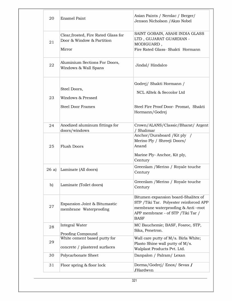
321
20 Enamel Paint Asian Paints / Nerolac / Berger/
Jenson Nicholson /Akzo Nobel
21
Clear,frosted, Fire Rated Glass for
Door & Window & Partition
Mirror
SAINT GOBAIN, ASAHI INDIA GLASS
LTD , GUJARAT GUARDIAN -
MODIGUARD ,
Fire Rated Glass- Shakti Hormann
22 Aluminium Sections For Doors,
Windows & Wall Spans Jindal/ Hindalco
23
Steel Doors,
Windows & Pressed
Steel Door Frames
Godrej/ Shakti Hormann /
NCL Alltek & Seccolor Ltd
Steel Fire Proof Door- Promat, Shakti
Hormann/Godrej
24 Anodized aluminum fittings for
doors/windows
Crown/ALANS/Classic/Bharat/ Argent
/ Shalimar
25 Flush Doors
Anchor/Duraboard /Kit ply /
Merino Ply / Shreeji Doors/
Anand
Marine Ply- Anchor, Kit ply,
Century
26 a) Laminate (All doors) Greenlam /Merino / Royale touche
Century
b) Laminate (Toilet doors) Greenlam /Merino / Royale touche
Century
27 Expansion Joint & Bitumastic
membrane Waterproofing
Bitumen expansion board-Shalitex of
STP /Tiki Tar. Polyester reinforced APP
membrane waterproofing & Anti –root
APP membrane - of STP /Tiki Tar /
BASF
28 Integral Water
Proofing Compound
MC Bauchemie; BASF, Fosroc, STP,
Sika, Penetron.
29 White cement based putty for
concrete / plastered surfaces
Wall care putty of M/s. Birla White;
Plasto Shine wall putty of M/s.
Walplast Products Pvt. Ltd.
30 Polycarbonate Sheet Danpalon / Palram/ Lexan
31 Floor spring & floor lock Dorma/Godrej/ Enox/ Sevax /
/Hardwyn

322
32 Door / Carpentry hardware Dorma/Godrej/ Ebco/Hettich /Hafele
33 Water Proof cement paint Snowcem/Asian Paints/Berger
34 Mineral Fiber Ceiling Armstrong/UGG Boral
35 Welding Rods ADOR/ Esab/ D& H welding
36 Fastner HILTI INDIA , FISCHER(BOSCH) ,
POWERS INDIA
37 Ready mix plaster Ultratech / Sound Buildcare
Pvt.Ltd./M/s Wall Plast products
38 AAC block Ultratech-Xtralite / Aerocon/ Siporex
39 Cement particle board NCL Industries Ltd.
40 Vitrified Tiles RAK / KAJARIA/ Restile/H.R.Jhonson
(I) /Nitco /Somany
41 Structural Glazing
a) Aluminium Section Jindal / Hindalco / Nalco/Vedanta
b) AIuminium Section finishes anodised
c) D.G.U. Glass , Fire Rated Glass
SAINT GOBAIN,GUJARAT GUARDIAN -
MODIGUARD , ASAHI INDIA GLASS
LTD
d) S.G.U. Glass SAINT GOBAIN,GUJARAT GUARDIAN -
MODIGUARD , ASAHI INDIA GLASS
LTD
e) A.C.P.
ALUCOBOND,
ALUDECORE,ALTOBOND
42 Architextural Expansion Joint
Sanfield – Floor to Floor – SAPX
Wall to Wall – SCTR
Terrace – SRFL
External wall to wall – Metazeal
Kantaflex – Floor to Floor – DA6
Wall to Wall – CM6
43 False Flooring Unifloor /Flexi Access Floor/
Armstrong
44 Wooden Laminated Flooring Pergo/Tiles/ Xylos,/Armstrong/Vista.

323
45 Commercial Plywood, Marine Plywood
& Prelaminated Particle Board Century/Green/Kit ply/ Anchor
46 Veneer Century / Durian,/ Timex/ANCHOR
47 Drawer Sliding Fittings Earl Bihari (EBCO)/ Godrej/ Hettich
48 Acrylic Sheets Sanmati Acrylics/Acrylic Sheet India/
Acry Plus
49 Vertical/Roller blinds Vista/MAC/DACK
50 Bitumen STP, TIKITAR, IWL
51 Pest Control PCI, PECOPP, GODREJ HI-CARE
52 Plaster of Paris KHATRI INDIA, GYPROC CHAMPION
PUTTY -SAINT GOBAIN GYPROC
53 Polyester triangular fibre -
Polyproplylene Fibres / Glass Fibres
Polyproplylene Fibres -RELIANCE -
RECRON 3S & Glass Fibres- OWENS
CORNING INDIA- CEM-FIL
54 Crystalline Waterproofing Liquid XYPEX INDIA, EVERCRETE INDIA ,
KRYTON INDIA
55 Compact Cubicle Partition Merino, Greenlam
56 Waterproofing System - Penetrative
Primer DR. FIXIT -PIDILITE ; MAPEI INDIA
57 APP Waterproofing Membrane STP, TIKI TAR , IWL; Carlisle
58 Adhesive for Granite Stone Joinery ARALDITE (STANDARD TYPE) -
HUNTSMAN ADVANCED MATERIAL
59 Glass Wool UP TWIGA , LLOYD INSULATION
,ISOVER -SAINT GOBAIN
60 PU Coating on Veneer MRF CORP, ICA ,ASIAN PAINTS
61
False ceiling -Gypsum Board &
Moisture Resistant Gypsum Board
;Mineral Fibre Board, wood ; Grid
Ceiling
SAINT GOBAIN GYPROC INDIA ; USG
BORAL INDIA; AMSTRONG

324
62 Mirror SAINT GOBAIN,GUJARAT GUARDIAN -
MODIGUARD , ASAHI INDIA GLASS
LTD
63 Adhesive for Wood, Laminate MARINE FEVICOL-PIDILITE MAKE;
EURO - JYOTI RESINS & ADHESIVE
64 Adhesive for PVC Laminate MARINE FEVICOL-PIDILITE MAKE;
SUPER BOND
65 Silicone Based Clear Water Repellant
coating
MONOPOL 333 OF KRISHNA
CONCHEM , TECHREPEL -CHOKSEY
,DULUX WEATHERSHIELD CLEAR -
AKZO NOBEL
66 Elastomeric Exterior Paint DR FIXIT RAIN COAT OF PIDILITE
MAKE , CLEAR SEAL -APURVA MAKE
67 Epoxy Resin Old To New Bonding
Agent
KRISHNA CONCHEM , SUNANDA ,
SIKA
68 Reinforcement Rust Preventive
Coating
KRISHNA CONCHEM, SUNANDA ,
CHOKSEY CHEMICALS
69 Rubber Flooring NORA MAKE -DEALER IN INDIA ZEN
EQUIP INDIA; RESPONSIVE
INDUSTRIES; EBACO INDIA
70 Non Metallic Hardner Sika, Fosroc, BASF
71 Dry Cladding (Porcelain)
TECHLAM-CLASSIC MARBLE CO.;
H.R. JOHNSON ; KALE OR
EQUIVALENT AS APPROVED BY
ARCHITECT.
72 Structural Silicon Sealant DOWCORNING,GE-MOMENTIVE
PERFORMANCE MATERIALS INDIA,
WACKER INDIA
73 Aluminium Facade Sun Louvers
System
HUNTER DOUGLAS; CONSTRUCTION
SPECIALTIES
74 Concrete Interlocking Paver Blocks SUPER TILES, VITCO , HINDUSTAN
BLOCK; VYARA TILES
75 Stainless Steel Kitchen Sink NIRALI -JYOTI INDIA METAL,
NEELKANTH- TROPICAL INDUSTRIES,
JAYNA SINKS

325
76 Stainless Steel Pipe For Handrailing
For Pipe-
JINDAL,ZENITHBIRLA,MUKAND;
Fabricated Pipe Handrailing- KICH
INDIA, INDIANA
77 Glass Fibre Reinforced Concrete
Chajja/ Cornice
BIRLA WHITE CEMENT -GRC
DIVISION, EVEREST COMPOSITES,
78 Soft Closing Drawer Channel HETTICH,BLUM, EBCO
79 PVC Edge Banding REHAU,PEGASUS,FIBRO
80 Aluminium /PVC Bird Net
GEETA ALUMINIUM , BALAJI SAFETY
NETS ; NETS "N" SCREENS; REACH
NETTINGS,
81 High Pressure Laminate Exterior
Panels FUNDERMAX,TIMEX,AMULYA MICA
82 Landscape Garden solutions , Green smile
83 SentryGlas Saint Gobain, DuPont
84 Stepping Stone for treads & Risers
Full body vitrified H.R. Johnson Endura Series;
85 Expansion Joint Filler Board STP-shalitex Board ; Tikitar , IWL
86 False ceiling -Calcium Silicate Board Ramco Hilux
87 Styrofill geofoam (Filler ) BASF / Owens Corning / Carlisle
88 UPVC Fins Finesta , Citadel

326
APPENDIX “B”
THEORETICAL STANDARD REQUIREMENT OF CEMENT FOR VARIOUS ITEMS OF
WORK
S.NO. BRIEF DESCRIPTION OF ITEM UNIT CEMENT
IN BAGS 1 Cement Concrete 1:5:10 Cum 2.60
2 Cement Concrete 1:4:8 Cum 3.40
3 Cement Concrete 1:3:6 Cum. 4.40*
4 Cement Concrete 1:2:4 Cum 6.40*
5 Reinforced Cement Concrete 1:2:4 Cum 6.40*
6 Reinforced Cement Concrete 1:1.5:3 Cum. 8.00*
7 Reinforced Cement Concrete 1:1:2 Cum 12.20*
* Note : For controlled concrete items like M-10, M-15, M-20, M-25 etc., the
consumption of cement will have to
be assessed by the Engr-in-Charge on the basis of design mixes approved for
individual work. 8 Brick masonry in C.M. 1:4 Cum. 1.90
9 Brick masonry in C.M. 1:6 Cum 1.25
10 Half brick masonry in C.M. 1:4 with RCC 1:2:4 stiffeners Sqm. 0.27
11 Half brick masonry in C.M. 1:4 Sqm 0.21
12.(a) R.R. Masonry in C.M. 1:6 Cum. 1.65
12.(b) C.R. Masonry in C.M. 1:6 Cum. 1.56
13. IPS Flooring (C.C. 1:2:4, finished smooth)
(a) 30mm. thick Sqm 0.23
(b) 40mm. thick (smooth/broom finish) Sqm 0.30
(c) 50mm. thick Sqm 0.36
(+) 20mm. thick skirting/dado in cm.1 :3 Sqm 0.30
14 Hardonate flooring -50mm. thick (C.C. 1:2:4, finished
smooth) Sqm. 0.41

327
15 Kota stone:
(a) Flooring (with lime mortar bedding pointed with matching
cement slurry) Sqm 0.13
S.NO. BRIEF DESCRIPTION OF ITEM UNIT CEMENT
IN BAGS
(b) Skirting with 20mm. thick C.M. 1:3 backing Sqm 0.27
(c) Coping Sqm. 0.13
16 Terrazzo tile :
(a) Flooring (with lime mortar bedding & pointed with cement
slurry). Sqm 0.18
(b) Skirting with 20mm. thick C.M. 1:3 Sqm 0.28
(c) Treads, hydraulically pressed with C.M. 1:3 bedding Sqm. 0.37
(d) Treads in one piece Sqm 0.28
(e) Risers, hydraulically pressed with C.M. 1:3 backing Sqm. 0.28
(f) Risers in one piece Sqm 0.23
17. Cast-in-situ terrazzo
(a) Flooring, 40mm. th. (28mm C.C. 1:2:4 + 12mm with marble
chips & powder) Sqm 0.26
(b) Skirting, 20mm. thick (12mm CM1:3+ 8mm marble chips with
cement & marble powder) Sqm 0.25
18. White glazed tile flooring and dado over 20mm. C.M.1 :3
bedding Sqm 0.31
19. Cement tile :
(a) flooring (lime mortar bedding). Sqm 0.18
(b) skirting with 20mm thick C.M. 1:3 Sqm 0.28
20 Plaster skirting, 20mm. thick in C.M.1 :3. Sqm 0.30
21. Cuddapah stone kitchen platform over 20mm. thick C.M.
1:4 Sqm 0.30
22 Cuddapah stone window sill over 20mm. thick C.M. 1:4 Sqm 0.27
23 Fixing hold fasts in CC 1:3:6 of size 300x100x150 mm. for
doors & windows
100
Nos 2.20

328
24. Cement Plaster in C.M. 1:4/1:5 with neeru finish
(A) Cement Mortar 1:4
(a) 12 mm. thick Sqm 0.11
S.NO. BRIEF DESCRIPTION OF ITEM UNIT CEMENT
IN BAGS
(b) 15 mm. thick Sqm 0.13
(c) 20 mm. thick. Sqm 0.17
(B) Cement Mortar 1:5
(a) 12 mm. thick Sqm 0.09
(b) 15 mm. thick Sqm 0.11
(c) 20 mm. thick Sqm 0.14
25. Cement plaster in C.M. 1:4 in two coats with neat
cement punning
a) 15 mm. thick.10mm + 5mm (for ceiling Sqm 0.18
(b) 20 mm. thick.15mm + 5mm (for internal walls Sqm 0.22
26
Cement plaster in C.M. 1:4, 20mm. thick
rough finish (for external
brick/concrete surfaces)
Sqm. 0.17
27. Sand faced plaster, 20mm. thick (12mm C.M. 1:4 + 8 mm
C.M. 1:3) Sqm 0.21
28. Rough cast plaster, 25 mm thick (12mm C.M. 1:4 + 13 mm
C.M.1 :3) Sqm 0.27
(+) (+) 10 mm wide & 18 mm thick plain or moulded cement
mortar band in CM 1:4
100
R.M 0.152
29. Cement plaster in C.M. 1:3 with water proofing
compound finished smooth with neat cement
(a) 12mm. thick Sqm 0.19
(b) 20mm. thick Sqm 0.27
30. Cement pointing in C.M. 1:3
(a) Ruled pointing (groove pointing) Sqm 0.02
(b) Raised & cut pointing Sqm 0.04

329
S.NO. BRIEF DESCRIPTION OF ITEM UNIT CEMENT
IN BAGS
31. Cement based waterproofing works (Through the agency
approved by the E.I.C)
(a) Terrace type average 115 mm. thick Sqm 0.45
(b) Basement type (Box type). Sqm 0.70
(c) Basement type (surface). Sqm 0.60
(d) In sunken floor of toilets, chajjas, parapets Sqm 0.30
(e) Brickbat coba in toilets, extra in roof terrace Cum 3.00
(f) O.H. Water tanks Sqm 0.50
(g) Expansion joints. R.M 0.50
32. Damp proof course in C.C. 1:2:4
(a) 25mm. thick Sqm 0.16
(b) 38mm. thick Sqm 0.24
33. Laying R.C.C. spun pipes in C.M. 1:1/1:2
(a) 100 mm dia. 10m 0.10
(b) 150 mm dia 10m 0.12
(c) 250 mm dia. 10m 0.18
(d) 300 mm dia 10m 0.22
(e) 450 mm dia 10m 0.48
(f) 600 mm dia 10m 0.64
34. Cement mortar 1:4 screed
(a) 20mm. thick Sqm 0.16
(b) 50mm. thick Sqm 0.38
35. Chain link fencing/barbed wire fencing - C.C. 1:2:4
pockets of 450x450x600 mm.:
(a) Angle iron posts m 0.21
(b) Cement Concrete 1:2:4 posts m 0.37
36 Kerb stone in CC 1:3:6 of size 125x375mm m. 0.21
37. Shahabad stone paving, pointed in C.M.1 :3, 15x10 mm
groove. Sqm 0.02
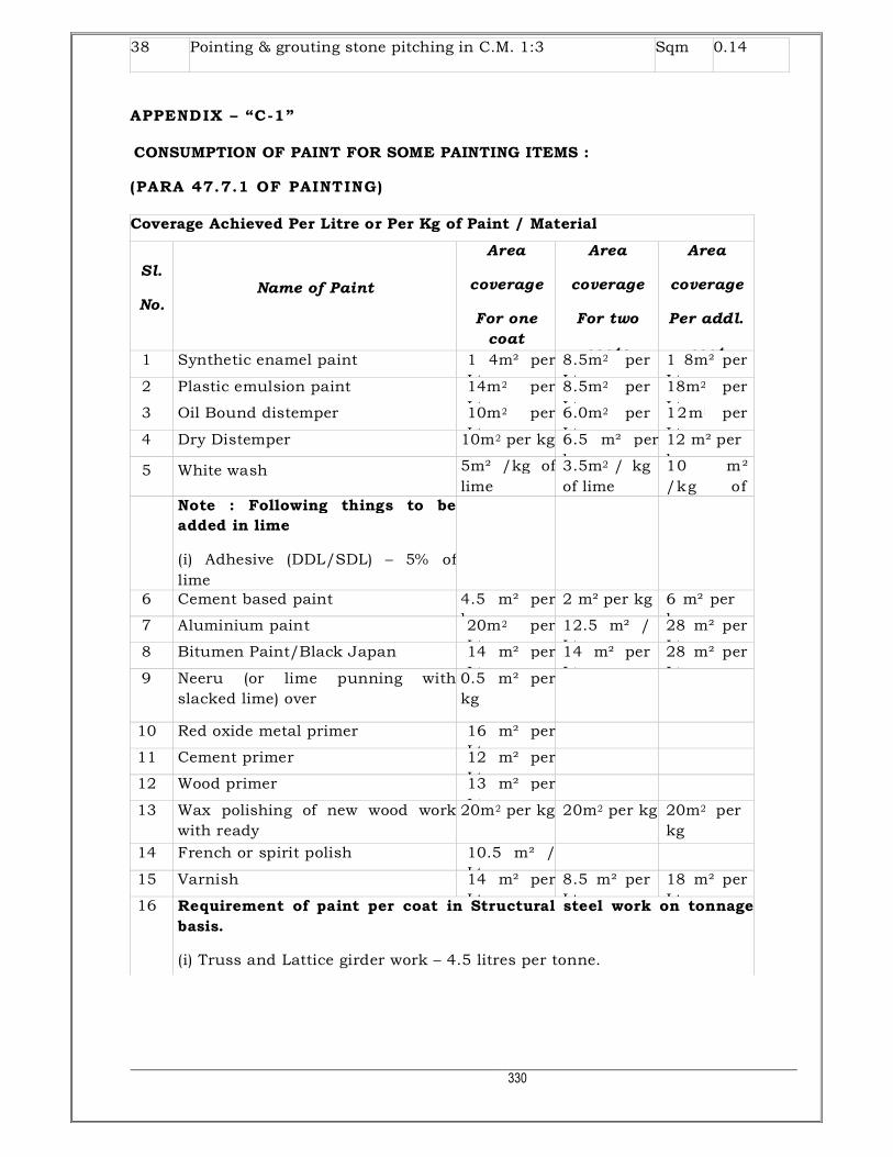
330
38 Pointing & grouting stone pitching in C.M. 1:3 Sqm 0.14
APPENDIX – “C-1”
CONSUMPTION OF PAINT FOR SOME PAINTING ITEMS :
(PARA 47.7.1 OF PAINTING)
Coverage Achieved Per Litre or Per Kg of Paint / Material
Sl.
No. Name of Paint
Area
coverage
For one
coat
Area
coverage
For two
coats
Area
coverage
Per addl.
coat 1 Synthetic enamel paint 1 4m² per
Ltr.
8.5m2 per
Ltr.
1 8m² per
Ltr. 2 Plastic emulsion paint 14m2 per
Ltr.
8.5m2 per
Ltr.
18m2 per
Ltr. 3 Oil Bound distemper 10m2 per
Ltr.
6.0m2 per
Ltr.
12m 2 per
Ltr. 4 Dry Distemper 10m2 per kg 6.5 m² per
kg
12 m² per
kg 5 White wash 5m² /kg of
lime
3.5m2 / kg
of lime
10 m²
/kg of
Note : Following things to be
added in lime
(i) Adhesive (DDL/SDL) – 5% of
lime
6 Cement based paint 4.5 m² per
kg
2 m² per kg 6 m² per
kg 7 Aluminium paint 20m2 per
Ltr.
12.5 m² /
Ltr.
28 m² per
Ltr. 8 Bitumen Paint/Black Japan 14 m² per
Ltr.
14 m² per
Ltr.
28 m² per
Ltr. 9 Neeru (or lime punning with
slacked lime) over
0.5 m² per
kg
10 Red oxide metal primer 16 m² per
Ltr.
11 Cement primer 12 m² per
Ltr.
12 Wood primer 13 m² per
Ltr.
13 Wax polishing of new wood work
with ready
20m2 per kg 20m2 per kg 20m2 per
kg
14 French or spirit polish 10.5 m² /
Ltr.
15 Varnish 14 m² per
Ltr.
8.5 m² per
Ltr.
18 m² per
Ltr. 16 Requirement of paint per coat in Structural steel work on tonnage
basis.
(i) Truss and Lattice girder work – 4.5 litres per tonne.

331
APPENDIX – “C-2”
CO-EFFICIENT FOR EQUIVALENT PLAIN AREAS FOR PAINTING ITEMS :
(PARA REFERRED TO CHAPTER 47 - PAINTING)
SN DESCRIPTION OF WORK MULTIPLYING CO-
EFFICIENTS
I. WOOD WORK : DOORS, WINDOWS ETC.
1 Panelled or framed and braced doors, windows etc.
1.30 (for each side) 2
Ledged & battened or ledged, battened & braced
doors, windows etc.
3 Flush doors etc 1 .20 (for each side)
4
Part panelled and part glazed or gauzed
doors,windows etc. 1.00 (for each side)
5 Fully glazed or gauzed doors, windows etc. 0.80 (for each side)
6 Fully venetioned or louvered doors, windows etc. 1.80 (for each side)
7 Trellis (or Jaffri) work one way or two way.
2.00 (for painting all
over)
8 Carved or enriched work: 2.00 (for each side)
9 Weather boarding: 1.20 (for each side)
10 Wood shingle roofing: 1.10 (for each side)
11 Boarding with cover fillets and match boarding. 1.05 (for each side)
12 Tile and slate battening:
0.80 (for painting all
over)
II. STEEL WORK: DOORS, WINDOWS ETC.
13 Plain sheeted steel door or windows: 1.10 (for each side)
14 Fully glazed or gauzed steel doors and windows 0.50 (for each side)
15
Partly panelled and partly gauzed or glazed doors and
windows. 0.80 (for each side)
16 Corrugated sheeted steel doors or windows. 1.25 (for each side)
17 Collapsible gates
1.50 (for painting all
over)
18 Rolling shutters of inter locked laths. 1.10 (for each side)
III. GENERAL WORKS :

332
19 Expanded metal, hard drawn
steel wire fabric of approved
quality,
grill work and gratings in guard bars,
balusters, railings,
partitions
and m.s. bars in window frames.
1.00 (for painting all
over)
20 Open palisade fencing and gates including standards,
braces, rails,
stays etc. in timber or steel.
1.00 (for painting all
over)
NOTE: The height shall be taken from the bottom of the lowest rail, if the
palisades do not go below it (or
from the lower end of palisades, if they project below the lowest rail) upto the top
of palisades but not upto
the top of standards, if they are higher than the palisades.
SN DESCRIPTION OF WORK MULTIPLYING CO-
EFFICIENTS
21 Corrugated iron sheeting in roofs, side cladding etc. 1.14 (for each side)
22 A.C. Corrugated sheeting in roofs, side cladding etc. 1.20 (for each side)
23 A.C. Semi-corrugated sheeting in roofs, side cladding
etc. or Nainital
pattern using plain sheets.
1.10 (for each side)
24 Wire gauze shutters including painting of wire gauze. 1 .00 (for each side).
* * *

333
APPENDIX – “D”
PROFORMA FOR GUARANTEE TO BE EXECUTED BY CONTRACTORS FOR
STABILITY OF PILE FOUNDATION SYSTEM AGAINST RISK OF SETTLEMENT &
OTHER TYPE OF DISTRESS TO THE BUILDING(S).
(PARA 7.7 OF PILE FOUNDATION)
This Agreement made this …………………………. day of Two thousand …….……………………………… between M/s.
…………………..……………………………………………….. (hereinafter called the Guarantor of the one part) and the
MAZAGON DOCK SHIPBUILDERS LIMITED (hereinafter called the Employer of the other part).
Whereas this Agreement is supplementary to a contract (hereinafter called the
Contract) dated………… and made between the Guarantor of the one part and the
Employer of the other part whereby the contractor interalia undertook to render the
damages caused to the buildings and structure to the satisfaction of the E.I.C.
AND WHEREAS THE GUARANTOR agreed to give a guarantee for the stability
of pile foundation system against the risk of settlement and against all damages
caused to the buildings erected on pile foundation system for a period of five (5) years
from the certified date of completion.
NOW THE GUARANTOR hereby guarantees that the stability of the pile
foundation system provided by him will render the structures completely free from
settlement and any other type of distress for a period of five (5) years to be reckoned
from the certified date of completion of the work.
During this period of guarantee, if the Guarantor fails to execute necessary
rendering work due to damages/distress caused to the buildings and structures for
settlement of pile foundation system or commits breach thereunder, then the
Guarantor will indemnify the principal and successors against all loss, damage, cost,
expense or otherwise which may be incurred by the Employer by reason of any
default on the part of the GUARANTOR in performance and observance of this
supplementary agreement. As to the amount of loss and/or damage and/or cost
incurred by the Employer, the decision of the Engineer-in-charge shall be final and
binding on the contractors.
IN WITNESS WHEREOF these presents have been executed by the
Obligator………………………… ………………………………………………….. and
by………………………...……………………..and for and on behalf of the MAZAGON DOCK
SHIPBUILDERS LIMITED, Bombay on the day, month and year first above written.

334
SIGNED, sealed and delivered by (OBLIGATOR) in the presence of :
(1)
(2)
SIGNED FOR AND ON BEHALF OF THE MDL
BY…………………………………………………………….in the presence of :
(1)
(2)
APPENDIX – “E”
Contact details for Expansion Joint & Underdeck Insulation
Sr. No. Description
01 Underdeck Insulation – BASF
Contact Person
Name
Mr. Merlin Nadar Mr. Koushal Pandey
Contact No 022 28580290
Mobile +91 97690 61417 91 98333 53984
Email id [email protected] [email protected]
Office address BASF India Limited, Plot no. 37, Chandivali farm Road,
Chandivali, Andheri (East) Mumbai- 400 072
02 Expansion Joint - Sanfield
Contact Person
Name
Kapil Rajwani
Contact No 022-26280467/468
Mobile 9820421502
Email id [email protected]
Office address 501, Eva Andheri CHS, plot
no.10,

335
V.P. road, S.V.Road,
Near Shree Ram Road,
Andheri (W), Mumbai-58
Head Office 13-A, D-sector, Industrial
Area,
Govindpura, Bhopal- 462
023
Contact No 0755-4233535/ 4271571,
4284320
APPENDIX – “F”
6 Special conditions for steel 1) The contractor shall procure TMT bars of Fe415/Fe415D/Fe500D/Fe550/Fe550D
grade (the grade to procured is to be specified) from primary steel producers such as
SAIL, Tata Steel Ltd., RINL, Jindal Steel & Power Ltd.; Essar and JSW Steel Ltd.
a) The grade of the steel such as Fe415/Fe415D/Fe500/Fe500D/Fe550/Fe550D or
other grade to be procured is to be specified as per BIS 1786-2008.
2) The contractor shall have to obtain and furnish test certificates to the Engineer-in-
Charge in respect of all supplies of steel brought by him to the site of work.
3) Samples shall also be taken and got tested by the Engineer-in-Charge as per the
provisions in this regard in relevant BIS codes. In case the test results indicate that
the steel arranged by the contractor does not conform to the specifications defined
under para (1)(d) & (1)(e) above, the same shall stand rejected, and it shall be removed
from the site of work by the contractor at his cost within a week time or written orders
from the Engineer-in-Charge to do so.
4) The steel reinforcement bars shall be brought to the site in bulk supply of 10 tonnes or
more, or as decided by the Engineer-in-Charge.
5) The steel reinforcement bars shall be stored by the contractor at site of work in such a
way as to prevent their distortion and corrosion, and nothing extra shall be paid on
this account. Bars of different sizes and lengths shall be stored separately to facilitate
easy counting and checking.
6) For checking nominal mass, tensile strength, bend test, re-bend test etc. specimens of
sufficient length shall be cut from each size of the bar at random, and at frequency
not less than that specified below:

336
Size of bar For consignment below
100 tonnes
For consignment above
100 tonnes
Under 10mm dia bars One sample for each 25
tonnes or part thereof
One sample for each 40
tonnes or part there of
10mm to 16mm dia bars One sample for each 35
tonnes or part thereof
One sample for each 45
tonnes or part there of
Over 16mm dia bars One sample for each 45
tonnes or part thereof
One sample for each 50
tonnes or part there of
7) The contractor shall supply free of charge the steel required for testing including its
transportation to testing laboratories. The cost of tests shall be borne by the
contractor.
8) The actual issue and consumption of steel on work shall be regulated and proper
accounts maintained as provided in clause of the contract. The theoretical
consumption of steel shall be worked out as per procedure prescribed in clause of the
contract and shall be governed by conditions laid therein. In case the consumption is
less than theoretical consumption including permissible no adjustment need to be
made.
Note:-
If the Contractor wishes to suggest minor improvements/changes in the
technical parameters without changing the major Contract technical
specification, then the same need to be informed to the Consultant and Client
for consideration with proper justification. However the Consultant’s and
Client’s decision will be full and final and binding on the Contractor.

337
II
PLUMBING WORK
TECHNICAL
SPECIFICATION

338
II - PLUMBING WORK TECHNICAL SPECIFICATION
INDEX
SR.
NO. TITLE PAGE NO.
1.0 GENERAL 340
2.0 APPLICABLE CODES & STANDARDS 340
3.0 QUALITY ASSURANCE & QUALITY CONTROL 341
4.0 SANITARY FIXTURES & C.P. FITTINGS 342
4.1 SCOPE 342
4.2 GENERAL REQUIREMENTS 342
4.3 EUROPEAN W.C. 342
4.4 KITCHEN / PANTRY SINKS 343
4.5 WASH BASINS 343
4.6 HOSE BIBB’S 343
4.7 URINALS 344
4.8 BATH TUB 344
4.9 MEASUREMENTS 344
5.0 WATER SUPPLY 345
5.1 SCOPE 345
5.2 GENERAL REQUIREMENTS 345
5.3 INTERNAL WORKS 346
5.4 EXTERNAL WORKS 350
5.5 VALVES 354
5.6 CHLORINATION OF DOMESTIC WATER LINES 356
5.7 CPVC PIPE & FITTINGS 357
5.8 COMPOSITE PIPE & FITTINGS 359
5.9 COPPER PIPES & FITTINGS 362
5.10 ASTM PVC PIPE & FITTINGS 362
5.11 PIPE HANDLING & STORAGE 364

339
INDEX
SR.
NO. TITLE PAGE NO.
5.12 LAYING & JOINTING 364
5.13 TESTING 366
6.0 INTERNAL DRAINAGE (SOIL, WASTE, VENT & RAIN WATER PIPES) 366
6.1 SCOPE 366
6.2 GENERAL REQUIREMENTS 367
6.3 CAST IRON PIPES & FITTINGS 367
6.4 SWR UPVC PIPES & FITTINGS 371
6.5 TRAPS 372
6.6 FLOOR TRAP INLET 372
6.7 C.P. / STAINLESS STEEL GRATING 372
6.8 CLEANOUT PLUGS 372
6.9 PIPE SLEEVES 372
7.0 EXTERNAL DRAINAGE SYSTEM (SEWERAGE & STORM WATER) 373
7.1 SCOPE 373
7.2 GENERAL REQUIREMENTS 373
7.3 TRENCHES FOR PIPE & DRAINAGE 373
7.4 RCC PIPES 375
7.5 STONE WARE PIPE 377
7.6 SEWER MANHOLES WITH FRAME AND COVER 382
7.7 DROP CONNECTIONS 386
8.0 LIST OF APPROVED MAKES 388

340
II- GENERAL TECHNICAL SPECIFICATION FOR PLUMBING WORK 1.0 GENERAL: 1.1 The work shall be carried out in the accordance with the drawings and design as
would be issued to the Contractor by the Design Consultant duly signed and stamped by him. The Contractor shall not take cognizance of any drawings, designs, specifications etc. not bearing Design Consultant signature and stamp. Similarly the Contractor shall not take cognizance of instructions given by any other Authority except the instructions given by the Client’s Representative in writing.
1.2 The work shall be executed and measured as per metric dimensions given in the
Bill of Quantities, drawings etc. 1.3 The Contractor shall acquaint himself fully with the partial provisions for supports
that may or may not be available in the structure and if are available then utilize them to the extent possible. In any case the Contractor shall provide all the supports regardless of provisions that they have been already made. Nothing extra shall be payable for situations where insert plates (for supports) are not available or are not useful.
1.4 Shop coats of paint that may be damaged during shipment or erection shall be
cleaned off with mineral spirits, wire brushed and spot primed over the affected areas, then coated with paint to match the finish over the adjoining shop painted surface.
1.5 The Contractor shall protect / handle the material carefully and if any damage
occurs while handling by the Contractor then the sole responsibility shall be of the Contractor. Such damages shall be rectified/recovered by the Contractor at no extra cost whatsoever.
1.6 The Contractor shall, within twenty one (21) days of receipt of the Notice of Award
for the Project, where applicable, complete the submission of shop drawings to the Client’s Representative for approval by the Design Consultants in order to conform to the contract schedule.
1.7 MEASUREMENTS: All measurements shall be taken in accordance with relevant IS codes, unless
otherwise specified.
2.0 APPLICABLE CODES AND STANDARDS:
All equipment, supply, erection, testing and commissioning shall comply with the requirements of Indian Standards and code of practice given below as amended up to the date of submission of Tender. All equipment and material being supplied shall meet the requirements of BIS and other relevant standard and codes.
Plumbing Works:
Vitreous Chinaware - IS: 2556 - 1974 (Part - I)
- IS: 2556 - 1981 (Part - II)
- IS: 2556 - 2556 (Part - III)
Ball Valve - IS: 1703 - 1977
Cistern Brackets - IS: 775 - 1970

341
Toilet Seat Cover - IS: 2548 - 1983
Vitreous China Cistern - IS: 2326 - 1987
Sand Cast Iron Pipes and Fittings - IS: 1729 - 1979
Spun Cast Iron Pipes and Fittings - IS: 3989 - 1984
GI Pipes - IS: 1239 - 1979
Galvanizing for GI Pipes - IS: 4736 - 1986
Pipe Threads - IS: 554 - 1985
Milleable Iron Fittings - IS: 1879 - 1987
Cast Iron Sluice Valves - IS: 780 - 1984
Full Way Valves - IS: 778 - 1984
Brass Ferrule - IS: 2692 - 1978
Stone Ware Gully Trap - IS: 651 - 1980
RCC Pipes - IS: 458 - 1971
Cast Iron Class LA Pipes - IS: 1536 - 1989
Cast (Spun) Iron Fittings - IS: 1538 - 1976
Pig Lead - IS: 782 - 1966
Induction Motors - IS: 4691
Code for Measurements - IS: 1200
UPVC Pipes and Fittings - IS: 4984
Specification for Caulking Lead - IS: 782
Code of Practice for laying of concrete - IS: 783
3.0 QUALITY ASSURANCE AND QUALITY CONTROL: 3.1 The work shall conform to high standard of design and workmanship, shall be
structurally sound and aesthetically pleasing. Quality standards prescribed shall form the backbone for the quality assurance and quality control system.
3.2 At the site, the Contractor shall arrange the materials and their stacking/ storage
in appropriate manner to ensure the quality. Contractor shall provide equipment and manpower to test continuously the quality of material, assemblies etc. as directed by the Client’s Representative. The test shall be conducted continuously and the result of tests maintained. In addition the Contractor shall keep appropriate tools and equipment for checking alignments, levels, slopes and evenness of surface.
3.3 The Client’s Representative shall be free to carry out such tests as may be decided
by him at this sole direction, from time to time, in addition to those specified in this Document. The Contractor shall provide the samples and labour for collecting the samples. Nothing extra shall be payable to the Contractor for samples or for the collection of the samples.
3.4 The test shall be conducted at Standard Laboratory selected by Client’s
Representative. Contractor shall keep the necessary testing equipment such as hydraulic testing machine, smoke testing machine, gauges and other necessary equipment required.
3.5 The Client’s Representative shall transport the samples to the laboratory.

342
3.6 Testing charges shall be borne by the Client’s Representative. 3.7 Testing may be witnessed by the Contractor or his Authorised Representative.
Whether witnessed by the Contractor or not, the test results shall be binding on the Contractor.
4.0 SANITARY FIXTURES & C.P. FITTINGS:
4.1 SCOPE 4.1.1 Work under this section shall consist of transportation, furnishing, installation,
testing and commissioning and all labour as necessary as required to completely install all sanitary fixtures, brass and chromium plated fittings and accessories as required by the drawings and specified hereinafter or given in the Bill of Quantities.
4.2 GENERAL REQUIREMENTS 4.2.1 All fixtures and fittings shall be fixed with all such accessories as are required to
complete the item in working condition whether specifically mentioned or not in the Bill of Quantities, specifications, drawings or not.
4.2.2 All fixtures and accessories shall be fixed in accordance with a set pattern
matching the tiles or interior finish as per architectural design requirements. Wherever necessary the fittings shall be centered to dimensions and pattern desired.
4.2.3 Fixing screws shall be half round head chromium plated brass with C.P. washers
wherever required as per directions of Client’s Representative. 4.2.4 All fittings and fixtures shall be fixed in a neat workmanlike manner true to levels
and heights shows on the drawings & in accordance with the manufacturer’s recommendations. Care shall be taken to fix all inlet and outlet pipes at correct positions. Faulty locations shall be made good and any damage to the finished floor, wall or ceiling surfaces shall be made good at Contractors cost.
4.2.5 All fixtures of the similar materials shall be by the same manufacturers. 4.2.6 All fitting shall be of the chromium plated materials. 4.2.7 Without restricting to the generally of the foregoing the sanitary fixtures shall
include all sanitary fixtures, C.P. fittings and accessories etc. necessary and required for the building.
4.7.8 Whether specifically mentioned or not all fixtures and appliances shall be provided
with approved fixing devices, nuts, bolts, screws, and hangers as required. These supports shall have the necessary adjustment to allow for irregularities in the building area construction.
4.7.9 For the installation of the CP fittings, Teflon tape shall be used.
4.3 EUROPEAN W.C. 4.3.1 European W.C. of glazed vitreous china shall be wash down, single or double
symphonic type, floor or wall mounted set, flushed by means of flush valve as specified in Bill of Quantities. Flush pipe / bend shall be connected to the W.C. by means of suitable rubber adopter. Wall hung W.C. shall be supported by C.I. floor

343
mounted chair. 4.3.2 Each W.C. seat cover shall be so fixed that it remains absolutely stationary in
vertical position without falling down on the W.C. Seat cover shall be of white solid plastic, elongated open front with heavy duty hinges. Exposed fixture trims shall be Chrome plated, and trims of similar function shall be by the same manufacturer.
4.3.3 Flush valves shall be of the best approved quality procurable with C.P. control
valve and C.P. flush pipe. 4.3.4 The flush pipe/bend shall be connected to the WC by means of a suitable rubber
adopter. 4.3.5 Alternatively if flushing cistern to be used shall conform to the requirements of IS:
774-1971. High level cisterns shall be of cast iron unless otherwise specified. Low level cistern shall be of the same material as the water closet or as instructed by the Owner/Architect/ Consultant. The cisterns shall be mosquito proof & shall fulfill the requirements of the local Authority.
4.3.6 The levels of the WC should be checked by placing sprit level on the W.C. W.C.
should be tested on completion of fixing by putting small paper balls and flushing out. If all the paper balls are not flushed out. The fixing will have to be rectified / re-aligned.
4.4 KITCHEN / PANTRY SINKS 4.4.1 Sinks shall be of stainless steel material as specified in the Bill of
Quantities/Drawings. 4.4.2 Each sink shall be provided with R. S. brackets and clips and securely fixed.
Counter top sinks shall be fixed with suitable angle iron clips or brackets as recommended by the manufacturer. Each sink shall be provided with 40 mm dia Chromium Plated waste with chain and plug or P.V.C. waste with Escutcheon plates. Fixing shall be done as directed by Client’s Representative.
4.4.3 Supply fittings for sinks shall be mixing fittings or C.P. taps, angle cocks etc. all as
specified in the Bill of Quantities/Drawings. 4.5 WASH BASINS 4.5.1 Wash basin shall be of white vitreous china of best quality manufactured by an
approved firm and sizes as specified in the Bill of Quantities. 4.5.2 Wash basin shall be of under counter drop in type shall be supported on a pair of
rolled steel brackets of approved design and shall be mounted on a countertop. So that rim and basin bowl is exposed from top.
4.5.3 Wash basin shall be provided with single lever mixer with chain and rubber plug,
chromium plated brass bottle trap of approved quality, design and make where hot water required. Single tap where hot water is not required.
4.5.4 Wash basin shall be fixed at proper location and height and truly horizontal as
shown on drawing or as directed by Client’s Representative. 4.6 HOSE BIBB’S

344
4.6.1 Hose Bib of Chromium Plate tap is draw off tap with horizontal inlet and free outlet knurling on outer face to fix the hose pipe. Hose bib shall be of specified size and shall be of screw down type and shall conform to IS: 781-1984. The closing device shall work by means of a disc carrying a renewable non-metallic washer which shuts against the water pressure on a seating at right angle to the axis of the threaded spindle which operate it. The handle shall be either crutch or butterfly type securely
4.7 URINALS Half stall wall hung urinals of glazed vitreous china shall be provided with 15mm
dia, C.P. brass spreader, 32mm dia C.P. domical waste and C.P. cast brass bottle trap with pipe and wall flange and shall fixed to wall by one C.I. bracket and two C.I. clips as recommended by manufacturers complete as directed by the Client’s Representative.
Urinals shall be flushed by means of “NO-TOUCH” infrared operated flush valves. Waste pipes for urinals shall be any one of the given material as directed by the
Client’s Representative:
a) G.I. Pipes b) Rigid PVC/High density polyethylene.
Waste pipes may be exposed on wall or concealed in chase as directed by the
Client’s Representative. 4.8 BATH TUB Bath tub & panel shall be white enameled cast iron or pressed steel as specified in
the Bill of Quantities of guaranteed quality and specifications. Each bath tub shall be provided with 40mm dia CP brass waste with 32mm C.P.
brass overflow, 40mm dia cast brass overflow-cum-waste trap with pop-up waste assembly.
Bath tub shall be provided with four Nos. C.P. brass concealed stop cocks, bath
spout and overhead shower or as specified in the Bill of Quantities. Bath tubs shall be fixed true to level firmly fixed to another or supports provided by
the manufacturer. Edges touching the wall shall be slightly recessed in the wall finishing so as ensuring water tightness. The fixing shall be perfectly done so that the wall behind does not tend to get damp or patchy.
Contractor shall during the entire period of installation and afterwards protect the
bathtub by providing suitable cover or any other protection so as to absolutely prevent any damage to the bathtub until handing over.
4.9 MEASUREMENTS 4.9.1 Rate for providing and fixing of sanitary fixtures, accessories, urinal partitions
shall include all items and operations stated in the respective specifications and Bill of Quantities, and nothing extra is payable.
4.9.2 Rates for all items under specifications para above shall be inclusive of cutting
holes and chases and making good the same, C.P. screws, nuts, bolts and any fixing arrangement required.

345
5.0 WATER SUPPLY:
5.1 SCOPE 5.1.1 Work under this section consists of furnishing all labour, materials equipment and
appliances necessary and required to completely install the water supply system as required by the drawings, specified hereinafter and given in the bill of quantities.
5.1.2 Without restricting to the generality of the foregoing, the water supply system shall
include the following:-
i. Pipe protection & painting. ii. Connections to all plumbing fixtures, tanks, pump etc. iii. Providing hot water pipe lines and supply point with isolation valves, wherever
required. iv. Control valves, masonry chambers and other appurtenances. v. Connections to all plumbing fixtures, tanks and appliances. vi. Excavation and refilling of pipe trenches, wherever necessary. vii. Internal galvanized water supply piping inside the toilets shaft/plant
room/terrace. viii.Testing all line and fixtures as specified.
5.2 GENERAL REQUIREMENTS: 5.2.1 All materials shall be new of the best quality and shall be furnished, delivered,
erected, connected and finished in every detail conforming to specifications and subject to the approval of Client’s Representative.
5.2.2 Pipes and fittings shall be fixed truly vertical, horizontal or in slopes as required in
a neat workmanlike manner. 5.2.3 Short or long bends shall be used on all main pipe lines as far as possible. Use of
elbows shall be restricted for short connections. As far as possible all bends shall be formed by means of hydraulic pipe bending
machine for pipes up to 65mm dia. 5.2.4 Pipes shall be fixed in a manner as to provide easy accessibility for repair and
maintenance and shall not cause obstruction in shafts, passages etc. and shall be selected and arranged so as to fit properly into the allocated building space.
5.2.5 Pipes shall be securely fixed to walls by suitable clamps at intervals specified. 5.2.6 Valves and other appurtenances shall be located to provide easy accessibility for
operation, maintenance and repairs. 5.2.7 Connection between dissimilar materials. 5.2.8 All G.I. pipes jointing shall be with white lead and spun yarn. 5.2.9 Drawings illustrating block out and penetration of pipes in the wall/floor/slab.

346
5.2.10 UNIONS: Contractor shall provide adequate no. of unions on all pipes to enable dismantling
later and for servicing. Union shall be provided near each gunmetal valve. 5.3 INTERNAL WORKS 5.3.1 MATERIALS: 5.3.1.1 G.I. PIPES
i. The pipes shall be galvanised mild steel threaded pipes conforming to the requirement of IS: 1239 Part-I for heavy grade upto 150mm dia and IS: 3589 for pipes above 150mm dia. They shall be of the dia (nominal bore) specified in the description of the item. Galvanising shall confirm to IS: 4736.
ii. The pipes shall be clearly finished, well galvanised in and out and free from
cracks, surface flow, laminations and other defects. All screw threads shall be clean and well cut. The ends shall be cut cleanly and square with axis of the tube.
iii. All screw tubes shall have pipe threads conforming to the requirements of IS:
544-1955 (or revised). 5.3.1.2 G.I. FITTINGS
i. All fittings shall be conforming to IS: 1239 Part II (or as revised). All fittings
shall have manufacturer's trade mark stamped on it. Fittings in G.I. pipe lines shall include elbows, tees, bends, reducers, nipples, union, G.I. Clamps / Steel structural supports of approved design, nuts, bolts, washers, etc. All fittings shall be tested at manufacturer's works. Contractors may be required to produce certificate to this effect from the manufacturers.
ii. The fittings shall have screw threads at the ends conforming to the
requirements of IS: 544-1955 (or revised). Female threads on fittings shall be parallel and male threads (except on running nipples and collars of unions) shall be tapered.
5.3.1.3 CUTTING AND JOINTING:
i) The pipes and fittings shall be inspected at site before use to ascertain that they conform the specification given in para no. 5.3.1.1 above. The defective pipes shall be rejected. Where the pipes have to be cut or re-threaded, the ends shall be carefully filled out so that no obstruction to bore is offered. The end of the pipes shall then be threaded conforming to the requirements of IS: 544-1955 with pipe dies and taps carefully is such a manner as will not result in slackness of joints when the two pieces are screwed together. The taps and dies shall be used only for straightening screw threads which have become bend or damaged and shall not be used for turning of the threads so as to make them slack, as the later procedure may not result in water tight joint.
ii) The screw threads of pipes and fittings shall be protected from damage until
they are fitted.
iii) The pipes shall be cleaned and cleared of all foreign matter before being laid. In jointing the pipes, the inside of the socket and the screwed end of the pipes shall be oiled and rubbed over with white lead and a few turns of spun yarn
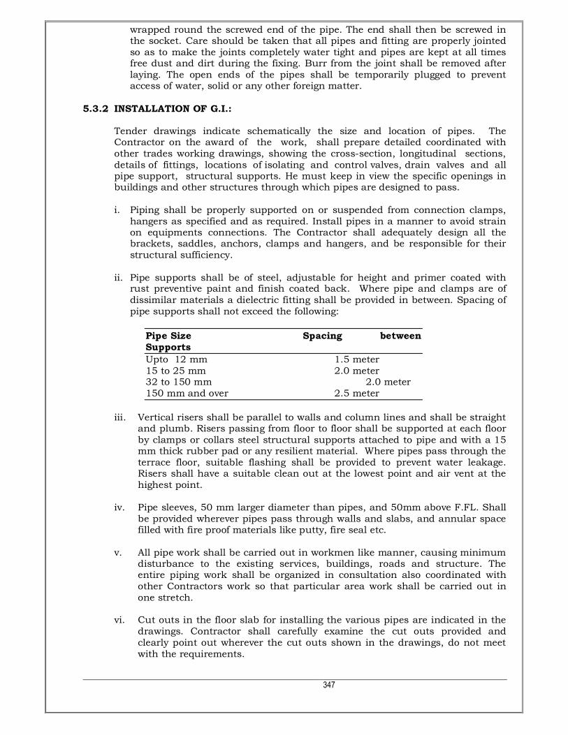
347
wrapped round the screwed end of the pipe. The end shall then be screwed in the socket. Care should be taken that all pipes and fitting are properly jointed so as to make the joints completely water tight and pipes are kept at all times free dust and dirt during the fixing. Burr from the joint shall be removed after laying. The open ends of the pipes shall be temporarily plugged to prevent access of water, solid or any other foreign matter.
5.3.2 INSTALLATION OF G.I.: Tender drawings indicate schematically the size and location of pipes. The
Contractor on the award of the work, shall prepare detailed coordinated with other trades working drawings, showing the cross-section, longitudinal sections, details of fittings, locations of isolating and control valves, drain valves and all pipe support, structural supports. He must keep in view the specific openings in buildings and other structures through which pipes are designed to pass.
i. Piping shall be properly supported on or suspended from connection clamps,
hangers as specified and as required. Install pipes in a manner to avoid strain on equipments connections. The Contractor shall adequately design all the brackets, saddles, anchors, clamps and hangers, and be responsible for their structural sufficiency.
ii. Pipe supports shall be of steel, adjustable for height and primer coated with
rust preventive paint and finish coated back. Where pipe and clamps are of dissimilar materials a dielectric fitting shall be provided in between. Spacing of pipe supports shall not exceed the following:
Pipe Size Spacing between Supports
Upto 12 mm 1.5 meter 15 to 25 mm 2.0 meter 32 to 150 mm 2.0 meter 150 mm and over 2.5 meter
iii. Vertical risers shall be parallel to walls and column lines and shall be straight
and plumb. Risers passing from floor to floor shall be supported at each floor by clamps or collars steel structural supports attached to pipe and with a 15 mm thick rubber pad or any resilient material. Where pipes pass through the terrace floor, suitable flashing shall be provided to prevent water leakage. Risers shall have a suitable clean out at the lowest point and air vent at the highest point.
iv. Pipe sleeves, 50 mm larger diameter than pipes, and 50mm above F.FL. Shall
be provided wherever pipes pass through walls and slabs, and annular space filled with fire proof materials like putty, fire seal etc.
v. All pipe work shall be carried out in workmen like manner, causing minimum
disturbance to the existing services, buildings, roads and structure. The entire piping work shall be organized in consultation also coordinated with other Contractors work so that particular area work shall be carried out in one stretch.
vi. Cut outs in the floor slab for installing the various pipes are indicated in the
drawings. Contractor shall carefully examine the cut outs provided and clearly point out wherever the cut outs shown in the drawings, do not meet with the requirements.

348
vii. The Contractor shall make sure that the clamps, steel structural supports, brackets, clamp saddles and hangers provided for pipe supports are adequate. Piping layout shall take due care for expansion and contraction in pipes, and include expansion joints where required.
viii. All pipes shall be accurately cut to the required sizes in accordance with
relevant BIS codes and burrs removed before laying. Open ends of the piping shall be closed as the pipe is installed to avoid entrance of foreign matter. Where reducers are to be made in horizontal runs, eccentric reducers shall be used for the piping to drain freely. In other locations, concentric reducers may be used.
ix. All buried pipes shall be cleaned and coated with zinc chromate primer and
bitumen paint, then wrapped with bitumen faced hesian. x. In case the pipe is embedded in walls or floors, it should be painted with two
coats of anti corrosive bitumastic paint of approved quality, covered with one layer of fiberglass tissue and finally painted with one coat of bitumen paint. The pipe should not come in contact with cement mortar or cement concrete as the pipe will be affected by cement. Under the floors, the pipes shall be laid in layer of filling under concrete floors.
xi. For pipes 15mm to 25mm dia, the holes in the walls and floors shall be made
by drilling with chisel or jumper and not by dismantling the brick work or concrete. However, for bigger dimension pipes the holes shall be carefully made of the smallest size as directed by the Client’s Representative. After fixing the pipes the holes shall be made good with cement mortar 1:3 (1 cement: 3 coarse sand) properly finished to match the adjacent surface.
xii. All pipes above ground shall be painted with one coat of red lead and two
coats of synthetic enamel paint of approved shade and quality. Pipes shall be painted to standard colour code/or as specified by the Client’s Representative.
xiii. Springing or forcing pipe into place will not be permitted. Protect piping at all
times from dirt and moisture. During storage at construction site, keep end plugged to prevent dirt and moisture entering.
xiv. Carefully grade all pipes to eliminate traps and pockets. Where air pockets or
water traps can not be avoided provide means of drainage with valved hose connection for water traps and valved automatic air vents for air pockets.
xv. Below grade piping shall be installed in such a manner that it does not
appear directly on ground. xvi. Any location where pipes/valves through or closed to basement walls shall be
protected from direct contact of concrete block. xvii. Pipes passing through building walls shall be protect by cast iron sleeves
large enough to permit changes size eccentric fittings shall be used except where branch pipes connect into mains and in domestic system.
5.3.3 INSULATION:
• All the Hot Water supply & Hot Water return pipe shall be insulated in the manner specified hereinafter.
• Insulating material shall be rigid performed sections of mineral/rock wool with

349
a “K” value of not more than 0.036 W/MK at 100 Deg. C mean temperature and of density 140 Kg/Cu.m
• No insulation shall be applied until the pipe is satisfactorily pressure tested.
• Pipes shall be insulated with rigid performed pipe sections of the following thickness:
Pipe Diameter (mm) Thickness (Mineral Wool) mm
80-150 50
• Pipe insulation shall be applied as follows:
• Pipe shall be thoroughly cleaned with wire brush and rendered free from all rust and grease and applied with two coats of anti-rust paint.
• Pipes in Shaft:
i) Fix rigid performed sections of insulation with adhesive between all points (transverse and circumferential).
ii) The insulation shall be tied with GI chicken wire mesh. iii) The insulation shall be provided with 24 gauge aluminium cladding screwed
at the joints with cadmium coated self tapping screws. Joints shall be overlapped minimum 12mm wide.
• Pipes exposed to weather:
i) Same as (b) (i) to (ii) ii) Provide polythene based hessian (500 gauges) overlapping 100mm on all
joints (transverse and circumferential) and stitched at the joints. iii) The hessian shall be covered with 15mm x 20mm hexagonal chicken wire
mesh. iv) Over the wire mesh the surface shall be covered with two layers of tarfelt
grade-II and type-II with bitumen between layer overlapping 100mm on all joints (transverse & circumferential).
v) Over the second layer of tarfelt final coat of hot bitumen not less than 6mm
thick shall be applied. vi) Over the final layer of tarfelt and hot bitumen coat aluminium cladding shall
be provided with 24 gauge aluminium shut screwed at the joints with cadmium coated self-tapings screws. Joints shall be overlapped minimum 25mm wide.
d) Pipes Buried Underground:
i) Rigid pipe sections of insulation shall be fixed tightly to the surface taking
care to seal all joints with 50mm wide aluminium adhesive tape (transverse and circumferential).
ii) The insulation shall be tied with aluminium band not less than 6mm width
and 24 gauge 4 bands per meter or equivalent plastic band using G.I. sheet

350
clamp crimped at the joints.
iii) Wrap the insulation with polythene sheet 400 gauges. Polythene
sheet shall be tied with 6mm, 24 gauge, aluminium band 4 bands per meter
or equivalent plastic tape using GI sheet clamp crimped at the joint.
iv) The polythene surface shall be covered with two layers of tarfelt grade – II,
type – II with bitumen between layers overlapped 100mm on all joints (transverse and
circumferential).
v) Over the second layer of tarfelt final coat of hot bitumen not less than 6mm
thick shall be applied. 5.3.4 TESTING:
After laying and jointing, the pipes and fittings shall be inspected under working condition of pressure and flow. Any joint found leaking shall be redone and all leaking pipes removed and replaced without extra cost. Use of any compound or stop leak compound will not permit.
The pipes and fittings after they are laid shall be tested to hydraulic pressure of 1.5 times the working pressure or 7.5 Kg/Sq.cm which ever is more. The pipes shall be slowly and carefully charged with water allowing all air to escape and avoiding all shock or water hammer. The draw of taps and stop cocks shall then be closed and specified hydraulic pressure shall be applied gradually. Pressure gauge must be accurate and preferably should have been recalibrated before the test. The test pump having been stopped, the test pressure should be maintained without loss for at least two hours. The pipes and fittings shall be tested in sections as the work of laying proceeds, having the joints exposed for inspection during the testing.
5.3.5 PAINTING:
The pipes shall be finally provided with synthetic enamel paint of approved quality for exposed pipes after the Hydrostatic test pressure. The cost of such painting should be included to the Contractor’s quote.
5.3.6 MEASUREMENTS: The length above ground shall be measured in running meter correct to a cm for
the finished work, which shall include G.I. pipe and G.I. fittings such as bends, tees, elbows, reducers, crosses, plugs, sockets, nipples and nuts, unions etc... Deductions for length of valves shall be made. Rate quoted shall be inclusive of all fittings, clamps, cutting holes chased and making good the same and all items mentioned in the specifications and Bill of Quantities.
5.4 EXTERNAL WORKS: 5.4.1 MATERIALS: 5.4.1.1 G.I. PIPES
i. The pipes shall be galvanised mild steel threaded pipes conforming to the

351
requirement of IS: 1239 Part-I for heavy grade upto 150mm dia and IS: 3589 for pipes above 150mm dia. They shall be of the dia (nominal bore) specified in the description of the item. Galvanising shall confirm to IS: 4736.
ii. The pipes shall be clearly finished, well galvanised in and out and free from
cracks, surface flow, laminations and other defects. All screw threads shall be clean and well cut. The ends shall be cut cleanly and square with axis of the tube.
iii. All screw tubes shall have pipe threads conforming to the requirements of IS:
544-1955 (or revised).
5.4.1.2 G.I. FITTINGS
i. All fittings shall be conforming to IS: 1239 Part II (or as revised). All fittings shall have manufacturer's trade mark stamped on it. Fittings in G.I. pipe lines shall include elbows, tees, bends, reducers, nipples, union, G.I. Clamps / Steel structural supports of approved design, nuts, bolts, washers, etc. All fittings shall be tested at manufacturer's works. Contractors may be required to produce certificate to this effect from the manufacturers.
ii. The fittings shall have screw threads at the ends conforming to the
requirements of IS: 544-1955 (or revised). Female threads on fittings shall be parallel and male threads (except on running nipples and collars of unions) shall be tapered.
iii. Contractor shall provide adequate number of unions on all pipes to enable
dismantling later. Unions shall be provided near each gunmetal valve, stop cocks, or check valves and on straight runs as necessary at appropriate locations as required and/or directed by Client’s Representative.
5.4.1.3 CUTTING AND JOINTING:
i) The pipes and fittings shall be inspected at site before use to ascertain that they conform the specification given in para no. 5.4.1.1 above. The defective pipes shall be rejected. Where the pipes have to be cut or re-threaded, the ends shall be carefully filled out so that no obstruction to bore is offered. The end of the pipes shall then be threaded conforming to the requirements of IS: 544-1955 with pipe dies and taps carefully is such a manner as will not result in slackness of joints when the two pieces are screwed together. The taps and dies shall be used only for straightening screw threads which have become bend or damaged and shall not be used for turning of the threads so as to make them slack, as the later procedure may not result in water tight joint.
ii) The screw threads of pipes and fittings shall be protected from damage until
they are fitted. iii) The pipes shall be cleaned and cleared of all foreign matter before being laid. In
jointing the pipes, the inside of the socket and the screwed end of the pipes shall be oiled and rubbed over with white lead and a few turns of spun yarn wrapped round the screwed end of the pipe. The end shall then be screwed in the socket. Care should be taken that all pipes and fitting are properly jointed so as to make the joints completely water tight and pipes are kept at all times free dust and dirt during the fixing. Burr from the joint shall be removed after laying. The open ends of the pipes shall be temporarily plugged to prevent access of water, solid or any other foreign matter.
5.4.1.4 INSTALLATION:

352
i) Trenches :
The galvanised iron pipes and fittings shall be laid in trenches. The widths and depths of the trenches for different diameters of the pipes shall be as in Table below:-
Dia of pipe Width of trench Depth of trench
15 mm to 50 mm 30 cm 60 cm 65 mm to 150 mm 45 cm 75 cm
At joints the trench width shall be widened where necessary. All G.I. / C.I. pipes below ground in trenches minimum cover over pipes shall be 60cm. Covered shall be measured from top of pipe to the surface of ground. The bed of the trench if in soft or made up earth, shall be well watered and rammed before laying the pipes and depressions if any shall be properly filled with earth and consolidated in 20cm layers.
If the trench bottom is extremely hard and rocky or loose stony soil, the trench shall be excavated at least 150mm below the trench grade. Rocks, Stone or other hard substances from the bottom of the trench brought back the required grade by filling with selected fine earth or sand and compacted so as to provide smooth bedding for the pipe. When excavation required blasting operation, it shall be ensured that no pipes have be stacked in the vicinity and completed pipe in the vicinity has already been covered before starting of blasting operations; this is necessary to prevent damage to the exposed pipe in the vicinity by falling stone as result of blasting.
After the excavation of the trench is completed, hollows shall be cut at the required position to receive the socket of the pipes and these hollows shall be of sufficient depth to ensure that the barrel of the pipes shall rest throughout their entire length on the solid ground and that sufficient spaces lift for jointing the under side of the pipe joint. These socket holes shall be refilled with sand after jointing the pipe.
Roots of tree within distance of about 0.5 meter from the side of the pipe line shall be removed or killed.
The excavated materials shall be placed within 1 meter or half of the depth of the trench, whichever is greater, from the edge of the trench. The material excavated shall be separated and stacked so that in refilling they may be re-laid and completed the same order to satisfaction of the Client’s Representative.
The filling shall be done in layers not exceeding 15mm in depth. Each layer shall be watered, rammed and consolidated. Ramming shall be done with iron rammers where possible and with blunt end of the crow brass where rammers can not be used. Special care shall be taken to ensure that no damage is caused to the pipes, drains, masonry or concrete in the trenches.
Filling in trenches shall be commenced soon after the joints of pipes, cables; conduits etc. have been tested and approved by Client’s Representative. The space around the pipes shall be cleared of all debris where the trenches are excavated in hard/soft soil. The filling shall be done with earth on the sides and tops of pipes in layers not exceeding 15mm in depth. Each layer shall be watered rammed and consolidated. The clods and lumps of earth exceeding 8cm in any direction shall be broken or removed before the excavated earth is used for filling. Generally no test

353
is done to determine the instrument diversity of filled earth but on the discretion of Client’s Representative the 95 proctor’s compaction test may be done to ensure the in situ density after filling. Consolidation is removal of water from the pores and compaction is the explosion of air from the pores. In case of refilling consolidation places most important role as the watering of the each layer is being done properly. If required by the Client’s Representative proctors needle may also be used for the proper checking of the refilling items of in situ density.
ii) Pipe Protection: For underground G.I. pipes following treatment will be given:
Coat of hot bitumen R 85/25 a) Wrapping of fiberglass tissue.
b) Coat of hot bitumen R 85/25 over fiberglass tissue.
The pipes shall be laid on a layer of 7.5 cm sand and filled upto 15 cm above the pipes. The remaining portion of the trench shall then be filled with excavated earth. The surplus earth shall be disposed off as directed.
iii) Jointing : The pipes shall be cleaned and cleared of all foreign matter before being laid. In
jointing the pipes, the inside of the socket and the screwed end of the pipes shall be oiled and rubbed over with white lead and a few turns of spun yarn wrapped around the screwed end of the pipes. The end shall then be screwed in the socket, tee etc with the pipe wrench. Care shall be taken that all pipes and fittings are properly jointed so as to make the joints completely water tight and pipes are kept at all times free from dust and dirt during fixing. Burr from the joints shall be removed after screwing. After laying, the ends of the pipes shall be temporarily plugged to prevent access of water, soil or any other foreign matter.
iv) Thrust Blocks : In case of bigger pipes (80 mm dia and above), thrust blocks of cement concrete
1:2:4 (1 cement: 2 coarse sand: 4 graded stone aggregate of 20 mm nominal size) shall be constructed on all bends as directed by the Client’s Representative.
5.4.1.5 TESTING:
i. All external water supply pipes shall be tested by hydrostatic pressure of 1.5 times the working pressure or 7.5 Kg/Sq.cm whichever is more.
ii. Pressure shall be maintained for a period of at least 180 minutes without any
drop in the pressure after fixing at site. iii. In addition to the sectional testing carried out during the construction.
Contractor shall test the entire installation after connections to the hydropneumatic system or pumping system. He shall rectify all leakages, and shall replace all defective materials in the system. Any damage done due to careless will has to be replaced by the Contractor.
iv. The initial back fill shall be placed evenly in a layer of about 100mm thick. This
shall be properly consolidated and this shall be continued till there is a cushion of at least 300mm of cover over the pipe.

354
v. The joint or coupling during the testing of mains shall be left exposed for inspection before cover-up, sufficient back fill shall be placed on the pipe to resist the movement due to pressure while testing. In this way if any error if workmanship will be found shall immediately corrected at a minimum cost.
5.4.1.6 MASONRY CHAMBER:
i) All masonry chambers for stop cocks, sluice valves and meter etc. shall be built as per supplied drawings.
ii) The excavation for chambers shall be done true to dimension and level
indicated on plans or as directed by the Client’s Representative. iii) Concrete shall be having cement concrete 1:2:4 (1 cement: 2 fine sand: 4
graded stone aggregate 40mm nominal size). iv) Brick shall be in 1st class bricks in cement mortar 1:5 (1 cement: 5 fine sand). v) Plastering not less than 12mm/15mm thick shall be done in cement mortar 1:3
(1 cement: 3 coarse sand) finished with a floating coat of neat cement for inside plaster and same for outside but with Rough plaster.
5.4.1.7 MEASUREMENTS:
All G.I pipes below ground shall be measured per linear meters (to the nearest cm) and shall be inclusive of all fittings e.g. coupling, tees, bends, elbows, unions, deduction for valves shall be made rate quoted shall be inclusive of all fittings, excavation, back filling and disposal of surplus earth, cutting holes and chase and making good all item mentioned in Bill of Quantities.
All C.I. class (LA) pipes below ground level shall be measured per linear meter (to the nearest cm) and shall be inclusive of all fittings e.g. tees, elbows, bends, deduction for valves shall be made. The portion of the pipe within the collar at the joints shall not be included in the length of the pipe work. Rate quoted shall be inclusive of all fittings, excavation, back filling of surplus earth including consolidation and compaction of earth.
5.5 VALVES: 5.5.1 BUTTERFLY VALVES: All the isolation valve 50cm and above on the equipment and water lines, where
specified or shown on drawings shall be wafer type butterfly valves. They shall be designed to fit without gaskets, the water tight seal being obtained by EPDM seat projection at the faces compressed between the flanges. The valves shall be supplied inclusive of M.S. pipe flanges and high tensile steel bolts of dimensions recommended by suppliers of valves. The valves shall comply with following specifications:
a) Test Pressure : Body 24 Bar, Seat 16 Bar b) Valve Component : Material of Construction i) Body : Cast Iron, Gr. FG 260, IS:210 ii) Disc : Nylon or Epoxy powder coated high duty iron,
Gr, FG 260

355
iii) Stem : Stainless Steel or carbon steel IS: 1570, Part-II. iv) Seat : EPDM v) Hand Lever : Cast Iron (Mechanical Memory Stop) vi) Bearings : PTFE or Nylon covered S.S. bush
bearings at stem and pivot. vii) Primary Seal : Reinforced PTEE slide bearings viii) Temperature : 80 Degree C (max.)
5.5.2 INSTALLATION: Valve shall be installed in a manner that allows future removal and service of the
valve. Packing and gasket shall not contain asbestos. The valve shall be of the same size as the pipe to which they are installing. Valve above 150mm diameter shall be self locking warm gear type water proof and
protory lubricated. Provide chain operators with chain cleats for all valves more than 2.4 meters above
floor. 5.5.3 NON RETURN VALVES: All non-return valves shall be provided as shown in the drawings conforming
to relevant Indian Standards and in accordance with the following specifications.
Size Construction Ends
Up to 50 mm. Gun metal Screwed 65 mm and above Gun metal/cast iron
flanged
Non-return valves shall be of approved make. Flap type non-return valve shall be used and tested to 15 Kg. / Sq.cm. pressure.
5.5.4 BALL VALVES (FLOAT VALVE): The ball valve shall be of high pressure class and shall be confirm to IS: 1703 of
sizes as specified. The nominal size of a ball valve shall be that corresponding to the size of the pipe to which it is fixed. The ball shall be of brass or gun metal as specified and the float shall be of polythene sheet. The minimum gauge of copper sheet used for making the float shall be 0.45mm for float upto 115mm dia and 0.55mm for float exceeding 115mm dia and shall be special in shape. The valve shall be constructed to permit replacing without console of the valve body from the valve line and the system shall not blow out under pressure. The jointing of the float shall be made by efficiently burnished, lapped and soldered seam or by bracing. Plastic float may also be used if specified. The body of ball valve when

356
assembled in working conditions with the float immersed to not more than half of its volume shall remain closed against a test pressure of 10.5 Kg/Sq.cm. All ball valves shall be capable of withstanding a pressure of 14 Kg/Sq.cm.
The ball valve shall generally conform to IS specifications No. 1703-1962. 5.5.5 BALL VALVES: The ball valve shall be of Brass or Gunmetal as specified conforming to IS: 1703.
The ball valve shall be as given below:
High Pressure: Indicated by the abbreviation ‘HP’ for use on mains having pressure. These shall
remain closed at a test pressure of 10.5 Kg/Sq.cm.
SL. NO.
NOMINAL SIZE OF BALL VALVE
15 mm
20m 25m 32m 40m 50mm
1. Diameter of spherical float (mm)
High Pressure 127 152 203 229 254 305
Low Pressure 114 127 178 203 203 254
Minimum weight of ball valve including back nut, body and
piston (gms)
283 446 823 1149 1589 1852
The ball valves shall be of following nominal sizes 15mm, 20mm, 25mm, 32mm, 40mm and 50mm. The nominal size shall correspond with the nominal bore of the inlet shanks.
5.5.6 AIR VALVES: Air valves shall be provided in all high points in the system to prevent air locks as
shown on the drawings or directed by Client’s Representatives. 5.5.7 TESTING:
All valves shall be tested while installed in pipe by hydrostatic pressure of 1.5 time of the working pressure 7.5 Kg/Sq.cm which ever is more.
5.5.8 MEASUREMENTS: All valves as mentioned in Bill of Quantities shall be measured by numbers and
shall include all items mentioned in the Bill of Quantities. 5.6 CHLORINATION OF DOMESTIC WATER LINES: 5.6.1 After the completion of all the hot and cold water service piping, disinfect all the
fresh water supply work and water reservoirs using a chlorine solution. 5.6.2 CHLORINATED SYSTEMS SHALL INCLUDE:
i. Domestic fresh water tanks ii. Fire water tanks iii. All pipe work systems receiving suction from the above mentioned tanks
apart from the fire systems.

357
5.6.3 Before handover of the system, submit to the consultant copies of the certification
of performance and laboratory report (if required) 5.6.4 Under no circumstances the use of any portion of the fresh water system until it is
properly disinfected, flushed and certified shall be permitted. 5.6.5 During the Chlorination work the Contractor shall take all necessary precautions
to prevent site staff from drinking the system water. Such precautions shall include looking doors to ‘wet’ areas and providing warning signs in English and Hindi.
5.7 CPVC PIPES & FITTINGS:
i. The pipes and fittings chemically known as Chlorinated Poly Vinyl Chloride [CPVC] shall be produced in Copper Tube Size [CTS] from ½” to 2” with two different standard dimensional ratios – SDR 11 and 13.5. The fittings shall be produced as per SDR 11. All the CPVC pipes and fittings in SDR 11 and SDR 13.5 shall be made from the identical CPVC compound having the same physical properties. Pipes and fitting shall be produced as per SDR 11 & shall meet the requirement of ASTM D 2846 where as the pipes produced with SDR 13.5 shall meet the requirement derived from ASTM F 442, specific to CPVC in Iron Pipe Size[IPS] dimension, which also shall be applied to CPVC pipes in Copper Tube Size[CTS] dimension.
5.7.1. CUTTING AND JOINTING AND INSTALLATION OF CPVC PIPES & FITTINGS:
i. CUTTING: In order to make a proper and neat joint, the pipe length shall be measured
accurately and make a small mark. Ensure that the pipe and fittings are size compatible. It shall be easily cut with a wheel type plastic pipe cutter or hacksaw blade. Cutting tubing as squarely as possible shall provide optimal bonding area within a joint.
ii. DEBURRING / BEVELING: Burrs and filings shall prevent proper contact between tube and fitting during
assembly and should be removed from the outside and inside of the pipe. A pocket knife or file shall be used for this purpose. A slight bevel on the end of the tubing shall ease the entry of the tubing into the fitting socket.
iii. FITTING PREPARATION: Using a clean, dry rag, wipe dirt and moisture from the fitting sockets and
tubing end. The tubing should make contact with the socket wall 1/3 to 2/3 of the way into the fitting socket.
iv. SOLVENT CEMENTS APPLICATION: Use only CPVC cement or an all – purpose cement conforming to ASTM -493 or
joint failure may result. When making a joint, apply a heavy, even coat of cement to the pipe end. Use the same applicator without additional cement to apply a thin coat inside the fitting socket. Too much cement can cause clogged water ways.
v. ASSEMLY: Immediately insert the tubing into the fitting socket, rotate the tube ¼ to ½
turn while inserting. This motion will ensure and even distribution of cement within the joint. Properly align the fittings. Hold the assembly for approximately 10 seconds, allowing the joint to set-up.

358
vi. SET AND CURE TIMES: Solvent cement set and cure times are a function of pipe size, temperature and
relative humidity. Curing time is shorter for drier environments, smaller sizes and higher temperatures. It requires 10 to 20 minutes for perfect joint.
vi. CEMENTING:
� Verify the cement is the same as the pipes and fittings being used.
� Check the temperature where the cementing will take place.
� Cement takes longer time to set up in cold weather. Be sure to allow
extra time for curing. Do not try to speed up the cure by artificial means – this could cause porosity and blisters in the cement film.
� Solvents evaporate faster in warm weather. Work quickly to avoid the
cement setting up before the joint is assembled. Keep the cement as cool as possible. Try to stay out of direct sunlight.
� Keep the lid on cements, cleaner and primers when not in use.
Evaporation of the solvent will affect the cement. � Stir or shake cement before using. � Use ¾" dauber on small diameter pipes, 1 ½" dauber up through 3"
pipe, and a natural bristle brush, swab or roller ½ the pipe diameter on pipes 4" and up.
� Do not mix cleaner or primer with cement. � Do not use thickened or lumpy cement. It should be like the
consistency of syrup or honey. � Do not handle joints immediately after assembly.
� Do not allow dauber to dry out. � Maximum temperature allowable for CPVC pipe is 180o F. � All colored cements, primers and cleaners will have a permanent stain.
There is no known cleaning agent. � Use according to the step outline in ASTM D – 2846, joining of pipe and
fittings. 5.7.2 TESTING
After laying and jointing, the pipes and fittings shall be inspected under working condition of pressure and flow. Any joint found leaking shall be redone and all leaking pipes removed and replaced without extra cost. Use of any compound or stop leak compound will not permit.
The pipes and fittings after they are laid shall be tested to hydraulic pressure of 1.5 times the working pressure or 7.5 Kg/Sq.cm which ever is more. The pipes shall be slowly and carefully charged with water allowing all air to escape and avoiding all shock or water hammer. The draw of taps and stop cocks shall then be closed and specified hydraulic pressure shall be applied gradually. Pressure gauge

359
must be accurate and preferably should have been recalibrated before the test. The test pump having been stopped, the test pressure should be maintained without loss for at least two hours. The pipes and fittings shall be tested in sections as the work of laying proceeds, having the joints exposed for inspection during the testing.
5.7.3 MEASUREMENTS The length above ground shall be measured in running meter correct to a cm for
the finished work, which shall include G.I. pipe and G.I. fittings such as bends, tees, elbows, reducers, crosses, plugs, sockets, nipples and nuts, unions etc... Deductions for length of valves shall be made. Rate quoted shall be inclusive of all fittings, clamps, cutting holes chased and making good the same and all items mentioned in the specifications and Bill of Quantities.
5.8 COMPOSITE PIPES & FITTINGS : (a) The pipe shall conform to IS 15450 2004 having welded aluminium tube
reinforcement between inner & outer polyethylene layers being bonded to aluminium tube by a melt adhesive with welded aluminium tube. The pipe dimensional detail shall be :
Nominal pipe size Equivalent NB size Wall thickness in mm
ID : OD In inch. Minimum Maximum
12:16 ½ 1.75 2.00
16:20 ¾ 2.00 2.25
20:25 1 2.45 2.70
25:32 1x1/4 2.80 3.20
32:40 1x1/2 3.40 3.80
(b) The test pressure rating shall be as below :
Nominal pipe size Minimum Burst Pressure
ID : OD in kg per sq.cm
12:16 60
16:20 50
20:25 40
25:32 40
32:40 35
(c) The internal test pressure rating for fittings shall be as below :
Nominal pipe size Minimum Burst Pressure
ID : OD in kg per sq.cm
12:16 34.30
16:20 26.70
20:25 26.70
25:32 23.00
32:40 22.30
(d) The fittings shall withstand the following condition & the manufacturer shall
submit the test certificate for the following: Test Temperature : 83 deg Celcius Test Pressure : 3.5 kg per sq.cm. Test duration : 3000 hrs.

360
(e) Jointing: Jointing shall be done by using proper fittings. Prper tools shall be used for the
same (f) Installation:
The pipe bending shall be done by using proper supports springs, either internal or external. The bending radius shall not be less than 5 times the OD of the pipe.
For concealed piping no supports shall be required but for exposed piping, the spacing of supports shall be as below:
The test pressure rating shall be as below:
Nominal pipe size Support spacing for horizontal pipe
lines
Support spacing for vertical pipe
lines
ID : OD in mtr. In mtr.
12:16 0.80 1.00
16:20 0.80 1.00
20:25 1.00 1.00
25:32 1.20 1.20
32:40 1.20 1.20
5.8.1 INSULATION 5.8.1.1 All the Hot Water supply & Hot Water return pipe shall be insulated in the
manner specified hereinafter. 5.8.1.2 Insulating material shall be rigid performed sections of mineral/rock wool with a
“K” value of not more than 0.036 W/MK at 100 Deg. C mean temperature and of density 140 Kg/Cu.m
5.8.1.3 No insulation shall be applied until the pipe is satisfactorily pressure tested. 5.8.1.4 Pipes shall be insulated with rigid performed pipe sections of the following
thickness:
Pipe Diameter (mm) Thickness (Mineral Wool) mm
80-150 50
5.8.1.5 Pipe insulation shall be applied as follows OR AS SPECIFIED IN BOQ:
Pipe shall be thoroughly cleaned with wire brush and rendered free from all rust and grease and applied with two coats of anti-rust paint.
a) Pipes in Shaft:
I) Fix rigid performed sections of insulation with adhesive between all points (transverse and circumferential).
ii) The insulation shall be tied with GI chicken wire mesh.
iii) The insulation shall be provided with 24 gauge aluminium cladding screwed at the joints with cadmium coated self tapping screws. Joints shall be

361
overlapped minimum 12mm wide.
b) Pipes exposed to weather: i) Same as (a) (i) to (ii) ii) Provide polythene based hessian (500 gauges) overlapping 100mm on
all joints (transverse and circumferential) and stitched at the joints. iii) The hessian shall be covered with 15mm x 20mm hexagonal chicken
wire mesh. iv) Over the wire mesh the surface shall be covered with two layers of
tarfelt grade-II and type-II with bitumen between layer overlapping 100mm on all joints (transverse & circumferential).
v) Over the second layer of tarfelt final coat of hot bitumen not less than 6mm thick shall be applied.
vi) Over the final layer of tarfelt and hot bitumen coat aluminium cladding shall be provided with 24 gauge aluminium shut screwed at the joints with cadmium coated self-tapings screws. Joints shall be overlapped minimum 25mm wide.
c) Pipes Buried Underground:
i) Rigid pipe sections of insulation shall be fixed tightly to the surface
taking care to seal all joints with 50mm wide aluminium adhesive tape (transverse and circumferential).
ii) The insulation shall be tied with aluminium band not less than 6mm
width and 24 gauge 4 bands per meter or equivalent plastic band using G.I. sheet clamp crimped at the joints.
iii) Wrap the insulation with polythene sheet 400 gauges. Polythene sheet shall be tied
with 6mm, 24 gauge, aluminium band 4 bands per meter or equivalent plastic tape
using GI sheet clamp crimped at the joint.
iv) The polythene surface shall be covered with two layers of tarfelt grade –
II, type – II with bitumen between layers overlapped 100mm on all joints
(transverse and circumferential).
v) Over the second layer of tarfelt final coat of hot bitumen not less than
6mm thick shall be applied.
5.8.1.6 TESTING
After laying and jointing, the pipes and fittings shall be inspected under working condition of pressure and flow. Any joint found leaking shall be redone and all leaking pipes removed and replaced without extra cost. Use of any compound or stop leak compound will not permit.
The pipes and fittings after they are laid shall be tested to hydraulic pressure of 1.5 times the working pressure or 7.5 Kg/Sq.cm which ever is more. The pipes shall be slowly and carefully charged with water allowing all air to escape and avoiding all shock or water hammer. The draw of taps and stop cocks shall then be closed and specified hydraulic pressure shall be applied gradually. Pressure gauge must be accurate and preferably should have been recalibrated before the test. The

362
test pump having been stopped, the test pressure should be maintained without loss for at least two hours. The pipes and fittings shall be tested in sections as the work of laying proceeds, having the joints exposed for inspection during the testing.
5.9. Copper Pipes & Fittings The pipes shall be hard tempered copper pipes and tubes confirming to
requirements of BS 2871 Table 'X' Part -1-1971 and the fittings shall confirm to BS 864 Part 2.
The fittings shall be as follows:
a. Internal Solder Ring (ISR) fitting: For pipes from 15 mm to 35 mm dia. b. Endex Fittings: For pipes from 42 mm to 54 mm dia. c. End brazes Fittings: For pipes from 67 mm dia and above.
Fabricated fittings in NO case shall be allowed. Fittings of all types such as Tees,
Crosses, Elbows, Reducers, Unions, Off Sets etc. shall be used on the pipes. Suitable fittings of approved type and make shall be used for jointing copper pipes to GI pipes and for-jointing copper pipes to CP fittings etc. shall be used. Use of DZR fitting shall be made for all connections.
Laving: and .Jointing: Of Copper Pipes and Capillary Fittings The copper" pipes and fittings shall run in wall chase or ceiling or as specified, The
fixing shall be done by means of standard pattern holder bat clamps keeping the pipes about 1.5 mm clear of the wall where to be laid on surface. Where it is specified to conceal the pipes, chasing may be adopted. For pipes fixed in the shafts, ducts, etc. there should be sufficient space to work on the pipes with the usual tools. As far as possible, pipes inlays are buried for short distances provided adequate protection is given against damage and where so required special care to be taken at joints. Where directed by the Owner's Site Representative I Architect, pipe sleeves shall be fixed at a place the pipe is passing through a wall or floor for reception of the pipe and allow freedom for expansion and contraction and other movements. In case of pipe is embedded in walls or floors it shall be covered with a protective tape wrapped around the pipes and fittings.
Copper pipes shall be jointed with approved above mentioned fitting conforming to
BS 864 Part 2. Care shall be taken to remove any burr from the end of the pipes after cutting. Only fittings of the size suitable to the pipe shall be used. The ends of the tube shall be cut to the correct size using a tube cutter or a fine blade hacksaw. Care shall be taken to ensure that the ends of the tube are cut perpendicular to the axis of the tube and that the ends remain undamaged and free of burrs. Any burrs remaining shall be removed with a smooth file. Clean the outside surface of the tube that shall go into the fitting. Flux shall be applied on the pipe surface ensuring even and uniform application. Insert the tube into the fittings and push home until the stop is reached. Wipe off excess flux with a soft cloth. Now the assembled joint shall be heated with a blow torch or any similar appliance that emits a clean, blue, soot free flume. The heat shall be turned off once a complete ring of solder has appeared around the mouth of the fitting.
The joint shall be allowed to cool without disturbance. All copper pipes to G.I. pipe and connection with the valves and faucets shall be
with De-zincified Resistance fittings (DZR).
5.10. ASTM - PVC PIPES & FITTINGS

363
5.10.1 SCOPE: This specification covers the requirements for manufacture, supplying, lowering,
laying, jointing, testing and commissioning of ASTM solvent welded PVC pipe with fittings for the conveyance & distribution system for above ground as well as below ground installation with required civil work.
5.10.2 CODES & STANDARDS: The manufacturing, testing, supplying, jointing and testing at work sites of PVC
pipes shall comply with all currently applicable statutes, regulations, standards and codes. in particular, the following standards, unless otherwise specified herein, shall be referred.
5.10.3 MATERIALS
ASTM D 1785 - Specification for Poly Vinyl Chloride (PVC) Plastic Pipes,
SCH 40 & SCH 80.
ASTM D 2466 - Socket type Vinyl Chloride Plastic Pipe Fittings SCH 40
ASTM D 2467 - Socket type Vinyl Chloride Plastic Pipe Fittings SCH 80
ASTM D 2564 - Solvent Cement for Plastic Pipes & Fittings
ASTM D 2774 - Underground installation of Thermo plastic Pipes
5.10.4 DESIGN
Design of uPVC pipes shall be according to ASTM D-1785 & fittings shall be made
according to ASTM D-2467 (for Schedule 80). The pipe shall have socketed solvent welded fittings.
5.10.5 TRENCHING 5.10.6 The width of the trench at the crown of the pipe shall be not less than the outside
diameter of pipe plus 300 mm to allow proper compaction of the side fills & at a 225 mm above the crown of the pipe. The trench width shall be as below :
NOMINAL PIPE SIZE (IN MM)
TRENCH WIDTH MIN. (IN MM)
TRENCH WIDTH MAX. (IN MM)
110 450 600
160 450 600
200 600 700 225 600 700
250 600 700
315 700 850
355 750 900
400 800 950
450 850 1000
5.10.7 The minimum trench depth shall be width plus outer diamter of pipe or 0.75 mtr.
above crown of pipe whichever is more.

364
5.10.8 The trench shall be backfilled as soon as possible.
5.10.9 The excavated material shall be deposited at a sufficient distance away from the edge of the trench to avoid damage to the pipes through falling stones & debris.
5.10.10 Pipe shall be laid with a cover, measured from the top of the pipe to the surface of
the ground of not less than1.2 mtr. under roads
5.10.11 The pipe bedding shall be with a granular material & backfilling shall be performed in layer of 6 inch with each layer & shall be sufficiently compacted to 85% to 95% compaction.
5.10.12 A meachanical compaction shall be carried out for compacting sand & gravel
backfill. Optionally manual compaction shall be carried out.
5.10.13 A trench shall be compeltely filled & backfilling shall be palced & spread in uniform layers to prevent any unfilled spaces or voids. Large rocks, stones, etc. shall be removed. Heavy tampers or rolling equipment shall be used for final backfilling only.
5.11 PIPE HANDLING & STORAGE : 5.11.1 The pipe shall not be pushed or dragged from the truck bed. Pallets for pipe shall
be removed with a fork lift. Loose pipe can be rolled down on timber. 5.11.2 The pipe shall be stored in open ground which shall be dry & free from sharp
objects. 5.11.3 The pipe shall be protected from the sun & shall be in area with proper ventilation. 5.11.4 If the pipe shall be stored in racks or it shall be supported throughtout its length
with the spacing not more than 3 feet. 5.12 LAYING & JOINTING : 5.12.1 Pipe shall be cut sqaure with the special tool. 5.12.2 The inside & outside edges shall be cleaned form any burrs with file or deburring
tool. 5.12.3 The surface shall be cleaned with a clean dry cloth. 5.12.4 With light pressure, pipe should go one third to one half of the way into the fitting
socket. 5.12.5 Pipes & fittings that are too tight shall not be used. Use an applicator having size
equal to one half the pipe diameter. 5.12.6 For jointing, full even layer of cement shall be povided on external surface of the
pipe & medium layer of cement shall be provided to the inside of a fitting 5.12.7 Pipe & fittings shall be assembled & pipe shall give a qaurter turn. 5.12.8 The piping (for sch. 40) shall be supported by the means of hangers having
recommended spacing as below :
NOMINAL PIPE SIZE (MM) TEMPERATURE IN DEG. C

365
15.5 26.6 37.7 48.8 60
15 4.5 MTR.
4.5 MTR.
4 MTR. 2.5 MTR.
2.5 MTR.
20 5 MTR. 4.5 MTR.
4 MTR. 2.5 MTR.
2.5 MTR.
25 5.5 MTR.
5 MTR. 4.5 MTR.
3 MTR. 2.5 MTR.
32 5.5 MTR.
5.5 MTR.
5 MTR. 3 MTR. 3 MTR.
40 6 MTR. 5.5 MTR.
5 MTR. 3.5 MTR.
3 MTR.
50 6 MTR. 5.5 MTR.
5 MTR. 3.5 MTR.
3 MTR.
63 6.5 MTR.
6 MTR. 5.5 MTR.
4 MTR. 3 MTR.
75 7 MTR. 7 MTR. 6 MTR. 4 MTR. 3.5 MTR.
100 7.5 MTR.
7 MTR. 6.5 MTR.
4.5 MTR.
4 MTR.
150 8.5 MTR.
8 MTR. 7.5 MTR.
5 MTR. 4.5 MTR.

366
5.12.9 The pipe joint setting & curing time shall be recommended as :
5.12.10 SET TIME :
Temperature Pipe size Pipe Size Pipe Size
Range 15 mm to 32 mm 40 mm to 75 mm 100 & 150 mm
15.5-37.7 deg C 15 minute 30 minute 60 minute
4.4-15.5 deg C 60 minute 120 minute 240 minute
5.12.11 CURE TIME :
Temperature Pipe size Pipe Size Pipe Size
Range 15 mm to 32 mm 40 mm to 75 mm 100 & 150 mm
15.5-37.7 deg C 6 hrs. 12 hrs. 24 hrs.
4.4-15.5 deg C 12 hrs. 24 hrs. 48 hrs.
5.12.12 To compensate the expansion & contraction, suitable means shall be provided by
expansion loops with 90 deg elbows / bellows subject to the application for the above ground installation
5.12.13 For underground application, the compensation for expansion & contraction shall
be done by anaking the pipe in trench. 5.13 TESTING : 5.13.1 The pipe shall be tested with water. Before testing, it shall be properly anchored. 5.13.2 Thrust blocks shall be provided at dead ends, at change in direction & at cahnge in
size. 5.13.3 The piping shall be slowly filled with water with velocity not exceeding
1ft./sec. 5.13.4 Vents shall be provided at high points & air shall be release before testing. 5.13.5 All valves & vents shall kept open during testing to release the air. 5.13.6 The piping shall be tested for 125% of design working pressure for one hour
maximum 5.13.7 During testing, if any joint is leaking, it shall be cut & replaced.
6.0 INTERNAL DRAINAGE (SOIL, WASTE, VENT AND RAIN WATER PIPES): 6.1 SCOPE: 6.1.1 Work under this section shall consist of furnishing all labour, materials,
equipment and appliances necessary and required to completely install all soil, waste, vent and rainwater pipes as required by the drawings, specified hereinafter and given in the Bill of Quantities.
6.1.2 Without restricting to the generality of the foregoing, the soil, waste, vent and
rainwater pipes system shall include the followings:-
i. Cast Iron / UPVC vertical and horizontal soil waste and vent pipes, rainwater

367
pipes and fittings, joints clamps and connections to fixtures. ii. Floor traps, floor drain clean out plugs, inlet fittings and rainwater roof drain,
area/local drains, trench drain... iii. Waste pipes connections from all fixtures e.g. wash basins, sinks, kitchen
equipment. iv. Testing of all pipes. v. Connection of main.
6.2 GENERAL REQUIREMENTS 6.2.1 All materials shall be new of the best quality conforming to specifications and
subject to the approval of Client’s Representative. 6.2.2 Pipes and fittings shall be fixed truly vertical, horizontal or in slopes as required in
a neat workmanlike manner. 6.2.3 Pipes shall be fixed in a manner as to provide easy accessibility for repair and
maintenance and shall not cause obstruction in shafts, passages etc. 6.2.4 Pipes shall be securely fixed to walls by suitable clamps at intervals specified. 6.2.5 Access doors for fittings and cleanouts shall be so located that they are easily
accessible for repair and maintenance. 6.2.6 All works shall be executed as directed by Client’s Representative.
6.3 CAST IRON PIPES & FITTINGS 6.3.1 Soil, waste, vent and anti-siphonage pipes shall be cast iron pipes with socket and
spigot. All pipes shall be straight and smooth and inside free from irregular bore, blow holes, cracks and other manufacturing defects. Pipes shall be centrifugally spun iron soil pipes conforming to sand cast I.S. 1729-1967.
6.3.2 STANDARD WEIGHT DIMENSIONS AND PIG LEAD REQUIRED FOR JOINTS
SHALL BE AS FOLLOWS:- For conforming to I.S. 1729-1967 (sand cast iron soil pipes and fittings)
Diameter Thickness Overall Internal Depth Weight diameter of 6'length or 1.83 M of socket lead
50 5 11.41 76 25 75 5 16.52 101 25 100 5 21.67 129 25 150 5 31.91 181 32
6.3.3 TOLERANCE Acceptable tolerance for pipes to I.S. 1729 shall be as follows:-
a) Wall thickness -15% b) Length ± 20 mm c) Weight ± 10%

368
6.3.4 FITTINGS Fittings shall conform to the corresponding Indian Standard as for pipes.
Contractor shall use pipes and fittings of matching specification. Access door shall be secured air and water tight with 3mm thick insertion rubber
washer and white lead. The bolts shall be lubricated with grease or white lead for easy removal.
6.3.5 JOINTING: All soil, waste and vent pipes including fixture connections between traps and soil
pipes shall be jointed with refined pig lead conforming to IS: 27-1977 sufficient sken of jute rope shall be caulked to leave a minimum space for the pig lead as given in 6.3.2 to be poured in. After pouring the lead shall be caulked into the joint with caulking tool and hammer. All surplus lead shall be cut and joint left flush with the rim of the socket neatly.
6.3.6 Vent pipes penetration through roof shall be by means of sleeves. The sleeve will be
kept 100mm higher the finish roof level and annular space filled with fire proof materials like putty, fire seal etc.
6.3.7 PIPE, HANGERS, SUPPORT, CLAMP, BRACKE ETC.: All vertical pipes shall be fixed by M.S. Clamps truly vertical. Branch pipes shall be
connected to the stack at the same angle as that of the fittings. No collars shall be used on vertical stacks. Each stack shall be terminated at top with a cowl (terminal guard).
Inclined pipes running along ceiling shall be fixed on M.S. adjustable hangers of
special design shown on the drawings or as directed. Pipes shall be laid to uniform slope and the hangers adjusted to the proper levels so that the pipes fully rest on them.
M.S. clamps shall be of standard design and fabricated from M.S. flat 40mm x
3mm x 3mm thick. They shall be painted with two coats of black bitumen paint before fixing.
Structural clamps shall be fabricated from M.S. structural members e.g. rods,
angles, channels, flats, as per detailed drawing or as directed. Contractor shall provide all nuts, bolts, welding and paint the clamps with one coat of red oxide. Wooden saddles shall be provided free of cost.
Slotted angle/channel supports on walls shall be provided wherever shown on
drawings or as required. Angles/channels shall be fixed to brick walls and bolts embedded in cement concrete blocks and to RCC walls with suitable anchor fasteners. Holes required in RCC walls shall be neatly drilled by electric drills and no manual chiseling will be allowed. The spacing of supports horizontally shall not exceed 1.8 M.
Wherever M.S. clamps are required to be anchored directly to brick walls, concrete
slabs, beams or columns, nothing extra shall be payable for clamping arrangement and for making good with cement concrete 1:2:4 (mix 1 cement :2 coarse sand :4 stone aggregate 20mm nominal size) as directed by the Client’s Representative.
6.3.8 TESTING: All pipe work shall be tested before connecting any appliances and then again after

369
connection of appliances. Pipe shall be tested after installation by one of the test given below as directed by the Client’s Representative.
Before use at site, all C.I. soil pipes shall be tested by filling up with water for at
least 10 minutes at 3 meter head. After filling, pipes shall be struck with a hammer and inspected for blow holes and cracks. All defective pipes shall be rejected and removed from the site within 48 hours.
Water Test:
Pipes shall be tested after installation by filling up the stack with water. All openings and connections shall be suitable plugged. The total head in the stack shall however not 3 M exceed. The level of water in the stack shall not drop within 8 hours. If there is a drop in level of water the leak shall be detected and rectified and test shall be re-conducted until satisfactory result is achieved.
Smoke Test: Contractor may test all soil and waste stacks by a smoke testing machine. Smoke
shall be pumped into the stack after plugging all inlet and outlet connections. The stack shall then be observed for leakages and all defective pipes and fittings
removed or repaired as directed by the Client’s Representative. 6.3.9 UPVC PIPES AND FITTINGS (RAIN WATER): The pipes shall be round and shall be supplied in straight lengths with socketed
ends. The internal and external surfaces of pipes shall be smooth, clean, and free from grooving and other defects. The ends shall be cleanly cut and square with the axis of the pipe. The pipes shall be designated by external diameter and shall conform to IS: 4985-1981.
OUTER DIA. (MM)
PRESSURE (KG/CM2)
INNER DIA. (MM)
WEIGHT/MT (KG.)
110 4 104.5 1.315
125 4 118.7 1.712
140 4 133.0 2.131
160 4 152.0 2.783
180 4 175.9 3.560
200 2 190.1 4.526
225 4 213.8 5.480
Fittings:
Fittings shall be of the same make as that of pipes, injection moulded and shall conform to Indian Standard.
Laying and Jointing:
The pipes shall be laid and clamped to wooden plugs fixed above the surface of the wall. Alternatively plastic clamps of suitable designs shall be preferred. Provision shall be made for the effect of thermal movement by not gripping or disturbing the pipe at supports between the anchors for suspended pipes. The supports shall allow the repeated movements to take place without abrasion.
Jointing for UPVC pipes shall be made by means of solvent cement for horizontal lines and `O’ rubber ring for vertical line. The type of joint shall be used as per site

370
conditions/direction of the Client’s Representative. Where UPVC pipes are to be used for rain water pipes, the pipe shall be finished with G.I. adopter for insertion in the R.C.C. slab for a water proof joint complete as directed by Client’s Representative.
Supports:
UPVC pipes require supports at close intervals. Recommended support spacing for unplasticised PVC pipes is 1400 mm for pipes 50 mm dia and above. Pipes shall be aligned properly before fixing them on the wooden plugs with clamps. Even if the wooden plugs are fixed using a plumb line, pipe shall also be checked for its alignment before clamping, piping shall be properly supported on, or suspended from clamps, hangers as specified and as required. The Contractor shall adequately design all the brackets, saddles, anchors, clamps and hangers and be responsible for their structural sufficiency. Pipe supports shall be primer coated with rust preventive paint.
Repairs:
While temporary or emergency repairs may be made to the damaged pipes, permanent repairs should be made by replacement of the damaged section. If any split or chip out occurs in the wall of the pipe, a short piece of pipe of sufficient length to cover the damaged portion of the pipe is cut. The sleeve is cut longitudinally and heated sufficiently to soften it so that it may be slipped over the damaged hard pipe.
Testing:
All lengths of PVC rain water pipes shall be fully tested for water tightness by means of water test maintained for not less than 30 minutes. All pipes shall be subjected to a test pressure of at least 1.5 meter head of water head. The test pressure shall, however, not exceed 6 meter head at any point. The pipes shall be plugged preferably with standard design plugs with rubber plugs on both ends. The upper end shall, however, be connected to a pipe for filling with water and getting the required head.
6.3.10 WASTE PIPE FROM APPLIANCES:
i) Waste pipe from appliances e.g. wash basins, sinks, urinals, chrome plate where seen water coolers shall be of galvanised steel (heavy class) conforming to IS:1239-1979.
ii) All pipes shall be fixed in gradient towards the outfalls of drains. Pipes inside a
toilet room shall be in chase unless otherwise shown on drawings. Where required pipes may be run at ceiling level in suitable gradient and supported on structural clamps. Spacing for clamps for such pipes shall be as follows:-
Vertical Horizontal
G.I. Pipes 300 cms 240 cms P.V.C. Pipes 180 cms 120
cms
6.3.11 PAINTING Soil, waste vent and rainwater pipes in exposed location, in shafts and pipe spaces

371
shall be thoroughly cleaned to remove dirt, rust and other contamination, and painted with two or more coats of synthetic enamel paint to give an even shade.
Paint shall be of approved quality and shade, where directed pipes shall be painted
in accordance with approved pipe colour code. Waste pipes in chase shall be thoroughly cleaned to remove dirt, rust and other
contamination, and painted with two coats of bitumen paint, covered with polythene tape and a final coat of bitumen paint. Exposed pipes shall be painted with two or more coats of synthetic enamel paint.
C.I. soil and waste pipes below ground and covered in cement concrete shall not be
painted. 6.3.12 MEASUREMENTS: C.I. / UPVC/ G.I. waste/soil, waste, vent and rain water pipes shall be measured
over all along the center line correct to a centimeter including all fittings along its length. The rate for these pipes shall be inclusive of all fittings, holder bat clamps, lead caulked joint for C.I. and cement joints for UPVC and all other items described in the Bill or Quantities. The portion of the pipe within the collar for C.I./UPVC pipe at the joint shall not be included in the length of the pipe work.
6.4. SWR uPVC PIPES AND FITTINGS: 6.4.1 Soil, waste, vent SWR Ring Fit pipes with socket and spigot. All pipes shall be
straight and smooth and inside free from irregular bore, blow holes, cracks and other manufacturing defects. These pipes conform to Indian Standard IS: 4985 – 2000 and are designed to withstand continuous internal hydraulic pressure of 4 Kgf/cm so as to ensure life-long trouble free working. The pipes are provided with an integral rubber ring type socket at one end while the other end is kept plain, smooth and free from burrs. Rubber ring type socket ends provide easy push – fit type jointing. Simultaneously, allowance for thermal expansion can also be provided during installation. Pipes shall be centrifugally spun iron soil pipes conforming to sand cast I.S. 1729-1967.
6.4.2 FITTINGS: Fittings shall conform to the corresponding Indian Standard as for pipes.
Contractor shall use pipes and fittings of matching specification. Access door shall be secured air and water tight with 3mm thick insertion rubber
washer and white lead. The bolts shall be lubricated with grease or white lead for easy removal.
6.4.3 JOINTING: Rubber Seal Rings for Joints & Access Doors : Manufactured in accordance with
IS : 5382 for 75 mm / 90 mm / 110 mm sizes. These are made out of natural rubber with a shore ‘A’ hardness pf 40 × 5. Provide superior resistance to biological attack. Special design of cross section ensures perfect sealing.
Lubricant: Available in 100 gms, 250 gms & 500 gms packing. Specially
formulated for compatibility with rubber seal as well as PVC. Does not support the growth of bacteria or fungi.
6.4.4 PIPE, HANGERS, SUPPORT, CLAMP, BRACKE ETC.:

372
Supports: UPVC pipes require supports at close intervals. Recommended support spacing for
unplastisized PVC pipes is 1400 mm for pipes 50 mm dia and above. Pipes shall be aligned properly before fixing them on the wooden plugs with clamps. Even if the wooden plugs are fixed using a plumb line, pipe shall also be checked for its alignment before clamping, piping shall be properly supported on, or suspended from clamps, hangers as specified and as required. The Contractor shall adequately design all the brackets, saddles, anchors, clamps and hangers and be responsible for their structural sufficiency. Pipe supports shall be primer coated with rust preventive paint.
6.4.5 TESTING: Before the system is put into use, it should be tested for leakages by air test,
hydraulic test or smoke test.
6.5 TRAPS: 6.5.1 NAHANI TRAP OR FLOOR TRAPS: Nahani traps or floor traps shall be cast iron/ PVC / , deep seal with an effective
seal of 50 mm. The trap and waste pipes shall be set in cement concrete blocks firmly supported on the structural floor. The blocks shall be in 1:2:3 mix (1 cement: 2 coarse sand: 4 stone aggregate 20 mm nominal size) mixed with water proof compound and extended to 40 mm below finished floor level. Contractor shall provide all necessary shuttering and centering for the blocks. Size of the block shall be 30 x 30 cms of the required depth. The trap shall be installed at lowest point ensure no pending occurs at perimeters of the drain.
6.6 FLOOR TRAP INLET Bath room traps and connections shall ensure free and silent flow of discharging
water. Where specified, the Contractor shall provide a special type galvanised iron inlet fitting without or with one, two or three inlet sockets to receive the waste pipe. Joint between waste and fitting shall be connected to a C.I. ‘P’ or ‘S’ trap with at least 50mm seal (Hopper and traps shall be paid for separately). Floor trap inlet fittings and the trap shall be set in cement concrete blocks.
6.7 C.P./STAINLESS STEEL GRATINGS Floor and Urinal traps shall be provided with 100-150mm square or round
C.P./Stainless steel grating as approved by Client’s Representative with rim, of approved design and shape. Minimum thickness shall be 4-5mm or as specified in the Bill of Quantities.
6.8 CLEANOUT PLUGS Contractor shall provide cast brass cleanout plugs in all horizontal run more than
15 meter length required one cleanout plugs shall be threaded and provided with key holes for opening. Cleanout plugs shall be fixed to the pipe by a G.I. socket and lead caulked joint.
6.9 PIPE SLEEVES Pipe sleeves 50mm larger diameter than pipes shall be provided wherever pipes
pass through walls and slabs and annular space filled with fire proof materials like putty, fire seal etc. All pipes shall be accurately cut to the required sizes in accordance with relevant BIS codes and burs removed before laying. Open ends of

373
the pipe shall be closed as the pipe is installed to avoid entrance of foreign matters. Vertical sleeve shall finish 50mm above finish floor level.
7.0 EXTERNAL DRAINAGE SYSTEM (SEWERAGE AND STORM WATER): 7.1 SCOPE:
i. Work under this section shall consist of furnishing all labour, materials, equipment and appliances necessary and required to completely install the drainage system as required by the drawings and specified hereinafter or given in the Bill of Quantities.
ii. Without restricting to the generality of the foregoing, the drainage system shall
include: Sewer lines including excavations, pipe lines, man holes, drop connections,
underground storm water drains, including pipes, man holes, catch basins and open drains, thrust blocks.
7.2 GENERAL REQUIREMENTS:
All materials shall be new of the best quality conforming to specifications and subject to the approval of the Client’s Representatives.
Drainage lines shall be laid to the required gradients and profiles. All drainage work shall be done in accordance with the local municipal bye-laws. Contractor shall obtain necessary approval and permission for the drainage system
from the municipal or any other competent authority and also existing invert levels required to enter sanitary system.
Location of all manholes, catch basins, etc. shall be confirmed by the Client’s
Representatives before the actual execution of work at site. All excavation, trenches etc shall be barricaded as per instruction of the Client's
Representatives. All works shall be executed as directed by the Client’s Representatives. 7.3 TRENCHES FOR PIPE & DRAINS: 7.3.1 ALIGNMENT AND GRADE:
The drains are to be laid to alignment and gradients in continuous shown on the drawings but subject to such modifications, as shall be ordered by the Client’s Representative from time to time to meet the requirements of the works. No deviations from the line, depths of cutting or gradients of sewers shown in the plans and sections shall be permitted except by the express direction in writing of the Client’s Representative.
7.3.2 OPENING OUT TRENCHES:
In excavating the trenches at the road metaling, pavement kerbing etc. are to be placed on one side and preserved for rein statement when the trench or other excavation shall be filled-up.
Before any road metal is replaced, it shall be carefully shifted. The surface of all trenches and holes shall be restored and maintained to the satisfaction of the

374
Client’s Representative. The Contractor shall not cut or break down any live fence or trees in the line of the proposed works but shall tunnel under them unless the Client’s Representative shall order to the contrary.
Trench to be excavated to alignment + depth required. Trench to be properly dressed and de-watered. Trench shall be kept free of water at all time. Discharge of water shall be into nearest drainage channel not on the road.
All under ground pipe to be laid open in trench. Pipes to be laid and maintained at required levels and grade during course of work. All joints to be aligned and complete.
Trench shall be of 450mm wide than pipe. Concrete anchors at change in direction for C.I. pipe shall be provided. Pipe shall be rest on cushion in the trench.
The Contractor shall scrub up and clear the surface over the trenches and other excavations of all stumps, roots and all other encumbrances affecting execution of the work and shall remove them from the site to the approval of the Client’s Representative.
7.3.3 CONSTRUCTION ACROSS THE ROADS:
All the pipe line or drain crossing existing road, the road crossing shall be excavated at a time, the second half being commenced after the pipes have been laid in the first half and the trench refilled. Necessary safety measure for traffic as directed shall be adopted. All type of pipes, water mains, cables etc. met within the course of excavation shall be carefully protected and supported. Care shall be taken not to disturb the electrical and communication cable removal of which is necessary shall be arranged by the Client’s Representative or the Contractor shall arrange to support and protect them during excavation.
7.3.4 EXCAVATION TO BE TAKEN TO PROPER DEPTH:
The trenches shall be excavated to such depth and width that the sewers pipe shall rest on cushion so that the inverts may be at the levels given on the section/plan. In bad ground the Client’s Representative may order the Contractor to excavate to a greater depth than that shown on the drawings and to fill up the excavation to the level of the sewer with such materials as decided by Client’s Representative in writing.
7.3.5 REFILLING:
The filling shall be done in layers not exceeding 15mm in depth. Each layer shall be watered, rammed and consolidated. Ramming shall be done with iron rammers where possible and with blunt end of the crow brass where rammers can not be used. Special care shall be taken to ensure that no damage is caused to the pipes, drains, masonry or concrete in the trenches. Filling in trenches shall be commenced soon after the joints of pipes, cables; conduits etc. have been tested and approved by Client’s Representative. The space around the pipes shall be cleared of all debris where the trenches are excavated in hard/soft soil. The filling shall be done with earth on the sides and tops of pipes in layers not exceeding 15mm in depth. Each layer shall be watered rammed and consolidated. The clods and lumps of earth exceeding 8cm in any direction shall be broken or removed before the excavated earth is used for filling. Generally no test is done to determine the instrument diversity of filled earth but on the discretion of Client’s Representative the 95 proctor’s compaction test may be done to ensure the in situ density after filling. Consolidation is removal of water from the pores and compaction is the explosion of air from the pores. In case of refilling consolidation

375
places most important role as the watering of the each layer is being done properly. If required by the Client’s Representative proctors needle may also be used for the proper checking of the refilling items of in situ density.
7.3.6 CONTRACTOR SHALL RESTORE SETTLEMENT AND DAMAGES:
The Contractor shall at his own cost make good promptly during the whole period the works are in hand, any settlements that may occur in the surfaces or roads, beams, footpaths, gardens, open spaces etc. Whether public or private caused by his trenches or by his other excavations due to not using the method of compaction as given in clause 7.3.5 and he shall be liable for any accidents caused thereby.
He shall also at his own expense and charges, repair and make good any damage done to the building and other properties.
7.3.7 DISPOSAL OF SURPLUS SOIL:
The Contractor shall at his own cost and charge, dispose off from the site all surpluses excavated material not required to be used on the works.
i. The width of excavated trench shall be as per table given below:
Excavation upto Upto 100 mm Upto 150 mm Dia. Pipe Dia. pipe
90 cms depth 33 cms 33 cms 90 - 150 cms depth 60 cms 60 cms 150 - 300 cms depth 75 cms 75 cms 300 - 500 cms depth 90 cms 100 cms
7.3.8 PROTECTION OF EXISTING SERVICES:
All pipes, water mains, cables etc encountered in the course of excavation shall be carefully protected and supported. In case of any damage caused the same shall be made good at no extra cost failing which necessary works will be carried out by the Clients Representative and contract charged to the Contractor.
7.4 RCC PIPES: 7.4.1 All underground storm water drainage pipes and sewer lines where specified (other
than those specified cast iron) shall be centrifugally spun RCC pipes NP2 for general and NP3 where road crossing. Pipes shall be true and straight with uniform bore throughout. Cracked, wrapped pipes shall not be used on the work. All pipes shall be tested by the manufacturer and the Contractor shall produce, prior to use on site, a certificate to that effect from the manufacturer.
The pipes shall be with or without reinforcement as required and of the class as
specified. These shall conform to IS: 458 - 1971. The reinforced cement concrete pipes shall be manufactured by centrifugal (or spun) process.
All pipes shall be true to shape, straight, perfectly sound and free from cracks and
flaws. The external and internal surface of the pipes shall be smooth and hard.

376
The pipes shall be free from defects resulting from imperfect grading of the aggregate mixing or moulding. The pipes shall be R.C.C. light duty, NP2 and NP3 type.
7.4.2 LAYING: R.C.C. spun pipes shall be laid on cements concrete bed or cradles as specified and
shown on the detailed drawings. The cradles may be pre-cast and sufficiently cured to prevent cracks and breakage in handling. The invert of the cradles shall be left 12mm below the invert level of the pipe and properly placed on the soil to prevent any disturbance. The pipe shall then be placed on the bed concrete or cradles and set for the line and gradient by means of sight rails and boning rods, etc. Cradles or concrete bed may be omitted, if directed by the Client’s Representatives.
7.4.3 JOINTING (RIGID SPIGOT AND SOCKET JOINT): Hemp rope soaked in neat cement wash shall be passed round the joint and
inserted in it by means of caulking tool. More skein of yarn shall be added and rammed home. Cement mortar with one part of cement and one part of sand and with minimum water content but on no account soft or sloppy, shall be carefully inserted, punched and caulked into the joint and more cement mortar added until the space of the joint has been filled completely with tightly caulked mortar. The joint shall then be finished off neatly outside the socket at an angle of 45 degree.
7.4.4 CURING: The joint shall be cured for at least seven days. 7.4.5 CEMENT CONCRETE FOR PIPE SUPPORTS: a) Unless otherwise directed by the Client’s Representative cement concrete for bed,
all round or in haunches shall be laid as follows:
Upto 1.5m depth (5’)
Upto 3m depth (10’)
Beyond 3m depth (10’)
Pipes in open ground (no sub soil water)
all round (1:5:10)
in haunches (1:3:6)
all round (1:5:10)
RCC/C.I. pipes in sub soil water all round (1:3:6)
in haunches (1:3:6)
in haunches (1:3:6)
RCC/C.I. pipes (in all conditions)
all round (1:3:6)
in haunches (1:3:6)
in haunches (1:3:6)
RCC/C.I pipes under road or building
all round (1:3:6)
all round (1:3:6)
all round (1:3:6)
b) RCC pipes or CI pipes may be supported on brick masonry or pre-cast RCC or in
situ cradles. Cradles shall be as shown on the drawings. c) Pipes in loose soil or above ground shall be supported on brick or stone masonry
pillars as shown on the drawings. 7.4.6 TESTING: All lengths of the sewer and drain shall be fully tested for water tightness by means
of water head maintained for not less than 30 minutes. Testing shall be carried out from manhole to manhole. All pipes shall be subjected to a test pressure of at least

377
1.5 meters head of water at the highest point of the section under test. The pipes shall be plugged preferably with standard drain plugs (with rubber rings) on both ends. The upper end shall, however, be connected to a pipe for filling with water and getting the required head.
Permissible drops in water head should not exceed …………………….. 7.4.7 MEASUREMENT:
a) Excavation: Measurement for excavation of pipes trenches shall be made per linear meter. b) Trenches shall be measurement between outside walls of manholes at top and
the depth shall be the average depth between the two ends to the nearest cm. The rate quoted shall be for a depth upto 1.5 meter or as given in the Bill of Quantities.
Payment for trenches more than 1.5 m in depth shall be made for extra depth
as given in the Bill of Quantities and above the rate for depth upto 1.5 m. c) RCC pipes shall be measured for the length of the pipe line per linear meter i.e.:
i. Length between manholes shall be recorded from inside of one manhole to
inside of other manhole. ii. Length between gully trap and manhole shall be recorded between socket of
pipe near gully trap and inside of manhole. 7.5 STONEWARE PIPE
a) GENERAL REQUIREMENTS 7.5.1 All materials shall be new of the best quality conforming to specifications and
subject to the approval of the Consultant/ Client/ Architect. Drainage lines shall be laid to the required gradients and profiles. 7.5.2 All drainage work shall be done in accordance with the local Municipal by-laws. 7.5.3 Contractor shall obtain necessary approval and permission for the drainage system
from the Municipal or any other competent authority. 7.5.4 Location of all manholes, catch basins etc. shall be got confirmed by the
Consultant/ Client/ Architect before the actual execution of work at site. 7.5.5 All works shall be executed as directed by Consultant/ Client/ Architect.
a) ALIGNMENT AND GRADE
The sewer and storm water drainage pipes shall be laid to alignment and gradient shown on the drawings but subject to such modifications as shall be ordered by the Consultant/ Client/ Architect from time to time to meet the requirements of the works. No deviation from the lines, depth of cutting or gradients of sewers shown on the plans and sections shall be permitted except by the express direction in writing of the Consultant/ Client/ Architect.
b) EXCAVATION

378
The excavation for sewer works shall be open cutting unless the permission of the Consultant/ Client/ Architect for the ground to be tunneled is obtained in writing. Where sewers have to be constructed along narrow passages, the Consultant/ Client/ Architect may order the excavation to be made party in tunnel and in such cases the excavated soil shall be brought back later on for refilling the trenches or tunnel.
c) OBSTRUCTION OF ROADS
The contractor shall not occupy or obstruct by his operation more than one half of the width of any road or street and sufficient space shall be then left for public and private transit. He shall remove the materials excavated and bring them back again when the trench is required to be refilled. The contractor shall obtain the consent of the Architect in writing before closing any road to vehicular traffic and the foot walks must be clear at all times.
d) EXCAVATION TO BE TAKEN TO PROPER DEPTH
The trenches shall be excavated to such a depth that the sewer shall rest on concrete as described in the several clauses relating there to and so that the inverts may be at the levels given in the sections. In bad ground, the Consultant/ Client/ Architect may order the contractor to excavate to a greater depth than that shown on the drawings and to fill up excavation to the level of the sewers with the concrete, broken stone, gravel or other materials, the contractor, shall be paid extra at rates laid down for such works in the schedule. If the extra work was ordered by the Consultant/ Client/ Architect in writing, but if the contractor shall excavate the trench to a greater depth than is required without a specific order to that effect in writing of the Consultant/ Client/ Architect the extra depth shall have to be filled up with concrete at the contractor’s own cost and charges to the requirements and satisfaction of the Consultant/ Client/ Architect.
e) REFILLING
After the sewer or other works has been laid and proved to be water tight, the trench or other excavation shall be refilled. Utmost care shall be taken in doing this, so that no damage shall be caused to the sewer and other permanent work. The filling in the haunches and upto 75 cms. Above the crown of the sewer shall consist of the finest selected materials placed carefully in 15 cms. Layers and consolidated. After this has been laid, the trench and other excavation shall be refilled in 15 cms. Layers with materials taken from the excavation, each layer being watered to assist in the consolidation, unless the Architect shall otherwise direct.
f) CONTRACTOR TO RESTORE SETTLEMENT AND DAMAGES
The contractor shall as his own costs and charges, make good promptly during the whole period for the works in hand, any settlement that may occur in the surfaces of roads beams, footpaths, gardens, open spaces etc. whether public or private caused by his trenches or by his other excavations and he shall be liable for any accident caused thereby. He shall also, at his own expense and charges, repair and make good may damage done to building and other property. If in the opinion of the Consultant/ Client/ Architect he fails to make good such works with all practicable dispatch, the Consultant/ Client/ Architect shall be at the liberty to get the work done by other means and the expenses thereof shall be paid by the contractor or deducted from any money that may be or become due to him or recovered from him any other manner according to the law of land.

379
g) DISPOSAL OF SURPLUS SOIL
The contractor shall at his own costs and charges provide places for disposal of all surplus materials not required to be used on the works. As each trench is refilled the surplus soil shall be immediately removed, the surface properly restored and roadways and sides left clear.
h) TIMBERING OF SEWER AND TRENCHES
1. The contractor shall at all times support efficiently and effectively the sides of the sewer trenches and other excavations by suitable timbering, pilling and sheeting and they shall be closed, timbered in loose or sand strata and below the surface of the sub soil water level.
2. All timbering, sheeting and piling with their walling and supports shall be of
adequate dimension and strength and fully braced and strutted so that no risk of collapse of subsidence of the walls of the trench shall take place.
3. The contractor shall be held responsible and will be accountable for the sufficiency of all timbering, sheeting and pilling used as also for all damage to persons and property resulting from improper quality, strength, maintaining or removing of the same.
i) SHORING OF BUILDINGS
The contractor shall shore up all buildings, walls and other structures, the stability of which is liable to be endangered by the work and shall be fully responsible for all damage to persons or property resulting from any accidents.
j) REMOVAL OF WATER FROM SEWER, TRENCH ETC.
1. The contractor shall at all times during the progress of the work keep the trenches and excavations free from water which shall be disposed of by him in a manner as will neither cause injury to the public health nor to the public or private properly nor the work completed or in progress nor to the surface of any roads or streets, nor cause any interference with the use of the same by the public.
2. If any excavation is carried out at any point or points to a greater width the
specified cross section of the sewer with its envelop, the full width of the trench shall be filled with concrete by the contractor at his own expense and charges to the requirements of the Consultant/ Client/ Architect.
k) WIDTH OF TRENCH
The Consultant/ Client/ Architect shall have power by giving an order in writing to the contractor to increase the maximum width in respect of which payment will be allowed for excavation in trenches for various classed of sewer, manholes and other works in certain lengths to be specifically laid down by him where on account of bad ground or other unusual conditions, he considers that such increased widths are necessary in view of the site conditions.
Recommended width of trenches at the bottom of the trench are as follows: 100 mm dia pipe 55 cms 150 mm dia pipe 55 cms 225-250 mm dia pipe 60 cms

380
300 mm dia pipe 75 cms Maximum width of the bed concrete shall be also as above. No additional payment is admissible for widths greater than specified.
m) SALT GLAZED STONEWARE PIPES:
Stone ware pipe shall be of first class quality salt glazed and free from rough texture inside and outside and straight. All pipes shall have the manufacturers names marked on it and shall comply to IS 651-1971.
n) LAYING AND JOINTING OF STONEWARE SALT GLAZED PIPES :
1. Pipes are liable to be damaged in transit and not with standing tests that may have been made before dispatching each pipe shall be examined carefully on arrival at site. Each pipe shall be rung with a wooden hammer or mallet and those that do not ring true and clear shall be rejected. Sound pipes shall be carefully stacked to prevent damage. All defective pipes should be segregated marked in a conspicuous manner and their use in the works prevented.
2. The pipes shall be laid with sockets leading uphill and should rest on solid
and even foundations for the full length of the barrel. Socket holes shall be formed in the foundation sufficiently deep to allow the pipe jointer room to work right round the pipe and as short as practicable to admit the socket and allow the joint to be made.
3. Where pipes are not bedded in concrete the trench bottom shall be left
slightly high and carefully bottomed up as pipe laying proceeds so that the pipe barrels rest no firm ground. If excavation has been carried too low it shall be made up with cement concrete at the contractor’s cost and charges.
4. If the bottom of the trench consists of rock or very hard ground that cannot
be easily excavated to a smooth surface, the pipes shall be laid on cement concrete bed to ensure even bearing.
o) JOINTING OF PIPES
1. Tarred gasket shall first be wrapped round the spigot of each pipe and the
spigot shall then be placed into the socket of the pipe previously laid, the pipe shall then adjusted and fixed in its correct positions and the gaskin caulked tightly home so as to fill not more than one quarter of the total length of the socket.
2. The remainder of the socket shall be filled with stiff mix of cement mortar (1
cement : 1 clear sharp washed sand). When the socket is filled, a filled should be formed round the joint with a trowel forming an angle of 45 Degrees with the barrel of the pipe. The mortar shall be mixed as needed
For immediate use and no mortar shall be beaten up and used after it has begun to set.
3. After the joint has been made, any extraneous material shall be removed
from inside of the joint with a suitable scraper or ‘badgar’. The newly made joint shall be protected until set from the sun, drying winds, rains or dust. Sacking or other materials which can be kept damp shall be used. The joints shall be exposed and space left all round the pipes for inspection by the Consultant/ Client/ Architect. The inside of the sewer must be left

381
absolutely clear in bore and free from cement mortar or other obstructions throughout its entire length, and shall efficiently drain and discharge.
p) TESTING
1. All lengths of the sewer and drain shall be fully tested for water tightness by
means of water pressure maintained for not less than 30 minutes. Testing shall be carried out from manhole to manhole. All pipes shall be subjected to a test pressure of atleast 1.5 mtrs. head of water. The test pressure shall, however, not exceed 6 metres head at any point. The pipes shall be plugged preferably with standard design plugs with rubber plugs on both sides. The upper end shall, however, be connected to a pipe for filling with water and getting the required head poured at one time permit.
2. Sewer lines shall be tested for a straightness by :
(i) Inserting a smooth ball 12 mm less than the internal diameter of the pipe. In the absence of obstruction such as yarn or mortar projecting at the joints the ball should roll down the invert of the pipe and emerge at the lower end.
(ii) Means of a mirror at one end and a lamp at the other end. If the pipe line is
straight the full circle of light will be seen otherwise obstructions or deviations will be apparent.
(iii) The contractor shall give a smoke test to the drain and sewer at his own
expense and charges, if directed by the Consultant/ Client/ Architect. (iv) A test register shall be maintained which shall be signed and dated by
contractor. Architect and representative of consultants.
q) MASONRY WORK
Masonry work for manhole, chambers, septic tanks and such other works as required shall be constructed from local best quality bricks in cement mortar 1 : 5 mix (1 cement : 5 coarse sand) or as specified in the Bill of Quantities. All joints shall be properly raked to receive plaster.
r) CEMENT CONCRETE FOR PIPE SUPPORT
1. Wherever specified or shown on the drawings, all pipes shall be supported in bed all round or in haunches. The thickness and mix of concrete shall be as given in the Bill of Quantities. Widths of the bedding shall be as per Para 13.
2. Unless otherwise directed by the Consultant/ Client/ Architect, cement
concrete of bed, all rounds or in haunches shall be laid as follows:
Upto 1.5 m depth
Upto 3 m depth
Beyond 3 m depth
RCC, stoneware pipes in open ground (above sub soil water)
All round (1 : 5 : 10)
In haunches (1 : 5 : 10)
In haunches (1 : 5 : 10)
C.I.pipes in sub soil water All round (1 : 3 : 6)
In haunches (1 : 3 : 6)
In haunches (1 : 3 : 6)
RCC or S.W. pipes in sub soil water
All round (1 : 3 : 6)
All round (1 : 3 : 6)
All round (1 : 3 : 6)

382
Upto 1.5 m depth
Upto 3 m depth
Beyond 3 m depth
RCC or S.W. pipes under floors or building
All round (1 : 2 : 4)
All round (1 : 2 : 4)
All round 3. : 2 : 4)
3. RCC pipes or C.I. or stoneware pipes may be supported on brick masonry or precast RCC or in situ cradles. Cradles shall be as shown on the drawing.
4. Pipes in loose soil or above ground shall be supported on brick or stone masonry pillars as shown on the drawings.
5. Hand mixing on properly constructed platforms may be allowed for small
quantities by the Consultant/ Client/ Architect. Rate for cement concrete shall be inclusive of all shuttering and centering at all depths and heights.
6. Concrete work shall be of such thickness and mix as given in the Bill of
quantities. 7. All concrete work shall be cured for a period of at least 7 days. Such work
shall be kept moist by means of gunny bags at all times. All pipes trenches and foundations shall be kept dry during curing period.
7.6 SEWER MANHOLES WITH FRAME AND COVER:
7.6.1 SCOPE
This specification covers the requirements for providing and constructing of Brick Masonry (for up to 3 mtr. depth) / RCC M 20 grade or 1:1x1/2 :3 mix (for more than 3 mtr. depth) manholes with steps, frame, cover and vent shafts.
7.6.2 STANDARDS
The following standards/codes, unless otherwise specified herein, shall be referred. In all cases, the latest revision of the standards /codes shall be referred to.
IS : 210 Specification for gray iron castings
IS : 269 Specification for ordinary and low heat Portland cement
IS : 383 Specification for coarse and fine aggregates from natural sources for concrete
IS : 432 Specification for mild steel and medium tensile steel bars and hard drawn steel wire for concrete reinforcement
IS : 516 Methods of tests for strength of concrete
IS : 651 Specification for salt-glazed stoneware pipes and fittings
IS : 1077 Specification for common burnt clay building bricks
IS : 1726 Specification for cast iron manhole covers and frames
IS : 1786 Specification for high strength deformed steel bars and wires for concrete reinforcement
IS : 2116 Specification for sand for masonry mortars

383
IS : 3495 Methods of tests of burnt clay building bricks
IS : 5455 Specification for cast iron steps for manholes
7.6.3 CODES OF PRACTICE
IS : 456 Code of practice for plain and reinforced concrete
IS : 2212 Code of practice for brickwork
IS : 2250 Code of practice for preparation and use of masonry mortars
IS : 4111 Code of practice for ancillary structures in sewerage system part 1manholes
IS : 4127 Code of practice for laying of glazed stoneware pipes
7.6.4 LOCATION Manholes shall be constructed in accordance with the drawings at the locations
indicated thereon. 7.6.5 CONSTRUCTION MANHOLES:
At every change of alignment, gradient or diameter of a drain, there shall be a
manhole or inspection chamber. Bends and junctions in the drains shall be grouped together in manhole as far as possible. The maximum distance between manholes shall be according to NBC.
Manholes of different types and sizes as specified shall be constructed in the sewer line at such places and to such levels and dimensions as shown in the drawings or as directed by the Engineer-in- charge. The size specified shall indicate the inside dimensions between brick faces of the manholes. Where the diameter of the drain is increased, the crown of the pipe shall be fixed at the same level and necessary slope given in the invert of the manhole chamber. In exceptional cases and where unavoidable, the crown of the branch sewer may be fixed at lower level but in such cases the peak flow level of the two sewers shall be kept the same. Sewers of unequal sectional area shall not be jointed at the same invert in a manhole. The invert of the smaller sewer at its junction with main shall be at least 2/3 the diameter of the main above the invert of the main. The branch sewers shall deliver sewage in the manhole in the direction of main flow and the junction must be made with care so that flow in main is not impeded. No drain from house fittings, e.g. gully trap or soil pipe, etc. to manhole shall normally exceed a length of 6 m unless it is unavoidable. Manholes 90 x 80 cm are generally constructed within compound for house drainage only and near the buildings for house drainage. Manholes 1.2 m x 90 cm are generally constructed for main drainage work for depths less than 1.5 m. Manhole 1.4 m x 90 cm is of the arched type and is generally constructed for main drainage works where depth is 1.50 m or more. The width of manholes shall be increased more than 90 cm on bends or junctions or pipes with diameter greater than 450 mm and that the benching width on either side of the channel is minimum 20 cm.

384
Manholes 1.4 m internal diameter are generally constructed for main drainage works where depth is 2.45 m or more as an alternative to manholes of arch type. The diameter shall be increased suitably, for pipes with diameter greater than 450 mm in the same manner as in the case of rectangular manholes. Before deciding size of manholes, it shall be as specified in BOQ or as per Local Municipal Bye Laws. When manholes are constructed on foot path, these shall be provided with cover of medium duty casting and when built within the width of the road under vehicular traffic, these shall be provided with cover of heavy duty casting.
7.6.6. EXCAVATION
The excavation for manhole shall be true to dimensions and levels shown on the plans or as directed by the Engineer-in-charge.
7.6.7 BED CONCRETE The manhole shall be built on a bed of foundation PCC 1 : 2 : 4 unless required by
local authorities. The thickness of the bed concrete shall be 15 cm for manholes up to 4.5 m depth and 30 cm for depths beyond 4.5 m unless otherwise specified or directed by the Engineer-in-charge. In bad ground, special foundations as suitable shall be provided.
7.6.8. BRICK MASONRY / CEMENT CONCRETE WORK BRICK MASONRY For depth up to 3 mtr, manhole shall be constructed with masonry wall, for more
than 3 mtr. Depth, it shall be of M 20 grade as specified below: The brick work shall be with class 75 bricks in cement mortar 1:4 (1 cement: 4
coarse sand). The brick work shall be with class 75 bricks in cement mortar 1:4 (1 cement: 4
coarse sand). The external joints of the brick masonry shall be finished smooth, and the joints of the pipes with the masonry shall be made perfectly leak proof. For arched type and circular manholes, brick masonry in arches and arching over the pipes shall be in cement mortar 1 : 3 (1 cement: 3 fine sand). In the case of manholes of circular type the excess shaft shall be corbelled inwardly on three sides at the top to reduce its size to the cover frame to be fitted.
The walls shall be built of one brick thickness for depths up to 4.25 m. below a
depth of 4.25 mtr in ordinary subsoil the wall thickness shall be increased to one and half brick and at 9.75 m below ground two brick thick walls
CEMENT CONCRETE WORK The walls shall be built of M20 grade (1 cement : 1.5 coarse sand : 3 coarse
aggregate having 20 mm nominal size) with 15 cm thickness for depth up to 4.5 m. Below a depth of 4.5 m in ordinary subsoil the wall thickness shall be increased to 30 cm
The thickness of the wall shall be take the total load coming over it including earth
pressure & water pressure. The chamber shall be tested for water tightness.

385
The wall shall further be water proofed with addition of approved water proofing compound in a quantity as per manufacturer's specifications. In case Local Authorities/Bye Laws specify richer specifications, the same shall be adopted.
For earth work excavation, bed concrete work, R.C.C. work and refilling of earth, respective specifications shall be followed.
PLASTER AND POINTING
In case of brick walls, the walls of the manholes shall be plastered inside with 20 mm thick cement plaster 1:2 (1 cement: 2 coarse sand) finished smooth. The plaster shall further be water proofed with addition of approved water proofing compound in a quantity as per manufacturer's specifications. In case Local Authorities/Bye Laws specify richer specifications, the same shall be adopted.
For earth work excavation, bed concrete brick work, plaster and pointing, R.C.C. work and refilling of earth, respective specifications shall be followed.
7.6.9 BENCHING
The channels and benching shall e done in cement concrete 1:1.5:3 (1 cement : 1.5 coarse sand : 3 graded stone aggregate 20 mm nominal size) and rendered smooth with neat cement. The depth of channels and benching shall be as given in Table .
TOP OF CHANNEL AT DEPTH OF BENCHING SIZE OF DRAIN THE CENTER ABOVE AT SIDE WALLS ABOVE BED CONC. BED CONC.
10 cm 15 cm 20 cm 15 cm 20 cm 30 cm 20 cm 25 cm 35 cm 25 cm 30 cm 40 cm 30 cm 35 cm 45
cm
7.6.10 FOOT RESTS
All manholes deeper than 0.8 m shall be provided with foot rests.
7.6.10.1 Foot rest shall be CI type, each weighing 5.5 Kg, 1:2:4 coping. 7.6.10.2 Alternatively MS foot rest shall be provided. These shall be embedded
20 cm deep in 20 x 20 x 10 cm blocks of cement concrete 1:2:4 (1 cement : 4 coarse sand : 4 graded stone aggregate 20 mm nominal size). The concrete block with M.S. foot rest placed in its center shall be cast in situ along with the RCC wall & finished smooth.
SIZE OF DRAIN MM
TOP OF CHANNEL AT THE CENTER ABOVE
BED CONCRETE CM
DEPTH OF BENCHING AT SIDE WALLS ABOVE BED
CONCRETE CM
100 15 20

386
150 20 30
200 25 35
250 30 40
300 35 45
350 40 50
400 45 55
450 50 60
Foot rests which shall be of 20x20 Sq. M.S. bars. Foot rests shall be fixed 40 cm apart vertically and staggered laterally and shall
project 10 cm beyond the surface of the wall. The top foot rest shall be 45 cm below the manhole cover.
Foot rests shall be painted with coal tar, the portion embedded in the cement
concrete block being painted with thick cement slurry before fixing.
7.6.11 MANHOLE COVERS AND FRAMES The frame of manhole shall be firmly embedded to correct alignment and levels in
R.C.C. slab or plain concrete as the case may be on the top of the masonry. After completion of the work, manhole covers shall be sealed by means of thick grease.
7.6.12 MEASUREMENTS Manholes shall be enumerated under relevant items. The depth of the manhole
shall be reckoned from the top level of RCC cover to the invert level of channel. The depth shall be measured correct to a cm. The extra depth shall be measured and paid as extra over the specified depth.
7.6.13 RATE The rate shall include the cost of materials and labour involved in all the
operations described above but exclude the cost of (i) excavation, (ii) refilling (iii) dewatering if required. These items shall be paid for separately under relevant items of work.
Payment for extra depths of manholes shall be made separately under relevant
items of work.
7.7 DROP CONNECTION
In cases where branch pipe sewer enters the manhole of main pipe sewer at a higher level than the main sewer, a drop connection shall be provided. The work shall be carried out as per specifications and RCC pipes and special conforming to IS: 458 shall be of the same size as that of the branch pipe sewer.
For 150 and 250 mm main line, if the difference in level between the water line
(peak flow level) and the invert level of the branch line is less than 60 cm, a drop connection may be provided within the manhole by giving suitable ramp. If the difference in level is more than 60 cm, the drop shall be provided externally.
The sewer main lines shall be designed with 0.8 full flow. 7.7.1 EXCAVATION

387
The excavation shall be done for the drop connection at the place where the branch line meets the manhole the excavation shall be carried up to the bed concrete of the manhole and to the full width of the branch line.
7.7.2 MEASUREMENTS
Drop connection shall be enumerated. The depths beyond 60 cm shall be
measured in running metres correct to a cm under relevant items.
7.7.3 RATE
The rate shall include the cost of labour and materials involved in all the
operations described above but excluding the cost of excavations and refilling.
7.7.4 TESTING The interior of manholes shall be cleared of all debris after construction and before
testing the same for water tightness by Contractor. Water for testing of manholes along with pipeline shall be arranged by Contractor
at his own cost.
7.7.5 R.C.C PRE CAST M.H.F.C. Manufacture, supply delivery at site of work and fixing on top of manhole precast
RCC Frame & cover suitable to drainage M.H. and including cost of reinforcement M.S. Angles or Flat, curing, mold work etc.
7.7.6 GENERAL SPECIFICATION
R.C.C Precast manhole frame & cover shall be manufacture as per standard type
design. Frame shall confirm to IS: 12592 part – II – 1991. Cover shall confirm to IS : 12592 part – I – 1988.
7.7.7 MATERIAL Sand, cement, water, aggregates and reinforcement steel shall confirm to relevant
I.S. specifications. Thickness of frame shall be 10 cm. Necessary reinforcement, M.S. angle or flat shall be placed as per design during the concreting work fabrication of R.C.C. M.H.F.C shall be carried out by mechanically vibrating process.
7.7.8 INSPECTION :
Inspection of materials will be carried out at work site by the Engineer who shall carry out inspection as soon as material is brought on work site. Inspection will be carried out normally within one week time. The supplier has to take care of the following points.

388
The manufacturer has to go in for one line stenciling for identifying size and class for proper separation.
The unloaded material has to be stacked in manageable batches with adequate
inspection space like spreading the pieces etc. to permit proper inspection. 7.7.9 TRANSIT RISK The contractor shall bring goods at his own risk or it should be covered against
the transit risk at its own cost. 7.7.10 TEST CERTIFICATE The contractor shall always provide manufacturer’s test certificate in accordance
with every batch/lot of goods so manufactured and supplied.
The supplier shall also produce in addition to manufacturer’s test certificate as
mentioned in above, the inspection certificate issued by Engineer for the same
purpose.
7.7.11 FIXING Precast R.C.C. frame shall be fixed on the top of manhole and properly embedded
in cement concrete 1:1.5:3 in required quantity in such a way that the top of the cover when placed in position shall remain at the finished road level.
7.7.12 MEASUREMENT The measurement shall be made on number basis subsequent to fixing the frame
on top of manhole and placing the cover in the frame. 7.7.13 MARKING Each manhole frame and cover shall have cast on them the following information. a) Manufacturer's name or trademark. b) Grade denoted by abbreviation such as HD, MD or LD. c) The word SWD or sewer to denote storm water drain or sewer respecting if
desired. d) An identification name as required by purchaser.
8.0 LIST OF APPROVED MAKES:
Sr.
No. Item Approved Make
1
SWR PVC PIPE & FITTINGS 6 KG CM²; FITTINGS : 6 KG CM²
ECO. DRAIN PIPE & FITTINGS
FINOLEX / SUPREME/PRINCE
SUPREME/ ASTRAL
2 GULLY TRAP GIRCO / TIRUMALA / SONIA/ SUPREME/ ASTRAL
3 STONE WARE PIPES GIRCO / TIRUMALA / SONIA
4 RCC HUME PIPES INDIAN HUME PIPE / PRANALI

389
5 C.I. PIPE & FITTINGS NICO OR EQ.
6 PPR PIPES & PPR FITTINGS SUREME/PRINCE/
7 M.S/G.I. PIPES FOR WATER SUPPLY TATA / JINDAL/ SWASTIK
8 ASTM/CPVC PIPE & FITTINGS FOR WATER SUPPLY
ASTRAL / SUPREME/ASHIRWAD /
9 COMPOSITE PLUMBING PIPE & COMPOSITE FITTINGS
KITEC OR EQ.
10 G.I. PIPES FITTINGS WATER SUPPLY
DRP-M / R-BRAND / ZOLOTO
11 GI TO GI JOINTS CHAMPION / EQUIVALENT
12 SOLVENT CEMENT SUPREME / KISSAN / FINOLEX
13 BALL VALVES LEADER / ZOLOTO / AUDCO
14 WHEEL VALVES LEADER / ZOLOTO/AUDCO

390
III TECHNICAL
SPECIFICATIONS OF ELECTRICAL WORKS

391
Contents
1.0 TECHNICAL SPECIFICATIONS FOR MEDIUM VOLTAGE PANELS .............................................. 394
1.1 SCOPE OF WORK ................................................................................................................................ 394
1.2 CODES & STANDARDS ...................................................................................................................... 394
1.3 DESIGN BASIS & SITE CONDITIONS ............................................................................................... 394
1.4 TECHNICAL REQUIREMENTS ........................................................................................................... 395
1.5 DRAWING & INFORMATION .............................................................................................................. 408
1.6 INSPECTION & TESTING .................................................................................................................... 408
1.7 METHOD OF MEASUREMENT ........................................................................................................... 408
1.8 GUARANTEE & WARRANTY ............................................................................................................. 408
1.9 DRAWINGS AND DATA ...................................................................................................................... 409
1.10 Testing at Manufacturer’s Works : ................................................................................................... 409
2.0 TECHNICAL SPECIFICATIONS FOR DISTRIBUTION BOARDS .................................................... 410
2.1 SCOPE OF WORK ................................................................................................................................ 410
2.2 CODE & STANDARDS ......................................................................................................................... 410
2.3 DESIGN BASIS & SITE CONDITIONS ............................................................................................... 410
2.4 DISTRIBUTION BOARDS .................................................................................................................... 411
2.5 DB TECHNICAL SPECIFICATION: .................................................................................................... 411
3.0 TECHNICAL SPECIFICATIONS FOR INTERNAL WIRING ............................................................. 412
3.1 SCOPE OF WORK ................................................................................................................................ 412
3.2 CODE & STANDARDS ......................................................................................................................... 412
3.3 DESIGN BASIS & SITE CONDITIONS ............................................................................................... 413
3.4 TECHNICAL REQUIREMENTS ........................................................................................................... 413
3.5 SYSTEM OF WIRING ........................................................................................................................... 413
3.6 GENERAL .............................................................................................................................................. 413
3.7 MATERIAL ............................................................................................................................................. 414
3.8 SWITCHES ............................................................................................................................................ 415
3.9 SOCKET................................................................................................................................................. 416
3.10 INSPECTION AND TESTING .............................................................................................................. 416
3.11 POLARITY OF SINGLE POLE SWITCHES ....................................................................................... 416
3.12 COMPLETION CERTIFICATES........................................................................................................... 416
3.13 INSTALLATION OF THE SYSTEM ..................................................................................................... 417
3.14 METHOD OF MEASUREMENT ........................................................................................................... 422
3.15 TRANSPORT, DELIVERY AND STORAGE ....................................................................................... 422
3.16 GUARANTEE AND WARRENTY ........................................................................................................ 423
4.0 TECHNICAL SPECIFICATIONS FOR UNDERFLOOR RACEWAYS & JUNCTION BOXES ............ 423
4.1 GENERAL:............................................................................................................................................. 423
4.2 CODES AND STANDARDS:................................................................................................................ 423
4.3 QUALITY ASSURANCE AND COMPLIANCE: .................................................................................. 423
4.4 SUBMITTALS: ....................................................................................................................................... 423
4.5 DELIVERY, STORAGE AND HANDLING: ......................................................................................... 423
4.6 UNDER FLOOR RACEWAYS – GI UNDER FLOOR RACEWAYS AS POWER HEADER: ......... 424
4.7 UNDER FLOOR JUNCTION OUTLETS SUITABLE FOR CARPET / CERAMIC TILES APPLICATION: .................................................................................................................................................. 424
4.8 INSTALLATION: ................................................................................................................................... 425
5.0 TECH TECHNICAL SPECIFICATIONS FOR SUPPLY OF LIGHT FIXTURE ................................... 425
5.1 SCOPE OF WORK ................................................................................................................................ 425
5.2 CODES & STANDARDS ...................................................................................................................... 425
5.3 DESIGN BASIS & SITE CONDITIONS ............................................................................................... 425
5.4 TECHNICAL REQUIREMENTS ........................................................................................................... 426
5.5 LED LAMPS .......................................................................................................................................... 427
5.6 LUMINAIRES ......................................................................................................................................... 427
5.7 DRAWINGS & INFORMATION ............................................................................................................ 427
5.8 INSPECTION AND TESTING .............................................................................................................. 427
5.9 METHOD OF MEASUREMENT ........................................................................................................... 428
5.10 GUARANTEE AND WARRENTY ........................................................................................................ 428
5.11 MOTION SENSORS .............................................................................................................................. 428
6.0 TECHNICAL SPECIFICATIONS FOR SUPPLY OF EARTHING SYSTEM ...................................... 428
6.1 SCOPE OF WORK ................................................................................................................................ 428

392
6.2 CODES & STANDARDS ...................................................................................................................... 428
6.3 DESIGN BASIS & SITE CONDITIONS ............................................................................................... 429
6.4 TECHNICAL REQUIREMENTS ........................................................................................................... 429
6.5 PLATE ELECTRODE EARTHING : .................................................................................................... 430
7.0 TECHNICAL SPECIFICATIONS FOR LT XLPE CABLES ............................................................... 431
7.1 SCOPE OF WORK ................................................................................................................................ 431
7.2 CODES & STANDARDS ...................................................................................................................... 433
7.3 DESIGN BASIS & SITE CONDITIONS ............................................................................................... 433
7.4 TECHNICAL REQUIREMENTS ........................................................................................................... 433
7.5 FLOOR RACEWAY&MS JUNCTION BOX ........................................................................................ 434
7.6 DRAWINGS & INFORMATION ............................................................................................................ 435
7.7 INSPECTION AND TESTING .............................................................................................................. 435
7.8 ROUTINE TEST: ................................................................................................................................... 435
7.9 TYPE TEST : ......................................................................................................................................... 435
7.10 ACCEPTANCE TEST : ......................................................................................................................... 436
7.11 SPECIAL TESTS FOR FRLS CABLES: ............................................................................................. 436
7.12 CONDUCTOR RESISTANCE TEST: .................................................................................................. 436
7.13 METHOD OF MEASUREMENT ........................................................................................................... 436
7.14 DATA SHEET FOR CABLES .............................................................................................................. 436
8.0 TECHNICAL SPECIFICATIONS FOR FIRE ALARM SYSTEM ........................................................ 437
8.1 SCOPE OF WORK ................................................................................................................................ 437
8.2 CODES & STANDARDS ...................................................................................................................... 437
8.3 DESIGN BASIS & SITE CONDITIONS ............................................................................................... 438
8.4 TECHNICAL REQUIREMENTS ........................................................................................................... 438
8.5 DETECTORS ......................................................................................................................................... 440
8.6 MANUAL CALL POINT ........................................................................................................................ 441
8.7 HANDING OVER DOCUMENTS ......................................................................................................... 441
8.8 INSPECTION AND TESTING .............................................................................................................. 441
8.9 METHOD OF MEASUREMENT ........................................................................................................... 441
8.10 GUARANTEE OF PERFORMANCE ................................................................................................... 441
9.0 TECHNICAL SPECIFICATIONS FOR PUBLIC ADDRESS SYSTEM .............................................. 441
9.1 SCOPE OF WORK ................................................................................................................................ 441
9.2 DESIGN BASIS & SITE CONDITIONS ............................................................................................... 441
9.3 SYSTEM DESIGN ................................................................................................................................. 442
9.4 AMPLIFIERS ......................................................................................................................................... 442
9.5 SPEAKERS............................................................................................................................................ 442
9.6 MICROPHONE WITH ZONE SELECTION PANEL ........................................................................... 442
9.7 P A SYSTEM WIRING .......................................................................................................................... 443
9.8 INSPECTION & TESTING .................................................................................................................... 443
9.9 METHOD OF MEASUREMENT ........................................................................................................... 443
9.10 GUARANTEE & WARRANTY ............................................................................................................. 443
10.0 TECHNICAL SPECIFICATIONS FOR MDF BOX / TELEPHONE SYSTEM ..................................... 443
10.1 SCOPE OF WORK ................................................................................................................................ 443
10.2 DESIGN BASIS & SITE CONDITIONS ............................................................................................... 444
10.3 TECHNICAL REQUIREMENTS ........................................................................................................... 444
10.4 SYSTEM PHILOSOPHY ....................................................................................................................... 444
11.0 TECHNICAL SPECIFICATIONS FOR RODENT REPELLENT SYSTEM ......................................... 445
11.1 SCOPE ................................................................................................................................................... 445
11.2 INTRODUCTION: .................................................................................................................................. 445
11.3 THE SYSTEM: ....................................................................................................................................... 445
11.4 SALIENT FEATURES: ......................................................................................................................... 445
11.5 SPECIFICATIONS: ............................................................................................................................... 446
11.6 TRANSDUCERS: .................................................................................................................................. 446
12.0 TECHNICAL SPECIFICATIONS FOR DATA & NETWORKING SYSTEM ....................................... 446
12.1 SCOPE:- ................................................................................................................................................. 446
12.2 TECHNICAL SPECIFICATION :- ......................................................................................................... 447
13.0 TECHNICAL SPECIFICATIONS FOR OPTICAL FIBER CABLE ..................................................... 447
13.1 SCOPE:-................................................................................................................................................. 447
13.2 CABLE CONSTRUCTION .................................................................................................................... 447
14.0 MAKE OF MATERIAL…………………..……………………………………………………………..…….448

393

394
1.0 TECHNICAL SPECIFICATIONS FOR MEDIUM VOLTAGE PANELS
1.1 SCOPE OF WORK
This scope shall cover design, manufacture, check test, Installation and supply of medium and low voltage motor/power control Panel boards, MCB distribution boards etc. as described in this specification, as per drawings and schedule of quantities.
1.2 CODES & STANDARDS
The Panels shall comply with the latest edition of relevant Indian Standards and Indian Electricity Rules and Regulations. The following Indian standards shall be complied with:
Sr. Item Relevant IS Relevant IEC
1 General requirements for switchgear and control gear for voltages not exceeding 1000 V AC or 1200 V DC
IS: 4237
2 Switchgear bus bars, main connection and auxiliary wiring, marking and arrangement.
IS: 375
3 Degree of protection provided by enclosures for Low voltage switch gear and control gear.
IS: 2147
4 Terminal marking for electrical measuring instrument and their accessories.
IS: 8197
5 Danger notice plates IS: 2551
6 Specification for factory built assemblies of switchgear and control gear for voltage up to and including 1000 V AC and 1200 V D.C.
IS: 8623
7 ACB, MCCB . IS: 8828
8 Current transformers IS: 2705
9 Voltage transformer IS: 3155
10 Electrical relay for protection IS: 3231
11 Indicating instruments IS: 1248
12 Integrating instruments IS: 722
13 Control switches and push buttons IS: 6875
14 AC motor starters of voltage not exceeding 1000 V
IS: 1822
The Panels also require approval of the MDL Executive/consultant at various stage of their manufacture such as design, selection, construction, testing, shipping etc.
1.3 DESIGN BASIS & SITE CONDITIONS
All the equipment and components provided in the panels and accessories shall be suitably designed for installation and satisfactory operation as specified below
Site conditions
Location Mumbai,Maharashtra Site altitude560M-800M above mean sea level
Ambient temperature Relative humidity

395
Maximum 410 C Maximum 85 %
Minimum 050 C Minimum 35 %
Design 450 C Design 90 % at 45 0 C
Seismic factor Zone IV as per IS:1893 Rainfall 722 mm/year
Environmental Tropical/wet & Dry Climate
Location of Equipment Indoor / Outdoor
Wind speed Annual average 4.35
Electrical system data:
Power supply for Equipment
Voltage 415 V ± 3 % Frequency 50 Hz ± 3 %
Permissible combined voltage & frequency variation
± 6 % System design faultslevel(Symmetrical)
25 kA for 1 sec. max.
System earthingLV side neutral solidly earthed
Wiring 3 phase, 4 wire on 415V system
Auxiliary power supply :
Power supply 240V AC, 1-Ph, 50Hz
Control Supply -----
Space heater power supply 240V AC, 1-Ph, 50Hz
Illumination power supply 240V AC, 1-Ph, 50Hz
Plug-socket power supply 240V AC, 1-Ph, 50Hz
1.4 TECHNICAL REQUIREMENTS
The Panel shall be metal clad, totally enclosed, rigid, floor mounting, air insulated, cubicle type suitable for operation on three phase/single phase, 415 V/240 V, 50 Hz., neutral effectively grounded at transformer and short circuit level as mentioned in the drawings. All the outdoor panel shall be double door type with IP65 protection class construction. The painting of all the metal part shall be as per the painting specification defined in the datasheet. The Panels shall be designed to withstand heaviest condition at site, with maximum expected ambient temperature of 45°c, 90% humidity and salty, dusty weather.
CUBICAL TYPE PANELS:
1.4.1 Structure
1.4.1.1 A. The Indoor Panels shall be metal clad enclosed and be fabricated out of high quality CRCA sheet, suitable for indoor installation having dead front operated and floor mounting type.
B. The Outdoor Panels shall be metal clad totally enclosed IP65 Enclosure and be
fabricated out of high quality CRCA sheet, suitable for Outdoor installation having dead front operated and floor mounting type.
1.4.1.2 All CRCA sheet steel used in the construction of Panels shall be 2 mm. thick and shall be
folded and braced as necessary to provide a rigid support for all components. Joints of any kind in sheet steel shall be seam welded, all welding slag grounded off and welding pits wiped smooth with plumber metal.
1.4.1.3 The Panels shall be totally enclosed, completely dust and vermin proof and degree of protection being not less than IP:52 for indoor & IP 65 for outdoor. Gaskets between all adjacent units and beneath all covers shall be provided to render the joints dust proof. All doors and covers shall be fully gasketed with foam rubber and/or rubber strips and shall be lockable.

396
1.4.1.4 All panels and covers shall be properly fitted and secured with the frame and holds in the panel correctly positioned. Fixing screws shall enter into holes, taped into an adequate thickness of metal or provided with bolts and nuts. Self-threading screws shall not be used in the construction of Panels.
1.4.1.5 A base channel of 100 mm. x 50 mm. shall be provided at the bottom. A clearance of 300
mm. between the floor of the Panels and the bottom of the lower most units shall be provided.
1.4.1.6 Panels shall be preferably arranged in multi-tier formation. The Panels shall be of adequate size with a provision of 20% spare space to accommodate possible future additional switchgear. The size of the Panels shall be designed in such a way that the internal space is sufficient for hot air movement and the electrical component does not attain temperature more than 450c. The entire electrical component shall be derated for 500c. The ratings indicated in the drawing are de-rated for 500c.
1.4.1.7 Knock out holes of appropriate size and number shall be provided in the Panels in
conformity with the number, and the size of incoming and outgoing conduits/cables.
1.4.1.8 Alternately, the Panels shall be provided with removable sheet steel plates at top and bottom to drill holes for cable/conduit entry at site.
1.4.1.9 The Panels shall be designed to facilitate easy inspection, maintenance and repair.
1.4.1.10 The Panels shall be sufficiently rigid to support the equipment without distortion under normal and under short circuit condition. They shall be suitably braced for short circuit duty.
1.4.2 Protection class: All the outdoor Panels shall have protection class of IP 65 for outdoor installation.
1.4.3 Painting: The painting shall be with 2 coats of epoxy primer along with two coats of PU paint [Anti-corrosive paint]. Paint shade shall be confirmed with the client.
1.4.4 Circuit compartments:
Each circuit breaker and switch fuse unit shall be housed in separate compartments and shall be enclosed on all sides. Sheet steel hinged lockable door shall be duly interlocked with the breaker/switch fuse unit in `ON’ and `OFF’ position. Safety interlocks shall be provided for air circuit breaker to prevent the breaker from being drawn out when the breaker is in `ON’ position. The door shall not form an integral part of draw out position of the circuit breaker. All instruments and indicating lamp shall be mounted on the compartment door. Sheet steel barriers shall be provided between the tiers in a vertical section.
1.4.5 Instrument Compartments: Separate adequate compartment shall be provided for accommodating instruments, indicating lamps, control contactors/relays and control fuses etc. These components shall be accessible for testing and maintenance without any danger of accidental contact with live parts of the circuit breaker/switch fuse unit, busbar and connections.

397
1.4.6 Bus-Bars: The busbar shall be air insulated and made of high quality, high conductivity & high strength Aluminium. The busbar shall be of 3 phases and neutral system with separate neutral and earth bar. The bus bar and interconnection between bus bars and various components shall be of high conductivity aluminum. The busbar shall be of rectangular cross-section designed to withstand full load current for phase bus bars and half rated current for neutral bus bars and shall be extensible on either side. The busbar size shall be as per drawing. The busbar shall have uniform cross-section throughout the length. The bus bars and interconnections shall be insulated with heat shrinkable PVC sleeve and be colour coded in red, yellow, blue and black to identify the 3 phases and neutral of the system if specified in datasheet. The busbar shall be supported on unbreakable, non-hydroscopic SMC/DMC insulated supports at sufficiently close intervals to prevent bus bars sag and shall effectively withstand electromagnetic stresses in the event of short circuit capacity of 10 KA RMS symmetrical for 1 sec. The bus bar shall be housed in a separate compartment. The bus bar shall be isolated with 3 mm. thick Bakelite sheet to avoid any accidental contact. The bus bar shall be arranged such that minimum clearance between the bus bars to be maintained as below:
Between phases : 25 mm. minimum Between phases and neutral : 25 mm. Between phases and earth : 25 mm. Between neutral and earth : 20 mm. minimum
All bus bar connections shall be done by drilling holes in bus bars and connecting by chromium plated or tinned plated brass bolts and nuts. Additional cross-section of bus bar shall be provided in all Panels to cover up the holes drilled in the bus bar. Spring and flat washers shall be used for tightening the bolts. All connections between bus bars and circuit breakers/switches and cable terminals shall be through GI strips of proper size to carry full rated current. These strips shall be insulated with insulating tapes.
1.4.7 Electrical power and control wiring connection: Terminal for both incoming and outgoing cable connections shall be suitable for 1100 V grade, aluminum/copper conductor PVC insulated and sheathed, armoured cable and shall be suitable for connections of solder-less sockets for the cable size as indicated on the appended drawings for the Panels. Power connections for incoming feeders of the HVAC Panel shall be suitable for 1100 V grade aluminum conductor (LT XLPE) cables. Both control and power wiring shall be brought out in cable alley for ease of external connections, operation and maintenance. Both control and power terminals shall be properly shrouded. 10% spare terminals shall be provided on each terminal block. Sufficient terminals shall be provided on each terminal block, so that not more than one outgoing wire is connected per terminal. Terminal strips for power and control shall preferably be separated from each other by suitable barriers of enclosures.

398
Wiring inside the modules for power, control, protection and instruments etc. shall be done with use of 660/1100 V grade, PVC insulated copper conductor cables conforming to IS: 694 and IS: 8130. Power wiring inside the starter module shall be rated for full current raring of respective contactor, but not less than 4.0 sq.mm. cross-section area. For current transformer circuits, 2.5 sq.mm. copper conductor wire shall be used. Other control wiring shall be done with 1.5 sq.mm. copper conductor wires. Wires for connections to the door shall be flexible. All conductors shall be crimped with solderless sockets at the ends before connections are made to the terminals. Control power for the Motor starter module shall be taken from the respective module switchgear outgoing. Control power wiring shall have control fuses, (HRC fuse type) for circuit protection. All indicating lamps shall be protected by HRC fuses. Particular care shall be taken to ensure that the layout of wiring is neat and orderly. Identification ferrules shall be fitted to all the wire termination for ease of identification and to facilitate checking and testing. Spring type washers shall be used for all copper and aluminium connections. Final wiring diagram of the Panels power and control circuit with ferrules numbers shall be submitted along with the Panels as one of the documents against the contract.
1.4.8 Terminals: The outgoing terminals and neutral link shall be brought out to a cable alley suitably located and accessible from the panel front. The current transformers for instruments metering shall be mounted on the disconnecting type terminal blocks. No direct connection of incoming or outgoing cables to internal components of the distribution board is permitted; only one conductor may be connected in one terminal.
1.4.9 Wire-ways: A horizontal PVC wire way with screwed covers shall be provided at the top to take interconnecting control wiring between different vertical sections.
1.4.10 Cable compartments: Cable compartments of adequate size shall be provided in the Panels for easy termination of all incoming and outgoing cables entering from bottom or top. Adequate supports shall be provided in the cable compartments to support cables. All outgoing and incoming feeder terminals shall be brought out to terminal blocks in the cable compartment.
1.4.11 Earthing: Copper earth bus of suitable size shall be provided in the Panels for the entire length of the panel. The frame work of the Panels shall be connected to this earth bar. Provisions shall be made for connection from this earth bar on both sides of the panels to the main earthing bar coming from the earth pit. Door earthing shall be provided for all the compartments. The earth continuity conductor of each incoming and outgoing feeder shall be connected to this earth bar. The armour shall be properly connected with earthing clamp, and the clamp shall be made for connection from this earth pit on both sides of the Panels. The earth continuity conductor of each incoming and outgoing feeder shall be connected to this earth bar. The armour shall be properly connected with earthing clamp, and the clamp shall be ultimately bonded with the earth bar.

399
1.4.12 Labels:
Engraved metal labels shall be provided on all incoming and outgoing feeders. Single line circuit diagram showing the arrangements of circuit inside the distribution board shall be pasted on inside of the panel door and covered with transparent laminated plastic sheet.
1.4.13 Name plate: A name plate with the Panel’s designation in bold letters shall be fixed at top of the central panel. A separate name plate giving feeder details shall be provided for each feeder module door. Inside the feeder compartments, the electrical components, equipments, accessories like switchgear, control gear, lamps, relays etc. shall suitably be identified by providing stickers. Engraved name plates shall preferably be of 3 ply,(Red-White-Red or Black-White-Black) lamicold sheet. However, black engraved Perspex sheet name plates shall also be acceptable. Engraving shall be done with square groove cutters. Name plate shall be fastened by counter sunk screws and not by adhesives.
1.4.14 Danger notice plates: The danger notice plate shall be affixed in a permanent manner on operating side of the Panels. The danger notice plate shall indicate danger notice both in Hindi and English and with a sign of skull and bones. The danger notice plates, in general, meet the requirements of local inspecting authorities. Overall dimensions of the danger notice plate shall be 200 mm. wide x 150 mm. high. The danger notice plate shall be made from minimum 1.6 mm. thick mild steel sheet and after due pre-treatment to the plate, the same shall be painted white with vitreous enamel paint on both front and rear surface of the plate. The letters, the figures, the conventional skull and bones etc. shall be positioned on plate as per recommendation of IS: 2551-1982. The said letters, the figures and the sign of skull and bones shall be painted in signal red colour as per IS: 5-1978. The danger plate shall have rounded corners. Location of fixing holes for the plate shall be decided to suit design of the Panels. The danger notice plate, if possible, be of ISI certification mark. Suitable Voltage rated rubber mates to be provided.
1.4.15 Internal Components
Switchgears & Accessories
Fuse switch units or circuit breakers as specified in the B.O.Q. shall be incorporated. Shrouds shall be provided for live terminals in each module. Each terminal shall have spring washers. Cam operated rotary switches with adequate terminal adaptors upto 25 AMP are acceptable but switches of higher ratings shall be heavy

400
duty type conforming to applicable IS. Minimum phase to phase and phase to earth clearances of 25 mm and20 mm respectively shall be provided. Phase barriers shall be provided, where appropriate clearances are not available. Breakers
A. Air circuit Breaker (ACB) Air circuit breakers, where specified, shall be sheet metal enclosed flush front, draw out type, and shall be trip free. Breaker shall have mechanical “ON/OFF”, “TRIP” indications. The ACB shall be 4 pole as specified, of modular construction, manually or electrically operated version as specified.
The Circuit breaker shall be for continuous rating and service. Short Circuit Breaking capacity shall be as specified on the single line diagram.
Circuit breakers shall be designed to ‘close’ and ‘trip’ without opening the circuit breaker compartment door. The operating handle and the mechanical trip push button shall be at the front of the breaker panel and integral with the breaker.
The contacts shall be of silver plated copper with a feature of contact wear inspection, indicating the life of the contacts. The moving and fixed contacts shall be totally enclosed for enhanced safety and in-accessibility to live parts. Spring charging mechanism shall be motor wound stored energy type with mechanical indicator for spring charged.
B. Cradle:
The cradle shall be so designed and constructed as to permit smooth withdrawal and insertion of the breaker into it. The movements shall be free from jerks, easy to operate and shall be on steel balls/ rollers and not on flat surfaces. For earthing, scraping earth facility shall be provided.
There shall be three distinct and separate positions of the circuit breaker on the cradle.
Service Position : Main isolating contacts and controlcontacts of the breaker are engaged. Test Position : Main isolating contacts are isolatedbut control contacts are stillengaged. Isolated Position : Both main isolating and controlcontacts are isolated.
C. Protections: Microprocessor based releases for overload short circuit and earth fault protection, where specified, shall be provided. The settings shall be adjustable.

401
The release shall incorporate micro-computer to offer accurate and versatile protection with complete flexibility and shall offer specified protection to the electrical system.
The Tenderer shall bring-out in his tender the details of protections proposed in the offered breaker, if they differ from those mentioned above.
D. Thermal Memory:
When the breaker shall reclose after tripping on overload then the thermal stresses caused by the overload if not dissipated completely shall get stored in the memory of the release and this thermal memory shall ensure reduced tripping time in case of subsequent overloads.
E. Defined Time-Current characteristics:
A variety of pick-up and time delay settings shall be available to define the current thresholds and the delays to be set independently for different protection zones thereby achieving a close-to-ideal protection curve. Available pick-up and time delay settings shall have flexibility to suit different applications.
F. Trip Indication:
Electromechanical fault status indicators shall be provided to display the type of fault that caused a trip without any auxiliary supply or battery, resulting in faster fault diagnosis and reduced system down time.
G. Test Facility:
Test facility shall be provided to test the operation of the release in different protection zones by simulating CT inputs externally through a testing kit.
H. Self Powered:
The release shall draw its power from integral CTs and shall require no external power supply for its operation.
I. Zone Selective Interlocking:
The release shall be suitable for communication between breakers, where specified, to enable zone selective interlocking. This feature shall be provided for both short circuit and ground fault protection zones to offer intelligent discrimination between breakers. Settings shall be by rotary switches having red knob for pick-up currents and blue knobs for time delays.
J. Factory Settings:
The releases shall be set at the following values at the time of shipping, where specified. Minimum 6 NO and 6 NC auxiliary contacts shall be provided on each breaker. The contacts shall be rated 5 amps.

402
K. Rated Insulation Voltage shall be 1000 volts AC.
The auxiliary contact blocks shall be so located as to be accessible from the front. The auxiliary contacts in the trip circuits shall close before the main contacts have closed. All other contacts shall close simultaneously with the main contacts. The auxiliary contacts in the trip circuits shall open after the main contacts open. All current carrying parts shall be silver plated, suitable arcing contacts with proper arc chutes shall be provided to protect the main contacts. The heat generated in the contacts due to tripping under fault conditions shall be very nominal.
L. Safety Features:
i) The safety shutter shall prevent inadvertent contact with isolating contacts when breaker is withdrawn from the Cradle.
ii) It shall be possible to interchange breakers of same ratings. iii) There shall be provision of positive earth connection between fixed and
moving portion either thru connector plug or sliding solid earth mechanism. Earthing bolts shall be provided on the cradle or body of fixed type breakers.
iv) It shall be possible to bolt the drawout frame not only in connected positionbut
also in TEST and ISOLATED position to prevent dislocation due to vibration and shocks.
M. Moulded Case Circuit Breaker (MCCB) :
MCCB shall be Current Limiting type and shall comprise Quick Make-break switching mechanism preferably of Double Break Contact system. Arc extinguishing device and the tripping unit shall be contained in a compact, high strength, heat resistant, flame retardant, insulating moulded case with high withstand capability against thermal and mechanical stresses. MCCBs rated 200 Amps and above shall have adjustable magnetic short circuit pick-up. MCCBs shall be 4 pole TPN, 3 pole with link in the neutral, DP etc. as specified. Further they shall motorise where specified. The trip command shall override all other commands. MCCB shall employ maintenance free double break contact system to minimise the let thru energies and capable of achieving discrimination upto full short circuit capacity of downstream MCCB. The manufacturer shall provide both discrimination tables and let thru energy curves. The breaking capacities unless specified otherwise shall be ICU=ICS. Co-ordination as per applicable IEC / IS. MCCBs shall be provided with rotary handle operating mechanism. The handle position shall give positive indication of “ON /OFF” or “Tripped” position.
MCCBs shall be provided with thermal magnetic releases. MCCBs offered shall be capable of performing the desired duties such as motor control, capacitor control etc.

403
Frame sizes of MCCBs shall be of following standard sizes. The breaking capacities of MCCBs are mentioned panel wise. On the drawings. MCCB, shall be provided in the thermal magnetic releases upto 250 amps rating unless otherwise asked for differently in the BOQ.
N. Miniature Circuit Breaker (MCB) : Miniature Circuit Breakers shall conform to the relevant IS standard. Miniature circuit breakers shall be of quick make and break type for 230/415 V AC 50 Hz application and shall have built-in thermomagnetic releases for over current and short circuit protection. The breaking capacity shall not be less than 10 KA at 415 VAC. MCBs shall be of DIN mounting and current Limiting type. They shall be classified as per their Tripping characteristic curves defined by the manufacturer. MCBs shall have the minimum power loss (Watts) per pole defined as per IS/ IEC, the manufacturer shall furnish these values. MCBs shall be 1 pole, 3 pole with link-in the neutral or 4 pole type as specified.
The housing shall be heat resistant and having a high impact strength. The terminals shall be protected against finger contact. All DP, TP and TPN miniature circuit breakers shall have a common trip bar independent of the external operating handle. MCBs offered shall be capable of performing the desired duties.
O. Earth Leakage / Residual Current Circuit Breaker, Current Operated Type
(ELCB/RCCB):
i. System of Operation:
Earth Leakage Circuit Breaker (ELCB) shall work on the principle of core balance transformer. The incoming shall pass through the torrodial core transformer. In the event of a leakage to earth, an unbalance shall be created which shall cause a current to be generated in the secondary winding. The current shall be fed to a high sensitive miniature relay which shall trip the circuit if the earth leakage current exceeds a predetermined critical value. ELCB/ RCCB shall be current operated independent of the line voltage. Current sensitivity of a minimum of 30 mA and a maximum of 300 mA as specified at 240/415 volts AC and shall have been designed for a minimum of 20000 electrical operations.
ii. Mechanical Operation:
The moving contacts of the phases shall be mounted on a common bridge actuated by a rugged toggle mechanism. Hence, the closing/ opening of all the three phases shall occur simultaneously. Simultaneous opening of all the contacts under automatic tripping conditions shall be ensured.
iii. Neutral Advance Feature:
The neutral moving contact shall be so mounted on the common bridge that at the time of closing the neutral shall make contact First before the phases

404
and at the time of opening the neutral shall break last after allowing the phases to open first.
iv. Testing Provision:
A test device shall be incorporated to check the integrity of the earth leakage detection system and the tripping mechanism. When the unit is connected to service, pressing the test knob shall trip the ELCB and the operating handle shall move to the “OFF” position.
v. Miniature Circuit Breakers (MCB):
The MCCB’s shall conform to the latest applicable standards (IS: 13947) MCCBs in AC circuits shall be of TP/TPN/FP construction arranged for simultaneous manual closing and opening. Operating mechanism shall be quick-make, quick-break and trip-free type. The ON, OFF and TRIP positions of the MCCB shall be clearly indicated and visible to the operator. Operating handle for operating MCCBs from door of board shall be provided. The instantaneous short circuit release shall be so chosen by the Contractor as to operate at a current in excess of the peak motor inrush current and a range of settings shall be provided for the Employer ‘S / Engineer’s selection. MCCB terminals shall be shrouded and designed to receive cable lugs for cable sizes relevant to circuit ratings. MCCB’s shall incorporate time delay devices to ensure that it will tolerate harmless transient overload unless this is well in excess of 25% of its rated value for a sustained period. The MCCBs shall be provided with the following features:
a) Inverse-time-current tripping characteristics under sustained overload. b) Instantaneous tripping on short circuit. c) MCCBs shall be of current limiting type only. d) MCCBs must have its rated service breaking capacity (Ics) equal to or greater
than its specified fault level. e) Variable Thermal setting shall be provided in all MCCB s with thermal Magnetic
releases.
1.4.16 Contactors: The contractors shall meet with the requirements of IS: 2959 and BS: 775. The contractors shall have minimum making and breaking capacity in accordance with utilization category AC3 and shall be suitable for minimum Class II intermittent duty. If the contractor forms part of a distribution board then a separate enclosure is not required, but the installation of the contractor shall be such that it is not possible to make an accidental contact with live parts.
1.4.17 Current transformer:
Where ammeters are called for C.T.s shall be provided for current measuring. Each phase shall be provided with separate current transformer of accuracy Class I and suitable VA burden for operation of associated metering and controls. Current transformer shall be in accordance with IS: 2705 - 1964 as amended upto date.

405
1.4.18 Push buttons:
The push button unit shall comprise of the contact element, a fixing holder, and a push button actuator. The push button shall be momentary contact type. The contacts shall be of silver alloy and rated at 10 Amps. continuous current rating. The actuator shall of standard type and colour as per its usage for ON, OFF and TRIP.
1.4.19 Indicating lamps: Indicating lamps shall be transformer operated low voltage rated and shall be supplied complete with translucent covers to diffuse the lamp light. Colour shade for the indicating lamps shall be as below – the LED shall be 22.5 mm and self coloured:
ON indicating lamp : Red OFF indicating lamp : Green TRIP indicating lamp : Amber PHASE indicating lamp : Red, Yellow, and Blue 1.4.20 Digital Multi-Function Meter
The load manager shall be digital type with RS485 port. It should measure KW, KVA, KVAR, V, I, PF etc.
1.4.21 Overload relays:
The overload relays shall conform to the latest ISspecification IS –13947 (4) The overload relays shall be suitable for 690 V, AC.
The overload relays shall have no de rating up to 55°C service temperature. In case the overload relays need de rating, manufacturer shall declare the de rated current carrying
capacity at 55°C service temperature. The overload relay shall be bi-metallic type with built-in single-phase preventer and 1NO+1NC aux contacts. The overload relay shall have trip test and auto / manual reset facility. For critical motors, wherever specified, microprocessor-based overload relay shall be used. Static relays shall not be allowed. For motors above 75 kW, a microprocessor-based motor protection relay shall be used. Static relays shall not be allowed. The relays shall offer at least following protections
3ph balanced overload - Locked rotor Phase imbalance - Earth fault Single phasing - Thermistor Trip cause indication by LED & - Trip class setting
1.4.22 Specific Requirements for Automatic power factor Control Panels (APFC).
Specifications covered in clause Nos. 5.3 and 5.4 above, as relevant, are applicable to these panels also.

406
Capacitors:
a) Capacitor units shall be of metalized polypropylene film. b) Each capacitor unit shall be provided with built-in silver fuse. c) The watt loss shall not exceed 1.5 watt/ kVAR d) Capacitors shall be impregnated void-free. e) Capacitor units shall be housed in sheet steel containers and shall be connected
to from a 3 phase bank suitable for operation on 415 V, 3 ph, 50 Hz supply.
Discharge Resistors:
The units shall be provided with permanently connected discharge resistors so that residual voltage shall be reduced to 50 volts or less within one minute after the capacitor is disconnected from the source of supply.
Earthing:
Two separate earthing terminals suitable for termination of 50 x 6 mm GI flat or conductor of specified size, shall be provided for each bank, for bonding to earth.
Automatic Power factor Control Panel (APFC) :
a) Sheet steel enclosed free standing, ‘APFC’, suitable for top/ bottom entry of cables, shall house the incoming/ outgoing MCCBs/ Isolators/ switch fuse units etc., of capacitor control duty, capacitor duty contactors, power factor correction capacitors, power factor measuring and controlling relays, associated control circuitary and all other components/ accessories etc. required for the satisfactory operation of the system. The constructional features shall be in line with those stipulated under Low Voltage Panels.
b) The total kVAR capacitor bank value shall be made using, standard 3 phase
units of specified kVAR, space for introducing specified no of banks in future, where specified shall be provided. Provision of power/ control wiring, internal connections etc. for the bank/s to be added in future shall be made in the panel. The kVAR ratings specified are values at 415 V and actual kVAR ratings offered shall suit the rated voltage. The section of the panel, where capacitor banks are to be located, shall be provided with an exhaust fan (in the side panel, not at the top) and louvres, at the bottom, backed by fine wire mesh, if required by the design.
c) It shall be possible to operate APFC either in ‘Auto Mode’ or ‘Manual Mode’ through a mode selector switch, to be provided on the panel.
d) For ‘Auto Mode’, the PF control relay unit shall be provided in APFC incomer
portion, the relay shall have following features :
i. PF indication, digital or analog to indicate actualsystem PF. ii. PF setting dial calibrated from about 0.5 lag to 0.5lead.
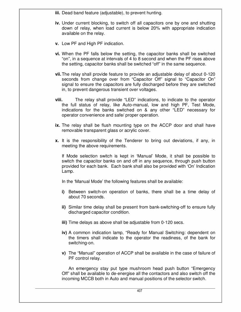
407
iii. Dead band feature (adjustable), to prevent hunting.
iv. Under current blocking, to switch off all capacitors one by one and shutting down of relay, when load current is below 20% with appropriate indication available on the relay.
v. Low PF and High PF indication.
vi. When the PF falls below the setting, the capacitor banks shall be switched “on”, in a sequence at intervals of 4 to 8 second and when the PF rises above the setting, capacitor banks shall be switched “off” in the same sequence.
vii. The relay shall provide feature to provide an adjustable delay of about 0-120 seconds from change over from “Capacitor Off” signal to “Capacitor On” signal to ensure the capacitors are fully discharged before they are switched in, to prevent dangerous transient over voltages.
viii. The relay shall provide “LED” indications, to indicate to the operator the full status of relay, like Auto-manual, low and high PF, Test Mode, indications for the banks switched on & any other “LED” necessary for operator convenience and safe/ proper operation.
ix. The relay shall be flush mounting type on the ACCP door and shall have removable transparent glass or acrylic cover.
x. It is the responsibility of the Tenderer to bring out deviations, if any, in meeting the above requirements.
If Mode selection switch is kept in ‘Manual’ Mode, it shall be possible to switch the capacitor banks on and off in any sequence, through push button provided for each bank. Each bank shall also be provided with ‘On’ Indication Lamp.
In the ‘Manual Mode’ the following features shall be available:
i) Between switch-on operation of banks, there shall be a time delay of about 70 seconds.
ii) Similar time delay shall be present from bank-switching-off to ensure fully
discharged capacitor condition. iii) Time delays as above shall be adjustable from 0-120 secs. iv) A common indication lamp, “Ready for Manual Switching: dependent on
the timers shall indicate to the operator the readiness, of the bank for switching-on.
v) The “Manual” operation of ACCP shall be available in the case of failure of
PF control relay.
An emergency stay put type mushroom head push button “Emergency Off” shall be available to de-energise all the contactors and also switch off the incoming MCCB both in Auto and manual positions of the selector switch.

408
The control voltage of ACCP panel shall be 110 V AC, with all operating coils of contactors etc. rated for 110 V AC.
MCBs shall be used in the control circuits for protection and isolation.
Safety Annunciation Features: The ACC Panel shall have the following located at top: - Two Tone Hooter. - Annunciation windows (audio/visual). - ‘ACCP Out of Circuit’ Indicating Lamp. - Set of Accept, Test and Reset push buttons.
1.5 DRAWING & INFORMATION
Prior to fabrication of the Panels the supplier/contractor shall submit for consultant’s approval the shop/vendor drawing consisting of G.A. drawing, sectional elevation, single line diagram, bill of material etc. and design calculations indicating type, size, short circuiting rating of all the electrical components used, busbar size, internal wiring size, Panels dimension, colour, mounting details etc. The contractor shall submit manufacturer’s catalogues of the electrical components installed in the Panels
1.6 INSPECTION & TESTING
At all reasonable times during production and prior to transport of the Panels to site, the supplier/contractor shall arrange and provide all the facilities at their plant for inspection. Testing of Panels shall be carried out at factory and at site as specified in Indian standards in the presence of Client / consultant. The test results shall be recorded on a prescribed form. The test certificate for the test carried out at factory and at site shall be submitted in duplicate to the consultant for approvals. The Following tests shall be conducted on all the Panels and Distribution Boards before the same are dispatched to the site from the vendors place. All the Tests shall be carried out in accordance with relevant IS codes and in presence of the Representative of Owner/ Consultant. Visual inspection of Panels and checking the bill of materials as per the approved drawings and Mechanical ON/OFF operation of the components. Checking of Protective Measures and electrical continuity of the protective circuits. High Voltage Test by applying 2.5 kV,1minute for checking insulation of equipment and the Material used and recording the leakage current. Megger tests before and after High Voltage Test at Vendors Factory. Primary Injection Test for Checking of all Meters and Relays. Testing of Barkers through Remote operation for ON/OFF and connectivity and operation of Barkers through the Software and RS 485 Port.
1.7 METHOD OF MEASUREMENT
All the items will be measured as mentioned in Bill of quantity.
1.8 GUARANTEE & WARRANTY

409
The Bidder shall stand guarantee for the performance of entire equipment and components for twelve (12) months from the date of commissioning or eighteen (18) months from the date of dispatch, whichever is earliest.
1.9 DRAWINGS AND DATA
Before fabrication of the panels/ boards, Contractor shall submit detailed general arrangement drawings, single line diagrams and schematic diagrams for all circuits/ modules for approval. G.A. drawings shall show foundation/ fixing details highlight constructional features / painting / details of internal wiring etc.
G.A. drawings shall indicate the list of components with manufacturer’s reference scheme/wiring diagram and detailed bill of materials. Minor changes suggested by the Consultants during approvals shall be without any pricevariation.
For APFC :
Following drawings/ data shall be furnished for approval by the Owner:
e) G.A. drawing of the ACCP showing Plan, Elevation and Sectional views, foundation details, BOQ, constructional features etc.
f) Single line diagram, control schematic and annunciation system diagram. g) A detailed write-up on the operational and control scheme. h) Data sheet for capacitor banks and GA drawing for the same.
1.10 Testing at Manufacturer’s Works :
1.10.1 Panels/ Boards :
The panels/ boards in fully wired and assembled condition shall be offered for inspection to the Owner at manufacturer’s works. During inspection, following tests/ measurements/ checks shall be carried-out:
a) Dimensional checks and verification of BOQ.
b) Mechanical and Electrical operation tests.
c) High voltage test at 2.5 kV for 1 min.
d) Insulation resistance measurement before and after HV test.
For bought-out items, manufacturers’ test certificates shall be furnished.
1.10.2APFC :
The APFC in fully wired and assembled condition and the capacitor banks shall be offered to the Owner for separate inspection.During the inspection, following tests/ measurements/ checks shall be carried-out :

410
A. APFC Panels – Tests/ measurements/ checks, as relevant, listed under Panels/ Boards.
B. Capacitor Banks – Routine & Acceptance tests as per applicable I.S.
For bought-out items, manufacturer’s test certificates shall be furnished. During the inspection, all observations and results of tests shall be recorded. Any short comings /deficiencies / non-compliance with stipulations recorded shall be attended by the Contractor / manufacturer to achieve compliance with the stipulations.
2.0 TECHNICAL SPECIFICATIONS FOR DISTRIBUTION BOARDS
2.1 SCOPE OF WORK
This scope of work shall cover the supply, Installation, Testing & Commissioning of the Distribution Board. TPN/FP/DP/SP MCB & ELMCB, Earthing terminal, connector strip for phase neutral and earth for each circuit, CRCA sheet steel housing and complete the item supply. Common banking of neutral and earth conductor is not allowed.
2.2 CODE & STANDARDS
The Distribution Board shall comply with the latest edition of relevant Indian Standards and Indian Electricity Rules and Regulations. The following Indian standards shall be complied with:
Sr. Item Relevant IS Relevant IEC
1 General requirements for switchgear and control gearfor voltages not exceeding 1000 V AC or 1200 V DC
IS: 4237
2 Switchgear bus bars, main connection and auxiliary wiring, marking and arrangement.
IS: 375
3 Terminal marking for electrical measuring instrumentand their accessories.
IS: 8197
4 Miniature circuit breakers. IS: 8828
2.3 DESIGN BASIS & SITE CONDITIONS
All the equipment and components provided in the DB and accessories shall be suitably designed for installation and satisfactory operation as specified below.
Site conditions
Location Mumbai,Maharashtra Site altitude560-800M above mean sea level
Ambient temperature Relative humidity
Maximum 410 C Maximum 85 %
Minimum 050 C Minimum 5 %
Design 450 C Design 90 % at 45 0 C
Seismic factor Zone IV as per IS:1893 Rainfall 722 mm/year
Environmental Tropical/Wet/dry climate Location of Equipment Indoor
Wind speed Annual avg. 4.35
Electrical system data:
Power supply for Equipment
Voltage 415 V ± 3 % Frequency 50 Hz ± 3 %
Permissible combined ± 6 % System design faults 10 kA for 1 sec. max.

411
voltage & frequency variation level (Symmetrical)
System earthing LV side neutral solidly earthed
Wiring 3 phase, 4 wire on 415V system
Auxiliary power supply :
Power supply ------
Control Supply -----
Space heater power supply -----
Illumination power supply -----
Plug-socket power supply -----
2.4 DISTRIBUTION BOARDS
2.4.1 System
Distributions boards along with the controlling MCBs as shown shall be fixed in a mild steel Box with hinged lockable door suitable for recessed mounting in wall. Distribution boards shall be made of 18 SWG sheet steel with hinged lockable spring loaded cover duly rust inhibited through a process of degreasing, acid pickling, phosphating and powder coated to an approved colour over a red oxide primer. The enclosure shall meet IP 43 rating. All components shall be mounted on DIN rails and covered totally with a sheet steel cover rendering it finger-safe. Access to the internal connections shall be only through removing the cover sheet. Three phase boards shall have phase to phase barriers and a wire channel for internal
wiring. All DB’s shall be internally prewired using copper insulated high temperature PVC
wires brought to a terminal strip of appropriate rating for outgoing feeders. Conduit knockouts shall be provided as required/shown on drawings and the entire board shall be rendered dust and vermin proof with necessary sealing gaskets. The distribution board shall have one main neutral and 3 separate sub - neutral links, one for each phase of adequate capacity as per number of outgoings per phase. The DB shall have earth bar(s) of adequate capacity as per total numbers of outgoings of DBs. Two numbers separate earth terminals, (one on each side) shall be provided on the outer body of DB for its body earthing. The DB shall be supplied complete with cable ties, circuit identification labels and few spare blanking plates.
2.5 DB TECHNICAL SPECIFICATION: No. of Ways : 4, 6, 8 & 12 ways Type of Installation : Surface & Flush mounting Colour / Finish : RAL Grey (Semi Glossy) Door Options : Reversible Door Locking Options : Sliding Lock Removable Gland Plates : Top & Bottom Protection Level of Distribution Board : Advanced Distribution Technique : Insulated Bus bar Bus Bar Rating : up to 125A Provision for Incomer slots : 8 Slots Voltage Rating : 240/415V-3 Phase/4 Wire Incoming Options : Three Phase MCCB, MCB or RCCB Outgoing Options : SP or TP or Both MCB Neutral Bar Terminal Capacity : 25 mm2, Split on both sides Earthing Bar Terminal Capacity : 25 mm2, Split on both sides Ingress Protection (IP) : IP43 Insulation Voltage (Ui) : 690V Frequency : 50Hz

412
Dielectric Strength : 2.5KV Ambient Temperature : -5 °C to 40 °C Distribution Board- Reference Standards : IS 8623; IS 13032 DRAWING & INFORMATION The following drawings shall be submitted along with the bid: General arrangement drawing showing overall dimensions, weight, internal arrangement and mounting details. Terminal chamber, showing bus-bar arrangement with all dimensions. Power wiring diagram METHOD OF MEASUREMENT
Supply of the DB including transport to site, loading and unloading etc. as specified will be treated as one unit for measurement and payment. The quotes values of parameters shall be within given tolerance for given period of service
life.
3.0 TECHNICAL SPECIFICATIONS FOR INTERNAL WIRING
3.1 SCOPE OF WORK
Thissection covers, definition of point wiring, system of wiring and supply, installation, connection, testing and commissioning of point wiring for light points, convenience socket outlet points, power socket outlet points etc. including fixing of light fixtures.
3.2 CODE & STANDARDS
The following standards and rules shall be applicable:
Sr. No. Item Relevant IS Relevant IEC
1 Code of practice for electrical wiring installation (System voltage not exceeding 650 V)
IS: 732
2 Code of practice for fire safety of buildings (General) Electrical installation.
IS: 1646
3 Rigid steel conduits for electrical wiring. IS: 9537 (Part - 2)
4 Fittings for rigid steel conduits for electrical wiring.
IS: 2667
5 Flexible steel conduits for Electrical wiring. IS: 3480 6 Accessories for rigid steel conduit for
electrical wiring. IS: 3837
7 PVC insulated cables. IS: 694
8 Rigid non-metallic conduits for electrical wiring.
IS: 9537 (Part - 3)
9 Flexible (Pliable) non-metallic conduits for electrical installation.
IS: 6946
10 3 pin plugs and sockets. IS: 1293 11 Specifications of conduits for electrical
installation. IS: 8130
12 Switches for domestic purpose. IS: 3854 13 Fittings for rigid non-metallic conduits. IS: 3419 14 Guide for electrical layout in residential
buildings Indian electricity act and rules. IS: 4648

413
3.3 DESIGN BASIS & SITE CONDITIONS All the equipment and components provided in the Wiring and accessories shall be suitably
designed for installation and satisfactory operation as specified below.
Site conditions
Location Mumbai, Maharashtra Site altitude560M-800M above mean sea level
Ambient temperature Relative humidity
Maximum 410 C Maximum 85 %
Minimum 050 C Minimum 35 %
Design 450 C Design 90 % at 50 0 C
Seismic factor Zone IV as per IS:1893 Rainfall 722 mm/year
Environmental Tropical/Wet/Dry climate Location of Equipment Indoor
Wind speed Annual avg. 4.35
Electrical system data:
Power supply for Equipment
Voltage 415 V ± 3 % Frequency 50 Hz ± 3 %
Permissible combined voltage & frequency variation
± 6 % System design faults level(Symmetrical)
10 kA for 1 sec. max.
System earthingLV side neutral solidly earthed
Wiring 3 phase, 4 wire on 415V system
3.4 TECHNICAL REQUIREMENTS 3.4.1 Point Wiring
A point shall consist of the branch wiring from the distribution board together with a switch as required, including the ceiling rose or pendant holder or swan holder, or socket or suitable termination. A point shall include, in addition, the earth continuity conductor/wire from the distribution board to the earth pin/stud of the outlet/switch box and to the outlet points Supply,installation,fixingofconduits with necessary accessories, junction/pull/inspection/switch boxes and outlet boxes Supplying and drawing of wires of required size including earth continuity wire Supply, installation and connection of flush type switches, sockets, cover plates, and switch plates etc. The point shall be complete with the branch wiring from the distribution board to the outlet point, through switch board, conduit with accessories, junction, pull, inspection boxes, control switch, socket, outlet boxes, etc.
3.5 SYSTEM OF WIRING
Unless otherwise mentioned on the drawings, the system of point wiring shall be as follows: The system of wiring shall consist of single core, FRLS insulated, 650/1100 volt grade, copper conductor wires/cables laid through exposed (surface mounted) PVC conduits as directed & wherever required, conduits shall be concealed in walls and slabs
3.6 GENERAL
Prior to laying of conduits, the contractor shall submit for approval, the shop drawing for conduit layout indicating the route of the conduits, number and size of the conduits, location of junction/inspection/pull/outlet boxes, size and location of switch boxes, number and size

414
of wires pulled through each conduit and all other necessary relevant details. Only after the drawings are approved, the contractor shall proceed with the work of laying of conduits.
3.7 MATERIAL 3.7.1 PVC Conduit
All non-metallic PVC conduits shall conform to IS: 9537 (Part - 3 ). The conduit shall be planed and of type as specified in IS: 9537 and shall be used with the corresponding accessories (Refer IS: 3419 specification for fittings for rigid non metallic conduits). PVC conduits shall be rigid unplasticised, heavy gauge having 2.0 mm. wall thickness upto 20 mm. diameter conduit and 2.5 mm. wall thickness for all sizes above 20 mm. diameter
3.7.2 M.S. Conduit
Conduits shall conform to IS: 9537 ( Part - 2 ), finished with galvanized surface. No steel conduit less than 25 mm. in diameter shall be used. Conduits shall be solid drawn of lap welded type, with minimum wall thickness for conduits having 25 mm. and above diameter The conduits shall be delivered to the site of construction in original bundles and each length of conduit shall bear the label of manufacturers The conduit accessories such bends, coupling etc. shall be conforming to the relevant Indian Standard specification
3.7.3 Boxes 1. All the boxes for switches, sockets and other receptacles, junction boxes, pull boxes and
outlet boxes shall be fabricated from 2.0 mm. thick mild sheet painted with two coats of red-oxide and then two coats of enamel paints as called for. Colour of the paints shall be as approved by the client. The boxes shall have smooth external and internal finished surface
2. Boxes in contact with earth or exposed to the weather shall be of 2 mm. mild steel and hot dip galvanized after fabrication
3. Separate screwed earth terminal shall be provided in the box for earthing purpose 4. All boxes shall have adequate no. of knock out holes of required diameter for conduit
entry 5. Switch boxes to receive switches, socket outlets, power outlets, telephone outlets, fan
regulators, etc. shall be fabricated to the approved shape and size to accommodate all the devices without overcrowding.
6. Boxes installed for concealed wiring shall be provided with suitable extension rings or plaster covers as required. Boxes for use in masonry block or tiled walls shall be square cornered tile type, or standard boxes having square cornered tile type covers. These boxes shall be installed in the centre of the masonry block or tiles
Cast metal boxes installed in wet locations and boxes installed flush with the outside of exterior surface shall be gasketed.
3.7.4 Cover Plate The cover of the boxes to receive outlet points shall be of best anodized sheet cut to shape and size or plate of approved manufacturers of switches.
3.7.5 Cable 1. The cables shall conform to IS: 697. For all internal wiring FRLS insulated cables of
650/1100 volts grade, single core shall be used.All cables shall be ISI marked. 2. The conductors shall be plain annealed copper conductors complying with IS: 1554.

415
3. The conductors shall be circular copper conductor. 4. The insulation shall be FRLS compound complying with the requirements of IS: 697. It
shall be applied by an extrusion process and shall form a compact homogenous body. 5. The thickness of FRLS insulation shall be as set out in the relevant standards 6. The cores of all cables shall be identified by colours in accordance with the following
sequence. Single phase Red
Three phase Red, Yellow, Blue
Neutral Black
Earth Green or Green/Yellow
7. Means of identifying the manufacturer shall be provided throughout the length of cable
8. Unless otherwise specified in the drawings the size of the cables used for internal wiring
shall be as follows:
• In case of circuit wiring for lights, convenience socket outlet points (P+N+E):
2.5sq.mm. From D.B. to switch boards.
1.5sq.mm. From switch boards to outlet points
• In case of power socket outlet circuit having not more than two 15 A power outlet (P+N+E): 2.5sq.mm. From D.B. to first power outlet
1.5sq.mm. From first power outlet to second power outlet
• In case of power socket outlet circuit having single 15 A power outlet (like water heater) (P+N+E):
4.0sq.mm. From D.B. to power outlet.
• In case of 15 A. power outlet for window Air conditioner or other likewise appliances (P+N+E):
4.0sq.mm. From D.B. to power outlet.
The earth continuity conductor shall be similar to circuit cables and shall be drawn through conduit along with other circuit cables. The size of the earth continuity conductor shall be as follows:
MINIMUM SIZE OF EARTH CONTINUITY CONDUCTOR NOT FORMING PART OF THE SAME CABLE AS THE ASSOCIATE CIRCUIT CONDUCTOR
Nominal cross-section area of largest associated copper circuit conductor in sq.mm.
Nominal cross-sectional area of earth continuity conductor in sq.mm.
1.5 1.5
2.5 2.5 4.0 4.0
3.8 SWITCHES
Switches shall conform to IS: 3854, IS: 1293 and IS: 4615. The switches shall be single pole, single or two way as shown on the drawings or as specified. They shall be of moulded type rated for 250 volt, and of full 5/15 A capacity. They shall be provided with insulated dollies and covers.

416
The switches shall be rocker operated with a quiet operating mechanism with bounce free snap action mechanism enclosed in an arc resistant chamber. The switches shall have pure silver and silver cadmium contacts. The switches shall be flush modular type. The make of the switches shall be as indicated in the drawings or BOQ or make of material or as suggested and approved by the client.
3.9 SOCKET
1. The sockets shall conform to IS: 1293. Each socket shall be provided with control switch of appropriate rating. The sockets shall be moulded type, rated for 250 volts, and either of full 5 A or 15 A capacity, as mentioned on the drawings.
2. Sockets shall be of three pin type, the third in being connected to earth continuity conductor.
3. The socket shall be flush modular type.
4. The finishing and make of all the sockets shall be same as light switch.
5. The socket shall have fully sprung contacts and solid brass shrouded.
6. Terminals to ensure positive electrical connections.
7. The sockets shall be provided with automatic shutters, which open only when earth pin of the plug inserts in the socket.
8. The socket shall be provided with three pin plug top suitable to the socket and of the same make as socket.
3.10 INSPECTION AND TESTING
3.10.1 Insulation Resistance Test
The insulation resistance shall be measured by applying 500 volt megger with all fuses in places, circuit breaker and all switches closed. The insulation resistance in mega ohms of an installation, measured shall not be less than 50 mega ohms divided by the number of points on the circuit. The insulation resistance shall be measured between
1. EARTH TO PHASE
2. EARTH TO NEUTRAL
3. PHASE TO NEURAL
4. PHASE TO PHASE
3.10.2 Earth continuity path The earth continuity conductors shall be tested for electrical continuity and the electrical resistance of the same along with the earthing lead but excluding any added resistance or earth leakage circuit-breaker, measured from the connection, with the earth electrode to any point in the earth continuity conductor in the completed installation and shall not exceed one ohm.
3.11 POLARITY OF SINGLE POLE SWITCHES A test shall be made to verify that every no-linked, single pole switch is connected to one of the phase of the supply system.
3.12 COMPLETION CERTIFICATES

417
All the above tests shall be carried out in presence of Client/Consultant and the results shall be recorded in prescribed forms. Any default during the testing shall be immediately rectified and that section of the installation shall be re tested. The completed test result form shall be submitted to the client for approval. On completion of an electric installation a certificate shall be furnished by the contractor, countersigned by the certified supervisor under whose direct supervision the installation was carried out. This certificate shall be in a prescribed form as required by the local electric supply authority.
3.13 INSTALLATION OF THE SYSTEM
3.13.1 Concealed Installation with Rigid PVC Conduit All the rigid PVC conduit used for concealed installation shall be as per IS: 9537 and its accessories shall be as per IS: 3419 (Small Wire Ropes). Whenever necessary bends or diversion may be achieved by bending the conduits with the help of bending spring. No other method of bending is allowed. Conduit pipes shall be joined with the help of plain coupler fixed at the end with the help of vinyl solvent cement. No other method of joining is permissible. All other methods, no wires through conduit, bunching, etc. Shall be as specified in the concealed installation. Prior to fixing the conduits, the complete route shall be marked on site for the approval of consultant.
3.13.2 Concealed Wiring System with Rigid PVC Conduit The rigid PVC conduits shall be used for concealed wiring system. The conduits shall be concealed in the concrete slab, floor, walls, beams, columns etc. FIXING OF CONDUIT Conduits embedded in concrete shall be installed in the frame work before pouring concrete. The conduits shall be installed above the bottom reinforcing bars, and shall provide positive wire fastening of the conduit to the reinforcing rods at an interval of not more than one meter, but on either side of couplers or bends or outlet/pull/junction boxes or similar fittings, proper hold fast shall be fixed at a distance of 30 cm from the centre of such fittings. Conduits embedded in the wall shall be fixed inside the chase . The chase in the wall shall be neatly made and be fixed in the manner desired. In the case of building under construction, chase shall be provided in the wall at the time of their construction and shall be filled up neatly with cement mortar 1:4 after erection of conduit and brought to the original finish of the wall. Cutting of horizontal chases in walls is prohibited. The conduits shall be fixed inside the chase by means of staples or by means of saddles not more than 60 cm apart. Conduits shall be so arranged as to facilitate easy drawing of wires through them. Entire conduit layout shall be done in such a way as to avoid additional junction boxes other than light points. The wiring shall be done in a looping manner. All the looping shall be done in either switch boxes or outlet boxes. Looping in junction or pull boxes are strictly not allowed. Where conduits cross building expansion joints, adequate expansion fittings or other approved devices shall be used to take care of any relative movement All conduits shall be installed so as to avoid steam and hot water pipes

418
Conduits shall be installed in such a way that the junction, derivation and pull boxes shall always be accessible for repairs and maintenance work. The location of junction/pull boxes shall be marked on the shop drawings and approved by the client A separation of 200 mm shall be maintained between electrical conduits and hot water lines in the building. No run of conduit shall exceed ten mtr. between adjacent draw in points nor shall it contain more than two right angle bends, or other derivation from the straight line. Caution shall be exercised in using the PVC conduits in location where ambient temperature is 50 degree cel. or above. Use of PVC conduits in places where ambient temperature is mote than 60 deg. cel. Is prohibited. The entire conduit system including boxes shall be thoroughly cleaned after completion of installations and before drawing of wires. Conduit system shall be erect and straight as far as possible. Traps where water may accumulate from condensation are to be avoided and if unavoidable, suitable provision for draining the water shall be made. All jointing method shall be subject to the approval of the client Separate conduits shall be provided for the following system.
• 15 A power outlets.
• 5 A outlets and lighting system.
• Low voltage system.
• Telephone/intercom system.
• Sound system
• Computer data cabling system
• Equipment wiring
3.13.3 Conduit Joint Conduits shall be joined by means of plain couplers vinyl and/or solvent cement. Where there are long runs of straight conduit, inspection type couplers shall be provided at intervals, as approved by the client. The conduits shall be thoroughly cleaned before making the joints. In case of plain coupler joints, proper jointing material like a vinyl solvent cement (gray in color) or any material as recommended by the manufacturer shall be used.
3.13.4 Bends In Conduit Wherever necessary, bends or diversions may be achieved by bending the conduits or by employing normal bends. No bends shall have radius less than 2.5 times outside dia. of the conduit Heat may be used to soften the PVC conduit for bending, but while applying heat to conduit, the conduit shall be filled with sand to avoid any damage to the conduit
3.13.5 Outlets All the outlets for fittings, switches etc. shall be boxes of substantial construction. In order to minimize condensation or sweating inside the conduits, all outlets of conduit system shall be properly drained and ventilated, but in such a manner as to prevent the entry of insects , etc.

419
Fixing between conduit and boxes, outlet boxes, switch boxes and the like must be provided with entry spouts and smooth PVC bushes. Joints between conduit and any type of boxes shall be affected by means of conduit couplers in to each of which shall be coupled smooth PVC bush from inside the box. In any case all the joints shall be fully water tight.
3.13.6 Bunching of Cables
Cables of AC supply of different phase shall be bunched in separate conduits. The number of insulated wires/ cables that may be drawn into the conduits shall be as per the following table. In this table, the space factor does not exceed 40%. However, in any case conduits having lesser than 19 mm dia. shall not be used. MAXIMUM PERMISSIBLE NUMBER OF 650 VOLT GRADE SINGLE CORE CABLES THAT MAY BE DRAWN IN TO RIGID PVC CONDUITS.
CABLE SIZE IN MM SQ.
SIZE OF CONDUITS (MM)
MAXIMUM NO. OF CABLES
25 32 38/40 51/50
1.5 8 15 --- --- 2.5 6 10 --- ---
7.0 4 8 12 ---
3.13.7 Wiring With RIGID Steel Conduit All conduits and it’s accessories shall be of threaded type and under no circumstances pin grip type or clamp type accessories be used.
3.13.8 Fixing of Conduit Conduit pipes shall be fixed by heavy gauge spacer bar saddles. The saddles shall be of 3 mm x 19 mm galvanized mild steel flat, properly treated and securely fixed to support by means of nuts and bolts raw bolts, brass machine screws, as mentioned, at an internal of not more than one meter but on either side of couplers, or bends, or junction/pull/outlet boxes or similar fittings, saddles shall be fixed at a distance of 30 cm from the centre of such fittings. Draw boxes shall be located at convenient location for easy drawing of wires. Every mains and sub mains shall run in independent conduits with an independent earth wire of specified capacity along the entire length of conduit. The conduits to be installed shall be of ample cross section area to facilitate the drawing of wires. The diameter of the conduit shall be selected as per table specified in these specifications. But in no case it shall be less than 25 mm diameter. Entire conduit layout shall be done such as to avoid additional junctions boxes other than for outlet points. Conduits shall be free from sharp edge and burrs. Conduits shall be laid in a neat and organized manner as directed and approved by the client. Conduit runs shall be planned so as not to conflict with any other services pipe, lines/duct. The entire conduit system shall be electrically and mechanically continuous and shall be bonded, together by means of approved type earthing clamp and earthed through a bare copper conductor of 14 SWG to the earthing terminals on the nearest distribution board.

420
If required, connection between PVC and steel conduits shall be through a junction box. Direct connection between PVC and steel conduits are not allowed. Where exposed conduits are suspended from the structure, they shall be clamped firmly and rigidly to hangers of design to be approved by client. Where hangers are to be anchored to reinforced concrete, appropriate inserts and necessary devices for their fixing shall be left in position at the time of concreting, making holes and opening in the concrete will generally not be allowed. In case, it is unavoidable, prior permission of the client shall be obtained.
3.13.9 Conduit Joints Conduit pipes shall be joined by means of screwed couplers and screwed accessories, as per IS: 2667 The threads shall be free from grease or oil. In long distanced straight runs of conduit, inspection type couplers two way junction boxes at reasonable intervals shall be provided or running threads with couplers and lock nuts shall be provided. The bare threaded portion shall be treated with anti-corrosive paints. Threads on conduit pipes in all cases shall be between 11mm to 27mm long, sufficient to accommodate pipes to full threaded portion of couplers or accessories. Cut ends of conduit pipes shall have no sharp edges nor any burrs left, to avoid damage to the insulation of conductors while pulling them through such pipes. Brass female bushes shall be used in each conduit termination in a switch box, outlet box, electrical panel or any other box. Conduit shall be secured in each outlet box switch box, electrical panel or any other ox by means of one brass hexagonal lock nut and bush, outside and inside the box. At each building, expansion joints approved oil tight double wire wound flexible steel conduit or any other approved method shall be used. This shall be united on both sides with the rigid conduits by suitable union. Conduits installed in the plant room for mechanical equipment shall be properly clamped with the mechanical supports, but in no case, it shall be fixed with the body of the equipment. The connection of conduit to the mechanical equipment shall be through oil tight double wire wound flexible steel conduit. In any case the length of the flexible conduit shall not exceed one meter. The flexible conduit shall be properly clamped with the body of the equipment. They shall not in any case be clamped with any cover or any removable parts of the equipment.
3.13.10 Bends In Conduit All necessary bends in the system including diversion shall be done by bending pipes or by inserting suitable solid or circular inspection type normal box or similar fittings. Conduit fittings shall be avoided as far as possible on conduit system exposed to weather, where necessary, solid type fittings shall be used. Radius of such bends in conduit pipes shall be not less than 75 mm. No length of conduit shall have more than the equivalent of four quarter bends from outlet, the bends at the outlets not being counted.
3.13.11 Protection Against Dampness In order to minimize condensation or sweating inside the conduit, all outlets of conduit system shall be properly drained and ventilated, but in such a manner as to prevent the entry of insects, as far as possible.
3.13.12 Protection of Conduit Against Rust

421
The outer surface of the conduits including bends, junction boxes, etc., forming part of the conduit system shall be adequately protected against rust, particularly when such system is exposed to weather. In all cases, no bare/threaded portion of conduit pipe shall be allowed unless such bare threaded portion is treated with anti-corrosive coating or covered with approved plastic compound.
3.13.13 Bunchingof Cables Unless otherwise specified, insulated conductors of different phases shall be bunched in separate conduit. Wires carrying current shall be so bunched in the conduit that the outgoing and return wires are drawn into the same conduit. Wires originating from two different phases shall not be run in the same conduit. The number of insulated wires/cables that be drawn into the conduits shall be as per the following table. MAXIMUM PERMISSIBLE NUMBER OF 650/1100 VOLTS GRADE SINGLE CORE CABLE THAT CAN BE DRAWN INTO RIGID STEEL CONDUITS.
CABLE SIZE IN MM SQ.
SIZEOFCONDUITS (MM)
MAXIMUM NO. OF CABLES 25 32 38 51
1.5 10 14 --- --- 2.5 8 12 --- --- 7.0 6 10 --- ---
3.13.14 Switch and Socket
Switches shall be installed at 900 mm above finished floor level unless otherwise indicated on the drawings. The switch controlling the light point shall be connected on to the phase wire of the circuit and neutral shall be continuous, having no fuse or switch installed in the line except at the D.B. The cover plates to the switch box shall be fixed by means of sunk head brass cadmium screws. Where two or more switches and fan regulators are installed together, they shall be provided with one gang cover plate with knockouts to accommodate required number of switches, sockets and regulators. The switch controlling the socket outlet shall be on the phase wire of the circuit. The third pin of the socket shall be connected to the earth continuity conductor of the circuit. The switch boxes, installed back-to-back in the same wall shall be offset from each other, 150 mm horizontally, to preclude noise transmission.
3.13.15 Drawing of Conductors The drawing and joining of copper conductor or wires shall be executed with due regard to the following precautions. While drawing insulated wires into the conduits, care shall be taken to avoid scratches and kinks which may cause breakage of conductors. There shall be no sharp bends Insulation shall be shaved off for a length of 15 mm at the end of wire like sharpening of a pencil and it shall not be removed by cutting it square or ringing.

422
FRLS insulated copper conductor wire ends before connection shall be properly soldered (at least 15 mm length) with soldering flux/copper solder, for copper conductor. Strands of wires shall not be cut for connecting to the terminals. All strands of wires shall be soldered at the terminals. All strands of wires shall be soldered at the end before connection. The connecting brass-screws shall have flat ends. All looped joints shall be soldered and connected through terminals. Block/connectors. The pressure applied to tighten terminal screws shall be just adequate, neither too much nor too less. Conductors having nominal cross section exceeding 4 sq. mm shall always be provided with crimping type cable sockets. At all bolted terminals, brass flat washer of large area and approved steel spring washers shall be used. Brass nuts and bolts shall be used for all connections. Only certified wire men and cable jointers shall be employed to do joining work. For all internal wiring FRLS insulated wires of 650/1100 volts grade shall be used. The sub-circuit wiring for point shall be carried out in looping system and no joint shall be allowed in the length of the conductors. No wire shall be drawn in to any conduit, until all work of any nature that may cause injury to wire is completed. Care shall be taken in pulling the wires so that no damage occurs to the insulation of the wire. Before the wires are drawn into the conduits the conduits shall be thoroughly cleaned of moisture, dust, and dirt or any other obstruction by forcing compressed air through the conduits.
3.13.16 Joints The wiring shall be by looping back system, and hence all joints shall be made at main switches, distribution boards, socket outlets, lighting outlets and switch boxes only. No joints shall be made inside conduits and junction boxes. Contacts shall be continuous from outlet to outlet. For joints where unavoidable, due to any specified reasons, prior permission in writing shall be obtained from the client before making such connections. Joints by twisting conductors are prohibited.
3.13.17 Load Balancing Balancing of circuit in three phase installation shall be planned before the commencement of wiring and shall be strictly adhered to.
3.13.18 Earthing
All earthing systems shall be in accordance with IS: 3043 - 1985 code of practice for earthing.
3.14 METHOD OF MEASUREMENT All the items will be measured as mentioned in Bill of quantity.
3.15 TRANSPORT, DELIVERY AND STORAGE The wire shall be supplied in the actual length as per detailed purchase order The wire shall be dispatched at client’s stores or at site as per detailed instructions given by client at later stage. The wire shall be loaded from the main vendor’s store and properly stacked as per instruction of client’s local representative. All such labour and transportation charges shall be clearly mentioned in the offer.

423
3.16 GUARANTEE AND WARRENTY The quotes values of parameters shall be within given tolerance for given period of service life.
4.0 TECHNICAL SPECIFICATIONS FOR UNDERFLOOR RACEWAYS & JUNCTION BOXES
4.1 GENERAL:
Under floor systems are intended for the support and accommodation of Power, Data and communication cables and possibly other Electrical / Low Voltage equipment cabling required for electrical/Instrumentation/Communication systems. The complete system and its components like service and junction outlets need to be supplied from a single manufacturer.
4.2 CODES AND STANDARDS:
The following standards and specifications shall have to be complied with – EN 10137 / 10142 – Pre galvanized sheet steel for Metal under floor raceways, base box, load plate and accessories - minimum galvanizing thickness of 18-24 Micron meter. Grade of steel shall have to be 275 Grams per square meter. DIN VDE 0634 Part 1 & 2 – Floor distribution system installation EN 50085 Part 1 & 2 – Loading requirement for floor distribution systems IEEE wiring regulations – Trunking capacity calculations and filling factor The proposed system of cable management shall have to be EMC compliant and confirmation for the same shall have to be submitted. The products proposed shall have to be CE Conformant in accordance with the appropriate EC directives. All related Test reports / certificates of conformity for loading on raceways and Junction outlet boxes from a recognized testing institution should be made available for final approval of materials.
4.3 QUALITY ASSURANCE AND COMPLIANCE:
The Contractor must demonstrate that the work in this section is carried out by experienced personnel. Any work not meeting the required standard will be removed at the discretion of the Company Representative. The mock up installation shall have to be inspected and certified by the manufacturer in presence of the client’s representative.
4.4 SUBMITTALS:
The following submittals will be required:
1. Manufacturer’s data and installation instructions. 2. Schedule of materials to be used. 3. Shop drawings showing all layouts, connections wall and floor boxes fixing methods and
the like. 4. Certificate of Origin confirmation on manufacturer’s letter head stamped and signed. 5. Test certificates / Certificates of conformity w.r.t loading of the metal and UPVC
raceways and junctions confirming to DIN VDE 0634 part 1&2 and EN 50085 Part 1 and 2.
4.5 DELIVERY, STORAGE AND HANDLING:

424
The delivery handling and storage procedures shall be in accordance with the manufacturer’s instructions.
4.6 UNDER FLOOR RACEWAYS – GI UNDER FLOOR RACEWAYS AS POWER HEADER:
The under floor duct for “in screed” system shall be of GI – Metal with sheet metal grade GZ 275 grams per square meter corresponding to 18-24 micron meter galvanizing coating thickness. These under floor GI metal ducts shall be manufactured in line with the drawings and details provided, in single, double and triple compartments as required for the project application. The under floor ducts shall be manufactured with 1.6 mm thickness (+ or - 0.1 mm tolerance) base and cover mig welded to form a box section and shall have to comply with the relevant sections of standard EN 50085 & DIN VDE 0634. The under floor GI metal ducts shall be of rectangular shape with overlapping sides of cover and base for better load withstand capacity and closed box type construction. The under floor ducts shall have to be provided with required rigidity with a standard loading capacity as defined in relevant sections of EN 50085 norms and shall prevent the seepage of concrete and screed water. These ducts shall have spot welded partitions of the same thickness as base and cover and all the spot welded joints and mig welded covers shall have to be cold galvanized for maintain the required galvanizing coating thickness referred above. Single, double or triple compartment metal ducts need to be used to accommodate different types of cables - Power, Data &Telecommunication as shown and indicated in the drawings. These ducts are supplied in 2.5 meter standard length and complete overlapping box type jointing coupler shall be used to connect the standard lengths of the ducts in screed covered system. These ducts need to be secured to the structural slab by means of screws secured through the jointing couplers. The vertical riser bends should be used as well for quick entry of cables in the under floor system. The under floor ducts shall be complying with all requirements as defined in EN 50085-2-1 and shall be ROHS compliant. These ducts shall have smooth surface finish without sharp edges and Burrs. The ducting shall have IP 40 Protection against access to hazardous parts.
4.7 UNDER FLOOR JUNCTION OUTLETS SUITABLE FOR CARPET / CERAMIC TILES
APPLICATION:
Under floor Junction boxes shall be robust in its construction with a base plate and side walls manufactured from 1.5 mm thick (+ or - 0.1 mm tolerance) galvanized sheet steel. The base box bodies shall be made from galvanized sheet steel with a zinc coating in accordance with EN 10327 with grade of steel as G275 confirming to 275 Grams per square meter . Height of the under floor junction boxes shall be 60 mm as minimum for metal ducts and 55 mm as minimum for UPVC ducts and shall have to be provided with four corner pillars for height adjustment from 60 to 70 mm and 55 to 65 mm respectively for first fix installation. The Trap and frame of Junction outlets shall be manufactured from GI in line with the specifications detailed above and shall be of three piece construction – Trap, Frame and floor covering protection flange. The frame shall be fitted with the floor covering protection flange of 10 mm all around for protection of the cut edges of the floor finishing material – carpet or ceramic tiles. The entire three piece GI trap and frame shall be powder coated colour matched to the floor finish material as per architect’s choice. GI powder coated trap and frame shall have to be 2 mm thick with an additional 3mm thick GI powder coated load plate completely supported by the frame for ensuring maximum

425
rigidity and providing adequate load bearing capacity. The junction outlet boxes shall be able to withstand a load of 1.5KN conforming to EN 50085. Junction outlet base boxes should have knock outs for either for Metal duct entries or single or multiple duct entry of size 90mm width and 35mm height respectively in all the four sides for quick and easy installation. Junction outlet boxes shall be substantially dimensioned to eliminate congestion and provide ample working space within. Junction boxes shall be supplied with cross over bridges for segregation of power, data and telecommunication cables if necessary. The trap of Junction outlets shall be with a standard 10 mm to accommodate various ceramic tile floor coverings. Junction outlet trap and frames need to be fixed on the height adjusting corner pillars and load plate shall be easily removable for installation / easy access to the wiring contained within.
4.8 INSTALLATION:
Under floor trunking system shall be installed strictly as per manufacturer’s instructions and to a level of workmanship to ensure that all the under floor boxes are consistently in level with the screed in line with the final finish floor level. Contractor has to ensure that any part of the boxes is not detected below and or above the final finish floor level. Failure to comply in this respect, the affected boxes shall be re-installed by the contractor, as required by the engineer. Cross-over bridges shall be installed at the junctions if required, to ensure that adequate separation of power, data and telecommunication cables are maintained. Equipotential earth bonding shall be carried out as per manufacturer’s recommendations. Service outlets polyamide shall be installed within floor boxes after screed installation is completed and wiring is carried out, onto cover plates which are provided with suitable pre-punched aperture with blanks for installation
5.0 TECH TECHNICAL SPECIFICATIONS FOR SUPPLY OF LIGHT FIXTURE
5.1 SCOPE OF WORK The scope of work shall cover the supply, installation and testing of various types of LED light fixtures are used in the project.
5.2 CODES & STANDARDS The following standards and rules shall be applicable: IS 3646 (1960) Code of practice for interior illuminator. IS 1913(1969) General and Safety requirements for electric lighting fittings.
Indian Electricity Act and Rules issued here under.
5.3 DESIGN BASIS & SITE CONDITIONS
Site conditions
Location Mumbai,Maharashtra
Ambient temperature Relative humidity Maximum 410 C Maximum 85 %

426
Minimum 050 C Minimum 35 % Design 450 C Design 90 % at 45 0 C
Environmental Tropical/dry/wet climate Location of Equipment Indoor / Outdoor Wind speed Annual avg 4.35 Electrical system data:
Power supply for Equipment
Voltage 230 V ± 3 % Frequency 50 Hz ± 3 %
Permissible combined voltage & frequency variation
± 6 % System design faults level (Symmetrical)
10 kA for 1 sec. max.
System earthing: LV side neutral solidly earthed
Wiring: 1 phase, 230V system
5.4 TECHNICAL REQUIREMENTS 5.4.1 General Requirements
All fixtures shall be complete with accessories and fixings necessary for installation whether so detailed under fixture description or not. Fixture housing, frame or canopy shall provide a suitable cover for the fixture outlet box of fixture opening. Fixture shall be installed at mounting heights as detailed on the drawings or instructed on site by the client's representative. Fixtures and/or fixture outlet boxes shall be provided with hangers to adequately support the complete weight of the fixture. Design of hangers and method of fastening other than shown on the drawings or herein specified shall be submitted to the client's representative for approval. Fixture shall be completely wired and constructed to comply with the regulations and standards for Electric Lighting Fixtures, unless otherwise specified. Fixtures shall bear manufacturer’s name and the factory inspection label unless otherwise approved. Wiring within the fixture and for connection to the branch circuit wiring shall not be less than 1.5 sq.mm. Copper for 250 Volt application. Wire insulation shall suit the temperature conditions inside the fixture and wires bypassing the choke shall be heat protected with a heat resistant sleeve. Metal used in lighting fixtures shall be not less than 22 SWG or heavier if so required to comply with specifications or standards. Sheet steel reflectors shall have a thickness of not less than 20 SWG. The metal parts of the fixtures shall be completely free from burrs and tool marks. Solder shall not be used as mechanical fastening device on any parts of the fixture. Ferrous metal shall be bonder ized and given a corrosion resistant phosphate treatment or other approved rust inhibiting prim coat to provide a rust-proof base before application of finish. Non-reflecting surfaces such as fixture frames and trim shall be Aluminum die cast. All the indoor fixtures are as per the IP - 20 insulation class. Vendor shall be responsible for measuring the level of illumination after installation. Lighting fixtures shall be designed for minimum glare and for continuous operation under specified atmospheric condition.

427
5.5 LED LAMPS
LED lamp is a light-emitting diode (LED) product which is assembled into a lamp (or light bulb) for use in lighting fixtures. LED lamps have a lifespan and electrical efficiency which are several times longer than incandescent lamps, and significantly more efficient than most fluorescent lamps.LEDs come to full brightness without need for a warm-up time; the life of fluorescent lighting is also reduced by frequent switching on and off. LEDs are “directional” light sources, which means they emit light in a specific direction, unlike incandescent and compact fluorescent bulbs, which emit light and heat in all directions. The LED bulbs require much less wattage than the CFL or Incandescent light bulbs.
5.6 LUMINAIRES
INDOOR LUMINAIRE:LED recessed mounted &suspended luminaire are proposed for indoor lighting. CRI > 80, integrated in separate mini-LED louver with UXP technology. Luminaire luminous flux 6000 lm. Construction height 18 mm. LED segments flush integrated into the square luminaire body ensure optimal thermal management. With integrated plastic cover for protection of optics against soiling. Luminaire body of flat aluminium profile, white, with colour highlighted, flush integrated end caps of anodized aluminium. Protection rating IP20. OUTDOOR LUMINAIRE: LED floor / Wall mounted Luminaires are proposed. LED outdoor light fixtures with lamp with a system lumen output not less than 900 lumens and system lumen efficacy should not less than 100 lumen/watt and CRI should be greater than 80 having high grade poly carbonate/CRCA/die cast aluminium Housing with IP 65 rating. The luminaire should have a colour temperature 6000 K . The luminaire PF should not be less than 0.95with minimum 30000 burning hours.The driver efficiency should not be less than 85% with surge protection 2.5 KV. The operating voltage range should be 140-270V AC, complete i/c connection, earthing from the existing light points etc as required.
5.7 DRAWINGS & INFORMATION As per of the proposal the bidder furnish relevant descriptive and illustrative literature on lighting fixtures and accessories and following drawings/ data for the respective lighting fixtures:- 1. Dimensional Drawings. 2. Mounting details cable entry facilities and weights. 3. Light distribution diagrams (Zonal &Isokandora) 4. Light absorption and utilization factors. 5. Lamp output V/S temp. Curves.
5.8 INSPECTION AND TESTING
Each fixture shall be tested at 1500 volts rms. 50 Hz for one minute and no flashover of breakdown shall occur between current carrying parts and ground. Insulation resistance of each fixture shall be tested at 500 V.D.C. and the insulation resistances so measured shall not be less than 2 mega ohms between all current carrying parts and ground. Each fixture complete with its proper lamp/lamps shall be shown to operate satisfactorily at its normal voltage and frequency. Each fixture shall be examined visually to ensure that it is complete in all respects and satisfactorily finished.

428
Type and routine test certificates shall be submitted for tests conducted as per relevant IS/BS for the fixture and accessories.
5.9 METHOD OF MEASUREMENT Supply of the fixture including transport to site, loading and unloading etc. as specified will be treated as one unit for measurement and payment.
5.10 GUARANTEE AND WARRENTY
The Bidder shall stand guarantee for the performance of entire fixtures and components for twelve (12) months from the date of commissioning or eighteen (18) months from the date of dispatch, whichever is earlier, as agreed up on and as reproduced in the purchase order within the tolerance specified or as permitted by the relevant standards for the equipment in his scope of supply. The Purchaser also reserves the right to use the rejected equipment or part thereof until the new equipment meeting the guaranteed performance is supplied by the Bidder.
5.11 MOTION SENSORS
Dual technology, PIR and Ultara Sonic wall mount sensor Must have detection angle of 180 degree, 6*7 m of total coverage Must have Zero current breaking inbuilt facilityNo load consumption must not be more than 0.6 WMust be capable to handle 8.5 A of Halogen load Must have additional no volt contact Must have 3 opration mode, Auto On/Off, Walkthrough, Manual On/Auto Off Must have facility of override push button Must be configurable with remote configurable tool Time delay setting span must be from 1 sec to 59 min Lux level setting must be from 5 Lux to 1275 lux Must be capable to be calibrated at actual lux level present at area of installation Can be corner mount with help of additional mounting bracket Dual technology, PIR and Ultara Sonic Ceiling mount sensor Must have detection angle of 360 degree and 8 m dia coverage Must be capable to handle 8.5 A of Halogen load Must have 3 opration mode, Auto On/Off, Walkthrough, Manual On/Auto Off Must have facility of override push button Must be configurable with remote configurable tool Time delay setting span must be from 1 sec to 59 min Lux level setting must be from 5 Lux to 1275 lux Must be capable to be calibrated at actual lux level present at area of installation
6.0 TECHNICAL SPECIFICATIONS FOR SUPPLY OF EARTHING SYSTEM
6.1 SCOPE OF WORK Design, assembling, testing, painting, supply, delivery at site with all related accessories as per the specifications as specified below. Compliance with the provisions of this specification shall not relieve the Bidder of the responsibility of furnishing apparatus and accessories of proper design, electrically and mechanically suited to meet the operating requirements under the specified service conditions and be suitable for the purpose of which they are intended.
6.2 CODES & STANDARDS The design, material, assembling, inspection and testing shall comply with all currently applicable statutes, regulations and safety codes in the locality where the system will be installed. The equipment shall also conform to the latest applicable standards and codes of practice as mentioned below.
Sr. Item Relevant IS / IEC
1 Code of Practice for Earthing IS 3043
2 Insulation Co-ordination Application Guide IS 3716
3 Code of Practice for Protection of Buildings and Allied Structures against Lightning
IS 2309

429
4 Indian Electricity Rules, 1956
5 Indian Electricity Act, 1910
6 National Electrical Code
7 Low Voltage Electrical Installations-Part 5-54: Selection & Erection of Electrical equipment- Earthing arrangement & protective conductors.
IEC 60364
8 Protection Against Lightning –Part 3: Protection of structures & life Hazards
IEC 62305
6.3 DESIGN BASIS & SITE CONDITIONS
All the equipment and components provided in the system and accessories shall be suitably designed for installation and satisfactory operation as specified below. Site conditions
Location Mumbai,Maharashtra Site altitude560-800 M above mean sea level
Ambient temperature Relative humidity Maximum 410 C Maximum 85 % Minimum 050 C Minimum 35 %
Design 450 C Design 90 % at 50 0 C Seismic factor Zone IV as per IS:1893 Rainfall 722 mm/year
Environmental Tropical/wet/dry conditions Location of Equipment Outdoor
Electrical system data: Power supply for Equipment
Voltage 415 V ± 3 % Frequency 50 Hz ± 3 %
Permissible combined voltage & frequency variation
± 6 % System design faultslevel(Symmetrical)
25 kA for 1 sec. max.
Wiring 3 phase, 4 wire on 415V system
6.4 TECHNICAL REQUIREMENTS
The earth gird shall consist of main grounding grid conductors forming a closed ring network with required number of Rod type earthing stations connected to it to provide a common earth for electrical equipments and metallic structures. Two distinct connections shall be made from each earthing station to the main grounding/earthing mat through GI/Cu. flat. Earthing system should offer a resistance of less than 2 ohms throughout the year. In places where Soil resistivity is more, total length of the earthing rod has to be increased by adding 1m length rods (one over the other) to achieve low and stable resistance value. In rocky places, multiple earth rods have to be installed and inter-connected to get the required value. Minimum length for each earthing station to be 3 meters. The earth bus in required numbers shall be installed in various plant open areas and rooms. Each earth bus shall be provided two distinct connections by GI/Cu flats / Cu. Flexible cable from the main grounding grid conductors available nearby. The plant/building equipment, metallic structures, tanks, etc. shall be brought to earth by providing two distinct connections between earth bus installed nearby and that equipments, tank, apparatus, etc. Solid Copper coated rods are recommended as earth electrode than a pipe due to the fact that solid rods have much longer life and can be easily driven by electric/hydraulic hammers. Copper has much longer life than all other materials as explained in IS 3043.

430
6.4.1 General Constructional Details 6.5 PLATE ELECTRODE EARTHING :
Earthingelectrodeshall consist ofa Galvanised Cast Iron platenot less than 600 x 600 x 6 mm
thick, or,60x 60 x 0.6 cm G.I. as called for in the drawings. The plate electrode shall be
buried as far aspracticablebelow permanent moisture level but in any case not less than 3
mts.below ground level. Wherever possible earth electrode shall be located as near
thewatertap,water drain or a down take pipe as possible. Earth electrodes shall not be
installed in proximity to a metal fence.
It shall be kept clear of the buildings foundations and innocase shall it be nearer than
1meterfromthe outdoorface of the wall. The earth plate shall be set vertically andsurrounded
with 150 mm thicklayerof charcoaldust and salt mixture. 20 mm G.I.pipe shall run from the
top edge of the plate to the groundlevel. The top of the pipe shall be provided with a funnel
and ameshfor watering the earth through theearth.The main earth conductors shall be
connected to theelectrodejust below the funnel, with proper terminallugs andchecksnuts.The
funnel over the G.I.pipe and earthconnections houses 300 mm wide and 300mmdeep. The
masonry chamber shall be provided with a cast iron cover resting cover a C.I. frame
embedded in masonry.

431
7.0 TECHNICAL SPECIFICATIONS FOR LT XLPE CABLES
7.1 SCOPE OF WORK
This section shall cover supply, laying, testing and commissioning of medium voltage XLPE cables. This specification gives the general requirement of cables. However, it is the responsibility of the vendor to take the joint measurement and obtain client’s approval before the placement of orders to the main supplier / manufacturer.
7.1.1 LT Power Cables - General Description: Electrolytic grade of Aluminium / high conductivity annealed copper conductor, as per IS : 7098, XLPE insulation, all sector shaped cores laid up with PP filler and PP tape (in case of extruded PVC inner sheath), taped/ extruded PVC inner sheath as per IS : 5831, armoured as per IS : 3975 and overall Flame Retardant ST2 PVC sheath as per IS:5831, 1100 Volts grade cable as per IS : 7098 (I).

432
7.1.2 LT Control Cables - General Description: Plain annealed electrolytic grade of Copper conductor, as per IS : 8130, PVC insulation as per IS : 5831, cores laid up, STI PVC inner sheath as per IS : 5831, armoured as per IS : 3975 and overall STI PVC sheath as per IS : 5831, 1100 Volts grade cable as per IS : 1554 (I).
7.1.3 Conductor: Conductor shall be stranded above 10 sqmm in case of Aluminium cables, and above 6 sqmm in case of copper cables, below which it shall be solid conductor. On customer demand stranded conductor can be supplied. Stranded conductor are shaped and compacted to reduce dimension and give a smoother profile. Strand details shall be as below : 1.5 to 10 sqmm (CU) - 7 Strands 6 to 10 sqmm (AL) - 1 Strands 16 to 50 sqmm (CU/AL) - 7 Strands 70 to 150 sqmm (CU/AL) - 19 Strands 185 to 300 sqmm (CU/AL) - 37 Strands 400 to 630 sqmm (CU/AL) - 61 Strands 800 to 1000 sqmm (CU/AL) - 91 Strands.
7.1.4 Insulation:
Insulation shall be of cross linked polyethylene with IR value more than 100 Mega .ohm/km for power cables and shall be of PVC type A with IR value more than 50 Mega Ohm/km for PVC cables. XLPE : Insulation having dielectric strength between (25 – 30 KV/MM) PVC Type A : Insulation having dielectric strength between (30 – 36 KV/MM)
7.1.5 Inner Sheath : Inner sheath of ST-2 PVC along with Polypropylene (PP) fillers, in case of Taped Inner Sheath. For extruded PVC inner sheath (if required) PP Fillers shall be provided with a binder of PP Tape.
7.1.6 Armour : ISI Marked armour, as per IS : 3975 should be provided over inner sheath to guard against mechanical damage. Armour should be galvanized steel wire/ strip. In case of single core cables used in A.C Systems, armouring should be non magnetic hard drawn aluminium wire/ strip. Round steel wire should be used where diameter over inner sheath is less than 13mm and flat steel strip armour when diameter over inner sheath exceeds 13 mm. Round wire can be provided on specific request. Armour coverage to be more than 95% to achieve better mechanical projection and low armour resistance.
7.1.7 Outer Sheath : Outer sheath is of extruded ST-2 Flame Retardant PVC compound, black in colour as per IS : 5831. Having Oxygen index value of min 30%. Outer sheath shall be resistant to terminate and rodent attack.

433
7.2 CODES & STANDARDS
The following standards and rules shall be applicable :
Sr. No Item Relevant IS Relevant IEC
1 XLPE insulated electric cables (heavy duty).
IS : 7098 Part I
2 Recommended current ratings for cables. IS : 3961
3 Aluminium conductors for insulated cables
IS : 8130 Indian Electricity Act and Rules.
7.3 DESIGN BASIS & SITE CONDITIONS
All equipment and materials will be selected and rated for use at the following site conditions.
Site conditions
Location Mumbai,Maharashtra Site altitude560M-800M above mean sea level
Ambient temperature Relative humidity
Maximum 410 C Maximum 85 %
Minimum 50 C Minimum 35 %
Design 450 C Design 90 % at 45 0 C
Seismic factor Zone IV as per IS:1893 Rainfall 722 mm/year
Environmental Tropical/wet & Dry climate Location of Equipment Ground/Air
Wind speed Annual avg. 4.35
Electrical system data :
Power supply for Equipment
Voltage 415 V ± 3 % Frequency 50 Hz ± 3 %
Permissible combined voltage & frequency variation
± 6 % System design faults level(Symmetrical)
30 kA for 1 sec. max.
System earthingLV side neutral solidly earthed Wiring 3 phase, 4 wire on 415V system 7.4 TECHNICAL REQUIREMENTS
7.4.1 General Constructional Features
The medium voltage cables shall be supplied, laid, connected, tested and commissioned in accordance with the drawings, specifications, relevant Indian Standards specifications, manufacturer’s instructions. The cables shall be delivered at site in original drums with manufacturer’s name, size, and type, clearly written on the drums.
7.4.2 Material: Medium voltage cable shall be XLPE insulated. PVC sheathed, aluminium or copper conductor, armoured conforming to IS: 7098 Part I.
7.4.3 Type:
The cables shall be circular, multi core, annealed copper or aluminium conductor, XLPE insulated and PVC sheathed, armoured or unarmoured.
7.4.4 Conductor:

434
Uncoated, annealed copper / aluminium, of high conductivity upto 4 mm.² size, the conductor shall be solid and above 4 mm.², conductors shall be concentrically stranded as per IEC : 228.
7.4.5 Insulation:
XLPE rated 70° c. extruded insulation. 7.4.6 Core Identification:
Two core : Red and Black Three cor : Red, Yellow and Blue Four core : Red, Yellow, Blue and Black Single core : Green, Yellow for earthing Black shall always be used for neutral.
7.4.7 Assembly: Two, three or four insulated conductors shall be laid up, filled with non-hygroscopic material and covered with an additional layer of thermoplastic material.
7.4.8 Armour: Galvanised steel flat strip / round wires applied helicaly in single layers complete with covering the assembly of cores. For cable size upto 25 Sq. mm.Armour of 1.4 mm dia G.I. round wire For cable size above 25 Sq. mm.Armour of 4 mm wide 0.8 mm thick G.I strip
7.4.9 Sheath:
XLPE 70 deg.c. rated extruded. Inner sheath shall be extruded type and shall be compatible with the insulation provided for the cables. Outer sheath shall be of an extruded type layer of suitable PVC material compatible with the specified ambient temp. 50 deg. C and operating temperature of cables. The sheath shall be resistant to water, ultraviolet radiation, fungus, termite and rodent attacks. The colour of outer sheath shall be black. Sequential length marking required at every 1.0 mtr. interval on outer sheath Vendor has to furnish resistance / reactance / capacitances of the cable. Rating:Up to and including 1100 Volts.
7.5 FLOOR RACEWAY&MS JUNCTION BOX
Floor raceways are made out of MS/pre galvanised iron of thickness ranging from 1.6 mm (SWG 16) upwards. The size (width) starts from 50 mm and can be made to any specification. Raceways with one or more partitions can provide segregated space for power, data and ancillary cables and reduce interference. Standard height is 40 mm but can be designed for any customer specific requirements. Raceways may be plain GI, enamel painted or powder coated. Raceway covers are mounted on the base over a gasket to provide protection against water seepage. Removable sliding cover design is also available. Standard lengths is 2.5 meters. There are various range of under floor junction boxes are available that find application in raceways, flooring for attempt cable and other purposes. These boxes are extensively used for connecting wires and also allow easy access when repairing is required. Made from high grade raw material, our under floor junction boxes are corrosion resistant and have high load bearing capacity.

435
7.6 DRAWINGS & INFORMATION
Contractor shall submit the as built drawing of the cable laying drawing. HANDINGOVER DOCUMENTS The supplier shall submit following: 1. Data sheet indicating results of tests 2. Test reports
7.7 INSPECTION AND TESTING
All cables shall be adequately protected against any risk of mechanical damage to which they may be liable in normal conditions of handling during transportation, loading, unloading etc.
The cable shall be supplied in single length i.e. Without any intermediate joint or cut unless specifically approved by the client. The cable ends shall be suitably sealed against entry of moisture, dust, water etc. with cable compound as per standard practice.
7.8 ROUTINE TEST:
a) Conductor resistance test. b) High voltage test. c) Partial discharge test (for screened cable only) (to be carried out on full drum length).
7.9 TYPE TEST :
a) Tests on conductorAnnealing test for copperTensile test (foraluminium)Wrapping test (for aluminium)Resistance test.
b) Test for armouring wire/ stripsTensile strength & elongation at breakThickness of zinc
coating (Dip Test) Torsion/ Winding test ResistivityTest Mass of Zinc coating test.
c) Test for thickness of insulation and sheath. d) Physical tests for insulation Tensile strength & elongation at breakAgeing in air oven Hot
set test Shrinkage test Water absorption(gravimetric).
e) Physical test for outer sheath Tensile strength & elongation at breakAgeing in air oven Shrinkage test Hot deformation.
f) Insulation resistance (volume resistivity test)
g) High voltage test
h) Flammability test
i) Bleeding and blooming test (for outer sheath).
j) Partial discharge test.
k) Bending test.
l) Impulse withstand test.

436
Each core of cable shall be tested at room temperature at 3 KV A.C. R.M.S. for duration of 5 minutes.
7.10 ACCEPTANCE TEST :
a) Annealing test (for copper) b) Tensile test (for Aluminium) c) Wrapping test (for Aluminium) d) Conductor resistance test e) Test for thickness of insulation and sheath f) Hot sheath test (for insulation) g) Tensile strength and elongation at break test (for insulation & sheath) h) Partial discharge test (for screen cable only) i) High voltage test. j) Insulation resistance test.
7.11 SPECIAL TESTS FOR FRLS CABLES:
i) Oxygen Index Test as per ASTM-D-2863 ii) Temp. Index Test as per ASTM-D-2863 iii) Acid Gas Generation test (HCL) as per IEC-754(I) iv) Smoke Density test as per ASTM-D-2843 v) Flammability tests
a) As per IEC 332-P-I b) As per IEC 332-P-3 c) Swedish Chimney As per SS-424-14-75 (Class F 3)IEEE – 383.
7.12 CONDUCTOR RESISTANCE TEST:
The D.C. Resistance of each conductor shall be measured at room temperature and the results shall be corrected to 20° c. to check the compliance with the values specified in IS 8130 - 1976. Cable Test Before and After Laying of Cables at Site Insulation Resistance test between phases and phase to Neutral and phase to earth. Continuity test of all the phases, neutral and earth continuity conductor. Sheathing continuity test. Earth resistance test of all the phases and neutral.
7.13 METHOD OF MEASUREMENT The cables will be measured in meters. The unit rate shall include cutting the cable into required lengths, packing, loading, unloading, insurance, transportation, delivery to stores/site as per work order, stocking in stores, testing of cables at stores etc. of medium voltage cable. Total quantity in meters shall be measured lug to lug basis.
7.14 DATA SHEET FOR CABLES

437
(Must be furnished along with the quotation for all cable of conductor size 50 Sq. mm and above). Sr No.
DESCRIPTION GUARANTEED PARTICULARS
1.0 Name of Manufacturer 2.0 Conductor 3.0 Form - circular/ segmented 4.0 Cross sectional area mm² 5.0 Whether cores identified by colours Yes/No
6.0 Overall dia. of finished cable 7.0
Critical Oxygen Index Value at 750oC when tested for temperature
index test as per ASTMD-2863
8.0 Total acid gas generation by weight when tested as per IEC 7541 % 9.0 Percentage of light transmission under fire for assessment of smoke
generation when tested as per ASTM-D-2843. %
10.0 Will cables offered pass the flammability tests as per: a) Class-F3-Swedish Standard S5-424-1475 b) IEC 332-1 c) IEC 331-1
Yes/No Yes/No Yes/No
8.0 TECHNICAL SPECIFICATIONS FOR FIRE ALARM SYSTEM
8.1 SCOPE OF WORK Supply, installation, testing & commissioning of Intelligent Analog AddressableFire Alarm System in accordance with the specifications, drawings & schedule of quantities. Microprocessor based addressable and intelligent (analog), fire detection and alarm system complete with addressable, intelligent (analog) heat and smoke sensors, Addressable Manual call point and hooters. The distributed Intelligent Fire Alarm Control Panel (FACP) shall function as fully stand-alone panel. FACP shall have its own microprocessor, software and memory complying with BS5839 Part 4 (1995) and should bear CE mark.
8.2 CODES & STANDARDS
The specifications and standards listed below form a part of this specification. The system shall fully comply with the latest issue of these standards, if applicable. A. National Fire Protection Association (NFPA) - USA: No. 12 CO2 Extinguishing Systems (low and high) No. 12B Halon 1211 Extinguishing Systems No. 13 Sprinkler Systems No. 13A Halon 1301 Extinguishing Systems No. 15 Water Spray Systems No. 16 Foam/Water Deluge and Spray Systems No. 17 Dry Chemical Extinguishing Systems No. 17A Wet Chemical Extinguishing Systems Clean Agent Extinguishing Systems No. 72 National Fire Alarm Code No. 101 Life Safety Code B. Underwriters Laboratories Inc. (UL) - USA: No. 268 Smoke Detectors for Fire Protective Signaling Systems No. 864 Control Units for Fire Protective Signaling Systems No. 268A Smoke Detectors for Duct Applications No. 521 Heat Detectors for Fire Protective Signaling Systems No. 464 Audible Signaling Appliances No. 38 Manually Actuated Signaling Boxes

438
No. 346 Water flow Indicators for Fire Protective Signaling Systems No. 1076 Control Units for Burglar Alarm Proprietary Protective Signaling Systems No. 1971 Visual Notification Appliances C. Local and State Building Codes.
8.3 DESIGN BASIS & SITE CONDITIONS
All the equipment and components provided in the Fire Alarm System and accessories shall be suitably designed for installation and satisfactory operation as specified below.
Site conditions Location MAZAGAON DOCK Site altitude50 M above mean sea level
Ambient temperature Relative humidity Maximum 450 C Maximum 98 %
Minimum 050 C Minimum 40 %
Design 450 C Design 98 % at 450 C Seismic factor Zone III as per IS:1893 Rainfall 1000 mm/year
Environmental Tropical/humid/corrosive conditions
Location of Equipment Indoor
Electrical system data: Power supply for Equipment 240V AC, 3-Ph, 50Hz Voltage240 V ±3 % Frequency 50 Hz ± 3 %
8.4 TECHNICAL REQUIREMENTS 8.4.1 Main Fire Alarm Panel
An Intelligent Analog Addressable Fire Alarm System (IFAS) shall be provided to effect total control over the life safety services required in the auditorium. The IFAS shall be of the analog addressable, distributed processing, real time, multitasking & multi-user type. The system shall be provided with Addressable and Analog fire alarm initiating, annunciating and controlling devices. The addressable and intelligent system shall be such that smoke sensors, thermal sensors, manual call points, etc. can be identified with point address. IFAS shall operate on 230 V AC supply & Smoke detectors shall be powered using the IFAS based smoke detection circuits. Devices shall receive power and communication from the same pair of conductors. IFAS shall provide for resetting smoke detectors, fault isolation and sensor loop operation. It shall be possible to mix different fire devices within the same loop to optimize field wiring. Provide alarm indication of INDIVIDUAL sensors. Systems that provide alarm indication on a zone basis alone shall not be acceptable. Panels should provide for detector pre-maintenance alarm indication for dust accumulation. The panel should check each detector once every 24 hrs. For contamination for this purpose. Based on the site condition the user should have the discretion to either clean the detector immediately or manually change the alarm threshold level on the panel (by programming) after ascertaining that it is a pre-maintenance alarm and not a developing alarm condition at the site. Setting smoke sensor sensitivity remotely (from the Intelligent Fire Alarm System) to either high sensitivity manually or on a pre-programmed sequence e.g. (Day / Night) period. The panel shall regularly supervise all the sensors and devices on the loop and initiates fire or trouble alarm whenever required.

439
The IFAS shall process the true continuous analog signal from the sensors. System using step setting to represent analog signal will not be accepted. Whenever the detector reaches the alarm threshold, the detector should send a dynamic analog value corresponding to the temperature / smoke density level for display in the panel. An alarm condition shall be sensed at the central panel when an analog sensor reports a value greater than the threshold value. Each thermal detector shall be individually accessed from the panel and asked to display the actual temperature sensed by it. The pre-alarm level for thermal detector and smoke detector shall be user defined. When the pre-alarm level is reached the panel signals warning at which moment the actual temperature / analog value corresponding to the pre-alarm smoke density level shall be displayed. When an alarm condition is sensed at the control panel from a smoke or heat detector, a delay time is started. If the sensor is still in alarm after the delay time expires, an alarm condition is reported. The delay time shall be adjustable from 0 to 990 secs. Each detector shall use the minimum of power for economic circuits, so that it shall have capacity to connect 126 devices per loop. These devices can either be Smoke / Heat sensors or Monitor / control Modules. However only 100 devices are to be connected to one loop and the rest will be for future expansion. Software zones shall be circuited and protected by Fault Isolation Modules such that in the event of a zone / loop short-circuit not more than twenty (20) devices shall be left non-functional. Monitor Modules shall be provided to monitor and address Manual Pull Stations and other contact type input devices. The panel should have an 80 character backlit LCD display which shall display date, time & description for Analog Sensors to indicate alarms and trouble situations. This display is to be utilised by the panel to display various information as per design. LCD display at the IFAS shall be provided to indicate point in alarm or trouble. It shall be possible to command test, reset and alarm silence from the FACP. IFAS switches shall allow authorized personnel to accomplish the following independent of the central console. The LCD display shall indicate the loss of AC power condition and the printer shall record the same. Following restoration to normal AC power, the fault indicator shall be reset, and the printer shall record the same. The LCD display shall indicate the loop in trouble and the printer shall record same. Fault isolation of fire zones shall be provided to enable part of a fault-tolerant loop to continue operating when a short occurs on the loop. Fault-isolation module shall have a LED that latches to indicate a short on the loop. Perform a walk test function such that an operation can be periodically checked out for all initiating devices. As each device is placed into an alarm condition the IFAS shall print the condition and automatically reset the device. No audible signals shall be initiated from the zone to prevent disruption of building occupants. If a zone is inadvertently left in the walk test mode, it shall automatically reset to normal after the idle time is exceeded. The memory data for panel configuration and operation shall reside in non-volatile memory (EEPROM). Removal of the board shall not cause loss of memory. IFAS shall provide general purpose inputs for monitoring such functions low battery or AC power failure. IFAS shall provide password protection and programmable outputs, which can operate relays or logic level devices. Each IFAS shall have a battery back up. Programming functions shall include alarm / trouble type assignment, point descriptor assignment, alarm message assignment, etc. Data file for the LCD display and a printer

440
shall be stored in EEPROM. Programming may be carried out from the panel key board or utilizing PC setup software via laptop / desktop computer.
8.5 DETECTORS
There are two types of detectors are used in the project i.e Smoke detector & Heat detector. Each detector shall incorporate indicator “LED” at the detector which shall blink during normal condition and light up on actuation of the detector to locate the detector which is operated. The detector shall not be affected by a failure of the response indicator lamp. All detectors shall be fitted with plug-in system type connections only, from the maintenance and compatibility point of view. The detector shall be vibration and shock proof. When disassembling for cleaning purposes, its components must not be damaged by static over voltage. The detector shall so designed as to be resistant to environmental criteria such as air currents, humidity, temperature fluctuations, and pressure and shall not cause false alarm due to the above conditions in normal working atmosphere. An alarm release shall not effect a detector’s good functioning. After resetting the alarm, the detector shall resume operations without readjustment of any kind. Intelligent smoke sensors shall be of the photoelectric type. Smoke sensors should be of the solid state type, addressable, and capable of sensing smoke density of particles of combustion. Smoke sensor’s sensitivity shall be capable of being adjusted at the central console, to work in conjunction with the Fire Alarm Control Panel, for the appropriate purpose. Sensors shall be capable of performing the required transmission of analog smoke density values, alarm delay, pre-alarm maintenance condition and alarm condition at the fire alarm panel. Two LEDs shall be provided on opposite sides of sensor head for 360° viewing angle. The detector address shall be programmed by a hand held programmer or a decade switch. DIL switch or Punched cards are not acceptable. Under fire condition, presence of smoke shall trigger the circuit of the detector and shall send a signal to the control panel. All fire sensors shall mount on a common base to facilitate the changing of sensor type if building conditions change. The base shall be incompatible with conventional detectors to preclude the mounting of a non-intelligent device. Each sensor shall contain an LED which shall blink each time the sensor is scanned by the IFAS. If the IFAS determines that the sensor is in alarm, the IFAS shall command the sensor LED to remain on to indicate them. Each sensor shall be capable of being tested for alarm via command from the IFAS. Each sensor shall respond to IFAS scan for information for its type identification. Photoelectric smoke sensors shall contain an optical sensing chamber. Ionization smoke sensors shall contain a unipolar dual chamber. Temperature sensor will provide temperature measurement when it reaches pre-alarm in normal course. However the operator has the option of calling up the temperature measured by the specific detector as and when required. The fault isolator device shall detect and isolate a short-circuited segment of a fault tolerant loop. The devices shall automatically determine a return to normal condition of the loop and restore the isolated segment. Devices shall be placed every 20 detectors / modules / field devices to limit the number lost on the event of short-circuit.

441
8.6 MANUAL CALL POINT
Under normal conditions push button shall be in the depressed condition. In the case of fire when the glass cover is broken the push button shall be released by the spring action and shall actuate an alarm at the control panel through its switching contacts. In additions to this, there shall be a LED indicator on the monitor module for visual indication to locate the call point easily. The manual stations shall be the non-coded resettable key insert type general alarm devices, painted red and suitable for surface for surface or flush mounting. Manual stations shall be interfacial to a monitor module that is addressable. The manual station shall have normally open fire alarm and annunciator contacts and these contacts shall close on activation. Contacts shall remain closed until station is manually reset.
8.7 HANDING OVER DOCUMENTS
The supplier shall submit following: a. GA drawing b. Data sheet indicating results of tests c. Test reports d. O & M manuals
8.8 INSPECTION AND TESTING
Performance of each equipment in coordination with other systems to prove the functional requirement.
8.9 METHOD OF MEASUREMENT
Supply of the Fire Alarm System including transport to site, loading and unloading etc. as specified will be treated as one unit for measurement and payment.
8.10 GUARANTEE OF PERFORMANCE The Bidder shall stand guarantee for the performance of entire equipment and components for twelve (12) months from the date of commissioning or eighteen (18) months from the date of dispatch, whichever is earlier, as agreed up on and as reproduced in the purchase order within the tolerance specified or as permitted by the relevant standards for the equipment in his scope of supply. The Purchaser also reserves the right to use the rejected equipment or part thereof until the new equipment meeting the guaranteed performance is supplied by the Bidder.
9.0 TECHNICAL SPECIFICATIONS FOR PUBLIC ADDRESS SYSTEM 9.1 SCOPE OF WORK
The scope of work under this head shall include designing supplying and installing of Public Address System. The work under this system shall consist of furnishing all materials, equipment’s and appliances and labour necessary to install the said system, complete with Speakers, Amplifiers, Mike and Zone selection Panel. The PA System is designed to making general announcement or to transmit the fire tone under fire condition.
9.2 DESIGN BASIS & SITE CONDITIONS

442
All the equipment and components provided in the Public Addressable system and accessories shall be suitably designed for installation and satisfactory operation as specified below.
Site conditions
Location MAZAGAON DOCK Ambient temperature Relative humidity
Maximum 450 C Maximum 98 %
Minimum 050 C Minimum 40 % Design 450 C Design 98 % at 450 C
Electrical system data: Power supply 240V AC, 1-Ph, 50Hz
TECHNICAL REQUIREMENTS 9.3 SYSTEM DESIGN
The Speakers shall be distributed in the entire floor and shall be configured in different zones. The announcement can be made in zone wise or to all the speakers simultaneously in ALL CALL mode. Fire Alarm shall be announced immediately on receipt of Fire signal from the panel to all zones.
9.4 AMPLIFIERS
All amplifiers shall be mixing type for combining speech and music. The power amplifiers shall have adequate continuous (RMS) power output to meet the requirement of the configuration. The unit shall be capable of delivering the rated output watts with less than 0.05% harmonic distortion in the design bandwidth. The amplifier shall have a broad band frequency response of 20 Hz to 20 KHz. The output voltage and impedance shall meet with the system requirements. The distributed audio amplifiers shall be magnetically coupled switch mode type with two input signal sources selectable manually or automatically by the fire alarm system. Output wattage shall be as shown in the schedule of work or as required to meet the needs of the PA System. Power as well as audio amplifiers shall be mounted in suitable wall mounted/floor standing enclosures.
9.5 SPEAKERS
Speakers shall be especially designed for broadcasting high quality, integrated emergency fire alarm signals and voice communications. Speakers shall be ceiling or Column mounted as shown in the schedule of work and shall be completed with mounting brackets accessories etc. Speakers shall be in wooden or metal enclosures. Speakers shall be of high efficiency yielding maximum output at minimum power across 200 – 12000 Hz frequency ranges. Speakers shall have a line-matching transformer for direct connection to amplifiers with multiple taps. Speakers shall be mounted in a rugged metal housing with vandal resistant grille if specified. Speakers shall be interconnected in the zone configuration.
9.6 MICROPHONE WITH ZONE SELECTION PANEL

443
The user interface to the entire public address system shall be the Zone Selection Panel. It shall be able to address 20 zones. The Panel shall have one Microphone for announcements. The selection of announcement is done through the Panel. The announcement/Fire tone can be made zone wise. The Control Panel shall have individual zone selection switches as well as ALL CALL switch. The Zone selection panel shall include a tone generator that shall serve the purpose of generating a unique fire tone in case of fire. The call station shall provide facilities to make calls to up to six selected zones in a PA system and also have single button all-call selection. Selected zones shall be indicated with amber LEDs on the call station, and two additional LEDs shall give visible feedback on the active state of the microphone and the system. A green LED shall indicate microphone on or chime active (flashing LED); amber shall indicate that the system is occupied by a source with a higher priority or operation error (flashing LED).
9.7 P A SYSTEM WIRING PA system wiring shall be done with cable in minimum 20 mm dia PVC conduit including termination complete as required. The speakers in each zone are connected in parallel and are connected to the respective output. The cables from each zone are separately routed and terminated in the Panel.
9.8 INSPECTION & TESTING
Entire PA system shall be tested to establish the following. 1. Functionality of the PA system. 2. Combined systems shall be tested for the overriding feature for prioritizing fire alarm and
life safety requirements. 3. Acceptable audibility of the public address in all spaces and record sound pressure
levels of the Public address viz a viz the ambient noise levels.
9.9 METHOD OF MEASUREMENT
Supply of PA System including transport to site, loading and unloading and installation, etc. as specified will be treated as one unit for measurement and payment.
9.10 GUARANTEE & WARRANTY
The Bidder shall stand guarantee for the performance of entire equipment and components for twelve (12) months from the date of commissioning or eighteen (18) months from the date of dispatch, whichever is earlier, as agreed up on and as reproduced in the purchase order within the tolerance specified or as permitted by the relevant standards for the equipment in his scope of supply. The Purchaser also reserves the right to use the rejected equipment or part thereof until the new equipment meeting the guaranteed performance is supplied by the Bidder.
10.0 TECHNICAL SPECIFICATIONS FOR MDF BOX / TELEPHONE SYSTEM
10.1 SCOPE OF WORK
The work described in this section shall apply to the supply, installation, testing and commissioning of MDF Box with relevant equipment and instruments. The work shall also

444
include testing, connecting and commissioning of telephone wiring system installed by others. This installation is intended to provide an adequate system which shall encompass the service requirements as described hereunder. Work under this section shall incorporate the supply, installation, testing and setting to work of the following: 1. The Main Distribution Frame (M.D.F.). 2. The telephone instruments, as required. 3. Connection, testing and commissioning of existing telephone wiring, tag boxes,
telephone outlets etc. 4. Any additional work found necessary for completion of the system. 5. The rate shall also include necessary hardware, raceways, brackets, cable tray,
supports, tag etc. required in the control room where MDF Box is to be installed.
10.2 DESIGN BASIS & SITE CONDITIONS All the equipment and components provided in the MDF and accessories shall be suitably designed for installation and satisfactory operation as specified below.
Site conditions Location MAZAGAON DOCK Site altitude50 M above mean sea level Ambient temperature Relative humidity
Maximum 450 C Maximum 98 %
Minimum 050 C Minimum 40 % Design 450 C Design 98 % at 450 C Seismic factor Zone III as per IS:1893
Rainfall 1000 mm/year
Environmental Tropical/humid/corrosive conditions
Location of Equipment Indoor
Wind speed 80 kmph maximum
Electrical system data: Power supply for Equipment
Voltage 240 V ± 5 % Frequency 50 Hz ± 3 %
10.3 TECHNICAL REQUIREMENTS 10.3.1 General
The following specification outlines the technical and operational requirements of MDF consisting of simple functional units enabling adaptations without interfering with the basic structure of the exchange. Equipment shall be of modular design and housed in dust-proof cabinets. Equipment shelves shall be of the modular type, with slide-in PC boards. The equipment shall be designed in such a way that the heat dissipation does not require built-in forced ventilation or separate air conditioning provisions.
10.4 SYSTEM PHILOSOPHY
The system must be provided with all the modern MDF facilities and it must be possible to handle voice, text, data and safety devices communications. The system shall be 100% non-blocking. The system should support ISDN (PRI/BRI) technology.

445
The MDF should be suited to work on an ac mains supply of 230V with a tolerance of +10V and -15V. The system should be ventilated by conventional airflow. No cooling fans should be used in any part of the MDF. MDF should be suitable for up to 5 digit extension numbering scheme. This numbering scheme should be flexible. System should also allow mixednumbering scheme.
The features mentioned below should be available from extensions. 1. Call forwarding 2. Do not disturb 3. Override do not disturb 4. Speed dialing: system numbers 5. Speed dialing: individual numbers 6. Barge in 7. Call back 8. Paging, both external and internal 9. Call parking 10. Blind Transfer In the night mode when the operator is not present at the console, the direct lines will have to be routed to different extensions for incoming calls. Once the call lands in the department it should be possible to answer it from any station. It should also be possible to have a different class of service during the day and during the night. The system should support automatic changeover of class of services.
11.0 TECHNICAL SPECIFICATIONS FOR RODENT REPELLENT SYSTEM 11.1 SCOPE
The work described in this section shall apply to the supply, installation, testing and commissioning of RODENT REPELLENT system with relevant equipment and instruments.
11.2 INTRODUCTION:
Rodents and other creeping pests are a nuisance for the services running above the false ceiling. They may chew away at the data, voice or even power cables causing a major downtime. The entry of Rodents and other unwanted pests shall be controlled using non-chemical, nontoxic devices. The entire facility, including under access floor void and above false ceiling void should be protected from rodents. It is required to install a Digital Rodent Repellent System. Digital Rodent Repellent System comprise of high frequency generator and Transducers. The transducers attached to it get these signals and convert it into high frequency sound waves in the range of 20 khz to 60 khz. These frequencies are well above the hearing range of humans, the sound waves pond the ear drum of rodent much like a loud siren.
11.3 THE SYSTEM:
Digital Rodent Repellent System is a system of one master controller and accessories that include 17 nos. of transducers and a pair of stands brackets. The master Controller is installed in the main control / server room and the transducers in the problematic area i.e. above and below false ceiling and below false flooring.
11.4 SALIENT FEATURES:
• CRMS (Centralized Reporting and Monitoring System) Software supporting:

446
• Scheduled or Real Time health status report generation for Systems Audit.
• Parameter configuration of the controller.
• Two-way Communication between the controller and the computer. • RS / EIA 485 to RS / EIA 232C converter to transfer the controller data to the serial port
of your computer.
• LCD display with on-board controls for changing the following parameters. 11.5 SPECIFICATIONS:
• Operating Frequency : Above 20 KHZ and below 60 Khz.
• Sound output : 80db to 110db at 1metre. • Power output : 1W per transducer.
• Sweeps per Minute : 130(Configurable).
• Frequency Division : 100(Configurable).
• Power Consumption : 15 Watts Approximately
• Power Supply : 230V AC/ 50Hz 14 Volts DC
• Dimensions : 270(W) x 100(H) x 320(D)mm
• Weight : 6.5 Kgs Approx.
• Mounting : Wall / Table Mounting 11.6 TRANSDUCERS:
• Each transducer covers an open area of 500 Sq. feet where the average height of the ceiling is 12 feet. Even when installed in the false ceiling or false floorings it will cover an area of 500 sq. feet. The same is possible because of the transducer’s streaming effect design.
• Each transducer occupies a maximum space of 15 cubic. Inches and aesthetically designed to match the décor.
• Being monopolar in nature. They can be installed in any sensitive area with zero risk of sparking.
• The transducers can withstand high temperatures in the false ceilings and low temperatures in cold storages and air locks.
• The transducers do not need a power connection.
• The transducers can be tested on an audible range independently, by selecting the Transducer testing menu from the LCD pane
12.0 TECHNICAL SPECIFICATIONS FOR DATA & NETWORKING SYSTEM
12.1 SCOPE:-
The work described in this section shall apply to the supply, installation, testing and commissioning of Data & Networking system with relevant equipment and instruments. Gigabit Smart Managed Switches integrates advanced management as well as security functions that provide performance and scalability. Management options for the switch include SNMP, Web Management, Network Assistant Utility, and compact command lines. Switch shall uses Auto Voice VLAN, ensuring bandwidth is prioritised for a smoother voice performance. Switch shall features a fanless design that allows for quieter operation and helps to extend the device’s lifetime, performance.
Modernize campus network architectures:- Modernize campus network architectures with a power-efficient and resilient 1/10GbEswitching solution with Power over Ethernet Plus (PoE+). Select N1500 models offer24 or 48 ports of PoE+ to deliver clean power to network devices such as wireless

447
access points(APs), Voice-over-IP (VoIP) handsets, video conferencing systems and security cameras.
12.2 TECHNICAL SPECIFICATION :- GENERAL FEATURES
1) The switch should support a minimum of 24 nos. 10/100/1000 PoE Ethernet Ports.The switch should support a minimum of 4 SFP Uplinks and shall have total 28 ports.
PERFORMANCE & SCALABILITY
The switch should support the following: 1. bandwidth of 28 Gbps 2. Full-duplex Switching bandwidth of 56 Gbps 3. 64-Byte Packet Forwarding Rate of 41.67 Mpps 4. 32 MB of Flash memory&128 MB of DRAM 5. 64 VLANs&4096 VLAN IDs 6. 8000 Unicast MAC addresses 7. Operating temperature from 0°to 45ºC 8. Operating relative humidity 15% to 90% noncondensing
LAYER 2 FEATURES
1. Automatic Negotiation of Trunking Protocol, to help minimize the configuration & errors.
2. Support IEEE 802.1Q VLAN encapsulation. 3. Centralized VLAN Management. VLANs created on the Core Switches should be
propagated automatically 4. Spanning-tree root guard to prevent other edge switches becoming the root bridge. 5. Per-port multicast storm control to prevent faulty end stations from degrading overall
systems performance 6. IGMP v1, v2 Snooping&IGMP v3 Snooping, IGMP v1, v2 Filtering. 7. Operating relative humidity 15% to 90% noncondensing
13.0 TECHNICAL SPECIFICATIONS FOR OPTICAL FIBER CABLE 13.1 SCOPE:-
The scope of work shall cover the supply, Installation, Testing & Commissioning of the Optical fiber cable.
13.2 CABLE CONSTRUCTION
Strength Member The aerial placement cables shall be figure of 8 type in cross section, having an integrated steel messenger wire. The cable shall be designed with sufficient strength members to meet installation and service conditions so that the fibers are not subject to excessive strain. The cable shall be designed for span lengths of up to 70m. Colour Coding Loose tubes shall be individually colored for ease of identification. Individual fibers shall also be colorcoded. The method used for colouring and tubing fibers shall be fully described. Cable Sheath Layers

448
The cable core shall be covered with a seamless black sheath mask of U.V. stabilised weather resistantpolyethylene. The outer sheath shall have a minimum thickness of 1mm. The cable sheath shall be printed inyellow with a suitable legend to be agreed between the Contractor and the SALCAB Project Manager. Thesheathing method including control measurements shall be fully described. In particular the cable diametermeasurement, high voltage testing, printing and take-up on drum shall be described. Secondary Protection
• The cables shall be of the tight or semitight construction.
• Cables for indoor use shall be unfilled.
• The method of removal of the secondary protection shall be clearly described including the specific Tools required.
Temperature Characteristics
Operational 0 (Degree Celsius) to +70 (Degree Celsius) Storage -40 (Degree Celsius) to +70 (Degree Celsius) Installation -20 (Degree Celsius) to +60 (Degree Celsius)
14.0 MAKE OF MATERIAL
SR.NO. ITEM STANDARD MAKE
1 LT PANEL BOARDS APJ ELECTRICAL / ABAK ENGG / ZENITH ENGG.
2 DISTRIBUTION BOARDS LEGRAND / HAGER / SCHNEIDER / C&S Electric
3 MEDIUM VOLTAGE CABLE POLYCAB / FINOLEX / RRKABLE
4 CABLE TRAY INDIANA / OBO BETTERMAN / LEGRAND/PROFAB
5 UPS / INVERTER APC / DELTA / EATON
6 LT SWITCHGEAR (ALL RANGE) SIEMENS / SCHNEIDER ELECTRIC / L & T / ABB
7 LT ACB SIEMENS / SCHNEIDER ELECTRIC / L & T / ABB
8 LT MCCB SIEMENS / SCHNEIDER ELECTRIC / L & T / ABB / LEGRAND
9 LT MCB, ELCB, RCBO SIEMENS / SCHNEIDER ELECTRIC / HAGER /LEGRAND
10 LT SFU SIEMENS / SCHNEIDER ELECTRIC / L&T / ABB
11 LT CONTACTORS SIEMENS / SCHNEIDER ELECTRIC / L & T / ABB
12 CHANGE OVER SWITCH ASCO / SOCOMEC / ABB
13 METERS (DIGITAL) ENERCON / L&T / TRINITY
14 LOAD MANAGER ENERCON / L&T / TRINITY
15 RELAYS SIEMENS / SCHNEIDER ELECTRIC / GE / L & T
16 INDICATING LAMPS SIEMENS / SCHNEIDER ELECTRIC / L & T / ABB

449
SR.NO. ITEM STANDARD MAKE
17 ELECTRIC TIMER SIEMENS / L&T / EAPL
18 SELECTOR SWITCH KEYCEE / SALZER / AE
19 APFC RELAY ELMEC / L & T / TRINITY
20 LT CAPACITORS L & T / EPCOS / SEIMENS
21 LUGS DOWELL’S / JAINSON / COMET
22 CABLE GLAND JAINSON / COMET / DOWELL’S
23 PVC CONDUITS AND
ACCESSORIES PRECISION / DIAMOND / POLYCAB / ASTRAL
24 CASING CAPING PRECISION / DIAMOND / LEGRAND
25 M.S. CONDUIT AND
ACCESSORIES AKG / BEC / STEELCRAFT
26 MODULAR SWITCHES, SOCKETS
& OTHER ACCESSORIES LEGRAND / MK - HONEYWELL / PANASONIC
27 METAL CLAD SOCKET WITH
MCB MDS-LEGRAND / SIEMENS / SCAME
28 PVC JUNCTION BOX SINTEX / CLIPSAL / SPELSBERG
29 WIRES FOR INTERNAL WIRING POLYCAB / FINOLEX / RRKABLE
30 FLEXIBLE WIRE POLYCAB / FINOLEX / RRKABLE
31 TELEPHONE CABLE DELTON / POLYCAB / FINOLEX
32 COAXIAL TV CABLE DELTON / POLYCAB / FINOLEX
33 CAT 6 D-LINK / LAPP INDIA/MOLEX
34 MULTICORE FLEXIBLE CABLE POLYCAB / FINOLEX / RRKABLE
35 FIRE ALARM PANEL (UL LISTED) RAVEL / NOTIFIER / MORLEY (HONEYWELL)
36 FIRE ALARM & PA SYSTEM RAVEL / BOSCH / HONYWELL
37 CONNECTORS (COLOURS AS
PER PHASE & NEUTRAL) SALZER / ELEMEX / CONNECTWELL
38 LIGHT FIXTURES HAVELLS / WIPRO / PHILIPS
39 LIGHTING CONTROLLER DYNALITTE /ANCHOR / LEGRAND
40 BATTERY EXIDE / AMCO / PENTA / AMARON

450
SR.NO. ITEM STANDARD MAKE
41 CEILING FAN / EXHAUST
FAN/WALL MOUNTED FAN CROMPTON / ORIENT / HAVELLS
42 FLOOR TRUNKING LEGRAND / OBO / MK
43 PA SYSTEM SPEAKERS BOSCH / HONEYWELL / JBL
44 NETWORK SWITCH CISCO/ HP / D-LINK
45 NETWORK RACK PENDUIT / RITAL / PRESIDENT
46 NETWORK ACCESSORIES PENDUIT / D-LINK / MOLEX
47 OPTICAL FIBER CABLE MOLEX / POLYCAB / D-LINK
48 ACCESS CONTROL SYSTEM MATRIX / HONEYWELL / eSSL
49 RODENT REPELLENT SYSTEM MASER / JAY FIRE / ULTRASONIC ELECTRONICS
50 CCTV MONITOR SAMSUNG / SONY / LG
51 CAMERA HONEYWELL / BOSCH / SAMSUNG
52 MOTION SENSOR LEGRAND / HONEYWELL / ABB
53 LED SMART TV SAMSUNG / LG / SONY
54 HDMI CABLE POLYCAB / FINOLEX / D-LINK
55 WIRELESS CALL BELL SYSTEM FOBIX SEMICON / GOLD METAL / HONEYWELL

451
IV
TECHNICAL
SPECIFICATION FOR
FIRE FIGHTING SYSTEM

452
INDEX
SR. NO. TITLE PAGE NO.
1.0 SCOPE OF WORK 453
2.0 SPECIFICATION 454
2.1 GENERAL REQUIREMENTS 454
2.2 PIPING 549
2.3 VALVES 460
2.4 YARD / EXTERNAL HYDRANT 460
2.5 INTERNAL HYDRANT (LANDING VALVES) 461
2.6 HOSES 461
2.7 HOSE REEL 462
2.8 BRANCH PIPES 462
2.9 HOSE CABINETS ( HOSE BOX ) 462
2.10 AIR RELEASE VALVE 462
2.11 FIRE BRIGADE INLET CONNECTION 462
2.12 SYSTEM DRAINAGE 463
2.13 VALVE CHAMBERS 463
2.14 HYDRANT SYSTEM 463
2.15 PRESSURE GAUGE 464
2.16 PRESSURE SWITCHES 464
2.17 SPECIFICATION FOR PUMPS AND ANCILLARY EQUIPMENT 464
2.18 SPRINKLER SYSTEM 470
2.19 FIRE BRIGADE CONNECTION 473
2.20 TESTING OF THE HYDRANT SYSTEM 473
2.21 START-UP/SYSTEM TESTING 474
2.22 COMMISSIONING OF SYSTEM 475
2.23 HANDING OVER 475
2.24 On Site Training 475
2.25 PREVENTIVE MAINTANCE OF THE PUMP ROOM EQUIPMENT
476
2.26 PREFERRED MAKE LIST 476
2.27 SCOPE OF WORK FOR COMPREHENSIVE ANNUAL MAINTENANCE CONTRACT
477

453
IV. TECHNICAL SPECIFICATION FOR FIRE FIGHTING SYSTEM
1.0 SCOPE OF WORK
1.1 Work under this section shall consist of furnishing all labour, materials, fabrication, equipment and appliances necessary and required to completely install wet riser, fire hydrant & sprinkler riser system as required by the drawings and specified here in after or given in the Bill of Quantities.
1.2 Without restricting to the generality of the foregoing,
1.3 The fire protection work shall include the following: -
a) Yard hydrants, Landing valves, hose reels, hose cabinets, branch pipe, nozzles, valves, orifice along with orifice flanges etc.
b) Design of orifice and furnishing the same so as to allow required flow of water at various locations and each hydrant.
c) Fire brigade inlets
d) Fire Hydrant pump with motor, Diesel Engine driven pump, Sprinkler pump with motor ,Jockey pump with motor, Air Vessel & Priming Tank in the Fire Pump Room
e) Fire Booster Pump with Motor at Terrace Level for both staircase
f) GI Class ‘C’ suction, delivery & header pipe, fittings, flanges, strainers, bellows & valves, inside the Pump Room & terrace level
g) GI Class ‘C’ pipe External Fire Hydrant, Wet Riser & Sprinkler line from Pump Room to the Building shaft.
h) Fire extinguishers & sand buckets for Pump House, Electrical Room, Lift Machine Room etc.
i) 4 Way & 2 Way Fire Brigade Inlet & Yard Hydrant with Single Headed Hydrant Valve, Fire Hose & Hose Cabinet
j) GI Class ‘C’ Wet risers, Sprinkler risers, air release valve, orifice plates etc. with fittings.
k) Double Headed Hydrant Valve, Fire Hose & Hose Reel Drum near both staircase fire shaft.
l) Fire Sprinklers & Flow Switches with accessories.
m) Pressure Gauges, Pressure switches with accessories.
n) Mounting hardwares, companion flanges, Nuts & bolts, Gaskets, etc.
o) Supports, clamps, anchoring with wall, ceiling, slab
p) Excavation, trenching, refilling, dewatering, etc., valve chambers & required civil work to complete the job

454
q) Painting, anti corrosive tape wrapping & coating, hydraulic testing at 1.5 times the working pressure for minimum 2 hrs.
r) Electrical System for the above installation like panel with starter, control, protections & indications, pressure switches interlocking with pumps.
s) Comprehensive all inclusive AMC for 3 years after completion of defect liability period for all the pumps and its accessories as per AMC scope of work.
t) Contractor shall prepare detail drawings for FF systems and obtain prior approval of the same from the local fire authority. Contractor shall keep a constant liaison with the local fire authority to keep them aware of the progress and standards of work followed, and for the inspections to be carried out during execution work. Contractor shall obtain all NOC/Approvals/Completion certificates with respect to fire fighting system installation from the Local Fire Authority required for occupancy of the building.
u) Latest revisions including amendments of codes and standards to be followed.
v) Contractor to note that, if the items mentioned in the specifications, drawings are not included in the BOQ, then the Contractor is required to provide the same without any additional cost and the same need to be included in the overall offered price for the project.
Appointment of sub-contractor/agency for Fire Fighting
work.
The Principal Contractor shall propose the sub-contractor/agency which
it intends to appoint for execution of Fire Fighting (FF) works, with the
submission of documentary proofs to prove the credentials of the
agency and experience of earlier completed FF work for review and
approval by the Consultant/MDL. The Principal Contractor shall appoint
the sub-contractor/agency only after approval of the Consultant/MDL.
2.0 SPECIFICATION:
2.1 GENERAL REQUIREMENTS:
2.1.1 All the materials shall be of LFA approved, best quality conforming to the specifications and subject to the approval of the Consultant / Client or his representative. If so directed, materials shall be tested in an approved testing laboratory & the contractor shall produce the test certificate in original to the Engineer-in-charge of consultant / client & the entire charges for original as well as repeated tests shall be borne by the Contractor.
2.1.2 Before welding, the pipe faces shall be cleared & then shall be welded conforming to IS: 9595. The electrodes used for welding shall comply with IS: 814. The laying of welded pipe shall also comply to IS 5822. The welding joints shall be tested in accordance to IS:3600, Part 1973.

455
2.1.3 Pipes and fittings shall be fixed truly vertical, horizontal or in slopes as required in a neat workman like manner.
2.1.4 Pipes shall be fixed in a manner as to provide easy accessibility for repair and maintenance and shall not cause obstruction in shafts, passages etc.
2.1.5 Pipes shall be securely fixed to walls, and ceilings by suitable clamps or supported at every 2.0 mtr. & at change of direction as required. Additional clamps/supports to be provided wherever required as per the directives of Client/Consultant without additional cost to MDL. Only approved type of anchor fasteners shall be used for RCC ceiling and walls. Additional, supports should be provided on both the sides of valves as per directives of the Consultant/Client to avoid vibrations during valve operation.
2.1.6 Valve and other appurtenances shall be so located that they are easily accessible for operations, repairs and maintenance.
2.1.7 For examination and testing of materials and works at the site contractor shall provide all testing and gauging equipment necessary but not limited to the following:
Steel tapes, painting/coating thickness gauge, plum bobs, spirit levels,
hammers, micrometers, vernier calipers, hydraulic test machines, pressure
gauges, flow meters, clamp-on ammeters, megger, “Holiday Test” machine.
Contractor shall submit calibration test certificates for all such
equipments/instruments. Further, if required by the Consultant/Client
calibration test certificate of any laboratory may have to be submitted by the
Contractor. All testing equipment shall be available at site. All tests whether on
the site or outside concerning the execution of the work and supply of material
by the Contractor shall be carried out by the Contractor at his own cost. The
Contractor shall provide for purpose of inspection access ladders, lighting and
necessary instruments at his own cost. All results of inspection and tests shall
be recorded in the inspection reports, Performa of which will be approved by the
Consultant/Client.
2.1.8 Contractor shall perform all such test may be necessary and required by the local authorities to meet statutory requirements and bye-laws in force at his own cost.
2.1.9 Contractor shall from time to time, clear away all debris and excess material at site.
2.1.10 After all the fixtures, equipment and appliances have been installed and commissioned, Contractor shall clean up the same and remove plaster, paint, stains, stickers and other foreign material and discoloration leaving the system in ready to use condition.
2.1.11 The welding procedure, types of electrodes etc. shall be in accordance with the following IS codes/specifications.
Welding procedure – IS: 823
Welding electrodes – IS: 814, but of approved makes only (ESAB, Advani
Oerlikon)
Testing of welders – IS: 817

456
Qualified welders having qualification certificates shall be deployed at site for
welding work.
2.1.12 Painting shall be done only after completion of fabrication work and testing. The instructions of paint manufacturer shall be followed. Paint and primer brands to be approved by the Consultant and Client before procurement and before starting the painting work. All rust, dust, scales, welding slag or any other foreign materials shall be removed fully, so that a clean and dry surface is obtained prior to painting. Any other oily traces shall be removed by use of solvent prior to surface cleaning. Coat of primer must be applied immediately within 3 hours of cleaning. Two coats of approved shade (Post office red) of enamel paint over a coat of approved primer to be applied.
2.1.13 All underground piping shall be protected by coating and wrapping. The materials and workmanship shall in general confirm to IS: 10221 or as directed by the Consultant/Client. The pipes shall be cleaned thoroughly to remove dust, rust, scales, oil, grease etc. by wire brush and scrappers. The work includes coat of approved primer for underground pipes and providing and fixing corrosion protection tape including supply and application of pipe coating and spiral Wrapping for underground piping (wrapping should have overlap of 15 to 20 mm) etc. complete as required as per ASTM standards/IS: 10221 for corrosion protection of pipes for the underground installation and as per manufacturer's instructions. The 'Holiday Test’ is to be conducted for detecting any entrapped air or any other defect. The contractor is to arrange for the Holiday Test and to rectify the defects if found any.
Drawings
The Fire Fighting (FF) Drawings issued with tender, are diagrammatic only and
indicate arrangement of various systems and the extent of work covered in the
contract.
These Drawings under no circumstances shall be scaled. Execution & Erection
drawings to be prepared by the Contractor based on the Tender drawing.
The contractor shall follow the tender drawings in preparation of his shop
drawings, and for subsequent installation work. He shall check the drawings of
other trades to verify spaces in which his work will be installed.
The contractor shall examine all interior, structural, plumbing, HVAC, electrical
and other services drawings and check the existing works. Before starting the
work, Contractor shall report to the Client / Architect / Consultant about any
discrepancies and obtain clarification. Any changes found essential to
coordinate installation of his work with other services and trades, shall be made
with prior approval of the Client – MDL / Architect / consultant without
additional cost to the Client – MDL.
Technical Data Sheet
Contractor shall submit the technical data sheet for all the items,
equipments after award of Contract and get it approved before
procurement of the items.
Execution Drawings

457
All the Execution, installation, shop drawings shall be prepared by the
Contractor on computer through AutoCAD System based on Tender Drawings.
Within two week of the award of the contract, contractor shall furnish, for the
approval of the Client – MDL / Architect / Consultant, three sets of detailed
Execution drawings in A1 color printout of all equipment and materials
including detailed showing exact location of all the FF items.
These Execution drawings shall contain all information required to complete the
Project as per specifications and as required by the Client – MDL/ Architect /
consultant.
Each Execution drawing shall contain tabulation of all measurable items of
equipment / materials / works and progressive cumulative totals from other
related drawings to arrive at a variation-in-quantity statement at the completion
of all execution drawings. Minimum 4 sets of drawings ‘A1’ size color
printout shall be submitted after final approval along with softcopy.
Each item of equipment / material proposed shall be from the manufacturers
given in list of makes and as per relevant standards and codes.
When the Client – MDL / Architect / Consultant makes any amendments in the
above drawings, the contractor shall supply three fresh sets of drawings with the
amendments duly incorporated along with check prints, for approval.
No material or equipment may be delivered or installed at the job site until the
contractor has in his possession, the approved execution drawing for the
material / equipment / installation.
No claims for extension of time shall be entertained because of any delay in the
work due to his failure to produce shop drawings at the right time, in
accordance with the approved program.
Manufacturers drawings, catalogues, pamphlets and other documents
submitted for approval shall be in four sets. Each item in each set shall be
properly labelled, indicating the specific services for which material or
equipment is to be used, giving reference to the governing section and clause
number and clearly identifying in ink the items and the operating
characteristics. Data of general nature shall not be accepted.
Also, wherever directed a mockup or sample installation shall be carried out for
approval before proceeding for further installation.
Approval of execution drawings shall not be considered as a guarantee of
measurements or of building dimensions. Where drawings are approved, said
approval does not mean that the drawings supersede the contract requirements,
nor does it in any way relieve the contractor of the responsibility or requirement
to furnish material and perform work as required by the contract.

458
Where the contractor proposes to use an item of equipment, other than that
specified or
detailed on the drawings, which requires any redesign, all such re-design, and
all new drawings and detailing required therefore, shall be prepared by the
contractor at his own expense and get it approved from the Client – MDL /
Architect / Consultant. Any delay on such account shall be at the cost of and
consequence of the Contractor.
Where the work of the contractor has to be installed in close proximity to, or will
interfere with work of other trades, he shall assist in working out space
conditions to make a satisfactory adjustment. If so directed by the Client –
MDL/Architect/Consultant, the contractor shall prepare composite working
drawings and sections at a suitable scale, not less than 1:100, clearly showing
how his work is to be installed in relation to the work of other trades.
Within two weeks of approval of all the relevant shop drawings, the contractor
shall submit four copies of a comprehensive anticipated variation in quantity
statement to Consultant/MDL.
2.1.14 SANCTIONS/APPROVALS FROM STATUTORY AUTHORITIES.LOCAL FIRE DEPARTMENT
The Contractor shall be fully responsible and shall carry out the following
activities and will be the scope of work under FF system.
• Submission of drawings
• Obtaining the approval of the drawings
• Arranging inspection of site by officials of the Authority
• Obtaining the final no objection/completion certificate after submission of required documents
• Any other statutory approvals required
As Built Drawings
Contractor shall submit as built drawings as and when work in all respects is
completed. These drawings shall be submitted in the form of two sets of CD’s
and four set of Hard copy – ‘A1’ Size color printout.
These drawings shall clearly indicate complete Fire Fighting system Equipment
layouts and piping layouts, location of wiring and sequencing of automatic
controls, location of all concealed piping, valves, controls, wiring and other
services.
Operating Instruction & Maintenance Manual

459
Upon completion and commissioning of system the contractor shall submit a
draft copy of comprehensive operating instructions, maintenance schedule and
log sheets for all systems and equipment included in this contract.
This shall be supplementary to manufacturer’s operating and maintenance
manuals. Upon approval of the draft, the contractor shall submit four (4)
complete bound sets of operating instructions and maintenance manuals; one
each for retention by Consultant and Client – MDL / Architect / Consultant and
two for Client – MDL’s Operating Personnel.
These manuals shall also include detailed technical data for each piece of
equipment as installed, spare parts manual and recommended spares for period
of maintenance of each equipment.
Quiet Operation and Vibration Isolation
All equipment shall operate under all conditions of load without any sound or
vibration which is objectionable in the opinion of the Client – MDL / Architect /
Consultant. In case of rotating machinery, sound or vibration noticeable outside
the room in which it is installed, or annoyingly noticeable inside its own room,
shall be considered objectionable. Such conditions shall be corrected by the
Contractor at his own expense. The contractor shall guarantee that the
equipment installed shall maintain the specified NC levels. Further, any noise &
vibration above specified industrial Standards / values shall not be accepted.
2.2 PIPING:
Pipes of the following types are to be used:
2.2.1 G.I. pipes as per IS : 1239, heavy duty (for pipes of sizes 150 mm N.B. and below) suitably lagged on the outside to prevent soil corrosion. M.S. pipes buried below ground shall be lagged as per IS:10211.
2.2.2 GI pipe lines up to 150 mm dia. shall have all fittings as per IS:1239, Part-II (heavy grade) while pipelines above 150 mm dia shall be fabricated from IS:3589 Gr.320 pipes as applicable or from steel plates.
2.2.3 For GI pipelines up to 40 mm dia. socket welded jointing shall be adopted, while for pipelines of 50 mm & above dia. butt welded or flanged construction is to be carried out.All GI Fittings should be of best quality conforming to the specifications and subject to the approval of the Consultant / Client or his representative.
2.2.4 All pipes shall be adequately supported from ceiling or walls by means of G.I anchor fasteners by drilling holes with electrical drill machine in an approved manner as recommended by manufacturer of the fasteners. All supports/clamps shall be fabricated from M.S structural like angles, channels, rods, flats etc. and shall be painted with 2 coats of enamel paint on one coat of primer. Hangers and supports shall be capable of carrying the sum of all concurrently acting loads. They shall be designed to provide the required supporting effects and allow pipeline movements as necessary. All guides, anchor, braces, dampener, expansion joint and structural steel to be attached to the building structure trenches etc. shall be provided. Hangers and components for all piping shall be approved by the Consultant / Client / Architect. The total assembly of G.I Hangers & supports should be from a single preferred make amongst the preferred makes list.

460
2.2.5 The piping system shall be capable of withstanding 150% of the working pressure including water hammer effects. Piping system to be hydro tested at 1.5 times of working pressure.
2.2.6 Flanged joints shall be used for connections to vessels, equipment, flanged valves and also on suitable straight lengths of pipeline of strategic points (@ at every 15-20 mtr.) to facilitate erection and subsequent maintenance work.
2.2.7 Excavation for pipe line shall be in open trenches. Pipes shall be buried at least one meter below ground level and shall have 230 mm x 230 mm masonry supports at least 300mm high at 3m intervals. Masonry work to have plain cement concrete foundation (1 cement: 4 coarse sand: 8 stone aggregate) of size 380 x 380 x 75 thick resting on firm soil.
2.2.8 Wherever required Contractor shall support all trenches or adjoining structures with adequate supports to prevent landslides during construction.
2.2.9 On completion of testing and painting trenches shall be refilled with excavated earth in 15 cm layers and compacted.
2.2.10 Contractor shall dispose off all surplus earth outside MDL at an authorized dumping area.
2.2.11 Contractor shall provide suitable cement concrete anchor blocks for overcoming pressure thrusts in underground / external pipes. Anchor blocks shall be of cement concrete 1:2:4 mix.
MEASUREMENT
Piping work shall be measured per linear meter of finished length as
installed at site, along the centre line and shall include all fittings
(including flanges). Separate measurement of pipe, fittings, flanges etc.
shall not be done for measurement and for calculating the length. Finished
length of piping work as installed at site will only be measured.
Welding/joining/fixing/Painting/wrapping/coating/pipe-supports/testing
of pipes shall be included in the rate for piping work.
2.3 VALVES:
2.3.1 Valves shall be used to start, stop or control flow. Non-return valves shall be provided for unidirectional flow.
2.3.2 Butterfly valve conforming to BS 5155 or as indicated in BOQ will be used for isolation of flow in pipelines. For sizes up to 40 mm, gate valves shall be outside screw rising spindle type and shall be as per IS: 778 / 14846 Class-1 and Class-2, as applicable. For sizes 50mm to 200mm, Butterfly valve shall be as per IS: PN = 16. Non-return valves shall be swing check type. An arrow mark in the direction of flow shall be marked on the body of the valve. These valves shall conform to IS:5312 for swing type or API 596/598 for spring type check valves
2.3.3 Valves below 50 mm size shall have threaded ends while those of 50 mm and higher sizes shall have flanged connections. Drain lines will have locks for draining.
2.4 YARD / EXTERNAL HYDRANT:

461
Yard or External Hydrants shall be as per IS:908 or as per latest IS code and the
valve as per IS:5290. The hydrant shall consist of stand post assembly and a
masonry base 200 mm X 200 mm X 200 cm high and shall be made at the point
where it comes out of the soil. The valve shall complete with hand wheel, quick
coupling connection spring and blank cap with chain securing arrangement. The
hydrant shall be laid on 150/100 dia main tee off to 100mm dia.
Hydrant shall have oblique female instantaneous pattern 63 mm diameter outlet
with caps and chains. The hydrant shall be of gunmetal and flange inlet and
single outlet conforming to IS:5290, a duck foot bend and flanged riser of
required height to bring the hydrant to level above ground. The valve spindle
shall be of brass rod conforming IS:320 - 1962. The hand wheel shall be mild
steel or cast iron, washers gaskets shall be of rubber conforming to IS:638 -
1965 or leather conforming to IS:581: 1969.
Each external hydrant shall be provided with two nos. 63 mm. diameter 15 mtr.
Long hose pipe with gunmetal male and female instantaneous type coupling,
machined wound with G.I. wire hose of IS 636 type A and couplings to IS:903
with IS certification, gunmetal branch pipe with 20 mm nozzle conforming to
IS:903.
2.5 INTERNAL HYDRANT (LANDING VALVES):
Internal hydrant shall be provided at each landing or at suitable location
consisting of twin headed gunmetal landing valve as indicated in BOQ with 63
mm dia. outlet and 80 mm inlet (IS:5290-1969) with separate shut off valve.
Landing valves shall be 63 mm dia. oblique female instantaneous pattern with
caps and chains. Landing valves shall be of gunmetal and fitted with
instantaneous coupling conforming to IS:901. The valve body, stop valve, check
valve, nut, instantaneous female outlet and blank cap shall be of leaded-tin
bronze conforming to Grade-II of IS:318-1962. The valve spindle shall be of
brass rod conforming IS:320 - 1962. The hand wheel shall be mild steel or cast
iron, washers gaskets shall be of rubber conforming to IS:638 - 1965 or leather
conforming to IS:581 : 1969. The coupling shall be fitted with an internal plug
secured by chain landing valves shall be installed on hydrant riser at a height of
1.0 to 1.2 meter from the floor level.
Each internal hydrant shall be provided with 63 mm. Diameter 15 mtr. Long
hose pipe (qty as per BOQ) with gunmetal male and female instantaneous type
coupling, machined wound with G.I. wire hose of IS 636 type A and couplings to
IS:903 with IS certification, gunmetal branch pipe with nozzle conforming to
IS:903. Quantities of all the items are as per BOQ.
2.6 HOSES:
Hoses pipes shall be of fabric reinforced rubber lines as per IS:636 Type A or
canvas hose as per IS:4927, with nominal size of 63 mm and lengths of 15
meter, as per quantities specified for in schedule or bill of quantity.
All hose pipes shall carry ISI marking on the body of the hose.
The hose shall have instantaneous spring lock-type coupling on ends. The
instantaneous coupling shall be as per IS:901. It shall be fixed to each other by

462
copper rivets and galvanized M.S. wires and leather bands. All coupling shall be
interchangeable with each other, and shall bear ISI markings.
2.7 HOSE REEL:
The hose reel shall be directly tapped from the riser through a 25 / 32 mm dia
pipe, the drum and the reel being firmly held against the wall by use of dash
fasteners. The hose reel shall be swinging type (180 degrees) and the entire
drum, reel etc. shall be as per IS:3876 and IS:884. The rubber tubing shall be of
best quality and the brass nozzle shall be shut off type.
2.8 BRANCH PIPES:
Branch pipe shall be gun metal and should conform to IS:903. One end of the
branch pipe will receive the coupling while the other end shall have a nozzle
screwed to it. It shall bear ISI marking.
2.9 HOSE CABINETS ( HOSE BOX ):
Each hydrant shall be housed in a Hose cabinet of suitable size. The hydrant
cabinet shall hold double / single headed hydrant as specified, 2 hoses and one
branch pipe as required. Internal hydrants shall normally fit the size of the
niche made for it. The cabinet shall be of minimum 16 SWG M.S. sheet with
centre opening, double glass front doors (cleat glass of 4mm thickness). The
glass shall be firmly fixed by means of steel clips and screw with rubber beading.
Hinges shall also be screwed and not welded. The corner members (frame) shall
be of 25 x 25 x 3 mm thick angle. The hose box shall be firmly fixed to the
wall/support by means of brackets and dash fasteners. The steel work shall
have one coat of primer and two coats of red paint. The words “Yard Hydrant”,
“Hydrant” etc. should be painted in white or red on the glass in 75 mm high
letters. The hose box shall be lockable. The box to have water drain holes with
slope.
2.10 AIR RELEASE VALVE:
Every wet riser shall be provided with an air release valve at its top most point.
The air release valve shall be provided with an automatic air release cock and
shut off valve.
2.11 FIRE BRIGADE INLET CONNECTION:
A fire brigade inlet connection with a non-return valve & butterfly valve shall be
provided to facilitate the fire brigade to pump water into the installation by the
use of their own equipment. Four way or 150 mm dia connection to the system
shall comprise of four instantaneous pattern 63 mm dia. male inlets shall be
with caps and chains complete with 150 mm dia. butterfly valves, non-return
valve housed in a M.S. cabinet (16 Gauge) with glass fronted door. The cabinet
shall be suitable for recess mounting.
Two way or 100 mm fire brigade inlet connection to the system shall comprise of
two instantaneous pattern 63 mm dia. male inlets shall be with caps and chains
complete with 100 mm dia butterfly valve, non-return valve housed in a M.S.

463
cabinet with glass fronted door. The cabinet shall be suitable for recess
mounting.
The locations of these Fire Brigade Inlet Connections shall be suitably decided
with approval of consultant/Architect/Client and with a view that these are
easily accessible to the Fire Brigade, without any possible hindrance.
2.12 SYSTEM DRAINAGE:
The systems shall be provided with suitable drainage arrangements with G.I.
piping of 50 mm dia. complete with all accessories, and provided with drain
valve.
2.13 VALVE CHAMBERS:
A valve chamber shall be brick masonry chamber in cement mortar 1:5 (1
cement : 5 coarse sand) on cement concrete foundation 150 mm thick
foundation 1:5:10 mix (1 cement : 5 fine sand : 10 graded stone aggregate 40
mm nominal size), 15 mm thick cement plaster inside and outside finished with
a floating coat of neat cement inside with cast iron surface box approved by fire
brigade including excavation, back filling, complete. The wall shall be 230 mm
thick with heavy duty ISI marked C.I. manhole covers.
2.14 HYDRANT SYSTEM:
2.14.1 The hydrant system shall comprise of AC motor driven pump sets, Diesel engine
driven pump, Jockey pump etc. with all required accessories including valves,
appurtenances, instrumentation and controls etc. complete in all respects as per
Fire Norms. The system shall cover the entire area from independent pipe work
from the fire water pump set. The hydrant work shall remain pressurized
through the proposed Jockey pump taking care of any leakages in the system
pipelines and valve glands. All pumps/motors/engines to be of makes as per
preferred make list of the tender.
2.14.2 The hydrant system shall be kept charged by pressurized water at approximately
7.0 Kg/cm2 at all times. In the event of fire when any of the hydrant valves in
the net work is opened, the resultant fall in header pressure should enable
starting the Electric Motor driven fire water pumping set through pressure
switches automatically. One Diesel Engine driven pump shall be a stand-by
pump serving hydrant system& sprinkler both. In case of failure of electricity or
failure of Elec. Pump to start on demand, the stand-by DG set operated pump
shall automatically take over. Apart from the automatic starting of the pump
sets, provision shall be kept for manual starting also. However shutting down of
the pump sets shall be manual.
2.14.3 The hydrant system in the yard shall be furnished with external hydrants
consisting of landing valves (positioned approx. 1.5 meter above ground level)
fitted GI (Heavy) class flanged single headed stand pipes installed on
underground hydrant headers distributed 45 M apart approximately or as
marked on the plan.
The entire system including all pumps, motors, diesel pump set and panels shall
be of preferred make list of the tender.

464
2.15 PRESSURE GAUGE: All pressure gauges shall be dial type with Borden tube element of SS 316. The dial size
shall be of 150 mm diameter and scale division shall be in metric units marked clearly
in black on a white dial. The range of pressure gauge shall be 0-10 kg.sq.cm or as
specified in BOQ. The pressure gauges shall be complete with isolation cock, nipples, tail
pieces, siphon tubing, etc.
2.16 PRESSURE SWITCHES:
(a) The pressure switch shall be industrial type single pole double throw electric pressure switch designed for starting or stopping of equipment when the pressure in the system drops or exceeds pre set limits. It shall comprise of a single pole change over switch, below element assembly and differential spindle.
(b) All pressure switches shall have ¼” BSP (F) inlet connection and screwed cable entry for fixing cable gland. All control cabling shall be provided.
2.17 SPECIFICATION FOR PUMPS AND ANCILLARY EQUIPMENT
2.17.1 SCOPE OF WORK:
2.17.1.1 Work under this section shall consist of furnishing all labour, materials,
equipment and appliances necessary and required to completely install
electrically operated pumps, diesel engine driven pumps for fire hydrant
installations as required by the drawings and specified hereinafter or given in
the schedule of quantities.
2.17.1.2 Without restricting to generality of the foregoing the pumps and the ancillary
equipment shall include the following:
a) Electrically operated pumps with motors base plate, vibration eliminator pads, foundation bolts and accessories.
b) Diesel engine driven pump.
c) Pump suction and delivery headers, valves, air vessel and connections.
d) Pressure gauges, pressure switch& Foot Valves.
e) Alarm system with all accessories, wiring and connections.
f) Supply and fixing of Loft type PVC Priming tank ( Make - Sintex / Prince ) of 1000 ltr capacity along with suitable supporting arrangement etc, piping at pump room with necessary cut off drain, isolation valve and air release arrangements and leading the drain pipe to the sump at pump room including approved pressure gauge with cock etc. complete. The scope shall also include piping to pump suction header with fittings & valves, etc. complete.
g) Supply and fixing of pre-charged air vessel (size 450mm dia x 2000 mm height) or equivalent with due approval of Consultant / Client to meet

465
the system requirement with adequate pressure switches with valves to operate as per operating sequence including 25 mm drain valve, air release valve with stop cock on top, 25 mm inlet with isolation valve & the vessel shall be painted inside & outside. The tank shall be fabricated from 8 to 10 mm thick MS plate with painting. Air vessel shall be designed as per IS 2825 code for Air Vessel design. Design code will be full and final.
h) Only single point 3 phase supply will be made available to the Contractor. From there, all provision viz. Electrical switchboard, wiring, cabling, cable tray, control panel, earthing, etc. shall be made.
2.17.2 GENERAL REQUIREMENT:
a) Pumps shall be installed true to level on suitable concrete foundations. Base plate shall be firmly fixed by foundation bolts properly grouted in concrete foundations.
b) Pumps and motors shall be truly aligned with suitable instruments.
c) All pump connections shall be standard flanged type with appropriate number of bolts.
d) Manufacturer’s instructions regarding installation connections and commissioning shall be followed with respect to all pumps, switchgear and accessories.
2.17.3 FIRE AND JOCKEY PUMPS:
a) The main Fire hydrant & Sprinkler pumps shall be centrifugal end Suction Back Pull Out / Split Casing type while Jockey pumps shall be of Centrifugal Monoblock Pump type having following specifications.
b) Pump shall be capable of delivering not less than 150% of rated capacity at a head of not less than 65% of the rated head. The shut off head shall not exceed 120% of rated head.
MATERIALS OF CONSTRUCTION
Part Material
Casing Cast Iron
Impeller Bronze IS:318, Gr. LTB 2
Casing Wearing Ring SS
Shaft AISI – 410 / Stainless Steel
Shaft Sleeve S.S. 316
Stuffing Box Mechanical Seal

466
c) Pumps shall be provided with pressure gauge of required range with isolation cock on the delivery side.
d) Flanges to be provided at Inlet / Outlet of the pumps for the easy removal.
e) In case of motor driven pump the motor rating should be adequate to drive the pump at 150% of rated discharge.
f) The pump and its prime mover (Electric motor or Diesel Engine) shall comply with all the equipment Rules of the Tariff Advisory Committee (TAC) and the unit shall be design proven in fire protection services.
g) All pumps shall have positive suction & shall be provided with suction strainer of SS & CI bell mouth
A) JOCKEY PUMP:
Starting and stopping of Jockey Pump set shall be automatic at predetermined
pressure through pressure switch. However, arrangements for manual start and
stop of the pump shall also be made. Jockey Pump shall take care of small
leakages in the piping system and pumps cushion tanks.
B) ELECTRIC DRIVEN:
Motors for the fire pumps shall meet all requirements of the Tariff Advisory
Committee.
Electrically driven pumps shall be provided with totally enclosed fan cooled, foot
mounted, squirrel cage induction motors suitable for fire pumps with IP-55
enclosure.
Speed of the motors shall be compatible with the speed of pump.
The motors should be rated not to draw more than 4.5 times the starting
current.
Motors shall be atleast equivalent to the horse power required to drive the pump
at 150% of its rates discharge.
The motors shall be wound for class-F insulation and windings shall be vacuum
impregnated with heat and moisture resisting varnish, glass fiber insulated.
C) BOOSTER PUMP:
A booster pump shall be provided at terrace to pressurize the wet riser system.
The pump shall be centrifugal end suction / monoblock type and as detailed in
the BOQ.
D) DIESEL FIRE PUMP

467
The diesel pump set shall be suitable for automatic operation complete with
necessary operating gears, for starting on wet battery system and shall be
complete with accessories. Both engine and the pump shall be assembled on a
common base plate, fabricated from MS steel channel/sections in the factory.
Pump shall only be direct driven by means of flexible coupling. Coupling guard
shall also be provided. The speed shall be 1500/2900 RPM as specified in the
BOQ.
The fire pump shall be capable of delivering 2280 LPM against head of 70 M & to
ensure minimum pressure required as per code at highest and farthest outlet at
specified flow & at specified head. Fire pump shall have C.I. casing, Cast Steel
diffusers, bronze impeller (hard finished and dynamically balanced) and S.S.
(304) Shaft with mechanical seal. The pump type should be horizontal mounted,
centrifugal, split casing type, side suction & top discharge. Pump shall be
capable of delivering not less than 150% of rated capacity at a head of not less
than 65% of the rated head. The shut off head shall not exceed 120% of rated
head.
DIESEL ENGINE
The engine shall conform to BS & IS standards all amended up to date. Diesel
Engine must meet the requirement of latest emission standards in India and
also meet the rules and regulations prevailing on date.
Engine shall be cold starting, self starting type without necessary of preliminary
heating of the engine cylinders or combustion chamber. The engine shall be
multi cylinder/vertical 4 stroke cycle, water cooled diesel engine, developing
suitable HP at the operating speed specified to drive the fire pump. Continuous
capacity available for the load shall be exclusive of the power requirement of
auxiliaries of the diesel engine, and after correction for altitude, ambient
temperature and humidity for specified environmental conditions. It shall also
be capable of driving the pump at 150% of the rated discharge at 65% of rated
head. The engine shall be capable of continuous non-stop operation of 8 hours.
The engine shall have 10% overload capacity for one hour in any period of 12
hours continuous running. The engine shall accept full load within 15 seconds
from the receipt of signal to start.
Engine Accessories – The engine shall be c complete with the following
accessories
Flywheel dynamically balanced
Direct coupling for pump and coupling guard
Corrosion resistor
Air cleaner, oil bath type/dry type
Fuel service tank, semi-rotary pump and fuel oil filter with necessary pipe work
Pump for lubricating oil and lube oil filter
Elect. Starting battery (24 V)
Exhaust silencer with necessary pipe work

468
Governor
Instrument panel housing all the gauges, including tachometer, hour meter and
staring switch with key (for manual starting)
Necessary safety controls
Heat exchanger
Starting System:
The starting system shall comprise of necessary batteries 24 volts, 24 volts
starter motor of adequate capacity. The battery capacity shall be suitable for
meeting the needs of the starting system. The battery capacity shall be adequate
for 10 consecutive starts without recharging with cold engine under full
compression. The scope shall cover all cabling, terminal, initial charging etc.
Exhaust System:
The exhaust system shall be complete with silencer suitable for outdoor
installation, and silencer piping including bends and accessories needed to be
taken out of the building as per statutory requirements. The Contractor is also
advised to check the drawing and site to assess the length of the exhaust pipe
required. The total back pressure shall not exceed the engine manufacturer’s
recommendations. The exhaust piping shall be suitably lagged. All exhaust pipe
properly covered with insulation and aluminum sheet cladding.
Engine shut down mechanism:
This shall be manually operated and shall return automatically to the starting
position after use with solenoid stop valve.
Governing system:
The engine shall be provided with an adjustable governor to control the engine
speed within 5% of its rated speed under all conditions of load up to full load.
The governor shall be set to maintain rated pump speed at maximum pump
load.
Engine instrumentation: Engine instrumentation shall include the following
Lube oil pressure gauge
Lube oil temperature gauge
Water pressure gauge
Water temperature gauge
Tachometer
Hour meter
The instrumentation panel shall be suitably mounted on the engine.
Engine Protection Devices: Following engine protection and automatic shut
down facilities shall be provided
Low lube oil pressure

469
High cooling water temperature
High lube oil temperature
Over speed shutdown
All pipe line with fittings and accessories shall be provided for fuel oil, lube oil
and exhaust systems.
Suitable anti-vibration mounting as per manufacturers design and
recommendations shall be installed for mounting the unit so as to minimize the
transmission of vibrations to the structure. The isolation efficiency achieved
shall be clearly indicated.
Necessary float and boot charger shall be incorporated in the control section of
the power and control panel, to keep the battery under trim condition. Voltmeter
to indicate the state of charge of the batteries shall be provided.
Vibration Eliminators
Provide on all suction and delivery lines double flanged reinforced neoprene
flexible pipe connectors. Connectors should be suitable for a working pressure of
each pump and tested to the test pressure given in the relevant head. Length of
the connector shall be as per manufacturer’s details.
2.17.4 BASE PLATE:
Pumps and motors shall be mounted on a common structural base plate and
installed as per manufacturer’s instructions.
2.17.5 SCOPE OF WORK AND SPECIFICATIONS FOR DOMESTIC WATER SUPPLY
AND FLUSHING PUMPS
a) SCOPE:
This scope of work & specification covers supply, installation, testing &
commissioning of electrical motor driven Centrifugal type (Mono-block / End
suction) pump sets having built-in Overload Protection, Motor Housing, Suction
Plate, Bottom Screen & all Screws to be of stainless steel, Motor Cover & Pump
Housing to be of Cast Iron, Pump to have bronze impeller & Double Mechanical
seals in oil chambers, including necessary supports as per BOQ and
specifications.
The scope also includes Pump Suction & Discharge Piping work along with
flanges, Y' Strainers, Foot Valve, Isolation and Non-Return valve, Pressure
Gauges & Pressure Switches all necessary fittings etc. installed inside the
pump house and inside the underground water tank, complete as per
drawing, BOQ, specifications and as directed by the Consultant and MDL. The
pipe shall be GI class B.
The scope of work includes all the items installed in the pump house and in the
underground water tank. Nothing extra will paid.

470
b) CODES AND STANDARDS:
The design and manufacture of the pump shall comply with all currently applicable
statutes, regulations and safety codes in the locality where the equipment will be
installed.
c) DESIGN FEATURES:
The pump shall be capable of developing required total head at rated capacity.
Impeller shall be enclosed type and shall be dynamically balanced.
The pump shall have non-overloading characteristics.
d) CONSTRUCTIONAL FEATURES:
The casing shall be of rigid construction and of Cast Iron Material.
The pump shall have double mechanical seal; Mechanical seal shall be provided to
avoid any leakage.
Impeller shall be of one piece and shall be of Bronze.
The shaft shall be of S.S. and its surface shall be properly finished.
Shaft sleeves shall be provided to protect shaft from any damage.
Bearing shall be ball or roller type.
Pump set shall be mounted on a common structural base plate along with
vibration isolator pads and installed as per manufacturer’s instructions.
e) INSPECTION AND TESTING:
Material test certificates for the various pump components shall be furnished for
purchaser’s approval.
Hydrostatic test shall be carried out at 1.5 times the maximum discharge pressure.
f) DRAWINGS:
Following drawings shall be furnished by the vendor:
Overall dimensional drawing.
Cross-sectional drawings with Bill of Material and Material of Construction
2.18 SPRINKLER SYSTEM:
A) SCOPE OF WORK:

471
To supply, install, testing and commissioning of sprinkler system of heavy class GI
pipe for Fire sprinkler system with fittings, Pendent type Sprinkler (below and
above ceiling), flexible braided pipes & Fire Extinguisher as per drawing and SLD.
Sprinkler piping is planned by taking separate tapping from pump room.
Work under this section shall consist of furnishing all labour, materials,
fabrication, equipment and appliances necessary and required to completely install
Fire sprinkler system as required by the drawings and specified here in after or
given in the Bill of Quantities.
Without restricting to the generality of the foregoing, the fire protection work shall
include the following:-
a) GI Class ‘C’ Sprinkler pipes with fittings
b) Fire Sprinklers with accessories.
c) Fire extinguishers
d) Mounting hardwares, companion flanges, Nuts & bolts, Gaskets, etc.
e) Supports, clamps, anchoring with wall / ceiling / slab
Sprinkler heads spacing shall be in conformity with the drawings and properly
coordinated in reflected ceiling with electrical fixtures, HVAC/ventilation ducts and
grills and other services along the ceiling.
B) SPECIFICATION:
g) PENDENT TYPE SPRINKLER HEAD
Sprinkler heads shall be quartzite bulb type with bulb, valve assembly, yoke and
the deflector. The sprinkler shall be of approved make and type with 15 mm
nominal diameter outlets.
Sprinkler heads shall be brass / gunmetal with quartz bulb with temperature
rating of 68 degree Celsius. Sprinkler heads shall be of type and quality approved
by the local fire brigade authority/NFPA 13. The inlet shall be screwed. Sprinkler
heads shall be pendent, recessed or special side all type. All sprinklers shall
conform to the specifications given by TAC, IS, NFPA, FOC, UL & FM.
The bulb shall be made of corrosion free material strong enough to withstand any
water pressure likely to occur in the system. The bulb shall shatter when the
temperature of the surrounding air reaches at 68 degree Celsius. The bulb shall
contain a liquid having freezing point below any natural climatic figure & a high
coefficient of expansion. The temperature rating of the sprinkler shall be stamped
on the deflector & the colour of the liquid filled in the bulb shall be according to the
temperature rating as per NFPA standard. The sprinkler heads shall be of type &
quality approved by the local fire brigade authority. The inlet shall be screwed.
(Operational test of the system at site shall call for breaking of minimum four
sprinkler heads during the test. In the event the test is not found satisfactory,

472
testing shall be reoffered by the contractor including breaking of up to four
sprinkler heads. After successful operational testing at site, all the broken
sprinklers shall be replaced with new sprinklers by contractor without any extra
cost to the client).
h) CONCEALED TYPE / WITH ROSSETE SPRINKLER HEAD
Adjustable concealed sprinklers shall be provided as specified in B.O.Q. in areas
where an attractive appearance is primary concern. Concealed Sprinkler heads
shall be infinitely adjustable for a full 15 mm so as to compensate for uneven
ceiling heights & allow adjustment of the sprinkler cover at any timer. The
sprinkler shall be of approved make and type with 15 mm nominal diameter
outlets.
The bulb shall be made of corrosion free material strong enough to withstand any
water pressure likely to occur in the system. The bulb shall shatter when the
temperature of the surrounding air reaches at 68 c. The colour of the liquid filled in
the bulb shall be according to the temperature rating as per NFPA standard.
The sprinkler system shall have Flow switch with Isolation Valve and Drain
arrangement along with assemblies at entry of main header in each floor.
i) FLOW SWITCH(UL/FM Approved)
Flow switch shall have a paddle made up of flexible material of the width to fit
within the pipe bore. The terminal box shall be mounted over the paddle / pipe
through a connecting socket. The switch shall be potential free in either NO or NC
position as required. The switch shall be able to trip and make/ break contact on
the operation of a single sprinkler head. The terminal box shall have connections
for wiring to the Fire alarm panel. The seat shall be of stainless steel. The flow
switch shall have IP: 55 protections.
The flow switch shall work at a minimum flow rate of 100 LPM. Further, it shall
have a retard to compensate for line leakage or intermittent flows.
j) BUTTERFLY VALVE
The Butterfly valve shall be of CI (PN 16) as per BS 5155 suitable for waterworks. The
valves shall fulfill the requirements of BIS (Indian Standard) BS: 5155 or AWWA C 504, API
609 and MSS-SP-67.
The body shall be of cast iron to IS: 210 in circular shape and of high strength. The disc
shall be heavy-duty cast iron with anti-Corrosive epoxy or nickel coating.
The valve seat shall be high grade elastomer or nitrile rubber. The valve in closed position
shall have complete contact between the seat and the disc throughout the perimeter. The
elastomeric rubber shall have a long life and shall not give away on continuous applied
water pressure. The shaft shall be of EN8 grade carbon steel.

473
The valve shall be fitted between two flanges on either side of pipe flanges. The valve edge
rubber shall be projected outside such that they are wedged within the pipe flanges to
prevent leakages.
The valve shall be supplied with manual gear operated opening/ closing system by
lever.
k) DRAIN VALVE
50 MM diameter G.I. pipe conforming to IS: 1239 (heavy grade) with 50 mm
diameter gunmetal full way valve shall be provided for drainage of any water in the
system in low pockets.
l) INSTALLATION CONTROL VALVE
Installation control valves shall comprise of the following:
• One man stop valve of full way pattern with gunmetal pointer to indicate
where open/shut
• Automatic alarm valve, fitted with handle and cover
• Hydraulic alarm motor and gong for sounding a continuous alarm upon out-
break of fire
• Combined waste and testing valve including required tubing and fittings
• Alarm stop valve
• Strainer
• Drain plug
• Padlock and strap
• Wall box for installation of valve
2.19 FIRE BRIGADE CONNECTION:
4 Way & 2 way, 63 mm Fire Brigade inlet connection shall be provided.
2.20 TESTING OF THE HYDRANT SYSTEM:
2.20.1 It should be ensured that no air is trapped inside complete piping system. Each
section of the pipe shall be slowly filled with the water & allow to stand the water
for few hours with the ends closed.
2.20.2 Flushing of underground connections: Underground mains and lead-in connections
to system risers shall be flushed before connections made to piping in order to remove foreign
materials which may have entered the underground piping during installation. For hydrant
system, the flushing operation shall be continued until water is clear.
2.20.3 Underground mains and lead-in connection shall be flushed at a flow rate of not
less than 480 ltrs. per minute.

474
2.20.4 Provision shall be made for the disposal of water issuing from test outlets to
avoid property damage.
2.20.5 Acceptance Test
At the time of taking over, the hydrant system shall fulfill the following acceptance tests:-
a) Starting up of the pressure suction (Jockey Pump): The pressure switch shall be set at 5.5 kg/cm2 at the lower limit and 7.0 kg/cm2 at the upper limit. The system drain shall be opened to cause a drop in the pressure. The Jockey Pump shall start as soon as the pressure gauge needle falls down to 5.5 kg from 7.0. The Jockey pump shall also stop automatically when the system has been pressurised again up to 7.0 kg/cm2.
b) The main electrical pump shall be set to start at 3.5 kg/cm2 at the lower limit and 5.5 kg/cm2 at the upper limit. An external hydrant valve using a single length of hose and branch pipe shall be fully opened to cause a drop of pressure in the system. At first, the jockey pump shall start when the pressure drops from 7.0 kg to 5.5 kg. Further, drop in the pressure should be allowed to test automatic start-up of the electrical pump. Once the main electrical pump starts, Jockey pump should stop automatically. The electrical pump shall continue to run atleast for 5 minutes and register rise in the pressure up to 7.0 kg/cm2. The electrical pump shall be stopped manually by pressuring the stop button.
c) Also, auto takeover of the Diesel pump shall be tested by shutting off the input current to main electrical pump. The Diesel pump shall take over automatically once the pressure drops to 3.5 kg/cm2 without electricity to main electrical pump.
d) The above pressure setting parameters will be finalised before procurement of pressure switches and its accessories and should be adjustable in the pressure switches at site during testing and commissioning.
All these tests mentioned above shall be repeated after one-hour interval.
The system has to satisfactorily withstand the above tests, without
occurrence of Leakages, Vibrations & Noise beyond standard industrial
acceptable norms.
2.21 START-UP/SYSTEM TESTING:
It will be the responsibility of the Contractor to undertake interim/stage
inspection by the Local Fire Authority/S.F.O/Tariff Advisory Committee during
execution of the work as and when required under intimation to the
Consultant/Client/Architect and shall carry out any rectification / modification
as may be suggested by the Local Fire Authority/Tariff Advisory
Committee/State Fire Officer (SFO).
Soon after the work is completed, the contractor shall inform the Local Fire
Authority /TAC/SFO in writing with a copy to the Consultant/Client/Architect
for getting the complete system including all sub system and instrumentation,
control etc. thoroughly inspected and tested for satisfactory performance. After
satisfactory completion of tests of the systems by the Local Fire
Authority/TAC/SFO the contractor shall be required to submit as built drawings
to the Consultant/Client which have been so approved.

475
Contractor shall obtain all NOC/Approvals/Completion certificates with
respect to fire fighting system installation from the Local Fire
Authority/S.F.O/Tariff Advisory Committee required for occupancy of the
building.
In addition to Local Fire Authority /TAC, the contractor shall also be responsible
for getting the system and equipment tested and approved by other Statutory
Authorities like the Area Fire Officer or the State Fire Services as may be
required.
2.22 COMMISSIONING OF SYSTEM:
2.22.1 Pressurize the fire hydrant system by running the main fire pump and after
attaining the required pressure, shut off the pump.
2.22.2 Open by-pass valve and allow the pressure to drop in the system. Check that the
jockey pump cuts-in and cuts-out at the pre-set pressure. If necessary, adjust the
pressure switch for the jockey pump. Close by-pass valve.
2.22.3 Open by-pass valve and allow the water to flow into the fire water tank to avoid
wastage of water. The main fire pump should cut-in at the preset pressure and
should not cut-out automatically on reaching the normal line pressure. The main
fire pump should stop only by manual push button. However, the jockey pump
should cut out as soon as the main pump starts.
2.22.4 When the fire pumps have been checked for satisfactory working on automatic
controls, open fire hydrant simultaneously and allow the hose pipe to discharge
water into the fire tank to avoid wastage. The electrically driven pump should run
continuously for eight hours so that its performance can be checked.
2.22.5 Check each landing valve, male and female couplings and branch pipes for
compatibility with each other. Any fitting which is found to be incompatible and
does not fit into the other properly, shall be replaced by the Contractor. Landing
valves shall also be checked by opening and closing under pressure.
2.23 HANDING OVER:
2.24.1 All commissioning and testing shall be done by the Contractor to the complete satisfaction of the Engineer-in-Charge of clients / Consultants, and the job handed over to the Client.
2.24.2 Contractor shall also hand over to the Client all operation and maintenance manuals and all items as per the terms of the contract.
2.24 On Site Training
Upon completion of all work and all tests, the Contractor shall depute necessary
qualified personnel, operators, labor and helpers for operating the entire Fire

476
Fighting installation to enable the Client’s personnel to get acquainted with the
operation of the system. During this period, the contractor shall train the Client’s
nominated personnel in the operation, adjustment, lubrication, overhauling,
repairs and routine maintenance of all equipment installed. The training period
shall be adequate and mutually agreed upon by the Client, Consultant and
Contractor. Nothing extra shall be paid to Contractor for training Client’s
personnel.
2.25 PREVENTIVE MAINTANCE OF THE PUMP ROOM EQUIPMENT
Quarterly visit for servicing & preventive maintenance of the Pumps & all related
accessories inside the pump room to be carried out by the Contractor during defect
Liability period preferably through OEM or its authorized dealer without any extra
cost to MDL.
2.26 PREFERRED MAKE LIST
SR.
NO. ITEM PREFERRED MAKE
1 PIPES TATA / JINDAL
2 VALVES KIRLOSKAR/LEADER / L&T / AUDCO
3 LANDING VALVES NEWAGE / SAFE GUARD / SAFEX /
EVERSAFE
4 FIRE HYDRANTS MINIMAX / NEWAGE / WINCO
5 FIRE HOSE REEL MINIMAX / SUPREME / DUTRON /
NEWAGE / DUNLOP
6
FIRE HOSE, COUPLING BRANCH
PIPE, NOZZLES, FIRE BRIGADE
INLET
MINIMAX /
NEWAGE/SAFEGUARD/SAFEX/EVERSAFE
7 RRL HOSE MINIMAX/SUPREME/DUTRON/INDIAN
RAYON / NEWAGE / FIRE MARSHAL
8 CP HOSE INDIAN RAYON / NEWAGE
9 PVC HOSE FOR HOSE REEL DUNLOP / SWASTIK / DUTRON
10 PUMPS KBL / KSB / GRUNDFOSS / WILO -
MATHER & PLATT
11 MOTOR SIEMENS / CGL / ABB
12 DIESEL ENGINE KOEL / KIRLOSKAR / GREAVES /
CUMMINS
13 SPRINKLER HEADS HD / TYCO / VIKING / NEWAGE / GEM
14 DELUGE VALVE HD / MATEHR & PLATT / VIKING
15 AIR RELEASE VALVE FOURSES / ARCO / ZOLOTO
16 PRESSURE SWITCHES SWITZER / INFOSS / DANFOSS

477
2.27 SCOPE OF WORK FOR COMPREHENSIVE ANNUAL MAINTENANCE CONTRACT OF ALL THE ELECTRICAL DRIVEN FF PUMPS, DIESEL ENGINE & DIESEL ENGINE DRIVEN FIRE FIGHTING PUMPS, DOMESTIC WATER PUMPS, FLUSHING PUMPS, BOOSTER PUMPS (ON TERRACE WITH ITS ACCESSORIES) ALONG WITH ALL THE ACCESSORIES (MECHANICAL, ELECTRICAL, ELECTRONICS/INSTRUMENTAION) IN THE PUMP HOUSE AND IN THE UNDERGROUND WATER TANK BELOW PUMP HOUSE.
2.27.1 SCOPE OF WORK:
The scope of work as mentioned below are the minimum expected from the firm /
agency / contractor apart from break down maintenance and any other work
required for maintenance in proper way as per the operation & maintenance
manuals of respective equipment and as per good engineering practices will be
required to be done under this scope of work.
Comprehensive, all inclusive Annual Maintenance Contract (AMC) for all the
electrical driven ,diesel engine driven Fire Fighting pumps, Domestic water pumps,
Flushing Pumps, Booster pumps (on terrace along with its accessories) & all the
accessories in the Pump House and in the Underground water tank below pump
house after end of 1 year of Defects Liability Period. Accessories and items shall
include but not limited to all electrical, electronics, mechanical, plumbing
accessories (e.g piping work, air vessel, alarm system, valves, strainers, gauges,
pressure switches, gaskets, packings, hardwares, electrical work, electrical panels,
cabling etc. etc.) related to all the pumps, Diesel Engine and its operation as per
installation in Pump house and UG Tank under the pump house.
17 PRESSURE GAUGE BELLS / H GURU / PRICOL/QUAREE /
BURDON/FIEBIG
18 FLOW SWITCHES FORBES MARSHALL/SWITZER/DANFOSS /
SYSTEM SENSOR
19 COATING & WRAPPING PYPKOTE/IWL / RUSTEK
20 FIRE EXTINGUISHERS MINIMEX / NEWAGE / SAFEX / CEASEFIRE
21 FIRE BRIGADE INLETS NEWAGE / SAFE GUARD / SAFEX /
EVERSAFE/MINIMAX
22 HOSE BOX NEWAGE / EVERSAFE
23 Y STRAINER KIRLOSKAR/ SANT / LEADER /ZOLOTO
24 ALARM VALVE TYCO / VIKING / NEWAGE
25 CABLES POLYCAB/ FINOLEX / RRKABLE
26 FOOT VALVE KIRLOSKAR / AUDO / NORMEX
27 PIPE HANGERS &SUPPORTS FISCHER / MUPRO

478
Successful bidder will make Proforma for recording the following minimum work
schedule/parameters and show to the employer to ensure proper accomplishment of
these tasks.
1) Attending complaints of systems which include routine as well as
breakdown maintenance of all the system.
2) Vendor shall supply consumables & all the spares / items for smooth operation of
all the pumping system and diesel engine system and the rates quoted by them
should be inclusive of all the spares (electrical, electronics & mechanical) and all the
items required during AMC should be considered in the AMC contract. No extra
payment will be made.
3) All tools & tackles, manpower, transportation and other resources required for
executing the job shall be in the scope of the contractor. No extra charges will be
paid by MDL regarding tools & tackles, manpower, transportation etc.
4) The Vendor has to maintain a maintenance register during each visit mentioning
what kind of job has been done during that visit. Contractor also has to provide
maintenance report. Also, before commencement of the AMC, the contractor shall
provide schedule of preventive maintenance visits to be carried out for that year.
These dates of visits as per schedule to be adhered & contractor’s rep / technician
to report on site without delay or requirement of any follow-up from client side.
Failure to adhere to the schedule shall attract penalty in accordance to PENALTY
clause of this document. Contractor to arrange manpower/material entry passes
well in advance in compliance to MDL’s security procedures to avoid any delay.
6) The vendor shall depute his authorized person, who will control this Annual
maintenance work, so that authority can contact him for any kinds of problem of
the complete system.
2.27.2 Quarterly Maintenance:-
1) Inspect/check all pipe joints, flange joints, valves & gaskets in the pump room for leakages and rectify the same.
2) Maintenance of the various valves, strainers, pressure gauges, pressure switches etc. and rectify/replacement of the same if required.
3) Greasing of various valves as per manufacturers standards.
4) Tightening of bolts of flanged joints, flanged valves, strainers etc and rectify/replacement of the same.
5) Inspection of air vessel & maintenance of joints and functioning of air vessel
6) Check PVC Priming tank along with its piping and valves
7) Replacement of glands/seals of all the pumps and valves, as and when required to ensure there are no leakages.

479
8) Checking of all the pumps for smooth and vibration free operation for reasonable time.
9) Check automatic operation of electric and diesel engine driven fire fighting pumps and check various controls are getting activated. Re-setting of controls to be carried out if during testing, automatic operation didn’t work at a set parameter.
10) Check exhaust system and check emission levels of diesel engine and carry out adjustments in the engine system to keep the emission levels as per regulatory requirement. Any other work like replacement of spares/items to be carried out for meeting the emission level standards.
11) In diesel engine, check air cleaner connection/hose, fuel tank sediments, fuel tank breather, fuel pump filter, fuel pump oil, coolant level, fan belt and belt tension, oil level and resolve the issues if any.
12) Check batteries, electrolyte level, battery terminals and its charging conditions.
13) Checking / setting / rectification of all safety and automatic controls.
14) To check the safety controls mechanical, Electrical/ Electronics and inter-locking of the various equipment’s.
15) Check lube oil requirement, filter cleaning and replacement of the same as per manufacturer’s recommendations in Diesel engine manuals.
16) To check the foundation bolts of the pump sets and to take the necessary action if required.
17) Check the condition of the vibration dampers/isolators and replace the same as per requirement.
18) Check the performance of equipment for proper functioning
19) Maintenance of all Electrical equipments, Feeders, Panels, Bus Bars, Cubicles, Motors, Heaters, Circuit Breakers, Power Points, etc. pertaining to pumps and pumping system as per standard electrical maintenance practice and as directed by Client’s concerned maintenance engineer.
20) Maintenance & repairing of motors.
21) Any other job required to be attended during course of Checking as per OEM and to keep the equipments/plant in perfectly working conditions.
NOTE: All the equipment’s/installations shall always be kept in good and trouble
free operating conditions. All the required record for break-downs/repairs and
maintenance etc. shall be maintained in the form of history books and logbooks etc.
as per directions. All the maintenance works shall be carried out in accordance with
the manufacturer’s specifications and instructions of the Administrative Officer
(PA&F) or his representative.
2.27.3 TOOLS & PLANTS

480
All the general & special tools, tackles required for proper maintenance and
repairs/break down etc, shall be arranged by the contractor at his own cost.
2.27.4 CONSUMABLES
The rates shall be all inclusive of establishment as well as spares and consumables
as per schedule of work. The contractor is required to assess the probable quantity
of all types of spares and consumables likely to be required for replacement for
keeping all the installations in good working conditions and include the lump sum
cost of these spares & consumables. Nothing extra on any account shall be
payable over and above the approved all-inclusive comprehensive rates of the
contract.
The consumables and spares shall be of best standard quality purchased from the
original manufactures or authorized dealers only and shall be approved by the
Client’s Officer. All related documents to be provided by contactor. Client’s office
may direct the contractor to use consumables of its choice from the listed/approved
vendors.
All spares and consumables shall be arranged by the contractor for which
nothing extra shall be payable. A list shall be prepared by the Contractor for
major & minor spares consumables.
Replaced parts/ spares, used brunt oil etc will be property of vendor. It is his
responsibility to dispose it off immediately.
2.27.5 PENALTY CLAUSE
If work is not done as per above schedule or any system is not functioning then a
penalty @ rate of Rs.1000 /- per day shall be imposed on contractor and will be
deducted from the AMC amount due to the contractor and if unsatisfactory
performance is continued for more than two days as felt by the client and AMC is
liable to be terminated and final decision for this shall rest with Client.
If the contractor is NOT able to locate and rectify the fault and the reasons
attributable to non-performance of contractor as assessed by officials nominated by
Client, the penalty clause is applicable as System remained non-functional for 1 day
or more. The penalty will be Rs.1000/- per day. There will be 24 X 7 support on
telephone during the AMC period. For any fault, onsite response time will be of 6
hours and resolution time will be of 24 hours.
If contractor is not able to rectify the fault then the same may be get done through
some other agency at the risk and cost of contractor failing which the same amount
will be deducted from AMC bill in addition to the penalty as stipulated above will
also be imposed. However, the decision of the Client in this regard shall be final and
binding.
2.27.6 Detailed Terms and Conditions for providing AMC & Comprehensive All
Inclusive Maintenance includes following:

481
The contractors shall be responsible for the safety of his/her man power, all the
items of furniture, plants, office equipment and other fittings provided in the
premises and shall be liable to make good any loss to the same if damaged during
the execution of their duties which shall be recoverable from their bill or other dues
payable to the contractors by the company.
The contractor shall raise their invoice for AMC on quarterly basis (AT THE
END OF THE QUARTER) only along with supporting documents. This quarterly
invoice will be submitted by the contractor after satisfactory completion of
quarterly maintenance and the same will be settled by Client after due
scrutiny only.
The contractors should deploy the personnel after screening/approval from Client.
The contractor shall be responsible for the good conduct and behavior of his
employees. If any employee of the contractor is found misbehaving with the
supervisory staff or any other staff member, the contractor shall terminate the
services of such employees at their own risk. The contractor shall issue necessary
instruction to his/its employees to act upon the instructions given by the Client’s
supervisory staff of office building.
2.27.7 SPECIAL TERMS AND CONDITIONS (STC)
Corrupt or Fraudulent Practices:
Bidders & Suppliers shall observe the highest standard of ethics during the
procurement and execution of the contract.
Any material required for making good the damages will be brought by the
contractor at his own cost and risk, and such material should be of proper brand
and of good quality.
The firm will be responsible for the security/insurance of their staff working at site
and Client will not be responsible in any manner in case of any accident / miss-
happenings.
The Principal Contractor is required to appoint OEM or authorized agency of
OEM as AMC contractor and should submit the credentials & past experience
of the FF AMC contractor before his appointment.
2.27.8 ADDITIONAL TERMS AND CONDITIONS
The AMC contractors should visit the site and acquaint themselves of the conditions
existing, restrictions in movements / working hour’s security aspects, Condition of
the plant equipment to be maintained / operated, before quoting for the job. No
complaint of loss of labour, items of work not included, scope of work variation etc.
will be entertained in handling similar works and should attach copies of cases
handled by them along with performance certificate.

482
The contractor should submit list of spare parts required to carry out repairs and
maintenance works well in advance to Client.
They shall be responsible for any periodic statutory inspection to be carried out on
the equipment necessary test report and certificate rectification of defects, pointed
during such inspection etc.
Contractors should follow all safety norms and provide necessary safety equipment
at their own cost. In case of any accident during the maintenance of the equipment
leading to injuries / damages to human beings equipment and / or loss of life, the
contractor shall be fully responsible for settling all claims and indemnify the Centre
against any claims arising out of such accidents. Consequent damages to other
systems will however be recoverable from the contractor

483
V
TECHNICAL
SPECIFICATIONS FOR
HVAC SYSTEMS

484
INDEX
SR. NO. TITLE PAGE NO.
Scope of Work for HVAC System 485
1.0 Description of the Project 485
2.0 General Scope of Work 485
3.0 SPECIFICATION OF VRF / VRV EQUIPMENT / MATERIAL AND INSTALLATION STANDARDS
493
4.0 SPECIFICATION OF AIR HANDLING UNIT (AHU) 499
5.0 DRAIN PIPING 505
6.0 REFRIGERANT PIPING 505
7.0 AIR DISTRIBUTION SYSTEM 505
8.0 Commissioning Standards- VRF Systems 508
9.0 PAINTING 510
10.0 INSULATIONFOR G.I. DUCTING 510
11.0 INLINE FAN 511
12.0 VARIABLE AIR VOLUME UNITS (VAV UNITS) 512
13.0 SCOPE OF WORK AND SPECIFICATIONS FOR PRECISION A.C (PAC)
513
14.0 PREMABLE TO BILL OF QUANTITIES 519
15.0 SCOPE OF WORK FOR COMPREHENSIVE ANNUAL MAINTENANCE CONTRACT OF HVAC
520
16.0 Detailed Terms and Conditions for providing AMC 523
17.0 SPECIAL TERMS AND CONDITIONS (STC) 523
18.0 Additional Terms and Conditions 524
19.0 LIST OF PREFERED MAKES/ MANUFACTURERS 524

485
V. TECHNICAL SPECIFICATIONS FOR HVAC SYSTEMS
Scope of Work for HVAC System 1.0 Description of the Project The Security Complex building having Ground Floor, Mezzanine Floor, First Floor & Second Floor & is located in the Mazagon Dock Shipbuilders Ltd. The Security Complex to have the new air conditioning system & ventilation system to ensure flexibility of operation, installation and maintenance of the HVAC system using latest state of the art technology and also the energy efficient one.
2.0 General Scope of Work The general character and the scope of work to be carried out under this contract is illustrated in Drawings, Specifications and Schedule of Quantities. The Contractor shall carry out and complete the said work under this contract in every respect in conformity with the contract documents and with the direction of and to the satisfaction of the Consultant / Architect/ Client. The contractor shall furnish all labour, materials and equipment as listed under Schedule of Quantities and specified otherwise, transportation and incidental necessary for supply, installation, testing and commissioning of the complete air conditioning system and ventilation system as described in the Specifications and as shown on the drawings. This also includes any material, equipment, appliances and incidental work not specifically mentioned herein or noted on the Drawings / Documents as being furnished or installed, but which are necessary and customary to be performed under this contract for completion of entire work. The central Heating, Ventilation and Air- Conditioning (HVAC) system shall comprise of following:
a. Ceiling Suspended Double Skin AHU as per drawing. b. VRV/VRF System Indoor & Outdoor Units as per drawing c. Precision ACs Indoor & Outdoor Units as per drawing d. Treated Fresh Air Units & fresh air ducting work. e. Refrigerant & condensate drain piping inclusive of all valves and fittings. f. Cable Tray work for External Refrigeration Piping work g. Control cabling between VRF Indoor to VRF Outdoor units & AHU units to VRF
Outdoor units h. Sheet metal ducts inclusive of insulation, Grilles, Diffusers, Dampers etc. i. Thermal & Acoustic Insulation of Ducting j. Under deck Insulation of exposed roof area k. Insulation of refrigeration pipes. l. Variable Air Volume Units (VAV) m. Flow Controllers n. AHU kit for connection of VRF ODU with Third Party AHU Integration o. Toilet Exhaust Inline Fan with sheet metal ducts & grill work p. Automatic controls and instruments. q. Vibration isolators for all HVAC equipment. r. Balancing, testing and commissioning of the entire HVAC system. s. Test reports, list of recommended spares, AS BUILT drawings, operation and
maintenance manual for the entire HVAC installation. t. Training of Client’s personnel. u. Comprehensive all inclusive AMC for 3 years after completion of defect
liability period.

486
Contractor to note that, if the items mentioned in the specifications, drawings are not included in the BOQ, then the Contractor is required to provide the same without any additional cost and the same need to be included in the overall offered price for the project. 2.1 Submission of program Contractor is required to submit planned detailed execution methodology & schedule for review / approval by consultant / Client within 14 days of placement of order.
Appointment of sub-contractor/agency for HVAC work The Principal Contractor shall propose the sub-contractor/agency which it intends to appoint for execution of HVAC works, with the submission of documentary proofs to prove the credentials of the agency and experience of earlier completed VRV/VRF systems for review and approval by the Consultant/MDL. The Principal Contractor shall appoint the sub-contractor/agency for HVAC work only after approval of the Consultant/MDL. 2.2 Dispatch of Materials to Site & their safe Custody At the time of execution, area shall be provided taking into consideration the space available at site, for storage of delivered material/equipment upon request of contractor. Contractor has to make his own arrangement for storage, safety & security of the material delivered at site and is responsible for the same till handing over of the work. Program of dispatch of material shall be framed keeping in view the progress of the construction of the building and its interior work. Safe custody of all machinery and equipment supplied by the contractor shall be the responsibility of the contractor till handing over of the work. 2.3 Coordination with Other Agencies The contractor shall co-ordinate with all other agencies involved in the work so that the work of other agencies is not hampered due to his work. Ducting, piping, cabling or any other work, which directly affect the progress of building work, shall be given priority.
2.4 Quality of Materials & Workmanship i) The components of the installation shall be of such design so as to satisfactorily
function under all conditions of operation. ii) The entire work of manufacture/fabrication, assembly and installation shall conform to
sound engineering practice. The entire installation shall be such as to cause minimum transmission of noise and vibration to the building structure.
iii) All equipment’s and materials to be used in work shall be manufactured in factories of
good repute having excellent track record of quality manufacturing, performance and proper after sales service.
2.5 PROTECTION OF WORK & MATERIAL
i) Copper tubes stored on site shall be supported clear of the ground and kept separate from all other stored ferrous materials & shall be suitably protected against the weather.
ii) All equipments and materials, fixed or unfixed shall be protected against ingress of dirt or moisture into working parts by means of Polythene covers or other

487
equivalent measures. iii) Precautions against mechanical damage by other trades shall be provided. iv) Precautions shall be taken and all necessary protection provided to safeguard the
work during bad weather. v) The inlet and discharges of all fan coils, and other terminal units shall be kept
covered until all local Plastering, Purging, etc. is completed and the units are ready to run.
vi) Equipment and material damaged shall be replaced by contractor at the discretion of the Consultant/MDL engineer. Equipment and materials are subject to rejection and replacement, if in the opinion of the Consultant/MDL Engineer, or in the opinion of the manufacturer's engineering department, the equipment has deteriorated or been damaged to the extent that its immediate use is questionable, or that its normal life expectancy has been curtailed.
The contractor shall be solely responsible to protect all the delivered materials from the time of delivery at site till satisfactory completion & handing over of the completed works from any mode/type of damage/loss that may occur during this period.
2.6 Care of the Building Care shall be taken by the contractor during execution of the work to avoid damage to the building. He shall be responsible for repairing all such damages and restoring the same to the original finish at his cost. He shall also remove all unwanted and waste materials arising out of the installation from the site of work from time to time. 2.7 Inspection & Testing All the equipments / materials shall be supplied with relevant quality / conformance / factory inspection documents. All the works under or in course of execution or executed in pursuance of the contract shall at all times be open to inspection & supervision of the MDL engineer / executives & the contractor at all times during the usual working hours offer assistance for the inspection of work. The contractor shall raise inspection call to MDL in the agreed format for the works undertaken at below mentioned stages –
a. After delivery of material at site before starting of installation works
b. Testing & commissioning of the completed works
The contractor shall submit supporting documents such as delivery challan(s), packing
lists, Factory Test reports for the HVAC items in requisite sets as relevant along with the
invoice for the purpose of certification by MDL engineer.
2.8 Project Execution Team The Contractor shall ensure that senior planning and erection personnel from his organization are assigned exclusively for this project. The Contractor shall appoint one Project manager. He shall be assisted on full time basis by erection engineers & supervisors. The entire staff shall be posted at site on full time basis. The Contractor shall arrange to have mechanized& modern facilities of transporting material to place of installation for speedy execution of work.
2.9 Performance Guarantee

488
The contractor shall carry out the work in accordance with the Drawings, Specifications, Schedule of Quantities and other documents forming part of the Contract. The contractor shall be fully responsible for the performance of the selected equipment (installed by him) at the specified parameters and for the efficiency of the installation to deliver the required result. Complete set of drawings is appended with this tender and reference may be made to same for any details or information. The contractor shall also guarantee that the performance of various equipment individually, shall not be less than the quoted capacity; also, actual power consumption shall not exceed the quoted rating, during testing and commissioning, handing over and guarantee period.
2.10 Drawings The HVAC Drawings issued with tenders, are diagrammatic only and indicate arrangement of various systems and the extent of work covered in the contract. These Drawings indicate the points of supply and of termination of services and broadly suggest the routes to be followed. Under no circumstances shall dimensions be scaled from these Drawings. Shop/execution drawings to be prepared by the Contractor based on the HVAC system configuration offered by them for approval by Consultant/Client The interiors drawings and details shall be examined for exact location of equipment, controls, grilles and diffusers. The contractor shall follow the tender drawings in preparation of his shop/execution drawings, and for subsequent installation work. He shall check the drawings of other trades to verify spaces in which his work will be installed. Maximum headroom and space conditions shall be maintained at all points. Where headroom appears inadequate, the contractor shall notify the Client – MDL/ Architect / Consultant before proceeding with the installation. In case installation is carried out without notifying, the work shall be rejected and contractor shall rectify the same at his own cost. The contractor shall examine all interior, structural, plumbing, and electrical and other services drawings and check the existing works. Before starting the work, Contractor shall report to the Client / Architect / Consultant about any discrepancies and obtain clarification. Any changes found essential to coordinate installation of his work with other services and trades, shall be made with prior approval of the Client – MDL / Architect / consultant without additional cost to the Client – MDL. 2.11 Technical Data Sheet Contractor shall submit the technical data sheet for all items after award of Contract and get it approved before procurement of the items. Technical data sheet of indoor & outdoor units to have parameters mentioned but not limited to those listed at Annexure A.
2.12 Shop/Execution Drawings All the shop drawings shall be prepared on computer through AutoCAD System based on tender drawings, site measurements and Interior Designer’s Drawings. Contractor to design & select various refrigerant piping sizes based on HVAC system configuration offered by them & accordingly incorporate in the shop drawings.

489
Within two week of the award of the contract, contractor shall furnish, for the approval of the Client – MDL / Architect / Consultant, three sets of detailed shop drawings in A1 color printout of all equipment and materials including detailed ducting drawings showing exact location of supports, flanges, bends, tee connections, reducers, guide vanes, silencers, distribution grids, air flow controller, VAV boxes, TFA units, volume control dampers, collars, grilles, diffusers; detailed piping drawings showing exact location and type of supports, valves, fittings etc. Acoustic lining and external insulation details for ducts, pipe insulation etc; electrical panels inside / outside views, power and control wiring schematics, cable trays, supports and terminations. These shop drawings shall contain all information required to complete the Project as per specifications and as required by the Client – MDL/ Architect / consultant. These Drawings shall contain details of construction, size, arrangement, operating clearances, and capacity of all items of equipment, also the details of all related items of work by other contractors. Each shop drawing shall contain tabulation of all measurable items of equipment / materials / works and progressive cumulative totals from other related drawings to arrive at a variation-in-quantity statement at the completion of all shop drawings. Minimum 4 sets of drawings ‘A1’ size color printout shall be submitted after final approval along with softcopy. Each item of equipment / material proposed shall be a standard catalogue product of an established manufacturer strictly from the manufacturers given in list of preferred makes and quoted by the tenderer in technical data part. When the Client – MDL / Architect / Consultant makes any amendments in the above drawings, the contractor shall supply three fresh sets of drawings with the amendments duly incorporated along with check prints, for approval. No material or equipment may be delivered or installed at the job site until the contractor has in his possession, the approved shop drawing for the material / equipment / installation. No claims for extension of time shall be entertained because of any delay in the work due to his failure to produce shop drawings at the right time, in accordance with the approved program. Manufacturer’s drawings, catalogues, pamphlets and other documents submitted for approval shall be in four sets. Each item in each set shall be properly labeled, indicating the specific services for which material or equipment is to be used, giving reference to the governing section and clause number and clearly identifying in ink the items and the operating characteristics. Data of general nature shall not be accepted. Also, wherever directed a mockup or sample installation shall be carried out for approval before proceeding for further installation. Approval of shop drawings shall not be considered as a guarantee of measurements or of building dimensions. Where drawings are approved, said approval does not mean that the drawings supersede the contract requirements, nor does it in any way relieve the contractor of the responsibility or requirement to furnish material and perform work as required by the contract. Where the contractor proposes to use an item of equipment, other than that specified or detailed on the drawings, which requires any redesign of the structure, partitions, foundation, piping, wiring or any other part of the mechanical, electrical layouts; all such re-design, and all new drawings and detailing required therefore, shall be prepared by the contractor at his own expense and gotten approved by the Client – MDL / Architect /

490
Consultant. Any delay on such account shall be at the cost of and consequence of the Contractor. Where the work of the contractor has to be installed in close proximity to, or will interfere with work of other trades, he shall assist in working out space conditions to make a satisfactory adjustment. If so directed by the Client – MDL/Architect/Consultant, the contractor shall prepare composite working drawings and sections at a suitable scale, not less than 1:100, clearly showing how his work is to be installed in relation to the work of other trades. Within two weeks of approval of all the relevant shop drawings, the contractor shall submit four copies of a comprehensive anticipated variation in quantity statement to Consultant/MDL. 2.13 Quiet Operation and Vibration Isolation All equipment shall operate under all conditions of load without any sound or vibration which is objectionable in the opinion of the Client – MDL / Architect / Consultant. In case of rotating machinery sound or vibration noticeable outside the room in which it is installed, or annoyingly noticeable inside its own room, shall be considered objectionable. Such conditions shall be corrected by the Contractor at his own expense. The contractor shall guarantee that the equipment installed shall maintain the specified NC levels. Further, any noise & vibration above specified industrial Standards / values shall not be accepted.
2.14 Accessibility The Contractor shall verify the sufficiency of the size of the shaft openings, clearances in cavity walls and suspended ceilings for proper installation of his equipments, ducting and piping. His failure to communicate insufficiency of any of the above shall constitute his acceptance of sufficiency of the same.
The Contractor shall locate all equipment which must be serviced, operated or maintained in fully accessible positions. The exact location and size of all access panels, required for each concealed control damper, valve or other devices requiring attendance, shall be finalized and communicated in sufficient time, to be provided in the normal course of work. Failing this, the Contractor shall make all the necessary repairs and changes at his own expense. Access panel shall be standardized for each piece of equipment / device / accessory and shall be clearly marked.
2.15 Materials and Equipment All materials and equipment shall conform to the relevant Indian / International Standards and shall be of the approved make and design. Makes shall be strictly in conformity with list of preferred makes/manufacturers as per BOQ & attached list.
2.16 Electrical Installation The electrical work related to air conditioning and ventilation system, shall be carried out in full knowledge of, and with the complete coordination of the contractor. The electrical installation shall be in total conformity with the control wiring drawings prepared by the contractor and approved by the Consultant/Client – MDL.

491
All air conditioning equipment shall be connected and tested in the presence of an authorized representative of the Contractor, Consultant & MDL. The system shall be commissioned only after the contractor has certified in writing that the electrical installation work for air conditioning services has been thoroughly checked, tested and found to be totally satisfactory and in full conformity with the contract. Drawings, Specifications and manufacturer’s instructions. It is to be clearly understood that the final responsibility for the sufficiency, adequacy and conformity to the contract requirements, of the electrical installation work for air conditioning services, lies solely with the contractor. 2.17 Completion Certificate: On completion of the Electrical installation for air conditioning, a certificate shall be furnished by the contractor, counter signed by the licensed supervisor, under whose direct supervision the installation was carried out.
2.18 Testing & Commissioning The performance, testing & commissioning of the complete HVAC system is required to be
carried out by the HVAC Contractor to comply with the various parameters specified in
the tender documents. Contractor shall submit Testing & Commissioning
methodology for complete HVAC system for review & approval of Client /
Consultant. Testing & commissioning of HVAC system shall be done strictly in
accordance with approved methodology.
Contractor shall also provide four copies of record of all safety and automatic control settings for the entire installation. The installation shall be tested again after removal of defects and shall be commissioned only after approval by the Client – MDL/ Architect / Consultant. All tests shall be carried out for satisfactory performance in the presence of the representatives of the Client – MDL / Architect / Consultant. All instruments, services needed for the tests shall be furnished by the Contractor themselves. All testing instruments shall be calibrated and the Contractor shall produce
calibration certificates in support.
Contractor shall raise call for inspection sufficiently in advance for witness by Consultant /MDL via officially acceptable means such as e-mail & letters.
2.19 GENERAL FEATURES: - BMS Compatible central controller is required for control of VRV/VRF based System and BMS Compatible VFD based PLC Panel for control of AHU Units. Following features shall be provided for central controller of VRV/VRF system & PLC based panel of AHUs.
ON / OFF Control
ON / OFF control for AHU unit & VRF Indoor & Outdoor Unit.
Mode Selection Simulated COOL/FAN operation.
Temperature setting range
Temperature selection for AHU Unit from 19Deg to 28Deg.C in cooling mode & For Outdoor Unit from 10 Deg to 43 Deg. C in cooling mode. Fan Speed
Setting HIGH-MEDIUM-LOW.
Timer Multiple daily time ON/OFF settings where temperature, fan speeds can be selected.

492
Fault Status If a fault occurs, the screen shall display the fault details within 3 minutes and a fault log shall be created. Provision to print the log automatically shall be provided.
System Status Actual operating conditions for each indoor and outdoor unit shall be monitored on the system display graphics.
Search Where many indoor units are controlled by NETWORK, a search function shall be available to find specific unit locations.
Language ENGLISH
Help Files Help files shall be provided in ENGLISH language.
Error Log All faults reports shall be stored with date and time information
providing a historical record.
Unit Registration
Information concerning the unit models, serial numbers shall be printed / marked on each unit for better after sales services.
Filter Maintenance
An indication shall appear, at selected time intervals, when it is
necessary to inspect the filter.
2.20 As Built Drawings Contractor shall submit as built drawings as and when work in all respects is completed in a particular area. These drawings shall be submitted in the form of two sets of CD’s and four set of Hard copy – ‘A1’ Size color printout. These drawings shall clearly indicate complete HVAC system Equipment layouts, ducting and piping layouts, location of wiring and sequencing of automatic controls, location of all concealed piping, valves, controls, dampers, wiring and other services.
2.21 Operating Instruction & Maintenance Manual
Upon completion and commissioning of system the contractor shall submit a draft copy of
comprehensive operating instructions, maintenance schedule and log sheets for all
systems and equipment included in this contract.
This shall be supplementary to manufacturer’s operating and maintenance manuals.
Upon approval of the draft, the contractor shall submit four (4) complete bound sets of
type written operating instructions and maintenance manuals; one each for retention
by Consultant and Client – MDL / Architect / Consultant and two for Client – MDL’s
Operating Personnel.
These manuals shall also include basis of design, detailed technical data for each piece of
equipment as installed, spare parts manual and recommended spares for period of
maintenance of each equipment.
2.22 On Site Training Upon completion of all work and all tests, the Contractor shall depute necessary
operators, labor and helpers for operating the entire HVAC installation for a period of ten
(10) working days, to enable the Client’s personnel to get acquainted with the operation
of the system. During this period, the contractor shall train the Client’s nominated
personnel in the operation, adjustment and maintenance of all equipment installed.
2.23 Servicing of HVAC System during Defect Liability Period

493
Contractor to arrange free of cost quarterly servicing of the entire HVAC system
installed during Defect liability period to keep the system in good and trouble free
operating conditions. The servicing agency appointed should be OEM or authorized
agency of OEM. It is preferred to appoint the AMC Contractor as a servicing
agency/Contractor.
3. SPECIFICATION OF VRF / VRV EQUIPMENT / MATERIAL AND INSTALLATION
STANDARDS
3.1 Variable Refrigerant Flow System.
The system selected is a modular system, with latest technology, with number of indoors
(AHUs) connected to centrally located outdoor units, as per detail designing given in the
tender. The outdoor units for all the system shall be air cooled type and mounted on
terrace of the building.
All the VRF air conditioners shall be fully factory assembled, wired, internally piped &
tested. The outdoor unit shall be pre-charged with first charge of R 410A/R 407C
refrigerant. Additional charge shall be added as per refrigerant piping at site without any
additional cost. All the units shall be suitable for operation with 415 V + 10%, 50 Hz +
3%, 3 Phase supply for outdoor units & 415 V + 10%, 50 Hz + 3%, 3 Phase supply / 220
V + 10%, 50 Hz + 3%, 1 Phase supply for indoor units (AHUs)
The VRF system shall provide stable, trouble free & safe operation, with flexibility of
operating desired indoor units. The outdoor units must be capable of delivering exact
capacity proportional to the number of indoor units (AHUs) switched on & the heat load
in the conditioned area. The proportional operation shall be achieved by varying speed of
the compressor in the outdoor units. Electronic expansion valve shall be provided in the
system.
The entire system shall be provided with BMS connectivity with MODBUS/BACNET
protocol and shall be provided with connectivity port ready to be integral with
intelligent building management system in future.
3.2 Outdoor units.
Outdoors units of the VRV/VRF system shall be compact air-cooled type.
All the compressors of the out-door units must be hermetically sealed scroll type. The
compressor shall be of the high efficiency complaint scroll design with an EER of not less
than 13.1 BTUH/watt (C O P of not less than 3.7) up to 40 HP Capacity at ARI rating
conditions. Each compressor shall have in-built overloads, HP and LP controllers and
mounted on vibration isolators. Each module of outdoor unit must have combination of
all Inverter Scroll Compressors, suitable to operate at heat load proportional to indoor
requirement.

494
a) Minimum Capacity of single module shall be 18 HP for ODU (consisting of multiple
modules) of 40 HP capacity & maximum 3 modules (including standby module) in a
single circuit of ODU.
b) Minimum Capacity of single module shall be 18 HP for ODU (consisting of multiple
modules) of 36 HP capacity & maximum 3 modules (including standby module) in a
single circuit of ODU.
c) Minimum Capacity of single module shall be 16 HP for ODU (consisting of multiple
modules) of 16 HP capacity & maximum 3 modules (including standby module) in a
single circuit of ODU.
Firstly, Vendor to select the basic combination/configuration of the modules for a
particular ODU (consisting of multiple modules) to fulfill the basic minimum cooling
requirement as indicated in the BOQ.
Further, Vendor to select the Standby Module, equal to the highest compressor
capacity of a single module among already selected modules in the basic
combination/configuration for the Outdoor unit. The combination of modules in a
single circuit of ODU should be selected in such a way to achieve 3.7 COP at 100%
capacity, and maximum 3 modules (including standby module) in a single
circuit of ODU.
All compressors of each module in an ODU shall be inverter type hermetically
sealed scroll type compressor.
Vendor to select combination of modules for ODU as per best available configuration
taking into consideration above conditions.
Mentioned capacities in the BOQ are minimum cooling requirements. Standby capacity
shall be over and above these capacities as mentioned above.
For e.g if basic ODU capacity requirement is 36 HP as per BOQ, then firstly vendor may
select 2 modules of 18 HP (18 HP + 18 HP = 36 HP) to fulfill the basic HP (36 HP)
requirement. Further vendor to select additional standby module of 18 HP (highest
compressor capacity of already selected individual module in basic configuration) over
and above the already selected basic modules (18 HP +18 HP). Hence the total
combination of ODU will become (18 HP + 18 HP = 36 HP) basic ODU capacity +18 HP
(standby capacity).
Selected model of VRF System ODU should be BMS compatible as per technical
specification. The Outdoor units shall be designed considering Saline Environment
condition.
Coated Hydrophilic/PE Fins (with special acryl pre-treatment)” for Aluminum fins of
Condenser Coils is mandatory for increased durability to salt corrosion. The system shall
be air-cooled, direct expansion type central air conditioning system consisting of one or
more Variable Refrigerant Flow Condensing unit (Outdoor Unit) for cooling operation.
Refrigerant used for system should be R410A / R407C / Eco Friendly.
The condensing unit shall be modular type, designed as per Indian atmospheric
conditions and should be capable to perform for outside ambient 43 Deg. C. Outdoor
Units should be modular in type and should be equipped with high efficiency DC inverter

495
compressor, Wide Range of Capacity Control (15 to 100Hz) with minimum Steps of 1Hz, 2
Stage Oil separating for improving reliability of system.
Each outdoor unit should have Inverter with variable speed compressors, capable of
changing the capacity in accordance to the cooling load requirement with highest
COP/EER. Also, the unit shall be capable of setting External Static Pressure of 60Pa and
above on site.
Outdoor unit should consist of DC variable speed motor for condenser fan with minimum
25 steps speed control to reduce input power, auto check function for connection error,
auto address setting. Unit should be equipped with a double stage highly efficient oil
separation management system to ensure minimum oil entrenchment and proper
lubrication with high reliability and stable operation with long refrigerant piping. The
noise level of the base unit shall be less than 66dB (A) when measured horizontally 1m
away from cover surface and 1.5 m above floor level during night shift. Unit should assess
demand function automatically and perform with the help of Central Station. Units
having Noise reduction mode will be preferred but must be having back up operation
function for emergency to avoid complete stop. Outdoor unit should have feature of
Rotation Operation function of Compressor to distribute load. The condenser coil should
be with AL-Cu internally grooved Cu tubes, mechanically bonded to super slit aluminum
fins. The surface of the condenser coil shall be coated with suitable chemical coating to
prevent deterioration due to climate.
Outdoor unit must have automatic judgment function to check whether or not the
refrigerant amount is sufficient in one refrigerant cycle. Reliable Transmission system
should be used between outdoor and indoor units (AHUs). All necessary safety devices
shall be provided to ensure safe operation of the system.
In VRF system, maximum allowable approximate piping length between outdoor unit & its
farthest connected indoor unit is 165 mtr & total approximate piping lengths for all
indoor units connected to same outdoor unit is 1000 mtr. Also allowable approximate
piping length between first indoor branch & the farthest Indoor unit is 90 mtr & between
the first outdoor branch & the farthest outdoor unit is 10 mtr. In VRF system, maximum
allowable level difference is 5 mtr between the outdoor unit, 30 mtr between the Indoor
units, 90 mtr between the outdoor units & indoor units.
The outdoor units must be suitable for up to 80M (straight length) refrigerant piping
between outdoor unit & the farthest indoor units. Allowable level difference between
outdoor unit & indoor units shall be 50 M in both case of out-door unit on top and
outdoor unit at bottom. Allowable level difference between various indoor units connected
to one out door unit shall be up to 15 m.
Back up operation, in case of failure of one of the compressors of outdoor unit, for single
module outdoor units or failure of one of the modules in case of multiple module outdoor
units shall be possible. Further, even if one of the module of a particular ODU circuit
(consisting of multi modules) fails to operate, then the other module/modules should still
operate automatically and the system should continue operating automatically without
stoppage. The system should not stop completely. The VRF system selected should
comply with these requirements. These requirements becomes essential and prominent,
so as to run the daily business/work of MDL without causing inconvenience to the
executives and without any loss of man days/time of the executives at any point of time
due to complete stoppage of HVAC system. This requirement will also allow AMC

496
contractor a reasonable time to reach the site and rectify the problem without stoppage of
total HVAC system.
The outdoor unit shall employ system of equal run time for all the compressors, inverter
or on/ off type, within each out-door unit – Single Module or Multi Module.
The outdoor units shall be suitable to operate within an ambient temperature range of
10Deg C to 43 Deg C, in cooling mode.
Air cooled condenser shall have Axial Flow, upward throw fan, directly coupled to fan
motors meeting the requirements of IP 65 protection. The outdoor unit condenser fan
shall be able to develop external static pressure of 60Pa and above. All modules of ODU
shall be top discharge type.
The entire operation of outdoor units shall be through Central Controller.
Soft Starters shall be provided for the Outdoor Unit compressors. Inverter compressor of
the unit shall start first & at the minimum frequency, to reduce the inrush current during
starting.
Refrigerant control in the outdoor unit shall be through Electronic Expansion Valve.
Complete refrigerant circuit, oil balancing/ equalizing circuit shall be factory assembled &
tested.
Outdoor units shall be complete with following safety devices:
• High pressure switch& Low pressure switch
• Fan driver overload protector
• Over current relay
• Inverter Overload Protector
• Fusible Plug
Unit shall be supplied with
• Installation manual
• Operation Manual
• Connection Pipes
• Paper pattern for installation.
• Clamp metal/ washer fixing plate/ sealing pads/ clamps/ screws/ washer for
hanging bracket/ insulation for fitting.
3.3 Indoor Units
3.3.1 Cassette type indoor units.
These units shall be installed between the bottom of finished slab & top of false ceiling.
The unit must have in built drain pump, suitable for vertical lift of minimum 850 mm for
four-way type Cassette Unit.
The unit must have in built drain pump, suitable for vertical lift of minimum 600 mm for
Two-way type Cassette Unit.
The unit must have in built drain pump, suitable for vertical lift of minimum 500 mm for
One way type Cassette Unit

497
The unit must have 3 – Speed fan motor
The unit casing shall be Galvanized Steel Plate.
The noise level of unit at the highest operating level shall not exceed 46 dB(A), at a
vertical distance of 1.5 m from the grille of the unit.
Unit shall have provision of connecting fresh air without any special chamber & without
increasing the total height of the unit (300 mm maximum).
The unit shall be supplied with anti-mould and antibacterial treatment filter. The filter
shall be easy to remove, clean & re install.
The unit will be connected in series to a suitable outdoor unit & it must be possible to
operate the unit independently, through cordless remote specified in the “Bill of
quantities”. The unit to have provision for further connecting to Intelligent Building
Management System it shall be possible to operate the unit through this IBMS system.
Even if one of the indoor unit among the various indoor units connected to a particular
ODU circuit, fails to operate, then the other indoor units should still continue to operate
without stoppage. The VRF system selected should comply with these requirements.
These requirements become essential and prominent, so as to run the daily
business/work of MDL without causing inconvenience to the executives and without any
loss of man days/time of the executives at any point of time. This requirement will also
allow AMC contractor a reasonable time to reach the site and rectify the problem without
stoppage of total HVAC system.
3.3.2 Ceiling Mounted Treated Fresh Air units.
These units shall be installed between the bottom of finished slab & top of false ceiling.
The unit shall have in built drain pump, suitable for vertical lift of 1000 mm.
The unit casing shall be Galvanized Steel Plate.
Unit shall be insulated with sound absorbing thermal insulation material, Polyurethane foam.
The noise level of unit at the highest operating level shall not exceed 48 dB (A), at a vertical distance of 1.5 m from the grille of the unit.
Treated Fresh air unit operates at outdoor ambient up to 43 deg. C in cooling mode.
The External static pressure of TFA unit allows the use of extensive ducting work.
The unit shall be supplied with High Efficiency Filter with dust collection efficiencies of 90%, Filter chamber & Drain Pump Kit.
The unit will be connected in series to a suitable outdoor unit & it must be possible to
operate the unit independently, through corded/ cordless remote specified in the bill of
quantities.
The unit to have provision for further connecting to Intelligent Building Management
System it shall be possible to operate the unit through this IBMS system.
3.4 REFRIGERANT PIPING

498
The indoor and outdoor units shall be connected with refrigerant copper piping. All piping
connections for the units should be performed inside the unit. The refrigerant copper
piping should be insulated with nitrile foam. All refrigerant piping to be done with hard
copper pipes only and should be selected from the manufacturer’s catalogue for specific
requirement of VRV/VRF system. Soft copper tubes if required & complying with
VRV/VRF requirement should be shown in the shop/execution drawings & get it
approved from the Consultant.
Mode of Measurement - Copper piping work for refrigerant would be measured in running meters excluding the length of copper pipe supplied by the Air conditioner manufacturer as part of the AC unit package wherever applicable. Cost towards insulation to be incorporated by the bidder in unit rate of copper tubing in the BOQ. No separate payment shall be made for insulation work.
a) The linear rate per meter for each nominal diameter shall include all pipe fittings, bends, flanges, unions, gaskets for joints, bolts and nuts, pipes support and hangers, vibration isolation devices or suspenders, flexible connections and any other item required to complete the copper piping installation.
b) For fittings like bends, elbows, branches, tees, etc. the same principle of linear
measurement as for pipe sections will be adopted except for bends, the length of
which will be the average of the lengths of inner and outer periphery along the
curvature.
3.5 UPVC DRAIN PIPING
Condensate from the evaporator unit shall be drained through properly installed drain
piping designed to prevent any accumulation of condensate in the drain pan. Drain piping
of specified sizes and suitable of 6 Kg/Sq cm. pressure rating with water tight
connections, leading from the indoor unit to a suitable drain point. Complete drain piping
shall be made leak proof and water tight by means of precise installation and the use of
leak proof sealant/adhesives. Drain piping shall be UPVC type as per relevant IS
standard and insulated with 6 mm nitrile foam insulation throughout the length.
UPVC pipelines to be adequately supported intermittently at uniform distance with
clamps, pipe supports with proper alignment in horizontal and vertical direction.
Additional pipe supports to be installed if required as per the directives of Consultant &
MDL without additional cost. The joints shall be properly sealed so that there is no water
leakage. Proper grouping of condensate drain pipes & gradient to be maintained for the
easy flow of condensate drain water.
3.6 Controls System
Wireless Remote Controller.
Wireless remote controller shall be supplied as specified in the “Bill of Quantities”.
The controller must have large crystal display screen, which displays complete operating
status.
The digital display must allow setting of temperature with 1 Deg C interval.
Remote shall be able to individually program by timer the respective times for operation
start and stop within a maximum of 72 hours

499
Remote must be equipped with thermostat sensor in the remote controller that will make
possible more comfortable room temperature control
The remote shall be able to monitor room temperature & preset temperature by
microcomputer & can select cool operation mode automatically.
The remote must constantly monitor malfunctions in the system & must be equipped with
a “self diagnosis function” that let know by a message immediately when a malfunction
occurs.
Remote Control units shall have digital indication of temperature along with setting and other functions. ON / OFF switch, timer, RTC, operation of the fans, swing of louvers and other operation modes as desired.
Compact light receiving unit to be mounted into wall or ceiling shall be included.
3.7 Constant Volume Air Flow Controller
Mechanical system-powered controllers are an economic solution for the control of
constant air flows. Constant Volume Air Flow Controller work without an external power
supply, no wiring or commissioning is necessary. The controller contains a control
damper supported by bearings. The aerodynamic forces of the air flow cause the damper
to close. These forces are amplified by bellows. A mechanical unit consisting of a leaf
spring and cam plate acts against the closure force keeping the flow rate constant as the
duct pressure varies. The bellows also has the function of acting as an oscillation damper.
Systems operated with constant air flow offer energy savings potential if the air flow is
reduced at unoccupied times.
4.0 SPECIFICATION OF AIR HANDLING UNIT (AHU)
The specification for Double Skin Air handling unit comprises the design, manufacture,
delivery at site, erection, commissioning and conducting performances test at site of Air
handling units conforming to these specifications.
4.1 SCOPE:
The Scope of this section comprises the Design, Supply, Erection, Testing and
Commissioning of double skin construction air handling units, conforming to these
Specifications and in accordance with requirements of drawings and of the bill of
Quantities. The equipment shall also confirm to the requirements of the latest editions of
applicable Indian/ASHRAE Standards. Nothing in this specification shall be construed to
relieve the Contractor of his responsibility.
4.2 TYPE:
The air handling units shall be double skin construction with 43 mm thick thermal break
section, draw-thru type comprising of various sections such as filter section, coil section
and fan section as shown on drawings and included in bill of quantities.
AHU to be provided with Variable Frequency drive PLC panel with pressure transmitter.
4.3 CAPACITY:
The air handling capacities and static pressure as shown in Bill of Quantities.
4.4 PRODUCTS:

500
Provide factory-built air handling units of the horizontal type or as shown in the drawings
with coil requirements and capacities as listed in the BOQ & tender document.
Construct each air handling unit complete with casings, fans, vibration isolation, insulation, drain pans, cooling coils, filters, fan motors, belt guards, and belt drives,
flexible connections.
4.5 UNIT CASING
Construct each unit with an airtight sectionalized casing of “lock forming” quality galvanized steel. The outer wall shall be painted with baked polyester paint finish. The inner wall shall be galvanized steel. The paint for outdoor application shall be weather resistant. For maximum rigidity provide a perimeter frame with modular system based on standardized double wall panels. Removal of side panels shall not affect the structural integrity of the unit. Casing strength shall be designed to meet European standard EN1886:1998. The coil section and casing shall be SS 304 including moisture
eliminators. All casing sections shall be coved at all corner joints for ease of cleaning.
Casing shall consist of a fan section, a coil section or filter section, mixing box section,
and a drain pan. Provide suitable gaskets at all joints between casing sections. Provide
stiffeners, if required, to prevent unit casing pulsation.
Completely enclose all connections, coil headers, and return bends in coil section. Do not
use coil frames as structural members of the coil section. Construct the coil section in
such a manner that the coils can be removed without affecting the structural integrity of
the casing.
The casing shall be of panelized construction. The frame shall be made of non-corrosive
extruded aluminum channels fitted with precession non-metal corner pieces. The casing
shall be attached to the framework through a self-locking mechanism to give air tight
construction to meet Eurovent class B air leakage requirement. The casing shall be able
to withstand up to 8 mm of total static pressure. Closed cell foam gasketing shall be
provided where the modules meet. The floor panel shall have double wall construction to
allow maintenance personnel access without damage to the insulation. The whole unit
shall be supported on a galvanized steel support work. The minimum gap between the
true ceiling and above the false ceiling for AHU to be kept as per manufacturers
recommendations and designed to ensure air circulation and avoid entrapment of
moisture.
The panel shall be 43 +/- 2 mm double wall type with injected PUF for a rigid non-
vibrating construction. The insulation shall not absorb moisture and shall be fire
resistant. The panel shall be held in place by proper fasteners. The fixing of each panel
shall be flush mounted. Sealing shall be achieved by means of non-hydroscopic seal
compressed between the panel and the aluminum frame channels to prevent cold
tracking and air leakage between the panel and the frame. Units which are exposed to
atmosphere shall have PUF insulation and shall be designed with special construction to
prevent sweating. The support sections shall have thermal break profile between the inner
and outer wall.
Extend the drain pan under the complete coil section including access and plenum
sections between multiple coils if any. The drain pan shall be rigid and watertight with
pipe drain connection. Provide drain pan of the double pan insulated type with a
galvanized outer pan and a 1mm thick stainless steel inner pan. Provide 30mm thick PUF

501
insulation cemented and vapor sealed between the inner and outer pan. Drain connection
shall be provided on both sides of the AHU coil and shall be GI with threaded connection.
Furnish access doors in the fan sections and mixing box section on all units to provide
inspection of and/or access to internal parts. Access doors shall be constructed with
double wall panel that compresses evenly or durable rubber seal on to a rigid frame. The
rubber around the perimeter of the access door shall be used to prevent air leakage.
Locate access doors on the most accessible side of the air handling unit as it is installed
on this Project. Provide access doors with hinges / cam locks so that it can be lifted off or
removed totally for easy access. The door design and panel shall incorporate thermal
break feature for outdoor units. Provide a view window made of 4mm thick transparent
Plexi-glass on inner and outer wall with a rubber grommet and fitted on the double wall
panel. The view window shall be of 150mm x 150mm size.
4.6 CABINET
The cabinet type unit shall be sectionalized construction consisting of fan section, coil
section, filter section, mixing box section and drain pan. The sectionalized construction
shall have minimum thickness of sheet as under:
a. Casing Outer skin 0.8mm GI
Inner skin 0.6mm GI
b. Drain pan outer skin 1mm GI
Inner skin 1mm SS 304
c. Coil Section & Eliminator Casing
Inner skin 0.6mm SS 304
4.7 SERVICE LIGHT
A factory-mounted, weather-resistant (enclosed and gasketed), vapor-tight, light fixture
shall be provided. Fixture shall be equipped with plastic switch box, single phase wiring,
PL lamp comes with ballast and reflector. This shall be provided in fan section and filter
section.
4.8 FAN MODULE
The vibration levels of the complete fan assembly (fan wheel, motor and drives assembled as a whole system) shall be checked and dynamically balanced in the factory. The testing and rating standards shall be Eurovent / AMCA and ISO1940 equivalent. Fan shaft shall be properly size and protectively coated. Fan wheels shall be keyed to fan shaft to prevent slipping. Fan shafts shall be solid and designed so that fan shaft does not pass through its first critical speed as the unit comes up to its rated rpm. Fan modules shall be provided with an access door on the drive side of the fan. Access side for both side of fan shall be an option.
4.9 FANS
4.9.1 BACKWARD CURVED FAN MODULES

502
Fan shall be double-width, double-inlet, and multi-blade type as produced by the unit
manufacturer. Fan shall be backward curve (BC) as required for stable operation, high
static pressure and optimum energy efficiency. The multiple blades shall be made of
treated steel with paint for corrosion resistant. The solid shaft shall be made of carbon
steel: C45, machined and polished to tolerance of standard ISO 286-2 Grade G6.
Protective coat of anti-rusting shall be applied to all bare surfaces of shafts at the factory.
Select fan drives with a minimum belt horsepower capacity of 120% of the motor
nameplate horsepower. Provide the fan drive components as follows
Provide non-adjustable type fan sheaves on all contact surfaces. Dynamically balance fan
sheaves with other grooves. Statically balance fan sheaves with three grooves or less.
Provide standard “V-groove” belts suitable for the service intended with the capacities
specified herein before. If in the opinion of the Engineer, the belts do not appear to be
properly matched during operation, recheck and, if necessary, replace with another
closely matched set of belts.
Provide fan shafts of one-piece design solid with solid stub. Two-piece shafts will not be
acceptable. Do not cantilever fans. Fan shafts shall not pass through their first critical
speed as the unit comes up to rated rpm.
Provide fan shafts with externally or internally mounted, grease-lubricated, self-aligning
ball bearings on each end of the shaft. Bearings shall have an average life of 200,000
hours at design operating conditions. Life lubricated sealed bearings will not be
acceptable. Provide for shafts with internally mounted bearings, grease lines extended
with tubing so as to be readily accessible from the drive side of the unit. In addition,
extend the grease line on the drive end of the shaft beyond the belt guard.
Provide belt guards for all fan drives mounted outside the unit casing. Guards shall
conform to the contour of the drive assembly. Material, construction, and finish of the
guard shall be similar to that of the unit casing. Guards shall be braced and fastened so
that objectionable vibration will not occur. Provide tachometer openings at least 2” in
diameter for checking fan and motor speeds. Tachometer hole must align with the shaft.
Two section fan guards shall be designed in such a manner that either section can be
removed without removing the adjacent section.
Motor shall be selected so that they will not overload if the static pressure drops one-
quarter inch below the specified value listed in the “Schedule of Capacity”. Motor shall be
mounted on the coil connection side unless indicated otherwise on the Drawings. Each
motor shall be factory mounted on an adjustable base rigidly supported to the unit. Motor
shall have an extended shaft to accommodate the adjustable pitch motor sheave specified
herein. See the section for electric motor specification.
Mixing boxes sections shall be provided wherever required as indicated in the drawings or
Bill of Quantities or as approved by the Consultant. Openings of appropriate size shall be
provided for return air and fresh air. Exact location of openings shall be finalized during
the drawing submission stage. Dampers shall be provided at the openings. The openings
shall be made in such a way that no insulation shall stick out. Proper framing, bracing
shall be done at the openings. Prior to fabrication of mixing box section the manufacturer
shall get the shop drawing approved showing all details of openings, access doors etc.

503
Fan section, including wheels and housing shall be fabricated from heavy gauges steel
(3mm). Fan wheel shall be of the backward curved multi-blade type. Fan housing shall be
made of die-formed side sheets with stream- lined inlet and guide vanes to ensure smooth
air-flow into the fans. Fan motor shall be mounted on an adjustable vibration isolating
base located on a common base plate in a fan section. A standard belt guard shall be
provided to enclose the pulley sheaves and belts. Fan and motor to have a base frame
with vibration isolators. Fan speed should not exceed 2000 rpm
Ceiling suspended Air handling units shall be provided with vibration eliminators having
95% efficiency. The inlet/outlet connection of the AHU to the main ducts shall be
achieved by double flexible connections of fire retardant/type not less than 100mm width
or as approved by the Consultant.
4.10 COIL MODULE
Coil shall be fabricated by the Air Handling manufacturer to maintain consistency in quality and reliability. Coil shall be installed such that unit casing enclose headers and return bends. Coil shall be designed to maximize the utilization of the availability unit cross-section area. Coil connections shall be clearly labeled on outside of units. Coil shall be cartridge type mounted on SS channel for easy removal. Coils shall have aluminum plate fins and seamless copper tubes. The fins shall be sine-wave design with slits for better heat transfer efficiency and moisture carry-over limit performance. Fins shall have collars drawn, belled and firmly bonded to tubes by mechanical expansion of the tubes. Soldering or tinning shall not be used in the bonding process. Capacities, pressure drops
and selection procedure shall be designed in accordance with ARI Standard 410.
Provide manual air vent connections for all. Furnish Coils with manual drain connection
extended outside the unit casing. Coils shall be circuited, and have connections arranged
for counter flow of air and water with inlet on bottom and outlet on top of the coil
headers.
Coil casing shall be 1.5mm thick stainless steel with formed and supports and top and bottom channels. Coil casing shall be a series of drain holes at the bottom channels to insure condensate drainage.
If stacked coil in the unit, intermediate drain-pan shall be installed between coils to drain condensate to the main drain pans without flooding the lower coils air passing condensate through the airstream of the lower coil. The coil working pressure at site shall
not exceed the leak test value on each coil type given below.
4.11 FILTER SECTIONS
FILTER MODULES
Filter sections shall have filter racks, an access door for filter removal and block-offs as
required to prevent air bypass around filters. Modules shall be supplied with 2” flat filter
as Prefilter (EU3). Filter shall be sized so as not exceed scheduled face velocities.
WASHABLE OR PERMANENT FILTERS
Filter media shall be non-woven synthetic media sandwiched between two layers of HDPE
fibers capable of operating up to 600fpm face velocity without loss of filter efficiency and
holding capacity. Filters shall have a rated average dust spot efficiency of not less than
25% to 35% when tested in accordance with ASHRAE 52-1-1992 atmospheric duct spot

504
method. Filter media shall be layers of cleanable wire maze. Filter frame shall be
constructed of galvanized steel. Filter access shall be accessed from either right or left
hand side as standard. Back access shall be as option. Provide one complete set of
commissioning filters with the Air Handling Units. Filters will be replaced after
commissioning trials and before start of defects liability period.
The filtration of air shall be as follows:
Filters that shall be provided before cooling coil single level of filtration as follows:
Pre filtration using EU3 filters having filtration efficiency of 95% down to 20 microns.
4.12 MOTORS
Motor shall be mounted integral to an isolated fan assembly furnished by the unit
manufacturer. Motor shall be mounted inside unit casing on a sliding base to permit
adjustment of drive belt tension.
Standard motor shall be horizontal foot mounting, induction motor, squirrel cage totally
enclosed fan-cooled meeting the requirement of IP65 protection with Class F insulation
and suitable for operation at ambient temperature of 54˚ C.
Motors shall be of the squirrel cage induction motor type having the following features.
a. Frequency : 50 Hz ± 3%
b. Operating Voltage : 415 Volt ± 10% / 3 pH / 50Hz.
c. Standards : Latest editions of relevant BS / NEMA
International Standards.
d. Efficiency : High efficiency
e. Direction of Rotation : Suitable for bi-directional rotation, or as
specified in equipment specification.
f. Terminal box : a. Six terminals with shorting stripes to be
provided.
b. To be preferably located on right hand side
when facing the driving end or on top.
c. To be rotatable and to sized to accept
armoured cables.
g. Earthing : Two external and one internal earthing terminal.
h. Starting duty : Motor up to 5.5kw suitable for soft starter
starting & above 5.5 KW for star delta starting.
i. Painting : Synthetic Enamel manufacturer’s standard paint.
j. Inspection/testing : Test Certificate to be submitted.

505
l. Bearing : Grease Lubricating ball or roller bearing.
Vertical motors shall have thrust bearings
designed to carry maximum axial thrust.
4.13 SITE TESTING
Cooling capacity of various air-handling unit models to be computed from the
measurements of air flow and dry and wet bulb temperatures of air entering and leaving
the coil.
Flow measurements shall be by an anemometer and temperature measurements by
accurately calibrated mercury-in-glass thermometers. Computed results shall conform to
the specified capacities and quoted ratings. Power consumption shall be computed from
measurements of incoming voltage an input current.
5.0 DRAIN PIPING
Condensate from the evaporator unit shall be drained through properly installed drain
piping designed to prevent any accumulation of condensate in the drain pan. Drain piping
of specified sizes and suitable of 6 Kg/Sq cm. pressure rating with watertight
connections, leading from the room unit to a suitable drain point.
Complete drain piping shall be made leak proof and water tight by means of precise
installation and the use of leak proof sealant/adhesives. Drain piping shall be UPVC type
as per relevant IS standard and insulated with 6 mm nitrile foam insulation throughout
the length. UPVC pipelines to be adequately supported intermittently at uniform distance
with clamps, pipe supports with proper alignment in horizontal and vertical direction. The
joints shall be properly sealed so that there is no water leakage. Proper grouping of
condensate drain pipes & gradient to be maintained for the easy flow of condensate drain
water.
6.0 REFRIGERANT PIPING
The indoor units (AHUs) and outdoor units shall be connected with refrigerant copper
piping. All piping connections for the units should be performed inside the unit. The
refrigerant copper piping should be insulated with nitrile foam. All refrigerant piping to be
done with hard copper pipes only. All refrigerant piping to be done with hard copper pipes
only and should be selected from the manufacturer’s catalogue for specific requirement of
VRV/VRF system. Soft copper tubes if required & complying with VRV/VRF requirement
should be shown in the shop/execution drawings & get it approved from the Consultant.
7.0 AIR DISTRIBUTION SYSTEM
7.1 SHEET METAL WORK-
Ducts shall be made of galvanized steel sheet as specified in the BOQ and confirm to IS-
655. The galvanized steel sheet shall confirm to IS-277 grade 120 gsm or better. The duct
construction shall be as follows.

506
RECTANGULAR DUCT CONSTRUCTION-
For low pressure System (Upto static pressure of +/- 75mm wc)
Max.Size Min.thick Trans joints Reinforcement Hanger
Up to 750 24 G 25x3
eq.angle
Cross Breaking 10mm
751 to 1500 22 G 25x3
eq.angle
25x3 girth angle
at 1250mm
centre
10mm
1501 to
2250
20G 37x3
eq.angle
37x3 girth angle
at 750
12mm
Above 2250 18g 40x6
eq.angle
40x6 girth angle
at 600
12mm
Ducts shall be fabricated using lock forming machine. Longitudinal seams shall be of lock
type. Flanges used for transverse joints shall be joined with each other with Galvanized
Steel Bolts, washer and nuts. The bolts shall be of minimum M8 size and spacing
between bolts shall be maximum 150 mm for low pressure ducting and 100mm for high
pressure ducting.
For transverse angle flanged joints, neoprene gasket (3mm uncompressed thickness and
width equal to flange face) adhered to the flange face shall be used. The bolt holes in the
gasket shall be the same as bolt diameter and shall be punched prior to insertion of
gaskets.
Angle shall have welded corners and shall be riveted to the ducts at 300 mm centers
maximum.
If specified in Schedule of Quantities, sealing of the longitudinal and spiral seams shall be
accomplished using RTV 732 sealants.
Rectangular duct shall be supported from ceiling using trapeze hangers. Ducts shall rest
on supporting angle or channel and this supporting angle or channel shall be supported
by CS rods or angles or channels on the both the side of the ducts with weld or bolts.
Zinc Coated anchor fasteners or embedded plates shall be provided for upper attachment
to the building. The Successful Bidder shall provide the anchor fasteners. Bidder shall
provide the embedded plates if marked in the drawings before casting of slabs. The
Successful Bidder shall provide the duct supports from angle cleats welded to the
embedded plates. Anchor fasteners shall be loaded to maximum 20% of the rated capacity
specified by the manufacturer.
Wherever sheet metal duct connects to the intake or discharge of fan units, a flexible
connection of fire retarding double layer of at least 150mm width shall be provided. The
material shall be attached to the angle frames by means of steel band over the end of the
flexible connections. The material shall be secured between the band and the angle frame
by bolting. Sleeve shall be made smooth and the connecting duct work rigidly held by

507
independent supports on both the ends. The flexible connections shall be suitable for fan
intake and outlet pressures.
All bends, offset and branch connections shall be made for smooth and noiseless flow of
air and minimum pressure drop. The Successful Bidder shall furnish the details of guide
vanes i.e. number of vanes and locations etc. in the construction drawings. The flow of air
to the branch duct shall be regulated by a splitter damper or volume control damper.
7.2 DAMPERS-
All dampers shall be of 18 S.W.G. G.I sheets louver dampers of robust construction and
tight fitting. The design, method of handling and control, shall be suitable for the location
and service required. Dampers shall be provided with suitable links, levers and quadrants
as required for their proper operation, control or setting in any desired position. Dampers
and their operating devices shall be made robust, easily operable and accessible through
suitable access door. Every damper shall have indication device clearly showing the
damper position at all times. All the bushing will be of brass only.
7.3 GRILLES AND DIFFUSERS-
All grilles (SA & RA), diffusers (SA & RA) will be made from heavy gauge extruded
Aluminum sections / M.S. (As specified in the BOQ) duly powder coated to match the
interior requirements. All the supply air grilles/diffusers will be provided with opposed
blade dampers fabricated from Aluminium. The damper should be suitable for operation
from front face of grille/diffuser.
7.4 DAMPER ACTUATOR
Electronic actuators shall be electric, direct-coupled type capable of being mounted over
the shaft of the damper. They shall be UL listed and the manufacturer shall provide a 2-
year unconditional warranty from the date of commissioning. Power consumption shall
not exceed 8 watts or 15 VA of transformer sizing capacity per high torque actuator nor 2
watts or 4 VA for VAV actuators.
The casing should be weather proof suitable for Saline environment outdoor application.
Electronic overload protection shall protect actuator motor from damage. If damper
jamActuator shall not burnout.
Internal end switch type actuators are not acceptable. Actuators may be mechanically
and electrically paralleled on the same shaft to multiply the available torque.
A reversing Switch shall be provided to change action from direct to reverse in relation to
control signal as operation requires.
Actuators shall be factory mounted and connected to the damper section and shall
conform to UL 555S specifications.
7.5 INSTALLATION-

508
a. All ducts shall be rigid and shall be adequately supported and braced where
required with standing seams, tees or angles of ample size to keep the ducts true to shape
and to prevent buckling, vibration or breathing. All the joints shall be made tight and all
interior surfaces shall be smooth. Bends shall be made with radius not less than one half
the width of the duct or with properly designed interior curved vanes where metal ducts
or sleeves terminate in woodwork, brick or masonry openings, tight-flanged collars.
Ducting over false ceiling shall be supported from the slab above or from beams. In no
case a duct shall be supported from the false ceiling hangers or to be permitted to rest on
a hung ceiling.
b. All holes in concrete, masonry etc. made by Successful Bidder for fixing supports &
also for all refrigerant piping etc. shall be made good and restored to original finish by the
civil contractor.
7.6 TESTING-
a. After completion, complete system shall be tested for leakage.
b. The entire air distribution system shall be balanced to supply the air quantities as
required in various zones and rooms to maintain the specified room conditions. The final
inspection shall be recorded and submitted to the Consultant for approval before
acceptance and taking over of the entire system by the Employer.
8.0. Commissioning Standards- VRF Systems
Refrigerant pipe work
• Pressure test
Good Practice; 5 Steps Strength and Leak Test.
1) 3 bar (N2) Minimum of 3 minutes.
2) 15 bar (N2) Minimum of 3 minutes.
3) 32 bar (N2) Minimum of 15 minutes.
4) 41.5 bar (N2) Strength test for a period of time that is acceptable to show any signs
of deformation to the pipe work.
5) 33 bar (N2) after step 4, drop pressure to 33 bar for final leak test for minimum 24
hours. Pressure testing signage will be clearly visible on site during testing periods.
• Steps Evacuation.
On completion of strength/leak testing an evacuation is to be carried out to 2mm Hg (2
Torr).
This will eliminate the risk of any moisture being present within the pipe work
installation. It is recommended that a triple evacuation process be carried as below. This
should then be followed by a pressure rise test.
1) Evacuate the system to 10 Torr from both service valves. System manifold gauges
“must not” be used to measure a vacuum. A Torr gauge must be used at all times.

509
2) Break the vacuum with OFN (N2) into “suction” service valve to 1 bar.
3) Evacuate to 5 Torr from “discharge valve”.
4) Repeat step 2.
5) Evacuate to lowest pressure vacuum pump will achieve (2 Torr for 1 hour minimum).
6) Pressure rise test to be carried for a minimum of 30 minutes.
• Electrical Work
Appropriate glands will be fitted to each item of equipment in accordance with
environmental conditions.
When running interconnecting control wiring it is essential to avoid the risk of electronic
control signals being corrupted. Care should therefore be taken to avoid running control
cables too close to power cables.
• Pre-commissioning.
The following items must be checked prior to any systems being switched on.
1. A marked up scale site drawing showing all units and refrigeration pipe work, address
settings (for units and remote controllers and model/serial numbers will be produced.
2. Indoor units (AHUs), Outdoor Units addressing and screened wiring (greater than 1.25
mm2) as per the specifications.
3. All control wiring and remote controllers will be complete and connected but final
connection shall be made by the Installation Engineer in charge from the manufacturer.
4. Before the Power Supply to outdoor unit is turned on, the mains wiring must be
checked phase to neutral, neutral to earth. Once this is complete the mains isolator can
be switched on to allow the crankcase heater to warm up the oil (minimum 24 hours).
5. Pressure test system refrigerant pipe work will be completed.
6. Evacuation of the system refrigerant pipe work will be completed as above.
7. Condensate pipe work will be completed and leak tightness to be demonstrated.
8. Totals lengths of liquid line pipe work installed, will be confirmed by installation
Engineers and marked on drawings for additional refrigerant charge calculation.
9. Sufficient supply of refrigerant R410A in dumpy cylinders will be on site adjacent to the
Outdoor.
Units ready for use.
10. Now charge refrigerant into pipe work based upon the additional refrigerant charge
calculation.
11. Outdoor Unit service valves will now be opened.
• Commissioning

510
1. Connect monitor tool and check system connect information is correct i.e. Outdoor
Unit, BC port, Indoor Unit and Remote controller addresses.
2. Start up the system and run each Indoor Unit (AHUs) one by one in cooling mode to
confirm correct operation.
3. Set up and configure all controllers/time clocks/centralized controllers.
4. Check operation of any accessory interlocks i.e. time clocks, centralized controllers etc.
5. Check operation of all condensate pumps if fitted.
6. Monitor operation for at least 1 hour. Observe and save all data.
7. Complete Commissioning Log Book.
8. Record all refrigerant usage in total compliance with F Gas.
Checklist / proper register to be maintained at site for physical witnessing & ensuring
that the laid down procedure are followed properly. The register to be signed by contractor
& Consultant for every activity.
9.0 PAINTING-
Angle iron flanges, stiffeners, hangers and supports shall be painted with 2 coats of anti
rust primer and those remaining uncovered shall be further painted with 2 coats of
synthetic enamel paints of black color.
10.0 INSULATIONFOR G.I. DUCTING –
(A) THERMAL INSUALTION-WITH NITRILE RUBBER
The supply air duct shall be insulated with 19 mm thick Elastomeric Nitrile Rubber as
specified in bill of quantities.
Method of applying insulation-
a) Clean the duct surface to be insulated.
b) Apply a thin layer of tar paints.
c) Apply a thin coat of rubber solution to stick the insulation.
d) Fix the insulation of specified thickness over the surface of the duct tightly and
seal all the joints using BOPP tape. Secure the insulation with 16 Gauge G. I. wire or 10
mm wire PVC box strapping at a distance of 300 mm.
(B) ACOUSTIC INSULATION
First 3 meter length of supply air duct shall be acoustically insulated with 12.5 mm thick
fiberglass of density 48 Kg./Cu.M. and covered with 26 G perforated Aluminum sheets
from the inside of the duct.
a) Apply a thin layer of tar paints.

511
b) Fix-up fiberglass slabs.
c) Cover-up with perforated Aluminum sheets with the help of G. I. Screw Washers.
(C) UNDER DECK INSULATION:
Under deck Insulation of the exposed roof shall be carried out with 50 mm Extruded
Poly Styrene Board having following Thermal insulation characteristics:
Insulating material: Extruded Poly Styrene board
Thermal conductivity: (ASTM C518) 90 days at 24 Deg C : 0.028 W/mK or better.
(The above is very essential that the above properties should be tested for 90 Days)
Density: 30 – 32 Kg/Cu. Mt.
Thickness: As per BOQ
Water absorption: As per ASTM C272: % (V / V): Less than 0.1
Compressive Strength: 250 Kpa
APPLICATION
• Clean the roof surface which is to be insulated
• Secure the panel in position with the help of GI screw washer & GI diagonal wires.
• The insulation shall also be carried out to the exposed beams and columns within the
air – conditioned space.
Code Compliance: ECBC 2009
11.0 INLINE FAN
The INLINE ventilation fans shall be designed for space saving / low noise generation.
Inline fans shall preferably be single skin with swing out motors; these fans shall be
complete with casing and impeller. Direction of discharge and rotation position shall be as
per the job requirement and shall be marked on the fan assembly.
The duty points shall be mentioned in the schedule of quantities. Brief specifications for
the fans are as under.
The proposed fan shall be complete with casing, motor and impeller. Direction of
discharge and rotation position shall be in line with the layout shown.
Housing shall be of GSS powder coated design. The duct connections at the inlet and
discharge side of the fan shall be in accordance with the manufacturer standards to avoid
transmission of vibrations if any to the ducting.
Impeller Fan shall have Aluminium impeller with backward curved blades suitable for
lowest sound power level. Impeller shall be statically and dynamically balanced.
Necessary acoustic insulation required to bring down the noise to the value as per
relevant standard/codes shall be carried out if required; the product shall be supplied
with factory insulated design in this case.
Ball Bearings shall be completely maintenance free and can be used in any mounting
position at maximum indicated temperature.
Fan motor Fans shall be energy efficient type have external rotor motor or IEC standard
motor supplied with built-in thermal contacts. At the critical high temperature point the

512
thermal contact shall open and break the power supply of the Fan. Fan motor shall be
insulation class F and protection class IP54.
Drive of the fans shall be direct driven.
Performance Data of all fans shall be selected for the lowest operating noise power levels.
Capacity ratings, power consumption with operating points indicated shall be submitted
and verified at the time of testing and commissioning of the installation. All technical data
of fans should be as per AMCA accredited. High temp fans should have valid European
certification in accordance with EN12101-3.
Testing Capacity of all fans shall be measured by an anemometer. Measured air flow
capacities shall confirm to specified capacities and quoted ratings. Power consumption
shall be computed from measurements of incoming voltage and input current.
12.0 VARIABLE AIR VOLUME UNITS (VAV UNITS)
a) VAV terminal units shall be DDC controlled pressure independent type & ceiling suspended with wall/ceiling mounted thermostat with ON/OFF and digital thermostat should display Set point, Actual temperature, Airflow and provision for varying the set point.
b) The complete VAV terminal unit including sensors, controller and actuator shall be fully supplied by VAV manufacturer to ensure one source responsibility for the performance of the VAV terminal unit. Factory performance test of both the VAV and controller shall be submitted for approval.
c) The complete VAV terminal unit shall be AHRI certified factory calibrated & tested complete with transducer/controllers and/or actuators prior to delivery to site.
d) The VAV terminal unit with its sensors, controller and actuator shall be fully
integrated at the VAV equipment manufacturer’s facility and tested to ensure
full compatibility.
e) VAV unit shall have integral sound attenuator, made of 22G GI sheet casing
consisting of 25mm thick 48Kg/cubic meter density fiber glass wool covered
with tissue paper. VAV unit is to be lined with insulation to provide sound
absorption and thermal resistance. During operation VAV units should work
smoothly and noise levels should not exceed beyond the stipulated value as per
relevant standard/codes.
f) VAV units shall be installed with hanger brackets, threaded rod supports etc.
as per manufacturers design and recommendations.
g) Accuracy:
• The combined system accuracy of VAV terminal completed with the required
DDC controller/transducer shall not exceed +/‐ 5% at an inlet velocity from
2.0m/s to 12m/s.
• DDC controller/transducer shall be capable of measuring the full range of
design flow rates from minimum to maximum flow as per design
specifications.

513
• Test reports shall be submitted to verify that the VAV terminal unit complete
with DDC controller/transducer are able to achieve the required accuracy.
h) Factory Type Test:
• Factory test for each size of terminal unit supplied shall be carried out to
verify that the system accuracy can be achieved.
• The result of the tests will be submitted and form part of the testing and
commissioning report of the complete VAV terminal unit.
i) The VAV equipment shall be selected to handle 120% of rated airflow capacity specified to cater for future requirements.
j) The VAV terminals unit shall have a precision multiple point differential airflow
sensors for accurate monitoring and control of airflow. Flow sensor shall be
designed to enhance the sensed pressure so that its signal is compatible with
the transducer resulting in more precision control and fasten response.
k) Airflow sensors shall be of the multiple‐point (minimum 12 points), true averaging
type with signal amplification function for accurate flow measurement.
l) Accuracy of the flow measurement shall be better than 5% at a velocity of 2.0 m/s
or higher, even with irregular duct approach.
m) Airflow sensors shall be capable of amplifying the velocity signal by at least
2.5 times to improve reading accuracy at low air velocity.
n) The Airflow sensors shall have minimum 24(2 X 12) test points and the position
of the test points shall be arranged to ensure a true average measurement
signal.
o) DDC Controller:
• The DDC controller shall be BACnet compliant with BTL certification and
suitable for integration into the BACnet Building Management system
(BMS).
• DDC controller shall have additional Inputs and Outputs for additional
application.
• The integral damper actuator shall be 5 NM torque over the shaft
mounting type. Stroke shall be fully adjustable from 0‐90-degree rotation
with visible position indicator. Actuator shall be equipped with manual
position override. The actuator stroke time shall be between 90 seconds to
120 seconds for 90 degrees rotation at 50Hz operation.
• Integral step-down transformer (240‐24VAC, 20VA) shall be provided for
each VAV terminal unit to provide power supply for the controller.
13.0 SCOPE OF WORK AND SPECIFICATIONS FOR PRECISION A.C (PAC)
Introduction.
The Server Room/Data Center is identified as one of the important element of the core
infrastructure of Security Complex that offers high reliability and availability. The Server
Room/Data Center is situated on 2nd Floor of Security Complex in MDL premises.

514
As the Server Room/Data centre is the Key-supporting element, thus reliability,
availability and serviceability for the Server Room/data centers needs to be ensured. The
vendor should have project management methodology to meet project timelines and
quality standards.
Scope of Work.
The scope of work is as follows:
i) Develop an overall high-level Project Plan. ii) Prepare shop drawings & HVAC layout for the Precision AC and obtain the
approval from the Consultant. iii) Preparation of the Activity Chart in consultation with Consultant & MDL to
for smooth execution. iv) Supply & delivery of all the equipments / materials at MDL site as per the
discussed & approved Specification, BOM and approved schedule/plan and installation of the same. Activity Scheduling and supervision during execution of the Project i.e. installation, to keep check whether the work done is according to the Data Center norms, quality & standards.
v) Commissioning of all the delivered materials as per the Specification & BOM. Vetting of Test Procedures by Consultant/MDL as submitted by vendor.
vi) Plan and witness testing by Consultant and MDL representatives. vii) Training for MDL employees. viii) Quarterly Servicing during Defect Liability Period to keep the system in
good and trouble free operating conditions ix) Comprehensive all-inclusive AMC for 3 years after completion of
Defects Liability Period. x) Submission of “AS BUILT” drawings, O&M Manuals, all the test reports and
other documents of all the works executed.
For further details also refer various sub-topics under the heading “Scope of Work
for HVAC System” as mentioned at the beginning of the section.
General Description – HVAC
• The Server Room/Data Center equipment should be air conditioned with an Air conditioning System in such a manner that a stable environment will be maintained during 24 hours a day, all year long without any interruption.
• The HVAC system for Server Room/Data Center must be independent from the building HVAC system.
• The HVAC is of under floor flow type for Server/Network room. It will circulate the air from the Data Center room and pump the output cold air under the raised flooring, whereby the cold air will exit into the rack cabinet through vented raised floor tiles.
• A system of Evaporating units/HVAC Air handler systems should be installed in the Data Center Server room for redundancy and fail over. The system should be capable of handling the heat load of the Data Center Server room, including Equipment, Switches, Solar Gain, Heat Emission from sub-floor and adjusting for an ambient outside temperature of 45 Degrees Celsius. Size of HVAC units should be 10 TR (35Kw) PAC Units and quantity 2 Working + 1 Standby.
• HVAC systems should contain an electronic control panel and should be capable of fitting a remote monitor and control panel. It should moreover be SNMP manageable and supplied with an SNMP Agent with Ethernet Connectivity
• The Data Center server Room will be maintained at a set temperature between18 and 22 degrees Celsius 24 hours a day, 7 days a week. Temperature must be maintained to 1 Degree Celsius from the set temperature.

515
• The Server room will have a constant humidity level of 50 percent, plus or minus 02 percent.
• Airflow calculation should be performed by vendors to maintain optimum positive air pressure in the sub flooring.
• A minimum of one standby HVAC Air Handlers should be installed in the data center server room. The ability to automatically rotate the operation of the HVAC system according to a preset schedule should be built in the system.
• System should be able to operate in a synchronized fashion so that one unit cannot switch to heating mode while others operate in cooling mode. Same synchronization should be possible for Humidification – De-Humidification.
SPECIFICATION OF PRECISION AIR CONDITIONING SYSTEM
BASIS OF DESIGN
1) Type of Unit : Direct Expansion Close Control Unit.
2) Discharge type : Bottom Discharge front suction/top
Suction.
3) Return air to Close Control Units : 20 +/- 1 Deg C and 50 % RH +/- 2 %.
4) Ambient Temperature : 35 Deg C ( Unit Should work up to 45
Deg C)
5) Capacity of Units and quantity : 10 TR (35 kW) Actual Capacity
6) Qty : 2W+1S
7) Compressor : Variable compressor with R410A
8) Fan : EC motor
9) Expansion valve : EEV
Bidder shall quote Close Control Units configuration as mentioned in the Bill of
Materials
Computer Generated Selection sheet shall be provided by the Contractor before
procurement after award of contract. The same needs to be demonstrated in-case
required at the time of finalization.
Scope
The scope of this section comprises of supply; installation, testing and
commissioning of self-contained direct expansion type Precision air conditioning units ,
BMS compatible, suitable for operation on with R410A/R407C refrigerant & should have
advanced microprocessor and electronically communicated motors conforming to these
specifications and in accordance with the Schedule of Quantities.
General
Modular construction Precision air conditioning unit suitable for operation on R-
410A/R407C refrigerant with bottom discharge arrangement consisting of inlet filter, blow
through direct drive Electronically communicated Motors and Backward curved Plug fans,
fan motor assembly to deliver desired air quantity, EC motor , Scroll Compressor with
One Variable compressor , Electronic Expansion Valve, Direct Expansion Cooling Coil,
Heater banks & modulating Humidifier to maintain humidity inside the space,
condensate drain pan of stainless steel construction, Microprocessor panel,

516
programmable control complete with LCD display. The unit shall be suitable for
operation on 415 V, 50 Hz, AC supply.
Unit Base & Casing
Base panel shall be constructed out of sandwich panels of galvanized steel and painted
with epoxy powder. All four side panels shall be double skinned sandwiched panels. The
panels shall be insulated on the inside 20 mm with minimum 32 Kg/ cum glass wool, for
fire insulation class A0. Unit shall be complete with space for refrigeration equipment,
fans, cooling coils, liquid receiver and multistage strip heaters and modulating
Humidifiers. Unit shall be provided with welded tubular steel floor stand with adjustable
legs and requisite vibration isolation pads.
Compressor
Minimum one no compressors shall be “scroll” with inverter controlled brushless DC
motor, operating with R410A/R407C and power supply of 400-460V/3ph/50-60Hz. The
compressors are provided with integrated thermal overload protection and acoustic hood.
The compressor motor control driver is provided with integral electronic protection against
over temperature, over current, over or under-voltage with absence of one or more phases.
The electronic control of the inverter is provided with automatic soft-start system and
continuous control of the compressor curve to prevent and correct its use beyond the
maximum allowed limits.
Fan
The units should be equipped with direct driven backward curved EC radial fans with
electronically commutated brushless motors; the technology employed by these motors
allows straightforward control of fan speed by means of the electronic controller in order
to obtain step less adjustment of air flow rate and static pressure to ensure correct
distribution of the treated air. The motor’s high efficiency should make for less energy
absorption, especially at partial loads and during starting (lowering of peak current).The
motor shall have minimum IP54 Protection.
Filters
The filter chamber shall be an integral part of the system and withdraw able from the
front of the unit. Filtration shall be provided by deep V form G4 performance dry
disposable media to AS1324.
Evaporator Coil
Precision packaged unit shall comprise of Slant cooling coil of copper tubes expanded into
aluminium fins with corrugated profile and hydrophilic treatment. Face and surface areas
shall be such as to assure rated capacity and the air velocity across the coil and Filter
shall not exceed 2.5 m/s. The cooling coil shall be minimum of 4 rows deep. Coil
selections to be suitable for SHF > 0.95 and provided with hydrophilic coating to minimize
/ eliminate water carry over into the airflow stream.
Drain pan shall be made of stainless steel.
Refrigeration Circuit

517
The refrigeration system shall be of the Single circuit direct expansion type and incorporate hermetic scroll inverter compressors, complete with crankcase heaters.
• The refrigerant circuit comprises:
• Liquid receiver
• Oil separator
• Electronically-controlled Expansion valve
• Solenoid valve for shutting off the refrigerant liquid
• Refrigerant liquid flow indicator
• Solid cartridge filter
• Safety valve
• High pressure safety pressure switch with manual reset
• Low pressure switch with automatic reset
• Shut-off valves for external connections (versions with remote condenser)
• Copper refrigerant pipes with anti-condensation insulation on the suction line
• Pipe taps on suction and delivery side and charging valve on liquid side.
• Each Compressor to have its own independent Evaporator and Condenser.
Expansion device: Electronic Expansion Valve (EEV)
The unit should have Electronic Expansion Valve and should be capable of responding
the varying load conditions of the compressor
Air Cooled Condenser
Condenser shall be air-cooled type, suitable for outdoor installation and shall be suitable
for operating at high ambient of 45 deg C db. Condenser shall be in copper tube &
aluminum fins construction.
The condenser fan/s shall be of propeller type with max 1000 RPM variable voltage
electric motor complete, meeting the requirement of IP-65 protection. Motor shall be
speed controlled to ensure a stable operation for varying ambient; by a factory fitted direct
acting head pressure activated step-less variable speed drive. The condenser shall be
complete with provisions for refrigerant piping connections, shut off valves and any other
standard accessories necessary with the equipment supplied. Each Circuit to have its
independent set of condenser coil and Fans is separate casing.
Electric Strip heaters
Each packaged unit shall be provided with Electric heaters with heating elements
constructed from a non- oxidable material. Electric strip heaters shall be of the low
temperature totally enclosed strip type fitted with radiation fins and suitable for operating
at black heat. If overheating occurs, a safety thermostat should cuts off the voltage supply
to the heaters and triggers an alarm.
Humidifier
Boiling water in a polypropylene steam generator shall provide humidification. The
humidifier shall be capable of providing continuous auto modulation in steam generation
from 30-100% as per the steam requirement per hour. The humidifier shall be fully
serviceable with replaceable electrodes. Waste water shall be flushed from the humidifier
by initiation of water supply valve via U-trap. The microprocessor should be able to
display the current drawn and actual steam output in the microprocessor.

518
De-Humidification
De-humidification cycle shall operate by reducing the speed of EC fan to reduce ADP of
coil. Hence, by reduction of fan speed there shall be additional power saving.
Water Sensor
The system shall be provided with relevant water detection kit .Each of the sensor must
be capable to detect individually any water below the false floor near the unit, the sensor
must be connected to the unit microprocessor thus enabling the controller to give an
alarm in-case of wet floor.
Microprocessor Control System
Logic Circuitry
A microprocessor shall continuously monitor operation of each Server room air-
conditioning unit continuously digitally display room temperature and room relative
humidity, alarm on system malfunction and simultaneously display problem. When
more than one malfunction occurs, flash fault in sequence with room temperature,
remember alarm even when malfunction cleared, and continue to flash fault until reset.
Microprocessor to control the following functions:
• Ambient temperature
• Humidity (HH versions)
• Speed of the delivery fans
• Speed of the condensation fans
• Timing of compressors with automatic rotation
• Alarm signal on two levels
• Controlled automatic reset of high and low pressure alarms
Malfunctions:
Power Loss, Loss of Airflow, High Room Temperature, Low Room Temperature, High
Humidity, Low Humidity, Supply Fan Overload, and Water Under Floor / Fire alarm.
The standby unit should immediately come in action in the event of any alarm/failure of
the working unit without waiting for the temperature to increase to the high temperature
limit thereby controlling the temperature of the Server Room/data Centre.
The unit should also be capable of starting the standby unit in-case the temperature is
not able to achieve with the working units.
Automatic lead unit sequencing to extend equipment life and automatic rotation of
standby unit should be part of the microprocessor itself. Microprocessor must be suitable
to control multiple units if required with hard wiring which can be done at a later date.
In case of power failure the precision packaged unit shall start automatically without any
body’s intervention. Controllers shall be Microprocessor based with capability to generate
alarm and networking of all units to rotate (working + standby) units, equalized run time
capability (for 2 or 3 packaged units), programmable timer, with display of all parameters.

519
14.0 PREMABLE TO BILL OF QUANTITIES
The Bill of Quantities must be read with the scope of work, Conditions of Contract,
Drawings and the Specifications and the Contractor shall be deemed to have examined
the Scope of Work, Drawings, Specifications, Conditions of Contract and to have visited
the Site and acquainted himself with the Works to be done and the way in which they are
to be carried out and all factors affecting the execution of the Works and the Costs thereof
including temporary works if required to complete the works.
All work shall be measured net as it is finished and/or fixed in the Works and no
allowance shall be made for wastage notwithstanding any general or local custom. Any
items of work not covered in the Preamble shall be measured as per specifications for
works methods laid down in relevant Indian Standards or as decided by the
Consultant/MDL Engineer.
The quantities set down against the items in this Bill of Quantities are an approximate
estimate of the quantity of each kind of work included in the Contract and are given for
the convenience of forming a common basis for tendering. They are not to be taken as a
guarantee that the quantities scheduled will be carried out or required or that they will
not be exceeded. The MDL reserves the right to delete any item indicated in the bill of
quantities at any time.
The quantities shall therefore not be considered as representing the final measurements,
it being the intention of the Contract (except where otherwise specifically stated) that the
actual quantities of work ordered and carried out shall be jointly measured on completion
by the MDL Engineer or his authorized representative and the Contractor and valued and
paid for at such prices and rates entered by the Contractor in the Bill of Quantities.
The rates and prices set down against the items are to be the full inclusive value of the
finished work shown on the Drawing and/or described in the Specifications or which can
reasonably be inferred there from and to cover the cost of every description of Temporary
Works executed or used in connection therewith (except those items in respect of which
specific provision has been separately made in this Bill of Quantities) and all the
Contractor's obligations under the Contract including testing, giving samples and all
matters and things necessary for the proper execution, completion and maintenance of
the Works. No claim for additional payment shall be allowed for any error or
misunderstanding by the Contractor of the work involved.
The Specifications and the various Sections in the Bill of Quantities are intended to cover
the supply of all the materials and the execution of all works necessary to complete the
Works. Should there be any details of Materials or Construction which have not been
referred to in the scope of work, specifications, Bill of Quantities or the Tender Drawings,
but the necessity for which may reasonably be implied or inferred there from, or which
are usual, or essential to the completion of all works in all trades, the same shall be
deemed to be included in the rates and prices within in the Bill of Quantities. The rates
and prices shall cover the items as described in the scope of work, Bill of Quantities,
tender drawings and other terms and conditions of the contract.
The Contractor's unit rates and prices in the BOQ shall include
A. all equipment, apparatus, material, indicated in the BOQ, Scope of Work,
Drawings, Specifications in connection with the item in question and also
associated labour as well as all additional equipment, apparatus, material,

520
consumables usually necessary to complete the system even though not
specifically shown, described or otherwise referred to and also associated labour.
B. It also includes delivering the material, item to the specified storage area at Site.
Installation of the same in the specified location as per Drawing & as specified,
testing and commissioning as per Specification and direction of the Engineer' at
Site.
C. The unit price shall be deemed to include everything necessary to complete the
work covered by this item in accordance with the scope of work, BOQ description,
Specifications and Drawings.
D. The sum total of all the individual item prices shall represent the total price of the
installation ready to be handed over.
E. All equipment, machinery, apparatus and materials required as well as the cost of
any tests which the Engineer may request in addition to the tests generally
required to prove quality and performance of HVAC system. Further, if any
equipment, machinery, apparatus and materials found to not comply/fulfill
satisfactory performance/duty during such testing, then cost of replacing such
materials.
F. Use of any tools, equipment, machinery, lifting tackle, ladders consumables etc.
required by the Contractor to carry out his work.
G. All the necessary measures to prevent the transmission of vibration. Storage,
security and insurance of all plant and equipment, apparatus and materials
15.0 SCOPE OF WORK FOR COMPREHENSIVE ANNUAL MAINTENANCE CONTRACT OF
HVAC (VRV/VRF ACs, AHUs, PRECISION ACs) SYSTEM, DX SYSTEM & TOILET EXHAUST AIR VENTILLATION SYSTEM
15.1 SCOPE OF WORK: The scope of work as mentioned below are the minimum expected from the firm / agency / contractor apart from break down maintenance and any other work required for maintenance in proper way as per the operation & maintenance manuals of respective equipment and as per good engineering practices will be required to be done under this scope of work. Successful bidder will make Proforma for recording the following minimum work schedule/parameters and show to the employer to ensure proper accomplishment of these tasks. 1) Attending complaints of systems which include routine as well as breakdown maintenance of all the system. 2) Vendor shall supply minimum following consumables & general spares / items for smooth operation of all the system and the rates quoted by them should be inclusive of following items. Further, any other spares (electrical, electronics & mechanical) not covered below, however required during AMC should be considered in the AMC contract. No extra payment will be made for the same:- a) Refrigerant Gas b) Lubricating oil for compressor systems c) Packing / Couplings / gaskets / insulation material / other general spares. d) All electrical spares e.g. Fuses / Relays, contactors, Condensers etc.

521
e) Indoor units Filter /Belts / Bearings / Valves / Other spares etc. 3) All tools & tackles, manpower, transportation and other resources required for executing the job shall be in the scope of the contractor. No extra charges will be paid by MDL regarding tools & tackles, manpower, transportation etc. 4) Spares of compressor, control panel card, Software etc. which may be required during maintenance of the system will have to be supplied by the contractor. 5) The Vendor has to maintain a maintenance register during each visit mentioning what kind of job has been done during that visit. Contractor also has to provide maintenance report. Also, before commencement of the AMC, the contractor shall provide schedule of preventive maintenance visits to be carried out for that year. These dates of visits as per schedule to be adhered & contractor’s rep / technician to report on site without delay or requirement of any follow-up from client side. Failure to adhere to the schedule shall attract penalty in accordance to clause 15.6 of this document. Contractor to arrange manpower/material entry passes well in advance in compliance to MDL’s security procedures to avoid any delay. 6) The vendor shall depute his authorized person, who will control this Annual maintenance work, so that authority can contact him for any kinds of problem of the complete system. 15.2 Monthly Maintenance:- 1) Maintenance of all filters, fans, diffusers, cooling coils, Refrigerant Gas make up etc. 2) Tightening of belts, foundation bolts of equipment, alignment of belt pulleys and couplings. 3) Examining indoor/outdoor units, VAV units & operating linkage for smoothness. 4) To check the gland /seal, coupling of units. 5) To check the safety controls mechanical, Electrical/ Electronics and inter-locking of the
various equipment’s. 6) To check all piping/ducting/insulation/proper positioning/damage and rectifying the same where ever required. 7) Inspect/check entire line for leakage and rectification of leakage, if any. 8) To check and lubricant (if required) the bearing of the fans/motors and keep the proper record. 9) To check the foundation bolts of the units/motors and to take the necessary action if required. 10) Check the quantity of Air flow from various out lets in each room/ Area as per
drawings and do adjustment as and when required. 11) Check the performance of equipment for proper functioning 12) Any other job required to be attended during course of Checking and to keep the plant
in perfectly working conditions.
15.3 Quarterly Maintenance:

522
1) Checking / setting / rectification of all safety and automatic controls. 2) Complete Overhauling of indoor/outdoor units, FCU, Fans. 3) Maintenance of Fresh Air & Exhaust Air Fans and their Balancing, if required. Observe the operation of all the dampers and make necessary adjustment in linkage and blade orientation for proper operation. 4) Functional checks & calibration of all switches, thermostats, humidistat and other instruments rectification of the same if required. 5) Any other job required to be attended during course of checking / as per OEM and to keep the plant in perfectly working conditions. 6) Maintenance of all Electrical equipment Feeders, Panels, Bus Bars, Cubicles, Motors, Heaters, Circuit Breakers, Power Points, etc. pertaining to HVAC as per standard electrical maintenance practice and as directed by concerned maintenance engineer. The maintenance and repairing of motors, Software re-installation (if required) etc. are also within the Vendor’s scope of work. 7) The gas charging in HVAC system will be executed by vendor, whenever required. NOTE: All the equipment’s/installations shall always be kept in good and trouble free operating conditions. All the required record for break-downs/repairs and maintenance etc. shall be maintained in the form of history books and logbooks etc. as per directions. All the maintenance works shall be carried out in accordance with the manufacturer’s specifications and instructions of the Administrative Officer (PA&F) or his representative.
15.4 TOOLS & PLANTS All the general & special tools, tackles required for proper maintenance and repairs/break down etc, shall be arranged by the contractor at his own cost.
15.5 CONSUMABLES The rates shall be all inclusive of establishment as well as spares and consumables as per schedule of work. The contractor is required to assess the probable quantity of all types of spares and consumables likely to be required for replacement for keeping all the installations in good working conditions and include the lump sum cost of these spares & consumables. Nothing extra on any account shall be payable over and above the approved all-inclusive comprehensive rates of the contract. The consumables and spares shall be of best standard quality purchased from the original manufactures or authorized dealers only and shall be approved by the Client’s Officer. All related documents to be provided by contactor. Client’s office may direct the contractor to use consumables of its choice from the listed/approved vendors. All spares and consumables shall be arranged by the contractor for which nothing extra shall be payable. A list shall be prepared by the Contractor for major & minor spares consumables. Replaced parts/ spares, used brunt oil etc will be property of vendor. It is his responsibility to dispose it off immediately.
15.6 PENALTY CLAUSE

523
15.6.1 If work is not done as per above schedule or any system is not functioning then a penalty @ rate of Rs.1000 /- per day shall be imposed on contractor and will be deducted from the AMC amount due to the contractor and if unsatisfactory performance is continued for more than two days as felt by the client and AMC is liable to be terminated and final decision for this shall rest with Client. 15.6.2 If the contractor is NOT able to locate and rectify the fault and the reasons attributable to non-performance of contractor as assessed by officials nominated by Client, the penalty clause is applicable as System remained non-functional for 1 day or more. The penalty will be Rs.1000/- per day. There will be 24 X 7 support on telephone during the AMC period. For any fault, onsite response time will be of 6 hours and resolution time will be of 24 hours. 15.6.3 If contractor is not able to rectify the fault then the same may be got done through some other agency at the risk and cost of contractor failing which the same amount will be deducted from AMC bill in addition to the penalty as stipulated above will also be imposed. However, the decision of the Client in this regard shall be final and binding. 16.0 Detailed Terms and Conditions for providing AMC & Comprehensive All
Inclusive Maintenance of HVAC systems includes following: 16.1. The contractors shall be responsible for the safety of his/her man power, all the items of furniture, plants, office equipment and other fittings provided in the premises and shall be liable to make good any loss to the same if damaged during the execution of their duties which shall be recoverable from their bill or other dues payable to the contractors by the company. 16.2. The contractor shall raise their invoice for AMC on quarterly basis only along with supporting documents. This quarterly invoice will be submitted by the contractor after satisfactory completion of monthly & quarterly maintenance and the same will be settled by Client after due scrutiny only. 16.3. The contractors should deploy the personnel after screening/approval from Client. 16.4. The contractor shall be responsible for the good conduct and behavior of his employees. If any employee of the contractor is found misbehaving with the supervisory staff or any other staff member, the contractor shall terminate the services of such employees at their own risk. The contractor shall issue necessary instruction to his/its employees to act upon the instructions given by the Client’s supervisory staff of office building.
17.0 SPECIAL TERMS AND CONDITIONS (STC) 17.1. Corrupt or Fraudulent Practices: 17.1.1 Bidders & Suppliers shall observe the highest standard of ethics during the procurement and execution of the contract. 17.2. Any material required for making good the damages will be brought by the contractor at his own cost and risk, and such material should be of proper brand and of good quality. 17.3. The firm will be responsible for the security/insurance of their staff working at site and Client will not be responsible in any manner in case of any accident / miss-happenings.

524
17.4. The Principal Contractor is required to appoint OEM or authorized agency of OEM as HVAC AMC contractor and should submit the credentials & past experience of the HVAC AMC contractor before his appointment.
18. Additional Terms and Conditions 18.1. The HVAC contractors should visit the site and acquaint themselves of the conditions existing, restrictions in movements / working hour’s security aspects, Condition of the plant equipment to be maintained / operated, before quoting for the job. No complaint of loss of labour, items of work not included, scope of work variation etc. will be entertained in handling similar works and should attach copies of cases handled by them along with performance certificate. 18.2. The contractor should submit list of spare parts required to carry out repairs and maintenance works well in advance to Client. 18.3. They shall be responsible for any periodic statutory inspection to be carried out on the equipment necessary test report and certificate rectification of defects, pointed during such inspection etc. 18.4. Contractors should follow all safety norms and provide necessary safety equipment at their own cost. In case of any accident during the maintenance of the equipment leading to injuries / damages to human beings equipment and / or loss of life, the contractor shall be fully responsible for settling all claims and indemnify the Centre against any claims arising out of such accidents. Consequent damages to other systems will however be recoverable from the contractor.
19.0 LIST OF PREFERED MAKES/ MANUFACTURERS: -
SR. ITEM PREFERED MAKES/MANUFACTUREER
1 VRV/VRF SYSTEM MITSUBISHI/ DAIKIN
2 DOUBLE SKIN AHU ZECO / EDGETECH / NEWTECH
3 GI DUCTING JINDAL /SAIL / TATA
4 GRILLES AND DIFFUSERS COSMOS/CARRYAIRE/SYSTEMAIRE/AIRTECH
5 CENTRIFUGAL FANS KRUGER / NICOTRA /SYSTEM AIR
6 VIBRATION ISOLATORS DUNLOP / CORI / BDK / RESISTOFLEX
7 FIRE DAMPERS CARRYAIRE / AIRTECH /RAVISTAR
8 DAMPER ACTUATOR SIEMENS / HONEYWELL
9 INSULATION MATERIAL:-
EXPANDED POLYSTYRENE
FIBERGLASS
LLOYDS INSULATION / BEARDSELL. / COOLINE

525
ARMAFLEX
NITRILE RUBBER
NAVAIR / PYROGUARD / UP TWIGA/ KIMMCO
VIDOFLX / ARMA FLEX / ARMA CELL /
THERMOBREAK INSULATION
K FLEX/ ARMA CELL / SUPERLON
10 VARIABLE FREQUENCY
DRIVE
SIEMENS / ABB / SCHNEIDER / DANFOSS
11 REFRIGERANT COPPER
PIPING & UPVC
INSULATION
KFLEX/ARMACELL/SUPERLON/THERMOBREAK
12 UPVC PIPE PRINCE / FINOLEX/SUPREME /ASTRAL
13 INLINE FAN KRUGER / NICOTRA /SYSTEM AIR
14 FLOW CONTROLLER TROXS / RUSKIN / ALDES
15 VAV UNITS COSMOS / CARRYAIRE / SYSTEMAIRE / TROX
/ JOHNSONCONTROLS
16 PRECISION AC UNITS STULZ / EMERSON /CLIMAVENETA / BLUE
BOX
ANNEXURE - A
DOCUMENT : TECHNICAL DATA SHEET
VRV/VRF SYSTEM_OUTDOOR UNIT (Technical information to be furnished in following format by Bidder after award of contract & before procurement.)
SR. NO. SPECIFICATION
TO BE FILLED IN BY BIDDER
OUTDOOR UNIT :
1.1 COMPRESSOR Make
Type
Model no.
Max. Speed (rpm) No. of Inverter / digital type compressor
% of full load capacity
% of Power consumption
Type of drive
List of safety device provided on compressor
Test pressure of compressor (kg./sq.cm.)
Refrigerant
Design conditions (at peak load)

526
i) Suction temperature(°C)
ii) Discharge temperature(°C)
iii) Suction Pressure (kg./sq.cm.)
Iv) Discharge Pressure (kg./sq.cm.)
Capacity of compressor at design conditions at full load (TR)
BKW at design conditions
Recommended motor HP
Overall dimensions of Outdoor Unit (mm) (Height, Width & Depth)
Weight of the Units
1.2 FAN SECTION : Fan dia. (mm) No.of fans Fan speed (rpm) Type of drive Design air quantity (cu.m./hr.) KW at full load Motor HP 1.3 CONDENSER COIL : Tube material Fin material No.of rows Design heat rejection capacity (TR)
1.4 ELECTRIC MOTOR FOR CONDENSER FAN : Make Type Method of starting Rated output (HP) Range of working voltage (volts) Rated frequency (Hz) Rated speed (rpm) Full load current (Amps.) Starting current (Amps.) Class of insulation
Efficiency and power factor at full load
1.5 COP COP of ODU capacity at 125% Diversity COP of ODU capacity at 100% Diversity COP of ODU capacity at 75% Diversity COP of ODU capacity at 50% Diversity
1.6 DERATION CAPACITY in BTU / HR Actual Deration Capacity of ODU at 40 °C Actual Deration Capacity of ODU at 43.0 °C
VRV/VRF SYSTEM_INDOOR UNIT (Technical information to be furnished in following format by Bidder after award
of contract & before procurement.)

527
SR. NO. SPECIFICATION
TO BE FILLED IN BY BIDDER
INDOOR UNIT :
1.1 COOLING COIL : Tube material Fin material Overall dimensions of Indoor Unit (mm)
(Height, Width & Depth)
Weight of the Units
1.2 EVAPORATOR FAN SECTION : Maximum air discharge capacity (cu.m./hr.)
1.3 ELECTRIC MOTOR FOR EVAPORATOR FAN : Make Type Method of starting Rated output (HP) Range of working voltage (volts) Rated frequency (Hz) Rated speed (rpm) Full load current (Amps.) Starting current (Amps.) Class of insulation
Efficiency and power factor at full load
DOUBLE SKIN AHU (Technical information to be furnished in following format by Bidder after award of contract & before procurement.)
SR. NO. SPECIFICATION
TO BE FILLED IN BY BIDDER
1.0 GENERAL
1.1 Manufacturer
1.2 Overall dimensions
1.3 Operating weight
1.4 Material thickness of outer casing (G.)
1.5 Material thickness of inner casing (G.)
1.6 Material / finish of outer casing
1.7 Material / finish of inner casing
1.8 Insulation material for casing
1.9 Insulation thickness ( MM )
1.10 Material thickness of drain pan
1.11 Insulation material of drain pan
1.12 Thickness of drain pan insulation

528
1.13 Fan section
Cooling coil section
Filter
1.14 Material of structural member
2.0 FAN
2.1 Maximum air discharge capacity (cfm)
2.2 Maximum static pressure (m.m.w.g.)
2.3 Maximum fan speed (rpm)
2.4 Fan diameter (m.m.)
2.5 No. of fans
2.6 Balance (static and/or dynamic)
2.7 IKW at full load.
2.8 Motor H.P.
3.0 FAN MOTOR
3.1 Make
3.2 Type
3.3 Method of starting
3.4 Rated output (HP)
3.5 Range of working voltage (volts)
3.6 Rated frequency (Hz)
3.7 Rated speed (rpm)
3.8 Full load current (Amps.)
3.9 Starting current (Amps.)
3.10 Class of insulation
3.11 Efficiency and power factor at full load
3.12 Type of vibration isolation for fan & motor
4.0 COOLING COIL
4.1 Tube material
4.2 Tube diameter (mm)
4.3 Tube thickness (mm)
4.4 Fin material
4.5 No. of fins per cm.
4.6 Coil face area (sq.m.)
4.7 No. of rows
4.8 Design ADP (deg.c.)
4.9 Design air circulation through coil (CFM)
4.10 Design air velocity through coil (m/s)
4.11 Design air pressure drop (pascal)
4.12 Design air inlet temperature - DB (deg.c.)
4.13 Design air outlet temperature - DB (deg.c.)

529
4.14 Design air inlet temperature - WB (deg.c.)
4.15 Design air outlet temperature – WB (deg.c.)
4.16 Air velocity across coil (m/s)
4.17 Design heat absorbing capacity (TR)
4.18 Air velocity across coil (m/s)
4.19 Design heat absorbing capacity (TR)
5.0 FILTERS
5.1 Make and type
5.2 Material of filter medium
5.3 Size of filter including frame (mm×mm×mm)
5.4 Effective filter area (sq.m.)
5.5 Velocity through filter (m/s)
5.6 Pressure drop through clean filter (m.m.w.g.)
5.7 Efficiency
PRECISION AC UNIT (Technical information to be furnished in following format by Bidder after award of contract & before procurement.)
SR. NO. SPECIFICATION
TO BE FILLED IN BY BIDDER
1.0 DX Cooling Capacity - TR (Total)
2.0 DX Cooling Capacity - TR (Sensible)
3.0 Air Quantity (CFM)
4.0 No of Fans
5.0 Type of Fan
6.0 No of Motors
7.0 Fan Power (KW)
8.0 Type of Drive
9.0 Type of Compressor
10.0 No of Compressors
11.0 Reheat (KW)
12.0 Humidifier Capacity (Kg/hr)
13.0 Dimension of PAC Unit
14.0 Weight of PAC Unit
Note:-
If the Contractor wishes to suggest improvements in the technical parameters
without changing the major Contract technical specification & requirement,
then the same need to be informed to the Consultant and Client for
consideration with proper justification. However the Consultant’s and Client’s
decision will be full and final and binding on the Contractor.

530
VI
TECHNCAIL
SPECIFICATION FOR
PASSANGER LIFTS

531
PASSANGER LIFT – GEARLESS & MACHINE ROOM LESS (MRL)
Civil Requirements
available at site
Clear Inside Shaft
(available)
1800 mm Width x 1750 mm Depth approx.
Manufacturer to check & confirm the requirement.
Pit Depth 1600 mm approx.
Manufacturer to confirm the requirement.
Travel Height 18m approx. (This data is available with MDL,
however it has to be confirmed by Lift supplier)
Lintel Height 2180 mm from finished floor level.
Elevator Specifications
Number of Elevator Two
Number of Persons 09 (minimum)
Rated Load 612 kg
Number of stops 5 Stops, 5 Openings
Number of Access sides 1
Floor designations G , Mezz., 1, 2, Terr.
Drive System Alternating Current VVVF drive
Type of controller Full Collective control - Simplex
Speed of travel 1.75 m/s
Car Size 1200 mm (W) x 1400 mm (D) x 2139 mm (H)
approx.
Door Width 800 mm approx.
Door Height 2000 mm approx.
Door Opening Direction Center, Power door
Car type MRL, Passenger type
Power Supply 415 volts, 3 phase, 50Hz, AC
Car Design
Car Walls Car walls finish in Stainless Steel Hairline
Car Door Material & Finish Car doors finish in Stainless Steel Hairline
Car flooring Suitable Granite Flooring (min.15 mm thk.),
Colour of granite flooring as per Consultant/Client
choice.
Car ceiling Deco Ceiling finish in Stainless Steel Hairline, LED
spot light in ceiling, fresh air fan/blowers
Mirror Full height mirror on rear car panel
Handrail Handrail in stainless steel finish on rear wall

532
Car Operating Panel
All Buttons shall be Braille Type (Lift Car as
well as at each floor)
Car operating panel with luminous push buttons.
Door open/close and alarm buttons.
Emergency stop button in car.
Visual call confirmation, Car Position Indicator.
Pre-announcing arrows for collective controls 16
Segment display.
Adjustable door open time.
Alarm button in car operating panel with battery
back-up.
Landing Doors
Center opening, Fully Automatic Landing doors in
Stainless steel Hairline finish Centre Gap Filling
Sheet.
LED Car position/direction Up/Down indicator on
all floors.
Standard Features
Combined luminous hall buttons with LED digital
system indicating all the floors
Floor announcement system.
Close loop control system.
Protection against power fluctuation.
Self diagnostic control.
2 Hours Fire rated landing doors.
Battery operated emergency rescue device for
bringing the lift to nearest floor in case of power
failure (ARD).
Light curtain on Car entrance.
Alarm horn.
Attendant service via key switch.
Lights at car ceiling with sufficient illumination.
Central fresh air fan/blowers
Auto fan Off.
Auto and Manual light Off.
Intercom- 3Way Voice synthesizer on car/3 station
intercom.
Overload detection, Overload warning indicator
with provision of not starting unless overloading is
reduced/avoided.
Battery operated emergency light & alarm.
Emergency stop button.

533
Battery operated (ARD).
Power supply cable with earthing.
Out of Service mode.
Fireman Control.
LED Indicator to be included in the car & Ground
floor (with direction arrows)
Other Features
Recorded music
Emergency Car Light Unit
Braille type push buttons
Pit Ladder
The above dimensions and various features are approximate and will be
decided after the Contractor is finalized. However, Consultant’s & MDL
decision will be final and binding on the Contractor.
Contractor to furnish the compliance of the above requirement for approval
of Consultant & Client, after award of Contract and before procurement of
the lifts
4. CODES AND STANDARDS:
Design of elevator components, their installation and operation shall
conform to the following latest Codes/ Standards/ Acts:
4.1 Local Lift codes and rules.
4.2 IS 14665:2000
4.3 IS code of practice no.1860-1980 for passenger and goods lifts.
4.4. ASA code for elevators, Dumbwaiters and Escalators.
4.5. IS: 4666/1980 specifications for Electric passenger and goods lifts.
4.6. I.E. Act and rules issued there under for all electrical wiring and/or I.E.E.
wiring regulation of National Electric code.
5. SPECIFICATIONS:
The work shall be executed as per the Specifications mentioned in the
tender documents/approved drawings or relevant mutually agreed
Codes/Standards as applicable to such (civil / fabrication/ painting) works.
In the absence of any specifications, the work shall be carried out as per
relevant I.S. Specification only.

534
6. SCOPE OF WORK:
a) Design, manufacture, transport, supply at MDL site, installation, testing,
commissioning & obtaining licenses to operate the lifts from PWD Inspector
of Lifts of 2 Nos. Passenger Lifts conforming to MDL Technical
Specifications.
b) The scope of work shall be inclusive of following:
i) Preparation of engineering data and preliminary layout drawings
(03 sets) including shaft details and get it approved from the
Consultant/Client, relevant to the scope of work for each lift as per site
conditions prevailing in MDL premises i.e. suiting to existing Lift Shafts
(Well sizes), Travel Length, examination of lift Pits and carrying out
changes (increase/decrease) as per lift norms including water proofing
of pit if required etc. for each lift prior to manufacturing of each lift.
ii) Erecting necessary scaffolding, working platform required for installation
and commissioning of lifts.
iii) Lifting and shifting of items. Necessary hoisting beams/hooks to be
provided.
iv) All associated civil works, wherever required for lift doors, masonry
works, buffer blocks in lift pit, grouting LPB boxes, digital position
indicators and painting of Lift Shaft, including waterproofing of Lift Pits,
if required, except chipping of RCC column/beam for opening of lift
doors, if necessary. Adequate ventilation for Head room with rain
protected windows or Louvers.
v) Supply and installation of suitable power cable/earthling through lift
shaft (i.e. through car travelling path) from MDL Switches, lift shaft
lighting as per codes and standards.
vi) Supply and installation of suitable ELCB & Fuse switches wherever
required for all the lifts.

535
vii) All moving parts of lift machine viz. motor, governor, moving wheel etc.
should be provided with safety guards.
viii) The quality of work must be of highest standard as prevailing in the lifts
industry. The contractor will conduct all mandatory and routine tests
during manufacturing of the lifts as per Specifications and relevant IS
codes for quality assurance. He will submit the reports of tests carried
out by him for different parts of the lift and manufacturer’s Tests
Certificates to Engineer-in-charge of the work.
ix) After completion of work the lift will be put to trial run. During this
period the contractor will appraise the MDL staff with various parts of
the lifts and their functioning. He will train 2-3 representatives of the
MDL regarding operation & preventive maintenance of the lifts.
x) Obtaining licenses to operate the above lifts from PWD Inspector of
Lifts including payment of all fees and incidental expenses thereof.
7. Providing three sets of handing over documents viz. i) O & M manuals of
Lift & its equipments with component manufacturers TC’s, ii) dimensional
as built drawing in A2 size.
8. Manual to include maintenance schedule & also contact details of OEM to
be included for breakdown & repairing.
9. Free servicing & resolution of malfunction / breakdown including
consumables during warrantee period of 1 year from commissioning
and handing over of the lift.
10. Three years of Comprehensive Annual Maintenance Contract (AMC) for
2 nos. Passenger Lift, after completion of Defect Liability Period.
LIST OF PREFERRED MAKE AND/OR MANUFACTURER
Sr.No Description Preferred make/Manufacturer
1 Passenger Lift SCHINDLER/THYSSENKRUPP/OTIS/KONE

536
Comprehensive all inclusive Annual Maintenance Contract (AMC)
for Lifts: Scope of Work & Terms & Conditions.
1. Attending complaints of systems which include routine as well as breakdown maintenance of Lift. The AMC charges shall include all items covered in Electrical, Electronic and Mechanical devices as per installation complete.
2. All necessary services shall be rendered to the satisfaction of the competent authority in MDL & shall also comply with lift inspector of Govt. of Maharashtra.
3. Breakdown calls between 7.00 A.M. & 10.00 P.M. shall be attended on the same day within two hours of telephonic intimation.
4. Calls intimated after 10.00 P.M. must be attended by 8.00 A.M. next day morning.
5. Major breakdown includes burned-out motors, changing gearbox, changing wire ropes & changing trailing cable which shall be attended within four days. Contractor shall ensure that at least one lift in a Security building/complex will be operational at all the time.
6. Form No. 11 as per Maharashtra Factory Act, 1963, duty filled in and certified with official seal of the firm to MDL maintenance Dept.
7. Regular servicing of each lift to be carried out every month & record of the same to be forwarded to concerned MDL Dept. in the form of Monthly services reports with checklist duty signed by the concerned officer(S).
8. Quarterly Payment will be made from the date of submission of Bill in triplicate together with Work Completion Certificate duly certified by the Officer of the concerned MDL Dept.
9. Penalty: 9.1 For the purpose of deductions towards non provision of monthly
preventive maintenance & major/minor breakdown maintenance of lift, ratio of bifurcation of preventive maintenance & breakdown maintenance of lift is as under:-
Preventive Maintenances charges-35% of the total AMC value.
Breakdown Maintenance Charges-65% of the total AMC value.
9.2 Downtime of lift shall not exceed beyond the acceptable limit of one hour. If it exceeds more than one hour, penalty at the rate of 0.5% per day per occasion to a maximum of 5% per lift per occasion on the 65% of the AMC value will apply subject to force majeure condition such as natural calamities, strike, riot, etc. Concerned MDL dept. will maintain downtime record & your services engineer/technician will register the acceptance of

537
downtime at the time of every breakdown as found by MDL dept. The reduction in AMC payment for downtime will be computed on per lift day basis.
9.3 Risk purchase clause as per MDL standard terms & conditions will be applicable beyond 10 days (plus four days for attending the complaints) from the date of loading of complaint by concerned MDL dept. in respect of major breakdown viz. burning of motors, change of gear box, wire ropes, trailing cables, etc.
9.4 If monthly servicing/preventive maintenance of lift is not carried out for a particular period due to reasons not attribute to MDL, penalty rate of 35% of the AMC value shall be deducted proportionality for the corresponding month i.e on monthly prorate basis.
10.0 Spare parts to be replaced during the AMC shall be registered at MDL security/CISF before installing them on the lifts. For Saturday & Sunday, the item may be registered at the security / CISF.
11.0 MDL standard terms & conditions will strictly apply during the tenure of AMC.
12.0 All tools & tackles, manpower, transportation and other resources required for executing the job shall be in the scope of the contractor. No extra charges will be paid by MDL regarding tools & tackles, manpower, transportation etc.
13.0 The contractor shall depute his authorized person, who will control this Annual maintenance work, so that authority can contact him for any kinds of problem of the complete system.
14.0 All the equipment’s/installations shall always be kept in good and trouble free operating conditions. All the required record for break-downs/repairs and maintenance etc. shall be maintained in the form of history books and logbooks etc. as per directions. All the maintenance works shall be carried out in accordance with the manufacturer’s specifications and standards
15.0 The rates shall be all inclusive of establishment as well as spares and consumables as per schedule of work. The contractor is required to assess the probable quantity of all types of spares and consumables likely to be required for replacement for keeping all the installations in good working conditions and include the lump sum cost of these spares & consumables. Nothing extra on any account shall be payable over and above the approved all-inclusive comprehensive rates of the contract.
16.0 The consumables and spares shall be of best standard quality purchased from the original manufactures or authorized dealers only and shall be approved by the Client’s Officer. All related documents to be provided by

538
contactor. Client’s office may direct the contractor to use consumables of its choice from the listed/approved vendors.
17.0 All spares and consumables shall be arranged by the contractor for which nothing extra shall be payable. A list shall be prepared by the Contractor for major & minor spares consumables.
18.0 Replaced parts/ spares etc will be property of vendor. It is his responsibility to dispose it off immediately.
19.0 The contractors shall be responsible for the safety of his/her man power. The contractor shall be responsible for the good conduct and behavior of his employees. If any employee of the contractor is found misbehaving with the supervisory staff or any other staff member, the contractor shall terminate the services of such employees at their own risk. The contractor shall issue necessary instruction to his/its employees to act upon the instructions given by the Client’s supervisory staff of office building
20.0 Contractor shall observe the highest standard of ethics during the procurement and execution of the contract.
21.0 Any material required for making good the damages will be brought by the contractor at his own cost and risk, and such material should be of proper brand and of good quality.
22.0 The firm will be responsible for the security/insurance of their staff working at site and Client will not be responsible in any manner in case of any accident / miss-happenings.
23.0 The successful Contractor is required to appoint OEM or authorized agency of OEM as AMC contractor and should submit the credentials & past experience of the AMC Contractor before his appointment.
24.0 The AMC contractors should visit the site and acquaint themselves of the conditions existing, restrictions in movements / working hour’s security aspects, Condition of the plant equipment to be maintained / operated. No complaint of loss of labour, items of work not included, scope of work variation etc. will be entertained.
25.0 The contractor should submit list of spare parts required to carry out repairs and maintenance works well in advance to Client.
26.0 They shall be responsible for any periodic statutory inspection (if any) to be carried out on the equipment necessary test report and certificate rectification of defects, pointed during such inspection etc.
27.0 Contractors should follow all safety norms and provide necessary safety equipment at their own cost. In case of any accident during the maintenance of the equipment leading to injuries / damages to human beings equipment and / or loss of life, the contractor shall be fully responsible for settling all claims and indemnify MDL (Client) against any

539
claims arising out of such accidents. Consequent damages to other systems will however be recoverable from the Contractor.