CONSTRUCTION AND USE OF P^ARM WEIRS
19
CONSTRUCTION AND USE OF P^ARM WEIRS VICTOR M. CONE IrriKaliou Engiuccr, Irri|;uliua InvtHtigalious lias TD««n r « v . —soa rev««d. binders at FARMERS' BULLETIN 813 ^^ of file. UNITED STATES DEPARTMENT OF AGRICULTURE Contribution from the Oflicc of Public Roads and Rural Engineering LOGAN WALLER PAGE, Director WauhingtoD, D. C. June, 1917 Aiiililicmul copiiiS of tliis Initli'.Liii moy lin oblnini-d frc;n frimi tlio Divisiuci of PuhliculioiiH, U. S. Dcparlmciil of Agricullurc WAIHINOTOH : aOVERHMKNT PRINTINa OPMCE : Itif
-
Upload
khangminh22 -
Category
Documents
-
view
1 -
download
0
Transcript of CONSTRUCTION AND USE OF P^ARM WEIRS
CONSTRUCTION AND USE OF P^ARM WEIRS
VICTOR M. CONE IrriKaliou Engiuccr, Irri|;uliua InvtHtigalious
lias TD««n r « v . —soa rev««d . b inde r s a t
FARMERS' BULLETIN 813 ^ ^ of f i l e .
UNITED STATES DEPARTMENT OF AGRICULTURE
Contribution from the Oflicc of Public Roads and Rural Engineering LOGAN WALLER PAGE, Director
WauhingtoD, D. C. June, 1917
Aiiililicmul copiiiS of tliis Initli'.Liii moy lin oblnini-d frc;n frimi tlio Divisiuci of PuhliculioiiH, U. S. Dcparlmciil of Agricullurc
WAIHINOTOH : aOVERHMKNT PRINTINa OPMCE : I t i f

CONSTRUCTION AND USE OF FARM WEIRS.
CONTENTS.
Page. Need o( farm weirs 3 Deflnitlons 3 Advantages and disadvantages of weirS with
complete contractions 4 Welrliox and weir pond 5 Weir crests and sides 9
Page. Weir eaiige 10 Hectanfular weirs 13 Cipollotti weirs 14 90" triangular-notch weirs ifl Units of measure 17
NEED OF FARM WEIRS.
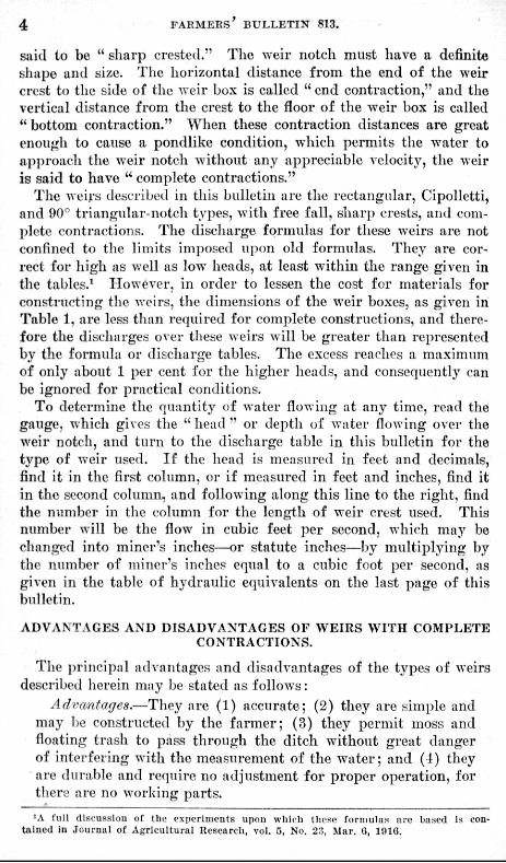
In the arid west vast sums of money have been exx^ended in tlie construction of ditch and canal systems to carry water to the lands where the rainfall is either insufficient or too uncertain for profitable agriculture, and the farmers have spent a still greater amount for preparing the land for irrigation and for purchasing " water rights," which entitle them to a certain amount of water. The value of the water has increased with the development of the country and now there is a general demand that the water be measured from the diteh to the irrigator as well as from the sti'eam to the main canal. This is an important step toward better business methods in the management of canal systems and farms, and culls for accurate and reliable information concerning devices suited to the measurement of comparatively small streams of flowing water,
DEFINITIONS.
The " w e i r " is one of the most commonly used devices for this purpose. A bulkhead or wall built across a ditch or stream, with an opening cut in the top of the wall through which the water is allowed to pass, Is called a " weir " and the opening is called the " weir notch." The bottom portion of the ditch immediately upstream from the bulkhead is the " weir b o x " or " weir pond." The height of the water surface in the weir pond above the weir crest is the "head . " When the water flows over the crest into the air before it strikes the surface of the water in the ditch downstream from the bulkhead, it is said to have " free fall," and when this overpouring stream of water touches only the sharp upstream edge of the crest, the weir is
N O T E . — T h e work on which this bulletin Is bayed was done In the hydraul ic laboratory a t For t Collins, Colo., under a cooperative ag rennen t between the Office of Exper iment Stations, Uulted S ta tes Depar tmen t of Agriculture, uud the Colorado Agricul tural Ex-perimcnf Stat ion,
For a technical repor t on the exper imental da ta see Journa l of Agricul tural Research, Vol. V, No. 2a, March 6, 1916.
The purpose of th i s bulletin is to give pruetlcal directions for the construct ion and use of the swal lc r sizes of weirs , such us a re suited to the measurement of wateT oa Irrigated t&rmn.
8
4 F A R M E R S ' B U L L E T I N 813.
said to be " sharp crested." The weir notch must have a definite shape and size. The horizontal distance from the end of the weir crest to the side of the weir box is called "end contraction," and the vertical distance from the crest to the floor of the weir box is called " bottom contraction." When these contraction distances are great enough to cause a pondlike condition, which permits the water to approach the weir notch without any appreciable velocity, the weir is said to have " complete contractions."
The weirs described in this bulletin are the rectangular, Cipolletti, and 00'' triangular-notch types, with free fall, sharp crests, and coni-])lcte contractions. The discharge formulas for these weirs are not confined to the limits imposed np<m old formulas. They are correct for high as well as low heads, at least within the range given in the tables.^ However, in order to lessen the cost for materials for constructing the weirs, the dimensions of the weir boxes, as given in Table 1, are less than required for complete constructions, and therefore the discharges ovei- these weirs will be greater than represented by the formula or discharge tables. The excess reaches a maximum of only about 1 per cent for the higher lieads, and consequently can be ignored for practical conditions.
To determine the quantity of water flowing at any time, read the gauge, which gives the " head " or depth of water flowing over the weir notch, and turn to the discharge table in this bulletin for the type of weir used. If the head is measured in feet and decimals, find it in the first column, or if measured in feet and inches, find it in the second column, and following along this line to the right, find the number in the column for the length of weir crest used. This number will be the flow in cubic feet per second, which may be changed into miner's inches—or statute inches—by multiplying by the number of miner's inches equal to a cubic foot per second, as given in the table of hydraulic equivalents on the last page of this bulletin.
ADVANTAGES AND DISADVANTAGES OF WEIRS WITH COMPLETE CONTRACTIONS.
The principal advantages and disadvantages of the types of weirs described herein may be stated as follows:
Advantages.—They are (1) accurate; (2) they are simple and may be constructed by the farmer; (3) they permit moss and floating trash to pass through the ditch without great danger of interfering with the measurement of the water; and (1) they are durable and require no adjustment for proper operation, for there are no working parts.
'A full discussion of the rxperiinents upon which thcKP forniuIan are based is contained in Journal of AgricuUural Research, vol. 5, No. 2.'!, Mar. 0, 191G.
CONSTRUCTION AND USE OF FABM WEIRS. 5 '
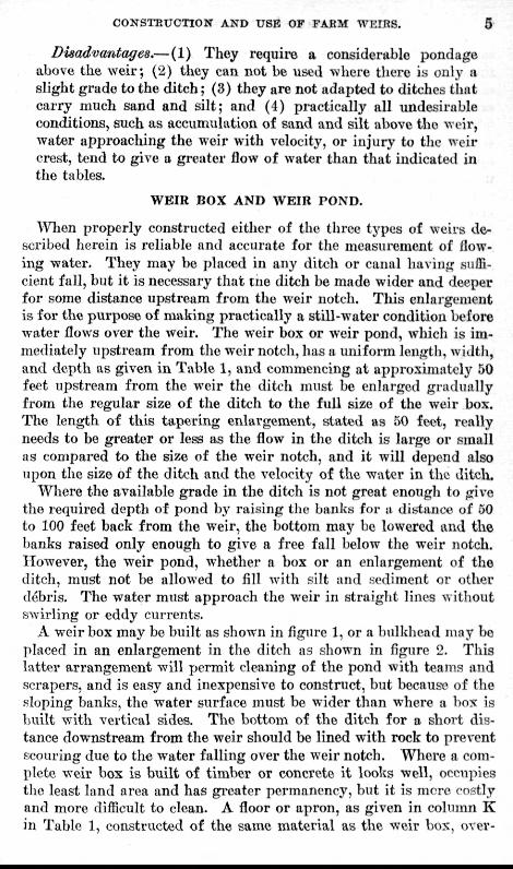
Disadvantages.— (1) They require a considerable pondage above the weir; (2) they can not be used where there is only a slight grade to the ditch; (3) they are not adapted to ditches that carry much sand and silt; and (4) practically all undesirable conditions, such as accumulation of sand and silt above the weir, water approaching the weir with velocity, or injury to the weir crest, tend to give a greater flow of water than that indicated in the tables.
WEIR BOX AND WEIR POND.
When properly constructed either of the three types of weirs described herein is reliable and accurate for the measurement of flowing water. They may be placed in any ditch or canal having sufTi-cient fall, but it is necessary that tne ditch be made wider and deeper for some distance upstream from the weir notch. This enlargement is for the purpose of making practically a still-water condition before water flows over the weir. The weir box or weir pond, whicli is immediately upstream from the weir notcli, has a uniform length, widtii, and depth as given in. Table 1, and commencing at approximately 50 feet upstream from the weir the ditch must be enlarged gradually from the regular size of the ditch to tlie full size of the weir box. The length of this tapering enlargement, stated as 50 feet, really needs to be greater or less as the flow in tlie ditch is large or small as compared to the size of the weir notch, and it will depend also upon the size of the ditch and the velocity of the water in the ditch.
Where the available grade in the ditch is not great enough to give the required depth of pond by raising the banks for a distance of 50 to 100 feet back from the weir, the bottom may ho lowered and the banks raised only enough to give a free fall below tlie weir notch. However, the weir pond, whether a box or an enlargement of the ditch, must not be allowed to fill with silt and .sediment or other debris. The water must approach the weir in straight lines without swirling or eddy currents.
A weir bos may be built as shown in figure 1, or a bulkhead niay be placed in an enlargement in the ditch as shown in figure 2. This latter arrangement will permit cleaning of the pond with teams and scrapers, and is easy and inexpensive to construct, but because of the sloping banks, the water surface must be wider than where a box is built with vertical sides. The bottom of the ditch for a short distance downstream from the weir should be lined with rock to prevent scouring due to the water falling over the weir notch. Where a complete weir box is built of timber or concrete it looks well, occupies the least land area and has greater permanency, but it is mere costly and more difficult to clean. A floor or apron, as given in colmnn K in Table 1, constructed of the same material as the weir bos, over-
6 FARMERS' BULLETIN 813.
comes the necessity for lining the ditch with rock below the weir. Precautions should be taken to prevent water from washing under the bottom or around the sides of the box. For most soils, if the earth is puddled with water as it is filled around the box, it will be safe; but where it is sandy or likely to wash, a board 12 inches wide should be placed on edge under the bottom and at the sides near the upper end of the box, to serve as a cut-oft' wall. The height of the weir crest above the bottom of the ditch downstream from the weir notch will dei>end upon the size and grade of the ditch, but this height must be such that when the greatest quantity of water is flowing over the weir the water level in the ditch downstream will be l)ek)w the crest. This is to permit the free passage of air between the bulkhead and the sheet of over-pouring water, which is the required condition for free flow.
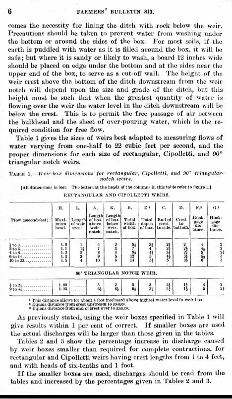
Table 1 gives the sizes of weirs best adapted to measuring flows of water varying from one-half to 22 cubic feet per second, and the proper dimensions for each size of rectangular, Cipolletti, and 90° tr iangular notch weirs.
TABLE 1.— Wvir-lmr (Uiiiriisionfi far rectangular, iHpoUctti, and i)0° triangular' notch iceirn.
[All dimensions in feet. The letters at the heads of the columns in this table refer to figure 1.1
• RECTANOULAIi AND CIPOLLETTI WRIRS.
Flow {sectmd-feet).
H.
Hiixl-miiia bead.
1.0 1.1 1.2 1.3 1.5
L.
LenRtb of weir crest.
1
3 4
A.
Length ol bo.t above weir.
notch.
6 7 8 9
10
K.
Length of box below weir.
notch.
2 3 4 5 6
B.
Totrtl width of box.
51 7 SI
12 H
E.I
Total depth of box.
31 4
5i
C.
End of crest
to side.
i 3 4 6
D.
Crest to
bottom.
3
v.*
Hook-
distance.
4
G 51 6
o.»
ITook-gage dis
tance.
2 2 a! 3 3
1,00 1.25
OO" TRIANGULAR NOTCH WEIB
6 2 Si
5 3 31
2i 3f \i\ 4
S 2 2!
' This dl3t;u!ce allows (or about } foot (rceboiu'd above highest water level in wolr box. • Equals distance from creut upstream to i»uKe. • Equals distance from end of crust over to gauge.
As previously stat^'il, using the weir boxes specified in Table 1 will g i \e results within 1 per cent of correct. If smaller boxes are used the actual discharges will be larger than those given in the tables.
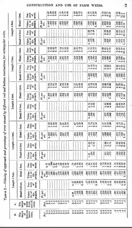
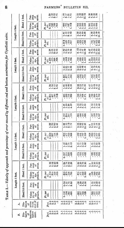
T'ables 2 and 3 show the percentage increase in discharge caused by weir boxes smaller than required for complete contractions, for rectangular and Cipolletti weirs having crest lengths from 1 to 4 feet, ami with heads of six-tenths and 1 foot
I f the smaller boxea are used, discharges should be read from the tables and increased by the percentages given in Tables 2 and 3.
CONSTBUCTION AND USE OF EABM WEIRS. 7
tPl CO S f j o S d"-< e4pi • e4raui
StO !•- c 00 O o i -J
oi^f l laj d
-" >rar4 O CO 0 1 - J *
^Pi ^ ~ e 4
d ' •
c4ciui
C O V
SS^
^s °g
. M
c4 r i u i a i
^ to if o m ^lOl ' -
d "H f .4o5 PO — OS ,-, CO t o 00 SSKS
e4i:4.ift»!
^ " • as CI M r- -p
mn H 3 [
ft
^ ^ ^
l i O f l S d — 'J
d • •
• o K c S -:c4'q)
-^§•^1
^s.4 ^^^i
!S3a CO -^ WP l OONCO t - 00 ^ 1 > . «
1—r-00 u i ^ • ^ e 4 u i
•-••Smi rt'T'AJ^
£ i ° i
^•
ffs'
£S' 5-fe
1 4
d ' - J
d ' 'i-icJ ' • .-i--ni " S — S o K S ^ i N M CO'-• m 5 S .—1" K i5 (5
h c g t - m Q _ Q o o - * ep?3
e^« S§sis
js ^ g ^ K s sjsffisss a s s s a
irif!Dtt^fD O i - ^ " ^ ^ * ^ ^a>Oi rT-o i <- i» '^ i ' -Qig
sS32g nat^sss Si^s^s a s s s a
^ 2 'SigS •OOtf^OiO O0'f^0»-1 »00i/>0»0 »OC3»OOfcO
, o o o o o fs Ifl") >n "5 i :mrfrfpjrfpie4c4e^Pi
0 0 0 0 0 iOift ir^4rt i f l 0 0 0 0 0 i n « < 0 « i O C494C4«4C4 ^ J r t - H * H p 4 ^ , - i r - i r J
FAEMERS' BULLETIN 813.
&Z'
Q. (t CO -^cD ^ " • K •'5 t i 1 - OS
^ - d • • •
1^ 0(1 d " !
F- tJ •-• 1 S c5 f c
— C» PICO to -« c ; o=
1 ^ O K pi
T-- 5i Q --1 m Tf-1 ( CO
e j o i—i cp CD to i^ n - f ' S c o o n
in 1-. M !
^ § ^ 1 (C OC ! - • * •-• pi v o o
io 5"t l CO O lO if^
^ 3 pi S o ^ ^ , J _ ; p i
- i - p i - r f
PI t - IC. I-JO u^ [ - c : CO
11 = ^ r-' pi cd
-H o t e 00 CD tr o — - - P3 ^ t o C^ ifl to Oa rff
fc CO [ - c rt
ft.c:Si3S?S g - d • • •
> - S.
is a«™ D
| § :
P3 S s S irj l i i - - to
sss; • • ' - J
« « P 1 C ( J
Ol OP5 a
i -*cipi 1- w iri - j d
S o i l e d
• * cii I - 1 - ^ - -
h w I-- -p to i ; . fri o — - f a-; , to PS •'51- P S •!• CO 1
Ol r-. t - (S ac c 00 i ;
• • ' -J
. § ° i i ^.
3nsg
O »''- ^ ^ ?5 PI m ^ Cl 5 -.p cc
> O s p ? c ^ : - ^ ^ o i
01P4 Q c O 1.^ lO ^ ' - ' i-i - - p i o J — -Hpji-;
o 5 « i ^ W
.-JpirooJ
c3 Q C ^ O J PI 03 rt • * CO PSpjcd U5--J
i?^l , -i
fc O - * PJ in S. t; r i PS J ^
£ ; -d ' • •
• f - H « 0 C^ O ^ O
a.;
M l - H I - - P i
ss;
- - i o « > d
-5 -H Pitrf
i r~ .--J P I ? 1^ C GC
*r? • " c r T-i ^ T~ SI . o ^ o ^
0 " d CTT £ c i c4 fH 1-5 ' • O O K J O U J
P3 c4 -J <-"' ' lO O in o "5 !?] C4 -H T-i •
5 " — •
! !£••
, o o o o " pi pj p* ( ^
1/5 lo in i.T lo
CONSTHUCTION' AND USE OF J-'AHM WEIRS. 9
WEIR C R E S T S A N D S I D E S .
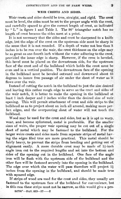
Weir crests and siden should be true, sti-aiglit, and rigid. The crest must be level, the sides mwst be set to the proper angle with tlie crest, and carefully spaced to jrive the correct lengtli of crest, as inclicated by " L " in figure 1 and Table 1. The 90" triangular notch has no length of crest because the sides meet at a point.
I t is not necessary that the sides and ci-est be sharpened to a knife edge, but the edge of the crest on the upsti-eam side must be sharp in (lie sense that it is not rounded. If a depth of water not less tlirtu H inches is to be run over the weir, the crest thickness on the edge may bt' as great as one-fourth incli without the water adhering to the crest, provided the inner edge is sharp. However, if the crest is beveled, this bevel must be placed on the downstream si(Je, for the upstream face of the crest and of the bulkhead which holds the crest must be even and in a vertical position. The downstream face of the opening in the bulkhead must be beveled outward and downward about 45 degrees to insure free passage of air imder the sheet of water as it flows over the weir.
Instead of cutting the notch in the bulkhead to just the size desii-ed and leaving this rather rough edge to serve as the cref! and sides of the weir notch, it is better to make the opening in the bulkhead at least 1 inch deeper and 2 inches wider than the desired size of weir oi>eiung. This will permit atttichment of crest and side strips to the bulkhead so as to project about an inch all around, making more perfect edges, and the overpouring sheet of water will not touch tlie bulkhead.
Wood may be used for the crest and sides, but as it is apt to warp, wear, and become splintered, metal is preferable. For the smaller sizes of weirs, the proper weir opening may be cut out of a single sheet of metal which may be fastened to the bulkhead. For the larger weirs crests and sides made from separate strips of metal having the edges filed true are more practical. This metal should be fairly heavy, to prevent the strips from bending and getting out of alignment easily. A more durable crest may be made of lA-inch angle iron cut to the required lengths and set into the bottom and sides of the opening cut in tlie bulkhead. One face of the angle iron will be flush with the upstream side of the bulkhead and the other face will be fastened securely into the opening in the bulkhead. The edge over which the water will pass therefore will project l i inches from the opening in the bulkhead, and should be made true with squared edge.
If strips of wood are used for the ci-est and sides, they usually are fastened to the upstream face of the bulkhead for comenience, but in this case these strips must not be narrow, as this would give a pro-
84700°—Rull. 813—17 2
10 FARMERS' BULLETIN 813.
jection the thickness of the strip, whicli will reduce the accuracy of Uie measurement of the water. With whatever type used, the joints foi'med by the sides and crest must fit nicely without leaving a crack and without causing an offset. , . ,
WEIR GAUGE.
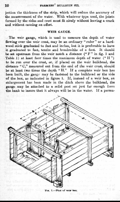
The weir gauge, which is used to measure the depth of water flowing over the weir crest, may be an ordinary " r u l e r " or a hardwood stick graduated to feet and inches, but it is preferable to have it graduated tt) feet, tenths and hundredths of a foot. I t should be set upstream from Uie weir notch a distance (" F " in fig. 1 and Table 1) at least four times the maximum depth of water ( " I I " ) to be run over the crest, or, if placetl on the weir bulkhead, the distance " C," measured out from the end of the weir crest, should be at least two times tlie dej>tii " H ." If a complete weir box has been built, the gini>ic may be fastened to the bulkhead or the side of the box, as indicated in figure 1. If, instead of a weir box, an enlargement }ia,s been made in the ditch above the bulkhead, the gauge may be attaclied to a soljil post set just far enough froui the bank io insure that il always will be in the water. If a perma-
P l B . 1 .—Plf in tif W^l* b«X. ! . V -*r .. : . ' " ;
CONSTRUCTION AND USE OF FARM WEIBS. J J
nent gauge is not desired, a block or otiier solid suppurt should bo providetl at the proper distance upon which to set a s<?a]e when taking readings.
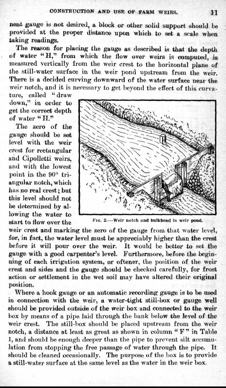
The reason for placing the gauge as described Is that the depth of water " I I , " from which the flow over weirs is computed, is measured vertically from the weir crest to the horizontal plane of the still-water surface in the weir pond upstream from the weir. There is a decided curving downward of the water surface near the weir notch, and it is necessary to get beyond the effect of this curva-tiH'e, called " draw down," in order to get the correct depth of water " I I . "
The ;4ero of tlie gauge should be set level with the weir crest for rectjingular and Cipolletti weirs, and with the lowest point in the 90' triangular notch, which has no real crest; but this level should not be determined by allowing the water to start to flow over the weir crest and marking the zero of the gauge from that water level, for, in fact, the water level must be appreciably higher than the crest before it will pour over the weir. I t would bo better to set the gauge with a good carpenter^s level. Furthermore, before the beginning of each irrigation system, or oftener, the position of the weir crest and sides and the gauge should be checked carefully, for frost action or settlement in the wet soil may have altered their original position, ' :,. •
Where a hook gauge or an automatic recording gauge is to be used in connection with the weir, a water-tight still-box or gauge well should be provided outside of the weir box and connected to the weii' box by means of a pipe laid through the bank below the level of the weir crest. The still-box should be placed upstream from the weir notch, a distance a t least as great as shown in column " F " in Table 1, and should be enoiigli deeper tJian tlie pipe to present silt accumulation from stopping the free passage of water through the pipe. I t should be cleaned occasionally. The purpose of the box is to provide a etiU-water surface at the same level as the water in the weir box.
Flu. 2.—Weir notch nnd buDcbcad In weir potid.
12 F A R M E R S ' B U L L E T I N 813.
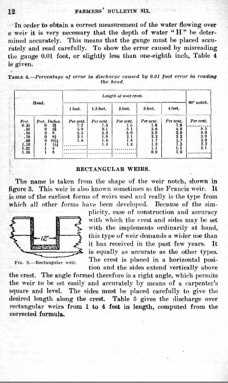
In order to obtain a correct measurement of the water flowing over a weir it is very necessary that the depth of water " H " be determined accurately. This means that the gauge must be placed accu-i-ately and read carefully. To show the error caused by misreading the gauge 0.01 foot, or slightly less than one-eighth inch. Table 4 is given.
TABLE 4.—Percentage of error in discharge caused hy 0.01 foot error in reading the head.
Feet. 020
.30
.50
.70
.90 1.10 1.25 1.50
Feet. Inches. 0 2i 0 ,l | 0 6 0 H 0 lOH 1 Hi 1 3 1 6
Length of weir cri'at.
Ifoot,
Per cent. 7.2 5.0 3 5 2.1 1.8
1.5 feet.
Per cent. 7.B &.1 3.2 1.9 1.8 1.4
2 feet.
Per cent. 7.5 5,1 3.0 2.1 1.8 1.3
3 feot.
Per cent. 7,6 5.6 2.9 2.2 1.7 1.3 1.1 0.9
4 feet.
Per cent. 7.9 4.8 2.9 2.2 1.7 1.3 l . l l.D
90' notch.
Per cent.
8.5 5,0 3.9 2.9 2.2 2.1
RECTANGULAR WEIRS.
The name is taken from the shape of the weir notch, shown in figure 3. This weir is also known sometimes as the Francis weir. I t is one of the earliest forms of weirs used and really is the type from which ijll other forms have been developed. Because of the sim
plicity, ease of construction and accuracy with which the crest and sides may be set with the implements ordinarily at hand, this type of weir demands a wider use than it has received in the past few years. I t is equally as accurate as the other types. The crest is placed in a horizontal position and the sides extend vertically above
tlie crest. The angle formed therefore is a right angle, which permits the weir to be set easily and accurately by means of a carpenter's square and level. The sides must be placed carefully to give the desired length along the crest. Table 5 gives the discharge over rectangular w^eirs from 1 to 4 feet in length, computed from the corrected formula.
Fio. 3.—Rectangular weir.
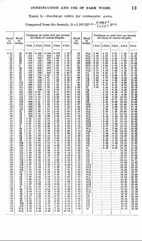
CONSTRUCTION AND USE OP FARM WEIRS. l^ TABLE 5.—Dinvharyc itibtct for rrvtaiigtihtr iccirn.
Computed from the formula (?=3.247I// ' -"- J:; " V.B ^'^'•'-
H i n d HI
feet.
0.20 .21 .22 .23 .21 .25 .26 .27 .2S .29 .30 .31 .32 .33 .31 .35 ..16 .37 .3R .39
.« .41 . .42
.43
.44
.45
.46
.47
.4N
.10
.60
.Til
.52
..•a
.54
.55
.56
.57
. 5S
.r,9
.60
.61
.62
.03
.64
.Ii5
.66
.67
.ON
.69
.70
.71
.72
.73
.74
.75
.76
.77
.78
.79 ,80 .81 .N2 .83 .84 .85
H e a d in
inches.
2 i 3}
^ 2j 2J 3
H H 3i 3* 3i ^l
3d ih
^', ^, 4A 4V 4 4 H 6i'r 5, ' , 51 5g 5 | 51 6? H 6 6 6
« 6 6 6
ft 6 7V
it i 8 S 81 ^1
H 8 » 9 9 oi 9l
il lOA
Discharge In niWc feet per second for crests of various length;^.
I I f o o t . l.Sfeat.
0.291 ,312 .335 . 358 .380 .101 .42K . 4.')2 .477 .503 .527 .5,53 .580 .606 .634 .601 .688 .717 .745 .774 .804 .833 .863 .893 .924 .955 .980
1.02 1.05 1,08 1.11 1,15 1.18 1.21 1.25 1.28 1.31 1.35 1.38 1.12 1.45 1.49 l..'i2 1.56 1.60 i , r a 1.67 1.71 1.74 1,78 1.^2 1.K6 1.90 1.93 1.07 2.01 2,05 2.09 2.13 2.17 2.21 2,25 2,29 2.33
2,:i7 2.41
0.439 .472 ,505 ..5.39 .574 .609 .646 .682 .720 . 758 .796 . 836 .876 .916 .mi .999
1.01 1.08 1.13 1.17 1.21 1 26 1 30 1.35 1.40 1.44 1.49 1,54 1.50 1.64 1.68 1,73 1.78 1-84 1.89 1.94 1.99 2.01 2.09 2.15 2.20 2.26 2,31 2. .16 2.12 2.47 2. ,53 2, r,9 2.61 2.70 2,76 2.81 2.87 2,93 2.99 3.05 3.11 3.17 3.23 3.29 3.35 3.41 3.47 3, ,51 3 .W 3,66
2 feet.
0. ,588 . 632 .677 .723 .769 .817 .865 • .911 . 965
1.02 i.iy; 1.12 1.18 1.23 1.2R 1,34 1.10 1,15 1.51 1.57 1,63 1.69 1.73 1.81 1.88 1,94 2.()0 2,1)7 2,13 2.20 2.26 2,33 2,40 2.1ft 2- 53 2,60 2.67 2 .71 2.81 2.88 2.96 3. IB 3.10 3,17 3.25 3,32 3,40 3.47 3. ,56 3.63 3,71 3,78 3,88 3.94 1.02 1,10 1.18 4,26 4.-34 1,42 4. r,i 1-,19 4.67 4.75 4.84 4.92
afeflt.
0.887 . 0.5-}
1,<\2 1.09 1,16 1,23 1.31 1,38 M O 1..53 1.61 1-69 1.77 1.86 i .m 2,02 2.11 2.20 2.28 2,37 2.46 2. .55 2.65 2.74 2.83 2.93 3.03 3.12 3.32 3.32 3.12 3. 52 3.62 3.73 3-83 3.91 4.04 1,15 4.26 4.30 4.47 4.59 4,60 1.81 4.02 5.03 5.15 5.26 5.38 5.40 5. 61 5.73 5,8,5 r,. 97 6,09 6.21 6.33 6.15 6.58 6.70 (>.H3 fi. 95 7.118 7 21 7.33 7,46
lleet.
1,19 1.28 1,37 1.16 1.55 1,65 1.75 1,85 1.95 2,05 2.16 2.26 2.37 2,48 2.60 2.71 3.82 2.94 3.06 3,18 a.:H) 3.42 3. ,54 3.tl7 3.80 3,93 1,05 4.18 4.32 4.45 4, ,58 4.72 4.80 l.ftS 5. 13 5.27 5.42 5.56 5,70 5.85 6.00 6.14 6,29 6.41 0. ,59 6.75 6,90 7.05 7,21 7.36 7. 52 7.68 7.84 «.00 8.17 8.,33 8.49 8,6fl 8.82 8.99 9 .W fi.33
u. m 9.67 S.H4
10,01
H e a d In
feet.
.86
.87
.«« ,89 ,90 .91 .92 .93 ,94 ,95 .96 .97 .98 ,99
1,00 l . l l l 1.{I2 1.03 1.04 I.O,'. 1.06 1.07 1.08 1.09 M O 1,11 1.12 1.13 1.11 1.15 1.16 M 7 1.18 1,19 1.20 1 21 1.22 1.23 1.24 1.25 1,26 1.27 1.28 J.29 1,30 1.31 1.32 J. 33 1.34 1.35 1.36 1.37 1.38 1.39 M O M l 1.12 1.43 M l 1. 45 l . W 1.17 1,18 M 9
i.r,o
II<-ad in
Inches.
!0,>, i(V. 1(1^ 10 10 lOlt " i v
\\t Hi! l U i i |
DIscharRe In Miblc fp<>t per second lor crests of var ious l eng ths .
I foo t .
2 46 2..')0 2..^1 2.58 2.62 3,67 2.71 2.75 2.79 2.84 2.88 2 93
n j ! 2.97 111 1 3.01 12 12 12 12 12 12
n 12J 12.
•
•
3.06
,.
13, . 1 13A 13,*, 13>ri 13^1^ I 13 , 13 13 H A H A 14 14 14 14 11 14 15 151 15^ 15J 15 1.51 15 I5ff 15 |} 1"!^ IflA I 6 A I'hV ! 6 , ' 16}
m Ifii 17A 17 17 nv 171 175 171 18
l .Sfeet
3,72 3.79 3.85 3,92 3,98 1.05 1.11 4.18 4,24 4.31 4.37 4 .41 4.51 4,57 4.64 4.71 4.78 4,85 4,92 4.98 5.05 5.12 5.20 6.36 5.34 B-41 S.48 5.55 6.62 6.69 8,77 5.84 5.91 6.98 e,oe 0.13 6,20 6,28 6,35 6,43
I 1
3 feet.
5.01 5, 10 5,18 5,27 5,36 5,44 5.53 6.62 5,71 6,80 5,8S 5.98 6.07 6.15 6,25 6.34 6-43 6. .52 6.63 6.71 6,80 6.90 6.99 7.09 7,10 7.2H 7,38 7.47 7.57 7,ft8 7,78 7.88 7.96 8.06 8,18 8,26 8.35 8,16 8,56 8,86
3 feet.
7,59 7,72 7,H5 7.99 8,12 8.25 8.38 8,52 8.65 8,70 8.93 9.00 9.20 9.34 9.48 9.62 9,78 9.90
10. (H 10.18 10.32 10.4« 10,61 10. 76 10,90 U . ( H 11,19 11,34 11.48 11.61 11,79 11,94 12,09 12,24 12.39 I 2 5 1 12,69 12,85 12.99 13.14 13.30 13.15 13.61
13,93 11.09 14.24 14.40 14, W 14.72 14, K8 15.04
16,36 16.53 16.69 15, »5 16.02 16.19 16.34 10.51 16.68 16.85 17,01 '17,17
i
4 feet.
10,19 10.36 10.54 10.71 10.89 11,07 11,3S 11,43 11.Gl It.Tfl 11.98 13.16 13.34 12.53 12.73 12.91 13.10 13 28 13,47 13. ed 13,85 14.04 14,24 14.43 14,64 U.K3 1.5,03 15.23 16.43 15.09 Lisa 16.03 16.23 16,43 16.03 16,83 17.03 17.38 17.45 17.65 17.87
19. 55
1 4 " FARMEBS' BULLETIN 813.
CIPOLLETTI WEIRS.
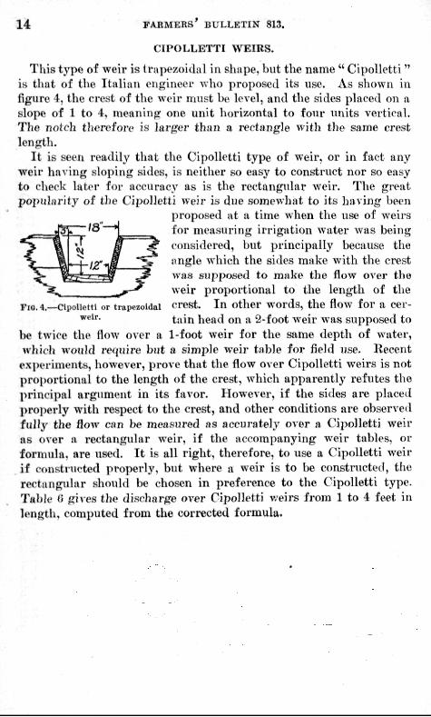
This type of weir is trapezoidal in shape, but the name " Cipollet t i" is tliat of the Italian engineer who proposed its use. As shown in figure 4, the crest of the weir must be level, and the sides placed on a slope of 1 to 4, meaning one unit horizontal to four units vertical. The notcli therefore is larger than a rectangle with the same crest length.
I t is seen readily that the Cipolletti type of weir, or in fact any weir having sloping sides, is neither so easy to construct nor so easy to check later for accuracy as is the rectangidar weir. The great popularity of the Cipolletti weir is due somewliat to its having been
proposed at a time when the use of weii-s for measuring irrigation water was being considered, but principally because the angle which the sides make with the crest was supposed to make the flow over the weir proportional to the length of the
FiQ.4_Cii,oUetti or traiiezoidai crest. I n other words, the flow for a cer-"'''''• tain head on a 2-foot weir was supposed to
be twice the flow over a 1-foot weir for the same depth of water, whicli would require but a simple weir table for field use. Recent
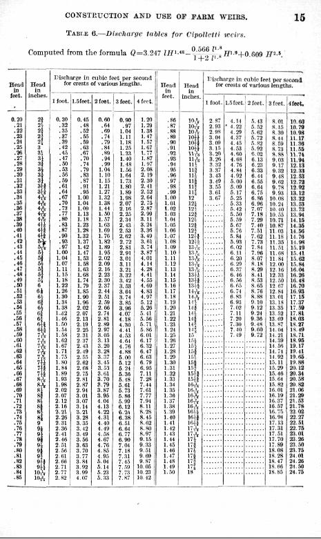
e.vperiments, however, prove that the flow over Cipolletti weirs is not pro[)ortional to the length of the crest, which apparently refutes the priiK-ipa! argument in its favor. However, if the sides are placed properly with respect to the crest, and other conditions are observed fully the flow can be measured as accurately over a Cipolletti weir as over a rectangular weir, if the accompanying weir tables, or formula, are used. I t is all right, therefore, to use a Cipolletti weir if constructed properly, but where a weir is to be constructed, the rectangular should be chosen in preference to the Cipolletti type. Table fi gives the di.srhai'ge over Cipolletti v/eirs from 1 to 4 feet in length, computed from the corrected formula.
CONSTEUCTION AND USE OF FARM WEIRS.
TABLE Q.—^Dlsvhargc tables for VipoUcifi trcir:^.
Computed from the formula Q=3.247 lH^-*^~-^.^^^-^l'lm'+0.Ci09 ff^-'.
16
Head in
feet.
.
0,21) .21 ,22 .23 .24 ,25 .26 .27 .28 ,39 .30 .31 .32 .33 .34 .35 .36 .37 .38 .39 .40 .41 .42 .43 .44 .45 .46 .47 .48 .49 .60 .51 .52 .53 .51 ..55 .56 .57 ..58 .59 .60 .61 .62 .63 .64 .65 .66 .67 .68 .69 .70 ,71 .72 .73 .71 .76 .76 .77 .78 .79 .80 .81 .82 .83 .81 .85
H e a d In
inches .
2i 2i 23 23 2s 3 ^^ H 1 3i
3 ^ • .
s-ti 3il ^1
*^ ii'f 4A 4 4 4 4
V 1 j j
^ ^'( 5J a 5 | 5} 5 | 6 6 i 61
of 6i
of
7"' 7A 7A
\i nil 7H 8A 8A H 8<
«l RJ f I 9 91 9 9i 9. 9 9'
lOA i»A
DLicharge In cub ic feet per second tor crests of var ious l eng ths .
- -— I foo t .
0,30 .32 .,15 .37 .39 .12 .15 .17 ,50 .53 .,56 .59 .61 .64 .67 .70 .73 .77 .80 .83 .87 .90 .93 .97
1.00 1,04 1,07 1,11 1,15 1.18 1.22 1.26 1.30 1.31 1.38 1.J2 1,16 l.,^fl 1,54 l.,5,S 1.62 1,67 1.71 1.75 1.80 1.81 1.89 1.S3 1.98 2,02 2.07 2,12 2.16 2,21 2.26 2.31 2.36 2.11 2,16 2. 51 2. .W 2.61 2.66 2.71 2,77 2.82
1.5feet.
0,45 .18 .52 .56 ..59 .63 .67 .70 ,74 .79 .83 .87 .91 .95
1,00 i.m 1.09 1,13 ] . ! 8 1.23 1.38 1.32 1.37 1,42 1.17 1..53 1,.58 1.63 1.68 1.74 1.79 1.85 1.90 1.96 2,02 2.07 2,13 2.19 2,25 2.31 2..17 2, 13 2.49 2. .''5 2,62 2.68 2,75 2.81 3.87 2,91 3,01 3.07 3,11 3.21 3.28 3.35 3,12 3.19 3,50 3,63 3.70 3.77 3.81 3,92 3,99 4.07
2 feet.
0.60 .61 .69 .71 .79 .81 .89 .94 ,99
1.04 1.10 1. 15 1.21 1.27 1.32 1,38 M l 1,.50 1,.57 1.63 1,69 1.76 1.82 1.89 1,95 2,02 2,09 2,16 2.23 3.30 2.37 2.14 2,51 2.ri9 2.66 2,71 2.81 2 89 3.97 3,05 3.13 3.20 3,28 3.37 3.15 3,53 3. til 3.70 3.79 3,87 3,95 I.Ot 1,13 1.22 4,31 4,10 4.19 4,58 1.67 4,76 4.85 4.95 5.04 B i t 5.23 5.33
3 feet.
0.90 .97
1,01 1.11 1.18 1.25 1,33 1,10 1,18 1,56 1.64 1.73 1,80 1.89 1,98 2,07 2,16 2,25 2,31 2,13 3. .53 2.63 2.72 2.81 2.91 3,01 3,11 3,21 3,32 3,12 3,53 3,64 3.74 3.85 3.96 4.07 4.18 1.30 4,41 4.53 4.64 4.78 4,88 5.00 5,12 5.24 6,36 5.18 5,61 5,73 5,86 5.99 6.12 6.21 6.38 8,51 6.61 6,77 6.90 7.01 7.18 7,31 7.15 7. .59 7-73 7-87
4 feet.
1,20 1.29 1,38 1.47 1.57 1.67 1,77 1,87 1.97 2,08 2,19 2,30 2,11 2.52 2.64 2.75 2.87 2,99 3.11 3,24 3,38 3.19 3.61 3.74 3.87 4.01 4,14 4.28 4.41 1,55 1,69 4,83 4,97 .5.12 5.20 5,41 5. m 5,71 .1.86 6.01 6.17 6.32 6,47 0.63 6.79 0.95 7.11 7,3s 7.44 7.61 7 77 7 94 8.11 8,28 8,15 8.62 8,80 8.97 9.15 9.33 9.51 9.69 9.87
10,05 10.21 10,42
H e a d in
feet.
.86 ,87 ,88 ,89 .90 .91 ,92 .93 .91 .95 ,98 .97 .98 .99
1.00 1,01 1.02 1,01 l .Ot 1. Ik'i 1.06 1,07 1,08 1.09 1,10 l . l l 1,12 1.13 1.11 1.15 1.16 1,17 M S 1,19 1.20 1.21 1.22 1.23 1.21 1.25 1.28 1.27 1,38 1,20 1.30 1.31 1.32 1,33 1.34 1.35 1.36 1,37 l.,18 1,39 1,40 1.41 1,42 1.13 1.14 1,15 1.40 1, 17 1.48 1.49 1,50
H e a d In
Inches.
W^ lOA 10'„ lOH 1(44 lOH U A
f! na H i
11*
m 12 121 12V 123 12.1 12} 12i 1 2 i | 12U 13A l ^ A 13A I 3 A 13,'s 13U
mi 11H 11A
llf m J-*^
I'a 111 i n 15
13 i . ' i 15.',
11 1511 1.5H lOA I'V iV 16A 16A 16, ' , IfiU 1611 15H 17 A
If-* 17: in
171 18
l ^ c h a r g e in cub ic feet per second tor crests of var ious lengths .
1 foot.
2.S7 2.93 2.98 3.04 3.09 3.15 3,2fl 3.26 3,32 3,37 3.13 3,49 3.,55 3.61 3,67
, 1.5 feet.
4.14 ' 4.22
4.29 4.37 4-15 4-53 l.fifl 4-68 4.76 4-81 4.92 5.00 5.09 5.17 5.25 6,.13 5.42 5-50 5..59 5.67 6,76 5.84 5.93 6,02 6.11 6.20 6.29 6,37 6,16 6. ,56 6 65 6.71 6,8,1 0.93 7.02 7.11 7.20 7.30 7.JO 7.19
2 feet.
5.13 5.,52 5.62 5.72 5.82 5.92 6.02 6.13 6.23 6.33 6.41 6,.55 6.64 6.75 6,88 8.90 7.07 7.18 7,39 7.10 7.51 7,62 7,73 7.84 7.96 8.07 8. IS 8.29 8.11 8.53 8.6.5 8,76 8.88 0,10 9.12 9.31 9.36 9.18 9,60 ».72
3 feet.
8.01 a. 15 8.30 8,44 8..';9 8.73 8.S8 9,03 9.17 0.32 9.18 9,62 9.78 9.93
10.08 10.24 10. 10 10. ,5, 10,71 10.87 11.03 11.18 11.35 U . 5 t 11,68 11,84 12.00 12.16 12. 33 12.,W 12 67 12 81 13.01 13.18 13.15 13. .53 13 69 13 S7 U . 0 1 n . 2 1 14,19 14.50 14.71 14,92 15.11 15,29 15.46 15.64 15.82 16.01 16.19 16.37 16,57 ie.7r> 16,94 17.13 17.31 17,51 17,70 17.89 18.03 18.28 18.47 18.66 18,85
• " - ' ^
I feet .
10.60 10.79 10.98 11.17 11 3a 11,55 11.74 11.04 12.13 12.33 12.53 12.72 12.92 13.13 13.32 13,63 13.73 13.91 14.15 14.35 11,58 14.70 14.98 15,19 15,41 15,62 15.84 16,04 16.36 16.18 16,70 10.93 17.15 17,37 17.59 17.81 18.03 l-*.27 IS. 19 18.71 18,95 19.17 19.11 19,05 19.88 20,12 20.34 20,53 30.83 21,00 21,29 21.53 21,78 22 fl2 22 27 22.51 22.75 23, Ot 23,26 23..50 23-75 21 01 24.26 21-50 24.75
X 8 ' ' FAEMEKS' BULLETIN 813.
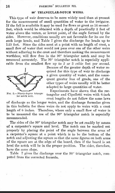
90" TRIANGULAR-NOTCH WEIRS.
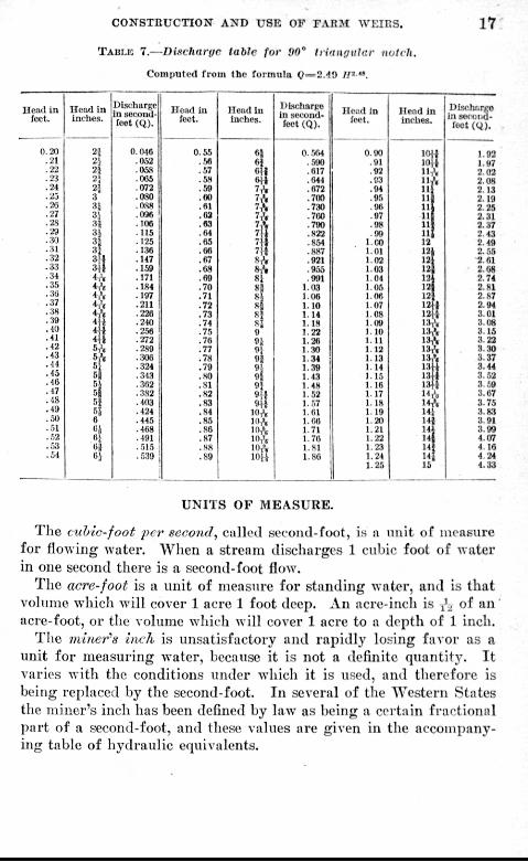
This type of weir deserves to be more widely used than at present for the measurement of small quantities of water to the iiTigator. I f the fall is available it may be used for flows as great as 14 second-feet, which would be obtained with a depth of practically 2 feet of water above the vertex, or lowest point, of the angle formed by the sides. However, conditions usually are not favorable for its use for such large heads, and Table 7 gives the discharge for heads up to 1.25 feet. Since the sides meet at a point with no length of crest, a .small B^ow oi water that would not pass over one of the other weirs without adhering to the crest and therefore making the measurement worthless, will Bow free in the 90° triangular notch and may be measured accurately. The 90° triangular notch is especially applicable from the smallest Bow up to 2 or 3 cubic feet per second.
Because of the greater depth of water required for this type of weir to dischai-ge !i given quantity of water, and the consequent greater loss of grade, one of the other types of weirs usually will be better adapted to large quantities of water.
Experiments have shown that the rectangular and Cipolletti weirs with O-inch crest lengths do not follow the same laws
of discharge as the longer weirs, and the discharge formulas given in this bulletin for these weirs do not apply to weirs with a crest length of G inches. Therefore, where only a small flow of water is to be measured the use of the 90° tr iangular notch is especially recommended.
The sides of the D0° triangular notch may he set readily by means of a carpenter's square and level. The notch can be marked out properly by placing the point of the angle between the arms of a carpenter's square at a point which is to be the bottom of the notch and adjusting the square so that the same figures on both arms of the srpiare are at the edge of the board, then if the board is set level the notch will be in the proper position. The sides, therefore, have the same slope.
Table 7 gives tlio discharge over tJie 90^ triangular notcli, computed from the corrected formula.
CONSTHUCTION" AND USE OF FARM WEIRS. 1 7 1
TABLE 7.—Disvhargc table for DO" trinnguUir notch.
Pompntud from the formula Ct=2.-!0 //='".
I lcai l i n foot.
0.30 ,21 .22 .23 .24 .25 .20 .27 .28 .29 .30 .31 .32 .33 .34 .35 .36 .37 .38 .39 • 10 .41 .42 .43 .14 .16 .16 .47 .18 .19 .50 .51 ..52 .,53 ,51
H e a d i n Incht 's .
n 21 2i 2-i 2'. 3 31 3.1 3a 31 33 3]
3l* 3!i i \ ii'„ 4, ' , 4 A * l ' .
4 U
4 U 5, ' , 5 A
M si 1
5i 53 6
5! oa 01
BischarRe in socond-fcet (Q) .
0.048 .052 .058 .065 .072 .080 .088 .096 .106 .115 .125 .136 .147 .169 .171 .184 .197 .211 .226 .210 .2.50 .272 .289 .306 .324 ,313 ,362 .382 ,103 .424 .146 ,168 .191 .515 .539
Head in feet.
0.55 .56 .57 .58 .59 ,80 .81 .63 ,63 ,64 ,65 ,66 ,67 .08 ,69 .70 .71 .72 .73 .74 ,75 .76 .77 ,78 .79 .80 .81 .82 .83 .84 .85 .86 .87 .88 .89
nca<i in inches.
6} 6 j 61 (4 7, ' , 7A 7 A 7 A 7V 7 7 7 8 A 8 A 81 8 ] 8} 8 | 8 | 81 9 9jt "i o| 9.; 9^ 93 Bit 9^.i
10,V l i 'A lOA lOA loX 10 1
IMscliarfro In .scwmd-foet CQ).
0..504 .,590 .617 .044 .672 .700 .730 .700 .790 .822 .851 .887 .921 ,955 ,991
1.03 1,06 1.10 1 1 4 1.18 1,22 1.26 1-30 1.34 1,39 M 3 1.48 1,52 1,.')7 1,01 i . r a 1,71 1-76 1.81 1,80
Hciid In let 't.
0.90 .91 .92 .'J3 .94 ,95 .96 .97 .98 .99
l.(X) 1.01 1.02 1 0 3 1,01 1.05 1,06 1.07 1.08 1.09 1.10 1.11 1.12 1.13 1.14 1.15 1,16 1.17 1,18 1-19 1.20 1.21 1,22 1.23 1-21 1.25
I le . td i n inches .
1 0 « 10| 11.•< " A III llj n It 11 11 12 12 12 121 12 12 12 12 12 1 13A
isX 13A 13,» 131 13+ 1 3 | I V . i *A 14 11 11 14 14 14 16
DIschr.rco inscco i .d -
f e o t ( y ) .
1.93 J. 97 2.03 3,08 3,13 2.19 2.35 2,31 2.37 2,43 2.49 2, .55 2,01 2,08 2,74 2. SI 2.S7 2.94 3.01 3.08 3,15 3.23 3.30 3,37 3.44 3. .52 3..'>9 3.07 3,75 3.83 3,91 3.99 4,07 4.16 4.24 4.33
UNITS OF MEASURE.
The (iihic'foot per second, called second-foot, is a unit of measure for flowing water. When a stream discharges 1 cubic foot of water in one second there is a second-foot flow.
The acre-foot is a unit of measure for standing water, and is that volume which will cover 1 acre 1 foot deep. An acre-inch is ^ of an ' acre-foot, or the volume which will cover 1 acre to a depth of 1 inch.
The mtner''fi Inch is unsatisfactory and rapidly losing favor as a unit for measuring water, because it is not a definite quantity. I t varies with the conditions under which it is used, and therefoi-e is being replaced by the second-foot. In several of the AVestern States the miiier's inch has been defined by law as being a certain fractional part of a second-foot, and these values are given in the accompanying table of hydraulic equivalents.

1 8 F A R M E R S ' BULLETIN 813.
TABLE OF HVDBAUUC EQUIVALENTS.
1 cubfe foot equals T.4,S ^latloiw, or upproxiiuiitely 7j fjulloiis. 1 cubic foot of water welt^Iis appruximately 02i pouml.s. 1 cubic foot per set-dml equiiis 44S.S3 gulluiw jier minute, or approximately
45o gallons per minute. 1 cubic fciot per second flowing for 1 hour equals approximately 1 acre-inch. 1 euhic foot per second flowint; for 12 hours eciuals appromiiitely 1 Hcre-f*K)t. 1 cuhlc-foot per second flowing for 24 hours G(|UII1S apprnxiiuately 2 acre-feet. 1 acr(?-f(»ot e(iuats 43,r»60 cubic feet, equals 325,851 gaUoiis. 1,000,000 cubic feet equals 22.95 acre-feet.
I n Ca l i fo rn ia , N e v a d a , a n d M o n t a n a 1 m i n e r ' s inch ( s t a t u t o r y inci i) e(pi.als ^ of 1 cubic foot pe r second.
In Utah, Idaho, and Arizona 1 miner's inch (statutory inch) equals T^ of 1 cubic foot per second.
In Colorado it is generally assumed that 1 miner's inch (statutory inch) etpials l/'dHA of 1 cubic foot per second.
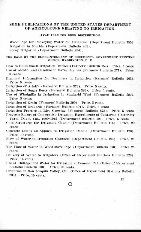
S O M E P U B L I C A T I O N S O F T H E U N I T E D S T A T E S D E P A R T M E N T O F A G R I C U L T U R E R E L A T I N G T O I R R I G A T I O N .
AVAILABLE FOR FREE DISTRIBUTION.
Wood r i p e for Conveying Wate r for I r r igat ion (Depart iueut Ilulletiu 155). I r r iga t ion in Flor ida (Depar tment Bulletin 402). Spray I r r iga t ion (Depar tment Rulletiii 4!)4).
FOR SALE BY THE SUPERINTENDENT OF DOCUMENTS, GOVERNMENT PRINTING OFFICE, WASHINGTON, D. C.
How to Build Snmil I r r iga t ion Ditches (I^'armers' bul let in ^r^'<). Price. .I coiitH. Use of Alcohol and (iasoUue iu F a r m Engines (Fa rmer s ' Itulletia 27T), l*rlce,
5 ceuts. Pract ica l Informat ion for I teginners in Trrfgation (Farmers* HuUelin 263).
Price. 5 cents. Irr lgii t iou of Alfalfa ( F a r m e r s ' RuUetin 373) . Price. 5 cents. IrrigjUioii <»f Sugar Beets ( F a r m e r s ' Bulletin 392). I'rico, n cents. Use of Windmil ls iu I r r iga t ion in Kemiarld West (Fa rmer s ' Biilletio S&4).
I 'rice, n ceiita I r r iga t ion of (Ir.ain ( F a r m e r s ' Bulletin 300). Price, 5 cents. I r r iga t ion of Orchards ( F a r m e r s ' Bulletin 404) . Price. r> cents. I r r iga t ion Prac t ice in Itlce Growing ( F a r m e r s ' Bulletin 073). Price, 5 cents. Progress Report of Cooperative I r r iga t ion Bxperi lnents at California ITnlversity
Farm, Davis, Cal.. 1009-1912 (I>epartment Bulletin 10) . Price, 5 cvnts, Oate S t ruc tures for I r r iga t ion Canals (Depar tment Bullet in 115). Price, 20
cents. Concrete Linhig a s Applied to I r r iga t ion Canals (Depar tment Bulletin 126).
Price, 10 cents. Flow of Wate r iu I r r iga t ion Channels (Depar tment Bulletin 104). Price, 25
cents. The Flow of W a t e r in Wood-stave Pipe (Depar tment Bulletin 376). Price 25
cents. Delivery of Wa te r to I r r igi i tors (Office of Exiierlment Stat ions Bulletin 220).
Price. 15 ceuts. T'se of I ' ndergronnd W a t e r for I r r igat ion a t Pomona. Cal. (Office of Experiment
Stat ions Bulletin 2.'U;). Price, 20 cents. I r r igat ion hi San Joaquin Valley, Cai. (Office of Experiment Sta t ions Bulletin
239). Price, 15 ceuts. 19
o