CONSENT DECREE (CD) CA N0.86-0029-B
176
United States, et al. v. Inmont Corporation, et al., Civ. No. 86‐0029‐B (D. Maine) Winthrop Town Landfill Superfund Site, Winthrop, Maine Amended Consent Decree Appendix B 1986 Consent Decree Part 2
-
Upload
khangminh22 -
Category
Documents
-
view
1 -
download
0
Transcript of CONSENT DECREE (CD) CA N0.86-0029-B

United States, et al. v. Inmont Corporation, et al., Civ. No. 86‐0029‐B (D. Maine)
Winthrop Town Landfill Superfund Site, Winthrop, Maine
Amended Consent Decree
Appendix B 1986 Consent Decree
Part 2

ALTERNATE CONCENTRATION LIMIT GUIDANCEBASED ON $264.94(5) CRITERIA
PART I
INFORMATION REQUIRED IN ACL DEMONSTRATIONS
DRAFT
Office of Solid Wast*Waste Management end Economics Division
U.S. Environmental Protection Agency401 M Street, S.W.
Washington, D.C. 20460
June 198S
CONTENTS
Page
Executive Summary ES-1
I. IntVCRJuction • 1*
II. Physical and Chemical Characteristics of the WasteConstituents 11
III. Hydrogeological Characteristics 16
IV. Ground-Water Flow Direction and Quantity 22W ^ ' -j V '-1*
V. Engineered Characteristics of the Site 29 " '*" *
VI. Patterns of Rainfall 36
VII. Proximity of Surface Water and Ground-Water Users 40
VIII. Current and Future Uses of Ground Water and SurfaceWater in the Area 46
IX. Existing Quality of Ground Water and Surface Waterand Other Sources of Contamination 51
X. Potential Health Risks 57
XI. Potential Damage to Wildlife, Vegetation, Agriculture,and Physical Structures 66
XII. Persistence and Permanence of Potential AdverseEffects BO
XIII. Institutional Ground-Water Use Restrictions 84
XIV. Summary and Conclusions 67
References •••• 91

EXECUTIVE SUMMARY
The hazardous waste regulations under the Resource Conservation•
and Recovery Act (RCRA) require owners and operators of hazardous'-«• . *
waste facilities to utilize design features and control measures
that prevent the leaking of hazardous waste into ground water.
Further, all regulated units (i.e., all surface impoundments/
waste piles, land treatment units, and landfills that received
hazardous waste after July 26, 1982), are also subject to the
ground-water monitoring and corrective action standards of 40
CFR Part 264, Subpart F. The ground-water protection standard
(GWPS) under Subpart F (40 CFR 264.92) requires the Regional
Administrator to establish in the facility permit, for each
hazardous constituent entering the ground water from a regulated
unit, a concentration limit beyond which degradation of ground-
water quality will not be allowed. The concentration limits
determine when corrective action is required.
There are three possible concentration levels that can be
used to establish the GWPS:
1. Background levels of the hazardous constituents,
2. Maximum concentration limits listed in Table 1 ofSection 264.94(a) of the regulations, or
3. Alternate concentration limits (ACL).
The- first two levels are established in the facility permit unless
the facility owner or operator applies for an ACL.

To obtain an ACL, a permit applicant must demonstrate
that the hazardous constituents detected in the ground water will
not pose a substantial present or potential hazard to human health
or the envarpnment at the ACL levels. ACLs are granted through t
the permit process under Parts 264 and 270 and are established
in the context of the facility GWPS. This document provides
guidance to RCRA facility permit applicants and writers concerning
the establishment of alternate concentration limits (ACLs).
The factors that are used to evaluate ACL requests, or demon-
strations, are listed in Section 264.94(b) of the regulation.
These factors are:
1. Potential adverse effects on ground-water quality
considering:
• The physical and chemical characteristics of thewaste in the regulated unit, including its potentialfor migration,
• The hydrogeological characteristics of the facilityand surrounding land,
• The quantity of ground water and the direction ofgiDund-water flow,
• The proximity and withdrawal rates of ground-waterusers/
• The current and future uses of ground water in thearea/
• The existing quality of ground water* includingother sources of contamination and their cumulativeimpact on the ground-water quality/
• The potential for health risks caused by humanexposure to waste constituents*
• The potential for damage to wildlife/ crops/ vegetation/and physical structures caused by exposure to wasteconstituents,
E-2

• The persistence and permanence of the potentialadverse effects, and
2. Potential adverse effects on hydraulically-connected
surface water quality/ considering:»•*"" The volume and physical and chemical characteristics
of the waste in the regulated unit,
• The hydrogeological characteristics of the facilityand surrounding land,
• The quantity and quality of ground water and thedirection of ground-water flow,
• The patterns of rainfall in the region,
• The proximity of the regulated unit to surface waters,
• The current and future uses of surface waters in thearea and any water quality standards established forthose surface waters,
• The existing quality of surface water, includingother sources of contamination and the cumulative impacton surface-water quality,
• The potential for health risks caused by humanexposure to waste constituents,
• The potential for damage to wildlife, crops,vegetation, and physical structures caused by exposureto waste constituents, and
• The persistence and permanence of the potentialadverse effects.
Information on each of these criteria is not required in every
ACL demonstration because each demonstration requires different
types and amounts of information, depending on the site-specific
characteristics. A separate chapter of this document is devoted
to each of these criteria. The criteria are briefly discussed,%
along with the type, quantity, and quality of information that
should be provided depending on the site-specific characteristics.

Chapter I is an introduction to the ACL guidance. This chapter
discusses the purpose, intent, and organization of the document.
It also defines an ACL and describes how ACLs fit into the RCRA
permitting, process. A major portion of the information required tI
for an ACL demonstration is also required for a RCRA Part B permit
application. This chapter points out the overlap between there
two informational requirements.
Chapter II discusses the data that the permit applicant
must submit on the physical and chemical characteristics of the
waste constituents. The permit applicant should already know about
the hazardous constituents present in the ground water at the
facility by the time an ACL demonstration is submitted. Additional
ground-water sample collection is probably not necessary for ACL
purposes. The permit applicant should submit the hazardous
constituent information in terms of three-dimensional represen-
tations of constituent concentrations. The permit applicant
•needs to submit data on any factors relating to the stability
and mobility of the waste constituents in the ground water.
These factors may include density, solubility, vapor pressure,
viscosity, and octanol-water partitioning coefficient of each
constituent for which an ACL is requested.
Chapter III discusses the data needed to describe the
hydrogeologic properties of the site. The geologic and hydrologic
properties of each of the individual strata beneath a site that
are likely to affect ground-water contaminant migration should
be submitted in the ACL demonstration. Much of the data should
E-4
already be available to the permit applicant if other RCRA per-
mitting requirements have been fulfilled. The important geologic
attributes of a site include:»
). Soil and rock characteristics, t
2. Geologic structure, and
3. Ceomorphology and topography.
In ACL demonstrations where soil and other matrix attenua-
tion mechanisms are used to justify that exposure to ground-water
contaminants will be minimal or prevented, data on attenuative
properties must be discussed. The near-surface stratigraphic units
located in the zone of saturation must be characterized for the
hydrologic parameters of hydraulic conductivity (vertical and
horizontal), specific yield (unconfined aquifer) or specific stor-
age (confined aquifer), and effective porosity.
Chapter IV discusses ground-water quantity and flow direction
which are used to assess contaminant transport. The general RCRA
permit requirements specify the submittal of ground-water flow
information. This data should be adequate for ACL demonstration
purposes and the permit applicant probably will not have to
collect additional field data. Ground-water quantity can be
estimated from hydrologic parameters such as specific yield
for unconfined aquifers and specific.storage for confined aquifers.•
The use of Darcy's law for determining ground-water flow quantity
IK acceptable.
The hydrogeologic portion of the ACL demonstration must
include an adequate description of both horizontal and vertical
ground-water flow components. The horizontal ground-water flow

description should include a flow net based on ground-water eleva-
tion Measurements taken from monitoring wells or peizometers,
screened at the sane elevation in the same saturated cone.»
Facilities-ehould hfve several nested piezometers for vertical *
gradient determinations. Facilities that are located in environ-
mental settings that exhibit temporal variation in ground-water
flow direction should define the extent to which the flow change
occurs.
Chapter V discusses man-made hydraulic barrier systems
that may be used to augment natural attenuation. Although
man-made barriers are not listed in the Section 264.94(b)
criteria, they are discussed in this guidance document because
they can be an important factor in assessing exposure to hazardous
constituents. Ground-water control structures that can be
used to justify ACLs are plume management mechanisms that
either steer contaminated ground water away from exposure
points or reduce- the ground-water transport velocity so that a
natural attenuation mechanism can reduce contaminant concentrations
to acceptable levels. The engineered ground-water control
measures that will be considered include low permeability•
barriers such as slurry walls. These measures can be used
•ither separately or together to prevent or limit exposure to
the contaminated ground water. Design and construction considerationsm
must be evaluated in order to assess the adequacy of all subsurface*
barrier systems. In cases where ground-water control structures
are proposed for preventing or limiting exposure, the applicant

•ust submit a plan detailing a methodology that will demonstrate
the effectiveness of the engineered system.
Chapter VI discusses the types of precipitation data that•
should be Submitted in an ACL demonstration. The permit applicant •>
should focus the discussions of precipitation around the site's
hydrologic regime. If the applicant's ACL demonstration clearly
shows that ground-water discharge to surface waters is unlikely,
then the discussion of precipitation events can be limited to
effects on infiltration and ground-water recharge. However, if
ground-water discharge to surface water is an important element
of the ACL demonstration, then precipitation events should be
related to ground-water recharge and discharge.
Chapter VIZ discusses the proximity of surface water and
ground-water users and the information that should be submitted
on these users. The level of information necessary to satisfy
the proximity of users requirement depends on the basis of the
ACL. If a downgradient surface water body is the primary focus
of a demonstration, then data related to the specific characteristics
of the surface water body are necessary. If the permit applicant
argues that downgradient surface water bodies are unaffected by
the ACL constituents, then general information on the distance
of the surface water bodies from the facility is necessary. In
order to assess the likelihood of exposure of current ground-water .
users, every ACL demonstration must discuss the proximity of
ground-water users to the facility.

Chapter VIII discusses the factors needed to determine
current and future uses of ground water and surface water in the
vicinity of the facility. The permit applicant should examine
pertinent Vfpects of both ground-water and surface water uses.
Permit applicants must submit information on the types of ground-
water uses in the vicinity of the facility, unless they can
successfully argue that no exposure to the contaminated ground
water will occur. The permit applicant should discuss the ground
water in the vicinity of the facility in terms of the three
classes discussed in the U.S. EPA Ground-Water Protection Strategy.
Surface water uses should be discussed by the permit appli-
cant if contaminated ground water can migrate to surface waters.
Surface water use information is especially critical for ACLs
based on surface water dilution.
Chapter IX is concerned with the existing quality of ground
water and surface water and other sources of contamination. In
order for "benchmark" levels oJ "'calami nation to be set, the
background levels of hazardous constituents in the ground water
and surface water must be established. For ACL purposes,
background water quality is the .quality that would be expected
to be found if the facility's regulated unit(s) was not leaking
contaminants. Background monitoring wells must yield ground-water
samples from the uppermost aquifer representative of the quality
of ground water that has not been affected by leakage from a
facility's regulated unit. Background surface water quality
need only be assessed in cases where surface waters are likely
to receive contaminated ground-water discharges.

The permit applicant should also examine the possibility of
other sources of contamination if the upgradient waters in the
vicinity of the facility are contaminated. This will give the*
p»r?«it applicant information for assessing cumulative impacts *
associated with any containination emanating from the facility.
Chapter X discusses the health risk assessment. A health
risk assessment should be submitted if human exposure to the
ground-water contaminants is not prevented. The purpose of the
health risk assessment is to determine acceptable concentrations
at a point of exposure for the constituents for which ACLs are
requested. There are two major components to a determination of
health risks. First, the applicant must perform an exposure
assessment characterizing the populations that may be exposed
to the contaminants, and the potential pathways to human exposure.
Second, the health effects associated with exposure to each
contaminant and mixture of contaminants must be examined.
The potential point of exposure to the ground-water
contaminants is assumed to be at the facility waste management
boundary unless use restrictions have been implemented. If
there are ground-water use controls 'beyond the facility waste
management boundary that will prevent use of the affected resource,
the potential ground-water exposure point will be at any point
downgradient of the waste management boundary. In .order to
designate the property boundary as the point of exposure, a
facility must ensure that there are permanent prohibitions on
the use of on-site ground water as a source of drinking water or

for any other use that would not be protective of human health
or the environment. These restrictions must apply to the owner
of the facility, as well as to any successive owners. In order
to designate a potential point of exposure beyond the facility t•* i
property boundary, ground-water use restrictions must be in
place off-site to prevent any use of the contaminated ground
water. The point of exposure for surface water bodies is assumed
to be the water body closest to the facility in the pathway of
contaminant migration.
If human exposure can occur, the permit applicant is responsible
for providing information on the health effects of the hazardous
constituents present in the ground water for which ACLs are
requested. The health risk assessment should be based on conservative
health assumptions. The applicant should distinguish between
ground-water contaminants having threshold (toxic) and non-threshold
(carcinogenic) effects. The Agency is currently compiling toxicity
information on many of the hazardous constituents and this
information should be useful in preparing ACL demonstrations.
Chapter XI discusses data that should be submitted on the
potential impacts to the environment. The initial step in
assessing possible environmental impacts is to determine the
probable exposure pathways for hazardous constituents to reach
environmental receptors. For ACL purposes, the receptors of
concern include wildlife and vegetation in aquatic and terrestrial%
environments; agricultural crops, products, and lands; and physical
structures. The permit applicant must examine the potential
.«• , A.pw

impacts to all of the receptors discussed above if exposure to
hazardous constituents is likely to occur. Otherwise, the permit
applicant should discuss specific data that support no probable»
exposure and explain why the potential environmental impact *
assessment is not needed. If there is a likely pathway for
wildlife and vegetation to become exposed to contaminants, then
environmental toxicity factors should be examined.
The permit applicant is responsible for surveying the area
near the facility and determining the presence of any endangered
or threatened species in terrestrial or surface water environments.
If any endangered or threatened species are in the area, then
the potential impacts of the contaminated ground water on the
species, including critical habitat impacts, should be discussed.
Physical structures can also be adversely affected by hazardous
constituents in the ground water. The determination of potential
impacts to and contamination of physical structures in the area
around the facility requires the examination of exposure pathways,•
waste characteristics, and construction materials and techniques.
Physical structures of concern include buildings, buried cables
and pipes, railroad beds, roads, parking areas, and machinery*
Chapter XII discusses data needed to determine the persistence
of the contaminants in the environment and the permanence of the
adverse effects. The applicant should discuss the process by which .
each ACL constituent will degrade, either from,a ground-water
perspective, surface water perspective, or a combination of both
depending on the site-specific situation. Information on'the

permanence of the adverse effects resulting from exposure to the
ACL constituents will be required only if the ACL demonstration
is based on an acceptable level of exposure to receptors. Information
on permanence is needed to determine the long-term effects associated
with exposure to the ACL constituents.
Chapter XIII discusses institutional controls that can be
used to prevent or minimize exposure by controlling access to the
contaminated ground water. Institutional ground-water use controls***ty - •- i
are not specifically listed in the Section 264.94(b) criteria
but they can be important factors in assessing exposure to hazardous
constituents. However, they are discussed in this document
because use controls are frequently implemented in situations
concerning ground-water contamination. The permit applicant
must submit evidence supporting all use controls that are being
proposed as a means of preventing exposure. The use controls
must prevent contact with the contaminated ground water as well
as encompass the existing and projected areal extent of the
ground-water contamination plum*. The institutional controls
used to prevent exposure to the ACL constituents must contain
some type of enforcement provision to guarantee the existence of.•
the use control for as long as the ground-water protection standard
is exceeded.
Chapter XIV presents the summary and conclusions of the ACL
guidance document. This chapter emphasizes the independent nature
of each ACL demonstration and presents the time frame of the ACL
process. Information on each of the criteria discussed in this
E-12

guidance document is not required in every ACL demonstration.
Each ACL demonstration must reflect site specific environmental
properties and waste characteristics. As part of the ground-water
protection "Standard1, an ACL is in effect during the compliance
period. If, at the end of the compliance period, the owner or
operator is engaged in a corrective action program, the compliance
period is extended until the owner or operator can demonstrate
that the GWPS, which may contain ACLs, has not been exceeded for
a period of three consecutive years.
Chapter I
Introduction
•
» tHazardous waste facilities permitted under the Resource
Conservation and Recovery Act (RCRA) regulations (40 CFR Parts 264
and 270) are required to be designed and operated in a manner
that will prevent ground-water contamination. Therefore, the
concentration limits for hazardous constituents detected in
ground water at RCRA facilities (the "ground-water protection
standards") will generally be set at background levels or RCRA
adopted maximum concentration limits. These maximum concentration
limits are established for 14 hazardous constituents, as set by
the National Interim Primary Drinking Water Standards, and are
listed in Table 1 of Section 264.94(a) of the regulations.
Variances are available from these standards if the permit applicant
can demonstrate that the constituents will not pose a substantial
present or potential hazard to human health or the environment." •
In such cases, the applicant may ask for an "alternate concentration
limit* (ACL) under Section 264.94 of the regulations. This
section of the regulations lists 10 criteria to be applied in ACL
demonstrations.
This guidance document serves to elaborate on these 10 criteria
• nd thus provide guidance to permit applicants seeking ACLs and
permit writers evaluating ACL demonstrations. The document is
divided into 14 chapters which include an introduction, an
explanation of each of the 10 criteria in the regulation, a

discussion of the use of man-made barriers,.a review of the use
of institutional ground-water use controls, and a conclusion.
This document is intended to be used by RCRA permit applicants
and*permit^, writers. It may also be useful for Record of Decision»-f t
preparations pursuant to the EPA Superfund program (CERCIA) or
for S«-ate p*-mit writers. In applying this guidance for Superfund
or for State permits, the users must be cognizant of any differences
between the requirements of their programs and the RCRA regulations
and permitting programs.
Alternate concentration limits are discussed in the RCRA
Standards for Owners and Operators of Hazardous Waste Treatment,
Storage, and Disposal Facilities under Subpart F: Ground-water
Protection (U.S. EPA 1982a). ACLs are granted through the permit
process under Parts 264 and 270. The permit applicant and reviewer
should become familiar with the ground-water protection regulations
and supporting preamble before proceeding with this guidance.
The Subpart F Ground-Water Protection regulations and applicable
parts of the preamble to the July 26, 1982, Federal Register are
reprinted in Appendix 1 (U.S. EPA 1982b). These documents will
give the permit applicant and reviewer a proper perspective on
both the requirements and the intent of the ground-water protection
regulations.
Alternate concentration limits are established in the context
of the facility ground-water protection standards. The standard
establishes a limit on the amount of ground-water contamination
that can be allowed without endangering public health or the
environment. The ground-water protection standard is an essential

element in the Agency's strategy to ensure that public health and
the environment are not endangered by any contamination of ground-
water resulting from the treatment, storage, or disposal of•
hazardous'Wastes. As such, the standard will indicate when *1 -i- >corrective action will be necessary to control contamination that
has emerged from a regulated unit.
The principal elements of the ground-water protection standard
are discussed in Section 264.92. For each hazardous constituent
entering the ground water from a regulated unit, a concentration
limit must be established that will serve as a limit beyond which
degradation of ground-water quality will not be allowed. There
are three possible concentration levels that can be used to
establish the ground-water protection standard:
1. Background levels of the constituents,
2. Maximum concentration limits listed in Table 1 of Section264.94(a), or
3. Alternate concentration limits as described in this guidance.
Section 264.94 establishes the criteria that must be used to
specify concentration limits. The approach used by the regulation
is to adopt widely accepted environmental performance standards,
when available, as concentration limits. However, because of the
lack of currently available standards, specific concentration
limits for only a few specific constituents have been included int
the regulations. These limits are those standards that were
established by the National interim primary Drinking Water Regulations.
If a constituent is not one of these compounds, then no degradation
beyond background water quality becomes the standard. In such

cases, the concentration limit should be set at background.
However, a specified amount of degradation beyond background levels
can.be allowed by establishing alternate concentration limits.
ai.e .concentration limits can be established only after the *
applicant successfully shows that these concentrations of
hazardous constituents will not adversely affect public health or
the environment.
The criteria that the applicant must use when preparing
requests for ACLs are specified in Section 264.94(b). Essentially,
the applicant must be able to demonstrate that as long as the
concentration of the hazardous constituent does not exceed the
requested alternate concentration limit at the point of compliance,
no substantial current or potential hazards to human health or the
environment will result.
An ACL demonstration is essentially a risk assessment and risk
management process in which a determination of acceptable ground-
water contamination is made. Site specific information, such as
local hydrogeological characteristics, the facility's waste
constituents, and local environmental factors, is needed to assess
the potential impact of each hazardous constituent present in the
ground water on human health or the environment. There are two
approaches that an applicant can take in an ACL demonstrations•
1. There will be no exposure to the ground-watercontaminants, or
2* The "exposure to the ground-water contaminants willbe at concentration levels that do not pose a substan-tial current or potential hazard to human health and theenvironment. " '

In the second approach, the ACL demonstration depends upon
determining concentration levels of the ground-water contaminants
thaj do not pose a substantial current or potential hazard to human*
health and-the environment at a potential point of exposure. *
The ACLs for the ground-water contaminants are derived from
these acceptable concentrations and are set at the facility's
point of compliance.
All Agency published acceptable exposure levels for the
protection of human health and the environment can be used as ACLs
without going through elaborate exposure pathway analyses or fate
and transport modeling. For example, a health based acceptable
ground-water exposure concentration for a constituent detected in
the ground water can be used as an ACL at the point of compliance.
However, the acceptable level used as an ACL may need to be modified
to include an assessment of any cumulative effects associated with
exposure to the ACL constituent. It is anticipated that the Agency
will periodically publish and update a list of acceptable dose
levels that can be used by permit applicants in preparing ACL
demonstrations.
The type and amount of information needed for an ACL
demonstration depends on site-specific characteristics and which
approach (either no exposure or acceptable risk) is chosen. Both•
approaches require information on the physical and chemical charac-
teristics of the waste, flow direction and quantity of the ground*
water* and hydrogeological characteristics of the site. An ACL
demonstration based on the second approach requires additional
information. Depending on the basis for the demonstration, one
or more of the following must be addressed in greater detail:
1. Current and future uses of ground water and surfacev^ter (if applicable),
2. the proximity of the user of the water resources to thefacility,
3. The existing ground-water quality,
4. The potential human health risks and environmentaldamage from exposure to the contaminants, and
5. The permanence of the potential adverse effects resultingfrom exposure to the contaminants.
For any of the above factors that are not part of the ACL basis,
justification is required to explain why they do not need to be
addressed. Depending on the site characteristics, either approach
may require information on the engineered characteristics of the
facility, the rainfall patterns in the area, the existing quality
of ground-water and surface water (if applicable), and any current
or future institutional ground-water use restrictions.
The ACL demonstration for *ach constituent must be independent.
It may cross reference many sections of the Part B Permit
Application and it will cross reference each individual ACL
constituent demonstration. Information required from the following
sections of the Part B Permit Application portion of the
regulations should be included in all ACL demonstrations:*
270.14(b) General information requirements for all hazardouswaste management facilities.
XI) General description of the facility.
(2) Chemical and physical analyses of the hazardouswaste, in accordance with Part 264.

..(8) Description of the procedures, structures, orequipment used at the facility to preventcontamination of water supplies.
(11) Facility location informations».-^ (}) Identification of the political t
jurisdiction (e.g., county or township)in which the facility is located,
(ii) If the facility is located in an arealisted in Appendix VI of Part 264, informationmust be submitted to demonstrate compliancewith the seismic standard under $264.18(a),
(iii) Identification of whether a facility islocated within a 100-year floodplain,
(iv) Information required if a facility islocated in a 100-year floodplain.
(19) A topographic map clearly showing:
(i) Map scale (at least one inch: 200 feet)and date,
(ii) 100-year floodplain area,
(iii) Surface waters including intermittent streams,
(iv) Surrounding land uses,
(vi) Orientation of the map,
(vii) Legal boundaries of the facility,
(ix) Injection and withdrawal wells both on-siteand off-site,
(x) Buildings; treatment, storage, or disposaloperations, or other structures,
(xi) Barriers for drainage or flood controls, and•
(xii) Location of operational units within thefacility site, where hazardous waste isor will be.
%
270.14(c) Additional information required for the protection ofground water for hazardous waste surface impoundments,piles, land treatment units, and landfills.
(1) A summary of the interim status ground-watermonitoring data.
(2) Identification of the uppermost aquifer andaquifers hydraulically interconnected beneath thefacility property, including ground-water flowdirection and rate, and the basis for .such t
" identification.
(3) Additional information to be included on thetopographic map:
(a) Delineation of the waste management area, theproperty boundary, and the proposed "pointof compliance";
(b) The location of ground-water monitoring wells;
(c) The hydrogeologic information required under$270.14(0(2).
(4) A description of any plume of contamination thathas entered the ground water that:
(i) Delineates the extent of the plume on thetopographic map, and
(ii) Identifies the concentration of eachPart 261 Appendix VIII constituent throughoutthe plume, or identifies the maximum concen-trations of each Appendix VIII constituentin the plume.
(7) Information needed to establish a compliancemonitoring program under {264.99:
(i) A description of the wastes previouslyhandled at the facility;
(ii) A characterization of the contaminatedground water, including concentrations ofhazardous constituents;
(iii) A list of hazardous constituents for whichcompliance monitoring will be undertakenin accordance with $$264.97 and 264.99;
(iv) Proposed concentration limits for eachhazardous constituent, based on the criteriaset forth in $264.94(a), including ajustification for establishing any ACLsj

(v) Detailed plans and an engineering reportdescribing the proposed ground-watermonitoring program to be implemented tomeet the requirements of $264.97} and
•
» (vi) A description of the proposed campling,*-r , analysis/ and statistical comparison *
procedures to be utilized in evaluatingground-water monitoring data.
The following sections of the Part B permit application could
be used in an ACL demonstration, if they apply to the site-specific
characteristics:
270.14(b)(5) General inspection requirements under f264.15(b),if applicable to the ACL demonstration.
(13) A copy of the closure plan and the post-closureplan, if applicable to the ACL demonstration.
(20) Additional information necessary to satisfy otherFederal law requirements under $270.3. These lawsmay include:
(a) The Wild and Scenic Rivers Act (16 USC 1273),
(b) The National Historic Preservation Act of 1966(16 USC 470),
(c) The Endangered Species Act (16 UC 1531),
(d) The Coastal Zone Management Act (16 USC 1451), or
(e) The Fish and Wildlife Coordination Act(16 USC 661).
270.14(0(8) Information needed to establish either a correctiveaction program which meets the requirements of$264.100, if applicable to the ACL demonstration,or a compliance monitoring program which meets therequirements of $264.99 and $270.14(c)(6).
The information presented in the demonstration on proposed
concentration limits is only one source that should be reviewed by%
the permit writer. Independent research by the permit writer is
essential in reviewing the applicant's ACL demonstration. The
rocks or steeply inclined strata. Ground-water flow direction
is difficult to determine from water level data in these types
of anisotrophic aquifers.•
The factors that make the determination of flow rates and- -i- . *
directions unreliable can often be overcome by an expanded effort
in water level monitoring. For seasonal variations in water
levels, a higher frequency monitoring schedule is necessary.
For low horizontal gradients, the effects of short-term changes
in water levels can be analyzed by installation of continuous
recorders in selected wells. In aquifers having significant
vertical gradients, piezometers completed at various depths may
be required in order to provide a three-dimensional description
of the flow field. For heterogeneous and anisotropic aquifers,
more water level monitoring wells and more field tests for
hydraulic properties are required.
The hydrogeologic portion of the ACL demonstration must
include an adequate description oi both horizontal and vertical
ground-water flow components. This requirement has very obvious
implications from the standpoint of determining where the hazardous
constituents may migrate. The horizontal ground-water flow
description should include a flow net based on ground-water elevation
measurements taken from monitoring wells or peizometers, screened
at the same elevation in the same saturated zone. It must be
designed to provide reliable results of the ground-water flow*
direction in the zone of saturation. There may be sites that
require the applicant to monitor for hazardous constituents

at more than one ground-water elevation. When this situation
occurs, the permit applicant must be especially careful to ensure
that the monitoring plan is designed correctly.«
Information obtained from analyses of the hydrogeological«• -«• i i
properties and flow direction will allow the calculation of the
interstitial flow velocity. The use of flow nets is described
in Appendix 4. Well identifier codes, well depths, screened
intervals, ground water elevations, and sampling data should
be presented in tabular form. The flow net data should be
graphically portrayed on a site map that includes ground-water
elevations, isopleths, and flow vectors. As discussed before,
the interstitial ground-water velocity can be determined by a
simple modification of Darcy's equation (see Appendix 4). All•
calculations and assumptions should be included in the discussion
of flow rates.
Vertical ground-water gradients and flow should also be
described. Facilities should have several nested piezometers
for vertical gradient determinations. Vertical flow gradient
will aid in determining discharge and recharge zones, aquitard
characteristics, and whether the monitoring wells are located
and screened at the appropriate depths. The permit applicant
should refer to Appendices 3 and 4 for further discussion of
nested piezometers. The data that should be submitted in tabular
form for each well nest includes well identification code,
well depth, screened interval, ground-water elevation, and sampling
date. All calculations and assumptions should be described in
detail.

Facilities that are located in environmental settings that
exhibit temporal variation in ground-water flow direction should
define the extent to which the flow change occurs. The main
caflses of_o;round-water flow variation are: t
1. Seasonality of recharge or discharge,
2. Ground-water withdrawals,
3. Underground injection, and
4. Surface water elevation changes.
In cases of seasonal ground-water flow variation, the permit
applicant should provide information that describes those temporal
changes in ground-water flow direction using records compiled over
• period of no less than one year.
The rate of withdrawal of ground water is an important
factor that influences ground water and contaminant movement,
and exposure to contaminated water. The rate of ground-water
withdrawal in the vicinity of the facility should be summarized
in tabular form and include well location, depth, type of user,
and withdrawal rates. The zone of impact created by any major
well or well field withdrawal should be identified on a USGS
topographic nap. The map should include drawdown isolines out
to the 10 centimeter drawdown level. Modeling of drawdown curves
Should use low recharge assumptions such as drought conditions.
28

Chapter V
Engineered Characteristics of the Site
m While the two previous chapters dealt with natural*
hydrogeol«g-ic characteristics of a facility's site, this chapter <
discusses nan-made hydraulic barrier systems that nay be used to
alter the natural hydrogeology. Man-made hydraulic barriers are
not specifically mentioned in the criteria listed in Section
264.94(b) of the regulation but they can be an important factor
in assessing exposure to hazardous constituents (see Section
264.94(b)(viii and ix)>. However, they are discussed in this
document because man-made barriers to ground-water movement,
such as slurry walls, frequently come into consideration as
control devices in cases of ground-water contamination. Han-made
ground-water control structures must meet one of the following
criteria before they will be accepted as the basis for ACLs:
1. Exposure to the ACL constituent will be preventedby the control structure, or
2. Exposure levels to the ACL constituents will be reducedto levels that are protective of human health and theenvironment by the use of hydraulic barriers.
It must b« stressed that a demonstration that claims perpetual
containment of contaminated ground water is not acceptable
for purposes of justifying ACLs. This is because engineered
systems-eventually leak and therefore by themselves do not preclude
the ACL constituent from "posing a substantial present or potential%
hazard" as specified by Section 264.94(a) of the regulation.
29

This is not to cay that containment measures (e.g., slurry
walls) cannot be used as part of a corrective action measure for
• facility. For example, a containment structure could be used•
in conjunction with withdrawal wells to remove contaminants from t
the ground water. Such corrective action measures must be initiated
and completed within a "reasonable period of time* under Section
264.100. The permit writer may specify the duration of such
corrective action measures after considering the need for prompt
action at the site and the technical capacity of the owner or
operator.
Any owner or operator that uses man-made hydraulic barriers
to restrict exposure or augment attenuation must demonstrate
that there will be a permanent monitoring system present to
ensure that the proposed control technology functions according
to the specified performance standards. Appendix S contains
information on the types of monitoring systems needed to ensure
the effectiveness of slurry walls. Similar monitoring systems
are required for other types of engineered structures.
The permit applicant has the opportunity to demonstrate that
a ground-water control structure will augment natural attenuation
of the ACL constituents in the ground water, thereby limiting
exposure. Ground-water control structures that can be used to
justify "ACLs are plume management mechanisms that either steer
contaminated ground water away from exposure points or reduce the«
ground-water transport velocity so that natural attenuation mechanisms
can reduce contaminant concentrations to acceptable levels.

Demonstration Objectives
Attenuation of ground-water contaminants occurs naturally
through several mechanisms:•
1. rt_lwtion of contaminants by mixing with ."uncontamirtated" ground water,
2. Adsorption of contaminants by the aquifer matrix, or
3. Degradation of contaminants by processes occurringin the ground water.
These processes depend on both spatial and temporal factors.
A ground-water control system can act to delay ground-water
transport so that natural attenuation is enhanced, aiding adsorp-
tion or degradation by increasing the time for processes to
occur or by increasing the contact time with the aquifer matrix.
Control systems can also act to increase the distance of travel
to exposure points or to prevent short-circuits via fractures,
sand lenses, or other hydrologic channels. An increase in transport
distance can be effective in attenuating contaminants because of
greater dilution or increased adsorption. Greater dilution
could result from an increase in the volume of ground water and
increased adsorption would result from more aquifer matrix coming
in contact with the hazardous constituents.
The objective of an ACL demonstration based on man-made
control .mechanisms is to show that the control system is
effective in reducing contaminant concentrations to acceptable
levels. Control structures could result in acceptable exposures
if they steer ground-water contaminants to major surface water
dilution sources where the effects of the contaminants are minimal.

Engineered Ground-Water Controls
The various methods of engineered ground-water control that
will be considered include barriers of low permeability such as»
slurry wall*, cutoff walls, and grout curtains. The low permeabilfty
barriers can be used to limit exposure to the contaminated ground
water. Low permeability barrier systems will be considered in
ACL demonstrations only when they are used to steer or manage
ground-water plumes.
Slurry walls and cutoff walls are subsurface barriers that
can reduce, retard, or redirect the flow of ground water. In
general, they consist of an excavated trench that is refilled
with either a soil-bentonite mixture, a bentonite-cement mixture,
or an asphalt mixture. In most instances, they will be keyed into
an impermeable layer or bedrock. There are several design and
construction considerations that must be evaluated in order to
assess the adequacy of such a system. The permit applicant must
submit the results of a thorough hydrogeologic and geotechnical
investigation (see Chapters III and IV). The applicant must also
submit detailed information regarding:
1. Hazardous constituent compatability;
2. Barrier wall constituent mixture ratios, and method ofmixing;
3. 'Method of excavation;
4. Method of keying the slurry wall into the aquitard orbedrock;
5. Method of determining the effectiveness of the barrierwallf
6. Location;

7. Length, width, and depth;
8. Hydraulic conductivity and sorption capacity; and,
9. Changes in the hydrologic regime.
All information submitted to the agency describing the design1 -»• •
considerations should be accompanied by the signature of a
professional engineer or qualified geologist or geotechnical
engineer attesting to the appropriateness of the barrier wall
system to the site geohydrology.
Grout curtains are another method of ground-water control.
In general, grouting is accomplished by drilling holes to the
desired depth and injecting the grout under pressure into
the holes. The grout mixture itself may be one of two types,
either suspension grout or chemical grout. For a more detailed
description of grout types, see Appendix 5.
As with designing a slurry wall system, hydrogeologic
and geotechnical testing must be performed prior to installing
a grout curtain. All the information needed for an evaluation
of a slurry wall system must be submitted by the permit applicant
In addition, the following information is needed:
1. Detailed drilling information,
2. Grid design,
3. Type of grout used,
4.' Grout losses and injection pressure, and
5. Curing time (if applicable).%
Ground-water pumping systems that are considered corrective
action measures may be used to augment plume management. Again,

the permit applicant must submit the detailed hydrogeologic
and geotechnical information as described in Chapters III and IV.
In addition, the applicant must submit an analysis describing
the predicted effect that the ground-water pumping system will ;i
have on the natural flow regime. The applicant must consider
the effects that the pumping system has on:
1. Production wells in the site vicinity,
2. Injection wells in the site vicinity, and
3. Facility withdrawal and/or injection wells.
A computer modeling analysis should be performed to predict
the above effects.
All hydrogeological parameters used for the computer
modeling analysis should be field-determined values. Parameter
values that are taken from the literature or represent "reasonable"
assumptions should not be accepted in lieu of actual facility-
specific parameter values except in those rare instances
when the literature data is unquestionably applicable to the
site.
In cases where ground-water control structures are proposed
for limiting exposure, the applicant must submit a plan detailing
a methodology that will demonstrate both the effectiveness of
the engineered system and the steps that will be taken if the
system fails. This plan must include a ground-water monitoring
program, a control structure testing plan, a modeling plan assessing%
effectiveness, and an exposure assessment describing the consequences
of system failure. Failure of the system to meet specifications
for its effectiveness is a violation of the permit equally as
serious as exceeding the ACL at the point of compliance. Such
failure will require reevaluation of the ground-water protection
standards fend possibly corrective action.

Chapter VI
Patterns of Rainfall(S264.94(b)(2)(iv))
»Precipitation ;s a driving factor for ground-water recharge
•nd ground-water discharge. These processes are basic components
of the hyirogeology at a facility. To verify a claim of no expo-
sure or exposure to acceptable levels of contaminants, precipi-
tation i;ta in support of ground-y^ater flow and contaminant trans-»»•£ • - *
port information must be submitted. This chapter describes the
type of precipitation data that should be submitted in support cf
an ACL demonstration.
The permit applicant should focus the discussion of precipi-
tation arouni the site's hydrologic regime. If the applicant's
ACL demonstration clearly shows that ground-water discharge to
surface waters is unlikely, then the discussion of precipitation
•vents can be limited to effects on infiltration and ground-water
recharge. However/ if ground-water discharge to surface water is
an important elerent of the ACL demonstration, then precipitation
events should be related to recharge and discharge of ground water.
Precipitation events are variable and occur with different
intensities, volumes, and durations. The geographical distribution
of rainfall also varies from one area to another within a region.
However, over a long period of time (years), the precipitation
data for an area can be represented by events with definite volumes
that occur at various frequencies. These frequencies are classified
in terms of duration and yearly return periods. For example, a one

day/10-year storm event is defined as the amount of rainfall that
is expected to occur during a 24-hour period, once every 10 years.
The precipitation volume of a storm of specific return period and
duration fs used to produce an estimate for the volume of precipi-.i
tation for a given geographical area.
All penr.it applicants must submit general information on the
precipitation characteristics of a site. This includes data on
rainfall and snowfall, expressed as its equivalent in rainfall.
Monthly precipitation data gathered over a period of at least 12
months should be submitted. Historical data can be used if it is
from an area within 15 km of the facility. The regional rainfall
data from areas greater than 15 km of the facility should be corre-
lated with available on-site data. The National Oceanographic
and AtTicspheric Administration or climate data in Ruffner (1980
and 1931) may be a source of this precipitation information if
on-site data is unavailable. The monthly mean and range of this
data, the specific time period the data comes from, and the loca-
tion of the rain gauge(s) in relation to the facility should be^ «
provided. The permit applicant should discuss the precipitation
data in terms of temporal effects on infiltration and seasonal
ground-water recharge. These processes should be related to any
effects on contaminant transport.
If'the facility is located near surface water bodies (see
Chapter VII), or if surface water dilution is used as an argument
in an ACL demonstration, then more detailed information on precipi-
tation events should be submitted. Otherwise, the permit applicant

can proceed to the next chapter. The permit applicant should sub-
mit data on specific storm frequency patterns and discuss how
these storms relate to flood and infiltration/discharge character-
istics of Ajie facility. t
The predicted volume of precipitation produced over a 24-hour
period by storms of return frequencies of 1, 10, 25, and 100-years
should be submitted. The 1-year and 10-year storm frequency
information gives insight into ground-water infiltration and dis-
charge patterns. The 25-year and 100-year storm frequency data
are useful in assessing discharge djring flood conditions.
The 100-year floodplain should be described on a USGS topogra-
phic map. The floodplain information should be readily available
to the applicant since it is required by Section 270.l4(b) permit-
ting requirements. Federal Insurance Administration flood maps
can be a useful source for this information. If the facility
has any special flood prevention devices, they should also be
shown on the map. These devices could include any dikes, berms,
and special flood retention walls. The effect of these devices
on ground-water infiltration and discharge should be discussed.
Furthermore, any special site conditions that affect infiltration
and discharge should be discussed. These include site topography,
solar orientation of the regulated unit, and wind patterns.
The ground-water discharge patterns at the facility should
also be delineated on a topographic map. All streams, ditches,%
culverts, and sewers that receive ground water should be clearly.-
identified. Normal ground-water discharge patterns (1-year storm)

and discharge during flood conditions (25 and 100-year storms)
should be clearly marked. Snow melt pathways should be identified,
if appropriate. Any discharge abatement or collection devices,»
lurh es detention basins, swales, and canals, should be described.

Chapter VII
Proximity of Surface Water and Ground-Water Users<S264.94(b)(l)(iv) and (2)(v))
•
* .
This chapter and the next chapter discuss important factors
necessary for assessing probable exposure pathways for the ACL
constituents through surface and ground water. This chapter dis-
cusses the location of surface water and ground-water users in the
vicinity of the facility. The uses of surface and ground water
in the vicinity of the facility are discussed in Chapter VIII.
A key factor involved in assessing exposure is the proximity
of surface water and ground-water users to the facility. This
factor is considered in the evaluation of existing or potential
off-site migration of hazardous constituents and in the assessment
of the uses of the specific water resources. For ACL demonstrations,
"proximity" is liberally defined to include both spatial and temporal
concepts. Linear distance may be more appropriate for judging poten-
tial surface water exposures, while time of travel is important for
ground-water exposures. Proximity should be expressed in terms of
both linear distance and time required for ground-water flow
and contaminant transport.
The level of information necessary to satisfy the proximity
of users- requirement depends on the basis of the ACL. If a down-
gradient surface water body is the primary focus of • demonstration,% •
then data related to the specific characteristics of the water body
•re necessary. The permit applicant may use surface water dilution
as an argument for acceptable exposure limits for an ACL constituent.

An ACL demonstration based on dilution should be supported
by data on specific physical attributes of the surface water body.
Th£s includes information necessary to estimate the dilution»
ootential trnd mixing mechanisms of the water body. If the permit
applicant argues that no exposure will take place in downgradient
water bodies, then general information on the distance of
the water bodies from the facility is necessary, along with
time of travel estimates for contaminant migration to the
water bodies. Likewise, the same arguments apply to the
level of information necessary to assess exposure of ground-water
users. This will be discussed further in the following sections.
Surface Water
All ACL demonstrations should include a discussion of the
potential effects of the facility on surface waters. The
initial evaluation includes assessing the facility's proximity
to surface waters and involves:
1. Identifying each surface water body in the vicinity ofthe facility,
2. Determining the distance from the waste management areaboundary to each surface water body,
3. Identifying ground-water discharge pathways to surfacewaters, and
4. Estimating time of travel of waste constituents to waterbodies.
Each water body within five kilometers downgradient (or
downstream) of the facility boundary should be identified. The
owner or operator of the facility must supply a USCS topographic
map identifying each water body. All streams, rivers, ponds,

lakes, estuaries, and marine waters should be clearly narked.
All ditches, streams, sewers, and runoff pathways that serve as
ground-water discharge or infiltration areas should be delineated»
on the topographic .map. A table specifying the name of each •
water body and the distance from the waste management area to the
closest part of each water body should be provided by the owner
or operator of the facility.
The travel time of the ACL constituents from the facility to
the discharge areas should be discussed by the permit applicant.
Ground water and hazardous constituents may move at different
rates due to different physical and chemical properties. Therefore,
discharge'calculations should include estimates of both hydraulic
transport and waste transport. The ground-water transport models
and methods discussed previously in Chapter IV should be used to
estimate the hydraulic and hazardous constituent loading rates.
Actual seepage measurements may be necessary to verify model
estimates if ground-water discharges are estimated to be a
significant portion of the annual hydraulic load to a water body.
A greater level of detail on characteristics of surface water
bodies is needed in ACL demonstrations that include dilution in
surface waters as an argument or in cases where surface waters
art likely to be exposed to ACL contaminants due to their proximity
to the facility. In these cases, the physical characteristics
of each identified downgradient (or downstream) water body should .
be included in a table. Important lake and pond characteristics
arei

1. Surface area,
2. Mean depth,
. 3. Volume,*
4. Temperature stratification, and *
5. Hydraulic residence time.
Information on estuarine and marine areas should include:
1. Surface area,
2. Mean depth, and
3. Tidal periodicity and amplitude.
Pertinent stream and river characteristics are:
1. Mean width;
2. Mean depth;
3. Flow rate, including average flow and lowest flow thatwould be expected to occur during a continuous 7-dayperiod, once every 10 years (07-10); and
4. Lowest recorded flow rate.
This information is necessary to estimate the dilution potential
and mixing mechanisms of rach type of surface water in the vicinity
of the facility. The temporal and spatial variability of flow
rates, tidal factors, and hydraulic residence times are also
essential factors for establishing dilution potential.
The permit applicant should synthesize this information to
support arguments of acceptable surface water exposures or no
significant exposures due to dilution in surface waters. The
expected amount of dilution and the mixing zones of probable
discharge areas should be factored into this discussion. The
permit applicant should be aware that certain States have approved

surface water dilution models that are used in the NPDES
permitting program. If approved models are available, they should
be used by the applicant to determine mixing zones and dilution
in surface, j^aters. , . •
Ground Water
As a matter of general policy for ACL demonstrations, the
potential ground-water exposure point is the waste management
boundary of the facility. If there are ground-water use controls
beyond the facility waste management boundary, the potential
groundwater exposure point will be at any point downgradient of
the waste management boundary. In order to designate the property
boundary as the point of exposure, a facility must ensure that
there are permanent prohibitions on the use of on-site ground•
water. These restrictions must apply to the owner of the facility,
as well as to any successive owners. In order to designate a
potential point of exposure beyond the property boundary, ground-
water use restrictions must be in place off-site to prevent any
use of the contaminated ground water. Ground-water use restrictions
are discussed in Chapter XIII.
In order to assess the likelihood of exposure of current
ground-water users, every ACL demonstration must discuss the
proximity of ground-water users to the facility. This requires•
determinings
1. The distance of each ground-water user from the facility,and
2. The hydrologic transport time for the contaminantsto reach the closest users. ' •

The users of ground water within a five kilometer radius of
the facility boundary must be identified. The applicant should
delineate^each ground-water withdrawal or injection well on a»-f t
USGS topographic map. The distance of each well from the waste
management area should be given in a table. The following uses
of each well should be clearly marked:
1. Potable (municipal and residential),
2. Domestic, non-potable,
3. Industrial,
4. Agricultural, and
5. Recharge.
The permit applicant has the opportunity to discuss the like-
lihood of exposure at the facility's property boundary. Although
it is not required in every ACL demonstration, it may be to the permit
applicant's advantage to submit information on the projected future
users of the ground water: Several factors sKoulti be examined:
1. Demography of the surrounding area,
2. Zoning patterns and projected changes in zoning*,
3. Projected population growth,
4. Projected ground-water use, and
5. Restrictions on ground-water use.
Each of these factors should be concisely described in a
narrative format. The projections in zoning changes, population•
growth, and ground-water use should include median and maximum
estimates. Discussions of ground-water use restrictions'should
explicitly state the legal nature of any restrictions and the
Chapter VIII
Current and Future U*es of Ground Water and SurfaceWater in the Area
(S264.94(b)(l)(v) and (2)(vi))
»
Once'The location of the surface water and ground-water users1
has been determined, the nature of the use must be considered.
A major objective of an ACL demonstration can be to show that
ground-water contamination at a facility will not adversely affect
any water use. The supporting arguments for the ACL can center
around the fact that the ground-water contamination at the facil-
ity is not degrading the designated beneficial uses of the water
resources. This requires the permit applicant to review federal,
state, and local standards or guidelines that govern the uses of
both ground and surface water to ensuce that the presence of a
contaminant plume is not inconsistent with any published regula-
tions, ordinances, or guidelines. This chapter points out the types
of water uses that should be investigated, and the information that
should be submitted on those water uses to support an ACL demonstration
An ACL demonstration based on a claim of no degradation of a
water resource should discuss the current uses of all water resources
near the facility. Information gathered to satisfy data requirements
on the proximity of water resource users (see Chapter VII) will be
adequate to identify major water resources near the facility. In
order to aid the permit reviewer, the water resource use information
should be structured around the following general categories:
1. Agricultural - irrigation and animal watering!
2. Industrial - process, cooling, and boiler water;
3. Domestic and municipal - potable and lawn/garden watering;
4. Environmental - ground-water recharge or discharge,fish and wildlife propagation, unique areas; and
- 5. Recreational - fishing, swimming, boating, andother contact uses.•• -* i
The permit applicant should examine pertinent aspects of both
ground water and surface water uses. Both the current uses and the
likely future uses of the water resources should be examined.
Permit applicants must submit information on the ground-water uses
in the vicinity of the facility, unless they can successfully
argue that no exposure to the contaminated ground water will occur.
The specific type of ground-water use information is described in
the following section.
Ground-Water Uses
The U.S. EPA has developed a Ground-Water Protection Strategy
(U.S. EPA, 1984b). An important part of this strategy is to
adopt guidelines for consistency in the Agency's ground-water
protection efforts. The strategy states that ground water should
be protected to its highest beneficial use. Guidelines for
classifying ground water should be available in the fall of 1965.
Three general classes .of ground water are recognized!•
Class Is Special ground waters are those that are highly vulnerableto contamination because of the hydrological characteristicsof the areas under which they occur, and that are alsocharacterized by either of the following two factorst
a) Irreplaceable—no reasonable alternative source ofdrinking water is available-to substantial populations*or
b) Ecologically vital—the aquifer provides the baseflow for a particularly sensitive ecological systemthat, if polluted, would destroy a unique habitat.
Class II: Current and potential sources of drinking water andwaters with other beneficial uses include all otherground waters that are currently used or potentiallyavailable for drinking water or other beneficial uses.
Class IIIjground waters not considered potential sources tof drinking water and of limited beneficial use arethose that are heavily saline, with total dissolvedsolids (TDS) levels over 10,000 mg/1, or are otherwisecontaminated beyond levels that allow cleanup usingmethods that are reasonably employed in public watersystem treatment. These ground waters also must notmigrate to Class I or II ground waters or have adischarge to surface water that could cause degradation.
The permit applicant should discuss the ground water
classification in the vicinity of the facility in terms of these
three classes or other appropriate State approved classification
schemes. This classification information may be found in State
ground-water plans (208 plans) or State ground-water classification
documents. The data should be presented in tabular form in
order to expedite its review. Certification by the state and/or
local government as to the beneficial use of the ground water
should be included if the State has classified the ground water.
Otherwise, the permit applicant should have its ground-water
classification data reviewed by the State. The State's review
should be included in the ACL demonstration.
It should be obvious that the ground-water use can be
critical in the setting of ACLs at a facility. Facilities that
are contaminating, or have the potential to contaminate, Class
X or Class^II ground waters must incorporate human health factors
into their ACL demonstration (see Chapter X). The Agency's
Ground-Water Protection Strategy states that the Agency'* policy
is to not grant ACLs'at hazardous waste facilities situated

above Class I ground waters. Before this policy can be fully
implemented in the ACL process, it will be necessary to define
Clfss I ground waters in regulations and to appropriately amend* *
«•»»• *ri. regulations. In the interim, this guidance document
emphasizes the careful consideration of contaminant impacts on
Class I ground waters during the ACL process.
If the ground water is Class III, then health-based concerns
nay be secondary to environmental-based concerns in the setting
of ACLs. More information on ACLs in Class III ground water is
presented in Appendix 6. Two situations are envisioned in which
ACLs could be proposed based on poor ground-water quality:
1. The existing risk from potential consumption or use ofthe ground water may be already so great that the increaseof the concentration of a specific constituent wouldpose no additional risk, or
2. The ground water has been declared unfit for use by theState government, and controls are in place to preventits use (see Chapter XIII).
Surface Water Uses
Surface water uses should be discussed by the permit
applicant if contaminated ground water can migrate to surface
waters. Surface water use information is especially critical•
for ACLs based on surface water dilution. The previous chapter
on proximity of surface waters should aid in deciding which
water bodies are of interest. If no surface water impacts are
likely, then the data discussed in this section are not required
to be submitted.

The statutory established guidelines, criteria, and/or
standards for each water body identified in Chapter VII must
be .examined. The permit applicant should list in a table the+ tdesignated-Aise of each water body, a citation of the local,
state, or federal regulations governing the use, and the agency
responsible for implementing the regulation. The following
general use categories should be used by the permit applicant in
preparing the table:
1. Drinking water source,
2. Fish and wildlife propagation area,
3. Industrial or agricultural water source,
4. Area of special ecological concern, and
5. Recreational area.
It should be noted that many States have generic restrictions
on the discharges of "toxic pollutants in toxic amounts" and of
"potential carcinogens" to surface waters.
The surface water use information will aid in determining
appropriate ACLs by identifying surface water exposures that can
occur. The data gathered to fulfill the requirements of this
section will be used to prioritize the likely exposure pathways and
to determine whether human health and environment factors should be
assessed in further detail (see Chapters X and XI).

Chapter IX
Existing Quality of Ground Water and Surface Water,and Other Sources of Contamination«264.94(b)(l)(vi) and (2)(vii))
»«• —»• ii
In order for "benchmark" levels of contamination to be
vet, the background levels of hazardous constituents in the
ground water must be determined in every ACL demonstration.
If surface water exposure to the ground-water contaminants is
part of the ACL demonstration, the background levels of the
ground-water contaminants in the surface water must also be
determined. If the ground water and surface water sampled
for background levels appear to be contaminated, the facility
owner or operator should examine the possibility of other
sources of contamination in the vicinity of the facility. This
chapter discusses the type of background water quality data that
should be submitted in an ACL demonstration in order to adequately
assess the cumulative impacts associated with any contamination
emanating from the facility.
Background Water Quality
For ACL purposes, background water quality is the quality
that would be expected to be found if the facility was not leaking
contaminants. Careful planning must he used in deciding where•
representative background water samples should be taken. Under
Section 264.99, the regulations specify a procedure for establishing
background levels for hazardous constituents for purposes of
setting ground-water standards. Essentially, background monitoring

well* must-yield ground-water samples from the uppermost aquifer
that represent the quality of ground water that has not been
affected by leakage from a facility's regulated unit. For most»
sites, thi-e -is an uogradient area that can be determined readily •
from the water level data. The permit applicant is directed to
the Draft RCRA Permit Writers* Manual for Ground-Water Protection
(U.S. EPA/ 1983a) for further guidance on ground-water monitoring
and station locations. Background surface water quality must
be assessed only in cases where surface waters are likely to
receive contaminated ground-water discharges (see Chapter VIII).
Background surface water quality should be determined upstream
of the facility to ensure that any leakage from the facility is
not affecting the monitoring results.•
The permit applicant should submit a site map that identifies
the location of background sampling stations and monitoring wells,
and the direction of both ground-water movement and stream flow.
Any flood discharge pathways and directions should also be shown
on the site map.
The permit applicant may find historical ground-water
monitoring studies and ambient surface water monitoring programs
to be useful when assessing background water quality. The USGS,
U.S.EPA, State, and local environmental program offices can be
good sources of historical data. The background concentrations
in both ground water and surface water of Appendix VIII consti-
tuents for which ACLs are being proposed should be included in
a summary table. Each distinct aquifer and surface water body

that is likely to be exposed to contaminants should be listed
separately. If additional monitoring studies are necessary for
determining background water quality, the EPA Regional Office* t
may assifft~t>y reviewing the monitoring work plans. Regardless
of the source of the background water quality data, the permit
applicant should submit available quality assurance and quality
control information on sample collection, sample analysis, well
construction, and environmental conditions. Documents from
which any data were taken should be available for review if
they are requested by the permit writer.
Ground-Water Contamination Sources
The permit applicant should investigate other sources of
ground-water contamination if background monitoring wells exhibit
contamination. If no contamination is found, the permit applicant
can omit the following discussion and proceed to the surface
water discussion. The types of upgradient pollution sources
and the impacts of the contamination on ground-water use are
important and should be considered. Identifying potential
pollution sources is necessary in order to assess the cumulative
impact of pollution sources on human health and the environment.
The following potential pollution sources should be identified
within a five kilometer radius of the site:
1. Other RCRA facilities,•
2. Superfund sites,
3. Landfills,
4. Industrial areas.
5. Surface impoundments,
6. Chemical storage areas,
7. Deep veil injection sites,*
8. Agricultural areas,
9. Septic tanks, and
10* Underground storage tanks.
Each potential contamination source should be delineated on a
USGS topographic map. The distance of each source from both
the facility and the upgradient monitoring wells should be
discussed. All pertinent ground-water data on any of the
identified sources should also be discussed.
Some areas may have hazardous constituents present.in the
ground water because of natural processes occurring in the*
ground water. For example, some metals may be found at fairly
high levels in certain ground waters. However, natural sources
of synthetic organic compounds (e.g., chlorinated solvents)
•re not expected. If synthetic organic compounds are found in
background samples, then the permit applicant should attempt to
to identify the the source of contamination.
The water-use impacts from the contamination should be
discussed by the permit applicant if upgradient ground water
is impaired by any source of contamination. In Chapter VZII
of this'guidance, the current and future uses of ground water
•re discussed in more detail.

Surface Water Contamination Sources
The permit applicant should examine other sources of surface
vat«r contamination if the applicant's facility affects surface
water resources. Consideration should be given to both point
and non-point sources of contamination. Any point sources of
pollutant loading to surface waters should be identified on a
USGS topographic map. The point sources should include:
1. Discharges from industrial facilities,
2. Discharges fron Publicly Owned Treatment Works (POTW),and
3. Past waste discharges.
The permit applicant should submit a table that includes
the name of each point source and the water body into which
the point source discharges. The discharge rate and NPDES permit
number of each point source should also be included in this
table. Any waste load allocations, permit discharge conditions,
and mixing zones should be discyssed. The applicant should
focus these discussions around the impact of the facility's
discharge on these factors. For example, a lake may have an
established waste load of 5 grams of lead/day, of which 4 grams»
are allocated to a NPDES permitted facility. The discharge of
lead from the applicant's facility to the lake is estimated to
be 3 grams/day. In this situation, an appropriate ACL for
lead nay be one that results in a loading rate of one gram/day%
to the lake* thus requiring some type of corrective action to
reduce the lead concentration to the ACL. Copies of available

NPDES permit compliance and permit application monitoring data
should be submitted if they contain information on the specific
ACt constituents.*
Any 'rio'h-point1 sources of pollution to surface waters that
may afreet the ACL decision should also be discussed. .The permit
applicant should submit information on:
1. Urban storm run-off,
2. Agricultural run-off,
3. Ground-water infiltration, and
4. Other RCRA facilities.
Actual monitoring data may be submitted along with loading
model calculations, if they are applicable.

Chapter X
Potential Health Ricks<S264.94(b)(l)(vii) and (2)(viii))
•
A health risk assessment should be included in an ACL demon- •
stration if human exposure to the ground-water contaminants is
not prevented. There are two major components to a determination
of health risks. First, an exposure assessment must be performed!
that characterizes the current and future populations that may
be exposed to the contaminants, and the current and potential
human exposure pathways. Second, the health effects associated
with exposure to each contaminant and mixture of contaminants
must be examined. The purpose of the health risk assessment is
to determine acceptable concentrations at a point of exposure
for the constituents for which ACLs are requested. These acceptable
concentrations can be used as a basis to calculate the ACLs at
the point of compliance. This chapter describes the information
necessary to sufficiently support proposed acceptable concentrations
for constituents in an ACL demonstration.
The type of information needed to satisfy the health risk
requirement depends on the exposure pathway. If the contaminated
ground water is discharging into a downgradient surface water
body that is a source of drinking water and a sustained fishery,
the health risk information must be based on exposure from the
consumption of contaminated water and aquatic organisms* In
this case, an ACL demonstration could be based on surface water
dilution of the contaminated ground water to an acceptable level*

If the primary exposure pathway is from a ground-water source of
drinking water, the health risk information must be based on the
cop sumption of contaminated drinking water. In this case, attenuation»
jr.c-chcr.isrss,. in the saturated zone may be the basis for the ACL *
demonstration.
The health risk assessment may be based on the following
types of likely exposure pathways:
1. Drinking water exposure from either a ground water or asurface water source,
2. Ingestion of contaminated food (e.g., aquatic organismsor agricultural products),
3. Dermal contact (e.g., recreational use of surface waters,or bathing) ,
4. Inhalation of volatile organics, or
5. Any combination of the above pathways.
The inhalation exposure pathway usually does not have to be
addressed in great detail in an ACL demonstration. It should
only be considered in cases where significant quantities of vola-
tile organic compounds are either likely to degas from the contami-
nated ground water during use or can be expected to penetrate sub-
surface structures such as basements. The permit applicant should
comment on the probability of the occurrence of these two types of
exposures. The applicant will have to address inhalation in the
health-assessment in these situations where the use of ground
water or the presence of subsurface structures allows for probable
exposures."
When determining potential health risks, certain assumptions
are usually made when comolete data on specific human effects

• re lacking. Both the information that i* needed to make a
reasonable determination of potential health ricks and the areas
where assumptions may be necessary are discussed in the following»
sections.,-^ > -
Exposure Assessment
The location of the potential sources of exposure from surface
and ground water is discussed in Chapter VII. The potential point
of exposure to the ground-water contaminants is assumed to be at
the facility waste management boundary unless use restrictions discussed
in Chapter XIII have been implemented. The point of exposure for
surface water bodies is assumed to be the water body closest to the
facility in the pathway of contaminant migration. Once the location
of the potential sources of exposure are identified, the applicant
should determine whether a characterization of the populations
that may be exposed at each point is necessary. In cases where
the probability of exposure is not high because of no current off-
site contamination or no large population centers, the exposure
assessment can be based on standard assumptions (e.g., a 70 kg
adult consuming 2 liters of water per day). The permit applicant
does not need to assess population characteristics of the site but
should follow the Agency's proposed quidelines for exposure assess-
ments (U.S. EPA, 1984C).
However, the permit applicant should specifically characterize
the exposed population in three specific situations:v
1. Exposure to hazardous constituents is occurring due tothe use of contaminated off-site water resources.
59

2. Exposure to hazardous constituents is highly probabledue to off-site migration of contaminants, and
3. Probability of exposure is high due to a large populationnear the facility.»
inese situ-a-frions of'likely exposure are defined for ACL purposes to2
be cases either where hazardous contaminants have moved off-site
via either ground-water or surface water pathways, or where the
facility is located within a standard metropolitan statistical area
(SMSA) as defined by the U. S. Department of Commerce. The following
population characteristics should be determined in these cases:
1. Sex and age distributions,
2. Growth rates, and
3. Sensitive subgroups.
Most of this information can be obtained through the Bureau of
the Census, U.S. Department of Commerce.
The presence of sensitive groups such as pregnant women,
children, or chronically ill individuals within an exposed population
directly affects the assumptions used to determine an acceptable
concentration for an ACL constituent (U.S. EPA, 1980). The*
applicant should identify the most sensitive group within the
exposed population. This subgroup should form the basis for the
exposure assumptions used in deriving the acceptable concentrations
for the ground-water contaminants. The U.S. Department of
Bealth and Human Services, National Center for Health Statistics
may be a good source of information on sensitive individuals in
the region. All of this information should be presented in
tabular form to facilitate easy reference.

Health Risk Assessment
Certain assumptions are usually made when determining health
risks. Assumptions must be made concerning either intake rates»
of food, water, and1 air, or body surface area and weight. *
Absorption and excretion rates may be assumed to estimate
equivalent oral doses based on data from inhalation or dermal
exposure studies. The permit applicant should use generally-
accepted standard factors in the exposure assessment. Some of
the common factors used are listed in Appendix 7.
The permit applicant should identify the compounds that can
be grouped together based on similar physical and chemical properties,
since health effects data are sometimes listed for broad groupings
such as polynuclear aromatic hydrocarbons (PAHs), halomethanes,
or polychlorinated biphenyls (PCBs).
The permit applicant may find it advantageous to use groupings
of hazardous constituents in order to simplify the development of
ACLs. The acceptable exposure level of each hazardous constituent
within a group can be based on the toxicity of the most toxic
compound within the group. This would result in the acceptable toxic
effect level for each constituent being set at the acceptable
level for the most toxic compound within the group. This con-
servative approach to risk assessment could reduce the amount of
data needed to quantify potential human health effects. However,
it must be emphasized that the grouping of compounds into specific
categories can be difficult, and approved methods are not available.

The applicant should perform a comprehensive literature search
for health effects data on the contaminants or groups of contaminants
found in the ground water for which ACLs are requested. Health»
effects data are available for compounds with established concentration
levels such as Ambient Water Quality Criteria. Site-specific
water quality criteria may be available at the State level.
Guidance on modifying national-criteria is available in the
Water Quality jridards Handbook (U.S. EPA, 1983b). Appendix 8" ' " " ' * *• > H
contains a list of health and environmental effects profiles
and assessments, available through the U.S. EPA, Environmental
Criteria and Assessment Office. The Agency is currently compiling
toxicity information on many of the hazardous constituents and this
information should be useful in preparing ACL demonstrations.
In order to account for cumulative impacts of the hazardous
constituents for which ACLs are requested, an assessment of the
existing concentrations of the ACL constituents in the potentially
impacted ground water or surface water should be performed.
This information is necessary for determining the total concentrationV
of the ACL constituents in the affected water resource, the
health effects associated with the concentrations, and the relative
contribution of the ACL constituents emanating from the site to
the total concentration.
The applicant should distinguish between ground-water con-
taminants having threshold (toxic) and non-threshold (carcinogenic)%
effects. Toxicity data should be submitted for the toxic (threshold)
contaminants. Draft guidance on the use of ADIs has been'proposed
62

by the Agency (U.S. EPA, 1984d). If Agency compiled data on
threshold contaminants are not available, then the submitted data
sheuld contain dose/response information reflecting the acute/»
s-jbchronic-r chronic, and "no effect" levels for the threshold *
contaminants. Acceptable concentrations can be derived by applying
appropriate exposure assumptions to established acceptable daily
intake values or alternate dose levels derived from the literature.
The National Academy of Sciences (NAS, 1977) defines and outlines
the use of uncertainty factors in determining acceptable dose levels
Non-threshold compounds, or carcinogens, should be subjected
to the same review as the other toxic compounds. Cancer risk
models, such as the linear non-threshold model, produce carcinogen
potency factors or unit cancer risk (UCR) values. A UCR value
represents the largest possible linear slope at low extrapolated
doses that is consistent with the dose-response data (U.S. EPA,
1980). The uncertainties and extrapolation techniques that are
used to estimate UCRs from cancer risk models should be clearly
stated. Unit cancer risk values are used to estimate hazardous
constituent concentrations that correspond to statistical lifetime
cancer risk values. For example, a contaminant concentration
corresponding to a lifetime cancer risk of 10~6, assuming that a
70 kg adult consumes 2 liters of water per day* is estimated by
the following formulat
Exposure level (rag/1) » 70 x 10"*2 K UCR
Unit cancer risk values have been derived for many compounds by
the Carcinogen Assessment Group (CAG, 1984) and are also available

from Ambient Water Quality Criteria. Reference citations should
accompany each exposure level based on a OCR.
The acceptable concentration of non-threshold compounds,• *
or carcinogens, is determined through the risk management process.1•
In general, the Agency has made decisions to allow concentrations
of carcinogens where the individual risk values have been within
the range of 10"* to 10~8. In setting ACLs the -following factors
should be considered in determining an acceptable risk level to
any exposed individual within the 10~4 to 10~8 range:
1. Other environmental health factors borne by the affectedpopulation,
2. Level of uncertainty in the data base and models used inthe risk analysis,
3. Level of uncertainty involved in predicting exposuresincluding the expected effectiveness and reliability ofman-made systems affecting exposure,
4. Current and expected future use of the affected resource,and
5. Impacts upon the environment.
It may be useful to also determine the total population that
is currently exposed or likely to be exposed in the future, when
weighing the importance of the five factors. As a general matter,
a level of 10" , the middle of the range, should be used as the
point of departure when proposing a risk level within the 10"*
to 10~8 range for a particular facility.
The permit applicant should discuss any other effects associated
with the contaminants, including odor and taste effects, mutagenic
effects, teratogenic effects, and synergistic or antagonistic
effects. At a minimum, an additive approach based on contaminants
€4

that produce the sane effects by similar mechanisms should be
used to estimate health effects from exposure to mixtures of
contaminants. The applicant should investigate criteria development
for entirfc^classes,of compounds. Ambient Water Quality Criteria :
have been developed for classes of compounds such as polynuclear
aromatic hydrocarbons (PAHs) and halomethanes. A reference
citation and a summary should be submitted for each study that
was used to determine the type of effect for each contaminant.
The permit applicant is responsible for providing information
on health effects of the hazardous constituents present in the
ground water for which ACLs are requested. Appendix 9 of this
document contains a survey sheet on health effect factors that
can be used to summarize the toxics information. The applicant
should submit available health effects numbers for each ACL
constituent. The health risk assessment should be based on
conservative health based numbers. If the applicant uses less
conservative numbers as a basis for the health risk assessment,
the applicant must submit information to justify the use of
these numbers. As discussed previously, the acceptable exposure
levels for a group of constituents can be based on the toxicity
of the most potent constituent within that group, if such a
grouping is sufficiently justified. If sufficient toxicity
information on any of the compounds has not been submitted, the
ground-water protection standard will be set at background levels»
or at the maximum concentration levels listed in Table 1 of
Section 264.94(a) of the regulations.

Chapter XI
Potential Damage to Wildlife, Vegetation,Agriculture, and Physical Structures<S264.94(b)(l)(viii) and (2
In addition to risks to human health, environmental risks •
must be addressed in an ACL demonstration. Unless an ACL demon-
stration is based on no exposure to hazardous constituents,
risks to animals, plants, and structures resulting front exposure •
to the hazardous constituents must be considered. This environ-
mental risk assessment involves an exposure assessment and an
effects assessment similar to the human health risk assessment.
This chapter delineates the information needed to perform the
assessments of risks other than those to human health.
The initial step in assessing possible environmental impacts
is to determine the probable exposure pathways for hazardous
constituents to reach environmental receptors. For ACL purposes,
the receptors of concern include wildlife and vegetation in aquatic
and terrestrial environments; agricultural crops, products, and
lands; and physical structures. The exposure assessment involvesV
examining the extent of the hazardous contaminant plume, the
potential migration of hazardous constituents, and the location
of receptors and environments of concern. The exposure assessment
will result in delineation of likely exposure pathways. Information•
submitted to fulfill requirements discussed in previous chapters
should be adequate to determine probable surface water and terrestrial
exposure pathways. The permit applicant should examine the data
requirements of Chapters VII and VIII, before proceeding with

this chapter. The data necessary for assessing the effects of
•xposure of physical structures and agricultural crops, lands,
and products to the hazardous constituents are discussed in
subsequent sections of this chapter. .i
The permit applicant must examine the potential impacts to
all the receptors discussed above if exposure to hazardous constit-
uents is likely to occur. Otherwise, the permit applicant should
discuss specific data that supports no probable exposure as well
as justify why the potential impacts assessment is unnecessary.
Generally, data on chronic toxicity levels of the hazardous
constituents are sufficient to characterize potential environmental
impacts. However, chronic environmental toxicity data may not be
available for many waste constituents likely to be the subjects
of ACL requests. In the absence of environmental toxicity data,
ACL applicants mey be able to argue that a contaminant will have
no adverse environmental effects. This argument could be based
upon considerations of exposure levels and the toxicities of similar
chemical compounds. If environmental receptors are actually being
exposed to ACL constituents above chronic toxicity levels, or
above background levels if no chronic toxicity levels are established,
then field assessments of the impacts can be performed to support
the proposed ACLs. The types of field studies that should be
carried out are discussed in more detail in the following sections.
Terrestrial Impact Assessment
The quantification of adverse terrestrial environmental
effects is difficult. However, examination of several environmental

factors will provide an estimate of potential impacts to the
environment due to exposure to contaminated ground water.
• Potential impacts to terrestrial wildlife and vegetation can+
be assessed by examining exposure and environmental toxicity factors.
The exposure assessment involves determining whether the contaminated
ground water at a facility has the potential to impact any terrestrial
environment. The specific data necessary to assess exposure are
discussed in Chapters II, III, and IV. If there is a likely pathway
for wildlife and vegetation to become exposed to contaminants,
then environmental toxicity factors should be examined. It is
expected that ACL applicants will not need to address terrestrial
environmental impacts in detail, where there are no direct exposure
routes between terrestrial systems and ground water. In these cases
the permit applicant can omit this section and move on to the
endangered species section of this chapter.
The toxicity and bioaccumulation of hazardous constituents
by terrestrial flora and fauna should be examined by the permit
applicant. Terrestrial species can be exposed to toxicants
either directly through assimilation of or contact with contaminated
ground water, or indirectly through food web interactions.
Toxicants can accumulate in exposed biota and increase to levels
that are lethal or have chronic effects. The permit applicant
should perform a comprehensive literature search for toxicity
and bioaccumulation values for the ACL constituents found in the»
ground water. The information should be summarized in a table

that includes information on the toxicants, the test species, the
specific effects, the effect levels, the bioaccumulation potential,
and the reference. The permit applicant can base the potential»
terrestrial toxicity assessment on the most toxic constituent within•
a group of constituents, if appropriate groupings of constituents
exist for a facility. If literature information is sparse or non-
existent, then a more thorough analysis of potential environmental
impacts may be necessary. This could be based on consideration of
exposure levels and the toxicities of similar chemical compounds.
Bioassays could also be used to support the proposed ACLs; however,
techniques for performing bioassays on terrestrial ecosystems
are not an exact science, and they involve considerable time and
expense to carry out. If the permit applicant plans to perform
bioassays, then he should consult either U.S. EPA (1983c) or U.S.
EPA (19B4e) for more discussions on the use of bioassays to
characterize chemical waste sites.
If terrestrial environments are presently being exposed to
contaminants above chronic toxicity levels, or above background
levels for constituents without established chronic toxicity
levels, then field studies can be used to support the proposed
ACLs. The permit applicant should examine the dominant terres-
trial habitats in the vicinity of the facility. Evidence of
any stressed vegetation should be documented and can be supported
with aerial IR photography, or ground photography and vegetation
surveys. Both a topographic map and low level aerial photographs
delineating any stressed terrestrial environments should be submitted.

Vegetation survey data on species and abundance information on
macrofloral types, usually trees and shrubs, should be collected.
However, if the dominant habitat is an alpine or prairie environment,»
grafc&es »nrd other .plants should be examined. The community *
floral diversity can be calculated from the species information.
Discussions of diversity should include species richness and
community structure. This diversity information should be summarized
in tabular form. Any differences between the background and
affected habitats should be explained. The selection of the
background habitat should be carefully planned so as to ensure
that it is outside the influence of the facility. Sampling
protocols for diversity and productivity studies should be submitted
by the applicant, along with the data collected and a complete
discussion of results.
Endangered Species Impact Assessment
Endangered and threatened species near the facility should
be identified. The facility _.:-ȣr or operator should contact the
U.S. Department of the Interior, Fish and Wildlife Service, for a
current list of endangered or threatened species in the vicinity
of the facility. The permit applicant is responsible for surveying
the area and determining the presence of these species in any
terrestrial or surface water environment. If any endangered or
threatened species are in the area, then the potential impacts of
the contaminated ground water on the species, including critical
habitat impacts, should be discussed. A table should be submitted
that lists the endangered and threatened species.
70
Aquatic Impact Assessment
The permit applicant should assess potential aquatic environ-
mental effects by examining exposure and aquatic toxicity factors.
The exposure assessment for surface waters was discussed in t* —!• *
Chapters VII and VIII. Ground-water contaminants, flow direction,
discharge areas, and proximity of surface waters are important
considerations. The permit applicant should examine potential
pathways of contaminant migration to surface waters. If exposure
to contaminants is likely, then aquatic toxicity factors should
be examined. If no hazardous constituents can reach surface waters,
then the permit applicant should provide supporting evidence of
this fact. The aquatic impact assessment can be omitted if suffi-
cient evidence is available to support a claim of no surface water
exposure.
The aquatic toxicity and bi©accumulation of hazardous con-
stituents found in the ground water should be examined by the
permit applicant if migration of the constituents to surface
waters is likely. The U.S. EPA has published Water Quality Criteria
for 64 toxic contaminants or contaminant groups (U.S. EPA, 1980).
These water quality criteria specify concentrations ,of contaminants
which, if they are not exceeded, are expected to normally result
in aquatic ecosystems suitable for fish and wildlife propagation*
and water recreation. A summary of the water quality criteria
is provided in Appendix 10. The permit applicant should calculate%
surface water contaminant concentrations from predicted ground-
water discharge volumes and hazardous constituent concentrations.

Conservative assumptions should be used, such as low flow (Q7-10)
conditions and small mixing zones (see Chapter VII). The
predicted contaminant concentrations should be compared to acute*
toxicity -values within the mixing zone and chronic toxicity valuesioutside of the mixing zone. If compounds for which ACLs are
requested do not have U.S. EPA or State approved water quality
criteria, the permit applicant should complete a comprehensive
literature search for aquatic toxicity data. This data may be
available from commercial computer data bases. The aquatic toxicity
data should be taken from studies that used test species comparable
to the aquatic species present in the water body. The toxic data
should be summarized in a table that includes information on the
toxicant, test species, specific effects, effect levels and the
references. The permit applicant can base the potential aquatic
toxicity assessment on the most toxic constituent within a group
of constituents, if appropriate groupings of constituents exist
for a facility.
Bi©accumulation values should also be summarized from the
literature. If aquatic toxicity information for an ACL constit-
uent is missing, a more thorough analysis of potential aquatic
impacts is necessary. This could include consideration of exposure
levels and toxicities of similar chemical compounds. The analysis
could also include field studies and possibly bioassays to justify
an ACL. ^If the permit applicant intends to use bioassay data to
support ACLs, the aquatic bioassay protocols and guidelines found
in U.S. EPA (1980) and U.S. EPA (1983O should be followed. All
72
aquatic toxicity and bioaccumulation data collected by the permit
applicant should be submitted. Appendix 11 contains a survey form
that can be used to summarize environmental effects data.»
The prrmit applicant could also submit available information
on aquatic community exposure to support an ACL demonstration.
Initially, the applicant could perform a literature search for
aquatic community effects information on the ACL constituents.
Aquatic effects can include fishery impacts, habitat impacts, and
productivity changes. Submitted information could contain data
on contaminant concentrations, environmental habitats, aquatic
effects, and literature citations.
If aquatic environments are being exposed to contaminants
above chronic toxicity levels, or above background levels if no
chronic toxicity levels are established, field assessments of
impacts may be necessary to support the proposed ACLs. Studies
can be performed to verify either environmental impact or no impact
to the exposed environment. A habitat assessment can be used to
identify affected habitats in exposed surface waters. The exposed
surface waters must be identified, along with their specific physical
characteristics (see Chapter VXD. The habitat assessment of such
surface waters involves examining habitat alterations that are
the result of ground-water contaminants. A control site in an
unaffected area should be used for-comparative purposes.
A comprehensive examination involving water and sediment
sampling of each nearby water body that is downgradient (down-
stream) of the facility and likely to receive contaminated •

ground-water discharges is also required. Each contaminant for
which an ACL is requested should be analyzed in each of these
media. The resulting data should be presented in a table that
identifies* the water body, the media, the specific contaminants .
and corresponding concentrations, the sampling locations and the
date of sampling. The data should be discussed in detail.
Affected aquatic environments should be delineated on a USGS
topographic map. The site-specific sampling protocol and data
should also be submitted.
The U.S. EPA publication, Water Quality Standards Handbook
(19B3b), contains information on evaluating the habitats and
water quality of surface water environments. The types of
environmental studies that are needed to evaluate the attainability
of water quality standards are discussed. This handbook can be
used as guidance by the permit applicant during the assessment
of surface-water impacts. Appendix 12 contains two chapters of
this handbook that may be useful,
The permit applicant should examine community structure
parameters for aquatic environments near the facility. Evidence
of floral and faunal impacts can include:
1. Stressed vegetation in surface waters or along shorelines,
2. Sparsely populated communitites,•
3. Changes in community diversity, and*
4. Altered community structure.%
These determinations may require an ecological survey of
habitats in each surface water body that is downgradieht from the
74

facility and likely to receive contaminants above chronic toxicity
levels, or above background levels for constituents without established
chronic toxicity levels. Floral surveys of dominant macrophyte
vegetatibiT will re'quire information on the number of species and
their abundance. Kacrobenthic surveys should be used to obtain
abundance information on benthic fauna. Sport and commercial fishery
impacts should be assessed. The permit applicant should submit all
sampling protocols and data used to examine community structure and
diversity. The diversity and species abundance information should
be summarized in a table. Any difference in diversity between control
and impacted areas should be discussed. Data discussions should
include both experimental design and sampling protocols.
Agricultural Impact Assessment
The potential impacts of ground-water contamination on agriculture
must be examined by the permit applicant. Exposure pathways, crop
impacts, and livestock impacts should be included in the assessment.
The exposure assessment is used to determine if there are likely
pathways for ground-water contaminants to reach any agricultural
lands or products. As part of the exposure assessment/ data on the
agricultural land uses near the facility should be submitted by the
permit applicant. Specific uses such as row crops, rangeland, grazing,
tree farming and timber should be depicted on a USGS topographic
nap. A table that lists acreages of the specific uses should
also be submitted.
The potential exposure pathways that the permit applicant should
examine include shallow ground water, ground-water irrigation, and
75

surface water irrigation. The shallow ground-water flow direction,
aquifer attenuation mechanisms, and ground-water elevation are
important characteristics that are used to determine exposure»
due to dfrvct crop'uptake of ground water. These topics were '
discussed in Chapters III and IV, and must be evaluated by the
permit applicant during this exposure assessment. The irrigation
wells near the facility should be identified and delineated on a
USGS topographic map. Chapter VIII lists specific use information
that is necessary for this assessment of the irrigation wells.
Surface waters that are used for irrigation and have the potential
to be impacted by ground-water contamination must be evaluated
(see Chapter VII). The current and projected irrigation withdrawal
rates should be determined from each irrigation source.
Agricultural crop impacts should be assessed by the permit
applicant if exposure to ACL constituents is likely to occur.
The agricultural damage assessment can be omitted if a condition
of no exposure is demonstrated. The following potential agricul-
tural impacts should be assessed:
1. Direct crop impacts and reduced productivity, and
2. Bioaccumulation of contaminants.
The permit applicant may be able to estimate the expected crop
and productivity impacts resulting from exposure to hazardous
contaminants in the ground water by examining the literature.
Literature*values that exist on crop impacts from exposure to the
contaminants should be summarized in a table that includes the
contaminant* the crop tested, the effect level, the bioaccumulation
76

potential, and the specific reference. The U.S. Department of
Agriculture (USDA) can be a source of crop effects information
and testing methods. If literature information does not exist,• ^
and crops .re likely to be exposed to ACL constituents, the ACL ti
demonstration nay be denied and the ground-water standards may
be set at background levels. However/ the permit applicant has
the opportunity to carry out experiments to estimate potential
crop impacts. The applicant should be aware that standard experimental
protocols do not exist and that all data to support the ACL
demonstration must be submitted in a timely fashion. If tests
are performed by the permit applicant, all protocols and data
should be submitted.
The permit applicant should describe potential livestock
impacts that may occur from direct and indirect exposure to
contaminants found in the ground water. Direct exposure would
include livestock contact through watering. Indirect exposure
could include contact during animal grazing and foraging. The•
applicant should submit any available information on potential
livestock impacts of the ACL contaminants. If literature values
exist, the information should be summarized in tabular-form and
include the factors discussed above in the crop impacts section.
The USDA may have information on this topic. Permit applicants
are not normally, expected to carry out experiments on exposed
livestock because of the high costs and long-term nature of such
experiments. If exposure modeling shows that livestock exposure
occurs and sufficient literature information does not exist to
77
support an ACL, then the ground-water protection standard may be
set at background levels.
Physical Structure Impact Assessment
Physical structures can be adversely affected by hazardous»-f • •
constituents in the ground water. The situation at Love Canal,
N.Y., where toxicants entered basements of homes, is just one
example. The determination of potential damage to and contamination
of physical structures in the area around the facility requires
the examination of exposure pathways, waste characteristics,
environmental factors, and construction materials and techniques.
Potential exposure of the physical structures to waste con-
taminants requires identifying physical structures in the area
and exposure pathways. All manmade structures including buildings,
buried cables and pipes, railroad beds, roads, parking areas, and
machinery near the facility should be identified and delineated
on a vicinity map. The possible exposure pathways of the ground-
water contaminants to the'physical structures should be identified.
The permit applicant should refer to Chapter IV to determine what
information should be submitted in order to determine contaminant
migration pathways. If the exposure assessment determines that
physical structures are likely to come in contact with ACL contaminants
then the potential effects of the contaminants on the physical
structures should be examined. Otherwise, the permit applicant
needs only to explain why the assessment is not needed.%
The hazardous constituent characteristics of primary concern
for the physical structure impact assessment are reactivity*

ignitability, and migration potential. Two important categories
of reactive chemicals are corrosives and solvents. The ground-
water contaminants that fall into either of these two categories
should be*listed in a table by the permit applicant. The potential
effects of these compounds on building materials such as concrete,
iron, steel, plastic, wood, asphalt, and limerock should be
identified and summarized in a table. The ability of the
contaminants to permeate these materials should also be discussed.
The permit applicant should submit data on the flammability and
ignitability of the ACL constituents which have the potential
to permeate subsurface structures. Volatile organic compounds
should be given special attention since they have been implicated
in sewer-line explosions.

Chapter XII
Persistence and Permanence of Potential Adverse Effects(S264.94(b)(l)(ix) and (2)(x)>
•
Many £>f the chapters in this guidance document discuss*-r . •
informational needs for ACL demonstrations that are related to
the persistence and permanence of the ACL constituents. The
general ACL policy will be to assume a worst case approach of no
degradation of the ACL constituents unless information on the
persistence of the ACL constituents in the environment is submitted,
Similarly, if there is a potential for exposure to the ACL
constituents resulting in adverse effects, the adverse effects
will be considered permanent unless it is generally accepted not
to be permanent or information is submitted by the permit applicant
to justify it is not permanent. This chapter describes the
information that is needed to characterize the persistence of
the ACL constituents in the environment and the permanence of
their adverse effects, if exposure occurs.
Persistence
Information on the persistence of the contaminants in the
environment should be discussed in varying detail, depending
on the basis of the ACL demonstration. The applicant should
discuss the process by which each ACL constituent will degrade,
either from a ground-water perspective, surface water perspective,
or ft combination of both depending on the site-specific situation.%
Contaminant degradation in ground water occurs predominantly
through chemically mediated processes. If the applicant is '

claiming attenuation as a means of reducing the contaminant
concentrations, the applicant must discuss the types of processes
that may occur. These processes can include biodegradation,
oxidation, reduction, or precipitation, all of '
which were discussed in Chapter II.
If surface water exposure is involved, bioconcentration and
biotransformation processes are important. Bioconcentration
factors are important for evaluating human intajce_ levels of contam-
inants from consumption of aquatic organisms and for assessing
the permanence of ecological effects. Bioconcentration factors
can be derived by experimentation or calculation. The applicant
should provide justification for the use of any bioconcentration
factors. Biotransformation is primarily carried out by micro-
organises in the surrounding nedia. A lag time or acclimation
period usually occurs before the biodegradation process begins.
If biotransformation is used in the ACL demonstration, the
applicant should determine wht_:.?r th» microbes are acclimated•
to the contaminant. A discussion of biotransformation and the
use of bioconcentration factors can be found in U.S. EPA (1980)
and U.S. EPA (1979).
If degradation processes are used in the ACL demonstration,
the process rates should be calculated. Whether the mechanism•
of degradation is biological or chemical, all rates describing
the processes should be included in the ACL demonstration. The
parameters, coefficients, and assumptions used by the permit
applicant to calculate the degradation rates for each contaminant•
should be submitted in tabular form.

Permanence
Information on the permanence of the adverse effects resulting
from exposure to the ACL constituents will be required only if
the ACL demonstration is risk based. This information should be t
included in the demonstration's health risk assessment (Chapter X)
and the environmental risk assessment (Chapter XI). Permanence
information is necessary in order to give the permit reviewer
some idea of the long-term effects associated with exposure to
each ACL constituent, as well as a better understanding of
which ground-water contaminants are of most concern.
Many environmental systems exhibit a high degree of resiliency.
If the danage is limited to individuals within the population
and the gene pool is not irreparably depleted, the environmental
damage may be reversible. However, if irretrievable habitat
change has occurred, then enviroanental damage may be permanent.
The permit applicant should examine the literature on the con-
taminant's environmental effects to determine the permanence of
likely ecological impacts. Many biological evaluations can be
performed to examine the resiliency and stability of an environ-
mental system. Some examples include tissue analyses to determine
bioaccumulation, diversity and recovery studies to estimate
elasticity* and intolerant species analyses to determine the degree
of degradation. A detailed explanation of these studies is
presented in the Technical Support Manualt Waterbody Surveys
and Assessments for Conducting Use Attainability Analyses
(U.S. EPA, 1983d). The permanence of the adverse effects is

related to the contaminant's concentration level at the point of
exposure. The acute and chronic effects levels for each contaminant
should be determined if the ACL demonstration is based on risk
considerations. The effects should be classified as either :
reversible or irreversible.
Chapter XIII
Institutional Ground-Water Use Restrictions
iExposure to a contaminant is a function of the pollutant path-e
way, the type of water resource use, and the proximity of receptors
to the water resources. This chapter discusses institutional
controls that can be used to prevent or minimize exposure by
controlling access to the contaminated ground water. Institutional
ground-water controls are not specifically mentioned in the
criteria listed in Section 264.94(5) of the regulations but they
can be important factors in assessing exposure to hazardous
constituents (see 264.94(b)(vii and ix)).
The permit applicant must submit evidence supporting all
use controls that are being proposed as a means of preventing
exposure. The use controls must prevent contact with the contam-
inated ground water and encompass the existing and projected
areal extent of the ground-water contamination plume. The
institutional controls used to prevent exposure to the ACL
constituents must contain some type of enforcement provision to
guarantee the existence of the use control for as long as the
ground-water protection standard is exceeded. In addition, the
use and projected uses of the affected ground-water resource•
must be considered.
States' ground-water allocation rules are generally categorized%
into three types:
1. Absolute ownership, where the landowner essentially ownsthe ground-water underlying the landowner's property;

2. Reasonable use, where the courts can place reasonablel imits on the use and wi thdrawal of ground water; and
3. Prior appropriation, where states, through common lawand s tatutory schemes, have the authori ty to allocateground-water rights and regulate ground-water use-(-Henderson, et al., 1984). *
' States that utilize the reasonable use rule or prior
Appropriation rule may contain ground-water use restrictions that
in.-lu!?* state enforced: »*>?^ «. ,
1. Ground-water extraction controls,
2. New well prohibit ions, and
3. Exis t ing well closures.
If the permit applicant uses arguments that depend on state
use controls such as these, then the applicant must submit
evidence that the State has authority to prevent exposure to the
contaminated ground water.
Another institutional option for preventing exposure to
contaminated ground water is a deed restriction. If the permit
applicant owns t^e property over a contaminated ground-water
plume, then the applicant may use deed restrictions that prevent
the use of the water. These must be enforceable covenants running
with the land that prevent exposure to the ground water, and
must apply to both current and future property owners. However,
if in the future the contamination no longer presents a threat•
to human health and the environment, a termination provision may
be allowed in the deed restriction. In order to remove the deed%
restriction, the petitioner must submit evidence to the U.S.
EPA that the use restrictions are no longer necessary. This

evidence must include long-term ground-water monitoring data
that supports the removal of the restriction. The permit applicant
could also use zoning restrictions to prevent the use of the
contaminated ground water. .

Chapter XIV
Summary and Conclusions
The (tutors involved in preparing and supporting an ACLi
demonstration were discussed in the previous chapters. Information
on each of the criteria discussed in this guidance document is
not required in every ACL demonstration. Every RCRA facility is
unique, with different environmental properties and waste
characteristics. This necessitates that each ACL demonstration
reflect site-specific conditions and that flexibility be integrated
in applying the criteria. Much of the information required for
an ACL demonstration may be taken from the facility's Part B permit
application. This guidance document points out when additional
information that satisfies the criteria should be submitted and
also when it may not be necessary. However, the burden is always
on the permit applicant to justify all arguments used for not
submitting information on specific criteria. Appendix 13 contains
a list of tables and figures that can be submitted as part of an
ACL demonstration. The use of these tables and figures will
greatly facilitate the review of the ACL demonstration by the
permit writers. Appendix 14 contains a summary outline of the
Information that can'be required to support an ACL demonstration.
The permit applicant should be sure to submit all data necessary
to fulfill the information requirements outlined in this Appendix.%
Permit applicants who anticipate the need for an ACL demon-
stration should do some advance planning to enable themselves

to make the demonstration quickly if ground-water contamination
is detected. However, in recognition of the fact that a permit
application requesting an ACL will contain more information and
analysis tfian an application based on the other types of
concentration limits, the ground-water regulations allow for
additional time to submit the data necessary to justify an ACL.
Within 90 days after detecting a significant increase in the
concentration of hazardous constituents at the compliance point,
the permit applicant must indicate whether he intends to seek an
ACL variance for any Appendix VIZI constituents detected in the
ground water. The permit applicant indicates his choice by
proposing established concentration limits, or offering background
concentration limits, or giving notice that he intends to seek
ACLs. The permit applicant has an additional 90 days to submit
the actual information to support the proposed ACLs.
Once the data have been submitted by the permit applicant,
the permit writer must assess the quality of the submitted infor-
mation and determine the appropriateness of the potential point
of use, the acceptable concentrations of contaminants at the
point exposure, and of the ACLs at the point of compliance. In
many cases, the permit writer will have to use professional
judgement in determining the adequacy of the submitted information.
The* Agency will indicate its decision on the merits of the
ACL demonstration when it issues the compliance monitoring permit.%
The permit will contain a ground-water protection standard (GWPS)
for each ground-water contaminant. The GWPS will contain either

background values or the National Interim Primary Drinking Water
Regulation limits listed in Table 1 of Section 264.94(a) (if EPA
rejects the ACL demonstration), or it will contain ACLs. The»
n**rt for corrective, action will be averted if the ACL for each
hazardous constituent is established at a level higher than its
concentration at the facility's compliance point. Zf any consti-
tuent exceeds its ACL, corrective action will be necessary. The
ACL then becomes the benchmark for the intensity and duration of
the corrective action.
As part of the ground-water protection standard, an ACL is
in effect during the compliance period. The compliance period
is the number of years equal to the active life of the waste
management area, including the closure period. If, at the end
of the compliance period, the owner or operator is engaged in a
corrective action program, the compliance period is extended
until the owner or operator can demonstrate that the GWPS, which
may contain ACLs, has not been exceeded for a period of three
consecutive years.
Once the ground-water protection standard has been set in
the permit* the permittee can only seek ACLs through permit
modifications under the procedures outlined in 40 CFR Part 124.»
Such modifications are always major and the burden of proof to
justify the variance is on the applicant. If a facility owner
or operator violates the ground-water protection standards, he
cannot postpone corrective action in order to argue for.ACL
changes.

The cost of ground-water corrective actions can be consider-
able. Therefore, there is a strong incentive for permit applicants
to forestall imposition of corrective action requirements by»
submitting-»n ACL demonstration. In balancing the risks of '
setting ACLs as opposed to requiring corrective action, permit
writers must consider that unwarranted and unnecessary corrective
actions not only constitute inefficient use of resources but
also could cause considerable adverse environmental impacts.
Actions necessary to remove hazardous constituents could result
in ground-water depletion, subsidence, and ecosystem dewatering.
It is essential that the preparation of an ACL demonstration be
fully supported, and that decisions on the demonstration be made
expeditiously.
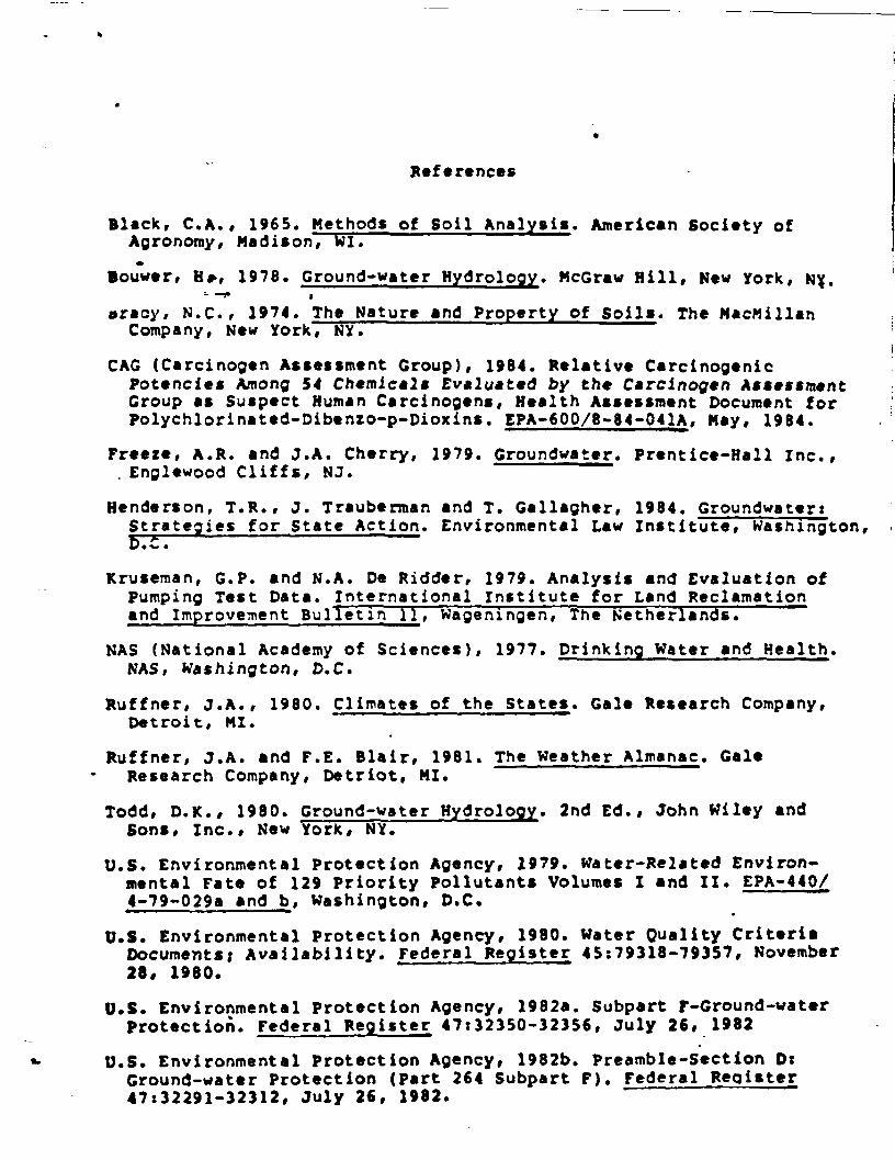
References
Black, C.A., 1965. Methods of Soil Analysis. American Society ofAgronomy, Madison, WI.
louwer, H*, 1978. Ground-water Hydrology. McGraw Hill, New York, NY;.~- ~f i
oracy, N.C., 1974. The Nature and Property of Soils. The MacMillanCompany, New York, NY.
CAG (Carcinogen Assessment Group), 1984. Relative CarcinogenicPotencies Among 54 Chemicals Evaluated by the Carcinogen AssessmentGroup as Suspect Human Carcinogens, Health Assessment Document forPolychlorinated-Dibenzo-p-Dioxins. EPA-600/8-84-041A, May, 1984.
Freeze, A.R. and J.A. Cherry, 1979. Croundwater. Prentice-Hall Inc.,. Enplewood Cliffs, NJ. "
Henderson, T.R., J. Trauberman and T. Gallagher, 1984. GroundwaterxStrategies for State Action. Environmental Law Institute, Washington,£_£_
Kruseman, G.P. and N.A. De Ridder, 1979. Analysis and Evaluation ofPumping Test Data. International institute for Land Reclamationand Improvement Bulletin H, Wageningen, The Netherlands.
NAS (National Academy of Sciences), 1977. Drinking Water and Health.NAS, Washington, D.C.
Ruffner, J.A., 1980. Climates of the States. Gale Research Company,Detroit, MI.
Ruffner, J.A. and F.E. Blair, 1981. The Weather Almanac. GaleResearch Company, Detriot, MI.
Todd, D.K., 1980. Ground-water Hydrology. 2nd Ed., John Wiley andSons, Inc., New York, NY.
U.S. Environmental Protection Agency, 1979. Water-Related Environ-mental Fate of 129 Priority Pollutants Volumes I and II. EPA-440/4-79-029a and b, Washington, D.C.
U.S. Environmental protection Agency, 1980. Water Quality CriteriaDocuments; Availability. Federal Register 45:79318-79357, November28, 1980.
U.S. Environmental Protection Agency, 1982a. Subpart F-Ground-waterProtection. Federal Register 47x32350-32356, July 26, 1982
U.S. Environmental Protection Agency, 1982b. Preamble-Section DtGround-water Protection (Part 264 Subpart F). Federal Register47x32291-32312, July 26, 1982.

U.S. Environmental Protection Agency, 1983a. Draft RCRA PermitWriters' Manual for Ground-water Protection. Contract No. 66-01-6464,October 4, 1983.
U.S. Environmental Protection Agency, 1983b. Water QualityStandards Handbook, Office of Water Regulations and Standards.Washington, D.C.j December, 1983. *
U.S. Environmental Protection Agency, 1983c. Draft Guidelines forDeriving Numerical National Water Quality Criteria for theProtection of Aquatic Life and Its Uses. Washington, D.C.,July S, 1983.
U.S. Environmental Protection Agency, 1983d. Technical SupportManual: Katerbody Surveys and Assessments for Conducting UseAttainability Analyses. Office of Water Regulations and Standards,Washington, D.C., November, 1983.
U.S. Environmental Protection Agency, 1984a. Hazardous WasteManagement System; Ground Water Testing and Monitoring Activities;Proposed Rule. Federal Register 49: 38786-38809, October 1, 1984.
U.S. Environmental Protection Agency, 1964b. Ground-Water ProtectionStrategy. Office of Ground-Water Protection, Washington, D.C.
U.S. Environmental Protection Agency, 1984c. Proposed Guidelinesfor Exposure Assessment; Request for Comments. Federal Register49:46304-46312, November 23, 1984.
U.S. Environmental Protection Agency, 1984d. Guidance and Methodsfor the use of Acceptable Daily Intakes (ADIs) in Health RiskAssessment. Environmental Criteria and Assessment Office,Cincinnati, OH.
U.S. Environmental Protection Agency, 1984e. Characterization ofChemical Waste Site Contamination and Its Extent Using Bioassays(Draft Report). Contract No. DE-AC06-76RLO 1830, December, 1984.
Walton, W.C., 1970. Ground-water Resource Evaluation. McGraw-HillPublishing Company, New York, NY.
Other resource documents•
0.6. Environmental Protection Agency,' 1978. Investigation ofLandfill Leachate Pollutant Attenuation by Soils. EPA 600/2-78-1SB. »
U.S. Environmental Protection Agency, 1980. Adsorption, Movement,and Biological Degradation of Large Concentrations of SelectedPesticides In Soils. EPA 600/ 2-80-124.

U.S. Environmental Protection Agency* 1982. Handbook for PerformingExposure Assessments (Draft). Washington, D.C., November, 1982.
U.S. Environmental Protection Agency, 1982. Handbook for Remedialffction at Waste Disposal Sites. EPA-625/6-82-006, Washington,D.C., Jfine, 1982. t
»—f *U.S. Environmental Protection Agency, 1983. Protocol for
Bioassessment of Hazardous Waste Sites. EPA-600/2-83-054,July, 1983.
U.S. Environmental Protection Agency, 1984. Soil Properties,Classification; and Hydraulic Conductivity Testing (Draft Report).SW-925.
U.S. Environmental Protection Agency, 1984. Slurry TrenchConstruction' for Pollution Migration Control. EPA-S40/2-84-001,Washington, D.C., February, 1984.
ATTACHMENT VIII
QUALITY ASSURANCE PROJECT PLAN
AVIIX-1
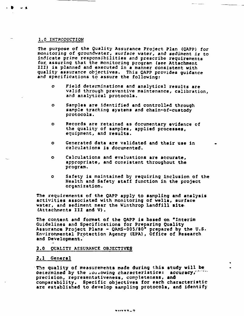
1.0 INTRODUCTION
The purpose of the Quality Assurance Project Plan (QAPP) formonitoring of groundwater, surface water, and sediment is toindicate prime responsibilities and prescribe requirementsfor assuring that the monitoring program (see AttachmentIII) is planned and executed in a manner consistent withquality assurance objectives. This QAPP provides guidanceand specifications to assure the following:
o Field determinations and analytical results arevalid through preventive maintenance, calibration,and analytical protocol*.
o Samples are identified and controlled throughsample tracking systems and chain-of-custodyprotocols.
o Records are retained as documentary evidence ofthe quality of samples, applied processes,equipment, and results.
o Generated data are validated and their use incalculations is documented.
o Calculations and evaluations are accurate,appropriate, and consistent throughout theprogram.
o Safety is maintained by requiring inclusion of theHealth and Safety staff function in the projectorganization.
The requirements of the QAPP apply to sampling and analysisactivities associated with monitoring of wells, surfacewater, and sediment near the Winthrop Landfill site(Attachments III and V).
The content and format of the QAPP is based on "InterimGuidelines and Specifications for Preparing QualityAssurance Project Plant: - QAMS-005/80" prepared by the U.S.Environmental Protection Agency (EPA), Office of Researchand Development/
2.0 QUALITY ASSURANCE OBJECTIVES
2.1 General
Ths quality of measurements made during this study will bedetermined by the i. on owing characteristic*: accuracy/" ""precision, representativeness, completeness, andcomparability. Specific objective* for each characteristicarc established to develop sampling protocol*, and identify
applicable documentation, sample handling procedures, andmeasurement sys.tem procedures. These objectives areestablished based on site conditions, objective of theproject, and knowledge of available measurement systems.The subsequent use of these measurements in calculations andevaluations is also subjected to aspects of the QAPP asdescribed in the following section.
2.2 Pepresentativeness
Measurements will be made so that results are asrenresentative of the media and conditions being measured,as possible. Sampling protocols will be used to assure thatsamples collected are representative of the media. Samplehandling protocols (e.g., storage, transportation) protectthe representativeness of the collected sample. Properdocumentation will establish that protocols have beenfollowed and sample identification and integrity assured.
2.3 Precision and Accuracy
Precision, the ability to replicate a value, and accuracy,the ability to obtain a true value, will be addressed forall data. Data quality objectives for precision andaccuracy are established for each major parameter to bemeasured at the site. These objectives are based on priorknowledge of the capabilities of the measurement system tobe employed, in turn, selected in accordance with therequirements of the project. The precision and accuracyrequirements vary, depending on their intended use. Forexample, a screening tool to identify the general extent ofchemical distribution will not require the same precisionand accuracy required to define the exact nature and amountof chemicals present at specific locations. Later sectionscontain information regarding analytical procedures.
2.4 Completeness
The characteristics of completeness is a measure of theamount of valid data obtained compared to the amount thatwas expected to be obtained under normal conditions. Theamount of valid data expected is established based on themeasurements required to accomplish project objectives. Theextent of completeness is expressed on a relative basis forsample collection activities. Completeness of data handlingsystems is described in later sections.
2.5 Comparability
The characteristic of comparability reflects both internalconsistency of measurements ais.le at the site and expressionof results in units consistent with other organizationsreporting similar data. Each value reported for a given
AVIII-3

measurement should be similar to other values within thesame data set and within other related data sets.Comparability Of data and measuring procedures must also beaddressed. This characteristic implies operating within thecalibrated range of an instrument and utilizing analyticalmethodologies which produce comparable results (e.g., dataobtained for phenol (4AAP) are not comparable to dataobtained for phenol (GC/MS).
Measurements compared to similar measurements which appearas outliers will be re-assessed. Units of measurement willbe externally comparably by utilizing the appropriatestandard units for each measurement system.
2.6 Quality Assurance Objectives
The quality assurance objectives for the monitoring programare listed below.
o To collect sufficient field, sampler, and tripblank samples and field duplicates to allow anassessment of sample representativeness and samplecollection protocol precision
o To analyze sufficient internal duplicates, blanks,reference standards and matrix spike samples toallow an assessment of analytical precision andaccuracy. Sufficiency of analytical QC proceduresis specified by the referenced methods.
o To produce consistent technically defensibleanalytical reports
3.0 SAMPLING PROCEDURES
3.1 General
The quality of sample collection techniques is assured bykeying the technique used to both the media/matrix to besampled and the analytes of interest. For example, samplesintended for semivolatile organic analysis are collected inglass bottles, samples for volatile organic analysis arc;collected in Teflon-septum-capped glass vials with'zero"head space to minimize diffusive and evaporative losses, andmost samples for inorganic analysis are collected in linearpolyethylene bottles. Sample containers will be prepared ina manner consistent with EPA protocol as noted in thefollowing section.
Acquisition of environmental samples also requires .. ;.:i.specialized collection techniques to preserve theirintegrity and ensure that a representative portion of thesource is collected. Media-specific sample collectiontechniques are specified in the following section*.
AVII1-4

Further, unless the proper sample bottle preparation andsample preservation measures are taken in the field, samplecomposition can be altered by contamination, degradation,biological transformation, chemical interactions, and otherfactors during the time between sample collection andanalysis. Typical sample bottle preparation protocols arepresented in Section 6.2. Steps taken to maintain thein-situ characteristics required for analysis may includerefrigeration on samples at 4»C, freezing, pH adjustment,and chemical fixation. Samples are preserved according tothe protocol established for the specific analytical methodselected to obtain the desired data. Table u-> providesmore specific information.
Water sample containers are generally filled directly fromthe source, sampler or pump discharge without specialconsiderations. A major exception is the collection ofvolatile organic analyte (VOA) samples. VOA samples must becollected as specified below. Each sample is taken induplicate. ,
o Uncap the sample bottle, taking care not to touchthe teflon-faced septa. N If the septa iscontaminated in any wa^ it should be replaced.
o If a chlorine residual is present, add three dropsof 10 percent sodium thiosulfate to the samplecontainer prior to filling the bottle.
o Pour the sample slowly, minimizing airentrainment, into the sample bottle. Pour sampleuntil the bottle overflows.
o Place the teflon-faced silicon rubber septa on theconvex miniscus, teflon side (shiny side) down andscrew cap on.
o Invert the bottle, tap lightly, and check for airbubbles.
o If air bubbles are present open the bottle, addsample to eliminate air bubbles, and reseal.Repeat-this procedures until the bottle is filledand no air bubbles are detected.
3.2 Preparation of Sample Containers
3.2.1 Semi-volatile (Acid/Base-Neutral) Organic Analytesand Sampler Blank Containers.The procedure for cleaningand one-liter glass bottle*"!., listed below. .<-;-•--.-
o Washing the bottles and teflon-lined capsthoroughly in hot, detergent water.
AVIII-5

TABLE 6-1SAMPLE CONTAINER ATO PRESERVATION REQUIREMENTS
CERCLA/RCRA SAMPLES
Concentrat ion Container Sample Size Preservation
WATER
Organic* GC & GC/MS
Inorganics
Organic/Inorganic
CODTOCOil t GreasePhenolsGeneral Cheaistry
SOIL
Organics GC & GC/MS
Inorganics
Organic/Inorganic
Dioxio
EP Toxicity
AIR
Volatile Organics
VOA
ExtractablesLow
Mediua
Metals
Mediua
Cyanide
MediuB
High Hazard
::---•--
VOA
ExtractablesLov/MediuB
Lov/Mediua
High Hazard
All
All
LowMediuB v
glass
amber glass
vide-Bouth glass
polyethylenewide-south glass
polyethylenewide-mouth glass
8-oz. wide-Boutb glass
polyethylenepolyethylene
glasspolyethylenepolyethylene
2 x 120 mi vide-Bouthglass
8 oz. or 2 x 4 oz.vide-Bouth glass
8 oz. or 2 x 4 oz.vide-Bouth glass
8 oz. vide-Boutb glait
4 oz. uide-Bouth (lass
2SO B£ polyethylene
Charcoal Tube7 CB long, OBB OD,
2 x 40 mi
2 x 80 oz. or4 x 1 £
4 x 32 oz.
1 £16 oz.
1 £16 oz.
6 oz.
0.5 £0.5 £1.0 £1.0 £1.0 £
240 B£
6 oz.
6 oz.
6 oz.
4 or.
200 grass
100 £ air
Cool to 4eC
Cool to 4°C
None
UNO, to pH <2JNone "
NaOH to pH >12
None
H,SO, to pH <2HCrto pH <2H,SO, to pH <2H,S07 to pH <22 *Kone
None
None
None
None •
None
None
Cool to 4«C
li days
}<• d»ys
li days
6 norths (Hg-20 days)6 nonths
14 days
14 days
28 fays28 days28 davs28 days""
NA
NA
NA
NA
NA
NA
NA
ID

o Rinse the bottles and caps thoroughly with hot tapwater,
o Rinse.the bottles and caps thoroughly with blankwater .
* o Heat bottles at 825eF for 30 minutes.
o Heat teflon-lined caps at 250»F for one hour.
o Allow bottles and caps to cool in a hood locatedin an area where they are protected from sourcesof contamination.
o After bottles and teflon-lined caps have cooled,cap the bottles using a pair of surgical gloves.
o For blank water bottles, fill the one-literbottles with blank water using a bell jarapparatus to protect from atmosphericcontamination. Change filters as required on thewater system to maintain steady flow.
3.2.2 Volatile Organic Analytes (VOA) Sample Containers.The procedures for cleaning the 40 ml glass vials, caps, andteflon-faced silicon rubber septa is listed below.
o Wash the vials and septa thoroughly with hotdetergent water.
o Rinse the above items thoroughly with hot tapwater.
o Rinse the above items thoroughly with blank water.
o Place the vials (upright) and septa in an.oven at105'C (225*?) for one hour.
o Remove the vials and septa from oven and cool in ahood located in an area protected from organic andother sources of contamination.
o After the bottles have cooled, place the septa(shiny surface down) and the cap on the bottle andseal screw cap on bottle. Wear surgical gloveswhile doing this.
The "blank water" used is identical to the reagent water(ASTM Type II or better) used to prepare sample blanks andis certified monthly by the ALS and State of Maine PublicHealth Laboratory.
AVIII-6
< t
o DO NOT OPEN the bottles until they are to befilled with sample.
3.2.3 Preparation of Pump Tubing. Adequate lengths of3/8-inch ID teflon tubing and 3/6-inch ID silicon tubingwill be prepared if purr.p tubing is specified for thesampling episode. The tubing preparation procedures islisted below.
o Prepare solution of hot water and detergent,
o Attach suction and pump tubing to ISCO unit.
o Place end of suction line in detergent solution.
o Pump detergent solution through the system for twominutes.
J& •
o Pump clean hot water through the system for twominutes or until clear, whichever is longer.
o Pump blank water through the system for twominutes.
3.3 Grourdvater Sampling
Objective: To obtain samples of groundwater suitable forchemical analysis.
Preprinted labels will be prepared for all groundvatersamples. These samples will consist of various containersfor each location and will be analyzed for the parametersselected for the project. Filtering of groundwater isnormally required prior to filling containers for dissolvedinorganics analysis except for drinking water samples andsamples requiring total suspended solids (T5S) analysis. Anexample of s sample-splitting flowchart is shown as-Figure u*"i • The pH and specific conductance of each samplewill be determined in the field. Glass containers will beused for samples required to be analyzed for organics, andplastic containers will be used for samples requiring allother analysis.
Monitoring wells will be sampled in the following manner:
Monitoring and sampling of groundwater wells will proceedfrom the upgradient or background wells to the downgradientor contaminated wells as can be best determined.
The well will first be checked fcr proper identification andlocation. The height of protective casing will be measuredand recorded.
AVIII-7

oE' o
g !
I— z
UJ
CO
ITUJ
|o
ccoI
o
a.COULJ
CO
•rf ««^* ««hiill000
I I I
'Ii85?
s
Ii
! i
s
g
t|8 =5 <
*
S « *
i i
i5
i s
I i
!!
X 5I •-
U§i
n
i
i Iii s£! ii
Iwx«
-12• I is
!i«s i : f
m
X*I
After unlocking the well and removing any well caps, measureand record the ambient and well-mouth organic vapor levelsusing the photoionization meter.
If the ambient air quality at breathing level reaches 5 ppm,the sampler shall utilize the appropriate safety equipmentas described in the Health and Safety Plan.
Using the electronic water level meter, measure and recordthe static water level in the well and the depth to the wellbottom to the nearest 0.01 foot. Upon removing the waterlevel wire, rinse with reagent grade methanol and thendistilled water. Calculate the volume of stagnant water inthe well casing. Volume in liters equals 0.154 times thesquare of the inside diameter of the casing in inches timesthe depth of water in feet.
Following these measurements, sampling will commence in thesequence listed below.
1. Lower the submersible pump or peristalic pumpintake into the well. Pumping should start at thestatic water level and the purr.p or pump intakeshould be gradually lowered to the bottom of thewell as the water is removed.
Connect the instrumentation header to the pumpdischarge and begin flushing the well. Monitorthe in-situ parameters (pH, Eh, temperature, andspecific conductivity) and measure the volume ofgroundwater being pumped. Alternately, in-situparameters may be monitored in a beaker filledfrom the pump discharge. Purging of the standingwell water is considered complete when one of thefollowing is achieved.
o Five well volumes have been purged
o In-situ parameters stabilize
o Well has been pumped dry
2. Record the in-situ parameters (see Figure 6.-Z.) .
3. After purging, lower the pump intake or bailer (asappropriate for the parameters of concern) to themiddle of the screened interval or mid-point ofthe static water level and collect the sample.
4. Volatile organic analyte (VOA) samples are Tilleddirectly.from the submersible pump dischargetubing or bailer with as little agitation aspossible.
AVIII-8

FIELD SAMPLE DATA AND QUALITY ASSURANCE RECORD
PROJECT
STATION NO/LOCATION
JOB NO
DATE
VCt HO TEI HO
SKETCH ON BACK D D PHOTOGRAPHS O D ROLL NO/EXPOSURE NO.
FIELD DATA "
TIME AIR TEMP WEATHER
WELL WATER SAMPLE SAMPLEDEPTH OFPTH DEPTH UFTHOO
VOL. SAMPLE D
PURCCD, TFMP »C n
D IN SITU
• H DIN BOTTLE Eh
VOA LEVEL (ppm)
BOTTLE ID
REMARKS/OBSEH
AUIflFMT
LAB 10 VOL
IN SITU SI
IN BOTTLE C
D IN SITU
D «N BOTTLE
SAMPLE LOCA-
MATERIAL
I
V
». D IN SITU
OMD / O> 25° C n IM •OTTI t
DISSOLVED 0
now
D IN BITU
• . ..._*»m D IN BOTTLE
MFAOSPACF
ANALYSISFILTERED PRES./VOL REQUESTED
v , M
^^^
^^
^^
^^
^^
^^
^^
^^
CATIONS "
FIELD EQUIPMENT QUALITY ASSURANCE CHECKLISTpH METER BUFFER CHECK >M 4 »H T pH 10
SP rr»ND METER STANDARDS Cn'iCK Eh PROBE
PUMP TUBING RINSED. CHANGED. SAMPLER BLANK.
FILTRATION BLANK WITH PRES. FILTERS ACID WASHED.
SAMPLER
FIGURE 6-:

Other samples will be placed directly into theappropriate container from the discharge tubing ofthe pump or bailer.
5. Remove the pump from the well and decontaminatethe pump and tubing by flushing one gallon ofmethanol/water mix through the pump and tubingfollowed by one gallon of distilled water. Usingpaper towels and reagent grade methanol, hand wipethe outside of the teflon tubing and pump. Risewith distilled water.
6. Attach appropriate labels to all sample bottlesand complete chain-of-custody forms after eachwell is sampled.
7. Secure the well cap and lock.
3.4 Surface Water Sampling
Objective: Surface water samples are to be collected foranalysis to establish the degree ofcontamination of the surface water for riskassessments and determination of contaminantplume extension.
Sample labels will be prepared prior to initiation of workusing the computerized label system. Each sample willrequire several containers dependent on the intendedanalysis to be performed. The pH and specific conductanceof each sample will be determined in the field at the timethe sample is obtained. At the time the sample is obtained,a surface water sample record will be completed. An examplesample record if? shown as Figure (/-?> • Records will includethe following information
o A plan of the site
o Sample label numbers
o A description of the cample site
o Width and depth of the stream and its approximateflow rate in cfs
o At least one photographic of the sample site(Note: Orientation of photograph must be shown onsketch map) showing the sampling equipment
o Chain-of-custoi y documentation
AVIII-9

SURFACE WATER AND STREAM SEDIMENT SAMPLE RECORD
SAMPLE STATION DATE
SITE LOCATED ON: MAP SITE
SKETCH MAP OF SAMPLE SITE(SHOW WHERE SAMPLE TAKEN)
AIR PHOTO
SCALE I" * .FT
PROFILE OF STREAM BED
NOTE = DIMENSION SKETCH
TIME ST. •END
SAMPLES OBTAINEDSERIAL NOS
SURFACE WATER
VOLATILE .PHSPEC. COND
SEDIMENT
PI VOLATILES,
NOTES
CONTAINER
VOA
VOA
I LITER GLASS
I LITER GLASS
VOA
VOA-
VOA
VOA
I OT GLASS
PHOTOGRAPH ROLL
REFERENCE' FIELD BOOK, PGATTACHMENTS
EX P.
SIGNATURE
FIGURE 6-3FC.ORDANCQ

The sample will be taken in the following manner.
1. The sample will be collected from the surfacewater body by immersing a clean beaker or watersampler. If a stream is being sampled, the samplewill be collected upstream of the sampler with theopening of the sampling device oriented upstreambut avoiding floating debris. If a lake if beingsampled, the sample will be collected near thebottom of the water column.
2. The appropriate sample containers will be filleddirectly from the sampling device (see Table k-l ).
3. The following measurements will be made, ifpossible, by direct immersion of instrument probesinto the body of water.
o Photoionization meter reading
o Temperature measurement
o pH measurement
o Specific conductance measurement
o Any other site-specific field measurementswhich are required
If direct measurement is not possible, thesemeasurements will be made from water remaining in thesampling device or another sample bottle. Thisinformation will be recorded on the sample data record,sample labels completed, and chain-of-custodyprocedures initiated.
3.5 Sediment Sampling
Objective: To obtain samples of the sediment found instreams, ponds or other bodies of water forchemical analysis. Usually sediment samples•re.taken in conjunction with surface watersamples to help define the partitioning ofthe contaminants between the toil and water.
*
Approach: Sediment sampling procedures for snailstreams and drainage ways are very similar toshallow soil sampling procedure; i.e., a ,trowl cr shovel is used. The exact locationof each sampling station will be establishedin the field at the tit;* of sampling. Thesample site will be noted on a site plan oraerial photograph and narked in the field
with flagging and a four-foot wooden stake.The stake will be labeled with the samplesite number.
If both water and sediment samples are to be collected at agiven sampling site, the water samples will be collectedprior to the sediment sample.
The sediment samples will be collected in the followingmanner.
o The sampler will select the sample site, locate iton a site map or aerial photograph and set thewooden stake. He will locate the sample site onthe site plan using the grid system.
o Where sediments are to be obtained in wetlands, agrab sample will be obtained in the immediatevicinity of any associated surface water sample.Unless otherwise specified, grab or compositedsamples will be obtained from the surface of thesediment.
o The sampler will photograph the sample cite,complete the required records and initiatechain-of-custody procedures.
Sediment samples collected from deeper waters will utilizeeither a gravity corer or dredge. These sediment samplelocations will be marked with buoys. When using a gravitycore sampler, the following procedures will be followed.
o Check all sampling equipment for cleanliness. Thegravity corer should be decontaminated prior toits use at any site and between sample points onthe same site.
o The sediment sample is collected by dropping thecorer from a near surface position and allowing itto free-fall through the liquid to the bottom.
o Once the corer has become imbedded in the bottomin an upright position, release the messenger toactivate the suction cup at the top of the corer.
o Retrieve the corer with a smooth, continuouslifting motion. Do not bump corer as this mayresult in some sample loss.
o Discharge the sediment from the corer int • a largeclean, unused, disposable aluminum foil pan.
AVIII-11

o Repeat the above sample collection procedures inadjacent areas until there is sufficient sedimentto fill the appropriate sample jar.
o Allow the sediment to settle in the pan, whichshould only take 2 to 3 minutes (only the heaviermaterials will be collected) , then decant (pour)the water from the surface.
io Remove and discard any foreign materials (stones,
pieces of wood or bark, aquatic weeds etc.) usingeither a pre-cleaned stainless steel spoon ortongs.
o Using the spoon or tongs, homogenize (mix) thesediment and then transfer the sample into theappropriate sample jar.
The decontamination procedures tc be used in the field arethe same as those followed when initially cleaning the corerprior to its being shipped to the field. These cleaningprocedures are listed below.
o Wash thoroughly with distilled water.
o Rinse with deionizedJ water
o Rinse with pesticide-grade acetone
o Rinse with pesticide-grade hexane
o Allow to air dry.
o Place core barrel in plastic bag prior to storingor moving between sample points
Sediment sampling information is recorded on the appropriateform (see Figure (,--3) . All sediment sample labels will beprepared prior to initiation of work using • computerizedlabel system.
3.6 Sample Handling and Preservation
All samples wilTbe preserved by packing in ice (4*C) andshipped to ensure sample receipt at the laboratory within48 hours of collection. In addition, at the direction ofEPA Region I, all samples collected for volatile organiccompounds (VOC) analysis will be preserved by the additionof 20 mg/L mercuric chloride to limit biodegradation ofpurgeable aromatics. VOC sample vials will be pre-preserved(sec Table
Holding time for samples prior to analysis shall not exceed14 days.
AVIII-12
4.0 PRCVTFfT CUSTODY
Sample chain-of-custody will he followed during samplehandling activities in both -the field and laboratoryoperations. This program is designed to assure that eachsample is accounted for at all tines. To maintain thislevel of sample monitoring, computer-generated samplecontainer labels, and shipping manifests are normallyemployed. Sample fie.ld data sheets, chain-of-custodyrecords, and laboratory receipt sheets must also becompleted by the appropriate sampling and laboratorypersonnel.
The objective of sample custody identification and controlis to assure that:
o All samples scheduled for collection, asappropriate for the data required, are uniquelyidentified
o The correct samples are analyzed ( 1 are traceableto their records
o Important sample characteristics are preserved
o Samples are protected Iron loss or damage
o A record of sample inte-gri±y is established forlegal purposes
The advantages of a computer-based rhain-of-custody systemover field marking systems are:
o All required samples BT« indicated on pre-preparedlabels and shipping manifests
o Once the computer-generated label is affixed tothe bottle and covered with clear plastic tape,sample identification is virtually unalterable
The chain-of-custody protocol followed by the sampling crewsinvolves:
o Documenting procedures and amount of reagents orsupplies (e.g., filters) which become an integralpart of the sample for cample preparation andpreservation
o Recording sampling locations and specific sampleAcquisition measures on ±be appropriate forms x
o Using pre-prepared sample labels to document allinformation necessary for effective sampletracking
AVII1-13

o Completing standard field data record forms toestablish sample custody in the field beforesample shipment
Pre-prepared labels are developed for each sample to becollected. Each label is numbered to correspond with theappropriate sample (s) to be collected. Examples ofpre-prepared labels are shown in Figure 7-1 . The field datasheet, is used to record the sample location, samplingmethod, type of sample, date of sample collection, the nameof the sampling crew member responsible for the sample, andother relevant information. Examples of field data sheetsare presented in Figures fr-a. and [/-J.
The chain-of-custody record is used to:
o Document sample handling procedures includingsample location, sample number and number ofcontainers corresponding to each sample number
o Described the sample
o Described the chain-of-custody process
The chain-of-custody description section requires:
o The sample number
o The names of the sampler (E) and the personshipping the samples
o The date and time that the samples were deliveredfor shipping
o The names of those responsible for receiving thesamples at the laboratory
A sample chain-of-custody record is shown in Figure ")-
The field data record and the chain-of-custody record arecompleted in quadruplicate. Two copies accompany thesamples to the laboratory, another is kept by the samplecrew chief, and £he fourth is maintained in the projectfile. Additional copies can be provided, if needed, for theproject.
A sample custodian at the laboratory signs for incomingsamples, obtains shipment documents, assigns a unique sampleidentification number and verifies data entered in samplecustody records. Lased on the type of sample collectedthe analysis required, further procedures for samplehandling, storage, and disbursement for analyses arespecified.
AVIZI-14
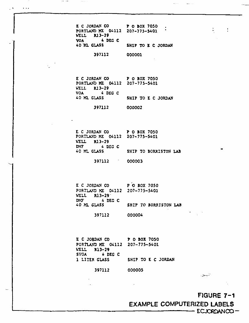
E C JORDAN CO P 0 BOX 7050PORTLAND ME 06112 207-775-5401WELL R13-29VOA 4 DEC C40 TO. CLASS SHIP TO E C JORDAN
397112 000001
E C JORDAN CO P 0 BOX 7050PORTLAND ME 04112 207-775-5401WELL R13-29VOA 4 DEC C40 ML GLASS SHIP TO E C JORDAN
397112 000002
E C JORDAN CO P 0 BOX 7050PORTLAND ME 04112 207-775-5401WELL R13-29DMF 4 DEC C40 ML CLASS SHIP TO BORRISTON LAB
397112 000003
E C JORDAN CO P O BOX 7050PORTLAND ME 04112 207-775-5401WELL R13-29DMF 4 DEC C40 ML CLASS SHIP TO BORRISTON LAB
397112 000004
E C JORDAN CO P 0 BOX 7050PORTLAND ME 04112 207-775-5401WELL R13-29SVOA 4 DEC C1 LITER CLASS SHIP TO E C JORDAN
397112 000005
FIGURE 7-1EXAMPLE COMPUTERIZED LABELS
ECJORLWJOQ-
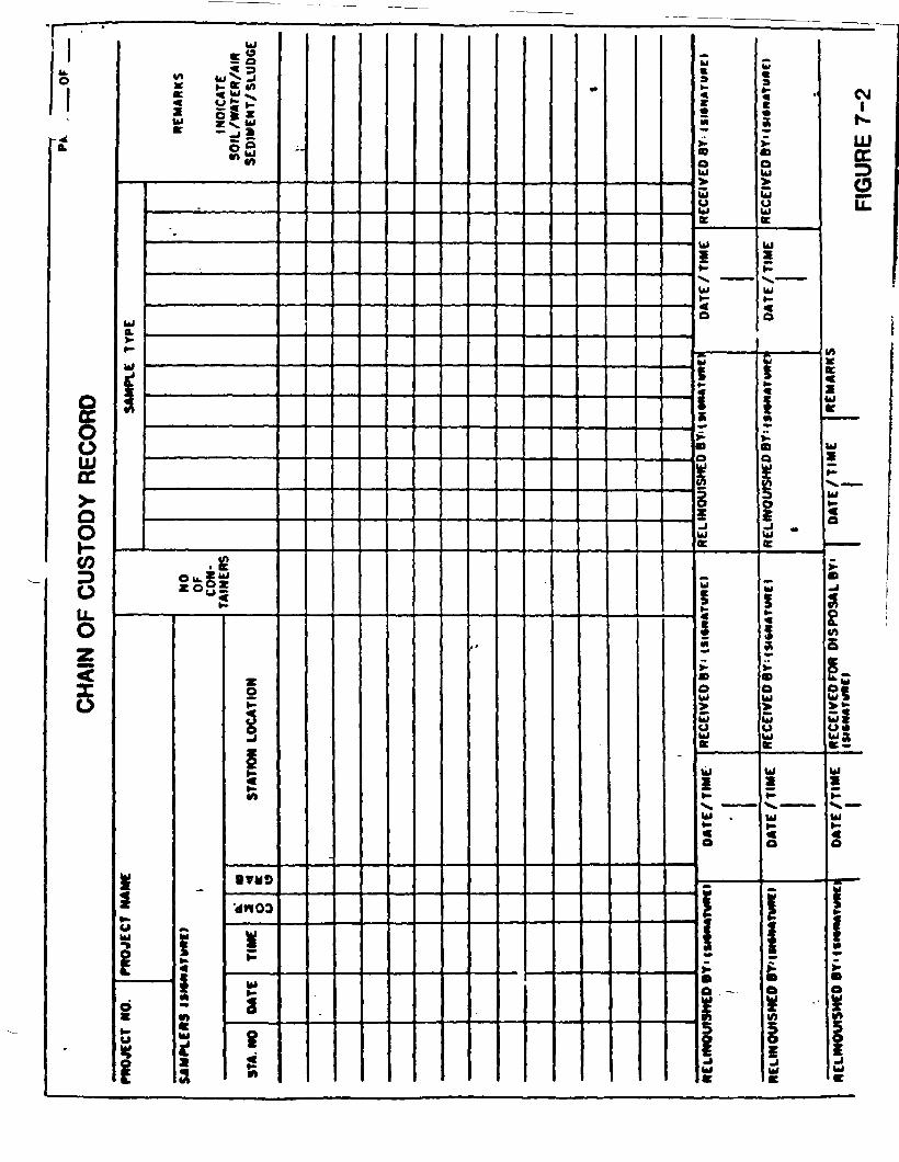
1u.O
1
~*
§
OLUDC
Q
OCO
0llu*0z<o
•
Ula.>•
*
fc*i2»•oUlpsiu
s S« c* 0£ i
ss£'««0.1-
_
i«§§«n
SA
MP
LCM
SO
IL
WA
TER
/AIM
SE
DIN
CN
T/ S
LUD
GE
»j|i
1 LO
CA
TIO
N
iavuQ
d«00
i!«
Ul
§8J
i »
«»
w«aK
•M
>•BoUl
Louac
Ul
IK
UlH1
o
w(5K
BQ
Xg-JUlK
U
^
RE
CE
IVE
D B
Y i
ISI«
NI
DA
TE
/ TIM
E
|>•
iUl
S«
1|
«oUl
uaK
Ul
P
Ulf-s
5i5
!Q
Q
!5j .Ul(C
w
«
i•oUl>5tiK
UlXP
Ul
o
.»
1Ifc•o
*VI
1Ul
O41
h-
LUOC
LL
KK
EUl•cPM^ ^H^
Ulx
tti•MHM V
^A
S
I>IH
I1*M
«I«
IM
S 10
IMX
I03A
I393M
DA
TE /T
IME
1
£
«
f
£•o
_iUl
•

The flow of samples and the analytical data through thelaboratory is .shown in Figure n.j}> . Properly identifiedsamples are received in the laboratory by a samplecustodian. This person signs the chain-of-custody formafter verifying that all samples submitted are listed andthe required information is entered on the form. The samplecustodian then places the samples in a refrigeratordesignated for the receipt of new samples. When a requestfor analysis form (Figure <7-^ ) is received by thelaboratory the sample custodian then places a laboratoryidentification number on each sample and the samples aremove? to another refrigerator dctign&tcd fcr rtoring samplesto be analyzed. Since there are several refrigeratorsdesignated for storing samples waiting for analysis, thesamples are also color coded to identify the refrigerator inwhich they are stored. Or. the front cf the refrigeratcr, alaboratory chain-of-custody recrrd (Figure 1-«T) is placedfor the purpose of keeping track of the samples duringanalysis. When directed to analyze a specific sample, theanalyst will record on the chain-of-custody record thesample number, the date it was removed from the refrigeratorand the analyst who removed it. The date when it wasreturned is also indicated.
Reagent Documentation. Records of all reagent preparationsare maintained in writing. Information recorded in thereagent log books includes identification of preparation,date, name of individual, lot number of reagent used, rawweighing and dilution data. Only volumetric glassware andanalytical balances are used for reagent preparation.Reagents are placed in appropriate containers, clearly andpermanently labeled with the date of preparation, individualand identification of reagent. Reagents are stored atconditions appropriate for each and discarded after standardpermissible holding -inen or if contamination/decompositionis evident.
All aqueous reagents are prepared from water of at leastASTM Type II purity. All reagents and solutions used are ofACS reagent grade quality (minimum). Organic solvents forphotometric procedures are Spectral grade. All solvents fororganics analysis are either suitable for pesticide residueanalysis or Nanograde. All organic standards are of CCstandard purity". Mixtures are purchased from reputablesuppliers and are of GC standard purity. Isotopicsurrogates are certified by the suppliers and are of highestpossible enrichment.
AVJJI-15

SAMPLE PROGRESSION THROUGH LABORATORY
SAMPLE RECEIPT
SAMPLE 1.0. NO. ASSIGNED SAMPLE.STORAGE
COMPUTER ENTRY
PRELIMINARY REPORT
DATA REVIEW
FINAL^REPORT
CLIENT
LABWORKSHEET
DATAREVIEW'
ANALYSES
RESULTS
FIGURE 7-3EC JORDAN CC —

ANALYSIS REQUEST FORMCLIENT iTION NAME
COMPANY.
MAUNQ AOORCS3
PURCHASE ORDER/JOB NUMBCR .
E.C. JORDAN CO.ENVIRONMENTAL LABORATORY SERVICESWHERE TO SEND REPORT: Q DIRECTLY TO CLIENT
O CCJ-NAME
ANALYSES REQUESTED BY
APPROVED BY:MOJCCT IMMMC*
SAMPLE IDENTIf CATION LAB NUMBERS DATE SAMf'O SAMP 0 BY ANALTSCS REQUIRED
DATE RECEIVED.LAB LOCATION_RESULTS DUC_
CLIENT ID NO..
ADDITIONAL ^FORMATION OR SPECIAL PROCEDURES.
LIST ANT HAZARDS.
O SOLID WASTE DAT* PN.CQ DATA DOCUMENTATION ROfOD ENTERED m COMPUTER
I—II | PROCEDURE FIGURE 7-4

LABORATORY CHAIN OF CUSTODY RECORDDATE IN ANALYST SAMPLE NO. DATE OUT
ECJORDANCO —•t 4^ • • f

?.Q LABORATORY PROCEDURES
The following preprinted sections of this Attachmentdocunent procedures to be used in assuring and controllingthe quality of laboratory data. These sections are entitledas follows:
8.0 Calibration Procedures and Frequency9.0 Analytical Procedures10.0 Data Reduction, Validation, and Reporting11.0 Internal Quality Control12.0 Audits13.0 Preventive Maintenance14.0 Data Quality Assessment15.0 Corrective Action16.0 Reports to Management17.0 Dimethyl Fonramide Analytical Methodology
These preprinted sections describe the procedures used byE.C. Jordan Company (ECJ) and Rhode Island AnalyticalLaboratories (RIAL), which have been retained by one of theSettling Parties. In the event that ECJ and RIAL are nolonger involved in these activities, similar procedures, asapproved by U.S. EPA and MEDEP, shall be adopted by theSettling Parties or their consultants to assure the qualityof laboratory work.
WDR119/009
AVIII-16

Section Ko. SRevision No. 0Date July I. J9ESpage i of »
8.0 CALIBRATION' PROCEDURES AND FREQUEKCY
8.1 CALIBRATION PROCEDURES TOR LABORATORY EQUIPKEKT
t.1.1 Cat Chroiratoiraph/Kit* Spectrometer/Data Systeir (GC/HS/DS)
All GC/MS analyses arc performed in accordance vith aethods established by EPA(40 CFR Part 136. October 26, 1984). Qualitative identification of the prio-rity pollutants is based on relative retention tines and the relative abundanceratios of the characteristic ions. Quantitative analysis of priority pollu-tants detected is performed using internal- standardization.
Initial Calibration
*•'•*« s, •*. -Initial calibration9 was performed for volatile (EPA Method 624) and seni-volatile (EPA Method 625) organic analytes in accordance vith sections 7 and Bof the respective nethods.
A calibration curve was developed froir the analysis of standard nixes of theanalytes at three concentration levels. Clean water precision and accuracydata were generated from the analysis of four replicates of laboratory blankwater spiked with standard nixes of the priority pollutants.
Continuing (Daily) Quality Control
Volatile Organic Analytes. The following operations are performed on a dailybasis:
o The instrument is tuned to manufacturer'* specifications with perfluoro-tributylan-ine (PFTBA).
o The tune is validated using p-bromofJuorobenrene (p-BFB) to verify that ititeets EPA criteria. Table 6-1 presents tune verification data.
o A method blanV. is analyzed.
.e A calibration check standard is analyzed and checked against the calibra-tion curve to verify that calibration acceptance criteria are net.
o All camples, blanks, and standards are spiked vith internal and surrogate•tandards.
'N
e 10% of'all aan-ples are analyzed in duplicate.
e 5* of all samples are vatrix spikes.
Semi-Volatile Organic Analytes. The following operations art performed on •daily b.s:>:
The instrument is tuned to »anufa^turer'a spttifications vith PFT1A.
8-1
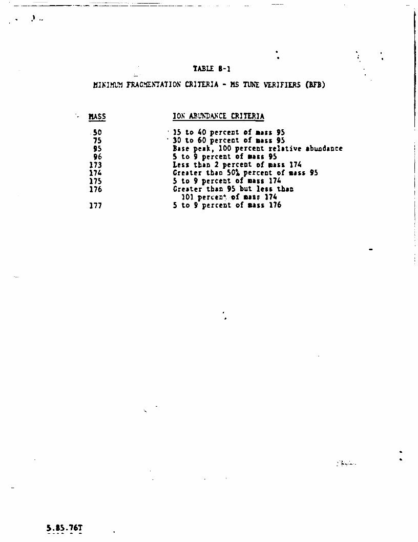
TABLE 8-1
MINIMUM FRAGMEKTAT10K CRITERIA - MS TUNE VERIFIERS (BFB)
MASS 10K ABUKDAECI CRITERIA
SO 15 to 40 percent of Bass 9575 ' 30 to 60 percent of Bass 9595 Base peak, 100 percent relative abundance96 5 to 9 percent of Bass 95173 Less than 2 percent of Bass 174174 Greater than 50** percent of Bass 95175 5 to 9 percent of Bass 174176 Greater than 95 but less than
101 perctar of Basp 174177 5 to 9 percent of Bass 176
S.B5.76T

Section No. 8_Revision No. 0Cite July 1.
• Page 3 of 9. «
o The tune it validated using decafluorotriphenylphosphine (DFTPP) to verifythai it meets EPA criteria. Table 6-2 presents tune verification data.
o A calibration check standard is analyzed and checked against the calibra-tion curve to verify that calibration acceptance criteria are atet.
o All samples, blanks and standards are spiked with internal and surrogatestandards. \
o 10*, of all samples are analyzed in duplicate.
o 5. of all saxples are eatrix spikes.
8.2 CAL!?F.ATIOV PRPrEDVRES AST) rREQVES'SY TOR HELD IKSTRVgNTS
Each piece of equipment will be calibrated prior to each day's us*. Theprocedures described below apply to the specific instrument noted. If otherinstruments are used, follow the manufacturer's calibration procedures.
8.2.1 Y.S.I. S-C-T Meter (Model No. 33)
Temperature Probe.
1. Using a National Bureau of Standards-approved thermometer, immerse bothprobes into a beaker of water and note any differences for the fieldprobe.
2. Recalibrate as necessary.
Specific Conductance Meter.
1. Calibrate meter and probe using the calibration control and the red-lineon the peter dial (Y.S.I. S-C-T Meter. Model No. 33).
2. Turn the function switch to read conductivity x 10 and then depress thecell test button, noting the deflection. If the needle falls more than 2percent of the reading, clean the probe and retest.
3. Using at least two buffer solutions, which vill cost likely bracket theexpected values for conductivity, note accuracy of the water and probe andclean probe if necessary.
8.2.2 Specific Ion Hettr
pM Probe.
1. P<ace electrodes and buffir solutions in a water bath at the temperatureof the water to be sampled. After temperature equilibrium, •easuratemperature and adjust the temperature compensation knob for this tempera-ture.
1-3
5.IS 76

TABLE 8-2•__ • f
MINIMUM FRAGMENTATION CRITERIA (DFTPP)
MASS IOK ABUNDANCE CRITERIA
51 30 to 60 percent of Bass 19668 .' Less than 2 percent of Bass 6970 less than 2 percent of Bass 69127 40 to 60 percent of Bass 196197 Less than 1 percent of Bass 196196 Base peak, 100 percent relative abundance199 5 to 9 percent of Bass 196275 10 to 30 percent of Bass 196365 Greater than 1 percent of Bass 196441 Present but less than Bass 443442 • Greater than 40 percent of Bass 196443 17 to 23 percent of Bass 442
5.B5.76TA i\

Section No. 8_Revision No. 0Date July 1. 19BSPage 5 of 9
2. If using refilliblt probes, remove tlectrode cap and cbeck that filling•olution IK aboVe the filling Bark.
3. JauDerse the probe in the pH 7 buffer solution and adjust the calibrationcontrol to read the appropriate pH. Check the pH buffer solution forcorrect pH value at the equilibrated temperature.
A. Remove the probe, rinse, with distilled water and then ioserse in titherthe pH 4 or pH 10 buffer solution, depending on the expected pH of thesample.
5. If the eeter does not register the correct pH for that buffer solution,adjust the calibration knob on the back of the instrument to obtain the pHof the buffer.
6. After rinsing, insert the pH probe into the flow cell and allow the probeto come to equilibrium with the sample water.
7. The pH probe is stored in the ambient air oven»i»v*..
Eh Probe.
1. Check that the platinum probe is cle^ "'and the platinum bond or tip is -unoxidized. If dirty, polish with emery paper.
2. Immerse the standard solution, Zobell solution, end probe in • water bathat the terperature of the water to be sampled. After the temperature hasequilibrated, increase the probe and the reference probe, if required,into the Zobell solution. Record the siV reading and the temperature Andcor.pare with the expected value (±10*20 »V).
•
3. Rinse the probe with distilled water or probes and insert into the flowcell. Allow for temperature equilibration and record the sample Eh.
4. At the end of the day, the probes should be stored in water.
6.3 3 Tripar Anilyter
Temperature Calibration.
o Temperature Zero Adjustment - Connect the temperature sensor and selecttemperature as the display parameter. Remove the rear access coverexposing the sensor calibration potentiometer*.
Prepare an ice water slurry and place the temperature sensor in the•olution. Allow the temperature sensor to stabilise for approximately oneaunute while stirring the sensor in the solution vigorously. Using theadjustment tool provided in the rear cover, adjust the temperature "zero"potentiometer for a n-ding of 0.00*C on the system display. .';.W~-
••5

Section No.Revision No.Date July
L of -L,
o Temperature Span Adjustment - Prepare • test solution to be used fortemperature calibration. A beaker of water at room temperature works wellas it will not be changing rapidly in temperature. Place the Tripartemperature tensor in the test solution and allow to stabilize for approx-imately one minute. Using a precision laboratory thermometer, s>easure thetemperature of the test solution. At the Tripar rear panel, adjust thetemperature "CAL" potentiometer until the Tripar display reads the valueof the calibration solution.
lest results will be obtained if the temperature "ZERO" and "SPAN" cali-bration procedures are repeated.
Conductivity Calibration. From time to time, it will be required to calibratethe Tripar conductivity circuit. A simple two-point calibration procedure isutilized by first adjusting the conductivity zero and then the span.
o Conductivity Zero Adjustment - V'ith the conductivity sensor clean, dry,and in air, adjust the conductivity "zero" potentiometer for a reading of0000 on the Tripar display.
o Conductivity Span Adjustment • Totally immerse the Tripar conductivitysensor in calibration solution of known conductance. Note that thereading displayed on the Tripar is a temperature corrected value to 2S*C*Therefore, the value of the standard solution must be calculated to 25*C.Also, the value of the calibration solution should fall in the upper 50percent of the ranges to be calibrated; i.e., adjustment of the 1000cicrotnho range should be accomplished with a 500 to 1000 cicromho stand-ard. Once the sensor has stabilized in the solution for approximately oneEinute, adjust the conductivity "CAL" potentiometer at the Tripar rearpanel for a reading on the display equal to the temperature correctedvalue of the standard solution. •
*
Best results will be obtained if the conductivity zero and span proceduresare repeated.
pM Calibration.
pH Standardization » The pH sensor should be standardized before each useafter long storage. First, moisten the electrode body with tap water andcarefully remove the plastic storage cap covering the tip of the elect-rode. Care should be taken not to bend the body of the electrode, as thiscan result in damage. to the internal element.
'•v
For first time use after long storage, immerse the lover and of thealectrode in tap water for 30 minutes. This hydrates the pH bulb andprepares the ceramic wick for contact with test solutions. If air bubblesare present in the pH bulb, shake the electrode downward to fill the bulbwith solution. . .. ,
' i * V ~" *•
Prepare a small sampl- of pH 7.00 buffer solution and measure the tempera*ture of the buffer. Rinse the pH electrode with distilled water andimmerse the pH bulb in the reference buffer. Set the compensation dial in

Section No. BRevision No. 0Date July 1. 1965Page _7_ of _9J.
the Tripar front panel to the temperature of the buffer, allow severalminutes for the sensor to reach equilibrium and stir the sensor slightlyto dislodge any possible air bubbles from the electrode tip. Using the"Standardize" potentiometer, adjust for a reading of 7.00 on the Tripardisplay.
o pK Slope Adjustment - Very infrequently, the pH slope adjustment mayrequire re-calibration. This adjustment is available at the Triparreadout rear panel. To accomplish this adjustment, prepare a test solut-ion of pH 4.00 or 10.00. Measure the temperature of the solution and makethe appropriate setting at the pH "Compensation" dial. Rinse the pHelectrode in distilled water and immerse in the buffer solution. Allowseveral minutes for the sensor to equilibrate and stir the electrodeslightly. Using the pH "Slope" potentiometer available at the rear panel,adjust the Tripar readout module for a reading equal to the value of thebuffer solution. For best results, the pH "Standardize" and "Slope"adjustments should be repeated at least once.
Note that some interference may be seen on the pH reading if the Triparconductivity sensor is present in the same test solution as the pH sensor.
8.2.A HN'U Photoionization Meter
With the probe attached to the instrument turn the function switch to the *battery check position. The needle on the meter should read within or abovethe green battery area on the scale plate. If the needle is In the lowerposition of the battery arc, the instrument should be recharged prior to anycalibration. If red LED comes "on", the battery should be recharged. Next,turn the function switch to the on position. In this position the UV lightsource should be on.
»
To zero the instrument, turn the function*switch to the standby position androtate the zero potentiometer until the meter reads zero. Clockwise rotationof the zero potentiometer produces an upscale deflection while counterclock-wise rotation yields a downscale deflection. If the span adjustment setting ischanged after zero is set, the zero should be rechecked and adjusted if neces-sary. Wait 15-20 seconds to ensure that the zero reading is stable. Ifnecessary, readjust the zero.
The instrument is now ready for calibration by switching the function switch tothe proper measurment range.
Using non-toxic analyzed ?as mixtures available from the manufacturer inpressurized containers", connect the cylinder with the analyzed gas mixture tothe end of the probe with a piece of tubing. Open the valve of the pressurizedcontainer until a slight flow is indicated and the instrument draws in thevolume of sample required for detection. Now adjust the span potentiometer sothat the instrument is reading the stated value of the calibration gas.
If the instrument span setting is changed, the instrument should be turned backto the standby position and the electronic zero should be readjusted if neces- .
8-7
5.63.760046.0.0

Section No.Revision No. 0Date July 1. 19BSPage a of 9.
• try. If the instrument does not calibrate, it may be Decenary to clean th«probe or the lamp connection.
B.2.5 Drianic Vapor Analyrer
Set up"the Photovac 10A10 in a temperature-stable environment at least eight toten hours before beginning analyses. Attach AC power cord to Photovac and pluginto 110V power outlet. Attach recorder AC power cord to Linear recorder andplug into 110V power outlet! If fully charged, internal battery packs provide6 to 8 hours operation as a portable instrument.
Connect coaxial cable to "output" jack on Photovac, and plug opposite and into4/- input jacks on records. If positive utter reading on the Photovac givesnegative recorder response, reverse polarity of recorder by reversing plug in+/- jacks. Attach gas supply to either "carrier in" port and test for properflow rate on "vent" and "out" parts with a bubble flow aeter. Record actualflow rate. Proper flow rate is 10-15 nt/sin during analysis; -5 Bt/cin enstandby or overnight. Reduce flow rate for overnight flush by adjusting theair tank pressure regulator. Note: Use only "Zerograde" or better air ascarrier. Plastic tubing is preferred for the connection.
Set Photovac attentuation on 100 and range on xl. Start gas flow at 10 ml/tic.Place "charge" switch in off position and turn detector twitch on 30 minutesprior to beginning of analysis. Turn recorder chart drive off, and with theinput voltage switch set at 100 »V, turn the recorder power on. Using the"xero" and "attenuation" knobs on the recorder, set ao that a zero reading onthe Photovac meter gives xero plot on the recorder, and so that 100 reading onPhotovac gives full scale reading on recorder. (Turn the "offset" knob on thePhotovac to cake photovac meter reading change.)
Turn the "offset" knob fully counterclockwise. Meter reading should be 20*50percent of full scalt. If higher, cither the air supply is contaminated or thecolumn needs to be flushed. The instrument can atill be used in this condi-tion, but the detector can aasily be overloaded. Wait until reading is 20-30percent if possible before analysis. Set the attenuation on the Photovac tothe desired setting (e.g., 100 for "unknown" or dirty samples; 10 for low ppastandards or clean samples).
Rotate the offset knob clockwise until meter (and recorder) reads -10 perctntof full scale. Set the column selector switch to the desired column. Usecolumn 01 (10 inches long) for screening unknown samples by injecting a email(- five-vl) amount in >ort 01 to determine how tiuch sample to inject in column12 (four feet long) for analytical purposes. Use the result! of this initialsmall injection on column fl to avoid overloading column f2. If column 02 isoverloaded, it may take hours or even days before it is useful atain.
Reset the offset (if necessary) to giva 10 perctnt full acala reading. Waitfor f ter to stabilize. Set recorder chart speed to 1 cm/-In and turn chartdrive on (flip switch up to cm/min setting). Inject sample or standard intoproper port in a smooth motion and nbte on the recorder chart the moment ofinjection. Note on the chromatogram the sample or standard identification,volume injected, column *, range and attenuation (t.g., 100 x 1), chart apeedand date.

Section No. 6Revision Ho. 0Date July 1. 1»B5Page 9 of 9.
Let chroiratogram run until all compounds have eluted and tb* baseline batstabilized before Baking another injection (-15-20 minutes for column fl.•90-60 minute* for column 92). Fun atandard mix. avery five or aix aamples toaionitor change* in retention tines or response. To interpret chromatograms,measure retention times from point of injection (1 cm « 1 Bin. or appropriatescale).. Measure peak height from baseline to estimate quantity of a givencompound, relating aaople peak retention tine and height to that of knownatandards. Peak height is directly proportional to concentration and to volumeInjected (*.g., if a 50 yt injection of a 5 ppa standard gives a 5 cs> peak withretention time of IK seconds, a sample with a 3 cat peak at 122 aeconds maycontain 3 pptr. of the same compounds if 50 Vt was injected).
Miscellaneous. Use only air-tight ayringes vith sharp pointed needles tointroduce sarrples into the Photovec. Any bend in the needle vill damage theseptum and analyzer vill not be reliable. Pierce tbe aeptua of the samplecontainer and rinse the syringe three or four tines by working the plunger backand forth before filling vith sample. Remove syringe and quickly adjust volumeand sake injection vith no hesitation. Never remove or loosen caps or valveson aairple containers. Once the septum on a sample container is pierced,complete all analyses on that sample as aoon as possible, as some loss ofcontaminants Bay occur.
Never interrupt the carrier gas (air) supply without first turning the detectoroff! Change air tanks when pressure reaches -300 psig, or at tbe end of theday if analyses are to be performed the following day (detector off whilechanging).
Typical Standards. Retention Times, Response Factors for the Phetovac 10A10.The revert ion titr.es and response factors below are estimates based on labora-tory work under controlled conditions (20*C and a carrier flow of 10-15 ml/Bin). Actual retention times and response factors Bust be acquired in thefield under identical conditions to those'under which samples vill be run.
A table like that shown below Bust be .:':*rat*2 prior to analysis of actualsamples. Documentation Bust also include attenuation settings, column identi-fication, head pressure and ambient conditions.
Mixed Standard RetentionConcentration Ti»e
Compound . (ppw) (seconds)
Bethylene chloride1 ,1-dichloroethane1 ,2-dichloroethanebenzenetoluene1,1,2,2-letrec.hlrroethylenerhlorobenzenexylenes (3 Isomers)
S.O10. 020.01.02.02.02.010.0
$0 "•3100110285340435
615,6*5 800
Response50 vtInjection
(cm)
-104.54.56.55.67.17.4
1.0.4.3.1.3
1-9

Section No.Revision No. 0Date July 1. 19B5Page 1 of 3
9.0 ANALYTICAL PROCEDURES
9.1 SELECTION' OF PARAMETERS
The parameters to be monitored in groundwater, surface water, and sedimentvert selected based on results obtained during pervious studies of the site.The studies showed volatile organic*, dimethyl formamide, tetrahydrofuran, MEK,and MJBX to be present it the sitt. In addition, seaivolatile organic* ere tobe analyzed annually at five monitoring veils.
9.2 ANALYTICAL PROCEDURES
Analyses will be performed by USEPA Methods 624 and 625 except for thtdetermination of dimethyl formatsidt (DMT). DMT will be analyzed by directinjection to a fas chromatograph utilizing a nitrogen-phosphorus detector and a1 percent SP-1000 on 60/80 Carbopack B, 1.8 meter by 2 millimeter (lass column inaccordance with the methodology specified by the Administrative Order byConsent for provision of alternate water supply, 1964.
The DMF analysis, discussed further in Section 17.0, will be performed by RhodeIsland Analytical Laboratories, Providence, K.I.
Samples will be collected in both water and soil »atrices. Water samples willbe analyzed for organic parameters in accordance with USEPA Methods promulgatedas 40 CFR 136 on 26 October 1985. Soil samples will be handled such thatorganic contaminants are exchanged to an aqueous or solvent extractant, andsubsequently analyzed by the same methods cited above.
9.2.1 Water Matrices
Table 9-1 presents selected organic analytical siethod information. Precision,accuracy and method detection limits, as stated by the methods, teflect nethodperformance under ideal sample matrix and laboratory conditions. Theseperformance levels are not exoected to be equaled during this project. Actualanalytical method performance is provided with the analytics] results in theform of duplicate analytical results, blank analytical results, spiked sampleresults and surrogate compound recoveries. Additional data documentation isnot required by the referenced methods.
9.2.? Solid Matrices
As noted previously, organic analyses of solid matrices will utilize the samemethods specified for'-water matrices. Precision, accuracy and method detectionlimits, as stated by the methods, reflect method performance under ideal samplematrix and laboratory conditions. These performance levels are not expected tobe equaled during this project. Actual analytics! method performance isprovided with the analytical results in the form of duplicate analyticalresult*, blank analytical results, spiked sample results and surrogate compound•*roveries. Additional d;.ta documentation is not required by the referencedmethods.
1-1i.85.76

TAUU. 9-1
____n _ USF.PMnaJytjc^lJIrthod1 & HoMinal Detection limit'Pan Meter _ Vater _ ~ _ ' Solufs _
Volatile Organic*3'4 624 - 10 pK/f 624 - 400 pg/kg
SeMi volatile Organic*3'4 625 - 20 pg/t 625 - BOO pg/kg
1 The ideal precision and accuracy of the referenced Methods (if available) is contained in the Method.4 Theactual precision and accuracy is dependent upon the Matrix interferences encountered and will be detenainedas the project progresses. It is anticipated that precision and accuracy will be less than that stated by theMethod. O
1 Nominal detection liMits are presented. Actual detection limits are dependent upon the Matrix interferencesencountered and the compound to be detemined.
3 Solid samples are prepared such that contawinants are exchanged to a liquid phase and the referencedMethods utilized.
4 Ortanic Methods are contained in 40 CFR Part 136 "Guidelines Establishing Test Procedures for the Analysisof Pollutants Under the Clean Water Act" 26 October I9H4. Inorganic Methods are contained in "Hethods for
Analysis of Water and Wastes," EPA-600/4-79-020, March I9B3. Both inorganic and organic Methods-tJice. are contained in "Test Methods for Evaluating Solid Wa.te" USF.PA SW-846, July 1982.
5.B5.76Tnnofc n O

Section No. 9_Revision No. 0_Date July I. 19BSPage 3 of 3
Solid *ample preparation for organic analysts will utiliae the followingprotocols:
Volatile • One gram of sample is placed la a 40 ml vial filledFraction with water and spiked with surrogates. The vial is
* - agitated for at least 16 hours at 4*C and the water isanalyzed hy the specified method.
Seal Volatile • 20 grains of sample are sonicated and sequentiallyFraction extracted with 3 volumes of a Bixture of rethylene
chloride and acetone. The combined extractant is thenanalyted.
These protocols are described in sore detail in "Development of Analytical TestProcedures for the Measurement of Organic Priority Pollutants in Sludge andSediments," Midwest Research Institute, Final Report-EPA Contract No.6E-03-2695, June 26, 1979, and USEPA's National Contract Laboratory Program"Consensus Organics Protocols", respectively.

Section No. 10Revision No. _ 0__Date July 1. 1965
10. L DATA REDUCTION. VALIDATION AND REPORTING
Data reduction it the process of converting sieasureaent system outputs to anexpression of the parameter which is consistent with the comparability objec-tive (identified in Section 5 of this QAPP) . Calculations Bade during datareduction are described in the USEPA analytical Methods.
Validation of measurements is • systematic process of reviewing a body of datato provide assurance that the data are adequate for their intended use. Theprocess includes the following activities:
o editing,
o screening,
o checking,
o auditing,
o verification,
o certification, and
o review.
Data validation activities will be documented and records kept of any necessarycorrective or remedial action.
Laboratory reports of data will be edited by comparing with original calcula-tions. Subsequent data tabulations will be edited by cosparing with thelaboratory reports. The data will be screened to determine compliance with thequality assurance objectives identified in Section 5.
Field data collection and validation will follow the process illustrated asFigure 10-1. Prior to data collection, determinations are vade regarding thedata which is required to be gathered in the field and the methodology to beused. Once the data is obtained, it will be reviewed and assessed as to itsadequacy. If it is determined that the initial data collection concept did notprovide adequate data, the entire process will be repeated.
Calculations performed during data reduction are checked, before the laboratoryreports the data, as was illustrated in Figure ?-).
Jordan's Environmental Laboratory routinely participates in and successfullycompletes performance audits using reference samples provided by USEPA andother regulatory authorities. Results of these audits will assist invalidating the data reported. In addition, system audits rf laboratoryprocedure* *r>4 data management rr* Conducted by tht QAC. _-::t--v
10-)
$.85.76

DCFlNE DATA REQUIREMENT
1DEFINE METHODOLOGY
VEKlFT (AMPLE LOCATION
IIDENTIFY SAMPLE TYPE
J
OENTIFV FIELDEQUIPMENT —REQUIRED
DOCUMENT• EQUIPMENTIDENTIFICATION
IDENTIFY OC SAMPLES, IF NEEDEDJSAMPLE COLLECTION
DUPLICATE SAMPLESIF REQUIRED
CALIBRATIONOF IQUIPMEHT
1DOCUMENT
CALIBRATION
DOCUMENTDUPLICATE
IDCNTiriCATlON
MEASUREMENT
JFIELD REPORTING
IDATA CONVERSION.
I-FINAL REPORT
IDATA REvlr
JA C C E P T A B L E DATA
CHECK CALIBRATIONOF EQUIPMENT
.fDOCUMENT HE-CALIBRATION
,VERIFICATION OFCALIBRATIONS
VERIFICATION
FIGURE 10-1FIELD DATA COLLECTION AND VALIDATION
EC JORDANCO —

Section No. 10Revision No. 0Date July 1. 1965Page 3 of 4.
Results reported for each sample are verified to assure proper identificationby comparing the original sample collection log sheets (see Section 6) withchain-of-custody fores and laboratory log books. Upon certification by thelaboratory eanager, the reported values are received and reviewed by thetechnical ataff and the QAC (if deemed accessary).
Analytical data are to be reported froo Jordan's laboratory within 30 days of• asple receipt in the format.' illustrated in Figure 10-2. It should be notedthat analytical data documentation is Halted to that required by the specifiedBethodologies.
- 10-3
at ?*

ECJORDANCQfrt?
IXPORT OF ANALYSISRIFERDJCE HUKBER
BATE 4/26/BA1183 PACE 1
CLIENT NAME
Client Date Received/lab ID Parameter Units Results
Lagoon 3/08/84 Volatile Organic*4068001 Toluene VC/KC
Ethylbensene DC/KGXylenes DC/KG
Volatile Surrogate RecoveryBroBochlorooethaneBenrene-32-Brono-l-Chloropropane1.4-DichlorobutaneP-Brosofluorobenxene1.2-Dichloroethane-IWi
Sesivolatile Organic*Butyl Benzyl Phthalate KC/KCDioctylphthalate MC/KCBis(2-Ethylhexyl)?hth*latt KC/KCDi-N-Bjltyiphthalate MC/KC
Secivolatile Surrogfte RecoveryPhenol-D5PentafluorophenolDecafluorobiphenyl2.A-Dichlorophenol-D3Kaphthalene-D8IP Extraction-Arsenic MC/LEP Extraction-Bariun MC/LEP Extraction-Cadaiia MC/LEP Extraction-ChromiuB MC/LEP Extraction-Lead MC/LEP Extraction-Mercury VC/LEP Extraction-Seltaiua MC/LEP Extraction-Silvtr MC/LEP Extraction-Endrio VC/LEP Extraction-Lindant VC/LEP Extnctlon-Methoxychlor VC/LEP Extraction-Toxaphent VC/LEP Extraction-2.*»D VC/LEP Extraction-2.«.5-TP Sllvex VC/L
SignatureReport toAuthor J*»: i»»n
iOOO1000085000
699762.6010676
6000370093002000
9217
130116130
0.0270.06&0.0010.0180.010
10.0100.001
1.00.11.01.010
1.0
FIGURE 10-2FVAMPI P AWAl YTIPAI HATA DEPORT

Section No. 11Revision No. o"""Date July 1. 1965Page I Of A.
.11.0 INTERNAL QUALITY CONTROL
11.1 KTASURZMENT SYSTEMS
Quality control procedures art established for laboratory and fitld activities.Procedural used in the Jordan laboratory, auch at analytical duplicates,blankj, control charts, internal standards, surrogates and reagent checks aredescribed in detail in the specified analytical aethods. Jordan also hasestablished quality control procedures for all field activities auch as samplerblank collection, duplicate sample collection, and field aeasureeentvalidation. Field quality control activities include the use of calibrationstandards and blanks for pH, specific conductance, teaperature and photoioni-cation measurements. Special samples to be submitted to the laboratoryinclude:
o
o
o
o
trip blanks,X
blind replicates (field duplicate),
sar.pler blanks
filtration blanks
These satrples provide a quantitative basis for validating the data reported.
Trip Hanks
Trip blanks are required for assessing volatile organic priority pollutantsreported in water sanples. The trip blank consists of a VOA sar.ple containerfilled with reagent water which is shipped to the site with the other VOAsen-pie containers. Two trip blanks are included vith each shipment of vatersamples scheduled for volatile organic analysis. One of the two trip blankswill be analyzed with the other VOA sanples. The other nay be analyzed ifVOA are detected in the first VOA trip blank.
Replicates
Feplicates of water and sediment will be submitted for analysis of allparameters specified for those samples according to the following schedule:
Hedia
groundwater and surfact water
aedietenta
Number
10* of samples analyzed or ••inimuoi of 1 per event
10» of samples analyzedor a viniBua of 1 per event
The identity of the replicate sanples will not be revealed to the laboratory.
11-1

fection No. 11Revision No. 0D«t« July I. 19B5Page 2 of 4-
True replicates of sediaent sample* are not possible because chemicals «retypically not uniformly distributed in these Materials. A aiodification of ASTMC702, Method B "Reducing Field Samples of Aggregate to Testing Sice" will beused to split sediment samples. Samples for volatile organic analysis,however, Bust be grab samples to avoid the loss of volatile constituents, which•ay be expected during sample splitting.
Filtration Blanks
Groundwater samples scheduled for analysis of inorganic parameters are to befiltered. In order to assess filtration apparatus cleaning proceduresand potential cross contamination, as veil as any contribution to the samplefrom the fitler itself, a filtration blank will be collected for every 10 to15 samples filtered. The filtration blank will be prepared by passing reagentwater through a freshly cleaned filtration apparatus.
Sampler Blanks
A ninimutr of one sampler blank for the bailer or sampling punp and tubingassembly is scheduled prior to monitoring well sampling. Volatile or sejti-volatile organics present within the pump apparatus or discharge tubing artassessed by collecting a sample of reagent water passed through the samplingapparatus after washing the pump and tubing with the aethanol-deionired water *solution followed by a rinse with reagent water.
Completeness
Completeness of scheduled sample collection will be controlled in the field bycomparing a computer generated label inventory with samples actually collectedeach day. Daily checking of field data sheets and comparison of transport andchain-of-custody logs will provide further control on documentation andcompleteness.
Criteria Used in Evaluating Laboratory Assays of Internal Quality Control Sa--ples anrf Fi*3d (Sarple) Replicates
Establishment of specific criteria depends on the nusber of field and qualitycontrol samples for tach vedia sampled, the quality of chemical data and howthe data will be used in interpreting, evaluating and assessing the site.Chemical assay results of a particular sample nay be used for more than onepurpose in a remedial investigation and feasibility study. Chemical assayresults of quality control samples nay be considered differently depending onhow the data will ba used.
The following general criteria arc identified for use by the professionalresponsible for assessing tite conditions:
e Quality of Laboratory Data:"""• ' *-
» acceptablaprovisionalunacceptable
11-2
$.•5.760017.0 0

Stction No.Revision No.Date JulyTttt 3 of _4-
Method Limitations:
detection rangeaccuracymethod detection Units (HDL)minimus reportable concentration (HRC)precision
Stapling/Analysis "Scope and Results:
number of replicates at one locationnuir.ber of sarples on site/mediabackground/downgradient distributionconsistency/trends of chemical assay data collected at siteagreement with existing site information
Use of Data:
chemical distribution and transport at the tit*(generally order of magnitude comparisons)compliance with standards, regulations, response objectivespresence or absence of chemicaltreatabilitydisposal method for aiedia containing chenicals
11.2 QUALITY REVIEW 07 STUDIES AVD REPORTS
The purpose of quality reviews through the course of studies, designs andreports is to ensure that the service, designs and documents produced by eachdepartment neet currently accepted professional standards. The level of effortfor each project will vary depending on type of project, duration and size.Review of small projects may entail periodic discussions between productionstaff and discipline managers. Quality control on larger projects cay requirethat a review team be selected for more frequent Bettings and discussions.Quality control reviews should be scheduled on • routine basis, but the optionof holding a quality control review at any time is always open.
The time required to plan, schedule, and conduct quality control reviews shouldbe considered part of all other design, writing and checking phases of aproject.
Each project is divided into phases for quality control reviews. At eachphase, the review should include client goals, contractual commitments, techni-cal Merit, timing, budget, assignment of appropriate personnel, departmentcoordination, project problem resolution, documentation, and consistency withcompany policy. Key elements to the success of any quality control review artidentification of problem areas, communication to implement solutions, and
11-3
S.tS.76

Section No.Itvis ion No.Date JulyPage A Of ^
Quality control during the preparation of studies and report* relies on docu-mentation of data utilized and peer review of conclusions drawn froo theassembled data base. The comparability objective established for the projectis of particular importance when data are derived froe many »ources (i.e., thedata base is comprised of secondary »easure»ents). Documentation of secondarydata typically is accomplished via data verification/tracking checklists withaccompanying written criteria describing "acceptable" data to insureconsistency in data selection. This allows all data base components to betraced to the pritnary generator and forces a review of data quality as the database is developed. All project personnel are responsible for utilization andnor.itoring of this process; compliance is audited by the QAC. Upon completionof the data base, data interpretation, evaluation, and report preparationcommence. Interpretation nay require consultation with Jordan's statisticianand/or use of computerized statistical routines. Documentation is alsoprepared for statistical manipulation methodologies. Data evaluationsincorporate peer review to provide broad-based insight to data correlations andinteractions.
To enhance the professional quality of the company's studies and reports, thediscipline manager will also:
o require that reports refer to and are consistent in scope with the projectproposal and contract; and
o require that report language and contents be chosen to foster client'sunderstanding of risks and uncertainties by distinguishing fact fromopinion and identifying risks and limitations in a clear and informativeBanner.
1I-*
ft<

Section No. 12Revision No. 0Date July 1. 19BSPage 1 of 6.
12.0 AUDITS
Quality assurance audits art performed to assure and document that qualitycontrol measures are being utilized to provide data of acceptablt quality andthat subsequent calculations, interpretation and otber project outputs arechecked 'and validated.
System and performance audits vill be conducted by the Quality AssuranceCoordinator (QAC). The Laboratory Technical Director will conduct projectaudits of calculations, interpetations and reports which are based on themeasurement system outputs.
12.1 SYSTEMS AVDIT
A systetc audit vill be conducted on all components of Beasurement systems todetercine proper selection and utilization. The systems audit includes evalua-tion of both field and laboratory procedures.
Organization and Personnel. The project organization is reviewed for conspli-ance with the proposed organization and for clarity of assigned responsibility.Personnel assigned to the project vill be reviewed to determine that assigned .responsibility, skill and training of the personnel are properly Bitched. Thelaboratory director maintains firsthand knowledge of bis team's capabilitiesand vill discuss the organization's efficacy vith the QAC. Assigned personnel•ay be interviewed by the QAC during an audit.
Facilities and Equipment. The audit vill address vhether field tools andanalytical instruments are selected and used to Beet requirements specified bythe project objectives stated in the QAPP. Equipment and facilities providedfor personnel health and safety vill also'be evaluated. Calibration anddocumentation procedures for instruments used in the field vill receive specialattention.
Analytical Methodology. Routine axternal performance evaluations as veil asblind internal performance evaluations are conducted. A review of analyticalmethodology in regard to the data requirements for the project is usuallyperformed; this project, however, has specified analytical methods. An on-siteobservation of analyst technique, data reduction and record keeping may baperformed. Periodic review of precision and accuracy data is essential.Jordan's Analytical Laboratory routinely participates in USEPA performance•valuations.
Sampling, and San-pie Handling Procedure. An audit of scheduled samples vssamples collected vs sacples received for analysis vill be perforated. Fielddocumentation vill be reviewed. If deemed necessary, • sit* visit vill be Badeto assure that designated control procedures are practiced during samplingactivities.
12-1

Section No.Revision No.Date July 1.
12
2 of 6
Pate Handling. During* a system audit, the QAC will review data handlingprocedures with the TD and Task Leaders. Accuracy, consistency, documentationand appropirate selection of methodologies vill be discussed.
1?.? PERFORMANCE AUDIT
Performance is eonitored periodically (about 10*) for sampling protocols andcontinuously for analytical procedures to determine the precision and accuracyof the total measurement system(s).
The precision of sampling Is assessed through field duplicates and sacpltr/filtration blanks. To determine the accuracy of measurement systems in thelaboratory, performance test samples are used to assess precision and accuracy.I'SEPA has prepared test samples for numerous parameters in cany different••trices. The QAC coordinates regulatory authority performance audits andperiodically submits blind performance audit samples for analysis. Currently,Jordan participates in (and successfully completes) USEPA VS-series andVP-series performing evaluations. Results of the most recent USEPA performanceevaluation are available upon request.
Performance audits for data handling systems vill involve review of field data.records, calculations and data reduction methods.
12.3 QA AUDIT RIPOKT
A written report of the QA audit (see Figure 12-1) is prepared to include:
o an assessment of project atatus in each of the major project areas;9
o clear statements of areas requiring improvement or problems to becorrected. Recommendation and assistance vill be provided regardingproposed corrective actions or system improvements. If no action isrequired, the report vill state that the QA audit vas satisfactorilycompleted;
o a timetable for any corrective action required; and
o a followup to assure that recommendations have been implemented.
The QA Audit Report is submitted to the project manager.
12-2

Section No. 12Revl«lon No. 0Date July 1. 1965Pa»e 3 of 6
riCURI 12-1
QUALITY ASSURANCE AUDIT REPORT
Project:.
Contract/Project No.: Quillty Assurance Coordinator:.
Laboratory or Systen Audittd:
Laboratory/System Director:
Audit Conducted By:
Date:
PURPOSE AST) OBJECTIVES OF THI PROJECT
C
BRIEF DESCRIPTION OT THI SAMPLING AST) ANALYTICAL REQUIREMENTS
12-3
S.BS.760062.0.0

Section No. 12Revision No. 0Date July I.
A of 6
FIGURE 12-1 (Cont.)RESULTS OF THE QUALITY ASSURANCE AUDIT
Organization and Personnel
facilities
AT>i?vtic«l Methodology
12-A
$.•5.76

gtctlon No. 12_Rcviftion No. 0_D«te July 1. 1965
5 of 6-
FIGURE 12-1 (Cont.)RESULTS OF THE QUALITY ASSURANCE AUDIT
Sampling and Sa-ryling Handling
Quilitv Control
Datt Hanifl int
12-5
riCURI 12-1 (Cont.)
Quality Assurance Deficiencies
F«cor.-eni«i Corrective Actions and Timetable
Section No. 12Revision No. 0Date ^July 1.M9E5 •.Fa»e 6 of 6
Signed Dated
Title
Distribution:Quality Assurance C?r-dinatorProject KanafirTechnical Project DirectorTask Leader*
12-6

tectlon No. 13Revision No.Date July 1.Page 1 of 1
13.0 PREVENTIVE MAINTENANCE
Prtvtntivt maintenance of fitld equipment proceeds routinely before aach»as?ling * vent; more extentlv« maintenance is perforated on the basis of hoursin ust. 'Preventive maintenance is performed contractually on the laboratory'sHewlett Packard fat chroaetograph/mass spectrometer, Parkin-Elmer 603 and 5000atomic absorption spectrophotometers, Perkin-Elmer Sigma I Gas Chromatographand analytical balances (Kettler H20, Hettler H2B, and Ohaus 1SOOD).
HEWLETT PACKARD H03EL S96SB GAS CHEDMATOCRAPHyMASS SPECTEyiETEE SYSTEM
This systetr is under a service agreement with Hewlett Packard which covers allrepair parts, extended parts, labor and travel, and three annual preventivemaintenance service visits. These visits involve cleaning, adjusting, inspect-ing, and testing procedures designed to reduce product failure and/or axtenduseful product life. Between visits, routine operator maintenance and cleaningis performed according to manufacturer's specifications.
PERK1K-ELMIR 603 ATOMIC ABSORPTION SPECTPDPH3TOMETER
The full service maintenance plan with Perkin-Elmer covering this systamincludes replacement parts required during both routine maintenance and emer-gency maintenance visits. Routine operator maintenance and cleaning is per-formed by an experienced analyst or cher.ist according to manufacturar'aspecifications.
KITTLER H:O. METTLES H2B. AM) QKAU5 15DDP- ASAIYT1CAL BALAS'CESw — ^ ^ ^ —
Each analytical balance is cleaned, serviced, and calibrated seal-annually by aqualified service representative.
PE3K1K-ELVIR SIGMA 1 FID/ECD CAS CHRDW03RAPH A\D PERKIN-IL^R MODEL 51C1A 3-BDIAL FID GAS CHE^ATOSEAPH
These systems are under service agreements with Perkin-Elmer vhich cover allrepair parts, extended parts, labor and travel. The visits involve cleaning,adjusting, inspecting, and testing procedures designed to reduce productfailure and/or axtend useful product life. Between visits, routine operatormaintenance and cleaning is performed according to manufacturar'a•pacifications.
PERKIK-ELMEa MODEL 5000 ATOMIC ABSi/R.-TlQS SPECTRDPHPTDMEITR ,:>:V—
This unit carries full service-maintenance warranty. Routine operator mainte-nance and cleaning is performed by an experienced analyst or chemist accordingto manufacturer's specifications.
13-1

Section No.levision No.Date July 1.Page 1 of
U.O DATA QUALITY ASSESSMENT
The purpose of data quality assessaent is to assure that data generated underthe program ere accurate and consistent vith project objectives. The qualityof data will be assessed based on the precision, accuracy, consistency and com-pleteness of the data that are measured or generated.
Tata quality assessment vill be conducted in three phases:
Prior to data collection, sampling and analysis procedures vill be evaluated inretard to their ability to generate the appropriate technically acceptableinformation required to achieve project objectives. This QAPP Beets thisrequirement by establishing project objectives defined in terns of parameters,analytical nethods, and required saspling protocola.
PHASE 2
During data collection, results vill be assessed to assure that the selected .procedures are efficient and effective and that the data generated are suffi-cient and comply vith the Administrative Order by Consent. Precision andaccuracy of measurement systems vill also be evaluated. In general, evaluationof data vill be based on performance audits, results of duplicate and ipikedsample analyses, and review of coopleteness objectives.
Documentation nay include:•
o number of replicate samples collected;
o number of replicate, spike and field blank samples analysed;
e identification of statistical techniques, if used, to measure centraltendency, dispersion, or testing for outliers;
o identification of analytical nethod; and
o verification of transmitted data by the laboratory technicaldirector.
'v
Completeness is expressed as a percentage of validated data sets obtainedversus those intended for collection. The process of evaluating completenesscompares:
e number of data sets desired (project objective) vith r
e samples collected, and vith
o samples analyxed, and with
14-1

Section No.Revision No. 0Date July 1. 19ESfttt 2 of >
validated data sets obtained.
The percentage obtained IK thin coapared with the percental* completenessrequired to fulfill project goals.
PHASE >
Following completion of data collection activities, «n astestsent of theadequacy of the data bate will be undertaken. Keco&zendations for inprovedquality control will be developed, if appropriate.
Each phase of the assessment will be conducted by the QAC ID conjunction withappropriate project staff.
It should be recognized that analytical data documentation available forreview is anticipated to be licited to that required by the specifiedvethods.
c
H-2
S.IS.76n n
Section No. 15_Revision No.Dale July
% Page 1 of .2. .
>5.0 CORRECTIVE ACTION
Corrective or preventive action is required when potential or existing condi-tions are identified that Bay have an adverse impact en data quantity orquality; Corrective action could be inrediate or long-ten. In general any•ember of the program staff vho identifies a condition adversely affectingquality can Initiate corrective action by notifiying in writing his or bersupervisor and the QAC. The written communication vill identify the conditionand explain how it Bay affect data quality or quantity.
15.1 IMMEDIATE CORRECTIVE ACTION
This type of corrective action is usually applied to spontaneous, non-recurringproblems, such as an instrument malfunction. The individual vho detects orsuspects non conference to previously established criteria or protocol inequipment, instruments, data, Bethods, etc.. vill iamediately notify his/hersupervisor. The supervisor and the appropriate task leader vill then investi-gate the extent of the problem and take the necessary corrective steps. If alarge quantity of data is affected, the task leader Bust prepare a memorandumto the Project Manager and the QAC. These individuals vill collectively decidehow to proceed. If the problem is limited in scope, the task leader villdecide on the corrective action measure, document the solution in the appro-priate workbook and notify the Project Manager and the QAC in Bemorandum form.
15.2 LC\G'TER CDREICT1VE ACTION
Long-term corrective action procedures are devised and implemented to preventthe recurrence of a potentially serious pjroblem. The QAC vill be notified ofthe problem and vill conduct an investigation to determine the severity andextent of the problem. The QAC vill then file a corrective action request viththe Project Manager.
In case of dispute between the QAC and the PM, the Responsible CorporateOfficer (RCO) vill Bake a final determination for the company.
Corrective actions Bay also be initiated as a result of ether activities,including:
o Performance Avdfts;
e System Audits;
e Laboratory/field comparison studies; and
e QA program audits.
The QAC vill be responsible for documenting all notifications, recommendations,and final decisions. The PM and the QAC vill be jointly responsible fornotifying program staff and implementing the agreed upon course ef action. T»e
1S-1
I.IS.76

Section No. 15_Revision No.Date June It,pate 2 of 2..
QAC vill be responsible for verifying the efficacy of the implemented action*.The development and inplenentation of preventive and corrective actions vill beti»ed so as to rot adversely inpict aither project schedules or subsequent dstageneration/processing activities to the extent possible. The QAC vill also beresponsible for developing and implementing routine program controls to•laicize the Deed for corrective action.
1S-2
i.iS.7*0070.0.0
Station No. UItvision No. 0Date July 1.
of16.0 KEPORTS TO MANAGEMENT
Sumaary reports will be prepared on a periodic basis to infor* Management ofproject atatus. The reports will include:
e periodic assessment of measurement data accuracy, precision andcocpleteness;
o results of performance audits and/or systems audits;
o significant QA problems and recommended solutions; and
o status of solutions to any problems previously identified.
Additionally, arty incidents requiring corrective action vill be fully docu-mented. Procedural!)*, the QAC vill prepare the reports to management. Thesereports vill be addressed to the Project Manager. The suaatary of findingsshall be factual, concise and complete. Any required supporting informationvill be appended to the report.
16-1

Section No.tevision No.Date July 8.Pate_l_ofJL
17. IMETHYL FORMAMIDE ANALYTICAL METHODOLOGYRHJDE ISLAND ANALYTICAL LABORATORIES
DiBtthyl for»tftid* anilysii will t* »ubcontr«cttd to Rhode Itland Analyticallaboratories. Thi* §n«ly»it will be performed In accordance with theAdministrative Order by Consent for provision of alternate water aupply, 1IB4.•s described in the following correspondence.
17-1

SPECIALIZING IN ENVIRONMENTAL ANALYSIS jj
. II.
July lr 1HS *MONE <401)«C744&2
Iruce Kallin, Ph.DEnvironmental Laboratory ServiceE.C. Jordan Company$62 Congress StreetP.O. Box 70$0Portland. M£ 04112
Subjects Dimethylfor&amide Analysis
Dear Dr. Kallins
This is the inform you the K.I. Analytical Laboratories* Inc. willbe pleased to perform DKF analyses for your firm. The following isa description of the analytical methodology and associated quality*control that will employed for this projects
-Analytical Methodology-
Instrument! Tracer Model 56S Gas Chromatograph
Detectors Tracor Model 702 Nitrogen/Phosphorus detector
Column:. Glass, 1.8M x 2 mm ID pack'ed with 1% SP-1000 on €0/10 s>eshCarbopack B.
Carrier Gass Helium I 30 nls./stin.
Injection Port Temps 220*C
Column Temps 190*C
Detection Temps 2SO*C
Samples will be analysed via direct injection into the instrument.Prior to each sample set, calibration will be performed using threedifferent standard concentrations to generate, with linearregression, a three point standard curve. External standards will berun At periodic intervals, i.e., every S to 10 samples. ,.
* ,-f—* _* j- «• • .

Bruce tfellin, Ph.D.July 1, 1»B5Page -2-
•Quality Control*
Quality Control will follow the general EPA Guidelines, i.e., 10%duplicates and spikes* as well at method blanks.
ffanples will be stored at 4*C when received and analysed within therecommended holding tine requirements.
-Cost-
The cost for the above work will be 1100.00/samples.
Thank you for allowing us to submit this proposal and we look forwardto working with you on this project.
Sincerely* f
^2 -^ cAnthony E. Perrotti
PJP

ATTACHMENT IX
INTERIM PERFORMANCE STANDARD
A IX -1
1.0 INTRODUCTION
The purpose of this attachment is to provide specific information
concerning Annabessacook Lake water quality at the Winthop
Landfill site. This standard will be used until final (ACLs)
are established (estimated to be 1 year). The ACLs are to be
used to determine the need for additional remedial action
described as elements 9 and 10 of the Remedial Action Work
Plan for the site. Based on on-site conditions, this attachment
presents details for sampling, analysis, the performance and
determination of compliance.
2.0 SITE CONDITIONS
2.1 CHEMICAL DISTRIBUTION
Annabessacook Lake water quality was determined at locations shown
in Figure 1 during the U.S. Environmental Protection Agency (EPA)
RI/FS and is summarized in Table 1. Subsequent investigations
were conducted by the EPA, Cobbossee Watershed District (CWD)
and Maine Department of Environmental Protection (ME DEP) in
the lake where a seep was observed in October, 1984. Character-
istics of the seep are summarized in Table 2.
Chemicals that potentially discharge to Annabessacook Lake from
the landfill migrate in the groundwater. Chemicals present in
in groundwater are summarized in Table 3 for the southern plume,
Table 4 for the northern deep plume and Table 5 for the northern
shallow plume. The seep described above is a suspected discharge
AK -2

of the southern plume. Graphical representation of chemicals in
each transport route is provided in Figures 2, 3 and 4. The
concentrations shown in these figures indicate chemical concen-
trations in groundwater near the landfill.
2.2 HEALTH AND ENVIRONMENTAL CRITERIA
Important potential receptors of chemicals migrating from the
landfill are expected to be aquatic life and human contact resulting
from recreational use (swimming and fishing) of Annabessacook Lake.
For the purposes of the INTERIM PERFORMANCE STANDARD, the duration
of exposure is expected to be 12 months. Potentially applicable
existing criteria for the chemicals identified in the lake,
seep and groundwater are summarized in Table 6. These exisiting
criteria are typically based on long-term (i.e., lifetime) exposure.
Presented in Table 7 are these existing criteria and preliminary
surrogate criteria for chemicals which do not have criteria
previously developed by EPA or ME DEP. These surrogate criteria
were developed and based on preliminary assessment of similar
chemical structure and toxicity. Criteria for ingestion of fish
shown in Figure 7 are based on lifetime exposure and have not
been adjusted to account for the limited (approximately 12 month)
exposure period over which this INTERIM PERFORMANCE STANDARD
is to be used.
The recreational use of Annabessacook Lake may result in exposure
via dermal or eye contact or occasional ingestion during swimming.
These possible exposure pathways are more difficult to quantify
A IX - 3

than those already described. Formulas to determine these less
common pathways are not readily available because there has been
little experience on which to base the formulas (Draft Superfund
Health Assessment Manual, May 1985). It is expected that the
risk from these exposure routes will be lower than that from other
routes, based on the limited time of exposure (summer only) and
quantity of exposure.
3.0 SAMPLING AND ANALYSIS
3.1 SAMPLING
Compliance with the INTERIM PERFORMANCER STANDARD will be based
on chemical analysis of samples collected from the lake. Locations
of lake samples are shown in Figure 1 and include the seep. To
provide a valid data base on which to determine compliance, repeat
samples will be collected in the same location. Buoys and electronic
distance measurement (EDM) devices will be useful in re-establishing
lake sample locations. Movement of buoy anchors due to winter
icing and subsequent ice flow movement or vandalism can be reduced
by use of double buoys. A buoy is affixed to an anchor with
a sturdy line to a height below the thickness of ice. A second
buoy floating on the water surface is attached with a low strength
(e.g., 6 Ib. test) line. Loss of the second buoy will not be
expected to cause anchor movement.
Samples will be collected near the bottom (within one foot)
of the water column at each lake sample location as recommended
by the Cobbossee Watershed District. The bottom of the water
A IX - 4

column is sampled to detect the presence of chemicals that may
seep into the lake from underlying groundwater before these chemicals
are diluted to lower concentrations at the lake surface.
This will be accomplished using a screw-capped 8 oz. glass bottle
affixed to a sampling rod that allows the bottle to be opened
and closed at the desired sampling depth. If the seep is exposed,
(it was exposed in 1984 for an approximate 2 month period from
mid-September to mid-November when the dam on the lake was repaired)
water samples will be collected using the 8 oz. glass bottle to
assure comparability of sampling procedures.
Quality control samples will be obtained to assess sample con-
tamination during collection, transport and analysis. These quality
control samples include sampler and trip blanks collected in
duplicate. These blanks consist of volatile organic analysis
(VOA) vials filled with reagent grade water. Trip blanks will be
filled in the laboratory and sampler blanks are filled with water
that has passed through the sampling equipment.
The procedures described in the Quality Assurance Project Plan,
Attachment VIII to the Remedial Action Work Plan, shall be untilized
for all sampling and analysis. Proper chain of custody shall be
maintained.
3.2 ANALYSES
Samples will be assayed for chemicals present in groundwater
that may discharge near the sample location i.e., chemicals listed
in Table 1 of the Remedial Action Work Plan to which this document
A IX - 5

is attached. The procedure for chemical analysis is described
in the Monitoring Plan, Attachment III to this Remedial Action
Work Plan.
Quality control samples will be used in the laboratory to define
the validity of analytical results. These control samples will
include method blanks and analytic duplicates. Results of these
analyses should readily identify the possible presence of chemicals
that may be introduced during the analytical procedure. Method
blanks will be used to assess sample preparation and analytic
sources of contamination. Analytic duplicates of sample are
routinely conducted on a random 10 percent of all samples processed
at the laboratory, regardless of project/site origin. Scheduling
will be adjusted to require the analytic duplicate to be selected
randomly from those samples collected at the Winthrop Landfill
site.
Results of each sampling and analytic event shall be provided
to EPA and ME DEP immediately upon receipt by Inmont.
If analysis shows that a given constituent is not detected,
then the concentration of that constituent shall be the detection
limit (minimum reportable concentration) for that particular
constituent and analytical protocol. The variance associated
with a not detected constituent shall be the analytic uncertainty
associated with the constituent's detection limit as determined
by the laboratory doing the analysis.
A IX - 6
Each of the following five compounds shall be excluded fromall calculation of total relative risk unless they are detectedat concentrations above their individual detection limits:
1. 2,4-dinitorphenol2. 2-methoxy ethanol3. chrysene4. d ie thylphthala te5. di-2-ethylhexyl adipate
4.0 INTERIM PERFORMANCE STANDARD
4.1 PURPOSE
Selection of an INTERIM PERFROMANCE STANDARD for determining the
need to implement elements 9 and 10 should consider protection
of public health and the environment from significant risks
and the lead time and significant resources required if the
standard is exceeded. The Interim Performance Standard used
until an ACL is established to evaluate the need for Groundwater
Extraction and Treatment should consider the public health and
environmental significance of:
0 increased chemical concentration,
0 appearance of new chemicals, and
0 effects of existing chemicals
in the water of Annabessacook Lake.
4.2 TOTAL RELATIVE RISK
Establishing a total relat ive risk l imi t acknowledges d i f fe rences
in toxicity of chemicals, and assumes addit ive toxici ty e f f ec t s .
A s imilar approach, called the hazard index, has been proposed
A IX - 7

by the USEPA (Fed. Reg. , Jan. 9, 1985). Relative risk posed by
each chemical is determined by dividing observed chemical concen-
trations by an appropriate cri terion as follows:
Relative Risk = observed chemical concentrationappropriate criterion
Criteria for use in estimating relative risk are shown in
Table 7. As an example, the relative risk to aquatic l i fe for
1,1,1-trichloroethane found in the seep is computed as follows:
Relative R i s k » 20 ug/1 ( f rom Table 2)3000 ug/1 ( f rom Table 7)
= 0 .007
If the computed relative risk exceeds 1.0, then there is a
potential for significant threat to receptors because the
observed concentration exceeds the criterion for protecting
public health and the environment. The total relative risk
can be determined by assuming all chemicals detected have
additive effects and summing the relative risk posed by each
chemical. As the sum of relative risks approaches 1.0 the
risk posed by the combined presence of chemicals approaches a
potentially significant threat to receptors. For example,
based on the maximum concentrations observed in the seep, the
relative risk and total relative risk for protection of aquatic
A IX - 8

l i f e and human heal th would be:
Relat ive Ri sk
Chemical Aquatic L i f e Ingestion of Fish
1,1,1-TCA 0.0067 0 .000021,1-DCA 0.0090 0.0011toluene 0.0406 0.0016
TOTAL RELATIVE RISK 0.0563 0.0027
In this example, the total relative risk to aquatic l i f e
posed by chemicals in the seep (assuming addit ive e f f e c t s ) is
approximately 17 times less than the threshold for potent ia l ly
s igni f icant effects , while for the human ingestion of f i sh it
is 370 times less than the threshold.
An upper l imi t on the total relat ive risk posed by chemicals found
at each sampling location is established as 1 based on maximum
total relat ive r isk to aquatic l i fe or to public health from
ingestion of f i sh .
5.0 DETERMINATION OF COMPLIANCE
To determine compliance based on total relative r i sk , the zone
of var iance , or error band, for the analytical results wi l l be
•quan t i f i ed and accounted for. If the sum of the relative r isk
and the var iance exceeds 1.0, it is possible that the total
relative risk actually exceeds 1.0, a condition which may present
an unacceptable risk to potential receptors.
A IX - 9

The zone of variance will be determined by collecting and analyzing
four replicate samples during the first quarterly monitoring
round from a minimum of at least three selected sampling locations.
The variance for each constituent detected is computed based
on the replicate data. The computed variance will be applied
to subsequent sampling episodes. The sum of the concentration
and variance for a particular constituent divided by an appropriate
criterion is the relative risk associated with the constituent.
The total relative risk would then be the sum of constituent
relative risks at a given sampling location.
If a particular sampling event results in a total relative
risk exceeding 1.0, the sampling location in question will be
resampled in quadruplicate within seven days after Inmont
receives the original sampling results. The variance will then
be recalculated based on the replicate data. This recalculated
variance will be used to determine compliance with the total
relative risk less than 1.0.
Results of any resampling and analysis shall be provided to EPA
and ME DEP no later than 30 days from the date the samples are
taken in the field.
A IX - 10

\\
APPROXIMATE SCALE: 1" - 490'
DEP • L4(CWD 1)
FIGURE 1LOCATION OF DEEP
WATER SAMPLING STATIONSECJORDANCQ
A IX -11

TABLE 1
ANNARESSACOOK LAKE WATER QUALITY - W1NTIIROP, MAINE''
Station 7Bb 7L! 8B 8B 15 60 (,]Date (8-24-82) (8-25-K3) (8-24-K2) (8-25-83) (0-24-83) (8-25-83) (8-25-83)Laboratory EPA ECJ _K™ KCJ 1-TA EPA__ KPA EPA EPA
di-n-butylphthalate 18 --C -- -- -- -- NA* NA NA
PCB - 1254 -- -- -- NA 0.05 -- NA NA NA
PCB - 1248 — -- -- NA 0.05 -- NA NA NA
toluene -- -- -- -- -- --/5.6(N
1 C,
.^ methyl isobutyl ketone -- -- -- -- -- --/26 -- -- -- .-M i< methylene chloride -- 12 -- 200
B indicates sample obtained from bottom of w;it_er column
-- indicates sample analyzed, chemical not drtrct n<l at or above m i n i m u m reportable corn f-ntrat ion
NA indicates sample not analyzed
/ indicates results of duplicate samples
X
8.P' 72T000. .0.0

TABLE 2
CHEMICALS DETECTED IN SEEP SAMPLES ATWINTHROP LANDFILL SITE3
Oct. 9, 1984 Nov. 6, 1984
Chemical ECJ EPA DEP
1,1-dichloroethane 180 [1.4] --C
toluene 71 [2.6] 2-25e
1 , 1 , 1-trichlo roe thane
methylene chloride
ECJ
52 |
9.7
20 |
21 I
[1.4]
[2.6]
[1.8]
;i.n
EPA
15
5e
15
--
trichloroethylene -- <1
chlorobenzene -- 26-50
eethylbenzene -- 2-25
chromatographi cally ,.similar to gasoline NA NA 100e [10] NA NA
concentrations in (Jg/J2
number shown in [] is the minimum reportable concentration (MRC) for theanalytical procedure
-- indicates sample analyzed, chemical not detected at or above MRC
chemical detected but not quantified
£estimated concentration
NA indicates sample not analyzed
8.85.72T A IX -130002.0.0

TABLE 3
VOLATILE AND SEMIVOLATILE ORGANICS DETECTED INSOUTHERN GROUNDWATER FLOW REGIME
WINTHROP LANDFILL SITE3
MW-5A
Chemical
2 , 4-dinit rcphenoldiethyl phthalatechrysene1 , 2-dichloroethane1,1, 1-trichloroethane1 , 1-dichloroethanecbloroethane1 , 1-dichloroethylene1 ,2-dichloroethylene1 , 2-dichloropropanemethylene chloridef luorotrichloromethanetetrachloroethylenetoluenetrichloroethylenevinyl chlorideacetonemethyl isobutyl ketonetetrahydrofurandimethyl formamide
NOV 1982EPA ECJ
21046208.518003407.27.023
5.510050762515
7.31400110024NA
b
110----
2900750--3428e
--140321506632--NANANANA
AUGEPA
-_
66----53022013
9.043
5.0602128124318NA230--600
MW-13A1983 NOV 1982 AUG 1983
ECJ EPA EPA
- - NAC
87/-- -- NANA
--380/400 47 74150/160__
— — —4l/46e__
84/9016/1832/3214/15
8.4/9.927/3094/--7.0/--
— NA
concentrations in
-- indicates sample analyzed, chemical not detected at or above minimumreportable concentration
NA indicates sample not analyzed
/ indicates results of duplicate samples
trans-1 ,2-dichloroethylene only. EPA data based on cis-1,2 andtrans-1 ,2-dichloroethylene
8.85.72T0004.0.0
A IX - 14

TABLE 4
VOLATILE AND SEMIVOLAT1LE ORGANICS DETECTED IK-NORTHERN SHALLOW GROUNDWATER FLOW REGIME
WINTHROP LANDFILL SITEa
MW-10C
Chemical
benzene1 ,1-dichloroethanechloroethane1 ,2-dichloroethyleneethylbenzenemethylene chloridetetrachloroethylenetolueneacetonemethyl ethyl ketone2-hexanonemethyl isobutyl ketonestyrenexylene2-methoxy ethanoltetrahydrofurandimethyl formamide
NOVEPA
338.3--42570--7.6
12,00027,00052,000820
12,00026760NA1,114NA
1982ECJ
5710--44--
—2969,000NA
40,000NANANANANA--NA
AUGEPA
383.464865017--
28,000NAC
6,200NA
36,000NANA
30,0001,000300,000
1983ECJ
25----4231038--
18,000140344NA6,800--1500NA91NA
concentrations in
-- indicates sample analyzed, chemical not detected at or aboveminimum reportable concentration
PNA indicates sample not analyzed
estimated due to low purge rate.
8.85.72T A IX - 15
0005.0.0

TAHLE
VOLATILE ANP SEMI VOLATI I,K ORGAN1CR DETECTED INNORTHERN DF.KP GKOUNDWATER FLOW REGIME
WINTHROP LANDFILL S1TF/1
MW-9C MW-10B MW-15A
N
Chemical
benzene1 , 1-dichloroethanechloroethane1 , 1-dichloroethylene1 ,2-dichloroethyleneethylbenzenemethylene chloridetoluenetrichloroethylenevinyl chloridexylenetetrahydrofurandimethyl formamide
NOVEPA
820350<5572111(5)--(5)25
1400NA
1982F.G.I
102234--52*----260----NANANA
AI'G 1EPA
4.0/5-f'1'8.5/24150/1708.4/2.923/27
6.0/8.16.8/6.35.2/'2.629/6.73.2/3-5
NA110/580
33,000/29,000
983EG.J
c
--89--21*--2315----1554"
NOV 1982EPA_ _
------------
800/750--------NA
AUG 198!EPA
5.62136--437.6
,1430 '4.04. 1NA610
26,000
AUG 1983EPA
_ __
13----8.3--40------NA2109,000
NOV" 198]
__ r-cj_ _
6.4150--4.9*--16--------30~ *~
\~>,-H
1
xM
<
concentration in
/ indicates results of duplicate samples
-- indicates sample analyzed, chemical not detei trrl at or .ibove minimum report;i!>le concentration
minimum concentration (see USEPA Remedial Investigation Report)
( ) indicates approximate concentration
0
NA indicates sample not analyzed
trans-1 ,2-dichloroethylene only. EPA data hnsr-d on Cis-1,2 ;ind t rans-1 ,2-di i h I
8.85.72T0006.0.0

00
« 00•ft , Q. UJ' * uj 5* 2 u <2 5 10 _i
104 1
,o3-
|
|
£ 29 I02-
cct-
UJ
zoo
10 -
,0°-
82
"°\* ^
A
•X
O
83 82
V __vs^* H^2— =cr ~
A ~~~~~-— —__^^
•o
AD
*
83 OCT.84
_—— "A
\\
~~~~~-~^^^ •^^^^-_
MOV, 84 82
\
\
gl
o x\
83
O
» V ^s$Xr *v*DISTANCE
LEGEND
W E5IIMAILU IRAVLL IIMt,t.O TtAKb W
1,1,1-TCA 1,1-DCAD EPA & EPA
• ECJ A ECJ FIGUF
TTE?AE * MRC CONCENTRATION SOUTHERN GROUND WATER FLOW RE(•ECJ WINTHROP LANDFILL ,
L . — ... .. _ pr.npnA

ESTIMATED TRAVEL TIME = 11.5 YEARS
10
J
<IT
ZLJO
8 10-
10 -
82-NA83-31,000
62-1400
83-580
•350183-110
82-NA83-26,000
82-NA83-610
82-NA83^9000 ( E C J 30)
DMF
<IOO(MRC)
THF
<I.O(MRC)
500 1000 1500
DISTANCE(FT)
2000 25OO
1 Ji t I I IUJo
oec
AREA C OD O)
5
X O
X
1LJ
<
§ FIGURE 3s NORTHERN DEEP GROUNDWATER FLOW REGIME
NOTE MRC IS MINIMUM REPORTABLE CONCENTRATION WINTHROP LANDFILL SITE
y^^^l ECJORDANOO -A IX - 13

MW-IOC
MX
aainZO
O
Ou
CATTAIL HOYTMARSH BROOK LAKE
NOT PRESENT AT OR ABOVEMINIMUM REPORTABLE
CONCENTRATION
LEGENDDISTANCE
DIMETHYL FORMAMIDE
O EPA
CHLOROETHANE
D EPA
FIGURE 4NORTHERN SHALLOW GROUNDWATER FLOW REGIME
WINTHROP LANDFILL SITEECJORDANCQ

TABLE 6
POTENTIALLY APPLICABLE CRITERIA FOR CHEMICALSFOUND AT WINTHROP LANDFILL SITE
Concentrations in pg/i
Ambient Water Quality Criteria*
Cheaical
Phenols and Alcohols2 , 4-dinitrophenol2-methoxy ethanolphenol
Aroaaticsbenzeneethylbenzene•tyrenetoluenexylene
Chlorinated Aliphatics
Methanes•ethylene chloridefluorotrichlorone thane
Ethaneschloroe thane1 , 1-dichloroethane1 ,2-di chloroe thane1,1, 1-trichloroe thane
Propane* ,2-dichlo-opropane
Ethylenesvinyl chloride1 , 1-dichloroethylene1 ,2-dichloroethylenetricbloroethylenetetra chloroe thy lene
Ke tonesacetone•ethyl butyl ketone•ethyl ethyl ketone•ethyl isobutyl ketone
OUterschryscnedi-2-ethylhexyl adipatediethylphthalatedimethyl formamidetetrahydrofuran
8.85.72T0012.0.0
, Human Consumption of Fish*"Aquatic Life (Freshwater)
Acutec Chronic*1 lo"5 Cancer Riskf Cone. Limits* ADI1
_._ * t A***»
230CC 150CC 14,300 140
10,200 2,560 7,000
I-
5,300 400°32,000 3,280 1,600
17,500 424,000 30,000
ll,000h 157h
. 13,000( 96,000
* * S
118,000 20,000 V_. 2430 52018,000 1.03x10* 38,000
23,000 5,700
525011,600 18.511,60045,000 310 1,7005,280 840 88.5
.311*_ _ •
940* 3 1.8x10 880,000
f
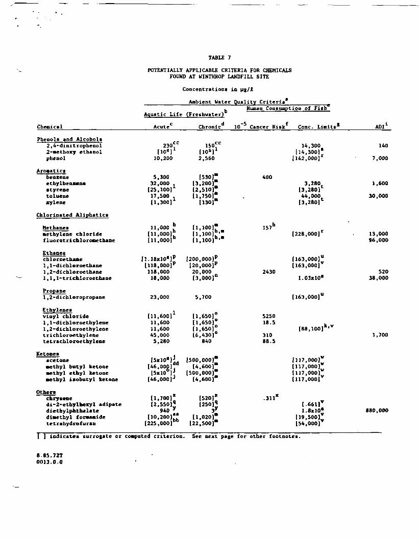
TABLE 7
POTENTIALLY APPLICABLE CRITERIA FOR CHEMICALSFOUND AT WINTHROP LANDFILL SITE
Concentrations in pg/Jt
Ambient Water Quality Criteria*
Chemical
Phenols and Alcohols2,4-dinitrophenol2-awthoxy ethanolphenol
Arosaticsbenzeneethylbenzenestyrenetoluenexylene
Chlorinated Aliphatic*
Methanes•ethylene chloridefluorotrichlorone thane
Ethaneschloroe thane1 , 1-dichloroe thane1 ,2-dichloroe thane1,1, 1-trichloroethane
Propane1 ,2-dichloropropane
Ethylenesvinyl chloride1 ,1-dichloroethylene1 ,2-dichloroethylenetrichloroethylenetetrachloroethylene
Ketonesacetone•ethyl butyl ketone•ethyl ethyl ketone•ethyl isobutyl ketone
Other*chrysenedi-2-etbylheiyl adipatediethylphthalatedimethyl fomaaidetetrabydrofuran
I ) indicates surrogate or
8.85.72T0013.0.0
Aquatic Life
Acute0
230"[ioar10,200
5,30032,000 .[25, 100] L
17,500I1.300]1
11,000 111,000)°111, 000]"
[1.18xlO«]P
(118,000]P
118,00018,000
23,000
[11.600]1
11,60011,60045,0005,280
I5xl0«][46,000]aa
[5xl06]J.[46,000]J
11,700]*12,550]*
940 y
110,200)"[225,000)Db
computed criterion.
'
b 1(Freshwater)
Chronic*1 10~5
150"[108)1
2,560
[530r(3,200)*[2.510]*11,7501"[1301*
li.ioo)-H.ioo) -[l,100)h>"
[200,000)p
I20,000)p
20,000[3,000)n
5,700
[1,650]°[1,650]°11,650)°16,430)°
840
[500,000]*14.600]*
[500,000)14,600)*
[520]*[250]<j
3I[1,020]*122,500]*
See next page for
iuoum Consumption of Fish"
Cancer Riskf Cone. Linits*
14,300[14,300]'[142,000)
4003,280
[s.uo]144,000[3.280P
157h
(228,000]r
[163,000]"[163,000]
24301.03X106
[163,000]"
5250l«-5 kv
188,100]"31088.5
[117,000]''[117,000];;1117,000);;[117,000]
-311"l-661]V
1.8xlOe
[ 19,500);[54,000]
other footnotes.
ADI1
140
7,000
1,600
30,000
13,00096,000
52038,000
1,700
880,000

NOTES FOR TABLES 6 & 7:
a Ambient Water Quality Criteria were formulated to protect aquatic life and human health from pollutants inaurface waters (AO CFR Summary, FR Nov. 28, 1980, p. 79318-79379 and FR Feb. 7, 1984, p. 4551-4554). AmbientWater Quality Criteria are not enforceable but are useful in establishing water quality-based effluentlimitations, water quality standards, and toxic pollutant effluent standards, and in assessing potentialenvironmental effects.
b Guidance criteria for the protection of fresh water aquatic life. Concentrations specified should protectmost (hut not necessarily all) aquatic freshwater life and its uses.
c The acute toxicity level is the maximum value to which organisms can be exposed without significant risk ofadverse impact.
d Chronic toxicity level is the 24-hour average value that organisms can be exposed to without significant riskof adverse impact. Weekly (7.5-day) and monthly (27-day) values were established when insufficient data wereavailbK to deveK. a 24-ho-.. lifetime average value. Monthly and weekly values are set at le.els whereorganisms can be exposed over that time period with no significant risk of adverse effect.
e Human Health Guidelines have been developed by the Office of Research and Development. UCRs (Unit CancerRisks) for carcinogens, and concentration limits (no effect or specific risk concentrations) have beenestablished to protect a 70-kg adult against average daily consumption of contaminated drinking water and/orfish. The average daily consumption is 2£/day of drinking water and 6.5 gram/day of fish (freshwater,estuarine and shellfish products).
f Unit Cancer Risks (UCRs) have been established assuming lifetime exposure and 10~*, 10*', and 10~7 risklevels. 10~8 is used in the USEPA Guidance Document for Feasibility Studies under RCRA (October 18, 1984)and has been presented in this table.
g Concentration limits are set at levels above which health would be affected through ingestion of contaminateddrinking water and/or aquatic organisms.
h Criterion for total halomethanes.
i ADI (Acceptable Daily Intake) is defined as the maximum daily dosage of a substance that a human (averageweight - 70 kg.) can be exposed to without lifetime risk. They are based on chronic toxicity data withoutconsideration of potential carcinogenic risk.
j Based on LD50 for goldfish.
k Based on 1,2-trans-dichloroethylene.
1 Based on a literature search conducted by Envirologic Data to identify the lowest LC Q level (lethal concen-tration levels for 50 percent of the test organisms).
m Based on a safety factor of 10 to prevent effects from chronic exposure versus acute exposure recommended byEnvirologic Data.
n Based on a safety factor of 6 to prevent effects from chronic exposure versus acute exposure for chlorinatedethanes, based on the ratio between acute and chronic criteria for 1,2 dichloroethane, another chlorinatedetane.
o Based on a safety factor of 7 to prevent effects from chronic exposure versus acute exposure for the ratiobetween acute and chronic criteria generated by EPA for tetrachloroethylene, another chlorinated etbylene.
p Based on the criterion for 1,2-dichloroethane which is more or as chlorinated and, therefore, likely to be atleast as toxic.
q Derived by extrapolation of rat LD. (lethal dose for 50 percent of test rats) data for di-2-ethylhexyladipate) to fish based on rat-to-flsh body weight ratio, adsorption coefficient, and ventilation volume offish.
S.85.72T0014.0.0

NOTES: (coat.)
r Based on acceptable daily intake as promulgated by EPA. Criteria were generated based on the ADI, bioconcen-tration factor (BCF), and average daily intake of fish as follows: ADI(pg/Jt) * Criterion.
BCF (£/kg) x 0.0065 kg
The BCF was determined fro* the chemical'B solubility or partition coefficient (Kov).
t Based on the criterion for 2,4-dinitropbenol.
t Bated on the nost stringent criterion for non-carcinogenic aromatic* (ethylbenzene).
u Based on the most stringent criterion for non-carcinogenic chlorinated ethane (1,1-dichloroethane).
v Based on lowest effect levels compiled by Envirologic Data from preliminary literature search. ADI wasgenerated based on 70-kg human and 10,000 safety factor. See footnote "r" for computation of criterion.
v Bated on the criterion for methyl isobutyl ketone.
x Based on the OCR for polynuclear arovatic hydrocarbon*.
j Criterion for total phthalate esters.
z Based on lowest values for available freshwater aquatic life criteria for polyaromatic hydrocarbons(accaaphthalene). Acute value for bluefish; chronic value for algae.
Based on TL data for rainbow trout exposed to dimethyl formamide.
Concentration of tetrahydrofuran reported to cause inhibition of cell multiplication in algae. .
c Criterion for total nitrophenols.
Based on criteria for methyl isobutyl ketone, due to similar chemical structure.
C.85.72T0015.0.0