Configuration and basic operation of OSD screen - 三菱
21
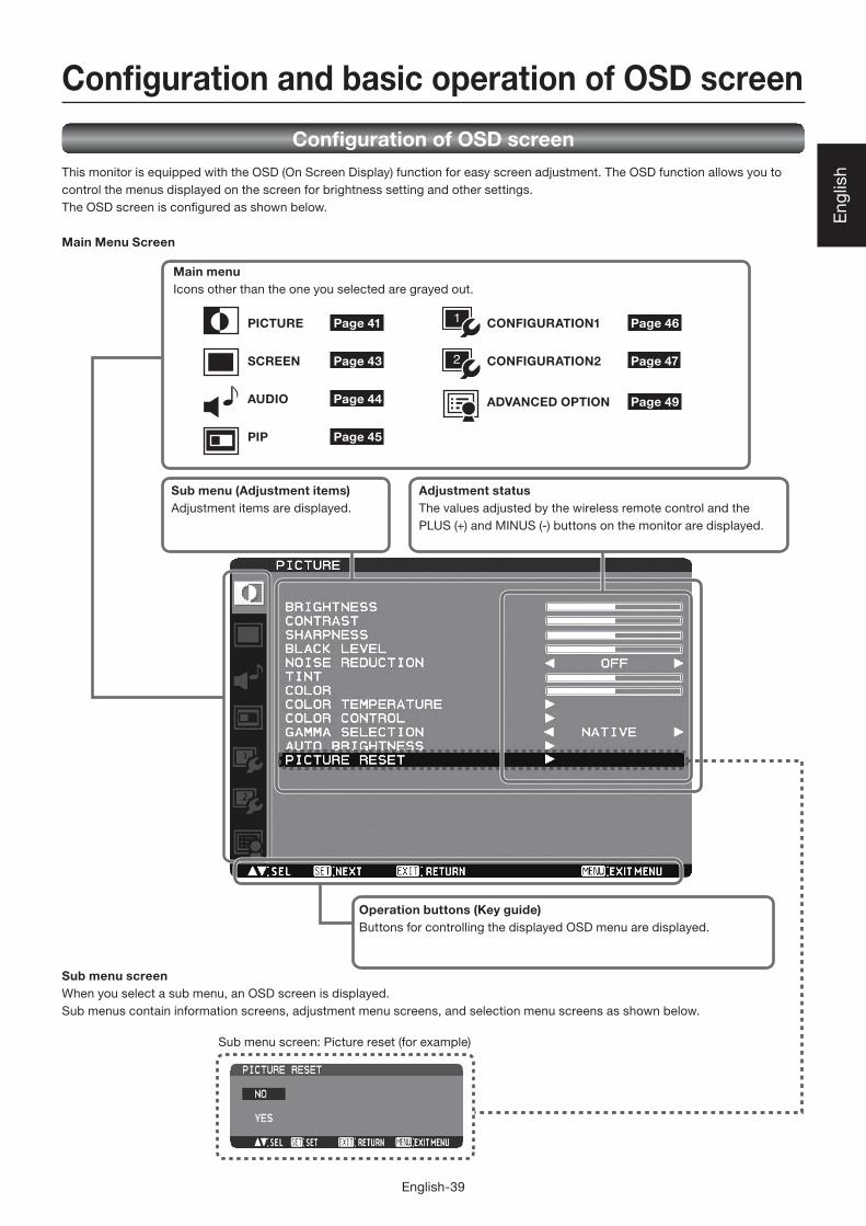
English-39 English Adjustment status The values adjusted by the wireless remote control and the PLUS (+) and MINUS (-) buttons on the monitor are displayed. Sub menu (Adjustment items) Adjustment items are displayed. Operation buttons (Key guide) Buttons for controlling the displayed OSD menu are displayed. PICTURE SCREEN AUDIO PIP CONFIGURATION1 CONFIGURATION2 ADVANCED OPTION Main menu Icons other than the one you selected are grayed out. Sub menu screen When you select a sub menu, an OSD screen is displayed. Sub menus contain information screens, adjustment menu screens, and selection menu screens as shown below. Sub menu screen: Picture reset (for example) Page 41 Page 43 Page 44 Page 45 Page 46 Page 47 Page 49 Configuration of OSD screen This monitor is equipped with the OSD (On Screen Display) function for easy screen adjustment. The OSD function allows you to control the menus displayed on the screen for brightness setting and other settings. The OSD screen is configured as shown below. Main Menu Screen Configuration and basic operation of OSD screen
-
Upload
khangminh22 -
Category
Documents
-
view
1 -
download
0
Transcript of Configuration and basic operation of OSD screen - 三菱
English-39
Eng
lish
Adjustment statusThe values adjusted by the wireless remote control and the
PLUS (+) and MINUS (-) buttons on the monitor are displayed.
Sub menu (Adjustment items)Adjustment items are displayed.
Operation buttons (Key guide) Buttons for controlling the displayed OSD menu are displayed.
PICTURE
SCREEN
AUDIO
PIP
CONFIGURATION1
CONFIGURATION2
ADVANCED OPTION
Main menuIcons other than the one you selected are grayed out.
Sub menu screen When you select a sub menu, an OSD screen is displayed.
Sub menus contain information screens, adjustment menu screens, and selection menu screens as shown below.
Sub menu screen: Picture reset (for example)
Page 41
Page 43
Page 44
Page 45
Page 46
Page 47
Page 49
Confi guration of OSD screenThis monitor is equipped with the OSD (On Screen Display) function for easy screen adjustment. The OSD function allows you to
control the menus displayed on the screen for brightness setting and other settings.
The OSD screen is confi gured as shown below.
Main Menu Screen
Confi guration and basic operation of OSD screen

English-40
Basic operation of OSDWhen the MENU button on the wireless remote control or the EXIT button on the monitor is pressed, the OSD screen is displayed.
Select a main menu by pressing the or button.
Accept the selected main menu
by pressing the SET button.
Accept the selected main menu
by pressing the INPUT button.
Select a sub menu by pressing
the or button.
Select a sub menu by pressing
the or button.
Accept the selected sub menu
by pressing the SET button.
Accept the selected sub menu
by pressing the INPUT button.
Select the setting value by
pressing the or button
and then press the SET button
to accept the setting.
Select the setting value by
pressing the or button and
then press the INPUT button to
accept the setting.
The OSD screen disappears when you press the MENU button on the wireless remote control once or the EXIT button on the
monitor three times.
Wireless remote control Monitor button OSD screen
Confi guration and basic operation of OSD screen (continued)

English-41
Eng
lish
OSD screen functions
PICTURE
BRIGHTNESSYou can adjust the brightness.
Press the PLUS (+) button to increase the brightness. Press
the MINUS (-) button to decrease the brightness.
CONTRASTYou can adjust the contrast.
Adjust the contrast using the PLUS (+) or MINUS (-) button to
obtain a desired result.
NOTE: Brightness changes luminance of the backlight.
Contrast changes signal levels, and therefore it is
likely to lead to whiteness.
SHARPNESSYou can adjust the sharpness.
Press the PLUS (+) button to make the image look sharper.
Press the MINUS (-) button to make the image look softer.
NOTE: If you increase the sharpness setting value too
much, lines may appear double. In such a case,
decrease the sharpness setting value.
BLACK LEVELYou can adjust the brightness in the dark area of the image.
Press the PLUS (+) button to brighten dark areas in the
image. Press the MINUS (-) button to further darken the
dark area of the image.
NOTE: This adjustment doesn’t work in the sRGB picture
mode.
NOISE REDUCTION* For the VIDEO<S> and VIDEO inputs only.
You can adjust the noise reduction level.
Press the PLUS (+) button to increase the value to lessen
the noise.
TINT* For the RGB1, DVD/HD, VIDEO<S>, and VIDEO inputs
only.
When you select TINT by pressing the SET button on the
wireless remote control, the TINT screen appears and you
can adjust the following.
[TINT]:
You can adjust all the colors at the same time. Press the
PLUS (+) button to add a green tint. Press the MINUS (-)
button to add a purple tint.
[RED], [MAGENTA], [BLUE], [CYAN], [GREEN], or [YELLOW]:
You can adjust each color individually. Press the PLUS (+)
button to shift the selected color to the right around the
color circle. Press the MINUS (-) button to shift the selected
color to the left around the color circle.
COLOR* For the RGB1, DVD/HD, VIDEO<S>, and VIDEO inputs
only.
When you select COLOR by pressing the SET button on the
wireless remote control, the COLOR screen appears and
you can adjust the following.
[COLOR]:
You can adjust all the colors at the same time. Press the
PLUS (+) button to deepen the colors. Press the MINUS (-)
button to lighten the colors.
[RED], [MAGENTA], [BLUE], [CYAN], [GREEN], or [YELLOW]:
You can adjust each color individually. Press the PLUS (+)
button to deepen the selected color. Press the MINUS (-)
button to lighten the selected color.
NOTE: This adjustment doesn’t work in the sRGB picture
mode.
COLOR TEMPERATUREYou can adjust the color temperature.
The image becomes reddish as the color temperature
decreases, and it becomes bluish as the color temperature
increases.
NOTE: This adjustment doesn’t work in the sRGB picture
mode.
COLOR CONTROLThe color levels of red, green, and blue are adjusted by the
color bars.
R: Red, G: Green, B: Blue
NOTE: This adjustment doesn’t work in the sRGB picture
mode.
GAMMA SELECTIONYou can select the gamma mode from NATIVE, S GAMMA,
2.2, 2.4 and OPTION.
NOTE: GAMMA is fi xed to 2.2 in the sRGB picture mode.
RED MAGENTA
GREEN
Color circle
CYAN
YELLOW BLUE

English-42
AUTO BRIGHTNESSThis function controls the screen brightness depending on
the ambient light for easy viewing.
In addition, it changes the screen brightness depending on
the ambient light and what are displayed on the screen to
reduce power consumption as low as possible.
[AUTO BRIGHTNESS]LOCAL: The auto brightness function is enabled.
REMOTE: The auto brightness function is enabled.
In addition, the monitor enters the
intercommunication mode where multiple
monitors are controlled collectively. (See page
52.)
OFF: This function is disabled.
[CONTROL]PRIMARY: Select this setting to confi gure the monitor
as Master when controlling multiple
monitors collectively.
SECONDARY: Select this setting to use the monitor
alone or to confi gure the monitor as
Slave when controlling multiple monitors
collectively.
[LIGHT FROM BACK]YES: Select this setting when there is a light source
such lighting equipment and a window behind the
monitor.
NO: Select this setting when there is no light source
such lighting equipment and a window behind the
monitor.
[BACK WALL]Select the following settings according to the distance
between the rear of the monitor and the wall or window.
FAR: The distance is 5 meters or longer.
NEAR: The distance is 5 meters or shorter.
[FRONT SENSOR]Select ON for normal use.
OFF: Select this setting when the sensor on the front
panel is shielded.
[REAR SENSOR]Select ON for normal use.
OFF: Select this setting when the sensor on the rear
panel is shielded.
[SATURATION]ON: The image saturation is adjusted depending on the
ambient light.
OFF: Image saturation isn’t adjusted.
[VIDEO DETECT]ON: The screen brightness varies depending on what
are displayed on the screen to reduce power
consumption of the monitor.
OFF: The screen brightness doesn’t vary and the power
consumption isn’t reduced.
PICTURE RESETYou can reset all the PICTURE settings to the factory
defaults.
OSD screen functions (continued)
English-43
Eng
lish
OSD screen functions (continued)
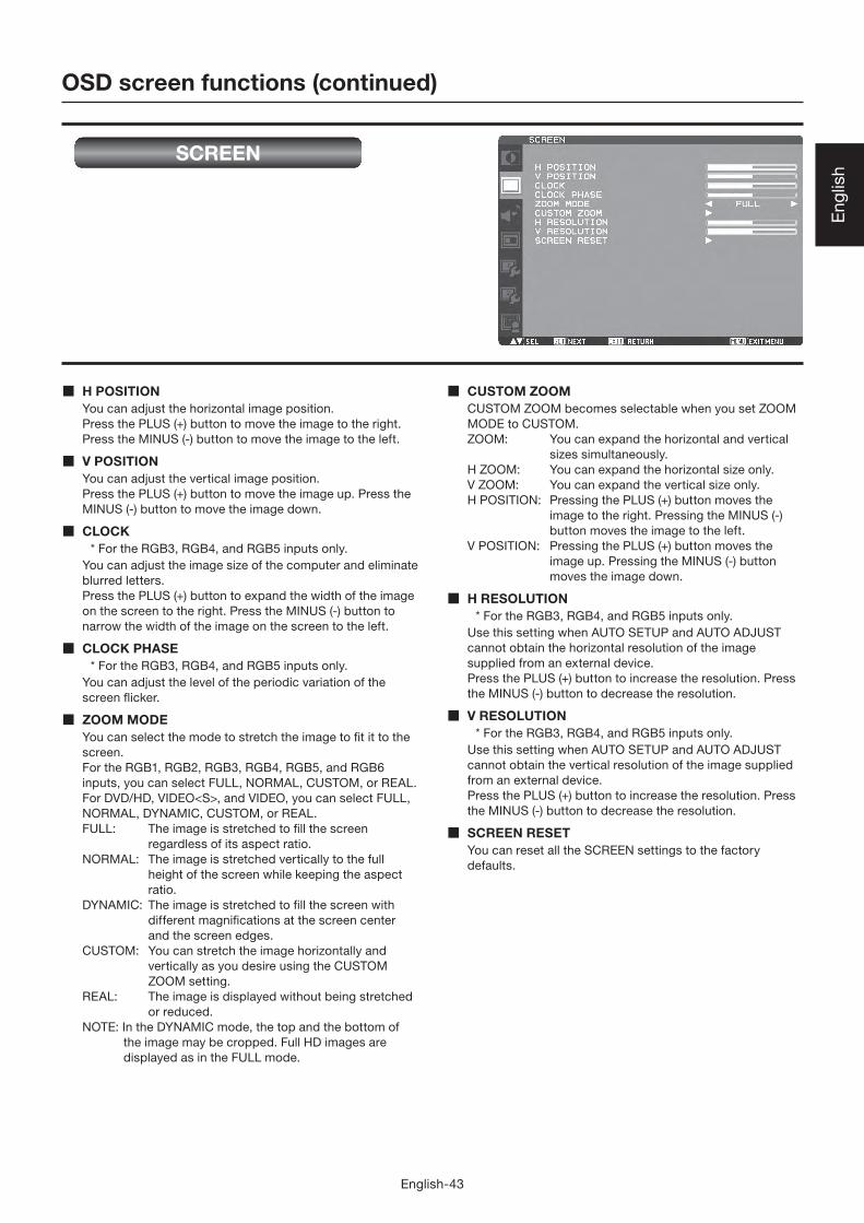
SCREEN
H POSITIONYou can adjust the horizontal image position.
Press the PLUS (+) button to move the image to the right.
Press the MINUS (-) button to move the image to the left.
V POSITIONYou can adjust the vertical image position.
Press the PLUS (+) button to move the image up. Press the
MINUS (-) button to move the image down.
CLOCK* For the RGB3, RGB4, and RGB5 inputs only.
You can adjust the image size of the computer and eliminate
blurred letters.
Press the PLUS (+) button to expand the width of the image
on the screen to the right. Press the MINUS (-) button to
narrow the width of the image on the screen to the left.
CLOCK PHASE* For the RGB3, RGB4, and RGB5 inputs only.
You can adjust the level of the periodic variation of the
screen fl icker.
ZOOM MODEYou can select the mode to stretch the image to fi t it to the
screen.
For the RGB1, RGB2, RGB3, RGB4, RGB5, and RGB6
inputs, you can select FULL, NORMAL, CUSTOM, or REAL.
For DVD/HD, VIDEO<S>, and VIDEO, you can select FULL,
NORMAL, DYNAMIC, CUSTOM, or REAL.
FULL: The image is stretched to fi ll the screen
regardless of its aspect ratio.
NORMAL: The image is stretched vertically to the full
height of the screen while keeping the aspect
ratio.
DYNAMIC: The image is stretched to fi ll the screen with
different magnifi cations at the screen center
and the screen edges.
CUSTOM: You can stretch the image horizontally and
vertically as you desire using the CUSTOM
ZOOM setting.
REAL: The image is displayed without being stretched
or reduced.
NOTE: In the DYNAMIC mode, the top and the bottom of
the image may be cropped. Full HD images are
displayed as in the FULL mode.
CUSTOM ZOOMCUSTOM ZOOM becomes selectable when you set ZOOM
MODE to CUSTOM.
ZOOM: You can expand the horizontal and vertical
sizes simultaneously.
H ZOOM: You can expand the horizontal size only.
V ZOOM: You can expand the vertical size only.
H POSITION: Pressing the PLUS (+) button moves the
image to the right. Pressing the MINUS (-)
button moves the image to the left.
V POSITION: Pressing the PLUS (+) button moves the
image up. Pressing the MINUS (-) button
moves the image down.
H RESOLUTION* For the RGB3, RGB4, and RGB5 inputs only.
Use this setting when AUTO SETUP and AUTO ADJUST
cannot obtain the horizontal resolution of the image
supplied from an external device.
Press the PLUS (+) button to increase the resolution. Press
the MINUS (-) button to decrease the resolution.
V RESOLUTION* For the RGB3, RGB4, and RGB5 inputs only.
Use this setting when AUTO SETUP and AUTO ADJUST
cannot obtain the vertical resolution of the image supplied
from an external device.
Press the PLUS (+) button to increase the resolution. Press
the MINUS (-) button to decrease the resolution.
SCREEN RESETYou can reset all the SCREEN settings to the factory
defaults.

English-44
OSD screen functions (continued)
AUDIO
BALANCEYou can adjust the balance of the right and left volumes.
Press the PLUS (+) button to decrease the left volume.
Press the MINUS (-) button to decrease the right volume.
TREBLEYou can adjust the high frequency sound.
Press the PLUS (+) button to increase the treble sound.
Press the MINUS (-) button to decrease the treble sound.
BASSYou can adjust the low frequency sound.
Press the PLUS (+) button to increase the bass sound.
Press the MINUS (-) button to decrease the bass sound.
AUDIO RESETYou can reset all the AUDIO settings to the factory defaults.

English-45
Eng
lish
OSD screen functions (continued)
PIP (PICTURE IN PICTURE)
PIP MODEYou can select the PIP mode from PIP, POP, SBS ASPECT,
SBS FULL, and OFF using the PLUS (+) and MINUS (-)
buttons. See page 53.
* SBS: SIDE BY SIDE
PIP SIZEYou can select the size of the sub picture displayed in the
PIP mode.
You can move the sub picture by pressing the UP ( ),
DOWN ( ), PLUS (+), and MINUS (-) buttons.
PIP AUDIOYou can select the audio output in the PIP mode.
When MAIN is selected, audio of the main picture is output.
When SUB is selected, audio of the sub picture is output.
PIP H POSITIONYou can adjust the horizontal position of the sub screen.
Press the PLUS (+) button to move the sub screen to the
right. Press the MINUS (-) button to move the sub screen to
the left.
PIP V POSITIONYou can adjust the vertical position of the sub screen.
Press the PLUS (+) button to move the sub screen up. Press
the MINUS (-) button to move the sub screen down.
SUB INPUTYou can select the video input for the sub screen from
HDMI (RGB1), DVI-D (RGB2), D-SUB (RGB3), RGB4, DVD/
HD, VIDEO<S>, and VIDEO.
PIP RESETYou can reset all the PIP settings to the factory defaults.
PIP
POP
SBS ASPECT
SBS FULL
OFF
NOTE:The PIP and POP functions don’t work in the CUSTOM and
REAL picture size modes.
Refer to “PIP, POP function” for details. (See page 53.)

English-46
Enlarged
90%
Motion
Move
The portion (shaded part) outside the
display area isn’t displayed.
OSD screen functions (continued)
CONFIGURATION1
AUTO SETUP* For the RGB3, RGB4, and RGB5 inputs only.
Press the SET button to automatically adjust the screen
size, horizontal position, vertical position, clock, clock
phase, white level, and black level.
AUTO ADJUST* For the RGB3, RGB4, and RGB5 inputs only.
When AUTO ADJUST is ON, the horizontal position, vertical
position, and clock phase are automatically adjusted at the
time of the timing switching.
POWER SAVEWhen the power saver in the OSD menu is turned ON, the
power management function works.
RGB: When the sync signal of computer input (RGB1, 2,
3, 4, 5, or 6) is terminated, the monitor will be in the
sleep mode in several seconds.
VIDEO: When the sync signal of video input (DVD/HD,
VIDEO<S>, or VIDEO) is terminated, the monitor will
be in the sleep mode in approximately 10 minutes.
LANGUAGEOSD control menus are available in eight languages.
(English, German, Spanish, French, Italian, Swedish,
Chinese, and Japanese)
SCREEN SAVERYou can set the SCREEN SAVER functions to reduce the
risk of “image persistence.”
GAMMA:
When you select ON, the gamma mode where image
persistence is diffi cult to occur is used.
COOLING FAN:
When you select ON, the cooling fan always runs.
When you select AUTO, the built-in fan automatically starts
running according to the operating temperature.
BRIGHTNESS:
When you select ON, the brightness decreases.
MOTION:
The screen slightly moves horizontally and vertically
at regular intervals to reduce the effect of the image
persistence.
NOTE: When you select a time period in the MOTION
setting, the monitor enlarges the image and moves it
horizontally and vertically. The portions of the image
out of the display area aren’t visible.
To make the entire image visible all the time, arrange
it to fi t within 90% of the screen area at the center.
COLOR SYSTEM* For the VIDEO<S> and VIDEO inputs only.
You can select the color system depending on the video
device you use.
AUTO: NTSC, PAL, SECAM, PAL60 or 4.43 NTSC is
automatically selected.
NTSC: NTSC
PAL: PAL
SECAM: SECAM
4.43NTSC: 4.43 NTSC
PAL-60: PAL60
NOTE: When you use a video device purchased from
overseas, set the COLOR SYSTEM menu.
SIDE BORDER COLORYou can adjust the brightness of the black areas displayed
on both sides of 4:3 images.
CONFIGURATION RESETYou can reset all the CONFIGURATION1 and
CONFIGURATION2 settings to the factory defaults.
Note that you cannot reset the setting of LANGUAGE,
MONITOR ID, SCHEDULE, and DATE AND TIME.
FACTORY RESETYou can reset all the settings of PICTURE, SCREEN, AUDIO,
CONFIGURATION1, CONFIGURATION2, and ADVANCED
OPTION to the factory defaults.
Note that you cannot reset the settings of LANGUAGE and
DATE AND TIME.

English-47
Eng
lish
OFF H FLIP
Horizontally
rotated
V FLIP
Vertically
rotated
OSD screen functions (continued)
CONFIGURATION2
CAT5 CONTROL
[CAT5 CABLE LENGTH]Select the cable length, and the defaults of all the
adjustment values are automatically determined.
Select the length that is closest to the actual length of your
cable.
[CAT5 EQ.]Make adjustment so that blur and smear of the displayed
letters and graphic objects are minimized.
[CAT5 RED GAIN, GREEN GAIN, BLUE GAIN]When the displayed image is dark, increase each value.
When whites aren’t displayed as intended, adjust the RED
GAIN and BLUE GAIN values.
NOTE: Before performing the color adjustment described
above, check the TINT settings on page 41.
[CAT5 RED SKEW, GREEN SKEW, BLUE SKEW]Adjust each value so that the color deviation in the
displayed letters and graphic objects is minimized.
SERIAL CONTROLSelect the communication interface (RS-232C, RS-485, or
LAN) for the serial communication function.
For connection of the signal cable, see page 23 to 26.
RS485 TERMINATIONTurn ON or OFF the termination resistance of the RS-485
interface.
ON: Select this setting to use the monitor alone or to
confi gure the monitor as the one at the end of the
connection when more than one monitor is multi-
connected.
OFF: Select this setting to confi gure the monitor as other
than the one at the end of the connection when more
than one monitor is multi-connected.
LAN SETTINGDHCP CLIENT
Select whether to use DHCP client or not.
Select OFF when not using it, and select ON when using
it.
IP ADDRESS
Set the IP address of the monitor.
SUBNET MASK
Set the gateway mask.
Set it to 255.255.255.0 for normal use.
DEFAULT GATEWAY
Set the IP address of the gateway router to externally
connect the local area including the monitor.
RESET
LAN settings are reset.
MONITOR IDID numbers for wireless remote control are assigned to
MDT652S monitors that are multi-connected via RS-232C.
ID numbers 1 to 26 are selectable.
OSD TURN OFFThe OSD control menu will stay on as long as it is used.
The preset choices are 5 -120 seconds.
OSD H POSITIONYou can adjust the horizontal position of the OSD menu.
OSD V POSITIONYou can adjust the vertical position of the OSD menu.
OSD ROTATIONThe OSD screen is rotated.
INFORMATION OSDYou can enable and disable the information OSD display.
The display time is selectable from 3 to 10 seconds.
NOTE: The information OSD display shows a message
when the input source is switched, the input signal
state is changed, or the input signal has an error.
OFF TIMERYou can select the OFF TIMER mode.
Select the time period to automatically turn off the power
from 1 to 24 hours.
NOTE: When OFF TIMER is enabled, the SCHEDULE
settings (see page 34) will be disabled.

English-48
OSD screen functions (continued)
SCHEDULEYou can program the LCD monitor operation schedules. (See
page 35.)
< HOW TO SETUP SCHEDULE >
Using the “SCHEDULE” function allows you to set up to
seven different scheduled time intervals when the LCD
Monitor will be activated.
You can select the time the monitor turns on and turns off,
the day of week the monitor is activated, and which input
source the monitor will use for each scheduled activation
period. A check mark in the box next to the number of the
schedule indicates that the selected schedule is in effect.
To select which schedule to set, use the up/down arrows to
move the number (1 to 7) of the schedule.
Use the (+) and (-) buttons to move the cursor horizontally
within the particular schedule. Use the and buttons
to increase the time and select the input port. The “SET”
button is used to make a selection.
If you create a schedule but do not want to set the power
on time, select “--” in the “ON” time slot.
If you do not want to use a power off time select “--” in the
“OFF” time slot.
If there is no input selected (“--” showing in the input spot)
the input from the previous schedule will be used.
The selection of EVERY DAY within a schedule takes priority
over other schedules that are set up to operate weekly.
When schedules are overlapping, scheduled Power ON time
has priority over scheduled Power OFF time.
If there are two schedules programmed for the same time,
then the highest numbered schedule has priority.
When OFF TIMER is enabled, the “SCHEDULE” settings are
disabled.
DATE AND TIMEYou can adjust the current date and time for the internal
clock.
You must set this item when using SCHEDULE.
After competing the setting, be sure to press the SET
button (button 5 on page 10). When using a button of the
monitor, use the INPUT button (button 5 on page 8).
MONITOR INFORMATIONThe model name and the serial number of your monitor are
displayed.

English-49
Eng
lish
OSD screen functions (continued)
ADVANCED OPTION
INPUT RESOLUTION* For the RGB3, RGB4, and RGB5 inputs only.
You can select the following resolutions according to
the input signal: AUTO, 1024x768, 1280x768, 1360x768,
1366x768, 1400x1050, 1680x1050, 1600x1200, and
1920x1200. AUTO selects the resolution automatically.
The setting you select becomes effective when POWER is
turned OFF and ON again.
BLACK LEVEL EXPANSIONSelects a level of black expansion from “OFF”, “MIDDLE”
and “HIGH.”
In case of go under the black cut-off level, please adjust the
“Black level” in moderation on OSD menu.
INPUT CHANGEYou can select the time for input switching from QUICK and
NORMAL.
NOTE: When you select QUICK, slight noise may appear.
SCAN MODE* For the RGB1 (HDMI), DVD/HD, VIDEO<S>, and VIDEO
inputs only.
You can select the image display area.
OVERSCAN: About 95% of the input image is displayed.
UNDERSCAN: Almost 100% of the input image is
displayed.
SCAN CONVERSION* For the RGB1 (HDMI), DVD/HD, VIDEO<S>, and VIDEO
inputs only.
You can select the IP conversion mode.
PROGRESSIVE: Interlace signals are converted into
progressive signals. Select this setting for
normal cases.
INTERLACE: Interlace signals are displayed without
being converted. Though this setting is
suitable for motion images, still images
aren’t displayed properly.
FILM MODEYou can select the fi lm mode function.
AUTO: Images of 24 frames per second are detected,
subjected to interpolation, and then displayed.
OFF: The input video signals are displayed without being
subjected to any processing.
NOTE: When FILM MODE is AUTO, set SCAN CONVERSION
to PROGRESSIVE. See page 49.
IR CONTROLYou can lock the wireless remote control.
Select from the following two modes using the and
buttons and then determine the selected mode by pressing
the SET button.
NORMAL: All the remote control operations are
enabled.
PRIMARY: The fi rst MDT652S monitor of those multi-
connected via RS-232C is designated as
PRIMARY.
SECONDARY: MDT652S monitors other than the fi rst
one multi-connected via RS-232C are
designated as SECONDARY.
LOCK: All the remote control operations are
disabled.
NOTE: When you hold down the DISPLAY button on the
wireless remote control for at least 5 seconds, the
NORMAL mode is activated.
You can lock the wireless remote control
independently from the control buttons on the rear
of the monitor. See page 51.
TILINGYou can enlarge an image across multiple screens.
A single large screen can be confi gured with up to 25
monitors. You can also divide the displayed image into up
to 5 pieces horizontally and vertically.
NOTE: A same video signal needs to be input to each
monitor. When different monitors need to be
adjusted so that their tint can be identical, it
is recommended to use a signal distributor
(commercially available).
When TILING is activated, PIP, POP, SBS, and STILL
are disabled.
TILING doesn’t work in the REAL picture size mode.
H MONITORS: Select the number of images obtained by
horizontal division.
V MONITORS: Select the number of images obtained by
vertical division.
POSITION: Select the area you want to enlarge.
FRAME COMP.: When displaying an image across multiple
monitors, you can select the mode to
compensate for the bezel widths for
smooth and natural display.
ENABLE: When you select ON, the image in the
selected area is enlarged on the screen.

English-50
OSD screen functions (continued)
HEAT STATUSThe statuses of the cooling fan, brightness, and internal
temperature are displayed.
NOTE: The cooling fan starts running according to the
operating temperature or when COOLING FAN is
ON in the SCREEN SAVER menu.
When the operating temperature substantially
exceeds the operation guaranteed range, the
message “TEMPERATURE WARNING!!” is displayed
on the screen.
POWER ON DELAYYou can adjust the delayed time until the power-on mode
is activated at the time of recovery from the sleep mode or
power-on.
The time is selectable from OFF and 2, 4, 6, 8, 10, 20, 30,
40, and 50 seconds.
TERMINAL SETTINGYou can select the mode to display the RGB1 (HDMI)
or RGB2 (DVI-D) signal according to their signal format
depending on their source device.
DVI-MODE:
Select this setting when displaying the RGB2 (DVI-D) signal.
Select DVI-PC when the source device is a PC.
Select DVI-HD when the source device is a video
device.
HDMI SIGNAL:
Select this setting when displaying the RGB1 (HDMI) signal.
Select LIMITED when displaying the signal that uses 16
to 235 levels of 256 levels for each of R, G, and B. This
mode is used primarily when input comes from a video
device.
Select FULL when displaying the signal that uses all 256
levels (from level 0 to 255). This mode is used primarily
when input comes from a computer.
DDC/CIUse to turn ON or OFF the DDC/CI communication function.
Select ON for normal use.
CLOSED CAPTIONYou can select to display or hide captions.
OFF: Captions are hidden.
CC1: Captions are displayed in sync with the
primary audio.
CC2: Information (related to the primary
audio) is displayed without sync.
CC3: Captions are displayed in sync with the
secondary audio.
CC4: Information (related to the secondary
audio) is displayed without sync.
TT1/TT2/TT3/TT4: Four types of information not related to
the displayed images are displayed. (For
example, news and weather forecast.)
NOTE: Check with each supplier of your video software and
external video devices in advance whether they are
compliant with EIA-608-A.
If their video signals are not compliant with it,
images may not be displayed correctly.
ADVANCED OPTION RESETSelecting ADVANCED OPTION RESET allows you to
reset all OSD settings from ADVANCED OPTION settings,
except for DATE AND TIME, SCHEDULE, DVI MODE, HDMI
SIGNAL, MONITOR ID, and DDC/CI.

English-51
Eng
lish
Picture sizeRGB1, 2, 3, 4, 5, 6 FULL NORMAL CUSTOM REAL
DVD/HD FULL NORMAL DYNAMIC CUSTOM REAL
VIDEO, VIDEO<S> FULL NORMAL DYNAMIC CUSTOM REAL
NORMAL: Images supplied from external devices such
as PC and DVD fi t the screen, keeping their
original aspect ratio.
FULL: Images are displayed on the entire screen.
DYNAMIC: 4:3 images are enlarged on the entire
screen with non-linearity. (Round images
may be cut when enlarged.)
CUSTOM (ZOOM): You can enlarge the displayed images
beyond the active display area. The portions
of the image out of the display area aren’t
visible.
REAL: Images are displayed in their original sizes.
Picture modeRGB1, 2, 3, 4, 5, 6 HIGHBRIGHT STANDARD sRGB
DVD/HD, VIDEO, VIDEO<S> HIGHBRIGHT STANDARD CINEMA
NORMAL
DYNAMIC
NORMAL
(Squeeze signal)
NORMAL
NORMAL
FULL
* DVD/HD, VIDEO only
Normal size of
each signal
Recommend
picture size
Audio input changeRGB1 HDMI AUDIO1 AUDIO2 AUDIO3
Other inputs AUDIO1 AUDIO2 AUDIO3
OSD information
RGB21024 x 76848kHz 60HzAUDIO : 1SIZE : FULL
DVD/HDAUDIO : 3SIZE : FULL
VIDEO<S>NTSCAUDIO : 3SIZE : NORMAL
RGB21024 x 76848kHz 60HzAUDIO : 1VIDEO<S>NTSCSIZE : FULL
Control Lock modeYou can lock the operation buttons so that the image
adjustments you made aren’t changed even when the buttons
are pressed.
By holding down both the and button on the monitor for
3 seconds or longer, you can lock the operation buttons.
By holding down both the and button on the monitor for
3 seconds or longer again, you can unlock the operation
buttons.
RGB1, 2, 3, 4, 5, 6
DVD/HD
VIDEO<S>, VIDEO
PIP, POPMain : RGB2Sub : VIDEO<S>
Current selection (RGB2)
Resolution Horizontal/vertical frequency
Audio input mode
Picture size mode
Current selection (DVD/HD)
Audio input mode
Picture size mode
Current selection (VIDEO<S>)
Color system mode
Audio input mode
Picture size mode
Main picture information
Audio input mode
Sub picture information
Main picture size
Other functions
ZOOM
ZOOM

English-52
Master: Monitor confi gured as Master that detects the
outside light (Monitor ID is “1”.)
Slave: Monitor controlled by the Master monitor (Monitor
ID is other than “1”.)
Monitor
ID = 9
(Slave)
Monitor
ID = 6
(Slave)
Monitor
ID = 3
(Slave)
Monitor
ID = 8
(Slave)
Monitor
ID = 5
(Slave)
Monitor
ID = 2
(Slave)
Monitor
ID = 7
(Slave)
Monitor
ID = 4
(Slave)
Monitor
ID = 1
(Master)
Other functions (continued)
Supplemental information of the auto brightness functionTo control multiple monitors collectivelyIn such a case where the tiling function is used, you can control the auto brightness function by sharing the detection result of the
brightness sensor of a certain monitor among the connected monitors.
1. Multi-connect the monitors using RS-232C or CAT5 cables separately sold as shown by the example below.
2. Assign a monitor ID to each multi-connected MDT652S using MONITOR ID. (See page 47.)
Monitor ID is selectable from 1 to 26.
The monitor ID of the Master monitor should be “1” and those of the Slave monitors should be other than “1”.
You are recommended to assign IDs to the monitors consecutively from 1, 2, 3, and on.
3. Set AUTO BRIGHTNESS on the OSD screen (PICTURE) as follows.
AUTO BRIGHTNESS CONTROL
Master monitor LOCAL PRIMARY
Slave monitors REMOTE SECONDARY
4. For connection with CAT5, set [RS485 TERMINATION] of the master monitor and the slave monitor at the end to ON. Set [RS485
TERMINATION] of the other slave monitors to OFF. See page 47.
To use a computer to control the monitorsWhen using a computer to control the monitors, you must prepare an application software program for control by yourself.
Brightness of all the monitors can be controlled centrally using a computer, if the customer create a control application to remotely
read the value from two brightness sensors of any monitor and distribute it to all monitors.
1. Connect the RS-232C IN connector of the Master monitor shown above and the RS-232C connector of the computer using an
RS-232C cable.
Or, using a CAT5 cable, connect the RS-232C connector of the computer to the CAT5 IN connector of the Master monitor via the
CAT5 Tx BOX.
2. Assign a monitor ID to each multi-connected MDT652S using MONITOR ID. (See step 2 on page 47.)
3. Set AUTO BRIGHTNESS on the OSD screen (PICTURE) as follows.
AUTO BRIGHTNESS CONTROL
Master monitor REMOTE SECONDARY
Slave monitors REMOTE SECONDARY
4. For connection with CAT5, set [RS485 TERMINATION] of the master monitor and the slave monitors to ON. However, set [RS485
TERMINATION] of the slave monitor at the end to OFF. See page 47.
5. A control application made by the customer reads the value from two brightness sensors of any monitor and distributes it to all
monitors. For the specifi cations of the communication commands, contact your dealer.
NOTE:• When using CAT5 for control only, you can connect up to 26 monitors. When using the video function together, you are
recommended to connect only 5 or less monitors due to the restrictions of the video function. See page 23.
• The communication control function via LAN isn’t supported on the monitor alone, however, it is available when the monitor is
used with the computer.

English-53
Eng
lish
PIP POP SIDE BY SIDE
ASPECT
SIDE BY SIDE
FULL
OFF
PIP, POP functionThe following table shows the combinations of signal inputs with which the “PIP” and “POP” modes function. However, these modes
do not function when the screen size is “CUSTOM” or “REAL”.
Sub screen
RGB1
(HDMI)
RGB2
(DVI-D)
RGB3
(D-SUB)
RGB4
(BNC)
RGB5
(CAT5)
RGB6
(DISPLAY
PORT)
DVD/HD
(YPbPr)VIDEO<S> VIDEO
Main
scre
en
RGB1 (HDMI) × × × × × × × RGB2 (DVI-D) × × × × × × × RGB3 (D-SUB) × × × × × × × RGB4 (BNC) × × × × × × × RGB5 (CAT5) × × × × × × × RGB6 (DISPLAY PORT) × × × × × × × DVD/HD (YPbPr) × × × × × × × VIDEO<S> × ×
VIDEO × ×
: Supported × : Not supported
By pressing the PIP ON/OFF button on the wireless remote control, you can change the PIP, POP, and SIDE BY SIDE modes in the
order shown below.
Alternatively, you can change the modes using the PIP MODE setting of PIP in the OSD main menu. See page 45.
The resolutions in the PIP, POP, and SIDE BY SIDE FULL modes are as follows:
PIP SIZE < SMALL > : 320 pixels X 240 pixels
< MIDDLE > : 480 pixels X 320 pixels
< LARGE > : 640 pixels X 480 pixels
POP SIZE : 450 pixels X 338 pixels
SIDE BY SIDE FULL : 960 pixels X 1080 pixels
NOTE:When the PIP, POP, or SIDE BY SIDE FULL mode has been selected, images in the sub picture always fi t the size of each mode
shown above irrespective of the aspect ratio of the input image.
Other functions (continued)

English-54
Remote control numbering functionBy connecting multiple MDT652S monitors using RS-232C cables, you can control any one monitor or all the monitors by one
remote controller.
1. Assign arbitrary ID number to each of multi-connected MDT652S monitors using MONITOR ID.
ID numbers 1 to 26 are selectable.
It is recommended to assign sequential ID numbers from 1 and up.
2. The remote control mode of the fi rst MDT652S monitor is set to PRIMARY and those of the other monitors are set to
SECONDARY.
3. When you direct the remote controller at the remote control signal sensor of the PRIMARY monitor and press the DISPLAY
button on the remote controller, the ID selection OSD appears at the upper left of the screen.
ID:1
ID No. :2
4. Direct the remote controller at the remote control signal sensor of the PRIMARY monitor.
OSD appears on the monitor having the ID number you selected.
NOTE:When the ID selection OSD is being displayed on the PRIMARY monitor, press the DISPLAY button on the remote controller again to
cancel the ID selection OSD and then control the monitor you selected.
If you set the remote control mode wrongly and remote control operation becomes unavailable, press any button on the control
panel of the monitor to display the OSD screen and change the remote control mode using ADVANCED OPTION. By pressing and
holding down the DISPLAY button on the remote control for 5 seconds or longer, the remote control mode is initialized to NORMAL.
Other functions (continued)
ID number of the currently viewed monitor
Select the ID number of the monitor you want to control using the +/- button on the remote controller.
The ID of the monitor you want to control is displayed at the upper left of its screen.
By selecting ALL, you can control all the multi-connected monitors.
English-55
Eng
lish
No picture• The signal cable should be securely connected to the display card/computer.
• The display card should be securely seated in its slot.
• The Main Power Switch and the computer power switch should be in the ON position.
• Make sure that the correct mode has been selected on the display card or system being used.
(Please consult the display card or system manual to change the graphics mode.)
• Check the monitor and your display card with respect to the compatibility and recommended settings.
• Check the signal cable connectors for bent or pushed-in pins.
Power button does not respond• Unplug the power cord of the monitor from the AC outlet to turn off and reset the monitor.
Image persistence• Please be aware that LCD Technology may experience a phenomenon known as “image persistence.” Image persistence occurs
when a residual or “ghost” image of a previous image remains visible on the screen. Unlike CRT monitors, LCD monitors’ image
persistence is not permanent, but constant images being displayed for a long period of time should be avoided. To alleviate
image persistence, turn off the monitor for as long as the previous image was displayed. For example, if an image was on the
monitor for one hour and a residual image remains, the monitor should be turned off for one hour to erase the image.
NOTE: As with all display devices, MITSUBISHI ELECTRIC recommends displaying moving images and using a moving screen saver at
regular intervals whenever the screen is idle or turning off the monitor when not in use.
Image is unstable, unfocused or swimming is apparent• Signal cable should be securely attached to the computer.
• Use the OSD Image Adjust controls to focus and adjust the display by increasing or decreasing the fi ne adjustment.
When the display mode is changed, the OSD Image Adjust settings may need to be re-adjusted.
• Check the monitor and your display card with respect to the compatibility and recommended signal timings.
• If the displayed text is garbled, change the video mode to the non-interlace mode and use 60 Hz refresh rate.
Image of component signal is greenish• Check to see if the DVD/HD input connector is selected.
LED on the monitor is not lit (No green or red color can be seen)• Power Switch should be in the ON position and power cord should be connected.
• Make certain the computer is not in the power-saving mode (touch the keyboard or mouse).
RED LED on the monitor is blinking• A certain failure may have occurred. Please contact your nearest authorized MITSUBISHI ELECTRIC service facility.
Displayed image is not sized properly• Use the OSD Image Adjust controls to increase or decrease the coarse adjustment.
• Make sure that the correct mode has been selected on the display card or system being used.
(Please consult the display card or system manual to change the graphics mode.)
Selected resolution is not displayed properly• Use OSD Display Mode to enter Information menu and check that the appropriate resolution has been selected. If not, select
corresponding option.
No sound• Check to see if the speaker cable is properly connected.
• Check to see if the mute is activated.
• Check to see if the volume is set to the minimum level.
Wireless remote control is not available• Check the wireless remote control’s batteries status.
• Check if the batteries are inserted correctly.
• Check if the wireless remote control is pointing at the monitor’s remote sensor.
“SCHEDULE”/“OFF TIMER” function is not working properly• The “SCHEDULE” function will be disabled when the “OFF TIMER” is set.
• If the “OFF TIMER” function is enabled and the power to the LCD monitor is turned off if the power supply is interrupted
unexpectedly, then the “OFF TIMER” will be reset.
Either light vertical or horizontal stripes may appear, depending on the specifi c display pattern. This is no product fault or
degradation.
Troubleshooting

English-56
Dimension (Unit: mm)
60
76
139
1498
873
1436
811
LCD Module
Screen size (diagonal) 64.5” (1639 mm)
Panel Type VA
Panel Pitch 0.744 mm
Resolution 1920 x 1080 pixels (Full HD)
Color Approximately 1.07 Billion
Brightness (typ.) 700 cd/m2
Contrast ratio 4000 : 1
Viewing Angle (CR>=10) Up/Down 178°, Left/Right 178°
Response time 8 ms (Gray to Gray)
Viewable Size (H x V) 1428.5 mm x 803.5 mm / 56.2” x 31.6”
Power Management VESA DPM
Plug and Play VESA DDC2B, DDC/CI
Auto Adjustment Yes (Contrast / Position / Phase / Clock)
OSD user functions
Brightness, Contrast, Black level, Zoom, PIP, Screen saver, Side border
color, Gamma selection, Black level expansion, Heat status, Power on
delay, Schedule, Tiling, CAT5 control, Auto brightness, Closed Caption, etc.
Input / Output
Signal
PC Input / Output
Input Connector(Analog)
D-SUB 9-pin, MINI D-SUB 15-pin, BNC (R, G, B, H, V) (PC/AV Common),
Modular 8-pin (CAT5)
(Digital) HDMI (PC/AV Common), DVI-D (HDCP supported, PC/AV Common), DisplayPort
Output Connector D-SUB 9-pin, MINI D-SUB 15-pin (PC/AV Common), Modular 8-pin (CAT5)
Horizontal Frequency 15.625/15.734, 31.5 kHz - 91.1 kHz
Vertical Frequency 50/58 Hz - 85 Hz
Video Signal Analog: Analog RGB, Digital: TMDS (with HDCP)
Sync Signal Analog: Separate (TTL), Sync on Green, Digital: TMDS
Supported Resolution
640 x 480, 800 x 600, 1024 x 768, 1280 x 768, 1360 x 768, 1280 x 1024,
1600 x 1200 (Compressed/Simplifi ed), 1920 x 1080, 1920 x 1200
(Compressed/Simplifi ed)
AV Input / Output
Input Connector(Analog)
Composite <BNC>, Separate (Y/C) <S-TERMINAL>,
Component (Y/Pb/Pr) <BNC> (PC/AV Common)
(Digital) HDMI (PC/AV Common), DVI-D (HDCP supported, PC/AV Common)
Output Connector Analog: Composite <BNC>, MINI D-SUB 15-pin (PC/AV Common)
Supported ResolutionComposite/Separate: NTSC, PAL, SECAM, 4.43 NTSC, PAL60
Component/Digital: 480i, 480p, 576i, 576p, 1080i, 720p, 1080p
Audio Input / OutputInput Connector
(Analog) RCA pin-jack L/R x 2, Stereo mini jack
(Digital) HDMI (digital audio)
Output Connector RCA pin-jack
Speaker Output External Speaker Terminal (L/R), 7W + 7W (8 ohm)
Control Input /
Output
Input ConnectorRS-232C <D-SUB 9-pin>, CAT5 <Modular 8-pin> (PC/Control Common),
LAN <Modular 8-pin>
Output Connector RS-232C <D-SUB 9-pin>, CAT5 <Modular 8-pin> (PC/Control Common)
Power Supply
Input Voltage / Current 4.9 A - 2.0 A @AC100 - 240 V, 50/60 Hz
Power Consumption 458 W (445 W without speaker)
Power Consumption at Power Saving
Sleep mode: Less than 2 W (less than 5 W with CAT5 input select, less than
2.6 W with LAN control select)
Power switch off: Less than 1 W (less than 5 W with CAT5 input select, less
than 2.6 W with LAN control select)
Main power switch off: 0 W
Operation
Environment
Temperature 5 - 40°C / 41 - 104°F (Landscape Mode), 5 - 35°C / 41 - 95°F (Portrait Mode)
Humidity 20 - 80% (without condensation)
Storage
Environment
Temperature -20 - 60°C / -4 - 140°F
Humidity 10 - 90% (Without condensation) / 90%-3.5% x (Temp-40 °C) regarding over 40 °C
Dimension
(W x H x D)
Net (without stand) 1498 mm (W) x 873 mm (H) x 139 mm (D) / 59.0” (W) x 34.4” (H) x 5.5” (D)
Gross 1774 mm (W) x 1200 mm (H) x 375 mm (D) / 69.8” (W) x 47.2” (H) x 14.8” (D)
WeightNet (without stand) Approximately 46.5 kg / 102.5 lbs
Gross Approximately 62.4 kg / 137.6 lbs
Wall mounting interface 8-M8 Screws holes (200 mm / 7.9” pitches) for Monitor mount
Complied regulatory and guidelines*1 UL60950-1 / C-UL / EN60950-1 / CE / BSMI / GOST-R / FCC-B / DOC-B /
EN55022-A / EN55024 / EN61000-3-2 / EN61000-3-3 / C-Tick / RoHS / US Mercury
*1: These regulatory and guidelines do NOT apply in Japan.
NOTE: Technical specifi cations are subject to change without notice.
Specifi cations
English-57
Eng
lishMini D-SUB 15-pin
CAT5
HDMI
DVI-D
11
65
1
10
15
1
916
8
17 24
18
1 19
2
1 2 3 4 5 6 7 8
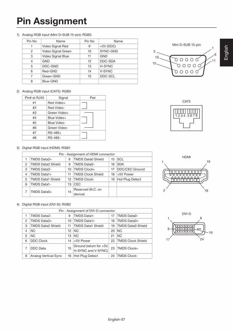
Pin Assignment1) Analog RGB input (Mini D-SUB 15-pin): RGB3
Pin No Name Pin No Name
1 Video Signal Red 9 +5V (DDC)
2 Video Signal Green 10 SYNC-GND
3 Video Signal Blue 11 GND
4 GND 12 DDC-SDA
5 DDC-GND 13 H-SYNC
6 Red-GND 14 V-SYNC
7 Green-GND 15 DDC-SCL
8 Blue-GND
2) Analog RGB input (CAT5): RGB5
Pin# at RJ45 Signal Pair
#1 Red Video+
#2 Red Video-
#3 Green Video+
#4 Blue Video+
#5 Blue Video-
#6 Green Video-
#7 RS-485+
#8 RS-485-
3) Digital RGB input (HDMI): RGB1
Pin - Assignment of HDMI connector:
1 TMDS Data2+ 8 TMDS Data0 Shield 15 SCL
2 TMDS Data2 Shield 9 TMDS Data0- 16 SDA
3 TMDS Data2- 10 TMDS Clock+ 17 DDC/CEC Ground
4 TMDS Data1+ 11 TMDS Clock Shield 18 +5V Power
5 TMDS Data1 Shield 12 TMDS Clock- 19 Hot Plug Detect
6 TMDS Data1- 13 CEC
7 TMDS Data0+ 14Reserved (N.C. on
device)
4) Digital RGB input (DVI-D): RGB2
Pin - Assignment of DVI-D connector:
1 TMDS Data2- 9 TMDS Data1- 17 TMDS Data0-
2 TMDS Data2+ 10 TMDS Data1+ 18 TMDS Data0+
3 TMDS Data2 Shield 11 TMDS Data1 Shield 19 TMDS Data0 Shield
4 NC 12 NC 20 NC
5 NC 13 NC 21 NC
6 DDC Clock 14 +5V Power 22 TMDS Clock Shield
7 DDC Data 15Ground (return for +5V,
H-SYNC and V-SYNC)23 TMDS Clock+
8 Analog Vertical Sync 16 Hot Plug Detect 24 TMDS Clock-

English-58
Modular 8-pin
1 2 3 4 5 6 7 8
DISPLAY PORT
MINI DIN 4-pin
D-SUB 9-pin
2
119
20
3
1
4
2
9
1 5
6
Pin Assignment (continued)
5) Digital RGB input (DISPLAY PORT): RGB6
Pin No Name Pin No Name
1 ML_Lane 3 (n) 11 GND Top
2 GND 12 ML_Lane 0 (p)
3 ML_Lane 3 (p) 13 CONFIG1
4 ML_Lane 2 (n) 14 CONFIG2
5 GND 15 AUX CH (p)
6 ML_Lane 2 (p) 16 GND
7 ML_Lane 1 (n) 17 AUX CH (n)
8 GND 18 Hot Plug Detect
9 ML_Lane 1 (p) 19 Return
10 ML_Lane 0 (n) 20 DP_PWR
6) S-VIDEO input (MINI DIN 4-pin): VIDEO<S>
Pin No Name
1 GND
2 GND
3 Y (Luminance)
4 C (Chroma)
7) RS-232C input/output
(LCD monitor) (CAT5 Tx BOX)
Pin No Name Pin No Name
1 NC 1 NC
2 RXD 2 RXD
3 TXD 3 TXD
4 NC 4 NC
5 GND 5 GND
6 NC 6 DSR
7 NC 7 NC
8 NC 8 NC
9 NC 9 NC
8) LAN (Modular 8-pin)
Pin# at RJ45 Signal Pair
#1 Orange/White stripe
#2 Orange
#3 Green/White stripe
#4 Blue
#5 Blue/White stripe
#6 Green
#7 Brown/White stripe
#8 Brown

Printed in China
AW-P1008A
North AmericaCanada (Mitsubishi Electric Sales Canada Inc.)http://www.mitsubishielectric.caInformation Technologies Group, 4299 14th Avenue, Markham, Ontario L3R 0J2, CanadaSales Phone :+1-(905) 475-7728 Fax :+1-(905) 475-7958 E-mail :[email protected] Phone :+1-(905) 475-7728 Fax :+1-(905) 475-7958Customer Care E-mail :[email protected]
U.S.A. (Mitsubishi Digital Electronics America, Inc.)(Warranty Registration)http://www.mitsubishi-presentations.comPresentation Products Division, 9351 Jeronimo Road, Irvine, CA 92618, U.S.A.Phone Main Line :+1-(949) 465-6000 Technical :+1-(888) 307-0309 Product Information :+1-(888) 307-0312Technical Support E-mail :[email protected]
Asia Pacifi cAustralia (Mitsubishi Electric Australia Pty. Ltd.)http://www.mitsubishielectric.com.au348 Victoria Road, Rydalmere, NSW 2116, AustraliaSales Phone :+61 2 9684 7777 Fax :+61 2 9684 7208 E-mail :[email protected] Phone :+61 1300 651 808 E-mail :[email protected]
New Zealand (Black Diamond Technologies Ltd.)http://www.bdt.co.nz1 Parliament Street, Lower Hutt Wellington 6009, New ZealandSales Phone :+64 4 5609100 Fax :+64 4 5609133 E-mail :[email protected] Phone :+64 4 5609100 Fax :+64 4 5609133 E-mail :[email protected]
Hong Kong (Mitsubishi Electric Ryoden Air-Conditioning & Visual Information Systems (Hong Kong) Ltd.) http://www.mitsubishi-ryoden.com.hk7/F, Manulife Tower, 169 Electric Road, North Point, Hong KongSales Phone :+852 2510 1505 Fax :+852 2510 0463Technical Phone :+852 2422 0161 Fax :+852 2487 0181
Singapore (Mitsubishi Electric Asia Pte Ltd.)http://www.mitsubishielectric.com.sg307 Alexandra Road #05-01/02 Mitsubishi Electric Building 159943, SingaporeSales Phone :+65-6473-2308 Fax :+65-6475-9503 E-mail :[email protected] Phone :+65-6473-2308 Fax :+65-6475-9503 E-mail :[email protected]
Malaysia (Melco Sales Malaysia Sdn. Bhd.)http://www.melcosales.com.myLot 11, Jalan 219, P O Box 1036, 46860 Petaling Jaya, Selangor Darul Ehsan, MalaysiaSales Phone :+603-7955 2088 Fax :+603-7958 2576Technical Phone :+603-7955 3997
Thailand (Mitsubishi Electric Kang Yong Watana Co., Ltd.)http://www.mitsubishi-kyw.co.th28 Krungthep Kreetha Road, Huamark, Bangkapi, Bangkok 10240, ThailandSales Phone :+66-2-731-6841 Fax :+66-2-379-4761Technical Phone :+66-2-731-6841 Fax :+66-2-379-4761
Taiwan (Mitsubishi Electric Taiwan Co., Ltd.)http://www.mitsubishielectric.com.tw11th Floor, 88 Sec. 6. Chung Shan N Road. Taipei 111. TaiwanSales Phone :+886-2-28328255 Fax :+886-2-28339813Technical Phone :+886-2-28328255 ext:3420 Fax :+886-2-28339813
India (Mitsubishi Electric India Pvt. Ltd.)http://www.mitsubishielectric.inBuilding No.9B, dlf Cyber City Phase3, Gurgaon, Delhi, IndiaSales Phone :+91-0124-4630300 Fax :+91-0124-4630399 E-mail :[email protected] Phone :+91-0124-4630300 Fax :+91-0124-4630399 E-mail :[email protected]
日本(三菱電機株式会社)本社〒100-8310 東京都千代田区丸の内 2-7-3(東京ビル)
MITSUBISHI Contact Information
EuropeFrance (Mitsubishi Electric Europe B.V. French Branch)25, Boulevard des Bouvets 92 741, Nanterre CEDEX, FranceSales Phone :+33 (0)1 55-68-55-07 Fax :+33 (0)1 55-68-57-31Technical Phone :+33 (0)1 55-68-56-42 Fax :+33 (0)1 55-68-57-31
Germany (Mitsubishi Electric Europe B.V. German Branch)http://www.mitsubishi-vis.deGothaer Strasse 8, 40880 Ratingen, GermanySales Phone :+49-2102-4869250 Fax :+49-2102-4867320Technical Phone :+49-2102-4865690 Fax :+49-2102-4861340
Italy (Mitsubishi Electric Europe B.V. Italian Branch)Centro Direzionale Colleoni, Palazzo Sirio, Viale Colleoni 7, 20041 Agrate Brianza, ItalySales Phone :+39-(0)39-60531 Fax :+39-(0)39-6053214 E-mail :[email protected]
The Netherlands (MitsubishiElectric Europe B.V. Benelux Branch)http://www.MitsubishiElectric.nlNijverheidsweg 23a, 3641 RP Mijdrecht, The NetherlandsSales Phone :+31-297-282461 Fax :+31-297-283936 E-mail :[email protected] Phone :+31-297-282461 Fax :+31-297-283936 E-mail :[email protected]
Spain (Mitsubishi Electric Europe B.V. Spanish Branch)http://www.mitsubishielectric.esCtra. de Rubi, 76-80, 08190 Sant Cugat del Valles, Barcelona, SpainSales Phone :+34-93.565.31.54 Fax :+34-93.589.43.88 E-mail :[email protected] Phone :+34-93.586.27.51 Fax :+34-93.699.74.45 E-mail :[email protected]
Sweden (Mitsubishi Electric Europe B.V. Scandinavian Branch)Hammarbacken 14, Box 750, S-19127, Sollentuna, SwedenSales Phone :+46-(0)8-6251070 Fax :+46-(0)8-6251036Technical Phone :+46-(0)8-6251052 Fax :+46-(0)8-6251036
United Kingdom (Mitsubishi Electric Europe B.V. UK Branch)http://www.mitsubishi.co.uk/evsVisual Information Systems Division, Travellers Lane, Hatfi eld, Hertfordshire, AL10 8XB, United KingdomSales Phone :+44 (1707) 278684 Fax :+44 (1707) 278541 E-mail :[email protected] Phone :+44 (870) 606 5008 Fax :+44 (1506) 431927 E-mail :[email protected]
Russia (Mitsubishi Electric Europe B.V. Moscow Representative Offi ce)52, bldg.5, Kosmodamianskaya Nab, 115054, Moscow, Russian FederationSales Phone :+7 (495) 721 2070 Fax :+7 (495) 721 2071Technical Phone :+7 (495) 721 2070 Fax :+7 (495) 721 2071