Condensed Catalog | Wolseley
202
REFRIGERATION & AIR CONDITIONING Condensed Catalog Featuring R410A Products Third Edition MAKING MODERN LIVING POSSIBLE
-
Upload
khangminh22 -
Category
Documents
-
view
1 -
download
0
Transcript of Condensed Catalog | Wolseley

REFRIGERATION & AIR CONDITIONING
Condensed CatalogFeaturing R410A Products
Third Edition
MAKING MODERN LIVING POSSIBLE

reliability from the leader in refrigeration
tr 6 thermostatic expansion valves
The valves can be delivered with special connections and fittings both at the inlet and outlet and at the equalizer connection.
• Compact size - hermetic design.
• Developed and designed for R22 and R410A
• Rated capacities ranging up to: • R22: 6 TR • R410A: 5 TR
See page 28 for more information.
Performer® universal replacement scrollRedefining aftermarket replacement
• OEM Drop-in replacement for easy field installation
• Easy to use mounting template for field replacements
• Reliable, efficient, and competitively priced
• Upper mounting bracket for tandem units
See page 119 for more information.
optyma™ Condensing units
• Condesner designed for dependable performance in the toughest of high ambient conditions
• Complete line from 1/6 to 13 1/2
• Units available for R134a, R22, R404A, and R12 replacement refrigerants
• Easy access service valves on all units
• Universal High/Medium/Low range in R404A fractional units
• Compact design
See page 125 for more information.

Condensed Catalog-Table of Contents
Thermostatic Expansion ValvesT(E)2 Series ................................................................................................................................... 2TUA(E) Series .................................................................................................................................. 4TCAE/TCBE/TCCE Series ................................................................................................................. 6TUB(E) Series.................................................................................................................................. 8Minimizer Service Kits ................................................................................................................... 11Maximizer Service Kits .................................................................................................................. 15TDE Series.................................................................................................................................... 17 TRE Series .................................................................................................................................... 22TR 6 Series................................................................................................................................... 28 TE5-TE55 Series ........................................................................................................................... 31
Solenoid ValvesEVR Series ................................................................................................................................... 39General Purpose Click-on CoilGP Series ..................................................................................................................................... 41
Pressure RegulatorsEvaporator Pressure RegulatorsKVP Series ................................................................................................................................... 46Electronic Pressure RegulatorsKVQ ............................................................................................................................................. 48Condenser Pressure RegulatorsKVR/NRD Series ........................................................................................................................... 51Hot Gas-bypass Capacity RegulatorsTUH/TCHE Series ......................................................................................................................... 53 KVC.............................................................................................................................................. 56 CPCE/LG Series ............................................................................................................................ 57 Crankcase Pressure Regulators KVL Series .................................................................................................................................... 59 Receiver Pressure Regulators KVD Series ................................................................................................................................... 61
Pressure ControlsKPU Series ................................................................................................................................... 63MP Lube Oil Protection Series ........................................................................................................ 69KPU Thermostat ............................................................................................................................ 71
Temperature ControlsUniversal Thermostat, Type UT ....................................................................................................... 75 Service Thermostats ..................................................................................................................... 76
Danfoss SaginomiyaCartridge Controls ACB Series ................................................................................................................................... 77Thermostats TB Series...................................................................................................................................... 78Condenser Fan Speed Control RGE Series ................................................................................................................................... 794 Way Reversing Valves STF and VHV Series ....................................................................................................................... 80
System ProtectionLiquid Line Filter DriersDCL and DML Series ..................................................................................................................... 82Burnout DriersDAS Series ................................................................................................................................... 86
New
New
�USCOC.PK.000.C1.22© Danfoss Inc. 01-07 (USCO)

Condensed Catalog-Table of Contents (continued)
Bi-flow Filter DriersDMB/DCB Series .......................................................................................................................... 88Interchangeable Core Filter DriersDCR Shells ................................................................................................................................... 91Sight GlassesSG Series ..................................................................................................................................... 93Check ValvesNRV Series ................................................................................................................................... 96Oil SeparatorsOUB Series ................................................................................................................................... 98
Water ValvesWVFX Series ............................................................................................................................... 100
Shut-off ValvesBM Series .................................................................................................................................. 101 GBC Valves ................................................................................................................................. 104
Fractional HP CompressorsR134a 115 Volt/60 HZ AC ........................................................................................................... 107R134a 220 Volt/50 HZ AC ........................................................................................................... 109R134a Battery Driven 12/24 Volt DC ............................................................................................ 110 R404A Applications ..................................................................................................................... 111
Fractional HP Condensing Units115 Volt/60 HZ AC ...................................................................................................................... 113
Commercial CompressorsType MT/MTZ.............................................................................................................................. 115Type LT/LTZ ................................................................................................................................ 118Scroll Compressors ..................................................................................................................... 119
Hermetic Commercial Condensing Units Optyma™ Condensing Units ......................................................................................................... 125Water Cooled Type CMW/CMEW & CLW/CLEW .............................................................................. 134
AppendicesCross Reference Thermostatic Expansion Valves ..............................................................................A1 Cross Reference Solenoid Valves ..................................................................................................A35Cross Reference Filter Driers.........................................................................................................A38Cross Reference Sight Glasses .....................................................................................................A42Cross Reference Pressure Regulators ............................................................................................A43Cross Reference Pressure Controls ...............................................................................................A45Cross Reference Thermostats .......................................................................................................A49Cross Reference Check Valves ......................................................................................................A50Cross Reference Differential Pressure/Lube Oil Protection Controls .................................................A51 Cross Reference Optyma™ Condensing Units .................................................................................A52
OEM Cross Reference.................................................................................................................... B1
New
�� USCOC.PK.000.C1.22 © Danfoss Inc. 01-07 (USCO)

Technical leaflet Pressure Temperature Chart
�USCOC.PK.000.C�.22© Danfoss Inc. 0�-07 (USCO)
-50-45-40-35-30-25-20-15-10- 50
+ 5101520253035404550556065707580859095100105110115120125130135140145150
15.4”13.3”11”8.4”5.5”2.3”0.62.44.56.79.11215182125283337424752586470778492100108117127136147158169181194207220235
6.2”2.7”0.52.64.97.410131720242833384349556269768493102111121132144156168182196211226243260278297317337359382
18.7”16.9”14.8”12.5”9.8”6.9”3.7”0.1”1.94.16.59.112151822263035404551576471798795104114124135146158171185199214229246263
0.62.75
7.610131721252934394450566370788695105115125137149161175189204219236253272291311332355378402428454
2.9”0.42.54.87.310131720242833384449566370788695105115125137149162176190206222239256275295315337359383407432
11.4”8.5”5.2”1.5”1.33.66.18.8121519232732374349556270788695105115126138150163177192208224242261280301323346371397
1.6”1.13.35.68.211141821253034394551576471798796105115126137149161174188203219235252270289309330352374398432
12.4”9.7”6.8”3.5”
02
4.16.591215182226303439444955616875829098106116125135146157169181194208222237253269286
17.2”15.2”13.1”10.7”8.1”5.1”1.9”0.82.84.97.29.713151922263035394450566269768392100109119130141152165178192206222238256
3.58.5121519232732374349556270788797107118130142155170185201217235254274295317341365391418446476507539573608
0.2”1.94.16.59.212151923273136414753596673818997107116127138149161174187201216232248265283301321341363385408
PRESSURE-TEMPERATURE CHART Red figures = vacuum in inches of mercury Black figures = pressure in psig
Formula for Superheat
Suction line temp - evaporator temp = superheat
Suction line temp 60oFmeasured 6-12’’ from suction part of evaporator
Evaporator temp 40oFconverted from suction pressure
Superheat 20oF
R12Vapor
R22Vapor
R134aVapor
R404AVapor
R407CLiquid Vapor
R408AVapor
R409ALiquid Vapor
R410AVapor
R502Vapor
oF

Technical leaflet Thermostatic expansion valves, type T 2 and TE 2
2 USCOC.PK.000.C�.22 © Danfoss Inc. 0�-07 (USCO)
Thermostatic element with sensor band, without orifice, filter cone, nuts
Refrigerant Valve type
Pressureequalization
Capillarytube
Connection Code no.
Inlet × outlet 1) Range N–40 to +50°F
Range NM–40 to –25°F
Range NL–40 to –5°F
Range B–75 to –15°F
ft in. × in. Without MOP MOP te = 60˚F MOP te = 32˚F MOP te = 15˚F Without MOP MOP te = –4˚F
R22TX 2 Int. 5 3/8 × 1/2 068Z3206 068Z3208 068Z3224 068Z3226 068Z3207 068Z3228
TEX 2 Ext. 5 3/8 × 1/2 068Z3209 068Z3211 068Z3225 068Z3227 068Z3210 068Z3229
R407CTZ 2 Int. 5 3/8 × 1/2 068Z3496 068Z3516
TEZ 2 Ext. 5 3/8 × 1/2 068Z3501 068Z3517
R134aTN 2 Int. 5 3/8 × 1/2 068Z3346 068Z3347 068Z3393 068Z3369
TEN 2 Ext. 5 3/8 × 1/2 068Z3348 068Z3349 068Z3392 068Z3370
R404A/R507
TS 2 Int. 5 3/8 × 1/2 068Z3400 068Z3402 068Z3406 068Z3408 068Z3401 068Z3410
TES 2 Ext. 5 3/8 × 1/2 068Z3403 068Z3405 068Z3407 068Z3409 068Z3404 068Z3411
1) Externally equalized connections are 1/4 in. flare.
Features
Thermostatic expansion valves regulate the injection of refrigerant liquid into evaporators.
Injection is controlled by the refrigerant superheat.
Therefore the valves are especially suitable for liquid injection in “dry” evaporators where the superheat at the evaporator outlet is proportional to the evaporator load.
Ordering, components with flare × flare connection
ExampleA TE 2 thermostatic expansion valve consists of two elements + flare nuts if required: – 1 thermostatic element – 1 orifice assembly and flare nuts
When ordering one thermostatic expansion valve, TEX 2 with orifice 01, two code numbers are required: – 1 thermostatic element 068Z3209 – 1 orifice assembly 01 068-2010
Flare connections
Connection for copper tubingwith outside diameter
Reducer for copper tubingwith outside diameter Code no.
in. in.1/4 011L1101
1/4 011L1107
Large temperature range Equally applicable to freezing, refrigeration, and air conditioning applications.
Interchangeable orifice assembly n easier stockingn easy capacity matchingn better service
Can be supplied with MOP (Max. Operating Pressure) n Protects the compressor motor against
excessive evaporating pressure during normal operation.
Introduction T 2 and TE 2 Range 1/6 to 41/2 tons (R22)
Patented double contact bulb n Fast and easy to install.n Good temperature transfer from pipe to bulb.
Valves for special temperature ranges can be supplied.
5 ft. long capillary tube

Technical leaflet Thermostatic expansion valves, type T 2 and TE 2
�USCOC.PK.000.C�.22© Danfoss Inc. 0�-07 (USCO)
Orifice assembly with filter
The rated capacity is based on:Evaporating temperature te = 40°Ffor range N and te = –20°F for range BCondensing temperature tc = 90°FRefrigerant temperature ahead of valve tl = 80°F
Range N: –40 to +50°F
Orifice no.Rated capacity in tons (TR)
Code no.R22 R407C R134a R404A
R507
0X 0.15 0.16 0.11 0.11 068-2002
00 0.3 0.3 0.25 0.21 068-2003
01 0.7 0.8 0.5 0.45 068-2010
02 1.0 1.1 0.8 0.6 068-2015
03 1.5 1.6 1.3 1.2 068-2006
04 2.3 2.5 1.9 1.7 068-2007
05 3.0 3.2 2.5 2.2 068-2008
06 4.5 4.9 3.0 2.6 068-2009
Range B: –75 to –15°F
Orifice no.Rated capacity in tons (TR)
Code no.R22 R404A
R507
0X 0.15 0.11 068-2002
00 0.2 0.21 068-2003
01 0.3 0.45 068-2010
02 0.6 0.6 068-2015
03 0.8 1.0 068-2006
04 1.2 1.4 068-2007
05 1.5 1.7 068-2008
06 2.0 1.9 068-2009

Technical leaflet Thermostatic expansion valves, type TUA/TUAE
� USCOC.PK.000.C�.22 © Danfoss Inc. 0�-07 (USCO)
Introduction TUA-TUAE Range 1/6 to 41/
2 TR(R22)
Type TUA/TUAE is available with interchangeable orifice assembly and removable strainer in a straightway design.
The valves are offered in rated capacities up to 4.5 TR(R22) and can be used in a wide range of applications.
Features Interchangeable orifice assembly �For�easier�stocking,�capacity�matching,�and�service.
Bi-metal connections Fast�and�easy�soldering�without�the�need�for�a��wet�cloth.
Refrigerants R22,�R134a,�R404A,�R407C,�R507�(for��other�refrigerants,�contact�Danfoss)
Ship weight .5 lbs.
Compact design Small�dimensions�and�light�weight�for�compact�installation.
Stainless steel n High body strengthn High corrosion resistancen Highly vibration-resistant, flexible capillary tube
Precision Port design Four�major�features�contributing�to�superior�repeatable�performance�over�an�extended��valve�life: n Laser-welded power element insures
diaphragm’s structural integrity and lengthens life.
n Precision-machined cone and bushing avoid the need for a packing gland.
n Free-floating push-rod is self-aligning and eliminates binding.
n Precision-machined cone and orifice accurately meters refrigerant under all operating conditions.
Stainless steel capillary tube n Tolerates more bending for easier installation
and longer life.n Greater resistance to vibration during operation.
Stainless steel double-contact bulb n Self-aligning for fast and easy installation;
secures with a single strap or quick clip.n More contact surface for better heat transfer.
Patented superheat adjustment device: Adjust�with�5/32�in.�Allen�wrench.
Removable strainer n 100 mesh removable strainer for easy
servicing.n Suitable for use with new POE oils.
Laser engravingn Durable positive valve identification; no labels
to peel off over time.
Optional quick clip bulb fastenern For fast and easy installation.
Maximum bulb temperature: 212°F
Maximum valve body temperature: 250°F
Short-lived peak: 300°F
Maximum working pressure MWP = 500 psig MWP R410A = 615 psig
Maximum test pressure p’ = 540 psig R410A p’ = 680 psig
Bi-flow operation n With flow in opposite direction, the rated
capacity is reduced by up to 15%.n Note: Only TUAE models (except orifice 9)
can be used for bi-flow operation.
The TUA/TUAE is made of stainless steel and therefore is especially well-suited to refrigeration systems where aggressive environments exist. The TUA/TUAE has been developed and designed especially for soldering into hermetic refrigeration systems.
For further information, please contact Danfoss.
Metric�conversion1 ton = 3.5 kW

Technical leaflet Thermostatic expansion valves, type TUA/TUAE
�USCOC.PK.000.C�.22© Danfoss Inc. 0�-07 (USCO)
Ordering
Thermostatic element and valve body with bulb strap (without orifice and filter) R22, R134a, R404A, R407C, R507
Refrigerant Valve type
Pressureequalization
Capillarytubein.
ConnectionsODF x ODF
in.
Code no.
Range N –40 to 50˚F
Range B –75 to –15˚F
w/o MOP MOP 60 °F MOP –4°F
R22 TUA TUA
Int. Int.
59 59
1/4 x 1/2 3/8 x 1/2
068U2234 068U2235
068U2242 068U2243
TUAE TUAE
Ext. 1/4 in. Ext. 1/4 in.
59 59
1/4 x 1/2 3/8 x 1/2
068U2236 068U2237
068U2244 068U2245
R134a TUA TUA
Int. Int.
59 59
1/4 x 1/2 3/8 x 1/2
068U2204 068U2205
068U2212 068U2213
TUA TUA
Ext. 1/4 in. Ext. 1/4 in.
59 59
1/4 x 1/2 3/8 x 1/2
068U2206 068U2207
068U2214 068U2215
R404A / R507 TUA TUA
Int. Int.
59 59
1/4 x 1/2 3/8 x 1/2
068U2284 068U2285
068U2292 068U2293
068U2316 068U2317
TUAE TUAE
Ext. 1/4 in. Ext. 1/4 in.
59 59
1/4 x 1/2 3/8 x 1/2
068U2286 068U2287
068U2294 068U2295
068U2318 068U2319
R407C TUA TUA
Int. Int.
59 59
1/4 x 1/2 3/8 x 1/2
068U2324 068U2325
068U2332 068U2333
TUAE TUAE
Ext. 1/4 in. Ext. 1/4 in.
59 59
1/4 x 1/2 3/8 x 1/2
068U2326 068U2327
068U2334 068U2335
1) According to ARI 750-01Rated capacities for range N are based on:Liquid temperature ahead of expansion valve t
l = 100°F
Evaporating temperature te = 40°F
Pressure drop across valve ∆ p = 60 psi for R134aPressure drop across valve ∆ p = 100 psi for R22, R404A, R407C and R507
Orifice assembly with filter and gasket–Rated capacity in tons (TR) 1)
Orifice no.
Range N: –40 to 50°F Range B: –75 to –15°FCode no.
R22 R134a R404A R407C R507 R22 R404A R407C R507
0 0.17 0.13 0.13 0.18 0.13 0.15 0.10 0.13 0.11 068U1030
1 0.25 0.19 0.19 0.26 0.19 0.19 0.14 0.16 0.15 068U1031
2 0.36 0.28 0.28 0.38 0.27 0.24 0.18 0.20 0.20 068U1032
3 0.50 0.39 0.39 0.53 0.38 0.34 0.25 0.28 0.28 068U1033
4 0.75 0.59 0.60 0.80 0.57 0.50 0.37 0.41 0.41 068U1034
5 1.00 0.78 0.79 1.1 0.76 0.66 0.50 0.55 0.55 068U1035
6 1.5 1.2 1.2 1.6 1.1 1.0 0.75 0.82 0.82 068U1036
7 2.0 1.6 1.6 2.1 1.5 1.3 1.0 1.1 1.1 068U1037
8 3.0 2.3 2.4 3.2 2.3 2.0 1.5 1.6 1.7 068U1038
9 4.5 3.5 3.5 4.8 3.4 2.9 2.2 2.4 2.4 068U1039
Filter (24 pcs): 068U0016 Gasket (24 pcs): 068U0015
Note: To secure tightness, the orifice gasket must be changed each time the orifice is disassembled.
Metric�conversions1 psi = 0.07 bar5/
9 (t
1°F – 32) = t
2°C
1 ton = 3.5 kW1 in. = 25.4 mm
Rated capacities for range B are based on:Liquid temperature ahead of expansion valve t
l = 100°F
Evaporating temperature te = –40°F
Pressure drop across valve ∆ p = 100 psi for R134aPressure drop across valve ∆ p = 150 psi for R22, R404A, R407C and R507
For range NM please contact Danfoss.
Spare parts

Technical leaflet Thermostatic expansion valves, type TCAE & TCBE
� USCOC.PK.000.C�.22 © Danfoss Inc. 0�-07 (USCO)
Introduction TCAE & TCBE Range 5-7 1/2 TR(R22) Straightway versions only
The TC thermostatic expansion valve has been developed and designed for soldering into hermetic refrigeration systems. It is manufactured in stainless steel and is therefore very suitable for installation in refrigeration systems for the food industry.
TC can be used in many different forms of refrigeration system.
TC is also available in a range of variants that give countless valve combination possibilities. Contact Danfoss for further information.
TCAE with interchangeable orifice assembly and adjustable superheat
TCBE with fixed orifice assembly and adjustable superheat
Bimetal connections n straightforward and fast soldering (no wet
cloth or cooling pliers required)
Refrigerants �R22,�R134a,�R404A,�R507,�R407C,��R410A�and�future�refrigerants
Compact design small�dimensions�and�low�weight
Stainless steel, hermetically tight solder version n high connection strength n high corrosion resistancen capillary tube joints of high strength and
vibration resistance
Laser-welded, stainless steel thermostatic diaphragm element n optimum functionn long diaphragm lifen high pressure resistance
Stainless steel double contact bulb n straightforward and fast installationn good heat transfer from bulb to pipe
Adjustable superheat type (TCAE/TCBE) n accurate settingn adjustable in operation
Fixed superheat type (TCCE)
Filter with high dirt retention capacity
Available with self-cleaning bleed
Available with MOP (Max. Operating Pressure)
�Max. bulb temperature 212°F Max. valve body temperature 250°F Short-lived peak 300°F
Max. working pressure (excl. R410A) PB = 500 psig
Max. working pressure, R410A PB = 615 psig
Max. test pressure (excl. R410A) p' = 540 psig
Max. test pressure, R410A p' = 680 psig
Bi-flow operation n With flow in the opposite direction, the rated
capacity is reduced by up to 15%.n TC with orifice no. 3, cannot be used for bi-flow
operation.
Features

Technical leaflet Thermostatic expansion valves, type TCAE & TCBE
7USCOC.PK.000.C�.22© Danfoss Inc. 0�-07 (USCO)
Thermostatic element without orifice and with bulb strap R22, R134a, R404A, R507, R407C, R410A
Refrigerant Type Pressure equalization
ConnectionInlet x outlet
Code no.
Range N−40/+50°F
Range NM −40/−25°F
Range B−75/−15°F
in. without MOP MOP+60°F MOP +32°F without MOP MOP−4°F
R22
TCAE ext.1/4 in.
3/8 x 5/8 068U4280 068U4282 068U4288
½ x 5/8 068U4281 068U4283 068U4289
R134a3/8 x 5/8 068U4292 068U4294 068U4300
½ x 5/8 068U4293 068U4295 068U4301
R404AR507
3/8 x 5/8 068U4304 068U4306 068U4312 068U4316 068U4318
½ x 5/8 068U4305 068U4307 068U4313 068U4317 068U4319
R407C3/8 x 5/8 068U4324 068U4326 068U4332
½ x 5/8 068U4325 068U4327 068U4333
R410A3/8 x 5/8 068U4336 068U4338 068U4344
½ x 5/8 068U4337 068U4339 068U4345
Capillary tube length 59 in.
Ordering-TCBE, straightway
Thermostatic expansion valve with bulb strap R22, R134a, R404A, R507, R407C, R410A
Refrigerant TypeRated
capacity 2) Orificeno. 1)
Pressureequalization
ConnectionInlet x outlet
Code no.
Range N−40°F
TR in. x in. without MOP MOP +60°F
R22
TCBE
5 1
ext.1/4 in.
3/8 x 5/8 068U4200 068U4204
5 1 ½ x 5/8 068U4201 068U4205
6 2 ½ x 5/8 068U4202 068U4206
7.5 3 ½ x 5/8 068U4203 068U4207
R134a
3.5 1 3/8 x 5/8 068U4216 068U4220
3.5 1 ½ x 5/8 068U4217 068U4221
4.1 2 ½ x 5/8 068U4218 068U4222
5.2 3 ½ x 5/8 068U4219 068U4223
R404AR507
3.8 1 3/8 x 5/8 068U4232 068U4236
3.8 1 ½ x 5/8 068U4233 068U4237
4.5 2 ½ x 5/8 068U4234 068U4238
5.7 3 ½ x 5/8 068U4235 068U4239
R407C
5.4 1 3/8 x 5/8 068U4248 068U4252
5.4 1 ½ x 5/8 068U4249 068U4253
6.5 2 ½ x 5/8 068U4250 068U4254
8.1 3 ½ x 5/8 068U4251 068U4255
R410A
6.5 1 3/8 x 5/8 068U4264 068U4268
6.5 1 ½ x 5/8 068U4265 068U4269
7.8 2 ½ x 5/8 068U4266 068U4270
9.8 3 ½ x 5/8 068U4267 068U4271
Capillary tube length 36 in. 1)TC with orifice no. 3, cannot be used for biflow operation. 2) The rated capacity is based on ARI 750-01.
Ordering-TCAE, orifice assembly
Spare partsFilter (24 pcs): 068U0016 Gaskets (24 pcs): 068U0015
Note: To secure tightness, the orifice gasket must be changed each time the orifice is disassembled.
1) TC with orifice no. 3, cannot be used for bi-flow operation.
Ordering-TCAE, straightway
With filter and gasket
Orifice 1) Bleed% Code no.
1 0 068U4100
1 15 068U4097
2 0 068U4101
2 15 068U4098
3 0 068U4102
3 15 068U4099

� USCOC.PK.000.C�.22 © Danfoss Inc. 0�-07 (USCO)
Introduction Type TUB 1/4 to 41/2 (R22)
The TU series of thermostatic expansion valves is specifically developed for installing into hermetic refrigeration systems.
TU valves are offered in rated capacities up to 4.5 TR(R22) and can be used in a wide range of applications.
The TU is made of stainless steel and therefore is well-suited to refrigeration systems for aggressive environments and for the food industry.
TUB, TUBE n Internal (TUB) or external (TUBE) equalizationn Fixed orifice and strainern Adjustable superheatn Angleway body
Stainless steelcapillary tube anddouble contact bulb
Custom laserengraving
Laser-weldedstainless steelpower element
Fixed oradjustable superheat
Stainless steel cone and orifice
Stainless steel body
Internal 80 mesh strainer
Bi-metalconnections
Detail
Technical leaflet Thermostatic expansion valves, type TUB, TUBE

Technical leaflet Thermostatic expansion valves, type TUB, TUBE
�USCOC.PK.000.C�.22© Danfoss Inc. 0�-07 (USCO)
Features Stainless steel n High body strength n High corrosion resistance n Highly vibration-resistant, flexible capillary tube
40% reserve capacity over nominal rating n Reduces pulldown time after defrost compared
to conventional TXV's.
Bi-metal connections n Fast and easy soldering without the need
for a wet cloth.
Precision Port design Four major features contributing to superior repeatable performance over an extended valve life: n Laser-welded power element insures
diaphragm’s structural integrity and lengthens life.
n Precision-machined push-rod and bushing avoid the need for a packing gland.
n Free-floating push-rod is self-aligning and eliminates binding.
n Precision-machined cone and orifice accurately meter refrigerant under all operating conditions.
Stainless steel capillary tube n Tolerates more bending for easier installation
and longer life.n Greater resistance to vibration during operation.
Stainless steel double-contact bulb n Self-aligning for fast and easy installation;
secures with a single strap or Quick Clip.n More contact surface for better heat transfer.
Built-in Strainer
Angleway valve body: n Unique 80 mesh strainer design capable of
retaining more than twice the amount of dirt compared to that of a conventional design without restricting flow.
Compact design n Small footprint and light weight for
compact installation.
Laser engraving: n Durable positive valve identification; no labels
to peel off over time.
Patented superheat adjustment device: n Adjust�with�5/32�in.�Allen�wrench.
Versions with optional self-cleaning bleed port available
Bi-flow operation
Optional Quick Clip bulb fastener n For fast and easy installation.
Cap tube length 2.6’ (5’ optional)
Danfoss also offers a wide range of options that makes possible countless valve combinations.
Maximum bulb temperature: 212°F
Maximum valve body temperature: 250°F
Short-lived peak: 300°F
Maximum working pressure (excl. R410A): n MWP = 500 psig
Maximum working pressure, R410A: n MWP = 615 psig
Maximum test pressure (excl. R410A): n p’ = 540 psig
Maximum test pressure, R410A: n p’ = 680 psig
Capillary tube length: n 2.6 or 5 ft.
Standard static superheat setting, Range N (R22, R134a, R404A, R407C, R410A) = 9°F
Range N (R507) = 11°F
Standard refrigerants: n R22, R134a, R404A, R407C, R410A and R507
TU valves are continually evaluated for use with newer refrigerants. For more information, please contact Danfoss.
Metric�conversions1 psi = 0.07 bar5/
9 (t
1°F – 32) = t
2°C
1 ton = 3.5 kW1 in. = 25.4 mm1 ft = 0.3 m1 lb = 0.454 kg1 oz = 28.35US gal/min = 0.86 m3/h
Thermostatic charge options
In addition to the standard range, TU is also available with the following range options:
Range N: −40 to +50°F MOP +60°F Range NM: −40 to +25°F MOP +32°F Range B 1) −75 to −15°F Range B 1) −75 to −15°F MOP −4°F
1) TU valves for range B are not supplied for R134a.

�0 USCOC.PK.000.C�.22 © Danfoss Inc. 0�-07 (USCO)
Angleway valve body with 2.6 ft. cap. tube and bulb strap1) Range N: −40 to +50°F (without MOP)
Valvetype
Connection Solder ODF
inlet × outletin.
Press.equal. Orifice
no.2)
R22 R134a R404A/R507 R407C R410A
Range N–40 to +50°F
Range N–40 to +50°F
Range N–40 to +50°F
Range N–40 to +50°F
Range N–40 to +50°F
Rated capacity
TR3)Code no.
Rated capacity
TR3)Code no.
Rated capacity
TR3)Code no.
Rated capacity
TR3)Code no.
Rated capacity
TR3)Code no.
TUB
1/4 × 1/2
Int.
1 0.25 068U2057 0.19 068U2027 0.19 068U2094 0.40 068U1958
2 0.36 068U2058 0.28 068U2028 0.28 068U2095 0.60 068U1959
3 0.50 068U2059 0.39 068U2029 0.39 068U2096 0.80 068U1960
4 0.75 068U2060 0.59 068U2030 0.60 068U2097 1.30 068U1961
5 1.00 068U2061 0.78 068U2031 0.79 068U2098 1.70 068U1962
6 1.50 068U2062 1.20 068U2032 1.20 068U2099 2.50 068U1963
3/8 × 1/2
1 0.25 068U2157
2 0.36 068U2179
3 0.50 068U2180
4 0.75 068U2183
5 1.00 068U2181
6 1.50 068U2182
7 2.00 068U2063
8 3.00 068U2064
TUBE
1/4 × 1/2
Ext.1/4 in.
solderODF
1 0.19 068U2103
2 0.28 068U2104
3 0.39 068U2020 0.39 068U2105
4 0.75 068U2070 0.59 068U2021 0.60 068U2106
5 1.00 068U2071 0.78 068U2022 0.79 068U2107 1.10 068U1935
6 1.50 068U2072 1.20 068U2023 1.20 068U2108 1.60 068U1936
3/8 × 1/2
1 0.25 068U2159
2 0.36 068U2160
3 0.50 068U2161
4 0.75 068U2162
5 1.00 068U2163
6 1.50 068U2164
7 2.00 068U2073 1.60 068U2024 1.60 068U2109 2.10 068U1937 3.40 068U1973
8 3.00 068U2074 2.30 068U2025 2.40 068U2110 3.20 068U1938 5.00 068U1974
9 4.50 068U2075 3.50 068U2026 3.50 068U2111 4.80 068U1939 7.50 068U1975
Ordering
1) The TUB series is also available with 5 ft. cap. tube. Please contact Danfoss for further information.
2) All TUB and TUBE valves with orifice #9 cannot be used for bi-flow operation.3) According to ARI 750-01
Rated capacities for range N are based on: Liquid temperature ahead of expansion valve t
l = 100°F
Evaporating temperature te = 40°F
Pressure drop across valve ∆ p = 60 psi for R134a Pressure drop across valve ∆ p = 100 psi for R22, R404A, R407C and R507 Pressure drop across valve ∆ p = 160 psi for R410A
Metric�conversions1 psi = 0.07 bar5/
9 (t
1°F – 32) = t
2°C
1 ton = 3.5 kW1 in. = 25.4 mm
Technical leaflet Thermostatic expansion valves, type TUB, TUBE

Technical leaflet Minimizer Expansion Valve Service Kits
��USCOC.PK.000.C�.22© Danfoss Inc. 0�-07 (USCO)
Features
Each case contains a valve capacity table. This case does not come with valves and orifices.
Choose from five Danfoss Minimizer Service Kits. Each has six expansion valve bodies and a selection of orifices to cover a wide range of capacities for three refrigerants.
Valve Series
Connection Type
Service KitCode no.
ValveRefrigerants
T2 Flare x Flare 000MMK-A000MMK-I
R12, R22, R502R22, R134a, R404A/R507
TUA Sweat x Sweat 000MMK-U R22, R134a, R404A/R507
Capacity selection charts and a pressure–temperature slide rule are included in each kit. Create your own custom kits by ordering the case and your selection of valves separately.
Service Kit Code no.
T2 00MMKBOX01
TUA 00MMKBOX02

Technical leaflet Minimizer Expansion Valve Service Kits
�2 USCOC.PK.000.C�.22 © Danfoss Inc. 0�-07 (USCO)
Selection Chart for Thermostatic Expansion Valves Choose valve by refrigerant and style, then read down to the required capacity in tons and select orifice.
R12 R502 R22 R134a R404A
Flare Style Valves (Internally Equalized)
TF2068Z3202
TY2068Z3212
TX2068Z3206
TN2068Z3346
TS2068Z3400
Flare Style Valves (Externally Equalized)
TEF2068Z3204
TEY2068Z3215
TEX2068Z3209
TEN2068Z3348
TES2068Z3403
Sweat Style Valves (Internally Equalized)
TF2068Z3280
TY2068Z3282
TX2068Z3281
TN2068Z3383
TS2068Z3414
Sweat Style Valves (Externally Equalized)
TEF2068Z3283
TEY2068Z3285
TEX2068Z3284
TEN2068Z3385
TES2068Z3415
Orifice no. Code no. (flare)
Code no. (sweat) Nominal Capacity*
0X 068-2002 068-2089 1/51/10
1/10
00 068-2003 068-2090 1/51/5
1/31/4
1/5
01 068-2010 068-2091 1/31/3
7/101/2
1/3
02 068-2015 068-2092 1/21/2 1 3/4
1/2
03 068-2006 068-2093 1 1 1 1/2 1 1/4 1
04 068-2007 068-2094 1 1/2 1 1/2 2 1/3 1 3/4 1 1/2
05 068-2008 068-2095 2 2 3 2 1/4 2
06 068-2009 068-2096 3 3 4 1/2 3 3
Solder adapters for Sweat Style valves:068-2062 for 1/4” OD pipe068-2060 for 3/8” OD pipe
* Valve capacity is rated at 40˚F evaporating temperature, 90˚F condensing temperature, and 80˚F refrigerant temperature ahead of valve.
T2 and TE2

Technical leaflet Minimizer Expansion Valve Service Kits
��USCOC.PK.000.C�.22© Danfoss Inc. 0�-07 (USCO)
Select Valve Body and Orifice Size This Kit contains TU type expansion valves which have Sweat (ODF) connections
R22 R134a R404A/R507
Internally Equalized Valve Bodies TUA068U2235
TUA068U2205
TUA068U2285
Externally Equalized Valve Bodies TUAE068U2237
TUAE068U2207
TUAE068U2287
Orifice size Code no. Nominal Capacity (Tons) for –40 to +50°F Range
0 068U1030 1/61/8
1/8
1 068U1031 1/41/5
1/5
2 068U1032 1/31/4
1/4
3 068U1033 1/21/3
1/3
4 068U1034 3/41/2
1/2
5 068U1035 1 3/43/4
6 068U1036 1 1/2 1 1
7 068U1037 2 1 1/2 1 1/2
8 068U1038 3 2 2 1/4
9 068U1039 4 1/2 3 3 1/2
Danfoss Minimizer-Sweat
Refill the Kit

Technical leaflet Minimizer Expansion Valve Service Kits
�� USCOC.PK.000.C�.22 © Danfoss Inc. 0�-07 (USCO)
Danfoss Minimizer-Flare Select Valve Body and Orifice Size
R22 R134a R404A/R507
Internally Equalized TX2068Z3206
TN2068Z3346
TS2068Z3400
Externally Equalized TEX2068Z3209
TEN2068Z3348
TES2068Z3403
Orifice size Code no. Nominal Capacity (Tons) for –40 to –10°F Range
0X 068-2002 1/61/10
1/10
00 068-2003 1/31/4
1/5
01 068-2010 3/41/2
1/3
02 068-2015 1 3/41/2
03 068-2006 1 1/2 1 1/3 1
04 068-2007 2 1/3 1 3/4 1 1/2
05 068-2008 3 2 1/5 2
06 068-2009 4 1/2 3 3
Refill the Kit
Technical leaflet Maximizer Kit
��USCOC.PK.000.C�.22© Danfoss Inc. 0�-07 (USCO)
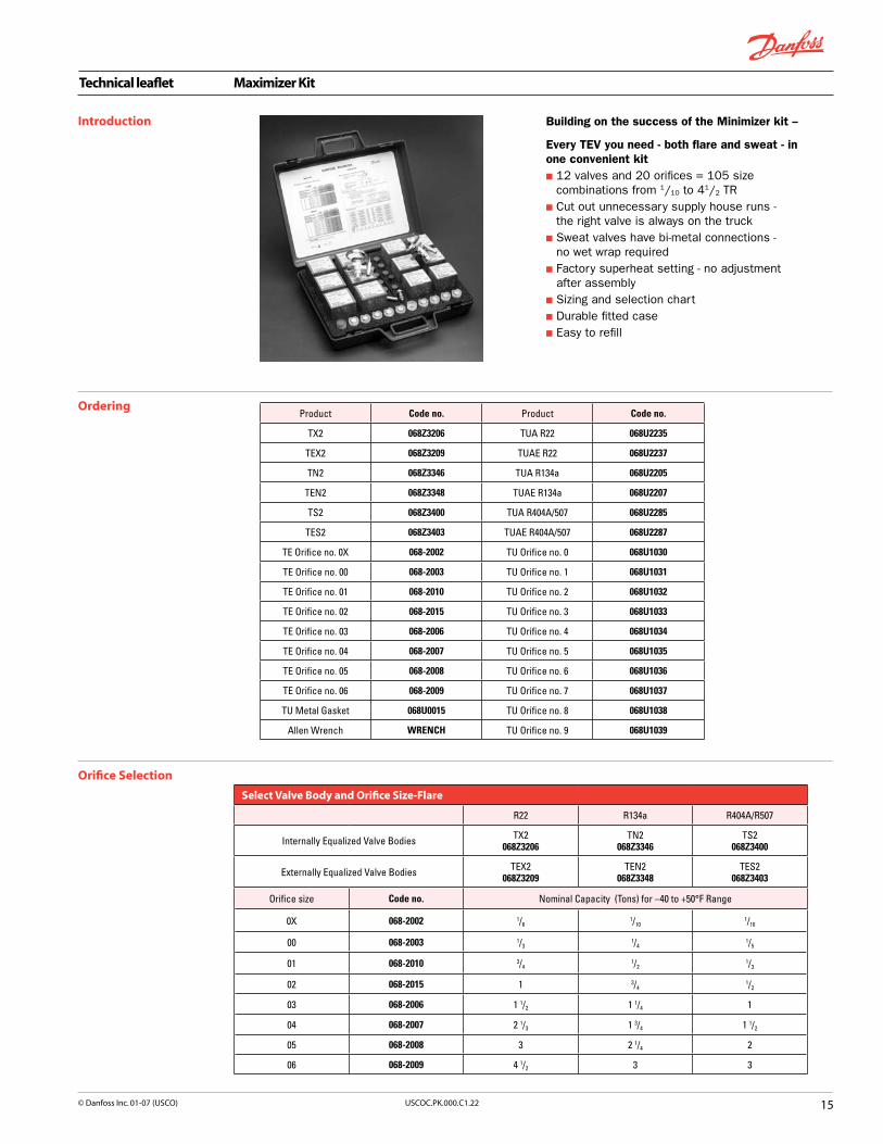
Building on the success of the Minimizer kit --
Every TEV you need - both flare and sweat - in one convenient kitn 12 valves and 20 orifices = 105 size
combinations from 1/10 to 41/2 TRn Cut out unnecessary supply house runs -
the right valve is always on the truckn Sweat valves have bi-metal connections -
no wet wrap requiredn Factory superheat setting - no adjustment
after assemblyn Sizing and selection chart n Durable fitted casen Easy to refill
Introduction
OrderingProduct Code no. Product Code no.
TX2 068Z3206 TUA R22 068U2235
TEX2 068Z3209 TUAE R22 068U2237
TN2 068Z3346 TUA R134a 068U2205
TEN2 068Z3348 TUAE R134a 068U2207
TS2 068Z3400 TUA R404A/507 068U2285
TES2 068Z3403 TUAE R404A/507 068U2287
TE Orifice no. 0X 068-2002 TU Orifice no. 0 068U1030
TE Orifice no. 00 068-2003 TU Orifice no. 1 068U1031
TE Orifice no. 01 068-2010 TU Orifice no. 2 068U1032
TE Orifice no. 02 068-2015 TU Orifice no. 3 068U1033
TE Orifice no. 03 068-2006 TU Orifice no. 4 068U1034
TE Orifice no. 04 068-2007 TU Orifice no. 5 068U1035
TE Orifice no. 05 068-2008 TU Orifice no. 6 068U1036
TE Orifice no. 06 068-2009 TU Orifice no. 7 068U1037
TU Metal Gasket 068U0015 TU Orifice no. 8 068U1038
Allen Wrench WRENCH TU Orifice no. 9 068U1039
Orifice Selection
Select Valve Body and Orifice Size-Flare
R22 R134a R404A/R507
Internally Equalized Valve Bodies TX2068Z3206
TN2068Z3346
TS2068Z3400
Externally Equalized Valve Bodies TEX2068Z3209
TEN2068Z3348
TES2068Z3403
Orifice size Code no. Nominal Capacity (Tons) for –40 to +50°F Range
0X 068-2002 1/61/10
1/10
00 068-2003 1/31/4
1/5
01 068-2010 3/41/2
1/3
02 068-2015 1 3/41/2
03 068-2006 1 1/2 1 1/4 1
04 068-2007 2 1/3 1 3/4 1 1/2
05 068-2008 3 2 1/4 2
06 068-2009 4 1/2 3 3
Select Valve Body and Orifice Size
R22 R134a R404A/R507
Internally Equalized TX2068Z3206
TN2068Z3346
TS2068Z3400
Externally Equalized TEX2068Z3209
TEN2068Z3348
TES2068Z3403
Orifice size Code no. Nominal Capacity (Tons) for –40 to –10°F Range
0X 068-2002 1/61/10
1/10
00 068-2003 1/31/4
1/5
01 068-2010 3/41/2
1/3
02 068-2015 1 3/41/2
03 068-2006 1 1/2 1 1/3 1
04 068-2007 2 1/3 1 3/4 1 1/2
05 068-2008 3 2 1/5 2
06 068-2009 4 1/2 3 3

Technical leaflet Maximizer Kit
�� USCOC.PK.000.C�.22 © Danfoss Inc. 0�-07 (USCO)
Orifice Selection (continued)
Select Valve Body and Orifice Size-Sweat
R22 R134a R404A/R507
Internally Equalized Valve Bodies TUA068U2235
TUA068U2205
TUA068U2285
Externally Equalized Valve Bodies TUAE068U2237
TUAE068U2207
TUAE068U2287
Orifice size Code no. Nominal Capacity (Tons) for –40 to +50°F Range*
0 068U1030 1/61/8
1/8
1 068U1031 1/41/5
1/5
2 068U1032 1/31/4
1/4
3 068U1033 1/21/3
1/3
4 068U1034 3/41/2
1/2
5 068U1035 1 3/43/4
6 068U1036 1 1/2 1 1
7 068U1037 2 1 1/2 1 1/2
8 068U1038 3 2 2 1/4
9 068U1039 4 1/2 3 3 1/2
Refill the Kit
*Valve capacity provided on page 11.

Technical leaflet Thermostatic expansion valves, type TDE and TDEB
�7USCOC.PK.000.C�.22© Danfoss Inc. 0�-07 (USCO)
The TDE series of thermostatic expansion valves is designed for use in: n Air conditioning systemsn Heat pumpsn Water chillersn Refrigerated containers n Traditional refrigeration systems
The TDE product programs consist of two hermetic valve designs: n Single port (type TDE) and balanced port (type
TDEB). Valve selection is determined by the application and the capacity required.
Single port version (type TDE) n The single port’s simplified construction
is designed for use on systems with small capacities (3 to 7.5 TR R22). Single port design is effective because in smaller capacities condensing pressure is negligible. Type TDE single port valves can also be used for bi-flow applications in the same capacity range.
Introduction TDE Range 3-71/2 TR (R22), TDEB Range 8-40 TR (R22)
Features
Balanced port versions (type TDEB) n The balanced port design has been developed
for large capacity systems (greater than 8 to 40 TR) where fluctuating condensing pressures are present.
n The balanced port feature eliminates any influence by condensing pressure on the expansion valve function in the normal flow direction.
n The TDEB design is unique in that it also provides a balance function in the reverse flow direction making it ideal for use in bi-flow applications.
All TDE valves are available with a selection of bulb charges with or without maximum operating pressure (MOP) function. Single and industrial pack quantities are available.
Hermetically sealed solder valves n Reduces the possibility of leaks in your system
Laser-welded, stainless steel thermostatic elementn Provides longer diaphragm life, protection
against corrosion and optimum pressure strength
Bi-flow function n Reduces installation costs by reducing the
number of valves required in a heat pump application
Patented double-contact bulb n Allows for quick and easy installation and
provides for good heat transfer between pipe and sensor
Available Refrigerants n R22, R407C, R134a (special order)
Versions available with: n Maximum operating pressure (MOP) functionn Bi-flow function

Technical leaflet Thermostatic expansion valves, type TDE and TDEB
�� USCOC.PK.000.C�.22 © Danfoss Inc. 0�-07 (USCO)
R22
Metric�conversions1 psi = 0.07 bar5/
9 (t
1°F – 32) = t
2°C
1 ton = 3.5 kW1 in. = 25.4 mm
Range K = –15 to 50°F with MOP 100 psig
Type and rated
capacity 1) TR
Connection solder
ODF × ODFin.
Code no.Multipack
TDEX 3 - 7.5 Single port
TDEX 3 3/8 × 5/8 068H6200
TDEX 3 1/2 × 5/8 068H6201
TDEX 4 1/2 × 7/8 068H6202
TDEX 6 1/2 × 5/8 068H6234
TDEX 6 1/2 × 7/8 068H6203
TDEX 6 5/8 × 7/8 068H6204
TDEX 7.5 5/8 × 7/8 068H6205
TDEBX 20 - 40 Balanced port
TDEBX 20 7/8 × 11/8 068H7146
TDEBX 26 7/8 × 13/8 068H7148
TDEBX 30 7/8 × 13/8 068H7150
TDEBX 30 11/8 × 13/8 068H7152
TDEBX 40 11/8 × 13/8 068H7154
1)The rated capacity is based on:Evaporating temperature t
e = 40°F
Liquid temperature tl = 80°F
Condensing temperature tc = 90°F
Range K = –15 to 50°F with MOP 100 psig
Type and rated
capacity 1)
TR
Connection solder
ODF × ODFin.
Code no.Multipack
TDEBX 8 - 19 Balanced port
TDEBX 8 5/8 × 7/8 068H7130
TDEBX 11 5/8 × 7/8 068H7132
TDEBX 11 5/8 × 11/8 068H7134
TDEBX 12.5 5/8 × 7/8 068H7136
TDEBX 12.5 5/8 × 11/8 068H7138
TDEBX 16 5/8 × 11/8 068H7140
TDEBX 16 7/8 × 11/8 068H7142
TDEBX 19 7/8 × 11/8 068H7144
Ordering
1) The rated capacity is based on: Evaporating temperature t
e = 40°F
Liquid temperature tl = 80°F
Condensing temperature tc = 90°F
R22Range AC = 15 to 60°F with MOP 120 psig
Type and rated
capacity 1)
TR
Connection solder
ODF × ODFin.
Code no.Multipack
TDEX 3 - 7.5 Single port
TDEX 3 3/8 × 5/8 068H6100
TDEX 3 1/2 × 5/8 068H6101
TDEX 4 1/2 × 7/8 068H6102
TDEX 6 1/2 × 5/8 068H6134
TDEX 6 1/2 × 7/8 068H6103
TDEX 6 5/8 × 7/8 068H6104
TDEX 7.5 5/8 × 7/8 068H6105
TDEBX 20 - 40 Balanced port
TDEBX 20 7/8 × 11/8 068H7116
TDEBX 26 7/8 × 13/8 068H7118
TDEBX 30 7/8 × 13/8 068H7120
TDEBX 30 11/8 × 13/8 068H7122
TDEBX 40 11/8 × 13/8 068H7124
Range AC = 15 to 60°F with MOP 120 psig
Type and rated
capacity 1)
TR
Connection solder
ODF × ODFin.
Code no.Multipack
TDEBX 8 - 19 Balanced port
TDEBX 8 5/8 × 7/8 068H7100
TDEBX 11 5/8 × 7/8 068H7102
TDEBX 11 5/8 × 11/8 068H7104
TDEBX 12.5 5/8 × 7/8 068H7106
TDEBX 12.5 5/8 × 11/8 068H7108
TDEBX 16 5/8 × 11/8 068H7110
TDEBX 16 7/8 × 11/8 068H7112
TDEBX 19 7/8 × 11/8 068H7114

Technical leaflet Thermostatic expansion valves, type TDE and TDEB
��USCOC.PK.000.C�.22© Danfoss Inc. 0�-07 (USCO)
R22
Metric�conversions1 psi = 0.07 bar5/
9 (t
1°F – 32) = t
2°C
1 ton = 3.5 kW1 in. = 25.4 mm
Range N = –40 to 50°F
Type and rated
capacity 1)
TR
Connection solder
ODF × ODFin.
Code no.Multipack
TDEX 3 - 7.5 Single port
TDEX 3 3/8 × 5/8 068H7050
TDEX 3 1/2 × 5/8 068H7052
TDEX 4 1/2 × 7/8 068H7054
TDEX 6 1/2 × 5/8 068H7056
TDEX 6 1/2 × 7/8 068H7058
TDEX 6 5/8 × 7/8 068H7060
TDEX 7.5 5/8 × 7/8 068H7062
TDEBX 20 - 40 Balanced port
TDEBX 20 7/8 × 11/8 068H7080
TDEBX 26 7/8 × 13/8 068H7082
TDEBX 30 7/8 × 13/8 068H7084
TDEBX 30 11/8 × 13/8 068H7086
TDEBX 40 11/8 × 13/8 068H7088
1) The rated capacity is based on: Evaporating temperature t
e = 40°F
Liquid temperature tl = 80°F
Condensing temperature tc = 90°F
Range N = –40 to 50°F
Type and rated
capacity 1)
TR
Connection solder
ODF × ODFin.
Code no.Multipack
TDEBX 8 - 19 Balanced port
TDEBX 8 5/8 × 7/8 068H7064
TDEBX 11 5/8 × 7/8 068H7066
TDEBX 11 5/8 × 11/8 068H7068
TDEBX 12.5 5/8 × 7/8 068H7070
TDEBX 12.5 5/8 × 11/8 068H7072
TDEBX 16 5/8 × 11/8 068H7074
TDEBX 16 7/8 × 11/8 068H7076
TDEBX 19 7/8 × 11/8 068H7078
R407CRange K = –15 to 50°F with MOP 95 psig
Type and rated
capacity 1)
TR
Connection solder
ODF × ODFin.
Code no.Multipack
TDEX 3 - 7.5 Single port
TDEZ 3 3/8 × 5/8 068H7160
TDEZ 3 1/2 × 5/8 068H7161
TDEZ 4 1/2 × 7/8 068H7162
TDEZ 6 1/2 × 5/8 068H7163
TDEZ 6 1/2 × 7/8 068H7164
TDEZ 6 5/8 × 7/8 068H7165
TDEZ 7.5 5/8 × 7/8 068H7166
TDEBX 20 - 40 Balanced port
TDEBZ 20 7/8 × 11/8 068H7191
TDEBZ 26 7/8 × 13/8 068H7193
TDEBZ 30 7/8 × 13/8 068H7195
TDEBZ 30 11/8 × 13/8 068H7197
TDEBZ 40 11/8 × 13/8 068H7199
Range K = –15 to 50°F with MOP 95 psig
Type and rated
capacity 1)
TR
Connection solder
ODF × ODFin.
Code no.Multipack
TDEBX 8 - 19 Balanced port
TDEBZ 8 5/8 × 7/8 068H7175
TDEBZ 11 5/8 × 7/8 068H7177
TDEBZ 11 5/8 × 11/8 068H7179
TDEBZ 12.5 5/8 × 7/8 068H7181
TDEBZ 12.5 5/8 × 11/8 068H7183
TDEBZ 16 5/8 × 11/8 068H7185
TDEBZ 16 7/8 × 11/8 068H7187
TDEBZ 19 7/8 × 11/8 068H7189
1) The rated capacity is based on: Evaporating temperature t
e = 40°F
Liquid temperature tl = 80°F
Condensing temperature tc = 90°F
Ordering (continued)
Technical leaflet Thermostatic expansion valves, type TDE and TDEB
20 USCOC.PK.000.C�.22 © Danfoss Inc. 0�-07 (USCO)
Ordering (continued) R407C
Metric�conversions1 psi = 0.07 bar5/
9 (t
1°F – 32) = t
2°C
1 ton = 3.5 kW1 in. = 25.4 mm
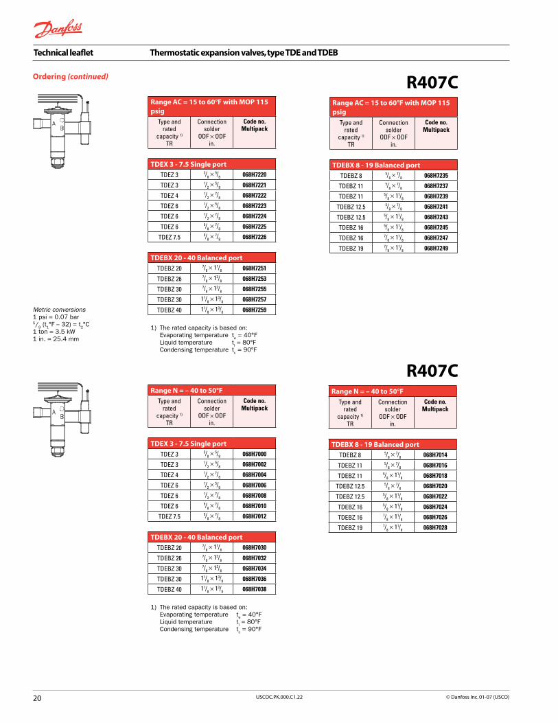
Range AC = 15 to 60°F with MOP 115 psig
Type and rated
capacity 1)
TR
Connection solder
ODF × ODFin.
Code no.Multipack
TDEX 3 - 7.5 Single port
TDEZ 3 3/8 × 5/8 068H7220
TDEZ 3 1/2 × 5/8 068H7221
TDEZ 4 1/2 × 7/8 068H7222
TDEZ 6 1/2 × 5/8 068H7223
TDEZ 6 1/2 × 7/8 068H7224
TDEZ 6 5/8 × 7/8 068H7225
TDEZ 7.5 5/8 × 7/8 068H7226
TDEBX 20 - 40 Balanced port
TDEBZ 20 7/8 × 11/8 068H7251
TDEBZ 26 7/8 × 13/8 068H7253
TDEBZ 30 7/8 × 13/8 068H7255
TDEBZ 30 11/8 × 13/8 068H7257
TDEBZ 40 11/8 × 13/8 068H7259
1) The rated capacity is based on: Evaporating temperature t
e = 40°F
Liquid temperature tl = 80°F
Condensing temperature tc = 90°F
Range AC = 15 to 60°F with MOP 115 psig
Type and rated
capacity 1)
TR
Connection solder
ODF × ODFin.
Code no.Multipack
TDEBX 8 - 19 Balanced port
TDEBZ 8 5/8 × 7/8 068H7235
TDEBZ 11 5/8 × 7/8 068H7237
TDEBZ 11 5/8 × 11/8 068H7239
TDEBZ 12.5 5/8 × 7/8 068H7241
TDEBZ 12.5 5/8 × 11/8 068H7243
TDEBZ 16 5/8 × 11/8 068H7245
TDEBZ 16 7/8 × 11/8 068H7247
TDEBZ 19 7/8 × 11/8 068H7249
R407CRange N = – 40 to 50°F
Type and rated
capacity 1)
TR
Connection solder
ODF × ODFin.
Code no.Multipack
TDEX 3 - 7.5 Single port
TDEZ 3 3/8 × 5/8 068H7000
TDEZ 3 1/2 × 5/8 068H7002
TDEZ 4 1/2 × 7/8 068H7004
TDEZ 6 1/2 × 5/8 068H7006
TDEZ 6 1/2 × 7/8 068H7008
TDEZ 6 5/8 × 7/8 068H7010
TDEZ 7.5 5/8 × 7/8 068H7012
TDEBX 20 - 40 Balanced port
TDEBZ 20 7/8 × 11/8 068H7030
TDEBZ 26 7/8 × 13/8 068H7032
TDEBZ 30 7/8 × 13/8 068H7034
TDEBZ 30 11/8 × 13/8 068H7036
TDEBZ 40 11/8 × 13/8 068H7038
1) The rated capacity is based on: Evaporating temperature t
e = 40°F
Liquid temperature tl = 80°F
Condensing temperature tc = 90°F
Range N = – 40 to 50°F
Type and rated
capacity 1)
TR
Connection solder
ODF × ODFin.
Code no.Multipack
TDEBX 8 - 19 Balanced port
TDEBZ 8 5/8 × 7/8 068H7014
TDEBZ 11 5/8 × 7/8 068H7016
TDEBZ 11 5/8 × 11/8 068H7018
TDEBZ 12.5 5/8 × 7/8 068H7020
TDEBZ 12.5 5/8 × 11/8 068H7022
TDEBZ 16 5/8 × 11/8 068H7024
TDEBZ 16 7/8 × 11/8 068H7026
TDEBZ 19 7/8 × 11/8 068H7028

Technical leaflet Thermostatic expansion valves, type TDE and TDEB
2�USCOC.PK.000.C�.22© Danfoss Inc. 0�-07 (USCO)
Identification
Essential valve data is given on the element label.
TDEX = Type (X: refrigerant R22)8 TR = Rated capacity Qnom. in
Tons of Refrigeration28 kW = Rated capacity Qnom. in kWR22 = Refrigerant–25/+10 °C = Evaporating temperature
range (°C)–15/+50 °F = Evaporating temperature
range (°F) 068H4112 = Code numberBP 15 = Bleed 15%MOP 100 = Max. Operation Pressure PB 28 bar/ MWP 400 psig = Max. working pressure288 = Date marking (week 28,
1998)
Dimensions and weights
TDE3-7.5,TDEB8-19 TDEB20-40
Element label
Type ConnectionODF solder
Capillarytube
length
H1 H2 H3 H4 L1 L2 L3 L4 L5 ØD1 ØD2 Weight
inlet × outlet
in. ft. in. in. in. in. in. in. in. in. in. in. in. lbs.
TDE 3 - 7.5
3/8 × 5/8 5 2.78 2.54 2.93 4.61 1.61 1.73 1.52 2.44 0.20 1.77 0.55 0.901/2 × 5/8 5 2.78 2.54 2.93 4.61 1.63 1.73 1.52 2.44 0.20 1.77 0.55 0.901/2 × 7/8 5 2.78 2.54 2.93 4.61 1.63 2.32 1.52 2.44 0.20 1.77 0.55 0.905/8 × 7/8 5 2.78 2.54 2.93 4.61 1.73 2.32 1.52 2.44 0.20 1.77 0.55 0.90
TDEB 8 - 19
5/8 × 7/8 5 3.35 3.07 3.58 5.39 1.83 2.42 1.61 2.44 0.28 2.09 0.55 1.305/8 × 1 1/8 5 3.35 3.07 3.58 5.39 1.83 2.62 1.61 2.44 0.28 2.09 0.55 1.307/8 × 1 1/8 5 3.35 3.07 3.58 5.39 2.42 2.62 1.61 2.44 0.28 2.09 0.55 1.30
TDEB 20 - 40
7/8 × 1 1/8 10 4.31 3.64 4.31 6.69 2.50 2.70 1.71 4.96 0.39 2.36 0.75 2.407/8 × 1 3/8 10 4.31 3.64 4.31 6.69 2.50 2.89 1.71 4.96 0.39 2.36 0.75 2.40
1 1/8 × 1 3/8 10 4.31 3.64 4.31 6.69 2.70 2.89 1.71 4.96 0.39 2.36 0.75 2.40

Technical leaflet Thermostatic expansion valves, type TRE 10, TRE 20, TRE 40, and TRE 80
22 USCOC.PK.000.C�.22 © Danfoss Inc. 0�-07 (USCO)
Introduction Type TRE 10, TRE 20, TRE 40, and TRE80 Range 8 to 70 TR (R22)
TRE thermostatic expansion valves have been designed and developed for soldering into air-conditioning and refrigeration systems. Their hermetic tight design meets environmental demands for today and the future. They can be used in systems ranging in capacity from 8 to 70 TR (R22).
The TRE design incorporates a forged brass body with the entire power element, including the capillary tube and bulb, fabricated from stainless steel. The straight through bimetal solder connections are formed from deep drawn stainless steel and copper. The valve incorporates a 2-way balanced port orifice making it ideal for bi-flow operation.
External superheat adjustment is a standard feature on all TRE valves. For non-adjustable OEM versions, a setting assembly is available for field retrofit.
Contact Danfoss for further information.
Features
Bimetal connections n waterless soldering n quicker installation times n higher productivity
Developed for R410An R22, R407C, R134a, R410A and other
fluorinated refrigerants
Laser-welded power element: n longer diaphragm life n high pressure tolerance and working pressure
Stainless steel power element, capillary tube and bulb n high corrosion resistance n high strength and vibration resistance n fast installation: self-aligning bulb
secures with one strapn good thermal contact and transmission
Two-way balanced port/bi-flow function n superheat unaffected by condensing
pressure independent of flow directionn one valve for heat pump service
Stainless steel double contact bulb n straightforward and fast installation n good thermal contact and heat transfer
Adjustable/non-adjustable version n setting spindle assembly can be
retrofitted to non-adjustable version
Static superheat, adjustable: 3.6 °F → 10.8 °F

Technical leaflet Thermostatic expansion valves, type TRE 10, TRE 20, TRE 40, and TRE 80
2�USCOC.PK.000.C�.22© Danfoss Inc. 0�-07 (USCO)
Valve options In addition to the standard program, TRE valves are also available with the following options:
Refrigerants - Range - MOP:Contact Danfoss for information regarding different refrigerants and evaporator ranges.
Static superheat, fixed: 3.6 °F → 10.8 °F
Internal bleed: 15%
Capillary tube length:
Type Capillary tube length
TRE 10 3 or 5 ft.
TRE 20 3; 5 or 10 ft.
TRE 40 5 or 10 ft.
TRE 80 5 or 10 ft.
Connections:
Type Inlet ODF solder Outlet ODF solder
TRE10 1/2 - 5/8 - 7/8 in. 1/2 - 5/8 - 7/8 - 11/8 in.
TRE 20 5/8 - 7/8 - 11/8 in. 5/8 - 7/8 - 11/8 - 13/8 in.
TRE 40 7/8 - 11/8 in. 7/8 - 11/8 - 13/8 in.
TRE 80 11/8 - 13/8 in. 11/8 - 13/8 - 15/8 in.
Equalizing connection 1/4 in. or 6 mm ODF on all types.
Sizes in bold type are standard sizes.
Ordering
Valve and bulb strap are supplied in bulk industrial pack or individually in multipack.
The numbers supplied are as follows:
Type Industrial pack Multipack
TRE 10 12 pcs 12 pcs
TRE 20 8 pcs 8 pcs
TRE 40 4 pcs 6 pcs
TRE 80 4 pcs 4 pcs
Overview of product range
CapacityTR
Refrigerant Range MOP
Type Code
8 - 70 R22 X K 60°F
8 - 70 R22 X N
8 - 85 R410A L K 60°F
8 - 85 R410A L N
8 - 70 R407C Z K 60°F
8 - 70 R407C Z N
5 - 56 R134a N K 60°F
5 - 56 R134a N N
K: −15 → +50°F N: −40 → +50°F

Technical leaflet Thermostatic expansion valves, type TRE 10, TRE 20, TRE 40, and TRE 80
2� USCOC.PK.000.C�.22 © Danfoss Inc. 0�-07 (USCO)
Ordering
Pressure equalization = 1/4 in. ODF
1) The rated capacity is based on: ARI Standard 750-01
2) Number of valves in industrial and multipacks: (see page 22)
Standard program
Refrigerant
Type Rated capacity
Qnom 1)
TR
Rated capacity
Qnom 1)
TR
ConnectionODF solder
Range K–15°/+50°F MOP 60°F
Range N–40°/+50°F
Inletin.
Outletin.
Code no.Multi-pack2)
Code no.Multi-pack2)
R22
TRE10- 8XTRE10-10X
810
5/85/8
7/87/8
067L1021067L1024
067L1121067L1124
TRE20-10XTRE20-12.5XTRE20-15XTRE20-20XTRE20-20X
1012.5152020
5/85/87/87/87/8
7/87/8
11/8
11/8
13/8
067L1075067L1079067L1084067L1087067L1088
067L1175067L1179067L1184067L1187067L1188
TRE40-20XTRE40-20XTRE40-25XTRE40-25XTRE40-30XTRE40-40X
202025253040
7/87/87/8
11/8
11/8
11/8
11/8
13/8
13/8
13/8
13/8
13/8
067L3001067L3002067L3005067L3006067L3009067L3012
067L3101067L3102067L3105067L3106067L3109067L3112
TRE80-40XTRE80-55XTRE80-70X
405570
11/8
11/8
11/8
13/8
13/8
15/8
067L3060067L3063067L3066
067L3160067L3163067L3166
R410A
TRE10-8LTRE10-8L
TRE10-10LTRE10-10L
TRE10-12.5LTRE10-12.5LTRE10-15LTRE10-15L
88
1010
12.512.51515
5/85/85/85/85/85/87/87/8
5/87/85/87/85/87/87/8
11/8
067L1028067L1029067L1030067L1031067L1034067L1035067L1038067L1039
067L1128067L1129067L1130067L1131067L1134067L1135067L1138067L1139
TRE20-15LTRE20-15LTRE20-20LTRE20-20LTRE20-25LTRE20-25L
151520202525
7/87/87/87/87/8
11/8
7/8
11/87/8
11/8
11/8
11/8
067L1091067L1092067L1093067L1094067L1097067L1099
067L1191067L1192067L1193067L1194067L1197067L1199
TRE40-25LTRE40-25LTRE40-30LTRE40-30LTRE40-40LTRE40-40LTRE40-55LTRE40-55L
2525303040405555
7/8
11/8
11/8
11/8
11/8
11/8
11/8
11/8
11/8
13/8
11/8
13/8
11/8
13/8
11/8
13/8
067L3015067L3016067L3019067L3020067L3023067L3024067L3027067L3028
067L3115067L3116067L3119067L3120067L3123067L3124067L3127067L3128
TRE80-55LTRE80-55LTRE80-80LTRE80-80LTRE80-80LTRE80-100LTRE80-100L
5555808080100100
11/8
11/8
11/8
11/8
13/8
11/8
13/8
11/8
13/8
13/8
15/8
13/8
15/8
15/8
067L3069067L3070067L3073067L3074067L3075067L3078067L3079
067L3169067L3170067L3173067L3174067L3175067L3178067L3179
For connections, refrigerants, capillary tube lengths, etc. outside the standard program, see Valve�options�on page 23.
R22, R410A

Technical leaflet Thermostatic expansion valves, type TRE 10, TRE 20, TRE 40, and TRE 80
2�USCOC.PK.000.C�.22© Danfoss Inc. 0�-07 (USCO)
Ordering
Note: Spring not included
Accessories
Pressure equalization = 1/4 in. ODF
1) According to ARI 750-01 Rated capacities for range N are based on: Liquid temperature ahead of expansion valve t
l = 100°F
Evaporating temperature te = 40°F
Pressure drop across valve ∆ p = 60 psi for R134a Pressure drop across valve ∆ p = 100 psi for R22, R404A, R407C and R507 Pressure drop across valve ∆ p = 160 psi for R410A
2) Number of valves in industrial and multipacks: (see page 23)
Standard program
Refrigerant
Type Rated capacity
Qnom 1)
TR
Rated capacity
Qnom 1)
TR
ConnectionODF solder
Range K–15°/+50°F MOP 60°F
Range N–40°/+50°F
Inletin.
Outletin.
Code no.Multi-pack2)
Code no.Multi-pack2)
R407C
TRE10- 8ZTRE10-10Z
810
5/85/8
7/87/8
067L1012067L1015
067L1112067L1115
TRE20-10ZTRE20-12.5ZTRE20-15ZTRE20-20ZTRE20-20Z
1012.5152020
5/85/87/87/87/8
7/87/811/811/813/8
067L1058067L1062067L1067067L1070067L1071
067L1158067L1162067L1167067L1170067L1171
TRE40-20ZTRE40-20ZTRE40-25ZTRE40-25ZTRE40-30ZTRE40-40Z
202025253040
7/87/87/811/811/811/8
11/813/813/813/813/813/8
067L3030067L3031067L3034067L3035067L3038067L3040
067L3130067L3131067L3134067L3135067L3138067L3140
TRE80-40ZTRE80-55ZTRE80-70Z
405570
11/811/811/8
13/813/815/8
067L3082067L3085067L3088
067L3182067L3185067L3188
R134a
TRE10- 5NTRE10- 7N
57
5/85/8
7/87/8
067L1003067L1006
067L1103067L1106
TRE20- 7NTRE20- 9NTRE20-11NTRE20-14NTRE20-14N
79111414
5/85/87/87/87/8
7/87/811/811/813/8
067L1041067L1045067L1050067L1053067L1054
067L1141067L1145067L1150067L1153067L1154
TRE40-14NTRE40-14NTRE40-16NTRE40-16NTRE40-20NTRE40-25N
141416162025
7/87/87/811/811/811/8
11/813/813/813/813/813/8
067L3043067L3044067L3047067L3048067L3051067L3054
067L3143067L3144067L3147067L3148067L3151067L3154
TRE80-25NTRE80-35NTRE80-45N
253545
11/811/811/8
11/813/815/8
067L3091067L3094067L3097
067L3191067L3194067L3197
For connections, refrigerants, capillary tube lengths, etc. outside the standard program, see Valve�options�on page 23.
Filter: For mounting in the inlet connection.
Dimension Code no.1/2 in. 067L1281
Setting spindle assembly: For installation on valves with fixed setting.
Type Tighteningtorque Code no.
TRE10 22 ft lbf 067L1295
TRE20 34 ft lbf 067L1296
TRE40 49 ft lbf 067L1297
TRE80 66 ft lbf 067L1298
R407C, R134a

Technical leaflet Thermostatic expansion valves, type TRE 10, TRE 20, TRE 40, and TRE 80
2� USCOC.PK.000.C�.22 © Danfoss Inc. 0�-07 (USCO)
Dimensions and weight
Type
Connection, ODF solder
Capillary tube
length H1 H2 H3 H4 L1 L2 L3 L4 ØD1 ØD2 Weight
Inlet × Outlet
in. ft in in in in in in in in in in lbs
TRE 10
1/2 × 1/2
4.92 1.26 0.30 0.20
1.591.59
1.36 2.76 1.77 0.59
1/2 × 5/8 1.79
5/8 × 1/2 4.09
1.79
1.59 0.865/8
× 5/8 1.795/8
× 7/8 3.231) 2.03 0.771)
7/8 × 7/8
2.032.03
7/8 × 1 1/8 2.31
TRE 20
5/8 × 5/8
4.92 1.46 0.35 0.31
1.891.89
1.50 4.69 2.09 0.65
5/8 × 7/8 2.13
7/8 × 7/8 4.80
2.13
2.13 1.327/8
× 11/8 2.407/8
× 1 3/8 3.941) 2.8011/8
× 7/8
2.40
2.13 1.231)
11/8 × 11/8 2.40
11/8 × 13/8 2.80
TRE 40
7/8 × 7/8
11.76 1.65 0.51 0.43
2.26
2.26
1.61 4.37 2.36 0.80
7/8 × 1 1/8 2.54
7/8 × 1 3/8 5.71 2.93 1.74
11/8 × 11/8 5.04
2.54
2.54 2.051)
11/8 × 13/8 2.93
11/8 × 15/8 3.25
TRE 80
11/8 × 11/8
11.76 1.85 0.67 0.51
2.64
2.64
1.73 5.83 2.83 0.80
11/8 × 13/8 6.50 3.03 2.95
11/8 × 15/8 5.83 3.35 2.871)
13/8 × 13/8
3.033.03
13/8 × 15/8 3.35
1) Fixed setting

Technical leaflet Thermostatic expansion valves, type TRE 10, TRE 20, TRE 40, and TRE 80
27USCOC.PK.000.C�.22© Danfoss Inc. 0�-07 (USCO)
Type
Connection, ODF solder
Capillary tube
length H1 H2 H3 H4 L1 L2 L3 L4 ØD1 ØD2 Weight
Inlet × Outlet
in. ft in in in in in in in in in in lbs
TRE 10
1/2 × 1/2
4.92 1.26 0.30 0.20
1.591.59
1.36 2.76 1.77 0.59
1/2 × 5/8 1.79
5/8 × 1/2 4.09
1.79
1.59 0.865/8
× 5/8 1.795/8
× 7/8 3.231) 2.03 0.771)
7/8 × 7/8
2.032.03
7/8 × 1 1/8 2.31
TRE 20
5/8 × 5/8
4.92 1.46 0.35 0.31
1.891.89
1.50 4.69 2.09 0.65
5/8 × 7/8 2.13
7/8 × 7/8 4.80
2.13
2.13 1.327/8
× 11/8 2.407/8
× 1 3/8 3.941) 2.8011/8
× 7/8
2.40
2.13 1.231)
11/8 × 11/8 2.40
11/8 × 13/8 2.80
TRE 40
7/8 × 7/8
11.76 1.65 0.51 0.43
2.26
2.26
1.61 4.37 2.36 0.80
7/8 × 1 1/8 2.54
7/8 × 1 3/8 5.71 2.93 1.74
11/8 × 11/8 5.04
2.54
2.54 2.051)
11/8 × 13/8 2.93
11/8 × 15/8 3.25
TRE 80
11/8 × 11/8
11.76 1.85 0.67 0.51
2.64
2.64
1.73 5.83 2.83 0.80
11/8 × 13/8 6.50 3.03 2.95
11/8 × 15/8 5.83 3.35 2.871)
13/8 × 13/8
3.033.03
13/8 × 15/8 3.35
Connection dimensions, see ordering table.Fig. 6. TUH, Angleway
Dimensions and weight
Connection dimensions, see ordering table.Fig. 6. TCHE, Angleway
Weight.28 lbs.
Weight.33 lbs.

2� USCOC.PK.000.C�.22 © Danfoss Inc. 0�-07 (USCO)
Technical leaflet Thermostatic expansion valves, type TR 6
Introduction
TR 6 thermostatic expansion valves have been designed and developed with features especially for use in applications such as:
n Residential air conditioning systems
n Split systems
n Roof top units
n Heat pumps
n Light commercial air conditioning systems
n Chillers
The hermetic tight design meets environmental demands for today and the future. The TR 6 pro-gram is available for R22 and R410A. The TR 6 can be used for all fluorinated refrigerants. Models for other refrigerants can be produced to order.
The TR design incorporates a hot-pressed brass body with the entire power element, including the capillary tube and bulb, fabricated from stainless steel. The valves are supplied as standard in straightway versions with fixed orifice and with external equalization. They can be delivered with or without internal check valve and with external superheat adjustment spindle for field retrofit. All valves are designed with balanced port which reduces the influence from varying condensing pressures.
The valves can be delivered with special connections and fittings both at the inlet and outlet and at the equalizer connection. The TR 6 can be delivered with a fixed setting in accordance with the customers' requirement for optimized unit performance.
Features
Compact size - hermetic design.
Developed and designed for R22 and R410A.
Rated capacities ranging up to: n R22: 6 TR n R410A: 7 TR
A complete program with or without internal check valve.
An internal check valve with low pressure drop at full flow.
Non-adjustable TR 6 with customer specific factory setting.
Laser-welded power element: n longer diaphragm life.n high pressure tolerance and working
pressure.
Stainless steel power element, capillary tube and bulb: n high corrosion resistancen high strength and vibration resistancen fast installation and good thermal contact
and transmission
Bleed function.
With internal check valve for heat pump systems.
With and without check valve.
Customer specific engravement. n UL Listed, file SA7200.

2�USCOC.PK.000.C�.22© Danfoss Inc. 0�-07 (USCO)
Technical leaflet Thermostatic expansion valves, type TR 6
Design and function
The central push pin is sealed with a robust seal (pos. 3) that ensures maximum tightness and minimum friction through the lifetime of the valve.
The balanced port (pos. 4) ensures minimal superheat changes when condensing pressure varies. This feature makes the valve ideal for bi-flow operation.
Static superheat (SS) can be adjusted with the setting spindle (see fig. 3, pos. 6) . The standard superheat setting is 3.6°F .
Terminology
SS = Static superheatOS = Opening superheatOSH = SS + OS = Operating superheat
Example
Static superheat SS = 3.6°F (factory setting)or according to customer specification.
Opening�superheat
OS = 7.2°F
The opening superheat is 7.2°F, i.e. from the point the valve begins to open up to nominal capacity. Opening superheat (OS) is a fixed value and cannot be changed.
Operating superheat
OSH = SS + OSOSH = 3.6°F + 7.2°F = 10.8°F (6°K)
OSH is the total superheat that can be measured on the system.
TR 6 with adjustable setting
1. Bulb
2. Thermostatic element
3. Push pin seal
4. Balanced port
5. Check valve
6. Setting spindle for adjustment of static superheat (SS)
7. Equalizer
8. Inlet connection
9. Outlet connection

30 USCOC.PK.000.C1.22 © Danfoss Inc. 01-07 (USCO)
Technical leaflet Thermostatic expansion valves, type TR 6
Ordering R22 and R410A
Adjustable superheatEqualization line: 24” with flare nutCapillary tube: 31.5”Connections 3/8” × 3/8” ODF, Aeroquip and Chatleff adapters supplied
Refrigerant TR Danfoss Code #Connections included in Kit
3/8 × 3/8 ODF Chatle� Aeroquip
R410A
1 to 2 067L5856 × × ×
3 to 4 067L5857 × × ×
5 to 6 067L5858 × × ×
R22
3 067L5955 × × ×
4 067L5956 × × ×
5 067L5957 × × ×
Adjustable setting
Correction factor for subcooling tsub
Correctionfactor
tsub
4°K 10°K 15°K 20°K 25°K 30°K 35°K 40°K
7.2°F 18°F 27°F 36°F 45°F 55°F 63°F 72°F
R22 1.00 1.06 1.11 1.15 1.20 1.25 1.30 1.35
R410A 1.00 1.08 1.15 1.21 1.27 1.33 1.39 1.45
Refrigerant
System
Capacity
(TR)
Danfoss
Code #
Connections included in Kit
3/8 X 3/8 ODF Aeroquip
R-410A
3 067L5955 X X X
4 067L5956 X X X
5 067L5957 X X X
R-22
1, 1.5, 2 067L5856 X X X
2.5, 3 067L5857 X X X
3.5, 4 067L5858 X X X
5, 6 067L5859 X X X
Chatle�

Technical leaflet Thermostatic expansion valves, type TE-5 - TE 55
��USCOC.PK.000.C�.22© Danfoss Inc. 0�-07 (USCO)
Large temperature range:�n 76°F to +50°F n Equally applicable to freezing, refrigeration and air conditioning plant.
Interchangeable orifice assembly n easier stocking n easy capacity matching n better service.
Stainless steel power element, capillary tube and bulb n high corrosion resistance n high strength and vibration resistance n fast installation: self-aligning bulb n good thermal contact and transmission
Rated capacities from 5.5 to 100 TR for R22
Can be supplied with MOP (Max. Operating Pressure) Protects the compressor motor against excessive evaporating pressure.
Patented double contact bulb n Fast and easy to install. n Good temperature transfer from pipe to bulb.
Features
Thermostatic expansion valves regulate the injection of refrigerant liquid into evaporators.
Injection is controlled by the refrigerant superheat.
Therefore the valves are especially suitable for liquid injection in ”dry“ evaporators where the superheat at the evaporator outlet is proportional to the evaporator load.
Introduction
Max. temperatureBulb, when valve is installed: 212°FComplete valve not installed: 140°F
Min. temperature: –76°F
Max. test pressure:� 406 psig
Permissible working pressure: �319 psig
Technical data
MOP = Max. Operating Pressure
MOP-points
Refrigerant
Range N−40 → +50°F
Range NM−40 → +23°F
Range NL−40 → +5°F
Range B−76 → −13°F
MOP-point in evaporating temperature te and evaporating pressure pe
+60°F +32°F +15°F −4°F
R22 101 psig 57.5 psig 37.8 psig 20.9 psig
R134a 57.4 psig 27.8 psig 15.0 psig
R404A/R507 124 psig 72.4 psig 49.1 psig 29.0 psig
R407C 94.3 psig

Technical leaflet Thermostatic expansion valves, type TE-5 - TE 55
�2 USCOC.PK.000.C�.22 © Danfoss Inc. 0�-07 (USCO)
Ordering
Orifice assembly
Valve type
Rated capacity Range N:
–40 to 50°FTR
Rated capacityRange B:
–40 to –13°FTR
Orifice no. Code no.
TEX 5-3 5.6 3.4 01 067B2089
TEX 5-4.5 7.6 4.8 02 067B2090
TEX 5-7.5 11.1 7.1 03 067B2091
TEX 5-12 15.8 10.1 04 067B2092
TEX 12-4.5 7.6 4.9 01 067B2005
TEX 12-7.5 12.4 8.1 02 067B2006
TEX 12-12 18.3 11.8 03 067B2007
TEX 12-18 24.1 16.0 04 067B2008
TEX 20-30 30.9 20.0 01 067B2172
TEX 55-50 68.3 42.3 01 067G2005
TEX 55-85 101.7 65.1 02 067G2006
Thermostatic element
Valvetype
Pressureequalization
Capillarytube
Code no.
Range N–40 to +50°F
Range NM–40 to +25°F
Range NL–40 to +5°F
Range B–76 to –13°F
1/4 in. / 6 mm feet Without MOP MOP+60°F MOP 32°F MOP 14°F Without MOP MOP –4°F
TEX 5 Ext. 1) 9.8 067B3250 067B3267 067B3249 067B3253 067B3263 067B3251
TEX 12 Ext. 2) 9.8 067B3210 067B3227 067B3207 067B3213 067B3211
TEX 12 Ext. 2) 16.4 067B3209 067B3212
TEX 20 Ext. 2) 9.8 067B3274 067B3286 067B3273 067B3275 067B3276
TEX 20 Ext. 2) 16.4 067B3290 067B3287
TEX 55 Ext. 2) 9.8 067G3205 067G3220 067G3206 067G3207
TEX 55 Ext. 2) 16.4 067G3209 067G3217
R22
1) Pressure equalization with solder connector can be supplied on contacting Danfoss.2) Available as accessory: solder adapter for TE 12, TE 20 and TE 55. Code no. 068B0170.
The rated capacity is based on:Evaporating temperature t
e = +40°F for range N and t
e = –22°F for range B
Condensing temperature tc = +90°F
Refrigerant temperature ahead of valve tl = +80°F
Valve body
Type Orifice no.
ConnectionInlet × Outlet Code no.
in. Flareangleway
Solderangleway
Solderstraightway
Solderflanges
TE 501 - 03
0304
1/2 × 5/81/2 × 7/85/8 × 7/8
067B4013 067B4009067B4010067B4011
067B4007067B4008
TE 1201 - 0203 - 0403 - 04
5/8 × 7/87/8 × 1
7/8 × 11/8
067B4022 1)
067B4023 2)
067B4020 1)
067B4021 2)
067B4025 1)067B4026 1)
TE 20 01 7/8 × 11/8067B4023 2) 067B4021 2)
TE 55 01- 02 11/8 × 13/8067G4004 3) 067G4003 3)
1) ODF × ODF2) ODF × ODM3) ODM × ODMODF = Internal diameterODM = External diameter

Technical leaflet Thermostatic expansion valves, type TE-5 - TE 55
��USCOC.PK.000.C�.22© Danfoss Inc. 0�-07 (USCO)
Ordering(continued)
1) Pressure equalization with solder connector can be supplied on contacting Danfoss.
2) Available as accessory: solder adapter for TE 12, TE 20 and TE 55. Code no. 068B0170.
Orifice assembly
Valve type
Rated capacity Range N:
–40 to 50°FTR
Orifice no. Code no.
TEZ 5-3.2 6.1 01 067B2089
TEZ 5-5.0 8.3 02 067B2090
TEZ 5-8.0 12.0 03 067B2091
TEZ 5-13 17.1 04 067B2092
TEZ 12-5.0 8.3 01 067B2005
TEZ 12-8.0 13.4 02 067B2006
TEZ 12-13 19.7 03 067B2007
TEZ 12-19.5 26.1 04 067B2008
TEZ 20-32.5 33.1 01 067B2172
TEZ 55-54 74.0 01 067G2005
TEZ 55-92 110.0 02 067G2006
R407CThermostatic element
Valvetype
Pressureequalization
Capillarytube
Code no.
Range N–40 to +50°F
1/4 in. / 6 mm feet Without MOP MOP+60°F
TEZ 5 Ext. 1) 9.8 067B3278 067B3277
TEZ 12 Ext. 2) 9.8 067B3366 067B3367
TEZ 20 Ext. 2) 9.8 067B3371 067B3372
TEZ 55 Ext. 2) 9.8 067G3240 067G3241
The rated capacity is based on:
Evaporating temperature te = +40°F for range N
and te = –22°F for range B
Condensing temperature tc = +90°F
Refrigerant temperature ahead of valve tl = +80°F
Valve body
Type Orifice no.
ConnectionInlet × Outlet Code no.
in. Flareangleway
Solderangleway
Solderstraightway
Solderflanges
TE 501 - 03
0304
1/2 × 5/81/2 × 7/85/8 × 7/8
067B4013067B4009067B4010067B4011
067B4007067B4008
TE 1201 - 0203 - 0403 - 04
5/8 × 7/87/8 × 1
7/8 × 11/8
067B4022 1)
067B4023 2)
067B4020 1)
067B4021 2)
067B4025 1)067B4026 1)
TE 20 01 7/8 × 11/8 067B4023 2) 067B4021 2)
TE 55 01- 0201- 02 11/8 × 13/8
067G4004 3)067G4002 3)
067G4003 3)067G4001 3)
1) ODF × ODF
2) ODF × ODM
3) ODM × ODM
ODF = Internal diameter
ODM = External diameter

Technical leaflet Thermostatic expansion valves, type TE-5 - TE 55
�� USCOC.PK.000.C�.22 © Danfoss Inc. 0�-07 (USCO)
Ordering(continued)
Orifice assembly
Valve type Rated capacityTR Orifice no. Code no.
TEN 5-3.7 3.7 01 067B2089
TEN 5-5.4 5.5 02 067B2090
TEN 5-8.3 8.3 03 067B2091
TEN 5-11.2 11.3 04 067B2092
TEN 12-4.7 4.8 01 067B2005
TEN 12-7.7 7.8 02 067B2006
TEN 12-11.4 11.4 03 067B2007
TEN 12-15 15.1 04 067B2008
TEN 20-18 18.6 01 067B2170
TEN 55-41 41.4 01 067G2001
TEN 55-62 62.9 02 067G2002
R134a
The rated capacity is based on:
Evaporating temperature te = +40°F for range N and t
e = –22°F for range B
Condensing temperature tc = +90°F
Refrigerant temperature ahead of valve tl = +80°F
Thermostatic element
Valvetype
Pressureequalization
Capillarytube
Code no.
Range N–40 to +50°F
Range NM–40 to 25°F
1/4 in. / 6 mm feet Without MOP MOP +60°F MOP 32°F
TEN 5 Ext. 1) 9.84 067B3297 067B3298 067B3360
TEN 12 Ext. 2) 9.84 067B3232 067B3233
TEN 12 Ext. 2) 16.4 067B3363
TEN 20 Ext. 2) 9.84 067B3292 067B3293
TEN 20 Ext. 2) 9.84 067B3370
TEN 55 Ext. 2) 9.84 067G3222 067G3223
TEN 55 Ext. 2) 9.84 067G3230
Orifice assembly
1) Pressure equalization with solder connector can be supplied on contacting Danfoss.2) Available as accessory: solder adapter for TE 12, TE 20 and TE 55. Code no. 068B0170.
Valve body
Type Orifice no.
ConnectionInlet × Outlet Code no.
in. Flareangleway
Solderangleway
Solderstraightway
Solderflanges
TE 501 - 03
0304
1/2 × 5/81/2 × 7/85/8 × 7/8
067B4013 067B4009067B4010067B4011
067B4007067B4008
TE 1201 - 0203 - 0403 - 04
5/8 × 7/87/8 × 1
7/8 × 11/8
067B4022 1)
067B4023 2)
067B4020 1)
067B4021 2)
067B4025 1)067B4026 1)
TE 20 0101
7/8 × 11/8067B4023 2)067B4017 2)
067B4021 2)067B4016 2)
TE 55 01- 0201- 02
11/8 × 13/8067G4004 3)067G4002 3)
067G4003 3)067G4001 3)
1) ODF × ODF2) ODF × ODM3) ODM × ODMODF = Internal diameterODM = External diameter

Technical leaflet Thermostatic expansion valves, type TE-5 - TE 55
��USCOC.PK.000.C�.22© Danfoss Inc. 0�-07 (USCO)
Ordering(continued)
The rated capacity is based on:Evaporating temperature t
e = +40°F for range N and t
e = –22°F for range B
Condensing temperature tc = +90°F
Refrigerant temperature ahead of valve tl = +80°F
R404A/R507
1) Pressure equalization with solder connector can be supplied on contacting Danfoss.2) Available as accessory: solder adapter for TE 12, TE 20 and TE 55. Code no. 068B0170.
Thermostatic element
Valvetype
Pressureequalization
Capillarytube
Code no.
Range N–40 to +50°F
Range NM–40 to 25°F
Range NL–40 to 5°F
Range B–76 to –13°F
1/4 in. / 6 mm feet Without MOP MOP +60°F MOP 32°F MOP 14°F Without MOP MOP –4°F
TES 5 Ext. 1) 9.8 067B3342 067B3357 067B3358 067B3344 067B3343
TES 12 Ext. 2) 9.8 067B3347 067B3345 067B3348 067B3349
TES 12 Ext. 2) 16.4 067B3346 067B3350
TES 20 Ext. 2) 9.8 067B3352 067B3351 067B3353 067B3354
TES 20 Ext. 2) 16.4 067B3356 067B3355
TES 55 Ext. 2) 9.8 067G3302 067G3303 067G3304 067G3305
TES 55 Ext. 2) 16.4 067G3301 067G3306
Orifice assembly
Valve type
Rated capacityrange N:
–40 to 50°FTR
Rated capacityrange B:
–76 to –13°FTR
Orifice no. Code no.
TES 5-3.7 3.7 2.3 01 067B2089
TES 5-5.0 5.1 3.2 02 067B2090
TES 5-7.2 7.2 4.7 03 067B2091
TES 5-10.3 10.3 6.8 04 067B2092
TES12-4.2 4.2 3.3 01 067B2005
TES 12-6.8 6.8 5.4 02 067B2006
TES 12-10.0 10.1 7.9 03 067B2007
TES 12-13.4 13.5 10.7 04 067B2008
TES 20-16.5 16.9 11.7 01 067B2175
TES 55-37.0 37.1 27.1 01 067G2011
TES 55-56.0 56.3 41.1 02 067G2012
Valve body
Type Orifice no.
ConnectionInlet × Outlet Code no.
in. Flareangleway
Solderangleway
Solderstraightway
Solderflanges
TE 501 - 03
0304
1/2 × 5/81/2 × 7/85/8 × 7/8
067B4013 067B4009067B4010067B4011
067B4007067B4008
TE 501- 03
0304
TE 1201 - 0203 - 0403 - 04
5/8 × 7/87/8 × 1
7/8 × 11/8
067B4022 1)
067B4023 2)
067B4020 1)
067B4021 2)
067B4025 1)067B4026 1)
TE 1201 - 0203 - 0403 - 04
TE 20 01 7/8 × 11/8067B4023 2) 067B4021 2)
TE 55 01- 02 11/8 × 13/8067G4004 3) 067G4003 3)
1) ODF × ODF2) ODF × ODM3) ODM × ODMODF = Internal diameterODM = External diameter

Technical leaflet Thermostatic expansion valves, type TE-5 - TE 55
�� USCOC.PK.000.C�.22 © Danfoss Inc. 0�-07 (USCO)
Identification
Element label
Orifice assembly markingfor TE 5 and TE 12
Orifice assembly markingfor TE 20 and TE 55
The thermostatic element is fitted with a label (on top of the diaphragm).The code refers to the refrigerant for which the valve is designed:
X = R22
N = R134a
S = R404A/R507
Z = R407C
The label gives valve type, evaporating temperature range, MOP point, refrigerant, and max. test pressure, PS.
With TE 20 and TE 55 the rated capacity is stamped on a band label fastened to the valve
Orifice�assembly�for�TE�5,�TE�12,�20�and�55�The orifice assembly is marked on top of the spring cup, e.g. as shown in the figure. For a given size of valve, the same orifice assembly can be used for valves with ranges N and B.
The thermostatic elements are different however:
n On�TE�5�and�TE�12�the upper stamp (TE 12) indicates for which valve type the orifice can be used. The lower stamp (01) is the orifice size.
n On�TE�20�and�TE�55�the upper stamp (N/B 50/35 TR) indicates the rated capacity in the two evaporating temperature ranges N and B, and the refrigerant. (50/35 TR= 175 kW in range N and 123 kW in range B). The lower stamp (TEX 55) refers to the valve type for which the assembly can be used.
Capillary tube labelTE 5 → TE 55
Capillary�tube�label�for�TE�5�to�TE�55�The label gives the orifice size (04). A new label always accompanies a new orifice assembly.

Technical leaflet Thermostatic expansion valves, type TE-5 - TE 55
�7USCOC.PK.000.C�.22© Danfoss Inc. 0�-07 (USCO)
Dimensions and weights
TE 5 - Flare, anglewayWeight: 2.4 lb
TE 5 - Solder, straightwayWeight: 2.2 lb
TE 5 - Solder, anglewayWeight: 2.2 lb
TE 5
TE 5
Inlet side∅D1
L1in.
1/2 in. / 12 mm ODF 0.45/8 in. / 16 mm ODF 0.4
Outlet side∅D2
L1in.
5/8 in. / 16 mm ODF 0.57/8 in. / 22 mm ODF 0.7
TE 5
L2 D
Range N 4.5 ∅0.6
Range B 4.4 ∅0.8
TE 12 and 20 - Solder, straightwayWeight: TE 12: 3.3 lb TE 20: 3.7 lb
TE 12 and 20 - Solder, anglewayWeight: TE 12: 3.3 lb TE 20: 3.5 lb

Technical leaflet Thermostatic expansion valves, type TE-5 - TE 55
�� USCOC.PK.000.C�.22 © Danfoss Inc. 0�-07 (USCO)
TE 12 - Solder flanges, straightwayWeight: Without filter: 5.1 lb With filter: 7.0 lb
Dimensions and weights (continued)
TE 12 and TE 20
Inlet side∅D1
L1in.
5/8 in. / 16 mm ODF 0.57/8 in. / 22 mm ODF 0.7
Bulb - TE 20
L2 D
Range N/B 5.8 ∅0.8
Outlet side∅D2
L1in.
7/8 in. / 22 mm ODF 0.7
11/8 in. / 28 mm ODM 1.0
Bulb - TE 12
L2 D
Range N 4.4 ∅0.8
Range B 5.8 ∅0.8
TE 55 - Solder, straightwayWeight: 3.7 lb
TE 55 - Solder, straightwayWeight: 3.5 lb
Outlet side∅D2
L1in.
11/8 in. / 28 mm ODF 0.9
13/8 in. / 35 mm ODM 1.1
Bulb - TE 55L2 D
Range N/B 5.8 ∅0.8
Type TE 55Inlet side
∅D1
L1in.
7/8 in. / 22 mm ODF 0.7
11/8 in. / 28 mm ODM 1.0

Technical leaflet Solenoid valves type EVR 2 to 40
��USCOC.PK.000.C�.22© Danfoss Inc. 0�-07 (USCO)
Introduction Type EVR 2 to 40
EVR is a direct or servo-operated solenoid valve for liquid, suction, and hot gas lines with fluorinated refrigerants.
EVR valves are supplied complete or as separate components, i.e. valve body, coil and flanges, if required, can be ordered separately.
Features Complete range of solenoid valves for refrigeration, freezing, and air conditioning plants.
Supplied both normally closed (NC) and normally open (NO) with de-energized coil.
Wide choice of coils for a.c. and d.c.
Suitable for all fluorinated refrigerants.
Designed for media temperatures up to 221°F.
MOPD up to 363 psi with 12 W coil.
Flare connections up to 5/8 in.
Solder connections up to 2 1/8 in.
Extended ends for soldering make installation easy.
It is not necessary to dismantle the valve when soldering in.
EVR are also available with flange connections.
Refrigerants: n CFC, HCFC, HFC
Temperature of medium: n −40 to +221°F with 10 W or 12 W coil. n Max. 266°F during defrosting.
ApprovalsDnV, Det norske Veritas, Norge.
Pressure Equipment Directive (PED) 97/23/EC.
The Low Voltage Directive (LVD) 73/23/EC with amendments EN 60730-2-8.
P Polski Rejestr Statków, Polen.
MRS, Maritime Register of Shipping, Russia.
Versions with and approval can be supplied to order.

Technical leaflet Solenoid valves type EVR 2 to 40
�0 USCOC.PK.000.C�.22 © Danfoss Inc. 0�-07 (USCO)
Separate valve bodies, normally open (NO)
Type
Rated capacity R22 (liquid)
tons
Connectionin.
Port sizein.
Cv valuegal/min
Valve body excl. coil
Flare in.
Solder ODFin.
EVR 6 5.8 3/81/4 0.93 032F1163 032F1164
EVR 10 13.8 1/23/8 2.20 032F1169
EVR 15 18.9 5/89/16 3.00 032F1174
Ordering Separate valve bodies, normally closed (NC)
Type Rated capacity
R22 (liquid)tons
Connectionin.
Port Sizein.
Cv valuegal/min
Code no. Valve body without coil type
Flare Solder ODF
With manual stem
operationin.
Without manual stem
operationin.
With manual stem
operationin.
Without manual stem
operationin.
EVR 2 1.17 1/43/32 0.19 32F7101 32F7100
EVR 3 2.03 1/41/8 0.32 32F1155 32F7105
EVR 3 2.03 3/81/8 0.32 32F1154 32F1157
EVR 4 4.15 3/85/32 0.66 32F7112 32F7110
EVR 4 4.15 1/25/32 0.66 32F7113 32F7111
EVR 6 5.83 3/815/64 0.93 32F1185 32F1160 32F7116 32F7115
EVR 6 5.83 1/215/64 0.93 32F1159 32F1162
EVR 6 5.83 5/815/64 0.93 32F7117
EVR 8 8.01 3/89/32 1.30 32F7120
EVR 8 8.01 1/29/32 1.30 32F7123 32F7121
EVR 8 8.01 5/89/32 1.30 32F7122
EVR 10 13.8 3/83/8 2.20 32F7125
EVR 10 13.8 1/23/8 2.20 32F1187 32F1165 32F1188 32F1166
EVR 10 13.8 5/83/8 2.20 32F1167 32F1168
EVR 15 18.9 5/89/16 3.00 32F1172 32F1171
EVR 15 18.9 7/81/4 3.00 32F7130
EVR 18 24.6 7/819/32 3.90 32F1004 32F7135
EVR 18 24.6 1 1/819/32 3.90 32F7136
EVR 20 36.4 7/87/8 5.80 32F1177 32F1176
EVR 20 36.4 1 1/87/8 5.80 32F2272 32F1178
EVR 22 43.7 1 1/89/16 6.90 32F7145
EVR 22 43.7 1 3/89/16 6.90 32F7146
EVR 25 72.8 1 1/8 1 12.00 32F1190 32F1189
EVR 25 72.8 1 3/8 1 12.00 32F1194 32F1193
EVR 32 116.5 1 3/87/8 18.00 42H1177 42H1176
EVR 32 116.5 1 5/87/8 18.00 42H1179 42H1178
EVR 32 116.5 2 1/87/8 18.00 42H1181 42H1180
EVR 40 182.0 1 5/8 1 29.00 42H1186 42H1185
EVR 40 182.0 2 1/8 1 29.00 42H1188 42H1187
Metric�conversions1 psi = 0.07 bar5/9 (t1
°F - 32) = t2°C
1 ton = 3.5 kW1 in. = 25.4 mmUS gal/min = 8.6 m3/h
Coils,�see�next�page
AccessoriesMounting bracket for EVR 2, 3, 4, 6 and 10Code no. 32F0086

Technical leaflet Solenoid valves type EVR 2 to 40
��USCOC.PK.000.C�.22© Danfoss Inc. 0�-07 (USCO)
Cross reference list–GP Coils
Old Code No. New Code No.
018Z7613 018F7683
018Z7612 018F7682
018Z7611 018F7681
018Z7603 018F7689
018Z7623 018F7693
018Z7622 018F7692
018Z7621 018F7691
018Z7625 018F7699
Listed with EVR, MH7648
Conformity with LVD 73/23/EC with amendments EN 60730-2-8
Valve typeVoltage
VFrequency
HzCode no.
PowerconsumptionJunction box
NEMA 2Conduit boss
NEMA 4
Alternating current a.c.
EVREVMEVRA/TEVRS/TAKV/A
24 50/60 018F7683 018F7693 Holding:14 W28 VA
Inrusch:49 V
110 50/60018F7682 018F7692
120 60
208 - 240 60018F7681 018F7691
230 50
Direct current d.c.
Design In accordance with UL 429
Power supply Alternating current (a.c.) and direct current (d.c.)
Permissible voltage variation Alternating current (a.c.): +10 to –15% Direct current (d.c.): +10 to –10
Power consumption Alternating current (a.c.): Inrush: 49VA; Holding: 28VA, 14WDirect current (d.c.): 20W
Insulation of coil wire Class H accordingto IEC 85
Connection Junction box or Conduit boss
Enclosure, IEC 529 Junction box NEMA 2 ~ IP 12-32Conduit boss NEMA 4 ~ IP 54
Ambient temperature –40 to +140°F (–40 to +50°C)
120 018F7689 018F7699 20W
Ordering
Approvals
Technical data
Sealed to protect against moisture. Easy click-on mounting system.
Introduction General Purpose Click-on coil, type GP

Technical leaflet Solenoid valves type EVR 2 to 40
�2 USCOC.PK.000.C�.22 © Danfoss Inc. 0�-07 (USCO)
Dimensions and weights EVR (NC) 2 → 15, flare connection
With�DIN�plugs�coilWith�cable�connection�coil
With�terminal�box�coil
Type Connection Flare
L B Weight with coil
in. in. in. lbs.
EVR 2 1/4 2.33 1.30 1.10
EVR 3 1/4 2.33 1.30 1.10
3/8 2.50 1.30 1.10
EVR 6 3/8 2.75 1.50 1.33
1/2 3.00 1.50 1.33
EVR 10 1/2 3.31 1.80 1.77
5/8 3.65 1.80 1.77
EVR 15 5/8 4.10 2.25 2.20

Technical leaflet Solenoid valves type EVR 2 to 40
��USCOC.PK.000.C�.22© Danfoss Inc. 0�-07 (USCO)
Dimensions and weights EVR (NC) 2 → 22, solder connection(continued)
With�cable�connection�coil
With�terminal�box�coil
Type Connection Solder
L B Weight with coil
in. in. in. lbs.
EVR 2 1/4 4.00 1.30 1.10
EVR 3 1/4 4.00 1.30 1.30
3/8 4.60 1.30 1.30
EVR 6 3/8 4.30 1.50 1.30
1/2 5.00 1.50 1.30
EVR 10 1/2 5.00 1.80 1.60
5/8 6.30 1.80 1.60
EVR 15 5/8 7.00 2.25 2.20
7/8 7.00 2.25 2.20
EVR 20 7/8 7.50 2.90 3.30
11/8 8.50 2.90 3.30
EVR 22 13/8 11.00 2.90 3.30
With�DIN�plugs�coil

Technical leaflet Solenoid valves type EVR 2 to 40
�� USCOC.PK.000.C�.22 © Danfoss Inc. 0�-07 (USCO)
EVR�25�with�terminal�box�coil
EVR�32�and�40�terminal�box
EVR�25EVR�32�and�40�
Coil�with�cable Coil�with�DIN�plugs�
Dimensions and weights EVR (NC) 25, 32 and 40, solder connection(continued)
Type Connection Solder
L B Weight with coil
in. in. in. lbs.
EVR 25 11/8 10.00 3.75 28.75
13/8 11.00 3.75 29.35
EVR 32 13/8 11.00 3.15 32.00
15/8 11.00 3.15 32.25
EVR 40 15/8 11.00 3.15 32.25
21/8 11.00 3.15 32.25

Technical leaflet Solenoid valves type EVR 2 to 40
��USCOC.PK.000.C�.22© Danfoss Inc. 0�-07 (USCO)
With�cable�connection�coil
With�DIN�plugs�coil
Flare
Type L B Weight with coil
in. in. lbs.
EVR 6 2.72 1.50 1.33
EVR 10 3.31 1.80 1.60
EVR 15 4.10 2.25 2.00
With�terminal�box�coil
Solder
Type L B Weight with coil
in. in. lbs.
EVR 6 4.30 1.50 1.33
EVR 10 5.00 1.80 1.60
EVR 15 7.00 2.25 2.00
EVR 20 7.50 1) 2.90 3.30
EVR 22 11.00 2.90 3.30
Dimensions and weights EVR (NO) 6 → 22, flare or solder connection(continued)
1) Applies to 7/8 in. connections. For 11/
8 in. connections, L = 8.43 in.

Technical leaflet Pressure Regulators, type KVP
�� USCOC.PK.000.C�.22 © Danfoss Inc. 0�-07 (USCO)
Introduction Ranges from 1 1/3 to 2 3/
4 TR R22, 0 to 80 psig, factory setting = 29 psig
KVP evaporator pressure regulators are mounted in the suction line of refrigeration and air conditioning systems.
They are used to maintain a constant pressure corresponding to a constant temperature on the evaporator.
FeaturesAccurate, adjustable pressure regulation
Wide capacity and operating range
Pulsation damping design
Stainless steel bellows
Compact angle design for easy installation in any position
"Hermetic" brazed construction
1/4 in. Schrader valve for pressure testing
Available with flare and ODF solder connections
For use with CFC, HCFC and HFC refrigerants
C US listed, file SA7200
Maximum working pressure n PS (MWP) = 261 psig
Maximum test pressure n KVP 12 to 22: p' = 410 psig n KVP 28 to 35: p' = 370 psig
Maximum temperature of medium: 266°F
Minimum temperature of medium: –40°F
P band (full valve stroke) n KVP 12 to 22 = 26 psi n KVP 28 to 35 = 40 psi
Metric�conversions1 psi = 0.07 bar5/
9 (t
1°F – 32) = t
2°C
They also protect against too low an evaporating pressure by throttling down when pressure falls below the set value.
They are also used to differentiate the evaporating pressures in two or more evaporators in systems with one compressor.

Technical leaflet Pressure Regulators, type KVP
�7USCOC.PK.000.C�.22© Danfoss Inc. 0�-07 (USCO)
Ordering
1) Rated capacity is based on: Evaporating temperature t
e = 40°F
Condensing temperature tc = 100°F
Pressure drop across regulator ∆p = 2 psi Offset (design evaporating pressure minus minimum allowable evaporator pressure) = 9 psi.
Note: The connection dimensions chosen must not be too small, as gas velocities in excess of 130 ft/s at the inlet of the regulator can result in flow noise.
Type Rated capacity 1)
tonsFlare
connectionCode no. Solder
connectionCode no.
R 22 R 134a R 404A / R 507 R 407C in. in. ODF
KVP 12 1.3 0.9 1.2 1.2 1/2 034L0021 1/2 034L0023
KVP 15 1.3 0.9 1.2 1.2 5/8 034L0022 5/8 034L0029
KVP 22 1.3 0.9 1.2 1.2 7/8 034L0025
KVP 28 2.8 1.9 2.4 2.6 11/8 034L0026
KVP 35 2.8 1.9 2.4 2.6 13/8 034L0032
Dimensions and weights
Metric�conversions1 in. = 25.4 mm1 lb = 0.454 kg
Type Connection NV1 NV2 H1 H2 H3 B1 B2 C Ø D Weight
Flare Solder ODF
in. in. in. in. in. in. in. in. in. in. in. lbs
KVP 12 1/21/2 0.75 0.75 7.05 3.90 2.60 2.52 1.61 0.39 1.18 0.90
KVP 15 5/85/8 0.95 0.95 7.05 3.90 2.60 2.52 1.61 0.47 1.18 0.90
KVP 22 7/8 0.95 0.95 7.05 3.90 2.60 2.52 1.61 0.67 1.18 0.90
KVP 28 11/8 0.95 0.95 10.20 5.95 4.13 4.10 1.89 0.79 1.69 2.00
KVP 35 13/8 10.20 5.95 4.13 4.10 1.89 0.98 1.69 2.00

Technical leaflet Electronic Pressure Regulators, type KVQ
�� USCOC.PK.000.C�.22 © Danfoss Inc. 0�-07 (USCO)
Introduction
KVQ is an electronically operated evaporating pressure regulator designed for small refrigerating systems. The KVQ valve is normally controlled by a controller from the Danfoss’ range of ADAP-KOOL® Refrigeration control system.
The KVQ valve consists of 2 main components: • Actuator • Valve
The valve can be used in small refrigerating systems, e.g. supermarket installations and cold rooms for fruit, vegetables, and meat products.
The valve functions as an evaporating pressure regulator. A pulsating voltage signal is transmitted to the actuator from the controller. The signal is supplied in pulse sequences of up to 10 sec. duration. In this way a force is produced in the actuator’s pressure container. This force will act on the charge in the bellows, move the pressure pin, and hence the valve plate.
The evaporating pressure rises when the valve closes. By varying the amount of power applied the controller ensures correct positioning of the valve plate. The evaporating pressure will therefore maintain the value resulting in the correct media temperature. Changes of the suction pressure are of no consequence, as the area of the bellows equals the orifice area. If the supply voltage is cut out, the valve opens.
Features
Accurate pressure control
Capacity: 3 to 7.2 TR (R 22)
All fluorinated refrigerants
Regulating range: 0 to 102 psi
US listed, file SA7200
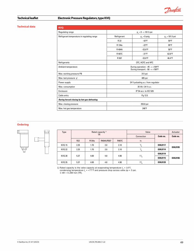
Technical leaflet Electronic Pressure Regulators, type KVQ
��USCOC.PK.000.C�.22© Danfoss Inc. 0�-07 (USCO)
Technical data
Ordering
KVQ
Regulating range pe = 0 → 101.5 psi
Refrigerant temperature in regulating range Refrigerant pe = 0 psig pe = 101.5 psi
R 22 −42°F 59°F
R 134a −22°F 95°F
R 404A −52.6°F 50°F
R 407C −31°F 62.6°F
R 507 −52.6°F 46.4°F
Refrigerants CFC, HCFC and HFC
Ambient temperature During operation: −45 → +104°F During transport: −50 → +158°F
Max. working pressure PB 312 psi
Max. test pressure p' 405 psi
Power supply 24 V pulsating a.c. from regulator
Max. consumption 35 VA / 24 V a.c.
Enclosure IP 54 acc. to IEC 529
Cable entry Pg 13.5
During forced closing by hot-gas defrosting
Max. closing pressure 253.8 psi
Max. hot gas temperature 248˚F
Type Rated capacity 1) TR
Valve Actuator
Connection Code no. Code no.
R22 R134a R404A/R507 R407C in.
KVQ 15 2.25 1.70 2.0 2.10 5/8 034L0117 034L0105
KVQ 22 2.25 1.70 2.0 2.10 7/8 034L0114
KVQ 28 5.37 4.00 4.8 4.90 11/8 034L0119
034L0106034L0115
KVQ 35 5.37 4.00 4.8 4.90 13/8 034L0120
1) Rated capacity is the valve capacity at evaporating temperature te = 14˚F,
condensing temperature tc = +77˚F and pressure drop across valve ∆p = 3 psi.
1 kW = 0.284 ton (TR).

Technical leaflet Electronic Pressure Regulators, type KVQ
�0 USCOC.PK.000.C�.22 © Danfoss Inc. 0�-07 (USCO)
Dimensions and weights
KVQ�actuator
KVQ�valve Complete�KVQ
KVQ actuator
Type H1 B C NV D Ø 1 Ø 2 Weight
in. in. in. in. in. in. in. lbs.
KVQ 15-22 6.40 2.15 1.07 1.26 0.63 × 0.06 2.50 2.37 1.10
KVQ 28-35 6.40 2.15 1.07 1.26 0.71 × 0.06 2.50 2.37 1.10
KVQ valve
Type Connect. Solder
H2 H3 B1 C D1 D NV Weight
in. in. in. in. in. in. in. in. lbs.
KVQ 15 5/8 11.93 3.90 6.07 2.52 0.50 1.19 1.11 1.00
KVQ 22 7/8 11.93 3.90 6.07 2.52 0.67 1.19 1.11 1.00
KVQ 28 11/8 14.41 5.95 8.50 4.14 0.87 1.70 1.38 2.00
KVQ 35 13/8 14.41 5.95 8.50 4.14 0.99 1.70 1.38 2.00
Complete KVQ
Type H4 H5
in. in.
KVQ 15-22 11.93 8.04
KVQ 28-35 14.41 8.31

Technical leaflet Condensor Pressure Regulators, type KVR/NRD
��USCOC.PK.000.C�.22© Danfoss Inc. 0�-07 (USCO)
Introduction
KVR condenser regulators can be mounted in either the gas or liquid side of the condenser in refrigeration and air conditioning systems.
They are used to maintain a constant and sufficiently high condensing pressure with systems using air-cooled condensers.
They can also be used with valve types NRD or KVD to assure that adequate pressure is maintained on the receiver.
Features
Accurate, adjustable pressure regulation
Wide capacity and operating range
Pulsation damping design
Stainless steel bellows
Compact angle design for easy installation in any position
"Hermetic" brazed construction
1/4 in. Schrader valve for pressure testing
Available with flare and ODF solder connections
For use with CFC, HCFC and HFC refrigerants
Can be used as a relief valve from high pressure to suction side
C US listed, file SA7200
Regulation range n 70 to 250 psig n Factory setting = 145 psig
Maximum working pressure n KVR: PS (MWP) = 400 psig n NRD: PS (MWP) = 400 psig
Maximum test pressure n KVR: p' = 450 psig n NRD: p' = 530 psig
Maximum temperature of medium n KVR/NRD with Schrader: 275°F n KVR without Schrader: 220˚F
Minimum temperature of medium –40°F
P band (full valve stroke) n KVR 12 to 22: 90 psi n KVR 28 to 35: 72.5 psi
Opening differential pressure for NRD�n Fully open: ∆p = 43 psi
Metric�conversions1 psi = 0.07 bar5/
9 (t
1°F – 32) = t
2°C

Technical leaflet Condensor Pressure Regulators, type KVR/NRD
�2 USCOC.PK.000.C�.22 © Danfoss Inc. 0�-07 (USCO)
Note: The connection dimensions chosen must not be too small, as gas velocities in excess of 130 ft/s at the inlet of the regulator can result in flow noise.
Ordering Type Rated liquid capacity 1)
(Evaporator capacity)tons
Rated hot gas 1)
(Evaporator capacity)tons
Flare connection
Code no. SolderConnection
Code no.
R22 R134a R404A/R507 R407C R22 R134a R404A/R507 R407C in. in.
KVR 12
12.7 11.8 8.2 13.8 4.13 3.03 3.27 4.50
1/2 034L0091 1/2 034L0093
KVR 15 5/8 034L0092 5/8 034L0097
KVR 22 7/8 034L0094
KVR 2832.6 30.2 20.9 35.5 10.93 8.04 8.66 11.91
11/8 034L0095
KVR 35 13/8 034L0100
1) Rated capacity is based on:
Evaporating temperature te = 40°F
Condensing temperature tc = 110°F
Pressure drop across valve ∆p = 3 psi for liquid capacity ∆p = 6 psi for hot gas capacity
KVR
NRD
Dimensions and weights
Metric�conversions1 in. = 25.4 mm1 lb = 0.454 kg
Type Connection
NV1 NV2
H1 H2 H3 L L1 B1 B2 C dia. D Weight
Flare Solder ODF
in. in. in. in. in. in. in. in. in. in. in. lbs.
KVR 12 1/21/2 0.75 0.75 7.05 3.90 2.60 2.52 1.61 0.39 1.18 0.88
KVR 15 5/85/8 0.95 0.95 7.05 3.90 2.60 2.52 1.61 0.47 1.18 0.88
KVR 22 7/8 7.05 3.90 2.60 2.52 1.61 0.67 1.18 0.88
KVR 28 11/8 10.20 5.95 4.06 4.13 1.89 0.79 1.69 2.20
KVR 35 13/8 10.20 5.95 4.06 4.13 1.89 0.98 1.69 2.20
NRD 1/2 5.16 0.39 0.87 0.22

Technical leaflet Capacity regulator (hot gas bypass), type TUH/TCHE
��USCOC.PK.000.C�.22© Danfoss Inc. 0�-07 (USCO)
Type Connection
NV1 NV2
H1 H2 H3 L L1 B1 B2 C dia. D Weight
Flare Solder ODF
in. in. in. in. in. in. in. in. in. in. in. lbs.
KVR 12 1/21/2 0.75 0.75 7.05 3.90 2.60 2.52 1.61 0.39 1.18 0.88
KVR 15 5/85/8 0.95 0.95 7.05 3.90 2.60 2.52 1.61 0.47 1.18 0.88
KVR 22 7/8 7.05 3.90 2.60 2.52 1.61 0.67 1.18 0.88
KVR 28 11/8 10.20 5.95 4.06 4.13 1.89 0.79 1.69 2.20
KVR 35 13/8 10.20 5.95 4.06 4.13 1.89 0.98 1.69 2.20
NRD 1/2 5.16 0.39 0.87 0.22
Introduction TUH/TCHE capacity regulators adapt the compressor capacity to the actual evaporator load for applications operating at an evaporating temperature of around 32°F. TUH/TCHE valves are typically used in applications such as:
n Air- driers n Water chillers
Placed in a bypass between the high- and low pressure sides of the system. TUH/TCHE maintain the compressor's suction pressure by injecting hot gas/cool gas from the high pressure side.
The TUH has internal pressure equalisation and is opening on a decrease in pressure at the outlet of the valve. The TCHE has external pressure equalisation and is opening directly on a de-crease in the suction pressure at the compressor.
For both valves, the bulb only serves as a reservoir for the charge, however, it is recommended to mount it in a position where the temperature variation during running conditions is limited (see a and b in the application drawing on page 55).
Features Bimetal connectionsn straightforward and fast soldering (no wet cloth
or refrigeration pliers required).
Refrigerants R134a, R404A/R507, R407C, and other refrigerants by request.
Replacement capacities up to 7.6 kW (2.2 TR) for R404A
Stable regulation
Tight across the seat
Stainless steel, hermetically tight solder versionn high connection strengthn high corrosion resistancen capillary tube joints of high strength and
vibration resistance
Compact design small dimensions and low weight
Laser-welded, stainless steel diaphragm element n optimum function n long diaphragm life n high pressure resistance
Adjustable setting n accurate setting n fine tuning possible
Low p-band
Advanced filter/strainer design
Low hysteresis
Orifice�sizes: TUH: Orifice 9 TCHE: Orifice 3 Orifice 4
Connections:
Inlet 3/8 in.
Outlet 1/2 in.
Standard range Versions available in the standard ranges only:
One�standard�range�per�refrigerant
Refrigerants: R134a, R404A/R507, R407C
Capillary�tube�length:� TUH: 2.6 ft. TCHE: 2.9 ft.
Max.�valve�body�temperature� 248°F�short-lived�peak�� 302°F
Permissible�working�pressure� MWP = 500 psig
Max.�test�pressure 540 psig
P-band� � 7.3 psig
Setting The valve is set to start opening at an evaporating temperature of +36°F . The setting can be changed by turning the setting spindle. The temperature at which the valve starts
opening will increase by turning the spindle clockwise whereas it will decrease by turning the spindle anticlockwise.
Adjustment�range�for�start�opening:
R134a +10 → +50°F
R404A/R507 +23 → +41°F
R407C� +19 → +45°F
Specifically designed for hot gas applications. Both the TUH and TCHE valves react only on suction pressure variations.
Technical data
(Variant versions available upon request)

Technical leaflet Capacity regulator (hot gas bypass), type TUH/TCHE
�� USCOC.PK.000.C�.22 © Danfoss Inc. 0�-07 (USCO)
Main valve data is given on the element (fig. 1) and on the valve body (fig. 2).
Main�valve�data�example,�fig.�1
TUH = Type
068U2954 = Code number
R404A = Refrigerant
+23 → +41°F = Adjusting range in °F
MWP 500 psig = Max. working pressure
104B = Date marking (week 10, year 2004, weekday B = Tuesday)
Main�valve�data�example,�fig.�2
⇒ = Normal flow direction
inch = Connection in inches (MM = millimetres)
ORIF 9 = Orifice number 9
1.3 TR = Replacement capacity in Tons of Refrigeration
4.5 kW = Replacement capacity in kW
Identification
Fig. 1
Fig. 2
R134a, R404A/R507, R407COrderingSupplied with bulb strap
Standard range
Refrigerant Type Orifice no. Pressure equalisationTR
ConnectionInlet × Outlet
in.2) Code no. Code no.
R134a
TUH 9 0.5 int. 3/8 × 1/2 068U2953 068U2950
TCHE 3 0.75 ext. 3/8 × 1/2 068U4540 068U4530
TCHE 4 1 ext. 3/8 × 1/2 068U4537 068U4534
R404A/R507
TUH 9 1.3 int. 3/8 × 1/2 068U2954 068U2951
TCHE 3 1.7 ext. 3/8 × 1/2 068U4541 068U4531
TCHE 4 2.2 ext. 3/8 × 1/2 068U4538 068U4535
R407C
TUH 9 0.8 int. 3/8 × 1/2 068U2955 068U2952
TCHE 3 1.2 ext. 3/8 × 1/2 068U4542 068U4532
TCHE 4 1.5 ext. 3/8 × 1/2 068U4539 068U4536
TU
TC
1) The nominal replacement capacity is the regulator capacity at evaporating temperature te = 28°F, condensing temperature tc = 104°F, reduction of suction temperature / suction pressure ∆ts = 7°F.2) Valves with inch connections have 1/4 in. pressure equalization.3) Valves with mm connections have 6 mm pressure equalization.
067L1179

Technical leaflet Capacity regulator (hot gas bypass), type TUH/TCHE
��USCOC.PK.000.C�.22© Danfoss Inc. 0�-07 (USCO)
1. Evaporator2. Condenser3. Receiver4. Solenoid valve5. Discharge bypass valve with
adjustable remote bulb6. Compressor
Application
Internally pressure equalized
Externally pressure equalized
Note:The bulb serves only as a reservoir for the charge, however, it is recommended to mount it in a position where the temperature variation during running conditions is limited (see a and b in the application drawings above).
a
b
a
b

Technical leaflet Hot Gas Bypass Capacity Regulators, type KVC
�� USCOC.PK.000.C�.22 © Danfoss Inc. 0�-07 (USCO)
KVC capacity regulators are used to adapt compressor capacity to actual evaporator load by supplying a replacement capacity in form of hot/cool gas.
Introduction
Features
Accurate, adjustable pressure regulation
Wide capacity and operating range
Pulsation, damping design
Stainless steel bellows
Compact angle design for easy installation
"Hermetic" brazed construction
Available with flare and ODF solder connections
For CFC, HCFC and HFC refrigerants
It is installed in a bypass line between the high and low pressure sides of the refrigeration system and is designed for direct gas injection into the suction line.
C US listed, file SA7200
Regulation range n 3 to 85 psig n Factory setting = 29 psig
Maximum working pressure: n PS = 400 psig
Maximum test pressure: n p' = 450 psig
Maximum temperature of medium: 266°F
Minimum temperature of medium: –40°F
Maximum P-band: 29 psi
Metric�conversions1 psi = 0.07 bar5/
9 (t
1°F – 32) = t
2°C
1 ton = 3.5 kW
Ordering
1) Rated capacity is based on: Suction gas temperature t
s = 10°F
Liquid temperature tl = 100°F
Offset ∆p = 10 psi
Note: The connection dimensions chosen must not be too small, as gas velocities in excess of 130 ft/s at the inlet of the regulator can result in flow noise.
If the temperature in the discharge gas line is too high according to the compressor specifications, it is recommended to install a liquid injection valve in a bypass from the liquid line to the suction line.
Type Rated capacity 1) tons
Flare connection
Code no. Solder connection
Code no.
R22 R134a R404A / R507 R407C in. in.
KVC 12 2.14 1.36 2.02 2.31 1/2 034L0141 1/2 034L0143
KVC 15 4.17 2.65 3.93 4.50 5/8 034L0142 5/8 034L0147
KVC 22 5.35 3.41 5.04 5.78 7/8 034L0144

Technical leaflet Hot Gas Bypass Capacity Regulators, type CPCE/LG
�7USCOC.PK.000.C�.22© Danfoss Inc. 0�-07 (USCO)
CPCE�hot�gas�capacity�valve
Superior control accuracy
Provides protection against too low an evaporator temperature
Direct connection to system suction line
For use with CFC, HCFC and HFC refrigerants
LG�liquid�gas�mixer
LG provides homogenous mixture of liquid and hot gas refrigerant in the evaporator
Can be used for hot gas defrosting or reverse cycle systems
US listed, file SA7200
Features
approved
Refrigerants: CFC, HCFC, HFC
Regulation range n p
e = 0 to 85 psig
n Factory setting = 5.8 psig
Maximum working pressure: n MWP = 310 psig
Maximum test pressure: n p’ = 400 psig
Maximum media temperature: 285°F
Minimum media temperature: –40°FMetric�conversions1 psi = 0.07 bar5/
9 (t
1°F – 32) = t
2°C
Introduction
CPCE capacity regulators are used to adapt compressor capacity to actual evaporator load.
They are installed in a bypass line between the high and low pressure sides of the refrigeration
system and is designed for hot gas injection into the evaporator just after the expansion valve.
Liquid-gas mixer type LG can be used at the point of injection to assure a proper mixture.

Technical leaflet Hot Gas Bypass Capacity Regulators, type CPCE/LG
�� USCOC.PK.000.C�.22 © Danfoss Inc. 0�-07 (USCO)
1) Rated capacity is based on: Minimum suction temperature t
s = 15°F
Condensing temperature tc = 100°F
Superheat of expansion valve ∆ts = 7°F
Ordering
Liquid - gas mixer
Type Connection Code no.
For expansion valveODM
For hot gasODF
For liquid distributorODF
in. in. in.
LG 12-16 5/81/2
5/8 069G4001
LG 12-22 7/81/2
7/8 069G4002
LG 16-28 1 1/85/8 1 1/8 069G4003
LG 22-35 1 3/87/8 1 3/8 069G4004
Capacity regulator
Type Connection Rated capacity1)
tonsCode no.
Flare Solder - ODFR22 R134a R404A/R507 R407C
in. in.
CPCE 12 1/2 6.2 4.3 6.3 6.7 034N0081
CPCE 12 1/2 6.2 4.3 6.3 6.7 034N0082
CPCE 15 5/8 9.2 6.3 9.1 9.9 034N0083
CPCE 22 7/8 12.2 8.4 12.1 13.2 034N0084
Dimensions and weights
CPCE�
LG
Metric�conversions1 in. = 25.4 mm1 lb = 0.454 kg
Type L1in.
Weightlbs
CPCE 12 0.38 2
CPCE 15 0.50 2
CPCE 22 0.67 2
Type Hin.
H1in.
L1in.
NVin.
Weightlbs
LG 12-16 2.13 0.88 1.56 0.94 0.20
LG 12-22 2.44 1.03 1.69 1.13 0.40
LG 16-28 3.13 1.38 1.88 1.44 0.70
LG 22-35 3.50 1.56 2.63 1.63 0.90

Technical leaflet Crankcase Pressure Regulators, type KVL
��USCOC.PK.000.C�.22© Danfoss Inc. 0�-07 (USCO)
Introduction
They are installed in the suction line of refrigeration systems.
Features
Accurate, adjustable pressure regulation
Wide capacity and operating range
Pulsation damping design
Stainless steel bellows
Compact angle design for easy installation in any position
"Hermetic" brazed construction
Available with flare and ODF solder connections
For use with CFC, HCFC and HFC refrigerants
C US approved, file SA7200
KVL crankcase pressure regulators are used to protect the compressor motor against overload experienced during startup after long off periods or just after defrost periods.
Regulation range n 3 to 85 psig n Factory setting = 29 psig
Maximum working pressure n KVL 12 to 22: PS = 261 psig n KVL 28 to 35: PS = 261 psig
Maximum test pressure n KVL 12 to 22: p' = 405 psig n KVL 28 to 35: p' = 370 psig
Maximum temperature of medium: 266°F
Minimum temperature of medium: –76°F
Maximum P-band n KVL 12 to 22: 29 psi n KVL 28 to 35: 22 psi
Metric�conversions1 psi = 0.07 bar5/
9 (t
1°F – 32) = t
2°C
1 ton = 3.5 kW

Technical leaflet Crankcase Pressure Regulators, type KVL
�0 USCOC.PK.000.C�.22 © Danfoss Inc. 0�-07 (USCO)
Metric�conversions1 psi = 0.07 bar5/
9 (t
1°F – 32) = t
2°C
1 ton = 3.5 kW1 in. = 25.4 mm
Ordering
1) Rated capacity is based on: Maximum suction pressure p
s = 70 psig
Suction temperature ts = 10°F
Condensing temperature tc = 100°F
Pressure drop across regulator ∆p = 2 psi
Note: The connection dimensions chosen must not be too small, as gas velocities in excess of 130 ft/s at the inlet of the regulator can result in flow noise.
Type Rated capacity 1) TR
Flare connection
Code no. Solder connection
Code no.
R22 R134a R404A / R507 R407C in. in.
KVL 12 0.34 0.22 0.28 0.31 1/2 034L0041 1/2 034L0043
KVL 15 0.34 0.22 0.28 0.31 5/8 034L0042 5/8 034L0049
KVL 22 0.34 0.22 0.28 0.31 7/8 034L0045
KVL 28 1.60 0.74 0.96 1.08 11/8 034L0046
KVL 35 1.60 0.74 0.96 0.96 13/8 034L0052
Dimensions and weights
Type Connection (in.) H1 H2 B1 C solder ∅D Weight
Flare Solder ODF in. in. in. in. in. lbs.
KVL 12 1/2 in. 1/2 in. 7.05 3.90 2.52 0.38 1.18 0.90
KVL 15 5/8 in. 5/8 in. 7.05 3.90 2.52 0.50 1.18 0.90
KVL 22 7/8 in. 7.05 3.90 2.52 0.63 1.18 0.90
KVL 28 11/8 in. 10.20 5.95 4.13 0.88 1.69 2.00
KVL 35 13/8 in. 10.20 5.95 4.13 1.00 1.69 2.00
Metric�conversions1 in. = 25.4 mm1 lb = 0.454 kg

Technical leaflet Receiver Pressure Regulators, type KVD
��USCOC.PK.000.C�.22© Danfoss Inc. 0�-07 (USCO)
KVD is a modulating pressure regulator. It opens on falling receiver pressure and bypasses hot gas to maintain the receiver pressure at the regulator setting (adjustable).
Introduction
KVD and KVR form a regulating system, used to maintain constant and adequately high condensing and receiver pressure in systems with heat-recovery, and in refrigeration and air conditioning systems with air-cooled condensers.
FeaturesAccurate, adjustable pressure regulation
Wide operating range
Pulsation damping design
Stainless steel bellows
Compact angle design for easy installation in any position
"Hermetic" brazed construction
1/4 in. access valve for pressure testing
Available with flare and ODF solder connections
For use with CFC, HCFC, HFC refrigerants
C US listed, file SA7200
Regulating range n 45 to 290 psig n Factory setting = ��� psig
Maximum working pressure: n PS (MWP) = 400 psig
Maximum test pressure: n p’ = 450 psig
Maximum temperature of medium:�212°F
Minimum temperature of medium:�–40°FMetric�conversions1 psi = 0.07 bar5/
9 (t
1°F – 32) = t
2°C
1 in. = 25.4 mm

Technical leaflet Receiver Pressure Regulators, type KVD
�2 USCOC.PK.000.C�.22 © Danfoss Inc. 0�-07 (USCO)
Ordering
The size of connection must not be chosen too small since gas velocities of more than 130 ft/s in the inlet can cause flow noise.
Type Flare connection Solder connection
in. Code no. in. Code no.
KVD 12 1/2 034L0171 1/2 034L0173
KVD 15 5/8 034L0172 5/8 034L0177
Dimensions and weights
Type Connection NV1 NV2 H1 H2 H3 B1 B2 C dia. D Weight
Flare Solder ODF
in. in. in. in. in. in. in. in. in. in. in. lbs.
KVD 12 1/21/2 0.75 0.95 7.05 3.90 2.60 2.52 1.61 0.39 1.18 0.90
KVD 15 5/85/8 0.95 0.95 7.05 3.90 2.60 2.52 1.61 0.39 1.18 0.90

Technical leaflet Pressure Controls, type KPU
��USCOC.PK.000.C�.22© Danfoss Inc. 0�-07 (USCO)
Introduction KPU pressure controls are designed for use in refrigeration and air-conditioning systems to protect the systems from excessively low suction pressure or too high discharge pressure. They can also be applied to start and stop compressors and the fans of air-cooled condensers.
KPU pressure controls, in single and dual versions cover a comprehensive range of applications, and are designed for use with fluorinated and non-aggressive refrigerants. All controls come with universal mounting bracket and hardware.
Snap action electrical contacts minimize chatter, bounce, and wear, and ensure long-term electrical and mechanical reliability
The fail-safe dual bellows used in KPU 6 and KPU 16 prevent refrigerant loss and enable primature cut-out when a fault occurs
SPDT or SPST switch a in single control models. SPST or SPDT with high-low pressure signal in dual control models
Manual trip allows electrical function test without tools
Easily replaces Johnson Controls and Ranco products
Features Wide pressure range: from low pressure KPU 2 with narrow differential to KPU 6 and KPU 16 for high pressure refrigerants (R 410A, CO2)
Automatic, manual or convertible reset versions available
Vibration and shock resistant
Integrated bellows-spring assembly, computer design for maximum accuracy
Repeatability less then 0.1 psi drift, even after 400,000 cycles
c UL listed for USA and Canada, file E31024 according to UL 873
CE-marked in accordance with EN 60947-4/-5
KPU6W, KPU6B, KPU16W and KPU16B:
CE-marked in accordance with PED 97/23/EC, category IV, safety equipment - EN 12263
Materials in contact with medium Unit type Material
KPU 1, 2, 5, 15 Tin bronze, no. 2.1020 to DIN 17662Nickel plated free cutting steel, no. 1.0737/ 1.0718 to DIN 1651
KPU 6 and 16 Stainless steel bellows
KPU with capillary tube Copper SF-CU no. 2.0090 to DIN 1787
Approvals

Technical leaflet Pressure Controls, type KPU
�� USCOC.PK.000.C�.22 © Danfoss Inc. 0�-07 (USCO)
Technical data Ambient temperature-40 to 122 °F (+ 175 °F for max 2 hours)
Maximum working pressureLow pressure (LP) controls KPU 1, KPU 2 and LP side of KPU15, KPU16: 250 psig
High pressure (HP) controlsKPU 5 and KPU15 on HP side: 510 psig KPU 6 and 16 on HP side: 675 psig
Maximum testing pressureLow pressure (LP) controls KPU 1 and KPU 2: 290 psig
High pressure (HP) controls KPU 5 and KPU 15 on HP side: 505 psig KPU 6 and 16 on HP side: 675 psig
Cable entry7/8” cable entry for ½” male pipe thread connection (conduit boss)
Contact loadAlternating current:
FLA = 24 A @ 120 Vac 24 A @ 240 Vac
LRA = 144 A @ 120 Vac 144 A @ 240 Vac
Direct current: 240 V DC: 12W pilot duty
Alternating current (acc. to EN 60947) AC1: 16 A, 400 V AC3: 16 A, 400 V AC15: 10 A, 400 V
Direct curent: DC 13: 12 W, 220 V, control current
Wire dimension:10 AWG maximum
EnclosureNEMA 1 acc. to NEMA Standard Publication 250 - 1997
Ordering
Pressure controls for fluorinated refrigerant
Pressure Control type
Low pressure (LP) High pressure (HP) Reset
Contact type
Code no.
Range psig
Differentialpsi
Range psig
Differentialpsi
Low pressureLP
High pressureHP
1/4" male flare 36" cap. tube w. 1/4"
flare nut
Low KPU 1 6" to 108 10 to 60 Aut. A 060-5231 060-5233
Low KPU 1 6" to 108 10 to 60 Aut. B 060-5236
Low KPU 1 28" to 100 10 fixed Man. A 060-5232 060-5234
Low KPU 2 6" to 73 6 to 30 Aut. B 060-5237 060-5235
Low KPU 2 6" to 73 6 to 30 Aut. A 060-5239 060-5240
Fan cycling KPU 5 100 to 465 25 to 85 Aut. B 060-5241 060-5242
Dual KPU 15 6" to 108 10 to 60 100 to 465 60 fixed Aut. Aut. C 060-5247 060-5248
Dual KPU 15 6" to 108 10 to 60 100 to 465 60 fixed Aut. Man. C 060-5249 060-5250
Pressure Control type
Low pressure (LP) High pressure (HP) Reset
Contact type
Code no.
Range psig
Differentialpsi
Range psig
Differentialpsi
Low pressureLP
High pressureHP
1/4" male flare 36" cap. tube w. 1/4"
flare nut
High KPU 6W 100 to 600 58 to 145 Aut. A 060-5243 060-5245
High KPU 6B 100 to 600 60 fixed Man. A 060-5244 060-5246
Dual KPU 16W 6" to 108 10 to 60 100 to 600 60 fixed Aut. Aut. D 060-5251 060-5252
Dual KPU 16B 6" to 108 10 to 60 100 to 600 60 fixed Conv. Conv. D 060-5253 060-5254
Fail-safe controls for high pressure refrigerants (R410A, CO2) ED approved according to EN 12263

Technical leaflet Pressure Controls, type KPU
��USCOC.PK.000.C�.22© Danfoss Inc. 0�-07 (USCO)
Switch type Switch action Application
A
SPDT
1. Terminals 1-4 close high and open low Terminals 1-2 can be used as low pressure alarm2. Terminals 1-2 open high and close low Terminals 1-4 can be used as high pressure alarm
1. Low pressure cut-out
2. High pressure cut-out
B
SPST
Terminals 1-4 close high and open low 1. Low pressure cut-out2. Condenser fan cycling control
C
SPST, dual pressure (LP/HP)
Dual pressure control employs an SPST switch that is open when either high or low pressure beyond the control setting is sensed on the two bellows sensing elements of the control
Dual pressure controlProtects the system against too low suction pressure and against too high discharge pressure
D
SPDT with LP/HP signal
Contact opens on pressure drop below LP set point (turns on the LP signal light) and on pressure rise above HP set point (turns on HP signal light). Contact action is controlled by two bellows sensing elements.Note: max. contact D rating is 50 VA
Dual pressure control.Protects the system against too low suction pressure (LP cut-out signal on terminal B) and against too high discharge pressure (HP signal on terminal D).
Pressure control setting with convertible reset
Low pressure Manual reset 1) Automatic reset Automatic reset Manual reset
High pressure Manual reset 1) Manual reset Automatic reset Automatic reset
Load
⊗ Signal
Bellows movement on pressure drop
Bellows movement on pressure rise
1) Factory setting
Contact system and application

Technical leaflet Pressure Controls, type KPU
�� USCOC.PK.000.C�.22 © Danfoss Inc. 0�-07 (USCO)
Design and function
Key sketch of KPU kontrol KPU single (KPU 1, 2, 5, 6) without front cover
1. Low pressure (LP) setting spindle2. High pressure (HP) setting spindle3. Differential4. Low pressure main spring5. High pressure main spring6. Differential spring7. Ground terminal8. Cable entry9. Bellows10. LP connection11. HP connection12. Control terminals13. Reset button14. Arm15. Switch16. Tumbler17. Locking plate18. Contact housing19. Damping device
Switch functionThe switch in KPU control has a snap-action function and the bellows moves only when cut-in or cut-out set point is reached.This design has following advantages:- high contact load- ultra-short bounce time- long mechanical and electrical lifetime- high resistance to pulsation and vibrations
ResetVersion with automatic reset cut-in again automatically when the pressure falls or rises to the set point minus differential.Version with manual reset have to be cut in manually with external reset button when the pressure in KPU 1 rises min. 10 psi above the set point value, and in KPU 6 falls min. 60 psi under the set point value.All KPU pressure controls operate independently of changes in ambient temperature around the control. Therefore the setting for cut-out pressure and differential stay constant unless the permissible ambient temperature is exceeded.
KPU dual (KPU 15, 16) without front cover
Fail-safe bellows conceptin KPU 6 and high pressure side of KPU 16.1. Pressure connection2. Regulating bellows3. Outer bellows
KPU 6 and high pressure side of KPU 16 have double bellows: an outer bellow and a regulating bellow. When system pressure exceeds the set value, the KPU will automatically stop the system. The double bellows system prevents the loss of charge in the event of bellows rupture.
Rupture in the outer bellows causes the control cut-out pressure to fall about 40 psi under the set value, thus providing fail-safe function.

Technical leaflet Pressure Controls, type KPU
�7USCOC.PK.000.C�.22© Danfoss Inc. 0�-07 (USCO)
Dimensions and weight
KPU with flare connection
KPU single
Approximate weight: 0.765 lb
KPU dual
Approximate weight: 1.19 lb
KPU single
KPU with capillary tube
KPU dual
Approximate weight: 0.91 lb Approximate weight: 1.5 lb
All controls are supplied with universal mounting bracket and mounting screws as standard accessory.Approximate weight of the bracket and mounting screws: 0.615 lb

Technical leaflet Pressure Controls, type KPU
�� USCOC.PK.000.C�.22 © Danfoss Inc. 0�-07 (USCO)
Cross reference list - pressure and temperature controls, type KPU
KPU US adopted KP Standard KP
Type Code no. Type Code no. Type Code no.
KPU 1 060-5231 KP 1 060-200166 KP 1 060-110166
KPU 1 060-5233 KP 1 060-205166 KP 1 060-110566
KPU 1 060-5236 KP 1 None KP 1 None
KPU 1 060-5232 KP 1 060-200266 KP 1 060-110366
KPU 1 060-5234 KP 1 060-205266 KP 1 None
KPU 2 060-5237 KP 2 None KP 2 None
KPU 2 060-5235 KP 2 None KP 2 None
KPU 2 060-5239 KP 2 060-201366 KP 2 060-112066
KPU 2 060-5240 KP 2 060-206366 KP 2 060-503766
KPU 5 060-5241 KP 5 060-201466 KP 5 060-117166
KPU 5 060-5242 KP 5 060-206466 KP 5 060-001866
KPU 15 060-5247 KP 15 060-200866 KP 15 060-124166
KPU 15 060-5248 KP 15 060-205866 KP 15 060-119966
KPU 15 060-5249 KP 15 060-202666 KP 15 060-114866
KPU 15 060-5250 KP 15 060-203066 KP 15 060-000766
KPU 6W 060-5243 KP 7W 060-200366 KP 6W 060-519066
KPU 6W 060-5245 KP 7W 060-205366 KP 6W None
KPU 6B 060-5244 KP 7B 060-200466 KP 6B 060-519166
KPU 6B 060-5246 KP 7B 060-205466 KP 6B None
KPU 16W 060-5251 KP 16W None KP 17W 060-127566
KPU 16W 060-5252 KP 17W 060-202966 KP 16W None
KPU 16B 060-5253 KP 16B None KP 17B 060-126866
KPU 16B 060-5254 KP 17B 060-211366 KP 16B None
KPU-61 060L5201 KP-61 060L2000 KP-61 060L1100
KPU-61 060L5202 KP-61 060L1101
KPU-61 060L5203 KP-61 060L1103
KPU-61 060L5204 KP-61 060L2005 KP-61 060L1105
KPU-61 060L5205
KPU-61 060L5210 KP-61 060L1128
KPU-62 060L5206 KP-62 060L1106
KPU-63 060L5213 KP-63 060L2007 KP-63 060L1107
KPU-63 060L5214 KP-63 060L2008 KP-63 060L1108
KPU-68 060L5215 KP-68 060L2016 KP-68 060L1111
kPU-69 060L5217 KP-69 060L2009 KP-69 060L1112
KPU-62 060L5207 KP-62 060L1110
KPU-71 060L5218 KP-71 060L2010 KP-71 060L1113
KPU-71 060L5216 KP-71 060L2011 KP-71 060L1115
KPU-73 060L5208 KP-73 060L2017
KPU-73 060L5209 KP-73 060L1117
KPU-73 060L5211
KPU-73 060L5212 KP-73 060L1118
KPU-74 060L5219 KP-73 060L2029
KPU-74 060L5220
KPU-75 060L5221 060L1120
KPU-75 060L5222 KP-75 060L2020 060L1137
KPU-77 060L5223 KP-77 060L2021 060L1121
Cross Reference List

Technical leaflet Differential pressure controls/Lube oil protection controls, MP 54 and MP 55
��USCOC.PK.000.C�.22© Danfoss Inc. 0�-07 (USCO)
Introduction
MP 54 and MP 55 oil differential pressure controls are used as safety switches to protect refrigeration compressors against low lubricating oil pressure.
If the oil pressure drops, the control will stop the compressor after a predetermined time period has elapsed.
MP 54 and 55 are used in refrigerating systems using CFC, HCFC, HFC.
MP 54 has a fixed differential pressure setting. It also incorporates a thermal time relay with a fixed release time setting.
MP 55 has adjustable differential pressure and is available with thermal time relay.
Features
Fixed and adjustable differentials available
240 or 120 V a.c. or d.c. control voltage
Simple manual trip, electrical test function eliminates need of tools and test “jumper” wires
Extremely narrow switch differential accuracy
Reliable, long life stainless steel bellows
Sturdy metal cover and universal mounting hole patterns
Integral 1/2 NPSM swivel cable connector
allows direct attachment of 1/2 in. male pipe
thread connector
Standard four-wire hook-up
Refrigerants CFC,�HCFC,�HFC�
listed for USA and Canada, file E31024
Maximum bellows temperature: 212°F
Temperature compensationn The time relay is temperature-compensated in
the range −40 to 140°F
Switch differential: n Maximum 2.8 psi
Maximum working pressure: n MWP = 245 psig
Maximum test pressure: n p’ = 320 psig
Control voltage: n 240 V or 120 V a.c. or d.c.
Permissible voltage variation: n +10 to −15%
Contact load of time relay output contacts M-S n 240 V a.c.: 2 FLA n 240 V a.c.*: 0.2 FLA * Not approved for d.c. application
Cable entry Integral�1/
2�in.�female�NPSM�swivel�cable�connector�
allows�direct�attachment�of�1/2�in.�male�pipe�thread�
connector.
Enclosure n NEMA 1; IP 20 to IEC 529
Cross reference list - pressure and temperature controls, type KPU
KPU US adopted KP Standard KP
Type Code no. Type Code no. Type Code no.
KPU 1 060-5231 KP 1 060-200166 KP 1 060-110166
KPU 1 060-5233 KP 1 060-205166 KP 1 060-110566
KPU 1 060-5236 KP 1 None KP 1 None
KPU 1 060-5232 KP 1 060-200266 KP 1 060-110366
KPU 1 060-5234 KP 1 060-205266 KP 1 None
KPU 2 060-5237 KP 2 None KP 2 None
KPU 2 060-5235 KP 2 None KP 2 None
KPU 2 060-5239 KP 2 060-201366 KP 2 060-112066
KPU 2 060-5240 KP 2 060-206366 KP 2 060-503766
KPU 5 060-5241 KP 5 060-201466 KP 5 060-117166
KPU 5 060-5242 KP 5 060-206466 KP 5 060-001866
KPU 15 060-5247 KP 15 060-200866 KP 15 060-124166
KPU 15 060-5248 KP 15 060-205866 KP 15 060-119966
KPU 15 060-5249 KP 15 060-202666 KP 15 060-114866
KPU 15 060-5250 KP 15 060-203066 KP 15 060-000766
KPU 6W 060-5243 KP 7W 060-200366 KP 6W 060-519066
KPU 6W 060-5245 KP 7W 060-205366 KP 6W None
KPU 6B 060-5244 KP 7B 060-200466 KP 6B 060-519166
KPU 6B 060-5246 KP 7B 060-205466 KP 6B None
KPU 16W 060-5251 KP 16W None KP 17W 060-127566
KPU 16W 060-5252 KP 17W 060-202966 KP 16W None
KPU 16B 060-5253 KP 16B None KP 17B 060-126866
KPU 16B 060-5254 KP 17B 060-211366 KP 16B None
KPU-61 060L5201 KP-61 060L2000 KP-61 060L1100
KPU-61 060L5202 KP-61 060L1101
KPU-61 060L5203 KP-61 060L1103
KPU-61 060L5204 KP-61 060L2005 KP-61 060L1105
KPU-61 060L5205
KPU-61 060L5210 KP-61 060L1128
KPU-62 060L5206 KP-62 060L1106
KPU-63 060L5213 KP-63 060L2007 KP-63 060L1107
KPU-63 060L5214 KP-63 060L2008 KP-63 060L1108
KPU-68 060L5215 KP-68 060L2016 KP-68 060L1111
kPU-69 060L5217 KP-69 060L2009 KP-69 060L1112
KPU-62 060L5207 KP-62 060L1110
KPU-71 060L5218 KP-71 060L2010 KP-71 060L1113
KPU-71 060L5216 KP-71 060L2011 KP-71 060L1115
KPU-73 060L5208 KP-73 060L2017
KPU-73 060L5209 KP-73 060L1117
KPU-73 060L5211
KPU-73 060L5212 KP-73 060L1118
KPU-74 060L5219 KP-73 060L2029
KPU-74 060L5220
KPU-75 060L5221 060L1120
KPU-75 060L5222 KP-75 060L2020 060L1137
KPU-77 060L5223 KP-77 060L2021 060L1121

Technical leaflet Differential pressure controls/Lube oil protection controls, MP 54 and MP 55
70 USCOC.PK.000.C�.22 © Danfoss Inc. 0�-07 (USCO)
Ordering Type Controldifferential
∆ppsi
Regulation range
LP side in. Hg to
psig
Time relaydelay timein seconds
Pressure connection
Code no.
1/4 in. flare
36 in. capillary
tube
88 in.capillary
tube
MP 54 fixed 6.0 29 in. to 170 45 + 60B2008 1)
MP 54 fixed 6.0 29 in. to 170 45 + 60B2050 1)
MP 54 fixed 6.0 29 in. to 170 45 + 60B2058
MP 54 fixed 6.0 29 in. to 170 60 + 60B2059
MP 54 fixed 9.0 29 in. to 170 60 + 60B2001
MP 54 fixed 9.0 29 in. to 170 60 + 60B2051
MP 54 fixed 9.0 29 in. to 170 90 + 60B2002
MP 54 fixed 9.0 29 in. to 170 120 + 60B2003 2)
MP 54 fixed 9.0 29 in. to 170 120 + 60B2053 2)
MP 55 4.3 to 64 29 in. to 170 45 + 60B2054
MP 55 4.3 to 64 29 in. to 170 60 + 60B2012 3)
MP 55 4.3 to 64 29 in. to 170 90 + 60B2006
MP 55 4.3 to 64 29 in. to 170 90 + 60B2056
MP 55 4.3 to 64 29 in. to 170 120 + 60B2007
MP 55 4.3 to 64 29 in. to 170 120 + 60B2057
1) Corresponds to CARRIER/CARLYLE specifications.2) Corresponds to COPELAND specifications. Three-wire hook-up.3) With operational light that remains on during normal
operation of compressor. Note: When time delay is energized which also means
that min. permissible oil pressure (differential ∆p) is reached, light goes out.
Dimensions and weights
�������MP�54,�55
� Weight:� approx.�1.8�lbs
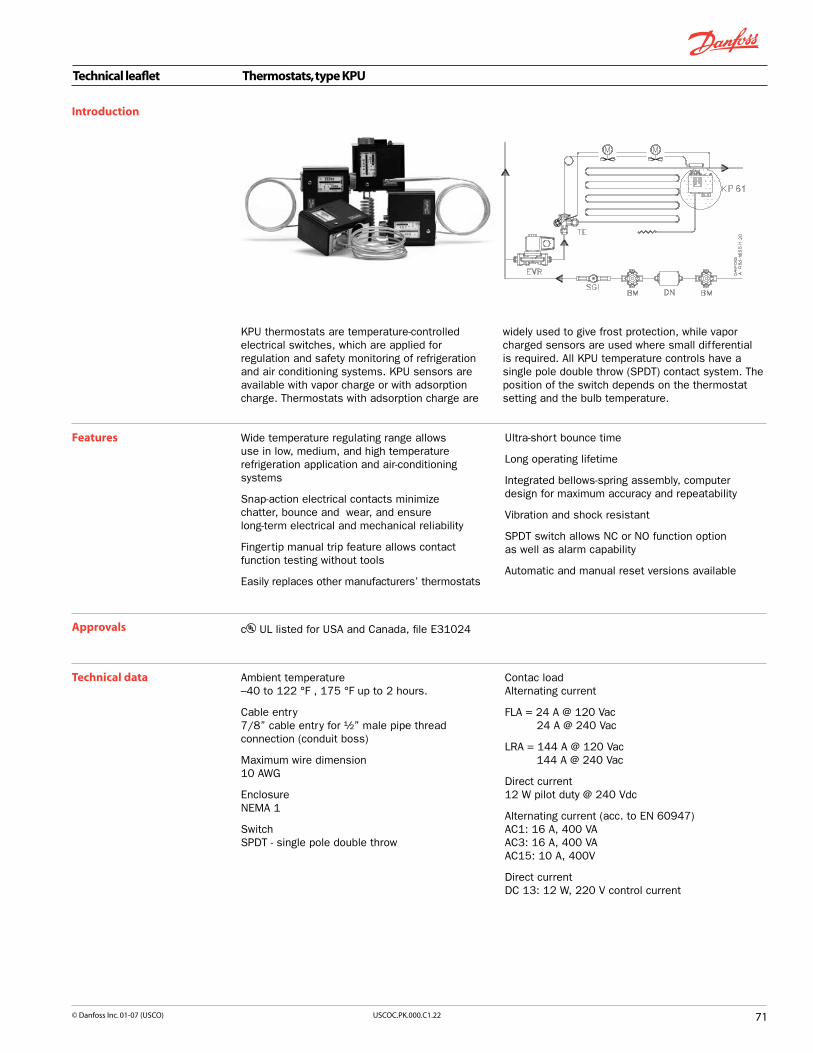
Technical leaflet Thermostats, type KPU
7�USCOC.PK.000.C�.22© Danfoss Inc. 0�-07 (USCO)
Introduction
KPU thermostats are temperature-controlled electrical switches, which are applied for regulation and safety monitoring of refrigeration and air conditioning systems. KPU sensors are available with vapor charge or with adsorption charge. Thermostats with adsorption charge are
Wide temperature regulating range allows use in low, medium, and high temperature refrigeration application and air-conditioning systems
Snap-action electrical contacts minimize chatter, bounce and wear, and ensure long-term electrical and mechanical reliability
Fingertip manual trip feature allows contact function testing without tools
Easily replaces other manufacturers’ thermostats
Features Ultra-short bounce time
Long operating lifetime
Integrated bellows-spring assembly, computer design for maximum accuracy and repeatability
Vibration and shock resistant
SPDT switch allows NC or NO function option as well as alarm capability
Automatic and manual reset versions available
c UL listed for USA and Canada, file E31024 Approvals
Ambient temperature–40 to 122 °F , 175 °F up to 2 hours.
Cable entry7/8” cable entry for ½” male pipe thread connection (conduit boss)
Maximum wire dimension 10 AWG
EnclosureNEMA 1
SwitchSPDT - single pole double throw
Technical data Contac loadAlternating current
FLA = 24 A @ 120 Vac 24 A @ 240 Vac
LRA = 144 A @ 120 Vac 144 A @ 240 Vac
Direct current12 W pilot duty @ 240 Vdc
Alternating current (acc. to EN 60947)AC1: 16 A, 400 VA AC3: 16 A, 400 VA AC15: 10 A, 400V
Direct currentDC 13: 12 W, 220 V control current
widely used to give frost protection, while vapor charged sensors are used where small differential is required. All KPU temperature controls have a single pole double throw (SPDT) contact system. The position of the switch depends on the thermostat setting and the bulb temperature.

Technical leaflet Thermostats, type KPU
72 USCOC.PK.000.C�.22 © Danfoss Inc. 0�-07 (USCO)
Charge Type Bulb type
Range
[°F]
Differential Max. bulb temp. [°F]
Reset function
Cpaillary tube length
[in.] Code no.at lowest
temperature setting [°F]
at highest temperature setting [°F]
Vapour (1)
KPU 61 A −20 to 60 8 to 40 2.5 to 13
250
auto. 80 060L5201
KPU 61 A −20 to 60 8 to 40 2.5 to 13 auto. 200 060L5202
KPU 61 B −20 to 60 8 to 40 2.5 to 13 auto. 80 060L5203
KPU 61 B −20 to 60 fixed 10 fixed 3.5 man. (3) 80 060L5204
KPU 61 B −20 to 60 fixed 10 fixed 3.5 man. (3) 200 060L5205
KPU 62 C1 −20 to 60 8 to 40 2.5 to 13 auto. room sensor 060L5206
KPU 61 B −20 to 60 8 to 40 2.5 to 13 auto. (4) 80 060L5210
KPU 63 A −60 to 15 18 to 125 5 to 15 auto. 80 060L5213
KPU 63 B −60 to 15 18 to 125 5 to 15 auto. 80 060L5214
KPU 68 C1 25 to 95 8 to 45 3 to 13 auto. room sensor 060L5215
KPU 69 B 25 to 95 8 to 45 3 to 13 auto. 80 060L5217
Adsorption (2)
KPU 62 C2 −20 to 60 9 to 36 3 to 14
175
auto. (4) room sensor 060L5207
KPU 73 E3 −15 to 60 6 to 18 5 to 50 auto.
80
060L5208
KPU 73 E1 −15 to 60 22 to 125 15 to 45 auto. 060L5209
KPU 73 E3 −15 to 60 fixed 6 fixed 6 man. (3) 060L5211
KPU 73 D −15 to 60 6 to 35 5 to 32 auto. 060L5212
KPU 71 E2 25 to 70 5.5 to 18 4 to 6 auto. 060L5218
KPU 71 E2 25 to 70 fixed 5 fixed 5 man. (3) 060L5216
KPU 74 E1 0 to 80 9 to 35 9 to 35 auto. 060L5219
KPU 74 E1 0 to 80 fixed 10 fixed 10 man. (3) 060L5220
KPU 75 F 30 to 95 6 to 29 4.5 to 21.5 230 auto. 060L5221
KPU 75 E2 30 to 95 6 to 30 4.5 to 22 230 auto. 060L5222
KPU 77 E3 60 to 140 6 to 18 6.3 to 18 265 auto. 060L5223
Regulating ranges in °F
Ordering
KPU 61
KPU 62 (room sensor) Vapor charge
KPU 63
KPU 68 (room sensor)
KPU 69
KPU 62
KPU 71
KPU 73 Adsorption charge
KPU 74
KPU 75
KPU 77
–50 0 50 100 150

Technical leaflet Thermostats, type KPU
7�USCOC.PK.000.C�.22© Danfoss Inc. 0�-07 (USCO)
Thermostat sensor types A Straight capillary tubeSensing length: 15”
a = 3 ”
KPU 61KPU 63
Vapor charge
B Remote air coila = 3 ”b = 2¾”
KPU 61KPU 69
Vapor charge
C Room sensor C1a = 1½”b = 1¼”
Room sensor C2a = 1”b = 3”
KPU 62KPU 68
Vapor chargeKPU 62
Adsorption charge
D Double contact remote bulba = ”
b = 3 ”
NOTE!Can not be used in sensor pocket
KPU 73Adsorption charge
E Remote bulbE1
a = ¼ b = 3¾”
E2a = ”
b = 4½ ”E3
a = ” , b = 3 ”
KPU 73, KPU 74Adsorption charge
KPU 71, KPU 75Adsorption charge
KPU 73, KPU 77Adsorption charge
F Remote duct coila = 1”b = 3 ”
KPU 75Adsorption charge

Technical leaflet Thermostats, type KPU
7� USCOC.PK.000.C�.22 © Danfoss Inc. 0�-07 (USCO)
Dimensions of KPU without capillary tube
weight of KPU without capillary tube ~ 0.77 lbweight of 80” cap. tube ~ 0.17 lbweight of 200” cap tube ~ 0.43 lb
All controls are supplied with universal mounting bracket and mounting screws as standard accessory.
Approximate weight of the bracket and mounting screws: 0.615 lb

7�USCOC.PK.000.C�.22© Danfoss Inc. 0�-07 (USCO)
Technical leaflet Universal thermostat, type UT
Introduction
Approvals
Technical data
CE-marked according to the low voltage directive EN 60335-1 and the electromagnetic compatibility
The UT thermostat is a temperature-controlled electric switch with copper capillary and sensor.
The temperature can be set easily and accurately using the large knob on the front of the thermostat. The temperature must be set to correspond to the required mean temperature.
The thermostat has a fixed differential. Electric connections are made by means of AMP quick connectors. UT is available for wall or panel mounting, and can be used for: n Cold roomsn Beverage coolersn Ice cream makersn Milk coolersn Refrigerated countersn Air-conditioning plantn Heat recovery systems
Range –20 → 85 °F
Ambient temperature –20 → 130 °F
Reset Automatic
Differential Fixed, 2.3 K
Switch system Changeover (SPDT) switch
directives EN 60335-1, and in accordance with the EMC Directive EN 50082-1 and EN 55014.
Code numbers
Accessories
Version Type DifferentialK Reset
Max. sensor temperature Capillary tube lengthQty. Code no.
°F m in.
Wall mounting UT 72 2.3 aut. 140 3.0 59 1 060H1108
Setting knobs (–20 → 85 °F) 48 060-1068
Contact load (max.) 16 (2.5) A / 250 V ~10 (1.5) A / 400 V ~
Capillary tube and sensor Copper
UT for wall mounting: IP 20 to EN 60529/IEC 529UT for building in: IP 00 to EN 60529/IEC 529
Dimensions and weight UT for panel mounting (weight 0.22 lbs)
UT for wall mounting (weight 0.44 lbs)

Technical leaflet Service Thermostats
7� USCOC.PK.000.C�.22 © Danfoss Inc. 0�-07 (USCO)
Introduction
Features
Thermostat 077B is used to control the temperature in refrigerators, upright and chest freezers, liquid coolers, bottle coolers and small commercial refrigeration appliances. The thermostat can be used as an evaporator thermostat or a room thermostat.
The thermostats are available with normal function, fixed cut-in and cut-out temperature, constant or variable cut-in temperature for automatic defrost, and with a pushbutton for semi-automatic defrost.
The thermostats can be supplied with the following supplementary functions:n Auxiliary contactn Changeover contactn Signal contactn Series contactn Reduction of temperature for super-function and
indication of same
All thermostats have normal function, i.e. they cut in the compressor current circuit on rising temperature.
Temperature control in the interval –44˚F to +52˚F.
Cut-out temperature interval (difference between cut-out temperature in position cold and cut-out position warm) from 41°F to 68°F.
Differentials (differences between cut-in and cut-out temperature) between 39˚F and 59˚F in position warm. For thermostats with fixed setting, from 37˚F.
With automatic defrost the cut-out temperature lies between –23˚F and –44˚F, the cut-in temperature between +34˚F and +52˚F.
Other temperature settings can be supplied by arrangement.
1/4 in or .19 in tabs.
Wide range with various extra functions and accessories.
Approved by recognized authorities.
Ordering
No. Application Temperatures ˚F Accessories Adaptor Capillary tube
lengthft.
Remarks Code no.
Warm pos. cut-in/cut-out
Cold pos. cut-in/cut-out
Signal pos. warm
Defrosting Big Knob Small Knob
Push Button
Mounting Bracket
Seal Cap
Small parts
1 Refrigerators -35.6/22.1 8.6/-13 • • • • • 4.3 077B7001
2 Refrigerators with pushbutton defrost
32/18.5 12.2/-5.8 42.8 • • • • • • 4.3 077B7002
3 Refrigerators with automatic defrost
38.3/12.2 38.3/-17.5 • • • • • 5.2 with auxiliary switch
077B7003
4 Absorption Refrigerators
38.3/30.2 23/12.2 • • • • • 4.9 with auxiliary switch
077B7004
5 Ice-cream cabinets and freezers
without signal
18.5/5 -5.8/-26.5 • • • • • 7.5 077B7005
6 Freezers with active signal
14/1.4 -11.2/-30.1 21.2 • • • • • 7.5 with active signal
077B7006
7 Freezers with passive signal
14/1.4 -11.2/-30.1 21.2 • • • • • 7.5 with passive signal
077B7007
8 Bottle and liquid coolers
52.7/42.8 30.2/16.7 • • • • • • 6.6 077B7008

77USCOC.PK.000.C�.22© Danfoss Inc. 0�-07 (USCO)
Technical leaflet Saginomiya Controls
Introduction Cartridge Controls, ACB seriesThe ACB series cartridge controls are small, disc type pressure controls designed and manufactured to ensure quality and reliable performance in applications including air conditioners, chillers, display cases, ice machines and other refrigeration systems. They are compact and light-weight for easy mounting directly on the refrigeration system where pressure regulation is required. Used by major OEMs worldwide, the ACB series have more than 100 million pieces installed.
Ordering
Water proof IP65, open type IP40
Contact load up to 8A (250V.AC), 6A for manual reset model
Automatic or manual reset
High and low pressure cut-in and cut-out and fan speed control
Normally closed (NC) or normally open (NO)
SPST or SPDT contact system
Corrosion resistant housing
approvals (CE, TUV, VDE, and CSA models are available upon request)
Wide range of port fittings for soldering or direct mounting. (Sweat, Flare, NPT and other fittings are available.)
Spade terminals or cables connection
Specifications: n Used with CFC, HCFC, HFC n (Model for CO2 is available)
Pressure range from –1.5 in Hg to 650 PSI
Media temp: -65˚ to 275˚F
Ambient temp: -22˚ to 212˚F
These are standard high and low pressure cut-out models. Water proof type IP65.
DanfossCode no. Application Reset Cut out
(PSI)Cut in (PSI) Contact
Style
Connection
Cable Length
(inches)
1/4” 1/4”
Solder Female Flare
0.12” insertion w/ depressor pin
O61F7505
High pressure
switch
Auto 260±10 190±17 SPST-NC X 59±2
O61F7506 Auto 260±10 190±17 SPST-NC X 59±2
O61F8494 Auto 335±10 275±17 SPST-NC X 59±2
O61F9714 Manual 380±15 290±30 SPST-NC X 59±2
O61F9713 Manual 380±15 290±30 SPST-NC X 59±2
O61F7508 Auto 377±14 290±21 SPST-NC X 59±2
O61F7509 Auto 377±14 290±21 SPST-NC X 59±2
O61F7513 Auto 405±14 305±21 SPST-NC X 59±2
O61F7514 Auto 405±14 305±21 SPST-NC X 59±2
O61F8492 Auto 450±14 350±22 SPST-NC X 59±2
O61F9575 Manual 610±17 480±29 SPST-NC X 59±2
O61F7516 Auto 610±17 480±30 SPST-NC X 59±2
O61F7517 Auto 610±17 480±30 SPST-NC X 59±2
O61F7519
Low pressure switch
Auto 7±6 22±5 SPST-NO X 59±2
O61F7520 Auto 7±6 22±5 SPST-NO X 59±2
O61F7522 Auto 10±7 25±6 SPST-NO X 59±2
O61F7523 Auto 10±7 25±6 SPST-NO X 59±2
O61F7525 Auto 25±7 40±6 SPST-NO X 59±2
O61F7526 Auto 25±7 40±6 SPST-NO X 59±2
O61F8490 Fan cycle control
Auto 125±17 160±12 SPST-NO X 59±2
O61F8333 Auto 190±22 230±14 SPST-NO X 59±2
Features

7� USCOC.PK.000.C�.22 © Danfoss Inc. 0�-07 (USCO)
TB series thermostats are available with custom specifications and accessories for OEMs with a wide standard range for refrigerators, freezers, beverage cooler, and air conditioners applications.
Technical leaflet Saginomiya Controls
Introduction Thermostats, TB series
Features
Standard 6 amp. at 240V.ACAvailable at 16 amp, 20amp and 25 amp.Available options for: narrow and wide differential, manual start/automatically reset defrost, damper controlCustomized accessories including dial knob, scale plate, fixing screws, insulation sleeves 2pcs and receptacle terminals SPST or SPDT options availableModels with and C US approval are available.
Specifications: n Available temperature range: -31˚ to 212˚F Max temperature range: n 64.4˚F (gas charge) n 140˚F (cross ambient charge)Differential: 3.6˚ to 19.8˚F
Ts: Ambient temp at switch body TB: Ambient temp at sensing bulb SPST or SPDT Contact system
Saginomiya Model No. Danfoss
Code No.
Operating TemperaturesMax
Sensing Element Temp.
Cold Normal Warm Forced Temperature Contact Style Electrical Application
ON OFF ON OFF ON OFF OFF Condition Condition Ratings
ATB-6U101 061G5502 (5) 28.4+/-2.7 14.9+/-2.7 (50) With 176 Ts > TB SPST 16A/120V.AC Refrigerator
ATB-6U102 061G5503 (-9.4) 5 +/-2.7 -4 +/-2.7 (10.4) With 176 Ts > TB SPST 16A/120V.AC Freezer
ATB-6U103 061G5504 42.8+/-2.7 34.7+/-2.7 - - (51.8) With 176 Ts > TB SPST 16A/120V.AC Beverage Cooler
YTB-7U128 061G5505 (65.3) 60.8+/-2.7 - - (87.8) (84.2) - 176 Ts > TB SPST 20A/240V.AC Room air conditioner
YTB-7U317 061G5506 (65.3) 60.8+/-2.7 - - (94.1) (89.6) - 140 Ts TB SPDT 20A/240V.AC Heat/Cool air conditioner
ITB-7U108 061G5507 (60.8) 55.4+/-2.7 - - (89.6) (86) - 176 Ts > TB SPST 25A/240V.AC Room air conditioner

7�USCOC.PK.000.C�.22© Danfoss Inc. 0�-07 (USCO)
Technical leaflet Saginomiya Controls
Introduction Condenser Fan Speed Control, RGE Series
Designed and optimized for precisely controlling the speed of a condenser fan of packaged air-conditioning units, condensing units, and other units that operate year round, RGE series control keep condensing pressure constant in winter and intermediate seasons for stable operation.
Available in single phase and three phase versionsAll in one senses pressure and controls fan speed
Reliable structure of the pressure-sensing element with bellows
Enbables low noise operation
Operation selectable for minimum speed operation or cut-off operation
An external forced operation switch can be connected
C US listed, CE certified.
Features
Ordering
Danfoss Code No. Catalog No.
F.V.S. Setting Adjusting
Range (psi)1
E.P.B. (psi) Fixed2
Max. Working Pressure (psi)
Eletrical RatingFunction Ambient
Temp. (oF) Refrigerants Factory Set (psi) Wt. (kg)
Voltage Ampere
061H3045 RGE-Z1L4-7DS
116 to 406
87
681Single phase
200 to 240V AC 50/60Hz
0.2 to 2A
At approx. 45% (50Hz) at approx 35% (60Hz). Cut Off or Minimum Speed function
is selectable with changeover
switch.
Default setting: Cut Off
-4 to 131
R22, R404A, R407C (R134a) 2763
0.36
061H3005 RGE-Z1N4-7DS
58
0.2 to 4A 0.50
061H3008 RGE-ZIP4-7DS 0.2 to 6A 0.54
061H3009 RGE-ZIQ4-7DS 0.2 to 8A 0.58
061H3048 RGE-Z1L6-7DS
232 to 566 116
0.2 to 2A
R410A 464
0.36
061H3021 RGE-Z1N6-7DS 0.2 to 4A 0.50
061H3022 RGE-Z1P6-7DS 0.2 to 6A 0.54
061H3023 RGE-Z1Q6-7DS 0.2 to 8A 0.58
061H3003 RGE-Z3R4-7DS
116 to 406
58
681
Three phase 200 to 240V AC
50/60Hz
0.2 to 5A
At approx. 35%, Cut Off or Minimum
Speed function is selectable
with changeover switch.
Default setting: Min. speed
-4 to 122
R22, R404A, R407C (R134a) 2323
1.40
061H3050 RGE-Z3T4-7DS 87 0.2 to 7A 1.53
061H3027 RGE-Z3R6-7DS
232 to 566 1160.2 to 5A
R410A 464
1.40
061H3051 RGE-Z3T6-7DS 0.2 to 7A 1.53
061H3006 RGE-X3R4-7DS 116 to 406 58 Three phase 380 to 415V AC
50/60Hz0.2 to 5A 5 to 122
R22, R404A, R407C (R134a) 2323
1.40
061H3028 RGE-X3R6-7DS 232 to 566 116 R410A 464
1 The pressure at which the control delivers 95% output effective voltage (VRMS).2 Pressure width where effective voltage corresponds to the minimum speed or causes cut off operation.3 When the refrigerant is R134a, please change the pressure setting.Minimum speed: Fan motor will be kept running at minimum speed when pressure decreases to the set value, (the specific value (V%)).Cut off: Fan motor will be stopped when pressure decreases to the specific value (V%) for R.M.S.

�0 USCOC.PK.000.C�.22 © Danfoss Inc. 0�-07 (USCO)
STF and VHV are pilot operated, 4-way reversing valves suitable for applications including unitary, split system and window type air-conditioning systems. These robust valves are engineered to provide power savings and are available in a wide selection of connection sizes and styles for air conditioning units of various sizes.
Technical leaflet Saginomiya Controls
Introduction 4 Way Reversing Valves, STF and VHV series
Features Different connection pipe size and configuration are available.
Reliable changeover operation by 4-way pilot valve
Unique design ensures reduced pressure drop
Full capacity range up to 50 TR
Minimize leakage
Splash proof resin encapsulated solenoid coil
Max. working pressure: 600 psig
Temperature of medium: -5 to +250°F VHV-20, 25, 30, 40, 50: -5 to +265°F
Ambient temperature: -5 to +135°F
Available for: R22, R134a, R407C, R410A
Coil Voltage : 24V.AC, 115 to 120 VAC, 230 V. AC 50/60 Hz, 208 to 240V.AC 50Hz and others are available.
Coil with Quick Connect terminals or Coil with lead wires available.
approved
Technical leaflet Saginomiya Controls
STF ; UL Recognized
Danfoss Code No.
Capacity from Minimum to Nominal Connection (inch) ODF (Standard configuration in bold) Configurations
available (Standard configurations in
bold)*
Box Qty.Saginomiya Model No.
R22 Applicable (Value for reference)
R410A Applicable (Value for reference) Discharge (D) E.S.C
TR TR
061L1200 STF-01U1G3 0.45 - 1.35 0.46 - 1.59 5/16 3/8 A 50
061L1210 STF-02U1G3 0.8 - 2.57 0.8 - 3.03
5/16, 3/8, 1/2
1/2, 5/8 A, B, C, D40
061L1211 STF-02U2G3 0.51 - 2.57 0.8 - 3.03 40
061L1212 STF-02U4G3 0.8 - 2.57 0.8 - 3.03 1/2, 5/8 A, B, C, D 40
061L1213 STF-02U9G3 0.8 - 2.57 0.8 - 3.03 1/2, 5/8 A, B, C, D 40
061L1214 STF-02U8G3 0.8 - 2.57 0.88 - 3.03 1/2, 5/8 A, B, C, D 40
061L1220 STF-03U6G3 1.28 - 3.1 1.51 - 3.7 3/8, 1/2 5/8, 3/4 E 36
061L1230 STF-04U1G3 2.02 - 5.7 2.36 - 6.7
1/2, 5/8, 3/4
3/4, 7/8 B 20
061L1231 STF-04U9G3 2.02 - 5.7 2.36 - 6.73/4, 7/8
B 20
061L1232 STF-04U20G3 2.02 - 6.5 2.4 -7.7 B 20
061L1240 STF-07U19G3 5.12 - 9.7 6.0 - 11.4 1/2, 5/8, 3/4, 7/8 7/8, 1-1/8 B 12
061L1243 STF-07U12G3 5.12 - 9.7 6.0 - 11.4 1/2, 5/8, 3/4, 7/8 7/8, 1-1/8 B 12

��USCOC.PK.000.C�.22© Danfoss Inc. 0�-07 (USCO)
Technical leaflet Saginomiya Controls
VHV; UL Recognized
Nominal capacity is based on Pressure Drop = 2.1 psi, condensing temperature = 100oF, evaporating temperature = 41oF and superheat = 9oF
*See diagrams below for body configurations
For non-standard configurations, please contact Danfoss Inc. Not all connection size combinations are available.
Configurations
�
A = Candycane x Straight B = Straight x Straight C = Candycane x Flare
D = Straight x Flare E = Offset x Flare F = Straight x Flare
G = Straight x Straight (for large capacity)
Danfoss Code No.
Capacity from Minimum to Nominal Connection (inch) ODF (Standard configuration in bold) Configurations
available (Standard configurations in
bold)*
Box Qty.Saginomiya Model No.
R22 Applicable (Value for reference)
R410A Applicable (Value for reference) Discharge (D) E.S.C
TR TR
061L1260 VHV-15U11G3 9.53 - 10.8 11.1 -12.7 7/8 1-1/8 F 8
061L1261 VHV-20U11G3 9.53 - 13.8 11.1 - 16.3 7/8, 1-1/8 1-1/8, 1-3/8 B, F 8
061L1262 VHV-25U1G3 12.8 - 20.8 14.8 - 24.6 1 1-1/4 G 1
061L1263 VHV-30U1G3 15.9 - 29.3 18.4 - 34.7 1-1/4 1-1/2 G 1
061L1264 VHV-40U1G3 28.4 - 40.9 32.7 - 48.4 1-1/2 1-3/4 G 1
061L1265 VHV-50U1G3 35.6 -53.2 41.2 - 62.8 1-1/2 2-1/8 G 1

Technical leaflet Eliminator® Liquid line filter driers, types DCL and DML
�2 USCOC.PK.000.C�.22 © Danfoss Inc. 0�-07 (USCO)
Introduction
Eliminator® liquid line filter driers protect refrigeration and air-conditioning systems from moisture, acids, and solid particles. With these contaminants eliminated, systems are safer from harmful chemical reactions and from abrasive impurities.
There are two types of Eliminator® cores. Type DML driers have a core composition of 100% Molecular Sieve, while type DCL contain 80% Molecular Sieve with 20% activated alumina.
All Eliminator® driers have a solid core with binding material held to an absolute minimum. Core selection is primarily based on the refrigerant oil used in the system.
Eliminator® type DML, with a solid core of 100% Molecular Sieve, is optimized for use with HFC refrigerants and polyolester (POE) or polyalkyl glycol (PAG) oils. Type DML driers are designed for applications requiring high water adsorption, and can be used with any manufacturer’s compressor. Because type DML driers contain no activated alumina, oil additives will not be depleted.
Eliminator® type DCL, with a solid core of 80% Molecular Sieve and 20% activated alumina, is the drier of choice for systems with HCFC and CFC refrigerants and mineral or alkyl benzene oils. Type DCL driers are particularly suited for systems that operate at high condensing temperatures and require high drying capacity.
Features The Core Type�DML100% 3Å Molecular Sieve core.
High drying capacity minimizing the risk of acid formation (hydrolysis).
Optimized for HFC refrigerants (R134a, R404A, R410A, etc.) with POE or PAG oils.
Compatible with R22.
Will not deplete oil additives.
Type�DCL80% 3Å Molecular Sieve with 20% activated alumina.
Perfect core blend for systems that operate at high condensing temperatures and require high drying capacity.
Optimized for CFC and HCFC refrigerants (R22, R502, etc.) with mineral or alkyl benzene oils.Compatible with HFC’s and refrigerant blends.
The Shell approved for Max Working Pressure up to
610 psig.
Available with solder (copper) and flare connections.
Compact 3 cubic inches drier ideal for refrigeration and air conditioning units.
Corrosion resistant powder-painted finish. Can be used in all environments including marine applications.
Allows installation with any orientation provided the arrow is in the flow direction.
Available in sizes from 3 to 75 cubic inches.
The Filter25 µm (0.001 in.) filter provides high retention with minimal pressure drop.
Thermally stable up to 250°F.
C US file no. SA 6398 PED 97/23/EC - a3p3

Technical leaflet Eliminator® Liquid line filter driers, types DCL and DML
��USCOC.PK.000.C�.22© Danfoss Inc. 0�-07 (USCO)
OrderingFlare DCL
Type Conn.in.
Code no. Conn.mm
Code no.
DCL 032*DCL 032DCL 033*DCL 033
1/41/43/83/8
023Z5000023Z5075023Z5001023Z5089
66
1010
023Z5000023Z5075023Z5001023Z5089
DCL 052DCL 053
1/43/8
023Z5002023Z5003
610
023Z5002023Z5003
DCL 082DCL 083DCL 084
1/43/81/2
023Z5004023Z5005023Z5006
61012
023Z5004023Z5005023Z5006
DCL 162DCL 163DCL 164DCL 165DCL 166
1/43/81/25/83/4
023Z5007023Z5008023Z5009023Z5010023Z5011
610121619
023Z5007023Z5008023Z5009023Z5010023Z5011
DCL 303DCL 304DCL 305DCL 306
3/81/25/83/4
023Z0012023Z0013023Z0014023Z0156
10121619
023Z0012023Z0013023Z0014023Z0156
DCL 413DCL 414DCL 415
3/81/25/8
023Z0101023Z0102023Z0103
101216
023Z0101023Z0102023Z0103
* Wire mesh in filter drier outlet
Flare DMLType Conn.
in.Code no. Conn.
mmCode no.
DML 032*DML 033*DML 033
1/43/83/8
023Z5035023Z5036023Z5090
61010
023Z5035023Z5036023Z5090
DML 052DML 053
1/43/8
023Z5037023Z5038
610
023Z5037023Z5038
DML 082DML 083DML 084DML 085
1/43/81/25/8
023Z5039023Z5040023Z5041023Z5073
6101216
023Z5039023Z5040023Z5041023Z5073
DML 162DML 163DML 164DML 165DML 166
1/43/81/25/83/4
023Z5042023Z5043023Z5044023Z5045023Z5046
610121619
023Z5042023Z5043023Z5044023Z5045023Z5046
DML 303DML 304DML 305DML 306
3/81/25/83/4
023Z0049023Z0050023Z0051023Z0193
10121619
023Z0049023Z0050023Z0051023Z0193
DML 413DML 414DML 415
3/81/25/8
023Z0108023Z0109023Z0110
101216
023Z0108023Z0109023Z0110
Solder (copper) DCLType Conn.
in.Code no. Conn.
mmCode no.
DCL 032sDCL 032.5sDCL 033s
1/45/163/8
023Z5013023Z5014023Z5015
6810
023Z5012023Z5014023Z5016
DCL 052sDCL 052.5sDCL 053s
1/45/163/8
023Z5018023Z5114023Z5019
6810
023Z5017023Z5114023Z5020
DCL 082sDCL 082.5sDCL 083sDCL 084s
1/45/163/81/2
023Z5022023Z5116023Z5023023Z5026
681012
023Z5021023Z5116023Z5024023Z5025
DCL 162sDCL 162.5sDCL 163sDCL 164sDCL 165sDCL 166sDCL 167s
1/45/163/81/25/83/47/8
023Z5028023Z5118023Z5029023Z5032023Z5033023Z5070023Z5034
681012161922
023Z5027023Z5118023Z5030023Z5031023Z5033023Z5070023Z5034
DCL 303sDCL 304sDCL 305sDCL 306sDCL 307sDCL 309s
3/81/25/83/47/8
11/8
023Z0030023Z0031023Z0032023Z0033023Z0034023Z0035
101216182228
023Z0196023Z0198023Z0032023Z0216023Z0034023Z0200
DCL 414sDCL 415sDCL 417sDCL 419s
1/25/87/8
11/8
023Z0104023Z0105023Z0106023Z0107
12162228
023Z0227023Z0105023Z0106023Z0202
DCL 604sDCL 607sDCL 609s
1/27/8
11/8
023Z0241023Z0036023Z0037
122228
023Z0221023Z0036023Z0204
DCL 757sDCL 759s
7/811/8
023Z0115023Z0116
2228
023Z0115023Z0206
Solder (copper) DMLType Conn.
in.Code no. Conn.
mmCode no.
DML 032sDML 032.5sDML 033sDML 034s
1/45/163/81/2
023Z5048023Z5049023Z5050023Z5121
681012
023Z5047023Z5049023Z5051023Z5123
DML 052sDML 052.5sDML 053sDML 054sDML 055s
1/45/163/81/25/8
023Z5053023Z5115023Z5054023Z5101023Z5100
68101216
023Z5052023Z5115023Z5055023Z5099023Z5100
DML 082sDML 082.5sDML 083sDML 084sDML 085s
1/45/163/81/25/8
023Z5057023Z5117023Z5058023Z5061023Z5072
68101216
023Z5056023Z5117023Z5059023Z5060023Z5072
DML 162sDML 162.5sDML 163sDML 164sDML 165sDML 166sDML 167s
1/45/163/81/25/83/47/8
023Z5063023Z5119023Z5064023Z5067023Z5068023Z5071023Z5069
681012161922
023Z5062023Z5119023Z5065023Z5066023Z5068023Z5071023Z5069
DML 303sDML 304sDML 305sDML 306sDML 307sDML 309s
3/81/25/83/47/811/8
023Z0067023Z0068023Z0069023Z0070023Z0071023Z0072
101216192228
023Z0197023Z0199023Z0069023Z0070023Z0071023Z0201
DML 414sDML 415sDML 417sDML 419s
1/25/87/811/8
023Z0111023Z0112023Z0113023Z0114
12162228
023Z0228023Z0112023Z0113023Z0203
DML 604sDML 606sDML 607sDML 609s
1/23/47/811/8
023Z0224023Z0225023Z0073023Z0074
12192228
023Z0229023Z0225023Z0073023Z0205
DML 757sDML 759s
7/811/8
023Z0117023Z0118
2228
023Z0117023Z0207

Technical leaflet Eliminator® Liquid line filter driers, types DCL and DML
�� USCOC.PK.000.C�.22 © Danfoss Inc. 0�-07 (USCO)
Liquid Line Filter Driers-Suggested Size DCL and DML typeTonnage Line Size Air Conditioning Refrigeration
R12, R22 & R502 R134, R404A, R410A & R507 R12, R22 & R502 R134A, R404A, R507
& R507
1/4 -> 1/3
1/4 DCL 032s DML 032s DCL 032s DML 032s
5/16 DCL 0325s DML 0325s DCL 0325s DML 0325s
3/8 DCL 033s DML 033s DCL 033s DML 033s
1/2 - DML 034s - DML 034s
1/2 -> 1
1/4 DCL 052s DML 052s DCL 082s DML 082s
5/16 DCL 0525s DML 0525s DCL 0825s DML 0825s
3/8 DCL 053s DML 053s DCL 083s DML 083s
1/2 - DML 054s DCL 084s DML 084s
5/8 - DML 055s - DML 085s
� �/2 -> 2 �/
2
1/4 DCL 082s DML 082s DCL 162s DML 162s
5/16 DCL 0825s DML 0825s DCL 1625s DML 1625s
3/8 DCL 083s DML 083s DCL 163s DML 163s
1/2 DCL 084s DML 084s DCL 164s DML 164s
5/8 - DML 085s DCL 165s DML 165s
3/4 - - DCL 166s DML 166s
7/8 - - DCL 167s DML 167s
3 -> 6
1/4 DCL 162s DML 162s - -
5/16 DCL 1625s DML 1625s - -
3/8 DCL 163s DML 163s DCL 303s DML 303s
1/2 DCL 164s DML 164s DCL 304s DML 304s
5/8 DCL 165s DML 165s DCL 305s DML 305s
3/4 DCL 166s DML 166s DCL 306s DML 306s
7/8 DCL 167s DML 167s DCL 307s DML 307s
1 1/8 - - DCL 309s DML 309s
7 -> 9
3/8 DCL 303s DML 303s DCL 413 DML 413
1/2 DCL 304s DML 304s DCL 414s DML 414s
5/8 DCL 305s DML 305s DCL 415s DML 415s
3/4 DCL 306s DML 306s - -
7/8 DCL 307s DML 307s DCL 417s DML 417s
1 1/8 DCL 309s DML 309s DCL 419s DML 419s
10 -> 12
3/8 DCL 413 DML 413 DCL 413 DML 413
1/2 DCL 414s DML 414s DCL 414s DML 414s
5/8 DCL 415s DML 415s DCL 415s DML 415s
7/8 DCL 417s DML 417s DCL 417s DML 417s
1 1/8 DCL 419s DML 419s DCL 419s DML 419s
13 -> 18
1/2 DCL 604s DML 604s DCL 604s DML 604s
3/4 - DML 606s - DML 606s
7/8 DCL 607s DML 607s DCL 607s DML 607s
1 1/8 DCL 609s DML 609s DCL 609s DML 609s
19 -> 307/8 DCL 757s DML 757s DCL 757s DML 757s
1 1/8 DCL759s DML 759s DCL759s DML 759s
DCL should not be used with refrigerants that have POE which contains additives. The additives render the activated alumina ineffective for acid absorption. DML should be used in applications with POE which contains additives.
Ordering

Technical leaflet Eliminator® Liquid line filter driers, types DCL and DML
��USCOC.PK.000.C�.22© Danfoss Inc. 0�-07 (USCO)
Selection
Type selection is made considering the application
DCL DML
Refrigerant
HFC Can be used Recommended
HCFC Recommended Can be used
CFC Recommended Not recommended 1)
Oil
Mineral or AB Recommended Can be used
POE or PAG, pure Can be used Recommended
POE or PAG, with additives Not recommended 2) Recommended
Identification
1) For CFC systems, DCL filter driers are recommended. In these systems, circumstances may require the use of a filter drier with acid adsorbing properties.
2) Use of filter driers containing activated alumina are not
recommended in systems with oils containing additives.
Type codes
Filter drier D
Solid core CM
80 / 20% composite core100% Molecular Sieve core
Application L Liquid line
Size (volume) 0305081630416075
3 in.3
5 in.3
8 in.3
16 in.3
30 in.3
41 in.3
60 in.3
75 in.3
Connection (filter connectionin 1/8 of an inch increments)
22.5345679
1/4 in.5/16 in.3/8 in.1/2 in.5/8 in. 3/4 in. 7/8 in. 11/8 in.
Connection type (blank)s
Flare connectionSolder connection
Example for type codes
D C L 05 3 s

Technical leaflet Eliminator® Burnout drier, type DAS
�� USCOC.PK.000.C�.22 © Danfoss Inc. 0�-07 (USCO)
Eliminator® burnout drier type DAS is used in the suction line to clean up refrigeration and AC-systems with fluorinated refrigerants after a compressor motor burnout.
The solid core, which is composed of 70% activated alumina and 30% Molecular Sieve, absorbs harmful acids as well as moisture. By absorbing these acids, the DAS burnout drier protects the new compressor against premature failure.
Introduction Range 8-60 cubic inches
FeaturesSolid core with 70% activated alumina and 30% Molecular Sieve for absorption of acid and moisture
2 Schrader access valves to measure pressure drop across the drier
Available in sizes from 8 to 60 cubic inches
Corrosion resistant powder-painted finish
Available with solder (solid copper) and flare connections
approved for MWP 500 psig
120 mesh wire mesh provides solid particle retention with minimal pressure drop
Allows installation with any orientation provided the flow is in the arrow direction
C US, file SA 6398 PED 97/23/EC - a3p3
Capacities
1) Rated capacity is stated at: evaporating temperature t
e = 40°F
pressure drop ∆p = 3 psi
2) Absorption capacity of oleic acid at 0.05 TAN (Total Acid Number).
Capacities for other temperatures than 40°F are calculated by use of correction factors. Divide your actual evaporator capacity with the correction factor given for your actual evaporating temperature.
Look up the capacity table for the necessary rated capacity.
Qe / Fe = Qn Qe = Actual evaporator capacity Qn = Nominal capacity Fe = Correction factor
Rated capacity, Qn 1) Acid capacity2)
R22/R407C/R410A R134a R404A/R507
[TR] [TR] [TR] [g]
DAS 083DAS 084DAS 085DAS 086
1.72.94.15.4
1.01.62.63.3
1.32.33.64.7
3.5
DAS 164DAS 165DAS 166DAS 167
3.04.35.76.3
1.72.73.43.9
2.43.74.95.4
7.8
DAS 305DAS 306DAS 307DAS 309
5.16.37.48.9
3.14.04.65.7
4.35.46.37.7
16.2
DAS 417DAS 419
8.610.0
5.16.3
7.18.6 23.0
DAS 607 5.7 3.4 4.9 32.5

Technical leaflet Eliminator® Burnout drier, type DAS
�7USCOC.PK.000.C�.22© Danfoss Inc. 0�-07 (USCO)
Ordering Eliminator Burnout drier, Type DAS
Flare Connection
Code no. Type nominal rating R22 Acid conn. overall weight
TR capac. size length lbs.
023Z1001 DAS 083VV 1.7 3.5 3/8” 6.2” 1.12
023Z1002 DAS 084VV 2.9 3.5 1/2” 6.5” 1.37
023Z1007 DAS 164VV 3 7.8 1/2” 6.9” 2.01
023Z1008 DAS 165VV 4.3 7.8 5/8” 7.2” 2.09
Solder Connection
Code no. Type nominal rating R22 Acid conn. overall weight
TR capac. size length lbs.
023Z1003 DAS 083sVV 1.7 3.5 3/8” 5.5” 1
023Z1004 DAS 084sVV 2.9 3.5 1/2” 5.6” 1.1
023Z1005 DAS 085sVV 4.1 3.5 5/8” 5.9” 1.1
023Z1006 DAS 086sVV 5.4 3.5 3/4” 6.3” 1.1
023Z1009 DAS 164sVV 3 7.8 1/2” 6” 2.03
023Z1010 DAS 165sVV 4.3 7.8 5/8” 6.2” 1.9
023Z1011 DAS 166sVV 5.7 7.8 3/4” 6.7” 1.9
023Z1012 DAS 167sVV 6.3 7.8 7/8” 6.8” 1.9
023Z1013 DAS 305sVV 5.1 16.2 5/8” 9.2” 2.9
023Z1014 DAS 306sVV 6.3 16.2 3/4” 9.7” 2.9
023Z1015 DAS 307sVV 7.4 16.2 7/8” 9.8” 2.9
023Z1016 DAS 309sVV 8.9 16.2 11/8” 9.8” 3
023Z1017 DAS 417sVV 8.6 23 7/8” 9.8” 4.6
023Z1018 DAS 419sVV 10 23 11/8” 9.8” 4.6
023Z1019 DAS 607sVV 5.7 32.5 7/8” 15.7” 5.3
023Z1020 DAS 609sVV 6.2 32.5 11/8” 15.7” 5.3
IdentificationType codes
Filter drier D
Solid core A Burn out, 70% activated alumina, 30% molecular sieves
Application S Suction line
Size (volume)
0816304160
8 in.3
16 in.3
30 in.3
41 in.3
60 in.3
Connection (filter connectionin 1/8 of an inch increments)
345679
3/8 in.1/2 in.5/8 in.3/4 in.7/8 in.
11/8 in.
Connection type (blank)s
Flare connectionSolder connection
Access valves (blank)V
V V
Inlet: Outlet:No access valves No access valvesSchraeder valve Schraeder valve Schraeder valve
Example for type codes
D A S 08 3 s VV

Technical leaflet Bi-flow filter driers with flare and cu-plated solder connectors, type DMB/DCB
�� USCOC.PK.000.C�.22 © Danfoss Inc. 0�-07 (USCO)
Introduction
Bi-flow filter driers, type DMB/DCB, are for use in liquid lines on heat pumps.
Bi-flow filter driers have built-in check valves which ensure that refrigerant liquid always flows through the filter driers from the outer side of the filter core towards the center. Thus all dirt particles are retained irrespective of flow direction.
DMB/DCB filter driers ensure fast and effective adsorption of moisture as well as organic and inorganic acids.
When building heat pump systems, the use of Bi-flow filters can, depending on the type of system, save up to ten solder connections. This reduces production costs and the number of potential leakage points.
FeaturesOptimum flow characteristics and dirt retention
The check valves are not sensitive to dirt and give minimum restriction, irrespective of flow direction
Effective dirt removal to 25 µm
No dirt released by reversing the flow direction
Available with solder (copper) and flare connections
US file no. SA ���� PED �7/2�/EC - a�p�
DMB filter driers n These filters contain a solid core consisting of
100% Molecular Sieve (no activated aluminum oxide whatsoever).
n DMB filter driers are especially suitable for heat pumps with HFC refrigerant and polyolester oil with additives.
DCB filter driers n These filters contain a solid core consisting of
3Å Molecular Sieve and activated aluminum oxide.
n DCB filter driers can be used in heat pumps with HCFC refrigerants and mineral oil, and also with HFC refrigerants and polyolester oil.

Technical leaflet Bi-flow filter driers with flare and cu-plated solder connectors, type DMB/DCB
��USCOC.PK.000.C�.22© Danfoss Inc. 0�-07 (USCO)
1) Drying capacity is based on following moisture content test standards before and after drying: R 134a: From 1050 ppm W to 75 ppm W. If drying to 50 ppm W is required, reduce stated capacities by 15%.R 404A, R 507: From 1020 ppm W to 30 ppm W.
R 407C: From 1020 ppm W to 30 ppm W. R 410A: From 1050 ppm W to 60 ppm W. R 22: From 1050 ppm W to 60 ppm
W in accordance with ARI 710-86.2) Capacity given in accordance with ARI
710-86 t
e = 5°F (−15°C)
tc = 86°F (30°C)
∆p = 1 psig (0.07 bar).
Drying and liquid capacity (DCB) R134a, R507, R404A, R407C, R410A, R22Type Liquid capacity [TR] 2) Drying capacity [lbs. refrigerant] 1) Max
WorkingPressure
PS[psig]
R134a R404AR507
R22R407CR410A
R134aR507 R404A R407C
R410A R22
75°F 125°F 75°F 125°F 75°F 125°F 75°F 125°F
DCB 082 / 082sDCB 083 / 083sDCB 084 / 084s
1.12.12.4
0.81.51.7
1.22.32.6
18.3 16.8 17.2 15.7 15.4 13.7 17.2 15.4610610610
DCB 162DCB 163 / 163sDCB 164 / 164sDCB 165 / 165s
2.25.18.010.6
1.53.75.78.3
2.55.79.111.4
34.4 31.3 32.0 29.3 28.9 25.6 32.2 29.1
610610610610
DCB 303DCB 304 / 304sDCB 305 / 305s
DCB 307s
5.48.0
10.912.3
4.35.78.09.1
6.08.9
12.013.4
84.7 76.7 78.9 72.3 70.8 62.8 79.1 71.4
610610610507
Capacities
Drying and liquid capacity (DMB) R134a, R507, R404A, R407C, R410A, R22Type Liquid capacity [TR] 2) Drying capacity [lbs. refrigerant] 1) Max
WorkingPressure
PS[psig]
R134a R404AR507
R22R407CR410A
R134aR507 R404A R407C
R410A R22
75°F 125°F 75°F 125°F 75°F 125°F 75°F 125°F
DMB 082 / 082sDMB 083 / 083sDMB 084 / 084s
1.12.12.4
0.81.51.7
1.22.32.6
20.3 18.7 19.2 17.9 17.6 16.1 19.2 17.6610610610
DMB 162DMB 163 / 163sDMB 164 / 164sDMB 165 / 165s
2.25.18.010.6
1.53.75.78.3
2.55.79.1
11.4
39.2 36.4 37.0 34.6 34.0 31.1 37.0 34.4
610610610610
DMB 303DMB 304 / 304sDMB 305 / 305s
DMB 307s
5.48.010.912.3
4.35.78.09.1
6.08.9
12.013.4
95.9 89.1 90.4 84.7 83.3 76.3 90.8 84.0
610610610507

Technical leaflet Bi-flow filter driers with flare and cu-plated solder connectors, type DMB/DCB
�0 USCOC.PK.000.C�.22 © Danfoss Inc. 0�-07 (USCO)
Flare
Type Connection size (in.) Code no. Liquid capacity R22 (Tons) Weight (lb.)
DMB 082 1/4 023Z1412 1.2 1.1
DMB 083 3/8 023Z1411 2.3 1.1
DMB 084 1/2 023Z1410 2.6 1.3
DMB 162 1/4 023Z1416 2.5 1.8
DMB 163 3/8 023Z1415 5.7 1.8
DMB 164 1/2 023Z1414 9.1 2
DMB 165 5/8 023Z1413 11.4 2
DMB 303 3/8 023Z1419 6 2.4
DMB 304 1/2 023Z1418 8.9 2.7
DMB 305 5/8 023Z1417 12 2.7
Sweat
Type Connection size (in.) Code no. Liquid capacity R22 (Tons) Weight (lb.)
DMB 082s 1/4 023Z1443 1.2 1.1
DMB 083s 3/8 023Z1442 2.3 1.1
DMB 084s 1/2 023Z1441 2.6 1.1
DMB 163s 3/8 023Z1446 5.7 1.8
DMB 164s 1/2 023Z1445 9.1 1.8
DMB 165s 5/8 023Z1444 11.4 2
DMB 304s 1/2 023Z1449 8.9 2
DMB 305s 5/8 023Z1448 12 2.4
DMB 307s 7/8 023Z1447 13.4 2.4
Capacities
Flare
Type Connection size (in.) Code no. Liquid capacity R22 (Tons) Weight (lb.)
DCB 082 1/4 023Z1402 1.2 1.1
DCB 083 3/8 023Z1401 2.3 1.1
DCB 084 1/2 023Z1400 2.6 1.3
DCB 162 1/4 023Z1406 2.5 1.8
DCB 163 3/8 023Z1405 5.7 1.8
DCB 164 1/2 023Z1404 9.1 2
DCB 165 5/8 023Z1403 11.4 2
DCB 303 3/8 023Z1409 6 2.4
DCB 304 1/2 023Z1408 8.9 2.7
DCB 305 5/8 023Z1407 12 2.7
Sweat
Type Connection size (in.) Code no. Liquid capacity R22 (Tons) Weight (lb.)
DCB 082s 1/4 023Z1434 1.2 1.1
DCB 083s 3/8 023Z1433 2.3 1.1
DCB 084s 1/2 023Z1432 2.6 1.1
DCB 163s 3/8 023Z1437 5.7 1.8
DCB 164s 1/2 023Z1436 9.1 1.8
DCB 165s 5/8 023Z1435 11.4 2
DCB 304s 1/2 023Z1440 8.9 2
DCB 305s 5/8 023Z1439 12 2.4
DCB 307s 7/8 023Z1438 13.4 2.4
DMB
DCB

Technical leaflet Filter drier with interchangeable solid core, type DCR
��USCOC.PK.000.C�.22© Danfoss Inc. 0�-07 (USCO)
Introduction
Features
48-DC n Refrigerants: R22, R134a, R404A and R507.
Compatible with blends containing R124, R125, R134a, R143a, R152a, R218, R23 and R32.
n High drying capacity throughout whole temperature range.
n Robust solid core withstands pressure surge and vibration.
n Optimized, uniform grain size in the solid core gives effective dirt removal and low pressure drop.
n Solid core consisting of - 3Å Molecular Sieve fully compatible with
R134a and R404A. - Activated aluminum oxide for acid adsorption.
48-DMn Refrigerants: R134a, R404a, R407C, etc.n Solid core with 100% 3Å Molecular Sieve.
Can be used with additives in polyolester oil.n High water absorption.n Effective protection against impurities.
48-DA for burnout filtersn Refrigerants: R22, R134a, R404A and
R507.n Solid core with high acid adsorption and
standard water adsorption.n Robust solid core withstands pressure surge
and vibration.n Protects the compressor against acid,
moisture, dirt, and other harmful substances.n Optimum flow gives low pressure drop across
the filter.
48-F strainern Refrigerants: All fluorinated refrigerants.n For use in suction or liquid lines.n Retains dirt particles larger than 15 µm.n For direct use in DCR filter housings.
C US listed, file SA 6398 certificate, no. 51840
DCR filter driers with interchangeable solid cores are for use in liquid and suction lines in refrigeration, freezing and air conditioning systems with fluorinated refrigerants.
The block holders are designed for use in compact units where limited space makes
it difficult to insert cores in DCR filter driers designed for three or four cores.
When inserting into or removing cores from a DCR filter housing with the new take-apart block holder, no more clearance space is needed than for a two-core block holder.
The take-apart block holder can also be used without taking it apart. Here the procedure is as with non-take-apart block holders.
Filter core type 48-DC: Solid core with moisture and acid adsorption properties.
Filter core type 48-DM: Solid core of 100% Molecular Sieve. For HFC systems.
Filter core type 48-DA: Solid core for acid adsorption after burnout.
Filter core type 48-F: Strainer for retaining dirt in suction and liquid lines.

Technical leaflet Filter drier with interchangeable solid core, type DCR
�2 USCOC.PK.000.C�.22 © Danfoss Inc. 0�-07 (USCO)
Ordering DCR Series-Filter drier shell without core
Extended copper ODF connections
Type Conn.In.
Code no.Solder ODF
Suggested Tonnage
R22
Weight
(lb.)
DCR 0485s 5/8 023U7250 10 11.5
DCR 0487s 7/8 023U7251 15 11.5
DCR 0489s 1 1/8 023U7253 20 11.5
DCR 04811s 1 3/8 023U7254 20 11.5
DCR 04813s 1 5/8 023U7255 20 11.5
DCR 04817s 2 1/8 023U7257 25 11.5
DCR 04821s 2 5/8 023U7276 25 11.5
DCR 0967s 7/8 023U7258 25 14.6
DCR 0969s 1 1/8 023U7260 35 14.6
DCR 09611s 1 3/8 023U7261 35 14.6
DCR 09613s 1 5/8 023U7262 40 14.6
DCR 09617s 2 1/8 023U7264 45 14.6
DCR 1449s 1 1/8 023U7265 40 17.2
DCR 14411s 1 3/8 023U7267 50 17.2
DCR 14417s 2 1/8 023U7270 60 17.2
DCR 19213s 1 5/8 023U7272 80 20.1
DCR 19217s 2 1/8 023U7274 85 20.1
Solid Cores for DCR Series
Type Description Code no.w/ Gasket
48 DC 80% MS / 20% AA 023U4381
48 DM 100% MS 023U1392
48 DA Burn out 023U5381
48 F Particulate filter 023U1921
Danfoss cores are direct replacements for most manufacturers, drier shells.

Technical leaflet Sight glasses, types SGI, SGN, SGR, SGRN, and SGH
��USCOC.PK.000.C�.22© Danfoss Inc. 0�-07 (USCO)
Introduction
Features
n Indication of lack of subcooling
n Indication of refrigerant deficiency
n Flare or solder connection
Type SGI/SGN/SGRNn For HCFC and CFC refrigerants
n Indicates too high water contents in the refrigeration system
Sight glasses are used to indicate:1. The condition of the refrigerant in the plant
liquid line.2. The moisture content in the refrigerant.3. The flow in the oil return line from the oil
separator.
The SGI, SGN, SGR or SGRN can be used for CFC, HCFC and HFC refrigerants.
The SGI and SGN are fitted with an indicator which changes color to show the moisture content in the refrigerant.
The SGR is used to indicate the liquid level in a receiver or the oil level in a compressor crankcase.
The SGRN is a sight glass like SGR, but supplied with a moisture indicator.
The moisture indicators in the sight glasses are dirt repelling.

Technical leaflet Sight glasses, types SGI, SGN, SGR, SGRN, and SGH
�� USCOC.PK.000.C�.22 © Danfoss Inc. 0�-07 (USCO)
Body Styles Type Version Connectionin. Code no. Length
in.Weight
lbs.
SGI 6SGI 10SGI 12SGI 16
Flareext. × ext.
1/4 × 1/43/8 × 3/81/2 × 1/25/8 × 5/8
014-0060014-0061014-0009014-0024
2.653.253.504.10
0.250.500.751.00
SGI 6SGI 10SGI 12
Flareint. × ext. 1)
1/4 × 1/43/8 × 3/81/2 × 1/2
014-0063014-0064014-0065
1.802.252.33
0.250.500.75
SGI 6sSGI 10sSGI 12sSGI 16sSGI 22s
ODF × ODFsolder
1/4 × 1/43/8 × 3/81/2 × 1/25/8 × 5/87/8 × 7/8
014-0066014-0067014-0068014-0069014-0070
4.004.705.755.756.82
0.250.250.500.500.50
SGI 10s ODF × ODMsolder
3/8 × 3/8 014-0119 4.004.70
0.250.25
SGR 1/2 NPT 1/2 NPT 014-0131
1) Can be screwed directly into the filter drier.2) ISO 228/1.
Ordering
Body Styles Type Version Connectionin. Code no. Length
in.Weight
lbs.
SGN 6SGN 10
Flareext. × ext.
1/4 × 1/43/8 × 3/81/2 × 1/2
014-0132014-0133
2.653.25
0.250.50
SGN 6SGN 10SGN 12
Flareint. × ext. 1)
1/4 × 1/43/8 × 3/81/2 × 1/2
014-0137014-0138014-0139
1.802.252.332.803.00
0.250.500.751.001.33
SGN 6sSGN 10sSGN 12sSGN 16sSGN 22s
ODF × ODFsolder
1/4 × 1/43/8 × 3/81/2 × 1/25/8 × 5/87/8 × 7/8
014-0142014-0143014-0144014-0145014-0147
4.004.705.756.82
0.250.250.500.50
SGN 10sSGN 16s
ODF × ODMsolder
3/8 × 3/85/8 × 5/87/8 × 7/8
014-0152014-0154
4.004.705.755.75
0.250.250.500.50
SGRN NPT 1/2 NPT 014-0006
1) Can be screwed directly into the filter drier.
SGI = CFC refrigerantsSGN = HFC, HCFC refrigerants
Body Styles Type Version Connectionin. Code no.
SGH 6 Flare ext. × ext. 1/4 × 1/4 014-1660
SGH 6sSGH 10sSGH 12sSGH 16sSGH 22sSGH 22s
ODF × ODF solder
1/4 × 1/43/8 × 3/81/2 × 1/25/8 × 5/87/8 × 7/8
11/8 × 11/8
014-1090014-1092014-1091014-1094014-1096014-1098
1) Can be screwed directly into the filter drier.
R410A

Technical leaflet Sight glasses, types SGI, SGN, SGR, SGRN, and SGH
��USCOC.PK.000.C�.22© Danfoss Inc. 0�-07 (USCO)
Refrigerant
SGI SGN
77°F 110°F 77°F 110°F
Greendry
Intermed.color
Yellowwet
Greendry
Intermed.color
Yellowwet
Greendry
Intermed.color
Yellowwet
Greendry
Intermed.color
Yellowwet
CFC **SGI recommended
R12 < 10 10 - 25 > 25 < 35 35 - 65 > 65
R502 < 70 70 - 140 > 140 < 110 110 - 230 > 230 < 10 10 - 50 > 50 < 20 20 - 90 > 90
HCFC **SGN recommended
R22 < 150 150 - 300 > 300 < 250 250 - 500 > 500 < 30 30 - 120 > 120 < 50 50 - 200 > 200
R134a < 130 130 - 270 > 270 < 210 210 - 430 > 430 < 30 30 - 100 > 100 < 45 45 - 170 > 170
R404A < 90 90 - 170 > 170 < 125 125 - 250 > 250 < 20 20 - 70 > 70 < 25 25 - 100 > 100
R407C < 170 170 - 350 > 350 < 280 280 - 560 > 560 < 30 30 - 140 > 140 < 60 60 - 225 > 225
R507 < 80 80 - 160 > 160 < 140 140 - 280 > 280 < 15 15 - 60 > 60 < 30 30 - 110 > 110
This chart indicates the moisture content in parts per million for both types of Danfoss sight glasses for the given refrigerants.

Technical leaflet Check valves, types NRV and NRVH
�� USCOC.PK.000.C�.22 © Danfoss Inc. 0�-07 (USCO)
Introduction
NRV check valves can be used in liquid, suction, and hot gas lines in refrigeration and air conditioning systems using fluorinated refrigerants. They allow flow in only one direction and have a built-in damping piston that makes the valve suitable for installation in lines where pulsation can occur. They are available in both angleway and straightway versions.
FeaturesTwo Versions available n Type NRV: Requires a minimum ∆p of 0.6 to
1 psi for 100% flow.n Type NRVH: Includes a stronger spring that
requires a minimum ∆p of 4.3 psi for 100% flow.
Both straightway and angleway versions
Prevents refrigerant migration from a warm evaporator to a cold evaporator
Built-in damping piston
Suitable for installation in lines where pulsation can occur, e.g. in the discharge line from the compressor.
Oversize connections provide flexibility in use.
Refrigerants: n CFC, HCFC and HFC
Temperature of medium: n −60 → +285°F
Maximum working pressure: n MWP = 400 psig
Maximum test pressure: n p’ = 520 psig
NRVH check valves can be used in liquid and hot gas lines in refrigeration and air conditioning systems using fluorinated refrigerants. They are supplied with a stronger spring than type NRV (∆P = 4.3 psi) and are especially suitable for installation in the discharge line of systems with compressors connected in parallel.

Technical leaflet Check valves, types NRV and NRVH
�7USCOC.PK.000.C�.22© Danfoss Inc. 0�-07 (USCO)
1) Oversize connections2) ∆p = the minimum pressure at which the valve is completely open. The NRVH with a stronger spring is used in the discharge line from compressors connected in parallel.3) C
v value is the water flow in gal/min at a pressure drop across valve of 1 psi, ρ = 10 lbs/gal.
NRV straightway, flare connection
Body Style Type Connectionin.
Pressure drop 2) across valve
∆p psi
Cv value 3) gal/min
Code no. Overall Lengthin.
Weightlbs.
NRV 6 1/4 1.0 0.65 020-1040 2.21 0.2
NRV 10 3/8 1.0 1.65 020-1041 2.36 0.4
NRV 12 1/2 0.7 2.37 020-1042 2.72 0.4
NRV 16 5/8 0.7 4.16 020-1043 3.15 0.7
NRV 19 3/4 0.7 5.78 020-1044 3.47 0.9
NRV / NRVH straightway, solder connection
Body Style Type Connectionin.
Pressure drop 2) across valve
∆p psi
Cv value 3) gal/min
Code no. Overall Length in.
Weightlbs.
NRV 6s 1/4 1.0 0.65 020-1010 3.62 0.2
NRV 6s1) 3/8 1.0 0.65 020-1057 3.62 0.4
NRVH 6s1) 3/8 1.0 0.65 020-1069 3.62 0.4
NRV 10s 3/8 1.0 1.65 020-1011 4.29 0.4
NRVH 10s 3/8 4.3 1.65 020-1046 4.29 0.4
NRV 10s1) 1/2 1.0 1.65 020-1058 4.29 0.4
NRVH 10s1) 1/2 4.3 1.65 020-1070 4.29 0.4
NRV 12s 1/2 0.7 2.37 020-1012 5.16 0.4
NRVH 12s 1/2 4.3 2.37 020-1039 5.16 0.4
NRV 12s1) 5/8 0.7 2.37 020-1052 5.16 0.4
NRVH 12s1) 5/8 4.3 2.37 020-1064 5.16 0.4
NRV 16s 5/8 0.7 4.16 020-1018 5.43 0.7
NRVH 16s 5/8 4.3 4.16 020-1038 5.43 0.7
NRV 16s1) 3/4 0.7 4.16 020-1059 5.43 0.7
NRVH 16s1) 3/4 4.3 4.16 020-1071 5.43 0.7
NRV 19s 3/4 0.7 5.78 020-1019 6.50 0.9
NRVH 19s 3/4 4.3 5.78 020-1023 6.50 0.9
NRV 19s1) 7/8 0.7 5.78 020-1054 6.50 0.9
NRVH 19s1) 7/8 4.3 5.78 020-1066 6.50 0.9
NRV / NRVH angleway, solder connection
Body Style Type Connectionin.
Pressure drop 2) across valve
∆p psi
Cv value 3) gal/min
Code no. Weightlbs.
NRV 22s 7/8 0.6 9.83 020-1020 1.1
NRVH 22s 7/8 4.3 9.83 020-1032 1.1
NRV 22s1) 11/8 0.6 9.83 020-1060 1.1
NRVH 22s1) 11/8 4.3 9.83 020-1072 1.1
NRV 28s 11/8 0.6 21.96 020-1021 2.4
NRVH 28s 11/8 4.3 21.96 020-1029 2.4
NRV 28s1) 13/8 0.6 21.96 020-1056 2.4
NRVH 28s1) 13/8 4.3 21.96 020-1068 2.4
NRV 35s 13/8 0.6 33.52 020-1026 2.4
NRVH 35s 13/8 4.3 33.52 020-1034 2.4
NRV 35s1) 15/8 0.6 33.52 020-1061 2.4
NRVH 35s1) 15/8 4.3 33.52 020-1073 2.4
Ordering
Metric�conversions1 psi = 0.07 bar1 in. = 25.4 mmUS gal/min = 0.86 m3/h

Technical leaflet Oil Separators, type OUB
�� USCOC.PK.000.C�.22 © Danfoss Inc. 0�-07 (USCO)
Introduction
FeaturesEnsures oil return to compressor oil sump. n���Prevents compressor breakdown caused by
lack of lubrication.n� Increases compressor operating life.
High efficiency caused by interaction of reduced flow velocity change of flow direction for oil concentration, oil separation collection of separated oil at high temperature, and automatic oil return to crankcase.
Protects against liquid hammer in compressor.
Better utilization of condenser and evaporator capacity (no oil-gas collection).
Pulsation and noise damping on high-pressure side of system.
US listed, file 3736
certified, LR51840
Refrigerants: n CFC, HCFC, HFC
Max. working pressure: n PS = 400 PSI
Max. test pressure: n p’ = 500 PSI
Temperature of medium: n −40 to 478°F
Net volume: n OUB 1: 1 qtn OUB 4: 5 qt
Oil reservoir: n OUB 1: .10 qtn OUB 4: .5 qt
The oil separator type OUB is for use in all refrigeration plants where the compressor lubricating oil must be returned direct to the compressor oil sump under all operating conditions.
In this way lubricating oil from the compressor is prevented from circulating with the refrigerant in the refrigeration system itself.

Technical leaflet Oil Separators, type OUB
��USCOC.PK.000.C�.22© Danfoss Inc. 0�-07 (USCO)
Ordering
OUB 1 / OUB 4
OUB 1s
Oil Separators, Type OUB
Code no. Body Style
040B0010 Oil Separator Body style OUB 1 body only * below connectors required
Connection Fittings *2 required
Code no. Connection Rated plant capacity (TR) Weight
size type R22 R134a R404A R507 R407C lbs. **
040B0023 1/4” Flare 0.90 0.75 1.00 1.00 1.25 3.5
040B0029 6mm Solder 0.90 0.75 1.00 1.00 1.25 3.5
040B0132 3/8” Flare 0.90 0.75 1.00 1.00 1.25 3.5
040B0140 3/8” Solder 0.90 0.75 1.00 1.00 1.25 3.5
040B0134 1/2” Flare 0.90 0.75 1.00 1.00 1.25 3.5
040B0142 1/2” Solder 0.90 0.75 1.00 1.00 1.25 3.5
040B0136 5/8” Flare 0.90 0.75 1.00 1.00 1.25 3.5
040B0144 5/8” Solder 0.90 0.75 1.00 1.00 1.25 3.5
Code no. Body Style
040B0040 Oil Separator Body style OUB 4 body only * below connectors required
Connection Fittings *2 required
Code no. Connection Rated plant capacity (TR) Weight
size type R22 R134a R404A R507 R407C lbs. **
040B0256 5/8” Flare 3.30 5.58 3.60 3.60 4.55 10
040B0266 5/8” Solder 3.30 5.58 3.60 3.60 4.55 10
040B0258 3/4” Flare 3.30 5.58 3.60 3.60 4.55 10
040B0268 3/4” Solder 3.30 5.58 3.60 3.60 4.55 10
040B0270 7/8” Solder 3.30 5.58 3.60 3.60 4.55 10
040B0260 1” Flare 3.30 5.58 3.60 3.60 4.55 10
040B0272 1” Solder 3.30 5.58 3.60 3.60 4.55 10
040B0274 11/8” Solder 3.30 5.58 3.60 3.60 4.55 10
** Weight is Oil Separator and connectors combined
OUB Body is sold separately if desired complete 2 connection fittings are required along with oil separator being ordered.
Dimensions and weightsType Flare connection Weight
in. lbs.
OUB 1
3/8 2.651/2 2.875/8 3.10
OUB 4
5/8 10.153/4 10.40
1 10.60
Type Solder connection Weight
in. lbs.
OUB 1
3/8 2.651/2 2.655/8 2.87
OUB 1s2.65
2.65
OUB 4
5/8 9.503/4 9.507/8 9.50
1 9.5011/8 9.50

Technical leaflet Condensing pressure regulators (water valves), type WVFX
�00 USCOC.PK.000.C�.22 © Danfoss Inc. 0�-07 (USCO)
Introduction
Ordering
Type Code no. Connection Range (psi) Cv (GPM)
Flare 36” Cap Tube Water side Condenser side
WVFX 10 003N5006 003N5005 3/8 NPT 1/4” flare 60-338 1.7
WVFX 15 003N6006 003N6005 1/2 NPT 1/4” flare 60-338 2.2
WVFX 20 003N7006 003N7005 3/4 NPT 1/4” flare 60-338 4.0
WVFX 25 003N8006 003N8005 1 NPT 1/4” flare 60-338 6.4
Media Temperature Range: –15°F to 260°FMax Water Pressure: 235 psigMax Water Test Pressure: 367 psigMax Water Pressure Differential: 150 psigBellows Material: Stainless SteelFor R 22, R 134a, R 404A, R 12, R 502
Pressure-controlled water valves types WVFM and WVFX are used for regulating the flow of water in refrigeration plants with water-cooled condensers.
The water valves give modulating regulation of the condensing pressure and so maintain it constant (practically speaking) during operation. When the refrigeration plant is stopped, the cooling water flow is shut off automatically.

Technical leaflet Shut-off valves, type BM
�0�USCOC.PK.000.C�.22© Danfoss Inc. 0�-07 (USCO)
Introduction
Features Can be used for all fluorinated refrigerants.
Fitted with three stainless steel diaphragms that prevent leakage throughout the operating life of the valve.
Valve plate of polyamide nylon to give complete shut-off with minimum torque.
Valve cover with counter-seat to prevent the ingress of moisture.
Technical data Temperature range −67° → + 212°F
Working range 14.5 → + 304.5° psi
Max. working pressure 406 psi
Max. test pressure 446.7 psi
Ordering
Version Type Connection
Code no.
CV Value gal/min
Flare ODF solder ODF extended ends
Straightway
BML 6 1/4 in. 009G0101 009G0102 009G0202 1.32
BML 10 3/8 in. 009G0127 009G0122 009G0222 3.7
BML 12 1/2 in. 009G0141 009G0142 009G0242 6.6
BML 15 5/8 in. 009G0168 009G0162 009G0262 9.69
BML 18 3/4 in. 009G0181 12.77
BML 22 7/8 in. 009G0191 009G0291 12.77
Three-way BMT 6 1/4 in. 009G0105 1.32
The BM is a manual shut-off valve designed for installation in the liquid, suction and hot gas lines of refrigeration plant.
BM with hand wheel

Technical leaflet Shut-off valves, type BM
�02 USCOC.PK.000.C�.22 © Danfoss Inc. 0�-07 (USCO)
Design / Function
The shut-off valves are fitted with three diaphragms all of stainless steel which ensure long operating life.
BM valves are available in straightway, and three-way versions.
The three-way version side connection can be shut off, but the end connections will always remain open. The BM can be fitted with a mounting bracket. Valve body, cover and spindle are made of brass, the handwheel (3) of coloured plastic. BM valves have a triple diaphragm seal (8) which is designed in such a way that the tension in the diaphragms lift the valve plate from the seat when the valve is opened.
1. Screw 2. Washer 3. Handwheel 4. Driver 5. Spindle 6. Cover 7. Thrust pad 8. Diaphragm with valve plate 9. Spring10. Valve body11. Bracket12. Screw
The valve plate itself is made of nylon and gives complete shut-off when the handwheel is lightly tightened.
The thrust pad (7) prevents direct contact between spindle (5) and diaphragms (8). This also contributes to increased valve life.
The spring (9) is able to hold the valve open at operating pressures down to −1 bar (pe).
The counter-seat in the cover (6) prevents the ingress of moisture in fully open position.
When the valve is opened, the pressure on the outlet side must not exceed the pressure on the inlet side by more than 1 bar.
BM 6 BM 10 BM 12 BM 16 BM 18/20
Description Qty. Code no. Code no. Code no. Code no. Code no.
Service KitPos. 1 Diaphragm assembly 2 Diaphragm
78
009G0025 009G0026 009G0027 009G0028 009G0029

Technical leaflet Shut-off valves, type BM
�0�USCOC.PK.000.C�.22© Danfoss Inc. 0�-07 (USCO)
Dimensions and weights
Version Type H3inches
H4inches
H5inches
Linches
L2inches
Binches
B1inches
B2inches
Ø dinches
Weightlbs.
Flare
BM 6 1.8 2 19 3 2.5 1.95 1.95 .20 .66
BM 10 1.9 2.1 .62 3.3 2.5 1.95 1.95 .20 .88
BM 12 2.2 2.4 .70 4 2.75 2.3 2.2 .24 1.1
BM 15 2.6 2.8 .86 4.65 3.25 2.8 2.7 .24 1.5
BMT 6 1.8 .75 3 2.5 1.95 1.45 .20 .66
ODF solder
BM 6 1.8 .66 2.6 .27 2.5 1.95 1.95 .20 .66
BM 10 1.9 .62 2.85 .35 2.5 1.95 1.95 .20 .88
BM 12 2.2 .70 3.4 .39 2.75 2.3 2.2 .24 1.1
BM 15 2.6 .78 4.2 .47 3.25 2.8 2.7 .24 1.5
BM 18-22 2.7 .86 4.1 .66 3.25 2.8 2.7 .24 1.75
ODF solder
extended ends
BM 6 1.8 2 .75 4.6 .27 2.5 1.95 1.95 .20 .66
BM 10 1.9 2.1 .62 4.6 .35 2.5 1.95 1.95 .20 .88
BM 12 2.2 2.4 .70 5 .39 2.75 2.3 2.2 .24 1.1
BM 15 2.6 2.3 .78 6.5 .47 3.25 2.8 2.7 .24 1.5
BM 18-22 2.7 2.85 .86 7.1 .66 3.25 2.8 2.7 .24 1.75

Danfoss ball valves, type GBC, are manually operated shut-off valves suitable for applications where bi-directional flow is a requirement.
GBC valves are approved for applications in liquid, suction, and hot gas lines in refrigeration and air- conditioning systems.
GBC valves offer maximum tightness across the seat and seal, with minimum pressure drop.
These ball valves give maximum flow in the fully open position. They are designed for operation within a broad temperature range and are approved for use with any fluorinated refrigerant. They may be used in applications using high pressure refrigerants including R-410A.
GBC valves are equipped with a one-piece seal cap to prevent tampering.
Slimline body – easier to install and service.
¼ turn from fully open to fully closed.
Rotation stops at fully open and fully closed positions.
Indicator on spindle top shows degree of opening.
Bi-flow – valve orientation is not an issue.
Precision laser welded construction.
Features Burst-proof spindle design.
Valve seal of low friction, tight-sealing modified PTFE Teflon®.
Drilled and tapped for panel mounting.
Technical data
*Safety and environmental requirements
Refrigerants CFC, HCFC, HFC
Temperature range –40 ➞ +300°F (–40 ➞ +150°C)
Max. working pressure (PS/MWP) 653 psig (45 bar)
Max. test pressure 943 psig (65 bar)
Approvals
Introduction
Technical leaflet Ball valves, type GBC
�0� USCOC.PK.000.C�.22 © Danfoss Inc. 0�-07 (USCO)

GBC without access port
TypeSolder ODF connection Cv value *)
[gal/min][in.] Code no.
GBC 6s 1/4 009G7020 9
GBC 10s 3/8 009G7021 25
GBC 12s 1/2 009G7022 47
GBC 16s 5/8 009G7023 62
GBC 18s 3/4 009G7024 90
GBC 22s 7/8 009G7025 124
GBC 28s 11/8 009G7026 229
GBC 35s 13/8 009G7027 356
GBC 42s 15/8 009G7028 533
GBC 54s 21/8 009G7029 990
Restricted flow
GBC 67s 25/8 009G7036 1082
GBC 79s 31/8 009G7037 980
Ordering The product range consists of two valve types: one with and one without access port. Both versions can be supplied in inch or millimeter
sizes from 1/4 in. to 31/8 in. (6 mm to 54 mm). All valves have holes for panel mounting.
Technical leaflet Ball valves, type GBC
�0�USCOC.PK.000.C�.22© Danfoss Inc. 0�-07 (USCO)
GBC without access port
TypeSolder ODF connection Cv value *)
[gal/min][in.] Code no.
GBC 6s 1/4 009G7050 9
GBC 10s 3/8 009G7051 25
GBC 12s 1/2 009G7052 47
GBC 16s 5/8 009G7053 62
GBC 18s 3/4 009G7054 90
GBC 22s 7/8 009G7055 124
GBC 28s 11/8 009G7056 229
GBC 35s 13/8 009G7057 356
GBC 42s 15/8 009G7058 533
GBC 54s 21/8 009G7059 990
Restricted flow
GBC 67s 25/8 009G7066 1082
GBC 79s 31/8 009G7067 980
*) CFD calculated values (Computational Fluid Dynamics)
GBC without access port
GBC with access port

Dimensions and weights
Technical leaflet Ball valves, type GBC
�0� USCOC.PK.000.C�.22 © Danfoss Inc. 0�-07 (USCO)
Type Conn [in.] H [in.] H1 [in.] L [in.] L1 [in.] L2 [in.] L3 [in.] L4 [in.] L5 [in.] M [in.] D [in.] d [in.] Weight(lbs)
GBC-6S 1/4’’ 1.96 0.59 5.43 0.27 2.91 2.83 0.87 1.22 M4 x 0.027 0.55 0.06 0.44
GBC-10S 3/8” 1.96 0.59 5.43 0.31 2.91 2.83 0.87 1.22 M4 x 0.027 0.55 0.06 0.44
GBC-12S 1/2” 1.96 0.59 6.30 0.39 3.35 3.27 0.87 1.22 M4 x 0.027 0.55 0.06 0.44
GBC-16S 5/8” 1.96 0.59 6.30 0.47 3.35 3.27 0.87 1.22 M4 x 0.027 0.55 0.06 0.44
GBC-18S 3/4” 2.44 0.75 7.28 0.55 3.90 3.78 1.18 1.46 M4 x 0.027 0.75 0.06 0.88
GBC-22S 7/8” 2.44 0.75 7.28 0.70 3.90 3.78 1.18 1.46 M4 x 0.027 0.75 0.06 0.88
GBC-28S 11/8” 2.95 0.98 8.19 0.79 4.41 4.25 1.50 1.73 M4 x 0.027 1.00 0.06 1.98
GBC-35S 13/8” 3.46 1.18 9.88 0.98 5.35 5.12 1.89 1.73 M4 x 0.39 1.26 0.06 3.09
GBC-42S 15/8” 4.01 1.38 11.06 1.14 5.94 5.71 2.17 2.20 M4 x 0.39 1.50 0.06 4.85
GBC-54S 21/8” 4.84 1.81 12.00 1.34 6.67 6.18 2.91 2.20 M4 x 0.39 1.97 0.06 9.26
GBC-67S 25/8” 4.84 1.81 12.00 1.46 6.67 6.18 2.91 2.20 M4 x 0.39 1.97 0.06 9.70
GBC-79S 31/8” 4.84 1.81 12.00 1.65 6.67 6.18 2.91 2.20 M4 x 0.39 1.97 0.06 9.92

Technical leaflet Fractional HP Compressors
�07USCOC.PK.000.C�.22© Danfoss Inc. 0�-07 (USCO)
Introduction
Features
Capacities 0.03 to 1.3 HP
High efficiency series for refrigerators and freezers
Light commercial line for bottle coolers and vending machines, etc.
Models for cooling electronic and scientific equipment
Danfoss fractional HP compressors provide superior performance and efficient operation under extreme conditions. They provide lasting performance thanks to minimum energy consumption and provide quiet operation. Danfoss offers a wide range of fractional horsepower refrigeration compressors for a variety of temperatures, refrigerants and voltage applications.
DC units for portable coolers, trucks, boats, etc.
Refrigerants: R134a, R404A
115V & 230V AC and 12 & 24 Volt DC applications
Internal or external overload protection
Ordering
R134a LBP - MBP Applications 115 V / 60 Hz
Model BTUH* NOMHP
StartTorque
Code no.
–10°F +20°F +45F
PL30F 103 269 518 0.03LST 101G9100LS
HST 101G9100HS
PL50F 175 389 NA 0.04LST 101G9202LS
HST 101G9202HS
TT2.5F 202 468 NA 0.05 LST 102G3248LS
TL2.5F 202 468 NA 0.05 LST 102G3206LS
TF3F 239 568 NA 0.06 LST 102G3303LS
TL3F 253 568 NA 0.06 LST 102G3300LS
TF3.5F 304 NA NA 0.08 LST 102G3304LS
TL4F 310 716 NA 0.08 LST 102G3400LS
TFS4F 356 NA NA 0.09 LST 102G3434LS
TLS4.5F 477 1135 NA 0.12LST 102G3421LS
HST 102G3421HS
TFS4.5FT 477 1135 NA 0.12 LST 102G3439LS
TFS4.5FT 477 1135 1768 0.12LST 102G3452LS
HST 102G3452HS
NF6FK 668 1389 2459 0.17LST 105G5628LS
HST 105G5628HS
NF5.5FX 696 1447 2561 0.17 HST 105G5623HS
*Rating conditions at ASHRAE rating point.
Standard Delivery Includes: Start components, either HST or LST as specified, mounting parts set (bolt type, 16mm grommets), terminal cover & strain relief where appropriate.

Technical leaflet Fractional HP Compressors
�0� USCOC.PK.000.C�.22 © Danfoss Inc. 0�-07 (USCO)
Ordering (continued)
*Rating conditions at ASHRAE rating point.
Standard Delivery Includes: Start components, either HST or LST as specified, mounting parts set (bolt type, 16mm grommets), terminal cover & strain relief where appropriate.
R134a LBP - MBP Applications 115 V / 60 Hz
Model BTUH* NOMHP
StartTorque
Code no.
–10°F +20°F +45F
NF6.1FX.2 721 1546 2723 0.18 HST 105G5631HS
NF7FK 833 1657 2915 0.2 LSTHST
105G5728LS
105G5728HS
NF7FX 859 1708 3006 0.2 HST 105G5723HS
NF7.3FX.2 892 1683 3254 0.2 HST 105G5722HS
NF9FK 923 1853 3270 0.2LST 105G5928LS
HST 105G5928HS
NF9FX 936 1913 3383 0.2 HST 105G5920HS
NF9.5FK 1024 2046 3590 0.3LST 105G5929LS
HST 105G5929HS
NF8.4FX.2 1030 2113 3668 0.3 HST 105G5918HS
NF10FX 1047 2130 3767 0.3 HST 105G5941HS
NF11FX 1099 2278 4055 0.3 HST 105G5945HS
NF11FX.2 NA 2704 4713 0.3 HST 105G5916HS
SC12FTX 1280 2678 NA 0.3 HST 104G7205HS
SC15FTX 1550 3145 NA 0.4 HST 104G7505HS
R134a LBP - MBP - HBP Applications 115 V / 60 Hz
Model BTUH* NOMHP
StartTorque
Code no.
–10°F +20°F +45F
TL2.5G 190 495 970 0.06 LST 102G3257LS
TL4G 305 732 1374 0.09LST 102G3462LS
HST 102G3462HS
FF6GK 414 1189 2305 0.15 LST 103G5680LS
FF7.5GK 515 1350 2540 0.17 LST 103G5780LS
FF8.5GX 661 1577 2854 0.2 HST 103G5880HS
FF10GX 715 1729 3159 0.2 HST 103G5980HS
SC12G 1006 2536 4765 0.3 HST 104G7250HS
SC15G 1031 3040 5543 0.4 HST 104G7550HS
SC18G 1355 3479 6216 0.4 HST 104G7800HS

Technical leaflet Fractional HP Compressors
�0�USCOC.PK.000.C�.22© Danfoss Inc. 0�-07 (USCO)
Ordering (continued)R134a LBP Applications 220 V / 50 - 60 Hz
Model BTUH* NOMHP
StartTorque
Code no. Remark
–10°F +20°F +45F
SC12FT
1275 2667 NA 0.3LST 104G8205LS
HST 104G8205HS
1275 2667 NA 0.3LST 104G8215LS w oil cooling
HST 104G8215HS w oil cooling
SC15FT 1541 3170 NA 0.4LST 104G8505LS
HST 104G8505HS
SC18FTX 1821 3756 NA 0.5 HST 104G8805HS
SC21FTX 2182 4415 NA 0.5 HST 104G8106HS
*Rating conditions at ASHRAE rating point.
Standard Delivery Includes: Start components, either HST or LST as specified, mounting parts set (bolt type, 16mm grommets), terminal cover & strain relief where appropriate.
R134a LBP Applications 220 V / 60 Hz - LBP / MBP / HBP Applications 220 V / 50 Hz
Model BTUH* NOMHP
StartTorque
Code no. Remark
–10°F +20°F +45F
TL2.5G 202 468 858 0.05LST 102G4250LS
HST 102G4250HS
TL3G 230 559 NA 0.06LST 102G4352LS
HST 102G4352HS
TL4G 329 733 NA 0.08 LSTHST
102G4458LS
102G4458HS
TL5G 429 907 NA 0.11LST 102G4550LS
HST 102G4550HS
FR6G 458 1193 NA 0.11LST 103G6660LS
HST 103G6660HS
FR7.5G 547 1334 NA 0.14
LST 103G6680LS
HST 103G6680HS
LST 103G6690LS w oil cooling
HST 103G6690HS w oil cooling
FR8.5G 660 1532 NA 0.17
LST 103G6780LS
HST 103G6780HS
LST 103G6790LS w oil cooling
HST 103G6790HS w oil cooling
FR10G 731 1688 NA 0.18
LST 103G6880LS
HST 103G6880HS
LST 103G6890LS w oil cooling
HST 103G6890HS w oil cooling
SC10G 669 1962 NA 0.17LST 104G8000LS
HST 104G8000 HS
SC12G 982 2439 NA 0.2
LST 104G8243LS
HST 104G8243HS
LST 104G8250LS w oil cooling
HST 104G8250HS w oil cooling

Technical leaflet Fractional HP Compressors
��0 USCOC.PK.000.C�.22 © Danfoss Inc. 0�-07 (USCO)
Ordering (continued) R134a LBP Applications 220 V / 60 Hz - LBP / MBP / HBP Applications 220 V / 50 Hz
Model BTUH* NOMHP
StartTorque
Code no. Remark
–10°F +20°F +45F
SC15G 1262 3005 NA 0.3HST 104G8525HS
w oil coolingHST 104G8530HS
SC18G 1558 3532 NA 0.4HST 104G8822HS
HST 104G8830HS w oil cooling
SC21G 1833 4132 NA 0.5 HST 104G8124HS
R134a LBP / MBP Applications 220 V / 60 Hz
Model BTUH* NOMHP
StartTorque
Code no. Remark
–10°F +20°F +45F
NF7FX 743 1711 3036 0.2 HST 105G6743HS
NF10FX 1068 2209 3937 0.3 HST 105G6846HS
SC12G NA 2439 4830 0.3 HST 104G8245HS
SC15G NA 3005 5315 0.4 HST 104G8526HS
SC18G NA 3532 6242 0.4 HST 104G8823HS
R134a MBP Applications 220 V / 50 - 60 Hz
Model BTUH* NOMHP
StartTorque
Code no. Remark
–10°F +20°F +45F
NL6.1MF 561 1302 2401 0.16LST 105G6660LS
HST 105G6660HS
NL7.3MF 750 1601 2880 0.2LST 105G6773LS
HST 105G6773HS
NL8.4MF 843 1858 3370 0.2LST 105G6879LS
HST 105G6879HS
NL10MF 1089 2272 4064 0.3
LST 105G6887LS w oil cooling
HST 105G6887HS w oil cooling
LST 105G6886LS
HST 105G6886HS
*Rating conditions at ASHRAE rating point.
Standard Delivery Includes: Start components, either HST or LST as specified, mounting parts set (bolt type, 16mm grommets), terminal cover & strain relief where appropriate.
R134a HBP Applications 220 V / 50-60 Hz
Model BTUH* NOMHP
StartTorque
Code no. Remark
–10°F +20°F +45F
TL4GH NA 725 1360 0.09 HST 102G4455HS
FR7GH NA 1313 2521 0.16 HST103G6683HS
103G6692HS w oil cooling
SC10GH NA 1889 3522 0.3 HST 104G8041HS
SC12GH NA 2338 4651 0.4 HST 104G8261HS
SC15GH NA 2660 5415 0.5 HST 104G8561HS
SC18GH NA 3320 6242 0.5 HST 104G8861HS

Technical leaflet Fractional HP Compressors
���USCOC.PK.000.C�.22© Danfoss Inc. 0�-07 (USCO)
Ordering (continued)R134a LBP - MBP Applications 12-24V DC
Model BTUH* NOMHP
StartTorque
Code no. Remark
–10°F +20°F +45F
BD35F 155 366 NA 0.05 HST 101Z0210 inch dimension connectors
BD50F 211 471 NA 0.06 HST 101Z0203 inch dimension connectors
BD80F 277 585 NA 0.07 HST 101Z0280 metric dimension connectors
*Rating conditions at ASHRAE rating point.
Standard Delivery Includes: Start components, either HST or LST as specified, mounting parts set (bolt type, 16mm grommets), terminal cover & strain relief where appropriate.
Electronic Units for BD Compressors
Model Code no. Remark
For BD35F and BD50F 101N0210 incl. speed setting, battery protection
For BD35F and BD50F 101N0220 radiation extra shielded, incl. speed setting, battery protection
For BD35F and BD50F 101N0500 AC/DC Electronic Unit
R404A LBP Applications 115 V / 60 Hz
Model BTUH* NOMHP
StartTorque
Code no. Remark
–10°F +20°F +45F
TF4CLX 702 1285 2151 0.18 HST 102U2102HS
TFS4.5CLX 926 1641 NA 0.2 HST 102U2103HS
NF5.5CLX 1376 2209 3669 0.3 HST 105F1621HS
NF7CLX 1716 2789 4669 0.4 HST 105F1721HS
SC10CLX 1420 3096 5560 0.4 HST 104L1503HS
SC12CLX 2374 NA NA 0.6 HST 104L1603HS
SC12CLX.2 2466 NA NA 0.6 HST 104L1696HS
SC15CLX.2 3000 5563 NA 0.8 HST 104L1853HS
SC18CLX.2 3656 NA NA 0.9 HST 104L2198HS
R404A MBP Applications 115 V / 60 Hz
Model BTUH* NOMHP
StartTorque
Code no. Remark
–10°F +20°F +45F
SC12MLX 2330 4391 7616 0.5 HST 104L1606HS
SC15MLX 2690 5070 8795 0.6 HST 104L1805HS
SC15MLX.2 2840 5120 8740 0.6 HST 104L1807HS
SC18MLX 3514 6296 10722 0.8 HST 104L2105HS

Technical leaflet Fractional HP Compressors
��2 USCOC.PK.000.C�.22 © Danfoss Inc. 0�-07 (USCO)
*Rating conditions at ASHRAE rating point.
Standard Delivery Includes: Start components, either HST or LST as specified, mounting parts set (bolt type, 16mm grommets), terminal cover & strain relief where appropriate.
R404A LBP Applications 220 V / 60 Hz
Model BTUH* NOMHP
StartTorque
Code no. Remark
–10°F +20°F +45F
SC10CLX 1760 3395 NA 0.4 HST 102U2536HS
SC12CLX 2374 4567 NA 0.6 HST 105F2695HS
SC15CLX 2632 5042 NA 0.7 HST 105F2854HS
SC12CLX.2 2404 NA NA 0.6 HST 104L2699HS
SC12CLX.2 2749 NA NA 0.7 HST 104L2697HS also 50 Hz
SC15CLX.2 3000 NA NA 0.8 HST 104L2897HS
SC18CLX.2 3449 NA NA 0.9 HST 104L2195HS
SC10/10CLX 3520 6790 NA 0.9 HST 104L4033HS
SC12/12CLX 4748 9134 NA 1.2 HST 104L4034HS
SC15/15CLX 5264 10084 NA 1.3 HST 104L1097HS
Ordering (continued)
R404A MBP Applications 220 V / 60 Hz
Model BTUH* NOMHP
StartTorque
Code no. Remark
–10°F +20°F +45F
NF7MLX 1543 2787 4669 0.3 HST 105F3720HS
SC10MLX 1538 3590 6200 0.4 HST 104L2506HS
SC12MLX 2209 4250 7259 0.5 HST 104L2606HS
SC15MLX.2 2861 5122 8807 0.6 HST 104L2803HS
SC18MLX 3514 6296 10722 0.8 HST 104L2138HS

Technical leaflet Fractional HP Condensing Units
���USCOC.PK.000.C�.22© Danfoss Inc. 0�-07 (USCO)
Ordering
Introduction
FeaturesFan cooled from 1/
20 to 1/
2+ hp.
R134a and R404A.
, C and CE approvals.
Ideal for commercial and restaurant equipment.
MBP Fan Cooled Condensing Units 115V / 60Hz R 134a / R 404A
Model Code no. Refrigerant Application HP Capacity in BTUH @ Evap Temp (F)
10°F 20°F 30°F 40°F
TF4.5FT 119-2202 R134a LBP/MBP 1/6 986 1200 1452 1707
NF7FX 119-2207 R134a LBP/MBP 1/4 1364 1923 2249 2696
NF11FX 119-2212 R134a MBP 1/3+ 1913 2324 2817 3451
SC15GX 119-2217 R134a LBP/HBP 1/2 2546 3204 4010 4884
LPB Fan Cooled Condensing Units 115V / 60Hz R 134a / R 404A
Model Code no. Refrigerant Application HP Capacity in BTUH @ Evap Temp (F)
–40°F –30°F –20°F –10°F
TF4CLX 119-2302 R404a LBP/MBP 1/5 269 431 577 740
NF7CLX 119-2307 R404a LBP/MBP 1/3 - - 943 1306
SC12CLX 119-2312 R404a LBP/MBP 1/2 6067 1172 1769 2400
Danfoss fractional condensing units provide superior performance and efficient operation. These condensing units use well dimensioned condensing surfaces and ensure good ventilation around the compressor under operating conditions to provide long life and low energy consumption. They also provide quiet operation. Danfoss offers a wide range of fractional horsepower refrigeration condensing units for a variety of temperatures, refrigerants and voltage applications.
Custom dimensions, features and control options are available by request.
Evaporator range from –50°F to 50°F are available.

Technical leaflet Fractional HP Condensing Units
��� USCOC.PK.000.C�.22 © Danfoss Inc. 0�-07 (USCO)
Compressor Model Designation
1 2 3 4 5 6 7
Compressor Design
Protector Location Optimization Level Compressor Size Application Range Refrigerant Code Letter for Starting
Characteristics
Generation
Internal External
Standard-High Capacity at Rating Point
Displace- ment(cc)
PTC“LST”
Relay“HST” PTC Relay VSD*
P
L
Ea)
20, 30, 35, 50
CL=LBP
CN=LBP
DL=HBP
F=LBP/(MBP)
FT=LBP Tropical
G=LBP/MBP/HBP
GH=Heat Pumps
GHH=Heat Pumps (opt.)
K=LBP/(MBP)
KT=LBP/(MBP) Tropical
MF=MBP
MK=MBP
ML=MBP
MN=MBP
R404A/R507
R290
R404/R507
R134a
R134a
R134a
R134a
R134a
R600a
R600a
R134a
R600a
R404A/R507
R290
Blank-Universal
(Principal Rule)
K=LSTCharacteristics(Capillary Tube)
X=HST Characteristics
(Expansion Valve)
Blank-First Generation
2-Second Generation
3-Third Generation
etc.
T
T F LV
Eb)
S
Ya) Xa)
2.5, 3, 4, 4.5, 4.8, 5, 5.7, 6, 6.5, 7, 7.5, 8,
8.7, 9, 10
N
5.2, 5.5, 5.7, 6, 6.5, 7, 7.3, 8.4, 8.8, 9,
10, 11, 13, 15
F R 6, 7.5, 8.5, 10, 11
S C C 10, 12, 15, 18, 21
Bla
nk
Alw
ays
Sem
idire
ct
Inta
ke
Alw
ays
Se
mid
irect
In
take
*Variable Speed Drive Blank = Standard a) = RC Compulsory E = Semi-Direct Intake b) = RC Optional Y = High Energy-Optimized X = High Energy-Optimized
Danfoss does not serialize the compressors but we do put a date stamp on them. Stamped into the shell above or just to the right of the paper label are two lines of data. The first line states the model designation and the code number, e.g. L-4CL-2071:
L = last letter (or last two letters) of the compressor type,
4CL = nominal displacement,
2071 = 4 last digits in the code no.
The second line contains the manufacturing place, the date of manufacture and an internal code, e.g., F-202E2207:
F = Manufacturing place (F = Germany, AL = Slovenia, AM = Mexico),
20 = week 20,
2 = 2002,
E = Friday (A = Monday, etc.),
220 = nominal voltage,
7 = internal Danfoss Code.
Beginning in 2002 Danfoss started to introduce a new coding consisting of two lines, e.g., H47117: 043C12A.
First line:
H4711 = 5 last digits in the code no.,
7 = internal Danfoss Code.
Second line:
04 = week 04,
3 = 2003,
C = Wednesday (A = Monday, etc.),
12 = Internal Danfoss Code,
A = Manufacturing place (A-G = Germany, K-N = Slovenia, R-S = Mexico).
Serial number and date code information

Technical leaflet Maneurop Reciprocating Compressors , type MT/MTZ
���USCOC.PK.000.C�.22© Danfoss Inc. 0�-07 (USCO)
Introduction
Both MT and MTZ compressors have a large internal free volume that reduces the risk of slugging when liquid refrigerant enters the compressor. Because they are fully cooled by suction gas, no additional compressor cooling is required. Compressors can be insulated with
Features
acoustic jackets to obtain lower sound levels without risk of overheating.
A sight glass and oil equalization connection are features in these compressors.
Format: AB CC DDDDDDDWhere A = year built, B = month built, CC = Factory code, DDDDDDD = Serial numberExample: MC 10 5264747 = compressor built in March 2001 at Trevoux factory
Year Month Factory codeF = 1995 A = Jan 10 = Trevoux, FranceG = 1996 B = Feb 11 = Anse, FranceH = 1997 C = March 14 = Lawrenceville, GAJ = 1998 D = AprilK = 1999 E = MayL = 2000 F = JuneM = 2001 G = JulyN = 2002 H = AugP = 2003 J = SeptQ = 2004 K = Oct
L = Nov M = Dec
Serial Number Nomenclature
Maneurop reciprocating compressors are designed for light commercial air conditioning applications as well as refrigeration applications.
Thanks to the very large internal volume, large oil sump, the sturdy design of compressor parts and its 100% suction gas cooled motor, the Maneurop reciprocating compressor has proven its ability to withstand the most harsh conditions where other compressors may fail.
Design version
Displacement code
MTZ64HM4-VE-
Motor voltage code1=208-230v / 1 ph / 60 Hz3=200-230v / 3 ph / 60 Hz4=460v / 3 ph / 60 Hz
Compressor type
Lubricant(Z: Polyolester oil-: mineral oil)
Motor power (divide by 12 to convert to HP)
Option code
Oil equalization port & threaded sight glass(-: standard version)

Technical leaflet Maneurop Reciprocating Compressors , type MT/MTZ
��� USCOC.PK.000.C�.22 © Danfoss Inc. 0�-07 (USCO)
Compressore Nomenclature
Code no. AvailableMotor Codes*
Hp MT-R22 MTZ-R407C MTZ-R134a MTZ-R404A/507A MCC LRA Discharge Conn
Suction Conn
Ship Weight
kW BTUH EER kW BTUH EER kW BTUH EER kW BTUH EER
MT/MTZ18 1,3,4 1.5 1.74 15,900 9.15 1.67 15,300 9.13 1.22 11,200 9.2 1.76 10,300 5.1 13 51 1” 1” 50
MT/MTZ22 1,3,4 2 2.27 22,000 9.68 2.17 19,600 9 1.54 14,800 9.63 2.05 14,100 6.01 17 49.3 1” 11/4” 50
MT/MTZ28 1,3,4 2.5 3.07 30,200 9.86 2.83 25,100 8.9 2.04 19,300 9.42 2.68 18,300 5.96 25 81 1” 11/4” 55
MT/MTZ32 1,3,4 2.75 3.58 33,000 9.22 3.21 28,400 8.86 2.39 20,900 8.76 2.99 20,100 5.85 26.5 84 1” 11/4” 60
MT/MTZ36 1,3,4 3 4.05 38,000 9.38 3.75 32,700 8.73 2.75 24,500 8.91 3.34 23,200 6.05 30 84 1” 11/4” 60
MT/MTZ40 1,3,4 3.5 4.63 42,900 9.27 4.33 37,400 8.64 3.08 27,900 9.03 3.77 26,400 6.11 34 99 1” 11/4” 60
MT/MTZ44 1,3,4 4 4.67 45,200 9.69 4.37 43,000 9.84 3.14 29,800 9.51 4.18 27,800 6.65 31 97 11/4” 13/4” 85
MT/MTZ50 1,3,4 4.5 5.18 50,500 9.74 4.96 48,100 9.71 3.6 34,500 9.57 4.83 32,500 6.73 36 114 11/4” 13/4” 85
MT/MTZ56 1,3,4,7 5 6.05 56,400 9.32 5.67 54,300 9.59 3.95 38,000 9.62 5.44 36,500 6.71 46 146 11/4” 1-ç” 90
MT/MTZ64 1,3,4 5.5 6.8 64,800 9.53 6.36 60,400 9.5 4.68 45,300 9.66 6.12 41,500 6.78 53 148 11/4” 13/4” 90
MT/MTZ72 3,4 6 7.58 70,100 9.26 7.22 67,900 9.41 5.19 50,000 9.63 6.91 46,500 6.72 31 135 11/4” 13/4” 90
MT/MTZ80 3,4 7 8.56 80,000 9.35 8.24 76,900 9.33 6 56,500 9.42 8.03 52,500 6.54 36 140 11/4” 13/4” 90
MT/MTZ100 3,4,7 9 9.59 95,900 10 9.9 94,400 9.53 6.5 63,900 9.84 8.72 60,800 6.07 43 157 11/4” 13/4” 145
MT/MTZ125 3,4,7 10 12.81 124,600 9.73 12.62 122,100 9.67 7.72 78,900 10.22 11.37 78,400 6 54 210 11/4” 13/4” 150
MT/MTZ144 3,4,7 12 14.36 140,700 9.8 14.47 137,200 9.48 9.82 96,900 9.87 13 92,300 6.19 64 259 11/4” 13/4” 155
MT/MTZ160 3 13.5 16.09 156,800 9.75 16.67 155,100 9.31 10.92 107,600 9.85 14.74 100,300 5.93 70 259 11/4” 13/4” 165
* Motor Codes
Code Description
1 208-230V / 1ph / 60Hz
3 200-230V / 3ph / 60Hz
4 460V / 3ph / 60Hz
7 575V / 3ph / 60hz
MCC- Maximum continuous current (A)LRA- Locked rotor current (A)Ratings at ARI conditions for R134a / R22 / R407C : 45°F evap, 130°F cond, 15°F subcooling, 20°F superheatRatings at ARI conditions for R404A / R507: 20°F evap, 120°F cond, 15°F subcooling, 20°F superheat
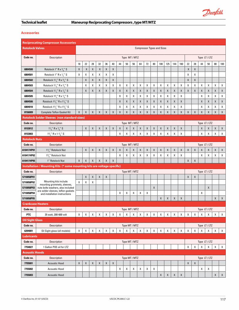
Technical leaflet Maneurop Reciprocating Compressors , type MT/MTZ
��7USCOC.PK.000.C�.22© Danfoss Inc. 0�-07 (USCO)
Reciprocating Compressor Accessories
Rotolock Valves
Compressor Types and Sizes
Code no. Description Type MT / MTZ Type LT / LTZ
18 22 28 32 36 40 44 50 56 64 72 80 100 125 144 160 22 28 44 50 88 100
6804500 Rotolock 1” R x 3/8” S X X X X X X X X
6804501 Rotolock 1” R x 1/2” S X X X X X X X X
6804502 Rotolock 11/4” R x 5/8” S X X X X X X X
6804503 Rotolock 11/4” R x 3/4” S X X X X X X X X X X X X X X X X X X X X X
6804504 Rotolock 11/4” R x 7/8” S X X X X X X X X X X X X X X X X X X X X X
6804505 Rotolock 13/4” R x 7/8” S X X X X X X X X X X X X X X
6804506 Rotolock 13/4” R x 11/8” S X X X X X X X X X X X X X X
6804010 Rotolock 13/4” R x 13/8” S X X X X X X X X X X X X X X
8156009 Complete Teflon Gasket Kit X X X X X X X X X X X X X X X X X X X X X X
Rotolock Solder Sleeves (non standard sizes)
Code no. Description Type MT / MTZ Type LT / LTZ
8153012 11/4” R x 7/8” S X X X X X X X X X X X X X X X X X X X
8153003 13/4” R x 1-3/8” S X X X X X X X X X X X X X X
Rotolock Nuts
Code no. Description Type MT / MTZ Type LT / LTZ
A104174P01 11/4” Rotolock Nut X X X X X X X X X X X X X X X X X X X X X
A104174P02 13/4” Rotolock Nut X X X X X X X X X X X X X X
A104174P05 1” Rotolock Nut X X X X X X X X
Installation / Mounting Kits (* some mounting kits are voltage specific)
Code no. Description Type MT / MTZ Type LT / LTZ
5710058P01
Mounting kits include mounting grommets, sleeves,
nuts bolts washers, also included are solder sleeves, teflon gaskets
and installation instructions
X X X X X X
5710058P02 X X X
5710058P03 X X
5710058P04 X X X X X X
5710058P05 X X X X X X
Crankcase Heaters
Code no. Description Type MT / MTZ Type LT / LTZ
PTC 35 watt, 200-600 volt X X X X X X X X X X X X X X X X X X X X X X
Oil Sight Glass
Code no. Description Type MT / MTZ Type LT / LTZ
6204001 Oil Sight glass (all models) X X X X X X X X X X X X X X X X X X X X X X
Lubricants
Code no. Description Type MT / MTZ Type LT / LTZ
7754027 1 Gallon POE oil for LTZ X X X X X X
Acoustic Hoods
Code no. Description Type MT / MTZ Type LT / LTZ
7755001 Acoustic Hood X X X X X X X X
7755002 Acoustic Hood X X X X X X X X
7755003 Acoustic Hood X X X X X X
Accessories

Technical leaflet Maneurop Reciprocating Compressors , type LT/LTZ
��� USCOC.PK.000.C�.22 © Danfoss Inc. 0�-07 (USCO)
* Motor Codes
Code Description
1 208-230V / 1ph / 60Hz
3 200-230V / 3ph / 60Hz
4 460V / 3ph / 60Hz
Code no. Available Motor Codes *
Hp R404A/507A LTZ R502 LT MCC LRA Discharge Conn.
Suction Conn.
Ship. weight
–10°F Evap –30°F Evap –10°F Evap –30°F Evap
kW BTUH kW BTUH kW BTUH kW BTUH
LT/LTZ22 1,3,4 2 1.75 5230 1.16 2950 1.81 5925 1.2 2720 17 49.3 1” 11/4” 50
LT/LTZ28 1,3,4 2.5 2.58 7890 1.7 4510 2.71 9805 1.8 5385 25 81 1” 11/4” 50
LT/LTZ44 1,3,4 4 4.37 13520 3.1 7540 4.02 16051 2.75 7820 34 103 11/4” 13/4” 80
LT/LTZ50 1,3,4 4.5 5.46 17470 3.93 10360 5.33 19027 3.65 10420 37 143 11/4” 13/4” 85
LT/LTZ88 3,4 7.5 8.32 26860 5.86 14440 7.74 29427 5.3 16000 43 157 11/4” 13/4” 140
LT/LTZ100 3,4 9 10.56 35480 7.23 19930 10.32 38911 7.25 22615 54 210 11/4” 13/4” 150
MCC- Maximum continuous current (A)LRA- Locked rotor current (A)* Rated Condition: R404A / R507, –10°F Evap, 130°F Cond, 15°F subcooling, 20°F superheat** Rated Condition: R404A / R507, –30°F Evap, 120°F Cond, 15°F subcooling, 20°F superheat
Design version
Displacement code
LTZ64HM4-VE-
Motor voltage code1=208-230v / 1 ph / 60 Hz3=200-230v / 3 ph / 60 Hz4=460v / 3 ph / 60 Hz
Compressor type
Lubricant(Z: Polyolester oil-: mineral oil)
Motor power (divide by 12 to convert to HP)
Option code
Oil equalization port & threaded sight glass(-: standard version)

Technical leaflet Performer® Scroll Compressors
���USCOC.PK.000.C�.22© Danfoss Inc. 0�-07 (USCO)
1 2 3 4
5 6 7 8
9 10
Optimized discharge assembly for low noise and higher efficiency.
1 2 3 4
5 6 7 8
9 10
Precision balanced moving parts to reduce vibration.
1 2 3 4
5 6 7 8
9 10
Shielded motor, 100% suction gas cooled.
1 2 3 4
5 6 7 8
9 10
Carefully designed channel with low resistance to suction gas.
1 2 3 4
5 6 7 8
9 10
Compact footprint and light weight.
Performer® scroll compressors are specially designed for commercial air conditioning applications. There is no contact between the scroll flanks in a Performer scroll compressor. The ultra-precise scroll profiles with controlled orbit, roll and slide on an oil film without friction or wear. Floating tip seals ensure axial sealing with low friction losses. With these techniques, the Performer scroll compressor combines high energy efficiency with low sound and vibration characteristics. The 100% suction gas cooled and shielded motor, built-in motor protection, large oil reserve and large internal free volume ensure high reliability and long lifetime.
Introduction
Features
1 2 3 4
5 6 7 8
9 10
Ultra precise scroll profile. No contact between scroll flanks but sealing with oil film.
1 2 3 4
5 6 7 8
9 10
Floating tip seals for perfect axial sealing, reducing friction losses.
1 2 3 4
5 6 7 8
9 10
Multiple knock-out terminal box. Electronic module for motor protection and reverse rotation protection on models 240 & 300.
1 2 3 4
5 6 7 8
9 10 Advanced oil management.
1 2 3 4
5 6 7 8
9 10 Large oil sump and large internal free volume.
1 2 3 4
5 6 7 8
9 10
1 2 3 4
5 6 7 8
9 10
1 2 3 4
5 6 7 8
9 10
1 2 3 4
5 6 7 8
9 10
1 2 3 4
5 6 7 8
9 10
1 2 3 4
5 6 7 8
9 10
1 2 3 4
5 6 7 8
9 10
1 2 3 4
5 6 7 8
9 10
1 2 3 4
5 6 7 8
9 10
1 2 3 4
5 6 7 8
9 10

Technical leaflet Performer® Scroll Compressors
�20 USCOC.PK.000.C�.22 © Danfoss Inc. 0�-07 (USCO)
Serial Number Nomenclature
Format: AB CC DDDDDDDWhere A = year built, B = month built, CC = Factory code, DDDDDDD = Serial numberExample: MC 10 5264747 = compressor built in March 2001 at Trevoux factory
Year Month Factory codeF = 1995 A = Jan 10 = Trevoux, FranceG = 1996 B = Feb 11 = Anse, FranceH = 1997 C = March 14 = Lawrenceville, GAJ = 1998 D = AprilK = 1999 E = MayL = 2000 F = JuneM = 2001 G = JulyN = 2002 H = AugP = 2003 J = SeptQ = 2004 K = Oct
L = Nov M = Dec
Model SM/SZ 084-090-100-110-120-161 SM/SZ 115-125-160-175-185
Version V R C
Suction and discharge connection brazed rotolock brazed
Oil sight glass threaded threaded threaded
Oil equalization connection 3/8” flare 3/8” flare 3/8” flare
Oil drain connection — 1/4” NPT 1/4” NPT
* Low pressure gauge port (schrader) 1/4” flare 1/4” flare 1/4” flare
UL evolution index (single compressors only)
SZ320–4–A
Motor voltage code:3 = 200-230/3/604 = 400/3/50 - 460/3/606 = 230/3/507 = 500/3/50-575/3/609 = 380/3/6
Product Family: S: Performer Scroll
Lubricant type: M: Mineral OilZ: Polyolester Oil
Nominal capacity rating in thousandBTUH at 60 Hz (R 22) ARI conditions
Product evolution index
Compressor version:R/V/C (See table below)
SZ125S4RASingle compressors
Tandem units
*Tandem units are also fitted with a high side gauge port (1/4” flare)

Technical leaflet Performer® Scroll Compressors
�2�USCOC.PK.000.C�.22© Danfoss Inc. 0�-07 (USCO)
Performer Scroll Compressors
Single compressors R 407C 60Hz
Model
Motor Voltage Hz/Ph code
Nominalcapacity
(Tons)
Nominalcapacity
BTUH
Powerinput(kW)
EER(BTUWH)
SoundpowerdBA
Compressor Body Style Connection Sizes
Ship.weight
lbs.V C
Rotolock Size Adapter Tube Size
Suction x Discharge Suction x Discharge
SZ084 3-4-7-9 7 76,900 7.06 10.9 78 11/8” x 3/4” - - - 159
SZ090 3-4-7-9 7.5 83,300 7.63 10.9 78 11/8” x 3/4” - - - 159
SZ100 3-4-7-9 8 90,500 8.18 11 78 11/8” x 3/4” - - - 159
SZ110 3-4-7-9 9 102,800 9.29 11.1 81 13/8” x 7/8” - - - 176
SZ115 3-4-7-9 9.5 112,000 10.22 10.9 81 - 13/8” x 7/8” 13/4”x 11/4” 11/8” x 3/4” 176
SZ120 3-4-7-9 10 118,900 10.75 11.1 81 13/8” x 7/8” 176
SZ125 3-4-7-9 10 119,200 10.89 10.9 81 - 13/8” x 7/8” 13/4” x 11/4” 11/8” x 3/4” 176
SZ160 3-4-7-9 13 155,400 14.08 11 85 - 15/8” x 11/8” 21/4” x 13/4” 13/8” x 7/8” 207
SZ161 3-4 13 156,900 14.32 10.9 85 13/8” x 7/8” - - - 190
SZ175 3-4-7-9 14 166,200 15.28 10.9 84 - 15/8” x 11/8” 21/4” x 13/4” 13/8” x 7/8” 227
SZ185 3-4-7-9 15 176,800 16.43 10.7 84 - 15/8” x 11/8” 21/4” x 13/4” 13/8” x 7/8” 227
Tandem compressors R 407C 60Hz
Model
Motor VoltageHz/Ph* code
Nominalcapacity
(Tons)
Nominalcapacity
BTUH
Powerinput(kW)
EER(BTUWH)
SoundpowerdBA
Sweat system connection Compressor rotolock connectionShip.
weight lbs.suction discharge Rotolock Adapter
SZ170 3-4-7-9 13.5 151,500 14.11 10.7 81 15/8” 11/8” - - 331
SZ180 3-4-7-9 15 164,100 15.26 10.7 81 15/8” 11/8” - - 331
SZ200 3-4-7-9 16 178,300 16.35 10.9 81 15/8” 11/8” - - 331
SZ220 3-4-7-9 18 202,400 18.56 10.9 84 21/8” 13/8” - - 375
SZ230 3-4-7-9 19 220,700 20.43 10.8 84 15/8” 11/8” 13/4” x 11/4” 11/8” x 3/4” 375
SZ242 3-4-7-9 20 234,300 21.48 10.9 84 21/8” 13/8” - - 375
SZ250 3-4-7-9 20 234,700 21.77 10.8 84 15/8” 11/8” 13/4” x 11/4” 11/8” x 3/4” 375
SZ285 3-4-7-9 23 270,400 24.97 10.8 86.5 21/8” 11/8” - - 441
SZ290 3-4-7-9 23.5 274,000 25.5 10.7 86 21/8” 11/8” - - 441
SZ310 3-4-7-9 25 291,500 27.32 10.7 86 21/8” 11/8” - - 441
SZ320 3-4-7-9 26 306,100 28.14 10.9 88 21/8” 13/8” 21/4” x 13/4” 13/8” x 7/8” 463
SZ322 3-4-7-9 26 309,100 28.62 10.8 88 21/8” 13/8” - - 424
SZ350 3-4-7-9 28 327,300 30.54 10.7 87 21/8” 13/8” 21/4” x 13/4” 13/8” x 7/8” 496
SZ370 3-4-7-9 30 348,200 32.84 10.6 87 21/8” 13/8” 21/4” x 13/4” 13/8” x 7/8” 496
Motor Codes
Code Description
3 200-230V / 3ph / 60 Hz
4 460V / 3ph / 60 Hz
7 575V/ 3ph / 60 Hz
9 380V / 3ph / 60 Hz
*See serial number nomenclature on page 120.
Compressor Connection Codes V C Rotolock
suction and discharge connection brazed brazed rotolock
oil sight glass threaded threaded threaded
oil equalization connection 3/8 ” flare 3/8 “ flare 3/8 “ flare
oil drain connection - 1/4 “ NPT 1/4 “ NPT
low pressure guage port (schrader) 1/4 “ flare 1/4 “ flare 1/4 “ flare

Technical leaflet Performer® Scroll Compressors
�22 USCOC.PK.000.C�.22 © Danfoss Inc. 0�-07 (USCO)
Performer Scroll Compressors
Single compressors R 22 60Hz
Model Motor VoltageHz/Ph* code
Nominalcapacity
(Tons)
Nominalcapacity
BTUH
Powerinput(kW)
EER(BTUWH)
SoundpowerdBA
Compressor Body Style Connection Sizes Ship.weight
lbs.
V C Rotolock Size Adapter Tube Size
Suction x Discharge Suction x Discharge
SM084 3-4-7-9 7 84,400 7.38 11.4 75 11/8” x 3/4” - - - 159
SM090 3-4-7-9 7.5 90,000 7.82 11.5 75 11/8” x 3/4” - - - 159
SM100 3-4-7-9 8 94,000 8.14 11.5 75 11/8” x 3/4” - - - 159
SM110 3-4-7-9 9 107,800 9.35 11.5 78 13/8” x 7/8” - - - 176
SM115 3-4-7-9 9.5 115,200 10.8 11.4 79 - 13/8” x 7/8” 13/4” x 11/4” 11/8” x 3/4” 176
SM120 3-4-7-9 10 125,300 10.8 11.6 78 13/8” x 7/8” 176
SM125 3-4-7-9 10 126,400 10.99 11.5 79 - 13/8” x 7/8” 13/4” x 11/4” 11/8” x 3/4” 176
SM160 3-4-7-9 13 163,000 14.22 11.5 84 - 15/8” x 11/8” 21/4” x 13/4” 13/8”x 7/8” 207
SM161 3-4 13 162,600 14.07 11.5 84 13/8” x 7/8” - - - 190
SM175 3-4-7-9 14 174,300 15.27 11.4 82.5 - 15/8” x 11/8” 21/4” x 13/4” 13/8” x 7/8” 227
SM185 3-4-7-9 15 185,400 16.22 11.4 82.5 - 15/8” x 11/8” 21/4” x 13/4” 13/8” x 7/8” 227
SY240 3-4-7-9 20 252,800 22.14 11.4 89 - 15/8” x 11/8” 21/4” x 13/4” 15/8” x 11/8” 353
SY300 3-4-7-9 25 322,600 27.55 11.7 91 - 15/8” x 11/8” 21/4” x 13/4” 15/8” x 11/8” 353
Tandem compressors R 22 60Hz
Model Motor VoltageHz/Ph* code
Nominalcapacity
(Tons)
Nominalcapacity
BTUH
Powerinput(kW)
EER(BTUWH)
SoundpowerdBA
Sweatsystem connection
Compressorrotolock connection
Ship.weight
lbs.Suction Discharge Rotolock Adapter
SM170 3-4-7-9 13.5 165,500 14.74 11.2 78 15/8” 11/8” - - 331
SM180 3-4-7-9 15 177,300 15.63 11.3 78 15/8” 11/8” - - 331
SM200 3-4-7-9 16 185,200 16.28 11.4 78 15/8” 11/8” - - 331
SM220 3-4-7-9 18 212,400 18.69 11.4 81 21/8” 13/8” - - 375
SM230 3-4-7-9 19 226,900 20.14 11.3 82 15/8” 11/8” 13/4” x 11/4” 11/8” x 3/4” 375
SM242 3-4-7-9 20 246,900 21.6 11.4 81 21/8” 13/8” - - 375
SM250 3-4-7-9 20 249,000 21.96 11.3 82 15/8” 11/8” 13/4” x 11/4” 11/8” x 3/4” 375
SM285 3-4-7-9 23 285,000 25.21 11.3 85 21/8” 11/8” - - 441
SM290 3-4-7-9 23.5 285,100 25.35 11.2 84 21/8” 111/8” - - 441
SM310 3-4-7-9 25 307,100 27.21 11.3 84 21/8” 11/8” - - 441
SM320 3-4-7-9 26 321,000 28.42 11.3 87 21/8” 13/8” 21/4” x 13/4” 13/8” x 7/8” 463
SM322 3-4-7-9 26 320,200 28.12 11.3 87 21/8” 13/8” - - 424
SM350 3-4-7-9 28 343,400 30.53 11.2 85.5 21/8” 13/8” 21/4” x 13/4” 13/8” x 7/8” 496
SM370 3-4-7-9 30 365,300 32.42 11.3 85.5 21/8” 13/8” 21/4” x 13/4” 13/8” x 7/8” 496
*See serial number nomenclature on page 120.

Technical leaflet Performer® Scroll Compressors
�2�USCOC.PK.000.C�.22© Danfoss Inc. 0�-07 (USCO)
Direct drop-in for below applications
Model Nominal Capacity Connection Type Voltage
SM115-3QAI 9T 1-3/8” x 7/8” Brazed 230V/3/60Hz
SM115-4QAI 9T 1-3/8” x 7/8” Brazed 460V/3/60Hz
SM125-3QAI 10T 1-3/8” x 7/8” Brazed 230V/3/60Hz
SM125-4QAI 10T 1-3/8” x 7/8” Brazed 460V/3/60Hz
SM175-3QAI 14T 1-5/8” x 1-1/8” Brazed 230V/3/60Hz
SM175-4QAI 14T 1-5/8” x 1-1/8” Brazed 460V/3/60Hz
SM185-3QAI 15T 1-5/8” x 1-1/8” Brazed 230V/3/60Hz
SM185-4QAI 15T 1-5/8” x 1-1/8” Brazed 460V/3/60Hz
Universal OEM Replacement Scroll Compressors

Scr
oll
Co
mp
ress
or
Acc
esso
ries
Roto
lock
val
ves
& n
uts
Sing
le c
ompr
esso
rsTa
ndem
com
pres
sors
Code
no.
Des
crip
tion
sm-z
084
sm-z
090
sm-z
100
sm-z
110
sm-z
115
sm-z
120
sm-z
125
sm-z
160
sm-z
161
sm-z
175
sm-z
185
SY 240
SY 300
sm-z
170
sm-z
180
sm-z
200
sm-z
220
sm-z
230
sm-z
242
sm-z
250
sm-z
285
sm-z
290
sm-z
310
sm-z
320
sm-z
322
sm-z
350
sm-z
370
6804
506
Roto
lock
13 / 4”R
x 1
1 / 8”SX
XX
XX
6804
505
Roto
lock
13 / 4”R
x 7 / 8”S
XX
XX
X
6804
503
Roto
lock
11 / 4”R
x 3 / 4”S
XX
6804
526
Roto
lock
21 / 4”R
x 1
3 / 8”SX
XX
6804
010
Roto
lock
13 / 4”R
x x
13 / 8”S
XX
XX
X
A10
4174
P01
11 / 4” Ro
tolo
ck N
utX
XX
X
A10
4174
P02
13 / 4” Ro
tolo
ck N
utX
XX
XX
XX
X
A10
4174
P03
21 / 4” Ro
tolo
ck N
utX
XX
XX
XX
X
8156
009
Teflo
n G
aske
t Kit
xx
xx
x
8156
013
Teflo
n G
aske
t Kit
xx
x
xx
R
oto
lock
So
lder
Sle
eve
Ad
apto
rs
Code
no.
Des
crip
tion
Sing
le c
ompr
esso
rsTa
ndem
com
pres
sors
8153
003
13 / 8”S x
13 / 4”R
X
XX
XX
8153
004
11 / 8”S x
13 / 4”R
XX
X
8153
005
13 / 8”S x
21 / 4”R
XX
XX
X
8153
006
15 / 8”S x
21 / 4”R
XXX
XX
X
8153
008
3 / 4”S x
11 / 4”R
XX
XX
XX
XX
X
8153
012
7 / 8”S x
11 / 4”R
XX
XX
X
8153
013
7 / 8”S x
13 / 4”R
XX
X
7765
005
Ada
ptor
Kit
*X
XX
7765
006
Ada
ptor
Kit
*X
X
* A
dapt
or K
its c
ome
with
2 R
otol
ock
adap
tors
, 2 R
otol
ock
nuts
, 2 s
olde
r sle
eves
and
2 g
aske
ts
So
un
d J
acke
ts
Code
no.
Des
crip
tion
Sing
le c
ompr
esso
rsTa
ndem
com
pres
sors
7755
007
Soun
d Ja
cket
XX
7755
008
Soun
d Ja
cket
X
7755
009
Soun
d Ja
cket
XX
7755
010
Soun
d Ja
cket
XX
7755
011
Soun
d Ja
cket
XX
X
Mo
un
tin
g P
arts
Code
no.
Des
crip
tion
Sing
le c
ompr
esso
rsTa
ndem
com
pres
sors
8156
138
4 gr
omm
ets
and
4 bo
lt sl
eeve
sX
XX
XX
XX
XX
XX
XX
XX
XX
XX
XX
XX
XX
XX
Lu
bri
can
ts
Code
no.
Des
crip
tion
Sing
le c
ompr
esso
rsTa
ndem
com
pres
sors
5402
007
1 G
allo
n m
iner
al o
il
7754
027
1 G
allo
n PO
E oi
l for
SZ
type
s
Accessories
Technical leaflet Performer® Scroll Compressors
�2� USCOC.PK.000.C�.22 © Danfoss Inc. 0�-07 (USCO)

Danfoss scroll compressors are the quietest, most reliable and longest-lasting compressors in the HVAC&R industry.
Key features include:
n Simple, compact design
n Lightweight construction n 90% of internal bolts have been eliminated
n One-third fewer parts than competitive models
Danfoss Scroll compressor model numbers have significance as indicated below:
Nomenclature
Application H: high temperature air conditioning
Type Size Motor Features
HRH 036 U1L P6
Family D: residential scroll C: light commercial scroll R: residential scroll (new platform) L: light commercial scroll (new platform)
Refrigerant and lubricant M: R-22, mineral or alkylbenzene oil P: R-407C, POE lubricant H: R-410A, POE lubricant J: R-410A, PVE lubricant
Nominal capacity In thousands of Btu/h @ 60Hz, ARI conditions
Model variation T: design optimized for 7.2/54.4 (45/130) U: design optimized for 7.2/37.8 (45/100)
Other features
Tubing and electrical connections P: brazed connections, spade terminals C: brazed connections, screw terminals
Motor protection L: internal motor protection
Motor voltage code 1: 208-230 V 1~ 60 Hz 2: 208-230 V 3~ 60 Hz 4: 380-400 V 3~ 50 Hz and 460 V 3~ 60 Hz 5: 220-240 V 1~ 50 Hz and 265 V 1~ 60 Hz 7: 500 V 3~ 50 Hz and 575 V 3~ 60 Hz 9: 380 V 3~ 60 Hz
Oil sight glass
Oil equalization
Oil drain
LP gauge port
2 None None None Schrader
5 Thread Rotolock NPT Schrader
6 None None None None
7 Thread None None None
8 None Brazed None None
Technical leaflet Scroll Technologies Compressors
125USCOC.PK.000.C1.22© Danfoss Inc. 01-07 (USCO)
Voltage Codes Copeland Danfoss
208-230V/1~/60Hz PFV 1
208-230V/3~/60Hz TFC or TF5 2
380V/3~/60Hz & 460V/3~/60Hz TFD 4
Voltage
NoteonSEERratings:The Scroll Tech compressors have motors optimized for the different SEER ratings. Use motor variation «U» for 13 SEER applications and «T» for 10 SEER

Cross Reference - R-22
Copeland Tons Btu/h Scroll Tech Btu/h Old ST Model # Model # Code# Voltage
ZR32**-***-*** 2-3/4 32,000 HRM032-***-** 32,000 XCD320HA HRM032U1LP6 120U0921 230 / 1
ZR32**-***-*** 2-3/4 32,000 HRM032-***-** 32,000 XCH322HA HRM032U4LP6 120U0996 460 / 3
ZR34**-***-*** 3 34,000 HRM034-***-** 34,000 XCD340HA HRM034U1LP6 120U0926 230 / 1
ZR34**-***-*** 3 34,000 HRM034-***-** 34,000 XCY342HA HRM034U2LP6 120U1081 230 / 3
ZR34**-***-*** 3 34,000 HRM034-***-** 34,000 XCH342HA HRM034U4LP6 120U1001 460 / 3
ZR36**-***-*** 3 36,500 HRM038-***-** 38,000 XCD380HA HRM038U1LP6 120U0931 230 / 1
ZR36**-***-*** 3 36,500 HRM038-***-** 38,000 XCY382HA HRM038U2LP6 120U1091 230 / 3
ZR36**-***-*** 3 36,500 HRM038-***-** 38,000 XCH382HA HRM038U4LP6 120U1011 460 / 3
ZR40**-***-*** 3-1/4 40,000 HRM040-***-** 40,000 XCD400HA HRM040U1LP6 120U0936 230 / 1
ZR40**-***-*** 3-1/4 40,000 HRM040-***-** 40,000 XCY402HA HRM040U2LP6 120U1101 230 / 3
ZR40**-***-*** 3-1/4 40,000 HRM040-***-** 40,000 XCH402HA HRM040U4LP6 120U1021 460 / 3
ZR42**-***-*** 3-1/2 42,000 HRM042-***-** 42,000 XCD420HA HRM042U1LP6 120U0941 230 / 1
ZR42**-***-*** 3-1/2 42,000 HRM042-***-** 42,000 XCY422HA HRM042U2LP6 120U1111 230 / 3
ZR42**-***-*** 3-1/2 42,000 HRM042-***-** 42,000 XCH422HA HRM042U4LP6 120U1031 460 / 3
ZR47**-***-*** 4 47,500 HRM047-***-** 47,000 XCD470HA HRM047U1LP6 120U0951 230 / 1
ZR47**-***-*** 4 47,500 HRM047-***-** 47,000 XCY472HA HRM047U2LP6 120U1131 230 / 3
ZR47**-***-*** 4 47,500 HRM047-***-** 47,000 XCH472HA HRM047U4LP6 120U1051 460 / 3
ZR54**-***-*** 5 54,200 HRM054-***-** 54,000 XRD540HA HRM054U1LP6 120U1511 230 / 1
ZR54**-***-*** 5 54,200 HRM054-***-** 54,000 XRY542HA HRM054U2LP6 120U1871 230 / 3
ZR54**-***-*** 5 54,200 HRM054-***-** 54,000 XRH542HA HRM054U4LP6 120U1696 460 / 3
ZR54**-***-*** 5 54,200 HRM054-***-** 54,000 XRJ542HA HRM054U7LP6 120U1811 575 / 3
ZR57**-***-*** 4-3/4 57,500 HRM058-***-** 58,000 XRD580HA HRM058U1LP6 120U1531 230 / 1
ZR57**-***-*** 4-3/4 57,500 HRM058-***-** 58,000 XRY582HA HRM058U2LP6 120U1876 230 / 3
ZR57**-***-*** 4-3/4 57,500 HRM058-***-** 58,000 XRH582HA HRM058U4LP6 120U1711 460 / 3
ZR61**-***-*** 5 61,200 HRM060-***-** 60,000 XRD600HA HRM060U1LP6 120U1546 230 / 1
ZR61**-***-*** 5 61,200 HRM060-***-** 60,000 XRY602HA HRM060U2LP6 120U1881 230 / 3
ZR61**-***-*** 5 61,200 HRM060-***-** 60,000 XRH602HA HRM060U4LP6 120U1736 460 / 3
ZR68**-***-*** 5-1/2 68,500 HLM068-***-** 68,000 XRD680AA HLM068T1LP6 120U1556 230 / 1
ZR68**-***-*** 5-1/2 68,500 HLM068-***-** 68,000 XRY682AE HLM068T2LC6 120U1891 230 / 3
ZR68**-***-*** 5-1/2 68,500 HLM068-***-** 68,000 XRH682AE HLM068T4LC6 120U1746 460 / 3
ZR72**-***-*** 6 73,500 HLM072-***-** 72,000 XRD720AA HLM072T1LP6 120U1566 230 / 1
ZR72**-***-*** 6 73,500 HLM072-***-** 72,000 XRY722AE HLM072T2LC6 120U1896 230 / 3
ZR72**-***-*** 6 73,500 HLM072-***-** 72,000 XRH722AE HLM072T4LC6 120U1751 460 / 3
ZR81**-***-*** 6 81,100 HLM081-***-** 81,000 XRD810AA HLM081T1LP6 120U1586 230 / 1
ZR81**-***-*** 6 81,100 HLM081-***-** 81,000 XRY812AE HLM081T2LC6 120U1911 230 / 3
ZR81**-***-*** 6 81,100 HLM081-***-** 81,000 XRH812AE HLM081T4LC6 120U1776 460 / 3
ZR84**-***-*** 7 84,000 HLM081-***-** 81,000 XRD810AA HLM081T1LP6 120U1586 230 / 1
ZR84**-***-*** 7 84,000 HLM081-***-** 81,000 XRY812AE HLM081T2LC6 120U1911 230 / 3
ZR84**-***-*** 7 84,000 HLM081-***-** 81,000 XRH812AE HLM081T4LC6 120U1776 460 / 3
ZR90**-***-*** 7-1/2 89,000 HCM094-***-** 94,000 SRY942AU HCM094T2LC8 120U0901 230 / 3
ZR90**-***-*** 7-1/2 89,000 HCM094-***-** 94,000 SRH942AU HCM094T4LC8 120U0596 460 / 3
ZR94**-***-*** 7-1/2 94,000 HCM094-***-** 94,000 SRY942AU HCM094T2LC8 120U0901 230 / 3
ZR94**-***-*** 7-1/2 94,000 HCM094-***-** 94,000 SRH942AU HCM094T4LC8 120U0596 460 / 3
ZR11**-***-*** 9 108,300 HCM109-***-** 109,000 SRH109AE HCM109T4LC6 120U0366 460 / 3
ZR108**-***-*** 9 108,900 HCM109-***-** 109,000 SRH109AE HCM109T4LC6 120U0366 460 / 3
ZR12**-***-*** 10-1/2 125,500 HCM120-***-** 120,000 SRY120AE HCM120T2LC6 120U0761 230 / 3
ZR12**-***-*** 10-1/2 125,500 HCM120-***-** 120,000 SRH120AE HCM120T4LC6 120U0391 460 / 3
Technical leaflet Scroll Technologies Compressors
�2� USCOC.PK.000.C�.22 © Danfoss Inc. 0�-07 (USCO)

Cross Reference - R-22
Copeland Tons Btu/h Scroll Tech Btu/h Old ST Model # Model # Code# Voltage
ZR32**-***-*** 2-3/4 32,000 HRM032-***-** 32,000 XCD320HA HRM032U1LP6 120U0921 230 / 1
ZR32**-***-*** 2-3/4 32,000 HRM032-***-** 32,000 XCH322HA HRM032U4LP6 120U0996 460 / 3
ZR34**-***-*** 3 34,000 HRM034-***-** 34,000 XCD340HA HRM034U1LP6 120U0926 230 / 1
ZR34**-***-*** 3 34,000 HRM034-***-** 34,000 XCY342HA HRM034U2LP6 120U1081 230 / 3
ZR34**-***-*** 3 34,000 HRM034-***-** 34,000 XCH342HA HRM034U4LP6 120U1001 460 / 3
ZR36**-***-*** 3 36,500 HRM038-***-** 38,000 XCD380HA HRM038U1LP6 120U0931 230 / 1
ZR36**-***-*** 3 36,500 HRM038-***-** 38,000 XCY382HA HRM038U2LP6 120U1091 230 / 3
ZR36**-***-*** 3 36,500 HRM038-***-** 38,000 XCH382HA HRM038U4LP6 120U1011 460 / 3
ZR40**-***-*** 3-1/4 40,000 HRM040-***-** 40,000 XCD400HA HRM040U1LP6 120U0936 230 / 1
ZR40**-***-*** 3-1/4 40,000 HRM040-***-** 40,000 XCY402HA HRM040U2LP6 120U1101 230 / 3
ZR40**-***-*** 3-1/4 40,000 HRM040-***-** 40,000 XCH402HA HRM040U4LP6 120U1021 460 / 3
ZR42**-***-*** 3-1/2 42,000 HRM042-***-** 42,000 XCD420HA HRM042U1LP6 120U0941 230 / 1
ZR42**-***-*** 3-1/2 42,000 HRM042-***-** 42,000 XCY422HA HRM042U2LP6 120U1111 230 / 3
ZR42**-***-*** 3-1/2 42,000 HRM042-***-** 42,000 XCH422HA HRM042U4LP6 120U1031 460 / 3
ZR47**-***-*** 4 47,500 HRM047-***-** 47,000 XCD470HA HRM047U1LP6 120U0951 230 / 1
ZR47**-***-*** 4 47,500 HRM047-***-** 47,000 XCY472HA HRM047U2LP6 120U1131 230 / 3
ZR47**-***-*** 4 47,500 HRM047-***-** 47,000 XCH472HA HRM047U4LP6 120U1051 460 / 3
ZR54**-***-*** 5 54,200 HRM054-***-** 54,000 XRD540HA HRM054U1LP6 120U1511 230 / 1
ZR54**-***-*** 5 54,200 HRM054-***-** 54,000 XRY542HA HRM054U2LP6 120U1871 230 / 3
ZR54**-***-*** 5 54,200 HRM054-***-** 54,000 XRH542HA HRM054U4LP6 120U1696 460 / 3
ZR54**-***-*** 5 54,200 HRM054-***-** 54,000 XRJ542HA HRM054U7LP6 120U1811 575 / 3
ZR57**-***-*** 4-3/4 57,500 HRM058-***-** 58,000 XRD580HA HRM058U1LP6 120U1531 230 / 1
ZR57**-***-*** 4-3/4 57,500 HRM058-***-** 58,000 XRY582HA HRM058U2LP6 120U1876 230 / 3
ZR57**-***-*** 4-3/4 57,500 HRM058-***-** 58,000 XRH582HA HRM058U4LP6 120U1711 460 / 3
ZR61**-***-*** 5 61,200 HRM060-***-** 60,000 XRD600HA HRM060U1LP6 120U1546 230 / 1
ZR61**-***-*** 5 61,200 HRM060-***-** 60,000 XRY602HA HRM060U2LP6 120U1881 230 / 3
ZR61**-***-*** 5 61,200 HRM060-***-** 60,000 XRH602HA HRM060U4LP6 120U1736 460 / 3
ZR68**-***-*** 5-1/2 68,500 HLM068-***-** 68,000 XRD680AA HLM068T1LP6 120U1556 230 / 1
ZR68**-***-*** 5-1/2 68,500 HLM068-***-** 68,000 XRY682AE HLM068T2LC6 120U1891 230 / 3
ZR68**-***-*** 5-1/2 68,500 HLM068-***-** 68,000 XRH682AE HLM068T4LC6 120U1746 460 / 3
ZR72**-***-*** 6 73,500 HLM072-***-** 72,000 XRD720AA HLM072T1LP6 120U1566 230 / 1
ZR72**-***-*** 6 73,500 HLM072-***-** 72,000 XRY722AE HLM072T2LC6 120U1896 230 / 3
ZR72**-***-*** 6 73,500 HLM072-***-** 72,000 XRH722AE HLM072T4LC6 120U1751 460 / 3
ZR81**-***-*** 6 81,100 HLM081-***-** 81,000 XRD810AA HLM081T1LP6 120U1586 230 / 1
ZR81**-***-*** 6 81,100 HLM081-***-** 81,000 XRY812AE HLM081T2LC6 120U1911 230 / 3
ZR81**-***-*** 6 81,100 HLM081-***-** 81,000 XRH812AE HLM081T4LC6 120U1776 460 / 3
ZR84**-***-*** 7 84,000 HLM081-***-** 81,000 XRD810AA HLM081T1LP6 120U1586 230 / 1
ZR84**-***-*** 7 84,000 HLM081-***-** 81,000 XRY812AE HLM081T2LC6 120U1911 230 / 3
ZR84**-***-*** 7 84,000 HLM081-***-** 81,000 XRH812AE HLM081T4LC6 120U1776 460 / 3
ZR90**-***-*** 7-1/2 89,000 HCM094-***-** 94,000 SRY942AU HCM094T2LC8 120U0901 230 / 3
ZR90**-***-*** 7-1/2 89,000 HCM094-***-** 94,000 SRH942AU HCM094T4LC8 120U0596 460 / 3
ZR94**-***-*** 7-1/2 94,000 HCM094-***-** 94,000 SRY942AU HCM094T2LC8 120U0901 230 / 3
ZR94**-***-*** 7-1/2 94,000 HCM094-***-** 94,000 SRH942AU HCM094T4LC8 120U0596 460 / 3
ZR11**-***-*** 9 108,300 HCM109-***-** 109,000 SRH109AE HCM109T4LC6 120U0366 460 / 3
ZR108**-***-*** 9 108,900 HCM109-***-** 109,000 SRH109AE HCM109T4LC6 120U0366 460 / 3
ZR12**-***-*** 10-1/2 125,500 HCM120-***-** 120,000 SRY120AE HCM120T2LC6 120U0761 230 / 3
ZR12**-***-*** 10-1/2 125,500 HCM120-***-** 120,000 SRH120AE HCM120T4LC6 120U0391 460 / 3
ZR125**-***-*** 10-1/2 125,900 HCM120-***-** 120,000 SRY120AE HCM120T2LC6 120U0761 230 / 3
Cross Reference - R-410A
Copeland Tons Btu/h Scroll Tech Btu/h Old ST Model # Model # Code # Voltage
ZP29***-***-*** 2-1/2 29,000 HRH031-***-** 31,000 XGD310HA HRH031U1LP6 120U1136 230 / 1
ZP29***-***-*** 2-1/2 29,000 HRH031-***-** 31,000 XGY312HA HRH031U2LP6 120U1251 230 / 3
ZP29***-***-*** 2-1/2 29,000 HRH031-***-** 31,000 XGH312HA HRH031U4LP6 120U1191 460 / 3
ZP31***-***-*** 2-1/2 31,100 HRH031-***-** 31,000 XGD310HA HRH031U1LP6 120U1136 230 / 1
ZP31***-***-*** 2-1/2 31,100 HRH031-***-** 31,000 XGY312HA HRH031U2LP6 120U1251 230 / 3
ZP31***-***-*** 2-1/2 31,100 HRH031-***-** 31,000 XGH312HA HRH031U4LP6 120U1191 460 / 3
ZP32***-***-*** 2-3/4 31,800 HRH032-***-** 32,000 XGD320HA HRH032U1LP6 120U1141 230 / 1
ZP32***-***-*** 3 31,800 HRH032-***-** 32,000 XGY322HA HRH032U2LP6 120U1256 230 / 3
ZP32***-***-*** 3 31,800 HRH032-***-** 32,000 XGH322HA HRH032U4LP6 120U1196 460 / 3
ZP34***-***-*** 3 34,500 HRH034-***-** 34,000 XGD340HA HRH034U1LP6 120U1146 230 / 1
ZP34***-***-*** 3 34,500 HRH034-***-** 34,000 XGY342HA HRH034U2LP6 120U1261 230 / 3
ZP36***-***-*** 3 36,000 HRH036-***-** 36,000 XGD360HA HRH036U1LP6 120U1151 230 / 1
ZP36***-***-*** 3-1/4 36,000 HRH036-***-** 36,000 XGY362HA HRH036U2LP6 120U1266 230 / 3
ZP36***-***-*** 3-1/2 36,000 HRH036-***-** 36,000 XGH362HA HRH036U4LP6 120U1201 460 / 3
ZP38***-***-*** 3-1/4 37,600 HRH038-***-** 38,000 XGD380HA HRH038U1LP6 120U1156 230 / 1
ZP38***-***-*** 3-1/2 37,600 HRH038-***-** 38,000 XGY382HA HRH038U2LP6 120U1271 230 / 3
ZP38***-***-*** 4 37,600 HRH038-***-** 38,000 XGH382HA HRH038U4LP6 120U1206 460 / 3
ZP39***-***-*** 3-1/4 39,000 HRH040-***-** 40,000 XGD410HA HRH040U1LP6 120U1161 230 / 1
ZP39***-***-*** 3-1/2 39,000 HRH040-***-** 40,000 XGY412HA HRH040U2LP6 120U1276 230 / 3
ZP39***-***-*** 4 39,000 HRH040-***-** 40,000 XGH412HA HRH040U4LP6 120U1211 460 / 3
ZP41***-***-*** 3-1/2 41,000 HRH040-***-** 40,000 XGD410HA HRH040U1LP6 120U1161 230 / 1
ZP41***-***-*** 4 41,000 HRH040-***-** 40,000 XGY412HA HRH040U2LP6 120U1276 230 / 3
ZP41***-***-*** 5 41,000 HRH040-***-** 40,000 XGH412HA HRH040U4LP6 120U1211 460 / 3
ZP42***-***-*** 3-1/2 42,000 HRH040-***-** 40,000 XGD410HA HRH040U1LP6 120U1161 230 / 1
ZP42***-***-*** 4 42,000 HRH040-***-** 40,000 XGY412HA HRH040U2LP6 120U1276 230 / 3
ZP42***-***-*** 5 42,000 HRH040-***-** 40,000 XGH412HA HRH040U4LP6 120U1211 460 / 3
ZP44***-***-*** 3-1/2 44,300 HRH044-***-** 44,000 XND440HA HRH044U1LP6 120U1286 230 / 1
ZP44***-***-*** 4 44,300 HRH044-***-** 44,000 XNY442HA HRH044U2LP6 120U1456 230 / 3
ZP44***-***-*** 5 44,300 HRH044-***-** 44,000 XNH442HA HRH044U4LP6 120U1361 460 / 3
ZP50***-***-*** 4-1/2 50,500 HRH051-***-** 51,000 XND510HA HRH051U1LP6 120U1296 230 / 1
ZP50***-***-*** 4-1/2 50,500 HRH051-***-** 51,000 XNY512HA HRH051U2LP6 120U1466 230 / 3
ZP50***-***-*** 4-1/2 50,500 HRH051-***-** 51,000 XNH512HA HRH051U4LP6 120U1371 460 / 3
ZP51***-***-*** 4-1/2 51,000 HRH051-***-** 51,000 XND510HA HRH051U1LP6 120U1296 230 / 1
ZP51***-***-*** 4-1/2 51,000 HRH051-***-** 51,000 XNY512HA HRH051U2LP6 120U1466 230 / 3
ZP51***-***-*** 4-1/2 51,000 HRH051-***-** 51,000 XNH512HA HRH051U4LP6 120U1371 460 / 3
ZP54***-***-*** 5 54,500 HRH054-***-** 54,000 XND540HA HRH054U1LP6 120U1301 230 / 1
ZP54***-***-*** 4-3/4 54,500 HRH054-***-** 54,000 XNY542HA HRH054U2LP6 120U1471 230 / 3
ZP54***-***-*** 5 54,500 HRH054-***-** 54,000 XNH542HA HRH054U4LP6 120U1376 460 / 3
ZP57***-***-*** 4-3/4 58,000 HRH056-***-** 56,000 XND560HA HRH056U1LP6 120U1306 230 / 1
ZP57***-***-*** 5 58,000 HRH056-***-** 56,000 XNY562HA HRH056U2LP6 120U1476 230 / 3
ZP57***-***-*** 5-1/2 58,000 HRH056-***-** 56,000 XNH562HE HRH056U4LC6 120U1386 460 / 3
ZP67***-***-*** 5-1/2 67,500 HLH068-***-** 68,000 XND680AA HLH068T1LP6 120U1311 230 / 1
ZP67***-***-*** 6 67,500 HLH068-***-** 68,000 XNY682AE HLH068T2LC6 120U1481 230 / 3
ZP67***-***-*** 6 67,500 HLH068-***-** 68,000 XNH682AE HLH068T4LC6 120U1391 460 / 3
ZP72***-***-*** 6 72,000 HLJ072-***-** 72,000 XND720AA HLJ072T1LP6 120U1316 230 / 1
ZP72***-***-*** 6 72,000 HLJ072-***-** 72,000 XNY722AE HLJ072T2LC6 120U1486 230 / 3
ZP72***-***-*** 7 72,000 HLJ072-***-** 72,000 XNH722AE HLJ072T4LC6 120U1396 460 / 3
ZP83***-***-*** 7 83,000 HLJ083-***-** 83,000 XND830AA HLJ083T1LP6 120U1321 230 / 1
ZP83***-***-*** 7-1/2 83,000 HLJ083-***-** 83,000 XNY832AE HLJ083T2LC6 120U1491 230 / 3
ZP83***-***-*** 7-1/2 83,000 HLJ083-***-** 83,000 XNH832AE HLJ083T4LC6 120U1401 460 / 3
ZP83***-***-*** 7-1/2 83,000 HLJ083-***-** 83,000 XNJ832AE HLJ083T7LC6 120U1441 575 / 3
Technical leaflet Scroll Technologies Compressors
127USCOC.PK.000.C1.22© Danfoss Inc. 01-07 (USCO)

Technical leaflet Danfoss Optyma™ Condensing Units
�2� USCOC.PK.000.C�.22 © Danfoss Inc. 0�-07 (USCO)
Introduction
Features
The optimum choice in condensing units–Danfoss condensing units offer a complete range, from 1/6 to 13 1/2 hp, based on Danfoss Dependable hermetic compressors. This optimum range is durable and compact, with components and construction that ensure extended lifetime reliability. A wider operating envelope delivers optimum performance even at higher ambient conditions.
Optimum range and optimum reliability are matched by optimum support. And Danfoss has an authorized wholesaler network and local sales representatives to assist with product selection. The new Danfoss condensing units are easy to select, install and maintain.
Condenser designer for dependable performance in the toughest of high ambient conditions
Complete line from 1/6 to 13 1/2
Units available fro R134a, R22, R404A, and R12 replacement refrigerants
Easy access service valves on all units
Universal High/Medium/Low range in R-404A fractional units
Compact design
100% factory tested
Condensing Unit Nomenclature
1. Application2. Design3. Refrigerant4. Condenser size5. hp rating 6. Certification7. Version 8. Electrical code
UCGC0033UWA000B
1 2 3 4 5 6 7 8
7
3W = Wholesale model
A = Power cord
B = Power cord, receiver
C = BX, receiver
D = BX, receiver, low pressure control, cartridge fan cycling control
E =BX, receiver, dual pressure control, cartridge fan cycling control, larger then 3 hp dual fan units use KPU fan cycling control
F = WE + filter drier, sight glass, solenoid valve with coil
Fan Motor Version
000 = Standard unit
300 = Complies with California standards
Condenser size - sized for 110oF ambient
R12 replacement B
R134a G
R404A/R507 H
R22 M
R404A/R134a/R507/R407C Z
1 2
4
85
Low L
Medium/High H
Universal Low/Med/High U
B: Compressor & fan(s) 115V, 1 ph, 60 Hz
N: Compressor & fan(s) 230V, 1 ph, 60 Hz
Q: Compressor 208-230V, 3 ph, 60 Hz; Fan(s) 230V, 1 ph, 60 Hz
R: Compressor 460V, 3 ph, 60 Hz; Fan(s) 460V, 1 ph, 60 Hz
X: Compressor 575V, 3 ph, 6, 0 Hz; Fan(s) 575V, 1 ph, 60 Hz
6R: UL Recognized
U: UL Listed
Rating Conditions (ARI) Application LBP MBP/HBP Ambient Temp 90oF 90oFReturn Gas 40oF 65oFSubCooling 5oF 5oF
C: Air cooled condenser, single fan, hermetic compressor
G: Air cooled condenser, dual fan, hermetic compressor
hp rating in hundreths of hp -i.e. 0033 = 1/3 hp1000 = 10 hp

�2�USCOC.PK.000.C�.22© Danfoss Inc. 0�-07 (USCO)
7
3W = Wholesale model
A = Power cord
B = Power cord, receiver
C = BX, receiver
D = BX, receiver, low pressure control, cartridge fan cycling control
E =BX, receiver, dual pressure control, cartridge fan cycling control, larger then 3 hp dual fan units use KPU fan cycling control
F = WE + filter drier, sight glass, solenoid valve with coil
Fan Motor Version
000 = Standard unit
300 = Complies with California standards
Condenser size - sized for 110oF ambient
R12 replacement B
R134a G
R404A/R507 H
R22 M
R404A/R134a/R507/R407C Z
1 2
4
85
Low L
Medium/High H
Universal Low/Med/High U
B: Compressor & fan(s) 115V, 1 ph, 60 Hz
N: Compressor & fan(s) 230V, 1 ph, 60 Hz
Q: Compressor 208-230V, 3 ph, 60 Hz; Fan(s) 230V, 1 ph, 60 Hz
R: Compressor 460V, 3 ph, 60 Hz; Fan(s) 460V, 1 ph, 60 Hz
X: Compressor 575V, 3 ph, 6, 0 Hz; Fan(s) 575V, 1 ph, 60 Hz
6R: UL Recognized
U: UL Listed
Rating Conditions (ARI) Application LBP MBP/HBP Ambient Temp 90oF 90oFReturn Gas 40oF 65oFSubCooling 5oF 5oF
C: Air cooled condenser, single fan, hermetic compressor
G: Air cooled condenser, dual fan, hermetic compressor
hp rating in hundreths of hp -i.e. 0033 = 1/3 hp1000 = 10 hp
Condensing Unit for R12 Replacement High/Medium Temperature Capacities
Model # Compressor Model hp
Avai
labl
e Ve
rsio
ns* Capacity (BTU/hr) @ 90°F ambient, at the rated ARI conditions
oF 0 5 10 15 20 25 30 35 40 45
oC -17.8 -15.0 -12.2 -9.4 -6.7 -3.9 -1.1 1.7 4.4 7.2
UCBC0017RW***** TFS4.5AT 1/6 A 587 684 780 889 998 1,121 1,243 1,378 1,514 1,661
UCBC0020RW***** NF6AK 1/5 A 1,001 1,138 1,275 1,433 1,591 1,771 1,950 2,151 2,352 2,569
UCBC0025RW***** NF9AK 1/4 A,B 1,258 1,422 1,585 1,770 1,956 2,161 2,367 2,591 2,815 3,018
UCBC0033RW***** SC12B 1/3 A,B,C 1,186 1,372 1,558 1,770 1,983 2,221 2,460 2,722 2,984 3,263
UCBC0045RW***** SC15B 1/3 + B,C 1,916 2,196 2,477 2,796 3,116 3,476 3,837 4,238 4,639 5,068
HCBC0050RW***** T6213A 1/2 B,C 2,570 2,881 3,289 3,696 4,164 4,633 5,131 5,629 6,130
HCBC0055RW***** T6215A 1/2 + B,C 3,671 4,116 4,698 5,279 5,949 6,618 7,330 8,041 8,757
HCBC0075RW***** J6220A 3/4 C 4,634 5,121 5,822 6,524 7,386 8,249 9,205 10,161 11,145
HCBC0100RW***** J6226A 1 D 6,551 7,126 7,724 8,322 9,102 9,881 10,899 11,917 13,117
Condensing Unit R134a High/Medium Temperature Capacities
Model # Compressor Model hp
Avai
labl
es
vers
ions
* Capacity (BTU/hr) @ 90°F ambient, rated at ARI conditions
oF 0 5 10 15 20 25 30 35 40 45
oC -17.8 -15.0 -12.2 -9.4 -6.7 -3.9 -1.1 1.7 4.4 7.2
UCGC0017RW***** TL4G 1/6 A 527 614 701 799 897 1,007 1,117 1,239 1,361 1,492
UCGC0020RW***** NF6.1FX.2 1/5 A 1,052 1,196 1,339 1,505 1,671 1,860 2,049 2,260 2,472 2,699
UCGC0025RW***** NF7.3FX.2 1/4 A,B 1,193 1,353 1,514 1,699 1,884 2,095 2,306 2,541 2,776 3,029
HCGC0033RW***** NF11FX 1/3 A,B,C 1,492 1,709 1,927 2,179 2,431 2,717 3,004 3,324 3,644 3,986
UCGC0050RW***** SC18G 1/2 B,C 2,339 2,682 3,025 3,420 3,815 4,264 4,713 5,212 5,712 6,249
HCGC0055RW***** T6215Z1 1/2+ B,C 3,091 3,466 3,956 4,446 5,009 5,573 6,172 6,771 7,374
HCGC0075RW***** J6220Z 3/4 C 4,596 5,079 5,774 6,470 7,325 8,180 9,129 10,077 11,052
HCGC0100RW***** J6226Z 1 D 6,848 7,448 8,192 8,936 9,785 10,634 11,553 12,471 13,417
Condensing Unit R22 High/Medium Temperature Capacities
Model # Compressor Model hp
Avai
labl
es
vers
ions
* R22 Capacity (BTU/hr) @ 90°F ambient, rated at ARI conditions
oF 0 5 10 15 20 25 30 35 40 45
oC -17.8 -15.0 -12.2 -9.4 -6.7 -3.9 -1.1 1.7 4.4 7.2
HCMC0025RW***** NE6181E 1/4 A,B 1,959 2,174 2,440 2,705 3,009 3,313 3,644 3,975 4,320
HCMC0033RW***** NE6210E 1/3 A,B,C 2,334 2,590 2,886 3,182 3,509 3,837 4,187 4,537 4,898
HCMC0050RW***** NE9213E 1/2 B,C 3,322 3,682 4,117 4,553 5,044 5,535 6,061 6,587 7,129
HCMC0060RW***** T6217E 5/8 B,C 3,145 3,736 4,331 4,925 5,516 6,108 6,690 7,273 7,846
HCMC0075RW***** T6220E 3/4 C 3,863 4,603 5,275 5,947 6,600 7,252 7,917 8,583 9,279
HCMC0100RW***** T6222E 1 D 4,812 5,333 5,932 6,531 7,210 7,890 8,653 9,417 10,247
HCMC0150UW**** MT18 1 1/2 E, F 4,805 5,810 6,815 8,035 9,255 10,707 12,159 13,787 15,518 17,432
HGMC0200UW**** MT22 2 E, F 7,460 8,919 10,378 12,042 13,705 15,575 17,444 19,468 21,581 23,848
HCMC0225UW**** MT28 2 1/4 E, F 10,824 12,557 14,289 16,210 18,131 20,243 22,355 24,596 26,926 29,352
HCMC0275UW**** MT36 2 3/4 E, F 13,477 15,495 17,513 19,711 21,909 24,270 26,631 29,077 31,572 34,127
HCMC0300UW**** MT40 3 E, F 14,865 17,222 19,578 22,225 24,871 27,827 30,783 33,990 37,316 40,861
HGMC0400UW**** MT50 4 E, F 17,905 20,868 23,832 27,120 30,409 34,069 37,730 41,686 45,823 50,282
HGMC0500UW**** MT64 5 E, F 24,237 27,665 31,093 35,054 39,016 43,503 47,990 52,867 57,998 63,425
HGMC0700UW**** MT80 7 E, F 30,010 34,312 38,614 43,622 48,630 54,327 60,024 66,208 72,610 79,392
HGMC0900UW**** MT100 9 E, F 36,271 42,255 48,240 55,346 62,451 70,789 79,127 88,392 98,310 109,250
HGMC1000UW**** MT125 10 E, F 47,314 54,823 62,334 71,115 79,895 90,002 100,109 111,258 123,041 135,855
HGMC1200UW**** MT144 12 E, F 53,238 61,508 69,778 79,429 89,079 100,199 111,318 123,538 136,389 150,380
HGMC1350UW**** MT160 13 1/2 E, F 58418 58,418 67,360 76,302 86,712 97,121 109,115 121,108 134,212 148,062 163,039
Technical leaflet Danfoss Optyma™ Condensing Units
*Please see Condensing Unit Nomenclature for version definitions and rating conditions.

Technical leaflet Danfoss Optyma™ Condensing Units
��0 USCOC.PK.000.C�.22 © Danfoss Inc. 0�-07 (USCO)
Condensing Units for R12 Replacement High/Medium Temperature Dimensions and Specifications
Model # hp
PORTS
Wid
th (i
n)
Dep
th (i
n)
Hei
ght (
in) Mounting
holes (in)
Wei
ght (
lbs)
Rece
iver
lbs
@ 9
0%
Figu
re
OIL MCA values for electrical code
Out
door
En
clos
ure
Suct
ion
Proc
ess
Liqu
id
A B Type
Char
ge
(oz)
B N Q R X
115V 230V(1) 220V(3) 460V(3) 575V(3)
UCBC0017RW***** 1/6 1/4” F 1/4” F 1/4” F 11.0 14.0 9.1 8.7 9.5 26 ---- 1 ALKYLBENZENE 9 4.1 ---- ---- ---- ---- E1
UCBC0020RW***** 1/5 3/8” F 1/4” F 1/4” F 11.1 14.0 9.1 8.7 9.5 36 ---- 1 ALKYLBENZENE 11 6.1 ---- ---- ---- ---- E1
UCBC0025RW***** 1/4 3/8” F 1/4” F 1/4” F 11.1 14.0 9.1 10.6 12.2 38 2.2 1 ALKYLBENZENE 11 6.4 ---- ---- ---- ---- E1
UCBC0033RW***** 1/3 3/8” F 1/4” F 1/4” F 12.4 14.0 10.2 10.6 12.2 39 2.2 1 ALKYLBENZENE 11 11.2 ---- ---- ---- ---- E1
UCBC0045RW***** 1/3 + 3/8” F 1/4” F 1/4” F 13.3 17.0 11.8 10.6 12.2 53 2.2 1 ALKYLBENZENE 20 13.4 ---- ---- ---- ---- E1
HCBC0050RW***** 1/2 3/8” F 1/4” F 1/4” F 13.3 18.0 11.8 10.6 12.2 53 2.2 1 ALKYLBENZENE 20 15.4 ---- ---- ---- ---- E2
HCBC0055RW***** 1/2 + 3/8” F 1/4” F 1/4” F 16.9 19.0 13.4 9.3 14.8 56 2.2 1 ALKYLBENZENE 20 19.3 ---- ---- ---- ---- E2
HCBC0075RW***** 3/4 3/8” F 1/4” F 1/4” F 19.0 21.0 16.2 10.6 20.0 85 4.0 1 ALKYLBENZENE 30 19.3 10.5 ---- ---- ---- E2
HCBC0100RW***** 1 3/8” F 1/4” F 1/4” F 19.0 21.0 16.2 10.6 20.0 97 4.0 1 ALKYLBENZENE 30 --- 11.3 ---- ---- ---- E2
Condensing Unit R134a High/Medium Temperature Dimensions and Specifications
Model # hp
PORTS
Wid
th (i
n)
Dep
th (i
n)
Hei
ght (
in) Mounting
holes (in)W
eigh
t (lb
s)
Rece
iver
lbs
@ 9
0%
Figu
re
OIL MCA values for electrical code
Out
door
en
clos
ure
Suct
ion
Proc
ess
Liqu
id
A B
Type
Char
ge
(oz)
B N Q R X
115V 230V(1) 220V(3) 460V(3) 575V(3)
UCGC0017RW***** 1/6 1/4” F 1/4”F 1/4” S 11 14 9.1 8.7 9.5 26 ---- 1 POE 9.5 4.1 ---- ---- ---- ---- E1
UCGC0020RW***** 1/5 5/16” S 1/4” F 1/4” S 11.1 14 9.1 8.7 9.5 36 ---- 1 POE 10.8 6.1 ---- ---- ---- ---- E1
UCGC0025RW***** 1/4 5/16” S 1/4” F 1/4” S 13 17 9.1 10.6 12.2 38 2.16 1 POE 10.8 6.4 ---- ---- ---- ---- E1
HCGC0033RW***** 1/3 5/16” S 1/4” F 1/4” S 13 17 10.2 10.6 12.2 39 2.16 1 POE 10.8 11.7 ---- ---- ---- ---- E1
UCGC0050RW***** 1/2 3/8” S 1/4” F 1/4” S 13.3 17 11.8 10.6 12.2 53 2.16 1 POE 20.3 13.4 ---- ---- ---- ---- E1
HCGC0055RW***** 1/2+ 3/8” S 1/4” F 1/4” S 13.3 18 11.8 10.6 12.2 57 4 1 POE 19.6 15.4 ---- ---- ---- ---- E1
HCGC0075RW***** 3/4 3/8” S 1/4” F 1/4” S 16.9 19 13.4 9.3 14.8 85 4 1 POE 30.1 19.3 10.5 ---- ---- ---- E2
HCGC0100RW***** 1 3/8” S 1/4” F 1/4” S 19 21 16.2 10.6 20.0 97 4 1 POE 30.1 11 ---- ---- ---- ---- E2
Condensing Unit R22 High/Medium Temperature Dimensions and Specifications
Model # hp
PORTS
Wid
th (i
n)
Dep
th (i
n)
Hei
ght (
in) Mounting
holes (in)
Wei
ght (
lbs)
Rece
iver
lbs
@ 9
0%
Figu
re
OIL MCA values for electrical code
Out
door
en
clos
ure
Suct
ion
Proc
ess
Liqu
id
A B
Type
Char
ge
(oz)
B N Q R X
115V 230V(1) 220V(3) 460V(3) 575V(3)
HCMC0025RW***** 1/4 5/16” S 1/4” F 1/4” S 13 17 10.2 10.6 12.2 40 2.16 1 ALKYLBENZENE 11.8 6.2 ---- ---- ---- ---- E1
HCMC0033RW***** 1/3 5/16” S 1/4” F 1/4” S 13 17 10.2 10.6 12.2 41 2.16 1 ALKYLBENZENE 11.8 7.6 ---- ---- ---- ---- E1
HCMC0050RW***** 1/2 5/16” S 1/4” F 1/4” S 13.3 17 11.8 10.6 12.2 47 2.16 1 ALKYLBENZENE 11.8 10.8 5.3 ---- ---- ---- E1
HCMC0060RW***** 5/8 3/8” S 1/4” F 1/4” S 13.3 18 11.8 10.6 12.2 57 4 1 ALKYLBENZENE 19.6 17.2 8.5 ---- ---- ---- E2
HCMC0075RW***** 3/4 3/8” S 1/4” F 1/4” S 16.9 19 14 9.3 14.8 64 4 1 ALKYLBENZENE 19.6 16.4 8.1 ---- ---- ---- E2
HCMC0100RW***** 1 3/8” S 1/4” F 1/4” S 16.9 19 14 9.3 14.8 67 4 1 ALKYLBENZENE 19.6 ---- 9.5 ---- ---- ---- E2
HCMC0150UW**** 1 1/2 1/2” S 1/4” F 3/8” S 19.6 24.8 16.1 16.5 16.0 130 10 1 MINERAL 28.7 ---- 14 9 6 ---- E2
HGMC0200UW**** 2 1/2” S 1/4” F 3/8” S 19.6 24.8 16.1 16.5 16.0 140 10 1 MINERAL 28.7 ---- 17 11 6 5 E2
HCMC0225UW**** 2 1/4 5/8” S 1/4” F 3/8” S 27.6 19.7 17.4 11.8 26.0 140 10 2 MINERAL 28.7 ---- 24 16 8 6 E3
HCMC0275UW**** 2 3/4 5/8” S 1/4” F 3/8” S 27.6 19.7 17.4 11.8 26.0 180 10 2 MINERAL 28.7 ---- 28 17 9 7 E3
HCMC0300UW**** 3 5/8” S 1/4” F 3/8” S 27.6 19.7 17.4 11.8 26.0 180 17.5 2 MINERAL 28.7 ---- 40 23 12 10 E3
HGMC0400UW**** 4 7/8” S 1/4” F 1/2” S 39.4 27.6 22 18.1 37.8 210 26 3 MINERAL 62.6 ---- 36 24 12 10 E4
HGMC0500UW**** 5 7/8” S 1/4” F 1/2” S 47.2 31.5 26.4 19.7 45.7 300 26 3 MINERAL 62.6 ---- 52 32 16 ---- E5
HGMC0700UW**** 7 1 1/8” S 1/4” F 1/2” S 47.2 31.5 26.4 19.7 45.7 300 26 3 MINERAL 62.6 ---- ---- 40 17 ---- E5
HGMC0900UW**** 9 1 1/8” S 1/4” F 5/8” S 59.1 34.3 34 22.4 56.7 500 36 3 MINERAL 131.9 ---- ---- 50 26 21 E6
HGMC1000UW**** 10 1 1/8” S 1/4” F 5/8” S 59.1 34.3 34 22.4 56.7 500 36 3 MINERAL 131.9 ---- ---- 60 30 24 E6
HGMC1200UW**** 12 1 1/8” S 1/4” F 5/8” S 59.1 34.3 34 22.4 56.7 510 43 3 MINERAL 131.9 ---- ---- 69 33 26 E6
HGMC1350UW**** 13 1/2 1 1/8” S 1/4” F 5/8” S 59.1 34.3 34 22.4 56.7 540 43 3 MINERAL 131.9 ---- ---- 75 38 31 E6

Technical leaflet Danfoss Optyma™ Condensing Units
���USCOC.PK.000.C�.22© Danfoss Inc. 0�-07 (USCO)
Condensing Unit R404A High/Medium Temperature Capacities
Model # Compressor Model hp
Avai
labl
es
vers
ions
*
R404A Capacity (BTU/hr) @ 90°F ambient, rated at ARI conditions
oF 0 5 10 15 20 25 30 35 40 45
oC -17.8 -15.0 -12.2 -9.4 -6.7 -3.9 -1.1 1.7 4.4 7.2
UCHC0020RW***** TF4CLX 1/5 A 961 1071 1181 1301 1422 1552 1682 1819 1956 2098
UCHC0025RW***** NF5.5CLX 1/4 A,B 1,625 1,808 1,992 2,198 2,405 2,634 2,864 3,115 3,367 3,635
UCHC0033RW***** NF7CLX 1/3 A,B,C 1,971 2,194 2,417 2,666 2,915 3,188 3,461 3,756 4,052 4,340
UCHC0050RW***** SC10CL 1/2 B,C 2,519 2,838 3,158 3,518 3,878 4,279 4,679 5,119 5,560 6,030
HCHC0060RW***** SC12MLX 5/8 B,C 3,648 4,035 4,480 4,925 5,427 5,928 6,484 7,039 7,634
HCHC0075RW***** SC18MLX 3/4 C 5,235 5,768 6,383 6,998 7,693 8,388 9,159 9,931 10,759
HCHC0100RW***** T6222GK 1 D 6,156 6,880 7,604 8,327 9,042 9,757 10,454 11,150 11,829
HCZC0150UW**** MTZ18 1 1/2 E, F 5,653 6,729 7,806 9,004 10,202 11,535 14,374 14,374 15,859 17,484
HGZC0200UW**** MTZ22 2 E, F 8,522 9,930 11,338 12,941 14,543 16,344 18,227 20,253 22,278 24,528
HCZC0225UW**** MTZ28 2 1/4 E, F 11,258 12,870 14,483 16,253 18,023 19,974 21,992 24,108 26,223 28,532
HCZC0275UW**** MTZ36 2 3/4 E, F 13,317 15,265 17,213 19,325 21,436 23,728 26,098 28,531 30,963 33,558
HCZC0300UW**** MTZ40 3 E, F 15,374 17,591 19,808 22,204 24,600 27,206 29,855 32,611 35,366 38,283
HGZC0400UW**** MTZ50 4 E, F 20,074 23,089 26,103 29,451 32,798 36,521 40,377 44,475 48,573 53,103
HGZC0500UW**** MTZ64 5 E, F 25,329 29,023 32,717 36,783 40,850 45,339 49,965 54,810 59,725 64,640
HGZC0700UW**** MTZ80 7 E, F 32,645 37,020 41,395 46,220 51,046 56,330 61,824 67,524 73,379 79,234
HGZC0900UW**** MTZ100 9 E, F 42,317 48,984 55,651 63,271 70,891 79,528 88,902 98,276 108,411 118,590
HGZC1000UW***** MTZ125 10 E, F 50,572 57,395 64,218 71,795 79,372 87,743 96,495 105,668 115,042 133,677
HGZC1200UW***** MTZ144 12 E, F 58,238 65,784 73,330 81,645 89,960 99,106 108,643 118,562 128,799 150,707
HGZC1350UW***** MTZ160 13 1/2 E, F 62,293 70,102 77,911 86,496 95,082 104,476 114,193 124,446 134,767 160,773
Condensing Unit R404A Low Temperature Capacities
Model # Compressor Model hp
Avai
labl
es
vers
ions
*
R404A Capacity (BTU/hr) @ 90°F ambient, rated at ARI conditions
oF -40 -35 -30 -25 -20 -15 -10 -5 0 5 10
oC -40.0 -37.2 -34.4 -31.7 -28.9 -26.1 -23.3 -20.6 -17.8 -15.0 -12.2
UCHC0020RW***** TF4CLX 1/5 A 327 387 447 520 593 679 764 862 961 1071 1181
UCHC0025RW***** NF5.5CLX 1/4 A,B 595 693 791 909 1,026 1,165 1,303 1,464 1,625 1,808 1,992
UCHC0033RW***** NF7CLX 1/3 A,B,C 699 821 944 1,090 1,235 1,406 1,577 1,774 1,971 2,194 2,417
UCHC0050RW***** SC10CL 1/2 B,C 710 885 1,060 1,267 1,474 1,716 1,959 2,239 2,519 2,838 3,158
LCHC0060RW***** SC15CLX.2 5/8 B,C 1,274 1,511 1,748 2,025 2,303 2,622 2,941 3,299 3,658 4,054 4,450
LCHC0075RW***** T2178GK 3/4 C 1,380 1,688 1,996 2,341 2,686 3,073 3,460 3,891 4,322 4,797 5,272
LCHC0100RW***** J2192GK 1 D 1,779 2,347 2,915 3,504 4,093 4,711 5,329 5,980 6,630 7,314 7,998
LCHC0150UW**** LTZ22 1 1/2 E, F 3,651 4,380 5,110 5,911 6,768 7,625 8,562 9,499 10,565
LCHC0200UW**** LTZ28 2 E, F 5,231 6,042 6,852 7,768 8,770 9,772 10,893 12,015 13,299
LCHC0300UW**** LTZ44 3 E, F 8,231 9,810 11,389 13,089 14,844 16,599 18,399 20,199 20,606
LGHC0400UW**** LTZ50 4 E, F 11,218 13,271 15,326 17,583 19,984 22,385
LGHC0600UW**** LTZ88 6 E, F 17,247 20,270 23,290 26,663 30,306 33,950
LGHC0750UW**** LTZ100 7 1/2 E, F 22,340 26,204 30,068 34,154 38,282 42,410
*Please see Condensing Unit Nomenclature for version definitions and rating conditions.

Technical leaflet Danfoss Optyma™ Condensing Units
��2 USCOC.PK.000.C�.22 © Danfoss Inc. 0�-07 (USCO)
Condensing Unit R404A High/Medium Temperature Dimensions and Specifications
Model # hp
PORTS
Wid
th (i
n)
Dep
th (i
n)
Hei
ght (
in)
Mounting holes (in)
Wei
ght (
lbs)
Rece
iver
lbs
@
90%
Figu
re
OIL MCA values for electrical code
Out
door
en
clos
ure
Suct
ion
Proc
ess
Liqu
id
A B
Type
Char
ge
(oz)
B N Q R X
115V 230V(1)
220V(3)
460V(3)
575V(3)
UCHC0020RW***** 1/5 1/4” F 1/4”F 1/4” S 12.4 14 10.2 8.7 9.5 32 ---- 1 POE 9.5 5.1 ---- ---- ---- ---- E1
UCHC0025RW***** 1/4 5/16” S 1/4” F 1/4” S 13 17 10.2 10.6 12.2 41 2.16 1 POE 10.8 6.2 ---- ---- ---- ---- E1
UCHC0033RW***** 1/3 5/16” S 1/4” F 1/4” S 13 17 10.2 10.6 12.2 39 2.16 1 POE 10.8 7.6 ---- ---- ---- ---- E1
UCHC0050RW***** 1/2 5/16” S 1/4” F 1/4” S 13.3 17 11.8 10.6 12.2 49 2.16 1 POE 18.6 11.6 4.2 ---- ---- ---- E1
HCHC0060RW***** 5/8 5/16” S 1/4” F 1/4” S 16.2 19 14 9.3 14.8 59 2.16 1 POE 20.3 14.2 7.1 ---- ---- ---- E2
HCHC0075RW***** 3/4 3/8” S 1/4” F 1/4” S 16.9 19 13.4 9.3 14.8 76 4 1 POE 20.3 23.3 9.4 ---- ---- ---- E2
HCHC0100RW***** 1 3/8” S 1/4” F 1/4” S 16.9 19 13.4 9.3 14.8 77 4 1 POE 19.6 ---- 10.9 ---- ---- ---- E2
HCZC0150UW**** 1 1/2 1/2” S 1/4” F 3/8” S 19.6 24.8 16.1 16.5 16.0 130 10 1 POE 28.7 ---- 14 9 6 ---- E2
HGZC0200UW**** 2 1/2” S 1/4” F 3/8” S 19.6 24.8 16.1 16.5 16.0 140 10 1 POE 28.7 ---- 17 11 6 5 E2
HCZC0225UW**** 2 1/4 5/8” S 1/4” F 3/8” S 27.6 19.7 17.4 11.8 26.0 140 10 2 POE 28.7 ---- 24 16 8 6 E3
HCZC0275UW**** 2 3/4 5/8” S 1/4” F 3/8” S 27.6 19.7 17.4 11.8 26.0 28 10 2 POE 28.7 ---- 28 17 9 7 E3
HCZC0300UW**** 3 5/8” S 1/4” F 3/8” S 27.6 19.7 17.4 11.8 26.0 28 17.5 2 POE 28.7 ---- 40 23 12 10 E4
HGZC0400UW**** 4 7/8” S 1/4” F 1/2” S 39.4 27.6 22 18.1 37.8 210 26 3 POE 62.6 ---- 36 24 12 10 E5
HGZC0500UW**** 5 7/8” S 1/4” F 1/2” S 47.2 31.5 26.4 19.7 45.7 300 26 3 POE 62.6 ---- 52 32 16 ---- E5
HGZC0700UW**** 7 1 1/8” S 1/4” F 1/2” S 47.2 31.5 26.4 19.7 45.7 300 26 3 POE 62.6 ---- ---- 40 17 ---- E5
HGZC0900UW**** 9 1 1/8” S 1/4” F 5/8” S 59.1 34.3 34 22.4 56.7 500 36 3 POE 131.9 ---- ---- 50 26 21 E6
HGZC1000UW***** 10 1 1/8” S 1/4” F 5/8” S 59.1 34.3 34 22.4 56.7 500 36 3 POE 131.9 ---- ---- 60 30 24 E6
HGZC1200UW***** 12 1 1/8” S 1/4” F 5/8” S 59.1 34.3 34 22.4 56.7 510 43 3 POE 131.9 ---- ---- 69 33 26 E6
HGZC1350UW***** 13 1/2 1 1/8” S 1/4” F 5/8” S 59.1 34.3 34 22.4 56.7 540 43 3 POE 131.9 ---- ---- 75 38 31 E6
Condensing Unit R404A Low Temperature Dimensions and Specifications
Model # hp
PORTS
Wid
th (i
n)
Dep
th (i
n)
Hei
ght (
in)
Mounting holes (in)
Wei
ght (
lbs)
Rece
iver
lbs
@ 9
0%
Figu
re
OIL MCA values for electrical code
Out
door
en
clos
ure
Suct
ion
Proc
ess
Liqu
id
A B
Type
Char
ge (o
z) B N Q R X
115V 230V(1)
220V(3)
460V(3)
575V(3)
UCHC0020RW***** 1/5 1/4” F 1/4”F 1/4” S 12.4 14 10.2 8.7 9.5 32 ---- 1 POE 9.5 5.1 ---- ---- ---- ---- E1
UCHC0025RW***** 1/4 5/16” S 1/4” F 1/4” S 13 17 10.2 10.6 12.2 41 2.16 1 POE 10.8 6.2 ---- ---- ---- ---- E1
UCHC0033RW***** 1/3 5/16” S 1/4” F 1/4” S 13 17 10.2 10.6 12.2 39 2.16 1 POE 10.8 7.6 ---- ---- ---- ---- E1
UCHC0050RW***** 1/2 5/16” S 1/4” F 1/4” S 13.3 17 11.8 10.6 12.2 49 2.16 1 POE 18.6 11.6 4.2 ---- ---- ---- E1
LCHC0060RW***** 5/8 3/8” S 1/4” F 1/4” S 13.3 17 11.8 10.6 12.2 48 2.2 1 POE 18.6 13.9 6.3 ---- ---- ---- E1
LCHC0075RW***** 3/4 3/8” S 1/4” F 1/4” S 13.3 18 11.8 10.6 12.2 63 4 1 POE 19.6 11.9 5.5 ---- ---- ---- E2
LCHC0100RW***** 1 3/8” S 1/4” F 1/4” S 16.9 19 13.4 9.3 14.8 90 4 1 POE 30.1 ---- 8.0 ---- ---- ---- E2
LCHC0150UW**** 1 1/2 1/2” S 1/4” F 3/8” S 19.6 24.8 16.1 16.5 16.0 130 10 1 POE 28.7 ---- 18 11 5 4 E2
LCHC0200UW**** 2 5/8” S 1/4” F 3/8” S 19.6 24.8 16.1 16.5 16.0 130 10 1 POE 28.7 ---- 24 19 6 4 E3
LCHC0300UW**** 3 7/8” S 1/4” F 1/2” S 27 27.5 17.4 19.1 25.4 150 10 2 POE 62.6 ---- 32 21 10 8 E4
LGHC0400UW**** 4 7/8” S 1/4” F 1/2” S 39.4 27.6 22 18.1 37.8 210 17.5 3 POE 62.6 ---- 36 78 12 10 E4
LGHC0600UW**** 6 1 1/8” S 1/4” F 1/2” S 47.2 31.5 26.6 19.7 45.7 300 26 3 POE 131.9 ---- ---- 43 17 14 E5
LGHC0750UW**** 7 1/2 1 1/8” S 1/4” F 1/2” S 47.2 31.5 26.6 19.7 45.7 300 26 3 POE 131.9 ---- ---- 53 22 18 E5

Technical leaflet Danfoss Optyma™ Condensing Units
���USCOC.PK.000.C�.22© Danfoss Inc. 0�-07 (USCO)
Model No.
Code No.
Widthin.
Depthin.
Heightin. Range
E4 119-6043 42 30 23 4 hp
E5 119-6044 48 33 27 5 -7 hp
E6 119-6045 62 36 33 9 - 13 1/2 hp
Outdoor enclosures
Lightweight, corrosive resistant enclosures are available for Danfoss Optyma Condensing Units in six different configurations to protect your unit from the elements when used in outdoor applications.
n Innovative design for quick and easy assembly
n Stretch connectors for easy service access, assembly and disassembly - no screws to lose!
n Durable, sturdy 16 gauge galvanized steel
n 6 models available to protect units up to 13½ hp
Model No.
Code No.
Width in.
Depthin.
Heightin. Range
E1 119-6040 22 18 15 1/6 - 5/8 hp
E2 119-6041 22 26 19 5/8 - 2 hp
E3 119-6042 29 29 19 2 1/2 - 3 hp
Fractional Units Cross Reference
High/Medium Temperature Units
R134a Model No. Code No. Version: WA
Code No. Version: WB
Code No. Version: WC
Code No. Version: WD R22 Model No. Code No.
Version: WACode No.
Version: WBCode No.
Version: WCCode No.
Version: WD
UCGC0017RWA000B 114N2016 HCMC0025RW*000B 114N2340 114N2341
UCGC0020RWA000B 114N2017 HCMC0033RW*000B 114N2342 114N2343 114N2344
UCGC0025RW*000B 114N2018 114N2019 HCMC0050RW*000B 114N2345 114N2347
HCGC0033RW*000B 114N2020 114N2021 114N2022 HCMC0050RW*000N 114N2346 114N2348
UCGC0050RW*000B 114N2023 114N2024 HCMC0060RW*000B 114N2349 114N2351
HCGC0055RW*000B 114N2025 114N2026 HCMC0060RW*000N 114N2350 114N2352
HCGC0075RWC000B 114N2027 HCMC0075UWC000B 114N2353
HCGC0075RWC000N 114N2028 HCMC0075UWC000N 114N2354
HCGC0100UWD000N 114N2029 HCMC0100UWD000N 114N2355
R12 Replacement Model No.
Code No. Version: WA
Code No. Version: WB
Code No. Version: WC
Code No. Version: WD R404A Model No. Code No.
Version: WACode No.
Version: WBCode No.
Version: WCCode No.
Version: WD
UCBC0017RWA000B 114N2030 UCHC0020RWA000B 114N2316
UCBC0020RWA000B 114N2031 UCHC0025RW*000B 114N2317 114N2318
UCBC0025RW*000B 114N2032 114N2033 UCHC0033RW*000B 114N2319 114N2320 114N2321
UCBC0033RW*000B 114N2034 114N2035 114N2036 UCHC0050RW*000B 114N2322 114N2324
UCBC0045RW*000B 114N2037 114N2038 UCHC0050RW*000N 114N2323 114N2325
HCBC0050RW*000B 114N2039 114N2040 HCHC0060RW*000B 114N2326 114N2328
HCBC0055UW*000B 114N2041 114N2042 HCHC0060RW*000N 114N2327 114N2329
HCBC0075UWC000B 114N2043 HCHC0075UWC000B 114N2330
HCBC0075UWC000N 114N2044 HCHC0075UWC000N 114N2331
HCBC0100UWD000N 114N2045 HCHC0100UWD000N 114N2332
Low Temperature Units
R404A Model No. Code No. Version: WA
Code No. Version: WB
Code No. Version: WC
Code No. Version: WD R404A Model No. Code No.
Version: WACode No.
Version: WBCode No.
Version: WCCode No.
Version: WD
LCHC0060RW*000B 114N2333 114N2335 LCHC0075UWC000N 114N2338
LCHC0060RW*000N 114N2334 114N2336 LCHC0100UWD000N 114N2339
LCHC0075UWC000B 114N2337
Model Number / Code Number Cross Reference

Technical leaflet Danfoss Optyma™ Condensing Units
��� USCOC.PK.000.C�.22 © Danfoss Inc. 0�-07 (USCO)
Integral Units Cross Reference
High/Medium Temperature Units
R22 Model No. Code No. Version: WE Code No. Version: WF R404A Model No. Code No. Version: WE Code No. Version: WF
HCMC0150UW*000N 114N6501 114N6601 HCZC0150UW*000N 114N6301 114N6401
HCMC0150UW*000Q 114N6502 114N6602 HCZC0150UW*000Q 114N6302 114N6402
HCMC0150UW*000R 114N6503 114N6603 HCZC0150UW*000R 114N6303 114N6403
HCMC0200UW*000N 114N6504 114N6604 HCZC0200UW*000N 114N6304 114N6404
HCMC0200UW*000Q 114N6505 114N6605 HCZC0200UW*000Q 114N6305 114N6405
HCMC0200UW*000R 114N6506 114N6606 HCZC0200UW*000R 114N6306 114N6406
HCMC0200UW*000X 114N6507 114N6607 HCZC0200UW*000X 114N6307 114N6407
HCMC0250UW*000N 114N6508 114N6608 HCZC0250UW*000N 114N6308 114N6408
HCMC0250UW*000Q 114N6509 114N6609 HCZC0250UW*000Q 114N6309 114N6409
HCMC0250UW*000R 114N6510 114N6610 HCZC0250UW*000R 114N6310 114N6410
HCMC0250UW*000X 114N6511 114N6611 HCZC0250UW*000X 114N6311 114N6411
HCMC0275UW*000N 114N6516 114N6616 HCZC0275UW*000N 114N6316 114N6416
HCMC0275UW*000Q 114N6517 114N6617 HCZC0275UW*000Q 114N6317 114N6417
HCMC0275UW*000R 114N6518 114N6618 HCZC0275UW*000R 114N6318 114N6418
HCMC0275UW*000X 114N6519 114N6619 HCZC0275UW*000X 114N6319 114N6419
HCMC0300UW*000N 114N6520 114N6620 HCZC0300UW*000N 114N6320 114N6420
HCMC0300UW*000Q 114N6521 114N6621 HCZC0300UW*000Q 114N6321 114N6421
HCMC0300UW*000R 114N6522 114N6622 HCZC0300UW*000R 114N6322 114N6422
HGMC0400UW*000N 114N6527 114N6627 HGZC0400UW*000N 114N6327 114N6427
HGMC0400UW*000Q 114N6528 114N6628 HGZC0400UW*000Q 114N6328 114N6428
HGMC0400UW*000R 114N6529 114N6629 HGZC0400UW*000R 114N6329 114N6429
HGMC0400UW*000X 114N6530 114N6630 HGZC0400UW*000X 114N6330 114N6430
HGMC0500UW*000N 114N6535 114N6635 HGZC0500UW*000N 114N6335 114N6435
HGMC0500UW*000Q 114N6536 114N6636 HGZC0500UW*000Q 114N6336 114N6436
HGMC0500UW*000R 114N6537 114N6637 HGZC0500UW*000R 114N6337 114N6437
HGMC0700UW*000Q 114N6540 114N6640 HGZC0700UW*000Q 114N6340 114N6440
HGMC0700UW*000R 114N6541 114N6641 HGZC0700UW*000R 114N6341 114N6441
HGMC0900UW*000Q 114N6542 114N6642 HGZC0900UW*000Q 114N6342 114N6442
HGMC0900UW*000R 114N6543 114N6643 HGZC0900UW*000R 114N6343 114N6443
HGMC0900UW*000X 114N6544 114N6644 HGZC0900UW*000X 114N6344 114N6444
HGMC1000UW*000Q 114N6545 114N6645 HGZC1000UW*000Q 114N6345 114N6445
HGMC1000UW*000R 114N6546 114N6646 HGZC1000UW*000R 114N6346 114N6446
HGMC1000UW*000X 114N6547 114N6647 HGZC1000UW*000X 114N6347 114N6447
HGMC1200UW*000Q 114N6548 114N6648 HGZC1200UW*000Q 114N6348 114N6448
HGZD1200UW*000R 114N6549 114N6649 HGZD1200UW*000R 114N6349 114N6449
HGZD1200UW*000X 114N6550 114N6650 HGZD1200UW*000X 114N6350 114N6450
HGMC1350UW*000Q 114N6551 114N6651 HGZC1350UW*000Q 114N6351 114N6451
HGMC1350UW*000R 114N6552 114N6652 HGZC1350UW*000R 114N6352 114N6452
HGMC1350UW*000X 114N6553 114N6653 HGZC1350UW*000X 114N6353 114N6453
Model Number / Code Number Cross Reference (continued)

Technical leaflet Danfoss Optyma™ Condensing Units
���USCOC.PK.000.C�.22© Danfoss Inc. 0�-07 (USCO)
Integral Units Cross Reference
Low Temperature Units
R404A Model No. Code No. Version: WE Code No. Version: WF R404A Model No. Code No. Version: WE Code No. Version: WF
LCHC0150UW*000N 114N6701 114N6725 LCHC0300UW*000X 114N6712 114N6736
LCHC0150UW*000Q 114N6702 114N6726 LGHC0400UW*000N 114N6713 114N6737
LCHC0150UW*000R 114N6703 114N6727 LGHC0400UW*000Q 114N6714 114N6738
LCHC0150UW*000X 114N6704 114N6728 LGHC0400UW*000R 114N6715 114N6739
LCHC0200UW*000N 114N6705 114N6729 LGHC0400UW*000X 114N6716 114N6740
LCHC0200UW*000Q 114N6706 114N6730 LGHC0600UW*000Q 114N6717 114N6741
LCHC0200UW*000R 114N6707 114N6731 LGHC0600UW*000R 114N6718 114N6742
LCHC0200UW*000X 114N6708 114N6732 LGHC0600UW*000X 114N6719 114N6743
LCHC0300UW*000N 114N6709 114N6733 LGHC0750UW*000Q 114N6720 114N6744
LCHC0300UW*000Q 114N6710 114N6734 LGHC0750UW*000R 114N6721 114N6745
LCHC0300UW*000R 114N6711 114N6735 LGHC0750UW*000X 114N6722 114N6746
Model Number / Code Number Cross Reference (continued)
Dimensions

Suction Port
Liquid Port
Fig. 2
D
B
H
W
A
Dimensions (continued)
Suction Port
Liquid Port
Fig. 2
D
B
H
W
A
Technical leaflet Danfoss Optyma™ Condensing Units
��� USCOC.PK.000.C�.22 © Danfoss Inc. 0�-07 (USCO)

Introduction
Condenser Type W = Water Cooled
Example:To order a standard 460/3/60 water cooled condensing unit with POE oil and a MTZ 50 compressor the model number is
How to order:To order a condensing unit, the following is required:1. Model series2. Type of oil3. Condenser type4. Compressor size5. Unit power supply6. BOM Code
Condensing Unit Nomenclature
CMEW503AA
Call Danfoss engineering for a list of available options (410-931-8250)
CM EW504AA 1 2 345 6
Model Series CM = Condensing unit with MT compressor CL = Condensing unit with LT compressor
Type of Oil E = P.O.E. oil (polyolester oil) Blank = Mineral Oil
Bill of Material CodeAA = standard product
Compressor size
Unit Power Supply 1 = (208-230/1/60) 3 = (208-230/3/60) 4 = (460/3/60)
Danfoss commercial air- and water-cooled condensing units are designed around the Maneurop reciprocating compressor and share the legendary Maneurop reliability. All units are fitted with a high efficiency condenser, compressor sight glass, suction and discharge valves and
built in protections for pressure, temperature and current. All have a pre-wired electrical enclosure with contactor and in 460 V (-4) verisions, a control circuit transfer. All air-cooled units are a two fan design and include a self regulating PTC crankcase heater.
Technical leaflet Hermetic Condensing Units, type CMW/CMEW/CLW/CLEW–Water Cooled
USCOC.PK.000.C�.22 ��7© Danfoss Inc. 0�-07 (USCO)

Water Cooled Condensing Units
Condensing Unit Model
Compressor Model
Hp
Voltage Code Dimensions (in.) Connections (in.) Receiver Capacity (lbs @
90%)
Approx. Shipping
Weight (lbs.)1 3 4 L W H Discharge conn. (Flare)
Suction conn. (ODS)
Water conn. (F.P.T)
208-230/1/60 208-230/3/60 460/3/60
MCA MCA MCA
CMEW 18 AA MT(Z) 18 1.5 11.6 8.0 3.1 24 18 15 3/43/8
5/83/8 10 135
CMEW 22 AA MT(Z) 22 2 15.1 9.9 4.0 ‘24 18 15 3/43/8
5/83/8 10 140
CMEW 28 AA MT(Z) 28 2.5 22.4 15.1 6.3 ‘24 18 15 3/43/8
5/81/2 10 140
CMEW 36 AA MT(Z) 36 3 26.8 19.6 8.0 ‘25 1/4 21 22 1/25/8
1/2 10 140
CMEW 50 AA MT(Z) 50 4 33.0 20.5 10.8 ‘25 1/4 21 22 1/27/8
3/4 16 190
CMEW 64 AA MT(Z) 64 5 47.4 27.6 13.4 ‘25 1/4 21 22 1/27/8
3/4 16 190
CMEW 72 AA MT(Z) 72 6 26.8 13.4 ‘25 1/4 21 22 1/2 1 1/83/4 16 195
CMEW 80 AA MT(Z) 80 7 37.5 20.5 ‘25 1/4 21 22 1/2 1 1/83/4 16 195
CMEW 100 AA MT(Z) 100 9 38.4 19.6 31 1/2 28 3/8 25 1/2 1 1/8 1 26 290
CMEW 125 AA MT(Z) 125 10 48.3 24.1 31 1/2 28 3/8 25 1/2 1 1/8 1 26 290
CMEW 144 AA MT(Z) 144 12 57.1 26.8 31 1/2 28 3/8 25 1/2 1 3/8 1 26 290
CMEW 160 AA MT(Z) 160 13.5 62.5 32.1 31 1/2 28 3/8 25 1/2 1 3/8 1 26 290
CLEW 22 AA LT(Z) 22 2 17.0 11.0 4.5 24 18 15 3/43/8
5/83/8 10 140
CLEW 28 AA LT(Z) 28 2.5 26.0 17.0 5.3 ‘24 18 15 3/43/8
5/83/8 10 140
CLEW 44 AA LT(Z) 44 3 34.0 22.0 10.0 ‘25 1/4 21 19 1/21/2
7/81/2 16 180
CLEW 50 AA LT(Z) 50 4 37.0 23.0 12.0 ‘25 1/4 21 22 1/27/8
1/2 16 190
CLEW 88 AA LT(Z) 88 6 38.0 17.0 31 1/2 28 3/8 25 1/2 1 1/83/4 26 270
CLEW 100 AA LT(Z) 100 9 43.0 22.0 31 1/2 28 3/8 25 1/2 1 1/83/4 26 290
MCA = Minimum Current AmpsUnits with voltage codes 1 or 3 have 208-230/1/60 fan motors
Technical leaflet Hermetic Condensing Units, type CMW/CMEW/CLW/CLEW–Water Cooled
USCOC.PK.000.C�.22��� © Danfoss Inc. 0�-07 (USCO)

Water Cooled Condensing Unit Accessories
Water Cooled CondensorsMedium Temp CMW = R 22 CMEW = R 134a Low Temp CLW = R 502
CLEW = R 404A/R 507
Code no. Description CMW CMW CMW CMW CMW CMW CMW CMW CMW CMW CMW CMW CLW CLW CLW CLW CLW CLW
CMEW CMEW CMEW CMEW CMEW CMEW CMEW CMEW CMEW CMEW CMEW CMEW CLEW CLEW CLEW CLEW CLEW CLEW
18 22 28 36 50 64 72 80 100 125 144 160 22 28 44 50 88 100
7402501 Condensor only X X X X
7402503 Condensor only X X
7402504 Condensor only X X X
7402505 Condensor only X X
7402506 Condensor only X X X
7402510 Condensor only X
7402511 Condensor only X
7402512 Condensor only X X
Cupro Nickel Water Cooled Condensors
Medium Temp CMW = R 22 CMEW = R 134a Low Temp CLW = R 502 CLEW = R 404A/R 507
Code no. Description CMW CMW CMW CMW CMW CMW CMW CMW CMW CMW CMW CMW CLW CLW CLW CLW CLW CLW
CMEW CMEW CMEW CMEW CMEW CMEW CMEW CMEW CMEW CMEW CMEW CMEW CLEW CLEW CLEW CLEW CLEW CLEW
18 22 28 36 50 64 72 80 100 125 144 160 22 28 44 50 88 100
7402514 Nickel Condensor only X X X X
7402507 Nickel Condensor only X X X X X
7402513 Nickel Condensor only X X
7402508 Nickel Condensor only X X X
7402515 Nickel Condensor only X
Water Valves Medium Temp CMW = R 22 CMEW = R 134a Low Temp CLW = R 502
CLEW = R 404A/R 507
Code no. Description CMW CMW CMW CMW CMW CMW CMW CMW CMW CMW CMW CMW CLW CLW CLW CLW CLW CLW
CMEW CMEW CMEW CMEW CMEW CMEW CMEW CMEW CMEW CMEW CMEW CMEW CLEW CLEW CLEW CLEW CLEW CLEW
18 22 28 36 50 64 72 80 100 125 144 160 22 28 44 50 88 100
6804532 3/8” Danfoss WVFX 10 X X X X
6804531 1/2” Danfoss WVFX 15 X X X X
6804530 3/4” Danfoss WVFX 20 X X X X X X
6804546 1” Danfoss WVFX 25 X X X X
Receivers Medium Temp CMW = R 22 CMEW = R 134a Low Temp CLW = R 502
CLEW = R 404A/R 507
Code no. Description CMW CMW CMW CMW CMW CMW CMW CMW CMW CMW CMW CMW CLW CLW CLW CLW CLW CLW
CMEW CMEW CMEW CMEW CMEW CMEW CMEW CMEW CMEW CMEW CMEW CMEW CLEW CLEW CLEW CLEW CLEW CLEW
18 22 28 36 50 64 72 80 100 125 144 160 22 28 44 50 88 100
6808517 Receiver 5” x 12” X X X X X X
6808507* Receiver 6” x 18” X X X X X X
6808510* Receiver 8 5/8” x 18” X X X X X X
6804527Receiver valve 1” R x 1/2” SAE
*required X X X X X X X X X X X X X X
Technical leaflet Hermetic Condensing Units, type CMW/CMEW/CLW/CLEW–Water Cooled
���USCOC.PK.000.C�.22© Danfoss Inc. 0�-07 (USCO)

Pressure ControlsMedium Temp CMW = R 22 CMEW = R 134a Low Temp CLW = R 502
CLEW = R 404A/R 507
Code no. Description CMW CMW CMW CMW CMW CMW CMW CMW CMW CMW CMW CMW CLW CLW CLW CLW CLW CLW
CMEW CMEW CMEW CMEW CMEW CMEW CMEW CMEW CMEW CMEW CMEW CMEW CLEW CLEW CLEW CLEW CLEW CLEW
18 22 28 36 50 64 72 80 100 125 144 160 22 28 44 50 88 100
6902502 Dual Pressure Control for all models X X X X X X X X X X X X X X X X X X
6902507 Dual Pressure Control / Auto reset X X X X X X X X X X X X X X X X X X
Run Capacitators Medium Temp CMT = R 22 CMTE = R 134a Low Temp CLT = R 502
CLTE = R 404A/R 507
Code no. Description CMW CMW CMW CMW CMW CMW CMW CMW CMW CMW CMW CMW CLW CLW CLW CLW CLW CLW
CMEW CMEW CMEW CMEW CMEW CMEW CMEW CMEW CMEW CMEW CMEW CMEW CLEW CLEW CLEW CLEW CLEW CLEW
18 22 28 36 50 64 72 80 100 125 144 160 22 28 44 50 88 100
7304533 25 MFD 440 VAC X
7304519 35 MFD 440 VAC
7304522 45 MFD 440 VAC X X X X X X X
7304523 55 MFD 440 VAC X
7304528 50 MFD 440 VAC X X
Pre-wired Start Relay and Capacitor Assembly
Medium Temp CMT = R 22 CMTE = R 134a Low Temp CLT = R 502 CLTE = R 404A/R 507
Code no. Description CMW CMW CMW CMW CMW CMW CMW CMW CMW CMW CMW CMW CLW CLW CLW CLW CLW CLW
CMEW CMEW CMEW CMEW CMEW CMEW CMEW CMEW CMEW CMEW CMEW CMEW CLEW CLEW CLEW CLEW CLEW CLEW
18 22 28 36 50 64 72 80 100 125 144 160 22 28 44 50 88 100
7305548All units except ones using MT(Z)
18-1 X X X X X X X X X X X X X X X X X
7305541 For units using MT(Z) 18-1 X
Contactors Medium Temp CMT = R 22 CMTE = R 134a Low Temp CLT = R 502
CLTE = R 404A/R 507
Code no. Description CMW CMW CMW CMW CMW CMW CMW CMW CMW CMW CMW CMW CLW CLW CLW CLW CLW CLW
CMEW CMEW CMEW CMEW CMEW CMEW CMEW CMEW CMEW CMEW CMEW CMEW CLEW CLEW CLEW CLEW CLEW CLEW
18 22 28 36 50 64 72 80 100 125 144 160 22 28 44 50 88 100
7305502 600v, 3pole, 60A, 208-240 coil 144-3 160-3
7305503 600v, 3pole, 40A, 208-240 coil 64-3 72-3 100-3 144-4 160-4 88-3 100-3
7305504 600v, 3pole, 30A, 208-240 coil 50-3 125-4 50-3 100-4
7305507 600v, 2pole, 50A, 208-240 coil 64-1
7305508 600v, 2pole, 40A, 208-240 coil 50-1 50-1
7305510 600v, 3pole, 25A, 208-240 coil 18-3,4 22-3,4 36-3,4 50-4 64-4 72-4 72-4 100-4 22-3,4 28-3,4 44-3,4 50-4 88-4
7305512 600v, 2pole, 25A, 208-240 coil 28-1
7305513 600v, 2pole, 30A, 204-240 coil 36-1 44-1
7305514 600v, 2pole, 20A, 204-240 coil 18-1 22-1 22-1
Technical leaflet Hermetic Condensing Units, type CMW/CMEW/CLW/CLEW–Water Cooled
��0 USCOC.PK.000.C�.22 © Danfoss Inc. 0�-07 (USCO)

Appendix A Cross Reference
A�USCOC.PK.000.C�.22© Danfoss Inc. 0�-07 (USCO)
Thermostatic Expansion Valves
Valve Applications Features Models Nominal Capacity Ranges in TR for Range N –40 to 50°F Body Type Pressure Equalization
Connections
R12 R22 R502 R134A R404A/507 R407C SAE x SAE SAE x ODF ODF x ODF
TUA(E)
Supermarket Cases Walk-In Coolers Residential A/C Ice-Machines
Heat Pump Transport
Refrigeration Food Dispensers
Interchangeable orifice, Bi-flow, Stainless Steel
body/cap tube/bulb, Adjustable Superheat
0.17-4.50 0.13-3.50 0.13-3.50 0.18-4.80 Straightway Internal /
External
1/4 x 3/81/4 x 1/23/8 x 3/83/8 x 1/21/2 x 5/8
TUB(E)
Supermarket CasesWalk-In CoolersResidential A/C
Commercial HVACIce-Machines
Heat PumpTransport
RefrigerationFood Dispensers
Bi-flow, Stainless Steel body/cap tube/bulb,
Adjustable Superheat
0.17-4.50 0.19-3.50 0.19-3.50 0.18-4.80 Angleway /
StraightwayInternal /External
1/4 x 3/81/4 x 1/23/8 x 3/83/8 x 1/2
TUC(E)
Supermarket CasesWalk-In CoolersResidential A/C
Commercial HVACIce-Machines
Heat PumpTransport
RefrigerationFood Dispensers
Bi-flow, Stainless Steel body/cap tube/bulb, Non-
Adjustable Superheat
0.17-4.50 0.19-3.50 0.19-3.50 0.18-4.80 Angleway /
StraightwayInternal /External
1/4 x 3/81/4 x 1/23/8 x 3/83/8 x 1/2
TC
Mobile refrigeration equipment
Air conditioning unitsHeat pump systems
Liquid coolersIce cube machines
Traditional refrigeration systems
Bi-flow, stainless steel double contact bulb, adjustable and non-
adjustable superheat type, available with
MOP, model TCAE with interchangeable orifice
assembly
TCAE 5.02 - 7.49
3.08 - 5.00 3.40 - 5.44 4.80 - 7.61 Straightway External
3/8 x 5/81/2 x 5/8
TCBE 5.02 - 7.49
3.08 - 5.00 3.40 - 5.44 4.80 - 7.61 Straightway External
3/8 x 5/81/2 x 5/8
TCCE 5.02 - 7.49
3.08 - 5.00 3.40 - 5.44 4.80 - 7.61 Straightway External
3/8 x 5/81/2 x 5/8
T(E)2
Supermarket CasesWalk-In CoolersResidential A/CIce-Machines
Heat PumpTransport
RefrigerationFood Dispensers
Interchangeable orifice, available with or w/o Maximum Operating
Pressure (MOP), Adjustable Superheat
0.20-3.00
0.15-4.50 0.20-3.00 0.11-3.00 0.11-2.60 Angleway Internal /
External3/8 x 1/2
3/8 x 1/2
1/4 x 1/23/8 x 1/2
TDE
Commercial HVACHeat PumpTransport
Refrigeration
High capacity capability, Bi-flow, available with or w/o Maximum Operating
Pressure (MOP), adjustable superheat
3.0-7.5 3.0-7.5 Straightway External
3/8 x 5/81/2 x 5/81/2 x 7/85/8 x 7/8
continued next page
Thermostatic Expansion Valves

A2
Appendix A Cross Reference
USCOC.PK.000.C�.22 © Danfoss Inc. 0�-07 (USCO)
Thermostatic Expansion Valves (Continued)
Valve Applications Features Models Nominal Capacity Ranges in TR for Range N –40 to 50°F Body Type Pressure Equalization
Connections
R12 R22 R502 R134A R404A/507 R407C SAE x SAE SAE x ODF ODF x ODF
TRE Commercial A/C
Stainless steel power element, capillary tube
and bulb, bi flow function, stainless steel double
contact bulb, adjustable/nonadjustable version
TRE 10 8.1 - 10.2 5.4 - 6.8 6.9 - 8.6 7.5 - 9.5 Straightway External
Inlet1/2-5/8-7/8
Outlet1/2 - 5/8
7/8 - 1 1/8
TRE 20 10.7 - 20.4 7.5 - 14.4 9.3 - 17.4 9.7 - 18.6 Straightway External
Inlet5/8 - 7/8
1 1/8
Outlet5/8 - 7/8
11/8 -13/8
TRE 40 20.3 - 41.0
13.2 - 27.2 17.4 - 34.4 18.7 - 38.4 Straightway External
Inlet7/8 - 11/8
Outlet7/8 - 11/8
13/8
TRE 80 40.5 - 71.6
26.4 - 47.4 34.9 - 59.6 37.9 - 67.0 Straightway External
Inlet11/8 - 13/8
Outlet11/8 - 13/8
15/8
TDEB
Commercial HVACHeat PumpTransport
Refrigeration
Balanced Port, High capacity capability, Bi flow, available with or w/o MOP, Adjustable
Superheat
7.5-40.0 7.5-40.0 Straightway External
5/8 x 7/85/8 x 11/87/8 x 11/87/8 x 13/8
11/8 x 13/8
TE
Commercial HVACHeat PumpTransport
Refrigeration
Take apart valve, High capacity capability
TE 5 2.0-8.0 3.0-12.0 2.0-8.0 3.7-11.2 3.7-10.3 Angleway /
Straightway External 1/2 X 5/8
1/2 x 5/81/2 x 7/85/8 x 7/8
TE 12 3.0-12.0
4.5-18.0 3.0-12.0 4.7-15.0 4.2-13.4 Straightway External
5/8 x 7/87/8 x 1
7/8 x 1 1/8
TE 20 20.0 30.0 20.0 18.0 16.5 Straightway External 7/8 x 1 1/8
TE 55 50.0-85.0
33.0-55.0 24.0-40.0 41.0-62.0 37.0-56.0 Straightway External 11/8 x 13/8
TXI 2 DesuperheatingLiquid Injection
Interchangeable orifice, Adjustable superheat
.32-3.36 Angleway Internal 3/8 x 1/2
3/8 x 1/2
AKVSupermarket Cases
Walk-In CoolersIce Machines
Electronic expansion valves
AKV 10 0.3-5.7 0.2-3.9 0.2-4.4 0.2-4.8 Angleway Internal3/8 x 1/21/2 x 5/8
3/8 x 1/2 1/2 x 5/8
AKV 15 7.2-29.0 6.0-24.0 5.6-22.2 Straightway Internal
3/4 x 3/47/8 x 7/8
11/8 x 11/8
AKV 20 28.0-179.0 Straightway Internal
13/8 x 13/8
15/8 x 15/8
21/8 x 21/8
Thermostatic Expansion Valves

Appendix A Cross Reference
A�USCOC.PK.000.C�.22© Danfoss Inc. 0�-07 (USCO)
R22
NominalCapacity
(Tons)
ConnectionType
Body Type
Danfoss Sporlan ALCO Parker
Internal External InternalModel
ExternalModel
InternalModel
ExternalModel
InternalModel
ExternalModel
Model Code no. Model Code no.
1/5
SAE x SAE
Angleway TX 2-0.15 068Z3206 TEX 2-0.15 068Z3209 GV-1/5 GVE-1/5 AFA 1/5H AFAE 1/5H
Orifice 0X 068-2002 Orifice 0X 068-2002 FV-1/5 FVE-1/5 TI 1/6H TIE 1/6H
Straight thru AN 1/5H ANE 1/5H
ODF x ODF
Angleway TX 2-0.15 068Z3281 TEX 2-0.15 068Z3284 EGV-1/5 EGVE-1/5 AA 1/5 H AAE 1/5 H
Orifice 0X 068-2089 Orifice 0X 068-2089
TUB-0.17 068U1877 TUBE-0.17 068U1827
Straight thru TUA 068U2235 TUAE 068U2237 AA 1/5 H AAE 1/5 H
Orifice 00 068U1030 Orifice 00 068U1030 EFV-1/5 EFVE-1/5 AN 1/5H ANE 1/5H
TUB-0.17 068U2520 TUBE-0.17 068U2530
1/4
SAE x SAE
Angleway TX 2-0.36 068Z3206 TEX 2-0.36 068Z3209 NIV-1/4 HF 1/4H HFE 1/4H G-1/4V GE-1/4V
Orifice 00 068-2003 Orifice 00 068-2003 BFV-AAA BFVE-AAA AFA 1/4H AFAE 1/4H
HFK 1/4H HFKE 1/4H
Straight thru AN 1/4H ANE 1/4H
ODF x ODF
Angleway TUB-0.26 068U1858 TUBE-0.26 068U1860 SBFV-AAA SBFVE-AAA HFSC 1/4H HFESC 1/4H EG-1/4V EGE-1/4V
AA 1/4H AAE 1/4H N-1/4 V
HFKSC 1/4H HFKESC 1/4H
Straight thru TUA 068U2235 TUAE 068U2237 EBFV-AAA EBFVE-AAA AA 1/4H AAE 1/4H
Orifice 01 068U1031 Orifice 01 068U1031 EMC-10V EMCE-10V AN 1/4H ANE 1/4H
TUB-0.26 068U2521 TUBE-0.26 068U2531 HFS 1/4H HFES 1/4H
HFKS 1/4 HFKES 1/4H
1/3
SAE x SAE
Angleway TX 2-0.36 068Z3206 TEX 2-0.36 068Z3209 FV-1/3 FVE-1/3 TI 1/3H TIE 1/3H
Orifice 00 068-2003 Orifice 00 068-2003 GV-1/3 GVE-1/3
Q-0(1/3)-V QE-0(1/3)-V
Straight thru
ODF x ODF
Angleway TX 2-0.36 068Z3281 TEX 2-0.36 068Z3284
Orifice 00 068-2090 Orifice 00 068-2090 EGV-1/3 EGVE-1/3
TUB-0.36 068U1859 TUBE-0.36 068U1861 SQ-0(1/3)-V SQE-0(1/3)-V
Straight thru TUA 068U2235 TUAE 068U2237
Orifice 02 068U1032 Orifice 02 068U1032 EFV-1/3 EFVE-1/3
TUB-0.36 068U2522 TUBE-0.36 068U2532 EQ-0(1/3)-V EQE-0(1/3)-V
continued next page
Thermostatic Expansion Valves

A�
Appendix A Cross Reference
USCOC.PK.000.C�.22 © Danfoss Inc. 0�-07 (USCO)
R22 (Continued)
NominalCapacity
(Tons)
ConnectionType
Body Type
Danfoss Sporlan ALCO Parker
Internal External InternalModel
ExternalModel
InternalModel
ExternalModel
InternalModel
ExternalModel
Model Code no. Model Code no.
GV-1/2 GVE-1/2 HF 1/2H HFE 1/2H G-1/2V GE-1/2V
Orifice 01 068-2010 Orifice 01 068-2010 NIV-1/2 TCL 1/2H TCLE 1/2H NI-1/2 V
TI 1/2H TIE 1/2H
HFK 1/2H HFKE 1/2H
Straight thru AN 1/2H ANE 1/2H
TCL 1/2H TCLE 1/2H
ODF x ODF
Angleway TUB-0.5 068U2180 TUBE-0.5 068U2161 EGV-1/2 EGVE-1/2 HFSC 1/2H HFESC 1/2H EG-1/2V EGE-1/2V
TCL 1/2H TCLE 1/2H
AA 1/2H AAE 1/2H
HFKSC 1/2H HFKESC 1/2H
Straight thru TUA 068U2235 TUAE 068U2237 AA 1/2H AAE 1/2H
Orifice 03 068U1033 Orifice 03 068U1033 AN 1/2H ANE 1/2H
TUB-0.5 068U2523 TUBE-0.5 068U2533 EFV-1/2 EFVE-1/2 BA/BN 1/2H BAE/BNE 1/2H
HFS 1/2H HFES 1/2H
TCL 1/2H TCLE 1/2H
HFKS 1/2H HFKES 1/2H
3/4
SAE x SAE
Angleway TX 2-0.87 068Z3206 TEX 2-0.87 068Z3209 GV-3/4 GVE-3/4 TI 3/4H TIE 3/4H C-AA(3/4)V CE-AA(3/4)V
Q-1(3/4)-V QE-1(3/4)-V
Orifice 01 068-2010 Orifice 01 068-2010 BFV-AA BFVE-AA
Straight thru
ODF x ODF
Angleway TX 2-0.87 068Z3281 TEX 2-0.87 068Z3284 EGV-3/4 EGVE-3/4
Orifice 01 068-2091 Orifice 01 068-2091 SQ-1(3/4)-V SQE-1(3/4)-V
TUB-0.75 068U2183 TUBE-0.75 068U2162 SBFV-AA SBFVE-AA
Straight thru TUA 068U2235 TUAE 068U2237
Orifice 04 068U1034 Orifice 04 068U1034 EQ-1(3/4)-V EQE-1(3/4)-V EC-AA(3/4)V ECE-AA(3/4)V
TUB-0.75 068U2524 TUBE-0.75 068U2534 EBFV-AA EBFVE-AA S-3/4V SE-3/4V
1
SAE x SAE
Angleway FV-1 FVE-1 AFA 1H AFAE 1H
TX 2-1.27 068Z3206 TEX 2-1.27 068Z3209 GV-1 GVE-1 HF 1H HFE 1H G-1V GE-1V
Orifice 02 068-2015 Orifice 02 068-2015 Q-2(1)-V QE-2(1)-V TCL 1H TCLE 1H N-1V NE-1V
NIV-1 TI 1H TIE 1H
HFK 1H HFKE 1H
Straight thru AN 1H ANE 1H
TCL 1H TCLE 1H
ODF x ODF
Angleway TX 2-1.27 068Z3281 TEX 2-1.27 068Z3284 HFSC 1H HFESC 1H
Orifice 02 068-2092 Orifice 02 068-2092 EGV-1 EGVE-1 TCL 1H TCLE 1H EG-1V EGE-1V
TUB-0.99 068U2181 TUBE-0.99 068U2163 SQ-2(1)-V SQE-2(1)-V AA 1H AAE 1H I-1V
HFKSC 1H HFKESC 1H
Straight thru TUA 068U2235 TUAE 068U2237 AA 1H AAE 1H
Orifice 05 068U1035 Orifice 05 068U1035 EFV-1 EFVE-1 AN 1H ANE 1H
TUB-0.99 068U2525 TUBE-0.99 068U2535 EQ-2(1)-V EQE-2(1)-V BA/BN 1H BAE/BNE 1H
EMC-11V EMCE-11V HFS 1H HFES 1H
EMC-12V EMCE-12V TCL 1H TCLE 1H
HFKS 1H HFKES 1H
Thermostatic Expansion Valves
continued next page

Appendix A Cross Reference
A�USCOC.PK.000.C�.22© Danfoss Inc. 0�-07 (USCO)
R22 (Continued)
NominalCapacity
(Tons)
ConnectionType
Body Type
Danfoss Sporlan ALCO Parker
Internal External InternalModel
ExternalModel
InternalModel
ExternalModel
InternalModel
ExternalModel
Model Code no. Model Code no.
1 1/2
SAE x SAE
Angleway FV-1 1/2 FVE-1 1/2 AFA 1 1/2H AFAE 1 1/2H
TX 2-1.27 068Z3206 TEX 2-1.27 068Z3209 GV-1 1/2 GVE-1 1/2 HF 1 1/2H HFE 1 1/2H G-1 1/2V GE-1 1/2V
Orifice 02 068-2015 Orifice 02 068-2006 Q-3(1 1/2)-V QE-3(1 1/2)-V TI 1 1/2H TIE 1 1/2H C-A(1 1/2)V CE-A(1 1/2)V
BFV-A BFVE-A HFK 1 1/2H HFKE 1 1/2H
Straight thru AN 1 1/2H ANE 1 1/2H
ODF x ODF
Angleway TX 2-1.27 068Z3281 TEX 2-1.27 068Z3284 EGV-1 1/2 EGVE-1 1/2 HFSC 1 1/2H HFESC 1 1/2H EG-1 1/2V EGE-1 1/2V
Orifice 02 068-2092 Orifice 02 068-2092 SQ-3(1 1/2)-V SQE-3(1 1/2)-V
TUB-1.5 068U2182 TUBE-1.5 068U2164 AA 1 1/2H AAE 1 1/2H
SBFV-A SBFVE-A HFKSC 1 1/2H HFKESC 1 1/2H
Straight thru TUA 068U2235 TUAE 068U2237 EFV-1 1/2 EFVE-1 1/2 AA 1 1/2H AAE 1 1/2H
Orifice 06 068U1036 Orifice 06 068U1036 EQ-3(1 1/2)-V EQE-3(1 1/2)-V AN 1 1/2H ANE 1 1/2H EC-A(1 1/2)V ECE-A(1 1/2)V
TUB-1.5 068U2526 TUBE-1.5 068U2536 EMC-13V EMCE-13V BA/BN 1 1/2H BAE/BNE 1 1/2H S-1 1/2V S-1 1/2V
EBFV-A EBFVE-A HFS 1 1/2H HFES 1 1/2H
2
SAE x SAE
Angleway TX 2-2.27 068Z3206 TEX 2-2.27 068Z3209 AFA 2H AFAE 2H G-2V GE-2V
FVE-2 HF 2H HFE 2H G-2 1/2 V GE 2 1/2 V
Orifice 03 068-2006 Orifice 03 068-2006 GVE-2 TCL 2H TCLE 2H
BFV-AA BFVE-AA TI 2H TIE 2H
HFK 2H HFKE 2H
Straight thru RIVE-2 AN 2H ANE 2H
TCL 2H TCLE 2H
ODF x ODF
Angleway TX 2-2.27 068Z3281 TEX 2-2.27 068Z3284 HFKSC 2H HFKESC 2H
Orifice 03 068-2093 Orifice 03 068-2093 EGVE-2 HFSC 2H HFESC 2H EG-2V EGE-2V
TUB-2.0 068U2063 TUBE-2.0 068U2073 TCL 2H TCLE 2H EG-2 1/2V EGE-2 1/2 V
AA 2H AAE 2H I-2V
Straight thru TUA 068U2235 TUAE 068U2237 AA 2H AAE 2H
Orifice 07 068U1037 Orifice 07 068U1037 EFVE-2 AN 2H ANE 2H
TUB-2.0 068U2527 TUBE-2.0 068U2537 SV-2 SVE-2 BA/BN 2H BAE/BNE 2H
RIVE-2 HFS 2H HFES 2H
TCL 2H TCLE 2H
HFKS 2H HFKES 2H
Thermostatic Expansion Valves
continued next page

A�
Appendix A Cross Reference
USCOC.PK.000.C�.22 © Danfoss Inc. 0�-07 (USCO)
R22 (Continued)
NominalCapacity
(Tons)
ConnectionType
Body Type
Danfoss Sporlan ALCO Parker
Internal External InternalModel
ExternalModel
InternalModel
ExternalModel
InternalModel
ExternalModel
Model Code no. Model Code no.
3
SAE x SAE
Angleway FV-2 1/2 FVE-3 AFA 2 1/2H AFAE 2 1/2
GV-2 1/2 GVE-3 AFA 3H AFAE 3H
TX 2-3.39 068Z3206 TEX 2-3.39 068Z3209 Q-4(2 1/2)-V QE-4(2 1/2)-V HF 2 1/2- 3H HFE 2 1/2-3H G-3V GE-3V
Orifice 04 068-2007 Orifice 04 068-2007 BFV-B BFVE-B TCL 3H TCLE 3H C-B(3)V CE-B(3)V
CV-3 TI 2 1/2H TIE 2 1/2H N-3V NE-3V
HFK 2 1/2-3H HFKE 2 1/2-3H
Straight thru RIVE-3 AN 3H ANE 3H
AN 2 1/2H ANE 2 1/2H
TCL 3H TCLE 3H
ODF x ODF
Angleway TX 2-3.39 068Z3281 TEX 2-3.39 068Z3284 EGV-2 1/2 EGVE-3 HFSC 2 1/2-3H HFESC 2 1/2-3H EG-3V EGE-3V
Orifice 04 068-2094 Orifice 04 068-2094 SQ-4(2 1/2)-V SQE-4(2 1/2)-V TCL 3H TCLE 3H
TUB-2.99 068U2064 TUBE-2.99 068U2074 SBFV-B SBFVE-B AA 3H AAE 3H
AA 2 1/2H AAE 2 1/2H
HFKSC 2 1/2-3H HFKESC 2 1/2-3H
AA 2 1/2H AAE 2 1/2H
Straight thru TUA 068U2235 TUAE 068U2237 EFV-2 1/2 EFVE-3 AA 3H AAE 3H
Orifice 08 068U1038 Orifice 08 068U1038 EQ-4(2 1/2)-V EQE-4(2 1/2)-V AN 3H ANE 3H EC-B(3)V ECE-B(3)V
TUB-2.99 068U2528 TUBE-2.99 068U2538 EBFV-B EBFVE-B AN 2 1/2H ANE 2 1/2H S-3V SE-3V
TDEX 3 SV-3 SVE-3 BA/BN 3H BAE/BNE 3H
RIVE-3 BA/BN 2 1/2H BAE/BNE 2 1/2H
HFS 2 1/2-3H HFES 2 1/2-3H
TCL 3H TCLE 3H
HFKS 2 1/2-3 HFKES 2 1/2-3H
4
SAE x SAE
Angleway TX 2-4.29 068Z3206 TEX 2-4.29 068Z3209 Q-5(3 1/2)-V QE-5(3 1/2)-V TCL 5H TCLE 5H
Q-6(5)-V QE-6(5)-V TI 4H TIE 4H G-4V GE-4V
Orifice 05 068-2008 Orifice 05 068-2008 CV-4 CVE-4 C-C(5) V CE-C(5) V
Straight thru RIVE-4 AN 4H ANE 4H
TCL 5H TCLE 5H
ODF x ODF
Angleway TX 2-4.29 068Z3281 TEX 2-4.29 068Z3284
Orifice 05 068-2095 Orifice 05 068-2095 SQ-5(3 1/2)-V SQE-5(3 1/2)-V TCL 5H TCLE 5H
TUB-4.46 068U2065 TUBE-4.46 068U2075 SQ-6(5)-V SQE-6(5)-V AA 4H AAE 4H
Straight thru TUA 068U2235 TUAE 068U2237 EQ-5(3 1/2)-V EQE-5(3 1/2)-V
Orifice 09 068U1039 Orifice 09 068U1039 EQ-6(5)-V EQE-6(5)-V AA 4H AAE 4H
TUB-4.46 068U2529 TUBE-4.46 068U2539 SV-4 SVE-4 AN 4H ANE 4H
TCAE-5.02 068U4281 SV-5 SVE-5 BA/BN 4H BAE/BNE 4H
Orifice 01 068U4100 RIVE-4 TCL 5H TCLE 5H
TCBE- 5.02 068U4203
TDEX 4 068H6102
Thermostatic Expansion Valves

Appendix A Cross Reference
A7USCOC.PK.000.C�.22© Danfoss Inc. 0�-07 (USCO)
R22-Extended Capacities
NominalCapacity
(Tons)
ConnectionType
Body Type
Danfoss Sporlan ALCO Parker
ExternalModel
ExternalModel
ExternalModel
ExternalModel
3
SAE x SAE
FVE-3GVE-3
QE-4(2 1/2)-VBFVE-B
AFAE 2 1/2HAFAE 3H
HFE 2 1/2-3HTCLE 3H
TIE 2 1/2HHFKE 2 1/2-3H
GE-3VCE-B(3)V
NE-3V
Angleway TEX 5-3
Orifice 01
TEX 2-3.39
Orifice 04
Straight thru RIVE-3 ANE 3HANE 2 1/2H
TCLE 3H
ODF x ODF
Angleway TEX 2-3.39
HFESC 2 1/2-3HTCLE 3HAAE 3H
AAE 2 1/2HHFKESC 2 1/2-3H
Orifice 04 EGVE-3 EGE-3V
TEX 5-3 SQE-4(2 1/2)-V
Orifice 01 SBFVE-B
Straight thru
EFVE-3EQE-4(2 1/2)-V
EBFVE-BSVE-3RIVE-3
AAE 3HAAE 2 1/2H
ANE 3HANE 2 1/2H
BAE/BNE 3HBAE/BNE 2 1/2H
HFES 2 1/2-3HTCLE 3H
HFKES 2 1/2-3H
TEX 5-3 ECE-B(3)V
Orifice 01
SE-3V
TDEX 3
4
SAE x SAE
Angleway TEX 5-4.5 QE-5(3 1/2)-V
Orifice 02 QE-6(5)-V TIE 4H GE-4V
TEX 2-4.29 CVE-4 TCLE 5H
Orifice 05
Straight thru RIVE-4 ANE 4H
TCLE 5H
ODF x ODF
Angleway TEX 2-4.29
Orifice 05
TEX 5-4.5 AAE 4H
Orifice 02 SQE-5(3 1/2)-V TCLE 5H
TEX 12-4.5 SQE-6(5)-V
Orifice 01
TUBE 4.46
Straight thru TEX 5-4.5 EQE-5(3 1/2)-V
Orifice 02 EQE-6(5)-V AAE 4H
TEX 12-4.5 SVE-4 ANE 4H
Orifice 01 RIVE-4 BAE/BNE 4H
TDEX 4 TCLE 5H
TCAE-5.02
Orifice 01
TUAE
Orifice 09
TCBE- 5.02
TDEX 4
TUBE 4.46
Thermostatic Expansion Valves
continued next page

A�
Appendix A Cross Reference
USCOC.PK.000.C�.22 © Danfoss Inc. 0�-07 (USCO)
R22-Extended Capacities (Continued)
NominalCapacity
(Tons)
ConnectionType
Body Type
Danfoss Sporlan ALCO Parker
ExternalModel
ExternalModel
ExternalModel
ExternalModel
6
SAE x SAE
Angleway TIE 5H
TEX 2-5.24 BFVE-C AFAE 5H GE-5V
Orifice 06 CVE-5 HFE 5 1/2H CE-C(5)V
TCLE 5H
HFKE 5 1/2H
Straight thru RIVE-5 ANE 5H
TCLE 5H
ODF x ODF
Angleway TEX 2-5.24 SBFVE-C HFESC 5 1/2H
Orifice 06 TCLE 5H
AAE 5H
HFKESC 5 1/2H
Straight thru TCAE-6.04 AAE 5H
Orifice 02 EBFVE-C ANE 5H ECE-C(5)V
TDEX 6 RIVE-5 BAE/BNE 5H SE-5V
TCBE- 6.04 BAE/BNE 6H
SVE-5 HFES 5 1/2H
TCLE 5H
HFKES 5 1/2H
7 1/2
SAE x SAE
Angleway TEX 5-7.5 TCLE 7 1/2H
Orifice 03
Straight thru TCLE 7 1/2H
ODF x ODF
Angleway TEX 5-7.5
Orifice 03 TCLE 7 1/2H
TEX 12-7.5
Orifice 02
Straight thru TEX 5-7.5
Orifice 03
TEX 12-7.5 TCLE 7 1/2H SE 7 1/2V
Orifice 02
TCAE -7.49
Orifice 03
TCBE- 7.49
TDEX 7.5
8
SAE x SAEAngleway CVE-8 HFE 8H GE 8V
Straight thru
ODF x ODF
Angleway HFESC 8H
Straight thru TDEBX 8 SVE-8 HFES 8H
TRE 10-8X EBSVE-8 TFE 8H
TFE 10H
11 SAE x SAE
Angleway HFE 10H
TCLE 10H
Straight thru TCLE 10H
Thermostatic Expansion Valves
continued next page

Appendix A Cross Reference
A�USCOC.PK.000.C�.22© Danfoss Inc. 0�-07 (USCO)
R22-Extended Capacities (Continued)
NominalCapacity
(Tons)
ConnectionType
Body Type
Danfoss Sporlan ALCO Parker
ExternalModel
ExternalModel
ExternalModel
ExternalModel
11 ODF x ODF
Angleway HFESC 10H
TCLE 10H
TJLE 11H
Straight thru TJLE 11H
TDEBX 11 SVE-10 HFES 10H SE 10V
TRE 10-10X EBSVE-11 TRAE+ 10H RE 10V
TRE 20-10X TCLE 10H
TFE 10H
12 1/2
SAE x SAE
Angleway TEX 5-12 TCLE 12H
Orifice 04
Straight thru TCLE 12H
ODF x ODF
Angleway TEX 5-12
Orifice 04 TCLE 12H
TEX 12-12
Orifice 03
Straight thru TEX 5-12
Orifice 04
TEX 12-12 TCLE 12H
Orifice 03 TFE 12H
TDEBX 12.5
TRE 20-12.5X
16
SAE x SAEAngleway HFE 15H
Straight thru
ODF x ODF
Angleway HFESC 15H
TJLE 14H
TJR 14H
Straight thru HFES 15H
TRAE + 15H
TDEBX 16 OVE-15 TJLE 14H RE 15V
TRE 20-15X TJR 14H
19
SAE x SAEAngleway
Straight thru
ODF x ODF
Angleway TEX 12-18 TJR 18H
Orifice 04
Straight thru TEX 12-18
Orifice 04 TJR 18H
TDEBX 19
20
SAE x SAEAngleway HFE 20H
Straight thru
ODF x ODF
Angleway TER 22H
Straight thru HFES 20H
TDEBX 20 OVE-20 TRAE+ 20H RE 20V
TRE 20-20X TER 22H
TRE 40-20X TFE 20H
continued next page
Thermostatic Expansion Valves

A�0
Appendix A Cross Reference
USCOC.PK.000.C�.22 © Danfoss Inc. 0�-07 (USCO)
R22-Extended Capacities (Continued)
NominalCapacity
(Tons)
ConnectionType
Body Type
Danfoss Sporlan ALCO Parker
ExternalModel
ExternalModel
ExternalModel
ExternalModel
26 ODF x ODF
Angleway TER 26H
Straight thru
TDEBX 26 TER 26H
TRE 40-25X
30 ODF x ODF
Angleway TEX 20-30
Orifice 01
TEX 20-30
Straight thru Orifice 01 OVE-30 TRAE+ 30H RE 30V
TDEBX 30
TRE 40-30X
40 ODF x ODF
Angleway TER 35H
Straight thru TDEBX 40
TRE 40-40X OVE-40 TRAE+ 40H RE 40V
TRE 80-40X TER 35H
50 ODF x ODF
Angleway TEX 55-50 TER 45H
Orifice 01 TIR 55H
Straight thru TEX 55-50 OVE-55 TRAE 50H
Orifice 01 TER 45H
TRE 80-55X TIR 55H
80 ODF x ODF
Angleway TEX 55-85 THR 70H
Orifice 02 THR 85H
Straight thru TEX 55-85 OVE-70 TRAE 60H
Orifice 02 TRAE 70H RE 70V
THR 70H
TRE 80-70X THR 85H
Thermostatic Expansion Valves

Appendix A Cross Reference
A��USCOC.PK.000.C�.22© Danfoss Inc. 0�-07 (USCO)
R12
NominalCapacity
(Tons)
ConnectionType
Body Type
Danfoss Sporlan ALCO Parker
Internal External InternalModel
ExternalModel
InternalModel
ExternalModel
InternalModel
ExternalModel
Model Code no. Model Code no.
1/8
SAE x SAE
Angleway TF 2-0.2 068Z3202 TEF 2-0.2 068Z3204 FF-1/8 FFE-1/8
GF-1/8 GFE-1/8 HF 1/8F HFE 1/8F G-1/8J GE-1/8J
Orifice 00 068-2003 Orifice 00 068-2003 Q-0(.17)-F QE-0(.17)-F AFA 1/8F AFAE 1/8F
NIF-1/8 HFK 1/8F HFKE 1/8F
Straight thru AN 1/8F ANE 1/8F
ODF x ODF
Angleway TF 2-0.2 068Z3280 TEF 2-0.2 068Z3283 EGF-1/8 EGFE-1/8 HFSC 1/8F HFESC 1/8F EG-1/8J EGE-1/8J
Orifice 00 068-2090 Orifice 00 068-2090 SQ-0(.17)-F SQE-0(.17)-F AA 1/8 F AAE 1/8F
HFKSC 1/8F HFKESC 1/8F
AN 1/8F ANE 1/8F
Straight thru EFF-1/8 EFFE-1/8 HFS 1/8F HFES 1/8F
EQ-0(.17)-F EQE-0(.17)-F AA 1/8 F AAE 1/8F
EMC-10F HFKS 1/8F HFKES 1/8F
1/4
SAE x SAE
Angleway TF 2-0.3 068Z3202 TEF 2-0.3 068Z3204 FF-1/4 FFE-1/4 AFA 1/4F AFAE 1/4F G-1/4J GE-1/4J
GF-1/4 GFE-1/4 HF 1/4F HFE 1/4F N-1/4 J
Orifice 01 068-2010 Orifice 01 068-2010 Q-1(.25)-F QE-1(.25)-F TCL 1/4F TCLE 1/4F
NIF-1/4 HFK 1/4F HFKE 1/4F
BFF-AAA BFFE-AAA
Straight thru TCL 1/4FAN 1/4F
TCLE 1/4FANE 1/4F
ODF x ODF
Angleway TF 2-0.3 068Z3280 TEF 2-0.3 068Z3283 EGF-1/4 EGFE-1/4 HFSC 1/4F HFESC 1/4F EG-1/4J EGE-1/4J
Orifice 01 068-2091 Orifice 01 068-2091 SQ-1(.25)-F SQE-1(.25)-F TCL 1/4FAA 1/4F
HFKSC 1/4F
TCLE 1/4FAAE 1/4F
HFKESC 1/4F
AN 1/4F ANE 1/4F
AA 1/4F AAE 1/4F
Straight thru EFF-1/4 EFFE-1/4 HFS 1/4F HFES 1/4F
EQ-1(.25)-F EQE-1(.25)-F TCL 1/4F TCLE 1/4F
BA/BN 1/4F BAE/BNE 1/4F
HFKS 1/4F HFKES 1/4F
1/2
SAE x SAE
Angleway FF-1/2 FFE-1/2 AFA 1/2F AFAE 1/2
TF 2-0.5 068Z3202 TEF 2-0.5 068Z3204 GF-1/2 GFE-1/2 HF 1/2F HFE 1/2F G-1/2J GE-1/2J
Q-2(.5)-F QE-2(.5)-F TCL 1/2F TCLE 1/2F C-AA(1/2)J CE-AA(1/2)J
Orifice 02 068-2015 Orifice 02 068-2015 BFF-AA BFFE-AA AA 1/2F AAE 1/2F N-1/2J
NIF-1/2 HFK 1/2F HFKE 1/2F
AN 1/2F ANE 1/2F
Straight thru TCL 1/2F TCLE 1/2F
AA 1/2F AAE 1/2F
ODF x ODF
Angleway TF 2-0.5 068Z3280 TEF 2-0.5 068Z3283 EGF-1/2 EGFE-1/2 HFSC 1/2F HFESC 1/2F EG-1/2J EGE-1/2J
Orifice 02 068-2092 Orifice 02 068-2092 SQ-2(.5)-F SQE-2(.5)-F TCL 1/2F TCLE 1/2F I-1/2J
SBFF-AA SBFFE-AA HFKSC 1/2F HFKESC 1/2F
Straight thru EFF-1/2 EFFE-1/2 HFS 1/2F HFES 1/2F EC-AA(1/2)J ECE-AA(1/2)J
EQ-2(.5)-F EQE-2(.5)-F TCL 1/2F TCLE 1/2F S-1/2J SE-1/2J
EBFF-AA EBFFE-AA AN 1/2F ANE 1/2F
EMC-11F EMCE-11F BA/BN 1/2F BAE/BNE 1/2F
HFKS 1/2F HFKES 1/2F
continued next page
Thermostatic Expansion Valves

A�2
Appendix A Cross Reference
USCOC.PK.000.C�.22 © Danfoss Inc. 0�-07 (USCO)
R12 (Continued)
NominalCapacity
(Tons)
ConnectionType
Body Type
Danfoss Sporlan ALCO Parker
Internal External InternalModel
ExternalModel
InternalModel
ExternalModel
InternalModel
ExternalModel
Model Code no. Model Code no.
1
SAE x SAE
Angleway FF-1 FFE-1 AFA 1F AFAE 1F
TF 2-1.0 068Z3202 TEF 2-1.0 068Z3204 GF-1 GFE-1 HF 1F HFE 1F G-1J GE-1J
Q-3(1.0)-F QE-3(1.0)-F TCL 1F TCLE 1F C-A(1)J CE-A(1)J
Orifice 03 068-2006 Orifice 03 068-2006 BFF-A BFFE-A HFK 1F HFKE 1F
NIF-1
Straight thru TCL 1F TCLE 1F
AN 1F ANE 1F
ODF x ODF
Angleway TF 2-1.0 068Z3280 TEF 2-1.0 068Z3283 EGF-1 EGFE-1 HFSC 1F HFESC 1F EG-1J EGE-1J
Orifice 03 068-2093 Orifice 03 068-2093 SQ-3(1.0)-F SQE-3(1.0)-F TCL 1F TCLE 1F I-1J
SBFF-A SBFFE-A AA 1F AAE 1F
HFKSC 1F HFKESC 1F
AN 1F ANE 1F
Straight thru EFF-1 EFFE-1 HFS 1F HFES 1F EC-A(1)J ECE-A(1)J
EQ-3(1.0)-F EQE-3(1.0)-F TCL 1F TCLE 1F S-1J SE-1J
EBFF-A EBFFE-A AA 1F AAE 1F
EMC-13F EMCE-13F BA/BN 1F BAE/BNE 1F
HFKS 1F HFKES 1F
1 1/2
SAE x SAE
Angleway TF 2-1.5 068Z3202 TEF 2-1.5 068Z3204 FF-1 1/2 FFE-1 1/2 AFA 1 1/2F AFAE 1 1/2F G-1 1/2J GE-1 1/2J
Orifice 04 068-2007 Orifice 04 068-2007 GF-1 1/2 GFE-1 1/2 HF 1 1/2F HFE 1 1/2F
Q-4(1.5)-F QE-4(1.5)-F HFK 1 1/4F HFKE 1 1/4F
BFF-B BFFE-B HFK 1 1/2F HFKE 1 1/2F
Straight thru AN 1 1/2F ANE 1 1/2F
ODF x ODF
Angleway TF 2-1.5 068Z3280 TEF 2-1.5 068Z3283 EGF-1 1/2 EGFE-1 1/2 HFSC 1 1/2F HFESC 1 1/2F EG-1 1/2J EGE-1 1/2J
Orifice 04 068-2094 Orifice 04 068-2094 SQ-4(1.5)-F SQE-4(1.5)-F AA 1 1/2F AAE 1 1/2F
HFKSC 1 1/4F HFKESC 1 1/4F
HFKSC 1 1/2F HFKESC 1 1/2F
AN 1 1/2F ANE 1 1/2F
Straight thru EFF-1 1/2 EFFE-1 1/2 HFS 1 1/2F HFES 1 1/2F
EQ-4(1.5)-F EQE-4(1.5)-F AA 1 1/2F AAE 1 1/2F
BA/BN 1 1/4F BAE/BNE 1 1/4F
BA/BN 1 1/2F BAE/BNE 1 1/4F
HFKS 1 1/4F HFKES 1 1/4F
HFKS 1 1/2F HFKES 1 1/2F
Thermostatic Expansion Valves
continued next page

Appendix A Cross Reference
A��USCOC.PK.000.C�.22© Danfoss Inc. 0�-07 (USCO)
Thermostatic Expansion Valves
R12 (Continued)
NominalCapacity
(Tons)
ConnectionType
Body Type
Danfoss Sporlan ALCO Parker
Internal External InternalModel
ExternalModel
InternalModel
ExternalModel
InternalModel
ExternalModel
Model Code no. Model Code no.
2
SAE x SAE
Angleway FF-2 FFE-2 AFA 2F AFAE 2F G-2J GE-2J
TF 2-2.0 068Z3202 TEF 2-2.0 068Z3204 GFE-2 HF 2F HFE 2F C-B(2)J CE-B(2)J
Orifice 05 068-2008 Orifice 05 068-2008 Q-5(2.0)-F QE-5(2.0)-F TCL 2F TCLE 2F N-2J NE-2J
CF-2 CFE-2 HFK 2F HFKE 2F
Straight thru TCL 2F TCLE 2F
AN 2F ANE 2F
ODF x ODF
Angleway TF 2-2.0 068Z3280 TEF 2-2.0 068Z3283 EGFE-2 HFSC 2F HFESC 2F EG-2J EGE-2J
Orifice 05 068-2095 Orifice 05 068-2095 SQ-5(2.0)-F SQE-5(2.0)-F TCL 2F TCLE 2F
SBFF-B SBFFE-B AA 2F AAE 2F
HFKSC 2F HFKESC 2F
Straight thru EFFE-2 AN 2F ANE 2F
EQ-5(2.0)-F EQE-5(2.0)-F HFS 2F HFES 2F EC-B(2)J ECE-B(2)J
EBFF-B EBFFE-B TCL 2F TCLE 2F S-2J SE-2J
SF-2 SFE-2 AA 2F AAE 2F
BA/BN 2F BAE/BNE 2F
HFKS 2F HFKES 2F
3
SAE x SAE
Angleway Q-6(3.0)-F QE-6(3.0)-F AFA 2 1/2F AFAE 2 1/2F G-2 1/2 J GE-2 1/2 J
TF 2-3.0 068Z3202 TEF 2-3.0 068Z3204 BFF-C BFFE-C AFA 3F AFAE 3F G-3J GE-3J
Orifice 06 068-2009 Orifice 06 068-2009 CF-2 1/2 CFE-2 1/2 TCL 3F TCLE 3F C-C(3)J CE-C(3)J
CF-3 CFE-3 HF 3 1/2F HFE 3 1/2F
HFK 3 1/2F HFKE 3 1/2F
Straight thru TCL 3F TCLE 3F
AN 2 1/2F ANE 2 1/2F
AN 3F ANE 3F
ODF x ODF
Angleway TF 2-3.0 068Z3280 TEF 2-3.0 068Z3283 SQ-6(3.0)-F SQE-6(3.0)-F TCL 3F TCLE 3F
Orifice 06 068-2096 Orifice 06 068-2096 SBFF-C SBFFE-C AA 2 1/2F AAE 2 1/2F
AA 3F AAE 3F
HFSC 3 1/2F HFESC 3 1/2F
HFKSC 3 1/2F HFKESC 3 1/2F
Straight thru EQ-6(3.0)-F EQE-6(3.0)-F TCL 3F TCLE 3F
EBFF-C EBFFE-C AA 2 1/2F AAE 2 1/2F EC-C(3) J ECE-C(3) J
SF-2 1/2 SFE-2 1/2 AA 3F AAE 3F S-3 J SE-3 J
SF-3 SFE-3 AN 2 1/2F ANE 2 1/2F
AN 3F ANE 3F
BA/BN 2 1/2F BAE/BNE 2 1/2F
BA/BN 3F BAE/BNE 3F
HFS 3 1/2F HFES 3 1/2F
HFKS 3 1/2F HFKES 3 1/2F

A��
Appendix A Cross Reference
USCOC.PK.000.C�.22 © Danfoss Inc. 0�-07 (USCO)
Thermostatic Expansion Valves
R12-Extended Capacities
NominalCapacity
(Tons)
ConnectionType
Body Type
Danfoss Sporlan ALCO Parker
ExternalModel
ExternalModel
ExternalModel
ExternalModel
2
SAE x SAE
Angleway FFE-2 AFAE 2F GE-2J
TEF 5-2 GFE-2 HFE 2F CE-B(2)J
Orifice 01 QE-5(2)-F TCLE 2F NE-2J
HFKE 2F
Straight thru TCLE 2F
ANE 2F
ODF x ODF
Angleway TEF 5-2 EGFE-2 HFESC 2F EGE-2J
Orifice 01 SQE-5(2)-F TCLE 2F
SBFFE-B AAE 2F
HFKESC 2F
Straight thru EFFE-2 AAE 2F
TEF 5-2 EQE-5(2)-F HFES 2F ECE-B(2)J
Orifice 01 EBFFE-B TCLE 2F SE-2J
SFE-2 ANE 2F
BAE/BNE 2F
HFKES 2F
3
SAE x SAE
Angleway TEF 5-3 QE-6(2 1/2)-F AFAE 2 1/2 -3F GE-2 1/2 -3J
Orifice 02 BFFE-C HFE 3 1/2F CE-C(3)J
CFE-3 TCLE 3F
HFKE 3 1/2F
Straight thru TCLE 3F
ANE 2 1/2 -3F
ODF x ODF
Angleway TEF 5-3 HFESC 3 1/2F
Orifice 02 SQE-6(2 1/2)-F TCLE 3F
TEF 12-3 SBFFE-C AAE 2 1/2 -3F
Orifice 01 HFKESC 3 1/2F
Straight thru TEF 5-3 EQE-6(2 1/2)-F AAE 2 1/2 -3F
Orifice 02 EBFFE-C HFES 3 1/2F ECE-C(3)J
TEF 12-3 SFE-3 TCLE 3F SE-3J
Orifice 01 ANE 2 1/2 -3F
BAE/BNE 2 1/2 -3F
HFKES 3 1/2F
5
SAE x SAE
Angleway TEF 5-5 CFE-5 TCLE 4F GE-5J
Orifice 03 HFE 5F
Straight thru TCLE 4F
ODF x ODF`
Angleway TEF 5-5
Orifice 03 HFESC 5F
TEF 12-5 TCLE 4F
Orifice 02 AAE 4F
Straight thru TEF 5-5 AAE 4F
TFE 5F
Orifice 03 EBSFE-5 HFES 5F RE-6J
TEF 12-5 SFE-5 TCLE 4F SE-5J
Orifice 02 BAE/BNE 3 1/2F
continued next page

Appendix A Cross Reference
A��USCOC.PK.000.C�.22© Danfoss Inc. 0�-07 (USCO)
Thermostatic Expansion Valves
R12-Extended Capacities (Continued)
NominalCapacity
(Tons)
ConnectionType
Body Type
Danfoss Sporlan ALCO Parker
ExternalModel
ExternalModel
ExternalModel
ExternalModel
8
SAE x SAE
Angleway TEF 5-8 TCLE 6 1/2F
Orifice 04 TCLE 7 1/2F
HFE 6F
HFE 9F
Straight thru TCLE 6 1/2F
TCLE 7 1/2F
ODF x ODF
Angleway TEF 5-8 HFESC 6F
Orifice 04 HFESC 9F
TCLE 6 1/2F
TEF 12-8 TCLE 7 1/2F
TJLE 7F
Orifice 03 TJLE 8F
TJR 8F
Straight thru TEF 5-8 HFES 6F
Orifice 04 SFE-6 HFES 9F
EBSFE-7 TFE 6 1/2F
OFE-9 TFE 8F
TCLE 6 1/2F
TEF 12-8 TCLE 7 1/2F RE-9J
TJLE 7F
Orifice 03 TJLE 8F
TRAE+ 7 1/2F
TJR 8F
12
SAE x SAEAngleway HF 12F
Straight thru
ODF x ODF
Angleway TEF 12-12 TJR 11F
Orifice 04 TER 13F
HFESC 12F
Straight thru TEF 12-12 TRAE+ 10F
Orifice 04 OFE-12 TRAE+ 12F RE-12J
TJR 11F
HFES 12F
TFE 12F
TER 13F
20SAE x SAE
Angleway
Straight thru
ODF x ODF
Angleway TEF 20-20 TER 15F
Orifice 01 TER 20F
TRAE+ 18F
Straight thru TEF 20-20 OFE-16 TER 15F RE-16J
Orifice 01 OFE-23 TER 20F RE-23J
continued next page

A��
Appendix A Cross Reference
USCOC.PK.000.C�.22 © Danfoss Inc. 0�-07 (USCO)
R12-Extended Capacities (Continued)
NominalCapacity
(Tons)
ConnectionType
Body Type
Danfoss Sporlan ALCO Parker
ExternalModel
ExternalModel
ExternalModel
ExternalModel
33
SAE x SAEAngleway
Straight thru
ODF x ODF
Angleway TEF 55-33 TER 25F
Orifice 01 TIR 35F
TRAE+ 25F
Straight thru TEF 55-33 OFE-32 TER 25F
Orifice 01 TIR 35F
55
SAE x SAE
Angleway
Straight thru
ODF x ODF
Angleway TEF 55-55 THR 45F
THR 55F
Orifice 02 TMR 55F
Straight thru TEF 55-55 OFE-40 THR 45F RE-40J
THR 55F
Orifice 02 TMR 55F
Thermostatic Expansion Valves

Appendix A Cross Reference
A�7USCOC.PK.000.C�.22© Danfoss Inc. 0�-07 (USCO)
R502
NominalCapacity
(Tons)
ConnectionType
Body Type
Danfoss Sporlan ALCO Parker
Internal External InternalModel
ExternalModel
InternalModel
ExternalModel
InternalModel
ExternalModel
Model Code no. Model Code no.
1/8 SAE x SAE Angleway FR-1/8 FRE-1/8 G-1/8S GE-1/8S
TY 2-0.11 068Z3212 TEY 2-0.11 068Z3215 GR-1/8 GRE-1/8 HF 1/8R HFE 1/8R
Orifice 0X 068-2003 Orifice 0X 068-2003 Q-0(.17)-R QE-0(.17)-R AFA 1/8R AFAE 1/8R
NIR-1/8 HFK 1/8R HFKE 1/8R
Straight thru
ODF x ODF Angleway TY 2-0.11 068Z3282 TEY 2-0.11 068Z3285 EGR-1/8 EGRE-1/8 HFSC 1/8R HFESC 1/8R EG-1/8S EGE-1/8S
Orifice 0X 068-2090 Orifice 0X 068-2090 SQ-0(.17)-R SQE-0(.17)-R AA 1/8R AAE 1/8R
HFKSC 1/8R HFKESC 1/8R
Straight thru EFR-1/8 EFRE-1/8 HFS 1/8R HFES 1/8R
EQ-0(.17)-R EQE-0(.17)-R AA 1/8R AAE 1/8R
HFKS 1/8R HFKES 1/8R
1/4 SAE x SAE Angleway FR-1/4 FRE-1/4 G-1/4S GE-1/4S
TY 2-0.25 068Z3212 TEY 2-0.25 068Z3215 GR-1/4 GRE-1/4 HF 1/4R HFE 1/4R N 1/4 S
Orifice 00 068-2010 Orifice 00 068-2010 Q-1(.25)-R QE-1(.25)-R TCL 1/4R TCLE 1/4R
NIR-1/4 AFA 1/4R AFAE 1/4R
BFR-AAA BFRE-AAA HFK 1/4R HFKE 1/4R
Straight thru TCL 1/4R TCLE 1/4R
ODF x ODF Angleway TY 2-0.25 068Z3282 TEY 2-0.25 068Z3285 EGR-1/4 EGRE-1/4 HFSC 1/4R HFESC 1/4R EG-1/4S EGE-1/4S
Orifice 00 068-2091 Orifice 00 068-2091 SQ-1(.25)-R SQE-1(.25)-R TCL 1/4R TCLE 1/4R
SBFR-AAA SBFRE-AAA AA 1/4 R AAE 1/4R
HFKSC 1/4R HFKESC 1/4R
Straight thru EFR-1/4 EFRE-1/4 HFS 1/4R HFES 1/4R
EBFR-AAA EBFRE-AAA AA 1/4 R AAE 1/4R
EQ-1(.25)-R EQE-1(.25)-R TCL 1/4R TCLE 1/4R
EMC-10R EMCE-10R BA/BN 1/4R BAE/BNE 1/4R
HFKS 1/4R HFKES 1/4R
1/2 SAE x SAE Angleway FR-1/2 FRE-1/2
TY 2-0.61 068Z3212 TEY 2-0.61 068Z3215 GR-1/2 GRE-1/2 HF 1/2R HFE 1/2R G-1/2S GE-1/2S
Orifice 01 068-2015 Orifice 01 068-2015 Q-2(.5)-R QE-2(.5)-R TCL 1/2R TCLE 1/2R C-AA(1/2)S CE-AA(1/2)S
BFR-AA BFRE-AA AFA 1/2R AFAE 1/2R N-1/2S
NIR-1/2 HFK 1/2R HFKE 1/2R
Straight thru TCL 1/2R TCLE 1/2R
ODF x ODF Angleway TY 2-0.61 068Z3282 TEY 2-0.61 068Z3285 EGR-1/2 EGRE-1/2 HFSC 1/2R HFESC 1/2R EG-1/2S EGE-1/2S
Orifice 01 068-2092 Orifice 01 068-2092 SQ-2(.5)-R SQE-2(.5)-R TCL 1/2R TCLE 1/2R I-1/2S
SBFR-AA SBFRE-AA AA 1/2R AAE 1/2R
HFKSC 1/2R HFKESC 1/2R
Straight thru EFR-1/2 EFRE-1/2 HFS 1/2R HFES 1/2R EC-AA(1/2)S
ECE-AA(1/2)S
EQ-2(.5)-R EQE-2(.5)-R TCL 1/2R TCLE 1/2R S-1/2S SE-1/2S
EBFR-AA EBFRE-AA AA 1/2R AAE 1/2R
EMC-11R BA/BN 1/2R BAE/BNE 1/2R
HFKS 1/2R HFKES 1/2R
continued next page
Thermostatic Expansion Valves

A��
Appendix A Cross Reference
USCOC.PK.000.C�.22 © Danfoss Inc. 0�-07 (USCO)
R502 (Continued)
NominalCapacity
(Tons)
ConnectionType
Body Type
Danfoss Sporlan ALCO Parker
Internal External InternalModel
ExternalModel
InternalModel
ExternalModel
InternalModel
ExternalModel
Model Code no. Model Code no.
1
SAE x SAE
Angleway FR-1 FRE-1
TY 2-0.89 068Z3212 TEY 2-0.89 068Z3215 GR-1 GRE-1 HF 1R HFE 1R G-1S GE-1S
Orifice 02 068-2006 Orifice 02 068-2006 Q-3(1.0)-R QE-3(1.0)-R TCL 1R TCLE 1R C-A(1)S CE-A(1)S
BFR-A BFRE-A AFA 1R AFAE 1R
NIR-1 HFK 1R HFKE 1R
Straight thru TCL 1R TCLE 1R
ODF x ODF
Angleway TY 2-0.89 068Z3282 TEY 2-0.89 068Z3285 EGR-1 EGRE-1 HFSC 1R HFESC 1R EG-1S EGE-1S
Orifice 02 068-2093 Orifice 02 068-2093 SQ-3(1.0)-R SQE-3(1.0)-R TCL 1R TCLE 1R I-1S
SBFR-A SBFRE-A AA 1R AAE 1R
HFKSC 1R HFKESC 1R
Straight thru EFR-1 EFRE-1 HFS 1R HFES 1R EC-A(1)S ECE-A(1)S
EQ-3(1.0)-R EQE-3(1.0)-R TCL 1R TCLE 1R S-1S SE-1S
EBFR-A EBFRE-A AA 1R AAE 1R
EMC-12R EMCE-12R BA/BN 1R BAE/BNE 1R
EMC-13R EMCE-13R HFKS 1R HFKES 1R
1 1/2
SAE x SAE
Angleway TY 2-1.59 068Z3212 TEY 2-1.59 068Z3215 FR-1 1/2 FRE-1 1/2 HF 1 1/2R HFE 1 1/2R G-1 1/2S GE-1 1/2S
Orifice 03 068-2007 Orifice 03 068-2007 GR-1 1/2 GRE-1 1/2 AFA 1 1/2R AFAE 1 1/2R
Q-4(1.5)-R QE-4(1.5)-R HFK 1 1/4R HFKE 1 1/4R
BFR-B BFRE-B HFK 1 1/2R HFKE 1 1/2R
Straight thru
ODF x ODF
Angleway TY 2-1.59 068Z3282 TEY 2-1.59 068Z3285 EGR-1 1/2 EGRE-1 1/2 HFSC 1 1/2R HFESC 1 1/2R EG-1 1/2S EGE-1 1/2S
Orifice 03 068-2094 Orifice 03 068-2094 SQ-4(1.5)-R SQE-4(1.5)-R AA 1 1/2R AAE 1 1/2R
HFKSC 1 1/4R HFKESC 1 1/4R
HFKSC 1 1/2R HFKESC 1 1/2R
Straight thru EFR-1 1/2 EFRE-1 1/2 HFS 1 1/2R HFES 1 1/2R
EQ-4(1.5)-R EQE-4(1.5)-R AA 1 1/2R AAE 1 1/2R
BA/BN 1 1/4R BAE/BNE 1 1/4R
BA/BN 1 1/2R BAE/BNE 1 1/2R
HFKS 1 1/4R HFKES 1 1/4R
HFKS 1 1/2R HFKES 1 1/2R
continued next page
Thermostatic Expansion Valves

Appendix A Cross Reference
A��USCOC.PK.000.C�.22© Danfoss Inc. 0�-07 (USCO)
R502 (Continued)
NominalCapacity
(Tons)
ConnectionType
Body Type
Danfoss Sporlan ALCO Parker
Internal External InternalModel
ExternalModel
InternalModel
ExternalModel
InternalModel
ExternalModel
Model Code no. Model Code no.
2
SAE x SAE
Angleway FRE-2 HF 2R HFE 2R G-2S GE-2S
TY 2-2.38 068Z3212 TEY 2-2.38 068Z3215 GRE-2 TCL 2R TCLE 2R C-B(2)S CE-B(2)S
Orifice 04 068-2008 Orifice 04 068-2008 Q-5(2.0)-R QE-5(2.0)-R AFA 2R AFAE 2R N-2S NE-2S
CR-2 CRE-2 HFK 2R HFKE 2R
Straight thru TCL 2R TCLE 2R
ODF x ODF
Angleway TY 2-2.38 068Z3282 TEY 2-2.38 068Z3285 EGR-2 EGRE-2 HFSC 2R HFESC 2R
Orifice 04 068-2095 Orifice 04 068-2095 SQ-5(2.0)-R SQE-5(2.0)-R TCL 2R TCLE 2R EG-2S EGE-2S
SBFR-B SBFRE-B AA 2R AAE 2R
HFKSC 2R HFKESC 2R
Straight thru EFR-2 EFRE-2 HFS 2R HFES 2R
EQ-5(2.0)-R EQE-5(2.0)-R TCL 2R TCLE 2R EC-B(2)S ECE-B(2)S
EBFR-B EBFRE-B AA 2R AAE 2R S-2S SE-2S
SR-2 SRE-2 BA/BN 2R BAE/BNE 2R
HFKS 2R HFKES 2R
3
SAE x SAE
Angleway Q-6(3.0)-R QE-6(3.0)-R TCL 3R TCLE 3R G-2 1/2 S GE -2 1/2 S
TY 2-3.01 068Z3212 TEY 2-3.01 068Z3215 BFR-C BFRE-C AFA 3R AFAE 3R G-3S GE-3S
Orifice 05 068-2009 Orifice 05 068-2009 CR-2 1/2 HF 3 1/2R HFE 3 1/2R
CR-3 CRE-3 HFK 3 1/2R HFKE 3 1/2R
Straight thru TCL 3R TCLE 3R
ODF x ODF
Angleway TY 2-3.01 068Z3282 TEY 2-3.01 068Z3285 SQ-6(3.0)-R SQE-6(3.0)-R TCL 3R TCLE 3R
Orifice 05 068-2096 Orifice 05 068-2096 SBFR-C SBFRE-C AA 3R AAE 3R
HFSC 3 1/2R HFESC 3 1/2R
HFKSC 3 1/2R HFKESC 3 1/2R
Straight thru EQ-6(3.0)-R EQE-6(3.0)-R TCL 3R TCLE 3R
EBFR-C EBFRE-C AA 3R AAE 3R
SR-2 1/2 SRE-2 1/2 BA/BN 2 1/2R BAE/BNE 2 1/2R
SR-3 SRE-3 BA/BN 3R BAE/BNE 3R
HFS 3 1/2R HFES 3 1/2R
HFKS 3 1/2R HFKES 3 1/2R
Thermostatic Expansion Valves

A20
Appendix A Cross Reference
USCOC.PK.000.C�.22 © Danfoss Inc. 0�-07 (USCO)
Thermostatic Expansion Valves
R502-Extended Capacities
NominalCapacity
(Tons)
ConnectionType
Body Type
Danfoss Sporlan ALCO Parker
ExternalModel
ExternalModel
ExternalModel
ExternalModel
2
SAE x SAE
Angleway TEY 5-2 GRE-2 HFE 2R GE-2S
Orifice 01 CRE-2 TCLE 2R CE-B(2)S
TEY 2-2.38 BFRE-B AFAE 2R NE-2S
Orifice 04 FRE-2 HFKE 2R
Straight thru TCLE 2R
ODF x ODF
Angleway TEY 5-2 EGRE-2 HFESC 2R EGE-2S
Orifice 01 SQE-4(2 1/2)-R TCLE 2R
TEY 2-2.38 AAE 2R
Orifice 04 SBFRE-B HFKESC 2R
Straight thru TEY 5-2 EQE-4(2 1/2)-R HFES 2R ECE-B(2)S
Orifice 01 EBFRE-B TCLE 2R SE-2S
EFRE-2 AAE 2R
BAE/BNE 2R
HFKES 2R
3
SAE x SAE
Angleway TEY 5-3 HFE 3 1/2R GE-2 1/2 S
Orifice 02 GRE-3 TCLE 3R GE-3S
TEY 2-3.01 QE-5(3 1/2)-R AFAE 3R
Orifice 05 CRE-3 HFKE 3 1/2R
Straight thru TCLE 3R
ODF x ODF
Angleway TEY 2-3.01
Orifice 05 AAE 2 1/2R
TEY 5-3 AAE 3R
Orifice 02 SQE-5(3 1/2)-R HFESC 3 1/2 R
98145.451 98145.451
Orifice 01 HFKESC 3 1/2R
Straight thru TEY 5-3 EFRE-3 HFES 3 1/2R
Orifice 02 EQE-5(3 1/2)-R TCLE 3R
TEY 12-3 SRE-3 AAE 2 1/2 -3R
Orifice 01 SRE-4 BAE/BNE 2 1/2R
BAE/BNE 3R
98145.451
continued next page

Appendix A Cross Reference
A2�USCOC.PK.000.C�.22© Danfoss Inc. 0�-07 (USCO)
Thermostatic Expansion Valves
R502-Extended Capacities (Continued)
NominalCapacity
(Tons)
ConnectionType
Body Type
Danfoss Sporlan ALCO Parker
ExternalModel
ExternalModel
ExternalModel
ExternalModel
5
SAE x SAE
Angleway TEY 5-5 CRE-4 TIE 5H GE-4S
Orifice 03 QE-6(4.8)-R HFE 5R CE-C(4)S
TEY 2-3.68 TCLE 4 1/2R
Orifice 06
Straight thru TCLE 4 1/2R
ODF x ODF
Angleway TEY 5-5
Orifice 03 SBFRE-C HFESC 5R
TEY 12-5 SQE-6(4.8)-R TCLE 4 1/2R
Orifice 02
TEY 2-3.68
Orifice 06
Straight thru TEY 5-5 EBFRE-C HFES 5R RE-6S
Orifice 03 SRE-4 TFE 5R ECE-C(4)S
TEY 12-5 EQE-6(4.8)-R TCLE 4 1/2R SE-4S
Orifice 02 BAE/BNE 4R
8
SAE x SAE
Angleway TEY 5-8 HFE 7R
Orifice 04 CRE-6 TCLE 7R GE-6R
TCLE 8R
Straight thru TCLE 7R
TCLE 8R
ODF x ODF
Angleway TEY 5-8 HFESC 7R
Orifice 04 TCLE 7R
TCLE 8R
TEY 12-8 TJLE 7R
Orifice 03 TJLE 9R
TJR 9R
Straight thru TEY 5-8 HFES 7R
Orifice 04 SRE-6 TFE 7R
SRE-7 TCLE 7R SE-6S
TEY 12-8Orifice 03
EBSRE-7 1/2 TCLE 8R RE-9S
ORE-9 TRAE+ 8R
TFE 9R
TJLE 7R
TJLE 9R
continued next page

A22
Appendix A Cross Reference
USCOC.PK.000.C�.22 © Danfoss Inc. 0�-07 (USCO)
R502-Extended Capacities (Continued)
NominalCapacity
(Tons)
ConnectionType
Body Type
Danfoss Sporlan ALCO Parker
ExternalModel
ExternalModel
ExternalModel
ExternalModel
12
SAE x SAE
Angleway HFE 10R
HFE 13R
Straight thru
ODF x ODF
Angleway TEY 12-12 HFESC 10R
Orifice 04 TJR 12R
TER 14R
Straight thru HFES 10R
TEY 12-12 HFES 13R
Orifice 04 ORE-12 TFE 14R RE-12S
TRAE+ 12R
TRAE+ 14R
TJR 12R
TER 14R
20
SAE x SAEAngleway
Straight thru
ODF x ODF
Angleway TEY 20-20 TER 16R
Orifice 01 TER 21R
Straight thru TEY 20-20 ORE-21 TER 16R RE-21S
TRAE+ 20R
Orifice 01 TER 21R
24
SAE x SAEAngleway
Straight thru
ODF x ODF
Angleway TEY 55-24 TER 27R
Orifice 01
Straight thru TEY 55-24 TER 27R
Orifice 01 TRAE+ 30R
40
SAE x SAEAngleway
Straight thru
ODF x ODF
Angleway TEY 55-40 TIR 37R
Orifice 02 THR 48R
THR 60R
Straight thru TEY 55-40 ORE-30 TIR 37R RE-30S
Orifice 02 ORE-35 THR 48R RE-45S
ORE-45 THR 60R
TRAE 35R
TRAE 40R
TRAE 50R
Thermostatic Expansion Valves

Appendix A Cross Reference
A2�USCOC.PK.000.C�.22© Danfoss Inc. 0�-07 (USCO)
Thermostatic Expansion Valves
R134a
NominalCapacity
(Tons)
ConnectionType
Body Type
Danfoss Sporlan ALCO Parker
Internal External InternalModel
ExternalModel
InternalModel
ExternalModel
InternalModel
ExternalModel
Model Code no. Model Code no.
1/8
SAE x SAE
Angleway TN 2-0.11 068Z3496 TEN 2-0.11 068Z3348 AFA 1/8M AFAE 1/8M G-1/8J GE-1/8J
Orifice 0x 068-2002 Orifice 0x 068-2002
Straight thru ANC 1/8M ANCE 1/8M
ODF x ODF
Angleway TN 2-0.11 068Z3496 TEN 2-0.11 068Z3348 AA 1/8M AAE 1/8M EG-1/8J EGE-1/8J
Orifice 0x 068-2002 Orifice 0x 068-2002
Straight thru TUA 068U2205 TUAE 068U2207 AA 1/8M AAE 1/8M
Orifice 00 068U1030 Orifice 00 068U1030 ANC 1/8M ANCE 1/8M
1/6
SAE x SAE
Angleway GJ-1/6 GJE-1/6
FJ-1/6 FJE-1/6
Q-0(.17)-J QE-0(.17)-J
Straight thru
ODF x ODF
Angleway TUB-0.19 068U2117 TUBE-0.19 068U2123 EGJ-1/6 EGJE-1/6
SQ-0(.17)-J SQE-0(.17)-J
SBFJ-AAA SBFJE-AAA
Straight thru TUA 068U2205 TUAE 068U2207 EFJ-1/6 EFJE-1/6
Orifice 01 068U1031 Orifice 01 068U1031 EQ-0(.17)-J EQE-0(.17)-J
TUB-0.19 068U2558 TUBE-0.19 068U2567 EBFJ-AAA EBFJE-AAA
1/4
SAE x SAE
Angleway GJ-1/4 GJE-1/4 AFA 1/4M AFAE 1/4M G-1/4J GE-1/4J
TN 2-0.23 068Z3346 TEN 2-0.23 068Z3348 FJ-1/4 FJE-1/4 HF 1/4M HFE 1/4M N-1/4 J
Orifice 00 068-2003 Orifice 00 068-2003 Q-1(.25)-J QE-1(.25)-J TCL 1/4M TCLE 1/4M
NIJ-1/4 TI 1/4M TIE 1/4M
BFJ-AAA BFJE-AAA HFK 1/4M HFKE 1/4M
Straight thru TCL 1/4M TCLE 1/4M
ANC 1/4M ANCE 1/4M
ODF x ODF
Angleway TN 2-0.23 068Z3383 TEN 2-0.23 068Z3385 HFSC 1/4M HFESC 1/4M EG-1/4J EGE-1/4J
Orifice 00 068-2090 Orifice 00 068-2090 EGJ-1/4 EGJE-1/4 TCL 1/4M TCLE 1/4M
TUB-0.27 068U2118 TUBE-0.27 068U2124 SQ-1(.25)-J SQE-1(.25)-J AA 1/4M AAE 1/4M
HFKSC 1/4M HFKESC 1/4M
Straight thru TUA 068U2205 TUAE 068U2207 AA 1/4M AAE 1/4M
Orifice 02 068U1032 Orifice 02 068U1032 EFJ-1/4 EFJE-1/4 HFS 1/4M HFES 1/4M
TUB-0.27 068U2559 TUBE-0.27 068U2568 EQ-1(.25)-J EQE-1(.25)-J TCL 1/4M TCLE 1/4M
EMC-10J EMCE-10J ANC 1/4M ANCE 1/4M
HFKS 1/4M HFKES 1/4M
2/5
SAE x SAEAngleway
Straight thru
ODF x ODF
Angleway TUB-0.37 068U2119 TUBE-0.37 068U2125 SBFJ-AA SBFJE-AA
Straight thru TUA 068U2205 TUAE 068U2207
Orifice 03 068U1033 Orifice 03 068U1033 EBFJ-AA EBFJE-AA
TUB-0.37 068U2560 TUBE-0.37 068U2569
continued next page

A2�
Appendix A Cross Reference
USCOC.PK.000.C�.22 © Danfoss Inc. 0�-07 (USCO)
R134a (Continued)
NominalCapacity
(Tons)
ConnectionType
Body Type
Danfoss Sporlan ALCO Parker
Internal External InternalModel
ExternalModel
InternalModel
ExternalModel
InternalModel
ExternalModel
Model Code no. Model Code no.
1/2
SAE x SAE
Angleway FJ-1/2 FJE-1/2
TN 2-0.48Orifice 01
068Z3346068-2010
TEN 2-0.48Orifice 01
068Z3348068-2010
GJ-1/2Q-2(.5)-J
GJE-1/2QE-2(.5)-J
AFA 1/2MHF 1/2M
AFAE 1/2MHFE 1/2M
G-1/2JC-AA(1/2)J
GE-1/2JCE-AA(1/
2)J
BFJ-AA BFJE-AA TI 1/2M TIE 1/2M N-1/2J
NIJ-1/2 HFK 1/2M HFKE 1/2M
Straight thru ANC 1/2M ANCE 1/2M
ODF x ODF
Angleway TN 2-0.48 068Z3383 TEN 2-0.48 068Z3385 EGJ-1/2 EGJE-1/2 HFSC 1/2M HFESC 1/2M EGE-1/2J
Orifice 01 0685-2091 Orifice 01 068-2091 SQ-2(.5)-J SQE-2(.5)-J AA 1/2M AAE 1/2M EG-1/2J
TUB-0.56 068U2120 TUBE-0.56 068U2126 SBFJ-AA SBFJE-AA HFKSC 1/2M HFKESC 1/2M I-1/2J
Straight thru TUA 068U2205 TUAE 068U2207 EFJ-1/2 EFJE-1/2 AA 1/2M AAE 1/2M
Orifice 04 068U1034 Orifice 04 068U1034 EQ-2(.5)-J EQE-2(.5)-J BA/BN 1/2M BAE/BNE 1/2M EC-AA(1/2)J
ECE-AA(1/2)J
TUB-0.56 068U2561 TUBE-0.56 068U2570 EBFJ-AA EBFJE-AA HFS 1/2M HFES 1/2M S-1/2J SE-1/2J
EMC-11J EMCE-11J ANC 1/2M ANCE 1/2M
HFKS 1/2M HFKES 1/2M
3/4
SAE x SAE
Angleway TN 2-0.68 068Z3346 TEN 2-0.68 068Z3348 HF 3/4M HFE 3/4M
BFJ-A BFJE-A TCL 3/4M TCLE 3/4M
Orifice 02 068-2015 Orifice 02 068-2015 TI 3/4M TIE 3/4M
AFA 3/4M AFAE 3/4M
HFK 3/4M HFKE 3/4M
Straight thru TCL 3/4M TCLE 3/4M
ANC 3/4M ANCE 3/4M
ODF x ODF
Angleway TN 2-0.68Orifice 02
068Z3383068-2092
TEN 2-0.68Orifice 02
068Z3385068-2092 SBFJ-A SBFJE-A HFSC 3/4M
TCL 3/4MHFESC 3/4MTCLE 3/4M
TUB-0.74 068U2121 TUBE-0.74 068U2127 AA 3/4M AAE 3/4M
HFKSC 3/4M HFKESC 3/4M
Straight thru TUA 068U2205 TUAE 068U2207 AA 3/4M AAE 3/4M
Orifice 05 068U1035 Orifice 05 068U1035 EBFJ-A EBFJE-A BA/BN 3/4M BAE/BNE 3/4M
TUB-0.74 068U2562 TUBE-0.74 068U2571 HFS 3/4M HFES 3/4M
TCL 3/4M TCLE 3/4M
ANC 3/4M ANCE 3/4M
HFKS 3/4M HFKES 3/4M
Thermostatic Expansion Valves
continued next page

Appendix A Cross Reference
A2�USCOC.PK.000.C�.22© Danfoss Inc. 0�-07 (USCO)
R134a (Continued)
NominalCapacity
(Tons)
ConnectionType
Body Type
Danfoss Sporlan ALCO Parker
Internal External InternalModel
ExternalModel
InternalModel
ExternalModel
InternalModel
ExternalModel
Model Code no. Model Code no.
1
SAE x SAE
Angleway FJ-1 FJE-1
TN 2-1.22 068Z3346 TEN 2-1.22 068Z3348 GJ-1 GJE-1 AFA 1M AFAE 1M G-1J GE-1J
Orifice 03 068-2006 Orifice 03 068-2006 Q-3(1.0)-J QE-3(1.0)-J HF 1M HFE 1M C-A(1)J CE-A(1)J
BFJ-A BFJE-A TI 1 1/4M TIE 1 1/4M
NIJ-1 HFK 1M HFKE 1M
Straight thru ANC 1M ANCE 1M
ODF x ODF
Angleway TN 2-1.22 068Z3383 TEN 2-1.22 068Z3385 EGJ-1 EGJE-1
Orifice 03 068-2093 Orifice 03 068-2093 SQ-3(1.0)-J SQE-3(1.0)-J HFSC 1M HFESC 1M EG-1J EGE-1J
TUB-1.12 068U2122 TUBE-1.12 068U2128 AA 1M AAE 1M I-1J
HFKSC 1M HFKESC 1M
Straight thru TUA 068U2205 TUAE 068U2207 EFJ-1 EFJE-1 AA 1M AAE 1M
Orifice 06 068U1036 Orifice 06 068U1036 EQ-3(1.0)-J EQE-3(1.0)-J BA/BN 1M BAE/BNE 1M EC-A(1)J ECE-A(1)J
TUB-1.12 068U2563 TUBE-1.12 068U2572 EMC-12J EMCE-12J HFS 1M HFES 1M S-1J SE-1J
EMC-13J EMCE-13J ANC 1M ANCE 1M
HFKS 1M HFKES 1M
1 1/2
SAE x SAE
Angleway FJ-1 1/2 FJE-1 1/2 HF 1 1/2M HFE 1 1/2M G-1 1/2J GE-1 1/2J
GJ-1 1/2 GJE-1 1/2 TCL 1 1/2M TCLE 1 1/2M
Q-4(1.5)-J QE-4(1.5)-J AFA 1 1/2M AFAE 1 1/2M
BFJ-B BFJE-B HFK 1 1/2M HFKE 1 1/2M
Straight thru TCL 1 1/2M TCLE 1 1/2M
ANC 1 1/2M ANCE 1 1/2M
ODF x ODF
Angleway TUB-1.49 068U2033 TUBE-1.49 068U2024 EGJ-1 1/2SQ-4(1.5)-J
SBFJ-B
EGJE-1 1/2SQE-4(1.5)-J
SBFJE-B
HFSC 1 1/2MTCL 1 1/2MAA 1 1/2M
HFKSC 1 1/2M
HFESC 1 1/2MTCLE 1 1/2MAAE 1 1/2M
HFKESC 1 1/2M
EG-1 1/2J EGE-1 1/2J
AA 1 1/2M AAE 1 1/2M
BA/BN 1 1/2M BAE/BNE 1 1/2M
Straight thru TUA 068U2205 TUAE 068U2207 EFJ-1 1/2 EFJE-1 1/2 HFS 1 1/2M HFES 1 1/2M
Orifice 07 068U1037 Orifice 07 068U1037 EQ-4(1.5)-J EQE-4(1.5)-J TCL 1 1/2M TCLE 1 1/2M
TUB-1.49 068U2564 TUBE-1.49 068U2573 EBFJ-B EBFJE-B HFKS 1 1/2M HFKES 1 1/2M
2
SAE x SAE
Angleway TN 2-1.8 068Z3346 TEN 2-1.8 068Z3348 FJE-2 AFA 2M AFAE 2M G-2J GE-2J
CJ-2 GJE-2 HF 1 3/4M HFE 1 3/4M C-B(2)J CE-B(2)J
Orifice 04 068-2007 Orifice 04 068-2007 Q-5(2.0)-J QE-5(2.0)-J TI 2M TIE 2M N-2J NE-2J
HFK 1 3/4M HFKE 1 3/4M
Straight thru ANC 2M ANCE 2M
ODF x ODF
Angleway EG-2J EGE-2J
TN 2-1.8 068Z3383 TEN 2-1.8 068Z3385 SQ-5(2.0)-J EGJE-2 HFSC 1 3/4M HFESC 1 3/4M
Orifice 04 068-2094 Orifice 04 068-2094 SQE-5(2.0)-J AA 2M AAE 2M
HFKSC 1 3/4M HFKESC 1 3/4M
Straight thru EFJE-2 AA 2M AAE 2M
EQ-5(2.0)-J EQE-5(2.0)-J BA/BN 2M BAE/BNE 2M EC-B(2)J ECE-B(2)J
SJ-2 SJE-2 HFS 1 3/4M HFES 1 3/4M S-2J SE-2J
ANC 2M ANCE 2M
HFKS 1 3/4M HFKES 1 3/4M
Thermostatic Expansion Valves
continued next page
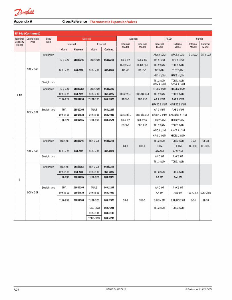
A2�
Appendix A Cross Reference
USCOC.PK.000.C�.22 © Danfoss Inc. 0�-07 (USCO)
R134a (Continued)
NominalCapacity
(Tons)
ConnectionType
Body Type
Danfoss Sporlan ALCO Parker
Internal External InternalModel
ExternalModel
InternalModel
ExternalModel
InternalModel
ExternalModel
Model Code no. Model Code no.
2 1/2
SAE x SAE
Angleway AFA 2 1/2M AFAE 2 1/2M G-2 1/2J GE-2 1/2J
TN 2-2.29 068Z3346 TEN 2-2.29 068Z3348 CJ-2 1/2 CJE 2 1/2 HF 2 1/2M HFE 2 1/2M
Q-6(2.5)-J QE-6(2.5)-J TCL 2 1/2M TCLE 2 1/2M
Orifice 05 068-2008 Orifice 05 068-2008 BFJ-C BFJE-C TI 2 1/2M TIE 2 1/2M
HFK 2 1/2M HFKE 2 1/2M
Straight thru TCL 2 1/2MANC 2 1/2M
TCLE 2 1/2MANCE 2 1/2M
ODF x ODF
Angleway TN 2-2.29 068Z3383 TEN 2-2.29 068Z3385 HFSC 2 1/2M HFESC 2 1/2M
Orifice 05 068-2095 Orifice 05 068-2095 SQ-6(2.5)-J SQE-6(2.5)-J TCL 2 1/2M TCLE 2 1/2M
TUB-2.23 068U2034 TUBE-2.23 068U2025 SBFJ-C SBFJE-C AA 2 1/2M AAE 2 1/2M
HFKSC 2 1/2M HFKESC 2 1/2M
Straight thru TUA 068U2205 TUAE 068U2207 AA 2 1/2M AAE 2 1/2M
Orifice 08 068U1038 Orifice 08 068U1038 EQ-6(2.5)-J EQE-6(2.5)-J BA/BN 2 1/4M BAE/BNE 2 1/4M
TUB-2.23 068U2565 TUBE-2.23 068U2574 SJ-2 1/2 SJE-2 1/2 HFS 2 1/2M HFES 2 1/2M
EBFJ-C EBFJE-C TCL 2 1/2M TCLE 2 1/2M
ANC 2 1/2M ANCE 2 1/2M
HFKS 2 1/2M HFKES 2 1/2M
3
SAE x SAE
Angleway TN 2-2.8 068Z3346 TEN 2-2.8 068Z3348 TCL 3 1/2M TCLE 3 1/2M G-3J GE-3J
CJ-3 CJE-3 TI 3M TIE 3M C-C(3)J CE-C(3)J
Orifice 06 068-2009 Orifice 06 068-2009 AFA 3M AFAE 3M
Straight thru ANC 3M ANCE 3M
TCL 3 1/2M TCLE 3 1/2M
ODF x ODF
Angleway TN 2-2.8 068Z3383 TEN 2-2.8 068Z3385
Orifice 06 068-2096 Orifice 06 068-2096 TCL 3 1/2M TCLE 3 1/2M
TUB-3.32 068U2035 TUBE-3.32 068U2026 AA 3M AAE 3M
Straight thru TUA 068U2205 TUAE 068U2207 ANC 3M ANCE 3M
Orifice 09 068U1039 Orifice 09 068U1039 AA 3M AAE 3M EC-C(3)J ECE-C(3)J
TUB-3.32 068U2566 TUBE-3.32 068U2575 SJ-3 SJE-3 BA/BN 3M BAE/BNE 3M S-3J SE-3J
TCAE- 3.33 068U4281 TCL 3 1/2M TCLE 3 1/2M
Orifice 01 068U4100
TCBE- 3.33 068U4203
Thermostatic Expansion Valves

Appendix A Cross Reference
A27USCOC.PK.000.C�.22© Danfoss Inc. 0�-07 (USCO)
R134a-Extended Capabilities
NominalCapacity
(Tons)
ConnectionType
Body Type
Danfoss Sporlan ALCO Parker
ExternalModel
ExternalModel
ExternalModel
ExternalModel
4
SAE x SAE
Angleway TEN 5-3.7 CJE-3 HFE 4M GE-3J
Orifice 01 BFJE-C TCLE 3 1/2M CE-C(3)J
AFAE 4M
HFKE 4M
Straight thru TCLE 3 1/2M
ANCE 4M
ODF x ODF
Angleway TEN 5-3.7 SBFJE-C HFESC 4M
Orifice 01 TCLE 3 1/2M
AAE 4M
HFKESC 4M
Straight thru TEN 5-3.7 AAE 4M
Orifice 01 EBFJE-C ANCE 4M ECE-C(3)J
TCAE- 3.33 SJE-3 BAE/BNE 3 1/2M SE-3V
Orifice 01 HFES 4M
TCAE- 4.21 TCLE 3 1/2M
Orifice 02 HFKES 4M
TCBE- 3.33
TCBE- 4.21
5
SAE x SAE
Angleway TEN 5-5.4 CJE-5 HFE 6M GE-5J
98145.451 98145.451
Straight thru TCLE 5 1/2M
ODF x ODF
Angleway TEN 5-5.4
Orifice 02 HFESC 6M
TEN 12-4.7 TCLE 5 1/2M
Orifice 01
Straight thru TEN 5-5.4 EBSJE-5 HFES 6M
Orifice 02 SJE-5 TFE 6M SE-5J
TEN 12-4.7 SJE-6 TCLE 5 1/2M RE-6J
Orifice 01 BAE/BNE 4 1/4M
TCAE- 5.41
Orifice 03
TCBE- 5.41
TRE 10-5N
continued next page
Thermostatic Expansion Valves

A2�
Appendix A Cross Reference
USCOC.PK.000.C�.22 © Danfoss Inc. 0�-07 (USCO)
R134a-Extended Capabilities (Continued)
NominalCapacity
(Tons)
ConnectionType
Body Type
Danfoss Sporlan ALCO Parker
ExternalModel
ExternalModel
ExternalModel
ExternalModel
8
SAE x SAE
Angleway TEN 5-8.3 HFE 7 1/2M
Orifice 03 TCLE 7 1/2 M
TCLE 9M
Straight thru TCLE 7 1/2M
TCLE 9M
ODF x ODF
Angleway TEN 5-8.3 HFESC 7 1/2M
98145.451 98145.451
TEN 12-7.7 TCLE 9M
Orifice 02 TJLE 9M
Straight thru TEN 5-8.3 TRAE+ 9M
Orifice 03 EBSJE-7 TFE 8M
TEN 12-7.7 EBSJE-7 HFES 7 1/2M RE-9J
Orifice 02 OJE-9 TCLE 7 1/2M
TRE 10-7N TCLE 9M
TRE 20-7N TJLE 9M
11
SAE x SAE
Angleway TEN 5-11.4 HFE 11M
Orifice 04
Straight thru
ODF x ODF
Angleway TEN 5-11.4 HFESC 11M
Orifice 04 TJLE 11M
TEN 12-11.4 TJR 11M
Orifice 03
Straight thru TEN 5-11.4 OJE-12 HFES 11M RE-12J
Orifice 04 TFE 10M
TEN 12-11.4 TJLE 11M
Orifice 03 TJR 11M
TRE 20-9N
TRE 20-11N
15
SAE x SAEAngleway HFE 14M
Straight thru
ODF x ODF Angleway TEN 12-15Orifice 04
HFESC 14MTJR 13MTER 16M
Straight thru OJE-16 HFES 14M RE-16J
TEN 12-15 TRAE+ 13M
Orifice 04 TRAE+ 14M
TFE 15M
TRE 20-14N TJR 13M
TRE 40-14N TER 16M
Thermostatic Expansion Valves
continued next page

Appendix A Cross Reference
A2�USCOC.PK.000.C�.22© Danfoss Inc. 0�-07 (USCO)
R134a-Extended Capabilities (Continued)
NominalCapacity
(Tons)
ConnectionType
Body Type
Danfoss Sporlan ALCO Parker
ExternalModel
ExternalModel
ExternalModel
ExternalModel
18
SAE x SAEAngleway
Straight thru
98145.451
98145.451 98145.451Orifice 01 98145.451
Straight thru TEN 20-18 OEJ-23 TRAE+ 22M RE-23J
Orifice 01 TER 19M
TRE 40-18N
TRE 40-21N
41
SAE x SAEAngleway
Straight thru
ODF x ODF
Angleway TEN 55-41 TER 25M
Orifice 01 TER 31M
Straight thru TRAE+ 30M RE-40J
TEN 55-41 OJE-32 TRAE 40M
Orifice 01 OJE-40 TER 25M
TRE 40-28N TER 31M
TRE 80-25N
TRE 80-39N
62
SAE x SAEAngleway
Straight thru
ODF x ODF
Angleway TEN 55-62 TIR 45M
Orifice 02 THR 55M
THR 68M
TMR 68M
Straight thru TRAE 45M
TEN 55-62 TRAE 50M
Orifice 02 TIR 45M
TRE 80-56N THR 55M
THR 68M
TMR 68M
Thermostatic Expansion Valves

A�0
Appendix A Cross Reference
USCOC.PK.000.C�.22 © Danfoss Inc. 0�-07 (USCO)
Thermostatic Expansion Valves
R404A / R507
NominalCapacity
(Tons)
ConnectionType
Body Type
Danfoss Sporlan ALCO Parker
Internal External InternalModel
ExternalModel
InternalModel
ExternalModel
InternalModel
ExternalModel
Model Code no. Model Code no.
1/8 SAE x SAE
Angleway FS-1/8 FSE-1/8 HF 1/8 HFE 1/8 G-1/8S GE-1/8S
TS 2-0.12 TSE 2-0.12 GS-1/8 GSE-1/8 AFA 1/8 AFAE 1/8
Orifice 0X Orifice 0X NIS-1/8 HFK 1/8 HFKE 1/8
Straight thru
1/5
ODF x ODF
Angleway TUB-0.13 TUBE-0.13 EGS-1/8 EGSE-1/8 HFSC 1/8 HFESC 1/8 EG-1/8S EGE-1/8S
TS 2-0.12 TSE 2-0.12 AA 1/8 AAE 1/8
Orifice 0X Orifice 0X HFKSC 1/8 HFKESC 1/8
Straight thru TUA 068U2285 TUAE 068U2287 EFS-1/8 EFSE-1/8 AA 1/8 AAE 1/8
Orifice 00 068U1030 Orifice 00 068U1030 HFS 1/8 HFS 1/8
TUB-0.13 TUBE-0.13 HFKS 1/8 HFKES 1/8
SAE x SAE
Angleway GS-1/6 GSE-1/6 TI 1/6 TIE 1/6
TS 2-0.24 068Z3400 TES 2-0.24 068Z3403 FS-1/6 FSE-1/6
Orifice 00 068-2003 Orifice 00 068-2003 Q-0(.17)-S QE-0(.17)-S
BFS-AAA BFSE-AAA
Straight thru
ODF x ODF
Angleway TS 2-0.24 068Z3414 TES 2-0.24 068Z3415 EGS-1/6 EGSE-1/6
Orifice 00 068-2090 Orifice 00 068-2090 SQ-0(.17)-S SQE-0(.17)-S
TUB-0.19 068U2129 TUBE-0.19 068U2135 SBFS-AAA SBFSE-AAA
Straight thru TUA 068U2285 TUAE 068U2287 EFS-1/6 EFSE-1/6
Orifice 01 068U1031 Orifice 01 068U1031 EQ-0(.17)-S EQE-0(.17)-S
TUB-0.19 068U2594 TUBE-0.19 068U2603 EBFS-AAA EBFSE-AAA
1/4
SAE x SAE
Angleway GS-1/4FS-1/4
Q-1(.25)-SNIS-1/4
GSE-1/4FSE-1/4
QE-1(.25)-S
AFA 1/4HF 1/4
TCL 1/4TI 1/3
HFK 1/4
AFAE 1/4HFE 1/4
TCLE 1/4TIE 1/3
HFKE 1/4
G-1/4SN-1/4 S
GE-1/4S
Straight thru TCL 1/4 TCLE 1/4
ODF x ODF
Angleway TUB-0.28 068U2130 TUBE-0.28 068U2136EGS-1/4
SQ-1(.25)-SEGSE-1/4
SQE-1(.25)-S
HFSC 1/4TCL 1/4AA 1/4
HFKSC 1/7
HFESC 1/4TCLE 1/4AAE 1/4
HFKESC 1/4
EG-1/4S EGE-1/4S
Straight thru TUA 068U2285 TUAE 068U2287 AA 1/4 AAE 1/4
Orifice 02 068U1032 Orifice 02 068U1032 EFS-1/4 EFSE-1/4 BA/BN 1/4 BAE/BNE 1/4
TUB-0.28 068U2595 TUBE-0.28 068U2604 EQ-1(.25)-S EQE-1(.25)-S HFS 1/4 HFES 1/4
EMC-10S EMCE-10S TCL 1/4 TCLE 1/4
HFKS 1/4 HFKES 1/4
2/5
SAE x SAE
Angleway TS 2-0.50 068Z3400 TES 2-0.50 068Z3403 BFS-AA BFSE-AA
Orifice 01 068-2010 Orifice 01 068-2010
Straight thru
ODF x ODF
Angleway TS 2-0.50 068Z3414 TES 2-0.50 068Z3415 SBFS-AA SBFSE-AA
Orifice 01 068-2091 Orifice 01 068-2091
TUB-0.38 068U2131 TUBE-0.38 068U2137
Straight thru TUA 068U2285 TUAE 068U2287 EBFS-AA EBFSE-AA
Orifice 03 068U1033 Orifice 03 068U1033
TUB-0.38 068U2596 TUBE-0.38 068U2605
continued next page

Appendix A Cross Reference
A��USCOC.PK.000.C�.22© Danfoss Inc. 0�-07 (USCO)
Thermostatic Expansion Valves
R404A / R507 (Continued)
NominalCapacity
(Tons)
ConnectionType
Body Type
Danfoss Sporlan ALCO Parker
Internal External InternalModel
ExternalModel
InternalModel
ExternalModel
InternalModel
ExternalModel
Model Code no. Model Code no.
1/2
SAE x SAE
Angleway FS-1/2 FSE-1/2 AFA 1/2 AFAE 1/2 G-1/2S GE-1/2S
TS 2-0.73 068Z3400 TES 2-0.73 068Z3403 GS-1/2 GSE-1/2 HF 1/2 HFE 1/2 C-AA(1/2)S CE-AA(1/2)S
Orifice 02 068-2015 Orifice 02 068-2015 Q-2(.5)-S QE-2(.5)-S TCL 1/2 TCLE 1/2 N-1/2S
NIS-1/2 TI 1/2 TIE 1/2
HFK 1/2 HFKE 1/2
Straight thru TCL 1/2 TCLE 1/2
ODF x ODF
Angleway TS 2-0.73 068Z3414 TES 2-0.73 068Z3415 HFSC 1/2 HFESC 1/2
Orifice 02 068-2092 Orifice 02 068-2092 EGS-1/2 EGSE-1/2 TCL 1/2 TCLE 1/2 EG-1/2S EGE-1/2S
TUB-0.58 068U2132 TUBE-0.58 068U2138 SQ-2(.5)-S SQE-2(.5)-S AA 1/2 AAE 1/2 I-1/2S
HFKSC 1/2 HFKESC
Straight thru TUA 068U2285 TUAE 068U2287 AA 1/2 AAE 1/2
Orifice 04 068U1034 Orifice 04 068U1034 EFS-1/2 EFSE-1/2 BA/BN 1/2 BAE/BNE 1/2 EC-AA(1/2)S ECE-AA(1/2)S
TUB-0.58 068U2597 TUBE-0.58 068U2606 EQ-2(.5)-S EQE-2(.5)-S HFS 1/2 HFES 1/2 S-1/2S SE-1/2S
EMC-11S EMCE-11S TCL 1/2 TCLE 1/2
3/4
SAE x SAE
Angleway TI 3/4 TIE 3/4
AFA 3/4 AFAE 3/4
Straight thru
ODF x ODF
Angleway TUB-0.76 068U2133 TUBE-0.76 068U2139 SBFS-A SBFSE-A AA 3/4 AAE 3/4
Straight thru TUA 068U2285 TUAE 068U2287 EBFS-A EBFSE-A AA 3/4 AAE 3/4
Orifice 05 068U1035 Orifice 05 068U1035
TUB-0.76 068U2598 TUBE-0.76 068U2607
1
SAE x SAE
Angleway FS-1 FSE-1
TS 2-1.29 068Z3400 TES 2-1.29 068Z3403 GS-1 GSE-1 AFA 1 AFAE 1 G-1S GE-1S
Orifice 03 068-2006 Orifice 03 068-2006 Q-3(1.0)-S QE-3(1.0)-S HF 1 HFE 1 C-A(1)S CE-A(1)S
NIS-1 TCL 1 TCLE 1
BFS-A BFSE-A TI 1 TIE 1
Straight thru TCL 1 TCLE 1
ODF x ODF
Angleway TS 2-1.29 068Z3414 TES 2-1.29 068Z3415 EGS-1 EGSE-1
Orifice 03 068-2093 Orifice 03 068-2093 SQ-3(1.0)-S SQE-3(1.0)-S HFSC 1 HFESC 1 EG-1S EGE-1S
TUB-1.15 068U2134 TUBE-1.15 068U2185 TCL 1 TCLE 1 I-1S
AA 1 AAE 1
Straight thru TUA 068U2285 TUAE 068U2287 EFS-1 EFSE-1 AA 1 AAE 1
Orifice 06 068U1036 Orifice 06 068U1036 EQ-3(1.0)-S EQE-3(1.0)-S BA/BN 1 BAE/BNE 1 EC-A(1)S ECE-A(1)S
TUB-1.15 068U2599 TUBE-1.15 068U2608 EMC-12S EMCE-12S HFS 1 HFES 1 S-1S SE-1S
EMC-13S EMCE-13S TCL 1 TCLE 1
continued next page

A�2
Appendix A Cross Reference
USCOC.PK.000.C�.22 © Danfoss Inc. 0�-07 (USCO)
R404A / R507 (Continued)
NominalCapacity
(Tons)
ConnectionType
Body Type
Danfoss Sporlan ALCO Parker
Internal External InternalModel
ExternalModel
InternalModel
ExternalModel
InternalModel
ExternalModel
Model Code no. Model Code no.
1 1/2
SAE x SAE
Angleway FS-1 1/2 FSE-1 1/2 AFA 1 1/2 AFAE 1 1/2 G-1 1/2S GE-1 1/2S
TS 2-1.93Orifice 04
068Z3400068-2007
TES 2-1.93Orifice 04
068Z3403068-2007
GS-1 1/2Q-4(1.5)-S
GSE-1 1/2QE-4(1.5)-S
HF 1 1/2TI 1 1/2
HFE 1 1/2TIE 1 1/2
BFS-B BFSE-B
Straight thru
ODF x ODF
Angleway TS 2-1.93 068Z3414 TES 2-1.93 068Z3415 EGS-1 1/2 EGSE-1 1/2 EG-1 1/2S EGE-1 1/2S
Orifice 04 068-2094 Orifice 04 068-2094 SQ-4(1.5)-S SQE-4(1.5)-S HFSC 1 1/2 HFESC 1 1/2
TUB-1.53 068U2100 TUBE-1.53 068U2109 SBFS-B SBFSE-B AA 1 1/4 AAE 1 1/4
Straight thru TUA 068U2285 TUAE 068U2287 EFS-1 1/2 EFSE-1 1/2 AA 1 1/4 AAE 1 1/4
Orifice 07 068U1037 Orifice 07 068U1037 EQ-4(1.5)-S EQE-4(1.5)-S BA/BN 1 1/4 BAE/BNE 1 1/4
TUB-1.53 068U2600 TUBE-1.53 068U2609 EBFS-B EBFSE-B BA/BN 1 1/2 BAE/BNE 1 1/2
HFS 1 1/2 HFES 1 1/2
2
SAE x SAE
Angleway TS 2-2.43 068Z3400 TES 2-2.43 068Z3403 FSE-2 AFA 2 AFAE 2 G-2S GE-2S
CS-2 GSE-2 HF 2 HFE 2 C-B(2)S CE-B(2)S
Orifice 05 068-2008 Orifice 05 068-2008 Q-5(2.0)-S QE-5(2.0)-S TCL 2 TCLE 2 N-2S NE-2S
TI 2 TIE 2
Straight thru TCL 2 TCLE 2
ODF x ODF
Angleway TS 2-2.43 068Z3414 TES 2-2.43 068Z3415 EG-2S EGE-2S
Orifice 05 068-2095 Orifice 05 068-2095 SQ-5(2.0)-S EGSE-2 HFSC 2 HFESC 2
TUB-2.29 068U2101 TUBE-2.29 068U2110 SQE-5(2.0)-S TCL 2 TCLE 2
AA 2 AAE 2
Straight thru TUA 068U2285 TUAE 068U2287 EFSE-2 AA 2 AAE 2
Orifice 08 068U1038 Orifice 08 068U1038 EQ-5(2.0)-S EQE-5(2.0)-S BA/BN 2 BAE/BNE 2 EC-B(2)S ECE-B(2)S
TUB-2.29 068U2601 TUBE-2.29 068U2610 SS-2 SSE-2 HFS 2 HFES 2 S-2S SE-2S
TCL 2 TCLE 2
2 1/2
SAE x SAE
Angleway TS 2-2.97Orifice 06
068Z3400068-2009
TES 2-2.97Orifice 06
068Z3403068-2009
TI 2 1/2AFA 2 1/4AFA 2 1/2
TIE 2 1/2AFAE 2 1/4AFAE 2 1/2
Straight thru
ODF x ODF
Angleway TS 2-2.97Orifice 06
068Z3414068-2096
TES 2-2.97Orifice 06
068Z3415068-2096
AA 2 1/4 AA 2 1/2
AAE 2 1/4AAE 2 1/2
AA 2 1/4 AAE 2 1/4
Straight thru AA 2 1/2 AAE 2 1/2
BA/BN 2 1/2 BAE/BNE 2 1/2
3
SAE x SAE
Angleway TS 2-2.97 068Z3400 TES 2-2.97 068Z3403 BFS-C BFSE-C AFA 3 1/2 AFAE 3 1/2 G-3S GE-3S
Orifice 06 068-2009 Orifice 06 068-2009 CS-3 CSE-3 TCL 3 TCLE 3 HF 3 1/2S HFE 3 1/2S
Q-6(3)-S QE-6(3)-S TI 3 TIE 3
Straight thru TCL 3 TCLE 3
ODF x ODF
Angleway TS 2-2.97Orifice 06
068Z3414068-2096
TES 2-2.97Orifice 06
068Z3415068-2096
SBFS-CSQ-6(3)-S
SBFSE-CSQE-6(3)-S
TCL 3AA 3 1/2
TCLE 3AAE 3 1/2
TUB-3.41 068U2102 TUBE-3.41 068U2111
Straight thru TUA 068U2285 TUAE 068U2287 EQ-6(3)-S EQE-6(3)-S BA/BN 3 BAE/BNE 3
Orifice 09 068U1039 Orifice 09 068U1039 EBFS-C EBSFSE-C AA 3 1/2 AAE 3 1/2
TUB-3.41 068U2602 TUBE-3.41 068U2611 SS-3 SSE-3 TCL 3 TCLE 3
TCAE -3.40 068U4281
Orifice 01 068U4100
TCBE- 3.40 068U4203
Thermostatic Expansion Valves

Appendix A Cross Reference
A��USCOC.PK.000.C�.22© Danfoss Inc. 0�-07 (USCO)
Thermostatic Expansion Valves
R404A / R507-Extended Capabilities
NominalCapacity
(Tons)
ConnectionType
Body Type
Danfoss Sporlan ALCO Parker
ExternalModel
ExternalModel
ExternalModel
ExternalModel
4
SAE x SAE
Angleway
TES 5-3.7 CSE-4 HFE 3 1/2 GE-4S
Orifice 01 AFAE 3 1/2 CE-C(4)S
Straight thru
ODF x ODF
Angleway TES 5-3.7
Orifice 01 HFESC 3 1/2
TES 12-4.2 AAE 3 1/2
Orifice 01
Straight thru TES 5-3.7 AAE 3 1/2
Orifice 01 SSE-4 BAE/BNE 4 ECE-C(4)S
TES 12-4.2 HFES 3 1/2 SE-4S
Orifice 01
TCAE -3.40
Orifice 01
TCAE -4.31
Orifice 02
TCBE- 3.40
TCBE- 4.31
5
SAE x SAE
Angleway TES 5-5.0 HFE 5
Orifice 02 CSE-6 TCLE 4 1/2
Straight thru TCLE 4 1/2
ODF x ODF
Angleway TES 5-5.0 HFESC 5
Orifice 02 TCLE 4 1/2
Straight thru TES 5-5.0 EBSSE-6 HFES 5
Orifice 02 SSE-6 TFE 5
TCAE -5.44 TCLE 4 1/2
Orifice 03
TCBE- 5.44
7
SAE x SAE
Angleway TES 5-7.2 HFE 7
Orifice 03 TCLE 7 GE-6S
TCLE 8
Straight thru TCLE 7
TCLE 8
ODF x ODF
Angleway TES 5-7.2 HFESC 7
Orifice 03 TCLE 7
TES 12-6.8 TCLE 8
Orifice 02 TJLE 7
Straight thru TES 5-7.2 HFES 7
Orifice 03 TRAE+ 8
EBSSE-7 1/2 TFE 7 SE-6S
TES 12-6.8 SSE-7 TCLE 7 RE-6S
Orifice 02 TCLE 8
TRE 10-8S TJLE 7
continued next page

A��
Appendix A Cross Reference
USCOC.PK.000.C�.22 © Danfoss Inc. 0�-07 (USCO)
Thermostatic Expansion Valves
R404A / R507-Extended Capabilities Continued
NominalCapacity
(Tons)
ConnectionType
Body Type
Danfoss Sporlan ALCO Parker
ExternalModel
ExternalModel
ExternalModel
ExternalModel
10
SAE x SAE
Angleway TES 5-10.3Orifice 04
HFE 10
Straight thru
ODF x ODF
Angleway TES 5-10.3Orifice 04
HFESC 10TJLE 9
TES 12-10Orifice 03 TJR 9
Straight thru TES 5-10.3 HFESC 10
Orifice 04 OSE-9 TFE 9 RE-9S
TES 12-10 TJLE 9
Orifice 03 TJR 9
TRE 20-8S
TRE 20-10S
13
SAE x SAEAngleway HFE 13
Straight thru
ODF x ODF
Angleway TES 12-13.4Orifice 04
TJR 12TER 14
Straight thru HFES 13
TES 12-13.4 OSE-12 TRAE+ 12 RE-12S
TFE 14
Orifice 04 TJR 12
TRE 20-12S TER 14
16
SAE x SAEAngleway
Straight thru
ODF x ODF
Angleway TES 20-16.7Orifice 01
TER 16TER 21
Straight thru TES 20-16.7 TRAE+ 14
Orifice 01 OSE-21 TRAE+ 20 RE-21S
TRE 20-16S TER 16
TRE 40-20S TER 21
TRE 40-25S
37
SAE x SAEAngleway
Straight thru
ODF x ODF
Angleway TES 55-37Orifice 01
TER 27TIR 37
Straight thru TES 55-37 OSE-30 TRAE+ 30
Orifice 01 OSE-35 TRAE 35
TRE 40-30S TRAE 40 RE-30S
TRE 40-40S TER 27
TRE 80-40S TIR 37
56
SAE x SAEAngleway
Straight thru
ODF x ODF
Angleway TES 55-56Orifice 02
THR 48THR 60TMR 60
Straight thru TES 55-56Orifice 02 OSE-45 TRAE 50
THR 48 RE-45S
TRE 80-55S THR 60
TRE 80-70S TMR 60

Appendix A Cross Reference
A��USCOC.PK.000.C�.22© Danfoss Inc. 0�-07 (USCO)
Solenoid Valves
Normally Closed
Danfoss Sporlan ALCO Parker
SolenoidValveModel
CapacityTonsR-22
(Liquid)
DanfossPortSize
DanfossCode
Number
ConnectionSize
SolenoidValveModel
CapacityTonsR-22
(Liquid)
SolenoidValveModel
CapacityTonsR-22
(Liquid)
SolenoidValveModel
CapacityTonsR-22
(Liquid)
EVR 2 1.17 3/32 032F7100 1/4 ODF Solder 100RB 2S2 100RB2T2 RB1E2
032F7101 1/4 SAE Flare 100RB 2F2 RB1F2
EVR 3 2.03 1/8 032F7105 1/4 ODF Solder E3S120 A3S1 100RB 2S2 RB1E2
032F1155 1/4 SAE Flare 100RB 2F2 RB1F2
032F1157 3/8 ODF Solder E3S130 A3S1 A3P1 100RB 2S3 200RB3T3 RB1E3
032F1154 3/8 SAE Flare A3F1 100RB 2F3
EVR 4 4.15 5/32
032F7110 3/8 ODF Solder E5S130 200RB 2T3
032F7112 3/8 SAE Flare
032F7111 1/2 ODF Solder
032F7113 1/2 SAE Flare
EVR 6 5.83 15/64
032F7115 3/8 ODF Solder E6S130 B6S1 B6P1 200RB 3T3 RB3E3
032F7116 3/8 ODF Solder w/ man. Stem ME6S130 MB6S1 200RB 3T3-M RB3ME3 R20E83M
032F1160 3/8 SAE Flare B6F1 200RB 4F3 RB3F3
032F1185 3/8 SAE Flare w/ man. Stem MB6F1 4.9 200RB 4F3-M R20F83M 5.7
032F1162 1/2 ODF Solder E6S140 B6S1 200RB 4T4 5.6 RB3E4
032F1159 1/2 SAE Flare
032F7117 5/8 ODF Solder 200RB 4T5
EVR 8 8.01 9/32
032F7120 3/8 ODF Solder E9S230 B9F2 B9P2 200RB 5T3
032F7121 1/2 ODF Solder E9S240 B9S2 200RB 5T4
032F7123 1/2 SAE Flare B10F2 200TB 5F4
032F7122 5/8 ODF Solder 200RB 5T5
EVR 10 13.8 3/8
032F7125 3/8 ODF Solder 200RB 6T3
032F1166 1/2 ODF Solder E10S240 200RB 6T4 RB6E4
032F1188 1/2 ODF Solder w/ man. Stem ME10S240 200RB 6T4-M RB6ME4 R30E124M
032F1165 1/2 SAE Flare B10F2 11.1 200RB 6F4 10 RB6F4 9.5
032F1187 1/2 SAE Flare w/ man. Stem 200RB 6F4-M RB6MF4
032F1168 5/8 ODF Solder E10S250 B10S2 200RB 6T5 RB6E5
032F1167 5/8 SAE Flare 200RB 6F5
EVR 15 18.9 9/16
032F1171 5/8 ODF Solder E14S250 B14S2 240RA 8T5 RB9E5
032F1172 5/8 ODF Solder w/ man. Stem ME14S250 MB14S2 15.8 240RA 8T5-M 15.6 RB9ME5 15.0
032F7130 7/8 ODF Solder 240RA 8T7
continued next page

A��
Appendix A Cross Reference
USCOC.PK.000.C�.22 © Danfoss Inc. 0�-07 (USCO)
Solenoid Valves
Normally Closed (Continued)
Danfoss Sporlan ALCO Parker
SolenoidValveModel
CapacityTonsR-22
(Liquid)
DanfossPortSize
DanfossCode
Number
ConnectionSize
SolenoidValveModel
CapacityTonsR-22
(Liquid)
SolenoidValveModel
CapacityTonsR-22
(Liquid)
SolenoidValveModel
CapacityTonsR-22
(Liquid)
EVR 18 24.6 19/32 032F7135 7/8 ODF Solder E19S270 B19S2 RB15E7 R40E187
32F1004 7/8 ODF Solder w/ man. Stem RB15ME7 R40E187M
032F7136 1 1/8 ODF Solder RB15E9 R40E189
EVR 20 36.4 7/8 032F1176 7/8 ODF Solder B19S2 B25S2 240RA 9T7 240RA 12T7 30.5 34.9 RB21E7 R40E287
032F1177 7/8 ODF Solder w/ man. Stem MB25S2 ME25S270 240RA 9T7-M 240RA 12T7-M
30.5 34.9 RB21ME7 R40E2811 36.0
R40E287M
032F1178 1 1/8 ODF Solder B25P2 2400RA 9T9 240RA 12T9 30.5 34.9 RB21E9 R40E289
032F2272 1 1/8 ODE Solder w/ man. Stem RB21ME9 R40E289M
EVR 22 43.7 9/16 032F7145 1 1/8 ODF Solder E25S290 B25S2
032F7146 1 3/8 ODF Solder
EVR 25 72.8 1 032F1189 1 1/8 ODF Solder E34S290 B33S2 240RA 16T9 RB41E9 R50E329
032F1190 1 1/8 ODF Solder w/ man. Stem ME34S290 MB33S2 240RA 16T9-M RB41ME9 R50E329M
032F1193 1 3/8 ODF Solder E34S2110 B33S2 240RA 16T11 RB41E11 R50E3211
032F1194 1 3/8 ODF Solder w/ man. Stem ME34S2110 MB33S2 240RA 16T11-M RB41ME11 R50E3211M
EVR 32 116.5 7/8 042H1176 1 3/8 ODF Solder 240RA 20T11
042H1177 1 3/8 ODF Solder w/ man. Stem 240RA 20T11-M
042H1178 1 5/8 ODF Solder E42S2130 240RA 20T13
042H1179 1 5/8 ODF Solder w/ man. Stem ME42S2130 MA42S3 240RA 20T13-M
042H1180 2 1/8 ODF Solder E42S2170 240RA 20T17
042H1181 2 1/8 ODF Solder w/ man. Stem ME42S2170 MA42S3 240RA 20T17-M
EVR 40 182.0 1
042H1185 1 5/8 ODF Solder
042H1186 1 5/8 ODF Solder w/ man. Stem
042H1187 2 1/8 ODF Solder
042H1188 2 1/8 ODF Solder w/ man. Stem

Appendix A Cross Reference
A�7USCOC.PK.000.C�.22© Danfoss Inc. 0�-07 (USCO)
Solenoid Valves
Normally Open
Danfoss Sporlan ALCO Parker
SolenoidValveModel
CapacityTonsR-22
(Liquid)
DanfossPortSize
Code no. ConnectionSize
SolenoidValveModel
CapacityTonsR-22
(Liquid)
SolenoidValveModel
CapacityTonsR-22
(Liquid)
SolenoidValveModel
CapacityTonsR-22
(Liquid)
EVR 6 5.80 1/4 032F1164 3/8 ODF Solder ORB3E3
R25E83
032F1163 3/8 SAE Flare ORB3F3
R25F83
EVR 10 13.8 3/8 032F1169 1/2 ODF Solder OR10S240 11.1 ORB6E4 9.5
R35E124
EVR 15 18.9 9/16 032F1174 5/8 ODF Solder OE14S250 15.8 540RA8T5 15.6 ORB9E5 15
OB14S2 R35E155
Note: All capacities are based on liquid R-22 with a ∆p of 3 psi.
Valve Type Danfoss Sporlan Alco Parker
Direct Operated
EVR 2 - EVR 3 E3 - E5 100RB RB1
Servo Diaphragm Operated
EVR 6 - EVR 22 240RB RB3 - RB41
Servo Disc Operated E6 - E19
Servo Piston
Operated
EVR 25 - EVR 40 E24 - E42 200RB

A��
Appendix A Cross Reference
USCOC.PK.000.C�.22 © Danfoss Inc. 0�-07 (USCO)
Standard Liquid Line Filter Driers
Cubic Inches
Danfoss Sporlan Alco Alco Parker
80% Sieve / 20%activate AL (DCL) (C)
Compacted Bead(EK)
Solid Core(ADK)
3
DCL 032 / 032s C-032 / 032s EK-032 / 032s ADK-032 / 032s 032 / 032s
C-032F / 032FM EK-032MF / 032FM 032 MF
DCL 32.5s
DCL 033 / 033s C-033 / 033s EK-033 / 033s ADK-033 / 033s
5
DCL 052 / 052s C-052 / 052s EK-052 / 052s ADK-052 / 052s 052 / 052s
DCL 052.5s C-0525s 0525s
C-052F / 052FM EK-052MF / 052FM
DCL 053 / 053s C-053 / 053s EK-053 / 053s ADK-053 / 053s 053 / 053s
8
DCL 082 / 082s C-082 / 082s EK-082 / 082s ADK-082 / 082s 082 / 082s
EK-082MF / 082FM
DCL 082.5s C-0825s EK-0825s 0825s
DCL 083 / 083s C-083 / 083s EK-083 / EK-083s ADK-083 / 083s 083 / 083s
DCL 084 / 084s C-084 / 084s EK-084 / 084s ADK-084 / 084s 084 / 084s
16
DCL 162 / 162s C-162 / 162s EK-162 / 162s ADK-162 / 162s 162 / 162s
EK-162MF / 162FM
DCL 162.5s C-1625s EK-1625s 1625s
DCL 163 / 163s C-163 / 163s EK-163 / 163s ADK-163 / 163s 163 / 163s
DCL 164 / 164s C-164 / 164s EK-164 / 164s ADK-164 / 164s 164 / 164s
DCL 165 / 165s C-165 / 165s EK-165 / 165s ADK-165 / 165s 165 / 165s
DCL 166 / 166s 166
DCL 167s C-167s EK-167s ADK-167s
30
DCL 303 / 303s C-303 / 303s EK-303 / 303s ADK-303 / 303s 303 / 303s
DCL 304 / 304s C-304 / 304s EK-304 / 304s ADK-304 / 304s 304 / 304s
DCL 305 / 305s C-305 / 305s EDK-305 / 305s ADK-305 / 305s 305 / 305s
DCL 306 / 306s C-306s EK-306s ADK-306s 306
DCL 307s C-307s EK-307s ADK-307s 307s
DCL 309s C-309s EK-309s ADK-309s
41
DCL 413 C-413 EK-413 ADK-413 413
DCL 414 / 414s C-414 / 414s EK-414 / 414s ADK-414 / 414s 414 / 414s
DCL 415 / 415s C-415 / 415s EK-415 / 415s ADK-415 / 415s 415 / 415s
DCL 417s C-417s EK-417s ADK-417s 417s
DCL 419s C-419s EK-419s ADK-419s
60
DCL 604s
DCL 607s C-607s
DCL 609s C-609s
75
756s
DCL 757s 757s EK-757s ADK-757s 757s
DCL 759s 759s EK-759s ADK-759s 759s
Filter Driers

Appendix A Cross Reference
A��USCOC.PK.000.C�.22© Danfoss Inc. 0�-07 (USCO)
Filter Driers
High Capacity Liquid Line Filter Driers
Cubic Inches
Danfoss Sporlan Alco
100% Sieve(DML) (CW) (UK)
3
DML 032 / 032s CW-032 / 032s UK-032 / 032s
DML 32.5s
DML 033 / 033s CW-033 / 033s UK-033 / 033s
DML 34s
5
DML 052 / 052s CW-052 / 052s UK-052 / 052s
DML 052.5s UK-0525s
DML 053 / 053s CW-053 / 053s UK-053 / 053s
DML 54s
DML 55s UK-054 / 054s
8
DML 082 / 082s CW-082 / 082s UK-082 / 082s
DML 082.5s CW-0825s UK-0825s
DML 083 / 083s CW-083 / 083S UK-083 / 083s
DML 084 / 084s CW-084 / 084s UK-084 / 084s
DML 085 / 85s UK-085 / 085s
16
DML 162 / 162s CW-162 / 162s UK-162 / 162s
DML 162.5s
DML 163 / 163s CW-163 / 163s UK-163 / 163s
DML 164 / 164s CW-164 / 164s UK-164 / 164s
DML 165 / 165s CW-165 / 165s UK-165 / 165s
DML 166 / 166s
DML 167s UK-166s
30
DML 303 / 303s CW-303 UK-303 / 303s
DML 304 / 304s CW-304 / 304s UK-304 / 304s
DML 305 / 305s CW-305 / 305s UK-305 / 305s
DML 306 / 306s
DML 307s CW-307s UK-307s
DML 309s
41
DML 413
DML 414 / 414s CW-414 / 414s UK-414 / 414s
DML 415 / 415s CW-415 / 415s UK-415 / 415s
DML 417s UK-417s
DML 419s CW-419s UK-419s
60
DML 604s
DML 605
DML 606s
DML 607s CW-607s
DML 609s CW-609s
75DML 757s
DML 759s

A�0
Appendix A Cross Reference
USCOC.PK.000.C�.22 © Danfoss Inc. 0�-07 (USCO)
Bi flow Filter Driers
Cubic Inches
Danfoss Sporlan Alco Parker
100% MolecularSieves (HPC) (BF)
8 DMB 082 / 082s BF-082s
DMB 083 / 083s HPC-103 / 103s BF-083 / 083s
DMB 084 / 084s HPC-104 / 104s BF-084 / 084s
16 DMB 162 BF-162s
DMB 163 / 163s BF-163 / 163s
DMB 164 / 164s BF-164 / 164s
DMB 165 / 165s BF165s
30 DMB 303
DMB 304 / 304s
DMB 305 / 305s
DMB 307s
Cubic Inches
Danfoss Sporlan Alco Parker
80% Sieve / 20%activate AL (DCB) (BFK)
8 DCB 082 / 082s BFK-052 / 052s
DCB 083 / 083s BFK-053 / 053s
BFK-083 / 083s
DCB 084 / 084s BFK-084 / 084s
BFK-085 / 085s
16 DCB 162
DCB 163 / 163s BFK-163 / 163s
DCB 164 / 164s BFK-164 / 164s
DCB 165 / 165s BFK-165 / 165s
30 DCB 303 BFK-303 /303s
DCB 304 / 304s BFK-304 / 304s
DCB 305 / 305s BFK-305 / 305s
98145.451 98145.451
98145.451
BFK-309s
Filter Driers

Appendix A Cross Reference
A��USCOC.PK.000.C�.22© Danfoss Inc. 0�-07 (USCO)
Replaceable Core Filter Drier Cross Reference
Cubic Inches
Danfoss Sporlan Alco Parker
Shell(DCR)
CodeNumber (C) (EK)
48
DCR 0485s 023U2250 C-485-G STAS-485T P485
DCR 0487s 023U2251 C-487-G STAS-487T P487
DCR 0489s 023U2253 C-489-G STAS-489T P489
DCR 04811s 023U2254 C-4811-G STAS-4811T P4811
DCR 04813s 023U2255 C-4813-G STAS-4813S-V P4813
DCR 04817s 023U2257 STAS-4817S-V P4817
DCR 04821s 023U2276 STAS-4821S-V P4821
96
DCR 0967s 023U2258 C-967-G STAS-967T P967
DCR 0969s 023U2260 C-969-G STAS-969T P969
DCR 09611S 023U2261 C-9611-G STAS-9611T P9611
DCR 09613S 023U2262 C-9613-G STAS-9613T P9613
DCR 09617S 023U2264 STAS-9617S-V P9617
144
DCR 1449S 023U2266 C-1449-G STAS-1449T P1449
DCR 14411S 023U2267 C-14411-G STAS-14411T P14411
DCR 14413S 023U2268 C-14413-G STAS-14413T P14413
DCR 14417S 023U2270 STAS-14417T P14417
192
DCR 19211S 023U2271 C-19211-G STAS-19211T P19211
DCR 19213S 023U2272 C-19213-G STAS-19213T P19213
DCR 19217S 023U2274 C-19217-G STAS-19217T P19217
300None C-30013-G ADKS-30013T
C-30017-G ADKS-30017T
400
None C-40017-G ADKS-40017T
C-40021-G ADKS-40021T
C-40025-G
C-40029-G
C-40033-G
Filter Driers
Danfoss Sporlan Alco Parker
CoreModel
CodeNumber
CoreDescription
CoreModel
CoreModel
CoreModel
48-DN 023U4081 80% MS / 20% AA RCW-48 UK-48 PCX-48
48-DU 023U1092 100% Molec. Sieve HX-48 Z-48
48-DA 023U5081 Burn out RC-4864-HH W-48 PCK-48HH
48-F 023U1621 Dirt Filter RPE-48-BD F-48 PFE-48-BF

USCOC.PK.000.C�.22 © Danfoss Inc. 0�-07 (USCO)
Sight Glasses
Danfoss Sporlan Alco Parker
Model Code no. Connection Type Connection Size (inches)
Model Model Model
SGN 6 014-0132 1/4 x 1/4 SA-12 ALM-1MM2 AMI-1MM2 PSG-2
SGN 10 014-0133 Flare 3/8 x3/8 SA-13 ALM-1MM3 AMI-1MM3 PSG-3
SGN 12 014-0134 ext. x ext. 1/2 x 1/2 SA-14 ALM-1MM4 AMI-1MM4 PSG-4
SGN 16 014-0135 5/8 x 5/8 SA-15 ALM-1MM5 AMI-1MM5 PSG-5
SGN 6 014-0137 1/4 x 1/4 SA-12FM ALM-1FM2 AMI-1FM2 PSG-2MF
SGN 10 014-0138/ Flare 3/8 x 3/8 SA-13FM ALM-1FM3 AMI-1FM3 PSG-3MF
SGN 12 014-0139 int. x ext. 1/2 x 1/2 SA-14FM ALM-1FM4 AMI-1FM4 PSG-4MF
SGN 16 014-0140 5/8 x 5/8 PSG-5MF
SGN 6s 014-0142 1/4 x 1/4 SA-12S ALM 1TT2 PSG-2S
SGN 10s 014-0143 ODF x ODF 3/8 x 3/8 SA-13S ALM 1TT3 PSG-3S
SGN 12s 014-0144 solder 1/2 x 1/2 SA-14S ALM 1TT4 PSG-4S
SGN 16s 014-0145 5/8 x 5/8 SA-15S ALM 1TT5 PSG-5S
SGN 22s 014-0147 7/8 x 7/8 SA-17S ALM 1TT7 PSG-7S
SGN 6s 014-0151 1/4 x 1/4
SGN 10s 014-0152 ODF x ODM 3/8 x 3/8
SGN 12s 014-0153 solder 1/2 x 1/2
SGN 16s 014-0154 5/8 x5/8
SGN 22s 014-0156 7/8 x 7/8
SGRN 1/2 014-0006 NPT 1/2
Danfoss offers two different types of sight glasses. Type “N” provides optimal moisture indicationfor all HCFC and HFC refrigerants. Type “I” provides optimal moisture indication for all CFC refrigerants.
Sight Glasses
A�2
Appendix A Cross Reference

A��USCOC.PK.000.C�.22© Danfoss Inc. 0�-07 (USCO)
Pressure Regulators
Application Danfoss Sporlan Alco
Model NominalCapacity
Code No.
Connection Size (inches)
Model Nominal Capacity
Model NominalCapacity
Evaporator
KVP 12 1.3 034L0021 1/2“ Flare ORIT 6 1.27 IPR-6 0.8
KVP 12 1.3 034L0023 1/2“ ODF ORIT-6 1.27 IPR-6 0.8
KVP 15 1.3 034L0022 5/8“ Flare ORIT 6 1.27 IPR-6 0.8
KVP 15 1.3 034L0029 5/8“ ODF ORIT 6 1.27 IPR-6 0.8
KVP 22 1.3 034L0025 7/8“ ODF ORIT 6 1.27 IPR-6 0.8
KVP 28 2.8 034L0026 1 1/8“ ODF ORIT 10 3.13 IPR-10 2.0
KVP 35 2.8 034L0032 1 1 3/8“ ODF ORIT 10 3.13 IPR-10 2.0
PKV 12 5.2 034N1051 1 1/8“ ODF ORIT 12 4.57 EPRB 12 4.47
PKVS 12 5.2 034N1060 1 1/8“ ODF SORIT 12 4.57 EPRBS 12 4.47
PKV 15 8.3 034N1052 1 1 3/8“ ODF ORIT 15 7.54 EPRB 16 7.88
PKVS 15 8.3 034N1061 1 1 3/8“ ODF SORIT 15 7.54 EPRBS 16 7.88
PKV 20 13.5 034N1053 1 5/8“ ODF ORIT 20 16.5 EPRB 20 14.7
PKVS 20 13.5 034N1062 1 5/8“ ODF SORIT 20 16.5 EPRBS 20 14.7
Condenser
KVR 12 7 034L0091 1/2“ Flare
KVR 12 7 034L0093 1/2“ ODF
KVR 15 7 034L0092 5/8“ Flare
KVR 15 7 034L0097 5/8“ ODF ORI-6 12
KVR 22 7 034L0094 7/8“ ODF ORI-6 12
KVR 28 17.9 034L0095 1 1 1/8“ ODF ORI-10 24
KVR 35 17.9 034L0100 1 1 3/8“ ODF ORI-10 24
NRD 020-1132 1/2“ ODF ORD-4
1 3/8“ ODF LAC-4-180 3.92 HP5T-170 3.2
5/8“ / 7/8“ ODF OROA5 100 14.5 HP8T-95 8.5
None 5/8“ / 7/8“ ODF OROA5 180 14.5 HP8T-170 8.5
7/8“ / 1-1/8“ / 1-1 3/8“
None HP14T-105 20.8
7/8“ / 1-1/8“ / 1-1 3/8“
None HP14T-160 20.8
Pressure Regulators
continued next page
Appendix A Cross Reference

USCOC.PK.000.C�.22 © Danfoss Inc. 0�-07 (USCO)
Pressure Regulators (Continued)
PressureRegulator
Application
Danfoss Sporlan Alco
Model NominalCapacity
Code No.
Connection Size
Model Nominal Capacity
Model NominalCapacity
Capacity / Hot Gas
Bypass
KVC 12 2.1 034L0141 1/2“ Flare
KVC 12 2.1 034L0143 1/2“ ODF CPHE 2 1.2
CPHE-3 2.3
KVC 15 4.2 034L0142 5/8“ Flare None
KVC 15 4.2 034L0147 5/8“ ODF
KVC 22 5.4 034L0144 7/8“ ODF CPHE 4 5.5
CPHE 5 6.7
CPCE 12 6.2 034N0081 1/2“ Flare ADRSE 2 3.7 DGRE-6 6
CPCE 12 6.2 034N0082 1/2“ ODF ADRSE 2 3.7 DGRE-6 6
CPCE 15 9.2 034N0083 5/8“ ODF ADRPE 3 7.2 DGRE-12 15.4
CPCE 22 12.2 034N0084 7/8“ ODF ADRHE 6 11.4 DGRE-12 15.4
Crankcase
KVL 12 1.2 034L0041 1/2“ Flare CRO-6 1.2 OPR 6 0.9
KVL 12 1.2 034L0043 1/2“ ODF CRO-6 1.2 OPR 6 0.9
KVL 15 1.2 034L0042 5/8“ Flare CRO-6 1.2 OPR 6 0.9
KVL 15 1.2 034L0049 5/8“ ODF CRO-6 1.2 OPR 6 0.9
KVL 22 1.2 034L0045 7/8“ ODF CRO-6 1.2 OPR 6 0.9
KVL 28 4.1 034L0046 1 1/8“ ODF CRO-10 3.5 OPR 10 2.3
KVL 35 4.1 034L0052 1 1 3/8“ ODF CRO-10 3.5 OPR 10 2.3
Receiver
KVD 12 034L0171 1/2“ Flare
KVD 12 034L0173 1/2“ ODF
KVD 15 034L0172 5/8“ Flare
KVD 15 034L0177 5/8“ ODF
Electronic
KVQ 15 2.3 034L0117 5/8“ ODF
KVQ 22 2.3 034L0114 7/8“ ODF ESR 12 5.8
KVQ 28 5.4 034L0115 1 1/8“ ODF
KVQ 35 5.4 034L0120 1 3/8“ ODF ESR 20 13.4
Pressure Regulators
All capacities are based on R-22. Competitor capacities are approximate values and are sized with similar sizing characteristics comparable to Danfoss nominal capacity characteristics.
A��
Appendix A Cross Reference
Prressure Controls, type KPU
Type ofControl
Danfoss Penn/Johnson Ranco Alco
ModelRange(psig)
Diff.(psig)
Code No.
ConnectionType Model
Range(psig) Model
Range(psig)
Diff.(psig) Model
Range(psig)
Diff.(psig)
Low Pressure
KPU-1 6 in - 108 10 - 58 060-5236* 1/4” Flare P170-AB2 20 in - 100 010-1831 10 in - 100 10 - 40
KPU-1 6 in - 108 10 - 58 060-5231 1/4” Flare
P70AB-1 20 in - 100 O10-1831 10 in - 100 10 - 40 FF115-S3 BAA 15 in - 100 7 - 70
PS1-X3A
P170AB-2 20 in - 100 O11-1799 10 in - 100 10 - 40
P270AB-2 20 in - 100 O16-107 10 in - 100 10 - 40
P170AB-12 12 in - 80
P270AB-12 12 in - 80
P170CA-1 20 in - 100
P270CA-1 20 in - 100
KPU-1 6 in - 108 10 - 58 060-5233 w/ Cap. Tube
P70CA-1 20 in - 100 O10-1483 10 in - 100 10 - 40 FF115-S3 BAK 15 in - 100 7 - 70
P70AB-2 20 in - 100 O10-1093 PS1-X3K
P70AA-2 0 - 150 O11-3099 10 in - 100 10 - 40
P70AB-12 12 in - 80 O16-527 10 in - 100 10 - 40
P70AA-176 20 in - 100 O20-7004 10 in - 100 10 - 40
O16-166 50 - 150 10 - 40
KPU-1 27 in - 100 fixed 10 060-5232 1/4” FlareP70EA-10 20 in - 100 O16-585 10 in to 100
KPU-1 27 in - 100 fixed 10 060-5234 w/ Cap. TubeO16-261 10 in to 100
KPU-2 6 in - 50 6 - 30 060-5239 1/4” FlareP70AB-1 20 in - 100 O10-1401 12 in - 50 5 - 35
O16-120 12 in - 50 5 - 35
KPU-2 6 in - 50 6 - 30 060-5240 w/ Cap. Tube
P70AB-2 20 in - 100 O10-1402 12 in - 50 5 - 35 FF115-S1 BAK 24 in - 42 3 - 30
P70CA-1 20 in - 100 O10-1842 12 in - 50 5 - 35 PS1-X1K
O16-557 12 in - 50 5 - 35
O20-7002 10 in - 100 10 - 40
KPU-2 6 in - 72.5 6 - 30 060-5237* 1/4” FlareP170AB-12 12 in - 80 010-1401 12 in - 50 5 - 35
KPU-2 6 in - 72.5 6 - 30 060-5235* w/ Cap. Tube P70AB-12 12 in - 80 010-1402 12 in - 50 5 - 35

A��USCOC.PK.000.C�.22© Danfoss Inc. 0�-07 (USCO)
Appendix A Cross Reference Pressure Controls
Prressure Controls, type KPU
Type ofControl
Danfoss Penn/Johnson Ranco Alco
ModelRange(psig)
Diff.(psig)
Code No.
ConnectionType Model
Range(psig) Model
Range(psig)
Diff.(psig) Model
Range(psig)
Diff.(psig)
Low Pressure
KPU-1 6 in - 108 10 - 58 060-5236* 1/4” Flare P170-AB2 20 in - 100 010-1831 10 in - 100 10 - 40
KPU-1 6 in - 108 10 - 58 060-5231 1/4” Flare
P70AB-1 20 in - 100 O10-1831 10 in - 100 10 - 40 FF115-S3 BAA 15 in - 100 7 - 70
PS1-X3A
P170AB-2 20 in - 100 O11-1799 10 in - 100 10 - 40
P270AB-2 20 in - 100 O16-107 10 in - 100 10 - 40
P170AB-12 12 in - 80
P270AB-12 12 in - 80
P170CA-1 20 in - 100
P270CA-1 20 in - 100
KPU-1 6 in - 108 10 - 58 060-5233 w/ Cap. Tube
P70CA-1 20 in - 100 O10-1483 10 in - 100 10 - 40 FF115-S3 BAK 15 in - 100 7 - 70
P70AB-2 20 in - 100 O10-1093 PS1-X3K
P70AA-2 0 - 150 O11-3099 10 in - 100 10 - 40
P70AB-12 12 in - 80 O16-527 10 in - 100 10 - 40
P70AA-176 20 in - 100 O20-7004 10 in - 100 10 - 40
O16-166 50 - 150 10 - 40
KPU-1 27 in - 100 fixed 10 060-5232 1/4” FlareP70EA-10 20 in - 100 O16-585 10 in to 100
KPU-1 27 in - 100 fixed 10 060-5234 w/ Cap. TubeO16-261 10 in to 100
KPU-2 6 in - 50 6 - 30 060-5239 1/4” FlareP70AB-1 20 in - 100 O10-1401 12 in - 50 5 - 35
O16-120 12 in - 50 5 - 35
KPU-2 6 in - 50 6 - 30 060-5240 w/ Cap. Tube
P70AB-2 20 in - 100 O10-1402 12 in - 50 5 - 35 FF115-S1 BAK 24 in - 42 3 - 30
P70CA-1 20 in - 100 O10-1842 12 in - 50 5 - 35 PS1-X1K
O16-557 12 in - 50 5 - 35
O20-7002 10 in - 100 10 - 40
KPU-2 6 in - 72.5 6 - 30 060-5237* 1/4” FlareP170AB-12 12 in - 80 010-1401 12 in - 50 5 - 35
KPU-2 6 in - 72.5 6 - 30 060-5235* w/ Cap. Tube P70AB-12 12 in - 80 010-1402 12 in - 50 5 - 35
* Indicates SPST**Indicates a LP and HP Signal

USCOC.PK.000.C�.22 © Danfoss Inc. 0�-07 (USCO)A��
Appendix A Cross Reference Pressure Controls
* Indicates SPST**Indicates a LP and HP Signal
Pressure Controls, type KPU (Continued)
Type ofControl
Danfoss Penn/Johnson Ranco Alco
ModelRange(psig)
Diff.(psig)
Code No.
ConnectionType Model
Range(psig) Model
Range(psig)
Diff.(psig) Model
Range(psig)
Diff.(psig)
High Pressure
KPU-5 100 - 465 25 - 85 060-5241* 1/4” FlareP170AA-118 100-400 O10-1807 100 - 250 20 - 100 FF115-S5 BAA 90 - 450 30 - 220
010-1894 PS1-X5A
KPU-5 100 - 465 25 - 85 060-5242* w/ Cap. Tube
P70AA-118 100 - 400 O10-2000 100 - 250 20 - 100 FF115-S5 BAK 90 - 450 30 - 220
PS1-X5K
FF115-S4 BAK 15 - 290 29 - 217
PS1-X4K
KPU-6W 100 - 465 58 - 140 060-5243 1/4” Flare
P70CA-3 50 - 450 O10-1807 100 - 250 20 - 100
P170AA-118 100 - 400 O10-1894 100 - 400 35 - 150
P170CA-3 50 - 450 O16-570 100 - 400 35 - 150
O11-1713 150 - 450 35 - 150
O16-583 150 - 450 35 - 150
KPU-6W 100 - 465 58 - 140 060-5245 w/ Cap. Tube
P70CA-3 50 - 450 O10-2000 100 - 250 100 - 250
P70AA-118 100-400 O10-2054 100 - 400 35 - 150
O16-108 100 - 400 35 - 150
P270AA-118 100 - 400 O20-7006 100 - 400 35 - 150
P270CA-3 50 - 450 O11-1711 150 - 400 35 - 150
KPU-6B 116 - 465 fixed 58 060-5244 1/4” FlareP170DA-1 50 - 450 O16-209 150 - 450 FF115-S5 BRA 90 - 450 fixed 60
P170KA-1 50 - 450 PS1-Y5A
KPU-6B 116 - 465 fixed 58 060-5246 w/ Cap. Tube
P70DA-1 50 - 450 O16-211 150 - 450 FF115-S5 BRK 90 - 450 fixed 60
P70KA-1 50 - 450 O16-142 100 - 400 fixed 17 PS1-Y5K
P270DA-1 50 - 450
P270KA-1 50 - 450

A�7USCOC.PK.000.C�.22© Danfoss Inc. 0�-07 (USCO)
Appendix A Cross Reference Pressure Controls
* Indicates SPST**Indicates a LP and HP Signal
Pressure Controls, type KPU (Continued)
Type ofControl
Danfoss Penn /Johnson Ranco Alco
ModelRange(psig)
Diff.(psig)
Code No.
ConnectionType Model
Range(psig) Model
Range(psig)
Diff.(psig) Model
Range(psig)
Diff.(psig)
Dual Pressure Controls
KPU-15 6 in - 108100 - 465
10 - 58fixed 58 060-5247 1/4” Flare
P170LB-1 20 in - 100 O12-1505 12 in - 50 5 - 35 FF215-S7 BAUA 15 in - 100 7 - 70
100 - 425 100 - 250 fixed 50 PS2-Y7A 90 - 450 fixed 60
P170LB-6 12 in - 80 O10-4139
100 - 425
P170LN-8 O12-1550 10 in - 100 10 - 40
150 - 450 fixed 70
P170LN-9
KPU-15 6 in - 108100 - 465
10 - 58fixed 58 060-5248 w/ Cap. Tube
P70LB-6 12 in - 80 O12-1506 12 in - 50 5 - 35 FF215-S7 BAUK 15 in - 100 7 - 70
100 - 425 100 - 250 fixed 50 P2-Y7K 90 - 450 fixed 60
P70LB-1 20 in - 100 O12-1554 12 in - 50 5 - 35
100 - 425 100 - 250 fixed 50
O12-1502 12 in - 50 5 - 35
150 - 450 fixed 70
O12-1549 10 in - 100 10 - 40
150 - 450 fixed 70
P270LB-1 20 in - 100
100 - 425
P270LB-6 12 in - 80
100 - 425
P270LN-8
P270LN-9
KPU-15 6 in - 108100 - 465
10 - 58fixed 58 060-5249 1/4” Flare
P170MA-1 20 in - 100 FF215-S7 BAUA 15 in - 100 7 - 70
100 - 425 PS2-Y7A 90 - 450 fixed 60
P170MA-18 12 in - 80
100 - 425

USCOC.PK.000.C�.22 © Danfoss Inc. 0�-07 (USCO)A��
Appendix A Cross Reference Pressure Controls
* Indicates SPST**Indicates a LP and HP Signal
Pressure Controls , type KPU (Continued)
Type ofControl
Danfoss Penn /Johnson Ranco Alco
ModelRange(psig)
Diff.(psig)
Code Number
ConnectionType Model
Range(psig) Model
Range(psig)
Diff.(psig) Model
Range(psig)
Diff.(psig)
Dual Pressure Controls
KPU-15 6 in - 108100 - 465
10 - 58fixed 58 060-5250 w/ Cap.
Tube
P70MA-18 12 in - 80100 - 425
O12-4834 10 in - 100150 - 450
10 - 40fixed 70
FF215-S7 BAUAPS2-Y7A
15 in - 10090 - 450
7 - 70fixed 60
P70MA-1 20 in - 100100 - 425
P270MA-1 20 in - 100100 - 425
P270MA-18 12 in - 80100 - 425
KPU-16W 6 in - 108100 - 465
10 - 58fixed 58 060-5252 w/ Cap.
Tube
P70LB-6 12 in - 80 O12-1506 12 in - 50 5 - 35
100 - 425 100 - 250 fixed 50
P70LB-1 20 in - 100 O12-1554 12 in - 50 5 - 35
100 - 425 100 - 250 fixed 50
O12-1502 12 in - 50 5 - 35
150 - 450 fixed 70
O12-1549 10 in - 100 10 - 40
150 - 450 fixed 70
KPU-16W “6 in - 108100-465”
10-58fixed58 060-5251 1/4” Flare
P170LB-6 12 in - 80 012-1505 12 in - 50 5 - 35
100 - 425 100 - 250 fixed 50
P170LB-1 20 in - 100 012-4139 5 to 35
100 - 425 150 to 450
012-1550 10 in - 100 10 - 40 FF215-S9 BAUK 24 in - 42 3 - 30
150 - 450 fixed 70 PS-Y9K 90 - 450 fixed 60
KPU-16B 6 in - 108100 - 465
10 - 58fixed 58 060-5254** w/ Cap. Tube
P70LB-6 12 in - 80 O12-1506 12 in - 50 5 - 35
100 - 425 100 - 250 fixed 50
P70LB-1 20 in - 100 O12-1554 12 in - 50 5 - 35
100 - 425 100 - 250 fixed 50
O12-1502 12 in - 50 5 - 35
150 - 450 fixed 70
O12-1549 10 in - 100 10 - 40
150 - 450 fixed 70
P70NA-1 20 in - 100 O12-1594 10 in - 100 10 - 40
100 - 500 150 - 450 fixed 70
P70SA-1 12 in - 80 O12-4840 10 in - 100 10 - 40
100 - 500 150 - 450 fixed 70
KPU-16B“10 - 58
060 5253**
“6 in - 1081/4” Flare
10 - 58fixed 58 060-5253** 1/4” Flare
P70LB-6 12 in - 80 O12-1506 12 in - 50 5 - 35
100 - 425 100 - 250 fixed 50
PL170LB-1 20 in - 100 012-4139 5 to 35
100 - 425 100 - 250
PL170LB-1 12 IN - 80 012-1550 10 in - 100 10 - 40
100 - 425 150 to 450 fixed 70
P170MA-18 12 in - 80 012-1550 10 in - 100 10 - 40
100 - 425 150 - 450 fixed 70
P170NA-1 20 in - 100 012-4147 10 in - 100 10 - 40
100 - 500 150 to 450 fixed 70
P170SA-1 12 in - 80 012-4846 10 in - 100 10 - 40
100 - 500 150 to 450 fixed 70

A��USCOC.PK.000.C�.22© Danfoss Inc. 0�-07 (USCO)
Appendix A Cross Reference Thermostats
Thermostat Cross Reference
Danfoss Penn/Johnson Ranco Alco
Type ofCharge Model
Range(°F)
Diff.Low (°F) Reset
Cap tubelength (in)
BulbType
Code Number Model
Range(°F)
Diff.(°F) Model
Range(°F)
Diff.(°F) Model
Range(°F)
Diff.(°F)
Vapor
KPU-61
-20 to 60 10 to 40 Auto. 80 Cap Tube 060L5201 016-588 -15 to 40 1.5 fixed
016-111 0 to 55 3 to 20
010-1416 0 to 55 3 to 20
010-1010 0 to 55 7 to 55
KPU-61 -20 to 60 10 to 40 Auto. 200 Cap Tube 060L5202
KPU-61 -20 to 60 8 to 40 Auto. 80 Remote Air Coil 060L5203
KPU-61
-20 to 60 fixed 11 Man.(3) 80 Remote Air Coil 010-1408 -15 to 40 3 to 20 TF115-S2
AA10 -20 to 60 3 to 30
060L5204 A19ACA-14 -30 to 110 Man. 010-1409 0 to 55 3 to 20 TS1-X2A 21/30 -20 to 60 3 to 30
016-104 0 to 55 3 to 20
010-1490 0 to 55 2
KPU-61 -20 to 60 fixed 11 Man.(3) 200 Remote Air Coil 060L5205 A19ACA-15 -30 to 110 Man.
KPU-61 -20 to 60 8 to 40 Auto.(4) 80 Remote Air Coil 060L5210
KPU-62 -20 to 60 10 to 40 Auto. 0 Room Sensor 060L5206 A19BBC-2 -30 to 110 3 to 12 010-1418 0 to 55 3 to 20
KPU-63-60 to 15 18 to 125 Auto. 80 Cap Tube 060L5213 010-1000 -55 to 0 3 to 20
010-1433 -35 to 15 3 to 20
KPU-63 -60 to 15 18 to 125 Auto. 80 Remote Air Coil 060L5214
KPU-68
25 to 95 8 to 45 Auto. 0 Room Sensor 060L5215 A19BAB-3 35 to 95 fixed 3.5 010-1802 25 to 75 3 to 20 TF115-S3AE00 -15 to 95 3 to 30
A19BAC-1 30 to 110 fixed 3.5 016-595 50 to 105 3 to 20 TS1-X3E 64/68 -15 to 95 3 to 30
A19BBC-2 -30 to 110 fixed 3.5 TF115-S2AE00 -20 to 60 3 to 30
TS1-X2E 36/40 -20 to 60 3 to 30
KPU-6925 to 95 8 to 45 Auto. 0 Remote Air
Coil 060L5217 010-1410 25 to 75 3 to 20
010-1491 25 to 75 2
Adsorption
KPU-62 -20 to 60 9 to 36 Auto.(4) 0 Room Sensor 060L5207
KPU-73
-15 to 60 6 to 18 Auto. 80 Remote Bulb 060L5208 A19ABC-24 -30 to 100 3 to 12 010-1409 0 to 55 3 to 20 TF115-S4AF10 -20 to 95 5 to 35
A19ABA-40 -30 to 110 3 to 12 060-100 -35 to 95 3.5 to 50 TS1-X4F 32/41 -20 to 95 5 to 35
010-1408 -15 to 40 3 to 20
KPU-73 -15 to 60 22 to 125 Auto. 80 Remote Bulb 060L5209
KPU-73 -15 to 60 fixed 6 Man.(3) 80 Remote Bulb 060L5211 016-264 0 to 55
016-263 0 to 55
KPU-73 -20 to 60 4 to 10 Auto. 80Double Contact
Remote Bulb060L5212
KPU-71
25 to 70 5.5 to 18 Auto. 80 Remote Bulb 060L5218 010-1410 25 to 75 3 to 20
020-8005 25 to 75 3 to 20
010-1491 25 to 75 2 fixed
016-601 22.5 to 47.5 1.5 fixed
KPU-71 25 to 60 fixed 5 Man.(3) 80 Remote Bulb 060L5216 A70GA2C 35 to 80 3 to 30
KPU-74 0 to 80 10 to 35 Auto. 80 Remote Bulb 060L5219 A19AAC-4C 0 to 80 fixed 5 016-104 0 to 55 3 to 20
010-1473 0 to 55 7 to 55
KPU-74
0 to 80 fixed 9 Man.(3) 80 Remote Bulb 060L5220 016-263 0 to 55 TF115-S4AF10
-20 to 95 5 to 35
TS1-X4F 32/41 -20 to 95 5 to 35
KPU-75 32 to 95 6.3 to 30 Auto. 80 Remote Duct Coil
060L5221
KPU-75 32 to 95 6.3 to 30 Auto. 80 Remote Bulb 060L5222 020-7013 50 to 105 3 to 20
KPU-77 70 to 140 6.3 to 18 Auto. 80 Remote Bulb 060L5223 A19ABC-4C 50 to 130 3.5 to 14 020-7013 50 to 105 3 to 20

USCOC.PK.000.C�.22 © Danfoss Inc. 0�-07 (USCO)
Check Valves
Danfoss Parker Mueller Superior Henry Watsco
Model Body Type
Cv Valuegal/min
LiquidCapacity
Code no.
Connection Size
Model Model Model Model Model
NRV 6(s)
Straightway
0.65 2.2
020-1040 1/4“ Flare A-15620 802B-4 119-1/4 MTS-4F
020-1010
1/4“ ODF A-15632 802B-4ST 120-1/4
MTS-4S
MTS-6S
MS-4
NRV 10(s) 1.6 5.3
020-10413/8“ Flare A-15621 802B-6 119-3/8 MTS-6F
020-1011 3/8“ ODF CV4-6FS-6FS A-15633 802-6ST 120-3/8
MTS-6S
MTS-8S
MS-6
NRV 12(s) 2.3 7.6
020-1042 1/2“ Flare A-15622 802B-8 119-1/2 MTS-8F
020-1012 1/2“ ODF CV5-8FS-8FS A-15634 802B-8ST 120-1/2
MTS-8S
MTS-10S
MS-8
NRV 16(s) 4.2 13.9
020-1043 5/8“ Flare A-15623 119-5/8 MTS-10F
020-10185/8“ ODF CV7-10FS-10FS A-15635 803B-10ST 120-5/8
MTS-10S
MS-10
NRV 19(s) 5.78 16.82 020-1044 3/4“ Flare
020-1019 3/4“ ODF
NRV 22s
Angleway
9.9 32.8 020-1020 7/8“ ODF A-15735 185C-14S 215-7/8
NRV 28s 22 73.5 020-1021 1 1/8“ ODF A-15736 186C-11S 215-1-1/8
NRV 35s 34 113 020-1026 1 3/8“ ODF A-15737 187C-13S 215-1-3/8
Check Valves
A�0
Appendix A Cross Reference

A��USCOC.PK.000.C�.22© Danfoss Inc. 0�-07 (USCO)
Differential Pressure/Lube Oil Protection Controls
Type of Control
Danfoss ALCO** PENN RANCO
Model * Diff.(psi)
Time relay delay time
(s)
Code no. Pressure Connection (in)
Part no. Diff.(psi)
Part no. Diff.(psi)
Part no. Diff.(psi)
DifferentialPressure /
Lube Oilprotection
MP 54
6.0 45 60B2008
1/4 flare
P145NCA-82C 6.5
P145NCB-82C 6.5
9.0 60 60B2001 3321-001 9.0
9.0 90 60B2002 3321-001 9.0
9.0 120 60B2003P145NCA-12C 9.0 P30-5827 9.0
P145NCB-12C 9.0 3321-001 9.0
6.0 45 60B2050
36 cap tube
P45NCA-82C 6.5 3321-009 5.0
6.0 60 60B2059 3321-009 5.0
9.0 60 60B2051 3321-010 9.0
9.0 120 60B2053P45NCA-12C 9.0 P30-5826 9.0
3321-010 9.0
6.0 45 60B2058 88 cap tube
MP 55
4.3 to 64 60 60B2012
1/4 flare
P128AA-2C 8 to 70
4.3 to 64 90 60B2006FD113-ZU 4 to 65 P28AN-1C 8 to 70
P128AA-1C 8 to 70
4.3 to 64 120 60B2007 P128AA-17C 8 to 70
4.3 to 64 45 60B2054
36 cap tube
P28AA-18C 8 to 70 P30-3601 8 to 60
P28AA-2C 8 to 70 3321-014 15.0
3321-015 30.0
4.3 to 6490
60B2056
FD113-ZUK 4 to 65 P28AA-1C 8 to 70 P30-3701 8 to 60
P28DA-1C*** 8 to 70 3321-014 15.0
3321-015 30.0
4.3 to 64 120 60B2057
P28AA-17C 8 to 70 P30-3801 8 to 60
P28NA-5C 8 to 70 3321-014 15.0
3321-015 30.0
* Danfoss models have fixed time relay delay time, and manual reset.** Alco models have adjustable time from 20 to 150 seconds.*** With runlight and alarm terminals.
Differential Pressure/Lube Oil Protection ControlsAppendix A Cross Reference

A�2
Appendix A Cross Reference
USCOC.PK.000.C�.22 © Danfoss Inc. 0�-07 (USCO)
Optyma™ Condensing Units
Locate the Tecumseh condensing units below and find the corresponding Danfoss condensing units to the right of it
Locate the Copeland condensing units below and find the corresponding Danfoss condensing units to the left of it
Capacity Cross Reference between Tecumseh, Copeland® and Danfoss
** Please see Condensing Unit Nomenclature for version definitions and rating conditions.
Copeland is a registered trademark of Emerson Climate Technologies.
R12 Replacement High/Medium (25/90)
Capacity Tecumseh units OEM and Aftermarket
Danfoss Aftermarket units
Danfoss Capacity
Copeland unitsOEM and Aftermarket Capacity
1110 AEA3414 UCBC0017RW***** 1121 MBFS0017 1185
1235 AEA3417 UCBC0020RW***** 1171 MBFS0020 1370
1725 AEA3425UCBC0025RW***** 2161
MBFHA026 2140
2180 AEA4430
2730 AEA4440 UCBC0033RW***** 2221 MBFS0033 2790
3325 AEA4448 UCBC0045RW***** 3476
4175 AJA4461HCBC0050RW***** 4164
MBFH0049 3710
4820 AJA7441 FBAM0050 4860
6380 AJA4492 HCBC0055RW***** 5949 FBAHB075 5700
7200 AJA7465 HCBC0075RW***** 7386 FBAHB100 5850
8500 AJA4512HCBC0100RW***** 9102
9400 AHA7480
R134a High/Medium (25/90)
Capacity Tecumseh units OEM and Aftermarket
Danfoss Aftermarket units
Danfoss Capacity
Copeland units OEM and Aftermarket Capacity
930 AEA3414 UCGC0017RW***** 1,007 M2FH0017 1150
1240 AEA3417UCGC0020RW***** 1,860
M2FH0020 1330
1620 AEA3425 M2FH0024 1810
1940 AEA4430 UCGC0025RW***** 2,095 M2FH0026 2080
2560 AEA4440UCGC0033RW***** 2,717 M2FHA033 2710
3180 AEA4448
4000 AKA4460UCGC0050RW***** 4,264 M2FH0049 3600
4250 AKA7437
4900 AKA4476 HCGC0055RW***** 5,009 M2FH0056 4630
5700 AJA4492
HCGC0075RW***** 7,325
FTAHA074 5450
FTAHA075 5510
6600 AJA7465
FRAHB074 5780
FTAMA074 6370
FTAMA075 7010
8200 AJA4512 HCGC0100RW***** 9,785FTAHA100 6790
FTAHA101 7770

Appendix A Cross Reference
A��USCOC.PK.000.C�.22© Danfoss Inc. 0�-07 (USCO)
Optyma™ Condensing Units
Capacity Cross Reference between Tecumseh, Copeland® and Danfoss (continued)
** Please see Condensing Unit Nomenclature for version definitions and rating conditions.
Copeland is a registered trademark of Emerson Climate Technologies.
R404A High/Medium (25/90)
Capacity Tecumseh units OEM and Aftermarket
Danfoss Aftermarket units
Danfoss Capacity
Copeland unitsOEM and Aftermarket Capacity
1610 AEA9415 UCHC0020RW***** 1552 M4FH0022 1720
2380 AEA9422 UCHC0025RW***** 2,634 M4FH0025 2430
3160 AKA9429 UCHC0033RW***** 3,188 M4FHA036 3370
4500 AKA9440 UCHC0050RW***** 4,279 M4FH0050 4380
HCHC0060RW***** 5,427 FJAFA056 5990
6633 AKA9460 HCHC0075RW***** 7,693
FJEMA075 7020
FJAFB078 6740
FJAFA078 6930
FJAFA074 6940
FJAFA075 7100
FJAFA076 7570
FJAFA079 7740
8620 AJA7480 HCHC0100RW***** 9,042
FJAMA100 7620
FJAMA101 8270
FJAMA106 8530
FJAFA100 9640
13142 AWA7512 HCZC0150UW**** 11,535
FJAMA125 9880
FJAMA126 11100
FJAMA150 13500
15654 AWA7515 HGZC0200UW**** 16,344VJAF017H 16000
FJAMA200 17300
HCZC0225UW**** 19,974VJAF020H 19300
FJAMA225 19200
HCZC0275UW**** 23,728 VJAF025H 23800
24781 AVA7523 HCZC0300UW**** 27,206
FJAMA300 25400
VJAF030H 26000
FJAMA325 28900
HGZC0400UW**** 36,521VJAF035Z* 36850
VJAF035H 38800
HGZC0500UW**** 45,339
FJAMB400 41380
VJAF040Z* 43400
VJAF040H 44000
FJAMB500 44200
VJAF050Z* 50150
HGZC0700UW**** 56,330 FJAH070Z* 64520
HGZC0900UW**** 79,528FNAR080Z* 66400
FNAR091Z* 76000
HGZC1000UW***** 87,743 FJAH100Z* 87580
HGZC1200UW***** 99,106 CJDM1000** 105870
HGZC1350UW***** 104,476FJAH120Z* 100900
FJAM130Z* 111930

A��
Appendix A Cross Reference
USCOC.PK.000.C�.22 © Danfoss Inc. 0�-07 (USCO)
Optyma™ Condensing Units
Capacity Cross Reference between Tecumseh, Copeland® and Danfoss (continued)
R404A Low Temp (-10/90)
Capacity Tecumseh units OEM and Aftermarket
Danfoss Aftermarket units
Danfoss Capacity
Copeland unitsOEM and Aftermarket Capacity
UCHC0020RW***** 764
1000 AEA2410 UCHC0025RW***** 1,303
1340 AEA2413 UCHC0033RW***** 1,577 M4FL0033 1440
2180 AKA2422 UCHC0050RW***** 1,959 M4FL0040 2120
2890 AJA2429 LCHC0060RW***** 2,941 M4FL0051 2550
LCHC0075RW***** 3,460M4FL0067 3520
FJAFA075 4180
4838 AWA2448 LCHC0100RW***** 5,329
FJALA100 4580
FJALA101 4850
FJALA103 4950
FJALA102 5090
6450 AWA2464 LCHC0150UW**** 6,768
7871 AWA2479
LCHC0200UW**** 8,770
FJALB200 9010
8790 AWA2490 FJALA225 9440
9999 AVA2510 FJALA0250 8110
11851 AVA2512
LCHC0300UW**** 14,844
VJAL025Z* 13600
14475 AVA2515FJALB301 14430
VJAL035Z* 15450
LGHC0400UW**** 19,984VJAL040Z* 18950
VJAL050Z* 22500
LGHC0600UW**** 30,306 CJDL0600** 33900
LGHC0750UW**** 38,282 CPDK0600** 35600
** Please see Condensing Unit Nomenclature for version definitions and rating conditions.
Copeland is a registered trademark of Emerson Climate Technologies.

Appendix A Cross Reference
A��USCOC.PK.000.C�.22© Danfoss Inc. 0�-07 (USCO)
Optyma™ Condensing Units
Capacity Cross Reference between Tecumseh, Copeland® and Danfoss (continued)
R22 High/Medium (25/90)
Capacity Tecumseh units OEM and Aftermarket
Danfoss Aftermarket units
Danfoss Capacity
Copeland unitsOEM and Aftermarket Capacity
1800 AEA9417
HCMC0025RW***** 3,009
MMFH0022 1680
1950 AEA0417MCFH0027 2600
2580 AEA9423
3710 AKA9433 HCMC0033RW***** 3,509 MCDH0036** 3140
5150 AKA9446 HCMC0050RW***** 5,044MCFH0049 4250
MCFH0056 4950
HCMC0060RW***** 5,516
6900 AKA9461 HCMC0075RW***** 6,600 F3AHA078 6450
7800 AJA9470 HCMC0100RW***** 7,210 F3AHA100 7480
9500 AJA9486 HCMC0150UW**** 10,707
V3AH010H 8400
V3AH012H 9400
F3AMA105 9600
F3ADB151 12100
13189 AWG4520HGMC0200UW**** 15,575
V3AH015H 12700
V3AH020H 15600
16399 AWG4524 F3ADB201 16200
20789 AWG4530 HCMC0225UW**** 20,243F3ADB225 18100
V3AH022H 18900
HCMC0275UW**** 24,270F3ADB301 24550
V3AH030H 25200
27485 AVA4540 HCMC0300UW**** 27,827F3ADB325 26790
V3AH032H 28200
38250 AGA4553 HGMC0400UW**** 34,069F3ADB401 37600
V3AH040H 35500
46000 AGA4563 HGMC0500UW**** 43,503V3AH050H 41500
F3ADA501 42700
49500 AGA4572 HGMC0700UW**** 54,327
HGMC0900UW**** 70,789
HGMC1000UW**** 90,002
HGMC1200UW**** 100,199
** Please see Condensing Unit Nomenclature for version definitions and rating conditions.
Copeland is a registered trademark of Emerson Climate Technologies.

Appendix B OEM Cross Reference
B�USCOC.PK.000.C�.22© Danfoss Inc. 0�-07 (USCO)
Danfoss Part No. (OEM) Specific
Standard Danfoss Code No.
Danfoss Part No. (OEM) Specific
Standard Danfoss Code No.
014-007500 014-0065 032F229800 032F1166
014-009300 014-0006 032F229900 032F1166
014-009300 014-0006 032F229900 032F1166
014-009300 014-0006 032F230321 032F7100
014-017700 014-0131 032F319300 032F7115
014-017800 014-0002 032F319300 032F7115
014-018000 014-0006 032F319300 032F7115
014-025600 014-0068 032F628701 032F4011
014-108000 014-0123 034L005600 034L0046
018F679600 018F6856 034L006000 034L0045
018F679600 018F6857 034L006000 034L0045
018Z829700 018F6707 034L012300 034L0115
020-107700 020-1021 034L012300 034L0115
020-108000 020-1040 034L014000 034L0046
020-108100 020-1041 034L014000 034L0046
020-115700 020-1040 034L018700 034L0045
020-115800 020-1041 034L025100 034L0106
020-118600 020-1010 034L025100 034L0106
023U407000 023Z5009 060-116666 060-2064
023U407000 023Z5009 060-206566 060-2064
023U548200 032U5380 060-211466 060-2058
023Z007700 023Z5008 060-505866 060-2001
023Z014400 023Z5032 060-535266 060-2051
023Z014800 023Z5019 060-535366 060-2058
023Z014900 023Z5026 060B206666 060-2050
023Z017500 023Z0108 060B206766 060-2050
023Z023100 023Z0013 060B206966 060-2050
023Z023200 023Z0014 060B207066 060-2050
023Z023500 023Z0102 060B207066 060-2050
023Z025800 023Z0014 067L210200 067L1045
023Z025900 023Z0034 068H853800 068H6204
023Z026200 023Z5033 068H861000 068H7130
023Z026300 023Z0106 068H861100 068H7132
023Z323100 023Z0013 068H861200 068H7134
023Z324900 023Z0032 068H861300 068H7140
023Z325000 023Z0034 068H861400 068H7146
023Z510200 023Z5007 068H861500 068H7148
023Z510400 023Z5008 068H861600 068H7130
023Z510600 023Z5009 068H861700 068H7132
023Z510800 023Z5009 068H861800 068H7134
023Z511300 023Z5009 068U173100 068U2286
023Z515200 023Z5048 068U173100 068U2286
023Z802200 023Z5022 068Z3212VT 068-3462
023Z812600 023Z5023 068Z339400 068Z3385
023Z813700 023Z5033 068Z344400 068Z3403
032F207901 032F1171 068Z349200 068Z3348
032F229800 032F1166 068Z650300 068Z3385
032F207901 032F1171 084B501100 084B5012
032F229800 032F1166


Danfoss Inc. is part of Danfoss A/S, a global enterprise, headquartered in Nordborg, Denmark. The Danfoss organization comprises three business segments: refrigeration and air-conditioning, motion controls, and heating & water. With 50 manufacturing plants in 18 countries and sales offices in over 100 countries, customers everywhere know Danfoss as dependable, reliable, and innovative. Danfoss is ISO 14001 certified.
We have a strong commitment to our people, technology, innovation, and the environment.
About Danfoss Inc.
How to Contact Danfoss
Danfoss, Refrigeration and Air-Conditioning Division, 7941 Corporate Drive, Baltimore, MD 21236 Tel. 1-888-Danfoss, Fax 410-931-8256, www.danfoss.com/North_America
Danfoss can accept no responsibility for possible errors in catalogues, brochures and other printed material. Danfoss reserves the right to alter its products without notice. This also applies to products already on order provided that such alterations can be made without subsequential changes being necessary in specifications already agreed.All Trademarks in this material are property of the respective companies. Danfoss and the Danfoss logotype are trademarks of Danfoss A/S. All rights reserved.
USCOC.PK.000.C1.22 Produced by Danfoss 01.07
BAltImore, mD
7941 Corporate DriveBaltimore, MD 21236410-931-8250 / Fax: 410-931-8256www.danfoss.com/North_America
■ Refrigeration & Air–Conditioning
■ Industrial Controls
■ Components for Oil Burners
■ Scroll Technologies
toronto, ont
E.S. Gallagher Sales Ltd.920 Caledonia RoadUnit 3BToronto, ON M6B 3Y1Canada800-430-6754 / Fax: 416-781-6734www.esgallagher.com
■ Refrigeration & Air–Conditioning
Glens FAlls, nY
Danfoss Flomatic Valves15 Pruyn’s Island DriveGlens Falls, NY 12801-4424800-833-2040 / Fax: 800-314-3155www.danfossflomatic.com
■ Water Controls
loves PArk, Il
Danfoss Drives4401 N. Bell School RoadLoves Park, IL 61111815-639-8600 / Fax: 815-639-8000www.namc.danfoss.com
■ Drives; Industrial Sales
mIlwAukee, wI
8800 W. Bradley RoadMilwaukee, WI 53224414-355-8800 / Fax: 414-355-6117www.namc.danfoss.com www.us.water.danfoss.com
■ Danfoss Graham HVAC
■ Danfoss Water & Wastewater
■ Nessie Water Hydraulics
mIssIssAuGA, ont
6711 Mississauga Rd, Ste. 410Mississauga, ON L5N 2WSCanada905-285-2050 / Fax: 905-285-2055www.danfoss.ca
■ Heating Controls
■ Motion Controls
somerset, nJ
Danfoss Bauer31 Schoolhouse RoadSomerset, NJ 08873- 1212732-469-8770 / Fax: 732-469-8773www.namc.danfoss.com
■ Gearmotors
tAllAHAssee, Fl
Danfoss Turbocor1769 Paul Dirac Dr.Tallahasee, FL 32310850-504-4800 / Fax: 850-575-2126www.turbocor.com
■ Oil-free Compressors forRefrigeration and Air Conditioning