Conceptual Design of a Two Spool Compressor for the NASA ...
22
Conceptual Design of a Two Spool Compressor for the NASA Large Civil Tilt Rotor Engine Joseph P. Veres National Aeronautics and Space Administration Glenn Research Center Cleveland, Ohio 44135 [email protected] Douglas R. Thurman U.S. Army Research Laboratory Glenn Research Center Cleveland, Ohio 44135 [email protected] ABSTRACT This paper focuses on the conceptual design of a two spool compressor for the NASA Large Civil Tilt Rotor engine, which has a design-point pressure ratio goal of 30:1 and an inlet weight flow of 30.0 lbm/sec. The compressor notional design requirements of pressure ratio and low-pressure compressor (LPC) and high pressure ratio compressor (HPC) work split were based on a previous engine system study to meet the mission requirements of the NASA Subsonic Rotary Wing Projects Large Civil Tilt Rotor vehicle concept. Three mean line compressor design and flow analysis codes were utilized for the conceptual design of a two-spool compressor configuration. This study assesses the technical challenges of design for various compressor configuration options to meet the given engine cycle results. In the process of sizing, the technical challenges of the compressor became apparent as the aerodynamics were taken into consideration. Mechanical constraints were considered in the study such as maximum rotor tip speeds and conceptual sizing of rotor disks and shafts. The rotor clearance-to-span ratio in the last stage of the LPC is 1.5% and in the last stage of the HPC is 2.8%. Four different configurations to meet the HPC requirements were studied, ranging from a single stage centrifugal, two axi-centrifugals, and all axial stages. Challenges of the HPC design include the high temperature (1,560 °R) at the exit which could limit the maximum allowable peripheral tip speed for centrifugals, and is dependent on material selection. The mean line design also resulted in the definition of the flow path geometry of the axial and centrifugal compressor stages, rotor and stator vane angles, velocity components, and flow conditions at the leading and trailing edges of each blade row at the hub, mean and tip. A mean line compressor analysis code was used to estimate the compressor performance maps at off-design speeds and to determine the required variable geometry reset schedules of the inlet guide vane and variable stators that would result in the transonic stages being aerodynamically matched with high efficiency and acceptable stall margins based on user specified maximum levels of rotor diffusion factor and relative velocity ratio. INTRODUCTION Engine System Study and Compression System Requirements A study of the notional Large Civil Tilt Rotor (LCTR-2) vehicle mission, references 1 and 2, identified the vehicle thrust requirements at the takeoff and cruise conditions, for which a thermodynamic cycle study of a notional three spool turboshaft engine for LCTR-2 was performed in reference 3 with the Numerical Propulsion System Simulator (NPSS) thermodynamic cycle code of reference 4. The results of the LCTR-2 engine system study are illustrated by the schematic diagram in Figure 1. The focus of this study reported herein is to perform a conceptual sizing of the two-spool compressor to meet the pressure ratio and flow requirements Presented at the American Helicopter Society 66th Annual Forum, Phoenix, Arizona, May 11-13, 2010. This is a work of the U.S. Government and is not subject to copyright protection in the United States. of the turboshaft engine gas generator for the LCTR-2 vehicle. Benefits of the two-spool gas generator over a single-spool configuration from an engine system perspective are noted in reference 3, while additional benefits are outlined in this paper. The engine system model study determined the specifications for the compressor design point to be at a flow rate of 30.0 lbm/sec and overall pressure ratio of 30:1. The pressure ratio was produced by two spools: a low pressure compressor (LPC) and a high pressure compressor (HPC), where the work split was based on minimizing the number of turbine stages required to drive each spool. The work split between the LPC and the HPC was determined a priori by the engine system model with the NPSS code with only slight variation from that during this conceptual design study of the HPC and LPC with the mean line compressor codes. Note that the turbine also has to be assessed for feasibility to meet the cycle requirements, but has not yet been addressed in detail beyond the WATE code assessments.
-
Upload
khangminh22 -
Category
Documents
-
view
1 -
download
0
Transcript of Conceptual Design of a Two Spool Compressor for the NASA ...

Conceptual Design of a Two Spool Compressor forthe NASA Large Civil Tilt Rotor Engine
Joseph P. VeresNational Aeronautics and Space Administration
Glenn Research CenterCleveland, Ohio 44135
Douglas R. ThurmanU.S. Army Research Laboratory
Glenn Research CenterCleveland, Ohio [email protected]
ABSTRACT
This paper focuses on the conceptual design of a two spool compressor for the NASA Large Civil Tilt Rotor engine, whichhas a design-point pressure ratio goal of 30:1 and an inlet weight flow of 30.0 lbm/sec. The compressor notional designrequirements of pressure ratio and low-pressure compressor (LPC) and high pressure ratio compressor (HPC) work split werebased on a previous engine system study to meet the mission requirements of the NASA Subsonic Rotary Wing ProjectsLarge Civil Tilt Rotor vehicle concept. Three mean line compressor design and flow analysis codes were utilized for theconceptual design of a two-spool compressor configuration. This study assesses the technical challenges of design for variouscompressor configuration options to meet the given engine cycle results. In the process of sizing, the technical challenges ofthe compressor became apparent as the aerodynamics were taken into consideration. Mechanical constraints were consideredin the study such as maximum rotor tip speeds and conceptual sizing of rotor disks and shafts. The rotor clearance-to-spanratio in the last stage of the LPC is 1.5% and in the last stage of the HPC is 2.8%. Four different configurations to meet theHPC requirements were studied, ranging from a single stage centrifugal, two axi-centrifugals, and all axial stages. Challengesof the HPC design include the high temperature (1,560 °R) at the exit which could limit the maximum allowable peripheraltip speed for centrifugals, and is dependent on material selection. The mean line design also resulted in the definition of theflow path geometry of the axial and centrifugal compressor stages, rotor and stator vane angles, velocity components, andflow conditions at the leading and trailing edges of each blade row at the hub, mean and tip. A mean line compressor analysiscode was used to estimate the compressor performance maps at off-design speeds and to determine the required variablegeometry reset schedules of the inlet guide vane and variable stators that would result in the transonic stages beingaerodynamically matched with high efficiency and acceptable stall margins based on user specified maximum levels of rotordiffusion factor and relative velocity ratio.
INTRODUCTION
Engine System Study and Compression SystemRequirements
A study of the notional Large Civil Tilt Rotor (LCTR-2)vehicle mission, references 1 and 2, identified the vehiclethrust requirements at the takeoff and cruise conditions, forwhich a thermodynamic cycle study of a notional three spoolturboshaft engine for LCTR-2 was performed in reference 3with the Numerical Propulsion System Simulator (NPSS)thermodynamic cycle code of reference 4. The results of theLCTR-2 engine system study are illustrated by the schematicdiagram in Figure 1. The focus of this study reported hereinis to perform a conceptual sizing of the two-spoolcompressor to meet the pressure ratio and flow requirements
Presented at the American Helicopter Society 66th Annual Forum,Phoenix, Arizona, May 11-13, 2010. This is a work of the U.S.Government and is not subject to copyright protection in theUnited States.
of the turboshaft engine gas generator for the LCTR-2vehicle. Benefits of the two-spool gas generator over asingle-spool configuration from an engine systemperspective are noted in reference 3, while additionalbenefits are outlined in this paper. The engine system modelstudy determined the specifications for the compressordesign point to be at a flow rate of 30.0 lbm/sec and overallpressure ratio of 30:1. The pressure ratio was produced bytwo spools: a low pressure compressor (LPC) and a highpressure compressor (HPC), where the work split was basedon minimizing the number of turbine stages required to driveeach spool. The work split between the LPC and the HPCwas determined a priori by the engine system model with theNPSS code with only slight variation from that during thisconceptual design study of the HPC and LPC with the meanline compressor codes. Note that the turbine also has to beassessed for feasibility to meet the cycle requirements, buthas not yet been addressed in detail beyond the WATE codeassessments.

Figure 1. Thermodynamic cycle study of the three-spool engine (two-spool gas generator) with NPSS.
The engine flow path was created with the NASAsoftware WATE (Weight Analysis of Turbine Engines)(ref. 5), which uses the thermodynamic data from NPSS toprovide information such as a flow path schematic, anestimate of the weight of the engine and individualcomponents, and stress analysis of rotating components suchas blades and disks. The maximum performance conditionsfor each engine component were determined from theaerodynamic design point and off-design cases. This data,along with material properties and the design rules for stressand stage-loading limits, were used to determine anacceptable engine layout and weight, and provided anestimate for the shaft sizes required to transmit the torquethrough the three spools of the engine.
Compressor Conceptual Design Objectives
There are four goals for the compressor conceptualdesign effort. The first goal is to give an early indication ofwhere the technical challenges may exist for a 30:1 pressureratio two spool compressor at the low flow rate of30 lbm/sec. Relative to that assumed for the engine systemstudies, the conceptual design effort is anticipated to providean improved estimate of the overall compressor aerodynamicperformance as well as insight into potential barriers thatwill need to be considered during the preliminary anddetailed design phases. The second goal is to create animproved estimate of the compressor performancecharacteristic maps at off-design operating conditions toupdate the initial maps utilized in the NPSS system model.This task will include determining how many stages willrequire variable geometry and defining the variablegeometry schedule that will provide an acceptablecompressor operating line free of choke and surge at allanticipated off-design speeds. The other importantconsideration while designing the variable geometryschedule is to assure the compressor achieves as high a levelof efficiency as possible along the defined operating line.These will be done by aerodynamically matching each stagealong the operating line by adjusting the setting angles of thevariable inlet guide vane and stators. Although the engineoperating line between the takeoff condition and the cruisecondition only moves from 100% down to 93% of designspeed, it is important to have acceptable aerodynamic
matching of the stages during startup and idle as well. Theresulting compressor characteristic maps will be provided tothe NPSS system model that is utilized to generate theengine performance characteristics throughout the vehicleflight envelope. The third goal of the compressor conceptualdesign effort is to provide an improved estimate of thecompressor size and weight by providing the compressorflow path coordinates and stage geometry (i.e., aspect ratios,chords, solidities) resulting from the conceptual design effortas input into the weight estimation code (WATE). Thefourth goal is to document the procedure and methodologiesfor performing the LCTR-2 compressor conceptual studiesand evaluating various design configuration options, as wellas the map creation process for LPC – HPC configurationsfeaturing variable geometry.
Design Codes and Conceptual Design Process
The conceptual design process started with obtainingthe overall performance requirements of pressure ratio andmass flow for the compressor as modeled by the NPSS code.The NPSS code defined the overall pressure ratio and massflow requirements at the sea level takeoff condition, as wellas the LPC – HPC work split. These were used as the designpoint for the compressors. The information was passed to theWATE code to estimate shaft diameters for the low pressurespool, high pressure spool and the power turbine spool, aswell as compressor disk space requirements. The WATEcode was used iteratively to determine the appropriate shaftand disk sizes for the resulting compression system.
The conceptual design and flow analysis codes to enablesizing the LPC and the HPC of the LCTR-2 engine consistof three mean line codes with specialized capabilities(COMDES, TCDES, QUIK, refs. 6, 7, and 8), as well as athrough flow code (T-AXI, ref. 7). The COMDES, TCDES,T-AXI and QUIK codes are utilized iteratively to producethe flow path geometry, as well as rotor blade and statorvane angles. This is a key part of the conceptual designprocess as the shafts and compressor disks impose a physicalsize limit on the compressor flow path hub dimensions. Thecompressor conceptual design was executed utilizing thethree mean line compressor flow analysis and design codesand focuses on the compressor flow path and key

Figure 2. Conceptual design process for a two-spool axi-centrifugal compressor.
aerodynamic parameters of the rotor, stator and stage at thedesign point condition. The following schematic diagram ofFigure 2 outlines the design procedure that was followedduring the conceptual design process.
The COMDES compressor mean line flow code wasutilized first to size the flow path by means of sizing theinlet and exit areas of the axial and the centrifugal rotors,with an initial estimate (based on user experience of similarcomponents) for the rotor and stator losses and thecentrifugal compressor impeller and diffusion system. Thedesign point work input in terms of pressure ratio for eachaxial rotor was determined by assuming a maximumdiffusion factor on the order of 0.50, with the blade solidityranging from 1.28 to 1.46 that was specified at each bladetip. The purpose of utilizing a maximum diffusion factorlimit was to reduce the likelihood of flow separation at thedesign condition, that is, to enable adequate surge margin.An iterative process was used that required variation of keydesign parameters to stay within the limits of maximumdiffusion factor per stage. In addition, the level of relativevelocity ratio for the rotors was limited to no higher than1.91 at the design condition.
The shaft rotational speeds for the axial rotors in the lowpressure compressor were determined from historicalcompressor experience where the maximum allowable tipspeed of 1,500 ft/sec is set due to anticipated structural limitsof compressor materials at standard inlet conditions. Inaddition, the axial rotor maximum blade tip speed limit wasalso driven by aerodynamic concerns (e.g., shock losses)which were set to limit rotor-inlet tip relative Mach numberto less than 1.49. The tip speeds of the subsequent axial
rotors would thus be reduced where a tapered tip flow path isused. However, the tip speed of the centrifugal impeller inthe high pressure compressor last stage was sized withconsideration for the limits of the maximum allowable tipspeed for a range of operating temperatures for selectedimpeller materials. In one case the maximum allowable tipspeed of the centrifugal at exit temperature conditions wasused to set the HPC shaft speed. The absolute flow angleentering each rotor was arbitrarily set at 0 ° at the designpoint operating condition. The work distribution between theaxial stages, as defined by work coefficient, was set to benearly uniform, while the work of the centrifugal stage istypically higher by design intent.
The axial rotors were sized to have a nominal inletabsolute Mach number of 0.50, while in the latter stages ofthe high pressure compressor this limit was reduced in aneffort to keep the blade spans preferably no smaller than0.50 in. for manufacturing concerns and to minimize bladetip leakage and its associated parasitic losses. The stator losscoefficients utilized in the sizing study were determinedfrom correlations to diffusion factor loading levels (ref. 6).
During the initial sizing process, an initial compressordesign was obtained iteratively based on user assessment ofan aesthetically acceptable flow path using the COMDEScode. The reason for using the COMDES code initially wasits ability to size an arbitrary flow path through both axialand centrifugal compressors. The blade solidity and the workdistribution per stage was specified, the velocity trianglesand other key aerodynamic and blade parameters weredetermine iteratively by concurrent assessment of the flowpath coordinates with this mean line code. The analysis code

was run with the work specified as an input item in terms ofrotor exit blade angles per stage and the resulting pressureratio and temperature rise determined as output items of theanalysis. In this fashion, each stage of the multistagecompressor was designed in sequence.
The resulting flow path and stage parameters oftemperature rise per stage, blade solidity, inlet Machnumbers and rotor and stator aspect ratios and spacingcoefficients, which are a percentage multiplier of theresulting axial blade chord were next input into the TCDEScode to determine blade numbers and to provide a refinedestimate of the flow path axial and radial coordinates. Notethat initial guesses for the losses, aerodynamic blockagesand deviation were input into both the COMDES and theTCDES codes, as in this phase of the conceptual designthese codes were primarily utilized to provide a reasonablyaccurate estimate of the flow path and blade geometry.
The next step was to estimate the design point axialcompressor efficiency and stator losses as well as overallcompressor pressure ratio and efficiency with the use of theT-AXI through flow analysis code. This code has lossmodels for shock, rotor tip clearance and diffusion factorprofile losses for axial rotors and stators. The TXSET code,a part of the TCDES/T-AXI package of codes, was used togenerate the computational grid utilized by T-AXI. Usingthe values estimated by the T-AXI code, the initial losses forthe axial rotor and stator utilized in COMDES and TCDESwere updated and the codes were once again executed until areasonable convergence between the output results wasachieved in all three flow codes.
The resulting finalized flow path dimensions whichwere iteratively obtained from running the COMDES andTCDES codes were drawn with the use of a computer aideddesign code to assist in updating the final flow path sketch.The flow path sketch was also iterative, since there was aninitial sketch made based on earlier design iterations with theCOMDES code.
In the HPC configurations which utilized a centrifugalcompressor, the initial sizing was done with the COMDEScode using initial values of losses for the rotor and radialdiffuser. The losses were then estimated by running theQUIK code (ref. 8) in the analysis mode on the resultingcentrifugal stage geometry and determining impeller anddiffuser losses based on extensive loss models within thecode. Since the centrifugal stage has the capability to domore work than an axial, it has a higher limit on diffusionfactor, typically in the range of from 0.75 to 0.85. Using thevalue for efficiency and loss estimates obtained from QUIK,the COMDES rotor and diffuser loss estimates wereupdated. The work through the centrifugal compressor interms of pressure ratio was sized with a goal of obtaining amore nearly optimal specific speed which is between 0.60 to0.90 as will be shown later in the report. One limitation ofpressure rise capability for centrifugal compressors is the
structural limitation on peripheral tip speed at the highoperating temperatures, and is a strong function of theselected impeller material.
Utilizing the aforementioned codes and methodology,the aerodynamic parameters for each individual rotor andstator blade row were calculated at the leading edge andtrailing edge (hub, mean, and tip) to determine the numberof stages that would be required to produce the requiredoverall pressure ratio. The compressor off-design analysisand map generation, including variable geometry resets,were accomplished with the COMDES mean line code forthe axial compressor stages, which was previously utilized tomodel the characteristic maps from representative testedaxial compressors in reference 6.
Low Pressure Compressor (LPC) Conceptual Design
The focus was to design an all axial low pressurecompressor (LPC) to meet the flow and pressure ratiorequirements from the engine cycle study. The flow rate of30 lbm/sec, the maximum rotor tip speed criteria of1,500 ft/sec, the hub-to-tip radius ratio of 0.48 and the inletabsolute Mach number of 0.5 were used to size the LPCfirst-stage axial compressor. The radius ratio limit wasdetermined iteratively from COMDES and WATE due to thephysical limitation of the rotor drum, or disk size and thesizes of the power turbine shaft, the low pressure shaft andhigh pressure compressor shaft. These shaft dimensionswere taken from the engine system study and modeling withthe WATE code as part of this report. The design criteriaresulted in a shaft speed of 24,800 rotations per minute.Using the design process previously described resulted in asix stage axial compressor producing a pressure ratio of10.83:1 at 84.2% adiabatic efficiency and an aestheticallypleasing flow path, as shown in Figure 3.
The T-AXI code was utilized next to provide throughflow code level of analysis of the flow field through the axialstages of the LPC and to provide an estimate of the lossesthrough the rotors and stators. The value of rotor tipclearance that was utilized was 0.012 in. and is based on thetraditional practice of assuming a running clearance on theorder of 0.001 in. of radial clearance per inch of rotordiameter. The clearance was specified as the average ratio ofclearance gap to inch of rotor tip radius for the 6 stages. Thevariation of rotor tip clearance gap to blade span ratio isfrom 0.3% at the LPC first stage, to 1.5% at the sixth stage.These levels of clearance are at typical levels for traditionalcompressors. The computational grid for the T-AXI codewas generated by the TXSET code (companion code toTCDES) and is shown in Figure 4, and includes the tipclearance gap.
There is a small difference between the flow pathgenerated by the TCDES/T-AXI codes compared to the finalflow path, due to the requirements in T-AXI that the flow beaxial at the first and last stages. Nevertheless, the flow

Figure 3. Six axial stage low-pressure compressor flow path illustrating rotors (R) and stators (S).
Figure 4. Six axial stage low pressure compressor grid for T-AXI analysis.
analysis results are for the most part quite consistentbetween the three flow codes (COMDES, TCDES, T-AXI).The complete design point mean line analysis results of theLPC with the T-AXI analysis code are listed in reference 10,and also summarized in Table 1.
The six axial stage LPC will produce an overall pressureratio of 10.83 at an adiabatic efficiency of 84.2% at thedesign corrected flow of 30.0 lbm/sec and 100% correctedshaft speed of 24,800 rpm. The first 4 stages are transonicwith inlet tip Mach numbers of 1.49, 1.33, 1.16, 1.05 at thefirst, second, third and fourth stages, respectively. Stage 1was loaded slightly less in terms of diffusion factor, sincethe tip relative Mach number is the highest there. The resultof this conceptual study is that this level of performance isachievable in a six stage LPC.
High Pressure Compressor Spool Conceptual Design
The goal of the HPC was to produce a pressure ratio of2.77:1 in order to achieve the required overall pressure ratioof 30:1 for the two spools per the engine cycle optimization.The actual flow rate into the HPC is 30.0 lbm/sec, Because
of the elevated temperatures and pressures from the LPCspool the corrected flow rate at the inlet to the HPC is4.06 lbm/sec. One of the advantages of having a two spoolcompressor over the single spool case study in reference 10is that the hub-to-tip ratio of the HPC stages can be reducedwhile still maintaining the ability to have a high workcoefficient, or high pressure ratio per stage. A furtheradvantage is the larger blade span and reduced clearance-to-span ratio of the HPC stages. As a consequence, the rotor tipleakage losses are reduced, and an increase in efficiency canbe realized. The two spool concept also permitted theinvestigation of whether the specific speed of the centrifugalcompressor stage can be varied to maximize the efficiencypotential.
To produce the 2.77:1 pressure ratio required by theHPC, four possible configuration options were studied. Dueto the elevated exit temperature, material selection for therotor is critical as it limits the maximum physical speed, andtherefore optimum specific speed, of the centrifugalimpeller. A notional tip speed limit curves for an impeller.

Table 1. LPC Compression System Stage Performance.
2 3 4Rotor inletFlow rate, corrected, lbm/sec 30.00 18.04 11.81 8.38 6.35 5.01Mach, absolute 0.52 0.51 0.42 0.38 0.35 0.34Mach, relative at tip 1.49 1.32 1.17 1.05 0.97 0.90Tip speed, ft/sec 1493. 1438. 1404. 1364. 1322. 1282.Flow angle, relative, deg 64.3 63.7 66.1 67.0 67.0 66.3Blade angle, deg 58.1 57.6 60.0 60.8 60.9 58.5Rotor blade number 22 34 42 48 58 72Rotor exitBlade angle, deg 48.8 48.8 52.1 53.3 52.3 50.6Flow angle, absolute, deg 46.4 46.1 45.9 43.5 42.4 40.4Deviation angle, deg 3.8 3.8 3.5 3.3 3.3 3.4Diffusion factor 0.47 0.49 0.48 0.45 0.45 0.43Relative velocity ratio 1.91 1.81 1.72 1.63 1.58 1.54Tip speed, ft/sec 1476. 1427. 1393. 1352. 1310. 1271.StatorVane number 40 68 83 100 123 128Diffusion factor 0.42 0.51 0.50 0.46 0.42 0.42StagePressure ratio 1.833 1.658 1.505 1.393 1.326 1.282Temperature ratio 1.215 1.179 1.141 1.113 1.095 1.083Exit temperature, °R 630.0 743.0 848.1 943.8 1033.6 1119.4Temperature rise, °R 111.3 113.0 105.0 95.7 89.8 85.8Efficiency, adiabatic 88.4 86.9 87.6 87.5 87.3 86.5Work coefficient 0.318 0.346 0.339 0.330 0.332 0.339Horsepower 1175. 1195. 1115. 1022. 964.6 928.0
made from forged Inconel 718, as well as more advancedhigh Nickel content high strength material were used as aguide to limit the maximum impeller tip speed as a functionof exit temperature. The actual maximum allowable tipspeed at the elevated impeller exit temperatures would bedetermined after final material selection with detailed aero-structural-thermal analyses of the final impeller blades anddisk. However, a final design of any portion of this two-spool compressor is out of the scope of this current study.
The first three options utilized a centrifugal stage as thelast stage with varying number of axial stages superchargingit. The effect of supercharging the centrifugal impeller onspecific speed and efficiency is noted. In addition, theoverall efficiency of the HPC as a function of the number ofaxial stages supercharging it was noted. The fourth HPCoption that was studied eliminated the centrifugal stage forconsideration of an all-axial four stage compressor. Thedetailed results for the four HPC options are listed inreference 10.
HPC Configuration Flow Path Sizing Option #1: SingleCentrifugal Stage
The first option assumes there are no axial stagessupercharging the centrifugal, that is, only a singlecentrifugal stage will produce the 2.77:1 pressure ratio at acorrected mass flow rate of 4.06 lbm/sec. Two differentsingle stage centrifugal cases were sized under this option,both running at the same tip speed of 1,982 ft/sec, but atdifferent shaft speeds of 38, 620, and 45,000 rpm. The keydesign features of the two centrifugals are listed in Table 2.
Table 2. Two different single stage centrifugals to meetthe HPC 2.77:1 pressure ratio.
Centrifugal 1 Centrifugal 2Shaft rpm 38,620. 45,000.Impeller tip radius (inch) 5.88 5.06Impeller tip speed (ft/sec) 1,982. 1,987.Impeller exit height (inch) 0.380 0.410Inlet hub-to-tip radius ratio 0.742 0.742Specific speed 0.55 0.65Stage efficiency 83.4 85.1Power (Horsepower) 4,805. 4,716.

Note that the physical tip speed of near 1,980 ft/sec isconsidered excessively high for traditional rotor materialssuch as Inconel 718 at nearly 1,560 °R exit temperature, butmay be achievable by other advanced high strength Nickelbased materials developed for high strength at elevatedtemperatures.
The lower shaft rpm case was studied initially, but itsresulting specific speed was considered low, resulting inlower efficiency potential. The higher shaft speed case wasstudied in order to increase the specific speed to a morefavorable range between 0.60 to 0.90, in an effort to increaseits efficiency potential. The centrifugal specific speed versusefficiency potential will be illustrated later in Figure 14.Both impellers were designed to have the same exit tip speedand a back sweep angle of 25°, but with different diameters.Table 2 shows the comparison between these two centrifugalstages.
The exit air temperature for both centrifugal cases is onthe order of 1,551 °R. Either one of these two single stagecentrifugal stages could produce a pressure ratio of 2.77, buttheir efficiencies are different because their specific speedsare different. While the centrifugal impeller running at38,620 rpm has an adiabatic efficiency potential of 83.4%,the impeller running at 45,000 rpm would have an efficiencypotential of 85.1% adiabatic due to its more favorablespecific speed that is between 0.60 to 0.90, as will bediscussed later. Note that these efficiencies do not includeadditional losses that may be incurred through the transitionduct, or goose neck. In addition to specific speed, there areother factors to consider that influence the level of efficiency
centrifugals can achieve, such as the hub-to-tip ratio as wellas the rotor tip clearance to span ratio, both of which areindicators of the potential for parasitic leakages at the rotorshroud. However, in the case of these two centrifugals, thehub-to-tip ratios are the same at 0.742.
The overall axial length of the single centrifugal stageconfiguration option, including the transition duct, is 6.46 in.The severity of the transition duct could have been reducedby increasing the axial length, but the duct loss optimizationwas not within the scope of this study. Figure 5(a) and (b)illustrate the two different single centrifugal stages whichwere sized to meet the HPC flow and pressure ratiorequirements. The goose-neck transition duct from the LPCillustrated in Figure 6 has a large change in radius from inletto exit, and therefore may be prone to experience excessivepressure losses, thereby possibly reducing the HPCefficiency.
When evaluating the overall effect of the 45,000 rpmhigh pressure spool with the WATE engine sizing code, itwas found that the high pressure turbine disk could not bedesigned sufficiently, since it did not have adequate radialspace between the flow path and the shaft. Therefore,although the high speed impeller would prefer to run at ahigher rpm for improved specific speed, and consequentlyhigher efficiency potential, it places a severe technicalchallenge on the structural design of the high pressureturbine disk. In this case the HPC compressor efficiencywould likely need to be traded for turbine disk structuraldesign considerations.
Figure 5. HPC Option #1: One Centrifugal stage. (a) Low specific speed impeller, 38,620 rpm, 5.88 in., (b) Highspecific speed impeller, 45,000 rpm, 5.06 in. Both Impellers have a tip speed of near 1980 ft/sec.

Polder 'Tur,bineShaft Center Line
Figure 6. Two spool compressor. Six stage axial LPC and a single centrifugal stage HPC.45.4 r
Figure 7. Three-spool engine generated by WATE code with compressor flow path using HPC Option #1.
Based on the high tip speed for this single centrifugalstage HPC concept, it would need to be fabricated from anadvanced technology high Nickel content material which hashigher strength properties at elevated temperatures thanInconel 718. Given such a material, this single stagecentrifugal compressor could produce the required HPCpressure ratio of 2.77 at near 1,980 ft/sec tip speed.
The complete two spool compression system utilizingHPC Option #1 with a single centrifugal stage is illustratedin Figures 6 and 7 illustrates the resulting engine based onthis HPC option. Note that the transition ducts between theLPC and HPC, as well as the duct between the HPT and LPTare likely excessively severe, and would need furtherrefinement to minimize duct losses before they can beconsidered feasible. The severe ducts may be caused by thelarge difference between the rotational speeds of the highpressure spool running at 38,620 rpm, and the low pressurespool running at 24,800 rpm. The larger the differencebetween the shaft speeds, the greater the severity in thetransition ducts. Note that the ducts can be designed withless severity with a penalty on engine length and weight. The
total engine pod weight for this current case is estimated tobe 921.5 lbm and the total engine pod length is 69.7 in. Theflow analysis output listing for the single centrifugal stageHPC is in reference 10.
The HPC design study also considered subsequentOptions #2 and #3 in which a centrifugal stage issupercharged by axial compressor stages, in an effort toreduce the tip speed of the centrifugal impeller to a level thatis achievable with traditional materials such as Inconel 718.
HPC Configuration Flow Path Sizing Option #2: SingleAxial Stage Supercharging a Centrifugal Stage
A second option was studied by adding one axial stagein front of a centrifugal stage to produce the 2.77:1 pressureratio. The design process outlined in Figure 2 was followedin an iterative fashion to result in agreement between theflow analyses obtained with the various codes utilized in theconceptual design process. Design iterations were performedin this process and each code was executed manually.However, a slightly different approach was utilized in this

iteration by starting with setting the maximum allowable tipspeed for a centrifugal impeller fabricated from Inconel 718to a notional tip speed limit of 1,650 ft/sec, since that ismaximum allowable for an impeller at the compressor exittemperature of near 1,560 °R. The flow path of the axialstage and the transition ducts from the LPC were sized suchthat they are aesthetically pleasing (neither would beexcessively severe). In addition, the annular area at the axialrotor inlet was designed to be smaller than the annular areaat the exit of the LPC in order to accelerate the flow andreduce the possibility of separation at the inner and outerwalls. This is expected to reduce the anticipated duct losses,although quantifying the duct losses was not part of thisstudy. Large wall curvatures in the transition duct reduce thepossibility of local accelerations and decelerations due tocurvature effects on local velocity, which can result inpressure losses and excessive aerodynamic blockages. Thetip speed of the first axial rotor was kept at nearly the samevalue of 1,275 ft/sec as that of the previous stage 6 of theLPC. The resulting rotational speed of the HPC became32,650 rpm to produce the required overall HPC pressureratio. The shaft speed was also arrived at by the axial rotor
disk size requirement for sufficient radial space between theflow path and the high pressure shaft, as determined by theWATE code.
The single axial stage produces a pressure ratio of1.36:1 while the centrifugal produces a pressure ratio of2.04:1. This case resulted in the centrifugal stage having avalue of normalized specific speed of 0.511, which is belowwhat is considered to be the optimum range and lower thanthe previous case, consequently the maximum efficiencypotential of this centrifugal is 83.5% adiabatic per the QUIKcode estimate, as well as the specific speed versus efficiencycurve shown in Figure 12 which is taken from reference 9.This HPC option would produce the required 2.77:1 pressureratio at an overall efficiency of 83.8%, since the axial stageis estimated to have an efficiency of 87.4% and thecentrifugal is at 83.5% efficiency. This impeller has an exitradius of 5.80 in., and exit blade height of 0.35 in. and aninlet hub-to-tip ratio is 0.80. The overall axial length of thisHPC configuration including the transition ducts is 8.09 in.,as illustrated in Figure 8.
Figure 8. HPC Option #2: One axial stage supercharging a centrifugal stage.

In order to design this centrifugal stage to operate at amore favorable specific speed between 0.60 to 0.90, theshaft rotational speed would need to be increased, with theproportional reduction in impeller exit tip speed. However,this would need to consider the radial space required forstructural design of the disk that supports the axial rotor. Inaddition, the high pressure turbine disk design requirementswould need to be addressed, specifically whether there isadequate radial distance available between the turbine flowpath and the high pressure spool shaft.
In addition to the specific speed, there are other factorsthat influence the efficiency, such as the hub-to-tip ratio atthe inlet, which for this impeller is 0.80. This high inlet hub-to-tip ratio has a negative effect on the attainable level ofefficiency. Note that this ratio for this impeller is slightlyhigher than in the previous single stage case, and is near thevalue considered to be the allowable limit for traditional aft-stage centrifugals. The impeller exit blade angle (backsweep) is nearly radial at 11.5°, resulting in the impeller exitabsolute flow angle of 65.3° at the design point. The inletradius of the vaned diffuser utilized for the conceptualdesign was at a 1.08 ratio with respect to the impeller exitradius, to avoid aeromechanical issues and is based onprevious centrifugal compressor experience. This radiusratio is anticipated to result in adequate space allocated formixing out the impeller exit blade-to-blade wakes prior toentering the radial diffuser vanes. The diffuser leading edgemetal angle has nearly 0° of incidence with the flow exitingthe impeller, which is at 65.3° from the radial direction. Forthe purposes of this study, a simple wedge diffuserconfiguration was sized, with a diffuser exit to inlet radiusratio of 1.525, resulting in an area ratio of 2.009 and apressure recovery on the order of 0.60. In the process ofstriving to keep the centrifugal stage more compact, theselection of the diffuser radius ratio, and consequently itsarea ratio may be inversely proportional to its pressurerecovery.
Table 3. HPC Compression SystemOne Axial and Centrifugal Stage.
Axial CentrifugalRotor inletFlow rate, corrected, lbm/sec 4.068 3.145Mach, absolute 0.42 0.43Mach, relative at tip 0.92 0.74Tip speed, ft/sec 1275. 974.Flow angle, relative, deg 60.3 51.1Blade angle, deg 54.1 44.3Rotor blade number 80 15/30Rotor exitBlade angle, deg 34.3 11.5Flow angle, absolute, deg 41.7 65.3Deviation angle, deg 4.41 20.4Diffusion factor 0.49 0.83Relative velocity ratio 1.66 1.77Tip speed, ft/sec 1266. 1652.StatorVane number 106 23Diffusion factor 0.46 n/aStagePressure ratio 1.358 2.042Temperature ratio 1.102 1.264Exit temperature, °R 1233.5 1558.6Temperature rise, °R 114.1 325.1Efficiency, adiabatic 87.4 83.5Work coefficient 0.458 0.776Horsepower 1245. 3592.
The design point overall mean line analysis code outputlisting for the two stages of this HPC compressor issummarized in Table 3 and is listed in reference 10.
The complete two spool compression system utilizingHPC Option #2 with a single axial followed by a centrifugalstage is illustrated in Figure 9. Although this configurationrequires further detailed analysis, it can potentially meet the
Power T,urblreShaft
Center Line
Figure 9. Two spool compressor. Six stage axial LPC, and one axial and centrifugal stage HPC.

Figure 10. Three-spool engine generated by WATE code with compressor flow path using HPC Option #2.
LCTR-2 engine requirements. The total engine pod weightfor this case is estimated to be 959.7 lbm and the total enginepod length is 74.3 in. The reduced radial diffusion systemdiameter at a diffuser exit to impeller radius ratio of 1.5resulted in an HPC with a more compact radius than thepower turbine. Figure 10 illustrates the resulting engineconfiguration for the single axial stage axi-centrifugal HPCoption.
HPC Configuration Flow Path Sizing Option #3: Two AxialStages Supercharging a Centrifugal Stage
A third option was studied by adding two axial stages infront of a centrifugal stage to produce the HPC overall2.77:1 pressure ratio at 28,500 rpm. The second axial stagefurther reduces the work required by the rear stagecentrifugal compressor consequently reducing its tip speedrequirements to a modest 1,462 ft/sec. The flow path of theaxial stage and the transition ducts were sized to reduceabrupt wall curvatures. The goose neck transition ductbetween the LPC and the HPC was sized such that theannular area at the HPC inlet is smaller than the annular areaat the LPC exit, to accelerate the flow and reduce thepossibility of separation at the inner and outer walls and as aconsequence reduce the anticipated duct losses.
The tip speed of the first axial rotor was sized on theorder of 1,275 ft/sec such that supporting disks would haveadequate radial space between the flow path and the highpressure shaft. The design point diffusion factor of the twoaxial stages was limited to on the order of 0.50 at the designcondition. Due to disk and shaft sizing constraintsdetermined with the WATE code, the hub-to-tip ratio of theaxial stages became 0.88. The two axial stages produce apressure ratio of 1.35:1 and 1.29:1 respectively, while thecentrifugal stage produces a relatively low pressure ratio of1.60:1. This HPC option would produce the required 2.77:1pressure ratio at an overall efficiency of 85.2%, an increaseover the previous two cases, since the axial stages areexpected to have an efficiency of 87.6 and 88.2%, while thecentrifugal is at 83.5% efficiency. This case resulted in thecentrifugal stage having a value of normalized specific speed
of 0.538, which does not fall within the desired rangebetween 0.60 to 0.90. This impeller has a diameter of11.76 in., an exit blade height of 0.38 in., and an inlet hub-to-tip ratio is 0.81. The overall axial length of this HPCconfiguration including the transition ducts is 8.81 in., andwould likely even be longer as the transition duct betweenthe axial stages and the inlet to the centrifugal may need tobe extended beyond that illustrated in Figure 11. Figure 12illustrates the engine configuration that resulted whenincorporating HPC Option #3. The total engine pod weightfor this case is estimated to be 987.5 lbm and 75.5 in. andthe total engine pod length is 75.5 in.
Summary of Centrifugal HPC Results
Figure 13 illustrates the historical variation of maximumattainable efficiency versus specific speed, with the abovethree cases featuring a centrifugal stage in the HPC. Alsoshown in Figure 13 is a potential increase in the level ofmaximum attainable efficiency that may result fromcentrifugal technology development efforts aimed atimproving on the current state-of-the-art. Areas of potentialefficiency improvement and pressure loss reductions includethe impeller, the radial diffuser, the 90° bend, and thedeswirler vane. Note that the specific speed for the abovecases which were considered to be feasible from an overallengine design consideration remained nearly constant atbetween 0.51 and 0.55, and therefore their design pointefficiencies were expected to be nearly constant. Option #1with the single stage centrifugal rotating at 45,000 rpm shaftspeed is shown on Figure 13 for reference, although its usein the current study was limited by the design constraint ofinadequate radial space for the high pressure turbine disk.However, all the HPC options in this study are at a higherlevel of specific speed and therefore higher efficiencypotential than the centrifugal stage from reference 11 whichwas a single spool compressor that produced the sameoverall pressure ratio as the two spool compressor in thisstudy. Note that even though the specific speed range withthe historically highest efficiency potential is between 0.60and 0.90, three of the centrifugals in this study do not fallinto that range due to other constraints such as inadequate

Figure 11. HPC Option #3: Two axial stages with one centrifugal stage high pressure compressor.
Figure 12. Three-spool engine generated by WATE code with compressor flow path using HPC Option #3.

0j00 625 10.50 0.75 1 '00 1; 25,'Specific speed
Figure 13. Centrifugal compressor specific speed versus maximum efficiency potential (ref. 9).
1'00'0' l ii iil ffi l fliillfil lfiiflfill I illfil f liiffiiflflllfil illfl
800 1000 1200 1400 1600 1'800 2000Compressor discharge temperature; °R
Figure 14. Exit temperature versus allowable tip speed limit for two different advancedNickel alloy materials, and the three HPC options utilizing centrifugal impellers.
space for the high pressure turbine disk, as previouslymentioned. Only the centrifugal running at 45,000 rpm fallsin the favorable specific speed range. Also note thatdevelopment of advanced compressor technology in thefuture may result in an increase of the absolute levels ofmaximum efficiency potential by 1-2 points as shown by thedashed line in Figure 13. Illustrated in Figure 14 are the tipspeeds of the centrifugal impeller configurations comparedto the impeller can potentially be met only with more
advanced technology high strength Nickel alloy materials.The two-stage axial plus centrifugal case studied (Option #3)is not fully utilizing the capability of either of these impellermaterials.
Note that any assumptions in this study if changed couldalter some of the outcomes and potentially impact some ofthe results. For example, an advanced high strength impellermaterial with better properties at high temperature would
enable centrifugal impeller tip speeds at 2,000 ft/sec andabove, and could potentially impact the specific speed andconsequently its efficiency potential. However, equivalentadvances in turbine technology are also necessary to fullyutilize improved capabilities on the compressor side.Specifically, advancements in turbine disk and bladematerials could also enable running the high pressure spoolat increased rotational speeds, resulting in a favorableincrease to the centrifugal compressor specific speed to bewithin the favorable range for maximum efficiencypotential. Any material change for the compressors andturbines may also impact the overall engine weight. Inaddition, if the work split between the LPC and the HPCwere changed from what was assumed to be fixed in thisstudy, it may impact design flexibility to improve thespecific speed of the centrifugal compressor.
HPC Configuration Flow Path Sizing Option #4: All-AxialFour Stage HPC
This option considers a four-stage all axial HPC, whichdid not use a centrifugal compressor as a last stage, toproduce the overall HPC pressure ratio of 2.77:1. A constanthub diameter option was utilized for sizing the multi-stageaxial compressor to allow radial space for the disks, and that
the hub-to-tip radius ratio of the latter stages would notbecome even larger. The design point diffusion factor of theaxial rotors was limited to 0.50 at the design condition. Asthe various design criteria were applied, the tip speed of thefirst axial rotor became 1,275 ft/sec and the shaft speedbecame 32,650 rpm. As a result of the disk and shaft sizingconstraints determined with the WATE code, the hub-to-tipratio of the first axial stage became 0.84 to allow adequatespace for the disks between the flow path and the shaft. Thefour axial stages produce a pressure ratio of 1.36, 1.31, 1.27,and 1.25, respectively. The last stage blade span became0.44 in., and is at or below the limit of what is considered tobe an acceptable design. The challenges with a low spanblade include higher than traditional rotor clearancepercentages, as well as the circumferential variation ofclearance due to high hub-to-tip ratio and high relativesurface finish in comparison to blade size. This four stageaxial option would produce the required 2.77:1 pressure ratioat an overall efficiency of 87.0%, an increase over theprevious three cases featuring centrifugal compressors.Figure 15 illustrates the four axial stage HPC option. Theoverall axial length of this HPC configuration including thetransition ducts is 7.73 in.
i..— — - — - - — - — Center Line
Figure 15. HPC Option #4: Four axial stages with last blade exit height of 0.44 in.

Figure 16. Two Spool compressor. Six axial stage LPC with all axial stage HPC.
Figure 17. Three-spool engine generated by WATE code with compressor flow path using HPC Option #4.
The complete flow path for the two-spool compressorincluding the transition duct is shown in Figure 16 for theLPC – HPC compressor cross section. Figure 17 illustratesthe engine configuration that resulted from this compressoroption. The total engine pod weight for this case is estimatedto be 892.2 lbm and 71.6 in.
HPC Design Refinement of Option #4: Four-StageAxial Compressor
The flow path obtained from the initial sizing of the fourstage axial flow path and blades with the COMDES codeusing assumed losses was input into the TCDES design codeper the procedure outlined in Figure 3. Losses and the flowpath were refined iteratively utilizing the TCDES and T-AXIcodes respectively, which contain the loss models. The laststage rotor blade height is 0.44 in. The rotor tip radialclearance of 0.012 in. results in a variation of rotor tipclearance to blade span ratio in the four stage axial HPC.The first stage tip clearance ratio is 1.7%, while the fourth
stage tip clearance ratio is 2.8%. These levels of clearanceare higher than for traditional compressors, and can result inincreased tip leakage losses.
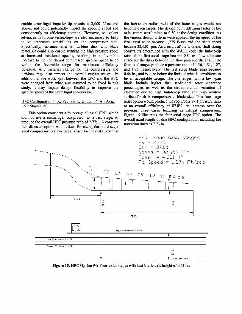
The computational grid for the four-stage axial HPC,also generated with the TCDES code, is shown in Figure 18.The T-AXI through flow code utilized this grid to determineimproved estimates of rotor efficiency levels and statorlosses, based on the models within the code for shock,diffusion factor loading and tip clearance losses.
The output from the COMDES, TCDES and the T-AXIthrough flow analysis resulted in the overall HPC efficiencyof 87.0% at the 2.77:1 pressure ratio. The hub diameterlimitations have been determined from the conceptualmechanical design and analyses utilizing the WATE code.The HPC stage performances are listed in Table 4, with thedetailed outputs listed in reference 10.
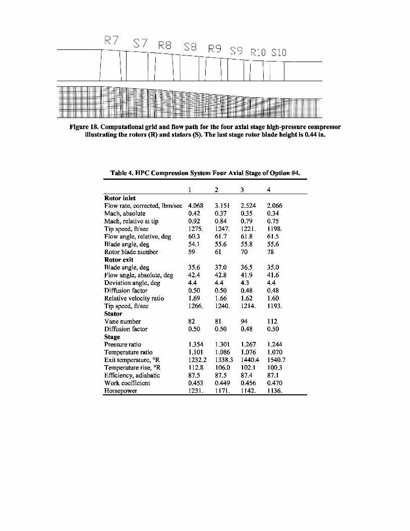
Figure 18. Computational grid and flow path for the four axial stage high-pressure compressorillustrating the rotors (R) and stators (S). The last stage rotor blade height is 0.44 in.
Table 4. HPC Compression System Four Axial Stage of Option #4.
2Rotor inletFlow rate, corrected, lbm/sec 4.068 3.151 2.524 2.066Mach, absolute 0.42 0.37 0.35 0.34Mach, relative at tip 0.92 0.84 0.79 0.75Tip speed, ft/sec 1275. 1247. 1221. 1198.Flow angle, relative, deg 60.3 61.7 61.8 61.5Blade angle, deg 54.1 55.6 55.8 55.6Rotor blade number 59 61 70 78Rotor exitBlade angle, deg 35.6 37.0 36.5 35.0Flow angle, absolute, deg 42.4 42.8 41.9 41.6Deviation angle, deg 4.4 4.4 4.3 4.4Diffusion factor 0.50 0.50 0.48 0.48Relative velocity ratio 1.69 1.66 1.62 1.60Tip speed, ft/sec 1266. 1240. 1214. 1193.StatorVane number 82 81 94 112Diffusion factor 0.50 0.50 0.48 0.50StagePressure ratio 1.354 1.301 1.267 1.244Temperature ratio 1.101 1.086 1.076 1.070Exit temperature, °R 1232.2 1338.3 1440.4 1540.7Temperature rise, °R 112.8 106.0 102.1 100.3Efficiency, adiabatic 87.5 87.5 87.4 87.1Work coefficient 0.453 0.449 0.456 0.470Horsepower 1231. 1171. 1142. 1136.

Figure 19. HPC efficiency versus axial length of the four design options cases studied.
Comparison of Four HPC Design Options
A comparison was made between the four options forthe HPC flow path, illustrating the estimated efficiencyversus the axial length in Figure 19. Note that the studyutilized current estimates for compressor efficiency as wellas the assumptions in the WATE code for sizing the turbinesbased on a certain level of technology. A further assessmentof state-of-the-art turbine technologies, including coolingrequirements and advanced materials could result inpotential improvements to the LCTR-2 engine, andsubsequently offer additional flexibility to determining thebest work split between the LPC and the HPC from both theperspective of turbine and compressor aerodynamic andstructural considerations. Also, potential futureadvancements in centrifugal compressor aerodynamics couldresult in additional realizable efficiency benefits, even atreduced levels of specific speed.
A comparison of total engine pod weight versus totalengine pod length was made from the WATE code resultsfor all four HPC design options and is illustrated inFigure 20. The resulting comparison indicates that the fourstage all axial HPC option (Option #4), appears to have thelowest total engine weight and pod length, however, thatoption needs further assessment, as it has a 0.44 in. last stageexit blade span, which is at, or below the limit considered tobe the minimum for axial blades.
LPC Off-Design Analysis:
The off-design compressor performance was estimatedwith COMDES. During the assessment of numerouscombinations of variable geometry settings, it wasdetermined that it would be adequate to vary only thevariable geometry inlet guide vane (IGV) along with thestators in the first two stages, as resetting these three vanesresulted in acceptable stage matching throughout a widerange of flows at each speed line. Variable geometry statorsin subsequent stages 3 to 6 would not have resulted insignificantly widening the resulting overall flow range oroperability of the LPC. The most suitable variable geometryschedule was determined for each speed line by manuallyvarying the IGV and stator reset angles, that is, byspecifying the inlet swirl angles at the rotor leading edges.The stage matching was achieved by varying the inlet guidevane and stators to result in acceptable levels of rotorincidence, relative velocity ratio and diffusion factor. Amodel consisting of a user defined function of rotorincidence in COMDES enables an estimate of the off-designperformance by reducing the design point rotor efficiency.As discussed in reference 6, the off design efficiency lapsein the code was calibrated based on test data of highlyloaded transonic compressor cases, with unique incidencebeing on the order of 6°. This enables sizing the variablegeometry schedule to result in the overall performance atoff-design speed and flow conditions. The performance

Figure 20. Total engine pod length versus total engine pod weight for the four HPC design options.
along each speed line for the LPC was estimated withCOMDES by incrementally varying the incidence ofrotor 1 to result in changing the air flow rate, until therotor maximum diffusion limits were reached in any ofthe six axial stages. This was repeated for each speed linefrom 105 to 80%. Figure 21(a) and (b) illustrate theestimated compressor characteristic maps for pressureratio and efficiency versus corrected flow and designcorrected percent speed. Note that at the 105% speed linethe variable geometry inlet guide vane was reset to 5° inthe positive direction in order to manage the tip relativevelocity of rotor 1, causing the speed line to appearslightly discontinuous in comparison with the lower speedlines. The criteria used to determine the onset of surgewere the maximum values of rotor diffusion factor of near0.60 and relative velocity ratio near 1.95. The estimatedLPC map data are listed in reference 10.
HPC Off-Design Analysis
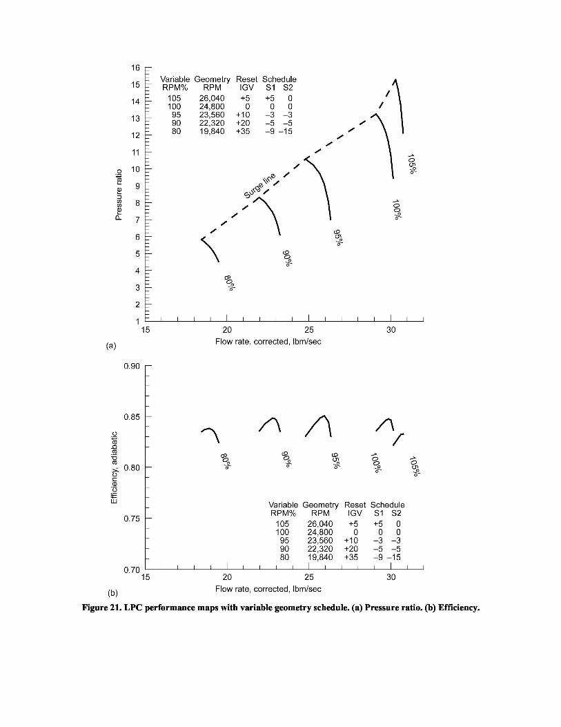
The characteristic performance map for the HPC wasalso estimated at off-design speeds and flows usingCOMDES. Since there is no variable geometry in theHPC, the process was simpler and merely involvedvarying the flow along each speed line by means ofincrementally changing the rotor incidence, and executingthe multistage flow analysis. For the purpose of mapgeneration the four-stage all axial compressorconfiguration was selected, even though the last stageblade height may be considered excessively small forreasons previously mentioned. The 105, 100, 95, 90, 85,and 80% of design corrected speed lines were executedfor a range of corrected flows. The criteria used todetermine the onset of surge were the same as for theLPC. The estimated HPC characteristic pressure ratio andefficiency maps are illustrated in Figure 22(a) and (b).
'1 ` 05 26,040 +'5 +5 0
100 24,800 0 0 0
95 (23,560 +10 -3 =3
90 22,320 ^+20 -5 -5
80 1'9,840 -65 —9 —150.70 _
`1'5 0 25 30F,low rate;,'cor,rected, Ibm/sec
Figure 21. LPC performance maps with variable geometry schedule. (a) Pressure ratio. (b) Efficiency.

C: Z- A(D, ^Des ig n
CTIcomecte'd 'Corredted
470w RPM% RPM 0
T05 '23,386
l'O . '65 100 72 ,225
95 21 1 1 40'0 0 89 1210"
10 .60 85 18 ,1602'80 1,18,0
1 0- 55 tO 2.,5 '0 6 4.0 43 0
F- low,ra te,loorreded , Ibm/sec
Figure 22. HPC performance maps. (a) Pressure ratio. (b) Efficiency.
CONCLUSIONS
A conceptual design study was made of a two spoolcompressor to meet the performance requirements of anotional LCTR-2 engine. The LPC requirements can be metwith a six stage transonic axial compressor with an overallpressure ratio of 10.83:1 at the design point. Characteristicmaps were produced for the LPC, with a variable inlet guidevane as well as variable stators in stages 1 and 2. Properaerodynamic matching between the transonic stages is achallenge for maintaining stability and efficiency. Fouroptions for the 2.77:1 PR HPC compressor were studiedfeaturing an axial-centrifugal compressor configuration withzero, one and two axial stages ahead of the centrifugalcompressor stage, as well as one option with four axialstages. The result of this study shows that from anaerodynamic perspective, it is feasible to meet therequirements of a 30:1 pressure ratio compressor for theLCTR-2 engine with a two spool axial-centrifugalcompressor, comprising a six stage transonic LPC, followedby an HPC configuration which can be either a single stagecentrifugal, an axi-centrifugal, or an all axial compressorfeaturing four stages.
Technical challenges for the LPC design include:
• High tip relative Mach number of the first stage,due in part to physical space limitation of the rotordrum.
• Aerodynamic matching of the transonic axial stagesat off-design operation with variable geometry.
Technical challenges of the HPC designs include:
• Small blade span of last stage rotor of all-axialcompressor at 0.44 in. may be excessively small.
• Large clearance-to-span ratio of 2.7% for the laststage axial rotor of the all axial stage option.
• Small exit blade span of centrifugal impellerranging from 0.35 to 0.41 in. depending onconfiguration and specific speed.
• Increasing the specific speed of the centrifugalstage from a nominal range of 0.51 to 0.55 to amore optimum value is limited by the disk spaceand strength requirements of the high pressureturbine at increased speeds.
• High impeller inlet hub-to-tip radius ratio of 0.80 isset by shaft size requirements and can limitefficiency potential.
• Higher centrifugal impeller tip speeds up to2,000 ft/sec could be required for a more optimumdesign and can only be achieved with the use ofadvanced nickel alloy materials with high strengthcharacteristics at elevated temperatures in the rangeof 1,560 °R.
The two spool configuration of the gas generator is athermodynamic and structural improvement over the singlespool, due to improved efficiency levels caused by reducedrotor tip clearance ratios and improved centrifugal impellerspecific speed. Modifying the LPC-HPC work split withconsideration for turbine design requirements, may result inadditional flexibility in optimizing the centrifugal stagespecific speed, and consequently improve its efficiencypotential.
ACKNOWLEDGEMENTS
I would like to thank the management of the SubsonicRotary Wing vehicle project within the NASA FundamentalAeronautics Program for supporting this research, and tothank Mr. Chris Snyder for providing the output from theNPSS engine system model and for his support during thisiterative process in achieving the compressor performancewhich is acceptable from an overall engine perspective. Iwould also like to thank Dr. Dario Bruna for his assistancein the execution of the TCDES and T-AXI codes while hewas a research associate at the NASA Glenn ResearchCenter and the Ohio Aerospace Institute as a Post DoctoralFellow under the Oak Ridge National Laboratory program.
1. Johnson, W., Yamauchi, G.K., and Watts, M.E.,“NASA Heavy Lift Rotorcraft Systems Investigation,”NASA/TP —2005-213467.
2. Acree, C.W., Hyeonsoo, Y., and Sinsay, J.D.,“Performance Optimization of the NASA Large CivilTiltrotor,” International Powered Lift Conference,London, UK, July 22–24, 2008.
3. Snyder, C.A., and Thurman, D.R., “Gas turbinecharacteristics for a Large Civil Tilt-Rotor (LCTR-2),”AHS International, 65th Annual Forum & TechnologyDisplay, Phoenix, Arizona, May 27–29, 2009.NASA/TM—2010-216089.
4. Jones, S.M., “An Introduction to ThermodynamicPerformance Analysis of Aircraft Gas Turbine EngineCycles Using the Numerical Propulsion SystemSimulation Code,” NASA/TM—2007-214690.
5. Tong, M.T., Naylor, B.A., “An Object-OrientedComputer Code for Aircraft Engine WeightEstimation,” GT2008–50062, ASME Turbo-Expo 2008,June 9–13, 2008.
6. Veres, J.P. “Axial and Centrifugal Compressor MeanLine Flow Analysis Method,” AIAA–2009–1641,NASA/TM—2009-215585.

7. Turner, M.G., Merchant, A., Bruna, D., “A 10. Veres, J.P., Thurman, D.R., Conceptual Design ofturbomachinery design tool for teaching design concepts Compressor for Two-Spool LCTR-2 Engine,for axial-flow fans, compressors, and turbines,” ASME NASA/TM—2010-216264.Paper Number GT2006–90105.
11. Veres, J.P., “Compressor Study to Meet Large Civil Tilt8. Wood, J.R. “Preliminary Design Code for Centrifugal Rotor Engine Requirements,” 65th Annual Forum and
Compressor Performance Prediction – QUIK,” NASA Technology Display sponsored by the Americanunpublished. Helicopter Society, Grapevine, Texas, May 27–29,
2009, NASA/TM—2009-215641.9. Balje, O.E., “TURBOMACHINES, A Guide to Design,
Selection and Theory,” 1981.