![STAM New Sample Qs - Home [howardmahler.com]](https://static.fdokumen.com/doc/165x107/632a4ed37e519a0bdc068b7b/stam-new-sample-qs-home-howardmahlercom.jpg)
Concepts Guide Quantum StorNext QS/QD Storage SANtricity ...
100
Concepts Guide Quantum StorNext QS/QD Storage SANtricity 11.20 6-68239-01 Rev A
-
Upload
khangminh22 -
Category
Documents
-
view
0 -
download
0
Transcript of Concepts Guide Quantum StorNext QS/QD Storage SANtricity ...

Concepts Guide
Quantum StorNext QS/QD Storage SANtricity 11.20
6-68239-01 Rev A

ii Concepts Guide
StorNext Q-Series Storage Concepts Guide, 6-68239-01 Rev A, May 2015, Product of USA.
©2015 All rights reserved. Quantum, the Quantum logo, DXi, Scalar and StorNext are registered trademarks of Quantum Corporation and its affiliates in the United States and/or other countries. All other trademarks are the property of their respective owners.

Contents iii
About this guide . . . . . . . . . . . . . . . . . . . . . . . . . . . . . . . . . . . . . . . . . . . . . . . . . . . . . . . xiNew Features . . . . . . . . . . . . . . . . . . . . . . . . . . . . . . . . . . . . . . . . . . . . . . . . . . . . . . . . . . . . . . . . . . . . . . . . . xiIntended audience . . . . . . . . . . . . . . . . . . . . . . . . . . . . . . . . . . . . . . . . . . . . . . . . . . . . . . . . . . . . . . . . . . . . xiiPrerequisites. . . . . . . . . . . . . . . . . . . . . . . . . . . . . . . . . . . . . . . . . . . . . . . . . . . . . . . . . . . . . . . . . . . . . . . . . xiiDocument conventions and symbols . . . . . . . . . . . . . . . . . . . . . . . . . . . . . . . . . . . . . . . . . . . . . . . . . . . . . . xii
Storing Data. . . . . . . . . . . . . . . . . . . . . . . . . . . . . . . . . . . . . . . . . . . . . . . . . . . . . . . . . .1Storage Arrays . . . . . . . . . . . . . . . . . . . . . . . . . . . . . . . . . . . . . . . . . . . . . . . . . . . . . . . . . . . . . . . . . . . . . . . . 1Storage Area Networks . . . . . . . . . . . . . . . . . . . . . . . . . . . . . . . . . . . . . . . . . . . . . . . . . . . . . . . . . . . . . . . . . 1Drive Configuration . . . . . . . . . . . . . . . . . . . . . . . . . . . . . . . . . . . . . . . . . . . . . . . . . . . . . . . . . . . . . . . . . . . . 2Disk Pools and Volume Groups . . . . . . . . . . . . . . . . . . . . . . . . . . . . . . . . . . . . . . . . . . . . . . . . . . . . . . . . . . . 2
Disk Pools . . . . . . . . . . . . . . . . . . . . . . . . . . . . . . . . . . . . . . . . . . . . . . . . . . . . . . . . . . . . . . . . . . . . . . . . . 2Volume Groups. . . . . . . . . . . . . . . . . . . . . . . . . . . . . . . . . . . . . . . . . . . . . . . . . . . . . . . . . . . . . . . . . . . . . 3Differences/Configuring Disk Pools and Volume Groups . . . . . . . . . . . . . . . . . . . . . . . . . . . . . . . . . . . . . . 3
Volumes . . . . . . . . . . . . . . . . . . . . . . . . . . . . . . . . . . . . . . . . . . . . . . . . . . . . . . . . . . . . . . . . . . . . . . . . . . . . . 3Management Methods. . . . . . . . . . . . . . . . . . . . . . . . . . . . . . . . . . . . . . . . . . . . . . . . . . . . . . . . . . . . . . . . . . 4
Out-of-Band Management . . . . . . . . . . . . . . . . . . . . . . . . . . . . . . . . . . . . . . . . . . . . . . . . . . . . . . . . . . . . 5In-Band Management . . . . . . . . . . . . . . . . . . . . . . . . . . . . . . . . . . . . . . . . . . . . . . . . . . . . . . . . . . . . . . . . 5
RAID Levels and Data Redundancy . . . . . . . . . . . . . . . . . . . . . . . . . . . . . . . . . . . . . . . . . . . . . . . . . . . . . . . . . 6RAID for a Disk Pool . . . . . . . . . . . . . . . . . . . . . . . . . . . . . . . . . . . . . . . . . . . . . . . . . . . . . . . . . . . . . . . . . 6RAID for a Volume Group . . . . . . . . . . . . . . . . . . . . . . . . . . . . . . . . . . . . . . . . . . . . . . . . . . . . . . . . . . . . . 6RAID Level Configuration . . . . . . . . . . . . . . . . . . . . . . . . . . . . . . . . . . . . . . . . . . . . . . . . . . . . . . . . . . . . . 7Dynamic RAID-Level Migration . . . . . . . . . . . . . . . . . . . . . . . . . . . . . . . . . . . . . . . . . . . . . . . . . . . . . . . . . 9
Hardware Redundancy . . . . . . . . . . . . . . . . . . . . . . . . . . . . . . . . . . . . . . . . . . . . . . . . . . . . . . . . . . . . . . . . . . 9Controller Cache Memory . . . . . . . . . . . . . . . . . . . . . . . . . . . . . . . . . . . . . . . . . . . . . . . . . . . . . . . . . . . . . 9Tray Loss Protection . . . . . . . . . . . . . . . . . . . . . . . . . . . . . . . . . . . . . . . . . . . . . . . . . . . . . . . . . . . . . . . . 10Drawer Loss Protection . . . . . . . . . . . . . . . . . . . . . . . . . . . . . . . . . . . . . . . . . . . . . . . . . . . . . . . . . . . . . . 10Hot Spare Drives . . . . . . . . . . . . . . . . . . . . . . . . . . . . . . . . . . . . . . . . . . . . . . . . . . . . . . . . . . . . . . . . . . . 11
I/O Data Path Protection. . . . . . . . . . . . . . . . . . . . . . . . . . . . . . . . . . . . . . . . . . . . . . . . . . . . . . . . . . . . . . . . 12Target Port Group Support. . . . . . . . . . . . . . . . . . . . . . . . . . . . . . . . . . . . . . . . . . . . . . . . . . . . . . . . . . . . . . 12
Failover for Windows . . . . . . . . . . . . . . . . . . . . . . . . . . . . . . . . . . . . . . . . . . . . . . . . . . . . . . . . . . . . . . . 12Load Balancing. . . . . . . . . . . . . . . . . . . . . . . . . . . . . . . . . . . . . . . . . . . . . . . . . . . . . . . . . . . . . . . . . . . . . . . 13
Round Robin with Subset . . . . . . . . . . . . . . . . . . . . . . . . . . . . . . . . . . . . . . . . . . . . . . . . . . . . . . . . . . . . 13Least Queue Depth with Subset . . . . . . . . . . . . . . . . . . . . . . . . . . . . . . . . . . . . . . . . . . . . . . . . . . . . . . . 13Least Path Weight with Subset . . . . . . . . . . . . . . . . . . . . . . . . . . . . . . . . . . . . . . . . . . . . . . . . . . . . . . . . 13
Introducing the Software . . . . . . . . . . . . . . . . . . . . . . . . . . . . . . . . . . . . . . . . . . . . . .15Enterprise Management Window. . . . . . . . . . . . . . . . . . . . . . . . . . . . . . . . . . . . . . . . . . . . . . . . . . . . . . . . . 15
Parts of the Enterprise Management Window . . . . . . . . . . . . . . . . . . . . . . . . . . . . . . . . . . . . . . . . . . . . 16EMW Devices Tab . . . . . . . . . . . . . . . . . . . . . . . . . . . . . . . . . . . . . . . . . . . . . . . . . . . . . . . . . . . . . . . . . . 16
Contents

iv Concepts Guide
Showing Managed Storage Arrays in Table View . . . . . . . . . . . . . . . . . . . . . . . . . . . . . . . . . . . . . . . . . . 18Adding a Storage Array. . . . . . . . . . . . . . . . . . . . . . . . . . . . . . . . . . . . . . . . . . . . . . . . . . . . . . . . . . . . . . 18Removing Multiple Storage Arrays Simultaneously . . . . . . . . . . . . . . . . . . . . . . . . . . . . . . . . . . . . . . . . . 18EMW Setup Tab . . . . . . . . . . . . . . . . . . . . . . . . . . . . . . . . . . . . . . . . . . . . . . . . . . . . . . . . . . . . . . . . . . . 19
Array Management Window . . . . . . . . . . . . . . . . . . . . . . . . . . . . . . . . . . . . . . . . . . . . . . . . . . . . . . . . . . . . 19Starting the Array Management Window . . . . . . . . . . . . . . . . . . . . . . . . . . . . . . . . . . . . . . . . . . . . . . . . 20Parts of the Array Management Window . . . . . . . . . . . . . . . . . . . . . . . . . . . . . . . . . . . . . . . . . . . . . . . . 20Summary Tab . . . . . . . . . . . . . . . . . . . . . . . . . . . . . . . . . . . . . . . . . . . . . . . . . . . . . . . . . . . . . . . . . . . . . 21Monitor and Capacity Panes . . . . . . . . . . . . . . . . . . . . . . . . . . . . . . . . . . . . . . . . . . . . . . . . . . . . . . . . . . 22Premium Features Pane. . . . . . . . . . . . . . . . . . . . . . . . . . . . . . . . . . . . . . . . . . . . . . . . . . . . . . . . . . . . . . 22Hardware Pane . . . . . . . . . . . . . . . . . . . . . . . . . . . . . . . . . . . . . . . . . . . . . . . . . . . . . . . . . . . . . . . . . . . . 23Storage and Copy Services Tab . . . . . . . . . . . . . . . . . . . . . . . . . . . . . . . . . . . . . . . . . . . . . . . . . . . . . . . . 23
Configuring Storage Arrays . . . . . . . . . . . . . . . . . . . . . . . . . . . . . . . . . . . . . . . . . . . . .31Disk Pools and Volume Groups . . . . . . . . . . . . . . . . . . . . . . . . . . . . . . . . . . . . . . . . . . . . . . . . . . . . . . . . . . 31
RAID Implementation . . . . . . . . . . . . . . . . . . . . . . . . . . . . . . . . . . . . . . . . . . . . . . . . . . . . . . . . . . . . . . . 32Recovery from Drive Failure . . . . . . . . . . . . . . . . . . . . . . . . . . . . . . . . . . . . . . . . . . . . . . . . . . . . . . . . . . 32
Volume Group Creation . . . . . . . . . . . . . . . . . . . . . . . . . . . . . . . . . . . . . . . . . . . . . . . . . . . . . . . . . . . . . . . . 32Create Volume Group Wizard . . . . . . . . . . . . . . . . . . . . . . . . . . . . . . . . . . . . . . . . . . . . . . . . . . . . . . . . . 32Size of a Volume Group . . . . . . . . . . . . . . . . . . . . . . . . . . . . . . . . . . . . . . . . . . . . . . . . . . . . . . . . . . . . . 33Types of Capacity . . . . . . . . . . . . . . . . . . . . . . . . . . . . . . . . . . . . . . . . . . . . . . . . . . . . . . . . . . . . . . . . . . 33Volume Group States . . . . . . . . . . . . . . . . . . . . . . . . . . . . . . . . . . . . . . . . . . . . . . . . . . . . . . . . . . . . . . . 34Change the RAID Level . . . . . . . . . . . . . . . . . . . . . . . . . . . . . . . . . . . . . . . . . . . . . . . . . . . . . . . . . . . . . . 35Volume Group Attributes . . . . . . . . . . . . . . . . . . . . . . . . . . . . . . . . . . . . . . . . . . . . . . . . . . . . . . . . . . . . 35
Disk Pool Creation . . . . . . . . . . . . . . . . . . . . . . . . . . . . . . . . . . . . . . . . . . . . . . . . . . . . . . . . . . . . . . . . . . . . 35Disk Pool Automatic Configuration Dialog . . . . . . . . . . . . . . . . . . . . . . . . . . . . . . . . . . . . . . . . . . . . . . . 35Create Disk Pool Wizard . . . . . . . . . . . . . . . . . . . . . . . . . . . . . . . . . . . . . . . . . . . . . . . . . . . . . . . . . . . . . 36Raid Level Auto-Assigned . . . . . . . . . . . . . . . . . . . . . . . . . . . . . . . . . . . . . . . . . . . . . . . . . . . . . . . . . . . . 36Size of Disk Pool . . . . . . . . . . . . . . . . . . . . . . . . . . . . . . . . . . . . . . . . . . . . . . . . . . . . . . . . . . . . . . . . . . . 36Type of Capacity . . . . . . . . . . . . . . . . . . . . . . . . . . . . . . . . . . . . . . . . . . . . . . . . . . . . . . . . . . . . . . . . . . . 36Capacity Alert Notifications. . . . . . . . . . . . . . . . . . . . . . . . . . . . . . . . . . . . . . . . . . . . . . . . . . . . . . . . . . . 38Disk Pool Attributes . . . . . . . . . . . . . . . . . . . . . . . . . . . . . . . . . . . . . . . . . . . . . . . . . . . . . . . . . . . . . . . . 38Disk Pool Reconstruction. . . . . . . . . . . . . . . . . . . . . . . . . . . . . . . . . . . . . . . . . . . . . . . . . . . . . . . . . . . . . 39
Volumes . . . . . . . . . . . . . . . . . . . . . . . . . . . . . . . . . . . . . . . . . . . . . . . . . . . . . . . . . . . . . . . . . . . . . . . . . . . . 40Types of Volumes . . . . . . . . . . . . . . . . . . . . . . . . . . . . . . . . . . . . . . . . . . . . . . . . . . . . . . . . . . . . . . . . . . 40Thin Volumes . . . . . . . . . . . . . . . . . . . . . . . . . . . . . . . . . . . . . . . . . . . . . . . . . . . . . . . . . . . . . . . . . . . . . 42Standard Volumes . . . . . . . . . . . . . . . . . . . . . . . . . . . . . . . . . . . . . . . . . . . . . . . . . . . . . . . . . . . . . . . . . 43Specify Standard Volume Attributes . . . . . . . . . . . . . . . . . . . . . . . . . . . . . . . . . . . . . . . . . . . . . . . . . . . . 44
Dynamic Capacity Expansion . . . . . . . . . . . . . . . . . . . . . . . . . . . . . . . . . . . . . . . . . . . . . . . . . . . . . . . . . . . . 44Register the Volume with the Operating System . . . . . . . . . . . . . . . . . . . . . . . . . . . . . . . . . . . . . . . . . . . . . 45Premium Features . . . . . . . . . . . . . . . . . . . . . . . . . . . . . . . . . . . . . . . . . . . . . . . . . . . . . . . . . . . . . . . . . . . . 45
Thin Provisioning Premium Feature. . . . . . . . . . . . . . . . . . . . . . . . . . . . . . . . . . . . . . . . . . . . . . . . . . . . . 45Thin Volume Attributes. . . . . . . . . . . . . . . . . . . . . . . . . . . . . . . . . . . . . . . . . . . . . . . . . . . . . . . . . . . . . . 46Guidelines . . . . . . . . . . . . . . . . . . . . . . . . . . . . . . . . . . . . . . . . . . . . . . . . . . . . . . . . . . . . . . . . . . . . . . . . 47Thin Volume States . . . . . . . . . . . . . . . . . . . . . . . . . . . . . . . . . . . . . . . . . . . . . . . . . . . . . . . . . . . . . . . . . 47Rollback . . . . . . . . . . . . . . . . . . . . . . . . . . . . . . . . . . . . . . . . . . . . . . . . . . . . . . . . . . . . . . . . . . . . . . . . . 47SANshare Storage Partitioning . . . . . . . . . . . . . . . . . . . . . . . . . . . . . . . . . . . . . . . . . . . . . . . . . . . . . . . . 47
Snapshot Premium Feature . . . . . . . . . . . . . . . . . . . . . . . . . . . . . . . . . . . . . . . . . . . . . . . . . . . . . . . . . . . . . 48Snapshot Images . . . . . . . . . . . . . . . . . . . . . . . . . . . . . . . . . . . . . . . . . . . . . . . . . . . . . . . . . . . . . . . . . . 48Snapshot Groups . . . . . . . . . . . . . . . . . . . . . . . . . . . . . . . . . . . . . . . . . . . . . . . . . . . . . . . . . . . . . . . . . . 49Snapshot Group Repository Volume . . . . . . . . . . . . . . . . . . . . . . . . . . . . . . . . . . . . . . . . . . . . . . . . . . . . 50Snapshot Volume . . . . . . . . . . . . . . . . . . . . . . . . . . . . . . . . . . . . . . . . . . . . . . . . . . . . . . . . . . . . . . . . . . 50Schedule Snapshot Images . . . . . . . . . . . . . . . . . . . . . . . . . . . . . . . . . . . . . . . . . . . . . . . . . . . . . . . . . . . 50Rollback to a Snapshot Image. . . . . . . . . . . . . . . . . . . . . . . . . . . . . . . . . . . . . . . . . . . . . . . . . . . . . . . . . 51Convert a Snapshot (Legacy) Volume to a Snapshot Group . . . . . . . . . . . . . . . . . . . . . . . . . . . . . . . . . . 52Create Consistency Groups . . . . . . . . . . . . . . . . . . . . . . . . . . . . . . . . . . . . . . . . . . . . . . . . . . . . . . . . . . . 53Consistency Group Snapshot Images . . . . . . . . . . . . . . . . . . . . . . . . . . . . . . . . . . . . . . . . . . . . . . . . . . . 54Consistency Group Snapshot Volume . . . . . . . . . . . . . . . . . . . . . . . . . . . . . . . . . . . . . . . . . . . . . . . . . . . 54

Contents v
Snapshot (Legacy) Premium Feature . . . . . . . . . . . . . . . . . . . . . . . . . . . . . . . . . . . . . . . . . . . . . . . . . . . . . . 56Creating Snapshot (Legacy) Volumes . . . . . . . . . . . . . . . . . . . . . . . . . . . . . . . . . . . . . . . . . . . . . . . . . . . 56Scheduling Snapshots (Legacy) . . . . . . . . . . . . . . . . . . . . . . . . . . . . . . . . . . . . . . . . . . . . . . . . . . . . . . . . 57Discontinuing the Use of a Snapshot (Legacy) Volume . . . . . . . . . . . . . . . . . . . . . . . . . . . . . . . . . . . . . . 58Disabling and Restarting Multiple Snapshots (Legacy) . . . . . . . . . . . . . . . . . . . . . . . . . . . . . . . . . . . . . . 58Snapshot (Legacy) Rollback. . . . . . . . . . . . . . . . . . . . . . . . . . . . . . . . . . . . . . . . . . . . . . . . . . . . . . . . . . . 58Dynamic Volume Expansion . . . . . . . . . . . . . . . . . . . . . . . . . . . . . . . . . . . . . . . . . . . . . . . . . . . . . . . . . . 59
Asynchronous Mirroring Premium Feature . . . . . . . . . . . . . . . . . . . . . . . . . . . . . . . . . . . . . . . . . . . . . . . . . . 60Differences Between Mirroring Features . . . . . . . . . . . . . . . . . . . . . . . . . . . . . . . . . . . . . . . . . . . . . . . . . 60Typical Use Scenarios . . . . . . . . . . . . . . . . . . . . . . . . . . . . . . . . . . . . . . . . . . . . . . . . . . . . . . . . . . . . . . . 61
Synchronous Mirroring Premium Feature. . . . . . . . . . . . . . . . . . . . . . . . . . . . . . . . . . . . . . . . . . . . . . . . . . . 62Disaster Recovery . . . . . . . . . . . . . . . . . . . . . . . . . . . . . . . . . . . . . . . . . . . . . . . . . . . . . . . . . . . . . . . . . . 63Data Replication . . . . . . . . . . . . . . . . . . . . . . . . . . . . . . . . . . . . . . . . . . . . . . . . . . . . . . . . . . . . . . . . . . . 63Link Interruptions or Secondary Volume Errors . . . . . . . . . . . . . . . . . . . . . . . . . . . . . . . . . . . . . . . . . . . . 63Connectivity and Volume Ownership . . . . . . . . . . . . . . . . . . . . . . . . . . . . . . . . . . . . . . . . . . . . . . . . . . . 64Controller Resets and Storage Array Power Cycles . . . . . . . . . . . . . . . . . . . . . . . . . . . . . . . . . . . . . . . . . 64Synchronous Mirroring Premium Feature Activation. . . . . . . . . . . . . . . . . . . . . . . . . . . . . . . . . . . . . . . . 64Connectivity Requirements . . . . . . . . . . . . . . . . . . . . . . . . . . . . . . . . . . . . . . . . . . . . . . . . . . . . . . . . . . . 65Restrictions . . . . . . . . . . . . . . . . . . . . . . . . . . . . . . . . . . . . . . . . . . . . . . . . . . . . . . . . . . . . . . . . . . . . . . . 65
Volume Copy Premium Feature . . . . . . . . . . . . . . . . . . . . . . . . . . . . . . . . . . . . . . . . . . . . . . . . . . . . . . . . . . 65Volume Copy Features . . . . . . . . . . . . . . . . . . . . . . . . . . . . . . . . . . . . . . . . . . . . . . . . . . . . . . . . . . . . . . 66Types of Volume Copies . . . . . . . . . . . . . . . . . . . . . . . . . . . . . . . . . . . . . . . . . . . . . . . . . . . . . . . . . . . . . 66Components of the Volume Copy Premium Feature . . . . . . . . . . . . . . . . . . . . . . . . . . . . . . . . . . . . . . . . 67
Data Assurance Premium Feature. . . . . . . . . . . . . . . . . . . . . . . . . . . . . . . . . . . . . . . . . . . . . . . . . . . . . . . . . 71High Performance Tier Premium Feature. . . . . . . . . . . . . . . . . . . . . . . . . . . . . . . . . . . . . . . . . . . . . . . . . 71Mixed Drive Type Premium Feature. . . . . . . . . . . . . . . . . . . . . . . . . . . . . . . . . . . . . . . . . . . . . . . . . . . . . 72Drive Slot Limit Premium Feature . . . . . . . . . . . . . . . . . . . . . . . . . . . . . . . . . . . . . . . . . . . . . . . . . . . . . . 72
Heterogeneous Hosts . . . . . . . . . . . . . . . . . . . . . . . . . . . . . . . . . . . . . . . . . . . . . . . . . . . . . . . . . . . . . . . . . . 72Password Protection. . . . . . . . . . . . . . . . . . . . . . . . . . . . . . . . . . . . . . . . . . . . . . . . . . . . . . . . . . . . . . . . . . . 72Persistent Reservations Management . . . . . . . . . . . . . . . . . . . . . . . . . . . . . . . . . . . . . . . . . . . . . . . . . . . . . . 73HotScale Technology . . . . . . . . . . . . . . . . . . . . . . . . . . . . . . . . . . . . . . . . . . . . . . . . . . . . . . . . . . . . . . . . . . 73
Maintaining/Monitoring Storage. . . . . . . . . . . . . . . . . . . . . . . . . . . . . . . . . . . . . . . . .75Storage Array Health . . . . . . . . . . . . . . . . . . . . . . . . . . . . . . . . . . . . . . . . . . . . . . . . . . . . . . . . . . . . . . . . . . 75
Background Media Scan . . . . . . . . . . . . . . . . . . . . . . . . . . . . . . . . . . . . . . . . . . . . . . . . . . . . . . . . . . . . . 75Event Monitor. . . . . . . . . . . . . . . . . . . . . . . . . . . . . . . . . . . . . . . . . . . . . . . . . . . . . . . . . . . . . . . . . . . . . 75Alert Notifications. . . . . . . . . . . . . . . . . . . . . . . . . . . . . . . . . . . . . . . . . . . . . . . . . . . . . . . . . . . . . . . . . . 77Performance Monitor . . . . . . . . . . . . . . . . . . . . . . . . . . . . . . . . . . . . . . . . . . . . . . . . . . . . . . . . . . . . . . . 77
Viewing Operations in Progress . . . . . . . . . . . . . . . . . . . . . . . . . . . . . . . . . . . . . . . . . . . . . . . . . . . . . . . . . . 80Retrieving Trace Buffers . . . . . . . . . . . . . . . . . . . . . . . . . . . . . . . . . . . . . . . . . . . . . . . . . . . . . . . . . . . . . . . . 81Upgrading the Controller Firmware . . . . . . . . . . . . . . . . . . . . . . . . . . . . . . . . . . . . . . . . . . . . . . . . . . . . . . . 82
Monitoring the Status of the Download . . . . . . . . . . . . . . . . . . . . . . . . . . . . . . . . . . . . . . . . . . . . . . . . . 83Problem Notification . . . . . . . . . . . . . . . . . . . . . . . . . . . . . . . . . . . . . . . . . . . . . . . . . . . . . . . . . . . . . . . . . . 84Event Log Viewer . . . . . . . . . . . . . . . . . . . . . . . . . . . . . . . . . . . . . . . . . . . . . . . . . . . . . . . . . . . . . . . . . . . . . 85
Viewing the Event Log . . . . . . . . . . . . . . . . . . . . . . . . . . . . . . . . . . . . . . . . . . . . . . . . . . . . . . . . . . . . . . 85Storage Array Problem Recovery . . . . . . . . . . . . . . . . . . . . . . . . . . . . . . . . . . . . . . . . . . . . . . . . . . . . . . . . . 85Recovery Guru . . . . . . . . . . . . . . . . . . . . . . . . . . . . . . . . . . . . . . . . . . . . . . . . . . . . . . . . . . . . . . . . . . . . . . . 85

vi Concepts Guide
Figures vii
Figures
1 Collection of Drives in a Volume Group . . . . . . . . . . . . . . . . . . . . . . . . . . . . . . . . . . . . . . . . . . . . . . . . 342 Collection of Drives in a Disk Pool. . . . . . . . . . . . . . . . . . . . . . . . . . . . . . . . . . . . . . . . . . . . . . . . . . . . . 373 Event Monitor/Enterprise Management Window . . . . . . . . . . . . . . . . . . . . . . . . . . . . . . . . . . . . . . . . . 76

viii Concepts Guide
Tables ix
Tables
1 Document conventions61 Document conventions . . . . . . . . . . . . . . . . . . . . . . . . . . . . . . . . . . . . . . . . . . . . . . . . . . . . . . . . . . . . . .xii2 RAID Level Configurations and Descriptions . . . . . . . . . . . . . . . . . . . . . . . . . . . . . . . . . . . . . . . . . . . . . . 73 Using Tray Loss Protection for Volume Groups . . . . . . . . . . . . . . . . . . . . . . . . . . . . . . . . . . . . . . . . . . . 104 Using RAID Level Drawer Loss Protection . . . . . . . . . . . . . . . . . . . . . . . . . . . . . . . . . . . . . . . . . . . . . . . 115 Enterprise Management Window . . . . . . . . . . . . . . . . . . . . . . . . . . . . . . . . . . . . . . . . . . . . . . . . . . . . . 166 Columns in the Managed Storage Array . . . . . . . . . . . . . . . . . . . . . . . . . . . . . . . . . . . . . . . . . . . . . . . . 177 Array Management Window. . . . . . . . . . . . . . . . . . . . . . . . . . . . . . . . . . . . . . . . . . . . . . . . . . . . . . . . . 208 Links Available from the Monitor and Capacity Panes. . . . . . . . . . . . . . . . . . . . . . . . . . . . . . . . . . . . . . 229 Child Nodes of Root Node . . . . . . . . . . . . . . . . . . . . . . . . . . . . . . . . . . . . . . . . . . . . . . . . . . . . . . . . . . 24
10 Child Nodes - Host Mappings Pane. . . . . . . . . . . . . . . . . . . . . . . . . . . . . . . . . . . . . . . . . . . . . . . . . . . . 2711 Defined Mappings Pane-1. . . . . . . . . . . . . . . . . . . . . . . . . . . . . . . . . . . . . . . . . . . . . . . . . . . . . . . . . . . 2812 Defined Mappings Pane-2. . . . . . . . . . . . . . . . . . . . . . . . . . . . . . . . . . . . . . . . . . . . . . . . . . . . . . . . . . . 2813 Defined Mappings Pane-3. . . . . . . . . . . . . . . . . . . . . . . . . . . . . . . . . . . . . . . . . . . . . . . . . . . . . . . . . . . 2914 Defined Mappings Pane-4. . . . . . . . . . . . . . . . . . . . . . . . . . . . . . . . . . . . . . . . . . . . . . . . . . . . . . . . . . . 2915 RAID Levels for a Volume Group . . . . . . . . . . . . . . . . . . . . . . . . . . . . . . . . . . . . . . . . . . . . . . . . . . . . . . 3316 Create Volume Group Attributes . . . . . . . . . . . . . . . . . . . . . . . . . . . . . . . . . . . . . . . . . . . . . . . . . . . . . 3517 Create Disk Pool Attributes . . . . . . . . . . . . . . . . . . . . . . . . . . . . . . . . . . . . . . . . . . . . . . . . . . . . . . . . . . 3818 Characteristics of Volumes . . . . . . . . . . . . . . . . . . . . . . . . . . . . . . . . . . . . . . . . . . . . . . . . . . . . . . . . . . 4019 Volume Descriptions . . . . . . . . . . . . . . . . . . . . . . . . . . . . . . . . . . . . . . . . . . . . . . . . . . . . . . . . . . . . . . . 4120 Create Standard Volume Attributes . . . . . . . . . . . . . . . . . . . . . . . . . . . . . . . . . . . . . . . . . . . . . . . . . . . 4421 Storage Partitions . . . . . . . . . . . . . . . . . . . . . . . . . . . . . . . . . . . . . . . . . . . . . . . . . . . . . . . . . . . . . . . . . 4722 Storage Array Snapshots. . . . . . . . . . . . . . . . . . . . . . . . . . . . . . . . . . . . . . . . . . . . . . . . . . . . . . . . . . . . 5623 Comparison Between Mirroring Features . . . . . . . . . . . . . . . . . . . . . . . . . . . . . . . . . . . . . . . . . . . . . . . 6124 Defined Mirrors. . . . . . . . . . . . . . . . . . . . . . . . . . . . . . . . . . . . . . . . . . . . . . . . . . . . . . . . . . . . . . . . . . . 6225 Volume Copies . . . . . . . . . . . . . . . . . . . . . . . . . . . . . . . . . . . . . . . . . . . . . . . . . . . . . . . . . . . . . . . . . . . 6626 Guidelines When Creating Volume Groups . . . . . . . . . . . . . . . . . . . . . . . . . . . . . . . . . . . . . . . . . . . . . . 6827 Performance Tuning . . . . . . . . . . . . . . . . . . . . . . . . . . . . . . . . . . . . . . . . . . . . . . . . . . . . . . . . . . . . . . . 7928 Controller Status. . . . . . . . . . . . . . . . . . . . . . . . . . . . . . . . . . . . . . . . . . . . . . . . . . . . . . . . . . . . . . . . . . 8329 Failed Controller/Firmware Downloads . . . . . . . . . . . . . . . . . . . . . . . . . . . . . . . . . . . . . . . . . . . . . . . . . 84

x Concepts Guide
About this guide xi
About this guide
This guide includes information about the conceptual framework necessary to understand the features and functions of the Quantum Q-Series SANtricity Storage Manager for Version 11.20.
New FeaturesSome software features described in this document might not be available for your QS1200, QS2400, QD6000, or QD7000 base system. For questions about available features, contact your Quantum.com support representative.
This release of SANtricity Storage Manager provides new software functionality:
Enterprise Management Window (EMW) – The first time you launch the EMW you will notice the following changes:
• The storage management software now supports the controller in the following base systems.
• QS1200
• QS2400
• QD6000
• QD7000
• Array Management Window (AMW) – The first time you launch the AMW you will notice the following changes:
• You can now reduce the capacity of a disk pool.
• Filtering Major Event Log (MEL) critical events - You can block or unblock alerts for specific MEL critical events by using Command Line Interface (CLI) commands. For more information about filtering MEL critical events, refer to Command Line Interface and Script Commands for Version 11.20.
• Asynchronous Mirroring (AM) enhancement - The Asynchronous Mirroring feature now supports thin volumes, in addition to standard volumes, for mirrored volume types.
• Synchronous Mirroring (SM) change - Asynchronous write mode was removed from the legacy Synchronous Mirroring feature for the older QD7000 controller (Soyuz). To do asynchronous mirroring on these controllers, use the new Asynchronous Mirroring feature instead. Asynchronous write mode is still available on the older QD7000 controller (Soyuz).
For more information about the AMW, see the topic "Learn About the Array Management Window" in the online help.

xii Concepts Guide
Intended audienceThis guide is intended for storage customers and technicians.
NOTE: This guide is based on the assumption that your storage cabinet in already installed within your location.
PrerequisitesPrerequisites for installing and using this product include knowledge of:
• Servers and computer networks
• Network administration
• Storage system installation and configuration
• Storage area network (SAN) management and direct attach storage (DAS)
• Fibre Channel (FC) and Ethernet protocols
Document conventions and symbols
CAUTION: Indicates that failure to follow directions could result in damage to equipment or data.
Table 1 Document conventions
Convention Element
Blue text Cross-reference links and e-mail addresses
Blue, underlined text Web site addresses
Bold text • Key names• Text typed into a GUI element, such as into a box• GUI elements that are clicked or selected, such as menu
and list items, buttons, and check boxes
Italic text Text emphasis
Monospace text • File and directory names• System output• Code• Text typed at the command-line
Monospace, italic text • Code variables• Command-line variables
Monospace, bold text Emphasis of file and directory names, system output, code, and text typed at the command-line

About this guide xiii
IMPORTANT: Provides clarifying information or specific instructions.
NOTE: Provides additional information.
TIP: Provides helpful hints and shortcuts.

xiv Concepts Guide
Storing Data 1
Chapter 1
Storing Data
The topics in this section describe the basic storage concepts, methods for managing storage arrays, including data-protection strategies, and multi-path failover drivers.
For additional information and detailed procedures for the options described in this section, refer to the online help topics for your version of the storage management software.
Storage ArraysThe storage array configuration provides a secure and robust system with which to store large amounts of data and offers different ways to backup and retrieve data. Administrators can set up the storage management software to maintain a specific level of security and configuration on the storage area network (SAN), so that the network requires little human interaction to perform its daily functions.
A storage array is a collection of both physical components and logical components. Physical components can include drives, controller fans, and other hardware. The physical drives are grouped into volume groups, disk pools, or both. The storage capacity of these volume groups or disk pools is organized into logical volumes.
Storage Area NetworksA storage area network (SAN) transfers data between computers and storage systems. A SAN is comprised of many hardware components. Each hardware component might have a device manager or third-party management software.
A SAN includes one or more storage arrays that are managed by one or more servers or hosts running the SANtricity Storage Manager.
You can use the storage management software to add, monitor, manage, and remove the storage arrays on your SAN.
Within the storage management software, you can configure the data to be stored in a particular configuration over a series of physical storage components and logical (virtual) storage components (that is, physical drives, logical disk pools or volume groups, and logical volumes).
The I/O data and management instructions are sent from a host to the controllers in the storage array. The controllers distribute the data and instructions across a series of drives which are mounted in trays.

2 Concepts Guide
In addition, the SAN can include storage management stations, which also run the storage management software. A storage management station manages the storage arrays but does not send I/O data to them. Although physical storage array configurations vary, all SANs work using these basic principles.
Drive ConfigurationSANtricity Storage Manager enables you to configure a collection of drives into either a disk pool, a volume group, or both. A disk pool or a volume group contains drives with the same or similar characteristics. The following characteristics are used to determine similar drives:
• Drive type – Drive type can be either SAS and NL-SAS.
• Drive media type – Supported media types are Hard Disk Drive (HDD) and Solid State Disk (SSD). A disk pool or volume group can have either HDDs or SSDs, but not both.
• Spindle speed – The spindle speed of the drives in a disk pool or a volume group is recommended to be the same, but not required.
• Full Disk Encryption (FDE)– If you want a disk pool or volume group to use FDE, all the drives in the disk pool or volume group must be FDE capable.
• Data Assurance (DA) – If you want a disk pool or volume group to use DA, all the drives in the disk pool or volume group must be DA capable.
• Capacity – To use the drives in a disk pool or a volume group efficiently, the capacity of each drive should be the same.
• If the drives have different capacities, the controller uses only the capacity equal to the capacity of the smallest drive.
• For example, if your disk pool or volume group is comprised of several 4-GB drives and several 8- GB drives, the controller uses up to 4 GB on each drive; meaning 4 GB of the 8-GB drives remains unused.
Disk Pools and Volume GroupsWhen you have your storage array assembled, you use the storage management software to group a collection of drives into one or more disk pools, one or more volume groups, or a mix of one or more disk pools and one or more volume groups. A disk pool and a volume group can coexist on the same storage array.
Disk PoolsA disk pool is a collection of 11 or more drives in a storage array that have the same spindle speed, the same security level, and preferably the same capacity to make the most efficient use of the drives.
A storage array can contain one or more disk pools, although the benefits of using a disk pool increase as the number of drives in a disk pool increase. Creating a disk pool with the largest number of similar drives is the preferred approach.
However, if not all drives in the storage array have the same characteristics or if you want certain drives to support different applications, you can create more than one disk pool on your storage array. In most cases, there is no practical limit on the number of drives that can comprise a disk pool, although a disk pool cannot contain more drives than the maximum limit for each storage array.

Storing Data 3
If a drive fails in a disk pool, all of the other operational drives in the disk pool participate in the reconstruction process. The reconstruction data space is used to reconstruct the data from the failed drive.
Volume GroupsA volume group is a collection of drives in a storage array that have the same type of drive (SAS) and have the same type of drive media (HDD or SSD). The minimum and maximum number of drives that can comprise a volume group depends on the RAID level you plan to assign to the volume group.
A storage array can contain one or more volume groups. You can create several volume groups if the drives in your storage array have different characteristics (Data Assurance or Full Disk Encryption), if you want to use different RAID levels, or if you want certain drives to support different applications. When you create a volume group, you assign a RAID level. This RAID level determines how redundancy or parity data is stored on the drives that comprise the volumes within the volume group.
When you create a volume group, you can create a hot spare drive to support a volume group. A hot spare is a drive, containing no data, that acts as a standby in case a drive fails. The hot spare drive will not be part of the volume group but must be available for the volume group to use in the event of a disk failure. The hot spare drive should match the characteristics of the drives in the volume group otherwise some of the capacity of the hot spare is not used.
When a host operating system writes data to the volumes within a volume group, the user data and redundancy or parity data is distributed across the drives in a volume group. Information about data locations is maintained by the controller. If a drive fails within a volume group, a hot spare drive takes over for the failed drive and is used in the data recovery process. To recover the data from the failed drive, the controller uses redundancy or parity data stored based on the RAID level assigned to a volume group.
Differences/Configuring Disk Pools and Volume GroupsSetting up a disk pool and setting up a volume group are different in two ways:
• With a volume group, you select the RAID level during the configuration process: RAID level 1, RAID level 3, RAID level 5, RAID level 6, or RAID level 10. With a disk pool, you do not select a RAID level and the RAID level is preset to RAID level 6.
• With a volume group, hot spare technology is used to recover from a drive failure condition. Disk pools do not use a hot spare drive.
VolumesIn your disk pool or volume group you need to create volumes for organizing your data. A volume is a logical component that a host uses to organize data storage on a storage array. The host operating system sees a volume as a single drive even though data is written across several physical drives within a disk pool or a volume group. Each volume is mapped to a logical unit number (LUN) that a host uses to access a volume.
Volumes can be either standard volumes or thin volumes. When you create a standard volume, you allocate the available storage up front, configuring the capacity of a standard volume to meet application needs for data availability and I/O performance. To increase the storage available for host I/O data writes, you can either perform a Dynamic Volume Expansion (DVE) if unconfigured capacity is available or add additional drives if unconfigured capacity is not available. Then you can create new volumes or expand volume capacity (if this feature is supported by your host operating system). You can create a standard volume in a disk pool or a volume group.
Thin volumes let you create large virtual volumes with small physical storage allocations that can grow over time to meet increased capacity demands. As storage demands increase, you can increase

4 Concepts Guide
the amount of physical storage capacity as it is needed. Using thin volumes helps to reduce the possibility of having excess, unused capacity. Thin volumes can be created only from a disk pool. You must have the thin provisioning premium feature enabled in order to create a thin volume disk pool.
Thin volumes have a large virtual capacity available for host I/O data writes, but not all of the virtual capacity is associated with the allocated physical capacity. When you configure a thin volume, you specify two types of capacity: the virtual capacity and the preferred capacity. The virtual capacity is the capacity that is reported to the host. The preferred capacity (also referred to as provisioned capacity and physical capacity) is the amount of physical drive space that is currently allocated for writing data. An administrator can increase the preferred capacity as capacity demands increase.
For thin volumes, you can configure two attributes to help monitor capacity utilization of the volume and prevent a host write request from failing due to insufficient capacity. You can set a repository utilization warning threshold percentage which causes the storage management software to generate an alert when the specified percentage of capacity is utilized. To permit the system to automatically expand the provisioned capacity by a specified amount when a repository utilization warning threshold is reached, you can set an automatic expansion policy amount.
A standard volume and a thin volume have the following differences:
• Supported volume types – You can create a standard volume from a disk pool or a volume group. You can create a thin volume from only a disk pool.
• Capacity allocation – With a standard volume you allocate the available storage capacity up front. With a thin volume you specify a virtual capacity and a preferred (or physical) capacity, and increase the preferred capacity to meet real capacity demands over time.
• Capacity increments – You can create the capacity of a standard volume in any increment. You must allocate capacity for a thin volume in increments of 4 GB.
• Premium feature – You can create a standard volume without enabling any premium features. You must enable the Thin Provisioning premium feature before you create a thin volume.
Management MethodsStorage management includes these activities:
• Configuring available storage array capacity to maximize data availability, optimize application performance, and make the most of storage resources
• Configuring destinations to receive alert messages for critical problems concerning one or more storage arrays
• Monitoring storage arrays for problems or conditions that require attention
• Recovering from storage array problems to maximize data availability
Depending on your system configuration, you can use an out-of-band management method, an in-band management method, or both to manage a storage array from a storage management station or host. If you have the Event Monitor running as recommended, up to seven storage management stations can have SANtricity Storage Manager installed and managing a single storage array. The maximum number of storage arrays that can be monitored by a single instance of SANtricity Storage Manager is dependent on memory and system configuration but should be in the range of 75-100 storage arrays.
NOTE: The in-band management method is not supported on all controllers.

Storing Data 5
Out-of-Band ManagementWith out-of-band management, you manage the storage array using the controller’s Ethernet connection. Storage management commands are sent over the local area network (LAN) from a storage management station to the Ethernet port on the controllers. Storage management stations require Transmission Control Protocol/Internet Protocol (TCP/IP) to support the out-of-band management of storage arrays.
Using out-of-band management has the following advantages:
• The system can be configured with the maximum number of Logical Unit Numbers (LUNs) supported by the host operating system and host adapters because this method does not require a management volume.
• The storage management commands do not take up any bandwidth because the commands do not share the I/O path with data.
Using out-of-band management has the following disadvantages:
• Two Ethernet addresses must be obtained to connect both controllers to the network, thus reducing the pool of IP addresses for the subnetwork.
• To add an out-of-band management connection, enter the network names or the IP addresses of the controllers.
In-Band ManagementWith in-band management, you manage the storage array through an attached host. Storage management commands are sent through an I/O connection from a host that is running host-agent software. The I/O connection can be Serial Attached SCSI (SAS), Fibre Channel (FC), or internet SCSI (iSCSI). The host-agent software receives communication from the storage management client software, that is running either on itself or on another management station, and passes it to the storage array controllers along an I/O connection. The controllers also use the I/O connections to send event information back to the storage management station through the host.
Using in-band management has the following advantages:
• Ethernet cables are not required to connect controllers to the network.
• Network configuration tasks for each controller are not required as there are no IP addresses involved
• Only a name or IP address for the host needs to be specified to add more storage arrays to it. After the host name or IP address has been added, the agent software automatically detects any storage arrays attached to the host.
Using in-band management has the following disadvantages:
• One LUN must be set aside for the Access volume that allows communication between the management stations and the storage array. This means there is one less LUN to use in configuring the storage array.
• Storage array management commands use the same path as data I/O; therefore, some of the bandwidth is not available for data transfer.
To add in-band management connections, you specify only the network name or IP address of the host. After you add the specific host name or the IP address, the host-agent software automatically detects any storage arrays that are connected to that host.
NOTE: Systems running desktop (non-server) Windows operating systems and desktop Linux operating systems can be used only as storage management stations. You cannot use systems running desktop operating systems to perform I/O to the storage array and to run the host-agent software.

6 Concepts Guide
RAID Levels and Data RedundancyRedundant Array of Independent Disks (RAID) is a storage function that allows data on a failed drive to be recovered. All RAID levels except RAID level 0 provide protection against drive failure. If a drive in a disk pool or a volume group fails, a controller uses the information stored as parity or redundant data to reconstruct data from a failed drive. The reconstructed data is saved to a hot spare drive configured for a volume group or the reserved reconstruction space on operational drives in a disk pool.
RAID has a series of configurations, called levels that determine how to manage data so it can be recovered in the event of a drive failure. Each RAID level provides different performance features and protection features. One difference between a volume group and a disk pool is that a volume group provides more RAID choices whereas disk pools are automatically based on RAID level 6.
RAID for a Disk PoolWhen you create a disk pool, the storage management software automatically configures RAID Level 6. This means that all volumes that comprise a disk pool have RAID Level 6. You cannot set or change the RAID level of a disk pool.
A volume group that coexists with a disk pool in a storage array can have a RAID level that is different from the RAID level auto-assigned for the disk pool. Because disk pools use 8+2 RAID 6 as the underlying data protection mechanism, two drives worth of capacity out of every 10 drives is dedicated to redundancy data.
The reserved reconstruction space allocated in a disk pool is in addition to the RAID level 6 redundancy data. If a drive fails, the user data and redundancy data stored on the failed drive is reconstructed using the reserved reconstruction space on the remaining drives in the disk pool.
Recovery from a drive failure condition is faster in a disk pool than a volume group because all the drives in a disk pool are used to recover the data and the reconstructed data is written to all the drives in the disk pool rather than to a single hot spare drive.
The reconstruction process runs in the background so there is minimal impact to the I/O processing. RAID level 6 can tolerate the simultaneous failure of two drives before data availability is affected, regardless of whether the drives are in a volume group or a disk pool.
A disk pool uses distributed spare capacity rather than hot spare drives in the reconstruction process.
RAID for a Volume GroupIn a volume group, the data is distributed across the volumes based on a RAID level. You can specify the RAID level when you create a volume group. The storage management software offers five RAID level configurations for a volume group: RAID Level 0, RAID Level 1, RAID Level 3, RAID Level 5, RAID Level 6. If available for your storage array, you also can select RAID Level 10. Select the RAID level that you want to apply to all volumes that comprise a volume group. You can configure only one RAID level for each volume group. If you need to use more than one RAID level, create multiple volume groups and select the appropriate RAID level for each volume group. If a volume group and a disk pool coexist in a storage array, the volume group and disk pool can have different RAID levels.
Each RAID level has a minimum number of drives required to perform the RAID functions. RAID level 0 does not provide data redundancy so all drives are used for user data. RAID level 1, RAID level 3, RAID level 5, RAID level 6, and RAID level 10 each require two or more drives, one drive for user data and another one or more drives for redundancy data or parity.
Parity is derived through a logical operation on the data. A controller uses the parity to recover data that was on the failed drive. Parity can exist on only one drive or can be distributed among all of the drives in a volume group. RAID level 3, RAID level 5, and RAID level 6 write parity to the drive media for fault tolerance. The capacity needed to perform the recovery process depends on the selected RAID level. RAID level 1 and RAID level 10 are fully Concepts Guideredundant.

Storing Data 7
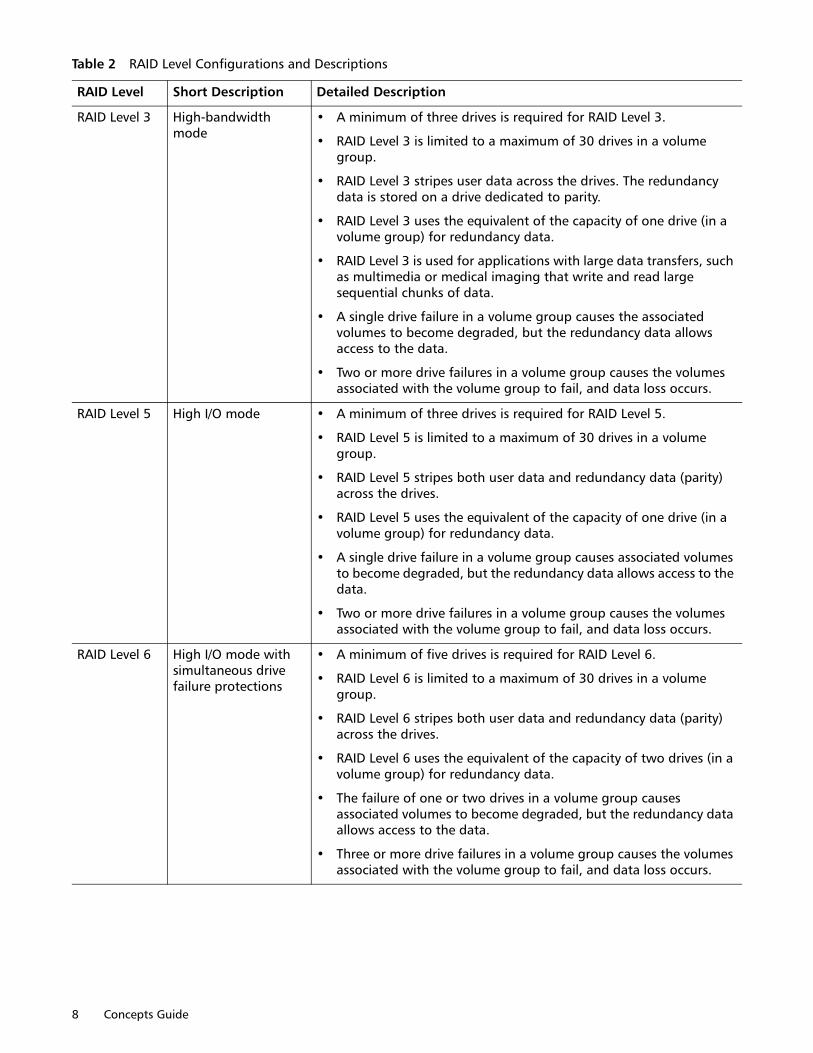
RAID Level ConfigurationTable 2 provides the RAID level configurations and descriptions.
Table 2 RAID Level Configurations and Descriptions
RAID Level Short Description Detailed Description
RAID Level 0 No protection against loss of a drive (non-redundant), striping mode
• A minimum of one drive is required for RAID Level 0.
• RAID Level 0 can use the maximum number of drives in a storage array.
• You can use RAID Level 0 for high-performance needs, but it does not provide data redundancy.
• Data is striped across all of the drives in the volume group.
• Do not use this RAID level for high data-availability needs. RAID Level 0 is better for non-critical data.
• A single drive failure in a volume group causes all of the volumes associated with the volume group to fail, and data loss occurs.
RAID Level 1 or RAID Level 10
Striping and mirroring mode
• A minimum of two drives are required for RAID Level 1: one for the user data and one for the mirrored data. If you select four or more drives, RAID Level 10 is automatically configured across the volume group: two drives for the user data, and two drives for the mirrored data.
• RAID Level 1 and RAID Level 10 can use the maximum number of drives in a storage array.
• RAID Level 1 and RAID Level 10 typically provide the best write performance, but not in all cases. On a RAID Level 1 volume, data is written to a duplicate drive. On a RAID Level 10 volume, data is striped across mirrored pairs.
• If one of the drives in a drive-pair fails, the system can instantly switch to the other drive without any loss of data or service.
• RAID Level 1 and RAID Level 10 use drive mirroring to make an exact copy from one drive to another.
• A single drive failure causes associated volumes to become degraded, but the mirror drive allows access to the data.
Two or more drive failures in a volume group causes the volumes associated with the volume group to fail, and data loss occurs.
8 Concepts Guide
RAID Level 3 High-bandwidth mode
• A minimum of three drives is required for RAID Level 3.
• RAID Level 3 is limited to a maximum of 30 drives in a volume group.
• RAID Level 3 stripes user data across the drives. The redundancy data is stored on a drive dedicated to parity.
• RAID Level 3 uses the equivalent of the capacity of one drive (in a volume group) for redundancy data.
• RAID Level 3 is used for applications with large data transfers, such as multimedia or medical imaging that write and read large sequential chunks of data.
• A single drive failure in a volume group causes the associated volumes to become degraded, but the redundancy data allows access to the data.
• Two or more drive failures in a volume group causes the volumes associated with the volume group to fail, and data loss occurs.
RAID Level 5 High I/O mode • A minimum of three drives is required for RAID Level 5.
• RAID Level 5 is limited to a maximum of 30 drives in a volume group.
• RAID Level 5 stripes both user data and redundancy data (parity) across the drives.
• RAID Level 5 uses the equivalent of the capacity of one drive (in a volume group) for redundancy data.
• A single drive failure in a volume group causes associated volumes to become degraded, but the redundancy data allows access to the data.
• Two or more drive failures in a volume group causes the volumes associated with the volume group to fail, and data loss occurs.
RAID Level 6 High I/O mode with simultaneous drive failure protections
• A minimum of five drives is required for RAID Level 6.
• RAID Level 6 is limited to a maximum of 30 drives in a volume group.
• RAID Level 6 stripes both user data and redundancy data (parity) across the drives.
• RAID Level 6 uses the equivalent of the capacity of two drives (in a volume group) for redundancy data.
• The failure of one or two drives in a volume group causes associated volumes to become degraded, but the redundancy data allows access to the data.
• Three or more drive failures in a volume group causes the volumes associated with the volume group to fail, and data loss occurs.
Table 2 RAID Level Configurations and Descriptions
RAID Level Short Description Detailed Description
Storing Data 9
Dynamic RAID-Level MigrationDynamic RAID-Level Migration (DRM) is a modification operation that lets you change the RAID level on a selected volume group without impacting data I/O. Data I/O activity continues on volumes within the volume group during the migration process.
The volume group must contain sufficient free capacity and the required number of drives to support the new RAID level, or the DRM request is rejected. You cannot cancel the DRM operation after the process begins.
NOTE: Dynamic RAID-Level Migration (DRM) is not a supported feature in disk pools.
Hardware RedundancyData-protection strategies provided by the storage array hardware include controller cache memory, hot spare drives, tray loss protection, drawer loss protection, and background media scans.
NOTE: With disk pools, a hot spare drive is not used.
Controller Cache MemoryWrite caching, or caching a drive segment to a memory buffer before writing to the drive, can increase I/O performance during data transfers.
Write-cache mirroring protects data during a controller-memory failure or a cache-memory failure. When you enable write cache, cached data is mirrored across two redundant controllers with the same cache size. Therefore, if one controller fails, the alternate controller can complete all outstanding write operations.
To prevent data loss or corruption, the controller periodically writes cache data to a drive (flushes the cache) when the amount of unwritten data in the cache reaches a certain level, called a start percentage, or when data has been in the cache for a predetermined amount of time. The controller continues to write data to a drive until the amount of data in the cache drops to a stop percentage level. You can configure the start percentage and the stop percentage to suit your own storage requirements. For example, you can specify that the controller start flushing the cache when it reaches 80-percent full and stop flushing the cache when it reaches 16-percent full.
In case of power outages, data in the controller cache memory is protected. Controller in base system contain batteries that protect the data in the cache by maintaining a level of power until the data can be written to the drive media or a flash memory card.
If the controller supports a flash memory card, the cache data can be written to the flash memory card when a power outage occurs. The battery is needed only to maintain power while the data in the cache is written to the flash memory card. The flash memory card provides nonvolatile backup of the cache data in case of long power outages. When power is restored to the controllers, the cache data can be read from the flash memory card by the controller.
If a power outage occurs when there is no UPS, and there is no battery or the battery is damaged, the data in the cache that has not been written to the drive media is lost. This situation occurs even if the data is mirrored to the cache memory of both controllers. Therefore, make sure that you change the batteries in the controller of the base system, at the recommended time intervals.
10 Concepts Guide
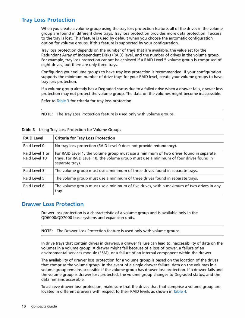
Tray Loss ProtectionWhen you create a volume group using the tray loss protection feature, all of the drives in the volume group are found in different drive trays. Tray loss protection provides more data protection if access to the tray is lost. This feature is used by default when you choose the automatic configuration option for volume groups, if this feature is supported by your configuration.
Tray loss protection depends on the number of trays that are available, the value set for the Redundant Array of Independent Disks (RAID) level, and the number of drives in the volume group. For example, tray loss protection cannot be achieved if a RAID Level 5 volume group is comprised of eight drives, but there are only three trays.
Configuring your volume groups to have tray loss protection is recommended. If your configuration supports the minimum number of drive trays for your RAID level, create your volume groups to have tray loss protection.
If a volume group already has a Degraded status due to a failed drive when a drawer fails, drawer loss protection may not protect the volume group. The data on the volumes might become inaccessible.
Refer to Table 3 for criteria for tray loss protection.
NOTE: The Tray Loss Protection feature is used only with volume groups.
Drawer Loss ProtectionDrawer loss protection is a characteristic of a volume group and is available only in the QD6000/QD7000 base systems and expansion units.
NOTE: The Drawer Loss Protection feature is used only with volume groups.
In drive trays that contain drives in drawers, a drawer failure can lead to inaccessibility of data on the volumes in a volume group. A drawer might fail because of a loss of power, a failure of an environmental services module (ESM), or a failure of an internal component within the drawer.
The availability of drawer loss protection for a volume group is based on the location of the drives that comprise the volume group. In the event of a single drawer failure, data on the volumes in a volume group remains accessible if the volume group has drawer loss protection. If a drawer fails and the volume group is drawer loss protected, the volume group changes to Degraded status, and the data remains accessible.
To achieve drawer loss protection, make sure that the drives that that comprise a volume group are located in different drawers with respect to their RAID levels as shown in Table 4.
Table 3 Using Tray Loss Protection for Volume Groups
RAID Level Criteria for Tray Loss Protection
Raid Level 0 No tray loss protection (RAID Level 0 does not provide redundancy).
Raid Level 1 or Raid Level 10
For RAID Level 1, the volume group must use a minimum of two drives found in separate trays. For RAID Level 10, the volume group must use a minimum of four drives found in separate trays.
Raid Level 3 The volume group must use a minimum of three drives found in separate trays.
Raid Level 5 The volume group must use a minimum of three drives found in separate trays.
Raid Level 6 The volume group must use a minimum of five drives, with a maximum of two drives in any tray.

Storing Data 11
NOTE: If you create a volume group by using the automatic drive selection method, the storage management software attempts to choose drives that provide drawer loss protection. If you create a volume group by using the manual drive selection method, you must use the criteria that are specified in the previous table.
For more information about how to create volume groups, refer to the "Using the Create Volume Group Wizard" online help topic in the Array Management Window of SANtricity Storage Manager.
If a volume group already has a Degraded status due to a failed drive when a drawer fails, drawer loss protection does not protect the volume group. The data on the volumes becomes inaccessible.
Hot Spare DrivesWith volume groups, a valuable strategy to protect data is to assign available drives in the storage array as hot spare drives. A hot spare is a drive, containing no data, that acts as a standby in the storage array in case a drive fails in a RAID Level 1, RAID Level 3, RAID Level 5, RAID Level 6, or RAID Level 10 volume group. The hot spare adds another level of redundancy to the storage array. Generally, hot spare drives must have capacities that are equal to or greater than the used capacity on the drives that they are protecting. Hot spare drives must be of the same media type, the same interface type, and the same capacity as the drives that they are protecting.
If a drive fails in the storage array, the hot spare is normally substituted automatically for the failed drive without requiring your intervention. If a hot spare is available when a drive fails, the controller uses redundancy data/parity to reconstruct the data onto the hot spare. After the failed drive is physically replaced, you can use either of the following options to restore the data:
Table 4 Using RAID Level Drawer Loss Protection
RAID Level Criteria for Drawer Loss Protection
Raid Level 3 & Raid Level 5
RAID Level 3 and RAID Level 5 require a minimum of three drives. Place all of the drives in different drawers for a RAID Level 3 volume group and for a RAID Level 5 volume group to achieve drawer loss protection. Drawer loss protection cannot be achieved for RAID Level 3 and RAID Level 5 if more than one drive is placed in the same drawer.
Raid Level 6 RAID Level 6 requires a minimum of five drives. Place all of the drives in different drawers or place a maximum of two drives in the same drawer and the remaining drives in different drawers to achieve drawer loss protection for a RAID Level 6 volume group.
Raid Level 1& Raid Level 10
RAID Level 1 requires a minimum of two drives. Make sure that each drive in a mirrored pair is located in a different drawer.
If you make sure that each drive in a mirrored pair is located in a different drawer, you can have more than two drives of the volume group within the same drawer. For example, if you create a RAID Level 1 volume group with six drives (three mirrored pairs), you can achieve the drawer loss protection for the volume group with only two drawers as shown in this example:
Six-drive RAID Level 1 volume group:
• Mirror pair 1 = Drive in tray 1, drawer 1, slot 1, and drive in tray 1, drawer 2, slot 1
• Mirror pair 2 = Drive in tray 1, drawer 1, slot 2, and drive in tray 1, drawer 2, slot 2
• Mirror pair 3 = Drive in tray 1, drawer 1, slot 3, and drive in tray 2, drawer 2, slot 3
RAID Level 10 requires a minimum of four drives. Make sure that each drive in a mirrored pair is located in a different drawer.
Raid Level 0 You cannot achieve drawer loss protection because the RAID Level 0 volume group does not have redundancy.
12 Concepts Guide
• When you have replaced the failed drive, the data from the hot spare is copied back to the replacement drive. This action is called copyback.
• You can assign the hot spare as a permanent member of the volume group. Performing the copyback function is not required for this option.
The availability of tray loss protection and drawer loss protection for a volume group depends on the location of the drives that comprise the volume group. Tray loss protection and drawer loss protection might be lost because of a failed drive and the location of the hot spare drive. To make sure that tray loss protection and drawer loss protection are not affected, you must replace a failed drive to initiate the copyback process.
The storage array automatically selects Data Assurance (DA)-capable drives for hot spare coverage of DA-enabled volumes. Make sure to have DA-capable drives in the storage array for hot spare coverage of DA-enabled volumes.
Security capable drives provide coverage for both security capable and non-security capable drives. Non-security capable drives can provide coverage only for other non-security capable drives.
If you do not have a hot spare, you can still replace a failed drive while the storage array is operating. If the drive is part of a RAID Level 1, RAID Level 3, RAID Level 5, RAID Level 6, or RAID Level 10 volume group, the controller uses redundancy data/parity to automatically reconstruct the data onto the replacement drive. This action is called reconstruction.
I/O Data Path ProtectionWhen designing a storage area network (SAN), the duplication of host bus adapters (HBAs), cables, switches, controllers, and other components provides redundancy and can prevent loss of data access in the event of a component failure. This redundancy means that the host has one or more paths to each controller.
When creating volumes, a controller is assigned to own the volume and is referred to as the preferred owner. The preferred owner may be selected to achieve load balancing across controllers. Most host multi-path drivers will attempt to access each volume on a path to its preferred controller. However, if this preferred path becomes unavailable, the multi-path driver on the host will failover to an alternate path. This failover might cause the volume ownership to change to the alternate controller.
Target Port Group SupportTarget Port Group Support (TPGS) is another multi-path driver that is available on specific combinations of operating systems and failover drivers that can be present on a host. TPGS provides failover for a storage array. Failover is an automatic operation that switches the data path for a volume from the preferred controller to the alternate controller in the case of a hardware failure.
TPGS is part of the ANSI T10 SPC-3 specification. It is implemented in the controller firmware. The advantage of TPGS is that it is based on the current standard, which allows interoperability with multi-pathing solutions from other vendors. Interoperability with other multi-pathing solutions simplifies administration of the host.
TPGS support is determined by examining the 'TPGS' field returned from a SCSI INQUIRY request.
Failover for WindowsThe failover driver for hosts with Microsoft Windows operating systems is the Microsoft Multipath I/O (MPIO) with a Device Specific Module (DSM) for SANtricity Storage Manager. The Microsoft MPIO (MPIO) is a feature that provides multipath I/O support for Windows Operating Systems. It handles
Storing Data 13
OS-specific details necessary for proper discovery and aggregation of all paths exposed by a storage array to a host system. This support relies on built-in or third-party drivers called Device-Specific Modules (DSMs) to handle details of path management such as load balance policies, I/O error handling, failover, and management of the DSM.
The DSM driver supports the TPGS command type ("Method") of failover.
Load BalancingLoad balancing is the redistribution of read/write requests to maximize throughput between the server and the storage array. Load balancing is very important in high workload settings or other settings where consistent service levels are critical. The multi-path driver transparently balances I/O workload without administrator intervention. Without multipath software, a server sending I/O requests down several paths might operate with very heavy workloads on some paths, while other paths are not used efficiently.
The multi-path driver determines which paths to a device are in an active state and can be used for load balancing. Multiple options for setting the load-balancing policies let you optimize I/O performance when mixed host interfaces are configured Load balancing is performed on multiple paths to the same controller but not across both controllers. The load-balancing policy uses one of three algorithms: round robin, least queue depth, or least path weight. The load-balancing policies that you can choose depend on your operating system, fail-over solution, and configuration.
Round Robin with SubsetThe round-robin with subset I/O load-balancing policy routes I/O requests, in rotation, to each available data path to the controller that owns the volumes. This policy treats all paths to the controller that owns the volume equally for I/O activity. Paths to the secondary controller are ignored until ownership changes. The basic assumption for the round robin policy is that the data paths are equal. With mixed-host support, the data paths might have different bandwidths
or different data transfer speeds.
Least Queue Depth with SubsetThe least queue depth with subset policy also is known as the least I/Os policy or the least requests policy. This policy routes the next I/O request to the data path on the controller that owns the volume that has the least outstanding I/O requests queued. For this policy, an I/O request is a command in the queue. The type of command or the number of blocks that are associated with the command is not considered. The least queue depth with subset policy treats large block requests and small block requests equally. The data path selected is one of the paths in the path group of the controller that owns the volume.
Least Path Weight with SubsetThe least path weight with subset policy assigns a weight factor to each data path to a volume. An I/O request is routed to the path with the lowest weight value to the controller that owns the volume. If more than one data path to the volume has the same weight value, the round-robin with subset path selection policy is used to route I/O requests between the paths with the same weight value.

14 Concepts Guide

Introducing the Software 15
Chapter 2
Introducing the Software
This chapter provides the information on using the Enterprise Management Window (EMW) and the Array Management Window (AMW).
Enterprise Management WindowThe Enterprise Management Window (EMW) is the first window to appear when you start the storage management software. The EMW lets you perform these management tasks:
• Discover hosts and storage arrays automatically on your local sub-network.
• Manually add and remove hosts and storage arrays.
• Monitor the health of the storage arrays and report a high-level status by using the applicable icon.
• Configure alert notifications through email or Simple Network Management Protocol (SNMP) and report events to the configured alert destinations.
• Schedule or automatically save a copy of the support data when the client monitor process detects an event.
• Launch the applicable Array Management Window (AMW) for a selected storage array to perform detailed configuration and management operations.
• Run SMcli scripts using the Script Editor to perform batch management tasks on a particular storage array.
• For example, scripts might be run to create new volumes or to download new controller firmware.
• For more information about running scripts, refer to the online help topics in the EMW.
• Upgrade the controller firmware.
• Collect support information on one or all of the storage arrays you are managing.
• Configure AutoSupport. With AutoSupport, data is automatically sent to Technical Support instead of manually sending it to Technical Support as is done with the legacy Collect Support Data feature. The new AutoSupport implementation speeds up troubleshooting and problem analysis.
NOTE: You must install the Support Monitor to use the AutoSupport feature.
16 Concepts Guide
• Retrieve a firmware inventory for all storage arrays you are managing.
• Set the session time-out. Time-out settings range from 1 minute to 30 minutes with a default of 20 minutes.
A local configuration file stores all of the information about storage arrays that you have added and any email destinations or SNMP traps that you have configured.
Parts of the Enterprise Management WindowThe Enterprise Management Window (EMW) has these areas that provide options for managing your storage array. Refer to Table 5.
EMW Devices TabThe Devices tab in the Enterprise Management Window presents two views of the storage arrays that are managed by the storage management station:
• Tree view
• Table view
Tree ViewThe Tree view provides a tree-structured view of the nodes in the storage system. The Tree view shows two types of nodes:
• Discovered Storage Arrays
• Unidentified Storage Arrays (not common)
Both the Discovered Storage Arrays node and the Unidentified Storage Arrays node are child nodes of the storage management station node.
Table 5 Enterprise Management Window
Part Description
Title bar “Enterprise Management” in the title bar text indicates that this is the EMW.
Menu bar The menu bar contains various options to manage the storage arrays. For more information about menu bar options, refer to the “EMW Menu Bar Options” online help topic in the Enterprise Management Window of SANtricity Storage Manager.
Toolbar The toolbar contains icons that are shortcuts to common commands. These icons let you perform these tasks:
• Automatically discover new storage arrays.
• Rescan selected hosts for new storage arrays.
• Add or Remove a storage array from view.
• Launch the Array Management Window (AMW).
Tabs The EMW contains two tabs:
• Devices – Shows the discovered storage arrays and provides basic information about your storage arrays, such as the status of a storage array and type of configured management connection.
• Setup – Allows you to perform initial setup tasks with the storage management software, such as adding, naming or managing a storage array or configuring alerts.
Status bar The Status bar shows a summary of the health of your storage arrays, messages, and a progress bar.

Introducing the Software 17
The Discovered Storage Arrays node has child nodes that represent the storage arrays that are currently managed by the storage management station. Each storage array is labeled with its machine name and is always present in the Tree view. When storage arrays and hosts with attached storage arrays are added to the EMW, the storage arrays become child nodes of the Discovered Storage Arrays node.
NOTE: If you move the mouse over the storage array node with an out-of-band management connection, a tooltip shows the controller’s IP address. For nodes with an in-band management connection, no information appears when move the pointer over a storage array node.
The Unidentified Storage Arrays node shows storage arrays that the storage management station cannot access because the name or IP address does not exist.
You can perform these actions on the nodes in the Tree view:
• Double-click the storage management station node and the Discovered Storage Arrays node to expand or collapse the view of the child nodes.
• Double-click a storage array node to launch the Array Management Window for that storage array.
• Right-click a node to open a pop-up menu that contains the applicable actions for that node.
The right-click menu for the storage management station node contains these options:
• Automatic Discovery
• Add Storage Array
• Configure Alerts
The right-click menu for the Discovered Storage Arrays node contains these options:
• Add Storage Array
• Automatic Discovery
• Refresh
Use the options on the Edit menu to add or rename a storage array, remove a storage array or management connection, configure alerts, enable remote status notification, or enter a comment that appears for a storage array node on the table view.
Use the options on the Tools menu to discover or manage storage arrays or hosts, upgrade firmware, load an existing configuration for a storage array, view a firmware inventory report, execute SMCLI scripts using the Script Editor, or collect support data.
Table ViewEach managed storage array is represented by a single row in the Table view. The columns in the Table view show data about the managed storage array. Refer to Table 6.
Table 6 Columns in the Managed Storage Array
Column Description
Name The name of the managed storage array. If the managed storage array is unnamed, the default name is Unnamed.
Type The type of device being managed. Currently, this column shows only an icon for a storage array.
Status An icon and a text label that report the status of the managed storage array.
18 Concepts Guide
Sort the rows in the Table view in ascending order or descending order by either clicking a column heading or by selecting a command from the View menu.
Showing Managed Storage Arrays in Table ViewYou can change the way that managed storage arrays appear in the Table view.
• Select the storage management station node to show all of the known managed storage arrays in the Table view.
• Select a Discovered Storage Array node or an Undiscovered Storage Array node in the Tree view to show any storage arrays that are attached to that specific host in the Table view.
NOTE: If you have not added any storage arrays, the Table view is empty.
Select a storage array node in the Tree view to show only that storage array in the Table view.
NOTE: Selecting an Unidentified node in the Tree view shows an empty Table view.
Adding a Storage ArrayThe SANtricity Storage Manager provides several ways to add or remove a storage array to and from the Enterprise Management Window (EMW). Having more than one method available to add a storage array lets you choose the method that best suits your working style. Use one of the following methods to add or remove a storage array to or from the EMW:
• Menu bar – Select a menu option.
• Toolbar – Click the appropriate icon.
• Setup tab – Click one of the links that appear.
• Tree view – Right-click a root node and select an option from a drop-down menu.
When you add a storage array, you are actually adding an icon that represents a storage array to your view of the Enterprise Management Window (EMW).
Removing Multiple Storage Arrays SimultaneouslyYou can simultaneously manage one or more storage arrays from the EMW. As described in Adding a Storage Array, there are several methods available to add or remove storage arrays from the EMW. Although you can manually add only one storage array to the EMW at a time, you can remove one or several storage arrays from the EMW at the same time using these methods:
• To remove a single storage array, from the Tree view click a node and then click the Remove storage array from view icon. Or you can select the appropriate option from the Edit menu.
Management Connections
Shows the type of management connection configured for a storage array. Options are In-band, Out-of-Band, or Out-of-Band/In-band meaning your storage array uses both types of management connections.
Click Details to see more information about any of these connections.
Comment Any comments that you have entered about the specific managed storage array.
Table 6 Columns in the Managed Storage Array
Column Description

Introducing the Software 19
• To remove several contiguous storage arrays, from the Tree view use the SHIFT key and click to select contiguous storage arrays. With the selected storage arrays highlighted in the Table view, right-click and select Remove from the pop-up menu.
• To remove several non-contiguous storage arrays, from the Tree view use the CTRL key and click to select contiguous storage arrays. With the selected storage arrays highlighted in the Table view, right-click and select Remove from the pop-up menu.
Remember that when you remove a storage array, you are removing only the icon from the Tree and Table views. You are not physically deleting the storage array.
EMW Setup TabThe EMW Setup tab is a gateway to tasks that you can perform when you set up a storage array. Using the EMW Setup tab, you can perform these tasks:
• Add a storage array
• Name or rename a storage array
• Configure an alert for one or all storage arrays
• Manage a storage array by launching the Array Management Window (AMW)
• Upgrade the controller firmware
• Open the Inherit Systems Settings window
Array Management WindowThe Array Management Window (AMW) is a Java™ technology-based software that you launch from the Enterprise Management Window (EMW). The AMW provides management functions for a single storage array. You can have more than one AMW open at the same time to manage different storage arrays. The AMW includes these management functions for a storage array:
• Provides storage array options, such as locating a storage array, configuring a storage array, renaming a storage array, or changing a password.
• Provides the ability to configure volumes from your storage array capacity, define hosts and host groups, and grant host or host group access to sets of volumes called storage partitions.
• Monitors the health of storage array components and reports a detailed status using applicable icons.
• Provides you with the applicable recovery procedures for a failed logical component or a failed hardware component.
• Presents a view of the Event Log for the storage array.
• Presents profile information about hardware components, such as controllers and drives.
• Provides controller management options, such as changing ownership of volumes or placing a controller online or offline.
• Provides drive management options, such as assigning hot spares and locating the drive.
• Monitors storage array performance.
The format and options that appear on the AMW is dependent on the version of controller firmware running on your controller. When you launch the AMW for a storage array, the version of the AMW that appears depends on the version of controller firmware running on the controller assigned to that storage array. The information in this document describes the functions of the AMW for the current release. Refer to previous versions of this document for information about how to use the AMW with earlier releases.

20 Concepts Guide
Starting the Array Management WindowTo start the Array Management Window (AMW) from the Enterprise Management Window (EMW), perform one of these tasks:
• Click the Devices tab, and double-click the name of the storage array that you want to manage.
• Click the Devices tab, right-click the name of the storage array you want to manage, and select Manage Storage Array.
• Click the Devices tab, and select Tools > Manage Storage Array.
• Click the Setup tab, and select Manage a Storage Array. In the Select Storage Array dialog, select the name of the storage array that you want to manage, and click OK.
Parts of the Array Management WindowThe Array Management Window (AMW) has these areas that provide options for managing your storage array. Refer to Table 7.
Table 7 Array Management Window
Part Description
Title bar “Array Management” in the title bar text indicates that this is the AMW.
Menu bar The menu bar contains various options to configure and manage the capacity of the drives in a storage array. For more information about menu bar options, refer to the “Learn About the Array Management Window” online help topic.
Toolbar The toolbar contains icons that are shortcuts to common commands. Use these icons to complete the following tasks:
• Create a new volume.
• View an Event Log.
• Run the Performance Monitor.
• View which operations are in progress.
• Initiate the Recovery Guru to help recover from a failure condition.
• Manage the base system/expansion unit alarms.
• Launch the copy manager.

Introducing the Software 21
Summary TabThe Summary tab in the AMW shows information about the storage array. Links to the Storage Array Profile dialog, relevant online help topics, and the storage concepts tutorial also appear. Additionally, the link to the Recovery Guru dialog appears when the storage array needs attention.
In the Summary tab, you can view this information:
• The status of the storage array
• Version information for storage management software and controller
• The capacity of the storage array
• A list of the number of disk pools and volume groups, volumes, snapshot image elements (premium feature), consistency groups (premium feature), snapshot (legacy) image elements (premium feature), and asynchronous mirror groups (premium feature) in the storage array
• The hosts, the mappings, and the storage partitions in the storage array
• A list of the number of Try and Buy premium features shipped (available) for your storage array, the number of Try and Buy premium features you are evaluating (active), and the number of purchased premium features enabled or disabled for your storage array
• A list of the hardware components in the storage array
• Links to online documentation available for learning about your storage array
Tabs The AMW contains five tabs:
• Summary – Provides links and shows information that helps you manage and monitor your storage array. The Summary tab also houses the Information Center which contains links to the available online help and online tutorials.
• Storage & Copy Service – Shows the organization of the storage array by total unconfigured capacity, disk pools, volume groups, consistency groups (premium feature), and mirroring groups. Additional features available from this tab include a search field that lets you locate objects by Name in the Tree view, and an Object Type search field that lets you display storage array objects and related information by type in the Table view.
• Host Mappings – Shows the topology of the logical nodes related to the storage partitions in the storage array and the defined mappings associated with a selected logical node.
• Hardware – Provides information about the controllers and drives in a storage array.
• Performance – The Array Management Window contains a new Performance tab. The Performance tab shows a dashboard where you can monitor six different performance graphs at once. New performance metrics that you can monitor are I/O latency for drives and volumes and throughput for the entire storage array and volumes. The Performance tab also contains links that give you a convenient way to start textual performance monitoring or background performance monitoring.
• Setup – Provides the links to tasks that you can perform when setting up a storage array, such as configuring the storage array, setting the storage array password, provisioning drives, and configuring the Ethernet management port in the storage array.
Status bar The Status bar shows which premium features are available and enabled/ disabled for your storage array. If a feature icon is gray, the feature is available but disabled. If a feature icon has color the feature is available and enabled. The tool tip also indicates if the premium feature is a Try and Buy feature.
Table 7 Array Management Window
Part Description
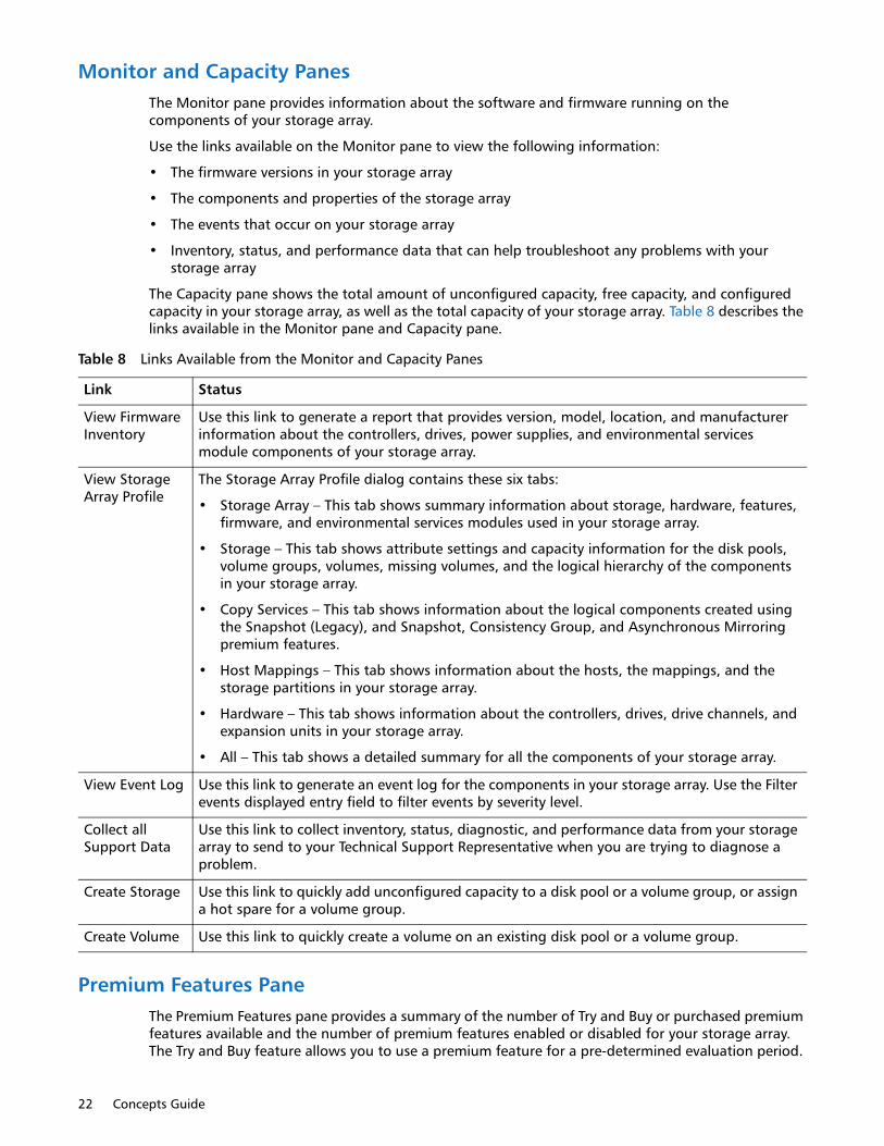
22 Concepts Guide
Monitor and Capacity PanesThe Monitor pane provides information about the software and firmware running on the components of your storage array.
Use the links available on the Monitor pane to view the following information:
• The firmware versions in your storage array
• The components and properties of the storage array
• The events that occur on your storage array
• Inventory, status, and performance data that can help troubleshoot any problems with your storage array
The Capacity pane shows the total amount of unconfigured capacity, free capacity, and configured capacity in your storage array, as well as the total capacity of your storage array. Table 8 describes the links available in the Monitor pane and Capacity pane.
Premium Features PaneThe Premium Features pane provides a summary of the number of Try and Buy or purchased premium features available and the number of premium features enabled or disabled for your storage array. The Try and Buy feature allows you to use a premium feature for a pre-determined evaluation period.
Table 8 Links Available from the Monitor and Capacity Panes
Link Status
View Firmware Inventory
Use this link to generate a report that provides version, model, location, and manufacturer information about the controllers, drives, power supplies, and environmental services module components of your storage array.
View Storage Array Profile
The Storage Array Profile dialog contains these six tabs:
• Storage Array – This tab shows summary information about storage, hardware, features, firmware, and environmental services modules used in your storage array.
• Storage – This tab shows attribute settings and capacity information for the disk pools, volume groups, volumes, missing volumes, and the logical hierarchy of the components in your storage array.
• Copy Services – This tab shows information about the logical components created using the Snapshot (Legacy), and Snapshot, Consistency Group, and Asynchronous Mirroring premium features.
• Host Mappings – This tab shows information about the hosts, the mappings, and the storage partitions in your storage array.
• Hardware – This tab shows information about the controllers, drives, drive channels, and expansion units in your storage array.
• All – This tab shows a detailed summary for all the components of your storage array.
View Event Log Use this link to generate an event log for the components in your storage array. Use the Filter events displayed entry field to filter events by severity level.
Collect all Support Data
Use this link to collect inventory, status, diagnostic, and performance data from your storage array to send to your Technical Support Representative when you are trying to diagnose a problem.
Create Storage Use this link to quickly add unconfigured capacity to a disk pool or a volume group, or assign a hot spare for a volume group.
Create Volume Use this link to quickly create a volume on an existing disk pool or a volume group.

Introducing the Software 23
The available Try and Buy premium features vary for different storage array configurations, but can include the following features:
• Snapshot Groups
• Thin provisioning
• High performance tier
• Synchronous Mirroring (SM)
Use the Manage Premium Features link to view which premium features are enabled or disabled for your storage array, to enable a premium feature using a feature key identifier, or disable Try and Buy or purchased premium feature on your storage array.
NOTE: Not all premium features are supported or available for all configurations.
Hardware PaneThe Hardware pane shows a summary of the controllers, expansion units, and drives that comprise your storage array. If your storage array contains different media types or different interface types, an icon that identifies the media type or drive type appears under the Media Type and Interface Type titles. For media type, there are icons for hard disk drives (HDD) and solid state disks (SSD). For interface type, there are icons for full disk encryption (FDE) security capable drives, Serial Attached SCSI (SAS) drives, and Data Assurance (DA)-capable drives.
Storage and Copy Services TabThe Storage & Copy Services tab in the AMW contains two panes: the Storage & Copy Services pane and the Properties pane.
NOTE: You can resize either pane by dragging the splitter bar, located between the two panes, to the right or to the left.
Storage and Copy Services PaneThe Storage & Copy Services pane provides a tree-structured view of the logical nodes. Click the plus (+) sign or the minus (-) sign adjacent to a node to expand or collapse the view. You can right-click a node to open a pop-up menu that contains the applicable actions for that node.
Nodes in the Logical PaneThe storage array, or root node, has several types of child nodes. The Unconfigured Capacity nodes and Volume Group nodes are standard nodes and will appear for all storage arrays. The Disk Pools nodes, Consistency Groups nodes, and Asynchronous Mirror Group nodes appear only if the associated premium feature is available and enabled on your storage array. Refer to Table 9.

24 Concepts Guide
Table 9 Child Nodes of Root Node
Child Nodes of Root Node
Description of the Child Nodes
All Logical Objects
This node lets you view information about all the logical objects that comprise your storage array. Use the Object Type drop-down menu in the View pane to select a particular object type. This option is a useful way to view the status and capacity information for a disk pool or a volume group, or view all the repository volumes that are associated or not associated with a base volume used with the Snapshot (Legacy) Image, Snapshot Image, and Consistency Group premium features.
Total Unconfigured Capacity
This node represents the sum of the capacity of all unassigned drives that are not in a disk pool or a volume group.
Unconfigured Capacity
This node represents the storage array capacity that is not configured into a volume group.
Multiple Unconfigured nodes appear if your storage array contains drives with different media types (hard disk drives or solid state drives) and different interface types. Each drive type has an associated Unconfigured Capacity node shown under the Total Unconfigured Capacity node if unassigned drives are available in a base system/expansion unit.
Disk Pools The storage management software shows a Disk Pools node if one or more disk pools have been configured for your storage array. Expand the Disk Pool node to see the individual disk pools. You see the Snapshot (Legacy) Image and Snapshot Image child nodes only when the Snapshot or Snapshot (Legacy) Group premium features are enabled for your storage array.
The disk pool node has several types of child nodes:
• Volume – This node represents a configured and defined volume. Multiple Volume nodes can exist under a Disk Pool node.
• Free Capacity – This node represents a region of capacity that you can use to create one or more new volumes within the disk pool. A Free Capacity node can exist under each Disk Pool node.
• Snapshot Images – This node represents a logical point-in-time image of a selected base volume. A base volume is a standard volume or a thin volume that is the source of a snapshot image.
• Snapshot Groups – This node represents the sequence of snapshot images of the same base volume.
• Snapshot Volumes – This node indicates that you have created a view of a snapshot image. You create a snapshot volume to allow a host to access a snapshot image as if were a volume.

Introducing the Software 25
Types of VolumesWith the exception of the standard volume, all other types of volumes are available only when the related premium feature is enabled for a storage array.
These types of volumes appear under the Disk Pool or Volume Group nodes:
• Standard volumes are the types of volume you can create from a volume group or a disk pool in a storage array to store data. When you configure a standard volume from a volume group or a disk pool, you must specify a capacity that is all or part of the volume group or disk pool capacity. The operating system sees a volume as one drive.
• Thin volumes are the types of volume you can create from a disk pool if the Thin Provisioning premium feature is available and enabled for your storage array. With a thin volume, capacity is allocated as the data is written. You can configure a thin volume only in a disk pool.
Volume Groups This node has several types of child nodes. The Volume node and the Free Capacity node are standard child nodes. If the Snapshot premium feature is enabled, you can have the snapshot image child nodes:
• Volume – This node represents a configured and defined volume. Multiple Volume nodes can exist under a Volume Group node.
• Free Capacity – This node represents a region of capacity that you can use to create one or more new volumes within the volume group. Multiple Free Capacity nodes can exist under a Volume Group node.
• Snapshot Images – This node represents a logical point-in-time image of a selected base volume. A base volume is a standard volume or a thin volume that is the source of a snapshot image.
• Snapshot Groups – This node represents the sequence of snapshot images of the same base volume.
• Snapshot Volumes – This node represents the snapshot images of a base volume that are visible to a host.
• Snapshot (Legacy) Volume – This node represents child nodes of their associated base volumes.
Consistency Groups
If the Snapshot premium feature is enabled, you can have the following consistency group child nodes:
• Consistency Group – This node represents a grouping node which includes all the child nodes created for this consistency group. Expand this node to see the child nodes.
• Snapshot Images –This node represents a collection of logical point-in-time image of the member volumes of a consistency group.
• Member Volumes – This node is a collection of the volumes that are members of this consistency group.
• Snapshot Volumes – This node represents the snapshot images of member volumes that are visible to a host.
Asynchronous Mirror Groups
These are special volumes in the storage array that are created as a resource for each controller in both local storage arrays and remote storage arrays. The controller stores duplicate information on the mirror repository volume, including information about remote writes that are not yet written to the secondary volume.
Table 9 Child Nodes of Root Node
Child Nodes of Root Node
Description of the Child Nodes
26 Concepts Guide
• Primary volumes that participate in a mirror relationship in the primary role. Primary volumes are standard volumes with a synchronized mirror relationship. The remote secondary volume that is associated with the primary volume appears as a child node.
• Secondary volumes appear directly under the Volume Group node when the local storage array contains this volume.
• Mirror repository volumes are special volumes in the storage array that are created as a resource for each controller in both local storage arrays and remote storage arrays. The controller stores duplicate information on the mirror repository volume, including information about remote writes that are not yet written to the secondary volume.
• Snapshot (Legacy) repository volumes are volumes in the storage array that are used as a resource for a snapshot (legacy) volume.
• Snapshot (Legacy) volumes are child nodes of their associated base volume.
• Snapshot volumes are volumes with associated repositories that enable a host to perform ongoing write operations for a specified volume.
• Base volumes are standard volumes or thin volumes that are being used in conjunction with the Snapshot premium feature or Consistency Groups premium feature.
• Snapshot Group repositories are physical standard volumes that store data for all the snapshot images taken of a base volume.
• Source volumes are standard volumes that participate in a volume copy relationship. Source volumes are used as the copy source for a target volume. Source volumes accept host I/O requests and store application data. A source volume can be a standard volume, a snapshot (legacy) volume, a snapshot (legacy) base volume, or a Synchronous Mirroring primary volume.
• Target volumes are standard volumes that participate in a volume copy relationship and contain a copy of the data from the source volume. Target volumes are read-only and do not accept write requests. A target volume can be created from a standard volume, the base volume of a snapshot (legacy) volume, or a Synchronous Mirroring primary volume. The volume copy overwrites any existing volume data if an existing volume is used as a target.
Properties PaneThe Properties pane provides detailed information about the component selected in the Logical pane. The information varies depending on what type of component is selected.
You can view the physical components that are associated with a logical component by selecting the Storage & Copy Services tab, right-clicking a component, and selecting View Associated Physical Components.
Host Mappings TabThe Host Mappings tab in the AMW contains two panes: the Topology pane and the Defined Mappings pane.
NOTE: You can resize either pane by dragging the splitter bar, located between the two panes, to the right or to the left.
Host Mappings PaneThe Host Mappings pane shows a tree-structured view of logical nodes that are related to storage partitions. Click the plus (+) sign or the minus (-) sign adjacent to a node to expand or collapse the view. You can right-click a node to open a pop-up menu that contains the applicable actions for that node.

Introducing the Software 27
Nodes in the Host Mappings PaneThe storage array, or the root node, has these types of child nodes. Refer to Table 10.
Storage and Copy Services TabThe Storage & Copy Services tab in the AMW contains two panes: the Storage & Copy Services pane and the Properties pane.
NOTE: You can resize either pane by dragging the splitter bar, located between the two panes, to the right or to the left.
Defined Mappings PaneThe Defined Mappings pane shows the mappings associated with a node selected in the Topology pane.
The information in Table 11 appears for a selected node.
Table 10 Child Nodes - Host Mappings Pane
Child Nodes of the Root Node
Description of Child Nodes
Undefined Mappings
The Undefined Mapping node has one type of child node.
Individual Undefined Mapping – Represents a volume with an undefined mapping. Multiple volume nodes can exist under an Undefined Mappings node.
Default GroupNOTE: If SANshare Storage Partitioning is disabled, all of the created volumes are in the Default Group.
A Default Group node has two types of child nodes:
• Host Group – Defined host groups that are not participating in specific mappings are listed. This node can have host child nodes, which can have child host port nodes.
• Host – Defined hosts that are not part of a specific host group but are part of the Default Group and are not participating in specific mappings are listed. This node can have child host port nodes.
Unassociated Host Port Identifier
An Unassociated Host Port Identifier node has one type of child node.#
Host Port Identifier – Host port identifier that has not been associated with any host.
Host Group A Host Group node has one type of child node.
Host – Defined hosts that belong to this defined host group are listed. This node can have child host port nodes.
NOTE: The host nodes that are child nodes of this host group also can participate in mappings specific to the individual host rather than the host group.
Host A Host node has one type of child node.
Host Port – This node has child nodes that represent all of the host ports or single ports on a host adapter that are associated with this host.

28 Concepts Guide
You can right-click a volume name in the Defined Mappings pane to open a pop-up menu. The pop-up menu contains options to change and remove the mappings.
The information shown in the Defined Mappings pane varies according to what node you select in the Topology pane, as shown in Table 12.
Table 11 Defined Mappings Pane-1
Column Name Description
Volume Name The user-supplied volume name.
The factory-configured access volume also appears in this column.
NOTE: An access volume mapping is not required for a storage array with an in-band connection and can be removed.
Accessible By Shows the Default Group, a defined host group, or a defined host that has been granted access to the volume in the mapping.
LUN The LUN assigned to the specific volume that the host or hosts use to access the volume.
Volume Capacity Shows the volume capacity in units of GB.
Type Indicates whether the volume is a standard volume or a snapshot (legacy) volume.
Table 12 Defined Mappings Pane-2
Node Selected Information That Appears in the Defined Mappings Pane
Root (storage array) node All defined mappings.
Default Group node or any child node of the Default Group
All mappings that are currently defined for the Default Group (if any).
Host Group node (outside of Default Group) All mappings that are currently defined for the Host Group.
Host node that is a child node of a Host Group node
All mappings that are currently defined for the Host Group, plus any mappings specifically defined for a specific host.
Host Port node or individual host port node outside of the Default Group
All mappings that are currently defined for the host port’s associated host.

Introducing the Software 29
Defined Mappings PaneThe Defined Mappings pane shows the mappings associated with a node selected in the Topology pane. The information in Table 13 appears for a selected node.
You can right-click a volume name in the Defined Mappings pane to open a pop-up menu. The pop-up menu contains options to change and remove the mappings.
The information shown in the Defined Mappings pane varies according to what node you select in the Topology pane, as shown in Table 14.
Controller StatusWhen you open the Array Management Window (AMW) to manage a storage array, the version of software that is appropriate for the version of firmware that the storage array uses is opened. For example, you manage two storage arrays using this software; one storage array has firmware version 6.14, and the other has firmware version 7.8x, where x represents a number. When you open the AMW for a particular storage array, the correct AMW version is used. The storage array with firmware 6.14 uses version 9.14 of the storage management software, and the storage array with firmware version 7.8x uses version 10.8x of the storage management software. You can verify the version that you are currently using by selecting Help > About in the AMW.
This bundling of previous versions of the AMW provides the flexibility of upgrading the firmware only on selected storage arrays instead of having to perform an upgrade on all of the storage arrays at one time.
Table 13 Defined Mappings Pane-3
Column Name Description
Volume Name The user-supplied volume name.
The factory-configured access volume also appears in this column.
NOTE: An access volume mapping is not required for a storage array with an in-band connection and can be removed.
Accessible By Shows the Default Group, a defined host group, or a defined host that has been granted access to the volume in the mapping.
LUN The LUN assigned to the specific volume that the host or hosts use to access the volume.
Volume Capacity Shows the volume capacity in units of GB.
Type Indicates whether the volume is a standard volume or a snapshot (legacy) volume.
Table 14 Defined Mappings Pane-4
Node Selected Information That Appears in the Defined Mappings Pane
Root (storage array) node All defined mappings.
Default Group node or any child node of the Default Group
All mappings that are currently defined for the Default Group (if any).
Host Group node (outside of Default Group) All mappings that are currently defined for the Host Group.
Host node that is a child node of a Host Group node
All mappings that are currently defined for the Host Group, plus any mappings specifically defined for a specific host.
Host Port node or individual host port node outside of the Default Group
All mappings that are currently defined for the host port’s associated host.

30 Concepts Guide
View Tray ComponentsThe View Tray Components command on each tray shows the status of the secondary components within the tray, such as power supplies, fans, and temperature sensors.
You can use the Drive type drop-down list and the Show button in the Hardware tab to identify drives of a particular type, speed, and capacity. In the Drive type drop-down list, select the type of drive you want to identify, and click Show. A green triangle appears on top of the relevant drives.
AMW Setup TabThe AMW Setup tab provides links to these tasks:
• Locating the storage array
• Renaming the storage array
• Changing the hardware view order
• Setting a storage array password
• Managing premium features
• Configuring the network parameters for the iSCSI host ports
• Provision drives into disk pools, volume groups, or a hot spare
• Saving configuration parameters in a file
NOTE: The Save Configuration function generates a CLI script that contains storage array settings, volume configuration, topology, or volume-to-LUN mappings for a storage array. You can use this generated CLI script to replicate a configuration to another storage array.
However, you should not use this generated CLI script for disaster recovery for storage arrays running SANtricity Version 10.86. Instead, to do a system restore use the configuration database backup file that you create manually or by having the Persistent Monitor running in the background.
• Manually defining the hosts
• Mapping volumes to hosts
• Configuring the Ethernet management ports
• Managing the additional iSCSI settings for authentication, identification, and discovery (this link only appears on the Setup tab when the controllers contain iSCSI host ports)

Configuring Storage Arrays 31
Chapter 3
Configuring Storage Arrays
This chapter describe the methods for configuring storage arrays, including managing security, and premium features.
For additional information and detailed procedures for the options described in this section, refer to the online help topics in SANtricity Storage Manager.
Disk Pools and Volume GroupsThe first logical component you configure for your storage array is a disk pool or a volume group. You can think of a disk pool or a volume group as a container for organizing like drives in your storage array. When you configure a storage array for the first time, you must create either a disk pool or a volume group, decide which data protection strategy is most appropriate for your storage array, and determine how the total storage capacity must be organized into volumes and shared among hosts.
Both a disk pool and a volume group consist of a set of drives. You use the storage management software to logically group the drives together to provide one or more volumes to an application host. All of the drives in a disk pool or volume group must be of the same media type: hard disk drives (HDDs).
The RAID level you select when you configure a volume group determines the number of drives to add to a volume group. Other factors to consider when determining which drives to add to a disk pool or a volume group are media type, spindle speed, security capability, Data Assurance (DA) capability, and capacity. The media type must be the same for all drives in a disk pool or a volume group. To allow for more efficient use of drives in a disk pool or a volume group, the spindle speed and capacity of the drives should be the same or very similar.
If you choose drives with different capacities, the capacity on each drive equal to the smallest drive in the disk pool or volume group is used. This means that if there are several 8-GB drives and several 4-GB drives, 4 GB on each 8-GB drive remains unused. If you want the disk pool or volume group to use Full Disk Encryption (FDE), all of the drives must be FDE capable. If you want the disk pool or volume group to use DA, all of the drives must be DA capable.
In general, disk pools are easier to configure and maintain. Most of the configuration settings for a disk pool are set automatically, such as the RAID level, and you do not have to configure a hot spare drive. Adding drives to a disk pool is a simpler and faster process than adding drives to a volume group. You can add up to 12 drives to a disk pool at one time as compared to adding one drive at a time to a volume group.
A storage array can contain one or more disk pools or volume groups. Disk pools can coexist with volume groups on the same storage array.
32 Concepts Guide
A disk pool and a volume group have these differences:
• RAID implementation – RAID level is selectable for volume groups, but auto-assigned for a disk pool.
• Recovery from drive failure – Volume groups use hot spare drives during the drive recovery operation. Disk pools use reserved reconstruction space to recover data during the reconstruction process.
• Minimum number of drives required – The RAID level selected for a volume group determines the minimum number of required drives for a volume group. A minimum of 11 drives are required to create a disk pool.
• Ability to use thin provisioning – You can create thin volumes only in disk pools.
• Availability of premium features – Not all premium features are available for use with disk pools. For example, you cannot use the Snapshot (Legacy) feature for disk pools.
RAID ImplementationThe RAID level determines how redundant/parity data is striped across volumes in a disk pool or a volume group. Striping is the process of storing segments of data among all drives, with the exception of the hot spare drive, in a volume. Data is sequentially striped across all volumes in a volume group. Because data is randomly striped across volumes in a disk pool, the stripe width of 8+2 for RAID stripe for drives in a disk pool is independent of the number of drives in a disk pool. Stripe width refers to the total number of drives used for both data and redundancy in a stripe.
Regardless of whether you are configuring a disk pool or a volume group, the configured RAID level applies to all volumes in a disk pool or a volume group. For a disk pool, the RAID level is automatically set to RAID level 6, but for a volume group you can select RAID level 0, RAID level 1, RAID level 3, RAID level 5, RAID level 6, or RAID level 10. If your storage array consists of several volume groups, you can assign different RAID levels to each volume group.
Recovery from Drive FailureYou use the hot spare functionality only with volume groups. If a drive fails in a volume group, the hot spare drive takes over operation for the failed drive. The controller uses redundancy/parity data stored on the volume to reconstruct the data from the failed drive.
Instead of hot spare drives, a disk pool uses a small capacity referred to as reserved reconstruction space on each drive to store redundancy data. In the event of a drive failure, the controller uses the reconstruction data space on the remaining operational drives to reconstruct the data from the failed drive. The controller redistributes the I/O operations and data storage across the remaining drives in the disk pool.
Volume Group CreationVolume groups are created from the Total Unconfigured Capacity of a storage array. Total Unconfigured Capacity is the sum of the capacity of all the unassigned drives that are not in a disk pool or a volume group. A volume group can be comprised of several volumes. All volumes in a volume group use the same collection of drives and function at the RAID level configured for the volume group.
Create Volume Group WizardThe storage management software provides a Create Volume Group Wizard which guides you through the process of creating a volume group that is comprised of one or more drives in your storage array. When you create a volume group you must specify two key parameters: the RAID level

Configuring Storage Arrays 33
and the capacity. The RAID level defines how the data is organized, how redundancy is performed, and the minimum and maximum number of drives permitted in a volume group. The capacity is the sum of the capacity of the drives you select for your volume group.
Both the RAID level and the capacity settings for a volume group can be determined by the storage management software or entered manually. With the automatic method you select the RAID level and the storage management software automatically selects the best collection of drives for your volume group. With the manual method you select the RAID level and the appropriate type and number of drives to correspond to the selected RAID level. Whenever possible, use the automatic method.
After you create a volume group, the storage management software prompts you to create at least one volume. You must configure at least one volume in a volume group and map the volume to a host before the host operating system can save data to the volume on the volume group. If you do not configure a volume in your newly created volume group, the storage management software creates a free-capacity volume group. At some point you must create volumes from the free capacity to enable the host operating system to save data to the volumes.
Size of a Volume GroupThe minimum and maximum number of drives that can comprise a volume group depends on the RAID level selected for a volume group. All RAID levels except RAID level 0 provide a level of data redundancy. Table 15 shows the number of drives required to support data redundancy, and the minimum and maximum number of drives your volume group can have for each RAID level. You must select an even number of drives for RAID level 10.
The limit on the number of volume groups is the number of drives supported by the storage array. This number varies with the different storage array models.
Types of CapacityAvailable capacity in a volume group consists of these types of storage space:
Free capacity – The usable capacity in a volume group minus the capacity of any defined volumes. Use the Free Capacity node in a volume group to create a volume or expand the capacity of an existing volume.
Unconfigured capacity – The sum of the capacity of all the unassigned drives that are not in a volume group or a disk pool. One unconfigured capacity node exists for each type of drive type and drive media.
Unassigned drive – Any drive in a storage array that is not in a volume group or a disk pool, or is not configured as a hot spare drive for a volume group.
Figure 1 shows a volume group that consists of three volumes and free capacity. One of the drives in the storage array has been configured as a hot spare drive that is available to a volume group in the
Table 15 RAID Levels for a Volume Group
RAID Level Minimum # of Drives
Maximum Number of Drives Redundancy
0 1 All drives in storage array None
10 2 All drives in storage array Mirrored pairs
3 3 30 1 drive
5 3 30 1drive
6 5 30 2 drives
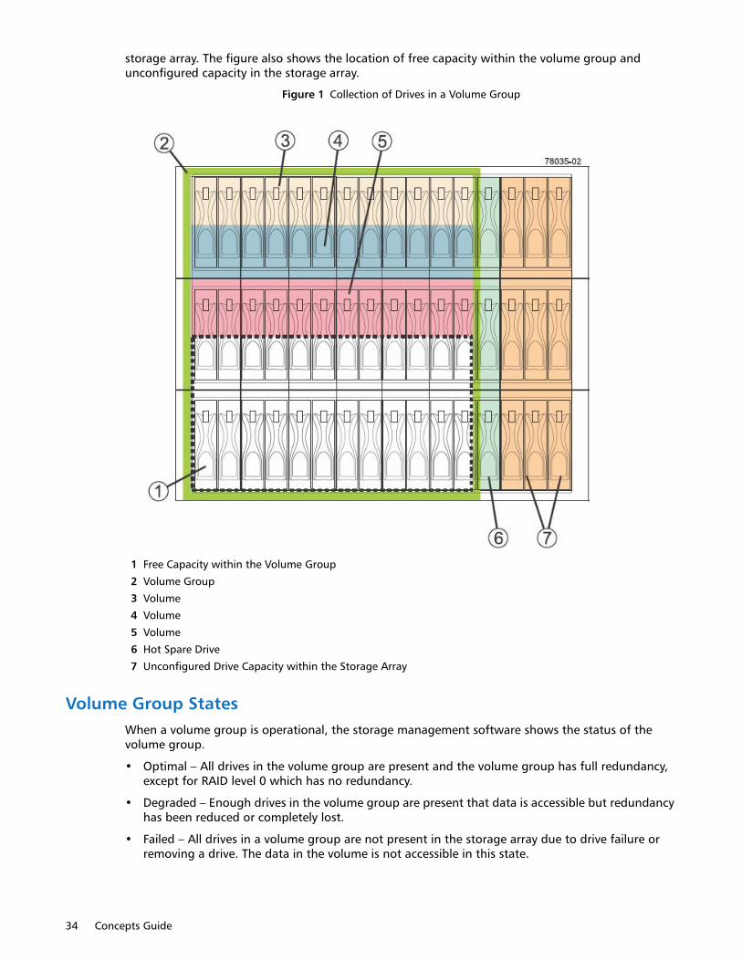
34 Concepts Guide
storage array. The figure also shows the location of free capacity within the volume group and unconfigured capacity in the storage array.
Figure 1 Collection of Drives in a Volume Group
1 Free Capacity within the Volume Group
2 Volume Group
3 Volume
4 Volume
5 Volume
6 Hot Spare Drive
7 Unconfigured Drive Capacity within the Storage Array
Volume Group StatesWhen a volume group is operational, the storage management software shows the status of the volume group.
• Optimal – All drives in the volume group are present and the volume group has full redundancy, except for RAID level 0 which has no redundancy.
• Degraded – Enough drives in the volume group are present that data is accessible but redundancy has been reduced or completely lost.
• Failed – All drives in a volume group are not present in the storage array due to drive failure or removing a drive. The data in the volume is not accessible in this state.

Configuring Storage Arrays 35
Change the RAID LevelThe storage management software lets you change the RAID level configured for a volume group. Use the Change RAID Level option when you want to change the level of redundancy or enhance performance of a volume group. Successfully changing the RAID level configured for a volume group requires the following conditions:
• The volume group must be operational.
• Sufficient free capacity must be available in the volume group to support the new RAID level.
• The status of the volume group must be Complete.
This operation is always carried out as a background task and volumes remain fully accessible during this operation.
Volume Group AttributesWhen you use the storage management software to create a volume group, some of the attributes you need to set are described in Table 16.
Disk Pool CreationDisk pools are created from the Total Unconfigured Capacity of a storage array. Total Unconfigured Capacity is the sum capacity of the unassigned drives in the storage array. To create a disk pool, the storage array must have a minimum of 11 drives.
The storage management software provides two ways to create a disk pool: using the Disk Pool Automatic Configuration dialog or using the Create Disk Pool Wizard.
Disk Pool Automatic Configuration DialogThe storage management software can detect the unconfigured capacity in a storage array. When the unconfigured capacity is detected, the storage management software lets you create one or more disk pools, or add the unconfigured capacity to an existing disk pool, or both. By default, the Automatic Configuration dialog appears each time you access the Array Management Window and your storage array has unassigned drives, or if new drives were added to a storage array that has at least one disk pool. This dialog shows the number of unassigned drives and calculates the free capacity of these drives.
By default, the storage management software assumes you want to create a disk pool rather than a volume group when your storage array has unassigned drives. If a disk pool already exists on your storage array and the storage management software detects unassigned drives, the Automatic Configuration dialog shows information about adding the unassigned drives to any existing disk pools.
Table 16 Create Volume Group Attributes
Attribute Description
Volume Group Creation Select the Create Volume Group option.
Volume Group Name Assign a name to the volume group.
Drive Selection Method Select either the automatic or manual drive selection method. The automatic method provides a list of drive and capacity options based on the selected RAID level. The manual method lets you choose specific drives.

36 Concepts Guide
When creating a disk pool using the Automatic Configuration dialog, you can indicate whether you want the storage management software to create a specific number of equal-capacity volumes in the disk pool or simply add a free capacity disk pool. A free-capacity disk pool does not have any volumes. If you have multiple applications on your storage array and do not want them competing for the same drive resources, you might consider manually creating a smaller disk pool for one or more of the applications. You can assign just one or two volumes instead of assigning the workload to a large disk pool that has many volumes across which to distribute the data.
Selecting No in response to the Automatic Configuration dialog closes the dialog, causes no action to your storage array, and shows the Array Management Window.
Create Disk Pool WizardUse the Create Disk Pool Wizard to guide you through the process of creating a disk pool. One advantage of using this wizard rather than the automatic configuration method is the wizard lets you change the Drive Security if this premium feature is enabled, include only Data Assurance (DA) capable drives in your disk pool, select specific unassigned drives to comprise your disk pool, and adjust the capacity alert notification percentages.
Raid Level Auto-AssignedRegardless of the method you use to create a disk pool, the storage management software automatically bases the RAID level of the disk pool on RAID Level 6. You cannot change the RAID level of the disk pool.
Size of Disk PoolThere is no practical limit on the number of drives that can comprise a disk pool. However, the disk pool cannot contain more drives than the maximum limit for each storage array. Total Unconfigured Capacity, which is based on the capacity of all drives in a storage array that are not in a disk pool or volume group minus the overhead, determines the size and number of volumes that can be in your disk pool.
Type of CapacityAvailable capacity in a disk pool consists of these types of storage space:
• Free capacity – The unassigned space on drives within a disk pool. The controller uses the free capacity when you expand the capacity of the disk pool or as additional space if it is needed in the data reconstruction process to recover from a failed drive.
• Available capacity – The amount of space in a disk pool that you can configure into volumes. This capacity does not include the reserved and non-user accessible space.
• Reserved capacity – The amount of space that is reserved for reconstructed data in the event of a drive failure.
Collection of Drives in a Disk Pool shows a storage array that has been configured as a disk pool consisting of more than 30 drives. Figure 2 shows the location of free capacity and spare capacity within the disk pool.

Configuring Storage Arrays 37
Figure 2 Collection of Drives in a Disk Pool
1 Controller A
2 Controller B
3 Data and parity for each volume striped across the drives randomly
4 Free capacity
5 Disk pool comprising of more that 30 drives
6 Drives in each tray
7 Spare capacity in each drive
8 Drive tray 0
9 Drive tray1
10 Drive tray 2
11 Drive tray n, where n represents a drive tray number
12 Drive tray n, where n represents a drive tray number

38 Concepts Guide
Capacity Alert NotificationsOver time, the storage capacity of your disk pool is consumed. Enough capacity must be available to perform I/O functions or store incoming data. Otherwise, functions of the storage array might be halted. To help prevent this type of situation, the storage management software provides capacity alert notification warnings. The storage management software generates these alert notifications based on capacity percentage values you set while configuring a disk pool from within the Array Management Window. You can use these alert notifications to determine when to add drives to the disk pool to increase the existing capacity.
When you create a disk pool using the Create Disk Pool Wizard, you can set an early warning threshold percentage and a critical warning threshold percentage. When the percentage of capacity utilized in the disk pool reaches the specified percentage, an alert notification in the form of e-mail notifications and SNMP trap messages are sent to the destination addresses that are specified in the Configure Alerts dialog.
Use the following guidelines when you set the early and critical warning percentages:
• Make sure that the Early Warning percentage is less than the Critical Warning percentage.
• If you set both warning percentages to the same value, the storage management software issues only a notification warning when the disk pool utilization reaches the critical warning percentage.
• If you set the early warning percentage to zero percent this warning is disabled.
• If you set the critical warning percentage to zero percent both the early and critical warnings are disabled.
• If you set both warning percentages to 100 percent, the storage management software does not send warning notifications.
The pool utilization threshold warnings are especially critical when you have thin volumes in your disk pool. When you configure thin volumes, you provision preferred (or physical) storage based on your current I/O and data storage needs. As I/O and storage needs change, you can increase the allocated preferred capacity to accommodate increased activity. When using thin volumes, the pool utilization threshold warnings help you determine when you need to provision additional capacity for a disk pool.
With a standard volume, you configure the capacity when you create the volume. To monitor the available storage capacity you can view the reports and logs available with the storage management software.
Disk Pool AttributesWhen you use the storage management software to create a disk pool you must select the appropriate values for the attributes described in Table 17.
Table 17 Create Disk Pool Attributes
Attribute Description
Disk Pool Creation Select the Create Disk Pool option.
Disk Pool Name Assign a name to the disk pool.
Drive Security Set the Any available drives option to create a disk pool comprised of drives that are not security capable. Set the Only security capable drives option if the Drive Security premium feature has been enabled, and a security key is set up for the storage array. If the Drive Security feature is not enabled, the storage management software automatically uses the Any available drives default setting.
Data Assurance Set the Only DA-capable drives option if your storage array has DA capable drive. Otherwise set the Any available drives option.
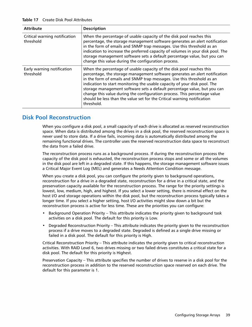
Configuring Storage Arrays 39
Disk Pool ReconstructionWhen you configure a disk pool, a small capacity of each drive is allocated as reserved reconstruction space. When data is distributed among the drives in a disk pool, the reserved reconstruction space is never used to store data. If a drive fails, incoming data is automatically distributed among the remaining functional drives. The controller uses the reserved reconstruction data space to reconstruct the data from a failed drive.
The reconstruction process runs as a background process. If during the reconstruction process the capacity of the disk pool is exhausted, the reconstruction process stops and some or all the volumes in the disk pool are left in a degraded state. If this happens, the storage management software issues a Critical Major Event Log (MEL) and generates a Needs Attention Condition message.
When you create a disk pool, you can configure the priority given to background operations, reconstruction for a drive in a degraded state, reconstruction for a drive in a critical state, and the preservation capacity available for the reconstruction process. The range for the priority settings is lowest, low, medium, high, and highest. If you select a lower setting, there is minimal effect on the host I/O and storage operations within the disk pool, but the reconstruction process typically takes a longer time. If you select a higher setting, host I/O activities might slow down a bit but the reconstruction process is active for less time. These are the priorities you can configure:
• Background Operation Priority – This attribute indicates the priority given to background task activities on a disk pool. The default for this priority is Low.
• Degraded Reconstruction Priority – This attribute indicates the priority given to the reconstruction process if a drive moves to a degraded state. Degraded is defined as a single drive missing or failed in a disk pool. The default for this priority is High.
Critical Reconstruction Priority – This attribute indicates the priority given to critical reconstruction activities. With RAID Level 6, two drives missing or two failed drives constitutes a critical state for a disk pool. The default for this priority is Highest.
Preservation Capacity – This attribute specifies the number of drives to reserve in a disk pool for the reconstruction process in addition to the reserved reconstruction space reserved on each drive. The default for this parameter is 1.
Critical warning notification threshold
When the percentage of usable capacity of the disk pool reaches this percentage, the storage management software generates an alert notification in the form of emails and SNMP trap messages. Use this threshold as an indication to increase the preferred capacity of volumes in your disk pool. The storage management software sets a default percentage value, but you can change this value during the configuration process.
Early warning notification threshold
When the percentage of usable capacity of the disk pool reaches this percentage, the storage management software generates an alert notification in the form of emails and SNMP trap messages. Use this threshold as an indication to start monitoring the usable capacity of your disk pool. The storage management software sets a default percentage value, but you can change this value during the configuration process. This percentage value should be less than the value set for the Critical warning notification threshold.
Table 17 Create Disk Pool Attributes
Attribute Description

40 Concepts Guide
VolumesWithin a disk pool or a volume group you create volumes for organizing your data. You configure the free capacity on your disk pool or volume group as volumes. You can create standard volumes in either a disk pool or a volume group, whereas you can create thin volumes only in a disk pool.
Table 18 provides comparison information for the two types of volumes.
NOTE: Not all storage arrays or software releases of SANtricity Storage Manager enable a user to create thin volumes or disk pools.
Configure a volume to meet application needs for data availability and I/O performance. The storage management software administers a volume as if the volume is one drive for data storage. A host attached to a storage array writes data to the volumes and reads data from the volumes.
Types of VolumesThe storage management software lets you create a standard volume and a thin volume. However, there are other names used to refer to how the storage management software is using a standard volume or a thin volume, such as primary volume or source volume. In addition, the storage management software automatically creates different types of volumes when related premium features are enabled for your storage array. The different volume names are described in Table 19.
Table 18 Characteristics of Volumes
Standard Volume Characteristics Thin Volume Characteristics
• Can be a member of a disk pool or a volume group
• Capacity allocated up front
• No minimum provisioned capacity required
• Only available option if the thin volume premium feature is not purchased
• Can be a member of only a disk pool
• Capacity is provisioned as data is being written
• Minimum required provision capacity is 4 GB
• More efficient use of storage capacity because you allocate space as it is needed
• Requires the purchase of the key file for the thin
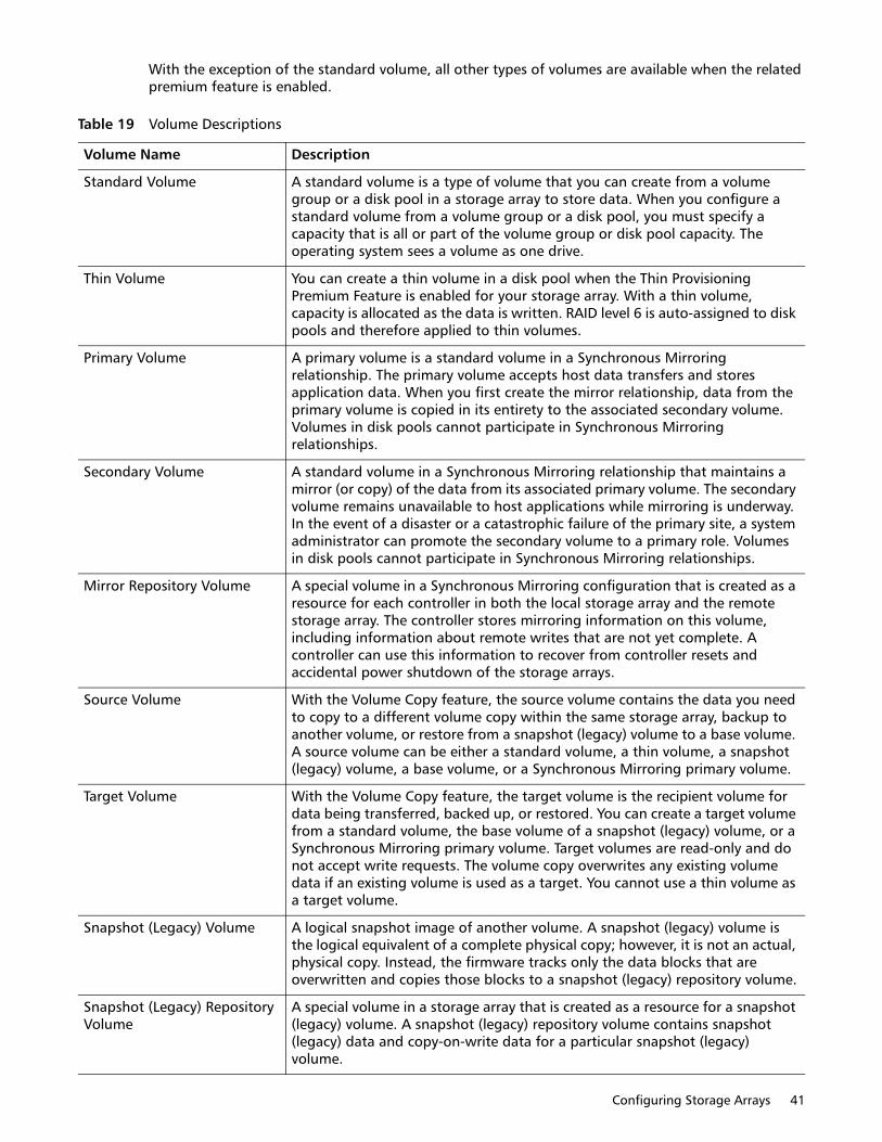
Configuring Storage Arrays 41
With the exception of the standard volume, all other types of volumes are available when the related premium feature is enabled.
Table 19 Volume Descriptions
Volume Name Description
Standard Volume A standard volume is a type of volume that you can create from a volume group or a disk pool in a storage array to store data. When you configure a standard volume from a volume group or a disk pool, you must specify a capacity that is all or part of the volume group or disk pool capacity. The operating system sees a volume as one drive.
Thin Volume You can create a thin volume in a disk pool when the Thin Provisioning Premium Feature is enabled for your storage array. With a thin volume, capacity is allocated as the data is written. RAID level 6 is auto-assigned to disk pools and therefore applied to thin volumes.
Primary Volume A primary volume is a standard volume in a Synchronous Mirroring relationship. The primary volume accepts host data transfers and stores application data. When you first create the mirror relationship, data from the primary volume is copied in its entirety to the associated secondary volume. Volumes in disk pools cannot participate in Synchronous Mirroring relationships.
Secondary Volume A standard volume in a Synchronous Mirroring relationship that maintains a mirror (or copy) of the data from its associated primary volume. The secondary volume remains unavailable to host applications while mirroring is underway. In the event of a disaster or a catastrophic failure of the primary site, a system administrator can promote the secondary volume to a primary role. Volumes in disk pools cannot participate in Synchronous Mirroring relationships.
Mirror Repository Volume A special volume in a Synchronous Mirroring configuration that is created as a resource for each controller in both the local storage array and the remote storage array. The controller stores mirroring information on this volume, including information about remote writes that are not yet complete. A controller can use this information to recover from controller resets and accidental power shutdown of the storage arrays.
Source Volume With the Volume Copy feature, the source volume contains the data you need to copy to a different volume copy within the same storage array, backup to another volume, or restore from a snapshot (legacy) volume to a base volume. A source volume can be either a standard volume, a thin volume, a snapshot (legacy) volume, a base volume, or a Synchronous Mirroring primary volume.
Target Volume With the Volume Copy feature, the target volume is the recipient volume for data being transferred, backed up, or restored. You can create a target volume from a standard volume, the base volume of a snapshot (legacy) volume, or a Synchronous Mirroring primary volume. Target volumes are read-only and do not accept write requests. The volume copy overwrites any existing volume data if an existing volume is used as a target. You cannot use a thin volume as a target volume.
Snapshot (Legacy) Volume A logical snapshot image of another volume. A snapshot (legacy) volume is the logical equivalent of a complete physical copy; however, it is not an actual, physical copy. Instead, the firmware tracks only the data blocks that are overwritten and copies those blocks to a snapshot (legacy) repository volume.
Snapshot (Legacy) Repository Volume
A special volume in a storage array that is created as a resource for a snapshot (legacy) volume. A snapshot (legacy) repository volume contains snapshot (legacy) data and copy-on-write data for a particular snapshot (legacy) volume.
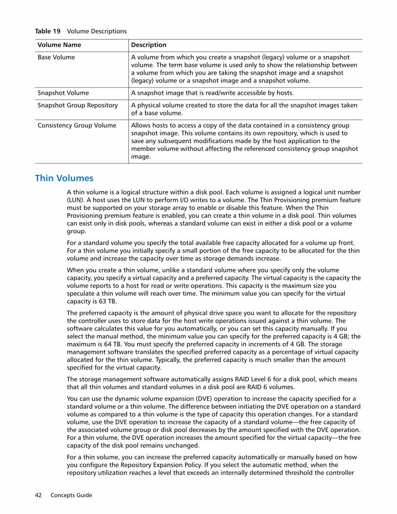
42 Concepts Guide
Thin VolumesA thin volume is a logical structure within a disk pool. Each volume is assigned a logical unit number (LUN). A host uses the LUN to perform I/O writes to a volume. The Thin Provisioning premium feature must be supported on your storage array to enable or disable this feature. When the Thin Provisioning premium feature is enabled, you can create a thin volume in a disk pool. Thin volumes can exist only in disk pools, whereas a standard volume can exist in either a disk pool or a volume group.
For a standard volume you specify the total available free capacity allocated for a volume up front. For a thin volume you initially specify a small portion of the free capacity to be allocated for the thin volume and increase the capacity over time as storage demands increase.
When you create a thin volume, unlike a standard volume where you specify only the volume capacity, you specify a virtual capacity and a preferred capacity. The virtual capacity is the capacity the volume reports to a host for read or write operations. This capacity is the maximum size you speculate a thin volume will reach over time. The minimum value you can specify for the virtual capacity is 63 TB.
The preferred capacity is the amount of physical drive space you want to allocate for the repository the controller uses to store data for the host write operations issued against a thin volume. The software calculates this value for you automatically, or you can set this capacity manually. If you select the manual method, the minimum value you can specify for the preferred capacity is 4 GB; the maximum is 64 TB. You must specify the preferred capacity in increments of 4 GB. The storage management software translates the specified preferred capacity as a percentage of virtual capacity allocated for the thin volume. Typically, the preferred capacity is much smaller than the amount specified for the virtual capacity.
The storage management software automatically assigns RAID Level 6 for a disk pool, which means that all thin volumes and standard volumes in a disk pool are RAID 6 volumes.
You can use the dynamic volume expansion (DVE) operation to increase the capacity specified for a standard volume or a thin volume. The difference between initiating the DVE operation on a standard volume as compared to a thin volume is the type of capacity this operation changes. For a standard volume, use the DVE operation to increase the capacity of a standard volume—the free capacity of the associated volume group or disk pool decreases by the amount specified with the DVE operation. For a thin volume, the DVE operation increases the amount specified for the virtual capacity—the free capacity of the disk pool remains unchanged.
For a thin volume, you can increase the preferred capacity automatically or manually based on how you configure the Repository Expansion Policy. If you select the automatic method, when the repository utilization reaches a level that exceeds an internally determined threshold the controller
Base Volume A volume from which you create a snapshot (legacy) volume or a snapshot volume. The term base volume is used only to show the relationship between a volume from which you are taking the snapshot image and a snapshot (legacy) volume or a snapshot image and a snapshot volume.
Snapshot Volume A snapshot image that is read/write accessible by hosts.
Snapshot Group Repository A physical volume created to store the data for all the snapshot images taken of a base volume.
Consistency Group Volume Allows hosts to access a copy of the data contained in a consistency group snapshot image. This volume contains its own repository, which is used to save any subsequent modifications made by the host application to the member volume without affecting the referenced consistency group snapshot image.
Table 19 Volume Descriptions
Volume Name Description

Configuring Storage Arrays 43
increases the preferred capacity amount. If you select the manual method, an administrator uses the Increase Provisioned Capacity volume command when the storage management software generates a capacity alert modification warning. With the manual method you can increase the preferred capacity in 4-GB increments. Using the automatic method is the recommended option. If you select the automatic method, the system shows an error message if you attempt to manually increase the preferred capacity.
Use the Create Volume Wizard to create a thin volume in a disk pool. During the volume creation process, the wizard prompts you to select the type of volume, the capacity to allocate for the volume, and to define basic volume attributes and optional advanced attributes.
Standard VolumesA standard volume is a logical structure that a host uses to access data storage on a storage array. You create a standard volume from a collection of drives that comprise a disk pool or a volume group. A volume assumes the RAID level configured for the volume group or disk pool. The capacity of a volume is limited by the amount of free capacity available in a volume group or a disk pool.
If you have not configured any volumes on a storage array, the only node that is available is the Unconfigured Capacity node. Node is used in the context of a connection point. Each volume is assigned a logical unit number (LUN) that a host uses to access a volume. Because the description refers to a volume that is not configured, hence has not been assigned a LUN, the term node refers to the unconfigured capacity.
The hosts that are attached to the storage array write data to the volumes and read data from the volumes. The host operating system sees a volume as a single logical drive, although for RAID level 1 and higher, data for a volume is written across several physical drives located in a storage array. With a standard volume, the data is distributed across the drives based on a RAID level. When you create a volume group, you specify the RAID level. All volumes within a volume group use the RAID level specified for the volume group. The data for each volume is written sequentially across a set of drives that comprise the volume group.
For standard volumes, redundancy (or parity) data is stored on the volumes in a volume group based on the RAID level assigned to a volume group. In the event of a drive failure, the controller uses the redundant (or parity) data and a hot spare drive configured for a volume group to complete the recovery process.
The storage management software provides a wizard that lets users create a volume. Use the Create Volume Wizard to create one or more volumes on a disk pool or a volume group. During the volume creation process, the wizard prompts you to select the type of volume (standard volume or thin volume), the capacity to allocate for the volumes, and to define basic volume parameters and optional advanced volume parameters for the volume.
NOTE: The host operating system might have specific limits about how many volumes and the size of a single volume that the host can access. You must consider these limits when you create volumes that are used by a particular host.
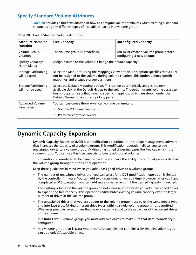
44 Concepts Guide
Specify Standard Volume AttributesTable 20 provides a brief explanation of how to configure volume attributes when creating a standard volume using the different types of available capacity in a volume group.
Dynamic Capacity ExpansionDynamic Capacity Expansion (DCE) is a modification operation in the storage management software that increases the capacity of a volume group. This modification operation allows you to add unassigned drives to a volume group. Adding unassigned drives increases the free capacity in the volume group. You can use this free capacity to create additional volumes.
This operation is considered to be dynamic because you have the ability to continually access data in the volume group throughout the entire operation.
Keep these guidelines in mind when you add unassigned drives to a volume group:
• The number of unassigned drives that you can select for a DCE modification operation is limited by the controller firmware. You can add two unassigned drives at a time. However, after you have completed a DCE operation, you can add more drives again until the desired capacity is reached.
• The existing volumes in the volume group do not increase in size when you add unassigned drives to expand the free capacity. This operation redistributes existing volume capacity over the larger number of drives in the volume group.
• The unassigned drives that you are adding to the volume group must be of the same media type and interface type. Mixing different drive types within a single volume group is not permitted. Whenever possible, select drives that have a capacity equal to the capacities of the current drives in the volume group.
• In a RAID Level 1 volume group, you must add two drives to make sure that data redundancy is configured.
• In a volume group that is Data Assurance (DA) capable and contains a DA-enabled volume, you can add only DA capable drives.
Table 20 Create Standard Volume Attributes
Attribute Name or Function
Free Capacity Unconfigured Capacity
Volume Group Creation
The volume group is predefined. You must create a volume group before configuring a new volume.
Specify Capacity/ Name Dialog
Assign a name to the volume. Change the default capacity.
Storage Partitioning will be used
Select the Map Later using the Mappings View option. This option specifies that a LUN not be assigned to the volume during volume creation. This option defines specific mappings and creates storage partitions.
Storage Partitioning will not be used
Select the Default Mapping option. This option automatically assigns the next available LUN in the Default Group to the volume. The option grants volume access to host groups or hosts that have no specific mappings, which are shown under the Default Group node in the Topology pane.
Advanced Volume Parameters
You can customize these advanced volume parameters:
• Volume I/O characteristics
• Preferred controller owner

Configuring Storage Arrays 45
Register the Volume with the Operating SystemAfter you have created all of your volumes and have assigned mappings, use a volume registration utility, such as the hot_add utility when using RDAC, to scan the mapped volumes and register the volumes with the operating system.
Premium FeaturesThe following premium features might be optionally provided through the Array Management Window of SANtricity:
• Thin Provisioning
• SANshare Storage Partitioning
• Snapshot
• Snapshot (Legacy)
• Synchronous Mirroring (this premium feature is supported only in storage arrays with the Fibre Channel [FC] host ports)
• Volume Copy
• Drive Security
• Enterprise Security Key Manager
• Data Assurance (DA)
• Solid State Drive Support (SSDs)
• High Performance Tier
• Mixed Drive Types
• Drive Slot Limit
Thin Provisioning Premium FeatureThe Thin Provisioning premium feature enables a disk pool to present more logical storage to hosts or users than is actually available on the physical drives in your disk pool. Instead of allocating a pre-determined amount of physical storage up front, storage space is dynamically allocated to each volume or LUN as data is written. Using thin provisioning helps to eliminate the large amounts of unused capacity that occurs with standard volumes. For a standard volume, all of the capacity is allocated up front.
You can create a thin volume only in a disk pool, not in a volume group. When you create a thin volume, you specify two types of capacity: the virtual capacity and the provisioned capacity. The virtual capacity is the capacity that is reported to the hosts. The maximum virtual capacity you can specify for a thin volume is 63 TB. The preferred (or provisioned) capacity is the amount of physical drive space that is currently allocated for writing data. The minimum preferred capacity required for a thin volume is 4 GB. The maximum preferred capacity allowed for a thin volume is 64 TB.
With a thin volume, capacity is referenced as virtual, provisioned, or consumed. The virtual capacity of the thin volume is the capacity that the host sees as being available for READ or WRITE operations. The provisioned capacity is the physical capacity used to store new data from host write requests. The provisioned capacity is typically a smaller capacity than the virtual capacity. The consumed capacity is the amount of provisioned capacity the host uses for saving data during processing of host write requests.
46 Concepts Guide
When the consumed capacity reaches the provisioned capacity, the storage array cannot accommodate additional write requests until the storage management software increases the provisioned capacity. The storage management software can automatically expand the provisioned capacity or you can do it manually. If you select the automatic expansion options, you can set a maximum expansion capacity. The maximum expansion capacity enables you to limit the automatic growth of the volume to be an amount below the virtual capacity.
If you have not configured any volumes on the storage array, you use the Disk Pool Free Capacity node to configure a thin volume. A node is a connection point that you can click to configure a volume. Disk pool free capacity is the unassigned space in a disk pool that you use to make a volume.
NOTE: The host operating system might have specific limits about how many volumes and the size of a single volume that the host can access. You must consider these limits when you create volumes that are used by a particular host.
Thin Volume AttributesWhen you configure a thin volume, you must select the thin volume option and enter a virtual capacity and volume name. After entering this information, the storage management software can automatically configure the remaining attributes or you can select the customize capacity settings option to set the values yourself. With the customize capacity settings option, you can specify values for the following attributes:
• Preferred Capacity – This attribute indicates the initial physical capacity of the volume. Use the Units list to indicate that the capacity is in MB, GB, or TB. Preferred capacity in a disk pool is allocated in 4-GB increments. If you specify a preferred capacity amount that is not a multiple of 4 GB, the storage management software allocates physical capacity in an increment of 4 GB and the remaining capacity is unused. For example, if you specify preferred capacity as 22 GB, the system allocates 20 GB and the remaining 2 GB is unused capacity. To make sure that the entire capacity is usable, specify the capacity in 4-GB increments. If unusable capacity exists, the only way to regain it is to increase the capacity of the thin volume.
• Repository (Volume) Expansion Policy – This attribute indicates whether the storage management software or a user is responsible for expanding the preferred (or physical) capacity of a thin volume as the consumed capacity gets close to the allocated preferred capacity. If you select the automatic expansion method, enter a maximum expansion capacity value. The storage management software will expand the preferred capacity in increments of 4 GB until it reaches the specified maximum expansion capacity. If you select the manual expansion method, you are responsible for expanding the preferred capacity when the consumed capacity gets close to the physical capacity. With the manual method, you need to rely on the Warning Threshold alerts you receive to determine when to increase the preferred capacity. The automatic method is recommended.
• Maximum Expansion Capacity – This attribute is used with the Automatic Repository Expansion Policy. The entered expansion capacity indicates the maximum capacity to which the storage management software can automatically expand the preferred capacity. The expansion capacity you enter must be less than the specified virtual capacity of the thin volume. Use the Units list to indicate that the capacity is in MB, GB, or TB.
• Warning Threshold – This attribute indicates when the storage management software will send an alert e-mail or SNMP message to indicate that the consumed capacity has reached this percentage of preferred capacity. The default setting is 85 percent.

Configuring Storage Arrays 47
GuidelinesAlthough most features work the same with standard volumes and thin volumes, there are a few differences:
• You cannot delete a thin volume if it has associated snapshot images.
• You can convert a thin volume to a standard volume by creating a Volume Copy of a thin volume.
• You cannot use a thin volume as the target in a Volume Copy.
• You cannot perform a Synchronous Mirroring operation with a thin volume.
You should consider creating a standard volume rather than a thin volume when you anticipate that storage consumption on a volume will be unpredictable or highly volatile, or an application using a volume will be mission critical.
Thin Volume StatesWhen a thin volume is operational, the storage management software shows one of the following states for the volume:
• Optimal – The thin volume is operating normally.
• Full – The preferred (physical) capacity of the thin volume is full, meaning that no more host write requests can be processed for this volume.
• Over Threshold – The preferred capacity of the thin volume is used at or beyond the specified Warning Threshold percentage. The storage management software assigns a Needs Attention condition for the storage array.
• Failed – The thin volume has failed and is no longer available for read or write operations. The storage management software assigns a Needs Attention condition for the storage array.
RollbackRollback operations are fully supported for thin volumes. A Rollback operation restores the logical content of a thin volume to match the selected snapshot image. There will be no change to the consumed capacity of the thin volume as a result of the rollback operation.
SANshare Storage PartitioningSANshare Storage Partitioning lets hosts with different operating systems share access to a storage array. Hosts with different operating systems that share access to a storage array are called heterogeneous hosts.
A storage partition is a logical entity that consists of one or more storage array volumes that can be shared among hosts. To create a storage partition after the total storage capacity has been configured into volumes, you must define a single host or a collection of hosts (or host group) that will access the storage array. Then you must define a mapping, which lets you specify the host group or the host that will have access to a particular volume in your storage array.
Based on the premium feature key file purchased, the storage management software can support the maximum storage partitions shown in Table 21.
Table 21 Storage Partitions
Storage Array Maximum # of Storage Partitions Supported
QS1200 Base System Up to 512
QS2400 Base System Up to 512
48 Concepts Guide
You can define a maximum of 256 volumes per partition (except for the HP-UX 11.23 operating system); this number is limited to the total number of volumes on your storage array.
Snapshot Premium FeatureThe storage management software provides a Snapshot Premium Feature that lets you take a logical copy of the content of a standard volume or a thin volume at a particular point in time. These point-in-time snapshots of volumes are named snapshot images. Taking a snapshot image is useful any time you need to be able to roll back to a known good data set at a specific point in time. For example, you can create a snapshot image as a backup that you can use during a recovery operation.
When you take a snapshot image of a volume, the storage management software saves the read-only snapshot image in a repository associated with a snapshot group. To provide a host access to snapshot images stored within a snapshot group repository, you must create a snapshot volume.
Remember the following important details about the relationships between a snapshot image, a snapshot group, and a snapshot volume:
• Each snapshot image is created in the context of exactly one snapshot group.
• A snapshot image is not host accessible. Only images in a snapshot volume are host-accessible.
• A snapshot group is a sequence of snapshot images of a single associated standard volume or thin volume. A volume used to create a snapshot image is referred to as a base volume.
• A snapshot group has exactly one repository that it uses to save the snapshot images that are part of the snapshot group.
• All snapshot images within a snapshot group repository have a direct association with that snapshot group.
• A snapshot group has an association with a single volume.
• Each snapshot volume has a direct association with a snapshot image.
• Each snapshot volume has a persistent relationship to the base volume of the snapshot image for which the snapshot volume was initially created.
• The repository associated with snapshot volume has an association with a snapshot group.
Snapshot ImagesThe Snapshot Image premium feature lets you take logical copies of the content of a standard volume or a thin volume at a particular point in time. These point-in-time images of volumes are named snapshot images. The volumes that are the source of a snapshot image are referred to as base volumes. You use the snapshot image feature to create multiple copies of production data of volumes in a disk pool, a volume group, or a consistency group. A consistency group is a collection of base volumes in your storage array. Snapshot images are useful any time you need to be able to roll back to a known good data set at a specific point in time. You can use a snapshot image to restore the database during a recovery operation or as an image to use to perform testing before you upgrade to a newer version of software.
QD6000 Base System Up to 512
QD7000 Base System Up to 512
Table 21 Storage Partitions
Storage Array Maximum # of Storage Partitions Supported

Configuring Storage Arrays 49
When you create your first snapshot image of a base volume, the storage management software automatically creates a snapshot group if one does not already exist. The first snapshot image is an exact logical copy of the base volume at that point in time. Thereafter, when the system generates a snapshot image, only the data changes since the last snapshot image are captured.
The snapshot mechanism creates the initial snapshot image and tracks source changes from the time each snapshot image is created until the snapshot image is disabled by a user. The snapshot mechanism saves existing data for the base volume to a repository volume associated with a snapshot group—referred to as a snapshot group repository volume—before the data in the base volume is overwritten with new data. The snapshot mechanism updates an index in the snapshot group repository volume to reflect the location of each new snapshot image.
A snapshot image is not directly read or write accessible to hosts because snapshot images contain only the changed data captured from the base volume. You need to create a snapshot volume to view snapshot images.
• Snapshot images have these characteristics:
• Snapshot images are always created inside a snapshot group.
• Each snapshot image is associated with exactly one snapshot group.
• You can add up to 32 snapshot images to a snapshot group.
• You cannot create a snapshot image of a failed volume.
Snapshot GroupsA snapshot group is a sequence of snapshot images of a single associated base volume. You create a snapshot group for each base volume for which you want to create snapshot images. The purpose of a snapshot group is to provide a means of creating a sequence of snapshot images for a given base volume. Each snapshot group has one associated repository volume, referred to as a snapshot group repository volume. The snapshot mechanism uses the repository volume to save the snapshot images. Each snapshot image is created in the context of exactly one snapshot group.
The base volume associated with a snapshot group can reside in a disk pool or a volume group. If the base volume resides in a volume group, the repository members for any associated snapshot group can reside in a disk pool or a volume group. However, if a base volume resides in a disk pool, all repository members for any associated snapshot group must reside in the same disk pool as the base volume.
You must enable the Snapshot premium feature on the storage array before you create a snapshot group. You can create a snapshot group only for standard volumes and thin volumes. There are two ways to create a snapshot group:
• The storage management software automatically creates a snapshot group when you create the first snapshot image for a base volume.
• You can create an empty snapshot group before you run the Create Snapshot Image command.
When you create a new snapshot group for a snapshot image, you can select to create the repository using either the automatic or manual method. With the automatic method, the storage management software creates the snapshot group repository with the default capacity settings. Using the automatic method is the recommended option.
Use the manual method to create a new snapshot group if you want to specify all of the customizable settings for the snapshot group repository. The manual method is considered advanced, and only those who understand drive redundancy and optimal drive configurations should use this option. The snapshot group includes these customizable settings:
• Repository capacity – Capacity of the associated snapshot group repository volume. You specify this capacity as either as a percentage of the base volume capacity or an actual capacity amount.
• Automatic deletion snapshot image limit – The system deletes the oldest snapshot image upon reaching the specified limit. The maximum limit is 32 snapshot images for a snapshot group.

50 Concepts Guide
• Repository utilization threshold percentage – The system sends an e-mail alert or SNMP alert to the administrator when the specified percentage of capacity of a snapshot repository volume has reached or exceeds the specified utilization threshold percentage.
• Action required for a repository full condition – Select the auto-purge option if you want the system to delete the oldest snapshot image in the snapshot group. Select the fail base writes option if you want the system to fail the current I/O write request because the repository is full.
The snapshot images in a snapshot group are stored in a specific order based on their creation time. The strict order of the snapshot images helps you to determine which snapshot image to use in a roll back operation for the base volume or which snapshot image to delete when it is no longer needed.
Keep the following guidelines in mind when you create a snapshot group:
• You can create up to four snapshot groups for a single associated base volume.
• You can add up to 32 snapshot images to a snapshot group.
• Each snapshot image is associated with exactly one snapshot group.
• Each snapshot group repository volume is associated with only one base volume.
• You cannot create a snapshot group on a failed base volume.
• A snapshot group has an association with a base volume for the related snapshot group.
The snapshot group repository volume must have the same Data Assurance (DA) and Quality of Service (QoS) settings as the associated base volume for the snapshot group. For example, if a base volume for a snapshot group is DA enabled, the associated snapshot group repository volume must also be DA enabled.
Snapshot Group Repository VolumeEach snapshot group has an associated repository volume that the system uses to store the snapshot images for a given base volume. When you use the storage management software GUI to create a snapshot group for a base volume, the software automatically creates this repository volume as part of the Create Snapshot Group process.
Snapshot VolumeSnapshot images are not directly accessible for either read or write operations by a host. To provide a host access to snapshot images stored within a snapshot group repository volume, you must create a snapshot volume.
When you create a snapshot volume, you can designate the volume as either read-only or read-write. A read-write snapshot volume requires an associated repository to provide the host application with write access to a copy of the data contained in the snapshot image. Any modifications made by the host application to the snapshot image are saved in this repository to allow the data of the original snapshot image to remain unchanged.
An administrator must monitor the utilization of a snapshot volume to ensure that ongoing write operations for the base volume are handled properly. The storage management software provides mechanisms for viewing the current utilization of a repository volume and remaining free space of a snapshot volume, and for managing alert thresholds that trigger notification when utilization reaches configured levels.
Every snapshot volume has a direct association with a base volume.
Schedule Snapshot ImagesYou can create a schedule for snapshot images and specify the frequency that the storage management software creates snapshot images. You can create a schedule when you initially create a

Configuring Storage Arrays 51
snapshot group or consistency group, or you can add one later to an existing snapshot group or consistency group.
You can do the following actions when you enable snapshot image scheduling:
• You can set up a schedule for a snapshot group to automatically create a snapshot image at a specific time in the future or on a regular basis.
• You can set up a schedule for a consistency group to automatically create a snapshot image of each member volume in the group at a specific time in the future or on a regular basis.
You can create a schedule that runs daily, weekly in which you select specific days of the week (Sunday through Saturday), or monthly. To make scheduling easier, you can import an existing schedule for a snapshot group or consistency group. In addition, you can temporarily suspend scheduled snapshot image creation by disabling the schedule. When a schedule is disabled, the schedule timer continues to run, but the scheduled snapshot image creations do not occur.
Keep the following guidelines in mind when creating schedules for snapshot groups and consistency groups:
• Using a schedule can result in a large number of snapshot images, so be sure that you have sufficient drive space.
• Each snapshot group or consistency group can have only one schedule.
• Scheduled snapshot image creations do not occur when the storage array is offline or powered off.
• If you delete a snapshot group or consistency group that has a schedule, the schedule is also deleted.
• Schedules are stored in the configuration database on the storage array. The management station does not need to be running the Enterprise Management Window (EMW) or the Array Management Window (AMW) for the scheduled snapshot image creation to occur.
Rollback to a Snapshot ImageThe rollback operation removes all data modifications that were made to a base volume since the specified snapshot image was taken. The host can continue to access the base volume for I/O operations during the rollback operation. You can roll back data by creating a snapshot volume of a snapshot image, which lets you view the base volume in its original state when the snapshot image was created. Alternatively, you can roll back data by restoring a snapshot image to the base volume, which lets you roll back the base volume to a previous state.
You can start a rollback from a snapshot image or a consistency group snapshot image. When you perform a rollback operation on a snapshot image, the system rolls back the base volume associated with a snapshot group to a previous state. The rollback operation does not change the content of the snapshot images that are associated with the base volume. When you roll back a consistency group snapshot image, the system rolls back all or select member volumes of the consistency group to a previous state.
Before you use the Start Rollback option, perform these actions:
• Make sure there is enough capacity in the repository to start a rollback operation.
• Make sure the selected snapshot image is in an Optimal state. If the snapshot image is in a Purged state or has been automatically deleted due to the Auto-Delete Limit, the system shows an error message.
• Make sure the selected volume is in an Optimal state. You cannot start a rollback operation on a failed volume.
• Make sure the selected volume does not have a rollback operation already in progress. You cannot start more than one rollback operation for a base volume at a time.
Keep these guidelines in mind before you start a rollback operation:

52 Concepts Guide
• During a rollback operation you cannot delete the snapshot image that is being used for the rollback.
• During a rollback operation you cannot create a new snapshot image for a base volume that is participating in a rollback operation.
• During a rollback operation you cannot change the associated snapshot group’s Repository-Full Policy.
• You cannot start a rollback operation when a Dynamic Capacity Expansion (DCE), Dynamic Volume Expansion (DVE), a Dynamic RAID Migration (DRM), or a Dynamic Segment Size (DSS) operation is in progress.
• You cannot start a rollback operation if the base volume is participating in a volume copy.
• You cannot start a rollback operation if the base volume is a secondary volume in a remote mirror. However, if the base volume is the primary volume in a remote mirror, you can start a rollback operation. Additionally, you cannot perform a role reversal in a remote mirror if the primary volume is participating in a rollback operation.
• A rollback operation fails if any of the used capacity in the associated snapshot repository volume has unreadable sectors.
For more information about using the rollback operation for snapshot images, see the topic “Performing Rollback Operations” in the online help.
Convert a Snapshot (Legacy) Volume to a Snapshot GroupUse the Convert Snapshot (Legacy) to Snapshot Group option to convert a snapshot (legacy) volume and its associated repository to a snapshot group. The system performs the following actions for each converted snapshot (legacy) volume:
• Deletes the snapshot (legacy) volume definition and creates a new snapshot group (the new snapshot group is created empty, with no snapshot images).
• Converts the associated snapshot (legacy) repository volume to a snapshot group repository.
• Retains the same schedule (if a schedule has been defined) for the new snapshot group.
• Creates a read-only snapshot volume with a Paused status. The new snapshot volume inherits the World-Wide Name (WWN) and host mappings as the converted snapshot (legacy) volume.
NOTE: If the number of snapshots (legacy) that exist for a given base volume exceeds the maximum number of allowed snapshot groups per base volume, a conversion request for that base volume will be rejected. Any excess snapshot (legacy) beyond the limit must be deleted before you can perform the conversion process.
Keep the following guidelines in mind when you use the Convert Snapshot (Legacy) to Snapshot Group option:
• The conversion process is performed on a given base volume, and applies to all snapshots of a given base volume.
• Snapshot (Legacy) volume and snapshot groups cannot exist on the same base volume; therefore, any snapshot (legacy) volume that you do not select for conversion will be deleted from the storage array.
• If a base volume has snapshot (legacy) images created as part of an online Volume Copy operation, those volume copy definitions must be deleted before you attempt to convert a snapshot (legacy) image to a snapshot image.
• You can perform the conversion operation only for those snapshot (legacy) volumes that are in the Stopped state.
Configuring Storage Arrays 53
Create Consistency GroupsA consistency group is a collection of base volumes in your storage array. These base volumes, which are the source of a snapshot image, are referred to as member volumes of a consistency group. The purpose of a consistency group is to take simultaneous snapshot images of multiple volumes, thus ensuring consistent copies of a collection of volumes at a particular point in time. For example, you can create a consistency group if you want to take a synchronized snapshot image of several volumes that are in different volume groups or disk pools in a storage array.
Using the consistency group mechanism is ideal for applications that span multiple volumes, for example, a database application that has the logs on one volume and the database on another volume. Each base volume that belongs to a consistency group is referred to as a member volume. A member volume is either a standard volume in a disk pool or a volume group, or a thin volume in a disk pool.
When you create a consistency group, the storage management software lets you add member volumes during the creation process or create the consistency group with no member volumes. If you want to add member volumes as part of the creation process, you select the desired volumes from the eligible volumes list and select the automatic or manual member repository creation option. With the automatic method, the storage management software uses the default values when creating the associated member repository for each member volume you add to the consistency group.
When you select the manual snapshot volume repository creation option, you need to select the Add members now option and select the desired volumes from the list of eligible volumes. With the manual method, you also need to understand how to use the auto-choose utility, how to use the repository candidate table, how to set the auto-deletion setting, and how to set the repository utilization threshold percentage. The manual method is considered advanced and only those who understand consistency group functions and optimal drive configurations should use this option.
• Auto-choose utility – Use the Auto-Choose utility to enable the storage management software to automatically generate a list of recommended candidates for each member volume based on either a percentage of the member volume capacity or a preferred capacity. The system shows the best repository candidates for each member volume based on your selection.
• Repository candidate table – The repository candidate table shows a list of repository volumes available for member volumes. When you run the auto-choose utility, the proposed repository candidates appear in this table for the new and existing member volumes.
• Automatic deletion snapshot image limit – The system deletes the oldest snapshot image upon reaching this specified limit.
• Repository utilization threshold percentage – The system sends an e-mail alert or SNMP alert to the administrator when the specified percentage of capacity of an associated snapshot repository volume has reached or exceeds the specified utilization threshold percentage.
When you add a member volume to a consistency group, the system automatically creates an associated member repository and a snapshot group for the member volume.
Consistency groups have these characteristics:
• There is a maximum allowable limit to the number of member volumes that can belong to a consistency group (depending on your configuration).
• You can create a schedule for creating snapshot images for all member volumes of a consistency group.
• You can perform a Rollback operation for a consistency group.
• A member volume can belong to several consistency groups.
For more information about creating a consistency group, see the topic “Managing Consistency Group Operations” in the online help.

54 Concepts Guide
MirroringWhen you add a base volume that is a member of a consistency group to an asynchronous mirror group, the system automatically changes the Repository Full Policy to automatically purge the oldest snapshot image and sets the auto-delete limit to the maximum allowable snapshot limit for a consistency group.
All member volumes in a consistency group that also belong to an asynchronous mirror group must belong to the same asynchronous mirror group. You can use consistency groups for snapshot and mirroring, so it is good practice to define separate and specific consistency groups for snapshot images and mirroring.
Consistency Group Snapshot ImagesA consistency group snapshot image is a logical point-in-time image of the content of each member volume in the consistency group at the same point in time. This action creates synchronized snapshot images of all the volumes in a consistency group. Consistency group snapshot images are stored consecutively based on creation time, with the oldest snapshot image at the top of the list.
Creating a snapshot image for a consistency group requires hosts to suspend all pending I/O operations for each member volume of the consistency group prior to taking the snapshot image. If the storage management software cannot successfully complete the snapshot image operation for all member volumes, the operation fails and no new snapshot images are created.
When you add a new member volume after snapshot images have been created for a consistency group, the existing member volumes will have a different number of stored snapshot images as compared to the newly added member volume. If you roll back to a snapshot image that was taken before new member volumes were added to a consistency group, the rollback operation affects only the member volumes that were in the consistency group at the time of the snapshot image.
You can think of a consistency group snapshot image as a restore point. The snapshot image is not directly read or write accessible to hosts as the consistency group snapshot image is used to save only the original data captured from the member volume. You must create a consistency group snapshot volume to enable the host access to a copy of the data contained in the consistency group snapshot image. The consistency group snapshot volume contains its own repository volume, which the storage management software uses to save any subsequent modifications made by the host application to the member volume without affecting the referenced consistency group snapshot image.
NOTE: If you enable Auto-Delete for a consistency, the system deletes the oldest consistency group snapshot image in the group when the system creates a new consistency group snapshot image.
Keep these guidelines in mind when creating a consistency group snapshot image:
• You cannot create a snapshot image for a consistency group that has reached its maximum number of snapshot images. You must enable auto-delete for the consistency group or manually delete one or more snapshot images from the consistency group, and then retry the Create Consistency Group Snapshot Image operation.
• You cannot create a snapshot image of a failed drive.
• If a volume is a member of a consistency group, the storage management software creates a snapshot group for that member volume. This snapshot group counts towards the maximum allowable number of snapshot groups per base volume.
Consistency Group Snapshot VolumeSnapshot images for member volumes of a consistency group are not directly accessible for either read or write operations by a host. To permit a host read-write access to snapshot images, you need to create a consistency group snapshot volume. A consistency group must contain at least one
Configuring Storage Arrays 55
member volume before you create a consistency group snapshot volume. You can store up to four snapshot images in a consistency group snapshot volume.
Read-write consistency group snapshot volumes require a repository to save any subsequent modifications made by the host application to a member volume. The storage management software creates the repository, referred to as a consistency group snapshot volume repository, as part of the consistency group snapshot volume creation process.
Keep these guidelines in mind when you create a consistency group snapshot volume:
• You can create a consistency group snapshot volume using an existing snapshot image that is in the optimal state.
• You can increase the capacity of a consistency group snapshot volume repository if you have the storage capacity. Monitoring and increasing the capacity helps to avoid a repository full message.
• You can convert a consistency group snapshot volume from read-only to read-write. This conversion operation requires that you manually create a consistency group snapshot volume repository to support the host write operations to the member volumes.
Consistency Group Snapshot Volume RepositoryDuring the creation of a consistency group snapshot volume that is designated as read-write, the storage management software creates a consistency group snapshot volume repository for every member of the consistency group. This repository provides the host application with write access to a copy of the data contained in the consistency group snapshot image. You can create the volume repository automatically using the default settings or you can manually create the repository by defining the capacity settings for the repository.
Use manual option if you want to manually define the capacity requirements for a consistency group snapshot volume repository. The manual method is considered advanced and only those who understand drive redundancy, provisioning, and optimal drive configurations should use this method.
Keep these guidelines in mind when you create a consistency group snapshot volume repository:
• The minimum required capacity of a consistency group snapshot volume repository is 32 MB.
• When you define the capacity requirements for a repository, keep in mind any future requirements that you might have for other volumes in this volume group or disk pool. Make sure that you have enough capacity to meet your data storage needs, but you do not over allocate because you can quickly use up all the storage in your system.
• The list of repository candidates can contain both new and existing repository volumes. Existing repository volumes are left on the storage array by default when you delete a consistency group snapshot volume. Existing repository volumes are placed at the top of the list. The benefit of reusing an existing repository volume is that you can avoid the initialization process that occurs when you create a new one.
• When you select the Overall Repository Increase Capacity option in the storage management software GUI to increase the capacity of a consistency group snapshot volume repository, the system is actually adding a standard volume to the end of a concatenated set of standard volumes that are already being used as the consistency group snapshot volume repository.
56 Concepts Guide
Snapshot (Legacy) Premium FeatureThe Snapshot (Legacy) Volume premium feature creates a logical point-in-time image of another volume. Snapshot (Legacy) Volume is a premium feature of the storage management software. You or your storage vendor must enable this premium feature, if it is available for your storage array.
Because the only data blocks that are physically stored in the snapshot (legacy) repository volume are those that have changed since the time that the snapshot (legacy) volume was created, the snapshot (legacy) volume uses less drive space than a full physical copy.
Typically, you create a snapshot (legacy) so that an application (for example, a backup application) can access the snapshot (legacy) and read the data; meanwhile, the base volume stays online and is user accessible. When the backup is completed, the snapshot (legacy) volume is no longer needed.
You also can create snapshots (legacy) of a base volume and write data to the snapshot (legacy) volumes to perform testing and analysis. Before upgrading your database management system, for example, you can use snapshot (legacy) volumes to test different configurations. Then you can use the performance data that is provided by the storage management software to help you decide how to configure your live database system. Refer to Table 22.
Creating Snapshot (Legacy) VolumesWhen a snapshot (legacy) volume is created, the controller suspends I/O activity to the base volume for a few seconds while it creates a physical volume, called the snapshot (legacy) repository volume. The snapshot (legacy) repository volume stores the snapshot (legacy) volume metadata and the copy-on-write data.
You can create snapshot (legacy) volumes by using the Create Snapshot (Legacy) Volume Wizard in the Array Management Window. The first dialog of the Create Snapshot (Legacy) Volume Wizard lets you select either the simple path or the advanced path to be followed through the wizard. You can choose the simple path to create a snapshot (legacy) volume if the volume group of the base volume has the required amount of free capacity. The simple path lets you specify the basic parameters for the snapshot (legacy) volume. The simple path accepts the default settings for the advanced parameters.
NOTE: If sufficient free capacity is not available in the volume group of the base volume, the Create Snapshot (Legacy) Volume Wizard uses the advanced path by default.
In the advanced path, either you can choose to place the snapshot (legacy) repository volume in another volume group, or you can use unconfigured capacity in the storage array to create a new volume group. The advanced path lets you customize the advanced settings for the snapshot (legacy) volume, such as the full conditions of the snapshot (legacy) repository volume and the notification settings.
Table 22 Storage Array Snapshots
Storage Array Maximum # of Snapshots (Legacy) per Volume
Maximum # of Snapshots (Legacy) per Storage Array
QS1200 Base System Up to 16 Up to 1024
QS2400 Base System Up to 16 Up to 1024
QD6000 Base System Up to 16 Up to 1024
QD7000 Base System Up to 16 Up to 1024
Configuring Storage Arrays 57
If you want to create a snapshot (legacy) volume that performs snapshot (legacy) operations at a later time or at regularly occurring intervals, specify a schedule. If you do not specify a schedule, the snapshot (legacy) operation occurs immediately.
Scheduling Snapshots (Legacy)If you want to create a snapshot (legacy) volume that performs snapshot (legacy) operations at a later time or at regularly occurring intervals, add a schedule to the snapshot (legacy) volume. If you do not add a schedule to the snapshot (legacy) volume, the snapshot (legacy) operation occurs immediately. You can add a schedule when you create a snapshot (legacy) volume, or you can add a schedule to an existing snapshot (legacy) volume. Each snapshot (legacy) volume can have only one schedule.
Typical Uses of Scheduling Snapshots (Legacy)Scheduled backups – For example, an application stores business-critical data in two volumes in the storage array. You back up this data every work day at 11:00 p.m. To accomplish this type of backup, select the first volume. Create a schedule that runs once a day on Monday, Tuesday, Wednesday, Thursday, and Friday. Choose a time between the end of your work day and 11:00 p.m. Select a starting date of today and no end date. Apply this schedule to the second volume, also. Map the two snapshot (legacy) volumes to your backup host, and perform the regular backup procedures. Unmap the two snapshot (legacy) volumes before the next scheduled snapshot (legacy) operation time. If you do not unmap the snapshot (legacy) volumes, the storage array skips the next snapshot (legacy) operation to avoid data corruption.
Rapid recovery – In this example, you back up your data at the end of every work day and keep hourly snapshots (legacy) from 8:00 a.m. to 5:00 p.m. If data loss or corruption occurs during the work day, you can recover the data from the snapshots (legacy) so that the data loss window is smaller than one hour. To accomplish this type of recovery, create a schedule that contains a start time of 8:00 a.m. and an end time of 5:00 p.m. Select 10 snapshots (legacy) per day on Monday, Tuesday, Wednesday, Thursday, and Friday. Select a start date of today and no end date. Create an end-of-day backup as described in the “Scheduled backups” example.
Guidelines for Creating SchedulesKeep the following guidelines in mind when creating schedules for snapshot (legacy) volumes:
• Either you can create a schedule when you create a snapshot (legacy) volume, or you can add a schedule to an existing snapshot (legacy) volume.
• Scheduled snapshot (legacy) operations do not take place when these conditions occur:
• The snapshot (legacy) volume is mapped.
• The storage array is offline or powered off.
• The snapshot (legacy) volume is used as a source volume in a Volume Copy operation, and the status of the copy operation is Pending or In progress.
• If you delete a snapshot (legacy) volume that has a schedule, the schedule is also deleted.
• Schedules are stored in the configuration database in the storage array. The management station does not need to be running the Enterprise Management Window (EMW) or the Array Management Window (AMW) for the scheduled snapshot (legacy) operation to occur.
Enabling and Disabling SchedulesYou temporarily can suspend scheduled snapshot (legacy) operations by disabling the schedule. When a schedule is disabled, the schedule’s timer continues to run, but the scheduled snapshot (legacy) operations do not occur.
58 Concepts Guide
Discontinuing the Use of a Snapshot (Legacy) VolumeAs long as a snapshot (legacy) volume is enabled, storage array performance is affected by the copy-on-write activity to the associated snapshot (legacy) repository volume. When you no longer need a snapshot (legacy) volume, you can disable it, reuse it, or delete it.
• Disable – Stops copy-on-write activity. This option keeps the snapshot (legacy) volume and snapshot (legacy) repository volume intact.
• Reuse – Creates a different point-in-time image of the same base volume. This action takes less time to configure than re-creating the snapshot (legacy) volume.
• Delete – Completely removes the snapshot (legacy) volume and the associated snapshot (legacy) repository volume. If you want to re-enable a snapshot (legacy) volume, you must re-create it.
Disabling and Restarting Multiple Snapshots (Legacy)If multiple volumes require regular snapshots (legacy) for backup purposes, keeping the snapshots (legacy) enabled might significantly affect storage array performance. In this situation, you can disable the snapshot (legacy) function for multiple volumes and then restart the snapshots (legacy) for all of the volumes before the next backup is scheduled.
The list of snapshots (legacy) to be restarted is treated as a single operation. The new point-in-time snapshot (legacy) images are created from the previously defined parameters. If an error is encountered on any of the listed snapshots (legacy), none of the snapshots (legacy) on the list are re-created.
Snapshot (Legacy) RollbackYou can use the snapshot (legacy) rollback feature for changing the content of a base volume to match the point-in-time image that is saved in a snapshot (legacy) volume. The host can continue to access the base volume for I/O operations during the rollback operation.
The snapshot (legacy) volume is set as read-only during the rollback operation. The snapshot (legacy) volume becomes available for write operations after the rollback operation is completed. You cannot restart, delete, or disable the snapshot (legacy) volume during a rollback operation. The associated snapshot (legacy) repository volume must have sufficient capacity to process the rollback operation and the write operations from the host.
NOTE: The content in the snapshot (legacy) volume might have changed after the creation of the snapshot (legacy) volume because of write operations from the host. The rollback operation also copies these changes to the base volume.
You can set the priority for a rollback operation. Higher priority allocates more system resources for the rollback operation and might affect the overall system performance.
Keep these guidelines in mind before you start a rollback operation:
• The rollback operation does not change the content of the snapshot (legacy) volumes that are associated with the base volume.
• You cannot start more than one rollback operation for a base volume at a time.
• You cannot create new snapshot (legacy) volumes for a base volume that is participating in a rollback operation.
• You cannot start a rollback operation when any of these operations are in progress in the storage array:
Configuring Storage Arrays 59
• Dynamic Capacity Expansion (DCE) to increase the capacity of a volume group
• Dynamic Volume Expansion (DVE) to increase the capacity of a volume
• Dynamic RAID Migration (DRM) to change the RAID level of a volume group
• Dynamic Segment Size (DSS) to change the segment size of a volume
• You cannot start a rollback operation if the base volume is participating in a volume copy.
• You cannot start a rollback operation if the base volume is a secondary volume in a remote mirror. However, if the base volume is the primary volume in a remote mirror, you can start a rollback operation. Additionally, you cannot perform a role reversal in a remote mirror if the primary volume is participating in a rollback operation.
• A rollback operation fails if any of the used capacity in the associated snapshot (legacy) repository volume has unreadable sectors.
The rollback operation is paused if an error occurs during the rollback operation. The base volume and the snapshot (legacy) volume display Needs Attention icons, and the controller logs the event to the Major Event Log (MEL). You can follow the Recovery Guru procedure to correct the problem and then try to resume the rollback operation.
CAUTION: Risk of data loss – You can cancel a rollback operation, but this action leaves the base volume in an unusable state, and the snapshot (legacy) volume appears as failed in the storage management software. Therefore, you must consider canceling a rollback operation only when recovery options exist for restoring the content of the base volume.
You also can use the command line interface (CLI) to start a rollback operation, cancel a rollback operation, resume a rollback operation, modify the priority of a rollback operation, and view the progress of a rollback operation.
Recovering from a Failed Rollback OperationPrior to starting a rollback operation, you can create a new snapshot (legacy) volume from the base volume. If the rollback operation from a snapshot (legacy) volume fails, you can use the new snapshot (legacy) volume as a source in a rollback operation and restore the content of the base volume.
Snapshot (Legacy) Volumes from Prior Versions of Storage Management SoftwareIf the snapshot (legacy) volumes were created using a prior version of the storage management software that did not support the snapshot (legacy) rollback feature, you can upgrade the version of the storage management software and the version of the controller firmware. After the upgrade, the snapshot (legacy) volumes will support the rollback feature. However, if you revert to an older version of the storage management software after a rollback operation, the storage management software will not support the snapshot (legacy) volume.
Dynamic Volume ExpansionNOTE Increasing the capacity of a standard volume is supported only on certain operating systems. If volume capacity is increased on a host operating system that is not supported, the expanded capacity is unusable, and you cannot restore the original volume capacity.
Dynamic Volume Expansion (DVE) is a modification operation that increases the capacity of standard volumes or snapshot (legacy) repository volumes, if this operation is supported by your operating system. The increase in capacity can be achieved by using any free capacity available on the volume group of the standard volume or the snapshot (legacy) repository volume. Data is accessible on volume groups, volumes, and drives throughout the entire modification operation.

60 Concepts Guide
If you receive a warning that the snapshot (legacy) repository volume is in danger of becoming full, you can use the DVE modification operation to increase the capacity of the snapshot (legacy) repository volume.
Increasing the capacity of a snapshot (legacy) repository volume does not increase the capacity of the associated snapshot (legacy) volume. The capacity of the snapshot (legacy) volume is always based on the capacity of the base volume at the time that the snapshot (legacy) volume was created.
Contact your Technical Support representative to determine whether your operating system allows you to increase the capacity of a volume.
Asynchronous Mirroring Premium FeatureAsynchronous Mirroring provides a controller-level, firmware-based mechanism for data replication between a local site and a remote site. Replication is managed on a per-volume basis, allowing a storage administrator to associate a distinct remote mirrored volume with any and every primary volume on a given storage array.
Asynchronous mirror groups allow you to manage the synchronization process as a set to create a consistent data-set on the remote storage array. Point-in-time images are used on the primary volume and the secondary volume to batch the resynchronization process. (A data repository volume is required for each mirrored volume.)
When write operations are performed to the primary volume of a mirrored pair, the modified data region of the primary volume is tracked. Periodically, the firmware creates a new point-in-time image of the primary volume and sends the changed data regions to the secondary volume. When data synchronization completes, the system uses the point-in-time images on the secondary volume to ensure that the data is maintained in a consistent state during subsequent synchronization operations to the secondary volume.
The automatic cycle in an active asynchronous mirroring session works as follows to maintain data at a remote site to be a point-in-time consistent copy of data at the local site.
1 Asynchronous mirror groups consisting of volumes are created at the local site.
2 Increments of consistent data are sent to the remote site.
3 Point-in-time copy operations are performed at the remote site.
The steps are repeated according to the defined synchronization intervals.
NOTE: Asynchronous Mirroring supports both iSCSI and Fibre Channel connections between storage arrays.
Asynchronous Mirroring supports both thin volumes and standard volumes for mirrored volume types.
How does Asynchronous Mirroring Differ from Synchronous Mirroring Premium Features?
When you upgrade to a release that supports the Asynchronous Mirroring premium feature, the legacy Synchronous Mirroring configurations are unaffected and continue to operate normally.
Differences Between Mirroring FeaturesAsynchronous Mirroring differs from Synchronous Mirroring in one essential way: Asynchronous Mirroring captures the state of the source volume at a particular point in time and includes just the data that has changed since the last image capture. Here are the differences:
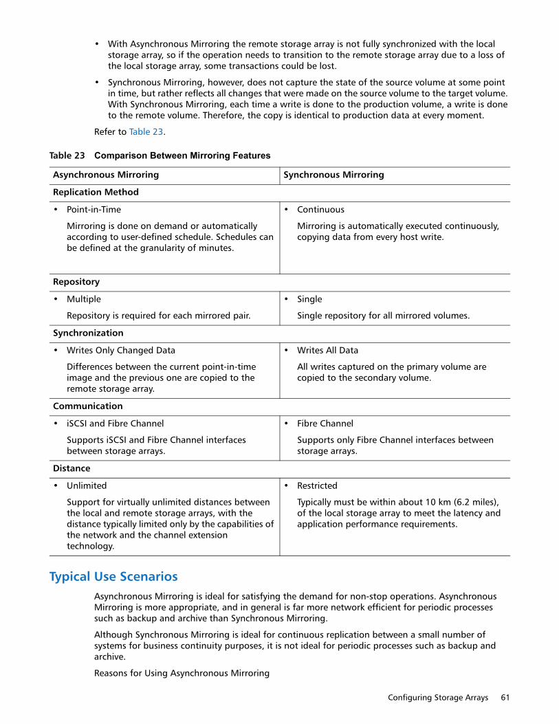
Configuring Storage Arrays 61
• With Asynchronous Mirroring the remote storage array is not fully synchronized with the local storage array, so if the operation needs to transition to the remote storage array due to a loss of the local storage array, some transactions could be lost.
• Synchronous Mirroring, however, does not capture the state of the source volume at some point in time, but rather reflects all changes that were made on the source volume to the target volume. With Synchronous Mirroring, each time a write is done to the production volume, a write is done to the remote volume. Therefore, the copy is identical to production data at every moment.
Refer to Table 23.
Typical Use ScenariosAsynchronous Mirroring is ideal for satisfying the demand for non-stop operations. Asynchronous Mirroring is more appropriate, and in general is far more network efficient for periodic processes such as backup and archive than Synchronous Mirroring.
Although Synchronous Mirroring is ideal for continuous replication between a small number of systems for business continuity purposes, it is not ideal for periodic processes such as backup and archive.
Reasons for Using Asynchronous Mirroring
Table 23 Comparison Between Mirroring Features
Asynchronous Mirroring Synchronous Mirroring
Replication Method
• Point-in-Time
Mirroring is done on demand or automatically according to user-defined schedule. Schedules can be defined at the granularity of minutes.
• Continuous
Mirroring is automatically executed continuously, copying data from every host write.
Repository
• Multiple
Repository is required for each mirrored pair.
• Single
Single repository for all mirrored volumes.
Synchronization
• Writes Only Changed Data
Differences between the current point-in-time image and the previous one are copied to the remote storage array.
• Writes All Data
All writes captured on the primary volume are copied to the secondary volume.
Communication
• iSCSI and Fibre Channel
Supports iSCSI and Fibre Channel interfaces between storage arrays.
• Fibre Channel
Supports only Fibre Channel interfaces between storage arrays.
Distance
• Unlimited
Support for virtually unlimited distances between the local and remote storage arrays, with the distance typically limited only by the capabilities of the network and the channel extension technology.
• Restricted
Typically must be within about 10 km (6.2 miles), of the local storage array to meet the latency and application performance requirements.

62 Concepts Guide
• Remote backup consolidation
• Wide area content distribution
• Long distance disaster recovery
• Backup of 24 x 7 application data
• Application development and testing on a point-in-time image of live data
• Application data replication to secondary site
Reasons for Using Synchronous Mirroring
• Data center type environment for top-tier applications and data.
• Protection of databases and other highly transactional applications
• Local and near-local disaster recovery; secondary data center in the same metro area
• Business continuity during scheduled maintenance of the primary storage array: secondary system acts as the primary system
Synchronous Mirroring Premium FeatureThe Synchronous Mirroring premium feature is used for online, real-time data replication between storage arrays over a remote distance. Storage array controllers manage the mirroring, which is transparent to host machines and software applications. You create one or more mirrored volume pairs that consist of a primary volume at the primary site and a secondary volume at a secondary, remote site. After you create the mirror relationship between the two volumes, the current owner of the primary volume copies all of the data from the primary volume to the secondary volume. This process is called full synchronization.
There is a base number of defined mirrors that are allowed for each storage array. You can increase the number of defined mirrors that are allowed for each model with the purchase of an optional feature upgrade key. This table shows the maximum number of defined mirrors to which you can upgrade with a feature pack upgrade key.
Refer to Table 24.
The Synchronous Mirroring premium feature is not supported in a simplex configuration. you must disable the Synchronous Mirroring premium feature before converting a storage array from a duplex configuration to a simplex configuration. The Synchronous Mirroring premium feature is supported only in storage arrays with fibre Channel (FC) host ports. The Synchronous Mirroring premium feature also requires a FC network switch.
NOTE: Possible loss of data access - You cannot create a mirror relationship if the primary volume contains unreadable sectors. Furthermore, if an unreadable sector is discovered during a mirroring operation, the mirror relationship fails.
Table 24 Defined Mirrors
Storage Array Maximum # of Defined Mirrors
QS1200 Base System Up to 128
QS2400 Base System Up to 128
QD6000 Base System Up to 128
QD7000 Base System Up to 128
Configuring Storage Arrays 63
Disaster RecoveryThe secondary, remote volume is unavailable to secondary host applications while mirroring is in progress. In the event of a disaster at the primary site, you can fail over to the secondary site. To fail over, perform a role reversal to promote the secondary volume to a primary volume. Then the recovery host can access the newly promoted volume, and business operations can continue.
NOTE: Because replication is managed on a per-volume basis, you can mirror individual volumes in a primary storage array to appropriate secondary volumes in several different remote storage arrays.
Data ReplicationWhen the current owner of the primary volume receives a write request from a host, the controller first logs information about the write to a special volume. This volume is called a mirror repository volume. It writes the data to the primary volume. Next, the controller, initiates a remote write operation to copy the affected data blocks to the secondary volume at the remote site.
Finally, the controller sends an I/O completion indication back th the host system to confirm that the data was copied successfully to the secondary storage array. The write mode that you selected when you first created a mirror determines when the I/O completion indication is sent to the host system.
The storage management software provides two write modes:
• Synchronous - When you select this write mode, any host write requests are written tot he primary volume and then copied to the secondary storage volume. The controller sends an I/O completion indication to the host system after the copy has been successfully completed.
• Asynchronous - When you select this write mode, host write requests are written to the primary volume. Then the controller sends and I/O completion indication back to the host system before the data has been successfully copied to the secondary storage array. Asynchronous write mode is not available on the QD7000 base system.
When write caching is enabled on either the primary volume or the secondary volume, the I/O completion is sent when data is in the cache on the side (primary or secondary) where write caching is enabled. When write caching is disabled on either the primary volume or the secondary volume, the I/O completion is not sent until the data has been stored to physical media on that side.
Host write requests received by the controller are handled normally. No communication takes place between the primary storage array and the secondary storage array.
Link Interruptions or Secondary Volume ErrorsWhen processing write requests, the primary controller might be able to write to the primary volume, but a link interruption prevents communication with the remote secondary controller.
In this case, the remote write cannot complete to the secondary volume. The primary volume and the secondary volume are no longer appropriately mirrored. The primary controller changes the mirrored pair into Unsynchronized status and sends an I/O completion to the primary host. The primary host can continue to write to the primary volume, but remote writes do not take place.
When connectivity is restored between the current owner of the primary volume and the current owner of the secondary volume, a full synchronization takes place. Only the blocks of data that have changed on the primary volume during the link interruption are copied to the secondary volume. The mirrored pair changes from an Unsynchronized state to Mirror Synchronization in Progress status.
The primary controller also marks the mirrored pair as Unsynchronized when a volume error on the secondary side prevents the remote write from completing. For example, an offline secondary volume or a failed secondary volume can cause the remote mirror to become unsynchronized. When the volume error is corrected (the secondary volume is placed online or is recovered to Optimal status), a

64 Concepts Guide
full synchronization automatically begins. The mirrored pair then changes to Synchronization in Progress status.
Connectivity and Volume OwnershipA primary controller attempts to communicate only with its matching controller in the secondary storage array. For example, controller A in the primary storage array attempts communication only with controller A in the secondary storage array. The controller that owns the primary volume determines the current owner of the secondary volume.
If the primary volume is owned by controller A on the primary side, the secondary volume is owned by controller A on the secondary side. If primary controller A cannot communicate with secondary controller A, controller ownership changes do not take place.
The next remote write processed automatically triggers a matching ownership change on the secondary side if one of these conditions exists:
• When an I/O path error causes a volume ownership change on the primary side
• If the storage administrator changes the current owner of the primary volume
For example, controller A owns a primary volume, and then you change the controller owner to controller B. In this case, the next remote write changes the controller owner of the secondary volume from controller A to controller B. Because controller ownership changes on the secondary side are controlled by the primary side, they do not require any special intervention by the storage administrator.
Controller Resets and Storage Array Power CyclesSometimes a controller reset or a storage array power cycle interrupts a remote write before it can be written to the secondary volume. The storage array controller does not need to perform a full synchronization of the mirrored volume pair in this case. A controller reset causes a controller ownership change on the primary side from the preferred controller owner to the alternate controller in the storage array. When a remote write has been interrupted during a controller reset, the new controller owner on the primary side reads information stored in a log file in the mirror repository volume of the preferred controller owner. The new controller owner then copies the affected data blocks from the primary volume to the secondary volume, which eliminates the need for a full synchronization of the mirrored volumes.
Synchronous Mirroring Premium Feature ActivationLike other premium features, you enable the Synchronous Mirroring premium feature by purchasing a feature key file from your storage supplier. You must enable the premium feature on both the primary storage array and the secondary storage array.
Unlike other premium features, you also must activate the premium feature after you enable it. To activate the premium feature, use the Activate Synchronous Mirroring Wizard in the Array Management Window (AMW). Each controller in the storage array must have its own mirror repository volume for logging write information to recover from controller resets and other temporary interruptions. The Activate Synchronous Mirroring Wizard guides you to specify the placement of the two mirror repository volumes (on newly created free capacity or existing free capacity in the storage array).
After you activate the premium feature, one Fibre Channel host side I/O port on each controller is solely dedicated to Synchronous Mirroring operations. Host-initiated I/O operations are not accepted by the dedicated port. I/O requests received on this port are accepted only from remote controllers that are participating in Synchronous Mirroring operations with the controller.
Configuring Storage Arrays 65
Connectivity RequirementsYou must attach dedicated Synchronous Mirroring ports to a Fibre Channel fabric environment. In addition, these ports must support the Directory Service interface and the Name Service.
You can use a fabric configuration that is dedicated solely to the Synchronous Mirroring ports on each controller. In this case, host systems can connect to the storage arrays using fabric, Fibre Channel Arbitrated Loop (FC-AL), or point-to-point configurations. These configurations are totally independent of the dedicated Synchronous Mirroring fabric.
Alternatively, you can use a single Fibre Channel fabric configuration for both the Synchronous Mirroring connectivity and for the host I/O paths to the controllers.
The maximum distance between the primary site and the secondary site is 10 km (6.2 miles), using single-mode fiber gigabit interface converters (GBICs) and optical long-wave GBICs.
RestrictionsThese restrictions apply to mirrored volume candidates and storage array mirroring:
• The RAID level, the caching parameters, and the segment size can be different on the two mirrored volumes.
• The secondary volume must be at least as large as the primary volume.
• The only type of volume that can participate in a mirroring relationship is a standard volume in a volume group. Snapshot (Legacy) volumes cannot participate.
• You can create a snapshot (legacy) volume by using either a primary volume or a secondary volume as the base volume.
• A primary volume can be a source volume or a target volume in a volume copy. A secondary volume cannot be a source volume or a target volume unless a role reversal was initiated after the volume copy has completed. If a role reversal is initiated during a Copy in Progress status, the volume copy fails and cannot be restarted.
• A given volume can participate in only one mirror relationship.
Volume Copy Premium Feature
CAUTION: Possible loss of data access – The volume copy operation overwrites existing data on the target volume and renders the volume read-only to hosts. This option fails all snapshot (legacy) volumes that are associated with the target volume, if any exist.
The Volume Copy premium feature copies data from one volume (the source) to another volume (the target) in a single storage array.
Use the Volume Copy premium feature to perform these tasks:
• Copy data from volume groups that use smaller capacity drives to volume groups that use larger capacity drives.
• Create an online copy of data from a volume within a storage array, while still being able to write to the volume with the copy in progress.
• Back up data or restore snapshot (legacy) volume data to the base volume.
Volume Copy is a premium feature of the storage management software and must be enabled either by you or your storage vendor. For more information about using the Volume Copy premium feature with a snapshot group, refer to Volume Copy with Snapshot Groups on page 70.
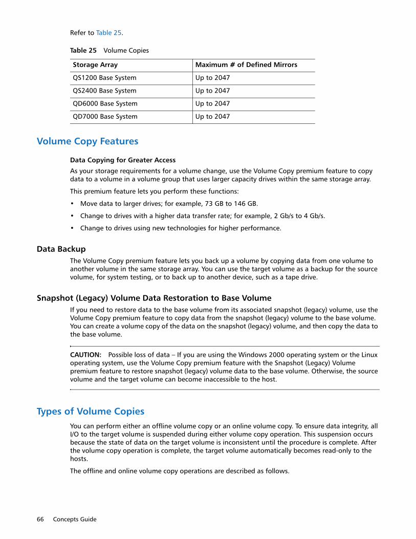
66 Concepts Guide
Refer to Table 25.
Volume Copy Features
Data Copying for Greater Access
As your storage requirements for a volume change, use the Volume Copy premium feature to copy data to a volume in a volume group that uses larger capacity drives within the same storage array.
This premium feature lets you perform these functions:
• Move data to larger drives; for example, 73 GB to 146 GB.
• Change to drives with a higher data transfer rate; for example, 2 Gb/s to 4 Gb/s.
• Change to drives using new technologies for higher performance.
Data BackupThe Volume Copy premium feature lets you back up a volume by copying data from one volume to another volume in the same storage array. You can use the target volume as a backup for the source volume, for system testing, or to back up to another device, such as a tape drive.
Snapshot (Legacy) Volume Data Restoration to Base VolumeIf you need to restore data to the base volume from its associated snapshot (legacy) volume, use the Volume Copy premium feature to copy data from the snapshot (legacy) volume to the base volume. You can create a volume copy of the data on the snapshot (legacy) volume, and then copy the data to the base volume.
CAUTION: Possible loss of data – If you are using the Windows 2000 operating system or the Linux operating system, use the Volume Copy premium feature with the Snapshot (Legacy) Volume premium feature to restore snapshot (legacy) volume data to the base volume. Otherwise, the source volume and the target volume can become inaccessible to the host.
Types of Volume CopiesYou can perform either an offline volume copy or an online volume copy. To ensure data integrity, all I/O to the target volume is suspended during either volume copy operation. This suspension occurs because the state of data on the target volume is inconsistent until the procedure is complete. After the volume copy operation is complete, the target volume automatically becomes read-only to the hosts.
The offline and online volume copy operations are described as follows.
Table 25 Volume Copies
Storage Array Maximum # of Defined Mirrors
QS1200 Base System Up to 2047
QS2400 Base System Up to 2047
QD6000 Base System Up to 2047
QD7000 Base System Up to 2047

Configuring Storage Arrays 67
Offline CopyAn offline copy reads data from the source volume and copies it to a target volume, while suspending all updates to the source volume with the copy in progress. All updates to the source volume are suspended to prevent chronological inconsistencies from being created on the target volume. The offline volume copy relationship is between a source volume and a target volume.
Source volumes that are participating in an offline copy are available for read requests only while a volume copy has a status of In Progress or Pending. Write requests are allowed after the offline copy has completed. If the source volume has been formatted with a journaling file system, any attempt to issue a read request to the source volume might be rejected by the storage array controllers, and an error message might appear. The journaling file system driver issues a write request before it attempts to issue the read request.
The controller rejects the write request, and the read request might not be issued due to the rejected write request. This condition might result in an error message appearing, which indicates that the source volume is write protected. To prevent this issue from occurring, do not attempt to access a source volume that is participating in an offline copy while the volume copy has a status of In Progress. Also, make sure that the Read-Only attribute for the target volume is disabled after the volume copy has completed to prevent error messages from appearing.
Online CopyAn online copy creates a point-in-time snapshot (legacy) copy of a volume within a storage array, while still being able to write to the volume with the copy in progress. This function is achieved by creating a snapshot (legacy) of the volume and using the snapshot (legacy) as the actual source volume for the copy. The online volume copy relationship is between a snapshot (legacy) volume and a target volume. The volume for which the point-in-time image is created is known as the base volume and must be a standard volume in the storage array.
A snapshot (legacy) volume and a snapshot (legacy) repository volume are created during the online copy operation. The snapshot (legacy) volume is not an actual volume containing data; rather, it is a reference to the data that was contained on a volume at a specific time. For each snapshot (legacy) that is taken, a snapshot (legacy) repository volume is created to hold the copy-on-write data for the snapshot (legacy). The snapshot (legacy) repository volume is used only to manage the snapshot (legacy) image.
Before a data block on the source volume is modified, the contents of the block to be modified are copied to the snapshot (legacy) repository volume for safekeeping. Because the snapshot (legacy) repository volume stores copies of the original data in those data blocks, further changes to those data blocks write only to the source volume.
NOTE: If the snapshot (legacy) volume that is used as the copy source is active, the base volume performance is degraded due to copy-on-write operations. When the copy is complete, the snapshot (legacy) is disabled, and the base volume performance is restored. Although the snapshot (legacy) is disabled, the repository infrastructure and copy relationship remain intact.
The online copy function is enabled with the Snapshot (Legacy) Volume premium feature. To use the online copy function, you must enable the Snapshot (Legacy) Volume premium feature by purchasing a feature key file from your storage vendor.
Components of the Volume Copy Premium FeatureThe Volume Copy premium feature includes these components:
Create Copy Wizard, which assists in creating a volume copy.
You can use the Create Copy Wizard to guide you through the following steps in creating a Volume Copy:

68 Concepts Guide
• Selecting a source volume from a list of available volumes and the type of copy you want to perform (offline or online)
• Selecting a target volume from a list of available volumes
• Allocating capacity for the snapshot (legacy) repository volume for online copy types
• Setting the copy priority for the volume copy
When you have completed the wizard dialogs, the volume copy starts, and data is read from the source volume and written to the target volume. Operation in Progress icons appear on the source volume and the target volume while the volume copy has a status of In Progress or Pending.
Copy Manager, which monitors volume copies after they have been created.
After you create a volume copy with the Create Copy Wizard, you can monitor the volume copy through the Copy Manager. You can use the Copy Manager to perform the following actions:
Monitor the progress of a volume copy
• Stop a volume copy
• Re-copy a volume copy
• Remove copy pairs
• Change target volume permissions
• Change copy priority
Keep these guidelines in mind when you create a volume copy.
Refer to Table 26.
Table 26 Guidelines When Creating Volume Groups
Item Guideline
Failed Controller You must manually change controller ownership to the alternate controller to allow the volume copy to complete under all of these conditions:
• The preferred controller of the source volume fails.
• The ownership transfer does not occur automatically in the failover.
Volume Failover for Online Copy Types
Ownership changes affect the base volume and all of its snapshots (legacy). The same controller should own the base volume, the snapshot (legacy) volume, and the snapshot (legacy) repository volume. The rules that apply to the base volume for host-driver-based or controller-based failover modes also apply to the associated snapshots (legacy) and snapshot (legacy) repository volumes. If a failover situation occurs, all related volumes change controller ownership as a group.
Volume Copy and Modification Operations for Offline Copy Types
For offline copy operations, if a modification operation is running on a source volume or a target volume, and the volume copy has a status of In Progress, Pending, or Failed, the volume copy does not take place. If a modification operation is running on a source volume or a target volume after a volume copy has been created, the modification operation must complete before the volume copy can start. If a volume copy has a status of In Progress, any modification operation does not take place.

Configuring Storage Arrays 69
Restrictions on Volume CopyThese restrictions apply to the source volume, the target volume, and the storage array when performing volume copy operations.
For an offline volume copy, the source volume is available for read requests only while a volume copy has a status of In Progress or Pending. Write requests are allowed after the volume copy is completed with the following conditions:
• You can use a volume as a target volume in only one volume copy at a time.
Preferred Controller Ownership
During a volume copy, the same controller must own both the source volume and the target volume. If both volumes do not have the same preferred controller when the volume copy starts, the ownership of the target volume is automatically transferred to the preferred controller of the source volume. When the volume copy is completed or is stopped, ownership of the target volume is restored to its preferred controller. If ownership of the source volume is changed during the volume copy, ownership of the target volume is also changed.
Failed Volume Copy A volume copy can fail due to these conditions:
• A read error from the source volume
• A write error to the target volume
• A failure in the storage array that affects the source volume or the target volume, such as a Synchronous Mirroring role reversal
When the volume copy fails, a Needs Attention icon appears in the Array Management Window. While a volume copy has this status, the host has read-only access to the source volume. Read requests from and write requests to the target volume do not take place until the failure is corrected by using the Recovery Guru.
Volume Copy Status If eight volume copies with a status of In Progress exist, any subsequent volume copy will have a status of Pending, which remains until one of the eight volume copies completes.
Snapshot (Legacy) Volume
A volume copy fails all snapshot (legacy) volumes that are associated with the target volume, if any exist. If you select a base volume of a snapshot (legacy) volume, you must disable all of the snapshot (legacy) volumes that are associated with the base volume before you can select it as a target volume. Otherwise, the base volume cannot be used as a target volume.
A volume copy overwrites data on the target volume and automatically makes the target volume read-only to hosts.
Snapshot (Legacy) Failure If a snapshot (legacy) volume that is serving as an online copy fails, the volume copy relationship is still maintained between the snapshot (legacy) volume and the target volume. If the snapshot (legacy) failure occurs when the physical copy is in progress, the status of “Failed” appears in the Copy Manager.
Volume Consistency When using the online volume copy operation, make sure that the source volume is in a consistent state. If the source volume is not consistent, the online volume copy is also inconsistent. An inconsistent volume might be unusable for its purpose, such as backup.
Copy Failure for Online Copy Types
A copy failure terminates the copy-on-write process for the snapshot (legacy) volume. If a copy failure occurs due to a snapshot (legacy) failure because of snapshot (legacy) repository volume overflow, you can correct the failure by deleting the copy relationship and re-creating it.
Table 26 Guidelines When Creating Volume Groups
Item Guideline
70 Concepts Guide
• The maximum allowable number of volume copies per storage array depends on the number of target volumes that are available in your storage array.
• A storage array can have up to eight volume copies running at any given time.
• The capacity of the target volume must be equal to or greater than the capacity of the source volume.
For an online volume copy, a source volume can be only a standard volume with the following conditions:
• If the source volume is a primary volume, the capacity of the target volume must be equal to or greater than the usable capacity of the source volume.
• You cannot use the snapshot (legacy) volume copy until after the online copy operation completes.
• You cannot use any of the Snapshot (Legacy) Volume options (Disable, Re-create, Create Copy, Delete, and Rename) or perform host mapping on a snapshot (legacy) volume that was created using the online copy operation in the Create Copy Wizard.
A source volume can be one of the following volumes:
• A standard volume
• A thin volume
• A snapshot (legacy) volume
• A snapshot (legacy) base volume
• A Synchronous Mirroring primary volume
A target volume can be one of these volumes:
• A standard volume
• A base volume of a disabled snapshot (legacy) volume or a failed snapshot (legacy) volume
• A Synchronous Mirroring primary volume
NOTE: If you choose a base volume of a snapshot (legacy) volume as your target volume, you must disable all snapshot (legacy) volumes that are associated with the base volume before you can select it as a target volume. Otherwise, you cannot use the base volume as a target volume.
Volumes that have these statuses cannot be used as a source volume or a target volume:
• A volume that is reserved by the host cannot be selected as a source volume or a target volume
• A volume that is in a modification operation
• A volume that is the source volume or a target volume in another volume copy operation with a status of Failed, In Progress, or Pending
• A volume with a status of Failed
• A volume with a status of Degraded
For detailed information about this premium feature, refer to the online help topics in the Array Management Window.
Volume Copy with Snapshot GroupsThe Volume Copy premium feature has been enhanced to work in conjunction with the Snapshot premium feature. The enhancements permit a user to initiate a volume copy operation while the source volume is online and available for data writes.

Configuring Storage Arrays 71
With the enhanced volume copy feature, a source volume can be a standard volume or a thin volume. A target volume can be a standard volume in a volume group, a standard volume in a disk pool, or a snapshot (legacy) base volume if the snapshot feature is disabled. A target volume cannot be a thin volume or a base volume in a snapshot group.
When you initiate a volume copy operation for a source volume, the storage management software creates a snapshot image of the base volume and a copy relationship between the snapshot image of the base volume and a target volume. Using the snapshot image as the source volume permits the controller to continue to write to the source volume while the copy is in progress. The volume copy mechanism automatically detects whether the snapshot (legacy) or snapshot feature is enabled for your storage array.
You also can use the volume copy feature to copy data from a thin volume to a standard volume in a disk pool that resides within the same storage array. But you cannot use this feature to copy data from a standard volume to a thin volume. When using the re-copy command for a volume copy operation, you can use a volume that is not in a snapshot group but is the target of a volume copy.
When you use the volume copy feature in conjunction with a snapshot group, keep the following guidelines in mind:
• You cannot create a new snapshot group for a target volume that is involved in a volume copy operation.
• For a base volume that is in a snapshot group but is not being used as a target in a volume copy operation, you can create another snapshot group for the same base volume and create a snapshot image of the base volume.
• You cannot use a base volume in a snapshot repository volume as a source volume or a target volume.
• While a snapshot image of a source volume is being used in a volume copy operation, the performance of the base volume associated with the snapshot image is degraded.
Data Assurance Premium FeatureThe Data Assurance (DA) premium feature checks for and corrects errors that might occur as data is moved within the controller, such as from cache to the drive. This checking leads to correction of write errors and increases data integrity across the entire storage system. DA is implemented using the SCSI direct-access block-device protection information model. DA creates error-checking information, such as a cyclic redundancy check (CRC) and appends that information to each block of data. Any errors that might occur when a block of data is transmitted or stored is then detected and corrected by checking the data with its error-checking information.
Only certain configurations of hardware, including DA-capable drives, controllers, and host interface cards (HICs), support the Data Assurance premium feature. When you install the DA premium feature on a storage array, SANtricity Storage Manager provides options to use DA with certain operations. For example, you can create a volume group that includes DA-capable drives and then create a volume within that volume group that is DA enabled. Other operations that use a DA-enabled volume have options to support the DA premium feature.
For detailed information about this premium feature, refer to the online help topics in the Array Management Window.
High Performance Tier Premium FeatureThe High Performance Tier premium feature provides an increase of performance of I/O operations on your storage array. Contact your Technical Support representative for more information about this feature.
72 Concepts Guide
The High Performance Tier feature might be available as a Try and Buy offering. If this feature is available for your storage array, you can enable the Try and Buy version to use for a pre-determined evaluation period before you purchase it.
NOTE: The available premium features and the availability of the High Performance Tier feature as a Try and Buy offering vary by storage array.
Mixed Drive Type Premium FeatureThe Mixed Drive Type premium feature lets you mix different types of drives that are supported by a storage array in a storage array. For example, if your storage array can be comprised of SAS or Fibre Channel drives, with the Mixed Drive Type premium feature you can have both drive types in the same array.
NOTE: The available premium features and the availability of the Mixed Drive Type feature vary by storage array.
Drive Slot Limit Premium FeatureThe Drive Slot Limit premium feature lets you increase the number of drive slots available for drives in your drive trays to a maximum value supported by your configuration. Contact your Technical Support representative for more information about this feature.
NOTE: The available premium features and the availability of the Drive Slot Limit feature vary by storage array.
Heterogeneous HostsHeterogeneous hosts are hosts with different operating systems that share access to the same storage array. To specify different operating systems for attached hosts, you must specify the appropriate host type when you define the host ports for each host. Host types can be completely different operating systems, or can be variants of the same operating system. By specifying a host type, you define how the controllers in the storage array will work with the particular operating system on the hosts that are connected to it.
Password Protection
CAUTION: Running operations that alter the configuration of your storage array can cause serious damage, including data loss. Configuring a password for each storage array that you manage prevents unauthorized access to destructive commands.
For added security, you can configure each storage array with a password to protect it from unauthorized access. A password protects any options that the controller firmware deems
Configuring Storage Arrays 73
destructive. These options include any functions that change the state of the storage array, such as creating a volume to modifying the cache setting.
NOTE If you forget the password, contact your Technical Support Representative.
After the password has been set on the storage array, you are prompted for that password the first time you attempt an operation in the Array Management Window that can change the state of the storage array, such as modifying the cache settings. You are asked for the password only once during a single management session.
For storage arrays with a password and alert notifications configured, any attempts to access the storage array without the correct passowrd are reported.
The storage management software provides other security features to protect data, including generation numbering to prevent replay attacks and hashing and encryption to guard against client spoofing and snooping.
Persistent Reservations Management
IMPORTANT: Technical Support Representative supervision required – Do not perform this procedure unless you are supervised by your Technical Support Representative.
Persistent reservation management lets you view and clear volume reservations and associated registrations. Persistent reservations are configured and managed through the cluster server software and prevent other hosts from accessing particular volumes.
Unlike other types of reservations, a persistent reservation performs these functions:
• Reserves access across multiple host ports
• Provides various levels of access control
• Offers the ability to query the storage array about registered ports and reservations
• Optionally, provides for persistence of reservations in the event of a storage array power loss
The storage management software lets you manage persistent reservations by performing these tasks:
• Viewing registration and reservation information for all of the volumes in the storage array
• Saving detailed information on volume reservations and registrations
• Clearing all registrations and reservations for a single volume or for all of the volumes in the storage array
HotScale TechnologyHotScale™ technology lets you configure, reconfigure, add, or relocate storage array capacity without interrupting user access to data.
Port bypass technology automatically opens ports and closes ports when drive trays are added to or removed from your storage array. Fibre Channel loops stay intact so that system integrity is maintained throughout the process of adding and reconfiguring your storage array.

74 Concepts Guide

Maintaining/Monitoring Storage 75
Chapter 4
Maintaining/Monitoring Storage
This chapter describe the methods for maintaining storage arrays, including troubleshooting storage array problems, recovering from a storage array problem using the Recovery Guru, and configuring alert notifications using the Event Monitor.
For additional conceptual information and detailed procedures for the options described in this section, refer to the topic Learn About Monitoring Storage Arrays in online help.
Storage Array HealthIMPORTANT To receive notification of events for the storage arrays, you must configure alert notifications in the Enterprise Management Window, and the Event Monitor must be running.
The Enterprise Management Window summarizes the conditions of all of the known storage arrays being managed. Appropriate status indicators appear in the Tree view on the Devices tab, the Table view on the Devices tab, and the Health Summary Status area in the lower-left corner of the window. To show the status bar, select View > Status Bar.
Background Media ScanA background media scan is a background process that is performed by the controllers to provide error detection on the drive media. A background media scan can find media errors before they disrupt normal drive reads and writes. The background media scan process scans all volume data to make sure that it can be accessed. The errors are reported to the Event Log.
A background media scan runs on all volumes in the storage array for which it has been enabled. You must enable the media scan for the entire storage array, and for individual volumes. If you enable a redundancy check, the background media scan also scans the redundancy data on a RAID Level 1 volume, a RAID Level 3 volume, a RAID Level 5 volume, or a RAID Level 6 volume.
Event MonitorThe Event Monitor runs continuously in the background, monitoring activity on a storage array and checking for problems. Examples of problems include impending drive failures or failed controllers. If the Event Monitor detects any problems, it can notify a remote system by using email notifications, Simple Network Management Protocol (SNMP) trap messages, or both, if the Enterprise Management Window is not running.
The Event severity Levels have been categorized into the following security levels:
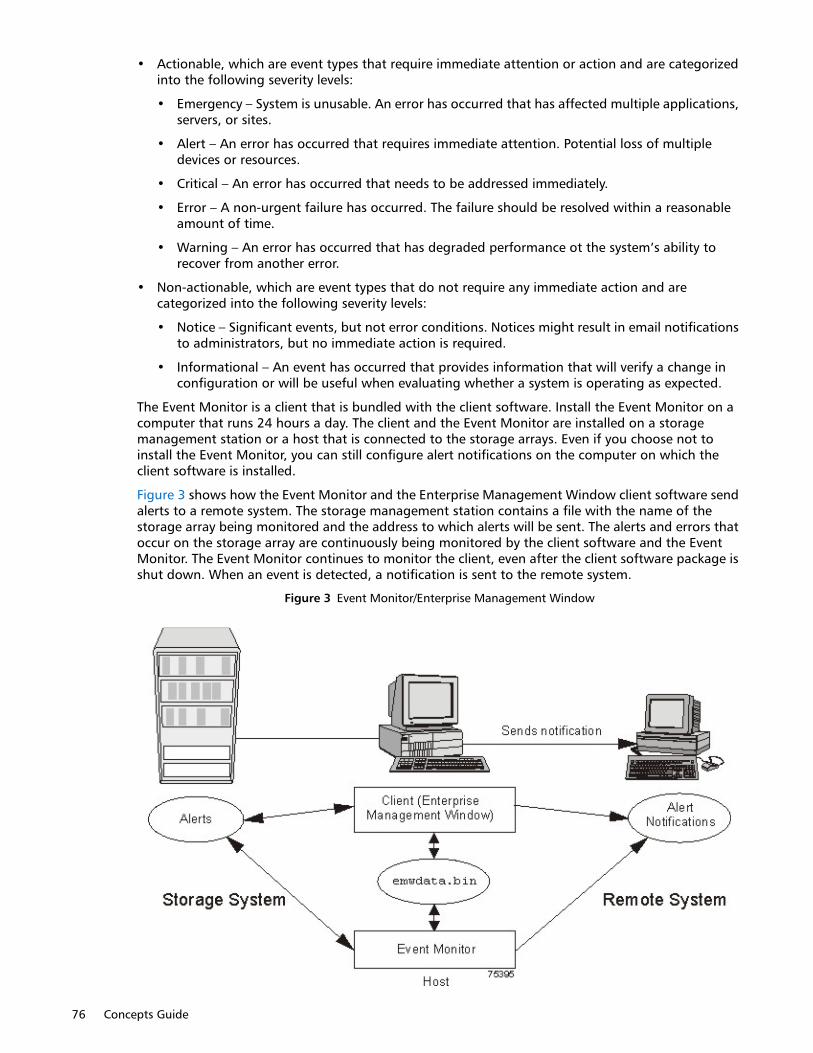
76 Concepts Guide
• Actionable, which are event types that require immediate attention or action and are categorized into the following severity levels:
• Emergency – System is unusable. An error has occurred that has affected multiple applications, servers, or sites.
• Alert – An error has occurred that requires immediate attention. Potential loss of multiple devices or resources.
• Critical – An error has occurred that needs to be addressed immediately.
• Error – A non-urgent failure has occurred. The failure should be resolved within a reasonable amount of time.
• Warning – An error has occurred that has degraded performance ot the system’s ability to recover from another error.
• Non-actionable, which are event types that do not require any immediate action and are categorized into the following severity levels:
• Notice – Significant events, but not error conditions. Notices might result in email notifications to administrators, but no immediate action is required.
• Informational – An event has occurred that provides information that will verify a change in configuration or will be useful when evaluating whether a system is operating as expected.
The Event Monitor is a client that is bundled with the client software. Install the Event Monitor on a computer that runs 24 hours a day. The client and the Event Monitor are installed on a storage management station or a host that is connected to the storage arrays. Even if you choose not to install the Event Monitor, you can still configure alert notifications on the computer on which the client software is installed.
Figure 3 shows how the Event Monitor and the Enterprise Management Window client software send alerts to a remote system. The storage management station contains a file with the name of the storage array being monitored and the address to which alerts will be sent. The alerts and errors that occur on the storage array are continuously being monitored by the client software and the Event Monitor. The Event Monitor continues to monitor the client, even after the client software package is shut down. When an event is detected, a notification is sent to the remote system.
Figure 3 Event Monitor/Enterprise Management Window
Maintaining/Monitoring Storage 77
Because the Event Monitor and the Enterprise Management Window share the information to send alert messages, the Enterprise Management Window has some visual cues to assist in the installation and synchronization of the Event Monitor.
Using the Event Monitor involves these three key steps:
1 Installing the client software
2 Setting up the alert destinations for the storage arrays that you want to monitor from the Enterprise Management Window
3 Synchronizing the Enterprise Management Window and the Event Monitor
Alert NotificationsYou can configure alert notifications by using the storage management software.
Configuring Alert NotificationsYou must configure alert notification settings to receive email notifications or SNMP notifications when an event occurs in a storage array. The notification summarizes the event and details about the affected storage array, including these items:
• The name of the affected storage array
• The host IP address (for an in-band managed storage array)
• The host name and ID (shown as out-of-band if the storage array is managed through the Ethernet connection of each controller)
• The event error type related to an Event Log entry
• The date and the time when the event occurred
• A brief description of the event
IMPORTANT: To set up alert notifications using SNMP traps, you must copy and compile a management information base (MIB) file on the designated network management station.
Three key steps are involved in configuring alert notifications:
1 Select a node in the Enterprise Management Window that shows alert notifications for the storage arrays that you want to monitor. You can select each storage array being managed, every storage array attached to and managed through a particular host, and individual storage arrays.
2 Configure email destinations, if desired.
3 Configure SNMP trap destinations, if desired. The SNMP trap destination is the IP address or the host name of a station running an SNMP service, such as a network management station.
Customer Support Alert NotificationsIf an event occurs in a storage array, the Enterprise Management Window contains options to configure the system to send email notifications to a specified customer support group. After the alert notification option is configured, the email alert notification summarizes the event, provides details about the affected storage array, and provides customer contact information. For more information about setting up this file, contact your Technical Support Representative.
Performance MonitorThe Performance Monitor provides visibility into performance activity across your monitored storage devices. You can use the Performance Monitor to perform these tasks:

78 Concepts Guide
• View in real time the values of the data collected for a monitored device. This capability helps you to determine if the device is experiencing any problems.
• See a historical view of a monitored device to identify when a problem started or what caused a problem.
• Specify various reporting attributes, such as time increments and filtering criteria, to examine performance trends and to pinpoint the cause of availability and performance issues.
• Show data in tabular format (actual values of the collected metrics) or graphical format (primarily as line-graphs), or export the data to a file.
• Show a dashboard where you can monitor six different performance graphs at once.
• Monitor I/O latency for drives and throughput for the entire storage array and volumes.
• Start textual performance monitoring or background performance monitoring.
About MetricsMetrics are measurements of the data that the Performance Monitor collects from the storage devices that you monitor. Metrics help to pinpoint problems and define their cause. Metrics define the types of data that you collect as well as the type of data source from which you collect the data.
Performance Metric DataYou can collect the following metric data:
• Total I/Os – Total I/Os performed by this device since the beginning of the polling session.
• Read Percentage – The percentage of total I/Os that are read operations for this device. Write percentage can be calculated as 100 minus this value.
• Cache Hit Percentage – The percentage of total I/Os that are processed with data from the cache rather than requiring a read from drive.
• Current or Maximum KBs per second – The current or maximum transfer rate during the current polling interval. The transfer rate is the amount of data in kilobytes (Table view) or megabytes (Graphical view) that can be moved through the I/O data connection in a second (also called throughput).
NOTE: A kilobyte is equal to 1024 bytes, and a megabyte is equal to 1024 x 1024 bytes (1,048,576 bytes).
• Current or Maximum I/O per second – The current or maximum number of I/O requests serviced per second during the current polling interval (also called an I/O request rate).
• Throughout Performance – The performance measured for the entire storage array and for individual volumes (max-average-min).
• I/O Latency – The I/O performed at the volume level and the drive level (max-average-min).
Metric SourcesMetrics define how the Performance Monitor collects data from supported data sources called metric sources. Metric sources are the aspects of a storage array or a controller that provide data. You can configure the Performance Monitor to report data from the following metric sources:
• Volume
• Volume group
• Disk Pools
• Controller

Maintaining/Monitoring Storage 79
• Storage array
You can use the data to create reports, and make tuning decisions based on the data values. If a value is outside of the desired range or is in an undesired state, you can take action to correct the problem.
NOTE: The Performance Monitor reports volume metrics and volume group metrics at the storage array level, regardless of volume controller ownership changes that might occur during monitoring.
Viewing Performance DataThe Performance Monitor provides both real-time analysis and historical context of performance metrics. The metrics are available in either of two views:
• Table view – In the Table view, the data appears in a tabular format. The actual numeric values of the collected metrics appear in a data table.
• Graphical view – In the Graphical view, the data is presented with a single x-axis and a single y-axis. The x-axis represents the time for which you selected to view performance data. The y-axis represents the metric you selected to view for a particular metric source.
Performance TuningThe Performance Monitor provides you with data about devices. You use this data to make storage array tuning decisions, as described in Table 27. When performance issues are encountered, tuning is required to alleviate the issues.
Table 27 Performance Tuning
Performance Metric Data
Implications for Performance Tuning
Total I/Os This data is useful for monitoring the I/O activity of a specific controller and a specific volume, which can help identify possible high-traffic I/O areas.
If the I/O rate is slow on a volume, try increasing the volume group size by selecting Volume Group > Add Free Capacity (Drives).
You might notice a disparity in the total I/Os (workload) of controllers. For example, the workload of one controller is heavy or is increasing over time while that of the other controller is lighter or more stable. In this case, you might want to change the controller ownership of one or more volumes to the controller with the lighter workload. Use the volume total I/O statistics to determine which volumes to move.
To monitor the workload across the storage array, look at the Total I/Os column of the Storage Array Totals row in the increase over time while application performance decreases, you might need to add additional storage array by adding storage array performance level.
Read Percentage Use the Read Percentage for a volume to determine actual application behavior. If a low percentage of read activity exists relative to write activity, you might want to change the RAID level of a volume group from RAID Level 5 to RAID Level 1 to obtain faster performance.
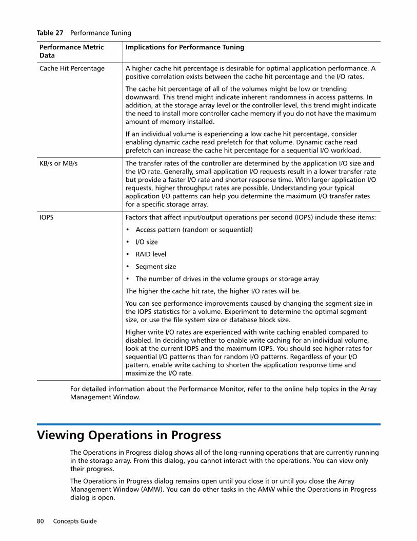
80 Concepts Guide
For detailed information about the Performance Monitor, refer to the online help topics in the Array Management Window.
Viewing Operations in ProgressThe Operations in Progress dialog shows all of the long-running operations that are currently running in the storage array. From this dialog, you cannot interact with the operations. You can view only their progress.
The Operations in Progress dialog remains open until you close it or until you close the Array Management Window (AMW). You can do other tasks in the AMW while the Operations in Progress dialog is open.
Cache Hit Percentage A higher cache hit percentage is desirable for optimal application performance. A positive correlation exists between the cache hit percentage and the I/O rates.
The cache hit percentage of all of the volumes might be low or trending downward. This trend might indicate inherent randomness in access patterns. In addition, at the storage array level or the controller level, this trend might indicate the need to install more controller cache memory if you do not have the maximum amount of memory installed.
If an individual volume is experiencing a low cache hit percentage, consider enabling dynamic cache read prefetch for that volume. Dynamic cache read prefetch can increase the cache hit percentage for a sequential I/O workload.
KB/s or MB/s The transfer rates of the controller are determined by the application I/O size and the I/O rate. Generally, small application I/O requests result in a lower transfer rate but provide a faster I/O rate and shorter response time. With larger application I/O requests, higher throughput rates are possible. Understanding your typical application I/O patterns can help you determine the maximum I/O transfer rates for a specific storage array.
IOPS Factors that affect input/output operations per second (IOPS) include these items:
• Access pattern (random or sequential)
• I/O size
• RAID level
• Segment size
• The number of drives in the volume groups or storage array
The higher the cache hit rate, the higher I/O rates will be.
You can see performance improvements caused by changing the segment size in the IOPS statistics for a volume. Experiment to determine the optimal segment size, or use the file system size or database block size.
Higher write I/O rates are experienced with write caching enabled compared to disabled. In deciding whether to enable write caching for an individual volume, look at the current IOPS and the maximum IOPS. You should see higher rates for sequential I/O patterns than for random I/O patterns. Regardless of your I/O pattern, enable write caching to shorten the application response time and maximize the I/O rate.
Table 27 Performance Tuning
Performance Metric Data
Implications for Performance Tuning
Maintaining/Monitoring Storage 81
You can view the progress for the following long-running operations:
• Dynamic Capacity Expansion (DCE) – Adding capacity to a volume group
• Dynamic RAID Migration (DRM) – Changing the RAID level of a volume group
• Checking the data redundancy of a volume group
• Defragmenting a volume group
• Initializing a volume
• Dynamic Volume Expansion (DVE) – Adding capacity to a volume
• Dynamic Segment Size (DSS) – Changing the segment size of a volume
• Reconstruction – Reconstructing data from parity because of unreadable sectors or a failed drive
• Copyback – Copying data from a hot spare drive to a new replacement drive
• Volume copy
• Synchronizing a remote mirror
For detailed information about this feature, refer to the topic Viewing Operation in Progress in online help.
Retrieving Trace Buffers
NOTE: Use this option only under the guidance of your Technical Support Representative.
You can save trace information to a compressed file. The firmware uses the trace buffers to record processing, including exception conditions, that might be useful for debugging. Trace information is stored in the current buffer. You have the option to move the trace information to the flushed buffer after you retrieve the information. You can retrieve trace buffers without interrupting the operation of the storage array and with minimal effect on performance.
• A zip-compressed archive file is stored at the location you specify on the host. The archive contains trace files from one or both of the controllers in the storage array along with a descriptor file named trace_description.xml. Each trace file includes a header that identifies the file format to the analysis software used by the Technical Support Representative. The descriptor file has the following information:
• The World Wide Identifier (WWID) for the storage array.
• The serial number of each controller.
• A time stamp.
• The version number for the controller firmware.
• The version number for the management application programming interface (API).
• The model ID for the controller board.
• The collection status (success or failure) for each controller. If the status is Failed, the reason for failure is noted, and there is no trace file for the failed controller.
For detailed information about this feature, refer to the online help topics in the Array Management Window.

82 Concepts Guide
Upgrading the Controller FirmwareYou can upgrade the firmware of the controllers in the storage array by using the storage management software.
In the process of upgrading the firmware, the firmware file is downloaded from the host to the controller. After downloading the firmware file, you can upgrade the controllers in the storage array to the new firmware immediately. Optionally, you can download the firmware file to the controller and upgrade the firmware later at a more convenient time.
The process of upgrading the firmware after downloading the firmware file is known as activation. During activation, the existing firmware file in the memory of the controller is replaced with the new firmware file.
The firmware upgrade process requires that the controllers have enough free memory space in which the firmware file resides until activation.
A version number exists for each firmware file. For example, 06.60.08.00 is a version number for a firmware file. The first two digits indicate the major revision of the firmware file. The remaining digits indicate the minor revision of the firmware file. You can view the version number of a firmware file in the Upgrade Controller Firmware window and the Download Firmware dialog. For more information, refer to the Downloading the Firmware online help topic in the Enterprise Management Window.
The process of upgrading the firmware can be either a major upgrade or a minor upgrade depending on the version of the firmware. For example, the process of upgrading the firmware is major if the version of the current firmware is 06.60.08.00, and you want to upgrade the firmware to version 07.36.12.00. In this example, the first two digits of the version numbers are different and indicate a major upgrade. In a minor upgrade, the first two digits of the version numbers are the same. For example, the process of upgrading the firmware is minor if the version of the current firmware is 06.60.08.00, and you want to upgrade the firmware to version 06.60.18.00 or any other minor revision of the firmware.
You can use the Enterprise Management Window to perform both major upgrades and minor upgrades. You can use the Array Management Window to perform minor upgrades only.
The storage management software checks for existing conditions in the storage array before upgrading the firmware. Any of these conditions in the storage array can prevent the firmware upgrade:
• An unsupported controller type or controllers of different types that are in the storage array that cannot be upgraded
• One or more failed drives
• One or more hot spare drives that are in use
• One or more volume groups that are incomplete
• Operations, such as defragmenting a volume group, downloading of drive firmware, and others, that are in progress
• Missing volumes that are in the storage array
• Controllers that have a status other than Optimal
• The storage partitioning database is corrupt
• A data validation error occurred in the storage array
• The storage array has a Needs Attention status
• The storage array is unresponsive, and the storage management software cannot communicate with the storage array
• The Event Log entries are not cleared

Maintaining/Monitoring Storage 83
You can correct some of these conditions by using the Array Management Window. However, for some of the conditions, you might need to contact your Technical Support Representative. The storage management software saves the information about the firmware upgrade process in log files. This action helps the Technical Support Representative to understand the conditions that prevented the firmware upgrade.
You can view the status of a storage array in the Status area of the Upgrade Controller Firmware window. Based on the status, you can select one or more storage arrays for which you want to upgrade the firmware.
You also can use the command line interface (CLI) to download and activate firmware to several storage arrays. For more information, refer to the About the Command Line Interface online help topic in the Enterprise Management Window.
Monitoring the Status of the DownloadMonitor the progress and completion status of the firmware and NVSRAM download to the controllers to make sure that errors did not occur. After the Confirm Download dialog is dismissed, the file is transferred to the storage array. Each controller is sent the new file one at a time. If the file transfer to the first controller succeeds, then the file is transferred to the second controller. The status of the file transfer and the update to each participating controller appear in the Upgrade Controller Firmware window.
NOTE: When the firmware download successfully completes, a dialog might appear stating that the current version of the Array Management Window (AMW) is not compatible with the new firmware just downloaded.
If you see this message, dismiss the AMW for the storage array, and open it again after selecting the storage array in the Enterprise Management Window (EMW) and selecting Tools > Manage Storage Array. This action launches a new version of the AMW that is compatible with the new firmware.
The progress and status of optimal controllers that are participating in the download appear. Controllers with statuses other than Optimal are not represented. Refer to Table 28.
Table 28 Controller Status
Icon Status Description
During Firmware or NVSRAM Download
Progress bar Transferring the firmware or the NVSRAM and the completed percentage
During Firmware or NVSRAM Activation
Progress bar Activating the firmware or the NVSRAM and the completed percentage of firmware activation
After Download and Results
Firmware Pending The storage array has pending firmware that is ready for activation.
Refreshing The storage array status is refreshing.
Error An error occurred during the operation.
Unresponsive The storage array cannot be contacted.

84 Concepts Guide
During firmware downloads, the storage management software periodically polls the controller to see if the download has completed successfully. Sometimes, controller problems occur that keep the download from occurring. Table 29 shows the results of firmware downloads if a controller is failed.
Problem Notification
IMPORTANT: To receive notification of events for the storage arrays, you must run the Enterprise Management Window (EMW) or the Event Monitor. In addition, you must have configured the alert notifications in the Enterprise Management Window.
Typically, storage array problems are indicated by using status notifications. A Needs Attention status icon appears in several locations:
• In the Status bar of the EMW
• In the Tree view and the Table view on the Devices tab of the EMW
• In the title bar of the Array Management Window (AMW)
• In the storage array name and status area above the tabs in the AMW
• On the Summary tab, the Logical tab, and the Physical tab in the AMW
Not-upgradeable The storage array cannot be upgraded for one or more reasons. For more information, refer to the Upgrading the Controller Firmware online help topic.
Health Check Passed No problems were detected, and you can upgrade the storage array.
Upgradeable: Needs Attention
One or more problems were detected, but you can still upgrade the storage array.
Firmware Upgraded The firmware is successfully upgraded in the storage array.
Table 28 Controller Status
Icon Status Description
Table 29 Failed Controller/Firmware Downloads
Task Result
You download new firmware to a storage array. A controller in the storage array fails, and you replace the failed controller with a new one.
After the new controller is installed, the storage array detects the controller replacement and synchronizes the firmware on both controllers.
You download new firmware to a storage array. A controller in the storage array fails, but you place the controller back online (assuming the problem was with something other than the controller).
The firmware synchronization does not occur.
Maintaining/Monitoring Storage 85
Event Log ViewerThe Event Log is a detailed record of events that occur in the storage array. You can use the Event Log as a supplementary diagnostic tool to the Recovery Guru for tracing storage array events. Always refer to the Recovery Guru first when you attempt to recover from component failures in the storage array.
The Event Log is stored in reserved areas on the disks in the storage array.
You can perform these actions in the Event Log window:
• View and filter the events that appear in the Event Log.
• Update the display to retrieve any new events.
• View detailed information about a selected event.
• Save selected Event Log data to a file.
• Clear the events in the Event Log.
The Event Log shows three levels of events: Critical, Informational, and Warning. To configure the destination addresses for delivery of email and SNMP trap messages that contain event details affecting managed storage arrays, select Edit > Configure Alerts in the Enterprise Management Window. For more information about SMTP notification, refer to the online help topics in the Enterprise Management Window.
Viewing the Event LogFrom the Array Management Window (AMW), select Advanced > Troubleshooting > View Event Log.
Several minutes might elapse for an event to be logged and to become visible in the Event Log window.
Storage Array Problem RecoveryWhen you see a storage array Needs Attention icon or link, launch the Recovery Guru. The Recovery Guru is a component of the Array Management Window that diagnoses the problem and provides the appropriate procedure to use for troubleshooting.
Recovery GuruThe Recovery Guru window is divided into three panes:
• Summary - This pane lists storage array problems.
• Details - This pane shows information about the selected problem in the Summary pane.
• Recovery Procedure - This pane lists the appropriate steps to resolve the selected problem in the Summary pane.
For detailed information about the Recovery Guru, refer to the online help topics in the Array Management Window.

86 Concepts Guide