
Computer Vision and Human Skin Colour - CiteSeerX
192
Computer Vision & Media Technology Laboratory Ph.D. Dissertation Computer Vision and Human Skin Colour Moritz St ¨ orring Faculty of Engineering and Science Aalborg University 2004
-
Upload
khangminh22 -
Category
Documents
-
view
3 -
download
0
Transcript of Computer Vision and Human Skin Colour - CiteSeerX

Computer Vision & Media Technology Laboratory
Ph.D. Dissertation
Computer Visionand
Human Skin Colour
Moritz Storring
Faculty of Engineering and Science
Aalborg University 2004

About the Author
Moritz Storring studied Electrical Engineering at the Technical University of Berlin, Ger-many and at the Institut National Polytechnique de Grenoble, France. He did his Mastersproject in the field of active computer vision at Aalborg University, Denmark, and grad-uated in 1998 at Techical University of Berlin. From 1998 to 2001 he was a researchassistant at the Computer Vision and Media Technology Laboratory (CVMT), AalborgUniversity within the European Training and Mobility of Researchers (TMR) projectSemi-autonomous Monitoring And Robotics Technology (SMART II). Since 2001 he isassistant professor at CVMT. In 2004 he receive a PhD degree from Aalborg University.His research interests include physics-based colour vision, outdoor computer vision, faceand skin detection, vision based HCI, and augmented reality.

Computer Vision
andHuman Skin Colour
A Ph.D. dissertation
by
Moritz Storring
Computer Vision & Media Technology Laboratory
Faculty of Engineering and Science
Aalborg University, Denmark
E-mail: [email protected]
URL: http://www.cvmt.dk/∼mst
August 2004

This report was typeset by the author using LATEX2ε.
All rights reservedc©2004 by Moritz StorringNo part of this report may be reproduced, stored in a retrieval system, or transmitted,in any form by any means, electronic, mechanical, photocopying, recording, or otherwise,without the prior written permission of the author.
ISBN 87-90562-23-2 (printed version)ISBN 87-90562-24-0 (electronic version, http://www.cvmt.dk/∼mst/8790562240.pdf)

This dissertation was submitted in April 2004 to the Faculty of Engineering and Science,Aalborg University, Denmark, in partial fulfilment of the requirements for the Doctor ofPhilosophy degree.
The defence took place at Aalborg University, Niels Jernes Vej 14, DK-9220 Aalborgon Wednesday June 16, 2004. The session was moderated by Professor Jens Haase,Department of Health Science and Technology, Aalborg University.
While the first edition was approved, this second edition includes revisions in accordancewith comments from the adjudication committee.
The following adjudication committee was appointed to evaluate the thesis. Note thatthe supervisor was a non-voting member of the committee.
Professor Matti Pietikainen, Dr. Tech.Department of Electrical and Information Engineering
University of OuluOulu, Finland
Professor James L. Crowley, Ph.D.I.N.P. Grenoble
INRIA Rhone-AlpesMontbonnot, France
Associate Professor Claus B. Madsen, Ph.D. (committee chairman)Computer Vision and Media Technology Laboratory
Department of Health Science and TechnologyAalborg UniversityAalborg, Denmark
Professor Erik Granum, Ph.D. (supervisor)Computer Vision and Media Technology Laboratory
Department of Health Science and TechnologyAalborg UniversityAalborg, Denmark


Abstract
Computer vision based face and gesture recognition will allow future human computerinterfaces to be more intuitive and user-friendly than traditional interfaces. A crucialprocessing step for the success of such systems is robust detection and tracking of facesand hands, which is frequently done by combining complementary cues, e.g., motion,shape, and colour. Skin colour is often used because it is invariant to orientation and size,gives an extra dimension compared to gray scale methods, and is fast to process. Themain problems with the robustness of skin colour detection are however: (1) dependenceon the illumination colour, (2) it varies between individuals, and (3) many everyday-lifeobjects are skin colour like, i.e., skin colour is not unique.
The objective of this study is to open for an improved skin colour cue, and the focus is toinvestigate the image formation process theoretically and experimentally – in particularwith respect to human skin colours under changing and mixed illumination. Physics-basedapproaches are used to model the reflections of skin and the image formation process whenregistered by a camera.
It is shown that skin colour “perception” as viewed by a state-of-the-art colour videocamera can be modelled sufficiently accurate with a physics-based approach given theillumination spectra, the reflectance of skin, and the camera characteristics. Furthermore,everyday-life illumination spectra can be modelled appropriately as Blackbody radiatorsin this context. This skin colour modelling may provide the basis for applications such asadaptive skin segmentation.
For adaptive segmentation it may also be useful to estimate the illumination colour. Twomethods are suggested and tested to estimate the illumination colour from observationof skin colour. The first uses the diffuse reflections from skin and the second uses thesurface or highlight reflections. These methods are complementary and their accuraciesare sufficient to improve adaptive skin segmentation.
In order to track skin areas through changing illumination conditions and to distinguishthem from other skin coloured objects a method is proposed to model the skin colourdistribution as a unimodal Gaussian. The parameters of the Gaussian can be modelledselectively for arbitrary illumination using a physics-based approach.
Finally, the reflectance characteristics of skin in the near infrared (NIR) spectrum areexplored. A combination of standard RGB bands with three narrow NIR bands is sug-gested to robustly detect skin under changing illumination and distinguish it from otherskin colour-like objects.
The results of this work may contribute to an adaptive skin colour cue that in combinationwith other cues will enable robust face and hand detection in unconstrained environments.The features of the skin colour cue, which combines the methods developed, are outlinedin the last chapter of this report.

Resume
Computer vision baseret ansigts og gestus genkendelse kan muliggøre at fremtidens men-neske-maskine interaktion vil blive mere intuitiv og brugervenlig end traditionelle bruger-grænseflader. En vigtig forudsætning for denne slags systemer er, at de sikkert genkenderansigter og hænder. Dette gøres ofte ved at kombinere flere forskellige metoder, som f.eks.bevægelse, form, og farve. Metoder baseret pa hudfarve er meget brugt fordi de er invari-ante i forhold til orientering og størrelse af objekterne og de giver en ekstra dimensionsammenlignet med graskala metoder. Desuden er metoder baseret pa farve hurtige atprocessere. De primære problemer med robust at genkende hudfarve er: (1) afhængighedaf lyskildens farve, (2) variationer medlem forskellige mennesker, og (3) at der er mangedagligdags objekter, som ligner hudfarve, dvs. hudfarve er ikke unik.
Formal med dette studie er at muliggøre en mere palidelig hudfarvegenkendelse ved at un-dersøge billededannelsesprocessen bade teoretisk og eksperimentelt, primært med henblikpa hudfarve under skiftende og blandede lysforhold. Fysisk baserede fremgangsmader ogmetoder er brugt til at modellere bade refleksioner af hud og billededannelsesprocessen.
Det bliver demonstreret at hudfarve-perception med et farvevideokamera kan modellerestilstrækkelig nøjagtigt med en fysisk baseret fremgangsmade, nar lyskildens spektrum,reflektansen af hud, og kamerakarakteristikken er kendt. Derudover kan spektre af “sæd-vanlige” dagligdags lyskilder i denne kontekst tilnærmes med udstralingen fra et opvarmetsort legeme (Blackbody radiator). Denne modellering af hudfarve kan bruges som basisfor en række applikationer som f.eks. adaptiv hudsegmentering.
For adaptiv hudsegmentering ville det være ønskeligt at kunne estimere lysets farve. Tometoder er foreslaet og afprøvet til estimering af lysets farve fra observationer af hudfarve.Den første bruger diffus refleksion fra hud, og den anden bruger “highlights” (overflade re-fleksioner). Metoderne kan komplementere hinanden og deres nøjagtighed er tilstrækkeligtil at forbedre adaptiv hudsegmentering.
For at følge hudomrader i bevægelse og under skiftende lysforhold og samtidigt skelnedem fra andre objekter, som ligner hudfarve, er en metode udviklet som modellerer hud-farve malinger som en Gaussisk fordeling. Parametrene af denne Gaussiske fordeling kanmodelleres med gode diskriminerende egenskaber for vilkarlige lysforhold med hjælp af enfysisk baseret fremgangsmade.
Desuden er huds refleksionskarakteristika i bølgeomradet nær infrarød (NIR) blevet un-dersøgt. En kombination af standard RGB band med tre smalle NIR band er foreslaettil palidelig hudgenkendelse under skiftende lysforhold, hvor der samtidigt kan skelnesmedlem hud og andre objekter med hudlignede farver.
Resultaterne af dette studie kan bidrage til en adaptiv metode til hudfarvegenkendelses,som i kombination med andre metoder kan muliggøre palidelig ansigts- og gestusgen-kendelse i naturlige omgivelser. En sadan adaptive hudfarvegenkendelsemetode, sombruger metoderne udviklet i dette studie, er beskrevet i rapportens sidste kapitel.

Preface
This dissertation is based on the research I did at the Computer Vision and Media Tech-nology Laboratory (CVMT) in the period between 1998 and 2003. From 1998-2001 I wasresearch assistant working on the SMART II project (Semi-autonomous Monitoring AndRobotics Technology), a Training and Mobility of Researchers (TMR) network fundedby the European Commission, contract no. ERBFMRX-CT96-0052 (1998-2000), and on“The Staging of Virtual Inhabited 3D Spaces” project funded by The Danish ResearchCouncil (2001). Since June 2001 I was assistant professor partly funded by the Faculty ofEngineering and Science, Aalborg University, and partly by the ARTHUR project (IST-2000-28559) under the European Commission’s IST program. I am very greatfull for thesefunding.
There are several people I would like to thank who made this work possible. First of allI would like to thank my supervisor Prof. Erik Granum for many fruitful discussions,encouragement, and providing the research environment by leading CVMT.
I would like to thank the staff and students at CVMT and VR Media Lab for providing anvery pleasant working atmosphere. Dr. Hans J. Andersen, Dr. Thomas B. Moeslund, andDr. Claus B. Madsen for comments and discussions as well as for productive collaboration.Jørgen Bjørnstrup, Christian Kristoffersen, and Gitte Sørensen for helping with practicaland administrative problems.
Finally, I would like to thank my family and friends, particularly my wife, parents, andbrothers for their unconditional support and love.
Moritz Storring
Aalborg, Denmark, August 2004


Contents
1 Introduction 1
1.1 Motivation for Skin Colour in Computer Vision . . . . . . . . . . . . . . . 2
1.2 Objectives and Focus of this Thesis . . . . . . . . . . . . . . . . . . . . . . 5
1.3 Outline and Contents of this Thesis . . . . . . . . . . . . . . . . . . . . . . 6
2 Skin Modelling and Detection: Background and Related Work 11
2.1 Introduction to Modelling Image Formation . . . . . . . . . . . . . . . . . 11
2.1.1 Light . . . . . . . . . . . . . . . . . . . . . . . . . . . . . . . . . . . 12
2.1.2 Reflection . . . . . . . . . . . . . . . . . . . . . . . . . . . . . . . . 14
2.1.3 Camera . . . . . . . . . . . . . . . . . . . . . . . . . . . . . . . . . 19
2.1.4 Comments on Image formation and Everyday-life Illumination . . . 20
2.2 Skin Reflectance: Properties and Modelling . . . . . . . . . . . . . . . . . . 21
2.2.1 Physiology of Skin . . . . . . . . . . . . . . . . . . . . . . . . . . . 22
2.2.2 Skin Optics . . . . . . . . . . . . . . . . . . . . . . . . . . . . . . . 23
2.2.3 Modelling Skin Reflectance . . . . . . . . . . . . . . . . . . . . . . . 25
2.2.4 Summary of Skin Reflectance . . . . . . . . . . . . . . . . . . . . . 30
2.3 Skin Colour Modelling and Detection . . . . . . . . . . . . . . . . . . . . . 31
2.3.1 Colour Spaces used for Skin Modelling and Detection . . . . . . . . 33
2.3.2 Modelling and Detection from known Camera . . . . . . . . . . . . 43
2.3.3 Modelling and Detection from unknown Camera . . . . . . . . . . . 54
2.4 Other Optical Skin Detection Methods . . . . . . . . . . . . . . . . . . . . 61
2.5 Summary and Concluding Remarks . . . . . . . . . . . . . . . . . . . . . . 63
3 Physics-based modelling of human skin colour under mixed illuminants 85
3.1 Introduction . . . . . . . . . . . . . . . . . . . . . . . . . . . . . . . . . . . 88
3.2 Modelling Colour Reflections and Light Sources . . . . . . . . . . . . . . . 89

ii CONTENTS
3.2.1 Dichromatic Reflection Model . . . . . . . . . . . . . . . . . . . . . 89
3.2.2 Light sources and their approximation by Blackbody radiators . . . 92
3.2.3 Mixed illumination . . . . . . . . . . . . . . . . . . . . . . . . . . . 93
3.3 Modelling Skin Colour . . . . . . . . . . . . . . . . . . . . . . . . . . . . . 94
3.3.1 Reflectance of human skin . . . . . . . . . . . . . . . . . . . . . . . 94
3.3.2 Modelling of the skin colour chromaticities . . . . . . . . . . . . . . 95
3.3.3 Skin colour and mixed illumination . . . . . . . . . . . . . . . . . . 97
3.4 Image Acquisition . . . . . . . . . . . . . . . . . . . . . . . . . . . . . . . . 97
3.4.1 Images under mixed illumination . . . . . . . . . . . . . . . . . . . 98
3.5 Comparison of Measured and Modelled Data . . . . . . . . . . . . . . . . . 99
3.5.1 Single known illumination . . . . . . . . . . . . . . . . . . . . . . . 99
3.5.2 Blackbody modelling of illumination . . . . . . . . . . . . . . . . . 101
3.5.3 Mixed illumination . . . . . . . . . . . . . . . . . . . . . . . . . . . 102
3.6 Conclusions . . . . . . . . . . . . . . . . . . . . . . . . . . . . . . . . . . . 103
4 Estimation of the Illuminant Colour from Human Skin Colour 107
4.1 Introduction . . . . . . . . . . . . . . . . . . . . . . . . . . . . . . . . . . . 110
4.2 Illuminant estimation from skin colour . . . . . . . . . . . . . . . . . . . . 110
4.2.1 Modelling skin colour image formation . . . . . . . . . . . . . . . . 110
4.2.2 Illumination estimation using the Neutral Interface Reflection as-sumption . . . . . . . . . . . . . . . . . . . . . . . . . . . . . . . . 113
4.2.3 Illuminant estimation using iso-melanin-lines . . . . . . . . . . . . . 115
4.3 Performance assessment . . . . . . . . . . . . . . . . . . . . . . . . . . . . 117
4.3.1 Materials and method . . . . . . . . . . . . . . . . . . . . . . . . . 117
4.3.2 Results . . . . . . . . . . . . . . . . . . . . . . . . . . . . . . . . . . 117
4.4 Discussion and conclusions . . . . . . . . . . . . . . . . . . . . . . . . . . . 118
5 Estimation of the illuminant colour using highlights from human skin 121
5.1 Introduction . . . . . . . . . . . . . . . . . . . . . . . . . . . . . . . . . . . 124
5.2 Theory and Background . . . . . . . . . . . . . . . . . . . . . . . . . . . . 125
5.2.1 Dichromatic Reflection Model . . . . . . . . . . . . . . . . . . . . . 125
5.2.2 Properties of Skin and Nose . . . . . . . . . . . . . . . . . . . . . . 125
5.3 Illuminant Colour Estimation . . . . . . . . . . . . . . . . . . . . . . . . . 126
5.3.1 Body Vector Estimation . . . . . . . . . . . . . . . . . . . . . . . . 127
5.3.2 Surface Vector Estimation . . . . . . . . . . . . . . . . . . . . . . . 127

CONTENTS iii
5.3.3 Reliability Tests of the Estimates . . . . . . . . . . . . . . . . . . . 128
5.4 Results . . . . . . . . . . . . . . . . . . . . . . . . . . . . . . . . . . . . . . 129
5.4.1 Image Acquisition . . . . . . . . . . . . . . . . . . . . . . . . . . . . 129
5.4.2 Performance Assessment . . . . . . . . . . . . . . . . . . . . . . . . 130
5.5 Discussion . . . . . . . . . . . . . . . . . . . . . . . . . . . . . . . . . . . . 132
5.6 Conclusions . . . . . . . . . . . . . . . . . . . . . . . . . . . . . . . . . . . 132
6 Tracking regions of human skin through illumination changes 135
6.1 Introduction . . . . . . . . . . . . . . . . . . . . . . . . . . . . . . . . . . . 138
6.2 Theory and Background . . . . . . . . . . . . . . . . . . . . . . . . . . . . 139
6.2.1 Skin chromaticities . . . . . . . . . . . . . . . . . . . . . . . . . . . 139
6.2.2 Statistical modelling of skin chromaticities . . . . . . . . . . . . . . 140
6.2.3 Physics-based modelling of skin chromaticities . . . . . . . . . . . . 140
6.3 Adapting statistical models to changing illumination . . . . . . . . . . . . 141
6.3.1 Initialisation . . . . . . . . . . . . . . . . . . . . . . . . . . . . . . . 142
6.3.2 Estimating eigenspaces for arbitrary CCTs . . . . . . . . . . . . . . 142
6.4 Skin-colour feature for segmented regions . . . . . . . . . . . . . . . . . . . 143
6.5 Experiments . . . . . . . . . . . . . . . . . . . . . . . . . . . . . . . . . . . 145
6.5.1 Image acquisition . . . . . . . . . . . . . . . . . . . . . . . . . . . . 145
6.5.2 Physics based modelling of eigenspaces . . . . . . . . . . . . . . . . 146
6.5.3 Tracking and discriminating Skin through varying illumination . . . 147
6.6 Discussion . . . . . . . . . . . . . . . . . . . . . . . . . . . . . . . . . . . . 148
6.7 Conclusions . . . . . . . . . . . . . . . . . . . . . . . . . . . . . . . . . . . 149
7 A multispectral approach to robust human skin detection 153
7.1 Introduction . . . . . . . . . . . . . . . . . . . . . . . . . . . . . . . . . . . 156
7.2 Background . . . . . . . . . . . . . . . . . . . . . . . . . . . . . . . . . . . 157
7.3 Skin Detection . . . . . . . . . . . . . . . . . . . . . . . . . . . . . . . . . 158
7.3.1 Visible Band . . . . . . . . . . . . . . . . . . . . . . . . . . . . . . 159
7.3.2 NIR Band . . . . . . . . . . . . . . . . . . . . . . . . . . . . . . . . 160
7.3.3 Combining Visible and NIR . . . . . . . . . . . . . . . . . . . . . . 160
7.4 NIR Experiment . . . . . . . . . . . . . . . . . . . . . . . . . . . . . . . . 161
7.5 Discussion . . . . . . . . . . . . . . . . . . . . . . . . . . . . . . . . . . . . 162

iv CONTENTS
8 Discussion and Conclusions 167
8.1 Contributions of this thesis . . . . . . . . . . . . . . . . . . . . . . . . . . . 168
8.2 Contributions in an application context . . . . . . . . . . . . . . . . . . . . 171
8.3 Conclusions . . . . . . . . . . . . . . . . . . . . . . . . . . . . . . . . . . . 175
8.4 Future Perspectives . . . . . . . . . . . . . . . . . . . . . . . . . . . . . . . 175

Chapter 1
Introduction
The human body’s largest organ is the skin, and it is presumably one of the materialswe look most at – since we often have another person in our field-of-view or parts of ourown body. The appearance of skin is important for humans and human-human relations.It gives us, e.g., an indication about the well-being of a person, a person’s ethnic origin,and the age. Our inherent concern and dissatisfaction about the appearance of our skinhas resulted in skin-care product sales reaching $34.1 billion worldwide in 2000, which isthe fastest-growing part of the personal-care market. $19.8 billion were spent worldwidein 2000 on makeup/colour cosmetics [10].
Of particular significance is the colour of skin, which contains, among other things, in-formation on the ethnic origin or whether somebody was exposed to the sun for longertime. The colour of skin has always been a subject of controversy and often caused, andstill causes, discrimination and unfair treatment of primarily non-white people [4], or onthe other hand white albino1 Africans are discriminated in Africa where albinism has forcenturies been viewed as a curse [11]. “Being white” is elsewhere considered as “beingprettier”, e.g., in Asia [27]. Also in the western culture among the “white population”well into the 20th century suntan was the mark of a manual labourer. Only in recenttimes, starting around the 1940s, a permanent suntan has become the symbol of radianthealth, jet-set wealth, and fresh-faced beauty [22]. This – often excessive – exposure toUV radiation of sunlight, and nowadays also the artificial sun of solariums, has on theother hand caused a rapid growth in skin diseases, particularly skin cancer, since 1980.Increasing numbers of skin diseases require medical research and treatment, e.g., Edwardsand Duntley [5] analysed already in 1939 skin pigment changes after sunlight exposure.
The human visual system can distinguish about 128 different hues, 130 different saturationlevels, and around 20 different shades, hence we can distinguish about 330,000 colours.When perceiving coloured objects the characteristics of the illumination source also havean important influence. A study by Rea et al. [20] investigated how well people can
1a person with pale skin, light hair, pinkish eyes, and visual abnormalities resulting from a hereditaryinability to produce the pigment melanin

2 Introduction
distinguish between five standard fluorescent lamp types when viewing their own skin orother materials illuminated by these lamps. The other materials were coloured or gray.The performance in distinguishing between the lamps was higher when looking at skinthan when looking at the other materials. That means we might be particularly sensitiveto colour nuances in skin – maybe because we are so familiar with its reflectance – whichmay also be a reason for our high demands on smooth skin colour appearance and ourdesire to remove small nuances and to improve it with cosmetic products.
In movie and television production it is common that everybody uses make-up to smooththe skin appearance, and some television broadcasting cameras even have an electronicfilter to smooth skin colours, i.e., “electronic make-up” [14, p. 86]. But not only thecapturing of skin images with cameras is carefully controlled, particular attention is takento the reproduction and visualisation of skin colour by television displays, photos, andprint industry [9; 12; 21]. Imai et al. [8], e.g., suggested a method to improve the skincolour reproduction on CRT2 displays and hardcopies. Even more difficult than realisticreproduction is the generation of artificial skin for computer graphics [6; 17], e.g., forcomputer game or movie production.
So far only the human observer looking at skin has been discussed, however, one mayask who or what else than humans is looking at humans and their skin? Apart fromother organisms there is an increasing number of machines watching humans and theirskin for different reasons such as medical [1; 13; 18] and cosmetic [23]. Yet another areaare so called computer vision applications, looking at humans, e.g., for human computerinterfaces and surveillance purposes. Computer vision has to deal with similar issuesmentioned above, i.e., changing light sources, different skin tones, and diverse cameras(artificial observers). These are the focus of this thesis:
The emphasis of the work presented in this report is on computer visionmethods analysing and detecting skin colour in unconstrained environ-ments.
1.1 Motivation for Skin Colour in Computer Vision
The daily life of humans in higher developed countries is more and more surrounded bycomputers, artificial- and ambient-intelligence supporting and assisting us in all kindsof activities – information technology is becoming ubiquitous. An important factor inachieving ubiquity is the availability of more user-friendly, intuitive, and efficient humancomputer interaction (HCI), i.e., migrating from traditional keyboard and mice inputstowards unobtrusive user interfaces that are natural to humans and that the user mayeven not be aware of, e.g., speech input, face recognition, facial expression interpretation,hand gesture recognition, and large-scale body language [16]. In this context human skincolour may be an important visual feature.
2Cathode-Ray-Tube
1.1 Motivation for Skin Colour in Computer Vision 3
Computer Vision Based HCI
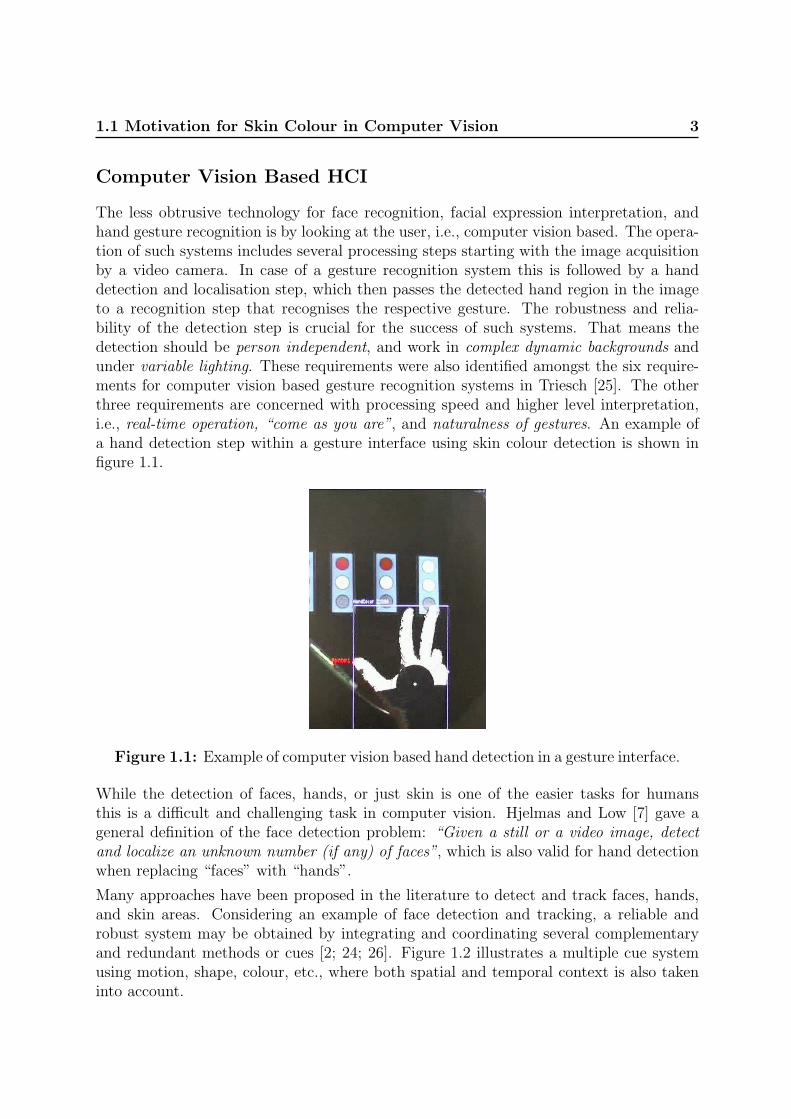
The less obtrusive technology for face recognition, facial expression interpretation, andhand gesture recognition is by looking at the user, i.e., computer vision based. The opera-tion of such systems includes several processing steps starting with the image acquisitionby a video camera. In case of a gesture recognition system this is followed by a handdetection and localisation step, which then passes the detected hand region in the imageto a recognition step that recognises the respective gesture. The robustness and relia-bility of the detection step is crucial for the success of such systems. That means thedetection should be person independent, and work in complex dynamic backgrounds andunder variable lighting. These requirements were also identified amongst the six require-ments for computer vision based gesture recognition systems in Triesch [25]. The otherthree requirements are concerned with processing speed and higher level interpretation,i.e., real-time operation, “come as you are”, and naturalness of gestures. An example ofa hand detection step within a gesture interface using skin colour detection is shown infigure 1.1.
Figure 1.1: Example of computer vision based hand detection in a gesture interface.
While the detection of faces, hands, or just skin is one of the easier tasks for humansthis is a difficult and challenging task in computer vision. Hjelmas and Low [7] gave ageneral definition of the face detection problem: “Given a still or a video image, detectand localize an unknown number (if any) of faces”, which is also valid for hand detectionwhen replacing “faces” with “hands”.
Many approaches have been proposed in the literature to detect and track faces, hands,and skin areas. Considering an example of face detection and tracking, a reliable androbust system may be obtained by integrating and coordinating several complementaryand redundant methods or cues [2; 24; 26]. Figure 1.2 illustrates a multiple cue systemusing motion, shape, colour, etc., where both spatial and temporal context is also takeninto account.

4 Introduction
colour
Preprocessing
Acquisition
Image
and
System
Output
Cues Units
Cameradetector
Unit
eye blink
features like
shape
motion
nose position
Tracking-
Supervisor-
Figure 1.2: Face tracking system integrating and coordinating complementarycues.
Comprehensive surveys on the current state-of-the-art of face detection methods wererecently published in Hjelmas and Low [7] and Yang, Kriegman, and Ahuja [29]. Althoughconsiderable progress has been made in face and hand detection there are problems withthe robustness of such systems. Particularly complex dynamic environments and varyinglighting conditions let them often fail [29], which were identified in [25] as two importantrequirements for a successful system.
The Skin Colour Cue
With increasing quality of colour video cameras and growing computation power the skincolour cue is more and more used in face and hand detection, e.g., [3; 15; 19; 28]. Theadvantage of using colour over gray scale is due to the extra dimensions of colour, i.e.,two objects of similar gray tones might be very different in a colour space [7]. Comparedto other cues in figure 1.2 such as shape, the colour feature is pixel based and requires nospatial context, thus it is orientation and size invariant, and fast to process. Many skincolour modelling and detection methods have been reported in the literature, section 2.3will give an overview.
Problems with the robustness of skin colour detection arise under varying lighting con-ditions, especially when the illumination colour changes, which may occur both inoutdoor- and indoor-environments with mixtures of daylight and artificial light. Thesame skin area appears as two different colours under two different illuminations, in otherwords skin colour depends on the scene context. Furthermore, skin colour viewed underconstant illumination may vary between individuals and also depends on the cameraused. Finally, there are many objects in everyday-life that have similar colour appearance

1.2 Objectives and Focus of this Thesis 5
to skin, i.e., skin reflectance is not unique, particularly when viewed with observersof low spectral resolution like the human eye or an RGB camera. A second class of skincolour-like materials are those that appear skin-coloured under a certain illumination,e.g., a light gray material viewed under yellowish illumination.
1.2 Objectives and Focus of this Thesis
In order to enable colour based skin detection and tracking methods to cope with theabove mentioned problems, e.g., by adapting to changing environment-conditions, and bydistinguishing skin from other skin colour-like objects, the focus of this thesis will be to
investigate the image formation process theoretically and experimentally,in particular with respect to human skin colours under changing andmixed illumination.
This thesis proposes to use a physics-based approach for modelling the image formationprocess exploiting available a priori knowledge, i.e., the colours in a camera image are theresult of the interaction between light source and the scene observed by a sensor. Althoughthis has been successfully used in some applications of computer vision, it has not yetbeen thoroughly exploited in the field of skin colour modelling and detection (chapter 2).
The specific problems addressed in this thesis are:
1. How well may skin colour be modelled with a physics-based approach fordifferent skin types when viewed by a camera under a range of single and mixedlight sources; and how accurate model of the light source is required?
2. Given the dependence of skin appearance on the illumination colour, how well andunder which conditions may the illumination colour be estimated from skingiven a camera input image?
3. How well may a skin area be distinguished from other skin-like objectsunder varying illumination conditions using a physics-based approach?
4. Can reflectance characteristics in the near infrared spectrum help to distin-guish between skin and other skin-like objects?
The answer to the first problem provides insight about the potential of using skin colour asa general robust method in a range of computer vision applications in everyday-life whenhumans appear in the scenario. The second problem assess the possibilities of estimatingthe light source colour which is relevant for adaptive segmentation methods, and mayopen for colour correction of images. Both, the third and fourth problem are importantfor practical applications, e.g., using skin colour segmentation in a cluttered environmentwith other skin colour-like objects. Finally, the fourth explores the possible benefit of newcameras that are particularly designed for robust skin detection.

6 Introduction
1.3 Outline and Contents of this Thesis
This thesis is organised in eight chapters including this introduction. In chapter 2 thetheoretical background for this thesis is introduced and the state-of-the-art in this partic-ular field is reviewed. This chapter may be skipped by readers familiar with the subject.
Chapters 3 to 7 are articles by the author that have previously been published in in-ternational conferences and journals. Chapter 3 attempts to find an answer to the firstquestion proposing and investigating a physics-based approach to model the image for-mation process of human skin colour under varying and mixed illuminations. Chapters 4and 5 are concerned with the second question and present two different methods to es-timate the illumination colour from skin reflections. Based on the model proposed inchapter 3, chapter 6 deals with the third question proposing a method to track regionsof skin through illumination changes and to distinguish them from other skin colour-like objects. The fourth and last question is considered in chapter 7, which presents amultispectral approach using wave-bands in the visible and near infrared spectrum forrobust skin detection under varying illumination. The last chapter 8 draws conclusionsand suggests further perspectives.
The remainder of this section will summarise and outline the following seven chapters.
Background and Related Work
Chapter 2 introduces the background of this thesis and reviews related work that rep-resents the state-of-the-art in this particular field. It consists of five sections: 1) A briefintroduction to physics-based computer vision. The image formation process is describedwith the involved components: light source, reflection, and sensor. 2) The optical prop-erties of human skin are described and several approaches to modelling skin reflectanceare presented. 3) Colour based skin modelling and detection methods for computer vi-sion are reviewed focusing on published work that considers the problem of unconstrainedenvironments with changing illumination, e.g., for real-time tracking of faces and hands.4) Other optical skin detection methods, e.g., using infrared bands, are briefly reviewed.5) Finally, a summary and concluding remarks on the state-of-the-art are given.
Physics-based modelling of human skin colour under mixed illuminants
In chapter 3, the image formation process is investigated with respect to human skincolour. The chapter reviews general models for reflection and for light sources. Thenthe reflections of skin are modelled for a variety of skin tones when viewed by a colourcamera under different and mixed everyday-life illuminations. It is shown that skin colouris varying considerably under different light sources and mixtures of those. When nor-malised for intensity, however, the range of possible skin colours is small compared to theentire colour space. Furthermore, using intensity normalised colours the variations due todifferent skin tones are small compared to the variations caused by changing illumination

1.3 Outline and Contents of this Thesis 7
colours.
The proposed modelling is empirically validated through a series of experiments. It mayprovide the basis for a wide range of applications such as adaptive segmentation of skincolour.
Estimation of the illuminant colour from human skin
The previous chapter showed how skin colour depends on the illumination, and that theknowledge of the light source characteristics would enable an improved detection of skin.In chapters 4 and 5, the opposite problem is investigated, i.e., estimating the illuminationcolour from a camera input image showing human skin. Two different reflection propertiesare exploited. The first uses the diffuse reflections of skin, while the second makes use ofthe highlights on skin, also known as glossy or specular reflections.
The method proposed in chapter 4 is based on the model introduced in chapter 3 andassumes everyday-life light sources. It consists of an initialisation step which enables forestimation of the illumination colour. In the initialisation step a reflectance parameter ofthe skin in a given image is estimated, which may then be used to estimate the illuminationcolour from skin colour in an image sequence.
Chapter 5 introduces a method to estimate the illumination colour from highlights onhuman skin. Highlights of non-homogeneous dielectric materials, such as skin, containinformation about the illuminant colour. They appear, e.g., on convex body parts likethe nose under certain viewing conditions and direct illumination. The proposed methodestimates the illumination colour from highlights on the nose tip. Neither an initialisationstep nor assumptions on the light source type are required as compared to the methodpresented in the previous chapter. It requires, however, a highlight which appears onlyunder direct illumination.
Both methods are complementary and have been experimentally validated with imagesfrom faces of different skin tones taken under a variety of illumination colours. They haveapplication, e.g., in skin detection and segmentation methods that can adapt to differentillumination conditions.
Tracking regions of human skin through illumination changes
Illumination changes may result in wrong classification, e.g., after an illumination changea “non-skin” object might be detected as skin, because the illumination change was notdetected or incorrectly interpreted.
Chapter 6 investigates 1) how accurately the parameters of a multivariate Gaussian,approximating the colour distribution of a particular skin patch, might be modelled fordifferent illumination colours using a physics-based approach, and 2) how this may beused as a feature to classify between skin and other materials. Results are presentedusing real image sequences taken under varying illumination colours and from subjects

8 Introduction
with different skin tones. The eigenvectors of the modelled and measured distributionsdeviate in orientation as little as about 4◦. It is further shown that this can be used totrack skin areas through changing illuminations and to distinguish the tracked skin areafrom other skin coloured objects in most cases.
A multispectral approach to robust human skin detection
All the above work used the visible spectrum and standard colour RGB cameras. Underthis condition it is often the case that other objects may appear similar to skin and thusbe wrongly classified. In other areas the use of multiple wave-bands and/or wave-bandsin the non-visible spectrum is common, e.g., in multispectral imaging and remote sensing,which enables for improved reproduction of colours, or improved detection of the cropstatus in a field, respectively.
In chapter 7 a new approach for detecting human skin using a combination of standardRGB bands and three near infrared bands is presented and investigated. Simulationswith changing illumination conditions and an experiment with real image data show animproved robustness over pure RGB based approaches.
Discussion and Conclusions
Chapter 8 summarises the main contributions of this thesis, and discusses them in anapplication context, i.e., describes a skin colour cue for a multiple cue face tracking system(figure 1.2) using the contributions of this thesis. Finally, further research directions aresuggested.
Bibliography
[1] Cotton, S.D. and Claridge, E. Developing a predictive model of human skin colouring.In Medical Imaging, volume 2708 of Proceedings of SPIE, pages 814–825, 1996.
[2] Crowley, J.L. Integration and control of reactive visual processes. J. of Robotics andAutonomous Systems, 16(1):17–27, Nov. 1995.
[3] Crowley, J.L. and Berard, F. Multi-modal tracking of faces for video communications.In IEEE Conf. on Computer Vision and Pattern Recognition, pages 640–645, SanJuan, Puerto Rico, June 1997.
[4] DeLisi, M. and Regoli, B. Race, conventional crime, and criminal justice: Thedeclining importance of skin color. Journal of Criminal Justice, 27(6):549–557, 1999.
[5] Edwards, E.A. and Duntley, S.Q. An analysis of skin pigment changes after exposureto sunlight. Science, New Series, 90(2332):235–237, Sept. 1939.

BIBLIOGRAPHY 9
[6] Hanrahan, P. and Krueger, W. Reflection from layered surfaces due to subsurfacescattering. In SIGGRAPH 93, pages 165–174, 1993.
[7] Hjelmas, E. and Low, B.K. Face detection: A survey. Computer Vision and ImageUnderstanding, 83(3):236–274, Sept. 2001.
[8] Imai, F.H., Tsumura, N., Haneishi, H., and Miyake, Y. Principal component analysisof skin color and its application to colorimetric color reproduction on crt display andhardcopy. J. of Imaging Science and Technology, 40(5):422–430, Sept. 1996.
[9] Kocheisen, M. and Troster, G. Head detection in low-resolution color photos bymeans of neural networks. In Workshop Machines that Learn, Utah, USA, Apr.1996.
[10] Koser, G. State of the industry 2001. Global Cosmetic Industry, 168(6):20–30, June2001.
[11] Kuster, R. Regulars – FEATURES – Albinism: White Skin, Black Souls. NewAfrican, 382:40–41, Feb. 2000. URL http://www.africasia.com/newafrican/
feb00/naft0203.htm.
[12] Lee, E.J. and Ha, Y.H. Automaic flesh tone reappearance for color enhancement inTV. IEEE Trans. on Consumer Electronics, 43(4):1153–1159, Nov. 1997.
[13] Liu, J., Bowyer, K., Goldgof, D., and Sarkar, S. A comparative study of texturemeasures for human skin treatment. In Int. Conf. on Information, Communicationsand Signal Processing, pages 170–174, Singapore, Sept. 1997.
[14] Luther, A.C. Video Camera Technology. Digtal Audio and Video Series. ArtechHouse, Inc., 1998. ISBN 0-89006-556-X.
[15] McKenna, S.J., Gong, S., and Raja, Y. Modelling facial colour and identity withGaussian mixtures. Pattern Recognition, 31(12):1883–1892, Dec. 1998.
[16] Moeslund, T.B. Computer Vision-Based Motion Capture of Body Language. ApplyingSpatially-Based Pruning of the State-Space. PhD thesis, Computer Vision and MediaTechnology Laboratory, Aalborg University, Niels Jernes Vej 14, DK-9220 Aalborg,2003.
[17] Ng, C.S.L. and Li, L. A multi-layered reflection model of natural human skin. InProceedings Computer Graphics International, pages 249–256, Hong Kong, China,July 2001.
[18] Nischik, M. and Forster, C. Analysis of skin erythema using true-color images. IEEETrans. on Medical Imaging, 16(6):711–716, Dec. 1997.
[19] Ohtsuki, T. and Healey, G. Using color and geometric models for extracting facialfeatures. J. of Imaging Science and Technology, 42(6):554–561, Dec. 1998.

10 Introduction
[20] Rea, M., Robertson, A., and W.M.Petrusic. Colour rendering of skin under fluores-cent lamp illumination. COLOR research and application, 15(2):80–92, Apr. 1990.
[21] Sanger, D., Asada, T., Haneishi, H., and Miyake, Y. Facial pattern detection and itspreferred color reproduction. In 2nd Color Imaging Conf., pages 149–153, Scottsdale,Arizona, USA, 1994.
[22] Science, B. The science of suntans, May 2002. URL http://www.bbc.co.uk/
science/hottopics/sunshine/suntans.shtml.
[23] Shimizu, H., Uetsuki, K., Tsumura, N., and Miyake, Y. Analyzing the effect ofcosmetic essence by independent component analysis for skin color images. In 3rdInt. Conf. on Multispectral Color Science, pages 65–68, Joensuu, Finland, June 2001.
[24] Spengler, M. and Schiele, B. Towards robust multi-cue integration for visual tracking.In Schiele, B. and Sagerer, G., editors, Int. Workshop on Computer Vision Systems,volume 2095 of LNCS, pages 93–106, Vancouver, Canada, July 2001.
[25] Triesch, J. Vision-Based Robotic Gesture Recognition. PhD thesis, Ruhr-UniversityBochum, Bochum, Germany, May 1999. Published as book, Shaker Verlag, Aachen,Germany, ISBN 3-8265-6257-7.
[26] Triesch, J. and von der Malsburg, C. Self-organized integration of adaptive visualcues for face tracking. In 4th IEEE Int. Conf. on Automatic Face- and Gesture-Recognition, pages 102–107, Grenoble, France, Mar. 2000.
[27] Voss, W. Sun protection: Dermatological and cosmetical aspects. URLhttp://www.dermatest.de/PB/Publikationen/PBEN/Sun_Protection/body_
sun_p%rotection.html.
[28] Yang, J. and Waibel, A. A real-time face tracker. In Third IEEE Workshop onApplications of Computer Vision, pages 142–147, Sarasota, Florida, USA, 1996.
[29] Yang, M.H., Kriegman, D., and Ahuja, N. Detecting faces in images: A survey. IEEETrans. on Pattern Analysis and Machine Intelligence, 24(1):34–58, Jan. 2002.

Chapter 2
Skin Modelling and Detection:Background and Related Work
This chapter introduces the theoretical background of this thesis and reviews the state-of-the-art in colour based skin detection and modelling. Since physics-based approaches willbe used in this thesis an introduction to physics-based vision and the image formationprocess is given in section 2.1 including the involved components: light source, reflection,and sensor. The optical properties of human skin are described and several approaches tomodel skin reflectance are presented in section 2.2. The state-of-the-art in colour basedskin modelling and detection for computer vision is then reviewed in section 2.3 focusingon work that considers the problem of unconstrained environments with changing illumi-nation, e.g., for real-time tracking of faces and hands. Optical skin detection methodsthat use other than standard RGB are briefly reviewed in section 2.4. Finally, section 2.5summarises this chapter and gives some concluding remarks on the current state-of-the-artin this field.
2.1 Introduction to Modelling Image Formation
Computer vision aims at analysing images, detecting and determining the objects in theimages as well as their positions, and doing higher level scene interpretation. E.g., a robotinteracting with humans may have to find faces and do an interpretation of their facialexpressions. Traditionally the computer vision based image understanding problem wasdivided into two phases: low-level segmentation with feature extraction, and a higher-levelreasoning phase relating the image features to object features that are described in objectmodels of the scene [86; 115]. The low-level segmentation has often been considered to bea statistical image processing problem determining statistically significant changes of pixelvalues under the presence of noise and under the assumption that such significant changescorrespond to the boundaries of objects. In other words, the image acquisition and thestructure of the optical energy in the scene were not considered. Since the mid-1980’s a

12 Background and Related Work
part of the computer vision community began to analyse images considering the laws ofoptics including the process of illumination, reflection, and sensing, and this approach wascalled physics-based vision [86]. The goal was to model the behaviour of light, startingfrom the light sources, travelling through the scene, interacting with different objects, andfinally reaching the camera, as illustrated in figure 2.1. This involves, e.g., the spectralcomposition and reflectance of the light sources and surfaces, respectively, their positionsand orientations, the optical roughness of the surfaces, and camera characteristics.
L
Nθr iV θ
Figure 2.1: Image formation process.
The image formation process within a colour video camera can be modelled by spectralintegration. Knowing the spectrum of the incoming light, the spectral characteristics ofthe camera’s sensing elements, and the spectral transmittance of filters in front of thesensing elements one can model, e.g., the red, green, and blue (RGB) pixel values of thecamera’s output. The incoming light is a result of the light source properties and thecharacteristics of the reflecting materials. The following subsections explain and modelthe above mentioned process and discuss the illumination of everyday scenarios.
2.1.1 Light
Light is the portion of electromagnetic radiation that can be detected by the human eye.Electromagnetic radiation occurs over a wide range of wavelengths (λ), from gamma raysof λ = 10−15m to long radio waves of kilometres. The wavelengths visible to humanslie between x-rays and radio waves, exhibiting a unique mix of ray, wave, and quantumproperties. They occupy the narrow band from violet at about 380nm (1nm =10−9m) todeep red at about 770nm. The spectral regions adjacent to the visible spectrum are oftenreferred to as light as well: infrared light above 770nm and ultraviolet light below 380nm.Electromagnetic waves, including light, can interfere with each other, become directionallypolarised, and bend slightly when passing an edge [172; 245]. These properties allow lightto be filtered/attenuated or amplified per wavelength. In computer vision, the light’spropagating wavefront is modelled as a ray travelling in a straight line. Lenses, mirrors,and other materials may redirect these rays along predictable paths. Wave effects may beneglected in an incoherent, large scale optical system because the light waves are randomlydistributed and there are enough photons [172].
The following will focus on everyday-life light sources that are commonly used in- and

2.1 Introduction to Modelling Image Formation 13
outdoors, e.g., daylight, fluorescent light, or tungsten filament light bulbs, and their char-acteristics.
Ignoring the polarisation, light may be characterised by its spectrum and direction. Thelatter will be considered in the next subsection. The spectrum indicates the radiantpower at a given wavelength, and its composition defines its colour. Figure 2.2 shows therelative radiant power distributions of several everyday-life light sources over the visiblewavelengths.
300 400 500 600 700 8000
0.5
1
1.5
2
2.5
4000 K
4000 K
25000 K
25000 K
Wavelength λ (nm)
Rel
ativ
e R
adia
nt P
ower
300 400 500 600 700 8000
0.5
1
1.5
2
2.5
Wavelength λ (nm)
Rel
ativ
e R
adia
nt P
ower
4 9 6
Figure 2.2: Relative spectral radiance normalised at λ = 560nm. Left: Daylightwith CCT varying from 4000 to 25000K [13]. Right: Blackbody radiator (dotted),daylight (solid), and fluorescent light (dashed), all with a CCT = 6200K.
The spectral composition of a light source may be described by the correlated colourtemperature (CCT) and the general colour rendering index Ra. The CCT of a lightsource is relating to the temperature of a Blackbody radiator emitting light of a similarspectral composition. The spectral radiant exitance M(λ, T ) of a Blackbody radiatoras a function of the absolute temperature T in degree Kelvin (K) is given by Planck’sformula [13; 245]:
M(λ, T ) = c1λ−5(e
c2Tλ − 1)−1 [Wm−3], c1 = 3.74 · 10−16 [Wm2], c2 = 1.44 · 10−2 [m ·K]
(2.1)
A spectrum with a low CCT has a maximum in the radiant power distribution at longwavelengths, which gives a reddish appearance, for example low power electric light bulbsand the sunlight filtered by the atmosphere during sunset. A light source with a highCCT has a maximum in the radiant power distribution at short wavelengths and has abluish appearance, e.g., diffuse skylight and special fluorescent lamps. Figure 2.2 (left)includes these two extrema for daylight.
The general colour rendering index of a light source describes the quality of the colourappearance of objects viewed by a human observer in comparison with their appearanceunder a reference light source. Usually the reference source is a Blackbody source, whichis also the case in the following examples. The higher Ra the better the correspondence.

14 Background and Related Work
Ra can be maximally 100 [245]. Fluorescent lamps may have low values for Ra, thusthe object may have a ”unnatural” colour appearance. Electric light bulbs have mostlytungsten as filament material. The spectral distribution of tungsten is approximately likethat of a Blackbody radiator, thus Ra is close to 100. Figure 2.2 (right) shows the spectraof a Blackbody radiator, daylight, and a fluorescent lamp, all having a CCT = 6200K.One can see that the daylight spectrum is close to the Blackbody spectrum whereasthe fluorescent lamp spectrum deviates significantly from the Blackbody spectrum. Thefluorescent lamp has an Ra = 90, the daylight has an Ra = 99.6.
Blackbody radiators are frequently used in computer vision to approximate everyday-lifelight sources. Finlayson and Schaefer [65] measured 172 light sources, including day-lights and fluorescent lamps and reported that, when viewed with a RGB colour camera,their colours are very close to Blackbody radiators. General purpose light sources mighttherefore be approximated by Blackbody radiators of the same CCT. If more accuratelight spectra are needed, e.g., for multispectral image analysis, light spectra may be mea-sured with a spectrometer or modelled. There are several approaches to model daylight[13; 166; 245]. A model to simulate the spectrum of sunlight (SMARTS2) includingparameters such as degree of longitude and latitude, time and date, and humidity wassuggested in Gueymard [80], and in Parkkinen and Silfsten [156] measured spectra ofdaylight were presented.
2.1.2 Reflection
The modelling of light reflection has been addressed in many areas, among those com-puter graphics and computer vision. Computer vision methods, e.g., may derive 3D shapeinformation from a 2D image using a reflection model and knowing the illumination, orthey may estimate the scene illumination including its colour using a 3D model and areflection model. Computer graphics aims at realistic rendering of scenes using 3D mod-els and reflection models. Modelling the reflection and illumination conditions for sceneinterpretation and rendering, respectively, is usually divided into two different processes,called global and local illumination [179]. Global illumination tries to collect the contri-butions of all parts of the environment which are illuminating a given point of the scene,whilst local illumination computes the transformation that occurs at this reflecting pointbetween incoming and outcoming light, i.e., the reflection. The latter will be focused onin this subsection.
A general and useful concept to describe reflection characteristics of a surface in com-puter graphics and computer vision is the Bi-directional Reflectance Distribution Func-tion1 (BRDF). It is defined as the ratio fr of the reflected radiance2 dLr in the viewing
1The BRDF was defined by the National Bureau of Standards, USA2Radiant power leaving a surface per unit solid angle and per unit surface area [W · sr−1 ·m−2]. The
solid angle is the angle that, seen from the centre of a sphere, includes a given area on the surface of thatsphere. The value of the solid angle is numerically equal to the size of that area divided by the square ofthe radius of the sphere. It is measured in steradians [sr].

2.1 Introduction to Modelling Image Formation 15
direction (θr, φr) to the irradiance3 dEi in the direction (θi, φi) of the incident light, fig-ure 2.3. The original definition of the BRDF defines the ratio over all visible wavelengths,e.g., [120]. fr can be extended to include the wavelength as a variable, which is thencalled Bi-directional Spectral Reflectance Distribution Function (BSRDF):
dωr
dωi
θi
θr
dA
φi
φr
Y
X
Z
Figure 2.3: Geometry of incident and reflected light beam.
fr(θi, φi; θr, φr; λ) =dLr(θi, φi; θr, φr; λ; Ei)
dEi(θi, φi; λ)(2.2)
The reflected radiance Lr may be calculated by integrating over the solid angle ωi (fig-ure 2.3) of the incoming radiation:
Lr(λ) =
∫dLr(θi, φi; θr, φr; λ; Ei) =
∫
ωi
fr(θi, φi; θr, φr; λ)dEi(θi, φi; λ) (2.3)
Many approaches have been suggested in the literature to model B(S)RDFs or reflections.These are usually divided into two main groups [179]: 1) ad hoc empirical models, whichtypically are computationally efficient and may provide realistic-looking images in com-puter graphics, however, without providing any exact value of energy or intensity. Theseare called shading models in [179]. 2) physics-based models, which use the optical proper-ties and provide quantitative values that are in good correspondence with experimentaldata. They are called reflectance models in [179].
Both, shading and reflectance models, are at least based on some qualitative knowledgeof the physics of light: When light illuminates a surface it is partly reflected immediatelyfrom the interface between the surface and the air, while the remaining part penetratesinto the surface material where it is partly absorbed and partly scattered around, and thenreflected back to the surface and into the air again [46; 84; 115; 120; 150; 160; 179; 182;
3Radiant power falling onto a surface per unit area [W ·m−2].

16 Background and Related Work
212; 215]. In case of a non-opaque material some parts of the light are also transmittedto the other side of the material, which will not be further considered here.
An often and successfully used physics-based reflection model in computer vision is theDichromatic Reflection Model. It is appropriate to model the reflections of skin and willbe described in the next paragraphs. It will also be applied in the following chapters.
Dichromatic Reflection Model The reflections of dielectric non-homogeneous mate-rials may be modelled by the Dichromatic Reflection Model [183], which describes thereflected radiance or light L as an additive mixture of the light LS reflected at the mate-rial’s surface (interface or surface reflection) and the light LB reflected from the material’sbody (body, diffuse, or matte reflection):
L(i, e, g, λ) = LS(i, e, g, λ) + LB(i, e, g, λ) (2.4)
where e is the the viewing angle, g the phase angle, and i the illumination directionangle (figure 2.4). They are called photometric angles, and may be calculated from theangles (θi, φi; θr, φr) used in BRDFs. In the following all photometric angles will be simplyabbreviated with θ.
Shafer [183] showed that the spectra of surface and body reflections from dielectrical mate-rials are invariant to the illumination geometry, and thus the surface and body reflectionsmay be split into a geometrical scaling factor and a spectrum, respectively:
L(θ, λ) = mS(θ)cS(λ) + mB(θ)cB(λ) (2.5)
where mS(θ) and mB(θ) are geometrical scaling factors, and cS(λ) and cB(λ) are the lightspectra for the surface and body reflections, respectively.
LocalSurfaceNormal
Interface
Material Body
Colorant
IncidentLight E
Exiting Body Reflection Li
eg
Exiting Surface Reflection LS
B
Figure 2.4: Photometric angles and reflection components from a non-homogeneous dielectric material [115].
For materials with high oil or water content, e.g., plastics, ceramics, wood, skin, and leaves,the light reflected on the surface has approximately the same spectral distribution as thelight it is exposed with, i.e., it has the same colour as the illuminant. This is categorised as

2.1 Introduction to Modelling Image Formation 17
the Dichromatic Reflection Model Type I, also known as the Neutral Interface Reflection(NIR) assumption [213]. It should be noted here that the Neutral Interface Reflectionassumption does not hold for all dielectrical materials. These exceptions are, e.g., cotton,polyester satin, silk, and metal which may be described with the Extended DichromaticReflection Models type II and III by Tominaga [213].
The light, which is not reflected at the surface, penetrates into the material body where itis scattered and selectively absorbed at wavelengths that are characteristic of the material.Some fraction of the light arrives again at the surface and exits the material (figure 2.4).The body reflection provides the characteristic colour of the material.
The reflected light spectra cS and cB from the surface and body components, respectively,are the product of the incident light spectrum E and the material’s spectral surfacereflectance ρS and body reflectance ρB, respectively: cS(λ) = E(λ)ρS(λ) and cB(λ) =E(λ)ρB(λ). An example for the spectral reflectance ρB of skin is shown in figure 2.15.Since the light reflected on the surface has the same spectral distribution as the incidentlight E the surface reflectance ρS is constant. The entire reflected light becomes:
L(θ, λ) = mS(θ)E(λ)ρS + mB(θ)E(λ)ρB(λ) (2.6)
The spectral reflectance of the body reflections depends on the material. Methods tomodel the spectral reflectance of specific materials have been suggested in the literature,e.g., for leaves [53]. In section 2.2 an overview of spectral skin reflectance modellingapproaches will be given.
Several approaches to model the geometric scaling factors m for diffuse and surface re-flections, respectively, have been suggested, and the most used will be described in thefollowing paragraphs.
Surface Reflections There are two ways to model surface reflections – also calledspecular reflections – using: 1) electromagnetic theory (Maxwell equations) or 2) rayoptics. The latter is widely used and described here. A classical approximation in physicsis to consider a rough surface as being composed of so-called microfacets which are smallplanar surfaces, figure 2.5 (left), also called V groove cavities. When the size of themicrofacets is large compared to the wavelength, the ray optics assumption is generallyconsidered valid. These microfacets are perfectly specular reflecting with orientationsn that are normally distributed around the macroscopic surface orientation N with avariance m describing the optical roughness of the surface. A small m results in a smoothsurface and large m in a rough surface.
The mathematical formula mainly comprises the Gaussian normal distribution D of themicrofacets orientation, a geometric attenuation factor G accounting for self shadowing,and a Fresnel term F (see also next section figure 2.12 left on page 24):
ms(θ) = I · C · F
π· D
(N · L)· G
(N · V ), D =
1
m2 cos4 α· e− tan2 α
m2 (2.7)

18 Background and Related Work
n
N N RL
Vα
Figure 2.5: Left: Surface with microfacets. Right: Reflected intensity distributionusing Torrance-Sparrow’s surface reflection model for different optical roughnessesm. Solid line m= 0.15; dotted m=0.3; dash-dotted m=0.4; dashed m=0.5.
I is the incoming radiance, C contains the microfacet size and other constants, and αthe off-specular angle, figure 2.5. The modelling results for different σ are shown infigure 2.5 (right). Details may be found in, e.g., Torrance and Sparrow [216] and Nayaret al. [148].
Body Reflections The first law in physics of light able to provide quantitative value,i.e., energy distributions, was introduced by Lambert in 1760, as the famous “cosinelaw”. The cosine law expresses light reflection on perfectly diffuse surfaces – also calledLambertian surfaces:
mB(i) = IA cos(i) (2.8)
I is the incoming radiance, A a scaling constant, and i the angle between the surfacenormal and the incident light. That means the body reflections are independent from theviewing direction, they only depend on the illumination direction, figure 2.6.
Surfacenormal
Incident light
Body reflectance
i
Figure 2.6: Intensity distribution of a diffuse surface using Lambert’s cosine law.
Although this model is widely used in computer vision and computer graphics, there arecertain limitations using it, e.g., for rough surfaces such as sand the appearance is notindependent of the viewing direction and also for rather smooth diffuse reflecting surfaceit only holds if the sum of the viewing and illumination angle is less than 50◦ [239].

2.1 Introduction to Modelling Image Formation 19
More sophisticated diffuse reflection models for rough surfaces were proposed in Oren andNayar [154] who modelled the effect of surface roughness on the body reflections, and inWolff et al. [239].
2.1.3 Camera
In the previous two sections light and light reflections were described and modelled usingcontinuous spectra. However, sensing devices, including the human eye and cameras, useonly a finite set k of samples to describe the spectrum [115], and often the three coloursred, green, and blue (RGB). Sample measurements are obtained by filtering the incominglight spectrum and integrating over this filtered spectrum, which is referred to spectralintegration. In order to get a pixel value Ck the amount of incoming light L(λ) is 1)weighted by the spectral transmittance τk(λ) of the respective filter k, 2) weighted by thespectral responsivity s(λ) of the camera, and 3) integrated over all wavelengths λv:
Ck =
∫
λv
L(θ, λ)τk(λ)s(λ) dλ (2.9)
A colour RGB camera has three outputs Ck with k ∈ {R, G,B}, which may be combinedin a three element vector CRGB. The spectral transmittance τk(λ) of the filters and thespectral responsivity s(λ) may be combined to fRGB(λ), an example for fRGB(λ) is shownin figure 2.7 (left). Equation 2.9 becomes then:
CRGB =
∫
λv
L(θ, λ)fRGB(λ) dλ (2.10)
Using the red, green, and blue sensing elements reduces the infinite vector space to athree-dimensional space. The linear relationship between reflected light and the coloursof surface and body reflection, equation 2.5, is maintained under spectral integration [115].Thus, the Dichromatic Reflection Model in three dimensional colour space is:
CRGB = ms(θ)Csurf + mb(θ)Cbody (2.11)
CRGB is a linear combination of the surface vector Csurf and the body vector Cbody,figure 2.7 (right). These two vectors span a plane in the RGB space, called the Dichromaticplane, which contains a parallelogram in which the colour cluster lies, figure 2.7 (right).
Figure 2.8 (left) shows a face with a highlight on the tip of the nose, and its colour clusterin the RGB cube is shown in figure 2.8 (right). The colour cluster shows a clear bodyand surface/highlight vector. Compared to figure 2.7 (right) it can also be seen thatthere is noise, which may be due to inhomogeneities in the skin and due to the imageacquisition. There are several noise sources in the image acquisition, e.g., the limiteddynamic range of the camera which results in colour clipping and blooming effects, andchromatic aberrations of the optics. A comprehensive description of noise due to the

20 Background and Related Work
300 400 500 600 700 8000
0.2
0.4
0.6
0.8
1
Wavelength λ (nm)
Spe
ctra
l Res
pons
ivity
f RG
B
blue green red
R
Cbody
Csurf
B
G
Figure 2.7: Left: Spectral responsivity fRGB(λ) of the JAI CV-M90 3CCD colourvideo camera. Right: RGB cube with colour cluster. Reflections from a materialare illustrated as a body Cbody and a surface Csurf vector, respectively, spanningthe Dichromatic plane (dashed line).
image acquisition may be found, e.g., in [115]. Camera calibration methods for colourresearch were presented in [16; 85].
2.1.4 Comments on Image formation and Everyday-life Illumi-nation
This section has introduced the basics behind the image formation process modelling lightsources and reflections. Light sources were mainly described by their spectral compositionand direction. When viewed by an RGB colour camera they may be approximated withBlackbody radiators. Reflections may be modelled as a linear combination of surface andbody reflections. Surface reflections have approximately the same spectral compositionas the light sources whereas body reflections will change the spectral composition, exceptfor materials with constant spectral reflectance. Materials with different reflectance willresult in different colours when viewed by a camera. This is very convenient and usedin human and computer vision to distinguish between objects based on their colour forexample between a green and a red pepper.
However, also the changes in the spectral composition of the light source changes the lightperceived by a camera, e.g., equation 2.6. Figure 2.9 shows the RGB output of a cameraviewing light from Blackbody radiators with correlated colour temperatures ranging from2400 to 25000K, which is the range between sunset and diffuse (bluish) sky light, andthus the range one might expect in everyday-life scenes. The camera is white balanced toa light source with CCT=4700K, i.e., the camera outputs are R = G = B if light withthis CCT irradiates the cameras sensing element. It can be seen that the illuminationcolour changes considerably. During a normal office day with a mixture of daylight and

2.2 Skin Reflectance: Properties and Modelling 21
0 50 100 150 200 2500
100
200
0
50
100
150
200
250
highlight pixels
R
body pixels
G
B
Figure 2.8: Left: Face with highlight on nose. Right: Skin colour cluster in theRGB cube of the marked area around the tip of the nose in the left image. Thedashed line represents the vector of the illuminant colour under which the imagewas taken.
artificial illumination the range is usually CCT=2700-6500K.
Since the light reflected by an object and perceived by a camera changes as the lightsource’s spectrum changes, the RGB output of the camera will change as well, which willbe shown in the example of skin in section 2.3.1. In other words the same object undertwo different illuminations will appear as two different colours. This is a problem whenusing colour as a feature to detect and recognise objects. Several approaches have beenpresented in the literature to achieve invariance to the colour of the illumination, whichis often referred to computational colour constancy. Computational colour constancy isan active research area [4; 15; 59; 63–65; 68; 72; 73; 76; 127; 128; 155; 211; 214; 218; 219],however, no generic method has been found yet. The problem of varying illumination willbe addressed in this and the following chapters regarding skin colour.
2.2 Skin Reflectance: Properties and Modelling
The optical analysis of human skin as well as its modelling are important in areas asdiverse as medical applications, cosmetic development, computer graphics, and computervision. Skin is, unlike most other organs, directly visible, which allows the dermatolo-gist often to diagnose and follow its condition simply by visual inspection. Changes inskin colour are often due to abnormal structures or depositions of pigmented substanceswithin the skin, thus, understanding of the optical properties of skin helps explaining suchchanges and can be useful in diagnosis of skin disease [8]. An increasing number of devicesbased on the interaction of visible and non-visible radiation with tissue are employed inmedical diagnostic and therapeutic procedures like laser surgery [180]. A quantitativeunderstanding of the optics of skin yields knowledge of the optical radiation doses re-

22 Background and Related Work
R
2400K
3500K
4700K6500K
12300K
25000K
B
G
Figure 2.9: RGB components of Blackbody radiators with CCT=2400-25000Kwhen viewed by a camera and plotted in RGB space (∗) and their projection intothe RG plan (·). The camera parameters are the same of all light sources, and thecamera is white balanced to CCT=4700K.
ceived, e.g., by different cell layers within the skin and by internal organs, when humansare exposed to optical radiation. Different wavelengths across the optical spectrum reachvastly different depths within tissue [8].
Biomedical applications need very accurate models of skin optics, but can assume to havecontrol over the direction and characteristics of the radiation source and measuring device,respectively. On the other hand, applications like computer graphics and computer visionmay use a less accurate model of the optics but also have to model the appearance changesunder arbitrary illumination- and viewing direction, and spatially varying reflectancecharacteristics and texture.
Understanding and modelling skin optics is still an active research field in the above men-tioned areas. The skin is a highly dynamic organ and so are its optical properties [8].In van Gemert et al. [225] it is stated: “At present, a rigorous theory is far from beingavailable, partly because skin is irregularly shaped, has hair follicles and glands, is inho-mogeneous, multilayered, and has anisotropic physical properties. So any fruitful attemptto understand skin optics requires a considerably simplified model for the skin.” Althoughthis statement is from 1989 it still holds nowadays.
The remainder of this section will present several approaches to model the optics/reflectanceof skin starting with its physiology and optics.
2.2.1 Physiology of Skin
Skin is composed of three layers: epidermis, dermis, and subcutaneous fatty tissue, asillustrated in figure 2.10. The outer layer, the epidermis, is constantly flaking off andbeing renewed from the dermis. The epidermis itself has four layers: The stratum corneum

2.2 Skin Reflectance: Properties and Modelling 23
(horny layer, 8− 15µm) is the outermost layer, which is composed of flattened dead cellsthat act as a barrier against light and heat energy and protect the body, e.g., from waterloss and microorganisms. The second layer of the epidermis, the stratum granulosum(granular layer, 3µm), has granules of keratohyalin in the cells, a substance also foundin hair and nails. The stratum spinosum (prickly layer, 50 − 150µm) is the third layerand consists of rows of prickle cells – so-called because of their spiny shape. The deepestlayer, stratum germinativum (regenerative layer, 5−10µm), generates new cells that giverise to all other cell layers in the epidermis. The epidermis contains three types of cells:melanocytes, keratocytes, and langerhans cells. Melanocytes, which produce melanin, arelocated in the stratum germinativum. Melanin is responsible for the diversity in humanskin colour/tones. Darker skin does not contain more melanocytes; the cells are simplymore active. Keratinocytes produce the protein keratin forming the basis, e.g., of nails,while langerhans cells help protect the body against infections [2; 8].
StratumCorneum
Epidermis
Subcutaneous Fatty Tissue
Dermis
Figure 2.10: Cross section of human skin.
The dermis nourishes the epidermis. Depending on the location on the body it is ap-proximately 1− 4mm thick and composed of elastic collagen fibres, blood vessels, nerves,lymph vessels, hair follicles, and sweat glands. Nerve endings are contained in the tinyprojections that fit the dermis to the epidermis like parts of a puzzle. These are especiallyprominent on the palms of the hands and soles of the feet, where the epidermis is ridgedand furrowed in patterns of tiny whorls and loops. These patterns are what form eachperson’s unique set of fingerprints and footprints.
Subcutaneous fatty tissue (also hypodermic fat) is the deepest layer of the skin, composedof connective tissue, blood vessels, and fat cells. This layer binds the skin to underlyingstructures, insulates the body from cold, and stores energy in the form of fat [2; 8].
2.2.2 Skin Optics
The reflections of skin may be described by several components, see figure 2.11. Atincident angles close to normal (< 40◦) about 5% of the incident radiation is directlyreflected at the surface, the stratum corneum. This is due to the change in refractive

24 Background and Related Work
index between air (nD = 1.0) and stratum corneum (nD = 1.55). Surface reflections areincreasing for larger incident angles, which is described by Fresnel’s equation [245] andshown in figure 2.12 (left).
Scattering Absorption
Remittance
RadiationIncident
Dermis
Epidermis
CorneumStratum
SurfaceReflections (5%)
RemittanceDermal
Epidermal
Figure 2.11: Schematic representation of the major optical pathways in humanskin, adapted from [8].
0 20 40 60 800
20
40
60
80
100
Incident angle (degree)
Ref
lect
ance
(%
)
400 500 600 7000
0.2
0.4
0.6
0.8
1
1.2
1.4
Wavelength λ (nm)
Abs
orpt
ion
melaninHbHbO
2bilirubin
Figure 2.12: Left: Surface reflectance as a function of the incident angle (withrespect to the surface normal) at a planar interface of a material with refractive indexnD=1.55. Right: Absorption spectra of major visible-light-absorbing pigments ofhuman skin, DOPA-melanin, deoxy-hemoglobin (Hb), oxy-hemoglobin (HbO2), andbilirubin [8].
The rest of the incident radiation (95%) is entering the skin where it is absorbed or scatteredwithin any of its layers. The remittance/reflectance of the skin is a function of scatteringand absorption within its various layers to which the radiation penetrates.
Figure 2.12 (right) shows the absorption spectra of the major visible-light-absorbing pig-ments of human skin. The melanin in the epidermis mainly absorbs radiation over the

2.2 Skin Reflectance: Properties and Modelling 25
entire visible range, making skin appear darker. Melanin absorbs more in the short thanin the long wavelengths.
In the dermis the light is both scattered and absorbed. The absorption is mainly due tothe ingredients in the blood such as hemoglobin, bilirubin, and beta-carotene. Hemoglobinmay be oxygenated (oxy-hemoglobin) giving blood a reddish colour, or deoxygenatedgiving blood a bluish colour. Carotene and bilirubin give skin a yellowish appearance.Carotene has almost the same absorption as bilirubin [7; 8], see figure 2.12 (right). Theoptical properties of the dermis are basically the same for all humans.
Finally, the remaining non-absorbed radiation is diffuse reflected from collagen fibresand white fat. Prior to exiting, it passes again through the dermal, epidermal, etc., layerscontaining hemoglobin and melanin absorbing the radiation depending on its wavelengths.
Figure 2.15 (left) on page 30 shows examples of spectral reflectance curves of skin in thevisible bands. More on the optics of skin may be found in, e.g., [8; 41; 100; 180; 187; 225].
2.2.3 Modelling Skin Reflectance
Many approaches to model the skin optics and reflectance have been presented duringthe last 30 years, particularly motivated by biomedical applications. The most commonbiomedical approaches to simulate light propagation in skin are based on the models ofBeer-Lambert [116; 206], Kubelka-Munk [7; 8; 47; 48; 232], random-walk/Monte Carlo[116; 141; 187; 226], and radiative-transport [180].
Not only in biomedicine but also in the computer graphics community reflectance modelsof skin are important when aiming at more realistic appearance of ’artificial’ skin in, e.g.,computer games and computer generated movies. More recently physics-based computervision methods also profit from such models.Below some representative models are briefly reviewed. Since there is no general modelyet, the following is subdivided into BRDF, spectral reflectance, and texture modellingissues.
BRDF The Bi-directional Reflectance Distribution Function describes the percentageof light arriving from each incoming direction that is reflected in each outgoing direction(section 2.1.2). It may be measured or represented by a parametrised function.
Hanrahan and Krueger [82] presented a parameterised model for reflection from layeredsurfaces due to subsurface scattering using one-dimensional linear transport theory. As anapplication of the model they simulated the appearance of a face and of leaves. The modelof skin reflectance is two layered and inspired by the properties of epidermis and dermisreported in [225]. Each layer’s scattering properties and pigmentation are modelled withseveral parameters. A Monte Carlo algorithms was used to compute the light transportthrough the skin layers. Furthermore, they simulated a third layer of oil on the surface ofthe face to produce specular reflections. Local area colour differences due to melanin andhemoglobin was realised by texture mapping. No comparison to measured BRDFs were

26 Background and Related Work
presented.
Ng and Li [149] extended the work by [82; 237] and presented a framework to render humanskin covered with a sebum layer. They stated that modelling the sebum layer makes therendered skin appear more natural and real. The BRDF was obtained from simulationand was verified experimentally with a database of measured BRDFs (Columbia-UtrechtReflectance and Texture Database [113]). They reported that the measured and modelledBRDFs were highly similar.
Instead of using Monte Carlo simulation which is still too expensive to perform in realtime, Stam [197] presented an analytical model for the reflection and transmission of lightfrom a skin layer bounded by rough surfaces. The model includes the effects of multipleanisotropic scattering within the skin. They have not done any experimental validation,but the rendered face looks qualitatively at least as natural as that presented in [82].
Marschner et al. [129, 130] developed an image-based technique to measure the directionalreflectance of living human skin. They photographed the forehead under twenty viewingdirections and constant point-light illumination. The curvature of the forehead was usedto obtain a dense set of BRDF samples, which were then used to derive a non-parametricisotropic BRDF representing the average reflectance properties of the forehead.
Debevec et al. [54] also acquired BRDFs of faces under controlled point source illumina-tion, using polarised light to separate specular and diffuse reflections. They used thesemeasurements to render the face under arbitrary changes in lighting and viewpoint withan image based rendering method. Compared to [82; 149] they did not relate the data tothe physical properties of the material.Wenger, Hawkins, and Debevec [238] presented techniques to improve colour matching ofspectrally complex illuminants incident upon spectrally complex surfaces using a 3 and9 channel light source, knowledge on the camera sensitivities and the objects spectralreflectance.
Spectral Reflectance The knowledge of the spectral reflectance of skin may be usedto calculate the RGB values of skin when seen by a camera under a given light spectrum(section 2.1). Usually the diffuse reflectance is used which may be measured or mod-elled. The spectral reflectance may be part of a BRDF, which is then called BSRDF(section 2.1.2).
Imai, Tsumura, Haneishi, and Miyake [96–98] measured spectral reflectance spectra of skin(facial pattern of Japanese women) and analysed them by principal component analysis.The results indicate that the reflectance spectra can be estimated approximately 99%using only three principal components. Based on the experimental results, they showedthat the spectral reflectance of skin can be calculated from the RGB signals of an HDTV4
camera imaging skin. The estimated spectra may be used to reproduction skin underdifferent illuminations.
4High Definition Television
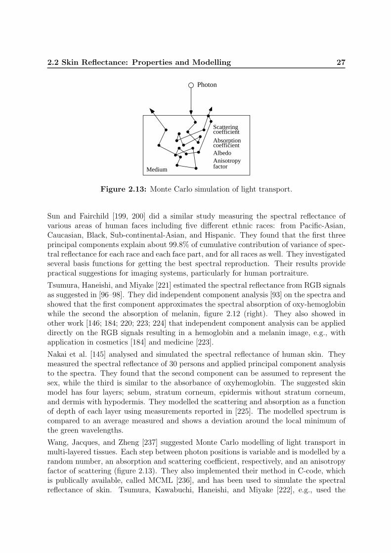
2.2 Skin Reflectance: Properties and Modelling 27
Photon
Medium
Scatteringcoefficient
factorAnisotropy
AbsorptioncoefficientAlbedo
Figure 2.13: Monte Carlo simulation of light transport.
Sun and Fairchild [199, 200] did a similar study measuring the spectral reflectance ofvarious areas of human faces including five different ethnic races: from Pacific-Asian,Caucasian, Black, Sub-continental-Asian, and Hispanic. They found that the first threeprincipal components explain about 99.8% of cumulative contribution of variance of spec-tral reflectance for each race and each face part, and for all races as well. They investigatedseveral basis functions for getting the best spectral reproduction. Their results providepractical suggestions for imaging systems, particularly for human portraiture.
Tsumura, Haneishi, and Miyake [221] estimated the spectral reflectance from RGB signalsas suggested in [96–98]. They did independent component analysis [93] on the spectra andshowed that the first component approximates the spectral absorption of oxy-hemoglobinwhile the second the absorption of melanin, figure 2.12 (right). They also showed inother work [146; 184; 220; 223; 224] that independent component analysis can be applieddirectly on the RGB signals resulting in a hemoglobin and a melanin image, e.g., withapplication in cosmetics [184] and medicine [223].
Nakai et al. [145] analysed and simulated the spectral reflectance of human skin. Theymeasured the spectral reflectance of 30 persons and applied principal component analysisto the spectra. They found that the second component can be assumed to represent thesex, while the third is similar to the absorbance of oxyhemoglobin. The suggested skinmodel has four layers; sebum, stratum corneum, epidermis without stratum corneum,and dermis with hypodermis. They modelled the scattering and absorption as a functionof depth of each layer using measurements reported in [225]. The modelled spectrum iscompared to an average measured and shows a deviation around the local minimum ofthe green wavelengths.
Wang, Jacques, and Zheng [237] suggested Monte Carlo modelling of light transport inmulti-layered tissues. Each step between photon positions is variable and is modelled by arandom number, an absorption and scattering coefficient, respectively, and an anisotropyfactor of scattering (figure 2.13). They also implemented their method in C-code, whichis publically available, called MCML [236], and has been used to simulate the spectralreflectance of skin. Tsumura, Kawabuchi, Haneishi, and Miyake [222], e.g., used the

28 Background and Related Work
ID
I0I0
J0R=J0
ID
I0T=
x=D
x=0
I J
T T1 2
T1 R2 T1R1
T1 R2 R1 T2
T1 R2 R1 R2 T1
Layer 2
Layer 1
Figure 2.14: Left: Kubelka-Munk model for a single layer. Right: Two layermodel. [56]
MCML program to simulate the diffuse spectral reflectance of skin by modelling it asa three layered tissue using measurements from [7; 225]. They suggested a method toestimate the pigmentations of melanin, oxy-hemoglobin, and deoxy-hemoglobin in skinfrom a multispectral skin image by iteratively adapting the simulated to the measuredspectrum. The method may have application in diagnosis of skin disease and reproductionof skin colour.
Doi and Tominaga [56] presented a method for modelling the diffuse spectral reflectancein different parts of human skin using the Kubelka-Munk theory [119]. The optical skinmodel in [56] consists of two layers, epidermis and dermis, with their different absorptionand scattering characteristics. The epidermis contains melanin and carotene; the dermisbilirubin, oxy- and deoxy-hemoglobin. They used the data from [7], see figure 2.12 (right).The thicknesses of the skin tissue layers are also used as model parameters. Their valuesdepend on body parts. It is further assumed that the hypodermis consists of white fatwith a constant reflectance equal to one.
The Kubelka-Munk theory for radiation transfer can be used to model the reflectance andtransmittance of a layer in an absorbing medium of turbid materials without consideringthe complex path of scattered light inside the medium. The Kubelka-Munk model for asingle layer is shown in figure 2.14 (left), where I is the radiation travelling in forwarddirection and J the radiation in backward direction.
The relationship between I and J can be described by two differential equations in avariable of the depth x:
dI
dx= −SI −KI + SJ,
dJ
dx= −SJ −KJ + SI (2.12)
S and K are coefficients of back-scattering and absorption in the media, respectively. Thereflectance R = J0/I0 and transmittance T = ID/I0 of a material of a thickness D maybe calculated from the above equations under some assumptions.

2.2 Skin Reflectance: Properties and Modelling 29
Figure 2.14 (right) shows the two layer model used in Doi and Tominaga [56]. Multiplereflections in the interface between the layers are considered (T1 and R1 are transmit-tance and reflectance of layer 1, respectively, and R2 is the reflectance of layer 2). Themethod is compared to measured skin reflectance and a method based on Kubelka-Munkproposed in Cotton and Claridge [47, 48] modelling only the two pigments melanin andoxy-hemoglobin. Doi and Tominaga report that their model is more accurate, however,the results are only from one test subject. In [55] they used their model to render theskin of human hand in computer graphics.
Ohtsuki and Healey [151] presented a model for spectral reflectance of skin and usedit in computer vision. They assumed that the Dichromatic Reflection Model [183] isvalid for skin reflections. In the proposed model skin is described by a thin surface layer(epidermis) and a thicker layer, the dermis. The surface reflection takes place at theepidermis surface and is constant 5% (wavelength independent). The body reflections aredue to light entering the skin being absorbed and scattered within the two skin layers. Thescattering in the epidermis is considered negligible, it mainly absorbs light, hence it hasthe properties of an optical filter. The absorption depends on the melanin concentrationin the epidermis. In the dermis the light is both scattered and absorbed. The opticalproperties of the dermis are basically the same for all humans. The variations of skincolour are thus determined by the epidermis transmittance. The body reflectance ρBody
is given in equation 2.13. The epidermis transmittance is squared because the lightpasses twice through it – when entering and when leaving the body. In the model thetransmittance of melanin is used for the epidermis transmittance, which can be calculatedfrom the absorption in figure 2.12 (right).
ρBody =< epidermis transmittance >2 · < dermis reflectance > (2.13)
Figure 2.15 (left) shows three spectral reflectance curves of human skin [7; 245]. Theuppermost is representative for normal Caucasian skin, the middle one for Caucasianskin right after sunburn (erythematous), which gives the skin a reddish appearance, andthe lower one for Negro skin. The uppermost corresponds to a low blood content inthe dermis whereas the middle one corresponds to a high blood content. Using thesetwo spectral reflectance curves and the transmittance of melanin, it is possible to modelspectral reflectance curves for any melanin concentration as shown in figure 2.15 (right).
Several researchers measured the spectral reflectance of skin in the visible bands, e.g.,The University of Oulu Physics-Based Face database by Marszalec et al. [131], which isdescribed in more detail below on page 50, contains spectra data of faces. It is also part ofthe recently released standard ISO/TR 16066:2003 Graphic technology – Standard objectcolour spectra database for colour reproduction evaluation (SOCS) [1; 203–205] includingmore than 400 skin reflectance spectra. In Angelopoulou et al. [9–12] the reflectancespectra of the back of hands and palm were measured. Furthermore, they showed thatthe spectral reflectance of skin can be modelled by a linear combination of Gaussian orWavelets. The combination of five Gaussian gives a RMS of 1%.

30 Background and Related Work
300 400 500 600 700 8000
20
40
60
80
100
Wavelength (λ), nm
Ref
lect
ance
(ρ)
, % Caucasian
CaucasianErythematous
Negro
300 400 500 600 700 8000
20
40
60
80
100
Wavelength (nm)
Ref
lect
ance
%
Figure 2.15: Left: Spectral reflectance curves of human skin for normal Caucasian[7], erythematous Caucasian [7], and dark Negro skin [245]. Right: Modelled spec-tral reflectance curves using using the method in Ohtsuki and Healey [151] withthe uppermost curve of the left figure. The dotted curves are the measured skinreflectance of Caucasian and dark Negro skin, respectively, shown in the left figure.
Skin Texture Also the texture of skin has been subject to research. Doi et al. [57]described a method to analyse and synthesise human skin with colour texture. Theirapproach is based on spatial frequency analysis of skin images, which are decomposedinto four component: base colour, regular surface texture, internal texture, and localtexture. These components may be used to synthesise realistic skin images, which wasshown for palm images.
Cula and Dana [50] used image-based representations of skin appearance in order tohave descriptive capabilities without the need for complex physics-based skin models. Amethod was presented for representing and recognising different areas of the skin surfacethat have visibly different texture properties, taking into account the varying appearanceof skin due to changes in illumination and viewing direction.
Many materials – including skin – are covered with a thin layer of sparse scatters, suchas dust or hairs. This ’velvety’ or ’peachy’ look of skin is an important aesthetic andemotional factor that is lacking when rendering skin. While Lambertian rendering looksdullish and paper-like, ’skin-type’ BRDF rendering looks like glossy plastic. Koenderinkand Pont [117] recently suggested to use asperity scattering to add a ’surface lobe’ to theusual diffuse, backscatter, and specular lobes of rough surfaces.
2.2.4 Summary of Skin Reflectance
Modelling geometric and spectral reflectance of skin has application in biomedicine, cos-metics, computer graphics, and computer vision. This section briefly summarised thephysiology and optics of human skin. Several approaches – mostly from computer graph-

2.3 Skin Colour Modelling and Detection 31
ics – of different accuracy to model skin reflectance were presented, subdivided into BRDF,spectral reflectance, and texture.
In the following chapters skin colour is assumed to be mostly diffuse reflecting, which isa reasonable assumption for illuminations with incident angles below 40◦ (angle betweensurface normal and light source), see also figure 2.12 (left). In everyday-life computervision applications skin is usually illuminated directly and by ambient light. Due to theoften convex form of faces and hands, some areas may have surface reflection/highlightsunder direct illumination, which will also be accounted for in the following chapters.Diffuse reflectance spectra will be modelled using the method proposed in Ohtsuki andHealey [151], which is sufficiently accurate for computer vision as it will be shown inchapter 3.
2.3 Skin Colour Modelling and Detection
In the last decade skin colour detection has become an often used cue in computer visionfor detecting, segmenting, and tracking faces and hands [89; 251]. It is used in many dif-ferent applications in motion capture, HCI (human-computer interaction), access control,surveillance, and content-based image retrieval and indexing of image databases.
In HCI one or several cameras are used to detect and track faces or hands in real-time5.The detected hands may then be used in a gesture interface or the tracked face maybe used in a smart video phone that is only transmitting the user’s face and not thesurroundings [49].
In access control also one or several cameras are used to capture a single image or asequence of images of a face which is then segmented and matched against a database inorder to decide whether the face is represented in the database or not. The aim of the lowlevel part of the access system is the same as for HCI, i.e., to detect and segment skin –the face or hands. However, the real-time constraint is less important compared to HCI,more than a second would still be acceptable.
The growth of the Internet and developments in imaging technology make content-basedimage retrieval and indexing inevitable. Here the aim is to retrieve pictorial entities, e.g.,faces, from large image archives or databases. Both still images [69; 174] and video se-quences [186] may be indexed. When searching for people in such databases skin colour isfrequently used as a feature. The main difference to the two above mentioned examples,HCI and access control, is that there is no image acquisition involved. The images ormovies were taken beforehand, which means that all information available is the imagedata itself. Usually no information is available on how the image was captured, whichcamera was used and how it was configured. Although newer digital cameras are savingthis information, the image might have been post-processed, hence making this informa-
5real-time in HCI often means several frames per second, so that the user gets fast enough feedback,e.g., > 10Hz

32 Background and Related Work
tion unreliable. That means that skin detection methods for indexing have to rely on theimage data whereas methods working on camera live input may use knowledge about thecamera characteristics, which might improve the robustness of skin detection methods.On the other hand, in most cases the images in databases are taken to please the humanvisual system that means that the skin colour in the image should look like skin. ForHCI, access control, and surveillance systems this is, however, often not the case. Suchsystems have to work in unconstrained environments with arbitrary illumination changeswhich also means that the skin colour might vary considerably.
Many skin colour modelling, detection, and segmentation methods have been proposed inthe literature – more than 120 are cited in the following of this section. There are severalpossibilities to classify these methods, e.g., into statistical-based, physics-based, by theused colour space, or how they are tested and evaluated.
A skin colour cue, i.e., using skin as a feature, may be divided into three sub-problems [227]:
• the choice of the colour space
• the way of modelling the skin colour distribution
• how the actual segmentation is done, e.g., pixel based or taking the spatial relation-ship into consideration as well
Although the latter one is important for a skin colour cue, this section focuses – due tothe overall focus of this thesis – on the first two problems which are a prerequisite for thethird problem.
A recent survey on pixel-based skin colour detection techniques by Vezhnevets, Sazonov,and Andreeva [227] defined the following categories for modelling skin colour distributions:explicitly defined skin region, nonparametric skin distribution, parametric skin distribution,and dynamic skin distribution models. In Martinkauppi [134] a similar categorisation wasdone but the latter category was further subdivided into non-parametric and parametricmethods. Both surveys also considered how the methods were tested. While in [227]the result of several methods are compared against the same dataset, in [134] it is morefocused on how the tests were done, e.g., whether illumination changes were tested or not.
In this section an additional categorisation level is introduced that divides skin colourmodelling and detection methods into two main groups: The first group consists of allmethods that use camera-live input, whereas the second group consists of all methodsthat work on still images, e.g., for image retrieval and indexing. This choice is a result ofthe survey in sections 2.3.2 and 2.3.3, and motivated by the fact that the work presentedin the following chapters assumes that camera characteristics and parameters are known.Figure 2.16 shows how the methods are further subdivided. An additional categorisationcould be by the used colour space, which is not done here. Instead colour spaces aredescribed, compared, and discussed in section 2.3.1.
The following of this section is divided into three parts: 1) the majority of the colour spacesused in the reviewed articles will be introduced and compared, 2) methods using direct

2.3 Skin Colour Modelling and Detection 33
dynamic
known camera parameters unknown camera parameters
explicitly defined
skin region
parametric non-parametric
explicitly defined
skin region
non-adaptive... ...
parametric non-parametric
thresholding
thresholding
adaptive
camera input indexing
Skin Colour Distribution Modelling
Figure 2.16: Classification of skin colour modelling methods.
camera input will be reviewed, also regarding the results whether, e.g., the robustnessagainst changing illumination and environment conditions has been tested, and 3) anoverview of methods for image retrieval and indexing, i.e., working on the image dataonly, will be given.
2.3.1 Colour Spaces used for Skin Modelling and Detection
An appropriate representation of colour signals is needed in order to use colour in computervision, image processing, computer graphics, and quality control. The different colourspaces – also called colour models – address this need. When humans, e.g., have to choosea colour in computer graphics it is most intuitive to define it by its hue, saturation, andbrightness. If this colour should be visualised on a screen it needs to be transformed toanother space, usually additive primary colours red, green, and blue (RGB). For printingthis colour it might be necessary to transform to subtractive colours cyan, yellow, magenta.In the field of image processing and computer vision colour spaces might be divided intothree categories [164]: Device-oriented colour spaces are associated with input, processingand output signal devices, user-oriented colour spaces are utilised as a bridge between theuser and the hardware used to manipulate the colour information, and device-independentcolour spaces are used to specify colour signals independently of the characteristics of agiven device or application.
Most colour cameras have some sort of RGB output and images may also be stored inRGB. For colour image segmentation it is often convenient to transform to another colourspace, because in the RGB space the intensity and chrominance signals are correlated.The intensity reflected from a diffuse object, such as skin, depends on the illuminationgeometry, e.g., distance to the light source, whereas the chrominance information is ratherinvariant to the illumination geometry (section 2.1), hence, a colour space where intensity-and chrominance-information are separate and uncorrelated may be more convenient for

34 Background and Related Work
segmentation. Furthermore, skin colour should be separable from non-skin coloured ob-jects in an appropriate colour space. Such colour spaces will be presented in this section,and in particular colour spaces that have been used for skin colour segmentation in theliterature (reviewed in sections 2.3.2 and 2.3.3) will be introduced and compared. Thecomparison will be based on results reported in the literature and on a simulation of skincolour under different illumination intensities and colours. More on colour spaces may befound in, e.g., Plataniotis and Venetsanoupoulos [164] and Wyszecki and Stiles [245].
In order to compare how well the colour spaces normalise for intensity and chrominance-information the following paragraphs show colour spaces with Caucasian skin colour underdifferent illuminations. For that purpose the RGB output of a camera imaging skin ismodelled, see section 2.1 or chapter 3 for details. The camera is white balanced to alight source with CCT=3680K. Skin colour under Blackbody illuminations with 2600,3680, and 6200K is modelled for 25 intensity levels. Each colour channel is modelledas an 8Bit value, which causes quantisation noise. No other noise is considered in thissimulation. In order to keep the figures in the following clear only Caucasian skin has beenmodelled, which is sufficient to get an idea of skin under different illuminations becausethe intensity invariant components of different skin tones are rather close to each other,see e.g., section 3.5. Figure 2.17 (left) shows the modelled RGB values in RGB space.
0 100 2000
100
200
0
50
100
150
200
250
RG
B
0 100 2000
100
200
0
50
100
150
200
250
RG
B
Figure 2.17: Modelled Caucasian skin colour in linear (left) and non-linear (right)RGB space. The “·” are for the 3680K light source, which is also the white-balancelight source, the “o” are for the 6200K and the “+” for the 2600K light source.
Linear and non-linear RGB spaces. The human eye has three types of colour pho-toreceptor cone cells, which are responsible for human colour vision. Each of thesethree cells has different spectral response curves, similar to those of a RGB camera,figure 2.7 (left). Because there are three types of colour photoreceptors, three numericalcomponents are sufficient to describe a colour for the human visual system. These three

2.3 Skin Colour Modelling and Detection 35
components can be defined in different ways, e.g., for displaying on a CRT (cathode-raytube) display RGB (red, green, and blue) are widely used because their additive mixtureresults in are large gamut (extent) of colours [165]. Therefore most cameras also haveRGB sensing elements and RGB outputs. The RGB space is a device oriented colourspace. There are standards for RGB spaces, e.g., for CRT phosphors in Rec. 709 [171].However, for cameras the RGB output depends on the sensing element and its configura-tion. Often the output of two cameras observing the same scene will give different results,although calibrated to the same light-source [137].
In the literature [164; 165] RGB spaces are usually grouped into linear and non-linear.Linear RGB space means that it is linear to the intensity, whereas a non-linear RGBspace (R’G’B’) is non-linear to the intensity. The intensity is gamma corrected in orderto compensate for the nonlinearity of CRT displays. The red component, e.g., may be
gamma corrected with the following equation: R′ = a ·R 1γ −b, where a and b are constants
and γ is around 0.45 [171]. Many cameras have build-in gamma correction and severalimage storage formats are storing gamma corrected RGBs, e.g., JPEG and GIF. LinearRGB is used, e.g., in computer graphics [165] and in computer vision.
Figure 2.17 shows the modelled skin colours in linear (left) and non-linear (right) RGBspace. All following colour spaces are transformations from linear or non-linear RGBspace, respectively. Furthermore, only the intensity invariant components of the colourspaces will be shown in the following.
Normalised RGB. A non-linear transformation of the RGB space are normalised rgb,also called ”little rgb”, rgb-chromaticities, or NCC rgb. They are obtained by normalisingthe colour elements (R, G, B) of linear RGB with their first norm:
r =R
R + G + B, g =
G
R + G + B, b =
B
R + G + B(2.14)
The normalisation removes intensity information, thus, the rgb values are ”pure colours”.Because r+g+b = 1 no information is lost if only two elements are considered. Figure 2.18shows the rg values of the modelled skin colours from linear (left) and non-linear (right)RGB, respectively. The gamut (all possible colours of the colour space) is within thetriangle.
In figure 2.18 it can be seen that the skin chromaticities of the three illuminant coloursare different and that the skin chromaticities of one illuminant colour under differentintensities fall nearly on the same point. The noise is due to the quantisation mentionedabove. The dashed line shows the skin chromaticities for illuminations ranging from 2600to 25000K.
In the following chapters rg values will be referred to as rg-chromaticities and rgb values asrgb-chromaticities, respectively. Furthermore, the formation of skin colour under differentilluminant colours in the chromaticity plan (dashed line) will be referred to as ’skin-locus’,see also figure 3.8 in section 3.3.1.

36 Background and Related Work
0 0.2 0.4 0.6 0.8 10
0.2
0.4
0.6
0.8
1
3680K 2600K6200K
r
g
white
red
green
blue
yellow
magenta
cyan
0 0.2 0.4 0.6 0.8 10
0.2
0.4
0.6
0.8
1
3680K2600K6200K
rg
white
red
green
blue
yellow
magenta
cyan
Figure 2.18: rg-chromaticity plane. Left: Linear RGB. Right: Non-linear RGB.
Ratios of RGB components. The ratios of RGB components are a non-linear trans-form that normalises for intensity, like the chromaticities. Figure 2.19 shows the ratiosof the modelled skin colours B
Gas function of R
G. These ratios are undefined for G = 0,
hence the gamut of this colour space is unlimited. However, the green component of skinis always non-zero. The skin distributions fall along a curve in the figure (dashed line).
0 0.5 1 1.5 2 2.50
0.5
1
1.5
2
2.5
3680K
2600K
6200K
R/G
B/G
white
green yellow
cyan
0 50 100 150 200 250
50
100
150
200
250
3680K
2600K
6200K
U
X white
redgreen
blue
yellow
magentacyan
Figure 2.19: Left: Ratios BG
as function of RG. Right: UX components of LUX
space.
HSI Family. The hue-saturation-intensity family represents user-oriented colour spaces,which are primarily used in computer graphics. The components are better suited forhuman interaction than, e.g., RGB, because they relate to the human perception of colour,saturation, and luminance. There are several versions: HSI, HSV, HSB, HSL. They differ

2.3 Skin Colour Modelling and Detection 37
mainly in the calculation of the last component, which might be, e.g., the linear intensity(I) or the non-linear lightness (L). The conversion from RGB to the HSI family is non-linear. An example from RGB to HSV is given below, others may be found, e.g., in [164].There is no standard whether the transformation uses linear or non-linear RGB [165].
H1 = arccos
(12[(R−G) + (R−B)]√
(R−G)2 + (R−B)(G−B)
)
H =
{H1 , if B ≤ G360◦ −H1 , if B > G
S =max(R,G, B)−min(R,G, B)
max(R, G, B)
V =max(R,G, B)
255(2.15)
Although the HSI spaces were originally made for user interaction they have also beenused in computer vision for intensity invariant colour based segmentation by using thehue-saturation plane. Figure 2.20 shows the modelled skin colours in the HS-plane.
0 0.2 0.4 0.6 0.8 10
0.2
0.4
0.6
0.8
1
3680K 2600K
6200K
Saturation
Hue
white red
green
blue
yellow
magenta
cyan3680K
2600K
6200K
whitered
green
blue
yellow
magenta
cyanSaturation
Hue
Figure 2.20: HS-plane of HSV space. Left: Cartesian coordinates. Right: Carte-sian coordinates but using HS as polar coordinates.
The HS values of skin under one illuminant colour cluster on the same point, apart fromquantisation noise, as above for the rg-chromaticities and RGB ratios. The gamut iswithin the square (left) or circle (right), respectively. It can be seen in the figures thatwhen using HS as polar coordinates skin under different illuminants falls approximatelyalong a line.
Colour difference coding spaces. Several colour difference coding spaces are used inorder to reduce the amount of data to be transmitted for video and television. They were

38 Background and Related Work
developed using knowledge about human colour perception: The human visual systemforms an achromatic channel and two chromatic colour-difference channels in the retina.It has considerably less spatial acuity for colour information than for brightness. Thereforea colour image can be coded into a wide-band component representative of brightness,and two narrow-band colour components, where each colour component has less resolutionthan brightness [165]. Colour difference coding spaces consist of three components: Non-linear R′G′B′ is transformed into luminance Y and two colour difference components B−Yand R−Y . Examples are Y′CBCR for digital video and Y′PBPR for analogue video. AlsoYUV, YES, and YIQ are doing colour difference coding. The transformation is linear. Anexample for Y′
601CBCR is given below, others may be found in [164; 165]. The number 601stands for recommendation ITU-R BT.601-4, which is for encoding parameters of digitaltelevision for studios.
Y ′601
CB
CR
=
16128128
+
65.481 128.553 24.966−37.797 −74.203 112.0112.0 −93.786 −18.214
R′
G′
B′
(2.16)
Figure 2.21 shows the modelled skin colour for the CBCR-plane of the Y′CBCR space (left)and the ES-plane of the YES space (right).
0 50 100 150 200 2500
50
100
150
200
250
3680K
2600K
6200K
CB
CR
white
red
green
blue
yellow
magenta
cyan
−150 −100 −50 0 50 100 150
−100
−50
0
50
100
3680K2600K
6200K
E
S white
redgreen
blue
yellow
magentacyan
Figure 2.21: Left: CBCR-plane of Y′CBCR space. Right: ES-plane of YES space(right).
The hexagons show the gamut. It can be seen that these spaces are not as invariant tointensity changes as the above described colour spaces. Note that therefore no skin-locus(dashed line in the other figures) is shown in these figures.
LUX colour space. Lievin and Luthon [122] recently suggested a new nonlinear colourspace for skin detection called Logarithmic hUe eXtention. This colour space derived froma colour difference coding space and is calculated as follows:

2.3 Skin Colour Modelling and Detection 39
L = (R + 1)0.3(G + 1)0.6(B + 1)0.1 − 1
U =
{M2
(R+1L+1
)if R < L
M − M2
(L+1R+1
)otherwise
X =
{M2
(B+1L+1
)if B < L
M − M2
(L+1R+1
)otherwise
(2.17)
where M is the dynamic range, e.g., for 8Bit data the range is [0, 255] and M = 255.UX are the chroma components, see figure 2.19 (right) page 36. It can be seen that theUX values of skin under one illuminant colour cluster around the same point. In [122]it was shown that this colour space provides more contrast between skin, lips, and othermaterials than CBCR.
Opponent colour spaces. The opponent colour spaces are also inspired by the humanvisual system that may be expressed in terms of the two opponent hues, yellow-blue andgreen-red, which cancel each other when superimposed [164]. A log-opponent colour spacefor skin colour detection was suggested in Fleck et al. [66]:
L(x) = 105 log10(x + 1 + n)
I = L(G)
Rg = L(R)− L(G)
By = L(B)− L(G) + L(R)
2(2.18)
where n is a random noise value generated from a distribution uniform over the range[0, 1) and the constant 105 is used to scale the range to the interval [−255, 255]. Fig-ure 2.22 (left) shows the modelled skin colours in log-opponent colour space. Like for therg-chromaticities and the HS-plane the skin colours under one illuminant colour fall onapproximately the same point. The hexagon shows the gamut. The simulation was donewithout random noise n. This colour space compresses the lower saturated achromaticcolours, e.g., skin colour, and stretches the more saturated colours, which might result inan inferior separability of colours that are close to achromatic.
TSV and TSL spaces. Terrillon et al. [207, 210] suggested the TSV [207] and TSL[210] space, respectively. T is the tint, S the saturation, V the value as in HSV, andL the luminance for gamma-corrected RGB values. T and S are based on normalisedRGB, thus, it is expected to have a similar performance in intensity normalisation thanrg-chromaticities. The TSV and TSL colour spaces are defined as follows:

40 Background and Related Work
−300 −200 −100 0 100 200 300
−200
−100
0
100
200
3680K2600K
6200K
Rg
By
white
redgreen
blue
yellow
magentacyan
0 0.2 0.4 0.6 0.8 10
0.2
0.4
0.6
0.8
1
3680K
2600K
6200K
Tint
Sat
urat
ion
white
redgreen
blue
yellow
magentacyan
Figure 2.22: Left: Log-opponent plane. Right: Tint-Saturation plane of TSVspace.
S =√
9/5(r′2 + g′2)
T =
arctan(r′/g′)/2π + 1/4, g′ > 0arctan(r′/g′)/2π + 3/4, g′ < 00, g′ = 0
V = (R + G + B)/3 or L = 0.299R + 0.587G + 0.144B (2.19)
where r′ = r − 1/3 and g′ = g − 1/3. r and g are the rg-chromaticities introduced above(page 35). Figure 2.22 (right) shows the simulated skin colours in the TS-plane. Againthe skin colours under one illuminant colour fall on approximately the same point. Thegamut is between S = 0 and the curved line.
CIE Colour Spaces. The CIE (Commission Internationale de L’Eclairage or Interna-tional Commission on Illumination) is the international body responsible for standardsin the area of colour perception. The CIE has standardised colourimetric and percep-tual uniform colour spaces, e.g., CIE XYZ, CIE L*a*b*, and CIE L*u*v*. The XYZspace is used to numerically specify the colour of a physically defined visual stimulus suchthat when viewed by an observer with normal colour vision, under the same observingconditions, stimuli with the same specification will look alike. Linear RGB can be trans-formed to XYZ with a linear transformation given the white point and the RGB primariesare known. The XYZ space can be transformed to perceptually uniform spaces, i.e., acolour space where a small perturbation in a component value is approximately equallyperceptible for humans across the range of that value, such as CIE L*a*b*.
The CIE spaces are concerned with human perception and are of interest for, e.g., re-production of images in a visually pleasant form. However, they are of minor interest
2.3 Skin Colour Modelling and Detection 41
in machine segmentation and recognition, particularly perceptual uniform spaces becausecameras may have a higher colour resolution than humans. For further details on CIEsee, e.g., Wyszecki and Stiles [245].
2.3.1.1 Comparison of Colour Space for Skin Colour Detection
Several studies comparing skin colour distribution in different colour spaces are reportedin the literature.
Zarit, Super, and Quek [254] compared CIE L*a*b*, HSV, rgb-chromaticities, YCBCR,and the log-opponent space suggested in [66] for skin detection using colour histogrambased approaches: a lookup-table-based method and a Bayesian decision theory basedmethod. The methods were trained and tested with different images downloaded from avariety of sources, including frames from movies and television. The images were selectedto include a wide range of skin tones, environments, cameras, and lighting conditions.However, no quantitative information on, e.g., the range of illumination changes is given.They report that the HSV and the log-opponent space perform best using lookup tables,whereas for the Bayesian approach the choice of the colour space had no influence on theresult.
Terrillon, Shirazi, Fukamachi, and Akamatsu [210] did a similar study comparing ninecolour spaces for skin colour detection: rg-chromaticities, CIE xy, TSL, CIE-DSH, HSV,YIQ, YES, CIE L*u*v*, and CIE L*a*b*. They modelled the skin distribution as a singleGaussian and as a mixture of Gaussian, respectively. The rate of correct face detectionand the rate of correct rejection of distractors was computed. A set of skin sampleimages of faces of Asian and Caucasian subjects were recorded under slowly varyingillumination conditions with a single camera. Furthermore, images downloaded from theInternet were used for comparing the colour spaces. No quantitative information on theimage data is given. Altogether the intensity normalised colour spaces, such as TSLand rg-chromaticities, performed best in both cases. It made no difference whether thedistribution was modelled with a single Gaussian or with a mixture of Gaussian. For thecolour spaces that are not illumination normalised the mixture of Gaussian performedbetter than the single Gaussian. They reported that skin distributions transformed withan illumination normalised space were simpler to model and more efficient for skin coloursegmentation. In recent studies Terrillon et al. [208, 209] showed that linear combinationsand ratios of rg-chromaticities and CIE-xy perform best for skin colour classification.
Albiol, Torres, and Delp [5] showed that for every colour space there exists an optimumskin detector scheme such that the performance of all these skin detector schemes isthe same, i.e., the separability of the skin and non-skin classes is independent on thecolour space. They demonstrated this theoretically for colour spaces where invertibletransformations exist. Experimental results with RGB, HSV, and YCBCR using morethan 200 CIF images showed that the performance of all three colour spaces is the same.No quantitative information of the used image data is given. Results using the CBCR
components of the YCBCR space – thus, a space which is not invertible back to the other

42 Background and Related Work
spaces tested – showed a lower performance than the other three colour spaces.
The work by Martinkauppi, Soriano, and Laaksonen [134; 137] compared skin colour de-tection in different colour spaces and explicitly addressed the problem of changes in theilluminant colour. They used The University of Oulu Physics-Based Face database [131],which contains images of faces under 16 different illumination/camera calibration condi-tions taken with four different cameras. The illumination colour ranges from 2300-6500K.A more detailed description of this database is given in section 2.3.2.2 on page 50. TheRGB values of skin areas were transformed into 17 different colour spaces, e.g., HSV,rg-chromaticities, YES, TSL, r/g ratios, YIQ, YCBCR, in order to determine the rangeof skin colour in the different spaces. The overlapping percentage between different skingroups (Asian and Caucasian) and the size of the skin distributions was measured. Theoverlapping ranges from 50% to 80% under calibrated conditions (only one illuminantcolour) depending on the camera an the colour space. Under all illuminant colours theoverlapping is up to 98.8%. The size of the distributions in the colour spaces is up to 86%.For the image data that was acquired with a 3CCD camera the distribution size of, e.g.,rg-chromaticities is 14%, HSL 45%, and log-opponent 8%. They also showed that it ispossible to model the skin distributions boundaries in most of the colour spaces with oneor two functions of up to quadric order. Furthermore, in [134] it is concluded that “othercolour spaces do not produce better results than NCC rgb” (rgb-chromaticities), and “thatthe behaviour of skin chromaticities is dependent on the selected camera”.
Gomez et al. [77; 78] used a data analysis approach for selecting colour components ofcolour spaces for skin detection. They evaluated each component of several colour spaces,e.g., HSV, YIQ, RGB-Y, CIE XYZ. Skin and non-skin images of more than 1000 subjectswith different skin tones were acquired with several cameras in- and outdoors under lightconditions with CCTs ranging from 3200 to 5500K. No information is given which cameraswere used and how they were configured, e.g., whether automatic white-balancing wasused or not. These images were used to explore the performance of the colour componentsand finding complementary components using, e.g., PCA and χ2. They found that a 3D
hybrid space of Hue, GY (RGB-Y), and the Wr component(
rr+g+b
− 13
)2
+(
gr+g+b
− 13
)2
suggested in [194] performed best with 97% of the original skin pixels detected and 5.16%false positives.
Shin, Chang, and Tsap [185] compared the performance of 9 colour spaces, RGB, HSI,YUV, CIE XYZ, and others. They used The University of Oulu Physics-Based Facedatabase [131] and the AR dataset at Purdue [133] for skin pixels and the University ofWashington’s content-based image retrieval dataset for non-skin pixels. The clusters ofskin and non-skin pixels are compared using four metrics, two scatter matrix based andtwo histogram based. They found that the separability between the two classes of skinand non-skin was highest in RGB space.
Finally, Vezhnevets et al. [227] concluded in their survey on pixel-based skin color detectiontechniques that “excluding color luminance from the classification process cannot helpachieving better discrimination of skin and non-skin colors, but can help to generalize

2.3 Skin Colour Modelling and Detection 43
sparse training data”.
2.3.1.2 Summary and Conclusions on Colour Spaces
Most images acquired with a colour video camera are in RGB space. The reason fortransforming to another colour space when aiming at skin colour detection is to achieveinvariance to changing illumination and/or skin tones. Many colour spaces have beenused to model and detect skin colour – some have even been invented especially for skincolour detection, e.g., the TSV and LUX spaces.
In the above paragraphs the most common colour spaces used for skin colour modellingand detection were presented. In order to evaluate their invariance to changes in in-tensity and colour of the illumination, skin colour was modelled for different illumina-tion intensities and colours (2600-6200K) viewed by a camera with fixed white balance(CCT=3680K). Except for the colour difference coding spaces all other colour spaces nor-malised for intensity, i.e., the 3D RGB space is transformed to a 2D plane representing allcolours normalised for intensity. However, none of the transformations achieves invarianceto changing illumination colours. The main differences between the colour spaces thatnormalise for intensity are 1) whether the skin colour distributions under different illu-minations fall along a simple curve, e.g., linear or second order, such as rg-chomaticities,LUX, and Log-opponent plane, or whether this curve is of higher order, such as TS- andHS-plane. 2) how close the skin colour distributions under different illuminations clusterin different spaces, in other words how much space they use in a given colour space. Inthe Log-opponent plane the skin colour distributions are rather close together. This mayresult in few false negatives under changing illumination, but also in a high number offalse positives under one static illumination since many everyday-life objects have ratherlow saturations – are close to grey. Other space, like the rg-chromaticities, would have abetter separability under one fixed illumination, i.e., low number of false positives, butwould require a dynamic adaption under changing illumination.
Furthermore, the literature addressing the choice of a colour space for skin colour detectionwas review in this section. The simulation results are in good accordance with reportedwork that considered illumination colour changes.
2.3.2 Modelling and Detection from known Camera
This section gives an overview of work presented in the literature that uses skin colourdetection as a cue in systems where knowledge about the camera characteristics andconfigurations is potentially available, e.g., systems that work with direct camera input.The methods are classified as shown in figure 2.16 (page 33), and those presented inthis section are divided into two main groups: non-adaptive and adaptive approachesto changing environment and illumination over time. A method that is initialised to anindividual but does not adapt its parameters after the initialisation step is classified as non-adaptive although parameters have been adapted to the individual to be tracked. These

44 Background and Related Work
main groups are further subdivided into: Thresholding, non-parametric, and parametricapproaches. This subdivision is with regard to the skin colour modelling method. Thatmeans, e.g., that a skin colour distribution modelled as a 2D Gaussian is consideredas a parametric approach, even if this Gaussian is ’only’ used to pre-calculate a binaryskin/non-skin classifier lookup table during an initialisation step.
It is difficult to compare the work reported in the literature because the evaluation andtests of methods are not specified in a standardised way, neither are methods testedagainst a common dataset, and often information on the test environment is missing.Therefore, most of the following is a qualitative description of reported work, groupingwork according to their methods. Whenever results on performance, and in particularperformance to changing illumination and environment, are reported this will be men-tioned in the following. Since the used camera and its configuration is a critical factor forthe performance of a method, this will also be mentioned whenever this information wasavailable.
Finally, it should be mentioned that, although skin colour is often combined with othermethods, the following will mainly concentrate on the skin colour methods presentedin the particular papers and only mention as a side note with which methods it wascombined.
2.3.2.1 Non-Adaptive Approaches
The following paragraphs present methods that were not designed to adapt to changingenvironments. These methods are usually constraint to rather fixed illumination condi-tions.
Thresholding. A method that is often used and easy to implement is thresholding oneor several channels of a colour space with one or several thresholds, e.g., in the HS-planeto use a minimum and maximum H and S value, respectively, i.e., define a skin area inthe HS plane. Sobottka and Pitas [189, 190, 191] and Jordao et al. [108] presented aface tracker using thresholding in the HS-plane of the HSV space to find and track faces.Collobert et al. [44] used a similar approach in YUV space using the UV componentsand Hidai et al. [88] used the CBCR components from the YCBCR space. Results fromimage sequences of faces are shown, however, no details or tests on illumination changesare reported.
Hunke and Waibel [92] presented a real-time face tracker using rg-chromaticities to seg-ment human faces. They obtained the average histogram of 30 individuals which wasused to create a general skin classifier working for all kinds of skin by determining twothresholds around the most frequent rg-chromaticities, thus, a rectangular area in the rg-chromaticity-plane. The system is automatically initialised from an image by segmentingskin areas using the general skin classifier. In the segmented areas faces are detectedusing shape information and a neural network. The skin area that is classified as a face

2.3 Skin Colour Modelling and Detection 45
is then used to calculate new thresholds that are adapted to that particular face. Thesethresholds are then used to segment the face during tracking. They report that faces werelocated correctly in more than 95% of more than 2000 images. No information on thetest environment was given.
Chiang et al. [42] presented a method to detect and segment skin colour, lips and eyes.They used the skin-locus, which is offline learned in the rg-chromaticity plane from severalinitialisation images and approximated with two quadric functions as suggested in Sorianoet al. [196]. The skin chromaticities are further constrained by two rules, which areR > G > B and R−G ≥ 45. Similar methods are used to find lips and eyes. Face regionsare detected using the segmented skin, lip, and eye areas with a geometric constraint.The overall detection rate on 815 images they acquired from Chinese faces with a ORITEVQ-681 USB PC camera is 94.3% with 3.4% false positives. On images collected fromthe Internet containing different skin tones the face detection rate is 89.1% and 6.3%false positives. The method can process on a 800MHz PC 9 frames/s with a resolution of320x240.
Physics-based Modelling of Boundary In Ohtsuki and Healey [151] a physics-basedapproach to model skin colour was presented. They modelled skin colour by spectralintegration using knowledge about the camera characteristics, the skin reflectance, andthe light sources, see section 2.1 for details. The light source was assumed to be sunlightwhich was modelled as a Blackbody radiator with CCT=6500K, and the skin reflectancewas modelled for different skin tones as it is described in section 2.2.3 (page 29). Inorder to achieve invariance to intensity changes they normalised RGB using the L2 norm:r2 = R/N , g2 = G/N with N =
√R2 + G2 + B2. Modelling different skin tones this
results in an area in the r2g2-plane. This was combined with geometrical features. Testimages were recorded outdoors from three subjects with different skin tones (Indian,Caucasian, Japanese) using a consumer cam-corder (Sony CCD-TR850, 1CCD, s-video).They reported that faces were correctly detected in 83.9% of the images (26 out of 31).
Non-Parametric. Many non-parametric methods have been proposed for skin colourmodelling. A lot of work has been inspired by Swain and Ballard [202] on colour indexingusing histogram intersection. Besides histograms often used non-parametric methods areskin probability maps and neural networks. Common for all these methods is that theskin model is estimated from training data without deriving an explicit model of the skincolour distribution [227].
Binary Lookup Table One way of classifying pixel-wise into skin and non-skin pixelsis using a lookup table (LUT). The LUT may be generated from thresholds as explainedabove or trained from sample skin images. Kjeldsen and Kender [114] trained a 2D HS-plane histogram-like structure, called colour predicate, with skin and non-skin samples.After training the colour predicate is thresholded to create a binary colour predicate,

46 Background and Related Work
thus, a LUT in the HS-plane. A hand tracker was implemented and tested in an officeenvironment using an uncalibrated colour camera. The hand is assumed to be the largestskin coloured object in the camera image. They report that the system is robust to minorchanges in illumination, but under drastic changes, such as switching on the ceiling light,retraining is required. The method has also been applied to finding face candidates inbroadcast video material. Good results are reported for sequences with stable illuminationsuch as news anchor desks or talk shows. The method fails if illumination colour changes,e.g., in outdoor scenes.Saxe and Foulds [177] used a similar approach, Bala et al. [14] used a user-specific skincolour LUT in the rg-chromaticity-plane, and Kawato and Ohya [110] used a 90 degreesrotated rg-chromaticity-plane LUT that was generated from a trained histogram that wasthen thresholded. No quantitative results were reported.
Histogram LUT Schiele and Waibel [178] constructed a general colour-map whichcontains most of the possible face-colours in rg-chromaticities, i.e., a 2D histogram orprobability map/LUT. This colour-map was used to generate a grey-level image wherepixels with high values have a high probability being skin coloured and low grey-levelsa low probability, respectively, which is called face colour intensifier in [178]. The grey-level image is fed to a neural network (Multi-Layer-Perceptron) that detects faces andestimates their orientation. Once a face is detected the general colour-map is adjustedto the individual’s face to be tracked. A real-time gaze tracker was implemented using acamera (Sony CCD-TR 101, 1CCD) on a pan-tilt unit. No results on the robustness ofthe segmentation were reported.
Yoo and Oh [253] suggested a method to track human faces based on colour and theelliptical form of the face. A histogram was learned in the HS-plane. Histogram backpro-jection was used to find image regions that are skin coloured. The backprojected imageis smoothed using a Gaussian filter and the smoothed image is binariesed using a fixedthreshold. An elliptical mask is then used to find faces. All test images are indoor andseem to have no illumination changes.
Probability Map (Bayes) Crowley and Berard [49] used skin colour detection as acue together with eye-blink detection and template matching in a face tracker. A 2Dhistogram of rg-chromaticities was computed from an image area known to be a sampleof skin. The histogram is normalised which gives the conditional probability of observinga colour vector C = (r, g) given that the pixel is an image of skin, p(C|skin). WithBayes rule this is converted to the conditional probability of skin given the colour vectorp(skin|C), which is used to construct a probability image for skin from a camera inputimage. The centre of gravity of the probability of skin is used as the position of the face.It is reported that the colour cue needs to be reinitialised after illumination changes. Noquantitative results on the robustness of the colour cue are reported. A similar approachwas shown in Schwerdt and Crowley [181].

2.3 Skin Colour Modelling and Detection 47
Histogram Intersection Comaniciu and Ramesh [45] also used rg-chromaticities forface tracking. An rg-chromaticity-histogram was computed from one face in an officeenvironment with windows under different illuminations (morning, afternoon, and night).In order to track faces in a camera image this histogram was compared to histograms ofsample regions in the camera input image by estimating the similarity between the twodensities (Bhattacharyya coefficient). The areas with the highest similarity are assumedto be skin coloured. A real-time tracker with a pan-tilt camera (Sony EVI-D30, 1CCD)was implemented and tested. From the qualitative results reported the method seems tobe robust. However, no quantitative tests on changing illumination are presented neitherare camera configurations mentioned.
Birchfield [19] presented a face tracker using intensity gradients and colour histograms.The colour space they used is a scaled version of the three axes: B-G, G-R, R+G+B. Ahistogram is offline initialised. During tracking histogram intersection is used to find skincoloured areas in the camera input image. A real-time tracker is implemented using apan-tilt camera and tested in an office environment. It is reported that the colour cue issensitive to changing lighting conditions and automatic gain adjustments by the camera.No quantitative results on the robustness were reported.
Bretzner et al. [24] reported a system for hand gesture recognition using multi-scale colourfeatures, hierarchical models, and particle filtering. The U and V components of the IUVspace are used as a feature in the particle filter. A skin colour prior is estimated dur-ing initialisation. Test results in cluttered background are presented and 99.5% correctsegmentation is reported. There is no information on performance under changing illu-mination.
Neural Networks Littmann and Ritter [123] compared a neural approach based onlocal linear maps to a classifier based on normal distributions using three different colourspaces: RGB, YQQ, and YUV. They tested the methods to segment a hand in a laboratoryenvironment, which seems to have only small illumination changes. They reported thatthe performance is largely independent on the chosen colour representation and that thelocal linear maps are slightly superior in performance to the normal distribution basedclassifier. A local linear map was also used by Rae and Ritter [168].
Parametric. In contrast to the above presented non-parametric methods another oftenused approach in skin colour detection is to model the skin distribution by its mean valuesor covariance matrix or both. Some approaches also use mixtures of Gaussian.
Mean Fieguth and Terzopoulos [62] suggested a method to track areas of uniformcolour. During initialisation the average Ri, Gi, and Bi values of each area i were cal-culated. When tracking the hypothesis is tested that an input area is the same as theinitialised area by comparing the ratios Rn/Ri, Gn/Gi, and Bn/Bi, where Rn, Gn, andBn are the average values of the area n to be tested. For areas with similar colours these

48 Background and Related Work
ratios are approximately equal. The method is tested with a single CCD camera (SiliconGraphics IndyCam). Qualitative result were reported on scale changes and occlusion, butno results on changing illumination were reported.
Unimodal Gaussian Instead of using a rectangular area for thresholding, as in someof the above mentioned work, a differently shaped area might be used that better ap-proximates the skin colour distribution, e.g., an ellipse. Sanger, Miyake, Haneishi, andTsumura [175] estimated the mean and the covariance of rg-chromaticities of skin andlips under different intensity intervals. Skin and lips are then segmented using severalconfidence levels and faces are detected by some geometrical constraints. The methodwas tested using images that were captured on a colour negative film and then digitisedwith a scanner. Most images were taken indoors using auto-exposure and the camera’sflash. They found that mean and covariance depend on the lightness interval for bothskin and lips. More than 90% of the faces were correctly detected. They suggested to usean illumination estimation method to improve the results. Furthermore, they reportedthat good colour quality of the images is important for the performance of their method.Kim et al. [112] presented a similar approach but using a single confidence level for allintensity intervals. They used a stereo system and combined the colour segmentation withrange information. Indoor tests under constant illumination are showing that faces arerobustly detected and segmented.
Terrillon, David, and Akamatsu [207] suggested two new colour spaces called TSV andTSL (Tint, Saturation, Value or Luminance), see section 2.3.1 (page 39). They calculateda unimodal 2D Gaussian in the TS plane from skin sample images. A fixed Mahalanobisdistance was used to segment input images in skin and non-skin regions. The segmentedskin regions are used in a neural network to find faces. Tests using a single CCD camera(Silicon Graphics IndyCam) are reported to give 90% correct detection of faces and 80% ofclutter was correctly rejected. No tests on changing environment conditions were reported.
Darrell et al. [52] presented an integrated person tracker using several cues includingcolour. They used an approach for locating skin colour that was originally presentedby Fleck et al. [66] for finding skin in image databases. Skin colour is detected using aclassifier with an empirically estimated Gaussian probability model of skin and non-skinin the log colour-opponent space. The likelihood ratio P (p = skin)/P (p = non-skin) iscomputed as a classification score for all possible colours in a LUT. The resulting grey-level image is further processed using morphological smoothing and thresholding. Thesystem has been shown in museums and at conferences and it is reported to be robust.The colour cue gave correct results for more than 15 seconds in 84% of the tests. Nofurther information on the test environment was given.Sun et al. [201] also used unimodal 2D Gaussian to model skin colour in the rg-chromaticity-plane and in the ab-plane of the L*a*b*-space. A colour distance map (grey-level image)was generated with each model, which were combined with some heuristic rules. The ex-perimental results seem to be done under rather constant illumination. Liu et al. [124; 125]presented a face detection system. They modelled skin as a unimodal Gaussian in the

2.3 Skin Colour Modelling and Detection 49
CBCR plane, which was combined with geometrical information. Test sequences from twodifferent web-cameras (PC631 and IK680) acquired in a laboratory and an airport envi-ronment were used. No further details are given. The entire system has a face detectionrate of around 98% with 1% false positives.
Mixture of Gaussian Jebara, Russell, and Pentland [102; 103] presented a real-timeface tracker. They used multiple training samples of skin from images of several individ-uals of varying skin tones and under varying illumination conditions to model skin RGBvalues as a 3D mixture of Gaussian. Expectation Maximisation (EM) is used to estimatethe mixture of Gaussian. In order to segment an image the likelihood of each pixel isevaluated using this model, and if it is above a threshold of probability, it is labelled asskin. This is followed by several post-processing steps. No results on changing environ-ment are reported and the presented experiments seem to be done in an environment ofrather constant illumination conditions.
2.3.2.2 Adaptive Approaches
The previous paragraphs presented non-adaptive skin colour modelling and detectionapproaches. While some of the work presented above could be adaptive through re-initialisation, e.g., Crowley and Berard [49], the work presented and discussed in thefollowing was designed to adapt to dynamically changing illumination conditions overtime.
Non-parametric.
Adaptive Mean Shift Bradski [21, 22] presented a face tracker for a perceptual userinterface. A CAMSHIFT (Continuously Adaptive Mean Shift) algorithm is used on theHue channel of the HSV space. Hues with Saturations or Values that are close to theminimum or maximum of the Saturation or Value range, respectively, are ignored. TheMean Shift algorithm is a robust non-parametric technique for climbing density gradientsto find the mode (peak) of a probability distribution. The CAMSHIFT is a modifiedMean Shift algorithm that can dynamically adapt to changing probability distributions.The system is tested with a CCD camera on top of a computer screen looking at theuser. Automatic white-balance was switched off and the other camera parameters areadjusted to use the dynamic range of the camera. Qualitative tests, where the user’s faceoccupies around 30-50% of the camera image, showed robust performance. No tests underillumination colour changes were reported.
Stern and Efros [198] found that the optimal colour space to segment skin colour dependson the illumination and the background in the image. They suggested to switch betweencolour spaces. They presented a colour space quality measure to choose the best colourspace. The segmentation and tracking is done using CAMSHIFT as it was suggested in

50 Background and Related Work
[21; 22]. The method is tested with three illumination colours that are only qualitativelydescribed in [198]. They found that switching between HS and RG colour spaces resultedin increased tracking performance. However, no quantitative results on the performanceare presented.
Histogram Several researchers from the Machine Vision Group, University of Oulu,Finland, worked on skin colour modelling and detection under changing illumination[81; 131; 132; 134; 135; 137; 193–196]. Marszalec et al. [131] created a physics-based facedatabase for colour research with images of 111 individuals of different ethnic origins,sexes, and ages. The images were captured with a 3CCD camera (Sony DXC-755P) un-der four different illuminants with CCTs from 2300-6500K. The camera was consecutivelywhite-balanced to all illuminations. Under each white-balance images with all four illumi-nations were taken, thus, 16 still images were captured per individual. Furthermore, threereflectance spectra from each face were measured between 400-700nm with 10nm resolu-tion, and camera sensitivities and illuminant spectra are available with the database. Thedatabase is known as The University of Oulu Physics-Based Face database (UOPB facedbase), which is also online available [132]. Later Martinkauppi et al. [135] created a FaceVideo Database as a complement to the UOPB face dbase which contains videos capturedunder varying illumination condition with different cameras (a Sony 3CCD camera andtwo low cost webcams) [132]. Ground truth data is provided with the database whichmakes it well suited for performance evaluation.
Soriano, Martinkauppi, Huovinen, and Laaksonen [193–196] presented a face trackingmethod that is adaptive to varying illumination colour. They constrained the possibleskin chromaticities by the skin-locus (see chapter 3), which is offline learned from sev-eral initialisation images taken under different light sources and approximated by twoquadric functions. When tracking, a non-parametric skin-colour model is updated byhistogram backprojection. The method was tested using the above mentioned Face VideoDatabase [135] with its ground truth data. The results are compared with a method usinga non-adaptive fixed skin colour model. While the non-adaptive method looses track anddoes not recover in the outdoor case, their method performs rather robust to illumina-tion changes and works also when, e.g., the face is illuminated by two light sources. Inthe outdoor case their method looses track under drastic changes, however, it is able torecover the face after some frames again.
Jang and Kweon [101] proposed a face tracker that is using the CONDENSATION (CON-ditional DENsity propagATION) [99] algorithm to track the skin colour distribution inthe rg-chromaticity-plane. They claim that due to the use of the CONDENSATION al-gorithm, instead of, e.g., a Kalman filter, the method should be robust against abruptillumination changes. A pan-tilt camera is used to follow a face. The reported tests showedrather robust tracking under abrupt illumination changes where the r-chromaticity of skinvaries between 0.32 and 0.37. Depending on the camera and its configuration (not re-ported in [101]) this might correspond to a change from CCT=4500 to 6000K, which isa rather moderate change that might occur when switching on cold artificial illumination

2.3 Skin Colour Modelling and Detection 51
in a room with outdoor illumination through its windows.
Neural Networks Wu and Huang [243, 244] presented a method using transductivelearning in a combination of HSV and RGB space. They formulate the problem ofnon-stationary colour tracking as a transductive learning problem, which offers a wayto design and transduce colour classifiers in non-stationary colour distribution throughimage sequences. They assume that some unlabelled pixels in a new image frame canbe ”confidently” labelled by a ”weak classifier” according to a preset confidence level. ADiscriminant-EM algorithm is used to transduce colour classifiers as well as to select thecolour space. They show robust segmentation of faces and hands in an office environ-ment. The tests seem to have little illuminant colour changes, there are mainly intensitychanges.
Nayak and Chaudhuri [147] suggested to accommodate for varying illumination conditionsusing a neural network that transforms the input colour pixels taken under unknownillumination conditions to colour pixels of canonical known illumination conditions. Theneural network is re-trained every frame using the previous frame. Only qualitative resultstracking a hand are reported.
Parametric.
Elliptical Model One of the earliest digital image processing approaches consideringillumination changes when detecting human skin is probably by Satoh, Miyake, Yaguchi,and Shinohara [176] in 1990. They captured images containing human faces under day-light, fluorescent, and tungsten illumination (3200-5500K) using conventional negativecolour films, which were then digitised using a scanner. The skin coloured patches of aMunsell colour chart were used to determine the chromaticities of skin colour regions un-der the different types of illumination, and these regions were modelled as ellipses. Theseellipse shaped skin chromaticity regions together with facial pattern detection were usedto recognise faces. Only qualitative results were reported showing robust face detection.Furthermore, they suggested a method to classify the images into daylight, fluorescent,and tungsten, which worked in 93% correct.
Unimodal Gaussian Yang et al. [246–248] suggested a real-time face tracker using anadaptive skin colour model. They modelled the rg-chromaticities of skin as a unimodal2D Gaussian distribution. In order to track skin through an image sequence they updatedeither only the mean values or both mean values and covariance matrix using the max-imum likelihood criterion. A pan-tilt camera (Canon VC-C1, 1CCD) was used to trackhuman faces. No results on the performance are presented. From [247] it seems that nobig changes in illumination colour were tested.The same approach was used by Wang and Sung [235] and a similar approach was sug-

52 Background and Related Work
gested by Oliver et al. [153] and by Qian et al. [167]. No results under changing illumi-nation were presented.
Buenaposada et al. [26, 27] presented a dynamic grey world colour constancy algorithmfor colour based face tracking. The grey world algorithm, (e.g. [72]) works for changingillumination colour as long as the image content does not change. To cope with changes inthe image content they assume that parts of the image content stay constant and applythe grey world algorithm only on these parts of the image. Template matching (SSDcorrelation) was used to find these parts of the image. The rg-chromaticities of skin andbackground were each modelled as unimodal 2D Gaussian and used for segmentation withBayes rule. Tests show that their method is superior to segmenting without grey worldnormalisation. Images were captured with a single CCD camera (Sony VL500) with gainand gamma correction turned off. Illumination changes are simulated with fluorescent,tungsten light, and a green colour filter. No quantitative information on the amount ofillumination change during the tests is given. They report that the performance of theirmethod can be seriously affected by strong and fast changes in the illuminant geometry.
Fritsch et al. [70, 71] presented a system to track multiple faces with a pan-tilt camera(Sony EVI-D31, 1CCD) on a mobile robot. They used skin colour as a cue to detectand segment faces in the rg-chromaticity-plane. Like in Soriano et al. [196] the possibleskin chromaticities were constrained with the skin-locus, which is offline learned frominitialisation images and approximated by two quadric functions. As in, e.g., [153; 167;246] the skin chromaticities of each face are modelled by a 2D unimodal Gaussian whichis used to segment into skin and non-skin pixel and which is updated with the newsegmented pixels. The system is tested in a standard office environment with windows.No quantitative information on the range of illumination changes is given in [70; 71],however, from the chromaticity diagram in [71] one can see that the illumination mighthave changed between 3600 and 6000K, thus, as it is typical in an office environment witha mixture of artificial- and daylight. Results on the face detection rate are not given, onlya recognition rate [70] which is 42%, and probably much lower than the skin detectionrate. No information about the camera configuration is given.
Mixture of Gaussian McKenna, Raja, and Gong [138–140; 169; 170] used adaptiveGaussian mixture models in the HS-plane for colour-based tracking of skin and otherobjects. During initialisation a mixture model is fitted using Expectation-Maximisation.The number of components is fixed after initialisation, only the components’ parametersare updated over time. The parameters are updated using weighted sums of the previousrecursive estimates, the estimates based on the new data, and the estimates based on theold data. An additional parameter controls the adaptivity of the model.
Due to the lack of ground truth when updating the colour model they suggested to usea log-likelihood measurement in order to detect erroneous frames, e.g., due to occlusion.These frames are not used to update the model. Tests with a real-time face tracker usinga pan-tilt camera (Sony EVI-D31, 1CCD) are reported. The camera’s auto-iris is used,but it is not reported whether the automatic white balancing feature was used. The tests

2.3 Skin Colour Modelling and Detection 53
seem to be done either under pure indoor or pure outdoor illumination, respectively, thusthere are mainly intensity changes but no big changes in the illumination colour. However,one could expect that, due to the mixture of Gaussian, this approach might be able tocope with several illumination colours, e.g., one illumination the left half of the face andanother the right half of the face.
2.3.2.3 Discussion on Modelling and Detection with known Camera
This section reviewed and categorised more than 60 publications6 that used skin colour asa cue for face and hand detection from camera live input or from image sequences wherethe camera and its configuration were known. They ranged from using rather simple non-adaptive thresholding to parametric and non-parametric methods that were designed toadapt online to changing environmental and illumination conditions. Particularly some ofthe latter, e.g., Soriano et al. [196], seem to perform reliable in a wide range of illuminationconditions.
From the number of publications and the high interest in this subject one might expectthat this subject should be rather well researched. However, it is difficult to draw objectiveand quantitative conclusions on this section which is due to several reasons. The majorityof the reported work does neither compare their results to others work nor use the sametest data. Test specifications are often incomplete, test results are only qualitativelygiven, or test results of the entire system using several cues are presented. A systematicperformance characterisation of the colour based methods is missing as opposed to otherfields of computer vision, e.g., [67; 83; 94; 159].
Another issue, which is related to how the results are reported, is the use of the camera.All methods in this section used camera live input. However, only around a third ofthe publications mentioned which camera was used, and among those the majority usedconsumer single CCD cameras that were designed, e.g., for video conferencing but notfor computer vision applications. Only a few mentioned how the camera parameters wereconfigured (gamma correction, auto white balance, auto gain) or how the image signalwas transmitted (composite, s-video, RGB, digital), although the image quality may beconsiderably improved when using appropriate camera configuration and image signaltransmission. The knowledge about the camera characteristics was exploited in the workof two groups [71; 196]. The rest of the publications did not use knowledge about theimage formation process, although the knowledge about sensor characteristics is used inother fields of computer vision, e.g., [6] and modelling of cameras is well known, e.g.,[228–231].
Furthermore, although physics-based computer vision has been a research topic for atleast the last two decades, e.g., Shafer [182], the knowledge about the rest of the im-age formation process, i.e., light source and reflections, is not exploited in skin colourdetection. The only work in this direction was by Ohtsuki and Healey [151].
6Published between 1990 and 2003. 16 journal and 47 conference papers by approximately 30 differentresearch groups.

54 Background and Related Work
2.3.3 Modelling and Detection from unknown Camera
While the last section reviewed skin colour modelling and detection methods that usedcamera live input, this section will give an overview of methods used when the cameraused for acquisition is unknown, e.g., for image retrieval and indexing of databases. Asmentioned above these methods can usually not assume any knowledge about the cameraused for acquisition neither about post-processing that might have been applied. Thatmeans less constraints are available. On the other hand these images were usually takento please the human visual system, thus one might assume that they were taken in arather constrained environment or appropriately post-processed in order to make “skinlook like skin”.
In the following the methods are ordered in the same categories as in the previous sectionand as shown in figure 2.16. As in the previous section many authors present resultsthat were obtained on their own databases, which makes a comparison based on reportedresults difficult. There are, however, several databases publically available where one ofthe most famous in the field of web indexing is the Compaq database by Jones and Rehg[105, 106, 107]. This database has been used for performance evaluation more and morein recent years. One important feature of this database is that it has ground truth data.Publications that gave quantitative results using this and two other databases is comparedat the end of this section. Other often used test images are from the MPEG evaluationsequences, example images are shown in figure 2.23. References to other databases maybe found in Gong et al. [79] and Martinkauppi [134].
Figure 2.23: MPEG test sequences Claire, carphone, and news.
Thresholding. Defining a region or a subspace to model and classify into skin andnon-skin pixels, in other words using several thresholds, is also in this category an oftenused method. Dai and Nakano [51], and Wang and Brandstein [233] used the YIQ spaceand thresholded the I component. In Dai and Nakano [51] the thresholding is doneafter enhancing the saturation of the orange-like parts in the image. This was combinedwith texture features. Herodotou et al. [87], Ikonomakis et al. [95], Hsieh et al. [90],and Baskan et al. [17] defined thresholds in the HS plane. In [95] a seed point in skinareas was interactively selected for initialisation. Garcia and Tziritas [74] and Smolka

2.3 Skin Colour Modelling and Detection 55
et al. [188] used a combination of thresholding in the HS plane and in CBCR plane or rg-chromaticities, respectively. Chai and Ngan [34] used thresholding in the CBCR plane andclassified regions with uniform colour and non-uniform brightness as skin, which was thencombined with geometric constraints. Wong et al. [240] also used the CBCR plane. Theyfound that the red component is often saturated and compensate for that by assuminga linear relationship between red component and intensity. Fleck, Forsyth, and Bregler[66; 69] suggested to use the Rg and By components of the log-opponent colour space(page 39). The array of Rg and By components is smoothed with a median filter andthen thresholded. This is combined with texture analysis and further post-processing.Abdel-Mottaleb and Elgammal [3] used the YUV space. Skin colour detection is used asa first processing step where pixels within a fixed subspace of YUV are classified as skin.Chen et al. [38, 39] thresholded the CR component and selected areas with small RGBvariance to find regions of interest containing faces for H.263+ compression. Yao and Gao[252] used thresholding in rgb-chromaticities.
In the above mentioned publications the colour cue was combined with other methods.No quantitative results were reported on the performance of using only the colour cue.
Non-Parametric. The non-parametric methods are rather popular in the field of skindetection for indexing because a skin model can be learned from training data which islargely available. Non-parametric methods are better than parametric methods to modeldata from different acquisition sources – which is often the case when indexing databases– because any shape may be modelled which is more complex or even impossible withparametric models Vezhnevets et al. [227].
Histogram LUT Wu, Chen, and Yachida [40; 241; 242] used a histogram-based ap-proach. A skin histogram was learned from training images in a perceptual uniform colourspace (Farnsworth [245]), which is used together with other features to detect faces usinga fuzzy pattern matching method. In [241] they report 95% face detection rate and in[242] a face detection rate between 90% and 100% is reported depending on the face sizein pixels which varied between 20x24 and 100x120.
Probability Map (Bayes) Wang and Chang [234] presented a face detection methodfor MPEG video streams. They generated a skin-tone and a non-skin-tone histogram inthe CBCR plane and used Bayes rule to classify into skin and non-skin. Combined withshape information they report 85-92% detection rate and 10-20% false positives. Similarapproaches were used in Jones and Rehg [106, 107], Zarit et al. [254], and Chai, Phung,and Bouzerdoum [33; 35; 36; 163]
Jones and Rehg [106, 107] compared a Bayesian approach to a mixture of Gaussian inRGB space. Their models include nearly 1 billion labelled training pixels obtained fromrandom crawls of the World Wide Web (Compaq database). They found that histogrammodels provide better accuracy and lower computational costs than mixture models, see

56 Background and Related Work
table 2.1. Furthermore, they compared the use of different numbers of histogram bins(2563, 323, 163) and found that the 323 histogram performed best, particularly when littletraining data was used. Brand and Mason [23] also used the Compaq database andcompared thresholding of ratios such as R/G, thresholding of the I component in YQIspace, and a 3D skin probability map in RGB (Bayes). The latter performed best with93.4% true positives and 19.8% false positives (table 2.1).
Chai, Phung, and Bouzerdoum [33; 35; 36; 163] used a Bayesian skin/non-skin colourclassifier. In [33; 35] CBCR space was used. Later they prepared the ECU (Edith CowanUniversity) face detection database consisting of more than 3000 colour images, which wasused for training and testing in [36; 163]. In [36] the RGB space was used and the classifierwas trained with more than 145 million pixels. They report 90% true positive and 5%false positives. In [163] it was assumed that skin regions are rather homogeneous, i.e.,low variance. The skin segmentation threshold was iteratively chosen until a homogeneitycriteria is fulfilled, which resulted in a higher true positive rate (table 2.1). This wasalso compared to simple thresholding which performed clearly worse than the Bayesianclassifier.
Neural Network Chen and Chiang [37] used a three-layer feed-forward neural networkwith CIE-xy components for skin colour classification. This is combined with other fea-tures. Karlekar and Desai [109] trained a multilayer perceptron in CBCR to classify pixelsinto skin and non-skin, which is also combined with other features. No results of the skincolour classification are reported in [37; 109].
Phung et al. [162] used a multilayer perceptron with CBCR components of the YCBCR
space as input of the network. Several network sizes and structures were tested. Thecorrect skin colour classification rate is up to 91.6% for a network with on hidden layerof 25 neurons. Furthermore, they compared the neural network classifier to a Bayesian,a Gaussian, a threshold, and an elliptical model. The neural network and the Bayesianhad comparable performance and performed better than the other approaches.
Brown et al. [25] used a Self-Organising Map (SOM) and tested several colour spaces,e.g., HSV, TSV. They tested their method using the Compaq database and found thatthe SOM in the TS plane performed best (table 2.1).
Marcel and Bengio [126] used skin colour in RGB as a feature together with other featuresin a multilayer perceptron. They showed that using skin as a feature lowered the numberof false positives and negatives. Fang and Qiu [61] presented a similar approach using asupport vector machine (SVM). The principal components of histograms of small imageareas are calculated in HMMD space (MPEG 7) and feed into the SVM. The entire facedetector, using skin colour and other features, has a detection rate of 83%.
Parametric. Like in section 2.3.2 many researchers have presented parametric skindistribution models which have the advance over the non-parametric models that theyrequire less training data and that they are more compact. The most popular is the

2.3 Skin Colour Modelling and Detection 57
unimodal Gaussian model, but also mixtures of Gaussian and elliptical models have beensuggested.
Unimodal Gaussian Saber et al. [173; 174], Yang and Ahuja [249], Cai and Gosh-tasby [31], Menser and Brunig [142, 143], Menser and Wien [144], Kruppa et al. [118],Bojic and Pang [20], and Gargesha and Panchanathan [75] used unimodal Gaussian formodelling the skin colour distribution. In [173; 174] skin colour was used as a featuretogether with other features. They modelled the skin colour distribution in the ES-planeof the YES space. The uv-plane of the CIE Luv space was chosen in [249], and [31] usedthe ab-plane of the CIE Lab space. The CBCR plane of the YCBCR space was used in[20; 75; 142–144]. In [142–144] skin was combined with other features such as morpho-logical and form features. Kruppa et al. [118] presented a skin patch detector integratingcolour and shape information. Skin was modelled in a chrominance model. All the abovementioned publications used different databases for performance evaluation and did notpresent quantitative results only on the skin cue. Menser and Wien [144] used the Compaqdatabase but did not report skin detection rates.
Kim et al. [111] presented a face detection algorithm. In the first step they used a water-shed segmentation on the gradient image. The resulting image areas were then classifiedin the rg-chromaticity plane with a single Gaussian which was learned from training data.A fixed probability threshold was used. The segmented areas were then further classifiedinto face and non-face by a neural network. The algorithm was tested with MPEG se-quences Claire and Foreman (figure 2.23). The average facial region extraction ratio is92%. No results on the skin colour detection are reported.
Elliptical Model Using a unimodal Gaussian with a fixed probability threshold for skindetection gives the same result as using an elliptical boundary around the mean value ofthe distribution. An elliptical boundary model for skin colour detection was suggestedby Lee and Yoo [121]. The elliptical boundary was estimated from training data in twosteps. First up to 5% of the training samples with low frequency are eliminated in orderto remove noise and outliers. The second step estimated the two parameters of the ellipseof the training data.According to the authors the advantage of this model is that it is not affected by thedegree of skew of the skin distribution since the centre of the ellipse is computed fromthe distribution’s area. They compared their method with single Gaussian and a mixtureof six Gaussian classification in six different colour spaces (rg-chromaticities, CIE-a*b*,CIE-xy, CIE-u*v*, CBCR, IQ) using the Compaq database [106]. The elliptical boundaryclassification performed in all cases considerably better than the single Gaussian and alsoin all cases better than the mixture of Gaussian (table 2.1).
Mixture of Gaussian Yang and Ahuja [250] modelled skin colour in the uv compo-nents of the CIE-Luv space using Gaussian mixtures. The parameters were estimated

58 Background and Related Work
with EM. They did statistical tests on the normality and the number of components andfound that a mixture model is more appropriate than a unimodal Gaussian. The methodis tested on a large dataset. However, no quantitative results on skin detection werepresented.
Caetano et al. [28–30] compared single and mixtures of Gaussian in the rg-chromaticityplane. They collected 20 million skin pixels from the Internet and used half for trainingand half for testing. 440 million non-skin pixels were added to the test set. They concludedthat single Gaussian have a lower performance for medium to high true positive rates,and that the performances of mixture models varying from two to eight Gaussian are verysimilar, see also table 2.1.
Zhu et al. [255] presented a method to detect and segment human hands of arbitrarycolour for wearable environments. They used Gaussian mixtures to model skin and back-ground colours in the HS-plane. The number of mixtures is constrained to five and theparameters are estimated by EM. A Bayesian classifier is used to segment the hand fromthe background. It is assumed that there are areas where the hand occurs with highprobability and that the hand can be modelled by one Gaussian. In the presented teststhe hand fills at least 30% of the image. They report 4% false positives and 7.5% falsenegatives.
Phung et al. [161] modelled skin colour in YCBCR space as a mixture of three Gaussiandistributions. They found that this corresponds approximately to three levels of lumi-nance: low, medium, and high. Classification is done using a threshold on the minimumMahalanobis distance to the clusters. They tested the method on the ECU database andreported 90% true positives and 12% false positives.
Casiraghi et al. [32] suggested a skin detection algorithm using colour and a neural networkclassifier. Skin colour is modelled with a mixture of Gaussian in the CBCR of a YCBCR
like space. Skin is detected by region growing starting with pixels with highest skinprobability. The face detection rate on a set of 750 images is 91.1% and 1.2% falsepositives.
Adaptive approaches. Several approaches have been suggested that can adapt tothe illumination conditions, the skin colour, and the camera. These approaches may bedivided into two groups: 1) methods that can adapt its parameters to a single static image,and 2) methods that work on image sequences and adapt to changing conditions over time.Advantages of adaptive approaches are that the skin model may be less general and moreoptimal to get a high true positive and low false positive rate for the given conditions.
Cho et al. [43] presented an adaptive ’mean-shift-like’ skin-colour filter in HSV space.While the hue range was fixed by a lower and upper threshold, the thresholds of saturationand value were adapted iteratively. A SV-histogram was generated using a set of initialthresholds and the centre of gravity was calculated using all bins that are greater than10% of the maximum bin. The thresholding rectangle is moved so that its centre is placedon the centre of gravity. This is repeated until the changes of the centre of gravity are

2.3 Skin Colour Modelling and Detection 59
below some threshold. The thresholds are then set so that only those bins are enclosedthat are greater than 10% of the maximum bin. This is followed by a cluster analysis.The method was tested using images downloaded from the Internet. If the backgrounddid not include colours similar to skin colour the average success rate is 94% and if thebackground contains such colour the rate is 87%. They also gave qualitative results of acomparison of their method with Fleck et al. [66] and Yang et al. [246] showing that theirmethod performs better.
Tsapatsoulis et al. [217] used a unimodal 2D Gaussian in the CBCR plane to model skin.The parameters are iteratively re-estimated based on the current image. They used asubset of the Compaq database to test their skin detector. Precision and recall wereused to measure the performance which are 78% and 85%, respectively, if post-processingwas applied. Precision is the average ratio of the common area covered by both masks(segmentation and ground truth) to the area of the segmentation. Recall is the averageratio of the common area to the ground truth masks. The skin detection was combinedwith shape feature, which improved the detection rate.
Hsu et al. [91] presented a face detection method based on colour and features. Theiralgorithm first estimates the illuminant colour and corrects to a canonical illumination.This is done by using the average of the pixels with the top 5% of the luma as white/greyreference. The image is then adjusted so that the average of the grey reference pixels isgrey, i.e., R=G=B. The skin detection is done in YCBCR space using an elliptical classifierwith fixed Mahalanobis distance. They constructed a database for face detection fromMPEG7 videos, the Internet, and images they acquired themselves. The images containchanging illumination conditions, varying backgrounds, and multiple faces. The detectionrate of skin colour is around 97% with a high number of false positives, which is, however,reduces considerably by the feature detection step. The final detection rate is 80% with10% false positives.
Sigal et al. [186] adapted a skin colour and a background histogram in HSV space overtime using feedback from the current segmentation result and the prediction of a secondorder Markov model. The method was tested on sequences of nine popular DVD moviesthat were ground-truth labelled. The average classification performance for skin is 82.2%and 95.8% for the background. They also compared to a method using a static histogramwhere skin was correctly classified in 76.9% and the background in 96.1%. Furthermore,they report that foreground adaptation had a higher impact than background adaptation.The system can account for slowly changing scenes but not for scene changes, which wouldrequire re-initialisation.
Bergasa et al. [18] presented an unsupervised and adaptive Gaussian skin colour modelthat adapts to changes over time. They classified the main colour clusters that composean input image in an rg-chromaticity histogram by competitive learning. The skin colourcluster is the one that is closest to a prototype cluster, which is modelled by a Gaussian.The adaptation is done by a linear combination of the prevision model parameters. Theypresented results on synthetic and real image sequences comparing to other methods, e.g.,Gaussian mixtures. However, no quantitative results were presented.

60 Background and Related Work
Comparison and Discussion. This section gave an overview of skin colour modellingand detection methods aiming mostly at indexing applications7. An overall performanceevaluation of the reported methods is not possible due to different datasets and differentways of reporting results. In table 2.1 skin colour classification results are summarisedthat were obtained using databases, which were used for at least two different methods.Three different databases were used with more than one method: 1) the Compaq databaseby Jones and Rehg [107] which was used by six different groups, 2) the database by Chaiet al. [36], and 3) the database by Caetano et al. [30]. The methods, the used colourspace, and the true positives (TP) and false positives (FP) are shown. It should benoted that several authors reported more results, e.g., Lee and Yoo [121], but only thebest ones are shown in the table. Some numbers were calculated from ROC (receiveroperating characteristics) curve or other information given in the respective publication.Furthermore, it is not reported whether the same subsets of the a database were used fortraining and testing, respectively.
Table 2.1: Comparison of skin classifiers using 1) Compaq database [107], 2) ECUdatabase [36], and 3) database by Caetano et al. [30]. The horizontal line separateswork using the same database in the order mentioned above. See text for moreinformation.
Method Colour Space TP FP AuthorsThresholding I (YIQ) 94.7% 30.2% Brand and Mason [23]
Thresh. Ratios RGB 94.7% 32.3% Brand and Mason [23]Bayes RGB 90.0% 13.5% Jones and Rehg [107]Bayes RGB 93.4% 19.8% Brand and Mason [23]SOM TS 78% 32% Brown et al. [25]Ellipse CIE-xy 90.0% 20.9% Lee and Yoo [121]Ellipse rg-chroma. 90.0% 21.3% Lee and Yoo [121]
Single Gaussian CBCR 90.0% 33.3% Lee and Yoo [121]Single Gaussian IQ 90.0% 33.3% Lee and Yoo [121]
Gaussian Mixture IQ 90.0% 30.0% Lee and Yoo [121]Gaussian Mixture RGB 90% 15.5% Jones and Rehg [107]Maximum Entropy RGB 80% 8% Jedynak et al. [104]
Bayes (adapt) RGB 96.0% 4.5% Phung et al. [163]Bayes RGB 90.0% 5% Chai et al. [36]
Gaussian Mixture YCBCR 90.0% 12% Phung et al. [161]Single Gaussian rg-chroma. 76% 30% Caetano et al. [30]
Gaussian Mixture rg-chroma. 87% 30% Caetano et al. [30]
There are considerable differences in performance between the methods but also differ-ences between the same methods using a different database. The latter might be due todifferent implementation or due to the database, thus, for a quantitative comparison it
722 journals, 41 conference, and 1 book

2.4 Other Optical Skin Detection Methods 61
would be necessary to compare implementations and databases. From the table it couldbe stated that the Bayesian approaches perform best with a high number of TP and thelowest numbers of FP. This is followed by the Gaussian mixtures and the ellipse by Leeand Yoo [121]. The rather high difference in FP of the Gaussian mixtures by Lee and Yoo[121] and Jones and Rehg [107] (30.0% and 15.5%) might be due to the different colourspaces but probably mainly due to different implementations. Jones and Rehg [107] mod-elled both skin colour and background whereas Lee and Yoo [121] only modelled skincolour. The single Gaussian and the thresholding classifier perform worse. Interestingly,thresholding the I component of YIQ in Brand and Mason [23] performs better than singleGaussian and similar to the Gaussian mixture of Lee and Yoo [121].
Martinkauppi et al. [136] recently compared four skin detection schemes under realisticconditions with drastic chromaticity change. In particular they compared the adaptiveskin-colour filter by Cho et al. [43], the probability based approach by Jones and Rehg[107], the skin colour modelling with colour correction by Hsu et al. [91], and the skin-locus explained in chapter 3 and Soriano et al. [196]. The methods are tested on a videotaken from the Face Video Database [135]. The skin-locus has the highest rate of truepositives and the second lowest false positive rate. They conclude that skin-locus performsbest under changing light conditions. The number of false positives may be lowered assuggested in [196] (see section 2.3.2 above). However, the other methods may be alsosuitable when illumination changes are small.
2.4 Other Optical Skin Detection Methods
In section 2.3 skin detection methods were reviewed that use colour RGB images asinput, i.e., three wave-bands are captured in the visible wave-band. Using these threebands is mainly motivated by the fact that colour cameras were originally designed toenable a good reproduction of the captured images for the human visual system, whichalso has the three sensitivities red, green, and blue. For automatically detecting skinand distinguishing skin from other skin coloured objects, however, it might be moreappropriate to use other and/or more bands in the visible and also in the non-visiblewave-bands, such as infrared. Using multiple wave-bands is common in multispectralimaging and remote sensing, e.g., to enable improved reproduction of colours or to detectthe crop status in a field, respectively. Using other than RGB bands requires a specialsensor.
In the following paragraphs a few examples of such approaches as reported in the literatureare described. First multispectral approaches are presented and then several approachesusing the infrared spectrum.
Multispectral Visible Band Multispectral imaging mainly aims at better reproduc-tion than what may be achieved with traditional RGB cameras, and opens also for repro-duction that simulates different illumination conditions than those used under acquisition.

62 Background and Related Work
As mentioned in section 2.2.3, Angelopoulou et al. [9–12] measured the reflectance spec-tra of the back of hands and palm. They showed that the spectral reflectance of skin canbe modelled by a linear combination of Gaussian or Wavelets. The combination of fiveGaussian gives a RMS of about 1%. They suggested that this might be used to definemultispectral sensitivities for accurately capturing skin reflectance.
In order to improve the reproduction of green shades, the most recent digital consumercameras that have four bands, two in the green wavelengths, one in the red, and one inthe blue [192]. This additional band is first of all important to reproduce green colours,but also skin contains important spectral information in the green wavelengths. Theeffects due to sun burn are mainly visible in the green wave-bands, which can be seen infigure 2.15 (left).
Although the aim of the above described is rather reproduction than detection of skin, theuse of more than three bands might also help in detection, e.g., avoiding metamerism8.
Infrared Band Another approach is to use light that is not visible to humans, i.e.,infrared light. These approaches may be subdivided into those measuring the radiationemitted by the human body (far infrared, FIR), and those measuring the infrared lightreflected by human skin (near infrared, NIR). Several methods for detecting skin by usinginfrared bands were recently presented in a special issue of Image and Vision Computingon computer vision beyond the visible spectrum [157].
Measuring FIR radiation requires sensors that are sensitive to wavelength between 5and 14µm. Objects emitting radiation in these wavelengths will cause sensor responsesaccording to the amount of radiation emitted. Such sensors are often used in militaryapplications. They work on long distance and they are independent on the illumination,but have usually a lower spatial resolution (320x240) than cameras for visible wavelengthsand are rather expensive. Eveland et al. [60] presented a method to track faces using FIR.They model the radiation emitted by a human face with a Blackbody radiator of 303K.Their tracking works at any light conditions.
In order to use NIR (wavelengths between 0.8 and 2µm) skin has to be exposed to radi-ation of these wavelengths. There are several approaches using sensors that are sensitivebetween 0.8 and 1.1µm, i.e., just above the visible band, because skin has a high re-flectance in these wavebands – all skin tones reflect between 50 and 70% in these wavebands. A second reason using these wavelengths is that these sensors are considerablycheaper than sensors that are sensitive above 1.1µm because the same silicon technologyas for cameras sensitive in the visible bands can be used. Oka et al. [152], e.g., suggesteda finger tip and gesture tracking for VR interfaces. These methods, however, only use oneband, and thus the same limitations as grey scale methods. Many objects may cause thesame sensor response as skin, hence other features have to be used to enable for robustsegmentation.
8Materials with different spectral compositions that have the same RGB components under certainilluminations [245].

2.5 Summary and Concluding Remarks 63
Another approach in the NIR band is by Dowdall, Pavlidis, and Bebis [58; 158]. Theyused the fact that there is a rather high difference in reflectance of skin between theareas 0.8-1.4µm and 1.4-1.8µm. They have two sensors, one for each range and take theratio. The approach works even through the front window of cars, and also in the darkwhen using infrared illumination. These sensors are, however, still very expensive becausethey use another semiconductor technology than silicon, e.g., Indium Gallium Arsenideor Indium Antimonide.
2.5 Summary and Concluding Remarks
This chapter introduced the background and related work in the field of computer visionbased skin colour modelling and detection. It started with a general introduction onphysics-based computer vision in section 2.1, including the image formation process withillumination and reflection models. Skin reflectance and its modelling was presented inmore detail in section 2.2. Both sections revealed that accurate modelling of skin colourreflections is possible given knowledge on light source, skin reflectance, and sensor.
In section 2.3 skin colour modelling and detection methods for computer vision were re-viewed. An important issue in skin colour detection is the dependence on the illuminationconditions. Therefore the most often used colour spaces for skin modelling were comparedin section 2.3.1 by simulating skin colours for different illuminations showing that thereare colour spaces eliminating intensity information, e.g., rg-chromaticities. None of thecolour spaces, however, normalises for changing illumination colour. Hence, the problemof changing illumination colour has to be solved by other means.
Skin colour modelling and detection methods were divided into those having potentiallyknowledge about the camera acquiring the input image, e.g., for HCI, and those nothaving this knowledge, e.g., for indexing Internet databases. The methods were fur-ther subdivided into thresholding, non-parametric, parametric, and methods that areadaptive to changing illumination. The methods for indexing are increasingly using stan-dard databases for performance evaluation and some report up to 95% true positives offace/skin areas with less than 5% false positives. Since this report focuses on skin colourfrom camera input, these methods will not be considered in the following chapters.
A quantitative comparison of the approaches using camera input is difficult which is dueto the lack of a standardised performance evaluation procedure. Different cameras anddatasets were used, often only qualitative results were presented. Among the methodsusing camera input the majority did not mention which camera was used, or cameras ofrather poor quality were used and by that making a complicated task even more compli-cated. Only few used a prior knowledge available about the camera in their skin colourmodelling methods, and even fewer used physics-based approaches, which is successfullyused in other areas of computer vision. It should, however, be noted that there are someadaptive methods that seem to cope with a wide range of illumination conditions.
Section 2.4 presented a selection of methods for detecting skin by optical sensors us-

64 Background and Related Work
ing other and/or more wave bands than an RGB camera in the visible and also in thenon-visible wave-bands, such as infrared. Multispectral approaches in the visible bandare mainly motivated by reproduction purposes. Those using infrared use either ratherexpensive sensors (wavelengths > 1µm) or single band methods in the NIR, i.e., manyobjects many have the same grey tone as skin.
In summary, a considerable amount of work and progress using the skin colour cue incomputer vision has been made. Remaining problems when using skin colour are:
• its dependence to the illumination colour,
• that skin colour varies between individuals, and
• that skin colour is not unique, i.e., there are many everyday-life objects that appearskin-coloured, which makes it difficult to distinguish between these objects and skin.
Approaches to find answers to these problems have not been thoroughly explored in thisarea, and it seems as physics-based modelling and the use of other and more wave bandscould help to solve the above mentioned problems. These possibilities will be investigatedin the following chapters.
Bibliography
[1] Graphic technology – Standard object colour spectra database for colour reproduc-tion evaluation (SOCS). ISO/TR 16066:2003, Mar. 2003. URL http://www.iso.
ch/iso/en/CatalogueDetailPage.CatalogueDetail?CSNUMBER=3%7358.
[2] Skin. Britannica Student Encyclopedia, Feb. 2004. URL http://search.eb.com/
ebi/article?eu=299205.
[3] Abdel-Mottaleb, M. and Elgammal, A. Face detection in complex environmentsfrom color images. In IEEE Int. Conf. on Image Processing, volume 3, pages 622–626, Kobe, Japan, 1999.
[4] Abdellatif, M., Tanaka, Y., Gofuku, A., and Nagia, I. Color constancy using theinter-reflection from a reference nose. Int. J. of Computer Vision, 39(3):171–194,Sept. 2000.
[5] Albiol, A., Torres, L., and Delp, E.J. Optimum color spaces for skin detection.In IEEE Int. Conf. on Image Processing, volume 1, pages 122–124, Thessaloniki,Greece, Oct. 2001.
[6] Andersen, H.J. and Granum, E. Classifying illumination condition from two lightsources by colour histogram assessment. J. of the Optical Society of America A, 17(4):667–676, Apr. 2000.
BIBLIOGRAPHY 65
[7] Anderson, R.R., Hu, J., and Parrish, J.A. Optical radiation transfer in the humanskin and applications in in vivo remittance spectroscopy. In Marks, R. and Payne,P.A., editors, Bioengineering and the Skin, chapter 28, pages 253–265. MTP PressLimited, 1981.
[8] Anderson, R.R. and Parrish, J.A. Optical properties of human skin. In Regan, J.D.and Parrish, J.A., editors, The Science of Photomedicine, chapter 6, pages 147–194.Plenum Press, 1982. ISBN 0-306-40924-0.
[9] Angelopoulou, E. The reflectance spectrum of human skin. Technical report,GRASP Laboratory, University of Pennsylvania, Dec. 1999.
[10] Angelopoulou, E. Understanding the color of human skin. In Proceedings of theSPIE Conf. on Human Vision and Electronic Imaging VI, volume 4299 of SPIEPress, pages 243–251, May 2001.
[11] Angelopoulou, E., Molana, R., and Daniilidis, K. Multispectral skin color modeling.In IEEE Conf. on Computer Vision and Pattern Recognition, volume 2, pages 635–642, Kauai, Hawaii, Dec. 2001.
[12] Angelopoulou, E., Molana, R., and Daniilidis, K. Multispectral skin color modeling.Technical report, Stevens Institute of Technology, June 2001.
[13] Anonymous. Method of measuring and specifying colour rendering properties oflight sources. Technical Report CIE 13.3, Commision Internationale de L’Eclairage(CIE), 1995.
[14] Bala, L.P., Talmi, K., and Liu, J. Automatic detection and tracking of faces andfacial features in video sequences. In Picture Coding Symposium, Berlin, Germany,Sept. 1997.
[15] Barnard, K., Finlayson, G., and Funt, B. Color constancy for scenes with varyingillumination. Computer Vision and Image Understanding, 65(2):311–321, Feb. 1997.
[16] Barnard, K. and Funt, B. Camera calibration for color research. In SPIE, volume3644 of Electronic Imaging IV, Jan. 1999.
[17] Baskan, S., Bulut, M., and Atalay, V. Projection based method for segmentation ofhuman face and its evaluation. Pattern Recognition Letters, 23(14):1623–1629, Dec.2002.
[18] Bergasa, L.M., Mazo, M., Gardel, A., Sotelo, M.A., and Boquete, L. Unsupervisedand adaptive gaussian skin-color model. Image and Vision Computing, 18(12):987–1003, Sept. 2000.
[19] Birchfield, S. Elliptical head tracking using intensity gradients and color histograms.In IEEE Conf. on Computer Vision and Pattern Recognition, Santa Barbara, Cali-fornia, USA, June 1998.

66 Background and Related Work
[20] Bojic, B. and Pang, K.K. Adaptive skin segmentation for head and shoulder videosequences. In Ngan, K.N., Sikora, T., and Sun, M.T., editors, Visual Communica-tions and Image Processing, volume 4067 of SPIE, pages 704–711, Perth, Australia,June 2000.
[21] Bradski, G.R. Computer vision face tracking for use in a perceptual user interface.Intel Technology Journal, Q2 1998. URL http://www.intel.com/technology/
itj/q21998/articles/art_2.htm.
[22] Bradski, G.R. Real time face and object tracking as a component of a perceptualuser interface. In Fourth IEEE Workshop on Applications of Computer Vision,pages 19–21, Princeton, NJ, USA, Oct. 1998.
[23] Brand, J. and Mason, J.S. A comparative assessment of three approaches to pixel-level human skin-detection. In Int. Conf. on Pattern Recognition, volume 1, pages1056–1059, Barcelona, Spain, Sept. 2000.
[24] Bretzner, L., Laptev, I., and Lindeberg, T. Hand gesture recognition using multi-scale colour features, hierachical models and particle filtering. In 5th IEEE Int.Conf. on Automatic Face- and Gesture-Recognition, pages 405–410, WashingtonD.C., USA, May 2002.
[25] Brown, D., Craw, I., and Lewthwaite, J. A SOM Based Approach to Skin Detectionwith Application in Real Time Systems. In Cootes, T. and Taylor, C., editors, 12thBritish Machine Vision Conf., Manchester, UK, Sept. 2001.
[26] Buenaposada, J., Sopena, D., and Baumela, L. Face tracking based on colourconstancy. In SNRFAI, volume 2, pages 145–150, Castellon, Spain, 2001.
[27] Buenaposada, J., Sopena, D., and Baumela, L. Face tracking using the dynamicgrey world algorithm. In Skarbek, W., editor, Computer Analysis of Images andPatterns, volume 2124 of LNCS, page 341 ff., Warsaw, Poland, Sept. 2001.
[28] Caetano, T.S. and Barone, D.A.C. A probabilistic model for human skin color. In11th Int. Conf. on Image Analysis and Processing, pages 279–283, 2001.
[29] Caetano, T.S., Olabarriaga, S.D., and Barone, D.A.C. Performance evaluationof single and multiple-gaussian models for skin color modeling. In XV BrazilianSymposium on Computer Graphics and Image Processing, pages 275–282, Oct. 2002.
[30] Caetano, T.S., Olabarriaga, S.D., and Barone, D.A.C. Do mixture models in chro-maticity space improve skin detection? Pattern Recognition, 36(12):3019–3021,Dec. 2003.
[31] Cai, J. and Goshtasby, A. Detecting human faces in color images. Image and VisionComputing, 18(1):63–75, Dec. 1999.

BIBLIOGRAPHY 67
[32] Casiraghi, E., Lanzarotti, R., and Lipori, G. A face detection system based oncolor and support vector machines. In et al., B.A., editor, Neural Nets: 14th ItalianWorkshop on Neural Nets, WIRN VIETRI, volume 2859 of LNCS, pages 113 – 120,Vietri sul Mare, Italy, June 2003.
[33] Chai, D. and Bouzerdoum, A. A bayesian approach to skin color classification inycbcr color space. In IEEE Region Ten Conf. (TENCON’2000), volume 2, pages421–424, Kualu Lumpur, Malaysia, Sept. 2000.
[34] Chai, D. and Ngan, K.N. Face segmentation using skin-color map in videophoneapplications. IEEE Trans. on Circuits and Systems for Video Technology, 9(4):551–564, June 1999.
[35] Chai, D., Phung, S.L., and Bouzerdoum, A. Skin color detection for face localizationin human-machine communications. In Int. Symposium on Signal Processing andits Applications (ISSPA), pages 343–346, Aug. 2001.
[36] Chai, D., Phung, S.L., and Bouzerdoum, A. A bayesian skin/non-skin color classifierusing non-parametric density estimation. In Proceedings of the Int. Symposium onCircuits and Systems, volume 2, pages 464–467, Bangkok, Thailand, May 2003.
[37] Chen, C. and Chiang, S.P. Detection of human faces in colour images. IEE Proc.-Vis. Image Signal Process, 144(6):384–388, Dec. 1997.
[38] Chen, M.J., Chi, M.C., Hsu, C.T., and Chen, J.W. Roi video coding based onh.263+ with robust skin-color detection technique. IEEE Trans. on Consumer Elec-tronics, 49(3):724–730, Aug. 2003.
[39] Chen, M.J., Chi, M.C., Hsu, C.T., and Chen, J.W. Roi video coding based onh.263+ with robust skin-color detection technique. In IEEE Int. Conf. on ConsumerElectronics (ICCE), pages 44–45, June 2003.
[40] Chen, Q., Wu, H., and Yachida, M. Face detection by fuzzy pattern matching. In5th Int. Conf. on Computer Vision, volume 1, pages 591–596, Cambridge, Mass.,USA, June 1995.
[41] Cheong, W., Prahl, S., and Welch, A. A review of the optical properties of biologicaltissues. IEEE Journal of Quantum Electronics, 26(12):2166–2185, Dec. 1990.
[42] Chiang, C.C., Tai, W.K., Yang, M.T., Huang, Y.T., and Huang, C.J. A novelmethod for detecting lips, eyes and faces in real time. Real-Time Imaging, 9(4):277–287, Aug. 2003.
[43] Cho, K.M., Jang, J.H., and Hong, K.S. Adaptive skin-color filter. Pattern Recogni-tion, 34(5):1067–1073, May 2001.

68 Background and Related Work
[44] Collobert, M., Feraud, R., Tourneur, G.L., Bernier, O., Viallet, J.E., Mahieux,Y., and Collobert, D. LISTEN: A System for Locating and Tracking IndividualSpeakers. In 2nd IEEE Int. Conf. on Automatic Face- and Gesture-Recognition,pages 283–288, 1996.
[45] Comaniciu, D. and Ramesh, V. Robust detection and tracking of of human faceswith an active camera. In 3rd IEEE Int. Workshop on Visual Surveillance, pages11–18, Dublin, Ireland, July 2000.
[46] Cook, R.L. and Torrance, K.E. A reflectance model for computer graphics. ACMComputer Graphics, 15(3):307–316, Aug. 1981.
[47] Cotton, S.D. and Claridge, E. Developing a predictive model of human skin colour-ing. In Medical Imaging, volume 2708 of Proceedings of SPIE, pages 814–825, 1996.
[48] Cotton, S.D. and Claridge, E. Do all human skin colours lie on a defined surfacewithin LMS space? Technical Report CSR-96-01, School of Computer Science,University of Birmingham, Birmingham, B15 2TT, UK, 1996.
[49] Crowley, J.L. and Berard, F. Multi-modal tracking of faces for video communica-tions. In IEEE Conf. on Computer Vision and Pattern Recognition, pages 640–645,San Juan, Puerto Rico, June 1997.
[50] Cula, O.G. and Dana, K.J. Image-based skin analysis. In 2nd Int. Workshop onTexture Analysis and Synthesis, pages 35–40, Copenhagen, Denmark, June 2002.
[51] Dai, Y. and Nakano, Y. Face-texture model based on sgld and its application inface detection in a color scene. Pattern Recognition, 29(6):1007–1017, June 1996.
[52] Darrell, T., Gordon, G., Harville, M., and Woodfill, J. Integrated person trackingusing stereo, color, and pattern detection. Int. J. of Computer Vision, 37(2):175–185, 2000.
[53] Dawson, T.P., Curran, P.J., and Plummer, S.E. LIBERTY - modeling the effectsof leaf biochemical concentration on reflectance spectra. Remote Sensing of Envi-ronment, 65(1):50–60, July 1998.
[54] Debevec, P., Hawkins, T., Tchou, C., Duiker, H.P., Sarokin, W., and Sagar, M.Acquiring the reflectance field of a human face. In ACM SIGGRAPH, pages 145–156, July 2000.
[55] Doi, M., Tanaka, N., and Tominaga, S. Spectral reflectance-based modeling of hu-man skin and its application. In IS&T’s Second Europ. Conf. on Color in Graphics,Images and Vision, pages 388–392, Aachen, Germany, Apr. 2004.

BIBLIOGRAPHY 69
[56] Doi, M. and Tominaga, S. Spectral estimation of human skin color using theKubelka-Munk theory. In Eschbach, R. and Marcu, G.G., editors, Color ImagingVIII: Processing, Hardcopy, and Applications, volume 5008 of Proceedings of SPIE-IS&T Electronic Imaging, SPIE, pages 221–228, Santa Clara, California, USA, Jan.2003.
[57] Doi, M., Ueda, S., and Tominaga, S. Frequency analysis and synthesis of skin colortextures. In 10th Color Imaging Conf., pages 233–238, Scottsdale, Arizona, USA,Nov. 2002.
[58] Dowdall, J., Pavlidis, I., and Bebis, G. Face detection in the near-ir spectrum.Image and Vision Computing, 21(7):565–578, July 2003.
[59] Drew, M.S., Wei, J., and Li, Z.N. Illumination-invariant image retrieval and videosegmentation. Pattern Recognition, 32(8):1369–1388, Aug. 1999.
[60] Eveland, C.K., Socolinsky, D.A., and Wolff, L.B. Tracking human faces in infraredvideo. Image and Vision Computing, 21(7):579–590, July 2003.
[61] Fang, J. and Qiu, G. A colour histogram based approach to human face detection.In IEE Visual Information Engineering (VIE2003), pages 133–136, Surrey, UK,July 2003.
[62] Fieguth, P. and Terzopoulos, D. Color-based tracking of heads and other mobileobjects at video frame rates. In IEEE Conf. on Computer Vision and PatternRecognition, pages 21–27, San Juan, Puerto Rico, June 1997.
[63] Finlayson, G.D., Drew, M.S., and Funt, B.V. Color constancy: generalized diagonaltransforms suffice. J. of the Optical Society of America A, 11(11):3011–3019, Nov.1994.
[64] Finlayson, G.D., Hordley, S.D., and Hubel, P.M. Color by correlation: A simple,unifying framework for color constancy. IEEE Trans. on Pattern Analysis andMachine Intelligence, 23(11):1209–1221, Nov. 2001.
[65] Finlayson, G.D. and Schaefer, G. Solving for colour constancy using a constraineddichromatic reflection model. Int. J. of Computer Vision, 42(3):127–144, May 2001.
[66] Fleck, M.M., Forsyth, D.A., and Bregler, C. Finding naked people. In Buxton, B.and Cipolla, R., editors, 4th European Conf. on Computer Vision, volume 2, pages592–602, Cambridge, UK, Apr. 1996.
[67] Forstner, W. 10 pros and cons against performance characterization of vision algo-rithms. In Christensen, H.I., Forstner, W., and Madsen, C., editors, Workshop onPerformance Characteristics of Vision Algorithms, Robin College, Cambridge, Apr.1996.

70 Background and Related Work
[68] Forsyth, D.A. Sampling, resampling and colour constancy. In IEEE Conf. onComputer Vision and Pattern Recognition, volume 1, pages 300–305, Fort Collins,CO, June 1999.
[69] Forsyth, D.A. and Fleck, M.M. Automatic detection of human nudes. Int. J. ofComputer Vision, 32(1):63–77, 1999.
[70] Fritsch, J., Kleinehagenbrock, M., Lang, S., Plotz, T., Fink, G.A., and Sagerer, G.Multi-modal anchoring for human-robot interaction. J. of Robotics and AutonomousSystems, 43(2–3):133–147, May 2003.
[71] Fritsch, J., Lang, S., Kleinehagenbrock, M., Fink, G.A., and Sagerer, G. Improvingadaptive skin color segmentation by incorporating results from face detection. InInt. Workshop on Robot and Human Interactive Communication, pages 337–343,Berlin, Germany, Sept. 2002.
[72] Funt, B., Barnard, K., and Martin, L. Is machine colour constancy good enough? InBurkhardt, H. and Neumann, B., editors, 5th European Conf. on Computer Vision,pages 445–459, Freiburg, Germany, June 1998.
[73] Funt, B. and Cardei, V.C. Bootstrapping color constancy. In SPIE, volume 3644 ofElectronic Imaging IV, Jan. 1999.
[74] Garcia, C. and Tziritas, G. Face detection using quantized skin color regions mergingand wavelet packet analysis. IEEE TRANS. Multimedia, 1(3):264–277, Sept. 1999.
[75] Gargesha, M. and Panchanathan, S. Face detection from color images by iterativethresholding on skin probability maps. In IEEE Int. Symposium on Circuits andSystems, volume 5, pages 673–676, 2002.
[76] Gershon, R., Jepson, A.D., and Tsotsos, J.K. Ambient illumination and the deter-mination of material changes. J. of the Optical Society of America A, 3:1700–1707,Oct. 1986.
[77] Gomez, G. On selecting colour components for skin detection. In Int. Conf. onPattern Recognition, volume 2, pages 961–964, Quebec, Canada, 2002.
[78] Gomez, G., Sanchez, M., and Sucar, L. On selecting an appropriate colour spacefor skin detection. In Mexican Int. Conf. on Artificial Intelligence, volume 2313 ofLNAI, pages 70–79, Merida, Yucatan, Mexico, Apr. 2002.
[79] Gong, S., McKenna, S.J., and Psarrou, A. DYNAMIC VISION From Images toFace Recognition. Imperial College Press, London, UK, 2000. ISBN 1-86094-181-8.
[80] Gueymard, C.A. Parameterized transmittance model for direct beam and circum-solar spectral irradiance. Solar Energy, 71(5):325–346, Nov. 2001.

BIBLIOGRAPHY 71
[81] Hadid, A., Pietikainen, M., and Martinkauppi, B. Color-based face detection usingskin locus model and hierarchical filtering. In Kasturi, R., Laurendeau, D., andSuen, C., editors, 16th Int. Conf. on Pattern Recognition, volume 4, pages 196–200,Quebec City, Canada, Aug. 2002. IEEE Comput. Soc.
[82] Hanrahan, P. and Krueger, W. Reflection from layered surfaces due to subsurfacescattering. In SIGGRAPH 93, pages 165–174, 1993.
[83] Haralick, R.M. Performance characterization in computer vision. Computer VisionGraphics and Image Processing, 60(2):245–249, Sept. 1994.
[84] He, X.D., Torrance, K.E., Sillion, F.X., and Greenberg, D.P. A comprehensivephysical model for light reflection. Computer Graphics, 25(4):175–186, July 1991.
[85] Healey, G.E. and Kondepudy, R. Radiometric ccd camera calibration and noiseestimation. IEEE Trans. on Pattern Analysis and Machine Intelligence, 16(3):267–276, Mar. 1994.
[86] Healey, G.E., Shafer, S.A., and Wolff, L.B., editors. Physics-Based Vision: Princi-ples and Practice. Color. Jones and Bartlett Publishers, 1992. ISBN 0-86720-295-5.
[87] Herodotou, N., Plataniotis, K.N., and Venetsanopoulos, A.N. A color segmentationscheme for object-based video coding. In IEEE Symposium on Advances in DigitalFiltering and Signal Processing, pages 25–29, Victoria, BC, Canada, May 1998.
[88] Hidai, K., Mizoguchi, H., Hiraoka, K., Tanaka, M., Shigehara, T., and Mishima,T. Robust face detection against brightness fluctuation and size variation. InIEEE/RSJ Int. Conf. on Intelligent Robots and Systems, volume 2, pages 1379–1384, Takamatsu, Japan, Oct. 2000.
[89] Hjelmas, E. and Low, B.K. Face detection: A survey. Computer Vision and ImageUnderstanding, 83(3):236–274, Sept. 2001.
[90] Hsieh, I.S., Fan, K.C., and Lin, C. A statistic approach to the detection of humanfaces in color nature scene. Pattern Recognition, 35(7):1583–1596, July 2002.
[91] Hsu, R.L., Abdel-Mottaleb, M., and Jain, A.K. Face detection in color images.IEEE Trans. on Pattern Analysis and Machine Intelligence, 24(5):696–706, May2002.
[92] Hunke, M. and Waibel, A. Face location and tracking for human-computer in-teraction. In Twenty-Eight Asilomar Conf. on Signals, Systems and Computers,volume 2, pages 1277–1281, Monterey, CA, USA, 1994.
[93] Hyvarinen, A., Karhunen, J., and Oja, E. Independent Component Analysis. JohnWiley & Sons, 2001. ISBN 047140540X.

72 Background and Related Work
[94] Int. Workshops on Performance Evaluation of Tracking and Surveillance, 1998–2004. IEEE. URL http://visualsurveillance.org/.
[95] Ikonomakis, N., Plataniotis, K.N., and Venetsanopoulos, A.N. User interaction inregion-based color image segmentation. In Huijsmans, D.P. and Smeulders, A.W.M.,editors, Visual Information and Information Systems, pages 99–106, Amsterdam,The Netherlands, June 1999.
[96] Imai, F.H. Color reproduction of facial pattern and endoscopic image based on colorappearance models. PhD thesis, Graduate school of science and technology, ChibaUniversity, Japan, Dec. 1996.
[97] Imai, F.H., Tsumura, N., Haneishi, H., and Miyake, Y. Principal component analysisof skin color and its application to colorimetric color reproduction on crt displayand hardcopy. J. of Imaging Science and Technology, 40(5):422–430, Sept. 1996.
[98] Imai, F.H., Tsumura, N., Haneishi, H., and Miyake, Y. Spectral reflectance of skincolor and its applications to color appearance modeling. In 4th Color Imaging Conf.,pages 121–124, Scottsdale, Arizona, USA, Nov. 1996.
[99] Isard, M. and Blake, A. CONDENSATION - conditional density propagation forvisual tracking. Int. J. of Computer Vision, 29(1):5–28, 1998.
[100] Jacques, S.L. Skin optics. Oregon Medical Lase Center News, Jan. 1998. URLhttp://omlc.ogi.edu/news/jan98/skinoptics.html.
[101] Jang, G. and Kweon, I.S. Robust object tracking using an adaptive color model. InProc. of the IEEE Int. Conf. on Robotics and Automation, pages 1677–1682, Seoul,Korea, May 2001.
[102] Jebara, T., Russell, K., and Pentland, A. Mixtures of eigenfeatures for real-timestructure from texture. In Int. Conf. on Computer Vision, Bombay, India, Jan.1998.
[103] Jebara, T.S. and Pentland, A. Parametrized structure from motion for 3d adap-tive feedback tracking of faces. In IEEE Conf. on Computer Vision and PatternRecognition, pages 144–150, San Juan, Puerto Rico, June 1997.
[104] Jedynak, B., Zheng, H., Daoudi, M., and Barret, D. Maximum entropy models forskin detection. In Proc. of the III Indian Conf. on Computer vision, Graphics andImage processing, Ahmedabad, India, Dec. 2002. URL http://www.ee.iitb.ac.
in/~icvgip/.
[105] Jones, M.J. and Rehg, J.M. Statistical color models with applications to skindetection. HP Labs Technical Reports CRL-98-11, HP Labs, Dec. 1998. URLhttp://www.hpl.hp.com/techreports/Compaq-DEC/CRL-98-11.html.
BIBLIOGRAPHY 73
[106] Jones, M.J. and Rehg, J.M. Statistical color models with application to skin detec-tion. In IEEE Conf. on Computer Vision and Pattern Recognition, pages 274–280,1999.
[107] Jones, M.J. and Rehg, J.M. Statistical color models with application to skin detec-tion. Int. J. of Computer Vision, 46(1):81–96, Jan. 2002.
[108] Jordao, L., Perrone, M., Costeira, J., and Santos-Victor, J. Active face and featuretracking. In IEEE Int. Conf. on Image Processing, pages 572–576, Kobe, Japan,1999.
[109] Karlekar, J. and Desai, U.B. Finding faces in color images using wavelet transform.In Int. Conf. on Image Analysis and Processing, pages 1085–1088, Venice, Italy,1999.
[110] Kawato, S. and Ohya, J. Automatic skin-color distribution extraction for face detec-tion and tracking. In Proceedings of 5th Int. Conf. on Signal Processing, volume 2,pages 1415–1418, Beijing, China, Aug. 2000.
[111] Kim, J.B., Moon, C.H., and Kim, H.J. Face tracking based on colour constancy. InYin, H., editor, Intelligent Data Engineering and Automated Learning, volume 2412of LNCS, page 538 ff., Manchester, UK, Aug. 2002.
[112] Kim, S.H., Kim, N.K., Ahn, S.C., and Kim, H.G. Object oriented face detectionusing range and color information. In 3rd IEEE Int. Conf. on Automatic Face- andGesture-Recognition, pages 76–81, Nara, Japan, Apr. 1998.
[113] K.J. Dana, B. van Ginneken, S.N. and Koenderink, J.J. Reflectance and texture ofreal world surfaces. ACM Trans. on Graphics, 18(1):1–34, Jan. 1999.
[114] Kjeldsen, R. and Kender, J. Finding skin in color images. In 2nd IEEE Int. Conf.on Automatic Face- and Gesture-Recognition, pages 312–317, Killington, Vermont,Oct. 1996.
[115] Klinker, G.J., Shafer, S.A., and Kanade, T. A physical approach to color imageunderstanding. Int. J. of Computer Vision, 4(1):7–38, Jan. 1990.
[116] Kobayashi, M., Ito, Y., Sakauchi, N., Oda, I., Konishi, I., and Tsunazawa, Y.Analysis of nonlinear relation of skin hemoglobin imaging. OPTICS EXPRESS, 9(13):802–812, Dec. 2001.
[117] Koenderink, J. and Pont, S. The secret of velvety skin. Machine Vision and Appli-cations, 14(4):260–268, Sept. 2003.
[118] Kruppa, H., Bauer, M.A., and Schiele, B. Skin patch detection in real-world images.In Pattern Recognition : 24th DAGM Symposium, volume 2449 of LNCS, pages 109–116, Zurich, Switzerland, Sept. 2002.

74 Background and Related Work
[119] Kubelka, P. New Contributions to the Optics of Intensely Light-Scattering Materi-als. Part I. J. Optical Society of America, 38:448–457, 1948.
[120] Lee, H.C., Breneman, E.J., and Schulte, C.P. Modeling light reflection for computercolor vision. IEEE Trans. on Pattern Analysis and Machine Intelligence, 12(4):402–409, Apr. 1990.
[121] Lee, J.Y. and Yoo, S.I. An elliptical boundary model for skin color detection. InInt. Conf. on Imaging Science, Systems, and Technology (CISST’02), Las Vegas,USA, June 2002.
[122] Lievin, M. and Luthon, F. Nonlinear color space and spatiotemporal mrf for hier-archical segmentation of face features in video. IEEE Trans. on Image Processing,13(1):63–71, Jan. 2004.
[123] Littmann, E. and Ritter, H. Adaptive color segmentation–a comparison of neuraland statistical methods. IEEE Trans. on Neural Networks, 8(1):175–185, Jan. 1997.
[124] Liu, Z.F., You, Z.S., Jain, A., and Wang, Y.Q. Face detection and facial featureextraction in color image. In Fifth Int. Conf. on Computational Intelligence andMultimedia Applications (ICCIMA), pages 126–130, Xian, China, Sept. 2003.
[125] Liu, Z.F., You, Z.S., and Wang, Y.Q. Face detection based on a new nonlinear colorspace. In Lu, H. and Zhang, T., editors, 3rd Int. Symp. on Multispectral ImageProcessing and Pattern Recognition, volume 5286, pages 343–347. SPIE, Sept. 2003.
[126] Marcel, S. and Bengio, S. Improving face verification using skin color information.In Int. Conf. on Pattern Recognition, pages 378–381, Quebec, Canada, 2002.
[127] Marchant, J. and Onyango, C. Shadow-invariant classification for scenes illuminatedby daylight. J. of the Optical Society of America A, 17(11):1952–1961, Nov. 2000.
[128] Marchant, J.A. and Onyango, C.M. Color invariant for daylight changes: relaxingthe constraints on illuminants. J. of the Optical Society of America A, 18(11):2704–2706, Nov. 2001.
[129] Marschner, S., Lafortune, E., Westin, S., Torrance, K., and Greenberg, D. Image-Based BRDF Measurements. Technical Report PCG-99-1, Cornell University Pro-gram of Computer Graphics, Jan. 1999.
[130] Marschner, S., Westin, S., Lafortune, E., Torrance, K., and Greenberg, D. Re-flectance measurements of human skin. Technical Report PCG-99-2, Cornell Uni-versity Program of Computer Graphics, Jan. 1999.
[131] Marszalec, E., Martinkauppi, B., Soriano, M., and Pietikainen, M. Physics-basedface database for color research. J. of Electronic Imaging, 9(1):32–38, Jan. 2000.

BIBLIOGRAPHY 75
[132] Marszalec, E., Martinkauppi, J., Soriano, M., and Pietikainen, M. The Universityof Oulu Physics-Based Face database (UOPB face dbase), 1999. URL http://www.
ee.oulu.fi/research/imag/color/.
[133] Martinez, A. and Benavente, R. The ar face database. Technical Report CVCTechnical Report 24, Purdue Robot Vision Lab, Purdue University, Indiana, USA,June 1998. URL http://rvl1.ecn.purdue.edu/~aleix/ar.html.
[134] Martinkauppi, B. Face colour under varying illumination - analysis and applica-tions. PhD thesis, Department of Electrical and Information Engineering, Uni-versity of Oulu, Oulu, Finland, Aug. 2002. URL http://herkules.oulu.fi/
isbn9514267885/.
[135] Martinkauppi, B., Soriano, M., Huovinen, S., and Laaksonen, M. Face videodatabase. In IS&T’s First Europ. Conf. on Color in Graphics, Images and Vision,pages 380–383, Poitiers, France, Apr. 2002.
[136] Martinkauppi, B., Soriano, M., and Pietikainen, M. Detection of skin color underchanging illumination: A comparative study. In 12th Int. Conf. on Image Analysisand Processing, pages 652–657, Mantova, Italy, Sept. 2003.
[137] Martinkauppi, J.B., Soriano, M.N., and Laaksonen, M.H. Behavior of skin colorunder varying illumination seen by different cameras at different color spaces. InHunt, M.A., editor, SPIE Machine Vision in Industrial Inspection IX, volume 4301,San Jose, California, USA, Jan. 2001.
[138] McKenna, S.J., Gong, S., and Raja, Y. Modelling facial colour and identity withGaussian mixtures. Pattern Recognition, 31(12):1883–1892, Dec. 1998.
[139] McKenna, S.J., Raja, Y., and Gong, S. Object tracking using adaptive colourmixture models. In Chin, R. and Pong, T.C., editors, 3rd Asian Conf. on ComputerVision, volume 1, pages 615–622, Hong Kong, China, Jan. 1998.
[140] McKenna, S.J., Raja, Y., and Gong, S. Tracking colour objects using adaptivemixture models. Image and Vision Computing, 17(3–4):225–231, 1999.
[141] Meglinski, I.V. and Matcher, S.J. Computer simulation of the skin reflectancespectra. Computer Methods and Programs in Biomedicine, 70:179–186, 2003.
[142] Menser, B. and Brunig, M. Locating human faces in color images with complexbackground. In IEEE Int. Symp. Intelligent Signal Processing and CommunicationSystems, pages 533–536, Phuket, Thailand, Dec. 1999.
[143] Menser, B. and Brunig, M. Segmentation of human faces in color images usingconnected operators. In IEEE Int. Conf. on Image Processing, volume 3, pages632–636, Kobe, Japan, Oct. 1999.

76 Background and Related Work
[144] Menser, B. and Wien, M. Segmentation and tracking of facial regions in color imagesequences. In SPIE Visual Communications and Image Processing, Perth, Australia,2000.
[145] Nakai, H., Manabe, Y., and Inokuchi, S. Simulation and analysis of spectral dis-tributions of human skin. In Int. Conf. on Pattern Recognition, volume 2, pages1065–1067, Brisbane, Australia, Aug. 1998.
[146] Nakao, D., Tsumura, N., and Miyake, Y. Real-time multi-spectral image processingfor mapping pigmentation in human skin. In 9th Color Imaging Conf., pages 80–84,Scottsdale, Arizona, USA, Nov. 2001.
[147] Nayak, A. and Chaudhuri, S. Self-induced color correction for skin tracking undervarying illumination. In IEEE Int. Conf. on Image Processing, volume 3, pages1009–1012, Barcelona, Spain, Sept. 2003.
[148] Nayar, S.K., Ikeuchi, K., and Kanade, T. Surface reflection: Physical and geomet-rical perspectives. IEEE Trans. on Pattern Analysis and Machine Intelligence, 13(7):611–634, July 1991.
[149] Ng, C.S.L. and Li, L. A multi-layered reflection model of natural human skin. InProceedings Computer Graphics International, pages 249–256, Hong Kong, China,July 2001.
[150] Novak, C.L. and Shafer, S.A. Method for estimating scene parameters from colorhistograms. J. of the Optical Society of America A, 11(11):3020–3036, Nov. 1994.
[151] Ohtsuki, T. and Healey, G. Using color and geometric models for extracting facialfeatures. J. of Imaging Science and Technology, 42(6):554–561, Dec. 1998.
[152] Oka, K., Sato, Y., and Koike, H. Real-time tracking of multiple fingertips andgesture recognition for augmented desk interface systems. In 5th IEEE Int. Conf.on Automatic Face- and Gesture-Recognition, pages 411–416, Washington D.C.,USA, 2002.
[153] Oliver, N., Pentland, A.P., and Berard, F. LAFTER: Lips and face real time tracker.In IEEE Conf. on Computer Vision and Pattern Recognition, pages 123–129, SanJuan, Puerto Rico, June 1997.
[154] Oren, M. and Nayar, S.K. Generalization of the lambertian model and implicationsfor machine vision. Int. J. of Computer Vision, 14(3):227–251, Apr. 1995.
[155] Otha, Y. and Hayashi, Y. Recovery of illuminant and surface colors from imagesbased on the CIE Daylight. In Eklundh, J.O., editor, 3rd European Conf. on Com-puter Vision, volume 2, pages 235–246, Stockholm, Sweden, 1994.

BIBLIOGRAPHY 77
[156] Parkkinen, J. and Silfsten, P. Spectra databases, 1995. URL http://www.cs.
joensuu.fi/~spectral/index.html.
[157] Pavilidis, I. and Bhanu, B. Guest editorial: Special issue on computer vision beyondthe visible spectrum. Image and Vision Computing, 21(7):563–564, July 2003.
[158] Pavilidis, I., Symosek, P.F., and Fritz, B.S. NEAR-IR HUMAN DETECTOR.United States Patent 6,370,260 B1, Honeywell International Inc., Morristown, NJ,USA, Apr. 9 2002.
[159] Phillips, P.J., Moon, H., Rizvi, S.A., and Rauss, P.J. The FERET evaluationmethodology for face-recognition algorithms. IEEE Trans. on Pattern Analysis andMachine Intelligence, 22(10):1090–1104, Oct. 2000.
[160] Phong, B.T. Illumination for computer generated pictures. Communications of theACM, 18(6):311–317, June 1975.
[161] Phung, S.L., Bouzerdoum, A., and Chai, D. A novel skin color model in ycbcr colorspace and its application to human face detection. In IEEE Int. Conf. on ImageProcessing, pages I: 289–292, 2002.
[162] Phung, S.L., Chai, D., and Bouzerdoum, A. A universal and robust human skincolor model using neural networks. In Int. Joint Conf. on Neural Networks (IJCNN),volume 4, pages 2844–2849, Washington DC, USA, July 2001.
[163] Phung, S.L., Chai, D., and Bouzerdoum, A. Adaptive skin segmentation in colorimages. In IEEE Int. Conf. on Acoustics, Speech, and Signal Processing (ICASSP),volume 3, pages 353–356, Hong Kong, Apr. 2003.
[164] Plataniotis, K.N. and Venetsanoupoulos, A.N. Color image processing and applica-tions. Springer, Berlin, Germany, 2000.
[165] Poynton, C.A. A Technical Introduction to Digital Video. John Wiley & Sons, 1996.ISBN 0-471-12253-X.
[166] Preetham, A.J., Shirley, P., and Smits, B. A practical analytic model for daylight.In SIGGRAPH, pages 91–100, Los Angeles, CA, USA, 1999.
[167] Qian, R., Sezan, M., and Matthews, K. A robust real-time face tracking algorithm.In IEEE Int. Conf. on Image Processing, volume 1, pages 131–135, Chicago, IL,USA, Oct. 1998.
[168] Rae, R. and Ritter, H.J. Recognition of human head orientation based on artificialneural networks. IEEE Trans. on Neural Networks, 9(2):257–265, Mar. 1998.
[169] Raja, Y., McKenna, S.J., and Gong, S. Colour model selection and adaptation indynamic scenes. In Burkhardt, H. and Neumann, B., editors, 5th European Conf.on Computer Vision, LNCS 1406, pages 460–474, Freiburg, Germany, June 1998.

78 Background and Related Work
[170] Raja, Y., McKenna, S.J., and Gong, S. Segmentation and tracking using colourmixture models. In Chin, R. and Pong, T.C., editors, 3rd Asian Conf. on ComputerVision, volume 1, pages 607–614, Hong Kong, China, Jan. 1998.
[171] Recommendation, I.R. Basic Parameter Values for the HDTV Standard for theStudio and for International Programme Exchange, 1990. Geneva, Swiss, [formerlyCCIR Rec. 709].
[172] Ryer, A. Light Measurement Handbook. international light, 1997. URL http:
//www.intl-light.com/handbook.
[173] Saber, E. and Tekalp, A.M. Frontal-view face detection and facial feature extractionusing color, shape and symmetry based cost functions. Pattern Recognition Letters,17(8):669–680, 1998.
[174] Saber, E., Tekalp, A.M., Eschbach, R., and Knox, K. Automatic image annotationusing adaptive color classification. Graphical Models and Image Processing, 58(2):115–126, Mar. 1996.
[175] Sanger, D., Miyake, Y., Haneishi, Y., and Tsumura, N. Algorithm for face extrac-tioni based on lip detection. J. of Imaging Science and Technology, 41(1):71–80,Jan. 1997.
[176] Satoh, Y., Miyake, Y., Yaguchi, H., and Shinohara, S. Facial pattern detection andcolor correction from negative color film. J. of Imaging Technology, 16(2):80–84,Apr. 1990.
[177] Saxe, D. and Foulds, R. Toward robust skin identification in video images. In2nd IEEE Int. Conf. on Automatic Face- and Gesture-Recognition, pages 379–384,Killington, Vermont, Oct. 1996.
[178] Schiele, B. and Waibel, A. Gaze tracking based on face-color. In Bichsel, M., editor,Int. Workshop on Automatic Face- and Gesture-Recognition, Zurich, Switzerland,June 1995.
[179] Schlick, C. A survey of shading and reflectance models. Computer Graphics Forum,13(2):121–132, June 1994.
[180] Schmitt, J.M., Zhou, G.X., and Walker, E.C. Multilayer model of photon diffusionin skin. J. of the Optical Society of America A, 7(11):2141–2153, Nov. 1990.
[181] Schwerdt, K. and Crowley, J.L. Robust face tracking using color. In 4th IEEE Int.Conf. on Automatic Face- and Gesture-Recognition, pages 90–95, Grenoble, France,Apr. 2000.
[182] Shafer, S. Describing light mixtures through linear algebra. J. of the Optical Societyof America A, 72(2):299–300, Feb. 1982.

BIBLIOGRAPHY 79
[183] Shafer, S.A. Using color to separate reflection components. COLOR Research andApplication, 10(4):210–218, 1985.
[184] Shimizu, H., Uetsuki, K., Tsumura, N., and Miyake, Y. Analyzing the effect ofcosmetic essence by independent component analysis for skin color images. In 3rdInt. Conf. on Multispectral Color Science, pages 65–68, Joensuu, Finland, June2001.
[185] Shin, M.C., Chang, K.I., and Tsap, L.V. Does colorspace transformation make anydifference on skin detection? In Sixth IEEE Workshop on Applications of ComputerVision (WACV 2002), pages 275–279, North Carolina Univ., Charlotte, NC, USA,2002.
[186] Sigal, L., Sclaroff, S., and Athitsos, V. Estimation and prediction of evolving colordistributions for skin segmentation under varying illumination. In IEEE Conf. onComputer Vision and Pattern Recognition, volume 2, pages 152–159, Hilton Head,SC, June 2000.
[187] Sinichkin, Y., Uts, S., and Pilipenko, E. Spectroscopy of human skin in vivo: 1.reflection spectra. Optics and Spectroscopy, 80(2):260–267, 1996. ISSN 00304034.
[188] Smolka, B., Czubin, K., Hardeberg, J.Y., Plataniotis, K.N., Szczepanski, M., andWojciechowski, K. Towards automatic redeye effect removal. Pattern RecognitionLetters, 24(11):1767–1785, July 2003.
[189] Sobottka, K. and Pitas, I. Face localization and facial feature extraction based onshape and color information. In IEEE Int. Conf. on Image Processing, volume 3,pages 483–486, Lausanne, Switzerland, Sept. 1996.
[190] Sobottka, K. and Pitas, I. Segmentation and tracking of faces in color images. In2nd IEEE Int. Conf. on Automatic Face- and Gesture-Recognition, pages 236–241,Killington, Vermont, Oct. 1996.
[191] Sobottka, K. and Pitas, I. Looking for faces and facial features in color images.Pattern Recognition and Image Analysis: Advances in Mathematical Theory andApplications, Russian Academy of Sciences, 7(1), 1997.
[192] Sony-Corporation. Realization of natural color reproduction in digital still cameras,closer to the natural sight perception of the human eye; technology development torealize 4-color filter ccd and new image processor, achieving halving of color repro-duction error. Press Release, July 2003. URL http://www.sony.net/SonyInfo/
News/Press/200307/03-029E/.
[193] Soriano, M., Martinkauppi, B., Huovinen, S., and Laaksonen, M. Skin color model-ing under varying illumination conditions using the skin locus for selecting trainingpixels. In Workshop on Real-Time Image Sequence Analysis, pages 43–49, Oulu,Finland, Sept. 2000.

80 Background and Related Work
[194] Soriano, M., Martinkauppi, B., Huovinen, S., and Laaksonen, M. Skin detection invideo under changing illumination conditions. In Int. Conf. on Pattern Recognition,volume 1, pages 839–842, Barcelona, Spain, Sept. 2000.
[195] Soriano, M., Martinkauppi, B., Huovinen, S., and Laaksonen, M. Using the skinlocus to cope with changing illumination conditions in color-based face tracking. InIEEE Nordic Signal Processing Symposium, pages 383–386, Kolmaarden, Sweden,June 2000.
[196] Soriano, M., Martinkauppi, B., Huovinen, S., and Laaksonen, M. Adaptive skincolor modeling using the skin locus for selecting training pixels. Pattern Recognition,36(3):681–690, Mar. 2003.
[197] Stam, J. An illumination model for a skin layer bounded by rough surfaces. In 12thEurographics Workshop on Rendering, pages 39–52, London, UK, June 2001.
[198] Stern, H. and Efros, B. Adaptive color space switching for face tracking in multi-colored lighting environments. In 5th IEEE Int. Conf. on Automatic Face- andGesture-Recognition, pages 249–254, Washington D.C., USA, May 2002.
[199] Sun, Q. and Fairchild, M.D. Statistical characterization of spectral reflectances inspectral imaging of human portraiture. In 9th Color Imaging Conf., pages 73–79,Scottsdale, Arizona, USA, Nov. 2001.
[200] Sun, Q. and Fairchild, M.D. Statistical characterization of face spectral reflectancesand its application to human portraiture spectral estimation. J. of Imaging Scienceand Technology, 46(6):498–506, Nov. 2002.
[201] Sun, Q.B., Huang, W.M., and Wu, J.K. Face detection based on color and localsymmetry information. In 3rd IEEE Int. Conf. on Automatic Face- and Gesture-Recognition, pages 130–135, Nara, Japan, Apr. 1998.
[202] Swain, M.J. and Ballard, D.H. Color indexing. Int. J. of Computer Vision, 7(1):11–32, 1991.
[203] Tajima, J. A huge spectral characteristics database and its application to colorimaging device design. In 6th Color Imaging Conf., pages 86–89, Scottsdale, Ari-zona, USA, Nov. 1998.
[204] Tajima, J. Consideration and experiments on object spectral reflectance for colorsensor evaluation/calibration. In Int. Conf. on Pattern Recognition, volume 3, pages588–591, Barcelona, Spain, Sept. 2000.
[205] Tajima, J., Tsukada, M., Miyake, Y., Haneishi, H., Tsumura, N., Nakajima, M.,Azuma, Y., Iga, T., Inui, M., Ohta, N., Ojima, N., and Sanada, S. Development andstandardization of a spectral characteristics database for evaluating color reproduc-tion in image input devices. In Bares, J., editor, Proc. SPIE, Electronic Imaging:Processing, Printing, and Publishing in Color, volume 3409, pages 42–50, 1998.

BIBLIOGRAPHY 81
[206] Takiwaki, H. Measurement of skin color : practical application and theoreticalconsiderations. The Journal of Medical Investigation, 44:121–126, 1998.
[207] Terrillon, J.C., David, M., and Akamatsu, S. Detection of human faces in complexscene images by use of a skin color model and of invariant fourier-mellin moments.In Int. Conf. on Pattern Recognition, pages 1350–1355, Brisbane, Australia, 1998.
[208] Terrillon, J.C., Niwa, Y., and Yamamoto, K. On the selection of an efficient chromi-nance space for skin color-based image segmentation with an application to facedetection. In 5th Int. Conf. on Quality Control by Artificial Vision (QCAV), pages409–414, Le Creusot, France, May 2001.
[209] Terrillon, J.C., Pilpre, A., Niwa, Y., and Yamamoto, K. Analysis of a large set ofcolor spaces for skin pixel detection in color images. In 6th Int. Conf. on QualityControl by Artificial Vision (QCAV), volume 5132 of SPIE, pages 433–446, Ten-nessee, USA, May 2003.
[210] Terrillon, J.C., Shirazi, M.N., Fukamachi, H., and Akamatsu, S. Comarative perfor-mance of different skin chrominance models and chrominance spaces for the auto-matic detection of human faces in color images. In 4th IEEE Int. Conf. on AutomaticFace- and Gesture-Recognition, pages 54–61, Grenoble, France, Mar. 2000.
[211] Thai, B. and Healey, G. Spatial filter selection for illumination-invariant color tex-ture discrimination. In IEEE Conf. on Computer Vision and Pattern Recognition,volume 1, pages 154–159, Fort Collins, CO, June 1999.
[212] Tominaga, S. Surface identification using the Dichromatic Reflection Model. IEEETrans. on Pattern Analysis and Machine Intelligence, 13(7):658–670, July 1991.
[213] Tominaga, S. Dichromatic reflection models for a variety of materials. COLORresearch and application, 19(4):277–285, Aug. 1994.
[214] Tominaga, S. Realization of color constancy using the dichromatic reflection model.In 2nd Color Imaging Conf., pages 37–40, Scottsdale, Arizona, USA, 1994.
[215] Tominaga, S. Estimation of reflection parameters from color images. In Chin, R.and Pong, T.C., editors, 3rd Asian Conf. on Computer Vision, volume 1, pages80–87, Hong Kong, China, Jan. 1998.
[216] Torrance, K.E. and Sparrow, E.M. Theory for off-specular reflection from roughenedsurfaces. J. of the Optical Society of America, 57(9):1105–1114, Sept. 1967.
[217] Tsapatsoulis, N., Avrithis, Y., and Kollias, S. Facial image indexing in multimediadatabases. Pattern Analysis and Applications, 4(2-3):93–107, June 2001.
[218] Tsukada, M. and Ohta, Y. An approach to color constancy using multiple images.In 3rd Int. Conf. on Computer Vision, pages 385–389, 1990.

82 Background and Related Work
[219] Tsukada, M. and Tajima, J. Color matching algorithm based on computational’color constancy’ theory. In IEEE Int. Conf. on Image Processing, volume 3, pages60–64, Kobe, Japan, 1999.
[220] Tsumura, N., Haneishi, H., and Miyake, Y. Independent-component analysis of skincolor image. J. of the Optical Society of America A, 16(9):2169–2176, Sept. 1999.
[221] Tsumura, N., Haneishi, H., and Miyake, Y. Independent component analysis ofspectral absorbance image in human skin. Optical Review, 7(6):479–482, Nov. 2000.
[222] Tsumura, N., Kawabuchi, M., Haneishi, H., and Miyake, Y. Mapping pigmentationin human skin by multi-visible-spectral imaging by inverse optical scattering tech-nique. In 8th Color Imaging Conf., pages 81–84, Scottsdale, Arizona, USA, Nov.2000.
[223] Tsumura, N., Miyake, Y., and Imai, F.H. Medical vision: measurement of skinabsolute spectral-reflectance-image and the application to component analysis. In3rd Int. Conf. on Multispectral Color Science, pages 25–28, Joensuu, Finland, June2001.
[224] Tsumura, N., Uetsuki, K., Ojima, N., and Miyake, Y. Correlation map analysis be-tween appearances of japanese facial images and amount of melanin and hemoglobincomponents in the skin. In Rogowitz, B.E. and Pappas, T.N., editors, Human Visionand Electronic Imaging VI, volume 4229, pages 252–260, 2001.
[225] van Gemert, M.J.C., Jacques, S.L., Sterenborg, H.J.C.M., and Star, W.M. Skinoptics. IEEE Trans. Biomedical Engineering, 36(12):1146–1154, Dec. 1989.
[226] Verkruysse, W., Lucassen, G.W., and van Gemert, M.J.C. Simulation of color ofport wine stain skin and its dependence on skin variables. Laser in Surgery andMedicine, 25(2):131–139, 1999.
[227] Vezhnevets, V., Sazonov, V., and Andreeva, A. A survey on pixel-based skin colordetection techniques. In GraphiCon, Moscow, Russia, Sept. 2003.
[228] Vora, P.L., Farrell, J.E., Tietz, J.D., and Brainard, D.H. Digital color cameras - 2 -spectral response. Technical Report HPL-97-54, Hewlett-Packard Laboratory, Mar.1997.
[229] Vora, P.L., Farrell, J.E., Tietz, J.D., and Brainard, D.H. Linear models for digitalcameras. In Proc. of the 50th Annual IS&T Conf., pages 377–382, Cambridge, MA,May 1997.
[230] Vora, P.L., Harville, M.L., Farrell, J.E., Tietz, J.D., and Brainard, D.H. Im-age capture: synthesis of sensor responses from multispectral images. In Proc.of IS&T/SPIE Conf. on Electronic Imaging, volume 3018, pages 2–11, San Jose,CA, USA, Feb. 1997.

BIBLIOGRAPHY 83
[231] Vrhel, M.J. and Trussell, J. Color device calibration: A mathematical formulation.IEEE Trans. on Image Processing, 8(12):1796–1806, Dec. 1999.
[232] Wan, S., Anderson, R.R., and Parrish, J.A. Analytical modeling of the opticalproperties of the skin with in vitro and in vivo applications. Photochemistry AndPhotobiology, 34(4):493–499, Oct. 1981.
[233] Wang, C. and Brandstein, M.S. Multi-source face tracking with audio and visualdata. In IEEE 3rd Workshop Multimedia Signal Processing, pages 169–174, Copen-hagen, Denmark, Sept. 1999.
[234] Wang, H. and Chang, S.F. A highly efficient system for automatic face region de-tection in mpeg video. IEEE Trans. on Circuits and Systems for Video Technology,7(4):615–628, Aug. 1997.
[235] Wang, J.G. and Sung, E. Frontal-view face detection and facial feature extractionusing color and morphological operations. Pattern Recognition Letters, 20(10):1053–1068, Oct. 1999.
[236] Wang, L. and Jacques, S.L. (MCML) Monte Carlo for Multi-Layered media inStandard C, 1992. URL http://oilab.tamu.edu/mc.html.
[237] Wang, L., Jacques, S.L., and Zheng, L. MCML – Monte Carlo modeling of lighttransport in multi-layered tissues. Computer Methods and Programs in Biomedicine,47(2):131–146, July 1995.
[238] Wenger, A., Hawkins, T., and Debevec, P. Optimizing color matching in a lightingreproduction system for complex subject and illuminant spectra. In ProceedingsEurographics Symposium on Rendering, Leuven, Belgium, June 2003.
[239] Wolff, L.B., Nayar, S.K., and Oren, M. Improved diffuse reflection models forcomputer vision. Int. J. of Computer Vision, 30(1):55–71, 1998.
[240] Wong, K.W., Lam, K.M., and Siu, W.C. An efficient color compensation schemefor skin color segmentation. In Int. Symposium on Circuits and Systems (ISCAS),volume 2, pages 676–679, Bangkok, Thailand, May 2003.
[241] Wu, H., Chen, Q., and Yachida, M. Detecting human face in color images. In IEEEInt. Conf. on Systems, Man, and Cybernetics, volume 3, pages 2232–2237, Beijing,China, Oct. 1996.
[242] Wu, H., Chen, Q., and Yachida, M. Face detection from color images using afuzzy pattern matching method. IEEE Trans. on Pattern Analysis and MachineIntelligence, 21(6):557–563, June 1999.
[243] Wu, Y. and Huang, T.S. Color tracking by transductive learning. In IEEE Conf. onComputer Vision and Pattern Recognition, pages 133–138, Hilton Head, SC, June2000.

84 Background and Related Work
[244] Wu, Y. and Huang, T.S. Nonstationary color tracking for vision-based human-computer interaction. IEEE Trans. on Neural Networks, 13(4):948–960, July 2002.
[245] Wyszecki, G. and Stiles, W.S. Color Science: Concepts and Methods, QuantitativeData and Formulae. John Wiley and Sons, 1982.
[246] Yang, J., Lu, W., and Waibel, A. Skin-color modeling and adaptation. In Chin,R. and Pong, T.C., editors, 3rd Asian Conf. on Computer Vision, volume 1352 ofLNCS, pages 687–694, Hong Kong, China, Jan. 1998.
[247] Yang, J., Stiefelhagen, R., Meier, U., and Waibel, A. Visual tracking for multimodalhuman computer interaction. In Conf. on Human Factors and Computing systems,pages 140–147, Los Angeles, California, USA, 1998.
[248] Yang, J. and Waibel, A. A real-time face tracker. In Third IEEE Workshop onApplications of Computer Vision, pages 142–147, Sarasota, Florida, USA, 1996.
[249] Yang, M.H. and Ahuja, N. Detecting human faces in color images. In IEEE Int.Conf. on Image Processing, volume 1, pages 127–130, Chicago, IL, USA, Oct. 1998.
[250] Yang, M.H. and Ahuja, N. Gaussian mixture model for human skin color and itsapplication in image and video databases. In Conf. on Storage and Retrieval forImage and Video Databases VII, volume 3656 of SPIE, pages 458–466, San Jose,CA, USA, Jan. 1999.
[251] Yang, M.H., Kriegman, D., and Ahuja, N. Detecting faces in images: A survey.IEEE Trans. on Pattern Analysis and Machine Intelligence, 24(1):34–58, Jan. 2002.
[252] Yao, H. and Gao, W. Face detection and location based on skin chrominance andlip chrominance transformation from color images. Pattern Recognition, 34(8):1555–1564, Aug. 2001.
[253] Yoo, T.W. and Oh, I.S. A fast algorithm for tracking human faces based on chro-matic histograms. Pattern Recognition Letters, 20(10):967–978, Oct. 1999.
[254] Zarit, B.D., Super, B.J., and Quek, F.K.H. Comparison of five color models in skinpixel classification. In Int. Workshop on Recognition, Analysis, and Tracking ofFaces and Gestures in Real-Time Systems, pages 58–63, Corfu, Greece, Sept. 1999.
[255] Zhu, X., Yang, J., and Waibel. Segmenting hands of arbitrary color. In 4th IEEEInt. Conf. on Automatic Face- and Gesture-Recognition, pages 466–453, Grenoble,France, Apr. 2000.

Chapter 3
Physics-based modelling of humanskin colour under mixed illuminants

86

87
Physics-based modelling of human skin colourunder mixed illuminants
Moritz Storring, Hans Jørgen Andersen, and Erik Granum
Computer Vision and Media Technology Laboratory,Aalborg University, Niels Jernes Vej 14, DK-9220 Aalborg, Denmark
Email: {mst,hja,eg}@cvmt.dk, http://www.cvmt.dk
Abstract
Skin colour is an often used feature in human face and motion track-ing. It has the advantages of being orientation and size invariantand it is fast to process. The major disadvantage is that it becomesunreliable if the illumination changes. In this paper skin colour ismodelled based on a reflectance model of the skin, the parametersof the camera and light sources. In particular, the location of theskin colour area in the chromaticity plane is modelled for differentand mixed light sources. The model is empirically validated. Ithas applications in adaptive segmentation of skin colour and in theestimation of the current illumination in camera images containingskin colour.
Published in:
Storring, M., Andersen, H.J., and Granum, E. Physics-based modelling of human skinunder mixed illuminants. J. of Robotics and Autonomous Systems, 35(3–4):131–142, June2001

88 Physics-based Skin Colour Modelling
3.1 Introduction
There are many computer vision applications which automatically detect and track hu-man faces and human motion. These applications are as different as: human computerinterfaces, surveillance systems, and automatic camera men.
Skin colour is an often used feature in such systems [5; 6; 10–13]. It is mostly used as aninitial approximate localisation and segmentation of faces or hands in the camera image.This reduces the search region for other more precise and computationally expensivefacial feature detection methods. Thus, it is important that the output of the skin coloursegmentation gives reliable information. Advantages of using skin colour are that it is sizeand orientation invariant, and fast to process. It is suitable for real time systems [6; 13].
A problem with robust skin colour detection arises under varying lighting conditions. Thesame skin area appears as two different colours under two different illuminations. Thisis a well known problem in colour vision and there are several colour constancy methodstrying to cope with this. However, until now no generic method has been found [8].
The appearance of skin depends on the brightness and the colour of the illumination. Thedependency on the brightness can be resolved by transforming into a chromatic colourspace as done by, e.g., Schiele and Waibel [13]. McKenna et al. [10] report a face trackingsystem where the skin colour segmentation algorithm adapts to the skin chromaticitydistribution using adaptive Gaussian mixture models. They can track a face movingrelative to fixed light sources, i.e. they can cope with changing illumination geometry,but no tests under significant changes of the illuminant colour are reported.
The dependency on the illuminant colour is usually not taken into account in skin coloursegmentation, despite the fact that the skin colour chromaticities may change drasticallywhen changing the illumination colour. Only recently the changes of skin colour underdifferent illumination colours were investigated [16; 17]. Storring et al. [17] show that it ispossible to model skin colour for different illuminant colours with a good approximation.
This paper investigates theoretically and experimentally the colour image formation pro-cess, in particular with respect to human skin colour, using one or two illuminationsources.
We first review general models for reflection and for illumination sources. Then thereflections of skin colour are modelled. A series of experiments is done in order to comparethe measured with the modelled data.
The specific problems addressed are:
• How well can skin colour reflections be modelled for a range of illumination sourcesand for a range of different humans with varying skin colours due their geneticbackgrounds
• How well does the modelling of illumination sources by Blackbody radiators applyin this application context

3.2 Modelling Colour Reflections and Light Sources 89
• How well does the modelling of mixed illumination sources apply for skin colouranalysis
The answer to the first problem provides insight about the potential of using skin colour asa general robust method in a range of computer vision applications when humans appearin the scenario. The second problem evaluates the possibilities of using simple modelsfor frequently used illumination sources. The last problem is extremely important for thepractical applications of skin colour analysis, as mixed illumination is a typical situationin everyday life.
3.2 Modelling Colour Reflections and Light Sources
The image formation process using a colour video camera can be modelled by spectralintegration. Knowing the spectrum of the incoming light, the spectral sensitivities of thecamera’s sensing elements, and the spectral transmittance of filters in front of the sensingelements one can model, e.g., the red, green, and blue (RGB) pixel values. The incominglight results from the spectrum of the light source and the reflectance characteristic of thereflecting material. This is often described by the Dichromatic Reflection Model. In thiswork the reflecting material is human skin. The following subsections explain and modelthe above mentioned process and discuss the illumination of everyday scenarios.
3.2.1 Dichromatic Reflection Model
The light L(θ, λ) reflected from an object is determined by its reflectance and the lightit is exposed with. It is a function of the wavelength λ and the photometric angles θincluding the viewing angle e, the phase angle g, and the illumination direction anglei, see figure 3.1. For dielectric non-homogeneous materials this is often modelled bythe Dichromatic Reflection Model [15], which describes the reflected light L(θ, λ) as anadditive mixture of the light LS reflected at the material’s surface (interface or surfacereflection) and the light LB reflected from the material’s body (body, diffuse, or mattereflection):
L(θ, λ) = mS(θ)LS(λ) + mB(θ)LB(λ) (3.1)
where mS(θ) and mB(θ) are geometrical scaling factors for the surface and body reflec-tions, respectively [9]. For materials with high oil or water content the light reflectedon the surface has approximately the same spectral power distribution as the light itis exposed with, i.e. it has the same colour as the illuminant. This is categorised asthe Dichromatic Reflection Model Type I, also known as the Neutral Interface Reflection(NIR) assumption [20].
The light, which is not reflected at the surface, penetrates into the material body where itis scattered and selectively absorbed at wavelengths that are characteristic of the material.

90 Physics-based Skin Colour Modelling
LocalSurfaceNormal
Interface
Material Body
Colorant
IncidentLight E
Exiting Body Reflection Li
eg
Exiting Surface Reflection LS
B
Figure 3.1: Photometric angles and reflection components from a non homogeneousdielectric material [9].
Some fraction of the light arrives again at the surface and exits the material, figure 3.1.The body reflection provides the characteristic colour of the material.
The reflected light LS and LB from the surface and body components is the product ofthe incident light spectrum E and the material’s spectral surface reflectance ρS and bodyreflectance ρB, respectively: LS(λ) = E(λ)ρS(λ) and LB(λ) = E(λ)ρB(λ). The spectraof light sources and skin reflectance will be described later.
The measured colours by a camera also depend on the characteristics of the used camera.While the Dichromatic Reflection Model describes light reflection using the continuouslight spectrum, the camera sensing device uses only a finite set of samples to describe thespectrum [9], usually the colours red, green, and blue (RGB). Sample measurements areobtained by filtering the light spectrum and integrating over this filtered spectrum, whichis referred to spectral integration:
CRGB =
∫
λv
L(θ, λ)fRGB(λ) dλ (3.2)
where fRGB(λ) are the spectral sensitivities of the red, green, and blue sensing elementsof the camera (tristimulus characteristic, see figure 3.2 for an example). CRGB is a threeelement vector of sensing element responses, i.e. the RGB pixel values. The integration isdone over the spectrum λv where the camera is sensitive. Using the red, green, and bluesensing elements reduces the infinite vector space to a three-dimensional space.
In this space the reflections CRGB from a material’s surface are modelled by the Dichro-matic Reflection Model as consisting of a body vector Cbody and a surface vector Csurf ,figure 3.3. These two span a plane in the RGB space, called the Dichromatic plane. AllRGB pixel values of the material’s surface lie in this plane [9].
For analysing the colour of the reflected light, independent of the scale of intensity, it isconvenient to transform a colour vector CRGB to its corresponding chromaticity crgb, i.e.,to the “pure colours”. This is done by normalising the colour vector elements (R,G, B)with their first norm (N = R + G + B):
r =R
N, g =
G
N, b =
B
N(3.3)

3.2 Modelling Colour Reflections and Light Sources 91
300 400 500 600 700 8000
0.2
0.4
0.6
0.8
1
Wavelength λ (nm)
Spe
ctra
l Res
pons
ivity
f RG
B
blue green red
Figure 3.2: Spectral sensitivities of the JAI CV-M90 3CCD colour video camera.
That means that r + g + b = 1, a mapping from 3D to 2D space. All chromaticitieslie on a plane, the chromaticity plane, illustrated by the dash-dotted line on figure 3.3.Knowing just two of the three chromaticities determines the third, therefore only the rand g chromaticities will be used in the following figures.
The intersection line of the Dichromatic plane and the chromaticity plane is called theDichromatic line in the following. The Dichromatic line connects the body- and thesurface-reflection chromaticities, cbody and csurf in figure 3.3. The body chromaticity isthe “pure colour” of the material, here the skin. The surface chromaticity is equal to theilluminant’s chromaticity.
G
1
1
B
csurf
cbody
chromaticity plane
1
Csurf
Cbody
R
Figure 3.3: RGB colour cube and the chromaticity plane. Reflections from amaterial are illustrated as a body Cbody and a surface Csurf vector, respectively.Their mapping on the chromaticity plane is illustrated.

92 Physics-based Skin Colour Modelling
3.2.2 Light sources and their approximation by Blackbody ra-diators
In the previous section it was explained that the colour appearance of an object is de-termined by its reflectance and the light it is exposed with. This section will focus oncommonly used in- and outdoor light sources, e.g. daylight, fluorescent light, or tungstenfilament light bulbs. The light source characteristics connected with the colour appearancewill be described.
The colour of a light source is defined by its spectral composition. Figures 3.4 andfigure 3.5 show the relative radiant power distributions of several light sources over thevisible wavelengths. The spectral composition of a light source may be described by thecorrelated colour temperature (CCT) and the general colour rendering index Ra [4; 21].
300 400 500 600 700 8000
0.5
1
1.5
2
2.5
4000 K
4000 K
25000 K
25000 K
Wavelength λ (nm)
Rel
ativ
e R
adia
nt P
ower
Figure 3.4: Relative spectral radiance of daylight [4] normalised at λ = 560nm.CCT varying from 4000K to 25000K.
The CCT of a light source is relating to the temperature of a Blackbody radiator emittinglight of a similar spectral composition. It is measured in Kelvin (K). A spectrum with alow CCT has a maximum in the radiant power distribution at long wavelengths, whichgives the material a reddish appearance, for example sunlight during sunset and low powerelectric light bulbs. A light source with a high CCT has a maximum in the radiant powerdistribution at short wavelengths and gives the material a bluish appearance, e.g., diffuseskylight and special fluorescent lamps. Figure 3.4 includes these two extrema for daylight.
The general colour rendering index of a light source determines the quality of the colourappearance of objects in comparison with their appearance under a reference light source.Usually the reference source is a Blackbody source, which is also the case in the followingexamples. The higher Ra the better the correspondence. Ra can be maximally 100 [21].Fluorescent lamps may have low values for Ra, thus the object will have a ”unnatural”colour appearance. Electric light bulbs have mostly tungsten as filament material. Thespectral distribution of tungsten is approximately like that of a Blackbody radiator, thusRa = 100. Figure 3.5 shows the spectra of a Blackbody radiator, daylight, and a fluores-

3.2 Modelling Colour Reflections and Light Sources 93
cent lamp, all having a CCT of 6200K. One can see that the daylight spectrum is closeto the Blackbody spectrum where as the fluorescent lamp spectrum deviates significantlyfrom the Blackbody spectrum. The fluorescent lamp has a Ra = 90, the daylight has aRa = 99.6.
300 400 500 600 700 8000
0.5
1
1.5
2
2.5
Wavelength λ (nm)
Rel
ativ
e R
adia
nt P
ower
4 9 6
Figure 3.5: Spectra of a Blackbody radiator (dotted), daylight (solid), and fluo-rescent light (dashed) all with a CCT of 6200K and normalised at λ = 560nm.
Figure 3.6 shows the r and g chromaticities of the three light spectra shown in figure 3.5.A 3700K Blackbody radiator is used as canonical illuminant. The canonical illuminantis the light source for which the camera is white balanced. That means that the cameraresponse to this light source is R = G = B and for the chromaticities that r = g = b = 1
3.
The chromaticities of daylight and fluorescent light have only a small deviation fromthe Blackbody radiator with the same CCT. Finlayson and Schaefer [7] measured 172light sources, including daylights and fluorescent. They report that the illuminant chro-maticities fall on a long thin band in the chromaticity plane which is very close to thePlanckian locus of Blackbody radiators. General purpose light sources might therefore beapproximated by Blackbody radiators of the same CCT.
3.2.3 Mixed illumination
Realistic in- and outdoor scenes usually have more than one source of illumination. Thesecan illuminate locally different areas, which can be treated locally as single source illu-minated as described above. Some areas might be illuminated by more than one source.This case will be modelled in the following paragraphs.
Outdoors there could be a mixture of direct sunlight, which has a CCT of around 5700K,and diffuse skylight, which may have a CCT up to 25000K. Indoors there may be amixture of several electric lamps and daylight. Traditional filament lamps have CCTsbetween 2500K and 3000K [1], while fluorescent lamps provide mostly diffuse ambientillumination with CCTs between 2600K and 4000K. Fluorescent lamps with higher CCTsare only used in special applications. Most halogen spots have CCTs around 3100K [1].
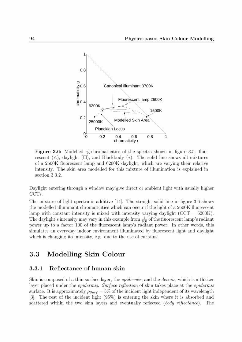
94 Physics-based Skin Colour Modelling
0 0.2 0.4 0.6 0.8 10
0.2
0.4
0.6
0.8
1
chromaticity r
chro
mat
icity
g
Modelled Skin Area
Planckian Locus
Canonical Illuminant 3700K
1500K
Fluorescent lamp 2600K
6200K
25000K
Figure 3.6: Modelled rg-chromaticities of the spectra shown in figure 3.5: fluo-rescent (M), daylight (¤), and Blackbody (∗). The solid line shows all mixturesof a 2600K fluorescent lamp and 6200K daylight, which are varying their relativeintensity. The skin area modelled for this mixture of illumination is explained insection 3.3.2.
Daylight entering through a window may give direct or ambient light with usually higherCCTs.
The mixture of light spectra is additive [14]. The straight solid line in figure 3.6 showsthe modelled illuminant chromaticities which can occur if the light of a 2600K fluorescentlamp with constant intensity is mixed with intensity varying daylight (CCT = 6200K).The daylight’s intensity may vary in this example from 1
100of the fluorescent lamp’s radiant
power up to a factor 100 of the fluorescent lamp’s radiant power. In other words, thissimulates an everyday indoor environment illuminated by fluorescent light and daylightwhich is changing its intensity, e.g. due to the use of curtains.
3.3 Modelling Skin Colour
3.3.1 Reflectance of human skin
Skin is composed of a thin surface layer, the epidermis, and the dermis, which is a thickerlayer placed under the epidermis. Surface reflection of skin takes place at the epidermissurface. It is approximately ρSurf = 5% of the incident light independent of its wavelength[3]. The rest of the incident light (95%) is entering the skin where it is absorbed andscattered within the two skin layers and eventually reflected (body reflectance). The

3.3 Modelling Skin Colour 95
epidermis mainly absorbs light, it has the properties of an optical filter. The light istransmitted depending on its wavelength and the melanin concentration in the epidermis.In the dermis the light is scattered and absorbed. The absorption is mainly dependent onthe content of blood and its ingredients such as haemoglobin, bilirubin, and beta-carotene.The optical properties of the dermis are basically the same for all humans. The skincolour related to different genetic backgrounds is, thus, determined by the epidermistransmittance, which depends mainly on its melanin concentration. The variation of theblood content of the dermis is independent of the genetic background.
Figure 3.7 shows spectral reflectance curves of human skin [3; 21]. The uppermost isrepresentative for normal Caucasian skin, the middle one for Caucasian skin right aftersunburn (erythematous, which gives the skin a reddish appearance), and the lower onefor Negro skin. The two spectral reflectance curves of Caucasian skin in figure 3.7 are thelower and upper extrema of the reddish appearance, which is due to the blood content ofthe dermis [12]. The normal Caucasian and the Negro define the range of the shade ofthe skin (brownish), which is due to the melanin concentration in the epidermis.
300 400 500 600 700 8000
20
40
60
80
100
Wavelength (λ), nm
Ref
lect
ance
(ρ)
, % Caucasian
CaucasianErythematous
Negro
Figure 3.7: Spectral reflectance curves of human skin for normal Caucasian [3],erythematous Caucasian (sunburn) [3], and dark Negro skin [21].
3.3.2 Modelling of the skin colour chromaticities
The surface and body chromaticities of the skin can be modelled using the reflectancecurves of skin, the spectrum of the illumination the skin is exposed with, and the cameracharacteristics. Figure 3.8 shows the rg-chromaticities of a number of Blackbody illumi-nants ranging from 1500K to 25000K (Planckian locus), illustrated by triangles (M). Thefigure is modelled for a Blackbody radiator with a CCT=3700K as canonical light source(white balance source). Two body reflection chromaticities, illustrated by squares (¤),are modelled for each illuminant using the Caucasian reflectance curves from figure 3.7in equation 3.2. These two chromaticities are called cCN and cCE for Caucasian normaland Caucasian erythematous. The solid lines connecting the illuminant and body chro-

96 Physics-based Skin Colour Modelling
0 0.2 0.4 0.6 0.8 10
0.2
0.4
0.6
0.8
1
chromaticity r
chro
mat
icity
g
1500K
2500K3700K6100K
25000K
Planckian Locus
Skin Reflectance Loci
Illuminant
cCN
cCE
cN
Figure 3.8: Modelled illuminant- and body reflection-chromaticities of skin withDichromatic lines for a number of Planckian illuminants.
maticities are the Dichromatic lines. According to the Dichromatic Reflection Model, skincolour chromaticities of a Caucasian subject are located in the area spanned by the threechromaticities - illuminant, Caucasian normal, and Caucasian erythematous.
In the previous section it was mentioned that the two Caucasian reflectance curves infigure 3.7 define the extrema of the reddish appearance of Caucasian skin, and that thesurface reflection of skin is only 5% [3]. It is, thus, expected, that most of the Caucasianskin colour reflections lie in a plane in the RGB space, which is spanned by the two vectorsof the body reflection chromaticities cCN and cCE. In the chromaticity plane cCN andcCE describe a line. For other skin colours, e.g. Asian or Negro, the respective reflectancecurves have to be used.
The asterisks (∗) in figure 3.8 shows the body reflectance chromaticity for Negro skincN (modelled with the Negro reflectance curve in figure 3.7) under the 3700K Blackbodyillumination. Compared to the changes of the chromaticities due to illumination colourchanges the difference between cCN and cN is small. The body reflectance chromatici-ties of all other shades of skin are located between cCN and cN . In order to model therange of reddish appearance a normal and an erythematous reflectance curve is requiredfor each shade of skin. As such a set of reflectance curves was not yet available to theauthors, a method, recently proposed by Ohtsuki and Healey [12], was used to synthe-sise skin reflectance spectra from Caucasian to Negro skin as a function of the melaninconcentration.

3.4 Image Acquisition 97
3.3.3 Skin colour and mixed illumination
In section 3.2.3 the illuminant chromaticities resulting from mixed light sources weremodelled. The spectra of a fluorescent lamp and varying daylight were additively mixed,figure 3.6. The figure shows also all possible skin chromaticities resulting from bodyreflections of skin under this illumination. They are obtained in the same way as thebody reflection chromaticities under single illumination by spectral integration. The skinchromaticities are expected to be enclosed by this straight area. This might be used toconstrain the search area for skin colour in the chromaticity plane.
3.4 Image Acquisition
For the experimental test of the skin colour model images are taken from several facesunder different illuminations.
The images are captured with a JAI CV-M90 3CCD colour video camera equipped with aFudjinon wide angle lens and connected to a Silicon Graphics Sirius or a FlashBus IntegralTechnologies frame-grabber. No automatic gain control or automatic white balancing areused and the gamma correction is set to one. The lens opening and the shutter speed aremanually adjusted to make use of the dynamic range of the camera. Figure 3.2 shows thespectral sensitivities of the CV-M90 camera.
The different illuminations were realized with four fluorescent lamps (Philips TLD 927,940, 950, 965), having the CCTs 2600K, 3680K, 4700K, and 6200K. The spectra of theselamps are provided from Philips and additionally measured with a J&M TIDAS spec-trometer. The measured spectra where used to calculate the CCTs. Figure 3.5 showsan example of a measured spectrum of a fluorescent lamp (dashed line). The fluorescentlamps are running with high frequency (> 24kHz) in order to avoid the 50Hz flicker ofthe power system. Figure 3.9 shows the setup for the image acquisition.
JAI recommends a standard illumination of 2000 lux for the CV-M90 camera using anopening of F=5.6. This illuminance is available in approximately 1.5 meter distance tothe lamps. Fluorescent lamps provide their full luminous flux 20 minutes after they areswitched on. Therefore all the lamps are switched on during the acquisition and coveredwhen not in use (figure 3.9). The fluorescent lamp with a CCT of 3680K was used ascanonical light source, i.e. to white balance the camera.
Indoor images of eight subjects coming from a variety of countries (China, Iran, Cameroun,Latvia, Greece, Spain, Denmark, and India) and hence with different skin colours weretaken. An example image is as shown in figure 3.10. Five images of each subject weretaken using the lamps in the order 940, 927, 965, 950, 940. Two images are taken atthe CCT = 3680K, one at the beginning and one at the end of a set of images as areproducibility test to make sure that the subject’s skin properties did not change, e.g.,more or less reddish at the end of the sequence.

98 Physics-based Skin Colour Modelling
Background
Subject
1.5 meter
Reflector
Fluorescent lamp
Camera
Figure 3.9: Top view of the setup for capturing images of peoples faces underlighting with different and mixed CCT.
3.4.1 Images under mixed illumination
In section 3.2.3 a mixture of daylight and fluorescent light was modelled. In order tosimulate such a mixture images of faces were taken illuminated with a mixture of differentfluorescent lamps. This was done by setting two fluorescent lamps with different CCTsin the same casing, e.g. a 6200K lamp together with a 2600K lamp. Hence, ten differentilluminations were available, six with mixed CCTs and four with a single CCT.
Figure 3.10: Image acquired by the setup shown in figure 3.9. Examples of colourimages are available at http://www.cvmt.dk/∼mst/ras.html

3.5 Comparison of Measured and Modelled Data 99
0.3 0.4 0.5 0.6
0.3
0.4
0.5
6200K4700K 3680K2600K
chromaticity r
chro
mat
icity
g
modelLatviaDenmarkGreeceSpainChinaIranIndiaCameroun
Figure 3.11: Chromaticity plane with modelled skin colour areas and mean valuesof the measured skin colour distributions under the four different CCTs as describedin section 3.4. The nationalities of the subjects are indicated by the different sym-bols, see legend.
3.5 Comparison of Measured and Modelled Data
The images were hand segmented into skin areas and non skin areas. The skin areas areused as skin colour measurements. First images taken under a single illumination colourwill be investigated for known illumination spectra and for Blackbody radiator modelledillumination. At the end of this section images taken under mixed illumination will bediscussed.
3.5.1 Single known illumination
Figure 3.11 shows the mean values of the measured skin colour distributions in the chro-maticity plane for the eight subjects under the four different illuminations. The fourareas, illustrated by the solid lines, are the modelled body reflectances of human skinranging from light Caucasian to dark Negro (melanin concentration) and from pale toreddish (blood content), respectively. For the upper boundary a reflectance curve froma very light Caucasian is used, which was provided by the ”physics-based face databasefor color research” [16] from Oulu University, Finland. The four measured light sourcespectra where used for the modelling.
The measurements lie inside the modelled skin colour areas, as one would expect forknown light spectra and this wide range of modelled skin colour. The relative structure ofthe distribution of the mean values looks similar for the different illuminations, it changesabout the same as the structure of the modelled area changes its form. The lightersubjects (Caucasians) are closer to the illuminant chromaticity (white) that the darkerones as it was shown in figure 3.8. The calculated area for the lowest CCT (2600K) isslightly lower relative to the measurements than the other areas. The images taken at

100 Physics-based Skin Colour Modelling
2600K have relatively high values for the red component and rather low ones for the bluecomponent of the skin, respectively. Thus, this deviation might be due to non-linearitiesof the camera, or due to the use of product specifications for the spectral sensitivities ofthe camera instead of using measures of the camera actually used.
The mean values of the three skin colour distributions shown in figure 3.12 are extremain figure 3.11 (Latvia, China, and Cameroun). The modelled skin colour area (solid lines)is the same as that in figure 3.11. All mean values of measured skin colour clusters areinclosed by the modelled area.
chromaticity r
chro
mat
icity
g
Caucasian
Negro
Asian
0.4 0.6
0.4
0.2
Figure 3.12: Skin colour distribution in the chromaticity plane of images takenat CCT=3680K. The solid line indicates the skin area, modelled with a large rangeof melanin. The images contain skin pixels of one Caucasian (Latvia), one Asian(China), and one Negro (Cameroun) subject. Approximately 10000 skin pixels persubject.
The Caucasian skin colour distribution is composed of two distributions. A smaller dis-tribution on the upper left side and a bigger one below, see also figure 3.13. The upperleft distribution is due to the ”whiter” skin areas such as the neck, and the lower dueto the rather red cheeks of the subject. The Caucasian subject has more variance in thereddishness (due to variations in the blood content) where as the Negro subject has morevariance in the direction depending on the melanin concentration.
Figure 3.13 shows the skin colour distributions of a light Caucasian subject. The solidline is the modelled skin area, adapted to the subject by changing the range of melaninconcentration and using the same reflectance curves as above. The adaption is done forthe canonical illuminant at CCT = 3680K. The skin colour areas for the other CCTs aremodelled using the same parameters except the spectrum of the light source, which ischanged to the respective ones. It can be seen that the modelled area changes its shapeas the measured skin colour distribution does.
The modelled skin areas shown in figure 3.13 were used to do a segmentation in thechromaticity space of the respective images, i.e. if the chromaticity of a pixel falls in

3.5 Comparison of Measured and Modelled Data 101
chromaticity r
chro
mat
icity
g
6200K 4700K3680K 2600K
0.2 0.4 0.6
0.4
0.2
Figure 3.13: Skin colour distribution of a Caucasian (Latvia) subject under fourdifferent illuminations. The solid line shows the modelled skin colour area adaptedto the subject.
the modelled area it is segmented as skin colour. The segmented images are shownin figure 3.14. It can be seen that very red areas, especially the cheeks, are not alwayscorrectly segmented, for example the image taken at a CCT=4700K. Also very pale/whiteareas, such as the neck of the subject, are not correctly segmented. These false negativescould be avoided by choosing another melanin range and other reflectance curves whichinclude more white and red areas. This would give more false positives, which are alreadypresent in the segmentation shown in figure 3.14. The large area of false positives in thelower left of the images is a wooden surface, which has the same chromaticities as theneck of the subject. The noisy false positives occur mostly at object edges, on the noticeboard and the poster behind the subject, which purposely contains skin colour.
This shows that using this simple colour model can give few false negative. It also showsthat there are many objects which have the same chromaticities as skin or chromaticitiesvery closed to those of skin. A robust segmentation of human skin will only be possibleusing context sensitive methods and/or in combination with other feature, e.g. motion,as reported, e.g., by [6; 10; 13].
3.5.2 Blackbody modelling of illumination
Figure 3.15 shows the same skin colour measurements as figure 3.11, but the skin areasare modelled using Blackbody radiators instead of the measured spectra. Particularly thearea modelled for 2600K is too low in the green component, but also the areas for 4700Kand 6200K are slightly too low in the green component. This is due to the deviations ofthe Blackbody radiators’ spectra from the corresponding (same CCT) fluorescent lamps’spectrum. It can be seen in figure 3.16 for the 2600K and the 6200K lamps that thechromaticities of the Blackbody radiators are slightly lower that those of the fluorescentlamps. The red component, on the other hand, fits nearly as well as the ones modelledusing measured light spectra, figure 3.11. Thus, using Blackbody modelling for the illu-mination gives an accurate estimation of the red component, but the green componentneeds some alternative compensation in order to be used, e.g., for segmentation.

102 Physics-based Skin Colour Modelling
CCT = 2600K CCT = 3680K
CCT = 6200KCCT = 4700K
Figure 3.14: Images segmented using the model shown in figure 3.13. The top leftimage is the segmentation from the image shown in figure 3.10.
3.5.3 Mixed illumination
In figure 3.6 (section 3.2.3) all mixtures of 2600K fluorescent light and 6200K daylightwere modelled. The corresponding body reflections of skin colour are also shown in thechromaticity plane.
Figure 3.16 shows the skin colour distributions of a Caucasian subject in images takenunder different mixtures of illumination, as described in section 3.4.1. The circles (◦) illus-trate measurements of single CCT illuminant colours and the squares (¤) measurementsof the mixed illuminant colours. These measurements were obtained from images of aBarium Sulphate plate. Barium Sulphate has an approximately constant reflectance overall visible wavelengths and reflects thus the colour of the illuminant. The measurementsof the single CCT illuminant colours form a straight line. All measurements of the mixedCCT illuminant colours lie on this line as well.
The dashed lines illustrate a skin colour area, which is modelled for the two fluorescentlamps with 2600K and 6200K, varying their relative intensities. The measured distribu-tions of skin colour chromaticities form a linear structure as the light sources do. Allcluster centres are enclosed by the modelled skin colour area. Thus, even for this mixtureof CCTs, the search area for skin colour can be reduced to a rather small area in thechromaticity plane.

3.6 Conclusions 103
0.3 0.4 0.5 0.6
0.3
0.4
0.5
6200K4700K 3680K2600K
chromaticity r
chro
mat
icity
g
modelLatviaDenmarkGreeceSpainChinaIranIndiaCameroun
Figure 3.15: Mean values of measured skin colour distribution as shown in fig-ure 3.11. Skin colour areas are modelled using Blackbody radiators instead of themeasured spectra.
3.6 Conclusions
In the previous sections it was shown that it is possible to model human skin colourunder changing and mixed illuminations. Indoor images of eight people with different skincolours under four different CCTs and mixtures of these confirm this. Body reflectionsof human skin are modelled by spectral integration using the spectral sensitivities of thecamera, spectral reflectance curves of human skin, and the relative spectral radiance ofthe light sources. The spectral reflectance curves of skin are synthesised from curvestaken from the literature [3; 16; 21] using a method proposed in [12]. Measured lightspectra and Blackbody radiators approximation were used. The use of measured spectragave good approximations under single and mixed illuminations. Even under unknownrelative intensities of the mixed illumination, the possible skin colours can be reducedto a small search area in the chromaticity plane (figure 3.16). The approximation byBlackbody radiators give accurate estimates in the red component but needs alternativecompensation in the green component.
The skin colour model may provide the basis for a wide range of applications such asadaptive segmentation of skin colour.
In future work an adaptive skin colour segmentation using the modelling presented inthis article and in [2] in combination with the illuminant estimation reported in [18] willbe developed. Tests will be done using images from skin in cluttered environments andoutdoors. Skin with other properties than facial skin like the palm of the hands and lipsshould be investigated.

104 Physics-based Skin Colour Modelling
0.2 0.4 0.60.2
0.4
chromaticity r
chro
mat
icity
g
2600K3700K6200K
Planckian Locus
Figure 3.16: Measured illuminant (◦: single CCT, ¤: mixed CCTs) and skincolour chromaticities under single and mixed illumination. The dashed line is themodelled skin area for a mixture of 2600K and 6200K fluorescent light.
Acknowledgements
We would like to thank all the persons who participated in the image acquisition. Thisresearch is partially funded by the European Commission as part of the TMR researchnetwork SMART II, contract no. ERBFMRX-CT96-0052.
Bibliography
[1] OSRAM Lichtprogramm. Product catalogue, 1998.
[2] Andersen, H.J. and Granum, E. Classifying illumination condition from two lightsources by colour histogram assessment. J. of the Optical Society of America A, 17(4):667–676, Apr. 2000.
[3] Anderson, R.R., Hu, J., and Parrish, J.A. Optical radiation transfer in the humanskin and applications in in vivo remittance spectroscopy. In Marks, R. and Payne,P.A., editors, Bioengineering and the Skin, chapter 28, pages 253–265. MTP PressLimited, 1981.
[4] Anonymous. Method of measuring and specifying colour rendering properties of lightsources. Technical Report CIE 13.3, Commision Internationale de L’Eclairage (CIE),1995.
[5] Chen, C. and Chiang, S.P. Detection of human faces in colour images. IEE Proc.-Vis.Image Signal Process, 144(6):384–388, Dec. 1997.

BIBLIOGRAPHY 105
[6] Crowley, J.L., Coutaz, J., and Berard, F. Things that see. Communications of theACM, 43(3):54–64, Mar. 2000.
[7] Finlayson, G. and Schaefer, G. Single surface colour constancy. In 7th Color ImagingConf., pages 106–113, Scottsdale, Arizona, USA, Nov. 1999.
[8] Funt, B., Barnard, K., and Martin, L. Is machine colour constancy good enough? InBurkhardt, H. and Neumann, B., editors, 5th European Conf. on Computer Vision,pages 445–459, Freiburg, Germany, June 1998.
[9] Klinker, G.J., Shafer, S.A., and Kanade, T. A physical approach to color imageunderstanding. Int. J. of Computer Vision, 4(1):7–38, Jan. 1990.
[10] McKenna, S.J., Gong, S., and Raja, Y. Modelling facial colour and identity withGaussian mixtures. Pattern Recognition, 31(12):1883–1892, Dec. 1998.
[11] Moeslund, T.B. and Granum, E. Multiple cues used in model-based human motioncapture. In 4th IEEE Int. Conf. on Automatic Face- and Gesture-Recognition, pages362–367, Grenoble, France, Mar. 2000.
[12] Ohtsuki, T. and Healey, G. Using color and geometric models for extracting facialfeatures. J. of Imaging Science and Technology, 42(6):554–561, Dec. 1998.
[13] Schiele, B. and Waibel, A. Gaze tracking based on face-color. In Bichsel, M., editor,Int. Workshop on Automatic Face- and Gesture-Recognition, Zurich, Switzerland,June 1995.
[14] Shafer, S. Describing light mixtures through linear algebra. J. of the Optical Societyof America A, 72(2):299–300, Feb. 1982.
[15] Shafer, S.A. Using color to separate reflection components. COLOR Research andApplication, 10(4):210–218, 1985.
[16] Soriano, M., Marszalec, E., and Pietikainen, M. Color correction of face images underdifferent illuminants by RGB Eigenfaces. In Second Int. Conf. on Audio- and Video-based Biometric Person Authentication, pages 148–153, Washington D.C., USA, Mar.1999.
[17] Storring, M., Andersen, H.J., and Granum, E. Skin colour detection under changinglighting conditions. In Araujo, H. and Dias, J., editors, 7th Int. Symposium onIntelligent Robotic Systems, pages 187–195, Coimbra, Portugal, July 1999.
[18] Storring, M., Andersen, H.J., and Granum, E. Estimation of the illuminant colourfrom human skin colour. In 4th IEEE Int. Conf. on Automatic Face- and Gesture-Recognition, pages 64–69, Grenoble, France, Mar. 2000.

106 Physics-based Skin Colour Modelling
[19] Storring, M., Andersen, H.J., and Granum, E. Physics-based modelling of humanskin under mixed illuminants. J. of Robotics and Autonomous Systems, 35(3–4):131–142, June 2001.
[20] Tominaga, S. Dichromatic reflection models for a variety of materials. COLORresearch and application, 19(4):277–285, Aug. 1994.
[21] Wyszecki, G. and Stiles, W.S. Color Science: Concepts and Methods, QuantitativeData and Formulae. John Wiley and Sons, 1982.

Chapter 4
Estimation of the Illuminant Colourfrom Human Skin Colour

108

109
Estimation of the Illuminant Colour from Human Skin Colour
Moritz Storring, Hans Jørgen Andersen, and Erik Granum
Computer Vision and Media Technology Laboratory,Aalborg University, Niels Jernes Vej 14, DK-9220 Aalborg, Denmark
Email: {mst,hja,eg}@cvmt.dk, http://www.cvmt.dk
Abstract
Colour is an important and useful feature for object tracking andrecognition in computer vision. However, it has the difficulty thatthe colour of the object changes if the illuminant colour changes.But under known illuminant colour it becomes a robust feature.There are more and more computer vision applications tracking hu-mans, for example in interfaces for human computer interaction orautomatic camera men, where skin colour is an often used feature.Hence, it would be of significant importance to know the illuminantcolour in such applications. This paper proposes a novel methodto estimate the current illuminant colour from skin colour observa-tions. The method is based on a physical model of reflections, theassumption that illuminant colours are located close to the Planck-ian locus, and the knowledge about the camera parameters. Themethod is empirically tested using real images. The average estima-tion error of the correlated colour temperature is as small as 180K.Applications are for example in colour based tracking to adapt tochanges in lighting and in visualisation to re-render image coloursto their appearance under canonical viewing conditions.
Published in:
Storring, M., Andersen, H.J., and Granum, E. Estimation of the illuminant colour fromhuman skin colour. In 4th IEEE Int. Conf. on Automatic Face- and Gesture-Recognition,pages 64–69, Grenoble, France, Mar. 2000

110 Illuminant Estimation from Skin
4.1 Introduction
Automatically detecting and tracking faces and human motion is important in applicationssuch as interfaces for human computer interaction (HCI), in- and outdoor surveillance,and automatic camera men. An often used feature in face and human motion trackingis skin colour [4; 6; 7; 10; 18], because it is a well suited orientation and size invariantfeature for segmentation and localisation. Most systems transform the image colours intoa chromatic colour space in order to be independent of the intensity, e.g. [9]. This worksin constraint indoor environments where the illuminant colour is stable or only slightlychanging.
In outdoor environments or indoor environments with a mixture of daylight and artificiallight the illuminant colour is varying significantly. Under unknown illuminant a segmen-tation in a chromatic colour space will produce either false positives or false negatives,depending on the control parameters. The influence of changing illuminant colour to skincolour detection was recently investigated [12; 13]. They found that skin colour can besegmented very accurately if the illuminant colour and camera characteristics are known.The estimation of the illuminant colour from the colours of surfaces is an active researcharea within colour vision. It is part of several colour constancy algorithms, which seek toseparate the colour of the illuminant from the surface colour.
To explore this problem we devise a method to investigate how accurately the illuminantcolour may be estimated given the (light) reflections of skin. In particular the correlatedcolour temperature of a light source is estimated based on a physical model of skin re-flectance, the knowledge of the camera characteristics, a known initial image, and theassumption that the illuminants are distributed along the Planckian locus of blackbodyradiators. This was recently found applicable for commonly used illumination sources,e.g., daylight, fluorescent light, or light bulbs [5]. This method will have application, e.g.,to adapt to changes in lighting in colour vision based face and human motion tracking.
In the following sections the method for estimating the illuminant colour from skin colouris described, tested, and discussed.
4.2 Illuminant estimation from skin colour
This section describes a method for estimating the illuminant colour from skin colour.The colour image formation process will be discussed, related work and its application toskin colour will be presented, and the proposed method will be explained.
4.2.1 Modelling skin colour image formation
The light reflected from a surface is composed of its reflectance and the light it is exposedwith. This is often modelled by the Dichromatic Reflection Model [11], which describes

4.2 Illuminant estimation from skin colour 111
the reflected light L(θ, λ) for dielectric objects as an additive mixture of the light LS
reflected from the material’s surface (interface or surface reflection) and the light LB
reflected from the material’s body (body, diffuse, or matte reflection):
L(θ, λ) = mS(θ)LS(λ) + mB(θ)LB(λ) (4.1)
mS(θ) and mB(θ) are geometrical scaling factors and θ includes the viewing-, illuminationdirection-, and phase-angle [8]. For materials with high water or oil content the lightreflected on the surface has approximately the same spectral power distribution as thelight source. This is categorised as the Dichromatic Reflection Model Type I, also known asthe Neutral Interface Reflection (NIR) assumption [15]. The light, which is not reflectedat the surface, penetrates into the material body where it is scattered and selectivelyabsorbed at wavelengths that are characteristic of the material. Some fraction of thelight arrives again at the surface and exits the material. The body reflection provides thecharacteristic object colour, i.e. the colour of human skin for the method presented inthis paper.
Skin is composed of a thin surface layer, the epidermis, and the dermis, which is a thickerlayer placed under the epidermis. Interface reflection of skin takes place at the epidermissurface. It is approximately ρSurf = 5% of the incident light independent of its wavelengthand the human race [2]. The rest of the incident light (95%) is entering the skin whereit is absorbed and scattered within the two skin layers (body reflectance). The epidermismainly absorbs light, it has the properties of an optical filter. The light is transmitteddepending on its wavelength and the melanin concentration in the epidermis. In thedermis the light is scattered and absorbed. The absorption is mainly due to the contentof blood and its ingredients. The optical properties of the dermis are basically the samefor all human races. The skin colour is thus determined by the epidermis transmittance,which depends mainly on its melanin concentration, and the blood content of the dermis .
Figure 4.1 shows spectral reflectance curves of human skin [2; 17]. The uppermost is
300 400 500 600 700 8000
20
40
60
80
100
Wavelength (λ), nm
Ref
lect
ance
(ρ)
, % Caucasian
CaucasianErythematous
Negro
Figure 4.1: Spectral reflectance curves of skin.
representative for normal Caucasian skin, the middle one for Caucasian skin right after

112 Illuminant Estimation from Skin
sunburn (erythematous), which gives the skin a reddish appearance, and the lower one forNegro skin. The uppermost corresponds to a low blood content in the dermis whereasthe middle one corresponds to a high blood content. In other words the two spectralreflectance curves of Caucasian skin in figure 4.1 define its lower and upper extremities ofthe reddish appearance, which is due to the blood content of the dermis [10].
The light LS,B reflected from a surface is the product of the incident light spectrum Eand the spectral reflectance ρ: LS,B(λ) = E(λ)ρS,B(λ). In this paper only commonly usedlight sources are considered, which will be modelled by a Planckian locus of blackbodyradiators as recently proposed in [5]. The spectral composition of light sources may bedescribed by their correlated colour temperature (CCT), measured in Kelvin (K). TheCCT of a light source is relating to the temperature of a blackbody emitting light of asimilar spectral composition. A light source with a high CCT gives the material a bluishappearance, e.g., skylight, whereas a low CCT gives a reddish appearance, e.g., duringsunset. Examples for light spectra can be found in [17].
The colour image formation process using a video camera can be modelled by spectralintegration:
CRGB =
∫
λv
L(θ, λ)fRGB(λ) dλ (4.2)
where fRGB(λ) are the spectral sensitivities of the red, green, and blue sensing elementsof the camera (tristimulus characteristic). CRGB is a 3 element vector of sensing elementresponses, i.e., the RGB pixel values. The integration is done over the visible spectrumλv. According to the Dichromatic Reflection Model each RGB value consists of a body andan interface part. These two parts span a plane in the RGB space, called the Dichromaticplane. All RGB pixel values of a material surface fall on this plane [8].
For analysing the colour of the reflected light, independent of the scale of intensity, it isconvenient to transform the colour vector CRGB to its corresponding chromaticity crgb, i.e.,to the “pure colours”. This is done by normalising the colour vector (R,G, B) elementswith their first norm (N):
r =R
N, g =
G
N, b =
B
N, N = R + G + B (4.3)
That means that r + g + b = 1, hence all chromaticities lie on a plane, the chromaticityplane. The Dichromatic plane falls along a line in the chromaticity plane, which is calledthe Dichromatic line in the following. The Dichromatic line connects the body- andthe interface-reflection chromaticities. The body chromaticity is the pure colour of thesurface, here the skin. The interface chromaticity is equal to the illuminant chromaticity.
Given the light spectrum, the reflectance curves of skin, and the camera characteristicsit is now possible to model the interface and body chromaticities of skin. Figure 4.2shows the rg-chromaticities of a number of illuminant colours ranging from 1500K to25000K (Planckian locus), illustrated by triangles (M). The corresponding two body

4.2 Illuminant estimation from skin colour 113
reflection chromaticities for each illuminant colour are illustrated by squares (¤). Theyare calculated using the two Caucasian reflectance curves from figure 4.1 in equation 4.2.In the following these two chromaticities are called cCN and cCE for Caucasian normal andCaucasian erythematous. The solid lines connecting the interface and body chromaticitiesare the Dichromatic lines. Skin colour of a Caucasian subject is located in the area spannedby the three chromaticities - illuminant, Caucasian normal, and Caucasian erythematous.
0 0.2 0.4 0.6 0.8 10
0.2
0.4
0.6
0.8
1
chromaticity r
chro
mat
icity
g
1500K
2500K3700K6100K
25000K
Planckian Locus
Skin Reflectance Loci
SkinIlluminant
cCE
cCN
Figure 4.2: Modelled illuminant- and body reflection-chromaticities of skin withDichromatic lines for a number of Planckian illuminants.
Figure 4.2 is modelled for a camera that is white balanced at a 3700K blackbody radiator.That means the illuminant chromaticity is located at r = g = b = 1
3.
4.2.2 Illumination estimation using the Neutral Interface Re-flection assumption
Several methods are reported in the literature to estimate the illuminant colour giventhat there are different surfaces in the image [16]. These are not appropriate here as weconsider only one surface, which is the human skin. A method using a single surface wasrecently reported by Finlayson and Schaefer [5]. They observed that the chromaticitiesof most illuminants are tightly clustered around the Planckian locus. Assuming a surfacematerial, which can be modelled with the Dichromatic Reflection Model, the illuminantchromaticity lies somewhere on the Dichromatic line of this surface. Hence, the intersec-tion of the Dichromatic line and the Planckian locus is an estimation of the illuminantchromaticity. An example of this method follows: Two images, both containing a greenplastic cup and Caucasian skin, were taken under fluorescent illuminations with a CCT

114 Illuminant Estimation from Skin
of 2600K and 6200K, respectively. Their rg-chromaticity distributions are shown in fig-ure 4.3. The Dichromatic lines are illustrated by the solid lines, which were calculated byprincipal component analysis (PCA) of the respective chromaticity distributions [5].
chromaticity r
chro
mat
icity
g
Planckian Locus
6200K
2600K
Skin
GreenPlastic
0 0.2 0.4 0.6 0.8 10
0.2
0.4
0.6
0.8
1
Figure 4.3: Measured chromaticities of a green plastic cup and Caucasian skinfrom two images using different light sources.
The Dichromatic lines of the plastic cup intersect nearly with the real illuminants, illus-trated by asterisks (∗). The error of the CCT estimation using the Planckian locus isonly 200K and 170K, respectively. It is reported in [5] that their method performs bestwith colours having a Dichromatic line approximately orthogonal to the Planckian locussuch as greens, purples, and magentas. The results using human skin are less satisfactory,because skin colour is near achromatic, i.e., it is clustered close to the illuminant chro-maticity, and its Dichromatic line is far from being orthogonal to the Planckian locus.Thus a small deviation between the illuminant colour and the corresponding Planckianlight source or a small error in the direction of the Eigenvector results in a large estimationerror of the illuminant colour.
A second problem is that the estimation of the Dichromatic lines by PCA is less reliable forskin, which is due to two reasons. First, human skin provides only 5% interface reflections[2], hence highlights are much less pronounced than for the plastic cup. Secondly, thereflectance of a skin area cannot be described by a single reflectance curve, which is dueto the varying blood content. Instead colours of a skin area are distributed along severalDichromatic lines. In other words, skin colour is composed of many colours distributedaround a mean Dichromatic line, i.e. the variance perpendicular to the mean Dichromaticline is larger than that for the green plastic cup, which makes the PCA less reliable.
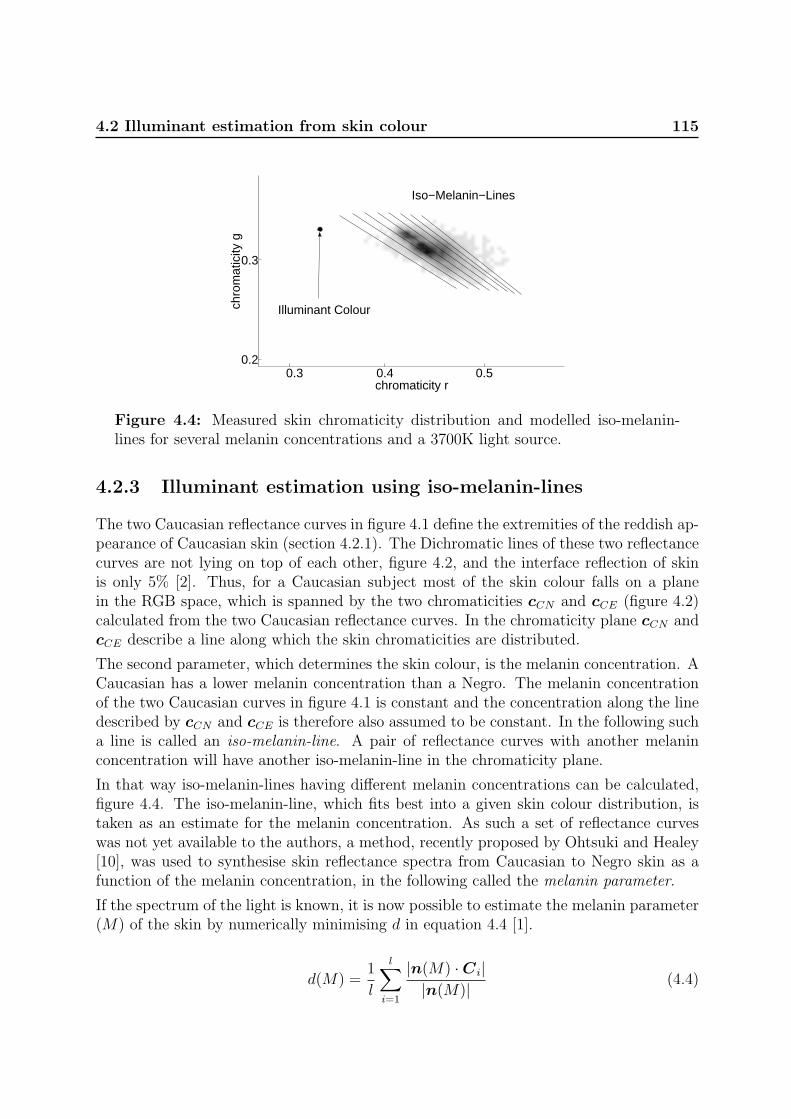
4.2 Illuminant estimation from skin colour 115
chromaticity r
chro
mat
icity
g
Illuminant Colour
Iso−Melanin−Lines
0.3 0.4 0.50.2
0.3
Figure 4.4: Measured skin chromaticity distribution and modelled iso-melanin-lines for several melanin concentrations and a 3700K light source.
4.2.3 Illuminant estimation using iso-melanin-lines
The two Caucasian reflectance curves in figure 4.1 define the extremities of the reddish ap-pearance of Caucasian skin (section 4.2.1). The Dichromatic lines of these two reflectancecurves are not lying on top of each other, figure 4.2, and the interface reflection of skinis only 5% [2]. Thus, for a Caucasian subject most of the skin colour falls on a planein the RGB space, which is spanned by the two chromaticities cCN and cCE (figure 4.2)calculated from the two Caucasian reflectance curves. In the chromaticity plane cCN andcCE describe a line along which the skin chromaticities are distributed.
The second parameter, which determines the skin colour, is the melanin concentration. ACaucasian has a lower melanin concentration than a Negro. The melanin concentrationof the two Caucasian curves in figure 4.1 is constant and the concentration along the linedescribed by cCN and cCE is therefore also assumed to be constant. In the following sucha line is called an iso-melanin-line. A pair of reflectance curves with another melaninconcentration will have another iso-melanin-line in the chromaticity plane.
In that way iso-melanin-lines having different melanin concentrations can be calculated,figure 4.4. The iso-melanin-line, which fits best into a given skin colour distribution, istaken as an estimate for the melanin concentration. As such a set of reflectance curveswas not yet available to the authors, a method, recently proposed by Ohtsuki and Healey[10], was used to synthesise skin reflectance spectra from Caucasian to Negro skin as afunction of the melanin concentration, in the following called the melanin parameter.
If the spectrum of the light is known, it is now possible to estimate the melanin parameter(M) of the skin by numerically minimising d in equation 4.4 [1].
d(M) =1
l
l∑i=1
|n(M) ·Ci||n(M)| (4.4)

116 Illuminant Estimation from Skin
where l is the number of skin pixel points, Ci the colour vector of pixel point i, andn = cCN×cCE the normal vector of the plane spanned by cCN and cCE. The minimisationis shown in figure 4.5.
1 1.2 1.40.2
0.3
0.4
0.5
0.6
0.7
0.8
melanin parameter
d
Figure 4.5: Estimation of melanin parameter.
Once the melanin parameter of the skin is estimated the illuminant colour can be tracked.Iso-melanin-lines are calculated for a range of blackbody radiators, e.g. from 1500Kto 10000K, in a certain resolution, e.g., 50K. That means normal vectors n(CCT ) arecalculated using the estimated melanin parameter. The CCT is then found by minimisingequation 4.4, replacing d(M) by d(CCT ) and n(M) by n(CCT ). Figure 4.6 shows theestimation of the illuminant colour temperature for four test images taken from the samesubject using the same melanin parameter under four different CCTs.
2600 3680 4700 62000
0.1
0.2
0.3
0.4
0.5
CCT, Kelvin
d
2600K3680K4700K6200K
Figure 4.6: Estimation of the current CCT from four images taken at CCTs of2600, 3680, 4700, and 6200K.

4.3 Performance assessment 117
4.3 Performance assessment
4.3.1 Materials and method
The proposed method using iso-melanin-lines is tested with images taken from eight sub-jects under four different illuminations. The images are captured with a JAI M90 3CCDcolour video camera equipped with a Fudjinon wide angle lens and connected to a SiliconGraphics Sirius frame-grabber. The automatic gain control is switched off and the gammacorrection is set to one. The lens opening and the shutter speed are manually adjustedto make use of the dynamic range of the camera.
The different illuminations were realized with four fluorescent lamps (Philips TLD 927,940, 950, 965) providing CCTs of 2600, 3680, 4700, and 6200K. The light spectra of theselamps were measured with a Zeiss MCS 500 spectrometer and the CCTs were calculatedfrom these spectra. Indoor images of the faces from eight subjects coming from a varietyof countries (China, Iran, Cameroun, Latvia, Spain, Greece, Denmark, and India) andhence with different skin colours were taken. The TLD 940 lamp was used as canonicallight source, i.e. the camera is white balanced to this illuminant colour.
The method was tested as follows: Each image of a subject is once used to estimate themelanin parameter (canonical melanin image in table 4.1). This melanin parameter isthen used to estimate the CCTs from all test images of the respective subject.
4.3.2 Results
Figure 4.7 shows the estimated CCTs as a function of the measured CCTs. The rootmean square (RMS) and maximum errors (in brackets) of the estimation are given intable 4.1.
2 3 4 5 6 72
3
4
5
6
7
Measured CCT, Kelvin × 103
Est
imat
ed C
CT
, Kel
vin
× 10
3
Figure 4.7: Estimated CCT as a function of the measured CCT.
The average error is 180K and the maximum error less than 400K. From table 4.1 it canbe seen that using the images taken under the canonical light source as canonical melanin

118 Illuminant Estimation from Skin
images (second row, second column) gives a maximum error of 240K (second column),the average error of this column is 150K.
Table 4.1: RMS- and maximum-error in K of the CCT estimation. Maximum errorin brackets.
Test Canonical Melanin ImageImage 2600K 3680K 4700K 6200K2600K 166 (171) 196 (231) 201 (251) 232 (271)3680K 298 (380) 228 (240) 223 (300) 157 (240)4700K 189 (278) 87 (118) 65 (98) 50 (102)6200K 172 (287) 96 (233) 96 (153) 237 (293)
There is no absolute or quantitative judgement whether these errors are too high or withinsome margins. This depends on the application and the CCT. The effect of an error at alow CCT is bigger than that one at a higher CCT. To give some qualitative comments, anerror of 200K is always less than the variation between a Caucasian and a Negro. Thatmeans, for a general skin colour segmentation, i.e. no individual subject recognition, thiserror has no or only little influence. If the estimation is used for re-rendering the colourto their appearance under canonical viewing conditions, e.g., for display purposes, thisaccuracy is (by human assessment) sufficient as well.
4.4 Discussion and conclusions
The previous sections have presented a novel method to estimate the illuminant CCTfrom skin colour. The method has shown to work with real images from eight subjectshaving a large range of different skin colours taken under four different illuminations in aCCT range between 2600 and 6200K. These illuminants cover most of everyday situations.The average estimation error is about 180K and the maximum error less than 400K.
It has to be commented on the high estimation error for the images taken under canonicalconditions, second row in table 4.1. Usually one would expect a low error instead it isthe highest. However, from figure 4.7 it may be noted that it is a systematic error. Allpoints are beyond the diagonal. This is due to the approximation of the illuminants bythe Planckian locus. The illuminant chromaticity of the canonical light source is furtherfrom the Planckian locus than the other three light sources used in this paper. Such anerror will always be present using Planckian modelling, especially fluorescent lamps havea large deviations from the spectrum of the corresponding blackbody radiator. In outdoorapplications the upper part of the Planckian locus (4000 – 25000K) can be replaced by adaylight locus [3].
The method needs the melanin parameter or an initialisation by a canonical melaninimage. If instead a fixed melanin parameter is used the estimation error will increase. Thisis because the CCT and the melanin concentration are correlated. A slightly increasing

BIBLIOGRAPHY 119
melanin concentration (darker skin) has the same effect as a slightly decreasing CCT(more reddish lighting).
The most novel aspect of the proposed method is the way the skin chromaticities aremodelled. In the Dichromatic reflection model it is assumed that the RGB pixel values ofa surface fall on the plane spanned by the body reflectance and the interface vector(section 4.2.1). As skin has very few interface reflections but instead a skin area iscomposed of several Dichromatic planes, this approach assumes that the RGB pixel valuesof skin fall on the plane which is spanned by the two extreme body reflectance vectorscCN and cCE. This observation might also be applicable to other biological matte objects.
The CCT estimation is real time suitable as the vectors n(CCT ) can be pre-calculated.In future work this will be implemented in a real time tracking system to adapt to lightchanges. The effect of having a mixture of two or more light sources including daylightwill be investigated and a larger set of test images will be used for evaluation.
Acknowledgements
We would like to thank the European Commission’s TMR research network SMART II,contract no. ERBFMRX-CT96-0052, for supporting this research.
Bibliography
[1] Andersen, H.J., Onyango, C.M., and Marchant, J.A. The design and operation of animaging sensor for detecting vegetation. J. of Imaging Science and Technology, 11:144–151, 2000.
[2] Anderson, R.R., Hu, J., and Parrish, J.A. Optical radiation transfer in the humanskin and applications in in vivo remittance spectroscopy. In Marks, R. and Payne,P.A., editors, Bioengineering and the Skin, chapter 28, pages 253–265. MTP PressLimited, 1981.
[3] Anonymous. Method of measuring and specifying colour rendering properties of lightsources. Technical Report CIE 13.3, Commision Internationale de L’Eclairage (CIE),1995.
[4] Crowley, J.L. and Berard, F. Multi-modal tracking of faces for video communications.In IEEE Conf. on Computer Vision and Pattern Recognition, pages 640–645, SanJuan, Puerto Rico, June 1997.
[5] Finlayson, G. and Schaefer, G. Single surface colour constancy. In 7th Color ImagingConf., pages 106–113, Scottsdale, Arizona, USA, Nov. 1999.
[6] Garcia, C. and Tziritas, G. Face detection using quantized skin color regions mergingand wavelet packet analysis. IEEE TRANS. Multimedia, 1(3):264–277, Sept. 1999.

120 Illuminant Estimation from Skin
[7] Kim, S.H., Kim, N.K., Ahn, S.C., and Kim, H.G. Object oriented face detectionusing range and color information. In 3rd IEEE Int. Conf. on Automatic Face- andGesture-Recognition, pages 76–81, Nara, Japan, Apr. 1998.
[8] Klinker, G.J., Shafer, S.A., and Kanade, T. A physical approach to color imageunderstanding. Int. J. of Computer Vision, 4(1):7–38, Jan. 1990.
[9] McKenna, S.J., Raja, Y., and Gong, S. Object tracking using adaptive colour mixturemodels. In Chin, R. and Pong, T.C., editors, 3rd Asian Conf. on Computer Vision,volume 1, pages 615–622, Hong Kong, China, Jan. 1998.
[10] Ohtsuki, T. and Healey, G. Using color and geometric models for extracting facialfeatures. J. of Imaging Science and Technology, 42(6):554–561, Dec. 1998.
[11] Shafer, S.A. Using color to separate reflection components. COLOR Research andApplication, 10(4):210–218, 1985.
[12] Soriano, M., Marszalec, E., and Pietikainen, M. Color correction of face images underdifferent illuminants by RGB Eigenfaces. In Second Int. Conf. on Audio- and Video-based Biometric Person Authentication, pages 148–153, Washington D.C., USA, Mar.1999.
[13] Storring, M., Andersen, H.J., and Granum, E. Skin colour detection under changinglighting conditions. In Araujo, H. and Dias, J., editors, 7th Int. Symposium onIntelligent Robotic Systems, pages 187–195, Coimbra, Portugal, July 1999.
[14] Storring, M., Andersen, H.J., and Granum, E. Estimation of the illuminant colourfrom human skin colour. In 4th IEEE Int. Conf. on Automatic Face- and Gesture-Recognition, pages 64–69, Grenoble, France, Mar. 2000.
[15] Tominaga, S. Dichromatic reflection models for a variety of materials. COLORresearch and application, 19(4):277–285, Aug. 1994.
[16] Tominaga, S. and Wandell, B. Standard surface-reflectance model and illuminatestimation. J. of the Optical Society of America A, 6(4):576–584, Apr. 1989.
[17] Wyszecki, G. and Stiles, W.S. Color Science: Concepts and Methods, QuantitativeData and Formulae. John Wiley and Sons, 1982.
[18] Yang, J. and Waibel, A. A real-time face tracker. In Third IEEE Workshop onApplications of Computer Vision, pages 142–147, Sarasota, Florida, USA, 1996.

Chapter 5
Estimation of the illuminant colourusing highlights from human skin

122

123
Estimation of the illuminant colour usinghighlights from human skin
Moritz Storring, Erik Granum, and Hans Jørgen Andersen
Computer Vision and Media Technology Laboratory,Aalborg University, Niels Jernes Vej 14, DK-9220 Aalborg, Denmark
Email: {mst,eg,hja}@cvmt.dk, http://www.cvmt.dk
Abstract
The knowledge of the illuminant colour exposing an object or a scenariois very useful for computer vision and allows much more reliable colourbased recognition and interpretation. In many computer vision applica-tions humans are important parts of the scenario and the obvious detectionof human skin colour is difficult due to varying illumination. Under certainconditions of direct illumination the skin shows highlights. It is well knownthat highlights of non-homogeneous dielectric materials, such as skin, con-tain information about the illuminant colour.This paper investigates how accurately the illuminant colour may be esti-mated from highlights on skin using the Dichromatic Reflection Model. Theproposed method extracts automatically the surface vector from a pixel areaaround a highlight on the tip of a human nose. Experimental results withfrontal view images of human faces having different shades of skin takenunder different illumination colours and geometries show the estimation ofthe illuminant colour vector orientation within a few degrees.
Keywords: Illuminant Colour, Colour Constancy, Human Skin, DichromaticReflection Model
Published in:
Storring, M., Granum, E., and Andersen, H.J. Estimation of the illuminant colour us-ing highlights from human skin. In First Int. Conf. on Color in Graphics and ImageProcessing, pages 45–50, Saint-Etienne, France, Oct. 2000

124 Illuminant from Highlights
5.1 Introduction
In many computer vision applications humans are part of the scenario and may play themain role. For example new human computer interfaces need to detect and track humanfaces and hands, respectively. The segmentation of skin colour is an often used featurein such systems [5; 6], mostly as an initial segmentation of faces or hands in the cameraimage. Hence, a reliable output of such a method is imperative for a robust system.However, as for any other material, the same skin area appears as two different coloursunder two different illuminations, which makes colour based segmentation unreliable.This is a well known problem in colour vision and several colour constancy methods areproposed in the literature to solve this [2]. Colour constancy methods seek to separate thecolour of the illuminant from the material’s colour. No generic method has been founduntil now [3].
A general approach might be in combining several methods where each has its strength andweaknesses but their combination results in a robust method. One contributing elementto such a combination of methods was recently proposed using the body/matte reflectionsof human skin to estimate the illuminant colour [8] (chapter 4). Given a reference imagetaken under known illuminant colour and making the assumption that the light sourcescan be approximated by Blackbody radiators the average estimation error of the lightsource’s correlated colour temperature (CCT) in an input image was 180K (Kelvin) onlight sources in the range of 2600 to 6200K [8].
Another contributing element could be in exploiting the information of surface reflections.The light reflected from non-homogeneous dielectric materials with high oil or watercontent, e.g., human skin, may be described by the Dichromatic Reflection Model Type I[7]. The surface reflections of such materials have approximately the same spectral powerdistribution as the light source. Klinker et al. [4] presented a method to segment an imagecontaining several coloured plastic objects into surface and body reflections, and showedthat the surface vector due to highlights is a good estimate for the illuminant colour.
Under certain conditions of direct illumination and viewing geometries the skin showshighlights, i.e. the surface reflections increase while the body reflections stay approxi-mately constant [4]. In the human face highlights can be seen under different illuminationand viewing geometries especially on the tip of the nose, the forehead, or the cheeks andmight be used to estimate the illuminant colour.
This paper investigates how accurate the illuminant colour may be estimated from high-lights on human skin. A method is proposed to automatically detect and extract infor-mation from highlights in a pixel area selected around the tip of the nose.The method has applications as well in outdoor as in indoor environments where directillumination gives rise to highlights.
In the following sections the Dichromatic Reflection Model and the properties of humanskin in the context of direct illumination will be briefly described. The method for esti-mating the illuminant colour will be described, tested on real image data, and discussed.

5.2 Theory and Background 125
5.2 Theory and Background
5.2.1 Dichromatic Reflection Model
The light L(θ, λ) reflected from an object is determined by the object’s reflectance and thelight it is exposed with. It is a function of the wavelength λ and the photometric anglesθ including the viewing angle, the phase angle, and the illumination direction angle. Fordielectric non-homogeneous materials this is often modelled by the Dichromatic ReflectionModel [7], which describes the reflected light L(θ, λ) as an additive mixture of the lightLS reflected at the material’s surface (surface or interface reflection) and the light LB
reflected from the material’s body (body, diffuse, or matte reflection):
L(θ, λ) = mS(θ)LS(λ) + mB(θ)LB(λ) (5.1)
where mS(θ) and mB(θ) are geometrical scaling factors for the surface and body reflec-tions, respectively [4]. For materials with high oil or water content the light reflected onthe material’s surface has approximately the same spectral power distribution as the lightit is exposed with. This is described by the Dichromatic Reflection Model Type I, alsoknown as the Neutral Interface Reflection assumption [10]. In other words the surfacevector is parallel to the vector of the illuminant. Thus, it provides an estimate of the il-luminant colour or chromaticity. Figure 5.1 shows the RGB cube with a measured colourpixel distribution of an area around the tip of a nose having a highlight. The darker pixelsare mainly due to body reflections. According to [1] there are only 5% surface reflectionsin typical ”non-highlight” skin reflections, i.e. body reflections predominate. Thereforethese reflections are approximated to be body reflection in the following. The brighterpixels are a mixture of body and surface reflections due to highlights. The dashed linerepresents the vector of the illuminant colour under which the image was taken. Theline shaped cluster formed by the highlight pixels is approximately parallel to illuminantvector.
5.2.2 Properties of Skin and Nose
A human face provides most of the highlights on the forehead, the cheeks, and the nose,which is due to their convex form. In this work it was chosen to use highlights on the tipof the nose to estimate the illuminant colour. The advantages of using human skin andnose are listed below:
• Skin colour differs enough from gray that it is possible to clearly separate the bodyvector from the highlight vector in the RGB cube.
• The brightness ratio between body and highlight reflections is within a reasonablerange, thus, if the camera is adjusted to the brightest highlight pixel, the bodypixels will still be in the dynamic range of the camera.

126 Illuminant from Highlights
0 50 100 150 200 2500
100
200
0
50
100
150
200
250
highlight pixels
R
body pixels
G
B
Figure 5.1: Skin colour cluster of an area around the tip of the nose in the RGBcube. The dashed line represents the vector of the illuminant colour under whichthe image was taken.
• The nose consists of only one single material with usually few colour variations.Hence, there is only one body vector along which body reflection pixels will betightly distributed.
• The spherical shape of the nose tip causes a high probability of highlights for arange of different illumination and viewing geometries.
• The range of incident angles on a sphere (the nose tip) gives a corresponding rangeof brightnesses for the body reflections (Lambert’s law).
• The nose is rarely occluded.
• The nose is automatically detectable, e.g., using feature detection as reported in [12].
5.3 Illuminant Colour Estimation
The detection and extraction of the surface vector from a highlight on the nose, whichcan be used for a illuminant estimation, may be done in several steps. These are listedbelow and described in the following subsections:
1. Selection of a pixel area around the tip of the nose containing a highlight (currentlydone manually).
2. Estimation of the body vector by doing stepwise Principal Component Analysis(PCA) over the RGB-values of the selected pixel from R = G = B = 0 in ascending
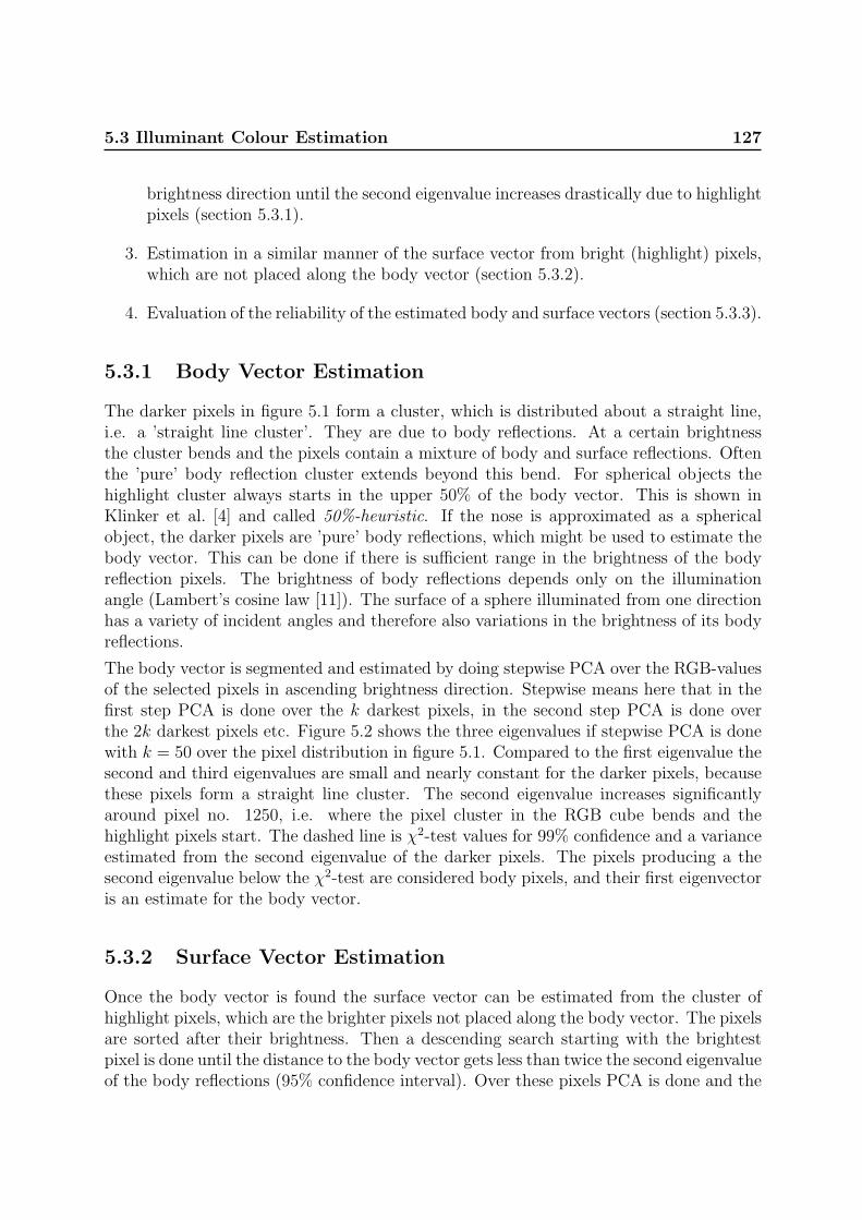
5.3 Illuminant Colour Estimation 127
brightness direction until the second eigenvalue increases drastically due to highlightpixels (section 5.3.1).
3. Estimation in a similar manner of the surface vector from bright (highlight) pixels,which are not placed along the body vector (section 5.3.2).
4. Evaluation of the reliability of the estimated body and surface vectors (section 5.3.3).
5.3.1 Body Vector Estimation
The darker pixels in figure 5.1 form a cluster, which is distributed about a straight line,i.e. a ’straight line cluster’. They are due to body reflections. At a certain brightnessthe cluster bends and the pixels contain a mixture of body and surface reflections. Oftenthe ’pure’ body reflection cluster extends beyond this bend. For spherical objects thehighlight cluster always starts in the upper 50% of the body vector. This is shown inKlinker et al. [4] and called 50%-heuristic. If the nose is approximated as a sphericalobject, the darker pixels are ’pure’ body reflections, which might be used to estimate thebody vector. This can be done if there is sufficient range in the brightness of the bodyreflection pixels. The brightness of body reflections depends only on the illuminationangle (Lambert’s cosine law [11]). The surface of a sphere illuminated from one directionhas a variety of incident angles and therefore also variations in the brightness of its bodyreflections.
The body vector is segmented and estimated by doing stepwise PCA over the RGB-valuesof the selected pixels in ascending brightness direction. Stepwise means here that in thefirst step PCA is done over the k darkest pixels, in the second step PCA is done overthe 2k darkest pixels etc. Figure 5.2 shows the three eigenvalues if stepwise PCA is donewith k = 50 over the pixel distribution in figure 5.1. Compared to the first eigenvalue thesecond and third eigenvalues are small and nearly constant for the darker pixels, becausethese pixels form a straight line cluster. The second eigenvalue increases significantlyaround pixel no. 1250, i.e. where the pixel cluster in the RGB cube bends and thehighlight pixels start. The dashed line is χ2-test values for 99% confidence and a varianceestimated from the second eigenvalue of the darker pixels. The pixels producing a thesecond eigenvalue below the χ2-test are considered body pixels, and their first eigenvectoris an estimate for the body vector.
5.3.2 Surface Vector Estimation
Once the body vector is found the surface vector can be estimated from the cluster ofhighlight pixels, which are the brighter pixels not placed along the body vector. The pixelsare sorted after their brightness. Then a descending search starting with the brightestpixel is done until the distance to the body vector gets less than twice the second eigenvalueof the body reflections (95% confidence interval). Over these pixels PCA is done and the

128 Illuminant from Highlights
0 250 500 750 1000 1250 15000
10
20
30
40
50
number of pixels
eige
nval
ues 1
2 3
Figure 5.2: Eigenvalues of pixel distribution shown in figure 5.1 obtained by doingstepwise PCA in ascending brightness direction. The dashed line is χ2-test values.
first eigenvector is an estimate of the surface vector and, hence, of the illuminant colour.Figure 5.3 shows the segmented body and highlight pixels and the estimated body andsurface vectors.
5.3.3 Reliability Tests of the Estimates
This method requires the presents of highlights, and measures are needed to indicatewhether the estimation of the illuminant colour is reliable.
In theory the body reflections of one material are distributed along a straight line thatstarts at the origin of the RGB cube (R = G = B = 0). If the estimated body vectorpasses far from the origin, the result is unreliable. This might be due to variations in thespectral reflectance of the selected area, i.e. more than one body vector exists. Anothermeasure for the reliability of the body vector estimation is the ratio between its first andthe second eigenvalue. A small ratio indicates that the body reflections are not forming astraight line cluster. This might be due to a small brightness range of the body reflectionand/or a large variation in the spectral reflectance of the selected area, which makes theresult less reliable.
The reflections due to highlights should also be distributed along a straight line thatstarts in the upper 50% of the body vector (50%-heuristic). The surface vector shouldbe further away than some minimum distance to the RGB cube’s origin. A minimumacceptable distance between the surface vector and the origin might be estimated fromthe darkest segmented highlight pixel and a worst case illumination, i.e. in the caseof human skin a reddish illumination (low CCT). A small ratio between first and secondeigenvalue indicates that the highlight reflections do not form a straight line cluster, whichmakes the estimation less reliable. This might be due to a too small number of highlightpixels.

5.4 Results 129
0 50 100 150 200 2500
100
200
0
50
100
150
200
250
Csurf
R
Cbody
G
B
Figure 5.3: Segmented body and highlight pixels from figure 5.1. The solid linesare the estimated body vector Cbody and surface vector Csurf , respectively. Thedashed line is the vector of the illuminant colour under which the image was taken.
5.4 Results
5.4.1 Image Acquisition
For the experimental evaluation of the illuminant colour estimation frontal view imagesof 14 subjects with different shades of skin (Asian, Caucasian, Negro) were taken. Thesubjects were between 20 and 60 years old and had no makeup. The illumination sourcewas a 500W electric light bulb (CCT=3200K). Six different illumination geometries wereused: 0◦, 30◦, 45◦, 60◦, 90◦ from the camera’s optical axis, where the lamp had approxi-mately the same hight as the camera and the subject’s face. For the sixth geometry theface was illuminated from the top with an angle of approximately 80◦ to the camera’soptical axis, called ’top’ in the following. For the 30◦ and 60◦ geometries images were alsotaken with a filter in front of the lamp simulating a CCT of 4700K or 4100K. The lampwas placed in 2 meter distance to the face. The images were acquired with a JAI CV-M903CCD camera. Lens opening and shutter speed were adapted in order to use the dynamicrange of the camera and to avoid clipped pixels in the highlights. The camera was whitebalanced to the 3200K light source. The size of the face images is approximately 350 x450 pixels, which gives an average nose area of 110 x 120 pixels and the measurementarea around the tip of the nose is in average 45 x 45 pixels. Figure 5.5a shows an exampleimage with the measurement area indicated.

130 Illuminant from Highlights
Table 5.1: Estimation error and number of pixels for the different illuminationgeometries.
estimation number of pixeltest error in degree body highlight
geometry min mean max mean mean min0 0.67 1.96 3.84 2326 196 6430 0.36 1.87 3.04 1911 130 5845 0.33 1.88 3.77 1706 86 5760 1.15 2.34 3.60 1513 106 3590 0.86 2.26 4.89 1319 112 31top 0.27 1.31 3.62 2062 254 93
5.4.2 Performance Assessment
In all images a rectangular pixel area around the highlight on the tip of the nose wasselected manually, figure 5.5a. From these pixels the illuminant colour was estimatedby the method described in the previous section. Ground truth of the illuminant colouris needed in order to evaluate the accuracy of the illuminant colour estimation. Theilluminant colour was measured using images of a Barium Sulphate plate, which has anapproximately constant reflectance over all visible wavelengths and reflects thus the colourof the illuminant.
The estimation error is calculated as the angle in degrees between the estimated andthe measured illuminant colour. It is presented in table 5.1 for the different illuminationgeometries. The mean error is about 2◦, i.e. for a light source with CCT=3200K the erroris less than 100K. The maximum error is less than 5◦.
Figure 5.4 shows the chromaticity diagram with measured and estimated illuminant chro-maticities. The estimates tend to be a bit too low in the red component.
Table 5.1 shows also the number of pixels used for the illuminant colour estimation. Themean number of highlight pixels is 136 and the minimum number is 31. The number ofhighlight pixels decreases with increasing illumination angle.
Table 5.2 shows the distances of the body and surface vector from the origin of the RGBcube. The mean distance of the body vectors to the origin is 3.2 and the maximumdistance is less than 10. The ratio between surface vector distance to origin and bodyvector distance to origin was always greater than 4 and usually between 15 and 40.
Another way of evaluating the estimation accuracy is to re-render the images to canonicalconditions for visual inspection. Canonical conditions means that R = G = B for grayvalues. Figure 5.5 of the appendix shows an example. The colours of the corrected imageare very close to those of the canonical reference image.

5.4 Results 131
b=1 r=1
g=1
3200K4700K
Figure 5.4: Chromaticity diagram with measured (4) and estimated (·) illuminantchromaticities for 3200K, 4100K, and 4700K. The solid circles indicate 3◦ error andthe dotted 6◦ error. The dashed line is the Planckian locus of Blackbody radiators.
Table 5.2: Distance from estimated vectors to the origin of the RGB cube for thedifferent illumination geometries. These computations relate to the normalised RGBcube (figure 5.1 and 5.3) with range 0-255 for each axis. The ratio between bodyand surface (surf) distance is given as well.
distance to origin ratiotest body surface surf/body
geometry mean max mean min mean min0 3.6 7.6 54.0 35.7 16.4 7.030 4.5 7.9 51.1 32.4 14.1 6.945 3.7 6.6 52.7 30.2 16.0 8.360 2.1 4.1 54.0 21.5 30.7 13.090 1.8 4.9 38.8 19.6 41.6 6.1top 3.6 9.2 44.8 23.2 32.1 4.4

132 Illuminant from Highlights
5.5 Discussion
The proposed method aims to estimate the illuminant colour from highlights on the tipof the human nose. The questions are: How well can it perform, how realistic is it, andhow robustly can it eventually be made.
Firstly, the performance seems to be within a useful range. Table 5.1 and figure 5.4illustrate that for light sources with CCT’s between 3200K and 4700K the estimatesproduced are fairly accurate, i.e. typically 2◦ compared to an angle of 21◦ between a3200K and a 4700K light source.
Secondly, the method and current results are based on a number of assumptions andconstraints. Direct illumination is required. The method was tested for frontal viewimages using one light source. In future work non-frontal views and mixtures of directand ambient illumination having different colours will be investigated. The number ofhighlight pixels has to be sufficient (> 30?) for a reliable estimation, which requires arelatively high resolution as a highlight area on the tip of the nose has usually a diameterof only a few millimetres. This potential problem may be of less importance in futuresince the resolution of new sensors is still increasing, 2 Mega pixels are standard for digitalconsumer cameras. The opening and shutter speed of the camera have to be adapted inorder to avoid sensor overflow in the highlight area. This might be a problem becausesome image areas may become quite dark. This could be overcome with sensors of higherdynamic range in their sensitivity.
The area around the highlight was selected manually. It is possible to detect the noseautomatically and by that automate the estimation, e.g. for use in broadcasting camerasin order to correct the white balance of the camera.
Thirdly, in everyday situations the nose is rarely occluded and provides due to its convexform highlights under a large variety of direct illumination and viewing geometries. Ad-ditional pilot experiments with makeup and freckles were done. Makeup did not influencethe estimation accuracy but reduced the number of highlight pixels and the brightnessrange of the highlight pixels. Freckles, which coincided with the highlight, increased theestimation error. In section 5.3.3 measures were suggested to build a self-test in order tocheck the reliability of the estimates. In the case of freckles the ratio between the first andsecond eigenvalue of the surface vector estimation was significantly smaller than usuallyand could therefore be considered unreliable.
Non of the points discussed above are prohibitive for the principle of use. Furthermore,the method is real-time feasible because the number of pixels to process is small.
5.6 Conclusions
The purpose of this paper was to investigate how accurately the illuminant colour couldbe estimated from highlights on tip of the human nose.
BIBLIOGRAPHY 133
The results show an encouraging accuracy of about 2◦ between the correct (measured)illuminant colour and the estimated illuminant colour when described in the RGB-cube.For practical purposes this seems accurate enough, although no concrete criteria for thisevaluation is available yet. However, the potential of the method is confirmed and anumber of measures are introduced to allow the method to evaluate the reliability of itsestimate in a given case. When further developed the method is expected to be useful fora number of applications.
Acknowledgements
We would like to thank the European Commission’s TMR research network SMART II,contract no. ERBFMRX-CT96-0052, for supporting this research.
Bibliography
[1] Anderson, R.R., Hu, J., and Parrish, J.A. Optical radiation transfer in the humanskin and applications in in vivo remittance spectroscopy. In Marks, R. and Payne,P.A., editors, Bioengineering and the Skin, chapter 28, pages 253–265. MTP PressLimited, 1981.
[2] Finlayson, G. and Schaefer, G. Single surface colour constancy. In 7th Color ImagingConf., pages 106–113, Scottsdale, Arizona, USA, Nov. 1999.
[3] Funt, B., Barnard, K., and Martin, L. Is machine colour constancy good enough? InBurkhardt, H. and Neumann, B., editors, 5th European Conf. on Computer Vision,pages 445–459, Freiburg, Germany, June 1998.
[4] Klinker, G.J., Shafer, S.A., and Kanade, T. A physical approach to color imageunderstanding. Int. J. of Computer Vision, 4(1):7–38, Jan. 1990.
[5] McKenna, S.J., Gong, S., and Raja, Y. Modelling facial colour and identity withGaussian mixtures. Pattern Recognition, 31(12):1883–1892, Dec. 1998.
[6] Moeslund, T.B. and Granum, E. Multiple cues used in model-based human motioncapture. In 4th IEEE Int. Conf. on Automatic Face- and Gesture-Recognition, pages362–367, Grenoble, France, Mar. 2000.
[7] Shafer, S.A. Using color to separate reflection components. COLOR Research andApplication, 10(4):210–218, 1985.
[8] Storring, M., Andersen, H.J., and Granum, E. Estimation of the illuminant colourfrom human skin colour. In 4th IEEE Int. Conf. on Automatic Face- and Gesture-Recognition, pages 64–69, Grenoble, France, Mar. 2000.

134 Illuminant from Highlights
[9] Storring, M., Granum, E., and Andersen, H.J. Estimation of the illuminant colourusing highlights from human skin. In First Int. Conf. on Color in Graphics andImage Processing, pages 45–50, Saint-Etienne, France, Oct. 2000.
[10] Tominaga, S. Dichromatic reflection models for a variety of materials. COLORresearch and application, 19(4):277–285, Aug. 1994.
[11] Wyszecki, G. and Stiles, W.S. Color Science: Concepts and Methods, QuantitativeData and Formulae. John Wiley and Sons, 1982.
[12] Yow, K.C. and Cipolla, R. Feature-based human face detection. Image and VisionComputing, 15(9):713–735, 1997.
APPENDIX
One possible application of the illuminant colour estimation is to re-render images tocanonical conditions, i.e. gray values will have the property that R = G = B. A re-rendering result is shown in figure 5.5 where the image in the centre is the re-renderedversion of right image. It can be seen that the colours in the left image are approximatelythe same as in the centre image. The estimation error of the illuminant colour from theright image is 1.6◦, and the correction made corresponds to about 21◦.
Figure 5.5: Correction of colour images to canonical conditions. Left: Imagetaken under canonical conditions (CCT=3200K). The dashed rectangle is the se-lected area used for the estimation. Centre: Right image corrected to canoni-cal conditions using the illuminant colour estimate. Right: Image taken underCCT=4700K. Images were taken under 30◦ incident angle. For colour images see:http://www.cvmt.dk/∼mst/cgip2000.html

Chapter 6
Tracking regions of human skinthrough illumination changes

136

137
Tracking regions of human skin through illumination changes
Moritz Storringa, Tomas Kockab, Hans Jørgen Andersena, and Erik Granuma
aComputer Vision and Media Technology Laboratory,Aalborg University, Niels Jernes Vej 14, DK-9220 Aalborg, Denmark
bInstitute for Computer Science, Aalborg UniversityFredrik Bajers Vej 7E, DK-9220 Aalborg, Denmark
Abstract
New human computer interfaces are using computer vision systems to trackfaces and hands. A critical task in such systems is the segmentation. Anoften used approach is colour based segmentation, approximating the skinchromaticities with a statistical model, e.g. with mean value and covariancematrix. The advantage of this approach is that it is invariant to size andorientation and fast to compute. A disadvantage is that it is sensitive tochanges of the illumination, and in particular to changes in the illuminationcolour.This paper investigates (1) how accurately the covariance matrix of skinchromaticities might be modelled for different illumination colours using aphysics-based approach, (2) how this may be used as a feature to classify be-tween skin and other materials. Results are presented using real image datataken under different illumination colours and from subjects with differentshades of skin. The eigenvectors of the modelled and measured covariancesdeviate in orientation about 4◦. The feature to distinguish skin from othersurfaces is tested on sequences with changing illumination conditions con-taining hands and other materials. In most cases it is possible to distinguishbetween skin and other objects.
Published in:
Storring, M., Kocka, T., Andersen, H.J., and Granum, E. Tracking regions of human skinthrough illumination changes. Pattern Recognition Letters, 24(11):1715–1723, July 2003

138 Tracking Human Skin
6.1 Introduction
Computer vision based tracking of human faces and hands has many applications, e.g.in human computer interfaces and surveillance systems. Different cues may be used fortracking, such as motion, shape, and colour. Each of these cues may fail under certainconditions, e.g. nothing is moving, rapid changes in shape, or changing illumination,respectively. In order to get more robust systems it has been suggested to fuse theinformation of multiple cues [3; 11; 17].
An often used cue is skin colour segmentation because it is invariant to size and orien-tation and fast to compute. Several approaches have been proposed, some statisticallybased, e.g. [6; 18], and some physics based, e.g. [10; 13]. A problem when using skin colouras a feature arises under varying lighting conditions. In particular changes in the spec-tral composition of the scene illumination may result in failures of colour segmentationmethods [5].
Yang et al. [18] and Storring and Granum [14] showed that the facial skin chromaticitydistribution of an individual under a single light source may be approximated by a multi-variate normal distribution in the red-green chromaticity plane. Yang et al. [18] proposedan adaptive statistical skin colour model updating the mean vector and the covariancematrix of the red-green chromaticities as the lighting conditions change. The model isused in a real-time face tracker and works under slightly changing indoor illuminationconditions.
McKenna et al. [6] use Gaussian mixtures to model the skin colour distribution in Hue-Saturation space. The model parameters are updated over time in order to adapt tochanges in illumination and viewing direction.
A problem with adapting the parameters of a statistical colour model during tracking isthe lack of ground-truth of the region of interest [6], i.e. the colour model might adapt toimage regions which do not belong to the skin coloured object and, hence, result in falsepositives and/or false negatives. Particularly under rapid illumination changes, e.g. fromindoor to outdoor illumination when opening the curtains or blinds of a window, the skinchromaticities are changing significantly.
In Storring et al. [13] skin chromaticities for different illuminations are modelled with agood approximation by a physics-based approach. The model uses knowledge about thecamera parameters and assumes that commonly used in- and outdoor light sources can bemodelled by blackbody radiators [4]. The skin chromaticities for a variety of illuminationswith different correlated colour temperatures (CCT) form a ’skin locus’ which follows thecurvature of the Planckian locus of blackbody radiators, figure 6.2. This might be usedto constrain the search area for skin colour in the chromaticity plane.
Soriano et al. [10] presented a face tracking system working outdoors under changing il-lumination conditions. They constrained the search area by the skin locus. Inside theskin locus a non-parametric skin colour model is learned and updated by histogram back-projection. Histogram backprojection has the same drawback as adapting the statistical

6.2 Theory and Background 139
model, i.e. the histogram might adapt to non-skin coloured objects in the background.
Adapting to non-skin objects might be avoided if the statistical skin colour model wouldbe constrained by physics-based knowledge about possible skin distributions. This isinvestigated in this paper, and in particular:
1. how accurately may the eigenspace of a skin chromaticity covariance matrix bemodelled for illuminations with arbitrary CCTs by using a physics-based approach.
2. using the modelled eigenspace, how well may a skin area be distinguished from otherskin-like objects under varying illumination, given a reference image of the skin areais available.
The paper is organised as follows: Section 6.2 gives an overview on statistical and physics-based modelling of skin colour. Section 6.3 proposes a method to model the covariancematrix of skin chromaticities under arbitrary illumination, which is used in section 6.4 toderive a feature to classify between skin and other objects. In section 6.5 experimentalresults are given which is followed by a discussion and conclusions.
6.2 Theory and Background
This section provides a brief overview of the reflection properties of human skin and howthey might be approximated with a statistical and a physics-based model.
6.2.1 Skin chromaticities
Reflections of human skin may be modelled with the Dichromatic Reflection Model [9]as surface and body/matte reflections. Most of the facial skin area shows ’pure’ bodyreflections [2; 13]. Even under direct illumination highlights occur usually not on theentire face but only on some areas, e.g. the nose, forehead, or cheeks, respectively, andmight be removed by filtering [15]. Therefore in the following only body reflections areconsidered. Furthermore, it is assumed that the investigated skin areas are illuminatedby a ’single’ light source. This single light source may be a mixture of several sourceshaving different spectral compositions. The constraint is that the mixture is uniform forthe investigated skin area. For spatially non-uniform illumination see e.g. [1].
In colour machine vision it is common to represent each pixel by a 3D vector CRGB con-taining the red, green, and blue camera responses. For analysing colours independent ofthe scale of intensity, it is convenient to transform a colour vector CRGB to its correspond-ing chromaticity crgb. This is done by normalising the colour vector elements (R,G, B)with their first norm (L = R + G + B):
cr =R
L, cg =
G
L, cb =
B
L(6.1)
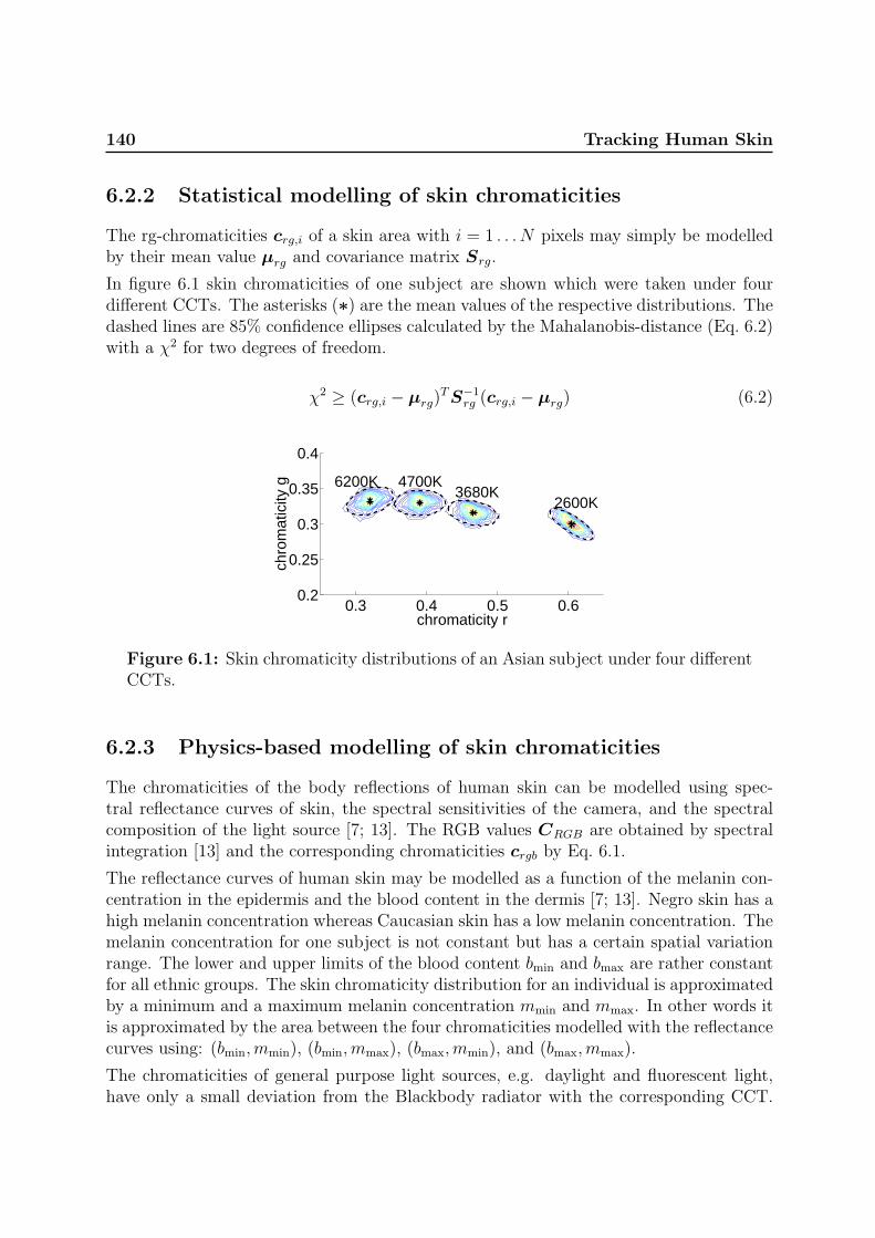
140 Tracking Human Skin
6.2.2 Statistical modelling of skin chromaticities
The rg-chromaticities crg,i of a skin area with i = 1 . . . N pixels may simply be modelledby their mean value µrg and covariance matrix Srg.
In figure 6.1 skin chromaticities of one subject are shown which were taken under fourdifferent CCTs. The asterisks (∗) are the mean values of the respective distributions. Thedashed lines are 85% confidence ellipses calculated by the Mahalanobis-distance (Eq. 6.2)with a χ2 for two degrees of freedom.
χ2 ≥ (crg,i − µrg)T S−1
rg (crg,i − µrg) (6.2)
0.3 0.4 0.5 0.60.2
0.25
0.3
0.35
0.4
chromaticity r
chro
mat
icity
g 6200K 4700K3680K
2600K
Figure 6.1: Skin chromaticity distributions of an Asian subject under four differentCCTs.
6.2.3 Physics-based modelling of skin chromaticities
The chromaticities of the body reflections of human skin can be modelled using spec-tral reflectance curves of skin, the spectral sensitivities of the camera, and the spectralcomposition of the light source [7; 13]. The RGB values CRGB are obtained by spectralintegration [13] and the corresponding chromaticities crgb by Eq. 6.1.
The reflectance curves of human skin may be modelled as a function of the melanin con-centration in the epidermis and the blood content in the dermis [7; 13]. Negro skin has ahigh melanin concentration whereas Caucasian skin has a low melanin concentration. Themelanin concentration for one subject is not constant but has a certain spatial variationrange. The lower and upper limits of the blood content bmin and bmax are rather constantfor all ethnic groups. The skin chromaticity distribution for an individual is approximatedby a minimum and a maximum melanin concentration mmin and mmax. In other words itis approximated by the area between the four chromaticities modelled with the reflectancecurves using: (bmin,mmin), (bmin,mmax), (bmax,mmin), and (bmax,mmax).
The chromaticities of general purpose light sources, e.g. daylight and fluorescent light,have only a small deviation from the Blackbody radiator with the corresponding CCT.

6.3 Adapting statistical models to changing illumination 141
0 0.2 0.4 0.6 0.8 10
0.2
0.4
0.6
0.8
1
chromaticity r
chro
mat
icity
g
1500K
2500K3700K6100K
25000K
Planckian Locus
Skin Reflectance Loci
Illuminant
cCN
cCE
cN
Figure 6.2: Illuminant- and body reflection-chromaticities of skin modelled for anumber of Blackbody illuminants (Planckian locus), from [13].
Finlayson and Schaefer [4] measured 172 light sources, including daylights and fluorescent.They report that the illuminant chromaticities fall on a long thin band in the chromaticityplane which is very close to the Planckian locus of Blackbody radiators. Light sourceswill in the following be approximated by Blackbody radiators of the same CCT as thelight source, which was successfully done in [13].
Figure 6.2 shows the red and green chromaticities of a number of Blackbody illuminantsranging from 1500 to 25000K (Planckian locus), plotted as triangles (M). The figure ismodelled for a Blackbody radiator with a CCT=3700K as canonical light source (whitebalance source). Two body reflection chromaticities, plotted as squares (¤), are modelledfor each illuminant using the Caucasian reflectance curves for low and for high bloodcontent, called cCN and cCE, respectively. The solid lines indicate the corresponding illu-minant and body chromaticities. The asterisk (∗) shows the body reflectance chromaticityfor Negro skin cN , i.e. with high melanin concentration.
6.3 Adapting statistical models to changing illumi-
nation
The method proposed in this paper uses physics-based knowledge to estimate how thestatistical model will change as the illumination changes. A necessary condition for thisis to find how these types of models can be related.
Firstly, we consider how the distributions of the skin chromaticities change as illustratedin figure 6.1 (see also figure 6.4 and 6.5). They change position along the skin locus andthe major and minor axes (eigenspace of the covariance matrix) change in orientation and

142 Tracking Human Skin
aspect ratio.
The physics-based model describes an expected area for the chromaticities given the CCTand some biological parameters of the human skin. This area can also be described by amajor and minor axes, hence an eigenspace, such that if the biological parameters for agiven individual are known, the eigenspace can be estimated for any CCT.
The question is if the physics-based and the statistical model can be adequately relatedvia their eigenspaces described above. If so, an initial ’calibration’ of the two models canbe established from a reference image, and parameters of the statistical model can thenbe estimated for any CCT.
To demonstrate and test if the eigenspace description may have practical use, we presenta procedure including two steps, initialisation for calibration, and then estimation ofeigenspaces for arbitrary CCTs.
6.3.1 Initialisation
Given is a reference image with a pre-segmented area of skin, and with known CCT of theillumination. The corresponding skin chromaticities are denoted Crg. The eigenvectorsvC and -values λC of Crg are calculated.
The next step is to find the physics-based model, which through maximum and minimummelanin and blood parameters defines an area with an eigenspace vM , λM that matchesvC , λC .
An iterative procedure scans through relevant combinations of these parameters testingfor the orientation deviation between vC and vM . Among those configurations with adeviation below some threshold, here 0.8◦, we chose the best fitting aspect ratio definedas
min
(∣∣∣∣λC,1
λC,2
− λM,1
λM,2
∣∣∣∣)
. (6.3)
From the selected configuration we get the melanin parameters as the major result of theinitialisation. To compensate for coarseness of our model (e.g. blood content independentof individuals/ethnic groups) we also introduce a diagonal matrix k relating the modelledand measured eigenvalues,
k11 =λC,1
λM,1
k22 =λC,2
λM,2
. (6.4)
6.3.2 Estimating eigenspaces for arbitrary CCTs
Using the parameters estimated from the reference image we get four skin reflectancecurves. Together with the camera sensitivities, and the Blackbody spectrum of the CCT

6.4 Skin-colour feature for segmented regions 143
in question an expected area for the skin chromaticities can be computed. Hence, aneigenspace (vM , λM) can be estimated for any CCT. This eigenspace can be used toestimate the expected covariance matrix M of the measurements for the CCT in question,
M = vM · λM · k · vM . (6.5)
6.4 Skin-colour feature for segmented regions
This section proposes a feature that indicates which of i = 1 . . . K (pre-segmented) imageareas Di corresponds to a skin model that had been initialised using a reference skin areain some previous image frame. Such a feature is of interest in tracking applications toclassify a segmentation result, in particular after rapid illumination changes when thecamera needs some frames to adapt the shutter speed and iris before providing usefulimage data.
In the previous section we have suggested a skin colour model Mskin that is a subsetof two-dimensional normal distributions parametrised by the CCT. A given area in theimage and data Di sampled from this area are assumed to come from some model Mo ofthe same type, not necessarily skin. The set of all such possible generative models Mo isequal to the set of all normal distributions.
The probability p(Mskin|Di) that the pixel chromaticities of an image area Di were gen-erated by the skin model Mskin may be used as such a feature. We will show how tocompute this probability up to a constant scaling factor, independent of the used data.This can be computed by Bayes’ rule:
p(Mskin|Di) =p(Di|Mskin)p(Mskin)
p(Di)(6.6)
where
p(Di) =∑
o
p(Di|Mo)p(Mo) (6.7)
and
log(p(Mskin)) = const (6.8)
because we have no prior knowledge we assume it to be constant and independent of thedata.
Instead of using eq. 6.6 it is numerically easier to compute
log(p(Mskin|Di)) = log(p(Di|Mskin)) + log(p(Mskin))− log(p(Di)) . (6.9)

144 Tracking Human Skin
For a given image area Di the maximum likelihood CCT parameter of the model Mskin
can be fitted. Assuming that Di is skin, the CCT of the illumination is estimated usinga simplified version of a method proposed in [12]. Mskin is then computed for this CCTas explained in section 6.3.2, given a skin model was initialised (section 6.3.1) with areference image.
log(p(Di|Mskin)) from eq. 6.6 can be approximated by the Bayesian Information Crite-rion [8] which together with the assumption of identically and independently distributed(iid) data Di with l = 1 . . . N cases gives
log(p(Di|Mskin)) =N∑
l=1
log p(xi,l|Mskin(CCT )) . (6.10)
The number of cases N is the number of pixels of an image area Di. xi,l is the chromaticityof the lth pixel in the ith image area. p(xi,l|Mskin(CCT )) is assumed Gaussian [14] andis easy to compute.
log(p(Di)) may be again approximated by the Bayesian Information Criterion [8] since itis an ordinary two dimensional distribution:
log(p(Di)) =∑
o
p(Di|Mo)p(Mo) = log(p(Di|θML,i))− d/2 log(N) (6.11)
where θML,i is the maximum likelihood parameter of the normal distribution given thedata Di, and d is the dimension of the model.
From eq. 6.9, 6.8, and 6.11 follows
log(p(Mskin|Di)) ≈ ri = log(p(Di|Mskin(CCT )))− log(p(Di|θML,i)) (6.12)
where we leave out d/2 log(N) and log(p(Mskin)) as they are both constant.
The larger the value of ri is, the more likely it is that a skin-model Mskin can explainthe data. The last term expresses how well the measurements of region Di matchesGaussian distributions directly, while the first measures match to distributions estimatedon the assumption that the data represents reflections from human skin according tosection 6.3. As the estimation of the skin-model is also based on the assumptions ofGaussian distributions of data it is expected that eq. 6.12 will always be negative, withzero as the ideal case.
We now have a feature to measure skin for arbitrary illuminations if a ”calibration” froma reference image, which defines the skin model Mskin, is available.

6.5 Experiments 145
6.5 Experiments
In the following two sets of experiments will be presented. First the method to modelthe covariance matrix (section 6.3) is tested using one reference CCT and 3 test CCTs.Images of faces of 8 subjects having different ethnic backgrounds (China, Iran, Cameroun,Latvia, Greece, Spain, Denmark, and India) were captured, so that altogether 32 imageswere used. For each reference there are 3 test images used to compare the estimatedstatistical model with the measurements.
Secondly, the feature proposed in section 6.4 will be tested using image sequences takenunder varying illumination conditions of a desktop environment containing a human handand other objects with chromaticities included in the skin locus, e.g. paper, wood, andcardboard, respectively.
6.5.1 Image acquisition
The images were captured with a JAI CV-M90 3CCD camera. Automatic gain controland automatic white balancing are switched off and gamma correction is set to one.
Face images:
The lens aperture and the shutter speed are manually adjusted to make optimal use ofthe dynamic range of the camera. The light sources are fluorescent lamps (Philips TLD927, 940, 950, 965) with CCTs of 2600, 3680, 4700, and 6200K, respectively. The spectraof these lamps are provided from Philips and were additionally measured with a J&MTIDAS spectrometer. The measured spectra were used to calculate their CCTs. Theilluminance on the faces is approximately 2000lux as it is recommended by JAI. Thereare no pronounced highlights on the faces. The number of pixels of a face is between5000 and 15000. The camera is white balanced to the 3680K lamp. An example image isshown in figure 6.3 (left). All images were hand segmented into facial skin areas, whichare used in the following for evaluating the method.
Image sequences of hands:
The camera is set to auto-shutter in order to adjust to intensity changes. The light sourceis a 500W electric light bulb (OSRAM Nitraphot B). Its CCT can be varied between 2500and 3400K by varying the voltage, and between 4300 and 5200K when using a daylightfilter in front of the light source. The used CCTs can be seen in figure 6.6(a). Imagesequences were captured of a static desktop environment containing a Caucasian handand several surfaces with chromaticities that are included in the skin locus. These arewood, cardboard, paper with different gray shades and colour tones. They have varyingsurface properties from glossy to diffuse. The camera was white balanced to 3200K. Anexample image is shown in figure 6.3 (right).

146 Tracking Human Skin
Figure 6.3: Example Images (left) of a face, (right) of a desktop environment.Examples of colour images are available at http://www.cvmt.dk/∼mst/ras.html
6.5.2 Physics based modelling of eigenspaces
The images taken at a CCT=3680K were used to estimate the parameters of the methodas it was described in section 6.3.1. Then the covariance matrices for the CCT=2600,4700, and 6200K, respectively, were modelled as described in section 6.3.2.
Figures 6.4 and 6.5 show example results with measured and modelled confidence ellipses.To allow comparison of the measured and the modelled covariances, their eigenvectorsand eigenvalues are given in table 6.1. The average of the absolute angular deviationbetween measured and modelled orientation is about 4◦ and maximal 9.8◦. The averagedeviation between the lengths of the vectors is 6 %.
0.3 0.4 0.5 0.60.2
0.25
0.3
0.35
0.4
chromaticity r
chro
mat
icity
g 6200K 4700K3680K
2600K
Figure 6.4: Skin chromaticities for a Caucasian subject under four different CCTs.The solid lines are the measured ellipses and the dashed lines are the modelledellipses.

6.5 Experiments 147
0.3 0.4 0.5 0.60.2
0.25
0.3
0.35
0.4
chromaticity r
chro
mat
icity
g 6200K 4700K3680K
2600K
Figure 6.5: Skin chromaticities for a Negro subject under four different CCTs. Thesolid lines are the measured ellipses and the dashed lines are the modelled ellipses.
Table 6.1: Deviations between measured and modelled data for 3 test CCTs and 8subjects. The angle error is the angle between the eigenvectors. The eigenvalue erroris the deviation between the square roots of the measured and modelled eigenvaluesin %. The numbers in brackets are from the initialisation data.
illumi- angle error eigenvalue errors in %nation in degree first secondCCT mean max mean max mean max2600 2.7 7.5 4.8 8.7 6.1 15.7
(3680) (0.3) (0.8) (0.0) (0.0) (0.0) (0.0)4700 3.7 5.2 3.8 8.1 6.0 16.56200 4.5 9.8 6.5 12.2 8.0 16.9
6.5.3 Tracking and discriminating Skin through varying illumi-nation
The images sequences of the static desktop environment were used to test the feature ri
that was proposed in section 6.4. Two skin areas and eight areas of other surfaces wereselected, each of N = 1500 pixels. A skin model was initialised from one of the skin areasof an image take at a CCT = 3200K.
The CCT of the illumination is varying between 2500 and 5200K as can be seen infigure 6.6(a).
Figure 6.6(b) shows ri for all selected areas over the 350 frames of an image sequence.The solid lines are for the two skin areas, the dashed for the other eight areas.
For both skin areas ri performs in most cases better than for the other areas, i.e. closer tozero. It fails above 4600K and below 2700K. Around the frames 125 and 160 all ri have anegative peek. This is due to big abrupt changes in intensity that results in overexposedand underexposed images, respectively. The camera needs some frames to adapt theshutter speed.
Figure 6.6(c) shows ri for the same sequence, but three skin models for different CCTs

148 Tracking Human Skin
50 100 150 200 250 300 3502000
4000
6000C
CT
(in
K) (a)
50 100 150 200 250 300 350−1500
−1000
−500
0
r i
(b)
50 100 150 200 250 300 350−1500
−1000
−500
0
r i
(c)
frames
Figure 6.6: Image sequence taken under varying illumination colour and intensity.(a) CCT, (b) ri using one skin model initialised at 3200K, (c) ri using three modelsinitialised at 2600, 3200, and 4800K. In (b) and (c) the two solid lines (close to zero)are the ri for the skin areas and the dashed lines are the ri for other surface areas.The image sequence is available at http://www.cvmt.dk/∼mst/Publications/phd/.
(2600, 3200, and 4800K) were initialised instead of only one model in figure 6.6(b). Nowthe ri of the skin areas are in all frames performing better than the ri of the other surfaceareas.
6.6 Discussion
This paper proposed (1) a method to estimate the covariance matrices and eigenspaces ofan individual’s skin chromaticity distribution for illuminations with arbitrary CCTs, and(2) its application as a skin-colour feature for segmented regions. We have tested (1) for8 very different skin types, and with 3 illuminations for each. The average of the absolutedeviation between measured and estimated orientations of the eigenspaces is about 4◦
and the maximum about 10◦. The average deviation between the lengths of the vectorsis about 6%.
The deviations are due to measurement noise during the image acquisition and the ap-proximations in modelling. The light spectra are approximated by blackbody radiatorswhich very coarsely match spectra of fluorescent lamps. They may introduce a smallerror, especially in the green chromaticity [13].

6.7 Conclusions 149
A skin-colour feature (2) to classify segmented regions between skin and other surfacesis suggested. It is tested on images sequences simulating illumination conditions rangingfrom indoor to outdoor, and containing surfaces with chromaticities included in the skinlocus. The feature works well between 2700 and 4600K, if one image taken at 3200K isused for initialisation. This is sufficient for most indoor illuminations. If several imagestaken under different illuminations were used for initialisation, the feature works on theentire test sequences, i.e. between 2500 and 5200K. It is not an absolute probability thatan area is skin, but it is proportional up to a constant. In figure 6.6 the ri is ratherconstant for skin. It might be possible to use ri as well as an absolute probability that anarea is skin. However, to confirm this more tests with different shades of skin and morevariety of surfaces will be required.
The method requires knowledge about an (approximate) CCT of the current illumination.This was estimated from the mean value of the measured skin chromaticities using asimplified version of a method proposed in [12].
Figures 6.1, 6.4, and 6.5 show the distributions of an Asian, a Caucasian, and a Negrosubject. A model for each individual is estimated. It can be seen that they differ fromeach other. This difference might be used to track and distinguish the skin of multiplefaces or hands in an image.
6.7 Conclusions
In this paper the linking of a statistical with a physics-based skin colour model wasinvestigated. It was demonstrated that the covariance matrix and the eigenspace of skinchromaticities can be modelled for different illuminations using a physics-based approach.The average orientation error is about 4◦, the average deviation between the lengths ofthe vectors is about 6 %.
Furthermore, using the proposed method a feature was suggested indicating which areain an image is most likely to be skin. The performance of this feature seems to be usefulto allow significant support of skin detection methods, i.e. improving their robustness toillumination changes.
In future work the skin reflection model could be improved and by that improving theaccuracy of the feature ri. Furthermore, priors p(Mi) might be estimated from other cues.This would enable the possibility for an absolute probability whether an area is skin.
Bibliography
[1] Andersen, H.J. and Granum, E. Classifying illumination condition from two lightsources by colour histogram assessment. J. of the Optical Society of America A, 17(4):667–676, Apr. 2000.

150 Tracking Human Skin
[2] Anderson, R.R., Hu, J., and Parrish, J.A. Optical radiation transfer in the humanskin and applications in in vivo remittance spectroscopy. In Marks, R. and Payne,P.A., editors, Bioengineering and the Skin, chapter 28, pages 253–265. MTP PressLimited, 1981.
[3] Crowley, J.L. and Berard, F. Multi-modal tracking of faces for video communications.In IEEE Conf. on Computer Vision and Pattern Recognition, pages 640–645, SanJuan, Puerto Rico, June 1997.
[4] Finlayson, G.D. and Schaefer, G. Solving for colour constancy using a constraineddichromatic reflection model. Int. J. of Computer Vision, 42(3):127–144, May 2001.
[5] Funt, B., Barnard, K., and Martin, L. Is machine colour constancy good enough? InBurkhardt, H. and Neumann, B., editors, 5th European Conf. on Computer Vision,pages 445–459, Freiburg, Germany, June 1998.
[6] McKenna, S.J., Raja, Y., and Gong, S. Tracking colour objects using adaptivemixture models. Image and Vision Computing, 17(3–4):225–231, 1999.
[7] Ohtsuki, T. and Healey, G. Using color and geometric models for extracting facialfeatures. J. of Imaging Science and Technology, 42(6):554–561, Dec. 1998.
[8] Schwarz, G. Estimating the dimension of a model. Annals of Statistics, 6:461–464,1978.
[9] Shafer, S.A. Using color to separate reflection components. COLOR Research andApplication, 10(4):210–218, 1985.
[10] Soriano, M., Martinkauppi, B., Huovinen, S., and Laaksonen, M. Skin detection invideo under changing illumination conditions. In Int. Conf. on Pattern Recognition,volume 1, pages 839–842, Barcelona, Spain, Sept. 2000.
[11] Spengler, M. and Schiele, B. Towards robust multi-cue integration for visual tracking.In Schiele, B. and Sagerer, G., editors, Int. Workshop on Computer Vision Systems,volume 2095 of LNCS, pages 93–106, Vancouver, Canada, July 2001.
[12] Storring, M., Andersen, H.J., and Granum, E. Estimation of the illuminant colourfrom human skin colour. In 4th IEEE Int. Conf. on Automatic Face- and Gesture-Recognition, pages 64–69, Grenoble, France, Mar. 2000.
[13] Storring, M., Andersen, H.J., and Granum, E. Physics-based modelling of humanskin under mixed illuminants. J. of Robotics and Autonomous Systems, 35(3–4):131–142, June 2001.
[14] Storring, M. and Granum, E. Adapting a statistical skin colour model to illuminationchanges. In IS&T’s First Europ. Conf. on Color in Graphics, Images and Vision,pages 16–21, Poitiers, France, Apr. 2002.

BIBLIOGRAPHY 151
[15] Storring, M., Granum, E., and Andersen, H.J. Estimation of the illuminant colourusing highlights from human skin. In First Int. Conf. on Color in Graphics andImage Processing, pages 45–50, Saint-Etienne, France, Oct. 2000.
[16] Storring, M., Kocka, T., Andersen, H.J., and Granum, E. Tracking regions of humanskin through illumination changes. Pattern Recognition Letters, 24(11):1715–1723,July 2003.
[17] Triesch, J. and von der Malsburg, C. Self-organized integration of adaptive visualcues for face tracking. In 4th IEEE Int. Conf. on Automatic Face- and Gesture-Recognition, pages 102–107, Grenoble, France, Mar. 2000.
[18] Yang, J., Lu, W., and Waibel, A. Skin-color modeling and adaptation. In Chin,R. and Pong, T.C., editors, 3rd Asian Conf. on Computer Vision, volume 1352 ofLNCS, pages 687–694, Hong Kong, China, Jan. 1998.

152 Tracking Human Skin

Chapter 7
A multispectral approach to robusthuman skin detection

154

155
A multispectral approach to robust human skin detection
Moritz Storring, Hans J. Andersen, and Erik Granum
Computer Vision and Media Technology Laboratory,Aalborg University, Niels Jernes Vej 14, DK-9220 Aalborg, Denmark
Abstract
Using multiple wave-bands is common in multispectral imaging andremote sensing, e.g., to enable improved reproduction of colours orto detect the crop status in a field, respectively. Computer vi-sion methods, however, mainly rely on monochrome or RGB wave-bands, although segmentation tasks might be improved consider-ably using more or other wave-bands than the standard RGB.This paper presents and investigates a new approach for detectinghuman skin using a combination of standard RGB bands and threenear infrared bands. Simulations under changing illumination con-ditions and a preliminary experiment show an improved robustnessover pure RGB based approaches.
Published in:
Storring, M., Andersen, H.J., and Granum, E. A multispectral approach to robust humanskin detection. In IS&T’s Second Europ. Conf. on Color in Graphics, Images and Vision,pages 110–115, Aachen, Germany, Apr. 2004

156 Multispectral Skin Detection
7.1 Introduction
Robust face and hand tracking is important for applications such as face and gesturerecognition in interfaces for HCI (human computer interaction). An often used approachto do unobtrusive tracking is computer vision. Robust and reliable segmentation of humanskin is then crucial for the success of such a system. The segmentation may be doneusing cues like colour, motion, or shape. Skin colour detection is more and more used [13]because it is invariant to size, shape, and viewing direction. However, other materials withdifferent spectral compositions than skin may have the same RGB colour components asskin, i.e. metamerism [6], and hence result in false detections. Furthermore, changes inthe illumination spectrum may cause changes in the light reflected by skin, i.e. changesin the apparent skin colour, which may also cause false positives or negatives [21].
These problems might be overcome using other wave-bands than the three RGB bandsor more bands, which is commonly done in other fields like multispectral imaging orremote sensing. Multispectral imaging got much attention in the past decade for accuratereproduction, archiving or food-inspection using 30 bands or even more in the visiblespectrum. This is usually done under controlled illumination and environment conditions.A series of workshops has been held on multispectral imaging [2] and various end userproducts are becoming available, e.g. Sony recently released a four colour CCD [20] withtwo bands in the green wavelengths for better colour reproduction.
Despite the success of using multiple wave-bands in multispectral imaging and remotesensing, this has not yet found much attention in the computer vision community exceptfor some few special applications, e.g. agricultural applications [3; 7]. Approaches usingmore than one wave-band are usually based on the RGB bands of colour cameras, oftenconsumer quality cameras, e.g. webcams.
Angelopoulou et al. [6] investigated the spectral reflectance of skin and presented a multi-spectral skin colour modelling approach using five Gaussian distributions. They suggestedto capture skin reflectance with five bandpass filters assuming the illumination is known.In [18] it is shown that skin reflectance spectra may be used not only to detect, butalso to recognise individual people. Other approaches for detecting skin are using nearinfrared (1-3µm) and far infrared (5-8µm) cameras, respectively [9; 10]. However, thesecameras have low resolutions and are rather expensive because they cannot use standardsilicon technology which is sensitive only up to wavelengths of 1.1µm (see dashed curvein figure 7.3).
In this paper a multispectral approach for skin detection under multiple illuminations ispresented. In particular, a combination of standard RGB bands with three NIR (nearinfrared) bands below 1µm is investigated.
The next section briefly reviews the theory used in this paper. Then the proposed methodand simulation results are presented, which is followed by an initial experiment. Finallythe results and the applicability are discussed.

7.2 Background 157
7.2 Background
The reflected light from a material may be described with the Dichromatic ReflectionModel [14] which states that the reflected light is the sum of the material’s body andsurface reflections. Surface reflections are taking place directly at the material’s surfacewithout penetrating into it. They have approximately the same spectral composition asthe light source and under certain illumination and viewing geometries they give high-lights. These are not considered in the following since they usually only occupy smallareas and they may be detected separately [4; 14]. Body reflections are due to lightpenetrating into the material where it is wavelength dependently absorbed and scatteredaround. This reflection gives persistent spectral information about the material, e.g. itscolour.
The image formation process may be modelled by spectral integration as in eq. 7.1. Ci
are the outputs of the camera channels, i.e. for a colour camera i ∈ {R,G, B}.
Ci = Gi
∫E(λ)ρ(λ)fi(λ)dλ (7.1)
where λ is the wavelength, E the illumination spectrum, ρ the material’s reflectance, andfi the spectral sensitivities (examples for E, ρ, fi are illustrated in figures 7.1, 7.2, and7.3, respectively). Gi depends on the camera, and the illumination- and viewing-geometry(photometric angles). The output of a camera for a given reflectance ρ, thus depends onGi and the illumination’s spectral composition and amplitude (intensity). In order to getinvariant to Gi and the intensity one may transform the RGB values to another colourspace [13; 17; 21], e.g. normalised RGB or band ratios. Band ratios are used in thefollowing and may be defined as r = CR/CB and g = CG/CB. Band ratios are notinvariant to changes in the illumination’s spectral composition.
Marchant and Onyango [15, 16] showed that for certain illuminant families a function Fof the band ratios of a material’s reflections exists that is invariant to illumination changeswithin one illuminant family:
F =r
gA(7.2)
where the exponent A depends on the centre wavelengths of the sensitivities fi. Hence, Ais constant for a given camera and may be precalculated. F is invariant to illuminationchanges within illuminant families that may be described by
E(λ, S) = a(λ) + u(λ)b(S) (7.3)
where a(λ) and u(λ) are any function of λ but not S and b(S) is any function of S, but notλ [16]. One family of such illuminants are Blackbody radiators, which have the followingform, when represented by the Wien approximation [23]: E(λ, T ) = c1λ
−5 exp(−c2/Tλ),where T is the colour temperature and the parameter S in b(S) which F is invariant to.

158 Multispectral Skin Detection
400 500 600 700 800 900 1000 11000
0.5
1
1.5
2
2.5
wavelength λ (in nm)
rela
tive
radi
ant e
xita
nce
T=15000K
T=3500K
Figure 7.1: Spectra of different illuminants normalised at λ = 560nm. Blackbody3500-15000K (dotted), daylight simulated with SMARTS2 [12] (solid), and daylightfrom the Joensuu database [19] (dashed).
In [16] it was shown that the family of daylights may also be described by eq. 7.3. Itshould be noted again that F is different for different illuminant families.
The exponent A may be calculated from the centre wavelengths of the sensitivities. An-other possibility, which is chosen here, is to simulate the camera outputs using eq. 7.1 fordifferent illuminants. Taking the logarithm eq. 7.2 gives
log(r) = A log(g) + log(F ) (7.4)
Hence, A may be estimated by fitting a line into the simulated data.
7.3 Skin Detection
In this section F is simulated for skin and examples of other materials under varyingillumination conditions. This is first done in the visual spectrum using the spectralsensitivities fi of a RGB camera to simulate FV IS. Then three sensitivities in the NIRspectrum are introduced and FNIR is simulated. Finally, FV IS and FNIR are combined.
Light sources are often characterised by their spectral composition. General purpose lightsources, such as daylight, electric light bulbs, and fluorescent lamps, have a non-zero spec-trum in the visible wavelengths. Some light sources like daylight and electric light bulbsalso have a non-zero spectrum in the NIR wavelengths. Figure 7.1 shows Blackbody (e.g.electric light bulb) and daylight spectra in the visible and NIR wavelengths. However,some artificial light sources block the NIR radiation, e.g. fluorescent lamps. The latterare therefore not be considered further.

7.3 Skin Detection 159
400 500 600 700 800 900 1000 11000
0.1
0.2
0.3
0.4
0.5
0.6
0.7
0.8
wavelength λ (in nm)
refle
ctan
ce
Figure 7.2: Reflectance spectra of skin and other objects in visible and NIR wave-lengths. Dashed thick lines for light skin (upper) and dark skin (lower) [5], dash-dotted for green vegetation [8], and thin solid lines for, e.g., different woods [19],reddish brick, and reddish metals [23].
In [11] it was shown that most general purpose light sources may be approximated withBlackbody radiators when seen by a RGB camera. In the following the illumination will bemodelled by Blackbody radiators with colour temperatures from 3500-15000K. It should,however, be noted here that this approximation might not be appropriate in NIR.
Figure 7.2 shows reflectance spectra of skin and examples of other materials. Non-skinreflectance spectra of 17 materials were chosen that have reflectance properties close toskin (metamer) when viewed by a RGB camera and/or when viewed in the NIR wave-lengths, respectively. In the visible spectrum, e.g. aspen, birch, polished rose granite arerather close to the reflectance of skin and in the NIR, e.g. vegetation is very similar toskin reflectance.
7.3.1 Visible Band
The RGB outputs of a camera are simulated by spectral integration (eq. 7.1) using theRGB sensitivities in figure 7.3, the reflectance spectra in figure 7.2, and varying illumi-nation conditions with colour temperatures from T=3500-15000K and ∆T=100K. FV IS
is calculated using the band ratios r = CR/CG and g = CB/CG. Figure 7.4 shows thesimulation result of FV IS.
It can be seen that several materials fall together with skin, e.g. aspen and birch. Thiswould result in false positives and/or negatives when using a colour based skin/non-skinclassifier. It should be noted that this is not a particular problem for band ratios but alsothe case in other colour spaces, see e.g. [17].

160 Multispectral Skin Detection
400 500 600 700 800 900 1000 11000
0.2
0.4
0.6
0.8
1
wavelength λ (in nm)
rela
tive
sens
itivi
ty f i
B G R
Figure 7.3: Spectral sensitivities. Solid lines: RGB sensitivities (400-700nm) ofJAI CV-M90 and three sensitivities in the NIR wavelengths (800-1000nm). Centrewavelengths are 850, 900, and 950nm. Dashed line: JAI CV-M4+.
7.3.2 NIR Band
The spectral information in the NIR band may be exploited to distinguish skin from ma-terials with similar FV IS values, i.e. use of additional sensitivities in NIR. The reflectancecurves of skin have a characteristic local minimum at around λ = 950nm, figure 7.2, thatis due to the high water content in skin. Also other biological material have local minimaaround that wavelength, however only vegetation has a similarly pronounced minimum.
A function FNIR might be introduced using the same approach as above for the visibleband (FV IS). This requires three bands in the NIR in order to get two ratios rNIR =CNIR1/CNIR2 and gNIR = CNIR3/CNIR2. These bands might be found iteratively bymaximising ∆FNIR between skin and other materials. Here it was chosen to fix onesensitivity to the local minimum at λ = 950nm and only iterate over two sensitivities.Due to the sensitivity range of silicon technology (300-1100nm, dashed line in figure 7.3)they had to be below 950nm. Furthermore, the sensitivities were modelled as standardoptical bandpass filters, e.g. available from Andover corp., NH, USA.
The sensitivities are shown in figure 7.3. The simulation result is shown in figure 7.5. Itcan be seen that the FNIR of skin is rather close to that of vegetation.
7.3.3 Combining Visible and NIR
Figure 7.6 (left) shows FV IS as function of FNIR. It can be seen that the skin distributionsare now separated from the other materials’ distributions. In this simulation additivenormal zero mean distributed noise with a signal to noise ratio (SNR) of 68dB was added.

7.4 NIR Experiment 161
4000 6000 8000 10000 12000 140000.5
1
1.5
2
Colour Temperature (in K)
FV
IS
Figure 7.4: FV IS as function of the colour temperature. Dashed thick lines forskin, thin solid lines for other materials.
The SNR definition in eq. 7.5 was used.
SNR = 20 log10
(S
N
)(7.5)
The JAI CV-M4+ (figure 7.3) has according to the data-sheet a SNR >57dB. Fig-ure 7.6 (right) shows the same simulation but with SNR = 60dB. Now the aspen andskin distributions start to overlap, which is due to FNIR.
7.4 NIR Experiment
This section shows a preliminary experiment in the NIR band in order to verify whetherthe local minimum of skin reflectance at λ=950nm is big enough to be detected with astate of the art camera. Images of skin and every day objects such as wood, fruit, water,cloth, plastic, vegetation etc. were captured using two optical bandpass filters with centrewavelengths λC1=830nm and λC2=950nm, respectively, and bandwidths λBW1=20nm andλBW2=40nm, respectively. Figure 7.7 (left) shows an example taken with a 830nm filter.In figure 7.7 (right) the ratio between the λC1=830nm and λC2=950nm images was takenand thresholded. As expected from the simulation, materials with high water contentmay not be removed in the NIR, however, wooden and other materials are removed.

162 Multispectral Skin Detection
4000 6000 8000 10000 12000 140000.85
0.9
0.95
1
1.05
Colour Temperature (in K)
FN
IR
Figure 7.5: FNIR as function of the colour temperature. Dashed thick lines forskin, thin solid lines for other materials.
7.5 Discussion
This paper suggested and investigated the use of standard RGB bands combined withthree NIR bands for skin detection under changing illumination conditions. Simulationswith reflectance spectra of skin and other materials with reflectance characteristics similarto skin show promising results.
Furthermore, preliminary tests using only the ratio between two real images of skin andother materials captured with bandpass filters of 830nm and 950nm, respectively, showthat the local minimum around 950nm might be used as a feature for skin detection whenusing blackbody illumination.
The approximation of light sources with blackbody radiators has been proven to workin the visible band and it is also a good approximation in NIR for tungsten light bulbs.However, daylight spectra deviate considerably from blackbody radiators in the NIR,particularly around the local minimum of skin, figure 7.1. It has to be verified whether theproposed NIR sensitivities also work for other light sources such as daylight. This might bedone using SMARTS (Simple Model of Atmospheric Radiative Transfer of Sunshine) [12]to simulate daylight.
Currently 17 materials have been tested. A more extensive simulation with spectra ofmore materials is necessary. In the visible spectrum large databases exist, e.g. [1], whichcould be used. In the NIR there is, to the knowledge of the authors, less data available.
As already shown by the four colour Sony CCD, new generations of imaging sensors couldhave more than the standard RGB sensitivities, e.g. in the NIR band and by that enablingrobust skin detection.

BIBLIOGRAPHY 163
0.85 0.9 0.95 1 1.05 1.10.5
1
1.5
2
FNIR
FV
IS
Skin
Vegetation
0.85 0.9 0.95 1 1.05 1.10.5
1
1.5
2
FNIR
FV
IS
Skin
Vegetation
Figure 7.6: FV IS as function of FNIR. Light skin (+), dark skin (4), other mate-rials (·). Left: Simulated with 68dB SNR. Right: Simulated with 60dB SNR.
Acknowledgements
This research is in part funded by the ARTHUR project (IST-2000-28559) under theEuropean Commission’s IST program. This support is gratefully acknowledged.
Bibliography
[1] Graphic technology – Standard object colour spectra database for colour reproductionevaluation (SOCS). ISO/TR 16066:2003, Mar. 2003. URL http://www.iso.ch/iso/
en/CatalogueDetailPage.CatalogueDetail?CSNUMBER=3%7358.
[2] Homepage for multispectral imaging, 2003. URL http://www.multispectral.org.
[3] Andersen, H.J., Onyango, C.M., and Marchant, J.A. The design and operation of animaging sensor for detecting vegetation. J. of Imaging Science and Technology, 11:144–151, 2000.
[4] Andersen, H.J. and Storring, M. Classifying body and surface reflections usingexpectation-maximisation. In PICS: Image Processing, Image Quality, Image Cap-ture Systems Conf., pages 441–446, Rochester, New York, USA, May 2003.
[5] Anderson, R.R., Hu, J., and Parrish, J.A. Optical radiation transfer in the humanskin and applications in in vivo remittance spectroscopy. In Marks, R. and Payne,P.A., editors, Bioengineering and the Skin, chapter 28, pages 253–265. MTP PressLimited, 1981.

164 Multispectral Skin Detection
Figure 7.7: Left: Image with human skin and other every day materials capturedunder tungsten light with a JAI CV-M4+ camera and an optical bandpass filterwith λ=830nm centre wavelength and 20nm bandwidth. Right: Thresholded ratiobetween two images captured with filters of λ=830nm and λ=950nm, respectively,centre wavelength.
[6] Angelopoulou, E., Molana, R., and Daniilidis, K. Multispectral skin color modeling.In IEEE Conf. on Computer Vision and Pattern Recognition, volume 2, pages 635–642, Kauai, Hawaii, Dec. 2001.
[7] Carlsohn, M.F. Guest editorial: Spectral imaging for real-time imaging applications.Real-Time Imaging (Special Issue on Spectral Imaging), 9(4):229–230, Aug. 2003.
[8] Dawson, T.P., Curran, P.J., and Plummer, S.E. LIBERTY - modeling the effects ofleaf biochemical concentration on reflectance spectra. Remote Sensing of Environ-ment, 65(1):50–60, July 1998.
[9] Dowdall, J., Pavlidis, I., and Bebis, G. Face detection in the near-ir spectrum. Imageand Vision Computing, 21(7):565–578, July 2003.
[10] Eveland, C.K., Socolinsky, D.A., and Wolff, L.B. Tracking human faces in infraredvideo. Image and Vision Computing, 21(7):579–590, July 2003.
[11] Finlayson, G.D. and Schaefer, G. Solving for colour constancy using a constraineddichromatic reflection model. Int. J. of Computer Vision, 42(3):127–144, May 2001.
[12] Gueymard, C.A. Parameterized transmittance model for direct beam and circumsolarspectral irradiance. Solar Energy, 71(5):325–346, Nov. 2001.
[13] Hjelmas, E. and Low, B.K. Face detection: A survey. Computer Vision and ImageUnderstanding, 83(3):236–274, Sept. 2001.

BIBLIOGRAPHY 165
[14] Klinker, G.J., Shafer, S.A., and Kanade, T. A physical approach to color imageunderstanding. Int. J. of Computer Vision, 4(1):7–38, Jan. 1990.
[15] Marchant, J. and Onyango, C. Shadow-invariant classification for scenes illuminatedby daylight. J. of the Optical Society of America A, 17(11):1952–1961, Nov. 2000.
[16] Marchant, J.A. and Onyango, C.M. Color invariant for daylight changes: relaxing theconstraints on illuminants. J. of the Optical Society of America A, 18(11):2704–2706,Nov. 2001.
[17] Martinkauppi, J.B., Soriano, M.N., and Laaksonen, M.H. Behavior of skin colorunder varying illumination seen by different cameras at different color spaces. InHunt, M.A., editor, SPIE Machine Vision in Industrial Inspection IX, volume 4301,San Jose, California, USA, Jan. 2001.
[18] Pan, Z., Healey, G., Prasad, M., and Tromberg, B. Face recognition in hyperspectralimages. IEEE Trans. on Pattern Analysis and Machine Intelligence, 25(12):1552–1560, Dec. 2003.
[19] Parkkinen, J. and Silfsten, P. Spectra databases, 1995. URL http://www.cs.
joensuu.fi/~spectral/index.html.
[20] Sony-Corporation. Realization of natural color reproduction in digital still cameras,closer to the natural sight perception of the human eye; technology development torealize 4-color filter ccd and new image processor, achieving halving of color repro-duction error. Press Release, July 2003. URL http://www.sony.net/SonyInfo/
News/Press/200307/03-029E/.
[21] Storring, M., Andersen, H.J., and Granum, E. Physics-based modelling of humanskin under mixed illuminants. J. of Robotics and Autonomous Systems, 35(3–4):131–142, June 2001.
[22] Storring, M., Andersen, H.J., and Granum, E. A multispectral approach to robusthuman skin detection. In IS&T’s Second Europ. Conf. on Color in Graphics, Imagesand Vision, pages 110–115, Aachen, Germany, Apr. 2004.
[23] Wyszecki, G. and Stiles, W.S. Color Science: Concepts and Methods, QuantitativeData and Formulae. John Wiley and Sons, 1982.

166 Multispectral Skin Detection

Chapter 8
Discussion and Conclusions
Face and gesture recognition will, among other things, be common in future human com-puter interfaces, since it potentially is more intuitive and user-friendly than traditionalinterfaces like keyboard and mice. The most unobtrusive way to realise such interfacesis using computer vision based methods. Six requirements for gesture recognition sys-tems were identified in [8]: real-time operation, person independence, “come as you are”,naturalness of gestures, complex dynamic backgrounds, and variable lighting, and mostof these requirements are also valid for face detection and recognition. The two latterrequirements are related to robust detection and tracking of faces and hands – hence, skin– in all kinds of unconstrained environments. An often used approach for detection andtracking is to combine several complementary and redundant cues such as motion, shape,and colour.
Using skin colour has the advantages of being invariant to orientation and size, givingextra dimensions compared to gray scale methods, and being fast to process, as discussedin section 1.1. While significant advances have been made in face and gesture recognitionduring the past decades, the robustness to complex dynamic backgrounds and variablelighting still remained a problem [8; 11].
This thesis dealt with such skin colour analysis and detection related issues. More con-cretely the main problems remaining when using skin colour are (section 1.1):
1. its dependence on the illumination colour,2. that skin colour varies between individuals, and3. that skin colour is not unique, i.e., there are many everyday-life objects that appearskin-coloured, which makes it difficult to distinguish between these objects and skin.
The objective of this work was to open for an improved skin colour cue, and the focuswas to
investigate the image formation process theoretically and experimentally,in particular with respect to human skin colours under changing andmixed illumination.

168 Discussion and Conclusions
It was suggested to use a physics-based approach to model the image formation process.Although this has been successfully used in other fields of computer vision, this approachhad rarely been used and is not thoroughly explored in the field of skin colour modellingand detection as shown in the review of the state-of-the-art in chapter 2.
The following sections summarise the main contributions of this work, discuss new ap-plication possibilities and areas in a system context, and, finally, future perspectives areoutlined.
8.1 Contributions of this thesis
This thesis makes a contribution to modelling and detection of human skin in computervision. Physics-based approaches are used to model the reflections of skin and the imageformation process when viewed by a camera. The main results are summarised below.
The theoretical background for this thesis and, in particular, a comprehensive survey onskin colour modelling and detection methods in computer vision as reported inthe literature was presented in chapter 2. This showed the current state-of-the-art andanalysed remaining shortcomings that are listed above (page 167).
In general terms it has been shown in this thesis that application of a priori knowledgederived from physics-based modelling of the image formation process in it self providesa constructive approach to solve important problems. Also, supplementary knowledge ofthe scene and light can provide additional robustness. More concretely the contributioncan be related to the questions posed in section 1.2, and explored in chapters 3 to 7.
1a) How well may skin colour be modelled with a physics-based approach?
The first question, how well may skin colour be modelled with a physics-based approachfor different skin types when viewed by a camera under a range of single and mixed lightsources, was investigated in chapter 3. Given the light spectra, the reflectance of skin,and the camera characteristics, then human skin colour can be modelled with goodapproximation for changing and mixed illumination. This was shown using realimages taken from human faces with diverse skin tones under single and mixed illumi-nation with CCTs ranging from 2600 to 6200K. The measured mean values of the skinchromaticity distributions and the modelled skin chromaticity areas for a range of skintones are shown in figure 8.1. It can be seen that the measurements are within the mod-elled areas.The CCT range of the used light sources covers most common in- and outdoor scenes,although higher CCTs may occur in shadowed areas purely illuminated by clear blue sky-light. A state-of-the-art 3CCD chip camera1 for machine vision was used to capture theimages, and its characteristics were used as specified by the manufacturer. Hence, the
1JAI CV M90, JAI A/S, Glostrup, DK

8.1 Contributions of this thesis 169
spectral sensitivities were not measured for the specific camera that was actually used(the same procedure was also used in the other chapters). The reflectance spectra of skinwere modelled for different skin tones – from light to dark – using a method explained insection 2.2.3, and the spectra of the light sources were measured with a spectrometer.
0 0.2 0.4 0.6 0.8 10
0.2
0.4
0.6
0.8
1
6200K 2600K
chromaticity r
chro
mat
icity
g
0.3 0.4 0.5 0.6
0.3
0.4
0.5
6200K4700K 3680K2600K
chromaticity r
chro
mat
icity
g
modelLatviaDenmarkGreeceSpainChinaIranIndiaCameroun
Figure 8.1: Chromaticity plane with modelled skin chromaticity areas and meanvalues of the measured skin chromaticity distributions under the four different CCTs(2600-6200K) as described in section 3.4 and also shown in figure 3.11, p. 99. Left:Entire chromaticity plane with light source chromaticities for 2600 and 6200K indi-cated by the asterisks (∗). Right: Central part of the chromaticity plane showing inmore detail the body reflections of different skin tones for different illuminations.
1b) How accurate model of the light source is required?
Since the exact light source spectra are difficult to measure within an application, e.g., ahand gesture recognition system, the first question also asked how accurate model of thelight source is required. It was shown by simulation and real experiments that everyday-life light sources can be approximated by Blackbody radiators when modellingskin colour, i.e., the illumination can be modelled by a single parameter, the correlatedcolour temperature (CCT). The results are close to those shown in figure 8.1 except forthe green component at the lowest CCT (figure 3.15 , p. 103). This is because lightsources that have the same CCT are nearly constant in the red component but may varyin the green component [10].The approximation with Blackbody radiators was used to model a so called skin-locusin the rg-chromaticity plane constraining the possible skin colours to a small area in therg-chromaticity plane (figure 3.8, p. 96), which may be used to improve the robustness ofskin detection methods. The possibility to model everyday-life light sources as Blackbodyradiators was also reported for other objects in [3].Furthermore, the simulations and experiments showed that skin colours of differentskin tones under the same illumination varies little, particularly when compared to vari-
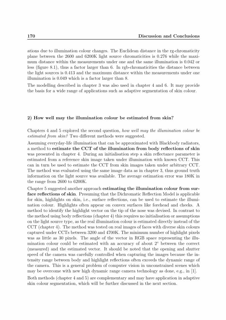
170 Discussion and Conclusions
ations due to illumination colour changes. The Euclidean distance in the rg-chromaticityplane between the 2600 and 6200K light source chromaticities is 0.276 while the maxi-mum distance within the measurements under one and the same illumination is 0.042 orless (figure 8.1), thus a factor larger than 6. In rgb-chromaticities the distance betweenthe light sources is 0.413 and the maximum distance within the measurements under oneillumination is 0.049 which is a factor larger than 8.
The modelling described in chapter 3 was also used in chapter 4 and 6. It may providethe basis for a wide range of applications such as adaptive segmentation of skin colour.
2) How well may the illumination colour be estimated from skin?
Chapters 4 and 5 explored the second question, how well may the illumination colour beestimated from skin? Two different methods were suggested.
Assuming everyday-life illumination that can be approximated with Blackbody radiators,a method to estimate the CCT of the illumination from body reflections of skinwas presented in chapter 4. During an initialisation step a skin reflectance parameter isestimated from a reference skin image taken under illumination with known CCT. Thiscan in turn be used to estimate the CCT from skin images taken under arbitrary CCT.The method was evaluated using the same image data as in chapter 3, thus ground truthinformation on the light source was available. The average estimation error was 180K inthe range from 2600 to 6200K.
Chapter 5 suggested another approach estimating the illumination colour from sur-face reflections of skin. Presuming that the Dichromatic Reflection Model is applicablefor skin, highlights on skin, i.e., surface reflections, can be used to estimate the illumi-nation colour. Highlights often appear on convex surfaces like forehead and cheeks. Amethod to identify the highlight vector on the tip of the nose was devised. In contrast tothe method using body reflections (chapter 4) this requires no initialisation or assumptionson the light source type, as the real illumination colour is estimated directly instead of theCCT (chapter 4). The method was tested on real images of faces with diverse skin colourscaptured under CCTs between 3200 and 4700K. The minimum number of highlight pixelswas as little as 30 pixels. The angle of the vector in RGB space representing the illu-mination colour could be estimated with an accuracy of about 2◦ between the correct(measured) and the estimated vector. It should be noted that the opening and shutterspeed of the camera was carefully controlled when capturing the images because the in-tensity range between body and highlight reflections often exceeds the dynamic range ofthe camera. This is a general problem of computer vision in unconstrained scenes whichmay be overcome with new high dynamic range camera technology as done, e.g., in [1].
Both methods (chapter 4 and 5) are complementary and may have application in adaptiveskin colour segmentation, which will be further discussed in the next section.

8.2 Contributions in an application context 171
3) How well may a skin area be distinguished from other skin-like objects?
The third question, how well may a skin area be distinguished from other skin-like objectsunder varying illumination conditions using a physics-based approach, was considered inchapter 6. Modelling the skin chromaticity distribution as a unimodal 2D Gaussian andusing the physics-based approach from chapter 3, a method was presented to model theparameters of the Gaussian for skin chromaticity distributions under arbitraryCCTs. It is assumed that the illumination spectra can be approximated with Blackbodyradiators, and an initialisation is required using a skin image taken under an illuminationwith known CCT, like the initialisation step in chapter 4. The method was tested usingthe same image data as in chapter 3, and image sequences of hands and other skin colouredobjects taken under varying illumination with CCTs ranging from 2500 to 5200K. Theeigenvectors of the modelled and measured covariances deviate in orientation as little asabout 4◦.Using the proposed method, a skin-colour feature was suggested indicating which areain a camera input image is most likely to be the same skin area as in the initialisationstep. The feature compares the measured rg-chromaticity distribution with a modelledskin chromaticity distribution. Experiments showed that the performance of this featureseems to be useful to allow significant support of skin tracking methods, i.e., improvingtheir robustness particularly to illumination changes. It may, e.g., be used within thework in [6], Modelling Facial Colour And Identity with Gaussian Mixtures (section 2.3.2.2,p. 49), to avoid that Gaussians adapt to “non-skin” objects.
4) Can NIR help to distinguish between skin and other skin-like objects?
The similarity to other objects led also to the fourth question can reflectance character-istics in the near infrared spectrum help to distinguish between skin and other skin-likeobjects? This was investigated in chapter 7. Using standard RGB bands com-bined with three near infrared bands may enable for robust skin detectionunder changing illumination conditions. Simulations under changing illuminationconditions with skin reflectance spectra and reflectance spectra from 17 other skin-likematerials showed an improved robustness over pure RGB based approaches. Furthermore,experiments using the ratio between two real images of skin and other materials capturedwith two NIR bandpass filters confirmed the simulation results. Although further testsalso with other types of light sources are required this may be another promising way toachieve robust segmentation of skin and might be used in future camera design.
8.2 Contributions in an application context
One motivation for the work presented in the preceding chapters was to enable colourbased skin detection and tracking methods to cope with varying illumination conditionsand dynamic complex environments containing other skin coloured objects. This section
172 Discussion and Conclusions
discusses the contributions of this thesis in an application context proposing how theymight be used as a comprehensive skin colour cue within a face/hand tracking system.
In chapter 1 it was described that face/hand detection and tracking systems are oftenusing multiple cues, e.g., motion, shape, and colour in order to improve the robustness todynamic complex environments and changing illumination conditions [2; 9]. Figure 8.2shows the example of a multiple cue system that was also shown in section 1.1 on page 4.
colour
Preprocessing
Acquisition
Image
and
System
Output
Cues Units
Cameradetector
Unit
eye blink
features like
shape
motion
nose position
Tracking-
Supervisor-
Figure 8.2: Multi cue face tracking system integrating and coordinating comple-mentary methods. (Identical to figure 1.2).
These cues have different complexities and update rates, and their robustness may bedifferent and depending on the background and illumination conditions. Some cues mightuse information from others, whereas some are stand alone just using the input image.A multiple cue system needs a tracking-supervisor-unit to combine the outputs from allcues, evaluate them, and decide, e.g., by voting, which cue or cues provide most convincinginformation in case that their outputs are different. This decision might be improved ifeach cue has a measure that indicates the confidence associated with its current output [2].
A skin colour cue
The main task of a skin colour cue for a face/hand tracking system is to detect andsegment skin areas in an image or – more likely for a tracking system – in a sequence ofimages. Considering the above example of a multiple cue system, a skin colour cue mayhave in addition to the input image and segmented output image several additional in-and outputs. More explicitly as outputs it may provide:

8.2 Contributions in an application context 173
1. an estimate of the current illumination colour or colours (colours if the illuminationis spatially varying). This is important information for further scene interpretation,e.g., to detect, segment, and interpret other coloured objects, or to dynamically adjustthe white balance of the camera.2. confidence measures indicating the confidence in the current outputs would beconvenient to improve the integration with other cues.3. estimates of the skin tones of the segmented skin areas. This may be useful, e.g.,when tracking multiple faces or hands in order to distinguish between them.
On the input side of the skin colour cue is the input image sequence, e.g., providedby a camera. The colour cue may take its own outputs as input to perform iterativeimprovements of analysis of an image or of the forthcoming images. Further useful inputsimproving the robustness of the skin colour cue would be:
1. locations or presence of features like convex areas (nose tip or forehead), locationsand pose of skin areas, locations of artifacts such as highlights.2. illumination colour or colours if available from other cues.3. areas of non-skin objects that were detected by other cues, in other words scenecontent information.4. confidence measures for these inputs.
It should be noted that these inputs would be advantageous for the robustness of the skincolour cue but not necessary for its basic function. Figure 8.3 outlines a skin colour cuethat might be used within a multiple cue tracker (figure 8.2). The elements of this skincolour cue with its in- and outputs will be explained in the following through discussionson how the contributions of this thesis may be used.
Detection and Segmentation The main requirements on the skin detection and seg-mentation are that it should operate robustly for mixed and changing illumination con-ditions and for complex backgrounds with other skin colour-like objects, i.e., it should becapable of adapting to changing conditions. It should cope with different skin tones andmay even distinguish between users/people by their different skin tones in order to trackmultiple skin areas.
If only the camera input image is available but no further information on the scene is given,then the search area in the chromaticity plane may be constrained by the skin-locus thatwas described in chapter 3. This has been successfully done, e.g., in [4; 7].
In case scene information is available, such as illumination colour or skin reflectance,a more accurate model may be calculated and used for segmentation and tracking asexplained in chapter 6. The skin-colour feature in chapter 6 might also be used as aconfidence measure whether the tracked skin area is still the same as in the previousframes.
A problem when using region based colour segmentation are often highlights, hence, ifknowledge on the presents of highlights is available, this might be used in region growingbased segmentation, e.g., using the approach suggested in [5].

174 Discussion and Conclusions
Illuminant Colour
Estimation from
- Body Reflections
- Highlights
Skin Colour
- Detection
- Segmentation
- Tracking/Verification
Segmented Skin Areas
Colour Supervisor
- Paramter Tracking
- Spatial info
- Illuminant Colour
- Confidence Measures
- Locations of highlights
- Camera settings
- Task Coordination
- ...
- Nose Position
- Skin Areas & Pose
- Confidence Measures
- ...
- Camera settings
Input Image Sequence
Figure 8.3: Example outline of an adaptive skin colour cue within a multiple cueface tracker (figure 8.2).
Another approach to achieve robust skin detection and segmentation would be in pursuingthe idea presented in chapter 7, i.e., using a multispectral approach combining visible andnear infrared information.
Illumination estimation As explained above, information on the illumination colourwould open for more robust skin detection and tracking. Here the work presented inchapters 4 and 5 may be used.
Under certain conditions of direct illumination and viewing geometries skin shows high-lights on convex areas, e.g., the tip of the nose, the forehead, or the cheeks. These may beused to estimate the illumination colour. A method to automatically extract the highlightvector given the tip of a human nose was presented in chapter 5. Several measures weresuggested in chapter 5 to allow the method to evaluate the confidence of its estimate ina given case.
The method to detect highlights may also be used in skin segmentation to verify whetheran apparent highlight actually is a highlight.
The illumination estimation from highlights works only if highlights are present and may,hence, only give output from time to time, i.e., it may not provide a continuous estimateover time. However, since it does not require an initialisation it is very useful for boot-strapping and re-initialisation of the methods used in the segmentation part and also forthe illumination colour estimation presented in chapter 4.
In case there is no highlight, the body reflections of skin may be used to estimate theillumination colour (chapter 4), which works even with a small number of skin coloured

8.3 Conclusions 175
pixels. The method is based on the model described in chapter 3. Because the skinreflectance depends on the skin type a skin reflectance parameter is estimated during aninitialisation step. This requires a reference image taken under known illumination colour,which may be acquired, e.g., using the illumination estimation from highlights (chapter 5).Once the reflectance parameter is estimated the illumination colour can be tracked fromthe skin areas. If no reference image is available a default reflectance parameter, which isan average of a range of reflectance parameters from different people, may be used insteadbut resulting in a larger estimation uncertainty.
The method of chapter 4 needs body reflections of skin as input. Therefore the input skinareas may be verified using the body and highlight segmentation suggested in chapter 5.
Colour supervisor The supervisor unit in the colour cue combines, coordinates, andtracks the information from the segmentation and illumination estimation. If, for example,an illumination colour estimate from a highlight is available (chapter 5) this is given both,to the skin area tracking in chapter 6, and to the illumination estimation from bodyreflections (chapter 4) in order to initialise the skin reflectance parameter. Depending onthe confidence measures of the estimation from highlights the confidence output of thecolour cue may be changed.
The supervisor-unit might give feedback to the image acquisition, e.g., in order to adjustcamera parameters such as shutter speed and white balance. Furthermore, it might main-tain a scene map containing local/spatial information, e.g., on the illumination conditions.
8.3 Conclusions
In this thesis new methods have been developed for:
• Skin colour modelling under arbitrary illumination
• Illumination colour estimation from skin reflections
• Tracking skin through arbitrary illuminations and distinguishing it from other skincoloured objects
• Skin detection using near infrared bands
These methods enable for a versatile skin colour cue with stand-alone-capabilities andimprovable robustness using a priori knowledge and/or iterations. The results and con-tributions allow for design of very general and/or dedicated and efficient colour cues.
8.4 Future Perspectives
Beside a further exploration, realisation, and evaluation of the above outlined skin colourcue, there are several issues in the preceding chapters that may point to further directions

176 Discussion and Conclusions
of research. Some of these are suggested below.
Spatial distribution Skin colour modelling and detection was considered pixel basedwithout spatial context. Looking at faces and hands, however, there are areas whichmight appear differently due to variation in the skin itself and/or due to spatially varyingillumination conditions. The finger joints, e.g., may be more reddish than other areas ofthe back of the hand. Given the image has sufficiently high resolution the hand mightbe modelled as several connected local areas, which would result in smaller areas in therg-chromaticity plane and by that result in less false positives. These local areas couldthen also include highlights.Furthermore, this might help to detect finger joints or facial features that may be used inhigher level recognition tasks.
Confidence features The importance of confidence features for the fusion of multiplecues was mentioned in section 8.2, and several features/measures were suggested in thisthesis which may be improved through further research:In section 5.3.3 several measures were suggested indicating the confidence in the identifiedhighlight and body vectors. These measures have to be further refined, combined, andtested in order to be used in an application context. It may also be combined with othermeasures such as distance to Blackbody locus.The skin colour feature suggested in section 6.4 currently gives a relative measure of whicharea in successive images is most likely to be the tracked area. For fusion, however, anabsolute measure would be more desirable.Furthermore, in all measures the spatial context as well as temporal changes should beconsidered.
Segmentation of highlights Highlights are generally a problem when segmenting animage. The segmentation in body and highlight vector in chapter 5 is assuming that thereis one predominant body and one predominant highlight vector. This assumption holdsfor small areas like the nose. For larger areas like the forehead, which are also convexbut not so smooth as the nose, there may be several highlight vectors and often alsoseveral different body vectors due to nuances in the skin tone or freckles. A method thatcan handle several highlight and body vectors also taking the spatial configuration intoaccount would be appropriate. In, e.g., [1; 5], methods were presented that can cope withseveral highlight vectors.
Multispectral approach The multispectral approach in chapter 7 was tested withBlackbody illumination which is a good approximation in the visible spectrum, however, inthe near infrared, e.g., daylight deviates considerably. The effects should be investigated.Furthermore, it might be worth investigating other wave band combinations for buildinga dedicated skin sensor.

BIBLIOGRAPHY 177
Bibliography
[1] Andersen, H.J. and Storring, M. Classifying body and surface reflections usingexpectation-maximisation. In PICS: Image Processing, Image Quality, Image Cap-ture Systems Conf., pages 441–446, Rochester, New York, USA, May 2003.
[2] Crowley, J.L. Integration and control of reactive visual processes. J. of Robotics andAutonomous Systems, 16(1):17–27, November 1995.
[3] Finlayson, G.D. and Schaefer, G. Solving for colour constancy using a constraineddichromatic reflection model. Int. J. of Computer Vision, 42(3):127–144, May 2001.
[4] Fritsch, J., Kleinehagenbrock, M., Lang, S., Plotz, T., Fink, G.A., and Sagerer, G.Multi-modal anchoring for human-robot interaction. J. of Robotics and AutonomousSystems, 43(2–3):133–147, May 2003.
[5] Klinker, G.J., Shafer, S.A., and Kanade, T. A physical approach to color imageunderstanding. Int. J. of Computer Vision, 4(1):7–38, January 1990.
[6] McKenna, S.J., Gong, S., and Raja, Y. Modelling facial colour and identity withGaussian mixtures. Pattern Recognition, 31(12):1883–1892, December 1998.
[7] Soriano, M., Martinkauppi, B., Huovinen, S., and Laaksonen, M. Adaptive skincolor modeling using the skin locus for selecting training pixels. Pattern Recognition,36(3):681–690, March 2003.
[8] Triesch, J. Vision-Based Robotic Gesture Recognition. PhD thesis, Ruhr-UniversityBochum, Bochum, Germany, May 1999. Published as book, Shaker Verlag, Aachen,Germany, ISBN 3-8265-6257-7.
[9] Triesch, J. and von der Malsburg, C. Self-organized integration of adaptive visualcues for face tracking. In 4th IEEE Int. Conf. on Automatic Face- and Gesture-Recognition, pages 102–107, Grenoble, France, March 2000.
[10] Wyszecki, G. and Stiles, W.S. Color Science: Concepts and Methods, QuantitativeData and Formulae. John Wiley and Sons, 1982.
[11] Yang, M.H., Kriegman, D., and Ahuja, N. Detecting faces in images: A survey. IEEETrans. on Pattern Analysis and Machine Intelligence, 24(1):34–58, January 2002.

Computer Vision &
Media Technology Laboratory
THE COMPUTER VISION AND MEDIA TECHNOLOGY LABORATORY(CVMT) IS PART OF THE INSTITUTE OF HEALTH SCIENCE ANDTECHNOLOGY. CVMT WAS FOUNDED IN 1984 AS THE LABORA-TORY OF IMAGE ANALYSIS (LIA). THE MAIN RESEARCH AREASOF THE LABORATORY ARE COMPUTER VISION, MULTIMEDIA IN-TERFACES VIRTUAL REALITY, AUGMENTED REALITY SYSTEMS,AND AUTONOMOUS SYSTEMS AND AGENTS.
CVMT HAS ESTABLISH RESEARCH COOPERATION WITH MORETHAN 30 INSTITUTIONS IN 16 DIFFERENT COUNTRIES.
CVMT IS HEADED BY ITS FOUNDER PROFESSOR ERIK GRANUM.
CVMTComputer Vision
& Media Technology LaboratoryAalborg University
Niels Jernes Vej 14DK-9220 Aalborg
Denmark
Telephone: +45 9635 8789
TeleFax: +45 9815 2444
E-Mail: [email protected]
URL: http://www.cvmt.dk
ISBN 87-90562-23-2