Computer Integrated Manufacturing Dr. Amandeep Singh ...
35
Computer Integrated Manufacturing Dr. Amandeep Singh Oberoi Imagineering Laboratory Indian Institute of Technology, Kanpur Lecture 26 Laboratory Demonstration, CAM software Hello everyone, welcome to the course Computer Integrated Manufacturing. In this lecture I like to bring you to the laboratory demonstration on the CAM, Computer Aided Manufacturing. We had discussed CAD, we had discussed a lot of theory on CAD, CAM computed part programming you have seen already, how does the part programming happens in laboratory or on the machine? First we will see the power mill software here, power mill is one of the CAM softwares, then we will see, how does the machine runs? how does the software interfaces with the machine in the next lecture? so this is the interface for the power mill software. Again, recalling the difference between CNC and NC machine was that in NC machines, what we use to watch the numerical control. Numerical control was nothing but using magnetic tape or the punch card to control the machine. Or when comes the computer, computer makes it CNC Computer Numerical Control in which the data can be recorded in the computer, data can be recorded in a CD or a DVD, or it was the floppy disk also before now it can be put in a pen drive or internet as well through the clouds as well, the data can be fetched and put in the software, and it can be from the software sent to the machine for the manufacturing. In NC code, there are certain limitations, because in NC code, we can just write the program in blocks, like 1 block, 2 block, 20 blocks, 10 blocks, so gradually either things improves and the number of blocks can go up to maybe thousands or maybe more than that, so that can help us to get a big programme to develop a very complex and large component or different parts of the components in one go. So, in CNC programming we go with part programming as well as the complete block program in the part programming we generate code for the particular part and the same code can be taken in repeated mode to get the repeated cycles and the complete body, complete product that is needed can be manufactured.
-
Upload
khangminh22 -
Category
Documents
-
view
0 -
download
0
Transcript of Computer Integrated Manufacturing Dr. Amandeep Singh ...

Computer Integrated Manufacturing
Dr. Amandeep Singh Oberoi
Imagineering Laboratory
Indian Institute of Technology, Kanpur
Lecture 26
Laboratory Demonstration, CAM software
Hello everyone, welcome to the course Computer Integrated Manufacturing. In this lecture I
like to bring you to the laboratory demonstration on the CAM, Computer Aided Manufacturing.
We had discussed CAD, we had discussed a lot of theory on CAD, CAM computed part
programming you have seen already, how does the part programming happens in laboratory or
on the machine?
First we will see the power mill software here, power mill is one of the CAM softwares, then
we will see, how does the machine runs? how does the software interfaces with the machine in
the next lecture? so this is the interface for the power mill software. Again, recalling the
difference between CNC and NC machine was that in NC machines, what we use to watch the
numerical control.
Numerical control was nothing but using magnetic tape or the punch card to control the
machine. Or when comes the computer, computer makes it CNC Computer Numerical Control
in which the data can be recorded in the computer, data can be recorded in a CD or a DVD, or
it was the floppy disk also before now it can be put in a pen drive or internet as well through
the clouds as well, the data can be fetched and put in the software, and it can be from the
software sent to the machine for the manufacturing.
In NC code, there are certain limitations, because in NC code, we can just write the program
in blocks, like 1 block, 2 block, 20 blocks, 10 blocks, so gradually either things improves and
the number of blocks can go up to maybe thousands or maybe more than that, so that can help
us to get a big programme to develop a very complex and large component or different parts
of the components in one go.
So, in CNC programming we go with part programming as well as the complete block program
in the part programming we generate code for the particular part and the same code can be
taken in repeated mode to get the repeated cycles and the complete body, complete product that
is needed can be manufactured.
In this way the stopping in between or checking the program in between becomes very easy.
So, now what we need to have? Is a CAD model the model that we have generated through any
of the CAD softwares like SolidWorks, Catia, IDEAS, or so that can be brought into this
program.
(Refer Slide Time: 02:57)
So, this is the software Delcam Powermill, this is a mystic software. So, when we click here
on the software, we get this interface. So, here we can generate the code for the drawing that
we have received, the drawing when I say, the drawing is the CAD, CAD is computed it design.
So, we can import the model for that. So, when I go to this drop down menu, option import
model. If I say import model, it would have to open the file. So, there are certain formats here,
like here we have IGS format, we have STP format, STL format IGS and STP are generally
used for the CAD or the computer aided manufacturing.
In IGS and STP, the triangular mesh that is that is the building blocks or the building would
say building elements of the CAD, those are all separate. In this when we have to use that on a
CNC machine it has to be taken care that z should be always in the tool direction. Other format
is STL format, in STL format it generally used for the additive manufacturing, because it is in
this it is it generally consider the whole triangular mesh as one body, all triangles are kind of a
merge in each other, so generally using 3D printing.
(Refer Slide Time: 04:36)
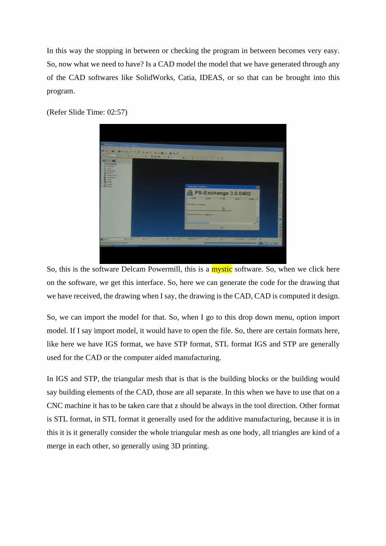
So, STL and IGS or DXF, these are the common input files that can be taken in this. So, this is
we can we have clicked here, so it is importing the CAD model here. So, this is the CAD model
where we will see, how can we work? So, this is a simple IGS CAD model for which we like
to generate a code. So, you can see here that the part programming and the particular area can
be worked upon for the talent profile as well, the program can be made.
So basically, numbers of machines are available for CNC and NC, like depending upon the
profile or the geometry of the job that is to be made, if the job is cylindrical, obviously you
know that we will use a lathe machine. The lathe machine in this one kind of lathe machine
known as center Lathe.
In CNC turning to we have a machine with tailstock or without tailstock. A machine with
tailstock or dead center is called as a central lathe, when there is no tailstock, we can call it a
simple lathe, this is the difference between the center lathe and simple lathe. Similarly, in
milling as well the machining center or the milling machines this difference, so this is the part
that we are going to manufacture on simple three axis milling machine.
So, generally when we see the classification of the milling machines, so three axis milling
machine, four axis milling machine and five axis milling machines are there and three axis
milling machines, we have the x and y axis that is the work piece or the table that moves in x
direction and in y direction and tool is just that is moving in z direction.
When the tool is also able to tilt itself this becomes a fourth axis. For instance, there is a
complex geometry for instance, we have a mouse here it can be manufacture while using this

direction itself or we like to tilt tool and try to do some machining here, some deep machining
here, this is 3 plus 1, 3 plus 1 that is 4 axis machine. In the 5 axis machine, what happens? This
tool can also be tilted and the work piece can also rotate to some extent that is 3 plus 2 that is
5 axis machine. So, basically a machine should have 3 axis. So, what we will use is a 3 axis
machine on which we will manufacture this component that we are showing here.
So, this is the component, so we can write the code for each and every corner like this corner
this corner or any profile, we can write the code for each and every point here, manually code
can be written it is known as MDI, manual data input, there are number of faces here, you can
see this one face other face, we can write the codes separately. So, here we can see the different
features or outlooks for the work space that we have there.
So, the software makes the task easy, it can create a code for all the points which are here. So,
we can see that there is a sector profile, there is an Angular profile here, there is a linear profile
here. So, linear this is linear x, this is linear y, so till its when tool is going down, it is linear is
linear in z direction.
So, whenever we generate the code, with the help of any software, we need to take care of three
things, three major things, number 1 machine tool, number 2 is cutting tool, number 3 is the
job where we need to work.
So, whenever we generate the code, whenever we start the machining, conventionally by hand
or using CNC machine, we have to take care of these three major things. Again, machine tool,
cutting tool and the job that is to be cut. So, the coordinates have to be set accordingly. So, the
as the reference point for the machine tool, cutting tool and the job is same.
So, this is one of the major concerns when we talk about the CNC machining, the reference
point, what is the starting point that is put in software, what is the setting point where the tool
touches the work space actually on the machine. So, we can define the block here. In the coding
system this is known as block define. When I go there, it will show block define the term that
is use is job reference or tool reference that we will fix here.
(Refer Slide Time: 09:03)
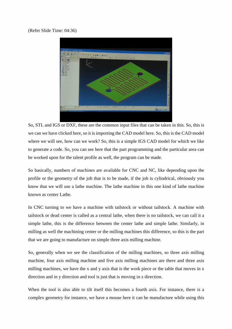
Actually machine reference and tool reference is generally the same, so I will click here, it is
showing the block form, it is clearly mentioned here that, what we need to calculate here, it
was calculating the x y coordinates and z coordinate for this particular component. It is standing
that the minimum axis 24.5, which what is the reference that we have to decide.
So, we can take this corner of the reference, this corner or we can take this corner or this corner
any of the corners can be taken as a reference point that is the starting point or we can take this
center of the work space, center would be the center of the x and the y direction both and also
the z has to z means the perpendicular direction the tool has to touch at the center of the work
space.
So, it is more convenient to take center of the machine, because that helps us a lot because also
this job this is symmetrical in both directions in x and y directions, it is better to take center.
(Refer Slide Time: 10:14)
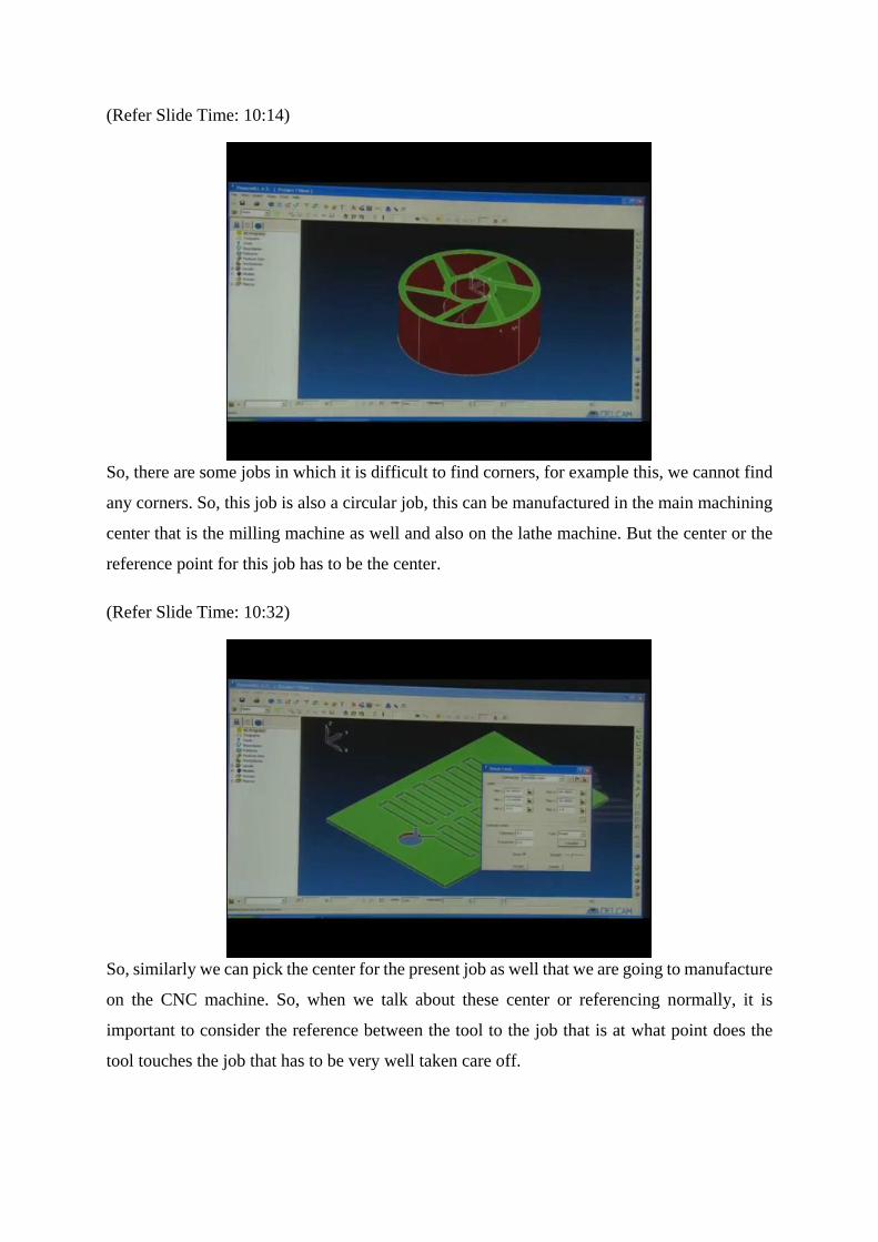
So, there are some jobs in which it is difficult to find corners, for example this, we cannot find
any corners. So, this job is also a circular job, this can be manufactured in the main machining
center that is the milling machine as well and also on the lathe machine. But the center or the
reference point for this job has to be the center.
(Refer Slide Time: 10:32)
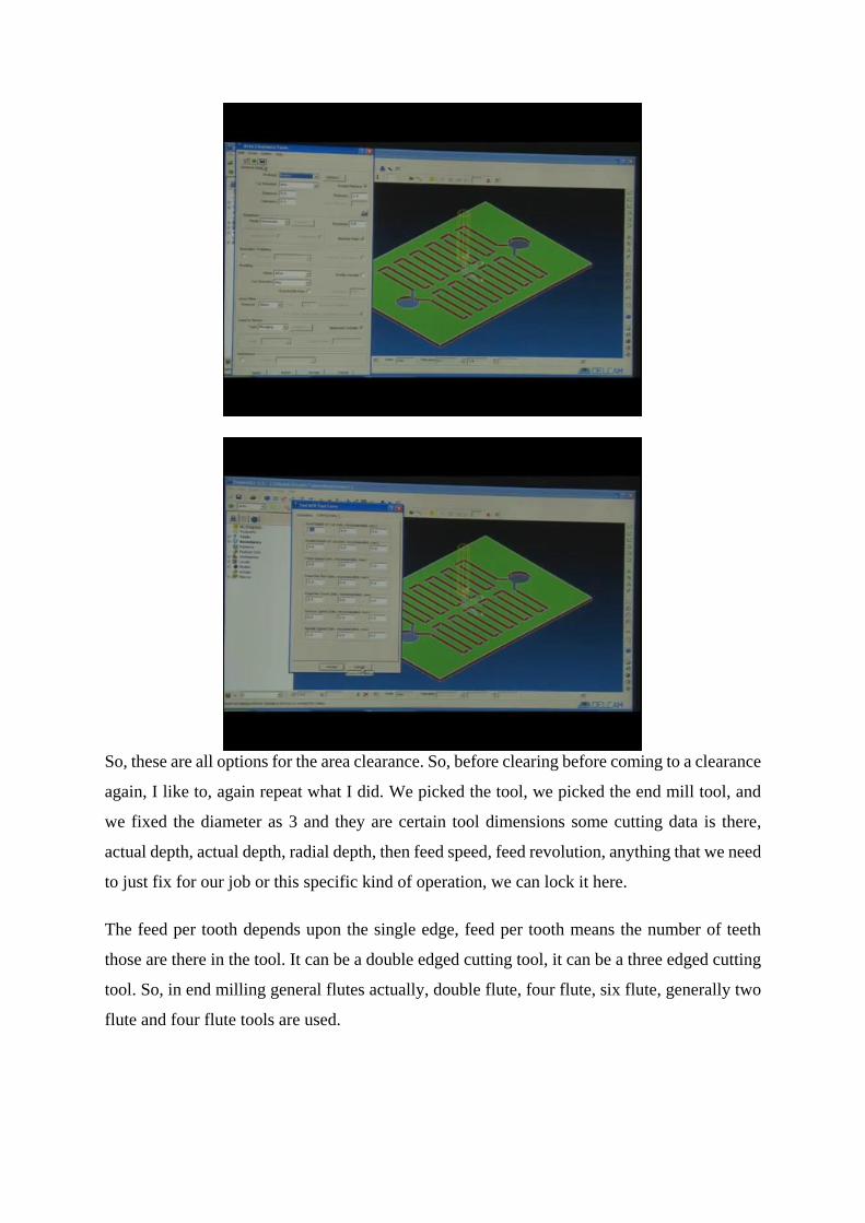
So, similarly we can pick the center for the present job as well that we are going to manufacture
on the CNC machine. So, when we talk about these center or referencing normally, it is
important to consider the reference between the tool to the job that is at what point does the
tool touches the job that has to be very well taken care off.

So, I am again repeating that thing because this is very important point, see this is the center of
our model, so this is 00. Now, we can see, this is 00 of our workspace that is x y z 0 is here,
and this is the corner of our block, so we need to match this center here. So, what we can do?
We can move the x we can we are moving x to 0 and moving y to 0 and we have also moved z
to 0. Now, x 0, y 0, z 0, makes the origin of the workspace and the origin of the workspace and
the corner is now matched.
Now, there is one big problem here. What we have what we can see here, this is z is at the
bottom that has to be at the top z has to be at the top. So, as we asked able to start the cut from
top and then go bottom, now z, when it is z minus 1.
(Refer Slide Time: 12:12)

Now, when it put z as minus 1, you see, when you put z minus 1, this reference has now the
origin point has come at the top, so this corner is now the reference point. So, when the
machining starts this tool will start moving from this point, it moves in x direction in this way,
in y direction in this way in z direction, it also can move.
Now, what if I need to bring it to the center of the workpiece, to bring it to the center of the
work space what I can do? I can take average of the values, any way we can we could have
taken any of the corner as also the reference but just to pick the center of the job as the reference.
So we can move the x again, we have by moving x to minus 20. Because this value x total
width for x is 40, x 20 would bring it to the center of the x dimension of the work space. So, it
is in x center, for the y it is 55.99, I need to take half of this value, half of this value would be
divided by 2, this is this value, I will just copy this value and put it here for the y.
(Refer Slide Time: 13:38)

So, now I have to put minus as well here. Now, it has brought the origin of the workspace or I
would say of the machine or of the software to the center of the work space, actually better I
would say of the software itself now, for the machine we have to separately do it when we go
to the machine. So, the software now the center is at the center of the work space, we can see
that when I rotate it, when a bend it. So, this is I can say that is safe z for milling. So, now I say
accept is accepted, saves the values entered accept, so this is lock now.
(Refer Slide Time: 14:23)

Now, I need to save this job, so I have created this folder, so class one, they have created, I will
save this folder here, this is the block that will led to machine to create an NC code. Now, one
of the important point is that I need to barricade the boundaries, so this is the top surface of the
job.
So, these are work planes, these are work planes we can create work planes, if I go click create
work plane, so this work plane is created. You can see this small change, there is a very thin
white line. So now, the software knows that this is a work plane where it will start machining.
Similarly we can fix the boundaries barricade to barricade the boundaries that within these
boundaries that tool will just be moving. So, it should not come out of the boundaries this is
the block that we have generated.

(Refer Slide Time: 15:29)
So, for creating boundary I will put the block, if I say block, so it will nigh, when I say accept,
apply and accept, it will you can see the thick white line, this white line indicates that this block
is generated now we can keep our tool inside the block or maybe we can also define the tool to
be kept outside the block. So, this is the boundary whether inside and outside that can be
definitely chosen.
Now, tool would never come out if we direct the software that the tools to remain inside the
block. Normally when we generate the code, it is important that we need to take care of the
movement of tool in x y direction as well as in z direction, because if anything goes wrong, the
job will be definitely go bad and also the tool can also go blunt, tool can also break as well and
big accidents can also happen. So, it is very important to do or to run this simulation before
going to the actual machining in CNC.
While experience definitely one develops in itself a prowess to work on the CNC machines on
different kinds of the setups, after that, one can definitely sometimes skip some simulation to
see and go directly. But it is recommended to see the simulation or the animation of how the
tool runs on the work space. So, we need to take care of the coordinates as well, coordinates
can be minus or plus in the negative or positive direction, but the tool would always do
machining in the minus direction here, so it is very important to be noted now, what are the
tools here?
So, the three points that I mentioned before, the machine tool, cutting tool and the job. So, let
us talk about the cutting tool here, what are the options, we have an end mill tool here to create

an end mill tool, what is the purpose of end mill tool? It does the roughing major of the material
is moved is removed using end mill. Then ball mill is are generally used for finishing. Then tip
radius tool is there. So, this is called bull nose then taper spherical tool. So, then we have taper
tip tools. Then we have a drill tool that is normal drilling this was possible, this is tipped disk
tool.
So, this is normally used for cutting the walls or sites. So, this is an off center tip radius tool,
there is some radius on the tip of the tool to bring more smoothness to the work space
sometimes. So, ball nose and tip nose tools are generally used for finishing, so for the purpose
for which this is developed, so this kind of profile, how can we do that. So, for this kind of
profile, we will pick an end mill tool.
(Refer Slide Time: 18:32)
So, when I click end mill, few things are to be important to mention here. The diameter of the
tool, diameter is 3 mm. Then if I pick diameter 3 by default is picking the length as 15 mm it
is showing that minimum length required is 15 mm, if we pick 3 mm dia to be held in that
tuning center.
So, we will held tool in then call it here. So, tool number, tool number is just a name of the tool
we can just name it like 3 a, 3 b, so on, I will just put tool number 3. So, I can even put tool in
the name of the company or the job number or the job name, we can put any name in that tool
number 3.

(Refer Slide Time: 19:11)
So, now rapid move heights, rapid move heights, what is the safe movement of z and starting
of the z here. Now, the tool is here at the center, the yellow colour portion you can see the tool
is here. So, tool would interact and detract from the work space, when it interacts, what is a
safe height? What is a start height? That has to be defined here? So, rapid move, what is a safe
height? I have put 3 and 2. So, safe is 3.
So, what does this reset to safe heights? Reset to save height is implies that the tool would now
start tool will come in a rapid mode close to the center, it will hold itself at this position that is
5 mm above the workpiece. This means that rapid move height would take the tool up to the 5
mm from the workpiece. So, it will then go down in two steps, in 3 mm and in 2 mm when the
actual feed cutting feed is given.
So, this is a safe working height when the tool tries to enter the job from the top of the block.
So, when sometimes the tops surface is not flat or some roughness is here like I just showed
you the mouse if it is having some software, there has to be some safe height and that is
calculated that is already evaluated before we start the machining.

(Refer Slide Time: 20:42)
So, next is start point form. What is start point form here? So, where to start the machine?
Block centre safe z or absolute or first points z or first point. Absolute, it can just pick these
coordinates 005, first points safe z or block center z, block center safe z, so I can put 1 or 2
points here or just pick one of these options here.
So, where would I like my tool to start from? That is safe side had that is already we have
mentioned this safe side height as 5 mm, I will put blocks center safe side because block center
safe side would definitely be the value that is given that is 5 mm. So, block centre safe side, I
have picked it here, and I will accept this option. Now, this is from the centre point to the tool,
here we have tool it is exactly aligned to the center of the job it is just 5 mm above the job.
So, the scheme distance and the plunge distance, the tool path lead and links. What is scheme
distance and plunge distance? See this diagram here the scheme distance is 3 mm and plunge
distance is 5 mm, there is certain ways the tool enters the work space. So, lead in and lead out,
lead in when tool interacts with the job lead out is when tool after machining comes out or
retract from the job.
So, some extensions the links is also there. So, let us keep all these things default and try to put
the z height, so it is already given, already we have mentioned 3 mm and 5 mm. So, we have
kept it 5 mm up, so the safe height that is kept is 5 mm from the center, so this tool starts
interacting with the job.
Now, skim distance and plunge distance. Basically, skim distance means the tool is at 5 mm
from the job, but it will go 3 mm in one step and then it will stop for some time then it will go

2 mm further. So, plunging is actually the engaging distance, so when the tool starts to get
engaged with the job that is known as plunging, so there are other methods as well that will
discuss. So, in this plunge it will go down.
(Refer Slide Time: 23:21)
So, now tool axis direction form. We can see here that tool axis has to be vertical, lead lean,
towards point, towards line, form line, fixed direction this actually different options in which
we will like our tool to move. For instance, if we make some access somewhere here,
somewhere here, somewhere here, somewhere here, like it out of the block, the tool will come
here first and then it will start leading towards the workplace in this mill make some corner or
something because this is normally a vertical milling machine that we are working on.
So, I will keep this option as tool axis vertical, it is also a three axis milling machine we do not
have 3 plus 1 or 3 plus 2 options in the machine that will work on, so we will just pick three
vertical. So, once everything is done, I am also saving my options what I am doing.
So, next is what planes so we have defined the workplace we are defined boundaries, we have
picked one tool that is 3 mm end mill cutter. Now, two important things are left that is tool path
and NC program. Now, we need to find the tool path next. After defining tool path, then we
will focus on the final output that is NC program, then we need to choose our strategy. We can
go with the area clearance form that what kind of clearance we like to have here
(Refer Slide Time: 25:02)
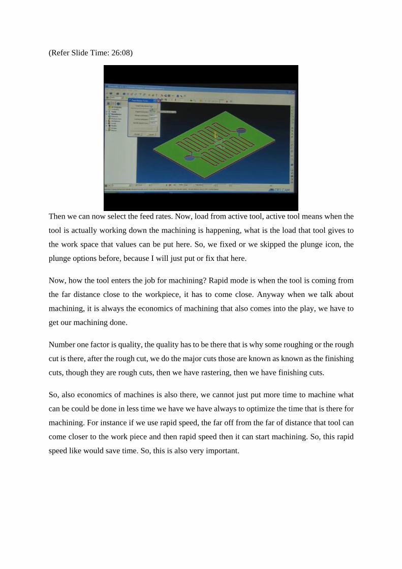
So, these are all options for the area clearance. So, before clearing before coming to a clearance
again, I like to, again repeat what I did. We picked the tool, we picked the end mill tool, and
we fixed the diameter as 3 and they are certain tool dimensions some cutting data is there,
actual depth, actual depth, radial depth, then feed speed, feed revolution, anything that we need
to just fix for our job or this specific kind of operation, we can lock it here.
The feed per tooth depends upon the single edge, feed per tooth means the number of teeth
those are there in the tool. It can be a double edged cutting tool, it can be a three edged cutting
tool. So, in end milling general flutes actually, double flute, four flute, six flute, generally two
flute and four flute tools are used.
(Refer Slide Time: 26:08)
Then we can now select the feed rates. Now, load from active tool, active tool means when the
tool is actually working down the machining is happening, what is the load that tool gives to
the work space that values can be put here. So, we fixed or we skipped the plunge icon, the
plunge options before, because I will just put or fix that here.
Now, how the tool enters the job for machining? Rapid mode is when the tool is coming from
the far distance close to the workpiece, it has to come close. Anyway when we talk about
machining, it is always the economics of machining that also comes into the play, we have to
get our machining done.
Number one factor is quality, the quality has to be there that is why some roughing or the rough
cut is there, after the rough cut, we do the major cuts those are known as known as the finishing
cuts, though they are rough cuts, then we have rastering, then we have finishing cuts.
So, also economics of machines is also there, we cannot just put more time to machine what
can be could be done in less time we have we have always to optimize the time that is there for
machining. For instance if we use rapid speed, the far off from the far of distance that tool can
come closer to the work piece and then rapid speed then it can start machining. So, this rapid
speed like would save time. So, this is also very important.
(Refer Slide Time: 27:39)
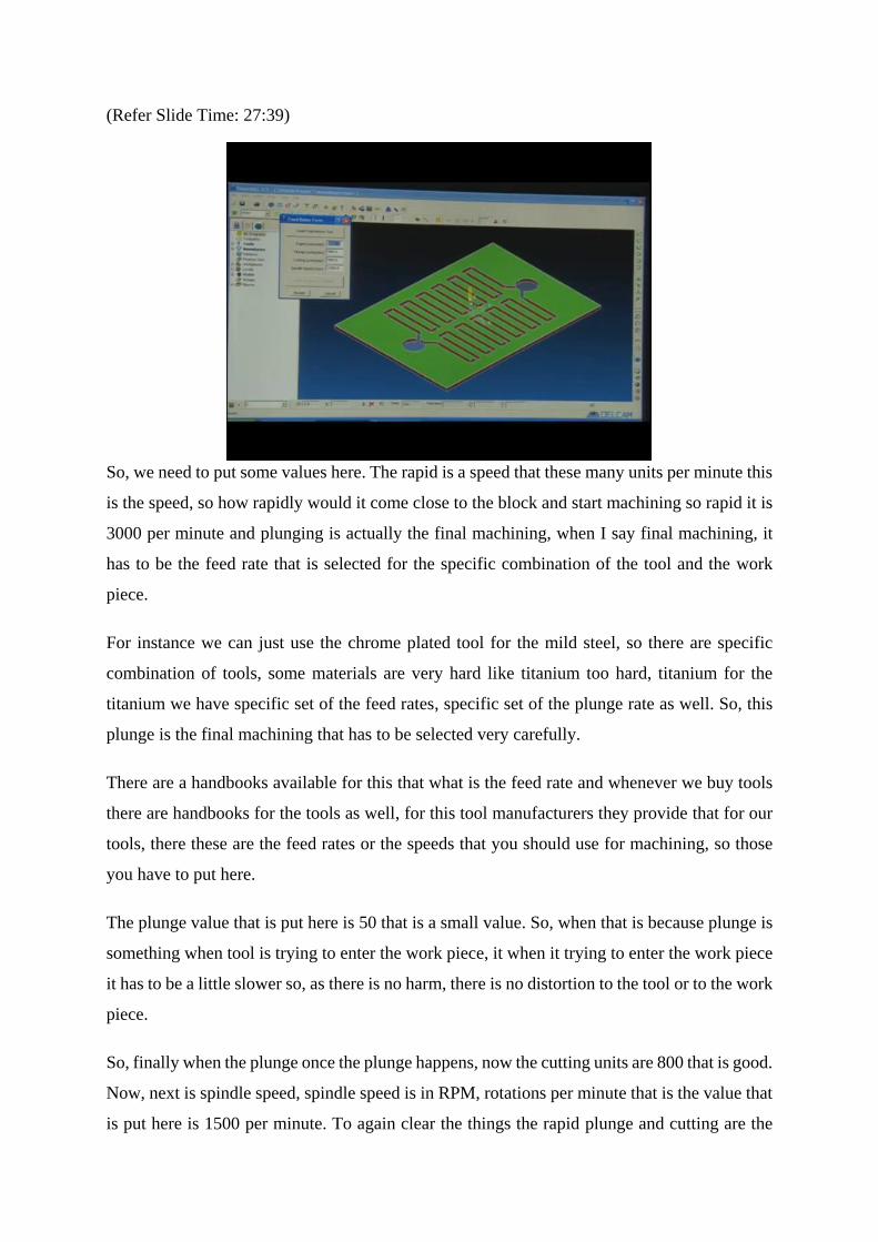
So, we need to put some values here. The rapid is a speed that these many units per minute this
is the speed, so how rapidly would it come close to the block and start machining so rapid it is
3000 per minute and plunging is actually the final machining, when I say final machining, it
has to be the feed rate that is selected for the specific combination of the tool and the work
piece.
For instance we can just use the chrome plated tool for the mild steel, so there are specific
combination of tools, some materials are very hard like titanium too hard, titanium for the
titanium we have specific set of the feed rates, specific set of the plunge rate as well. So, this
plunge is the final machining that has to be selected very carefully.
There are a handbooks available for this that what is the feed rate and whenever we buy tools
there are handbooks for the tools as well, for this tool manufacturers they provide that for our
tools, there these are the feed rates or the speeds that you should use for machining, so those
you have to put here.
The plunge value that is put here is 50 that is a small value. So, when that is because plunge is
something when tool is trying to enter the work piece, it when it trying to enter the work piece
it has to be a little slower so, as there is no harm, there is no distortion to the tool or to the work
piece.
So, finally when the plunge once the plunge happens, now the cutting units are 800 that is good.
Now, next is spindle speed, spindle speed is in RPM, rotations per minute that is the value that
is put here is 1500 per minute. To again clear the things the rapid plunge and cutting are the
feed rates and spindle speed is actually the speed, when I say rapid, plunge or cutting, these are
feed rates, 3000 units per minute, 50 per minute, 800 per minute, this is the feed rate.
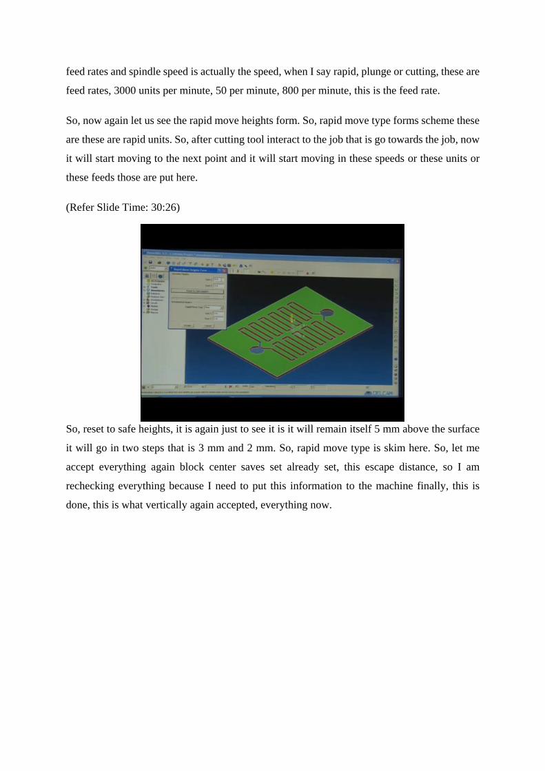
So, now again let us see the rapid move heights form. So, rapid move type forms scheme these
are these are rapid units. So, after cutting tool interact to the job that is go towards the job, now
it will start moving to the next point and it will start moving in these speeds or these units or
these feeds those are put here.
(Refer Slide Time: 30:26)
So, reset to safe heights, it is again just to see it is it will remain itself 5 mm above the surface
it will go in two steps that is 3 mm and 2 mm. So, rapid move type is skim here. So, let me
accept everything again block center saves set already set, this escape distance, so I am
rechecking everything because I need to put this information to the machine finally, this is
done, this is what vertically again accepted, everything now.

(Refer Slide Time: 31:07)
Let us come back to the area clearance form. See, there are three options, raster, offset and
profile. So, we have to clear the area in various ways this is the area that is to be cleared. Now,
how would it clear the area, there are certain modes for the raster that can be selected. So, this
is in raster is actually one thing that matters MRR, Material removal Rate, that how fast we can
remove the material and also while keeping it fast we mean need to maintain the quality and
one important factor is also the tool life, we cannot move it very fast and affect the tool life that
is also one of the important factors to be considered.
So, also this is pocket machining, pocket machining that this is a circle pocket, this is a
rectangular pocket or these are linear pockets here. So, when the separation of the certain
pockets are there, then pocket it will actually by itself pick whether they are pockets or not, we
can check it or uncheck it.
So, machine areas pocket by pocket it can do, so there are certain ways to do machining, so
thickness can be put here. So, whenever the pocket machining is needed the software is
intelligent enough to identify that pockets are there that will pick that.
Now, step down, what is step down? Step down is kept as 5, the maximum distance to allow in
z direction, so I am putting it 0.1, 1 mm actually the distance finally. So, now plunging, ramping
and drilling these are lead in moves I just mentioned the lead in moves, now, what are this
leading moves? Plunging, ramping and drilling the three ways the tool can enter the workplace.
So, this is important to understand how does the tool goes to the workplace.

(Refer Slide Time: 33:07)
So, when a tool goes down let us say the three options, number 1 is I would say plunging,
number 2 is drilling, number 3 is ramping. So, plunging is suppose this is our work piece and
this is our tool end-mill cutter. Plunging is it just comes down to this length, it suppose if I say
height is this height is 3 mm and the second plunger length I would say is 2 mm, it will just
come up to this height and then this height it will just come in one direction, this is plunging.
What happens in drilling? It will just have the reciprocating movements in up and down
directions, up and down directions, so it will come down and go up. Now, drill in drill what we
have, we have the tip here, so in tip we have some angle this is known as leap angle or tip
angle, so drill comes down and goes up.
In the second step it again comes down, then goes up, this is one, then this is the second step it
comes, so this is first step, this is second step, it will come to distraction. The third step it might
come down, make a through hole, this is step one, this is step two, and I would put this is step
three, this is drilling.
What is ramping? As we know, what is ramp? Ramp is a wedge kind of a shape. So, in this
tool can move in z direction, it can move in x direction and it can also move in z and y direction,
z and x direction together, z plus x direction. What happens, suppose this is a work piece and
we have a tool here and we need to cut something like this, you need to cut here.
So, it is like the landing of the aeroplane, it will move in this direction both z and x direction,
moving in this direction and make its cut, so it is ramping it is moving in this direction, so this
known as ramping. Here three ways how the tool can enter the work piece. So, this can be
selected in the software itself, so these are the ways the tool slowly approaches a work piece or
interacts with the work piece and which is a maximum depth of cut that is there.
(Refer Slide Time: 36:16)
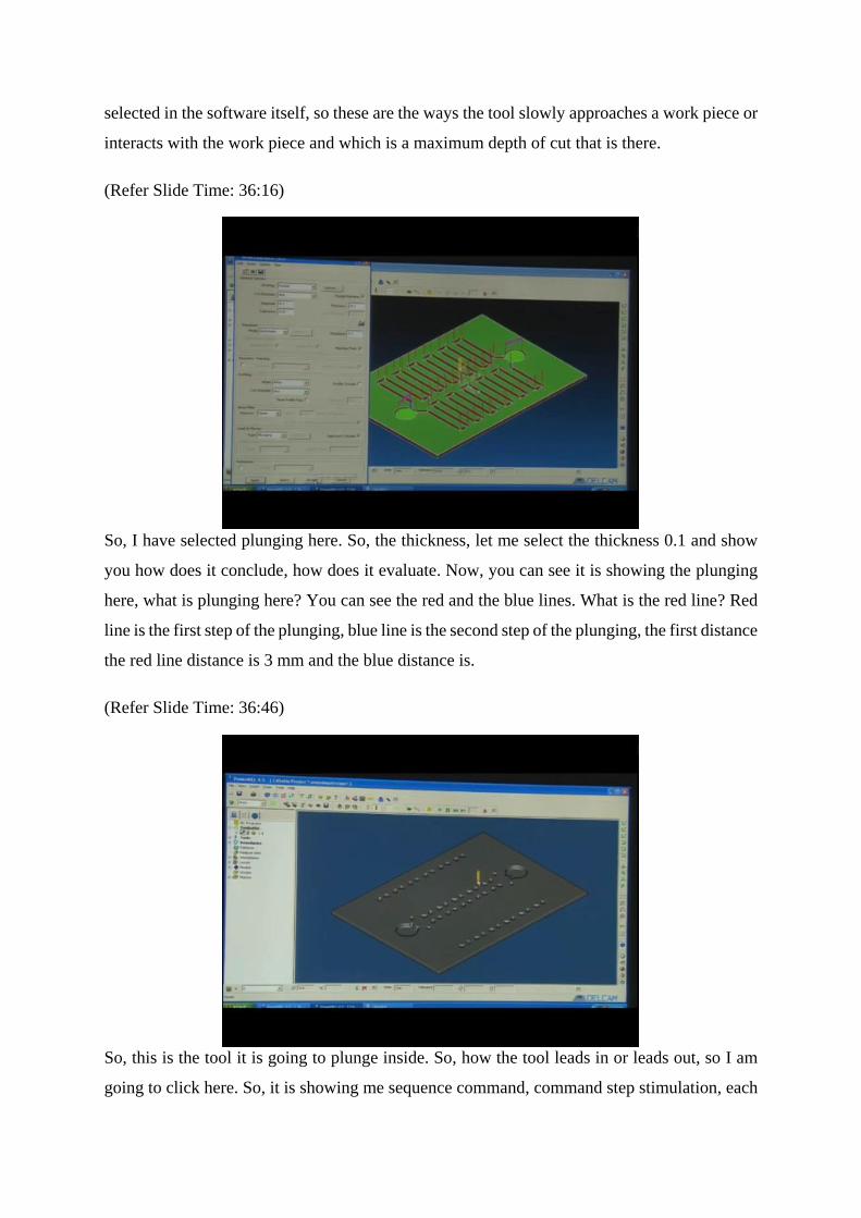
So, I have selected plunging here. So, the thickness, let me select the thickness 0.1 and show
you how does it conclude, how does it evaluate. Now, you can see it is showing the plunging
here, what is plunging here? You can see the red and the blue lines. What is the red line? Red
line is the first step of the plunging, blue line is the second step of the plunging, the first distance
the red line distance is 3 mm and the blue distance is.
(Refer Slide Time: 36:46)
So, this is the tool it is going to plunge inside. So, how the tool leads in or leads out, so I am
going to click here. So, it is showing me sequence command, command step stimulation, each

step it will show, while click on the next step, next step is this next step, next step, next step
next, so it is command wise it is leading in and coming out. So, once it has done the machining
or some of its operation here it will come back to the safe height that is 5 mm.
So, it is going in two steps. So, it is coming back, because it in a rapid mode it is come 1, 3 and
2 mm. Again, see it again carefully. So, it is 5 mm above in rapid mode, now 3 mm down and
2 mm down in two steps, so now in the rapid mode. So, now the complete simulation I just
place the play button in the complete simulation, so with this command system, we can get the
complete code of the whole job.
It is just the plunging, where does the plunging happens? When we fix the coordinates you can
see this spectrum, the spectrum that is built here on the work piece this spectrum at each corner
whenever the tool turns the plunge happens the tool comes down or comes out. So, that is being
shown in this simulation, so lead in and lead out is being shown here.
So, see the simulation again, step wise, one, two, safe height is 5 mm, tool difference three.
Now, 3 mm and 2 mm, yes now it has entered, now it is machining then lifted up, the lead out
then lead in then lead out and so on complete machining again, complete machining, complete
plunging action.
(Refer Slide Time: 39:00)
So, we can also stay this strategy let me say. So, I had actually what I did I just I had just put
the thicknesses 0.1 mm. Now, let me try to change thickness as 0 and we can see, what is this
showing that? It is just 3 mm, 5 mm, this is just tool profile, tool movement in a rapid mode.
So, this is just important to see because in case the operator or the coder who is trying to code
or trying to put the values manually, he might forgot to put some minus sign, he might forgot
to put some value properly, there might be some accident. So, this is important to see that how
the rapid movement happening. So, rapid movement always has to happen outside the work
piece area. So, that is important to see.
(Refer Slide Time: 39:53)
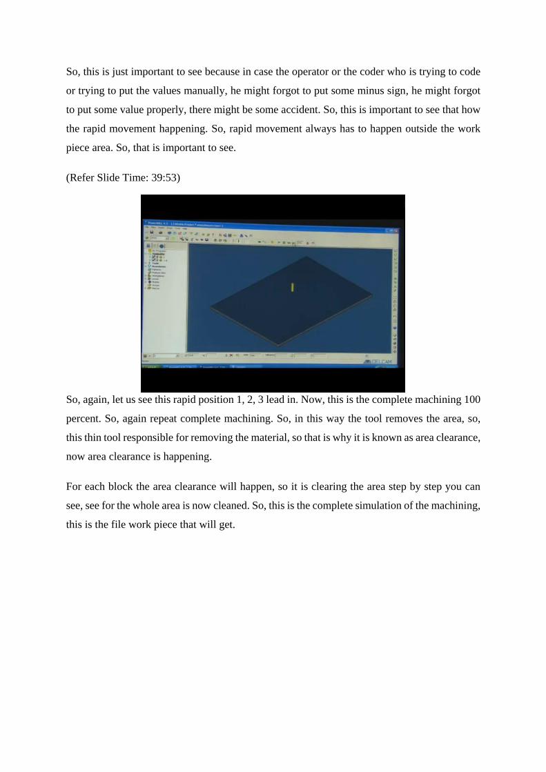
So, again, let us see this rapid position 1, 2, 3 lead in. Now, this is the complete machining 100
percent. So, again repeat complete machining. So, in this way the tool removes the area, so,
this thin tool responsible for removing the material, so that is why it is known as area clearance,
now area clearance is happening.
For each block the area clearance will happen, so it is clearing the area step by step you can
see, see for the whole area is now cleaned. So, this is the complete simulation of the machining,
this is the file work piece that will get.
(Refer Slide Time: 40:58)
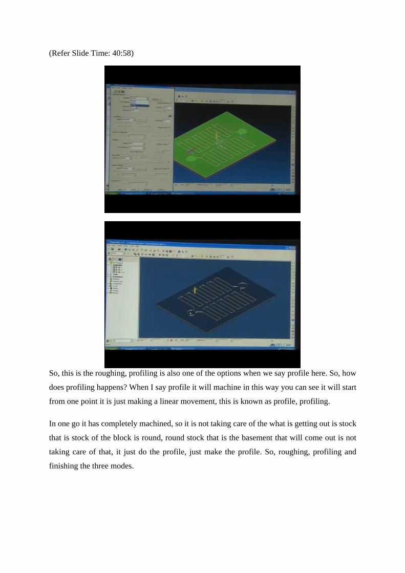
So, this is the roughing, profiling is also one of the options when we say profile here. So, how
does profiling happens? When I say profile it will machine in this way you can see it will start
from one point it is just making a linear movement, this is known as profile, profiling.
In one go it has completely machined, so it is not taking care of the what is getting out is stock
that is stock of the block is round, round stock that is the basement that will come out is not
taking care of that, it just do the profile, just make the profile. So, roughing, profiling and
finishing the three modes.

(Refer Slide Time: 41:42)
So, let us see different modes here. So, strategies different strategies for finishing for finishing
form you can see her there is certain strategies, this raster, radial, spiral, pattern, constant z then
optimize constants z, rotary, 3d offset, pencil, multi pencil, what are these? Let us try to see,
there are numerous types of profiles that can be taken here. So, like what is raster? It is just
doing the entire area, radial it is just taking off the corners of the radius.
So, fine spiral just taking stops surface in a spiral mode, these are all rastering patterns actually.
So, the pattern it is making a pattern the small area, then constant z. Constant z, it is making
these z value feed constant from the top to bottom it is coming down. In the circular ring pattern
it is one of the ways it is doing. Then comes rotary, rotary is all around the job that is your job
with the work piece that is there.
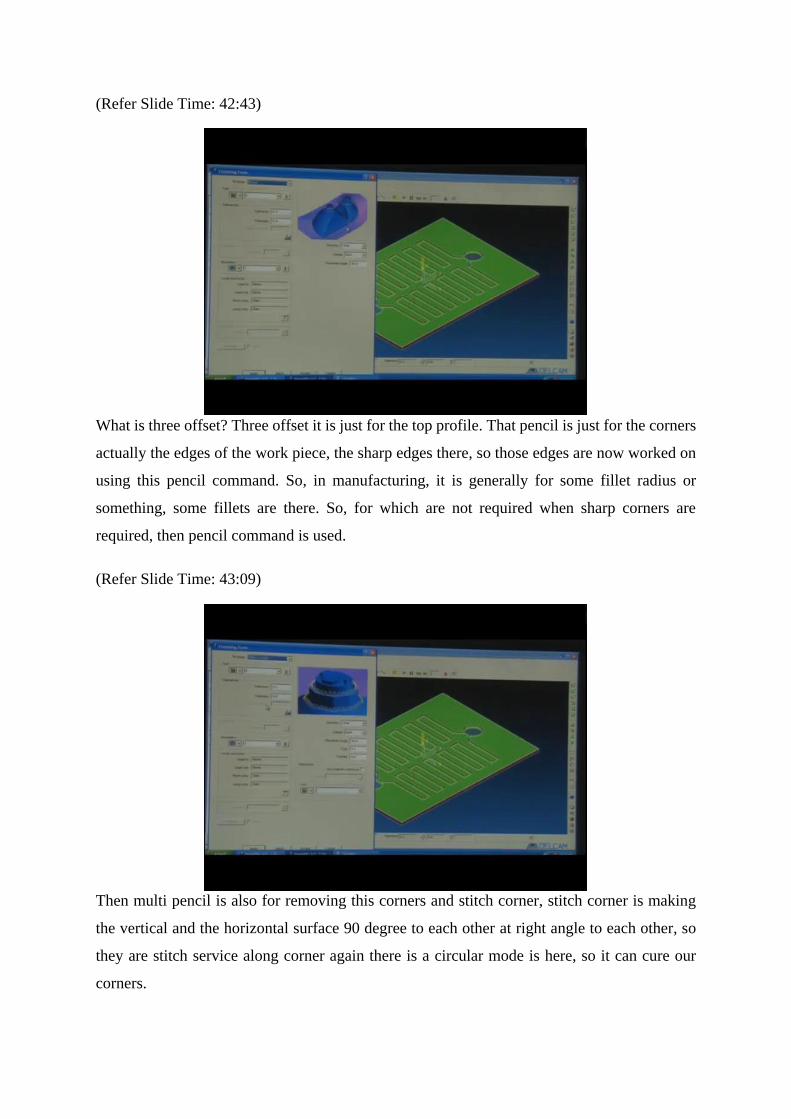
(Refer Slide Time: 42:43)
What is three offset? Three offset it is just for the top profile. That pencil is just for the corners
actually the edges of the work piece, the sharp edges there, so those edges are now worked on
using this pencil command. So, in manufacturing, it is generally for some fillet radius or
something, some fillets are there. So, for which are not required when sharp corners are
required, then pencil command is used.
(Refer Slide Time: 43:09)
Then multi pencil is also for removing this corners and stitch corner, stitch corner is making
the vertical and the horizontal surface 90 degree to each other at right angle to each other, so
they are stitch service along corner again there is a circular mode is here, so it can cure our
corners.
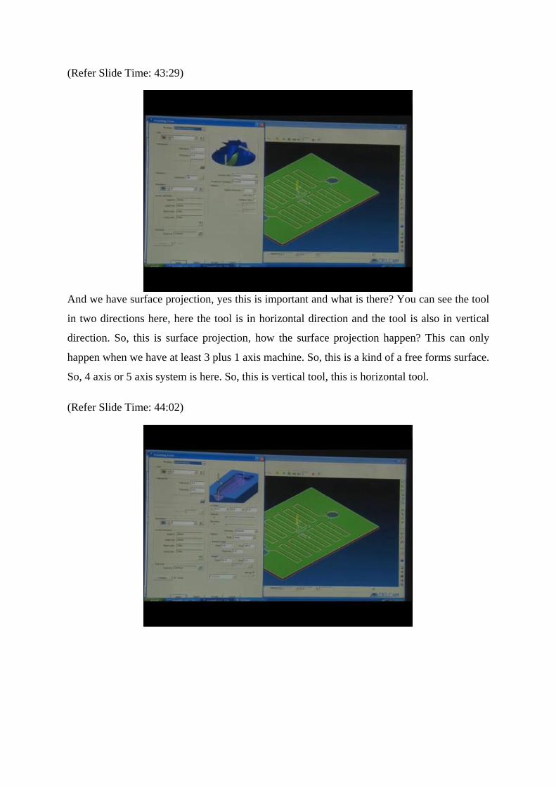
(Refer Slide Time: 43:29)
And we have surface projection, yes this is important and what is there? You can see the tool
in two directions here, here the tool is in horizontal direction and the tool is also in vertical
direction. So, this is surface projection, how the surface projection happen? This can only
happen when we have at least 3 plus 1 axis machine. So, this is a kind of a free forms surface.
So, 4 axis or 5 axis system is here. So, this is vertical tool, this is horizontal tool.
(Refer Slide Time: 44:02)
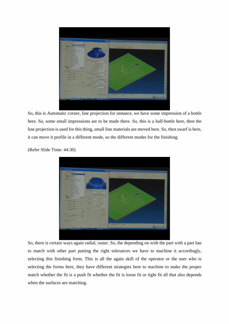
So, this is Automatic corner, line projection for instance, we have some impression of a bottle
here. So, some small impressions are to be made there. So, this is a half-bottle here, then the
line projection is used for this thing, small line materials are moved here. So, then swarf is here,
it can move it profile in a different mode, so the different modes for the finishing.
(Refer Slide Time: 44:30)
So, there is certain ways again radial, raster. So, the depending on with the part with a part has
to match with other part putting the right tolerances we have to machine it accordingly,
selecting this finishing form. This is all the again skill of the operator or the user who is
selecting the forms here, they have different strategies here to machine to make the proper
match whether the fit is a push fit whether the fit is loose fit or tight fit all that also depends
when the surfaces are matching.

So, minimum step down that can also be set here it is let me say it is 0.1. So, boundaries already
mentioned, sharp corners, corner selected, corrections are sharped, direction is climb, direction
is climbed, conventional or any let me put conventional. So, boundary trimming, boundary
trimming yes this is important, what is boundary trimming?
We have already selected the block here, this block form is there, to which direction or which
side of the block we need to keep. While see it, I put it keep inside if I could keep inside it will
keep the tool inside the block if it said keep outside, it will keep the tool outside the block, this
is to be selected properly.
(Refer Slide Time: 45:56)
A boundary when we say boundary, boundary barricades are there, it has to remain inside those
barricades, so this is finishing form. So, it is choosing its path by own and trying to finish the
form, which is taking care of the finishing of the work piece. So, in this way we generate the
tool path. It is how tool will move, how the tool interacts, or the tool retracts. So, we can also
name our different tool paths like I will just put it different name for that, so that we can recall
the data whenever we like. So, we can also store this same program somewhere and try to redo
this program multiple times and also,
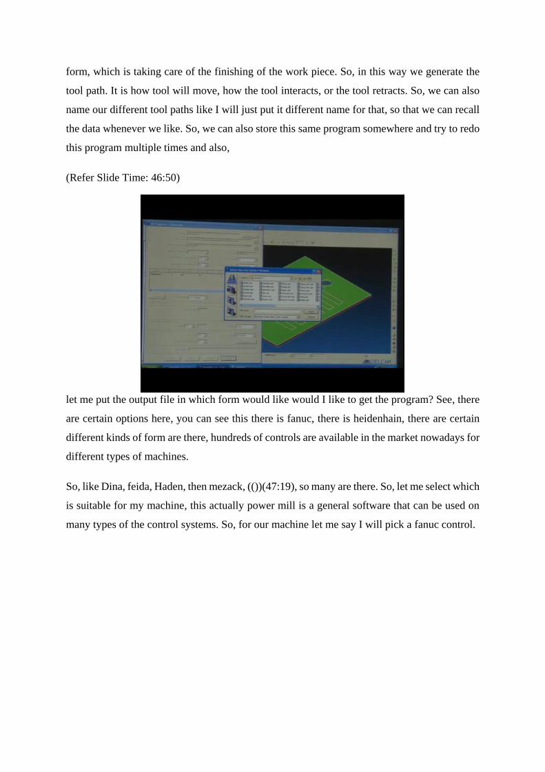
(Refer Slide Time: 46:50)
let me put the output file in which form would like would I like to get the program? See, there
are certain options here, you can see this there is fanuc, there is heidenhain, there are certain
different kinds of form are there, hundreds of controls are available in the market nowadays for
different types of machines.
So, like Dina, feida, Haden, then mezack, (())(47:19), so many are there. So, let me select which
is suitable for my machine, this actually power mill is a general software that can be used on
many types of the control systems. So, for our machine let me say I will pick a fanuc control.

(Refer Slide Time: 47:35)
So, now, this is the program this is a long program that is generated. So, it is would be very
difficult to generate big programs like these manually, however there are certain you would
say redundant or unwanted commands here. So, what does this percentage signifies? The may
signifies that it is a fanuc.
So, when I say fanuc system, fanuc system has code written in a four digit number, four name,
it is like Nepean 0001 here, I can it will all be four digit, we can put it to maybe 9999 or so or
maybe 1111 or 1234. But fanuc system always has the code in 4 digits that is the program
number.
Alphabet O and four digits, this is the fanuc, alphabet O and 1234, 1234 any four digits, so and
20, 30, 40, 60 these are all sequences, these are names block sequences are there. So, what is
G 91, G 28, x 0, y 0, z 0? So, G 91 is generally first line, then we have G 40, G 17, G 18, G 49.
So, already you know, what are G Codes, what our meaning of these codes? So, you can write
your own code as well. G 00 is actually rapid code, z 5 is the safe z value.
So, then T 3, M 6. What is T 3, M 6? T 3, M 6 as you know, there are certain codes G and M
codes these are G are the general codes, M are the miscellaneous code, G 54 is the tool
reference. So, you already know applications and the meaning of these codes and tool rotation
is important, the certain codes are there.
Tool cutting moves, thickness tolerances says, so already raster roughing is the first operation
that is going to happen here. So, these are these are few things just mentioned from by the
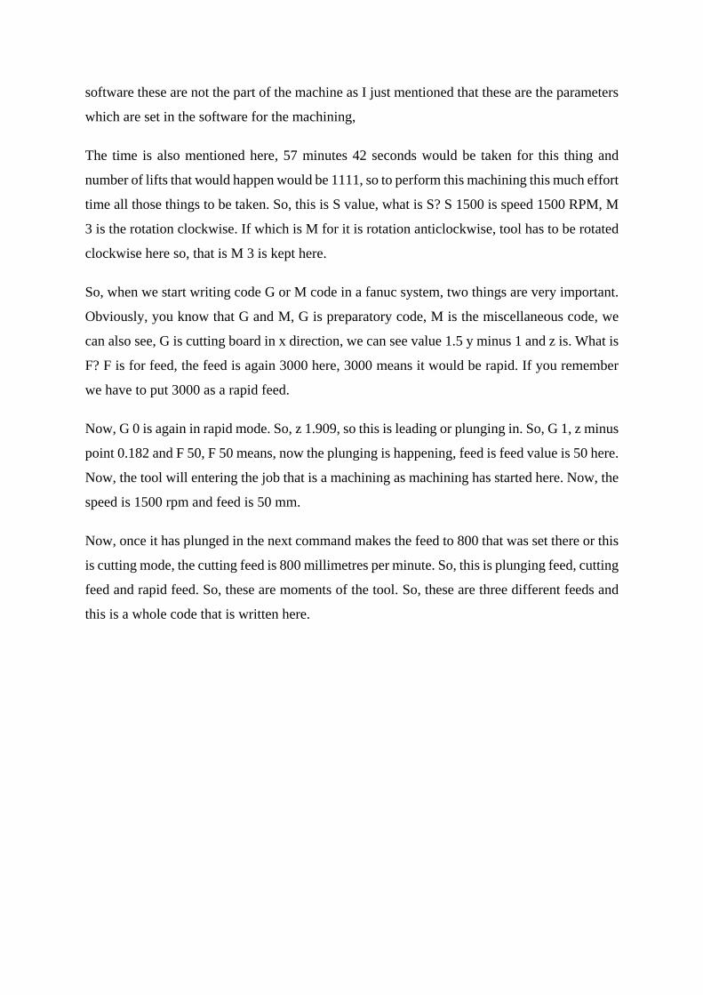
software these are not the part of the machine as I just mentioned that these are the parameters
which are set in the software for the machining,
The time is also mentioned here, 57 minutes 42 seconds would be taken for this thing and
number of lifts that would happen would be 1111, so to perform this machining this much effort
time all those things to be taken. So, this is S value, what is S? S 1500 is speed 1500 RPM, M
3 is the rotation clockwise. If which is M for it is rotation anticlockwise, tool has to be rotated
clockwise here so, that is M 3 is kept here.
So, when we start writing code G or M code in a fanuc system, two things are very important.
Obviously, you know that G and M, G is preparatory code, M is the miscellaneous code, we
can also see, G is cutting board in x direction, we can see value 1.5 y minus 1 and z is. What is
F? F is for feed, the feed is again 3000 here, 3000 means it would be rapid. If you remember
we have to put 3000 as a rapid feed.
Now, G 0 is again in rapid mode. So, z 1.909, so this is leading or plunging in. So, G 1, z minus
point 0.182 and F 50, F 50 means, now the plunging is happening, feed is feed value is 50 here.
Now, the tool will entering the job that is a machining as machining has started here. Now, the
speed is 1500 rpm and feed is 50 mm.
Now, once it has plunged in the next command makes the feed to 800 that was set there or this
is cutting mode, the cutting feed is 800 millimetres per minute. So, this is plunging feed, cutting
feed and rapid feed. So, these are moments of the tool. So, these are three different feeds and
this is a whole code that is written here.

(Refer Slide Time: 52:29)
So, let us see the closing commands here, it will do all the compressions then we have M 9, M
9 means, it will shut off the cutting fluid. Then G 91, G 28 z 0, G 91, G 28, z 0, so it will put z
at value 0. So, now G 28, x 0, y 0. So, in the milling, it is very important to note that we need
to put our x y and z values till 0 first, then M 30, M 30 is end the program, M 30 is program
end that is all.
So, all the commands gets switched off when we put M 30 there, some commands are taken in
absolute and some in incremental mode here. So, because it is generated by the software itself,
it has to get the work done, get the job manufactured or fabricated. So, it has taking its own
intelligence to develop the commands accordingly. So, there are certain things which are not
required like these are just the information.

I can just take this off, all these not required, this is also not required. So, there are certain
conditions in which the program is written able software it has its intelligence and also certain
limitations are there. So, those sometimes are to be taken care of for the specific machines, the
operator might have to put its own values to keep the reference at a proper alignment or maybe
some other tool value to selection, selected tool, the certain things those are to be taken care
of.
And for instance, if you have taken a fanuc program and we are trying to put it on a different
machine, we have selected the program, we have made the program for a specific kind of
machine and the same program is to be exported to another kind of machine for that kind of
machine different kind of setup in the beginning and at the end different commands are put.
However, the machining the major operations would be remaining same most of the time. So,
these are the major things. Now, this was all about the PowerMill software. Now, in the next
lecture, I will take you to the three axis milling machine where we will use this code that we
have generated here this component or the profiling that we have seen this specific pattern that
we have seen in the software, we will try to produce that there. So, what are the points or tips
to be noted, while we go on machine while we work on machine that two I will discuss in the
next lecture. Thank you.