Natural Convection in a Tilted Rectangular Enclosure with a Single Discrete Heater
Upload
universidadefederaldealagoasCategory
view
0download
0
Vol. 10, No. 2/February 1993/J. Opt. Soc. Am. A 299
Computer-generated holograms of tilted planes by a spatialfrequency approach
Tullio Tommasi and Bruno Bianco
Department of Biophysical and Electronic Engineering, University of Genova, Via Opera Pia 11a,16145 Genova, Italy
Received September 25, 1991; revised manuscript received July 22, 1992; accepted July 27, 1992Computer-generated holograms of plane surfaces tilted and shifted with respect to the hologram plane are con-sidered. The analysis is made in the spatial frequency domain by using the translation and rotation transfor-mations of angular spectra. The frequency approach permits the use of the fast-Fourier-transform algorithm,which decreases the computation time and makes it possible to consider any position of the planes in space.Various configurations of tilted and shifted planes have been investigated, and computer-generated hologramsof off-axis planes have been obtained. Computer and optical reconstructions, both of which show the feasibil-ity of the proposed approach, have been carried out.
1. INTRODUCTION
Three-dimensional (3-D) displays can be obtained by us-ing computer-generated holograms (CGH's), and severalmethods for performing this task have been investigated.A CGH has the advantage of dealing with both objects ex-isting in a mathematical description and sampled real ob-jects stored in a computer. In the generation of asynthetic hologram, one major problem is the calculationof the complex amplitude distribution produced by an ob-ject on the hologram plane. There are two aspects to thisproblem: first, the need for a satisfactory mathematicaldescription of the light produced by the object and, second,the computation time and the computer memory requiredfor such a description to be obtained.
Theoretically, the problem can be solved by regard-ing any object as a set of points. The complex amplitudeof each point can be calculated by a diffraction equation,e.g., the Fresnel equation or the more general Rayleigh-Sommerfeld equation,' disregarding the hidden surfaceproblem. The superposition of all point amplitudes yieldsthe total amplitude distribution, calculated on the holo-gram plane. Even though this approach is correct, it istoo time consuming, as a large number of points are nec-essary for an accurate representation of an object. Toreduce the computation time, many different techniqueshave been proposed that use the fast-Fourier-transform(FFT) algorithm. For example, one can generate a holo-gram composed of some Fourier holograms of differentperspective projections of a 3-D object: the stereoscopiceffect permits a 3-D sensation.2 3 The FFT can also beapplied in the case of a Fresnel CGH. When the Fresnelapproximations for diffraction are used, one can calculatethe light diffracted by a two-dimensional (2-D) object par-allel to the hologram plane by means of the FFT algo-rithm. For a 3-D object, a set of 2-D cross sections can beused, and the light diffracted by each section is evalu-ated.4 The superposition of all these complex amplitudesgives the total amplitude distribution.
Another approach has been developed that is based onthe knowledge of the amplitude distribution in a closed
form. This method is attractive for its precision and lim-ited computation time but can be applied only to a re-stricted class of objects, i.e., some mathematical curves.If line segments are considered,' the related amplitudesare cylindrical waves. This allows one to calculate thelight coming from lines with different inclinations withrespect to the hologram plane; as a result, a 3-D objectcan be described as a composition of segments. Other pa-pers dealing with analytical curve descriptions were pub-lished recently.6' 7
3-D objects made up of planes tilted with respect to theoptical axis of the hologram have been considered in twopapers.8 9 In these papers the light diffracted by a tiltedplanar segment is evaluated by using the Fresnel approxi-mation to implement the diffraction formula by the FFTalgorithm. The method has also been extended to largeobjects, assuming side shifts of such objects with respectto the optical axis.9 The main problem with this ap-proach is that the Fresnel conditions impose restrictionson the positions of the planes.
The basic idea of our approach to CGH's is that a 3-Dobject can be regarded as a sum of tilted and shiftedplanes, but our method of light calculation is differentfrom that of Frere and Leseberg. By means of a spatialfrequency analysis we evaluate the complex amplitude dis-tribution for each plane of a 3-D object. To this end, weconsider the angular spectrum and impose no restrictionson the plane position. Any 3-D surface can be generatedand its complex amplitude distribution evaluated; it isnecessary only to model a 3-D surface as a series of rotatedand translated planes. Our simple model of 3-D objectsassumes no interactions among planes, which means thatthe light coming from a plane is not diffracted by other ob-jects. Hence, hidden surfaces are not taken into account.The wave propagating from each plane is evaluated inthe frequency domain by applying the transformations forthe angular spectra of two planes. Translation transfor-mation is well known,1 and rotation transformation wasrecently proposed.' 0 The inverse Fourier transform ofthe angular spectrum calculated on the hologram planegives the complex amplitude generated by the plane under
0740-3232/93/020299-07$05.00 © 1993 Optical Society of America
T. Tommasi and B. Bianco
300 J. Opt. Soc. Am. A/Vol. 10, No. 2/February 1993
investigation. The superposition of the amplitudes pro-duced by all the planes forming the 3-D object gives thetotal complex amplitude distribution. A hologram canthen be generated by adding a reference wave.
In Section 2 the angular spectrum transformations areoutlined. In Section 3 the basic steps for generating thehologram of a rotated and translated plane are described,and the required software operations are specified.Problems concerning the hologram size and the sampledangular spectrum are addressed in Section 4. Both digi-tal and optical reconstructions are evaluated in Section 5.
2. ANGULAR SPECTRUMTRANSFORMATIONSThe scalar diffraction theory for monochromatic light canbe formulated not only in the spatial domain (leading tothe Rayleigh-Sommerfeld equation) but also in the spatialfrequency domain.' In the latter case, if the complex am-plitude distribution on any plane is Fourier analyzed, theFourier components can be seen as plane waves with dif-ferent directions of propagation, and the Fourier trans-form of the amplitude is referred to as the angularspectrum. The frequencies (fr, f) and the direction co-sines (a,,8,y) of propagation of a plane wave are relatedthrough the following equations:
a = Aft, f = Afy, 7 V a - 2 2 (1)
where A is the wavelength used.The relation between the angular spectra of two paral-
lel planes is well known. If AO is the spectrum of a planeof known amplitude, the spectrum Al of a second planelocated at a distance z from the first plane can be ex-pressed as
Al ( f y, z) Ao(f., f,)exp[27rjz(1/A' - -f_ )"2]. (2)
If 1/A2 - -X2 _ fy < 0, evanescent waves are generated,which do not contribute significantly to the amplitudedistribution on the second plane compared with progres-sive waves. The relation between the angular spectraof two rotated planes has been discussed elsewhere.'0
Here we want only to recall the equations useful for thenext analysis.
We assume two reference frames, 0; x, y, z and 0; 4i, 4and we calculate the angular spectrum on the plane2(,,0), A2(f , f,0), starting from the knowledge ofAl(f, fy, 0), which is the spectrum on the plane 1(x, y, 0).Let M be the rotation matrix relating (x, y, z) to (j, q)and the frequencies (f., fy f) to (fe, f, f):
(x, y, z) = M(6 n, V ,
(fe fA f& = MVt(fx Y, fz) where
f(1/A 2-f2 - 2)1l2
(3)
(4)
(5)
The superscript t denotes transpose, and an analogous re-lation to Eq. (5) holds for (fe, f, f).
Calculations carried out in Ref. 10 yield the followingresult:
where fx, fy, and f are calculated through Eqs. (4) and (5)and region C in the frequency domain is defined by theconditions
fz>0, fc>0. (7)
Conditions (7) state that evanescent and backward waveswith respect to the z and ; axes do not contribute to thelight on plane 2. It can be proved that region C isbounded by elliptical contours. 0
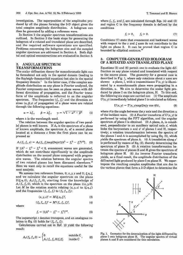
3. COMPUTER-GENERATED HOLOGRAMOF A ROTATED AND TRANSLATED PLANEEquations (2) and (6) permit one to evaluate the light dif-fraction on any plane rotated and translated with respectto the source plane. The geometry for a general case isdescribed in Fig. 1, where only rotations about x axes areshown: a plane, I, with a transmittance T(x, y) is illumi-nated by a monochromatic plane wave propagating in adirection, u. We aim to determine the scalar light pro-duced by plane I on the hologram plane, H. To this end,the following six steps are carried out: (1) The amplitudeU(x, y) immediately behind plane I is calculated as follows:
U(x,y) = T(x,y)exp(2irjy cos 0/A), (8)
where 0 is the angle between they axis and the direction uof the incident wave. (2) A Fourier transform of U(x, y) isperformed by using the FFT algorithm, and the angularspectrum of plane I is obtained. (3) A plane, A, is consid-ered, perpendicular to an auxiliary optical axis z' whichlinks the barycenters o and o' of planes I and H, respec-tively; a rotation transformation between the spectra ofthe planes I and A is accomplished by using Eq. (6), whichyields the spectrum of plane A. (4) A translation along z'is performed by means of Eq. (2), thereby determining thespectrum of plane B. (5) A rotation transformation be-tween the spectra of planes B and H gives the spectrum ofhologram plane H. (6) An inverse Fourier transformyields, as a final result, the amplitude distribution of thediffracted light produced by plane I on plane H. We super-impose the resulting complex amplitudes that are due tothe various planes that form a 3-D object to determine the
H
1-1+,, -
A Z/Axz'7
NO0 \\
X
"I
B]
N 0I I
/ X
y
, f,0) ={0 outside CA2 (f if ( 0) = fy, ffo f fi inside C Fig. 1. Geometry for the determination of the light diffracted by
(6) plane I onto hologram plane H. The angular spectra of virtualplanes A and B are considered for this calculation.
T. Tommasi and B. Bianco
\

Vol. 10, No. 2/February 1993/J. Opt. Soc. Am. A 301
total amplitude distribution on the hologram plane. Areference plane wave w is added, and the sum is squared,generating an interference pattern, i.e., a hologram.
For the implementation of the above six steps on a com-puter, the following software operations have to be carriedout: (1) The input transmittance, i.e., an n n pixel ma-trix, is related to an xy plane with the coordinate rangefrom - n/2 to n/2 for both the x and the y coordinates.The plane origin, o(0, 0), which is the center of rotationbetween planes I and A, is at the center of the pixel ma-trix. A coordinate translation is performed to associatethe coordinates from 0 to n/2 and from -n/2 to -1 withthe pixel domain, that is, from 1 to n, for both the x andthey axes. (2) A FFT of this transmittance is calculated,and the resulting data, stored in an n X n complex ma-trix, refer to the frequency range from 0 to n/2D and from- n/2D to -1D, corresponding to matrix indices rangingfrom 1 to n, for both f and f, where D is the actual size ofa square transmittance side. A translation is performedto refer to the range (-n/2D, n/2D), for both f and f.(3) The rotation is computed starting from the frequenciesfe and f of plane A. These frequencies are varied by 1/Dsteps, from -n/2D to n/2D, and the corresponding fre-quencies f and f are calculated through Eq. (4). A checkis made to ascertain that f and f are positive. The in-dices i and j of the A(fx, fy, 0) data matrix are found bymeans of the equations
i = n/2 + Dfx + 1, j = n/2 + Dfy + 1
(ij = 1-n). (9)
As a final result, the indices i and j permit one to asso-ciate a value of A1(fx f 0) with the spectrum A2 (f&, f,, 0).An interpolation of A(fx, fy, 0) data is required, as Eq. (4)gives real Dfx and Dfy values, which means that i andj arereal as well. Results show that a simple linear interpola-tion is sufficient, which is performed on the real and theimaginary part of A(fx, f, 0) separately. Sampling ff andf, by constant 1/D steps permits one to apply the FFT al-gorithm to the spectrum A2(f6, f,, 0). If one implementsthe transformation by varying f and f the resulting feand f,1values are not taken by constant steps; as a conse-quence, the FFT algorithm cannot be utilized. (4) Thetranslation transformation is calculated by consideringthe spectrum in the range (-n/2D, n/2D) for both fe andf,. The resulting spectrum of plane B is in the same do-main. (5) The same operations as for step (3) are carriedout. In this case f and f, are related to plane H, while fxand f correspond to plane B. Once the spectrum ofplane H has been computed, a coordinate translation isperformed to relate the frequency domain origin to theentry (1,1) of a complex matrix. (6) An inverse FFT algo-rithm applied to the spectrum data yields the complex am-plitude of the diffracted light. The final amplitude isfound by performing a translation that shifts the origincoordinates at the center of the matrix, as assumed for theinitial transmittance of plane I.
4. SAMPLED ANGULAR SPECTRUMA problem associated with the frequency analysis forCGH's concerns the actual size of a hologram. If a pixelmatrix n X n is considered and its actual size is D X D,
then, for a D value greater than n/2 times the wave-length, the repetition of the discrete Fourier transformplays an important role in the software computation. Theconsequences of a large-size D can be explained as follows:For simplicity, we assume a rotation about the x axis. Ifwe assume a wavelength equal to 1 for the present analy-sis, as f = jD and f,, = jJID (j, jj = -n/2 to n/2), we canexpress Eq. (4) as
j = clij + c2 (D2 - ii2 - jj2)1/2
i = ii, (10)
where c and c2 are entries of the rotation matrix and theindex ii is associated with fe (ii = - n/2 to n/2). We shiftthe resulting indices i andj by Eqs. (9) to refer to a matrixof sampled spectrum data. If D is greater than approxi-mately n/2 times the wavelength, some indices related tof, turn out to be outside the range (1, n). To generate ahologram whose size D is suitable for an optical recon-struction (i.e., D is greater than n/2), a software imple-mentation based on the repetition of the discrete Fouriertransform can be accomplished. To this end, the follow-ing remarks should first be made. If a normally incidentplane wave u illuminates a plane, say, B in Fig. 1, the un-diffracted wave corresponds to the frequencies f = 0 and
= 0, and it corresponds to the frequencies f 3/A ande 0 for plane H in Fig. 1, where f3 is a direction cosine
derived from the rotation transformation. The index jjassociated with f,, is found as jj = D13/A. For a correctevaluation of the spectrum it is necessary to vary the fre-quency f, within a range centered around the significantfrequencies of the angular spectrum of the tilted plane.A simple equation permits one to calculate this range:the value w that corresponds to the range (wlD, w/D + n/D)for a negative j3 and to the range (wID - nD, wD) for apositive 3 is the integer closest to w' which is found as
= M3/A - n/2
for a negative f3 and as
w' = D13/A + n/2 (11)
for a positive 13.Owing to the repetition of the discrete Fourier trans-
form, it is correct to consider the frequency range (a, b),shifted with respect to the range (-n/2D, n/2D). It isnecessary only to relate the new domain to the range(-n/2D, n/2D). To this end, the following relations hold:the frequencies in (a, mn/2D) correspond to those in(n/2D + a - mn/2D, n/2D), while the frequencies in(mn/2D + 1Db) correspond to those in (-n/2D, n/2D +a - mn/2D - 1D), where mn/2D is the smallest valuegreater than a, m being an odd number. It is useful toperform a coordinate translation for the f, values inorder to use the algorithm implemented for the domain(-n/2, n/2).
The configuration that includes planes I and A in Fig. 1requires a different analysis. In this case, the angularspectrum of plane I is centered around a frequency f cor-responding to ,k/A, where is determined by the propaga-tion direction u of the illuminating plane wave. Thespectrum of plane A is centered around (0, 0), as this planeis orthogonal to u. Hence the frequencies f,, of plane A
T. Tommasi and B. Bianco

302 J. Opt. Soc. Am. A/Vol. 10, No. 2/February 1993
A H
Z
0 -ULL
- l U
Fig. 2. Geometry for the generation of the hologram of an on-axis tilted plane A, illuminated by a plane wave u.
are varied from - n/2D to n/2D, while the frequencies f, ofplane I are outside the domain (-n/2D, n/2D). It is nec-essary to shift the f, values to make the related indicesvary from 1 to n. Considerations analogous to those dis-cussed above also apply to this coordinate translation.
One can extend the present analysis to a rotation aboutthe y axis, so obtaining general configurations with noconstraints on the positions and on the sizes of the planes.
5. RESULTS
We tested three configurations, with planes tilted andshifted with respect to the hologram, to evaluate the fea-sibility of the method. In particular, planes shifted fromthe optical axis were also considered. All the hologramswere generated by performing the six steps described inSection 3, and both computer and optical reconstructionswere carried out. The computer reconstructions were ob-tained by using the Rayleigh-Sommerfeld diffraction inte-gral; this made it possible to confirm the results of thefrequency approach through a procedure different fromthe one used for hologram generation. In this case theFresnel equation for diffraction was not applied, owing tothe presence of off-axis tilted planes. A comparison wasmade between the holograms generated in the spatial do-main (i.e., by means of the Rayleigh-Sommerfeld integral)and those computed in the frequency domain.
As a first configuration, an on-axis tilted plane wasconsidered (Fig. 2). A plane wave u illuminated plane A(the object), and a reference plane wave w whose directionof propagation was orthogonal to hologram plane H wasassumed. Two different planes were tested: the firsthad a transmittance with the letters CGH as a patternand an angle of inclination 0 = 45 deg, and the secondhad the word OPTICAL at an angle 0 = 10 deg. Both theobject and the hologram planes were composed of 512 512 pixel matrices, each quantized in 256 gray levels, andeach letter was contained in a 60 40 pixel matrix. Forthis configuration, only a rotation was needed, whichyielded a plane parallel to hologram plane H. Then atranslation was accomplished. The size of the matrices,D X D, and the distance oo' were 3200 3200 and 30,000times the wavelength, respectively. Figures 3 and 4show the holograms of the letters CGH and of the wordOPTICAL, respectively. The holograms were plotted by acolor video printer (Hitachi VY-150E) and then photo-reduced to provide transparencies for optical reconstruc-tions, which were performed by using an on-axis planewave in laser light with A = 633 nm. The actual size ofthe transparencies was approximately 2mm 2mm.
Figures 5 and 6 show some reconstructions obtained byusing a diffusing screen (tilted or parallel to the hologram
plane) to record the images. We projected the lettersCGH onto a screen both parallel and tilted by 45 deg withrespect to the hologram in order to reconstruct the origi-nal pattern. The reconstruction of the word OPTICAL isshown on a screen both tilted by 80 deg and parallel to thehologram. Because of the length of the word and becauseof an imperfect photoreduction in size (our simple appara-tus did not allow us to regulate the reduction dimensionsexactly) the entire word OPTICAL could not be broughtinto focus, as the letters required different focus positions.When the images were projected onto a screen parallel tothe hologram, the letters appear attached, as the planegenerated was nearly parallel to the optical axis.
The second configuration is shown in Fig. 7. An off-axis plane, A, was illuminated by a normally incidentplane wave u. A reference plane wave w was considered,with the direction of propagation orthogonal to the holo-
Fig. 3. Hologram of the letters CGH tilted by 45 deg with re-spect to the hologram plane.
Fig. 4. Hologram of the word OPTICAL tilted by 80 deg withrespect to the hologram plane.
T. Tommasi and B. Bianco
Vol. 10, No. 2/February 1993/J. Opt. Soc. Am. A 303
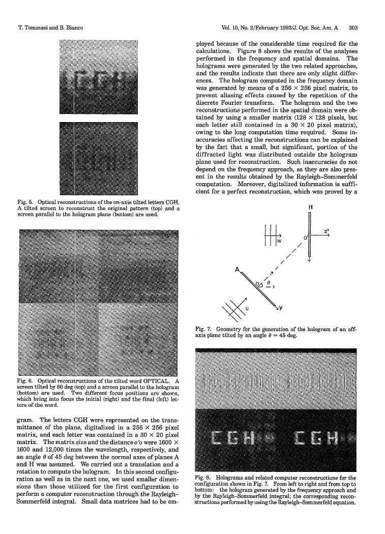
ployed because of the considerable time required for thecalculations. Figure 8 shows the results of the analysesperformed in the frequency and spatial domains. Theholograms were generated by the two related approaches,and the results indicate that there are only slight differ-ences. The hologram computed in the frequency domainwas generated by means of a 256 X 256 pixel matrix, toprevent aliasing effects caused by the repetition of thediscrete Fourier transform. The hologram and the tworeconstructions performed in the spatial domain were ob-tained by using a smaller matrix (128 x 128 pixels, buteach letter still contained in a 30 X 20 pixel matrix),owing to the long computation time required. Some in-accuracies affecting the reconstructions can be explainedby the fact that a small, but significant, portion of thediffracted light was distributed outside the hologramplane used for reconstruction. Such inaccuracies do notdepend on the frequency approach, as they are also pres-ent in the results obtained by the Rayleigh-Sommerfeldcomputation. Moreover, digitalized information is suffi-cient for a perfect reconstruction, which was proved by a
Fig. 5. Optical reconstructions of the on-axis tilted letters CGH.A tilted screen to reconstruct the original pattern (top) and ascreen parallel to the hologram plane (bottom) are used.
I L
H
/ II/
0
y
Fig. 7. Geometry for the generation of the hologram of an off-axis plane tilted by an angle 0 = 45 deg.
Fig. 6. Optical reconstructions of the tilted word OPTICAL. Ascreen tilted by 80 deg (top) and a screen parallel to the hologram(bottom) are used. Two different focus positions are shown,which bring into focus the initial (right) and the final (left) let-ters of the word.
gram. The letters CGH were represented on the trans-mittance of the plane, digitalized in a 256 256 pixelmatrix, and each letter was contained in a 30 20 pixelmatrix. The matrix size and the distance oo were 1600 1600 and 12,000 times the wavelength, respectively, andan angle of 45 deg between the normal axes of planes Aand H was assumed. We carried out a translation and arotation to compute the hologram. In this second configu-ration as well as in the next one, we used smaller dimen-sions than those utilized for the first configuration toperform a computer reconstruction through the Rayleigh-Sommerfeld integral. Small data matrices had to be em-
Fig. 8. Holograms and related computer reconstructions for theconfiguration shown in Fig. 7. From left to right and from top tobottom: the hologram generated by the frequency approach andby the Rayleigh-Sommerfeld integral; the corresponding recon-structions performed by using the Rayleigh-Sommerfeld equation.
T. Tommasi and B. Bianco

304 J. Opt. Soc. Am. A/Vol. 10, No. 2/February 1993
Fig. 9. Holograms and reconstructions analogous to those shownin Fig. 8 but related to the configuration in Fig. 1.
Fig. 10. Computer reconstructions showing a higher diffractionorder. The reconstructions have been obtained by applying theRayleigh-Sommerfeld integral to holograms generated by the fre-quency approach (right) and by the Rayleigh-Sommerfeld inte-gral (left).
reconstruction (not shown here) performed in the fre-quency domain by using a procedure opposite to the oneadopted for the hologram generation and applied to a256 256 pixel matrix.
A third, more general, configuration is shown in Fig. 1.It involves a rotation between planes I and A by an angle0 = 45 deg, a translation between planes A and B, andanother rotation between planes B and H by an angle 0' =45 deg. The letters OPT formed the transmittance ofplane I, and the D x D and oo' values were the same as forthe previous configuration. Figure 9 shows the results ofthe analysis, which was analogous to that related to Fig. 8.In this case, too, the Rayleigh-Sommerfeld equation wasused, and a 128 x 128 pixel matrix was utilized, whichexcluded a small part of the hologram.
We carried out some tests to evaluate the feasibility ofthe method. To this end, the holograms were generatedin the frequency domain, and the computer reconstruc-tions were obtained in the spatial domain. Some of theimportant results follow. The ratio x = Dn, which rep-resents the resolution of the pixel matrix, can be takenequal to 8-9 with no significant reconstruction degrada-tion. A higher ratio gave worse results, even though theletters were still visible. Optical reconstructions werealso performed for holograms with D = 6000 times thewavelength and n = 512; results show a high enough reso-lution but a low contrast between the letters and the back-ground. A digital analysis led us to state that limits onthe size D are set by the interpolation associated with the
rotation, as accurate reconstructions can be achievedwhen planes parallel to the hologram are considered. Wedetermined limits for the x ratio for a plane tilted by80 deg (see Fig. 2) in order to evaluate x for an extremeconfiguration. For lower inclination angles the size Dcan be taken slightly larger (e.g., for an inclination of45 deg, x can be 9-10). The positions of higher diffrac-tion orders cannot be computed by means of the usualequation, i.e., Ax = zA/8x (where Ax is the distance be-tween two orders), when configurations of off-axis tiltedplanes are considered. The tests performed for the con-figuration shown in Fig. 7 (with an object sampled into a256 x 256 pixel matrix of a D X D size equal to 1600 X1600) proved that it is necessary to set the distance oo' atleast equal to 12,000 to avoid the presence of higher or-ders in a reconstruction displayed in a matrix of the samesize as the one used for the object. Figure 10 shows twocomputer reconstructions carried out by applying theRayleigh-Sommerfeld equation to holograms generated byboth the spatial and the frequency approaches. A higherdiffraction order is visible, the distance o' being equal to8000. Similar conclusions can be drawn also for the otherconfigurations investigated, but, in on-axis cases, the twinimage must be accounted for, and a distance oo' equal to12,000 might not be sufficient to eliminate this contribu-tion. Computer tests showed that the twin image be-comes negligible for oo' equal to 15,000-20,000, andgood-quality reconstructions can be achieved by consider-ing a distance oo' until approximately 30,000-35,000. Be-yond this limit, coding errors are incurred.
When the discrete Fourier transform is used, aliasingeffects must be taken into account. Therefore it is usefulto consider an object bounded by black regions in order togenerate a correct hologram. It is evident that the more aplane is tilted, the more an object extends toward theplane sides (see, for example, Fig. 6).
6. CONCLUSIONS
CGH's of off-axis and on-axis planes tilted with respect tothe hologram plane have been obtained. No restrictionsare imposed on the rotation and translation of the dif-fracting planes, as the analysis is developed in the spatialfrequency domain and does not involve the Fresnel ap-proximations. In principle, the same result could beachieved with the Rayleigh-Sommerfeld equation, butthis approach would be time consuming. Our testsshowed that the frequency approach, implemented by theFFT algorithm, is more than 100 times faster than thespatial approach.
Various configurations have been tested, and resultsdemonstrate the feasibility of the proposed procedure. Inparticular, some specific examples (i.e., the tilted wordOPTICAL nearly parallel to the optical axis and an off-axis planar object orthogonal to the hologram plane) pointout that neither practical nor theoretical constraints haveto be imposed on configurations. Some limits on the D/nratio and on the distance between the hologram and theobject are required if one is to avoid coding errors. Theoptical reconstructions have been achieved by using asimple technical apparatus. A better control of resolutionand of the size of photoreductions might yield still more-satisfactory results. On the other hand, the computer re-
T. Tommasi and B. Bianco

Vol. 10, No. 2/February 1993/J. Opt. Soc. Am. A 305
constructions of off-axis configurations (performed withthe Rayleigh-Sommerfeld diffraction integral) confirmthe correctness of the method.
REFERENCES
1. J. W Goodman, Introduction to Fourier Optics (McGraw-Hill, New York, 1968).
2. L. P. Yaroslavskii and N. S. Merzlyakov, Methods of DigitalHolography (Plenum, New York, 1980).
3. T. Yatagai, "Stereoscopic approach to 3-D display usingcomputer-generated holograms," Appl. Opt. 15, 2722-2729(1976).
4. T. S. Huang, "Digital holography," Proc. IEEE 59, 1335-1346(1971).
5. Ch. Frere, D. Leseberg, and 0. Bryngdahl, "Computer-gener-ated holograms of three-dimensional objects composed of linesegments," J. Opt. Soc. Am. A 3, 726-730 (1986).
6. S. Bara, Ch. Frere, Z. Jaroszewicz, A. Kolodziejczyk, and D.Leseberg, "Modulated on-axis circular zone plates for a gen-eration of 3-D focal curves," J. Mod. Opt. 37, 1287-1295(1990).
7. Z. Jaroszewicz, A. Kolodziejczyk, D. Mouriz, and S. Bara,'Analytic design of computer-generated Fourier-transformholograms for plane curves reconstruction," J. Opt. Soc. Am.A 8, 559-565 (1991).
8. D. Leseberg and Ch. Frere, "Computer-generated hologramsof 3-D objects composed of tilted planar segments," Appl.Opt. 27, 3020-3024 (1988).
9. Ch. Frere and D. Leseberg, "Large objects reconstructedfrom computer-generated holograms," Appl. Opt. 28, 2422-2425 (1989).
10. T. Tommasi and B. Bianco, "Frequency analysis of light dif-fraction between rotated planes," Opt. Lett. 17, 556-558(1992).
T. Tommasi and B. Bianco
Copyright © 2022 FDOKUMEN