Multiple-viewpoint projection holograms synthesized by spatially incoherent correlation with...
10
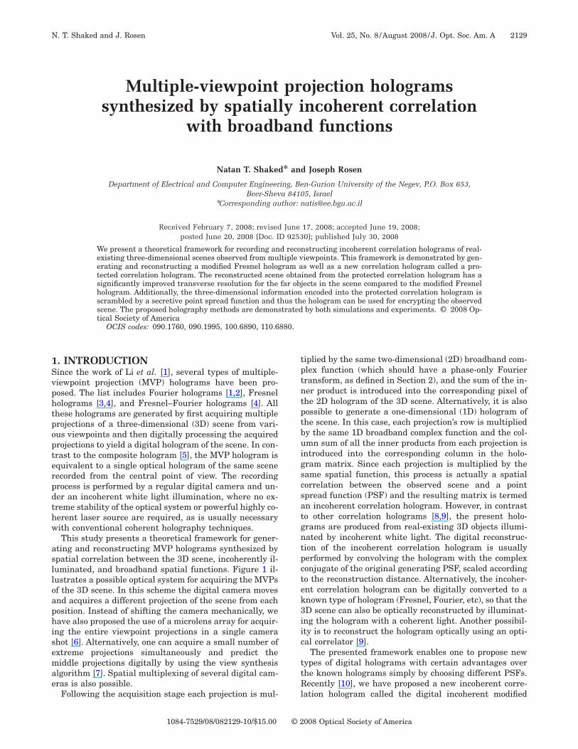
Multiple-viewpoint projection holograms synthesized by spatially incoherent correlation with broadband functions Natan T. Shaked* and Joseph Rosen Department of Electrical and Computer Engineering, Ben-Gurion University of the Negev, P.O. Box 653, Beer-Sheva 84105, Israel * Corresponding author: [email protected] Received February 7, 2008; revised June 17, 2008; accepted June 19, 2008; posted June 20, 2008 (Doc. ID 92530); published July 30, 2008 We present a theoretical framework for recording and reconstructing incoherent correlation holograms of real- existing three-dimensional scenes observed from multiple viewpoints. This framework is demonstrated by gen- erating and reconstructing a modified Fresnel hologram as well as a new correlation hologram called a pro- tected correlation hologram. The reconstructed scene obtained from the protected correlation hologram has a significantly improved transverse resolution for the far objects in the scene compared to the modified Fresnel hologram. Additionally, the three-dimensional information encoded into the protected correlation hologram is scrambled by a secretive point spread function and thus the hologram can be used for encrypting the observed scene. The proposed holography methods are demonstrated by both simulations and experiments. © 2008 Op- tical Society of America OCIS codes: 090.1760, 090.1995, 100.6890, 110.6880. 1. INTRODUCTION Since the work of Li et al. [1], several types of multiple- viewpoint projection (MVP) holograms have been pro- posed. The list includes Fourier holograms [1,2], Fresnel holograms [3,4], and Fresnel–Fourier holograms [4]. All these holograms are generated by first acquiring multiple projections of a three-dimensional (3D) scene from vari- ous viewpoints and then digitally processing the acquired projections to yield a digital hologram of the scene. In con- trast to the composite hologram [5], the MVP hologram is equivalent to a single optical hologram of the same scene recorded from the central point of view. The recording process is performed by a regular digital camera and un- der an incoherent white light illumination, where no ex- treme stability of the optical system or powerful highly co- herent laser source are required, as is usually necessary with conventional coherent holography techniques. This study presents a theoretical framework for gener- ating and reconstructing MVP holograms synthesized by spatial correlation between the 3D scene, incoherently il- luminated, and broadband spatial functions. Figure 1 il- lustrates a possible optical system for acquiring the MVPs of the 3D scene. In this scheme the digital camera moves and acquires a different projection of the scene from each position. Instead of shifting the camera mechanically, we have also proposed the use of a microlens array for acquir- ing the entire viewpoint projections in a single camera shot [6]. Alternatively, one can acquire a small number of extreme projections simultaneously and predict the middle projections digitally by using the view synthesis algorithm [7]. Spatial multiplexing of several digital cam- eras is also possible. Following the acquisition stage each projection is mul- tiplied by the same two-dimensional (2D) broadband com- plex function (which should have a phase-only Fourier transform, as defined in Section 2), and the sum of the in- ner product is introduced into the corresponding pixel of the 2D hologram of the 3D scene. Alternatively, it is also possible to generate a one-dimensional (1D) hologram of the scene. In this case, each projection’s row is multiplied by the same 1D broadband complex function and the col- umn sum of all the inner products from each projection is introduced into the corresponding column in the holo- gram matrix. Since each projection is multiplied by the same spatial function, this process is actually a spatial correlation between the observed scene and a point spread function (PSF) and the resulting matrix is termed an incoherent correlation hologram. However, in contrast to other correlation holograms [8,9], the present holo- grams are produced from real-existing 3D objects illumi- nated by incoherent white light. The digital reconstruc- tion of the incoherent correlation hologram is usually performed by convolving the hologram with the complex conjugate of the original generating PSF, scaled according to the reconstruction distance. Alternatively, the incoher- ent correlation hologram can be digitally converted to a known type of hologram (Fresnel, Fourier, etc), so that the 3D scene can also be optically reconstructed by illuminat- ing the hologram with a coherent light. Another possibil- ity is to reconstruct the hologram optically using an opti- cal correlator [9]. The presented framework enables one to propose new types of digital holograms with certain advantages over the known holograms simply by choosing different PSFs. Recently [10], we have proposed a new incoherent corre- lation hologram called the digital incoherent modified N. T. Shaked and J. Rosen Vol. 25, No. 8/ August 2008/ J. Opt. Soc. Am. A 2129 1084-7529/08/082129-10/$15.00 © 2008 Optical Society of America
Transcript of Multiple-viewpoint projection holograms synthesized by spatially incoherent correlation with...
1Svphtpopterpdthw
aslloaphisemae
N. T. Shaked and J. Rosen Vol. 25, No. 8 /August 2008 /J. Opt. Soc. Am. A 2129
Multiple-viewpoint projection hologramssynthesized by spatially incoherent correlation
with broadband functions
Natan T. Shaked* and Joseph Rosen
Department of Electrical and Computer Engineering, Ben-Gurion University of the Negev, P.O. Box 653,Beer-Sheva 84105, Israel
*Corresponding author: [email protected]
Received February 7, 2008; revised June 17, 2008; accepted June 19, 2008;posted June 20, 2008 (Doc. ID 92530); published July 30, 2008
We present a theoretical framework for recording and reconstructing incoherent correlation holograms of real-existing three-dimensional scenes observed from multiple viewpoints. This framework is demonstrated by gen-erating and reconstructing a modified Fresnel hologram as well as a new correlation hologram called a pro-tected correlation hologram. The reconstructed scene obtained from the protected correlation hologram has asignificantly improved transverse resolution for the far objects in the scene compared to the modified Fresnelhologram. Additionally, the three-dimensional information encoded into the protected correlation hologram isscrambled by a secretive point spread function and thus the hologram can be used for encrypting the observedscene. The proposed holography methods are demonstrated by both simulations and experiments. © 2008 Op-tical Society of America
OCIS codes: 090.1760, 090.1995, 100.6890, 110.6880.
tptntptbuigscsatgntpctek3iic
ttRl
. INTRODUCTIONince the work of Li et al. [1], several types of multiple-iewpoint projection (MVP) holograms have been pro-osed. The list includes Fourier holograms [1,2], Fresnelolograms [3,4], and Fresnel–Fourier holograms [4]. Allhese holograms are generated by first acquiring multiplerojections of a three-dimensional (3D) scene from vari-us viewpoints and then digitally processing the acquiredrojections to yield a digital hologram of the scene. In con-rast to the composite hologram [5], the MVP hologram isquivalent to a single optical hologram of the same sceneecorded from the central point of view. The recordingrocess is performed by a regular digital camera and un-er an incoherent white light illumination, where no ex-reme stability of the optical system or powerful highly co-erent laser source are required, as is usually necessaryith conventional coherent holography techniques.This study presents a theoretical framework for gener-
ting and reconstructing MVP holograms synthesized bypatial correlation between the 3D scene, incoherently il-uminated, and broadband spatial functions. Figure 1 il-ustrates a possible optical system for acquiring the MVPsf the 3D scene. In this scheme the digital camera movesnd acquires a different projection of the scene from eachosition. Instead of shifting the camera mechanically, weave also proposed the use of a microlens array for acquir-
ng the entire viewpoint projections in a single camerahot [6]. Alternatively, one can acquire a small number ofxtreme projections simultaneously and predict theiddle projections digitally by using the view synthesis
lgorithm [7]. Spatial multiplexing of several digital cam-ras is also possible.
Following the acquisition stage each projection is mul-
1084-7529/08/082129-10/$15.00 © 2
iplied by the same two-dimensional (2D) broadband com-lex function (which should have a phase-only Fourierransform, as defined in Section 2), and the sum of the in-er product is introduced into the corresponding pixel ofhe 2D hologram of the 3D scene. Alternatively, it is alsoossible to generate a one-dimensional (1D) hologram ofhe scene. In this case, each projection’s row is multipliedy the same 1D broadband complex function and the col-mn sum of all the inner products from each projection is
ntroduced into the corresponding column in the holo-ram matrix. Since each projection is multiplied by theame spatial function, this process is actually a spatialorrelation between the observed scene and a pointpread function (PSF) and the resulting matrix is termedn incoherent correlation hologram. However, in contrasto other correlation holograms [8,9], the present holo-rams are produced from real-existing 3D objects illumi-ated by incoherent white light. The digital reconstruc-ion of the incoherent correlation hologram is usuallyerformed by convolving the hologram with the complexonjugate of the original generating PSF, scaled accordingo the reconstruction distance. Alternatively, the incoher-nt correlation hologram can be digitally converted to anown type of hologram (Fresnel, Fourier, etc), so that theD scene can also be optically reconstructed by illuminat-ng the hologram with a coherent light. Another possibil-ty is to reconstruct the hologram optically using an opti-al correlator [9].
The presented framework enables one to propose newypes of digital holograms with certain advantages overhe known holograms simply by choosing different PSFs.ecently [10], we have proposed a new incoherent corre-
ation hologram called the digital incoherent modified
008 Optical Society of America
FbTdiocdttlhh
letaa
iSflSstac
2IHAta1nqah2hgagitglt
aitttob
st[t
f3tupPsm
wh
wmruqptscrdrtS
adP
wrb
wet
r
Ft
2130 J. Opt. Soc. Am. A/Vol. 25, No. 8 /August 2008 N. T. Shaked and J. Rosen
resnel hologram (DIMFH), in which the 3D scene haseen correlated with a PSF of a quadratic phase function.he DIMFH has been generated by processing the MVPsirectly rather than by the previous indirect method [3,4],n which a Fourier hologram had been computed first, andnly then was a Fresnel hologram generated from the re-onstructed image of the first hologram. Therefore, redun-ant calculations and digital errors during the variousransformations are avoided by using the DIMFH. Fur-hermore, this direct Fresnel holography method is notimited to small angles, in contrast to the MVP Fourierologram and the indirect MVP Fresnel hologram, andence the hologram reconstruction is more accurate.In this study, by choosing a new broadband, space-
imited, and secretive PSF, we also present a new incoher-nt correlation hologram called the digital incoherent pro-ected correlation hologram (DIPCH). This hologram hashigher resolving power than the DIMFH, as well as the
bility to encrypt the observed 3D information.Following the presentation of the proposed framework
n Section 2, we mathematically confirm its correctness inection 3. Then, we show in Section 4 how to use this
ramework in order to propose two types of correlation ho-ograms, the DIMFH and the DIPCH mentioned above.ections 5 and 6 present simulation and experimental re-ults, respectively, in which we demonstrate the genera-ion and reconstruction of the DIMFH and the DIPCHnd compare between them. Section 7 introduces someoncluding remarks.
. GENERATING AND RECONSTRUCTINGNCOHERENT CORRELATIONOLOGRAMSs mentioned above, by choosing different PSFs various
ypes of incoherent correlation holograms can be gener-ted from the acquired MVPs. For every hologram type,D or 2D holograms can be synthesized depending on theature of the MVP aquisition. In case the MVPs are ac-uired only horizontally (as illustrated in Fig. 1) or alongdifferent transverse axis, a 1D incoherent correlation
ologram is generated. When the MVPs are acquired on aD grid of positions on the transverse plane, a 2D inco-erent correlation hologram is generated. The 1D holo-rams are easier to produce because the projections arecquired along a single axis only. However, the 2D holo-rams have the advantage of encoding the 3D informationnto both axes. This advantage can be demonstrated withhe following example. Assume that we record a 1D holo-ram of an object with the shape of a thin long horizontaline, where the camera moves along the long dimension ofhis line-shaped object. The axial location of the object is
ig. 1. Optical system for acquiring MVPs of the 3D scene alonghe horizontal axis.
ctually lost in the hologram and the reconstructed images in focus along a long axial range. On the other hand,he 2D hologram contains the axial information, no mat-er what the recorded object shape is, and the image ofhe line-shaped object in the example above is in focusnly in a single well-defined transverse plane, as it shoulde.Next, we present the theory of generating and recon-
tructing 2D incoherent correlation holograms, where theheory of 1D incoherent correlation holograms (used in10], for example) can be straightforwardly derived fromhe general 2D case.
The 2D incoherent correlation hologram is synthesizedrom 2K+1 horizontal by 2K+1 vertical projections of theD scene. We number the projections by m and n, so thathe middle projection is denoted by �m ,n�= �0,0�, thepper-right projection by �m ,n�= �K ,K�, and the lower-leftrojection by �m ,n�= �−K ,−K�. The �m ,n�th projectionm,n�xp ,yp� is multiplied by a PSF and the product isummed to the �m ,n�th pixel in the following complexatrix:
H2�m,n� =�� Pm,n�xp,yp�E2�xp,yp�dxpdyp, �1�
here E2�xp ,yp� represents the generating PSF of the 2Dologram. This PSF is given by
E2�xp,yp� = A2�bxp,byp�exp�ig2�bxp,byp��, �2�
here A2 and g2 are functions depending on �xp ,yp� anday be chosen differently for each type of incoherent cor-
elation hologram, and b is an adjustable parameter (withnits that preserve the arguments of A2 and g2 as unitlessuantities). Additionally, the function E2�xp ,yp� has theroperty that its Fourier transform is a phase-only func-ion. As we show in the following this condition is neces-ary to guarantee that the generated hologram can be re-onstructed properly. The process manifested by Eq. (1) isepeated for all the projections, so that in the end of thisigital process the resulting 2D complex matrix H2�m ,n�epresents the 2D incoherent correlation hologram ofhe 3D scene. The validation of this process is given inection 3.The reconstructed planar image s2�m ,n ;zr�, located at
n axial distance zr from the 2D hologram, is obtained byigitally convolving the hologram with the reconstructingSF as follows:
s2�m,n;zr� = �H2�m,n� � R2�m,n;zr��, �3�
here � denotes a 2D convolution and R2�m ,n ;zr� is theeconstructing PSF of the 2D hologram. This PSF is giveny
R2�m,n;zr� = A2�m�p
zr,n�p
zr�exp− ig2�m�p
zr,n�p
zr� ,
�4�
here A2 and g2 are the same functions used for the gen-rating PSF of Eq. (2) and �p is the pixel size of the digi-al camera.
Similar theory can also be applied for generating andeconstructing 1D incoherent correlation holograms [10].
HPa1slg
3DTototfsgft3cpg
wc(
w
Tb
d�
Tah
H
Ehh
te
N. T. Shaked and J. Rosen Vol. 25, No. 8 /August 2008 /J. Opt. Soc. Am. A 2131
owever, in this case each row in the mth projectionm�xp ,yp� is multiplied by the same 1D PSF E1�xp�nd the result is summed to the mth column in theD hologram H1�m ,n�. The reconstructed planar image1�m ,n ;zr�, located at an axial distance zr from the 1D ho-ogram, is obtained by convolving the rows of the holo-ram matrix with the 1D reconstructing PSF R1�m ;zr�.
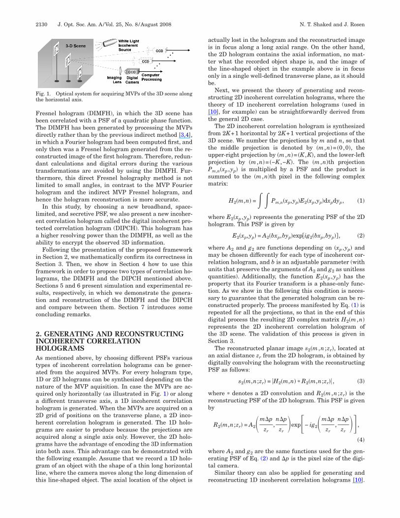
. MATHEMATICAL ANALYSIS OF THEIGITAL PROCESShis section provides verification that the reconstructionf the incoherent correlation hologram yields the image ofhe observed 3D scene. Here also, the analysis is carriedut for the case of the 2D hologram, where the analysis ofhe 1D hologram is briefly discussed afterward. There-ore, contrary to what is illustrated in Fig. 1, we first as-ume that the MVPs of the 3D scene are acquired on a 2Drid. Figure 2 shows a top view of the optical system usedor acquiring the MVPs. From this figure it is seen thathe geometric relations between a point �xs ,ys ,zs� at theD scene (where the coordinate origin is defined on theenter of the imaging lens at the middle projection) and aoint �xp ,yp� on the �m ,n�th projection Pm,n�xp ,yp� areiven by
xp =f�xs − m��
zs, yp =
f�ys − n��
zs, �5�
here f is the focal length of the imaging lens and � is theamera gap between two adjacent projections. Using Eqs.5) the generating PSF, defined by Eq. (2), is
E2�xp,yp� = A2�bxp,byp�exp�ig2�bxp,byp��
= A2��,��exp�ig2��,��� = E2�xs − m�,ys − n�;zs�,
�6�
here
� =bf�xs − m��
zs=
bf�
zs�p�xs�p
�− m�p� ,
� =bf�ys − n��
zs=
bf�
zs�p�ys�p
�− n�p� .
he complex distribution obtained on the hologram plane
y a single source point, located in the 3D scene at coor- oinates �xs ,ys ,zs�, and having an infinitesimal size of�xs ,�ys ,�zs� and a value of h�xs ,ys ,zs�, is given by
H̃2�m,n;xs,ys,zs� =�� �h�xs,ys,zs��xs�ys�zs
���xp� − xp,yp� − yp��E2�xp�,yp��dxp�dyp�
= h�xs,ys,zs�E2�xp,yp��xs�ys�zs
= h�xs,ys,zs�E2�xs − m�,ys − n�;zs�
��xs�ys�zs. �7�
he overall distribution of the hologram, resulting fromll the 3D scene points, is a volume integral over all theolograms of these single points as follows:
2�m,n�
=��� H̃2�m,n;xs,ys,zs�dxsdysdzs
=��� h�xs,ys,zs�E2�xs − m�,ys − n�;zs�dxsdysdzs.
�8�
quation (8) indeed indicates that for each value of zs theologram is a 2D correlation between the scene function�xs ,ys ,zs� and the PSF.To confirm that this hologram can be reconstructed to
he image of the observed 3D scene, let us substitute thexpression of the hologram [Eq. (8)] into Eq. (3) in order to
Fig. 2. Top view of the optical system of the MVP acquisition.
btain the reconstructed image s2�m ,n ;zr� as follows:
s2�m,n;zr� = �H2�m,n� � R2�m,n;zr��
= �� � � �� h�xs,ys,zs�E2�xs − m��,ys − n��;zs�dxsdysdzsR2�m − m�,n − n�;zr�dm�dn��= �� � � h�xs,ys,zs�� � E2�xs − m��,ys − n��;zs�R2�m − m�,n − n�;zr�dm�dn�dxsdysdzs�= �� � � h�xs,ys,zs�E2�xs − m�,ys − n�;zs� � R2�m,n;zr�dxsdysdzs� . �9�

Ev
wi(
Esggtaoai
t
Cfljttadastttet
2132 J. Opt. Soc. Am. A/Vol. 25, No. 8 /August 2008 N. T. Shaked and J. Rosen
Let us define ���m ,�n� so that FT�E2�m�p ,n�p� =exp�i���m ,�n��, where FT denotes a Fourier transform. Since R2 and2 are a complex conjugate pair, FT�R2�m�p ,n�p� =exp�−i��−�m ,−�n��. Using Eqs. (4) and (6) we first calculate the con-olution between the generating and the reconstructing PSFs in Eq. (9) as the following:
E2�xs − m�,ys − n�;zs� � R2�m,n;zr� = FT−1�FT�E2�xs − m�,ys − n�;zs� · FT�R2�m,n;zr�
= FT−1�FT�A2��,��exp�ig2��,��� · FT�A2�m�p
zr,n�p
zr�exp− ig2�m�p
zr,n�p
zr���
= C · FT−1�expi��− zs�p
�bf�m,
− zs�p
�bf�n�exp− i�xs�p
��m +
ys�p
��n�
· exp�− i��− zr�m,− zr�n���= C · ��m�p −
xs�p
�,n�p −
ys�p
�;zr −
zs�p
�bf � , �10�
Tctbscat=sit
ttFaP
Ftc
wrt
Tl(mHm
here FT−1 denotes an inverse Fourier transform and Cs a constant. Thus, after substituting the result of Eq.10) back into Eq. (9) the reconstruction image is
s2�m,n;zr� = �C ·��� h�xs,ys,zs���m�p −xs�p
�,n�p
−ys�p
�;zr −
zs�p
bf� �dxsdysdzs�= �C · h�m�p ·
�
�p,n�p ·
�
�p;zr ·
bf�
�p �� . �11�
quation (11) indicates that a scaled version of the 3Dcene h�xs ,ys ,zs� is indeed reconstructed from the holo-ram and hence the correctness of the entire digital holo-raphic process is verified. Note that under the conditionhat the Fourier transforms of the two PSFs, E2 and R2,re conjugate-pair phase-only functions, the convolutionf Eq. (10) is equal to the delta function and consequentlyproper reconstruction of the scene is obtained as shown
n Eq. (11).The transverse and the longitudinal magnifications of
he proposed hologram resulting from Eq. (11) are
M2,x = M2,y =�p
�, M2,z =
�p
bf�. �12�
ontrary to conventional MVP holograms, it is evidentrom Eqs. (12) that the magnifications of the proposed ho-ogram are independent on the axial positions of the ob-ects in the 3D scene. Therefore, the original scale rela-ions between the various objects are maintained duringhe digital reconstruction, no matter whether the objectsre close to or far from the acquisition plane. Hence, theigital image reconstructed from this hologram is a moreccurate representation of the 3D scene. In addition, thispecial feature of the hologram may be very useful for op-ical 3D pattern recognition and object segmentation. In-uitively, this behavior can be explained as follows. Al-hough farther objects look smaller than closer objects inach captured projection, they also “move” slowerhroughout the projections because of the parallax effect.
he slower “movement” of farther objects broadens theorrelation with the PSF in a way that the reduction ofhe image size in each projection is exactly compensatedy the increment of the correlation size. However, if onetill wants to eliminate this effect during the digital re-onstruction process in order to obtain the perspective ofconventional optical imaging system, one should scale
he reconstructed image by M /M2,x= �f /zs� / ��p /��1/ �bzr� [since zr /zs=�p / �bf��] for each and every recon-tructed plane, where M= f /zs is the magnification of themaging lens. This rescaling process is demonstrated inhe results described in Section 5.
A similar mathematical confirmation can be applied forhe 1D incoherent correlation hologram. In this 1D case, ifhe digital camera moves only horizontally (as shown inig. 1), the geometric relations between a point �xs ,ys ,zs�t the 3D scene and a point �xp ,yp� on the mth projectionm�xp ,yp� are different from the 2D case and given by
xp =f�xs − m��
zs, yp =
fys
zs. �13�
ollowing a similar mathematical analysis introduced forhe 2D case, the reconstruction distribution in the 1Dase is
s1�m,n;zr� = �C� · h�m�p ·�
�p,n�p ·
zs
f;zr ·
bf�
�p �� ,
�14�
here C� is a constant. Contrary to the 2D incoherent cor-elation hologram and based on Eq. (14), the magnifica-ions of the 1D incoherent correlation hologram are
M1,x =�p
�, M1,y =
f
zs, M1,z =
�p
bf�. �15�
herefore, while the vertical magnification of the 1D ho-ogram is dependent on the axial positions of the objectsas it is in conventional imaging systems), the horizontalagnification is constant (as it is in the 2D hologram).ence, the aspect ratios of the reconstructed objectsight be different from the aspect ratios of the original

osad
4CIletairv
ATgsoimbcgptf
SEd
BHThacat
“bTcotc
astfsrTPwfjPtsapPfjbtgdjtsclrdsepofmtttulPPFta
sIsDtmv
Ft
N. T. Shaked and J. Rosen Vol. 25, No. 8 /August 2008 /J. Opt. Soc. Am. A 2133
bserved objects. To eliminate this effect during the recon-truction process we can apply a scaling factor of 1/ �bzr�long the horizontal axis only. This rescaling process isemonstrated in the results presented in Section 6.
. TWO EXAMPLES OF INCOHERENTORRELATION HOLOGRAMS
n this section, we present two possible incoherent corre-ation holograms, the DIMFH and the DIPCH, whereach has certain advantages over the other types of digi-al holograms. The only difference between the DIMFHnd the DIPCH is the choice of the PSF used for generat-ng each of the holograms. More types of incoherent cor-elation holograms might be found for gaining other ad-antages.
. Digital Incoherent Modified Fresnel Hologramhe DIMFH is actually an incoherent Fresnel hologramenerated directly by processing the MVPs of the 3Dcene. However, since this hologram magnifies the vari-us objects in the observed scene in a unique way, we callt a modified Fresnel hologram. This direct holography
ethod is faster and more accurate than the Fourier-ased Fresnel holography method [3,4], since redundantalculations and approximation errors are avoided. Theeneration and the reconstruction of the 1D DIMFH iserformed by Eqs. (1) and (3) (but for the 1D case), respec-ively, where the generating PSF is a 1D quadratic phaseunction given by
E1�xp,yp� = exp�i2b2xp2���yp�. �16�
imilarly, the 2D DIMFH processing is carried out byqs. (1) and (3), where the generating PSF is a 2D qua-ratic phase function given by
E2�xp,yp� = exp�i2b2�xp2 + yp
2��. �17�
. Digital Incoherent Protected Correlationologramhe DIPCH is a new incoherent correlation hologram thatas two advantages over the Fresnel hologram in generalnd over the DIMFH in particular. First, since a random-onstrained PSF is used to generate the hologram, onlyn authorized user that knows this PSF can reconstructhe 3D scene encoded into the hologram. By the term
ig. 3. Schematics of the POCS algorithm for finding the PSF ofhe DIPCH.
random-constrained” we mean that this PSF is computedy an iterative algorithm initiated by a random function.herefore, the DIPCH can be used as a method of en-rypting the observed scene. Second, the reconstructionbtained from the DIPCH has a significantly higherransverse resolution for the far objects in the 3D sceneompared to the DIMFH.
The DIPCH processing is still carried out by Eqs. (1)nd (3). However, this time, the generating PSF is apace-limited random-constrained function that fulfillshe constraint that its Fourier transform is a phase-onlyunction. To find this PSF we use the projection onto con-traint sets (POCS) algorithm [11,12]. The POCS algo-ithm used for finding this PSF is illustrated in Fig. 3.he POCS is an iterative algorithm that bounces from theSF domain to its spatial spectrum domain and back-ard, using Fourier transform and inverse Fourier trans-
orm, respectively. In each domain the function is pro-ected onto the constraint set. The two constraints of theOCS express the two properties required for the PSF of
he DIPCH. First, the Fourier transform of the PSFhould be a phase-only function. This requirement en-bles one to reconstruct the scene well from the DIPCH asrovided by Eq. (10). Therefore, the constraint of theOCS in the spectral domain is the set of all phase-only
unctions and the Fourier transform of the PSF is pro-ected onto this constraint by setting its magnitude distri-ution to the constant 1. The other property of the PSF ishat it should be space limited into a relatively narrow re-ion close to, but outside of, the origin. This condition re-uces the reconstruction noise from the out-of-focus ob-ects because the overlap during the convolution betweenhe hologram at out-of-focus regions and the resampledpace-limited reconstructing PSF is lower than in thease of using a widespread PSF. Of course, this noise isower as much as the existence region of the PSF is nar-ower. However narrowing the existence region makes itifficult for the POCS algorithm to converge to a PSF thatatisfies both constraints with an acceptable error. In anyvent, the constraint set in the PSF domain is all the com-lex functions that identically equal to zero in any pixelutside the predefined narrow existence region. There-ore, the projection onto the constraint set in the PSF do-ain is performed by multiplying the PSF by a function
hat is equal to one inside the narrow existence region ofhe PSF and zero elsewhere. In the case of the 1D DIPCHhe constrained PSF is limited into a narrow strip of col-mns, whereas in the case of the 2D DIPCH the PSF is
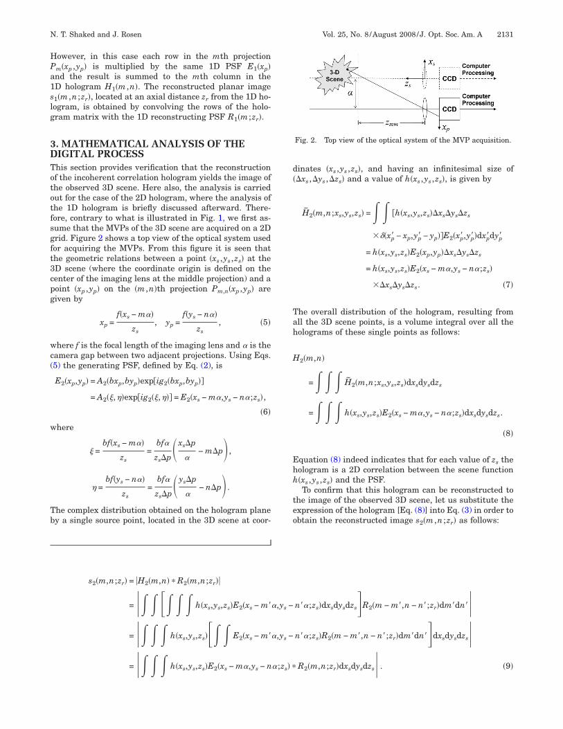
imited into a narrow ring. At the end of the process, theOCS algorithm yields the suitable random-constrainedSF that can be used in the hologram generation process.igures 4(a) and 4(b) show the resulting phase distribu-ions of the PSFs that were used for generating the 1Dnd the 2D DIPCHs, respectively.In the following, we show that in the DIPCH the recon-
truction resolution is improved compared to the DIMFH.n fact, far objects captured by the DIMFH are recon-tructed with a reduced resolution for two reasons. (a)ue to the parallax effect, farther objects move slower
hroughout the projections, and therefore they sample aagnified version of the generating PSF. This magnified
ersion has narrower bandwidth, and thus the recon-
sqfapojdsut(tc
jtttaaacmmcctccsi
c(fwfg�t2jilo
thwcWtmziDae
5Tgjtrasjsspcmptsgppa
D(jspadsvwtfrechmifdTso6cf
FrD
2134 J. Opt. Soc. Am. A/Vol. 25, No. 8 /August 2008 N. T. Shaked and J. Rosen
truction resolution of farther objects decreases. (b) Theuadratic phase function used in the DIMFH has lowerrequencies as one approaches its origin. Since far objectsre correlated with the central part of the quadratichase function along a range that becomes shorter as thebject is farther, the bandwidth of the DIMFH of far ob-ects becomes even narrower beyond the bandwidth re-uction mentioned in (a). Contrary to the DIMFH, thepatial frequencies of the DIPCH’s PSF are distributedniformly all over its area. Therefore, the DIPCH sus-ains resolution reduction of far objects only due to reasona). Hence, the images of far objects reconstructed fromhe DIPCH, besides being protected by the random-onstrained PSF, also have higher resolution.
Let us show quantitatively that the resolution of far ob-ects reconstructed from the DIMFH is worse than that ofhe DIPCH. The bandwidth of the generating PSF is de-ermined by the movement (throughout the projections) ofhe object point that is the closest to the imaging lens. For
distance of � between any two consecutive projectionsnd for a distance of zmin between the closest object pointnd the imaging lens, the smallest shift that can be re-orded on the camera is �f /zmin, where f /zmin is the maxi-al magnification of the imaging lens. �f /zmin is also theinimal practical feature size of the generating PSF be-
ause a smaller feature size cannot be detected by theamera due to the minimal sampling gap of �f /zmin. Forhis reason, the smallest object detail that can be re-orded and reconstructed by the DIPCH is �f / �Mzmin�. Re-alling that M= f /zs, one realizes that the DIPCH’s recon-truction resolution linearly decreases for the far objectsn the 3D scene.
For a single object point, the resulting hologram in thease of the DIMFH is exactly the PSF given by Eq. (16) or17). These expressions are actually equal to the transferunction of a lens for which the resolution properties areell known. For a single point located at distance zmin
rom the imaging system, the width of the recorded holo-ram is 2K�f /zmin and the smallest resolved detail isf / �Mzmin�. Now, for a point located at distance zs fromhe imaging system, the width of the recorded hologram isK�f /zs. Since, as explained above, the DIMFH of an ob-
ect point located at distance zs from the imaging systems equivalent to a lens, the hologram resolving power isinearly dependent on its width. Thus, the resolved detailf an object at distance z is the smallest-ever resolved de-
ig. 4. Examples of the phase distributions of the generatingandom-constrained PSFs of (a) a 1D DIPCH and (b) a 2DIPCH.
s
ail �f / �Mzmin� multiplied by the ratio of the maximumologram width, 2K�f /zmin, and the actual hologramidth, 2K�f /zs. Hence, the resolved detail of an object at a
ertain distance zs is �fzs / �Mzmin2 � in the case of DIMFH.
e recall that the size of the resolved detail in the case ofhe DIPCH is �f / �Mzmin�. Therefore, the ratio of the mini-um resolved detail of the DIMFH and the DIPCH is
s /zmin. This means that the farther the object from themaging lens is, the worse the resolving power of theIMFH, compared to the DIPCH, becomes. In Sections 5nd 6 we demonstrate this conclusion by simulations andxperiments.
. SIMULATION RESULTSo demonstrate the generation of 2D correlation holo-rams by simulation we first generated the 3D scene pro-ections in the computer. The 3D scene was composed ofhree equal-size partial United States Air Force (USAF)esolution charts positioned at different transverse andxial locations relative to the camera. To simulate thisituation the chart sizes on each computer-generated pro-ection plane were determined according to their axial po-itions from the plane, where farther charts appearedmaller than closer charts. In addition, the charts wereositioned at different transverse locations in eachomputer-generated projection, where closer chartsoved faster than farther charts throughout the different
rojections. Figure 5 shows the eight most extreme, andhe central projections, out of the 600�600 projectionsynthesized in the computer as the input for the hologrameneration algorithms. Note that we synthesized theserojections with partial object occlusions in part of therojections to demonstrate that the method is resistantgainst these occlusions.For comparison purposes we generated both a 2D
IMFH and a 2D DIPCH. As described by Eqs. (1) and17) to generate the 2D DIMFH we multiplied each pro-ection by a 2D quadratic phase function and thenummed each of the inner products to the correspondingixel in the hologram. Figure 6(a) presents the magnitudend phase of the 2D DIMFH generated by this process. Asescribed by Eqs. (2)–(4) and (17), reconstructing the 3Dcene from this hologram digitally was carried out by con-olving the hologram with 2D quadratic phase functionsith a phase sign opposite to the generating PSF. The
hree 2D quadratic phase functions yielding the best in-ocus reconstructed planes are shown in Fig. 6(b). The cor-esponding reconstructed planes are shown in Fig. 6(c). Inach plane only a single USAF resolution chart is in fo-us, whereas the other two charts are out of focus. Thisolographic phenomenon validates that the volume infor-ation is indeed encoded into the hologram. As explained
n Section 3, a 2D resampling process should be per-ormed on the reconstructed planes to retain the originalepth perspective of far and close objects in the 3D scene.hese rescaled, best in-focus, reconstructed planes arehown in Fig. 6(d). Figure 6(e) presents zoomed-in imagesf the best in-focus USAF resolution charts shown in Fig.(d). Evidently from these figures, the resolution of the re-onstructed charts decreases as the distance of the objectsrom the acquisition plane increases.

fjbpvissisvPaatUctwstaat
tf6ttfgt
6Tht8fhatce1wp2
FD
N. T. Shaked and J. Rosen Vol. 25, No. 8 /August 2008 /J. Opt. Soc. Am. A 2135
The same computer-generated projections were usedor generating the 2D DIPCH. For this purpose, each pro-ection was multiplied by the PSF of Fig. 4(b), computedy the POCS algorithm. The inner product between eachrojection and the PSF was summed to a single complexalue, which was introduced into the corresponding pixeln the 2D DIPCH. The magnitude and the phase of the re-ulting 2D hologram are shown in Fig. 7(a). The recon-truction from this hologram was obtained by convolvingt with the conjugate function of the generating PSFcaled differently in order to reconstruct a different trans-erse plane with each scaled PSF. The phases of the threeSFs that yield the best in-focus reconstructed planesnd the corresponding best in-focus reconstructed planesre shown in Figs. 7(b) and 7(c), respectively. Here again,he fact that in each of the reconstructed planes oneSAF resolution chart is in focus whereas the other two
harts are out of focus demonstrates that the 3D informa-ion is encoded properly into this hologram. Then again,e performed a 2D resampling process on the recon-
tructed planes for retaining the original depth perspec-ive. The resampled best in-focus reconstructed planesre shown in Fig. 7(d). Figure 7(e) shows zoomed-in im-ges of the best in-focus USAF resolution chart in each ofhese resampled reconstructed planes. Comparing be-
ig. 5. Several projections taken from the entire computer-geneIMFH and the 2D DIPCH.
ween the best in-focus reconstructed charts obtainedrom the DIPCH [Fig. 7(e)] and from the DIMFH [Fig.(e)], one realizes that the far objects reconstructed fromhe DIPCH have a significantly better resolution thanhose reconstructed from the DIMFH, although theormer are a bit noisier due to the nonuniformity of theray levels of the random-constrained PSF generated byhe POCS algorithm.
. EXPERIMENTAL RESULTShe experiment of synthesizing 1D incoherent correlationolograms was carried out on the optical system illus-rated in Fig. 1. Three equal-size USAF resolution charts,.5 cm�8.5 cm each, were positioned at the 3D scene inront of a dark background and were illuminated by aalogen white light. The axial distance between the firstnd the second charts, as well as between the second andhe third charts, was 10 cm. The distance between thelosest chart and the camera was 50 cm. The digital cam-ra (CCD type, model: PCO, Scientific 230XS, containing280�1024 pixels and an 8.6 mm�6.9 mm active area)as positioned on a micrometer slider and captured 1200rojections of the 3D scene across a horizontal range of4 cm. Note that in contrast to the 2D hologram, in which
set containing 600�600 projections, used for generating the 2D
rated
Fntffbc
Fntffbc
FD
2136 J. Opt. Soc. Am. A/Vol. 25, No. 8 /August 2008 N. T. Shaked and J. Rosen
ig. 6. Generating and reconstructing the 2D DIMFH: (a) mag-itude and phase of the hologram; (b) the phase distributions ofhe reconstructing PSFs used for obtaining the three best in-ocus reconstructed planes; (c) the corresponding three best in-ocus reconstructed planes along the optical axis; (d) same as (c),ut after the 2D resampling process; (e) zoomed-in images of the
orresponding best in-focus reconstructed objects.ig. 7. Generating and reconstructing the 2D DIPCH: (a) mag-itude and phase of the hologram; (b) the phase distributions ofhe reconstructing PSFs used for obtaining the three best in-ocus reconstructed planes; (c) the corresponding three best in-ocus reconstructed planes along the optical axis; (d) same as (c),ut after the 2D resampling process; (e) zoomed-in images of theorresponding best in-focus reconstructed objects.
ig. 8. Several projections taken from the entire experimentally obtained set containing 1200 projections, used for generating the 1DIMFH and the 1D DIPCH.
t2stp
e
D(prpAt
Fntffbc
Fntffbc
N. T. Shaked and J. Rosen Vol. 25, No. 8 /August 2008 /J. Opt. Soc. Am. A 2137
he projections of the 3D scene have to be acquired on aD grid, in the 1D hologram the camera moves along aingle axis only. Figure 8 shows the two most extreme andhe central projections taken from the entire set of 1200rojections.These captured projections were used in order to gen-
rate both the 1D DIMFH and the 1D DIPCH. The 1D
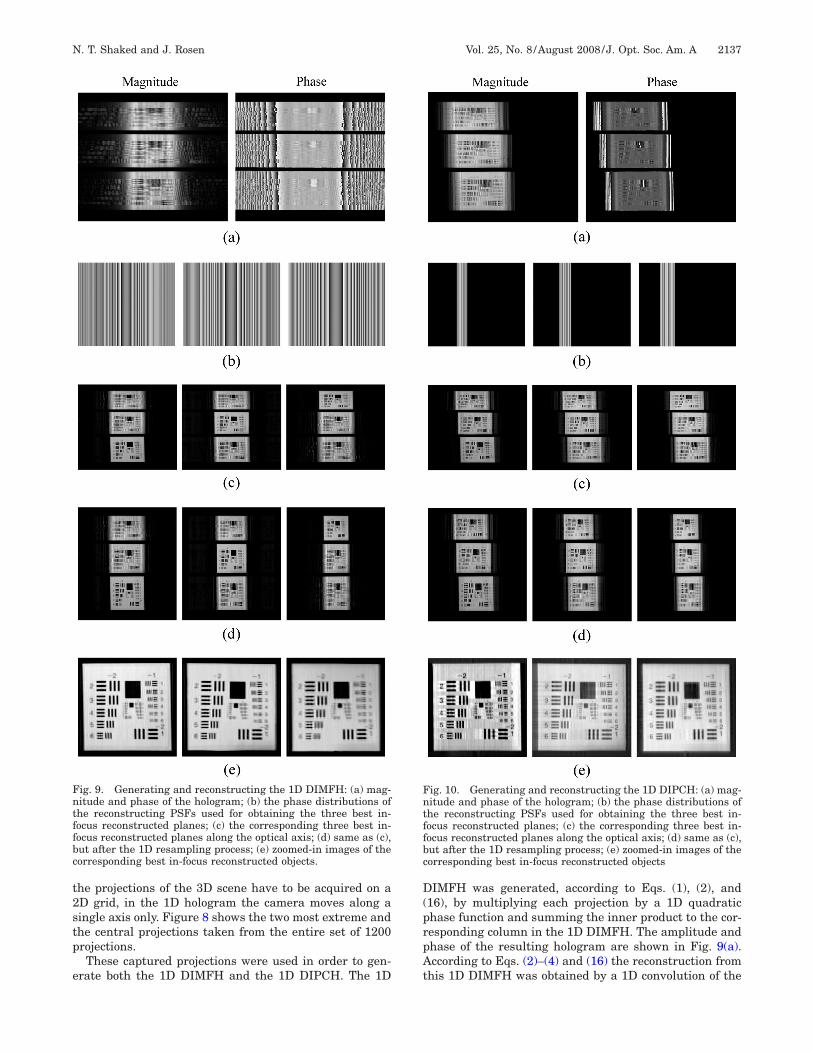
ig. 9. Generating and reconstructing the 1D DIMFH: (a) mag-itude and phase of the hologram; (b) the phase distributions ofhe reconstructing PSFs used for obtaining the three best in-ocus reconstructed planes; (c) the corresponding three best in-ocus reconstructed planes along the optical axis; (d) same as (c),ut after the 1D resampling process; (e) zoomed-in images of theorresponding best in-focus reconstructed objects.
IMFH was generated, according to Eqs. (1), (2), and16), by multiplying each projection by a 1D quadratichase function and summing the inner product to the cor-esponding column in the 1D DIMFH. The amplitude andhase of the resulting hologram are shown in Fig. 9(a).ccording to Eqs. (2)–(4) and (16) the reconstruction from
his 1D DIMFH was obtained by a 1D convolution of the
ig. 10. Generating and reconstructing the 1D DIPCH: (a) mag-itude and phase of the hologram; (b) the phase distributions ofhe reconstructing PSFs used for obtaining the three best in-ocus reconstructed planes; (c) the corresponding three best in-ocus reconstructed planes along the optical axis; (d) same as (c),ut after the 1D resampling process; (e) zoomed-in images of theorresponding best in-focus reconstructed objects

hpbba9tseptmFocrjt
aFrcwsttspsowaopm1bcrpswti
7Wi
hoodMetdphraiTsfca
R
1
1
1
2138 J. Opt. Soc. Am. A/Vol. 25, No. 8 /August 2008 N. T. Shaked and J. Rosen
ologram with 1D quadratic phase functions in which thehase sign is opposite to the generating PSF. The threeest in-focus reconstructing PSFs and the correspondingest in-focus reconstructed planes are shown in Figs. 9(b)nd 9(c), respectively. In each of the planes shown in Fig.(c) a different USAF resolution chart is in focus, whereashe other two charts are out of focus. This validates theuccess of the holographic process of the 1D DIMFH. Asxplained in Section 3, resampling these reconstructedlanes along the horizontal axis is required in order to re-ain the original aspect ratios of the objects. These resa-pled best in-focus reconstructed planes are shown inig. 9(d). Looking on the corresponding zoomed-in imagesf the best in-focus charts, shown in Fig. 9(e), one can con-lude that the far objects in the 3D scene indeed have aeduced horizontal resolution compared to the close ob-ects in the scene, due to the reasons explained in Subsec-ion 4.B.
A 1D DIPCH was generated by multiplying each of thecquired projections by the random-constrained PSF ofig. 4(a), computed for the 1D case by the POCS algo-ithm. Next, each inner product was summed to a singleolumn in the 1D DIPCH, the amplitude and phase ofhich are shown in Fig. 10(a). To reconstruct the 3D
cene from this hologram the DIPCH was convolved withhe conjugate of a scaled version of the same PSF used forhe hologram generation. The phases of the three recon-tructing PSFs, yielding the best in-focus reconstructedlanes, are shown in Fig. 10(b). The corresponding recon-tructed planes are shown in Fig. 10(c). As before, in eachf these planes a different USAF chart is in focus,hereas the other two charts are out of focus. Once again,resamapling process was applied on the horizontal axis
f the reconstructed planes for retaining the original as-ect ratios of the objects. Figure 10(d) shows these resa-pled best in-focus reconstructed planes, whereas Fig.
0(e) shows the corresponding zoomed-in images of theest in-focus charts at these three planes. As in the 2Dase farther objects have a higher resolution (horizontalesolution for the 1D case) in the DIPCH [Fig. 10(e)] com-ared to the DIMFH [Fig. 9(e)]. Once again, this propertyignifies the advantage of the DIPCH over the DIMFH,here the other advantage of the DIPCH is being pro-
ected by the random-constrained PSF used for generat-ng the hologram.
. CONCLUSIONSe have presented a theoretical framework for generat-
ng and reconstructing 1D and 2D incoherent correlation
olograms. These holograms are synthesized from MVPsf a 3D scene illuminated by incoherent white light, with-ut the need for special laboratory conditions. A properigital process, involving multiplication of each of theVPs by a certain broadband PSF and summation of
ach of the products, yields the final incoherent correla-ion hologram of the 3D scene. Different PSFs generateifferent types of holograms. Two examples have beenresented: (a) the DIMFH, which is an incoherent Fresnelologram generated directly, without approximations oredundant calculations; and (b) the DIPCH, which en-bles one to encode the 3D scene in a secured way and tomage the scene with a significantly improved resolution.hese new holograms have been demonstrated by bothimulation and experiments. In the future, the proposedramework might be used to find new types of incoherentorrelation holograms for other purposes and with otherdvantages over the existing types of holograms.
EFERENCES1. Y. Li, D. Abookasis, and J. Rosen, “Computer-generated
holograms of three-dimensional realistic objects recordedwithout wave interference,” Appl. Opt. 40, 2864–2870(2001).
2. D. Abookasis and J. Rosen, “Computer-generatedholograms of three-dimensional objects synthesized fromtheir multiple angular viewpoints,” J. Opt. Soc. Am. A 20,1537–1545 (2003).
3. Y. Sando, M. Itoh, and T. Yatagai, “Holographic three-dimensional display synthesized from three-dimensionalFourier spectra of real existing objects,” Opt. Lett. 28,2518–2520 (2003).
4. D. Abookasis and J. Rosen, “Three types of computer-generated hologram synthesized from multiple angularviewpoints of a three-dimensional scene,” Appl. Opt. 45,6533–6538 (2006).
5. T. Yatagai, “Stereoscopic approach to 3-D display usingcomputer-generated holograms,” Appl. Opt. 15, 2722–2729(1976).
6. N. T. Shaked, J. Rosen, and A. Stern, “Integral holography:white-light single-shot hologram acquisition,” Opt. Express15, 5754–5760 (2007).
7. N. T. Shaked, B. Katz, and J. Rosen, “Fluorescencemulticolor hologram recorded by using a macrolens array,”Opt. Lett. 33, 1461–1463 (2008).
8. B. Javidi and A. Sergent, “Fully phase encoded key andbiometrics for security verification,” Opt. Eng. 36, 935–942(1997).
9. D. Abookasis and J. Rosen, “Digital correlation hologramsimplemented on a joint transform correlator,” Opt.Commun. 225, 31–37 (2003).
0. N. T. Shaked and J. Rosen, “Modified Fresnel computer-generated hologram directly recorded by multiple-viewpoint projections,” Appl. Opt. 47, D21–D27 (2008).
1. J. R. Fienup, “Phase retrieval algorithms: a comparison,”Appl. Opt. 21, 2758–2769 (1982).
2. H. Stark, ed., Image Recovery: Theory and Application
(Academic, 1987), pp. 29–78 and 277–320.