computer aided building drawing ii semester - Amrita ...
56
AMRITA COLLEGE OF ENGINEERING AND TECHNOLOGY Amritagiri, Erachakulam, Nagercoil – 629902 DEPARTMENT OF CIVIL ENGINEERING CE8211 – COMPUTER AIDED BUILDING DRAWING II SEMESTER – R 2017 LABORATORY MANUAL
-
Upload
khangminh22 -
Category
Documents
-
view
0 -
download
0
Transcript of computer aided building drawing ii semester - Amrita ...

AMRITA COLLEGE OF ENGINEERING AND TECHNOLOGY
Amritagiri, Erachakulam, Nagercoil – 629902
DEPARTMENT OF CIVIL ENGINEERING
CE8211 – COMPUTER AIDED BUILDING DRAWING
II SEMESTER – R 2017
LABORATORY MANUAL
CE8211 Computer Aided Building Drawing
1. Syllabus
OBJECTIVES:
To introduce the students to draft the plan, elevation and sectional views of buildings in
accordance with development and control rules satisfying orientation and functional
requirements as per National Building Code.
LIST OF EXPERIMENTS
1. Principles of planning, orientation and complete joinery details (Paneled and Glazed
Doors and Windows)
2. Buildings with load bearing walls
3. Buildings with sloping roof
4. R.C.C. framed structures.
5. `Industrial buildings – North light roof structures
OUTCOMES:
The students will be able to draft the plan, elevation and sectional views of the
buildings, industrial structures, and framed buildings using computer softwares.
TEXTBOOKS:
1. Sikka V.B., A Course in Civil Engineering Drawing, 4th Edition, S.K.Kataria and Sons, 2015.
2. George Omura, Mastering in Autocad 2005 and Autocad LT 2005– BPB Publications, 2008
REFERENCES:
1. Chuck Eastman, Paul Teicholz, Rafael Sacks, Kathleen Liston, BIM Handbook: A Guide to
building information modeling for Owners, Managers, Designers, Engineers, and Contractors, John
Wiley and Sons. Inc.,2011.
2. Marimuthu V.M., Murugesan R. and Padmini S., Civil Engineering Drawing-I, Pratheeba
Publishers, 2008.
3. Shah.M.G., Kale. C.M. and Patki.S.Y., Building Drawing with an Integrated Approach to Built
Environment, Tata McGraw Hill Publishers Limited, 2007.
4. Verma.B.P., Civil Engineering Drawing and House Planning, Khanna Publishers, 2010.
Page 1

Page 2
CE8211-COMPUTER AIDED BUILDING DRAWING
Sl. No. Name of the Experiment Page No.
CYCLE 1 – EXPERIMENTS 1 Study Excise -Auto Cad commands
2
Principles of planning , orientation and complete joinery details (paneled and glazed doors and windows )
3 A reading room with RCC flat roof
4 A residential building with single bed room
5 Library building with RCC slab
CYCLE 2 – EXPERIMENTS
6 Fully tiled gabled house
7 Residential building with load bearing walls and pitched roof
8 RCC framed building with RCC roof
9 Primary health centre
10 School building
11 School building

Page 3
Pre Caution
1. Students should wear lab coat in CAD lab.
2. Students are advised to enter the CAD lab WITH FORMAL SHOES ONLY.
3. They are not supposed to move the systems and monitors.
4. They should enter in the login name and password assigned to each student.
5. Students are advised to complete their record work before the next class.
6 Students are asked to logout from their area and switch off the computers after
leaving
7. Students can access the printers through lab technician.
8. Students have free access to use the computers and software available in the lab.
9. During the laboratory hours, accessing the internet is strictly prohibited.
10. Computer games are strictly prohibited in the CAD lab.
‘General Instructions to Students’
1. Students should wear lab coat in CAD lab.
2. Students are advised to enter the CAD lab WITH FORMAL SHOES ONLY.
3. They are not supposed to move the systems and monitors.
4. They should enter in the login name and password assigned to each student.
5. Students are advised to complete their record work before the next class.
6. Students are asked to logout from their area and switch off the computers before
leaving the lab.
7. Students can access the printers through lab technician.
8. Students have free access to use the computers and software available in the lab.
9. During the laboratory hours, accessing the internet is strictly prohibited.
10. Computer games are strictly prohibited in the CAD lab.

Page 4
CE8211 Computer Aided Building Drawing
CONVENTIONS & SYMBOLS
Sl. No.
Term
Abbreviation
1.
Aggregate
Agg
2.
Approximate
Approx
3.
Asbestos cement
asb/cem
4.
At
@
5.
Air Conditioner
A/C
6.
Brick work
BWK
7.
Brick on edge
BOE
8.
Building
Bldg
9.
Bench mark
BM
10.
Cast-iron
CI
11.
Cement concrete
CC
12.
Centre to centre
c to c, c/c
13.
Cement mortar
CM
14.
Coarse rubble masonry
CR
15.
Random rubble masonry
RR

CE8211 Computer Aided Building Drawing
Sl. No.
Term
Abbreviation
16.
Column
COL
17.
Concrete
CONC
18.
Corrugated
CORR
19.
Cross-section
CS
20.
Cupboard
CB
21.
Collapsible gate
CG
22.
Door
D
23.
Damp proof course
DPC
24.
Diameter
dia,
25.
European water closet
EWC
26.
Figure
Fig.
27.
Finished floor level
FFL
28.
Floor trap
FT
29.
Flushing cistern
FC
30.
Fresh air inlet
FAI
31.
Full supply level
FSL
Page 6

CE8211 Computer Aided Building Drawing
Sl. No.
Term
Abbreviation
32.
Full tank level
FTL
33.
First floor
FF
34.
Floor level
FL
35.
Flush out latrine
FOL
36.
Galvanized
Galv
37.
Galvanized iron
GI
38.
Grease trap
GRT
39.
Ground level
GL
40.
Grills
G
41.
Gully trap
GT
42.
Height
Ht
43.
Indian water closet
IWC
44.
Imperial (standard) wire gauge
SWG
45.
Inspection chamber
ICH, IC
46.
Intercepting trap
IT
Page 7

CE8211 Computer Aided Building Drawing
Sl. No.
Term
Abbreviation
47.
Joist
J
48.
Jolly work
JW
49.
Kilo
K
50.
Kilogram
KG
51.
Kilometer
KM
52.
Litre
LT.
53.
Level crossing
LC
54.
Low water level
LWL
55.
Lime mortar
LM
56.
Lime concrete
LC
57.
Maximum flood level
MFL
58.
Maximum water level
MWL
59.
Manhole
MH
60.
Maximum
Max
61.
Mild steel
MS
62. Millimeter Mm
Page 8

CE8211 Computer Aided Building Drawing
Sl. No.
Term
Abbreviation
63.
Minimum
MIN
64.
Not to scale
NTS
65.
Number
No.
66.
Overhead tank
OHT
67.
Plain cement concrete
PCC
68.
Plinth level
PL
69.
Prestressed concrete
PCONC
70.
Radius
Rad
71.
Rainwater pipe
RWP
72.
Rolled section / Rolling shutter
RS
73.
Rolled steel joist or I-section
RSJ OR I
74.
Reinforced Cement Concrete
RCC
75.
Ribbed tor steel
RTS
76.
Stone ware pipe
SWP
77.
Surki mortar
SM
78. Sink S
Page 9

Page 10
CE8211 Computer Aided Building Drawing
Sl.No. Term Abbreviation
79.
Soil pipe
SP
80.
Standard
Std
81.
Septic tank
ST
82.
Switch
Sw
83.
Ventilator
V
84.
Vent pipe
VP
85.
Wash basin
WB
86.
Water closet
WC
87.
Window
W
88.
Window cum ventilator
W/V
89.
Water level
WL

Page 11
CE8211 Computer Aided Building Drawing
SYMBOLS

Page 12
CE8211 Computer Aided Building Drawing

13
Exp No.: Date:
1. STUDY EXERCISE – AUTOCAD COMMANDS
AIM
To study the basic commands used in AUTOCAD drawing
OBJECTIVE
To study the basic commands used in AUTOCAD drawing in accordance with
development and control rules satisfying orientation and functional requirements as per
National Building Code.
KEYWORDS:
Auto Cad Software
THEORY
CAD means Computer Aided Design or Drafting. Auto cad is most widely used
software developed by auto desk. Auto cad is a drafting package in almost all engineering
branches. There are drafting packages like cad are DIAP, CAMD, and Delights. Auto cad is one
of the most popular cad packages. It is a general purpose computer aided design. We can
draw geometrical entries like plan, section and elevation of a building.
• We can make accurate drawings like plan, section and elevation of a building.
• Improved engineering productively
. • Reduced engineering personal requirement.
• Drawing modification or eraser to intake.
• Drawings prepared in the software can be stored safely.
EXPERIMENT PROCEDURE
STEPS :
ARC Creates an arc
AREA Calculates the area and perimeter of objects or of defined areas
ARRAY Creates multiple copies of objects in a pattern
BHATCH Fills an enclosed area or selected objects with a hatch pattern
BLOCK Creates a block definition from objects you select
BOUNDARY creates a region or a polyline from an enclosed area
BOX Creates a three-dimensional solid box
BREAK Erases parts of objects or splits an object in two
CAL Evaluates mathematical and geometric expressions
CHAMFER Bevels the edges of objects
CIRCLE Creates a circle

14
COPY Duplicates objects
DIST Measures the distance and angle between two points
DIVIDE Places evenly spaced point objects or blocks along the length or perimeter of
an
object
DONUT Draws filled circles and rings
ELLIPSE Creates an ellipse or an elliptical arc
ERASE Removes objects from a drawing
EXPLODE Breaks a compound object into its component objects
EXPORT Saves objects to other file formats
EXTEND Extends an object to meet another object
EXTRUDE Creates unique solid primitives by extruding existing two-dimensional objects
FILLET Rounds and fillets the edges of objects
GRID Displays a dot grid in the current viewport
GROUP Creates a named selection set of objects
HATCH Fills a specified boundary with a pattern
VIVA – VOCE
PRE LAB
1. List out the types of building symbols.
2. What are all the basic kinds of building?
3. What kinds of doors are available in buildings?
4. What is footing?
5. Define PCC and RCC
POST LAB
6) How to fix scale for a building.
7) Mention the dimension of title block
8) Write the dimension of A1,A2,A3,A4 Drawing sheets
9) What is section plane?
10) What is plinth level?
RESULT:
The study of basic commands used in AUTOCAD and able to draft the plan ,section , elevation of a structure using these command

15
Exp No.: Date:
2. PRINCIPLES OF PLANNING, ORIENTATION AND
COMPLETE JOINERY DETAILS (PANELED AND GLAZED DOORS
AND WINDOWS) AIM
To draw a paneled and glazed doors and windows using basic AutoCAD commands
OBJECTIVE
To introduce the students to draft the paneled and glazed doors and windows using
accordance with development and control rules satisfying orientation and functional
requirements as per National Building Code.
KEYWORDS:
Auto Cad Software
THEORY
CAD means Computer Aided Design or Drafting. Auto cad is most widely used
software developed by auto desk. Auto cad is a drafting package in almost all engineering
branches. There are drafting packages like cad are DIAP, CAMD, and Delights. Auto cad is one
of the most popular cad packages. It is a general purpose computer aided design. We can
draw geometrical entries like plan, section and elevation of a building.
• We can make accurate drawings like plan, section and elevation of a building.
• Improved engineering productively
. • Reduced engineering personal requirement.
• Drawing modification or eraser to intake.
• Drawings prepared in the software can be stored safely.
EXPERIMENTAL PROCEDURE
STEP 1
Plan aspect of residential building:
The planning of residential buildings requires careful considerations on the part of the
architect.
The barest requirements for a family unit are living room, kitchen, bath and w.c. But
for the purpose of discussion, the usual requirements of a normal residential unit can be
mentioned as follows:
(1) Bath and w.c.
(2) Bed room

16
(3) Dining room
(4) Drawing room
(5) Garage
(6) Kitchen
(7) Living room
(8) Open chowk
(9) Passages
(10) Stair
(11) Store
(12) Verandah
STEP 2
Planning aspects of industrial structures:
Following are the factors which are to be considered while planning the industrial
structures:
(1) Functional aspect
(2) Lighting
(3) Materials of construction
(4) Mechanical layout
(5) Number of floors
(6) Site conditions
(7) Ventilation
STEP 3
Requirements of big industrial units :
The size of industrial unit is generally decided by the number of workers or
labourers employed by the unit and accordingly, the industrial unit is required to provide
various facilities for the smooth functioning of the industrial concern. Following are t he
requirements of big industrial units:
(1) Canteen
(2) Cloak-room
(3) Drinking water
(4) Entrance
(5) Loading and unloading platforms
(6) Medical aid
(7) Office
(8) Sanitary block

17
(9) Storage
Principles underlying building bye-laws:
The broad principles to be observed while framing the building bye-laws.
(1) Permissible size of plots:
The minimum size of plot required for each family unit shall be as follows:
170m2
for one family unit
300 m2 for two semi-detached family units
670 m2 for ownership flats.
(2) Margins:
The margins on road side and adjacent properties shall be respectively 4.50 m and
3.00 m.
For plots having areas less than 300m2, they shall be respectively 3.00m and 2.00 m.
(3) Area of rooms:
Table shows the minimum areas of various rooms.
Sl. Use of room Minimum area Remarks
No.
1. Living room, Bed room, Drawing room, Sitting 9m2 No side to be less
room, Ladies room, Dining room, Study room than 2.40m
2. Store room, Kitchen 5.40 m2
No side to be less than 1.80m
3. Bath room, Dressing room, Pump room, Water Minimum 1.35 m2
and No side to be
less
room, Coal room max. 4.50 m2
than 90cm.
4 W.C., Urinal 0.81m
2 No side to be less
than 90cm.
(5) Plinth height:
It shall be 45cm above road level or plot level, whichever is higher.
(6) Height of floors:
The minimum heights shall be as follows:
2.10m: Bath room, w.c., pump room, coal room and water room.
2.70m: Floor height on each floor
The maximum height of floors shall not be more than 1.25 times the minimum height.
(7) Projections in margins:
Following projections in marginal spaces shall be permitted:
(i) Canopy of 3.00m width above 2.40m from ground level;
(ii) Gallery of maximum width 1.20 m at floor levels.
(iii) Stair attached to building and open to sky with minimum width of 90cm; and
(iv) Weather-shed of maximum width 50cm at lintel level
(8) Cellar: The permission to construct cellar shall be granted with the following restrictions:

18
Height : 2.40m
Stair width : 90cm
Ventilation : One-tenth of floor area
Water and drainage connection: Not allowed
Use : For storage only
Maximum area : One-half of built-up area of G.F
(9) Loft:
The provision of loft shall be permitted in kitchen and store. The maximum width of
loft shall be one-third the width in that direction. The maximum height above loft shall be
1.50m and bottom of loft shall be at a minimum height of 2.10m from floor level.
(10) Lift:
For buildings having more than three floors (exclusive of ground floor), lift shall be
provided at the rate of one lift for 20 family units or part thereof. The lift shall be provided
from ground floor and its minimum capacity shall be of 6 persons.
(11) Ventilation:
All rooms except coal room, water room, store room and garage shall have atleast one
side adjacent to open space. Area of windows and ventilators excluding frames shall be
atleast one-tenth of the floor area of room.
(12) Stair:
The minimum width of stair shall be 90 cm and it shall be made of fire-proof
construction. The pitch of stair shall be within 30 to 45. The stair cabin shall not exceed
11m2 in area
(14) Joinery Details

19
VIVA – VOCE
PRE LAB
1. List out the commends involved in modify tool bar.
2. Why do we use mirror ?
3. List out the commends involved arc tool bar.
4. Define plan of the building.
5. How to obtain section from plan?
POST LAB
1. How to obtain elevation?
2) How will you modify text command?
3) What is the purpose of using hatch command?.
4) What is the height of sill level?
5) What is load bearing structure?.
RESULT:
The paneled and glazed doors and windows are drawn successfully using basic AutoCAD commands

20
Exp No.: Date:
3. A READING ROOM WITH R.C.C FLAT ROOF
Aim:
To draw a reading room with R.C.C flat roof using Auto CAD with suitable scale the
following views with complete dimensions and details.
1. Plan at window sill level.
2. Section on AB.
3. Front elevation.
OBJECTIVE
To introduce the students to draft the plan, elevation and sectional views of RCC
buildings in accordance with development and control rules satisfying orientation and
functional requirements as per National Building Code.
KEYWORDS:
Auto Cad Software
THEORY
CAD means Computer Aided Design or Drafting. Auto cad is most widely used
software developed by auto desk. Auto cad is a drafting package in almost all engineering
branches. There are drafting packages like cad are DIAP, CAMD, and Delights. Auto cad is one
of the most popular cad packages. It is a general purpose computer aided design. We can
draw geometrical entries like plan, section and elevation of a building.
• We can make accurate drawings like plan, section and elevation of a building.
• Improved engineering productively
. • Reduced engineering personal requirement.
• Drawing modification or eraser to intake.
• Drawings prepared in the software can be stored safely.
EXPERIMENTAL PROCEDURE Specifications:
The following specifications correspond to the line plan of the reading room with
R.C.C flat roof.
1. Foundation:
The foundation for all main walls will be in cement concrete 1:4:8, 600 wide and 200 thick laid at 600 below ground level. The masonry footing will be in RR masonry in CM 1:5, the first footing being 400x400 for all walls.
2. Basement:
The basement will be in RR masonry in CM 1:5, 200 wide 300 thick above G.L for all walls and is filled with clean sand to a depth of 150. A D.P.C in CM 1:3, 20 thick will be provided for all walls at basement level.
3. Super structure:

21
All walls will be in B.W in CM 1:5, using 1st
class B.W, 200 thick. The height of all walls will be 3000 above F.L. All walls including basement will be plastered smooth and CM 1:4 externally and 1:6 internally for 12.5 thick. Parapet walls, 200 thick and 450 high will be provided all round.
4. Roofing:
The roofing will be of R.C.C 1:2:4 mix , 100 thick flat slab over the room. A
weathering course in brick jelly lime concrete 1:5:9 mix plastered with combination mortar 75 thick over the slab.
5. Doors, windows :
D- Flush door : 1500 into 2100
W-Window paneled : 1200x1200
6. Lintel:
All internal wall openings will be provided with R.C.C lintels, 1:1.5:3 mix;150 thick. All external openings will be provided with R.C.C lintel – cum-sunshade, 1:1.5:3 mix, 600 wide and 50 thick.
7. Flooring:
The flooring will be in CC 1:4:8, 130 thick and plastered smooth with CM 1:3,
20 thick.
8. Steps:
Steps will be in brick walk in CM 1:5 laid on a 1800 x450 x150 thick CC
1:4:8 footing. Rise 150, Tread 300.
Note:
1. Any other dimensions found necessary may be assumed suitably making clear
indications of the same.
2. All dimensions indicated are in millimeter.

22
VIVA – VOCE
PRE LAB
1. What are all the steps involved in site clearance?
2 How will you mark a site for setting out a foundation?
3 Define the term masonry.
4 Explain the sequence of operation in construction with an example.
5 What is composite masonry?
POST LAB
1 What are all the types of ashlar masonry?
2) Differentiate English bond and Flemish bond.
3) Write notes on zig-zag bond
4) Write notes on temporary shed
5) What are all the types of scaffolding?
RESULT:
The reading room with R.C.C flat roof are drawn successfully using AutoCAD commands

23
Exp No.: Date:
4. A RESIDENTIAL BUILDING WITH SINGLE BED ROOM
Aim:
To draw the following views with complete dimension for a residential building with
single bed room (R.C.C flat roof)
1. Plan at window sill level.
2. Section on ABCD.
3. Front elevation.
OBJECTIVE
To introduce the students to draft the plan, elevation and sectional views of residential
building with single bed room buildings in accordance with development and control rules satisfying
orientation and functional requirements as per National Building Code.
KEYWORDS:
Auto Cad Software
THEORY
CAD means Computer Aided Design or Drafting. Auto cad is most widely used
software developed by auto desk. Auto cad is a drafting package in almost all engineering
branches. There are drafting packages like cad are DIAP, CAMD, and Delights. Auto cad is one
of the most popular cad packages. It is a general purpose computer aided design. We can
draw geometrical entries like plan, section and elevation of a building.
• We can make accurate drawings like plan, section and elevation of a building.
• Improved engineering productively
. • Reduced engineering personal requirement.
• Drawing modification or eraser to intake.
• Drawings prepared in the software can be stored safely.
EXPERIMENTAL PROCEDURE
Specifications:
The following specification correspond to the line plan of a house with single bed room and attached bathroom with R.C.C flat roof.

24
1. Foundation:
The foundation for all main walls and verandah retaining walls will be CC 1:4:8 mix, 1000 wide and 200 thick laid at 1100 below ground level. The masonry footing will be in
BW in CM 1:6 , the 1st
footing being 700x400 ant the 2nd
being 400 x 500 for all walls and verandah retaining walls.
2. Basement:
The basement will be in BW in CM 1:6 ,200 wide and 600 high above GL for all main walls and verandah retaining walls is filled with clean sand to a depth of 450. A D.P.C in CM 1:3, 20 thick will be provided for all walls at basement level.
3. Super structure:
All walls will be in B.W in CM 1:5, using 1st
class B.W, 200 thick. The height of all
walls will be 3000 above F.L. the height of roof at verandah portion will be 2700. The partition wall in WC and bath 100 thick in BW in CM 1:5 using country bricks and carried up to a height of 2100. One brick pillar 200x400 will be provided in the verandah. All walls including basement will be plastered smooth and CM 1:4 externally and 1:6 internally for 12.5 thick. Parapet walls, 200 thick and 600 high will be provided all round.
4. Roofing:
Theroofing will be of R.C.C 1:1.5:3 mix , 125 thick flat slab over the rooms and the verandah. A weathering course , 75 thick consists of two course of flat tiles set in CM 1:3 mixed with crude oil will be provided with slab.
5. Doors, windows,etc.,:
D1-panelled door :1100x 2100 D2-panelled door :900x 2100 W1-panelled Window :1200 x 1200 W2-Glazed Window :1500 x 1200
V1-Ventilator glazed :900 x 450 V2-Ventilator glazed :1500 x 450 J – R.C. Jolly : 2400 x 1200
CB-cupboard: 300 depth S-shelf :200 depth
6. Lintel:
All internal wall openings will be provided with R.C.C lintels, 1:1.5:3 mix; 150 thick. All external openings will be provided with R.C.C lintel – cum-sunshade, 1:1.5:3 mix, 450 wide and 150 thick and 600 wide R.C.C lofts shall be provided in bed, kitchen and utility.
7. Flooring:
The flooring will be in CC 1:4:8, 130 thick and plastered smooth with CM 1:3, 20
thick.


25

VIVA – VOCE
PRE LAB
1. Write notes on centring 2) Define dampness 3) What are all the causes of dampness? 4) What are all the types of damp proofing courses? 5) Write the fire protective requirement of the building
POST LAB
1,Explain the various types of foundation with neat sketches
2) Explain the various types of stone masonry with neat sketches
3) Make a comparison between stone masonry and brick masonry
4) What are all the different types of bonds in masonry
5) Explain the various types of flooring with neat sketches
RESULT:
The A residential building with single bed room are drawn successfully using AutoCAD commands

26

27
Exp No.: Date:
5. LIBRARY BUILDING WITH R.C.C FLAT ROOF
Aim:
To draw the following views with complete dimension for a residential building with two
bed room (R.C.C flat roof)
1. Plan at window sill level.
2. Section on XY.
3. Front elevation.
OBJECTIVE
To introduce the students to draft the plan, elevation and sectional views of a Library
building with RCC slab buildings in accordance with development and control rules satisfying
orientation and functional requirements as per National Building Code.
KEYWORDS:
Auto Cad Software
THEORY
CAD means Computer Aided Design or Drafting. Auto cad is most widely used software
developed by auto desk. Auto cad is a drafting package in almost all engineering branches. There
are drafting packages like cad are DIAP, CAMD, and Delights. Auto cad is one of the most popular
cad packages. It is a general purpose computer aided design. We can draw geometrical
entries like plan, section and elevation of a building.
• We can make accurate drawings like plan, section and elevation of a building.
• Improved engineering productively
. • Reduced engineering personal requirement.
• Drawing modification or eraser to intake.
• Drawings prepared in the software can be stored safely.
EPERIMENTAL PROCEDURE
Specifications:
The following specifications correspond to the line plan of a LIBRARY BUILDING.
1. Foundation:
The foundation for all main walls will be in CC 1:4:8 mix, 900 wide and 300 thick, laid at
1000 below ground level. The masonry footing will be in BW in CM 1:6 , the 1st
footing
being 700x300 ant the 2nd
being 400 x 400 for all main walls
2. Basement:

28
The basement will be in BW in CM 1:5 , 200 wide and 600 high in rubble masonry above GL for all main walls. The basement will be filled with clean sand to a depth of 450. A D.P.C in CM 1:3, 20 thick will be provided for all walls at basement level.
3. Super structure:
All walls will be in BW in CM 1:5, using 1st
class BW, 200 thick. The height of all walls
will be 3600 above F.L. Pillars 300x300 are provided in the building. All walls including basement will be plastered smooth and CM 1:4 externally and 1:6 internally for 12.5 thick. Parapet walls, 200 thick and 450 high will be provided all round.
4. Roofing:
Theroofing will be of R.C.C 1:1.5:3 mix , 125 thick flat slab over the rooms. A weathering course , 75 thick will be provided over the slab.
5. Doors, windows,etc.,:
D- Door :1200x 2100 D1- Door :900x 2100 W1- Window :1500 x 1200 W2- Window :1000 x 1200
6. Lintel:
All external openings will be provided with R.C.C lintel – cum-sunshade, 1:1.5:3 mix, 450 wide and 150 thick.
7. Flooring:
The flooring will be in CC 1:4:8, 150 thick and plastered smooth with CM 1:3, 20 thick.
8. Steps:
Steps will be in brick walk in CM 1:5 laid on 800 x150 thick CC 1:4:8 footing. Rise 200, Tread 300.


29

30
VIVA – VOCE
PRE LAB
1. Write notes on centring
2) Define dampness 3) What are all the causes of dampness? 4) What are all the types of damp proofing courses? 5) Write the fire protective requirement of the building
POST LAB
1,Explain the various types of foundation with neat sketches
2) Explain the various types of stone masonry with neat sketches
3) Make a comparison between stone masonry and brick masonry
4) What are all the different types of bonds in masonry
5) Explain the various types of flooring with neat sketches
RESULT:
The library building with single bed room are drawn successfully using AutoCAD commands

31
Exp No.: Date:
6. RESIDENTIAL BUILDING WITH LOAD BEARING WALLS
AND PITCHED ROOF
Aim:
To draw to a suitable scale the following views with complete dimensions and details for
residential building (R.C.C Piched roof)
1. Plan at window sill level.
2. Front elevation
3. Sectional elevation on EFGH
4. Section at EFGH.
OBJECTIVE
To introduce the students to draft the plan, elevation and sectional views of a Fully tiled
gabled house buildings in accordance with development and control rules satisfying orientation
and functional requirements as per National Building Code.
KEYWORDS:
Auto Cad Software
THEORY
CAD means Computer Aided Design or Drafting. Auto cad is most widely used software
developed by auto desk. Auto cad is a drafting package in almost all engineering branches. There
are drafting packages like cad are DIAP, CAMD, and Delights. Auto cad is one of the most popular
cad packages. It is a general purpose computer aided design. We can draw geometrical
entries like plan, section and elevation of a building.
• We can make accurate drawings like plan, section and elevation of a building.
• Improved engineering productively
. • Reduced engineering personal requirement.
• Drawing modification or eraser to intake.
• Drawings prepared in the software can be stored safely.
EXPERIMENTAL PROCEDURE
Specifications:
The following specifications correspond to a residential building.

32
1. Foundation:
The depth of foundation will be 750 mm below ground level. The concrete course at the
base of the foundation will be 100 mm wide and 150 mm deep. The footings will be of brick
masonry with 1st class brick in cement mortar (1:4). Width of 1st and 2nd footings will be 500
mm and 700 mm respectively and each having thickness of 300 mm.
2. Plinth:
The plinth height will be 450 mm, above ground level. Thickness of wall in plinth will be
300 mm. A D.P.C. will be provided 50 mm thick in C.M. 1:3.
3. Superstructure:
The wall in super structure will be 1st class brick in C.M. 1:6. Thickness of all walls will
be 300 mm except the partition wall between W.C. and bath, which will be 200 mm thick. All
exterior windows and the verandah opening will be having a chajja projection of 600 mm. The
kitchen will be having shelves (as shown in the line sketch) in there tier. Projection of shelves
will be 450 mm beyond the wall. A cooking platform of 750 mm width will be provided at a height
of 750 mm from floor level. Width of the sink will be 450 mm. Size of the cupboard will be 1050
mm x 300 mm x 2100 m. The verandah opening will be 2250 mm. Height of wall for the court yard
is 2300 mm.
4. Roofing:
Roofing will be of R.C.C. (1:2:4) 125 mm thick. Provide lime terrace of thickness 100
mm over the roof slab. The parapet height will be 450 mm. Coping will except for dinning space,
kitchen, W.C. and bath which in turn will be having ceiling height of 3150 mm. Ceiling height
for verandah will be 3000
5. Flooring:
Provide patent stone flooring of 25 mm thickness over 100 mm thick rammed khoa over
sand filling.
6. Steps :
Rise 150 mm and Tread 200 mm. Door and window frame is 100 mm x 75 mm
7. Size of doors and window : D
- 1000 mm x 2100 mm D1
- 750 mm x 2100 mm D2 -
1100 mm x 2100 mm D3 -
600 mm x 2100 mm D4 -
1200 mm x 2100 mm W -
1800 mm x 1200 mm W1 -
1500 mm x 1200 mm W2 -
900 mm x 1200 mm W3 -
600 mm x 900 mm
Note:
1. Any other dimensions found necessary may be assumed suitably making clear indications of
the same.

33
2. All dimensions are in millimetres.

34
VIVA – VOCE
PRE LAB
1 Explain the various types of trusses with neat sketches
2) Explain the various types of roof finishes with neat sketches
3) Write notes on acoustic of the building
4) Write the step by step procedure of laying of brick.
5) What are all the various types of roof finishes?
POST LAB
1,Explain the various types of foundation with neat sketches
2) Explain the various types of stone masonry with neat sketches
3) Make a comparison between stone masonry and brick masonry
4) What are all the different types of bonds in masonry
5) Explain the various types of flooring with neat sketches
RESULT:
The residential building with single bed pitched roof are drawn successfully using AutoCAD commands

35
Exp No.: Date:
7. FULLY TILED GABLED HOUSE
Aim:
To draw to a suitable scale the following views with complete dimensions and details for a fully tiled gabled house (Pitched roof)
1. Plan at window sill level.
2. Section on AB.
3. Front elevation.
OBJECTIVE
To introduce the students to draft the plan, elevation and sectional views of Residential
building with load bearing walls and pitched roof in accordance with development and control
rules satisfying orientation and functional requirements as per National Building Code.
KEYWORDS:
Auto Cad Software
THEORY
CAD means Computer Aided Design or Drafting. Auto cad is most widely used software
developed by auto desk. Auto cad is a drafting package in almost all engineering branches. There
are drafting packages like cad are DIAP, CAMD, and Delights. Auto cad is one of the most popular
cad packages. It is a general purpose computer aided design. We can draw geometrical
entries like plan, section and elevation of a building.
• We can make accurate drawings like plan, section and elevation of a building.
• Improved engineering productively
. • Reduced engineering personal requirement.
• Drawing modification or eraser to intake.
• Drawings prepared in the software can be stored safely
EXPERIMENTAL PROCEDURE
Specifications:
The following specification correspond to the line plan of a fully tiled gabled house single
bed room and attached bathroom with R.C.C flat roof.
1. Foundation:
The foundation for all main walls will be in PCC 1:4:8 mix, 800x200 laid at 1000 below
ground level. The masonry footing will be in BW in CM 1:5, the 1st
footing being 500x400
ant the 2nd
being 400 x 400 for all main walls.
6
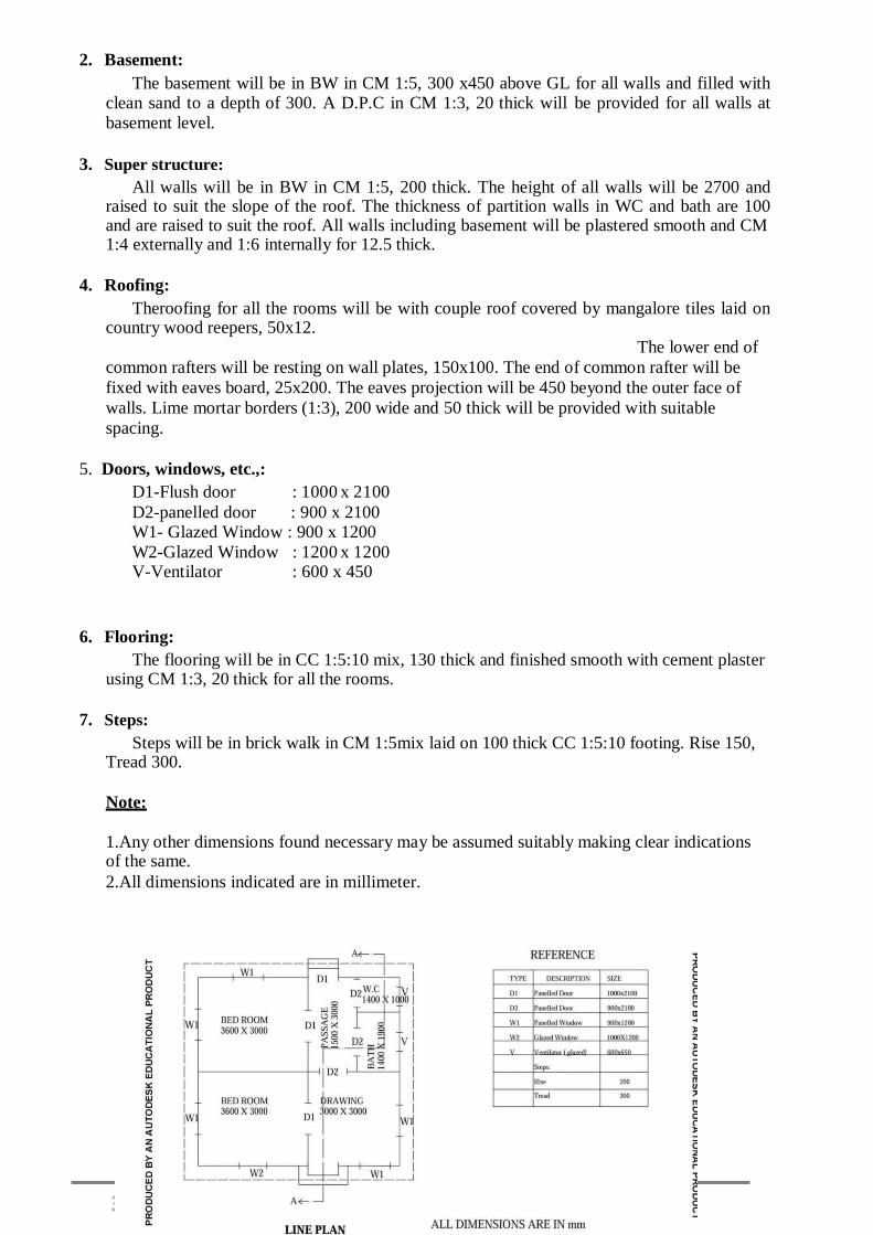
2. Basement:
The basement will be in BW in CM 1:5, 300 x450 above GL for all walls and filled with clean sand to a depth of 300. A D.P.C in CM 1:3, 20 thick will be provided for all walls at basement level.
3. Super structure:
All walls will be in BW in CM 1:5, 200 thick. The height of all walls will be 2700 and raised to suit the slope of the roof. The thickness of partition walls in WC and bath are 100 and are raised to suit the roof. All walls including basement will be plastered smooth and CM 1:4 externally and 1:6 internally for 12.5 thick.
4. Roofing:
Theroofing for all the rooms will be with couple roof covered by mangalore tiles laid on country wood reepers, 50x12.
The lower end of
common rafters will be resting on wall plates, 150x100. The end of common rafter will be
fixed with eaves board, 25x200. The eaves projection will be 450 beyond the outer face of
walls. Lime mortar borders (1:3), 200 wide and 50 thick will be provided with suitable
spacing.
5. Doors, windows, etc.,:
D1-Flush door : 1000 x 2100
D2-panelled door : 900 x 2100 W1- Glazed Window : 900 x 1200
W2-Glazed Window : 1200 x 1200 V-Ventilator : 600 x 450
6. Flooring:
The flooring will be in CC 1:5:10 mix, 130 thick and finished smooth with cement plaster using CM 1:3, 20 thick for all the rooms.
7. Steps:
Steps will be in brick walk in CM 1:5mix laid on 100 thick CC 1:5:10 footing. Rise 150, Tread 300.
Note:
1.Any other dimensions found necessary may be assumed suitably making clear indications of the same.
2.All dimensions indicated are in millimeter.


37

38
VIVA – VOCE
PRE LAB
1. Write notes on centring
2) Define dampness 3) What are all the causes of dampness? 4) What are all the types of damp proofing courses? 5) Write the fire protective requirement of the building
POST LAB
1,Explain the various types of foundation with neat sketches
2) Explain the various types of stone masonry with neat sketches
3) Make a comparison between stone masonry and brick masonry
4) What are all the different types of bonds in masonry
5) Explain the various types of flooring with neat sketches
RESULT:
The fully tiled gabled house are drawn successfully using AutoCAD commands

39
Exp No.: Date:
8. RCC FRAMED BUILDING WITH RCC ROOF
Aim:
To draw to a suitable scale the following views with complete dimensions and details of
residential building:
1. Plan at window sill level.
2. Sectional elevation on PQRS.
3. Front elevation.
OBJECTIVE
To introduce the students to draft the plan, elevation and sectional views of draw Primary
health centre in accordance with development and control rules satisfying orientation and
functional requirements as per National Building Code.
KEYWORDS:
Auto Cad Software
THEORY
CAD means Computer Aided Design or Drafting. Auto cad is most widely used software
developed by auto desk. Auto cad is a drafting package in almost all engineering branches. There
are drafting packages like cad are DIAP, CAMD, and Delights. Auto cad is one of the most popular
cad packages. It is a general purpose computer aided design. We can draw geometrical
entries like plan, section and elevation of a building.
• We can make accurate drawings like plan, section and elevation of a building.
• Improved engineering productively
. • Reduced engineering personal requirement.
• Drawing modification or eraser to intake.
• Drawings prepared in the software can be stored safely
EXPERIMENTALPROCEDURE
Specifications:
The following specifications correspond to residential building with R.C.C. flat roof.
1. Foundation:
The sloped isolated footing of size 1.2m x 1.2m x 500mm depth and the reinforcements
of dia. 8@150c/c on bothways with a cc 1:2:4 are provided under all columns located at a depth
of 1.2m below ground level.

40
2. Plinth beam:
The plinth beam of size 230 x 450mm is connected at ground level all around the
building.
3. Super structure:
All main walls will be in brick work in cement mortar 1:5 using country bricks, 230 thick.
The height of main walls will be 3000 above floor level. The partition walls in w.c. and bath will
be 100 thick in brick work in cement mortar 1:5, using country bricks and carried up to a height
of 2000. All the walls including basement will be plastered smooth with cement mortar 1:4
externally and 1:6 internally for 12.5 thick. Parapet walls 200 thick and 450 high will be
provided all-round.
4. Roofing:
The roofing will be of R.C.C. 1:2:4 mix, 150 thick flat slab over all the rooms and
verandah. A weathering course 75 thick, consists of two courses of flat tiles set in cement mortar
1:3 mixed with crude oil will be provided over the slab.
5. Doors, windows, etc.
D - Door panelled 1100 x 2100
D1 - Door panelled 800 x 2100
W - Window panelled 1500 x 1350
V - Ventilator 800 x 400
C - Cup-board 900 x 1200
6. Lintel:
All internal openings will be provided with R.C.C. lintel 1:2:4 mix, 150 thick and all
external openings will be provided with R.C.C. lintel-cum-sunshade 1:2:4 mix, 150 thick.
7. Flooring:
The flooring will be in cement concrete 1:4:8, 130 thick, plastered smooth with cement
mortar 1:3, 20 thick for all the portions.
8. Steps:
Steps will be in brick work in cement mortar 1:5 laid on a 800 x 150 cement concrete
1:4:8 footing. Rise 200, Tread 300.

41
VIVA – VOCE
PRE LAB
1. What are all the steps involved in site clearance?
2 How will you mark a site for setting out a foundation?
3 Define the term masonry.
4 Explain the sequence of operation in construction with an example.
5 What is composite masonry?
POST LAB
1 What are all the types of ashlar masonry?
2) Differentiate English bond and Flemish bond.
3) Write notes on zig-zag bond
4) Write notes on temporary shed
5) What are all the types of scaffolding?
RESULT:
The R.C.C framed structure are drawn successfully by using AutoCAD commands

42
Exp No.: Date:
9. PRIMARY HEALTH CENTRE Aim:
To draw to a suitable scale the following views with complete dimensions and details of
primary health center:
1. Plan at window sill level.
2. Sectional elevation on AB.
3. Front elevation.
OBJECTIVE
To introduce the students to draft the plan, elevation and sectional views of draw a School
building in accordance with development and control rules satisfying orientation and functional
requirements as per National Building Code
KEYWORDS:
Auto Cad Software
THEORY
CAD means Computer Aided Design or Drafting. Auto cad is most widely used software
developed by auto desk. Auto cad is a drafting package in almost all engineering branches. There
are drafting packages like cad are DIAP, CAMD, and Delights. Auto cad is one of the most popular
cad packages. It is a general purpose computer aided design. We can draw geometrical
entries like plan, section and elevation of a building.
• We can make accurate drawings like plan, section and elevation of a building.
• Improved engineering productively
. • Reduced engineering personal requirement.
• Drawing modification or eraser to intake.
• Drawings prepared in the software can be stored safely
EPERIMENTAL PROCEDURE
Specifications:
The following specifications correspond to a primary health centre.
1. Foundation:
The foundation for all main walls will be in cement concrete 1:4:8 mix, 1500 wide and
400 thick laid at 1100 below ground level. The masonry footing will be in brick work in cement
mortar 1:5, first footing being 1100 x 600 and the second being 800 x 500 for all main walls. The
foundation for verandah retaining walls will be in cement concrete 1:4:8 mix, 1000 wide and 200
thick, laid at 700 below ground level. It will have a footing in brick work in cement mortar 1:5 to
a width of 400.

43
2. Basement:
The basement will be in brick work in cement mortar 1:5, 500 wide and 450 thick above
ground level for all main walls, 400 wide and 450 thick above ground level for verandah
retaining wall. It is filled with clean sand to a depth of 300. A damp proof course in cement
mortar 1:3, 20 thick will be provided for all walls at basement level.
3. Super structure:
All main walls will be in brick work in cement mortar 1:5 using first class bricks, 300 thick.
The height of main walls will be 4500 above floor level. The partition walls in w.c. and bath
will be 100 thick in brick work in cement mortar 1:5, using first class bricks and carried up to a
height of 2500. Masonry pillars in brick work in cement mortar 1:5 using first class bricks,
300 x 300 will be provided in the verandah to a height of 2600. R.C.C. beams 1:2:4 mix, 300 x
400 will be provided over the pillars. Parapet walls 200 thick and 600 high will be provided all-
round. All the walls including basement will be plastered smooth with cement mortar 1:4
externally and 1:6 internally for 12.5 thick.
4. Roofing:
The roofing will be of R.C.C. 1:2:4 mix, 150 thick flat slab. A weathering course 200 thick,
consists of two courses of flat tiles set in cement mortar 1:5 mixed with crude oil will be provided
over the slab.
5. Doors, windows, etc.
C.G – collapsible gate – 1500x2100
D – Flushed door – 1200x2100
D1 – Glazed door – 1200x2100
D2 – Panelled door – 1000x2100
D3 – Flushed door – 1000x2100
G.W – Grilled window – 1500x1200
W – Panelled window – 1200x1200
W1 – Glazed window – 1500x1200
W2 – Glazed window – 1200x1200
V – Glazed ventilator – 600x600
V1 – Glazed ventilator – 450x450
U –Urinal – 600x1000
6. Lintel:
All internal openings will be provided with R.C.C. lintel 1:2:4 mix, 150 thick. All
external openings will be provided with R.C.C. lintel-cum-sunshade 1:2:4 mix, 150 thick.
7. Flooring:
The flooring will be in cement concrete 1:4:8, 130 thick, plastered smooth with cement
mortar 1:3, 20 thick for all the portions.
8. Steps:
Steps will be in brick work in cement mortar 1:5 laid on a 700 x 150 cement concrete
1:4:8 footing. Rise 150, Tread 300.

44
Note:
1. Any other dimensions found necessary may be assumed suitably making clear indications of
the same.
2. All dimensions are in millimetres
PRIMARY HEALTH CENTRE

45
VIVA – VOCE
PRE LAB
1. Write notes on centring
2) Define dampness 3) What are all the causes of dampness? 4) What are all the types of damp proofing courses? 5) Write the fire protective requirement of the building
POST LAB
1,Explain the various types of foundation with neat sketches
2) Explain the various types of stone masonry with neat sketches
3) Make a comparison between stone masonry and brick masonry
4) What are all the different types of bonds in masonry
5) Explain the various types of flooring with neat sketches
RESULT: The primary health center is drawn successfully using AutoCAD commands

46
Exp No.: Date:
10. SCHOOL BUILDING
Aim:
To draw to a suitable scale the following views with complete dimensions and details
of primary school:
OBJECTIVE
To introduce the students to draft the plan, elevation and sectional views of draw a
Workshop building in accordance with development and control rules satisfying orientation
and functional requirements as per National Building Code
1. Plan at window sill level.
2. Sectional elevation on PQRS.
3. Front elevation.
KEYWORDS:
Auto Cad Software
THEORY
CAD means Computer Aided Design or Drafting. Auto cad is most widely used
software developed by auto desk. Auto cad is a drafting package in almost all engineering
branches. There are drafting packages like cad are DIAP, CAMD, and Delights. Auto cad is one
of the most popular cad packages. It is a general purpose computer aided design. We can draw
geometrical entries like plan, section and elevation of a building.
• We can make accurate drawings like plan, section and elevation of a building.
• Improved engineering productively
. • Reduced engineering personal requirement.
• Drawing modification or eraser to intake.
• Drawings prepared in the software can be stored safely
EPERIMENTAL PROCEDURE
Specifications:
The following specifications correspond to a primary school.
1. Foundation:
The foundation for all main walls and verandah retaining walls will be in cement
concrete 1:4:8 mix, 1000 wide and 300 thick laid at 1100 below ground level. The masonry
footing will be in brick work in cement mortar 1:5, the footing being 700 x 400 and the
second being 500 x 400 for all main walls and verandah retaining walls.
2. Basement:

47
The basement will be in brick work in cement mortar 1:5, 200 wide and 450 thick above
ground level for all main walls and verandah retaining walls and is filled wit h clean sand to
a depth of 300. A damp proof course in cement mortar 1:3, 20 thick will be provided for all
walls at basement level.
3. Super structure:
All main walls will be in brick work in cement mortar 1:5 using first class bricks, 200
thick. The height of main walls will be 4000 above floor level. The partition walls in w.c. and
bath will be 100 thick in brick work in cement mortar 1:5, using first class bricks and carried
up to a height of 2200. Masonry pillars in brick work in cement mortar 1:5 using first class
bricks, 200 x 200 will be provided in the verandah to a height of 2200. R.C.C. beams 1:2:4
mix, 200 x 300 will be provided over verandah pillars. Parapet walls 200 thick and 450 high
will be provided all-round. All the walls including basement will be plastered smooth with
cement mortar 1:4 externally and 1:6 internally for 12.5 thick.
4. Roofing:
The roofing will be of R.C.C. 1:2:4 mix, 150 thick flat slab. A weathering course in
brick jelly concrete plastered with combination mortar 1:5:9 mix, 100 thick will be provided
over the slab.
5. Doors, windows, etc.
D - Steel door 1200 x 2200
D1 - Door 900 x 1200
W - Steel window 1200x1200
V - Ventilator 1500x600
W1- Steel window 1200x1200
6. Lintel:
All internal openings will be provided with R.C.C. lintel 1:2:4 mix, 150 thick and all
external openings will be provided with R.C.C. lintel-cum-sunshade 1:2:4 mix, 150 thick.
7. Flooring:
The flooring will be in cement concrete 1:4:8, 130 thick, plastered smooth with
cement mortar 1:3, 20 thick for all the portions.
8. Steps:
Steps will be in brick work in cement mortar 1:5 laid on a 800 x 150 cement concrete
1:4:8 footing. Rise 200, Tread 30

48
SCHOOL BUILDING
VIVA – VOCE
PRE LAB
1. What are all the steps involved in site clearance?
2 How will you mark a site for setting out a foundation?
3 Define the term masonry.
4 Explain the sequence of operation in construction with an example.
5 What is composite masonry?
POST LAB
1 What are all the types of ashlar masonry?
2) Differentiate English bond and Flemish bond.
3) Write notes on zig-zag bond
4) Write notes on temporary shed
5) What are all the types of scaffolding?
RESULT:
The school building is drawn successfully using AutoCAD commands

49
Exp No.: Date:
11. WORKSHOP BUILDING
Aim:
To draw to a suitable scale the following views with complete dimensions and details
of workshop building:
1. Plan at window sill level.
2. Sectional elevation on AB.
3. Front elevation.
KEYWORDS:
Auto Cad Software
THEORY
CAD means Computer Aided Design or Drafting. Auto cad is most widely used
software developed by auto desk. Auto cad is a drafting package in almost all engineering
branches. There are drafting packages like cad are DIAP, CAMD, and Delights. Auto cad is
one of the most popular cad packages. It is a general purpose computer aided design. We can
draw geometrical entries like plan, section and elevation of a building.
• We can make accurate drawings like plan, section and elevation of a building.
• Improved engineering productively
. • Reduced engineering personal requirement.
• Drawing modification or eraser to intake.
• Drawings prepared in the software can be stored safely
EPERIMENTAL PROCEDURE
Specifications:
The following specifications correspond to a workshop building
1. Foundation:
The foundation for all walls will be cement concrete 1:4:8 mix, 1100mm wide and
300mm thick laid at 1500 below ground level. The masonry footing will be in brick work in
cement mortar 1:5, first footing being 1100 x 400, second being 900 x 400 and the third being
700 x 400 for all walls.
2. Basement:
The basement will be in brick work in cement mortar 1:5, 500 wide and 450 thick above
ground level for all walls and is filed with clean earth to a depth of 300. A damp proof course
in cement mortar 1:3, 20 thick will be provided for all walls at basement level.

50
3. Super structure:
All main walls will be in brick work in cement mortar 1:5 using country bricks, 300
thick. The height of all walls will be 4000 above floor level. Interior wall of foreman rooms
will be in brick work in cement mortar 1:5, using first class brick 200 thick and carried up to
a height of 3000. All the walls including basement will be plastered smooth with cement mortar
1:4 externally and 1:6 internally for 12.5 thick.
4. Roofing:
Pratt truss of span 18000, height 1500 will be provided at a spacing of 6000 c/c. North
light roof truss of span 6000, height 1500 will be provided at a spacing of 3000 c/c. The roofing
will be of asbestos cement sheet laid on angle purlin over the north light roof truss. Glass
panels of thickness 3 will be provided in the north direction.
5. Doors, windows, etc.
D1 - Rolling steel shutter 3000 x 3200
D2 - Flush door 1000 x 2200
W - Window glazed 1500 x 1200
W1 - Peep window glazed 1200 x 300
C - Ventilator glazed 1800 x 400
6. Lintel:
All external openings of doors and windows will be provided with R.C.C. lintel-cum-
sunshade 1:2:4 mix, 150 thick and all internal openings will be provided with R.C.C. lintel
1:2:4 mix, 100 thick.
7. Flooring:
The flooring will be in cement concrete 1:4:8, 130 thick, plastered smooth with
cement mortar 1:3, 20 thick for all the portions.
8. Ramp 003A
Ramp will be in cement concrete 1:3:6, 3600 x 2000 laid over concrete footing. 1:3:6
of 150 thick.
Note :
1. Any other dimensions found necessary may be assumed suitably making clear indications
of the same.
2. All dimensions are in millimetres.

51
WORKSHOP BUILDING

52
VIVA – VOCE
PRE LAB
1. List out the commends involved in modify tool bar.
2. Why do we use mirror ?
3. List out the commends involved arc tool bar.
4. Define plan of the building.
5. How to obtain section from plan?
POST LAB
1. How to obtain elevation?
2) How will you modify text command?
3) What is the purpose of using hatch command?.
4) What is the height of sill level?
5) What is load bearing structure?.
RESULT:
The workshop building is drawn successfully using basic AutoCAD commands