Computer-aided analysis of star shot films for high-accuracy radiation therapy treatment units
15
IOP PUBLISHING PHYSICS IN MEDICINE AND BIOLOGY Phys. Med. Biol. 57 (2012) 2997–3011 doi:10.1088/0031-9155/57/10/2997 Computer-aided analysis of star shot films for high-accuracy radiation therapy treatment units Tom Depuydt 1, 7 , Rudi Penne 2 , Dirk Verellen 1 , Jan Hrbacek 3 , Stephanie Lang 3 , Katrien Leysen 1 , Iwein Vandevondel 1 , Kenneth Poels 1 , Truus Reynders 1 , Thierry Gevaert 1 , Michael Duchateau 1 , Koen Tournel 1 , Marlies Boussaer 1 , Dorian Cosentino 4 , Cristina Garibaldi 5 , Timothy Solberg 6 and Mark De Ridder 1 1 Radiotherapy Department, UZ Brussel, Vrije Universiteit Brussel, Brussels, Belgium 2 Departement Wiskunde, Universiteit Antwerpen en Departement IWT, Karel de Grote-Hogeschool, Antwerpen, Belgium 3 Universit¨ atsSpital Z¨ urich, Z¨ urich, Switzerland 4 Ospedale Sant’Anna, Via Ravona, 22020 San Fermo della Battaglia, Como, Italy 5 Radiation Oncology Department, European Institute of Oncology, Milan, Italy 6 University of Texas Southwestern Medical Center, Dallas, Texas, USA E-mail: [email protected] Received 4 November 2011, in final form 4 March 2012 Published 26 April 2012 Online at stacks.iop.org/PMB/57/2997 Abstract As mechanical stability of radiation therapy treatment devices has gone beyond sub-millimeter levels, there is a rising demand for simple yet highly accurate measurement techniques to support the routine quality control of these devices. A combination of using high-resolution radiosensitive film and computer- aided analysis could provide an answer. One generally known technique is the acquisition of star shot films to determine the mechanical stability of rotations of gantries and the therapeutic beam. With computer-aided analysis, mechanical performance can be quantified as a radiation isocenter radius size. In this work, computer-aided analysis of star shot film is further refined by applying an analytical solution for the smallest intersecting circle problem, in contrast to the gradient optimization approaches used until today. An algorithm is presented and subjected to a performance test using two different types of radiosensitive film, the Kodak EDR2 radiographic film and the ISP EBT2 radiochromic film. Artificial star shots with a priori known radiation isocenter size are used to determine the systematic errors introduced by the digitization of the film and the computer analysis. The estimated uncertainty on the isocenter size measurement with the presented technique was 0.04 mm (2σ ) and 0.06 mm (2σ ) for radiographic and radiochromic films, respectively. As an application of the technique, a study was conducted to compare the mechanical stability of O-ring gantry systems with C-arm-based gantries. In 7 Author to whom any correspondence should be addressed. 0031-9155/12/102997+15$33.00 © 2012 Institute of Physics and Engineering in Medicine Printed in the UK & the USA 2997
Transcript of Computer-aided analysis of star shot films for high-accuracy radiation therapy treatment units
IOP PUBLISHING PHYSICS IN MEDICINE AND BIOLOGY
Phys. Med. Biol. 57 (2012) 2997–3011 doi:10.1088/0031-9155/57/10/2997
Computer-aided analysis of star shot films forhigh-accuracy radiation therapy treatment units
Tom Depuydt1,7, Rudi Penne2, Dirk Verellen1, Jan Hrbacek3,Stephanie Lang3, Katrien Leysen1, Iwein Vandevondel1, Kenneth Poels1,Truus Reynders1, Thierry Gevaert1, Michael Duchateau1,Koen Tournel1, Marlies Boussaer1, Dorian Cosentino4,Cristina Garibaldi5, Timothy Solberg6 and Mark De Ridder1
1 Radiotherapy Department, UZ Brussel, Vrije Universiteit Brussel, Brussels, Belgium2 Departement Wiskunde, Universiteit Antwerpen en Departement IWT,Karel de Grote-Hogeschool, Antwerpen, Belgium3 UniversitatsSpital Zurich, Zurich, Switzerland4 Ospedale Sant’Anna, Via Ravona, 22020 San Fermo della Battaglia, Como, Italy5 Radiation Oncology Department, European Institute of Oncology, Milan, Italy6 University of Texas Southwestern Medical Center, Dallas, Texas, USA
E-mail: [email protected]
Received 4 November 2011, in final form 4 March 2012Published 26 April 2012Online at stacks.iop.org/PMB/57/2997
AbstractAs mechanical stability of radiation therapy treatment devices has gone beyondsub-millimeter levels, there is a rising demand for simple yet highly accuratemeasurement techniques to support the routine quality control of these devices.A combination of using high-resolution radiosensitive film and computer-aided analysis could provide an answer. One generally known technique isthe acquisition of star shot films to determine the mechanical stability ofrotations of gantries and the therapeutic beam. With computer-aided analysis,mechanical performance can be quantified as a radiation isocenter radius size.In this work, computer-aided analysis of star shot film is further refined byapplying an analytical solution for the smallest intersecting circle problem,in contrast to the gradient optimization approaches used until today. Analgorithm is presented and subjected to a performance test using two differenttypes of radiosensitive film, the Kodak EDR2 radiographic film and the ISPEBT2 radiochromic film. Artificial star shots with a priori known radiationisocenter size are used to determine the systematic errors introduced by thedigitization of the film and the computer analysis. The estimated uncertaintyon the isocenter size measurement with the presented technique was 0.04 mm(2! ) and 0.06 mm (2! ) for radiographic and radiochromic films, respectively.As an application of the technique, a study was conducted to compare themechanical stability of O-ring gantry systems with C-arm-based gantries. In
7 Author to whom any correspondence should be addressed.
0031-9155/12/102997+15$33.00 © 2012 Institute of Physics and Engineering in Medicine Printed in the UK & the USA 2997
2998 T Depuydt et al
total ten systems of five different institutions were included in this study andstar shots were acquired for gantry, collimator, ring, couch rotations and gantrywobble. It was not possible to draw general conclusions about differences inmechanical performance between O-ring and C-arm gantry systems, mainly dueto differences in the beam–MLC alignment procedure accuracy. Nevertheless,the best performing O-ring system in this study, a BrainLab/MHI Vero system,and the best performing C-arm system, a Varian Truebeam system, showedcomparable mechanical performance: gantry isocenter radius of 0.12 and0.09 mm, respectively, ring/couch rotation of below 0.10 mm for both systemsand a wobble of 0.06 and 0.18 mm, respectively. The methodology describedin this work can be used to monitor mechanical performance constancy ofhigh-accuracy treatment devices, with means available in a clinical radiationtherapy environment.
1. Introduction
Modern radiation treatment units show highly accurate mechanical performance. Current state-of-the-art radiation treatment delivery techniques use large numbers and various combinationsof gantry, treatment couch and collimator angles to optimize target coverage and minimizethe exposure of surrounding healthy tissues. The device is assumed by the treatment planningsystems to have infinite mechanical rigidity and to be perfectly mechanically calibrated. Thetreatment planning process does account for mechanical imperfections with a contribution tosetup uncertainties in the CTV-to-PTV margin (ICRU Report 83 2010). Accurate measurementof these mechanical distortions can lead to better calculation of these margins. For the lastgeneration of radiation therapy treatment devices, mechanical distortions are indeed lesssignificant compared to the other, mainly patient-related, uncertainties (van Herk et al 2004).However, with advances in treatment planning and delivery techniques aiming at improvedaccuracy of the treatment, the machine accuracy will become of considerable importance,certainly in advanced high-precision radiation therapy and radiosurgery.
A radiation therapy treatment unit consists of a mechanical gantry on which a linearaccelerator is mounted. To shape the therapeutic beam, a set of collimation devices is attachedto the gantry. Depending on the design of the treatment unit, both the gantry, the collimatorand the treatment couch can perform rotational motion allowing complex treatment delivery.For these rotations, the diameter of the smallest sphere containing all central beam axes isa measure for the effective movement of the isocenter, relative to the patient, throughouta treatment using different beam angles (Lutz et al 1988). The sphere is a consequence ofapparatus misalignments, elastic deflections in the gantry structure and mechanical tolerancesin the bearings. The effective movement of the isocenter has a similar effect on dose spread asspatially widening of the penumbra.
The isocenter travel can be measured in many different ways. Lutz et al (1988) proposed amethod using a steel ball precisely located in the isocenter and rigid x-ray conical collimatorsfor stereotactic radiosurgery. They captured the irradiation field and the radio-opaque steelball projection on a film, on which the deviation between the field axis and the isocentercould easily be quantified for different rotation positions of the treatment unit. Already thecombination between mechanical stability of the gantry and the alignment of the collimationdevice were merged in this test, which makes sense because the actual patient treatmentmechanical accuracy is also a combination of these factors. Some variations exist of this
High accuracy computer-aided star shot films analysis 2999
methodology (Low et al 1995, Tsai et al 1996, Karger et al 2001), some using the visuallinac light field (Brezovich et al 1997) or the electronic portal imaging device instead offilm (Dong et al 1997, Winkler et al 2003). Mamalui-Hunter et al (2008) and Mao et al(2011) extended the methodology to multiple markers in a calibration phantom to quantifythe mechanical performance of a radiation therapy treatment unit. In the current image-guidedradiation therapy era, some of these methods include measurement of the coincidence betweenintegrated kV and MV imaging and the treatment beam. The work presented in this paper onlyfocuses on the mechanical stability of the MV therapeutic beam.
One approach, used in many reports on rotational stability of the radiotherapy treatmentbeam, is the acquisition of a star shot film (Treuer et al 2000, Gonzalez et al 2004). Usuallya radiosensitive film is placed in the plane of rotation and a sequence of narrow fields atdifferent angles is exposing the film. The intersection of these fields forms a star-shaped pattern.Qualitatively, a lack of multi-axial symmetry of this pattern can already be an indication ofmechanical instability of the rotation. The film also contains, be it more implicitly, high-resolution information about the radiation isocenter. Some publications on this subject (Treueret al 2000, Gonzalez et al 2004) propose to apply computer-aided analysis of the star shotfilms. First, an automatic detection/segmentation of all the central axes of the individual starshot fields is performed. Even when the locus shape of isocenter travel may differ from acircle, a commonly used simplification is to assume a circular shape and perform a search forthe smallest circle intersecting with all beam axes. The center of this circle is then called theradiation isocenter. The circle radius is called the radiation isocenter size, a quality measurefor the rotational mechanical stability. When the instability contributions originate mainlyfrom mechanical distortion and errors in beam axis segmentation, the intersection pattern willshow an irregular shape. In the case of an appreciable systematic radial shift, resulting froman offset in the collimator to beam or beam to isocenter alignment, a more regular polygonalwill be formed by the intersecting field axes.
The accuracy of the star shot approach depends on the field axis segmentation, mainlyinfluenced by the noise in the film digitization, and the smallest circle detection algorithm.In most reports the latter was solved as a gradient-based optimization problem (Winkler et al2003, Gonzalez et al 2004, Rosca et al 2006, Skworcow et al 2007). Treuer et al (2000)have mentioned a possible analytical solution to the smallest intersecting circle problem. Thisavoids the potential introduction of additional noise and uncertainties from the optimizationapproximation. They use the fact that the smallest circle intersecting a finite line set L oflines in the plane always occurs as the inscribing circle of three lines of L. Unfortunately theauthors did not prove this property, that moreover only holds under certain conditions, neitherdid they settle the conditions that guarantee the existence and uniqueness of such a smallestcircle. The intention of this paper is to provide the mathematical proofs that are missing inTreuer et al (2000) and present an algorithm which makes use of the analytical solution tothe smallest intersecting circle problem for computer-aided star shot analysis. Additionally,the accuracy of an implementation of the algorithm was determined and the methodologywas applied on star shots acquired on a wide range of treatment units with different designs.The mechanical stability was investigated in terms of radiation isocenter for O-ring-basedgantry systems and some traditional cantilever or C-arm gantry designs. This work reportson mechanical performance of five different installations of the novel Vero system (Vero,BrainLab AG, Feldkirchen, Germany and Mitsubishi Heavy Industries, Ltd, Tokyo, Japan),an O-ring gantry system only recently introduced in the field, dedicated for stereotactic bodyradiation therapy (Kamino et al 2006, Depuydt et al 2011). To our knowledge this is the firstreport comparing different installations of this system in terms of the mechanical stability ofthe MV treatment beam.
3000 T Depuydt et al
2. Methods and materials
2.1. Acquisition of the star shot films
A star shot film is acquired by placing a radiation sensitive film in the rotation plane of themotion under investigation. The film is exposed to radiation from different angles of rotationsuch that the beams cross each other centrally in the film. The beams are typically collimatedto a small field size in the film plane. The crossing of the different fields forms a star-shapedpattern on the film. As mentioned earlier, one way of interpreting a star shot film is to assessvisually the multi-axial symmetry of this star pattern. This symmetry is directly related tomechanical stability of rotation when the star shot fields are evenly spread over the range ofrotation angles. The computer-aided analysis of star shot films as described here does not usethe central crossing pattern, but uses the central beam axis of the individual fields and recreatesthe crossing of the beam axes mathematically.
For gantry rotation, where the full 360! range is available for all treatment devices, in totalfive evenly spread beam angles of 216!, 288!, 0!, 72! and 144! were used, ordered clockwise.The field width was set to 1 cm, shaped by the MLC. For treatment couch rotation, the gantrywas set fixed to 90! and the couch was rotating covering the angle range allowed by thisgantry position. For the Vero system, where couch rotation is replaced by a rotation of theentire O-ring gantry around the vertical axis, the gantry angle was set fixed to 90! and theso-called ring rotation star shot was acquired instead. This Vero system and the Tomotherapysystem (Tomotherapy/Accuray, Madison, WI, USA) do not allow rotation of the collimatorseparately. On the other C-arm gantry devices also the collimator rotation was measured witha star shot. Here, only the two central leaf pairs of the MLC were fully opened, forming aslit-shaped field. With again a set of evenly spread collimator angles, a star shot could berealized. On the Tomotherapy system only gantry rotation was measured using the static fieldoption of the TomoDirect functionality (Reynders et al 2009). The wobble was measured usinga similar approach as the collimator star shot; however, the slit-shaped field was given at 350!
and 50! collimator rotation at gantry 0!, and the same at gantry 180!, forming a star shot offour slit fields.
2.2. Computer-aided analysis of the star shot films
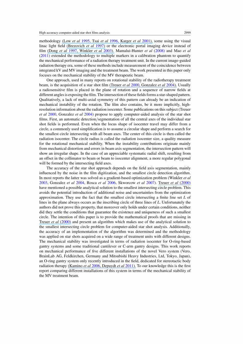
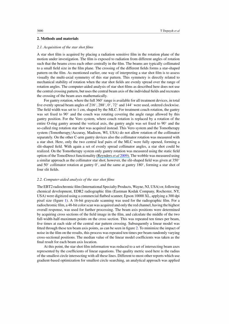
The EBT2 radiochromic film (International Specialty Products, Wayne, NJ, USA) or, followingchemical development, EDR2 radiographic film (Eastman Kodak Company, Rochester, NY,USA) were digitized using a commercial flatbed scanner, Epson 10000 XL, applying a 300 dpipixel size (figure 1). A 16-bit grayscale scanning was used for the radiographic film. For aradiochromic film, a 48-bit color scan was acquired and only the red channel, having the highestoverall response, was used for further processing. The beam axis positions were determinedby acquiring cross sections of the field image in the film, and calculate the middle of the twofull-width-half-maximum points on the cross section. This was repeated ten times per beam,five times at each side of the central star pattern crossing. Subsequently a linear model wasfitted through these ten beam axis points, as can be seen in figure 2. To minimize the impact ofnoise in the film on the results, this process was repeated ten times per beam randomly varyingcross-sectional positions. The median value of the linear model coefficients was taken as thefinal result for each beam axis location.
At this point, the star shot film information was reduced to a set of intersecting beam axesrepresented by the coefficients of linear equations. The quality metric used here is the radiusof the smallest circle intersecting with all these lines. Different to most other reports which usegradient-based optimization for smallest circle searching, an analytical approach was applied
High accuracy computer-aided star shot films analysis 3001
(a) (b)
Figure 1. A star shot film acquired with (a) the Kodak EDR2 radiographic film, after developmentand digitization or (b) the ISP EBT2 radiochromic film. Both are exposed to 200 MU per beam.
Figure 2. Star shot analysis, showing field axis segmentation. The inset shows the enlarged crossingof all detected beam axes and the calculated smallest intersecting circle, of which the radius iscalled the radiation isocenter size.
here. It can be proven mathematically (appendix) that the smallest intersecting circle alwaysoccurs as an inscribing circle of one of the possible triplet line subsets which can be made
3002 T Depuydt et al
from the complete set of beam axis lines. As such, the search algorithm constructs all theseinscribing circles and selects the smallest one intersecting all beam axes.
2.3. Precision and accuracy of the algorithm
The rotational mechanical stability of state-of-the-art radiation therapy delivery equipment istypically below 0.5 mm. The accuracy and precision of the algorithm were investigated toconfirm its adequacy to be used in these circumstances. Only with specialized equipment,to which the authors had no access, it would have been possible to create a gold standardreference mechanically. Here a similar approach was used as adopted by Gonzalez et al (2004)to create artificial star shots in silico for verification of the algorithm. Using a digitization of adeveloped blank film and superposition of artificially created beams, artificial star shot filmswere created. The advantage of this approach is that any given isocenter size can be introducedinto the data. Noise characteristics were made similar to the levels seen in digitization of realfilm. The signal-to-noise ratios (SNRs) were varied in a wide range including those observedin actually acquired star shots with film and radiation. Divergence and attenuation of the beamwere not included in the artificial star shot generation. The created artificial star shot data werefed to the algorithm and the results were compared to the a priori known radiation isocentersize, which was considered here as a gold standard reference.
Second, to investigate the influence of the scanning procedure and the film quality, fivegantry angle star shots were acquired on the UZB Vero system, each with a stack of twoidentical films pressed together. Each film was digitized on the flatbed scanner multiple timesand also under different orientations varying the angle with respect to the main axes of thescanner, and flipping sides of the film. The results of the analysis of the different films anddifferent film orientations were compared to assess the reproducibility of the radiation isocentersize results. The above was performed for both the radiochromic and radiographic film types.
From the film stack measurements, the differences between the two films of every stackwere calculated. Normal distribution for single film measurements was assumed becausenormality cannot be tested reliably on two sample data sets. For the difference distributionnormality was verified using the Lilliefors test. From the distribution of the two film stackradiation isocenter size differences, first the standard deviation ! A"B was calculated bymultiplying the mean absolute difference by #("/2). Second, the standard deviation of thesingle film measurement distribution ! A could be retrieved by dividing this by a factor
#2,
following from ! 2A"B = ! 2
A + ! 2B and ! B = ! A. All the individually determined uncertainties
were combined into one estimated total uncertainty of the method for both types of filmseparately.
To determine the relation between SNR of the beam images in film and the radiationexposure, expressed in monitor units (MU), some additional star shot measurements wereperformed varying the exposure in multiple steps from 12.5 to 300 MU per beam.
2.4. Application of the methodology in QC of different radiation therapy devices
A range of radiation therapy devices were subjected to the experiments described in theprevious sections. In total five Vero systems, one Tomotherapy system and additionally four C-arm systems of different vendors and types were included in this study. On the Vero systems, thegantry and O-ring rotations and the gantry wobble were measured. On the Tomotherapy systemonly the gantry rotation could be tested. On the C-arm gantries, the gantry, collimator andcouch rotations and the C-arm wobble were investigated. Both radiochromic and radiographic
High accuracy computer-aided star shot films analysis 3003
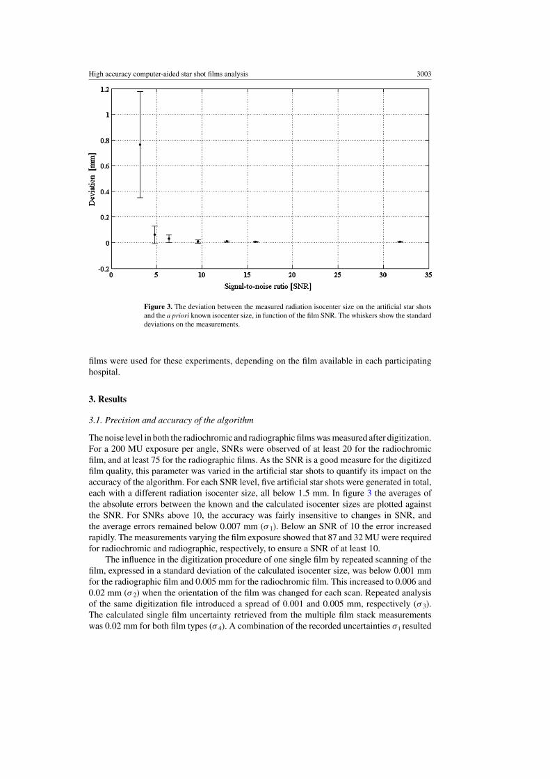
Figure 3. The deviation between the measured radiation isocenter size on the artificial star shotsand the a priori known isocenter size, in function of the film SNR. The whiskers show the standarddeviations on the measurements.
films were used for these experiments, depending on the film available in each participatinghospital.
3. Results
3.1. Precision and accuracy of the algorithm
The noise level in both the radiochromic and radiographic films was measured after digitization.For a 200 MU exposure per angle, SNRs were observed of at least 20 for the radiochromicfilm, and at least 75 for the radiographic films. As the SNR is a good measure for the digitizedfilm quality, this parameter was varied in the artificial star shots to quantify its impact on theaccuracy of the algorithm. For each SNR level, five artificial star shots were generated in total,each with a different radiation isocenter size, all below 1.5 mm. In figure 3 the averages ofthe absolute errors between the known and the calculated isocenter sizes are plotted againstthe SNR. For SNRs above 10, the accuracy was fairly insensitive to changes in SNR, andthe average errors remained below 0.007 mm (! 1). Below an SNR of 10 the error increasedrapidly. The measurements varying the film exposure showed that 87 and 32 MU were requiredfor radiochromic and radiographic, respectively, to ensure a SNR of at least 10.
The influence in the digitization procedure of one single film by repeated scanning of thefilm, expressed in a standard deviation of the calculated isocenter size, was below 0.001 mmfor the radiographic film and 0.005 mm for the radiochromic film. This increased to 0.006 and0.02 mm (! 2) when the orientation of the film was changed for each scan. Repeated analysisof the same digitization file introduced a spread of 0.001 and 0.005 mm, respectively (! 3).The calculated single film uncertainty retrieved from the multiple film stack measurementswas 0.02 mm for both film types (! 4). A combination of the recorded uncertainties ! i resulted
3004 T Depuydt et al
in an estimated overall uncertainty of 0.02 mm (! ) for radiographic film and 0.03 mm (! ) forradiochromic film.
3.2. Application of the methodology in QC of different radiation therapy devices
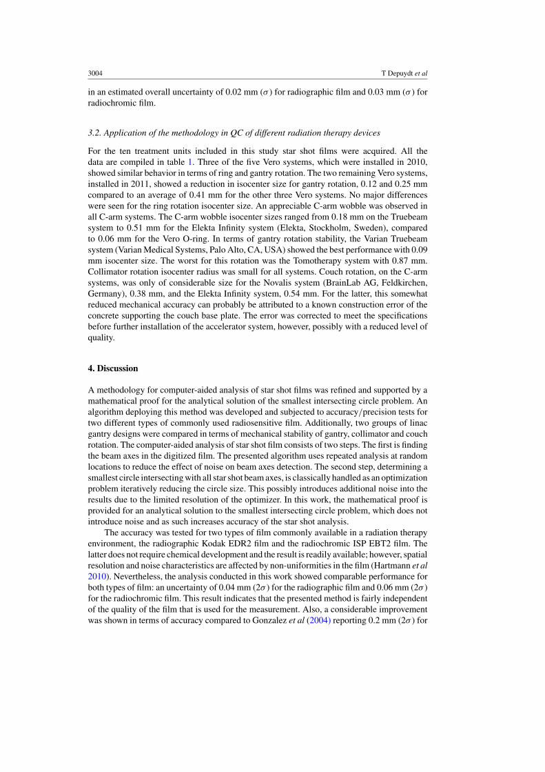
For the ten treatment units included in this study star shot films were acquired. All thedata are compiled in table 1. Three of the five Vero systems, which were installed in 2010,showed similar behavior in terms of ring and gantry rotation. The two remaining Vero systems,installed in 2011, showed a reduction in isocenter size for gantry rotation, 0.12 and 0.25 mmcompared to an average of 0.41 mm for the other three Vero systems. No major differenceswere seen for the ring rotation isocenter size. An appreciable C-arm wobble was observed inall C-arm systems. The C-arm wobble isocenter sizes ranged from 0.18 mm on the Truebeamsystem to 0.51 mm for the Elekta Infinity system (Elekta, Stockholm, Sweden), comparedto 0.06 mm for the Vero O-ring. In terms of gantry rotation stability, the Varian Truebeamsystem (Varian Medical Systems, Palo Alto, CA, USA) showed the best performance with 0.09mm isocenter size. The worst for this rotation was the Tomotherapy system with 0.87 mm.Collimator rotation isocenter radius was small for all systems. Couch rotation, on the C-armsystems, was only of considerable size for the Novalis system (BrainLab AG, Feldkirchen,Germany), 0.38 mm, and the Elekta Infinity system, 0.54 mm. For the latter, this somewhatreduced mechanical accuracy can probably be attributed to a known construction error of theconcrete supporting the couch base plate. The error was corrected to meet the specificationsbefore further installation of the accelerator system, however, possibly with a reduced level ofquality.
4. Discussion
A methodology for computer-aided analysis of star shot films was refined and supported by amathematical proof for the analytical solution of the smallest intersecting circle problem. Analgorithm deploying this method was developed and subjected to accuracy/precision tests fortwo different types of commonly used radiosensitive film. Additionally, two groups of linacgantry designs were compared in terms of mechanical stability of gantry, collimator and couchrotation. The computer-aided analysis of star shot film consists of two steps. The first is findingthe beam axes in the digitized film. The presented algorithm uses repeated analysis at randomlocations to reduce the effect of noise on beam axes detection. The second step, determining asmallest circle intersecting with all star shot beam axes, is classically handled as an optimizationproblem iteratively reducing the circle size. This possibly introduces additional noise into theresults due to the limited resolution of the optimizer. In this work, the mathematical proof isprovided for an analytical solution to the smallest intersecting circle problem, which does notintroduce noise and as such increases accuracy of the star shot analysis.
The accuracy was tested for two types of film commonly available in a radiation therapyenvironment, the radiographic Kodak EDR2 film and the radiochromic ISP EBT2 film. Thelatter does not require chemical development and the result is readily available; however, spatialresolution and noise characteristics are affected by non-uniformities in the film (Hartmann et al2010). Nevertheless, the analysis conducted in this work showed comparable performance forboth types of film: an uncertainty of 0.04 mm (2! ) for the radiographic film and 0.06 mm (2! )for the radiochromic film. This result indicates that the presented method is fairly independentof the quality of the film that is used for the measurement. Also, a considerable improvementwas shown in terms of accuracy compared to Gonzalez et al (2004) reporting 0.2 mm (2! ) for
High
accuracycom
puter-aidedstarshotfilm
sanalysis
3005
Table 1. The results of all radiation isocenter size measurements performed on different machine types in different institutions (BrainLab headquarters, UZ Brussel, Ospedale Sant’AnnaComo, University of Texas Southwestern, European Institute of Oncology, UniversitatsSpital Zurich). Depending on the type of machine, only certain rotations could be measured.
Vendor BrainLab/MHI BrainLab/Varian Varian Elekta Elekta Tomotheraphy
Machine type Vero Vero Vero Vero Vero Novalis Truebeam Compac Infinity Hi ArtGantry type O-ring O-ring O-ring O-ring O-ring C-arm C-arm C-arm C-arm O-ringSite BrainLab UZB Como UTSW IEO UZB USZ UZB UZB UZBFilm type EDR2 EDR2 EBT2 EBT2 EBT2 EDR2 EBT2 EDR2 EDR2 EDR2
Isocenter radius (mm)Gantry 0.39 0.40 0.43 0.12 0.25 0.28 0.09 0.23 0.26 0.87Collimator NA NA NA NA NA 0.03 0.09 0.01 0.01 NARing 0.05 0.01 0.06 0.02 0.08 NA NA NA NA NACouch / / / / / 0.38 0.03 0.09 0.54a NAWobble / 0.06 / / / 0.44 0.18 0.25 0.51 NA
a Base plate construction issue.
3006 T Depuydt et al
(a)
(c)
(b)
(d)
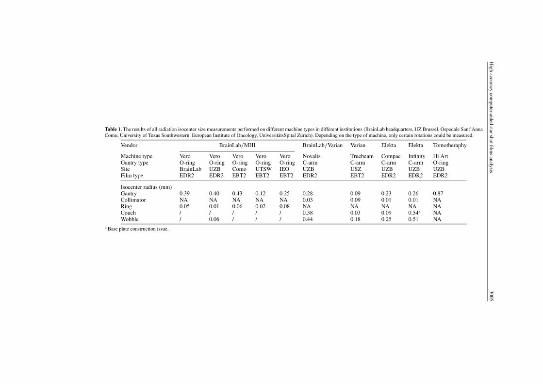
Figure 4. (a) The star shot patterns of the original acquisition on the UZB Vero system with (b) its analysis resultingin a radiation isocenter size calculation of 0.40 mm. (c) The acquisition after correction with an MLC shift of 0.4 mmresulted in an improvement to (d) 0.06 mm isocenter size.
a computer-aided star shot analysis. Measurement of radiation isocenter sizes below 0.2 mmnow becomes possible with the improvements described in this work.
The main scope of this work was primarily to investigate the computer-aided star shotanalysis using the analytical solution of the smallest circle problem. Additionally the methodwas applied in a study concerning mechanical rotation stability of a range of differentradiotherapy treatment unit gantries. The fields used to acquire the star shots were collimatedusing the MLC. As such the results include misalignments of the MLC with respect to thebeam. An example of this is shown in figure 4, where a star shot analysis is observed forthe UZB Vero system. In figures 4(a) and (b) the initial analysis is shown resulting in anisocenter radius of 0.40 mm. It can be seen in figure 4(b) that the field axis lines form a regularpolygon, which indicates a systematic misalignment of the field. After applying a shift ofthe MLC leafs by 0.4 mm, a second star shot was acquired resulting in more irregular beam
High accuracy computer-aided star shot films analysis 3007
axes crossing or the so-called random walk and an isocenter radius reduction to 0.06 mm(figure 4(d)). This difference can also readily be observed in the improvement of multi-axialsymmetry of the star pattern in figure 4(c) compared to figure 4(a), showing the sensitivity ofthe star shot method even using visual inspection only. The same correction experiment couldbe repeated on the Vero system sited at the BrainLab headquarters, suggesting a misalignmentof the MLC with respect to the isocentric rotation embedded in the system calibration. Forthe more recent installations of the Vero system, this systematic misalignment was reduced.It is unclear whether the beam/MLC alignment procedure was modified or whether it canbe attributed to the installation team gaining experience with this novel device. For the Verosystem its gimbaled linac system (Kamino et al 2006, Depuydt et al 2011) is actively usedto establish a better definition of the radiation isocenter through compensation of mechanicaldistortions during gantry rotation. The 0.06 mm radiation isocenter radius thus reflects mostprobably better Vero’s intrinsic mechanical performance than the initial 0.40 mm. However,for actual patient treatments the system is only as accurate as the quality of the mechanicalcalibration of the MLC collimated treatment beam.
For tomotherapy a quantification of the tongue-and-groove/penumbral blurring effect isused to align MLC and linac (Balog et al 2003), with a reported accuracy of 0.7 mm. Baloget al also describe a 0!–180! gantry angle test to verify the alignment of the collimated beamwith respect to the center of rotation for which a 1.5 mm tolerance level was proposed. Fenwicket al (2004) advised inclusion of a star shot film test in the three-monthly QC with a tolerancelevel of 1 mm. For helical tomotherapy dose delivery striving toward more stringent tolerancelevels might not have a significant impact on the final dose delivery quality. However, for thenovel static gantry beam delivery approach on the Tomotherapy device called TomoDirect(Reynders et al 2009), smaller tolerance levels for isocentric alignment might be appropriate.
Based on the data provided here, one could conclude that a limited accuracy of thecalibration/alignment procedure influences the performance of the linac despite their highintrinsic mechanical accuracy. For this reason, a general conclusion of the comparison betweenmechanical stability of O-ring and C-arm designs remains inconclusive. When comparing theVero isocenter size measurement with the best performing C-arm system, the Varian Truebeam,and accounting for the obtained accuracy of the measurement technique used in this study, thedifference is too small to conclude to a significant difference in mechanical performance ofboth gantry designs.
The methodology described in this work can be used to monitor mechanical performanceconstancy of high-accuracy radiation treatment units. Besides determination of the isocentersize, the star shot film can be used as an accurate measurement of rotation angles. In general,film measurements in combination with computer-aided analysis can be used for a rangeof mechanical quality control of gantry, MLC but also couch translations and roboticscouch rotations. An advantage over many other high-accuracy methods presented in otherpublications is that film and film digitizers or flatbed scanners are available in nearly allradiation therapy institutions. In combination with some fairly simple software, a highlyaccurate measurement tool becomes available for mechanical QC in clinical radiation therapyenvironments.
5. Conclusion
An analytical solution for the smallest intersecting circle problem was mathematicallyproven and applied in a computer-aided star shot film analysis tool. This resulted ina measurement procedure to assess mechanical rotational performance of high-accuracyradiotherapy treatment units. The technique was validated and used to compare mechanical
3008 T Depuydt et al
quality data of five different installations of the novel Vero system, a Tomotherapy system and arange of C-arm linacs. A potential advantage of O-ring gantries over C-arm gantries, in terms ofmechanical stability of the treatment beam during rotation of the gantry, could not be confirmed.The application of computer-aided film analysis methodology can be further extended to othermechanics quality tests of radiation therapy linacs. The methodology described in this workcan be used to monitor mechanical performance constancy of high-accuracy treatment devices,with means available in a clinical radiation therapy environment.
Acknowledgments
This collaborative work was supported by the Flemish government through the Herculesfoundation and the ‘Fonds voor Wetenschappelijk Onderzoek—Vlaanderen’ grants G.0486.06and G.0412.08, and corporate funding from BrainLab AG. The authors would like to thankProfessor T R Mackie for valuable comments regarding the alignment of the Tomotherapy HiArt unit. The authors also wish to thank Greg Aloupis, Sebastian Collette and Perouz Taslakianfor their design of a linear algorithm for constructing the smallest intersecting circle. The ideaof this algorithm significantly contributed to the composition of the proofs of the theorems inthe appendix.
Appendix
In this appendix we prove the existence and uniqueness of the smallest intersecting circle fora regular line configuration in the plane. A planar configuration L of lines is called regular ifit contains a finite number of lines, not all going through the same point, such that no two areparallel.
Furthermore, we will show that for a regular line configuration this circle is always tangentto three lines of L (figure 2).
Let us identify our workplane with the XY-plane in 3D space, given by the equation z =0. Furthermore, we represent a circle C in this plane with center (x0, y0) and radius R as a pointp(C) = (x0, y0, R) in 3D space. Of course, such a point p(C) always lies in the upper half-spaceU : z ! 0, where the case p(C) "XY corresponds to a limit circle C with radius 0.
Next, with any line l in XY we can associate the two planes #1(l) and #2(l) that makean angle of 45! with XY. The half-spaces above these planes and bounded by these planesare denoted by H1(l) and H2(l), respectively. Note that the wedge W (l) = H1(l) $ H2(l) iscompletely contained in the upper half-space U. The following result is immediate:
Lemma A.1. A circle C intersects a line l in XY if and only if the point p(C) lies in the wedgeW(l).
Suppose now we are given a finite configuration of lines in the plane, L = {l1, . . . ,ln}. Thehit region W (L) of L is a polyhedral subset of U defined as W (L) = W (l1)$W (l2)$ . . . $W (ln)and it consists of exactly these points p(C) that correspond to circles C intersecting everyline of L. Clearly, such circles always exist and this proves that W (L) is not empty for finiteconfigurations. As a matter of fact, W (L) is unbounded because there is no restriction on theradius of hitting circles.
The polyhedron W (L) only meets XY if there exists a limit circle with zero radius thatintersects every line in the configuration. Equivalently, this exactly occurs if there is a pointthat belongs to every member of L. We call L a star configuration if all its lines go through onepoint. Now we can state our existence theorem.
High accuracy computer-aided star shot films analysis 3009
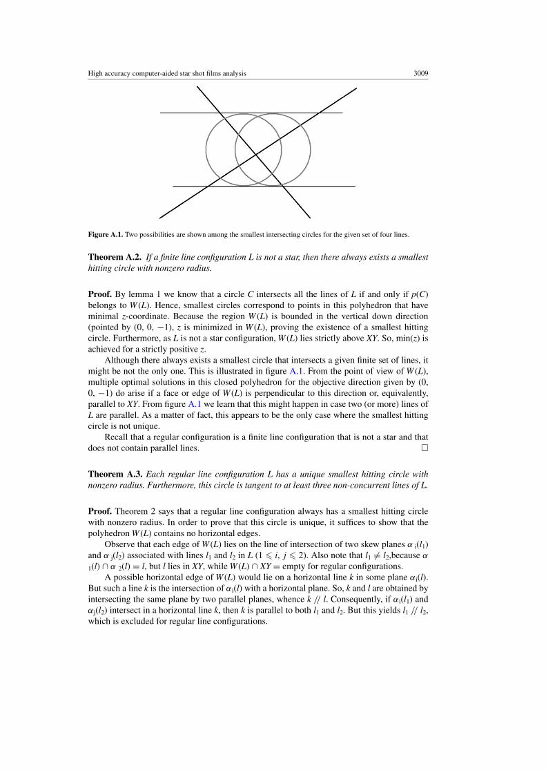
Figure A.1. Two possibilities are shown among the smallest intersecting circles for the given set of four lines.
Theorem A.2. If a finite line configuration L is not a star, then there always exists a smallesthitting circle with nonzero radius.
Proof. By lemma 1 we know that a circle C intersects all the lines of L if and only if p(C)belongs to W (L). Hence, smallest circles correspond to points in this polyhedron that haveminimal z-coordinate. Because the region W (L) is bounded in the vertical down direction(pointed by (0, 0, "1), z is minimized in W (L), proving the existence of a smallest hittingcircle. Furthermore, as L is not a star configuration, W (L) lies strictly above XY. So, min(z) isachieved for a strictly positive z.
Although there always exists a smallest circle that intersects a given finite set of lines, itmight be not the only one. This is illustrated in figure A.1. From the point of view of W (L),multiple optimal solutions in this closed polyhedron for the objective direction given by (0,0, "1) do arise if a face or edge of W (L) is perpendicular to this direction or, equivalently,parallel to XY. From figure A.1 we learn that this might happen in case two (or more) lines ofL are parallel. As a matter of fact, this appears to be the only case where the smallest hittingcircle is not unique.
Recall that a regular configuration is a finite line configuration that is not a star and thatdoes not contain parallel lines. "
Theorem A.3. Each regular line configuration L has a unique smallest hitting circle withnonzero radius. Furthermore, this circle is tangent to at least three non-concurrent lines of L.
Proof. Theorem 2 says that a regular line configuration always has a smallest hitting circlewith nonzero radius. In order to prove that this circle is unique, it suffices to show that thepolyhedron W (L) contains no horizontal edges.
Observe that each edge of W (L) lies on the line of intersection of two skew planes # i(l1)and # j(l2) associated with lines l1 and l2 in L (1 # i, j # 2). Also note that l1 %= l2,because #
1(l) $ # 2(l) = l, but l lies in XY, while W (L) $ XY = empty for regular configurations.A possible horizontal edge of W (L) would lie on a horizontal line k in some plane #i(l).
But such a line k is the intersection of #i(l) with a horizontal plane. So, k and l are obtained byintersecting the same plane by two parallel planes, whence k // l. Consequently, if #i(l1) and#j(l2) intersect in a horizontal line k, then k is parallel to both l1 and l2. But this yields l1 // l2,which is excluded for regular line configurations.
3010 T Depuydt et al
We conclude that there is exactly one point P = p(C) in the region W (L) with minimalz-coordinate and that this point must be a vertex of W (L). Such a vertex P always occurs asintersection of at least three planes #i(l) associated with three lines in L. Note also that thesethree lines are non-concurrent, because otherwise the intersection P of the associated planeslies in XY and that is impossible. This proves that the corresponding optimal circle C is tangentto three non-concurrent lines. "
Remark. More details on the geometric properties and algorithms for the minimal intersectingcircle of a line configuration can be found in Penne et al 2011 Here we provide, among otherthings:
• The proof that the minimal intersecting circle of a regular configuration always occurs asinscribed circle of a triangle formed by three of its lines.
• The proof that an inscribed circle to three lines of a regular configuration, moreoverintersecting the whole configuration, must be the unique smallest intersecting circle.
• The proof that the minimal intersecting circle of a regular configuration always occurs asthe largest of all inscribed circles to one of its triangles.
• An O(n) time algorithm to compute a smallest intersecting circle for a finite lineconfiguration.
References
Balog J et al 2003 Benchmarking beam alignment for a clinical helical tomotherapy device Med. Phys. 30 1118–27Brezovich I et al 1997 Quality assurance system to correct for errors arising from couch rotation in linac-based
stereotactic radiosurgery Int. J. Radiother. Oncol. Biol. Phys. 38 883–90Depuydt T et al 2011 Geometric accuracy of a novel gimbals based radiation therapy tumor tracking system Radiother.
Oncol. 98 365–72Dong L et al 1997 Verification of radiosurgery target point alignment with an electronic portal imaging device (EPID)
Med. Phys. 24 263–7Fenwick J et al 2004 Quality assurance of a helical tomotherapy machine Phys. Med. Biol. 47 2933–53Gonzalez et al 2004 A procedure to determine the radiation isocenter size in a linear accelerator Med.
Phys. 31 1489–93Hartmann B et al 2010 Homogeneity of Gafchromic R& EBT2 film Med. Phys. 37 1753–56ICRU 2010 Prescribing, recording, and reporting photon-beam intensity-modulated radiation therapy (IMRT) ICRU
Report 83 (Oxford: Oxford University Press)Kamino Y et al 2006 Development of a four-dimensional image-guided radiotherapy system with a gimbaled x-ray
head Int. J. Radiat. Oncol. Biol. Phys. 66 271–8Karger C et al 2001 A method for determining the alignment accuracy of the treatment table axis at an isocentric
irradiation facility Phys. Med. Biol. 46 N19–26Low D et al 1995 Minimization of target positioning error in accelerator-based radiosurgery Med. Phys. 22 443–8Lutz W et al 1988 A system for stereotactic radiosurgery with a linear accelerator Int. J. Radiother. Oncol. Biol.
Phys. 14 373–81Mamalui-Hunter M et al 2008 Linac mechanic QA using a cylindrical phantom Phys. Med. Biol. 53 5139–49Mao et al 2011 Initial application of a geometry QA tool for integrated MV and kV imaging systems on three image
guided radiotherapy systems Med. Phys. 38 2335–41Penne R et al 2011 A study of the smallest circle intersecting a given line configuration Technical Report IWT
2011–02 ISSN 2032–0450Reynders T et al 2009 Dosimetric assessment of static and helical tomotherapy in the clinical implementation of
breast cancer treatments Radiother. Oncol. 93 71–9Rosca F et al 2006 An MLC-based linac QA procedure for the characterization of radiation isocenter and room lasers’
position Med. Phys. 33 1780–7Skworcow P et al 2007 A new approach to quantify the mechanical and radiation isocentres of radiotherapy treatment
machine gantries Phys. Med. Biol. 52 7109–24

High accuracy computer-aided star shot films analysis 3011
Treuer H et al 2000 On isocentre adjustment and quality control in linear accelerator based radiosurgery with circularcollimators and room lasers Phys. Med. Biol. 45 2331–42
Tsai J et al 1996 The measurement of linear accelerator isocenter motion using a three-micrometer device and anadjustable pointer Int. J. Radiother. Oncol. Biol. Phys. 34 189–95
van Herk M et al 2004 Errors and margins in radiotherapy Semin. Radiat. Oncol. 14 52–64Winkler P et al 2003 Introducing a system for automated control of rotation axes, collimator and laser adjustment for
a medical linear accelerator Phys. Med. Biol. 48 1123–32