Computer Aided Design: Past, Present, Future
23
Computer Aided Design: Past, Present, Future, by Jonathon Allen & Paul Kouppas This is a preprint copy of a book chapter I wrote that appears in the Book “Design & Designing: A Critical Introduction”, edited by Steve Garner and Chris Evans, and published by Berg. For referencing, the details are as follows: Allen, J.L. & Kouppas, P., “Computer Aided Design: Past, Present, Future” in Garner, S. & Evans, C. (Eds), Design & Designing: A Critical Introduction, Berg, Oxford, 2012, pp. 97-111 ISBN: 978-1-84-788576-0
-
Upload
westernsydney -
Category
Documents
-
view
0 -
download
0
Transcript of Computer Aided Design: Past, Present, Future

Computer Aided Design: Past, Present, Future, by Jonathon Allen & Paul Kouppas This is a preprint copy of a book chapter I wrote that appears in the Book “Design & Designing: A Critical Introduction”, edited by Steve Garner and Chris Evans, and published by Berg.
For referencing, the details are as follows: Allen, J.L. & Kouppas, P., “Computer Aided Design: Past, Present, Future” in Garner, S. & Evans, C. (Eds), Design & Designing: A Critical Introduction, Berg, Oxford, 2012, pp. 97-111 ISBN: 978-1-84-788576-0
1
Computer Aided Design: Past, Present, Future
Jonathon Allen & Paul Kouppas
INTRODUCTION
Computer aided design (CAD) has evolved at a tremendous pace, from simple two-
dimensional (2D) draughting, to more complex three-dimensional (3D) modelling, to
the use of animation and the linking with artificial intelligence. Since the first
integrated circuit was developed in 1958, computational processing speed and
memory capacity have grown exponentially, doubling every two years or so – a
phenomenon known as Moore’s Law after Gordon Moore the co-founder of Intel who
first identified and predicted this trend. The proliferation of ever more powerful and
cheaper computers has provided a fertile environment for CAD’s growth but,
moreover, the great leaps forward have been when CAD has migrated from one
discipline to another. This chapter is about this important migration. The way in which
CAD has evolved by jumping between disciplines is indicative of the evolution of the
design professions themselves. The resultant cross-pollination of ideas, practices
and tools has led to new hybrid design disciplines. Computers are now increasingly
mediating design processes and have changed much of design practice itself.
CAD AT THE CORE OF DESIGN PRACTICE AND DESIGN EDUCATION
The ever-evolving and multi-modal nature of the design process means that design
students and professionals will necessarily need to be conversant in a wide range of
CAD programs, and further, will often be simultaneously learning whilst using
software. Knowing which process or software to use, and when, is perhaps the key to
addressing today’s design challenges and meeting ever-shorter timescales. The new
design virtuoso’s instrument is the computer and the designer’s virtuosity is in
drawing together a range of computer tools to compose their designs or perform their

2
role in delivering a good response to a brief. The designer at times will perform solos,
but will typically be working alongside (whether literally or, increasingly, virtually)
other specialists as part of a team working on the different aspects of a complex
design project. These projects can often involve many people in different parts of the
world. The integration and management of these projects pose their own challenges,
such as the consideration of file formats and compression to allow for the acceptance
and delivery of files, and a suite of computer tools more readily assists this process.
Figure 1. EV-L, 2009. Conceptual sneaker design by Shayne Reynolds, completed in
his 3rd year of studies of Industrial Design in a module that introduces students to the
fundamentals of NURBS surface modelling for conceptual product design
Navigating these challenges can be both exciting and daunting, but if
approached in the right way CAD can help unleash and augment the designer’s
creative capacity.

3
That creative capacity, of course, must already exist in the designer. CAD can assist
in realizing visions and facilitating a greater understanding of concepts, but still
requires ideas to be worked out via more traditional means such as drawing,
argument, critique and research. As with any instrument, CAD requires talent and
diligence to master.
From starting a design degree to commencing a professional career in design
will take between three and five years. In that time you will be exposed to a plethora
of software applications, from general word-processing, web-searching and
communication tools, to more specialist 2D draughting packages for the generation
of engineering and plan drawings; 3D modelling software for creating accurate
representations of products, buildings, packaging or animation characters; animation
applications for the generation of fly-throughs or short movies; digital imaging
software for vector and pixel based image generation and manipulation; multi-media
applications and web authoring tools for interactivity; as well as analytical software to
help verify and evaluate design ideas.

4
Figure 2. Nasal Mask Elbow Component, 2008. NURBS surface model, HDRI (High
Dynamic Range Rendering) with caustics and design verification. Paul Kouppas
You may spend three or four years honing your skills with these packages, before
perhaps entering the profession you’ve trained for. An important realisation is that
the field of CAD will also evolve dramatically in this time, with upgrades and new
features – indeed by the time you graduate, the software you began using may look
nothing like it did when you started learning it. The software may not even be
available, or new players may enter the market, such is the pace of change and
competition in the CAD software market.
This may seem rather formidable, and indeed there is a lot to learn, but
understanding how CAD has evolved and how it is being applied to help realise
designers’ ideas can be quite inspiring. Investing the time to hone design skills – both
manual and digital – is vital to your success as a designer. Having an appreciation
and understanding of how computers are, or potentially could be, used in the design
process, along with some generalizable technical skills in their application is now
increasingly important. It matters less what particular software you use. What’s more
important to employers is your knowledge of CAD, the adaptability of your skills and
your ability to learn quickly. Indeed, many companies use their own in-house
proprietary software (e.g. Pixar) and so the only way of learning the package is to
work there. What is important is garnering the fundamental processes that are the
foundation of most proprietary software. So if your dream job is to work at Pixar
(whose isn’t?), then you need to equip yourself with the principles of traditional
animation such as ‘squash and stretch’, ‘timing and motion’, and so on. Even if your
ambition is not to work for an animation studio, a knowledge of animation and the
ability to ‘stage’ an idea, can facilitate both a better presentation of your designs and

5
can help you incorporate personality, expression or the mood in your design ideas.
Increasingly designers are combining inspiration, skills and techniques whilst
adopting tools from outside their primary discipline.
When faced with learning a CAD package, the terminology can be somewhat
daunting and alien – from ACIS SAT to splines and NURBS, the terminology used in
CAD sounds like something more akin to science fiction – and certainly the field of
CAD is guilty of acronym abuse. So what does it all mean, and what do you really
need to know to get your head around the subject? In order to answer this, and
anticipate what your future as a design practitioner will be like, it is worth not only
looking at current practice, but also how we have got to here. In turn, we can better
anticipate how CAD is likely to evolve in the near future.
2D CAD: FROM DRAUGHTING MACHINES TO MACHINES THAT DRAUGHT
The evolution of CAD has followed an interesting path, migrating from aircraft to
automotive to architecture to animation to artificial intelligence, gaining richness en
route. Computer Aided Design also used to be known as Computed Aided
Draughting, and this is an indicator of CAD’s two-dimensional origins. The first CAD
packages were largely replacements of the drawing board, producing predominantly
orthographic and isometric drawings. The huge advantage of CAD was its ability to
duplicate elements allowing for quick modifications of part drawings, easy sharing of
files, and dramatic reduction in the time taken to produce and edit drawings. There
was also a key advantage in electronic storage of files, meaning that files could
readily be duplicated and shared (particularly important when the design team are
working in different locations and manufacture is occurring overseas). The need for
plan chests full of drawings in each location quickly became a thing of the past.

6
It is rare to see drawing boards and draughting machines these days, but not
so long ago design studios were full of them – many manufacturing companies,
engineering firms and architects offices had vast rooms filled with draughters
labouring over their technical drawings, with plan chests full of blueprints and detailed
drawings of every single part of a product or building. Thankfully, but also sadly for
the loss of this artistry, those days are gone and technical drawings are now almost
exclusively computer generated. This has dramatically accelerated the design
detailing and development process. Many CAD packages now include standardised
parts files, so designers can simply ‘drag and drop’ items into their design drawings.
For instance, standardised items such as doors, windows and various building panels
can be retrieved from a directory and dropped into architectural plans; or in
engineering, standardised pipes, tubes and mechanical fixings can be quickly
inserted into drawing files. This not only speeds up the process of producing detailed
drawings and plans, but also ensures dimensional accuracy. Many parts
manufacturers also provide digital drawing files of their stock, so that designers can
accurately accommodate these parts in their designs with the assurances that
everything will fit.
Importantly, producing drawings in CAD means that the same computer file
that produced the drawing can also be used to generate cutting paths for the
manufacture of items, thus resulting in a far more efficient and accurate process. This
translation from CAD draughting to digital making is often referred to as CAD/CAM,
where CAM stands for Computer Aided Manufacture. Many 2D CAD applications
now incorporate 3D capabilities, but the development of 3D CAD systems have, by
and large, superseded their 2D cousins.
3D CAD: FROM AIRCRAFT TO AUTOMOTIVE AND BACK

7
The development of commercial 3D CAD software has an interesting past. Aircraft
designers during the 1940s would use small wooden strips, called splines to create
templates for aircraft. The thin wooden strips were bent and held in place at key
points (nodes) and the timber’s natural stiffness ensured that a smooth curve
resulted. These ‘splines’ were then traced onto paper to create the templates for the
construction of the aircraft. This was very much a hands-on craft technique, but the
principles behind the construction of these spline curves remains the basis of much
of modern CAD systems. In the late 1950s and early 1960s, mathematical definitions
of these curves were developed by the French mathematicians Paul De Casteljau
and Pierre Bézier. Both worked in the automotive industry (De Casteljau for Citroën
and Bézier for Renault) and, as is typical of the secrecy of the automotive industry,
worked independently without knowing of each other’s work. Bézier published his
work in 1962 and his name is best remembered because the early vector-based
graphics and animation tools used Bézier curves to generate lines or motion paths in
the computer. A Bézier curve consists of a line defined by two end points plus a
series of nodes on that line that can be moved using control handles to redefine the
curve. Bézier curves are still an integral way in which computer models in CAD are
drawn and defined today.
A mathematical definition of such curves allowed computers to quickly crunch
the numbers to generate and manipulate the lines, allowing precise representation of
exterior surfaces. Commonly, 3D surfaces in CAD are referred to as parametric
surfaces, and they can be mathematically represented by NURBS, or Non-uniform
rational B-Splines, which are like rubber sheets stretched over the surface. Imagine
then, a grid of lines projected over this sheet with control points to allow the surface
to be stretched and manipulated by the designer to create complex free-form
surfaces. This is how dynamic models can be created, by patching together a series
of these NURBS surfaces.

8
Figure 3. Wall-E Paper Mechanics, 2008. UV layout and paper cut-out, flat shade
render, and textured HDRI rendering. Paul Kouppas
Once the overall surfaces of the object are created, a material editor is used to create
textures that can be mapped onto those surfaces for rendering. So once the CAD
model has been created, the object can be rendered to appear matte or shiny, hairy
or smooth, coloured or plain, translucent or opaque. Many animation and
visualisation packages call their desktop a ‘scene’, allowing the designer the ability to
stage their models with cameras, lights, and other digital assets (sometimes referred
to as actors). Each of these digital assets must be controlled through a variety of
settings to allow for various lighting conditions and viewing angles so that the
computer knows how to render the surfaces, cast shadows and add reflections to
create life-like visualisations.

9
Figure 4. Kiwi-Lime, 2009. Simple NURBS demonstration surface model constructed
from single Bezier curve and ‘revolve’ or ‘lathe’ technique, photo textures applied
allow for a convincing rendering. Paul Kouppas
Much of the development of early CAD systems was either in research groups
at Universities, or by in-house teams at large automotive and aircraft manufacturing
companies. There were two reasons for this – firstly, the sheer cost of computers in
the 1960s was prohibitive for smaller industries to adopt CAD, and secondly, the
engineering requirements of both automobiles and aircraft required the ability to
manufacture complex 3D surfaces. The pioneering developers of CAD systems
included from the automotive field, General Motors, Renault and Ford, and from the
aircraft industry, Lockheed and McDonnell-Douglas. Throughout the 1970s many
other automotive and aircraft manufacturers developed their own CAD programs, but
because of the nature of those industries and the commercial sensitivity of their
processes, these CAD systems were specialised and bespoke. It wasn’t until 1980
that standardization began, with the introduction of the Initial Graphic Exchange
Standard (IGES) – a standard still in use today that allows complex 3D curves and
surfaces to be transferred between different CAD systems.
The French aircraft manufacturer Avion Marcel Dassault, began developing a
3D CAD application in 1977 for the development of the Mirage jet fighter aircraft.
It was soon realized that the software application they had created could have
commercial value, and in 1981 a subsidiary company, Dassault Systemes, was
established. A year later, in a sales and marketing partnership with IBM, one of the
most successful 3D CAD applications, Computer Aided Three-dimensional
Interactive Application, or CATIA® for short, was released. Dassault Systemes,
remains one of the leading CAD software providers, and includes SolidWorks® and

10
CATIA® in their portfolio along with several other computer software tools to manage
the complete product lifecycle.
FROM AIRCRAFT TO ARCHITECTURE
Because CATIA was initially developed for handling the complex nature of 3D aircraft
surfaces, it was readily adopted by other transport design disciplines, such as
automotive, rail and marine craft design. Architects have also utilised the software for
its ability to handle complex geometry and surfaces. Most notably, Frank Gehry’s
Gehry Technologies, has developed Digital Project™, a suite of software for 3D
building information modeling, built upon the CATIA engine, precisely because it can
handle the complex free-form surfaces typical of his buildings.
Another architect who advocates the use of CATIA, along with several other
CAD tools, is Professor Mark Burry, Director of the Spatial Information Architecture
Laboratory, and Professor of Innovation at RMIT University in Melbourne, Australia.
He is a pioneering researcher and practitioner in the role of CAD in creative and
transdisciplinary projects, and one of many case studies where this best plays out is
in his career-long work on Antoni Gaudí’s masterpiece, the Sagrada Família church
in Barcelona (see www.sagradafamilia.cat/).
Gaudí commenced work on the church in 1883, but by the time of his death in
1926 the church was less than a quarter complete. During the Spanish Civil War,
many of Gaudí’s models of the building were destroyed, and so the completion of the
church has relied on in-depth research, interrogation and interpretation of Gaudí’s
processes in order to complete the design according to his intent. One of the design
processes Gaudí developed was to create physical models by stretching strings
across a space and adding weights to the strings at particular points to pull the string
to generate complex catenary structures. When the structure (or an image of it such

11
as a photo) was inverted, the form of his buildings was revealed. In essence, Gaudí’s
process is not too dissimilar to the way in which aircraft designers used splines;
adding extra force at particular points to change the curvature of a line. This process
can be digitally modelled today using 3D CAD systems where control points are
manipulated to replicate the complex surfaces that Gaudí proposed.
Professor Burry first began work on Gaudí whilst still a student, and at that time
the complex structures had to be calculated and drawn by hand. This was a very
labour-intensive process but perhaps too, an insightful one as it afforded a deeper
understanding of the complexities of Gaudí’s structures, and of the processes by
which they were generated. Professor Burry is now executive architect for the
project, and works with teams in Australia and Spain studying the remaining pieces
of Gaudí’s physical models and drawings in order to interpret and complete the
design. Parametric CAD software is used to help generate digital models that resolve
some of the details left behind in an attempt to present designs that correlate with
Gaudí’s intent. Because parametric software allows multiple points of a surface to be
manipulated in relation to each other point, the 3D CAD model can be tweaked
relatively quickly to best fit with the remaining physical models. With the use of rapid
prototyping, the digital model can be reproduced as a physical model to help verify
the design.
The use of CAD here is particularly interesting, as it is helping to reveal insights
into Gaudí’s ‘compositional strategies’, and is allowing the creative exploration and
interpretation of Gaudí’s work long after his death. The Sagrada Família church is still
under construction and CAD is used to share information and progress across the
world. From an office in Melbourne, the architect can be discussing (via video-link) a
particular design feature, with the stone masons and site architects in Barcelona. In

12
front of them both can be the same CAD model in both digital form (on screen) and
as a physical representation (a rapid prototyped part).
THE ARTISTRY OF MEDIA AND MEDIATION
The ability to use CAD with other forms of computer-based communication was very
attractive to the automotive industry because of its need to support international team
working. Indeed, the automotive sector has been one of the pioneers of CAD, and
has also been an early adopter of other technologies to streamline its business.
There are several reasons for this. Automotive design and manufacture is a global
business, producing vehicles for international markets. Cars and commercial vehicles
must conform to different national legislation and design requirements, as well as
appeal to the nuances of different cultural groups. The complexities of operating such
a business with design, engineering and manufacturing teams geographically
dispersed around the globe, and the necessity to ensure that all of the teams work
toward the common goal, on time and on budget, requires very effective
management and communication. Increasingly this management and communication
is being mediated with computational tools typically referred to as Product Lifecycle
Management (PLM).
The management of the lifecycle of a vehicle not only involves every stage of
design, development and manufacture, but also use and after care service, and the
vehicle’s disposal and recycling after life, all of which need to be planned for and
accommodated in the vehicle’s design from the outset. The development of a new
vehicle, from initial meetings and early concept sketches to the time the vehicle
drives off the production line, takes several years and an incredible financial
investment. There are many stages in the process of design and development,
involving teams of specialists in different locations around the world.

13
CAD has a vital role to play in the styling of vehicle form and designers work
using an array of 2D and 3D computer applications to produce lifelike visual
representations of vehicles. The process begins with many sketches, whether
traditionally with pen, pencil, marker and pastel, or on a digital tablet. After a series of
reviews and critiques, refinement of the sketches will translate into exploratory CAD
models. Typically, the 2D illustrations can be inserted into the background so that
splines and surfaces can be created from them. Programs such as Autodesk Alias®
allow designers to capture details of their 2D digital sketches to form the basis of a
3D CAD model. The two dimensional curves are given a new life, curving and
bending as they are shaped into three-dimensional representations. BMW’s fabric-
skinned shape-shifting sports car concept, the GINA – ‘Geometry and functions In 'N'
Adaptations’ – is the embodiment of such practice. The aluminium wire frame
structure accurately represents the NURBS curves used to generate the design, and
its stretchable polyurethane-coated elastane skins the NURBS surfaces.
Automotive clay modellers will work alongside the designers to produce
physical representations of a vehicle. Both the clay modellers and the designers are
after Class A surfaces, where all of the curves on the surface are accurately aligned
and congruent. In order to obtain this, often the CAD and clay models are developed
and refined concurrently. An initial CAD model may provide the basis for the
production of a clay model, which will be refined by hand, digitally scanned and re-
imported to CAD software to finesse.
CAD AND THE SUPPORT OF TEAMS
Once the CAD model is produced, others in the design, engineering, manufacture
and marketing divisions of the company can work with the CAD data to help
plan and develop other essential design tasks. Mechanical engineers can use
analytical software tools to asses such things as the vehicle’s aerodynamics and

14
drag efficiency, the structural integrity of the vehicle and how it will perform in virtual
crash testing, and the vehicle’s vibration and handling characteristics. Ergonomists
can asses the vehicle’s accommodation of the particular demographic it has been
designed for – this is particularly relevant in a global market where anthropometric
data varies from region to region, and cultural factors, such as the wearing of turbans
by Sikh communities, also needs to be taken into account. Ergonomic software can
help assess (preferably early in the design cycle) a vehicle’s design based on the 3D
CAD model, and the layout of controls, seating posture, ingress and egress, viewing
position, safety and comfort can be resolved alongside the designer. Colour and trim
designers will take the CAD model and render different colour and material finish
combinations, and prepare specifications based upon this. Manufacturing and
production engineers can detail a Bill of Materials (BOM) from the CAD model that, in
turn, can be used to help procure parts, liaise with suppliers, develop manufacturing
plants, and inform costing and financial analysis of the vehicle’s profitability.
Consideration of environmental impact, eco-design, and design for
disassembly needs to be factored into the design cycle, preferably as early as
possible. Automotive Regulatory Compliance Management tools are now part of
many CAD and PLM software, providing lists of suppliers, identification of recycled
content in parts, and even assessing the best and worst manufacturing locations in
regard to environmental and financial factors. Different legislation in different parts of
the world also needs to be considered and, in conjunction with the BOM, legislative
and regulatory compliance can be assessed and changes made accordingly using
analytical software. This is an increasingly important factor in automotive design (and
in product design more generally) particularly in Europe, where end-of-life vehicle
legislation makes it the responsibility of automotive manufactures to consider how the
vehicles they produce will be disposed of.

15
With the proliferation of CAD-based tools, one would have thought that manual
skills such as hand sketching and hand modelling were no longer so relevant. This is
far from the case. Indeed, sketching is still core to automotive design, as sketching
allows relatively quick exploration of form, and is also a wonderfully emotive medium
that captures the gestural energy, essence and flair of an idea. Physical making is
also still prevalent, in the form of clay modelling. Whilst the automotive sector has
experimented with the all-digital studio, limitations of this process were observed, and
most studios will have a balance of digital and physical processes. The real success
of CAD and CAM systems here has been in speeding up the process, and facilitating
more fluid conversation and design iteration amongst the teams.
Increasingly in the automotive sector, project teams are distributed around the
globe, with key divisions of companies located in the US, Asia and Europe. This has
given rise to the ‘24-hour studio’ where designers and engineers will each build upon
the work of the other. So a project might move from Detroit, USA, to Melbourne
Australia, to Cologne in Germany and then back again. This has the great potential of
speed up the process, but also poses problems of management and communication
(in the 24-hour studio described above, language differences mean that the car hood
becomes a bonnet and then an auto haube as it travels from team to team). Working
from the same CAD model, where the parts are visually represented provides a more
universal language, but also necessitates powerful computers and a fast network
system to not only transfer the data but to work on it concurrently.

16
Figure 5. Augmented Reality Glasses, 2011. Renders of 3D Solid Model for Rapid
Prototyping by Explore Engage
Augmented Reality (AR) is an emerging technology that allows for the real-time
visualisation of CAD over a live video feed. It can facilitate, using immersive
stereoscopic head-up displays and haptic devices, the ability for designers to virtually
see a CAD model appear immersed in their field of vision so that they can move
around it and see it from any angle. Haptics allow the user to seemingly feel and
touch the virtual object using three-degrees-of-freedom (3DOF) torque feedback
devices. The integration of such technology will allow for the designer to step away
from their computers and virtually sculpt or verify a design in much the same way as
automotive clay modellers do today. Volkswagen currently employs AR for training of
technical experts in the field of car service; the digital projections enable the
company to convey the complex technical inner life of the vehicles to the trainees
much better than conventional methods. Sydney-based company Explore Engage is
developing see-through AR glasses; these devices will tether to smartphones and
allow the user to experience AR for a range of applications. Soon such devices and
the technology will be prolific in the marketplace, so it is quite plausible that
augmented reality will be part of CAD systems in the very near future.
17
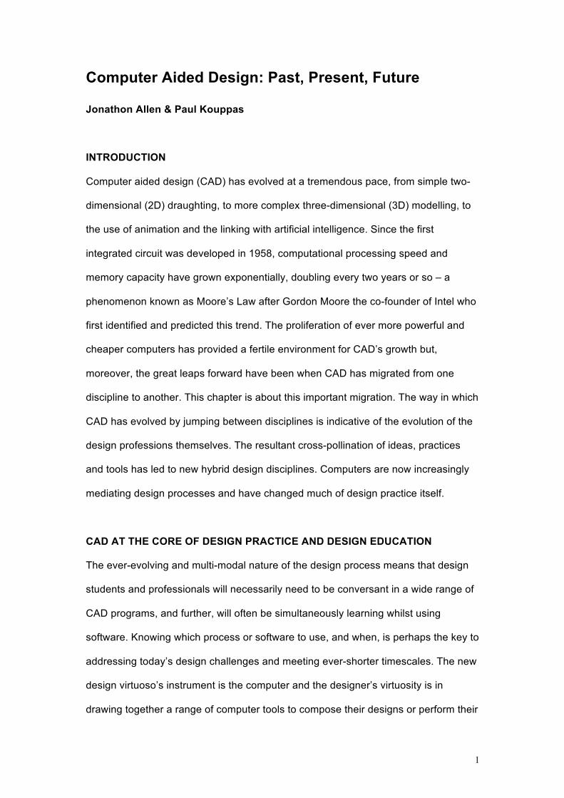
FROM ANIMATION TO ALLEGORY
The discussion of CAD and its evolution cannot ignore the phenomenal development
in Computer Generated Imagery (CGI), and its impact across the spectrum of design.
In particular, dynamic CGI in the form of computer animation is perhaps one of the
most interesting allegorical stories of the phenomenal rate of progress of CAD
capabilities, and how computers have transformed an entire industry. The term
animation perhaps serves as a poignant analogy in the context of this discussion:
frame by frame CAD has moved on faster and faster to a point where it appears to be
fluid and has come to life.
Figure 6. Puppet ‘No Strings Attached’, 2008. NURBS surface model with realistic
photo wood textures, rendered using HDRI. Paul Kouppas
When Toy Story by Pixar hit the screens in 1995 a new era in computer
animation began. It was the first completely computer-generated feature-length film,
and was highly profitable – in comparison with traditionally animated films, the film
18
used far fewer animators and was therefore significantly cheaper to make. The box
office takings were also a testament to the compelling story and captivating detail of
the film. Making the film took 800,000 computer hours to generate and render well
over 100,000 frames, equating to 600 billion bytes of information. Prior to this date,
computational hardware would have struggled to produce such a film. A whole raft of
full-length computer animated films have followed and CGI animation has long since
overtaken traditional animation to become the industry standard. CGI is also
extensively used in live-action films and, in many case, the quality is so good it is
very difficult to determine whether some scenes in films are real or not. The
advertising industry has been quick to see the advantages.
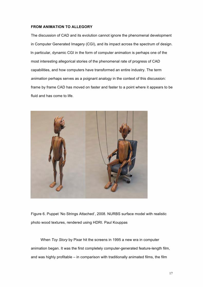
Figure 7. Realistic Human Spine Model 1999. Originally NURBS surface, converted
to a polygonal model, materials applied and rendered. Paul Kouppas | Moberg
Multimedia
In 3D computer animation a character is modelled, and a representation of the
character’s structure, or skeleton, is generated. This skeleton consists of a number of
animation variables, or Avars, that define the character’s motion. In Toy Story, the
central character, Woody, had in the order of 700 avars that could be controlled to
bring the character to life. Ten years later, Aslan, the title character in the film

19
production of The Chronicles of Narnia: The Lion, the Witch and the Wardrobe, had
as many avars to control his face as Woody had in his entire body. These avars can
be considered much like the control points in other 3D parametric models, but
interestingly the movement of the points can be programmed to move in certain
ways. All of these morph and dynamically bend the 3D mesh of the character, each a
reflection of a physical nuance or ‘phoneme’ to give life to the character. Behavioural
properties can be assigned to the avars to define how these control points move – for
instance, the way grass wafts in the breeze can be described mathematically and
then computer models can be programmed to behave in the same way. This is giving
rise to fascinating new disciplines and hybrid areas of design, linking such areas as
mathematics, computing, bio-mechanics and biology. Avars can also be controlled
through motion capture, whereby an actor wearing a body costume containing
numerous reflective marker points acts out the role in front of the camera. The
movement of the points is detected and that movement applied to the avars of the
CAD model to create life-like movement. This technique has been used very
effectively by a number of films, but perhaps most impressively by Weta Digital in
their work on The Lord of the Rings, King Kong and Avatar.
FROM ANIMATION TO ARTIFICIAL INTELLIGENCE
A major breakthrough in CGI films was the enormous scale of the battle scenes in
The Lord of the Rings, where a hundred thousand characters appeared in the
panorama. The characters were predominantly produced by CGI, but each behaved
with a degree of uniqueness that hitherto had not been produced before. To control
and choreograph each character would have been far too time-consuming, and
would have also made directorial changes extremely difficult. A solution came from
one of the computer graphics software engineers working at Weta Digital, Stephen
Regelous, who gave each character a ‘brain’. Rather than treating the characters as
particles that move in a uniform or predictable way, the characters were given

20
artificial intelligence that allowed them to react and respond to others around them as
well as to the environment they were in. Stephen Regelous received an Academy
Award for his work, and the proprietary software he developed, Massive (Multiple
Agent Simulation System in Virtual Environment), has since been used on many
other films.
Massive software has also been used in real-life applications, to model
behaviour of human crowds, traffic and other ecological systems. For instance, crowd
planning and emergency evacuations of buildings and urban environments can be
simulated entirely in CAD. This allows for architects and designers to become better
informed prior to committing to a final design. It can also save an incredible amount
of money save time, and of course help save lives.
Figure 8. Swimmer with goggles, 2008. Face modelled as NURBS surface based on
stock photo, and then converted to polygonal model. Evidence of organic/NURBS
surface present in her cap. Model and rendering by Paul Kouppas

21
Modelling humans, be it their anthropometric form, their dynamic movement, or
their behaviour is particularly challenging given the complexities of capturing realistic
motion and expression, let alone analyse and synthesise behavioural and attitudinal
responses. There are many around the world working on this though, and perhaps in
the not too distant future evidence-based avatars will be incorporated into CAD
software to help verify, evaluate and even perform the designing for you.
Whilst CAD has changed the way in which designers work, of crucial
importance is to ensure that computers are the ones assisting designers in the
process of designing. There is a very real danger in being seduced by CAD; that
somehow the capabilities of CAD can compensate for a lack of design ability. As with
any instrument, to master CAD requires talent and diligence. It requires creative
capacity and a particularly capable designer who can use the tool and not be
instrumentally designed by it.
CHAPTER SUMMARY
• The way in which CAD has evolved by jumping between disciplines is indicative
of the evolution of the design professions themselves. Computers are now
increasingly mediating design processes and have changed much of design
practice.
• CAD quickly gained a foothold in design because it enabled easy duplication of
parts, quick modifications of drawings, the visualisation and testing of models
and easy sharing of files.
• CAD models can also be used to guide manufacturing. Linking CAD with
Computer Aided Manufacture is referred to as CAD/CAM.

22
• Knowing which computing tool to use, and when, in the design process is key to
addressing today’s design challenges and meeting ever-shorter timescales.
• CAD can help unleash and augment the designer’s creative capacity.
• A knowledge of animation and the ability to ‘stage’ an idea, can facilitate both a
better presentation of your designs and can help you incorporate personality,
expression or mood in your design ideas.
• In the designing process there continues to be an important symbiotic
relationship between tangible models and digital models.
• Today CAD can be used to model complex behaviour such as crowds, traffic or
ecological systems.
• CAD and CAM systems have speeded up the designing process and facilitated
more fluid conversations and iteration amongst design teams.
Word count 5618
7.3.11