OUT-OF-PLANE VIBRATIONS OF SHEAR DEFORMABLE CONTINUOUS HORIZONTALLY CURVED THIN-WALLED BEAMS

m
nTp
2
Computation of a single-scattering matrix for nonsphericalparticles randomly or horizontally oriented in space
Vincent Noel, Guy Ledanois, Helene Chepfer, and Pierre H. Flamant
The computation of the scattering properties of cirrus cloud ice crystals by the ray-tracing approach isdescribed. A light beam is represented by its Stokes quadrivector I, which describes intensity as well aspolarization, and the scattering properties of particles ~molecules, droplets, or ice crystals! are introducedby means of a 4 3 4 transformation matrix M known as the Mueller matrix, or M matrix. Obtainingsuch a matrix for each kind of particle gives access to a complete description of the scattering medium.Most computations of the M matrices of cirrus ice crystals have introduced several simplifying hypoth-eses, by using basic shapes, by assuming a random orientation of the particles, or both. The presentstudy focuses on the calculation of the complete M matrix for a specific shape of particles ~i.e., hexagonallybased crystals! either with optional oscillation about the horizontal plane or with random orientation.The validity of the computation code is checked against specific well-known cases for randomly orientedparticles. For horizontally oscillating particles the computation of this matrix is a new result. Sensi-tivity of the M matrix to the following variables is studied: refractive index, amplitude of oscillation,particle shape and size, and angle of incidence. © 2001 Optical Society of America
OCIS codes: 080.2730, 280.3640, 290.5850, 260.1180.
acwue
dpmSssnS
1. Introduction
Cirrus clouds play a major role in the Earth’s radia-tion budget.1,2 Inasmuch as they permanently cover
ore than 30% of the Earth’s surface,3 they have astrong influence on weather and climate. However,quantification of their influence on the radiative bud-get is still uncertain, as their optical, radiative, andmicrophysical behaviors are poorly known, partly be-cause of the difficulties encountered for in situ study.For a correct estimation of their effects on both globaland local scales, a good description of their radiativebehavior and more specifically of their microphysicalproperties ~closely linked to their radiative effect! isessential. However, most of these clouds are com-posed of nonspherical ice crystals, which are difficultto model. An appropriate method of determiningthe scattering properties of such particles is the ray-tracing technique, based on the principles of geomet-rical optics.4–8
The authors are with the Laboratoire de Meteorologie Dy-amique, Ecole Polytechnique, Palaiseau Cedex 91128, France.he e-mail address for V. Noel is [email protected] 20 October 2000; revised manuscript received 13 April
001.0003-6935y01y244365-11$15.00y0© 2001 Optical Society of America
In this formalism, a light beam is represented byits Stokes quadrivector I, which describes intensityas well as polarization. The scattering propertiesof particles ~molecules, droplets, and ice crystals!are introduced by means of a 4 3 4 transformationmatrix M known as the Mueller matrix, or M ma-trix.9,11 Obtaining such a matrix for ice particlesgives access to a complete description of the scat-tering medium.
Most computations of the M matrix of ice crystalshave introduced several simplifying hypotheses, byusing basic shapes, by assuming a random orienta-tion of the particles, or both. The present study fo-cuses on the restitution of the complete M matrix for
specific shape of particles ~i.e., hexagonally basedrystals! randomly oriented in the horizontal plane,ith a possible oscillation about the horizontal, byse of a model termed the scattering matrix for ori-nted crystals ~SMOC!.In Section 2 we introduce the standard formalism
edicated to the description of the properties andropagation of light. A description of the scatteringedium is presented in Section 3 before we focus inection 4 on various light–crystal interactions. Re-ults and a study of the M matrix’s sensitivity toeveral input factors are presented in Section 5. Fi-ally, an analysis is made in Section 6, a discussion inection 7, and a conclusion in Section 8.
20 August 2001 y Vol. 40, No. 24 y APPLIED OPTICS 4365
bc
cm
c
em
s
elam
bTmQ
cpisr
a
m
stc
lmi
r3
sa
s
j
4
2. Formalism of Light Scattering
When one is considering a beam of monochromaticlight with a direction of propagation s ~unit vector!, areference plane can be defined as containing s and asecond unit vector, l, orthogonal to s. The lighteam’s electric field can then be described by its twoomplex components, EL and ER, with r 5 s 3 l.
However, it is easier to describe the light beam’s in-tensity and polarization properties with its Stokesvector I, a function of EL and ER.10 The choice of land consequently the definition of the Stokes vectorare arbitrary; a rotation of l about s to l* of w degreeshanges I into I* 5 R~w!I, where R is the rotationatrix.At the same time, the optical properties of a parti-
le can be described by a scattering cross section ssca,an absorption cross section sabs, and a 4 3 4 scatter-ing matrix M@~l, s!3 ~l*, s*!# called a Mueller matrixor an M matrix. This matrix is hereafter written Mto simplify the notation. The choice of l and l* isasily taken into account by application of rotationatrices to M. The M11 element of the matrix,
which describes the probability of scattering of unpo-larized light in a given direction, is often called thephase function, normalized as **M@~l, s! 3 ~l*,*!#ds* 5 4p.Any incident beam with a Stokes vector I~l, s! will
then be scattered by a crystal into an angular distri-bution of vectors I*~l*, s*! 5 MI~l, s!. When thisvent occurs, a convenient choice of reference vectorsand l* is one that introduces simplification by takingdvantage of symmetry in the structure of the Matrix, as follows:
For randomly oriented particles, both l and l* cane selected in the incidence plane containing s and s*:he M matrix has a simple structure and further-ore depends only on the product s z s* 5 cos~Q!, withas the scattering angle.For horizontally oriented crystals, the most natural
hoice for the incidence reference plane is the verticallane containing the incident direction s. Then, if l*s selected in the incidence plane, the M matrix pre-ents many symmetries but now depends on the di-ection of s* described with two angles uV and wV
~Subsection 4.D below! as well as on the incidencengle cos uI 5 s z k ~with k the vertical axis!.
3. Definition of the Scattering Medium
A. Model of Scattering Particles
When one is working with ray tracing, the main hy-pothesis is that between successive interactions thelight beam is represented as a plane wave.12 Thisassumption is valid only for size parameters x 52preyl . 60.13 For light in the visible domain ~0.4
m # l # 0.8 mm!, this method is valid for particlesbigger than re 5 8 mm. Ray tracing is therefore welluited to modeling the interaction between light inhe visible domain and most ice particles found inirrus clouds.
An almost infinite variety of particle shapes can be
366 APPLIED OPTICS y Vol. 40, No. 24 y 20 August 2001
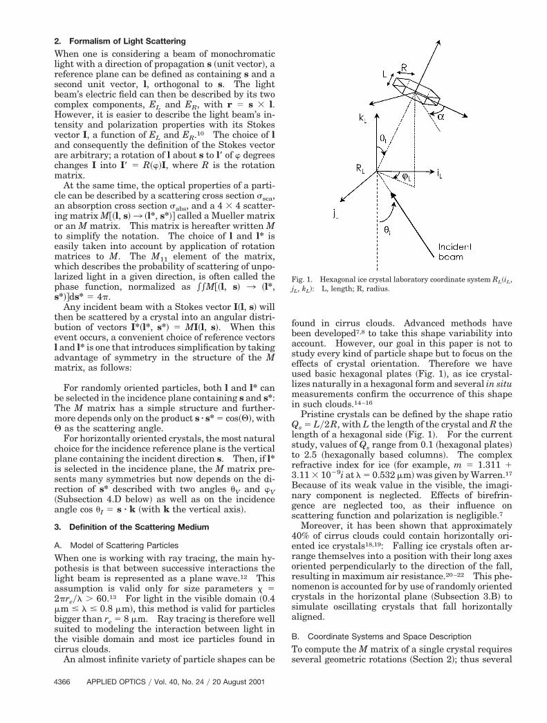
found in cirrus clouds. Advanced methods havebeen developed7,8 to take this shape variability intoaccount. However, our goal in this paper is not tostudy every kind of particle shape but to focus on theeffects of crystal orientation. Therefore we haveused basic hexagonal plates ~Fig. 1!, as ice crystal-izes naturally in a hexagonal form and several in situ
easurements confirm the occurrence of this shapen such clouds.14–16
Pristine crystals can be defined by the shape ratioQs 5 Ly2R, with L the length of the crystal and R thelength of a hexagonal side ~Fig. 1!. For the currentstudy, values of Qs range from 0.1 ~hexagonal plates!to 2.5 ~hexagonally based columns!. The complexefractive index for ice ~for example, m 5 1.311 1.11 3 1029i at l 5 0.532 mm! was given by Warren.17
Because of its weak value in the visible, the imagi-nary component is neglected. Effects of birefrin-gence are neglected too, as their influence onscattering function and polarization is negligible.7
Moreover, it has been shown that approximately40% of cirrus clouds could contain horizontally ori-ented ice crystals18,19: Falling ice crystals often ar-range themselves into a position with their long axesoriented perpendicularly to the direction of the fall,resulting in maximum air resistance.20–22 This phe-nomenon is accounted for by use of randomly orientedcrystals in the horizontal plane ~Subsection 3.B! toimulate oscillating crystals that fall horizontallyligned.
B. Coordinate Systems and Space Description
To compute the M matrix of a single crystal requireseveral geometric rotations ~Section 2!; thus several
Fig. 1. Hexagonal ice crystal laboratory coordinate system RL~iL,L, kL!: L, length; R, radius.
i1
i
t
tap
b
r
it
dewac
a~toaoa
positioning parameters are needed. They are pre-sented in Fig. 1.
The system of laboratory coordinates RL indicatesthe real vertical direction kL. The horizontal plane~iL, jL! of this coordinate system is the idle position ofthe crystal ~with no oscillation!. In this study, thencident beam is considered to come from below ~Fig.!.In this coordinate system the position of the crystal
s given by three angles: uL, wL, and a. uL and wL~elevation and azimuth, respectively! give the anglebetween the vertical direction kL and the normal to ahexagonal face of the crystal. To simulate limitedoscillation about the horizontal plane, we take uL ascos~umax! , cos~uL! , 1, whereas wL is randomlyaken as 0–2p. The last angle, a, gives the crystal
rotation about the normal to a hexagonal face: thevalue @a 1 n~py3!# gives the orientation of the normalo the nth rectangular face relative to the x axis ~0 ,, 2py6!. For the special case of randomly orientedarticles, umax is taken as py2.
4. Light–Crystal Interactions
A. Initial Settings
A single light–crystal system is defined by a crystalposition given by uL, wL, a ~Subsection 3.B!, and aeam’s initial direction in RL. To ensure that pho-
tons fully intercept the crystal, beam starting pointsare uniformly distributed on a disk orthogonally tothe incident direction, with its diameter larger thanthe main diagonal of the crystal and a total surface S.These six parameters are produced by a generator oflow-discrepancy Sobol sequences23 in a hypercube@0,1#5, and they completely determine the geometricbehavior of the subsequent reflected and transmittedpartial beams. An initial unity M matrix M0 is as-signed to the incident beam.
B. Light–Crystal Interactions
Before calculation of the light’s interaction with thecrystal, a rotation matrix must be applied to the Mmatrix such that a reference plane ~Section 2!, includ-ing the normal vector to the crystal face, can be used.Interaction between the light beam and the crystalface gives rise to two new light beams, a reflected anda refracted beam ~possibly null in the case of totalreflection!. Provided that the incident beam has al-ready entered the crystal, the first beam stays insidethe crystal, leading to new interactions, whereas thesecond beam leaves the crystal and is recorded asscattered light ~Subsection 4.D below!. During thesimulation each beam carries its own M matrix, M9,which can be represented as resulting from the ap-plication of a matrix G to the incident beam’s matrixM0. Elements of G are given by general Fresnelformulas that depend on the relevant interaction, re-flection or refraction.24 Total reflection is treated asa special case.
For a partial reflection interaction, 12% of the in-cident energy goes to the reflected beam and 88% tothe transmitted beam. After five interactions of this
kind, only 0.0025% of the original energy on averageis left in the beam, and the ray tracing is stopped.
C. Special Interactions
1. Fraunhofer DiffractionFraunhofer diffraction is an important phenomenonfor small angles of scattering ~the diffracted energyepresents half of the total scattered energy7!. For
simplicity, Pdiff~u!, the diffraction pattern used, issimilar to diffraction by a spherical particle and isgiven by the Fraunhofer approximation. It influ-ences equally the four diagonal elements of the Mmatrix ~M11, M22, M33, M44!.25
2. d-Function TransmissionWhen light is scattered by polyhedral particles suchas hexagonal ones, a great amount of energy is trans-mitted through the parallel faces of the crystal. Therefracted beam is then collinear with the incidentbeam. This kind of interaction is treated separately,as it leads to a singularity with no angular width at~s, s*! 5 1 for the scattering matrix. Because of thisnull angular width, this interaction ~known as thed-function transmission of Takano and Liou7! playsno part in the normalization and therefore must beseparated from the continuous angular scattering.It is characterized by a cross section sd and a diagonalM matrix Md, which has no influence on beam direc-tion but changes the polarization slightly. Never-theless, it has to be computed, as it represents a largepart of the emergent photons. A d-function trans-mission can also be distinguished for backscatteringevents ~scattered beam following a path opposite thencident beam!, although its intensity is less impor-ant.
To detect d-function transmission in the forwardirection, the code checks whether successive facesncountered by the beam are parallel. In the back-ard direction the d-function transmission is treateds part of the angular scattering distribution. Mish-henko and Macke26 have demonstrated that this in-
teraction was the dominant element for transparentparticles with large parallel planes. In the currentstudy more than 75% of the scattered photons werepart of the d transmission ~as much as 90% for smalloscillations around the horizontal plane!.
D. Scattered-Beam Recording
Each beam emerging from the crystal in a direction~uv, wv! carries its own M matrix M~uv, wv!, dependingon the path followed by the photon within the crystal.Angles ~uv, wv! are, respectively, the elevation and thezimuth angles defined in the laboratory referenceSubsection 3.B!. As the waves scattered by the par-icles are incoherent, one can simply take the variousrientations of the particles in space into account bydding the elements of the matrix obtained for eachrientation. Coefficients of each of these matricesre added into angle-related bins to create the global
20 August 2001 y Vol. 40, No. 24 y APPLIED OPTICS 4367
B
bt
a
nblei
isPa1t
b
cn
ibwst
ct
4
M matrix of the crystal. Size bins are constant foreach angle: Dwv 5 4.5° and Duv 5 0.2°:
Mtotal~uv, wv! 51N (
i51
N
Mi~uv,i, wv,i!. (1)
ins are filled with respect to the exact wv and uv ~aweighted interpolation is done to take into accountthe distance to the bin boundaries!. When the num-er of photons N is high enough ~typically N . 106!,he global matrix is correct for any scattering angle.
The Mtotal matrix is normalized such that *spaceM11~V!dV 5 4p ~with V the scattering solid angle!,nd the other elements are given as MijyM11.
5. Results
A. Validation of the Computation Code: Application ToRandomly Oriented Particles
As shown by Eq. ~1!, the ray-tracing code gives theMtotal M matrix for oscillating particles by addingsingle M matrices Mi for fixed orientations uniformlydistributed between 0 and umax. The value umax 590° corresponds to a random orientation of the crys-tal. In this configuration, as there is no preferentialplane for the particle, Mtotal does not depend on azi-muth angle wL. Therefore each matrix element
eeds only to be expressed as a function of the angleetween the incident and the emergent beams ~most-y known as scattering angle Q!. As there is no pref-rential orientation, the angle of incidence becomesrrelevant.
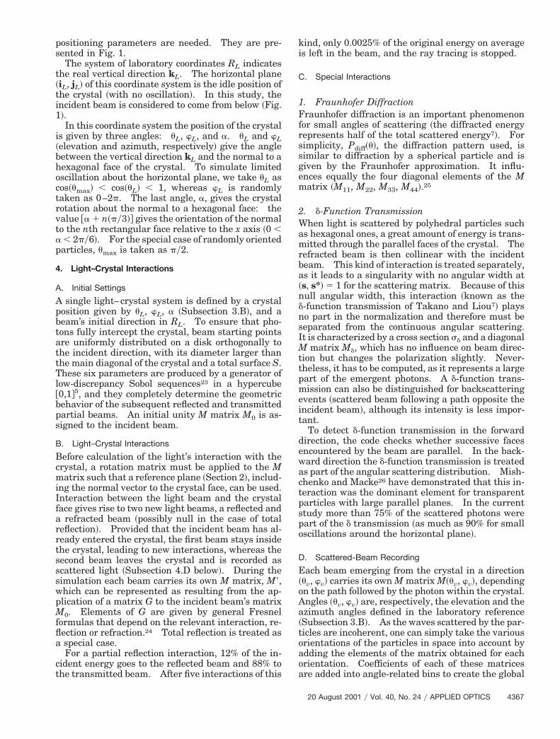
As an example, computation of this matrix, includ-ng diffraction and d-function transmission, is pre-ented in Fig. 2. The code was used on a 933-MHzC Linux workstation with 1 Gbit of RAM. With anverage 95% of CPU time, a simulation involving 7 308 photons took 15 min to process. This configura-ion leads to an average of N 5 103 photons per bin.
A value of N was chosen such that adding new pho-
Fig. 2. M matrix nonzero values for crystals randomly oriented,with three values of shape ratio Q, as a function of scattering angleQ.
368 APPLIED OPTICS y Vol. 40, No. 24 y 20 August 2001
tons would not change the result. Elements that arenot present in Fig. 2 are either zeros ~nondiagonallocks! or proportional to other elements ~M12 5 M21
and M34 5 2M43!. The general organization of suchan M matrix can be given by a block-diagonal model:
M 5 3M11 M12 0 0M12 M22 0 00 0 M33 M34
0 0 2M34 M44
4 . (2)
Equation ~2! confirms the validity of the current ray-tracing model, as such results are already well knownand documented.7,8,27,28 In addition, this organiza-tion was predicted by van de Hulst,10 considering thesymmetry properties of the problem:
The hexagonally based particle shapes present atleast one plane of symmetry, which leads to simpli-fication of specific matrices inside the crystal.
The medium presents symmetry properties: Asthe particles are randomly oriented in space, eachparticle can find its own mirror particle relative to theincident beam. Inclusion of these mirror particles inthe model leads to a matrix with some opposite valuesfor the same incidence angle and in consequence tothe values’ being canceled when every single matrixis added @Eq. ~1!#.
Figure 2 also shows effects of shape ratio QS on theM matrix. A comparison with published material27
yields good agreement ~correlation, 92–99.8%!.
B. Horizontally Oriented Particles
It is useful to use the randomly oriented particles tovalidate the SMOC, but, as we have already dis-cussed ~Subsection 3.A!, horizontally oriented parti-les are also of strong interest. However, severalew parameters need to be taken into account.For horizontally oriented particles, the direction of
ncident light is important. Therefore, results muste given as a function of the two angles uv and wv,hich permit a full description to be made of the
cattering properties of the case studied. Represen-ation of M is more complex: Each matrix element is
separately represented on a color-scaled polar dia-gram ~uv corresponds to the distance to center and wvto the polar angle!. The center of a diagram ~uv 5 0°!orresponds to the laboratory upward vertical andhe edge ~uv 5 180°! to the downward vertical; and
the light beam is arbitrarily chosen as coming frombelow the crystal ~uv . 90°!. It must be noted thatd-function transmission ~Subsection 4.C! cannot beaccounted for in the resultant figure because of itsnull angular width.
Figure 3 shows an example of this representationfor uI 5 40°, uosc 5 5°, QS 5 0.05, and mr 5 1.311.The diagrams have the following organization: non-zero values gathered in a circular shape centeredabout the main incidence angle uI, with zeros fillingthe rest of the diagram. A striking feature is thesymmetry property found in each of the Mij: Some

t
~Cscetsdwp
a
parameters are symmetrical with respect to the planethat contains the incident beam and some are anti-symmetrical with respect to the same plane. Thisproperty is also found in complementary figures.The general organization of the matrix is the follow-ing:
M } 3S S A AS S A AA A S SA A S S
4 , (3)
with S denoting the symmetrical parameters and Athe antisymmetrical parameters.
6. Analysis
A. Randomly Oriented Particles
Results for randomly oriented particles are alreadywell documented ~Subsection 5.A!, so we describeonly key features here.
Fig. 3. Sixteen values of the M matrix for horizontally oriented pngle of 40°, an oscillation angle of 5°, and a refractive index of 1
~1! Influence of Shape Ratio ~Fig. 2!Effects of the variation of the shape ratios Q can beobserved in Fig. 2. The global level of each second-ary peak on Mij is modified: the first halo ~Q 5 22°!,he secondary halo ~Q 5 45°!, etc.
2! Influence of Particle Size and Refractive Indexomplementary computations for various particleizes and refractive indices show that the ray-tracingontribution is not influenced by particle size. How-ver, particle size influences the Fraunhofer diffrac-ion component of the scattering function: As can beeen in Subsection 4.D, the diffraction effect stronglyepends on the particle equivalent radius. The for-ard peak of the scattering function will vary witharticle size. The first element, M11, shows that a
small variation of mr leads to a slight shift in thepositions of the secondary peaks: Decreasing mrfrom 1.31 to 1.28, i.e., increasing the wavelength from0.532 to 1.06 mm, shifts the peaks to smaller scatter-
les, as a function of u and w, for a size factor of 0.05, an incidence
artic.311.20 August 2001 y Vol. 40, No. 24 y APPLIED OPTICS 4369
cbsd
2Fm
a~uwMT4
pmu
c
4
ing angles. When mr is decreased even more, thesecondary peaks are totally attenuated.
B. Horizontally Oriented Particles
Figures 3–7 show the behavior of Mij for horizontallyoriented crystals with variations of several input pa-rameters ~shape factor QS, incidence angle uI, oscil-lation angle uosc, refractive index, and particle size!.The influence of these parameters is detailed below.
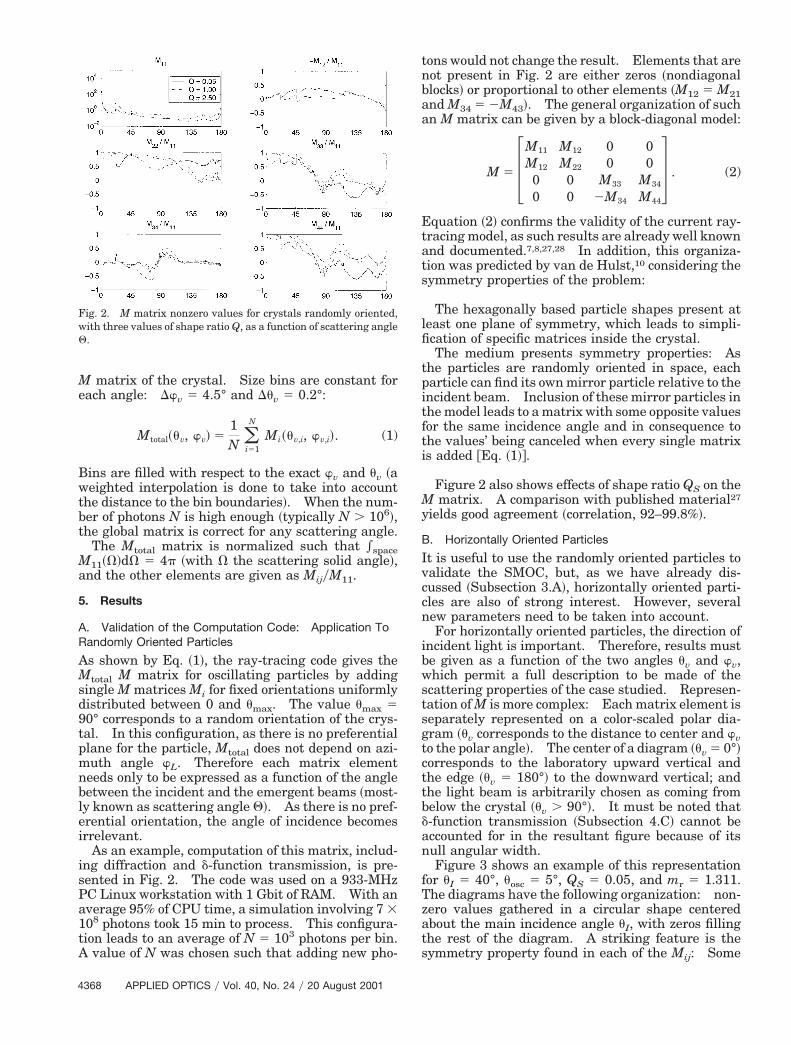
1. Influence of Oscillation AngleThe width of the main circular shape strongly de-pends on the value of uosc: Nonzero coefficient val-ues are closely clustered about uI for smalloscillations ~Fig. 3! and spread across the entire dia-gram for stronger oscillations ~Fig. 4!. These config-urations are clearly visible on the first coefficient,M11: The reflection and transmission spot sizes in-rease with the oscillation angle and at the same timeecome more blurred ~in other words, the spot inten-ity decreases!. However, the organization of theiagrams remains the same.
370 APPLIED OPTICS y Vol. 40, No. 24 y 20 August 2001
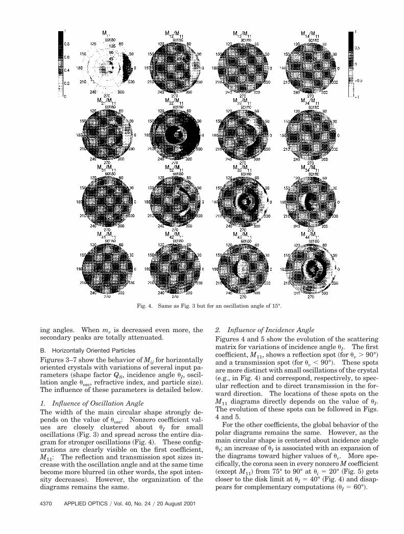
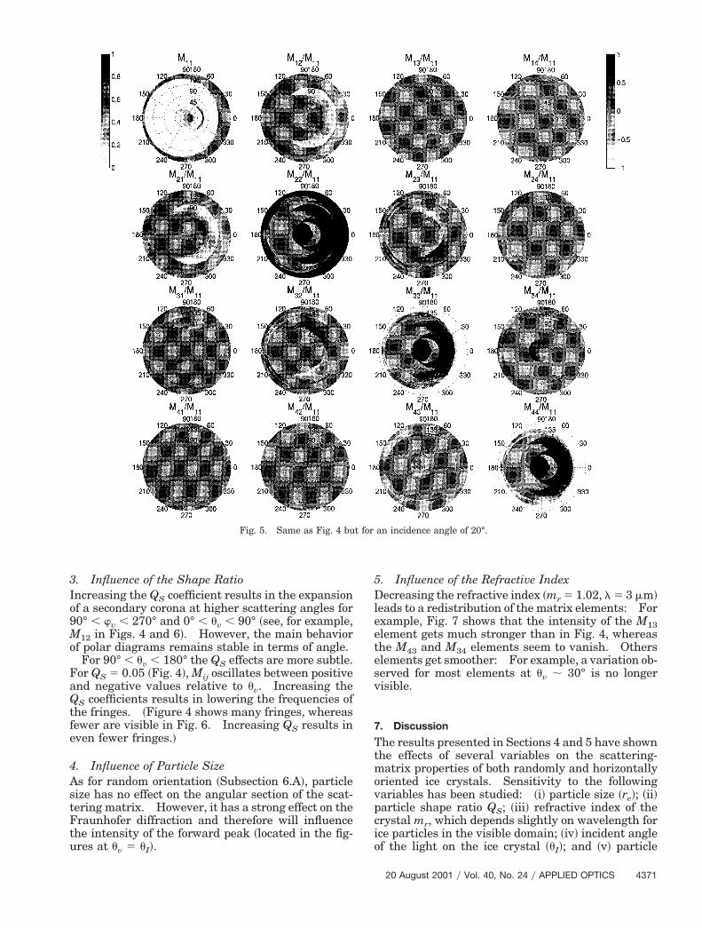
. Influence of Incidence Angleigures 4 and 5 show the evolution of the scatteringatrix for variations of incidence angle uI. The first
coefficient, M11, shows a reflection spot ~for uv . 90°!and a transmission spot ~for uv , 90°!. These spotsre more distinct with small oscillations of the crystale.g., in Fig. 4! and correspond, respectively, to spec-lar reflection and to direct transmission in the for-ard direction. The locations of these spots on the11 diagrams directly depends on the value of uI.
he evolution of these spots can be followed in Figs.and 5.For the other coefficients, the global behavior of the
olar diagrams remains the same. However, as theain circular shape is centered about incidence angle
I; an increase of uI is associated with an expansion ofthe diagrams toward higher values of uv. More spe-cifically, the corona seen in every nonzero M coefficient~except M11! from 75° to 90° at ui 5 20° ~Fig. 5! getsloser to the disk limit at uI 5 40° ~Fig. 4! and disap-
pears for complementary computations ~uI 5 60°!.
Fig. 4. Same as Fig. 3 but for an oscillation angle of 15°.
f
le
c
3. Influence of the Shape RatioIncreasing the QS coefficient results in the expansionof a secondary corona at higher scattering angles for90° , wv , 270° and 0° , uv , 90° ~see, for example,M12 in Figs. 4 and 6!. However, the main behaviorof polar diagrams remains stable in terms of angle.
For 90° , uv , 180° the QS effects are more subtle.For QS 5 0.05 ~Fig. 4!, Mij oscillates between positiveand negative values relative to uv. Increasing theQS coefficients results in lowering the frequencies ofthe fringes. ~Figure 4 shows many fringes, whereasewer are visible in Fig. 6. Increasing QS results in
even fewer fringes.!
4. Influence of Particle SizeAs for random orientation ~Subsection 6.A!, particlesize has no effect on the angular section of the scat-tering matrix. However, it has a strong effect on theFraunhofer diffraction and therefore will influencethe intensity of the forward peak ~located in the fig-ures at uv 5 uI!.
Fig. 5. Same as Fig. 4 bu
5. Influence of the Refractive IndexDecreasing the refractive index ~mr 5 1.02, l 5 3 mm!eads to a redistribution of the matrix elements: Forxample, Fig. 7 shows that the intensity of the M13
element gets much stronger than in Fig. 4, whereasthe M43 and M34 elements seem to vanish. Otherselements get smoother: For example, a variation ob-served for most elements at uv ; 30° is no longervisible.
7. Discussion
The results presented in Sections 4 and 5 have shownthe effects of several variables on the scattering-matrix properties of both randomly and horizontallyoriented ice crystals. Sensitivity to the followingvariables has been studied: ~i! particle size ~re!; ~ii!particle shape ratio QS; ~iii! refractive index of therystal mr, which depends slightly on wavelength for
ice particles in the visible domain; ~iv! incident angleof the light on the ice crystal ~uI!; and ~v! particle
an incidence angle of 20°.
t for20 August 2001 y Vol. 40, No. 24 y APPLIED OPTICS 4371

n
etztrt
ti
siwimsh
cmsmp~
pmht
4
angle of oscillations about the horizontal position~uosc!. Among these five variables, only the firstthree are relevant for particles that are randomlyoriented in space, whereas all of them affect the hor-izontally oriented ice crystals:
~i! The particle size ~re! plays the same role for bothrandomly and horizontally oriented particles: Thewidth of the diffraction peak decreases as the particlesize increases. At the same time, the intensity of thediffraction peak increases. As was mentioned inSubsection 4.C, the diffraction directly influences thediagonal elements of the scattering matrix and onlyindirectly ~through the normalization! the nondiago-
al elements.~ii! The ice crystal shape ratio ~QS! strongly influ-
nces all the elements of the scattering matrix. Forhe randomly oriented particles as well as the hori-ontally oriented ones, the intensity and the width ofhe secondary peaks are directly linked to the shapeatio. This phenomenon can be explained by the facthat photons tend to pass through the lateral sides of
372 APPLIED OPTICS y Vol. 40, No. 24 y 20 August 2001
he crystals as soon as these lateral faces are larger;.e., QS increases.
~iii! The real part of the refractive index does nottrongly vary for ice in the visible domain, and themaginary part, which corresponds to the absorptionithin the ice crystals, is negligible. Even if this
maginary part varies with wavelength, it still re-ains low and thus does not strongly influence the
cattering-matrix elements for both randomly andorizontally oriented ice crystals.~iv! The angle of incidence of the light on the ice
rystals has an important relation to the scattering-atrix elements of particles horizontally oriented in
pace, as it directly influences the positions of theain intensity peaks, such as the forward scattering
eak, the specular reflection peak, and the d peakstransmitted and backscattered!.
~v! The angle of oscillation about the horizontalosition has a nonnegligible influence on the ele-ents of the scattering matrix for particles that areorizontally oriented, as it influences the widths ofhe scattering peaks.
Fig. 6. Same as Fig. 4 but for a size factor of 0.2.
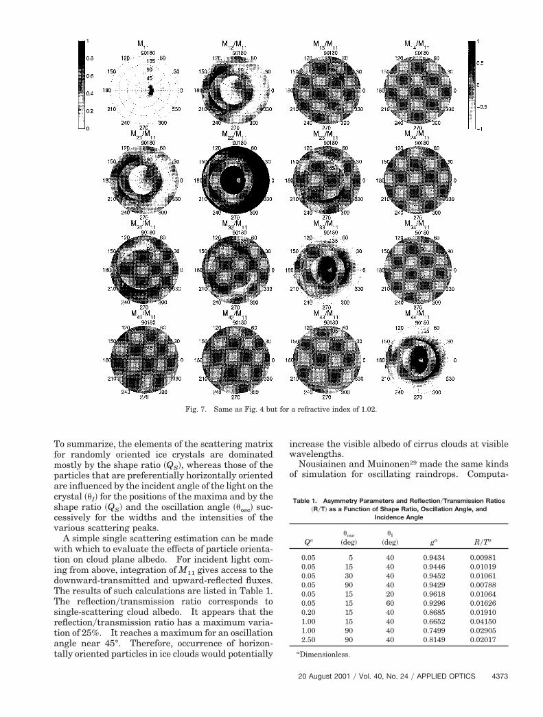
Table 1. Asymmetry Parameters and ReflectionyTransmission Ratios
To summarize, the elements of the scattering matrixfor randomly oriented ice crystals are dominatedmostly by the shape ratio ~QS!, whereas those of theparticles that are preferentially horizontally orientedare influenced by the incident angle of the light on thecrystal ~uI! for the positions of the maxima and by theshape ratio ~QS! and the oscillation angle ~uosc! suc-cessively for the widths and the intensities of thevarious scattering peaks.
A simple single scattering estimation can be madewith which to evaluate the effects of particle orienta-tion on cloud plane albedo. For incident light com-ing from above, integration of M11 gives access to thedownward-transmitted and upward-reflected fluxes.The results of such calculations are listed in Table 1.The reflectionytransmission ratio corresponds tosingle-scattering cloud albedo. It appears that thereflectionytransmission ratio has a maximum varia-tion of 25%. It reaches a maximum for an oscillationangle near 45°. Therefore, occurrence of horizon-tally oriented particles in ice clouds would potentially
increase the visible albedo of cirrus clouds at visiblewavelengths.
Nousiainen and Muinonen29 made the same kindsof simulation for oscillating raindrops. Computa-
Fig. 7. Same as Fig. 4 but for a refractive index of 1.02.
~RyT! as a Function of Shape Ratio, Oscillation Angle, andIncidence Angle
Qauosc
~deg!uI
~deg! ga RyTa
0.05 5 40 0.9434 0.009810.05 15 40 0.9446 0.010190.05 30 40 0.9452 0.010610.05 90 40 0.9429 0.007880.05 15 20 0.9618 0.010640.05 15 60 0.9296 0.016260.20 15 40 0.8685 0.019101.00 15 40 0.6652 0.041501.00 90 40 0.7499 0.029052.50 90 40 0.8149 0.02017
aDimensionless.
20 August 2001 y Vol. 40, No. 24 y APPLIED OPTICS 4373
owdlHStc
aost
scmitmrCau
at
mtBticemt
mtttTlssigaistt;
slmptti
amdAc
4
tions of the three-dimensional asymmetry factor g forriented platelike crystals give values that are al-ays superior to those of the same factor for rain-rops. The angle of incidence seems also to haveess influence on the g parameter than for raindrops.owever, a comparison of oscillating raindrops andMOC results has to be conducted with caution, ashe physical frameworks ~size range and shape! areompletely different.
The scattering function ~M11! depends strongly onthe large variability of particle size, shape, and ori-entation in space. Those variations imply strongconsequences for remote-sensing applications in cir-rus clouds. Classic passive remote sensors in thevisible domain measure radiances. Retrieval ofclouds’ radiative properties ~such as a cloud’s opticalthickness! from the measured radiance often requires
hypothesis concerning the microphysical propertiesf the ice crystals. For example, a mistake with re-pect to the prescribed ice crystal type, correspondingo a prescribed M11, will lead to incorrect perception
of the optical thickness. The amplitude of the mis-take will depend on the viewing geometries of theobservations and the given microphysical model.Nevertheless, as microphysical properties of naturalcirrus vary strongly with latitude, humidity, temper-ature, and conditions of formation, the different mod-els presented in this paper cannot pretend to coverthe complete natural variations of the real scatteringfunction ~M11!.
Moreover, the new generation of remote sensorssuch as lidars30 and the POLDER ~polarization anddirectionality of the Earth’s reflectances!31 instru-ment are able to measure the polarization character-istics of the light scattered by the ice crystals. Acorrect interpretation of those observations requiresa complete description of the scattering properties ofthe crystals, i.e., the complete scattering matrix.For example, in the framework of a single-scatteringapproximation, the lidar depolarization ratio can becomputed as a function of M11 and M22 and thePOLDER’s polarized radiance can be computed as afunction of M11 and M12. Hence in the future thecattering matrix computed in the current paperould be used in interpreting the polarized measure-ents for both randomly and horizontally oriented
ce crystals. Nevertheless, a rigorous analysis ofhose observations requires taking into accountultiple-scattering effects in cirrus clouds and hence
equires the development of radiative transfer Montearlo codes that are able to compute polarization innisotropic media with the single-scattering matrixsed as an input.
8. Conclusions
The current study aims at computing the completescattering matrix for hexagonal base particles ran-domly oriented in space or oscillating about the hor-izontal plane. The SMOC computation code is ableto compute indifferently random or horizontal orien-tations. With this code the random orientation isconsidered a particular case of horizontal orientation
374 APPLIED OPTICS y Vol. 40, No. 24 y 20 August 2001
with an oscillating angle of 90°. This code is basedon separate computations of the following compo-nents: the geometrical optics with a particulartreatment for contributions of refraction by two par-allel faces of the crystal ~Dirac peaks! in transmissionnd backscattering and ~ii! the Fraunhofer diffrac-ion.
We validated the code by computing the scatteringatrix for particles randomly oriented in space, as
hose results are already well known and published.ased on this validation, we used the code to compute
he scattering matrix for particles preferentially hor-zontally oriented in space. These scattering matri-es are new results, which show that some of thelements of the scattering matrix exhibit some sym-etrical and antisymmetrical properties with respect
o the incident plane.Finally a study of the sensitivity of the scatteringatrix to the five following variables has been made:
he refractive index, the particle size, the shape ratio,he angle of the incident light on the scatterer, andhe oscillation angle about the horizontal plane.his study shows that, within the framework of va-
idity of the geometrical-optics approximation, thecattering matrix is mostly sensitive to the particlehape ratio, to the angle of oscillation about the hor-zontal plane ~for horizontally oriented particles! thatoverns the width of the scattering peaks, and to thengle of incidence of light onto the scatterer ~for hor-zontally oriented particles! for the position of thecattering peaks. Moreover, the effect of horizon-ally oriented particles on a cloud plane albedo seemso be maximum ~125%! for an oscillation angle of45°.Our results can have a strong effect on remote-
ensing applications that use both intensity and po-arization observations. The complete scattering
atrices obtained in the research reported in thisaper for oriented particles will be used in the futureo facilitate a better understanding of the effects ofhe microphysical parameters of ice crystals on var-ous remote-sensing records.
The authors thank J. Hovenier for his contributionnd the anonymous reviewers for their useful com-ents. Thanks also go to the Centre National
’Etudes Spatiales and Sodern EADS ~Europeaneronautic Defence and Space Company! for finan-ial support.
References1. G. L. Stephens, S. C. Tsay, P. W. Stackhouse, Jr., and P. J.
Flateau, “The relevance of the microphysical and radiativeproperties of cirrus clouds to the climate and climatic feed-back,” J. Atmos. Sci. 47, 1742–1753 ~1990!.
2. K. N. Liou, “Influence of cirrus clouds on weather and climateprocesses: a global perspective,” J. Geophys. Res. 103, 1799–1805 ~1986!.
3. D. P. Wylie, W. P. Menzel, H. M. Woolf, and K. L. Strabal,“Four years of global cirrus clouds statistics using HIRS,”J. Clim. 7, 315–335 ~1994!.
4. P. Wendling, R. Wendling, and H. K. Weickmann, “Scattering
of solar radiation by hexagonal ice crystals,” Appl. Opt. 18,
1
1
1
1
1
1
1
1
1
1
cirrus clouds with POLDER-1yADEOS-1,” J. Quantum Spec-
2
2
2
2
2
2
2
2
2
2
3
3
2663–2671 ~1979!.5. Q. Cai and K. N. Liou, “Polarized light scattering by hexagonal
ice crystals: theory,” Appl. Opt. 21, 3569–3580 ~1982!.6. G. Brogniez, “Light scattering by finite hexagonal crystals ar-
bitrarily oriented in space,” in Proceedings of the 1998 Inter-national Radiation Symposium, ~Deepak, Hampton, Va.,1989!, pp. 64–67.
7. Y. Takano and K. N. Liou, “Solar radiative transfer in cirrusclouds. 1. Single-scattering and optical properties of hexag-onal ice clouds,” J. Atmos. Sci. 49, 3–19 ~1989!.
8. A. Macke, “Scattering of light by polydrehal ice crystals,” Appl.Opt. 32, 2780–2788 ~1993!.
9. H. Mueller, “Foundations of optics,” J. Opt. Soc. Am. 38, 661~A!1948!.
0. H. C. van de Hulst, Light Scattering by Small Particles ~Dover,New York, 1952!.
1. C. F. Bohren and D. R. Huffman, Absorption and Scattering ofLight by Small Particles ~Wiley-Interscience, New York, 1983!.
2. G. Bruhat, Cours de Physique Generale—Optique ~Masson,Paris 1954!.
3. M. I. Mishchenko, L. D. Travis, and A. Macke, “Light scatter-ing by nonspherical particles in the atmosphere: an over-view,” in International Radiation Symposium 1996Proceedings, ~Deepak, Hampton, Va., 1996!, pp. 801–807.
4. A. J. Heymsfield and C. M. R. Platt, “A parameterization of theparticle size spectrum of ice clouds in terms of the ambienttemperature and the ice water content,” J. Atmos. Sci. 41,846–855 ~1984!.
5. D. D. Downling and L. F. Radke, “A summary of the physicalproperties of cirrus clouds,” J. Appl. Meteorol. 29, 970–978~1990!.
6. L. M. Miloshevich and A. J. Heymsfield, “A balloon-borne cloudparticle replicator for measuring vertical profiles of clouds mi-crophysics: instrument design and performance,” presentedat the International Conference on Clouds and Precipitation,Zurich, Switzerland, 19–23 August 1996.
7. S. G. Warren, “Optical constants of ice from the ultraviolet tothe microwave,” Appl. Opt. 23, 1206–1225 ~1984!.
8. L. Thomas, J. C. Cartwright, and D. P. Wareing, “Lidar obser-vations of the horizontal orientation of ice crystals in cirrusclouds,” Tellus Ser. B 42, 211–216 ~1990!.
9. H. Chepfer, G. Brogniez, P. Goloub, F. M. Breon, and P. H.Flamant, “Observations of horizontally oriented ice crystals in
trosc. 63, 521–543 ~1999!.0. D. K. Lynch, S. D. Gedzelman, and A. B. Fraser, “Subsuns,
Bottlinger’s rings, and elliptical halos,” Appl. Opt. 33, 4580–4589 ~1994!.
1. D. K. Lynch, J. G. Shanks, and S. D. Gedzelman, “Specularscattering and crystal dynamics in cirrus clouds,” in PassiveInfrared Remote Sensing of Clouds and the Atmosphere II,D. K. Lynch, ed., Proc. SPIE 2309, 375–382 ~1994!.
2. J. G. Shanks and D. K. Lynch, “Specular scattering in cirrusclouds,” in Infrared Remote Sensing of Clouds and AtmosphereIII, D. K. Lynch and E. P. Shettle, eds., Proc. SPIE 2578,227–238 ~1995!.
3. P. Bratley and L. F. Benett, “Implementing Sobol’s quasiran-dom sequence generator,” ACM Trans. Math. Software 14,88–100 ~1988!.
4. K. Muinonen, “Light scattering by stochastically shaped par-ticles,” in Light Scattering by Nonspherical Particles: Theory,Measurements, and Applications, M. Mishchenko, J. W. Hove-nier, and L. D. Travis, eds. ~Academic, San Diego, Calif., 2000!,Chap. 11.
5. M. Born and E. Wolf, Principles of Optics, 6th ed. ~Pergamon,New York, 1959!.
6. M. I. Mishchenko and A. Macke, “Incorporation of physicaloptics effects and computation of the Legendre expansion forray-tracing scattering functions involving d-function transmis-sion,” J. Geophys. Res. 103, 1799–1805 ~1998!.
7. M. Hess and M. Wiegner, “COP: a data library of opticalproperties of hexagonal ice crystals,” Appl. Opt. 33, 7740–7746~1994!.
8. M. Hess, “Modellierung und Messung optischer Eigenschaftenvon Cirren,” Ph.D. dissertation ~Universitat Munchen, Meteo-rologisches Institut, Munich, Germany, 1996!.
9. T. Nousiainen and K. Muinonen, “Light scattering by Gauss-ian, randomly oscillating raindrops,” J. Quant. Spectrosc. Rad.Transfer 63, 643–666 ~1999!.
0. K. Sassen, “The polarization lidar technique for cloud re-search: a review and current assessment,” Bull. Am. Meteo-rol. Soc. 72, 1848–1866 ~1991!.
1. P. Y. Deschamps, F. M. Breon, M. Leroy, A. Podaire, A. Brick-aud, J. C. Buriez, and G. Seze, “The POLDER mission: in-strument characteristics and scientific objectives,” IEEETrans. Geosci. Rem. Sens. 32, 598–615 ~1994!.
20 August 2001 y Vol. 40, No. 24 y APPLIED OPTICS 4375
Copyright © 2022 FDOKUMEN