Comparison of a Cascade and Feedback Linearisation Scheme for DC Link Voltage Control in a Grid...
10
Rev. Energ. Ren. : Power Engineering (2001) 29-38 29 Comparison of a Cascade and Feedback Linearisation Scheme for DC Link Voltage Control in a Grid Connected Wind Turbine Alan Mullane, G. Lightbody and R.Yacamini Electrical and Electronic Engineering Department, University College Cork, Cork, Ireland. Abstract – This paper compares cascade and feedback linearisation controllers for dc link voltage control of back to back IGBT inverter drives. The cascade controller is implemented using an inner loop controlling d i and q i , and an outer loop controlling the link voltage. It is shown that the linear cascade controller will only guarantee the desired closed loop response at a specific operating point. A feedback linearisation controller is then developed. Using this controller results in a stable system across the operating space. The feedback linearisation controller is applied to a variable speed wind turbine model, and satisfactory control of the DC Link voltage is achieved. Résumé – Dans cet article, nous présentons une étude comparative entre deux types de contrôleurs, en cascade et feedback, pour le contrôle de la différence de potentiel en mode continu des composants inverseurs IGBT. Le contrôleur en cascade est mis en œuvre employant une boucle interne pour la commande des courants d i et q i , et une boucle externe pour le contrôle de la différence de potentiel. D’après les résultats, il apparaît que le contrôleur en cascade linéaire ne pourra assurer une réponse en boucle fermée satisfaisante qu’a un point d’opération spécifique. C’est pourquoi, le contrôleur Feedback linearisation a été mis au point. L’utilisation de ce contrôleur a donne lieu a un système stable. Ainsi, le contrôleur Feedback a été applique a la turbine a vitesse variable d’une Eolienne; des résultats satisfaisants ont été obtenus quant au contrôle de la différence de potentiel. Keywords : Controller – Cascade – Feedback liberalization – IGBT – Inverter – Wind turbine. 1. INTRODUCTION The purpose a wind turbine is to convert the power in the wind into the mechanical-rotational power of the wind turbine. This is then converted using an electrical machine into electrical energy, which is usually supplied onto the grid at the distribution level. The scheme being examined here is the use of a variable speed turbine, connected to an induction generator. The generator is not connected directly onto the grid, but instead through a voltage source converter. The voltage source converter consists of two back to back inverters connected via a DC link. This setup allows electrical energy at an arbitrary frequency to be supplied to the grid at grid frequency. With this system, maximum energy can be extracted from the wind by varying the speed of the turbine for a range of wind conditions. This energy can then be supplied to the grid at grid frequency through the voltage source converter [2]. The control strategy for the converter is space vector modulation. The attractive features in using a back to back configuration with a space vector modulation scheme are, digital calculation of switching times, bi-directional power flow, controllable power factor and increased DC link utilization compared to other techniques and it allows modern control strategies to be applied to variable speed problems [7]. The objective of the supply side converter is to keep the DC link voltage constant, regardless of fluctuations in link current. Two controllers are examined to achieve this objective. Control of the DC link voltage using PI controllers has been reported by many researchers [9],[10]. However modern control techniques such as feedback linearisation have only recently been applied to PWM converters. The application of a feedback linearisation technique for control of link voltage in a grid connected wind turbine will be examined in this paper. This paper will compare a cascade controller and a feedback linearisation controller for the control of DC link voltage of a back to back IGBT drive. The first type of controller examined, uses a cascade configuration, PID controllers control the d and q axis currents, and an outer PID controller controls the link voltage [9]. The second scheme uses a feedback linearisation technique, where the nonlinear system is linearised using the input-output feedback linearisation method and from this a controller is designed for the DC link using linear control theory [4].
Transcript of Comparison of a Cascade and Feedback Linearisation Scheme for DC Link Voltage Control in a Grid...
Rev. Energ. Ren. : Power Engineering (2001) 29-38
29
Comparison of a Cascade and Feedback Linearisation Scheme for DC Link Voltage Control in a Grid Connected Wind Turbine
Alan Mullane, G. Lightbody and R.Yacamini
Electrical and Electronic Engineering Department, University College Cork, Cork, Ireland.
Abstract – This paper compares cascade and feedback linearisation controllers for dc link voltage control of
back to back IGBT inverter drives. The cascade controller is implemented using an inner loop controlling di and
qi , and an outer loop controlling the link voltage. It is shown that the linear cascade controller will only
guarantee the desired closed loop response at a specific operating point. A feedback linearisation controller is then developed. Using this controller results in a stable system across the operating space. The feedback linearisation controller is applied to a variable speed wind turbine model, and satisfactory control of the DC Link voltage is achieved.
Résumé – Dans cet article, nous présentons une étude comparative entre deux types de contrôleurs, en cascade et feedback, pour le contrôle de la différence de potentiel en mode continu des composants inverseurs IGBT. Le
contrôleur en cascade est mis en œuvre employant une boucle interne pour la commande des courants di et qi ,
et une boucle externe pour le contrôle de la différence de potentiel. D’après les résultats, il apparaît que le contrôleur en cascade linéaire ne pourra assurer une réponse en boucle fermée satisfaisante qu’a un point d’opération spécifique. C’est pourquoi, le contrôleur Feedback linearisation a été mis au point. L’utilisation de ce contrôleur a donne lieu a un système stable. Ainsi, le contrôleur Feedback a été applique a la turbine a vitesse variable d’une Eolienne; des résultats satisfaisants ont été obtenus quant au contrôle de la différence de potentiel.
Keywords : Controller – Cascade – Feedback liberalization – IGBT – Inverter – Wind turbine.
1. INTRODUCTION
The purpose a wind turbine is to convert the power in the wind into the mechanical-rotational power of the wind turbine. This is then converted using an electrical machine into electrical energy, which is usually supplied onto the grid at the distribution level. The scheme being examined here is the use of a variable speed turbine, connected to an induction generator. The generator is not connected directly onto the grid, but instead through a voltage source converter. The voltage sourc e converter consists of two back to back inverters connected via a DC link. This setup allows electrical energy at an arbitrary frequency to be supplied to the grid at grid frequency. With this system, maximum energy can be extracted from the wind by varying the speed of the turbine for a range of wind conditions. This energy can then be supplied to the grid at grid frequency through the voltage source converter [2].
The control strategy for the converter is space vector modulation. The attractive features in using a back to back configuration with a space vector modulation scheme are, digital calculation of switching times, bi-directional power flow, controllable power factor and increased DC link utilization compared to other techniques and it allows modern control strategies to be applied to variable speed problems [7].
The objective of the supply side converter is to keep the DC link voltage constant, regardless of fluctuations in link current. Two controllers are examined to achieve this objective. Control of the DC link voltage using PI controllers has been reported by many researchers [9],[10]. However modern control techniques such as feedback linearisation have only recently been applied to PWM converters. The application of a feedback linearisation technique for control of link voltage in a grid connected wind turbine will be examined in this paper.
This paper will compare a cascade controller and a feedback linearisation controller for the control of DC link voltage of a back to back IGBT drive. The first type of controller examined, uses a cascade configuration, PID controllers control the d and q axis currents, and an outerPID controller controls the link voltage [9].
The second scheme uses a feedback linearisation technique, where the nonlinear system is linearised using the input-output feedback linearisation method and from this a controller is designed for the DC link using linear control theory [4].
A.Mullane et al. 30
The fluctuation of the DC link current is provided by a variable speed wind turbine connected through the second inverter to the DC link. Changes in wind speed cause a disturbance of the DC link voltage [8]. A detailed simulation of this nonlinear system has been developed using Matlab/Simulink [6]. Both controllers have been tested and their effectiveness in rejecting disturbances in DCv examined.
2. CASCADE CONTROL OF DC LINK VOLTAGE
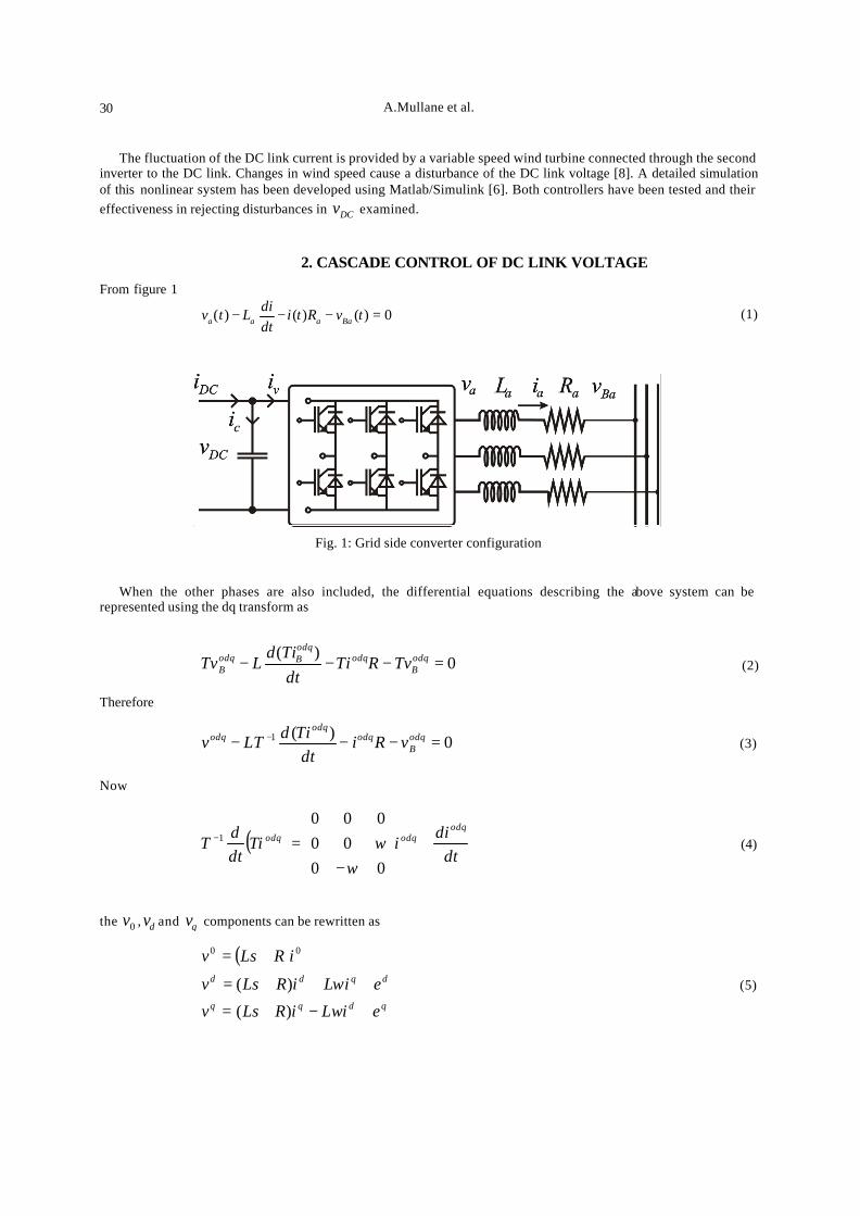
From figure 1
0)()()( =−−− tvRtidtdiLtv Baaaa
(1)
Fig. 1: Grid side converter configuration
When the other phases are also included, the differential equations describing the above system can be represented using the dq transform as
0)(
=−−− odqB
odqodqBodq
B TvRTidt
TidLTv (2)
Therefore
0)(1 =−−− − odqB
odqodq
odq vRidt
TidLTv (3)
Now
( )dt
diiTi
dtd
Todq
odqodq +
−=−
0000
0001
ωω (4)
the 0v , dv and qv components can be rewritten as
( )
qdqq
dqdd
eiLiRLsv
eiLiRLsv
iRLsv
+−+=
+++=
+=
ω
ω
)(
)(
00
(5)
UPEC : Comparison of a Cascade and Feedback Linearisation…. 31
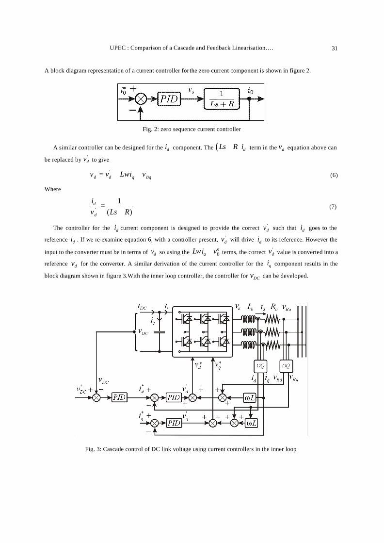
A block diagram representation of a current controller for the zero current component is shown in figure 2.
Fig. 2: zero sequence current controller
A similar controller can be designed for the di component. The ( ) dLs R i+ term in the dv equation above can
be replaced by 'dv to give
Bqqdd viLvv ++= ω' (6)
Where
)(1
' RLsvi
d
d
+= (7)
The controller for the di current component is designed to provide the correct 'dv such that di goes to the
reference di . If we re-examine equation 6, with a controller present, 'dv will drive di to its reference. However the
input to the converter must be in terms of dv so using the q
q BL i vω + terms, the correct 'dv value is converted into a
reference dv for the converter. A similar derivation of the current controller for the qi component results in the
block diagram shown in figure 3.With the inner loop controller, the controller for DCv can be developed.
Fig. 3: Cascade control of DC link voltage using current controllers in the inner loop
A.Mullane et al. 32
2.1. Power balance between DC link and output side of converter The total power in the DC link is given by DCi DCv neglecting losses this equals the total phase power on the
three phase side of the converter, and for a balanced system can be shown to equal
)(3
221
qqdd viviK
P += (8)
where 1K is a scaling term used in the dq transformation. Also form figure 1
dtdv
Ci DCc = (9)
DCv viP = (10)
cDCv iii −= (11)
Writing P in terms of DCi and DCv gives
)(1
DCDC
DC
vP
iCdt
dv−= (12)
With the reference frame aligned to the voltage v in figure 1, the 0v and qv terms in equation 8 disappear and the
power equation reduces to.
)(3
221
dd viK
P = (13)
The nonlinear model of the DC link equations results.
−=DC
dd
DCDC
v
viK
iCdt
dv)(
32
1 21 (14)
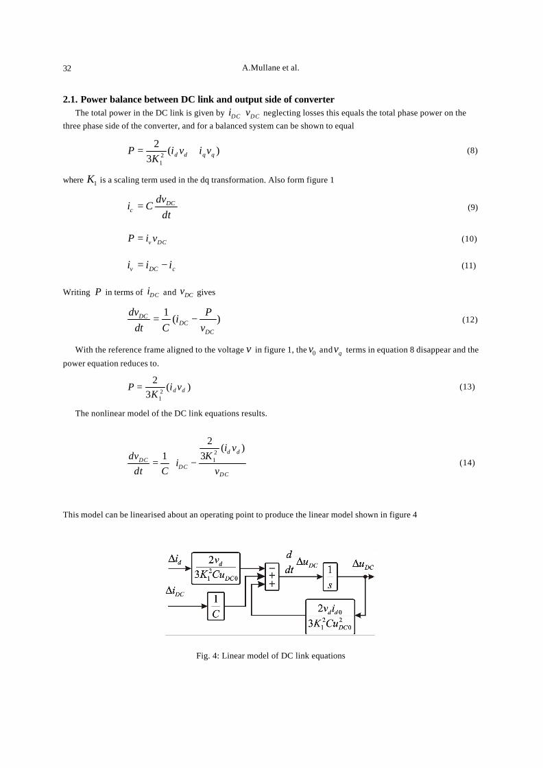
This model can be linearised about an operating point to produce the linear model shown in figure 4
Fig. 4: Linear model of DC link equations
UPEC : Comparison of a Cascade and Feedback Linearisation…. 33
The first term in this block diagram accounts for the current taken from the capacitor due to the di component of the drive. The second term accounts for the current added to the capacitor due to the current flowing from the turbine to the dc link. The third component accounts for the current change due to dc voltage variation [5] this component shows a positive feedback, which may cause stability problems. Using 690dv = , 2
1 3K = , 41 10C −= × ,
0 1100DCv V= and 0 500DCi A= , a controller was designed for the linear model shown in figure 4 using the root-
locus method. The controller was designed to reject a current disturbance and return the dc link voltage to its set-point in 15ms .
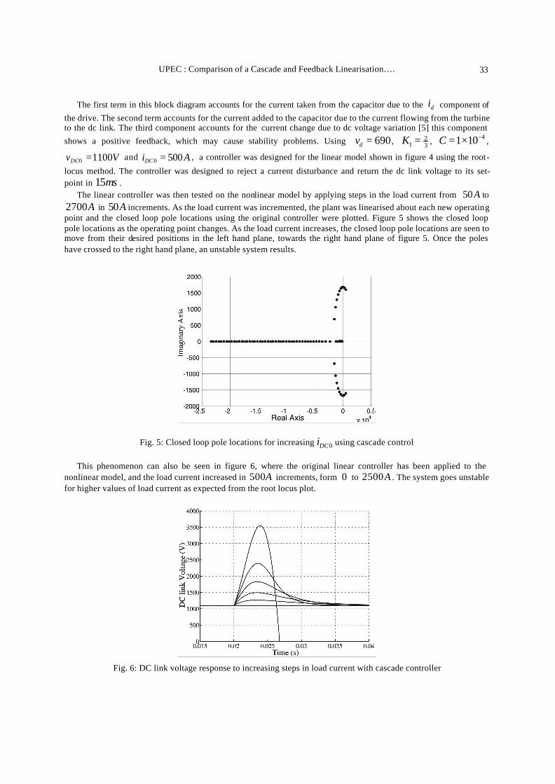
The linear controller was then tested on the nonlinear model by applying steps in the load current from 50A to 2700A in 50A increments. As the load current was incremented, the plant was linearised about each new operating point and the closed loop pole locations using the original controller were plotted. Figure 5 shows the closed loop pole locations as the operating point changes. As the load current increases, the closed loop pole locations are seen to move from their desired positions in the left hand plane, towards the right hand plane of figure 5. Once the poles have crossed to the right hand plane, an unstable system results.
Fig. 5: Closed loop pole locations for increasing 0DCi using cascade control
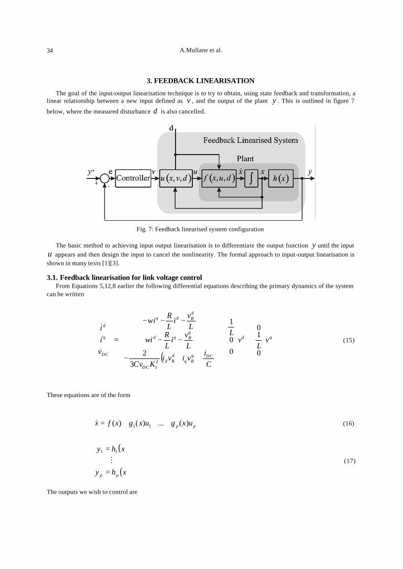
This phenomenon can also be seen in figure 6, where the original linear controller has been applied to the nonlinear model, and the load current increased in 500A increments, form 0 to 2500A . The system goes unstable for higher values of load current as expected from the root locus plot.
Fig. 6: DC link voltage response to increasing steps in load current with cascade controller
A.Mullane et al. 34
3. FEEDBACK LINEARISATION
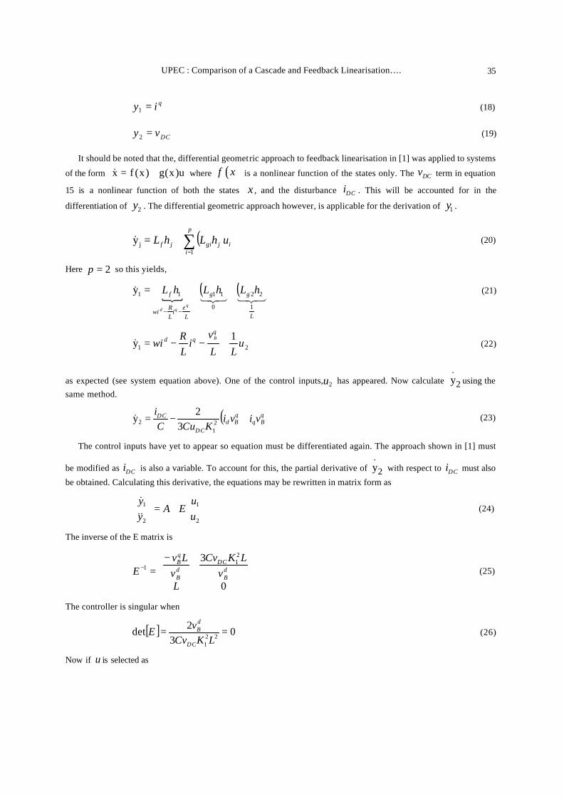
The goal of the input-output linearisation technique is to try to obtain, using state feedback and transformation, a linear relationship between a new input defined as v , and the output of the plant y . This is outlined in figure 7
below, where the measured disturbance d is also cancelled.
Fig. 7: Feedback linearised system configuration
The basic method to achieving input output linearisation is to differentiate the output function y until the input
u appears and then design the input to cancel the nonlinearity. The formal approach to input-output linearisation is shown in many texts [1][3]. 3.1. Feedback linearisation for link voltage control
From Equations 5,12,8 earlier the following differential equations describing the primary dynamics of the system can be written
( )
qd
DCqBq
dBd
DC
qBqd
dBdq
DC
q
d
vL
vL
Ci
viviKCv
Lv
iLR
i
Lv
iLR
i
vii
+
+
++−
−−
−−−
=
0
10
00
1
32
21
ω
ω
&
&
&
(15)
These equations are of the form
pp uxguxgxfx )(...)()( 11 +++=& (16)
( )
( )xhy
xhy
pp =
=M
11
(17)
The outputs we wish to control are
UPEC : Comparison of a Cascade and Feedback Linearisation…. 35
qiy =1 (18)
DCvy =2 (19)
It should be noted that the, differential geometric approach to feedback linearisation in [1] was applied to systems
of the form u)x(g)x(fx +=& where ( )f x is a nonlinear function of the states only. The DCv term in equation
15 is a nonlinear function of both the states x , and the disturbance DCi . This will be accounted for in the
differentiation of 2y . The differential geometric approach however, is applicable for the derivation of 1y .
( ) i
p
ijgijf uhLhL ∑
=
+=1
jy& (20)
Here 2p = so this yields,
{( ) ( )
321321&
L
gg
Le
iLR
i
f hLhLhLq
qd 1
22
0
1111y ++=
−−ω
(21)
21
1y u
LL
vi
LR
iq
qd B
+−−= ω& (22)
as expected (see system equation above). One of the control inputs, 2u has appeared. Now calculate 2
.y using the
same method.
( )qBq
qBd
DC
DC viviKCuC
i+−= 2
12 3
2y& (23)
The control inputs have yet to appear so equation must be differentiated again. The approach shown in [1] must
be modified as DCi is also a variable. To account for this, the partial derivative of 2
.y with respect to DCi must also
be obtained. Calculating this derivative, the equations may be rewritten in matrix form as
+=
2
1
2
1
uu
EAyy&&&
(24)
The inverse of the E matrix is
−=−
0
3 21
1
Lv
LKCvv
LvE d
B
DCdB
qB
(25)
The controller is singular when
[ ] 03
2det 221
==LKCv
vEDC
dB (26)
Now if u is selected as
A.Mullane et al. 36
[ ]
+−=
−
1
11
1
1
vv
AEuu
(27)
the following equations result
=
=
2
1
2
1
vv
vi
yy
DC
q
&&
&
&&&
(28)
Now by choosing the values of 1v and 2v we can shape the error dynamics. First examine 1e
11 yye ref &&& −= (29)
We design the error dynamics to be convergent and stable
01 =+ eke& (30)
This is achieved by choosing of 1v as
1111 ekyv ref += & (31)
For the other input
ekekyv ref 3212 ++= &&& (32)
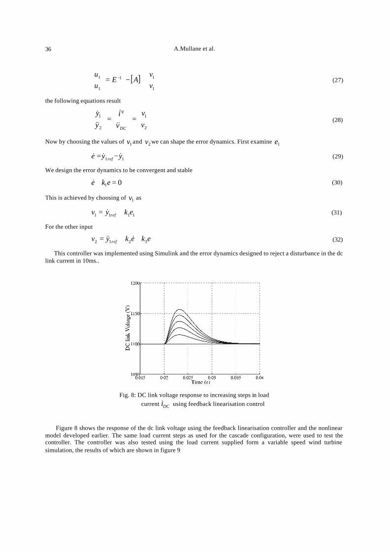
This controller was implemented using Simulink and the error dynamics designed to reject a disturbance in the dc link current in 10ms..
Fig. 8: DC link voltage response to increasing steps in load current DCi using feedback linearisation control
Figure 8 shows the response of the dc link voltage using the feedback linearisation controller and the nonlinear
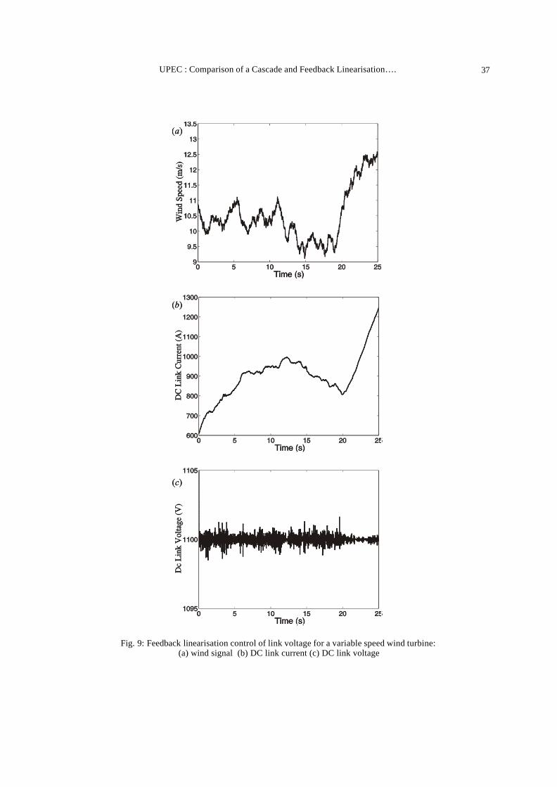
model developed earlier. The same load current steps as used for the cascade configuration, were used to test the controller. The controller was also tested using the load current supplied form a variable speed wind turbine simulation, the results of which are shown in figure 9
UPEC : Comparison of a Cascade and Feedback Linearisation…. 37
Fig. 9: Feedback linearisation control of link voltage for a variable speed wind turbine: (a) wind signal (b) DC link current (c) DC link voltage
A.Mullane et al. 38
4. CONCLUSION
This paper describes the development of cascade and feedback linearisation controllers for dc link voltage control in back to back IGBT inverters. The It can be seen that the linear cascade controller will only guarantee the desired closed loop response at the operating point for which the controller was designed. In the real system as the parameters DCv and DCi change, the transfer function for the system also changes, and the controller can no longer
guarantee the same closed loop response. As the model changes, the closed loop poles move and it is possible that the system model deviates so much, that the closed loop poles move to the unstable region. Therefore using the cascade configuration, control over the dc link voltage can only be guaranteed if the disturbance or set-point changes, cause the system to deviate little from the operating point for which the controller was designed. The feedback linearisation controller however results in a stable system across the operating space used in the test. The dc link voltage returns to its set-point in 15ms as the operating point changes. The feedback linearisation controller was also applied to a variable speed wind turbine model, and satisfactory control of the DC Link voltage was achieved. Acknowledgements - The support from the Electricity Supply Board (ESB) is gratefully acknowledged. Also the author would like to thank Simon Grimes of ESB for his useful comments.
REFERENCES [1] Jean-Jacques E. Slotine, “Applied Nonlinear Control ”, Prentice-Hall, Englewood Cliffs, New Jersy, 1 edition, 1991. [2] Siegfried Heier, “Wind Energy Conversion Systems”, Wiley, 1996. [3] Hassan K. Khalil, “Nonlinear Systems”, Prentice-Hall, Upper Saddle River, New Jersy, 2 edition, 1996. [4] Dong-Choon Lee, “DC-bus Voltage Control of Three-Phase AC/DC PWM Converters Using Feedback Linearization”, IEEE
Transactions on Industry Applications, 36(3):826–833, May/June 2000. [5] Leopoldo Rossetto Luigi Malesani, ‘‘AC/DC/AC PWM Converter With Reduced Energy Storage in the DC Link”, IEEE
Trans. on Industry Applications, 31(2):287–292, 1995. [6] Chee-Mun Ong, “Dynamic Simulation of Electric Machinery”, Prentice Hall, 1998. [7] B. Dewan R. Wu, ‘‘Analysis of an ac-to-dc Voltage Source Converter Using PWM with Phase and Amplitude Control”, IEEE
Transactions on Industry Applications, 27(2):355–363, 1991. [8] R. Chedid, “Intelligent Control for Wind Energy Conv ersion Systems”, Wind Engineering, 22(1):1–16, 1998. [9] R. Pena, ‘‘Doubly Fed Induction Generator Using Back-to-Back PWM Converters and its Application To Variable Speed
Wind Energy Generation’’, IEE Proc. Electr. Power Appl., 143(3):231–241, May 1996. [10] Y.Iwaji S.Fukuda and T.Aoyama, ‘‘Modelling and Control of Sinusoidal PWM Rectifiers”, Proc. EPE, pages 115–120, Sept.
1993.