Comparative Study of Dual PM Vernier Machines - MDPI
16
Article Comparative Study of Dual PM Vernier Machines Huan Qu 1 , Zi Qiang Zhu 1, *, Toru Matsuura 2 , Dusan Ivanovic 2 , Takashi Kato 2 , Kensuke Sasaki 2 , Jim Greenough 2 , Bob Bateman 2 , David A. Stone 1 , Martin P. Foster 1 and Javier Riedemann 1 Citation: Qu, H.; Zhu, Z.Q.; Matsuura, T.; Ivanovic, D.; Kato, T.; Sasaki, K.; Greenough, J.; Bateman, B.; Stone, D.A.; Foster, M.P.; et al. Comparative Study of Dual PM Vernier Machines. World Electr. Veh. J. 2021, 12, 12. https://doi.org/ 10.3390/wevj12010012 Received: 30 December 2020 Accepted: 8 January 2021 Published: 12 January 2021 Publisher’s Note: MDPI stays neu- tral with regard to jurisdictional clai- ms in published maps and institutio- nal affiliations. Copyright: © 2021 by the authors. Li- censee MDPI, Basel, Switzerland. This article is an open access article distributed under the terms and con- ditions of the Creative Commons At- tribution (CC BY) license (https:// creativecommons.org/licenses/by/ 4.0/). 1 Department of Electronic and Electrical Engineering, University of Sheffield, Mappin Street, Sheffield S1 3JD, UK; hqu2@sheffield.ac.uk (H.Q.); d.a.stone@sheffield.ac.uk (D.A.S.); m.p.foster@sheffield.ac.uk (M.P.F.); j.riedemann@sheffield.ac.uk (J.R.) 2 Research & Advanced Engineering, Nissan Technical Centre Europe, Cranfield Technology Park, Cranfield MK43 0DB, UK; [email protected] (T.M.); [email protected] (D.I.); [email protected] (T.K.); [email protected] (K.S.); [email protected] (J.G.); [email protected] (B.B.) * Correspondence: z.q.zhu@sheffield.ac.uk; Tel.: +44-(0)114-222-5195 Abstract: In this paper, two types of dual permanent magnet (PM) machines, i.e., stator slot dual- PM (SSDPM) machine and split-tooth dual-PM (STDPM) machine, are investigated and compared. Both machines have consequent pole structure with Halbach array PMs. Their difference lies in the position of stator PM. The SSDPM machine has Halbach array PMs in the stator slots, while the STDPM machine has PMs between the split teeth. Torque characteristics, i.e., average torques and torque ripples, of different slot/pole number combinations of the two machines are compared. The 24 stator slots/20 rotor slots/4 armature pole pair (24S20R4Pa) SSDPM machine with distributed windings and the 24 stator slots/10 rotor slots/4 armature pole pair (12S20R4Pa) STDPM machine with concentrated windings are compared under both open-circuit and on-load conditions. The re- sults show that the SSDPM machine is more competitive by delivering higher torque density and higher power density. Keywords: dual permanent magnet (PM); electric vehicle (EV); flux modulation; Halbach PM array 1. Introduction Recently, flux modulation (FM) machines have been widely investigated due to their high torque density [1–5]. They can be a strong competitor for interior permanent magnet (IPM) machines. Research shows that different FM machines, i.e., flux-switching permanent magnet (PM) (FSPM) machines, flux reversal PM (FRPM) machines, doubly salient PM (DSPM) machines, vernier PM (VPM) machines, magnetically geared machines, etc., share the same operation principle, i.e., magnetic gearing effect or flux modulation effect [6–9]. The FM machines can also be categorified by PM positions and stator/rotor numbers: stator PM FM machines that have PMs in the stator [10–14], rotor PM FM machines that have PMs in the rotor [15,16], dual-PM FM machines that have PMs in both the rotor and stator [5,17–22], dual stator/single rotor FM machines that have two stators and one single rotor [4,23–28], dual rotor/single stator FM machines that have two rotors and one stator [1–3,29], triple rotor/dual stator FM machines that have three rotors and two stators [30], etc. Stator PM FM machines include FSPM machines, FRPM machines, and DSPM ma- chines [10–14]. FSPM machines have better flux-focusing effect than the other two types of machines. Stator PM machines have easier heat management if a forced liquid cooling is employed. This means that the electric loading can be further increased to improve the torque density. Rotor PM FM machines mainly refer to VPM machines, which can produce high torque at low speed, albeit with poor power factor [15,16]. To further enhance the torque density, dual stator/single rotor [4,23–28], dual ro- tor/single stator [1–3,29], and multi stator/multi rotor [30] PM machines are proposed and World Electr. Veh. J. 2021, 12, 12. https://doi.org/10.3390/wevj12010012 https://www.mdpi.com/journal/wevj
-
Upload
khangminh22 -
Category
Documents
-
view
3 -
download
0
Transcript of Comparative Study of Dual PM Vernier Machines - MDPI
Article
Comparative Study of Dual PM Vernier Machines
Huan Qu 1, Zi Qiang Zhu 1,*, Toru Matsuura 2, Dusan Ivanovic 2, Takashi Kato 2, Kensuke Sasaki 2,Jim Greenough 2, Bob Bateman 2, David A. Stone 1, Martin P. Foster 1 and Javier Riedemann 1
�����������������
Citation: Qu, H.; Zhu, Z.Q.;
Matsuura, T.; Ivanovic, D.; Kato, T.;
Sasaki, K.; Greenough, J.; Bateman, B.;
Stone, D.A.; Foster, M.P.; et al.
Comparative Study of Dual PM
Vernier Machines. World Electr. Veh. J.
2021, 12, 12. https://doi.org/
10.3390/wevj12010012
Received: 30 December 2020
Accepted: 8 January 2021
Published: 12 January 2021
Publisher’s Note: MDPI stays neu-
tral with regard to jurisdictional clai-
ms in published maps and institutio-
nal affiliations.
Copyright: © 2021 by the authors. Li-
censee MDPI, Basel, Switzerland.
This article is an open access article
distributed under the terms and con-
ditions of the Creative Commons At-
tribution (CC BY) license (https://
creativecommons.org/licenses/by/
4.0/).
1 Department of Electronic and Electrical Engineering, University of Sheffield, Mappin Street,Sheffield S1 3JD, UK; [email protected] (H.Q.); [email protected] (D.A.S.);[email protected] (M.P.F.); [email protected] (J.R.)
2 Research & Advanced Engineering, Nissan Technical Centre Europe, Cranfield Technology Park,Cranfield MK43 0DB, UK; [email protected] (T.M.); [email protected] (D.I.);[email protected] (T.K.); [email protected] (K.S.);[email protected] (J.G.); [email protected] (B.B.)
* Correspondence: [email protected]; Tel.: +44-(0)114-222-5195
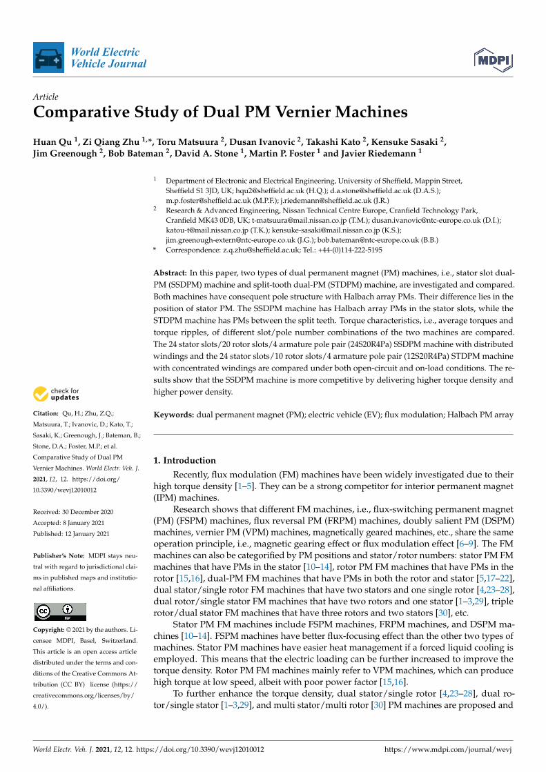
Abstract: In this paper, two types of dual permanent magnet (PM) machines, i.e., stator slot dual-PM (SSDPM) machine and split-tooth dual-PM (STDPM) machine, are investigated and compared.Both machines have consequent pole structure with Halbach array PMs. Their difference lies in theposition of stator PM. The SSDPM machine has Halbach array PMs in the stator slots, while theSTDPM machine has PMs between the split teeth. Torque characteristics, i.e., average torques andtorque ripples, of different slot/pole number combinations of the two machines are compared.The 24 stator slots/20 rotor slots/4 armature pole pair (24S20R4Pa) SSDPM machine with distributedwindings and the 24 stator slots/10 rotor slots/4 armature pole pair (12S20R4Pa) STDPM machinewith concentrated windings are compared under both open-circuit and on-load conditions. The re-sults show that the SSDPM machine is more competitive by delivering higher torque density andhigher power density.
Keywords: dual permanent magnet (PM); electric vehicle (EV); flux modulation; Halbach PM array
1. Introduction
Recently, flux modulation (FM) machines have been widely investigated due to theirhigh torque density [1–5]. They can be a strong competitor for interior permanent magnet(IPM) machines.
Research shows that different FM machines, i.e., flux-switching permanent magnet(PM) (FSPM) machines, flux reversal PM (FRPM) machines, doubly salient PM (DSPM)machines, vernier PM (VPM) machines, magnetically geared machines, etc., share the sameoperation principle, i.e., magnetic gearing effect or flux modulation effect [6–9]. The FMmachines can also be categorified by PM positions and stator/rotor numbers: stator PM FMmachines that have PMs in the stator [10–14], rotor PM FM machines that have PMs in therotor [15,16], dual-PM FM machines that have PMs in both the rotor and stator [5,17–22],dual stator/single rotor FM machines that have two stators and one single rotor [4,23–28],dual rotor/single stator FM machines that have two rotors and one stator [1–3,29], triplerotor/dual stator FM machines that have three rotors and two stators [30], etc.
Stator PM FM machines include FSPM machines, FRPM machines, and DSPM ma-chines [10–14]. FSPM machines have better flux-focusing effect than the other two types ofmachines. Stator PM machines have easier heat management if a forced liquid cooling isemployed. This means that the electric loading can be further increased to improve thetorque density. Rotor PM FM machines mainly refer to VPM machines, which can producehigh torque at low speed, albeit with poor power factor [15,16].
To further enhance the torque density, dual stator/single rotor [4,23–28], dual ro-tor/single stator [1–3,29], and multi stator/multi rotor [30] PM machines are proposed and
World Electr. Veh. J. 2021, 12, 12. https://doi.org/10.3390/wevj12010012 https://www.mdpi.com/journal/wevj

World Electr. Veh. J. 2021, 12, 12 2 of 16
developed, albeit with complex structures. Dual-PM machines can also help to increasethe torque density significantly due to torque contribution by both stator PM and rotorPM [5,17–22].
In this paper, two types of dual-PM machines, i.e., stator slot dual-PM (SSDPM)machine and split-tooth dual-PM (STDPM) machine, together with consequent pole ro-tors, are investigated and compared. On one hand, they can deliver very high torque.More importantly, since there is only one airgap, they have much simpler structures thandual-stator/dual-rotor machines. The working principle, slot/pole number combination,together with comparison of two dual-PM machines, will be discussed. Figure 1 shows theSSDPM machine with 24 stator slots/20 rotor slots/4 armature pole pair (24S20R4Pa) andsplit-tooth dual-PM (STDPM) machine with (12S20R4Pa).
World Electric Vehicle Journal 2020, 11, x FOR PEER REVIEW 2 of 16
developed, albeit with complex structures. Dual-PM machines can also help to increase the torque density significantly due to torque contribution by both stator PM and rotor PM [5,17–22].
In this paper, two types of dual-PM machines, i.e., stator slot dual-PM (SSDPM) ma-chine and split-tooth dual-PM (STDPM) machine, together with consequent pole rotors, are investigated and compared. On one hand, they can deliver very high torque. More importantly, since there is only one airgap, they have much simpler structures than dual-stator/dual-rotor machines. The working principle, slot/pole number combination, to-gether with comparison of two dual-PM machines, will be discussed. Figure 1 shows the SSDPM machine with 24 stator slots/20 rotor slots/4 armature pole pair (24S20R4Pa) and split-tooth dual-PM (STDPM) machine with (12S20R4Pa).
(a) (b)
Figure 1. Machine topologies of dual permanent magnet (PM) machines. (a) 24S20R4Pa stator slot dual-PM (SSDPM) ma-chine; (b) 12S20R4Pa split-tooth dual-PM (STDPM) machine.
2. Machine Topologies and Working Principle 2.1. Machine Topology
In [5], the dual-PM machine employs radially magnetized PMs in both the rotor slots and the stator slots. Article [20] improves the dual-PM machine by replacing the radially magnetized stator PMs with Halbach PMs. In this paper, to further enhance the torque density, dual Halbach PMs are employed in the SSDPM machine, as shown in Figure 1a. Both the rotor PM and stator PM are Halbach PM arrays.
The STDPM machines also employ Halbach PM array in the rotor slots, but with ra-dially magnetized PMs between the split teeth [17].
2.2. Working Principle For the dual-PM machines, the torque can be attributed to two parts: rotor PM and
stator PM. The 12S11R1Pa SSDPM machine and 12S23R1Pa STDPM machine are taken as examples to explain the machine decomposition, as shown in Figures 2 and 3. The key design dimensions are shown in Figure 4. The design details are given in Tables 1 and 2.
A+A
-
HalbachMagnets
Stator
Rotor
Halbach Magnetization
Stator
Rotor
Radial magnetization
Figure 1. Machine topologies of dual permanent magnet (PM) machines. (a) 24S20R4Pa stator slot dual-PM (SSDPM)machine; (b) 12S20R4Pa split-tooth dual-PM (STDPM) machine.
2. Machine Topologies and Working Principle2.1. Machine Topology
In [5], the dual-PM machine employs radially magnetized PMs in both the rotor slotsand the stator slots. Article [20] improves the dual-PM machine by replacing the radiallymagnetized stator PMs with Halbach PMs. In this paper, to further enhance the torquedensity, dual Halbach PMs are employed in the SSDPM machine, as shown in Figure 1a.Both the rotor PM and stator PM are Halbach PM arrays.
The STDPM machines also employ Halbach PM array in the rotor slots, but withradially magnetized PMs between the split teeth [17].
2.2. Working Principle
For the dual-PM machines, the torque can be attributed to two parts: rotor PM andstator PM. The 12S11R1Pa SSDPM machine and 12S23R1Pa STDPM machine are taken asexamples to explain the machine decomposition, as shown in Figures 2 and 3. The keydesign dimensions are shown in Figure 4. The design details are given in Tables 1 and 2.

World Electr. Veh. J. 2021, 12, 12 3 of 16
World Electric Vehicle Journal 2020, 11, x FOR PEER REVIEW 3 of 16
Figure 2. Machine decomposition of 12S11R1Pa SSDPM machine.
Figure 3. Machine decomposition of 12S23R1Pa STDPM machine.
(a) SSDPM machine (b) STDPM machine
Figure 4. Key design dimensions of dual-PM machines. (a) SSDPM machine; (b) STDPM machine.
On one hand, when the stator PMs are set as air, they become vernier PM machines and split-tooth vernier PM machines, and the slot/pole number combinations comply with the Equation (1) [31] and Equation (2) [32], respectively.
Nr = Ns ± Pa, (1)
Nr = nNs ± Pa, (2)
in which Ns is the stator slot number, Nr is the rotor slot number, Pa is the armature pole pair number, n is the split tooth number which is larger than 1.
On the other hand, when the rotor PMs are set as air, they become flux reversal PM machines, and the slot/pole number combinations also comply with the above-mentioned equations. Hence, the slot/pole number combinations of dual-PM machines comply with (1) and (2). To calculate the torque decomposition of dual-PM machines, linear material is employed, and the relative permeability is set as 50, considering the overload capability.
r3yk
twr1
gh1
w1hal
w2h2
w2hal
r3yk
twr1
gh1
w1 w1
w2h2
w2hal ht
Figure 2. Machine decomposition of 12S11R1Pa SSDPM machine.
World Electric Vehicle Journal 2020, 11, x FOR PEER REVIEW 3 of 16
Figure 2. Machine decomposition of 12S11R1Pa SSDPM machine.
Figure 3. Machine decomposition of 12S23R1Pa STDPM machine.
(a) SSDPM machine (b) STDPM machine
Figure 4. Key design dimensions of dual-PM machines. (a) SSDPM machine; (b) STDPM machine.
On one hand, when the stator PMs are set as air, they become vernier PM machines and split-tooth vernier PM machines, and the slot/pole number combinations comply with the Equation (1) [31] and Equation (2) [32], respectively.
Nr = Ns ± Pa, (1)
Nr = nNs ± Pa, (2)
in which Ns is the stator slot number, Nr is the rotor slot number, Pa is the armature pole pair number, n is the split tooth number which is larger than 1.
On the other hand, when the rotor PMs are set as air, they become flux reversal PM machines, and the slot/pole number combinations also comply with the above-mentioned equations. Hence, the slot/pole number combinations of dual-PM machines comply with (1) and (2). To calculate the torque decomposition of dual-PM machines, linear material is employed, and the relative permeability is set as 50, considering the overload capability.
r3yk
twr1
gh1
w1hal
w2h2
w2hal
r3yk
twr1
gh1
w1 w1
w2h2
w2hal ht
Figure 3. Machine decomposition of 12S23R1Pa STDPM machine.
World Electric Vehicle Journal 2020, 11, x FOR PEER REVIEW 3 of 16
Figure 2. Machine decomposition of 12S11R1Pa SSDPM machine.
Figure 3. Machine decomposition of 12S23R1Pa STDPM machine.
(a) SSDPM machine (b) STDPM machine
Figure 4. Key design dimensions of dual-PM machines. (a) SSDPM machine; (b) STDPM machine.
On one hand, when the stator PMs are set as air, they become vernier PM machines and split-tooth vernier PM machines, and the slot/pole number combinations comply with the Equation (1) [31] and Equation (2) [32], respectively.
Nr = Ns ± Pa, (1)
Nr = nNs ± Pa, (2)
in which Ns is the stator slot number, Nr is the rotor slot number, Pa is the armature pole pair number, n is the split tooth number which is larger than 1.
On the other hand, when the rotor PMs are set as air, they become flux reversal PM machines, and the slot/pole number combinations also comply with the above-mentioned equations. Hence, the slot/pole number combinations of dual-PM machines comply with (1) and (2). To calculate the torque decomposition of dual-PM machines, linear material is employed, and the relative permeability is set as 50, considering the overload capability.
r3yk
twr1
gh1
w1hal
w2h2
w2hal
r3yk
twr1
gh1
w1 w1
w2h2
w2hal ht
Figure 4. Key design dimensions of dual-PM machines. (a) SSDPM machine; (b) STDPM machine.
On one hand, when the stator PMs are set as air, they become vernier PM machinesand split-tooth vernier PM machines, and the slot/pole number combinations comply withthe Equation (1) [31] and Equation (2) [32], respectively.
Nr = Ns ± Pa, (1)
Nr = nNs ± Pa, (2)
in which Ns is the stator slot number, Nr is the rotor slot number, Pa is the armature polepair number, n is the split tooth number which is larger than 1.
On the other hand, when the rotor PMs are set as air, they become flux reversal PMmachines, and the slot/pole number combinations also comply with the above-mentionedequations. Hence, the slot/pole number combinations of dual-PM machines comply with
World Electr. Veh. J. 2021, 12, 12 4 of 16
(1) and (2). To calculate the torque decomposition of dual-PM machines, linear material isemployed, and the relative permeability is set as 50, considering the overload capability.
Before discussing detailed results, it should be mentioned that the torque, power, ironloss, power factor, back EMF, etc., are all normalized due to confidentiality. As shown inFigure 5, for the 12S11R1Pa SSDPM machine, the rotor PM machine and the stator PMmachine produce 0.515 p.u. and 0.335 p.u. torque, respectively. The dual-PM machinedelivers 1.7% lower torque than the sum of the rotor PM machine and the stator PMmachine. This is mainly due to that the flux leakage increases when the rotor PM and statorPM are working together. Similarly, for the 12S23R1Pa STDPM machine, the dual-PMmachine produces 1.5% lower torque than the sum of the corresponding rotor PM machineand stator PM machine, as shown in Figure 6.
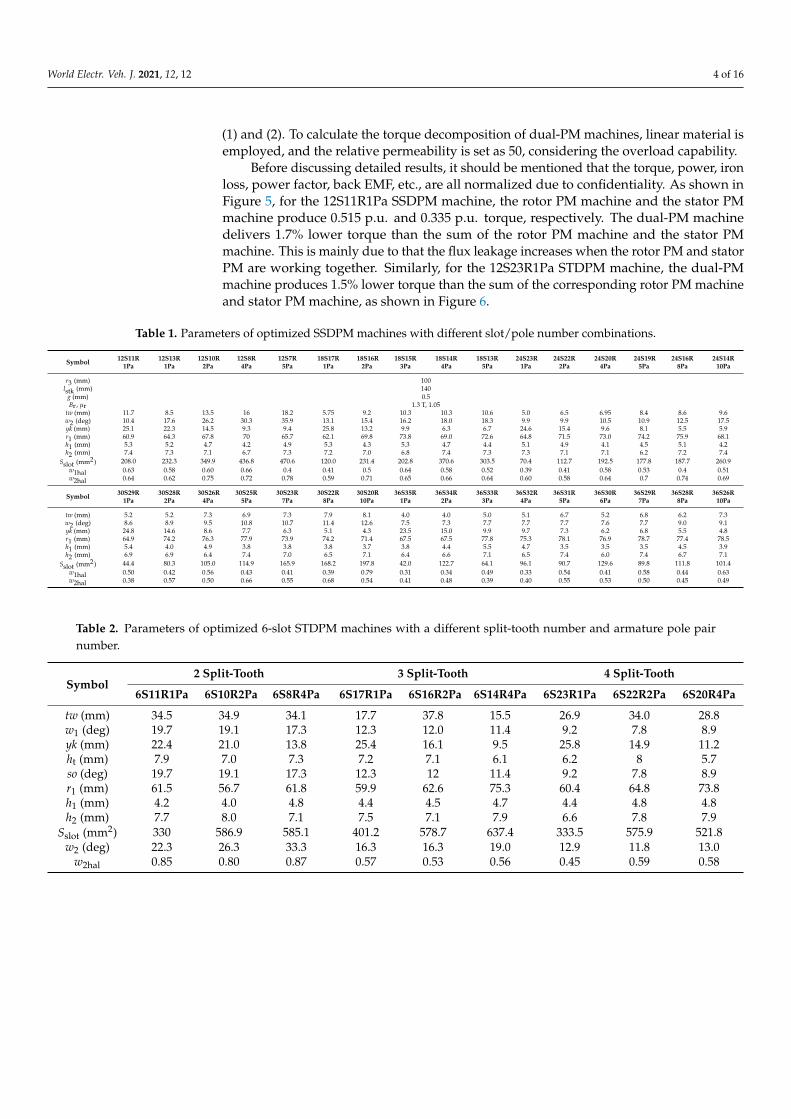
Table 1. Parameters of optimized SSDPM machines with different slot/pole number combinations.
Symbol 12S11R 12S13R 12S10R 12S8R 12S7R 18S17R 18S16R 18S15R 18S14R 18S13R 24S23R 24S22R 24S20R 24S19R 24S16R 24S14R1Pa 1Pa 2Pa 4Pa 5Pa 1Pa 2Pa 3Pa 4Pa 5Pa 1Pa 2Pa 4Pa 5Pa 8Pa 10Pa
r3 (mm) 100lstk (mm) 140
g (mm) 0.5Br , µr 1.3 T, 1.05
tw (mm) 11.7 8.5 13.5 16 18.2 5.75 9.2 10.3 10.3 10.6 5.0 6.5 6.95 8.4 8.6 9.6w2 (deg) 10.4 17.6 26.2 30.3 35.9 13.1 15.4 16.2 18.0 18.3 9.9 9.9 10.5 10.9 12.5 17.5yk (mm) 25.1 22.3 14.5 9.3 9.4 25.8 13.2 9.9 6.3 6.7 24.6 15.4 9.6 8.1 5.5 5.9r1 (mm) 60.9 64.3 67.8 70 65.7 62.1 69.8 73.8 69.0 72.6 64.8 71.5 73.0 74.2 75.9 68.1h1 (mm) 5.3 5.2 4.7 4.2 4.9 5.3 4.3 5.3 4.7 4.4 5.1 4.9 4.1 4.5 5.1 4.2h2 (mm) 7.4 7.3 7.1 6.7 7.3 7.2 7.0 6.8 7.4 7.3 7.3 7.1 7.1 6.2 7.2 7.4
Sslot (mm2) 208.0 232.3 349.9 436.8 470.6 120.0 231.4 202.8 370.6 303.5 70.4 112.7 192.5 177.8 187.7 260.9w1hal 0.63 0.58 0.60 0.66 0.4 0.41 0.5 0.64 0.58 0.52 0.39 0.41 0.58 0.53 0.4 0.51w2hal 0.64 0.62 0.75 0.72 0.78 0.59 0.71 0.65 0.66 0.64 0.60 0.58 0.64 0.7 0.74 0.69
Symbol 30S29R 30S28R 30S26R 30S25R 30S23R 30S22R 30S20R 36S35R 36S34R 36S33R 36S32R 36S31R 36S30R 36S29R 36S28R 36S26R1Pa 2Pa 4Pa 5Pa 7Pa 8Pa 10Pa 1Pa 2Pa 3Pa 4Pa 5Pa 6Pa 7Pa 8Pa 10Pa
tw (mm) 5.2 5.2 7.3 6.9 7.3 7.9 8.1 4.0 4.0 5.0 5.1 6.7 5.2 6.8 6.2 7.3w2 (deg) 8.6 8.9 9.5 10.8 10.7 11.4 12.6 7.5 7.3 7.7 7.7 7.7 7.6 7.7 9.0 9.1yk (mm) 24.8 14.6 8.6 7.7 6.3 5.1 4.3 23.5 15.0 9.9 9.7 7.3 6.2 6.8 5.5 4.8r1 (mm) 64.9 74.2 76.3 77.9 73.9 74.2 71.4 67.5 67.5 77.8 75.3 78.1 76.9 78.7 77.4 78.5h1 (mm) 5.4 4.0 4.9 3.8 3.8 3.8 3.7 3.8 4.4 5.5 4.7 3.5 3.5 3.5 4.5 3.9h2 (mm) 6.9 6.9 6.4 7.4 7.0 6.5 7.1 6.4 6.6 7.1 6.5 7.4 6.0 7.4 6.7 7.1
Sslot (mm2) 44.4 80.3 105.0 114.9 165.9 168.2 197.8 42.0 122.7 64.1 96.1 90.7 129.6 89.8 111.8 101.4w1hal 0.50 0.42 0.56 0.43 0.41 0.39 0.79 0.31 0.34 0.49 0.33 0.54 0.41 0.58 0.44 0.63w2hal 0.38 0.57 0.50 0.66 0.55 0.68 0.54 0.41 0.48 0.39 0.40 0.55 0.53 0.50 0.45 0.49
Table 2. Parameters of optimized 6-slot STDPM machines with a different split-tooth number and armature pole pairnumber.
Symbol2 Split-Tooth 3 Split-Tooth 4 Split-Tooth
6S11R1Pa 6S10R2Pa 6S8R4Pa 6S17R1Pa 6S16R2Pa 6S14R4Pa 6S23R1Pa 6S22R2Pa 6S20R4Pa
tw (mm) 34.5 34.9 34.1 17.7 37.8 15.5 26.9 34.0 28.8w1 (deg) 19.7 19.1 17.3 12.3 12.0 11.4 9.2 7.8 8.9yk (mm) 22.4 21.0 13.8 25.4 16.1 9.5 25.8 14.9 11.2ht (mm) 7.9 7.0 7.3 7.2 7.1 6.1 6.2 8 5.7so (deg) 19.7 19.1 17.3 12.3 12 11.4 9.2 7.8 8.9r1 (mm) 61.5 56.7 61.8 59.9 62.6 75.3 60.4 64.8 73.8h1 (mm) 4.2 4.0 4.8 4.4 4.5 4.7 4.4 4.8 4.8h2 (mm) 7.7 8.0 7.1 7.5 7.1 7.9 6.6 7.8 7.9
Sslot (mm2) 330 586.9 585.1 401.2 578.7 637.4 333.5 575.9 521.8w2 (deg) 22.3 26.3 33.3 16.3 16.3 19.0 12.9 11.8 13.0
w2hal 0.85 0.80 0.87 0.57 0.53 0.56 0.45 0.59 0.58

World Electr. Veh. J. 2021, 12, 12 5 of 16
World Electric Vehicle Journal 2020, 11, x FOR PEER REVIEW 4 of 16
Before discussing detailed results, it should be mentioned that the torque, power, iron loss, power factor, back EMF, etc., are all normalized due to confidentiality. As shown in Figure 5, for the 12S11R1Pa SSDPM machine, the rotor PM machine and the stator PM machine produce 0.515 p.u. and 0.335 p.u. torque, respectively. The dual-PM machine de-livers 1.7% lower torque than the sum of the rotor PM machine and the stator PM machine. This is mainly due to that the flux leakage increases when the rotor PM and stator PM are working together. Similarly, for the 12S23R1Pa STDPM machine, the dual-PM machine produces 1.5% lower torque than the sum of the corresponding rotor PM machine and stator PM machine, as shown in Figure 6.
Figure 5. Torque decomposition of 12S11R1Pa SSDPM machine when relative permeability is 50.
Table 1. Parameters of optimized SSDPM machines with different slot/pole number combinations.
Symbol 12S11R 12S13R 12S10R 12S8R 12S7R 18S17R 18S16R 18S15R 18S14R 18S13R 24S23R 24S22R 24S20R 24S19R 24S16R 24S14R 1Pa 1Pa 2Pa 4Pa 5Pa 1Pa 2Pa 3Pa 4Pa 5Pa 1Pa 2Pa 4Pa 5Pa 8Pa 10Pa
r3 (mm) 100 lstk (mm) 140 g (mm) 0.5 Br, µr 1.3 T, 1.05
tw (mm) 11.7 8.5 13.5 16 18.2 5.75 9.2 10.3 10.3 10.6 5.0 6.5 6.95 8.4 8.6 9.6 w2 (deg) 10.4 17.6 26.2 30.3 35.9 13.1 15.4 16.2 18.0 18.3 9.9 9.9 10.5 10.9 12.5 17.5 yk (mm) 25.1 22.3 14.5 9.3 9.4 25.8 13.2 9.9 6.3 6.7 24.6 15.4 9.6 8.1 5.5 5.9 r1 (mm) 60.9 64.3 67.8 70 65.7 62.1 69.8 73.8 69.0 72.6 64.8 71.5 73.0 74.2 75.9 68.1 h1 (mm) 5.3 5.2 4.7 4.2 4.9 5.3 4.3 5.3 4.7 4.4 5.1 4.9 4.1 4.5 5.1 4.2 h2 (mm) 7.4 7.3 7.1 6.7 7.3 7.2 7.0 6.8 7.4 7.3 7.3 7.1 7.1 6.2 7.2 7.4
Sslot (mm2)
208.0 232.3 349.9 436.8 470.6 120.0 231.4 202.8 370.6 303.5 70.4 112.7 192.5 177.8 187.7 260.9
w1hal 0.63 0.58 0.60 0.66 0.4 0.41 0.5 0.64 0.58 0.52 0.39 0.41 0.58 0.53 0.4 0.51 w2hal 0.64 0.62 0.75 0.72 0.78 0.59 0.71 0.65 0.66 0.64 0.60 0.58 0.64 0.7 0.74 0.69
Symbol 30S29R 30S28R 30S26R 30S25R 30S23R 30S22R 30S20R 36S35R 36S34R 36S33R 36S32R 36S31R 36S30R 36S29R 36S28R 36S26R 1Pa 2Pa 4Pa 5Pa 7Pa 8Pa 10Pa 1Pa 2Pa 3Pa 4Pa 5Pa 6Pa 7Pa 8Pa 10Pa
tw (mm) 5.2 5.2 7.3 6.9 7.3 7.9 8.1 4.0 4.0 5.0 5.1 6.7 5.2 6.8 6.2 7.3 w2 (deg) 8.6 8.9 9.5 10.8 10.7 11.4 12.6 7.5 7.3 7.7 7.7 7.7 7.6 7.7 9.0 9.1 yk (mm) 24.8 14.6 8.6 7.7 6.3 5.1 4.3 23.5 15.0 9.9 9.7 7.3 6.2 6.8 5.5 4.8 r1 (mm) 64.9 74.2 76.3 77.9 73.9 74.2 71.4 67.5 67.5 77.8 75.3 78.1 76.9 78.7 77.4 78.5 h1 (mm) 5.4 4.0 4.9 3.8 3.8 3.8 3.7 3.8 4.4 5.5 4.7 3.5 3.5 3.5 4.5 3.9 h2 (mm) 6.9 6.9 6.4 7.4 7.0 6.5 7.1 6.4 6.6 7.1 6.5 7.4 6.0 7.4 6.7 7.1
Sslot (mm2)
44.4 80.3 105.0 114.9 165.9 168.2 197.8 42.0 122.7 64.1 96.1 90.7 129.6 89.8 111.8 101.4
w1hal 0.50 0.42 0.56 0.43 0.41 0.39 0.79 0.31 0.34 0.49 0.33 0.54 0.41 0.58 0.44 0.63 w2hal 0.38 0.57 0.50 0.66 0.55 0.68 0.54 0.41 0.48 0.39 0.40 0.55 0.53 0.50 0.45 0.49
0 60 120 180 240 300 3600.0
0.3
0.6
0.9
1.2
0.335
0.515
Dual PM Rotor PM Stator PM
Nor
mal
ized
torq
ue
Rotor position (elec.deg.)
0.836
Figure 5. Torque decomposition of 12S11R1Pa SSDPM machine when relative permeability is 50.
World Electric Vehicle Journal 2020, 11, x FOR PEER REVIEW 5 of 16
Table 2. Parameters of optimized 6-slot STDPM machines with a different split-tooth number and armature pole pair number.
Symbol 2 Split-Tooth 3 Split-Tooth 4 Split-Tooth
6S11R1Pa 6S10R2Pa 6S8R4Pa 6S17R1Pa 6S16R2Pa 6S14R4Pa 6S23R1Pa 6S22R2Pa 6S20R4Pa tw (mm) 34.5 34.9 34.1 17.7 37.8 15.5 26.9 34.0 28.8 w1 (deg) 19.7 19.1 17.3 12.3 12.0 11.4 9.2 7.8 8.9 yk (mm) 22.4 21.0 13.8 25.4 16.1 9.5 25.8 14.9 11.2 ht (mm) 7.9 7.0 7.3 7.2 7.1 6.1 6.2 8 5.7 so (deg) 19.7 19.1 17.3 12.3 12 11.4 9.2 7.8 8.9 r1 (mm) 61.5 56.7 61.8 59.9 62.6 75.3 60.4 64.8 73.8 h1 (mm) 4.2 4.0 4.8 4.4 4.5 4.7 4.4 4.8 4.8 h2 (mm) 7.7 8.0 7.1 7.5 7.1 7.9 6.6 7.8 7.9
Sslot (mm2) 330 586.9 585.1 401.2 578.7 637.4 333.5 575.9 521.8 w2 (deg) 22.3 26.3 33.3 16.3 16.3 19.0 12.9 11.8 13.0
w2hal 0.85 0.80 0.87 0.57 0.53 0.56 0.45 0.59 0.58
Figure 6. Torque decomposition of 12S23R1Pa STDPM machine when relative permeability is 50.
3. Influence of Rotor Slot Number As shown in (1) and (2), when the stator slot number and armature pole pair number
are fixed, the rotor slot number can be chosen as Ns + Pa and Ns − Pa for SSDPM machine, and nNs + Pa and nNs − Pa for STDPM machine. To compare the effect of rotor slot number selection, 12S1Pa SSDPM machines with 11R and 13R, 12S1Pa STDPM machine with 23R and 25R are investigated, respectively, as shown in Figures 7 and 8.
(a) 12S11R1Pa (b) 12S13R1Pa
Figure 7. Twelve-stator-slot SSDPM machines with a different rotor slot number. (a) 12S11R1Pa; (b) 12S13R1Pa.
0 60 120 180 240 300 3600.0
0.3
0.6
0.9
1.2
Dual PM Rotor PM Stator PM
Nor
mal
ized
torq
ue
Rotor position (elec.deg.)
0.907
0.685
0.236
Figure 6. Torque decomposition of 12S23R1Pa STDPM machine when relative permeability is 50.
3. Influence of Rotor Slot Number
As shown in (1) and (2), when the stator slot number and armature pole pair numberare fixed, the rotor slot number can be chosen as Ns + Pa and Ns − Pa for SSDPM machine,and nNs + Pa and nNs − Pa for STDPM machine. To compare the effect of rotor slot numberselection, 12S1Pa SSDPM machines with 11R and 13R, 12S1Pa STDPM machine with 23Rand 25R are investigated, respectively, as shown in Figures 7 and 8.
For fair comparison, all the investigated machine topologies are globally optimized formaximum torque under the same stator outer diameter, stack length, copper loss (120 ◦C)(copper loss is set according to the thermal restriction). All the optimizations are basedon Genetic Algorithm (GA), and 30 individuals in each population with 35 generationshave been employed. Tables 1 and 3 list the key design dimensions. In addition, the endwinding length is calculated by the following equation:
lend = yπ2(r3 − yk − 0.5sh)/Ns, (3)
in which y is the slot pitch, r3 is the stator outer radius, yk is the stator yoke width, sh isslot height.
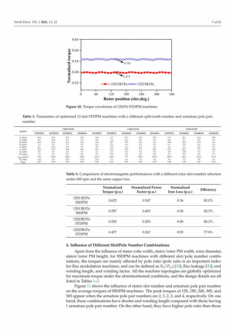
Figures 9 and 10 show that when the rotor slot number is selected lower than thestator slot number, higher torque can be produced. More importantly, higher power factor,lower iron loss, and higher efficiency can also be achieved with lower rotor slot number, aslisted in Table 4, due to lower electrical frequency.

World Electr. Veh. J. 2021, 12, 12 6 of 16
World Electric Vehicle Journal 2020, 11, x FOR PEER REVIEW 5 of 16
Table 2. Parameters of optimized 6-slot STDPM machines with a different split-tooth number and armature pole pair number.
Symbol 2 Split-Tooth 3 Split-Tooth 4 Split-Tooth
6S11R1Pa 6S10R2Pa 6S8R4Pa 6S17R1Pa 6S16R2Pa 6S14R4Pa 6S23R1Pa 6S22R2Pa 6S20R4Pa tw (mm) 34.5 34.9 34.1 17.7 37.8 15.5 26.9 34.0 28.8 w1 (deg) 19.7 19.1 17.3 12.3 12.0 11.4 9.2 7.8 8.9 yk (mm) 22.4 21.0 13.8 25.4 16.1 9.5 25.8 14.9 11.2 ht (mm) 7.9 7.0 7.3 7.2 7.1 6.1 6.2 8 5.7 so (deg) 19.7 19.1 17.3 12.3 12 11.4 9.2 7.8 8.9 r1 (mm) 61.5 56.7 61.8 59.9 62.6 75.3 60.4 64.8 73.8 h1 (mm) 4.2 4.0 4.8 4.4 4.5 4.7 4.4 4.8 4.8 h2 (mm) 7.7 8.0 7.1 7.5 7.1 7.9 6.6 7.8 7.9
Sslot (mm2) 330 586.9 585.1 401.2 578.7 637.4 333.5 575.9 521.8 w2 (deg) 22.3 26.3 33.3 16.3 16.3 19.0 12.9 11.8 13.0
w2hal 0.85 0.80 0.87 0.57 0.53 0.56 0.45 0.59 0.58
Figure 6. Torque decomposition of 12S23R1Pa STDPM machine when relative permeability is 50.
3. Influence of Rotor Slot Number As shown in (1) and (2), when the stator slot number and armature pole pair number
are fixed, the rotor slot number can be chosen as Ns + Pa and Ns − Pa for SSDPM machine, and nNs + Pa and nNs − Pa for STDPM machine. To compare the effect of rotor slot number selection, 12S1Pa SSDPM machines with 11R and 13R, 12S1Pa STDPM machine with 23R and 25R are investigated, respectively, as shown in Figures 7 and 8.
(a) 12S11R1Pa (b) 12S13R1Pa
Figure 7. Twelve-stator-slot SSDPM machines with a different rotor slot number. (a) 12S11R1Pa; (b) 12S13R1Pa.
0 60 120 180 240 300 3600.0
0.3
0.6
0.9
1.2
Dual PM Rotor PM Stator PM
Nor
mal
ized
torq
ue
Rotor position (elec.deg.)
0.907
0.685
0.236
Figure 7. Twelve-stator-slot SSDPM machines with a different rotor slot number. (a) 12S11R1Pa; (b) 12S13R1Pa.World Electric Vehicle Journal 2020, 11, x FOR PEER REVIEW 6 of 16
(a) (b)
Figure 8. Twelve-stator-slot STDPM machines with a different rotor slot number. (a) 12S23R1Pa; (b) 12S25R1Pa.
For fair comparison, all the investigated machine topologies are globally optimized for maximum torque under the same stator outer diameter, stack length, copper loss (120 °C) (copper loss is set according to the thermal restriction). All the optimizations are based on Genetic Algorithm (GA), and 30 individuals in each population with 35 generations have been employed. Tables 1 and 3 list the key design dimensions. In addition, the end winding length is calculated by the following equation:
lend = yπ2(r3 − yk − 0.5sh)/Ns, (3)
in which y is the slot pitch, r3 is the stator outer radius, yk is the stator yoke width, sh is slot height.
Figures 9 and 10 show that when the rotor slot number is selected lower than the stator slot number, higher torque can be produced. More importantly, higher power factor, lower iron loss, and higher efficiency can also be achieved with lower rotor slot number, as listed in Table 4, due to lower electrical frequency.
Figure 9. Torque waveforms of 12S1Pa SSDPM machines.
0 60 120 180 240 300 3600.55
0.60
0.65
0.70
12S13R1Pa 12S11R1Pa
Nor
mal
ized
torq
ue
Rotor position (elec.deg.)
0.625
0.597
Figure 8. Twelve-stator-slot STDPM machines with a different rotor slot number. (a) 12S23R1Pa; (b) 12S25R1Pa.
World Electric Vehicle Journal 2020, 11, x FOR PEER REVIEW 6 of 16
(a) (b)
Figure 8. Twelve-stator-slot STDPM machines with a different rotor slot number. (a) 12S23R1Pa; (b) 12S25R1Pa.
For fair comparison, all the investigated machine topologies are globally optimized for maximum torque under the same stator outer diameter, stack length, copper loss (120 °C) (copper loss is set according to the thermal restriction). All the optimizations are based on Genetic Algorithm (GA), and 30 individuals in each population with 35 generations have been employed. Tables 1 and 3 list the key design dimensions. In addition, the end winding length is calculated by the following equation:
lend = yπ2(r3 − yk − 0.5sh)/Ns, (3)
in which y is the slot pitch, r3 is the stator outer radius, yk is the stator yoke width, sh is slot height.
Figures 9 and 10 show that when the rotor slot number is selected lower than the stator slot number, higher torque can be produced. More importantly, higher power factor, lower iron loss, and higher efficiency can also be achieved with lower rotor slot number, as listed in Table 4, due to lower electrical frequency.
Figure 9. Torque waveforms of 12S1Pa SSDPM machines.
0 60 120 180 240 300 3600.55
0.60
0.65
0.70
12S13R1Pa 12S11R1Pa
Nor
mal
ized
torq
ue
Rotor position (elec.deg.)
0.625
0.597
Figure 9. Torque waveforms of 12S1Pa SSDPM machines.
World Electr. Veh. J. 2021, 12, 12 7 of 16
World Electric Vehicle Journal 2020, 11, x FOR PEER REVIEW 7 of 16
Figure 10. Torque waveforms of 12S1Pa STDPM machines.
Table 3. Parameters of optimized 12-slot STDPM machines with a different split-tooth number and armature pole pair number.
Symbol 2 Split-Tooth 3 Split-Tooth 4 Split-Tooth
12S23R1Pa12S25R1Pa12S22R2Pa12S20R4Pa12S19R5Pa12S35R1Pa12S34R2Pa12S32R4Pa12S31R5Pa12S47R1Pa12S46R2Pa12S44R4Pa12S43R5Patw (mm) 14.6 19.9 18.6 22.2 23.0 6.7 21.7 22.1 22.4 11.7 16.1 21.8 15.8 w1 (deg) 8.6 10.4 8.9 8.3 9.4 6.4 6.6 6.2 6.0 4.6 4.1 4.2 3.8 yk (mm) 24.3 22.6 16.1 12.4 12.0 24.7 17.4 10.2 11.1 24.4 18.9 12.2 8.6 ht (mm) 7.6 6.5 7.5 8.1 6.8 6.5 7.6 6.9 5.9 6.1 5.8 6.6 5.4 so (deg) 8.6 10.4 8.9 8.3 9.4 6.4 6.6 6.2 6.0 4.6 4.1 4.2 3.8 r1 (mm) 59.3 61.2 64.8 66.9 69.1 61.4 65.5 71.7 68.7 61.0 64.5 73.1 73.4 h1 (mm) 3.8 4.9 4.6 4.5 4.1 4.6 4.2 3.0 3.0 4.9 2.60 3.6 3.2 h2 (mm) 7.7 6.3 7.6 5.6 7.6 5.8 7.0 6.7 8.0 3.7 5.9 6.9 7.6
Sslot (mm2) 190 168.2 248.2 246.2 231.3 210.9 173 235.6 281.8 205.8 242.3 167.8 351.4 w2 (deg) 12.6 9.9 12.9 13.4 12.6 7.5 6.9 7.6 7.8 6.1 5.5 5.8 6.3
w2hal 0.47 0.58 0.52 0.47 0.54 0.41 0.57 0.69 0.58 0.49 0.49 0.47 0.42
Table 4. Comparison of electromagnetic performances with a different rotor slot number selection under 600 rpm and the same copper loss.
Normalized
Torque (p.u.) Normalized Power
Factor (p.u.) Normalized Iron
Loss (p.u.) Efficiency
12S11R1Pa 0.625 0.547 0.36 83.0%
SSDPM 12S13R1Pa
0.597 0.493 0.38 82.3% SSDPM
12S23R1Pa 0.550 0.293 0.89 80.3%
STDPM 12S25R1Pa
0.477 0.267 0.95 77.8% STDPM
4. Influence of Different Slot/Pole Number Combinations Apart from the influence of stator yoke width, stator/rotor PM width, rotor diameter,
stator/rotor PM height, for SSDPM machines with different slot/pole number combina-tions, the torques are mainly affected by pole ratio (pole ratio is an important index for flux modulation machines, and can be defined as Nr/Pa.) [33], flux leakage [33], end wind-ing length, and winding factor. All the machine topologies are globally optimized for max-imum torque under the aforementioned conditions, and the design details are all listed in Tables 1–3.
Figure 11 shows the influence of stator slot number and armature pole pair number on the average torques of SSDPM machines. The peak torques of 12S, 18S, 24S, 30S, and 36S appear when the armature pole pair numbers are 2, 3, 2, 2, and 4, respectively. On one hand, these combinations have shorter end winding length compared with those having 1 armature pole pair number. On the other hand, they have higher pole ratio than those
0 60 120 180 240 300 360
0.42
0.48
0.54
0.60
0.66
12S25R1Pa 12S23R1PaNor
mal
ized
torq
ue
Rotor position (elec.deg.)
0.550
0.477
Figure 10. Torque waveforms of 12S1Pa STDPM machines.
Table 3. Parameters of optimized 12-slot STDPM machines with a different split-tooth number and armature pole pairnumber.
Symbol2 Split-Tooth 3 Split-Tooth 4 Split-Tooth
12S23R1Pa 12S25R1Pa 12S22R2Pa 12S20R4Pa 12S19R5Pa 12S35R1Pa 12S34R2Pa 12S32R4Pa 12S31R5Pa 12S47R1Pa 12S46R2Pa 12S44R4Pa 12S43R5Pa
tw (mm) 14.6 19.9 18.6 22.2 23.0 6.7 21.7 22.1 22.4 11.7 16.1 21.8 15.8w1 (deg) 8.6 10.4 8.9 8.3 9.4 6.4 6.6 6.2 6.0 4.6 4.1 4.2 3.8yk (mm) 24.3 22.6 16.1 12.4 12.0 24.7 17.4 10.2 11.1 24.4 18.9 12.2 8.6ht (mm) 7.6 6.5 7.5 8.1 6.8 6.5 7.6 6.9 5.9 6.1 5.8 6.6 5.4so (deg) 8.6 10.4 8.9 8.3 9.4 6.4 6.6 6.2 6.0 4.6 4.1 4.2 3.8r1 (mm) 59.3 61.2 64.8 66.9 69.1 61.4 65.5 71.7 68.7 61.0 64.5 73.1 73.4h1 (mm) 3.8 4.9 4.6 4.5 4.1 4.6 4.2 3.0 3.0 4.9 2.60 3.6 3.2h2 (mm) 7.7 6.3 7.6 5.6 7.6 5.8 7.0 6.7 8.0 3.7 5.9 6.9 7.6
Sslot (mm2) 190 168.2 248.2 246.2 231.3 210.9 173 235.6 281.8 205.8 242.3 167.8 351.4w2 (deg) 12.6 9.9 12.9 13.4 12.6 7.5 6.9 7.6 7.8 6.1 5.5 5.8 6.3
w2hal 0.47 0.58 0.52 0.47 0.54 0.41 0.57 0.69 0.58 0.49 0.49 0.47 0.42
Table 4. Comparison of electromagnetic performances with a different rotor slot number selectionunder 600 rpm and the same copper loss.
NormalizedTorque (p.u.)
Normalized PowerFactor (p.u.)
NormalizedIron Loss (p.u.) Efficiency
12S11R1Pa0.625 0.547 0.36 83.0%SSDPM
12S13R1Pa0.597 0.493 0.38 82.3%SSDPM
12S23R1Pa0.550 0.293 0.89 80.3%STDPM
12S25R1Pa0.477 0.267 0.95 77.8%STDPM
4. Influence of Different Slot/Pole Number Combinations
Apart from the influence of stator yoke width, stator/rotor PM width, rotor diameter,stator/rotor PM height, for SSDPM machines with different slot/pole number combi-nations, the torques are mainly affected by pole ratio (pole ratio is an important indexfor flux modulation machines, and can be defined as Nr/Pa.) [33], flux leakage [33], endwinding length, and winding factor. All the machine topologies are globally optimizedfor maximum torque under the aforementioned conditions, and the design details are alllisted in Tables 1–3.
Figure 11 shows the influence of stator slot number and armature pole pair numberon the average torques of SSDPM machines. The peak torques of 12S, 18S, 24S, 30S, and36S appear when the armature pole pair numbers are 2, 3, 2, 2, and 4, respectively. On onehand, these combinations have shorter end winding length compared with those having1 armature pole pair number. On the other hand, they have higher pole ratio than those
World Electr. Veh. J. 2021, 12, 12 8 of 16
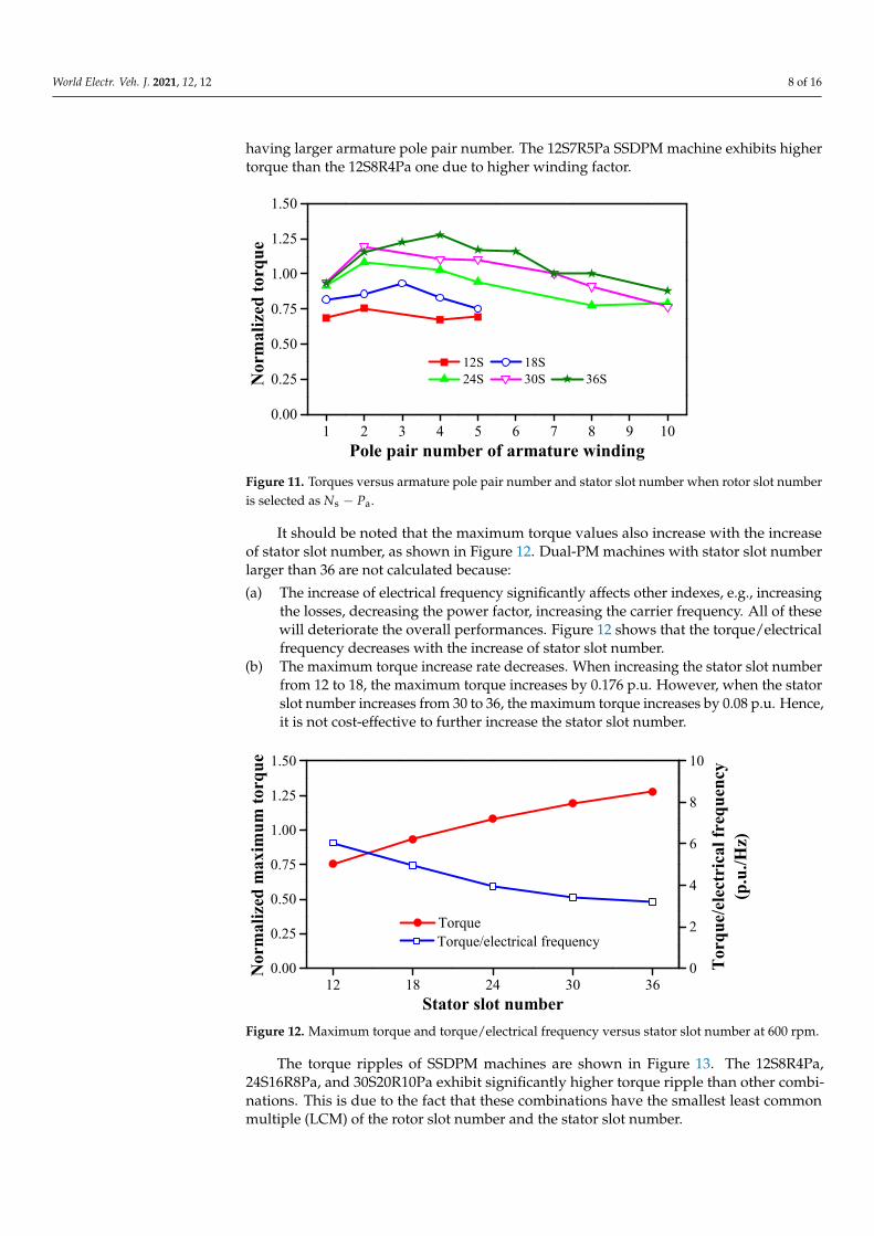
having larger armature pole pair number. The 12S7R5Pa SSDPM machine exhibits highertorque than the 12S8R4Pa one due to higher winding factor.
World Electric Vehicle Journal 2020, 11, x FOR PEER REVIEW 8 of 16
having larger armature pole pair number. The 12S7R5Pa SSDPM machine exhibits higher torque than the 12S8R4Pa one due to higher winding factor.
Figure 11. Torques versus armature pole pair number and stator slot number when rotor slot number is selected as Ns − Pa.
It should be noted that the maximum torque values also increase with the increase of stator slot number, as shown in Figure 12. Dual-PM machines with stator slot number larger than 36 are not calculated because: (a) The increase of electrical frequency significantly affects other indexes, e.g., increasing
the losses, decreasing the power factor, increasing the carrier frequency. All of these will deteriorate the overall performances. Figure 12 shows that the torque/electrical frequency decreases with the increase of stator slot number.
(b) The maximum torque increase rate decreases. When increasing the stator slot num-ber from 12 to 18, the maximum torque increases by 0.176 p.u. However, when the stator slot number increases from 30 to 36, the maximum torque increases by 0.08 p.u. Hence, it is not cost-effective to further increase the stator slot number.
Figure 12. Maximum torque and torque/electrical frequency versus stator slot number at 600 rpm.
The torque ripples of SSDPM machines are shown in Figure 13. The 12S8R4Pa, 24S16R8Pa, and 30S20R10Pa exhibit significantly higher torque ripple than other combi-nations. This is due to the fact that these combinations have the smallest least common multiple (LCM) of the rotor slot number and the stator slot number.
1 2 3 4 5 6 7 8 9 100.00
0.25
0.50
0.75
1.00
1.25
1.50
12S 18S 24S 30S 36SN
orm
aliz
ed to
rque
Pole pair number of armature winding
12 18 24 30 360.00
0.25
0.50
0.75
1.00
1.25
1.50
Torque
Nor
mal
ized
max
imum
torq
ue
Stator slot number
0
2
4
6
8
10
Torque/electrical frequency
Torq
ue/e
lect
rica
l fre
quen
cy(p
.u./H
z)
Figure 11. Torques versus armature pole pair number and stator slot number when rotor slot numberis selected as Ns − Pa.
It should be noted that the maximum torque values also increase with the increaseof stator slot number, as shown in Figure 12. Dual-PM machines with stator slot numberlarger than 36 are not calculated because:
(a) The increase of electrical frequency significantly affects other indexes, e.g., increasingthe losses, decreasing the power factor, increasing the carrier frequency. All of thesewill deteriorate the overall performances. Figure 12 shows that the torque/electricalfrequency decreases with the increase of stator slot number.
(b) The maximum torque increase rate decreases. When increasing the stator slot numberfrom 12 to 18, the maximum torque increases by 0.176 p.u. However, when the statorslot number increases from 30 to 36, the maximum torque increases by 0.08 p.u. Hence,it is not cost-effective to further increase the stator slot number.
World Electric Vehicle Journal 2020, 11, x FOR PEER REVIEW 8 of 16
having larger armature pole pair number. The 12S7R5Pa SSDPM machine exhibits higher torque than the 12S8R4Pa one due to higher winding factor.
Figure 11. Torques versus armature pole pair number and stator slot number when rotor slot number is selected as Ns − Pa.
It should be noted that the maximum torque values also increase with the increase of stator slot number, as shown in Figure 12. Dual-PM machines with stator slot number larger than 36 are not calculated because: (a) The increase of electrical frequency significantly affects other indexes, e.g., increasing
the losses, decreasing the power factor, increasing the carrier frequency. All of these will deteriorate the overall performances. Figure 12 shows that the torque/electrical frequency decreases with the increase of stator slot number.
(b) The maximum torque increase rate decreases. When increasing the stator slot num-ber from 12 to 18, the maximum torque increases by 0.176 p.u. However, when the stator slot number increases from 30 to 36, the maximum torque increases by 0.08 p.u. Hence, it is not cost-effective to further increase the stator slot number.
Figure 12. Maximum torque and torque/electrical frequency versus stator slot number at 600 rpm.
The torque ripples of SSDPM machines are shown in Figure 13. The 12S8R4Pa, 24S16R8Pa, and 30S20R10Pa exhibit significantly higher torque ripple than other combi-nations. This is due to the fact that these combinations have the smallest least common multiple (LCM) of the rotor slot number and the stator slot number.
1 2 3 4 5 6 7 8 9 100.00
0.25
0.50
0.75
1.00
1.25
1.50
12S 18S 24S 30S 36SN
orm
aliz
ed to
rque
Pole pair number of armature winding
12 18 24 30 360.00
0.25
0.50
0.75
1.00
1.25
1.50
Torque
Nor
mal
ized
max
imum
torq
ue
Stator slot number
0
2
4
6
8
10
Torque/electrical frequency
Torq
ue/e
lect
rica
l fre
quen
cy(p
.u./H
z)
Figure 12. Maximum torque and torque/electrical frequency versus stator slot number at 600 rpm.
The torque ripples of SSDPM machines are shown in Figure 13. The 12S8R4Pa,24S16R8Pa, and 30S20R10Pa exhibit significantly higher torque ripple than other combi-nations. This is due to the fact that these combinations have the smallest least commonmultiple (LCM) of the rotor slot number and the stator slot number.

World Electr. Veh. J. 2021, 12, 12 9 of 16
World Electric Vehicle Journal 2020, 11, x FOR PEER REVIEW 9 of 16
Figure 13. Torque ripples versus armature pole pair number and stator slot number when rotor slot number is selected as Ns − Pa.
Torques and torque ripples of STDPM machines are shown in Figures 14 and 15, re-spectively. Apart from the aforementioned influence factors, split-tooth number will in-crease the pole ratio, and thus affect the torque characteristics.
Figure 14. Torques versus stator slot number, armature pole pair number, and split-tooth number when rotor slot number is selected as nNs − Pa.
Figure 15. Torque ripples versus stator slot number, armature pole pair number, and split-tooth number when rotor slot number is selected as nNs − Pa.
1 2 3 4 5 6 7 8 9 100.0
0.1
0.2
0.3
0.4 12S 18S 24S 30S 36S
Torq
ue ri
pple
(%)
Pole pair number of armature winding
1 2 3 4 50.00.10.20.30.40.50.60.70.80.9
12S (2 split teeth) 12S (3 split teeth) 12S (4 split teeth) 6S (2 split teeth) 6S (3 split teeth) 6S (4 split teeth)
Nor
mal
ized
torq
ue
Pole pair number of armature winding
1 2 3 4 50.0
0.2
0.4
0.6
0.8 12S (2 split teeth) 12S (3 split teeth) 12S (4 split teeth) 6S (2 split teeth) 6S (3 split teeth) 6S (4 split teeth)
Torq
ue r
ippl
e
Pole pair number of armature winding
Figure 13. Torque ripples versus armature pole pair number and stator slot number when rotor slotnumber is selected as Ns − Pa.
Torques and torque ripples of STDPM machines are shown in Figures 14 and 15,respectively. Apart from the aforementioned influence factors, split-tooth number willincrease the pole ratio, and thus affect the torque characteristics.
World Electric Vehicle Journal 2020, 11, x FOR PEER REVIEW 9 of 16
Figure 13. Torque ripples versus armature pole pair number and stator slot number when rotor slot number is selected as Ns − Pa.
Torques and torque ripples of STDPM machines are shown in Figures 14 and 15, re-spectively. Apart from the aforementioned influence factors, split-tooth number will in-crease the pole ratio, and thus affect the torque characteristics.
Figure 14. Torques versus stator slot number, armature pole pair number, and split-tooth number when rotor slot number is selected as nNs − Pa.
Figure 15. Torque ripples versus stator slot number, armature pole pair number, and split-tooth number when rotor slot number is selected as nNs − Pa.
1 2 3 4 5 6 7 8 9 100.0
0.1
0.2
0.3
0.4 12S 18S 24S 30S 36S
Torq
ue ri
pple
(%)
Pole pair number of armature winding
1 2 3 4 50.00.10.20.30.40.50.60.70.80.9
12S (2 split teeth) 12S (3 split teeth) 12S (4 split teeth) 6S (2 split teeth) 6S (3 split teeth) 6S (4 split teeth)
Nor
mal
ized
torq
ue
Pole pair number of armature winding
1 2 3 4 50.0
0.2
0.4
0.6
0.8 12S (2 split teeth) 12S (3 split teeth) 12S (4 split teeth) 6S (2 split teeth) 6S (3 split teeth) 6S (4 split teeth)
Torq
ue r
ippl
e
Pole pair number of armature winding
Figure 14. Torques versus stator slot number, armature pole pair number, and split-tooth numberwhen rotor slot number is selected as nNs − Pa.
World Electric Vehicle Journal 2020, 11, x FOR PEER REVIEW 9 of 16
Figure 13. Torque ripples versus armature pole pair number and stator slot number when rotor slot number is selected as Ns − Pa.
Torques and torque ripples of STDPM machines are shown in Figures 14 and 15, re-spectively. Apart from the aforementioned influence factors, split-tooth number will in-crease the pole ratio, and thus affect the torque characteristics.
Figure 14. Torques versus stator slot number, armature pole pair number, and split-tooth number when rotor slot number is selected as nNs − Pa.
Figure 15. Torque ripples versus stator slot number, armature pole pair number, and split-tooth number when rotor slot number is selected as nNs − Pa.
1 2 3 4 5 6 7 8 9 100.0
0.1
0.2
0.3
0.4 12S 18S 24S 30S 36S
Torq
ue ri
pple
(%)
Pole pair number of armature winding
1 2 3 4 50.00.10.20.30.40.50.60.70.80.9
12S (2 split teeth) 12S (3 split teeth) 12S (4 split teeth) 6S (2 split teeth) 6S (3 split teeth) 6S (4 split teeth)
Nor
mal
ized
torq
ue
Pole pair number of armature winding
1 2 3 4 50.0
0.2
0.4
0.6
0.8 12S (2 split teeth) 12S (3 split teeth) 12S (4 split teeth) 6S (2 split teeth) 6S (3 split teeth) 6S (4 split teeth)
Torq
ue r
ippl
e
Pole pair number of armature winding
Figure 15. Torque ripples versus stator slot number, armature pole pair number, and split-toothnumber when rotor slot number is selected as nNs − Pa.

World Electr. Veh. J. 2021, 12, 12 10 of 16
When the stator slot number is 6, increasing the split tooth number will increase thetorque. However, when the stator slot number is 12 and the armature pole number is 1,increasing the split tooth number does not increase the torque, due to the increased fluxleakage, as shown in Figure 16.
World Electric Vehicle Journal 2020, 11, x FOR PEER REVIEW 10 of 16
When the stator slot number is 6, increasing the split tooth number will increase the torque. However, when the stator slot number is 12 and the armature pole number is 1, increasing the split tooth number does not increase the torque, due to the increased flux leakage, as shown in Figure 16.
(a) (b) (c)
Figure 16. Flux line distributions of 12S1Pa STDPM machines with a different split tooth number at open-circuit condition. (a) 2 split teeth; (b) 3 split teeth; (c) 4 split teeth.
5. Comparison of Stator Slot Dual-PM Machine and Split Tooth Dual-PM Machine In this section, the 24S20R4Pa SSDPM machine with distributed windings and the
12S20R4Pa STDPM machine with concentrated windings, as shown in Figure 17, are com-pared. Employing split-tooth mainly helps to ease manufacturing and decrease end wind-ing length. These two combinations are chosen for comparison since they have the same armature pole pair number, rotor tooth number, pole ratio, stator outer diameter, and stack length. The design details of these two machines are listed in Tables 1 and 2.
(a) (b)
Figure 17. Topologies of two dual-PM machines. (a) 24S20R4Pa SSDPM machine; (b) 12S20R4Pa STDPM machine.
Figure 18 compares the torque waveforms of the two machines under the same cop-per loss (120 °C). The SSDPM machine can deliver 48% higher torque with 63.2% lower torque ripple compared with the STDPM machine.
Figure 16. Flux line distributions of 12S1Pa STDPM machines with a different split tooth number at open-circuit condition.(a) 2 split teeth; (b) 3 split teeth; (c) 4 split teeth.
5. Comparison of Stator Slot Dual-PM Machine and Split Tooth Dual-PM Machine
In this section, the 24S20R4Pa SSDPM machine with distributed windings and the12S20R4Pa STDPM machine with concentrated windings, as shown in Figure 17, arecompared. Employing split-tooth mainly helps to ease manufacturing and decrease endwinding length. These two combinations are chosen for comparison since they have thesame armature pole pair number, rotor tooth number, pole ratio, stator outer diameter, andstack length. The design details of these two machines are listed in Tables 1 and 2.
World Electric Vehicle Journal 2020, 11, x FOR PEER REVIEW 10 of 16
When the stator slot number is 6, increasing the split tooth number will increase the torque. However, when the stator slot number is 12 and the armature pole number is 1, increasing the split tooth number does not increase the torque, due to the increased flux leakage, as shown in Figure 16.
(a) (b) (c)
Figure 16. Flux line distributions of 12S1Pa STDPM machines with a different split tooth number at open-circuit condition. (a) 2 split teeth; (b) 3 split teeth; (c) 4 split teeth.
5. Comparison of Stator Slot Dual-PM Machine and Split Tooth Dual-PM Machine In this section, the 24S20R4Pa SSDPM machine with distributed windings and the
12S20R4Pa STDPM machine with concentrated windings, as shown in Figure 17, are com-pared. Employing split-tooth mainly helps to ease manufacturing and decrease end wind-ing length. These two combinations are chosen for comparison since they have the same armature pole pair number, rotor tooth number, pole ratio, stator outer diameter, and stack length. The design details of these two machines are listed in Tables 1 and 2.
(a) (b)
Figure 17. Topologies of two dual-PM machines. (a) 24S20R4Pa SSDPM machine; (b) 12S20R4Pa STDPM machine.
Figure 18 compares the torque waveforms of the two machines under the same cop-per loss (120 °C). The SSDPM machine can deliver 48% higher torque with 63.2% lower torque ripple compared with the STDPM machine.
Figure 17. Topologies of two dual-PM machines. (a) 24S20R4Pa SSDPM machine; (b) 12S20R4Pa STDPM machine.
Figure 18 compares the torque waveforms of the two machines under the same copperloss (120 ◦C). The SSDPM machine can deliver 48% higher torque with 63.2% lower torqueripple compared with the STDPM machine.

World Electr. Veh. J. 2021, 12, 12 11 of 16
World Electric Vehicle Journal 2020, 11, x FOR PEER REVIEW 11 of 16
Figure 18. Comparison of torque waveforms of two dual-PM machines under the same copper loss (120 °C).
In actual operation, both DC voltage and phase current are limited. Here, space vec-tor pulse width modulation (SVPWM) control strategy is employed. The turn number per slot is adjusted as 10. The parallel branch is adjusted to 2 and 1, for the SSDPM and STDPM machines, respectively.
Figure 19 shows the flux density distributions of the two compared dual-PM ma-chines at open circuit condition and load condition (Id = 0 and Iq = Imax). For the SSDPM and STDPM machines, the maximum flux density appears in the tooth and the split teeth, respectively, no matter what the condition is. In addition, slightly higher flux density can be observed in the yoke of the SSDPM machine at load condition. Despite this, the SSDPM exhibits better overload capability, which will be shown later. Hence, for both machines, the iron core material is fully utilized.
Figure 20 compares the back EMFs of the two dual-PM machines. The SSDPM ma-chine exhibits 40.4% higher fundamental harmonic, albeit with much higher 5th harmonic. The STDPM machine has obvious 2nd harmonic due to unbalanced PM magnetomotive force (MMF).
(a) (b)
0 60 120 180 240 300 3600.00
0.25
0.50
0.75
1.00
24S20R4Pa SSDPM 12S20R4Pa STDPMN
orm
aliz
ed to
rque
Rotor position (elec.deg.)
Torque 0.945Ripple 2.9%
Torque 0.638Ripple 8.0%
Figure 18. Comparison of torque waveforms of two dual-PM machines under the same copper loss(120 ◦C).
In actual operation, both DC voltage and phase current are limited. Here, space vectorpulse width modulation (SVPWM) control strategy is employed. The turn number per slotis adjusted as 10. The parallel branch is adjusted to 2 and 1, for the SSDPM and STDPMmachines, respectively.
Figure 19 shows the flux density distributions of the two compared dual-PM machinesat open circuit condition and load condition (Id = 0 and Iq = Imax). For the SSDPM andSTDPM machines, the maximum flux density appears in the tooth and the split teeth,respectively, no matter what the condition is. In addition, slightly higher flux density canbe observed in the yoke of the SSDPM machine at load condition. Despite this, the SSDPMexhibits better overload capability, which will be shown later. Hence, for both machines,the iron core material is fully utilized.
Figure 20 compares the back EMFs of the two dual-PM machines. The SSDPM machineexhibits 40.4% higher fundamental harmonic, albeit with much higher 5th harmonic. TheSTDPM machine has obvious 2nd harmonic due to unbalanced PM magnetomotive force(MMF).
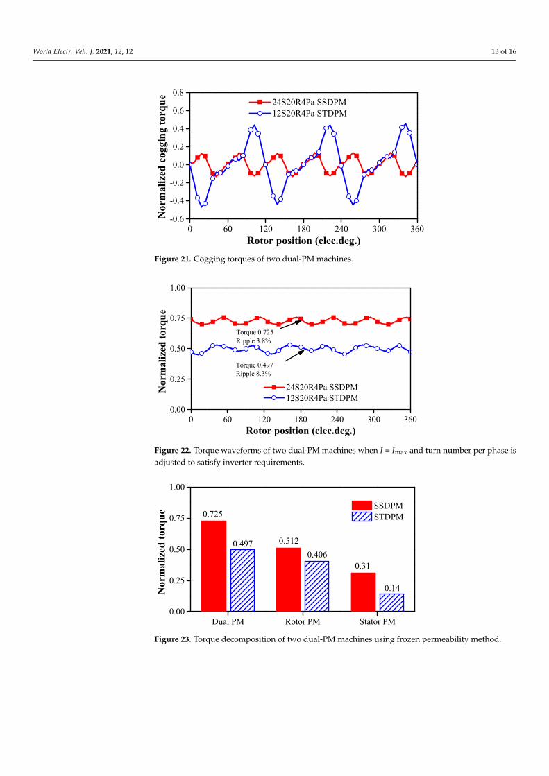
Figure 21 shows the cogging torques of the two compared machines. The coggingtorque of the STDPM machine is 3.6 times larger than the SSDPM machine, which explainsthe higher torque ripple in the STDPM machine. For the SSDPM and STDPM machines, thefluctuation frequency in one electrical period is 6 and 3, respectively. The higher amplitudeand lower fluctuation frequency of the cogging torque of the STDPM machine are mainlydue to its smaller least common multiple (LCM) of the stator slots and the rotor poles.
Figure 22 shows that the SSDPM machine produces 46% higher torque than theSTDPM machine, together with 51.7% lower torque ripple. This is due to the fact thatthe rotor PM and stator PM in the SSDPM machine produce 26% and 122% higher torquethan their counterparts, as shown in Figure 23. It can also be concluded that the stator PMmachine with Halbach array PMs in the stator slots can deliver much higher torque thanthat with PMs between split teeth.
Figure 24 shows that the SSDPM machine has better overload capability than theSTDPM machine. The overload capability can be indicated by inductance. The former hassmaller inductance than the latter. This is due to the fact that the inductance is inverselyproportional to the length of the flux path and the SSDPM has a longer flux path, as shownin Figure 19a,b. The torques/powers versus speed are calculated according to [33], andshown in Figure 25. The two dual-PM machines have similar corner speed. The SSDPMmachine can produce 50.3% higher power than its counterpart.

World Electr. Veh. J. 2021, 12, 12 12 of 16
World Electric Vehicle Journal 2020, 11, x FOR PEER REVIEW 11 of 16
Figure 18. Comparison of torque waveforms of two dual-PM machines under the same copper loss (120 °C).
In actual operation, both DC voltage and phase current are limited. Here, space vec-tor pulse width modulation (SVPWM) control strategy is employed. The turn number per slot is adjusted as 10. The parallel branch is adjusted to 2 and 1, for the SSDPM and STDPM machines, respectively.
Figure 19 shows the flux density distributions of the two compared dual-PM ma-chines at open circuit condition and load condition (Id = 0 and Iq = Imax). For the SSDPM and STDPM machines, the maximum flux density appears in the tooth and the split teeth, respectively, no matter what the condition is. In addition, slightly higher flux density can be observed in the yoke of the SSDPM machine at load condition. Despite this, the SSDPM exhibits better overload capability, which will be shown later. Hence, for both machines, the iron core material is fully utilized.
Figure 20 compares the back EMFs of the two dual-PM machines. The SSDPM ma-chine exhibits 40.4% higher fundamental harmonic, albeit with much higher 5th harmonic. The STDPM machine has obvious 2nd harmonic due to unbalanced PM magnetomotive force (MMF).
(a) (b)
0 60 120 180 240 300 3600.00
0.25
0.50
0.75
1.00
24S20R4Pa SSDPM 12S20R4Pa STDPMN
orm
aliz
ed to
rque
Rotor position (elec.deg.)
Torque 0.945Ripple 2.9%
Torque 0.638Ripple 8.0%
World Electric Vehicle Journal 2020, 11, x FOR PEER REVIEW 12 of 16
(c) (d)
Figure 19. Flux density distributions of two dual-PM machines. (a) 24S20R4Pa SSDPM machine at open circuit condition; (b) 12S20R4Pa STDPM machine at open circuit condition; (c) 24S20R4Pa SSDPM machine at load condition (Id = 0 and Iq = Imax); (d) 12S20R4Pa STDPM machine at load condition (Id = 0 and Iq = Imax).
(a) (b)
Figure 20. Back EMFs of two dual-PM machines at 600 rpm. (a) Waveforms; (b) spectra.
Figure 21 shows the cogging torques of the two compared machines. The cogging torque of the STDPM machine is 3.6 times larger than the SSDPM machine, which explains the higher torque ripple in the STDPM machine. For the SSDPM and STDPM machines, the fluctuation frequency in one electrical period is 6 and 3, respectively. The higher am-plitude and lower fluctuation frequency of the cogging torque of the STDPM machine are mainly due to its smaller least common multiple (LCM) of the stator slots and the rotor poles.
Figure 22 shows that the SSDPM machine produces 46% higher torque than the STDPM machine, together with 51.7% lower torque ripple. This is due to the fact that the rotor PM and stator PM in the SSDPM machine produce 26% and 122% higher torque than their counterparts, as shown in Figure 23. It can also be concluded that the stator PM ma-chine with Halbach array PMs in the stator slots can deliver much higher torque than that with PMs between split teeth.
0 60 120 180 240 300 360-1.0
-0.5
0.0
0.5
1.0
24S20R4Pa SSDPM 12S20R4Pa STDPM
Nor
mal
ized
bac
k EM
F
Rotor position (elec.deg.)1 2 3 4 5 6 7 8 9 10
0.0
0.2
0.4
0.6
0.8
1.0
24S20R4Pa SSDPM 12S20R4Pa STDPM
Nor
mal
ized
bac
k EM
F
Harmonics
Figure 19. Flux density distributions of two dual-PM machines. (a) 24S20R4Pa SSDPM machine at open circuit condition;(b) 12S20R4Pa STDPM machine at open circuit condition; (c) 24S20R4Pa SSDPM machine at load condition (Id = 0 andIq = Imax); (d) 12S20R4Pa STDPM machine at load condition (Id = 0 and Iq = Imax).
World Electric Vehicle Journal 2020, 11, x FOR PEER REVIEW 12 of 16
(c) (d)
Figure 19. Flux density distributions of two dual-PM machines. (a) 24S20R4Pa SSDPM machine at open circuit condition; (b) 12S20R4Pa STDPM machine at open circuit condition; (c) 24S20R4Pa SSDPM machine at load condition (Id = 0 and Iq = Imax); (d) 12S20R4Pa STDPM machine at load condition (Id = 0 and Iq = Imax).
(a) (b)
Figure 20. Back EMFs of two dual-PM machines at 600 rpm. (a) Waveforms; (b) spectra.
Figure 21 shows the cogging torques of the two compared machines. The cogging torque of the STDPM machine is 3.6 times larger than the SSDPM machine, which explains the higher torque ripple in the STDPM machine. For the SSDPM and STDPM machines, the fluctuation frequency in one electrical period is 6 and 3, respectively. The higher am-plitude and lower fluctuation frequency of the cogging torque of the STDPM machine are mainly due to its smaller least common multiple (LCM) of the stator slots and the rotor poles.
Figure 22 shows that the SSDPM machine produces 46% higher torque than the STDPM machine, together with 51.7% lower torque ripple. This is due to the fact that the rotor PM and stator PM in the SSDPM machine produce 26% and 122% higher torque than their counterparts, as shown in Figure 23. It can also be concluded that the stator PM ma-chine with Halbach array PMs in the stator slots can deliver much higher torque than that with PMs between split teeth.
0 60 120 180 240 300 360-1.0
-0.5
0.0
0.5
1.0
24S20R4Pa SSDPM 12S20R4Pa STDPM
Nor
mal
ized
bac
k EM
F
Rotor position (elec.deg.)1 2 3 4 5 6 7 8 9 10
0.0
0.2
0.4
0.6
0.8
1.0
24S20R4Pa SSDPM 12S20R4Pa STDPM
Nor
mal
ized
bac
k EM
F
Harmonics
Figure 20. Back EMFs of two dual-PM machines at 600 rpm. (a) Waveforms; (b) spectra.
World Electr. Veh. J. 2021, 12, 12 13 of 16
World Electric Vehicle Journal 2020, 11, x FOR PEER REVIEW 13 of 16
Figure 21. Cogging torques of two dual-PM machines.
Figure 22. Torque waveforms of two dual-PM machines when I = Imax and turn number per phase is adjusted to satisfy inverter requirements.
Figure 23. Torque decomposition of two dual-PM machines using frozen permeability method.
Figure 24 shows that the SSDPM machine has better overload capability than the STDPM machine. The overload capability can be indicated by inductance. The former has smaller inductance than the latter. This is due to the fact that the inductance is inversely proportional to the length of the flux path and the SSDPM has a longer flux path, as shown in Figure 19a,b. The torques/powers versus speed are calculated according to [33], and shown in Figure 25. The two dual-PM machines have similar corner speed. The SSDPM machine can produce 50.3% higher power than its counterpart.
0 60 120 180 240 300 360-0.6
-0.4
-0.2
0.0
0.2
0.4
0.6
0.8 24S20R4Pa SSDPM 12S20R4Pa STDPM
Nor
mal
ized
cog
ging
torq
ue
Rotor position (elec.deg.)
0 60 120 180 240 300 3600.00
0.25
0.50
0.75
1.00
Torque 0.497Ripple 8.3%
24S20R4Pa SSDPM 12S20R4Pa STDPM
Nor
mal
ized
torq
ue
Rotor position (elec.deg.)
Torque 0.725Ripple 3.8%
Dual PM Rotor PM Stator PM0.00
0.25
0.50
0.75
1.00
0.14
0.310.406
0.5120.497
SSDPM STDPM
Nor
mal
ized
torq
ue 0.725
Figure 21. Cogging torques of two dual-PM machines.
World Electric Vehicle Journal 2020, 11, x FOR PEER REVIEW 13 of 16
Figure 21. Cogging torques of two dual-PM machines.
Figure 22. Torque waveforms of two dual-PM machines when I = Imax and turn number per phase is adjusted to satisfy inverter requirements.
Figure 23. Torque decomposition of two dual-PM machines using frozen permeability method.
Figure 24 shows that the SSDPM machine has better overload capability than the STDPM machine. The overload capability can be indicated by inductance. The former has smaller inductance than the latter. This is due to the fact that the inductance is inversely proportional to the length of the flux path and the SSDPM has a longer flux path, as shown in Figure 19a,b. The torques/powers versus speed are calculated according to [33], and shown in Figure 25. The two dual-PM machines have similar corner speed. The SSDPM machine can produce 50.3% higher power than its counterpart.
0 60 120 180 240 300 360-0.6
-0.4
-0.2
0.0
0.2
0.4
0.6
0.8 24S20R4Pa SSDPM 12S20R4Pa STDPM
Nor
mal
ized
cog
ging
torq
ue
Rotor position (elec.deg.)
0 60 120 180 240 300 3600.00
0.25
0.50
0.75
1.00
Torque 0.497Ripple 8.3%
24S20R4Pa SSDPM 12S20R4Pa STDPM
Nor
mal
ized
torq
ue
Rotor position (elec.deg.)
Torque 0.725Ripple 3.8%
Dual PM Rotor PM Stator PM0.00
0.25
0.50
0.75
1.00
0.14
0.310.406
0.5120.497
SSDPM STDPM
Nor
mal
ized
torq
ue 0.725
Figure 22. Torque waveforms of two dual-PM machines when I = Imax and turn number per phase isadjusted to satisfy inverter requirements.
World Electric Vehicle Journal 2020, 11, x FOR PEER REVIEW 13 of 16
Figure 21. Cogging torques of two dual-PM machines.
Figure 22. Torque waveforms of two dual-PM machines when I = Imax and turn number per phase is adjusted to satisfy inverter requirements.
Figure 23. Torque decomposition of two dual-PM machines using frozen permeability method.
Figure 24 shows that the SSDPM machine has better overload capability than the STDPM machine. The overload capability can be indicated by inductance. The former has smaller inductance than the latter. This is due to the fact that the inductance is inversely proportional to the length of the flux path and the SSDPM has a longer flux path, as shown in Figure 19a,b. The torques/powers versus speed are calculated according to [33], and shown in Figure 25. The two dual-PM machines have similar corner speed. The SSDPM machine can produce 50.3% higher power than its counterpart.
0 60 120 180 240 300 360-0.6
-0.4
-0.2
0.0
0.2
0.4
0.6
0.8 24S20R4Pa SSDPM 12S20R4Pa STDPM
Nor
mal
ized
cog
ging
torq
ue
Rotor position (elec.deg.)
0 60 120 180 240 300 3600.00
0.25
0.50
0.75
1.00
Torque 0.497Ripple 8.3%
24S20R4Pa SSDPM 12S20R4Pa STDPM
Nor
mal
ized
torq
ue
Rotor position (elec.deg.)
Torque 0.725Ripple 3.8%
Dual PM Rotor PM Stator PM0.00
0.25
0.50
0.75
1.00
0.14
0.310.406
0.5120.497
SSDPM STDPM
Nor
mal
ized
torq
ue 0.725
Figure 23. Torque decomposition of two dual-PM machines using frozen permeability method.

World Electr. Veh. J. 2021, 12, 12 14 of 16
World Electric Vehicle Journal 2020, 11, x FOR PEER REVIEW 14 of 16
Figure 24. Torques versus current of two dual-PM machines.
Figure 25. Torques/powers versus speed of two dual-PM machines.
Table 5 compares the electromagnetic performances of the dual-PM machines. The SSDPM machine has higher torque, higher torque per PM volume, higher power factor, and higher efficiency. Hence, the SSDPM machine is preferred.
Table 5. Comparison of electromagnetic performances of two dual-PM machines under 600 rpm and the same copper loss.
24S20R4Pa SSDPM 12S20R4Pa STDPM Normalized torque (p.u.) 0.725 0.497
Torque per PM volume (p.u./cm3) 1.34 1.28 Normalized power factor (p.u.) 0.93 0.69
D-axis inductance (µH) 56.9 61.1 Q-axis inductance (µH) 62.59 61.4
Normalized iron loss (p.u.) 0.33 0.24 Efficiency 93.5% 89.7%
6. Conclusions Two types of dual-PM machines, i.e., SSDPM machine and STDPM machine, are an-
alyzed in terms of working principle, slot/pole number combinations, along with the com-parison of electromagnetic performances. The results show that: (a) Dual-PM machines can be decomposed into stator PM machines and rotor PM ma-
chines that share the same slot/pole number combinations. (b) There exists one optimum armature pole pair number for maximum torque.
0.0 0.6 1.2 1.8 2.4 3.00.00
0.25
0.50
0.75
1.00
1.25
24S20R4Pa SSDPM 12S20R4Pa STDPMN
orm
aliz
ed to
rque
Normalized RMS armature current
0 2000 4000 6000 8000 10000 12000 140000.00
0.25
0.50
0.75
1.00 Torque (24S20R4Pa SSDPM) Torque (12S20R4Pa STDPM)
Nor
mal
ized
torq
ue
Speed (rpm)
0.00
0.25
0.50
0.75
1.00
1.25 Power (24S20R4Pa SSDPM) Power (12S20R4Pa STDPM)
Nor
mal
ized
pow
er
Figure 24. Torques versus current of two dual-PM machines.
World Electric Vehicle Journal 2020, 11, x FOR PEER REVIEW 14 of 16
Figure 24. Torques versus current of two dual-PM machines.
Figure 25. Torques/powers versus speed of two dual-PM machines.
Table 5 compares the electromagnetic performances of the dual-PM machines. The SSDPM machine has higher torque, higher torque per PM volume, higher power factor, and higher efficiency. Hence, the SSDPM machine is preferred.
Table 5. Comparison of electromagnetic performances of two dual-PM machines under 600 rpm and the same copper loss.
24S20R4Pa SSDPM 12S20R4Pa STDPM Normalized torque (p.u.) 0.725 0.497
Torque per PM volume (p.u./cm3) 1.34 1.28 Normalized power factor (p.u.) 0.93 0.69
D-axis inductance (µH) 56.9 61.1 Q-axis inductance (µH) 62.59 61.4
Normalized iron loss (p.u.) 0.33 0.24 Efficiency 93.5% 89.7%
6. Conclusions Two types of dual-PM machines, i.e., SSDPM machine and STDPM machine, are an-
alyzed in terms of working principle, slot/pole number combinations, along with the com-parison of electromagnetic performances. The results show that: (a) Dual-PM machines can be decomposed into stator PM machines and rotor PM ma-
chines that share the same slot/pole number combinations. (b) There exists one optimum armature pole pair number for maximum torque.
0.0 0.6 1.2 1.8 2.4 3.00.00
0.25
0.50
0.75
1.00
1.25
24S20R4Pa SSDPM 12S20R4Pa STDPMN
orm
aliz
ed to
rque
Normalized RMS armature current
0 2000 4000 6000 8000 10000 12000 140000.00
0.25
0.50
0.75
1.00 Torque (24S20R4Pa SSDPM) Torque (12S20R4Pa STDPM)
Nor
mal
ized
torq
ue
Speed (rpm)
0.00
0.25
0.50
0.75
1.00
1.25 Power (24S20R4Pa SSDPM) Power (12S20R4Pa STDPM)
Nor
mal
ized
pow
er
Figure 25. Torques/powers versus speed of two dual-PM machines.
Table 5 compares the electromagnetic performances of the dual-PM machines. TheSSDPM machine has higher torque, higher torque per PM volume, higher power factor,and higher efficiency. Hence, the SSDPM machine is preferred.
Table 5. Comparison of electromagnetic performances of two dual-PM machines under 600 rpm andthe same copper loss.
24S20R4Pa SSDPM 12S20R4Pa STDPM
Normalized torque (p.u.) 0.725 0.497
Torque per PM volume (p.u./cm3) 1.34 1.28
Normalized power factor (p.u.) 0.93 0.69
D-axis inductance (µH) 56.9 61.1
Q-axis inductance (µH) 62.59 61.4
Normalized iron loss (p.u.) 0.33 0.24
Efficiency 93.5% 89.7%
6. Conclusions
Two types of dual-PM machines, i.e., SSDPM machine and STDPM machine, areanalyzed in terms of working principle, slot/pole number combinations, along with thecomparison of electromagnetic performances. The results show that:

World Electr. Veh. J. 2021, 12, 12 15 of 16
(a) Dual-PM machines can be decomposed into stator PM machines and rotor PM ma-chines that share the same slot/pole number combinations.
(b) There exists one optimum armature pole pair number for maximum torque.(c) The SSDPM machines exhibits better electromagnetic performances than the STDPM
machines.
Author Contributions: The work presented in this paper is the output of an Innovate UK researchproject, HiTEV, jointly undertaken by The University of Sheffield and Nissan Technical Centre Europe.Z.Q.Z., D.A.S., M.P.F., and B.B. are the project investigators, while H.Q., J.R., T.M., D.I., T.K., K.S., andJ.G., are the project team members, all contributed to the FEA calculation, analyses, discussions andthe paper writing. All authors have read and agreed to the published version of the manuscript.
Funding: This research was funded by Innovate UK, grant number 105386.
Data Availability Statement: The data presented in this study are available on request from thecorresponding author. The data are not publicly available due to confidentiality.
Conflicts of Interest: The authors declare no conflict of interest.
Abbreviations
µr Relative permeability of PM materialBr Remanence of PM materialg Airgap lengthh1 Stator PM heighth2 Rotor PM heightht Tooth tip heightlstk Stack lengthr1 Rotor outer radiusr3 Stator outer radiustw Stator tooth widthSslot Slot areaw1 Stator PM widthw1hal Width of radially magnetized PM in stator Halbach PM arrayw2 Rotor PM widthw2hal Width of radially magnetized PM in rotor Halbach PM arrayyk Stator yoke widthImax Amplitude of maximum currentId D-axis currentIq Q-axis current
References1. Atallah, K.; Rens, J.; Mezani, S.; Howe, D. A Novel “Pseudo” Direct-Drive Brushless Permanent Magnet Machine. IEEE Trans.
Magn. 2008, 44, 4349–4352. [CrossRef]2. Cooke, G.; Atallah, K. “Pseudo” Direct Drive Electrical Machines with Alternative Winding Configurations. IEEE Trans. Magn.
2017, 53, 1–8. [CrossRef]3. Penzkofer, A.; Atallah, K. Analytical Modeling and Optimization of Pseudo-Direct Drive Permanent Magnet Machines for Large
Wind Turbines. IEEE Trans. Magn. 2015, 51, 1–14. [CrossRef]4. Li, D.; Qu, R.; Lipo, T.A. High-Power-Factor Vernier Permanent-Magnet Machines. IEEE Trans. Ind. Appl. 2014, 50, 3664–3674.
[CrossRef]5. Ishizaki, A.; Tanaka, T.; Takasaki, K.; Nishikata, S. Theory and optimum design of PM Vernier motor. In Proceedings of the
International Conference on Electrical Machines and Drives, Durham, UK, 11–13 September 1995; pp. 208–212.6. Wu, Z.Z.; Zhu, Z.Q. Analysis of Air-Gap Field Modulation and Magnetic Gearing Effects in Switched Flux Permanent Magnet
Machines. IEEE Trans. Magn. 2015, 51, 1–12. [CrossRef]7. Qu, R.; Li, D.; Wang, J. Relationship between magnetic gears and vernier machines. In Proceedings of the International Conference
on Electrical Machines and Systems, Beijing, China, 20–23 August 2011; pp. 1–6.8. Wu, Z.Z.; Zhu, Z.Q. Analysis of Magnetic Gearing Effect in Partitioned Stator Switched Flux PM Machines. IEEE Trans. Energy
Convers. 2016, 31, 1239–1249. [CrossRef]

World Electr. Veh. J. 2021, 12, 12 16 of 16
9. Chen, Y.; Fu, W.; Weng, X. A Concept of General Flux-Modulated Electric Machines Based on a Unified Theory and Its Applicationto Developing a Novel Doubly-Fed Dual-Stator Motor. IEEE Trans. Ind. Electron. 2017, 64, 9914–9923. [CrossRef]
10. Cheng, M.; Chau, K.; Chan, C. Static characteristics of a new doubly salient permanent magnet motor. IEEE Trans. Energy Convers.2001, 16, 20–25. [CrossRef]
11. Chen, J.T.; Zhu, Z.Q. Winding Configurations and Optimal Stator and Rotor Pole Combination of Flux-Switching PM BrushlessAC Machines. IEEE Trans. Energy Convers. 2010, 25, 293–302. [CrossRef]
12. Chen, J.T.; Zhu, Z.Q.; Iwasaki, S.; Deodhar, R. A novel E-core flux-switching PM brushless AC machine. In Proceedings of theIEEE Energy Conversion Congress & Expo, Atlanta, GA, USA, 12–16 September 2010; pp. 3811–3818.
13. Deodhar, R.; Andersson, S.B.; Boldea, I.; Miller, T. The flux-reversal machine: A new brushless doubly-salient permanent-magnetmachine. IEEE Trans. Ind. Appl. 1997, 33, 925–934. [CrossRef]
14. Wang, C.; Nasar, S.A.; Boldea, I. Three-phase flux reversal machine (FRM). IEEE Proc. Electr. Power Appl. 1999, 146, 139. [CrossRef]15. Li, J.; Chau, K.T.; Jiang, J.Z.; Liu, C.; Li, W. A New Efficient Permanent-Magnet Vernier Machine for Wind Power Generation.
IEEE Trans. Magn. 2010, 46, 1475–1478. [CrossRef]16. Kim, B.; Lipo, T.A. Operation and design principles of a PM vernier motor. IEEE Trans. Ind. Appl. 2014, 50, 3656–3663. [CrossRef]17. Jang, D.K.; Chang, J.H. Design of a Vernier Machine with PM on Both Sides of Rotor and Stator. IEEE Trans. Magn. 2014, 50,
877–880. [CrossRef]18. Wang, Q.; Niu, S.; Yang, L. Design Optimization and Comparative Study of Novel Dual-PM Excited Machines. IEEE Trans. Ind.
Electron. 2017, 64, 9924–9933. [CrossRef]19. Liu, Y.; Fu, W.N.; Guo, X.; Li, Z.; Fang, R. A dual permanent magnet machine for high-torque low-speed applications. In
Proceedings of the 20th International Conference on Electrical Machines and Systems (ICEMS), Sydney, Australia, 11–14August 2017; pp. 1–4.
20. Xie, K.; Li, D.; Qu, R.; Gao, Y. A Novel Permanent Magnet Vernier Machine with Halbach Array Magnets in Stator Slot Opening.IEEE Trans. Magn. 2017, 53, 1–5. [CrossRef]
21. Gao, Y.; Li, D.; Qu, R.; Ding, H. Synthesis of Novel Flux Modulation Machine with Permanent Magnets on Both Stator and Rotor.In Proceedings of the 2019 IEEE International Electric Machines & Drives Conference (IEMDC), San Diego, CA, USA, 12–15May 2019; pp. 678–685.
22. Jia, S.; Qu, R.; Li, D.; Li, J. A High Torque Density Vernier PM Machines for Hybrid Electric Vehicle Applications. In Proceedingsof the 2016 IEEE Vehicle Power and Propulsion Conference (VPPC), Hangzhou, China, 17–20 October 2016; pp. 1–6.
23. Zhu, Z.Q.; Hua, H.; Wu, D.; Shi, J.T.; Wu, Z.Z. Comparative Study of Partitioned Stator Machines with Different PM ExcitationStators. IEEE Trans. Ind. Appl. 2016, 52, 199–208. [CrossRef]
24. Wu, Z.Z.; Zhu, Z.Q. Partitioned Stator Flux Reversal Machine with Consequent-Pole PM Stator. IEEE Trans. Energy Convers. 2015,30, 1472–1482. [CrossRef]
25. Wu, Z.Z.; Zhu, Z.Q.; Shi, J.T. Novel Doubly Salient Permanent Magnet Machines with Partitioned Stator and Iron Pieces Rotor.IEEE Trans. Magn. 2015, 51, 1–12. [CrossRef]
26. Evans, D.J.; Zhu, Z.Q. Novel Partitioned Stator Switched Flux Permanent Magnet Machines. IEEE Trans. Magn. 2014, 51, 1–14.[CrossRef]
27. Wang, F.; Zhou, L.; Wang, J.; Xiao, Y.; Zhou, J.; Shentu, L. A Novel Dual-Stator Permanent Magnet Vernier Machine with Magnetsin Rotor and Both Stators. In Proceedings of the 21st International Conference on Electrical Machines and Systems (ICEMS), Jeju,Korea, 7–10 October 2018; pp. 197–201.
28. Wang, Q.; Niu, S. Design optimization and comparative analysis of dual-stator flux modulation machines. In Proceedings of theAnnual Conference of the IEEE Industrial Electronics Society, Beijing, China, 5–8 November 2017; pp. 3719–3724.
29. Wang, H.; Fang, S.; Jahns, T.M.; Yang, H.; Lin, H. Design and Analysis of a Dual-Rotor Field Modulation Machine with TriplePM Excitation. In Proceedings of the 2018 IEEE Energy Conversion Congress and Exposition (ECCE), Portland, OR, USA, 23–27September 2018; pp. 3302–3309.
30. Zhang, R.; Li, J.; Qu, R.; Li, D. A Novel Triple-Rotor Axial-Flux Vernier Permanent Magnet Machine. IEEE Trans. Appl. Supercond.2016, 26, 1–5. [CrossRef]
31. Wu, L.; Qu, R.; Li, D.; Gao, Y. Influence of Pole Ratio and Winding Pole Numbers on Performance and Optimal Design Parametersof Surface Permanent-Magnet Vernier Machines. IEEE Trans. Ind. Appl. 2015, 51, 3707–3715. [CrossRef]
32. Ho, S.L.; Niu, S.; Fu, W.N. Design and Comparison of Vernier Permanent Magnet Machines. IEEE Trans. Magn. 2011, 47,3280–3283. [CrossRef]
33. Chu, W.Q.; Zhu, Z.Q.; Zhang, J.; Liu, X.; Stone, D.A.; Foster, M.P. Investigation on Operational Envelops and Efficiency Maps ofElectrically Excited Machines for Electrical Vehicle Applications. IEEE Trans. Magn. 2015, 51, 1–10. [CrossRef]