Comment (2) of James H. Riley on Draft Regulatory Guide DG-1144 ...
82
NUCLEAR ENERGY INSTITUTE ~7/ F9~VL5' James H. Riley DIRECTOR, ENGINEERING NUCLEAR GENERATION DIVISION September 22, 2006 Rules and Directives Branch Office of Administration U.S. Nuclear Regulatory Commission Washington, DC 20555-0001 SUBJECT: Transmittal of Comments on draft Regulatory Guide DG-1144 and Revision 1 of MRP-47 PROJECT NUMBER: 690 DDi 7Th %-n C/' C/i We appreciate the opportunity to comment on the subject draft regulatory guide concerning guidelines for evaluating fatigue analyses. On behalf of the Materials Reliability Program (MRP), NEI submits the attached comments in response to the Federal Register request for comments. This letter transmits comments on draft Regulatory Guide DG-1144: * "Guidelines For Evaluating Fatigue Analyses Incorporating The Life Reduction Of Metal Components Due To The Effects Of The Light-Water Reactor Environment For New Reactors," July 2006 These comments are provided as an enclosed document. The MRP believes that other referenced documents in these comments have already been made available to the NRC. Additionally, this letter transmits revision 1 of the subject Report to the Nuclear Regulatory Commission (NRC) on behalf of the Materials Reliability Program (MRP): Materials Reliability Program: Guidelines for Addressing Fatigue Environmental Effects in a License Renewal Application (MRP-47 Revision 1), 1012017, September 2005 This report is Copyright Only and since it has been introduced to the public domain before, no affidavit has been prepared or is necessary. MRP-47 Revision 1 describes a fatigue environmental effect license renewal approach that can be applied by any license renewal applicant. It provides I 02c w i(ý it+-F-91NJz 1,0M -- a3 S1 1776 I STREET, NW SUITE 400 WASHINGTON. DC 20006-3708 PHONE 202.739.8137 FAX 202.785.4019 [email protected] lr-z.
-
Upload
khangminh22 -
Category
Documents
-
view
3 -
download
0
Transcript of Comment (2) of James H. Riley on Draft Regulatory Guide DG-1144 ...

NUCLEAR ENERGY INSTITUTE ~7/ F9~VL5'James H. RileyDIRECTOR, ENGINEERINGNUCLEAR GENERATION DIVISION
September 22, 2006
Rules and Directives BranchOffice of AdministrationU.S. Nuclear Regulatory CommissionWashington, DC 20555-0001
SUBJECT: Transmittal of Comments on draft Regulatory GuideDG-1144 and Revision 1 of MRP-47
PROJECT NUMBER: 690
DDi
7Th%-n
C/'
C/i
We appreciate the opportunity to comment on the subject draft regulatory guideconcerning guidelines for evaluating fatigue analyses. On behalf of the MaterialsReliability Program (MRP), NEI submits the attached comments in response to theFederal Register request for comments.
This letter transmits comments on draft Regulatory Guide DG-1144:
* "Guidelines For Evaluating Fatigue Analyses Incorporating The LifeReduction Of Metal Components Due To The Effects Of The Light-WaterReactor Environment For New Reactors," July 2006
These comments are provided as an enclosed document. The MRP believes thatother referenced documents in these comments have already been made available tothe NRC.
Additionally, this letter transmits revision 1 of the subject Report to the NuclearRegulatory Commission (NRC) on behalf of the Materials Reliability Program(MRP):
Materials Reliability Program: Guidelines for Addressing FatigueEnvironmental Effects in a License Renewal Application (MRP-47 Revision1), 1012017, September 2005
This report is Copyright Only and since it has been introduced to the public domainbefore, no affidavit has been prepared or is necessary.
MRP-47 Revision 1 describes a fatigue environmental effect license renewal
approach that can be applied by any license renewal applicant. It provides
I 02c w i(ý it+-F-91NJz 1,0M --a3S1
1776 I STREET, NW SUITE 400 WASHINGTON. DC 20006-3708 PHONE 202.739.8137 FAX 202.785.4019 [email protected]
lr-z.

Rules and Directives BranchSeptember 22, 2006Page 2
guidelines for performing environmental fatigue assessments using fatigueenvironmental factors from currently accepted Fen methodology. Using the guidanceprovided herein, the amount of effort needed-to justify individual license renewalsubmittals and respond to NRC questions should be minimized, and a more unified,consistent approach should be achieved throughout the industry. More importantly,this revision provides "details of execution" for applying the environmental fatigueapproach currently accepted by the NRC in the license renewal application process.
Again, we appreciate the opportunity to comment. If you have any questionsregarding this letter, please contact me at 202-739-8137; [email protected].
Please contact Shannon Chu (650-855-2987; [email protected]) if copies ofany document referenced in these comments need to be transmitted to the NRC.
Sincerely,
James H. Riley
Enclosures
c: Mr. Les Spain, Dominion GenerationMs. Christine King, EPRIMr. David Steininger, EPRIMs. Shannon Chu, EPRIDocument Control Desk, NRC

I
c:\temp\GW)00001.TMP Page 1 1c:\temp\GWIOOOO1 .TMP Page 1 I
Mail Envelope Properties (45144E64.ADD:17:19165)
Subject:47Creation DateFrom:
Created By:
Comments on draft Regulatory Guide DG-1 144 and Revision 1 of MRP-
Fri, Sep 22, 2006 4:54 PM"RILEY, Jim" <[email protected]>
Recipients
Files Size Date & TimeMESSAGE 1696 Friday, September 22, 2006 4:54 PMTEXT.htm 936609-22-06_NRCComments on DG-1 144 and MRP-47 Rev IEnclosure 1.pdf 13140609-22-06_NRC_Comments on DG-1 144 and MRP-47 Rev 1_Enclosure 2.pdf 321090309-22-06_NRCComments on DG-1 144 and MRP-47 Rev 1.pdf 101656Mime.822 4728543
OptionsExpiration Date:Priority:ReplyRequested:Return Notification:
Concealed Subject:Security:
NoneStandardNoNone
NoStandard
Junk Mail Handling Evaluation ResultsMessage is eligible for Junk Mail handlingThis message was not classified as Junk Mail
Junk Mail settings when this message was deliveredJunk Mail handling disabled by UserJunk Mail handling disabled by AdministratorJunk List is not enabledJunk Mail using personal address books is not enabledBlock List is not enabled

Enclosure 1
Comments onDRAFT REGULATORY GUIDE DG-1144,
"GUIDELINES FOR EVALUATING FATIGUE ANALYSESINCORPORATING THE LIFE REDUCTION OF METAL COMPONENTS
DUE TO THE EFFECTS OF THE LIGHT-WATER REACTORENVIRONMENT FOR NEW REACTORS," JULY 2006.
The methodology used by DG-1144 is an environmental fatigue multiplier (Fen)approach that is very similar to the approach being used by license renewalapplicants, as documented in NUREG/CR-5704 (ANL-98/31), "Effects of LWRCoolant Environments on Fatigue Design Curves of Austenitic Stainless Steels,"April 1999, and NUREG/CR-6583 (ANL-97/18), "Effects of LWR CoolantEnvironments on Fatigue Design Curves of Carbon and Low-Alloy Steels," March1998. The EPRI Materials Reliability Program (MRP) has previously providedguidance to utilities for performing plant specific environmental fatigue evaluationsfor plants pursuing license renewal in 'Materials Reliability Program: Guidelinesfor Addressing Fatigue Environmental Effects in a License Renewal Application(MRP-47 Revision 1), EPRI Product # 1012017, September 2005 (copy attached).The intent of MRP-47, Rev. 1 was to unify the process used by applicants to addressenvironmental effects in the License Renewal Application, and provide specificguidance on the use of currently accepted environmental fatigue evaluationmethodologies. As a result of industry application of the Fen relationships, MRP-47,Rev. 1 identified several practical issues associated with the application of the FPnmethodology to typical industry fatigue evaluation problems. These issues have ledto application of a variety of different solutions applied by analysts depending uponthe analyst or the level of detail available in the existing fatigue evaluations. Thisvaried approach has led to non-consistent application of the Fen approach betweenplants, and some amount of confusion amongst the industry.
Since DG-1144 utilizes a similar Fen methodology to that evaluated in MRP-47, Rev.1, the issues identified in MRP-47, Rev. 1 are considered to be equally applicable tothe DG-1144 methodology. Based on the foregoing, the EPRI MRP wishes toprovide the following comments on draft Regulatory Guide DG-1144, with specialemphasis on the relevant issues raised in MRP-47, Rev. 1.

Comment #1
Since DG-1144 utilizes a similar Fen methodology to that evaluated in MRP-47, Rev.1, the issues identified in MRP-47, Rev. 1 are considered to be equally applicable tothe DG-1144 methodology. Some, but not all, of the issues raised in MRP-47, Rev. 1have been specifically addressed in DG-1144. Based on this, the MRP would like tosee clarification on the remaining issues included in DG-1144 or the supportingdocument (DRAFT REPORT FOR COMMENT NUREG/CR-6909 (ANL 06/08),"Effect of LWR Coolant Environments on the Fatigue Life of Reactor Materials,"July 2006.).
Please clarify the following specific issues:
a. "Linking" of transients pairs is not straight-forward and can lead tosignificant differences in results (refer to Figure 1). The MRP thinks thatthe recommendations made in Section 4.2.2 of MRP-47, Rev. 1 are anacceptable means of addressing linking of transients with respect to:* Situations where the starting and ending stress points between two
linked transients are not equal.* Establishing the rate of change for the discontinuity between linked
transients.* Computing the strain rate for linked transients.
Please revise the text of DG-1144 to state that the recommendations madein Section 4.2.2 of MRP-47, Rev. 1 are an acceptable means of addressinglinking of transients, or provide alternate recommendations.
b. Please revise the text of DG-1144 to state that cycle counting methodsother than those typically employed in ASME Code Section IIIcalculations, such as Rainflow Cycle Counting, are acceptable for use infatigue analyses associated with DG-1144.
c. The MRP thinks that the recommendations made in Section 4.2.6 of MRP-47, Rev. 1 are an acceptable means for addressing the effect on strain ratefrom the elastic-plastic correction factor (K,). Please revise the text of DG-1144 to state that the recommendations made in Section 4.2.6 of MRP-47,Rev. 1 are an acceptable means of addressing the effect on strain ratefrom K,, or provide alternate recommendations.
d. The MRP thinks that the recommendations made in Section 4.2.6 of MRP-47, Rev. 1 are an acceptable means for addressing stratification loads.Please revise the text of DG-1144 to state that the recommendations madein Section 4.2.6 of MRP-47, Rev. 1 are an acceptable means of addressingstratification loads, or provide alternate recommendations.
Revision: September 20, 2006Page 2 of 11

e. The MRP thinks that the recommendations made in Section 4.2.6 of MRP-47, Rev. 1 are an acceptable means for addressing seismic loads. Pleaserevise the text of DG-1144 to state that the recommendations made inSection 4.2.6 of MRP-47, Rev. 1 are an acceptable means of addressingseismic loads, or provide alternate recommendations.
f. The MRP thinks that the recommendations made in Section 4.2.6 of MRP-47, Rev. 1 are an acceptable means for addressing pressure and momentloads. Please revise the text of DG-1144 to state that therecommendations made in Section 4.2.6 of MRP-47, Rev. 1 are anacceptable means of addressing pressure and moment loads, or providealternate recommendations.
g. Environmental fatigue is typically linked to dissolved oxygen. As noted inMRP-47, Rev. 1, this involves inappropriate over-simplification andignores the key role of other water chemistry parameters such asconductivity (or more correctly, level of dissolved anionic impurities) andpH. NUREG/CR-6909 notes (for example, in Section 5.2.6) that waterchemistry effects have been appropriately incorporated into the modelexcept for off-normal water chemistry conditions. Please define off-normalwater chemistry conditions and provide specific guidance on what shouldbe done to evaluate such conditions.
h. NUREG/CR-6909 includes definitions for temperature for use with the Fenexpressions. Please revise the text of DG-1144 to state which temperature(metal or fluid) is to be used in environmental fatigue evaluations. If it isthe metal temperature, please provide guidance in DG-1144 onalternatives for cases when metal temperature is not available.
Revision: September 20, 2006Page 3 of 11

1-WJD
M.Ow
431WD
231wO
2030 400 MD
Tingtscon3h
EDO IDDD
200D3 4WD3 130
Time ticods
D 313D 1MOD
Figure 1. Issue of Transient Linking
Revision: September 20, 2006Page 4 of 11

Comment #2
In the Introduction of DG-1144, the NRC states:
"This draft regulatory guide provides guidance for use in determining theacceptable fatigue life of ASME pressure boundary components, withconsideration of the light-water reactor (LWR) environment. In so doing, thisguide describes a methodology that the staff of the U.S. Nuclear RegulatoryCommission (NRC) considers acceptable to support reviews of applicationsthat the agency expects to receive for new nuclear reactor construction permitsor operating licenses under 10 CFR Part 50, design certifications under 10CFR Part 52, and combined licenses under 10 CFR Part 52 that do notreference a standard design. Because of significant conservatism inquantifying other plant -related variables (such as cyclic behavior, includingstress and loading rates) involved in cumulative fatigue life calculations, thedesign of the current fleet of reactors is satisfactory, and the plants are safe tooperate."
The above text is not clear on what constitutes "new nuclear reactor construction."During the August 2006 meetings of the American Society of Mechanical Engineers(ASME) Boiler and Pressure Vessel Code in Henderson, NV, the NRC clarified thatDG-1144 requirements will only apply to new plant construction, and that therequirements did not apply to repair or replacement component design for operatingreactors. Please revise the text of DG-1144 to state that environmental fatiguerules do not apply to repair or replacement component design for operating reactors.
Revision: September 20, 2006Page 5 of 11

Comment #3
In Appendix A of NUREG/CR-6909, reference is made to two papers that may beused for guidance:
(1) Mehta, H. S., "An Update on the Consideration of Reactor Water Effects inCode Fatigue Initiation Evaluations for Pressure Vessels and Piping,"Assessment Methodologies for Preventing Failure: Service Experience andEnvironmental Considerations, PVP Vol. 410-2, R. Mohan, ed., AmericanSociety of Mechanical Engineers, New York, pp. 45-51, 2000.
(2) Nakamura, T., M. Higuchi, T. Kusunoki, and Y. Sugie, "JSME Codes onEnvironmental Fatigue Evaluation," Proc. of the 2006 ASME PressureVessels and Piping Conf., July 23-27, 2006, Vancouver, BC, Canada, paper# PVP2006-ICPVT1 1-93305.
While both of these papers describe Fen methodologies and their application tofatigue analyses, the Fen formulas contained in these papers differ from thosespecified in DG-1144 and supporting document NUREG/CR-6909. Please revise thetext of DG-1144 to state that the Fen methods and formulas specified in either of theabove two documents are acceptable alternatives to the methodology specified inDG-1144.
Revision: September 20, 2006Page 6 of 11

Comment #4
DG-1144 does not provide any specific methods for evaluating Ni-Cr-Fe material.Alloy 600 and Alloy 690 materials, for example, have regularly been used inoperating nuclear plants. It is assumed that this practice will continue for newreactors.
Ni-Cr-Fe rules that have previously been applied by some license renewalapplicants are specified in the following documents:
0. Chopra, "Status of Fatigue Issues at Argonne National Laboratory,"Presented at EPRI Conference on Operating Nuclear Power Plant FatigueIssues & Resolutions, Snowbird, UT, August 22-23, 1996
* EPRI TR-105759, "An Environmental Factor Approach to Account for ReactorWater Effects in Light Water Reactor Pressure Vessel and Piping FatigueEvaluations," December 1995.
Please revise the text of DG-1144 to state that the rules defined in the above twodocuments are acceptable for use in evaluating Ni-Cr-Fe materials (including Alloy690).
Revision: September 20, 2006Page 7of 11

Comment #5
DG-1144 specifies rules for fatigue analysis for new reactor design. It is assumedthat new reactors will need to be certified in accordance with ASME Code, SectionIII, in order to receive an N-stamp or similar certification prior to entry into service.The fatigue rules specified in DG-1144 currently differ from the fatigue rulesspecified in ASME Code, Section III. At this point in time, there is no reason tobelieve that the ASME Code will adopt methodology into Section III that isconsistent with the methodology specified in DG-1144. Please revise the text of DG-1144 to state how these differences are to be reconciled to allow proper certificationof nuclear components for nev reactors.
Revision: September 20, 2006Page 8 of 11

Comment #6
Page A.3 of NUREG/CR-6909 states the following:
"When the results of detailed transient analyses are available an averagetemperature (i.e., average of the maximum and minimum temperatures for thetransients) may be used to calculate Fen. The maximum temperature can beused to perform the most conservative evaluation."
We are not clear on the definition of "average" temperature and how it would beused in each of the recommended methods of evaluation.
As an example, consider a fluid temperature transient that step changes from 550°Fto 100'F and pairs with a Zeroload (zero stress at 70°F) transient. Based on theguidance in Appendix A of NUREG/CR-6909, we understand the following withrespect to the use of an average temperature:
The Fen would be computed based on the following for an "average strainrate" approach:
o An average strain rate may be determined using the differencebetween the peak stress for the cooldown transient and zero, and thetime from the beginning of the transient until the peak stress occurs.
o An average transient temperature of 310°F (i.e., average of 70°F and5500 F) for this postulated transient pairing may be used.
" Alternatively, the Fen would be computed based on the following for a"modified rate approach" (as described in Section 4.2.14 of NUREG/CR-6909):
o An integrated strain rate may be determined using Equation (28) ofNUREG/CR-6909 for the tensile portion of the cooldown transient.
o For each integration step, the average temperature during theintegration step is used in Equation (28). Alternatively, as asimplification, the average transient temperature of 310°F(i.e., averageof 70'F and 550°F for the two transients being evaluated) may be usedfor all integration steps.
Alternatively, for either of the above examples, the maximum temperature of 550°Fcould be used to provide a conservative assessment.
Please expand the text Appendix A of NUREG/CR-6909 to state that the aboveexamples are an acceptable means of addressing average temperature, or providealternate recommendations.
Revision: September 20, 2006Page 9 of 11
Comment #7
For cumulative usage factor (CUF) due to rapid thermal cycling, such as the cyclingtypically evaluated for boiling water reactor (BWR) feedwater nozzles, the MRPthinks that Fn = 1.0 is appropriate. Similar to dynamic loading practices, thisapproach is based on the premise that the cycling due to rapid thermal cyclingoccurs too quickly for environmental effects to be significant. Please revise the textof DG-1144 to state that the application of Fn = 1.0 is an appropriate treatment ofrapid thermal cycling fatigue effects in environmental fatigue analyses, or providealternate recommendations.
Revision: September 20, 2006Page 10 of 11

Comment #8
There is no guidance in DG-1144 regarding how to treat carbon steel or low alloysteel that is protected from the primary coolant environment by stainless steel (orAlloy 690) cladding. The MRP thinks it is reasonable to neglect the effects of thecladding and perform environmental fatigue assessment of the underlying basematerial, consistent with ASME Code, Section III methodology where the structuraleffects of cladding are neglected when the cladding is less than 10% of thecomponent wall thickness. Please revise the text of DG-1144 to state that thecladding may be. neglected in environmental fatigue analyses, or provide alternaterecommendations
Revision: September 20, 2006Page 11 of 11

* I~f2I ILECIRIC POWER* REESFARC I IJSTII!'F
Materials Reliability Program:Guidelines for Addressing FatigueEnvironmental- Effects in a LicenseRenewal Application(MRP-47, Revision 1)
Technical Report

MaterialsReliability Program:Guidelines for Addressing FatigueEnvironmental Effects in a LicenseRenewal Application(MRP-47 Revision 1)
1012017
Final Report, September 2005
EPRI Project ManagerJ. Carey
ELECTRIC POWER RESEARCH INSTITUTE3420 Hiliview Avenue. Palo Alto. California 94304-1395 - PO Box 10412. Palo Alto, California 94303-0813 - USA
800.313.3774 - 650.855.2121 - [email protected] - www.epri.com

DISCLAIMER OF WARRANTIES AND LIMITATION OF LIABILITIES
THIS DOCUMENT WAS PREPARED BY THE 'ORGANIZATION(S) NAMED BELOW AS ANACCOUNT OF WORK SPONSORED OR COSPONSORED BY THE ELECTRIC POWER RESEARCHINSTITUTE, INC. (EPRI). NEITHER EPRI, ANY MEMBER OF EPRI, ANY COSPONSOR, THEORGANIZATION(S) BELOW, NOR ANY PERSON ACTING ON BEHALF OF ANY OF THEM:
(A) MAKES ANY WARRANTY OR REPRESENTATION WHATSOEVER, EXPRESS OR IMPLIED, (I)WITH RESPECT TO THE USE OF ANY INFORMATION, APPARATUS, METHOD, PROCESS, ORSIMILAR ITEM DISCLOSED IN THIS DOCUMENT, INCLUDING MERCHANTABILITY AND FITNESSFOR A PARTICULAR PURPOSE, OR (11) THAT SUCH USE DOES NOT INFRINGE ON ORINTERFERE WITH PRIVATELY OWNED RIGHTS, INCLUDING ANY PARTY'S INTELLECTUALPROPERTY, OR (I11) THAT THIS DOCUMENT IS SUITABLE TO ANY PARTICULAR USER'SCIRCUMSTANCE; OR
(B) ASSUMES RESPONSIBILITY FOR ANY DAMAGES OR OTHER LIABILITY WHATSOEVER(INCLUDING ANY CONSEQUENTIAL DAMAGES, EVEN IF.EPRI OR ANY EPRI REPRESENTATIVEHAS BEEN ADVISED OF THE POSSIBILITY OF SUCH DAMAGES) RESULTING FROM YOURSELECTION OR USE OF THIS DOCUMENT OR ANY INFORMATION, APPARATUS, METHOD,PROCESS, OR SIMILAR ITEM DISCLOSED IN THIS DOCUMENT.
ORGANIZATION(S) THAT PREPARED THIS DOCUMENT
Structural Integrity Associates, Inc.
ORDERING INFORMATION
Requests for copies of this report should be directed to EPRI Orders and Conferences, 1355 WillowWay, Suite 278, Concord, CA 94520, (800) 313-3774, press_2 or internally x5379, (925) 609-9169,(925) 609-1310 (fax).
Electric* Power Research Institute and EPRI are registered service marks of the Electric PowerResearch Institute, Inc.
Copyright © 2005 Electric Power Research Institute, Inc. All rights reserved.

CITATIONS
This report was prepared by
Structural Integrity Associates. Inc.6855 South Havana Street, Suite 350Centennial, CO 80112
Authors:Gary L. Stevens, P.E.
and:
J Michael Davis, P.E.Duke Energy
... .. .. ...... .... . .......... . . . . . . . . . . . . . .
This report describes research sponsored by the Electric Power Research Institute (EPRI).
The report is a corporate document that should be cited in the literature in the following manner:
Materials Reliability Program: Guidelines for Addressing Fatigue Environmental Effects in aLicense Renewal Application (MRP-47 Revision 1). EPRI, Palo Alto, CA: 2005. 1012017.
iii

REPORT SUMMARY
For about the last 15 years, the effects of light water reactor environment on fatigue have beenthe subject of research in both the United States and abroad. Based on a risk study reported inNUREG/CR-6674, the NRC concluded that reactor water environmental effects were not asafety issue for a 60-year operating life, but that some limited assessment of its effect would berequired for a license renewal extended operating period beyond 40 years. This guideline offersmethods for addressing environmental fatigue in a license renewal submittal.
BackgroundMany utilities are currently embarking upon efforts to renew their operating licenses. One of thekey areas of uncertainty in this process relates to fatigue of pressure boundary components.Although the NRC has determined that fatigue is not a significant contributor to core damagefrequency, they believe that the frequency of pipe leakage may increase significantly withoperating time and have requested that license renewal applicants perform an assessment todetermine the effects of reactor water coolant environment on fatigue, and, where appropriate,manage this effect during the license renewal period. As the license renewal application processprogressed starting in 1998, several utilities addressed this request using different approaches. Inmore recent years,.aunified approach.has emerged that has.obtained regulator approval andallowed utilities to satisfactorily address this issue and obtain a renewed operating license for 60years of plant operation.
Objectives* To provide guidance for assessment and management of reactor coolant environmental
effects
" To minimize the amount of plant-specific work necessary to comply with NRC requirementsfor addressing this issue in a license renewal application
" To provide "details of execution" for applying the environmental fatigue approach currentlyaccepted by the NRC in the license renewal application process.
ApproachThe project team reviewed previous work by EPRI and utilities related to fatigue environmentaleffects and license renewal includirig reports on this subject created by EPRI, NRC, and NRCcontractors. Recent license renewal applications, NRC Requests for Additional Information, andthe commitments made by the past license renewal applicants provided insight into NRCexpectations. After evaluation of all this information, the project team developed alternatives foraddressing fatigue environmental effects. This revision provides guidelines based on industryexperience, consensus, and insight gained from more than six years of experience with this issueand the license renewal approval process.
v

ResultsThe report describes a fatigue environmental effect license renewal approach that can be appliedby any license renewal applicant. It provides guidelines for performing environmental fatigueassessments using fatigue environmental factors from currently accepted F,,, methodology.
EPRI PerspectiveUtilities have committed significant resources.to.license.renewal activitiesrelated to fatigue..Based on input from applicants to-date, NRC requirements for addressing fatigue environmentaleffects continued to change for the first few applicants, but more recently have become moreunified. These guidelines were developed to provide stability. refihed guidance, and assurance ofNRC acceptance and include an approach that may be taken to address fatigue environmentaleffects-in-a-license renewal application. Use of the approach provided in this document shouldlimit the amount of effort necessary by individual license renewal applicants in addressing thisrequirement and putting activities in place for the extended operating period to manage reactorwater environmental effects on fatigue,
KeywordsFatigueLicense RenewalReactor Water Environmental Fatigue Effects
vi

ABSTRACT
For about the last 15 years. the effects of light water reactor environment on fatigue have beenthe subject of research in both the United States and abroad. The conclusions from this researchare that the reactor water temperature and chemical composition (particularly oxygen content orECP) can have a significant effect on the fatigue life of carbon, low alloy, and austenitic stainlesssteels. The degree of fatigue life reduction is a function of the tensile strain rate during atransient, the specific material, the temperature, and the water chemistry. The effects of otherthan moderate environment were not considered in the original development'of the ASME CodeSection ID1 fatigzue curves................................................
This issue has been studied by the Nuclear Regulatory Commission (NRC) for many years. Oneof the major efforts was a program to evaluate the effects of reactor water environment for both
* early and late vintage plants designed by all U.S. vendors. The results of that study, published inNUREG/CR-6260, showed that there were a few high usage factor locations in all reactor types,and that the effects of reactor water environment could cause fatigue usage factors to exceed theASME Code-required fatigue usage limit of 1.0. On the other hand, it was demonstrated thatusage factors at many locations could be shown acceptable by refined analysis and/or fatiguemonitoring of actual plant transients.
Based on a risk study reported in NUREG/CR-6674, the NRC concluded that reactor waterenvironmental effects were not a safety issue for a 60-year operating life, but that some limitedassessment of its effect would be required for a license renewal extended operating periodbeyond 40 years. Thus; for all license renewal submittals to-date, there have been formalquestions raised on the topic of environmental fatigue and, in all cases, utility commitments toaddress the environmental effects on fatigue in the extended operating period. Many plants havealready performed these commitments.This guideline offers methods for addressing cnvironmental fatigue, in a.license renewal
submittal. It requires that a sampling of the most affected.fatigue sensitive locations beidentified for evaluation and tracking in the extended operating period. NUREG/CR-6260locations are considered an appropriate sample for F,, evaluation as long'as none exceed theacceptance criteria with environmental effects considered. If this occurs, the sampling is to beextended to other locations. For these locations, evaluations similar to those conducted inNUREG/CR-6260 are required. In the extended operating period, fatigue monitoring is used forthe sample of locations to show that ASME Code limits are not exceeded. If these limits areexceeded, corrective actions are identified for demonstrating acceptability for continuedoperation.
vii

Using the guidance provided herein, the amount of effort needed to justify individual licenserenewal submittals and respond to NRC questions should be minimized, and a more unified,consistent approach should be achieved throughout the industry. More importantly, this revisionprovides "details of execution" for applying the environmental fatigue approach currentlyaccepted by the NRC in the license renewal application process.
viii

CONTENTS
1 INTRODUCTION ............. ...................................................................................................... 1-1'
1.1 Objectives ....................................................................................................................... 1-1
1.2 Compliance Responsibilities ................................... " ....................................................... 1-2
2 BACKGROUND ..................................................................................................................... 2-1
. 2.1 Research Results .,. -...-..--............................ " ............................................................... 2-1
2.2 License Renewal Environmental Fatigue Issue .............................................................. 2-2
2.3 Industry/EPRI Programs .................................................................................................. 2-2
3 LICENSE RENEW AL APPROACH ........................................................................................ 3-1
3.1 Overview .......................................................................................................................... 3-1
3.2 Method for Evaluation of Environmental Effects ............................................................. 3-3
3.2.1 Identification of Locations for Assessment of Environmental Effects ...................... 3-4
3.2.2 Fatigue Assessment Using Environmental Factors ................................................. 3-7
3.3 Alternate Fatigue Management in the License Renewal Period .................................. 3-10
3.4 Guidance for Plants with B31.1 Piping Systems ....................... : ................................. 3-10
* 3.5 Consideration of Industry Operating Experience ......................... 3-11
4 GUIDANCE FOR PERFORMING ENVIRONMENTAL FATIGUE EVALUATIONS ............... 4-1
4.1 Environmental Fatigue Factor (Fen) Relationships ........................ 4-1
4.2 Guidelines for Application of the Fe, Methodology ......................... 4-3
4.2.1 Contents of a Typical Fatigue Evaluation ....... * .................................................... 4-4
4.2.1.1 "OId" Calculation (Figure 4-1) .......................................................................... 4-5
4.2.1.2 "New" Calculation (Figures 4-2 through 4-4)........................... ..........
4.2.2 Transformed Strain Rate, *................................................................................. 4-11
4.2.3 Transformed Sulfur Content, S*. ............................... .......... ................................... 4-16
4.2.4 Transformed Temperature, T* ............................................................................. 4-16
4.2.5 Transformed Dissolved Oxygen, 0* ...................................................................... 4-19
ix

4.2.6 Additional Considerations ...................................................................................... 4-23
.4.2.7 Sample Calculation ............................... ............................................................ 4-23
4.3 Issues Associated W ith F,, Methodology ...................................................................... 4-25
5 CONCLUSIONS .................................................................................................................... 5-1
6REFERENCES ........................................................................................................................ 6-1
A SURVEY OF APPROACHES USED TO-DATE FOR ADDRESSING FATIGUEENVIRONMENTAL EFFECTS IN THE EXTENDED OPERATING PERIOD....................... A-1
x

LIST OF FIGURES
Figure 3-1 Overview of Fatigue Environmental Effects Assessment and Management ............. 3-4Figure 3-2 Identification of Component Locations and Fatigue Environmental Effects
A ssessm ent ........................................................................................................................ 3-6Figure 3-3 Fatigue Management if Environmental Assessment Conducted .............................. 3-9
Figure 4-1 Example of "Old" Fatigue Calculation ...................................................................... 4-6Figure 4-2 Example of "New" Fatigue Calculation - CUF Calculation ....................................... 4-8
Figure 4-3 Example of "New" Fatigue Calculation-.Load.Pair.Definitions.... .......... 4-9Figure 4-4 Example. of "New" Fatigue Calculation -Transient Definitions .............................. 4-10Figure 4-5 Detailed and Integrated Strain Rate Calculation .................................................... 4-15
Figure 4-6 Fen Values as a Function of Temperature ............................................................... 4-18Figure 4-7 F,, Values as a Function of DO Level .................................................................... 4-22Figure 4-8 Sample Environmental Fatigue Calculation ............................................................ 4-25
Figure 4-9 Issue of Transient Linking ...... : ..................................... 4-25
xi

1INTRODUCTION
1.1 Objectives
The nuclear industry has discussed the issue of reactor water environmental fatigue effects withthe U. S. Nuclear Regulatory Commission (NRC) staff for several years. All of the licenserenewal applicants to-date-have been required to commit to an approach to evaluate the effects ofreactor water environment on specific Class I reactor coolant system components for the licenserenewal term in order to obtain approval for a renewed license.
This report provides discussion of an approach that may be used for addressing reactor waterenvironmental effects on fatigue of reactor coolant system components in the extended operatingperiod (after 40 years). Specific guidance for calculating environmental fatigue usage factors forNUREG/CR-6260 [2] locations is provided using the methodology documented in NUREG/CR-6583 [3] and NUREG/CR-5704 [4]. This report does not provide guidance on addressing fatigueas a Time Limiting Aging Analysis (TLAA) per IOCFR54. The details of monitoring thermalfatigue for acceptance are contained in Reference [23].
Thus, the objectives.of this report are as. follows: ......... .. ............... .......
1. To provide guidance for evaluating the effects of reactor water environmental effects onfatigue for license renewal applicants,
2. To provide specific guidance on the use of NUREG/CR-6583 for carbon and low alloy steels13] and in NUREG/CR-5704 for austenitic stainless steels [4] in plant specific evaluations ofthe effects of reactor water environmental effects on fatigue,
3. To provide separate guidance for pressurized water reactors (PWRs) and boiling waterreactors (BWRs) to assist in the development of reasonable estimates for the significantparameters (e.g., oxygen, temperature, and strain rate) required by the environmental fatigueassessment methodology at evaluated locations,
4. To provide approaches for removing excess conservatism'in existing fatigue analyses tooffset the impact of environmental effects,
5. To provide alternatives for managing environmental effects using flaw tolerance evaluationand inspection,
6. To provide guidance that minimizes the amount of effort needed to justify individual licenserenewal submittals and respond to NRC questions, and promote a more unified, consistentapproach throughout the industry, and
7. Incorporate "Lessons Learned" from ASME Code activities supported by the MRPassociated with this topic.
1-1

Introduction
This guideline document includes appropriate logic to allow users to efficiently performenvironmental fatigue calculations for a plant pursuing license renewal activities. The logic isprovided such that some components can be evaluated using simplified methods, whereas otherscan be evaluated using more complex methods.
Finally, this document also summarizes the approaches for addressing fatigue environmentaleffects in the extended operating period used by those applicants that have already submitted thelicense renewal applications.
1.2 Compliance Responsibilities
The Industry Guidelines contained in this report are considered to be "Good Practice".
1-2

2BACKGROUND
2.1 Research Results
NRC-research in the area of reactor-water environmental effects on fatigue began in the early1990s. Based on testing both in Japan and in the U.S., fatigue life in a light water reactor (LWR)environment was determined to be adversely affected by certain water chemistries, strainamplitude, strain rate, temperature and material sulfur content (for ferritic: steels). Whereas LWRpressure boundary components -are in contact with the reactor water at elevated temperatures, thefatigue curves in Section I11 of the ASME Boiler and Pressure Vessel Code were based on testingin air, primarily. at room temperature, adjusted by a structural factor in-part to compensate fortemperature and "industrial" environments. In 1993, a set of "interim" fatigue curves for carbon,low alloy, and stainless steels were published in NUREG/CR-5999 [1] based on the results ofresearch testing at that point in time.
- To determine the effects of the .environment in operating nuclear plants during the current 40-year licensing term and for an assumed 60-year extended period, Idaho National EngineeringLaboratories (INEL) evaluated fatigue-sensitive component locations, and documented theirresults in NUREG/CR-6260 [2J...Using inform-.ation -from. ex-isting -reactor component stressreports, supplemented by additional evaluations, cumulative fatigue usage factors (CUFs) werecalculated for plants designed by all four nuclear steam supply system (NSSS) vendors utilizingthe interim fatigue curves provided in NUREG/CR-5999 [1]. The results showed that CUFswould exceed 1.0 at several locations, although the CUFs at many of these were shown to be lessthan 1..0.if.excessive. conservatisms were removed-from the evaluations.................
Continued research led to changes to the fatigue curves utilized in deriving the results presentedin NUREG/CR-6260 [2]. The latest proposed environmental fatigue correlations are presentedin NUREG/CR-6583 [3] for carbon and low alloy steels and in NUREG/CR-5704 [4] foraustenitic stainless steels. These approaches do-not-use the revised fatigue curve approachoriginally defined in NUREG/CR-5999, but instead employ a selective environmental fatiguemultiplier, or F, approach that is defined as follows:
- Fm = NairNwater
where: F,, = environmental fatigue multiplier .Nir = fatigue life (number of cycles) in air, at room temperatureN, = fatigue life (number of cycles) in water (environment), at
temperature
2-1

Background
The fatigue usage derived from air curves is multiplied by F,, to obtain the fatigue usage in theassociated environment.
More recently, an evaluation was conducted to assess the implications of LWR environments onreducing component fatigue for a 60-year plant life. This study, based on the information inNUREG/CR-6260 [2] and documented in NUREG/CR-6674 [5], concluded that theenvironmental effects of reactor water on fatigue curves had an insignificant contribution to coredamage frequency. However, the frequency of Oipe leakage was shown to increase in some cases..
2.2 License Renewal Environmental Fatigue Issue
The environmental fatigue issue for license renewal reached the current disposition via thecloseout of Generic Safety Issue 190 (GSI-190) [6] in December 1999. In a memorandum fromNRC-RES to NRC-NRR [7], it was concluded that environmental effects would have anegligible impact on core damage frequency, and as such; no generic regulatory action wasrequired. However, since NUREG/CR-6674.[5] indicated that reactor coolant environmentalfatigue effects would result in an increased frequency of pipe leakage, the NRC required thatutilities applying for license renewal must address the effects of reactor water environments onfatigue usage in selected examples of affected components on a plant specific basis.
2.3 Industry/EPRI Programs
Following the issuance of NUREG/CR-6260 [2], EPRI performed several studies toquantitatively address the issue of environmental fatigue during the license renewal period.
. .. . .. . .... . .. .. . • . . . . .. . . . . . .. . .... . .. ... .. ... .. ... .... .. . .... . . . . . . . . . . . . . . . . . . . . . . . . . . . . .
The initial efforts were focused on developing a simplified method for addressing environmentalfatigue effects and evaluating more recent research results. The calculations reported in*NUREG/CR-6260 [2] were based on the interim fatigue design curves given in NUREG/CR-5999 [1]. The conservative approach in NUREG/CR-6260 [2] and NUREG/CR-5999 [1] over-penalized the component-fatigue analysis,- since later research identified that a combination ofenvironmental conditions is.required before reactor water environmental effects becomepronounced. The strain rate must be sufficiently low and the strain range must be sufficientlyhigh to cause repeated rupture of the protective oxide layers that protect the exposed surfaces ofreactor components. Temperature, dissolved oxygen content, metal sulfur content, and waterflow rate are examples of additional variablds to be considered.
In order to take these parameters into consideration, EPRI and GEjointly developed a method,.commonly called the F,. approach [8], which permits reactor water environmental effects to beapplied selectively, as justified by evaluating the combination of effects that contribute toincreased fatigue susceptibility.
2-2

Background
The F,, approach was used in several EPRI projects to evaluate fatigue-sensitive componentlocations in. four typ.es of nuclear.power p!ants:., an e.ary-vintage Combustion Engin.ee.ring (CE)PWR [9], an early-vintage Westinghouse PWR [10], and both late-vintage [11] and early-vintage112] General Electric (GE) BWRs. Component locations similar to those evaluated inNUREG/CR-6260 [2] were examined in these generic studies.
The NRC staff has not accepted the studies performed by EPRI 13], primarily because theenvironmental fatigue effects were based on data that was developed prior to the .issuance of laterreports by Argonne National Laboratory (ANL) [3, 4]. The following issues were raised in aletter from NRC to the Nuclear Energy Institute [131:
.The environmental fatigue correction factors .develogped in the EPRI .studies. were. not basedon the latest ANL test report.
The environmental factors developed in the EPRI studies were not based on a comparison ofenvironmental data at temperature to air data at room temperature.
The NRC did not agree with the use of the reduction factors (Z-factors) of four (for carbonsteel) and two (for stainless steel) to account for moderate environmental effects (i.e., Fe,= F,,/Z-factor). Instead, the NRC staff believed that the maximum factors that could be usedwere three (for carbon steel) and 1.5 (for stainless steel).
.There was di~sagreement on the strain thresholds that were .used. ....................
The NRC staff did not agree that credit could be taken for the cladding in omittingconsideration of environmental effects for the underlying carbon steel/low alloy steelmaterials, unless fatigue in the cladding was specifically addressed.
-... The staff agreed with the use of-a weighted -averagestrain-rate for-computing environmentaleffects only if the maximum temperature of the transient was used.
Based on NRC review of more recent Japanese and ANL data, NRC believes that no creditshould be given for inherent margins with regard to moderate environmental effects [ 14], i.e., theabove factor of 4 (EPRI)/3 (NRC) for carbon and low alloy steels, and 2/1.5 for stainless steelsshould not exceed 1.0.
The Pressure Vessel Research Council (PVRC) Steering Committee on Cyclic Life andEnvironmental Effects (CLEE) has reviewed published environmental fatigue test data and theF,. methodology. Based on this review, the most recent findings by ANL have been incorporatedinto the equations.for the environmental factors. More importantly, it was concluded that theenvironmental factors could be reduced, by factors of 3.0 for carbon/low-alloy steel and 1.5 forstainless steel, to credit moderate environmental effects included in the current ASME Codefatigue design curves. The PVRC recommendations have been forwarded to the Board ofNuclear Codes and Standards (BNCS) [15]. The recommended evaluation procedure ispublished in Welding Research Council (WRC) Bulletin No. 487 [18]. WRC-487 includesevaluations based on recent data that would support reduction factors of 3.0 for carbon/low-alloysteel and 1.5 for stainless steel.
2-3

Background
In conjunction with the PVRC efforts, the MRP reviewed all published industry fatigue data anddocumented their review. of.the.data and .recommended assessment.methodologies. 1.19]...Basedon those findings, in 2003, the industry pursued. a formal response to the NRC regarding theabove areas of disagreement for carbon and low alloy steels 120]. The NRC staff ruled againstthis response in January 2004 [21] citing that an adequate technical basis was not provided tosupport several of the assumptions used in the industiy's proposal. As a result, EPRI has chosento work with the license renewal applicants on -an industry guideline that defines evaluationtechniques that plants can use to satisfactorily achieve resolutions to the issues. These prototyperesolutions are formulated for use with F,. expressions whether from NRC, NUREG, PVRC orother sources, with discussion provided for the NUREG methodology since that methodology iscurrently accepted for use by license renewal applicants. The industry is pursuing longer-termapplication of the PVRC rules through ASME Code changes.
2-4

3LICENSE RENEWAL APPROACH
3.1 Overview
This document describes how the technical issues associated with reactor water fatigueenvironmental effects evaluation may be addressed, and guidelines are provided on how toperform environmental fatigue evaluations using the methodologies documented in NUREG/CR-6583 [3] and NUREG/CR-5704 [4]. To assess the effects of reactor water environment onfatigue life, a limited number of components (including those in NUREG/CR-6260 [2] for theappropriate vintage/vendor plant) are to be assessed considering the effects of recentenvironmental fatigue data. As explained below, NUREG/CR-6260. locations are considered anappropriate sample for F,, evaluation as long as none exceed the acceptance criteria withenvironmental effects considered. If this occurs, the sampling is to be extended to otherlocations. These component locations serve as the leading indicators to assess the significance ofenvironmental effects. For this limited number of components, the effects of the environment onfatigue life must be addressed and adequately managed in the extended operating period.
The process chosen to address environmental effects by the first few applicants for licenserenewal varied. After a series.of requqests, for additional .information; .the process that .the .NRCaccepted for Calvert Cliffs and Oconee involved an analytical approach coupled with futureplanned refinements in their plant fatigue monitoring. Since that time, there has been acceptanceof the approaches used by other applicants, and some applicants have committed to performevaluation only just before entering into the license renewal period (i.e., prior to the end of 40years).. Appendix A provides-the results of an industry, survey of license-renewal applicants-to-.date describing the varied approaches that have been used.
In many cases, the commitment to perform evaluation later by some of the license renewalapplicants has been based on uncertainty and lack of consensus on this topic throughout theindustry, and reflects a "wait-and-see" attitude and an avoidance of expending resources now onan issue that may change later. Therefore, it is the intent of this report to develop guidelines foraging management of reactor water fatigue effects for license renewal, so that an acceptable andmore unified approach for addressing this issue will be clearly documented for future licenserenewal applicants.
These guidelines provide a process to address environmental effects in the License RenewalApplication, and provide specific guidance on the use of currently accepted environmentalfatigue evaluation methodologies. Where necessary, these guidelines are consistent with theThermal Fatigue Licensing Basis Monitoring Guidelines [23], based on today's knowledge andindustry experience. The elements of this approach may change in the future as moreinformation becomes available. Attributes of the fatigue management activity are as follows:
3-1

License Renewal Approach
1. SCOPE
The scope is discussed in detail in Section 2.5.2 of Reference [23]. NUREG/CR-6260locations will be captured and thus automatically included by the activity steps discussedtherein.
2. PREVENTIVE ACTIONS
Cracking due to thermal fatigue of locations specifically designed to preclude such crackingis prevented by assuring that the thermal fatigue licensing basis remains valid for the periodof extended operation. The actions taken in Thermal Fatigue Licensing Basis Monitoring arebased on reliance on the standards established in ASME Section IlII and ASME Section XI.
3. PARAMETERS MONITORED OR INSPECTED
Monitored parameters are defined and discussed in detail in Sections 2.5.2 and 2.6 ofReference [23].
4. DETECTION OF AGING EFFECTS
The only detectable aging effects of fatigue are the presence of cracks. These cracks mayinitiate earlier in life and grow to a detectable size sometime after the CUF exceeds 1.0. TheInseryvice .Inspection Plan a.s governed by ASME Secton..XI administers.a set of actions.
relative to the inspection for, detection of, and disposition of crack like indications. Thisguideline is a sister guideline to the Thermal Fatigue Licensing Basis Monitoring Guidelinebut is not a part of it.
The Thermal Fatigue Licensing Basis Monitoring Guideline tracks the margin allotted to thepoint of CUF = I (or to a lesser threshold point) as a way of tracking the life expended prior.to the onset of structurally relevant fatigue cracking. Refer to Sections 2.5.2 and 2.6 ofReference [23] for a discussion of the parameters monitored for this purpose.
5. MONITORING & TRENDING
Sections 2.5.2 and 2.6 of Reference [231 provide a discussion of the parameters monitoredand the trending of those parameters as the component fatigue life is expended.
6. ACCEPTANCE CRITERIA
Sections 2.5.2 and 2.6 of Reference. [23) provide a discussion of the parameters monitored,the establishment of acceptance criteria for those parameters, and the trending of thoseparameters as the component fatigue life is expended.
7. CORRECTIVE ACTION
Section 2.6.3 of Reference [23] provides a detailed discussion of the application of thecorrective action requirements.
8. CONFIRMATION PROCESS
The confirmation process is part of the corrective action program.
3-2

License Renewal Approach
9. ADMINISTRATIVE CONTROLS
The Thermal Fatigue Licensing Basis Monitoring Guideline-actions are implemented byplant work processes.
10. OPERATING EXPERIENCE
Refer to Sections L.1 and 2.5.2.3 of Reference [23] for a discussion of how operatingexperience becomes part of the Thermal Fatigue Licensing Basis Monitoring Guidelineimplementation.
3.2 Method for Evaluation of Environmental Effects
There are several methods that have been published to assess the effects of reactor waterenvironment on fatigue for each specific location to be considered. In this document, guidance isprovided for performing evaluations in accordance with NUREG/CR-6583 [3] for carbon andlow alloy steels and NUREG/CR-5704 [4] for austenitic stainless steels, since these are thecurrently accepted methodologies for evaluating environmental fatigue effects. Other methodsthat have been published, including those currently being used in Japan, are documented inReferences [18] and [22].
Figure 3-1 is a flowchart that shows an overview of the assessment approach.
" The first step is to identify the locations to be used in the assessment. This step is discussedin Section 3.2.1
" The second step is to perform an assessment of the effects of environmental fatigue on thelocations identified in Step 1. This includes an assessment of the actual expected.fatigueusage factor including the influence of environmental effects. Inherent conservatisms indesign transients may be removed to arrive at realistic CUFs that include environmentaleffects. This approach is most applicable to locations where the design transientssignificantly envelope actual operating conditions in the plant. Further discussion isprovided in Section 3.2.2. Specific guidance on performing such evaluation is provided inSection 4.0.
" The bottom of Figure 3-1 indicates that fatigue management occurs after the evaluation fromStep 2 is performed for each location. This may be as simple as counting the accumulatedcycles and showing that they remain less than or equal to the number of cycles utilized in theassessment performed in Step 2. On the other hand, it may not be possible to show continuedacceptance throughout the extended operating period such that additional actions arerequired. Such options are discussed in Section 3.3. Refer also to Reference [23] for adiscussion of cycle counting.
3-3'

License Renewal Approach
IDENTIFY LOCATIONS
PERFORMENVIRONMENTALFATIGUE USAGE
ASSESSMENT
FATIGUE MANAGEMENT INEXTENDED OPERATING
PERIOD
,4 71
Figure 3-1Overview of Fatigue Environmental Effects Assessment and Management
3.2.1 Identification of Locations for Assessment of Environmental Effects
A sampling of locations is chosen for the assessment of environmental effects. The purpose ofidentifying this set of locations is to focus the environmental assessment on just a fewcomponents.that..wi.il serve as .leading, indicators. of fatigue.reactor.water.environmental effects....Figure 3-2 shows an overview of the approach identified for selecting and evaluating locations.
For both PWR and BWR plants, the locations chosen in NUREG/CR-6260 [2] were deemed tobe representative of locations with relatively high usage factors for all plants. Although thelocations may not have been those with the highest valuesof fatigue usagereported for the-plantsevaluated, they were considered representative enough that the effects of LWR environment onfatigue could be assessed.
The locations evaluated in NUREG/CR-6260 [2] for the appropriate vendor/vintage plant shouldbe evaluated on a plant-unique basis. For cases where acceptable fatigue results are demonstrated forthese locations for 60 years of plant operation including environmental effects, additionalevaluations or locations need not be considered. However, plant-unique evaluations may showthat some of the NUREG/CR-6260 [2) locations do not remain within allowable limits for 60years of plant operation whe n environmental effects are considered. In this situation, plantspecific evaluations should expand the sampling of locations accordingly to include otherlocations where high usage factors might be a concern.
3-4

License Renewal Approach
In original stress reports, usage factors may have been reported in many cases that areunrealistically high, but met the ASME Code requirement for allowable CUF. In these cases,revised analysis may be conducted to derive a more realistic usage factor or to show that therevised usage factor is significantly less than reported.
If necessary, in identifying the set of locations for the expanded environmental assessment, it isimportant that a diverse set of locations be chosen with respect to component loading (includingthermal transients), geometry, materials, and reactor water environment. If high usage factorsare presented for a number of locations that are similar in geometry, material, loading conditions,and environment, the location with the highest expected CUF, considering typical environmentalfatigue multipliers, should be chosen as the bounding location to use in the environmental fatigueassessment. Similar to the approach taken in NUREG/CR-6260 [2]. the final set of locationschosen for expanded environmental assessment should include several different types oflocations that are expected to have the highest CUFs and should be those most adversely affectedby environmental effects. The basis of location choice should be described in the individualplant license renewal application.
In conclusion, the following steps should be taken to identify the specific locations that are to beconsidered in the environmental assessment:
* Identify the locations evaluated in NUREG/CR-6260 [2] for the appropriate vintage/vendorplant............................................ .
* Perform a plant-unique'environmental fatigue assessment for the NUREG/CR-6260locations.
" If the CUF results for all locations above are less than or equal to the allowable (typically1.0) for.the 60-year operating life,.the environmental assessment may be consideredcomplete; additional evaluations or locations need not be considered.
* If the CUF results for any locations above are greater than the allowable for the 60-yearoperating life, expand the locations evaluated, considering the following:
- Identify.-all-Class -1 piping systems- and major components. For the reactor pressurevessel, there may be multiple locations t6 consider.
- For each system or component, identify the highest usage factor locations. By reasons ofgeometric discontinuities or local transient severity, there will generally be a fewlocations that have the highest usage factors when considering environmental effects.
- From the list of locations that results from the above steps, choose a set of locations. that.are a representative sampling of locations with the highest expected usage factors whenconsidering environmental effects. Considerations for excluding locations can include:(1) identification of excess conservatism in the transient grouping or other aspects of thedesign fatigue analysis, or (2) locations that have similar loading conditions, geometry,material, and reactor water environment compared to another selected location.
3-5

License Renewal Approach
SELECT NUREG/CR-6260-- LOCATIONS-FOR -...
APPROPRIATE PLANT
PERFORM PLANT-UNIQUEENVIRONMENTAL
FATIGUE EVALUATIONSFOR 60 YEARS
ARE RE_.SULTS YESACCEPTABLE?I.E., CUF<I.0?/
NOSELECT OTHER
APPROPRIATE HIGHUSAGE FACTOR
LOCATIONS
RE-PERFORM PLANT-UNIQUE ASSESSMENT
FOR ALL LOCATIONS
ARE RES ASSESSMENT COMPLETE.A CTIVE ACCEPTABLE? MONITOR VIA FATIGUE
ITO,.E.,CUF<.0? MONITORINGPROGRAM.
M24
Figure 3-2Identification of Component Locations and Fatigue EnvironmentalI Effects Assessment
.3-6

License Renewal Approach
3.2.2 Fatigue Assessment Using Environmental Factors
In performing an assessment of environmental fatigue effects, factors to account forenvironmental effects are incorporated into an updated fatigue evaluation for each selectedlocation using the F,, approach documented in NUREG/CR-6583 [3] for carbon and low alloysteels and NUREG/CR-5704 [4] for austenitic stainless steels. Excess conservatism in theloading definitions, number of cycles, and the fatigue analyses may be considered. Figure 3-3shows the approach for performing the assessment and managing fatigue in. the extendedoperating period.
Determination of Existing Licensing Basis
Existing plant records must be reviewed to determine the cyclic loading specification (transientdefinition and number of cycles) and stress analysis for the location in question. Review of theanalysis may or may not show that excess conservatism exists. Reference [23] providesguidance on reviewing the original design basis, the operating basis, and additions imposed bythe regulatory oversight process, to determine the faiigue licensing basis events -for which thecomponent is required to be evaluated.
Considerationof Increased Cycles for Extended Period
As a part of the license renewal application process, the applicant must update the projectedcycles to account for 60 years of plant operation. The first possible outcome is that the numberof expected cycles in the extended operating period will remain at or below those piojected forthe initial 40-year plant life. In this case, the governing fatigue analyses will not reiquiremodification to account for the extended period of operation.
The second possibility is that more cycles are projected to occur for 60 years of plant operationthan were postulated for the first 40 years. In this case, an applicant must address the increasedcycle counts. One possible solution is to perform a revised fatigue analysis to confirm that theincreased number of cycles will still result in a CUF less than or equal to the allowable. Asecond possibility is to determine the number of cycles at which the CUF would be expected toreach the allowable. This cycle quantity then becomes the allowable against which the actualoperation is tracked. Section 3.3 discusses options to be employed if this lower allowable isprojected to be exceeded.
Fatigue Assessment
Fatigue assessment includes the determination of CUF considering environmental effects. Thismay be accomplished conservatively using information from design documentation andbounding F,, factors from NUREG/CR-6583 [3] and NUREG/CR-5704 [4], or it may require amore extensive approach (as discussed in Section 4.0).
A revised fatigue analysis may or may not be required. Possible reasons for updating the fatigueanalysis could include:
* Excess conservatism in original fatigue analysis with respect to modeling, transientdefinition, transient grouping and/or use of an early edition of the ASME Code.
3-7

License Renewal Approach
* For piping, use of an ASME Code Edition prior to 1979 Summer Addenda, which includedthe AT, tern in Equation (10) of NB-3650. Use of a later code reduces the need to applyconservative elastic-plastic penalty factors.
* Re-analysis may be needed to determine strain rate time histories possibly not reported inexisting component analyses, such that bounding environmental multipliers (i.e., very low or"saturated" strain rates) would not have to be used.
. ................... ..... . ..... .. ........... .......... .... ... ..... ....... . ..... ......... . ............. . .•. . . . . . . . . . .
A simplified revised fatigue analysis may be performed using results from the existing fatigueanalysis, if sufficient detail is available. Alternatively, a new complete analysis could beconducted to remove additional conservatisms. Such an evaluation would not necessarily needthe full pedigree of a certified ASME Code Section II1 analysis (i.e.. Certified DesignSpecification,-etc:); but it-should -utilize-all -of- the-characteristic methods from-Section 111-forcomputing CUF. In the environmental fatigue assessment, the environmental fatigue usage maybe calculated using the following steps:
* For each load set pair in the fatigue analysis, determine an environmental factor F,,. this_ factor should be developed using the.equations in.NUREG/CR-6583 [3]. orNUREG/CR-
5704 [4]. (Section 4.0 provides specific guidance on performing an F,, evaluation)
* The environmental partial fatigue usage for each load set pair is then determined bymultiplying the original partial usage factor by F,.. In no case shall the F,, be less than 1.0.
*- The.usage factor is the. sum of the partial.usage -factors calculated with consideration of -----environmental effects.
Fatigue Management Approach
As shown in Figure 3-3, the primary fatigue management approaches for the extended operatingperiod consist of tracking either the CUF or number of accumulated cycles.
For cycle counting, an updated allowable number of cycles may be needed if the fatigueassessment determined the CUF to be larger than allowable. One approach is to derive areduced number of cycles that would .limit the CUF to less than or equal .to the allowablevalue (typically 1. 0). On the other hand, if the assessed CUF was shown to be less than orequal to the allowable, the allowable number of cycles may remain as assumed in theevaluation, or increased appropriately. As long as the number of cycles in the. extendedoperating period remains within this allowed number of cycles, no further action is required.
For CUF tracking, one.approach would be to utilize fatigue monitoring that accounts for theactual cyclic operating conditions for each location. This approach would track the CUF dueto the actual cycle accumulation, and would take credit for the combined effects of alltransients. Environmental factors would have to be factored into the monitoring approach orapplied to the CUF results of such monitoring. No further action is required as long as thecomputed usage factor remains less than or equal to the allowable value.
Prior to such time that the CUF is projected to exceed the allowable value, or the number ofactual cycles is projected to exceed the allowable number of cycles, action must be taken suchthat the allowable limits will not be exceeded. If the cyclic or fatigue limits are expected to beexceeded during the license renewal period, further approaches to fatigue management would berequired prior to reaching the limit, as described in Section 3.3. Further details on guidelines forthermal fatigue monitoring -and compliance/mitigation options are provided in Reference [23].
3-8

License Renewal Approach
Figure 3-3Fatigue Management if Environmental Assessment Conducted
3-9

License Renewal Approach
3.3 Alternate Fatigue Management in the License Renewal Period
As identified in Section 3.2, and discussed in detail in Reference [23], results from cyclecounting or fatigue .monitoring may predict that established limits are exceeded during theextended operating period. If this occurs, there are several alternative approaches which may beused to justify continued operation with the affected component in service without having toperform repair or replacement, as follows:
" Reanalysis
" Partial Cycle Counting
" Fatigue Monitoring
* Flaw Tolerance Evaluation and Inspection
* Modified Plant Operations
* Evaluation of Similar Components
In ad-dition, the fatigue management program may need to be expanded if plant-unique orindustry experience shows that fatigue limits are exceeded or if cracking is discovered, due toeither anticipated or unanticipated transients. Refer to Reference [23] for a comprehensivediscussion of these items.
3.4 Guidance for Plants with B31.1 Piping Systems
Many plants that were designed in the 1960s had pipi~ng sy.stems that were designed inaccordance with the-rules of the ANSI B31.1 Power Piping Code. This Code did not require anexplicit fatigue analysis. However, the effects of thermal expansion cycles were included. If thenumber of equivalent full range thermal expansion cycles was greater than 7,000, the allowablerange of thermal expansion stress was reduced. There was no consideration of stresses due tothrough-wall thermal.gradients, axial temperature gradients, or bi-metall ic. welds .........
Although ANSI B31.1 and ASME Code, Section I1, Class 1 piping rules are fundamentallydifferent, experience in operating plants has shown that piping systems designed to B31.1 areadequate. An evaluation of fatigue-sensitive B31.1 piping systems by EPRI [17] showed thatthere were only very limited locations in piping systems that exhibited high usage factors.- Ineach case, these locations could be easily identified. It was concluded that high usage factorsoccurred only at locations that experienced significant thermal transients such as steptemperature changes. In addition, the locations with high usage factors were always at astructural or material -discontinuity, such as pipe-to-valve or pipe-to-nozzle transition welds. Thereport also noted that the design features of B31.1 plants are essentially no different than those inmore modern plants designed to ASME Code, Section I11, Class 1.
The high usage factor locations evaluated in NUREG/CR-6260 [2] were primarily associatedwith piping system discontinuitiesand occurred due to severe transients, except for PWR surgelines where a high number of stratification transients contributed to high usage factors.
3-10

License Renewal Approach
The operation of B31.1 plants is also not different from that of plants designed to ASME Code,Section 111, Class 1. All have limitations on heatup/cooldown rates as required by ASME Code,Sections III and XI; and IOCFR50Appendix G. The NSSSvendorshavealso provided .........continued feedback to plant operators to reduce the thermal fatigue challenges to componentsbased on industry experience. Thus, the approach taken by an appliiant with ANSI B31.1 pipingsystems need not be significantly different than that taken for a more modern plant:
" The locations of NUREG/CR-6260 [2] for the appropriate vintage/vendor plant are selected.For systems without specified design transients, a set of transients for tracking in the.extended operating period must be established.
* Evaluations shall be.undertaken to establish the usage factors at each of the selectedlocations.. :This may...be based on similarities in geometry,.materials, and transient cycles.relative to other similarly designed plants. In addition, the information provided inNUREG/CR-6260 12] may be used. Alternately, an ASME Code, Section II1. Class Ianalysis can be conducted. Such an evaluation would not necessarily need the full pedigreeof a certified ASME Code, Section III analysis (i.e., Certified Design Specification, etc.), but.it should utilize all of thie characteristic methods from Section III for computing CUF. Suchan analysis would be used to establish the baseline fatigue usage without environmentaleffects for the plant.
* Using this information, the approach previously described for the ASME Code, Section I11,Class I plants can be used to evaluate and manage fatigue environmental effects.
3.5 Consideration of Industry Operating Experience
Consistent with current practice, industry experience with fatigue cracking will continue to bereviewed. The assessment of any fatigue cracking in the extiended operating period will considerthe effects of environment as a potential.contributor. Monitoring of industry experience mustconsider fatigue cracking for both anticipated and unanticipated transients. An MRP integratedfatigue management guideline is currently under preparation that will consider all aspects offatigue management, including consideration of industry experience. See Reference [241.
3-11

4.GUIDANCE FOR PERFORMING ENVIRONMENTALFATIGUE EVALUATIONS
This section provides guidance for performing plant specific environmental fatigue evaluationsfor. selected.locations...The .intent is to unify. the.process.used by applicants to address ..environmental effects in the License Renewal Application. and provide specific guidance on theuse of currently accepted environmental fatigue evaluation methodologies.
There are several methods that have been published to assess the effects of reactor waterenvironment on fatigue for each specific location to-be considered_ The currently acceptedmethodologies for evaluating environmental fatigue effects are documented in NUREG/CR-6583[3] for carbon and low alloy steels and NUREG/CR-5704 [4] for austenitic stainless steels.Although other methods have been developed and published, guidance is only provided for usingNUREG/CR-6583 [3] and NUREG/CR-5704 [4]. However, all methods currently published aresimilar in terms of variables and applicability (i.e., they all use an F,. factor approach), so theguidance.that follows has general applicability to all methods. For reference, the other publishedmethods, including those currently being used in Japan, are documented in References 18] and[22].
4.1 Environmental Fatigue Factor (Fen) Relationships
An environmental correction factor (F,,) is defined as the ratio of fatigue usage withenvironmental effects divided by fatigue usage in air, or allowable cycles to fatigue crackinitiation in air divided by aillowable cycles with water reactor environmental effects'. F -
equations are provided in the latest ANL reports for carbon and low alloy steel [3] and stainlesssteel [4].
Fr.om. NUREG/C.R-5704A [4], .the F. relative to room-temperature air for Types 304 and 316stainless steel is given by the following expression:
F,.= exp(0.935 - T' " 0')
The constants for transformed temperature (T), transformed strain rate (t ), and transformeddissolved oxygen (0) in the above expression are defined as follows:
'"Fatigue crack initiation" is an investigator determined quantity. often related to a 25% load drop in a load-controlled laboratory fatigue test. This usually corresponds to significant crack depths, typically of the order of25% of the specimen thickness for the deepest crack.
4-1

Guidance fir Performing Envirotm'ental Fatigue Evaluations
T* =0 (T < 2000C)
T*= 1 (T >. 2000C)
T = metal service temperature, OC
" =0 (t> 0.4%/sec)
"= f n(i/0.4) (0.0004 _ 5 < 0.4% /sec)
i = t n(0.0004/0.4) (t < 0.0004% /sec)
• = strain rate, %/sec
0 = 0.260
O = 0.172
(DO < 0.05 ppm)
(DO > 0.05 ppm)
DO = dissolved oxygen
From NUREG/CR-6583 [3], the environmental correction factors relativeto-room-temperatureair for carbon steel and alloy steel are given by the following expressions':
For carbon steel: F,, = exp(O.585 - 0.00124T-0.101S" T" 0 .)
Substituting T = 25'C to yield an F. relative to room temperature air, the above equation
becomes:
F,, = exp(O.554 - 0.10IS' T" 0" ,)
For low allor steel: F,,, =exip(O.929-O0.00124 T -O0.I101S T'0* t)'
Substituting T = 25°C to yield an F,, relative to room temperature air, the above equation
becomes:
F,. = exp(0.898 - 0.101S T 0 ")
The transformed sulfur content (S°), transformed temperature (T), transformed dissolved oxygen(0), and transformed strain rate (, *) in the above expressions are defined as follows:
2"t has been noted that several past license renewal applicants have substituted the maximum operating temperature
for T in the second term of the F,, expressions (i.e., the" 0.00124 T" term) to represent the metal temperature.Since all ASME Code fatigue applications throughout the industry are based on relating room temperature air data toservice temperature data in water, T = 25*C should be used in the F,, expressions for the "- 0.00124 T" term, ratherthan service temperature, as shown above.
4-2

Guidance for Performing Environmental Fatigue Evaluations
S* = S (0 < S:_ 0.015 wt. %)
S* = 0.015 (S > 0.015 wt. %)
S = weight percent sulfur
T* = 0' (T < 150°C)
T* = T - 150 (150:5 T_5 350°C)
T = metal service temperature, 0C
O* = 0 (DO < 0.05 ppm)
0* = t n (DO/0.04) (0.05 ppm _5 DO _ 0.5 ppm)
0* = f n (12.5) (DO > 0.5 ppm)
DO = dissolved oxygen
S= o (6> 1%/./s)
(0.0o1 s < 1%/s)
n= en(0.001) (e<0.001 %/Is)
= strain rate, %/sec
4.2 Guidelines for Application of the Fen Methodology
This section provides guidelines for performing environmental fatigue evaluations.
As introduced in-Section 2..1 Fj,s are determined and used to adjust the CUF previouslydetermined using the ASME Code air curves. Bounding F,, values may be determined or, wherenecessary, individual Fe.values are computed for each load pair in a detailed fatigue calculation.The environmental fatigue is then determined as U°,,.= (U)x(F,,,), where U is the originalincrementitl fatigue usage for each load pair, and U,,,, is the environmentally assisted incrementalfatigue usage factor. The total environmental CUF is computed as the sum of all U.,. values forall load pairs.Based on industry practice and recommendations available from some of the published F,.
methods, there are three increasingly refined approaches used to compute-the F,,,s:
0 Average strain rate
* Detailed strain rate
* Integrated strain rate
Common to each of these approaches is that the F,, is comput6d for the load pair over theincreasing (tensile) portion of the paired stress range only. In other words, the relevant stressrange is determined first by assuming that the transient with the maximum compressive stress (orminimum tensile stress) occurs first in time, followed by the transient with the maximum tensilestress. The relevant stress range for F,, computation is then from the maximum compressivestress (or minimum tensile stress) to the maximum tensile stress. Further details are given in thediscussions that follow.
4-3

Guidance fior Performing Environmental Fatigue Evaluations
A separate section follows for each parameter utilized in the F,, expressions, that is transformedsulfur content (S), transformed temperature (T), transformed dissolved oxygen (0), andtransformed strain rate (i *). For the transformed strain rate, temperature, and oxygenparameters, the three approaches are discussed. Transformed sulfur does not vary over the threeapproaches. A single approach should be utilized for all of the transformed parameters in asingle load-pair F,. determination, although different approaches may be utilized for differentload-pair F,,s.
First, the typical content of a fatigue calculation is presented.
4.2.1 Contents of a Typical Fatigue Evaluation
This section provides the content of a typical fatigue calculation. Whereas fatigue calculationshave varied over the years, their basic content.is the same. With the advent of computertechnology, the calculations have basically maintained the same content, but computations havebecome rmor e.refined.and exhaustive.:.For example,.30 years ago it was computationally. difficultfor a stress analyst to evaluate 100 different transients in a fatigue calculation. Therefore, theanalyst would have grouped the transients into as few as one transient grouping and performed asfew incremental fatigue calculations as possible. With today's computer technology and desireto show more margin, it is relatively easy for the modem-day analyst to evaluate all 100incremental fatigue calculations for this same problem. Also, older technology would have.likely utilized conservative shell interaction hand solutions for computing stress, whereas todayfinite element techniques are commonly deployed. This improvement in technology would nothave changed the basic inputs to the fatigue calculation (i.e., stress), but it would have typicallyyielded significantly more representative input values.
The discussion here is limited to the general content of most typical fatigue calculations.Discussions of removing excess conservatisms from the input (stress) values of thesecalculations are not included, as it is assumed that those techniques are generally well understoodby engineers performing these assessments throughout the industry.
Two typical fatigue calculations are shown in Figures 4-1 through 4-4. Figure 4-1 reflects an"old" calculation, i.e.,'one that is typical from a stress report from a plant designed in the 1960s.Figures 4-2 through 4-4 reflect a "new" calculation, i.e., one that is typical from a 1990s vintagestress report.. .A description.of. the content of these-two.calculations is Provided below.
The same basic content is readily apparent in both CUF calculations shown in Figures 4-1through 4-4. However, it is also apparent that much more detail is present in Figures 4-2 through4-4 for the "new" calculation compared to Figure 4-1 for the "old" calculation. Therefore, withrespect to applying F,. methodology to a CUF calculation, the guidance provided in the following-sections equally applies to both vintages of calculations. The main difference is in assumptionsthat need to be made for the F,, transformed variables due to a lack of detail backing up thecalculations in the stress report. Guidance for these assumptions is described in Sections 4.2.2through 4.2.5, with appropriate reference to the calculations shown in Figures 4-1 through 4-4.
4-4
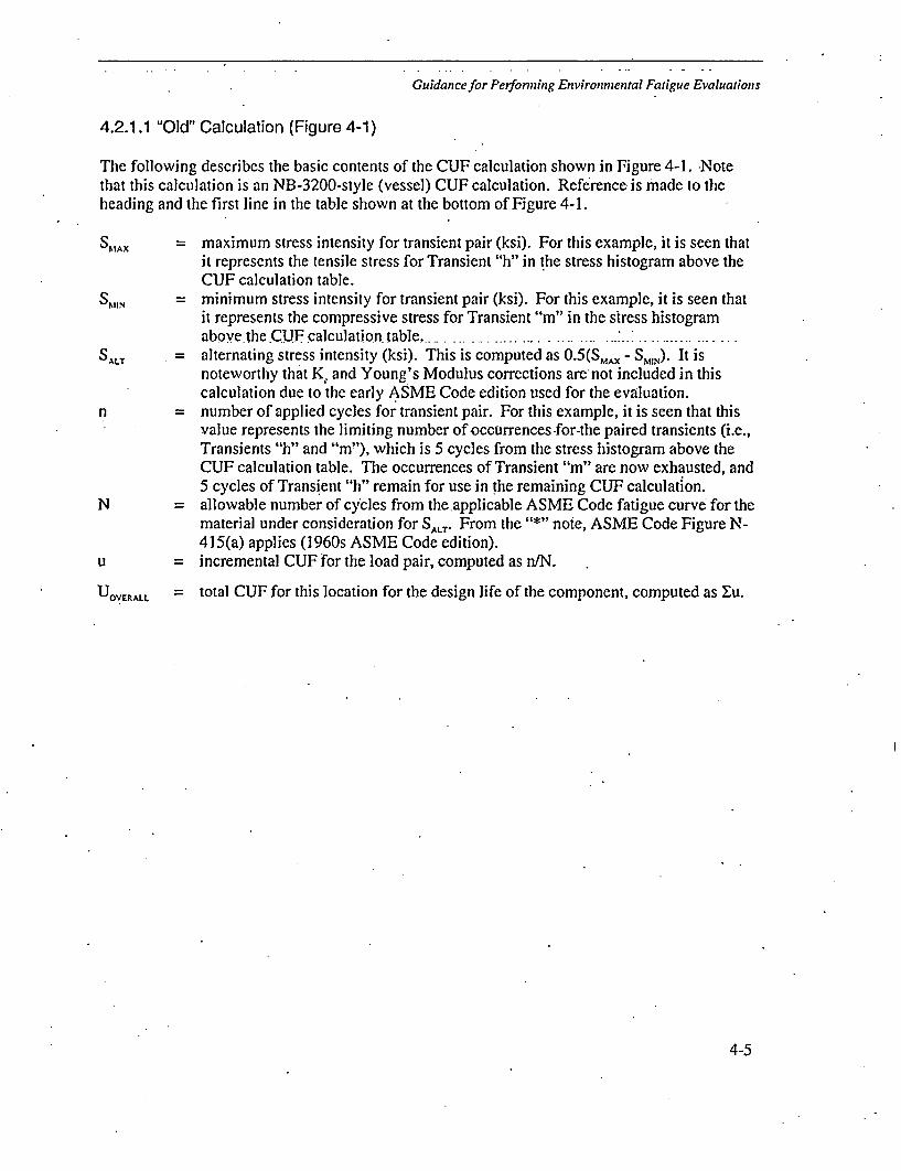
Guidance for Performing Environmental Fatigue Evaluations
4.2.1.1 "Old" Calculation (Figure 4-1)
The following describes the basic contents of the CUF calculation shown in Figure 4-1. Notethat this calculation is an NB-3200-style (vessel) CUF calculation. Reference is made to theheading and the first line in the table shown at the bottom of Figure 4-1.
SMAx = maximum stress intensity for transient pair (ksi). For this example, it is seen thatit represents the tensile stress for Transient "h" in the stress histogram above theCUF calculation table.
SM•N = minimum stress intensity for transient pair (ksi). For this example, it is seen thatit represents the compressive stress for Transient "m" in the stress histogramabove the .ClF, calculation table,.....
SALT = alternating stress intensity (ksi). This is computed as 0.5(SMAX - S,10N). It isnoteworthy that K, and Young's Modulus corrections are not included in thiscalculation due to the early ASME Code edition used for the evaluation.
n = number of applied cycles for transient pair. For this example, it is seen that thisvalue represents the limiting number of occurrences -for-the paired transients (iLe.,Transients "h" and "m"), which is 5 cycles from the stress histogram above theCUF calculation table. The occurrences of Transient "m" are now exhausted, and5 cycles of Transient "h" remain for use in the remaining CUF calculation.
N = allowable number of cycles from the.applicable ASME Code fatigue curve for thematerial under consideration for SALT* From the "*" note, ASME Code Figure N-415(a) applies (1960s ASME Code edition).
u = incremental CUF for the load pair, computed as n/N.
UOVERALL = total CUF for this location for the design life of the component, computed as Xu.
4-5

Guidance for Performing Environmental Fatigue Evaluations
-52- Jt7.94'U .4sq, ,o,:, - . -.
• t iI I I I ~ ~ I. I IAl&~
€i I , I ... 1 • I•L " i J". : I\j. I
*l .1 I " '
• I.- I .. i I " I I I. I .I, --o" 1 I I* ... ,I *I I
I *, .I f I I * I.*" a I' I J i . .1 I g . 1 . ,- .
.6,... 6 I I, v 0 I I /.0 / 4 I; .
... . I t I, : I. i I * I
r,,,•,~ a. ,6 g. .a' * . e "f " " "J " h &.'•" in"
Aelr•420 &c /5O• "',O 2•O20 A /•0 '1, .90
S.*Iv SI-in I- f4L : CL
4'//Z -7.44/ i-t 76 140 / ýA' PA
41,1Z -5.55 2244 5 40020 o-moij32.33 -2.0, is 17510 9. o'o
3..1 ? A4f '460 133' O.9003425:6~. S I /;U 4-ff 10 O -0
-~&PJfEAt'E 1
Figure 4-1Example of "Old" Fatigue Calculation
4-6

Guidance for Perfonning Environmental Fatigue Evaluations
4.2.1.2 "New" Calculation (Figures 4-2 through 4-4)
The following describes the basic contents of'the CUF calculation shown in Figure 4-2.. Notethat this calculation is an NB-3600-style (piping) CUF calculation. References are also made toFigures 4-3 and 4-4 where necessary.
(Note: Near the top of the table shown in Figure 4-2, the maximum load case information isreported, i.e., the two lines beginning with "GELBOW" and "0.512" - the descriptions thatfollow apply to the information below these lines.)
Load Range = paired load cases, as defined in Load Case definitions (see Figure 4-3).
Equation 10 Moment = moment (ft-lbf), computed in accordance with Equation (10) ofASME Code, Section III, NB-3600.
Equation 10 Stress = stress intensity (psi), computed in accordance with Equation (10) ofASME Code, Section III, NB-3600. - ....
Equation 11 Moment = moment (ft-lbf), computed in accordance with Equation (11) ofASME Code, Section III, NB-3600.
Equation 1I Stress = stress intensity (psi), computed in accordance with Equation (11) ofASME Code, Section III, NB-3600.
Equation 12 Moment = moment (ft-lbf), computed in accordance with Equation (12) ofASME Code, Section III, NB-3600.
Equation 12 Stress = stress intensity (psi), computed in accordance with Equation (12) ofASME Code, Section III, NB-3600.
Equation 13 Moment = moment (ft-lbf), computed in accordance with Equation (13) ofASME Code, Section III, NB-3600.
Equation 13 Stress stress intensity (psi), computed in accordance with Equation (13) ofASME Code, Section III, NB-3600.
Equation 14 KE = elastic-plastic strain concentration factor, K, computed inaccordance with ASME Code, Section III, NB-3600.
Equation 14 Stress alternating stress intensity (psi), computed in accordance withEquation (14) of ASME Code, Section Il1, NB-3600.
Cycles Actual number of applied cycles for the transient pair. For this example, thefirst load pair represents thermal Load Cases 24 and 36, coupledwith dynamic Load Case 56 and (E)arthquake. From Figure 4-3,Load Case 24 represents Daily Power Reduction, Load Case 36represents Vessel Flooding, and Load Case 56 represents OBE/SRV
4-7

Guidance for Performing Environmental Fatigue Evaluations
dynamic loading. From the transient definitions (similar to thoseshown in Figure 4-4), the number of applied cycles for each loadcase is obtained. The fatigue analysis uses the limiting number ofcycles for all of these loads, which is 10 cycles.
Cycles Allow = allowable number of cycles from the applicable ASME Code fatiguecurve for the material under consideration for "Equation 14 Stress".
Usage Factor = incremental CUF for the load pair, computed as "CyclesActual"'"Cycles Allow".
The-total.CUF-for this location for-the design life of the .component, computed as Zu, is shown at-the top of the table in the summary portion (i.e., 0.6512)..
AV% U..I it A IWO r.A-m ; 10) I 4tlqR VJk)5 MAK?UNITS - HIP WALL(1hI. NUIENTS(F'-LIF). AND STRESS (PSI)
1413 MALL MO. - ftANG1
GELBOW U5 HA1IM0.512 1605
0,6.24 27.1 623-_24
16.23:2416.2024$6.0- 43
%4.39-44
56. 2:374
so1. 2615611-21315.20-3811.0- 40351,-2955.20-3455 *14-20155,31:3955 22 3355.20_32SS 25-3166,20-31553.0-315S.22.2055.*10-3355.13-20S, -. 10-1655,10-17ss.20:275520_2115119-20
EQUATION 10 aiUATIO it • ( 3Allow 12 0EQUATION 381N4T STE 3STRES I STRES MOM335 STRSS "KEVAIS2R0S14S
N 143173 77836- 143173 132028 114270 46152 16721 24073 1.62 207166(9.56.24-36) (1,56.24-36) (24-36) (E,56,35.43) (C.56,24-36)
143173 77836 143173 132023 114270 44162 16121 21777 2.62 101164142334 719S4 142334 130901 113390 41"80 10721 16521 1.58 103510131716 74542 131776 127991 208117 439"8 16721 19093 1.51 96785137776 ?4542 120986 1151782 108817 43958 16721 19093 1.28 74319137726 72771 120966 112284 IDMI1 43958 16721 19093 1.22 6873613398t 70332 117114 110051 104930 42389 1:721 16077 1.12 43511613117 68279 120789 103190 104643 -43888 16721 19321 1.07 51353
3983 66435 117164 201360 104930 423.9 " 16721 12181 1.00 5249013485 645752 110061 103094 108894 42778 26721 13323 1.00 61547137776 61291 120984 06507 106817 43021 1672" 7611 1.00 49254122192 62268 105571 93199 93733 37665 16721 I1PSO 1.09 46879100145 50316 84455 91572 73932 2986" 16721 19093 1.00 45176137490 87445 120772 91132 108578 43862 16721 1326 1O0 45111137567 16712 120739 3810 100443 43888 16721 6756 1.00 44055136728 " 1 ,17 117210 85308 105643 438M8 16721 6755 1.00 42754136226 $51171 113210 85506 108643 43888 16721 6155 1.00 42754107412 37662 88418 84663 19996 32317 16721 17038 1.00 42282l1o0s6 "4134 91830 81742 8325.4 33632 15121 11324 1.00 4067197910 53443 0W83 77208 73812 29731 16721 18710 1.00 38604
1)2804 51421 93769 75317 60139 34434 16721 12467 1.00 3755982511 502133 6317 71649 17520 23236 16721 16750 1.00 318240006 40222 62962 1043 152"99 22339 16721 18179 1.00 35219
82304 47036 *84291 6663 60265 24342 16721 18750 1.00 3308263526 47061 66483 6520 54760- 23737 16723 13379 1.00 32910$ 4439 46W6 68288 68"130 62130 2598 16721 19321 1.00 3251S73389 44115 57110 5909 5115? 20641 18721 18750 1.00 3041583180 416DO• 9878 57681 M1881 23771 16721 14751 1.00 2884072338 42170 6.4844 75761 47811 19314 16721 16750" 1.00 2876079803 34091 53610 46735 57832 23362 16721 3468 1.00 24361S,120---27787 ... 39612--.3-1610 .30996---.12521..16721 67s5 1.00 1635558920 27769 39612 304676 309 25121 16721 6755 1.00 1833859302 27302 40000 34705 32396 12443 1T7O1 8017 1.00 1735358022 24124 38710 20171 30104 12161 16721 1177 1.00 14"115700S 23319 29713 22456 21094 0521 16721 7006 1.00 11233
CYCLES VSAGEACIUAL ALLOY FAClOR
0.6512
10 494 0.0202)30 512 D.0DSS360 150 0.0923:120 13151 0.00Y4Y90 16389 0.05331,
1 2331 0.0004632 3200 0.1975
14 3716 0.003.15 3974 0.003.
161 4172 6.03152%1o 5361 0.00191 5743 0.0002
I11 S835 0.0190V370 6458 0.0570o
72 7139 0.01013/106 7139 0.014,8115 7319 0,0102015 8254 .0.0018..35 "943 0.0015
106 10791 0.00911V15 12743 0.001215 13494 0.0011
126 16197 6.007ijIII 16992 0.0065/249 176.37 0.0141.'113 22238 0.00504435 26965 0.0180-61 27116 0.002440 SOW01 0.0008
307 153886 0.002015 254462 0.000170 195284 0.0004
2000 424507 0.00474310 999999 o.o0o0
Figure 4-2Example of "New" Fatigue Calculation - CUF Calculation
4-8

Guidance for Performing En vironnental Fatigue Evaluations
8210loi/u?5el Condition, (..04
2 0 10 M5 2537.. 77507 100SS3 SSEl SSE INERTIA.....GROPIN 3?1Y 0 SM 30S4 SIV I1V,2VSRVrO2V)...... Gpfl80 by S= SASSS £01 (16T.01V0IM80....... OUVIM 3y 805 lSMSS coo- CMMENS.OSCILL S 0030723...... GRUPING BY 57D, 5007 PS. 10OM SWELL.......... G0JP030 By STD SASS
* 00450- ANNULUS PRES 000ZI1?IOW H.S.3... GRCP2ING BY STD SRllg APR07- ANNULUS PRSZSSOfa?006O 15.0.3... .GROUPING By 0 ST Ss
10 AMD-. ANUL. PRESURIZTIO 50301067 W .1.8 ... GMU?0W0 BY STD SASS11 Dl- D!AVWZ31ffT7 3033.75251 TL030.3,t 7968 - 0712000 1.010)
13 1-013 ONE ANCHO 54031
15 TIMM I- IKWML OPEMATIIO; (12) 7706# 40420/no/20 r 300 1 532/328/32116 MMM 2- TURD MOLL COLD. (I-.)PPG 0 70/70/70 7 37V0 !502/552/4S117 'HEIM 3- BMTL-U,LZAX 70514 M3-1.0) 70-10018 -_Z3 7 0046 my00527000 (2A) 100.180-10019 Tito 5- SIAR?-01':(0) (31-2.") 2.00-40620 0NM 6. S5hJ57.OPSIUiP) 033-2) 100-4%21 TEM 7- TOO2ROLL M2.4 -2.) 70-12522 Tam &_ TURN MOLL: (43-1*2i 10-70-32523 TEM3 9- TUBE 75011 (&A-..~). 325-42024 TIDM I*- DAIY1 19M RED=1 t (51-2.0) 810-3S&21 ,~ 11- DAILY P93 MM17 , (S-3..) 356-62026 7MO 12* . .v 093 PR~7 M 5 (6-1, 2) 420-326
... + 13 I. P9 M0 &OSS: (M-1-2) 410-3S2TOM 18s PW 300 ES70M2 (9-3) 352-420
29 'MM13 IS* 30#3(1 (22-1.2..) 420-27330 7M" 1#- M9 15020070 (13) 820-190
32 '~ 19. 90? SELBYT: (141-1.4) 190-03533 IMOM 1" WE! 57031; (140-2) . 635-19036 1RER 20. 5802-D3WN 00172078: (M3-1) 43S-15635 THEM 21' S=0-dww 101y7X7:(0?) (iSSa-) 156-39536 TIMM 22- VESSEL. 31.000130 (16A-1) 70-15737 TEM 13* VESSEL. 72.000230; (6-3..) 267-10439 TODM 26. VESSEL FL000230 (1664-4) 109-16739 3~ 25- VESSEL YLO~ru0: (6-*)14"-6-12540 T1MM 28. SOVE-DOW, 8103011: (171..) 167-100
WAD CASE
&I42434440
466748d9seS15283
54
56S738596061
?M~w 27. LosOFS 07 79 710710) (20-1..) 420-S73-455IDOM 25- PIPE PU0711100 (27-1-2) 420-259-707HM 29- SLAVO-VP. (DY) 0A3-..) 456-70
THMA 30- START-U1.IDN) .402.3) 486-18025MM 31- SHU?-DO8WN 1117220Il0 (M.5-3) 395-14910MM 32- LOSS Of 7wPO;A 121.20-13.3.4) 050-70T?3tH 33- 723DZ 2 WI2TH 1-0 PSITHEM 34- 23400 1S 9270 P-SIS1 9S1111m35- )S. D2 IS WITH3 3-1171 PSI2.0 M2. 03E ANCRO 440311......CASES-12-L3 1? 51510501A. 0-1.0 X040790030 ANCHO 9731S. ... .01505 1.2-13.24 31 lOtSS£81. (DAV ME8) ........ 010 CASE 315 84Y22504 1VA.UESILSS(SDV,?X)......... CASES 52.1 BY SASS
MS~(030r,000030 S350(0322.SRV.?) ... CASES 2.82.1 BY SOts?OB3y- AbS(0512 - 0011)..01505Z 2.51 BY ABS. SUM4~SMSS00E,O~I). SRSS1IABSCO(SI.080).SOV.P?) . .C10155-53 31 MOSS1sM04032.Ml. . .CA5E5 1.2 3Y SROS (0028973 CAM4 ONLY)
0Ont. 004 1W3011 (CAM St U ?OR170 500 R 503431 62)5314 IV. 2?. SPvoV05 ....... (1St REPEA7TED = 033 OWL!an)SoV(167.SR0OI6V8) ...... (CASE REM=00 lOM 9K 030 OWLY)
(Rim~ 00-7)
1ST5I 50.5. SEIEMPU¶87.. kthclo 51 0~L1004 '
2 StTILEZ tu0f.O.%t1.0118,1 ... AlUX. Seti.. SLTE toz *- I'
Figure 4-3Example of "New" Fatigue Calculation - Load Pair Definitions
4-9

Guidance for Perfoining Environmental Fatigue Evaluations
P 1]-1020 ýt1. 0MOMS'
L j oa? Fab SM0-ILIE
I .DAS" LINK---- 500-1ACRUD T TM3f116
3400-4.;" UP-) -
T1000ML TPAJNIMT1AM APPLICA.L To
S. TT%= :0C.413 2 111, ot. boltA 1 10'
.ýtm 15m " MN 12?
7. o . Ww; It .,i U!!W 100 -
Two.&~ W2T i.-"-~
Guidance.los. Perfon•ffng Environmental Fatigue Evaluations NORMAL AND UPSET ICONCITION13
It! NO
.4W
IPI
P
I4MITAll
'1'.5
~*406*S
* I
-iI 4'P I
I,I I
'I
vi-g
P.
F-
o.
P.42
-~44
j~JFKTA
Is~.y~ 7 Hj 90
.3,o
4
EvýI3T DECcRIPTION sal- wof LAJ 1r I"*? MAE?4 isa"q 5,431 Van = O2j..j cL aI w____ o.c OL -x ý
I OTIC"To CN(W1 1498AZI PlQw 0 W .AIP rt~f 601w F"1 wmll O.,t ptft "MU ototo~3ha~ - oq -r
L YOt u&3f . I 2 4 3&4 &11.3 '1 30.4 1 t 36-3 4" 1 4&-t 4&-1 45-H 49-1 40-3 1 -1 5.2 5-3 0-1G3 6 . 3 ?- .1 1.PRESSURE - PS16 0 O_" .6w. 0-0804M O-WO000 *-am emmo io-j~to. I Goo,63 AM~16 64 1wtw t* £6r0 !.*f t TOM8 vygIfe3 ,cica '00 W4 .' od-ZT' '.078DURATION OF FINX" TEW.-MR. tom ou 9w___ lIow. 310?. oa loff. "tu 10.15? IoIOV. 0.1047l330UW MOK-U NE N9.NtFIOF NF WC
"Moir CYCL tv 123 40 IN M0 10 45 1 13 I 1016 * 6 IIS - I IS 10.000 10.000 10.000 2000 7000 Z=0 400. _400
RATE 001 IEM C14ANIE-11ftU S Ica6. 60 l. ~1 0 74~310 no 1600 Taw0 1190 *264 0 264 -188 0 Ida -24.s a-IK3C M avo rs"_ I__ soe- to 3i00 Go [to low "a0 - 1001 is0m 1400 "00
I.FINIAL VtLOCQ fl-rttSK~' 736 V'SetC 5.) fl *2I41 Z1 -48 1 '214 .t3S 4 -.14 . 41 73317 .24-1421-A.44 7-517 Z414. 37 11)3.17-35312" 3421 '77 M ' 2 ??3 2z4 34Z 37 373 a77.3
2.FlhtC VELLOOC*TY-FT7/5.d 41 44. &.da, '418 *1 -3 645-- s, -SM., 4"0S - P43 1 31 S&B1 *3474 &-C43 .l5-7'. J33.732l133.7S1 S4 I 5. 143 1.43 '"14. 3 5423 62
-4 L a j salmCES.CLU ZZ.70 OwR .M0 P6EF&RK h 3-6-64 Z!4LAmAL TRANSIENTS
~~~~~~pip 16-1-16-0 T110 -A.ItU 0SISC)4 Mo3.- &.4117) by(91 a, .-esA.. ltoA ars u wTV&VS'rm`I~~~~ ~ ~ ~~ -41 3m23161*-4111 . t~~~t Y q6f '
Figur 4-4P1 DM -064pw-bby.- 1
I4P I" -or-A.. . _A.' VtDOI_ ..Y X,_ - qf41fc * w$It tisi 3amotfNm, AVR
Figure 4-4 1Example of "New"t Fatigue Calculation -Transient Definitions
4-10

Guidance for Performing Environmental Fatigue Evaluations
4.2.2 Transformed Strain Rate, i *
The transformed strain rate, i *, is required by both the carbon and low alloy steel F,,expressions documented in NUREG/CR-6583 [3], and the stainless steel F,, expressiondocumented in NUREG/CR-5704 [4], and is defined as follows:
For carbon/low alloy steels (NUREG/CR-6583 [3]):
b =(o (> 1%/s)
.*.-.n.(.) . ....... (0.001o : 1%/s)
*= fn (0.001) (i<0.001 %/s)
, = strain rate, %/sec
For stainless steels (NUREG/CR-5704 [4]):
i" =0 " (> 0.4% /sec)
h'= en(k1/0.4) (0.0004•Jý _ • 0.4%/sec)
= I n(0.0004/0.4) (i < 0.0004% /sec)
c = strain rate, %/secThe .abov.expressionsare straightforward to apply if the strain rate, i, is known. This can be
relatively straightforward for design transients where definitive ramp rates and temperature.differentials are provided. It is much more difficult for actual transients obtained from actualplant data or fatigue monitoring systems. In particular, how two transients that occur separately.in time are "linked" together (as shown in Figure 4-9) can have a significant influence on strainrate calculations depending upon the method used.
Section 4.3 discusses other issues associated with calculating the strain rate when applying theF,, expressions. Solving those other issues is beyond thescope of this report, so guidance isprovided in this section to address only the above three methods of computing strain rate.
Consistent with some of the calculations performed in NUREG/CR-6260 [2], for cases where themagnitudes of the portions of the stress range due to heatup and cooldown are unknown (i.e.,only the total stress intensity range is known), or for cases where the stress-histories are notavailable, one-half of the alternating stress intensity may be used to compute strain rate. This isdone in the sample problem shown in Section 4.2.7, but it requires that some form of time historyinformation be available for the transient to justify strain rates greater than the slowest saturatedstrain rate. Parametric studies could also be used to justify time assumptions.
4-11

Guidance for Performing Environmental Fatigue Evalumtions
Discussion for each of the three Average, Detailed, and Integrated Strain Rate approachesfollows,.........................................................
Approach #1: Average Strain Rate
The Average Strain Rate approach is simple in that it is based on "connecting the valley with thepeak with a straight line and computing the slope." -Referring to Figure 4-9, this represents theslope of a line drawn from the lowest stress point of the heatup (maximum compressive) event(i.e., left side of Figure 4-9), to the highest stress point of the cooldown (maximum tensile) event(i.e., fight side of Figure 4-9). But, as shown in the area between the two events in Figure 4-9,linking of the two transients is not necessarily straightforward. There are two issues associatedwith the proper linking of the two events:
* For the maximum compressive stress transient (i.e., left side of Figure 4-9), the return(tensile) side of the transient is important for the strain rate calculation. An estimate. of thetime until steady state conditions are reached is needed.
The ending stress for the maximum compressive stress transient (i.e., left side of Figure 4-9)may be different than the beginning stress for the maximum tensile stress transient (i.e., rightside of Figure 4-9). This difference causes a discontinuity in the linking process.
The following guidance is provided for each of the above issues:
* For steady state conditions associated with the return (tensile) side of the maximumcompressive stress transient, the time for the stress to reach at least 90% of the steady statestress value can be used. This involves a steady state stress solution that includes a time-based solution, which is readily available in most stress analyses, and is readily achievablewith the use of allmodern-day stress programs.
For stress discontinuities that exist between the ending stress for the maximum compressivestress transient and the beginning stress for the maximum tensile stress transient, thetransients can be linked with a vertical line between the two stress points (i.e., no elapsedtime).
Under the above assumptions, the Average Strain Rate is computed as:
=I OOAa/(AtE)
where: c = average strain rate, %/sec
Aa = total stress intensity range
= stress difference between the highest stress point of the maximum tensilestress event (i.e., right side of Figure 4-9) and the lowest stress point of themaximum compressive stress event (i.e., left side of Figure 4-9), psi
At = time between peak and valley, sec
4-12

Guidance for Performing Environmental Fatigue Evaluations
= time lapse from the event start to the algebraic highest stress point of themaximum tensile stress event (i.e., right side of Figure 4-9) plus the time lapsefrom the algebraic lowest stress point of the maximum compressive stressevent (i.e., left side of Figure 4-9), to the time for the stress to reach at least90% of the steady state stress value, sec.
E = Young's Modulus, psi, normally taken from the governing fatigue curve usedfor the fatigue evaluation.
ApRp2oach #2: Detailed Strain Rate
The Detailed Strain Rate approach is similar to the average approach discussed above, exceptthat a.weighted strain rate is obtained based on strain-based integrati.on.oqver..t.he. i.ncrea.sing.(tensile) portion of the paired stress range. Referring to Figure 4-9, this represents the integratedslope of strain response from the algebraic lowest stress point of the maximum compressivestress event to the algebraic highest stress point of the maximum tensile stress event, weighted bystrain. Similar to the average approach discussed above, linking of the two transients in notnecessarily straightforward. However, the two issues associated with the proper linking of thetwo events that are identified above are less pronounced because of the integration process. *Nevertheless, aspects of these issues remain, so the following guidance is provided for each ofthose issues:
* For steady state conditions associated with the return (tensile) side of the maximum- fcoimi . ssive -stress iran-sint,-the ii-me for the stress to reach at least 90% of the steady statestress value can be used. This involves a steady state stress solution, which is readilyavailable in most stress analyses, and is readily achievable with the use of all modem-daystress programs.
* For stress discontinuities that exist between the ending stress for the maximum compressivestress transient and the beginning stress for the maximum tensile stress transient, thediscontinuity can be ignored.
Under the above assumptions and referring to Figure 4-5, the Detailed Strain Rate is computed as:
100 Ac1 AE,At
where: * = detailed strain rate, %/sec
Asi = change in strain at Point i, in/in
- (ar 1--ý)/E
Gi = stress intensity at Point i, psi
7i.1 = stress intensity at Point i-1, psi
At = change in time at Point i, sec
S ti - ti.I
E = Young's Modulus, psi, normally taken from the governing fatigue curve usedfor the fatigue evaluation.
4-13

Guidance for Performing Environnmental Fatigue Evaluations
The summation is over the range from Point (3) to (4) and the range from Point (1) to (2). In thefigure, Points (1) and (4) are assumed coincident. Point (4) is actually taken as the point wherethe stress returns to at least 90% of the steady state stress value. The strain discontinuitybetween this point and Point (1) is accounted for by omitting this increment from the total strainrange in the denominator.
If two tensile transients are being ranged, the summation_ranges from the algebraic minimum ofthe two Point (I)s to the algebraic maximum of the two Point (2)s. If two compressive transientsare being ranged, the summation ranges from the algebraic minimum of the two Point (3)s to thealgebraic maximum of the two Point (4)s. If a tensile transient is being ranged with itself (its'zero' state), the summation ranges from Point (1) to Point (2). If a compressive transient isbeing ranged.with.itself (its.'Lzero'. state),.the .summation ranges.from.Point. (3).to Point.(4). withPoint (4) again taken where the stress returns to at least 90% of the steady state stress value.
Approach #3: Integrated Strain Rate
The Integrated Strain Rate approach is similar to the detailed approach discussed above, exceptthat an F.. factor is computed at multiple points over the increasing (tensile) portion of the pairedstrain range, and an overall F. is integrated over the entiretensile portion of the strain range (i.e.,from the algebraic lowest stress point of the maximum compressive stress event to the algebraichighest stress point of the maximum tensile stress event in Figure 4-9). Thus, this process ismore specifically an "integrated F,, approach", where strain rate is computed as a part of theprocess. Similar to the two approaches discussed above, linking of the two transients remains anissue with this method. However, similar to the detailed approach, the two issues associated withthe proper linking of the two events are less pronounced because of the integration process. Thefollowing guidance is provided for each of those issues:
For steady state conditions associated with the return (tensile) side of the maximumcompressive stress transient, the time for the stress to reach at least 90% of the steady statestress value can be used. This involves a steady state stress solution, which is readilyavailable in most stress analyses, and is readily achievable with the use of all modern-daystress programs.
* For stress discontinuities that exist between the ending stress for the maximum compressivestress transient and the beginning stress for the maximum tensile stress transient, thediscontinuity can. be ignored.
Under the above assumptions and referring to Figure 4-5, the Integrated Strain Rate F,, iscomputed as:
E Ac.
where: F,,.i = F,, computed at Point i, based on = I 00A/S/At a*nd transformed parameters(T) and (0) computed using the respective Integrated Strain Rateapproaches for each, discussed below.
A = change in strain at Point i, in/in
= (a,- a1 ,.)/E
4-14

Guidance for Performing Enviroi-nmental Fatigue Evaluations
Gi = stress intensity at Point i, psi
ý., = stress intensity at. Pointi-.,.psi
At = change in time at Point i, sec
t -ti-I
E Young's Modulus, psi, normally taken from the governing fatigue curve.used.for.the.fatigue.evaluation ................... ...................... ............ .
The summation is over the range from Point (3) to (4) and the range from Point (1) to (2). In thefigure,.Points (1) and (4) are assumed coincident. Point (4) is actually taken as the point wherethe stress returns to at least 90% of the steady state stress value. The strain discontinuitybetween this point -and Point (1) is accounted for by omitting this increment from the total strainrange in the denominator.
If two tensile transients are being ranged, the summation ranges from the algebraic minimum ofthe two Point (I)s to the algebraic maximum of the two Point (2)s. If two compressive transientsare being ranged, the summation ranges from the algebraic minimum of the two Point (3)s to thealgebraic maximum of the two Point (4)s. If a tensile transient is being ranged with itself (its6zero' state), the summation ranges from Point (1) to Point (2). If a compressive transient isbeing ranged with itself (its 'zero' state), the summation ranges from Point (3) to Point (4) withPoint (4) again taken where the stress returns to at least 90% of the steady state stress value.
-'.-9.~~~ R• 1t, • +(""0 17 ta- C'_
TransientA •
Transier4• Tra rslenf A
Z. --.- -Refer to the discussion above for Approaches#2 (Detailed Strain Rate) and #3 (IntegratedStrain Rate) for instances where Point (4)
_ _ __ does not coincide with Point (1).
Tiansient B
Figure 4-5Detailed and Integrated Strain Rate Calculation
4-15

Guidance for Performing Environmental Fatigue Evaluations
4.2.3 Transformed Sulfur Content, S*
The transformed sulfurc6ntent, S*, is required only, bythe carbon and low alloy steel F,,expressions documented in NUREG/CR-6583 [3], and is defined as follows:
S* = S (0 < S:5 0.015 wt. %)
.S*= 0.015 (S > 0.015 wt.%) • .
S = weight percent sulfur
There are no ambiguities associated with computing S*, as it is a function of the material sulfurcontent for the location .under consideration. Normally, sulfur content would be obtained fromCeitifiedT~fr-ra1-T~stsR~p6dW-(CMTRs) that are usually readily available. However, due to thesecondary effect of this variable in the F,. expressions, most analyses to-date have assumed highsulfur content (i.e., S* = 0.015) for simplicity.
4.2.4 Transformed Temperature, T*
The transformed temperature, T*, is required by both the carbon and low alloy steel F,,expressions documented in NUREG/CR-6583 [3], and the stainless steel F, expressiondocumented in NUREG/CR:5704 [4], and is defined as follows:
For carbon/low alloy steels (NUREG/CR-6583 [3]):
T* = 0 (T < 1500 C)
T* = T - 150 (1505 <-T: 350 °C)
T = metal service temperature, 0C
For stainless steels (NUREG/CR-5704 [4]):
T* =0. (T<200°C)
T*= 1 (T >. 2000C)
T = metal service temperature, 0C
The above expressions are straightforward to apply if the metal service temperature,T, is known.
As discussed in Section 4.3, there are other issues associated with temperature when applying theF,, expressions. Generally, the issue is, "what temperature should be used for the generaltransient pairing shown in Figure 4-9?" The answer to this question is dependent upon therefinement on the evaluation used to compute the F,, factor. As discussed above at the start ofSection 4.2, there are three increasingly refined approaches used to compute the F,, factor:Average, Detailed, and Integrated Strain Rate.
4-16

Guidance for Perfonning Environmental Fatigue Evaluations
The following recommendations are made for determining the temperature, T, for each of theabove. three approaches: ............................................
Approach #1: F_ Factor Calculated Based on Average Strain Rate Calculation
For this approach, a constant temperature that is the maximum of the fluid temperatures of bothpaired -transients over the-time-period of increasing tensile stress should be used. Referring toFigure 4-9, this would include the maximum temperature that occurs during any of the followingtime periods:
* For the maximum compressive stress transient (i.e., left side of Figure 4-9), beginning at thetime of algebraic minimum stress until the end of the transient.
" For the maximum tensile stress transient (i.e., right side of Figure 4-9), beginning at the startof the transient until the time of algebraic maximum stress.
Fluid temperature is an acceptable substitute for the above -specified metal temperature in thatfluid temperature is more readily available in CUF calculations, as it is a required input withrespect to transient definitions. This is true for both older-vintage and modern-day evaluations.Since the maximum fluid temperature envelopes any metal temperature, this is conservative.
A.proach #2: F Factor Calculated Based on Detailed Strain Rate...
For this approach, the maximum fluid temperature of both paired transients over the time periodof increasing tensile stress should be used (i.e., same as Approach #1 above).
Approach #3: F, Factor Calculated Based on Integrated Strain Rate..................
For this approach, F,, is computed in an integrated fashion at multiple points between thetransient pair stress valley and peak. For this case, the maximum metal temperature of both localtime points considered over the period of increasing tensile stress should be used. Referring toFigure 4-5, this represents the maximum of Points i and i-I, or T = MAXIMUM(T1, T,). Metaltemperature is more appropriate and avoids potential excess conservatism that would result fromusing fluid temperature in a heating event and inappropriate omission of effects in a coolingevent.
For all three approaches described above, a conservative, simplified, and bounding evaluationwould be to use the maximum operating temperature for the component location being evaluated.Note that it is not obvious that the use of maximum temperature in the F,, expressions isbounding (due to subtraction of the temperature terms), but routine application of the expressionshas demonstrated that the use of the maximum temperature is bounding in all of the F,'expressions. This is also shown in Figure.4-6, which shows F,,, values as a function oftemperature.
4-17

Guidance for Performing Environmental Fatigue Evaluations
Stainless Steel Fen
18.0
16.0
14.0-
12.0-
- Low 02, +Low t iLow 02 + Int. t
" " Low 02+ High ;
- High 02 + Low t
-- - High 02 + Int. t..--- ... High 02 + High t
10.0
1.8.0-
6.0
4.0
2.0
0.0275 325 375 425 475 525 575
Temperature, "F
Carbon Steel Fn
016
140 -High02 4 Low t
High 02 +Int. t
120 High 02 +High i
Int. 02+ Low I
100 -
~80
60-
40-
20-
0.150
- - -kInL 02 InL i
.......... IMI. 02 -High t
-- LowO02 -Low t
200 250 300 350 400 450 500 550
Temperature, F
600 650
Figure 4-6Fen Values as a Function of Temperature
4-18

Guidance for Perfonning Environmental Fatigue Evaluations
4.2.5 Transformed Dissolved Oxygen, 0*
The transformed oxygen, 0*, is required by both the carbon and low alloy steel Fe expressionsdocumented in NUREG/CR-6583 [3], and the stainless steel F,, expression documented inNUREG/CR-5704 [4], and is defined as follows:
For carbon/low alloy steels (NUREG/CR-6583 [3]):
O*= 0 (DO.< 0.05 ppm)
0* = ( n (DO/0.04) (0.05 ppm < DO _ 0.5 ppm)
0* =..(n.(12.5) (DO > 0.5. ppm)..
DO = dissolved oxygen
For stainless steels (NUREG/CR-5704 [4]):
O. 0.260 ...... (DO < 0.05 ppm)
0 =0.172 (DO Ž>0.05 ppm)
DO = dissolved oxygen
The above expressions are straightforward to apply if the dissolved oxygen level, DO, is known.Although DO measurements are normally available through routine chemistry measurements,they are typically very limited with respect to frequency of collection and locations collected inthe reactor coolant system (RCS). Therefore, there are several difficulties associated withdetermining the DO that is appropriate for use in the F,, expressions:
* The DO level is not known at the component location being evaluated. For example, it is theDO directly at the surface of the component that is required, e.g., for a BWR componentexposed to saturated steam, the (much lower) DO in the condensate film is really what isapplicable to an environmental fatigue analysis, not the much higher DO content of the steamitself.
0 The DO level is not known at all times during a transient (i.e., perhaps DO data is onlycollected once per day as opposed to continuously during a transient).
As discussed in Section 4.3, there are other issues associated with.DO.when applyi.ngt.he. F,expressions. Solving those other issues is beyond the scope of this report, so guidance i*spr6vided in this section to address only the above two issues and answering the question, "whatDO level should be used for the general transient pairing shown in Figure 4-9?" As with T*, theanswer to this question is dependent upon the refinement on the evaluation used to compute theFe, factor. Section 4.2 contains the definitions and details for each of these three approaches.The following recommendations are made for determining the dissolved oxygen, DO, for each ofthe three approaches:
4-19

Guidance for Performing Environmental Fatigue Evaluations
Approach #1: F, Factor Calculated Based on Average Strain Rate Calculation
For this approach, the maximum DO level (for carbon and low alloy steels), or the minimum DOlevel (for stainless steels) of both paired transients over the time period of increasing tensilestress should be used. Referring to Figure 4-9, this would include the maximum (or minimum)DO level that occurs during any of the following time periods:
* For the maximum compressive stress transient (i.e., left side of Figure 4-9), beginning at thetime of algebraic minimum stress until the-end of the transient.
* For the maximum tensile stress transient (i.e., right side of Figure 4-9), beginning at the startof the transient until the time of algebraic maximum stress.
Approach #2: F, Factor Calculated Based on Detailed Strain Rate
For this approach, the maximum DO level (for carbon and low alloy steels), or the minimum DOlevel. (for.stainless steels). of both paired.transients oyer. the.time.period of increasing tensilestress should be used (i.e., same as Approach #1 above).
Approach #3: F Factor Calculated Based on Integrated Strain Rate
For this approach, F,, is computed.in an integrated fashion at-multiple points between thetransient pair stress valley and peak. For this case, the maximum DO level (for carbon and lowalloy steels), or the minimum DO level (for stainless steels) of both local points considered overthe time period of increasing tensile stress should be used. Referring to Figure 4-5, thisrepresents the maximum of Points i and i-I (DO = MAXIMUM[DOi, DOJ]) for carbon ahd lowalloy steels, or the minimum of Points i and i-1 (DO MINIMUM[DO,, DOJ) for stainlesssteels.
For.all three approaches described above, the following guidance is provided for establishing theDO level:
.. . . .. . .. . . .. . ... .. . . . . . . .. ... . . . . ... . .. . . . .... . . . ... ... . . .. . . . . . .... .. ... .. ............. . .
* In rare cases, DO level measurements are available at or near the component location beingevaluated via plant instrumentation. For this case, the plant data is used directly for DO.
In the majority of cases, DO level measurements are available at periodic intervals duringplant. operation. These. measurements -are routinely made remotely from the-component ........location of interest. In some cases, the remote reading may be valid for application at thecomponent location. For these cases, "typical" values can normally be determined based onconsultation with the plant chemistry personnel. The typical values should be used with abrief write-up describing the basis for the values. Consideration should be given forvariations-in the DO level,-i.e.; consideration of bounding values, as described below, shouldbe factored into the estimates.
For cases where DO levels have changed over the course of plant operation (i.e., implementationof HWC after plant startup), a time-based average DO level is recommended, based onexpected DO levels, as follows:
4-20

Guidance for Performing Environmental Fatigue Evaluations
DO = DO, Time, + DO 2 Time 2 + DO 3 Time 3 +Time, + Time 2 .+ Time3 .+.
where: DO = time-averaged DO levelDO = average DO level for time period Time,Time, = time period #1 where DO level was relatively constant
. .. DO. = ...... average DO level for-time-period Time ............Time, = time period #2 where DO level was-relatively constantDO. = average DO level for. time period Time,Time. = time period #3 where DO level was relatively constantetc.
Thus, for a case where a-BWR-operated-20 years under NWC (typical DO - 200 ppb), 10 yearswith 50% HWC availability (typical DO = 5 ppb), and is projected to complete'operation to 60years with 95% HWC availability, thefollowing DO level is calculated:
DO - (200x20) + (200x0.5x10) + (5x0.5xlD) + (5x30) _ 8625(20+10+30)
Alterhatively, F,, factors could be computed for each time period and an overall Fe, factorcalculated based on the weighted average, as follows:
F,,=F200 pp. x 20 + F,,2oO ppb x 0.5x 10 + F,,,, ppb x 0.5x 10 + F,,,p,,,Pb x 30(20+10+30)
Another alternative-method involves assigning a DO value to each logged transient according tothe date it occurred. This is more involved than the above in that the range pair table would needto be apportioned into subsets over the past and future history of the unit and the incremental U-sre-calculated. An approximation of this would be to do a simple apportioning of the range pairU-s according to an assumed linear distribution of the occurrences, n, over the past and futurehistorical DO values.
Similar to that described for T*, a simplified, conservative and bounding evaluation would be to.use the maximum DO level (for carbon and low alloy steels), or the minimum DO level (forstainless steels) for the component location.being evaluated. Note that it-is not obvious that theuse of these maximum or minirmum DO levels in the F, expressions is bounding (due tosubtraction of the oxygen terms), but routine application of the expressions has demonstrated thatthe use of the maximum DO level is bounding. in all of the F,. expressions for carbon and lowalloy steels, and the minimum DO level is bounding in all of the F,, expressions for stainlesssteels. This is also shown in Figure 4-7 which shows F,, values as a function of DO level.
4-21

Guidance for Pe]ormning Environmental Fatigue Evaluations
Stainless Steel Fen"
18.0 ..
16.0 -
14.0
12.0 -
10.0
-High T +Low tHigh T +Int.
-High T +High f
-Low T+Low t
I -Low T *Int. t---- Low T+ High t
LL
8,0- I6.0o-
4.0-
2.0
0.0 - . -. . -... ... - ... -.
0.01 0.02 0.03 0.04 0.05 0.06
Dissolved Oxygen, ppm0.07 0.08 0.09 0.10
Carbon Steel Fen
High T -Lowt
140 HighT - Int. (
-High T -High 1
120 -nL T 4Lowt
- - - Int. T. + W. I
100 .. :-mnL T -High I
--- Low T - ow t
80IL
60,
40-
20
- --- - _- - - - -
0.00 0.10 0.20 0.30 0.40
Dissolved Oxygen, ppm
Figure 4-7Fen Values as a Function of DO Level
4-22
0.50 0.60. 0.70

Guidance for Pelfonning Environmental Fatigue Evaluations
4.2.6 Additional Considerations
The following additional considerations are provided for the above'guidance: ...............
* Dynamic Loading: For load pairs in a CUF calculation that are based on seismic or otherdynamic loading, F,, = 1.0 for the dynamic portion of.the strain for the load pair in question.This is based on the premise that the cycling due to dynamic loading occurs too quickly forenvironmental effects to be significant.--Theremaining portion of-the strain range-shouldbetreated the same as discussed elsewhere in this guideline.
" Thermal Stratification Loading: For load pairs in a CUF calculation that are based solely onthermal stratification loading, the strain rate can generally be taken as the minimum strainrate that produces the maximum environmental effect. Alternatively, the strain rate effects_can be determined as for any other cycle pair.
" Pressure and Moment Loading: The stresses for all load pairs in a CUF calculation typicallycontain stresses due to pressure and moment loading (i.e., non-thermal loads). All of thelaboratory testing that forms the basis for the F,, expressions was conducted with alternatingstrain as a result of mechanical loadings, which would be analogous to pressure and momentloadings. Thus, the F,,s, as determined herein, should be applied to the strain ranges forcyclic pressure and moment the same as for rapid thermal effects. The effects should beconsidered appropriately in the Detailed and Integrated Strain Rate approaches if theavailable stress histories account for different rates of strain for cyclic pressure and momentstrains.
"K_, : The stresses for some load pairs in a CUF calculation can contain the effect of K.. TheK, factor causes a higher strain, thus increasing the strain rate that would be computed foraffected load pair, which in turn lowers the F,. factor. The strain rate should instead be basedon a stress history for the load pair with K, effects removed.
4.2.7 Sample Calculation
As a demonstration of the guidance provided in Sections 4.2.2 through 4.2.5, a sample problemis provided here based on the "old" fatigue calculation shown in Figure 4-1. The completedenvironmental fatigue calculation is shown in Figure 4-8.
In the upper portion of Figure 4-8, the original design CUF calculation is reproduced, yielding atotal CUF of 0.0067. The only additional information in this step is the total stress intensityrange, SR, is computed (= Smax - Smin).
Then, environmental fatigue effects are-evaluated using two approaches. Each of theseapproaches is. described below.................................
Case #1: Bounding F Multiplier
For this case, since the design CUF is so low, a conservative (but very simple) approach is taken.The maximum possible F,, multiplier is determined and applied to the CUF result. Using therules for low alloy steel documented in Section 4.1, the maximum F., multiplier is computed as2.45. The environmental fatigue usage factor, U,,,, is then computed as CUF x F,, = 0.0 164.
4-23

Guidance for Performing Environmental Fatigue Evaluations
Case #2: Compute F., Multipliers For Each Load Pair
For this case.a more refined approach is taken compared to the first approach. Fen multipliers arecomputed for each load pair. Using the rules for low alloy steel documented in Section 4.1, theoverall F,, multiplier is also 2.45 for this approach, since the F,, does not vary with temperaturedue to the low DO. The environmental fatigue usage factor, U,,, for this case is also computedas 0.0 164.
The following descriptions are provided for the calculations for Load Pair #1:
Saltt
Strain Rate
MAX T
T*
0*
--dot*
= alternating stress intensity from design CUF calculation, psi= time for tensile portion of stress range in load pair, sec. Obtained from stress
report from the tensile portions of both transients = 3 seconds.= computed using the Average Strain Rate approach as I 00(Salt/2)/(Et) =
I00(58.77/2)/(30,000x3) = 0:03265%/sec= maximum fluid temperature for tensile portion of stress range, .F. Obtained from
stress report from the tensile portions of both transients = 550'F.= T-150 since T > 150'C (550°F = 287.8°C) = 287.8 - 150 = 137.8
- 0 since DO < 0.05 ppm (5 ppb = 0.005 ppm)
= In(Strain Rate) since 0.001 < Strain Rate I 1%/sec = ln(0.03265) = -3.422= exp(0.898 - 0.101 S*T*O*e-dot*
= exp(0.898 - 0.1010x.01 5x1 37.8xOx-3.422)
= exp(0.898)
= 2.45
4-24

Guidance for Performing Environmental Fatigue Evaluations
Design Basis CUF: 0.0067Reference: Design Basis CUF Calculation Shown in Figure 4.2
Material: SA-336 (Low alloy steel)Young's Modulus. E - 3.00E ,07 psi . . .
DO Level - 5 ppb (always)Transfornmed sullur content. S' = 0.015 (assume maximum)
Smax Smin SR Salt n N U41.12 -76.41 117.53 58.77 5 1.860 0.002741.12 -3.55 44.67 22.34 5 40,020 0.000132.33 -2.69 35.02 17.51 40 95.650 0.000430.12 -2.69 32.81 18.41 460 133.000 0.003525.05 " 11.74 13.31 6.66 400 >e6 " 0.0000
NOe Aboe sreies ore in ksi. Total CUF - 0.0067 (Design CJF is reproducedj)
Approach #1: Use a Bounding F Multiplie
LowAlloy Steel: F.. = exp(0.898 . 0.101s'TO'7) Relerece: NUREGICR.6583
For a DO - 5 ppb . 0.005 ppm. 0 = 0.Therefore. F., is conslant vs. T = exp(0.898) 2.45:
Maximum F.. = 2.45
Un. = CUF.F. a 0.0164 (1 t.0 so ecceptable)
Approach #2: Compute Foo Multipliers for Each Load Pair:
I Strain Rate MAXI[Salt (sec) (%Isec) . C'F) "r 0. -dot* Fe,i n N U*F,•
58.77 3 3.26E-02 550 137.8 0.00 -3.422 2.45 5 1,860 0,006622.34 15 2.48E-03 450 "82.2 0.00 -5.999 2.45 5 40,020 0.000317.51 10D 2.92E-04 325 12.8 0.00 -6.908 2.45 40 95,650 0.001016.41 1000 2.73E-05 250 .0.0 0.00 -6.908 2.45 460 133,000 0.0085
6.66 300 3.70E-05 150 0.0 0.00 -6.908 2.45 400 >le8 0.0000Nhue Abu S•eresa Ore in Ahi. Totat I U*... 0.0164
Overall F.. = U_,JCUF = 2.45(4 1.0 so acceplablen
Figure 4-8Sample Environmental Fatigue Calculation
4.3 Issues Associated With Fen Methodology
As a result of industry application of the FeT relationships summarized in Section 4.1, there havebeen several issues identified associated with practical applicati.on of the methodology to typicalindustry fatigue evaluation problems. These issues have led to application-of a variety ofdifferent solutions applied by analysts depending upon the analyst or the level of detail availablein the existing fatigue evaluations. This varied approach has led to non-consistent application ofthe Fe, approach between plants, and some amount of confusion amongst the industry.
This guideline document is formulated based on the current "state of the art" with respect to theFea methodology. In many respects, the current state of the technology with respect to the Feemethodology is incomplete or lacking in detail and specificity. Recommendations are made inthis guideline where needed to fill in these missing details. Further work should focus on theissues associated with areas where the technology is lacking. Some of the issue areas that areassociated with the Fe, methodology are summarized below ("0'" indicates where this guidelineprovides recommendations):
4-25

Guidance for Performning Environmental Fatigue Evaluations
Issues of Test vs. Application
* There must be more communication between the people performing tests and those who mustperform the analysis. This is one driving force behind the biannual series of "Fatigue ReactorComponents" conferences that were started by EPRI in 2000. The proceedings of the mostrecent 2004 meeting (to be published 2005) contain several papers that address this specificissue-.. . . . . . . . . . .
Testing for environmental effects has resulted in some rules for analysis that are notconsistent with real component transient response:
- Testing involves constant load/unload cycling, while real transients are separated in time,involve various stress -magnitudes and non-constant rise times............
- Hold time at an intermediate stress level or random load magnitude cycling has not beenadequately considered in environmental testing, although some work outside the U.S. hasaddressed these issues.
-- The "real world" is different than laboratory tests, i.e., loading rates are random asopposed to carefully controlled ("ramped" or "saw-toothed") loads applied in thelaboratory.
Strain hardening effects may affect the results of fatigue testing at high cycles.
* Mayals6-fed-ri 6-i•-hickel alloy data.
Issues of Analysis and Evaluation
• "Linking" of transients pairs is not straight-forward and can lead to significant differences inresults (refer to Figure 4-9): -
- How do you treat cases where the starting and ending stress points are not equal?
- What rate of change do you assume for the discontinuity between transients?
- What is strain rate?R] This guideline makes recommendations in Section 4.2.2 for addressing this issue.Work is also.ongoing within the EPRI BWRVIP program to investigate alternativeapproaches to this issue with regard to ASME Section XI calculations [25].
" Some have questioned the adequacy of Miner's Rule for fatigue analysis and that perhapsdesign fatigue curves should have a factor to account for this.
- On the other hand, methods such as Rainflow Cycle Counting will generally show thatthe use of Miner's Rule with ASME Code analysis is conservative.
" For the.purpose.of component analysis. for.environmental.effects, perhaps special stressindices and analytical methods need to be developed to distinguish between inside (fluidexposed) surfaces and external (air exposed) surfaces.
" Effect of elastic-plastic correction factor (K) on strain rate.
- To neglect is conservative- how to eliminate conservatism?@ This guideline makes recommendations in Section 4.2.6 for addressing Ke.
4-26

Guidance for Performzing Environmental Fatigue Evaluations
The F,,, formulations for stainless steel are based on the NUREG author's own mean stainlesssteel S-N curve in air, which is different than the ASME mean S-N curve over the high cycleportion of the curve. Therefore, inconsistencies are present in the application of the F.methods since these studies (and most applications of F,, being performed throughout theindustry) apply F,, factors to fatigue results that use the ASME S-N -curve.
Analysis Issues: Different Loadings
How are stratification loads addressed?
0 This guideline makes recommendations in Section 4.2.6 for addressing strati.fication loads.
How are seismic loads addressed?
El This guideline makes recommendations in Section 4.2.6 for addressing seismic and otherdynamic loads.
How are pressure and moment loads addressed?
0 This guideline makes recommendations in Section 4.2.6 for addressing cyclic pressure andmoment strains.
Analysis Issues: Oxygen
Environmental fatigue is typically linked to dissolved oxygen. As previously mentioned, thisinvolves inappropriate over-simplification and ignores the key role of other water chemistryparameters such as conductivity (or more correctly, level of dissolved anionic impurities) andpH. Even with regard just to dissolved oxygen, however:
Experts say oxygen is not the correct parameter- should be electrochemical potential(ECP), which is affected by the overall balance of oxidants and reductants inthe water, aswell as by temperature, flow, surface condition, etc. ECP, rather than dissolved oxygen,is the control parameter used in BWR water chemistry guidelines in the context of stresscorrosion cracking mitigation.
- Hydrogen water chemistry (HWC) may produce much different results, as the oxygenlevel is significantly lowered for HWC operation (for some locations).
- What oxygen level to use?
N Time history during transients not generally available.• Value at component location not generally available.0 What about different periods of operation, i.e., NWC for first 15 years, then
intermittent HWC, then reliable HWC?_ .... If.time.history.is available:........ ..............................
* Maximum or minimum of transient?* Maximum or minimum local?, i.e., MAX(D01 , DO,)* Maximum or minimum between peak and valley?
0 This guideline makes recommendations in Section 4.2.5 for addressing varying historicaloxygen levels.
4-27

Guidance for Performing Environmental Fatigue Evaluations
'Analysis Issues: Temperature
Temperature: -----.-- .
- What temperature to use?
* Metal? (not generally available)* Fluid?* Maximum of transient?" Maximum local?, i.e., MAX(T1 , T,.,)* Maximum between peak and valley?
0l This guideline makes recommendations in Section 4.2.4 for addressing temperature.
Analysis Issues: Defining Design Loads
* The strain range (and therefore the CUF) decreases as an imposed temperature change isapplied over a longer time period. The longer time period results in a slower strain rate and,all other things.being equal,.the slower.strain.rate.produces.a larger. F,,...Therefore, .a..challenge presents itself with respect to defining a set of transients (and their associatedtemperature ramp rates) that are boundingfor design purposes. Component-specificpreliminary studies have shown that the F,,-adjusted CUF for a variation of temperature ramprates reaches a maximum when the temperature variation is on the order of 1,000°F/hour orhigher-[26]: Furtherinvestigations are expected -toshow that it-will be possible to define- ---design transients in a manner that will determine the maximum F,.-adjusted CUF as thetemperature ramp rate (and thus the strain rate) is varied in a narrow range fromapproximately ],000°F/hour (or other component-specific rates) to infinite rates. Theseefforts mirror similar work on crack growth in reactor components through corrosion fatigue[25], and it is expected that such efforts will demonstrate that the issue of defining a transientwith a range of ramp rates, extracting the strain rates, performing the design, and monitoringfor compliance are all very manageable when utilizing the F,, approach for design.
As noted, several of the issues identified above were addressed earlier in this report. Thoserecommendations are intended to serve as a guide for performing environmental fatigueevaluations. The remaining issues that are not addressed in this report are beyond the scope ofthe work associated with this report at the current point iii time, and some are impossible toresolve with information currently available. An example would be the issue of usingECP/conductivity as a more appropriate parameter for assessing environmental effects. Allcurrent F,, methodologies are based on measured dissolved oxygen, as that was the only waterchemistry parameter recorded during laboratory testing. The remaining non-addressed issuesrepresent the limitations on the current state of the art. As further industry work is completed toaddress some of the remaining issues summarized above, refinements or additions to theseguidelines may be made to further define and enhance plant specific evaluations. Therefore,these guidelines can be thought of as an "instruction manual" for performing plant specificenvironmental fatigue evaluations based on the current state of technology and informationavailable. Res6lution of the remaining non-addressed issues is not needed in order for licenserenewal applicants to satisfy the current regulatory requirements of addressing reactor waterenvironmental effects.
4-28

Guidance for Performing Environmental Fatigue Evaluations
2w 4w D MD Iwon
D 2MJD W ..0. 3O, D 1I
Figure 4-9Issue of Transient Linking
4-29

5CONCLUSIONS
This report has provided guidance that may be used by individual license renewal applicants toaddress the environmental effects on fatigue in a license renewal application. The approachesdocumented in this report are geared to allow individual utilities to determine the optimumapproach for their plants, allowing different approaches to be taken frr different locations.
The overall approach taken for license renewal is to select a sampling of Iocations that might beaffected by reactor water environmental effects. NUREG/CR-6260 locations are considered anappropriate sample for F,, evaluation as long as none exceed the acceptance, criteria wit henvironmental effects considered. If this occurs, the sampling is to be extended to other locations.An assessment of the chosen locations is undertaken: (1) to show that there is sufficientconservatism in the design basis transients to cover environmental effects, or (2) or to derive anexpected fatigue usage factor including environmental effects. Then, either through tracking ofreactor transient cycles or accumulated fatigue. usage, utilities can. determine iffurther. steps mustbe taken to adequately manage fatigue environmental effects in the extended operating period.'
Different methods are outlined for managing fatigue in the extended license renewal periodshould fatigue limits be exceeded. These include component re-analysis, fatigue monitoring,partial cycle counting, etc. Flaw tolerance evaluation as outlined in ASME Code, Section X1,Nonmandatory.Appendix L, coupled with component inspection verifying the absence of flaws,is also included, although further work is underway by the Code to satisfy past regulatoryconcerns. Component repair/replacement is also a possibility, but this option is typicallyreserved to instances where other more economical approaches cannot show acceptable results.
Consistent with current ASME Code, Section XI philosophy for conducting additionalexaminations when flaws are 'found in service, the recommendations in this guideline includeexpansion of the number of locations tracked if fatigue limits are exceeded in the extendedoperating period. In addition, utilities will continue to monitor operating plant fatigueexperience, especially with respect to cracking that might indicate a strong contribution fromfatigue environmental effects.
Guidance for performing plant specific environmental fatigue evaluations for selected locationsis provided. The. intent is to.unify. the process used.by. applicants to. address.environmental.effects in the License Renewal Application, and provide specific guidance on the use of currentlyaccepted environmental fatigue evaluation methodologies. The guidance provided by this reportis considered to be "Good Practice".
Using the guidance provided in this report, the amount of effort needed to justify individuallicense renewal submittals and respond to NRC.questions should be minimized, and a moreunified, consistent approach throughout the industry should be achieved.
5-1

6REFERENCES
1. NUREG/CR-5999 (ANL-93/3), "Interim Fatigue Design Curves for Carbon, Low-Alloy, andAustenitic Stainless Steels in LWR Environments," April 1993.
2. NUREG/CR-6260 (INEL-95/0045), "Application of NUREG/CR-5999 Interim FatigueCurves to Selected Nuclear Power Plant Components," March 1995.
3. NUREG/CR-6583 (ANL-97/18), "Effects of LWR Coolant Environments on Fatigue DesignCurves of Carbon and Low-Alloy Steels," March 1998.
4. NUREG/CR-5704 (ANL-98/3 1), "Effects of LWR Coolant Environments on Fatigue DesignCurves of Austenitic Stainless Steels," April 1999.
5. NUREG/CR-6674 (PNNL-13227), "Fatigue Analysis of Components for 60-Year PlantLife," June 2000.
6. U. S. Nuclear Regulatory Commission, Generic Safety Issue 190, "Fatigue Evaluation ofMetail Comporiidnts for-60-Yeai-Plhiuit Life." .............•.....
7. Memorandum, Ashok C. Thadani, Director, Office of Nuclear Regulatoiy Research, toWilliam D. Travers, Executive Director for Operations, Closeout of Generic Safety Issue-190, "Fatigue Evaluation of Metal Components for 60 Year Plant Life," U. S. NuclearRegulatory Commission,-Washington, DC, December 26,--1999. ...
8. "An Environmental Factor Approach to Account for Reactor Water Effects in Light WaterReactor Pressure Vessel and Piping Fatigue Evaluations," TR-105759, EPRI, Palo Alto, CA,December 1995.
9. "Evaluation of Thermal Fatigue-Effects on Systems Requiring Aging Management Reviewfor License Renewal for the Calvert Cliffs Nuclear Power Plant," TR- 107515, EPRI, PaloAlto, CA, January 1998.
10. "Evaluation of Environmental Fatigue Effects for a Westinghouse Nuclear PowerPlant," TR-i1i 0043,_ EPR1, Palo Alto, CA, April 1998.
11. "Evaluation of Environmental Thermal Fatigue Effects on Selected Components in a BoilingWater Reactor Plant," TR-l 10356, EPRI, Palo Alto, CA, April 1998.
12. "Environmental Fatigue Evaluations of Representative BWR Components," TR-107943,. EPRI, Palo Alto,.CA, May1998 .................
13. Letter from Chris Grimes (NRC) to Doug Walters (NEI), "Request for AdditionalInformation on the Industries Evaluation of Fatigue Effects for License Renewal,"August 6, 1999.
14. Kalinousky, D., and Muscara, J.,."Fatigue of Reactor Components: NRC Activities,"Presented at EPRI International Fatigue Conference, Napa, California, August 2000.
6-1

References
15. Letter from Greg Hollinger (PVR) to 3. H. Ferguson, Chairman Board of Nuclear Codes andStandards, October 31, 1999.
16. Mehta, H. S., "An Update on the Consideration of Reactor Water Effects in Code FatigueInitiation Evaluations for Pressure Vessels and Piping," PVP-Volume 410-2, pp. 45-51,AmericanSociety of Mechanical Engineers, 2000.
17. "Fatigue Comparison of Piping Designed to ANSI B31.1 and ASME Section III, Class IRules," TR- 102901, EPRI, Palo Alto, CA, December 1993..
18. Welding Research Council, Inc. Bulletin 487, "PVRC's Position on Environmental Effectson Fatigue Life in LWR Applications," W. Alan Van Der Sluys, December 2003.
19. "MaterialsReliability Program (MRP): Evaluation of Fatigue Data Including Reactor WaterEnvironmenrtal Effects.(MRP-49)," TR-1003079, EPRI, Palo Alto CA, December 2001.
20. Letter from Alexander Marion (NEI) to P. T. Kuo (NRC), "Revision I to Interim StaffGuidance (ISG)-l 1: Envi'ronmental Assisted Fatigue for Carbon/Low Alloy. Steel," October3, 2003.
21. Letter from Pao-Tsin Kuo (NRC-NRR) to Fred A. Emerson (NEI), "Evaluation of ProposedInterim Staff Guidance (ISG)-1 1: Recommendations for Fatigue Environmental Effects in aLicenseRenewal Application," January 21,2004.
22. "Guidelines for Environmental Fatigue Evaluation for LWR Component," Thermal andNuclear Power Engineering Society (TENPES), June 2002 (Translated in-toEnglish-in-November 2002).
23. "Materials Reliability Program (MRP): Thermal Fatigue Licensing Basis MonitoringGuideline (MRP-149)," TR-1012018, EPRI, Palo Alto CA, September 2005.
24. "MateifiAl -Re'liabilityPirgraffi (MRP)- I ntegraited FatigueMan'ag-em'entGuidelin (MRP- 148),"TR-101 1957, EPRI, Palo Alto CA, September 2005.
25. S. Ranganath and J. Hickling, "Development of a Possible Bounding Corrosion FatigueCrack Growth Relationship for Low Alloy Steel Pressure Vessel Materials in BWREnvironments," 3rd International EPRI Conference on Fatigue of Reactor Components,Seville, Spain, October 2004.
26. Assessment of Environmental Fatigue (F,.) Approaches, PVP2005-71636, G.L. Stevens,J.J. Carey, J.M. Davis, A.F. Deardorff, Proceedings of PVP2005: 2005 ASME PressureVessels and Piping Division Conference,July 17-2 1, 2005, Denver, Colorado USA (inpreparation).
6-2

SURVEY OF APPROACHES USED TO-DATE FORADDRESSING FATIGUE ENVIRONMENTAL EFFECTSIN THE EXTENDED OPERATING PERIOD
This appendix summarizes the approaches for addressing fatigue environmental effects in theextended operating period used by those applicants that have already submitted the licenserenewal application.
Plant License Renewal Approach Extended Operating Period Commitment
Calvert Environmental fatigue calculations will Continue to monitor fatigue usageCliffs be performed for NUREG/CR-6260
locations using NUREG/CR-6583 and Component with a CUF> 1.0 will be added to theNUREG/CR-5704 Fen rules fatigue monitoring system
Develop Class 1 fatigue analysis forthe B31.1 piping locations
Oconee Concluded that the effects of fatigue Update allowable cycles for remaining threeare adequately managed for the locations (all SS)based on EAF adjusted CUFextended period with EAF to be using NUREG/CR-5704 but with a Z-factor of 1.5addressed priorto Year 40 - Continue to monitor fatigue usage via cycle/severity
Based on 4 EPRI studies and counting/comparisonOconee confirmatory research" Participate with EPRI in additional confirmatoryNUREG/CR-6260 RPV locations research on this issueaccepted via NRC staff SER forBAW-2251A
ANO-1 Performed environmental fatigue Continue to monitor fatigue usage, and do one ofcalculations for NUREG/CR-6260 the following for the components where CUF > 1.0:locations using NUREG/CR-6583 andNUREG/CR-5704 Fen rules refinement of the fatigue analysis in an attempt to
lower the CUF to < 1.0The EAFfor the RPV componentsspecified in NUREG/CR-6260 were repair of affected locationsdetermined to be acceptable for the replacement of affected componentsperiod of extended operation
management of the effects of fatigue during theFor the piping components, the surge period of extended operation using a program thatline and HPI nozzles and safe ends will be reviewed and approved by the'staff throughhad CUF > 1.0. These components the RI-ISI programare included in the RI-ISI program.
A-]

Surey of Approaches Used to-Date for Addressing Fatigue Environmental Effects in the Extended OperatingPeriod
Plant License Renewal Approach Extended Operating Period Commitment
Hatch Performed environmental fatigue Continue to monitor fatigue usage, perform acalculations for NUREG/CR-6260 refined analysis for feedwater piping andlocations using NUREG/CR-6583 and recirculation nozzles before Year 40NUREG/CR-5704 Fen rules
Assumed HWC conditions
Used 60-year projections of actualcycles and actual fatigue usage to-date (higher than 40-year designbasis in some cases)
Environmental CUF < 1.0 for 60years at all locations except reactorrecirculation nozzles and feedwaterpiping
Turkey Performed environmental fatigue Continue to monitor fatigue usage, agingPoint calculations for NUREG/CR-6260 management for surge line
locations using NUREG/CR-6583 andNUREG/CR-5704 Fen rules
Revised NUREG/CR-6260calculations to incorporate poweruprate and NUREG/CR-6583 and -5704 methods
Used 60-year projections of actual.cycles (same as design basis)
Environmental. CUF < 1.0 for 60years at all locations except surgeline hot leg nozzle
North Performed environmental fatigue Continue to monitor fatigue usage, agingAnna/Surry calculations for NUREG/CR-6260 . management for surge line
locations using .NUREG/CR-6583 andNUREG/CR-5704 Fen rules
Scaled plant-specific results basedon results in NUREG/CR-6260
Used 60-year projections of actualcycles (same as design basis)
Environmental CUF < 1.0 for 60years at all locations except surgeline elbow
Peach Did not perform environmental fatigue Continue to monitor fatigue usage, performBottom calculations for NUREG/CR-6260 environmental fatigue calculation before Year 40
locations
Committed to do so before Year 40
A-2

Sun,ey ofApproaches Used to-Date for Addressing Fatigue Environmental Effects in the Extended Operating
Period
Plant License Renewal Approach Extended Operating Period Commitment
St. Lucie Performed environmental fatigue Continue to monitor fatigue usage, agingcalculations for NUREG/CR-6260 management for surge linelocations using NUREG/CR-6583 andNUREG/CR-5704 Fen rules
Refined several Class 1 fatigueanalyses to offset Fen impact.
Used 60-year projections of actualcycles (same as design basis)
Environmental CUF < 1.0 for 60-- years at all locations except surge
line elbow
Ft. Calhoun Performed environmental fatigue Continue to monitor fatigue usagecalculations for NUREG/CR-6260locations using NUREG/CR-6583 andNUREG/CR-5704 Fen rules
Revised NUREG/CR-6260calculations to incorporateNUREG/CR-6583 and -5704methods
Used 60-year projections of actualcycles (same as design basis)
Refined surge line Class 1 fatigueanalysis to offset Fen impact
-Note from OPPD: The refinedsurge line analysis has alreadybeen completed because ofpressurizer replacement and poweruprate activities, so the surge linehad to be reanalyzed for otherreasons and wasn't done forLicense Renewal alone.Otherwise, it probably would still bea pending action.
Environmental CUF < 1.0 for 60years at all locations
A-3
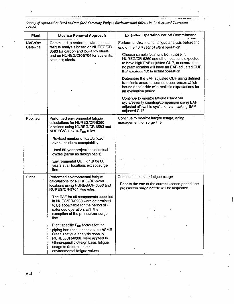
Survey offApproaches Used to-Date for Addressing Fatigue Environmental .ffects in the Extended Operating
Period
Plant License Renewal Approach Extended Operating Period Commitment
McGuire/ Committed to perform environmental Perform environmental fatigue analysis before theCatawba fatigue analysis based on NUREG/CR- end of the 40th year of plant operation
6583 for carbon and low-alloy steelsand on NUREG/CR-5704 for austenitic Choose sample locations from those in
stainless steels NUREG/CR-6260 and other locations expectedto have high EAF adjusted CUF, to ensure thatno plant location will have an EAF-adjusted CUFthat exceeds 1.0 in actual operation
Determine the EAF adjusted CUF using definedtransients and/or assumed occurrences whichbound or coincide witht realistic expectations foran evaluation period
Continue to monitor fatigue usage viacycle/severity counting/comparison using EAFadjusted allowable cycles or via tracking EAFadjusted CUF
Robinson Performed environmental fatigue Continue to monitor fatigue usage, agingcalculations for NUREG/CR-6260 management for surge linelocations using NUREG/CR-6583 andNUREG/CR-5704 Fen rules
Revised number of load/unloadevents to show acceptability
Used 60-year projections of actualcycles (same as design basis)
Environmental CUF < 1.0 for 60years at all locations except surgeline
Ginna Performed environmental fatigue Continue to monitor fatigue usagecalculations fo.r.NUREG/CR-6260..
locations using NUREG/CR-6583 and Prior to the end of the current license period, the
NUREG/CR-5704 Fen rules pressurizer surge nozzle will be inspected
The EAF for all components specifiedin NUEG/CR-6260 were determinedto be acceptable for the period of--extended operation, with theexception of the pressurizer surgeline
Plant specific Fen factors for thepiping locations, based on the ASMEClass 1 fatigue analysis done inNUREG/CR-6260, were applied toGinna-specific design basis fatigueusage to determine theenvironmental fatigue values
A-4

Survey ofApproaches Used to-Dare jfr Addressing Fatigue Environmental Effects in the Extended OperatingPeriod
Plant License Renewal Approach Extended Operating Period Commitment
Summer The thermal fatigue management .... assess EAF-before the end of the current-licensingprogram will be revised by the end of periodthe current licensing term to basefuture projections on 60 years ofoperation and to account for EAF
Dresden/ Did not perform environmental fatigue Continue to monitor fatigue usage, performQuad Cities calculations for NUREG/CR-6260 -environmental fatigue calculation before Year 40
locations
Committed to do so before Year 40
Farley Performed environmental fatigue.. Continue to monitor fatigue usagecalculations for NUREG/CR-6260locations using NUREG/CR-6583 and Prior to the end of the current license period, theNUREG/CR-5704 Fen rules charging and RHR locations will be addressed
furtherUsed existing Class 1 fatigueanalysis for all NUREG/CR-6260locations, except surge line and BITtee to RHR/SI piping
Developed Class 1 fatigue analysisfor surge line using stress-basedfatigue software
Used actual fatigue usage to date(based on available stress-baseddata) and design number of cyclesfor the surge line
Developed Class 1 fatigue analysisfo'r BIT tee to RHR/SI piping usingSummer 1979 ASME piping rules
The EAF for all components specified- in-NUREG/CR-6260 were determined
to be acceptable for the period ofextended operation with theexception of the charging nozzle andRHR locations
ANO-2 Performed environmental fatigue Continuetomonitor fatigue usage, and do one ofcalculations for NUREG/CR-6260 the following for the components where CUF > 1.0:locations using NUREG/CR-6583 andNUREG/CR-5704 Fen rules refinement of the fatigue analysis in an attempt to
lowerthe CUF to < 1.0Environmental CUF < 1.0 for 60 repairof ffoctedldtationt'-years for all RPV locations
For the pressurizer surge line, replacement of affected componentscharging nozzle and shutdown management of the effects of fatigue during thecooling line CUF > 1.0, safety period of extended operation using a program thatinjection nozzle < 1.0 will be reviewed and approved by the staff
through the RI-ISI program
A-5

Survey of Approaches Used to-Dare for Addressing Fatigue Environmental Effects in the Extended Operating
Period
Plant License Renewal Approach Extended Operating Period Commitment
Cook Performed environmental fatigue Continue to monitor fatigue usagecalculations for NUREGiCR-6260locations using NUREG/CR-6583 andNUREG/CR-5704 Fen rules
Developed Class 1 fatigue analysisfor three B31.1 piping locations
Used 60-year projections of actualcycles and actual fatigue usage to-date (higher than 40-year designbasis in some cases)
Environmental CUF < 1.0 for 60years at 5 of 6 locations. The "
environmental CUF was greater than1.0 for the pressurizer surge line.
Browns Performed environmental fatigue Continue to monitor fatigue usage, performFerry calculations for NUREG/CR-6260 analysis for piping locations
locations using NUREG/CR-6583 andNUREG/CR-5704 Fen rules
Refined several .Class -1 fatigueanalyses to offset Fen impact
Separate oxygen values computedfor HWC and NWC conditions,applied based upon historical andprojected system availability.
Used 60-year projections of actualcycles and actual fatigue usage to-date (higher than 40-year designbasis in some cases)
Environmental CUF < 1.0 for 60years for all RPV locations, pipinglocations > 1.0
TVA is developing Class 1 fatigueanalysis for piping locations
A-6

• ~ ~ ~ ~ ~ ~~~~~~ ".. . . .. .. .. . .. . .. . . . . ........... ...........
Survey ofApproaches Used to-Dare for Addressing Fatigue Environmental Effects in the Extended OperatingPeriod
Plant License Renewal Approach Extended Operating Period Commitment
Point Performed environmental fatigue........ Continue to monitor fatigue usageBeach calculations for NUREG/CR-6260
locations using NUREG/CR-6583 andNUREG/CR-5704 Fen rules
The EAF for all components specifiedin NUEG/CR-6260 were determinedto be acceptable for the period ofextended operation
Fatigue monitoring software used tocalculate spray line usage
Used plant operating data to analyzefatigue for piping locations sincedesign CUF values were notavailable
Brunswick Performed environmental fatigue Continue to monitor fatigue usagecalculations for NUREG/CR-6260locations using NUREG/CR-6583 andNUREG/CR-5704 Fen rules
Refined several Class 1 fatigueanalyses to offset Fen impact
Developed Class 1 fatigue analysisfor two B31.1 piping locations
Separate oxygen values computedfor HWC-and NWC conditions,applied based Upon historical andprojected system availability.
Used 60-year projections of actualcycles and actual fatigue usage to-date (higher than 40-year designbasis in some cases)
Environmental CUF < 1.0 for 60years at all locations
A-7

Export Control Restrictions
Access to and use of EPRI Intellectual Property is granted with
the specific understanding and requirement that responsibility
for ensuring full compliance with all applicable U.S. and
foreign export laws and regulations is being undertaken by
you and your company. This includes an obligation to ensure
that any individual receiving access hereunder who is not a
U.S. citizen or permanent U.S. resident is permitted access
under applicable U.S. and foreign export lows and
regulations., In the event you are uncertain whether you or
your company may lawfully obtain access to this EPRI
Intellectual Property, you acknowledge that it is your
obligation to consult with your company's legal counsel to
determine whether this access is lawful. Although EPRI may
make available on a case-by-case basis an informal
assessment of the applicable U.S. export classification for
specific EPRI Intellectual Property, you and your company
acknowledge that this assessment is solely for informational
pur.ses..and 'not for reliance purposes. You and your
company acknowledge that it is still the obligation of you and
your company to make your own assessment of the applicable
U.S. export classification and ensure compliance accordingly.
You and your company understand and acknowledge your
obligations to make a prompt report to EPRI and the
appropriate authorities regarding any access to or use of EPRI
Intellectual Property hereunder that may be in violation of
applicable U.S. or Foreign export laws or regulations.
O 2005 Electric Power Research Institute (EPRI., Inc. All rights reserved.Electric Power Research Inslitute and EPRI are registered service marks oFthe Electric Power Research Institute, Inc.
@ Printed on recycled paper in the United States of America
The Electric Power Research Institute (EPRI)
The Electric Power Research Institute (EPRI), with major locations in
- Polo Alto, California, and Charlolle, North Carolina, was established
in 1973 as on independent, nonprofit center for public interest
energy and environmental research. EPRI brings together members,
participants, the Institute's scientists and engineers, and other leading
experts to work collaborolively on solutions to the challenges of electric
power. These solutions span nearly every area of electricity generation,
delivery, and use, including health, safety, and environment. EPRI's
members represent over 90% of the electricity generated in the
United States, International participation represents nearly 15% of
EPRI's total research, development, and demonstration program.
Together...Shaping the Future of Electricity
Program:
Nuclear Power
t012017
ELECTRIC POWER RESEARCH INSTITUTE3420 Hillview Avenue, Polo Alto, California 94304-1395 * PO Box 104 12, Polo Alto, California 94303-0813 USA
800.313.3774 - 650.855.2121 * [email protected] o www.epri.com