CombiTac main catalog - Staubli
136
CombiTacline | Industrial Connectors CombiTac Main catalog
-
Upload
khangminh22 -
Category
Documents
-
view
1 -
download
0
Transcript of CombiTac main catalog - Staubli

CombiTacline | Industrial Connectors
CombiTac Main catalog

2 CombiTac main catalog
STÄUBLI ELECTRICAL CONNECTORS
Long-term solutions – Expert connections
Stäubli Electrical Connectors is a leading
international manufacturer of high-quality
electrical connector systems. We are part
of the Stäubli Group which off ers mecha-
tronics solutions for electrical connectors,
liquid and gas couplings, robots and textile
machinery.
Stäubli develops, produces, sells and main-
tains products for markets with high produc-
tivity standards. As recognized specialists,
our focus is always on solutions and cus-
tomers. Many new developments got their
start here and have begun to make their way
around the world.
Businesses and customers count on our
commitment and our active support when
dealing with unusual problems. With us, you
are entering into a long-term partnership
built on reliability, dynamism, and excep-
tional quality in both products and services.
CombiTac main catalog 3
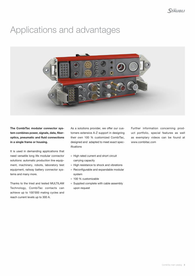
Applications and advantages
The CombiTac modular connector sys-
tem combines power, signals, data, fi ber-
optics, pneumatic and fl uid connections
in a single frame or housing.
It is used in demanding applications that
need versatile long life modular connector
solutions: automatic production line equip-
ment, machinery, robots, laboratory test
equipment, railway battery connector sys-
tems and many more.
Thanks to the tried and tested MULTILAM
Technology, CombiTac contacts can
achieve up to 100’000 mating cycles and
reach current levels up to 300 A.
As a solutions provider, we off er our cus-
tomers extensive A-Z support in designing
their own 100 % customized CombiTac,
designed and adapted to meet exact spec-
ifi cations
High rated current and short circuit
carrying capacity
High resistance to shock and vibrations
Reconfi gurable and expandable modular
system
100 % customizable
Supplied complete with cable assembly
upon request
Further information concerning prod-
uct portfolio, special features as well
as exemplary videos can be found at
www.combitac.com
4 CombiTac main catalog
Content
Page 6 Introduction
Page 8 Ø 12 mm Power unit
Up to 300 A, 1000 V
For details on see page 121
Page 16 Ø 8 mm Power unit
Up to 150 A, 1000 V
For details on see page 121
Page 18 Ø 6 mm, Ø 8 mm Power unit
Up to 125 A, 150 A, 1000 V
For details on see page 121
Page 20 Ø 6 mm Power unit
Up to 120 A, 1000 V
For details on see page 121
Page 22 Ø 3 mm Power unit
Up to 40 A, 1000 V
For details on see page 121
Page 26 Ø 3 mm High voltage unit
Up to 5 kV, 42 A
For details on see page 121
Page 28 Ø 1,5 mm High voltage unit
Up to 2.5 kV, 19 A
For details on see page 121
Page 30 Ø 1.5 mm Signal unit
Up to 19 A, 600 V
For details on see page 121
Page 32 Ø 1 mm Signal unit
Up to 12 A, 300 V
For details on see page 121
Page 36 Ø 0.6 mm Signal unit
Up to 6 A, 150 V
Page 38 Last Mate First Break module
For details on see page 121
Page 40 Coaxial unit 6 GHz
For details on see page 121
Page 42 Coaxial unit 1.5 GHz
Page 44 Data transfer unit
CAT5 Ethernet, IEEE802.3, Profibus, Profinet,
Interbus, CAN-BUS, USB 2.0, PoE
10Gbit module CAT6A Ethernet IEEE 802.3an,
USB 2.0, PoE
RJ45 Data Transfer Unit
CAT5 Ethernet IEEE802.3, USB 2.0
Page 50 Optical fiber unit POF
(Plastic optical fiber)
Page 52 Optical fiber unit GOF
(Glass optical fiber)
Page 54 Thermocouple unit
Page 58 Pneumatic and fluid units
Compressed air – vacuum unit
Coolant unit
Page 72 Single parts for CombiTac frames
Page 73 Calculation of installation dimensions
Page 74 Panel mounted
Page 76 DIN housings for CombiTac
Coding
Calculation of housing size
Spacers
Aluminum / Plastic DIN housings
Page 96 Protective grounding of conductive housings
For details on see page 121
Page 102 Light housing for testing applications
Page 104 Crimping pliers
Page 106 Assembly tools
Page 109 Appendix
Derating diagrams
Technical information
Index

CombiTac main catalog 5
Changes / provisos
All data, illustrations, and drawings in the
catalog have been carefully checked. They
are in accordance with our experience to
date, but no responsibility can be accepted
for errors.
We also reserve the right to make modi-
fi cations for design and safety reasons.
When designing equipment incorporating
our components, it is therefore advisable
not to rely solely on the data in the catalog
but to consult us to make sure this informa-
tion is up to date. We shall be pleased to
advise you.
Copyright
The use of this catalog for any other pur-
pose, in whatever form, without our prior
written consent is not permitted.
RoHS ready
All CombiTac parts comply with Directive
2011/65/EC on the restriction of the use of
certain hazardous substances in electrical
and electronic equipment.
Symbols
Accessories or special tools exist for this
product
www.staubli.com/electrical
MAIch bin eine Montageanleitung.
Man sollte mich unbedingt le-
sen, bevor man das Produkt ver-
wendet! Ich beinhalte wertvolle
Hinweise zur korrekten Montage
und zum richtigen Einsatz des
Produktes. Im Moment ist die
Schrift zwar ein bischen klein,
aber später geht das dann ganz
gut zu lesen, da die MA dann
The assembly instructions MA000 are
available for this product
www.staubli.com/electrical
Surface Ag
Surface Au
Abbreviations
S = Screw termination
PCB = Flow soldered termination
C = Crimp termination
L = Soldering
AWG = American Wire Gauge
Housing
TG = Coupler hood
KG = Coupler housing
AG = Surface mount housing
SG = Pedestal mount housing
-S = Cable inlet, side
-G = Cable inlet, straight
-PW = Protective wall
-D = With lid
-PS = Park station
ZV = Central locking
SD-...L/FSCH = Plastic protective cover
with lanyard for metal
housing IP65
General information

6 CombiTac main catalog
DIN coupler hoods
6 different sizes
Mating cycles
CombiTac as panel mounted: up to 100,000
CombiTac in housing: up to 5,000
For the connector, the lowest mating cycle value of the individual
components applies.
The modular connector systemCOMBITAC
Rails
Included in delivery
May be ordered separately
End pieces in 2 versions
Housing assembly
Panel mounting
Included in delivery
May be ordered separately
Delivery status of the CombiTac
Contact carriers mounted on rails
Assembled with end pieces
Contacts separately
Gas and fluid couplings will be mounted in the carriers
PCB contacts will be mounted on request
Possible connections
Electric
Thermocouple pressure contacts
Coaxial
Optical fiber
Compressed air
Liquid
Electric + PE
Data transfer
Fully assembled CombiTac connector with connecting lines
On request
DIN surface and pedestal mount housing
6 different sizes
CombiTac main catalog 7
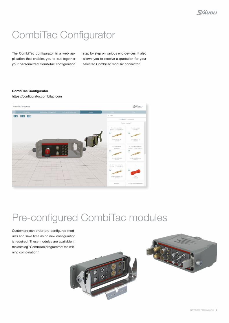
CombiTac Configurator
https://configurator.combitac.com
CombiTac Configurator
step by step on various end devices. It also
allows you to receive a quotation for your
selected CombiTac modular connector.
The CombiTac configurator is a web ap-
plication that enables you to put together
your personalized CombiTac configuration
Pre-configured CombiTac modulesCustomers can order pre-configured mod-
ules and save time as no new configuration
is required. These modules are available in
the catalog "CombiTac programme: the win-
ning combination".
E229145
8 CombiTac main catalog
Technical data
Number of poles 1
For contact diameter 12 mm
Pollution degree / overvoltage category 2 / CATII 3 / CATIII
Rated voltage, crimp termination screw termination
1000 V800 V 400 V
Rated voltage UL 600 V
Degree of protection (socket and plug front) IP2X
Clearances and creepage distance IEC 60664-1 and UL 1977
Limiting temperature (IEC 61984), upper lower
+90 °C −40 °C
Contact carrier material PA
Order No. Type Description
33.4082 CT-E12-1/B Socket carrier (identification “B”)
33.4081 CT-E12-1/S Pin carrier (identification “S”)
33.4083 CT-RC12 Retaining clip (included with carriers)
MAIch bin eine Montageanleitung.
Man sollte mich unbedingt le-
sen, bevor man das Produkt ver-
wendet! Ich beinhalte wertvolle
Hinweise zur korrekten Montage
und zum richtigen Einsatz des
Produktes. Im Moment ist die
Schrift zwar ein bischen klein,
aber später geht das dann ganz
gut zu lesen, da die MA dann
Assembly instructions MA213-01
www.staubli.com/electrical
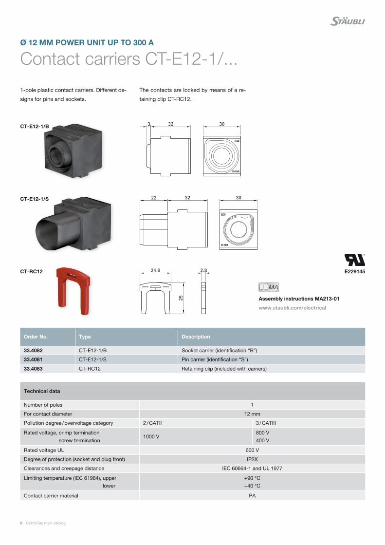
Contact carriers CT-E12-1/...Ø 12 MM POWER UNIT UP TO 300 A
1-pole plastic contact carriers. Different de-
signs for pins and sockets.
The contacts are locked by means of a re-
taining clip CT-RC12.
CT-E12-1/B
CT-RC12
CT-E12-1/S
CombiTac main catalog 9
1) IEC Rated values refer to heat-resistant copper wires in accordance with IEC 60364-5-52.
Technical data
Nominal-Ø socket/pin 12 mm
Max. sliding force per contact 28 N
Contact resistance < 25 μΩ
Mating cycles 100,000
MAIch bin eine Montageanleitung.
Man sollte mich unbedingt le-
sen, bevor man das Produkt ver-
wendet! Ich beinhalte wertvolle
Hinweise zur korrekten Montage
und zum richtigen Einsatz des
Produktes. Im Moment ist die
Schrift zwar ein bischen klein,
aber später geht das dann ganz
gut zu lesen, da die MA dann
Assembly instructions MA213-01
www.staubli.com/electrical
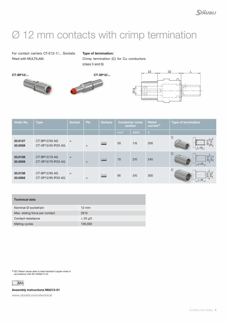
Ø 12 mm contacts with crimp termination
For contact carriers CT-E12-1/... Sockets
fitted with MULTILAM.
Type of termination:
Crimp termination (C) for Cu conductors
(class 5 and 6)
CT-SP12/... CT-BP12/...
Order No. Type Socket Pin Surface Conductor cross section
Rated current¹⁾
Type of termination
mm² AWG A
33.0127 33.0558
CT-BP12/50 AG CT-SP12/50 IP2X AG
× ×
50 1/0 200
33.0128 33.0559
CT-BP12/70 AG CT-SP12/70 IP2X AG
× ×
70 2/0 245
33.0138 33.0562
CT-BP12/95 AG CT-SP12/95 IP2X AG
× ×
95 3/0 300
C
C
C

10 CombiTac main catalog
Ø 12 mm contacts with M10 inside thread
For contact carriers CT-E12-1/... Sockets
fitted with MULTILAM
Type of termination:
Screw termination (S) using an M10 inside
thread by means of a cable lug for Cu con-
ductors (class 5 and 6)
Note:
Screw terminations can not be fitted in
housings due to space limitations.
CT-B12/M10 AG CT-S12/M10 IP2X AG
1) Depending on cable lug size.2) IEC Rated values refer to heat-resistant copper wires in
accordance with IEC 60364-5-52.3) Cable lugs Cu/Sn according to DIN 46234.
Order No. Type Socket Pin Surface Conductor cross section
Rated current²⁾
Type of termination
mm² AWG A
33.0139 CT-B12/M10 AG ×50 70 95
1/0 2/0 3/0
200 245 300
33.0564 CT-S12/M10 IP2X AG ×50 70 95
1/0 2/0 3/0
200 245 300
33001501 K-SCH50-10³⁾ Cable lug 50 1/0
33.4114 CT-K-SCH70-10³⁾ Cable lug 70 2/0
33.4115 CT-K-SCH95-10³⁾ Cable lug 95 3/0
S
S
Technical data
Nominal-Ø socket/pin 12 mm
Max. sliding force per contact 28 N
Contact resistance 25 μΩ
Mating cycles 100,000
Pos. Order No. Type Remarks
1 11004669 ZYL-SHR-IN-6KT M10×20 ISO4762 BN610 Cheese head screw M10x20
2 08.0706 F/M10 DIN6798A BN781 Serrated lock washer F/M10
3 08.0306 U/M10 AG Washer M10
Individual parts (supplied with 33.0139 and 33.0564)
CombiTac main catalog 11
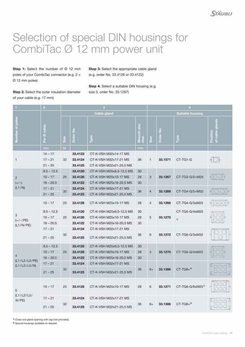
Step 1: Select the number of Ø 12 mm
poles of your CombiTac connector (e.g. 2 ×
Ø 12 mm poles)
Step 2: Select the outer insulation diameter
of your cable (e.g. 17 mm)
Selection of special DIN housings for CombiTac Ø 12 mm power unit
Step 3: Select the appropriate cable gland
(e.g. order No. 33.4126 or 33.4122)
Step 4: Select a suitable DIN housing (e.g.
size 3, order No. 33.1267)
1) Close one gland opening with cap (not provided).2) Special housings available on request.
1 2 3 4
Num
ber
of
po
les
For
Ø c
able
Cable gland Suitable housing
Siz
e
Ord
er N
o.
Typ
e
Wre
nch
size
m
ax.
Siz
e
Ord
er N
o.
Typ
e
Po
sitio
n o
f ca
ble
gla
nds
mm M mm
1
14 – 17
32
33.4123 CT-K-VSH M32x14-17 MS
36 1 33.1571 CT-TG1-G17 – 21 33.4124 CT-K-VSH M32x17-21 MS
21 – 25 33.4125 CT-K-VSH M32x21-25,5 MS
2 (+ / -) (L1 / N)
9.5 – 12.5
25
33.4120 CT-K-VSH M25x9,5-12,5 MS 30
3 33.1267 CT-TG3-G/2×M2510 – 17 33.4126 CT-K-VSH M25x10-17 MS 28
16 – 20.5 33.4122 CT-K-VSH M25x16-20,5 MS 30
17 – 2132
33.4124 CT-K-VSH M32x17-21 MS36 4 33.1269 CT-TG4-G/2×M32
21 – 25 33.4125 CT-K-VSH M32x21-25,5 MS
3 (+ / - / PE) (L1 / N / PE)
10 – 17 25 33.4126 CT-K-VSH M25x10-17 MS 28 4 33.1268 CT-TG4-G/3xM25
9.5 – 12.5
25
33.4120 CT-K-VSH M25x9,5-12,5 MS 30
5 33.1270
CT-TG5-G/4xM25
10 – 17 33.4126 CT-K-VSH M25x10-17 MS 28¹⁾
16 – 20.5 33.4122 CT-K-VSH M25x16-20,5 MS 30
17 – 21
32
33.4124 CT-K-VSH M32x17-21 MS
36 6 33.1272 CT-TG6-G/3xM3221 – 25 33.4125 CT-K-VSH M32x21-25,5 MS
4 (L1 / L2 / L3 / PE) (L1 / L2 / L3 / N)
9.5 – 12.5
25
33.4120 CT-K-VSH M25x9,5-12,5 MS 30
5 33.1270 CT-TG5-G/4xM2510 – 17 33.4126 CT-K-VSH M25x10-17 MS 28
16 – 20.5 33.4122 CT-K-VSH M25x16-20,5 MS 30
17 – 21
32
33.4124 CT-K-VSH M32x17-21 MS
36 6+ 33.1386 CT-TG6+²⁾21 – 25 33.4125 CT-K-VSH M32x21-25,5 MS
5 (L1 / L2 / L3 / N / PE)
10 – 17 25 33.4126 CT-K-VSH M25x10-17 MS 28 6 33.1271 CT-TG6-G/6xM25¹⁾
17 – 21
32
33.4124 CT-K-VSH M32x17-21 MS
36 6+ 33.1386 CT-TG6+²⁾21 – 25 33.4125 CT-K-VSH M32x21-25,5 MS
E229145
12 CombiTac main catalog
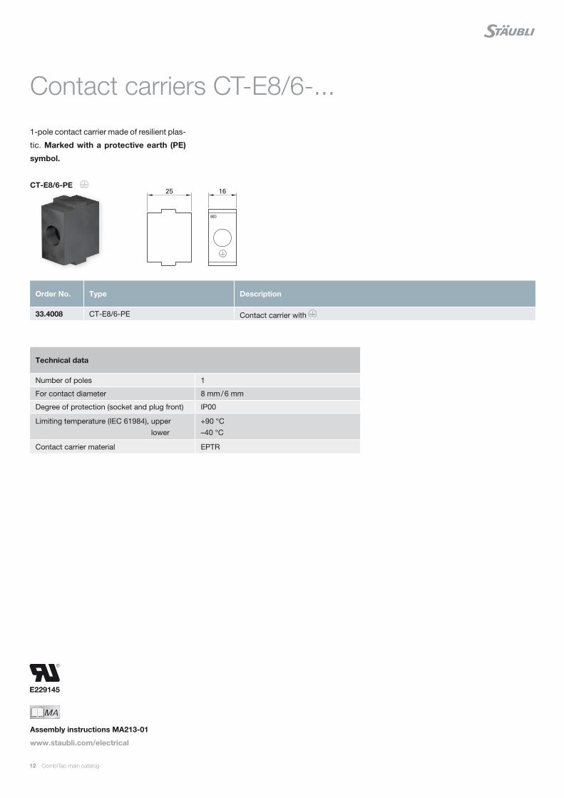
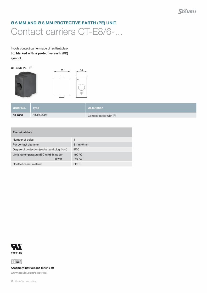
Contact carriers CT-E8/6-...
1-pole contact carrier made of resilient plas-
tic. Marked with a protective earth (PE)
symbol.
Order No. Type Description
33.4008 CT-E8/6-PE Contact carrier with
Technical data
Number of poles 1
For contact diameter 8 mm / 6 mm
Degree of protection (socket and plug front) IP00
Limiting temperature (IEC 61984), upper lower
+90 °C –40 °C
Contact carrier material EPTR
MAIch bin eine Montageanleitung.
Man sollte mich unbedingt le-
sen, bevor man das Produkt ver-
wendet! Ich beinhalte wertvolle
Hinweise zur korrekten Montage
und zum richtigen Einsatz des
Produktes. Im Moment ist die
Schrift zwar ein bischen klein,
aber später geht das dann ganz
gut zu lesen, da die MA dann
Assembly instructions MA213-01
www.staubli.com/electrical
CT-E8/6-PE
CombiTac main catalog 13
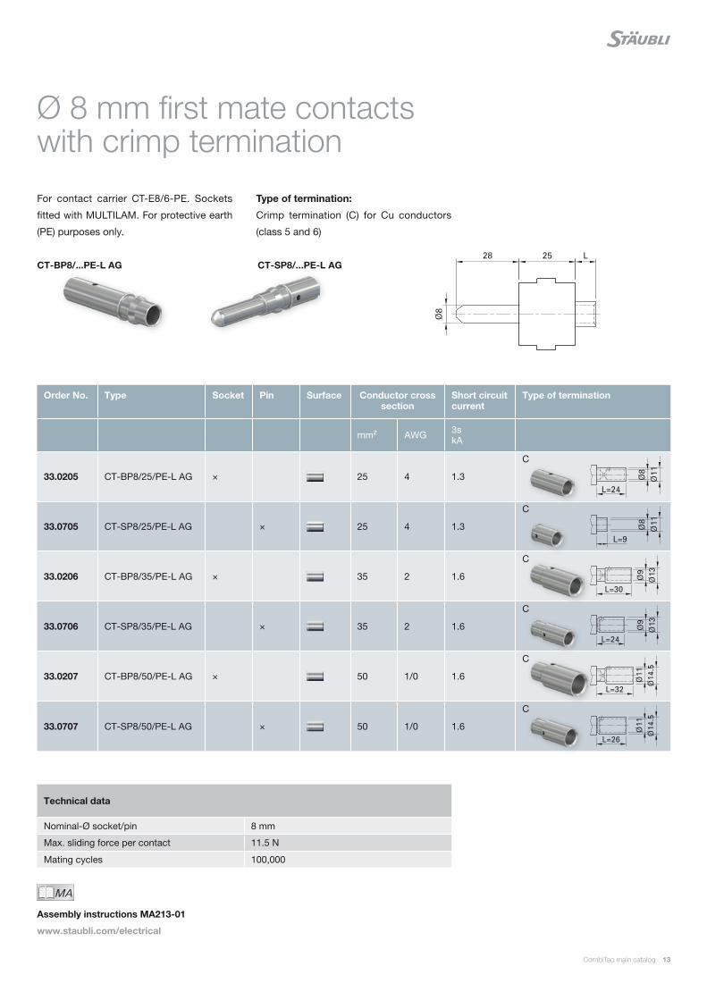
Ø 8 mm first mate contacts with crimp termination
For contact carrier CT-E8/6-PE. Sockets
fitted with MULTILAM. For protective earth
(PE) purposes only.
Type of termination:
Crimp termination (C) for Cu conductors
(class 5 and 6)
CT-SP8/...PE-L AG CT-BP8/...PE-L AG
Order No. Type Socket Pin Surface Conductor cross section
Short circuit current
Type of termination
mm² AWG 3s kA
33.0205 CT-BP8/25/PE-L AG × 25 4 1.3
33.0705 CT-SP8/25/PE-L AG × 25 4 1.3
33.0206 CT-BP8/35/PE-L AG × 35 2 1.6
33.0706 CT-SP8/35/PE-L AG × 35 2 1.6
33.0207 CT-BP8/50/PE-L AG × 50 1/0 1.6
33.0707 CT-SP8/50/PE-L AG × 50 1/0 1.6
C
C
C
C
C
C
Technical data
Nominal-Ø socket/pin 8 mm
Max. sliding force per contact 11.5 N
Mating cycles 100,000
MAIch bin eine Montageanleitung.
Man sollte mich unbedingt le-
sen, bevor man das Produkt ver-
wendet! Ich beinhalte wertvolle
Hinweise zur korrekten Montage
und zum richtigen Einsatz des
Produktes. Im Moment ist die
Schrift zwar ein bischen klein,
aber später geht das dann ganz
gut zu lesen, da die MA dann
Assembly instructions MA213-01
www.staubli.com/electrical
14 CombiTac main catalog
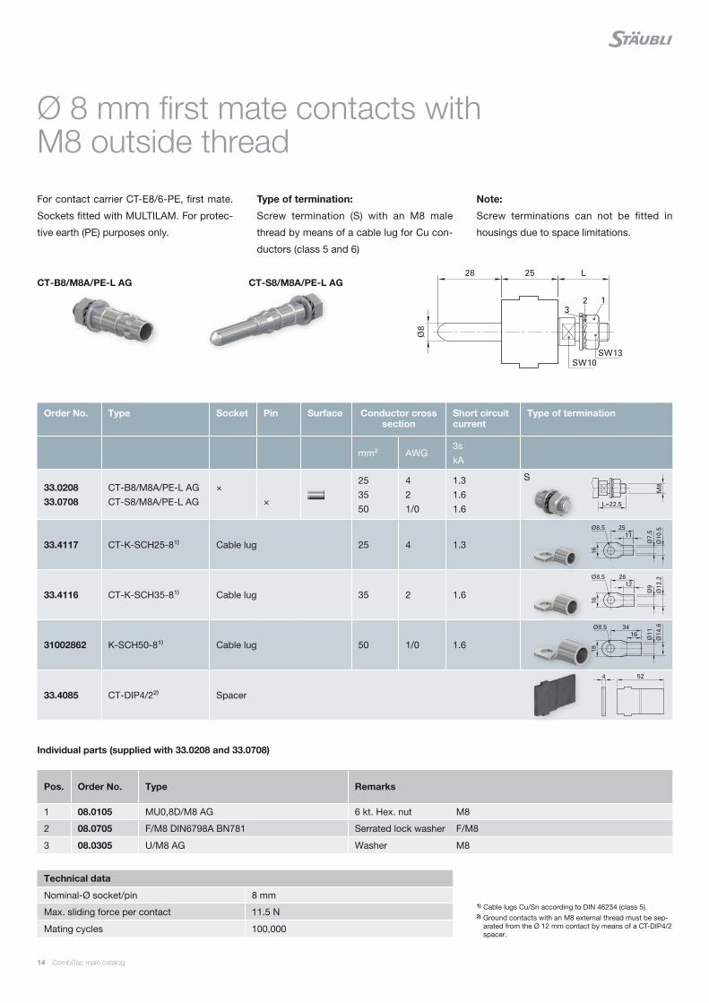
Ø 8 mm first mate contacts with M8 outside thread
For contact carrier CT-E8/6-PE, first mate.
Sockets fitted with MULTILAM. For protec-
tive earth (PE) purposes only.
Type of termination:
Screw termination (S) with an M8 male
thread by means of a cable lug for Cu con-
ductors (class 5 and 6)
Note:
Screw terminations can not be fitted in
housings due to space limitations.
1) Cable lugs Cu/Sn according to DIN 46234 (class 5).2) Ground contacts with an M8 external thread must be sep-
arated from the Ø 12 mm contact by means of a CT-DIP4/2 spacer.
Technical data
Nominal-Ø socket/pin 8 mm
Max. sliding force per contact 11.5 N
Mating cycles 100,000
CT-S8/M8A/PE-L AG CT-B8/M8A/PE-L AG
Order No. Type Socket Pin Surface Conductor cross section
Short circuit current
Type of termination
mm² AWG3s kA
33.0208 33.0708
CT-B8/M8A/PE-L AG CT-S8/M8A/PE-L AG
× ×
25 35 50
4 2 1/0
1.3 1.6 1.6
33.4117 CT-K-SCH25-8¹⁾ Cable lug 25 4 1.3
33.4116 CT-K-SCH35-8¹⁾ Cable lug 35 2 1.6
31002862 K-SCH50-8¹⁾ Cable lug 50 1/0 1.6
33.4085 CT-DIP4/2²⁾ Spacer
S
Pos. Order No. Type Remarks
1 08.0105 MU0,8D/M8 AG 6 kt. Hex. nut M8
2 08.0705 F/M8 DIN6798A BN781 Serrated lock washer F/M8
3 08.0305 U/M8 AG Washer M8
Individual parts (supplied with 33.0208 and 33.0708)

CombiTac main catalog 15
CombiTac: modular, compact, versatile
E229145
16 CombiTac main catalog
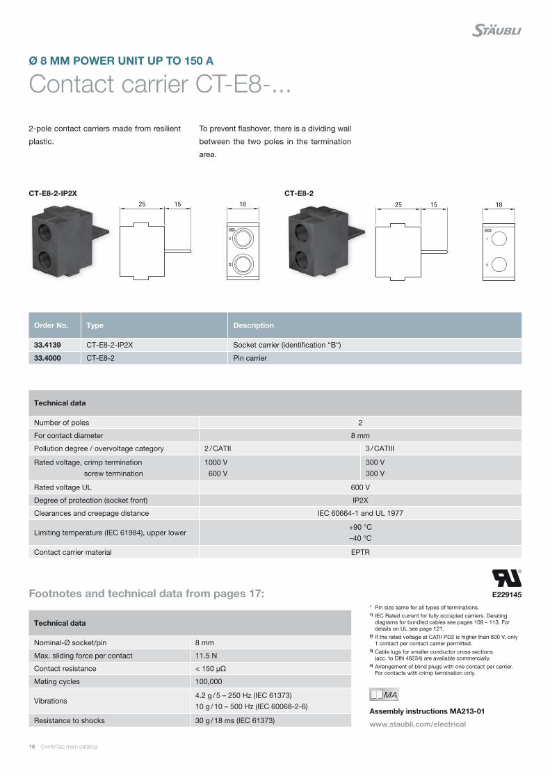
Contact carrier CT-E8-...Ø 8 MM POWER UNIT UP TO 150 A
2-pole contact carriers made from resilient
plastic.
To prevent flashover, there is a dividing wall
between the two poles in the termination
area.
* Pin size same for all types of terminations.1) IEC Rated current for fully occupied carriers. Derating
diagrams for bundled cables see pages 109 – 113. For details on UL see page 121.
2) If the rated voltage at CATII PD2 is higher than 600 V, only 1 contact per contact carrier permitted.
3) Cable lugs for smaller conductor cross sections (acc. to DIN 46234) are available commercially.
4) Arrangement of blind plugs with one contact per carrier. For contacts with crimp termination only.
Technical data
Number of poles 2
For contact diameter 8 mm
Pollution degree / overvoltage category 2 / CATII 3 / CATIII
Rated voltage, crimp termination screw termination
1000 V 600 V
300 V 300 V
Rated voltage UL 600 V
Degree of protection (socket front) IP2X
Clearances and creepage distance IEC 60664-1 and UL 1977
Limiting temperature (IEC 61984), upper lower+90 °C –40 °C
Contact carrier material EPTR
Technical data
Nominal-Ø socket/pin 8 mm
Max. sliding force per contact 11.5 N
Contact resistance < 150 μΩ
Mating cycles 100,000
Vibrations4.2 g / 5 – 250 Hz (IEC 61373) 10 g / 10 – 500 Hz (IEC 60068-2-6)
Resistance to shocks 30 g / 18 ms (IEC 61373)
Order No. Type Description
33.4139 CT-E8-2-IP2X Socket carrier (identification “B“)
33.4000 CT-E8-2 Pin carrier
Footnotes and technical data from pages 17:
MAIch bin eine Montageanleitung.
Man sollte mich unbedingt le-
sen, bevor man das Produkt ver-
wendet! Ich beinhalte wertvolle
Hinweise zur korrekten Montage
und zum richtigen Einsatz des
Produktes. Im Moment ist die
Schrift zwar ein bischen klein,
aber später geht das dann ganz
gut zu lesen, da die MA dann
Assembly instructions MA213-01
www.staubli.com/electrical
CT-E8-2 CT-E8-2-IP2X

CombiTac main catalog 17
Ø 8 mm contacts
For contact carrier CT-E8-2-IP2X and
CT-E8-2. Sockets fitted with MULTILAM.
Type of termination:
Crimp termination (C) for Cu conductors
(class 5 and 6)
Screw termination (S) for cable lugs
and contacts with M6 inside or outside
thread
Note:
Screw terminations can not be fitted in
housings due to space limitations.
Order No. Type Socket Pin Surface Conductor cross section
Rated current¹⁾ Type of termination
mm² AWG A
33.0100 33.0500
CT-BP8/10 AG CT-SP8/10 AG
× ×
10 8 5533.0101 33.0501
CT-BP8/10 AU CT-SP8/10 AU
× ×
33.0102 33.0502
CT-BP8/16 AG CT-SP8/16 AG
× ×
16 6 7533.0103 33.0503
CT-BP8/16 AU CT-SP8/16 AU
× ×
33.0104 33.0504
CT-BP8/25 AG CT-SP8/25 AG
× ×
25 4 10033.0105 33.0505
CT-BP8/25 AU CT-SP8/25 AU
× ×
33.0106 33.0506
CT-BP8/35 AG CT-SP8/35 AG
× ×
35²⁾ 2 120¹⁾ / 150²⁾
33.0110 33.0510
CT-B8/M6 AG CT-S8/M6 AG
× ×
10 16 25 35
8 6 4 2
55 75 100 120
33.0111 33.0511
CT-B8/M6 AU CT-S8/M6 AU
× ×
33.0120 33.0520
CT-B8/M6A AG CT-S8/M6A AG
× ×
10 16 25 35
8 6 4 2
55 75 100 120
33.0121 33.0521
CT-B8/M6A AU CT-S8/M6A AU
× ×
33.4039 CT-KSCH6-35³⁾ Cable lug 35 2
33.4050 CT-BS8 Blind plug⁴⁾
C
C
C
C
S
S
CT-E8-2 CT-E8-2-IP2X CT-SP8/... CT-BP8/...
E229145
18 CombiTac main catalog
Contact carriers CT-E8/6-...Ø 6 MM AND Ø 8 MM PROTECTIVE EARTH (PE) UNIT
1-pole contact carrier made of resilient plas-
tic. Marked with a protective earth (PE)
symbol.
Order No. Type Description
33.4008 CT-E8/6-PE Contact carrier with
Technical data
Number of poles 1
For contact diameter 8 mm / 6 mm
Degree of protection (socket and plug front) IP00
Limiting temperature (IEC 61984), upper lower
+90 °C –40 °C
Contact carrier material EPTR
MAIch bin eine Montageanleitung.
Man sollte mich unbedingt le-
sen, bevor man das Produkt ver-
wendet! Ich beinhalte wertvolle
Hinweise zur korrekten Montage
und zum richtigen Einsatz des
Produktes. Im Moment ist die
Schrift zwar ein bischen klein,
aber später geht das dann ganz
gut zu lesen, da die MA dann
Assembly instructions MA213-01
www.staubli.com/electrical
CT-E8/6-PE
CombiTac main catalog 19
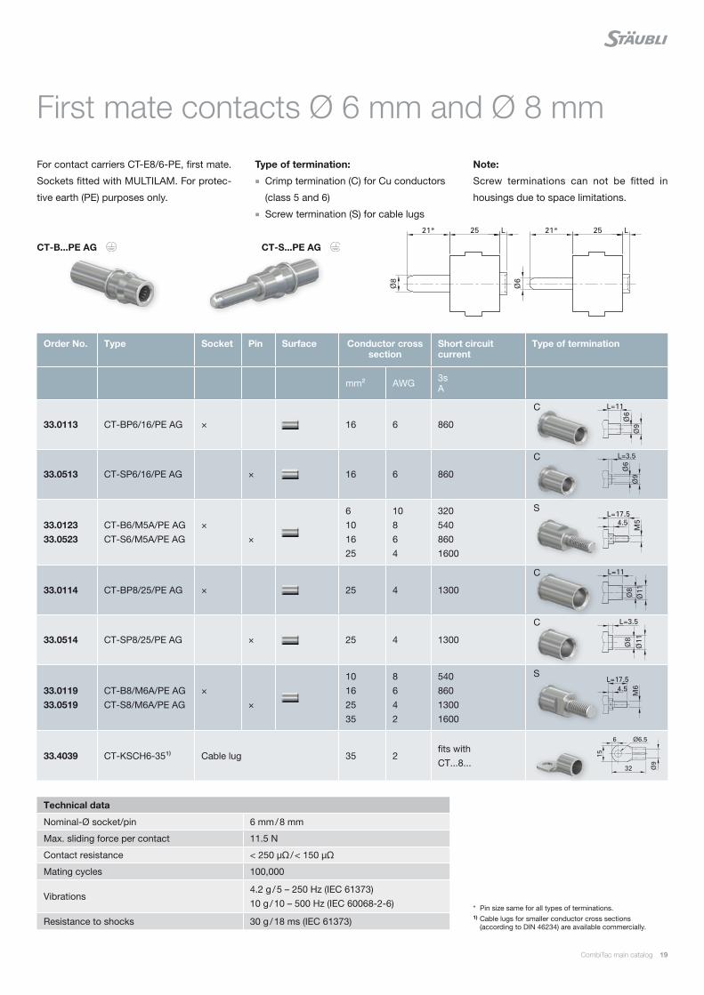
First mate contacts Ø 6 mm and Ø 8 mm
For contact carriers CT-E8/6-PE, first mate.
Sockets fitted with MULTILAM. For protec-
tive earth (PE) purposes only.
Type of termination:
Crimp termination (C) for Cu conductors
(class 5 and 6)
Screw termination (S) for cable lugs
Note:
Screw terminations can not be fitted in
housings due to space limitations.
* Pin size same for all types of terminations.1) Cable lugs for smaller conductor cross sections
(according to DIN 46234) are available commercially.
Technical data
Nominal-Ø socket/pin 6 mm / 8 mm
Max. sliding force per contact 11.5 N
Contact resistance < 250 μΩ / < 150 μΩ
Mating cycles 100,000
Vibrations4.2 g / 5 – 250 Hz (IEC 61373) 10 g / 10 – 500 Hz (IEC 60068-2-6)
Resistance to shocks 30 g / 18 ms (IEC 61373)
Order No. Type Socket Pin Surface Conductor cross section
Short circuit current
Type of termination
mm² AWG 3s A
33.0113 CT-BP6/16/PE AG × 16 6 860
33.0513 CT-SP6/16/PE AG × 16 6 860
33.0123 33.0523
CT-B6/M5A/PE AG CT-S6/M5A/PE AG
× ×
6 10 16 25
10 8 6 4
320 540 860 1600
33.0114 CT-BP8/25/PE AG × 25 4 1300
33.0514 CT-SP8/25/PE AG × 25 4 1300
33.0119 33.0519
CT-B8/M6A/PE AG CT-S8/M6A/PE AG
× ×
10 16 25 35
8 6 4 2
540 860 1300 1600
33.4039 CT-KSCH6-35¹⁾ Cable lug 35 2fits with CT...8...
C
C
S
C
C
S
CT-S...PE AG CT-B...PE AG
E229145
20 CombiTac main catalog
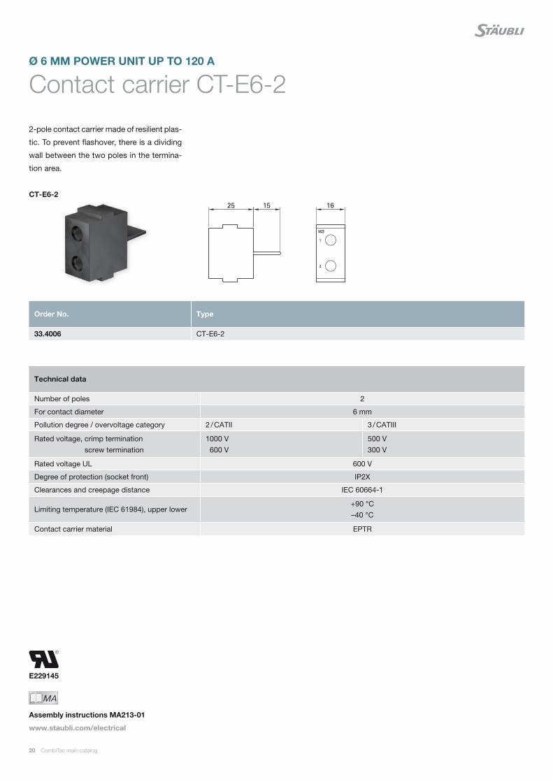
Contact carrier CT-E6-2Ø 6 MM POWER UNIT UP TO 120 A
2-pole contact carrier made of resilient plas-
tic. To prevent flashover, there is a dividing
wall between the two poles in the termina-
tion area.
CT-E6-2
Order No. Type
33.4006 CT-E6-2
Technical data
Number of poles 2
For contact diameter 6 mm
Pollution degree / overvoltage category 2 / CATII 3 / CATIII
Rated voltage, crimp termination screw termination
1000 V 600 V
500 V 300 V
Rated voltage UL 600 V
Degree of protection (socket front) IP2X
Clearances and creepage distance IEC 60664-1
Limiting temperature (IEC 61984), upper lower+90 °C –40 °C
Contact carrier material EPTR
MAIch bin eine Montageanleitung.
Man sollte mich unbedingt le-
sen, bevor man das Produkt ver-
wendet! Ich beinhalte wertvolle
Hinweise zur korrekten Montage
und zum richtigen Einsatz des
Produktes. Im Moment ist die
Schrift zwar ein bischen klein,
aber später geht das dann ganz
gut zu lesen, da die MA dann
Assembly instructions MA213-01
www.staubli.com/electrical

CombiTac main catalog 21
Ø 6 mm contacts
For contact carriers CT-E6-2. Sockets fitted
with MULTILAM.
Type of termination:
Crimp termination (C) for Cu conductors
(class 5 and 6)
Screw termination (S) for cable lugs and
contacts with an M5 inside or outside
thread
Note:
Screw terminations can not be fitted in
housings due to space limitations.
CT-S6... CT-B6...
* Pin size same for all types of terminations.1) IEC Rated current for fully occupied carriers. Derating
diagrams for bundled leads, see pages 109 – 113. For details on UL see page 121.
2) Cable lugs according to DIN 46234 are available commercially.
Order No. Type Socket Pin Surface Conductor cross section
Rated current¹⁾ Type of termination
mm² AWG A
33.0107 33.0507
CT-BP6/6 AG CT-SP6/6 AG
× ×
6 10 40
33.0108 33.0508
CT-BP6/10 AG CT-SP6/10 AG
× ×
10 8 55
33.0109 33.0509
CT-BP6/16 AG CT-SP6/16 AG
× ×
16 6 75
33.0112 33.0512
CT-B6/M5 AG CT-S6/M5 AG
× ×
6 10 16 25
10 8 6 4
40 55 75 100
33.0122 33.0522
CT-B6/M5A AG CT-S6/M5A AG
× ×
6 10 16 25
10 8 6 4
40 55 75 100
18.5502 MVS5 Blind plug
C
C
C
S²⁾
S²⁾
Technical data
Nominal-Ø socket/pin 6 mm
Max. sliding force per contact 11.5 N
Contact resistance < 250 μΩ
Mating cycles 100,000
Vibrations4.2 g / 5 – 250 Hz (IEC 61373) 10 g / 10 – 500 Hz (IEC 60068-2-6)
Resistance to shocks 30 g / 18 ms (IEC 61373)
MAIch bin eine Montageanleitung.
Man sollte mich unbedingt le-
sen, bevor man das Produkt ver-
wendet! Ich beinhalte wertvolle
Hinweise zur korrekten Montage
und zum richtigen Einsatz des
Produktes. Im Moment ist die
Schrift zwar ein bischen klein,
aber später geht das dann ganz
gut zu lesen, da die MA dann
Assembly instructions MA213-01
www.staubli.com/electrical
E229145
22 CombiTac main catalog
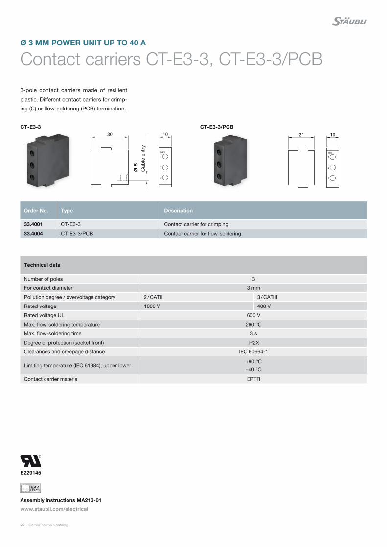
Contact carriers CT-E3-3, CT-E3-3/PCB
3-pole contact carriers made of resilient
plastic. Different contact carriers for crimp-
ing (C) or flow-soldering (PCB) termination.
Ø 3 MM POWER UNIT UP TO 40 A
Technical data
Number of poles 3
For contact diameter 3 mm
Pollution degree / overvoltage category 2 / CATII 3 / CATIII
Rated voltage 1000 V 400 V
Rated voltage UL 600 V
Max. flow-soldering temperature 260 °C
Max. flow-soldering time 3 s
Degree of protection (socket front) IP2X
Clearances and creepage distance IEC 60664-1
Limiting temperature (IEC 61984), upper lower+90 °C –40 °C
Contact carrier material EPTR
Order No. Type Description
33.4001 CT-E3-3 Contact carrier for crimping
33.4004 CT-E3-3/PCB Contact carrier for flow-soldering
MAIch bin eine Montageanleitung.
Man sollte mich unbedingt le-
sen, bevor man das Produkt ver-
wendet! Ich beinhalte wertvolle
Hinweise zur korrekten Montage
und zum richtigen Einsatz des
Produktes. Im Moment ist die
Schrift zwar ein bischen klein,
aber später geht das dann ganz
gut zu lesen, da die MA dann
Assembly instructions MA213-01
www.staubli.com/electrical
CT-E3-3 CT-E3-3/PCBØ
5
Cab
le e
ntry
CombiTac main catalog 23
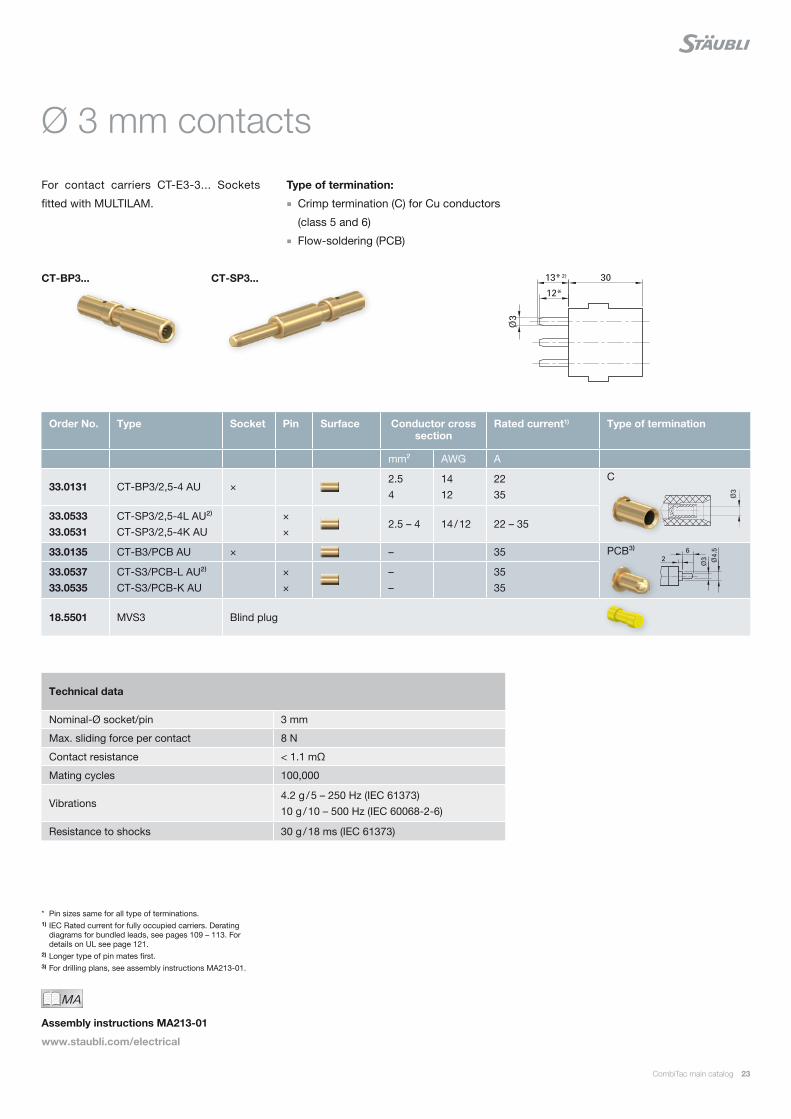
Ø 3 mm contacts
For contact carriers CT-E3-3... Sockets
fitted with MULTILAM.
Type of termination:
Crimp termination (C) for Cu conductors
(class 5 and 6)
Flow-soldering (PCB)
* Pin sizes same for all type of terminations.1) IEC Rated current for fully occupied carriers. Derating
diagrams for bundled leads, see pages 109 – 113. For details on UL see page 121.
2) Longer type of pin mates first.3) For drilling plans, see assembly instructions MA213-01.
Technical data
Nominal-Ø socket/pin 3 mm
Max. sliding force per contact 8 N
Contact resistance < 1.1 mΩ
Mating cycles 100,000
Vibrations4.2 g / 5 – 250 Hz (IEC 61373) 10 g / 10 – 500 Hz (IEC 60068-2-6)
Resistance to shocks 30 g / 18 ms (IEC 61373)
Order No. Type Socket Pin Surface Conductor cross section
Rated current1) Type of termination
mm² AWG A
33.0131 CT-BP3/2,5-4 AU ×2.5 4
14 12
22 35
33.0533 33.0531
CT-SP3/2,5-4L AU²⁾ CT-SP3/2,5-4K AU
× ×
2.5 – 4 14 / 12 22 – 35
33.0135 CT-B3/PCB AU × – 35
33.0537 33.0535
CT-S3/PCB-L AU²⁾ CT-S3/PCB-K AU
× ×
– –
35 35
18.5501 MVS3 Blind plug
C
PCB³⁾
MAIch bin eine Montageanleitung.
Man sollte mich unbedingt le-
sen, bevor man das Produkt ver-
wendet! Ich beinhalte wertvolle
Hinweise zur korrekten Montage
und zum richtigen Einsatz des
Produktes. Im Moment ist die
Schrift zwar ein bischen klein,
aber später geht das dann ganz
gut zu lesen, da die MA dann
Assembly instructions MA213-01
www.staubli.com/electrical
CT-BP3... CT-SP3...
24 CombiTac main catalog
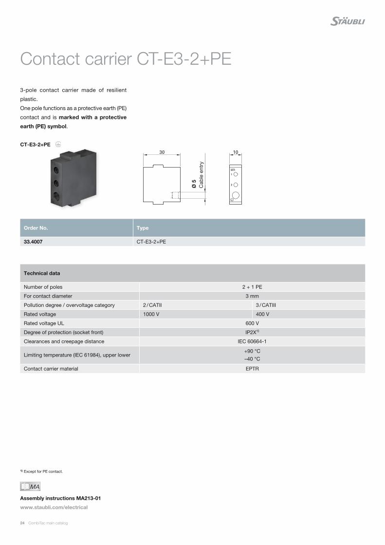
Contact carrier CT-E3-2+PE
3-pole contact carrier made of resilient
plastic.
One pole functions as a protective earth (PE)
contact and is marked with a protective
earth (PE) symbol.
CT-E3-2+PE
1) Except for PE contact.
Order No. Type
33.4007 CT-E3-2+PE
Technical data
Number of poles 2 + 1 PE
For contact diameter 3 mm
Pollution degree / overvoltage category 2 / CATII 3 / CATIII
Rated voltage 1000 V 400 V
Rated voltage UL 600 V
Degree of protection (socket front) IP2X¹⁾
Clearances and creepage distance IEC 60664-1
Limiting temperature (IEC 61984), upper lower+90 °C –40 °C
Contact carrier material EPTR
MAIch bin eine Montageanleitung.
Man sollte mich unbedingt le-
sen, bevor man das Produkt ver-
wendet! Ich beinhalte wertvolle
Hinweise zur korrekten Montage
und zum richtigen Einsatz des
Produktes. Im Moment ist die
Schrift zwar ein bischen klein,
aber später geht das dann ganz
gut zu lesen, da die MA dann
Assembly instructions MA213-01
www.staubli.com/electrical
Ø 5
C
able
ent
ry

CombiTac main catalog 25
Ø 3 mm contacts
For contact carriers CT-E3-2+PE. Sockets
fitted with MULTILAM. Protective earth (PE)
contacts and standard contacts. PE contacts
for protective earth (PE) purposes only.¹⁾
Type of termination:
Crimp termination (C) for Cu conductors
(class 5 and 6)
CT-BP3/2,5-4/PE AU CT-SP3/2,5-4/PE AU
1) Short circuit current 3s 2.5 mm²: 135 A 4 mm²: 216 A
2) IEC Rated current for fully occupied carriers. Derating diagrams for bundled leads, see pages 109 – 113. For details on UL see page 121.
3) Protective earth (PE) contact.4) Longer type of pin mates first.
Order No. Type Socket Pin Surface Conductor cross section
Rated current²⁾ Type of termination
mm² AWG A
33.0129 CT-BP3/2,5-4/PE AU³⁾ ×2.5 4
14 12
–¹⁾ –¹⁾
33.0529 CT-SP3/2,5-4/PE AU³⁾ ×2.5 4
14 12
–¹⁾ –¹⁾
33.0131 CT-BP3/2,5-4 AU ×2.5 4
14 12
22 35
33.0533 33.0531
CT-SP3/2,5-4L AU⁴⁾ CT-SP3/2,5-4K AU
× ×
2.5 4
14 12
22 35
18.5501 MVS3 Blind plug
C
Technical data
Nominal-Ø socket/pin 3 mm
Max. sliding force per contact 8 N
Contact resistance < 1.1 mΩ
Mating cycles 100,000
Vibrations4.2 g / 5 – 250 Hz (IEC 61373) 10 g / 10 – 500 Hz (IEC 60068-2-6)
Resistance to shocks 30 g / 18 ms (IEC 61373)
MAIch bin eine Montageanleitung.
Man sollte mich unbedingt le-
sen, bevor man das Produkt ver-
wendet! Ich beinhalte wertvolle
Hinweise zur korrekten Montage
und zum richtigen Einsatz des
Produktes. Im Moment ist die
Schrift zwar ein bischen klein,
aber später geht das dann ganz
gut zu lesen, da die MA dann
Assembly instructions MA213-01
www.staubli.com/electrical

E229145
26 CombiTac main catalog
Contact carriers CT-E3-.../HV...
1- and 2-pole contact carriers made of resil-
ient plastic. With PTFE insert.
Ø 3 MM HIGH VOLTAGE UNIT UP TO 5 KV
Note:
The maximum outside diameter of the con-
ductor insulation is 6.6 mm.
Technical data
Number of poles 1 or 2
For contact diameter 3 mm
Pollution degree 2
Rated voltage phase-to-earth 2.9 kV
Rated voltage phase-to-phase 5 kV
Rated voltage UL 600 V
Test Voltage 1 min., 50/60 Hz; phase-to-earth 6.6 kV
Test Voltage 1 min., 50/60 Hz; phase-to-phase 13.7 kV
Degree of protection (in mated condition) IP2X
Limiting temperature (IEC 61984), upper lower+90 °C –40 °C
Contact carrier material Insulation material
EPTR PTFE
Order No. Type Description
33.4136 CT-E3-2/HV-B 2-pole socket carrier
33.4137 CT-E3-1/HV-B 1-pole socket carrier
33.4536 CT-E3-2/HV-S 2-pole pin carrier
33.4537 CT-E3-1/HV-S 1-pole pin carrier
MAIch bin eine Montageanleitung.
Man sollte mich unbedingt le-
sen, bevor man das Produkt ver-
wendet! Ich beinhalte wertvolle
Hinweise zur korrekten Montage
und zum richtigen Einsatz des
Produktes. Im Moment ist die
Schrift zwar ein bischen klein,
aber später geht das dann ganz
gut zu lesen, da die MA dann
Assembly instructions MA213-05
www.staubli.com/electrical
CT-E3-1/HV-B
CT-E3-1/HV-S
CT-E3-2/HV-B
CT-E3-2/HV-S

CombiTac main catalog 27
Ø 3 mm/HV
For contact carrier CT-E.../HV-... Sockets
fitted with MULTILAM.
Type of termination:
Crimp termination (C) for Cu high voltage
conductors 2.5 mm², followed by insulation
with shrink tubing CT-HV-SRTU
Note:
All data regarding ratings apply to the
mated condition
Connector without breaking capacity
(COC)
The connector must not be connected or
disconnected when live or under load
* Add the desired color code.1) IEC Rated current for fully occupied carriers. Derating
diagrams for bundled leads, see pages 109 – 113. For details on UL see page 121.
Technical data
Nominal-Ø socket/pin 3 mm
Max. sliding force per contact 8 N
Contact resistance < 1.1 mΩ
Mating cycles 100,000
Vibrations4.2 g / 5 – 250 Hz (IEC 61373) 10 g / 10 – 500 Hz (IEC 60068-2-6)
Resistance to shocks 30 g / 18 ms (IEC 61373)
Order No. Type Socket Pin Surface Conductor cross section
Rated current¹⁾ Type of termination
mm² AWG 2 poles 1 pole
33.0163 33.0563
CT-BP3/2,5-HV AU CT-SP3/2,5-HV AU
× ×
2.5 14 20 A 32 A
Accessories
33.5666 CT-HV-SRTU Shrink tubing 45 mm (included)
MAIch bin eine Montageanleitung.
Man sollte mich unbedingt le-
sen, bevor man das Produkt ver-
wendet! Ich beinhalte wertvolle
Hinweise zur korrekten Montage
und zum richtigen Einsatz des
Produktes. Im Moment ist die
Schrift zwar ein bischen klein,
aber später geht das dann ganz
gut zu lesen, da die MA dann
Assembly instructions MA213-05
www.staubli.com/electrical
Order No. Type Conductor cross section Rated current¹⁾ Colors
mm² AWG 2 poles 1 pole
61.7634-* SILI-HV 2,5 2.5 14 20 A 32 A 21 22
Recommended cable
CT-BP3/2,5-HV AU CT-SP3/2,5-HV AU

E229145
28 CombiTac main catalog
CT-E1,5-4/HV-B CT-E1,5-4/HV-S
Order No. Type Designation
33.4118 CT-E1,5-4/HV-B 4-pole socket carrier
33.4518 CT-E1,5-4/HV-S 4-pole pin carrier
Contact carrier CT-E1,5-4/HV...
4-pole high voltage module up to 2.5 kV for
general industry, railway, and testing appli-
cations.
Features:
Space saving 4-pole solution
Railway compliant material
Resistance to shock and vibrations
Tool-free insertion of contacts in carrier
Ø 1.5 MM HIGH VOLTAGE UNIT UP TO 2.5 KV
Technical data
Number of poles 4
For contact diameter 1.5 mm
Pollution degree / overvoltage category 2/CATII 3/CATIII
Rated voltageUAC 2000 V UDC 2500 V
1000 V
Rated voltage UL 600 V
Test voltage r.m.s. 1 min., 50/60 Hz 6.6 kV
Degree of protection (socket front) IP2X
Limiting temperature (IEC 61984), upper lower
+90 °C –40 °C
Contact carrier material PA
Fire and smoke compliance EN 45545-2 (HL2 R22)
MAIch bin eine Montageanleitung.
Man sollte mich unbedingt le-
sen, bevor man das Produkt ver-
wendet! Ich beinhalte wertvolle
Hinweise zur korrekten Montage
und zum richtigen Einsatz des
Produktes. Im Moment ist die
Schrift zwar ein bischen klein,
aber später geht das dann ganz
gut zu lesen, da die MA dann
Assembly instructions MA213-05
www.staubli.com/electrical
CombiTac main catalog 29
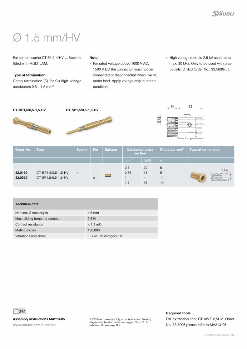
Ø 1.5 mm/HV
For contact carrier CT-E1,5-4/HV-... Sockets
fitted with MULTILAM.
Type of termination:
Crimp termination (C) for Cu high voltage
conductors 0.5 – 1.5 mm²
Note:
For rated voltage above 1000 V AC,
1500 V DC the connector must not be
connected or disconnected when live or
under load. Apply voltage only in mated
condition.
1) IEC Rated current for fully occupied carriers. Derating diagrams for bundled leads, see pages 109 – 113. For details on UL see page 121.
Technical data
Nominal-Ø socket/pin 1.5 mm
Max. sliding force per contact 2.5 N
Contact resistance < 1.3 mΩ
Mating cycles 100,000
Vibrations and shock IEC 61373 category 1B
Order No. Type Socket Pin Surface Conductor cross section
Rated current1) Type of termination
mm² AWG A
33.0169 33.0569
CT-BP1,5/0,5-1,5-HV CT-SP1,5/0,5-1,5-HV
× ×
0.50.7511.5
2018–16
691114
MAIch bin eine Montageanleitung.
Man sollte mich unbedingt le-
sen, bevor man das Produkt ver-
wendet! Ich beinhalte wertvolle
Hinweise zur korrekten Montage
und zum richtigen Einsatz des
Produktes. Im Moment ist die
Schrift zwar ein bischen klein,
aber später geht das dann ganz
gut zu lesen, da die MA dann
Assembly instructions MA213-05
www.staubli.com/electrical
CT-BP1,5/0,5-1,5-HV CT-SP1,5/0,5-1,5-HV
Required tools
For extraction tool CT-AWZ-2,5HV, Order
No. 33.3006 please refer to MA213-05.
High voltage module 2.5 kV used up to
max. 30 kHz. Only to be used with plas-
tic rails (CT-BS Order No.: 33.5606-...).
E229145
30 CombiTac main catalog
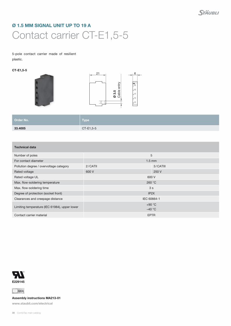
Contact carrier CT-E1,5-5
5-pole contact carrier made of resilient
plastic.
Ø 1.5 MM SIGNAL UNIT UP TO 19 A
Technical data
Number of poles 5
For contact diameter 1.5 mm
Pollution degree / overvoltage category 2 / CATII 3 / CATIII
Rated voltage 600 V 250 V
Rated voltage UL 600 V
Max. flow-soldering temperature 260 °C
Max. flow-soldering time 3 s
Degree of protection (socket front) IP2X
Clearances and creepage distance IEC 60664-1
Limiting temperature (IEC 61984), upper lower+90 °C –40 °C
Contact carrier material EPTR
Order No. Type
33.4005 CT-E1,5-5
MAIch bin eine Montageanleitung.
Man sollte mich unbedingt le-
sen, bevor man das Produkt ver-
wendet! Ich beinhalte wertvolle
Hinweise zur korrekten Montage
und zum richtigen Einsatz des
Produktes. Im Moment ist die
Schrift zwar ein bischen klein,
aber später geht das dann ganz
gut zu lesen, da die MA dann
Assembly instructions MA213-01
www.staubli.com/electrical
CT-E1,5-5
Ø 3
.5
Cab
le e
ntry
CombiTac main catalog 31
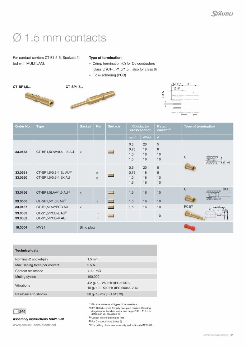
Ø 1.5 mm contacts
For contact carriers CT-E1,5-5. Sockets fit-
ted with MULTILAM.
Type of termination:
Crimp termination (C) for Cu conductors
(class 5) (CT-...P1,5/1,5... also for class 6)
Flow-soldering (PCB)
* Pin size same for all types of terminations.1) IEC Rated current for fully occupied carriers. Derating
diagrams for bundled leads, see pages 109 – 113. For details on UL see page 121.
2) Longer type of pin mates first.3) For Cu conductors (class 6).4) For drilling plans, see assembly instructions MA213-01.
Technical data
Nominal-Ø socket/pin 1.5 mm
Max. sliding force per contact 2.5 N
Contact resistance < 1.1 mΩ
Mating cycles 100,000
Vibrations4.2 g / 5 – 250 Hz (IEC 61373) 10 g / 10 – 500 Hz (IEC 60068-2-6)
Resistance to shocks 30 g / 18 ms (IEC 61373)
Order No. Type Socket Pin Surface Conductor cross section
Rated current¹⁾
Type of termination
mm² AWG A
33.0153 CT-BP1,5LAV/0,5-1,5 AU ×
0.5 0.75 1.0 1.5
20 18 18 16
5 8 10 10
33.0551 33.0550
CT-SP1,5/0,5-1,5L AU²⁾ CT-SP1,5/0,5-1,5K AU
× ×
0.5 0.75 1.0 1.5
20 18 18 16
5 8 10 10
33.0156 CT-BP1,5LAV/1,5 AU³⁾ × 1.5 16 10
33.0555 CT-SP1,5/1,5K AU³⁾ × 1.5 16 10
33.0157 CT-B1,5LAV/PCB AU × 1.5 16 10
33.0553 33.0552
CT-S1,5/PCB-L AU²⁾ CT-S1,5/PCB-K AU
× ×
10
18.5504 MVS1 Blind plug
C
C
PCB⁴⁾
MAIch bin eine Montageanleitung.
Man sollte mich unbedingt le-
sen, bevor man das Produkt ver-
wendet! Ich beinhalte wertvolle
Hinweise zur korrekten Montage
und zum richtigen Einsatz des
Produktes. Im Moment ist die
Schrift zwar ein bischen klein,
aber später geht das dann ganz
gut zu lesen, da die MA dann
Assembly instructions MA213-01
www.staubli.com/electrical
CT-BP1,5... CT-SP1,5...

E229145
32 CombiTac main catalog
Contact carriers CT-E1-26/...
26-pole contact carrier made of resil-
ient plastic. Different designs for pins and
sockets.
For suitable contacts, see page 35.
Ø 1 MM SIGNAL UNIT UP TO 12 A
CT-E1-26/B CT-E1-26/S
Technical data
Number of poles 26
For contact diameter 1 mm
Pollution degree / overvoltage category 2 / CATII 3 / CATIII
Rated voltage 300 V 150 V
Rated voltage UL 250 V
Max. flow-soldering temperature 260 °C
Max. flow-soldering time 3 s
Degree of protection (socket front) IP2X
Clearances and creepage distance IEC 60664-1
Limiting temperature (IEC 61984), upper lower+90 °C –40 °C
Contact carrier material EPTR
Order No. Type Description
33.4002 CT-E1-26/B Socket carrier (identification “B”)
33.4003 CT-E1-26/S Pin carrier (identification “S”)
MAIch bin eine Montageanleitung.
Man sollte mich unbedingt le-
sen, bevor man das Produkt ver-
wendet! Ich beinhalte wertvolle
Hinweise zur korrekten Montage
und zum richtigen Einsatz des
Produktes. Im Moment ist die
Schrift zwar ein bischen klein,
aber später geht das dann ganz
gut zu lesen, da die MA dann
Assembly instructions MA213-01
www.staubli.com/electrical
Ø 2
.5
Cab
le e
ntry
Ø 2
.5
Cab
le e
ntry

E229145
CombiTac main catalog 33
Contact carriers CT-E1-15/...
15-pole contact carrier made of resil-
ient plastic. Different designs for pins and
sockets.
For suitable contacts, see page 35.
CT-E1-15/B CT-E1-15/S
Technical data
Number of poles 15
For contact diameter 1 mm
Pollution degree / overvoltage category 2 / CATII 3 / CATIII
Rated voltage 300 V 150 V
Rated voltage UL 250 V
Max. flow-soldering temperature 260 °C
Max. flow-soldering time 3 s
Degree of protection (socket front) IP2X
Clearances and creepage distance IEC 60664-1
Limiting temperature (IEC 61984), upper lower+90 °C –40 °C
Contact carrier material PA & EPTR
Order No. Type Description
33.4022 CT-E1-15/B Socket carrier (identification “B“)
33.4023 CT-E1-15/S Pin carrier (identification “S“)
MAIch bin eine Montageanleitung.
Man sollte mich unbedingt le-
sen, bevor man das Produkt ver-
wendet! Ich beinhalte wertvolle
Hinweise zur korrekten Montage
und zum richtigen Einsatz des
Produktes. Im Moment ist die
Schrift zwar ein bischen klein,
aber später geht das dann ganz
gut zu lesen, da die MA dann
Assembly instructions MA213-01
www.staubli.com/electrical
Ø 2
.5
Cab
le e
ntry
Ø 2
,5
Cab
le e
ntry
E229145
34 CombiTac main catalog
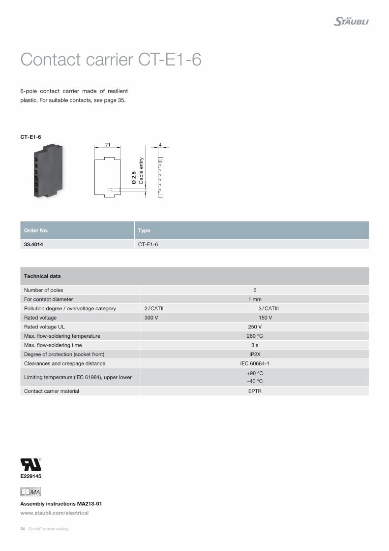
Contact carrier CT-E1-6
6-pole contact carrier made of resilient
plastic. For suitable contacts, see page 35.
MAIch bin eine Montageanleitung.
Man sollte mich unbedingt le-
sen, bevor man das Produkt ver-
wendet! Ich beinhalte wertvolle
Hinweise zur korrekten Montage
und zum richtigen Einsatz des
Produktes. Im Moment ist die
Schrift zwar ein bischen klein,
aber später geht das dann ganz
gut zu lesen, da die MA dann
Assembly instructions MA213-01
www.staubli.com/electrical
Technical data
Number of poles 6
For contact diameter 1 mm
Pollution degree / overvoltage category 2 / CATII 3 / CATIII
Rated voltage 300 V 150 V
Rated voltage UL 250 V
Max. flow-soldering temperature 260 °C
Max. flow-soldering time 3 s
Degree of protection (socket front) IP2X
Clearances and creepage distance IEC 60664-1
Limiting temperature (IEC 61984), upper lower+90 °C –40 °C
Contact carrier material EPTR
Order No. Type
33.4014 CT-E1-6
CT-E1-6Ø
2.5
C
able
ent
ry

CombiTac main catalog 35
Ø 1 mm contacts
For contact carriers CT-E1-26/...,
CT-E1-15/..., and CT-E1-6. Sockets fitted
with MULTILAM.
Type of termination:
Crimp termination (C) for Cu conductors
(class 5 and 6)
Flow-soldering (PCB)
* Pin size same for all types of terminations.1) IEC Rated current for fully occupied carriers. Derating
diagrams for bundled leads, see pages 110 – 113. For details on UL see page 121.
2) Longer type of pin mates first.3) For drilling plans, see assembly instructions MA213-01.
Technical data
CT-BP... & CT-B... CT-BP1ET... & CT-B1ET...
Nominal-Ø socket/pin 1 mm 1 mm
Max. sliding force per contact 2 N 0.5 N
Contact resistance < 1.6 mΩ < 3 mΩ
Mating cycles 5000 100,000
Vibrations4.2 g / 5 – 250 Hz (IEC 61373) 10 g / 10 – 500 Hz (IEC 60068-2-6)
Resistance to shocks 30 g / 18 ms (IEC 61373)
Order No. Type Socket Pin Surface Conductor cross section
Rated current1)
Type of termination
mm² AWG A
33.0141 33.0143
CT-BP1/0,25-0,75 AU CT-BP1ET/0,25-0,75 AU³⁾
× ×
0.25 0.5 0.75
24 20 18
2 3 5
33.0543 33.0541
CT-SP1/0,25-0,75L AU²⁾ CT-SP1/0,25-0,75K AU
× ×
0.25 0.5 0.75
24 20 18
2 3 5
33.0145 33.0146
CT-B1/PCB AU CT-B1ET/PCB AU
× ×
5 5
33.0547 33.0545
CT-S1/PCB-L AU²⁾ CT-S1/PCB-K AU
× ×
5 5
33.4051 CT-BS1 Blind plug
C
PCB³⁾
MAIch bin eine Montageanleitung.
Man sollte mich unbedingt le-
sen, bevor man das Produkt ver-
wendet! Ich beinhalte wertvolle
Hinweise zur korrekten Montage
und zum richtigen Einsatz des
Produktes. Im Moment ist die
Schrift zwar ein bischen klein,
aber später geht das dann ganz
gut zu lesen, da die MA dann
Assembly instructions MA213-01
www.staubli.com/electrical
CT-BP1... CT-SP1... CT-E1-6 CT-E1-15/... CT-E1-26/...
36 CombiTac main catalog
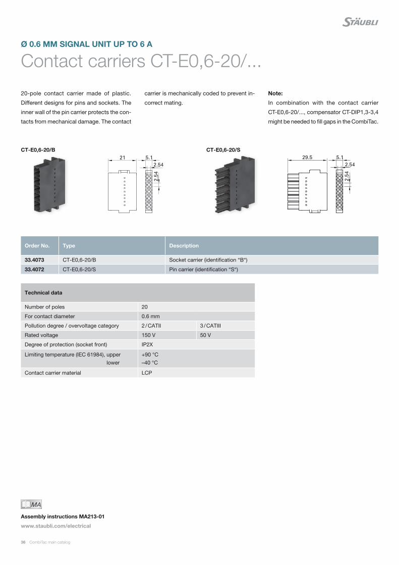
Contact carriers CT-E0,6-20/...
20-pole contact carrier made of plastic.
Different designs for pins and sockets. The
inner wall of the pin carrier protects the con-
tacts from mechanical damage. The contact
Ø 0.6 MM SIGNAL UNIT UP TO 6 A
carrier is mechanically coded to prevent in-
correct mating.
Note:
In combination with the contact carrier
CT-E0,6-20/..., compensator CT-DIP1,3-3,4
might be needed to fill gaps in the CombiTac.
CT-E0,6-20/SCT-E0,6-20/B
Technical data
Number of poles 20
For contact diameter 0.6 mm
Pollution degree / overvoltage category 2 / CATII 3 / CATIII
Rated voltage 150 V 50 V
Degree of protection (socket front) IP2X
Limiting temperature (IEC 61984), upper lower
+90 °C –40 °C
Contact carrier material LCP
Order No. Type Description
33.4073 CT-E0,6-20/B Socket carrier (identification “B“)
33.4072 CT-E0,6-20/S Pin carrier (identification “S“)
MAIch bin eine Montageanleitung.
Man sollte mich unbedingt le-
sen, bevor man das Produkt ver-
wendet! Ich beinhalte wertvolle
Hinweise zur korrekten Montage
und zum richtigen Einsatz des
Produktes. Im Moment ist die
Schrift zwar ein bischen klein,
aber später geht das dann ganz
gut zu lesen, da die MA dann
Assembly instructions MA213-01
www.staubli.com/electrical
CombiTac main catalog 37
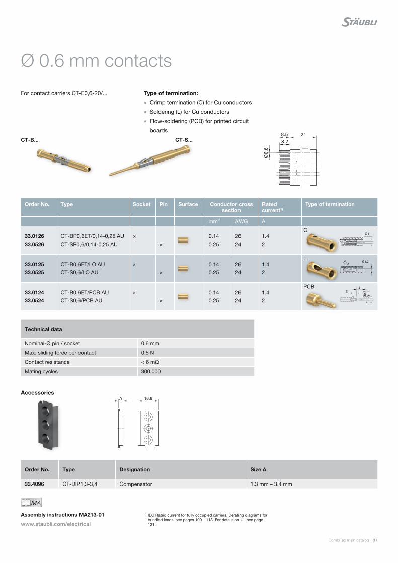
Ø 0.6 mm contacts
For contact carriers CT-E0,6-20/... Type of termination:
Crimp termination (C) for Cu conductors
Soldering (L) for Cu conductors
Flow-soldering (PCB) for printed circuit
boards
CT-B... CT-S...
1) IEC Rated current for fully occupied carriers. Derating diagrams for bundled leads, see pages 109 – 113. For details on UL see page 121.
Order No. Type Socket Pin Surface Conductor cross section
Rated current1)
Type of termination
mm² AWG A
33.0126 33.0526
CT-BP0,6ET/0,14-0,25 AU CT-SP0,6/0,14-0,25 AU
× ×
0.140.25
2624
1.42
33.0125 33.0525
CT-B0,6ET/LO AU CT-S0,6/LO AU
× ×
0.140.25
2624
1.42
33.0124 33.0524
CT-B0,6ET/PCB AU CT-S0,6/PCB AU
× ×
0.140.25
2624
1.42
C
L
PCB
Technical data
Nominal-Ø pin / socket 0.6 mm
Max. sliding force per contact 0.5 N
Contact resistance < 6 mΩ
Mating cycles 300,000
MAIch bin eine Montageanleitung.
Man sollte mich unbedingt le-
sen, bevor man das Produkt ver-
wendet! Ich beinhalte wertvolle
Hinweise zur korrekten Montage
und zum richtigen Einsatz des
Produktes. Im Moment ist die
Schrift zwar ein bischen klein,
aber später geht das dann ganz
gut zu lesen, da die MA dann
Assembly instructions MA213-01
www.staubli.com/electrical
Order No. Type Designation Size A
33.4096 CT-DIP1,3-3,4 Compensator 1.3 mm – 3.4 mm
Accessories

E229145
38 CombiTac main catalog
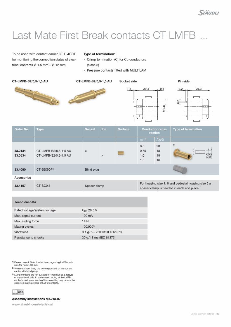
Module CT-LMFB/...
Last Mate First Break (LMFB) contacts are
intended for monitoring purposes, and show
whether a CombiTac is fully connected or
not. Each CombiTac LMFB module consists
LAST MATE FIRST BREAK MODULE
of two LMFB contacts placed at the edge
positions of a carrier.
Suitable for panel mount and housing ap-
plications.
Order No. Type Description
33.2257 CT-LMFB/B Socket module
33.2657 CT-LMFB/S Pin module
Technical data
Contact carrier material PA
Limiting temperature (IEC 61984), upper lower
+90 °C –40 °C
MAIch bin eine Montageanleitung.
Man sollte mich unbedingt le-
sen, bevor man das Produkt ver-
wendet! Ich beinhalte wertvolle
Hinweise zur korrekten Montage
und zum richtigen Einsatz des
Produktes. Im Moment ist die
Schrift zwar ein bischen klein,
aber später geht das dann ganz
gut zu lesen, da die MA dann
Assembly instructions MA213-07
www.staubli.com/electrical
CT-LMFB/B CT-LMFB/S
Rails ≤ 90 mm¹⁾
CombiTac main catalog 39
Last Mate First Break contacts CT-LMFB-...
To be used with contact carrier CT-E-4GOF
for monitoring the connection status of elec-
trical contacts Ø 1.5 mm – Ø 12 mm.
Type of termination:
Crimp termination (C) for Cu conductors
(class 5)
Pressure contacts fitted with MULTILAM
Technical data
Rated voltage/system voltage UDC 29.5 V
Max. signal current 100 mA
Max. sliding force 14 N
Mating cycles 100,000³⁾
Vibrations 3.1 g / 5 – 250 Hz (IEC 61373)
Resistance to shocks 30 g / 18 ms (IEC 61373)
Order No. Type Socket Pin Surface Conductor cross section
Type of termination
mm² AWG
33.0134 33.0534
CT-LMFB-B2/0,5-1,5 AU CT-LMFB-S2/0,5-1,5 AU
× ×
0.50.751.01.5
20181816
33.4080 CT-BSGOF²⁾ Blind plug
Accesories
33.4157 CT-SC0,8 Spacer clampFor housing size 1, 6 and pedestal housing size 5 a spacer clamp is needed in each end piece
C
1) Please consult Stäubli sales team regarding LMFB mod-ules for Rails > 90 mm
2) We recomment filling the two empty slots of the contact carrier with blind plugs.
3) LMFB contacts are not suitable for inductive (e.g. relays) or capacitive loads. In such cases, arcing at the LMFB contacts during connecting/disconnecting may reduce the expected mating cycles of LMFB contacts.
MAIch bin eine Montageanleitung.
Man sollte mich unbedingt le-
sen, bevor man das Produkt ver-
wendet! Ich beinhalte wertvolle
Hinweise zur korrekten Montage
und zum richtigen Einsatz des
Produktes. Im Moment ist die
Schrift zwar ein bischen klein,
aber später geht das dann ganz
gut zu lesen, da die MA dann
Assembly instructions MA213-07
www.staubli.com/electrical
CT-LMFB-B2/0,5-1,5 AU CT-LMFB-S2/0,5-1,5 AU Pin sideSocket side
E229145
40 CombiTac main catalog
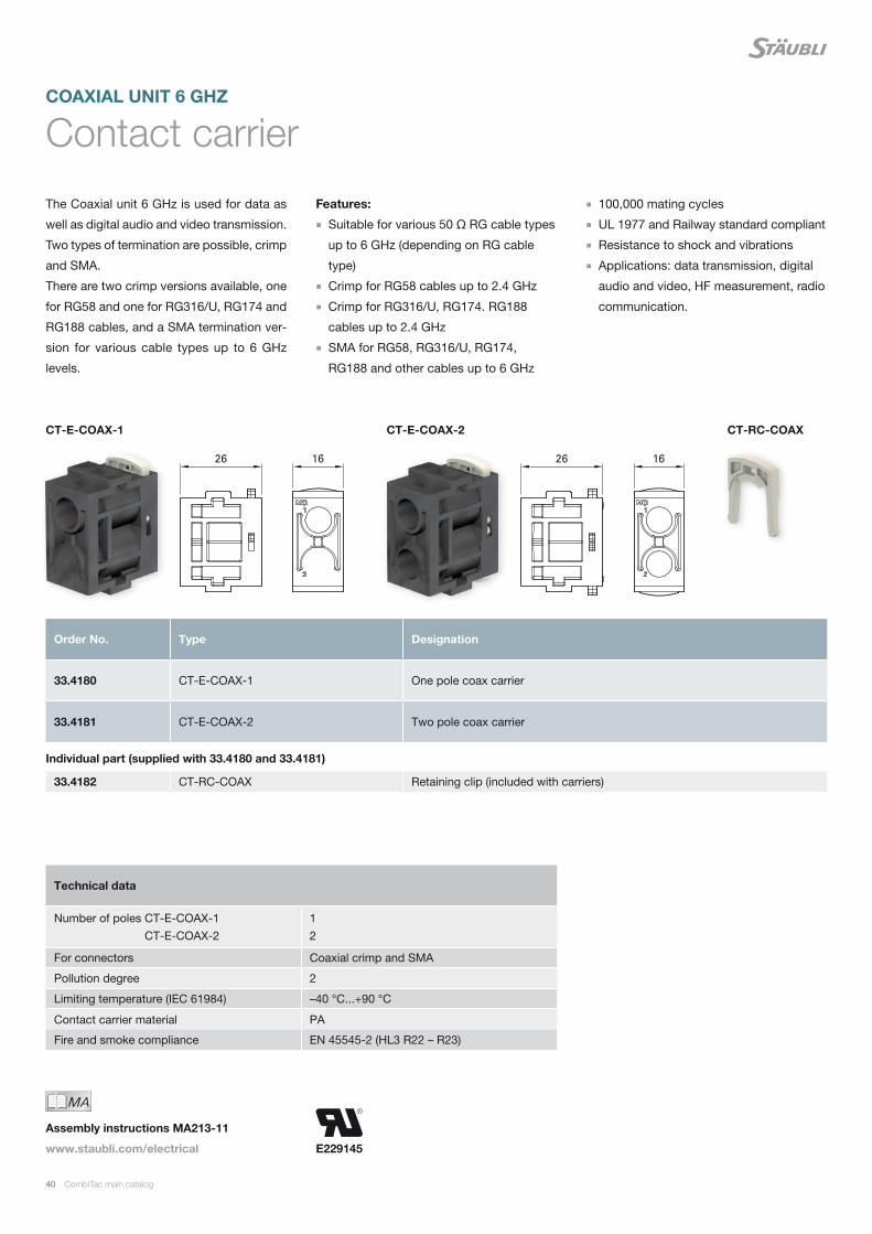
CT-E-COAX-1 CT-E-COAX-2 CT-RC-COAX
Order No. Type Designation
33.4180 CT-E-COAX-1 One pole coax carrier
33.4181 CT-E-COAX-2 Two pole coax carrier
Individual part (supplied with 33.4180 and 33.4181)
33.4182 CT-RC-COAX Retaining clip (included with carriers)
Contact carrier
Technical data
Number of poles CT-E-COAX-1 CT-E-COAX-2
1 2
For connectors Coaxial crimp and SMA
Pollution degree 2
Limiting temperature (IEC 61984) –40 °C...+90 °C
Contact carrier material PA
Fire and smoke compliance EN 45545-2 (HL3 R22 – R23)
MAIch bin eine Montageanleitung.
Man sollte mich unbedingt le-
sen, bevor man das Produkt ver-
wendet! Ich beinhalte wertvolle
Hinweise zur korrekten Montage
und zum richtigen Einsatz des
Produktes. Im Moment ist die
Schrift zwar ein bischen klein,
aber später geht das dann ganz
gut zu lesen, da die MA dann
Assembly instructions MA213-11
www.staubli.com/electrical
The Coaxial unit 6 GHz is used for data as
well as digital audio and video transmission.
Two types of termination are possible, crimp
and SMA.
There are two crimp versions available, one
for RG58 and one for RG316/U, RG174 and
RG188 cables, and a SMA termination ver-
sion for various cable types up to 6 GHz
levels.
Features:
Suitable for various 50 Ω RG cable types
up to 6 GHz (depending on RG cable
type)
Crimp for RG58 cables up to 2.4 GHz
Crimp for RG316/U, RG174. RG188
cables up to 2.4 GHz
SMA for RG58, RG316/U, RG174,
RG188 and other cables up to 6 GHz
100,000 mating cycles
UL 1977 and Railway standard compliant
Resistance to shock and vibrations
Applications: data transmission, digital
audio and video, HF measurement, radio
communication.
COAXIAL UNIT 6 GHZ
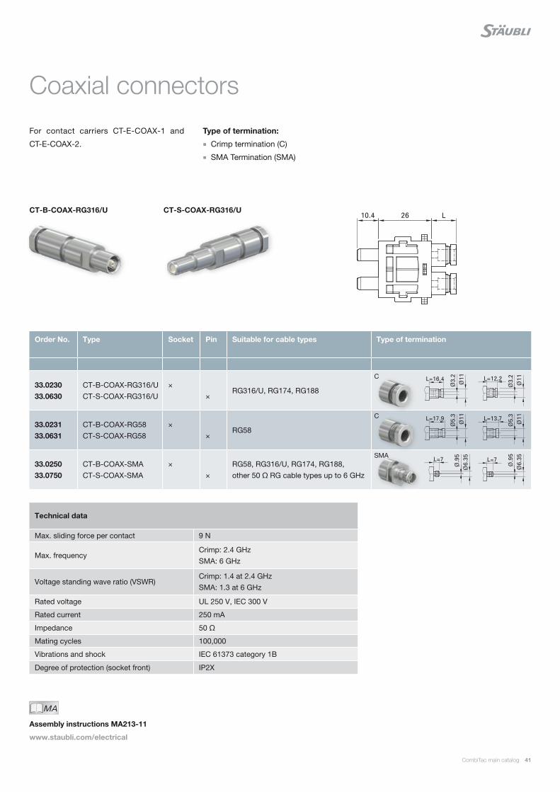
CombiTac main catalog 41
CT-S-COAX-RG316/UCT-B-COAX-RG316/U
For contact carriers CT-E-COAX-1 and
CT-E-COAX-2.
Order No. Type Socket Pin Suitable for cable types Type of termination
33.0230 33.0630
CT-B-COAX-RG316/U CT-S-COAX-RG316/U
× ×
RG316/U, RG174, RG188
33.0231 33.0631
CT-B-COAX-RG58 CT-S-COAX-RG58
× ×
RG58
33.0250 33.0750
CT-B-COAX-SMA CT-S-COAX-SMA
× ×
RG58, RG316/U, RG174, RG188, other 50 Ω RG cable types up to 6 GHz
C
C
SMA
Coaxial connectors
Type of termination:
Crimp termination (C)
SMA Termination (SMA)
MAIch bin eine Montageanleitung.
Man sollte mich unbedingt le-
sen, bevor man das Produkt ver-
wendet! Ich beinhalte wertvolle
Hinweise zur korrekten Montage
und zum richtigen Einsatz des
Produktes. Im Moment ist die
Schrift zwar ein bischen klein,
aber später geht das dann ganz
gut zu lesen, da die MA dann
Assembly instructions MA213-11
www.staubli.com/electrical
Technical data
Max. sliding force per contact 9 N
Max. frequencyCrimp: 2.4 GHzSMA: 6 GHz
Voltage standing wave ratio (VSWR)Crimp: 1.4 at 2.4 GHzSMA: 1.3 at 6 GHz
Rated voltage UL 250 V, IEC 300 V
Rated current 250 mA
Impedance 50 Ω
Mating cycles 100,000
Vibrations and shock IEC 61373 category 1B
Degree of protection (socket front) IP2X
42 CombiTac main catalog
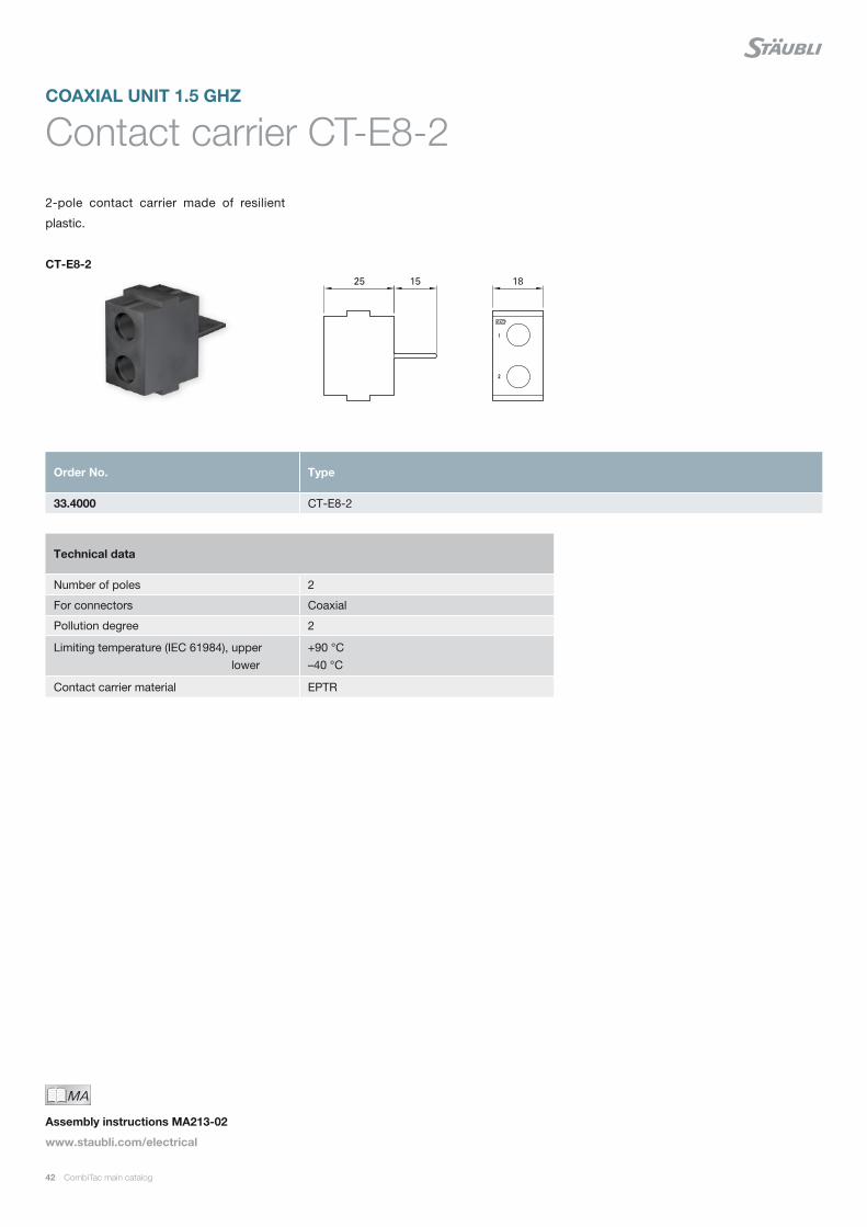
CT-E8-2
Contact carrier CT-E8-2
2-pole contact carrier made of resilient
plastic.
COAXIAL UNIT 1.5 GHZ
Technical data
Number of poles 2
For connectors Coaxial
Pollution degree 2
Limiting temperature (IEC 61984), upper lower
+90 °C –40 °C
Contact carrier material EPTR
Order No. Type
33.4000 CT-E8-2
MAIch bin eine Montageanleitung.
Man sollte mich unbedingt le-
sen, bevor man das Produkt ver-
wendet! Ich beinhalte wertvolle
Hinweise zur korrekten Montage
und zum richtigen Einsatz des
Produktes. Im Moment ist die
Schrift zwar ein bischen klein,
aber später geht das dann ganz
gut zu lesen, da die MA dann
Assembly instructions MA213-02
www.staubli.com/electrical
CombiTac main catalog 43
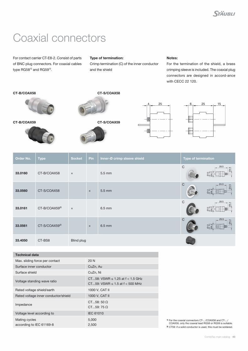
Coaxial connectors
For contact carrier CT-E8-2. Consist of parts
of BNC plug connectors. For coaxial cables
type RG58¹⁾ and RG59¹⁾.
Type of termination:
Crimp termination (C) of the inner conductor
and the shield
Notes:
For the termination of the shield, a brass
crimping sleeve is included. The coaxial plug
connectors are designed in accord-ance
with CECC 22 120.
CT-B/COAX58
CT-B/COAX59
CT-S/COAX58
CT-S/COAX59
1) For the coaxial connectors CT-.../COAX58 and CT-.../COAX59, only the coaxial lead RG58 or RG59 is suitable.
2) CT59: if a solid conductor is used, this must be soldered.
Order No. Type Socket Pin Inner-Ø crimp sleeve shield Type of termination
33.0160 CT-B/COAX58 × 5.5 mm
33.0560 CT-S/COAX58 × 5.5 mm
33.0161 CT-B/COAX59²⁾ × 6.5 mm
33.0561 CT-S/COAX59²⁾ × 6.5 mm
33.4050 CT-BS8 Blind plug
C
C
C
C
Technical data
Max. sliding force per contact 20 N
Surface inner conductor CuZn, Au
Surface shield CuZn, Ni
Voltage standing wave ratioCT...58: VSWR ≤ 1.25 at f < 1.5 GHzCT...59: VSWR ≤ 1.5 at f < 500 MHz
Rated voltage shield/earth 1000 V, CAT II
Rated voltage inner conductor/shield 1000 V, CAT II
ImpedanceCT...58: 50 ΩCT...59: 75 Ω
Voltage level according to IEC 61010
Mating cyclesaccording to IEC 61169-8
5,0002,500
44 CombiTac main catalog
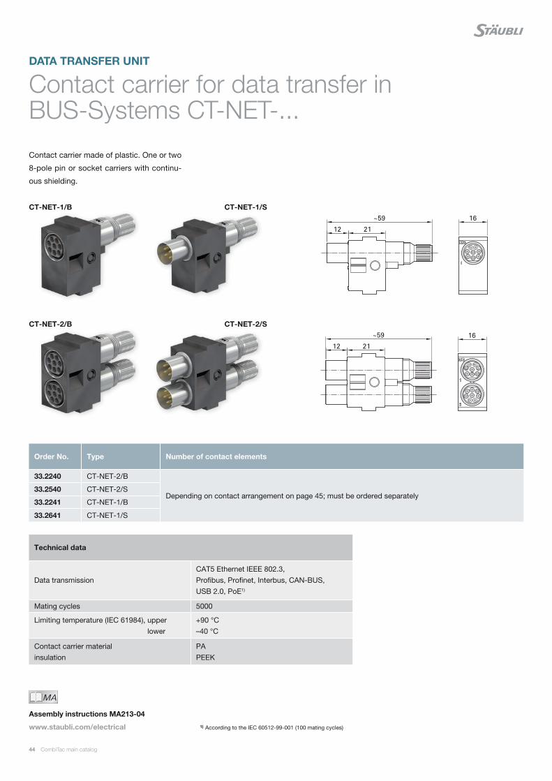
Contact carrier for data transfer in BUS-Systems CT-NET-...
Contact carrier made of plastic. One or two
8-pole pin or socket carriers with continu-
ous shielding.
DATA TRANSFER UNIT
CT-NET-1/B
CT-NET-2/B
CT-NET-1/S
CT-NET-2/S
Technical data
Data transmissionCAT5 Ethernet IEEE 802.3, Profibus, Profinet, Interbus, CAN-BUS, USB 2.0, PoE1)
Mating cycles 5000
Limiting temperature (IEC 61984), upper lower
+90 °C –40 °C
Contact carrier material insulation
PA PEEK
Order No. Type Number of contact elements
33.2240 CT-NET-2/B
Depending on contact arrangement on page 45; must be ordered separately 33.2540 CT-NET-2/S
33.2241 CT-NET-1/B
33.2641 CT-NET-1/S
MAIch bin eine Montageanleitung.
Man sollte mich unbedingt le-
sen, bevor man das Produkt ver-
wendet! Ich beinhalte wertvolle
Hinweise zur korrekten Montage
und zum richtigen Einsatz des
Produktes. Im Moment ist die
Schrift zwar ein bischen klein,
aber später geht das dann ganz
gut zu lesen, da die MA dann
Assembly instructions MA213-04
www.staubli.com/electrical 1) According to the IEC 60512-99-001 (100 mating cycles)

CombiTac main catalog 45
Contacts for data transfer in BUS-System CT-NET-...
For contact carrier CT-NET-... Sockets fitted
with MULTILAM.
Type of termination:
Crimp termination (C) to a Cu conductor
(class 5 and 6)
CT-NET-B… CT-NET-S…
Contact arrangement of the
contact carrier
Left: socket side; right: pin side
(Viewed from the termination side)
Order No. Type Socket Pin Surface Conductor cross section
Rated current Type of termination
mm² AWG A
33.0148 CT-NET-BP1ET/0,25-0,75 AU ×0.25 0.5 0.75
24 20 18
2 3 5
33.0548 CT-NET-SP1/0,25-0,75 AU ×0.25 0.5 0.75
24 20 18
2 3 5
33.9589 CT-NET-BS¹⁾ Blind plug
C
Technical data
Nominal-Ø socket/pin Ø 1 mm
Max. sliding force per contact 1 N
Contact resistance 1.6 mΩ
Max. outer diameter per wire 2.3 mm
Maximum outer diameter over the whole cable with special nut 13009834 and pliers 13009832
8 mm8.5 mm
Ethernet / Profinet Interbus Profibus
1) Unused contact chambers should be closed with blind plugs.
MAIch bin eine Montageanleitung.
Man sollte mich unbedingt le-
sen, bevor man das Produkt ver-
wendet! Ich beinhalte wertvolle
Hinweise zur korrekten Montage
und zum richtigen Einsatz des
Produktes. Im Moment ist die
Schrift zwar ein bischen klein,
aber später geht das dann ganz
gut zu lesen, da die MA dann
Assembly instructions MA213-04
www.staubli.com/electrical
46 CombiTac main catalog
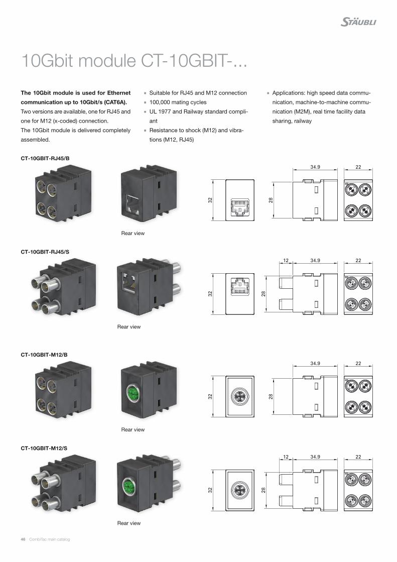
10Gbit module CT-10GBIT-...
The 10Gbit module is used for Ethernet
communication up to 10Gbit/s (CAT6A).
Two versions are available, one for RJ45 and
one for M12 (x-coded) connection.
The 10Gbit module is delivered completely
assembled.
Suitable for RJ45 and M12 connection
100,000 mating cycles
UL 1977 and Railway standard compli-
ant
Resistance to shock (M12) and vibra-
tions (M12, RJ45)
CT-10GBIT-RJ45/B
CT-10GBIT-M12/B
CT-10GBIT-RJ45/S
CT-10GBIT-M12/S
Rear view
Rear view
Rear view
Rear view
Applications: high speed data commu-
nication, machine-to-machine commu-
nication (M2M), real time facility data
sharing, railway
E229145
CombiTac main catalog 47
1) According to the IEC 60512-99-001 (100 mating cycles)2) Less than DC 30 V for UL 1977. For details on UL see page
121.
Order No. Type
33.0130 CT-10GBIT-RJ45/B
33.0530 CT-10GBIT-RJ45/S
33.0240 CT-10GBIT-M12/B
33.0640 CT-10GBIT-M12/S
Technical data
Data transmissionCAT6A Ethernet IEEE 802.3an, USB 2.0, PoE1) with M12
Mating cycles 100,000
Rated current 0.75 A
Rated voltage2) 48 V
Limiting temperature (IEC 61984), upper lower
+90 °C –40 °C
Contact carrier material PA
Fire and smoke compliance EN 45545-2 (HL3 R22 – R23)
Insulation resistance ≥ 500 MΩ
Vibrations, RJ45 M12
5 g / 10 – 500 Hz (IEC 60512-6-4) 0.58 g / 5 - 150 Hz (IEC 61373 category 1B)
Resistance to shocks, M12 3.06 g / 30 ms (IEC 61373 category 1B)
MAIch bin eine Montageanleitung.
Man sollte mich unbedingt le-
sen, bevor man das Produkt ver-
wendet! Ich beinhalte wertvolle
Hinweise zur korrekten Montage
und zum richtigen Einsatz des
Produktes. Im Moment ist die
Schrift zwar ein bischen klein,
aber später geht das dann ganz
gut zu lesen, da die MA dann
Assembly instructions MA213-08
www.staubli.com/electrical
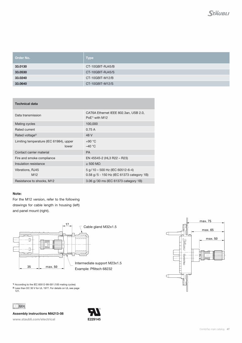
Note:
For the M12 version, refer to the following
drawings for cable length in housing (left)
and panel mount (right).
Cable gland M32x1.5
Intermediate support M23x1.5
Example: Pflitsch 68232

48 CombiTac main catalog
Order No. Type
33.2169 CT-RJ45/B
33.2170 CT-RJ45/S
Technical data
Data transmission CAT5 Ethernet IEEE 802.3, USB 2.0
Mating cycles 5,000
Limiting temperature (IEC 61984), upper lower
+90 °C –40 °C
Contact carrier material Insulation
PA PEEK
Test voltage 1 min., 50/60 Hz UAC 500 V
100 Mbit module CT-RJ45/...
The 100 Mbit module is used for Ethernet
communication up to 100 Mbit/s (CAT5).
Suitable network cables with a RJ45 con-
nectors can be directly connected to the
CT-RJ45/B
CT-RJ45/S
View from rear view
View from rear view
100 Mbit module. The 100 Mbit module is
delivered completely assembled.

0
10
20
30
40
50
60
70
80
90
100
110
120
1 10 100 1000
1 10 100 500 1000
120
100
80
60
40
20
0
1 10 100 500 1000
120
100
80
60
40
20
0
CombiTac main catalog 49
Attenuation characteristics for CT-10GBIT-...
Att
enua
tion
dB
Frequency in MHz
Pairs 1.2 – 3.6 Pairs 1.2 – 4.5 Pairs 1.2 – 7.8Pairs 3.6 – 7.8 Pairs 4.5 – 7.8
Limit CAT6APairs 3.6 – 4.5
Attenuation characteristics for CT-NET... Attenuation characteristics for CT-RJ45...
1) Further technical specifications: www.staubli.com/electrical > Downloads > Technical Info > Industry > Data connectors.
Diagram 1)
Frequency MHz
Att
enua
tion
dB
Att
enua
tion
dB
Frequency MHz
Diagram 1)
Pair 1-2 / 3-6 New condition Pair 1-2 / 3-6 5000 Mating cycles CAT 6 Limit CAT 5 Limit
Pair 1-2 / 3-6 New condition Pair 1-2 / 3-6 5000 Mating cycles CAT 6 Limit CAT 5 Limit
50 CombiTac main catalog
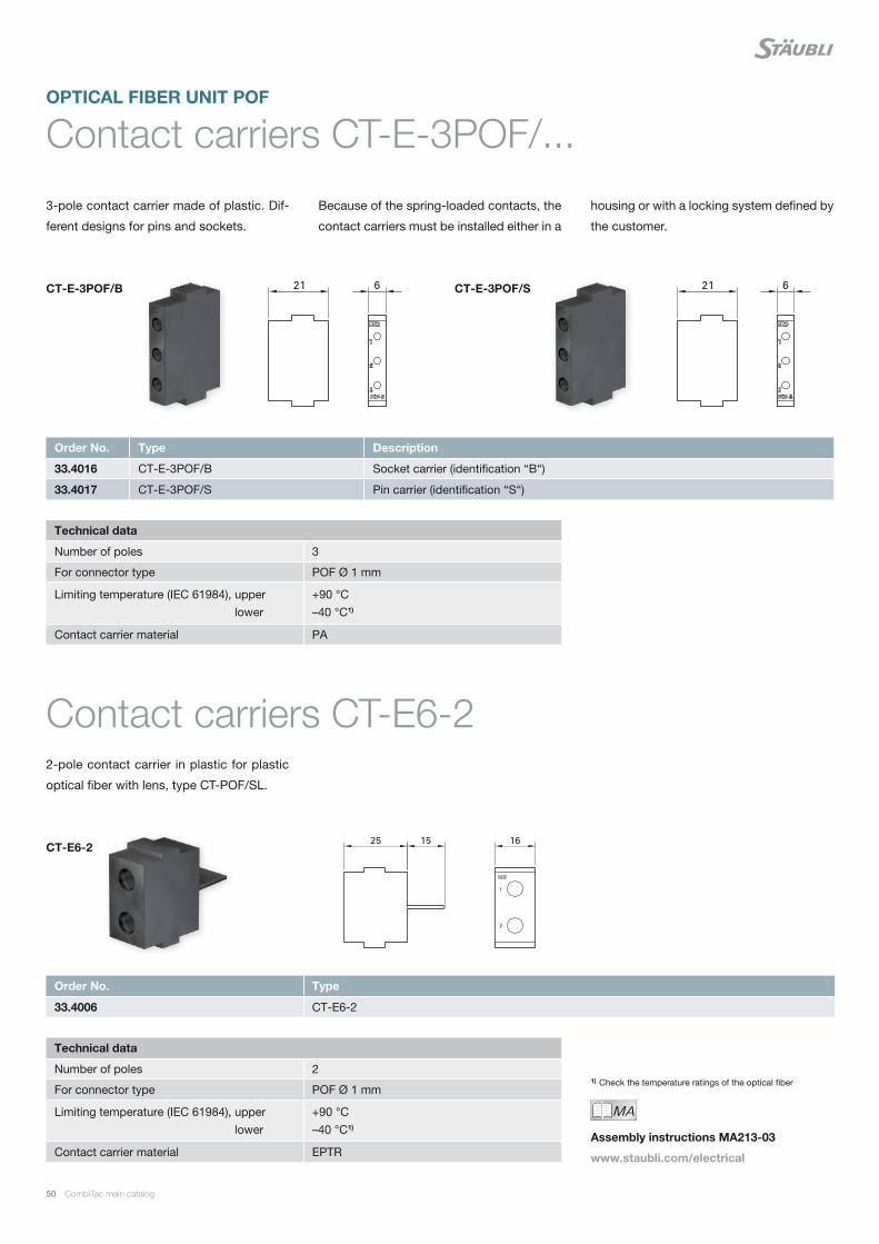
Contact carriers CT-E-3POF/...OPTICAL FIBER UNIT POF
3-pole contact carrier made of plastic. Dif-
ferent designs for pins and sockets.
Because of the spring-loaded contacts, the
contact carriers must be installed either in a
housing or with a locking system defined by
the customer.
Order No. Type Description
33.4016 CT-E-3POF/B Socket carrier (identification “B“)
33.4017 CT-E-3POF/S Pin carrier (identification “S“)
Order No. Type
33.4006 CT-E6-2
Technical data
Number of poles 3
For connector type POF Ø 1 mm
Limiting temperature (IEC 61984), upper lower
+90 °C –40 °C1)
Contact carrier material PA
Technical data
Number of poles 2
For connector type POF Ø 1 mm
Limiting temperature (IEC 61984), upper lower
+90 °C –40 °C1)
Contact carrier material EPTR
MAIch bin eine Montageanleitung.
Man sollte mich unbedingt le-
sen, bevor man das Produkt ver-
wendet! Ich beinhalte wertvolle
Hinweise zur korrekten Montage
und zum richtigen Einsatz des
Produktes. Im Moment ist die
Schrift zwar ein bischen klein,
aber später geht das dann ganz
gut zu lesen, da die MA dann
Assembly instructions MA213-03
www.staubli.com/electrical
CT-E-3POF/B CT-E-3POF/S
Contact carriers CT-E6-22-pole contact carrier in plastic for plastic
optical fiber with lens, type CT-POF/SL.
CT-E6-2
1) Check the temperature ratings of the optical fiber
CombiTac main catalog 51
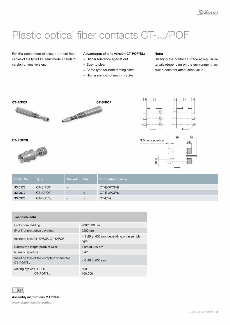
Plastic optical fiber contacts CT-.../POF
For the connection of plastic optical fiber
cables of the type POF Multimode. Standard
version or lens version.
Advantages of lens version CT-POF/SL:
Higher tolerance against dirt
Easy to clean
Same type for both mating sides
Higher number of mating cycles
Technical data
Ø of core/cladding 980/1000 µm
Ø of first protective covering 2200 µm
Insertion loss CT-B/POF, CT-S/POF< 3 dB at 650 nm, depending on assembly type
Bandwidth length product MHz 1 km at 650 nm
Numeric aperture 0.47
Insertion loss of the complete connector CT-POF/SL
< 6 dB at 650 nm
Mating cycles CT-POF CT-POF/SL
500100.000
Order No. Type Socket Pin For contact carrier
33.0170 CT-B/POF × CT-E-3POF/B
33.0570 CT-S/POF × CT-E-3POF/S
33.0370 CT-POF/SL × × CT-E6-2
MAIch bin eine Montageanleitung.
Man sollte mich unbedingt le-
sen, bevor man das Produkt ver-
wendet! Ich beinhalte wertvolle
Hinweise zur korrekten Montage
und zum richtigen Einsatz des
Produktes. Im Moment ist die
Schrift zwar ein bischen klein,
aber später geht das dann ganz
gut zu lesen, da die MA dann
Assembly instructions MA213-03
www.staubli.com/electrical
CT-B/POF
CT-POF/SL
CT-S/POF
3.5 Lens position
Note:
Cleaning the contact surface at regular in-
tervals (depending on the environment) as-
sure a constant attenuation value.
52 CombiTac main catalog
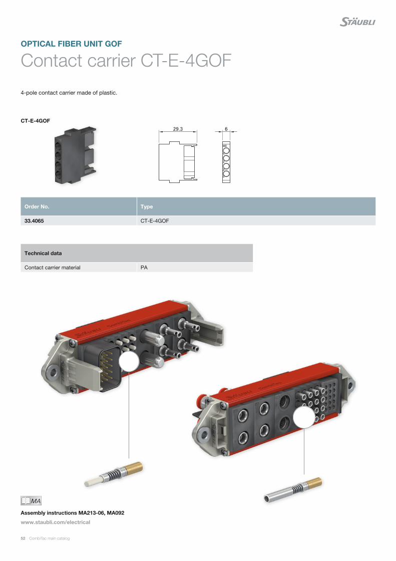
Contact carrier CT-E-4GOFOPTICAL FIBER UNIT GOF
4-pole contact carrier made of plastic.
Order No. Type
33.4065 CT-E-4GOF
Technical data
Contact carrier material PA
MAIch bin eine Montageanleitung.
Man sollte mich unbedingt le-
sen, bevor man das Produkt ver-
wendet! Ich beinhalte wertvolle
Hinweise zur korrekten Montage
und zum richtigen Einsatz des
Produktes. Im Moment ist die
Schrift zwar ein bischen klein,
aber später geht das dann ganz
gut zu lesen, da die MA dann
Assembly instructions MA213-06, MA092
www.staubli.com/electrical
CT-E-4GOF

CombiTac main catalog 53
Glass optical fiber contacts CT-.../GOF
For the connection of glass optical fiber ca-
bles of the type GOF Mono- and Multimode,
to fit contact carrier CT-E-4GOF.
In preassembled cables, one end is equipped
with ST, SC or FSMA plug connectors ac-
cording to choice. The cable length is 1 m or
0.3 m for FSMA pin. Fiber type: Multimode,
gradient fiber (GI) 50/125 μm.
LF= total length.L = length from CombiTac mounting position.1) Other cable lengths and connectors type (LC, ...) on
request. Specify L or LF length.
2) Note: Cleaning the contact surface at regular intervals (depending on the environment) assures a constant attenu-ation value and increases the number of mating cycles.
Order No. Type Socket Pin Designation on tail end preassembled with
33.0171 CT-B/GOF × Contact
33.0571 CT-S/GOF × Contact
33.0171-100 CT-B/GOF-100-ST¹⁾ × 1 m Preassembled multimode cable ST
33.0571-100 CT-S/GOF-100-ST¹⁾ × 1 m Preassembled multimode cable ST
33.0172-100 CT-B/GOF-100-SC¹⁾ × 1 m Preassembled multimode cable SC
33.0572-100 CT-S/GOF-100-SC¹⁾ × 1 m Preassembled multimode cable SC
33.0228-100 CT-B/GOF-025-FSMA × 1 m Preassembled multimode cable FSMA
33.0628-030 CT-S/GOF-030-FSMA × 0.3 m Preassembled multimode cable FSMA
Technical data
Insertion loss <0.5 dB at 1310 nm, depending on assembly type
Mating cycles ≥ 500 (cleaning interval every 100 mating cycles) ²⁾
Spring deflection 3 mm
Contact pressure 10 N per contact with 3 mm spring deflection
Allowable operating temperature –30 °C ... +90 °C
MAIch bin eine Montageanleitung.
Man sollte mich unbedingt le-
sen, bevor man das Produkt ver-
wendet! Ich beinhalte wertvolle
Hinweise zur korrekten Montage
und zum richtigen Einsatz des
Produktes. Im Moment ist die
Schrift zwar ein bischen klein,
aber später geht das dann ganz
gut zu lesen, da die MA dann
Assembly instructions MA213-06, MA092
www.staubli.com/electrical
Fiber types
Graded-index fiber (GI) 50/125 μm
Graded-index fiber (GI) 62.5/125 μm
Single mode fiber (SM) 9/125 μm
Coating diameter 250/900 μm
Ø of cable max. 3 mm
CT-B/GOF
CT-B/GOF-100-ST
CT-S/GOF Pin sideSocket side
250 500 750 1000 1250 1500
80
70
60
50
40
30
20
10
0
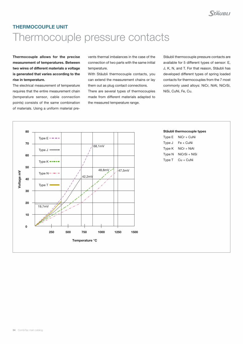
47,5mV48,8mV
68,1mV
42,2mV
19,7mV
Type E
Type J
Type K
Type N
Type T
54 CombiTac main catalog
Thermocouple pressure contacts
Thermocouple allows for the precise
measurement of temperatures. Between
two wires of different materials a voltage
is generated that varies according to the
rise in temperature.
The electrical measurement of temperature
requires that the entire measurement chain
(temperature sensor, cable connection
points) consists of the same combination
of materials. Using a uniform material pre-
THERMOCOUPLE UNIT
vents thermal imbalances in the case of the
connection of two parts with the same initial
temperature.
With Stäubli thermocouple contacts, you
can extend the measurement chains or lay
them out as plug contact connections.
There are several types of thermocouples
made from different materials adapted to
the measured temperature range.
Stäubli thermocouple pressure contacts are
available for 5 different types of sensor: E,
J, K, N, and T. For that reason, Stäubli has
developed different types of spring loaded
contacts for thermocouples from the 7 most
commonly used alloys: NiCr, NiAl, NiCrSi,
NiSi, CuNi, Fe, Cu.
Vo
ltag
e m
V
Temperature °C
Stäubli thermocouple types
Type E NiCr + CuNi
Type J Fe + CuNi
Type K NiCr + NiAl
Type N NiCrSi + NiSi
Type T Cu + CuNi

CombiTac main catalog 55
To ensure clear identification, our spring-loaded thermocouple contacts are provided with different grooves and markings:
Description according to: IEC 60584-1
Cu
Copper (without groove)
Fe
Iron (without groove)
NiAl
Alumel® (1 groove)
NiCr
Chromel® (2 grooves)
NiSi
Nisil (3 grooves)
NiCrSi
Nicrosil (4 grooves)
CuNi
Constantan® (1 wide groove)
Material marking
Groove

56 CombiTac main catalog
Contact carrier CT-E-2TH+PE/...
3-pole contact carrier made of plastic. For
two thermocouple pressure contacts and
one PE contact.
Different designs for pins and sockets. Be-
cause of the springloaded contacts, the
contact carriers must be installed either in
a housing or with a locking system defined
by the customer.
MAIch bin eine Montageanleitung.
Man sollte mich unbedingt le-
sen, bevor man das Produkt ver-
wendet! Ich beinhalte wertvolle
Hinweise zur korrekten Montage
und zum richtigen Einsatz des
Produktes. Im Moment ist die
Schrift zwar ein bischen klein,
aber später geht das dann ganz
gut zu lesen, da die MA dann
Assembly instructions MA213-01
www.staubli.com/electrical
Order No. Type Description
33.4011 CT-E-2TH+PE/B Socket carrier (identification “B“)
33.4012 CT-E-2TH+PE/S Pin carrier (identification “S“)
Technical data
Number of poles 1 thermocouple (2 contacts) / 1 PE
Contact carrier material EPTR
CT-E-2TH+PE/B CT-E-2TH+PE/SC
able
ent
ry
Cab
le e
ntry
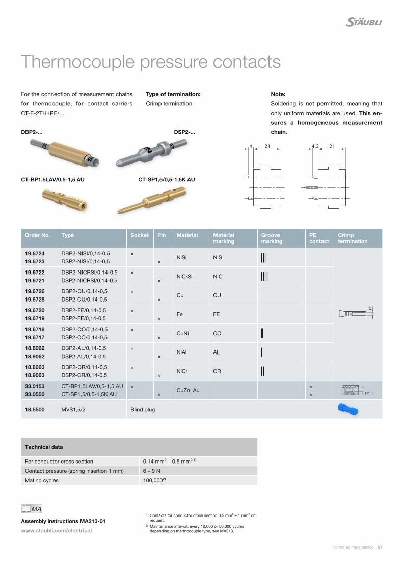
CombiTac main catalog 57
Thermocouple pressure contacts
For the connection of measurement chains
for thermocouple, for contact carriers
CT-E-2TH+PE/...
Type of termination:
Crimp termination
Note:
Soldering is not permitted, meaning that
only uniform materials are used. This en-
sures a homogeneous measurement
chain.
1) Contacts for conductor cross section 0.5 mm² – 1 mm² on request.
2) Maintenance interval: every 10,000 or 50,000 cycles depending on thermocouple type, see MA213.
Order No. Type Socket Pin Material Material marking
Groove marking
PE contact
Crimp termination
19.6724 19.6723
DBP2-NISI/0,14-0,5 DSP2-NISI/0,14-0,5
× ×
NiSi NIS
19.6722 19.6721
DBP2-NICRSI/0,14-0,5 DSP2-NICRSI/0,14-0,5
× ×
NiCrSi NIC
19.6726 19.6725
DBP2-CU/0,14-0,5 DSP2-CU/0,14-0,5
× ×
Cu CU
19.6720 19.6719
DBP2-FE/0,14-0,5 DSP2-FE/0,14-0,5
× ×
Fe FE
19.6718 19.6717
DBP2-CO/0,14-0,5 DSP2-CO/0,14-0,5
× ×
CuNi CO
18.8062 18.9062
DBP2-AL/0,14-0,5 DSP2-AL/0,14-0,5
× ×
NiAl AL
18.8063 18.9063
DBP2-CR/0,14-0,5 DSP2-CR/0,14-0,5
× ×
NiCr CR
33.0153 33.0550
CT-BP1,5LAV/0,5-1,5 AU CT-SP1,5/0,5-1,5K AU
× ×
CuZn, Au× ×
18.5500 MVS1,5/2 Blind plug
Technical data
For conductor cross section 0.14 mm² – 0.5 mm² ¹⁾
Contact pressure (spring insertion 1 mm) 6 – 9 N
Mating cycles 100,000²⁾
MAIch bin eine Montageanleitung.
Man sollte mich unbedingt le-
sen, bevor man das Produkt ver-
wendet! Ich beinhalte wertvolle
Hinweise zur korrekten Montage
und zum richtigen Einsatz des
Produktes. Im Moment ist die
Schrift zwar ein bischen klein,
aber später geht das dann ganz
gut zu lesen, da die MA dann
Assembly instructions MA213-01
www.staubli.com/electrical
DBP2-...
CT-BP1,5LAV/0,5-1,5 AU
DSP2-...
CT-SP1,5/0,5-1,5K AU
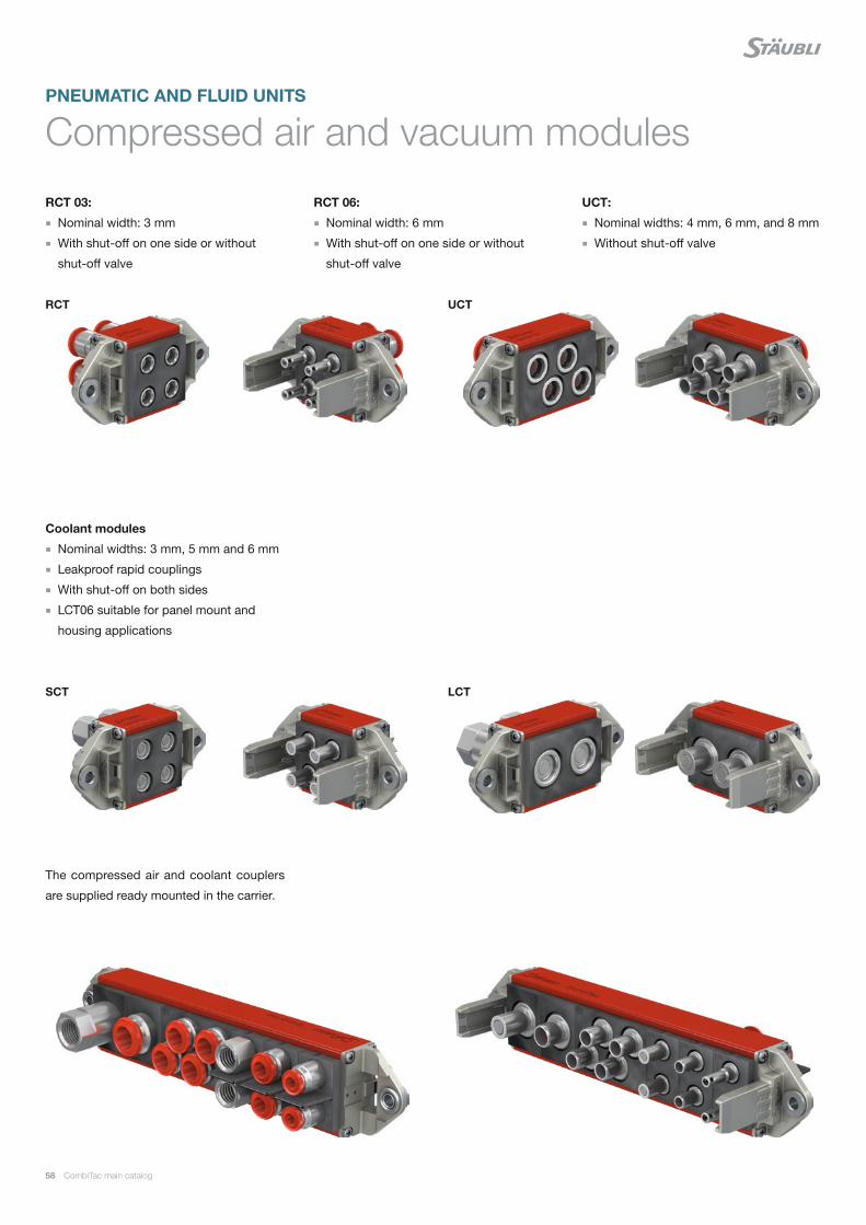
58 CombiTac main catalog
The compressed air and coolant couplers
are supplied ready mounted in the carrier.
Compressed air and vacuum modules
RCT 03:
Nominal width: 3 mm
With shut-off on one side or without
shut-off valve
Coolant modules
Nominal widths: 3 mm, 5 mm and 6 mm
Leakproof rapid couplings
With shut-off on both sides
LCT06 suitable for panel mount and
housing applications
RCT 06:
Nominal width: 6 mm
With shut-off on one side or without
shut-off valve
UCT:
Nominal widths: 4 mm, 6 mm, and 8 mm
Without shut-off valve
UCT
SCT LCT
RCT
PNEUMATIC AND FLUID UNITS
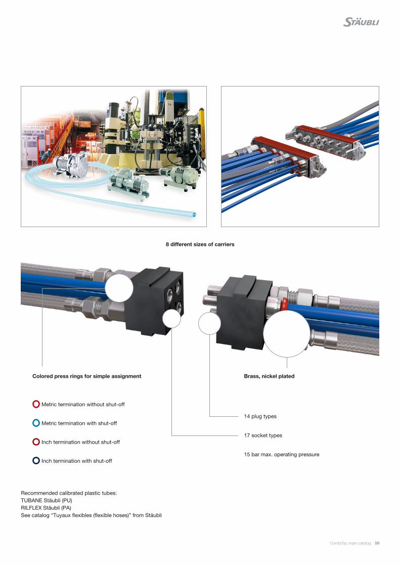
CombiTac main catalog 59
Recommended calibrated plastic tubes: TUBANE Stäubli (PU) RILFLEX Stäubli (PA) See catalog “Tuyaux flexibles (flexible hoses)” from Stäubli
Colored press rings for simple assignment
8 different sizes of carriers
Metric termination without shut-off
Metric termination with shut-off
Inch termination without shut-off
Inch termination with shut-off
Brass, nickel plated
14 plug types
17 socket types
15 bar max. operating pressure
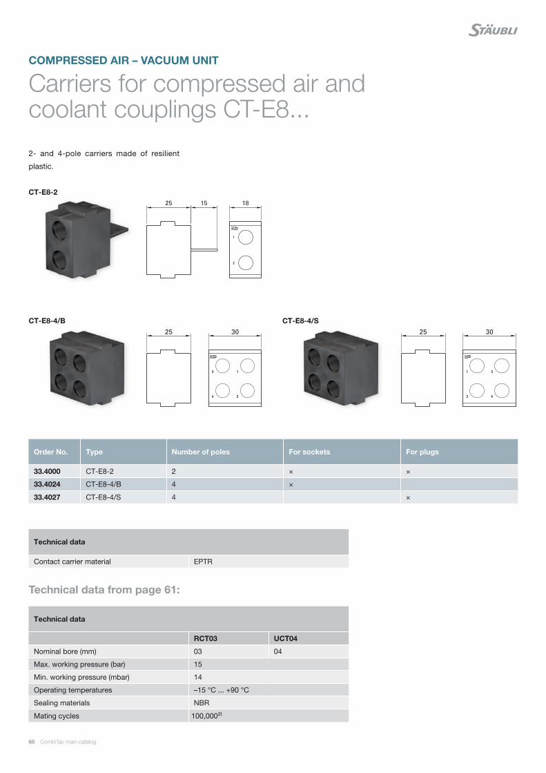
60 CombiTac main catalog
Carriers for compressed air and coolant couplings CT-E8...
2- and 4-pole carriers made of resilient
plastic.
COMPRESSED AIR – VACUUM UNIT
Order No. Type Number of poles For sockets For plugs
33.4000 CT-E8-2 2 × ×
33.4024 CT-E8-4/B 4 ×
33.4027 CT-E8-4/S 4 ×
Technical data
RCT03 UCT04
Nominal bore (mm) 03 04
Max. working pressure (bar) 15
Min. working pressure (mbar) 14
Operating temperatures –15 °C ... +90 °C
Sealing materials NBR
Mating cycles 100,000²⁾
Technical data
Contact carrier material EPTR
CT-E8-2
CT-E8-4/B CT-E8-4/S
Technical data from page 61:
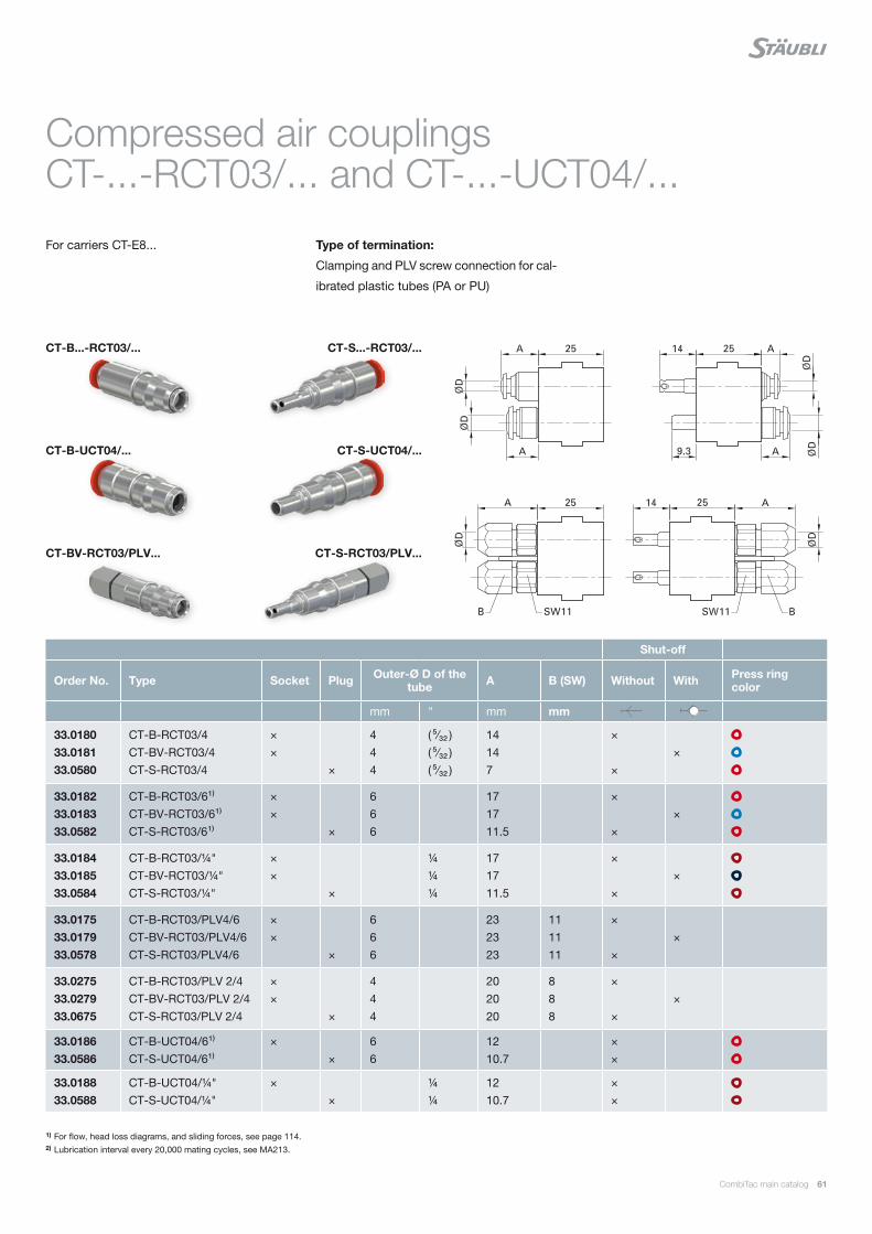
CombiTac main catalog 61
Compressed air couplings CT-...-RCT03/... and CT-...-UCT04/...
For carriers CT-E8... Type of termination:
Clamping and PLV screw connection for cal-
ibrated plastic tubes (PA or PU)
1) For flow, head loss diagrams, and sliding forces, see page 114.2) Lubrication interval every 20,000 mating cycles, see MA213.
Shut-off
Order No. Type Socket Plug Outer-Ø D of the tube A B (SW) Without With Press ring
color
mm " mm mm
33.0180 33.0181 33.0580
CT-B-RCT03/4 CT-BV-RCT03/4 CT-S-RCT03/4
× ×
×
4 4 4
( ⁵⁄₃₂ ) ( ⁵⁄₃₂ ) ( ⁵⁄₃₂ )
14 14 7
× ×
×
33.0182 33.0183 33.0582
CT-B-RCT03/6¹⁾ CT-BV-RCT03/6¹⁾ CT-S-RCT03/6¹⁾
× ×
×
6 6 6
17 17 11.5
× ×
×
33.0184 33.0185 33.0584
CT-B-RCT03/¼" CT-BV-RCT03/¼" CT-S-RCT03/¼"
× ×
×
¼ ¼ ¼
17 17 11.5
× ×
×
33.0175 33.0179 33.0578
CT-B-RCT03/PLV4/6 CT-BV-RCT03/PLV4/6 CT-S-RCT03/PLV4/6
× ×
×
6 6 6
23 23 23
11 11 11
× ×
×
33.0275 33.0279 33.0675
CT-B-RCT03/PLV 2/4 CT-BV-RCT03/PLV 2/4 CT-S-RCT03/PLV 2/4
× ×
×
4 4 4
20 20 20
8 8 8
× ×
×
33.0186 33.0586
CT-B-UCT04/6¹⁾ CT-S-UCT04/6¹⁾
× ×
6 6
12 10.7
× ×
33.0188 33.0588
CT-B-UCT04/¼" CT-S-UCT04/¼"
× ×
¼ ¼
12 10.7
× ×
CT-B...-RCT03/...
CT-BV-RCT03/PLV...
CT-B-UCT04/...
CT-S...-RCT03/...
CT-S-RCT03/PLV...
CT-S-UCT04/...
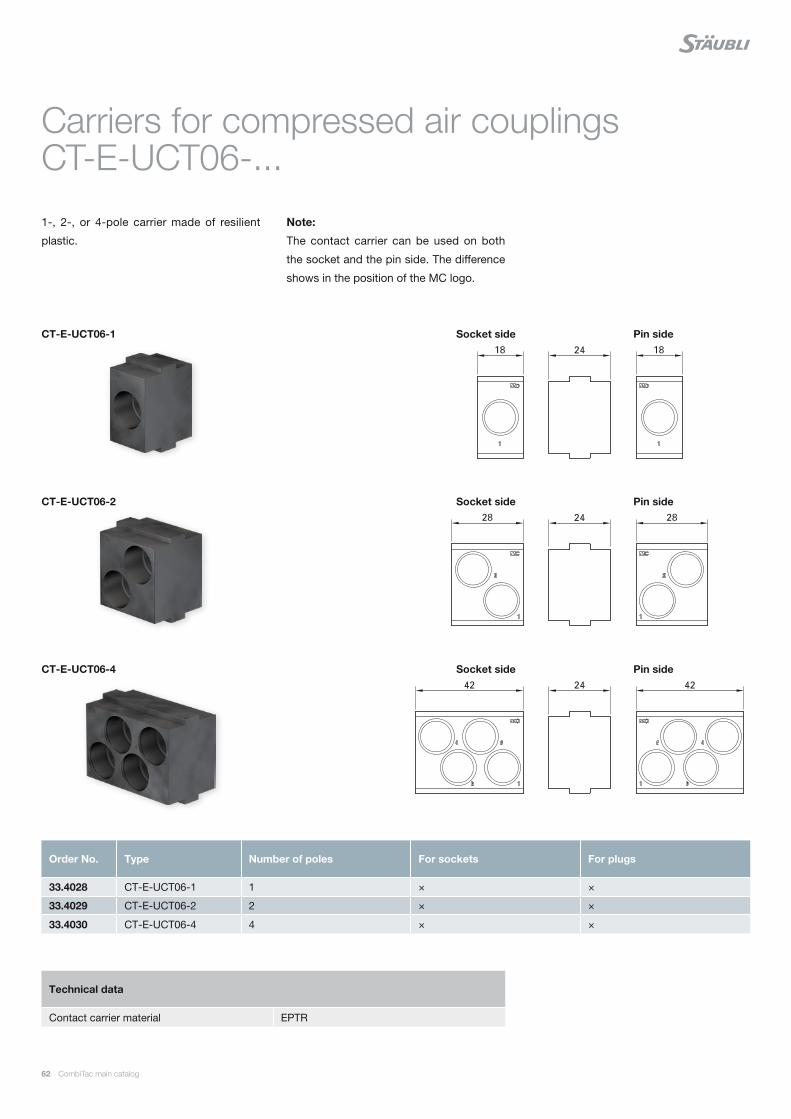
62 CombiTac main catalog
Carriers for compressed air couplings CT-E-UCT06-...
1-, 2-, or 4-pole carrier made of resilient
plastic.
Note:
The contact carrier can be used on both
the socket and the pin side. The difference
shows in the position of the MC logo.
Order No. Type Number of poles For sockets For plugs
33.4028 CT-E-UCT06-1 1 × ×
33.4029 CT-E-UCT06-2 2 × ×
33.4030 CT-E-UCT06-4 4 × ×
Technical data
Contact carrier material EPTR
CT-E-UCT06-1
CT-E-UCT06-2
CT-E-UCT06-4
Pin side
Pin side
Pin side
Socket side
Socket side
Socket side
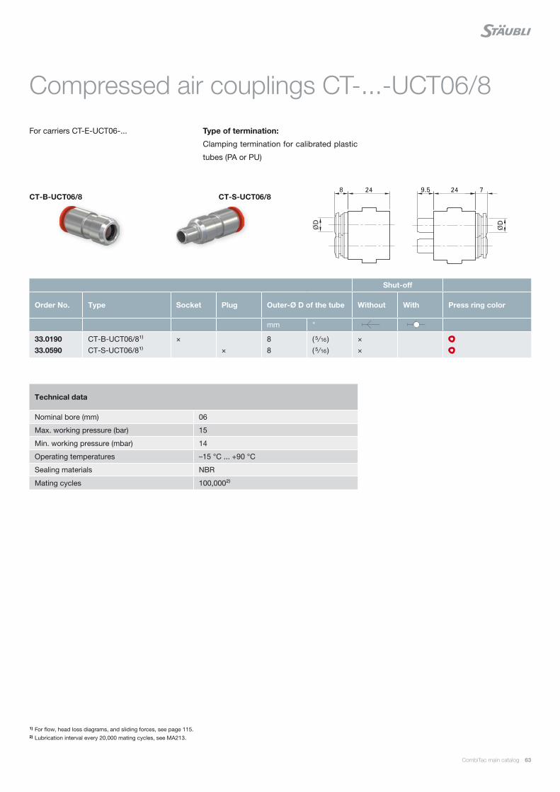
CombiTac main catalog 63
Compressed air couplings CT-...-UCT06/8
For carriers CT-E-UCT06-... Type of termination:
Clamping termination for calibrated plastic
tubes (PA or PU)
1) For flow, head loss diagrams, and sliding forces, see page 115.2) Lubrication interval every 20,000 mating cycles, see MA213.
Technical data
Nominal bore (mm) 06
Max. working pressure (bar) 15
Min. working pressure (mbar) 14
Operating temperatures –15 °C ... +90 °C
Sealing materials NBR
Mating cycles 100,000²⁾
Shut-off
Order No. Type Socket Plug Outer-Ø D of the tube Without With Press ring color
mm "
33.0190 33.0590
CT-B-UCT06/8¹⁾ CT-S-UCT06/8¹⁾
× ×
8 8
( 5 ∕ 16 ) ( 5 ∕ 16 )
× ×
CT-B-UCT06/8 CT-S-UCT06/8
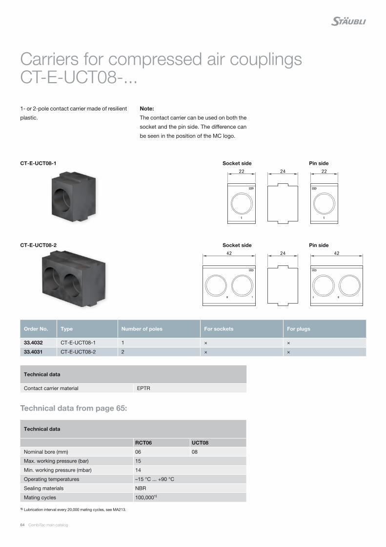
64 CombiTac main catalog
Carriers for compressed air couplings CT-E-UCT08-...
1- or 2-pole contact carrier made of resilient
plastic.
Note:
The contact carrier can be used on both the
socket and the pin side. The difference can
be seen in the position of the MC logo.
1) Lubrication interval every 20,000 mating cycles, see MA213.
Order No. Type Number of poles For sockets For plugs
33.4032 CT-E-UCT08-1 1 × ×
33.4031 CT-E-UCT08-2 2 × ×
Technical data
RCT06 UCT08
Nominal bore (mm) 06 08
Max. working pressure (bar) 15
Min. working pressure (mbar) 14
Operating temperatures –15 °C ... +90 °C
Sealing materials NBR
Mating cycles 100,000¹⁾
Technical data
Contact carrier material EPTR
CT-E-UCT08-1
CT-E-UCT08-2
Pin side
Pin side
Socket side
Socket side
Technical data from page 65:

CombiTac main catalog 65
Compressed air couplings CT-...-UCT08... and CT-...-RCT06/...
For carriers CT-E-UCT08-... Type of termination:
Clamping and PLV screw termination for
calibrated plastic tubes (PA or PU)
1) For flow, head loss diagrams, and sliding forces, see page 115.
Shut-off
Order No. Type Socket Plug Outer-Ø D of the tube A without with Press ring color
mm " mm
33.0201 33.0601
CT-BV-RCT06/8 CT-S-RCT06/8
× ×
8 8
( 5 ∕ 16 ) ( 5 ∕ 16 )
×
×
33.0176 33.0576
CT-BV-RCT06/PLV6/8 CT-S-RCT06/PLV6/8
× ×
8 8
×
×
33.0177 33.0577
CT-BV-RCT06/PLV8/10 CT-S-RCT06/PLV8/10
× ×
10 10
×
×
33.0194 33.0594
CT-B-UCT08/10¹⁾ CT-S-UCT08/10¹⁾
× ×
10 10
× ×
33.0196 33.0596
CT-B-UCT08/3/8" CT-S-UCT08/3/8"
× ×
3 ∕ 8 3 ∕ 8
× ×
CT-BV-RCT06/8
CT-B-UCT08/10
CT-BV-RCT06/PLV6/8
CT-BV-RCT06/PLV8/10
CT-S-RCT06/8
CT-S-UCT08/10
CT-S-RCT06/PLV6/8
CT-S-RCT06/PLV8/10

66 CombiTac main catalog
Carriers for coolants couplings CT-E8...
2- and 4-pole carrier made of resilient
plastic.
Order No. Type Number of poles For sockets For plugs
33.4000 CT-E8-2 2 × ×
33.4024 CT-E8-4/B 4 ×
33.4027 CT-E8-4/S 4 ×
Technical data
Contact carrier material EPTR
CT-E8-2
CT-E8-4/B CT-E8-4/S
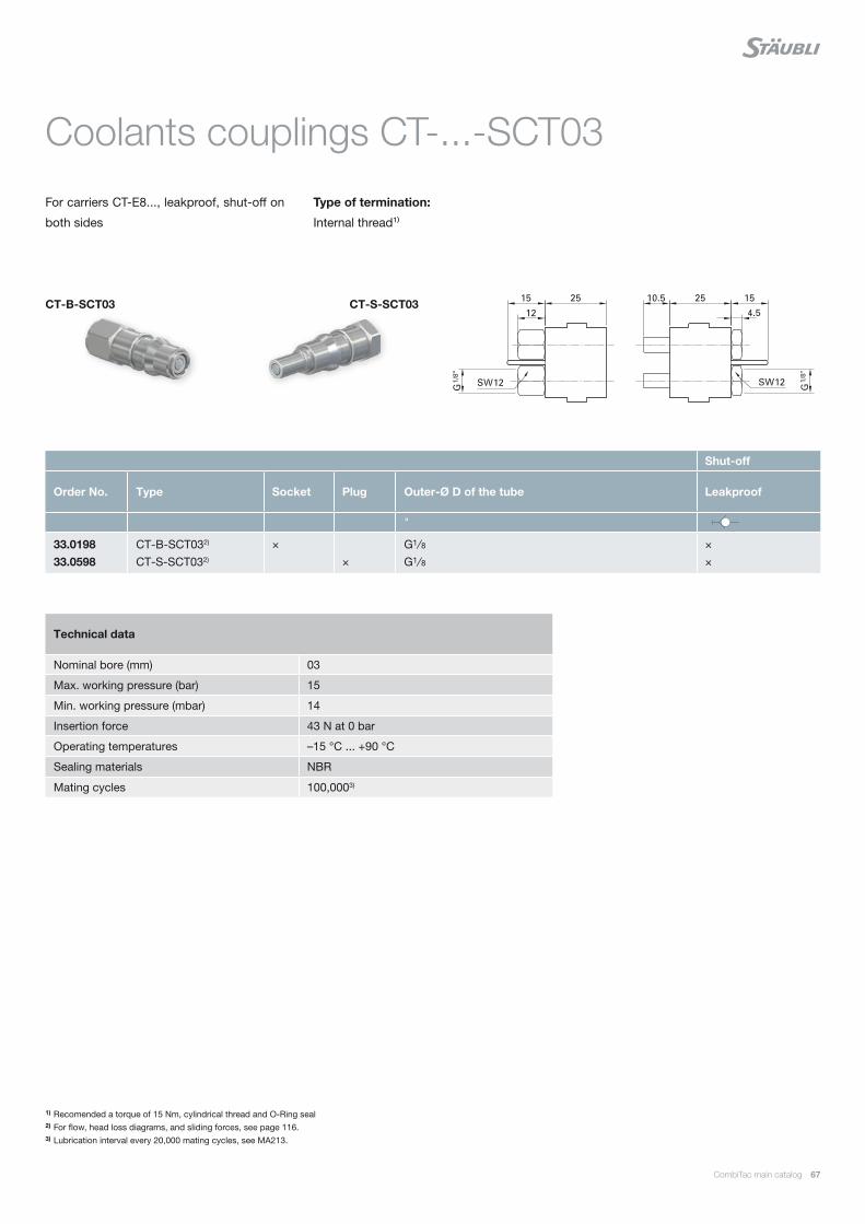
CombiTac main catalog 67
Coolants couplings CT-...-SCT03
For carriers CT-E8..., leakproof, shut-off on
both sides
Type of termination:
Internal thread¹⁾
1) Recomended a torque of 15 Nm, cylindrical thread and O-Ring seal2) For flow, head loss diagrams, and sliding forces, see page 116.3) Lubrication interval every 20,000 mating cycles, see MA213.
Shut-off
Order No. Type Socket Plug Outer-Ø D of the tube Leakproof
"
33.0198 33.0598
CT-B-SCT032) CT-S-SCT032)
× ×
G1 ∕ 8 G1 ∕ 8
× ×
Technical data
Nominal bore (mm) 03
Max. working pressure (bar) 15
Min. working pressure (mbar) 14
Insertion force 43 N at 0 bar
Operating temperatures –15 °C ... +90 °C
Sealing materials NBR
Mating cycles 100,0003)
CT-B-SCT03 CT-S-SCT03

68 CombiTac main catalog
Carriers for coolants couplings CT-E-UCT08-...
1- and 2-pole carriers made of resilient plas-
tic.
Note:
The contact carrier can be used on both the
socket and the pin side. The difference can
be seen in the position of the MC logo.
Order No. Type Number of poles For sockets For plugs
33.4032 CT-E-UCT08-1 1 × ×
33.4031 CT-E-UCT08-2 2 × ×
Technical data
Contact carrier material EPTR
CT-E-UCT08-1
CT-E-UCT08-2
Pin side
Pin side
Socket side
Socket side

CombiTac main catalog 69
Coolants couplings CT-...-SCT05
For carrier CT-E-UCT08-..., leakproof, shut-
off on both sides
Type of termination:
Internal thread1)
Note:
Not suited for use in DIN housings. Due to
the long stroke of the SCT05 coupling, two
movements (push and lock) are required to
connect the DIN housing.
Note
Observe page 120 :
Electrical plug connectors for control and
power in the immediate proximity of con-
nections for liquids and gas.
1) Recomended a torque of 15 Nm, cylindrical thread and O-Ring seal2) For flow, head loss diagrams, and sliding forces, see page 116.3) Lubrication interval every 20,000 mating cycles, see MA213..
Shut-off
Order No. Type Socket Plug Outer-Ø D of the tube A With
mm " mm
33.0199 33.0599
CT-B-SCT052) CT-S-SCT052)
× ×
8 8
G ( 1 ∕ 4 ) G ( 1 ∕ 4 )
× ×
Technical data
Nominal bore (mm) 05
Max. working pressure (bar) 15
Min. working pressure (mbar) 14
Insertion force 60 N at 0 bar
Operating temperatures –15 °C ... +90 °C
Sealing materials NBR
Mating cycles 100,0003)
CT-B-SCT05 CT-S-SCT05
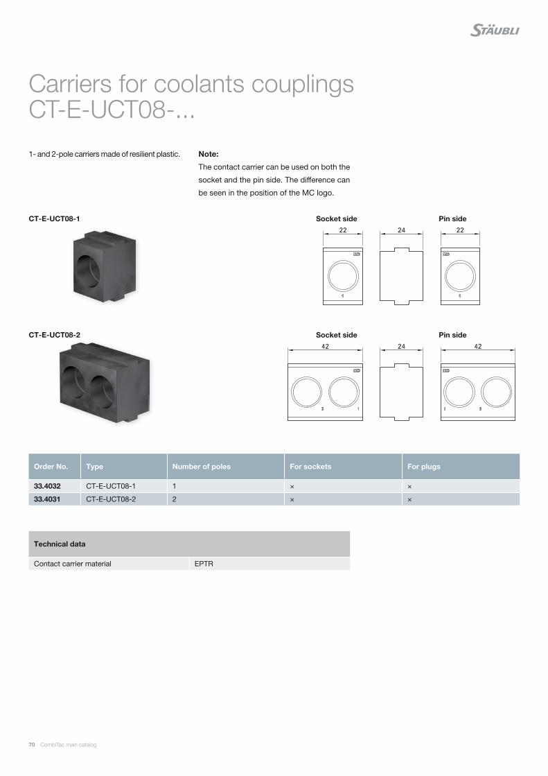
70 CombiTac main catalog
Carriers for coolants couplings CT-E-UCT08-...
1- and 2-pole carriers made of resilient plastic. Note:
The contact carrier can be used on both the
socket and the pin side. The difference can
be seen in the position of the MC logo.
Order No. Type Number of poles For sockets For plugs
33.4032 CT-E-UCT08-1 1 × ×
33.4031 CT-E-UCT08-2 2 × ×
Technical data
Contact carrier material EPTR
CT-E-UCT08-1
CT-E-UCT08-2
Pin side
Pin side
Socket side
Socket side

CombiTac main catalog 71
Coolants couplings CT-...-LCT06
For carrier CT-E-UCT08-..., leakproof, shut-
off on both sides
Type of termination:
Internal thread
Note
Observe page 120 :
Electrical plug connectors for control and
power in the immediate proximity of con-
nections for liquids and gas.
Shut-off
Order No. Type Socket Plug Outer-Ø D of the tube A With
mm " mm
33.0229 33.0629
CT-B-LCT06¹⁾ CT-S-LCT06¹⁾
× ×
8 8
G 1 ∕ 4 G 1 ∕ 4
× ×
Technical data
Nominal bore (mm) 06
Max. working pressure (bar) 15
Min. vacuum absolute pressure (mbar) 14
Insertion force 44.5 N / 0 bar; 135 N / 10 bar; 187 N / 15 bar
Max. retention force 187 N / 15 bar
Operating temperatures –15 °C ... +90 °C
Sealing materials NBR
Mating cycles 100,000²⁾
CT-B-LCT06 CT-S-LCT06
Note:
CT-...-LCT06 suitable for panel and
housing applications.
1) For flow, head loss diagrams, and sliding forces, see page 117.2) Lubrication interval every 20,000 mating cycles, see MA213.
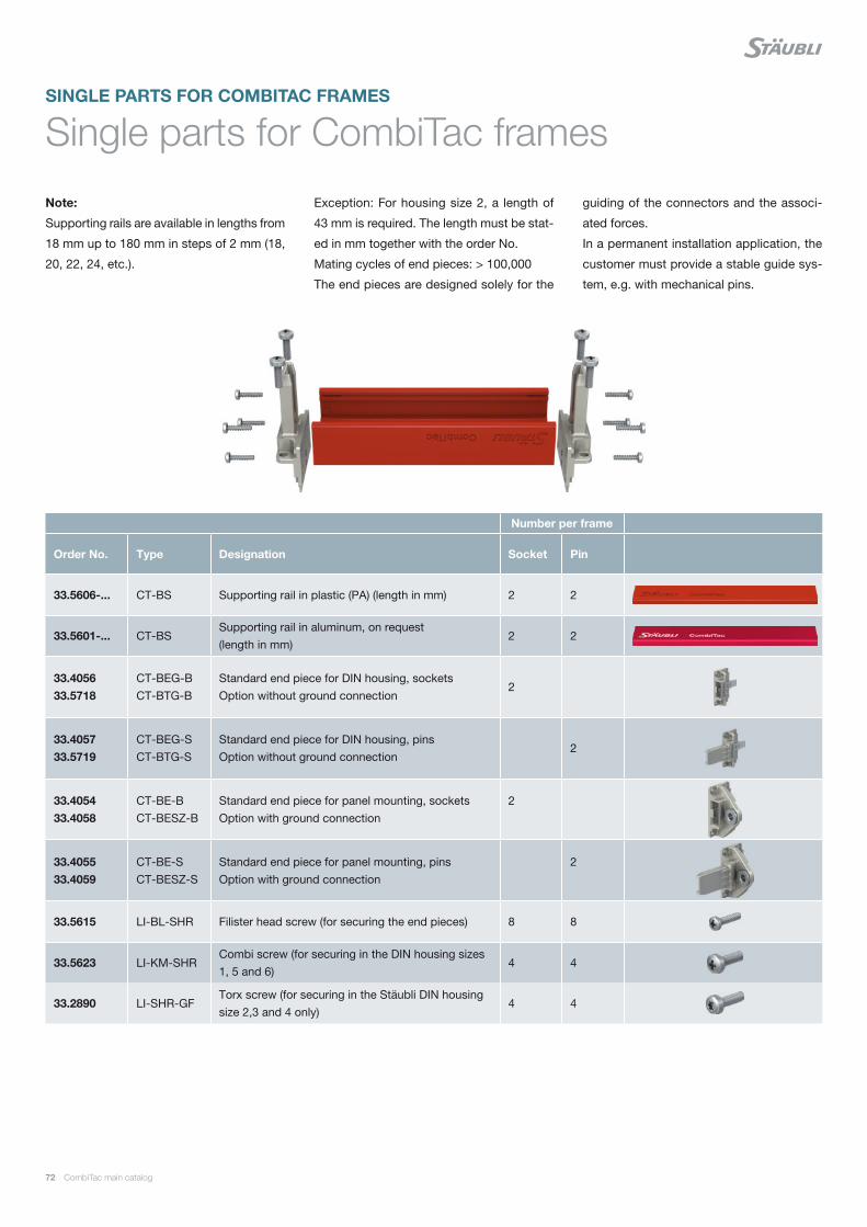
72 CombiTac main catalog
Single parts for CombiTac frames
Note:
Supporting rails are available in lengths from
18 mm up to 180 mm in steps of 2 mm (18,
20, 22, 24, etc.).
Exception: For housing size 2, a length of
43 mm is required. The length must be stat-
ed in mm together with the order No.
Mating cycles of end pieces: > 100,000
The end pieces are designed solely for the
guiding of the connectors and the associ-
ated forces.
In a permanent installation application, the
customer must provide a stable guide sys-
tem, e.g. with mechanical pins.
Number per frame
Order No. Type Designation Socket Pin
33.5606-... CT-BS Supporting rail in plastic (PA) (length in mm) 2 2
33.5601-... CT-BSSupporting rail in aluminum, on request (length in mm)
2 2
33.405633.5718
CT-BEG-B CT-BTG-B
Standard end piece for DIN housing, sockets Option without ground connection
2
33.405733.5719
CT-BEG-S CT-BTG-S
Standard end piece for DIN housing, pinsOption without ground connection
2
33.405433.4058
CT-BE-BCT-BESZ-B
Standard end piece for panel mounting, socketsOption with ground connection
2
33.405533.4059
CT-BE-SCT-BESZ-S
Standard end piece for panel mounting, pinsOption with ground connection
2
33.5615 LI-BL-SHR Filister head screw (for securing the end pieces) 8 8
33.5623 LI-KM-SHRCombi screw (for securing in the DIN housing sizes 1, 5 and 6)
4 4
33.2890 LI-SHR-GFTorx screw (for securing in the Stäubli DIN housing size 2,3 and 4 only)
4 4
SINGLE PARTS FOR COMBITAC FRAMES
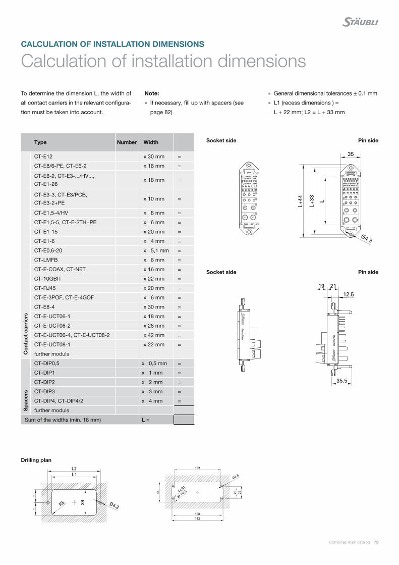
CombiTac main catalog 73
Calculation of installation dimensions
To determine the dimension L, the width of
all contact carriers in the relevant configura-
tion must be taken into account.
Note:
If necessary, fill up with spacers (see
page 82)
General dimensional tolerances ± 0.1 mm
L1 (recess dimensions ) =
L + 22 mm; L2 = L + 33 mm
Drilling plan
Pin side
Pin side
Socket side
Socket side
CALCULATION OF INSTALLATION DIMENSIONS
Type Number Width
Co
ntac
t ca
rrie
rs
CT-E12 x 30 mm =
CT-E8/6-PE, CT-E6-2 x 16 mm =
CT-E8-2, CT-E3-.../HV..., CT-E1-26
x 18 mm =
CT-E3-3, CT-E3/PCB, CT-E3-2+PE
x 10 mm =
CT-E1,5-4/HV x 8 mm =
CT-E1,5-5, CT-E-2TH+PE x 6 mm =
CT-E1-15 x 20 mm =
CT-E1-6 x 4 mm =
CT-E0,6-20 x 5,1 mm =
CT-LMFB x 6 mm =
CT-E-COAX, CT-NET x 16 mm =
CT-10GBIT x 22 mm =
CT-RJ45 x 20 mm =
CT-E-3POF, CT-E-4GOF x 6 mm =
CT-E8-4 x 30 mm =
CT-E-UCT06-1 x 18 mm =
CT-E-UCT06-2 x 28 mm =
CT-E-UCT06-4, CT-E-UCT08-2 x 42 mm =
CT-E-UCT08-1 x 22 mm =
further moduls
Sp
acer
s
CT-DIP0,5 x 0,5 mm =
CT-DIP1 x 1 mm =
CT-DIP2 x 2 mm =
CT-DIP3 x 3 mm =
CT-DIP4, CT-DIP4/2 x 4 mm =
further moduls
Sum of the widths (min. 18 mm) L =

74 CombiTac main catalog
1. Max. permissible mounting offset
2. Max. permissible mounting angular misalignment during mating
Panel mounted
Distance Z in mated condition
PANEL MOUNTED
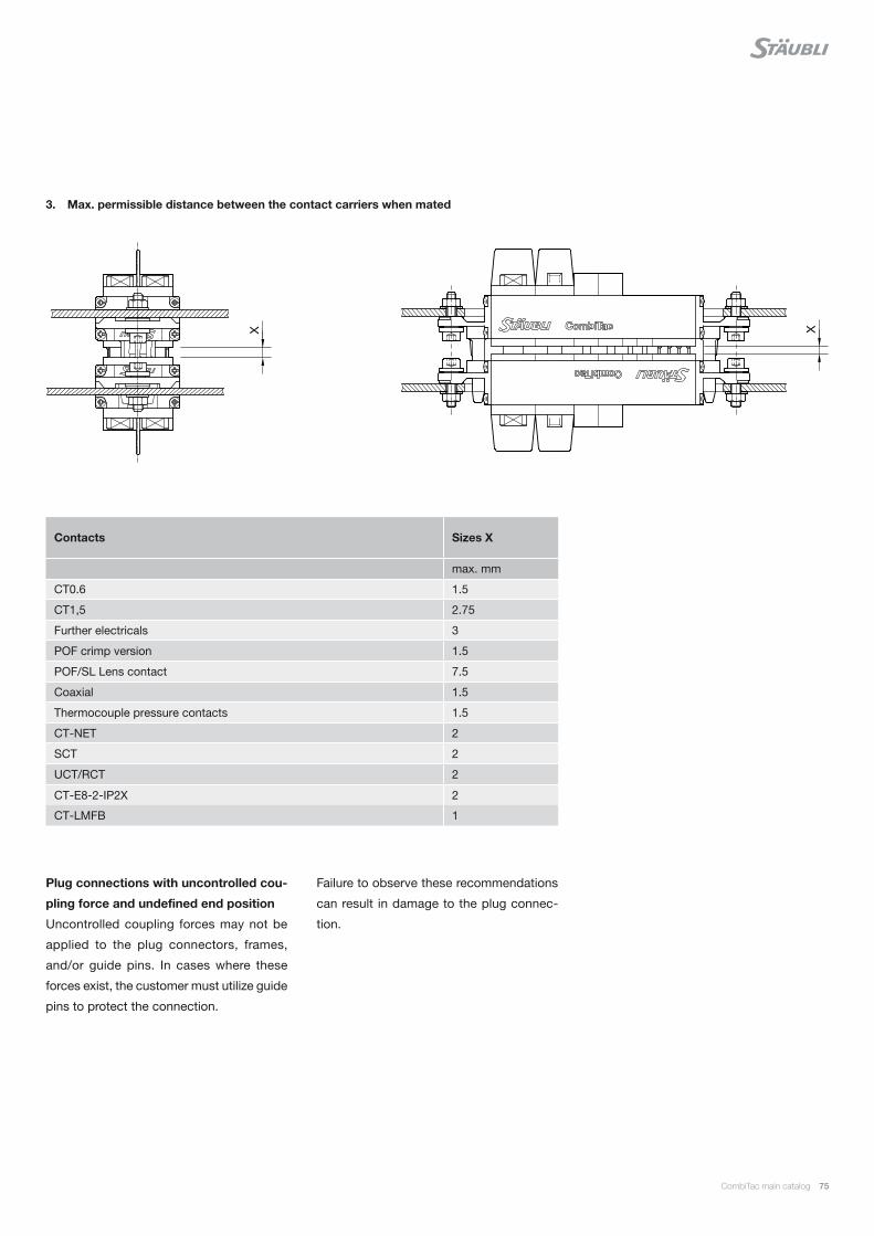
CombiTac main catalog 75
3. Max. permissible distance between the contact carriers when mated
Plug connections with uncontrolled cou-
pling force and undefined end position
Uncontrolled coupling forces may not be
applied to the plug connectors, frames,
and/or guide pins. In cases where these
forces exist, the customer must utilize guide
pins to protect the connection.
Contacts Sizes X
max. mm
CT0.6 1.5
CT1,5 2.75
Further electricals 3
POF crimp version 1.5
POF/SL Lens contact 7.5
Coaxial 1.5
Thermocouple pressure contacts 1.5
CT-NET 2
SCT 2
UCT/RCT 2
CT-E8-2-IP2X 2
CT-LMFB 1
Failure to observe these recommendations
can result in damage to the plug connec-
tion.
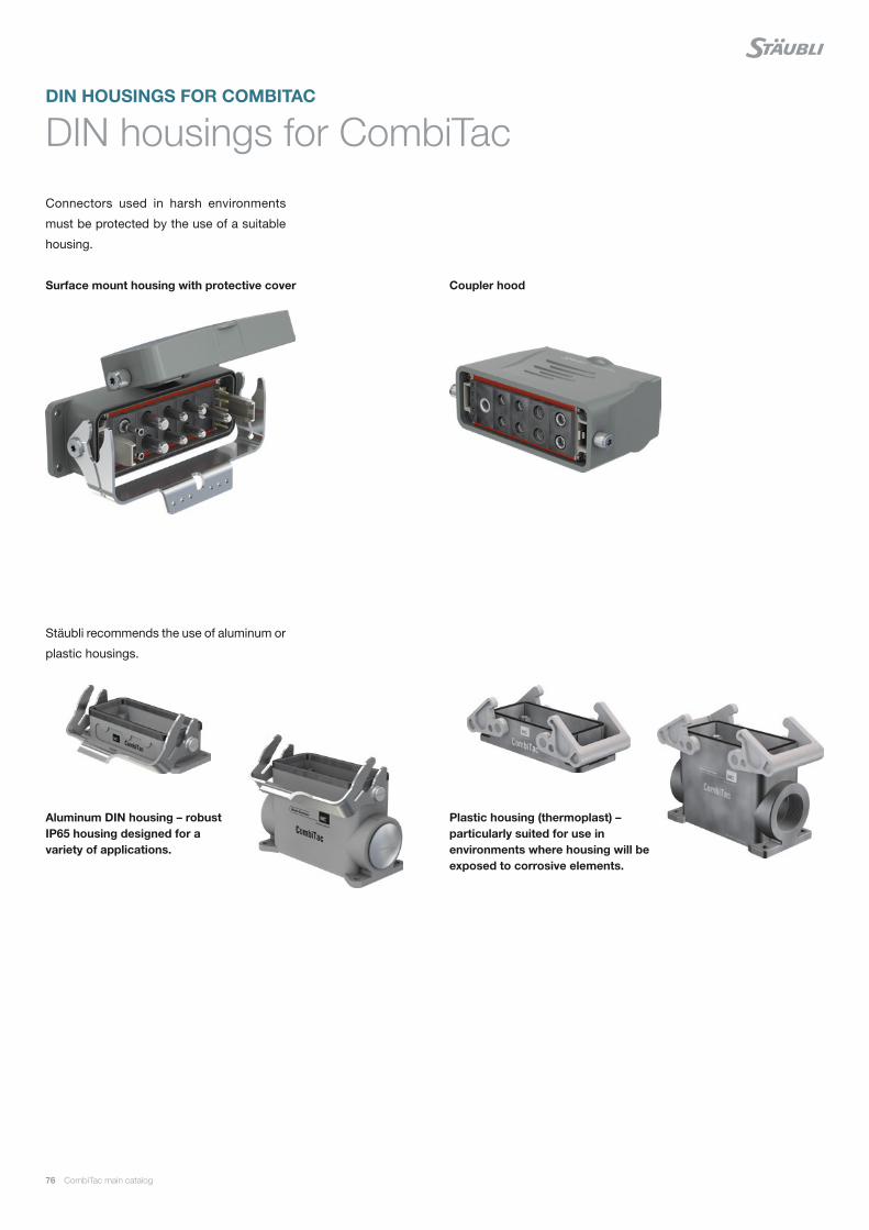
76 CombiTac main catalog
Connectors used in harsh environments
must be protected by the use of a suitable
housing.
Stäubli recommends the use of aluminum or
plastic housings.
Plastic housing (thermoplast) – particularly suited for use in environments where housing will be exposed to corrosive elements.
Aluminum DIN housing – robust IP65 housing designed for a variety of applications.
DIN housings for CombiTac
Surface mount housing with protective cover Coupler hood
DIN HOUSINGS FOR COMBITAC

CombiTac main catalog 77
The coupler hood with protective wall
provides IP2X finger protection during the
plugging / unplugging operation in accor-
dance with IEC 61984:2001 (IEC 61984).
The protective wall can be used on only one
side of the plug connection, preferably on
the flying side (coupler hood).
Protective wall material PA.
The housing sizes 5 and 6 fit 2 CombiTac
units.
The surface mounting housing is available
with or without a protective cover. When
closed, the lid protects all contacts from ex-
ternal influences (pollution, etc.).
The surface mount housing is also available
with a protective lid. This option is available
for all surface and pedestal mount housings
or coupler hoods with plug end pieces.
6 different sizes
2 different heights
Housing sizes 5 and 66 different sizes
Without protective coverWith protective cover With protective cap
With protective wall
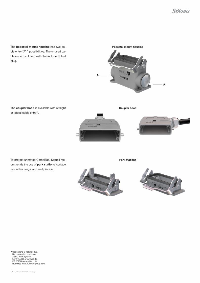
78 CombiTac main catalog
The pedestal mount housing has two ca-
ble entry “A” ¹⁾ possibilities. The unused ca-
ble outlet is closed with the included blind
plug.
The coupler hood is available with straight
or lateral cable entry¹⁾.
To protect unmated CombiTac, Stäubli rec-
ommends the use of park stations (surface
mount housings with end pieces).
1) Cable gland is not included. Recommended producers: AGRO www.agro.ch LAPP KABEL www.lapp.de PFLITSCH www.pflitsch.de HUMMEL www.hummel-group.com
Park stations
Pedestal mount housing
Coupler hood
A
A
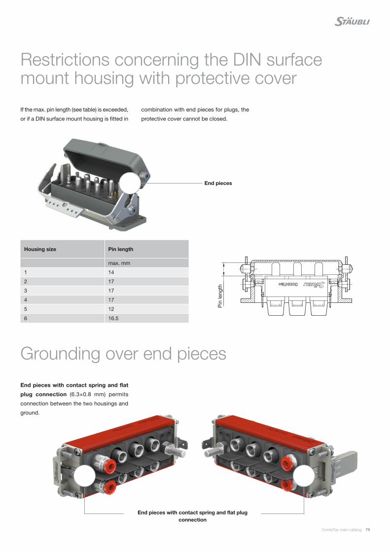
CombiTac main catalog 79
If the max. pin length (see table) is exceeded,
or if a DIN surface mount housing is fitted in
Restrictions concerning the DIN surface mount housing with protective cover
combination with end pieces for plugs, the
protective cover cannot be closed.
Housing size Pin length
max. mm
1 14
2 17
3 17
4 17
5 12
6 16.5
End pieces with contact spring and flat
plug connection (6.3×0.8 mm) permits
connection between the two housings and
ground.
Grounding over end pieces
End pieces
End pieces with contact spring and flat plug connection
Pin
leng
th
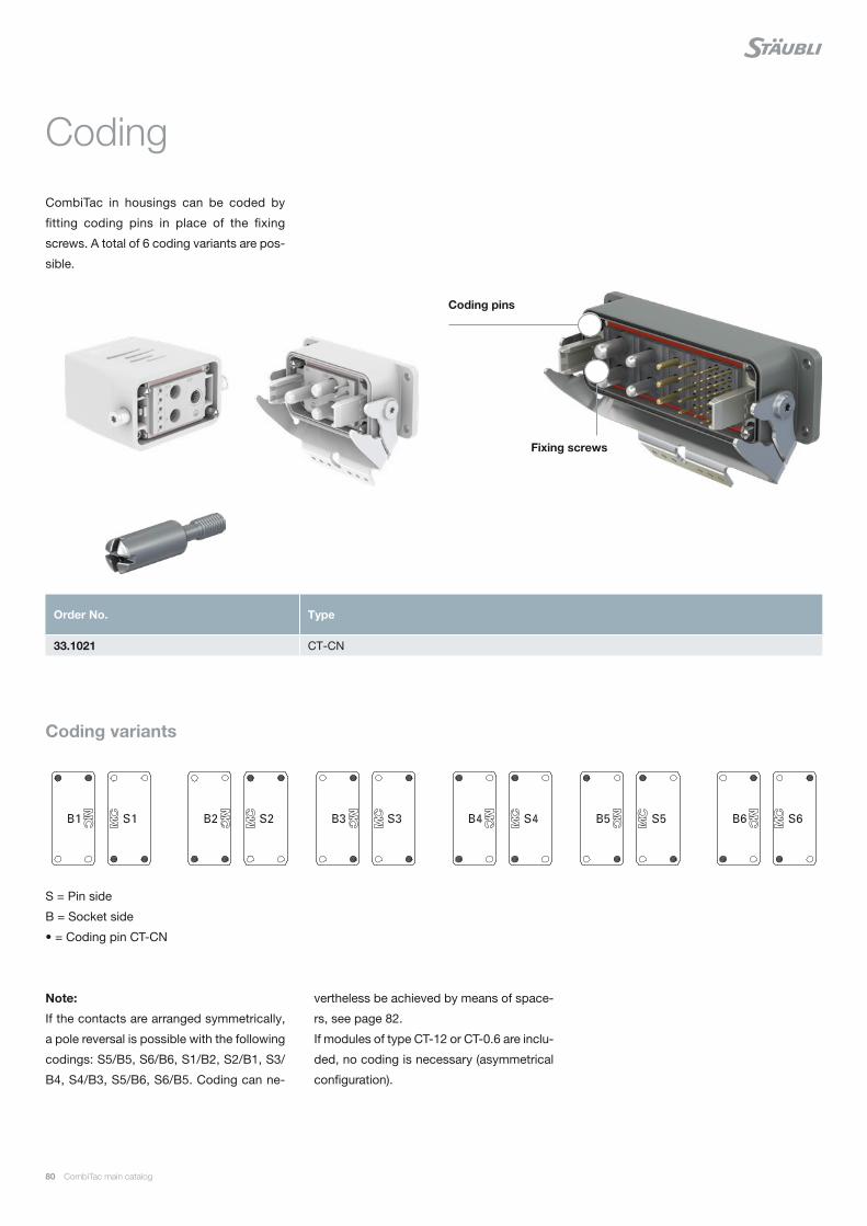
80 CombiTac main catalog
CombiTac in housings can be coded by
fitting coding pins in place of the fixing
screws. A total of 6 coding variants are pos-
sible.
Coding
S = Pin side
B = Socket side
• = Coding pin CT-CN
Note:
If the contacts are arranged symmetrically,
a pole reversal is possible with the following
codings: S5/B5, S6/B6, S1/B2, S2/B1, S3/
B4, S4/B3, S5/B6, S6/B5. Coding can ne-
vertheless be achieved by means of space-
rs, see page 82.
If modules of type CT-12 or CT-0.6 are inclu-
ded, no coding is necessary (asymmetrical
configuration).
Fixing screws
Coding pins
Order No. Type
33.1021 CT-CN
Coding variants
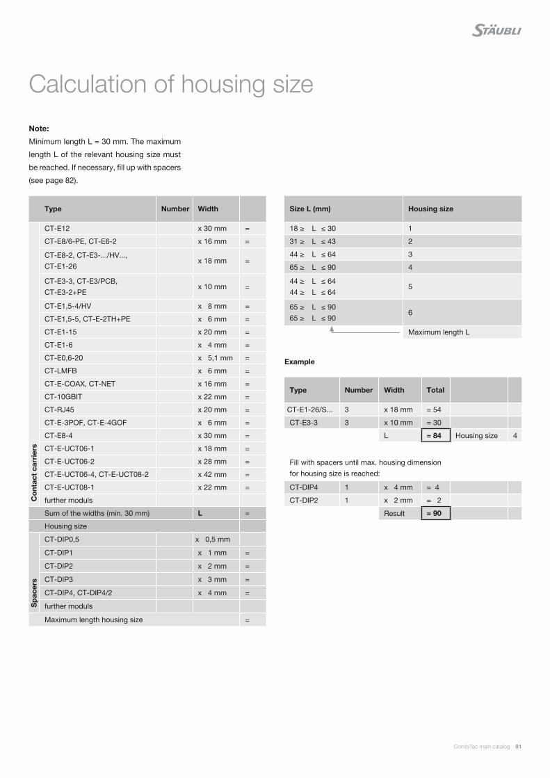
CombiTac main catalog 81
Calculation of housing size
Note:
Minimum length L = 30 mm. The maximum
length L of the relevant housing size must
be reached. If necessary, fill up with spacers
(see page 82).
Example
Type Number Width Total
CT-E1-26/S... 3 x 18 mm = 54
CT-E3-3 3 x 10 mm = 30
L = 84 Housing size 4
Fill with spacers until max. housing dimension for housing size is reached:
CT-DIP4 1 x 4 mm = 4
CT-DIP2 1 x 2 mm = 2
Result = 90
Size L (mm) Housing size
18 ≥ L ≤ 30 1
31 ≥ L ≤ 43 2
44 ≥ L ≤ 64 3
65 ≥ L ≤ 90 4
44 ≥ L ≤ 64 44 ≥ L ≤ 64
5
65 ≥ L ≤ 90 65 ≥ L ≤ 90
6
Maximum length L
Type Number Width
Co
ntac
t ca
rrie
rs
CT-E12 x 30 mm =
CT-E8/6-PE, CT-E6-2 x 16 mm =
CT-E8-2, CT-E3-.../HV..., CT-E1-26
x 18 mm =
CT-E3-3, CT-E3/PCB, CT-E3-2+PE
x 10 mm =
CT-E1,5-4/HV x 8 mm =
CT-E1,5-5, CT-E-2TH+PE x 6 mm =
CT-E1-15 x 20 mm =
CT-E1-6 x 4 mm =
CT-E0,6-20 x 5,1 mm =
CT-LMFB x 6 mm =
CT-E-COAX, CT-NET x 16 mm =
CT-10GBIT x 22 mm =
CT-RJ45 x 20 mm =
CT-E-3POF, CT-E-4GOF x 6 mm =
CT-E8-4 x 30 mm =
CT-E-UCT06-1 x 18 mm =
CT-E-UCT06-2 x 28 mm =
CT-E-UCT06-4, CT-E-UCT08-2 x 42 mm =
CT-E-UCT08-1 x 22 mm =
further moduls
Sum of the widths (min. 30 mm) L =
Housing size
Sp
acer
s
CT-DIP0,5 x 0,5 mm
CT-DIP1 x 1 mm =
CT-DIP2 x 2 mm =
CT-DIP3 x 3 mm =
CT-DIP4, CT-DIP4/2 x 4 mm =
further moduls
Maximum length housing size =
Size L (mm) Housing size
18 ≥ L ≤ 30 1
31 ≥ L ≤ 43 2
44 ≥ L ≤ 64 3
65 ≥ L ≤ 90 4
44 ≥ L ≤ 64 44 ≥ L ≤ 64
5
65 ≥ L ≤ 90 65 ≥ L ≤ 90
6
Maximum length L
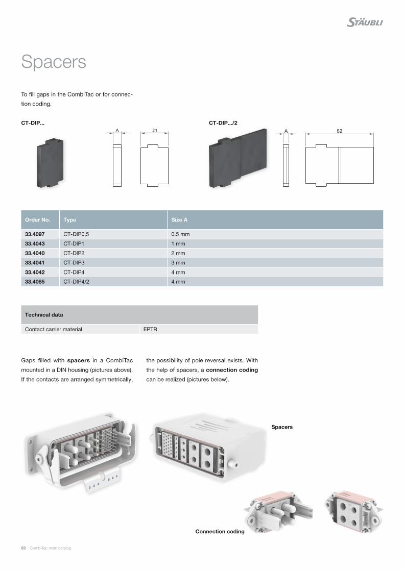
82 CombiTac main catalog
Gaps filled with spacers in a CombiTac
mounted in a DIN housing (pictures above).
If the contacts are arranged symmetrically,
Order No. Type Size A
33.4097 CT-DIP0,5 0.5 mm
33.4043 CT-DIP1 1 mm
33.4040 CT-DIP2 2 mm
33.4041 CT-DIP3 3 mm
33.4042 CT-DIP4 4 mm
33.4085 CT-DIP4/2 4 mm
Technical data
Contact carrier material EPTR
To fill gaps in the CombiTac or for connec-
tion coding.
Spacers
the possibility of pole reversal exists. With
the help of spacers, a connection coding
can be realized (pictures below).
CT-DIP...
Connection coding
Spacers
CT-DIP.../2
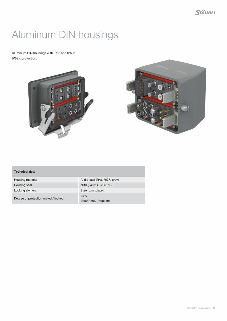
CombiTac main catalog 83
Technical data
Housing material Al die-cast (RAL 7037, gray)
Housing seal NBR (–40 °C...+125 °C)
Locking element Steel, zinc plated
Degree of protection mated / lockedIP65 IP68/IP69K (Page 89)
Aluminum DIN housings with IP65 and IP68/
IP69K protection.
Aluminum DIN housings
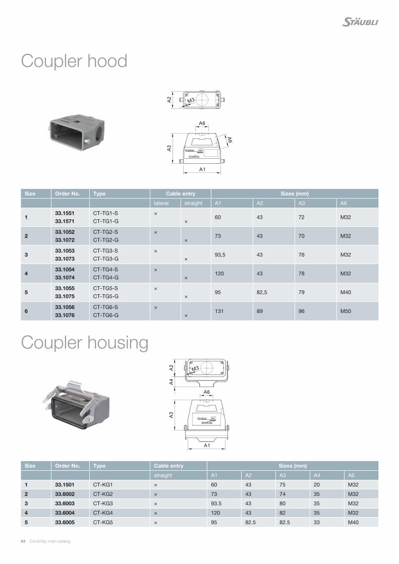
84 CombiTac main catalog
Coupler hood
Coupler housing
Size Order No. Type Cable entry Sizes (mm)
lateral straight A1 A2 A3 A6
133.1551 33.1571
CT-TG1-S CT-TG1-G
× ×
60 43 72 M32
233.1052 33.1072
CT-TG2-S CT-TG2-G
× ×
73 43 70 M32
333.1053 33.1073
CT-TG3-S CT-TG3-G
× ×
93,5 43 76 M32
433.1054 33.1074
CT-TG4-S CT-TG4-G
× ×
120 43 78 M32
533.1055 33.1075
CT-TG5-S CT-TG5-G
× ×
95 82,5 79 M40
633.1056 33.1076
CT-TG6-S CT-TG6-G
× ×
131 89 96 M50
Size Order No. Type Cable entry Sizes (mm)
straight A1 A2 A3 A4 A6
1 33.1501 CT-KG1 × 60 43 75 20 M32
2 33.6002 CT-KG2 × 73 43 74 35 M32
3 33.6003 CT-KG3 × 93.5 43 80 35 M32
4 33.6004 CT-KG4 × 120 43 82 35 M32
5 33.6005 CT-KG5 × 95 82.5 82.5 33 M40
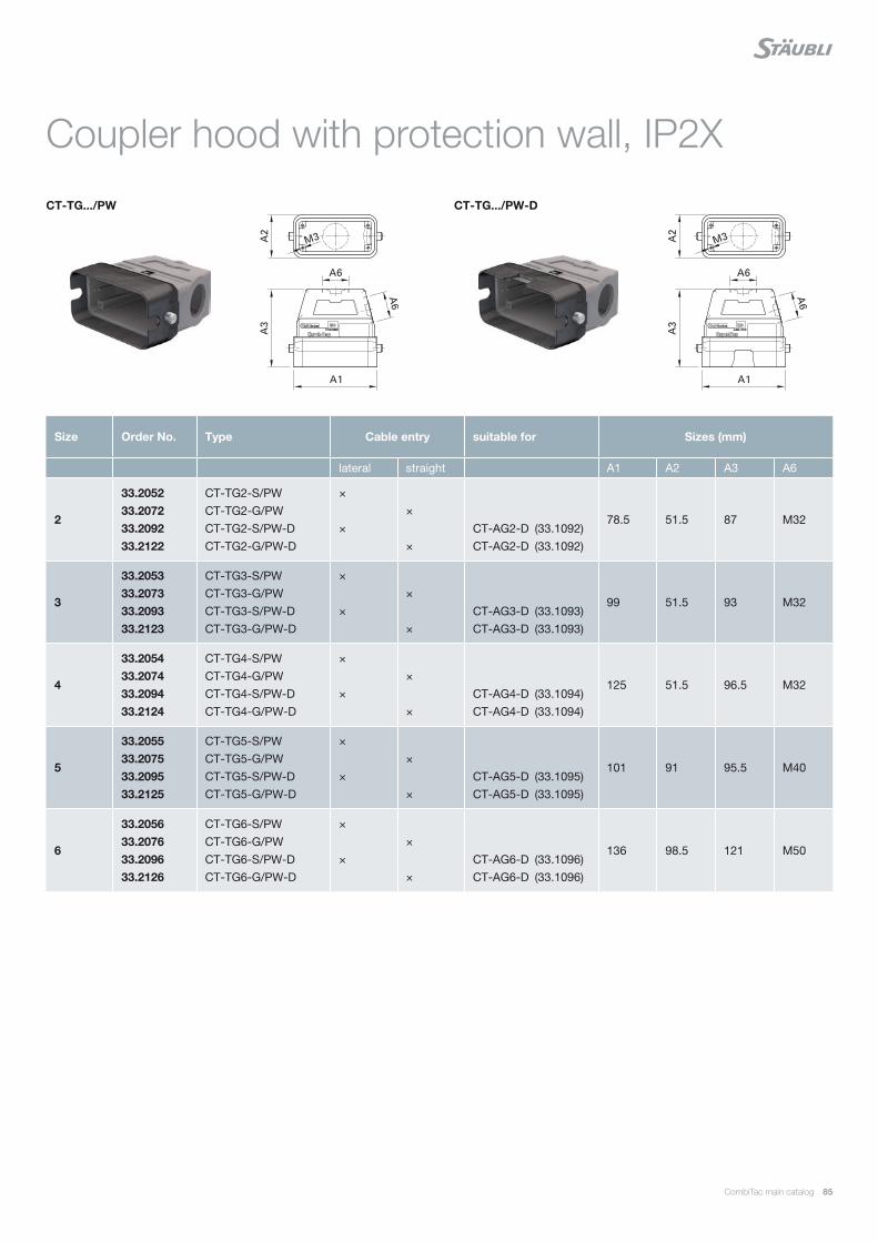
CombiTac main catalog 85
CT-TG.../PW-DCT-TG.../PW
Coupler hood with protection wall, IP2X
Size Order No. Type Cable entry suitable for Sizes (mm)
lateral straight A1 A2 A3 A6
2
33.2052 33.2072 33.2092 33.2122
CT-TG2-S/PW CT-TG2-G/PW CT-TG2-S/PW-D CT-TG2-G/PW-D
× ×
× ×
CT-AG2-D (33.1092) CT-AG2-D (33.1092)
78.5 51.5 87 M32
3
33.2053 33.2073 33.2093 33.2123
CT-TG3-S/PW CT-TG3-G/PW CT-TG3-S/PW-D CT-TG3-G/PW-D
× ×
× ×
CT-AG3-D (33.1093) CT-AG3-D (33.1093)
99 51.5 93 M32
4
33.2054 33.2074 33.2094 33.2124
CT-TG4-S/PW CT-TG4-G/PW CT-TG4-S/PW-D CT-TG4-G/PW-D
× ×
× ×
CT-AG4-D (33.1094) CT-AG4-D (33.1094)
125 51.5 96.5 M32
5
33.2055 33.2075 33.2095 33.2125
CT-TG5-S/PW CT-TG5-G/PW CT-TG5-S/PW-D CT-TG5-G/PW-D
× ×
× ×
CT-AG5-D (33.1095) CT-AG5-D (33.1095)
101 91 95.5 M40
6
33.2056 33.2076 33.2096 33.2126
CT-TG6-S/PW CT-TG6-G/PW CT-TG6-S/PW-D CT-TG6-G/PW-D
× ×
× ×
CT-AG6-D (33.1096)CT-AG6-D (33.1096)
136 98.5 121 M50

86 CombiTac main catalog
CT-AG...-DCT-AG...
Size Order No. Type Protective cover Sizes (mm)
without with A1 A2 A3 A4 A5
133.1561 33.1591
CT-AG1 CT-AG1-D
× ×
82 43 29 20– 26.5
233.1062 33.1092
CT-AG2 CT-AG2-D
× ×
93 43.5 28.5 35– 26
333.1063 33.1093
CT-AG3 CT-AG3-D
× ×
113 43.5 28.5 35– 26
433.1064 33.1094
CT-AG4 CT-AG4-D
× ×
140 43.5 28.5 35– 26
533.1065 33.1095
CT-AG5 CT-AG5-D
× ×
124 90 36 27– 22
633.1066 33.1096
CT-AG6 CT-AG6-D
× ×
165 90 38.5 50– 25
Size Order No. Type Sizes (mm)
A1 A2 A3 A4
2 33.2062 CT-AG2/PW 93 51.5 41 31
3 33.2063 CT-AG3/PW 113 51.5 41 31
4 33.2064 CT-AG4/PW 140 51.5 41 31
5 33.2065 CT-AG5/PW 124 91 48 29.5
Surface mount housing
Surface mount housing with protection wall
Note: IP2X
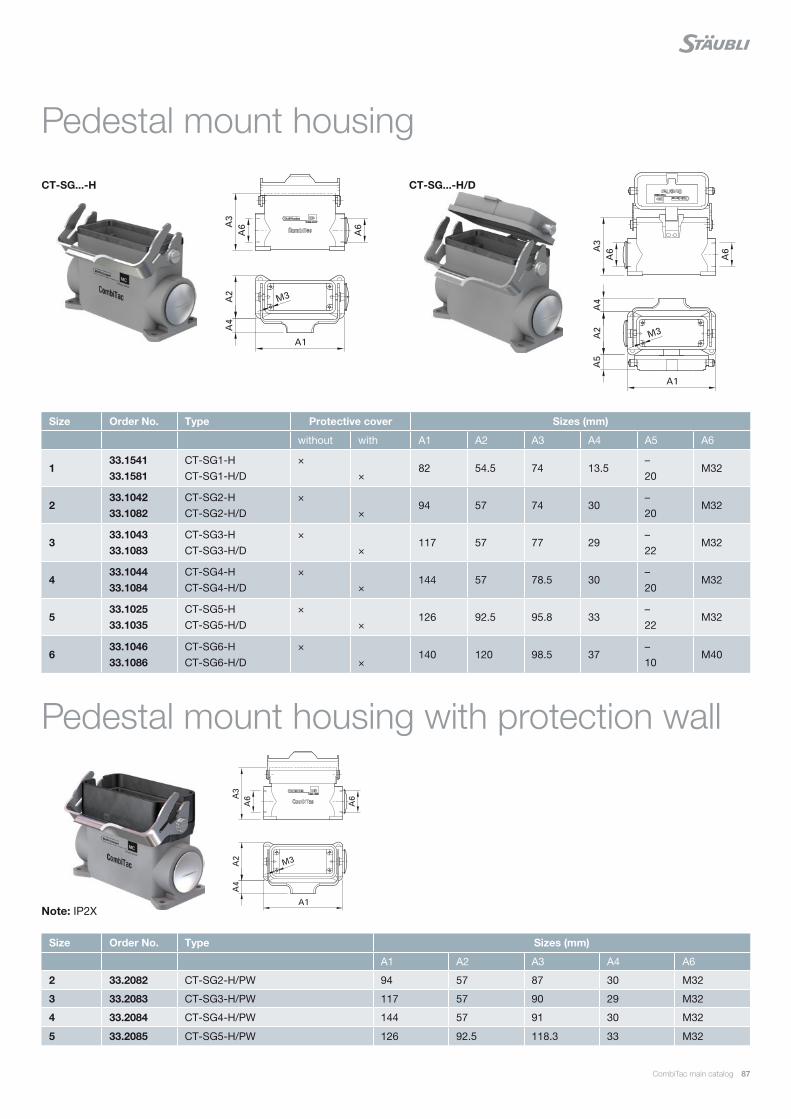
CombiTac main catalog 87
CT-SG...-H/DCT-SG...-H
Size Order No. Type Protective cover Sizes (mm)
without with A1 A2 A3 A4 A5 A6
133.1541 33.1581
CT-SG1-H CT-SG1-H/D
× ×
82 54.5 74 13.5– 20
M32
233.1042 33.1082
CT-SG2-H CT-SG2-H/D
× ×
94 57 74 30– 20
M32
333.1043 33.1083
CT-SG3-H CT-SG3-H/D
× ×
117 57 77 29– 22
M32
433.1044 33.1084
CT-SG4-H CT-SG4-H/D
× ×
144 57 78.5 30– 20
M32
533.1025 33.1035
CT-SG5-H CT-SG5-H/D
× ×
126 92.5 95.8 33– 22
M32
633.1046 33.1086
CT-SG6-H CT-SG6-H/D
× ×
140 120 98.5 37– 10
M40
Size Order No. Type Sizes (mm)
A1 A2 A3 A4 A6
2 33.2082 CT-SG2-H/PW 94 57 87 30 M32
3 33.2083 CT-SG3-H/PW 117 57 90 29 M32
4 33.2084 CT-SG4-H/PW 144 57 91 30 M32
5 33.2085 CT-SG5-H/PW 126 92.5 118.3 33 M32
Pedestal mount housing
Pedestal mount housing with protection wall
Note: IP2X
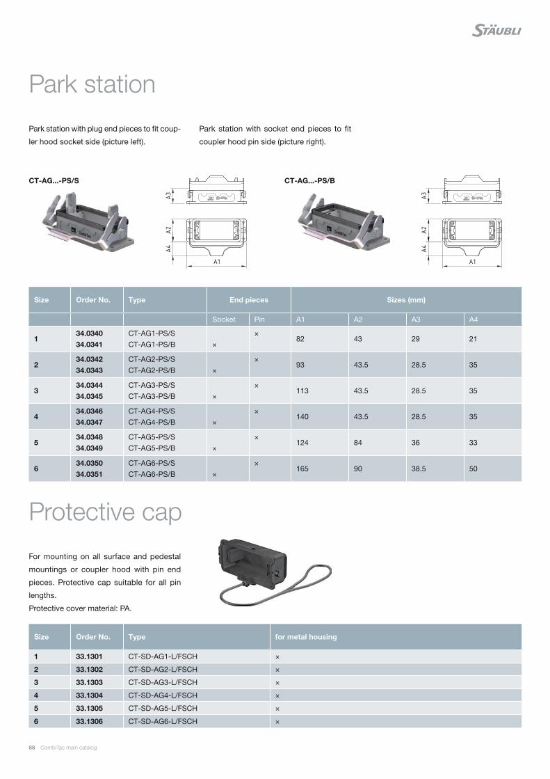
88 CombiTac main catalog
Park station with plug end pieces to fit coup-
ler hood socket side (picture left).
Size Order No. Type End pieces Sizes (mm)
Socket Pin A1 A2 A3 A4
134.0340 34.0341
CT-AG1-PS/S CT-AG1-PS/B
×
× 82 43 29 21
234.0342 34.0343
CT-AG2-PS/S CT-AG2-PS/B
×
× 93 43.5 28.5 35
334.0344 34.0345
CT-AG3-PS/S CT-AG3-PS/B
×
× 113 43.5 28.5 35
434.0346 34.0347
CT-AG4-PS/S CT-AG4-PS/B
×
× 140 43.5 28.5 35
534.0348 34.0349
CT-AG5-PS/S CT-AG5-PS/B
×
× 124 84 36 33
634.0350 34.0351
CT-AG6-PS/S CT-AG6-PS/B
×
× 165 90 38.5 50
Park station
Protective cap
Park station with socket end pieces to fit
coupler hood pin side (picture right).
CT-AG...-PS/BCT-AG...-PS/S
For mounting on all surface and pedestal
mountings or coupler hood with pin end
pieces. Protective cap suitable for all pin
lengths.
Protective cover material: PA.
Size Order No. Type for metal housing
1 33.1301 CT-SD-AG1-L/FSCH ×
2 33.1302 CT-SD-AG2-L/FSCH ×
3 33.1303 CT-SD-AG3-L/FSCH ×
4 33.1304 CT-SD-AG4-L/FSCH ×
5 33.1305 CT-SD-AG5-L/FSCH ×
6 33.1306 CT-SD-AG6-L/FSCH ×
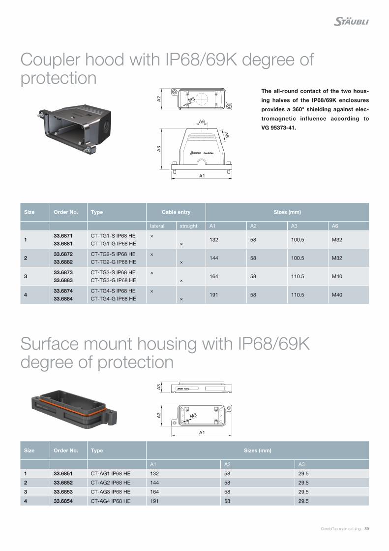
CombiTac main catalog 89
The all-round contact of the two hous-
ing halves of the IP68/69K enclosures
provides a 360° shielding against elec-
tromagnetic influence according to
VG 95373-41.
Size Order No. Type Cable entry Sizes (mm)
lateral straight A1 A2 A3 A6
133.6871 33.6881
CT-TG1-S IP68 HE CT-TG1-G IP68 HE
× ×
132 58 100.5 M32
233.6872 33.6882
CT-TG2-S IP68 HE CT-TG2-G IP68 HE
× ×
144 58 100.5 M32
333.6873 33.6883
CT-TG3-S IP68 HE CT-TG3-G IP68 HE
× ×
164 58 110.5 M40
433.6874 33.6884
CT-TG4-S IP68 HE CT-TG4-G IP68 HE
× ×
191 58 110.5 M40
Coupler hood with IP68/69K degree of protection
Surface mount housing with IP68/69K degree of protection
Size Order No. Type Sizes (mm)
A1 A2 A3
1 33.6851 CT-AG1 IP68 HE 132 58 29.5
2 33.6852 CT-AG2 IP68 HE 144 58 29.5
3 33.6853 CT-AG3 IP68 HE 164 58 29.5
4 33.6854 CT-AG4 IP68 HE 191 58 29.5
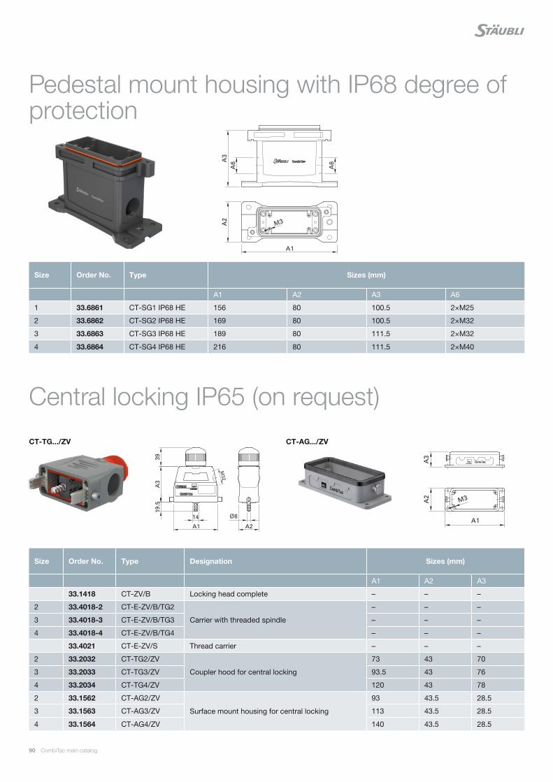
90 CombiTac main catalog
Size Order No. Type Sizes (mm)
A1 A2 A3 A6
1 33.6861 CT-SG1 IP68 HE 156 80 100.5 2×M25
2 33.6862 CT-SG2 IP68 HE 169 80 100.5 2×M32
3 33.6863 CT-SG3 IP68 HE 189 80 111.5 2×M32
4 33.6864 CT-SG4 IP68 HE 216 80 111.5 2×M40
Size Order No. Type Designation Sizes (mm)
A1 A2 A3
33.1418 CT-ZV/B Locking head complete – – –
2 33.4018-2 CT-E-ZV/B/TG2
Carrier with threaded spindle
– – –
3 33.4018-3 CT-E-ZV/B/TG3 – – –
4 33.4018-4 CT-E-ZV/B/TG4 – – –
33.4021 CT-E-ZV/S Thread carrier – – –
2 33.2032 CT-TG2/ZV
Coupler hood for central locking
73 43 70
3 33.2033 CT-TG3/ZV 93.5 43 76
4 33.2034 CT-TG4/ZV 120 43 78
2 33.1562 CT-AG2/ZV
Surface mount housing for central locking
93 43.5 28.5
3 33.1563 CT-AG3/ZV 113 43.5 28.5
4 33.1564 CT-AG4/ZV 140 43.5 28.5
Pedestal mount housing with IP68 degree of protection
Central locking IP65 (on request)
CT-AG.../ZVCT-TG.../ZV
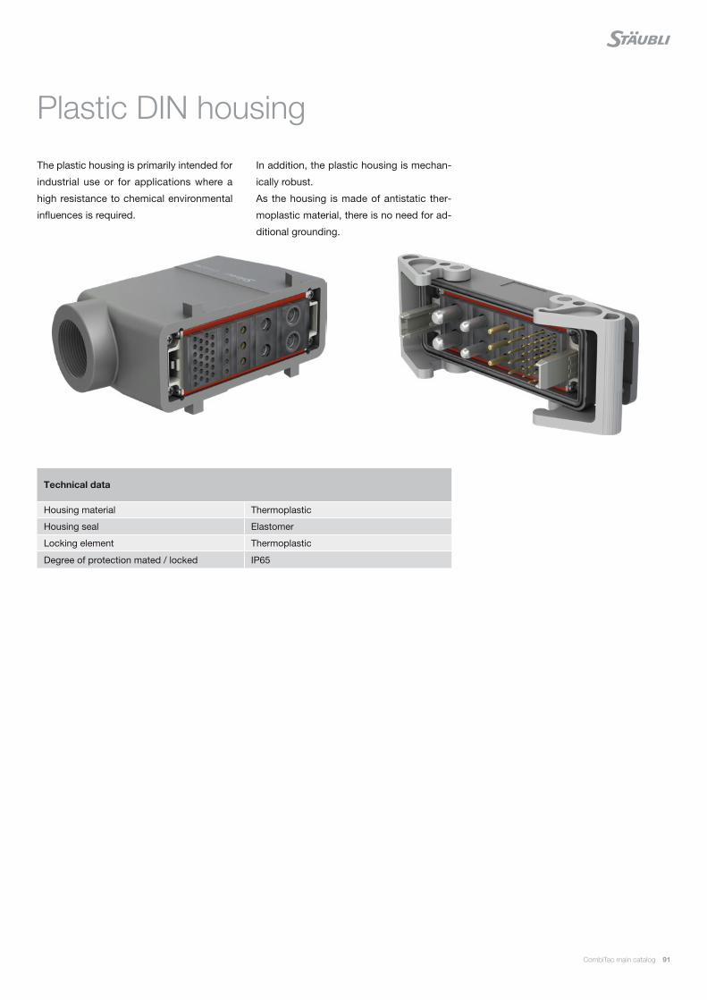
CombiTac main catalog 91
The plastic housing is primarily intended for
industrial use or for applications where a
high resistance to chemical environmental
influences is required.
Technical data
Housing material Thermoplastic
Housing seal Elastomer
Locking element Thermoplastic
Degree of protection mated / locked IP65
Plastic DIN housing
In addition, the plastic housing is mechan-
ically robust.
As the housing is made of antistatic ther-
moplastic material, there is no need for ad-
ditional grounding.
92 CombiTac main catalog
Plastic housing – Resistance to aggressive media
Resistant Limited resistance
1-Pentanol x
Alum x
Amide, aqueous x
Ammonia gas x
Ammonia, 10% aqueous solution x
Ammonium acetate x
Ammonium carbonate x
Ammonium chloride x
Ammonium nitrate x
Ammonium phosphate x
Ammonium sulfate x
Aniline x
Asphalt x
Beer x
Borated water x
Borax x
Boric acid, 10% aqueous solution x
Boric acid x
Butane gas x
Butane, liquid x
Calcium chloride, 10% aqueous solution x
Calcium chloride x
Calcium nitrate x
Calcium sulfate x
Chlorinated lime, diluted x
Copper sulfate, 10% aqueous solution x
Cresol acids x
Cresol solution x
Cutting oil x
Cyclohexane x
Diesel x
Diisononyl phthalate x
Di-Octyl-Phtalat x
Diluted glucose x
Diluted glycerol x
Diluted glycol x
Diluted phenol x
Ethanol, non-denaturized x
Ethylene glycol or propylene glycol x
Fatty acids x
Fruit juices x
Gasoline x
Plastic housing – Resistance to aggressive media
Resistant Limited resistance
Glycerol x
Grinding oil x
Gypsum (see calcium sulfate) x
Heptane x
Hexane x
Hydrogen sulfide x
Ink x
Isopropyl alcohol x
Lactic acid x
Linseed oil x
Lubricating oil x
Mercury x
Methanol, diluted by 50% x
Mineral oil x
Mineral spirits (Avio) x
Mineral-based oil x
Mothballs x
Motor oil x
n-Butanol x
Naphthalene x
Octane x
Oil IRM 901, 20 °C x
Oil IRM 902, 20 °C x
Oil IRM 903, 20 °C x
Oil x
Oleic acid x
Oxalic acid x
Paraffin oil x
Petroleum x
Phthalate x
Potassium carbonate x
Potassium chlorate x
Potassium chloride x
Potassium chromate x
Potassium cyanide, aqueous solution x
Potassium iodide x
Potassium nitrate x
Potassium persulfate x
Potassium sulfate x
Seawater x
Silicone oil x
Soap solution x

CombiTac main catalog 93
Plastic housing – Resistance to aggressive media
Resistant Limited resistance
Sodium bicarbonate x
Sodium carbonate x
Sodium chlorate x
Sodium chloride (table salt) x
Sodium hydrogen sulfate, aqueous solution x
Sodium hydroxide 12.5% (alkaline solution) x
Sodium nitrate x
Sodium nitrite x
Sodium perborate x
Sodium phosphate x
Sodium silicate x
Sodium sulfate x
Sodium sulfide x
Sodium thiosulfate (fixing salt/developing film) x
Solution for developing photographs x
Stearic acid x
Succinic acid x
Sulfur dioxide x
Sulfur x
Table salt, aqueous solution x
Tallow x
Tartaric acid x
Tar x
Transformer oil x
Tricresyl phosphate x
Turpentine substitute x
Urea, diluted x
Urine x
Vegetable oil x
Water x
White spirits (isopropanol and ethanol) x
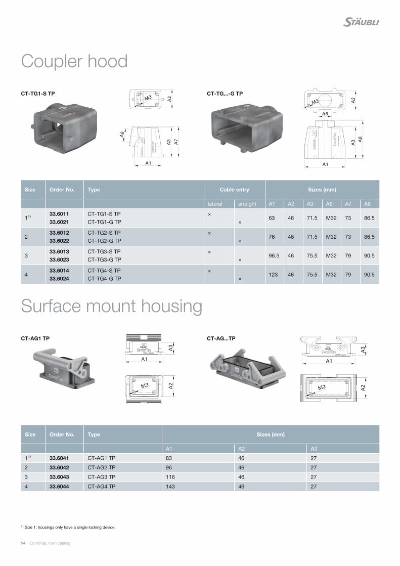
94 CombiTac main catalog
Coupler hood
Surface mount housing
1) Size 1: housings only have a single locking device.
Size Order No. Type Sizes (mm)
A1 A2 A3
1¹⁾ 33.6041 CT-AG1 TP 83 46 27
2 33.6042 CT-AG2 TP 96 46 27
3 33.6043 CT-AG3 TP 116 46 27
4 33.6044 CT-AG4 TP 143 46 27
Size Order No. Type Cable entry Sizes (mm)
lateral straight A1 A2 A3 A6 A7 A8
1¹⁾33.6011 33.6021
CT-TG1-S TP CT-TG1-G TP
× ×
63 46 71.5 M32 73 86.5
233.6012 33.6022
CT-TG2-S TP CT-TG2-G TP
× ×
76 46 71.5 M32 73 86.5
333.6013 33.6023
CT-TG3-S TP CT-TG3-G TP
× ×
96.5 46 75.5 M32 79 90.5
433.601433.6024
CT-TG4-S TP CT-TG4-G TP
× ×
123 46 75.5 M32 79 90.5
CT-AG1 TP CT-AG...TP
CT-TG1-S TP CT-TG...-G TP

CombiTac main catalog 95
Protective cap
Pedestal mount housing
1) Size 1: housings only have a single locking device.
Size Order No. Type Sizes (mm)
A1 A2 A3 A6
1¹⁾ 33.6601 CT-SG1 TP 82 57 73 M32
2 33.6602 CT-SG2 TP 94 57 80 M32
3 33.6603 CT-SG3 TP 117 57 80 M32
4 33.6604 CT-SG4 TP 144 57 80 M32
Size Order No. Type
1¹⁾ 33.6031 CT-SD-TG1 TP
2 33.6032 CT-SD-TG2 TP
3 33.6033 CT-SD-TG3 TP
4 33.6034 CT-SD-TG4 TP
CT-SD-TG1 TP CT-SD-TG... TP
CT-SG1 TP CT-SG...TP

E229145
96 CombiTac main catalog
Appropriate ground protection is available
for conductive DIN housings to protect the
users against electrical shock, according to
IEC 611401).
Protective grounding through end pieces
For live conductors 0.14 mm² – 6 mm²
(AWG 26 – 10)
Protective grounding through PE module
For live conductors 10 mm² – 95 mm²
(AWG 8 – 3/0)
1) For voltages > 60 V DC or > 30 V AC, metal (conductive) housings must be connected to protective earth (PE).
Protective grounding of conductive housings
End pieces with contact spring and flat connector termination
PE module
CombiTac conductive housings can be
grounded internally through its end pieces
or the CombiTac PE module.
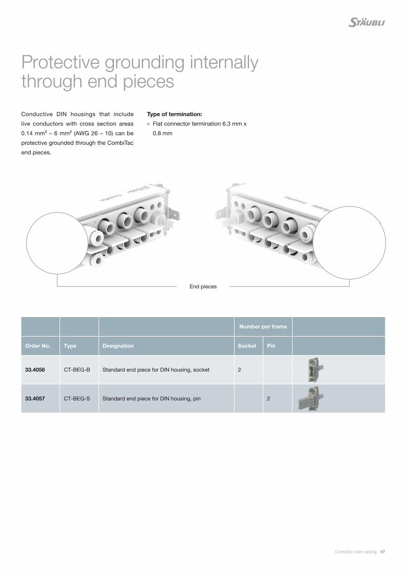
CombiTac main catalog 97
Conductive DIN housings that include
live conductors with cross section areas
0.14 mm² – 6 mm² (AWG 26 – 10) can be
protective grounded through the CombiTac
end pieces.
Number per frame
Order No. Type Designation Socket Pin
33.4056 CT-BEG-B Standard end piece for DIN housing, socket 2
33.4057 CT-BEG-S Standard end piece for DIN housing, pin 2
End pieces
Protective grounding internally through end pieces
Type of termination:
Flat connector termination 6.3 mm x
0.8 mm

E229145
98 CombiTac main catalog
CT-GND10 AG
The CombiTac PE module is used for inter-
nal protective grounding of CombiTac con-
ductive housings size 2 – 6.
The PE module carrier replaces one of the
end pieces and is directly connected to the
housing.
Required tools
For the required tools please refer to
MA213-09.
Order No. Type Description
33.4165 CT-GND10 AG PE module carrier
Technical data
Number of poles 1
For contact diameter 10 mm
Contact carrier material Brass
Limiting temperature (IEC 61984), upper lower
+90 °C −40 °C
PE module
The size of the PE module contacts is
determined by the cross section area
of the largest live conductor used in the
CombiTac configuration (see selection
table page 100).
Aluminum rails are required to ensure
correct protective grounding of conduc-
tive housings.
Fitted with MULTILAM
MAIch bin eine Montageanleitung.
Man sollte mich unbedingt le-
sen, bevor man das Produkt ver-
wendet! Ich beinhalte wertvolle
Hinweise zur korrekten Montage
und zum richtigen Einsatz des
Produktes. Im Moment ist die
Schrift zwar ein bischen klein,
aber später geht das dann ganz
gut zu lesen, da die MA dann
Assembly instructions MA213-09
www.staubli.com/electrical
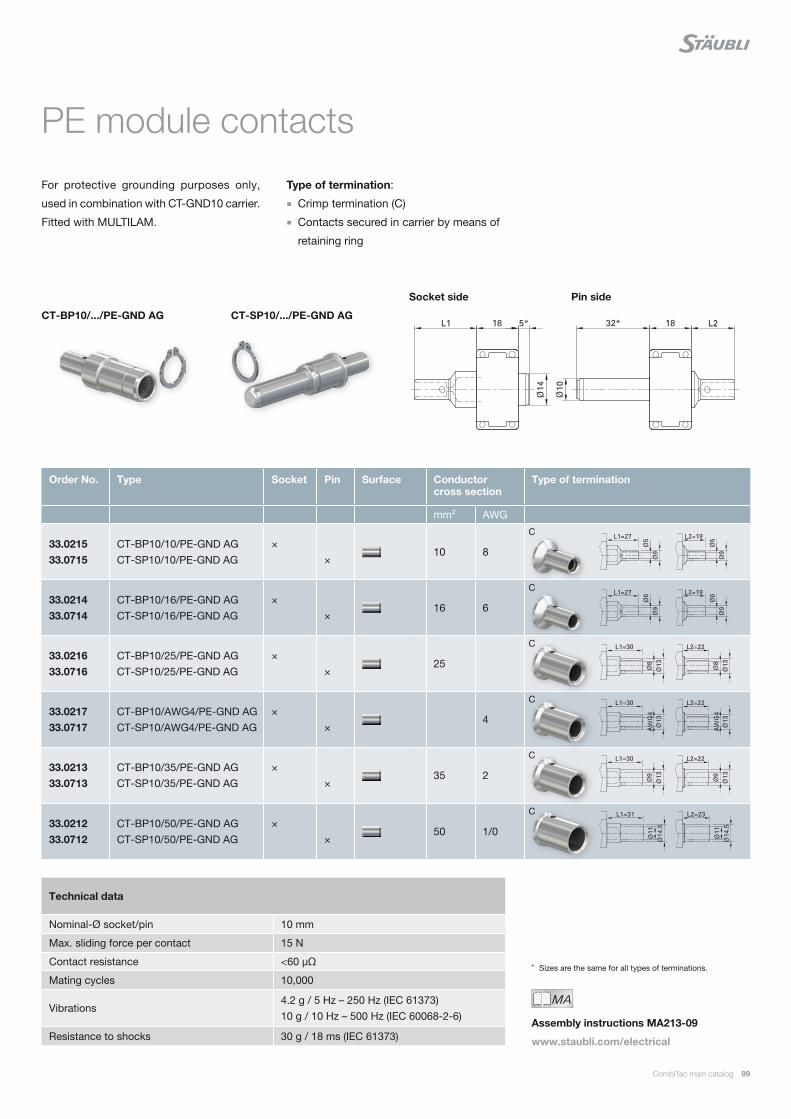
CombiTac main catalog 99
CT-BP10/.../PE-GND AG CT-SP10/.../PE-GND AG
Pin sideSocket side
For protective grounding purposes only,
used in combination with CT-GND10 carrier.
Fitted with MULTILAM.
* Sizes are the same for all types of terminations.
Order No. Type Socket Pin Surface Conductor cross section
Type of termination
mm² AWG
33.0215 33.0715
CT-BP10/10/PE-GND AG CT-SP10/10/PE-GND AG
× ×
10 8
33.0214 33.0714
CT-BP10/16/PE-GND AG CT-SP10/16/PE-GND AG
× ×
16 6
33.0216 33.0716
CT-BP10/25/PE-GND AG CT-SP10/25/PE-GND AG
× ×
25
33.0217 33.0717
CT-BP10/AWG4/PE-GND AG CT-SP10/AWG4/PE-GND AG
× ×
4
33.0213 33.0713
CT-BP10/35/PE-GND AG CT-SP10/35/PE-GND AG
× ×
35 2
33.0212 33.0712
CT-BP10/50/PE-GND AG CT-SP10/50/PE-GND AG
× ×
50 1/0
C
C
C
C
C
C
Technical data
Nominal-Ø socket/pin 10 mm
Max. sliding force per contact 15 N
Contact resistance <60 μΩ
Mating cycles 10,000
Vibrations4.2 g / 5 Hz – 250 Hz (IEC 61373)10 g / 10 Hz – 500 Hz (IEC 60068-2-6)
Resistance to shocks 30 g / 18 ms (IEC 61373)
PE module contacts
Type of termination:
Crimp termination (C)
Contacts secured in carrier by means of
retaining ring
MAIch bin eine Montageanleitung.
Man sollte mich unbedingt le-
sen, bevor man das Produkt ver-
wendet! Ich beinhalte wertvolle
Hinweise zur korrekten Montage
und zum richtigen Einsatz des
Produktes. Im Moment ist die
Schrift zwar ein bischen klein,
aber später geht das dann ganz
gut zu lesen, da die MA dann
Assembly instructions MA213-09
www.staubli.com/electrical

100 CombiTac main catalog
PE module contacts selection table
mm²AWG
mm²AWG
mm²AWG
mm²AWG
mm²AWG
mm²AWG
mm²AWG
mm²AWG
Largest live conductor cross section 10 8
166
254
352
50–
–1/0
702/0
953/0
Required PE conductor cross section according to IEC 61984 108
166
166
166
25–
–4
352
501/0
Sui
tabl
e P
E m
odul
e pi
ns/s
ocke
t
CT-SP10/10/PE-GND AG ×
CT-BP10/10/PE-GND AG ×
CT-SP10/16/PE-GND AG × × ×
CT-BP10/16/PE-GND AG × × ×
CT-SP10/25/PE-GND AG ×
CT-BP10/25/PE-GND AG ×
CT-SP10/AWG4/PE-GND AG ×
CT-BP10/AWG4/PE-GND AG ×
CT-SP10/35/PE-GND AG ×
CT-BP10/35/PE-GND AG ×
CT-SP10/50/PE-GND AG ×
CT-BP10/50/PE-GND AG ×
Suitable housing size
2 × × × ×
3 × × × × × × × ×
4 × × × × × × × ×
5 × × × × × × × ×
6 × × × × × × × ×
According to IEC 61984, the size of a PE
conductor cross section depends on the
size of the live conductor cross section. In a
CombiTac configuration, the size of the larg-
est live conductor determines the size of the
PE conductor.
For example, if Ø 12 mm CombiTac contacts
are used with 95 mm² live conductor cross
sections, then a 50 mm² PE conductor is
required (i.e. requires CT-SP10/50/... and
CT-BP10/50/...).
The table below indicates the suitable PE
contacts and housing size.
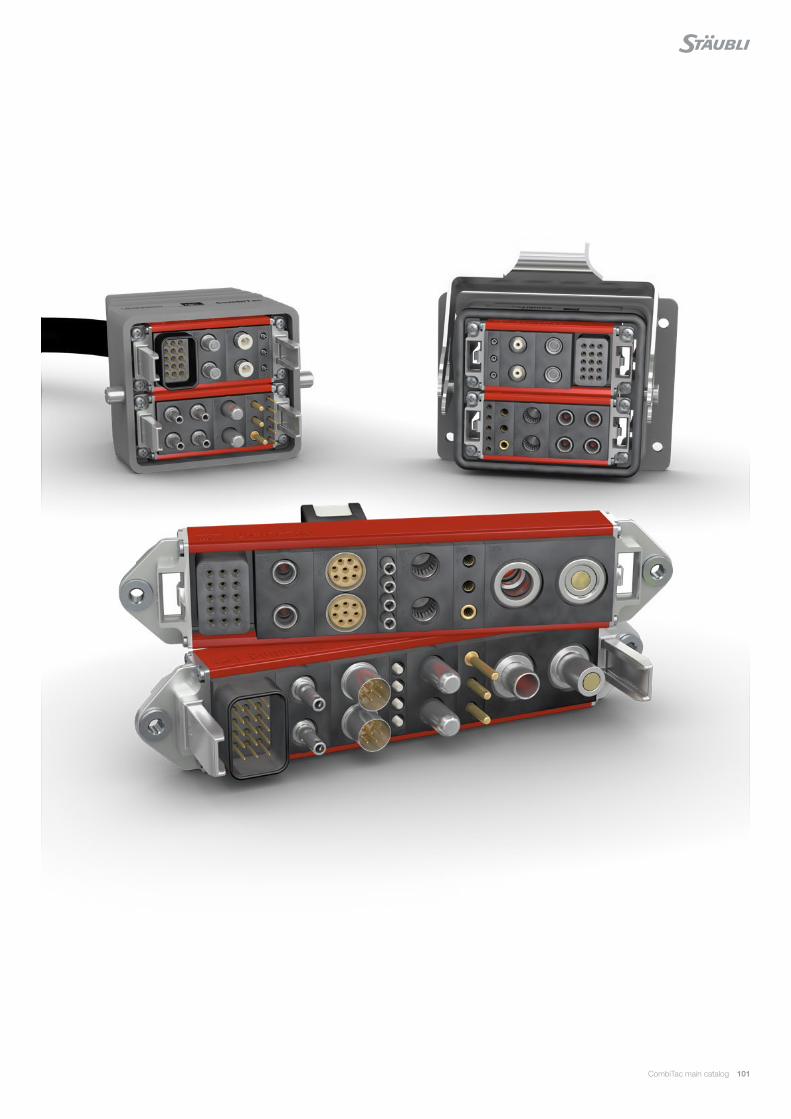
CombiTac main catalog 101
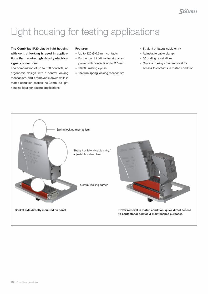
102 CombiTac main catalog
The CombiTac IP20 plastic light housing
with central locking is used in applica-
tions that require high density electrical
signal connections.
The combination of up to 320 contacts, an
ergonomic design with a central locking
mechanism, and a removable cover while in
mated condition, makes the CombiTac light
housing ideal for testing applications.
Light housing for testing applications
Features:
Up to 320 Ø 0.6 mm contacts
Further combinations for signal and
power with contacts up to Ø 6 mm
10,000 mating cycles
1/4 turn spring locking mechanism
Spring locking mechanism
Central locking carrier
Cover removal in mated condition: quick direct access to contacts for service & maintenance purposes
Straight or lateral cable entry / adjustable cable clamp
Socket side directly mounted on panel
Straight or lateral cable entry
Adjustable cable clamp
36 coding possibilities
Quick and easy cover removal for
access to contacts in mated condition
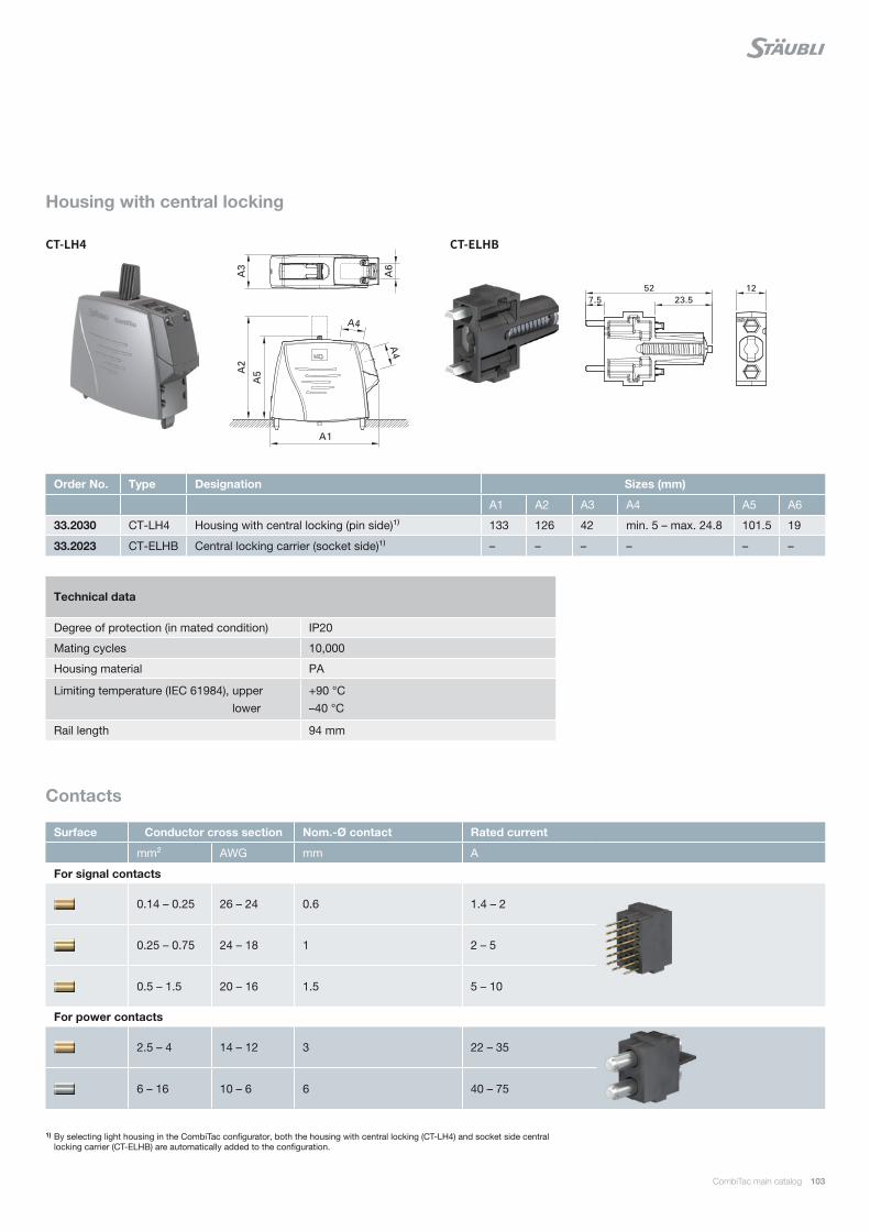
CT-LH4 CT-ELHB
CombiTac main catalog 103
Housing with central locking
Contacts
1) By selecting light housing in the CombiTac configurator, both the housing with central locking (CT-LH4) and socket side central locking carrier (CT-ELHB) are automatically added to the configuration.
Order No. Type Designation Sizes (mm)
A1 A2 A3 A4 A5 A6
33.2030 CT-LH4 Housing with central locking (pin side)¹⁾ 133 126 42 min. 5 – max. 24.8 101.5 19
33.2023 CT-ELHB Central locking carrier (socket side)¹⁾ – – – – – –
Surface Conductor cross section Nom.-Ø contact Rated current
mm² AWG mm A
For signal contacts
0.14 – 0.25 26 – 24 0.6 1.4 – 2
0.25 – 0.75 24 – 18 1 2 – 5
0.5 – 1.5 20 – 16 1.5 5 – 10
For power contacts
2.5 – 4 14 – 12 3 22 – 35
6 – 16 10 – 6 6 40 – 75
Technical data
Degree of protection (in mated condition) IP20
Mating cycles 10,000
Housing material PA
Limiting temperature (IEC 61984), upper lower
+90 °C –40 °C
Rail length 94 mm
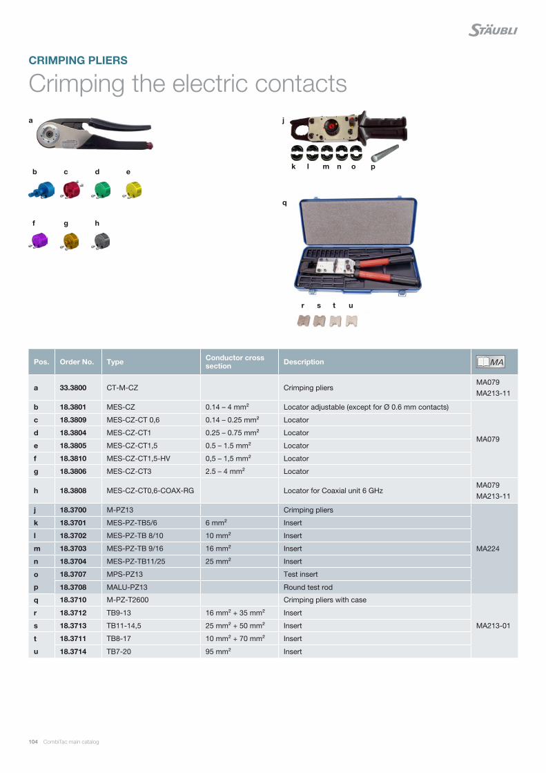
a
b
q
r s t u
c d e
j
k l m n o p
gf h
104 CombiTac main catalog
Crimping the electric contactsCRIMPING PLIERS
Pos. Order No. Type Conductor cross section Description MA
Ich bin eine Montageanleitung.
Man sollte mich unbedingt le-
sen, bevor man das Produkt ver-
wendet! Ich beinhalte wertvolle
Hinweise zur korrekten Montage
und zum richtigen Einsatz des
Produktes. Im Moment ist die
Schrift zwar ein bischen klein,
aber später geht das dann ganz
gut zu lesen, da die MA dann
a 33.3800 CT-M-CZ Crimping pliersMA079 MA213-11
b 18.3801 MES-CZ 0.14 – 4 mm² Locator adjustable (except for Ø 0.6 mm contacts)
MA079
c 18.3809 MES-CZ-CT 0,6 0.14 – 0.25 mm² Locator
d 18.3804 MES-CZ-CT1 0.25 – 0.75 mm² Locator
e 18.3805 MES-CZ-CT1,5 0.5 – 1.5 mm² Locator
f 18.3810 MES-CZ-CT1,5-HV 0,5 – 1,5 mm² Locator
g 18.3806 MES-CZ-CT3 2.5 – 4 mm² Locator
h 18.3808 MES-CZ-CT0,6-COAX-RG Locator for Coaxial unit 6 GHzMA079 MA213-11
j 18.3700 M-PZ13 Crimping pliers
MA224
k 18.3701 MES-PZ-TB5/6 6 mm² Insert
l 18.3702 MES-PZ-TB 8/10 10 mm² Insert
m 18.3703 MES-PZ-TB 9/16 16 mm² Insert
n 18.3704 MES-PZ-TB11/25 25 mm² Insert
o 18.3707 MPS-PZ13 Test insert
p 18.3708 MALU-PZ13 Round test rod
q 18.3710 M-PZ-T2600 Crimping pliers with case
MA213-01
r 18.3712 TB9-13 16 mm² + 35 mm² Insert
s 18.3713 TB11-14,5 25 mm² + 50 mm² Insert
t 18.3711 TB8-17 10 mm² + 70 mm² Insert
u 18.3714 TB7-20 95 mm² Insert

a b
a b c
CombiTac main catalog 105
Crimping the 1.5 GHz coaxial contacts
Crimping the plastic optical fiber contacts
Pos. Order No. Type Description MAIch bin eine Montageanleitung.
Man sollte mich unbedingt le-
sen, bevor man das Produkt ver-
wendet! Ich beinhalte wertvolle
Hinweise zur korrekten Montage
und zum richtigen Einsatz des
Produktes. Im Moment ist die
Schrift zwar ein bischen klein,
aber später geht das dann ganz
gut zu lesen, da die MA dann
a 33.3021 CT-AIWZ/POF Insulation stripper MA213-03
b 33.3023 CT-PS/POF Polishing disc MA213-03
c 33.3020 CT-CZ/POF Crimping pliers MA065, MA213-03
Pos. Order No. Type Description MAIch bin eine Montageanleitung.
Man sollte mich unbedingt le-
sen, bevor man das Produkt ver-
wendet! Ich beinhalte wertvolle
Hinweise zur korrekten Montage
und zum richtigen Einsatz des
Produktes. Im Moment ist die
Schrift zwar ein bischen klein,
aber später geht das dann ganz
gut zu lesen, da die MA dann
a 33.3011 CT-AIWZ/COAX Insulation stripper for Coaxial unit 1.5 GHz MA213-02
b 33.3010 CT-CZ/COAX Crimping pliers for shield and inner conductor for Coaxial unit 1.5 GHz MA213-02

106 CombiTac main catalog
Insertion tools socket/pin
1) For contacts with screw connection with external thread.2) For contacts with screw connection with internal thread.3) Extraction tool for pin and socket.
ASSEMBLY TOOLS
Insertion tool Order No. Type For nominal-Ø socket/pin For contact
33.3003 CT-E-WZ0,6 0.6 mm
33.3001 CT-E-WZ1-9,5 1 mm Thermocouple contacts
18.3003 ME-WZ1,5/2 1.5 mm
18.3010 ME-WZ3 3 mm
18.3013 ME-WZ5 6 mmCT-POF/SLCoaxial contacts
18.3016 ME-WZ6 8 mm
18.3015 MSA-WZ5¹⁾ 6 mm
18.3018 MSA-WZ6¹⁾ 8 mm
18.3014 MBA-WZ5²⁾ 6/8 mm
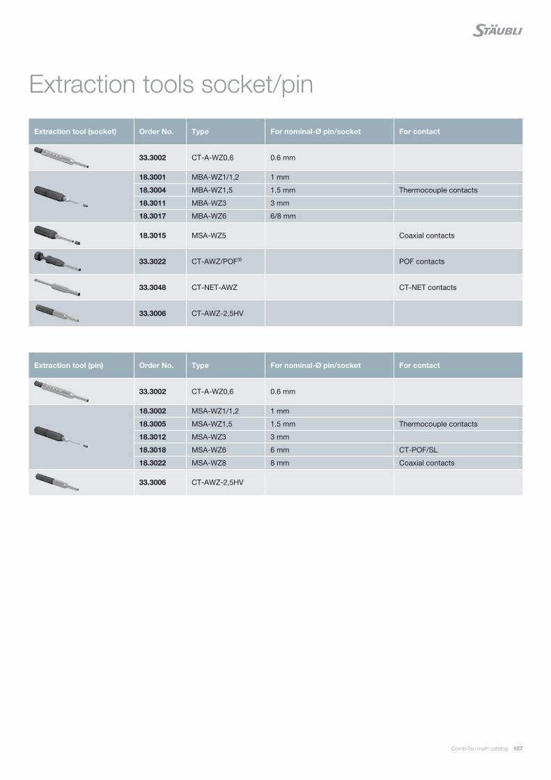
CombiTac main catalog 107
Extraction tools socket/pin
Extraction tool (pin) Order No. Type For nominal-Ø pin/socket For contact
33.3002 CT-A-WZ0,6 0.6 mm
18.3002 MSA-WZ1/1,2 1 mm
18.3005 MSA-WZ1,5 1.5 mm Thermocouple contacts
18.3012 MSA-WZ3 3 mm
18.3018 MSA-WZ6 6 mm CT-POF/SL
18.3022 MSA-WZ8 8 mm Coaxial contacts
33.3006 CT-AWZ-2,5HV
Extraction tool (socket) Order No. Type For nominal-Ø pin/socket For contact
33.3002 CT-A-WZ0,6 0.6 mm
18.3001 MBA-WZ1/1,2 1 mm
18.3004 MBA-WZ1,5 1.5 mm Thermocouple contacts
18.3011 MBA-WZ3 3 mm
18.3017 MBA-WZ6 6/8 mm
18.3015 MSA-WZ5 Coaxial contacts
33.3022 CT-AWZ/POF³⁾ POF contacts
33.3048 CT-NET-AWZ CT-NET contacts
33.3006 CT-AWZ-2,5HV
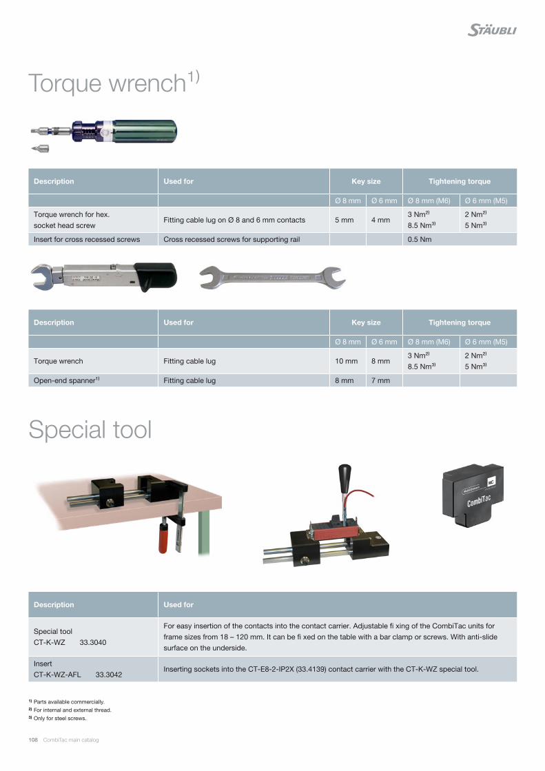
108 CombiTac main catalog
Torque wrench¹⁾
1) Parts available commercially.2) For internal and external thread.3) Only for steel screws.
Description Used for Key size Tightening torque
Ø 8 mm Ø 6 mm Ø 8 mm (M6) Ø 6 mm (M5)
Torque wrench for hex. socket head screw
Fitting cable lug on Ø 8 and 6 mm contacts 5 mm 4 mm3 Nm²⁾8.5 Nm³⁾
2 Nm²⁾5 Nm³⁾
Insert for cross recessed screws Cross recessed screws for supporting rail 0.5 Nm
Description Used for Key size Tightening torque
Ø 8 mm Ø 6 mm Ø 8 mm (M6) Ø 6 mm (M5)
Torque wrench Fitting cable lug 10 mm 8 mm3 Nm²⁾8.5 Nm³⁾
2 Nm²⁾5 Nm³⁾
Open-end spanner¹⁾ Fitting cable lug 8 mm 7 mm
Description Used for
Special toolCT-K-WZ 33.3040
For easy insertion of the contacts into the contact carrier. Adjustable fi xing of the CombiTac units for frame sizes from 18 – 120 mm. It can be fi xed on the table with a bar clamp or screws. With anti-slide surface on the underside.
InsertCT-K-WZ-AFL 33.3042
Inserting sockets into the CT-E8-2-IP2X (33.4139) contact carrier with the CT-K-WZ special tool.
Special tool
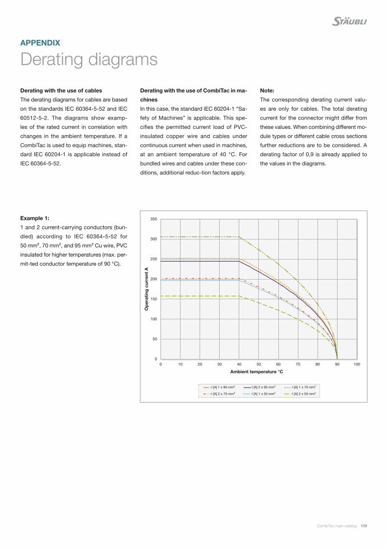
0
50
100
150
200
250
300
350
0 10 20 30 40 50 60 70 80 90 100
I [A] 1 x 95 mm² I [A] 2 x 95 mm² I [A] 1 x 70 mm²
I [A] 2 x 70 mm² I [A] 1 x 50 mm² I [A] 2 x 50 mm²
CombiTac main catalog 109
Derating diagrams
Derating with the use of cables
The derating diagrams for cables are based
on the standards IEC 60364-5-52 and IEC
60512-5-2. The diagrams show examp-
les of the rated current in correlation with
changes in the ambient temperature. If a
CombiTac is used to equip machines, stan-
dard IEC 60204-1 is applicable instead of
IEC 60364-5-52.
Derating with the use of CombiTac in ma-
chines
In this case, the standard IEC 60204-1 “Sa-
fety of Machines” is applicable. This spe-
cifies the permitted current load of PVC-
insulated copper wire and cables under
continuous current when used in machines,
at an ambient temperature of 40 °C. For
bundled wires and cables under these con-
ditions, additional reduc-tion factors apply.
Example 1:
1 and 2 current-carrying conductors (bun-
dled) according to IEC 60364-5-52 for
50 mm², 70 mm², and 95 mm² Cu wire, PVC
insulated for higher temperatures (max. per-
mit-ted conductor temperature of 90 °C).
Op
erat
ing
cur
rent
A
Ambient temperature °C
APPENDIX
Note:
The corresponding derating current valu-
es are only for cables. The total derating
current for the connector might differ from
these values. When combining different mo-
dule types or different cable cross sections
further reductions are to be considered. A
derating factor of 0,9 is already applied to
the values in the diagrams.
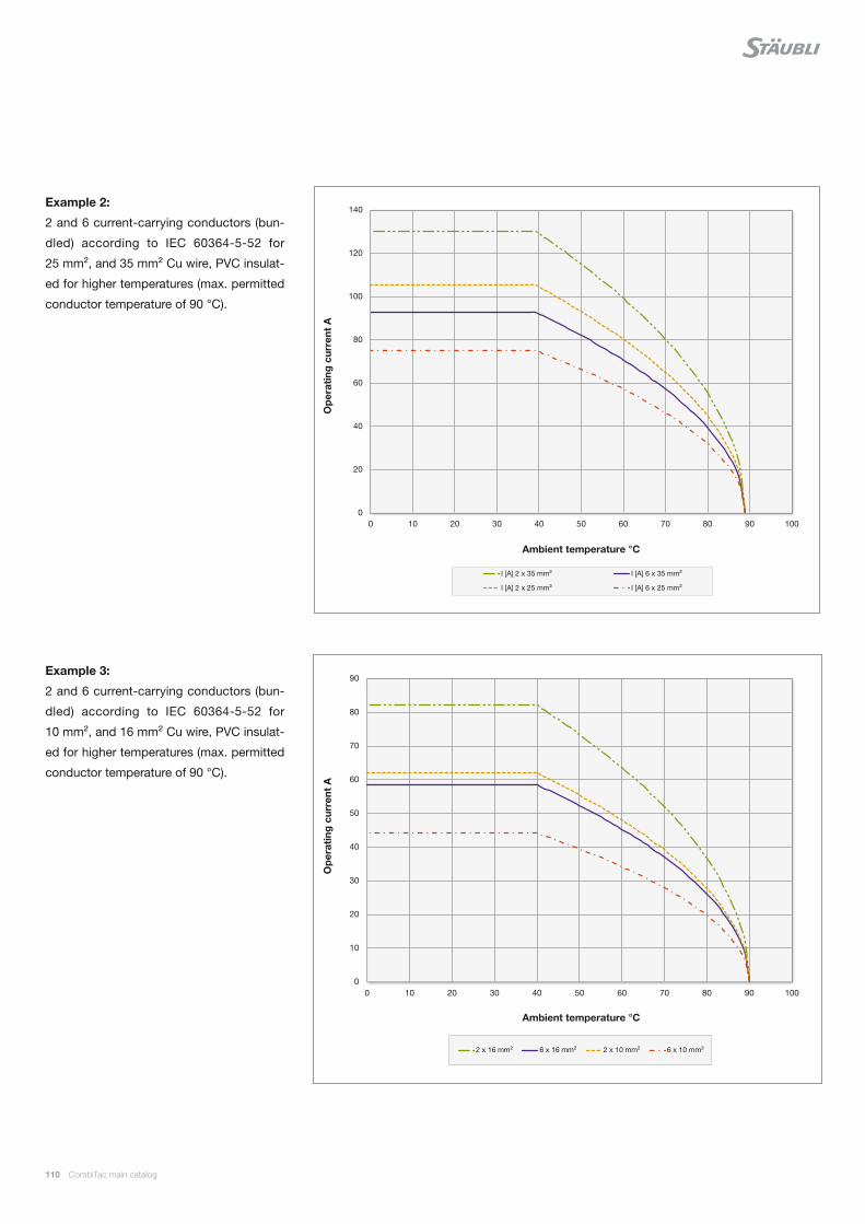
0
10
20
30
40
50
60
70
80
90
0 10 20 30 40 50 60 70 80 90 100
2 x 16 mm² 6 x 16 mm² 2 x 10 mm² 6 x 10 mm²
0
20
40
60
80
100
120
140
0 10 20 30 40 50 60 70 80 90 100
I [A] 2 x 35 mm² I [A] 6 x 35 mm²
I [A] 2 x 25 mm² I [A] 6 x 25 mm²
110 CombiTac main catalog
Example 3:
2 and 6 current-carrying conductors (bun-
dled) according to IEC 60364-5-52 for
10 mm², and 16 mm² Cu wire, PVC insulat-
ed for higher temperatures (max. permitted
conductor temperature of 90 °C).
Example 2:
2 and 6 current-carrying conductors (bun-
dled) according to IEC 60364-5-52 for
25 mm², and 35 mm² Cu wire, PVC insulat-
ed for higher temperatures (max. permitted
conductor temperature of 90 °C).
Op
erat
ing
cur
rent
AO
per
atin
g c
urre
nt A
Ambient temperature °C
Ambient temperature °C

0
5
10
15
20
25
30
35
40
45
50
0 10 20 30 40 50 60 70 80 90 100
2 x 6 mm² 6 x 6 mm² 2 x 4 mm²
6 x 4 mm² 2 x 2.5 mm² 6 x 2.5 mm²
0
5
10
15
20
25
0 10 20 30 40 50 60 70 80 90 100
2 x 1.5 mm² 4 x 1.5 mm² 10 x 1.5 mm²
2 x 1 mm² 4 x 1 mm² 10 x 1 mm²
CombiTac main catalog 111
Op
erat
ing
cur
rent
AO
per
atin
g c
urre
nt A
Ambient temperature °C
Ambient temperature °C
Example 4:
2 and 6 current-carrying conductors (bun-
dled) according to IEC 60364-5-52 for
2.5 mm², 4 mm², and 6 mm² Cu wire, PVC
insulated for higher temperatures (max. per-
mitted conductor temperature of 90 °C).
Example 5:
2, 4, and 10 current-carrying conductors
(bundled) according to IEC 60364-5-52 for
1 mm² and 1.5 mm² Cu wire, PVC insulat-
ed for higher temperatures (max. permitted
conductor temperature of 90 °C).

0
2
4
6
8
10
12
0 10 20 30 40 50 60 70 80 90 100
2 x 0.75 mm² 4 x 0.75 mm² 6 x 0.75 mm²
10 x 0.75 mm² 16 x 0.75 mm² 28 x 0.75 mm²
0
1
2
3
4
5
6
7
8
9
0 10 20 30 40 50 60 70 80 90 100
2 x 0.5 mm² 4 x 0.5 mm² 6 x 0.5 mm²
10 x 0.5 mm² 16 x 0.5 mm² 28 x 0.5 mm²
112 CombiTac main catalog
Example 6:
2, 4, 6, 10, 16, and 28 current-carrying
conductors (bundled) according to IEC
60364-5-52 for 0.75 mm² Cu wire, PVC in-
sulated for higher temperatures (max. per-
mitted conductor temperature of 90 °C).
Example 7:
2, 4, 6, 10, 16, and 28 current-carrying
conductors (bundled) according to IEC
60512-5-2 for 0.5 mm² Cu wire, PVC insulat-
ed for higher temperatures (max. permitted
conductor temperature of 90 °C).
Op
erat
ing
cur
rent
AO
per
atin
g c
urre
nt A
Ambient temperature °C
Ambient temperature °C

0
0,5
1
1,5
2
2,5
3
3,5
0 10 20 30 40 50 60 70 80 90 100
6 x 0.25 mm² 16 x 0.25 mm² 28 x 0.25 mm² 100 x 0.25 mm²
0
0,2
0,4
0,6
0,8
1
1,2
1,4
1,6
1,8
2
0 10 20 30 40 50 60 70 80 90 100
10 x 0.14 mm² 20 x 0.14 mm² 60 x 0.14 mm² 100 x 0.14 mm²
CombiTac main catalog 113
Example 8:
6, 16, 28 and 100 current-carrying conduc-
tors (bundled) according to IEC 60512-5-2
for 0.25 mm² Cu wire, PVC insulated for
higher temperatures (max. permitted con-
ductor temperature of 90 °C).
Example 9:
10, 20, 60 and 100 current-carrying con-
ductors (bundled) according to IEC 60512-
5-2 for 0.14 mm² Cu wire, PVC insulated for
higher temperatures (max. permitted con-
ductor temperature of 90 °C).
Op
erat
ing
cur
rent
AO
per
atin
g c
urre
nt A
Ambient temperature °C
Ambient temperature °C
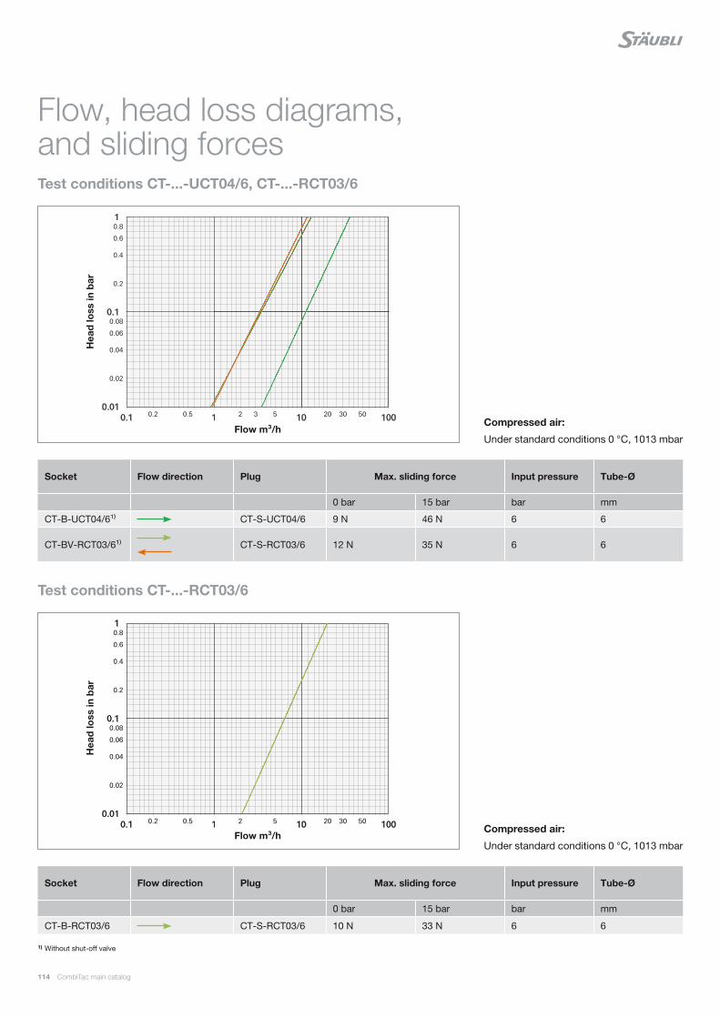
0.2 0.5 2 3 5 20 30 50
0.02
0.04
0.06
0.08
0.2
0.4
0.6
0.8
0.01
0.1
1
0.1 1 10 100
0.2 0.5 2 5 20 30 50
0.02
0.04
0.06
0.08
0.2
0.4
0.6
0.8
0.01
0.1
1
0.1 1 10 100
114 CombiTac main catalog
Flow, head loss diagrams, and sliding forces
Socket Flow direction Plug Max. sliding force Input pressure Tube-Ø
0 bar 15 bar bar mm
CT-B-UCT04/6¹⁾ CT-S-UCT04/6 9 N 46 N 6 6
CT-BV-RCT03/6¹⁾
CT-S-RCT03/6 12 N 35 N 6 6
Socket Flow direction Plug Max. sliding force Input pressure Tube-Ø
0 bar 15 bar bar mm
CT-B-RCT03/6 CT-S-RCT03/6 10 N 33 N 6 6
Test conditions CT-...-UCT04/6, CT-...-RCT03/6
1) Without shut-off valve
Compressed air:
Under standard conditions 0 °C, 1013 mbar
Compressed air:
Under standard conditions 0 °C, 1013 mbar
Test conditions CT-...-RCT03/6
Hea
d lo
ss in
bar
Hea
d lo
ss in
bar
Flow m³/h
Flow m³/h
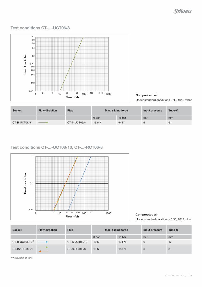
2 5 20 50 200 500
0.02
0.04
0.06
0.08
0.2
0.4
0.6
0.8
0.01
0.1
1
1 10 100 1000
5 6 20 30 50 60 200 0.01
0.1
1
1 10 100 1000
CombiTac main catalog 115
Socket Flow direction Plug Max. sliding force Input pressure Tube-Ø
0 bar 15 bar bar mm
CT-B-UCT06/8 CT-S-UCT06/8 16.5 N 94 N 6 6
Socket Flow direction Plug Max. sliding force Input pressure Tube-Ø
0 bar 15 bar bar mm
CT-B-UCT08/10¹⁾ CT-S-UCT08/10 16 N 134 N 6 10
CT-BV-RCT06/8
CT-S-RCT06/8 19 N 106 N 6 8
Test conditions CT-...-UCT06/8
1) Without shut-off valve
Compressed air:
Under standard conditions 0 °C, 1013 mbar
Compressed air:
Under standard conditions 0 °C, 1013 mbar
Test conditions CT-...-UCT08/10, CT-...-RCT06/8
Hea
d lo
ss in
bar
Hea
d lo
ss in
bar
Flow m³/h
Flow m³/h
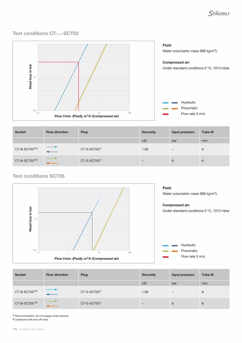
0,01
0,1
1
0,1 1 10 100
0,01
0,1
1
0,1 1 10 100
116 CombiTac main catalog
1) Recommendation: do not engage under pressure2) Leackproof with shut-off valve
Socket Flow direction Plug Viscosity Input pressure Tube-Ø
cSt bar mm
CT-B-SCT03¹⁾²⁾
CT-S-SCT03¹⁾ 1.08 – 6
CT-B-SCT03¹⁾²⁾
CT-S-SCT03¹⁾ – 6 6
Socket Flow direction Plug Viscosity Input pressure Tube-Ø
cSt bar mm
CT-B-SCT05¹⁾²⁾
CT-S-SCT05¹⁾ 1.08 – 8
CT-B-SCT05¹⁾²⁾
CT-S-SCT05¹⁾ – 6 8
Test conditions SCT05
Test conditions CT-...-SCT03
Fluid:
Water (volumetric mass 998 kg/m³).
Compressed air:
Under standard conditions 0 °C, 1013 mbar
Fluid:
Water (volumetric mass 998 kg/m³).
Compressed air:
Under standard conditions 0 °C, 1013 mbar
Hydraulic
Pneumatic
Flow rate 5 m/s
Hydraulic
Pneumatic
Flow rate 5 m/s
Hea
d lo
ss in
bar
Hea
d lo
ss in
bar
Flow l/min. (Fluid); m³/h (Compressed air)
Flow l/min. (Fluid); m³/h (Compressed air)
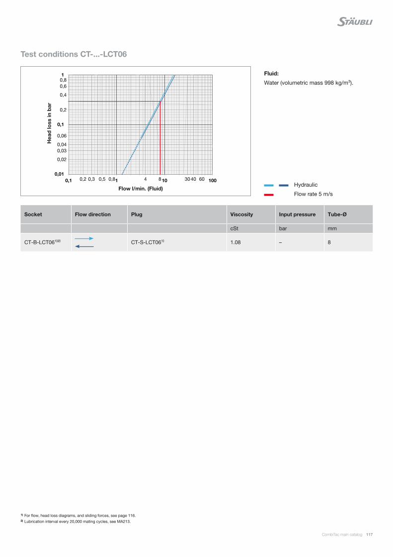
0,2 0,3 0,5 0,8 4 8 30 40 60
0,02
0,03 0,04
0,06
0,2
0,4
0,6 0,8
0,01
0,1
1
0,1 1 10 100
CombiTac main catalog 117
Test conditions CT-...-LCT06
Fluid:
Water (volumetric mass 998 kg/m³).
Socket Flow direction Plug Viscosity Input pressure Tube-Ø
cSt bar mm
CT-B-LCT06¹⁾²⁾
CT-S-LCT06¹⁾ 1.08 – 8
Hydraulic
Flow rate 5 m/s
Hea
d lo
ss in
bar
Flow l/min. (Fluid)
1) For flow, head loss diagrams, and sliding forces, see page 116.2) Lubrication interval every 20,000 mating cycles, see MA213.
118 CombiTac main catalog
IEC 60664-1 IEC 61984
Rated voltageImpulse withstand voltage Test voltage: r.m.s withstand voltage 1 min, 50/60 Hz
Overvoltage category II Overvoltage category III Overvoltage category II Overvoltage category III
< 51 V 500 V 800 V 370 V 500 V
51 V – 100 V 800 V 1500 V 500 V 840 V
101 V – 150 V 1500 V 2500 V 840 V 1390 V
151 V – 300 V 2500 V 4000 V 1390 V 2210 V
301 V – 600 V 4000 V 6000 V 2210 V 3310 V
601 V – 1000 V 6000 V 8000 V 3310 V 4260 V
Sliding forces
The total sliding force of a connector is the
sum of all the single contact sliding forces.
The stated values are guideline values, and
may be reduced by 20 – 30 % after a num-
ber of mating cycles.
Locking cycles DIN housing
Max. 500 locking cycles without lubrication.
For up to 5000 locking cycles, a lubrication
must be executed. See note about lubrica-
tion, assembly instructions MA213.
Rated current
The rated current is the current, preferably
at an ambient tem-perature of 40 °C, that
the plug connector or plug device can carry
continuously (without interruption) and that
flows simultaneously through all its contacts
that are connected to the largest possible
conductor without the maximum permitted
temperature being exceeded. The stated
current values were determined in accor-
dance with UL1977 (4-hour temperature
test, contacts connected in series).
Technical information
Bundled wires
If the CombiTac is used together with bun-
dled wires, a reduction factor must be ap-
plied to the wires. The derating diagrams
on pages 109 – 113 show various exam-
ples for bundled copper wires with different
cross sections that are suitable for use with
CombiTac. The specified wires are PVC in-
sulated with increased heat resistance (max.
permissible conductor temperature 90 °C) in
accordance with IEC 60364-5-52, and IEC
60512-5-2. A specific derating factor ap-
plies to a given number of bundled wires or
types of wire.
Rated voltage IEC 60664-1
Value of voltage assigned by the manufac-
turer, to a component, device, or equipment
and to which operation and performance
characteristics are referred. Equipment may
have more than one rated voltage value or
may have a rated voltage range.
The rated voltages listed below correlate
normatively with the following impulse with-
stand voltages. This is subject to the over
voltage category to be met.
Overvoltage categories
The concept of overvoltage categories is
used for equipment energized directly from
the low-voltage mains.
CATII: Equipment of the overvoltage cate-
gory II is energy consuming equipment to
be supplied from the fixed installation. Ex-
amples of such equipment are appliances,
portable tools, and other household and
similar loads.
Protective conductor PE (IEC 61140)
Conductor provided for purposes of safe-
ty, for example protection against electric
shock. Marking of the protective bonding
terminal with Letter PE, or color combination
green-yellow, or graphical symbol. Connect
this terminal to the protective-equipoten-
tial-bonding system of the installation.
CombiTac main catalog 119
Pollution degree 2 IEC 60664-1
Normally only nonconductive pollution oc-
curs. Occasionally, however, temporary
conductivity caused by condensation is to
be expected.
CATIII: Equipment of overvoltage category
III is equipment in fixed installations and for
cases where the reliability and the availabil-
ity of the equipment is subject to special
requirements. Examples of such equipment
are switches in the fixed installation and
equipment for industrial use with a perma-
nent connection to the fixed installation.
Pollution degree 3 IEC 60664-1
Presence of conductive pollution or of dry
nonconductive pollution that becomes con-
ductive due to condensation that is to be
expected.
CATIV: Equipment of overvoltage category
IV is for use at the origin of the installation.
Examples of such equipment are electricity
meters and primary overcurrent protection
equipment.
Contact resistance
The contact resistance is determined by
means of the voltage drop, measured be-
tween the lead terminations of the pin and
socket. The stated values are mean values
derived from the rated current after 100 mat-
ing cycles.
Mating cycles
Mating cycles tests for CombiTac parts are
performed under typical laboratory environ-
mental conditions.
Limiting temperature
The limiting temperatures specified in this
catalog apply to CombiTac connectors while
in mated condition.

120 CombiTac main catalog
Protection against electric shock
A connector shall be so designed that, after
mounting, its live parts are not accessible
by the IEC test finger in accordance with
clause 5 of IEC 60529 using a test force
of 20 N. Some CombiTac modules are not
contact-protected on the cable connec-
tion side. These products are designed to
be built into a housing that guarantees the
relevant IP protection for cable connections
(at least IP2X). Protection against electric
shock must be provided by the end product
and ensured by the users themselves. This
requirement does not apply to a connector
operated with a safety extra-low voltage
(SELV) of a maximum AC 50 V eff. or DC
120 V. The customer must take appropriate
measures when fitting the connectors to en-
sure that the cable connection is protected
against tension and twisting and is re spon-
sible for correct implementation of the con-
tact-protection measures. Connection and
disconnection only when not live.
Enclosure
An enclosed connector is a connector for
which the protection against electric shock
is ensured by the housing of the connec-tor
itself. An unenclosed connector is a connec-
tor for which the protection against electric
shock is provided by the enclosure of the
equipment in which the connector is mount-
ed.
In relation to the direction of power flow,
connectors should be incorporated in the
circuit wiring in such a way that pins that
can be touched are not live in the unmated
state (IEC 61984).
Safety notes
Protection wall
In order to meet the requirement for protec-
tion against accessibility of live parts up to
AC 600 V during engagement or with-draw-
al, CombiTac is provided with a specially
designed protection wall. Measures shall
be taken to ensure that insertion and with-
drawal is done under no load (0 A) (see
page 122 “Safety situation for CombiTac
connectors”).
Electrical contacts in close proximity to
connectors for liquids and gases
Defect electrical contacts or connectors that
leak gas or liquids can be a safety hazard to
personnel and the environment, as well as
affecting the proper function of the system.
It is the responsibility of the end-user to en-
sure that both safety and proper function in
the end-use is guaranteed. The result of a
risk analysis requires that the end-user of
CombiTac connectors must ensure the fol-
lowing:
All relevant national and international
standards and regulations must be
complied with in the end-use.
Field-tested techniques must be applied
and, if necessary, a risk assessment
must be carried out in order to identify
and reduce the risks.
The use of flammable or explosive
liquids or gases is prohibited.
Exclusively CT-…SCT couplings with
both male- and female-sided locking
systems are permitted to be used for
liquids.
Automatic disconnection of power
supply in the event of indirect contact,
overload, or short circuit is required
according to IEC 60364-4-41.
If the voltage is higher than AC 33 V or
DC 70 V, all simultaneously accessib-
le conductive parts that do not carry
current during normal operation must be
connected to the protective conductor
(protective equipotential bonding accor-
ding to IEC 60364-4-41).
If the voltage is higher than AC 33 V or
DC 70 V, all electric circuits have to be
protected by a residual-current-operated
protective device (RCD) with a rated
residual operating current not exceeding
30 mA according to IEC 60364-4-41.
Connecting or disconnecting under
load or live is not allowed (connector
without breaking capacity according to
IEC 61984).
On permanently fixed installations, elec-
trical contacts have to be placed above
liquid couplings.
In CombiTac housing applications, the
housing has to be connected to the
protective conductor according to IEC
60364-4-41.
The maximum rated voltage phase to
neutral conductor is AC/DC 600 V.
The fluid couplings must be replaced if a
leak is detected.
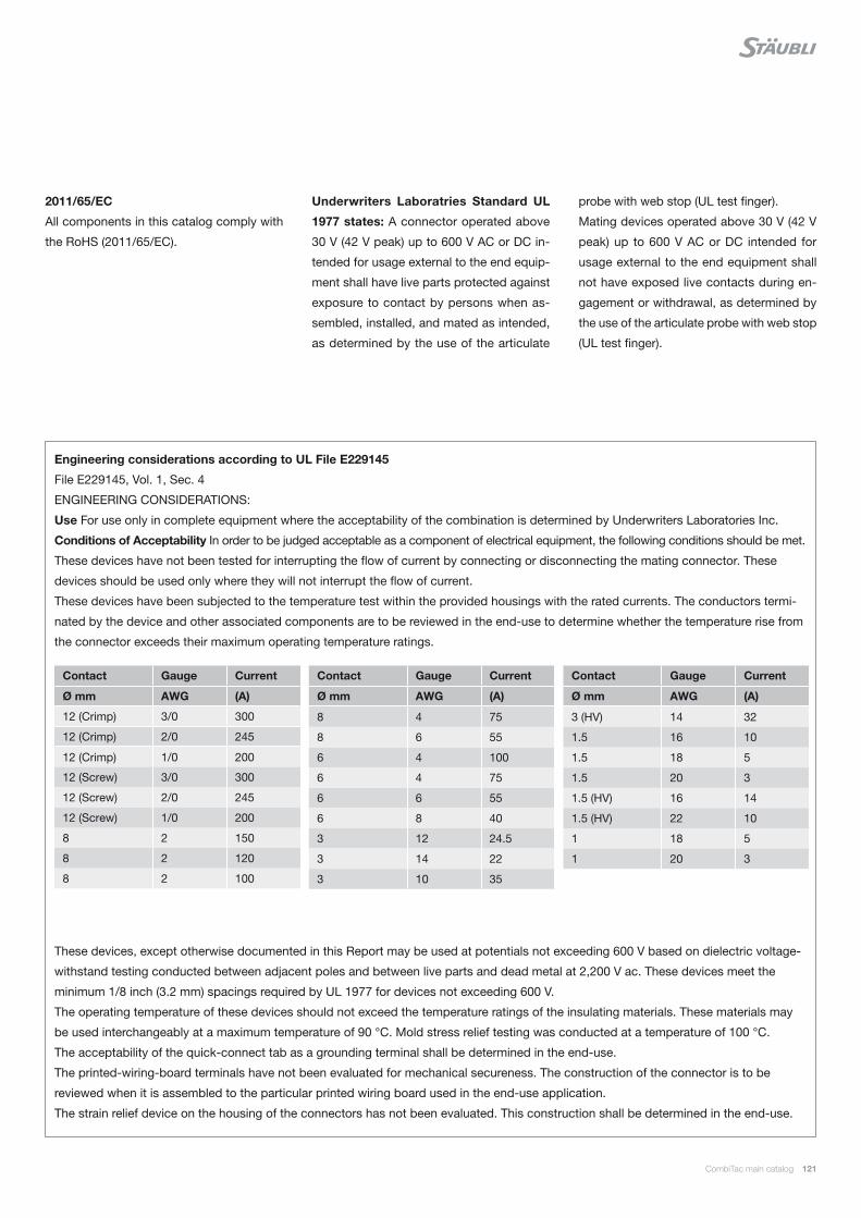
CombiTac main catalog 121
2011/65/EC
All components in this catalog comply with
the RoHS (2011/65/EC).
Underwriters Laboratries Standard UL
1977 states: A connector operated above
30 V (42 V peak) up to 600 V AC or DC in-
tended for usage external to the end equip-
ment shall have live parts protected against
exposure to contact by persons when as-
sembled, installed, and mated as intended,
as determined by the use of the articulate
probe with web stop (UL test finger).
Mating devices operated above 30 V (42 V
peak) up to 600 V AC or DC intended for
usage external to the end equipment shall
not have exposed live contacts during en-
gagement or withdrawal, as determined by
the use of the articulate probe with web stop
(UL test finger).
Engineering considerations according to UL File E229145
File E229145, Vol. 1, Sec. 4
ENGINEERING CONSIDERATIONS:
Use For use only in complete equipment where the acceptability of the combination is determined by Underwriters Laboratories Inc.
Conditions of Acceptability In order to be judged acceptable as a component of electrical equipment, the following conditions should be met.
These devices have not been tested for interrupting the flow of current by connecting or disconnecting the mating connector. These
devices should be used only where they will not interrupt the flow of current.
These devices have been subjected to the temperature test within the provided housings with the rated currents. The conductors termi-
nated by the device and other associated components are to be reviewed in the end-use to determine whether the temperature rise from
the connector exceeds their maximum operating temperature ratings.
Contact Gauge Current
Ø mm AWG (A)
12 (Crimp) 3/0 300
12 (Crimp) 2/0 245
12 (Crimp) 1/0 200
12 (Screw) 3/0 300
12 (Screw) 2/0 245
12 (Screw) 1/0 200
8 2 150
8 2 120
8 2 100
Contact Gauge Current
Ø mm AWG (A)
8 4 75
8 6 55
6 4 100
6 4 75
6 6 55
6 8 40
3 12 24.5
3 14 22
3 10 35
Contact Gauge Current
Ø mm AWG (A)
3 (HV) 14 32
1.5 16 10
1.5 18 5
1.5 20 3
1.5 (HV) 16 14
1.5 (HV) 22 10
1 18 5
1 20 3
These devices, except otherwise documented in this Report may be used at potentials not exceeding 600 V based on dielectric voltage-
withstand testing conducted between adjacent poles and between live parts and dead metal at 2,200 V ac. These devices meet the
minimum 1/8 inch (3.2 mm) spacings required by UL 1977 for devices not exceeding 600 V.
The operating temperature of these devices should not exceed the temperature ratings of the insulating materials. These materials may
be used interchangeably at a maximum temperature of 90 °C. Mold stress relief testing was conducted at a temperature of 100 °C.
The acceptability of the quick-connect tab as a grounding terminal shall be determined in the end-use.
The printed-wiring-board terminals have not been evaluated for mechanical secureness. The construction of the connector is to be
reviewed when it is assembled to the particular printed wiring board used in the end-use application.
The strain relief device on the housing of the connectors has not been evaluated. This construction shall be determined in the end-use.
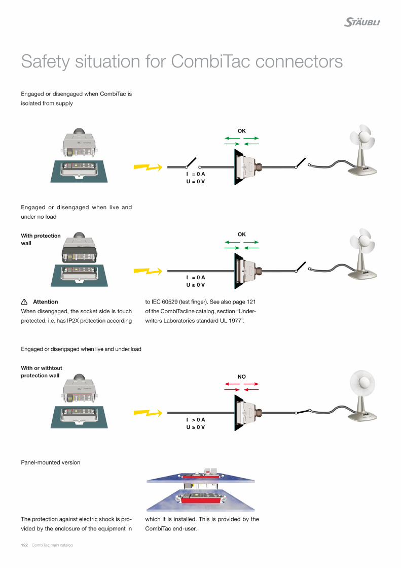
122 CombiTac main catalog
Engaged or disengaged when CombiTac is
isolated from supply
Engaged or disengaged when live and
under no load
Attention
When disengaged, the socket side is touch
protected, i.e. has IP2X protection according
Engaged or disengaged when live and under load
Panel-mounted version
Safety situation for CombiTac connectors
OK
OK
NO
I = 0 A U = 0 V
I = 0 A U ≥ 0 V
I > 0 AU ≥ 0 V
With protection wall
to IEC 60529 (test finger). See also page 121
of the CombiTacline catalog, section “Under-
writers Laboratories standard UL 1977”.
With or withtout protection wall
The protection against electric shock is pro-
vided by the enclosure of the equipment in
which it is installed. This is provided by the
CombiTac end-user.
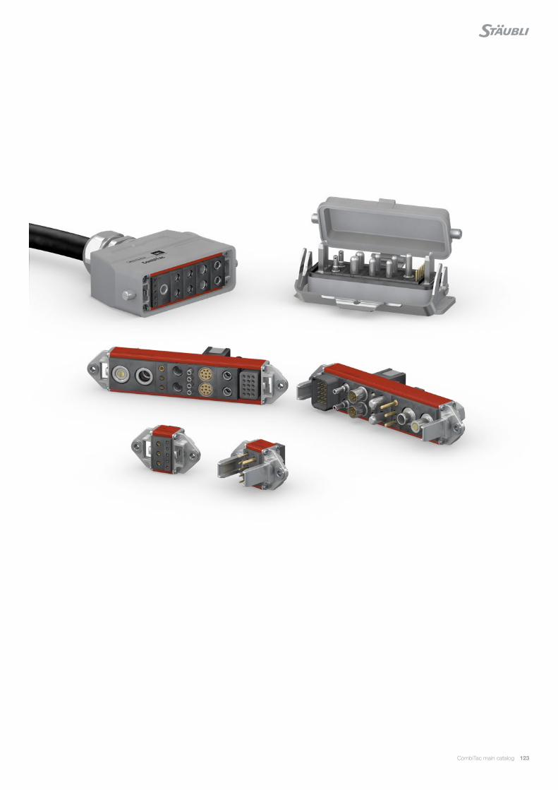
CombiTac main catalog 123

124 CombiTac main catalog
CombiTac in an automated radio testing station for the automotive industry.
The connector solution consists of signal, coaxial and fiber optic contacts.
Connector solution with CombiTac for plate mounting, to create a connection between the various milling head units and the drive.
Applications

CombiTac main catalog 125
CombiTac for connections to mobile trolleys in operation rooms for medical technology.
CombiTac in a modular test bench for the testing and simulation of electric components.
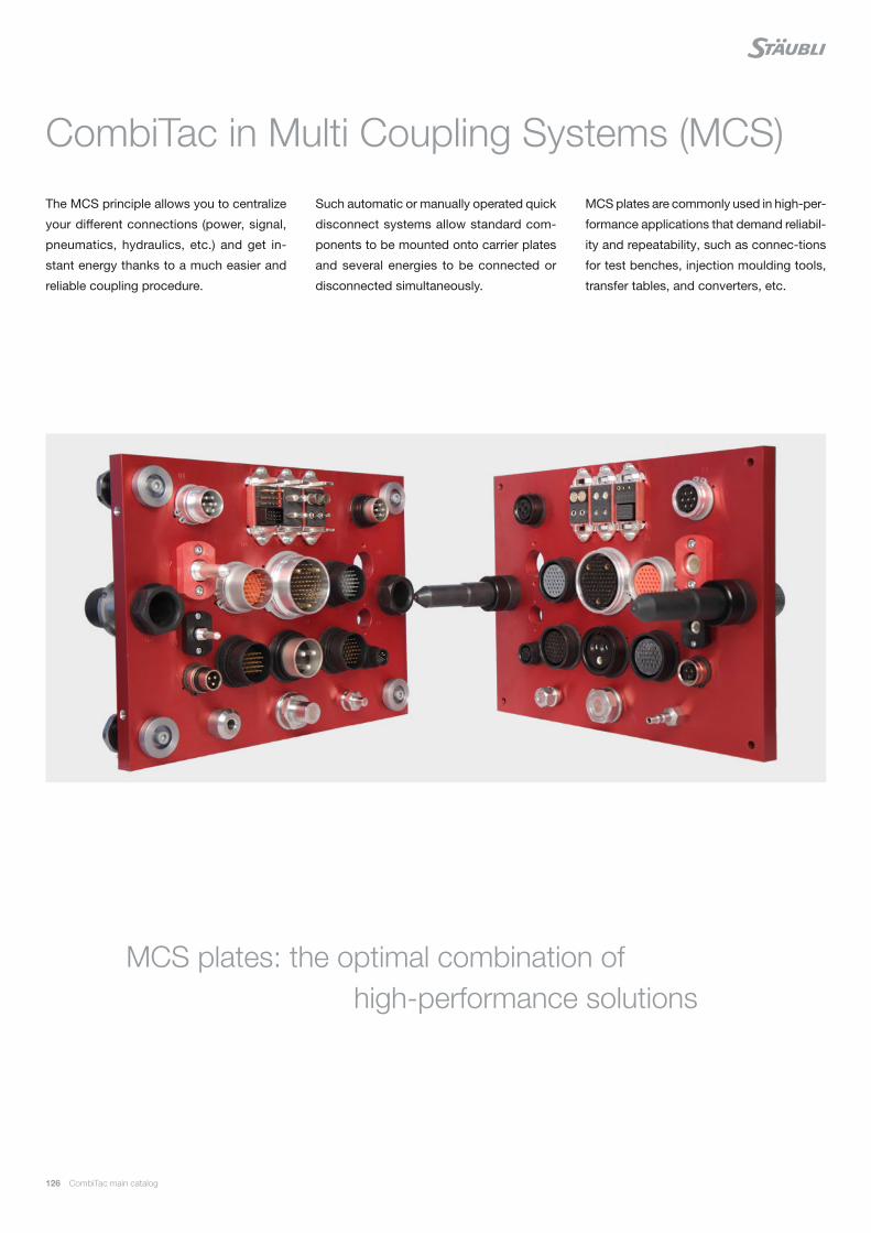
126 CombiTac main catalog
The MCS principle allows you to centralize
your different connections (power, signal,
pneumatics, hydraulics, etc.) and get in-
stant energy thanks to a much easier and
reliable coupling procedure.
CombiTac in Multi Coupling Systems (MCS)
Such automatic or manually operated quick
disconnect systems allow standard com-
ponents to be mounted onto carrier plates
and several energies to be connected or
disconnected simultaneously.
MCS plates are commonly used in high-per-
formance applications that demand reliabil-
ity and repeatability, such as connec-tions
for test benches, injection moulding tools,
transfer tables, and converters, etc.
MCS plates: the optimal combination of high-performance solutions

CombiTac main catalog 127
MULTIL AM are specially formed and
resilient contact elements. All Stäubli
Electrical Connectors products benefi t
from the unique and outstanding perfor-
mance of the MULTIL AM Technology.
Thanks to their constant spring pressure,
MULTIL AM louvers ensure continuous con-
tact with the contact surface, resulting in a
constantly low contact resistance.
MULTIL AM Technology allows to fi nd solu-
tions for connectors within the severest con-
straints and in certain products for up to 1
million mating cycles.
This makes the MULTIL AM Technology the
best choice for applications with demanding
requirements:
Reliable and longlife operation due to
constantly high performance
Safe operation under highest environ-
mental demands on temperature, vibra-
tion and shock
Suitable for data and signal contacts as
well as high-current connectors
Automated solutions with a high number
of mating cycles
UNLIMITED POSSIBILITIES FOR CONTACT SOLUTIONS
MULTIL AM Technology

128 CombiTac main catalog
Index
Type Page
CT-10GBIT-M12/B 47
CT-10GBIT-M12/S 47
CT-10GBIT-RJ45/B 47
CT-10GBIT-RJ45/S 47
CT-AG1 86
CT-AG1-D 86
CT-AG1 IP68 HE 89
CT-AG1-PS/B 88
CT-AG1-PS/S 88
CT-AG1 TP 94
CT-AG2 86
CT-AG2-D 86
CT-AG2 IP68 HE 89
CT-AG2-PS/B 88
CT-AG2-PS/S 88
CT-AG2/PW 86
CT-AG2 TP 94
CT-AG2/ZV 90
CT-AG3 86
CT-AG3-D 86
CT-AG3 IP68 HE 89
CT-AG3-PS/B 88
CT-AG3-PS/S 88
CT-AG3/PW 86
CT-AG3 TP 94
CT-AG3/ZV 90
CT-AG4 86
CT-AG4-D 86
CT-AG4 IP68 HE 89
CT-AG4-PS/B 88
CT-AG4-PS/S 88
CT-AG4/PW 86
CT-AG4 TP 94
CT-AG4/ZV 90
CT-AG5 86
CT-AG5-D 86
CT-AG5-PS/B 88
CT-AG5-PS/S 88
CT-AG5/PW 86
CT-AG6 86
CT-AG6-D 86
CT-AG6-PS/B 88
CT-AG6-PS/S 88
CT-AIWZ/COAX 105
Type Page
CT-AIWZ/POF 105
CT-A-WZ0,6 107
CT-AWZ-2,5HV 107
CT-AWZ/POF 107
CT-B0,6ET/LO AU 37
CT-B0,6ET/PCB AU 37
CT-B1,5LAV/PCB AU 31
CT-B1ET/PCB AU 35
CT-B1/PCB AU 35
CT-B3/PCB AU 23
CT-B6/M5A AG 21
CT-B6/M5 AG 21
CT-B6/M5A/PE AG 19
CT-B8/M6A AG 17
CT-B8/M6A AU 17
CT-B8/M6 AG 17
CT-B8/M6A/PE AG 19
CT-B8/M6 AU 17
CT-B8/M8A/PE-L AG 14
CT-B12/M10 AG 10
CT-B/COAX58 43
CT-B/COAX59 43
CT-B-COAX-RG58 41
CT-B-COAX-RG316/U 41
CT-B-COAX-SMA 41
CT-BE-B 72
CT-BEG-B 72 / 97
CT-BEG-S 72 / 97
CT-BE-S 72
CT-BESZ-B 72
CT-BESZ-S 72
CT-B/GOF 53
CT-B/GOF-025-FSMA 53
CT-B/GOF-100-SC 53
CT-B/GOF-100-ST 53
CT-B-LCT06 71
CT-BP0,6ET/0,14-0,25 AU 37
CT-BP1/0,25-0,75 AU 35
CT-BP1,5/0,5-1,5-HV 29
CT-BP1,5LAV/0,5-1,5 AU 31 / 57
CT-BP1,5LAV/1,5 AU 31
CT-BP1ET/0,25-0,75 AU 35
CT-BP3/2,5-4 AU 23 / 25
CT-BP3/2,5-4/PE AU 25

CombiTac main catalog 129
Type Page
CT-BP3/2,5-HV AU 27
CT-BP6/6 AG 21
CT-BP6/10 AG 21
CT-BP6/16 AG 21
CT-BP6/16/PE AG 19
CT-BP8/10 AG 17
CT-BP8/10 AU 17
CT-BP8/16 AG 17
CT-BP8/16 AU 17
CT-BP8/25 AG 17
CT-BP8/25 AU 17
CT-BP8/25/PE AG 19
CT-BP8/25/PE-L AG 13
CT-BP8/35 AG 17
CT-BP8/35/PE-L AG 13
CT-BP8/50/PE-L AG 13
CT-BP10/10/PE-GND AG 99
CT-BP10/16/PE-GND AG 99
CT-BP10/25/PE-GND AG 99
CT-BP10/35/PE-GND AG 99
CT-BP10/50/PE-GND AG 99
CT-BP10/AWG4/PE-GND AG 99
CT-BP12/50 AG 9
CT-BP12/70 AG 9
CT-BP12/95 AG 9
CT-B/POF 51
CT-B-RCT03/¼“ 61
CT-B-RCT03/4 61
CT-B-RCT03/6 61
CT-B-RCT03/PLV 2/4 61
CT-B-RCT03/PLV4/6 61
CT-BS 72
CT-BS1 35
CT-BS8 17 / 43
CT-B-SCT03 67
CT-B-SCT05 69
CT-BSGOF 39
CT-BTG-B 72
CT-BTG-S 72
CT-B-UCT04/¼“ 61
CT-B-UCT04/6 61
CT-B-UCT06/8 63
CT-B-UCT08/3/8“ 65
CT-B-UCT08/10 65
Type Page
CT-BV-RCT03/¼“ 61
CT-BV-RCT03/4 61
CT-BV-RCT03/6 61
CT-BV-RCT03/PLV 2/4 61
CT-BV-RCT03/PLV4/6 61
CT-BV-RCT06/8 65
CT-BV-RCT06/PLV6/8 65
CT-BV-RCT06/PLV8/10 65
CT-CN 80
CT-CZ/COAX 105
CT-CZ/POF 105
CT-DIP0,5 82
CT-DIP1 82
CT-DIP1,3-3,4 37
CT-DIP2 82
CT-DIP3 82
CT-DIP4 82
CT-DIP4/2 14 / 82
CT-E0,6-20/B 36
CT-E0,6-20/S 36
CT-E1,5-4/HV-B 28
CT-E1,5-4/HV-S 28
CT-E1,5-5 30
CT-E1-6 34
CT-E1-15/B 33
CT-E1-15/S 33
CT-E1-26/B 32
CT-E1-26/S 32
CT-E-2TH+PE/B 56
CT-E-2TH+PE/S 56
CT-E3-1/HV-B 26
CT-E3-1/HV-S 26
CT-E3-2/HV-B 26
CT-E3-2/HV-S 26
CT-E3-2+PE 24
CT-E3-3 22
CT-E3-3/PCB 22
CT-E-3POF/B 50
CT-E-3POF/S 50
CT-E-4GOF 52
CT-E6-2 20 / 50
CT-E8-2 16 / 42 / 60 / 66
CT-E8-2-IP2X 16
CT-E8-4/B 60 / 66
130 CombiTac main catalog
Type Page
CT-E8-4/S 60 / 66
CT-E8/6-PE 12 / 18
CT-E12-1/B 8
CT-E12-1/S 8
CT-E-COAX-1 40
CT-E-COAX-2 40
CT-ELHB 103
CT-E-UCT06-1 62
CT-E-UCT06-2 62
CT-E-UCT06-4 62
CT-E-UCT08-1 64 / 68
33.4032 70
CT-E-UCT08-2 64 / 68
33.4031 70
CT-E-WZ0,6 106
CT-E-WZ1-9,5 106
CT-E-ZV/B/TG2 90
CT-E-ZV/B/TG3 90
CT-E-ZV/B/TG4 90
CT-E-ZV/S 90
CT-GND10 AG 98
CT-HV-SRTU 27
CT-KG1 84
CT-KG2 84
CT-KG3 84
CT-KG4 84
CT-KG5 84
CT-KSCH6-35 17 / 19
CT-K-SCH25-8 14
CT-K-SCH35-8 14
CT-K-SCH70-10 10
CT-K-SCH95-10 10
CT-K-VSH M25x9,5-12,5 MS 11
CT-K-VSH M25x10-17 MS 11
CT-K-VSH M25x16-20,5 MS 11
CT-K-VSH M32x14-17 MS 11
CT-K-VSH M32x17-21 MS 11
CT-K-VSH M32x21-25,5 MS 11
CT-K-WZ 108
CT-K-WZ-AFL 108
CT-LH4 103
CT-LMFB/B 38
CT-LMFB-B2/0,5-1,5 AU 39
CT-LMFB/S 38
Type Page
CT-LMFB-S2/0,5-1,5 AU 39
CT-M-CZ 104
CT-NET-1/B 44
CT-NET-1/S 44
CT-NET-2/B 44
CT-NET-2/S 44
CT-NET-AWZ 107
CT-NET-BP1ET/0,15-0,75 AU 45
CT-NET-BS 45
CT-NET-SP1/0,15-0,75 AU 45
CT-POF/SL 51
CT-PS/POF 105
CT-RC12 8
CT-RC-COAX 40
CT-RJ45/B 48
CT-RJ45/S 48
CT-S0,6/LO AU 37
CT-S0,6/PCB AU 37
CT-S1,5/PCB-K AU 31
CT-S1,5/PCB-L AU 31
CT-S1/PCB-K AU 35
CT-S1/PCB-L AU 35
CT-S3/PCB-K AU 23
CT-S3/PCB-L AU 23
CT-S6/M5A AG 21
CT-S6/M5 AG 21
CT-S6/M5A/PE AG 19
CT-S8/M6A AG 17
CT-S8/M6A AU 17
CT-S8/M6 AG 17
CT-S8/M6A/PE AG 19
CT-S8/M6 AU 17
CT-S8/M8A/PE-L AG 14
CT-S12/M10 IP2X AG 10
CT-SC0,8 39
CT-S/COAX58 43
CT-S/COAX59 43
CT-S-COAX-RG58 41
CT-S-COAX-RG316/U 41
CT-S-COAX-SMA 41
CT-SD-AG1-L/FSCH 88
CT-SD-AG2-L/FSCH 88
CT-SD-AG3-L/FSCH 88
CT-SD-AG4-L/FSCH 88
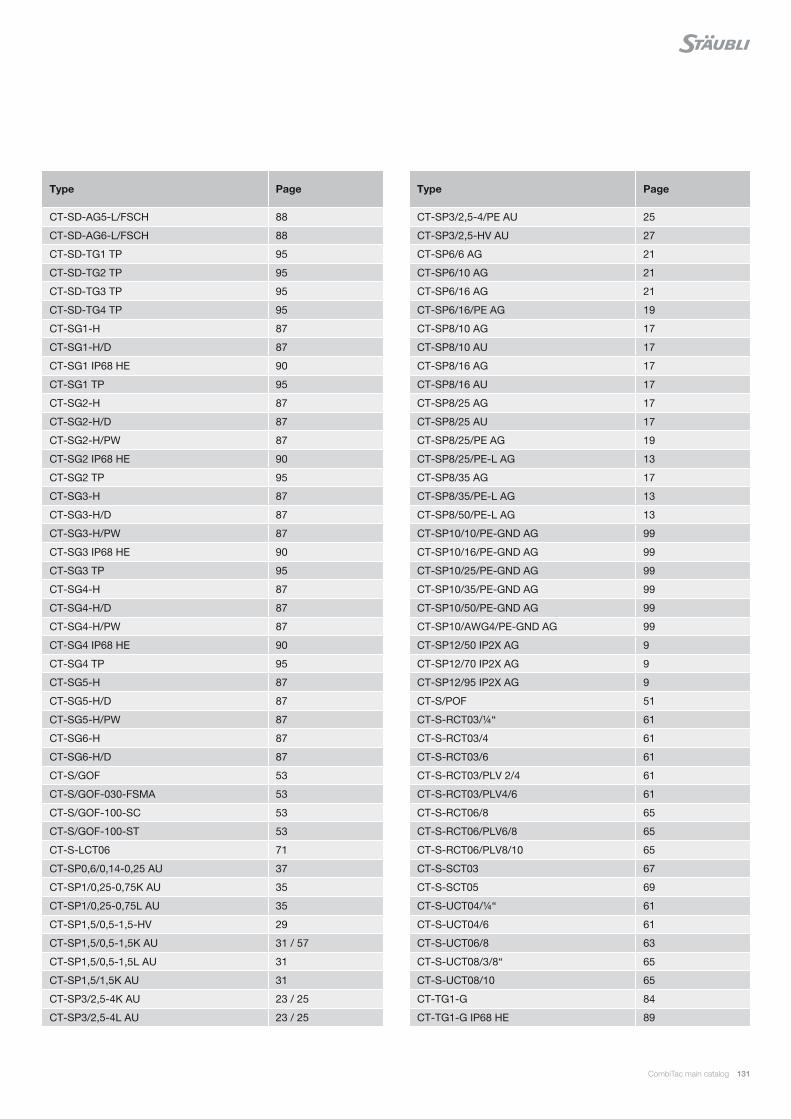
CombiTac main catalog 131
Type Page
CT-SD-AG5-L/FSCH 88
CT-SD-AG6-L/FSCH 88
CT-SD-TG1 TP 95
CT-SD-TG2 TP 95
CT-SD-TG3 TP 95
CT-SD-TG4 TP 95
CT-SG1-H 87
CT-SG1-H/D 87
CT-SG1 IP68 HE 90
CT-SG1 TP 95
CT-SG2-H 87
CT-SG2-H/D 87
CT-SG2-H/PW 87
CT-SG2 IP68 HE 90
CT-SG2 TP 95
CT-SG3-H 87
CT-SG3-H/D 87
CT-SG3-H/PW 87
CT-SG3 IP68 HE 90
CT-SG3 TP 95
CT-SG4-H 87
CT-SG4-H/D 87
CT-SG4-H/PW 87
CT-SG4 IP68 HE 90
CT-SG4 TP 95
CT-SG5-H 87
CT-SG5-H/D 87
CT-SG5-H/PW 87
CT-SG6-H 87
CT-SG6-H/D 87
CT-S/GOF 53
CT-S/GOF-030-FSMA 53
CT-S/GOF-100-SC 53
CT-S/GOF-100-ST 53
CT-S-LCT06 71
CT-SP0,6/0,14-0,25 AU 37
CT-SP1/0,25-0,75K AU 35
CT-SP1/0,25-0,75L AU 35
CT-SP1,5/0,5-1,5-HV 29
CT-SP1,5/0,5-1,5K AU 31 / 57
CT-SP1,5/0,5-1,5L AU 31
CT-SP1,5/1,5K AU 31
CT-SP3/2,5-4K AU 23 / 25
CT-SP3/2,5-4L AU 23 / 25
Type Page
CT-SP3/2,5-4/PE AU 25
CT-SP3/2,5-HV AU 27
CT-SP6/6 AG 21
CT-SP6/10 AG 21
CT-SP6/16 AG 21
CT-SP6/16/PE AG 19
CT-SP8/10 AG 17
CT-SP8/10 AU 17
CT-SP8/16 AG 17
CT-SP8/16 AU 17
CT-SP8/25 AG 17
CT-SP8/25 AU 17
CT-SP8/25/PE AG 19
CT-SP8/25/PE-L AG 13
CT-SP8/35 AG 17
CT-SP8/35/PE-L AG 13
CT-SP8/50/PE-L AG 13
CT-SP10/10/PE-GND AG 99
CT-SP10/16/PE-GND AG 99
CT-SP10/25/PE-GND AG 99
CT-SP10/35/PE-GND AG 99
CT-SP10/50/PE-GND AG 99
CT-SP10/AWG4/PE-GND AG 99
CT-SP12/50 IP2X AG 9
CT-SP12/70 IP2X AG 9
CT-SP12/95 IP2X AG 9
CT-S/POF 51
CT-S-RCT03/¼“ 61
CT-S-RCT03/4 61
CT-S-RCT03/6 61
CT-S-RCT03/PLV 2/4 61
CT-S-RCT03/PLV4/6 61
CT-S-RCT06/8 65
CT-S-RCT06/PLV6/8 65
CT-S-RCT06/PLV8/10 65
CT-S-SCT03 67
CT-S-SCT05 69
CT-S-UCT04/¼“ 61
CT-S-UCT04/6 61
CT-S-UCT06/8 63
CT-S-UCT08/3/8“ 65
CT-S-UCT08/10 65
CT-TG1-G 84
CT-TG1-G IP68 HE 89

132 CombiTac main catalog
Type Page
CT-TG1-G TP 94
CT-TG1-S 84
CT-TG1-S IP68 HE 89
CT-TG1-S TP 94
CT-TG2-G 84
CT-TG2-G IP68 HE 89
CT-TG2-G/PW 85
CT-TG2-G/PW-D 85
CT-TG2-G TP 94
CT-TG2-S 84
CT-TG2-S IP68 HE 89
CT-TG2-S/PW 85
CT-TG2-S/PW-D 85
CT-TG2-S TP 94
CT-TG2/ZV 90
CT-TG3-G 84
CT-TG3-G IP68 HE 89
CT-TG3-G/PW 85
CT-TG3-G/PW-D 85
CT-TG3-G TP 94
CT-TG3-S 84
CT-TG3-S IP68 HE 89
CT-TG3-S/PW 85
CT-TG3-S/PW-D 85
CT-TG3-S TP 94
CT-TG3/ZV 90
CT-TG4-G 84
CT-TG4-G IP68 HE 89
CT-TG4-G/PW 85
CT-TG4-G/PW-D 85
CT-TG4-G TP 94
CT-TG4-S 84
CT-TG4-S IP68 HE 89
CT-TG4-S/PW 85
CT-TG4-S/PW-D 85
CT-TG4-S TP 94
CT-TG4/ZV 90
CT-TG5-G 84
CT-TG5-G/PW 85
CT-TG5-G/PW-D 85
CT-TG5-S 84
CT-TG5-S/PW 85
CT-TG5-S/PW-D 85
CT-TG6-G 84
Type Page
CT-TG6-G/PW 85
CT-TG6-G/PW-D 85
CT-TG6-S 84
CT-TG6-S/PW 85
CT-TG6-S/PW-D 85
CT-ZV/B 90
DBP2-AL/0,14-0,5 57
DBP2-CO/0,14-0,5 57
DBP2-CR/0,14-0,5 57
DBP2-CU/0,14-0,5 57
DBP2-FE/0,14-0,5 57
DBP2-NICRSI/0,14-0,5 57
DBP2-NISI/0,14-0,5 57
DSP2-AL/0,14-0,5 57
DSP2-CO/0,14-0,5 57
DSP2-CR/0,14-0,5 57
DSP2-CU/0,14-0,5 57
DSP2-FE/0,14-0,5 57
DSP2-NICRSI/0,14-0,5 57
DSP2-NISI/0,14-0,5 57
F/M8 DIN6798A BN781 14
F/M10 DIN6798A BN781 10
K-SCH50-8 14
K-SCH50-10 10
LI-BL-SHR 72
LI-KM-SHR 72
LI-SHR-GF 72
MALU-PZ13 104
MBA-WZ1/1,2 107
MBA-WZ1,5 107
MBA-WZ3 107
MBA-WZ5 106
MBA-WZ6 107
MES-CZ 104
MES-CZ-CT 0,6 104
MES-CZ-CT0,6-COAX-RG 104
MES-CZ-CT1 104
MES-CZ-CT1,5 104
MES-CZ-CT1,5-HV 104
MES-CZ-CT3 104
MES-PZ-TB5/6 104
MES-PZ-TB 8/10 104
MES-PZ-TB 9/16 104
MES-PZ-TB11/25 104

CombiTac main catalog 133
Type Page
ME-WZ1,5/2 106
ME-WZ3 106
ME-WZ5 106
ME-WZ6 106
MPS-PZ13 104
M-PZ13 104
M-PZ-T2600 104
MSA-WZ1/1,2 107
MSA-WZ1,5 107
MSA-WZ3 107
MSA-WZ5 106 / 107
MSA-WZ6 106 / 107
MSA-WZ8 107
MU0,8D/M8 AG 14
Type Page
MVS1 31
MVS1,5/2 57
MVS3 23 / 25
MVS5 21
TB7-20 104
TB8-17 104
TB9-13 104
TB11-14,5 104
U/M8 AG 14
U/M10 AG 10
ZYL-SHR-IN-6KT M10×20 ISO4762 BN610 10

134 CombiTac main catalog
Notes

CombiTac main catalog 135
Notes

Global presenceof the Stäubli Group
Stäubli Units Agents
Staubli is a trademark of Stäubli International AG, registered in Switzerland and other countries.We reserve the right to modify product specifi cations without prior notice. © Stäubli [email protected] | Photo credits: Stäubli
www.staubli.com
IS C
T M
ain
1101
4009
-en
D
12.2
019
, Shutterstock